Embed Size (px)
Citation preview
Supporting Fabric OS 8.1.0
ADMINISTRATION GUIDE
Brocade Fabric OS Administration Guide, 8.1.0
53-1004392-0114 December 2016

© 2016, Brocade Communications Systems, Inc. All Rights Reserved.
Brocade, the B-wing symbol, and MyBrocade are registered trademarks of Brocade Communications Systems, Inc., in the United States and in othercountries. Other brands, product names, or service names mentioned of Brocade Communications Systems, Inc. are listed at www.brocade.com/en/legal/brocade-Legal-intellectual-property/brocade-legal-trademarks.html. Other marks may belong to third parties.
Notice: This document is for informational purposes only and does not set forth any warranty, expressed or implied, concerning any equipment,equipment feature, or service offered or to be offered by Brocade. Brocade reserves the right to make changes to this document at any time, withoutnotice, and assumes no responsibility for its use. This informational document describes features that may not be currently available. Contact a Brocadesales office for information on feature and product availability. Export of technical data contained in this document may require an export license from theUnited States government.
The authors and Brocade Communications Systems, Inc. assume no liability or responsibility to any person or entity with respect to the accuracy of thisdocument or any loss, cost, liability, or damages arising from the information contained herein or the computer programs that accompany it.
The product described by this document may contain open source software covered by the GNU General Public License or other open source licenseagreements. To find out which open source software is included in Brocade products, view the licensing terms applicable to the open source software, andobtain a copy of the programming source code, please visit http://www.brocade.com/support/oscd.
Brocade Fabric OS Administration Guide, 8.1.02 53-1004392-01

ContentsPreface................................................................................................................................................................................................................................17
Document conventions.........................................................................................................................................................................................................................17Notes, cautions, and warnings..................................................................................................................................................................................................17Text formatting conventions......................................................................................................................................................................................................17Command syntax conventions.................................................................................................................................................................................................18
Brocade resources..................................................................................................................................................................................................................................18Document feedback.............................................................................................................................................................................................................................. 18Contacting Brocade Technical Support......................................................................................................................................................................................... 19
Brocade customers.......................................................................................................................................................................................................................19Brocade OEM customers.......................................................................................................................................................................................................... 19
About This Document..................................................................................................................................................................................................... 21Supported hardware and software...................................................................................................................................................................................................21
Brocade Gen 5 (16-Gbps) fixed-port switches................................................................................................................................................................21Brocade Gen 5 (16-Gbps) Directors.....................................................................................................................................................................................21Brocade Gen 6 (32-Gbps) fixed-port switches................................................................................................................................................................21Brocade Gen 6 (32-Gbps) Directors.....................................................................................................................................................................................22
What's new in this document............................................................................................................................................................................................................. 22
Understanding Fibre Channel Services ...................................................................................................................................................................... 23Fibre Channel services overview...................................................................................................................................................................................................... 23Management server............................................................................................................................................................................................................................... 24
Application server.......................................................................................................................................................................................................................... 24Platform services.....................................................................................................................................................................................................................................24
Platform services and Virtual Fabrics....................................................................................................................................................................................25Enabling platform services.........................................................................................................................................................................................................25Disabling platform services ......................................................................................................................................................................................................25
Management server database........................................................................................................................................................................................................... 25Displaying the management server ACL.............................................................................................................................................................................26Adding a member to the ACL.................................................................................................................................................................................................. 26Deleting a member from the ACL .........................................................................................................................................................................................27Viewing the contents of the management server database ........................................................................................................................................28Clearing the management server database........................................................................................................................................................................28
Topology discovery................................................................................................................................................................................................................................ 29Displaying topology discovery status....................................................................................................................................................................................29Enabling topology discovery ....................................................................................................................................................................................................29Disabling topology discovery....................................................................................................................................................................................................29
Device login...............................................................................................................................................................................................................................................30Principal switch............................................................................................................................................................................................................................... 31E_Port login process ...................................................................................................................................................................................................................31Fabric login process .................................................................................................................................................................................................................... 31Port login process..........................................................................................................................................................................................................................31RSCNs................................................................................................................................................................................................................................................32Duplicate Port World Wide Name...........................................................................................................................................................................................32
High availability of daemon processes...........................................................................................................................................................................................32FL_Port and arbitrated loop support..............................................................................................................................................................................................33
Performing Basic Configuration Tasks........................................................................................................................................................................ 35
Brocade Fabric OS Administration Guide, 8.1.053-1004392-01 3

Fabric OS overview................................................................................................................................................................................................................................ 35Fabric OS command line interface..................................................................................................................................................................................................35
Console sessions using the serial port................................................................................................................................................................................. 36Telnet or SSH sessions............................................................................................................................................................................................................... 36Getting help on a command..................................................................................................................................................................................................... 38Viewing a history of command line entries.........................................................................................................................................................................38Using fosexec to run commands on remote switches or domains.......................................................................................................................... 41
Modification of default passwords................................................................................................................................................................................................... 43Default account passwords........................................................................................................................................................................................................44
The switch Ethernet interface ............................................................................................................................................................................................................44Brocade Directors..........................................................................................................................................................................................................................44Brocade switches...........................................................................................................................................................................................................................45Virtual Fabrics and the Ethernet interface............................................................................................................................................................................45Management Ethernet port bonding.....................................................................................................................................................................................45Displaying the network interface settings............................................................................................................................................................................ 46Resetting the management network interface error counters.....................................................................................................................................47Static Ethernet addresses...........................................................................................................................................................................................................48DHCP activation.............................................................................................................................................................................................................................49Configuring the static IPv6 gateway address.....................................................................................................................................................................54IPv6 autoconfiguration................................................................................................................................................................................................................54Setting the Ethernet interface mode and speed............................................................................................................................................................... 55
Date and time settings.......................................................................................................................................................................................................................... 56Setting the date and time........................................................................................................................................................................................................... 56Time zone settings........................................................................................................................................................................................................................57Network Time Protocol................................................................................................................................................................................................................59
Domain IDs................................................................................................................................................................................................................................................60Domain ID issues.......................................................................................................................................................................................................................... 61Displaying the domain IDs.........................................................................................................................................................................................................61Setting the domain ID..................................................................................................................................................................................................................62
Switch names............................................................................................................................................................................................................................................63Customizing the switch name.................................................................................................................................................................................................. 63
Chassis names.........................................................................................................................................................................................................................................63Customizing chassis names......................................................................................................................................................................................................63
Fabric name...............................................................................................................................................................................................................................................64Configuring the fabric name......................................................................................................................................................................................................64High availability considerations for fabric names............................................................................................................................................................. 64Upgrade and downgrade considerations for fabric names..........................................................................................................................................64
Switch activation and deactivation................................................................................................................................................................................................... 64Disabling a switch.......................................................................................................................................................................................................................... 65Enabling a switch........................................................................................................................................................................................................................... 65Disabling a chassis........................................................................................................................................................................................................................65Enabling a chassis.........................................................................................................................................................................................................................66
Device shutdown.....................................................................................................................................................................................................................................66Powering off a Brocade switch.................................................................................................................................................................................................66Powering off a Brocade Director............................................................................................................................................................................................. 67
Basic connections...................................................................................................................................................................................................................................67Device connection.........................................................................................................................................................................................................................67Switch connection..........................................................................................................................................................................................................................68
Performing Advanced Configuration Tasks................................................................................................................................................................ 69Port identifiers and PID binding overview.....................................................................................................................................................................................69
Brocade Fabric OS Administration Guide, 8.1.04 53-1004392-01
Core PID addressing mode.......................................................................................................................................................................................................69Fixed addressing mode...............................................................................................................................................................................................................7010-bit addressing (mode 0)......................................................................................................................................................................................................70256-area addressing (mode 1 and mode 2).....................................................................................................................................................................70WWN-based PID assignment..................................................................................................................................................................................................71
Ports............................................................................................................................................................................................................................................................. 73Port types..........................................................................................................................................................................................................................................73Director port blades...................................................................................................................................................................................................................... 74Setting port names........................................................................................................................................................................................................................75Port identification by slot and port number........................................................................................................................................................................ 75Port identification by port area ID........................................................................................................................................................................................... 75Port identification by index.........................................................................................................................................................................................................75Dynamic Portname.......................................................................................................................................................................................................................76Configuring a device-switch connection .............................................................................................................................................................................81Swapping port area IDs...............................................................................................................................................................................................................81Enabling a port................................................................................................................................................................................................................................82Disabling a port...............................................................................................................................................................................................................................83Port decommissioning................................................................................................................................................................................................................ 83Setting port speeds.......................................................................................................................................................................................................................84Setting all ports on a switch to the same speed............................................................................................................................................................... 84Setting port speed for a port octet......................................................................................................................................................................................... 84Setting maximum auto-negotiated port speed.................................................................................................................................................................87Decoding fdmiShow command output................................................................................................................................................................................88
Blade terminology and compatibility.............................................................................................................................................................................................. 88CP blades..........................................................................................................................................................................................................................................90Core blades...................................................................................................................................................................................................................................... 90Port and application blade compatibility..............................................................................................................................................................................91
Enabling and disabling blades...........................................................................................................................................................................................................91Enabling blades.............................................................................................................................................................................................................................. 91Disabling blades.............................................................................................................................................................................................................................92
Blade swapping........................................................................................................................................................................................................................................92How blades are swapped........................................................................................................................................................................................................... 93Swapping blades............................................................................................................................................................................................................................97
Disabling switches.................................................................................................................................................................................................................................. 97Power management...............................................................................................................................................................................................................................97
Powering off a port blade or core blade............................................................................................................................................................................... 97Powering on a port blade or core blade............................................................................................................................................................................... 98Persistently powering off a port blade or core blade.......................................................................................................................................................98
Equipment status.................................................................................................................................................................................................................................... 99Checking switch operation.........................................................................................................................................................................................................99Verifying High Availability features (Backbones and Directors only)........................................................................................................................99Verifying fabric connectivity................................................................................................................................................................................................... 100Verifying device connectivity..................................................................................................................................................................................................100
Audit log configuration.......................................................................................................................................................................................................................101Verifying host syslog prior to configuring the audit log.............................................................................................................................................. 102Configuring an audit log for specific event classes...................................................................................................................................................... 102Configuring remote syslog servers..................................................................................................................................................................................... 103Hostname support for the syslogAdmin command....................................................................................................................................................104Configuring quiet time for RASLog and audit log messages.................................................................................................................................. 104
Duplicate PWWN handling during device login...................................................................................................................................................................... 107
Brocade Fabric OS Administration Guide, 8.1.053-1004392-01 5

Setting 0, First login precedence......................................................................................................................................................................................... 108Setting 1, Second login precedence...................................................................................................................................................................................108Setting 2, Mixed precedence................................................................................................................................................................................................. 108Setting the behavior for handling duplicate PWWNs.................................................................................................................................................. 109
Forward error correction....................................................................................................................................................................................................................109FEC limitations.............................................................................................................................................................................................................................110Enabling forward error correction.........................................................................................................................................................................................110Disabling forward error correction........................................................................................................................................................................................111Enabling or disabling FEC for long-distance ports .....................................................................................................................................................111Displaying and clearing the FEC counters.......................................................................................................................................................................112FEC-via-TTS................................................................................................................................................................................................................................ 112
Routing Traffic................................................................................................................................................................................................................ 115Routing overview..................................................................................................................................................................................................................................115
Paths and route selection........................................................................................................................................................................................................115FSPF................................................................................................................................................................................................................................................116Fibre Channel NAT.....................................................................................................................................................................................................................117
Inter-switch links...................................................................................................................................................................................................................................117Buffer credits................................................................................................................................................................................................................................ 119Congestion versus over-subscription................................................................................................................................................................................ 119Virtual channels........................................................................................................................................................................................................................... 119
Gateway links......................................................................................................................................................................................................................................... 120Configuring a link through a gateway................................................................................................................................................................................. 121
Routing policies.................................................................................................................................................................................................................................... 122Considerations for routing policies .....................................................................................................................................................................................122Displaying the current routing policy.................................................................................................................................................................................. 122Port-based routing ....................................................................................................................................................................................................................123Exchange-based routing......................................................................................................................................................................................................... 123Device-based routing................................................................................................................................................................................................................123Dynamic Path Selection...........................................................................................................................................................................................................123
Route selection......................................................................................................................................................................................................................................124Dynamic Load Sharing.............................................................................................................................................................................................................125
Frame order delivery...........................................................................................................................................................................................................................125Forcing in-order frame delivery across topology changes....................................................................................................................................... 126Restoring out-of-order frame delivery across topology changes..........................................................................................................................126Enabling Frame Viewer............................................................................................................................................................................................................126Using Frame Viewer to understand why frames are dropped ................................................................................................................................127
Lossless Dynamic Load Sharing on ports................................................................................................................................................................................ 128Lossless core................................................................................................................................................................................................................................130Configuring Lossless Dynamic Load Sharing ...............................................................................................................................................................130Lossless Dynamic Load Sharing in Virtual Fabrics......................................................................................................................................................130Two-hop Lossless DLS route update................................................................................................................................................................................131
Frame Redirection............................................................................................................................................................................................................................... 132Creating a frame redirect zone.............................................................................................................................................................................................. 133Deleting a frame redirect zone.............................................................................................................................................................................................. 133Viewing frame redirect zones................................................................................................................................................................................................ 134
Buffer-to-Buffer Credits and Credit Recovery........................................................................................................................................................ 135Buffer credit management ..............................................................................................................................................................................................................135
Buffer-to-buffer flow control..................................................................................................................................................................................................135Optimal buffer credit allocation ............................................................................................................................................................................................136
Brocade Fabric OS Administration Guide, 8.1.06 53-1004392-01

Fibre Channel gigabit values reference definition......................................................................................................................................................... 136Buffer credit allocation based on full-size frames.........................................................................................................................................................137Allocating buffer credits based on average-size frames............................................................................................................................................140Configuring buffers for a single port directly...................................................................................................................................................................140Configuring buffers using frame size................................................................................................................................................................................. 141Calculating the number of buffers required given the distance, speed, and frame size................................................................................141Allocating buffer credits for F_Ports................................................................................................................................................................................... 142Monitoring buffers in a port group.......................................................................................................................................................................................143Buffer credits per switch or blade model..........................................................................................................................................................................145Maximum configurable distances for Extended Fabrics............................................................................................................................................146Configuring credits for a single VC......................................................................................................................................................................................148
Buffer credit recovery ........................................................................................................................................................................................................................149Buffer credit recovery over an E_Port................................................................................................................................................................................149Buffer credit recovery over an F_Port................................................................................................................................................................................ 149Buffer credit recovery over an EX_Port.............................................................................................................................................................................150Enabling and disabling buffer credit recovery.................................................................................................................................................................150
Credit loss detection........................................................................................................................................................................................................................... 151Back-end credit loss detection and recovery support on Brocade 6520 switches.......................................................................................151Enabling back-end credit loss detection and recovery for link reset thresholds.............................................................................................. 151Performing link reset for loss of sync from peer ports............................................................................................................................................... 152Back-end credit loss detection and recovery for link faults...................................................................................................................................... 153
Managing User Accounts.............................................................................................................................................................................................155User accounts overview ................................................................................................................................................................................................................... 155
Role-Based Access Control...................................................................................................................................................................................................156Management channel............................................................................................................................................................................................................... 157Managing user-defined roles.................................................................................................................................................................................................157Configuring time-based access............................................................................................................................................................................................159
Local database user accounts........................................................................................................................................................................................................ 159Default accounts......................................................................................................................................................................................................................... 159Local account passwords........................................................................................................................................................................................................ 161
Local user account database distribution...................................................................................................................................................................................162Distributing the local user database....................................................................................................................................................................................162Accepting distributed user databases on the local switch......................................................................................................................................... 162Rejecting distributed user databases on the local switch...........................................................................................................................................162
Password policies................................................................................................................................................................................................................................ 162Password strength policy.........................................................................................................................................................................................................163Password history policy........................................................................................................................................................................................................... 164Password expiration policy..................................................................................................................................................................................................... 164Account lockout policy............................................................................................................................................................................................................. 165Changing the root password without the old password..............................................................................................................................................166Configuring the password hash type..................................................................................................................................................................................167
The boot PROM password..............................................................................................................................................................................................................168Setting the boot PROM password for a switch with a recovery string................................................................................................................. 168Setting the boot PROM password for Backbones and Directors with a recovery string..............................................................................169Setting the boot PROM password for a switch without a recovery string...........................................................................................................170Setting the boot PROM password for a Backbone or Director without a recovery string........................................................................... 170
Remote authentication.......................................................................................................................................................................................................................171Remote authentication configuration..................................................................................................................................................................................171Setting the switch authentication mode............................................................................................................................................................................ 174Fabric OS user accounts......................................................................................................................................................................................................... 174
Brocade Fabric OS Administration Guide, 8.1.053-1004392-01 7

Fabric OS users on the RADIUS server............................................................................................................................................................................176Setting up a RADIUS server...................................................................................................................................................................................................178LDAP configuration and Microsoft Active Directory....................................................................................................................................................186LDAP configuration and OpenLDAP.................................................................................................................................................................................188TACACS+ service....................................................................................................................................................................................................................... 192Obfuscation of RADIUS and TACACS+ shared secret...............................................................................................................................................195Remote authentication configuration on the switch..................................................................................................................................................... 196Configuring local authentication as backup.....................................................................................................................................................................197
Configuring Protocols...................................................................................................................................................................................................199Security protocols................................................................................................................................................................................................................................ 199Secure Copy...........................................................................................................................................................................................................................................201
Setting up SCP for configuration uploads and downloads....................................................................................................................................... 201Secure Shell protocol..........................................................................................................................................................................................................................201
SSH public key authentication...............................................................................................................................................................................................202Managing SecCryptoCfg templates....................................................................................................................................................................................204
Configuring the ciphers, KEX, and MAC algorithms............................................................................................................................................................. 209Secure Sockets Layer protocol ..................................................................................................................................................................................................... 210
Browser and Java support...................................................................................................................................................................................................... 210SSL configuration overview....................................................................................................................................................................................................210The browser ................................................................................................................................................................................................................................. 217Root certificates for the Java plugin....................................................................................................................................................................................217
Simple Network Management Protocol..................................................................................................................................................................................... 218SNMP Manager.......................................................................................................................................................................................................................... 218SNMP Agent................................................................................................................................................................................................................................ 219Management Information Base............................................................................................................................................................................................219Basic SNMP operation.............................................................................................................................................................................................................219Configuring SNMP using CLI................................................................................................................................................................................................220
Telnet protocol.......................................................................................................................................................................................................................................231Blocking Telnet............................................................................................................................................................................................................................ 231Unblocking Telnet.......................................................................................................................................................................................................................232
Listener applications...........................................................................................................................................................................................................................232Ports and applications used by switches................................................................................................................................................................................... 233
Port configuration.......................................................................................................................................................................................................................233
Configuring Security Policies...................................................................................................................................................................................... 235ACL policies overview........................................................................................................................................................................................................................235
How the ACL policies are stored..........................................................................................................................................................................................235Policy members.......................................................................................................................................................................................................................... 236
ACL policy management..................................................................................................................................................................................................................236Displaying ACL policies........................................................................................................................................................................................................... 236Saving changes without activating the policies..............................................................................................................................................................236Activating ACL policy changes............................................................................................................................................................................................. 237Deleting an ACL policy.............................................................................................................................................................................................................237Adding a member to an existing ACL policy.................................................................................................................................................................. 237Removing a member from an ACL policy.......................................................................................................................................................................238Abandoning unsaved ACL policy changes......................................................................................................................................................................238
FCS policies........................................................................................................................................................................................................................................... 238FCS policy restrictions..............................................................................................................................................................................................................239Ensuring fabric domains share policies ............................................................................................................................................................................240Creating an FCS policy.............................................................................................................................................................................................................240
Brocade Fabric OS Administration Guide, 8.1.08 53-1004392-01
Modifying the order of FCS switches.................................................................................................................................................................................240FCS policy distribution............................................................................................................................................................................................................. 241
Device Connection Control policies............................................................................................................................................................................................. 242Virtual Fabrics considerations for Device Connection Control policies .............................................................................................................. 242DCC policy restrictions.............................................................................................................................................................................................................243Creating a DCC policy.............................................................................................................................................................................................................. 243Deleting a DCC policy.............................................................................................................................................................................................................. 244DCC policy behavior with Fabric-Assigned PWWNs..................................................................................................................................................244
SCC Policies...........................................................................................................................................................................................................................................246Virtual Fabrics considerations for SCC policies ............................................................................................................................................................246Creating an SCC policy............................................................................................................................................................................................................ 246
Authentication policy for fabric elements...................................................................................................................................................................................247Virtual Fabrics considerations for authentication policies .........................................................................................................................................248E_Port authentication................................................................................................................................................................................................................248Device authentication policy...................................................................................................................................................................................................250AUTH policy restrictions..........................................................................................................................................................................................................251Authentication protocols.......................................................................................................................................................................................................... 251Secret key pairs for DH-CHAP.............................................................................................................................................................................................252FCAP configuration overview................................................................................................................................................................................................254Fabric-wide distribution of the authorization policy......................................................................................................................................................257
IP Filter policy........................................................................................................................................................................................................................................257Virtual Fabrics considerations for IP Filter policies ......................................................................................................................................................257Creating an IP Filter policy......................................................................................................................................................................................................258Cloning an IP Filter policy....................................................................................................................................................................................................... 258Displaying an IP Filter policy..................................................................................................................................................................................................258Saving an IP Filter policy......................................................................................................................................................................................................... 258Activating an IP Filter policy...................................................................................................................................................................................................259Deleting an IP Filter policy......................................................................................................................................................................................................259IP Filter policy rules....................................................................................................................................................................................................................259IP Filter policy enforcement................................................................................................................................................................................................... 262Adding a rule to an IP Filter policy.......................................................................................................................................................................................262Deleting a rule from an IP Filter policy...............................................................................................................................................................................262Aborting an IP Filter transaction...........................................................................................................................................................................................263IP Filter policy distribution.......................................................................................................................................................................................................263
Policy database distribution.............................................................................................................................................................................................................263Database distribution settings............................................................................................................................................................................................... 264ACL policy distribution to other switches......................................................................................................................................................................... 265Fabric-wide enforcement........................................................................................................................................................................................................ 266Notes on joining a switch to the fabric...............................................................................................................................................................................267
Management interface security......................................................................................................................................................................................................269Configuration examples........................................................................................................................................................................................................... 269IPsec protocols............................................................................................................................................................................................................................ 271Security associations.................................................................................................................................................................................................................272Authentication and encryption algorithms........................................................................................................................................................................272IPsec policies................................................................................................................................................................................................................................273IKE policies....................................................................................................................................................................................................................................273Creating the tunnel..................................................................................................................................................................................................................... 274Example of an end-to-end transport tunnel mode...................................................................................................................................................... 276
Maintaining the Switch Configuration File............................................................................................................................................................... 279Configuration settings........................................................................................................................................................................................................................ 279
Brocade Fabric OS Administration Guide, 8.1.053-1004392-01 9

Configuration file format .........................................................................................................................................................................................................280Configuration file backup..................................................................................................................................................................................................................281
Special characters in FTP server credentials.................................................................................................................................................................. 281Uploading a configuration file in interactive mode........................................................................................................................................................282
Configuration file restoration........................................................................................................................................................................................................... 282Restrictions when downloading a configuration file..................................................................................................................................................... 283Configuration download without disabling a switch..................................................................................................................................................... 284
Configurations across a fabric........................................................................................................................................................................................................ 285Downloading a configuration file from one switch to another switch of the same model........................................................................... 286Security considerations............................................................................................................................................................................................................ 286
Configuration management for Virtual Fabrics....................................................................................................................................................................... 286Uploading a configuration file from a switch with Virtual Fabrics enabled......................................................................................................... 286Restoring a logical switch configuration using configDownload.............................................................................................................................287Configuration upload and download restrictions when Virtual Fabrics is enabled..........................................................................................288
Brocade configuration form.............................................................................................................................................................................................................288
Managing Virtual Fabrics............................................................................................................................................................................................. 291Virtual Fabrics overview.....................................................................................................................................................................................................................291Logical switch overview.....................................................................................................................................................................................................................292
Default logical switch.................................................................................................................................................................................................................292Logical switches and fabric IDs............................................................................................................................................................................................ 294Port assignment in logical switches....................................................................................................................................................................................295Logical switches and connected devices..........................................................................................................................................................................297
Management model for logical switches................................................................................................................................................................................... 298Logical fabric overview...................................................................................................................................................................................................................... 299
Logical fabric and ISLs.............................................................................................................................................................................................................299Base switch and extended ISLs............................................................................................................................................................................................300
Account management and Virtual Fabrics................................................................................................................................................................................304Setting up IP addresses for a logical switch..............................................................................................................................................................................304
Logical switch login context....................................................................................................................................................................................................305Supported platforms for Virtual Fabrics.....................................................................................................................................................................................306
Supported port configurations in the fixed-port switches.........................................................................................................................................307Supported port configurations in Brocade Backbones and Directors................................................................................................................. 307
Virtual Fabrics interaction with other Fabric OS features.................................................................................................................................................... 308Limitations and restrictions of Virtual Fabrics..........................................................................................................................................................................309
Restrictions on using XISLs................................................................................................................................................................................................... 309Restrictions on moving ports ............................................................................................................................................................................................... 310
Enabling Virtual Fabrics mode....................................................................................................................................................................................................... 310Disabling Virtual Fabrics mode...................................................................................................................................................................................................... 311Configuring logical switches to use basic configuration values........................................................................................................................................312Creating a logical switch or base switch..................................................................................................................................................................................... 312Executing a command in a different logical switch context................................................................................................................................................314Deleting a logical switch....................................................................................................................................................................................................................315Adding and moving ports on a logical switch.......................................................................................................................................................................... 315Displaying logical switch configuration....................................................................................................................................................................................... 316Changing the fabric ID of a logical switch..................................................................................................................................................................................317Changing a logical switch to a base switch............................................................................................................................................................................... 317Configuring a logical switch for XISL use ................................................................................................................................................................................. 318Creating a FICON logical switch....................................................................................................................................................................................................319
Changing an existing logical switch to a FICON logical switch...............................................................................................................................322Considerations for FICON logical switch..........................................................................................................................................................................322
Brocade Fabric OS Administration Guide, 8.1.010 53-1004392-01

Changing the context to a different logical fabric....................................................................................................................................................................323
Administering Advanced Zoning................................................................................................................................................................................ 325Zone types.............................................................................................................................................................................................................................................. 325Zoning overview................................................................................................................................................................................................................................... 326
Approaches to zoning...............................................................................................................................................................................................................327Zone objects................................................................................................................................................................................................................................. 328Zone configurations...................................................................................................................................................................................................................329Zoning enforcement.................................................................................................................................................................................................................. 330Considerations for zoning architecture.............................................................................................................................................................................. 331Best practices for zoning.........................................................................................................................................................................................................331
Broadcast zones...................................................................................................................................................................................................................................332Broadcast zones and FC-FC routing................................................................................................................................................................................. 332High availability considerations with broadcast zones................................................................................................................................................ 333Loop devices and broadcast zones.................................................................................................................................................................................... 333Broadcast zones and default zoning mode.....................................................................................................................................................................333
Zone aliases............................................................................................................................................................................................................................................333Creating an alias.......................................................................................................................................................................................................................... 334Adding members to an alias.................................................................................................................................................................................................. 334Removing members from an alias......................................................................................................................................................................................335Deleting an alias.......................................................................................................................................................................................................................... 335Viewing an alias in the defined configuration..................................................................................................................................................................336
Zone creation and maintenance.....................................................................................................................................................................................................337Displaying existing zones .......................................................................................................................................................................................................337Creating a zone............................................................................................................................................................................................................................337Adding devices (members) to a zone.................................................................................................................................................................................338Removing devices (members) from a zone.....................................................................................................................................................................339Replacing zone members....................................................................................................................................................................................................... 340Deleting a zone............................................................................................................................................................................................................................341Viewing a zone.............................................................................................................................................................................................................................342Viewing zone configuration names without case distinction....................................................................................................................................344Validating a zone.........................................................................................................................................................................................................................345
Default zoning mode..........................................................................................................................................................................................................................349Setting the default zoning mode.......................................................................................................................................................................................... 349Viewing the current default zone access mode............................................................................................................................................................. 350
Zone database size............................................................................................................................................................................................................................. 350Zone configurations............................................................................................................................................................................................................................ 351
Creating a zone configuration................................................................................................................................................................................................352Adding zones to a zone configuration............................................................................................................................................................................... 352Removing members from a zone configuration............................................................................................................................................................353Enabling a zone configuration...............................................................................................................................................................................................353Disabling a zone configuration..............................................................................................................................................................................................354Validating zone members in the zone configuration....................................................................................................................................................354Deleting a zone configuration................................................................................................................................................................................................356Abandoning zone configuration changes.........................................................................................................................................................................357Viewing all zone configuration information......................................................................................................................................................................358Viewing selected zone configuration information......................................................................................................................................................... 358Viewing the zone aliases in the zone configuration......................................................................................................................................................359Viewing the configuration in the effective zone database..........................................................................................................................................361Clearing all zone configurations............................................................................................................................................................................................361
Zone object maintenance................................................................................................................................................................................................................. 362
Brocade Fabric OS Administration Guide, 8.1.053-1004392-01 11

Copying a zone object..............................................................................................................................................................................................................362Deleting a zone object..............................................................................................................................................................................................................362Renaming a zone object.......................................................................................................................................................................................................... 363
Zone configuration management..................................................................................................................................................................................................364Security and zoning.............................................................................................................................................................................................................................364Zone merging........................................................................................................................................................................................................................................ 365
Fabric segmentation and zoning..........................................................................................................................................................................................366Zone merging scenarios..........................................................................................................................................................................................................367
Concurrent zone transactions......................................................................................................................................................................................................... 372Viewing zone database transactions...................................................................................................................................................................................373
Peer Zoning............................................................................................................................................................................................................................................374Peer Zoning compared to other zoning types................................................................................................................................................................374Advantages of Peer Zoning....................................................................................................................................................................................................377Peer Zone connectivity rules..................................................................................................................................................................................................377Firmware upgrade and downgrade considerations for Peer Zoning.....................................................................................................................378LSAN and QoS Peer Zoning considerations..................................................................................................................................................................378Peer Zone configuration.......................................................................................................................................................................................................... 378Alias support for peer zoning................................................................................................................................................................................................ 380
Target Driven Zoning..........................................................................................................................................................................................................................383Limitations and considerations for Target Driven Zoning..........................................................................................................................................384Target Driven Zoning configuration.....................................................................................................................................................................................384
Supported commands for Peer Zones and Target Driven Peer Zones........................................................................................................................ 388Boot LUN zoning.................................................................................................................................................................................................................................388
Setting up boot LUN zoning..................................................................................................................................................................................................390
Traffic Isolation Zoning................................................................................................................................................................................................. 393Traffic Isolation Zoning overview................................................................................................................................................................................................... 393
TI zone failover ........................................................................................................................................................................................................................... 394FSPF routing rules and traffic isolation.......................................................................................................................................................................................395Enhanced TI zones..............................................................................................................................................................................................................................397
Invalid configurations with enhanced TI zones...............................................................................................................................................................398General rules for TI zones................................................................................................................................................................................................................ 400
Additional configuration rules for enhanced TI zones.................................................................................................................................................401Limitations and restrictions of Traffic Isolation Zoning.........................................................................................................................................................402Creating a TI zone................................................................................................................................................................................................................................402Modifying TI zones..............................................................................................................................................................................................................................403Changing the state of a TI zone.....................................................................................................................................................................................................404Deleting a TI zone................................................................................................................................................................................................................................404Displaying TI zones.............................................................................................................................................................................................................................404Enforcing Local TI Filtering..............................................................................................................................................................................................................406
Traffic Isolation Zoning over FC routers............................................................................................................................................................................ 406TI zones within an edge fabric...............................................................................................................................................................................................407TI zones within a backbone fabric....................................................................................................................................................................................... 408Limitations of TI zones over FC routers............................................................................................................................................................................410
Fabric-Level Traffic Isolation in a backbone fabric.................................................................................................................................................................410Fabric-Level TI zones............................................................................................................................................................................................................... 411Failover behavior for Fabric-Level TI zones.................................................................................................................................................................... 412Creating a separate TI zone for each path........................................................................................................................................................................412Creating a single TI zone for all paths................................................................................................................................................................................ 413Setting up TI zones over FCR (sample procedure).......................................................................................................................................................414
Virtual Fabrics considerations for Traffic Isolation Zoning.................................................................................................................................................. 418
Brocade Fabric OS Administration Guide, 8.1.012 53-1004392-01

Traffic Isolation Zoning over FC routers with Virtual Fabrics............................................................................................................................................. 420Troubleshooting TI zone routing problems...............................................................................................................................................................................422
TI Zone violation handling for trunk ports........................................................................................................................................................................ 423
Optimizing Fabric Behavior.........................................................................................................................................................................................425Adaptive Networking overview.......................................................................................................................................................................................................425Ingress Rate Limiting..........................................................................................................................................................................................................................425
Virtual Fabrics considerations for ingress rate limiting................................................................................................................................................426Limiting traffic from a particular device............................................................................................................................................................................. 426Disabling Ingress Rate Limiting............................................................................................................................................................................................426
QoS............................................................................................................................................................................................................................................................426License requirements for QoS..............................................................................................................................................................................................427QoS on E_Ports..........................................................................................................................................................................................................................427QoS over FC routers.................................................................................................................................................................................................................428vTap and QoS High Priority Zoning Compatibility mode.......................................................................................................................................... 429Virtual Fabrics considerations for QoS zone-based traffic prioritization.............................................................................................................430Traffic prioritization based on QoS zones.........................................................................................................................................................................431
CS_CTL-based frame prioritization..............................................................................................................................................................................................437Supported configurations for CS_CTL-based frame prioritization........................................................................................................................438High availability considerations for CS_CTL-based frame prioritization............................................................................................................. 438Enabling CS_CTL-based frame prioritization on ports...............................................................................................................................................438Disabling CS_CTL-based frame prioritization on ports............................................................................................................................................. 438Using CS_CTL auto mode at the chassis level..............................................................................................................................................................439Considerations for using CS_CTL-based frame prioritization.................................................................................................................................439
In-flight Encryption and Compression...................................................................................................................................................................... 441In-flight encryption and compression overview...................................................................................................................................................................... 441
Supported ports for in-flight encryption and compression...................................................................................................................................... 442In-flight encryption and compression restrictions.........................................................................................................................................................443How in-flight encryption and compression are enabled.............................................................................................................................................445Authentication and key generation for encryption and compression....................................................................................................................446Availability considerations for encryption and compression.....................................................................................................................................447Virtual Fabrics considerations for encryption and compression.............................................................................................................................447In-flight compression on long-distance ports................................................................................................................................................................447Compression ratios for compression-enabled ports...................................................................................................................................................447
Configuring in-flight encryption and compression on an EX_Port.................................................................................................................................448Configuring in-flight encryption and compression on an E_Port....................................................................................................................................449Viewing the encryption and compression configuration......................................................................................................................................................450Configuring and enabling authentication for in-flight encryption.....................................................................................................................................451Enabling in-flight encryption........................................................................................................................................................................................................... 453Enabling in-flight compression...................................................................................................................................................................................................... 454Disabling in-flight encryption.......................................................................................................................................................................................................... 455Disabling in-flight compression..................................................................................................................................................................................................... 456
NPIV..................................................................................................................................................................................................................................457NPIV overview.......................................................................................................................................................................................................................................457
Upgrade considerations...........................................................................................................................................................................................................458Fixed addressing mode............................................................................................................................................................................................................45810-bit addressing mode......................................................................................................................................................................................................... 458
Configuring NPIV.................................................................................................................................................................................................................................458Enabling and disabling NPIV.......................................................................................................................................................................................................... 459Base device logout..............................................................................................................................................................................................................................460
Brocade Fabric OS Administration Guide, 8.1.053-1004392-01 13

Difference in the device logout behaviors........................................................................................................................................................................ 460Enabling base device logout..................................................................................................................................................................................................461Use cases and dependencies................................................................................................................................................................................................461Viewing base device logout setting.....................................................................................................................................................................................463
Viewing NPIV port configuration information.......................................................................................................................................................................... 463Viewing virtual PID login information.................................................................................................................................................................................465
Fabric-Assigned PWWN.............................................................................................................................................................................................. 467Fabric-Assigned PWWN overview............................................................................................................................................................................................... 467User- and auto-assigned FA-PWWN behavior .....................................................................................................................................................................468Configuring an FA-PWWN for an HBA connected to an Access Gateway................................................................................................................ 469Configuring an FA-PWWN for an HBA connected to an edge switch..........................................................................................................................470Supported switches and configurations for FA-PWWN......................................................................................................................................................470Configuration upload and download considerations for FA-PWWN............................................................................................................................. 471Security considerations for FA-PWWN......................................................................................................................................................................................471Restrictions of FA-PWWN............................................................................................................................................................................................................... 472Access Gateway N_Port failover with FA-PWWN.................................................................................................................................................................472
Inter-chassis Links.........................................................................................................................................................................................................473Inter-chassis links ............................................................................................................................................................................................................................... 473
License requirements for ICLs..............................................................................................................................................................................................473Using the QSFPs that support 2 km on ICL ports .....................................................................................................................................................474
ICLs between DCX 8510 Backbones........................................................................................................................................................................................475ICL trunking between Brocade DCX 8510 Backbones............................................................................................................................................ 476
ICLs between X6 Directors..............................................................................................................................................................................................................477ICL trunking between Brocade X6 Directors.................................................................................................................................................................. 480
ICLs between DCX 8510 Backbones and X6 Directors....................................................................................................................................................482ICL trunking between DCX 8510 Backbones and X6 Directors...........................................................................................................................483
Virtual Fabrics considerations for ICLs.......................................................................................................................................................................................484Supported topologies for ICL connections...............................................................................................................................................................................485
Mesh topology.............................................................................................................................................................................................................................485Core-edge topology..................................................................................................................................................................................................................487
Managing Trunking Connections................................................................................................................................................................................489Trunking overview................................................................................................................................................................................................................................ 489
Types of trunking........................................................................................................................................................................................................................ 489Masterless trunking....................................................................................................................................................................................................................490License requirements for trunking.......................................................................................................................................................................................490Port groups for trunking...........................................................................................................................................................................................................490
Supported platforms for trunking..................................................................................................................................................................................................491Supported configurations for trunking........................................................................................................................................................................................ 491
High Availability support for trunking................................................................................................................................................................................. 491Requirements for trunk groups...................................................................................................................................................................................................... 492Recommendations for trunk groups............................................................................................................................................................................................492Configuring trunk groups..................................................................................................................................................................................................................493Enabling trunking................................................................................................................................................................................................................................. 493Disabling trunking................................................................................................................................................................................................................................ 494Displaying trunking information.....................................................................................................................................................................................................494ISL trunking over long-distance fabrics......................................................................................................................................................................................495EX_Port trunking..................................................................................................................................................................................................................................496
Masterless EX_Port trunking................................................................................................................................................................................................. 496Supported configurations and platforms for EX_Port trunking...............................................................................................................................496
Brocade Fabric OS Administration Guide, 8.1.014 53-1004392-01

Configuring EX_Port trunking............................................................................................................................................................................................... 497Displaying EX_Port trunking information......................................................................................................................................................................... 497
F_Port trunking......................................................................................................................................................................................................................................497F_Port trunking for Access Gateway.................................................................................................................................................................................. 498F_Port trunking for Brocade adapters................................................................................................................................................................................501F_Port trunking considerations............................................................................................................................................................................................. 502F_Port trunking in Virtual Fabrics.........................................................................................................................................................................................504
Displaying F_Port trunking information...................................................................................................................................................................................... 504Disabling F_Port trunking................................................................................................................................................................................................................. 505Enabling the DCC policy on a trunk area................................................................................................................................................................................... 505
Managing Long-Distance Fabrics..............................................................................................................................................................................507Long-distance fabrics overview.....................................................................................................................................................................................................507Extended Fabrics device limitations.............................................................................................................................................................................................507Long-distance link modes............................................................................................................................................................................................................... 508Configuring an extended ISL.......................................................................................................................................................................................................... 508
Enabling long distance when connecting to TDM devices ......................................................................................................................................510Forward error correction on long-distance links..................................................................................................................................................................... 511
Enabling FEC on a long-distance link................................................................................................................................................................................511Disabling FEC on a long-distance link.............................................................................................................................................................................. 511
Using FC-FC Routing to Connect Fabrics................................................................................................................................................................513FC-FC routing overview....................................................................................................................................................................................................................513
License requirements for FC-FC routing......................................................................................................................................................................... 514Supported platforms for FC-FC routing...........................................................................................................................................................................514Supported configurations for FC-FC routing................................................................................................................................................................. 515Network OS connectivity limitations ................................................................................................................................................................................. 515
Fibre Channel routing concepts.....................................................................................................................................................................................................515Proxy devices............................................................................................................................................................................................................................... 520FC-FC routing topologies.......................................................................................................................................................................................................521Phantom domains......................................................................................................................................................................................................................521FC router authentication ......................................................................................................................................................................................................... 525
Setting up FC-FC routing.................................................................................................................................................................................................................525Verifying the setup for FC-FC routing............................................................................................................................................................................... 526
Backbone fabric IDs........................................................................................................................................................................................................................... 527Assigning backbone fabric IDs............................................................................................................................................................................................. 527
Assigning alias names to fabric IDs............................................................................................................................................................................................. 528FCIP tunnel configuration.................................................................................................................................................................................................................529Inter-fabric link configuration...........................................................................................................................................................................................................529
Configuring an IFL for both edge and backbone connections................................................................................................................................530Configuring EX_Ports on an ICL..........................................................................................................................................................................................533
FC router port cost configuration..................................................................................................................................................................................................535Port cost considerations.......................................................................................................................................................................................................... 535Setting router port cost for an EX_Port.............................................................................................................................................................................536
Shortest IFL cost configuration......................................................................................................................................................................................................537Configuring shortest IFL cost................................................................................................................................................................................................539
EX_Port frame trunking configuration.........................................................................................................................................................................................541LSAN zone configuration................................................................................................................................................................................................................. 541
Zone definition and naming................................................................................................................................................................................................... 541LSAN zones and fabric-to-fabric communications.....................................................................................................................................................542Controlling device communication with the LSAN.......................................................................................................................................................542
Brocade Fabric OS Administration Guide, 8.1.053-1004392-01 15

Configuring interconnectivity between backbone and edge fabrics......................................................................................................................545Setting the maximum LSAN count.....................................................................................................................................................................................545HA and downgrade considerations for LSAN zones...................................................................................................................................................546LSAN zone policies using LSAN tagging........................................................................................................................................................................ 547LSAN zone binding................................................................................................................................................................................................................... 552
Location embedded LSAN zones................................................................................................................................................................................................ 556Creating location embedded LSAN zones...................................................................................................................................................................... 557Migrating LSAN zones to location embedded LSAN zones in the edge fabric...............................................................................................559Limitations of location embedded LSAN zones........................................................................................................................................................... 559
Peer LSAN zone support................................................................................................................................................................................................................. 560Proxy PID configuration.................................................................................................................................................................................................................... 560Fabric parameter considerations................................................................................................................................................................................................... 561Inter-fabric broadcast frames..........................................................................................................................................................................................................561
Displaying the current broadcast configuration..............................................................................................................................................................561Enabling broadcast frame forwarding................................................................................................................................................................................ 561Disabling broadcast frame forwarding...............................................................................................................................................................................562
Resource monitoring.......................................................................................................................................................................................................................... 562FC-FC routing and Virtual Fabrics................................................................................................................................................................................................563
Logical switch configuration for FC routing.....................................................................................................................................................................564Backbone-to-edge routing with Virtual Fabrics.............................................................................................................................................................566
Upgrade and downgrade considerations for FC-FC routing.............................................................................................................................................567How replacing port blades affects EX_Port configuration.........................................................................................................................................568
Displaying the range of output ports connected to xlate domains..................................................................................................................................568FC-FC routing scalability limits......................................................................................................................................................................................................568
Port Indexing...................................................................................................................................................................................................................571
Switch and Blade Sensors........................................................................................................................................................................................... 573Brocade switch sensors.................................................................................................................................................................................................................... 573Brocade blade temperature sensors............................................................................................................................................................................................573System temperature monitoring....................................................................................................................................................................................................574
Hexadecimal Conversion..............................................................................................................................................................................................575Hexadecimal overview....................................................................................................................................................................................................................... 575
Example conversion of the hexadecimal triplet 0x616000.....................................................................................................................................575Decimal-to-hexadecimal conversion table......................................................................................................................................................................575
Brocade Fabric OS Administration Guide, 8.1.016 53-1004392-01

Preface• Document conventions................................................................................................................................................................................... 17• Brocade resources............................................................................................................................................................................................ 18• Document feedback.........................................................................................................................................................................................18• Contacting Brocade Technical Support....................................................................................................................................................19
Document conventionsThe document conventions describe text formatting conventions, command syntax conventions, and important notice formats used inBrocade technical documentation.
Notes, cautions, and warningsNotes, cautions, and warning statements may be used in this document. They are listed in the order of increasing severity of potential
hazards.
NOTEA Note provides a tip, guidance, or advice, emphasizes important information, or provides a reference to related information.
ATTENTIONAn Attention statement indicates a stronger note, for example, to alert you when traffic might be interrupted or the device mightreboot.
CAUTIONA Caution statement alerts you to situations that can be potentially hazardous to you or cause damage to hardware,firmware, software, or data.
DANGERA Danger statement indicates conditions or situations that can be potentially lethal or extremely hazardous to you. Safetylabels are also attached directly to products to warn of these conditions or situations.
Text formatting conventionsText formatting conventions such as boldface, italic, or Courier font may be used to highlight specific words or phrases.
Format Description
bold text Identifies command names.
Identifies keywords and operands.
Identifies the names of GUI elements.
Identifies text to enter in the GUI.
italic text Identifies emphasis.
Identifies variables.
Identifies document titles.
Courier font Identifies CLI output.
Brocade Fabric OS Administration Guide, 8.1.053-1004392-01 17

Format Description
Identifies command syntax examples.
Command syntax conventionsBold and italic text identify command syntax components. Delimiters and operators define groupings of parameters and their logicalrelationships.
Convention Description
bold text Identifies command names, keywords, and command options.
italic text Identifies a variable.
value In Fibre Channel products, a fixed value provided as input to a command option is printed in plain text, forexample, --show WWN.
[ ] Syntax components displayed within square brackets are optional.
Default responses to system prompts are enclosed in square brackets.
{ x | y | z } A choice of required parameters is enclosed in curly brackets separated by vertical bars. You must selectone of the options.
In Fibre Channel products, square brackets may be used instead for this purpose.
x | y A vertical bar separates mutually exclusive elements.
< > Nonprinting characters, for example, passwords, are enclosed in angle brackets.
... Repeat the previous element, for example, member[member...].
\ Indicates a “soft” line break in command examples. If a backslash separates two lines of a commandinput, enter the entire command at the prompt without the backslash.
Brocade resourcesVisit the Brocade website to locate related documentation for your product and additional Brocade resources.
White papers, data sheets, and the most recent versions of Brocade software and hardware manuals are available at www.brocade.com.Product documentation for all supported releases is available to registered users at MyBrocade.Click the Support tab and select Document Library to access documentation on MyBrocade or www.brocade.com You can locatedocumentation by product or by operating system.
Release notes are bundled with software downloads on MyBrocade. Links to software downloads are available on the MyBrocade landingpage and in the Document Library.
Document feedbackQuality is our first concern at Brocade, and we have made every effort to ensure the accuracy and completeness of this document.However, if you find an error or an omission, or you think that a topic needs further development, we want to hear from you. You canprovide feedback in two ways:
• Through the online feedback form in the HTML documents posted on www.brocade.com
• By sending your feedback to [email protected]
Provide the publication title, part number, and as much detail as possible, including the topic heading and page number if applicable, aswell as your suggestions for improvement.
Brocade resources
Brocade Fabric OS Administration Guide, 8.1.018 53-1004392-01

Contacting Brocade Technical SupportAs a Brocade customer, you can contact Brocade Technical Support 24x7 online or by telephone. Brocade OEM customers shouldcontact their OEM/solution provider.
Brocade customersFor product support information and the latest information on contacting the Technical Assistance Center, go to www.brocade.com andselect Support.
If you have purchased Brocade product support directly from Brocade, use one of the following methods to contact the BrocadeTechnical Assistance Center 24x7.
Online Telephone
Preferred method of contact for non-urgent issues:
• Case management through the MyBrocade portal.
• Quick Access links to Knowledge Base, Community, DocumentLibrary, Software Downloads and Licensing tools
Required for Sev 1-Critical and Sev 2-High issues:
• Continental US: 1-800-752-8061
• Europe, Middle East, Africa, and Asia Pacific: +800-AT FIBREE(+800 28 34 27 33)
• Toll-free numbers are available in many countries.
• For areas unable to access a toll-free number:+1-408-333-6061
Brocade OEM customersIf you have purchased Brocade product support from a Brocade OEM/solution provider, contact your OEM/solution provider for all ofyour product support needs.
• OEM/solution providers are trained and certified by Brocade to support Brocade® products.
• Brocade provides backline support for issues that cannot be resolved by the OEM/solution provider.
• Brocade Supplemental Support augments your existing OEM support contract, providing direct access to Brocade expertise.For more information, contact Brocade or your OEM.
• For questions regarding service levels and response times, contact your OEM/solution provider.
Contacting Brocade Technical Support
Brocade Fabric OS Administration Guide, 8.1.053-1004392-01 19

Brocade Fabric OS Administration Guide, 8.1.020 53-1004392-01
About This Document• Supported hardware and software..............................................................................................................................................................21• What's new in this document........................................................................................................................................................................22
Supported hardware and softwareThe following hardware platforms are supported by Fabric OS 8.1.0.
Although many different software and hardware configurations are tested and supported by Brocade for Fabric OS 8.1.0, documentingall possible configurations and scenarios is beyond the scope of this document.
Fabric OS support for the Brocade Analytics Monitoring Platform (AMP) device depends on the specific version of the software runningon that platform. For more information, refer to the Brocade Analytics Monitoring Platform documentation and release notes.
Brocade Gen 5 (16-Gbps) fixed-port switches• Brocade 6505 Switch
• Brocade 6510 Switch
• Brocade 6520 Switch
• Brocade M6505 blade server SAN I/O module
• Brocade 6542 blade server SAN I/O module
• Brocade 6543 blade server SAN I/O module
• Brocade 6545 blade server SAN I/O module
• Brocade 6546 blade server SAN I/O module
• Brocade 6547 blade server SAN I/O module
• Brocade 6548 blade server SAN I/O module
• Brocade 6558 blade server SAN I/O module
• Brocade 7840 Extension Switch
Brocade Gen 5 (16-Gbps) DirectorsFor ease of reference, Brocade chassis-based storage systems are standardizing on the term “Director.” The legacy term “Backbone” canbe used interchangeably with the term “Director.”
• Brocade DCX 8510-4 Director
• Brocade DCX 8510-8 Director
Brocade Gen 6 (32-Gbps) fixed-port switches• Brocade G610 Switch
• Brocade G620 Switch
Brocade Fabric OS Administration Guide, 8.1.053-1004392-01 21

Brocade Gen 6 (32-Gbps) Directors• Brocade X6-4 Director
• Brocade X6-8 Director
What's new in this documentThe following changes are applied to this document:
• The Diagnostics Port chapter was moved to the Brocade Fabric OS Troubleshooting and Diagnostics Guide.
• Added a topic about the application server for VM Insight support.
• Added a topic about configuring the static IPv6 gateway address.
• Added a topic about persistently powering off a port or core blade even after reboot.
• Added a topic about configuring the quiet time for RASLog and Audit log messages.
• Added a topic about mapping vendor attributes, such as chassis role, home LF, and LF list for LDAP user roles.
• Added a topic about the secCertMgmt command to generate, import, export, delete, and show certificates.
• Added a topic about encrypting the SNMPv3 user password.
• Added a topic about using enhanced zone object names starting with numbers, and including the hyphen (-), dollar sign ($), andcaret (^).
• Added a topic about creating peer zones using alias names as principal and non-principal members.
• Added a topic about FC-FC router scalability limits.
• Updated the Frame Viewer section to support enabling framelog for type 1, type 2, and type 6 misses.
• Updated the number of buffer credits supported on the Brocade G610.
• Updated the maximum configurable distances for extended fabrics using the Brocade G610.
• Updated the obfuscation support to include TACACS+ shared secrets.
• Updated the required Open SSL package version to 1.0.2h.
• Updated the topic about secCryptoCfg templates to include FIPS templates.
• Updated the topic about default secCryptoCfg templates to include FIPS templates.
• Updated the number of logical switches supported on the X6 Director to 16.
• Updated the topic about creating a logical switch to include the -lisldisable option.
• Added a topic about creating FICON logical switches.
• Updated the topic about zone database size to include chassis wide restriction.
• Updated the list of supported ports and devices for in-flight encryption and compression.
• Updated the bandwidth and port limits for in-flight encryption and compression.
• Updated the maximum number of FC routers supported in a backbone fabric from 12 to 16.
• Updated the maximum number of LSAN zones supported in a metaSAN from 5,000 to 7,500.
• Updated the maximum number of LSAN devices supported in a metaSAN from 10,000 to 15,000.
What's new in this document
Brocade Fabric OS Administration Guide, 8.1.022 53-1004392-01

Understanding Fibre Channel Services• Fibre Channel services overview.................................................................................................................................................................23• Management server..........................................................................................................................................................................................24• Platform services............................................................................................................................................................................................... 24• Management server database......................................................................................................................................................................25• Topology discovery...........................................................................................................................................................................................29• Device login..........................................................................................................................................................................................................30• High availability of daemon processes..................................................................................................................................................... 32• FL_Port and arbitrated loop support.........................................................................................................................................................33
Fibre Channel services overviewFibre Channel services define service functions that reside at well-known addresses. A well-known address is a reserved three-byteaddress for each service. Services are provided to either nodes or management applications in the fabric.
FIGURE 1 Well-known addresses
Fabric Login — The Fabric Login server assigns a fabric address to a fabric node, which allows it to communicate with services on theswitch or other nodes in the fabric. The fabric address is a 24-bit address (0x000000) containing three 3-byte nodes. Reading from leftto right, the first node (0x000000) represents the domain ID, the second node (0x000000) the port area number of the port where thenode is attached, and the third node (0x000000) the arbitrated loop physical address (AL_PA), if applicable.
Directory server — The directory server or name server registers fabric and public nodes and conducts queries to discover other devicesin the fabric.
Fabric controller — The fabric controller provides State Change Notifications (SCNs) to registered nodes when a change in the fabrictopology occurs.
Time server — The time server sends the time to the member switches in the fabric from either the principal switch or, if configured, theprimary fabric configuration server (FCS) switch. Refer to Configuring Security Policies on page 235 for additional information on FCSpolicies.
Management server — The management server provides a single point for managing the fabric. This is the only service that users canconfigure. Refer to Management server on page 24 for more details.
Alias server — The alias server keeps a group of nodes registered as one name to handle multicast groups.
Brocade Fabric OS Administration Guide, 8.1.053-1004392-01 23

Broadcast server — The broadcast server is optional. When frames are transmitted to this address, they are broadcast to all operationalN_ and NL_Ports.
When registration and query frames are sent to a well-known address, a different protocol service, Fibre Channel Common Transport(FC-CT), is used. This protocol provides a simple, consistent format and behavior when a service provider is accessed for registration andquery purposes.
Management serverThe Brocade Fabric OS management server (MS) allows a SAN management application to retrieve information and administerinterconnected switches, servers, and storage devices. The management server assists in the autodiscovery of switch-based fabrics andtheir associated topologies.
A client of the management server can find basic information about the switches in the fabric and use this information to constructtopology relationships. The management server also allows you to obtain certain switch attributes and, in some cases, modify them. Forexample, logical names identifying switches can be registered with the management server.
The management server provides several advantages for managing a Fibre Channel fabric:
• It is accessed by an external Fibre Channel node at the well-known address FFFFFAh, so an application can access informationabout the entire fabric management with minimal knowledge of the existing configuration.
• It is replicated on every Brocade switch within a fabric.
• It provides an unzoned view of the overall fabric configuration. This fabric topology view exposes the internal configuration of afabric for management purposes; it contains interconnect information about switches and devices connected to the fabric.Under normal circumstances, a device (typically an FCP initiator) queries the name server for storage devices within its memberzones. Because this limited view is not always sufficient, the management server provides the application with a list of the entirename server database.
Application serverThe application server is a key component of the VM Insight flow monitoring feature for Flow Vision.
As a component of the management server, the application server stores entity IDs for virtual machine (VM) instances registered byHBAs and allocates application IDs to HBAs for identifying VM traffic in the fabric. With traffic for individual VM flows identified, monitorscan be configured to provide flow statistics to help isolate VM performance issues.
The application server is a distributed database, similar to the name server and management server, and it is propagated to all switches inthe fabric that support the application server. The application server is only supported by Gen 6 platforms running Fabric OS 8.1.0 andlater. It will not attempt inter-switch communication with Gen 4 or Gen 5 platforms.
You can use the appserver --show command to display contents of the application server database, including N_Port IDs, applicationIDs, PIDs, and domain information associated with all registered VM entity IDs. Refer to the Brocade Fabric OS Command Reference fordetails.
Platform servicesBy default, all management services except platform services are enabled; the MS platform service and topology discovery are disabled.
Management server
Brocade Fabric OS Administration Guide, 8.1.024 53-1004392-01
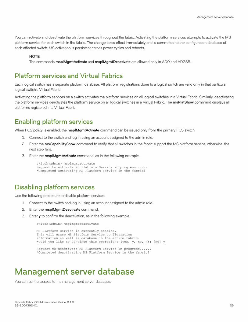
You can activate and deactivate the platform services throughout the fabric. Activating the platform services attempts to activate the MSplatform service for each switch in the fabric. The change takes effect immediately and is committed to the configuration database ofeach affected switch. MS activation is persistent across power cycles and reboots.
NOTEThe commands msplMgmtActivate and msplMgmtDeactivate are allowed only in AD0 and AD255.
Platform services and Virtual FabricsEach logical switch has a separate platform database. All platform registrations done to a logical switch are valid only in that particularlogical switch’s Virtual Fabric.
Activating the platform services on a switch activates the platform services on all logical switches in a Virtual Fabric. Similarly, deactivatingthe platform services deactivates the platform service on all logical switches in a Virtual Fabric. The msPlatShow command displays allplatforms registered in a Virtual Fabric.
Enabling platform servicesWhen FCS policy is enabled, the msplMgmtActivate command can be issued only from the primary FCS switch.
1. Connect to the switch and log in using an account assigned to the admin role.
2. Enter the msCapabilityShow command to verify that all switches in the fabric support the MS platform service; otherwise, thenext step fails.
3. Enter the msplMgmtActivate command, as in the following example.
switch:admin> msplmgmtactivateRequest to activate MS Platform Service in progress......*Completed activating MS Platform Service in the fabric!
Disabling platform servicesUse the following procedure to disable platform services.
1. Connect to the switch and log in using an account assigned to the admin role.
2. Enter the msplMgmtDeactivate command.
3. Enter y to confirm the deactivation, as in the following example.
switch:admin> msplmgmtdeactivate MS Platform Service is currently enabled.This will erase MS Platform Service configurationinformation as well as database in the entire fabric.Would you like to continue this operation? (yes, y, no, n): [no] y Request to deactivate MS Platform Service in progress......*Completed deactivating MS Platform Service in the fabric!
Management server databaseYou can control access to the management server database.
Management server database
Brocade Fabric OS Administration Guide, 8.1.053-1004392-01 25

An access control list (ACL) of WWN addresses determines which systems have access to the management server database. The ACLtypically contains those WWNs of host systems that are running management applications.
If the list is empty (the default), the management server is accessible to all systems connected in-band to the fabric. For more accesssecurity, you can specify WWNs in the ACL so that access to the management server is restricted to only those WWNs listed.
NOTEThe management server is logical switch-capable. All management server features are supported within a logical switch.
Displaying the management server ACLUse the following procedure to display the management server ACL.
1. Connect to the switch and log in using an account assigned to the admin role.
2. Enter the msConfigure command.
The command becomes interactive.
3. At the "select" prompt, enter 1 to display the access list.
A list of WWNs that have access to the management server is displayed.
The following is an example of an empty access list.
switch:admin> msconfigure0 Done1 Display the access list2 Add member based on its Port/Node WWN3 Delete member based on its Port/Node WWNselect : (0..3) [1] 1MS Access list is empty.0 Done1 Display the access list2 Add member based on its Port/Node WWN3 Delete member based on its Port/Node WWNselect : (0..3) [1] 0done ...
Adding a member to the ACLUse the following procedure to add a member to the ACL.
1. Connect to the switch and log in using an account assigned to the admin role.
2. Enter the msConfigure command.
The command becomes interactive.
3. At the "select" prompt, enter 2 to add a member based on its port/node WWN.
4. At the "Port/Node WWN" prompt, enter the WWN of the host to be added to the ACL.
5. At the "select" prompt, enter 1 to display the access list so you can verify that the WWN you entered was added to the ACL.
6. After verifying that the WWN was added correctly, enter 0 at the prompt to end the session.
7. At the "Update the FLASH?" prompt, enter y.
8. Press Enter to update the nonvolatile memory and end the session.
Management server database
Brocade Fabric OS Administration Guide, 8.1.026 53-1004392-01
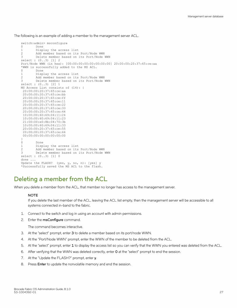
The following is an example of adding a member to the management server ACL.
switch:admin> msconfigure0 Done1 Display the access list2 Add member based on its Port/Node WWN3 Delete member based on its Port/Node WWNselect : (0..3) [1] 2Port/Node WWN (in hex): [00:00:00:00:00:00:00:00] 20:00:00:20:37:65:ce:aa*WWN is successfully added to the MS ACL.0 Done1 Display the access list2 Add member based on its Port/Node WWN3 Delete member based on its Port/Node WWNselect : (0..3) [2] 1MS Access List consists of (14): { 20:00:00:20:37:65:ce:aa 20:00:00:20:37:65:ce:bb 20:00:00:20:37:65:ce:ff 20:00:00:20:37:65:ce:11 20:00:00:20:37:65:ce:22 20:00:00:20:37:65:ce:33 20:00:00:20:37:65:ce:44 10:00:00:60:69:04:11:24 10:00:00:60:69:04:11:23 21:00:00:e0:8b:04:70:3b 10:00:00:60:69:04:11:33 20:00:00:20:37:65:ce:55 20:00:00:20:37:65:ce:66 00:00:00:00:00:00:00:00}0 Done1 Display the access list2 Add member based on its Port/Node WWN3 Delete member based on its Port/Node WWNselect : (0..3) [1] 0done ...Update the FLASH? (yes, y, no, n): [yes] y*Successfully saved the MS ACL to the flash.
Deleting a member from the ACLWhen you delete a member from the ACL, that member no longer has access to the management server.
NOTEIf you delete the last member of the ACL, leaving the ACL list empty, then the management server will be accessible to allsystems connected in-band to the fabric.
1. Connect to the switch and log in using an account with admin permissions.
2. Enter the msConfigure command.
The command becomes interactive.
3. At the "select" prompt, enter 3 to delete a member based on its port/node WWN.
4. At the "Port/Node WWN" prompt, enter the WWN of the member to be deleted from the ACL.
5. At the "select" prompt, enter 1 to display the access list so you can verify that the WWN you entered was deleted from the ACL.
6. After verifying that the WWN was deleted correctly, enter 0 at the "select" prompt to end the session.
7. At the "Update the FLASH?" prompt, enter y.
8. Press Enter to update the nonvolatile memory and end the session.
Management server database
Brocade Fabric OS Administration Guide, 8.1.053-1004392-01 27
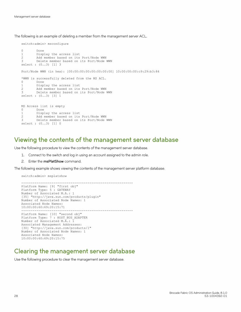
The following is an example of deleting a member from the management server ACL.
switch:admin> msconfigure 0 Done1 Display the access list2 Add member based on its Port/Node WWN3 Delete member based on its Port/Node WWNselect : (0..3) [1] 3 Port/Node WWN (in hex): [00:00:00:00:00:00:00:00] 10:00:00:00:c9:29:b3:84 *WWN is successfully deleted from the MS ACL.0 Done1 Display the access list2 Add member based on its Port/Node WWN3 Delete member based on its Port/Node WWNselect : (0..3) [3] 1 MS Access list is empty 0 Done1 Display the access list2 Add member based on its Port/Node WWN3 Delete member based on its Port/Node WWNselect : (0..3) [1] 0
Viewing the contents of the management server databaseUse the following procedure to view the contents of the management server database.
1. Connect to the switch and log in using an account assigned to the admin role.
2. Enter the msPlatShow command.
The following example shows viewing the contents of the management server platform database.
switch:admin> msplatshow -----------------------------------------------------------Platform Name: [9] "first obj"Platform Type: 5 : GATEWAYNumber of Associated M.A.: 1[35] "http://java.sun.com/products/plugin"Number of Associated Node Names: 1Associated Node Names:10:00:00:60:69:20:15:71-----------------------------------------------------------Platform Name: [10] "second obj"Platform Type: 7 : HOST_BUS_ADAPTERNumber of Associated M.A.: 1Associated Management Addresses:[30] "http://java.sun.com/products/1"Number of Associated Node Names: 1Associated Node Names:10:00:00:60:69:20:15:75
Clearing the management server databaseUse the following procedure to clear the management server database.
Management server database
Brocade Fabric OS Administration Guide, 8.1.028 53-1004392-01
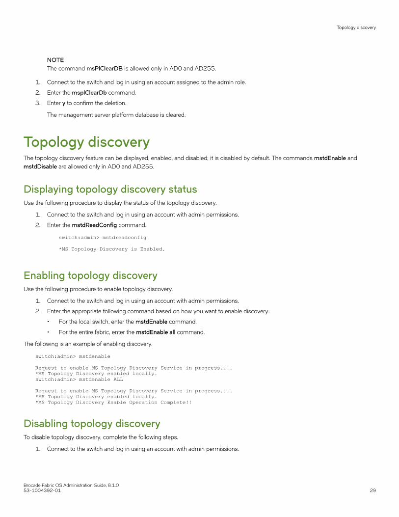
NOTEThe command msPlClearDB is allowed only in AD0 and AD255.
1. Connect to the switch and log in using an account assigned to the admin role.
2. Enter the msplClearDb command.
3. Enter y to confirm the deletion.
The management server platform database is cleared.
Topology discoveryThe topology discovery feature can be displayed, enabled, and disabled; it is disabled by default. The commands mstdEnable andmstdDisable are allowed only in AD0 and AD255.
Displaying topology discovery statusUse the following procedure to display the status of the topology discovery.
1. Connect to the switch and log in using an account with admin permissions.
2. Enter the mstdReadConfig command.
switch:admin> mstdreadconfig *MS Topology Discovery is Enabled.
Enabling topology discoveryUse the following procedure to enable topology discovery.
1. Connect to the switch and log in using an account with admin permissions.
2. Enter the appropriate following command based on how you want to enable discovery:
• For the local switch, enter the mstdEnable command.
• For the entire fabric, enter the mstdEnable all command.
The following is an example of enabling discovery.
switch:admin> mstdenable Request to enable MS Topology Discovery Service in progress....*MS Topology Discovery enabled locally.switch:admin> mstdenable ALL Request to enable MS Topology Discovery Service in progress....*MS Topology Discovery enabled locally.*MS Topology Discovery Enable Operation Complete!!
Disabling topology discoveryTo disable topology discovery, complete the following steps.
1. Connect to the switch and log in using an account with admin permissions.
Topology discovery
Brocade Fabric OS Administration Guide, 8.1.053-1004392-01 29
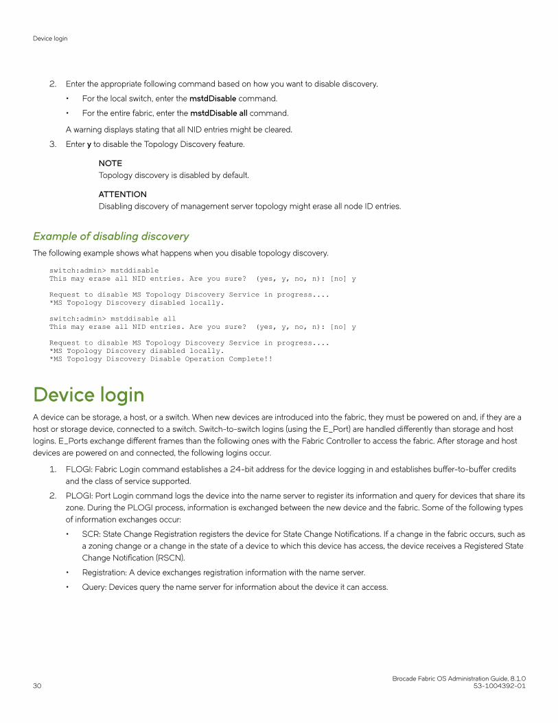
2. Enter the appropriate following command based on how you want to disable discovery.
• For the local switch, enter the mstdDisable command.
• For the entire fabric, enter the mstdDisable all command.
A warning displays stating that all NID entries might be cleared.
3. Enter y to disable the Topology Discovery feature.
NOTETopology discovery is disabled by default.
ATTENTIONDisabling discovery of management server topology might erase all node ID entries.
Example of disabling discoveryThe following example shows what happens when you disable topology discovery.
switch:admin> mstddisableThis may erase all NID entries. Are you sure? (yes, y, no, n): [no] y Request to disable MS Topology Discovery Service in progress....*MS Topology Discovery disabled locally.
switch:admin> mstddisable allThis may erase all NID entries. Are you sure? (yes, y, no, n): [no] y Request to disable MS Topology Discovery Service in progress....*MS Topology Discovery disabled locally.*MS Topology Discovery Disable Operation Complete!!
Device loginA device can be storage, a host, or a switch. When new devices are introduced into the fabric, they must be powered on and, if they are ahost or storage device, connected to a switch. Switch-to-switch logins (using the E_Port) are handled differently than storage and hostlogins. E_Ports exchange different frames than the following ones with the Fabric Controller to access the fabric. After storage and hostdevices are powered on and connected, the following logins occur.
1. FLOGI: Fabric Login command establishes a 24-bit address for the device logging in and establishes buffer-to-buffer creditsand the class of service supported.
2. PLOGI: Port Login command logs the device into the name server to register its information and query for devices that share itszone. During the PLOGI process, information is exchanged between the new device and the fabric. Some of the following typesof information exchanges occur:
• SCR: State Change Registration registers the device for State Change Notifications. If a change in the fabric occurs, such asa zoning change or a change in the state of a device to which this device has access, the device receives a Registered StateChange Notification (RSCN).
• Registration: A device exchanges registration information with the name server.
• Query: Devices query the name server for information about the device it can access.
Device login
Brocade Fabric OS Administration Guide, 8.1.030 53-1004392-01

Principal switchIn a fabric with one or more switches interconnected by an inter-switch link (ISL) or inter-chassis links (ICL), a principal switch isautomatically elected. The principal switch provides the following capabilities:
• Maintains time for the entire fabric. Subordinate switches synchronize their time with the principal switch. Changes to the clockserver value on the principal switch are propagated to all switches in the fabric.
• Manages domain ID assignment within the fabric. If a switch requests a domain ID that has been used before, the principalswitch grants the same domain ID unless it is in use by another switch.
E_Port login processAn E_Port does not use a FLOGI to log in to another switch. Instead, the new switch exchanges frames with the neighboring switch toestablish that the new switch is an E_Port and that it has information to exchange. If everything is acceptable to the neighboring switch, itreplies to the new switch with an SW_ACC (accept) frame. The initializing frame is an Exchange Link Parameters (ELP) frame that allowsan exchange of parameters between two ports, such as flow control, buffer-to-buffer credits, RA_TOV, and ED_TOV. This is not anegotiation. If one or the other port’s link parameters do not match, a link does not occur. Once an SW_ACC frame is received from theneighboring switch, the new switch sends an Exchange Switch Capabilities (ESC) frame. The two switches exchange routing protocolsand agree on a common routing protocol. An SW_ACC frame is received from the neighboring switch and the new switch sends anExchange Fabric Parameters (EFP) frame to the neighboring switch, requesting principal switch priority and the domain ID list. Buffer-to-buffer credits for the device and switch ports are exchanged in the SW_ACC command sent to the device in response to the FLOGI.
Fabric login processA device performs a fabric login (FLOGI) to determine if a fabric is present. If a fabric is detected then it exchanges service parameterswith the fabric controller. A successful FLOGI sends back the 24-bit address for the device in the fabric. The device must issue andsuccessfully complete a FLOGI command before communicating with other devices in the fabric.
Because the device does not know its 24-bit address until after the FLOGI, the source ID (SID) in the frame header of the FLOGI requestare zeros (0x000000).
Port login processThe steps in the port initialization process occur as the result of a protocol that discovers the type of device connected and establishesthe port type and negotiates port speed. Refer to Port types on page 73 for a discussion of available port types.
The Fibre Channel protocol (FCP) auto discovery process enables private storage devices that accept the process login (PRLI) tocommunicate in a fabric.
If device probing is enabled, the embedded port performs a PLOGI and attempts a PRLI into the device to retrieve information to enterinto the name server. This enables private devices that do not explicitly register with the Name Server (NS) to be entered in the NS andreceive full fabric access.
A fabric-capable device registers its information with the name server during a FLOGI. These devices typically register information withthe name server before querying for a device list. The embedded port still performs a PLOGI and attempts a PRLI with these devices.
If a port decides to end the current session, it initiates a logout. A logout concludes the session and terminates any work in progressassociated with that session.
To display the contents of a switch’s name server, use the nsShow or nsAllShow command. For more information about thesecommands, refer to the Brocade Fabric OS Command Reference.
Device login
Brocade Fabric OS Administration Guide, 8.1.053-1004392-01 31

RSCNsA Registered State Change Notification (RSCN) is a notification frame that is sent to devices that are zoned together and are registered toreceive a State Change Notification (SCN). The RSCN is responsible for notifying all devices of fabric changes. The following general listof actions can cause an RSCN to be sent through your fabric:
• A new device has been added to the fabric.
• An existing device has been removed from the fabric.
• A zone has changed.
• A switch name has changed or an IP address has changed.
• Nodes leaving or joining the fabric, such as zoning, powering on or shutting down a device, or zoning changes.
NOTEFabric reconfigurations with no domain change do not cause an RSCN.
Duplicate Port World Wide NameAccording to Fibre Channel standards, the Port World Wide Name (PWWN) of a device cannot overlap with that of another device, thushaving duplicate PWWNs within the same fabric is an illegal configuration.
If a PWWN conflict occurs with two devices attached to the same domain, Fabric OS handles device login in such a way that only onedevice may be logged in to the fabric at a time. For more information, refer to Duplicate PWWN handling during device login on page107.
If a PWWN conflict occurs and two duplicate devices are attached to the fabric through different domains, the devices are removed fromthe Name Server database and a RASlog is generated.
Device recoveryTo recover devices that have been removed from the Name Server database due to duplicate PWWNs, you must login the devices to thefabric again. This is true for any device—for example, a device on an F_Port, NPIV devices, or devices attached to a switch in AccessGateway mode.
High availability of daemon processesStarting non-critical daemons is automatic; you cannot configure the startup process. The following sequence of events occurs when anon-critical daemon fails:
1. A RASlog and AUDIT event message are logged.
2. The daemon is automatically started again.
3. If the restart is successful, then another message is sent to RASlog and AUDIT reporting the successful restart status.
High availability of daemon processes
Brocade Fabric OS Administration Guide, 8.1.032 53-1004392-01

4. If the restart fails, another message is sent to RASlog and no further attempts are made to restart the daemon. You can thenschedule downtime and reboot the switch at your convenience.
The following table lists the daemons that are considered non-critical and are automatically restarted on failure.
TABLE 1 Daemons that are automatically restarted
Daemon Description
arrd Asynchronous Response Router, which is used to send managementdata to hosts when the switch is accessed through the APIs (FA APIor SMI-S).
cald Common Access Layer daemon, which is used by manageabilityapplications.
raslogd Reliability, Availability, and Supportability daemon logs errordetection, reporting, handling, and presentation of data into a formatreadable by you and management tools.
rpcd Remote Procedure Call daemon, which is used by the API (FabricAccess API and SMI-S).
snmpd Simple Network Management Protocol daemon.
npd Flow Vision daemon.
traced Trace daemon provides trace entry date and time translation to TraceDevice at startup and when date/time changed by command.Maintains the trace dump trigger parameters in a Trace Device.Performs the trace Background Dump, trace automatic FTP, andFTP "aliveness check" if auto-FTP is enabled.
webd Webserver daemon used for Web Tools (includes httpd as well).
weblinkerd Weblinker daemon provides an HTTP interface to manageabilityapplications for switch management and fabric discovery.
FL_Port and arbitrated loop supportThe following information applies to FL_Ports and arbitrated loops.
• FL_Ports are not supported on Brocade FC32-48, FC16-32, FC16-48, FC16-64, SX6, Brocade 6505, Brocade 6510,Brocade 6520, Brocade G620, or Brocade 7840 platforms.
• VE_Ports on the FX8-24 platforms do not support arbitrated loops.
FL_Port and arbitrated loop support
Brocade Fabric OS Administration Guide, 8.1.053-1004392-01 33

Brocade Fabric OS Administration Guide, 8.1.034 53-1004392-01

Performing Basic Configuration Tasks• Fabric OS overview...........................................................................................................................................................................................35• Fabric OS command line interface.............................................................................................................................................................35• Modification of default passwords..............................................................................................................................................................43• The switch Ethernet interface ...................................................................................................................................................................... 44• Date and time settings.....................................................................................................................................................................................56• Domain IDs.......................................................................................................................................................................................................... 60• Switch names...................................................................................................................................................................................................... 63• Chassis names....................................................................................................................................................................................................63• Fabric name......................................................................................................................................................................................................... 64• Switch activation and deactivation..............................................................................................................................................................64• Device shutdown................................................................................................................................................................................................66• Basic connections............................................................................................................................................................................................. 67
Fabric OS overviewThis chapter describes how to configure your Brocade SAN using the Fabric OS command line interface (CLI). Before you can configurea storage area network (SAN), you must power up the Backbone platform or switch and blades, and then set the IP addresses of thosedevices. Although this chapter focuses on configuring a SAN using the CLI, you can also use the following methods to configure a SAN:
• Web Tools: For Web Tools procedures, refer to the Brocade Web Tools Administrator's Guide.
• Brocade Network Advisor: For additional information, refer to the Brocade Network Advisor User Manual.
• A third-party application using the API: For third-party application procedures, refer to the third-party API documentation.
Due to the differences between fixed-port and variable-port devices, procedures sometimes differ among Brocade models. As newBrocade models are introduced, new features sometimes apply only to those models.
When procedures or parts of procedures apply to some models but not others, this guide identifies the specifics for each model. Forexample, a number of procedures that apply only to variable-port devices are found in Performing Advanced Configuration Tasks onpage 69.
Although many different software and hardware configurations are tested and supported by Brocade Communication Systems, Inc,documenting all possible configurations and scenarios is beyond the scope of this document. In some cases, earlier releases arehighlighted to present considerations for interoperating with them.
The hardware reference manuals for Brocade products describe how to power up devices and set their IP addresses. After the IP addressis set, you can use the CLI procedures contained in this guide. For additional information about the commands used in the procedures,refer to the Brocade Fabric OS Command Reference.
Fabric OS command line interfaceFabric OS uses Role-Based Access Control (RBAC) to control access to all Fabric OS operations. Each feature is associated with anRBAC role and you need to know which role is allowed to run a command, make modifications to the switch, or view the output of thecommand. To determine which RBAC role you need to run a command, review Role-Based Access Control on page 156.
Note the following about the command display in this guide:
• The entire command line (both commands and options) is case-sensitive. Selected command names and options also supportJava-style capitalization. Java-style capitalization means that while bannershow and bannerShow will both work,
Brocade Fabric OS Administration Guide, 8.1.053-1004392-01 35

BANNERSHOW and BannerShow will not. Refer to the Brocade Fabric OS Command Reference for explicit instructions onsupported capitalization for each command.
• When command examples in this guide show user input enclosed in quotation marks, the quotation marks are required. Forexample, zonecreate "zonename" requires that the value for zonename be in quotation marks.
Console sessions using the serial portBe aware of the following behaviors for serial connections:
• Some procedures require that you connect through the serial port; for example, setting the IP address or setting the bootPROM password.
• Brocade DCX 8510 and X6 Backbone families: You can connect to CP0 or CP1 using either of the two serial ports.
Connecting to Fabric OS through the serial portUse the following procedure to connect to the Fabric OS using the serial port.
NOTEIf you connect the serial console port to a terminal server, ensure that flow control isdisabled.
1. Connect the serial cable to the serial port on the switch and to an RS-232 serial port on the workstation.
If the serial port on the workstation is an RJ-45 port, instead of RS-232, remove the adapter on the end of the serial cable andinsert the exposed RJ-45 connector into the RJ-45 serial port on the workstation.
2. Open a terminal emulator application (such as HyperTerminal in a Windows environment, or TERM, TIP, or Kermit in a UNIXenvironment), and configure the application as follows:
• In a UNIX environment, enter the following string at the prompt:
tip /dev/ttyb -9600
If ttyb is already in use, enter ttya instead, and enter the following string at the prompt:
tip /dev/ttya -9600
• In a Windows environment, enter the following parameters:
TABLE 2 Parameters to configure a Windows terminal emulator application
Parameter Value
Bits per second 9600
Data bits 8
Parity None
Stop bits 1
Flow control None
Telnet or SSH sessionsYou can connect to the Fabric OS through a Telnet or SSH connection or by using a console session on the serial port. The switch mustalso be physically connected to the network. If the switch network interface is not configured or the switch has been disconnected fromthe network, use a console session on the serial port as described in Console sessions using the serial port on page 36.
By default, the root user is disabled on the serial ports. Use the following steps to enable the root user.
Fabric OS command line interface
Brocade Fabric OS Administration Guide, 8.1.036 53-1004392-01

NOTEYou can no longer log in to the root account with a default password. You must first change the defaultpassword.
During the initial login to the switch or director, use the admin account to change all the default passwords. Then, perform one of thefollowing steps:
1. Enable the root account using the following command (if your device does not have a root account, perform the other step):
userconfig --change root -e yes
OR
2. Enable root access via the serial port with the following command:
rootaccess --set all
NOTETo automatically configure the network interface on a DHCP-enabled switch, plug the switch into the network and power it on.The DHCP client automatically gets the IP and gateway addresses from the DHCP server. The DHCP server must be on thesame subnet as the switch. Refer to DHCP activation on page 49.
Rules for Telnet connectionsThe following rules must be observed when making Telnet connections to your switch:
• Never change the IP address of the switch while Telnet sessions are active; if you do, the existing Telnet sessions will hang andyour next attempt to log in will fail. To recover, gain access to the switch by one of these methods:
– You can use Web Tools to perform a fast boot. When the switch comes up, the Telnet quota is cleared. (For instructions onperforming a fast boot with Web Tools, refer to the Brocade Web Tools Administrator's Guide.)
– If you have the required privileges, you can connect through the serial port, log in as admin, and use the killTelnetcommand to identify and stop the Telnet processes without disrupting the fabric.
• For accounts with an admin role, Fabric OS limits the number of simultaneous Telnet sessions per switch to four like otherusers. For more details on session limits, refer to Managing User Accounts on page 155.
• The login command creates nested sessions; therefore, only a maximum of 5 logins are allowed from the same session, afterwhich the following session limit message is displayed. The killtelnet command kills only the latest login but leaves the othersopen.
Connecting to Fabric OS using TelnetUse the following procedure to connect to the Fabric OS using Telnet.
1. Connect through a serial port to the switch that is appropriate for your fabric:
• If Virtual Fabrics is enabled, log in using an admin account assigned the chassis-role permission.
• If Virtual Fabrics is not enabled, log in using an account assigned to the admin role.
2. Verify the switch’s network interface is configured and that it is connected to the IP network through the RJ-45 Ethernet port.
Switches in the fabric that are not connected through the Ethernet port can be managed through switches that are using IP overFibre Channel. The embedded port must have an assigned IP address.
3. Log off the switch’s serial port.
4. From a management station, open a Telnet connection using the IP address of the switch to which you want to connect.
The login prompt is displayed when the Telnet connection finds the switch in the network.
Fabric OS command line interface
Brocade Fabric OS Administration Guide, 8.1.053-1004392-01 37

5. Enter the account ID at the login prompt.
6. Enter the password.
If you have not changed the system passwords from the default, you are prompted to change them. Enter the new systempasswords, or press Ctrl+C to skip the password prompts. For more information on system passwords, refer to Default accountpasswords on page 44.
7. Verify the login was successful.
The prompt displays the switch name and user ID to which you are connected.
login: adminpassword: xxxxxxx
Getting help on a commandYou can display a list of all command help topics for a given login level. For example, if you log in as user and enter the help command, alist of all user-level commands that can be executed is displayed. The same rule applies to the admin, securityAdmin, and theswitchAdmin roles.
1. Connect to the switch and log in using an account assigned to the admin role.
2. Enter the help command with no specific command and all commands are displayed.
The optional |more argument displays the commands one page at a time.
For command-specific information, enter the help command and specify the command for which you need specificinformation.
help command |more
The commands in the following table provide help files for the indicated specific topics.
TABLE 3 Help topic contents
Topic name Help contents description
diagHelp Diagnostic help information
fcipHelp FCIP help information
ficonHelp FICON help information
mapsHelp MAPS help information
routeHelp Routing help information
secHelp Security help information
zoneHelp Zoning help information
Viewing a history of command line entriesThe CLI command history log file saves the last 1680 commands from all users on a first-in-first-out (FIFO) basis, and this log ispersistent across reboots and firmware downloads. This command is also supported for standby CPs.
The log records the following information whenever a command is entered in the switch CLI:
• Timestamp
• User name
Fabric OS command line interface
Brocade Fabric OS Administration Guide, 8.1.038 53-1004392-01

• IP address of the Telnet session
• Options
• Arguments
Use the following procedure to view the CLI command log.
1. Connect to the switch and log in.
2. Enter the cliHistory command with the desired argument (refer to the following arguments for the cliHistory command).Entering no specific argument displays only the command-line history of the currently logged-in user.
NOTECommands entered through an interactive SSH login session are recorded in the command-line history. However, if acommand is entered as a single line with the SSH login (for example, ssh [email protected] switchshow), the entire
command is not recorded.
cliHistoryEntering cliHistory with no keywords displays the command line history for the currently logged-in user only. This is true for the root useraccount as well.
The following example shows the output of the cliHistory command for the root login.
switch:root> clihistory CLI historyDate & Time MessageThu Sep 27 04:58:00 2012 root, 10.70.12.101, firmwareshow -vThu Sep 27 04:58:19 2012 root, 10.70.12.101, telnet 127.1.10.1Thu Sep 27 05:25:45 2012 root, 10.70.12.101, ipaddrshow]
The following example shows the output of the cliHistory command for the admin login.
switch:admin> clihistory CLI historyDate & Time MessageThu Sep 27 10:14:41 2012 admin, 10.70.12.101, clihistory Thu Sep 27 10:14:48 2012 admin, 10.70.12.101, clihistory --show
The following example shows the output of the cliHistory command with FIDs in virtual fabric mode.
switch:admin> clihistory CLI historyDate & Time MessageFri Sep 19 09:41:08 2014 root, FID 128, console, clihistory --clearFri Sep 19 09:41:41 2014 root, FID 128, console, lscfg --create 10Fri Sep 19 09:42:10 2014 root, FID 128, console, lscfg --create 120Fri Sep 19 09:42:54 2014 root, FID 128, console, lscfg --create 30Fri Sep 19 09:42:59 2014 root, FID 128, console, setcontext 30Fri Sep 19 09:43:14 2014 root, FID 30, console, rasdecode -m 65Fri Sep 19 09:43:32 2014 root, FID 30, console, tracecfg -p -m 138Fri Sep 19 09:43:42 2014 root, FID 30, console, setcontext 10
The following example shows the output of the cliHistory command without the FIDs in non-virtual fabric mode. The output shows thatthe firmwareShow and errDump commands were executed in non-virtual fabric mode.
switch:admin> clihistory Fri Sep 19 09:43:53 2014 root, FID 10, console, tracedump Fri Sep 19 09:43:59 2014 root, FID 10, console, coreshow Fri Sep 19 09:44:21 2014 root, , console, firmwareshow Fri Sep 19 09:44:25 2014 root, , console, errdump
Fabric OS command line interface
Brocade Fabric OS Administration Guide, 8.1.053-1004392-01 39

cliHistory --showUsing the --show keyword displays the same results as entering cliHistory alone.
cliHistory --showuser usernameUse the --showuser username keyword to display the command-line history for the named user. This argument is available only to theRoot, Admin, and Securityadmin RBAC roles.
The following example shows the output of the clihistory --showuser admin for the “admin” user account.
switch:root> clihistory --showuser admin CLI historyDate & Time MessageThu Sep 27 10:14:41 2012 admin, 10.70.12.101, clihistory Thu Sep 27 10:14:48 2012 admin, 10.70.12.101, clihistory --showThu Sep 27 10:15:00 2012 admin, 10.70.12.101, clihistory
cliHistory --showallUse the --showall keyword to display the command-line history for all users. This allows admin, factory, and securityadmin users to seethe root user command history. This argument is available only to the Root, Admin, and Securityadmin RBAC roles.
The following example displays the command history for all users.
switch:admin> clihistory --showall | moreCLI history
Date & Time MessageMon Oct 5 10:44:05 2015 admin, FID 128, 172.26.3.86, setcontext 20
Mon Oct 5 10:44:17 2015 admin, FID 20, 172.26.3.86, firmwareshowMon Oct 5 10:44:32 2015 admin, FID 20, 172.26.3.86, islshowMon Oct 5 10:44:20 2015 admin, FID 20, 172.26.3.86, versionMon Oct 5 10:44:36 2015 admin, FID 20, 172.26.3.86, switchshow
Mon Oct 5 10:44:40 2015 admin, FID 20, 172.26.3.86, trunkshow
cliHistory --helpUse the --help argument to display a list of the available command arguments.
The following example shows the output of the clihistory --help command.
swd77:admin> clihistory --help clihistory usage:clihistory:Displays the CLI History of the current userclihistory --show:Displays the CLI History of the current userclihistory --showuser <username>:Displays the CLI History of the given userclihistory --showall:Displays the CLI History of all usersclihistory --clear:Clears the CLI History of all usersclihistory --help: Displays the command usage
Fabric OS command line interface
Brocade Fabric OS Administration Guide, 8.1.040 53-1004392-01

Considerations when viewing CLI logsYou should be aware of the following considerations when viewing CLI logs:
• SSH login CLI logs are not recorded in the command-line history (as shown in the following example):
ssh user@Ipaddr switchshow
• The CLI command log is collected as part of any supportSave operation. The command log record of such an operation is theequivalent of running cliHistory --showall.
• For commands that require a password (for example, the firmwaredownload, configupload, configdownload, and supportsavecommands), only the command (and no arguments) is stored (refer to the following example for an illustration).
switch:admin> firmwaredownload -s -p scp 10.70.4.109,fvt,/dist,pray4green Server IP: 10.70.4.109, Protocol IPv4Checking system settings for firmwaredownload...Failed to access scp://fvt:**********@10.70.4.109//dist/release.plist switch:admin> clihistory Date & Time MessageWed Nov 23 03:39:37 2016 root, console, firmwaredownload
Using fosexec to run commands on remote switches or domainsThe fosexec command allows you to run Fabric OS commands on remote switches or domains across the fabric. Both the local andremote switches must be configured to send and receive remote command execution. You do not need to log in to the remote switchlocally. The outputs of the commands are displayed in the local switch. The commands that you run using fosexec are also captured inthe CLI history and audit logs of the remote switch.
The fosexec feature is a configurable feature. Using the configure command, you can configure the fosexec feature. The fosexec featureis off by default. The fosexec feature must be on in both the sending and receiving switches or domains. The configuration is checkedwhen sending any fosexec request to a remote switch and also when receiving such a request from a remote switch. You can execute thiscommand on either a specific switch or domain or all the switches or domains in the fabric. For a specific domain or switch, you mustinput the Domain ID (DID), which must be between 1 and 240.
The configure command has the following option under Configure CLI - Fabric Parameters section to enable or disable the remotefosexec feature:
sw_85:admin> configure
Not all options will be available on an enabled switch.To disable the switch, use the "switchDisable" command.
Configure...
Fabric parameters (yes, y, no, n): [no] y
WWN Based persistent PID (yes, y, no, n): [no] Location ID: (0..4) [0] High Integrity Fabric Mode (yes, y, no, n): [no] Edge Hold Time(Low(80ms), Medium(220ms), High(500ms), UserDefined(80-500ms): (80..500) [220] Remote Fosexec feature: (on, off): [off] onD-Port Parameters (yes, y, no, n): [no] 2014/02/10-12:39:49, [CONF-1043], 1815, FID 128, INFO, sw_85, Fabric Configuration Parameter Remote Fosexec feature changed to enabledZoning Operation parameters (yes, y, no, n): [no]Commands executed via remote fosexec is captured in clihistory and audit logs of remote switch
The fosexec syntax is as follows:
fosexec –-domain DID –cmd "cmd [args]" fosexec –-domain all –cmd “cmd [args]”
Fabric OS command line interface
Brocade Fabric OS Administration Guide, 8.1.053-1004392-01 41

When nested quotes or strings must be provided, instead of using nested quotes, precede the string with an escape character orbackward slash with quotes, as shown in the following example:
fosexec --domain all -cmd "CLIname --set \"SWAT Setup\""
The fosexec command has the following limitations:
• fosexec requires Fabric OS 7.3.0 or later on both the local and remote domains or switches.
• Remote execution is allowed based on RBAC checks or permissions for the remote domain role. The RBAC permission deniedmessage is displayed for unsupported commands.
• Can be executed only by users with the fabricadmin, admin, or root roles or privileges and RBAC permissions.
• Does not work during remote domain or switch HA failover or reboot.
• Command syntax must match the command syntax supported by the remote switch.
• Commands with parameters such as slot/port specific to a fixed-port switch or Director chassis are not supported with the alloption.
• Does not support interactive commands that require inputs in the middle of execution.
• Commands that take longer time to execute are not supported. The timeout period is 15 seconds.
• Returns only a maximum of 64 kilobytes of data from the remote switch. Any extra data gets truncated.
• Not supported in FIPS and Access Gateway modes.
• When you run supportSave through fosexec, wait for the execution to complete. To know whether the execution is completed,refer to the RASLOG [SS-1000] on all or the specific domain where fosexec is being run.
• The fosexec feature must be disabled to downgrade from Fabric OS 7.3.0 to any other earlier version.
NOTERunning the fosexec command does not log you out from the current session in your local switch.
Fabric OS command line interface
Brocade Fabric OS Administration Guide, 8.1.042 53-1004392-01

Example 1
sw_85:user9> fosexec --domain all -cmd "islshow"Domain 19========= 1: 80-> 40 10:00:00:05:1e:0f:73:40 53 ls20d53_5100_8_ sp:-------- bw: 8.000G 2: 81->289 10:00:00:05:33:0d:7b:02 4 ls20d4_plpl_8_4 sp:-------- bw: 8.000G Domain 23=========Remote fosexec feature is disabled.
Domain 53========= 1: 40-> 80 10:00:00:05:33:39:0d:da 19 ls20d19_5300_8_ sp:-------- bw: 8.000G 2: 41->288 10:00:00:05:33:0d:7b:02 4 ls20d4_plpl_8_4 sp:-------- bw: 16.000G Domain 65=========Remote fosexec feature is disabled.Domain 150========= 1: 0-> 38 10:00:00:27:f8:f1:15:c2 1 ls20d1_wedge_8_ sp: 16.000G bw: 16.000G TRUNK QOS CR_RECOV FEC Domain 1========= 1: 3-> 10 10:00:00:05:33:7a:4b:76 65 ls20d65_6510_8_47_58 sp: 8.000G bw: 16.000G TRUNK QOS CR_RECOV 2: 5-> 13 10:00:00:05:33:e5:56:2c 2 ls20d2_odin_8_39_58 sp: 16.000G bw: 16.000G TRUNK QOS CR_RECOV FEC 3: 6-> 42 10:00:00:05:33:0d:7b:02 4 ls20d4_plpl_8_47_30 sp: 16.000G bw: 16.000G TRUNK QOS CR_RECOV FEC 4: 22-> 12 10:00:00:05:33:e5:56:2c 2 ls20d2_odin_8_39_58 sp: 16.000G bw: 16.000G TRUNK QOS CR_RECOV FEC 5: 38-> 0 10:00:50:eb:1a:64:63:1f 150 ls20d150_amp_38_37_113 sp: 16.000G bw: 16.000G TRUNK QOS CR_RECOV FEC 6: 42-> 39 10:00:00:05:33:7a:4b:76 65 ls20d65_6510_8_47_58 sp: 8.000G bw: 8.000G TRUNK QOS CR_RECOV
Example 2
sw_85:user9> fosexec --domain 19 -cmd "islshow" 1: 80-> 40 10:00:00:05:1e:0f:73:40 53 ls20d53_5100_8_ sp:-------- bw: 8.000G 2: 81->289 10:00:00:05:33:0d:7b:02 4 ls20d4_plpl_8_4 sp:-------- bw: 8.000G
Modification of default passwordsThe switch automatically prompts you to change the default account passwords after logging in for the first time. If you do not changethe passwords, the switch prompts you after each subsequent login until all the default passwords have been changed.
There is one set of default accounts for the entire chassis: admin, user, and root. Use the admin account when you log in to the switch forthe first time and to perform basic configuration tasks. The user account is primarily used for basic system monitoring. The root accountis reserved for development and manufacturing or for debugging. For more information on the default accounts, refer to Defaultaccounts on page 159.
NOTEThe passwords for the default accounts should be changed from their default values immediately when prompted following thelogin; these passwords cannot be changed using the passwd command later in the session until the user has completed thisstep. If you skip this step, and then later decide to change the passwords, you will need to log out and then log back in. Whenyou log in to the root account, you are forced to change the default password.
Modification of default passwords
Brocade Fabric OS Administration Guide, 8.1.053-1004392-01 43

NOTEWhen you log in as admin and the default passwords are not changed, you are requested to change the default passwords onlyfor the admin and user accounts. You cannot change the default password for the root account if you log in as admin. Thedefault password for the root account can be changed when you log in as root.
Default account passwordsThe change default account passwords prompt is a string that begins with the message "Please change your passwords now". User-defined passwords can have from 8 through 40 characters. They can include alphabetic characters, numeric characters, specialcharacters such as the period (.), the underscore ( _ ), and spaces ( ) except a colon (:). They are case-sensitive, and they are not displayedwhen you enter them on the command line.
Record the passwords exactly as entered and store them in a secure place because recovering passwords requires significant effort andfabric downtime. Although the root account is not meant for general use, change their passwords if prompted to do so and save thepasswords in case they are needed for recovery purposes.
For more information, refer to Password policies on page 162.
Changing the default account passwords at loginUse the following procedure to change the default account passwords.
1. Connect to the switch and log in using the default administrative account.
2. At each of the "Enter new password" prompts, either enter a new password or skip the prompt.
To skip a single prompt, press Enter. To skip all of the remaining prompts, press Ctrl-C.
NOTEFor root login, you cannot skip this step if the default password is present. You must change the default password.
The following example shows the output for changing passwords.
login: admin Password:Please change your passwords now.Use Control-C to exit or press 'Enter' key to proceed.Enter new password: <hidden> Password changed.Saving password to stable storage.Password saved to stable storage successfully.(output truncated)
The switch Ethernet interfaceThe Ethernet (network) interface provides management access, including direct access to the Fabric OS CLI, and allows other tools, suchas Web Tools, to interact with the switch. You can use either Dynamic Host Configuration Protocol (DHCP) or static IP addresses for theEthernet network interface configuration.
Brocade DirectorsOn Brocade DCX 8510 and X6 Directors, you must set IP addresses for the following components:
• Both Control Processors (CP0 and CP1)
The switch Ethernet interface
Brocade Fabric OS Administration Guide, 8.1.044 53-1004392-01

• Chassis management IP
Brocade switchesOn Brocade switches, you must set the Ethernet and chassis management IP interfaces.
Setting the chassis management IP address eliminates the need to know which CP is active and automatically connects the requestor tothe currently active CP.
You can continue to use a static Ethernet addressing system or allow the DHCP client to automatically acquire Ethernet addresses.Configure the Ethernet interface IP address, subnet mask, and gateway addresses in one of the following manners:
• Using static Ethernet addresses (refer to Static Ethernet addresses on page 48)
• Activating DHCP (refer to DHCP activation on page 49)
NOTEWhen you change the Ethernet interface settings, open connections such as SSH or Telnet may be dropped. Reconnect usingthe new Ethernet IP address information or change the Ethernet settings using a console session through the serial port tomaintain your session during the change. You must connect through the serial port to set the Ethernet IP address if the Ethernetnetwork interface is not configured already. For details, refer to Connecting to Fabric OS through the serial port on page 36.
Virtual Fabrics and the Ethernet interfaceOn the Brocade DCX 8510 Backbone and X6 Director, the single-chassis IP address and subnet mask are assigned to themanagement Ethernet ports on the front panels of the CPs. These addresses allow access to the chassis—more specifically, the activeCP of the chassis—and not individual logical switches. The IP addresses can also be assigned to each CP individually. This allows fordirect communication with a CP, including the standby CP. Each CP has two management Ethernet ports on its front panel. These twophysical ports are bonded together to create a single, logical Ethernet port, and it is the logical Ethernet port to which IP addresses areassigned.
IPv4 addresses assigned to individual Virtual Fabrics are assigned to IP over Fibre Channel (IPFC) network interfaces. In Virtual Fabricsenvironments, a single chassis can be assigned to multiple fabrics, each of which is logically distinct and separate from one another. EachIPFC point of connection to a given chassis needs a separate IPv4 address and prefix to be accessible to a management host. For moreinformation on how to set up these IPFC interfaces to your Virtual Fabric, refer to Managing Virtual Fabrics on page 291.
Management Ethernet port bondingThe two external Ethernet ports of a CP (CP8 or CPX6) blade can be bound together as a single logical network interface. Thisconfiguration uses an active-standby failover model to provide automatic failover support for the primary Ethernet port on the blade. Ifthe primary Ethernet port fails (due to something other than power loss), the second Ethernet port immediately takes over to ensure linklayer communication is retained.
One of the physical Ethernet ports is selected as the active interface. The second interface is set as the standby interface. All traffic istransmitted over the active interface. No traffic is transmitted over the standby interface, unless the active interface is determined to be nolonger connected; at which point, the second interface is made active.
When active, all the Fabric OS kernel modules and applications on the CP blade will use the logical network interface named “bond0”instead of “eth0”.
NOTEOn bootup, physical port eth0 is always made active if it is connected.
The switch Ethernet interface
Brocade Fabric OS Administration Guide, 8.1.053-1004392-01 45

The CP blade contains multiple Ethernet devices (including eth0 and eth3), which map to the two Ethernet ports on the front of the CPblade. Other Ethernet devices on the blade are reserved for use by the operating system.
The CP blade enables eth0 by default. If an error is encountered on eth0, it is treated the same as for any other port, unless the errorcauses the eth0 port to go down. If eth0 goes down, the eth3 interface becomes active and will remain active ev en if eth0 comes backup. Use one of the following actions to restore eth0 as the active interface.
• Unplug the network cable, wait 5 seconds, and then plug it back in.
• Perform a High Availability (HA) failover routine.
• Power down the switch and then power it back up again.
ATTENTIONPerforming an HA failover and powering down the switch will cause a disruptive delay in content delivery.
Supported Brocade Backbones and DirectorsManagement Ethernet port bonding is available on the following CP blades:
• CP8 blade installed on a Brocade DCX 8510 Backbone
• CPX6 blade installed on a Brocade X6 Director
Setting up the second Ethernet port on a CP8 bladeThe port speed and duplex mode between the Ethernet ports should always match. Both ports should be set at a fixed speed or set toautonegotiate.
1. Make sure that the speed and link operating mode settings are the same for both eth3 and eth0. Refer to Setting the Ethernetinterface mode and speed on page 55 for instructions on setting port modes, and Setting port speeds on page 84 forinstructions on setting port speeds.
2. Physically connect the second Ethernet port to the same network as the primary Ethernet port.
Displaying the network interface settingsNOTEIf an IP address has not been assigned to the network interface (Ethernet), you must connect to the Fabric OS CLI using aconsole session on the serial port. For more information, refer to Console sessions using the serial port on page 36. Otherwise,connect using SSH.
1. Connect to the switch, and log in using an account assigned to the admin role.
The switch Ethernet interface
Brocade Fabric OS Administration Guide, 8.1.046 53-1004392-01
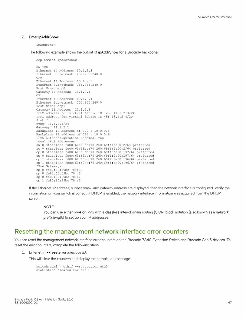
2. Enter ipAddrShow.
ipAddrShow
The following example shows the output of ipAddrShow for a Brocade backbone.
ecp:admin> ipaddrshow SWITCHEthernet IP Address: 10.1.2.3Ethernet Subnetmask: 255.255.240.0CP0Ethernet IP Address: 10.1.2.3Ethernet Subnetmask: 255.255.240.0Host Name: ecp0Gateway IP Address: 10.1.2.1CP1Ethernet IP Address: 10.1.2.4Ethernet Subnetmask: 255.255.240.0Host Name: ecp1Gateway IP Address: 10.1.2.3IPFC address for virtual fabric ID 123: 11.1.2.3/24IPFC address for virtual fabric ID 45: 13.1.2.4/20Slot 7eth0: 11.1.2.4/24Gateway: 11.1.2.1Backplane IP address of CP0 : 10.0.0.5Backplane IP address of CP1 : 10.0.0.6IPv6 Autoconfiguration Enabled: YesLocal IPv6 Addresses:sw 0 stateless fd00:60:69bc:70:260:69ff:fe00:2/64 preferredsw 0 stateless fec0:60:69bc:70:260:69ff:fe00:2/64 preferredcp 0 stateless fd00:60:69bc:70:260:69ff:fe00:197/64 preferredcp 0 stateless fec0:60:69bc:70:260:69ff:fe00:197/64 preferredcp 1 stateless fd00:60:69bc:70:260:69ff:fe00:196/64 preferredcp 1 stateless fec0:60:69bc:70:260:69ff:fe00:196/64 preferredIPv6 Gateways:cp 0 fe80:60:69bc:70::3cp 0 fe80:60:69bc:70::2cp 0 fe80:60:69bc:70::1cp 1 fe80:60:69bc:70::3
If the Ethernet IP address, subnet mask, and gateway address are displayed, then the network interface is configured. Verify theinformation on your switch is correct. If DHCP is enabled, the network interface information was acquired from the DHCPserver.
NOTEYou can use either IPv4 or IPv6 with a classless inter-domain routing (CIDR) block notation (also known as a networkprefix length) to set up your IP addresses.
Resetting the management network interface error countersYou can reset the management network interface error counters on the Brocade 7840 Extension Switch and Brocade Gen 6 devices. Toreset the error counters, complete the following steps.
1. Enter ethIf -–reseterror interface ID.
This will clear the counters and display the completion message.
switch:admin> ethif --reseterror eth0Statistics cleared for eth0
The switch Ethernet interface
Brocade Fabric OS Administration Guide, 8.1.053-1004392-01 47

2. To confirm that the error counters have been cleared, enter ethIf --show interface ID.
This displays the counters for that interface. The errors counter will be zero (0).
switch:admin> ethif --show eth0eth0 interface:Link mode: negotiated 100baseTx-FD, link okMAC Address: 59:AB:AA:B5:75:BCeth0 Link encap:Ethernet HWaddr 59:AB:AA:B5:75:BC inet addr:10.x.x.x Bcast:10.x.x.x Mask:255.255.255.0 UP BROADCAST RUNNING MULTICAST MTU:1500 Metric:1 RX packets:382496 errors:0 dropped:0 overruns:0 frame:0 TX packets:393 errors:0 dropped:0 overruns:0 carrier:0 collisions:0 txqueuelen:1000
Static Ethernet addressesUse static Ethernet network interface addresses in environments where DHCP service is not available. To use static addresses for theEthernet interface, you must first disable DHCP. You can enter static Ethernet information and disable DHCP at the same time. For moreinformation, refer to DHCP activation on page 49.
If you choose not to use DHCP or to specify an IP address for your switch Ethernet interface, you can do so by entering "none" or"0.0.0.0" in the Ethernet IP address field.
On an application blade, configure the two external Ethernet interfaces to two different subnets. If two subnets are not present, configureone of the interfaces and leave the other unconfigured. Otherwise, the following message displays and blade status may go into a faultystate after a reboot.
Neighbor table overflow.print: 54 messages suppressed
Setting the static addresses for the Ethernet network interfaceUse the following procedure to set the Ethernet network interface static addresses.
1. Connect to the switch and log in using an account assigned to the admin role.
2. Perform the appropriate action based on whether you have a switch or backbone:
• If you are setting the IP address for a switch, enter the ipAddrSet command.
• If you are setting the IP address for a backbone, enter the ipAddrSet command specifying either CP0 or CP1. You mustset the IP address for both CP0 and CP1.
The following is an example of setting an IPv4 address.
switch:admin> ipaddrset Ethernet IP Address [10.1.2.3]:Ethernet Subnetmask [255.255.255.0]:Fibre Channel IP Address [220.220.220.2]:Fibre Channel Subnetmask [255.255.0.0]:Gateway IP Address [10.1.2.1]:DHCP [OFF]: off
The following is an example of setting an IPv6 address on a switch
switch:admin> ipaddrset -ipv6 --add 1080::8:800:200C:417A/64 IP address is being changed...Done.
For more information on setting up an IP address for a Virtual Fabric, refer to Managing Virtual Fabrics on page 291.
The switch Ethernet interface
Brocade Fabric OS Administration Guide, 8.1.048 53-1004392-01

3. Enter the network information in dotted-decimal notation for the Ethernet IPv4 address or in semicolon-separated notation forIPv6.
4. Enter the Ethernet Subnetmask at the prompt.
5. The Fibre Channel prompts are not relevant; you can skip them by pressing Enter.
The Fibre Channel IP address is used for management.
6. Enter the Gateway IP Address at the prompt.
7. Disable DHCP by entering off.
Setting the static addresses for the chassis management IP interfaceUse the following procedure to set the chassis management IP interface static addresses.
1. Connect to the switch and log in using an account assigned to the admin role.
2. Enter the ipAddrSet -chassis command.
switch:admin>> ipaddrset -chassisDHCP [Off]:Ethernet IP Address [10.38.18.142]:Ethernet Subnetmask [255.255.240.0]:Committing configuration...Done.
3. Enter the network information in dotted-decimal notation for the Ethernet IPv4 address or in semicolon-separated notation forIPv6.
4. Enter the Ethernet Subnetmask at the prompt.
DHCP activationSome Brocade switches have Dynamic Host Configuration Protocol (DHCP) enabled by default.
The Fabric OS DHCP client conforms to the latest IETF Draft Standard RFCs for IPv4, IPv6, and DHCP, and supports the followingparameters:
• External Ethernet port IP addresses and subnet masks
• Default gateway IP address
Notes on DHCPThe following items need to be kept in mind when working with DHCP:
• The DHCP client uses a DHCP vendor-class identifier that allows DHCP servers to determine that the discover/request packetare coming from a Brocade switch. The vendor-class identifier is the string "BROCADE" followed by the SWBD model numberof the platform. For example, the vendor-class identifier for a request from a Brocade G620 is "BROCADESWBD145."
• The DHCP client can obtain stateful IPv6 addresses.
• When DHCP is enabled, the switch name is registered to the Domain Name System (DNS) server automatically and the switchis assigned an IP address from the DHCP server. If the switch name is changed using the CLI, the DNS record in the DNSserver is updated automatically. Dynamic DNS (DDNS) is the method used to automatically update a name server in theDomain Name System (DNS).
The switch Ethernet interface
Brocade Fabric OS Administration Guide, 8.1.053-1004392-01 49
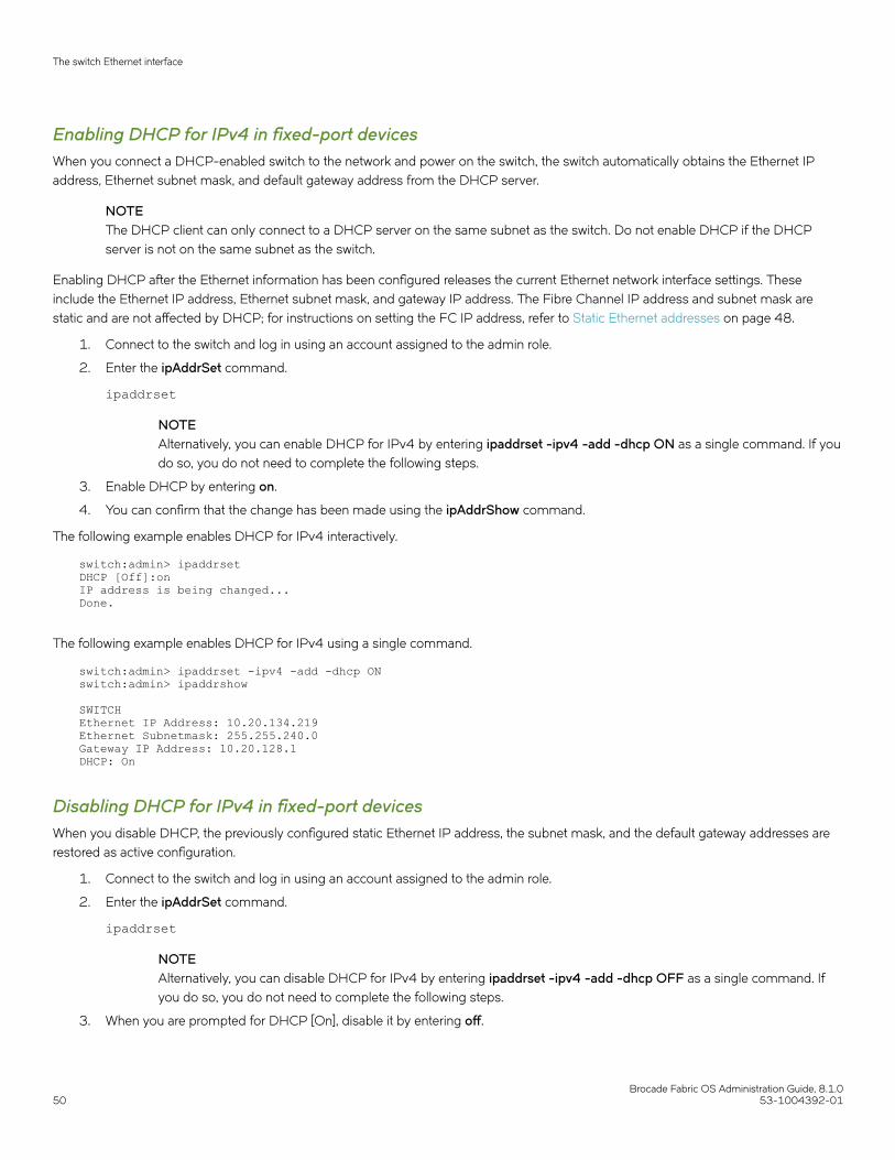
Enabling DHCP for IPv4 in fixed-port devicesWhen you connect a DHCP-enabled switch to the network and power on the switch, the switch automatically obtains the Ethernet IPaddress, Ethernet subnet mask, and default gateway address from the DHCP server.
NOTEThe DHCP client can only connect to a DHCP server on the same subnet as the switch. Do not enable DHCP if the DHCPserver is not on the same subnet as the switch.
Enabling DHCP after the Ethernet information has been configured releases the current Ethernet network interface settings. Theseinclude the Ethernet IP address, Ethernet subnet mask, and gateway IP address. The Fibre Channel IP address and subnet mask arestatic and are not affected by DHCP; for instructions on setting the FC IP address, refer to Static Ethernet addresses on page 48.
1. Connect to the switch and log in using an account assigned to the admin role.
2. Enter the ipAddrSet command.
ipaddrset
NOTEAlternatively, you can enable DHCP for IPv4 by entering ipaddrset -ipv4 -add -dhcp ON as a single command. If youdo so, you do not need to complete the following steps.
3. Enable DHCP by entering on.
4. You can confirm that the change has been made using the ipAddrShow command.
The following example enables DHCP for IPv4 interactively.
switch:admin> ipaddrsetDHCP [Off]:onIP address is being changed...Done.
The following example enables DHCP for IPv4 using a single command.
switch:admin> ipaddrset -ipv4 -add -dhcp ON switch:admin> ipaddrshow SWITCHEthernet IP Address: 10.20.134.219Ethernet Subnetmask: 255.255.240.0Gateway IP Address: 10.20.128.1DHCP: On
Disabling DHCP for IPv4 in fixed-port devicesWhen you disable DHCP, the previously configured static Ethernet IP address, the subnet mask, and the default gateway addresses arerestored as active configuration.
1. Connect to the switch and log in using an account assigned to the admin role.
2. Enter the ipAddrSet command.
ipaddrset
NOTEAlternatively, you can disable DHCP for IPv4 by entering ipaddrset -ipv4 -add -dhcp OFF as a single command. Ifyou do so, you do not need to complete the following steps.
3. When you are prompted for DHCP [On], disable it by entering off.
The switch Ethernet interface
Brocade Fabric OS Administration Guide, 8.1.050 53-1004392-01
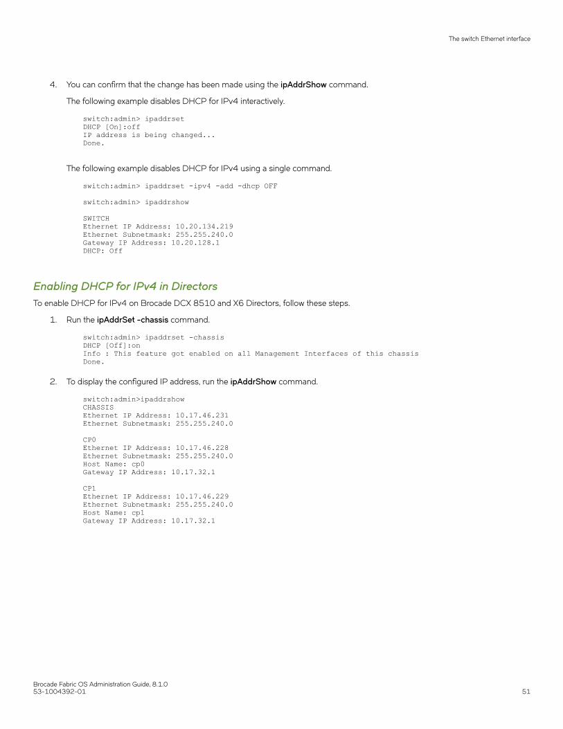
4. You can confirm that the change has been made using the ipAddrShow command.
The following example disables DHCP for IPv4 interactively.
switch:admin> ipaddrset DHCP [On]:offIP address is being changed...Done.
The following example disables DHCP for IPv4 using a single command.
switch:admin> ipaddrset -ipv4 -add -dhcp OFF switch:admin> ipaddrshow SWITCHEthernet IP Address: 10.20.134.219Ethernet Subnetmask: 255.255.240.0Gateway IP Address: 10.20.128.1DHCP: Off
Enabling DHCP for IPv4 in DirectorsTo enable DHCP for IPv4 on Brocade DCX 8510 and X6 Directors, follow these steps.
1. Run the ipAddrSet -chassis command.
switch:admin> ipaddrset -chassisDHCP [Off]:onInfo : This feature got enabled on all Management Interfaces of this chassisDone.
2. To display the configured IP address, run the ipAddrShow command.
switch:admin>ipaddrshowCHASSISEthernet IP Address: 10.17.46.231Ethernet Subnetmask: 255.255.240.0 CP0Ethernet IP Address: 10.17.46.228Ethernet Subnetmask: 255.255.240.0Host Name: cp0Gateway IP Address: 10.17.32.1 CP1Ethernet IP Address: 10.17.46.229Ethernet Subnetmask: 255.255.240.0Host Name: cp1Gateway IP Address: 10.17.32.1
The switch Ethernet interface
Brocade Fabric OS Administration Guide, 8.1.053-1004392-01 51

3. To disable DHCP for IPv4 on Directors, follow these steps.
When you disable DHCP, the previously configured static Ethernet IP address, the subnet mask, and the default gatewayaddresses are restored as the active configuration.
• In interactive mode:
switch:admin>ipaddrset -chassisDHCP [On]:offIP address is being changed...Done
• In a single command:
switch:admin>ipaddrset -chassis -ipv4 -add -dhcp offIP address is being changed...Done.
Configuring DHCPv6 for IPv6You can configure the IPv6 address from the DHCPv6 server with the following procedure.
1. Run the ipAddrSet –ipv6 –dhcpv6 command.
2. To display the configured IPv6 address, run the ipAddrShow command.
• In case of fixed-port switches, the following output is displayed:
switch:admin>ipaddrshowSWITCHEthernet IP Address: 10.17.33.33Ethernet Subnetmask: 255.255.240.0Gateway IP Address: 10.17.32.1DHCP: OffIPv6 Autoconfiguration Enabled: NoLocal IPv6 Addresses:dhcpv6 2620:100:0:f603::f9ff/64 preferredlink local fe80::205:33ff:fe3a:77f9/64IPv6 Gateways:fe80::21b:edff:fe0b:9000DHCPv6: On
• In case of Directors, the following output is displayed:
switch:admin>ipaddrshowCHASSISLocal IPv6 Addresses:dhcpv6 2620:100:0:f603::f912/64 preferredlink local fe80::205:33ff:fe3a:77f9/64 CP0Local IPv6 Addresses:dhcpv6 2620:100:0:f603::f9fb/64 preferredlink local fe80::205:33ff:fe3a:77f8/64IPv6 Gateways:fe80::21b:edff:fe0b:9000DHCPv6: On CP1Local IPv6 Addresses:dhcpv6 2620:100:0:f603::f9fa/64 preferredlink local fe80::205:33ff:fe3a:77f7/64IPv6 Gateways:fe80::21b:edff:fe0b:9000DHCPv6: On
The switch Ethernet interface
Brocade Fabric OS Administration Guide, 8.1.052 53-1004392-01
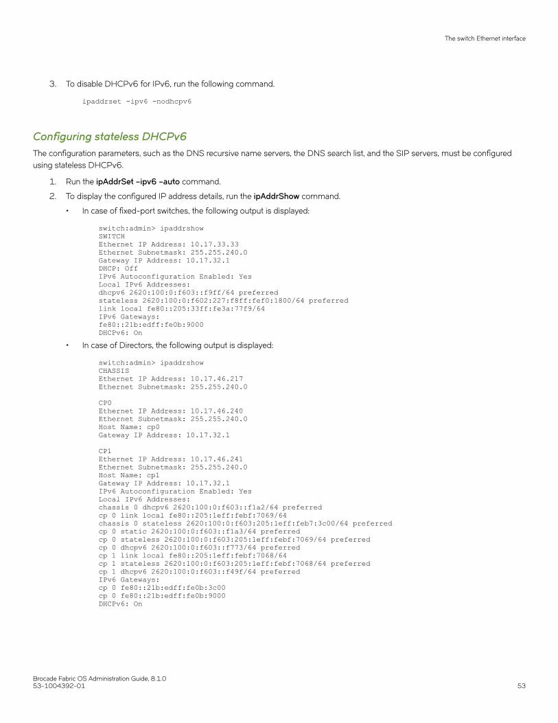
3. To disable DHCPv6 for IPv6, run the following command.
ipaddrset -ipv6 -nodhcpv6
Configuring stateless DHCPv6The configuration parameters, such as the DNS recursive name servers, the DNS search list, and the SIP servers, must be configuredusing stateless DHCPv6.
1. Run the ipAddrSet –ipv6 –auto command.
2. To display the configured IP address details, run the ipAddrShow command.
• In case of fixed-port switches, the following output is displayed:
switch:admin> ipaddrshowSWITCHEthernet IP Address: 10.17.33.33Ethernet Subnetmask: 255.255.240.0Gateway IP Address: 10.17.32.1DHCP: OffIPv6 Autoconfiguration Enabled: YesLocal IPv6 Addresses:dhcpv6 2620:100:0:f603::f9ff/64 preferredstateless 2620:100:0:f602:227:f8ff:fef0:1800/64 preferredlink local fe80::205:33ff:fe3a:77f9/64IPv6 Gateways:fe80::21b:edff:fe0b:9000DHCPv6: On
• In case of Directors, the following output is displayed:
switch:admin> ipaddrshowCHASSISEthernet IP Address: 10.17.46.217Ethernet Subnetmask: 255.255.240.0
CP0Ethernet IP Address: 10.17.46.240Ethernet Subnetmask: 255.255.240.0Host Name: cp0Gateway IP Address: 10.17.32.1
CP1Ethernet IP Address: 10.17.46.241Ethernet Subnetmask: 255.255.240.0Host Name: cp1Gateway IP Address: 10.17.32.1IPv6 Autoconfiguration Enabled: YesLocal IPv6 Addresses:chassis 0 dhcpv6 2620:100:0:f603::f1a2/64 preferredcp 0 link local fe80::205:1eff:febf:7069/64chassis 0 stateless 2620:100:0:f603:205:1eff:feb7:3c00/64 preferredcp 0 static 2620:100:0:f603::f1a3/64 preferredcp 0 stateless 2620:100:0:f603:205:1eff:febf:7069/64 preferredcp 0 dhcpv6 2620:100:0:f603::f773/64 preferredcp 1 link local fe80::205:1eff:febf:7068/64cp 1 stateless 2620:100:0:f603:205:1eff:febf:7068/64 preferredcp 1 dhcpv6 2620:100:0:f603::f49f/64 preferredIPv6 Gateways:cp 0 fe80::21b:edff:fe0b:3c00cp 0 fe80::21b:edff:fe0b:9000DHCPv6: On
The switch Ethernet interface
Brocade Fabric OS Administration Guide, 8.1.053-1004392-01 53

3. To display the configuration parameters of the DNS name servers, run the dnsconfig --show command.
switch:admin> dnsconfig --showDomain Name Server Configuration Information ___________________________________________ Domain Name = englab.brocade.comName Server IP Address = englab.brocade.comName Server IP Address = 10.31.2.10
Configuring the static IPv6 gateway addressYou can configure the static IPv6 gateway address using the ipaddrset -ipv6 -add command. When the static IPv6 gateway isconfigured, the auto-assignment of the gateway address is not blocked; however, the static address remains active.
Consider the following when configuring the static IPv6 gateway address:
• Both the CPs in the chassis always must have the same gateway IP.
• When you delete the static IPv6 gateway address, a chassis reboot is needed for Directors and a reboot for fixed-port switchesfor the auto-configured IPv6 gateway address to become active.
• Only one IPv6 static gateway can be configured at a time. Configuring another overwrites the existing one.
• On platforms with blade processors, using the option -cp cp_number for IPv6 static gateway configuration updates both CPs,no matter what number is used for cp_number.
1. Configure the static IPv6 gateway address using the following syntax:
ipaddrset -ipv6 -add -gwyip gateway_ip [-cp (x)]
2. Delete the static IPv6 gateway address using the following syntax:
ipaddrset -ipv6 -del -gwyip gateway_ip [-cp (x)]
IPv6 autoconfigurationIPv6 can assign multiple IP addresses to each network interface. Each interface is configured with a link local address in almost all cases,but this address is only accessible from other hosts on the same network. To provide for wider accessibility, interfaces are typicallyconfigured with at least one additional global scope IPv6 address. IPv6 autoconfiguration allows more IPv6 addresses, the number ofwhich is dependent on the number of routers serving the local network and the number of prefixes they advertise.
There are two methods of autoconfiguration for IPv6 addresses: stateless autoconfiguration and stateful autoconfiguration. Statelessautoconfiguration allows an IPv6 host to obtain a unique address using the IEEE 802 MAC address. Stateful autoconfiguration uses aDHCPv6 server, which keeps a record of the IP address and other configuration information for the host. Whether a host engages inautoconfiguration and which method it uses is dictated by the routers serving the local network, not by a configuration of the host. Therecan be multiple routers serving the network, each potentially advertising multiple network prefixes. Thus, the host is not in full control ofthe number of IPv6 addresses that it configures, much less the values of those addresses, and the number and values of addresses canchange as routers are added to or removed from the network.
When IPv6 autoconfiguration is enabled, the platform engages in stateless IPv6 autoconfiguration. When IPv6 autoconfiguration isdisabled, the platform relinquishes usage of any autoconfigured IPv6 addresses that it may have acquired while it was enabled. Thissame enable or disable state also enables or disables the usage of a link local address for each managed entity, though a link localaddress continues to be generated for each nonchassis-based platform and for each CP of a chassis-based platform because those linklocal addresses are required for router discovery. The enabled or disabled state of autoconfiguration is independent of whether any staticIPv6 addresses have been configured.
The switch Ethernet interface
Brocade Fabric OS Administration Guide, 8.1.054 53-1004392-01

Setting IPv6 autoconfigurationUse the following procedure to enable IPv6 autoconfiguration:
1. Connect to the switch and log in using an account with admin permissions.
2. Take the appropriate following action based on whether you want to enable or disable IPv6 autoconfiguration:
• Enter the ipAddrSet -ipv6 -auto command to enable IPv6 autoconfiguration for all managed entities on the targetplatform.
• Enter the ipAddrSet -ipv6 -noauto command to disable IPv6 autoconfiguration for all managed entities on the targetplatform.
NOTEIn Gen 6 device, if this is set to "auto", your manually configured DNS servers will be overwritten by any IPv6 DNS broadcastsafter a failover or reboot.
Setting the Ethernet interface mode and speedNetwork interfaces can be set to use one of the link operating modes: full duplex or autonegotiate.
Changing the link operating mode is not supported for all network interfaces or for all Ethernet network interfaces. On the CP blade in aBrocade Backbone, the supported interfaces are eth0 and eth3. On all other platforms, only eth0 is supported.
For dual-CP systems, the ethIf command affects only the CP to which you are currently logged in. Therefore, to set the link operatingmode on the active CP, you must issue the ethIf command on the active CP; and to set the mode on the standby CP, you must issue theethIf command on the standby CP. During failover, the mode is retained separately for each CP because the physical links may be set tooperate in different modes.
ATTENTIONForcing the link to an operating mode not supported by the network equipment to which it is attached may result in an inabilityto communicate with the system through its Ethernet interface. It is recommended that the ethIf command be used only fromthe serial console port. When used through an interface other than the serial console port, the command displays a warningmessage and prompts for verification before continuing. This warning is not displayed and you are not prompted when thecommand is used through the serial console port.
Use the following procedure to set the mode of a port.
1. Connect to the switch and log in using an account with admin permissions.
2. Enter the ethIf command.
Example of setting the port mode to full autonegotiateThe following example sets the mode for eth3 to autonegotiate, and permits full duplex modes to be selected at both 10, 100, and1000 Mbps.
switch:admin> ethif --set eth3 -an on -speed 1000 -duplex fullan:onspeed:1000cap:fullMII_CMD:-AADVERTISE:AdvertiseDEFMODE:yesauto:1MII_MODE:1000baseTx-FD,Committing configuration...done.
The switch Ethernet interface
Brocade Fabric OS Administration Guide, 8.1.053-1004392-01 55
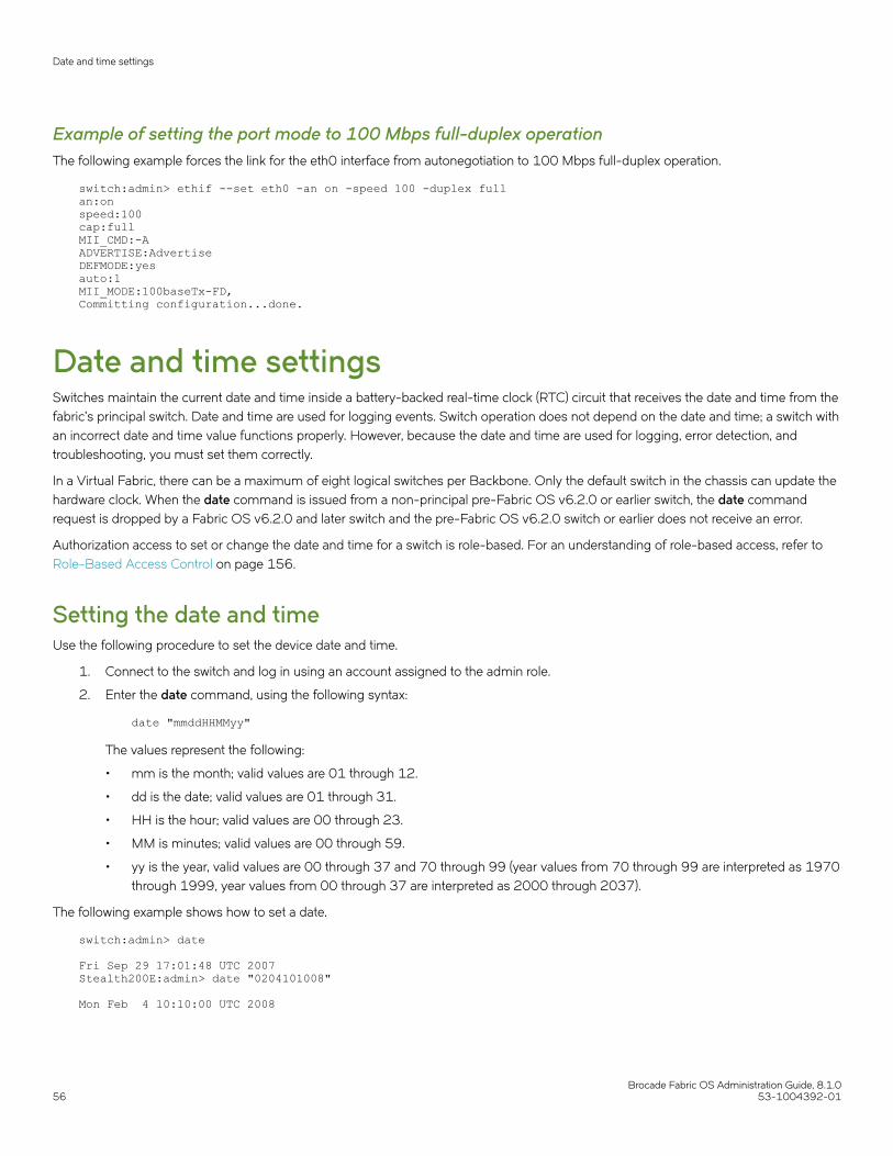
Example of setting the port mode to 100 Mbps full-duplex operationThe following example forces the link for the eth0 interface from autonegotiation to 100 Mbps full-duplex operation.
switch:admin> ethif --set eth0 -an on -speed 100 -duplex fullan:onspeed:100cap:fullMII_CMD:-AADVERTISE:AdvertiseDEFMODE:yesauto:1MII_MODE:100baseTx-FD,Committing configuration...done.
Date and time settingsSwitches maintain the current date and time inside a battery-backed real-time clock (RTC) circuit that receives the date and time from thefabric’s principal switch. Date and time are used for logging events. Switch operation does not depend on the date and time; a switch withan incorrect date and time value functions properly. However, because the date and time are used for logging, error detection, andtroubleshooting, you must set them correctly.
In a Virtual Fabric, there can be a maximum of eight logical switches per Backbone. Only the default switch in the chassis can update thehardware clock. When the date command is issued from a non-principal pre-Fabric OS v6.2.0 or earlier switch, the date commandrequest is dropped by a Fabric OS v6.2.0 and later switch and the pre-Fabric OS v6.2.0 switch or earlier does not receive an error.
Authorization access to set or change the date and time for a switch is role-based. For an understanding of role-based access, refer to Role-Based Access Control on page 156.
Setting the date and timeUse the following procedure to set the device date and time.
1. Connect to the switch and log in using an account assigned to the admin role.
2. Enter the date command, using the following syntax:
date "mmddHHMMyy"
The values represent the following:
• mm is the month; valid values are 01 through 12.
• dd is the date; valid values are 01 through 31.
• HH is the hour; valid values are 00 through 23.
• MM is minutes; valid values are 00 through 59.
• yy is the year, valid values are 00 through 37 and 70 through 99 (year values from 70 through 99 are interpreted as 1970through 1999, year values from 00 through 37 are interpreted as 2000 through 2037).
The following example shows how to set a date.
switch:admin> date Fri Sep 29 17:01:48 UTC 2007Stealth200E:admin> date "0204101008" Mon Feb 4 10:10:00 UTC 2008
Date and time settings
Brocade Fabric OS Administration Guide, 8.1.056 53-1004392-01
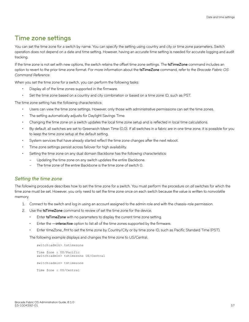
Time zone settingsYou can set the time zone for a switch by name. You can specify the setting using country and city or time zone parameters. Switchoperation does not depend on a date and time setting. However, having an accurate time setting is needed for accurate logging and audittracking.
If the time zone is not set with new options, the switch retains the offset time zone settings. The tsTimeZone command includes anoption to revert to the prior time zone format. For more information about the tsTimeZone command, refer to the Brocade Fabric OSCommand Reference.
When you set the time zone for a switch, you can perform the following tasks:
• Display all of the time zones supported in the firmware.
• Set the time zone based on a country and city combination or based on a time zone ID, such as PST.
The time zone setting has the following characteristics:
• Users can view the time zone settings. However, only those with administrative permissions can set the time zones.
• The setting automatically adjusts for Daylight Savings Time.
• Changing the time zone on a switch updates the local time zone setup and is reflected in local time calculations.
• By default, all switches are set to Greenwich Mean Time (0,0). If all switches in a fabric are in one time zone, it is possible for youto keep the time zone setup at the default setting.
• System services that have already started reflect the time zone changes after the next reboot.
• Time zone settings persist across failover for high availability.
• Setting the time zone on any dual domain Backbone has the following characteristics:
– Updating the time zone on any switch updates the entire Backbone.– The time zone of the entire Backbone is the time zone of switch 0.
Setting the time zoneThe following procedure describes how to set the time zone for a switch. You must perform the procedure on all switches for which thetime zone must be set. However, you only need to set the time zone once on each switch because the value is written to nonvolatilememory.
1. Connect to the switch and log in using an account assigned to the admin role and with the chassis-role permission.
2. Use the tsTimeZone command to review of set the time zone for the device.
• Enter tsTimeZone with no parameters to display the current time zone setting.
• Enter the --interactive option to list all of the time zones supported by the firmware.
• Enter timeZone_fmt to set the time zone by Country/City or by time zone ID, such as Pacific Standard Time (PST).
The following example displays and changes the time zone to US/Central.
switch:admin> tstimezone Time Zone : US/Pacific switch:admin> tstimezone US/Central switch:admin> tstimezone Time Zone : US/Central
Date and time settings
Brocade Fabric OS Administration Guide, 8.1.053-1004392-01 57

Setting the time zone interactivelyUse the following procedure to set the current time zone to PST using interactive mode.
1. Connect to the switch and log in using an account assigned to the admin role and with the chassis-role permission.
2. Enter the tsTimeZone --interactive command.
You are prompted to select a general location.
Please identify a location so that time zone rules can be set correctly.Please select a continent or ocean.1) Africa2) Americas3) Antarctica4) Arctic Ocean5) Asia6) Atlantic Ocean7) Australia8) Europe9) Indian Ocean10) Pacific Ocean11) none - I want to specify the time zone using the POSIX TZ format.Enter number or control-D to quit ?1
3. Enter the appropriate number or press Ctrl-D to quit.
Please select a country.1) Algeria 18) Gabon 35) Rwanda2) Angola 19) Gambia 36) Sao Tome & Principe3) Benin 20) Ghana 37) Senegal4) Botswana 21) Guinea 38) Sierra Leone5) Burkina Faso 22) Guinea-Bissau 39) Somalia6) Burundi 23) Kenya 40) South Africa7) Cameroon 24) Lesotho 41) Spain8) Central African Rep. 25) Liberia 42) Sudan9) Chad 26) Libya 43) Swaziland10) Congo (Dem. Rep.) 27) Malawi 44) Tanzania11) Congo (Rep.) 28) Mali 45) Togo12) Cote d'Ivoire 29) Mauritania 46) Tunisia13) Djibouti 30) Morocco 47) Uganda14) Egypt 31) Mozambique 48) Western Sahara15) Equatorial Guinea 32) Namibia 49) Zambia16) Eritrea 33) Niger 50) Zimbabwe17) Ethiopia 34) NigeriaEnter number or control-D to quit ?1The following information has been given:
Algeria
Therefore TZ='Africa/Algiers' will be used.Local time is now: Wed Oct 28 15:01:38 CET 2015.Universal Time is now: Wed Oct 28 14:01:38 UTC 2015.
4. Select a country location at the prompt.
Date and time settings
Brocade Fabric OS Administration Guide, 8.1.058 53-1004392-01

5. Enter the appropriate number at the prompt to specify the time zone region. Enter 1 to confirm or 2 to restart the time zoneselection again. At any time, use Ctrl-D to quit.
Is the above information OK?1) Yes2) NoEnter number or control-D to quit ?2Please identify a location so that time zone rules can be set correctly.Please select a continent or ocean.1) Africa2) Americas3) Antarctica4) Arctic Ocean5) Asia6) Atlantic Ocean7) Australia8) Europe9) Indian Ocean10) Pacific Ocean11) none - I want to specify the time zone using the POSIX TZ format.Enter number or control-D to quit ?
Network Time ProtocolTo keep the time in your SAN current, you should synchronize the local time of the principal or primary FCS switch with at least oneexternal Network Time Protocol (NTP) server.
The principal or primary FCS switch connects to the NTP server and broadcasts time service updates to all switches in the fabric. Theother switches in the fabric automatically take their time from the principal or primary FCS switch.
You can synchronize the local time of the principal or primary FCS switch to a maximum of eight external NTP servers.
All switches in the fabric maintain the current NTP clock server value in nonvolatile memory. By default, this value is the local clock(LOCL) of the principal or primary FCS switch. Changes to the clock server value on the principal or primary FCS switch are propagatedto all switches in the fabric.
When a new switch enters the fabric, the time server daemon of the principal or primary FCS switch sends out the addresses of allexisting clock servers and the time to the new switch. When a switch enters the fabric, it stores the list and the active servers.
If Virtual Fabrics is enabled, the switch behavior is as follows:
• All switches in a given chassis must be configured for the same set of NTP servers. This ensures that time does not go out ofsync in the chassis. It is not recommended to configure LOCL in the NTP server list.
• All default switches in the fabric can query the NTP server. If Virtual Fabrics is not enabled, only the principal or primary FCSswitch can query the NTP server.
• The logical switches in a chassis get their clock information from the default logical switch, and not from the principal or primaryFCS switch.
Synchronizing the local time with an external sourceThe tsClockServer command accepts multiple server addresses in IPv4, IPv6, or Domain Name System (DNS) name formats. Whenmultiple NTP server addresses are passed, tsClockServer sets the first obtainable address as the active NTP server. The rest are storedas backup servers that can take over if the active NTP server fails. The principal or primary FCS switch synchronizes its time with theNTP server every 64 seconds.
1. Connect to the switch and log in using an account assigned to the admin role.
Date and time settings
Brocade Fabric OS Administration Guide, 8.1.053-1004392-01 59

2. Enter the tsClockServer command.
switch:admin> tsclockserver ntp1;ntp2
In this syntax, ntp1 is the IP address or DNS name of the first NTP server, which the switch must be able to access. The secondvariable, ntp2, is the second NTP server and is optional. The operand "ntp1;ntp2" is optional; by default, this value is LOCL,which uses the local clock of the principal or primary FCS switch as the clock server.
The following example sets the NTP server.
switch:admin> tsclockserver LOCL switch:admin> tsclockserver "10.1.2.3"
The following example displays the NTP server.
switch:admin> tsclockserver 10.1.2.3
The following example sets up more than one NTP server using a DNS name.
switch:admin> tsclockserver "10.1.2.4;10.1.2.5;ntp.localdomain.net" Updating Clock Server configuration...done.Updated with the NTP servers
Changes to the clock server value on the principal or primary FCS switch are propagated to all switches in the fabric.
NTP configuration distribution to Access GatewaysIn switch mode, the principal or primary FCS switch synchronizes its time with the external NTP server every 64 seconds and sends timeupdates to other switches in the fabric. The time updates are not sent in-band to Access Gateway (AG) devices. An AG device need notsync with the external NTP server as it can receive NTP server configuration from the connected FOS switch. If the AG device isconnected to more than one fabric, the latest clock server request received is configured.
Consider the following points when distributing the NTP server configuration:
• Any switch running Fabric OS 7.4.0 or later can distribute the NTP server configuration to core AG devices connected to thefabric. The core AG devices must be running Fabric OS 7.4.0 or later to be able to distribute the NTP configuration to othercascaded or edge AG devices. However, AG devices are not capable of distributing the NTP configuration to other switches inthe fabric.
• A switch running Fabric OS 7.4.0 or earlier can distribute the NTP server configuration to AG devices connected to the fabric.However, AG devices cannot distribute the NTP configuration to other switches in the fabric.
• The tsclockserver command distributes the NTP server configuration to all switches within the fabric and AG devicesconnected to the same fabric.
• NTP server configurations that have already been distributed will persist on the AG device after firmware downgrade fromFabric OS 8.0.1 and later to an earlier version on supported platforms. However, the AG device cannot distribute anyconfiguration to the edge AG devices.
Domain IDsAlthough domain IDs are assigned dynamically when a switch is enabled, you can change them manually so that you can control the IDnumber or resolve a domain ID conflict when you merge fabrics.
Domain IDs
Brocade Fabric OS Administration Guide, 8.1.060 53-1004392-01

If a switch has a domain ID when it is enabled, and that domain ID conflicts with another switch in the fabric, the conflict is automaticallyresolved if the other switch’s domain ID is not persistently set. The process can take several seconds, during which time traffic is delayed.If both switches have their domain IDs persistently set, one of them needs to have its domain ID changed to a domain ID not used withinthe fabric.
NOTEThe default domain ID for Brocade switches is 1. To avoid future conflicts and unexpected changes when additional switchesare enabled that might be assigned the default ID, it is recommended that you change the default ID to an insistent domain ID.
The xlate domain ID (XD) or front domain ID (FD) for an FC Router is assigned in the following ranges, if the insistent domain ID is notconfigured.
• The FD range for an FC Router is 160 through 199. The default front domain ID requested by an FC Router is 160.
• The XD range for an FC Router is 200 through 239. The default xlate domain ID requested by an FC Router is 200.
NOTEIf there is no free domain ID available in the specified range for XD or FD, the principal switch assigns the lowest availabledomain ID starting from 1. The principal switch must be running Fabric OS 7.4.0 or later.
The principal switch overrides the specified domain ID range if the following conditions are true:
• If the insistent domain ID is configured for FD or XD
• The requested domain ID is not in the specified range
• The requested domain ID is available for domain ID assignment
When a switch, other than the FC Router FD or XD, requests a domain ID within the new specified range for the FC Router FD or XD, theprincipal switch assigns the domain ID, if it is available.
NOTEIt is recommended that the Insistent Domain ID be configured when deploying features that rely on domain IDs, such as [D, I]Zoning, and TI Zoning.
Domain ID issuesKeep the following restrictions in mind when working with domain IDs.
• Do not use domain ID 0. Using this domain ID can cause the switch to reboot continuously.
• Avoid changing the domain ID on the FCS switch in secure mode.
• To minimize downtime, change the domain IDs on the other switches in the fabric.
Displaying the domain IDsUse the following procedure to display device domain IDs.
1. Connect to the switch and log in using an account assigned to the admin role.
Domain IDs
Brocade Fabric OS Administration Guide, 8.1.053-1004392-01 61

2. Enter the fabricShow command.
The following is an example of output of fabric information, including the domain ID (D_ID).
The principal switch is determined by the arrow ( > ) next to the name of the switch.
switch:admin> fabricshow Switch ID Worldwide Name Enet IP Addr FC IP Addr Name------------------------------------------------------------------------- 2: fffc02 10:00:00:60:69:e0:01:46 10.3.220.1 0.0.0.0 "ras001" 3: fffc03 10:00:00:60:69:e0:01:47 10.3.220.2 0.0.0.0 "ras002" 5: fffc05 10:00:00:05:1e:34:01:bd 10.3.220.5 0.0.0.0 "ras005" fec0:60:69bc:63:205:1eff:fe34:1bd 6: fffc06 10:00:00:05:1e:34:02:3e 10.3.220.6 0.0.0.0 >"ras006" 7: fffc07 10:00:00:05:1e:34:02:0c 10.3.220.7 0.0.0.0 "ras007" (output truncated)The Fabric has 26 switches
The following table displays the fabricShow fields.
TABLE 4 fabricShow fields
Field Description
Switch ID The switch domain_ID and embedded port D_ID. The numbers arebroken down as shown in the following example:
64: fffc40
64 is the switch domain_ID
fffc40 is the hexadecimal format of the embedded port D_ID.
World Wide Name The switch WWN.
Enet IP Addr The switch Ethernet IP address for IPv4- and IPv6-configuredswitches. For IPv6 switches, only the static IP address displays.
FC IP Addr The switch Fibre Channel IP address.
Name The switch symbolic or user-created name in quotes.
Setting the domain IDUse the following procedure to set the domain ID:
1. Connect to the switch and log in on an account assigned to the admin role.
2. Enter the switchDisable command to disable the switch.
3. Enter the configure command.
4. Enter y after the Fabric Parameters prompt.
Fabric parameters (yes, y, no, n): [no] y
5. Enter a unique domain ID at the Domain prompt. Use a domain ID value from 1 through 239 for normal operating mode(FCSW-compatible).
Domain: (1..239) [1] 3
6. Respond to the remaining prompts, or press Ctrl-D to accept the other settings and exit.
7. Enter the switchEnable command to re-enable the switch.
Domain IDs
Brocade Fabric OS Administration Guide, 8.1.062 53-1004392-01

Switch namesA switch can be identified by an IP address, a domain ID, a World Wide Name (WWN), or by a customized switch name that is uniqueand meaningful.
The following considerations apply to switch naming:
• Switch names can be from 1 through 30 characters long.
• All switch names must begin with a letter or number and can contain letters, numbers, hyphens, or underscore characters.
• Switch names must be unique across logical switches.
• Changing the switch name causes a domain address format RSCN to be issued and might be disruptive to the fabric.
Customizing the switch name1. Connect to the switch and log in using an account assigned to the admin role.
2. Enter the switchName newname command using a new name for the switch.
The prompt does not change to the new switch name until after you log in again.
3. Record the new switch name for future reference.
switch:admin> switchname myswitchCommitting configuration...Done.Switch name has been changed. Please re-login into the switch for the change to be applied.switch:FID128:# admin>
Chassis namesBrocade recommends that you customize the chassis name for each platform. Some system logs identify devices by platform names; ifyou assign meaningful platform names, logs are more useful. All chassis names supported by Fabric OS v7.0.0 and later allow 31characters. Chassis names must begin with an alphabetic character and can include alphabetic and numeric characters, and theunderscore ( _ ).
Customizing chassis namesUse the following procedure to customize the chassis name:
1. Connect to the switch and log in using an account assigned to the admin role.
2. Enter the chassisName command.
ecp:admin> chassisname newname
3. Record the new chassis name for future reference.
Chassis names
Brocade Fabric OS Administration Guide, 8.1.053-1004392-01 63

Fabric nameYou can assign a alphanumeric name to identify and manage a logical fabric that formerly could only be identified by a fabric ID. Thefabric name does not replace the fabric ID or its usage. The fabric continues to have a fabric ID, in addition to the assigned alphanumericfabric name.
The following considerations apply to fabric naming:
• Each name must be unique for each logical switch within a chassis; duplicate fabric names are not allowed.
• A fabric name can be from 1 through 128 alphanumeric characters (a–z, 0–9).
• All switches in a logical fabric must be running Fabric OS v7.2.0 or later. Switches running earlier versions of the firmware cancoexist in the fabric, but do not show the fabric name details.
• You must have admin permissions to configure the fabric name.
Configuring the fabric nameTo set and display the fabric name, use the fabricName command.
switch:admin> fabricname --set myfabric@1
Using the fabricName --set command without a fabric name takes the existing fabric name and synchronizes it across the entire fabric.An error message displays if no name is configured.
To set a fabric name that includes spaces, enclose the fabric name in quotes.
switch:admin> fabricname --set "my new fabric"
To set a fabric name that includes special meta-characters or spaces, use the command fabricName.
switch:admin> fabricname --set 'red fabric $$'
To clear the fabric name, use the fabricName --clear command.
High availability considerations for fabric namesFabric names locally configured or obtained from a remote switch are saved in the configuration database, and then synchronized to thestandby CP on dual-CP-based systems.
Upgrade and downgrade considerations for fabric namesFabric names are lost during a firmware downgrade. No default fabric name is provided. If a fabric name is needed, it must be configuredafter the upgrade.
Switch activation and deactivationBy default, the switch is enabled after power is applied and diagnostics and switch initialization routines have finished. You can disableand re-enable the switch as necessary.
When you enable or disable a switch, the affected ports depend on whether Virtual Fabrics is enabled. The following table describeswhich ports are affected for each type of enable or disable operation.
Fabric name
Brocade Fabric OS Administration Guide, 8.1.064 53-1004392-01

TABLE 5 Ports affected when you enable or disable a switch in VF or non-VF mode
Operation Virtual Fabrics enabled Virtual Fabrics not enabled
Enable switch Enables all ports on logical switch Enables all ports on physical chassis
Enable chassis Enables all ports on physical chassis Not allowed
Disable switch Disables all ports on logical switch Disables all ports on physical chassis
Disable chassis Disables all ports on physical chassis Not allowed
Disabling a switchYou must disable a switch before making configuration changes or before running offline diagnostic tests.
1. Connect to the switch and log in using an account assigned to the admin role.
2. Enter the switchDisable command.
switch:admin> switchdisable
All Fibre Channel ports on the switch are taken offline. If the switch is part of a fabric, the fabric is reconfigured.
If Virtual Fabrics is enabled, only the ports allocated to the logical switch are disabled. To disable all of the ports, you mustdisable the entire chassis.
Enabling a switchThe switch is enabled by default after it is powered on and switch initialization routines have finished. You must re-enable the switch aftermaking configuration changes or running offline diagnostics.
1. Connect to the switch and log in using an account assigned to the admin role.
2. Enter the switchEnable command.
switch:admin> switchenable
All Fibre Channel ports that passed the Power-On Self-Test (POST) are enabled. If the switch has inter-switch links (ISLs) to afabric, it joins the fabric.
If Virtual Fabrics are enabled, only the ports allocated to the logical switch are enabled. To enable all of the ports, you mustenable the entire chassis.
Disabling a chassisDisabling a chassis disables all Fibre Channel ports on all logical switches in the chassis. You must disable a chassis before makingchassis-wide configuration changes or before running offline diagnostic tests.
1. Connect to any logical switch in the chassis and log in using an account assigned to the admin role.
Switch activation and deactivation
Brocade Fabric OS Administration Guide, 8.1.053-1004392-01 65

2. Enter the chassisDisable command.
switch:FID128:admin> chassisdisable This command can cause disruption to multiple logical switches.Are you sure you want to disable all chassis ports now? (yes, y, no, n): [no]yswitch:FID128:admin>
All Fibre Channel ports on all logical switches are taken offline. If the logical switches are in fabrics, the fabrics are reconfigured.
NOTEAfter a chassisDisable , if you want to do an haFailover , you should wait at least 30 seconds.
Enabling a chassisEnabling a chassis enables all Fibre Channel ports on all logical switches in the chassis. The chassis is enabled by default after it ispowered on and switch initialization routines have finished. You must re-enable the chassis after making fabric-wide configurationchanges or running offline diagnostics.
1. Connect to the switch and log in using an account assigned to the admin role.
2. Enter the chassisEnable command.
switch:FID128:admin> chassisenable
For all logical switches in the chassis, all Fibre Channel ports are enabled. If any of the logical switches have inter-switch links(ISLs) to a fabric, it joins the fabric.
Device shutdownTo avoid corrupting your file system, you must perform graceful shutdowns of Brocade switches, Backbones, and Directors by using thefollowing instructions.
Powering off a Brocade switchUse the following procedure to gracefully shut down a Brocade switch.
1. Connect to the switch and log in using an account assigned to the admin role.
2. Enter the sysShutdown command.
3. Enter y at the prompt.
switch:admin> sysshutdown This command will shutdown the operating systems on your switch.You are required to power-cycle the switch in order to restore operation.Are you sure you want to shutdown the switch [y/n]?y
Device shutdown
Brocade Fabric OS Administration Guide, 8.1.066 53-1004392-01

4. Wait until the following message displays:
Broadcast message from root (ttyS0) Wed Jan 25 16:12:09 2006...The system is going down for system halt NOW !!INIT: Switching to runlevel: 0INIT: Sending processes the TERM signalUnmounting all filesystems.The system is haltedflushing ide devices: hdaPower down.
5. Power off the switch.
Powering off a Brocade DirectorUse the following procedure to power off a Brocade DCX 8510 and X6 Directors:
1. From the active CP in a dual-CP platform, enter the sysShutdown command.
NOTEWhen the sysShutdown command is issued on the active CP, the active CP, the standby CP, and any applicationblades are all shut down.
2. Enter y at the prompt.
3. Wait until the following message displays:
DCX:FID128:admin> sysshutdown This command will shutdown the operating systems on your switch.You are required to power-cycle the switch in order to restore operation.Are you sure you want to shutdown the switch [y/n]?yHA is disabledStopping blade 10Shutting down the blade....Stopping blade 12Shutting down the blade....Broadcast message from root (pts/0) Fri Oct 10 08:36:48 2008...The system is going down for system halt NOW !!
4. Power off the switch.
Basic connectionsBefore connecting a switch to a fabric that contains switches running different firmware versions, you must first set the same portidentification (PID) format on all switches. The presence of different PID formats in a fabric causes fabric segmentation.
• For information on PID formats and related procedures, refer to Performing Advanced Configuration Tasks on page 69.
• For information on configuring the routing of connections, refer to Routing Traffic on page 115.
• For information on configuring extended inter-switch connections, refer to Managing Long-Distance Fabrics on page 507.
Device connectionTo minimize port logins, power off all devices before connecting them to the switch. When powering the devices back on, wait for eachdevice to complete the fabric login before powering on the next one.
For devices that cannot be powered off, first use the portDisable command to disable the port on the switch, connect the device, andthen use the portEnable command to enable the port.
Basic connections
Brocade Fabric OS Administration Guide, 8.1.053-1004392-01 67

Switch connectionRefer to the hardware reference manual of your specific switch for ISL connection and cable management information. The standard ordefault ISL mode is L0. ISL mode L0 is a static mode, with the following maximum ISL distances:
• 10 km at 1 Gbps
• 5 km at 2 Gbps
• 2.5 km at 4 Gbps
• 1 km at 8 Gbps
• 1 km at 10 Gbps
• 625 m at 16 Gbps
• 150 m at 32 Gbps
For more information on extended ISL modes, which enable long distance inter-switch links, refer to Managing Long-Distance Fabricson page 507.
Basic connections
Brocade Fabric OS Administration Guide, 8.1.068 53-1004392-01

Performing Advanced Configuration Tasks• Port identifiers and PID binding overview............................................................................................................................................... 69• Ports........................................................................................................................................................................................................................73• Blade terminology and compatibility.........................................................................................................................................................88• Enabling and disabling blades......................................................................................................................................................................91• Blade swapping.................................................................................................................................................................................................. 92• Disabling switches.............................................................................................................................................................................................97• Power management......................................................................................................................................................................................... 97• Equipment status...............................................................................................................................................................................................99• Audit log configuration................................................................................................................................................................................. 101• Duplicate PWWN handling during device login.................................................................................................................................107• Forward error correction.............................................................................................................................................................................. 109
Port identifiers and PID binding overviewPort identifiers (PIDs, also called Fabric Addresses) are used by the routing and zoning services in Fibre Channel fabrics to identify portsin the network.
All devices in a fabric must use the same PID format. When you add new equipment to the SAN, you might need to change the PIDformat on legacy equipment.
Many scenarios cause a device to receive a new PID; for example, unplugging the device from one port and plugging it into a differentport as part of fabric maintenance, or changing the domain ID of a switch, which might be necessary when merging fabrics, or changingcompatibility mode settings.
Some device drivers use the PID to map logical disk drives to physical Fibre Channel counterparts. Most drivers can either change PIDmappings dynamically, also called dynamic PID binding, or use the WWN of the Fibre Channel disk for mapping, also called WWNbinding.
Some older device drivers behave as if a PID uniquely identifies a device; they use static PID binding. These device drivers should beupdated, if possible, to use WWN binding or dynamic PID binding instead, because static PID binding creates problems in many routinemaintenance scenarios. Fortunately, very few device drivers still behave this way. Many current device drivers enable you to select staticPID binding as well as WWN binding. You should only select static PID binding if there is a compelling reason, and only after you haveevaluated the effect of doing so.
Core PID addressing modeCore PID is the default PID format for Brocade platforms. It uses the entire 24-bit address space of the domain, area ID, and AL_PA todetermine an object’s address within the fabric.
The Core PID is a 24-bit address built from the following three 8-bit fields:
• Domain ID, written in hex and the numeric range is from 01 through ee (1 through 239)
• Area ID, written in hex and the numeric range is from 01 through ff (1 through 255)
• AL_PA
For example, if a device is assigned an address of 0f1e00, the following would apply:
• 0f is the domain ID.
• 1e is the area ID.
Brocade Fabric OS Administration Guide, 8.1.053-1004392-01 69

• 00 is the assigned AL_PA.
From this information, you can determine which switch the device resides on from the domain ID, which port the device is attached tofrom the area ID, and if this device is part of a loop from the AL_PA number.
Fixed addressing modeWith fixed addressing mode, each port has a fixed address assigned by the system based on the port number.
This address does not change unless you choose to swap the address using the portSwap command.
Fixed addressing mode is the default addressing mode used in all platforms that do not have Virtual Fabrics enabled. When VirtualFabrics is enabled on the Brocade Backbone, fixed addressing mode is used only on the default logical switch.
10-bit addressing (mode 0)The 10-bit addressing mode is the default mode for all the logical switches. This addressing scheme is flexible to support a largenumber of F_Ports.
NOTEThe default switch in the Brocade Backbones uses the fixed addressingmode.
The 10-bit addressing mode utilizes the 8-bit area ID and the borrowed upper two bits from the AL_PA portion of the PID. Areas 0x00through 0x8F use only 8 bits for the port address and support up to 256 NPIV devices. A logical switch can support up to 144 portsthat can each support 256 devices. Areas 0x90 through 0xFF use an additional two bits from the AL_PA for the port address.Therefore, these ports support only 64 NPIV devices per port.
10-bit addressing mode provides the following features:
• A PID is dynamically allocated only when the port is first moved to a logical switch and thereafter it is persistently maintained.
• PIDs are assigned in each logical switch starting with 0xFFC0, and can go to 0x8000 in the case of 64-port blades.
• Shared area limitations are removed on 48-port and 64-port blades.
• Any port on a 48-port or 64-port blade can support up to 256 NPIV devices (in fixed addressing mode, only 128 NPIVdevices are supported in non-VF mode and 64 NPIV devices in VF mode on a 48-port blade).
• Any port on a 48-port blade can support loop devices.
• Any port on a 48-port or 64-port blade can support hard port zoning.
• Port index is not guaranteed to be equal to the port area ID.
256-area addressing (mode 1 and mode 2)The 256-area addressing mode is available only in a logical switch on the Brocade Backbone. In this mode, only 256 ports aresupported and each port receives a unique 8-bit area address. This mode can be used in FICON environments, which have strictrequirements for 8-bit area FC addresses.
There are two types of area assignment modes with 256-area addressing: zero-based and port-based.
ATTENTIONOn default logical switches with an address mode other than mode 1, any 48-port and 64-port blades are disabled if FICONManagement Server (FMS) is enabled.
Port identifiers and PID binding overview
Brocade Fabric OS Administration Guide, 8.1.070 53-1004392-01

Refer to the Brocade FICON Administrator's Guide for additional details.
Zero-based addressing (mode 1)With zero-based addressing, unique area assignments begin at zero regardless of where the port is physically located. This allows FICONusers to make use of high port count blades with port indexes greater than 256.
Zero-based addressing assigns areas when the ports are added to the logical switch, beginning at area 0x00. When a port is assigned toa logical switch, the next free PID starting from 0x00 is assigned. This mode allows FICON customers to make use of the upper ports ofa 48-port or 64-port blade.
Zero-based mode is supported on the default switch.
Port-based addressing (mode 2)With port-based addressing, unique area assignments are based on the port index.
Port-based addressing mode does not allow FICON users to make use of ports with an index greater than 256 (high ports of a high portcount blade), but this mode is compatible with domain-index zoning.
Port-based addressing is not supported on the default switch.
The 48-port and 64-port blades have the following restrictions:
• Port-based addressing is not supported on the upper 16 ports of a 64-port blade on the DCX 8510-4 Backbones.
• Port-based addressing is not supported on the 48-port blades in the Brocade DCX 8510-8 Backbones. Only zero-basedaddressing is supported on these blades.
WWN-based PID assignmentWWN-based PID assignment is disabled by default. When the feature is enabled, bindings are created dynamically; as new devices login, they automatically enter the WWN-based PID database. The bindings exist until you explicitly unbind the mappings through the CLI orchange to a different addressing mode. If there are any existing devices when you enable the feature, you must manually enter theWWN-based PID assignments through the CLI.
This feature also allows you to configure a PID persistently using a device WWN. When the device logs in to the switch, the PID is boundto the device WWN. If the device is moved to another port in the same switch, or a new blade is hot-plugged, the device receives thesame PID (area) at its next login.
Once WWN-based PID assignment is enabled, you must manually enter the WWN-based PID assignments through the CLI for anyexisting devices.
NOTEWhen the WWN-based PID assignment feature is enabled, area assignment is dynamic and has no predetermined order orprecedence. This means that on the first fabric login of a PID, the PID will be assigned the next available WWN area and it willremain mapped to that WWN after that point (including subsequent logins). Static WWN-area bindings are preserved, but arenot used for dynamic assignments.
PID assignments are supported for a maximum of 4096 devices; this includes both point-to-point and NPIV devices. The number ofpoint-to-point devices supported depends on the areas available. For example, 448 areas are available on Backbones and 256 areasare available on switches. When the number of entries in the WWN-based PID database reaches 4096 areas used up, the oldest unusedentry is purged from the database to free up the reserved area for the new FLOGI.
Port identifiers and PID binding overview
Brocade Fabric OS Administration Guide, 8.1.053-1004392-01 71

Virtual Fabrics considerations for WWN-based PID assignmentWWN-based PID assignment is disabled by default and is supported in the default switch on the Brocade DCX 8510 Backbones andX6 Directors. This feature is not supported on the FX8-24 and SX6 blades. The total number of ports in the default switch must be 256or less.
When the WWN-based PID assignment feature is enabled and a new blade is plugged into the chassis, the ports for which the area is notavailable are disabled.
NPIVIf any N_Port ID Virtualization (NPIV) devices have static PIDs configured and the acquired area is not the same as the one beingrequested, the FDISC coming from that device is rejected and the error is noted in the RASlog.
If the NPIV device has Dynamic Persistent PID set, the same AL_PA value in the PID is used. This guarantees NPIV devices get thesame PID across reboots and AL_PAs assigned for the device do not depend on the order in which the devices come up. For moreinformation on NPIV, refer to NPIV on page 457.
Enabling automatic PID assignment
NOTETo activate the WWN-based PID assignment, you do not need to disable the switch.
Use the following procedure to enable automatic PID assignment.
1. Connect to the switch and log in using an account with admin permissions.
2. Enter the configure command.
3. At the Fabric parameters prompt, type y .
4. At the WWN Based persistent PID prompt, type y .
5. Press Enter to bypass the remaining prompts without changing them.
Example of activating PID assignments
switch: admin> configure Configure...Fabric parameters (yes, y, no, n): [no] y WWN Based persistent PID (yes, y, no, n): [no] y System services (yes, y, no, n): [no] ssl attributes (yes, y, no, n): [no] rpcd attributes (yes, y, no, n): [no] cfgload attributes (yes, y, no, n): [no] webtools attributes (yes, y, no, n): [no] Custom attributes (yes, y, no, n): [no] system attributes (yes, y, no, n): [no]
Assigning a static PIDUse the following procedure to assign a static PID.
1. Connect to the switch and log in using an account with admin permissions.
2. Enter the wwnAddress -bind command to assign a 16-bit PID to a given WWN.
Port identifiers and PID binding overview
Brocade Fabric OS Administration Guide, 8.1.072 53-1004392-01

Clearing PID bindingUse the following procedure to clear a PID binding.
1. Connect to the switch and log in using an account with admin permissions.
2. Enter the wwnAddress -unbind command to clear the PID binding for the specified WWN.
Showing PID assignmentsUse the following procedure to display PID assignments.
1. Connect to the switch and log in using an account with admin permissions.
2. Based on what you want to display, enter the appropriate command.
• To display the assigned WWN-PID bindings, enter the following:
wwnAddress --show
• To display the PID assigned to the specific device WWN, enter the following:
wwnAddress -findPID wwn
PortsPorts provide either a physical or virtual network connection point for a device. Brocade devices support a wide variety of ports.
Port typesThe following is a list of port types that might be part of a Brocade device:
• D_Port: A diagnostic port lets you isolate the link to diagnose link-level faults. This port runs only specific diagnostics tests anddoes not carry any fabric traffic. Refer to the "Diagnostic Port" chapter in the Brocade Fabric OS Troubleshooting andDiagnostics Guide for more information on this port type.
• E_Port: An expansion port that is assigned to ISL links to expand a fabric by connecting it to other switches. Two connectedE_Ports form an inter-switch link (ISL). When E_Ports are used to connect switches, those switches merge into a single fabricwithout an isolation demarcation point. ISLs are non-routed links.
• EX_Port: A type of E_Port that connects a Fibre Channel router to an edge fabric. From the point of view of a switch in an edgefabric, an EX_Port appears as a normal E_Port. It follows applicable Fibre Channel standards as do other E_Ports. However, therouter terminates EX_Ports rather than allowing different fabrics to merge as would happen on a switch with regular E_Ports. AnEX_Port cannot be connected to another EX_Port.
• F_Port: A fabric port that is assigned to fabric-capable devices, such as SAN storage devices.
• G_Port: A generic port that acts as a transition port for non-loop fabric-capable devices.
• L_Port or FL_Port: A loop or fabric loop port that connects loop devices. L_Ports are associated with private loop devices andFL_Ports are associated with public loop devices.
• U_Port: A universal Fibre Channel port. This is the base Fibre Channel port type, and all unidentified or uninitiated ports arelisted as U_Ports.
• VE_Port: A virtual E_Port that is a gigabit Ethernet switch port configured for an FCIP tunnel.
• VEX_Port: A virtual EX_Port that connects a Fibre Channel router to an edge fabric. From the point of view of a switch in anedge fabric, a VEX_Port appears as a normal VE_Port. It follows the same Fibre Channel protocol as other VE_Ports. However,
Ports
Brocade Fabric OS Administration Guide, 8.1.053-1004392-01 73

the router terminates VEX_Ports rather than allowing different fabrics to merge as would happen on a switch with regularVE_Ports.
Director port bladesBecause DCX 8510 and X6 Directors contain interchangeable port blades, their procedures differ from those for fixed-port switches.For example, fixed-port models identify ports only by the port number, while Backbones identify ports by slot/port notation
NOTEFor detailed information about the Brocade DCX 8510 and X6 Director families, refer to the respective hardware referencemanuals.
The different blades that can be inserted into a chassis are described as follows:
• Control processor (CP) blades contain communication ports for system management, and are used for low-level, platform-widetasks.
• Core blades are used for intra-chassis switching as well as interconnecting two Directors.
• Port blades are used for host, storage, and interswitch connections.
• Application (AP) blades are used for Extension (FCIP and IP) support.
NOTEOn each port blade, a particular port must be represented by both slot number and port number.
The Brocade DCX 8510-8 has 12 slots that contain control processor, core, port, and AP blades:
• Slot numbers 6 and 7 contain CPs.
• Slot numbers 5 and 8 contain core blades.
• Slot numbers 1 through 4 and 9 through 12 contain port and AP blades.
The Brocade DCX 8510-4 has 8 slots that contain control processor, core, port, and AP blades:
• Slot numbers 4 and 5 contain CPs.
• Slot numbers 3 and 6 contain core blades.
• Slot numbers 1 and 2, and 7 and 8 contain port and AP blades.
The Brocade X6-8 has 12 slots that contain control processor, core, port, and AP blades:
• Slot numbers 1 and 2 contain CPs.
• Slot numbers 7 and 8 contain core blades.
• Slot numbers 3 through 6 and 9 through 12 contain port and AP blades.
The Brocade X6-4 has 8 slots that contain control processor, core, port, and AP blades:
• Slot numbers 1 and 2 contain CPs.
• Slot numbers 5 and 6 contain core blades.
• Slot numbers 3 and 4, and 7 and 8 contain port and AP blades.
When you have port blades with different port counts in the same Backbones or Directors, (for example, 32-port blades and 48-portblades, or 48-port blades and 64-port blades), the area IDs no longer match the port numbers. Table 10 on page 89 lists the portnumbering schemes for the blades.
Ports
Brocade Fabric OS Administration Guide, 8.1.074 53-1004392-01

Setting port namesPerform the following steps to specify a port name. For Backbones, specify the slot number where the blade is installed.
1. Connect to the switch and log in using an account with admin permissions.
2. Enter the portName command.
switch:admin> portname 1/0 -n trunk1
Port identification by slot and port numberThe port number is assigned to an external port to give it a unique identifier in a switch.
To select a specific port in a Backbone, you must identify both the slot number and the port number using the format slot number/portnumber. No spaces are allowed between the slot number, the slash (/), and the port number.
The following example enables port 4 on a blade in slot 2.
switch:admin> portenable 2/4
Port identification by port area IDThe relationship between the port number and area ID depends upon the PID format used in the fabric. When Core PID format is ineffect, the area ID for port 0 is 0, for port 1 is 1, and so forth.
For 32-port blades (FC16-32), the numbering is contiguous up to port 15; from port 16, the numbering is still contiguous, but startswith 128. For example, port 15 in slot 1 has a port number and area ID of 15; port 16 has a port number and area ID of 128; port 17has a port number and area ID of 129.
For 48-port blades (FC16-48, FC32-48), the numbering is the same as for 32-port blades for the first 32 ports on the blade. Forports 32 through 47, area IDs are not unique and port index should be used instead of area ID.
For the 64-port blades (FC16-64), the numbering is the same as for 32-port blades for the first 32 ports on the blade. For ports 32through 63, area IDs are not unique and port index should be used instead of area ID.
If you perform a port swap operation, the port number and area ID no longer match.
To determine the area ID of a particular port, enter the switchShow command. This command displays all ports on the current (logical)switch and their corresponding area IDs.
Port identification by indexWith the introduction of 48-port and 64-port blades, indexing was introduced. Unique area IDs are possible for up to 255 areas, butbeyond that there needed to be some way to ensure uniqueness.
A number of fabric-wide databases supported by Fabric OS (including ZoneDB, and the ACL DCC) allow a port to be designated by theuse of a "D,P" (domain,port) notation. While the "P" component appears to be the port number, for up to 255 ports it is actually the areaassigned to that port.
NOTEThe port area schema does not apply to the Brocade DCX 8510-4 and X6-4 Backbones.
Ports
Brocade Fabric OS Administration Guide, 8.1.053-1004392-01 75
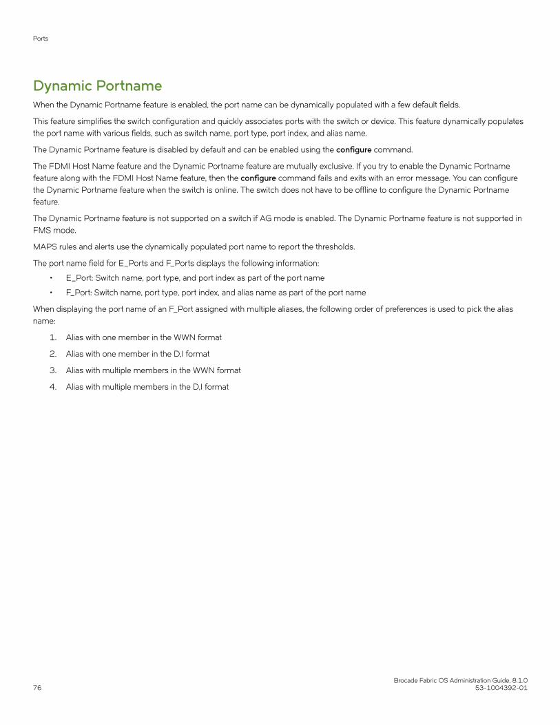
Dynamic PortnameWhen the Dynamic Portname feature is enabled, the port name can be dynamically populated with a few default fields.
This feature simplifies the switch configuration and quickly associates ports with the switch or device. This feature dynamically populatesthe port name with various fields, such as switch name, port type, port index, and alias name.
The Dynamic Portname feature is disabled by default and can be enabled using the configure command.
The FDMI Host Name feature and the Dynamic Portname feature are mutually exclusive. If you try to enable the Dynamic Portnamefeature along with the FDMI Host Name feature, then the configure command fails and exits with an error message. You can configurethe Dynamic Portname feature when the switch is online. The switch does not have to be offline to configure the Dynamic Portnamefeature.
The Dynamic Portname feature is not supported on a switch if AG mode is enabled. The Dynamic Portname feature is not supported inFMS mode.
MAPS rules and alerts use the dynamically populated port name to report the thresholds.
The port name field for E_Ports and F_Ports displays the following information:
• E_Port: Switch name, port type, and port index as part of the port name
• F_Port: Switch name, port type, port index, and alias name as part of the port name
When displaying the port name of an F_Port assigned with multiple aliases, the following order of preferences is used to pick the aliasname:
1. Alias with one member in the WWN format
2. Alias with one member in the D,I format
3. Alias with multiple members in the WWN format
4. Alias with multiple members in the D,I format
Ports
Brocade Fabric OS Administration Guide, 8.1.076 53-1004392-01

Example to configure the Dynamic Portname featureThe configure command is used to configure the Dynamic Portname. The option to configure the Dynamic Portname appears underFabric parameters.
switch:admin> configure
Configure...
Fabric parameters (yes, y, no, n): [no] yes WWN Based persistent PID (yes, y, no, n): [no] Location ID: (0..4) [0] Dynamic Portname (on, off): [off] on Edge Hold Time(Low(80ms), Medium(220ms), High(500ms), UserDefined(80-500ms): (80..500) [220] Remote Fosexec feature: (on, off): [on] High Integrity Fabric Mode (yes, y, no, n): [no] D-Port Parameters (yes, y, no, n): [no] RDP Polling Cycle(hours)[0 = Disable Polling]: (0..24) [0] System services (yes, y, no, n): [no] ssl attributes (yes, y, no, n): [no] rpcd attributes (yes, y, no, n): [no] cfgload attributes (yes, y, no, n): [no] webtools attributes (yes, y, no, n): [no]
This example shows that the FDMI Host Name and Dynamic Portname features are mutually exclusive. If you try to enable the DynamicPortname feature along with the FDMI Host Name feature, the configure command fails and exits with an error message.
switch:admin> configure
Configure...
Fabric parameters (yes, y, no, n): [no] yes
Domain: (1..239) [1] WWN Based persistent PID (yes, y, no, n): [no] F-Port Device Update Mode: (on, off): [on] Allow XISL Use (yes, y, no, n): [yes] R_A_TOV: (4000..120000) [10000] E_D_TOV: (1000..5000) [2000] WAN_TOV: (0..30000) [0] MAX_HOPS: (7..19) [7] Data field size: (256..2112) [2112] Sequence Level Switching: (0..1) [0] Disable Device Probing: (0..1) [0] Suppress Class F Traffic: (0..1) [0] Per-frame Route Priority: (0..1) [0] Long Distance Fabric: (0..1) [0] BB credit: (1..27) [16] Disable FID Check (yes, y, no, n): [no] Insistent Domain ID Mode (yes, y, no, n): [no] Disable Default PortName (yes, y, no, n): [no] Display FDMI Host Name (yes, y, no, n): [yes] Dynamic Portname (on, off): [off] on
Error: "Dynamic Portname" and "Display FDMI Host Name" are mutually exclusive. Please set "Display FDMI Host Name" to "no" to enable "Dynamic Portname".
Ports
Brocade Fabric OS Administration Guide, 8.1.053-1004392-01 77

Example to show the portname outputThe portname command displays the switch name, port type, port index, and alias name in the output. The value none indicates an errorin the alias name and null indicates that the alias name is not present.
switch:admin> portnameport 0: EDGE1_sw76.E_PORT.0port 1: EDGE1_sw76..1port 2: EDGE1_sw76..2port 3: EDGE1_sw76..3port 4: EDGE1_sw76..4port 5: EDGE1_sw76..5port 6: EDGE1_sw76.F_PORT.6.emlxport 7: EDGE1_sw76.F_PORT.7.port 8: EDGE1_sw76.F_PORT.8.
Example to show the portshow outputThe portshow command displays the switch name, port type, port index, and alias name in the output.
switch:admin> portshow 28portIndex: 28portName: sw78.E_PORT.28portHealth: HEALTHY
Authentication: NoneportDisableReason: NoneportCFlags: 0x1portFlags: 0x1000090b PRESENT ACTIVE E_PORT T_PORT T_MASTER G_PORT U_PORT LOGICAL_ONLINE LOGINLocalSwcFlags: 0x0portType: 18.0POD Port: Port is licensedportState: 1 Online Protocol: FCportPhys: 6 In_Sync portScn: 16 E_Port Trunk master port Flow control mode 4port generation number: 0state transition count: 1 [output truncated]
Ports
Brocade Fabric OS Administration Guide, 8.1.078 53-1004392-01

Example to show the switchshow outputThe switchshow -portname command displays the switch name, port type, port index, and alias name in the output.
switch:admin> switchshow -portname
switchName: sw0switchType: 66.1switchState: OnlineswitchMode: NativeswitchRole: PrincipalswitchDomain: 1switchId: fffc01switchWwn: 10:00:00:05:1e:82:3c:2azoning: OFFswitchBeacon: OFFFC Router: OFFFabric Name: switch_testAllow XISL Use: OFFLS Attributes: [FID: 128, Base Switch: No, Default Switch: Yes, Address Mode 0]
Index Port PortWWN Name================================================== 0 0 20:00:00:05:1e:82:3c:2a port0 1 1 20:01:00:05:1e:82:3c:2a port1 2 2 20:02:00:05:1e:82:3c:2a port2 3 3 20:03:00:05:1e:82:3c:2a port3 4 4 20:04:00:05:1e:82:3c:2a port4 5 5 20:05:00:05:1e:82:3c:2a port5 6 6 20:06:00:05:1e:82:3c:2a port6 7 7 20:07:00:05:1e:82:3c:2a port7 8 8 20:08:00:05:1e:82:3c:2a port8 9 9 20:09:00:05:1e:82:3c:2a port9 10 10 20:0a:00:05:1e:82:3c:2a port10 11 11 20:0b:00:05:1e:82:3c:2a port11 12 12 20:0c:00:05:1e:82:3c:2a port12 13 13 20:0d:00:05:1e:82:3c:2a port13 14 14 20:0e:00:05:1e:82:3c:2a port14
[output truncated]
Dynamic port name formatYou can configure the port name format for the dynamically populated port names. You can add or delete any fields from the supportedlist. At least one field should be given as input to set the dynamic port name format. Use the portName command with the -d option toconfigure the dynamic port name format. The dynamic port name format is a switch-wide configuration and this format is used for all theports in the switch. The dynamic port name format is stored in the configuration.
The supported port name fields are Switch name, Port type, Port Index, slot number/port number, F_Port Alias, FDMI hostname, andRemote switch name. A control key is used to represent the supported port name fields. The period (.), hyphen (-), and underscore (_) arethe supported field separators. Only these control keys and field separators are allowed as inputs to set the dynamic port name format.
NOTEYou can define the dynamic port name format even if the dynamic port name feature is not enabled. However, the customizeddynamic port name format is displayed only if the dynamic port name feature is enabled.
NOTEYou cannot downgrade to an earlier version than Fabric OS 8.0.1 when the dynamic port name format is set to a non-defaultdynamic port name format using the dynamic port name format feature.
Ports
Brocade Fabric OS Administration Guide, 8.1.053-1004392-01 79

The following table lists the supported port name fields and their corresponding control keys.
TABLE 6 Control keys associated with supported port name fields
Control key (case-sensitive) Port name field
S Switch name
T Port type
I Port index
C Slot number / port number
A F-Port alias
F FDMI hostname
R Remote switch name
Consider the following conditions while configuring the dynamic port name format.
• The default format string is "S.T.I.A" and the default field separator is a period (.).
“S.T.I.A” represents <switchname>.<Port type>.<Port index>.<F_Port alias name>
• The maximum number of characters can be 128. Exceeding characters are truncated.
• Only the control keys and supported separators are allowed in the format string, and the control keys are case sensitive.
• The dynamic port name format is not supported in AG and FMS modes.
• The format string should not start or end with field separators. For example, ".S.T.I.A.".
• All field separators must be of same type. Using different types of field separators is not allowed in a format string. For example,"S.T_I-A".
• Consecutive field separators are not allowed. For example, "S..T..I.A".
• Consecutive control keys are not allowed. For example, "ST.A".
• Repeated control keys are not allowed in the format string. For example, "S.T.S.I.T".
• The "C" and "I" control keys are mutually exclusive.
• At least one control key should be available to set the dynamic port name format.
• The fields without values will be left empty. For example, "my_switch..246" for format string "S.T.I.A", while the port is offline.
The following is an example:
switch:admin> portname -d "S.T.I.R.A"The dynamic port name format "S.T.I.R.A" is configured successfully
switch:admin> portname -d"S.T.I.R.A"
switch:admin> portnameport 0: sw0..0..port 1: sw0..1..port 2: sw0..2..port 3: sw0.E_PORT.3.pluto_218.port 4: sw0..4..port 5: sw0..5..// (output truncated) //port 14: sw0..14..port 15: sw0..15..port 16: sw0.E_PORT.16.sw-46.port 17: sw0.F_PORT.17..port 18: sw0..18..port 19: sw0.F_PORT.19..port 20: sw0..20..// (output truncated) //
Ports
Brocade Fabric OS Administration Guide, 8.1.080 53-1004392-01

Configuring a device-switch connectionFor 8-Gbps platforms only: To configure an 8 Gbps (and 8 Gbps only) connection between a device and a switch, use theportCfgFillWord command.
The portCfgFillWord command provides the following configuration options:
• Mode Link Init/Fill Word
• Mode 0 IDLE/IDLE
• Mode 1 ARBF/ARBF
• Mode 2 IDLE/ARBF
• Mode 3 If ARBF/ARBF fails, use IDLE/ARBF
This command not applicable to Gen 5 (16-Gbps) and Gen 6 (32-Gbps) platforms.
ATTENTIONAlthough this setting only affects devices logged in at 8 Gbps, changing the mode is disruptive regardless of the speed at whichthe port is operating.
The setting is retained and applied any time an 8 Gbps device logs in. Upgrades from prior releases which supported only Modes 0 and1 will not change the existing setting, but switches reset to factory defaults with Fabric OS v6.3.1 or later will be configured to Mode 0 bydefault. The default setting on new units may vary by vendor.
Modes 2 and 3 are compliant with FC-FS-3 specifications (standards specify the IDLE/ARBF behavior of Mode 2, which is used byMode 3 if ARBF/ARBF fails after three attempts). For most environments, Brocade recommends using Mode 3, as it provides moreflexibility and compatibility with a wide range of devices. In the event that the default setting or Mode 3 does not work with a particulardevice, contact your switch vendor for further assistance.
Swapping port area IDsIf a device that uses port binding is connected to a port that fails, you can use port swapping to make another physical port use the samePID as the failed port. The device can then be plugged into the new port without the need to reboot the device.
If two ports are changed using the portSwap command, their respective areas and “P” values are exchanged.
For ports that are numbered above 255, the “P” value is a logical index. The first 256 ports continue to have an index value equal to thearea ID assigned to the port. If a switch is using Core PID format, and no port swapping has been done, the port index value for all portsis the same as the physical port numbers. Using portSwap on a pair of ports will exchange the area ID and index values of those ports.
Port swapping has the following restrictions:
• Shared area ports cannot be swapped.
• Ports that are part of a trunk group cannot be swapped.
• GbE ports cannot be swapped.
• Ports on a faulty blade cannot be swapped.
• Swapping ports between different logical switches is not supported. The ports on the source and destination blades must be inthe same logical switch.
• The portSwap command is not supported for ports above 256.
• Port swapping is not supported when TI Zoning is in use.
• Port swapping is not supported on 48-port and 64-port blades.
Ports
Brocade Fabric OS Administration Guide, 8.1.053-1004392-01 81

Use the following procedure to swap the port area IDs of two physical switch ports. The swapped area IDs for the two ports remainpersistent across reboots, power cycles, and failovers.
To swap port area IDs, the port swap feature must be enabled, and both switch ports must be disabled.
1. Connect to the switch and log in using an account with admin permissions.
2. Enter the portSwapEnable port_ID command to enable the feature.
3. Enter the portDisable port_ID command on each of the source and destination ports to be swapped.
The following example disables port 1 and port 1/2.
switch:admin> portdisable 1 switch:admin> portdisable 1/2
4. Enter the portSwap port_ID1 port_ID2 command for the ports you want swapped.
The following example swaps port 1 and port 2.
switch:admin> portswap 1 2 switch:admin> portswap 1/1 2/2
5. Enter portSwapShow to verify that the port area IDs have been swapped.
A table is displayed, showing the physical port numbers and the logical area IDs for any swapped ports.
6. Enter portSwapDisable to disable the port swap feature.
Enabling a portBy default, all licensed ports are enabled. You can disable and re-enable them as needed.
Ports that you activate with the Ports-on-Demand license must be enabled explicitly, as described in the Brocade Fabric OS SoftwareLicensing Guide.
1. Connect to the switch and log in using an account with admin permissions.
2. Enter the appropriate command based on the current state of the port and whether it is necessary to specify a slot number:
• To enable a port that is disabled, enter the following command:
portEnable [slot / ]port
• To enable a port that is persistently disabled, enter the following command:
portCfgPersistentEnable [slot / ]port
In FMS mode, you cannot use the portCfgPersistentEnable command, so you must use the portEnable commandinstead.
If you change port configurations during a switch failover, the ports might become disabled. To bring the ports online, re-issuethe portEnable command after the failover is complete.
NOTEYou can also use the portCfgPersistence command while enabling or disabling a port. For more information, refer tothe Fabric OS Command Reference.
NOTEThe use of the portCfgDefault command is not recommended on the Blade Server SAN I/O Modules. For moreinformation refer to the Fabric OS Command Reference
Ports
Brocade Fabric OS Administration Guide, 8.1.082 53-1004392-01

Disabling a portCAUTIONIf you disable the last E_Port or ISL connecting the switch to the fabric, the fabric reconfigures, the switch segments fromthe fabric, and all traffic flowing between the switch and the fabric is lost.
1. Connect to the switch and log in using an account with admin permissions.
2. Enter the appropriate command based on the current state of the port and whether it is necessary to specify a slot number:
• To disable a port that is enabled, enter the portDisable command.
• To disable a port that is persistently enabled, enter the portCfgPersistentDisable command.
In FMS mode, you cannot use the portCfgPersistentDisable command, so you must use the portDisable commandinstead.
• To set a persistently disabled port to normal disabled without enabling the port first, enter the portCfgPersistence --set -persistentenable command.
In this case, the port becomes normal disabled and not persistently disabled.
In FMS mode, you cannot use the portCfgPersistence command.
The following example disables port 3 and persistently disables port 4, both in slot 2.
switch:admin> portdisable 2/3switch:admin> portcfgpersistentdisable 2/4
The following example changes port 4 to be normal disabled instead of persistently disabled.
switch:admin> portcfgpersistence --set -persistentenable 2/4
Port decommissioningPort decommissioning provides an automated mechanism to remove an E_Port or E_Port trunk port from use.
The port decommissioning feature identifies the target port and communicates the intention to decommission the port to those systemswithin the fabric affected by the action. Each affected system can agree or disagree with the action, and these responses areautomatically collected before a port is decommissioned.
Fabric OS 7.1.0 and later provides F_Port decommissioning and recommissioning using Brocade Network Advisor 12.1.0 and later.Refer to the Brocade Network Advisor User Manual for details.
NOTEAll members of a trunk group must have an equal link cost value in order for any of the members to be decommissioned. If anymember of a trunk group does not have an equal cost, requests to decommission a trunk member will fail and an errorreminding the caller of this requirement is produced.
The following restrictions apply to port decommissioning:
• The local switch and the remote switch on the other end of the E_Port must both be running Fabric OS 7.0.0 or later.
• Port decommissioning is not supported on ports with DWDM, CWDM, or TDM.
• Port decommissioning requires that the lossless feature is enabled on both the local switch and the remote switch.
Use the portDecom command to begin the decommission process.
Ports
Brocade Fabric OS Administration Guide, 8.1.053-1004392-01 83

Setting port speedsUse the following procedure to set port speeds.
1. Connect to the switch and log in using an account with admin permissions.
2. Enter the portCfgSpeed command.
The following example sets the speed for port 3 on slot 2 to 16 Gbps:
switch:admin> portcfgspeed 2/3 16
The following example sets the speed for port 3 on slot 2 to auto-negotiate:
switch:admin> portcfgspeed 2/3 0
NOTEThe supported port speed depends on the SFP used. The sfpshow command displays the SFP information. Thesfpshow --link command displays the peer port SFP information for a link between an N_Port on the device and anFX_Port or F_Port on the switch, but does not display the peer port SFP information in case of ISL and ICL links.
Setting all ports on a switch to the same speedUse the following procedure to set all ports on a switch to the same speed.
1. Connect to the switch and log in using an account with admin permissions.
2. Enter the switchCfgSpeed command.
If the specified speed is not supported on a particular port or blade, then that port or blade is skipped and the speed is notchanged.
The following example sets the speed for all ports on the switch to 8 Gbps:
switch:admin> switchcfgspeed 8 Committing configuration...done.
The following example sets the speed for all ports on the switch to autonegotiate:
switch:admin> switchcfgspeed 0 Committing configuration...done.
Setting port speed for a port octetThe portcfgoctetspeedcombo command sets the octet mode for all ports in an octet.
Fabric OS supports the following per-octet speed combinations. All ports in the same octet can support only the port speeds listed inthe applicable column of the following table for that combination.
TABLE 7 Port octet combinations and modes
Port Octet in Combination Gen 6 octet modes Gen 5 octet modes
1 (default) 32G | 16G | 8G | 4G 16G | 8G | 4G | 2G
2 10G | 8G | 4G 8G | 4G
3 Not supported 16G | 10 G
Ports
Brocade Fabric OS Administration Guide, 8.1.084 53-1004392-01

NOTEA port octet can be set to a single octet mode. The ports in the octet can run on speeds supported by its octet combination.This applies to both auto-speed-negotiation and fixed speeds.
To change the octet speed combination you have to ensure the following:
• All the fixed-speed ports must be configured at a speed that is supported for the port octet combinations.
• All the online ports in auto-negotiation mode must have a negotiated speed that is supported for the port octet combinations. Ifthe port is running at a speed not supported in the specified combination, the user needs to disable the port or change thespeed to a supported fixed speed in order to change the combo.
• All the ports that are in "media invalid" state should be disabled before the octet combo is changed.
If the conditions are not met, the combination change operations will fail with an appropriate error message. When you receive the errormessage, you can configure the ports to a supported speed in the specific combo or can disable the online ports.
Example 1: If you have the octet of ports 0-7 set to combination 1, port 0 can be set to ASN up to 32G, port 1 to ASN up to 16G, port2 to fixed 8G, port 3 to fixed 4G, as so on, as long as only the port speeds of 4G, 8G, 16G, or 32G are configured.
Example 2: If you have the octet of ports 8-15 set to combination 2, port 8 can be set to fixed 10G, port 9 to ASN up to 8G, port 10 toASN up to 4G, and so on, as long as only the port speeds of 4G, 8G, or 10G are configured.
The octet can be specified by any port within the octet. To change the first octet, for example, any port from 0 through 7 can be used asthe port argument value.
This command is nondisruptive. If any of the ports do not meet the port octet conditions, the operation fails and you have to change theport speed or disable the ports and retry the operation.
NOTEBe aware that in a Virtual Fabrics environment, this command configures the speed of a port octet chassis-wide and not only onthe logical switch.
This feature is supported on Gen 6 (32-Gbps) and Gen 5 (16-Gbps) switches and ports, except for the core blades, the FC16-64 portblade, and the Brocade 7840 Extension Switch.
1. Connect to the switch and log in using an account with admin permissions.
Ports
Brocade Fabric OS Administration Guide, 8.1.053-1004392-01 85

2. Enter the portcfgoctetspeedcombo command, specifying the octet and mode.
This example configures the ports in the first octet for combination 3 (supporting autonegotiated or fixed-port speeds of 16Gbps and 10 Gbps):
switch:admin> portcfgoctetspeedcombo 1 3
If the combinations configurations cannot be switched without disrupting the ports, the following message is displayedindicating which ports must be disabled and which speed configurations must be changed. Octet combination information isstored in the configuration file. All the configuration operations are supported with octet speed combinations.
switch:admin> portcfgoctetspeedcombo 8/1 2The following ports must be disabled or speed configuration needs to be change.Please retry the operation after taking appropriate action.
Speeds supported for octet combo 2 - [10G,8G,4G,AN]
Port Index Speed===================== 192 AN 193 N16+ 194 N16+ 195 N16+ 196 N16+ 197 N32+ 198 AN 199 AN
* Port speed configuration or SFP must be changed+ Port must be disabledSetting octet speed combo failed
Ports
Brocade Fabric OS Administration Guide, 8.1.086 53-1004392-01

3. Enter portcfgspeed.
This command checks if the desired speed is allowed based on the combination configured for that octet. If the speed is invalid,a warning message is displayed with the suggested combination to achieve the desired speed and the command is aborted.You then have to run portcfgoctetspeedcombo to set the suggested combination before re-running portcfgspeed with yourdesired speed setting. For example, if the octet of port 3 is in combination 1, and you specified "10", the command is rejectedwith the suggested combination of 2. You then have to change the octet speed combination to 2 before retrying "10".
The supported speed for each combination is shown in the following table for Gen 6 devices.
TABLE 8 Supported speed arguments and command strings for octet combinations
Octet Combination Supported <speed> Argument Setting portCfgShow Combination String portCfgShow Speed String
1 (32G|16G|8G|4G) 0 1 AN
4 4G
8 8G
16 16G
32 32G
2 (10G|8G|4G) 0 2 AN
4 4G
8 8G
10 10
The final speed achieved also depends on the SFP used.
Example 1: If the octet of ports 0-7 is set to combination 1, port 0 is set to "0", and 8G SFP is inserted, it can negotiate only upto 8G; if 10G SFP is inserted, port will not go online, because combination 1 does not support 10G.
Example 2: If the octet of ports 8-15 is set to combination 2, port 8 is set to "10", but 16G SFP is inserted, the port will not goonline as the configured speed (10G), because that port is not supported by the SFP (16G|8G|4G).
Setting maximum auto-negotiated port speedIf you do not know exactly at what speed a new device will connect, but you want to ensure that nothing connects faster than a certainspeed, then you can configure the maximum auto-negotiated speed.
For example, if a port is configured with a maximum auto-negotiated speed of 16 Gbps, and the SFP is 32 Gbps, then the attemptedspeed negotiations are 16 and 8 Gbps.
NOTEA 32-Gbps optical transceiver in a Gen 6 device can only auto-negotiate to 32 Gbps, 16 Gbps, or 8 Gbps, and a 16-Gbpsoptical transceiver in a Gen 6 device can only auto-negotiate to 16 Gbps, 8 Gbps, or 4 Gbps; this capability is determined bythe speed of the optical transceiver at the other end of the link.
1. Connect to the switch and log in using an account with admin permissions.
2. Enter the portCfgSpeed command with the -m option.
The following example sets the maximum auto-negotiated speed to 16 Gbps for port 3 on slot 2.
switch:admin> portcfgspeed 2/3 0 -m 16
Ports
Brocade Fabric OS Administration Guide, 8.1.053-1004392-01 87

Decoding fdmiShow command outputPrior to Fabric OS 7.4.0a, the fdmiShow command displays the hexadecimal data for all non-ASCII and non-WWN port attributes. Thisrequired you to lookup the hexadecimal conversion data in the standardized specifications to decode the information. Starting with FabricOS 7.4.0a, the fdmiShow command automatically decodes certain hexadecimal port attribute data to ASCII format. However, if you stillneed to view the data in hexadecimal format, you can use the fdmiShow -hexoutput command.
The following example highlights the difference in the fdmiShow command output:
sw0:admin> fdmishowLocal HBA database contains: 30:03:00:05:1e:0e:ee:b9 Ports: 1 30:03:00:05:1e:0e:ee:b9 Port attributes: FC4 Types: FCP Supported Speed: 1 2 4 8 Gb/s Port Speed: 8 Gb/s Max Frame Size: 2048 bytes Device Name: /proc/scsi/brcd/edsim Host Name: EDSIM-FDMI Node Name: 10:00:00:05:1e:0e:ee:b9 Port Name: 30:03:00:05:1e:0e:ee:b9 Port Type: N_PORT (0x1) Port Symb Name: dsim:fdmi_host Class of Service: F, 1 Fabric Name: 00:00:00:00:00:00:00:00 FC4 Active Type: FCP Port State: 0x0 Discovered Ports: 0x1 Port Identifier: 0x000000 HBA attributes: Node Name: 10:00:00:05:1e:0e:ee:b9 Manufacturer: Brocade Communication Systems Serial Number: EDSIM003000 Model: BRCD-EDSIM Model Description: PCI-Express Dual Channel 8Gb Fibre Channel HBA Hardware Version: Driver Version: 8.02.21 Option ROM Version: 2.08 Firmware Version: 4.03.01 [Multi-ID] OS Name and Version: Linux 2.6.14.2 #1 Wed Mar 4 14:56:56 PST 2015
Local Port database contains: 30:03:00:05:1e:0e:ee:b9
Remote HBA database contains:
Remote Port database contains:
Blade terminology and compatibilityBefore configuring a chassis, familiarize yourself with the platform CP blade and port blade nomenclature, as well as the port bladecompatibilities.
TABLE 9 Core and CP blade terminology and platform support
Blade Blade ID(slotshow)
Supported on: Definition
DCX 8510 family X6 family
CP8 50 Yes No Brocade DCX 8510 Backbone family control processorblade. This CP supports all blades used in the DCX 8510Backbone families.
Blade terminology and compatibility
Brocade Fabric OS Administration Guide, 8.1.088 53-1004392-01

TABLE 9 Core and CP blade terminology and platform support (continued)
Blade Blade ID(slotshow)
Supported on: Definition
DCX 8510 family X6 family
CR16-8 98 Yes
DCX 8510-8 only
No A core blade that has 16x4 QSFPs per blade. It can beconnected to another CR16-8 or a CR16-4 core blade.
CR16-4 99 Yes
DCX 8510-4 only
No A core blade that has 8x4 QSFPs per blade. It can beconnected to another CR16-4 or a CR16-8 core blade.
CPX6 175 No Yes Brocade X6 Backbone family control processor blade. ThisCP supports all blades used in the X6 Backbone families.
CR32-8 177 No Yes
X6-8 only
A core blade that has 16x4 QSFPs per blade. It can beconnected to another CR32-8 or a CR32-4 core blade.
CR32-4 176 No Yes
X6-4 only
A core blade that has 8x4 QSFPs per blade. It can beconnected to another CR32-4 or a CR32-8 core blade.
TABLE 10 Port blade terminology, numbering, and platform support
Blade Blade ID(slotshow)
Supported on:
DCX 8510family
X6 family Ports Definition
FC32-48 178 No Yes 48 A 48-port, 32-Gbps port blade supporting 8, 10, 16, and 32Gbps port speeds.
SX6 186 No Yes 24 Extension blade with 32-Gbps Fibre Channel, FCIP, and 10-GbEtechnology.
FC16-32 97 Yes No 32 A 32-port, 16-Gbps port blade supporting 2, 4, 8, 10, and 16Gbps port speeds.
NOTE10 Gbps speed for FC16-xx blades requires the 10Glicense.
Ports are numbered from 0 through 15 from bottom to top on theleft set of ports and 16 through 31 from bottom to top on the rightset of ports.
FC16-48 96 Yes No 48 A 48-port, 16-Gbps port blade supporting 2, 4, 8, 10, and 16Gbps port speeds.
NOTE10 Gbps speed for FC16-xx blades requires the 10Glicense.
Ports are numbered from 0 through 23 from bottom to top on theleft set of ports and 24 through 47 from bottom to top on the rightset of ports.
FC16-64 153 Yes No 64 A 64-port, 16-Gbps port blade supporting 4, 8, and 16 Gbpsport speeds. These ports have 16 QSFPs per blade.
FC Ports are numbered from 0 through 63 from bottom to top.QSFPs are numberd from 0 through 15 from bottom to top.
FC8-32E 125 Yes No 32 8-Gbps port blade supporting 2, 4, and 8 Gbps port speeds.
Ports are numbered from 0 through 15 from bottom to top on theleft set of ports and 16 through 31 from bottom to top on the rightset of ports.
FC8-48E 126 Yes No 48 8-Gbps port blade supporting 2, 4, and 8 Gbps port speeds.
Blade terminology and compatibility
Brocade Fabric OS Administration Guide, 8.1.053-1004392-01 89

TABLE 10 Port blade terminology, numbering, and platform support (continued)
Blade Blade ID(slotshow)
Supported on:
DCX 8510family
X6 family Ports Definition
Ports are numbered from 0 through 23 from bottom to top on theleft set of ports and 24 through 47 from bottom to top on the rightset of ports.
FC8-64 77 Yes No 64 8-Gbps port blade supporting 2, 4, and 8 Gbps port speeds. TheBrocade DCX and Brocade DCX 8510 Backbone families supportloop devices on 64-port blades in a Virtual Fabrics-enabledenvironment. The loop devices can only be attached to ports on a64-port blade that is not a part of the default logical switch.
This blade uses mSFP, not a standard SFP. Ports are numberedfrom 0 through 31 from bottom to top on the left set of ports and32 through 63 from bottom to top on the right set of ports.
FX8-24 75 Yes No 12 FC
10 1-GbE
2 10-GbE
Extension blade with 8-Gbps Fibre Channel, FCIP, and 10-GbEtechnology.
Port numbering on this blade is as follows.
On the left side of the blade going from bottom to top:
• Six FC ports numbered from 0 through 5
• Two 10-GbE ports numbered xge0 and xge1
• Four 1-GbE ports numbered from ge0 through ge3
On the right side of the blade going from bottom to top:
• Six FC ports numbered from 6 through 11
• Six 1-GbE ports numbered from ge4 through ge9
CP bladesThe control processor (CP) blade provides redundancy and acts as the main controller on the Brocade Backbone. The Brocade DCX8510 devices support the CP8 blades, and the X6 Backbone devices support the CPX6 blades.
The CP blades in the Brocade DCX 8510 and X6 Backbone devices are hot-swappable. The CP8 blades are fully interchangeableamong Brocade DCX 8510-4 and DCX 8510-8 Backbones. The CPX6 blades are fully interchangeable among Brocade X6-4 andX6-8 Backbones.
Brocade recommends that each CP (primary and secondary partition) should maintain the same firmware version.
Core bladesCore blades provide intra-chassis switching and inter-chassis link (ICL) connectivity between DCX 8510 and X6 platforms.
• Brocade DCX 8510-8 supports two CR16-8 core blades.
• Brocade DCX 8510-4 supports two CR16-4 core blades.
• Brocade X6-8 supports two CR32-8 core blades.
• Brocade X6-4 supports two CR32-4 core blades.
The core blades for each platform are not interchangeable or hot-swappable with the core blades for any other platform. If you try tointerchange the blades, they may be physically incompatible or become faulty.
Blade terminology and compatibility
Brocade Fabric OS Administration Guide, 8.1.090 53-1004392-01

Port and application blade compatibilityThe maximum number of intelligent blades supported is eight on an 8-slot chassis and four on a 4-slot chassis. However, the maximumnumber of a specific blade type is limited.
The following table lists the maximum supported limits of each blade for a specific platform. Software functions are not supported acrossapplication blades.
NOTEThe hardware limit is enforced by software.
TABLE 11 Intelligent blade support within Brocade Backbone families
Intelligent blade DCX 8510-8 DCX 8510-4 X6-8 X6-4
FX8-24 4 4 Not supported Not supported
SX6 Not supported Not supported 4 4
Follow these guidelines when using an FX8-24, 7800, 7840 and SX6 platforms
• Brocade FX8-24 blade and 7800 cannot be connected to the 7840 and SX6 platforms. The ports may come online, but theywill not communicate with each other.
• If an FX8-24 blade is replaced by another FX8-24 blade, the previous IP configuration data would be applied to the newFX8-24.
Enabling and disabling bladesPort blades are enabled by default. In some cases, you will need to disable a port blade to perform diagnostics. When diagnostics areexecuted manually (from the Fabric OS command line), many commands require the port blade to be disabled. This ensures thatdiagnostic activity does not interfere with normal fabric traffic.
If you need to replace an application blade with a different application blade, there may be extra steps you need to take to ensure that theprevious configuration is not interfering with your new application blade.
Enabling bladesUse the following procedure to enable a blade.
1. Connect to the switch and log in using an account with admin permissions.
2. Enter the bladeEnable command with the slot number of the port blade you want to enable.
ecp:admin> bladeenable 3 Slot 3 is being enabled
Exceptions in enabling 48-port and 64-port bladesBecause the area IDs are shared with different port IDs, the 48-port and 64-port blades support only F_Ports and E_Ports. They do notsupport FL_Ports. (FL_Ports are not supported on any of the 16-Gbps or 32-Gbps blades.)
Port swapping is not supported on 48-port and 64-port blades. For the 32-port blades, port swapping is supported on all 32 ports.This means that if you replace a 32-port blade where a port has been swapped with a 48-port blade, the 48-port blade faults. To correctthis, reinsert the 32-port blade and issue portSwap to restore the original area IDs.
Enabling and disabling blades
Brocade Fabric OS Administration Guide, 8.1.053-1004392-01 91

Disabling bladesUse the following procedure to disable a blade.
1. Connect to the switch and log in using an account with admin permissions.
2. Enter the bladeDisable command with the slot number of the port blade you want to disable.
ecp:admin> bladedisable 3 Slot 3 is being disabled
Blade swappingBlade swapping allows you to swap one blade with another of the same type; in this way, you can replace a FRU with minimal trafficdisruption.
The entire operation is accomplished when the bladeSwap command runs on the Fabric OS. Fabric OS then validates each commandbefore implementing the command on the Backbone. If an error is encountered, the blade swap quits without disrupting traffic flowingthrough the blades. If an unforeseen error does occur during the bladeSwap command, an entry will be made in the RASlog and all portsthat have been swapped as part of the blade swap operation will be swapped back. On successful completion of the command, thesource and destination blades are left in a disabled state, allowing you to complete the cable move.
Blade swapping is based on port swapping and has the same restrictions:
• Shared area ports cannot be swapped.
• Ports that are part of a trunk group cannot be swapped.
• GbE ports cannot be swapped.
• Faulty blades cannot be swapped.
• Swapping ports between different logical switches is not supported. The ports on the source and destination blades must be inthe same logical switch.
• Undetermined board types cannot be swapped. For example, a blade swap will fail if the blade type cannot be identified.
• Blade swapping is not supported when swapping to a different model of blade or a different port count. For example, youcannot swap an FC16-32 blade with an FC16-48 port blade.
Blade swapping
Brocade Fabric OS Administration Guide, 8.1.092 53-1004392-01

How blades are swappedThe bladeSwap command performs the following operations:
1. Blade selection
The selection process includes selecting the switch and the blades to be affected by the swap operation. The following figureshows the source and destination blades identified to begin the process.
FIGURE 2 Identifying the blades
Blade swapping
Brocade Fabric OS Administration Guide, 8.1.053-1004392-01 93

2. Blade validation
The validation process includes determining the compatibility between the blades selected for the swap operation:
• Blade technology. Both blades must be of compatible technology types (for example, Fibre Channel to Fibre Channel,Ethernet to Ethernet, application to application, and extension to extension).
• Port count. Both blades must support the same number of front ports (for example, 32 ports to 32 ports, 48 ports to 48ports, and 64 ports to 64 ports).
• Availability. The ports on the destination blade must be available for the swap operation and not attached to any otherdevices.
ATTENTIONIf you have swapped different types of blades by error, or if there is a need to swap two cards of different types, youcan do that only by destructively erasing the existing blade configuration and reconfiguring the new blades and ports.
Blade swapping
Brocade Fabric OS Administration Guide, 8.1.094 53-1004392-01

3. Port preparation
The process of preparing ports for a swap operation includes basic operations such as ensuring the source and destinationports are offline, or verifying that none of the destination ports have failed.
The preparation process also includes any special handling of ports associated with logical switches. For example, the followingfigure shows the source blade has ports in a logical switch or logical fabric, and the corresponding destination ports must beincluded in the associated logical switch or logical fabric of the source ports.
FIGURE 3 Blade swap with Virtual Fabrics during the swap
Blade swapping
Brocade Fabric OS Administration Guide, 8.1.053-1004392-01 95

4. Port swapping
The swap ports action is an iteration of the portSwap command for each port on the source blade to each corresponding porton the destination blade.
As shown in the following figure, the blades can be divided into different logical switches as long as they are divided the sameway. If slot 1 and slot 2 ports 0 through 7 are all in the same logical switch, then blade swapping slot 1 to slot 2 will work. Theentire blade does not need to be in the same partition.
FIGURE 4 Blade swap with Virtual Fabrics after the swap
Blade swapping
Brocade Fabric OS Administration Guide, 8.1.096 53-1004392-01
Swapping bladesUse the following procedure to swap blades.
1. Connect to the Backbone and log in using an account with admin permissions.
2. Enter the bladeSwap command.
If no errors are encountered, the blade swap will complete successfully. If errors are encountered, the command is interruptedand the ports are set back to their original configurations.
3. Once the command completes successfully, move the cables from the source blade to the destination blade.
4. Enter the bladeEnable command on the destination blade to enable all user ports.
Disabling switchesSwitches are enabled by default. In some cases, you may need to disable a switch to perform diagnostic testing. This ensures thatdiagnostic activity does not interfere with normal fabric traffic.
Use the following procedure to disable a switch.
1. Connect to the switch and log in using an account with admin permissions.
2. Enter switchCfgPersistentDisable --setdisablestate.
This procedure sets the switch to the disabled state without disabling it. On reset, the switch will be in a disabled state, and willneed to be enabled.
Power managementTo manage power and ensure that more critical components are the least affected by power changes, you can specify the order in whichthe components are powered off by using the powerOffListSet command.
The power monitor compares the available power with the power required to determine if there will be enough power to operate. If it ispredicted to be less power available than required, the power-off list is processed until there is enough power for operation. By default,the processing begins with slot 1 and proceeds to the last slot in the chassis. As power becomes available, slots are powered up in thereverse order. During the initial power up of a chassis, or using the slotPowerOn command, or the insertion of a blade, the availablepower is compared to required power before power is applied to the blade.
NOTESome FRUs in the chassis may use significant power, yet cannot be powered off throughsoftware.
The powerOffListShow command displays the power-off order.
Powering off a port blade or core bladeBlades cannot be powered off when POST or AP initialization is in progress.
The CP blades cannot be powered off from the CLI. You must manually power off the CP blades by lowering the slider or removingpower from the chassis. If the CP is not up and running, then physical removal or powering off the chassis is required.
Power management
Brocade Fabric OS Administration Guide, 8.1.053-1004392-01 97

ATTENTIONPowering off the last operational core blade disables thechassis.
1. Connect to the switch and log in using an account with admin permissions.
2. Enter the slotPowerOff command with the slot number of the port blade or core blade you want to power off.
ecp:admin> slotpoweroff 3 Slot 3 is being powered off
ecp:admin> slotpoweroff 5
You have chosen a core blade to power off,if this is the last operational core blade, thenthe chassis will disable itself.Would you like to proceed? (yes, y, no, n):[no] y
Powering on a port blade or core bladeAll blades are powered on by default when the switch chassis is powered on.
1. Connect to the switch and log in using an account with admin permissions.
2. Enter the slotPowerOn command with the slot number of the port blade or core blade you want to power on.
ecp:admin> slotpoweron 3 Powering on slot 3
Persistently powering off a port blade or core bladeThe slotpoweroff command powers down a blade and keeps the blade powered off even after an HA failover. However, when the chassisis rebooted, the blade is powered on. Then, you can persistently power down a blade so that the slot remains powered down even afterreboot, using the slotcfgpersistence --poweroff command. The persistent power off works even in an empty slot.
When a blade is inserted into a persistently powered-off slot, the slot powers on. However, when the chassis is rebooted, the slot powersoff again.
1. Use the following command to persistently power off a slot:
switch:admin> slotcfgpersistence --poweroff 4
2. Use the following command to display the persistent power flag for all the slots:
switch:admin> slotcfgpersistence
Power management
Brocade Fabric OS Administration Guide, 8.1.098 53-1004392-01

3. Use the following command to display the “(Persistent)” flag for the slot.
switch:admin> slotshow Slot Blade Type ID Status ----------------------------------- 1 UNKNOWN VACANT 2 UNKNOWN VACANT 3 UNKNOWN VACANT, (Persistent) 4 SW BLADE 97 INSERTED, NOT POWERED ON (Persistent) 5 UNKNOWN VACANT 6 CP BLADE 50 ENABLED 7 CP BLADE 50 ENABLED 8 CORE BLADE 98 ENABLED 9 SW BLADE 96 ENABLED 10 SW BLADE 96 ENABLED 11 UNKNOWN VACANT 12 UNKNOWN VACANT
4. Use the following command to persistently power on a slot:
switch:admin> slotcfgpersistence --poweron 4
NOTEAfter you issue the configdownload command, the system must be rebooted for slotcfgpersistence settings to takeeffect. You can use the slotpoweron command to temporarily power on a blade that is persistently disabled. After thesystem is powered up or rebooted, the blade will be powered off.
NOTEIf a blade is removed and re-inserted or a new blade is re-inserted in the same slot, the blade will be online. Theslotcfgpersistence flag setting will remain unchanged and will be applied after reboot.
Equipment statusYou can check the status of switch operation, High Availability features, and fabric connectivity.
Checking switch operationUse the following procedure to check switch operation.
1. Connect to the switch and log in using an account with admin permissions.
2. Enter the switchShow command. This command displays a switch summary and a port summary.
3. Check that the switch and ports are online.
Verifying High Availability features (Backbones and Directors only)High Availability (HA) features provide maximum reliability and nondisruptive management of key hardware and software modules.
Use the following procedure to verify High Availability features for a Brocade DCX 8510 Backbones and X6 Directors.
1. Connect to the switch and log in using an account with admin permissions.
2. Enter the chassisShow command to verify the model of the DCX or X6 and obtain a listing of all field-replaceable units (FRUs).
3. Enter the haShow command to verify HA is enabled, the heartbeat is up, and that the HA state is synchronized between theactive and standby CP blades.
Equipment status
Brocade Fabric OS Administration Guide, 8.1.053-1004392-01 99

4. Enter the haRedundancy --show command to display the CP redundancy settings and switch uptime.
X6-8:FID165:admin> haredundancy --show=== HA Redundancy Statistics === HA State synchronized Current Active Session: Active Slot = CP0 (Local), Expected Recovered Standby Slot = CP1 (Remote) Start Time: 17:55:33 UTC Fri Jan 03 2014
Previous Active Session: Active Slot = CP1, Expected Recovered Standby Slot = CP0 Start Time: 17:49:46 UTC Fri Jan 03 2014 End Time: 17:54:10 UTC Fri Jan 03 2014
System Uptime: 17:42:11 UTC Fri Jan 03 2014
5. Enter the fanShow command to display the current status and speed of each fan in the system. Refer to the hardware referencemanual of your system to determine the appropriate values.
6. Enter the psShow command to display the current status of the switch power supplies. Refer to the hardware reference manualof your system to determine the appropriate values.
7. Enter the slotShow -m command to display the inventory and the current status of each slot in the system.
Example of the slot information displayed for a X6-8 Director chassisX6-8:FID165:admin> slotshow -mSlot Blade Type ID Model Name Status-------------------------------------------------- 1 CP BLADE 175 CPX6 ENABLED 2 CP BLADE 175 CPX6 ENABLED 3 SW BLADE 178 FC32-48 ENABLED 4 SW BLADE 178 FC32-48 ENABLED 5 SW BLADE 178 FC32-48 ENABLED 6 SW BLADE 178 FC32-48 ENABLED 7 CORE BLADE 177 CR32-8 ENABLED 8 CORE BLADE 177 CR32-8 ENABLED 9 SW BLADE 178 FC32-48 ENABLED 10 EXT BLADE 186 SX6 ENABLED 11 SW BLADE 178 FC32-48 ENABLED 12 EXT BLADE 186 SX6 ENABLED
Verifying fabric connectivityUse the following procedure to verify fabric connectivity.
1. Connect to the switch and log in using an account with admin permissions.
2. Enter the fabricShow command. This command displays a summary of all the switches in the fabric.
The output of the fabricShow command is discussed in Domain IDs on page 60.
Verifying device connectivityUse the following procedure to verify device connectivity.
1. Connect to the switch and log in using an account with admin permissions.
2. Optional: Enter the switchShow command to verify devices, hosts, and storage are connected.
3. Optional: Enter the nsShow command to verify devices, hosts, and storage have successfully registered with the name server.
Equipment status
Brocade Fabric OS Administration Guide, 8.1.0100 53-1004392-01

4. Enter the nsAllShow command to display the 24-bit Fibre Channel addresses of all devices in the fabric.
switch:admin> nsallshow { 010e00 012fe8 012fef 030500 030b04 030b08 030b17 030b18 030b1e 030b1f 040000 050000 050200 050700 050800 050de8 050def 051700 061c00 071a00 073c00 090d00 0a0200 0a07ca 0a07cb 0a07cc 0a07cd 0a07ce 0a07d1 0a07d2 0a07d3 0a07d4 0a07d5 0a07d6 0a07d9 0a07da 0a07dc 0a07e0 0a07e1 0a0f01 0a0f02 0a0f0f 0a0f10 0a0f1b 0a0f1d 0b2700 0b2e00 0b2fe8 0b2fef 0f0000 0f0226 0f0233 0f02e4 0f02e8 0f02ef 210e00 211700 211fe8 211fef 2c0000 2c0300 611000 6114e8 6114ef 611600 620800 621026 621036 6210e4 6210e8 6210ef 621400 621500 621700 621a0075 Nx_Ports in the Fabric }
The number of devices listed should reflect the number of devices that are connected.
Audit log configurationWhen managing SANs, you may want to audit certain classes of events to ensure that you can view and generate an audit log for what ishappening on a switch, particularly for security-related event changes. These events include login failures, zone configuration changes,firmware downloads, and other configuration changes; in other words, critical changes that have a serious effect on the operation andsecurity of the switch.
Important information related to event classes is also tracked and made available. For example, you can track changes from an externalsource by the user name, IP address, or type of management interface used to access the switch.
Auditable events are generated by the switch and streamed to an external host through a configured system message log daemon(syslog). You specify a filter on the output to select the event classes that are sent through the system message log. The filtered eventsare streamed chronologically and sent to the system message log on an external host in the specified audit message format. Thisensures that they can be easily distinguished from other system message log events that occur in the network. Then, at some regularinterval of your choosing, you can review the audit events to look for unexpected changes.
Before you configure audit event logging, familiarize yourself with the following audit event log behaviors and limitations:
• By default, all event classes are configured for audit; to create an audit event log for specific events, you must explicitly set afilter with the class operand and then enable it.
• Audited events are generated specific to a switch and have no negative impact on performance.
• The last 1024 messages are persistently saved in the audit log, but all audit events are sent to the system message log, which— assuming there are no bottlenecks — will be forwarded to your syslog server.
• The audit log depends on the system message log facility and IP network to send messages from the switch to a remote host.Because the audit event log configuration has no control over these facilities, audit events can be lost if the system message logand IP network facilities fail.
• If too many events are generated by the switch, the system message log becomes a bottleneck and audit events are dropped bythe Fabric OS.
• If the user name, IP address, or user interface is not transported, "None" is used instead for each of the respective fields.
• For High Availability, the audit event logs exist independently on both active and standby CPs. The configuration changes thatoccur on the active CP are propagated to the standby CP and take effect.
• Audit log configuration is also updated through a configuration download.
Before configuring an audit log, you must select the event classes you want audited.
Audit log configuration
Brocade Fabric OS Administration Guide, 8.1.053-1004392-01 101

NOTEOnly the active CP can generate audit messages because event classes being audited occur only on the active CP. Auditmessages cannot originate from other blades in a Backbone.
Switch names are logged for switch components and Backbone names for Backbone components. For example, a Backbone name maybe FWDL or RAS and a switch component name may be zone, name server, or SNMP.
Refer to the Brocade Fabric OS Message Reference for details on event classes and message formats. For more information on settingup the system error log daemon, refer to the Brocade Fabric OS Troubleshooting and Diagnostics Guide.
NOTEIf an AUDIT message is logged from the CLI, any environment variables will be initialized with proper values for login, interface,IP and other session information. Refer to the Brocade Fabric OS Message Reference for more information.
Verifying host syslog prior to configuring the audit logAudit logging assumes that your syslog is operational and running. Before configuring an audit log, you must perform the following stepsto ensure that the host syslog is operational.
1. Set up an external host machine with a system message log daemon running to receive the audit events that will be generated.
2. On the switch where the audit configuration is enabled, enter the syslogAdmin command to add the IP address of the hostmachine so that it can receive the audit events.
You can use IPv4, IPv6, or DNS names for the syslogAdmin command.
3. Ensure the network is configured with a network connection between the switch and the remote host.
4. Check the host syslog configuration. If all error levels are not configured, you may not see some of the audit messages.
Configuring an audit log for specific event classes1. Connect to the switch from which you want to generate an audit log and log in using an account with admin permissions.
2. Enter the auditCfg --class command, which defines the specific event classes to be filtered.
NOTEBy default, audit log is enabled for all event classes.
switch:admin> auditcfg --class 2,4 Audit filter is configured.
3. Enter the auditCfg --enable command, which enables audit event logging based on the classes configured in step 2.
switch:admin> auditcfg --enable Audit filter is enabled.
To disable an audit event configuration, enter the auditCfg --disable command.
4. Enter the auditCfg --show command to view the filter configuration and confirm that the correct event classes are beingaudited, and the correct filter state appears (enabled or disabled).
switch:admin> auditcfg --show Audit filter is enabled. 2-SECURITY 4-FIRMWARE
Audit log configuration
Brocade Fabric OS Administration Guide, 8.1.0102 53-1004392-01

5. Enter the auditDump -s command to confirm that the audit messages are being generated.
Example of the syslog (system message log) output for audit loggingOct 10 08:52:06 10.3.220.7 raslogd: AUDIT, 2008/10/10-08:20:19 (GMT), [SEC-3020], INFO, SECURITY, admin/admin/10.3.220.13/telnet/CLI, ad_0/ras007/FID 128, , Event: login, Status: success, Info: Successful login attempt via REMOTE, IP Addr: 10.3.220.13. Oct 10 08:52:23 10.3.220.7 raslogd: 2008/10/10-08:20:36, [CONF-1001], 13, WWN 10:00:00:05:1e:34:02:0c | FID 128, INFO, ras007, configUpload completed successfully. All config parameters are uploaded. Oct 10 09:00:04 10.3.220.7 raslogd: AUDIT, 2008/10/10-08:28:16 (GMT), [SEC-3021], INFO, SECURITY, admin/NONE/10.3.220.13/None/CLI, None/ras007/FID 128, , Event: login, Status: failed, Info: Failed login attempt via REMOTE, IP Addr: 10.3.220.13.
Configuring remote syslog serversFabric OS supports configuring a switch to forward all error log entries to a remote syslog server, to set the syslog facility to a specifiedlog file, to remove a syslog server, and to display the list of configured syslog servers. Brocade switches use the syslog daemon, aprocess available on most UNIX systems that reads and forwards system messages to the appropriate log files or users, depending onthe system configuration. Up to six servers are supported.
By default, the switch uses UDP protocol to send the error log messages to the syslog server. The default UDP port is 514. Use the -secure option to configure the switch to send the error log messages securely using the Transport Layer Security (TLS) protocol. TLS isan encryption protocol over the TCP/IP network protocol and it can be used only with the TCP-based destinations (tcp() and tcp6()). Thedefault TLS port is 6514. While enabling secure syslog mode, you must specify a port that is configured to receive the log messagesfrom the switch.
Refer to the following examples to configure syslog server hosts.
To configure an IPv4 secure syslog server to which error log messages are sent:
switch:admin> syslogadmin --set -ip 172.26.26.173 -secure -port 2000
To configure an IPv6 non-secure syslog server:
switch:admin> syslogadmin --set -ip fec0:60:69bc:92:218:8bff:fe40:15c4
To set the syslog facility to LOG_LOCAL2:
switch:admin> syslogadmin --set -facility 2switch:admin> syslogadmin --show -facilitySyslog facility: LOG_LOCAL2
To display all syslog IP addresses configured on a switch:
switch:admin> syslogadmin --show -ipsyslog.1 172.26.26.173syslog.2 fec0:60:69bc:92:218:8bff:fe40:15c4
To remove the IP address fec0:60:69bc:92:218:8bff:fe40:15c4 from the list of servers to which error log messages are sent:
switch:admin> syslogadmin --remove -ip fec0:60:69bc:92:218:8bff:fe40:15c4
Using secure syslog CA certificatesYou can import and export syslog CA certificates.
• Use the following command to import syslog CA certificates.
seccertmgmt import -ca -server syslog
• Use the following command to delete syslog CA certificates.
Audit log configuration
Brocade Fabric OS Administration Guide, 8.1.053-1004392-01 103

seccertmgmt delete -ca -server syslog
• Use the following command to export syslog CA certificates.
seccertmgmt export -ca -server syslog
• Use the following command to display the syslog CA certificates.
seccertmgmt show -ca -server syslog
Hostname support for the syslogAdmin commandThe syslogAdmin command accepts either an IP address or a host name as input for the syslog server. The system does not validate thehost name. You must ensure that you enter the correct host name.
• The following example shows the command using a host name and then using an IP address as input:
switch:admin> syslogadmin --set –ip win2k8-58-113Syslog host name win2k8-58-113 addedswitch:admin>switch:admin> syslogadmin --set –ip 10.20.58.113Syslog IP address 10.20.58.113 added
• The following example shows the output of the syslog server information:
switch:admin> syslogadmin --show –ipsyslog.1 10.20.58.113syslog.2 win2k8-58-113
• The following example shows the command used to remove the syslog server host name:
switch:admin> syslogadmin --remove –ip win2k8-58-113 Syslog host name win2k8-58-113 removed
Configuring quiet time for RASLog and audit log messagesRASLog messages and audit log messages can be suppressed and sent only to CF storage (but not to other destinations such as asyslog server, SNMP, Telnet, or a console) by entering rasadmin --quiet on the active CP. The quiet time settings are preserved afterboth HA failover and switch reboot, but are overwritten when the command is run again for the same message type (RASLog messages,audit log messages, or both). Once the quiet time is configured, a log message will be generated which indicates that quiet time has beenconfigured to enable or disable LOG or AUDIT messages. After that, LOG or AUDIT messages will be disabled or enabled depending onthe configuration settings.
To configure quiet time for RASLog and audit log messages, complete the following steps.
1. Enter rasadmin --quiet followed by the desired quiet time options.
Use the following syntax options to specify the quiet time settings:
• –enable log_type . Valid values for log_type are: 1 (audit messages), 2 (RASLog messages), and 3 (both audit and RASLogmessages).
• -stime start _time. The format for start_time is: HH:MM, based on a 24-hour clock. This is when the quiet time shouldstart.
• -etime end_time. The format for end_time is: HH:MM, based on a 24-hour clock. This is when the quiet time should end.
• dow Days_of_week. Valid values for Days_of_week are: 1 (Monday) through 7 (Sunday). Indicate multiple days byseparating the numbers using a comma. For example, Monday, Thursday and Saturday would be 1,4,6.
Audit log configuration
Brocade Fabric OS Administration Guide, 8.1.0104 53-1004392-01

2. Enter rasadmin --quiet -show to display the quiet time settings.
device:admin> rasadmin --quiet -showType QuietTime StartTime EndTime DayOfWeek ----------------------------------------------------------- AUDIT ON 06:00 12:00 MON, TUE RASLOG OFF NA NA NA
NOTEIf a message is part of both RASLog messages and audit log messages, and the quiet time is set only for the audit logmessages, the RASLog message is sent to the console, the syslog server, the local CF, and SNMP. If a message ispart of both message types, and the quiet time is set only for the RASLog messages, the audit log message is sent tothe local CF and the syslog server.
The quiet time configuration keys are visible in the configshow command output.
device:admin> configshow (output truncated)raslog.quiettime.enableraslog.quiettime.starttime raslog.quiettime.endtime raslog.quiettime.dow ...auditlog.quiettime.enable auditlog.quiettime.starttime auditlog.quiettime.endtime auditlog.quiettime.dow (output truncated)
NOTEThe configuration keys are set to their default values when you upgrade to Fabric OS 8.1.0 or later. The configurationkeys are removed when you downgrade to an earlier version of Fabric OS.
Audit log configuration
Brocade Fabric OS Administration Guide, 8.1.053-1004392-01 105

ExamplesThe following example displays the configured quiet time.
device:admin> rasadmin --quiet -showType QuietTime StartTime EndTime DayOfWeek ------------------------------------------------------------------------------- AUDIT ON 06:00 12:00 MON, TUE RASLOG ON 07:00 12:00 EVERYDAY
The following example immediately suppresses the audit log messages. Audit log messages will not be displayed until the setting ischanged.
device:admin> rasadmin --quiet –enable 12016/11/28-11:19:46, [LOG-1012], 2070, SLOT 1 CHASSIS, INFO, Sherman_58, Ras Quiet Time is enabled for Audit LOG, for ever.
The following example enables quiet time for LOG and AUDIT messages without an end date.
device:admin> rasadmin --quiet -enable 32016/11/28-11:19:46, [LOG-1012], 2072, SLOT 1 CHASSIS, INFO, Sherman_58, Ras Quiet Time is enabled for ALL, for ever.
switch:admin> rasadmin --quiet -showType QuietTime StartTime EndTime DayOfWeek -----------------------------------------------------------------------------------------------AUDIT ON NA NA FOREVERRASLOG ON NA NA FOREVER
The following example disables quiet time for LOG and AUDIT messages.
device:admin> rasadmin --quiet -disable 32016/11/28-11:17:46, [LOG-1013], 2071, SLOT 1 CHASSIS, INFO, Sherman_58, Ras Quiet Time is disabled for ALL.
switch:admin> rasadmin --quiet -showType QuietTime StartTime EndTime DayOfWeek ---------------------------------------------------------------------------------------------------AUDIT OFF NA NA NARASLOG OFF NA NA NA
The following example automatically enables quiet time for LOG and AUDIT messages every day at 7 a.m. (07:00), and disables themat noon (12:00 pm).
device:admin> rasadmin --quiet -enable 3 -stime 07:00 -etime 12:002016/11/28-11:24:44, [LOG-1012], 2073, SLOT 1 CHASSIS, INFO, Sherman_58, Ras Quiet Time is enabled for ALL, with stime and etime.
switch:admin> rasadmin --quiet -showType QuietTime StartTime EndTime DayOfWeek ---------------------------------------------------------------------------------------------------AUDIT ON 07:00 12:00 EVERYDAYRASLOG ON 07:00 12:00 EVERYDAY
The following example automatically enables quiet time for LOG and AUDIT messages every day at 10 p.m. (22:00), and disables themthe next day at 2 a.m. (02:00).
device:admin> rasadmin --quiet -enable 3 -stime 22:00 -etime 02:002016/11/28-11:29:44, [LOG-1012], 2075, SLOT 1 CHASSIS, INFO, Sherman_58, Ras Quiet Time is enabled for ALL, with stime and etime.
switch:admin> rasadmin --quiet -showType QuietTime StartTime EndTime DayOfWeek ----------------------------------------------------------------------------------------------------AUDIT ON 22:00 02:00 EVERYDAYRASLOG ON 22:00 02:00 EVERYDAY
Audit log configuration
Brocade Fabric OS Administration Guide, 8.1.0106 53-1004392-01

The following example automatically enables quiet time for both LOG and AUDIT messages on Mondays and Thursdays at7 a.m. (07:00), and disables them at Noon (12:00 pm).
device:admin> rasadmin --quiet -enable 3 -stime 07:00 -etime 12:00 -dow 1,42016/11/28-11:31:27, [LOG-1012], 2076, SLOT 1 CHASSIS, INFO, Sherman_58, Ras Quiet Time is enabled for ALL, with stime, etime and dow.
switch:admin> rasadmin --quiet -showType QuietTime StartTime EndTime DayOfWeek ---------------------------------------------------------------------------------------------------AUDIT ON 07:00 12:00 Mon Thu RASLOG ON 07:00 12:00 Mon Thu
The following example automatically enables quiet time for both LOG and AUDIT messages on Tuesdays and Fridays at10 p.m. (22:00), and disables them the next day at 2 a.m. (02:00).
device:admin> rasadmin --quiet -enable 3 -stime 22:00 -etime 02:00 -dow 2,52016/11/28-11:33:04, [LOG-1012], 2077, SLOT 1 CHASSIS, INFO, Sherman_58, Ras Quiet Time is enabled for ALL, with stime, etime and dow. switch:admin> rasadmin --quiet -showType QuietTime StartTime EndTime DayOfWeek -----------------------------------------------------------------------------------------------------AUDIT ON 22:00 02:00 Tue Fri RASLOG ON 22:00 02:00 Tue Fri
The following example enables quiet time for AUDIT messages forever and also automatically enables quiet time for LOG messages onMondays and Wednesdays at 10 p.m. (22:00), and disables them the next day at 2 a.m. (02:00).
device:admin> rasadmin --quiet -enable 1 2016/11/28-11:35:20, [LOG-1012], 2079, SLOT 1 CHASSIS, INFO, Sherman_58, Ras Quiet Time is enabled for Audit LOG, for ever.
device:admin> rasadmin --quiet -enable 2 -stime 22:00 -etime 02:00 -dow 1,32016/11/28-11:35:02, [LOG-1012], 2078, SLOT 1 CHASSIS, INFO, Sherman_58, Ras Quiet Time is enabled for RAS LOG, with stime, etime and dow.
switch:admin> rasadmin --quiet -showType QuietTime StartTime EndTime DayOfWeek --------------------------------------------------------------------------------------------------AUDIT ON NA NA FOREVERRASLOG ON 22:00 02:00 Mon Wed
Duplicate PWWN handling during device loginIf a device attempts to log in with the same port WWN (PWWN) as another device on the same switch, you can configure whether thenew login or the existing login takes precedence.
Note that if a device attempts to log in with the same PWWN as another device on a different switch, both devices are logged out. Thissection describes what happens with devices logging in on the same switch.
You can configure how duplicate PWWNs are handled by selecting an option in the Enforce FLOGI/FDISC login prompt of the configurecommand:
• Setting 0: First login takes precedence over second login (default behavior).
• Setting 1: Second login overrides first login.
• Setting 2: The port type determines whether the first or second login takes precedence.
Duplicate PWWN handling during device login
Brocade Fabric OS Administration Guide, 8.1.053-1004392-01 107

Setting 0, First login precedenceWhen setting 0 is selected, the first login takes precedence over the second. This is the default behavior. The following table describesthe behavior when setting 0 is selected.
TABLE 12 Duplicate PWWN behavior: First login takes precedence over second login
Input port First port login is NPIV port First port login is F_Port
FLOGI received The new login is rejected and the new port ispersistently disabled.
The new login is rejected and the new port ispersistently disabled.
FDISC received The new FDISC is rejected. The new FDISC is rejected.
Setting 1, Second login precedenceWhen setting 1 is selected, the second login takes precedence over the first. The following table describes the behavior when setting 1 isselected.
TABLE 13 Duplicate PWWN behavior: Second login overrides first login
Input port First port login is F_Port First port login is NPIV port
FLOGI received New login forces an explicit logout of originallogin on the previous F_Port.
The previous F_Port is persistently disabled.
New login forces an explicit logout of originalFDISC on the previous NPIV port.
If Base Device Logout is enabled on the NPIVport, only the base device is logged out and theremaining NPIV devices stay logged in.
FDISC received New FDISC forces an explicit logout of originallogin on the previous F_Port.
The previous F_Port is persistently disabled.
New FDISC forces an explicit logout of originalFDISC on the previous NPIV port.
If Base Device Logout is enabled on the NPIVport, only the base device is logged out and theremaining NPIV devices stay logged in.
Setting 2, Mixed precedenceWhen setting 2 is selected, the precedence depends on the port type of the first login:
• If the previous port is an F_Port, the first login takes precedence.
• If the previous port is an NPIV port, the second login overrides the first login.
TABLE 14 Duplicate PWWN behavior: Port type determines which login takes precedence
Input port First port login is NPIV port First port login is F_Port
FLOGI received New login forces an explicit logout of originalFDISC on the previous NPIV port.
If Base Device Logout is enabled on the NPIVport, only the base device is logged out and theremaining NPIV devices stay logged in.
New login is rejected and the new port ispersistently disabled.
FDISC received New FDISC forces an explicit logout of originalFDISC on the previous NPIV port.
If Base Device Logout is enabled on the NPIVport, only the base device is logged out and theremaining NPIV devices stay logged in.
New FDISC is rejected.
Duplicate PWWN handling during device login
Brocade Fabric OS Administration Guide, 8.1.0108 53-1004392-01

Setting the behavior for handling duplicate PWWNsYou can configure how duplicate port WWNs (PWWNs) are handled if a device attempts to log in with the same PWWN as anotherdevice on the switch.
1. Connect to the switch and log in using an account with admin permissions.
2. Enter the switchDisable command to disable the switch.
3. Enter the configure command.
4. Enter y after the F_Port login parameters prompt.
F-Port login parameters (yes, y, no, n): [no] y
5. Enter one of the following options at the Enforce FLOGI/FDISC login prompt to select the behavior for handling duplicatePWWNs.
• Enter 0 to have the first login take precedence over the second login (default).
• Enter 1 to have the second login override the first login.
• Enter 2 to have the port type determine the behavior.
If a duplicate login is received on an F_Port, the duplicate login is rejected and the old login is preserved; if a duplicate login isreceived on an NPIV port, the newer login is accepted.
Enforce FLOGI/FDISC login: (0..2) [0] 1
6. Respond to the remaining prompts, or press Ctrl + D to accept the other settings and exit.
7. Enter the switchEnable command to re-enable the switch.
With any of these settings, detection of duplicate PWWNs results in a RASLog. Ports that are restricted become persistentlydisabled, marked with the reason "Duplicate Port WWN detected".
Forward error correctionForward error correction (FEC) provides a data transmission error control method by including redundant data (error-correcting code) toensure error-free transmission on a specified port or port range. When 10/16G FEC is enabled, it can correct one burst of up to 11-biterrors in every 2112-bit transmission, whether the error is in a frame or a primitive. When 32G FEC is enabled, it can correct up to 7symbols in every 5280-bit transmission. A symbol consists of 10 bits, so there are 528 symbols in every 5280-bit transmission.
Since FEC is optional at 10-Gbps and 16-Gbps speeds, the Transmitter Training Signal (TTS) was extended to include a means tonegotiate FEC capabilities. FEC is negotiated and activated when both sides of the link have FEC enabled. The FEC active indicator inthe Fabric OS indicates whether or not FEC was successfully negotiated or not. FEC uses unused bits within the signaling protocol togenerate an Error Correcting Code (ECC) and correct bits as needed.
The following considerations apply to FEC:
• FEC is always active on ports operating at 32 Gbps speed based on the standard, regardless of the FEC settings on the switch.
• FEC is supported on E_Ports on 16 Gbps-capable switches at 10/16G speeds.
• FEC is supported on the N_Ports and F_Ports of an Access Gateway using RDY, Normal (R_RDY), or Virtual Channel(VC_RDY) flow control modes.
• FEC is supported on F_Ports if the device attached to it supports FEC.
• FEC is enabled by default.
Forward error correction
Brocade Fabric OS Administration Guide, 8.1.053-1004392-01 109

• FEC enables automatically when negotiation with a switch detects FEC capability.
• FEC persists after driver reloads and system reboots.
• FEC functions with features such as QoS, trunking, and BB_Credit recovery.
FEC limitationsThe following limitations apply to Forward Error Correction (FEC):
• FEC is configurable only on 16 and 32 Gbps-capable switches (Brocade 6505, 6510, 6520, M6505, 6547, 6548, 7840,G610, G620, and the Brocade DCX 8510 and X6 Director family). 32 Gbps is supported only with Fabric OS 8.0.0 and later.FEC is mandatory for ports operating at 32 Gbps speed and hence enabled by default.
• For switch-to-adaptor connections, FEC is supported only on QLogic BR-1860 and BR-1867 with driver v3.2.x on the FabricAdapter ports operating in HBA mode connected to 16- and 32- Gbps Brocade switches running Fabric OS 7.1 and later.
• FEC is supported only on link speeds of 10-Gbps, 16-Gbps, and 32-Gbps regardless of whether the platform is FEC-capable.
• To connect between a switch and an HBA at 16 or 32 Gbps, both sides must be in the same mode (port speed, and FEC on oroff) for them to communicate at that rate. If only one port has FEC enabled, neither port will be able to see the other. If the portsare in dynamic mode, then they may connect, but not at 16 or 32 Gbps.
• FEC is not active unless enabled when the HBA port speed changes to less than 16 or 32 Gbps.
• Some DWDMs in transparent mode can support FEC. For details, check with the DWDM vendor.
Enabling forward error correctionUse the following procedure to enable FEC.
ATTENTIONEnabling FEC is disruptive to traffic. FEC can be enabled or disabled only at 16 Gbps, or at 10 Gbps on E_Ports with octetmode 2 or 3 on Gen 5 devices. The FEC is always enabled at 32 Gbps.
1. Connect to the switch and log in using an account with admin permissions.
2. Enter the portCfgFec --enable command, specifying the port or range of ports on which FEC is to be enabled.
portcfgfec --enable -FEC slot/port
3. Enter the portCfgFec --show command to display the current FEC configuration.
portcfgfec --show slot/port
Enabling FEC on a single portswitch:admin> portcfgfec --enable -FEC 1Warning : FEC changes will be disruptive to the trafficFEC has been enabled. switch:admin> portcfgfec --show 1 Port: 1FEC Capable: YES10G/16G FEC Configured: ON16 FEC via TTS Configured: OFFFEC State: active
Forward error correction
Brocade Fabric OS Administration Guide, 8.1.0110 53-1004392-01

Disabling forward error correctionUse the following procedure to disable FEC.
ATTENTIONDisabling FEC is disruptive to traffic and can be disabled at 10, 16, 32 Gbps. However, FEC is always active (even if disabled)at 32 Gbps.
1. Connect to the switch and log in using an account with admin permissions.
2. Enter the portCfgFec --disable command, specifying the port or range of ports on which FEC is to be enabled.
portcfgfec --disable -FEC slot/port
3. Enter the portCfgFec --show command to display the current FEC configuration.
portcfgfec --show slot/port
Disabling FEC on a single portswitch:admin> portcfgfec --disable -FEC 1Warning : FEC changes will be disruptive to the trafficFEC has been disabled. switch:admin> portcfgfec --show 1 Port: 1FEC Capable: YES10G/16G FEC Configured: OFF16G FEC via TTS Configured: OFFFEC State: Inactive
Enabling or disabling FEC for long-distance portsTo enable or disable FEC for long-distance ports, use portCfgLongDistance with the -fecEnable or -fecDisable parameter as required.
switch:admin> portcfglongdistance 12/6 LS 1 -distance 100 -fecenable
Refer to Managing Long-Distance Fabrics on page 507 for more details on working with long-distance ports.
Forward error correction
Brocade Fabric OS Administration Guide, 8.1.053-1004392-01 111

Displaying and clearing the FEC countersBoth correctable and uncorrectable FEC counters help you to identify link degradation and take actions.
1. Enter the portstatsshow and portstats64show commands to display the counters.
switch:admin> portstatsshow 16 | grep fecfec_cor_detected 1111 Count of blocks that were corrected by FECfec_uncor_detected 0 Count of blocks that were left uncorrected by FEC
switch:admin> portstats64show 16…stat64_fec_cor 0 top_int : FEC corrected errors detected 1111 bottom_int : FEC corrected errors detectedstat64_fec_uncor 0 top_int : FEC uncorrected errors detected 0 bottom_int : FEC uncorrected errors detected
NOTE"fec_cor_detected" is displayed on Gen 5 platforms. Gen 6 platforms display "fec_uncor_detected" and"fec_corrected_rate".
2. Enter the portstatsclear command to clear the counters.
FEC-via-TTSAll devices that support FEC-via-TTS have it enabled by default; however, not all devices that support 16 Gbps support FEC-via-TTS.FEC-via-TTS is negotiated during speed negotiation when a link comes up. Any HBA or device connection that supports 16 Gbps butnot FEC-via-TTS auto-negotiates to 8 Gbps. Therefore, FEC-via-TTS must only be enabled on switch ports intended for connections toHBAs and devices that support FEC-via-TTS. A Brocade to Brocade ISL connection does not utilize TTS to enable FEC; consequently,FEC-via-TTS must be disabled on all E_Ports. When FEC-via-TTS is enabled on a port, the port will automatically be disabled whenconnected to another Brocade 16 Gbps Gen 5 switch.
• FEC-via-TTS is disabled by default.
• When enabling FEC-via-TTS, the port is momentarily disabled and therefore is a disruptive action. FEC-via-TTS is active onlywhen both ends of the link have FEC enabled.
• E_Port connectivity is not supported when FEC-via-TTS is enabled on the switch port.
• DWDM devices do not support FEC-via-TTS.
• FEC-via-TTS is supported only on QLE267x and QLE274x with driver v9.1.14.22 and later. Prior to enabling FECTransmitter Training Signal (TTS) mode, refer to your HBA documentation to confirm FEC-via-TTS functionality and support.
• FEC-via-TTS displays ON when control of the FEC state is permitted via TTS by an externally attached host or device even ifthe peer does not support it. Displays Active when FEC has been negotiated between the switch and the attached HBA ordevice. Displays (..) or OFF when the external control of FEC is disabled.
FEC-via-TTS can be enabled or disabled using the CLI on a port range on a fixed-port switch or on a port range within a slot forDirectors. FEC-via-TTS is a method to negotiate FEC on Gen 5 and Gen 6 16-Gbps TTS-capable links when FEC is supported.Therefore. FEC must be enabled as well.
1. Before executing any commands, remember to set the CLI context to the fabric ID (FID) for the logical switch. For example, toset the context to FID 1:
switch:admin> setcontext 1
2. To enable FEC-via-TTS on all ports of a 32-port blade in slot 1 without confirmation:
switch:admin> portcfgfec --enable –tts –f 1/0-31
Forward error correction
Brocade Fabric OS Administration Guide, 8.1.0112 53-1004392-01

3. To enable FEC-via-TTS on port 0 of slot 1 with confirmation:
switch:admin> portcfgfec --enable –tts 1/0
4. To disable FEC-via-TTS on port 0 of slot 1 without confirmation:
switch:admin> portcfgfec --disable –tts –f 1/0
5. To disable FEC on port 0 of slot 1 without confirmation:
switch:admin> portcfgfec --disable –fec –f 1/0
Forward error correction
Brocade Fabric OS Administration Guide, 8.1.053-1004392-01 113

Brocade Fabric OS Administration Guide, 8.1.0114 53-1004392-01

Routing Traffic• Routing overview............................................................................................................................................................................................ 115• Inter-switch links..............................................................................................................................................................................................117• Gateway links....................................................................................................................................................................................................120• Routing policies...............................................................................................................................................................................................122• Route selection................................................................................................................................................................................................ 124• Frame order delivery..................................................................................................................................................................................... 125• Lossless Dynamic Load Sharing on ports...........................................................................................................................................128• Frame Redirection..........................................................................................................................................................................................132
Routing overviewData moves through a fabric from switch to switch and from storage to server along one or more paths that make up a route. Routingpolicies determine the path for each frame of data.
Before the fabric can begin routing traffic, it must discover the route a packet should take to reach the intended destination. Route tablesare lists that indicate the next hop to which packets are directed to reach a destination. Route tables include network addresses, the nextaddress in the data path, and a cost to reach the destination network. There are two kinds of routing protocols on intranet networks,distance vector and link state.
• Distance vector is based on hop count. This is the number of switches that a frame passes through to get from the sourceswitch to the destination switch.
• Link state is based on a metric value based on a cost. The cost could be based on bandwidth, line speed, or round-trip time.
With the link state protocol, switches that discover a route identify the networks to which they are attached, receiving an initial route tablefrom the principal switch. After an initial message is sent out, the switch only notifies the others when changes occur.
It is recommended that no more than seven hops occur between any two switches. This limit is not required or enforced by FabricShortest Path First (FSPF). Its purpose is to ensure that a frame is not delivered to a destination after the Resource Allocation TimeOutValue (R_A_TOV) has expired.
Fabric OS supports unicast Class 2 and Class 3 traffic, multicast, and broadcast traffic. Broadcast and multicast are supported in Class 3only.
NOTERouted edge-core-edge EX_Ports can only be used in the base switch. Other logical switch constitutes in a backbone routedbase fabric cannot be in a default switch even though they are not in the routed traffic path.
Paths and route selectionPaths are possible ways to get from one switch to another. Each inter-switch link (ISL) has a metric cost based on bandwidth. Thecumulative cost is based on the sum of all costs of all traversed ISLs.
Route selection is the path that is chosen. Paths that are selected from the routing database are chosen based on the minimal cost.
Brocade Fabric OS Administration Guide, 8.1.053-1004392-01 115

FSPFFabric Shortest Path First (FSPF) is a link state path selection protocol that directs traffic along the shortest path between the source anddestination based upon the link cost. FSPF is also referred to as Layer 2 routing. FSPF detects link failures, determines the shortestroute for traffic, updates the routing table, provides fixed routing paths within a fabric, and maintains correct ordering of frames. FSPFalso keeps track of the state of the links on all switches in the fabric and associates a cost with each link. The protocol computes pathsfrom a switch to all the other switches in the fabric by adding the cost of all links traversed by the path, and chooses the path thatminimizes the costs. This collection of the link states, including costs, of all the switches in the fabric constitutes the topology database orlink state database.
Once established, FSPF programs the hardware routing tables for all active ports on the switch. FSPF is not involved in frame switching.FSPF uses several frames to perform its functions. Because it may run before fabric routing is set up, FSPF does not use the routingtables to propagate the frames, but floods the frames throughout the fabric hop-by-hop. Frames are first flooded on all the ISLs; as theprotocol progresses, it builds a spanning tree rooted on the principal switch. Frames are only sent on the principal ISLs that belong to thespanning tree. When there are multiple ISLs between switches, the first ISL to respond to connection requests becomes the principal ISL.Only one ISL from each switch is used as the principal ISL.
The following figure shows the thick red lines as principal ISLs, and thin green lines as regular ISLs.
FIGURE 5 Principal ISLs
NOTEFSPF only supports 16 routes in a zone, including Traffic IsolationZones.
FSPF makes minimal use of the ISL bandwidth, leaving virtually all of it available for traffic. In a stable fabric, a switch transmits 64 bytesevery 20 seconds in each direction. FSPF frames have the highest priority in the fabric. This guarantees that a control frame is notdelayed by user data and that FSPF routing decisions occur very quickly during convergence.
FSPF guarantees a routing loop-free topology at all times. It is essential for a fabric to include many physical loops because, withoutloops, there would not be multiple paths between switches, and consequently no redundancy. Without redundancy, if a link goes down,
Routing overview
Brocade Fabric OS Administration Guide, 8.1.0116 53-1004392-01

part of the fabric is isolated. FSPF ensures both that the topology is loop-free and that a frame is never forwarded over the same ISLmore than once.
FSPF calculates paths based on the destination domain ID. The fabric protocol must complete domain ID assignments before routingcan begin. ISLs provide the physical pathway when the Source ID (SID) address has a frame destined to a port on a remote switchDestination ID (DID). When an ISL is attached or removed from a switch, FSPF updates the route tables to reflect the addition or deletionof the new routes.
As each host transmits a frame to the switch, the switch reads the SID and DID in the frame header. If the domain ID of the destinationaddress is the same as the switch (intra-switch communications), the frame buffer is copied to the destination port and a credit R_RDYmessage is sent to the host. The switch only needs to read word zero and word one of the Fibre Channel frame to perform what is knownas cut-through routing. A frame may begin to emerge from the output port before it has been entirely received by the input port. Theentire frame does not need to be buffered in the switch.
If the destination domain ID is different from the source domain ID, then the switch consults the FSPF route table to identify which localE_Port provides Fabric Shortest Path First (FSPF) to the remote domain.
Fibre Channel NATWithin an edge fabric or across a backbone fabric, the standard Fibre Channel FSPF protocol determines how frames are routed fromthe source Fibre Channel (FC) device to the destination FC device. The source or destination device can be a proxy device.
Fibre Channel fabrics require that all ports be identified by a unique port identifier (PID). In a single fabric, FC protocol guarantees thatdomain IDs are unique, and so a PID formed by a domain ID and area ID is unique within a fabric. However, the domain IDs and PIDs inone fabric may be duplicated within another fabric, just as IP addresses that are unique to one private network are likely to be duplicatedwithin another private network.
In an IP network, a network router can maintain network address translation (NAT) tables to replace private network addresses with publicaddresses when a packet is routed out of the private network, and to replace public addresses with private addresses when a packet isrouted from the public network to the private network. The Fibre Channel routing equivalent to this IP-NAT is Fibre Channel networkaddress translation (FC-NAT). Using FC-NAT, the proxy devices in a fabric can have PIDs that are different from the real devices theyrepresent, allowing the proxy devices to have appropriate PIDs for the address space of their corresponding fabric.
Inter-switch linksAn inter-switch link (ISL) is a link between two switches, E_Port-to-E_Port. The ports of the two switches automatically come online asE_Ports once the login process finishes successfully. For more information on the login process, refer to Understanding Fibre ChannelServices on page 23.
You can expand your fabric by connecting new switches to existing switches. Figure 6 shows a new switch being added into an existingfabric. The thick red line is the newly formed ISL.
Inter-switch links
Brocade Fabric OS Administration Guide, 8.1.053-1004392-01 117

FIGURE 6 New switch added to existing fabric
When connecting two switches together, Brocade recommends the best practice that the following parameters are differentiated:
• Domain ID
• Switch name
• Chassis name
You must also verify the following fabric parameters are identical on each switch for a fabric to merge:
• R_A_TOV (Resource Allocation TimeOut Value)
• E_D_TOV (Error Detect TimeOut Value)
• Data Field Size
• Sequence Level Switching
• Disable Device Probing
• Suppress Class F Traffic
• Per-frame Route Priority
There are non-fabric parameters that must match as well, such as zoning. Some fabric services, such as management server, mustmatch. If the fabric service is enabled in the fabric, then the switch you are introducing into the fabric must also have it enabled. If youexperience a segmented fabric, refer to the Brocade Fabric OS Troubleshooting and Diagnostics Guide to fix the problem.
Inter-switch links
Brocade Fabric OS Administration Guide, 8.1.0118 53-1004392-01

Buffer creditsIn order to prevent the dropping of frames in the fabric, a device can never send frames without the receiving device being able to receivethem, so an end-to-end flow control is used on the switch. Flow control in Fibre Channel uses buffer-to-buffer credits, which aredistributed by the switch. When all buffer-to-buffer credits are utilized, a device waits for a VC_RDY or an R_RDY primitive from thedestination switch before resuming I/O. The primitive is dependent on whether you have R_RDYs enabled on your switch using theportCfgISLMode command. When a device logs in to a fabric, it typically requests from two to sixteen buffer credits from the switch,depending on the device type, driver version, and configuration. This determines the maximum number of frames the port can transmitbefore receiving an acknowledgement from the receiving device.
For more information on how to set the buffer-to-buffer credits on an extended link, refer to Buffer-to-Buffer Credits and Credit Recoveryon page 135.
Congestion versus over-subscriptionCongestion occurs when a channel is bottlenecked and fully utilized. This kind of bottleneck is a congestion bottleneck. You should beaware that "over-subscription" does not have the same meaning as "congestion". Over-subscription refers only to the potential forcongestion; an over-subscribed link may go through a lifetime of normal operation and never be congested. The term over-subscriptionis not to be used in place of congestion, which is the actual contention for bandwidth by devices through an ISL.
Virtual channelsVirtual channels create multiple logical data paths across a single physical link or connection. They are allocated their own networkresources such as queues and buffer-to-buffer credits. Virtual channel technology is the fundamental building block used to constructAdaptive Networking services. For more information on Adaptive Networking services, refer to Optimizing Fabric Behavior on page 425.
Virtual channels are divided into three priority groups. P1 is the highest priority, which is used for Class F, F_RJT, and ACK traffic. P2 isthe next highest priority, which is used for data frames. The data virtual channels can be further prioritized to provide higher levels ofQuality of Service. P3 is the lowest priority and is used for broadcast and multicast traffic. This example is illustrated in Figure 7.
Quality of Service (QoS) is a licensed traffic shaping feature available in Fabric OS. QoS allows the prioritization of data traffic based onthe SID and DID of each frame. Through the use of QoS zones, traffic can be divided into three priorities: high, medium, and low, asshown in Figure 7. The seven data virtual channels (VC8 through VC14) are used to multiplex data frames based upon QoS zones whencongestion occurs. For more information on QoS zones, refer to Optimizing Fabric Behavior on page 425.
Inter-switch links
Brocade Fabric OS Administration Guide, 8.1.053-1004392-01 119
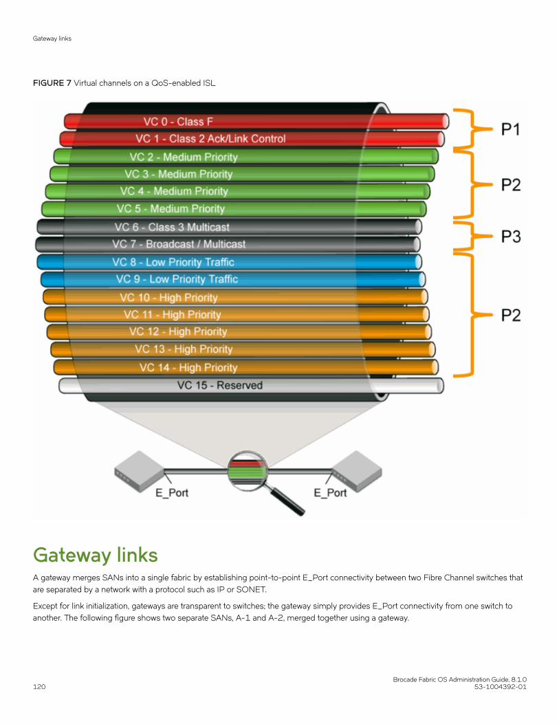
FIGURE 7 Virtual channels on a QoS-enabled ISL
Gateway linksA gateway merges SANs into a single fabric by establishing point-to-point E_Port connectivity between two Fibre Channel switches thatare separated by a network with a protocol such as IP or SONET.
Except for link initialization, gateways are transparent to switches; the gateway simply provides E_Port connectivity from one switch toanother. The following figure shows two separate SANs, A-1 and A-2, merged together using a gateway.
Gateway links
Brocade Fabric OS Administration Guide, 8.1.0120 53-1004392-01

FIGURE 8 Gateway link merging SANs
By default, switch ports initialize links using the Exchange Link Parameters (ELP) mode 1. However, gateways expect initialization withELP mode 2, also referred to as ISL R_RDY mode. Therefore, to enable two switches to link through a gateway, the ports on bothswitches must be set for ELP mode 2.
Any number of E_Ports in a fabric can be configured for gateway links, provided the following guidelines are followed:
• All switches in the fabric use the core PID format, as described in Configuring a link through a gateway on page 121.
• The switches connected to both sides of the gateway are included when determining switch-count maximums.
• Extended links (those created using the Extended Fabrics licensed feature) are not supported through gateway links.
Configuring a link through a gateway1. Connect to the switch at one end of the gateway and log in using an account assigned to the admin role.
2. Enter the portCfgISLMode command.
3. Repeat step 1 and step 2 for any additional ports that are connected to the gateway.
Gateway links
Brocade Fabric OS Administration Guide, 8.1.053-1004392-01 121

4. Repeat this procedure on the switch at the other end of the gateway.
Example of enabling a gateway link on slot 2, port 3:
ecp:admin> portcfgislmode 2/3, 1 Committing configuration...done.ISL R_RDY Mode is enabled for port 3. Please make sure the PIDformats are consistent across the entire fabric.
Routing policiesBy default, all routing protocols place their routes into a routing table. You can control the routes that a protocol places into each table andthe routes from that table that the protocol advertises by defining one or more routing policies and then applying them to the specificrouting protocol.
The routing policy is responsible for selecting a route based on one of three user-selected routing policies:
• Port-based routing
• Exchange-based routing
• Device-based routing
Considerations for routing policiesBe aware of the following considerations when working with routing policies:
• Routing is handled by the FSPF protocol and routing policy.
• Each switch can have its own routing policy and different policies can exist in the same fabric.
ATTENTIONFor most configurations, the default routing policy is optimal and provides the best performance. You should change the routingpolicy only if there is a significant performance issue, or a particular fabric configuration or application requires it.
Displaying the current routing policy1. Connect to the switch and log in using an account with admin permissions.
2. Enter the aptPolicy command with no parameters.
The current policy is displayed, followed by the supported policies for the switch.
In the following example, the current policy is device-based routing (2).
switch:admin> aptpolicy Current Policy: 23 : Default Policy1: Port Based Routing Policy2: Device Based Routing Policy (FICON support only)3: Exchange Based Routing Policy
Routing policies
Brocade Fabric OS Administration Guide, 8.1.0122 53-1004392-01

Port-based routingThe choice of routing path is based only on the incoming port and the destination domain. To optimize port-based routing, DynamicLoad Sharing (DLS) can be enabled to balance the load across the available output ports within a domain.
NOTEFor FC routers only: When an FC router is in port-based routing mode, the backbone traffic is load-balanced based on SID andDID. When an FC router is in exchange-based routing mode, the backbone traffic is load-balanced based on SID, DID, andOXID.
Whatever routing policy a switch is using applies to the VE_Ports as well. For more information on VE_Ports, refer to the Brocade FabricOS FCIP Administrator's Guide.
Exchange-based routingThe choice of routing path is based on the Source ID (SID), Destination ID (DID), and Fibre Channel originator exchange ID (OXID)optimizing path utilization for the best performance. Thus, every exchange can take a different path through the fabric. Exchange-basedrouting requires the use of the Dynamic Load Sharing (DLS) feature; when this policy is in effect, you cannot disable the DLS feature.
Exchange-based routing is also known as Dynamic Path Selection (DPS). For more information on DPS refer to Dynamic Path Selectionon page 123.
Device-based routingDevice-based routing optimizes routing path selection and utilization based on the Source ID (SID) and Destination ID (DID) of the pathsource and destination ports. As a result, every distinct flow in the fabric can take a different path through the fabric. Effectively, device-based routing works the same as exchange-based routing but does not use the OXID field. This helps to ensure that the exchangesbetween a pair of devices stay in order.
NOTEDevice-based routing requires the use of Dynamic Load Sharing (DLS); when this policy is in effect, you cannot disable the DLSfeature.
Device-based routing is also a form of Dynamic Path Selection (DPS). For more information on DPS refer to Dynamic Path Selection onpage 123.
NOTEDevice-based routing is supported in FICON environments, and in open environments only when FICON coexists.
Dynamic Path SelectionDPS assigns communication paths between end devices in a fabric to egress ports in ratios proportional to the potential bandwidth ofthe ISL, ICL, or trunk group. When there are multiple paths to a destination, the input traffic is distributed across the different paths inproportion to the bandwidth available on each of the paths. This improves utilization of the available paths, thus reducing possiblecongestion on the paths. Every time there is a change in the network (which changes the available paths), the input traffic can beredistributed across the available paths. This is a very easy and non-disruptive process when the exchange-based routing policy isengaged.
Routing policies
Brocade Fabric OS Administration Guide, 8.1.053-1004392-01 123

Displaying a dynamic path selection group for reachable domainsYou can use the portChannelShow command to display a dynamic path selection group for one or all reachable domains.
• Use the portChannelShow command to display the port channels from a domain to all the reachable domains on the switch.For example,
switch:admin> portchannelshow
6 domain(s) in the fabric; Local Domain ID: 4
Domain: 1Name: sw0WWN: 10:00:00:05:33:c1:26:00Port Channel: None
Domain: 2Name: DCX_35_F_128WWN: 10:00:00:05:1e:38:e5:23Port Channel: Ports: 384, 385, 386, 387, 400, 401, 402, 403, 417, 418, 419, 432, 433, 434, 435
Domain: 3Name: SW_122_F_128WWN: 10:00:00:05:1e:9b:10:5bPort Channel: Ports: 111, 248
Domain: 5Name: SW_65_F128WWN: 10:00:00:05:1e:5c:f6:fdPort Channel: Ports: 384, 385, 386, 387, 400, 401, 402, 403, 417, 418, 419, 432, 433, 434, 435
Domain: 6Name: SW_121_F_128WWN: 10:00:00:05:1e:9c:32:ccPort Channel: None
• Use the portChannelShow [remote-domain-id | switch-name | switch-WWN] command to display the port channels from theswitch where this command is executed to the specified switch or domain. For example,
switch:admin> portchannelshow 2 (OR)switch:admin> portchannelshow 10:00:00:05:1e:38:e5:23 (OR)switch:admin> portchannelshow DCX_35_F_128
Domain: 2Name: DCX_35_F_128WWN: 10:00:00:05:1e:38:e5:23Port Channel: Ports: 384, 385, 386, 387, 400, 401, 402, 403, 417, 418, 419, 432, 433, 434, 435
Route selectionSelection of specific routes can be dynamic, so that the router can constantly adjust to changing network conditions; or it may be static,so that data packets always follow a predetermined path.
Route selection
Brocade Fabric OS Administration Guide, 8.1.0124 53-1004392-01
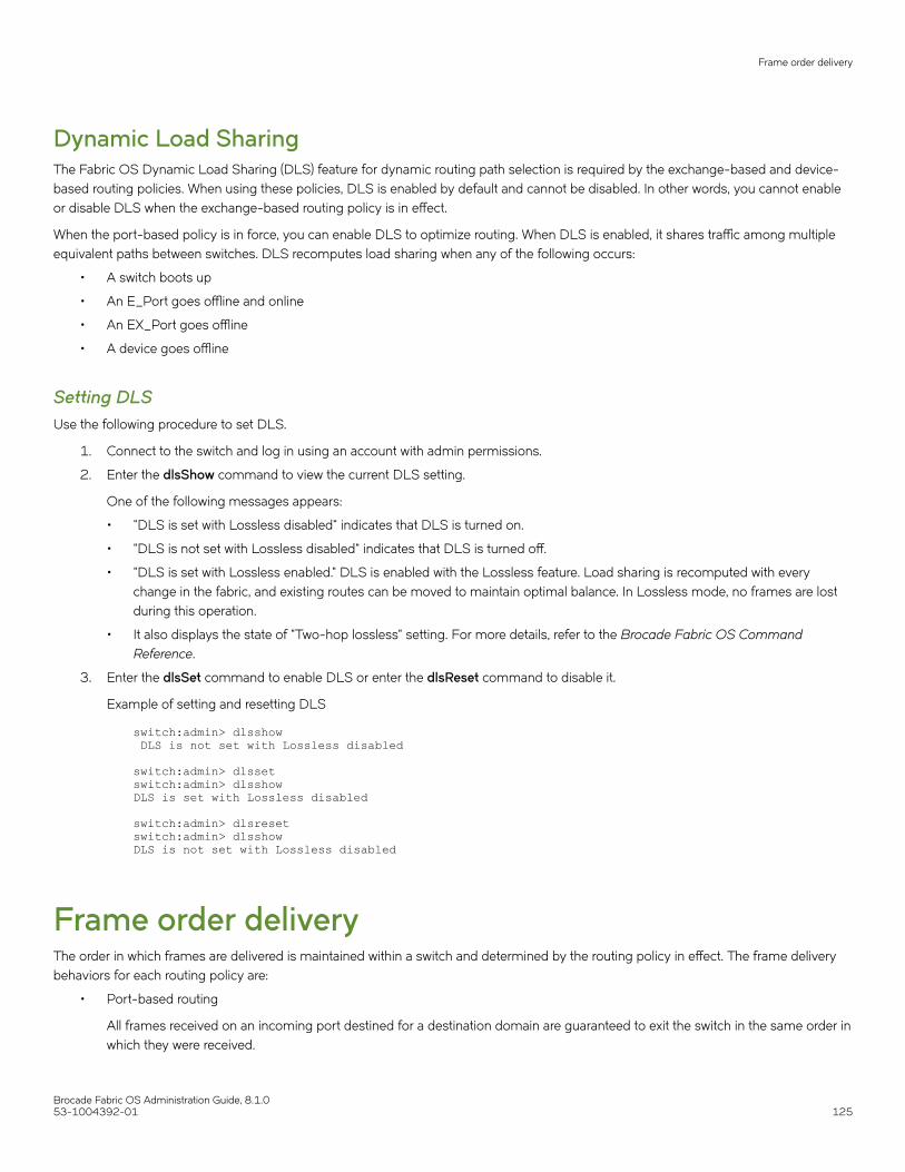
Dynamic Load SharingThe Fabric OS Dynamic Load Sharing (DLS) feature for dynamic routing path selection is required by the exchange-based and device-based routing policies. When using these policies, DLS is enabled by default and cannot be disabled. In other words, you cannot enableor disable DLS when the exchange-based routing policy is in effect.
When the port-based policy is in force, you can enable DLS to optimize routing. When DLS is enabled, it shares traffic among multipleequivalent paths between switches. DLS recomputes load sharing when any of the following occurs:
• A switch boots up
• An E_Port goes offline and online
• An EX_Port goes offline
• A device goes offline
Setting DLSUse the following procedure to set DLS.
1. Connect to the switch and log in using an account with admin permissions.
2. Enter the dlsShow command to view the current DLS setting.
One of the following messages appears:
• "DLS is set with Lossless disabled" indicates that DLS is turned on.
• "DLS is not set with Lossless disabled" indicates that DLS is turned off.
• "DLS is set with Lossless enabled." DLS is enabled with the Lossless feature. Load sharing is recomputed with everychange in the fabric, and existing routes can be moved to maintain optimal balance. In Lossless mode, no frames are lostduring this operation.
• It also displays the state of "Two-hop lossless" setting. For more details, refer to the Brocade Fabric OS CommandReference.
3. Enter the dlsSet command to enable DLS or enter the dlsReset command to disable it.
Example of setting and resetting DLS
switch:admin> dlsshow DLS is not set with Lossless disabled
switch:admin> dlssetswitch:admin> dlsshowDLS is set with Lossless disabled
switch:admin> dlsresetswitch:admin> dlsshowDLS is not set with Lossless disabled
Frame order deliveryThe order in which frames are delivered is maintained within a switch and determined by the routing policy in effect. The frame deliverybehaviors for each routing policy are:
• Port-based routing
All frames received on an incoming port destined for a destination domain are guaranteed to exit the switch in the same order inwhich they were received.
Frame order delivery
Brocade Fabric OS Administration Guide, 8.1.053-1004392-01 125

• Exchange-based routing
All frames received on an incoming port for a given exchange are guaranteed to exit the switch in the same order in which theywere received. Because different paths are chosen for different exchanges, this policy does not maintain the order of framesacross exchanges.
• Device-based routing
All frames received on an incoming port for a given pair of devices are guaranteed to exit the switch in the same order in whichthey were received.
If even one switch in the fabric delivers out-of-order exchanges, then exchanges are delivered to the target out of order, regardless of thepolicy configured on other switches in the fabric.
NOTESome devices do not tolerate out-of-order exchanges; in such cases, use the port-based routing policy.
In a stable fabric, frames are always delivered in order, even when the traffic between switches is shared among multiple paths. However,when topology changes occur in the fabric (for example, if a link goes down), traffic is rerouted around the failure, and some frames couldbe delivered out of order. Most destination devices tolerate out-of-order delivery, but some do not.
By default, out-of-order frame-based delivery is allowed to minimize the number of frames dropped. Enabling in-order delivery (IOD)guarantees that frames are either delivered in order or dropped. You should only force in-order frame delivery across topology changes ifthe fabric contains destination devices that cannot tolerate occasional out-of-order frame delivery.
Forcing in-order frame delivery across topology changesUse the following procedure to force in-order frame delivery across topology changes.
1. Connect to the switch and log in using an account with admin permissions.
2. Enter the iodSet command.
NOTEThe iodSet command can cause a delay in the establishment of a new path when a topology change occurs; use itwith care.
3. Confirm the in-order delivery has been set by entering the iodShow command.
Restoring out-of-order frame delivery across topology changesUse the following procedure to restore out-of-order frame delivery across topology changes.
1. Connect to the switch and log in using an account with admin permissions.
2. Enter the iodReset command.
Enabling Frame ViewerThe Frame Viewer application allows you to view the contents of discarded frames, which can be recorded at up to 40 frames persecond per ASIC.
To enable Frame Viewer, complete the following steps.
1. Connect to the switch and log in using an account with admin permissions.
Frame order delivery
Brocade Fabric OS Administration Guide, 8.1.0126 53-1004392-01

2. Enter frameLog --enable -type type.
The following table lists the supported values for -type. If the -type all option is specified, then all six discard frame type optionsare enabled and frames will be recorded when they are discarded.
TABLE 15 Supported values for the -type option.
Option Reason
timeout Due to a timeout.
du Due to the destination being unreachable.
unroute Due to an unrouteable frame.
type1miss Due to a type 1 miss.
type2miss Due to a type 2 miss.
type6miss Due to a type 6 miss.
all Due to all the reasons.
3. Use the frameLog --status command to view the configuration. The following is a typical example of the output of thiscommand:
switch:admin> framelog --statusService Status: EnabledEnabled Disc Frame Types: timeout unroute
NOTEFrame viewing for unrouteable and “destination unreachable” frames is supported only on the following devices:
• Brocade 6505, 6510, 6520, G610, G620, DCX 8510-4, DCX 8510-8, X6-4 and X6-8 switches.
• Brocade CR32-4, CR32-8, CR16-4, CR16-8, FC32-48, FC16-32, FC16-48, and FC16-64 blades. If achassis has any older blades, only the timeout frames will be captured for those blades.
Using Frame Viewer to understand why frames are droppedWhen a frame is unable to reach its destination because of a timeout, is unrouteable, or has an unreachable destination, or type-1,2, 6miss, it is discarded. You can use Frame Viewer to find out which flows contained the dropped frames, which in turn can help youdetermine the applications that might be impacted. Frame Viewer allows you to see the exact time (within one second) that the frameswere dropped.
You can view up to 40 discarded frames per ASIC per second for 1200 seconds with the frameLog command. You filter this view usinga number of fields to filter this output so you are viewing only those frames you are concerned with.
To display information about discarded frames, complete the following steps. This assumes that the framelog application has beenenabled previously.
1. Connect to the switch and log in using an account with admin permissions.
2. Enter frameLog --show.
Refer to the Brocade Fabric OS Command Reference for additional information on using the frameLog command, includingresetting (clearing) the frame log.
Frame order delivery
Brocade Fabric OS Administration Guide, 8.1.053-1004392-01 127
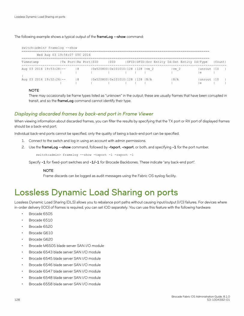
The following example shows a typical output of the frameLog --show command:
switch:admin> framelog --show ================================================================================================== Wed Aug 03 19:54:07 UTC 2016==================================================================================================Timestamp |Tx Port|Rx Port|SID |DID |SFID|DFID|Src Entity Id|Dst Entity Id|Type |Count|-----------------------------------------------------------------------------------------------------------Aug 03 2016 19:53:28|-- |8 |0x520800|0x101010|128 |128 |vm_2 |vm_2 |unrout |10 | | | | | | | | | |e | | Aug 03 2016 19:52:26|-- |8 |0x520800|0x101010|128 |128 |N/A |N/A |unrout |10 | | | | | | | | | |e | |
NOTEThere may occasionally be frame types listed as “unknown” in the output; these are usually frames that have been corrupted intransit, and so the frameLog command cannot identify their type.
Displaying discarded frames by back-end port in Frame ViewerWhen viewing information about discarded frames, you can filter the results by specifying that the TX port or RX port of displayed framesshould be a back-end port.
Individual back-end ports cannot be specified, only the quality of being a back-end port can be specified.
1. Connect to the switch and log in using an account with admin permissions.
2. Use the frameLog --show command, followed by -txport, -rxport, or both, and specifying -1 for the port number.
switch:admin> framelog --show -txport -1 -rxport -1
Specify -1 for fixed-port switches and -1/-1 for Brocade Backbones. These indicate “any back-end port”.
NOTEFrame discards can be logged as audit messages using the Fabric OS syslog facility.
Lossless Dynamic Load Sharing on portsLossless Dynamic Load Sharing (DLS) allows you to rebalance port paths without causing input/output (I/O) failures. For devices wherein-order delivery (IOD) of frames is required, you can set IOD separately. You can use this feature with the following hardware:
• Brocade 6505
• Brocade 6510
• Brocade 6520
• Brocade G610
• Brocade G620
• Brocade M6505 blade server SAN I/O module
• Brocade 6543 blade server SAN I/O module
• Brocade 6545 blade server SAN I/O module
• Brocade 6546 blade server SAN I/O module
• Brocade 6547 blade server SAN I/O module
• Brocade 6548 blade server SAN I/O module
• Brocade 6558 blade server SAN I/O module
Lossless Dynamic Load Sharing on ports
Brocade Fabric OS Administration Guide, 8.1.0128 53-1004392-01

• Brocade DCX 8510 Directors with the following blades:
– Brocade FC16-32, FC16-48, FC16-64 port blades
• Brocade X6 Directors with the following blades:
– Brocade FC32-48 port blades
Lossless DLS must be implemented along the path between the target and the initiator. You can use Lossless DLS on ports connectingswitches to perform the following functions:
• Eliminate dropped frames and I/O failures by rebalancing the paths going over the ISLs whenever there is a fabric event thatmight result in suboptimal utilization of the ISLs.
• Eliminate the frame delay caused by establishing a new path when a topology change occurs.
Lossless mode means no frame loss during a rebalance and only takes effect if DLS is enabled. Lossless DLS can be enabled on afabric topology to have zero frame drops during rebalance operations. If the end device also requires the order of frames to bemaintained during the rebalance operation, then IOD must be enabled. However, this combination of Lossless DLS and IOD issupported only in specific topologies, such as in a FICON environment.
You can disable or enable IOD when Lossless DLS is enabled. You can also choose between exchange- or port-based policies withLossless DLS. The following events cause a rebalance:
• Adding a redundant E_Port
• Adding a slave E_Port
• Removing the last E_Port from a neighbor domain (However, frame loss occurs on traffic flows to this port.)
• Removing an F_Port (However, frame loss occurs on traffic flows to this port.)
Lossless DLS does the following whenever paths need to be rebalanced:
1. Pauses ingress traffic by not returning credits. Frames that are already in transit are not dropped.
2. Applies the results of the rebalance calculations.
3. If IOD is enabled, waits for sufficient time for frames already received to be transmitted. This is needed to maintain IOD.
4. Resumes traffic.
The following table shows the effect of frames when you have a specific routing policy turned on with IOD.
TABLE 16 Combinations of routing policy and IOD with Lossless DLS enabled
Policy IOD Rebalance result with Lossless DLS enabled
Port-based Disabled No frame loss, but out-of-order frames may occur.
Port-based Enabled No frame loss and no out-of-order frames. Topology restrictions apply. Intended forFICON environment.
Exchange-based Disabled No frame loss, but out-of-order frames may occur.
Exchange-based Enabled No frame loss and no out-of-order frames. Topology restrictions apply. Intended forFICON environment.
Device-based Disabled No frame loss, but out-of-order frames may occur.
Device-based Enabled No frame loss and no out-of-order frames. Topology restrictions apply. Intended forFICON environment.
NOTENot only the link cost has influence on DLS, but the order of ports that become online and the speeds of each E_Portor F_Port also have an impact on how the switch calculates or chooses the path using DLS.
Lossless Dynamic Load Sharing on ports
Brocade Fabric OS Administration Guide, 8.1.053-1004392-01 129

Lossless coreLossless core works with the default configuration of the Brocade DCX 8510 Backbones and X6 Directors to prevent frame loss duringa core blade removal and insertion. This feature is on by default and cannot be disabled. Lossless core has the following limitations:
• Only supported with IOD disabled, which means Lossless core cannot guarantee in-order delivery of exchanges
• ICL limitations
• Traffic flow limitations
ICL limitationsIf ICL ports are connected during a core blade removal, it is equivalent to removing external E_Ports which may cause I/O disruption onthe ICL ports that have been removed.
If ICL ports are connected during a core blade insertion, it is equivalent to adding external E_Ports which may cause I/O disruptionbecause of reroutes. Lossless DLS, if enabled, takes effect to prevent I/O disruption.
NOTEBefore you replace the core blades, enable lossless so that the portDecom can decommission the E_Ports losslessly and bringup the E_Ports back losslessly.
Configuring Lossless Dynamic Load SharingYou can configure Lossless DLS on either a switch- or chassis-wide basis by using the dlsSet command to specify that no frames aredropped while rebalancing or rerouting traffic.
NOTEFor more information regarding DLS or E_Port balancing, refer to the dlsset command in the Brocade Fabric OS CommandReference.
To configure Lossless Dynamic Load Sharing, complete the following steps.
1. Connect to the switch and log in using an account with admin permissions.
2. Enter the appropriate dlsSet command to enable or disable Lossless Dynamic Load Sharing.
switch:admin> dlsset --enable -losslessswitch:admin> dlsset --disable -lossless
NOTETo enable lossless on the whole chassis when multiple logical switches exist, you must enable lossless on each logicalswitch independently or use the fosexec --fid all -cmd dlsset command.
Lossless Dynamic Load Sharing in Virtual FabricsEnabling Lossless Dynamic Load Sharing is optional on logical switches in Virtual Fabrics. If you enable this feature, it must be on a per-logical switch basis and can affect other logical switches in the fabric.
How DLS affects other logical switches in the fabricOn a Brocade DCX 8510 platform, logical switch 1 consists of ports 0 through 5 in slot 1. Logical switch 2 consists of ports 6 through10 in slot 1. The Lossless DLS feature is enabled on logical switch 1. Because ports 0 through 5 in slot 1 belong to a logical switchwhere Lossless DLS is enabled, the traffic in logical switch 2 is affected whenever traffic for logical switch 1 is rebalanced.
Lossless Dynamic Load Sharing on ports
Brocade Fabric OS Administration Guide, 8.1.0130 53-1004392-01
ATTENTIONAlthough Lossless DLS is enabled for a specific logical switch, you must have chassis-level permissions to use thisfeature.
The effect on logical switch 2 is based on the configuration on logical switch 2:
• If logical switch 2 has IOD enabled (iodSet only), IOD is enforced.
• If logical switch 2 has Lossless DLS enabled, traffic is paused and resumed.
• If logical switch 2 has no IOD (iodReset ), traffic is paused and resumed.
To avoid this behavior, it is recommended to define your logical switches as follows:
• Define logical switches that require Lossless DLS at the blade boundary.
• Define logical switches that require Lossless DLS only using supported blades. For example, do not use blades that supportIOD, but do not support Lossless DLS.
For more information on Virtual Fabrics and chassis-level permissions, refer to Managing Virtual Fabrics on page 291.
Two-hop Lossless DLS route updateCertain fabric topology changes may affect the Shortest Path First results that lead to rebalance operations, and thus change the pathsutilized. During these rebalance operations, even if the lossless DLS setting is enabled, route updates caused by fabric shortest pathchanges may result in I/O disruptions and/or out-of-order frame delivery. Route updates are not done globally across all switches at thesame time. A new path may be used before the later switches are ready.
Lossless DLS supports rebalance operations after events that affect redundancy within a hop but do not cause fabric shortest pathchanges. Lossless DLS can only ensure that the local switch updates are performed in the required manner. Lossless DLS cannot ensurethat a downstream domain has completed its rebalancing operations prior to a new path being used. The Two-hop enhancement toLossless DLS extends the lossless route update capabilities to support the addition of a new hop between switches.
When a new link is added between two switches where one was not there previously, the new link is likely to cause changes to theshortest path results. The Two-hop enhancement to Lossless DLS ensures that the route updates happen on the local switches of thenew link prior to the rest of the fabric. For devices on those two switches, when they attempt to start using the new link, Two-hopLossless DLS ensures that the routes are ready for use prior to their route updates.
For a switch that is directly connected to one of the two switches with the new link, when it performs the rebalance operation, its devicetraffic is shifted to the new path in a lossless manner. If the new path to which traffic is being shifted to is up to two hops (one of whichincludes the new link), Two-hop Lossless DLS ensures that the routes along that two-hop path are ready for use.
NOTEIf a fabric shortest path that includes the new link is longer than two hops, when the switches perform their rebalancingoperations, the traffic may still experience I/O disruptions and/or out-of-order frame delivery.
Once the new hop has been established, all later route updates use the standard lossless DLS capabilities.
• Two-hop Lossless DLS has the same platform and ISL technology restrictions as the Lossless DLS feature.
• Two-hop Lossless DLS is not supported with TI zones due to non-deterministic ordering of events when multiple ISLs comeonline at the same time.
• Two-hop Lossless DLS is not supported with any hops to or through an FC router related domain (front and translate domains).
• Two-hop Lossless DLS is not supported over logical ISLs (LISLs).
• You must manually enable this feature on all switches to get the desired results.
Lossless Dynamic Load Sharing on ports
Brocade Fabric OS Administration Guide, 8.1.053-1004392-01 131

Configuring Two-hop Lossless DLSUse the following commands to configure Two-hop Lossless DLS feature.
TABLE 17 Commands used to configure the Two-hop Lossless DLS feature
Command Usage
dlsshow Displays the state of the Two-hop Lossless DLS state when it has beenenabled.
dlsreset Resets the state of DLS in port-based routing.
dlsset Sets the lossless, two-hop, and eportbal states. Enables or disables theTwo-hop Lossless DLS feature.
The following example shows the use of the--help option of the dlsset command to display the possible uses of the command. Thesyntax for enabling and disabling the Two-hop Lossless DLS feature are highlighted.
switch:admin> dlsset --helpdlsset usage:dlssetdlsset --enable -losslessdlsset --disable -losslessdlsset --enable -twohopdlsset --disable -twohopdlsset --enable -eportbaldlsset --disable -eportbaldlsset --rebalancedlsset --rebalance -all
The following example shows the use of the dlsshow command to display the state of the Two-hop Lossless DLS feature when it hasbeen enabled. If the feature were disabled, the original default output would be displayed.
switch:admin> dlsshowDLS is set with Two-hop Lossless enabledE_Port Balance Priority is not set
Frame RedirectionFrame Redirection provides a means to redirect traffic flow between a host and a target that use virtualization and encryption applications,such as the Brocade SAS blade and Brocade Data Migration Manager (DMM), so that those applications can perform without having toreconfigure the host and target. You can use this feature if the hosts and targets are not directly attached.
Frame Redirection depends on the wide distribution of the Defined Zone Database. The Defined Zone Database on Fabric OS switchesis pushed out to all other Fabric OS switches in the fabric that support Frame Redirection. Redirection zones exist only in the definedconfiguration and cannot be added to the effective configuration.
NOTEFabric OS v7.2.0 is not supported on the Brocade 7600 or Brocade SAS blade. However, this hardware can run in a pre-FabricOS v7.2.0 system and attach to a Fabric OS v7.2.0 fabric.
Frame Redirection uses a combination of special frame redirection zones and name server changes to spoof the mapping of real deviceWWNs to virtual PIDs.
Frame Redirection
Brocade Fabric OS Administration Guide, 8.1.0132 53-1004392-01

FIGURE 9 Single host and target
Figure 9 demonstrates the flow of Frame Redirection traffic. A frame starts at the host with a destination to the target. The port where theappliance is attached to the host switch acts as the virtual initiator and the port where the appliance is attached to the target switch is thevirtual target.
Creating a frame redirect zoneThe first time the zone --rdcreate command is run, the following zone objects are created by default:
• The base zone object, "red_______base".
• The redirect (RD) zone configuration, "r_e_d_i_r_c__fg".
NOTEFrame redirect zones are not supported with D or I initiator target zones.
ATTENTIONPrior to creating the frame redirect zone, you must create a Layer 2 zone for the Initiator (host) and Target (storage). This zonemust be part of the effective configuration and must be defined using the port World Wide Name (WWN). Refer to Creating azone on page 337, and Enabling a zone configuration on page 353.
Use the following procedure to create a frame redirect zone.
1. Connect to the switch and log in using an account with admin permissions.
2. Enter the zone --rdcreate command.
3. Enter the cfgSave command to save the frame redirect zones to the defined configuration.
The following example creates a redirect zone, given a host (10:10:10:10:10:10:10:10), target (20:20:20:20:20:20:20:20),virtual initiator (30:30:30:30:30:30:30:30), and virtual target (40:40:40:40:40:40:40:40):
switch:admin>zone --rdcreate 10:10:10:10:10:10:10:10 20:20:20:20:20:20:20:20 \ 30:30:30:30:30:30:30:30 40:40:40:40:40:40:40:40 restartable noFCR
Deleting a frame redirect zoneUse the following procedure to delete a frame redirect zone.
1. Connect to the switch and log in using an account with admin permissions.
Frame Redirection
Brocade Fabric OS Administration Guide, 8.1.053-1004392-01 133

2. Enter the zone --rddelete command to remove the base redirect zone object, "red_______base".
NOTEWhen the base zone is removed, the redirect zone configuration "r_e_d_i_r_c__fg" is removed aswell.
3. Enter the cfgSave command to save changes to the defined configuration.
Example of deleting a frame redirect zone
switch:admin> zone --rddelete \ red_0917_10_10_10_10_10_10_10_10_20_20_20_20_20_20_20_20
Viewing frame redirect zonesUse the following procedure to view frame redirect zones.
1. Connect to the switch and log in using an account with admin permissions.
2. Enter the cfgShow command.
Frame Redirection
Brocade Fabric OS Administration Guide, 8.1.0134 53-1004392-01

Buffer-to-Buffer Credits and CreditRecovery
• Buffer credit management .........................................................................................................................................................................135• Buffer credit recovery ...................................................................................................................................................................................149• Credit loss detection......................................................................................................................................................................................151
Buffer credit managementBuffer-to-buffer credit management affects performance over distances; therefore, allocating a sufficient number of buffer credits forlong-distance traffic is essential to performance.
To prevent a target device (either host or storage) from being overwhelmed with frames, the Fibre Channel architecture provides flowcontrol mechanisms based on a system of credits. Each of these credits represents the ability of the device to accept additional frames. Ifa recipient issues no credits to the sender, no frames can be sent. Pacing the transport of subsequent frames on the basis of this creditsystem helps prevent the loss of frames and reduces the frequency of entire Fibre Channel sequences needing to be retransmittedacross the link.
Because the number of buffer credits available for use within each port group is limited, configuring buffer credits for extended links mayaffect the performance of the other ports in the group used for core-to-edge connections. You must balance the number of long-distance ISL connections and core-to-edge ISL connections within a switch.
NOTEConfiguring long-distance ISLs between core and edge switches is possible, but is not a recommended practice.
All switch ports provide protection against buffer depletion through buffer limiting. A buffer-limited port reserves a minimum of eightbuffer credits, allowing the port to continue to operate rather than being disabled because of a lack of buffers.
Buffer-limited operations are supported for the static mode (LS) and dynamic mode (LD) extended ISL modes only. For LD, distance inkilometers is the smaller of the distance measured during port initialization versus the desired_distance value. For LS, distance inkilometers is always the desired_distance value.
Buffer-to-buffer flow controlBuffer-to-buffer (BB) credit flow control is implemented to limit the amount of data that a port may send, and is based on the numberand size of the frames sent from that port. Buffer credits represent finite physical-port memory. Within a fabric, each port may have adifferent number of buffer credits. Within a connection, each side may have a different number of buffer credits.
Buffer-to-buffer flow control is flow control between adjacent ports in the I/O path, for example, transmission control over individualnetwork links. A separate, independent pool of credits is used to manage buffer-to-buffer flow control. A sending port uses its availablecredit supply and waits to have the credits replenished by the port on the opposite end of the link. These buffer credits are used by Class2 and Class 3 services and rely on the Fibre Channel Receiver-Ready (R_RDY) control word to be sent by the receiving link port to thesender. The rate of frame transmission is regulated by the receiving port, and is based on the availability of buffers to hold receivedframes.
If Virtual Channel technology is in use, the VC_RDY or EXT_VC control word is used instead of the R_RDY control word to managebuffer credits. For Virtual Channels, the buffer credits are managed for each Virtual Channel, and not for the entire physical link.
Brocade Fabric OS Administration Guide, 8.1.053-1004392-01 135

The Virtual Channels used in VC_RDY flow-control mode range from VC0 through VC7. When QoS is enabled, EXT_VC_RDY flow-control mode allocates VC0 through VC14. VC8 through VC14 are allocated specifically for QoS VCs.
Upon arriving at a receiver, a frame goes through several steps. It is received, deserialized, and decoded, and is stored in a receive bufferwhere it is processed by the receiving port. If another frame arrives while the receiver is processing the first frame, a second receive bufferis needed to hold this new frame. Unless the receiver is capable of processing frames as fast as the transmitter is capable of sendingthem, it is possible for all of the receive buffers to fill up with received frames. At this point, if the transmitter should send another frame,the receiver will not have a receive buffer available and the frame is lost. Buffer-to-buffer flow control provides consistent and reliableframe delivery of information from sender to receiver.
Optimal buffer credit allocationThe optimal number of buffer credits is determined by the distance (frame delivery time), the processing time at the receiving port, thelink signaling rate, and the size of the frames being transmitted. As the link speed increases, the frame delivery time is reduced and thenumber of buffer credits must be increased to obtain full link utilization, even in a short-distance environment.
For each frame that is transferred, the hardware at the other end must acknowledge that the frame has been received before a successfultransmission occurs. This flow requires enough capacity in the hardware to allow continuous transmission of frames on the link, whilewaiting for the acknowledgment to be sent by the receiver at the other end.
As the distance between switches and the link speed increases, additional buffer credits are required for the ports used for long-distanceconnections. Distance levels define how buffer credits are allocated and managed for extended ISLs. Buffer credits are managed from acommon pool available to a group of ports on a switch. The buffer credit can be changed for specific applications or operatingenvironments, but it must be in agreement among all switches to allow formation of the fabric.
Smaller frame sizes need more buffer credits. Two commands are available to help you determine whether you need to allocate morebuffer credits to handle the average frame size. The portBufferShow command calculates the average frame size. The portBufferCalccommand uses the average frame size with the speed and link distance to determine the number of buffer credits needed.
Considerations for calculating buffer creditsThe following are the considerations that you need to follow for calculating the number of ports that can be configured for long distanceon all Fabric OS 7.x and later-capable switch modules:
• Each port is part of a port group that includes a pool of buffer credits that can be used. This port group is not the same as theport groups used for ISL Trunking.
• Each user port reserves eight buffer credits when online or offline.
• Any remaining buffers can be reserved by any port in the port group.
• When QoS is enabled and the port is online, additional buffers are allocated to that port. Refer to Calculating the number ofbuffers required based on full-size frames on page 138 and Configuring buffers for a single port directly on page 140 formore information.
Fibre Channel gigabit values reference definitionThe following table shows the Fibre Channel gigabit values that you can use to calculate buffer requirements.
TABLE 18 Fibre Channel gigabit values
Gigabit value Line rate
1 Gbps 1.0625
2 Gbps 2.125
Buffer credit management
Brocade Fabric OS Administration Guide, 8.1.0136 53-1004392-01
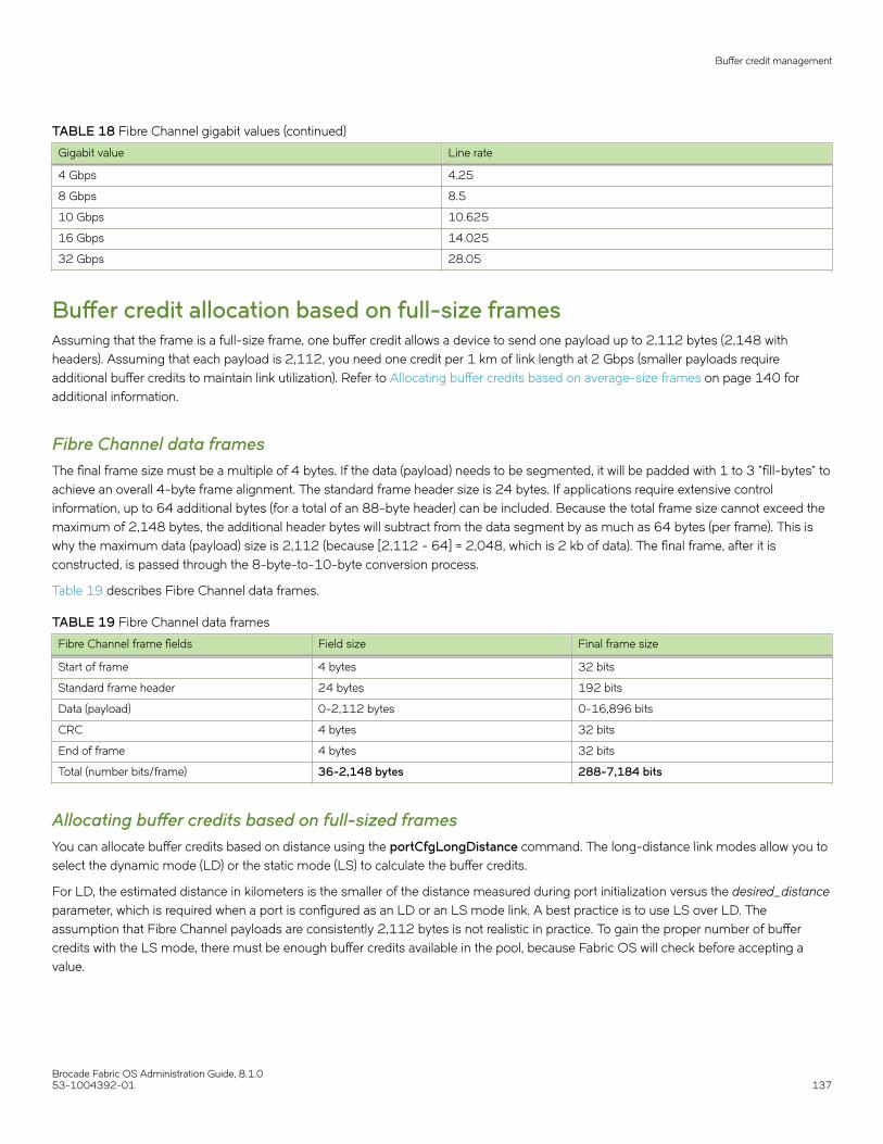
TABLE 18 Fibre Channel gigabit values (continued)
Gigabit value Line rate
4 Gbps 4.25
8 Gbps 8.5
10 Gbps 10.625
16 Gbps 14.025
32 Gbps 28.05
Buffer credit allocation based on full-size framesAssuming that the frame is a full-size frame, one buffer credit allows a device to send one payload up to 2,112 bytes (2,148 withheaders). Assuming that each payload is 2,112, you need one credit per 1 km of link length at 2 Gbps (smaller payloads requireadditional buffer credits to maintain link utilization). Refer to Allocating buffer credits based on average-size frames on page 140 foradditional information.
Fibre Channel data framesThe final frame size must be a multiple of 4 bytes. If the data (payload) needs to be segmented, it will be padded with 1 to 3 "fill-bytes" toachieve an overall 4-byte frame alignment. The standard frame header size is 24 bytes. If applications require extensive controlinformation, up to 64 additional bytes (for a total of an 88-byte header) can be included. Because the total frame size cannot exceed themaximum of 2,148 bytes, the additional header bytes will subtract from the data segment by as much as 64 bytes (per frame). This iswhy the maximum data (payload) size is 2,112 (because [2,112 - 64] = 2,048, which is 2 kb of data). The final frame, after it isconstructed, is passed through the 8-byte-to-10-byte conversion process.
Table 19 describes Fibre Channel data frames.
TABLE 19 Fibre Channel data frames
Fibre Channel frame fields Field size Final frame size
Start of frame 4 bytes 32 bits
Standard frame header 24 bytes 192 bits
Data (payload) 0-2,112 bytes 0-16,896 bits
CRC 4 bytes 32 bits
End of frame 4 bytes 32 bits
Total (number bits/frame) 36-2,148 bytes 288-7,184 bits
Allocating buffer credits based on full-sized framesYou can allocate buffer credits based on distance using the portCfgLongDistance command. The long-distance link modes allow you toselect the dynamic mode (LD) or the static mode (LS) to calculate the buffer credits.
For LD, the estimated distance in kilometers is the smaller of the distance measured during port initialization versus the desired_distanceparameter, which is required when a port is configured as an LD or an LS mode link. A best practice is to use LS over LD. Theassumption that Fibre Channel payloads are consistently 2,112 bytes is not realistic in practice. To gain the proper number of buffercredits with the LS mode, there must be enough buffer credits available in the pool, because Fabric OS will check before accepting avalue.
Buffer credit management
Brocade Fabric OS Administration Guide, 8.1.053-1004392-01 137

NOTEThe desired_distance parameter of the portCfgLongDistance command’s is the upper limit of the link distance and is used tocalculate buffer availability for other ports in the same port group. When the measured distance exceeds the value ofdesired_distance, this value is used to allocate the buffers. In this case, the port operates in degraded mode instead of beingdisabled as a result of insufficient buffer availability. In LS mode, the actual link distance is not measured; instead, thedesired_distance value is used to allocate the buffers required for the port.
Refer to the data in Table 20 on page 145 and Table 23 on page 146 to get the total ports in a switch or blade, the number of userports in a port group, and the unreserved buffer credits available per port group. The values reflect an estimate, and may differ from thesupported values in Table 23 on page 146.
Calculating the number of buffers required based on full-size framesUse the following procedure to calculate the number of buffers required for a long-distance connection:
1. Determine the desired distance in kilometers of the switch-to-switch connection.
2. Determine the speed that you will use for the long-distance connection.
Buffer credit management
Brocade Fabric OS Administration Guide, 8.1.0138 53-1004392-01

3. Use one of the following formulas to calculate the reserved buffers for distance:
• If QoS is enabled:
(Reserved_Buffer_for_Distance_Y) = (X * LinkSpeed / 2) + 6 + 14
• If QoS is not enabled:
(Reserved_Buffer_for_Distance_Y) = (X * LinkSpeed / 2) + 6
The formulas use the following parameters:
X = The distance determined in step 1 (in km).
LinkSpeed = The speed of the link determined in step 2.
6 = The number of buffer credits reserved for fabric services, multicast, and broadcast traffic. This number is static.
14 = The number of buffer credits reserved for QoS. This number is static.
Using 50 km as the desired distance of the switch-to-switch connection and 2 Gbps as the speed of the long-distanceconnection, insert the numbers into the appropriate formula. The formula should read as follows:
(50 km * 2 Gbps / 2) + 6 = 5 6 buffers, which is the number of buffers reserved for distance.
The following examples use different speeds, all based on a distance of 50 km. The distances and speeds are variables that canchange depending on how your network is set up.
• If you have a distance of 50 km at 1 Gbps, then (50 km * 1 Gbps / 2) + 6 = 31 buffers.
• If you have a distance of 50 km at 2 Gbps, then (50 km * 2 Gbps / 2) + 6 = 56 buffers.
• If you have a distance of 50 km at 4 Gbps, then (50 km * 4 Gbps / 2) + 6 = 106 buffers.
• If you have a distance of 50 km at 8 Gbps, then (50 km * 8 Gbps / 2) + 6 = 206 buffers.
• If you have a distance of 50 km at 10 Gbps, then (50 km * 10 Gbps / 2) +6 = 256 buffers.
• If you have a distance of 50 km at 16 Gbps, then (50 km * 16 Gbps / 2) + 6 = 406 buffers.
• If you have a distance of 50 km at 32 Gbps, then (50 km * 32 Gbps / 2) + 6 = 806 buffers.
Example
Consider the Brocade 300, which has a single 24-port port group and a total of 676 buffer credits for that port group. Theformulas use the following parameters:
24 = The number of user ports in a port group retrieved from Table 20 on page 145
8 = The number of reserved credits for each user port
676 = The number of buffer credits available in the port group
The maximum remaining number of buffer credits for the port group, after each port reserves its 8 buffer credits, is obtainedfrom the following formula:
676 - (24 * 8) = 484 unreserved buffer credits
492 buffers to a single port (484 + 8 [8 for the reserved buffers already allocated to that user port]), you can calculate themaximum single-port extended distance supported:
Maximum_Distance_X (in km) = (BufferCredits + 6) * 2 / LinkSpeed
498 km = (492 + 6 buffers for Fabric Services) * 2 / 2 Gbps
If you have a distance of 50 km at 8 Gbps, then 484 / (206 - 8) = 2 ports.
The following values are used in the example:
Buffer credit management
Brocade Fabric OS Administration Guide, 8.1.053-1004392-01 139

• 484 -- The total number of unreserved buffer credits
• 206 -- Buffer credits needed for 50 km at 8 Gbps
• 8 -- The number of reserved buffer credits already allocated to that port
The resulting number is rounded down to the next whole number because fractions of a port are not allowed.
If you have a distance of 50 km at 1 Gbps, then 484 / (31 - 8) = 21 ports.
Allocating buffer credits based on average-size framesIn cases where the frame size is average, for example 1,024 bytes, you must allocate twice the buffer credits or configure twice thedistance in the long-distance LS configuration mode. Refer to Fibre Channel gigabit values reference definition on page 136 for anapproximation of the calculated number of buffer credits.
1. Use the following formula to calculate the value for the desired_distance parameter needed for Fabric OS to determine thenumber of buffer credits to allocate:
desired_distance = roundup [(real_estimated_distance * 2112) / average_payload_size]
The average_payload_size in this equation uses 1024 bytes
If the real estimated distance is 100 km, the desired_distance is 207.
desired_distance = roundup [(100 * 2112) / 1024] = 207
When configuring the LS mode with the portCfgLongDistance command, enter a desired_distance value of 207 for an actual100-km link connected to an 8-Gbps E_Port. This causes Fabric OS to allocate the correct number of buffer credits.
2. Determine the speed you will use for the long-distance connection. This example uses 8 Gbps.
3. Look up the data_rate value for the speed of the connection. Refer to Fibre Channel gigabit values reference definition on page136 to determine the data_rate value.
For example, the data_rate is 8.5 for a speed of 8 Gbps.
4. Use the following formula to calculate the number of buffer credits to allocate:
buffer_credits = [desired_distance * (data_rate / 2.125)]
With the values for desired_distance and data_rate from step 1 and step 3, the value for buffer credits is calculated as follows:
buffer_credits = [207 * (8.5 / 2.125)] = 828
NOTEThis buffer credits formula does not work with LD mode because LD mode checks the distance and limits theestimated distance to the real value of 100 km. LS mode allows for the necessary desired_distance value based onthe data size entered, regardless of the distance.
If buffer credit recovery is enabled, Fabric OS supports a BB_SC_N range of 1 to 15; therefore, it is impossible for thedesired_distance value to be more than the number of buffer credits available in the pool as determined by the previouscalculations The distance for buffer credit recovery is well within the range of all possible connections. An estimated distance of32,768 is considerably higher than the available buffer credits and only lower values of desired_distance are permitted byFabric OS.
Configuring buffers for a single port directlyTo configure the number of buffers directly, use the -buffers option of the portCfgLongDistance command. Fabric OS uses this value tocalculate the total number of buffers according to the following formula:
Buffer credit management
Brocade Fabric OS Administration Guide, 8.1.0140 53-1004392-01

Total Buffers = Configured Buffers + QOS_VC_Credits + Non-data_VC_Credits
Seven Virtual Channels (VCs) are required for each QoS port. Each VC requires two buffers. Thus, the total number of QoS buffersrequired for a port is 14 (7*2). An additional 6 VCs are required for nondata transmission (for example, control traffic). As a consequence,for a QoS port, 20 buffers are added. For a non-QoS port, 6 buffers are added.
For example, if the configured number of buffers is 100, then the total number of buffers allocated for a QoS port is 120, as shown inthe following example.
Total_Buffers = 100 + 14 + 6 = 120
If the configured number of buffers is 100, the total number of buffers allocated for a non-QoS port is 106, as shown in the followingexample.
Total_Buffers = 100 + 6 = 106
NOTEYou cannot use the -buffers option with the -distance option or the -frameSize option.
switch:admin> portcfglongdistance 2/35 LS 1 -buffers 400Reserved Buffers = 420
Configuring buffers using frame sizeYou can configure the number of buffers by using the -frameSize option of the portCfgLongDistance command along with the -distance option. Fabric OS calculates the number of buffers from the -frameSize option value according to the following formula:
buffers_required = (2048/framesize) * data_vc_credits
If you enter the average frame size of 1024, Fabric OS will allocate almost twice as many buffers as for the maximum frame size of2048.
The -frameSize option value is persistent across reboots and HA failover.
Example
switch:admin> portcfglongdistance 2/35 LS 1 -distance 100 -framesize 1024
Calculating the number of buffers required given the distance, speed, andframe sizeIf you know the distance, speed, and frame size for a given port, you can use the portBufferCalc command to calculate the number ofbuffers required. If you omit the distance, speed, or frame size, the command uses the currently configured values for the port. Given thebuffer requirement and port speed, you can use the same distance and frame size values when using the portCfgLongDistancecommand.
To determine the number of buffers required, complete the following steps:
1. Connect to the switch and log in using an account assigned to the admin role.
Buffer credit management
Brocade Fabric OS Administration Guide, 8.1.053-1004392-01 141

2. Enter the portBufferCalc command and provide values for the distance, port speed, and frame size.
The following example calculates the number of buffers required for an 8-Gbps port on a 100-km link with an average framesize of 512 bytes.
switch:admin> portbuffercalc 9/4 -distance 100 -speed 8 -framesize 5121606 buffers required for 100km at 8G and framesize of 512 bytes
NOTEThe portBufferCalc and portCfgEportCredits are applicable to the 2 km ICL QSFP ports as well.
The following examples show calculation of buffers for 2 km ICL ports at 16 Gbps and 32 Gbps:
switch_6510:admin> portbuffercalc 1 -distance 2 -speed 16 -framesize 204822 buffers required for 2km at 16G and framesize of 2048bytes
switch_6510:admin> portbuffercalc 1 -distance 2 -speed 16 -framesize 102438 buffers required for 2km at 16G and framesize of 1024bytes
switch_6510:admin> portbuffercalc 1 -distance 2 -speed 16 -framesize 51270 buffers required for 2km at 16G and framesize of 512bytes
switch_6510:admin> portbuffercalc 1 -distance 1 -speed 16 -framesize 204814 buffers required for 1km at 16G and framesize of 2048bytes
switch_6510:admin> portbuffercalc 1 -distance 1 -speed 16 -framesize 102422 buffers required for 1km at 16G and framesize of 1024bytes
switch_6510:admin> portbuffercalc 1 -distance 1 -speed 16 -framesize 51238 buffers required for 1km at 16G and framesize of 512bytes
switch_G620:admin> portbuffercalc 1 -distance 2 -speed 32 -framesize 204838 buffers required for 2km at 32G and framesize of 2048bytes
switch_G620:admin> portbuffercalc 1 -distance 2 -speed 32 -framesize 102470 buffers required for 2km at 32G and framesize of 1024bytes
switch_G620:admin> portbuffercalc 1 -distance 2 -speed 32 -framesize 512 134 buffers required for 2km at 32G and framesize of 512bytes
switch_G620:admin> portbuffercalc 1 -distance 1 -speed 32 -framesize 204822 buffers required for 1km at 32G and framesize of 2048bytes
switch_G620:admin> portbuffercalc 1 -distance 1 -speed 32 -framesize 102438 buffers required for 1km at 32G and framesize of 1024bytes
switch_G620:admin> portbuffercalc 1 -distance 1 -speed 32 -framesize 512 70 buffers required for 1km at 32G and framesize of 512bytes
Allocating buffer credits for F_PortsThe default configured F_Port buffer credit is fixed at eight buffers for all Gen 5 devices and 20 buffers for all Gen 6 devices, except theBrocade G610, which is fixed at eight buffers. You can use the portcfgfportbuffers command to configure a given port with thespecified number of buffers.
1. Connect to the switch and log in using an account assigned to the admin role.
Buffer credit management
Brocade Fabric OS Administration Guide, 8.1.0142 53-1004392-01

2. Enter the portcfgfportbuffers command.
switch:admin> portcfgfportbuffers --enable 2/44 12
Notice that in the sample commands provided in the following procedure, 12 buffers are configured for an F_Port.
To disable the port buffer configuration and return to the default buffer allocation, use the --disable option.
switch:admin> portcfgfportbuffers --disable 2/44
NOTEThe configured number of buffers for a given port is stored in the configuration database and is persistent acrossreboots. The F_Port buffer feature does not support EX_Port, Long-Distance, L_Port, FastWrite, QoS, and Trunk Areaenabled ports. F_Port Buffers are mutually exclusive to E_Port Credits
Monitoring buffers in a port groupUse the portBufferShow command to monitor the remaining buffers on a long-distance link and to monitor the average frame size andaverage buffer usage for a given port.
1. Connect to the switch and log in using an account assigned to the admin role.
Buffer credit management
Brocade Fabric OS Administration Guide, 8.1.053-1004392-01 143

2. Enter the portBufferShow command.
The average frame size in bytes is shown in parentheses with the average buffer usage for packet transmission and reception.
switch:admin> portbuffershowUser Port Lx Max/Resv Avg Buffer Usage & FrameSize Buffer Needed Link RemainingPort Type Mode Buffers Tx Rx Usage Buffers Distance Buffers---- ---- ---- ------- ---------------------------- ------ ------- --------- ---------- 0 - 34 - ( - ) - ( - ) 0 - - 1 F - 20 - ( - ) - ( - ) 8 - - 2 E - 20 - ( - ) - ( - ) 26 26 <2km 3 E - 20 - ( - ) - ( - ) 34 34 <2km 4 F - 48 - ( - ) - ( - ) 48 - - 5 F - 48 - ( - ) - ( - ) 48 - - 6 F - 48 - ( - ) - ( - ) 48 - - 7 F - 48 - ( - ) - ( - ) 48 - - 8 E LS 1634 - ( - ) - ( - ) 1634 1634 100km 9 - 20 - ( - ) - ( - ) 0 - - 10 E - 34 - ( - ) - ( - ) 8 8 <2km 11 - 20 - ( - ) - ( - ) 0 - - 12 - 20 - ( - ) - ( - ) 0 - - 13 - 20 - ( - ) - ( - ) 0 - - 14 - 20 - ( - ) - ( - ) 0 - - 15 - 20 - ( - ) - ( - ) 0 - - 16 - 20 - ( - ) - ( - ) 0 - - 17 - 20 - ( - ) - ( - ) 0 - - 18 - 20 - ( - ) - ( - ) 0 - - 19 - 20 - ( - ) - ( - ) 0 - - 20 - 20 - ( - ) - ( - ) 0 - - 21 - 20 - ( - ) - ( - ) 0 - - 22 - 20 - ( - ) - ( - ) 0 - - 23 - 20 - ( - ) - ( - ) 0 - - 24 - 20 - ( - ) - ( - ) 0 - - 25 - 20 - ( - ) - ( - ) 0 - - 26 - 20 - ( - ) - ( - ) 0 - - 27 - 20 - ( - ) - ( - ) 0 - - 28 - 20 - ( - ) - ( - ) 0 - - 29 - 20 - ( - ) - ( - ) 0 - - 32 - 20 - ( - ) - ( - ) 0 - - 33 - 20 - ( - ) - ( - ) 0 - - 34 - 20 - ( - ) - ( - ) 0 - - 35 - 20 - ( - ) - ( - ) 0 - - 36 - 20 - ( - ) - ( - ) 0 - - 37 - 20 - ( - ) - ( - ) 0 - - 38 - 20 - ( - ) - ( - ) 0 - - 39 - 20 - ( - ) - ( - ) 0 - - 40 - 20 - ( - ) - ( - ) 0 - - 41 - 20 - ( - ) - ( - ) 0 - - 42 - 20 - ( - ) - ( - ) 0 - - 43 - 20 - ( - ) - ( - ) 0 - - 44 - 20 - ( - ) - ( - ) 0 - - 45 - 20 - ( - ) - ( - ) 0 - - 46 - 20 - ( - ) - ( - ) 0 - - 47 E - 20 - ( - ) - ( - ) 26 26 <2km 48 - 20 - ( - ) - ( - ) 0 - - 49 - 20 - ( - ) - ( - ) 0 - - 50 - 20 - ( - ) - ( - ) 0 - - 51 - 20 - ( - ) - ( - ) 0 - - 52 - 20 - ( - ) - ( - ) 0 - - 53 - 20 - ( - ) - ( - ) 0 - - 54 - 20 - ( - ) - ( - ) 0 - - 55 - 20 - ( - ) - ( - ) 0 - - 56 E - 20 - ( - ) - ( - ) 70 70 <2km 57 E - 20 - ( - ) - ( - ) 70 70 <2km 58 E - 20 - ( - ) - ( - ) 70 70 <2km 59 E - 20 - ( - ) - ( - ) 70 70 <2km 60 E - 20 - ( - ) - ( - ) 70 70 <2km 61 E - 20 - ( - ) - ( - ) 70 70 <2km 62 E - 20 - ( - ) - ( - ) 105 105 <2km 63 E - 20 - ( - ) - ( - ) 105 105 <2km 11522
Buffer credit management
Brocade Fabric OS Administration Guide, 8.1.0144 53-1004392-01

Buffer credits per switch or blade modelThe following table shows the total FC ports in a switch or blade, the number of user ports in a port group, and the unreserved buffercredits available per port group.
Formula for Gen 6 32-Gbps devicesRemaining buffers = Total Buffers - [(Total FE Ports * 20) + (Total BE/BI Ports * Buffers for BE/BI Port) +Internal buffer usages(approximately 152).
TABLE 20 Total FC ports, ports per port group, and unreserved buffer credits per port group
Switch/blademodel
Total FC ports (perswitch/blade)
User port groupsize
Unreserved buffer credits perport group (with minimumbuffer allocation)
Unreserved buffercredits per port group(with QoS)
Unreserved buffer creditsper port group (withoutQoS)
G610 24 24 1728 960 1296
G620 64 64 13928 8488 10728
FC32-48 48 24 8152 6112 6952
CR32-8
CR32-4
64
32
16
16
4376 3016 3576
SX6 16 16 5432 4072 4632
Formula for Gen 5 16-Gbps and older devicesRemaining buffers = Total Buffers - [(Total FE Ports * 8) + (Total BE/BI Ports * Buffers for BE/BI Port) + EMB Buffers + SAB Buffers.
TABLE 21 Total FC ports, ports per port group, and unreserved buffer credits per port group
Switch/blademodel
Total FC ports perswitch/blade
User port groupsize
Unreserved buffer credits perport group (with minimumbuffer allocation)
Unreserved buffercredits per port group(with QoS)
Unreserved buffer creditsper port group (withoutQoS)
6505 24 24 7904 7280 7424
M6505 24 24 7904 7280 7424
6510 48 48 7712 6464 6752
6520 96 24 4784 4160 4304
6542 48 48 7712 6464 6752
6543 24 24 7904 7280 7424
6545 26 26 7888 7212 7368
6546 24 24 7904 7280 7424
6547 48 48 7712 6464 6752
6548 28 28 7872 7144 7312
6549 28 28 7904 7280 7424
6558 48 48 7712 6464 6752
6559 48 48 7712 6464 6752
7840 24 24 5024 4400 4544
FC16-32 32 16 5408/2464 4992/2048 5088/2144
FC16-48 48 24 4960/2016 4336/1392 4480/1536
FC16-64 64 32 4288/1344 3456/512 3648/704
CR16-8 64 16 5432/2072 4072/712 4632/1272
Buffer credit management
Brocade Fabric OS Administration Guide, 8.1.053-1004392-01 145

TABLE 21 Total FC ports, ports per port group, and unreserved buffer credits per port group (continued)
Switch/blademodel
Total FC ports perswitch/blade
User port groupsize
Unreserved buffer credits perport group (with minimumbuffer allocation)
Unreserved buffercredits per port group(with QoS)
Unreserved buffer creditsper port group (withoutQoS)
CR16-4 32 16
FC8-32E 32 16 5408/2464 4992/2048 5088/2144
FC8-48E 48 24 4960/2016 4336/1392 4480/1536
FC8-64 64 16 620 204 300
FX8-24 12 12 988 676 748
For the FC16-x port blades and CR16-xx core blades, the first number in the "Unreserved buffer credits per port group" columndesignates the number of unreserved buffers per port group without buffer optimized mode; the second number designates theunreserved buffers with buffer optimized mode enabled on the slot. Use the bufOpMode command to display or change the bufferoptimized mode.
TABLE 22 Minimum buffers allocated per port type
Port type Minimum buffers allocated per port
32-Gbps Gen 6 / Condor 4 - F_Port 20
32-Gbps Gen 6 / Condor 4 - E_Port (non QoS) or F_Port trunk without QoS 70
32-Gbps Gen 6 / Condor 4 - E_Port with QoS, F_Port with AoQ, or F_Port trunk with QoS 105
16/10/8/4-Gbps Gen 6 / Condor 4 - F_Port 8
16/10/8/4-Gbps Gen 6 / Condor 4 - E_Port (non QoS), or F_Port trunk without QoS 28
16/10/8/4-Gbps Gen 6 / Condor 4 - E_Port with QoS, F_Port with AoQ, or F_Port trunk with QoS 34
16/10/8/4/2-Gbps Gen 5 / Condor 3 - F_Port 8
16/10/8/4/2-Gbps Gen 5 / Condor 3 - E_Port (non QoS), or F_Port trunk without QoS 28
16/10/8/4/2-Gbps Gen 5 / Condor 3 - E_Port with QoS, F_Port with AoQ, or F_Port trunk withQoS
34
Maximum configurable distances for Extended FabricsThe following table shows the maximum supported extended distances (in kilometers) that can be configured for one port on a specificswitch or blade at different speeds.
Formula for Gen 6 32-Gbps devicesThe remaining buffers = (Total FE Ports * 20) + (Total BE/BI Ports * Buffers for BE/BI Port) + Internal buffer usages (approximately 152)
Long distance Calculation: Buffers = distance * speed * 0.5
Distance = (Buffers * 2) / speed
TABLE 23 Configurable distances for Gen 6 Extended Fabrics
Maximum distances (km) that can be configured (assuming a 2112-byte frame size)
Switch/blade model 4 Gbps 8 Gbps 10 Gbps 16 Gbps 32 Gbps
G610 861 (with min. buffers)
549 (with QoS)
645 (without QoS)
430 (with min. buffers)
274 (with QoS)
322 (without QoS)
N/A 215 (with min. buffers)
137 (with QoS)
161 (without QoS)
107 (with min. buffers)
59 (with QoS)
80 (without QoS)
Buffer credit management
Brocade Fabric OS Administration Guide, 8.1.0146 53-1004392-01

TABLE 23 Configurable distances for Gen 6 Extended Fabrics (continued)
Maximum distances (km) that can be configured (assuming a 2112-byte frame size)
Switch/blade model 4 Gbps 8 Gbps 10 Gbps 16 Gbps 32 Gbps
G620 6068 3034 2427 1517 758
FC32-48 4073 2036 1629 1018 509
SX6 2713 1356 1085 678 339
NOTEThe distances in the previous table assume that QoS is enabled. If QoS is disabled, the maximum supported distances arehigher, because QoS requires an additional 20 buffer credits per active port.
Estimated maximum equally distributed distance = 1-port maximum distance/Number of ports
Formula for Gen 5 16-Gbps and older devicesThe remaining buffers = (Total FE Ports * 8) + (Total BE/BI Ports * Buffers for BE/BI Port) + EMB Buffers + SAB Buffers
TABLE 24 Configurable distances for Gen 5 Extended Fabrics
Maximum distances (km) that can be configured (assuming a 2112-byte frame size)
Switch/blade model 2 Gbps 4 Gbps 8 Gbps 10 Gbps 16 Gbps
M6505 N/A 3949 1974 N/A 987
6505 7898 3949 1974 N/A 987
6510 7706 3853 1926 1541 963
6520 4778 2389 1194 955 597
6542 N/A 3853 1926 N/A 963
6543 N/A 3949 1974 N/A 987
6545 N/A 3941 1970 N/A 985
6546 N/A 3949 1974 N/A 987
6547 N/A 3853 1926 N/A 963
6548 N/A 3933 1966 N/A 983
6549 N/A 3949 1974 N/A 987
6558 N/A 3853 1926 N/A 963
6559 N/A 3853 1926 N/A 963
7840 5018 2509 1254 1003 627
FC16-32 5402/2458 2701/1229 1350/614 1080/491 675/307
FC16-48 4954/2010 2477/1005 1238/502 990/402 619/251
FC16-64 4282/1338 2141/669 1070/334 856/267 535/167
*** Extended Fabrics is not recommended on this blade due to buffer limitations but can be configured. ***
FC8-32E 5402/2458 2701/1229 1350/614 N/A N/A
FC8-48E 4954/2010 2477/1005 1238/502 N/A N/A
FC8-64 614 307 153 N/A N/A
*** Extended Fabrics is not recommended on this blade due to buffer limitations but can be configured. ***
FX8-24 982 491 245 N/A N/A
Buffer credit management
Brocade Fabric OS Administration Guide, 8.1.053-1004392-01 147

NOTEThe distances in the previous table assume that QoS is enabled. If QoS is disabled, the maximum supported distances arehigher, because QoS requires an additional 20 buffer credits per active port.
NOTEFor the FC16-x port blades, the first number in the speed column designates the distance (km) supported at that speed withoutbuffer optimized mode; the second number designates the distance (km) supported at that speed with buffer optimized modeenabled on the slot. Use the bufopmode command to display or change the buffer optimized mode
For example, for three ports running at 32 Gbps on a Brocade G620 switch, the maximum equally distributed distance is calculated as758 / 3 = 252 km.
Configuring credits for a single VCYou can alter the default credit allocation for a normal distance E_Port or EX_Port so that a specific number of credits is allocated to aport. When you allocate a specific number of credits to an E_Port or EX_Port, the number of credits specified override the default creditallocation. When this feature is disabled, the default credit model is restored. Only a normal distance E_Port and EX_Port can utilize thenew credit model, and the allocated credits are reserved only for that port.
When this feature is enabled, the E_Port credit configuration is persistent across system reboots and High Availability (HA) failover.
This feature is supported on E_Ports and EX_Ports. It does not support ports configured as F_Ports, Mirror Ports, L_Ports, andLongdistance Ports. If E_Port credits are configured on ports, you cannot move the ports from one logical switch to another. You canalso allocate buffers for 2 km ICL ports.
For Gen 5 devices (16 Gbps-capable blades), the minimum credit allocation is 5 and the maximum is 40. For ICL ports of Gen 5devices, the valid range is from 5 through 16. For Gen 6 devices, the credit allocation is allowed in the range between 5 to 160 for bothICL ports and normal ISL and EX_Port links. In Gen 6 devices, if the specified credit allocation is less than the default allocation, thedefault allocation scheme is enforced (in Gen 6 devices, except for the Brocade G610, 32 Gbps links are reserved 20 credits per VC).The configured credits will be allocated for each of the medium virtual channels (VCs) for the non-QoS ports. For QoS ports, aftersharing, both the medium and high VCs will have the configured credits allocated.
Increasing credits for normal distance E_PortsUse the following steps to allocate credits to an E_Port.
1. Connect to the switch and log in using an account assigned to the admin role.
2. Enter the portCfgEPortCredits --enable command to allocate credits to an E_Port. In the following example, 14 credits areallocated to each of the medium Virtual Channels (VCs) for non-QoS ports, and to both the medium and high VCs for QoSports.
switch:admin> portcfgeportcredits --enable 12/6 14Success
3. Enter the portCfgEPortCredits --show command to verify that the credits have been allocated to the E_Port. In the followingexample, it is verified that 14 credits per VC have been allocated to the E_Port.
switch:admin> portcfgeportcredits --show 12/6 E-Port Credit Configured : 14Success.
Buffer credit management
Brocade Fabric OS Administration Guide, 8.1.0148 53-1004392-01

Buffer credit recoveryBuffer credit recovery allows links to recover after buffer credits are lost when the buffer credit recovery logic is enabled. The buffer creditrecovery feature also maintains performance. If a credit is lost, a recovery attempt is initiated. During link reset, the frame and credit losscounters are reset without performance degradation.
Credit recovery is supported on E_Ports, F_Ports, and EX_Ports. Buffer credit recovery is enabled automatically across any long-distance connection for which the E_Port, F_Port, or EX_Port buffer credit recovery mechanism is supported.
For 16-Gbps and 32-Gbps FC devices and blades (Brocade 6505, 6510, 6520, G610, G620, M6505, 6547, CR32-4, CR32-8,CR16-4, CR16-8, FC32-48, FC16-32, FC16-48, FC16-64. FC8-32E, FC8-48E, and FC8-64):
• You can use the portCfgCreditRecovery command to disable or enable buffer credit recovery on a port.
NOTEThe credit recovery mode is supported when a link is in ISL_RDY mode and VC Init is off (only on VC0). If VC init is off, and ISLRDY mode is set, then VC0 will support credit recovery.
Buffer credit recovery over an E_PortTo support buffer credit recovery, E_Ports must be connected between devices that support 32 or 16 Gbps or between devices thatsupport 8 Gbps.
• Devices that support 32 Gbps
– Brocade G610– Brocade G620– FC32-48, SX6
• Devices that support 16 Gbps:
– Brocade 6505, 6510, 6520, M6505, 6543, 6547– FC16-32, FC16-48, FC16-64
If a device that supports 32/16 Gbps is connected to a device that supports only 8 Gbps, buffer credit recovery is disabled,even if both devices are running 8 Gbps.
There is a limited amount of credit recovery that occurs between 32/16G platforms and 8G platforms. In order for buffer credit recoveryto occur between 32 or 16 Gbps devices and 8 Gbps devices, the long-distance mode must be enabled for the link.
The buffer credit recovery feature for E_Ports is enabled for the following flow-control modes:
• Normal (R_RDY)
• Virtual Channel (VC_RDY)
• Extended VC (EXT_VC_RDY)
Buffer credit recovery over an F_PortBuffer credit recovery for F_Ports is supported for F_Port-to-N_Port links between a Brocade switch and Access Gateway, between aBrocade switch and an adapter, and between an Access Gateway and an adapter. For an F_Port on a Brocade switch connected to anAccess Gateway, the following conditions must be met:
• Both devices must run Fabric OS v7.1 or later.
• Fabric OS must support buffer credit recovery at either end of the link.
Buffer credit recovery
Brocade Fabric OS Administration Guide, 8.1.053-1004392-01 149

• If both devices support 16 Gbps, the flow-control mode can be either Normal mode (R_RDY) or VC mode (VC_RDY);otherwise the flow-control mode must be R_RDY.
For an F_Port on a Brocade switch or Access Gateway connected to an adapter, the following conditions must be met:
• The Brocade switch or Access Gateway must run Fabric OS v7.1 or later.
• Fabric OS must support buffer credit recovery at both ends of the link.
• The adapter must be running HBA v3.2 firmware or later.
• The adapter must operate at maximum speed.
• The flow-control mode must be R_RDY.
The feature is enabled automatically during a link reset if the conditions are met. If the conditions for buffer credit recovery are not met,the link will come up, but buffer credit recovery will not be enabled.
Buffer credit recovery over an EX_PortBuffer credit recovery is supported on a Fibre Channel router (FCR) EX_Port that connects over an inter-fabric link (IFL) to an edge fabricE_Port when the following conditions are met:
• The FCR and the switch at the other end of the IFL must both run Fabric OS v7.1 or later.
• The FCR and the switch at either end of the IFL must Gen 5 (16 Gbps) or Gen 6 (32 Gbps).
• Either end of the IFL must support buffer credit recovery.
• If the inter-fabric link (IFL) connects devices that support 8 Gbps only, long-distance mode must also be enabled. Long-distance mode can be enabled or disabled on devices that support 16 and 32 Gbps.
• Virtual Channel flow control (VC_RDY) or Extended VC flow control (EXT_VC_RDY) mode must be in use. Buffer credit recoveryis not supported for EX_Ports when normal (R_RDY) flow control mode is in use.
The feature is enabled automatically during a link reset if the conditions are met. If the capabilities at either end of the EX_Port-to-E_Portlink are not matched, the link will come up with the buffer credit recovery feature enabled.
Enabling and disabling buffer credit recoveryNOTEBy default, buffer credit recovery is not enabled on any of theplatforms.
1. To disable buffer credit recovery on a port, perform the following steps.
a) Connect to the switch and log in using an account assigned to the admin role.
b) Enter the portCfgCreditRecovery command and include the -disable option.
The following example disables buffer credit recovery on port 1/20.
switch:admin> portcfgcreditrecovery 1/20 -disable
2. To enable buffer credit recovery on a port for which it has been disabled, perform the following steps.
a) Connect to the switch and log in using an account assigned to the admin role.
b) Enter the portCfgCreditRecovery command and include the enable option.
The following example enables buffer credit recovery on port 1/20.
switch:admin > portcfgcreditrecovery 1/20 -enable
Buffer credit recovery
Brocade Fabric OS Administration Guide, 8.1.0150 53-1004392-01

Credit loss detectionFabric OS 7.1.0 and later supports credit loss detection for back-end ports and core blades, and on the Brocade 5300 and 6520switches, although the support is slightly different on each device. Refer to the following topics for information on credit loss detection forthese devices; and the Brocade Fabric OS Troubleshooting and Diagnostics Guide for more general information on credit loss detection.
Back-end credit loss detection and recovery support on Brocade 6520switchesThe following credit loss detection methods are supported for Brocade 6520 back-end ports:
• Per-port polling to detect credit loss. If credit loss is detected using this method, the RASlog C3-1012 message is displayedand recorded.
• Per-VC credit loss detection. If single-credit loss is detected using this method, it will be automatically recovered and theRASlog C3-1023 message is displayed and recorded. If multi-credit loss is detected using this method, the RASlog C3-1013message is displayed and recorded. There is no automatic recovery for multi-credit loss.
• Complete VC credit loss detection. If credit loss is detected using this method, the RASlog C3-1011 message is displayed andrecorded.
The following credit loss recovery methods are supported for Brocade 6520 back-end ports:
• For all the credit loss methods described previously, a link reset will automatically be performed, assuming that this option wasenabled. Refer to Enabling back-end credit loss detection and recovery for link reset thresholds on page 151 for details onenabling this feature.
• A manual link reset option using the creditRecovMode command is also available. Refer to Enabling back-end credit lossdetection and recovery for link reset thresholds on page 151 for instructions.
NOTEWhenever a link reset is performed on this switch, the RASlog C3-1014 message is displayed and recorded.
Enabling back-end credit loss detection and recovery for link resetthresholdsCredit loss detection and recovery is enabled and disabled using the creditrecovmode command, which is only supported on the back-end ports of Brocade 5300, Brocade 6520, and 16 and 32 Gbps-capable Fiber Channel blades in the chassis of Brocade DCX 8510Backbones and X6 Directors.
ATTENTIONThis command might be constrained by Virtual Fabric restrictions. Refer to the Brocade Fabric OS Troubleshooting andDiagnostics Guide for more information.
In versions of Fabric OS prior to 7.4.0, the fault option in creditrecovmode applied only if a link reset threshold is set. In Fabric OS 7.4.0and later, creditrecovmode --fault makes this fault option applicable to all back-end link failures. Which blade fault is registered due to aback-end link failure is decided by the blade fault option. If credit recovery mode is off and there are any back-end link failures, thenFabric OS will fault the core blade; if there is only one core blade, then Fabric OS will fault the edge blade. Refer to Back-end credit lossdetection and recovery for link faults on page 153 for additional information about using creditrecovmode --fault.
To enable back-end credit loss detection and recovery, perform the following steps.
Credit loss detection
Brocade Fabric OS Administration Guide, 8.1.053-1004392-01 151

For more information on creditrecovmode command options, refer to the Brocade Fabric OS Command Reference.
1. Connect to the switch and log in using an account assigned to the admin role.
2. Enter creditrecovmode --cfg to enable credit recovery of back-end ports.
In the following example, back-end port credit loss recovery is enabled with the link reset only option.
switch:admin> creditrecovmode --cfg onLrOnly
3. Enter creditrecovmode --show to display information about the back-end port credit recovery configuration. In the followingexample, back-end port credit loss recovery is enabled with the “link reset only” option.
switch:admin> creditrecovmode --showInternal port credit recovery is Enabled with LrOnlyC2 FE Complete Credit Loss Detection is Enabled
Performing link reset for loss of sync from peer portsYou can perform link reset on all the 8-Gbps, 16-Gbps, and 32-Gbps backend ports if there is a loss of sync from peer ports. You canconfigure either or both of the following link resets.
1. Run the creditrecovmode --be_crdloss [off|on] to configure the credit loss detection link reset. By default, it is off.
2. Run the creditrecovmode --be_losync [off|on]to configure the loss of sync detection link reset. By default, it is off.
The link reset action is decided based on the --lrthreshold, --crdLoss, and --losync settings as per the following matrix.
TABLE 25 Link reset actions based on settings
Lrthreshold crdloss losync Link reset action
On Off On Link resets with threshold logic to fault blade.
Off Off On Link resets with no threshold logic.
On On Off Link resets with threshold logic to fault blade.
Off On Off Link resets with no threshold logic.
On On On Link resets with threshold logic to fault blade.
Off On On Link resets with no threshold logic.
Off/On Off Off No link reset.
Credit loss detection
Brocade Fabric OS Administration Guide, 8.1.0152 53-1004392-01
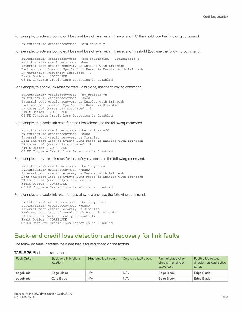
For example, to activate both credit loss and loss of sync with link reset and NO threshold, use the following command:
switch:admin> creditrecovmode --cfg onLrOnly
For example, to activate both credit loss and loss of sync with link reset and threshold (10), use the following command:
switch:admin> creditrecovmode --cfg onLrThresh --lrthreshold 2switch:admin> creditrecovmode –showInternal port credit recovery is Enabled with LrThreshBack end port Loss of Sync's Link Reset is Enabled with LrThreshLR threshold (currently activated): 2Fault Option : COREBLADEC2 FE Complete Credit Loss Detection is Disabled
For example, to enable link reset for credit loss alone, use the following command.
switch:admin> creditrecovmode --be_crdloss onswitch:admin> creditrecovmode --showInternal port credit recovery is Enabled with LrThreshBack end port Loss of Sync's Link Reset is DisabledLR threshold (currently activated): 2Fault Option : COREBLADEC2 FE Complete Credit Loss Detection is Disabled
For example, to disable link reset for credit loss alone, use the following command.
switch:admin> creditrecovmode --be_crdloss offswitch:admin> creditrecovmode --showInternal port credit recovery is DisabledBack end port Loss of Sync's Link Reset is Enabled with LrThreshLR threshold (currently activated): 2Fault Option : COREBLADEC2 FE Complete Credit Loss Detection is Disabled
For example, to enable link reset for loss of sync alone, use the following command.
switch:admin> creditrecovmode --be_losync onswitch:admin> creditrecovmode --showInternal port credit recovery is Enabled with LrThreshBack end port Loss of Sync's Link Reset is Enabled with LrThreshLR threshold (currently activated): 2Fault Option : COREBLADEC2 FE Complete Credit Loss Detection is Disabled
For example, to disable link reset for loss of sync alone, use the following command.
switch:admin> creditrecovmode --be_losync offswitch:admin> creditrecovmode --showInternal port credit recovery is DisabledBack end port Loss of Sync's Link Reset is DisabledLR threshold (not currently activated): 2Fault Option : COREBLADEC2 FE Complete Credit Loss Detection is Disabled
Back-end credit loss detection and recovery for link faultsThe following table identifies the blade that is faulted based on the factors.
TABLE 26 Blade fault scenarios
Fault Option Back-end link failurelocation
Edge chip fault count Core chip fault count Faulted blade whendirector has singleactive core
Faulted blade whendirector has dual activecores
edgeblade Edge Blade N/A N/A Edge Blade Edge Blade
edgeblade Core Blade N/A N/A Edge Blade Edge Blade
Credit loss detection
Brocade Fabric OS Administration Guide, 8.1.053-1004392-01 153

TABLE 26 Blade fault scenarios (continued)
Fault Option Back-end link failurelocation
Edge chip fault count Core chip fault count Faulted blade whendirector has singleactive core
Faulted blade whendirector has dual activecores
coreblade Edge Blade N/A N/A Edge Blade Core Blade
coreblade Core Blade N/A N/A Edge Blade Core Blade
edgecoreblade Edge blade N/A <2 Edge blade Edge blade
edgecoreblade Edge blade N/A >2 Edge blade Core Blade
edgecoreblade Core blade N/A <2 Edge blade Edge blade
edgecoreblade Core blade N/A >2 Edge blade Core blade
Examples of credit recovery mode fault commandsThe following examples illustrate the use of the creditrecovmode --fault command in various settings.
switch:admin> creditrecovmode --fault edgebladeswitch:admin> creditrecovmode –showInternal port credit recovery is DisabledBack end port Loss of Sync's Link Reset is Enabled with LrThreshLR threshold (currently activated): 2Fault Option : EDGEBLADEC2 FE Complete Credit Loss Detection is Disabled switch:admin> creditrecovmode --fault edgecorebladeswitch:admin> creditrecovmode --showInternal port credit recovery is DisabledBack end port Loss of Sync's Link Reset is Enabled with LrThreshLR threshold (currently activated): 2Fault Option : EDGECOREBLADEC2 FE Complete Credit Loss Detection is Disabled switch:admin> creditrecovmode --fault corebladeswitch:admin> creditrecovmode –showInternal port credit recovery is DisabledBack end port Loss of Sync's Link Reset is Enabled with LrThreshLR threshold (currently activated): 2Fault Option : COREBLADEC2 FE Complete Credit Loss Detection is Disabled
Credit loss detection
Brocade Fabric OS Administration Guide, 8.1.0154 53-1004392-01

Managing User Accounts• User accounts overview ..............................................................................................................................................................................155• Local database user accounts...................................................................................................................................................................159• Local user account database distribution............................................................................................................................................. 162• Password policies...........................................................................................................................................................................................162• The boot PROM password.........................................................................................................................................................................168• Remote authentication..................................................................................................................................................................................171
User accounts overviewIn addition to the default permissions assigned to the roles of root, admin, and user, Fabric OS supports up to 252 additional useraccounts on the chassis. These accounts expand your ability to track account access and audit administrative activities.
NOTEUpon new installation of Fabric OS, the root user is disabled by default and must be enabled, if required.
Each user account is associated with the following:
• Permissions — Associate roles with each user account to determine the functional access levels.
• Virtual Fabric list — Specifies the Virtual Fabric a user account is allowed to log in to.
• Home Virtual Fabric — Specifies the Virtual Fabric that the user is logged in to, if available. The home Virtual Fabric must be amember of the user’s Virtual Fabric list. If the home Virtual Fabric ID is not available, then the user is logged in to the defaultswitch if that is a member of the user's Virtual Fabric list. If the default switch is also not available, then the valid lowest VirtualFabric ID from the user's VF list is used.
• LF Permission List — Determines functional access levels within the bounds of the user’s Virtual Fabrics.
• Chassis role — Similar to switch-level roles, but applies to a different subset of commands.
For more information about Virtual Fabrics, refer to Managing Virtual Fabrics on page 291.
Fabric OS provides four options for authenticating users: remote RADIUS service, remote LDAP service, remote TACACS+ service, andthe local-switch user database. All options allow users to be managed centrally by means of the following methods:
• Remote RADIUS service — Users are managed in a remote RADIUS server. All switches in the fabric can be configured toauthenticate against the centralized remote database.
• Remote LDAP service — Users are managed in a remote LDAP server. All switches in the fabric can be configured toauthenticate against the centralized remote database. The remote LDAP server can run Microsoft Active Directory orOpenLDAP.
• Remote TACACS+ service — Users are managed in a remote TACACS+ server. All switches in the fabric can be configured toauthenticate against the centralized remote database.
• Local user database — Users are managed by means of the local user database. The local user database is manuallysynchronized by means of the distribute command to push a copy of the switch’s local user database to all other switches inthe fabric running Fabric OS v5.3.0 and later, but the distribute command is blocked if users with user-defined roles exist onthe sending switch or on any remote, receiving switch.
Brocade Fabric OS Administration Guide, 8.1.053-1004392-01 155

Role-Based Access ControlRole-Based Access Control (RBAC) specifies the permissions that a user account has on the basis of the role the account has beenassigned. For each role, a set of predefined permissions determines the jobs and tasks that can be performed on a fabric and itsassociated fabric elements. Fabric OS uses RBAC to determine which commands a user is allowed to access.
When you log in to a switch, your user account is associated with a predefined role or a user-defined role. The role that your account isassociated with determines the level of access you have on that switch and in the fabric. The chassis role can also be associated withuser-defined roles; it has permissions for RBAC classes of commands that are configured when user-defined roles are created. Thechassis role is similar to a switch-level role, except that it affects a different subset of commands. You can use the userConfig commandto add this permission to a user account.
The following table outlines the Fabric OS predefined (default) roles.
TABLE 27 Default Fabric OS roles
Role name Duties Description
Admin All administration All administrative commands
BasicSwitchAdmin Restricted switch administration Mostly monitoring with limited switch (local)commands
FabricAdmin Fabric and switch administration All switch and fabric commands, excluding usermanagement commands
Operator General switch administration Routine switch-maintenance commands.
SecurityAdmin Security administration All switch security and user managementfunctions
SwitchAdmin Local switch administration Most switch (local) commands, excludingsecurity, user management, and zoningcommands
User Monitoring only Nonadministrative use, such as monitoringsystem activity
ZoneAdmin Zone administration Zone management commands only
Role permissionsThe following table describes the types of permissions that are assigned to roles.
TABLE 28 Permission types
Abbreviation Definition Description
O Observe The user can run commands by using optionsthat display information only, such as runninguserConfig --show -a to show all users on aswitch.
M Modify The user can run commands by using optionsthat create, change, and delete objects on thesystem, such as running the userConfig --change command with the -r option to change auser’s role.
OM Observe and Modify The user can run commands by using bothobserve and modify options; if a role has modifypermissions, it almost always has observepermissions.
N None The user is not allowed to run commands in agiven category.
User accounts overview
Brocade Fabric OS Administration Guide, 8.1.0156 53-1004392-01

To view the permission type for categories of commands, use the classConfig command.
• Enter the classConfig --show -classlist command to list all command categories.
• Enter the classConfig --showroles command with the command category of interest as the argument.
This command shows the permissions that apply to all commands in a specific category.
switch:admin> classconfig --showroles authenticationRoles that have access to the RBAC Class ‘authentication’ are: Role name Permission --------- ---------- Admin OM Root OM Security Admin OM
You can also use the classConfig --showcli command to show the permissions that apply to a specific command.
Management channelThe management channel is the communication established between the management workstation and the switch. The following tableshows the number of simultaneous login sessions allowed for each user when authenticated locally. The roles are displayed in alphabeticorder, which does not reflect their importance.
TABLE 29 Maximum number of simultaneous sessions
User role Maximum sessions
Admin 4
BasicSwitchAdmin 4
FabricAdmin 4
Operator 4
SecurityAdmin 4
SwitchAdmin 4
User 4
ZoneAdmin 4
NOTEThe total number of sessions on a switch cannot exceed 32.
Managing user-defined rolesFabric OS provides an extensive toolset for managing user-defined roles:
• The roleConfig command is available for defining new roles, deleting created roles, or viewing information about user-definedroles.
• The classConfig command is available for displaying RBAC information about each category or class of commands, andincludes an option to show all roles associated with a given RBAC command category.
• The userConfig command can be used to assign a user-defined role to a user account.
CAUTIONBrocade recommends that you do not add more than 150 user defined roles as Fabric OS and other managementapplications such as Brocade Network Advisor and Web Tools might encounter performance issues.
User accounts overview
Brocade Fabric OS Administration Guide, 8.1.053-1004392-01 157

Creating a user-defined roleYou can define a role as long as it has a unique name that is not the same as any of the Fabric OS default roles, any other user-definedrole, or any existing user account name.
The following conditions also apply:
• A role name is case-insensitive and contains only letters.
• The role name should have a minimum of 4 letters and can be up to 16 letters long.
• The maximum number of user-defined roles that are allowed on a chassis is 150.
The roleConfig command can be used to define unique roles. You must have chassis-level access and permissions to execute thiscommand. The following example creates a user-defined role called mysecurityrole. The RBAC class Security is added to the role, andthe Observe permission is assigned:
switch:admin> roleconfig --add mysecurityrole -class security -perm O Role added successfully
The assigned permissions can be no higher than the admin role permission assigned to the class. The admin role permission for theSecurity class is Observe/Modify. Therefore, the Observe permission is valid.
The roleConfig --show command is available to view the permissions assigned to a user-defined role. You can also use theclassConfig--showroles command to see that the role was indeed added with Observe permission for the security commands.
switch:admin> classConfig --showroles securityRoles that have access to RBAC Class ‘security’ are: Role Name Permissions --------- ----------- User O Admin OM Root OM SwitchAdmin O FabricAdmin OM BasicSwitchAdmin O SecurityAdmin OM mysecurityrole O
To delete a user-defined role, use the roleConfig --delete command.
Assigning a user-defined role to a userThe userConfig command allows you to assign a user-defined role to a user.
To assign a user-defined role to a user, complete the following steps.
1. Connect to the device and log in using an account with admin permissions.
2. You have multiple options for assigning a user-defined role to a user:
• To create a new user account and assign a role: userConfig --add user_account -r role_name .
• To change a user-defined role or add a new one to an existing user account: userConfig --change user_account -rrole_name
• To create a new user account and assign a chassis role: userConfig --add user_account -c chassis_role_name.
• To add a chassis role to an account: userConfig --change user_account -c chassis_role_name.
User accounts overview
Brocade Fabric OS Administration Guide, 8.1.0158 53-1004392-01

The commands can be combined; the following example assigns the “mysecurityrole” role to the existing “anewuser” account and alsoadds the admin chassis role.
switch:admin> userConfig --change anewuser -r mysecurityrole -c admin
For more information on userConfig command options, refer to the Brocade Fabric OS Command Reference.
Configuring time-based accessYou can also restrict the access for a user to a specified time of the day. The restriction applies for Telnet, SSH, console, and Web accessfor a user on all days.
Run the userConfig --add todUser command to add time-based users.
switch:admin> userconfig --add toduser -r user –l 1-128 –h 128 –c user –d “Time of day User” –at hh:mm-hh:mm
The first instance of hh:mm after the "-at" option indicates the start time and the second instance indicates the end time. Todowngrade to a previous Fabric OS version, you need to remove the time-based user configuration.
CAUTIONThe time of access must not be configured for switch default accounts such as root or admin user, because it canlock you out of the switch access completely. To provide accessibility to the switch, you must have at least oneaccount without the time of access configured.
Local database user accountsUser add, change, and delete operations are subject to the subset rule: an admin with LFlist 1-10 cannot perform operations on anadmin, user, or any role with LFlist 11-128. The user account being changed must have an LFlist that is a subset of the account that ismaking the change.
In addition to the default administrative and user accounts, Fabric OS supports up to 252 user-defined accounts in each switch (domain).These accounts expand your ability to track account access and audit administrative activities.
Default accountsThe following table lists the predefined accounts offered by Fabric OS that are available in the local-switch user database. The passwordfor all default accounts should be changed during the initial installation and configuration of each switch.
TABLE 30 Default local user accounts
Account name Role Logical Fabric Description
admin Admin LF1-128
home: 128
Most commands have observe/modify permission
root Root LF1-128
home: 128
Reserved
user User LF-128
home: 128
Most commands have observe-only permission
Local database user accounts
Brocade Fabric OS Administration Guide, 8.1.053-1004392-01 159

NOTEWhen using Virtual Fabrics, administrators can act on other accounts only if that account has a Logical Fabric list that is a subsetof the administrator.
Root user access settings:
• Root access is disabled by default and restricted to the console only. To enable the root account use the userconfig --changeroot -e yes command.
• Root access is allowed only through the console by default. Use the rootAccess --set <none|consoleonly|all> command tochange the root access settings.
• The default root password must be changed in the first login.
For all users, an asterisk (*) is displayed next to the username if the password is still a default password when you run userConfig -showcommand.
CAUTIONThe passwdDefault command is supported only on root. Do not use the command, because it deletes all user-definedaccounts and resets the passwords of root, admin, and user to the default passwords. It also resets the root access back toconsole only and disables the root account.
Displaying account information1. Connect to the switch and log in using an account with admin permissions, or an account associated with a user-defined role
with permissions for the UserManagement class of commands.
2. Enter the appropriate show operands for the account information you want to display:
• userConfig --show -a to show all account information for a switch
NOTEA * is displayed next to the user names that still have the default password set.
• userConfig --show username to show account information for the specified account
• userConfig --showlf -l logicalFabric_ID for each LF in an LF_ID_list, displays a list of users that include that LF in their LFpermissions.
Creating an account1. Connect to the switch and log in using an account with admin permissions, or an account associated with a user-defined role
with permissions for the UserManagement class of commands.
2. Enter the userConfig --add command.
> userconfig --add metoo -l 1-128 -h 128 -r admin -c admin
This example creates a user account for the user metoo with the following properties:
• Access to Virtual Fabrics 1 through 128
• Default home logical switch to 128
• Admin role permissions
• Admin chassis role permissions
3. In response to the prompt, enter a password for the account.
The password is not displayed when you enter it on the command line.
Local database user accounts
Brocade Fabric OS Administration Guide, 8.1.0160 53-1004392-01

Deleting an accountThis procedure can be performed on local user accounts.
1. Connect to the switch and log in using an account with admin permissions, or an account associated with a user-defined rolewith permissions for the UserManagement class of commands.
2. Enter the userConfig --delete command.
You cannot delete the default accounts. An account cannot delete itself. All active CLI sessions for the deleted account arelogged out.
3. At the prompt for confirmation, enter y.
Changing account parametersThis procedure can be performed on local user accounts.
1. Connect to the switch and log in using an account with admin permissions, or an account associated with a user-defined rolewith permissions for the UserManagement class of commands.
2. Enter the userConfig --change command.
Local account passwordsThe following rules apply to changing passwords:
• Users can change their own passwords.
• To change the password for another account requires admin permissions or an account associated with a user-defined role withModify permissions for the LocalUserEnvironment RBAC class of commands. When changing an admin account password,you must provide the current password.
• An admin with ADlist 0-10 or LFlist 1-10 cannot change the password on an account with admin, user, or any permission withan ADlist 11-25 or LFlist 11-128. The user account being changed must have an ADlist of VFlist that is a subset of theaccount that is making the change.
• A new password must have at least one character different from the previous password.
• You cannot change passwords using SNMP.
Changing the password for the current login account1. Connect to the switch and log in using an account with admin permissions.
2. Enter the passwd command.
3. Enter the requested information at the prompts.
Changing the password for a different account1. Connect to the switch and log in using an account with admin permissions.
2. Enter the passwd command specifying the name of the account for which the password is being changed.For example, passwd username.
3. Enter the requested information at the prompts.
Local database user accounts
Brocade Fabric OS Administration Guide, 8.1.053-1004392-01 161
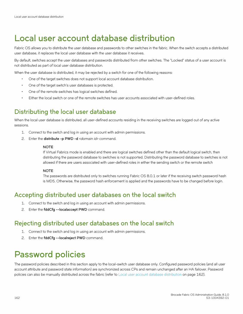
Local user account database distributionFabric OS allows you to distribute the user database and passwords to other switches in the fabric. When the switch accepts a distributeduser database, it replaces the local user database with the user database it receives.
By default, switches accept the user databases and passwords distributed from other switches. The "Locked" status of a user account isnot distributed as part of local user database distribution.
When the user database is distributed, it may be rejected by a switch for one of the following reasons:
• One of the target switches does not support local account database distribution.
• One of the target switch’s user databases is protected.
• One of the remote switches has logical switches defined.
• Either the local switch or one of the remote switches has user accounts associated with user-defined roles.
Distributing the local user databaseWhen the local user database is distributed, all user-defined accounts residing in the receiving switches are logged out of any activesessions.
1. Connect to the switch and log in using an account with admin permissions.
2. Enter the distribute -p PWD -d <domain id> command.
NOTEIf Virtual Fabrics mode is enabled and there are logical switches defined other than the default logical switch, thendistributing the password database to switches is not supported. Distributing the password database to switches is notallowed if there are users associated with user-defined roles in either the sending switch or the remote switch
NOTEThe passwords are distributed only to switches running Fabric OS 8.0.1 or later if the receiving switch password hashis MD5. Otherwise, the password hash enforcement is applied and the passwords have to be changed before login.
Accepting distributed user databases on the local switch1. Connect to the switch and log in using an account with admin permissions.
2. Enter the fddCfg --localaccept PWD command.
Rejecting distributed user databases on the local switch1. Connect to the switch and log in using an account with admin permissions.
2. Enter the fddCfg --localreject PWD command.
Password policiesThe password policies described in this section apply to the local-switch user database only. Configured password policies (and all useraccount attribute and password state information) are synchronized across CPs and remain unchanged after an HA failover. Passwordpolicies can also be manually distributed across the fabric (refer to Local user account database distribution on page 162).
Local user account database distribution
Brocade Fabric OS Administration Guide, 8.1.0162 53-1004392-01

Password strength policyThe password strength policy is enforced across all user accounts, and enforces a set of format rules to which new passwords mustadhere. The password strength policy is enforced only when a new password is defined. The total of the other password strength policyparameters (lowercase, uppercase, digits, and punctuation) must be less than or equal to the value of the MinLength parameter.
Use the following attributes to the passwdCfg command to set the password strength policy:
• Lowercase
Specifies the minimum number of lowercase alphabetic characters that must appear in the password. The default value is zero.The maximum value must be less than or equal to the MinLength value.
• Uppercase
Specifies the minimum number of uppercase alphabetic characters that must appear in the password. The default value is zero.The maximum value must be less than or equal to the MinLength value.
• Digits
Specifies the minimum number of numeric digits that must appear in the password. The default value is zero. The maximumvalue must be less than or equal to the MinLength value.
• Punctuation
Specifies the minimum number of punctuation characters that must appear in the password. All printable, non-alphanumericpunctuation characters except the colon ( : ) are allowed. The default value is zero. The maximum value must be less than orequal to the MinLength value.
• MinLength
Specifies the minimum length of the password. The minimum can be from 8 through 40 characters. New passwords must bebetween the minimum length specified and 40 characters. The default value is 8. The maximum value must be greater than orequal to the MinLength value.
• CharSet
Specifies the minimum length of the character set. Character set includes alphabets and special characters. The default value is0. For example, if the -charset option is set to 3, then the password should contain at least 3 characters (can be 2 alphabetsand 1 special character, or 3 alphabets or any other combination). However, there can be more than three characters andinclude digits as part of the password. But the password cannot have less than three characters.
• AllowUser
Specifies whether to allow username to be included in the password either in the forward or reverse order of characters. Thedefault value is set to "yes" for "-allowusername" option. If the option is set to "no", the username both in forward and reversedirection is not allowed to be part of the password. The user names are validated as case sensitive.
• Repeat
Specifies the length of repeated character sequences that will be disallowed. For example, if the "repeat" value is set to 3, apassword "passAAAword" is disallowed because it contains the repeated sequence "AAA". A password of "passAAword" wouldbe allowed because no repeated character sequence exceeds two characters. The range of allowed values is from 1 through 40.The default value is 1.
• Sequence
Specifies the length of sequential character sequences that will be disallowed. A sequential character sequence is defined as acharacter sequence in which the ASCII value of each contiguous character differs by one. The ASCII value for the characters inthe sequence must all be increasing or decreasing. For example, if the "sequence" value is set to 3, a password "passABCword"is disallowed because it contains the sequence "ABC". A password of "passABword" would be allowed because it contains no
Password policies
Brocade Fabric OS Administration Guide, 8.1.053-1004392-01 163

sequential character sequence exceeding two characters. The range of allowed values is from 1 through 40. The default value is1. When set to 1, sequential characters are not enforced.
• Reverse
Activates or deactivates the validation check to determine whether the password is an exact reverse string of the user name.This option is disabled by default.
Example of a password strength policy
The following example shows a password strength policy that requires passwords to contain at least 3 uppercase characters, 4 lowercasecharacters, and 2 numeric digits; the minimum length of the password is 9 characters. The password cannot be an exact reverse string ofthe username.
switch:admin> passwdcfg --set -uppercase 3 -lowercase 4 -digits 2 -minlength 9 -reverse 1
Password history policyThe password history policy prevents users from recycling recently used passwords, and is enforced across all user accounts when usersare setting their own passwords. The password history policy is enforced only when a new password is defined.
Specify the number of past password values that are disallowed when setting a new password. Allowable password history values rangefrom 0 through 24. If the value is set to 0, the new password cannot be set to the current password, but can be set to the most recentpassword. The default value is 1, which means the current and one previous password cannot be reused. The value 2 indicates that thecurrent and the two previous passwords cannot be used (and so on, up to 24 passwords).
This policy does not verify that a new password meets a minimal standard of difference from prior passwords; rather, it only determineswhether or not a newly specified password is identical to one of the specified number (1-24) of previously used passwords.
The password history policy is not enforced when an administrator sets a password for another user; instead, the user’s password historyis preserved and the password set by the administrator is recorded in the user’s password history.
NOTEYou can also use the -oldpasswd option to enable or disable old password check while changing the root password.
Password expiration policyThe password expiration policy forces the expiration of a password after a configurable period of time. The expiration policy can beenforced across all user accounts or on specified users only. A warning that password expiration is approaching is displayed when theuser logs in. When a password expires, the user must change the password to complete the authentication process and open a usersession. You can specify the number of days prior to password expiration during which warnings will commence. Password expirationdoes not disable or lock out the account.
Use the following attributes to the passwdCfg command to set the password expiration policy:
• MinPasswordAge
Specifies the minimum number of days that must elapse before a user can change a password. MinPasswordAge values rangefrom 0 through 999. The default value is zero. Setting this parameter to a nonzero value discourages users from rapidlychanging a password in order to circumvent the password history setting to select a recently used password. TheMinPasswordAge policy is not enforced when an administrator changes the password for another user.
• MaxPasswordAge
Password policies
Brocade Fabric OS Administration Guide, 8.1.0164 53-1004392-01
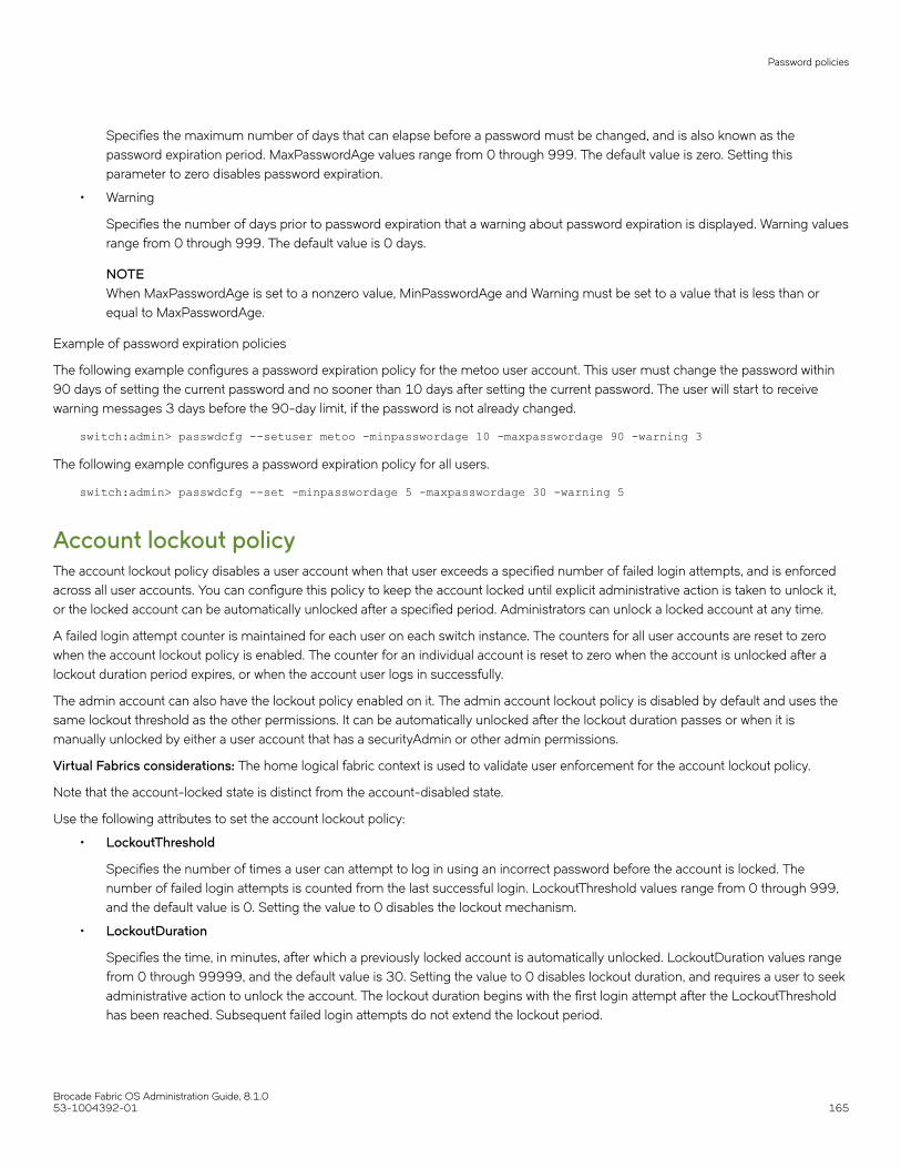
Specifies the maximum number of days that can elapse before a password must be changed, and is also known as thepassword expiration period. MaxPasswordAge values range from 0 through 999. The default value is zero. Setting thisparameter to zero disables password expiration.
• Warning
Specifies the number of days prior to password expiration that a warning about password expiration is displayed. Warning valuesrange from 0 through 999. The default value is 0 days.
NOTEWhen MaxPasswordAge is set to a nonzero value, MinPasswordAge and Warning must be set to a value that is less than orequal to MaxPasswordAge.
Example of password expiration policies
The following example configures a password expiration policy for the metoo user account. This user must change the password within90 days of setting the current password and no sooner than 10 days after setting the current password. The user will start to receivewarning messages 3 days before the 90-day limit, if the password is not already changed.
switch:admin> passwdcfg --setuser metoo -minpasswordage 10 -maxpasswordage 90 -warning 3
The following example configures a password expiration policy for all users.
switch:admin> passwdcfg --set -minpasswordage 5 -maxpasswordage 30 -warning 5
Account lockout policyThe account lockout policy disables a user account when that user exceeds a specified number of failed login attempts, and is enforcedacross all user accounts. You can configure this policy to keep the account locked until explicit administrative action is taken to unlock it,or the locked account can be automatically unlocked after a specified period. Administrators can unlock a locked account at any time.
A failed login attempt counter is maintained for each user on each switch instance. The counters for all user accounts are reset to zerowhen the account lockout policy is enabled. The counter for an individual account is reset to zero when the account is unlocked after alockout duration period expires, or when the account user logs in successfully.
The admin account can also have the lockout policy enabled on it. The admin account lockout policy is disabled by default and uses thesame lockout threshold as the other permissions. It can be automatically unlocked after the lockout duration passes or when it ismanually unlocked by either a user account that has a securityAdmin or other admin permissions.
Virtual Fabrics considerations: The home logical fabric context is used to validate user enforcement for the account lockout policy.
Note that the account-locked state is distinct from the account-disabled state.
Use the following attributes to set the account lockout policy:
• LockoutThreshold
Specifies the number of times a user can attempt to log in using an incorrect password before the account is locked. Thenumber of failed login attempts is counted from the last successful login. LockoutThreshold values range from 0 through 999,and the default value is 0. Setting the value to 0 disables the lockout mechanism.
• LockoutDuration
Specifies the time, in minutes, after which a previously locked account is automatically unlocked. LockoutDuration values rangefrom 0 through 99999, and the default value is 30. Setting the value to 0 disables lockout duration, and requires a user to seekadministrative action to unlock the account. The lockout duration begins with the first login attempt after the LockoutThresholdhas been reached. Subsequent failed login attempts do not extend the lockout period.
Password policies
Brocade Fabric OS Administration Guide, 8.1.053-1004392-01 165
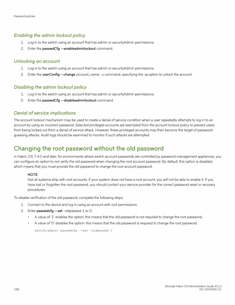
Enabling the admin lockout policy1. Log in to the switch using an account that has admin or securityAdmin permissions.
2. Enter the passwdCfg --enableadminlockout command.
Unlocking an account1. Log in to the switch using an account that has admin or securityAdmin permissions.
2. Enter the userConfig --change account_name -u command, specifying the -u option to unlock the account.
Disabling the admin lockout policy1. Log in to the switch using an account that has admin or securityAdmin permissions.
2. Enter the passwdCfg --disableadminlockout command.
Denial of service implicationsThe account lockout mechanism may be used to create a denial of service condition when a user repeatedly attempts to log in to anaccount by using an incorrect password. Selected privileged accounts are exempted from the account lockout policy to prevent usersfrom being locked out from a denial of service attack. However, these privileged accounts may then become the target of password-guessing attacks. Audit logs should be examined to monitor if such attacks are attempted.
Changing the root password without the old passwordIn Fabric OS 7.4.0 and later, for environments where switch account passwords are controlled by password management appliances, youcan configure an option to not verify the old password when changing the root account password. By default, this option is disabled,which means that you must provide the old password to change the root account password.
NOTENot all systems ship with root accounts. If your system does not have a root account, you will not be able to enable it. If youhave lost or forgotten the root password, you should contact your service provider for the correct password reset or recoveryprocedures.
To disable verification of the old password, complete the following steps.
1. Connect to the device and log in using an account with root permissions.
2. Enter passwdcfg --set -oldpasswd 1 or 0.
• A value of ‘1’ enables the option; this means that the old password is not required to change the root password.
• A value of ‘0’ disables the option; this means that the old password is required to change the root password.
switch:admin> passwdcfg –-set -oldpasswd 1
Password policies
Brocade Fabric OS Administration Guide, 8.1.0166 53-1004392-01

3. Enter the passwd command to change the root password.
NOTEThe -oldpasswd configuration is discarded when you downgrade to any version prior to Fabric OS 7.4.0. The -oldpasswd configuration is retained when you upload the switch configuration or upgrade to a later version of FabricOS.
switch:admin> passwdWarning: Access to the Root account may be required for proper support of the switch. Please ensure the Root Passwords are documented in a secure location. Recovery of a lost Root password will result in fabric downtime.Changing password for rootEnter new password:
Configuring the password hash typeVersions of Fabric OS prior to 8.0.1 use the MD5 hash type for storing the local user passwords. With Fabric OS 8.0.1 and later,SHA256 and SHA512 hash types are also supported. Whenever you change the hash type, you will be prompted to change thepassword in the next login. You can also use the manual option to manually trigger a password change immediately after the hash typeconfiguration.
After a new password hash configuration has started, by default, you are forced to change the password in the next login. When the -manual option is used, you can change the password using the passwd command.
To change the password hash type, complete the following steps:
1. Log in to the device using the username and password.
2. Enter the passwdcfg --hash {md5|sha256|sha512} [-manual] command to configure the hash type for the logged-in user'spassword.
3. Do one of the following:
• If you do not use the -manual option, log out the user session and at the time of re-login, enter the new password andconfirm the same.
• If you use the -manual option, explicitly change the passwords for the account using passwd command.
4. Use the following commands to display the password hash type for the current user, any user, or all users configured in thedevice.
• Use the passwdcfg --showhash command to display the configured hash type on the switch.
• Use the passwdcfg --showhash username command to display the current password hash for the username.
• Use the passwdcfg --showhash -all to display the current password has for all the users on the switch.
Sample output:
switch(mode)# passwdcfg --hash sha256 -manualswitch(mode)# passwdcfg -showhash -all<Command output>
• When a password database update is received, the hash type is not reset if the received hash configuration is weaker than theexisting hash configuration. For example, if the switch is currently using SHA512, and the configuration request is for SHA256using the distribute command, then the hash type is retained as SHA512.
• When you upgrade the switch to Fabric OS 8.0.1 or later, the MD5 hash type configuration is retained.
• When you downgrade the switch from Fabric OS 8.0.1 or later, the downgrade is blocked unless the following two conditionsare met:
– The password hash type for all the users is changed to MD5.
Password policies
Brocade Fabric OS Administration Guide, 8.1.053-1004392-01 167

– The switch hash type is changed to MD5.
If the two conditions are met but the password history consists of non-MD5 hash for any user, then the following message isdisplayed during the firmware downgrade.
" WARNING !!!!! Password hash in the history contains non-MD5 hash for user(s) which must be cleared to proceed with downgrade. Please confirm with [Y/N] to proceed further, when prompted for.System settings check passed.
You can run firmwaredownloadstatus to get the status of this command.
This command will cause a warm/non-disruptive boot but will require that existing telnet, secure telnet or SSH sessions be restarted.
Do you want to continue (Y/N) [Y]:”
• When you do a net install, all the password hash types are set to SHA512.
NOTEYou can use the passwddefault command to reset all the password hash types to SHA512 and reset all the passwords todefault.
The boot PROM passwordThe boot PROM password provides an additional layer of security by protecting the boot PROM from unauthorized use. Setting arecovery string for the boot PROM password enables you to recover a lost boot PROM password by contacting your switch serviceprovider. Without the recovery string, a lost boot PROM password cannot be recovered.
Although you can set the boot PROM password without also setting the recovery string, it is strongly recommended that you set both thepassword and the recovery string. If your site procedures dictate that you set the boot PROM password without the recovery string, referto Setting the boot PROM password for a switch without a recovery string on page 170.
To set the boot PROM password with or without a recovery string, refer to the section that applies to your switch or Backbone model.
CAUTIONSetting the boot PROM password requires accessing the boot prompt, which stops traffic flow through the switch until theswitch is rebooted. Perform this procedure during a planned downtime.
Setting the boot PROM password for a switch with a recovery stringThis procedure applies to the fixed-port switch models. The password recovery instructions provided within this section are only for theswitches listed in supported hardware section. If your switch is not listed, contact your switch support provider for instructions.
1. Connect to the serial port interface as described in Connecting to Fabric OS through the serial port on page 36.
2. Reboot the switch.
3. Press Esc within four seconds after the message "Press escape within 4 seconds..." is displayed.
The boot PROM password
Brocade Fabric OS Administration Guide, 8.1.0168 53-1004392-01
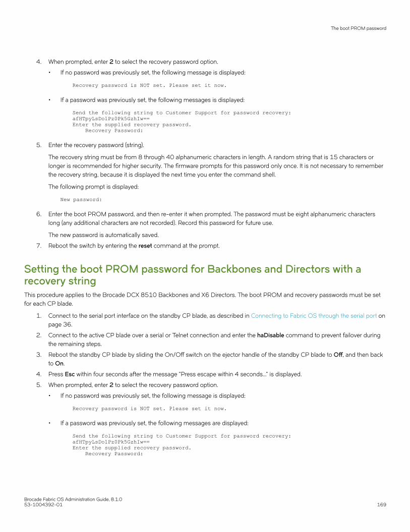
4. When prompted, enter 2 to select the recovery password option.
• If no password was previously set, the following message is displayed:
Recovery password is NOT set. Please set it now.
• If a password was previously set, the following messages is displayed:
Send the following string to Customer Support for password recovery:afHTpyLsDo1Pz0Pk5GzhIw==Enter the supplied recovery password. Recovery Password:
5. Enter the recovery password (string).
The recovery string must be from 8 through 40 alphanumeric characters in length. A random string that is 15 characters orlonger is recommended for higher security. The firmware prompts for this password only once. It is not necessary to rememberthe recovery string, because it is displayed the next time you enter the command shell.
The following prompt is displayed:
New password:
6. Enter the boot PROM password, and then re-enter it when prompted. The password must be eight alphanumeric characterslong (any additional characters are not recorded). Record this password for future use.
The new password is automatically saved.
7. Reboot the switch by entering the reset command at the prompt.
Setting the boot PROM password for Backbones and Directors with arecovery stringThis procedure applies to the Brocade DCX 8510 Backbones and X6 Directors. The boot PROM and recovery passwords must be setfor each CP blade.
1. Connect to the serial port interface on the standby CP blade, as described in Connecting to Fabric OS through the serial port onpage 36.
2. Connect to the active CP blade over a serial or Telnet connection and enter the haDisable command to prevent failover duringthe remaining steps.
3. Reboot the standby CP blade by sliding the On/Off switch on the ejector handle of the standby CP blade to Off, and then backto On.
4. Press Esc within four seconds after the message "Press escape within 4 seconds..." is displayed.
5. When prompted, enter 2 to select the recovery password option.
• If no password was previously set, the following message is displayed:
Recovery password is NOT set. Please set it now.
• If a password was previously set, the following messages are displayed:
Send the following string to Customer Support for password recovery:afHTpyLsDo1Pz0Pk5GzhIw==Enter the supplied recovery password. Recovery Password:
The boot PROM password
Brocade Fabric OS Administration Guide, 8.1.053-1004392-01 169

6. Enter the recovery password (string).
The recovery string must be from 8 through 40 alphanumeric characters in length. A random string that is 15 characters orlonger is recommended for higher security. The firmware only prompts for this password once. It is not necessary to rememberthe recovery string because it is displayed the next time you enter the command shell.
The following prompt is displayed:
New password:
7. Enter the boot PROM password, and then re-enter it when prompted. The password must be eight alphanumeric characterslong (any additional characters are not recorded). Record this password for future use.
The new password is automatically saved (the saveEnv command is not required).
8. Connect to the active CP blade over a serial or Telnet connection and enter the haEnable command to restore high availability,and then fail over the active CP blade by entering the haFailover command.
Traffic flow through the active CP blade resumes when the failover is complete.
9. Connect the serial cable to the serial port on the new standby CP blade (previously the active CP blade).
10. Repeat step 2 through step 7 for the new standby CP blade (each CP blade has a separate boot PROM password).
11. Connect to the active CP blade over a serial or Telnet connection and enter the haEnable command to restore high availability.
Although you can set the boot PROM password without also setting the recovery string, it is strongly recommended that youset both the password and the string as described in Setting the boot PROM password for a switch with a recovery string onpage 168. If your site procedures dictate that you must set the boot PROM password without the string, follow the procedurethat applies to your switch model.
Setting the boot PROM password for a switch without a recovery stringThis procedure applies to fixed-port switches.
The password recovery instructions provided within this section are only for the switches listed in the supported hardware section. If yourswitch is not listed, contact your switch support provider for instructions.
1. Create a serial connection to the switch as described in Connecting to Fabric OS through the serial port on page 36.
2. Reboot the switch by entering the reboot command.
3. Press Esc within four seconds after the message "Press escape within 4 seconds..." is displayed.
4. When prompted, enter 3 to enter the command shell.
5. At the shell prompt, enter the passwd command.
The passwd command only applies to the boot PROM password when it is entered from the boot interface.
6. Enter the boot PROM password at the prompt, and then re-enter it when prompted. The password must be eight alphanumericcharacters long (any additional characters are not recorded). Record this password for future use.
7. Enter the saveEnv command to save the new password.
8. Reboot the switch by entering the reset command.
Setting the boot PROM password for a Backbone or Director without arecovery stringThis procedure applies to the Brocade DCX 8510 Backbones and X6 Directors.
The boot PROM password
Brocade Fabric OS Administration Guide, 8.1.0170 53-1004392-01
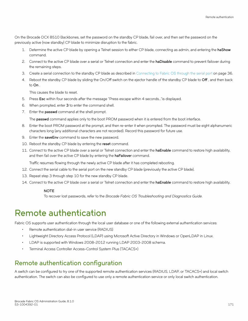
On the Brocade DCX 8510 Backbones, set the password on the standby CP blade, fail over, and then set the password on thepreviously active (now standby) CP blade to minimize disruption to the fabric.
1. Determine the active CP blade by opening a Telnet session to either CP blade, connecting as admin, and entering the haShowcommand.
2. Connect to the active CP blade over a serial or Telnet connection and enter the haDisable command to prevent failover duringthe remaining steps.
3. Create a serial connection to the standby CP blade as described in Connecting to Fabric OS through the serial port on page 36.
4. Reboot the standby CP blade by sliding the On/Off switch on the ejector handle of the standby CP blade to Off , and then backto On .
This causes the blade to reset.
5. Press Esc within four seconds after the message "Press escape within 4 seconds..."is displayed.
6. When prompted, enter 3 to enter the command shell.
7. Enter the passwd command at the shell prompt.
The passwd command applies only to the boot PROM password when it is entered from the boot interface.
8. Enter the boot PROM password at the prompt, and then re-enter it when prompted. The password must be eight alphanumericcharacters long (any additional characters are not recorded). Record this password for future use.
9. Enter the saveEnv command to save the new password.
10. Reboot the standby CP blade by entering the reset command.
11. Connect to the active CP blade over a serial or Telnet connection and enter the haEnable command to restore high availability,and then fail over the active CP blade by entering the haFailover command.
Traffic resumes flowing through the newly active CP blade after it has completed rebooting.
12. Connect the serial cable to the serial port on the new standby CP blade (previously the active CP blade).
13. Repeat step 3 through step 10 for the new standby CP blade.
14. Connect to the active CP blade over a serial or Telnet connection and enter the haEnable command to restore high availability.
NOTETo recover lost passwords, refer to the Brocade Fabric OS Troubleshooting and Diagnostics Guide.
Remote authenticationFabric OS supports user authentication through the local user database or one of the following external authentication services:
• Remote authentication dial-in user service (RADIUS)
• Lightweight Directory Access Protocol (LDAP) using Microsoft Active Directory in Windows or OpenLDAP in Linux.
• LDAP is supported with Windows 2008-2012 running LDAP 2003-2008 schema.
• Terminal Access Controller Access-Control System Plus (TACACS+)
Remote authentication configurationA switch can be configured to try one of the supported remote authentication services (RADIUS, LDAP, or TACACS+) and local switchauthentication. The switch can also be configured to use only a remote authentication service or only local switch authentication.
Remote authentication
Brocade Fabric OS Administration Guide, 8.1.053-1004392-01 171

Client/server modelWhen configured to use one of the supported remote authentication services, the switch acts as a Network Access Server (NAS) andRADIUS, LDAP, or TACACS+ client. The switch sends all authentication, authorization, and accounting (AAA) service requests to theauthentication server. The authentication server receives the request, validates the request, and sends its response back to the switch.
The supported management access channels that integrate with RADIUS, LDAP, and TACACS+ include serial port, Telnet, SSH, andWeb Tools. All these access channels require the switch IP address or name to connect. RADIUS, LDAP, and TACACS+ servers acceptboth IPv4 and IPv6 address formats. For accessing both the active and standby CP blades, and for the purpose of HA failover, both CPIP addresses of a Backbone should be included in the authentication server configuration.
NOTEFor systems such as the Brocade DCX Backbone, the switch IP addresses are aliases of the physical Ethernet interfaces on theCP blades. When specifying client IP addresses for the logical switches in such systems, make sure that the CP IP addressesare used.
Authentication server dataWhen configured for remote authentication, a switch becomes a RADIUS, LDAP, or TACACS+ client. In any of these configurations,authentication records are stored in the authentication host server database. Login and logout account name, assigned permissions, andtime-accounting records are also stored on the authentication server for each user.
Switch configurationBy default, the remote authentication services are disabled, so AAA services default to the switch’s local database.
To enable remote authentication, it is strongly recommended that you access the CLI through an SSH connection so that the sharedsecret is protected. Multiple login sessions can configure simultaneously, and the last session to apply a change leaves its configurationin effect. After a configuration is applied, it persists after a reboot or an HA failover.
To enable the secure LDAP service, you must install a certificate from the Microsoft Active Directory server or the OpenLDAP server. Bydefault, the LDAP service does not require certificates.
The configuration applies to all switches. On a Backbone, the configuration replicates itself on a standby CP blade if one is present. It issaved in a configuration upload and applied in a configuration download.
Brocade recommends configuring at least two authentication servers, so that if one fails, the other will assume service. Up to five serversare supported.
You can set the configuration with any one of the supported authentication services and local authentication enabled, so that if theauthentication servers do not respond because of a power failure or network problems, the switch uses local authentication.
For Gen 6 devices, RADIUS server authentication is supported by installing a certificate for the RADIUS server on the switch. Thiscapability is not available on Gen 5 devices.
Consider the effects of the use of a remote authentication service on other Fabric OS features. For example, when a remoteauthentication service is enabled, all account passwords must be managed on the authentication server. The Fabric OS mechanisms forchanging switch passwords remain functional; however, such changes affect only the involved switches locally. They do not propagate tothe authentication server, nor do they affect any account on the authentication server. Authentication servers also support notifying usersof expiring passwords.
When RADIUS, LDAP, or TACACS+ is set up for a fabric that contains a mix of switches with and without RADIUS, LDAP, and TACACS+support, the way a switch authenticates users depends on whether a RADIUS, LDAP, or TACACS+ server is set up for that switch. For aswitch with remote authentication support and configuration, authentication bypasses the local password database. For a switch withoutremote authentication support or configuration, authentication uses the switch’s local account names and passwords.
Remote authentication
Brocade Fabric OS Administration Guide, 8.1.0172 53-1004392-01
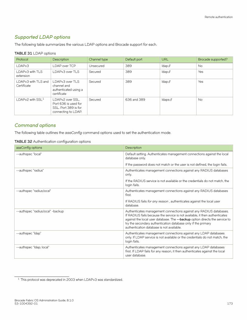
Supported LDAP optionsThe following table summarizes the various LDAP options and Brocade support for each.
TABLE 31 LDAP options
Protocol Description Channel type Default port URL Brocade supported?
LDAPv3 LDAP over TCP Unsecured 389 ldap:// No
LDAPv3 with TLSextension
LDAPv3 over TLS Secured 389 ldap:// Yes
LDAPv3 with TLS andCertificate
LDAPv3 over TLSchannel andauthenticated using acertificate
Secured 389 ldap:// Yes
LDAPv2 with SSL1 LDAPv2 over SSL.Port 636 is used forSSL. Port 389 is forconnecting to LDAP.
Secured 636 and 389 ldaps:// No
Command optionsThe following table outlines the aaaConfig command options used to set the authentication mode.
TABLE 32 Authentication configuration options
aaaConfig options Description
--authspec "local" Default setting. Authenticates management connections against the localdatabase only.
If the password does not match or the user is not defined, the login fails.
--authspec "radius" Authenticates management connections against any RADIUS databasesonly.
If the RADIUS service is not available or the credentials do not match, thelogin fails.
--authspec "radius;local" Authenticates management connections against any RADIUS databasesfirst.
If RADIUS fails for any reason , authenticates against the local userdatabase.
--authspec "radius;local" -backup Authenticates management connections against any RADIUS databases.If RADIUS fails because the service is not available, it then authenticatesagainst the local user database. The --backup option directs the service totry the secondary authentication database only if the primaryauthentication database is not available.
--authspec "ldap" Authenticates management connections against any LDAP databasesonly. If LDAP service is not available or the credentials do not match, thelogin fails.
--authspec "ldap; local" Authenticates management connections against any LDAP databasesfirst. If LDAP fails for any reason, it then authenticates against the localuser database.
1 This protocol was deprecated in 2003 when LDAPv3 was standardized.
Remote authentication
Brocade Fabric OS Administration Guide, 8.1.053-1004392-01 173

TABLE 32 Authentication configuration options (continued)
aaaConfig options Description
--authspec "ldap; local" -backup Authenticates management connections against any LDAP databasesfirst. If LDAP fails for any reason, it then authenticates against the localuser database. The --backup option states to try the secondaryauthentication database only if the primary authentication database is notavailable.
--authspec "tacacs+" Authenticates management connections against any TACACS+ databasesonly. If TACACS+ service is not available or the credentials do not match,the login fails.
--authspec "tacacs+; local" Authenticates management connections against any TACACS+ databasesfirst. If TACACS+ fails for any reason, it then authenticates against the localuser database.
--authspec "tacacs+; local" -backup Authenticates management connections against any TACACS+ databasesfirst. If TACACS+ fails for any reason, it then authenticates against the localuser database. The --backup option states to try the secondaryauthentication database only if the primary authentication database is notavailable.
--authspec <auth-type> -nologout Prevents users from being logged out when you change authentication.Default behavior is to log out users when you change authentication.
--authspec <auth-type> -logpriauth [yes/no] Suppresses log messages for authentication failure by primary AAAservice if authentication is to be done using secondary AAA service whichis local switch database. The default value is set to "Yes" and displays loginfailure messages from the primary AAA service always. This is allowed forLDAP, RADIUS, and TACACS+.
Setting the switch authentication mode1. Connect to the switch and log in using an account with admin permissions.
2. Enter the aaaConfig --authspec command.
Fabric OS user accountsRADIUS, LDAP, and TACACS+ servers allow you to set up user accounts by their true network-wide identities rather than by the accountnames created on a Fabric OS switch. With each account name, assign the appropriate switch access permissions. For LDAP servers,you can use the ldapCfg --maprole and --mapattr commands to map LDAP server permissions.
RADIUS, LDAP, and TACACS+ support all the defined RBAC roles described in Role-Based Access Control on page 156.
Users must enter their assigned RADIUS, LDAP, or TACACS+ account name and password when logging in to a switch that has beenconfigured with remote authentication. After the remote authentication (RADIUS, LDAP, or TACACS+) server authenticates a user, itresponds with the assigned switch role in a Brocade Vendor-Specific Attribute (VSA). If the response does not have a VSA permissionsassignment, the user role is assigned or the authentication is rejected.
You can set a user password expiration date and add a warning for RADIUS login and TACACS+ login. The password expiry date mustbe specified in UTC and in MM/DD/YYYY format. The password warning specifies the number of days prior to the password expirationthat a warning of password expiration notifies the user. You either specify both attributes or none. If you specify a single attribute or thereis a syntax error in the attributes, the password expiration warning will not be issued. If your RADIUS server maintains its own passwordexpiration attributes, you must set the exact date twice to use this feature, once on your RADIUS server and once in the VSA. If the datesdo not match, then the RADIUS server authentication fails.
Table 33 describes the syntax used for assigning VSA-based account switch roles on a RADIUS server.
Remote authentication
Brocade Fabric OS Administration Guide, 8.1.0174 53-1004392-01
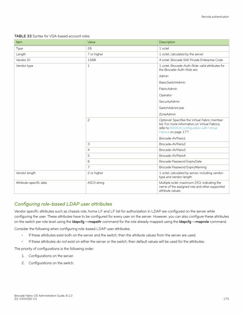
TABLE 33 Syntax for VSA-based account roles
Item Value Description
Type 26 1 octet
Length 7 or higher 1 octet, calculated by the server
Vendor ID 1588 4 octet, Brocade SMI Private Enterprise Code
Vendor type 1 1 octet, Brocade-Auth-Role; valid attributes forthe Brocade-Auth-Role are:
Admin
BasicSwitchAdmin
FabricAdmin
Operator
SecurityAdmin
SwitchAdminUser
ZoneAdmin
2 Optional: Specifies the Virtual Fabric memberlist. For more information on Virtual Fabrics,refer to RADIUS configuration with VirtualFabrics on page 177.
Brocade-AVPairs1
3 Brocade-AVPairs2
4 Brocade-AVPairs3
5 Brocade-AVPairs4
6 Brocade Password ExpiryDate
7 Brocade Password ExpiryWarning
Vendor length 2 or higher 1 octet, calculated by server, including vendor-type and vendor-length
Attribute-specific data ASCII string Multiple octet, maximum 253, indicating thename of the assigned role and other supportedattribute values.
Configuring role-based LDAP user attributesVendor specific attributes such as chassis role, home LF and LF list for authorization in LDAP are configured on the server whileconfiguring the user. These attributes have to be configured for every user on the server. However, you can also configure these attributeson the switch per role level using the ldapcfg --mapattr command for the role already mapped using the ldapcfg --maprole command.
Consider the following when configuring role-based LDAP user attributes:
• If these attributes exist both on the server and the switch, then the attribute values from the server are used.
• If these attributes do not exist on either the server or the switch, then default values will be used for the attributes.
The priority of configurations is the following order:
1. Configurations on the server.
2. Configurations on the switch.
Remote authentication
Brocade Fabric OS Administration Guide, 8.1.053-1004392-01 175
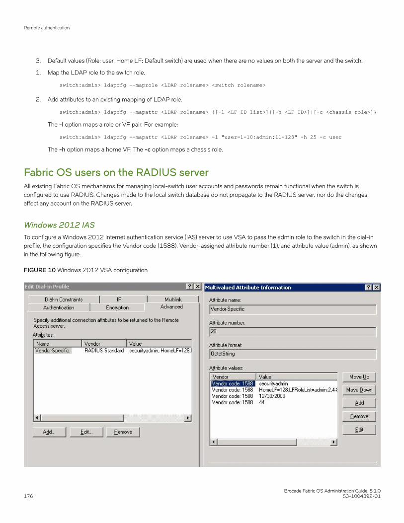
3. Default values (Role: user, Home LF: Default switch) are used when there are no values on both the server and the switch.
1. Map the LDAP role to the switch role.
switch:admin> ldapcfg --maprole <LDAP rolename> <switch rolename>
2. Add attributes to an existing mapping of LDAP role.
switch:admin> ldapcfg --mapattr <LDAP rolename> {[-l <LF_ID list>]|[-h <LF_ID>]|[-c <chassis role>]}
The -l option maps a role or VF pair. For example:
switch:admin> ldapcfg --mapattr <LDAP rolename> -l "user=1-10;admin:11-128" -h 25 -c user
The -h option maps a home VF. The -c option maps a chassis role.
Fabric OS users on the RADIUS serverAll existing Fabric OS mechanisms for managing local-switch user accounts and passwords remain functional when the switch isconfigured to use RADIUS. Changes made to the local switch database do not propagate to the RADIUS server, nor do the changesaffect any account on the RADIUS server.
Windows 2012 IASTo configure a Windows 2012 Internet authentication service (IAS) server to use VSA to pass the admin role to the switch in the dial-inprofile, the configuration specifies the Vendor code (1588), Vendor-assigned attribute number (1), and attribute value (admin), as shownin the following figure.
FIGURE 10 Windows 2012 VSA configuration
Remote authentication
Brocade Fabric OS Administration Guide, 8.1.0176 53-1004392-01
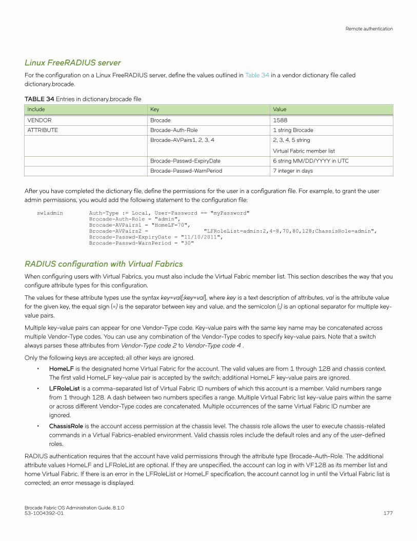
Linux FreeRADIUS serverFor the configuration on a Linux FreeRADIUS server, define the values outlined in Table 34 in a vendor dictionary file calleddictionary.brocade.
TABLE 34 Entries in dictionary.brocade file
Include Key Value
VENDOR Brocade 1588
ATTRIBUTE Brocade-Auth-Role 1 string Brocade
Brocade-AVPairs1, 2, 3, 4 2, 3, 4, 5 string
Virtual Fabric member list
Brocade-Passwd-ExpiryDate 6 string MM/DD/YYYY in UTC
Brocade-Passwd-WarnPeriod 7 integer in days
After you have completed the dictionary file, define the permissions for the user in a configuration file. For example, to grant the useradmin permissions, you would add the following statement to the configuration file:
swladmin Auth-Type := Local, User-Password == "myPassword" Brocade-Auth-Role = "admin", Brocade-AVPairs1 = "HomeLF=70", Brocade-AVPairs2 = "LFRoleList=admin:2,4-8,70,80,128;ChassisRole=admin", Brocade-Passwd-ExpiryDate = "11/10/2011", Brocade-Passwd-WarnPeriod = "30"
RADIUS configuration with Virtual FabricsWhen configuring users with Virtual Fabrics, you must also include the Virtual Fabric member list. This section describes the way that youconfigure attribute types for this configuration.
The values for these attribute types use the syntax key=val[;key=val], where key is a text description of attributes, val is the attribute valuefor the given key, the equal sign (=) is the separator between key and value, and the semicolon (;) is an optional separator for multiple key-value pairs.
Multiple key-value pairs can appear for one Vendor-Type code. Key-value pairs with the same key name may be concatenated acrossmultiple Vendor-Type codes. You can use any combination of the Vendor-Type codes to specify key-value pairs. Note that a switchalways parses these attributes from Vendor-Type code 2 to Vendor-Type code 4 .
Only the following keys are accepted; all other keys are ignored.
• HomeLF is the designated home Virtual Fabric for the account. The valid values are from 1 through 128 and chassis context.The first valid HomeLF key-value pair is accepted by the switch; additional HomeLF key-value pairs are ignored.
• LFRoleList is a comma-separated list of Virtual Fabric ID numbers of which this account is a member. Valid numbers rangefrom 1 through 128. A dash between two numbers specifies a range. Multiple Virtual Fabric list key-value pairs within the sameor across different Vendor-Type codes are concatenated. Multiple occurrences of the same Virtual Fabric ID number areignored.
• ChassisRole is the account access permission at the chassis level. The chassis role allows the user to execute chassis-relatedcommands in a Virtual Fabrics-enabled environment. Valid chassis roles include the default roles and any of the user-definedroles.
RADIUS authentication requires that the account have valid permissions through the attribute type Brocade-Auth-Role. The additionalattribute values HomeLF and LFRoleList are optional. If they are unspecified, the account can log in with VF128 as its member list andhome Virtual Fabric. If there is an error in the LFRoleList or HomeLF specification, the account cannot log in until the Virtual Fabric list iscorrected; an error message is displayed.
Remote authentication
Brocade Fabric OS Administration Guide, 8.1.053-1004392-01 177
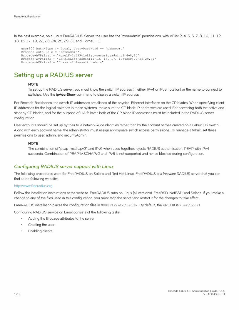
In the next example, on a Linux FreeRADIUS Server, the user has the "zoneAdmin" permissions, with VFlist 2, 4, 5, 6, 7, 8, 10, 11, 12,13, 15 17, 19, 22, 23, 24, 25, 29, 31 and HomeLF 1.
user300 Auth-Type := Local, User-Password == "password"Brocade-Auth-Role = "zoneadmin",Brocade-AVPairs1 = "HomeLF=1;LFRoleList=securityadmin:2,4-8,10"Brocade-AVPairs2 = "LFRoleList=admin:11-13, 15, 17, 19;user:22-25,29,31"Brocade-AVPairs3 = "ChassisRole=switchadmin"
Setting up a RADIUS serverNOTETo set up the RADIUS server, you must know the switch IP address (in either IPv4 or IPv6 notation) or the name to connect toswitches. Use the ipAddrShow command to display a switch IP address.
For Brocade Backbones, the switch IP addresses are aliases of the physical Ethernet interfaces on the CP blades. When specifying clientIP addresses for the logical switches in these systems, make sure the CP blade IP addresses are used. For accessing both the active andstandby CP blades, and for the purpose of HA failover, both of the CP blade IP addresses must be included in the RADIUS serverconfiguration.
User accounts should be set up by their true network-wide identities rather than by the account names created on a Fabric OS switch.Along with each account name, the administrator must assign appropriate switch access permissions. To manage a fabric, set thesepermissions to user, admin, and securityAdmin.
NOTEThe combination of “peap-mschapv2” and IPv6 when used together, rejects RADIUS authentication. PEAP with IPv4succeeds. Combination of PEAP-MSCHAPv2 and IPv6 is not supported and hence blocked during configuration.
Configuring RADIUS server support with LinuxThe following procedures work for FreeRADIUS on Solaris and Red Hat Linux. FreeRADIUS is a freeware RADIUS server that you canfind at the following website:
http://www.freeradius.org
Follow the installation instructions at the website. FreeRADIUS runs on Linux (all versions), FreeBSD, NetBSD, and Solaris. If you make achange to any of the files used in this configuration, you must stop the server and restart it for the changes to take effect.
FreeRADIUS installation places the configuration files in $PREFIX/etc/raddb . By default, the PREFIX is /usr/local .
Configuring RADIUS service on Linux consists of the following tasks:
• Adding the Brocade attributes to the server
• Creating the user
• Enabling clients
Remote authentication
Brocade Fabric OS Administration Guide, 8.1.0178 53-1004392-01

Adding the Brocade attributes to the server
1. Create and save the file $PREFIX/etc/raddb/dictionary.brocade with the following information:
# dictionary.brocade#VENDOR Brocade 1588## attributes#ATTRIBUTE Brocade-Auth-Role 1 string BrocadeATTRIBUTE Brocade-AVPairs1 2 string BrocadeATTRIBUTE Brocade-AVPairs2 3 string BrocadeATTRIBUTE Brocade-AVPairs3 4 string BrocadeATTRIBUTE Brocade-AVPairs4 5 string BrocadeATTRIBUTE Brocade-Passwd-ExpiryDate 6 string BrocadeATTRIBUTE Brocade-Passwd-WarnPeriod 7 string Brocade
This information defines the Brocade vendor ID as 1588, Brocade attribute 1 as Brocade-Auth-Role, Brocade attribute 6 asBrocade-Passwd-ExpiryDate, and Brocade attribute 7 as Brocade-Passwd-WarnPeriod.
2. Open the file $PREFIX/etc/raddb/dictionary in a text editor and add the line:
$INCLUDE dictionary.brocade
As a result, the file dictionary.brocade is located in the RADIUS configuration directory and loaded for use by the RADIUS
server.
Creating the user
1. Open the $PREFIX/etc/raddb/user file in a text editor.
2. Add the user names and their permissions for users accessing the switch and authenticating through RADIUS.
The user logs in using the permissions specified with Brocade-Auth-Role. The valid permissions include root, admin,switchAdmin, zoneAdmin, securityAdmin, basic SwitchAdmin, fabricAdmin, operator, and user. You must use quotation marksaround "password" and "role".
Example of adding a user name to the RADIUS authentication
For example, to set up an account called JohnDoe with admin permissions with a password expiry date of May 28, 2008 and a warningperiod of 30 days:
JohnDoe Auth-Type := LocalUser-Password == "johnPassword", Brocade-Auth-Role = "admin",Brocade-Passwd-ExpiryDate = "05/28/08",Brocade-Passwd-WarnPeriod = "30"
Remote authentication
Brocade Fabric OS Administration Guide, 8.1.053-1004392-01 179

Example of using the local system password to authenticate users
The following example uses the local system password file to authenticate users.
Auth-Type := SystemBrocade-Auth-Role = "admin", Brocade-AVPairs1 = "HomeLF=70",Brocade-AVPairs2 = "LFRoleList=admin:2,4-8,70,80,128",Brocade-AVPairs3 = "ChassisRole=switchadmin",Brocade-Passwd-ExpiryDate = "11/10/2008",Brocade-Passwd-WarnPeriod = "30"
When you use network information service (NIS) for authentication, the only way to enable authentication with the password file is to forcethe Brocade switch to authenticate using Password Authentication Protocol (PAP); this requires the -a pap option with the aaaConfigcommand.
Enabling clients
Clients are the switches that use the RADIUS server; each client must be defined. By default, all IP addresses are blocked.
The Brocade Backbones send their RADIUS requests using the IP address of the active CP. When adding clients, add both the activeand standby CP IP addresses so that, in the event of a failover, users can still log in to the switch.
1. Open the $PREFIX/etc/raddb/client.config file in a text editor and add the switches that are to be configured as
RADIUS clients.
For example, to configure the switch at IP address 10.32.170.59 as a client, the following is displayed:
client 10.32.170.59 secret = Secret shortname = Testing Switch nastype = other
In this example, shortname is an alias used to easily identify the client. Secret is the shared secret between the client and server.Make sure the shared secret matches that configured on the switch (refer to Adding an authentication server to the switchconfiguration on page 196).
2. Save the file $PREFIX/etc/raddb/client.config, and then start the RADIUS server as follows:
$PREFIX/sbin/radiusd
Configuring RADIUS server support with Windows 2012The instructions for setting up RADIUS on a Windows 2012 server are listed here for your convenience but are not guaranteed to beaccurate for your network environment. Always check with your system administrator before proceeding with setup.
NOTEAll instructions involving Microsoft Windows 2012 can be obtained from www.microsoft.com or your Microsoft documentation.Confer with your system or network administrator prior to configuration for any special needs that your network environmentmight have.
Configuring RADIUS service on Windows 2012 consists of the following steps:
1. Installing Internet Authentication Service (IAS)
For more information and instructions on installing IAS, refer to the Microsoft website.
Remote authentication
Brocade Fabric OS Administration Guide, 8.1.0180 53-1004392-01

2. Enabling the Challenge Handshake Authentication Protocol (CHAP)
If CHAP authentication is required, then Windows must be configured to store passwords with reversible encryption. Reversepassword encryption is not the default behavior; it must be enabled.
NOTEIf a user is configured prior to enabling reverse password encryption, then the user’s password is stored and cannotutilize CHAP. To use CHAP, the password must be re-entered after encryption is enabled. If the password is not re-entered, then CHAP authentication will not work and the user will be unable to authenticate from the switch.Alternatives to using CHAP are Password Authentication Protocol (PAP), or PEAP-MSCHAPv2.
3. Configuring a user
IAS is the Microsoft implementation of a RADIUS server and proxy. IAS uses the Windows native user database to verify userlogin credentials; it does not list specific users, but instead lists user groups. Each user group should be associated with aspecific switch role. For example, you should configure a user group for root, admin, switchAdmin, and user, and then add anyusers whose logins you want to associate with the appropriate group.
4. Configuring the server
For more information and instructions on configuring the server, refer to the Microsoft website. You will need the followinginformation to configure the RADIUS server for a Brocade switch. A client is the device that uses the RADIUS server; in thiscase, it is the switch.
5. Check if Active Directory Users and Computers tool is available. If not, select Server Manager > Manager tab > Add Roles andFeature.
The Add Role and Feature wizard is displayed. Follow these steps to install Active Directory Users and Computers.
a) Select Installation Type from the left pane and choose the Role-based or feature-based Installation option.
b) Select Server Selection from the left pane and choose the Select a server from the server pool option.
c) Select the server from the list displayed and click Next.The Features tab is displayed.
d) From the Features tab, select all the checkboxes starting from the Remote Server Administration Tools checkbox till the ADDS Snap-Ins and Command-Line Tools element checkbox in the navigation tree.
e) From the Feature tab, select the Group Policy Management checkbox, and then click Next.The Confirmation tab is displayed.
f) Select the Restart the destination server automatically if required checkbox and click Finish.
Remote authentication
Brocade Fabric OS Administration Guide, 8.1.053-1004392-01 181

6. Check if the switch is part of RADIUS client. If not, select Administrative tools > Network policy server > Radius clients andServers > Radius client from the menu. Right click and add the switch IP address as Radius client.
Client address (IP or DNS) -- Enter the IP address of the switch.
Client-Vendor -- Select RADIUS Standard.
Shared secret -- Provide a password. Shared secret is a password used between the client device and server to prevent IPaddress spoofing by unwanted clients. Keep your shared secret password in a safe place. You will need to enter this password inthe switch configuration.
After clicking Finish , add a new client for all switches on which RADIUS authentication will be used.
a) In the Internet Authentication Service window, right-click the Remote Access Policies folder, and then select New RemoteAccess Policy from the pop-up window.
A remote access policy must be created for each group of Brocade login permissions (root, admin, switchAdmin, and user)for which you want to use RADIUS. Apply this policy to the user groups that you already created.
b) In the Vendor-Specific Attribute Information window, enter the vendor code value 1588. Click the Yes. It conforms option,and then click Configure Attribute.
c) In the Configure VSA (RFC compliant) window, enter the following values, and then click OK.
Vendor-assigned attribute number -- Enter the value 1.
Attribute format -- Enter String.
Attribute value -- Enter the login role (root, admin, switchAdmin, user, and so on) that the user group must use to log in tothe switch.
d) After returning to the Internet Authentication Service window, add additional policies for all Brocade login types for whichyou want to use the RADIUS server. After this is done, you can configure the switch.
7. Add Admin group and CHAP/PAP/PEAP group before adding the user. To add Admin group in Active Directory User andComputers, follow these steps:
a) In Server Manager, open AD DS tab and then open Active Directory User and Computers.
b) Right-click on the left panel tab and select New > Group from the menu.The New Object - Group dialog box is displayed.
c) Enter the Group name as "admin". Select the Group scope as Global and Group type as Security and then click OK.The admin Properties window displayed.
d) Enter the Description as "FOS admin role" and click Apply.
8. Add CHAP group in Active Directory Users and Computers. To add CHAP group, follow these steps:
a) In Server Manager, open AD DS tab and then open Active Directory User and Computers.
b) Right-click on the left panel tab and select New > Group from the menu.The New Object - Group dialog box is displayed.
c) Enter the Group name as "chap". Select the Group scope as Global and Group type as Security and then click OK.The chap Properties window displayed.
d) Enter the Description as "FOS chap group" and click Apply.
Remote authentication
Brocade Fabric OS Administration Guide, 8.1.0182 53-1004392-01

9. Define a CHAP policy for CHAP group users. To define the CHAP policy, follow these steps:
a) Open the Administrative tools > Network policy server > Policies > Network Policies from the menu bar.
b) Right-click and select New.The New Network Policy dialog box is displayed.
c) Enter the policy name as "swchap". Select the Type of network access server as Unspecified and click Next.
d) Click Add and then select the Windows Groups from the list.The Select Group dialog box is displayed.
e) Enter the object name to select as "chap" and then click OK. Click Next.The Specify Access Permission window is displayed.
f) Select the Access granted option and click Next.The Configure Authentication Methods window is displayed.
g) Select the Encrypted authentication (CHAP) check box and click Next.The Configure Settings window is displayed.
h) Select the Vendor Specific option from the left pane and click Add.The Add Vendor Specific Attribute dialog box is displayed.
i) Select RADIUS Standard from the list and click Add.The Vendor Specific Attribute Information dialog box is displayed.
j) Select RADIUS Standard from the list and choose the Yes, it confirms option. Click OK.The Configure VSA (RFC Compliant) dialog box is displayed.
k) Select the Vendor assigned attribute number, Attribute format as String, and Attribute value as "admin" and then click OK.
l) Click Finish.
10. Add new Radius user with CHAP authentication. To add a Radius user follow these steps:
a) In Server Manager, open AD DS tab and then open Active Directory User and Computers.
b) Right-click on the left panel tab and select New > User from the menu.The New Object - User dialog box is displayed.
c) Enter First name and User Logon name as "swchap", select the server from the list and click Next.
d) Enter a password, confirm the password, and then click Next.
e) Click Finish, select the added user from the list.
f) Right-click and select Properties.The swchap Properties dialog box is displayed.
g) Select the Account tab and complete the details.
h) Select the Member of tab, click Add, and then add the user Role as admin. Apply changes and click OK.
Remote authentication
Brocade Fabric OS Administration Guide, 8.1.053-1004392-01 183
11. Add new Radius user with PAP authentication. To add a Radius user follow these steps:
a) In Server Manager, open AD DS tab and then open Active Directory User and Computers.
b) Right-click on the left panel tab and select New > User from the menu.The New Object - User dialog box is displayed.
c) Enter First name and User Logon name as "swpap", select the server from the list and click Next.
d) Enter a password, confirm the password, and then click Next.
e) Click Finish, select the added user from the list.
f) Right-click and select Properties.The swpap Properties dialog box is displayed.
g) Select the Account tab and complete the details.
h) Select the Member of tab, click Add, Add the user Role as admin and PAP group member. Apply changes and click OK.
12. Configure client for added user server and try to log in with added user from client machine.
RSA RADIUS serverTraditional password-based authentication methods are based on one-factor authentication, where you confirm your identity using amemorized password. Two-factor authentication increases the security by using a second factor to corroborate identification. The firstfactor is either a PIN or password and the second factor is the RSA SecurID token.
RSA SecurID with an RSA RADIUS server is used for user authentication. The Brocade switch does not communicate directly with theRSA Authentication Manager, so the RSA RADIUS server is used in conjunction with the switch to facilitate communication.
To learn more about how RSA SecurID works, visit www.rsa.com for more information.
Setting up the RSA RADIUS server
For more information on how to install and configure the RSA Authentication Manager and the RSA RADIUS server, refer to yourdocumentation or visit www.rsa.com.
1. Create user records in the RSA Authentication Manager.
2. Configure the RSA Authentication Manager by adding an agent host.
Remote authentication
Brocade Fabric OS Administration Guide, 8.1.0184 53-1004392-01

3. Configure the RSA RADIUS server.
Setting up the RSA RADIUS server involves adding RADIUS clients, users, and vendor-specific attributes to the RSA RADIUSserver.
a) Add the following data to the vendor.ini file:
vendor-product = Brocade
dictionary = brocade
ignore-ports = no
port-number-usage = per-port-type
help-id = 2000
b) Create a brocade.dct file that must be added into thedictiona.dcm file located in the following path:
C:\Program Files\RSA Security\RSA RADIUS\ServiceExample of a brocade.dct file
######################################################################## brocade.dct -- Brocade Dictionary## (See readme.dct for more details on the format of this file)######################################################################### Use the Radius specification attributes in lieu of the Brocade one:#@radius.dctMACRO Brocade-VSA(t,s) 26 [vid=1588 type1=%t% len1=+2 data=%s%]ATTRIBUTE Brocade-Auth-Role Brocade-VSA(1,string) rATTRIBUTE Brocade-Passwd-ExpiryDate Brocade-VSA(6,string) rATTRIBUTE Brocade-Passwd-WarnPeriod Brocade-VSA(7,integer) r######################################################################## brocade.dct -- Brocade Dictionary#######################################################################
Example of the dictiona.dcm file
######################################################################## dictiona.dcm######################################################################## Generic [email protected]## Specific Implementations (vendor specific)#@[email protected]@[email protected]@[email protected]@[email protected]@[email protected]@[email protected]@[email protected]@bandwagn.dct @brocade.dct <-------
Remote authentication
Brocade Fabric OS Administration Guide, 8.1.053-1004392-01 185

Example of a brocade.dct file shows what the brocade.dct file should look like and Example of the dictiona.dcm file showswhat needs to be modified in the dictiona.dcm file.
NOTEThe dictionary files for the RSA RADIUS server must remain in the installation directory. Do not move the files toother locations on your computer.
c) Add Brocade-VSA macro and define the attributes as follows:
• vid (Vendor-ID): 1588
• type1 (Vendor-Type): 1
• len1 (Vendor-Length): >=2
d) When selecting items from the Add Return List Attribute , select Brocade-Auth-Role and type the string Admin . Thestring you type equals the role on the switch.
e) Add the Brocade profile.
f) In RSA Authentication Manager , edit the user records that will be authenticated using RSA SecurID.
LDAP configuration and Microsoft Active DirectoryLDAP provides user authentication and authorization using the Microsoft Active Directory service or using OpenLDAP in conjunctionwith LDAP on the switch. This section discusses authentication and authorization using Microsoft Active Directory. For information aboutauthentication and authorization using OpenLDAP, refer to LDAP configuration and OpenLDAP on page 188.
Two operational modes exist in LDAP authentication, FIPS mode and non-FIPS mode. This section discusses LDAP authentication innon-FIPS mode. For more information on LDAP in FIPS mode, refer to Configuring Security Policies on page 235.
The following are restrictions when using LDAP in non-FIPS mode:
• Passwords cannot be changed through Active Directory.
• Migration of newly created users is not automatic from the local switch database to Active Directory. This is a manual processexplained later.
• Only IPv4 is supported for LDAP on Windows 2000 and LDAP on Windows Server 2003. For LDAP on Windows Server2008, both IPv4 and IPv6 are supported.
• LDAP authentication is used on the local switch only and not for the entire fabric.
• You can use the User-Principal-Name and not the Common-Name for AD LDAP authentication.
To provide backward compatibility, authentication based on the Common Name is still supported for Active Directory LDAP2000 and 2003. Common Name-based authentication is not recommended for new installations.
• A user can belong to multiple groups as long as one of the groups is the primary group. The primary group in the AD servershould not be set to the group corresponding to the switch role. You can choose any other group.
• A user can be part of any Organizational Unit (OU).
When authentication is performed by User-Principal-Name, in Fabric OS 7.1.0 and later releases, the suffix part of the name (the@domain-name part) can be omitted when the user logs in. If the suffix part of the User-Principal-Name name is omitted, the domainname configured for the LDAP server (in the aaaConfig --add command) is added and used for authentication purposes.
Roles for Brocade-specific users can be added through the Microsoft Management Console. Groups created in Active Directory mustcorrespond directly to the RBAC user roles on the switch. Role assignments can be achieved by including the user in the respectivegroup. A user can be assigned to multiple groups such as Switch Admin and Security Admin. For LDAP servers, you can use theldapCfg --maprole command to map LDAP server permissions to one of the default roles available on a switch. For more informationon RBAC roles, refer to Role-Based Access Control on page 156.
Remote authentication
Brocade Fabric OS Administration Guide, 8.1.0186 53-1004392-01

NOTEAll instructions involving Microsoft Active Directory can be obtained from www.microsoft.com or your Microsoft documentation.Confer with your system or network administrator prior to configuration for any special needs your network environment mayhave.
Configuring Microsoft Active Directory LDAP serviceThe following is an overview of the process used to set up LDAP.
1. If your Windows Active Directory server for LDAP needs to be verified by the LDAP client (that is, the Brocade switch), then youmust install a Certificate Authority (CA) certificate on the Windows Active Directory server for LDAP.
Follow Microsoft instructions for generating and installing CA certificates on a Windows server.
2. Create a user in Microsoft Active Directory server.
For instructions on how to create a user, refer to www.microsoft.com or Microsoft documentation to create a user in your ActiveDirectory.
3. Create a group name that uses the switch’s role name so that the Active Directory group’s name is the same as the switch’s rolename.
or
Use the ldapCfg --maprole ldap_role_name switch_role and --mapattr commands to map an LDAP server role to one of thedefault roles available on the switch.
4. Associate the user to the group by adding the user to the group.
5. Add the user’s Virtual Fabrics to the CN_list by either editing the adminDescription value or adding the brcdAdVfData attributeto the existing Active Directory schema.
This action maps the Virtual Fabrics to the user name. Virtual Fabrics are added as a string value separate by a comma ( , ) andentered as a range.
Creating a userTo create a user in Active Directory, refer to www.microsoft.com or Microsoft documentation. There are no special attributes to set. Youcan use a fully qualified name for logging in; for example, you can log in as "[email protected]".
Creating a groupTo create a group in Active Directory, refer to www.microsoft.com or Microsoft documentation. You must verify that the group has thefollowing attributes:
• The name of the group must match the RBAC role.
• The Group Type must be Security.
• The Group Scope must be Global.
• The primary group in the AD server should not be set to the group corresponding to the switch role. You can choose any othergroup.
• If the user you created is not a member of the Users OU, then the User Principal Name, in the format of "user@domain", isrequired to log in.
Remote authentication
Brocade Fabric OS Administration Guide, 8.1.053-1004392-01 187

Assigning the group (role) to the userTo assign the user to a group in Active Directory, refer to www.microsoft.com or Microsoft documentation. If you have a user-definedgroup, use the ldapCfg --maprole command to map LDAP server permissions to one of the default roles available on a switch.Alternatively, update thememberOf field with the login permissions (root, admin, switchAdmin, user, and so on) that the user must use tolog in to the switch.
Adding a Virtual Fabric list1. From the Windows Start menu, select Programs > Administrative Tools > ADSI.msc.
ADSI is a Microsoft Windows Resource Utility. This utility must be installed to proceed with the rest of the setup. For Windows2003, this utility comes with Service Pack 1 or you can download this utility from the Microsoft website.
2. Go to CN=Users.
3. Select Properties. Click the Attribute Editor tab.
4. Double-click the adminDescription attribute.
The String Attribute Editor dialog box displays.
NOTEThe attribute can be added to user objects only.
5. Enter the values of the logical fabrics separated by a semi-colon ( ; ) into the Value field.
Example for adding Virtual Fabrics:
HomeLF=10;LFRoleList=admin:128,10;ChassisRole=admin
In this example, the logical switch that would be logged in to by default is 10. If 10 is not available, then the lowest FID availablewill be chosen. You would have permission to enter logical switch 128 and 10 in an admin role and you would also have thechassis role permission of admin.
NOTEYou can perform batch operations using the Ldifde.exe utility. For more information on importing and exporting
schemas, refer to your Microsoft documentation or visit www.microsoft.com.
Adding attributes to the Active Directory schemaTo create a group in Active Directory, refer to www.microsoft.com or Microsoft documentation. You must:
• Add a new attribute brcdAdVfData as Unicode String.
• Add brcdAdVfData to the person’s properties.
LDAP configuration and OpenLDAPFabric OS provides user authentication and authorization by means of OpenLDAP or the Microsoft Active Directory service inconjunction with LDAP on the switch. This section discusses authentication and authorization using OpenLDAP. For information aboutauthentication and authorization using Microsoft Active Directory, refer to LDAP configuration and Microsoft Active Directory on page186.
Two operational modes exist in LDAP authentication: FIPS mode and non-FIPS mode. This section discusses LDAP authentication innon-FIPS mode. For information on LDAP in FIPS mode, refer to Configuring Security Policies on page 235. When using OpenLDAPin non-FIPS mode, you must use the Common-Name for OpenLDAP authentication. User-Principal-Name is not supported inOpenLDAP. OpenLDAP 2.4.23 is supported.
Remote authentication
Brocade Fabric OS Administration Guide, 8.1.0188 53-1004392-01

When a user is authenticated, the role of the user is obtained from the memberOf attribute, which determines group membership. Thisfeature is supported in OpenLDAP through the memberOf overlay. You must use this overlay on the OpenLDAP server to assignmembership information.
For OpenLDAP servers, you can use the ldapCfg --maprole command to map LDAP server permissions to one of the default rolesavailable on a switch. For more information on RBAC roles, refer to Role-Based Access Control on page 156.
OpenLDAP server configuration overviewFor complete details about how to install and configure an OpenLDAP server, refer to the OpenLDAP user documentation at http://www.openldap.org/doc/. A few key steps for the Brocade environment are outlined here.
1. If your OpenLDAP server needs to be verified by the LDAP client (that is, the Brocade switch), then you must install a CertificateAuthority (CA) certificate on the OpenLDAP server.
Follow OpenLDAP instructions for generating and installing CA certificates on an OpenLDAP server.
2. Enable group membership through the memberOf mechanism by including the memberOf overlay in the slapd.conf file.
3. Create entries (users) in the OpenLDAP Directory.
4. Assign users to groups by using the member attribute.
5. Use the ldapCfg --maprole ldap_role_name switch_role command to map an LDAP server role to one of the default rolesavailable on the switch.
6. Add the user’s Virtual Fabrics to the user entry.
a) Add the brcdAdVfData attribute to the existing OpenLDAP schema,
b) Add the brcdAdVfData attribute to the user entry in the LDAP directory with a value that identifies the Virtual Fabrics withwhich to associate the user.
Enabling group membershipGroup membership in OpenLDAP is specified by an overlay called memberOf. Overlays are helpful in customizing the back-endbehavior without requiring changes to the back-end code. The memberOf overlay updates the memberOf attribute whenever changesoccur to the membership attribute of entries of the groupOfNames objectClass. To include this overlay, add "overlay memberof" to theslapd.conf file, as shown in the following example.
overlay memberofExample file:include /usr/local/etc/openldap/schema/core.schemainclude /usr/local/etc/openldap/schema/cosine.schemainclude /usr/local/etc/openldap/schema/local.schema###############################################TLSCACertificateFile /root/sachin/ldapcert/cacert.pemTLSCertificateFile /root/sachin/ldapcert/serverCert.pemTLSCertificateKeyFile /root/sachin/ldapcert/serverKey.pemTLSVerifyClient neverpidfile /usr/local/var/run/slapd.pidargsfile /usr/local/var/run/slapd.argsdatabase bdbsuffix "dc=mybrocade,dc=com"rootdn "cn=Manager,dc=mybrocade,dc=com"rootpw {SSHA}HL8uT5hPaWyIdcP6yAheMT8n0GoWubr3# The database directory MUST exist prior to running slapd AND# should only be accessible by the slapd and slap tools.# Mode 700 recommended.directory /usr/local/var/openldap-data# Indices to maintainindex objectClass eqoverlay memberof
Remote authentication
Brocade Fabric OS Administration Guide, 8.1.053-1004392-01 189
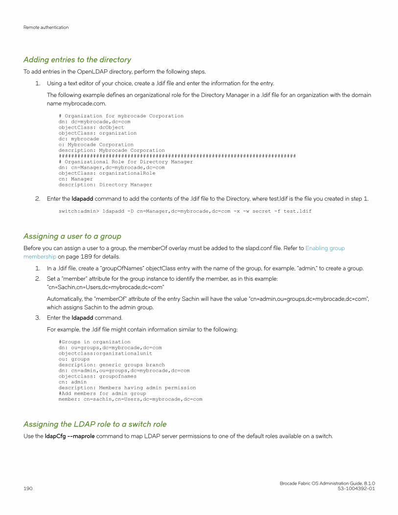
Adding entries to the directoryTo add entries in the OpenLDAP directory, perform the following steps.
1. Using a text editor of your choice, create a .ldif file and enter the information for the entry.
The following example defines an organizational role for the Directory Manager in a .ldif file for an organization with the domainname mybrocade.com.
# Organization for mybrocade Corporationdn: dc=mybrocade,dc=comobjectClass: dcObjectobjectClass: organizationdc: mybrocadeo: Mybrocade Corporationdescription: Mybrocade Corporation############################################################################# Organizational Role for Directory Managerdn: cn=Manager,dc=mybrocade,dc=comobjectClass: organizationalRolecn: Managerdescription: Directory Manager
2. Enter the ldapadd command to add the contents of the .ldif file to the Directory, where test.ldif is the file you created in step 1.
switch:admin> ldapadd -D cn=Manager,dc=mybrocade,dc=com -x -w secret -f test.ldif
Assigning a user to a groupBefore you can assign a user to a group, the memberOf overlay must be added to the slapd.conf file. Refer to Enabling groupmembership on page 189 for details.
1. In a .ldif file, create a "groupOfNames" objectClass entry with the name of the group, for example, "admin," to create a group.
2. Set a "member" attribute for the group instance to identify the member, as in this example:"cn=Sachin,cn=Users,dc=mybrocade,dc=com"
Automatically, the "memberOf" attribute of the entry Sachin will have the value "cn=admin,ou=groups,dc=mybrocade,dc=com",which assigns Sachin to the admin group.
3. Enter the ldapadd command.
For example, the .ldif file might contain information similar to the following:
#Groups in organizationdn: ou=groups,dc=mybrocade,dc=comobjectclass:organizationalunitou: groupsdescription: generic groups branchdn: cn=admin,ou=groups,dc=mybrocade,dc=comobjectclass: groupofnamescn: admindescription: Members having admin permission#Add members for admin groupmember: cn=sachin,cn=Users,dc=mybrocade,dc=com
Assigning the LDAP role to a switch roleUse the ldapCfg --maprole command to map LDAP server permissions to one of the default roles available on a switch.
Remote authentication
Brocade Fabric OS Administration Guide, 8.1.0190 53-1004392-01
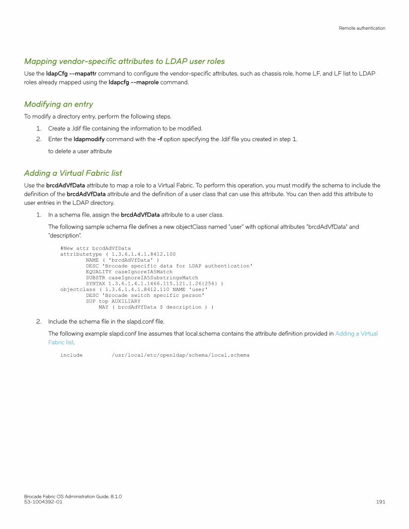
Mapping vendor-specific attributes to LDAP user rolesUse the ldapCfg --mapattr command to configure the vendor-specific attributes, such as chassis role, home LF, and LF list to LDAProles already mapped using the ldapcfg --maprole command.
Modifying an entryTo modify a directory entry, perform the following steps.
1. Create a .ldif file containing the information to be modified.
2. Enter the ldapmodify command with the -f option specifying the .ldif file you created in step 1.
to delete a user attribute
Adding a Virtual Fabric listUse the brcdAdVfData attribute to map a role to a Virtual Fabric. To perform this operation, you must modify the schema to include thedefinition of the brcdAdVfData attribute and the definition of a user class that can use this attribute. You can then add this attribute touser entries in the LDAP directory.
1. In a schema file, assign the brcdAdVfData attribute to a user class.
The following sample schema file defines a new objectClass named "user" with optional attributes "brcdAdVfData" and"description".
#New attr brcdAdVfDataattributetype ( 1.3.6.1.4.1.8412.100 NAME ( 'brcdAdVfData' ) DESC 'Brocade specific data for LDAP authentication' EQUALITY caseIgnoreIA5Match SUBSTR caseIgnoreIA5SubstringsMatch SYNTAX 1.3.6.1.4.1.1466.115.121.1.26{256} )objectclass ( 1.3.6.1.4.1.8412.110 NAME 'user' DESC 'Brocade switch specific person' SUP top AUXILIARY MAY ( brcdAdVfData $ description ) )
2. Include the schema file in the slapd.conf file.
The following example slapd.conf line assumes that local.schema contains the attribute definition provided in Adding a VirtualFabric list.
include /usr/local/etc/openldap/schema/local.schema
Remote authentication
Brocade Fabric OS Administration Guide, 8.1.053-1004392-01 191

3. Include the brcdAdVfData attribute in a user entry in the LDAP directory.
• If you are using Virtual Fabrics, enter the value of the logical fabrics to which the user has access. Up to three value fieldscan be specified, separated by an semicolons ( ; ):
– The HomeLF field specifies the user’s home Logical Fabric.– The LFRole list field specifies the additional Logical Fabrics to which the user has access and the user’s access
permissions for those Logical Fabrics. Logical Fabric numbers are separated by commas ( , ). A hyphen ( - ) indicates arange.
– The ChassisRole field designates the permissions that apply to the ChassisRole subset of commands.
Example for adding Virtual Fabrics
In the following example, the logical switch that would be logged in to by default is 10. If 10 is not available, then the lowestFID available will be chosen.The user is given permission to enter logical switches 1 through 128 in an admin role and isalso given the chassis role permission of admin.
brcdAdVfData: HomeLF=10;LFRoleList=admin:1-128;ChassisRole=admin
The following fragment from a file named test4.ldif provides an entry for a user with Virtual Fabric access roles.
# Organizational Role for Usersdn: cn=Users,dc=mybrocade,dc=comobjectClass: organizationalRolecn: Usersdescription: User# User entriesdn: cn=Sachin,cn=Users,dc=mybrocade,dc=comobjectClass: userobjectClass: personobjectClass: uidObjectcn: Sachinsn: Mishradescription: First userbrcdAdVfData: HomeLF=30;LFRoleList=admin:1-128;ChassisRole=adminuserPassword: passuid: [email protected]
The following command adds the user to the LDAP directory.
switch:admin> ldapadd -D cn=Sachin,dc=mybrocade,dc=com -x -w secret -f test4.ldif
TACACS+ serviceFabric OS can authenticate users with a remote server using the Terminal Access Controller Access-Control System Plus (TACACS+)protocol. TACACS+ is a protocol used in AAA server environments consisting of a centralized authentication server and multiple NetworkAccess Servers or clients. Once configured to use TACACS+, a Brocade switch becomes a Network Access Server (NAS).
The following authentication protocols are supported by the TACACS+ server for user authentication:
• Password Authentication Protocol (PAP)
• Challenge Handshake Authentication Protocol (CHAP)
TACACS+ is not a FIPS-supported protocol, so you cannot configure TACACS+ in FIPS mode. To enable FIPS, any TACACS+configuration must be removed.
The TACACS+ server can be a Microsoft Windows server or a Linux server. For Linux servers, use TACACS+ 4.0.4 or later from Cisco.For Microsoft Windows servers, use any TACACS+ freeware that uses TACACS+ protocol v1.78 or later.
Remote authentication
Brocade Fabric OS Administration Guide, 8.1.0192 53-1004392-01

TACACS+ configuration overviewConfiguration is required on both the TACACS+ server and the Brocade switch. On the TACACS+ server, you should assign a role foreach user and, provide lists of Virtual Fabrics to which the user should have access. For details, refer to The tac_plus.cfg file on page193.
On the Brocade switch, use the aaaConfig command to configure the switch to use TACACS+ for authentication. The aaaConfigcommand also allows you to specify up to five TACACS+ servers. When a list of servers is configured, failover from one server to anotherserver happens only if a TACACS+ server fails to respond. It does not happen when user authentication fails.
Failover to another TACACS+ server is achieved by means of a timeout. You can configure a timeout value for each TACACS+ server, sothat the next server can be used in case the first server is unreachable. The default timeout value is 5 seconds.
Retry, the number of attempts to authenticate with a TACAS+ server, is also allowed. The default value is 5 attempts. If authentication isrejected or times out, Fabric OS will try again. The retry value can also be customized for each user.
Refer to Remote authentication configuration on the switch on page 196 for details about configuring the Brocade switch forauthenticating users with a TACACS+ server.
Configuring the TACACS+ server on LinuxFabric OS software supports TACACS+ authentication on a Linux server running the Open Source TACACS+ LINUX package v4.0.4from Cisco. To install and configure this software, perform the following steps.
1. Download the TACACS+ software from http://www.cisco.com and install it.
2. Configure the TACACS+ server by editing the tac_plus.cfg file.
Refer to The tac_plus.cfg file on page 193 for details.
3. Run the tac_plus daemon to start and enable the TACACS+ service on the server.
switch:admin> tac_plus -d 16 /usr/local/etc/mavis/sample/tac_plus.cfg
The tac_plus.cfg fileThe TACACS+ server is configured in the tac_plus.cfg file. Open the file by using the editor of your choice and customize the file asneeded.
You must add users into this file and provide some attributes specific to the Brocade implementation. Table 35 lists and definesattributes specific to Brocade.
TABLE 35 Brocade custom TACACS+ attributes
Attribute Purpose
brcd-role Role assigned to the user account
brcd-AV-Pair1 The Virtual Fabric member list, and chassis role
brcd-AV-Pair2 The Virtual Fabric member list, and chassis role
brcd-passwd-expiryDate The date on which the password expires
brcd-passwd-warnPeriod The time before expiration for the user to receive a warning message
Remote authentication
Brocade Fabric OS Administration Guide, 8.1.053-1004392-01 193

Adding a user and assigning a role
When adding a user to the tac_plus.cfg file, you should at least provide the brcd-role attribute. The value assigned to this attribute shouldmatch a role defined for the switch. When a login is authenticated, the role specified by the brcd-role attribute represents the permissionsgranted to the account. If no role is specified, or if the specified role does not exist on the switch, the account is granted user rolepermissions only.
Refer to Role-Based Access Control on page 156 for details about roles.
The following fragment from a tac_plus.cfg file adds a user named fosuser1 and assigns the securityAdmin role to the account.
user = fosuser1 { chap = cleartext "my$chap$pswrd" pap = cleartext "pap-password" service = exec { brcd-role = securityAdmin; }}
Configuring Virtual Fabric lists
If your network uses Virtual Fabrics, you should create Virtual Fabric lists for each user to identify the Virtual Fabrics to which the accounthas access.
Assign the following key-value pairs to the brcd-AV--Pair1 and, optionally, brcd-AV-Pair2 attributes to grant the account access to theVirtual Fabrics:
• HomeLF is the designated home Virtual Fabric for the account. The valid values are from 1 through 128 and chassis context.The first valid HomeLF key-value pair is accepted by the switch. Additional HomeLF key-value pairs are ignored.
• LFRoleList is a comma-separated list of Virtual Fabric ID numbers to which this account is a member, and specifies the role theaccount has on those Virtual Fabrics. Valid numbers range from 1 through 128. A - between two numbers specifies a range.
The following example sets the home Virtual Fabric for the userVF account to 30 and allows the account admin role access to VirtualFabrics 1, 3, and 4 and securityAdmin access to Virtual Fabrics 5 and 6.
user = userVF { pap = clear "password" service = shell { set brcd-role = zoneAdmin set brcd-AV-Pair1 = "homeLF=30;LFRoleList=admin:1,3,4;securityAdmin:5,6" set brcd-AV-Pair2 = "chassisRole=admin" }}
Configuring the password expiration date
FabricOS allows you to configure a password expiration date for each user account and to configure a warning period for notifying theuser that the account password is about to expire. To configure these values, set the following attributes:
• brcd-passwd-expiryDate sets the password expiration date in mm/dd/yyyy format.
• brcd-passwd-warnPeriod sets the warning period as a number of days.
The following example sets the password expiration date for the fosuser5 account. It also specifies that a warning be sent to the user 30days before the password is due to expire.
user = fosuser5 { pap = clear "password" chap = clear "password" password = clear "password" service = shell { set brcd-role = securityAdmin set brcd-passwd-expiryDate = 03/21/2014;
Remote authentication
Brocade Fabric OS Administration Guide, 8.1.0194 53-1004392-01
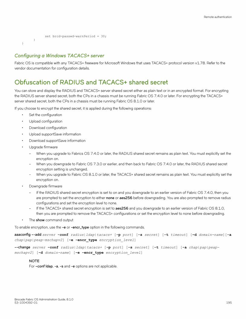
set brcd-passwd-warnPeriod = 30; }}
Configuring a Windows TACACS+ serverFabric OS is compatible with any TACACS+ freeware for Microsoft Windows that uses TACACS+ protocol version v1.78. Refer to thevendor documentation for configuration details.
Obfuscation of RADIUS and TACACS+ shared secretYou can store and display the RADIUS and TACACS+ server shared secret either as plain text or in an encrypted format. For encryptingthe RADIUS server shared secret, both the CPs in a chassis must be running Fabric OS 7.4.0 or later. For encrypting the TACACS+server shared secret, both the CPs in a chassis must be running Fabric OS 8.1.0 or later.
If you choose to encrypt the shared secret, it is applied during the following operations:
• Set the configuration
• Upload configuration
• Download configuration
• Upload supportSave information
• Download supportSave information
• Upgrade firmware
– When you upgrade to Fabrics OS 7.4.0 or later, the RADIUS shared secret remains as plain text. You must explicitly set theencryption on.
– When you downgrade to Fabric OS 7.3.0 or earlier, and then back to Fabric OS 7.4.0 or later, the RADIUS shared secretencryption setting is unchanged.
– When you upgrade to Fabric OS 8.1.0 or later, the TACACS+ shared secret remains as plain text. You must explicitly set theencryption on.
• Downgrade firmware
– If the RADIUS shared secret encryption is set to on and you downgrade to an earlier version of Fabric OS 7.4.0, then youare prompted to set the encryption to either none or aes256 before downgrading. You are also prompted to remove radiusconfigurations and set the encryption level to none.
– If the TACACS+ shared secret encryption is set to aes256 and you downgrade to an earlier version of Fabric OS 8.1.0,then you are prompted to remove the TACACS+ configurations or set the encryption level to none before downgrading.
• The show command output
To enable encryption, use the -e or -encr_type option in the following commands.
aaaconfig –-add server -conf radius|ldap|tacacs+ [-p port] [-s secret] [-t timeout] [–d domain-name][-achap|pap|peap-mschapv2] [-e -encr_type encryption_level]–-change server -conf radius|ldap|tacacs+ [-p port] [-s secret] [-t timeout] [-a chap|pap|peap-mschapv2] [-d domain-name] [-e -encr_type encryption_level]
NOTEFor –conf ldap, -a, -s and -e options are not applicable.
Remote authentication
Brocade Fabric OS Administration Guide, 8.1.053-1004392-01 195

Remote authentication configuration on the switchAt least one RADIUS, LDAP, or TACACS+ server must be configured before you can enable a remote authentication service. You canconfigure the remote authentication service even if it is disabled on the switch. You can configure up to five RADIUS, LDAP, or TACACS+servers. You must be logged in as admin or switchAdmin to configure the RADIUS service.
NOTEOn DCX 8510 Backbones and X6 Directors, the switch sends its RADIUS, LDAP, or TACACS+ request using the IP address ofthe active CP. When adding clients, add both the active and standby CP IP addresses so that users can still log in to the switchin the event of a failover.
RADIUS, LDAP, or TACACS+ configuration is chassis-based configuration data. On platforms containing multiple switch instances, theconfiguration applies to all instances. The configuration is persistent across reboots and firmware downloads. On a chassis-basedsystem, the command must replicate the configuration to the standby CP.
Multiple login sessions can invoke the aaaConfig command simultaneously. The last session that applies the change is the one whoseconfiguration is in effect. This configuration is persistent after an HA failover.
The authentication servers are contacted in the order they are listed, starting from the top of the list and moving to the bottom.
Adding an authentication server to the switch configuration1. Connect to the switch and log in using an account with admin permissions.
2. Enter the aaaConfig --add command.
At least one authentication server must be configured before you can enable the RADIUS, LDAP, or TACACS+ service.
If no RADIUS, LDAP, or TACACS+ configuration exists, turning on the authentication mode triggers an error message. Whenthe command succeeds, the event log indicates that the configuration is enabled or disabled.
Enabling and disabling remote authentication1. Connect to the switch and log in using an account with admin permissions.
2. Enter the aaaConfig --authspec command to enable or disable RADIUS, LDAP, or TACACS+.
You must specify the type of service as one of RADIUS, LDAP, or TACACS+. Local is used for local authentication if the userauthentication fails on the authentication server.
Example for enabling RADIUS
switch:admin> aaaconfig --authspec "radius;local" -backup
Example for enabling LDAP
switch:admin> aaaconfig --authspec "ldap;local" -backup
Example for enabling TACACS+
switch:admin> aaaconfig --authspec "tacacs+;local" -backup
3. You can configure the logpriauth option as yes or no.
switch:admin> aaaconfig --authspec <"aaa1[;aaa2]"> [-backup] [-nologout] [logpriauth <yes/no>]
Remote authentication
Brocade Fabric OS Administration Guide, 8.1.0196 53-1004392-01

Deleting an authentication server from the configuration1. Connect to the switch and log in using an account with admin permissions.
2. Enter the aaaConfig --remove command.
When the command succeeds, the event log indicates that the server is removed.
Changing an authentication server configuration1. Connect to the switch and log in using an account with admin permissions.
2. Enter the aaaConfig --change command.
Changing the order in which authentication servers are contacted for service1. Connect to the switch and log in using an account with admin permissions.
2. Enter the aaaConfig --move command.
When the command succeeds, the event log indicates that a server configuration is changed.
Displaying the current authentication configuration1. Connect to the switch and log in using an account with admin permissions.
2. Enter the aaaConfig --show command.
If a configuration exists, its parameters are displayed. If the RADIUS, LDAP, or TACACS+ services are not configured, only theparameter heading line is displayed. Parameters include:
TABLE 36 Current authentication configuration parameters
Parameter Description
Position The order in which servers are contacted to provide service.
Server The server names or IPv4 or IPv6 addresses. IPv6 is not supportedwhen using PEAP authentication.
Port The server ports.
Secret The shared secrets.
Timeouts The length of time servers have to respond before the next server iscontacted.
Authentication The type of authentication being used on servers.
Configuring local authentication as backupIt is useful to enable local authentication, so that the switch can take over authentication locally if the RADIUS or LDAP servers fail torespond because of power outage or network problems.
1. Connect to the switch and log in using an account with admin permissions.
2. Enter the aaaConfig --authspec command to enable or disable RADIUS, LDAP, or TACACS+ with local authentication as abackup authentication mechanism.
You must specify the type of service as one of RADIUS, LDAP, or TACACS+. Local is used for local authentication if the userauthentication fails on the authentication server.
Remote authentication
Brocade Fabric OS Administration Guide, 8.1.053-1004392-01 197

Example for RADIUSExample of enabling local authentication as a backup for RADIUS.
switch:admin> aaaconfig --authspec "radius;local" -backup
Example for LDAPswitch:admin> aaaconfig --authspec "ldap;local" -backup
Example for TACACS+switch:admin> aaaconfig --authspec "tacacs+;local" -backup
For details about the aaaConfig command refer toCommand options on page 173.
When local authentication is enabled and the authentication servers fail to respond, you can log in to the default switch accounts (adminand user) or any user-defined account. You must know the passwords of these accounts.
When the aaaConfig command succeeds, the event log indicates that local database authentication is disabled or enabled.
Remote authentication
Brocade Fabric OS Administration Guide, 8.1.0198 53-1004392-01

Configuring Protocols• Security protocols...........................................................................................................................................................................................199• Secure Copy..................................................................................................................................................................................................... 201• Secure Shell protocol.................................................................................................................................................................................... 201• Configuring the ciphers, KEX, and MAC algorithms........................................................................................................................209• Secure Sockets Layer protocol ................................................................................................................................................................210• Simple Network Management Protocol................................................................................................................................................218• Telnet protocol..................................................................................................................................................................................................231• Listener applications......................................................................................................................................................................................232• Ports and applications used by switches..............................................................................................................................................233
Security protocolsSecurity protocols provide endpoint authentication and communications privacy using cryptography.
Typically, you are authenticated to the switch while the switch remains unauthenticated to you. This means that you can be sure with whatyou are communicating. The next level of security, in which both ends of the conversation are sure with whom they are communicating, isknown as two-factor authentication. Two-factor authentication requires public key infrastructure (PKI) deployment to clients.
Fabric OS supports the secure protocols shown in the following table.
TABLE 37 Secure protocol support
Protocol Description
CHAP Challenge Handshake Authentication Protocol (CHAP) uses sharedsecrets to authenticate switches.
HTTPS HTTPS is a Uniform Resource Identifier scheme used to indicate a secureHTTP connection. Web Tools supports the use of Hypertext TransferProtocol over SSL (HTTPS).
IPsec Internet Protocol Security (IPsec) is a framework of open standards forproviding confidentiality, authentication and integrity for IP datatransmitted over untrusted links or networks.
LDAP Lightweight Directory Access Protocol with TLS uses a certificate authority(CA). By default, LDAP traffic is transmitted unsecured. With the import ofsigned certificates, you can make LDAP traffic confidential and secure byusing Secure Sockets Layer (SSL) / Transport Layer Security (TLS)technology in conjunction with LDAP.
RADIUS RADIUS uses TLS when configured with peap-mschap2. The CAcertificate for RADIUS can be imported using the SecCertMgmtcommand.
SCP Secure Copy (SCP) is a means of securely transferring computer filesbetween a local and a remote host or between two remote hosts, using theSecure Shell (SSH) protocol. Configuration upload and download supportthe use of SCP.
Secure Syslog Secure syslog requires importing syslog CA certificates using theseccertmgmt command.
SFTP Secure File Transfer Protocol (SFTP) is a network protocol for securelytransferring files on a network. Configuration upload and downloadsupport the use of SFTP.
Brocade Fabric OS Administration Guide, 8.1.053-1004392-01 199

TABLE 37 Secure protocol support (continued)
Protocol Description
SNMP Simple Network Management Protocol (SNMP) is used in networkmanagement systems to monitor network-attached devices for conditionsthat warrant administrative attention. Supports SNMPv1 and v3.
SSH Secure Shell (SSH) is a network protocol that allows data to be exchangedover a secure channel between two computers. Encryption providesconfidentiality and integrity of data. SSH uses public-key cryptography toauthenticate the remote computer and allow the remote computer toauthenticate the user, if necessary.
SSL Fabric OS uses Secure Socket Layer (SSL) to support HTTPS. Acertificate must be generated and installed on each switch to enable SSL.Supports SSLv3, 128-bit encryption by default. Also supports TLSv1.0,TLSv1.1, and TLSv1.2.
NOTEChallenge Response Authentication (CRA) is supported in SCP and SSH sessions.
Table 38 describes additional software or certificates that you must obtain to deploy secure protocols.
TABLE 38 Items needed to deploy secure protocols
Protocol Host side Switch side
SSHv2 Secure shell client None
HTTPS No requirement on host side except a browserthat supports HTTPS
Switch IP certificate for SSL
SCP SSH daemon, SCP server None
SNMPv3 None None
The security protocols are designed with the four main use cases described in Table 39.
TABLE 39 Main security scenarios
Fabric Management interfaces Comments
Nonsecure Nonsecure No special setup is needed to use Telnet orHTTP.
Nonsecure Secure Secure protocols may be used. An SSL switchcertificate must be installed if HTTPS is used.
Secure Secure Switches running earlier Fabric OS versions canbe part of the secure fabric, but they do notsupport secure management.
Secure management protocols must beconfigured for each participating switch.Nonsecure protocols may be disabled onnonparticipating switches.
If SSL is used, then certificates must beinstalled. For more information on installingcertificates, refer to Installing a switch certificateon page 213.
Secure Nonsecure You must use SSH because Telnet is notallowed with some features.
Security protocols
Brocade Fabric OS Administration Guide, 8.1.0200 53-1004392-01

Secure CopyThe Secure Copy protocol (SCP) runs on port 22. It encrypts data during transfer, thereby avoiding packet sniffers that attempt to extractuseful information during data transfer. SCP relies on SSH to provide authentication and security.
Setting up SCP for configuration uploads and downloadsUse the following procedure to configure SCP for configuration uploads and downloads.
1. Connect to the switch and log in using an account with admin permissions.
2. Enter one of the following commands:
• If Virtual Fabrics is enabled, enter the configurechassis command.
• If Virtual Fabrics is not enabled, enter the configure command.
3. Enter y at the cfgload attributes prompt.
4. Enter y at the Enforce secure configUpload/Download prompt.
Example of setting up SCP for configUpload/download
switch:admin# configure Not all options will be available on an enabled switch.To disable the switch, use the "switchDisable" command.Configure... System services (yes, y, no, n): [no] n ssl attributes (yes, y, no, n): [no] n http attributes (yes, y, no, n): [no] n snmp attributes (yes, y, no, n): [no] n rpcd attributes (yes, y, no, n): [no] n cfgload attributes (yes, y, no, n): [no] yEnforce secure config Upload/Download (yes, y, no, n): [no]# y Enforce signature validation for firmware (yes, y, no, n): [no]#
Secure Shell protocolTo ensure security, Fabric OS supports Secure Shell (SSH) encrypted sessions. SSH encrypts all messages, including the clienttransmission of the password during login.
The SSH package contains a daemon (sshd), which runs on the switch. The daemon supports a wide variety of encryption algorithms,such as Digital Encryption Standard (DES) and Advanced Encryption Standard (AES).
NOTETo maintain a secure network, you should avoid using Telnet or any other unprotected application when you are working on theswitch.
Commands that require a secure login channel must originate from an SSH session. If you start an SSH session, and then use the logincommand to start a nested SSH session, commands that require a secure channel will be rejected.
Fabric OS supports OpenSSH version 6.2p2 and OpenSSL version 1.0.2h with the heartbeat feature disabled .
If you set up a message of the day (MOTD), the MOTD displays either before or after the login prompt, depending on the SSH clientimplementation. Fabric OS does not control when the message displays.
Secure Shell protocol
Brocade Fabric OS Administration Guide, 8.1.053-1004392-01 201

SSH public key authenticationOpenSSH public key authentication provides password-less logins, known as SSH authentication, that uses public and private key pairsfor incoming and outgoing authentication.
This feature allows only one allowed-user to be configured to utilize outgoing OpenSSH public key authentication. Any admin user canperform incoming Open SSH public key authentication.
Using OpenSSH RSA, DSA, and ECDSA, the authentication protocols are based on a pair of specially generated cryptographic keys,called the private key and the public key. The advantage of using these key-based authentication systems is that in many cases, it ispossible to establish secure connections without having to depend on passwords for security. ECDSA asynchronous algorithms areFIPS-compliant.
Incoming authentication is used when the remote host needs to authenticate to the switch. Outgoing authentication is used when theswitch needs to authenticate to a server or remote host, such as when running the configupload or configdownload commands, orperforming firmware download. Both password and public key authentication can coexist on the switch.
NOTESSH is supported only with local user accounts.
Allowed-userFor outgoing authentication, the default admin user must set up the allowed-user with admin permissions. By default, the admin is theconfigured allowed-user. While creating the key pair, the configured allowed-user can choose a passphrase with which the private key isencrypted. Then the passphrase must always be entered when authenticating to the switch. The allowed-user must have adminpermissions to perform OpenSSH public key authentication, import and export keys, generate a key pair for an outgoing connection, anddelete public and private keys.
NOTEThere are no special privileges required for the incoming allowed user.
Configuring incoming SSH authentication1. Log in to your remote host.
2. Generate a key pair for host-to-switch (incoming) authentication by verifying that SSH v2 is installed and working (refer to yourhost’s documentation as necessary) by entering the following command:
ssh-keygen -t rsa
The following example generates RSA/DSA key pair.
anyuser@mymachine: ssh-keygen -t rsaGenerating public/private rsa key pair.Enter file in which to save the key (/users/anyuser/.ssh/id_rsa):Enter passphrase (empty for no passphrase):Enter same passphrase again:Your identification has been saved in /users/anyuser/.ssh/id_rsa.Your public key has been saved in /users/anyuser/.ssh/id_rsa.pub.The key fingerprint is:32:9f:ae:b6:7f:7e:56:e4:b5:7a:21:f0:95:42:5c:d1 anyuser@mymachine
Secure Shell protocol
Brocade Fabric OS Administration Guide, 8.1.0202 53-1004392-01

3. Import the public key to the switch by logging in to the switch as any user with the admin role and entering the sshUtilimportpubkey command to import the key.
The following example adds the public key to the switch.
switch:anyuser> sshutil importpubkeyEnter user name for whom key is imported: aswitchuserEnter IP address:192.168.38.244Enter remote directory:~auser/.sshEnter public key name(must have .pub suffix):id_rsa.pubEnter login name:auserPassword:Public key is imported successfully.
4. Test the setup by logging in to the switch from a remote device, or by running a command remotely using SSH.
Configuring outgoing SSH authenticationAfter the allowed-user is configured, the remaining setup steps must be completed by the allowed-user.
Use the following procedure to configure outgoing SSH authentication.
1. Log in to the switch as the default admin.
2. Change the allowed-user’s permissions to admin, if applicable.
switch:admin> userconfig --change username -r admin
The username variable is the name of the user who can perform SSH public key authentication, and who can import, export,and delete keys.
3. Set up the allowed-user by typing the following command:
switch:admin> sshutil allowuser username
The username variable is the name of the user who has admin privileges.
4. Generate a key pair for switch-to-host (outgoing) authentication by logging in to the switch as the allowed-user and entering thesshUtil genkey command.
You may enter a passphrase for additional security.
Example of generating a key pair on the switch
switch:alloweduser> sshutil genkey [-rsa|-dsa|-ecdsa]Enter passphrase (empty for no passphrase):Enter same passphrase again:Key pair generated successfully.
5. Export the public key to the host by logging in to the switch as the allowed-user and entering the sshUtil exportpubkeycommand to export the key.
Example of exporting a public key from the switch
switch:alloweduser> sshutil exportpubkey Enter IP address:192.168.38.244 Enter remote directory:~auser/.ssh Enter login name:auser Password:public key out_going.pub is exported successfully.
Secure Shell protocol
Brocade Fabric OS Administration Guide, 8.1.053-1004392-01 203

6. Append the public key to a remote host by logging in to the remote host, locating the directory where authorized keys arestored, and appending the public key to the file.
You may need to refer to the host’s documentation to locate where the authorized keys are stored.
7. Test the setup by using a command that uses SCP and authentication, such as firmwareDownload or configUpload.
Deleting public keys on the switchUse the following procedure to delete public keys from the switch.
1. Connect to the switch and log in using an account with admin permissions.
2. Use the sshUtil delpubkeys command to delete public keys.
You will be prompted to enter the name of the user whose the public keys you want to delete. Enter all to delete public keys forall users.
For more information on IP filter policies, refer to Configuring Security Policies on page 235.
Deleting private keys on the switchUse the following procedure to delete private keys from the switch.
1. Log in to the switch as the allowed-user.
2. Use the sshUtil delprivkey command to delete the private key.
For more information on IP filter policies, refer to Configuring Security Policies on page 235.
Generating and installing hostkeys on a switchYou can generate, install, display, and delete SSH hostkeys on a switch.
1. Log in to the switch as the allowed user.
2. Enter the sshutil genhostkey [ -rsa | -dsa | -ecdsa ] command to generate and install the SSH hostkey.
3. Enter the sshutil showhostkey command to display current SSH hostkeys installed on the switch.
4. Enter the sshutil delhostkey [ -rsa | -dsa | -ecdsa ] command to delete the selected SSH hostkeys on the switch.
5. Enter the sshutil rekeyinterval secondscommand to configure the SSH rekey interval from 900 to 3600 seconds. In thefollowing example, the SSH rekey interval is set to 1200
switch:admin> sshutil rekeyinterval 1200
6. Enter the sshutil showrekey to display the SSS rekey interval.
switch:admin> sshutil showrekey
Managing SecCryptoCfg templatesSecCryptoCfg templates provide granularity in choosing, verifying, and confirming the switch cipher configurations according to therequirement, for example Certificate Authorities. Templates can be used to configure the ciphers based on the requirement. Currently,templates are supported for TLS, SSH and FIPS configurations. You can use the secCryptoCfg CLI to configure ciphers and FIPS modethrough a template file. Templates consist of key value pairs for configuring ciphers such as for RADIUS, LDAP, HTTPS, SSH ciphers,SSH key exchange algorithms, and SSH MAC.
Secure Shell protocol
Brocade Fabric OS Administration Guide, 8.1.0204 53-1004392-01

The following default templates are available and supported:
• Default Configuration (default_generic)
• Secured configuration (default_strong)
• FIPS configuration (default_fips)
• CC configuration (default_cc)
A default template can be specific to the requirements of a certification or based on the definition of security configurations for varioussecurity levels. For example, a high-security configuration template can enforce high-security strengths that are not FIPS approved, too.You cannot overwrite the default configurations but can upload the configurations, edit them, and then download them with a differentname. You can create a new template similar to default templates, download it, and apply it. Only a maximum of eight templates,including the default templates, are supported.
Format and rule of the template• The templates must be organized into the following groups and options:
Group Option
SSH Kex, Mac, Enc
HTTPS Ciphers
AAA RAD_Ciphers, LDAP_Ciphers
FIPS Enable, Zeroize, selfTests, Simulate, Bootprom
• The version must be specified to identify the version type.
• If an option is mentioned multiple times, the last value is considered.
• Lines starting with /* are considered to be comments and must be terminated with */
• Configuration upload/download does not include the template files. You must use the commands to import, export, apply, anddelete templates.
Use the following commands to manage the template files:
1. Enter the seccryptocfg --apply command to set a template file.
switch:admin> seccryptocfg –apply <template filename>
NOTEUsing the seccryptocfg --apply is not an approved method for enabling cryptographic compliance in FIPS mode on aswitch. Instead, use the fipscfg command. Refer to Cryptographic compliance in FIPS mode on page 209 foradditional information.
2. Enter the seccryptocfg --import command to import a template file.
switch:admin> seccryptocfg –import <template filename> [-server <ipaddr> -name <user> -proto <ftp|scp> -file <remotefilename>]<Interactive Prompt comes up to provide server details>
3. Enter the seccryptocfg --export command to export a template file.
seccryptocfg --export <template filename> -server <ipaddr> -name <user> -proto <scp|sftp|ftp> -file <remote file name>
Secure Shell protocol
Brocade Fabric OS Administration Guide, 8.1.053-1004392-01 205

4. Enter the seccryptocfg --verify command to verify the running configuration against a required configuration specified in thetemplate file.
switch:admin> seccryptocfg –verify <template filename>
5. Enter the seccryptocfg --show command to display the existing ciphers, Kex, and Mac, or configuration contents in thetemplate file if you provide a template name.
switch:admin> seccryptocfg –show <template filename>switch:admin> seccryptocfg --show
6. Enter the seccryptocfg --delete command to delete a template file.
7. Enter the seccryptocfg --lstemplates command to list all the template files.
Default secCryptoCfg templatesThe following default secCryptoCfg templates are available and supported:
Default_generic
/************************************************************************* Brocade - Generic Template for Security Crypto Configuration** Desc: ** Default values for security crypto configurations for operation in * generic mode**************************************************************************/
[Ver] 0.1
/** Group : SSH * Rules : Comma Separated* Example : aes128-ctr,aes192-ctr -> Note, no space before and after comma.* Valid options: Kex, Mac, Enc*/[SSH] Enc:aes128-ctr,aes192-ctr,aes256-ctr,aes128-cbc,3des-cbc,aes192-cbc,aes256-cbcKex:ecdh-sha2-nistp256,ecdh-sha2-nistp384,ecdh-sha2-nistp521,diffie-hellman-group-exchange-sha256,diffie-hellman-group-exchange-sha1,diffie-hellman-group14-sha1,diffie-hellman-group1-sha1Mac:hmac-md5,hmac-sha1,hmac-sha2-256,hmac-sha2-512
/** Group : AAA* Rules : Textual openssl cipherlist (colan,comma and space separated)* Example: ALL:-MD5:!PSK* Valid options: RAD_Ciphers, LDAP_Ciphers*/[AAA]RAD_Ciphers:!ECDH:!DH:HIGH:-MD5:!CAMELLIA:!SRP:!PSK:!AESGCM LDAP_Ciphers:!ECDH:!DH:HIGH:-MD5:!CAMELLIA:!SRP:!PSK:!AESGCM
/** Group : HTTPS* Rules : Textual openssl cipherlist (colan,comma and space separated)* Example: ALL:-MD5:!PSK* Valid options: Ciphers*/[HTTPS] Ciphers:!ECDH:!DH:HIGH:-MD5:!CAMELLIA:!SRP:!PSK:!AESGCM
Secure Shell protocol
Brocade Fabric OS Administration Guide, 8.1.0206 53-1004392-01

Default_strong
Strong configuration consist of TLSv1.2 and SHA above 256.
/************************************************************************* Brocade - Template for High Security Crypto Configuration** Desc: ** Default values for security crypto configurations for high security**************************************************************************/
[Ver] 0.1
/** Group : SSH * Rules : Comma Separated* Example : aes128-ctr,aes192-ctr -> Note, no space before and after comma.* Valid options: Kex, Mac, Enc*/[SSH] Enc:aes128-ctr,aes192-ctr,aes256-ctr,aes128-cbc,3des-cbc,aes192-cbc,aes256-cbcKex:ecdh-sha2-nistp256,ecdh-sha2-nistp384,ecdh-sha2-nistp521,diffie-hellman-group-exchange-sha256Mac:hmac-sha2-256,hmac-sha2-512
/** Group : AAA* Rules : Textual openssl cipherlist (colan,comma and space separated)* Example: ALL:-MD5:!PSK* Valid options: RAD_Ciphers, LDAP_Ciphers*/[AAA]RAD_Ciphers:!ECDH:!DH:HIGH:-MD5:!CAMELLIA:!SRP:!PSK:!AESGCM:!SSLv3LDAP_Ciphers:!ECDH:!DH:HIGH:-MD5:!CAMELLIA:!SRP:!PSK:!AESGCM:!SSLv3
/** Group : HTTPS* Rules : Textual openssl cipherlist (colan,comma and space separated)* Example: ALL:-MD5:!PSK* Valid options: Ciphers*/[HTTPS] Ciphers:!ECDH:!DH:HIGH:-MD5:!CAMELLIA:!SRP:!PSK:!AESGCM:!SSLv3
Default_fips
FIPS template has the ciphers that are certified for Brocade products. It consists of key value pairs for configuring FIPS such as zeroize,enable, bootprom, and selftests.
/************************************************************************* Brocade - FIPS Template for Security Crypto Configuration** Desc: ** Default values for security crypto configurations for FIPS compliance**************************************************************************/
[Ver] 0.1
/** Group : SSH * Rules : Comma Separated* Example : aes128-ctr,aes192-ctr -> Note, no space before and after comma.* Valid options: Kex, Mac, Enc*/
Secure Shell protocol
Brocade Fabric OS Administration Guide, 8.1.053-1004392-01 207

[SSH] Enc:aes128-ctr,aes192-ctr,aes256-ctr,aes128-cbc,3des-cbc,aes192-cbc,aes256-cbcKex:ecdh-sha2-nistp256,ecdh-sha2-nistp384,ecdh-sha2-nistp521,diffie-hellman-group-exchange-sha256Mac:hmac-sha1,hmac-sha2-256,hmac-sha2-512
/** Group : AAA* Rules : Textual openssl cipherlist (colan,comma and space separated)* Example: ALL:-MD5:!PSK* Valid options: RAD_Ciphers, LDAP_Ciphers*/[AAA]RAD_Ciphers:!ECDH:!DH:HIGH:-MD5:!CAMELLIA:!SRP:!PSK:!AESGCM LDAP_Ciphers:!ECDH:!DH:HIGH:-MD5:!CAMELLIA:!SRP:!PSK:!AESGCM
/** Group : HTTPS* Rules : Textual openssl cipherlist (colan,comma and space separated)* Example: ALL:-MD5:!PSK* Valid options: Ciphers*/[HTTPS] Ciphers:!ECDH:!DH:HIGH:-MD5:!CAMELLIA:!SRP:!PSK:!AESGCM
/** Group : FIPS* Rules : Applicable only to FIPS mode configuration. "yes" for configuration enabled and "no" for disabled* Example: "yes" OR "no"* Valid options: SelfTests, BootProm, Enable*/[FIPS]SelfTests:yesBootProm:noZeroize:yesEnable:noSimulate:no
Default_cc
/************************************************************************* Brocade - Common Criteria (CC) Template for Security Crypto Configuration** Desc: ** Default values for security crypto configurations for CC compliance**************************************************************************/
[Ver] 0.1
/** Group : SSH * Rules : Comma Separated* Example : aes128-ctr,aes192-ctr -> Note, no space before and after comma.* Valid options: Kex, Mac, Enc*/[SSH] Enc:aes128-cbc,aes256-cbcKex:diffie-hellman-group14-sha1,ecdh-sha2-nistp256,ecdh-sha2-nistp384,ecdh-sha2-nistp521Mac:hmac-sha1,hmac-sha2-256,hmac-sha2-512
/** Group : AAA* Rules : Textual openssl cipherlist (colon,comma and space separated)* Example: ALL:-MD5:!PSK* Valid options: RAD_Ciphers, LDAP_Ciphers*/
Secure Shell protocol
Brocade Fabric OS Administration Guide, 8.1.0208 53-1004392-01

[AAA]RAD_Ciphers:!ECDH:!DH:HIGH:-MD5:!CAMELLIA:!SRP:!PSK:!AESGCM:!SSLv3LDAP_Ciphers:!ECDH:!DH:HIGH:-MD5:!CAMELLIA:!SRP:!PSK:!AESGCM:!SSLv3
/** Group : HTTPS* Rules : Textual openssl cipherlist (colon,comma and space separated)* Example: ALL:-MD5:!PSK* Valid options: Ciphers*/[HTTPS] Ciphers:!ECDH:!DH:HIGH:-MD5:!CAMELLIA:!SRP:!PSK:!AESGCM:!3DES:!DES
Cryptographic compliance in FIPS modeTo ensure that the cryptographic modules on switches configured for FIPS always use FIPS-approved cryptography, you must ensurethat only the following supported algorithms are configured; otherwise, the module is in a non-compliant state if it is configure to anyother algorithm or protocol.
[Ver] 0.1 [SSH] Enc:aes128-ctr,aes192-ctr,aes256-ctr,aes128-cbc,3des-cbc,aes192-cbc,aes256-cbcKex:ecdh-sha2-nistp256,ecdh-sha2-nistp384,ecdh-sha2-nistp521,diffie-hellman-group-exchange-sha256Mac:hmac-sha1,hmac-sha2-256,hmac-sha2-512[AAA]RAD_Ciphers:!ECDH:!DH:HIGH:-MD5:!CAMELLIA:!SRP:!PSK:!AESGCM LDAP_Ciphers:!ECDH:!DH:HIGH:-MD5:!CAMELLIA:!SRP:!PSK:!AESGCM[HTTPS] Ciphers:!ECDH:!DH:HIGH:-MD5:!CAMELLIA:!SRP:!PSK:!AESGCM
Configuring the ciphers, KEX, and MAC algorithmsStarting with Fabric OS 7.4.0, you can configure the ciphers, key exchange (KEX), and message authentication code (MAC) algorithmsdictated by your security policies.
1. To configure the ciphers, KEX, and MAC algorithm for SSH, use the seccryptocfg command.
secCryptoCfg --replace -type SSH [-cipher cipher string|-kex value|-mac value] -force
The following example configures the ciphers, and KEX and MAC algorithms.
secCryptoCfg --replace -type SSH -cipher 3des-cbc,aes128-cbc,aes192-cbc -kex diffie-hellman-group-exchange-sha1 -mac hmac-sha2-256
To enforce the default algorithm, use the following command.
secCryptoCfg --default -type SSH –force
2. To configure the cipher for https, use the seccryptocfg.
seccryptocfg --replace -type https -cipher cipher string
3. To display the configured algorithm, use the following command.
secCryptoCfg –-show
Configuring the ciphers, KEX, and MAC algorithms
Brocade Fabric OS Administration Guide, 8.1.053-1004392-01 209

Secure Sockets Layer protocolSecure Sockets Layer (SSL) protocol provides secure access to a fabric through web-based management tools such as Web Tools. SSLsupport is a standard Fabric OS feature.
Switches configured for SSL grant access to management tools through Hypertext Transfer Protocol over SSL links (which begin withhttps:// ) instead of standard links (which begin with http:// ).
SSL uses public key infrastructure (PKI) encryption to protect data transferred over SSL connections. PKI is based on digital certificatesobtained from an Internet Certificate Authority (CA) that acts as the trusted key agent.
Certificates are based on the switch IP address or fully qualified domain name (FQDN), depending on the issuing CA. If you change aswitch IP address or FQDN after activating an associated certificate, you may have to obtain and install a new certificate. Check with theCA to verify this possibility, and plan these types of changes accordingly.
Browser and Java supportFabric OS supports the following web browsers for SSL connections:
• Internet Explorer v7.0 or later (Microsoft Windows)
• Mozilla Firefox v2.0 or later (Solaris and Red Hat Linux)
NOTEReview the release notes for the latest information and to verify if your platform and browser are supported.
In countries that allow the use of 128-bit encryption, you should use the latest version of your browser. For example, Internet Explorer7.0 and later supports 128-bit encryption by default. You can display the encryption support (called "cipher strength") using the InternetExplorer Help > About menu option. If you are running an earlier version of Internet Explorer, you may be able to download anencryption patch from the Microsoft website at http://www.microsoft.com .
You should upgrade to the Java 1.6.0 plug-in on your management workstation. To find the Java version that is currently running, openthe Java console and look at the first line of the window. For more details on levels of browser and Java support, refer to the BrocadeWeb Tools Administrator's Guide.
Enabling TLS 1.2 for the entire Web Tools session requires you to also enable TLS 1.2 in the Java Control Panel.
SSL configuration overviewYou configure SSL access for a switch by obtaining, installing, and activating digital certificates. Certificates are required on all switchesthat are to be accessed through SSL.
Also, you must install a certificate in the Java plug-in on the management workstation, and you might need to add a certificate to yourweb browser.
Configuring for SSL involves these main steps, which are shown in detail in the next sections.
1. Choose a certificate authority (CA).
2. Generate the following items on each switch:
a) A public and private key by using the seccertutil genkey command.
b) A certificate-signing request (CSR) by using the seccertutil gencsr command.
3. Store the CSR on a file server by using the seccertutil export command.
Secure Sockets Layer protocol
Brocade Fabric OS Administration Guide, 8.1.0210 53-1004392-01

4. Obtain the certificates from the CA.
You can request a certificate from a CA through a web browser. After you request a certificate, the CA either sends certificatefiles by e-mail (public) or gives access to them on a remote host (private).
5. On each switch, install the certificate. Once the certificate is loaded on the switch, HTTPS starts automatically.
6. If necessary, install the root certificate to the browser on the management workstation.
7. Add the root certificate to the Java plug-in keystore on the management workstation.
NOTEA new command seccertmgmt performs all operations on certificates for any applications. It is recommended to use it in placeof seccertutil.
Certificate authoritiesTo ease maintenance and allow secure out-of-band communication between switches, consider using one certificate authority (CA) tosign all management certificates for a fabric. If you use different CAs, management services operate correctly, but the Web Tools FabricEvents button is unable to retrieve events for the entire fabric.
Each CA (for example, Verisign or GeoTrust) has slightly different requirements; for example, some generate certificates based on IPaddress, while others require an FQDN, and most require a 1024-bit public/private key pair while some may accept a 2048-bit key.Consider your fabric configuration, check CA websites for requirements, and gather all the information that the CA requires.
Generating a public/private key pairUse the following procedure to generate a public/private key pair.
NOTEYou must perform this procedure on each switch.
1. Connect to the switch and log in using an account with admin permissions.
2. Enter the secCertUtil genkey command to generate a public/private key pair.
The system reports that this process will disable secure protocols, delete any existing CSR, and delete any existing certificates.
3. Respond to the prompts to continue and select the key size.
The following example generates a key pair
Continue (yes, y, no, n): [no] y Select key size [1024 or 2048]: 1024 Generating new rsa public/private key pairDone.
Generating and storing a Certificate Signing RequestAfter generating a public/private key pair, you must generate and store a certificate signing request (CSR).
1. Connect to the switch and log in using an account with admin permissions.
2. Enter secCertUtil gencsr.
Secure Sockets Layer protocol
Brocade Fabric OS Administration Guide, 8.1.053-1004392-01 211

3. Enter the requested information.
The following example generates a CSR.
switch:admin> secCertUtil gencsrInput hash type (sha1 or sha256): sha1Country Name (2 letter code, eg, US):USState or Province Name (full name, eg, California):CaliforniaLocality Name (eg, city name):San JoseOrganization Name (eg, company name):BrocadeOrganizational Unit Name (eg, department name):FOSCommon Name (Fully qualified Domain Name, or IP address):10.17.37.3Generating CSR, file name is: 10.37.209.110.csrDone.
Your CA might require specific codes for Country, State or Province, Locality, Organization, and Organizational Unit names.Make sure that your spelling is correct and matches the CA requirements. If the CA requires that the Common Name bespecified as an FQDN, make sure that the fully qualified domain name is set on the domain name switch or director. The IPaddress or FQDN is the switch where the certificate gets installed.
You can also specify the hash type using the -hash <sha1 | sha256> option while generating the CSR. For example,
switch:admin> seccertutil gencsr -hash sha256 -country IN –state Kar –locality Bng –org brocade –orgunit fos –cn switchip
4. Enter secCertUtil export to store the CSR.
5. Enter the requested information. You can use either FTP or SCP.
If you are set up for Secure Copy Protocol (SCP), you can select it; otherwise, select FTP. Enter the IP address of the switch onwhich you generated the CSR. Enter the remote directory name of the FTP server to which the CSR is to be sent. Enter youraccount name and password on the server.
The following example exports a CSR.
Select protocol [ftp or scp]: ftpEnter IP address: 192.1.2.3Enter remote directory: path_to_remote_directoryEnter Login Name: your accountEnter Password: your passwordSuccess: exported CSR.
Obtaining certificatesOnce you have generated a CSR, you will need to follow the instructions on the website of the certificate issuing authority that you wantto use; and then obtain the certificate.
Fabric OS and HTTPS support the following types of files from the Certificate Authority(CA):
• .cer (binary)
• .crt (binary)
• .pem (text)
Typically, the CA provides the certificate files listed in the following table.
TABLE 40 SSL certificate files
Certificate file Description
name .pem The switch certificate.
name Root.pem The root certificate. Typically, this certificate is already installed in thebrowser, but if not, you must install it.
Secure Sockets Layer protocol
Brocade Fabric OS Administration Guide, 8.1.0212 53-1004392-01

TABLE 40 SSL certificate files (continued)
Certificate file Description
name CA.pem The CA certificate. It must be installed in the browser to verify the validityof the server certificate or server validation fails.
NOTEYou must perform this procedure for each switch.
Use the following procedure to obtain a security certificate.
1. Generate and store the CSR as described in Generating and storing a Certificate Signing Request on page 211.
2. Open a web browser window on the management workstation and go to the CA website. Follow the instructions to request acertificate. Locate the area in the request form into which you are to paste the CSR.
3. Through a Telnet window, connect to the switch and log in using an account with admin permissions.
4. Enter the secCertUtil showcsr command. The contents of the CSR are displayed.
5. Locate the section that begins with "BEGIN CERTIFICATE REQUEST" and ends with "END CERTIFICATE REQUEST".
6. Copy and paste this section (including the BEGIN and END lines) into the area provided in the request form; then, follow theinstructions to complete and send the request.
It may take several days to receive the certificates. If the certificates arrive by e-mail, save them to an FTP server. If the CAprovides access to the certificates on an FTP server, make note of the path name and make sure you have a login name andpassword on the server.
Installing a switch certificateBefore you import a switch certificate, be aware of the following:
• Certificate Authorities may provide their certificates in different encodings and different extensions. Be sure to save thecertificate with the applicable file extension before you import the certificate to the switch.
For example, certificates that contain lines similar to the following are usually .pem encoded:
"----BEGIN REQUEST----" and "----END REQUEST---- (and may include the strings "x509" or "certificate")
• For Certificate Authorities that request information regarding the type of web server, Fabric OS uses the Apache web serverrunning on Linux.
• If you try to import certificates of different sizes for a given switch, the import fails. If this happens, remove the previouscertificate and then import the new certificate.
Use the following procedure to install a security certificate on a switch.
NOTEYou must perform this procedure on each switch.
1. Connect to the switch and log in using an account with admin permissions.
2. Enter the secCertUtil import command.
3. Select a protocol, enter the IP address of the host on which the switch certificate is saved, and enter your login name andpassword.
Secure Sockets Layer protocol
Brocade Fabric OS Administration Guide, 8.1.053-1004392-01 213

Example of installing a switch certificate in interactive mode
switch:admin> seccertutil import -config swcert -enable https Select protocol [ftp or scp]: ftp Enter IP address: 192.10.11.12 Enter remote directory: path_to_remote_directory Enter certificate name (must have ".crt", ".cer", \ ".pem" or ".psk" suffix): 192.1.2.3.crt Enter Login Name: your_account Enter Password: ***** Success: imported certificate [192.1.2.3.crt].
Example of installing a switch certificate in noninteractive mode
switch:admin> seccertutil import -config swcert -enable https \ -protocol ftp -ipaddr 192.10.11.12 -remotedir path_to_remote_directory \ -certname 192.1.2.3.crt -login your_account -password passwd Success: imported certificate [192.1.2.3.crt]. Certificate file in configuration has been updated. Secure http has been enabled.
Example of installing a common certificate in non-interactive mode
switch:admin> seccertutil import -commonswcert -config swcert -enable https -protocol scp -ipaddr 192.10.11.12 -remotedir path_to_remote_directory -login cert -certname 192.1.2.3.pem
Generating self-signed certificatesYou can use the secCertUtil Generate command to generate a new key pair, sign the generated certificate with the private key, install theself-signed identity certificate within the switch for HTTPS, and enable the HTTPS service. Also, using MAPS, you can configure thetime period for notification when certificates expire.
NOTEUsing this feature to generate self-signed certificates for FCAP is notsupported.
1. Log in to the device
2. Run the secCertUtil generate -https command.
switch:admin> seccertutil generate -https -keysize <1024|2048|4096|8192> -type <rsa|dsa> -hash <sha1|sha256|sha512> -years <x >[-nowarn]
Managing the security certificates using the secCertMgmt commandYou can also manage all operations such as generate CSR or certificate, import certificate, export CSR or certificate, delete CSR orcertificates, and display the CSR or certificate for any application using the secCertMgmt command. The secCertMgmt command is animproved alternative to the secCertUtil command.
The following options are available:
switch:admin> seccertmgmt generate - Generate keypairs and CSR or Certificate delete - Delete CSR or Certificates and associated Keypair import - Import Certificate export - Export CSR or Certificate show - List or Display Certificates help - Shows the usage
Secure Sockets Layer protocol
Brocade Fabric OS Administration Guide, 8.1.0214 53-1004392-01
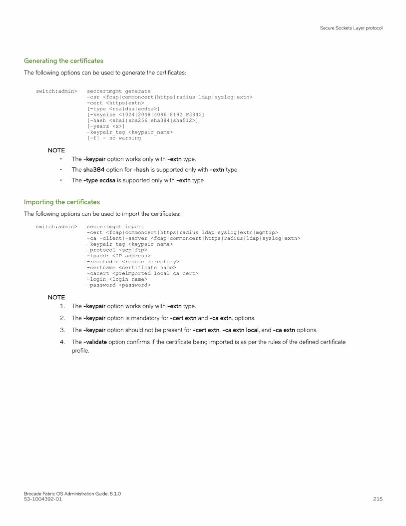
Generating the certificates
The following options can be used to generate the certificates:
switch:admin> seccertmgmt generate -csr <fcap|commoncert|https|radius|ldap|syslog|extn> -cert <https|extn> [-type <rsa|dsa|ecdsa>] [-keysize <1024|2048|4096|8192|P384>] [-hash <sha1|sha256|sha384|sha512>] [-years <x>] -keypair_tag <keypair_name> [-f] - no warning
NOTE• The -keypair option works only with -extn type.
• The sha384 option for -hash is supported only with -extn type.
• The -type ecdsa is supported only with -extn type
Importing the certificates
The following options can be used to import the certificates:
switch:admin> seccertmgmt import -cert <fcap|commoncert|https|radius|ldap|syslog|extn|mgmtip> -ca -client|-server <fcap|commoncert|https|radius|ldap|syslog|extn> -keypair_tag <keypair_name> -protocol <scp|ftp> -ipaddr <IP address> -remotedir <remote directory> -certname <certificate name> -cacert <preimported_local_ca_cert> -login <login name> -password <password>
NOTE1. The -keypair option works only with -extn type.
2. The -keypair option is mandatory for -cert extn and -ca extn. options.
3. The -keypair option should not be present for -cert extn, -ca extn local, and -ca extn options.
4. The -validate option confirms if the certificate being imported is as per the rules of the defined certificateprofile.
Secure Sockets Layer protocol
Brocade Fabric OS Administration Guide, 8.1.053-1004392-01 215

Exporting the certificates
The following options can be used to export the certificates:
switch:admin> seccertmgmt export -cert <fcap|commoncert|https|radius|ldap|syslog|extn|mgmtip> -ca -client|-server <fcap|commoncert|https|radius|ldap|syslog|extn> -csr <fcap|commoncert|https|radius|ldap|syslog|extn> -keypair_tag <keypair_name> -protocol <scp|ftp> -ipaddr <IP address> -remotedir <remote directory> -certname <certificate name> -login <login name> -password <password>
NOTE1. The -keypair option works only with -extn type.
2. The -keypair option is mandatory for -cert extn and -ca extn options.
3. The -keypair option should not be present for -cert extn, -ca extn local, and -ca extn options.
Deleting the certificates
The following options can be used to delete the certificates:
switch:admin> seccertmgmt delete -cert <fcap|commoncert|https|radius|ldap|syslog|extn (<certificate name> | -keypair_tag <keypair_tag>)|mgmtip <certificate name>|all> -ca -client|-server <fcap|commoncert|https|radius|ldap|syslog|extn <certificate name> |all> -csr <fcap|commoncert|https|radius|ldap|syslog|extn -keypair_tag <keypair_tag>> -all <default|fcap|commoncert|https|radius|ldap|syslog|extn|mgmtip> [-f] - no warning
NOTE1. The -keypair option works only with -extn type.
2. The -keypair option is mandatory for -cert extn and -ca extn options.
3. The -keypair option should not be present for -cert extn, -ca extn local, and -ca extn options.
Displaying the certificates
The following options can be used to display the certificates:
switch:admin> seccertmgmt show -cert <fcap|commoncert|https|radius|ldap|syslog|extn <certificate name>|mgmtip <certificate name>> -ca -client|-server <fcap|commoncert|https|radius|ldap|syslog|extn <certificate name>> -csr <fcap|commoncert|https|radius|ldap|syslog|extn <csr name>> -keypair_tag <keypair_name> -hexdump - Dump the hexadecimal output -all
NOTE1. The -keypair option works only with -extn type.
2. The -keypair option is mandatory for -cert extn and -ca extn options.
3. The -keypair option should not be present for -cert extn remote and -ca extn options.
Secure Sockets Layer protocol
Brocade Fabric OS Administration Guide, 8.1.0216 53-1004392-01
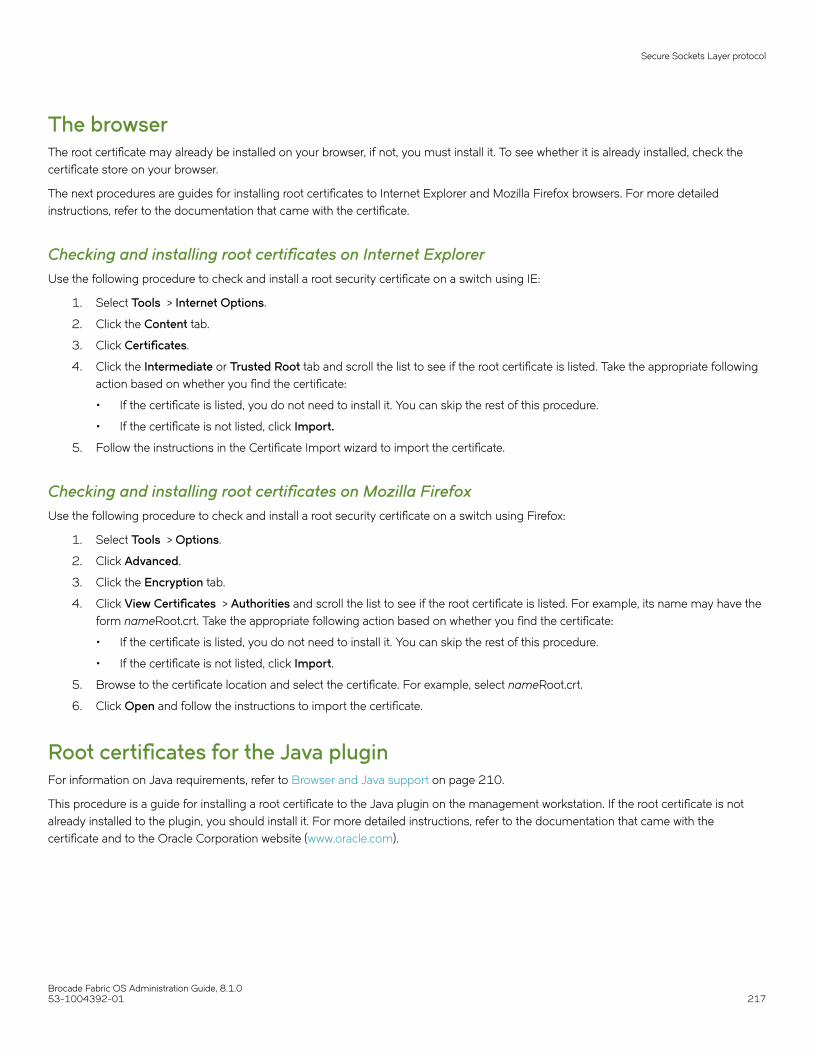
The browserThe root certificate may already be installed on your browser, if not, you must install it. To see whether it is already installed, check thecertificate store on your browser.
The next procedures are guides for installing root certificates to Internet Explorer and Mozilla Firefox browsers. For more detailedinstructions, refer to the documentation that came with the certificate.
Checking and installing root certificates on Internet ExplorerUse the following procedure to check and install a root security certificate on a switch using IE:
1. Select Tools > Internet Options.
2. Click the Content tab.
3. Click Certificates.
4. Click the Intermediate or Trusted Root tab and scroll the list to see if the root certificate is listed. Take the appropriate followingaction based on whether you find the certificate:
• If the certificate is listed, you do not need to install it. You can skip the rest of this procedure.
• If the certificate is not listed, click Import.
5. Follow the instructions in the Certificate Import wizard to import the certificate.
Checking and installing root certificates on Mozilla FirefoxUse the following procedure to check and install a root security certificate on a switch using Firefox:
1. Select Tools > Options.
2. Click Advanced.
3. Click the Encryption tab.
4. Click View Certificates > Authorities and scroll the list to see if the root certificate is listed. For example, its name may have theform nameRoot.crt. Take the appropriate following action based on whether you find the certificate:
• If the certificate is listed, you do not need to install it. You can skip the rest of this procedure.
• If the certificate is not listed, click Import.
5. Browse to the certificate location and select the certificate. For example, select nameRoot.crt.
6. Click Open and follow the instructions to import the certificate.
Root certificates for the Java pluginFor information on Java requirements, refer to Browser and Java support on page 210.
This procedure is a guide for installing a root certificate to the Java plugin on the management workstation. If the root certificate is notalready installed to the plugin, you should install it. For more detailed instructions, refer to the documentation that came with thecertificate and to the Oracle Corporation website (www.oracle.com).
Secure Sockets Layer protocol
Brocade Fabric OS Administration Guide, 8.1.053-1004392-01 217

Installing a root certificate to the Java pluginUse the following procedure to install a root certificate to the Java plugin.
1. Copy the root certificate file from its location on the FTP server to the Java plugin bin directory. For example, the bin locationmay be:
C: \program files\java\j2re1.6.0\bin
2. Open a Command Prompt window and change the directory to the Java plugin bin directory.
3. Enter the keyTool command and respond to the prompts.
Example of installing a root certificate
C:\Program Files\Java\j2re1.6.0\bin> keytool -import -alias RootCert -file RootCert.crt -keystore ..\lib\security\RootCerts Enter keystore password: changeit Owner: CN=Brocade, OU=Software, O=Brocade Communications, L=San Jose, ST=California, C=USIssuer: CN=Brocade, OU=Software, O=Brocade Communications, L=San Jose, ST=California, C=USSerial number: 0Valid from: Thu Jan 15 16:27:03 PST 2007 until: Sat Feb 14 16:27:03 PST 2007Certificate fingerprints: MD5: 71:E9:27:44:01:30:48:CC:09:4D:11:80:9D:DE:A5:E3 SHA1: 06:46:C5:A5:C8:6C:93:9C:FE:6A:C0:EC:66:E9:51:C2:DB:E6:4F:A1Trust this certificate? [no]: yes Certificate was added to keystore
In the example, changeit is the default password and RootCert is an example root certificate name.
Simple Network Management ProtocolSimple Network Management Protocol (SNMP) is a set of protocols for managing complex networks. SNMP protocols are applicationlayer protocols. Using SNMP, devices within a network send messages, called protocol data units (PDUs), to different parts of a network.Network management using SNMP requires three components:
• SNMP Manager
• SNMP Agent
• Management Information Base (MIB)
SNMP ManagerThe SNMP Manager can communicate to the devices within a network using the SNMP protocol. Typically, SNMP Managers arenetwork management systems (NMS) that manage networks by monitoring the network parameters, and optionally, setting parameters inmanaged devices. Normally, the SNMP Manager sends read requests to the devices that host the SNMP Agent, to which the SNMPAgent responds with the requested data. In some cases, the managed devices can initiate the communication, and send data to theSNMP Manager using asynchronous events called traps.
Simple Network Management Protocol
Brocade Fabric OS Administration Guide, 8.1.0218 53-1004392-01

SNMP AgentThe SNMP agent is a software that resides in the managed devices in the network, and collects data from these devices. Each devicehosts an SNMP Agent. The SNMP Agent stores the data, and sends these when requested by an SNMP Manager. In addition, the Agentcan asynchronously alert the SNMP Manager about events, by using special PDUs called traps.
Management Information BaseSNMP Agents in the managed devices store the data about these devices in a database called a Management Information Base (MIB).The MIB is a hierarchical database, which is structured on the standard specified in the RFC 2578 (Structure of Management InformationVersion 2 (SMIv2)).
The MIB is a database of objects that can be used by a network management system to manage and monitor devices on the network.The MIB can be retrieved by a network management system that uses SNMP. The MIB structure determines the scope of managementaccess allowed by a device. By using SNMP, a manager application can issue read or write operations within the scope of the MIB.
Basic SNMP operationEvery Brocade device carries an agent and management information base (MIB). The agent accesses information about a device andmakes it available to an SNMP network management station.
FIGURE 11 SNMP structure
When active, the management station can get information or set information when it queries an agent. SNMP commands, such as get,set, and getnext are sent from the management station, and the agent replies once the value is obtained or modified. Agents usevariables to report such data as the number of bytes and packets in and out of the device, or the number of broadcast messages sentand received. These variables are also known as managed objects. All managed objects are contained in the MIB.
FIGURE 12 SNMP query
The management station can also receive traps, unsolicited messages from the switch agent if an unusual event occurs.
Simple Network Management Protocol
Brocade Fabric OS Administration Guide, 8.1.053-1004392-01 219

FIGURE 13 SNMP trap
The agent can receive queries from one or more management stations and can send traps to up to six management stations.
Configuring SNMP using CLIFor information about Fabric OS commands for configuring SNMP, refer to the Brocade Fabric OS Command Reference.
Configuring SNMP security levelThe following example sets the SNMP security level to 1 (authentication only). This setting allows all SNMPv1 users to perform GET andSET operations on MIBs, but creates an exception for SNMPv3 users that do not have authentication and privacy privileges(noAuthnoPriv).
switch:admin> snmpconfig --set secLevel -snmpget 0 -snmpset 3
Select SNMP GET Security Levels are 0 = No security, 1 = Authentication only, 2 = Authentication and Privacy, 3 = No Access
Select SNMP SET Security Levels are 0 = No security, 1 = Authentication only, 2 = Authentication and Privacy, 3 = No Access
NOTEThe default options are No security for GET and No access for SET.
The following table shows the security level options.
TABLE 41 Security level options
Security level Protocol Query behavior Traps
No security [0] (noAuthnoPriv) SNMPv1
SNMPv3
Allowed.
Allowed.
Sent.
Sent.
Authentication only [1] (authNoPriv) SNMPv1
SNMPv3
Allowed.
All SNMPv3 users allowed exceptnoAuthNoPriv users.
Sent.
Sent for all SNMPv3 users exceptnoAuthNoPriv users.
Authentication and Privacy [2]
(authPriv)
SNMPv1
SNMPv3
Not allowed.
Only SNMPv3 users with authPrivprivilege are allowed.
Not Sent.
Sent only for authPriv users.
No Access [3 ] SNMPv1
SNMPv3
Not allowed. Not Sent.
Supported protocol configurations for SNMPv3 usersThe following table shows the authentication and privacy protocols supported for configuring SNMPv3 users.
Simple Network Management Protocol
Brocade Fabric OS Administration Guide, 8.1.0220 53-1004392-01
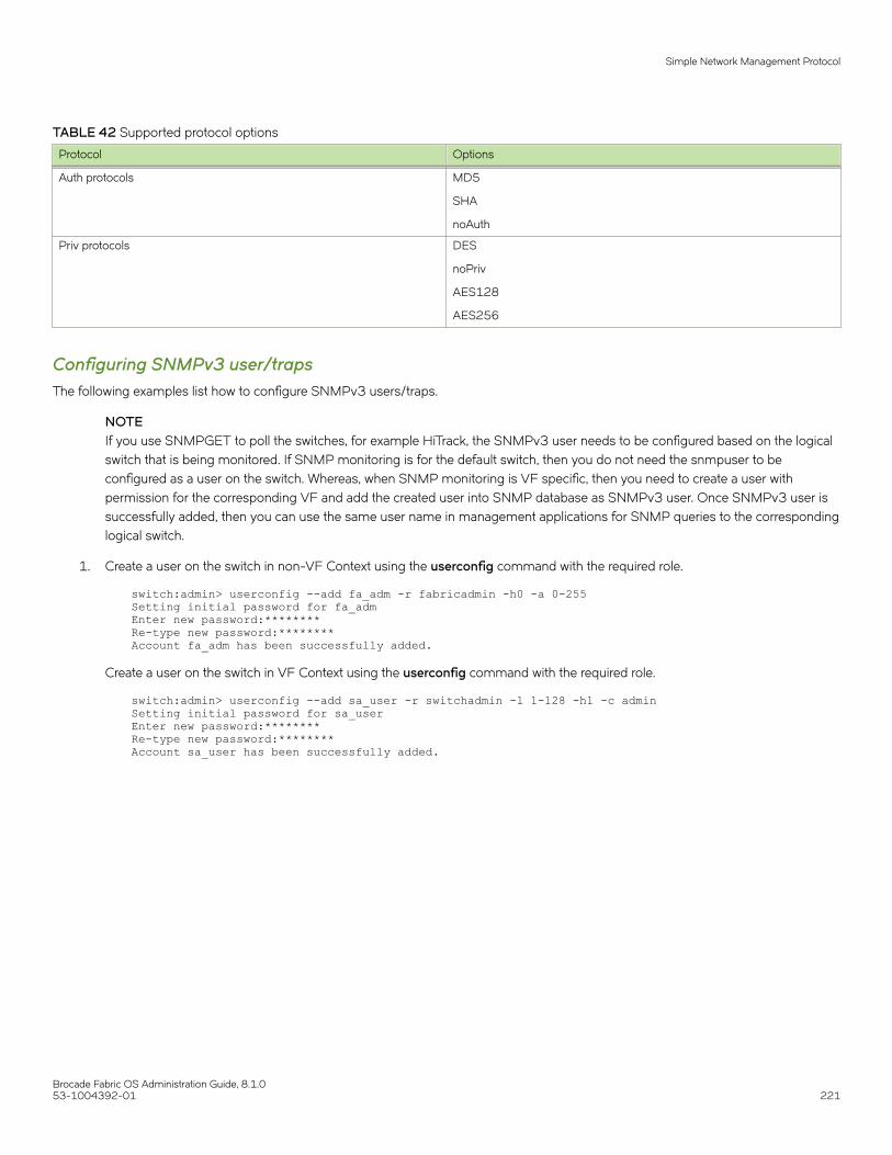
TABLE 42 Supported protocol options
Protocol Options
Auth protocols MD5
SHA
noAuth
Priv protocols DES
noPriv
AES128
AES256
Configuring SNMPv3 user/trapsThe following examples list how to configure SNMPv3 users/traps.
NOTEIf you use SNMPGET to poll the switches, for example HiTrack, the SNMPv3 user needs to be configured based on the logicalswitch that is being monitored. If SNMP monitoring is for the default switch, then you do not need the snmpuser to beconfigured as a user on the switch. Whereas, when SNMP monitoring is VF specific, then you need to create a user withpermission for the corresponding VF and add the created user into SNMP database as SNMPv3 user. Once SNMPv3 user issuccessfully added, then you can use the same user name in management applications for SNMP queries to the correspondinglogical switch.
1. Create a user on the switch in non-VF Context using the userconfig command with the required role.
switch:admin> userconfig --add fa_adm -r fabricadmin -h0 -a 0-255Setting initial password for fa_admEnter new password:********Re-type new password:********Account fa_adm has been successfully added.
Create a user on the switch in VF Context using the userconfig command with the required role.
switch:admin> userconfig --add sa_user -r switchadmin -l 1-128 -h1 -c adminSetting initial password for sa_userEnter new password:********Re-type new password:********Account sa_user has been successfully added.
Simple Network Management Protocol
Brocade Fabric OS Administration Guide, 8.1.053-1004392-01 221

2. Enter snmpconfig --set snmpv3 to create the SNMPv3 user.
switch:admin> snmpconfig --set snmpv3
SNMP Informs Enabled (true, t, false, f): [true]
SNMPv3 user configuration(snmp user not configured in FOS user database will have physical AD and admin role as the default):User (rw): [password] Auth Protocol [MD5(1)/SHA(2)/noAuth(3)]: (1..3) [1] New Auth Passwd:Priv Protocol [DES(1)/noPriv(2)/AES128(3)/AES256(4)]): (1..4) [3] New Priv Passwd:Engine ID: [80:00:05:23:01:ac:1a:1a:ac] User (rw): [passpass] Auth Protocol [MD5(1)/SHA(2)/noAuth(3)]: (1..3) [1] New Auth Passwd:Priv Protocol [DES(1)/noPriv(2)/AES128(3)/AES256(4)]): (1..4) [4] New Priv Passwd:Engine ID: [80:00:05:23:01:ac:1a:1a:ac] User (rw): [snmpadmin3] password1Auth Protocol [MD5(1)/SHA(2)/noAuth(3)]: (1..3) [3] 1New Auth Passwd:Verify Auth Passwd:Priv Protocol [DES(1)/noPriv(2)/AES128(3)/AES256(4)]): (1..4) [2] 3New Priv Passwd:Verify Priv Passwd:Engine ID: [00:00:00:00:00:00:00:00:00] 80:00:05:23:01:ac:1a:1a:ac]User (ro): [snmpuser1] Auth Protocol [MD5(1)/SHA(2)/noAuth(3)]: (1..3) [1] New Auth Passwd:Priv Protocol [DES(1)/noPriv(2)/AES128(3)/AES256(4)]): (1..4) [3] New Priv Passwd:Engine ID: [00:00:00:00:00:00:00:00:00] User (ro): [snmpuser2] Auth Protocol [MD5(1)/SHA(2)/noAuth(3)]: (1..3) [2] New Auth Passwd:Priv Protocol [DES(1)/noPriv(2)/AES128(3)/AES256(4)]): (1..4) [3] New Priv Passwd:Engine ID: [00:00:00:00:00:00:00:00:00] User (ro): [admin] Auth Protocol [MD5(1)/SHA(2)/noAuth(3)]: (1..3) [3] Priv Protocol [DES(1)/noPriv(2)/AES128(3)/AES256(4)]): (2..2) [2] Engine ID: [80:00:06:34:03]
SNMPv3 trap/inform recipient configuration:Trap Recipient's IP address : [172.26.26.172]
Notify Type [TRAP(1)/INFORM(2)]: (1..2) [1] 2UserIndex: (1..6) [1] 1Trap recipient Severity level : (0..5) [4] Trap recipient Port : (0..65535) [162] Trap Recipient's IP address : [172.26.26.172]
Notify Type [TRAP(1)/INFORM(2)]: (1..2) [2] 1UserIndex: (1..6) [1] Trap recipient Severity level : (0..5) [5] Trap recipient Port : (0..65535) [1000] Trap Recipient's IP address : [172.26.26.172]
Notify Type [TRAP(1)/INFORM(2)]: (1..2) [1] UserIndex: (1..6) [1] Trap recipient Severity level : (0..5) [4]
SNMPv3 trap recipient configuration:Trap Recipient's IP address : [0.0.0.0] 10.35.52.33UserIndex: (1..6) [1]Trap recipient Severity level : (0..5) [0] 5Trap recipient Port : (0..65535) [162]Trap Recipient's IP address : [0.0.0.0] 10.35.52.27UserIndex: (1..6) [2]
Simple Network Management Protocol
Brocade Fabric OS Administration Guide, 8.1.0222 53-1004392-01

Trap recipient Severity level : (0..5) [0] 5Trap recipient Port : (0..65535) [162]Trap Recipient's IP address : [0.0.0.0]Trap Recipient's IP address : [0.0.0.0]Trap Recipient's IP address : [0.0.0.0]Trap Recipient's IP address : [0.0.0.0]Committing configuration.....done.
Spike-7800:FID128:root> snmpconfig --show snmpv3
SNMP Informs = 1 (ON)
SNMPv3 USM configuration:User 1 (rw): password Auth Protocol: MD5 Priv Protocol: AES128 Engine ID: 80:00:05:23:01:ac:1a:1a:acUser 2 (rw): passpass Auth Protocol: MD5 Priv Protocol: AES256 Engine ID: 80:00:05:23:01:ac:1a:1a:acUser 3 (rw): password1 Auth Protocol: MD5 Priv Protocol: AES128 Engine ID: 80:00:05:23:01:ac:1a:1a:acUser 4 (ro): snmpuser1 Auth Protocol: MD5 Priv Protocol: AES128 Engine ID: 00:00:00:00:00:00:00:00:00User 5 (ro): snmpuser2 Auth Protocol: SHA Priv Protocol: AES128 Engine ID: 00:00:00:00:00:00:00:00:00User 6 (ro): admin Auth Protocol: noAuth Priv Protocol: noPriv Engine ID: 80:00:06:34:03
SNMPv3 Trap/Informs configuration:Trap Entry 1: 172.26.26.172 Trap Port: 162 Trap User: password Trap recipient Severity level: 4 Notify Type: INFORM(2)Trap Entry 2: 172.26.26.172 Trap Port: 1000 Trap User: password Trap recipient Severity level: 5 Notify Type: TRAP(1)Trap Entry 3: 172.26.26.172 Trap Port: 1000 Trap User: password Trap recipient Severity level: 4 Notify Type: TRAP(1)Trap Entry 4: No trap recipient configured yet Notify Type: TRAP(1)Trap Entry 5: No trap recipient configured yet Notify Type: TRAP(1)Trap Entry 6: No trap recipient configured yet Notify Type: TRAP(1)
An example of the SNMPv3 user trap recipients configured with DNS names and IPv6 addresses:
switch:admin> snmpconfig --set snmpv3
SNMP Informs Enabled (true, t, false, f): [true]
SNMPv3 user configuration(snmp user not configured in FOS user database will have physical AD and admin role as the default):User (rw): [password] Auth Protocol [MD5(1)/SHA(2)/noAuth(3)]: (1..3) [1]
Simple Network Management Protocol
Brocade Fabric OS Administration Guide, 8.1.053-1004392-01 223

New Auth Passwd:Priv Protocol [DES(1)/noPriv(2)/AES128(3)/AES256(4)]): (1..4) [3] New Priv Passwd:Engine ID: [80:00:05:23:01:ac:1a:1a:ac] User (rw): [passpass] Auth Protocol [MD5(1)/SHA(2)/noAuth(3)]: (1..3) [1] New Auth Passwd:Priv Protocol [DES(1)/noPriv(2)/AES128(3)/AES256(4)]): (1..4) [4] New Priv Passwd:Engine ID: [80:00:05:23:01:ac:1a:1a:ac] User (rw): [password1] Auth Protocol [MD5(1)/SHA(2)/noAuth(3)]: (1..3) [1] New Auth Passwd:Priv Protocol [DES(1)/noPriv(2)/AES128(3)/AES256(4)]): (1..4) [3] New Priv Passwd:Engine ID: [80:00:05:23:01:ac:1a:1a:ac] User (ro): [snmpuser1] Auth Protocol [MD5(1)/SHA(2)/noAuth(3)]: (1..3) [1] New Auth Passwd:Priv Protocol [DES(1)/noPriv(2)/AES128(3)/AES256(4)]): (1..4) [3] New Priv Passwd:Engine ID: [00:00:00:00:00:00:00:00:00] User (ro): [snmpuser2] Auth Protocol [MD5(1)/SHA(2)/noAuth(3)]: (1..3) [2] New Auth Passwd:Priv Protocol [DES(1)/noPriv(2)/AES128(3)/AES256(4)]): (1..4) [3] New Priv Passwd:Engine ID: [00:00:00:00:00:00:00:00:00] User (ro): [admin] Auth Protocol [MD5(1)/SHA(2)/noAuth(3)]: (1..3) [3] Priv Protocol [DES(1)/noPriv(2)/AES128(3)/AES256(4)]): (2..2) [2] Engine ID: [80:00:06:34:03]
SNMPv3 trap/inform recipient configuration:Trap Recipient's IP address : [172.26.26.172] fe80::224:1dff:fef6:3f98
Notify Type [TRAP(1)/INFORM(2)]: (1..2) [2] UserIndex: (1..6) [1] Trap recipient Severity level : (0..5) [4] Trap recipient Port : (0..65535) [162] Trap Recipient's IP address : [172.26.26.172] HCL0389U.corp.brocade.com
Notify Type [TRAP(1)/INFORM(2)]: (1..2) [1] UserIndex: (1..6) [1] Trap recipient Severity level : (0..5) [5] Trap recipient Port : (0..65535) [1000] Trap Recipient's IP address : [172.26.26.172]
Notify Type [TRAP(1)/INFORM(2)]: (1..2) [1] Committing configuration.....done.Spike-7800:FID128:root> snmpconfig --show snmpv3
SNMP Informs = 1 (ON)
SNMPv3 USM configuration:User 1 (rw): password Auth Protocol: MD5 Priv Protocol: AES128 Engine ID: 80:00:05:23:01:ac:1a:1a:acUser 2 (rw): passpass Auth Protocol: MD5 Priv Protocol: AES256 Engine ID: 80:00:05:23:01:ac:1a:1a:acUser 3 (rw): password1 Auth Protocol: MD5 Priv Protocol: AES128 Engine ID: 80:00:05:23:01:ac:1a:1a:acUser 4 (ro): snmpuser1 Auth Protocol: MD5 Priv Protocol: AES128 Engine ID: 00:00:00:00:00:00:00:00:00User 5 (ro): snmpuser2
Simple Network Management Protocol
Brocade Fabric OS Administration Guide, 8.1.0224 53-1004392-01
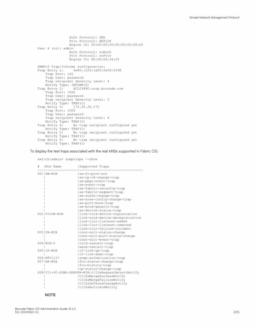
Auth Protocol: SHA Priv Protocol: AES128 Engine ID: 00:00:00:00:00:00:00:00:00User 6 (ro): admin Auth Protocol: noAuth Priv Protocol: noPriv Engine ID: 80:00:06:34:03
SNMPv3 Trap/Informs configuration:Trap Entry 1: fe80::224:1dff:fef6:3f98 Trap Port: 162 Trap User: password Trap recipient Severity level: 4 Notify Type: INFORM(2)Trap Entry 2: HCL0389U.corp.brocade.com Trap Port: 1000 Trap User: password Trap recipient Severity level: 5 Notify Type: TRAP(1)Trap Entry 3: 172.26.26.172 Trap Port: 1000 Trap User: password Trap recipient Severity level: 4 Notify Type: TRAP(1)Trap Entry 4: No trap recipient configured yet Notify Type: TRAP(1)Trap Entry 5: No trap recipient configured yet Notify Type: TRAP(1)Trap Entry 6: No trap recipient configured yet Notify Type: TRAP(1)
To display the test traps associated with the real MIBs supported in Fabric OS:
switch:admin> snmptraps --show
# |Mib Name |Supported Traps ---|----------------|--------------------------------001|SW-MIB |sw-fc-port-scn | |sw-ip-v6-change-trap | |sw-pmgr-event-trap | |sw-event-trap | |sw-fabric-reconfig-trap | |sw-fabric-segment-trap | |sw-state-change-trap | |sw-zone-config-change-trap | |sw-port-move-trap | |sw-brcd-generic-trap | |sw-device-status-trap 002|FICON-MIB |link-rnid-device-registration | |link-rnid-device-deregistration | |link-lirr-listener-added | |link-lirr-listener-removed | |link-rlir-failure-incident 003|FA-MIB |conn-unit-status-change | |conn-unit-port-status-change | |conn-unit-event-trap 004|MIB-2 |cold-restart-trap | |warm-restart-trap 005|IF-MIB |if-link-up-trap | |if-link-down-trap 006|RFC1157 |snmp-authetication-trap 007|HA-MIB |fru-status-change-trap | |fru-history-trap | |cp-status-change-trap 008|T11-FC-ZONE-SERVER-MIB|t11ZsRequestRejectNotify | |t11ZsMergeSuccessNotify | |t11ZsMergeFailureNotify | |t11ZsDefZoneChangeNotify | |t11ZsActivateNotify
NOTE
Simple Network Management Protocol
Brocade Fabric OS Administration Guide, 8.1.053-1004392-01 225
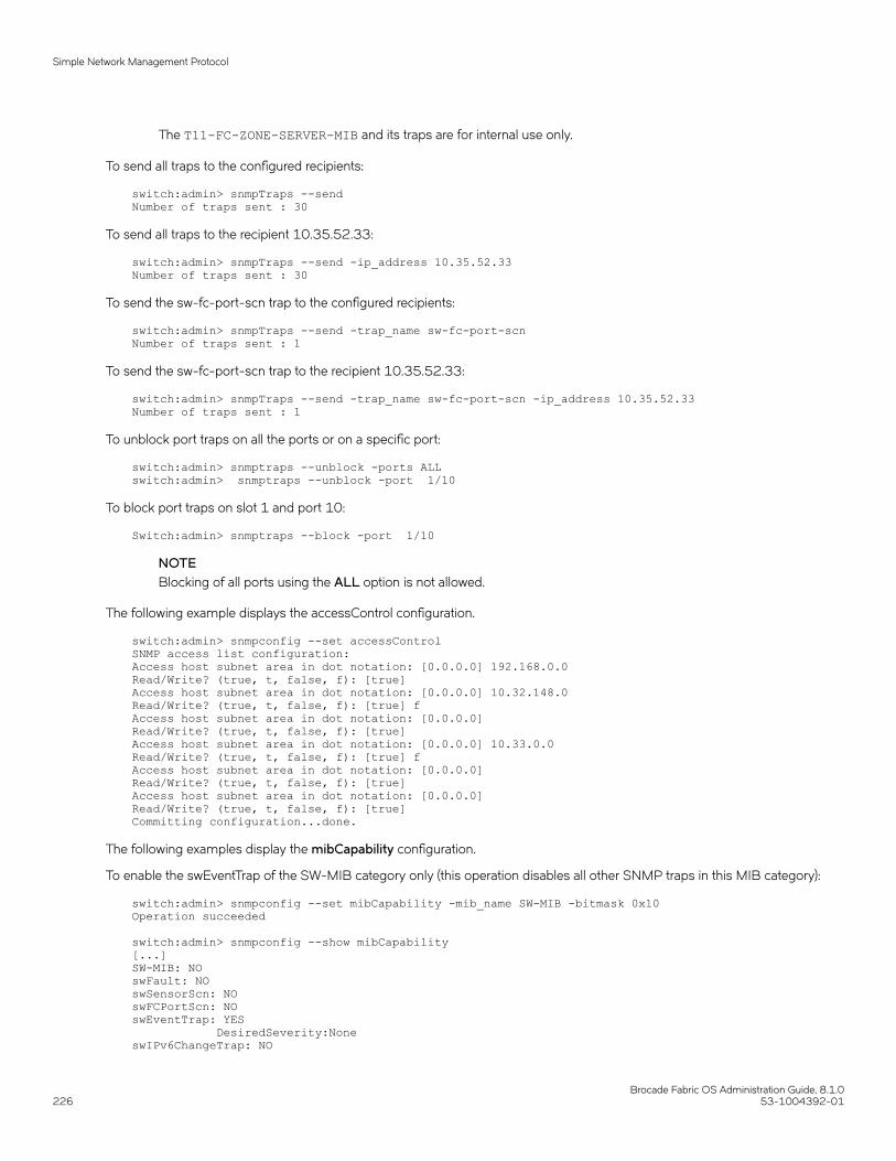
The T11-FC-ZONE-SERVER-MIB and its traps are for internal use only.
To send all traps to the configured recipients:
switch:admin> snmpTraps --sendNumber of traps sent : 30
To send all traps to the recipient 10.35.52.33:
switch:admin> snmpTraps --send -ip_address 10.35.52.33Number of traps sent : 30
To send the sw-fc-port-scn trap to the configured recipients:
switch:admin> snmpTraps --send -trap_name sw-fc-port-scnNumber of traps sent : 1
To send the sw-fc-port-scn trap to the recipient 10.35.52.33:
switch:admin> snmpTraps --send -trap_name sw-fc-port-scn -ip_address 10.35.52.33Number of traps sent : 1
To unblock port traps on all the ports or on a specific port:
switch:admin> snmptraps --unblock -ports ALLswitch:admin> snmptraps --unblock -port 1/10
To block port traps on slot 1 and port 10:
Switch:admin> snmptraps --block -port 1/10
NOTEBlocking of all ports using the ALL option is not allowed.
The following example displays the accessControl configuration.
switch:admin> snmpconfig --set accessControlSNMP access list configuration:Access host subnet area in dot notation: [0.0.0.0] 192.168.0.0Read/Write? (true, t, false, f): [true]Access host subnet area in dot notation: [0.0.0.0] 10.32.148.0Read/Write? (true, t, false, f): [true] fAccess host subnet area in dot notation: [0.0.0.0]Read/Write? (true, t, false, f): [true]Access host subnet area in dot notation: [0.0.0.0] 10.33.0.0Read/Write? (true, t, false, f): [true] fAccess host subnet area in dot notation: [0.0.0.0]Read/Write? (true, t, false, f): [true]Access host subnet area in dot notation: [0.0.0.0]Read/Write? (true, t, false, f): [true]Committing configuration...done.
The following examples display the mibCapability configuration.
To enable the swEventTrap of the SW-MIB category only (this operation disables all other SNMP traps in this MIB category):
switch:admin> snmpconfig --set mibCapability -mib_name SW-MIB -bitmask 0x10Operation succeeded
switch:admin> snmpconfig --show mibCapability[...]SW-MIB: NOswFault: NOswSensorScn: NOswFCPortScn: NOswEventTrap: YES DesiredSeverity:NoneswIPv6ChangeTrap: NO
Simple Network Management Protocol
Brocade Fabric OS Administration Guide, 8.1.0226 53-1004392-01

swPmgrEventTrap: NOswFabricReconfigTrap: NOswFabricSegmentTrap: NOswExtTrap: NOswStateChangeTrap: NOswPortMoveTrap: NOswBrcdGenericTrap: NOswDeviceStatusTrap: NOswZoneConfigChangeTrap: NO(output truncated)
To enable the SW-MIB only without changing the current trap configuration:
switch:admin> snmpconfig --enable mibCapability -mib_name SW-MIBOperation succeeded
switch:admin> snmpconfig --show mibCapability[...]SW-MIB: YESswFault: NOswSensorScn: NOswFCPortScn: NOswEventTrap: YES DesiredSeverity:NoneswTrackChangesTrap: NOswIPv6ChangeTrap: NOswPmgrEventTrap: NOswFabricReconfigTrap: NOswFabricSegmentTrap: NOswExtTrap: NOswStateChangeTrap: NOswPortMoveTrap: NOswBrcdGenericTrap: NOswDeviceStatusTrap: NOswZoneConfigChangeTrap: NO(output truncated)
To re-enable all traps under the SW-MIB category after they were disabled:
switch:admin> snmpconfig --set mibCapability -mib_name SW-MIB -bitmask 0xFFFOperation succeeded
switch:admin> snmpconfig --show mibCapability[...]SW-MIB: YESswFault: YESswSensorScn: YESswFCPortScn: YESswEventTrap: YES DesiredSeverity:NoneswTrackChangesTrap: YESswIPv6ChangeTrap: YESswPmgrEventTrap: YESswFabricReconfigTrap: YESswFabricSegmentTrap: YESswExtTrap: YESswStateChangeTrap: YESswPortMoveTrap: YESswBrcdGenericTrap: YESswDeviceStatusTrap: YESswZoneConfigChangeTrap: YES(output truncated)
To display the configuration for all MIBs and associated traps:
switch:admin> snmpconfig --show mibcapabilityFE-MIB: YESSW-MIB: YESFA-MIB: YESFICON-MIB: YESHA-MIB: YES
Simple Network Management Protocol
Brocade Fabric OS Administration Guide, 8.1.053-1004392-01 227

FCIP-MIB: YESIF-MIB: YESBROCADE-MAPS-MIB: YEST11-FC-ZONE-SERVER-MIB: NOSW-TRAP: YES swFCPortScn: YES swEventTrap: YES DesiredSeverity:None swIPv6ChangeTrap: YES swPmgrEventTrap: YES swFabricReconfigTrap: YES swFabricSegmentTrap: YES swExtTrap: NO swStateChangeTrap: NO swPortMoveTrap: NO swBrcdGenericTrap: YES swDeviceStatusTrap: YES swZoneConfigChangeTrap: NOFA-TRAP: YES connUnitStatusChange: YES connUnitEventTrap: YES connUnitPortStatusChange: YESFICON-TRAP: YES linkRNIDDeviceRegistration: YES linkRNIDDeviceDeRegistration: YES linkLIRRListenerAdded: YES linkLIRRListenerRemoved: YES linkRLIRFailureIncident: YESHA-TRAP: YES fruStatusChanged: YES cpStatusChanged: YES fruHistoryTrap: YESIF-TRAP: YES linkDown: YES linkUp: YESBD-TRAP: YES bdTrap: YES bdClearTrap: YESMAPS-TRAP: YES mapsTrapAM: YEST11-FC-ZONE-SERVER-TRAP: NO t11ZsRequestRejectNotify: NO t11ZsMergeFailureNotify: NO t11ZsMergeSuccessNotify: NO t11ZsDefZoneChangeNotify: NO t11ZsActivateNotify: NO
To set the system group:
switch:admin> snmpconfig --set systemgroup -syscontact "Sys contact" –authTrapEnabled false -sysdescr "Filed Support" -syslocation "Sys Location"Committing configuration.....done.switch:admin> snmpconfig --show systemgroupsysDescr = Filed SupportsysLocation = Sys LocationsysContact = Sys contactauthTrapEnabled = 0 (OFF)
Simple Network Management Protocol
Brocade Fabric OS Administration Guide, 8.1.0228 53-1004392-01

3. Set the security level.
switch:admin> snmpconfig --set secLevel -snmpget 2 -snmpset 2switch:admin> snmpconfig --show secLevelGET security level = 2, SET level = 2SNMP GET Security Level: Authentication and PrivacySNMP SET Security Level: Authentication and Privacy
To set the security level to default:
switch:admin> snmpconfig --default seclevelGET security level = 0, SET level = 3SNMP GET Security Level: No securitySNMP SET Security Level: No AccessSNMP GET Security Level will be set to 'No Security'SNMP SET Security Level will be set to 'No Access'Do you want to continue? (yes, y, no, n): [no] y
switch:admin> snmpconfig --show seclevelGET security level = 0, SET level = 3SNMP GET Security Level: No securitySNMP SET Security Level: No Access
4. Set audit interval.
switch:admin> snmpconfig --set auditinterval -interval 31Committing configuration.....done.Spike-7800:FID128:root> snmpconfig --show auditIntervalSNMP Audit Interval (in min): 31
Set to the default audit interval.
switch:admin> snmpconfig --default auditInterval*****This command will reset the agent's audit log interval configuration back to factory default*****SNMP Audit Interval (in min): 31
*****Are you sure? (yes, y, no, n): [no] ySpike-7800:FID128:root> snmpconfig --show auditIntervalSNMP Audit Interval (in min): 60
NOTEThe Success and Failure count Audit messages are only for SNMPv3 logins and not for SNMPv1 logins.
5. In the Manager (SNMP Browser), create a user snmpadmin1 with Authentication protocol as noAuth, Privacy protocol as noPriv,set the password and set the trap port as 162. (Same values are set as in the switch SNMPv3 configuration.)
Notes:
• SNMPv3 supports AES-128, AES-256, and DES protocols.
• For resolving AES-256 protocol in the USM MIB walk, the eso Consortium MIB has to be loaded.
Encrypting SNMPv3 user passwordsThe SNMPv3 user authentication and privacy passwords stored in the configuration database can be stored in either an encrypted orunencrypted form.
If password encryption is enabled, the SNMPv3 user authentication and privacy passwords are encrypted and stored in the configurationdatabase. The encrypted password cannot be decrypted. If an encrypted SNMPv3 user password is disabled, the authentication andprivacy passwords are reset to their default values. The SNMPv3 user password encryption option is only available in the CLI.
Simple Network Management Protocol
Brocade Fabric OS Administration Guide, 8.1.053-1004392-01 229

CAUTIONIf the SNMPv3 user authentication and privacy passwords are encrypted, do not modify the configuration key attributesvalue for that user in the configuration file. Doing so will cause the configuration download to fail.
To encrypt SNMPv3 user passwords, complete the following steps.
1. Connect to the device and log in using an account with admin permissions.
2. Enable the SNMPv3 encryption. The command you will use depends on the mode you are operating in.
• If you are in interactive mode, enter snmpconfig --set snmpv3, and then enter "t" or "true", followed by "Yes".
device:admin> snmpconfig --set snmpv3 SNMPv3 user password encryption Enabled (true, t, false, f): [false] Warning "The encrypted password cannot be decrypted. Do you want to continue (Yes / No)?”
• If you are in non-interactive mode, enter snmpconfig --set snmpv3 -enable passwd_encryption.
device:admin> snmpconfig –-set snmpv3 -enable passwd_encryption
When you enable the encryption option during the SNMPv3 user configuration, the password encryption configuration key foreach configured user is automatically enabled internally by the software. This key is used to identify whether the passwordsshould be encrypted or not for each user.
Changing encrypted SNMPv3 user passwords to unencrypted formOnce encrypted, you cannot remove the encryption from the SNMPv3 user authentication and privacy passwords stored in theconfiguration database. You can only replace them with new unencrypted passwords.
To change an account's passwords to unencrypted form, you must first disable the encrypted password, and then replace it. When anencrypted SNMPv3 password is disabled, the authentication and privacy passwords are reset to their default values. You can thenspecify new values for the passwords that will not be encrypted.
NOTEThe SNMPv3 user password decryption option is only available in the CLI.
To change encrypted SNMPv3 user passwords to unencrypted passwords, complete the following steps.
1. Connect to the device and log in using an account with admin permissions.
2. Disable the SNMPv3 encryption. The command you will use depends on the mode you are operating in.
• If you are in interactive mode, enter snmpconfig --set snmpv3, and then enter "f" or "false", followed by "Yes".
device:admin> snmpconfig --set snmpv3 SNMPv3 user password encryption Enabled (true, t, false, f): [false] Warning "The encrypted password cannot be decrypted. Do you want to continue (Yes / No)?”
• If you are in non-interactive mode, enter snmpconfig --set snmpv3 –disable passwd_encryption
device:admin> snmpconfig –-set snmpv3 -disable passwd_encryption
3. If you want to change from the default passwords, enter the new unencrypted passwords. Refer to Local account passwords onpage 161 for instructions on this task.
Simple Network Management Protocol
Brocade Fabric OS Administration Guide, 8.1.0230 53-1004392-01

Telnet protocolTelnet is enabled by default. To prevent passing clear text passwords over the network when connecting to the switch, you can block theTelnet protocol using an IP filter policy. For more information on IP filter policies, refer to IP Filter policy on page 257.
ATTENTIONBefore blocking Telnet, make sure you have an alternate method of establishing a connection with the switch.
Blocking TelnetIf you create a new policy using commands with just one rule, all the missing rules have an implicit deny and you lose all IP access to theswitch, including Telnet, SSH, and management ports.
Use the following procedure to block Telnet access.
1. Connect to the switch and log in using an account with admin permissions.
2. Clone the default policy by entering the ipFilter --clone command.
switch:admin> ipfilter --clone BlockTelnet -from default_ipv4
3. Save the new policy by entering the ipFilter --save command.
switch:admin> ipfilter --save BlockTelnet
4. Verify the new policy exists by entering the ipFilter --show command.
switch:admin> ipfilter --show
5. Add a rule to the policy, by entering the ipFilter --addrule command.
switch:admin> ipfilter --addrule BlockTelnet -rule 1 -sip any -dp 23 -proto tcp -act deny
ATTENTIONThe rule number assigned must precede the default rule number for this protocol. For example, in the defined policy,the Telnet rule number is 2. Therefore, to effectively block Telnet, the rule number to assign must be 1. If you choosenot to use 1, you must delete the Telnet rule number 2 after adding this rule. Refer to Deleting a rule from an IP Filterpolicy on page 262 for more information on deleting IP filter rules.
6. Save the new IP filter policy by entering the ipFilter --save command.
7. Verify the new policy is correct by entering the ipFilter --show command.
8. Activate the new IP filter policy by entering the ipFilter --activate command.
switch:admin> ipfilter --activate BlockTelnet
Telnet protocol
Brocade Fabric OS Administration Guide, 8.1.053-1004392-01 231

9. Verify the new policy is active (the default_ipv4 policy should be displayed as defined).
switch:admin> ipfilter --show Name: default_ipv4, Type: ipv4, State: definedRule Source IP Protocol Dest Port Action1 any tcp 22 permit2 any tcp 23 permit3 any tcp 80 permit4 any tcp 443 permit5 any udp 161 permit6 any udp 123 permit7 any tcp 600 - 1023 permit8 any udp 600 - 1023 permit
Name: default_ipv6, Type: ipv6, State: activeRule Source IP Protocol Dest Port Action1 any tcp 22 permit2 any tcp 23 permit3 any tcp 80 permit4 any tcp 443 permit5 any udp 161 permit6 any udp 123 permit7 any tcp 600 - 1023 permit8 any udp 600 - 1023 permit
Name: BlockTelnet, Type: ipv4, State: active (modified)Rule Source IP Protocol Dest Port Action1 any tcp 23 deny2 any tcp 22 permit3 any tcp 80 permit4 any tcp 443 permit5 any udp 161 permit6 any udp 123 permit7 any tcp 600 - 1023 permit8 any udp 600 - 1023 permit
Unblocking TelnetUse the following procedure to unblock Telnet access.
1. Connect to the switch through a serial port or SSH and log in as admin.
2. Enter the ipfilter --delete command.
Refer to Deleting a rule from an IP Filter policy on page 262 for more information on deleting IP filter rules.
3. To permanently delete the policy, type the ipfilter --save command.
ATTENTIONIf you deleted the rule to permit Telnet, you must add a rule to permit Telnet.
Listener applicationsBrocade switches block Linux subsystem listener applications that are not used to implement supported features and capabilities.
The following table lists the listener applications that Brocade switches either block or do not start. Note that RPC ports are blocked.
TABLE 43 Blocked listener applications
Listener application Brocade DCX and DCX 8510 Backbonefamilies
Brocade switches
chargen Disabled Disabled
Listener applications
Brocade Fabric OS Administration Guide, 8.1.0232 53-1004392-01

TABLE 43 Blocked listener applications (continued)
Listener application Brocade DCX and DCX 8510 Backbonefamilies
Brocade switches
daytime Disabled Disabled
discard Disabled Disabled
echo Disabled Disabled
ftp Disabled Disabled
rexec Block with packet filter Disabled
rlogin Block with packet filter Disabled
rsh Block with packet filter Disabled
rstats Disabled Disabled
rusers Disabled Disabled
time Block with packet filter Disabled
Ports and applications used by switchesIf you are using the FC-FC Routing Service, be aware that the secModeEnable command is not supported.
The following table lists the defaults for accessing hosts, devices, switches, and zones.
TABLE 44 Access defaults
Access default
Hosts Any host can access the fabric by SNMP.
Any host can Telnet to any switch in the fabric.
Any host can establish an HTTP connection to any switch in the fabric.
Any host can establish an API connection to any switch in the fabric.
Devices All devices can access the management server.
Any device can connect to any FC port in the fabric.
Switch access Any switch can join the fabric.
All switches in the fabric can be accessed through a serial port.
Zoning No zoning is enabled.
Port configurationThe following table provides information on ports that the switch uses. When configuring the switch for various policies, take intoconsideration firewalls and other devices that may sit between switches in the fabric and your network or between the managers and theswitch.
TABLE 45 Port information
Port Type Common use Comment
22 TCP SSH, SCP
23 TCP Telnet Use the ipfilter command to blockthe port.
80 TCP HTTP Use the ipfilter command to blockthe port.
Ports and applications used by switches
Brocade Fabric OS Administration Guide, 8.1.053-1004392-01 233

TABLE 45 Port information (continued)
Port Type Common use Comment
123 UDP NTP
161 UDP SNMP Disable the SNMP service on theremote host if you do not use it, orfilter incoming UDP packets goingto this port.
443 TCP HTTPS Use the ipfilter command to blockthe port.
Ports and applications used by switches
Brocade Fabric OS Administration Guide, 8.1.0234 53-1004392-01

Configuring Security Policies• ACL policies overview.................................................................................................................................................................................. 235• ACL policy management.............................................................................................................................................................................236• FCS policies......................................................................................................................................................................................................238• Device Connection Control policies........................................................................................................................................................242• SCC Policies..................................................................................................................................................................................................... 246• Authentication policy for fabric elements............................................................................................................................................. 247• IP Filter policy...................................................................................................................................................................................................257• Policy database distribution....................................................................................................................................................................... 263• Management interface security.................................................................................................................................................................269
ACL policies overviewEach supported Access Control List (ACL) policy is identified by a specific name, and only one policy of each type can exist, except forDCC policies. Policy names are case-sensitive and must be entered in all uppercase. Fabric OS provides the following policies:
• Fabric configuration server (FCS) policy: Used to restrict which switches can change the configuration of the fabric.
• Device connection control (DCC) policies: Used to restrict which Fibre Channel device ports can connect to which FibreChannel switch ports.
• Switch connection control (SCC) policy: Used to restrict which switches can join with a switch.
How the ACL policies are storedThe policies are stored in a local database. The database contains the ACL policy types of FCS, DCC, SCC, and IPFilter. The number ofpolicies that may be defined is limited by the size of the database. FCS, SCC and DCC policies are all stored in the same database.
The limit for security policy database size is set to 1Mb. The policies are grouped by state and type. A policy can be in either of thefollowing states:
• Active, which means the policy is being enforced by the switch.
• Defined, which means the policy has been set up but is not enforced.
Policies with the same state are grouped together in a Policy Set . Each switch has the following two sets:
• Active policy set , which contains ACL policies being enforced by the switch.
• Defined policy set , which contains a copy of all ACL policies on the switch.
When a policy is activated, the defined policy either replaces the policy with the same name in the active set or becomes a new activepolicy. If a policy appears in the defined set but not in the active set, the policy was saved but has not been activated. If a policy with thesame name appears in both the defined and active sets but they have different values, then the policy has been modified but thechanges have not been activated.
Virtual Fabric considerations for ACL policiesACL policies such as DCC, SCC, and FCS can be configured on each logical switch. The limit for security policy database size is set to1Mb per logical switch.
Brocade Fabric OS Administration Guide, 8.1.053-1004392-01 235

Policy membersThe FCS, DCC and SCC policy members are specified by device port WWN, switch WWN, domain IDs, or switch names, depending onthe policy. The valid methods for specifying policy members are listed in Table 46.
TABLE 46 Valid methods for specifying policy members
Policy name Device port WWN or Fabricport WWN
Switch WWN Domain ID Switch name
FCS_POLICY No Yes Yes Yes
DCC_POLICY_nnn Yes Yes Yes Yes
SCC_POLICY No Yes Yes Yes
ACL policy managementAll policy modifications are temporarily stored in volatile memory until those changes are saved or activated. You can create multiplesessions to the switch from one or more hosts. It is recommended you make changes from one switch only to prevent multipletransactions from occurring. Each logical switch has its own access control list.
The FCS, SCC, and DCC policies in Secure Fabric OS are not interchangeable with Fabric OS FCS, SCC and DCC policies. Uploadingand saving a copy of the Fabric OS configuration after creating policies is strongly recommended. For more information on configurationuploads, refer to Maintaining the Switch Configuration File on page 279.
NOTEAll changes, including the creation of new policies, are saved and activated on the local switch only—unless the switch is in afabric that has a strict or tolerant fabric-wide consistency policy for the ACL policy type for SCC or DCC. Refer to Policydatabase distribution on page 263 for more information on the database settings and fabric-wide consistency policy.
Displaying ACL policiesYou can view the active and defined policy sets at any time. In addition, within a defined policy set, any policies created in the same loginsession will be listed, but these policies are automatically deleted if you log out without saving them.
To view the active and defined policy sets, complete the following steps.
1. Connect to the switch and log in using an account with admin permissions, or an account with “O” permission for the SecurityRBAC class of commands.
2. Enter secPolicyShow.
The following example shows the command and a typical response
switch:admin> secPolicyShow
____________________________________________________ ACTIVE POLICY SET____________________________________________________ DEFINED POLICY SET
Saving changes without activating the policies1. Connect to the switch and log in using an account with admin permissions, or an account with OM permissions for the Security
RBAC class of commands.
ACL policy management
Brocade Fabric OS Administration Guide, 8.1.0236 53-1004392-01
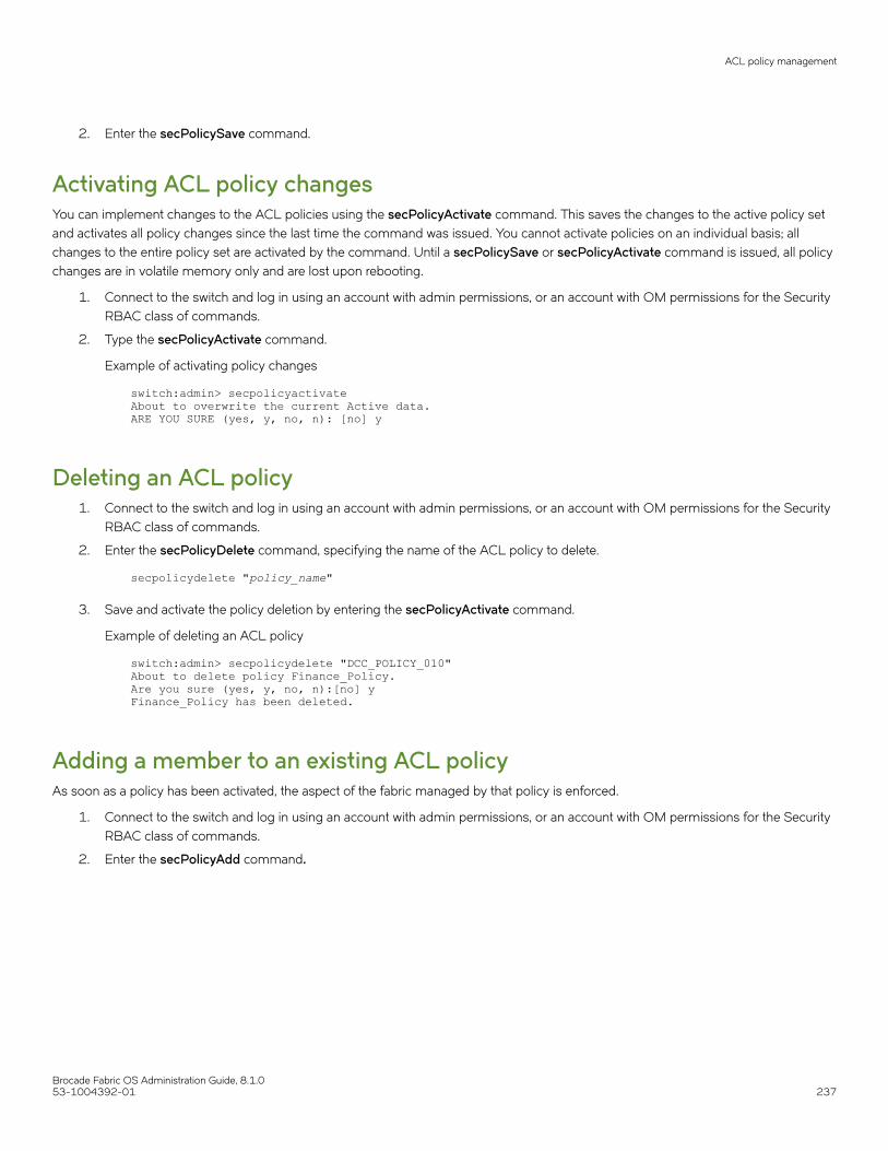
2. Enter the secPolicySave command.
Activating ACL policy changesYou can implement changes to the ACL policies using the secPolicyActivate command. This saves the changes to the active policy setand activates all policy changes since the last time the command was issued. You cannot activate policies on an individual basis; allchanges to the entire policy set are activated by the command. Until a secPolicySave or secPolicyActivate command is issued, all policychanges are in volatile memory only and are lost upon rebooting.
1. Connect to the switch and log in using an account with admin permissions, or an account with OM permissions for the SecurityRBAC class of commands.
2. Type the secPolicyActivate command.
Example of activating policy changes
switch:admin> secpolicyactivateAbout to overwrite the current Active data.ARE YOU SURE (yes, y, no, n): [no] y
Deleting an ACL policy1. Connect to the switch and log in using an account with admin permissions, or an account with OM permissions for the Security
RBAC class of commands.
2. Enter the secPolicyDelete command, specifying the name of the ACL policy to delete.
secpolicydelete "policy_name"
3. Save and activate the policy deletion by entering the secPolicyActivate command.
Example of deleting an ACL policy
switch:admin> secpolicydelete "DCC_POLICY_010"About to delete policy Finance_Policy.Are you sure (yes, y, no, n):[no] yFinance_Policy has been deleted.
Adding a member to an existing ACL policyAs soon as a policy has been activated, the aspect of the fabric managed by that policy is enforced.
1. Connect to the switch and log in using an account with admin permissions, or an account with OM permissions for the SecurityRBAC class of commands.
2. Enter the secPolicyAdd command.
ACL policy management
Brocade Fabric OS Administration Guide, 8.1.053-1004392-01 237

3. To implement the change immediately, enter the secPolicyActivate command.
For example, to add a member to the SCC_POLICY using the switch WWN:
switch:admin> secpolicyadd "SCC_POLICY", "12:24:45:10:0a:67:00:40"Member(s) have been added to SCC_POLICY.
Example of adding members to the DCC policy
To add two devices to the DCC policy, and to attach domain 3 ports 1 and 3 (WWNs of devices are 11:22:33:44:55:66:77:aaand 11:22:33:44:55:66:77:bb):
switch:admin> secpolicyadd "DCC_POLICY_abc","11:22:33:44:55:66:77:aa;11:22:33:44:55:66:77:bb;3(1,3)"
Removing a member from an ACL policyAs soon as a policy has been activated, the aspect of the fabric managed by that policy is enforced.
1. Connect to the switch and log in using an account with admin permissions, or an account with OM permissions for the SecurityRBAC class of commands.
2. Enter the secPolicyRemove command.
3. To implement the change immediately, enter the secPolicyActivate command.
Example of removing a member
For example, to remove a member that has a WWN of 12:24:45:10:0a:67:00:40 from the SCC_POLICY:
switch:admin> secpolicyremove "SCC_POLICY", "12:24:45:10:0a:67:00:40"Member(s) have been removed from SCC_POLICY.
Abandoning unsaved ACL policy changesYou can abandon all ACL policy changes that have not yet been saved.
1. Connect to the switch and log in using an account with admin permissions, or an account with OM permissions for the SecurityRBAC class of commands.
2. Enter the secPolicyAbort command.
Example of aborting unsaved changes
switch:admin> secpolicyabortUnsaved data has been aborted.
All changes since the last time the secPolicySave or secPolicyActivate commands were entered are aborted.
FCS policiesFabric configuration server (FCS) policy in base Fabric OS may be performed on a local switch basis and may be performed on anyswitch in the fabric.
The FCS policy is not present by default, but must be created. When the FCS policy is created, the WWN of the local switch isautomatically included in the FCS list. Additional switches can be included in the FCS list. The first switch in the list becomes the PrimaryFCS switch.
FCS policies
Brocade Fabric OS Administration Guide, 8.1.0238 53-1004392-01

Switches in the fabric are designated as either a Primary FCS, backup FCS, or non-FCS switch. Only the Primary FCS switch is allowedto modify and distribute the database within the fabric. Automatic distribution is supported and you can either configure the switches inyour fabric to accept the FCS policy or manually distribute the FCS policy. Changes made to the FCS policy are saved to permanentmemory only after the changes have been saved or activated; they can be aborted later if you have set your fabric to distribute thechanges manually.
TABLE 47 FCS policy states
Policy state Characteristics
No active policy Any switch can perform fabric-wide configuration changes.
Active policy with one entry A Primary FCS switch is designated (local switch), but there are no backupFCS switches. If the Primary FCS switch becomes unavailable for anyreason, the fabric is left without an FCS switch.
Active policy with multiple entries A Primary FCS switch and one or more backup FCS switches aredesignated. If the Primary FCS switch becomes unavailable, the nextswitch in the list becomes the Primary FCS switch.
FCS policy restrictionsThe backup FCS switches normally cannot modify the policy. However, if the Primary FCS switch in the policy list is not reachable, then abackup FCS switch is allowed to modify the policy.
Once an FCS policy is configured and distributed across the fabric, only the Primary FCS switch can perform certain operations.Operations that affect fabric-wide configuration are allowed only from the Primary FCS switch. Backup and non-FCS switches cannotperform security, zoning and AD operations that affect the fabric configuration. The following error message is returned if a backup ornon-FCS switch tries to perform these operations:
Can only execute this command on the Primary FCS switch.Operations that do not affect the fabric configuration, such as show or local switch commands, are allowed on backup and non-FCSswitches.
FCS enforcement applies only for user-initiated fabric-wide operations. Internal fabric data propagation because of a fabric merge is notblocked. Consequently, a new switch that joins the FCS-enabled fabric could still propagate the AD and zone database.
Table 48 shows the commands for switch operations for Primary FCS enforcement.
TABLE 48 FCS switch operations
Allowed on FCS switches Allowed on all switches
secPolicyAdd (Allowed on all switches for SCC and DCC policies as longas it is not fabric-wide)
secPolicyShow
secPolicyCreate (Allowed on all switches for SCC and DCC policies aslong as it is not fabric-wide)
fddCfg --localaccept or fddCfg --localreject
secPolicyDelete (Allowed on all switches for SCC and DCC policies aslong as its not fabric-wide)
userconfig, Passwd, Passwdcfg (Fabric-wide distribution is not allowedfrom a backup or non-FCS switch.)
secPolicyRemove (Allowed on all switches for SCC and DCC policies aslong as its not fabric-wide)
secPolicyActivate
fddCfg -- fabwideset secPolicySave
Any fabric-wide commands secPolicyAbort
All zoning commands except the show commands SNMP commands
All AD commands configupload
Any local-switch commands
FCS policies
Brocade Fabric OS Administration Guide, 8.1.053-1004392-01 239

In Fabric OS v7.1.0 and later, to avoid segmentation of ports due to a member-list order mismatch, security policy members are sortedbased on WWN. By default, DCC and SCC policy members are sorted based on WWN. Switches running earlier Fabric OS versions willhave the member list in the unsorted manner. Any older-version switch with a policy already created in unsorted order will have portsegmentation due to order mismatch when attempting to join any switch with Fabric OS v7.1.0 or later. To overcome the ordermismatch, you can modify the member list in the switch by using the -legacy option in the secPolicyAdd and secPolicyCreatecommands.
Ensuring fabric domains share policiesWhether your intention is to create new FCS policies or manage your current FCS policies, you must follow certain steps to ensure thedomains throughout your fabric have the same policy.
The local-switch WWN cannot be deleted from the FCS policy.
1. Create the FCS policy using the secPolicyCreate command.
2. Activate the policy using the secPolicyActivate command.
If the command is not entered, the changes are lost when the session is logged out.
3. Distribute the policy using the distribute -p command.
distribute -p policy_list -d switch_list
You can specify an asterisk (*) for the switch_list to send the policy to all switches.
Creating an FCS policy1. Connect to the switch and log in using an account with admin permissions, or an account with OM permissions for the Security
RBAC class of commands.
2. Enter the secPolicyCreate "FCS_POLICY" command.
Example of creating an FCS policy
The following example creates an FCS policy that allows a switch with domain ID 2 to become a primary FCS and domain ID 4to become a backup FCS:
switch:admin> secpolicycreate "FCS_POLICY", "2;4"FCS_POLICY has been created
3. To save or activate the new policy, enter either the secPolicySave or the secPolicyActivate command. Once the policy has beenactivated you can distribute the policy.
NOTEFCS policy must be consistent across the fabric. If the policy is inconsistent in the fabric, then you will not be able toperform any fabric-wide configurations from the primary FCS.
Modifying the order of FCS switches1. Log in to the Primary FCS switch using an account with admin permissions, or an account with OM permissions for the
Security RBAC class of commands.
2. Type secPolicyShow "Defined", "FCS_POLICY" .
This displays the WWNs of the current Primary FCS switch and backup FCS switches.
FCS policies
Brocade Fabric OS Administration Guide, 8.1.0240 53-1004392-01

3. Enter the secPolicyFCSMove command.
secpolicyfcsmove from to
Specify the existing and new positions of the switch in the list using the from and to options. Alternatively, you can specify thepositions interactively at the prompts.
Example of moving an FCS policy
The following example moves a backup FCS switch from position 2 to position 3 in the FCS list, using interactive mode:
primaryfcs:admin> secpolicyfcsmovePos Primary WWN DId swName.=================================================1 Yes 10:00:00:60:69:10:02:18 1 switch5.2 No 10:00:00:60:69:00:00:5a 2 switch60.3 No 10:00:00:60:69:00:00:13 3 switch73.Please enter position you’d like to move from : (1..3) [1] 2Please enter position you’d like to move to : (1..3) [1] 3____________________________________________________DEFINED POLICY SETFCS_POLICYPos Primary WWN DId swName__________________________________________________1 Yes 10:00:00:60:69:10:02:18 1 switch5.2 No 10:00:00:60:69:00:00:13 3 switch73.3 No 10:00:00:60:69:00:00:5a 2 switch60.____________________________________________________
4. Enter the secPolicyActivate command to activate and save the new order.
FCS policy distributionThe FCS policy can be automatically distributed using the fddCfg --fabwideset command or it can be manually distributed to theswitches using the distribute -p command. Each switch that receives the FCS policy must be configured to receive the policy. Toconfigure the switch to accept distribution of the FCS policy, refer to Database distribution settings on page 264.
Database distributions may be initiated from only the Primary FCS switch. FCS policy configuration and management is performedusing the command line or a manageability interface.
Only the Primary FCS switch is allowed to distribute the database. The FCS policy can be manually distributed across the fabric usingthe distribute -p command. Since this policy is distributed manually, the command fddCfg --fabwideset is used to distribute a fabric-wide consistency policy for FCS policy in an environment consisting of only Fabric OS v6.2.0 and later switches.
FCS enforcement for the distribute command is handled differently for FCS and other databases in an FCS fabric:
• For an FCS database, the enforcement allows any switch to initiate the distribution. This is to support FCS policy creationspecifying a remote switch as Primary.
• For other database distributions, only the Primary FCS switch can initiate the distribution.
The FCS policy distribution is allowed to be distributed from a switch in the FCS list. However, if none of the FCS switches in the existingFCS list are reachable, receiving switches accept distribution from any switch in the fabric. To learn more about how to distribute policies,refer to ACL policy distribution to other switches on page 265.
Local switch configuration parameters are needed to control whether a switch accepts or rejects distributions of FCS policy and whetherthe switch is allowed to initiate distribution of an FCS policy. A configuration parameter controls whether the distribution of the policy isaccepted or rejected on the local switch. Setting the configuration parameter to accept indicates distribution of the policy will be acceptedand distribution may be initiated using the distribute -p command. Setting the configuration parameter to reject indicates the policydistribution is rejected and the switch may not distribute the policy.
FCS policies
Brocade Fabric OS Administration Guide, 8.1.053-1004392-01 241

The default value for the distribution configuration parameter is accept, which means the switch accepts all database distributions and isable to initiate a distribute operation for all databases.
TABLE 49 Distribution policy states
Fabric OS State
v6.2.0 and later configured to accept Target switch accepts distribution and fabric state change occurs.
v6.2.0 and later configured to reject Target switch explicitly rejects the distribution and the operation fails. Theentire transaction is aborted and no fabric state change occurs.
Device Connection Control policiesMultiple Device Connection Control (DCC) policies can be used to restrict which device ports can connect to which switch ports. Thedevices can be initiators, targets, or intermediate devices such as SCSI routers and loop hubs. By default, all device ports are allowed toconnect to all switch ports; no DCC policies exist until they are created. For information regarding DCC policies and F_Port trunking, referto the Brocade Access Gateway Administrator's Guide.
Each device port can be bound to one or more switch ports; the same device ports and switch ports may be listed in multiple DCCpolicies. After a switch port is specified in a DCC policy, it permits connections only from designated device ports. Device ports that arenot specified in any DCC policies are allowed to connect only to switch ports that are not specified in any DCC policies.
When a DCC violation occurs, the related port is automatically disabled and must be re-enabled using the portEnable command.
Table 50 shows the possible DCC policy states.
TABLE 50 DCC policy states
Policy state Characteristics
No policy Any device can connect to any switch port in the fabric.
Policy with no entries Any device can connect to any switch port in the fabric. An empty policy isthe same as no policy.
Policy with entries If a device WWN or Fabric port WWN is specified in a DCC policy, thatdevice is only allowed access to the switch if connected by a switch portlisted in the same policy.
If a switch port is specified in a DCC policy, it only permits connectionsfrom devices that are listed in the policy.
Devices with WWNs that are not specified in a DCC policy are allowed toconnect to the switch at any switch ports that are not specified in a DCCpolicy.
Switch ports and device WWNs may exist in multiple DCC policies.
Proxy devices are always granted full access and can connect to anyswitch port in the fabric.
Virtual Fabrics considerations for Device Connection Control policiesThe DCC policies that have entries for the ports that are being moved from one logical switch to another will be considered stale and willnot be enforced. You can choose to keep stale policies in the current logical switch or delete the stale policies after the port movements.Use the secPolicyDelete command to delete stale DCC policies.
Device Connection Control policies
Brocade Fabric OS Administration Guide, 8.1.0242 53-1004392-01

DCC policy restrictionsThe following restrictions apply when using DCC policies:
• Some older private-loop host bus adaptors (HBAs) do not respond to port login from the switch and are not enforced by theDCC policy. This does not create a security problem because these HBAs cannot contact any device outside of their immediateloop.
• DCC policies cannot manage or restrict iSCSI connections, that is, an FC Initiator connection from an iSCSI gateway.
• You cannot manage proxy devices with DCC policies. Proxy devices are always granted full access, even if the DCC policy hasan entry that restricts or limits access of a proxy device.
Creating a DCC policyDCC policies must follow the naming convention "DCC_POLICY_nnn", where nnn represents a unique string. The maximum length is 30characters, including the prefix DCC_POLICY_.
Device ports must be specified by port WWN. Switch ports can be identified by the switch WWN, domain ID, or switch name followed bythe port or area number. To specify an allowed connection, enter the device port WWN, a semicolon, and the switch port identification.
The following methods of specifying an allowed connection are possible:
• deviceportWWN;switchWWN (port or area number)
• deviceportWWN;domainID (port or area number)
• deviceportWWN;switchname (port or area number)
1. Connect to the switch and log in using an account with admin permissions, or an account with OM permissions for the SecurityRBAC class of commands.
2. Enter the secPolicyCreate command, specifying the name of the DCC policy.
secpolicycreate "DCC_POLICY_nnn"
3. To save or activate the new policy, enter the appropriate command:
• To save the policy, enter the secPolicySave command.
• To save and activate the policy, enter the secPolicyActivate command.
If neither of these commands is entered, the changes are lost when the session is logged out.
Device Connection Control policies
Brocade Fabric OS Administration Guide, 8.1.053-1004392-01 243

Examples of creating DCC policiesTo create the DCC policy "DCC_POLICY_server" that includes device 11:22:33:44:55:66:77:aa and port 1 and port 3 of switch domain1:
switch:admin> secpolicycreate "DCC_POLICY_server","11:22:33:44:55:66:77:aa;1(1,3)"DCC_POLICY_server has been created
To create the DCC policy "DCC_POLICY_storage" that includes device port WWN 22:33:44:55:66:77:11:bb, all ports of switch domain2, and all currently connected devices of switch domain 2:
switch:admin> secpolicycreate "DCC_POLICY_storage", "22:33:44:55:66:77:11:bb;2[*]"DCC_POLICY_storage has been created
To create the DCC policy "DCC_POLICY_abc" that includes device 33:44:55:66:77:11:22:cc and ports 1 through 6 and port 9 ofswitch domain 3:
switch:admin> secpolicycreate "DCC_POLICY_abc", "33:44:55:66:77:11:22:cc;3(1-6,9)"DCC_POLICY_abc has been created
To create the DCC policy "DCC_POLICY_example" that includes devices 44:55:66:77:22:33:44:dd and 33:44:55:66:77:11:22:cc,ports 1 through 4 of switch domain 4, and all devices currently connected to ports 1 through 4 of switch domain 4:
switch:admin> secpolicycreate "DCC_POLICY_example", "44:55:66:77:22:33:44:dd;33:44:55:66:77:11:22:cc;4[1-4]"DCC_POLICY_example has been created
Deleting a DCC policy1. Connect to the switch and log in using an account with admin permissions, or an account with OM permissions for the Security
RBAC class of commands.
2. Enter the secPolicyDelete command.
Example of deleting stale DCC policies
switch:admin> secpolicydelete ALL_STALE_DCC_POLICY About to clear all STALE DCC policiesARE YOU SURE (yes, y, no, n): [no] y
DCC policy behavior with Fabric-Assigned PWWNsA DCC policy check is always performed for the physical port WWN of a device when the HBA has established that the device isattempting a normal FLOGI and has both a fabric-assigned port WWN (FA-PWWN) and a physical port WWN.
DCC policies created with FA-PWWNs will result in the disabling of FA-PWWN assigned ports on subsequent FLOGI. It is thereforerecommended to create policies with the physical PWWN
DCC policies created with the lock down feature result in DCC policies with FA-PWWNs. It is therefore recommended to avoid using thelock down feature in fabrics that are using FA-PWWNs.
A DCC policy created with a device WWN for a specific port allows the device to log in only on the same port. The same device will notbe allowed to log in on a different port. For devices that log in across an AG, the policy should be created with all the NPIV ports, so evenif failover occurs, the device will be allowed to log in on a different NPIV port.
Table 51 lists the behavior of the DCC policy with FA-PWWNs in the fabric when the DCC policy is created using lockdown support.
Device Connection Control policies
Brocade Fabric OS Administration Guide, 8.1.0244 53-1004392-01

TABLE 51 DCC policy behavior with FA-PWWN when created using lockdown support
Configuration WWN seen on DCC policy list Behavior when DCC policyactivates
Behavior on portDisable andportEnable
• FA-PWWN has loggedinto the switch.
• DCC policy creation withlockdown (uses FA-PWWN).
• DCC policy activation.
FA-PWWN Traffic is not disrupted.2 Ports are disabled for securityviolation. 3
• DCC policy creation withlockdown (uses physicalPWWN).
• FA-PWWN has loggedinto the switch.
• DCC policy activation.
Physical PWWN Traffic is not disrupted. Ports come up without securityissues.
• DCC policy creation withlockdown (uses physicalPWWN).
• DCC policy activation.
• FA-PWWN has loggedinto the switch.
Physical PWWN Traffic is not disrupted. Ports come up without securityissues.
Table 52 shows the behavior of a DCC policy created manually with the physical PWWN of a device. The configurations shown in thistable are the recommended configurations when an FA-PWWN is logged into the switch.
TABLE 52 DCC policy behavior when created manually with PWWN
Configuration WWN seen on DCC policy list Behavior when DCC policyactivates
Behavior on portDisable andportEnable
• FA-PWWN has loggedinto the switch.
• DCC policy creationmanually with physicalPWWN of device.
• DCC policy activation.
PWWN Traffic is not disrupted. Ports come up without securityissues.
• DCC policy creation.manually with physicalPWWN.
• FA-PWWN has loggedinto the switch.
• DCC policy activation.
PWWN Traffic is not disrupted. Ports come up without securityissues.
• DCC policy creationmanually with physicalPWWN.
• DCC policy activation.
Physical PWWN Traffic is not disrupted. Ports come up without securityissues.
2 Indicates a security concern, because devices that are logged in with FA-PWWNs will not be disabled after activation of DCC policies that are createdwith FA-PWWNs. This is done to avoid disturbing any existing management.
3 Any disruption in the port will disable the port for a security violation. As the traffic is already disrupted for this port, you must enforce the DCC policyfor a physical device WWN; otherwise, the device will not be allowed to log in again.
Device Connection Control policies
Brocade Fabric OS Administration Guide, 8.1.053-1004392-01 245

TABLE 52 DCC policy behavior when created manually with PWWN (continued)
Configuration WWN seen on DCC policy list Behavior when DCC policyactivates
Behavior on portDisable andportEnable
• FA-PWWN has loggedinto the switch.
SCC PoliciesThe switch connection control (SCC) policy is used to restrict which switches can join the fabric. Switches are checked against the policyeach time an E_Port-to-E_Port connection is made. The policy is named SCC_POLICY and accepts members listed as WWNs, domainIDs, or switch names. Only one SCC policy can be created.
By default, any switch is allowed to join the fabric; the SCC policy does not exist until it is created. When connecting a Fibre Channelrouter to a fabric or switch that has an active SCC policy, the front domain of the Fibre Channel router must be included in the SCCpolicy.
SCC policy states are shown in Table 53.
TABLE 53 SCC policy states
Policy state SCC policy enforcement
No active policy All switches can connect to the switch with the specified policy.
Active policy that has no members All neighboring switches are segmented.
Active policy that has members The neighboring switches not specified in the SCC policy are segmented.
Virtual Fabrics considerations for SCC policiesIn a logical fabric environment, the SCC policy enforcement is not done on the logical ISL. For a logical ISL-based switch, the SCC policyenforcement is considered as the reference, and the logical ISL is formed if the SCC enforcement passes on the extended ISL. Thefollowing changes occur:
• A logical switch supports an SCC policy. You can configure and distribute an SCC policy on a logical switch.
• SCC enforcement is performed on a ISL, based on the SCC policy present on the logical switch.
For more information on Virtual Fabrics, refer to Managing Virtual Fabrics on page 291.
Creating an SCC policy1. Connect to the switch and log in using an account with admin permissions, or an account with OM permissions for the Security
RBAC class of commands.
2. Enter the secPolicyCreate "SCC_POLICY" command.
3. Save or activate the new policy by entering either the secPolicySave or the secPolicyActivate command.
If neither of these commands is entered, the changes are lost when the session is logged out.
Example of creating an SCC policy
For example, to create an SCC policy that allows switches that have domain IDs 2 and 4 to join the fabric:
switch:admin> secpolicycreate "SCC_POLICY", "2;4"SCC_POLICY has been createdswitch:admin> secpolicysave
SCC Policies
Brocade Fabric OS Administration Guide, 8.1.0246 53-1004392-01

Authentication policy for fabric elementsBy default, Fabric OS v6.2.0 and later use Diffie Hellman - Challenge Handshake Authentication Protocol) (DH-CHAP) or Fibre ChannelAuthentication Protocol (FCAP) for authentication.
These protocols use shared secrets and digital certificates, based on switch WWN and public key infrastructure (PKI) technology, toauthenticate switches. Authentication automatically defaults to FCAP if both switches are configured to accept FCAP protocol inauthentication, unless ports are configured for in-flight encryption, in which case authentication defaults to DH-CHAP if both switchesare configured to accept the DH-CHAP protocol in authentication. To use FCAP on both switches, PKI certificates have to be installed.
The DH-CHAP and FCAP authentication protocols used by Brocade switches are FC-SP2 standard compliant.
NOTEThe fabric authentication feature is available in base Fabric OS. No license is required.
FCAP requires the exchange of certificates between two or more switches to authenticate to each other before they form or join a fabric.Beginning with Fabric OS v7.0.0, these certificates are no longer issued by Brocade, but by a third-party which is now the root CA for allof the issued certificates. You can use Brocade and third-party certificates between switches that are Fabric OS v6.4.0, but onlyBrocade-issued certificates (where Brocade is the root CA) for Fabric OS versions earlier than v6.4.0. The certificates must be in PEM(Privacy Enhanced Mail) encoded format for both root and peer certificates. The switch certificates issued from the third-party vendorscan be directly issued from the root CA or from an intermediate CA authority.
When you configure DH-CHAP authentication, you also must define a pair of shared secrets known to both switches as a secret keypair . Figure 14 illustrates how the secrets are configured. A secret key pair consists of a local secret and a peer secret. The local secretuniquely identifies the local switch. The peer secret uniquely identifies the entity to which the local switch authenticates. Every switch canshare a secret key pair with any other switch or host in a fabric.
To use DH-CHAP authentication, a secret key pair has to be configured on both switches. For more information on setting up secret keypairs, refer to Setting a secret key pair on page 253.
When configured, the secret key pair is used for authentication. Authentication occurs whenever there is a state change for the switch orport. The state change can be due to a switch reboot, a switch or port disable and enable, or the activation of a policy.
FIGURE 14 DH-CHAP authentication
Authentication policy for fabric elements
Brocade Fabric OS Administration Guide, 8.1.053-1004392-01 247

If you use DH-CHAP authentication, then a secret key pair must be installed only in connected fabric elements. However, as connectionsare changed, new secret key pairs must be installed between newly connected elements. Alternatively, asecret key pair for all possibleconnections may be initially installed, enabling links to be arbitrarily changed while still maintaining a valid secret key pair for any newconnection.
The switch authentication (AUTH) policy initiates DH-CHAP/FCAP authentication on all E_Ports. This policy is persistent across reboots,which means authentication will be initiated automatically on ports or switches brought online if the policy is set to activate authentication.The AUTH policy is distributed by command; automatic distribution of the AUTH policy is not supported.
The default configuration directs the switch to attempt FCAP authentication first, DH-CHAP second. The switch may be configured tonegotiate FCAP, DH-CHAP, or both.
The DH group is used in the DH-CHAP protocol only. The FCAP protocol exchanges the DH group information, but does not use it.
Virtual Fabrics considerations for authentication policiesIf Virtual Fabrics is enabled, all AUTH module parameters, such as shared secrets and shared switch and device policies, are logicalswitch-wide. Therefore, you must configure shared secrets and policies separately on each logical switch, and the shared secrets andpolicies must be set on each switch prior to authentication. During logical switch creation, authentication takes the default values forpolicies and other parameters. FCAP certificates are installed on a chassis but are configured on each logical switch.
E_Port authenticationThe authentication (AUTH) policy allows you to configure DH-CHAP authentication on switches with Fabric OS v5.3.0 and later. Bydefault the policy is set to PASSIVE and you can change the policy. All changes to the AUTH policy take effect during the nextauthentication request. This includes starting authentication on all E_Ports on the local switch if the policy is changed to ON or ACTIVE,and clearing the authentication if the policy is changed to OFF. The authentication configurations will be effective only on subsequent E_and F_Port initialization.
ATTENTIONA secret key pair has to be installed prior to changing the policy. For more information on setting up secret key pairs, refer to Setting a secret key pair on page 253.
If you must disable authentication on a port that has in-flight encryption or compression configured, you must first disable in-flightencryption or compression on the port, and then disable authentication.
Virtual Fabrics considerations for E_Port authenticationThe switch authentication policy applies to all E_Ports in a logical switch. This includes ISLs and extended ISLs. Authentication ofextended ISLs between two base switches is considered peer-chassis authentication. Authentication between two physical entities isrequired, so the extended ISL that connects the two chassis needs to be authenticated. The corresponding extended ISL for a logical ISLauthenticates the peer-chassis; therefore, the logical ISL authentication is not required. Because the logical ISLs do not carry actual traffic,they do not need to be authenticated. Authentication on re-individualization is also blocked on logical ISLs. The following error messageis printed on the console when you execute the authUtil --authinit command on logical-ISLs: "Failed to initiate authentication.Authentication is not supported on logical ports <port#>". For more information on Virtual Fabrics, refer to Virtual Fabrics considerationsfor E_Port authentication .
Authentication policy for fabric elements
Brocade Fabric OS Administration Guide, 8.1.0248 53-1004392-01

Configuring E_Port authentication1. Connect to the switch and log in using an account with admin permissions, or an account with OM permissions for the
Authentication RBAC class of commands.
2. Enter the authUtil command to set the switch policy mode.
Example of configuring E_Port authentication
The following example shows how to enable Virtual Fabrics and configure the E_Ports to perform authentication using the AUTHpolicies authUtil command.
switch:admin> fosconfig -enable vfWARNING: This is a disruptive operation that requires a reboot to take effect.All EX ports will be disabled upon reboot.Would you like to continue [Y/N] yswitch:admin> authutil --authinit 2,3,4
CAUTIONIf data input has not been completed and a failover occurs, the command is terminated without completion and your entireinput is lost.If data input has completed, the enter key pressed, and a failover occurs, data may or may not be replicated tothe other CP depending on the timing of the failover. Log in to the other CP after the failover is complete and verify the datawas saved. If data was not saved, run the command again.
Example of setting the policy to active mode
switch:admin> authutil --policy -sw activeWarning: Activating the authentication policy requireseither DH-CHAP secrets or PKI certificates dependingon the protocol selected. Otherwise, ISLs will besegmented during next E-port bring-up.ARE YOU SURE (yes, y, no, n): [no] yAuth Policy is set to ACTIVE
NOTEThis authentication-policy change will not affect onlineEX_Ports.
Re-authenticating E_PortsUse the authUtil --authinit command to re-initiate the authentication on selected ports. It provides flexibility to initiate authentication forspecified E_Ports, a set of E_Ports, or all E_Ports on the switch. This command does not work on loop, NPIV and FICON devices, or onports configured for in-flight encryption. The command authUtil can re-initiate authentication only if the device was previouslyauthenticated. If the authentication fails because shared secrets do not match, the port is disabled.
This command works independently of the authentication policy; this means you can initiate the authentication even if the switch is inPASSIVE mode. This command is used to restart authentication after changing the DH-CHAP group, hash type, or shared secretbetween a pair of switches.
ATTENTIONThis command may bring down E_Ports if the DH-CHAP shared secrets are not installed correctly.
1. Log in to the switch using an account with admin permissions, or an account with OM permissions for the Authentication RBACclass of commands.
2. Enter the authUtil --authinit command.
Authentication policy for fabric elements
Brocade Fabric OS Administration Guide, 8.1.053-1004392-01 249
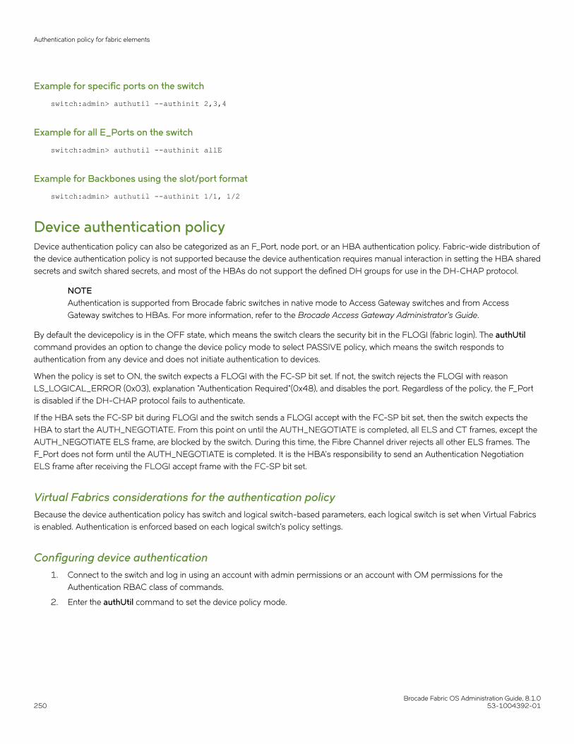
Example for specific ports on the switch
switch:admin> authutil --authinit 2,3,4
Example for all E_Ports on the switch
switch:admin> authutil --authinit allE
Example for Backbones using the slot/port format
switch:admin> authutil --authinit 1/1, 1/2
Device authentication policyDevice authentication policy can also be categorized as an F_Port, node port, or an HBA authentication policy. Fabric-wide distribution ofthe device authentication policy is not supported because the device authentication requires manual interaction in setting the HBA sharedsecrets and switch shared secrets, and most of the HBAs do not support the defined DH groups for use in the DH-CHAP protocol.
NOTEAuthentication is supported from Brocade fabric switches in native mode to Access Gateway switches and from AccessGateway switches to HBAs. For more information, refer to the Brocade Access Gateway Administrator's Guide.
By default the devicepolicy is in the OFF state, which means the switch clears the security bit in the FLOGI (fabric login). The authUtilcommand provides an option to change the device policy mode to select PASSIVE policy, which means the switch responds toauthentication from any device and does not initiate authentication to devices.
When the policy is set to ON, the switch expects a FLOGI with the FC-SP bit set. If not, the switch rejects the FLOGI with reasonLS_LOGICAL_ERROR (0x03), explanation "Authentication Required"(0x48), and disables the port. Regardless of the policy, the F_Portis disabled if the DH-CHAP protocol fails to authenticate.
If the HBA sets the FC-SP bit during FLOGI and the switch sends a FLOGI accept with the FC-SP bit set, then the switch expects theHBA to start the AUTH_NEGOTIATE. From this point on until the AUTH_NEGOTIATE is completed, all ELS and CT frames, except theAUTH_NEGOTIATE ELS frame, are blocked by the switch. During this time, the Fibre Channel driver rejects all other ELS frames. TheF_Port does not form until the AUTH_NEGOTIATE is completed. It is the HBA's responsibility to send an Authentication NegotiationELS frame after receiving the FLOGI accept frame with the FC-SP bit set.
Virtual Fabrics considerations for the authentication policyBecause the device authentication policy has switch and logical switch-based parameters, each logical switch is set when Virtual Fabricsis enabled. Authentication is enforced based on each logical switch’s policy settings.
Configuring device authentication1. Connect to the switch and log in using an account with admin permissions or an account with OM permissions for the
Authentication RBAC class of commands.
2. Enter the authUtil command to set the device policy mode.
Authentication policy for fabric elements
Brocade Fabric OS Administration Guide, 8.1.0250 53-1004392-01

Example of setting the device policy to passive mode
switch:admin> authutil --policy -dev passiveWarning: Activating the authentication policy requiresDH-CHAP secrets on both switch and device. Otherwise,the F-port will be disabled during next F-portbring-up.ARE YOU SURE (yes, y, no, n): [no] yDevice authentication is set to PASSIVE
AUTH policy restrictionsAll fabric element authentication configurations are performed on a local switch basis.
Device authentication policy supports devices that are connected to the switch in point-to-point manner and is visible to the entire fabric.The following are not supported:
• Public loop devices
• Single private devices
• Private loop devices
• Mixed public and private devices in loop
• NPIV devices
• FICON channels
• Configupload and download will not be supported for the following AUTH attributes: auth type, hash type, group type.
NOTEFor information about how to use authentication with Access Gateway, refer to the Brocade Access Gateway Administrator'sGuide.
Authentication protocolsUse the authUtil command to perform the following tasks:
• Display the current authentication parameters.
• Select the authentication protocol used between switches.
• Select the DH (Diffie-Hellman) group for a switch.
Run the authUtil command on the switch you want to view or change. Use the following options to specify which DH group you want touse:
• 00 - DH Null option
• 01 - 1024 bit key
• 02 - 1280 bit key
• 03 - 1536 bit key
• 04 - 2048 bit key
Viewing the current authentication parameter settings for a switch1. Log in to the switch using an account with admin permissions, or an account with the O permission for the Authentication
RBAC class of commands.
Authentication policy for fabric elements
Brocade Fabric OS Administration Guide, 8.1.053-1004392-01 251

2. Enter the authUtil --show command.
Example of output from the authUtil-- show command
AUTH TYPE HASH TYPE GROUP TYPE--------------------------------------fcap,dhchap sha1,md5 0, 1, 2, 3, 4Switch Authentication Policy: PASSIVEDevice Authentication Policy: OFF
Setting the authentication protocol1. Log in to the switch using an account with admin permissions, or an account with OM permissions for the Authentication RBAC
class of commands.
2. Enter the authUtil --set -a command specifying fcap, dhchap, or all.
Example of setting the DH-CHAP authentication protocol
switch:admin> authutil --set -a dhchapAuthentication is set to dhchap.
When using DH-CHAP, make sure that you configure the switches at both ends of a link.
NOTEWhen you set the authentication protocol to FCAP, ensure that the certificates are present at bothends.
NOTEIf you set the authentication protocol to DH-CHAP or FCAP, have not configured shared secrets or certificates, andauthentication is checked (for example, you enable the switch), then switch authentication will fail. If the E_Port is tocarry in-flight encrypted traffic, the authentication protocol must be set to DH-CHAP. You must also use the -g optionto set the DH group value to group 4 or all groups.
switch# authutil --set -g *
OR
switch# authutil --set -g 4
Secret key pairs for DH-CHAPWhen you configure the switches at both ends of a link to use DH-CHAP for authentication, you must also define a secret key pair --onefor each end of the link. Use the secAuthSecret command to perform the following tasks:
• View the WWN of switches with a secret key pair
• Set the secret key pair for switches.
• Remove the secret key pair for one or more switches.
NOTEThe DH-CHAP secrets are stored using AES-256 encryption.
Characteristics of a secret key pair• The secret key pair must be set up locally on every switch. The secret key pair is not distributed fabric-wide.
Authentication policy for fabric elements
Brocade Fabric OS Administration Guide, 8.1.0252 53-1004392-01

• If a secret key pair is not set up for a link, authentication fails. The "Authentication Failed" (reason code 05h) error will be reportedand logged.
• The minimum length of a shared secret is 8 characters and the maximum length is 40 characters. If the E_Port is to carry in-flight encrypted traffic, a shared secret or at least 32 characters is recommended. The value that you specify cannot havespaces. All other characters are allowed.
NOTEWhen setting a secret key pair , note that you are entering the shared secrets in plain text. Use a secure channel (for example,SSH or the serial console) to connect to the switch on which you are setting the secrets.
Viewing the list of secret key pairs in the current switch database1. Log in to the switch using an account with admin permissions, or an account with the O permission for the Authentication
RBAC class of commands.
2. Enter the secAuthSecret --show command.
The output displays the WWN, domain ID, and name (if known) of the switches with defined shared secrets:
WWN DId Name-----------------------------------------------10:00:00:60:69:80:07:52 Unknown10:00:00:60:69:80:07:5c 1 switchA
Note about Access Gateway switches
Because Domain ID and name are not supported for Access Gateway, secAuthSecret --show output for Access Gateway appears asfollows:
WWN DId Name-----------------------------------------------10:00:8C:7C:FF:03:9E:00 -1 Unknown10:00:8C:7C:FF:03:9E:01 -1 Unknown10:00:8C:7C:FF:0D:AF:01 -1 Unknown
When setting and removing the secret for a switch or device on Access Gateway, only the WWN can be used.
Setting a secret key pair1. Log in to the switch using an account with admin permissions, or an account with OM permissions for the Authentication RBAC
class of commands.
Authentication policy for fabric elements
Brocade Fabric OS Administration Guide, 8.1.053-1004392-01 253

2. Enter the secAuthSecret --set command.
The command enters interactive mode. The command returns a description of itself and needed input; then it loops through asequence of switch specification, peer secret entry, and local secret entry.
NOTEThe value that you specify should not contain spaces. All the other characters are allowed.
To exit the loop, press Enter for the switch name; then type y .
Example of setting a secret key pair
switchA:admin> secauthsecret --set This command is used to set up secret keys for the DH-CHAP authentication.The minimum length of a secret key is 8 characters and maximum 40characters. Setting up secret keys does not initiate DH-CHAPauthentication. If switch is configured to do DH-CHAP, it is performedwhenever a port or a switch is enabled.Warning: Please use a secure channel for setting secrets. Usingan insecure channel is not safe and may compromise secrets.Following inputs should be specified for each entry.1. WWN for which secret is being set up.2. Peer secret: The secret of the peer that authenticates to peer.3. Local secret: The local secret that authenticates peer.Press Enter to start setting up shared secrets > <cr>Enter WWN, Domain, or switch name (Leave blank when done): 10:20:30:40:50:60:70:80Enter peer secret: <hidden>Re-enter peer secret: <hidden>Enter local secret: <hidden>Re-enter local secret: <hidden>Enter WWN, Domain, or switch name (Leave blank when done): 10:20:30:40:50:60:70:81Enter peer secret: <hidden>Re-enter peer secret: <hidden>Enter local secret: <hidden>Re-enter local secret: <hidden>Enter WWN, Domain, or switch name (Leave blank when done): <cr>Are you done? (yes, y, no, n): [no] ySaving data to key store... Done.
3. Disable and enable the ports on a peer switch using the portDisable and portEnable commands.
FCAP configuration overviewBeginning with Fabric OS release 7.0.0, you must configure the switch to use third-party certificates for authentication with the peerswitch.
To perform authentication with FCAP protocol with certificates issued from third party, the user has to perform following steps:
1. Choose a certificate authority (CA).
2. Generate a public key, a private key, a passphrase, and a CSR on each switch.
3. Store the CSR from each switch on a file server.
Authentication policy for fabric elements
Brocade Fabric OS Administration Guide, 8.1.0254 53-1004392-01

4. Obtain the certificates from the CA.
You can request a certificate from a CA through a Web browser. After you request a certificate, the CA either sends certificatefiles by e-mail (public) or gives access to them on a remote host (private). Typically, the CA provides the certificate files listed inthe following table.
ATTENTIONOnly the .pem file type is supported for FCAPauthentication.
TABLE 54 Certificate files provided by certificate authority
Certificate File Description
name CA.pem The CA certificate. It must be installed on the remote and local switchto verify the validity of the switch certificate or switch validation fails.
name .pem The switch certificates:switch certificate.
5. On each switch, install the CA certificate before installing the switch certificate.
6. After the CA certificate is installed, install the switch certificate on each switch.
7. Update the switch database for peer switches to use third-party certificates.
8. Use the newly installed certificates by starting the authentication process.
Generating the key and CSR for FCAPThe public/private key and CSR has to be generated for the local and remote switches that will participate in the authentication. In FCAP,one command is used to generate the public/private key the CSR, and the passphrase.
1. Log in to the switch using an account with admin permissions, or an account associated with the chassis role and having OMpermissions for the PKI RBAC class of commands.
2. Enter the secCertUtil generate -fcap -keysize command on the local switch.
switch:admin> seccertutil generate -fcap -keysize 1024 -hash sha1|sha256WARNING!!!About to create FCAP:ARE YOU SURE (yes, y, no, n): [no] yInstalling Private Key and Csr...Switch key pair and CSR generated...
3. Repeat step 2 on the remote switch.
Exporting the CSR for FCAPYou will need to export the CSR file created in Generating the key and CSR for FCAP on page 255 section and send to a CertificateAuthority (CA). The CA will in turn provide two files as outlined in FCAP configuration overview on page 254.
1. Log in to the switch using an account with admin permissions, or an account associated with the chassis role and having OMpermissions for the PKI RBAC class of commands.
2. Enter the secCertUtil export -fcapswcsr command.
switch:admin> seccertutil export -fcapswcsrSelect protocol [ftp or scp]: scpEnter IP address: 10.1.2.3Enter remote directory: /myHome/jdoe/OPENSSLEnter Login Name: [email protected]'s password: <hidden text>Success: exported FCAP CA certificate
Authentication policy for fabric elements
Brocade Fabric OS Administration Guide, 8.1.053-1004392-01 255

Importing CA for FCAPOnce you receive the files back from the Certificate Authority, you will need to install or import them onto the local and remote switches.
1. Log in to the switch using an account with admin permissions, or an account associated with the chassis role and having OMpermissions for the PKI RBAC class of commands.
2. Enter the secCertUtil import -fcapcacert command and verify the CA certificates are consistent on both local and remoteswitches.
switch:admin> seccertutil import -fcapcacertSelect protocol [ftp or scp]: scpEnter IP address: 10.1.2.3Enter remote directory: /myHome/jdoe/OPENSSLEnter certificate name (must have a ".pem" suffix):CACert.pemEnter Login Name: [email protected]'s password: <hidden text>Success: imported certificate [CACert.pem].
NOTEFirmware downgrade from Fabric OS 7.3.0 to an earlier version is blocked if SHA-256 is one of the configured hashtypes for DH-CHAP or FCAP in at least one of the logical switches.
Importing the FCAP switch certificate
ATTENTIONThe CA certificates must be installed prior to installing the switchcertificate.
1. Log in to the switch using an account with admin permissions, or an account associated with the chassis role and having OMpermissions for the PKI RBAC class of commands.
2. Enter the secCertUtil import -fcapswcert command.
switch:admin> seccertutil import -fcapswcertSelect protocol [ftp or scp]: scpEnter IP address: 10.1.2.3Enter remote directory: /myHome/jdoe/OPENSSLEnter certificate name (must have ".crt" or ".cer" ".pem" or ".psk" suffix):01.pemEnter Login Name: [email protected]'s password: <hidden text>Success: imported certificate [01.pem].
Starting FCAP authentication1. Log in to the switch using an account with admin permissions, or an account with OM permissions for the Authentication RBAC
class of commands.
2. Enter the authUtil --authinit command to start the authentication using the newly imported certificates. (This command is notsupported in Access Gateway mode.)
Authentication policy for fabric elements
Brocade Fabric OS Administration Guide, 8.1.0256 53-1004392-01

3. Enter the authUtil --policy -sw command with either the active or on option.
authutil --policy -sw active
This makes the changes permanent and forces the switch to request authentication. (For Access Gateway mode, the defaults forsw policy and dev policy are off, and there is no passive option for sw policy.)
NOTEThis authentication-policy change does not affect onlineEX_Ports.
Fabric-wide distribution of the authorization policyThe AUTH policy can be manually distributed to the fabric using a command; there is no support for automatic distribution. To distributethe AUTH policy, refer to Distributing the local ACL policies on page 265 for instructions.
Local Switch configuration parameters are needed to control whether a switch accepts or rejects distributions of the AUTH policy usingthe distribute command and whether the switch can initiate distribution of the policy. To set the local switch configuration parameter, referto Policy database distribution on page 263.
NOTEThis capability is not supported for Access Gateway mode.
IP Filter policyThe IP Filter policy is a set of rules applied to the IP management interfaces as a packet filtering firewall. The firewall permits or deniesthe traffic going through the IP management interfaces according to the policy rules.
Fabric OS supports multiple IP Filter policies to be defined at the same time. Each IP Filter policy is identified by a name and has anassociated type. Two IP Filter policy types, IPv4 and IPv6, exist to provide separate packet filtering for IPv4 and IPv6. You cannot specifyan IPv6 address in the IPv4 filter, nor can you specify an IPv4 address in the IPv6 filter. There can be up to six different IP Filter policiesdefined for both types. Only one IP Filter policy for each IP type can be activated on the affected management IP interfaces.
Audit messages will be generated for any changes to the IP Filter policies.
The rules in the IP Filter policy are examined one at a time until the end of the list of rules. For performance reasons, the most commonlyused rules should be specified at the top.
On a chassis system, changes to persistent IP Filter policies are automatically synchronized to the standby CP when the changes aresaved persistently on the active CP. The standby CP will enforce the filter policies to its management interface after policies aresynchronized with the active CP.
Virtual Fabrics considerations for IP Filter policiesEach logical switch cannot have its own different IP Filter policies. IP Filter policies are treated as a chassis-wide configuration and arecommon for all the logical switches in the chassis.
IP Filter policy
Brocade Fabric OS Administration Guide, 8.1.053-1004392-01 257

Creating an IP Filter policyYou can create an IP Filter policy specifying any name and using type IPv4 or IPv6. The policy created is stored in a temporary buffer,and is lost if the current command session logs out. The policy name is a unique string composed of a maximum of 20 alpha, numeric,and underscore characters. The names "default_ipv4" and "default_ipv6" are reserved for default IP filter policies. The policy name iscase-insensitive and always stored as lowercase. The policy type identifies the policy as an IPv4 or IPv6 filter. There can be a maximumof six IP Filter policies.
1. Log in to the switch using an account with admin permissions, or an account associated with the chassis role and having OMpermissions for the IPfilter RBAC class of commands.
2. Enter in the ipFilter --create command.
Cloning an IP Filter policyYou can create an IP Filter policy as an exact copy of an existing policy. The policy created is stored in a temporary buffer and has thesame type and rules as the existing defined or active policy.
1. Log in to the switch using an account with admin permissions, or an account associated with the chassis role and having OMpermissions for the IPfilter RBAC class of commands.
2. Enter the ipFilter --clone command.
Displaying an IP Filter policyYou can display the IP Filter policy content for the specified policy name, or all IP Filter policies if a policy name is not specified.
For each IP Filter policy, the policy name, type, persistent state and policy rules are displayed. The policy rules are listed by the rulenumber in ascending order. There is no pagination stop for multiple screens of information. Pipe the output to the |more command toachieve this.
If a temporary buffer exists for an IP Filter policy, the--show subcommand displays the content in the temporary buffer, with the
persistent state set to no.
1. Log in to the switch using an account with admin permissions, or an account associated with the chassis role and having the Opermission for the IPfilter RBAC class of commands.
2. Enter the ipFilter --show command.
Saving an IP Filter policyYou can save one or all IP Filter policies persistently in the defined configuration.
Only the CLI session that owns the updated temporary buffer may run this command. Modification to an active policy cannot be savedwithout being applied. Hence, the--save subcommand is blocked for the active policies. Use--activate instead.
1. Log in to the switch using an account with admin permissions, or an account associated with the chassis role and having theOM permissions for the IPfilter RBAC class of commands.
2. Enter the ipFilter --save command.
IP Filter policy
Brocade Fabric OS Administration Guide, 8.1.0258 53-1004392-01

Activating an IP Filter policyIP Filter policies are not enforced until they are activated. Only one IP Filter policy per IPv4 and IPv6 type can be active. If there is atemporary buffer for the policy, the policy is saved to the defined configuration and activated at the same time. If there is no temporarybuffer for the policy, the policy existing in the defined configuration becomes active. The activated policy continues to remain in thedefined configuration. The policy to be activated replaces the existing active policy of the same type. Activating the default IP Filterpolicies returns the IP management interface to its default state. An IP Filter policy without any rule cannot be activated. Thissubcommand prompts for a user confirmation before proceeding.
1. Log in to the switch using an account with admin permissions, or an account associated with the chassis role and having OMpermissions for the IPfilter RBAC class of commands.
2. Enter the ipFilter --activate command.
Deleting an IP Filter policyYou can delete a specified IP Filter policy. Deleting an IP Filter policy removes it from the temporary buffer. To permanently delete thepolicy from the persistent database, run ipfilter --save . An active IP Filter policy cannot be deleted.
1. Log in to the switch using an account with admin permissions, or an account associated with the chassis role and having theOM permissions for the IPfilter RBAC class of commands.
2. Enter the ipFilter --delete command.
3. To permanently delete the policy, enter the ipfilter --save command.
IP Filter policy rulesAn IP Filter policy consists of a set of rules. Each rule has an index number identifying the rule. There can be a maximum of 256 ruleswithin an IP Filter policy.
Each rule contains the following elements:
• Source Address: A source IP address or a group prefix.
• Destination Port: The destination port number or name, such as: Telnet, SSH, HTTP, HTTPS.
• Protocol: The protocol type. Supported types are TCP or UDP.
• Action: The filtering action taken by this rule, either Permit or Deny.
A traffic type and destination IP can also be specified
Source addressFor an IPv4 filter policy, the source address has to be a 32-bit IPv4 address in dot decimal notation. The group prefix has to be a CIDRblock prefix representation. For example, 208.130.32.0/24 represents a 24-bit IPv4 prefix starting from the most significant bit. Thespecial prefix 0.0.0.0/0 matches any IPv4 address. In addition, the keyword any is supported to represent any IPv4 address.
For an IPv6 filter policy, the source address has to be a 128-bit IPv6 address, in a format acceptable in RFC 3513. The group prefix hasto be a CIDR block prefix representation. For example, 12AB:0:0:CD30::/64 represents a 64-bit IPv6 prefix starting from the mostsignificant bit. In addition, the keyword any is supported to represent any IPv6 address.
IP Filter policy
Brocade Fabric OS Administration Guide, 8.1.053-1004392-01 259

Destination portFor the destination port, a single port number or a port number range can be specified. According to IANA ( http://www.iana.org ), ports 0to 1023 are well-known port numbers, ports 1024 to 49151 are registered port numbers, and ports 49152 to 65535 are dynamic orprivate port numbers. Well-known and registered ports are normally used by servers to accept connections, while dynamic port numbersare used by clients.
For an IP Filter policy rule, you can only select port numbers in the well-known port number range, between 0 and 1023, inclusive. Thismeans that you have the ability to control how to expose the management services hosted on a switch, but not the ability to affect themanagement traffic that is initiated from a switch. A valid port number range is represented by a dash, for example 7-30. Alternatively,service names can also be used instead of port number. Table 55 lists the supported service names and their corresponding portnumbers.
TABLE 55 Supported services
Service name Port number
echo 7
discard
systat 11
daytime 13
netstat 15
chargen 19
ftp data 20
ftp 21
fsp 21
ssh 22
telnet 23
smtp 25
time 27
name 42
whois 43
domain 53
bootps 67
bootpc 68
tftp 69
http 80
kerberos 88
hostnames 101
sftp 115
ntp 123
snmp 161
snmp trap 162
https 443
ssmtp 465
exec 512
login 513
shell 514
IP Filter policy
Brocade Fabric OS Administration Guide, 8.1.0260 53-1004392-01

TABLE 55 Supported services (continued)
Service name Port number
uucp 540
biff 512
who 513
syslog 514
route 520
timed 525
kerberos4 750
ProtocolTCP and UDP protocols are valid protocol selections. Fabric OS v6.2.0 and later do not support configuration to filter other protocols.Implicitly, ICMP type 0 and type 8 packets are always allowed to support ICMP echo request and reply on commands like ping andtraceroute.
ActionFor the action, only "permit" and "deny" are valid.
Traffic type and destination IPThe traffic type and destination IP elements allow an IP policy rule to specify filter enforcement for IP forwarding. The INPUT traffic typeis the default and restricts rules to manage traffic on IP management interfaces,
The FORWARD traffic type allows management of bidirectional traffic between the external management interface and the inbandmanagement interface. In this case, the destination IP element should also be specified.
Implicit filter rulesFor every IP Filter policy, the two rules listed in Table 56 are always assumed to be appended implicitly to the end of the policy. Thisensures that TCP and UDP traffic to dynamic port ranges is allowed, so that management IP traffic initiated from a switch, such assyslog, radius and ftp, is not affected.
TABLE 56 Implicit IP Filter rules
Source address Destination port Protocol Action
Any 1024-65535 TCP Permit
Any 1024-65535 UDP Permit
Default policy rulesSwitches have a default IP Filter policy for IPv4 and IPv6. The default IP Filter policy cannot be deleted or changed. When an alternativeIP Filter policy is activated, the default IP Filter policy becomes deactivated. Table 57 lists the rules of the default IP Filter policy.
TABLE 57 Default IP policy rules
Rule number Source address Destination port Protocol Action
1 Any 22 TCP Permit
2 Any 23 TCP Permit
IP Filter policy
Brocade Fabric OS Administration Guide, 8.1.053-1004392-01 261
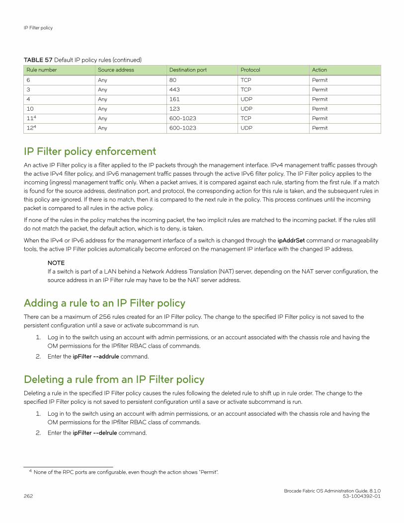
TABLE 57 Default IP policy rules (continued)
Rule number Source address Destination port Protocol Action
6 Any 80 TCP Permit
3 Any 443 TCP Permit
4 Any 161 UDP Permit
10 Any 123 UDP Permit
114 Any 600-1023 TCP Permit
124 Any 600-1023 UDP Permit
IP Filter policy enforcementAn active IP Filter policy is a filter applied to the IP packets through the management interface. IPv4 management traffic passes throughthe active IPv4 filter policy, and IPv6 management traffic passes through the active IPv6 filter policy. The IP Filter policy applies to theincoming (ingress) management traffic only. When a packet arrives, it is compared against each rule, starting from the first rule. If a matchis found for the source address, destination port, and protocol, the corresponding action for this rule is taken, and the subsequent rules inthis policy are ignored. If there is no match, then it is compared to the next rule in the policy. This process continues until the incomingpacket is compared to all rules in the active policy.
If none of the rules in the policy matches the incoming packet, the two implicit rules are matched to the incoming packet. If the rules stilldo not match the packet, the default action, which is to deny, is taken.
When the IPv4 or IPv6 address for the management interface of a switch is changed through the ipAddrSet command or manageabilitytools, the active IP Filter policies automatically become enforced on the management IP interface with the changed IP address.
NOTEIf a switch is part of a LAN behind a Network Address Translation (NAT) server, depending on the NAT server configuration, thesource address in an IP Filter rule may have to be the NAT server address.
Adding a rule to an IP Filter policyThere can be a maximum of 256 rules created for an IP Filter policy. The change to the specified IP Filter policy is not saved to thepersistent configuration until a save or activate subcommand is run.
1. Log in to the switch using an account with admin permissions, or an account associated with the chassis role and having theOM permissions for the IPfilter RBAC class of commands.
2. Enter the ipFilter --addrule command.
Deleting a rule from an IP Filter policyDeleting a rule in the specified IP Filter policy causes the rules following the deleted rule to shift up in rule order. The change to thespecified IP Filter policy is not saved to persistent configuration until a save or activate subcommand is run.
1. Log in to the switch using an account with admin permissions, or an account associated with the chassis role and having theOM permissions for the IPfilter RBAC class of commands.
2. Enter the ipFilter --delrule command.
4 None of the RPC ports are configurable, even though the action shows "Permit".
IP Filter policy
Brocade Fabric OS Administration Guide, 8.1.0262 53-1004392-01

Aborting an IP Filter transactionA transaction is associated with a command line or manageability session. It is opened implicitly when the --create, --addrule, --delrule,--clone, and --delete subcommands are run. The --transabort, --save, or --activate subcommands explicitly end the transactionowned by the current command line or manageability session. If a transaction is not ended, other command line or manageabilitysessions are blocked on the subcommands that would open a new transaction.
1. Log in to the switch using an account with admin permissions, or an account associated with the chassis role and having theOM permissions for the IPfilter RBAC class of commands.
2. Enter the ipFilter --transabort command.
IP Filter policy distributionThe IP Filter policy is manually distributed using a command. The distribution includes both active and defined IP Filter policies. Allpolicies are combined as a single entity to be distributed and cannot be selectively distributed. However, you can choose the time atwhich to implement the policy for optimization purposes. If a distribution includes an active IP Filter policy, the receiving switches activatethe same IP Filter policy automatically. When a switch receives IP Filter policies, all uncommitted changes left in its local transactionbuffer are lost, and the transaction is aborted.
The IP Filter policy can be manually distributed to the fabric using a command; there is no support for automatic distribution. Todistribute the IPFilter policy, refer to Distributing the local ACL policies on page 265 for instructions.
You can accept or deny IP Filter policy distribution using the commands fddCfg --localaccept or fddCfg --localreject. Refer to Policydatabase distribution on page 263 for more information about distributing the IP Filter policy.
NOTEAny RPC ports that were allowed in Fabric OS versions earlier than 7.2.0 are removed and ignored in Fabric OS 7.2.0 and later.
NOTETo distribute the IP Filter policy in a logical fabric using Virtual Fabrics, use the chassisDistribute command.
Policy database distributionFabric OS lets you manage and enforce the ACL policy database on either a per-switch or fabric-wide basis. The local switch distributionsetting and the fabric-wide consistency policy affect the switch ACL policy database and related distribution behavior.
The ACL policy database is managed as follows:
• Switch database distribution setting -- Controls whether or not the switch accepts or rejects databases distributed from otherswitches in the fabric. The distribute command sends the database from one switch to another, overwriting the target switchdatabase with the distributed one. To send or receive a database the setting must be accept. For configuration instructions, referto .
Virtual Fabric considerations: FCS, DCC, SCC, and AUTH databases can be distributed using the -distribute command, but the PWD isblocked from distribution. The IPFILTER databases can be distributed using the FID in VF environment.
• Manually distribute an ACL policy database -- Use the distribute command to push the local database of the specified policytype to target switches. Refer to ACL policy distribution to other switches on page 265.
• Fabric-wide consistency policy -- Use this policy to ensure that switches in the fabric enforce the same policies. Set a strict ortolerant fabric-wide consistency policy for each ACL policy type to automatically distribute that database when a policy changeis activated. If a fabric-wide consistency policy is not set, then the policies are managed on a per-switch basis. For configurationinstructions, refer to Fabric-wide enforcement on page 266.
Policy database distribution
Brocade Fabric OS Administration Guide, 8.1.053-1004392-01 263

Virtual Fabric considerations: Fabric-wide consistency policies are configured on a per-logical switch basis and are applied to the fabricsconnected to the logical switches. Automatic policy distribution behavior for DCC, SCC, and FCS is the same as that of pre-v6.2.0releases and are configured on a per-logical switch basis.
The following table explains how the local database distribution settings and the fabric-wide consistency policy affect the local databasewhen the switch is the target of a distribute command.
TABLE 58 Interaction between fabric-wide consistency policy and distribution settings
Distribution setting Fabric-wide consistency policy
Absent (default) Tolerant Strict
Reject Database is protected, it cannot beoverwritten.
May not match other databases inthe fabric.
Invalid configuration.5 Invalid configuration.5
Accept (default) Database is not protected, thedatabase can be overwritten.
If the switch initiating a distributecommand has a strict or tolerantfabric-wide consistency policy, thefabric-wide policy is alsooverwritten.
May not match other databases inthe fabric.
Database is not protected.
Automatically distributes activatedchanges to other v6.2.0 or laterswitches in the fabric.
If the fabric-wide consistency is setas "strict" for a particular policy, thenthe manual distribution is blocked.
May not match other databases inthe fabric.
Database is not protected.
Automatically distributes activatedchanges to all switches in the fabric.
Fabric can only contain switchesrunning Fabric OS v6.2.0 or later.
Active database is the same for allswitches in the fabric.
NOTEStarting with Fabric OS 7.3.0, Access Gateways are capable of receiving the password database distributed by native switchesand domains. However, the Access Gateways are not capable of distributing the password database to the switches or domains.
Database distribution settingsThe distribution settings control whether a switch accepts or rejects distributions of databases from other switches and whether theswitch may initiate a distribution. Configure the distribution setting to reject when maintaining the database on a per-switch basis.
Table 59 lists the databases supported in Fabric OS v6.2.0 and later switches.
TABLE 59 Supported policy databases
Database type Database identifier (ID)
Authentication policy database AUTH
DCC policy database DCC
FCS policy database FCS
IP Filter policy database IPFILTER
Password database PWD
SCC policy database SCC
5 An error is returned indicating that the distribution setting must be Accept before you can set the fabric-wide consistency policy.
Policy database distribution
Brocade Fabric OS Administration Guide, 8.1.0264 53-1004392-01

Use the chassisDistribute command to distribute IP filter policies. To distribute other security policies, use the distribute command. Thedistribute command distributes the database also to Access Gateways in non-VF mode.
Displaying the database distribution settings1. Connect to the switch and log in using an account with admin permissions, or an account with OM permissions for the
FabricDistribution RBAC class of commands.
2. Enter the fddCfg --showall command.
The following sample output shows the database distribution settings.
switch:admin> fddcfg --showallLocal Switch Configuration for all Databases:- DATABASE - Accept/Reject--------------------------------- SCC - accept DCC - accept PWD - accept FCS - accept AUTH - accept IPFILTER - acceptFabric Wide Consistency Policy:- ""
Enabling local switch protection1. Connect to the switch and log in using an account with admin permissions, or an account with OM permissions for the
FabricDistribution RBAC class of commands.
2. Enter the fddCfg --localreject command.
Disabling local switch protection1. Connect to the switch and log in using an account with admin permissions, or an account with OM permissions for the
FabricDistribution RBAC class of commands.
2. Enter the fddCfg --localaccept command.
ACL policy distribution to other switchesThis section explains how to manually distribute local ACL policy databases. The distribute command has the following dependencies:
• All target switches must be running Fabric OS v6.2.0 or later.
• All target switches must accept the database distribution (refer to Database distribution settings on page 264).
• The fabric must have a tolerant or no (absent) fabric-wide consistency policy (refer to Fabric-wide enforcement on page 266).
If the fabric-wide consistency policy for a database is strict, the database cannot be manually distributed. When you set a strict fabric-wide consistency policy for a database, the distribution mechanism is automatically invoked whenever the database changes.
• The local distribution setting must be accepted. To be able to initiate the distribute command, set the local distribution toAccept.
Distributing the local ACL policies1. Connect to the switch and log in using an account with admin permissions, or an account with OM permissions for the
FabricDistribution RBAC class of commands.
Policy database distribution
Brocade Fabric OS Administration Guide, 8.1.053-1004392-01 265
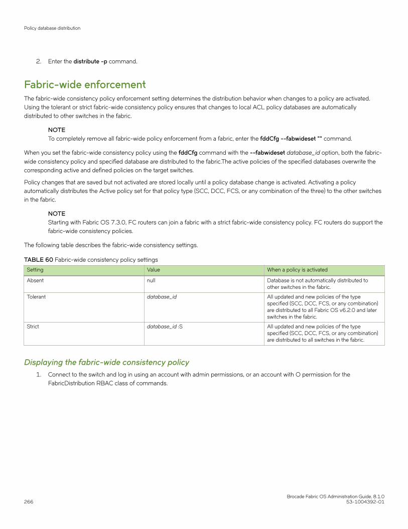
2. Enter the distribute -p command.
Fabric-wide enforcementThe fabric-wide consistency policy enforcement setting determines the distribution behavior when changes to a policy are activated.Using the tolerant or strict fabric-wide consistency policy ensures that changes to local ACL policy databases are automaticallydistributed to other switches in the fabric.
NOTETo completely remove all fabric-wide policy enforcement from a fabric, enter the fddCfg --fabwideset "" command.
When you set the fabric-wide consistency policy using the fddCfg command with the --fabwideset database_id option, both the fabric-
wide consistency policy and specified database are distributed to the fabric.The active policies of the specified databases overwrite thecorresponding active and defined policies on the target switches.
Policy changes that are saved but not activated are stored locally until a policy database change is activated. Activating a policyautomatically distributes the Active policy set for that policy type (SCC, DCC, FCS, or any combination of the three) to the other switchesin the fabric.
NOTEStarting with Fabric OS 7.3.0, FC routers can join a fabric with a strict fabric-wide consistency policy. FC routers do support thefabric-wide consistency policies.
The following table describes the fabric-wide consistency settings.
TABLE 60 Fabric-wide consistency policy settings
Setting Value When a policy is activated
Absent null Database is not automatically distributed toother switches in the fabric.
Tolerant database_id All updated and new policies of the typespecified (SCC, DCC, FCS, or any combination)are distributed to all Fabric OS v6.2.0 and laterswitches in the fabric.
Strict database_id :S All updated and new policies of the typespecified (SCC, DCC, FCS, or any combination)are distributed to all switches in the fabric.
Displaying the fabric-wide consistency policy1. Connect to the switch and log in using an account with admin permissions, or an account with O permission for the
FabricDistribution RBAC class of commands.
Policy database distribution
Brocade Fabric OS Administration Guide, 8.1.0266 53-1004392-01

2. Enter the fddCfg --showall command.
The following sample output shows policies for a fabric where no consistency policy is defined.
switch:admin> fddcfg --showallLocal Switch Configuration for all Databases:- DATABASE - Accept/Reject--------------------------------- SCC - accept DCC - accept PWD - accept FCS - accept AUTH - accept IPFILTER - acceptFabric Wide Consistency Policy:- ""
Setting the fabric-wide consistency policy1. Connect to the switch and log in using an account with admin permissions, or an account with OM permissions for the
FabricDistribution RBAC class of commands.
2. Enter the fddCfg --fabwideset command.
The following example shows how to set a strict SCC and tolerant DCC fabric-wide consistency policy.
switch:admin> fddcfg --fabwideset "SCC:S;DCC"switch:admin> fddcfg --showallLocal Switch Configuration for all Databases:- DATABASE - Accept/Reject--------------------------------- SCC - accept DCC - accept PWD - accept FCS - accept AUTH - accept IPFILTER - acceptFabric Wide Consistency Policy:- "SCC:S;DCC"
Notes on joining a switch to the fabricWhen a switch is joined to a fabric with a tolerant SCC, DCC, or FCS fabric-wide consistency policy, the joining switch must have amatching tolerant SCC, DCC, or FCS fabric-wide consistency policy. If the tolerant SCC, DCC, or FCS fabric-wide consistency policiesdo not match, the switch can still join the fabric, but an error message notifies you about the mismatch. If the tolerant SCC, DCC, andFCS fabric-wide consistency policies match, the corresponding SCC, DCC, and FCS ACL policies are compared.
The enforcement of fabric-wide consistency policy involves comparison of the Active policy set. If the ACL polices match, the switchjoins the fabric successfully. If the ACL policies are absent either on the switch or on the fabric, the switch joins the fabric successfully,and the ACL policies are copied automatically from where they are present to where they are absent. The Active policy set where it ispresent overwrites the Active and Defined policy set where it is absent. If the ACL policies do not match, the switch cannot join the fabricand the neighboring E_Ports are disabled.
Use the fddCfg --fabwideset command on either the switch or the fabric to set a matching strict SCC, DCC, or FCS fabric-wideconsistency policy. Use ACL policy commands to delete the conflicting ACL policy from one side to resolve the ACL policy conflict. Ifneither the fabric nor the joining switch is configured with a fabric-wide consistency policy, there are no ACL merge checks required.Under both conflicting conditions, secPolicyActivate is blocked in the merged fabric. Use the distribute command to explicitly resolveconflicting ACL policies.
The descriptions also apply to joining two fabrics. In this context, the joining switch becomes a joining fabric.
Policy database distribution
Brocade Fabric OS Administration Guide, 8.1.053-1004392-01 267

Matching fabric-wide consistency policiesThis section describes the interaction between the databases with active SCC and DCC policies and combinations of fabric-wideconsistency policy settings when fabrics are merged.
For example: Fabric A with SCC:S;DCC (strict SCC and tolerant DCC) joins Fabric B with SCC:S;DCC (strict SCC and tolerant DCC), thefabrics can merge as long as the SCC policies match, including the order SCC:S;DCC and if both are set to strict.
Table 61 describes the impact of merging fabrics with the same fabric-wide consistency policy that have SCC, DCC, or both policies.
TABLE 61 Merging fabrics with matching fabric-wide consistency policies
Fabric-wide consistencypolicy
Fabric A ACL policies Fabric B ACL policies Merge results Database copied
None None None Succeeds No ACL policies copied.
None SCC/DCC Succeeds No ACL policies copied.
Tolerant None None Succeeds No ACL policies copied.
None SCC/DCC Succeeds ACL policies are copiedfrom B to A.
SCC/DCC SCC/DCC Succeeds If A and B policies do notmatch, a warning displaysand policy commands aredisabled. 6
Strict None None Succeeds No ACL policies copied.
None SCC/DCC Succeeds ACL policies are copiedfrom B to A.
Matching SCC/DCC Matching SCC/DCC Succeeds No ACL policies copied.
Different SCC/DCC policies Different SCC/DCC policies Fails Ports are disabled.
Non-matching fabric-wide consistency policiesYou may encounter one of the following two scenarios described in Table 62 and Table 63 where you are merging a fabric with a strictpolicy to a fabric with an absent, tolerant, or non-matching strict policy and the merge fails and the ports are disabled.
Table 62 shows merges that are not supported.
TABLE 62 Examples of strict fabric merges
Fabric-wide consistency policy setting Expected behavior
Fabric A Fabric B
Strict/Tolerant SCC:S;DCC:S SCC;DCC:S Ports connecting switches aredisabled.
SCC;DCC:S SCC:S;DCC
SCC:S;DCC SCC:S
Strict/Absent SCC:S;DCC:S
SCC:S
DCC:S
Strict/Strict SCC:S DCC:S
6 To resolve the policy conflict, manually distribute the database you want to use to the switch with the mismatched database. Until the conflict isresolved, commands such as fddCfg --fabwideset and secPolicyActivate are blocked.
Policy database distribution
Brocade Fabric OS Administration Guide, 8.1.0268 53-1004392-01

Table 63 has a matrix of merging fabrics with tolerant and absent policies.
TABLE 63 Fabric merges with tolerant and absent combinations
Fabric-wide consistency policy setting Expected behavior
Fabric A Fabric B
Tolerant/Absent SCC;DCC Error message logged.
Run the fddCfg command with the--fabwideset "policy_ID" from anyswitch with the desiredconfiguration to fix the conflict. ThesecPolicyActivate command isblocked until conflict is resolved.
DCC
SCC;DCC SCC
DCC SCC
Management interface securityYou can secure an Ethernet management interface between two Brocade switches or Backbones by implementing IPsec and IKEpolicies to create a tunnel that protects traffic flows. While the tunnel must have a Brocade switch or Backbone at each end, there may berouters, gateways, and firewalls in between the two ends.
ATTENTIONEnabling secure IPsec tunnels does not provide IPsec protection for traffic flows on the external management interfaces ofintelligent blades in a chassis, nor does it support protection of traffic flows on FCIP interfaces.
Internet Protocol security (IPsec) is a framework of open standards that ensures private and secure communications over InternetProtocol (IP) networks through the use of cryptographic security services. The goal of IPsec is to provide the following capabilities:
NOTEThe ipSecConfig --enable command is not supported in Fabric OS 8.0.0.
• Authentication -- Ensures that the sending and receiving end-users and devices are known and trusted by one another.
• Data Integrity -- Confirms that the data received was in fact the data transmitted.
• Data Confidentiality -- Protects the user data being transmitted, such as utilizing encryption to avoid sending data in clear text.
• Replay Protection -- Prevents replay attack in which an attacker resends previously-intercepted packets in an effort tofraudulently authenticate or otherwise masquerade as a valid user.
• Automated Key Management --Automates the process, as well as manages the periodic exchange and generation of new keys.
Using the ipSecConfig command, you must configure multiple security policies for traffic flows on the Ethernet management interfacesbased on IPv4 or IPv6 addresses, a range of IPv4 or IPv6 addresses, the type of application, port numbers, and protocols used(UDP/TCP/ICMP). You must specify the transforms and processing choices for the traffic flow (drop, protect or bypass). Also, you mustselect and configure the key management protocol using an automatic or manual key.
For more information on IPv4 and IPv6 addressing, refer to Performing Basic Configuration Tasks on page 35.
Configuration examplesThe following examples demonstrate various configurations you can use to implement an IPsec tunnel between two devices. You canconfigure other scenarios as nested combinations of these configurations.
Management interface security
Brocade Fabric OS Administration Guide, 8.1.053-1004392-01 269

Endpoint-to-endpoint transport or tunnelIn this scenario, both endpoints of the IP connection implement IPsec, as required of hosts in RFC4301. Transport mode encrypts onlythe payload while tunnel mode encrypts the entire packet. A single pair of addresses will be negotiated for packets protected by this SA.
It is possible in this scenario that one or both of the protected endpoints will be behind a network address translation (NAT) node, in whichcase tunneled packets will have to be UDP-encapsulated so that port numbers in the UDP headers can be used to identify individualendpoints behind the NAT.
FIGURE 15 Protected endpoints configuration
A possible drawback of end-to-end security is that various applications that require the ability to inspect or modify a transient packet willfail when end-to-end confidentiality is employed. Various QoS solutions, traffic shaping, and firewalling applications will be unable todetermine what type of packet is being transmitted and will be unable to make the decisions that they are supposed to make.
Gateway-to-gateway tunnelIn this scenario, neither endpoint of the IP connection implements IPsec, but the network nodes between them protect traffic for part ofthe way. Protection is transparent to the endpoints, and depends on ordinary routing to send packets through the tunnel endpoints forprocessing. Each endpoint would announce the set of addresses behind it, and packets would be sent in tunnel mode where the inner IPheader would contain the IP addresses of the actual endpoints.
FIGURE 16 Gateway tunnel configuration
Management interface security
Brocade Fabric OS Administration Guide, 8.1.0270 53-1004392-01

Endpoint-to-gateway tunnelIn this scenario, a protected endpoint (typically a portable computer) connects back to its corporate network through an IPsec-protectedtunnel. It might use this tunnel only to access information on the corporate network, or it might tunnel all of its traffic back through thecorporate network in order to take advantage of protection provided by a corporate firewall against Internet-based attacks. In either case,the protected endpoint will want an IP address associated with the security gateway so that packets returned to it will go to the securitygateway and be tunneled back.
FIGURE 17 Endpoint-to-gateway tunnel configuration
RoadWarrior configurationIn endpoint-to-endpoint security, packets are encrypted and decrypted by the host which produces or consumes the traffic. In thegateway-to-gateway example, a router on the network encrypts and decrypts the packets on behalf of the hosts on a protected network.A combination of the two is referred to as a RoadWarrior configuration where a host on the Internet requires access to a network througha security gateway that is protecting the network.
IPsec protocolsIPsec ensures confidentiality, integrity, and authentication using the following protocols:
• Authentication Header (AH)
• Encapsulating Security Payload (ESP)
IPsec protocols protect IP datagram integrity using hash message authentication codes (HMAC). Using hash algorithms with thecontents of the IP datagram and a secret key, the IPsec protocols generate this HMAC and add it to the protocol header. The receivermust have access to the secret key in order to decode the hash.
IPsec protocols use a sliding window to assist in flow control, The IPsec protocols also use this sliding window to provide protectionagainst replay attacks in which an attacker attempts a denial of service attack by replaying an old sequence of packets. IPsec protocolsassign a sequence number to each packet. The recipient accepts each packet only if its sequence number is within the window. Itdiscards older packets.
Management interface security
Brocade Fabric OS Administration Guide, 8.1.053-1004392-01 271

Security associationsA security association (SA) is the collection of security parameters and authenticated keys that are negotiated between IPsec peers toprotect the IP datagram. A security association database (SADB) is used to store these SAs. Information in these SAs--IP addresses,secret keys, algorithms, and so on--is used by peers to encapsulate and decapsulate the IPsec packets
An IPsec security association is a construct that specifies security properties that are recognized by communicating hosts. The propertiesof the SA are the security protocol (AH or ESP), destination IP address, and Security Parameter Index (SPI) number. SPI is an arbitrary32-bit value contained in IPsec protocol headers (AH or ESP) and an IPsec SA is unidirectional. Because most communication is peer-to-peer or client-to-server, two SAs must be present to secure traffic in both directions. An SA specifies the IPsec protocol (AH or ESP),the algorithms used for encryption and authentication, and the expiration definitions used in security associations of the traffic. IKE usesthese values in negotiations to create IPsec SAs. You must create an SA prior to creating an SA-proposal. You cannot modify an SA onceit is created. Use the ipSecConfig --flush manual-sa command to remove all SA entries from the kernel SADB and re-create the SA.
IPsec proposalThe IPsec sa-proposal defines an SA or an SA bundle. An SA is a set of parameters that define how the traffic is protected using IPsec.These are the IPsec protocols to use for an SA, either AH or ESP, and the encryption and authentication algorithms to use to protect thetraffic.
For SA bundles, [AH, ESP] is the supported combination.
Authentication and encryption algorithmsIPsec uses different protocols to ensure the authentication, integrity, and confidentiality of the communication. Encapsulating SecurityPayload (ESP) provides confidentiality, data integrity and data source authentication of IP packets, and protection against replay attacks.Authentication Header (AH) provides data integrity, data source authentication, and protection against replay attacks, but unlike ESP, AHdoes not provide confidentiality.
In AH and ESP, hmac_md5 and hmac_sha1 are used as authentication algorithms. Only in ESP, 3des_cbc, blowfish_cbc, aes256_cbcand null_enc are used as encryption algorithms. Use Table 64 when configuring the authentication algorithm.
TABLE 64 Algorithms and associated authentication policies
Algorithm Encryption Level Policy Description
hmac_md5 128-bit AH, ESP A stronger MAC because it is akeyed hash inside a keyed hash.When MD5 or SHA-1 is used inthe calculation of an HMAC; theresulting MAC algorithm is termedHMAC-MD5 or HMAC-SHA-1accordingly.
NOTEThe MD5 hashalgorithm is blockedwhen FIPS mode isenabled
hmac_sha1 160-bit AH, ESP
3des_cbc 168-bit ESP Triple DES is a more secure variantof DES. It uses three different 56-bit keys to encrypt blocks of 64-bitplain text. The algorithm is FIPS-approved for use by Federalagencies.
Management interface security
Brocade Fabric OS Administration Guide, 8.1.0272 53-1004392-01

TABLE 64 Algorithms and associated authentication policies (continued)
Algorithm Encryption Level Policy Description
blowfish_cbc 64-bit ESP Blowfish is a 32-bit to 448-bitkeyed, symmetric block cipher.
aes128_cbc 128-bit ESP Advanced Encryption Standard is a128- or 256-bit fixed block sizecipher.
aes256_cbc 256-bit ESP
null_enc n/a ESP A form of plaintext encryption.
IPsec policiesAn IPsec policy determines the security services afforded to a packet and the treatment of a packet in the network. An IPsec policy allowsclassifying IP packets into different traffic flows and specifies the actions or transformations performed on IP packets on each of thetraffic flows. The main components of an IPsec policy are: IP packet filter and selector (IP address, protocol, and port information) andtransform set.
IPsec traffic selectorThe traffic selector is a traffic filter that defines and identifies the traffic flow between two systems that have IPsec protection. IPaddresses, the direction of traffic flow (inbound, outbound) and the upper layer protocol are used to define a filter for traffic (IP datagrams)that is protected using IPsec.
IPsec transformA transform set is a combination of IPsec protocols and cryptographic algorithms that are applied on the packet after it is matched to aselector. The transform set specifies the IPsec protocol, IPsec mode and action to be performed on the IP packet. It specifies the keymanagement policy that is needed for the IPsec connection and the encryption and authentication algorithms to be used in securityassociations when IKE is used as the key management protocol.
IPsec can protect either the entire IP datagram or only the upper-layer protocols using tunnel mode or transport mode. Tunnel modeuses the IPsec protocol to encapsulate the entire IP datagram. Transport mode handles only the IP datagram payload.
IKE policiesWhen IKE is used as the key management protocol, IKE policy defines the parameters used in IKE negotiations needed to establish IKESA and parameters used in negotiations to establish IPsec SAs. These include the authentication and encryption algorithms, and theprimary authentication method, such as preshared keys, or a certificate-based method, such as RSA signatures.
Key managementThe IPsec key management supports Internet Key Exchange or Manual key/SA entry. The Internet Key Exchange (IKE) protocol handleskey management automatically. SAs require keying material for authentication and encryption. The managing of keying material that SAsrequire is called key management .
The IKE protocol secures communication by authenticating peers and exchanging keys. It also creates the SAs and stores them in theSADB.
The manual key/SA entry requires the keys to be generated and managed manually. For the selected authentication or encryptionalgorithms, the correct keys must be generated using a third party utility on your LINUX system. The key length is determined by thealgorithm selected.
Management interface security
Brocade Fabric OS Administration Guide, 8.1.053-1004392-01 273

Linux IPsec-tools 0.7 provides tools for manual key entry (MKE) and automatic keyed connections. The LINUX setKey command can beused for manually keyed connections, which means that all parameters needed for the setup of the connection are provided by you.Based on which protocol, algorithm, and key used for the creation of the security associations, the switch populates the securityassociation database (SAD) accordingly.
Pre-shared keysA pre-shared key has the .psk extension and is one of the available methods IKE can be configured to use for primary authentication. Youcan specify the pre-shared keys used in IKE policies; add and delete pre-shared keys (in local database) corresponding to the identity ofthe IKE peer or group of peers.
The ipsecconfig command does not support manipulating pre-shared keys corresponding to the identity of the IKE peer or group ofpeers. Use the seccertmgmt command to import, delete, or display the pre-shared keys in the local switch database. For moreinformation on this procedure, refer to Configuring Protocols on page 199.
Security certificatesA certificate is one of the available methods IKE can be configured to use for primary authentication. You can specify the local public keyand private key (in X.509 PEM format) and peer public key (in X.509 format) to be used in a particular IKE policy.
Use the secCertUtil import command to import public key, private key and peer-public key (in X.509 PEM format) into the switchdatabase. For more information on this procedure, refer to Configuring Protocols on page 199.
ATTENTIONThe CA certificate name must have the IPSECCA.pemname.
Static Security AssociationsManual Key Entry (MKE) provides the ability to manually add, delete and flush SA entries in the SADB. Manual SA entries may not havean associated IPsec policy in the local policy database. Manual SA entries are persistent across system reboots.
Restrictions when using IKE policiesYou should be aware of the following restrictions when using IKE policies:
• For Fabric OS 7.0.0 and later versions, IPsec does not support null encryption (null_enc) for IKE policies.
• IPv6 policies cannot tunnel IMCP traffic.
Creating the tunnelEach side of the tunnel must be configured in order for the tunnel to activate. After you are logged into the switch, do not log off, becauseeach step requires that you be logged in to the switch. IPsec configuration changes take effect upon execution and are persistent acrossreboots. Use the following procedure to configure each side of the tunnel:
1. Determine the authentication protocol and algorithm to be used on the tunnel.
Refer to Table 64 on page 272 to determine which algorithm to use in conjunction with a specific authentication protocol.
2. Determine the type of keys to be used on the tunnel.
If you are using CA signed keys, you must generate them prior to setting up your tunnels.
Management interface security
Brocade Fabric OS Administration Guide, 8.1.0274 53-1004392-01

3. Enable IPsec.
a) Connect to the switch and log in using an account with admin permissions, or an account associated with the chassis roleand having OM permissions for the IPsec RBAC class of commands.
b) Enter the ipSecConfig --enable command to enable IPsec on the switch.
4. Create an IPsec SA policy on each side of the tunnel using the ipSecConfig --add command.
Example of creating an IPsec SA policy
This example creates an IPsec SA policy named "AH01" , which uses AH protection with MD5. You would run this commandon each switch; on each side of the tunnel so that both sides have the same IPsec SA policy.
switch:admin> ipsecconfig --add policy ips sa -t AH01 -p ah -auth hmac_md5
5. Create an IPsec proposal on each side of the tunnel using the ipSecConfig --add command.
Example of creating an IPsec proposal
This example creates an IPsec proposal "IPSEC-AH" to use "AH01" as SA.
switch:admin> ipsecconfig --add policy ips sa-proposal -t IPSEC-AH -sa AH01
6. Import the pre-shared key file.
Refer to Configuring Protocols on page 199 for information on how to set up pre-shared keys and certificates.
7. Configure the IKE policy using the ipSecConfig --add command.
Example of creating an IKE policy
This example creates an IKE policy for the remote peer.
switch:admin> ipsecconfig --add policy ike -t IKE01 -remote 10.33.74.13 -id 10.33.69.132 -remoteid 10.33.74.13 -enc 3des_cbc -hash hmac_md5 -prf hmac_md5 -auth psk -dh modp1024 -psk ipseckey.psk
8. Create an IPsec transform on each switch using the ipSecConfig --add command.
Example of creating an IPsec transform
This example creates an IPsec transform TRANSFORM01 to use the transport mode to protect traffic identified for IPsecprotection and use IKE01 as key management policy.
switch:admin> ipsecconfig --add policy ips transform -t TRANSFORM01 -mode transport -sa-proposal IPSEC-AH -action protect -ike IKE01
9. Create a traffic selector on each switch using the ipSecConfig --add command.
Example of creating a traffic selector
This example creates a traffic selector to select outbound and inbound traffic that needs to be protected.
switch:admin> ipsecconfig --add policy ips selector -t SELECTOR-OUT -d out -l 10.33.69.132 -r 10.33.74.13 -transform TRANSFORM01switch:admin> ipsecconfig --add policy ips selector -t SELECTOR-IN -d in -l 10.33.74.13 -r 10.33.69.132 -t transform TRANSFORM01
Inbound and outbound selectors use opposite values for local and remote IP addresses. In this example, notice that the local ("-l") address of SELECTOR-OUT is the same as the remote ("-r") address or SELECTOR-IN, Similarly, the local ("-l") address ofSELECTOR-IN is the same as the remote ("-r") address or SELECTOR-OUT. That is, "local" refers to the source IP address ofthe packet, and "remote" is the destination IP address. Hence inbound packets have opposite source and destination addressesthan outbound packets.
Management interface security
Brocade Fabric OS Administration Guide, 8.1.053-1004392-01 275
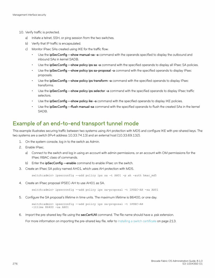
10. Verify traffic is protected.
a) Initiate a telnet, SSH, or ping session from the two switches.
b) Verify that IP traffic is encapsulated.
c) Monitor IPsec SAs created using IKE for the traffic flow:
• Use the ipSecConfig --show manual-sa -a command with the operands specified to display the outbound andinbound SAs in kernel SADB.
• Use the ipSecConfig --show policy ips sa -a command with the specified operands to display all IPsec SA policies.
• Use the ipSecConfig --show policy ips sa-proposal -a command with the specified operands to display IPsecproposals.
• Use the ipSecConfig --show policy ips transform -a command with the specified operands to display IPsectransforms.
• Use the ipSecConfig --show policy ips selector -a command with the specified operands to display IPsec trafficselectors.
• Use the ipSecConfig --show policy ike -a command with the specified operands to display IKE policies.
• Use the ipSecConfig --flush manual-sa command with the specified operands to flush the created SAs in the kernelSADB.
Example of an end-to-end transport tunnel modeThis example illustrates securing traffic between two systems using AH protection with MD5 and configure IKE with pre-shared keys. Thetwo systems are a switch (IPv4 address 10.33.74.13) and an external host (10.33.69.132).
1. On the system console, log in to the switch as Admin.
2. Enable IPsec.
a) Connect to the switch and log in using an account with admin permissions, or an account with OM permissions for theIPsec RBAC class of commands.
b) Enter the ipSecConfig --enable command to enable IPsec on the switch.
3. Create an IPsec SA policy named AH01, which uses AH protection with MD5.
switch:admin> ipsecconfig --add policy ips sa -t AH01 -p ah -auth hmac_md5
4. Create an IPsec proposal IPSEC-AH to use AH01 as SA.
switch:admin> ipsecconfig --add policy ips sa-proposal -t IPSEC-AH -sa AH01
5. Configure the SA proposal's lifetime in time units. The maximum lifetime is 86400, or one day.
switch:admin> ipsecconfig --add policy ips sa-proposal -t IPSEC-AH -lttime 86400 -sa AH01
6. Import the pre-shared key file using the secCertUtil command. The file name should have a .psk extension.
For more information on importing the pre-shared key file, refer to Installing a switch certificate on page 213.
Management interface security
Brocade Fabric OS Administration Guide, 8.1.0276 53-1004392-01

7. Configure an IKE policy for the remote peer.
switch:admin> ipsecconfig --add policy ike -t IKE01 -remote 10.33.69.132 -id 10.33.74.13 -remoteid 10.33.69.132 -enc 3des_cbc -hash hmac_md5 -prf hmac_md5 -auth psk -dh modp1024 -psk ipseckey.psk
NOTEIKE version (‘-v’ option) needs to be set to 1 (IKEv1) if remote peer is a Windows XP or 2000 Host as Windows XPand 2000 do not support IKEv2.
8. Create an IPsec transform named TRANSFORM01 to use transport mode to protect traffic identified for IPsec protection anduse IKE01 as key management policy.
switch:admin> ipsecconfig --add policy ips transform -t TRANSFORM01 -mode transport -sa-proposal IPSEC-AH -action protect -ike IKE01
9. Create traffic selectors to select the outbound and inbound traffic that needs to be protected.
switch:admin> ipsecconfig --add policy ips selector -t SELECTOR-OUT -d out -l 10.33.74.13 -r 10.33.69.132 -transform TRANSFORM01 switch:admin> ipsecconfig --add policy ips selector -t SELECTOR-IN -d in -l 10.33.69.132 -r 10.33.74.13 -transform TRANSFORM01
10. Verify the IPsec SAs created with IKE using the ipSecConfig --show manual-sa -a command.
11. Perform the equivalent steps on the remote peer to complete the IPsec configuration. Refer to your server administration guidefor instructions.
12. Generate IP traffic and verify that it is protected using defined policies.
a) Initiate Telnet or SSH or ping the session from the switch to the remote host.
b) Verify that the IP traffic is encapsulated.
c) Monitor IPsec SAs created using IKE for the traffic flow.
• Use the ipSecConfig --show manual-sa -a command with the operands specified to display the outbound andinbound SAs in the kernel SADB.
• Use the ipSecConfig --show policy ips sa -a command with the specified operands to display all IPsec SA policies.
• Use the ipSecConfig --show policy ips sa-proposal -a command with the specified operands to display IPsecproposals.
• Use the ipSecConfig --show policy ips transform -a command with the specified operands to display IPsectransforms.
• Use the ipSecConfig --show policy ips selector -a command with the specified operands to display IPsec trafficselectors.
• Use the ipSecConfig --show policy ike -a command with the specified operands to display IKE policies.
• Use the ipSecConfig --flush manual-sa command with the specified operands to flush the created SAs in the kernelSADB.
ATTENTIONFlushing SAs requires IPsec to be disabled and re-enabled. This operation is disruptive to traffic using thetunnel.
Management interface security
Brocade Fabric OS Administration Guide, 8.1.053-1004392-01 277

Brocade Fabric OS Administration Guide, 8.1.0278 53-1004392-01
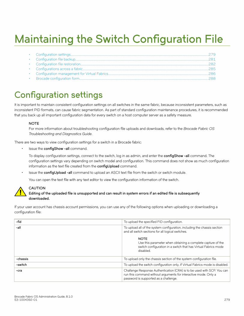
Maintaining the Switch Configuration File• Configuration settings...................................................................................................................................................................................279• Configuration file backup.............................................................................................................................................................................281• Configuration file restoration......................................................................................................................................................................282• Configurations across a fabric...................................................................................................................................................................285• Configuration management for Virtual Fabrics..................................................................................................................................286• Brocade configuration form....................................................................................................................................................................... 288
Configuration settingsIt is important to maintain consistent configuration settings on all switches in the same fabric, because inconsistent parameters, such asinconsistent PID formats, can cause fabric segmentation. As part of standard configuration maintenance procedures, it is recommendedthat you back up all important configuration data for every switch on a host computer server as a safety measure.
NOTEFor more information about troubleshooting configuration file uploads and downloads, refer to the Brocade Fabric OSTroubleshooting and Diagnostics Guide.
There are two ways to view configuration settings for a switch in a Brocade fabric:
• Issue the configShow -all command.
To display configuration settings, connect to the switch, log in as admin, and enter the configShow -all command. Theconfiguration settings vary depending on switch model and configuration. This command does not show as much configurationinformation as the text file created from the configUpload command.
• Issue the configUpload -all command to upload an ASCII text file from the switch or switch module.
You can open the text file with any text editor to view the configuration information of the switch.
CAUTIONEditing of the uploaded file is unsupported and can result in system errors if an edited file is subsequentlydownloaded.
If your user account has chassis account permissions, you can use any of the following options when uploading or downloading aconfiguration file:
-fid To upload the specified FID configuration.
-all To upload all of the system configuration, including the chassis sectionand all switch sections for all logical switches.
NOTEUse this parameter when obtaining a complete capture of theswitch configuration in a switch that has Virtual Fabrics modedisabled.
-chassis To upload only the chassis section of the system configuration file.
-switch To upload the switch configuration only, if Virtual Fabrics mode is disabled.
-cra Challenge Response Authentication (CRA) is to be used with SCP. You canrun this command without arguments for interactive mode. Only apassword is supported as a challenge.
Brocade Fabric OS Administration Guide, 8.1.053-1004392-01 279

-map Uploads the port-to-area addressing mode configuration files. Thiscommand should be used in FICON environment before replacing boththe CP blades.
-vf Upload the virtual fabric data.
Configuration file formatThe configuration file is divided into three areas: the header, the chassis section, and one or more logical-switch sections.
Chassis sectionThere is only one chassis section within a configuration. It defines configuration data for chassis components that affect the entiresystem, not just one individual logical switch. The chassis section is included in non-Virtual Fabric modes only if you use theconfigUpload -all command.
The chassis section specifies characteristics for the following software components:
• FC Routing - Fibre Channel Routing
• Chassis configuration - Chassis configuration
• FCOE_CH_CONF - FCoE chassis configuration
• UDROLE_CONF - User-defined role configuration
• LicensesDB - License Database (newer-format license storage)
• DMM_WWN - Data migration manager World Wide Name configuration
• License Database - (older-format license storage)
• AGWWN_MAPPING_CONF - Access Gateway WWN mapping configuration
• LicensesLservc - Sentinel License configuration
• GE blade mode - GigE Mode configuration
• FRAME LOG - Frame log configuration (enable/disable)
• DMM_TB - Data migration manager configuration
• MOTD - Message of the day
Switch sectionThere is always at least one switch section for the default switch or a switch that has Virtual Fabrics mode disabled, and there areadditional sections corresponding to each additionally defined logical switch instance on a switch with Virtual Fabrics mode enabled. Thisdata is switch-specific and affects only that logical switch behavior.
The switch section of the configuration file contains information for all of the following:
• Boot parameters
• Configuration
• Bottleneck configuration
• Flow Vision configuration
• FCoE software configuration
• Zoning
• Defined security policies
• Active security policies
Configuration settings
Brocade Fabric OS Administration Guide, 8.1.0280 53-1004392-01
• iSCSI
• CryptoDev
• FICU saved files
• VS_SW_CONF
• MAPS configuration
• Banner
Configuration file backupIt is recommended that you keep a backup configuration file. You should keep individual backup files for all switches in the fabric andavoid copying configurations from one switch to another. The configUpload command, by default, only uploads the switch contextconfiguration for the logical switch context in which the command is executed.
In non-Virtual Fabric mode, you must use the configUpload -all command to include both the switch and the chassis information. InVirtual Fabric mode, the configUpload -all command can be selected to upload all logical switches and the chassis configuration. Onlyadministrators with chassis permissions are allowed to upload other FIDs or the chassis configuration.
The following information is not saved in a backup:
• dnsConfig command information
• Passwords
Before you upload a configuration file, verify that you can reach the FTP server from the switch. Using a Telnet connection, save abackup copy of the configuration file from a logical switch to a host computer.
Secure File Transfer Protocol (SFTP) is now an option when uploading a configuration file. SFTP is analogous to Secure Copy Protocol(SCP). SFTP can be used for the configupload, configdownload, supportsave, and auto FFDC/trace upload (supportftp ) commands.
NOTEIf you download a configuration file that was uploaded from a switch whose default FID (128) was changed, then you shoulddownload the VF configuration file first before you download the normal configuration file to ensure that all the logical switchesare the same in both switches. Therefore, follow these steps:
1. Run the configUpload -vf command from the old setup.
2. Run the configUpload -all command from the old setup.
3. Run the configDownload -vf command in the new setup.
4. Run the configDownload -all command in the new setup.
Special characters in FTP server credentialsFTP server credentials may include special characters (also referred to as meta-characters) that are members of a special character setthat are interpreted differently when used in command-line mode. These characters have an alternate meaning or are designated toperform a special instruction. Here is a list of some of the more commonly used special characters and their alternate meanings.
NOTEThis list is not exhaustive, and alternate meanings for some characters are contextual. For detailed information on using specialcharacters in FTP credentials, refer to Linux scripting information available on the internet.
• & is used to put a command in background/batch mode.
Configuration file backup
Brocade Fabric OS Administration Guide, 8.1.053-1004392-01 281

• ! is used to recall the last invocation of the command matching the pattern that follows the character.
• | is used to direct (pipe) output to the command that follows the character.
• ; is used to concatenate multiple commands.
• * is used to represent a wildcard character.
• ? is used as a match for any single character in the specified position.
• () is used for integer expansion.
• < and > are used for redirection. < represents input and > represents output.
• $ is used to represent a shell variable.
• ` is used for command substitution or for assigning the output of a command to a variable.
• " is used for partial quoting.
• ' is used for full quoting.
• A space is used as a separation character.
• #, when preceded by a space, treats all characters through the end of the line as a comment rather than commands.
These special characters may be used to enhance user credential security. However, in order for these characters to be properlyinterpreted, you must use one of the following methods:
• “Escape” each instance of the special character by preceding it with the escape character (\).
• Enclose the credentials containing special characters within single quotes (').
If single quotes are themselves part of the credential, precede each instance of the single quote with the escape character (\).Alternately, the string may be enclosed in double quotes (") if a more intricate bash substitution is desired to further strengthenthe security measure of the credentials.
You can test the representation of the credentials by logging in with root-level permissions and using the echo command.
Uploading a configuration file in interactive mode1. Verify that the FTP, SFTP, or SCP service is running on the host computer.
2. Connect to the switch and log in using an account with admin permissions.
3. Enter the configUpload command. The command becomes interactive and you are prompted for the required information.
4. Store a soft copy of the switch configuration information in a safe place for future reference.
switch:admin> configuploadProtocol (scp, ftp, sftp, local) [ftp]: sftpServer Name or IP Address [host]: 10.1.2.3User Name [user]: UserFooPath/Filename [<home dir>/config.txt]: switchConfig.txtSection (all|chassis|FID# [all]): [email protected]'s password:Password: <hidden>configUpload complete
Configuration file restorationWhen you restore a configuration file, you overwrite the existing configuration with a previously saved backup configuration file.
Configuration file restoration
Brocade Fabric OS Administration Guide, 8.1.0282 53-1004392-01

CAUTIONMake sure that the configuration file you are downloading is compatible with your switch model. Downloading aconfiguration file from a different switch model or from a different firmware could cause your switch to fail.
CAUTIONIf you have Virtual Fabrics enabled, you must follow the procedure in Configuration management for Virtual Fabrics on page286 to restore the logical switches.
If a configDownload command is issued on a non-FC router, any FC router parameters may be viewed in the downloaded data. This isharmless to the switch and can be ignored.
MAPS configuration is downloaded onto the switch only if MAPS is enabled on the local switch.
You can download the configuration file from a device with Fabric OS 7.2.0 or Fabric OS 7.3.0 to Fabric OS 7.4.0.
You can use the configDownload command to restore the switch configuration.
configdownload -vf config_VF fileconfigdownload -all config_All file
Restrictions when downloading a configuration fileNOTEIf you modify the configuration attributes of a user in the key file, then the configuration download will beblocked.
The following table lists restrictions for some of the options of the configDownload command.
TABLE 66 Restrictions for using the options of the configDownload command
Option Restrictions
-chassis The number of switches defined in the downloaded configuration file must match the number of switches currentlydefined on the switch.
-fid FID The FID must be defined in both the downloaded configuration file and the current system.
NOTEBrocade recommends you disable a switch before downloading a configuration file. If you plan todownload a configuration file while the switch is enabled, refer to Configuration download withoutdisabling a switch on page 284.
-fid FID -sfid FID The FID must be defined on the switch and the source FID must be defined in the downloaded configuration file.
-all The number of switches or FIDs defined in the downloaded configuration file must match the number of switchesor FIDs currently defined on the switch.
The switches must be disabled first. If they are not, the configDownload command will download the configurationfor as many switches as possible until a non-disabled switch is found. If a non-disabled switch is found, thedownloading process stops. Before running the configDownload command, verify if any switches must bedisabled.
If you are performing a configuration download due to a configuration error, it is highly recommended to run theconfigDefault command before running the configDownload command. Refer to Configuration download withoutdisabling a switch on page 284 for more information on non-disruptive configuration downloads.
If Virtual Fabrics mode is enabled, the chassisDisable and chassisEnable commands are used to disable all logicalswitches on the affected switch. This process bypasses the need to disable and enable each switch individuallyonce the configuration download has completed.
Non-Virtual Fabric configuration files downloaded to a Virtual Fabric system have a configuration applied only tothe default switch. If there are multiple logical switches created in a Virtual Fabric-enabled system, there may beproblems if there are ports that belong to the default switch in a Virtual Fabric-disabled system, but are now
Configuration file restoration
Brocade Fabric OS Administration Guide, 8.1.053-1004392-01 283

TABLE 66 Restrictions for using the options of the configDownload command (continued)
Option Restrictions
assigned to logical switches in a Virtual Fabric-enabled system. Only configurations related to ports within thedefault switch are applied.
If you need to set up your switch again, run the commands listed in Table 67 and save the output in a file format. Store the files in a safeplace for emergency reference.
TABLE 67 CLI commands to display or modify switch configuration information
Command Displays
configShow System configuration parameters, settings, and license information.
fcLunQuery LUN IDs and LUNs for all accessible targets.
fcrRouterPortCost FC Router route information.
fcrXlateConfig Translate (xlate) domain's domain ID for both EX_Port-attached fabric and backbone fabric.
fosConfig Fabric OS features.
ipAddrShow IP address.
isnscCfg Configuration state of the iSNS client operation.
licenseShow License keys installed with more detail than the license information from the configShowcommand.
portCfgEXPort EX_Port configuration parameters.
portCfgVEXPort VEX_Port configuration parameters.
CAUTIONThough the switch itself has advanced error checking, the configdownload feature within Fabric OS was not designed forusers to edit, and it is limited in its ability. Edited files can become corrupted, and this corruption can lead to switch failures.
NOTEIf you download a configuration file with either the portCfgEportCredits or portCfgFportBuffers entries manually removed, theswitch will retain the existing configuration even after the configuration has downloaded.
Configuration download without disabling a switchYou can download configuration files to a switch while the switch is enabled; that is, you do not need to disable the switch for changes inSNMP, MAPS, Fabric Watch, or ACL parameters. However, if there is any changed parameter that does not belong to SNMP, MAPS, orACL, then you must disable the switch. When you use the configDownload command, you are prompted to disable the switch only whennecessary .
ATTENTIONThe configuration download process can restore only logical switches that already exist and that use the same FIDs. It cannot beused to clone or repair the current switch because the configDownload command cannot create logical switches if they do notexist.
Configuration file restoration
Brocade Fabric OS Administration Guide, 8.1.0284 53-1004392-01

Restoring a configuration
CAUTIONUsing the SFID parameter erases all configuration information on the logical switch. Use the SFID parameter only when thelogical switch has no configuration information you want to save.
1. Verify that the FTP service is running on the server where the backup configuration file is located.
2. Connect to the switch and log in using an account with admin permissions, and if necessary, with chassis permissions.
3. If there are any changed parameters in the configuration file that do not belong to SNMP, Fabric Watch, or ACL, disable theswitch by entering the switchDisable command.
4. Enter the configDownload command.
The command becomes interactive and you are prompted for the required information.
5. At the "Do you want to continue [y/n]" prompt, enter y .
Wait for the configuration to be restored.
6. If you disabled the switch, enter the switchEnable command when the process is finished.
NOTEAlways perform a reboot after you download a configuration file. On dual-CP platforms, you must reboot both CPssimultaneously.
switch:admin> configdownloadProtocol (scp, ftp, local) [ftp]:Server Name or IP Address [host]: 10.1.2.3User Name [user]: UserFooPath/Filename [<home dir>/config.txt]:Section (all|chassis|FID# [all]): all *** CAUTION ***This command is used to download a backed-up configuration for a specific switch. If using a file from a different switch, this file's configuration settings will override any current switch settings. Downloading a configuration file, which was uploaded from a different type of switch, may cause this switch to fail. A switch reboot is required for the changes to take effect. Please make sure all the switches are disabled by using "chassisdisable" command. Downloading configuration to an online switch may result in some configuration not being downloaded to that switch. configDownload operation may take several minutes to complete for large files. Do you want to continue [y/n]:yPassword: <hidden>configDownload complete.
Example of a non-interactive download of all configurations (chassis and switches)
configdownload -a -ftp 10.1.2.3,UserFoo,/pub/configurations/config.txt,password
Configurations across a fabricTo save time when configuring fabric parameters and software features, you can save a configuration file from one switch and downloadit to other switches of the same model type.
Configurations across a fabric
Brocade Fabric OS Administration Guide, 8.1.053-1004392-01 285

Do not download a configuration file from one switch to another switch that is a different model or runs a different firmware version,because it can cause the switch to fail. If you need to reset affected switches, issue the configDefault command after download iscompleted but before the switch is enabled. If a switch is enabled with a duplicate domain ID, the switch becomes segmented.
NOTEThe configDefault command is not recommended on the Blade Server SAN I/O Modules. For more information, refer to theFabric OS Command Reference.
Downloading a configuration file from one switch to another switch of thesame model
1. Configure one switch.
2. Use the configUpload command to save the configuration information. Refer to Configuration file backup on page 281 formore information.
3. Run configDefault on each of the target switches, and then use the configDownload command to download the configurationfile to each of the target switches. Refer to Configuration file restoration on page 282 for more information.
Security considerationsSecurity parameters and the switch identity cannot be changed by the configDownload command. Parameters such as the switch nameand IP address (lines in the configuration file that begin with "boot") are ignored. Security parameters (lines in the configuration file thatbegin with "sec"), such as secure mode setting and version stamp, are ignored. For more detailed information on security, refer to Configuring Protocols on page 199.
Configuration management for Virtual FabricsYou can use the configUpload -vf or configDownload -vf command to restore configurations to a logical switch. The -vf option onlyrestores the Virtual Fabrics configuration information on to a switch of the same model and same release. For example, a Virtual Fabricsconfiguration file for Fabric OS 7.4.x cannot be used on a Fabric OS 7.2.x switch and vice versa.
The Virtual Fabrics configuration on the switch defines all of the logical switches allowed and configured for a particular platform.
Uploading a configuration file from a switch with Virtual Fabrics enabledThe configUpload command with the -vf option specifies that configuration upload will upload the Virtual Fabrics configuration insteadof the non-Virtual Fabrics configuration information.
You must specify a file name with the configUpload -vf command. It is recommended not to use config.txt for a file name as this namecan be confused with a normal uploaded configuration file.
Example of configUpload on a switch with Virtual Fabrics
DCX_80:FID128:admin> configupload -vfProtocol (scp, ftp, sftp, local) [ftp]:Server Name or IP Address [host]: 10.1.2.3User Name [user]: anonymousPath/Filename [<home dir>/config.txt]: 5100_vf.txtconfigUpload complete: VF config parameters are uploaded2014/07/20-09:13:40, [LOG-1000], 225, SLOT 7 | CHASSIS, INFO, BrocadeDCX, Previous message repeated 7 time(s)
Configuration management for Virtual Fabrics
Brocade Fabric OS Administration Guide, 8.1.0286 53-1004392-01

2014/07/20-10:27:14, [CONF-1001], 226, SLOT 7 | FID 128, INFO, DCX_80, configUpload completed successfully for VF config parameters.
Example of configUpload on a logical switch configuration
Sprint5100:FID128:admin> configuploadProtocol (scp, ftp, sftp, local) [ftp]: Server Name or IP Address [host]: 10.1.2.3User Name [user]: UserFooPath/Filename [<home dir>/config.txt]: 5100.txtPotentially remote file may get overwrittenSection (all|chassis|FID# [all]): Password: <hidden>configUpload complete: All selected config parameters are uploaded
Restoring a logical switch configuration using configDownloadThe configDownload -vf command specifies that the Virtual Fabrics configuration download file is downloaded instead of the regularconfiguration. After the Virtual Fabrics configuration file is downloaded, the switch is automatically rebooted.
On dual-CP platforms, if CPs are incompatible (HA not in sync), the Virtual Fabrics configuration file is not propagated to the standby CP.If CPs are compatible, the active CP attempts to remain active after the reboot, and the new Virtual Fabrics configuration file is thenpropagated to the standby CP.
CAUTIONYou must issue the configDownload command on the switch after restoring the Virtual Fabrics configuration to fully restoreyour switch or chassis configuration.
1. Connect to the switch and log in using an account with admin permissions.
2. Enter the configDownload -vf command.
3. Respond to the prompts.
Wait for the configuration file to download on to the switch. You may need to reconnect to the switch.
4. Enter the configDownload - all command.
5. Respond to the prompts.
Wait for the configuration file to download to the switch.
6. Verify the LISL ports are set up correctly.
Example of a non-interactive download from a switch with FID = 8 and SFID =10configdownload -fid 8 -sfid 10 -ftp 10.1.2.3,UserFoo,config.txt,password
Configuration management for Virtual Fabrics
Brocade Fabric OS Administration Guide, 8.1.053-1004392-01 287

Example of configDownload on a switch5100:FID128:admin> configdownload -vfProtocol (scp, ftp, sftp, local) [ftp]: Server Name or IP Address [host]: 10.1.2.3User Name [user]: UserFooPath/Filename [<home dir>/config.txt]: 5100_FID89.txt *** CAUTION *** This command is used to download the VF configuration to the switch. Afterwards, the switch will be automatically rebooted and the new VF settings will be used. You will then need to run configdownload again to install the configuration(s) for any logical switch(s) that are setup in the new VF configuration. Do you want to continue [y/n]: y(output truncated)
Configuration upload and download restrictions when Virtual Fabrics isenabled
NOTEA reboot is required after downloading a configuration in order for all parameters to takeeffect.
The following restrictions apply when using the configupload or configdownload commands when Virtual Fabrics mode is enabled:
• The -vf option is incompatible with the -fid, -sfid, or -all options. Any attempt to combine it with any of the other three willcause the configuration upload or download operation to fail.
• You are not allowed to modify the Virtual Fabrics configuration file after it has been uploaded. Only minimal verification is doneby the configdownload command to ensure it is compatible, much like the normal downloaded configuration file.
• After the configdownload -vf command completes and reboots your switch, you must then download the matching regularconfiguration using the configdownload -all command. This ensures proper behavior of the system and logical switches.
All of the attributes of the Virtual Fabrics configuration file will be downloaded to the system and take effect. This includes, but is notlimited to, logical switch definitions, whether Virtual Fabrics is enabled or disabled, and the F_Port trunking ports, except the LISL ports.The LISL ports on the system are not affected by the Virtual Fabrics configuration file download.
You can restore Virtual Fabrics configurations only to a switch of the same model and same release. For example, a Virtual Fabricsconfiguration file for Fabric OS 7.2.x cannot be used on a Fabric OS 7.1.x switch and vice versa.
Brocade configuration formComplete the second column in the following table, and save it as a hard-copy reference for your configuration information.
TABLE 68 Brocade configuration and connection form
Basic settings Values that you chose
IP address
Gateway address
Chassis configuration option
Management connections Values that you chose
Serial cable tag
Ethernet cable tag
Brocade configuration form
Brocade Fabric OS Administration Guide, 8.1.0288 53-1004392-01

Configuration information Values that you chose
Domain ID
Switch name
Ethernet IP address
Ethernet subnet mask
Total number of local devices (nsShow )
Total number of devices in fabric (nsAllShow )
Total number of switches in the fabric (fabricShow )
Brocade configuration form
Brocade Fabric OS Administration Guide, 8.1.053-1004392-01 289

Brocade Fabric OS Administration Guide, 8.1.0290 53-1004392-01
Managing Virtual Fabrics• Virtual Fabrics overview............................................................................................................................................................................... 291• Logical switch overview................................................................................................................................................................................292• Management model for logical switches..............................................................................................................................................298• Logical fabric overview.................................................................................................................................................................................299• Account management and Virtual Fabrics...........................................................................................................................................304• Setting up IP addresses for a logical switch........................................................................................................................................ 304• Supported platforms for Virtual Fabrics................................................................................................................................................306• Virtual Fabrics interaction with other Fabric OS features...............................................................................................................308• Limitations and restrictions of Virtual Fabrics.....................................................................................................................................309• Enabling Virtual Fabrics mode..................................................................................................................................................................310• Disabling Virtual Fabrics mode.................................................................................................................................................................311• Configuring logical switches to use basic configuration values.................................................................................................. 312• Creating a logical switch or base switch................................................................................................................................................312• Executing a command in a different logical switch context...........................................................................................................314• Deleting a logical switch...............................................................................................................................................................................315• Adding and moving ports on a logical switch.....................................................................................................................................315• Displaying logical switch configuration..................................................................................................................................................316• Changing the fabric ID of a logical switch............................................................................................................................................ 317• Changing a logical switch to a base switch..........................................................................................................................................317• Configuring a logical switch for XISL use ............................................................................................................................................318• Creating a FICON logical switch.............................................................................................................................................................. 319• Changing the context to a different logical fabric.............................................................................................................................. 323
Virtual Fabrics overviewVirtual Fabrics is an architecture to virtualize hardware boundaries. Traditionally, SAN design and management is done at the granularityof a physical switch. Virtual Fabrics allows SAN design and management to be done at the granularity of a port.
Virtual Fabrics is a suite of related features that can be customized based on your needs. The Virtual Fabrics suite consists of thefollowing specific features:
• Logical switch
• Logical fabric
• Device sharing
This chapter describes the logical switch and logical fabric features. For information about device sharing with Virtual Fabrics, refer to FC-FC routing and Virtual Fabrics on page 563.
NOTEA note on terminology: Virtual Fabrics is the name of the suite of features. A logical fabric is a type of fabric that you can createusing the Virtual Fabrics suite of features.
Brocade Fabric OS Administration Guide, 8.1.053-1004392-01 291

NOTESNMPv3 is required to manage Virtual Fabrics. If you use SNMPGET to poll the switches, for example HiTrack, the SNMPv3user needs to be configured based on the logical switch that is being monitored. If SNMP monitoring is for the default switch,then you do not need the snmpuser to be configured as a user on the switch. Whereas, when SNMP monitoring is VF specific,then you need to create a user with permission for the corresponding VF and add the created user into SNMP database asSNMPv3 user. Once SNMPv3 user is successfully added, then you can use the same user name in management applicationsfor SNMP queries to the corresponding logical switch.
Logical switch overviewTraditionally, each switch and all the ports in the switch act as a single Fibre Channel switch (FC switch) that participates in a single fabric.The logical switch feature allows you to divide a physical chassis into multiple fabric elements. Each of these fabric elements is referred toas a logical switch . Each logical switch functions as an independent self-contained FC switch.
NOTEEach chassis can have multiple logical switches.
Default logical switchTo use the Virtual Fabrics features, you must first enable Virtual Fabrics on the switch. Enabling Virtual Fabrics creates a single logicalswitch in the physical chassis. This logical switch is called the default logical switch.
The default logical switch initially contains all of the ports in the physical chassis.
The following figure shows a switch before and after enabling Virtual Fabrics. In this example, the switch has 10 ports, labeled P0through P9.
Logical switch overview
Brocade Fabric OS Administration Guide, 8.1.0292 53-1004392-01

FIGURE 18 Switch before and after enabling Virtual Fabrics
After you enable Virtual Fabrics, you can create up to 7 or 15 additional logical switches, depending on the switch model.
NOTEThe X6 Directors running Fabric OS 8.1.0 or later support up to 16 logical switches including the default logical switch. All theother platforms including fixed-port switches and DCX 8510 Directors support up to 8 logical switches.
The following figure shows a Virtual Fabrics-enabled switch before and after it is divided into logical switches. Before you create logicalswitches, the chassis appears as a single switch (default logical switch). After you create logical switches, the chassis appears as multipleindependent logical switches. All of the ports continue to belong to the default logical switch until you explicitly move them to otherlogical switches.
The default logical switch always exists. You can add and delete other logical switches, but you cannot delete the default logical switchunless you disable Virtual Fabrics.
NOTEA FICON logical switch or an existing logical switch that has been modified to become a FICON logical switch cannot serve asthe default logical switch.
Logical switch overview
Brocade Fabric OS Administration Guide, 8.1.053-1004392-01 293

FIGURE 19 Switch before and after creating logical switches
Logical switches and fabric IDsWhen you create a logical switch, you must assign it a fabric ID (FID). The fabric ID uniquely identifies each logical switch within a chassisand indicates to which fabric the logical switch belongs. You cannot define multiple logical switches with the same fabric ID within thechassis.
In the following figure, logical switches 2, 3, 4, and 5 are assigned FIDs of 1, 15, 8, and 20, respectively. These logical switches belongto different fabrics, even though they are in the same physical chassis. For example, you could not assign logical switch 5 a fabric ID of15, because logical switch 3 is already assigned FID 15 in the chassis.
The default logical switch is initially assigned FID 128. You can change this value later.
NOTEEach logical switch is assigned one and only one FID. The FID identifies the logical fabric to which the logical switchbelongs.
Logical switch overview
Brocade Fabric OS Administration Guide, 8.1.0294 53-1004392-01
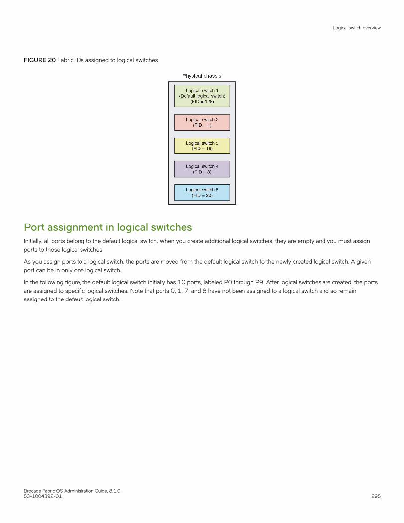
FIGURE 20 Fabric IDs assigned to logical switches
Port assignment in logical switchesInitially, all ports belong to the default logical switch. When you create additional logical switches, they are empty and you must assignports to those logical switches.
As you assign ports to a logical switch, the ports are moved from the default logical switch to the newly created logical switch. A givenport can be in only one logical switch.
In the following figure, the default logical switch initially has 10 ports, labeled P0 through P9. After logical switches are created, the portsare assigned to specific logical switches. Note that ports 0, 1, 7, and 8 have not been assigned to a logical switch and so remainassigned to the default logical switch.
Logical switch overview
Brocade Fabric OS Administration Guide, 8.1.053-1004392-01 295

FIGURE 21 Assigning ports to logical switches
A given port is always in one (and only one) logical switch. The following scenarios refer to the chassis after port assignment in Figure 21:
• If you assign P2 to logical switch 2, you cannot assign P2 to any other logical switch.
• If you want to remove a port from a logical switch, you cannot delete it from the logical switch, but must move it to a differentlogical switch. For example, if you want to remove P4 from logical switch 3, you must assign it to a different logical switch:logical switch 2, logical switch 4, or logical switch 1 (the default logical switch).
• If you assign a port to a logical switch, it is removed automatically from the logical switch it is currently in. If you assign P3 toLogical switch 3, P3 is automatically removed from logical switch 2.
• If you do not assign a port to any logical switch, it remains in the default logical switch, as is the case with ports 0, 1, 7, and 8.
Refer to Adding and moving ports on a logical switch on page 315 for instructions for assigning and moving ports on logical switches.
A logical switch can have as many ports as are available in the chassis. In Figure 21, the chassis has 10 ports. You could assign all 10ports to a single logical switch, such as logical switch 2; if you did this, however, no ports would be available for logical switches 3 and 4.
You can move only F_Ports and E_Ports from one logical switch to another. If you want to configure a different type of port, such as aVE_Port or EX_Port, you must configure them after you move them. Some types of ports cannot be moved from the default logicalswitch. Refer to Supported platforms for Virtual Fabrics on page 306 for detailed information about these ports.
Logical switch overview
Brocade Fabric OS Administration Guide, 8.1.0296 53-1004392-01

Logical switches and connected devicesYou can connect devices to logical switches, as shown in Figure 22. In logical switch 2, P2 is an F_Port that is connected to H1. In logicalswitch 3, P4 is an F_Port that is connected to D1. H1 and D1 cannot communicate with each other because they are in different fabrics,even though they are both connected to the same physical chassis.
You can also connect other switches to logical switches. In Figure 22, P6 is an E_Port that forms an inter-switch link (ISL) betweenlogical switch 4 and the non-Virtual Fabrics switch. Logical switch 4 is the only logical switch that can communicate with the non-VirtualFabrics switch and D2, because the other logical switches are in different fabrics.
FIGURE 22 Logical switches connected to devices and non-Virtual Fabrics switch
Figure 23 shows a logical representation of the physical chassis and devices in Figure 22. As shown in Figure 23, the devices areisolated into separate fabrics.
Logical switch overview
Brocade Fabric OS Administration Guide, 8.1.053-1004392-01 297

FIGURE 23 Logical switches in a single chassis belong to separate fabrics
Management model for logical switchesThe operations you can perform on a logical switch depend on the context you are in. Some operations affect only a single logical switch,and some operations affect the entire physical chassis.
All user operations are classified into one of the following:
• Chassis management operations
These are operations that span logical switch boundaries, such as:
– Logical switch configuration (creating, deleting, or modifying logical switches)– Account management (determining which accounts can access which logical switches)– Field-replaceable unit (FRU) management (slot commands, such as slotShow )– Firmware management (firmware upgrade, HA failover)
• Logical switch operations
These are operations that are limited to the logical switch, such as displaying or changing port states. Logical switch operationsinclude all operations that are not covered in the chassis management operations.
When you log in, you are assigned an active context, or active logical switch. This context filters the view that you get, and determineswhich ports you can see. You can change the active context. For example, if you are working with logical switch 1, you can change thecontext to logical switch 5. When you change the context to logical switch 5, you only see the ports that are assigned to that logicalswitch. You do not see any of the other ports in the chassis.
The scope of logical switch operations is defined by the active context. When you are in the context of a logical switch, you can performport, switch, and fabric-level operations, subject to Role-Based Access Control (RBAC) rules.
If you have permission to execute chassis-level commands, you can do so, regardless of which logical switch context you are in.
Management model for logical switches
Brocade Fabric OS Administration Guide, 8.1.0298 53-1004392-01

Logical fabric overviewA logical fabric is a fabric that contains at least one logical switch.
The four fabrics shown in Figure 22 on page 297 and Figure 23 on page 298 are logical fabrics because they each have at least onelogical switch.
You can connect logical switches to non-Virtual Fabrics switches and to other logical switches.You connect logical switches to non-VirtualFabrics switches using an ISL, as shown in Figure 22 on page 297.
You connect logical switches to other logical switches in two ways:
• Using ISLs
• Using base switches and extended ISLs (XISLs)
Logical fabric and ISLsFigure 24 shows two physical chassis divided into logical switches. In Figure 24, ISLs are used to connect the logical switches with FID1 and the logical switches with FID 15. The logical switches with FID 8 are each connected to a non-Virtual Fabrics switch. The twological switches and the non-Virtual Fabrics switch are all in the same fabric, with FID 8.
FIGURE 24 Logical switches connected to other logical switches through physical ISLs
Figure 25 shows a logical representation of the configuration in Figure 24.
Logical fabric overview
Brocade Fabric OS Administration Guide, 8.1.053-1004392-01 299
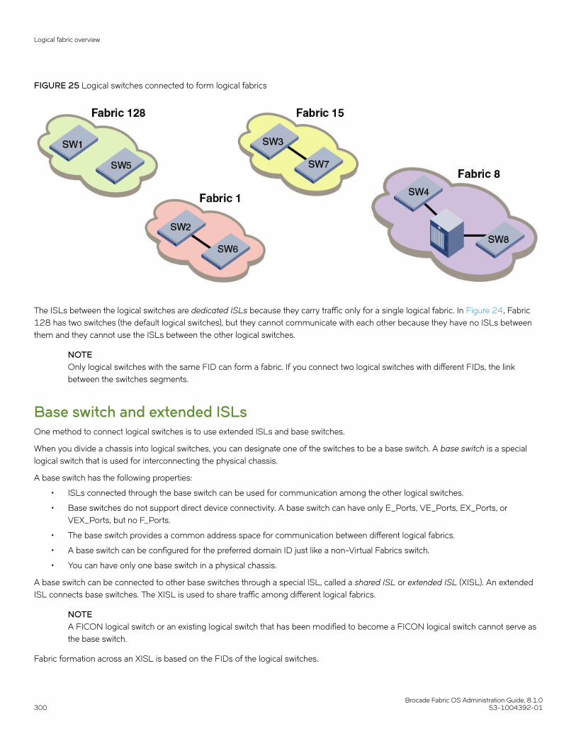
FIGURE 25 Logical switches connected to form logical fabrics
The ISLs between the logical switches are dedicated ISLs because they carry traffic only for a single logical fabric. In Figure 24, Fabric128 has two switches (the default logical switches), but they cannot communicate with each other because they have no ISLs betweenthem and they cannot use the ISLs between the other logical switches.
NOTEOnly logical switches with the same FID can form a fabric. If you connect two logical switches with different FIDs, the linkbetween the switches segments.
Base switch and extended ISLsOne method to connect logical switches is to use extended ISLs and base switches.
When you divide a chassis into logical switches, you can designate one of the switches to be a base switch. A base switch is a speciallogical switch that is used for interconnecting the physical chassis.
A base switch has the following properties:
• ISLs connected through the base switch can be used for communication among the other logical switches.
• Base switches do not support direct device connectivity. A base switch can have only E_Ports, VE_Ports, EX_Ports, orVEX_Ports, but no F_Ports.
• The base switch provides a common address space for communication between different logical fabrics.
• A base switch can be configured for the preferred domain ID just like a non-Virtual Fabrics switch.
• You can have only one base switch in a physical chassis.
A base switch can be connected to other base switches through a special ISL, called a shared ISL or extended ISL (XISL). An extendedISL connects base switches. The XISL is used to share traffic among different logical fabrics.
NOTEA FICON logical switch or an existing logical switch that has been modified to become a FICON logical switch cannot serve asthe base switch.
Fabric formation across an XISL is based on the FIDs of the logical switches.
Logical fabric overview
Brocade Fabric OS Administration Guide, 8.1.0300 53-1004392-01

The following figure shows two physical chassis divided into logical switches. Each chassis has one base switch. An ISL connects the twobase switches. The ISL is an extended ISL (XISL) because it connects base switches.
FIGURE 26 Base switches connected by an XISL
Traffic between the logical switches can now flow across this XISL. The traffic can flow only between logical switches with the same fabricID. For example, traffic can flow between logical switch 2 in chassis 1 and logical switch 6 in chassis 2, because they both have FID 1.Traffic cannot flow between logical switch 2 and logical switch 7, because they have different fabric IDs (and are, therefore, in differentfabrics).
It is useful to think of the logical switches as being connected with logical ISLs, as shown in the following figure. The logical ISLs are notconnected to ports, because they are not physical cables. They are a logical representation of the switch connections that are allowed bythe XISL.
Logical fabric overview
Brocade Fabric OS Administration Guide, 8.1.053-1004392-01 301

FIGURE 27 Logical ISLs connecting logical switches
To use the XISL, the logical switches must be configured to allow XISL use. By default, they are configured to do so; you can change thissetting, however, using the procedure described in Configuring a logical switch for XISL use on page 318.
NOTEIt is a good practice to configure at least two XISLs forredundancy.
You can also connect logical switches using a combination of ISLs and XISLs, as shown in the following figure. In this diagram, trafficbetween the logical switches in FID 1 can travel over either the ISL or the XISL. Traffic between the other logical switches travels onlyover the XISL.
Logical fabric overview
Brocade Fabric OS Administration Guide, 8.1.0302 53-1004392-01
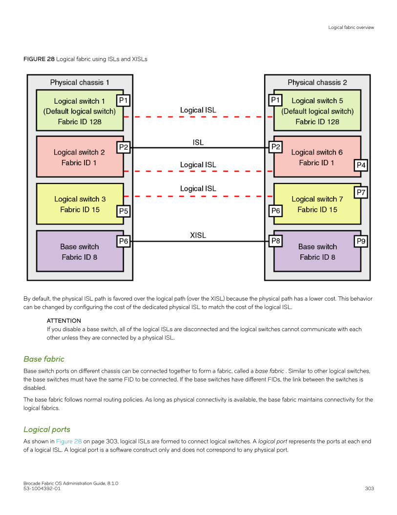
FIGURE 28 Logical fabric using ISLs and XISLs
By default, the physical ISL path is favored over the logical path (over the XISL) because the physical path has a lower cost. This behaviorcan be changed by configuring the cost of the dedicated physical ISL to match the cost of the logical ISL.
ATTENTIONIf you disable a base switch, all of the logical ISLs are disconnected and the logical switches cannot communicate with eachother unless they are connected by a physical ISL.
Base fabricBase switch ports on different chassis can be connected together to form a fabric, called a base fabric . Similar to other logical switches,the base switches must have the same FID to be connected. If the base switches have different FIDs, the link between the switches isdisabled.
The base fabric follows normal routing policies. As long as physical connectivity is available, the base fabric maintains connectivity for thelogical fabrics.
Logical portsAs shown in Figure 28 on page 303, logical ISLs are formed to connect logical switches. A logical port represents the ports at each endof a logical ISL. A logical port is a software construct only and does not correspond to any physical port.
Logical fabric overview
Brocade Fabric OS Administration Guide, 8.1.053-1004392-01 303

Most port commands are not supported on logical ports. For example, you cannot change the state or configuration of a logical port.However, state change on a logical link is permitted using the lfcfg --lislEnable command.
The World Wide Name (WWN) for logical ports is in NAA=5 format, using the following syntax:
5n:nn:nn:nz:zz:zz:zx:xx
The NAA=5 syntax uses the following variables:
• nnnnnn is the Brocade Organizationally Unique Identifier (OUI).
• zzzzzz is the logical fabric serial number.
• xxx is the logical port number, in the range 0 through FFF.
Logical fabric formationFabric formation is not based on connectivity, but on the FIDs of the logical switches. The basic order of fabric formation is as follows:
1. Base fabric forms.
2. Logical fabrics form when the base fabric is stable.
3. Devices begin recognizing one another.
4. Traffic is initiated between the logical switches.
Account management and Virtual FabricsWhen user accounts are created, they are assigned a list of logical fabrics to which they can log in and a home logical fabric (home FID).When you connect to a physical chassis, the home FID defines the logical switch to which you are logged in by default. You can changeto a different logical switch context, as described in Changing the context to a different logical fabric on page 323.
When you are logged in to a logical switch, the system prompt changes to display the FID of that switch. The following are exampleprompts for when you are logged in to the default logical switch (FID = 128) and a user-defined logical switch (FID = 15):
switch:FID128:admin>switch:FID15:admin>
Refer to Managing User Accounts on page 155 for information about creating user accounts and assigning FIDs to user accounts.
Setting up IP addresses for a logical switchEach physical chassis has one common IP address that is shared by all of the logical switches in the chassis. You can set up individualIPv4 addresses for each logical switch.
IPv4 addresses assigned to individual logical switches are assigned to IP over Fibre Channel (IPFC) network interfaces. In Virtual Fabricsenvironments, a single chassis can be assigned to multiple fabrics, each of which is logically distinct and separate from one another. EachIPFC point of connection to a given chassis needs a separate IPv4 address and prefix to be accessible to a management host.
For a management host to access logical switches, the host bus adapter (HBA) must be able to connect with the common, shared IPaddress and the individual IPv4 addresses configured for each logical switch.
NOTEIPv6 is not supported when setting the IPFC interface for Virtual Fabrics.
Account management and Virtual Fabrics
Brocade Fabric OS Administration Guide, 8.1.0304 53-1004392-01

IPFC addresses are not handled by configupload or configdownload. The IPFC address of the default logical switch or a non-VF switchis stored on the WWN card or compact flash. This address does not display in a configshow. Non-default logical switch IPFC addressesdisplay in a confgshow. The ipaddrshow command displays all switch addresses and IPFC addresses configured in the chassis.
Use the following procedure to set up IP addresses for a logical switch:
1. Connect to the switch and log in using an account with admin permissions.
2. Enter the ipAddrSet -ls command.
• To add an IPv4 address, use the--add parameter. Specify the network information in dotted-decimal notation for theEthernet IPv4 address with a Classless Inter-Domain Routing (CIDR) prefix.
• To delete an IPv4 address, use the --delete parameter.
3. Enter the ipaddrshow command to verify the result.
The following example sets IP addresses with the CIDR prefix for logical switches with FID 1, 2, and 128 (default logical switch).
switch:FID128:admin> ipaddrset -ls 1 --add 192.0.2.11/24IP address is being changed...Done.switch:FID128:admin> ipaddrset -ls 2 --add 192.0.2.22/24IP address is being changed...Done. switch:FID128:admin> ipaddrset -ls 128 --add 192.0.2.0/24IP address is being changed...Done.
switch:FID128:admin> ipaddrshow
SWITCHEthernet IP Address: 198.51.100.0Ethernet Subnetmask: 255.255.255.0Gateway IP Address: 198.51.100.1DHCP: OffIPFC address for virtual fabric ID 128: 192.0.2.0/124IPFC address for virtual fabric ID 1: 192.0.2.11/24IPFC address for virtual fabric ID 2: 192.0.2.22/24
The following example deletes the IP address for the logical switch with FID 1.
switch:FID128:admin> ipaddrset -ls 1 --delete
Logical switch login contextWhen you log in to a logical switch with Telnet or SSH, the login shell uses the destination IPFC address to look up and set thecorresponding logical switch context. When you log in from the serial console, the login shell always sets your default home logical switchcontext. The IPFC assigned to a logical switch is managed by the ipAddrSet command that was supported in releases prior to Fabric OS7.4.0. When you use Telnet or SSH from a remote host, the IPFC address must share the same network (netmask) as the managementinterface. The values of FCIP addresses and subnet masks are stored in the WWN card. For example, if the management interface IPaddress is 10.38.18.183 with netmask 255.255.240.0, you can create the IPFC address using the following command.
ipaddrset –ls 8 --add 10.38.18.183/20
NOTEThe logical switch login context supersedes the default FID context of a user.
To delete the IPFC address, you can use the following command.
ipaddrset –ls 8 --delete
Setting up IP addresses for a logical switch
Brocade Fabric OS Administration Guide, 8.1.053-1004392-01 305
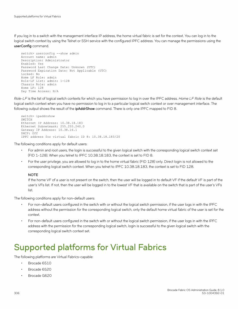
If you log in to a switch with the management interface IP address, the home virtual fabric is set for the context. You can log in to thelogical switch context by using the Telnet or SSH service with the configured IPFC address. You can manage the permissions using theuserConfig command.
switch> userconfig --show adminAccount name: adminDescription: AdministratorEnabled: YesPassword Last Change Date: Unknown (UTC)Password Expiration Date: Not Applicable (UTC)Locked: NoHome LF Role: adminRole-LF List: admin: 1-128Chassis Role: adminHome LF: 128Day Time Access: N/A
Role-LF is the list of logical switch contexts for which you have permission to log in over the IPFC address. Home LF Role is the defaultlogical switch context when you have no permission to log in to a particular logical switch context or over management interface. Thefollowing output shows the result of the ipAddrShow command. There is only one IPFC mapped to FID 8.
switch> ipaddrshowSWITCHEthernet IP Address: 10.38.18.183Ethernet Subnetmask: 255.255.240.0Gateway IP Address: 10.38.16.1DHCP: OffIPFC address for virtual fabric ID 8: 10.38.18.183/20
The following conditions apply for default users:
• For admin and root users, the login is successful to the given logical switch with the corresponding logical switch context set(FID 1-128). When you telnet to IPFC 10.38.18.183, the context is set to FID 8.
• For the user privilege, you are allowed to log in to the home virtual fabric (FID 128) only. Direct login is not allowed to thecorresponding logical switch context. When you telnet to IPFC 10.38.18.183, the context is set to FID 128.
NOTEIf the home VF of a user is not present on the switch, then the user will be logged in to default VF if the default VF is part of theuser's VFs list. If not, then the user will be logged in to the lowest VF that is available on the switch that is part of the user's VFslist.
The following conditions apply for non-default users:
• For non-default users configured in the switch with or without the logical switch permission, if the user logs in with the IPFCaddress without the permission for the corresponding logical switch, only the default home virtual fabric of the user is set for thecontext.
• For non-default users configured in the switch with or without the logical switch permission, if the user logs in with the IPFCaddress with the permission for the corresponding logical switch, login is successful to the given logical switch with thecorresponding logical switch context set.
Supported platforms for Virtual FabricsThe following platforms are Virtual Fabrics-capable:
• Brocade 6510
• Brocade 6520
• Brocade G620
Supported platforms for Virtual Fabrics
Brocade Fabric OS Administration Guide, 8.1.0306 53-1004392-01
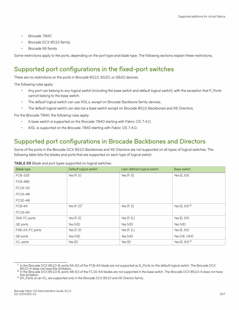
• Brocade 7840
• Brocade DCX 8510 family
• Brocade X6 family
Some restrictions apply to the ports, depending on the port type and blade type. The following sections explain these restrictions.
Supported port configurations in the fixed-port switchesThere are no restrictions on the ports in Brocade 6510, 6520, or G620 devices.
The following rules apply:
• Any port can belong to any logical switch (including the base switch and default logical switch), with the exception that F_Portscannot belong to the base switch.
• The default logical switch can use XISLs, except on Brocade Backbone family devices.
• The default logical switch can also be a base switch except on Brocade 8510 Backbones and X6 Directors.
For the Brocade 7840, the following rules apply:
• A base switch is supported on the Brocade 7840 starting with Fabric OS 7.4.0.
• XISL is supported on the Brocade 7840 starting with Fabric OS 7.4.0.
Supported port configurations in Brocade Backbones and DirectorsSome of the ports in the Brocade DCX 8510 Backbones and X6 Directors are not supported on all types of logical switches. Thefollowing table lists the blades and ports that are supported on each type of logical switch.
TABLE 69 Blade and port types supported on logical switches
Blade type Default logical switch User-defined logical switch Base switch
FC8-32E
FC8-48E
FC16-32
FC16-48
FC32-48
Yes (F, E) Yes (F, E) Yes (E, EX)
FC8-64
FC16-64
Yes (F, E)7 Yes (F, E) Yes (E, EX) 8
SX6: FC ports
GE ports
Yes (F, E)
Yes (VE)
Yes (F, E,)
Yes (VE)
Yes (E, EX)
Yes (VE)
FX8-24: FC ports
GE ports
Yes (F, E)
Yes (VE)
Yes (F, E,)
Yes (VE)
Yes (E, EX)
Yes (VE, VEX)
ICL ports Yes (E) Yes (E) Yes (E, EX) 9
7 In the Brocade DCX 8510-8, ports 56-63 of the FC8-64 blade are not supported as E_Ports on the default logical switch. The Brocade DCX8510-4 does not have this limitation.
8 In the Brocade DCX 8510-8, ports 48-63 of the FC16-64 blades are not supported in the base switch. The Brocade DCX 8510-4 does not havethis limitation.
9 EX_Ports on an ICL are supported only in the Brocade DCX 8510 and X6 Director family.
Supported platforms for Virtual Fabrics
Brocade Fabric OS Administration Guide, 8.1.053-1004392-01 307

Restrictions on Brocade BackbonesThe following restrictions apply to Brocade Backbones:
• EX_Ports and VEX_Ports can be in only the base switch.
• ICL ports cannot be in a logical switch that is using XISLs.
• All of the user ports in an ICL cable must be in the same logical switch. Distributing the user ports within the same cable acrossmultiple logical switches is not supported.
• ICL ports that are configured as EX_Ports can be in only the base switch.
• The default logical switch cannot use XISLs.
• The default logical switch cannot be designated as the base switch.
• In Fabric OS v7.0.0 and later, VE_Ports on the FX8-24 blade are supported on a logical switch that is using an XISL, and onthe base switch as an XISL.
NOTEFor the FX8-24 blade, if XISL use is enabled it is not recommended that you configure VE_Ports on both the logical switch andthe base switch, because FCIP tunnels support only two hops maximum.
Virtual Fabrics interaction with other Fabric OSfeaturesThe following table lists some Fabric OS features and considerations that apply when using Virtual Fabrics.
TABLE 70 Virtual Fabrics interaction with Fabric OS features
Fabric OS feature Virtual Fabrics interaction
Access Gateway Virtual Fabrics is not supported on a switch if AG mode is enabled.
Configuration upload and download Virtual Fabrics uses a configuration file that is different from theconfiguration file used to download system configuration parameters.Refer to Maintaining the Switch Configuration File on page 279 for moreinformation about how Virtual Fabrics affects the configuration file.
Encryption Encryption functionality using the FS8-18 blade is available only on thedefault logical switch.
FC-FC Routing Service All EX_Ports must reside in a base switch.
You cannot attach EX_Ports to a logical switch that has XISL use enabled.You must use ISLs to connect the logical switches in an edge fabric.
Refer to Using FC-FC Routing to Connect Fabrics on page 513 for moreinformation about Virtual Fabrics and FC-FC routing.
FICON Up to two logical switches per chassis can run FICON ManagementServer (CUP), but the FICON logical switch can use both ISLs and XISLs.
ISL R_RDY mode ISL R_RDY mode is not supported in a base switch.
Licensing Licenses are applicable for all logical switches in a chassis.
Network time protocol (NTP) The clock information for a chassis is maintained by the default logicalswitch and not from the principal or primary FCS switch. Refer to NetworkTime Protocol on page 59 for more information about how Virtual Fabricsaffects NTP.
QoS QoS VCs are maintained across the base fabric. Refer to OptimizingFabric Behavior on page 425 for more information about using theAdaptive Networking features with Virtual Fabrics.
Virtual Fabrics interaction with other Fabric OS features
Brocade Fabric OS Administration Guide, 8.1.0308 53-1004392-01

TABLE 70 Virtual Fabrics interaction with Fabric OS features (continued)
Fabric OS feature Virtual Fabrics interaction
Traffic Isolation Traffic Isolation with Failover-Disabled (TI FD) zoning is not supportedover LISLs; Traffic Isolation zones with Failover-Enabled (TI FE) issupported. TI FD zoning is supported over DISLs (physical links). TI FDzoning is not supported in the base fabric.
Refer to Optimizing Fabric Behavior on page 425 for additionalinformation about using TI Zones with Virtual Fabrics.
Limitations and restrictions of Virtual FabricsBefore you use the Virtual Fabrics feature, you should be aware of the restrictions and limitations regarding QSFP ports and themaximum number of logical switches per chassis.
In the core blades, the four ports belonging to the same QSFP can be assigned to different logical switches. However, if one of the fourports belongs to the base switch, then the remaining three ports cannot be assigned to any other logical switch.
The maximum number of logical switches per chassis varies depending on the switch model. The following table lists the supportedplatforms and the maximum number of logical switches (including the default logical switch) supported on each.
TABLE 71 Maximum number of logical switches per chassis
Platform Maximum number of logical switches
Brocade X6 Directors 16
Brocade DCX 8510 Backbones 8
Brocade 6510 4
Brocade 6520 4
Brocade G620 4
Brocade 7840 4
Refer to Supported port configurations in Brocade Backbones and Directors on page 307 for restrictions on the default logical switch.
If a blade slot is being decommissioned and has ports configured in logical switches, it is recommended that the logical portassignments be removed from that blade before removing the blade. This ensures a seamless transition for any new port or AP bladethat might occupy that slot in the future. This does not apply if you are simply replacing a blade of the same type.
Restrictions on using XISLsThe Allow XISL Use option of the configure command, allows a logical switch to use XISLs in the base switch as well as any standardISLs that are connected to that logical switch. To allow or disallow XISL use for a logical switch, refer to Configuring a logical switch forXISL use on page 318.
The following restrictions apply when using XISLs. XISL use is not permitted in any of the following scenarios:
• The logical switch has ICL ports.
• The logical switch is the default logical switch in the Brocade DCX 8510 or X6 Director devices.
• The logical switch is a base switch.
• The logical switch is an edge switch for an FC router.
Limitations and restrictions of Virtual Fabrics
Brocade Fabric OS Administration Guide, 8.1.053-1004392-01 309

In this case, if the logical switch is enabled, you cannot allow XISL use. If the logical switch is disabled or has not yet joined theedge fabric, you can allow XISL use; however, fabric segmentation occurs when the logical switch is enabled or connected to anedge fabric.
NOTEUsing XISL and fmsmode at the same time is permitted, but this combination will only work in a one-hop topology.
Restrictions on moving portsThe following are restrictions on moving ports among logical switches:
• FC ports cannot be moved if any one of the following features is enabled:
– Long distance– QoS– F_Port buffers– F_Port trunking– E_Port credits– SIM_Port
• Before moving VE_Ports, you must remove the VE_Port tunnel configuration.
• VE_Ports on the FX8-24 or SX6 blade can be moved to any logical switch independent of the location of the physical GE port.
• If you move existing EX_Ports or VEX_Ports to any logical switch other than the base switch, these ports are automaticallydisabled.
Enabling Virtual Fabrics modeA fabric is said to be in Virtual Fabrics mode (VF mode) when the Virtual Fabrics feature is enabled. Before you can use the VirtualFabrics features, such as logical switch and logical fabric, you must enable VF mode.
VF mode is enabled by default.
NOTEWhen you enable VF mode, the control processors (CPs) are rebooted and all EX_Ports are disabled after the reboot.
1. Connect to the physical chassis and log in using an account with the chassis-role permission.
2. Use the fosConfig command to check whether VF mode is enabled:
fosconfig --show
3. Use the fosConfig command to enable VF mode:
fosconfig --enable vf
4. Enter y at the prompt.
Enabling Virtual Fabrics mode
Brocade Fabric OS Administration Guide, 8.1.0310 53-1004392-01
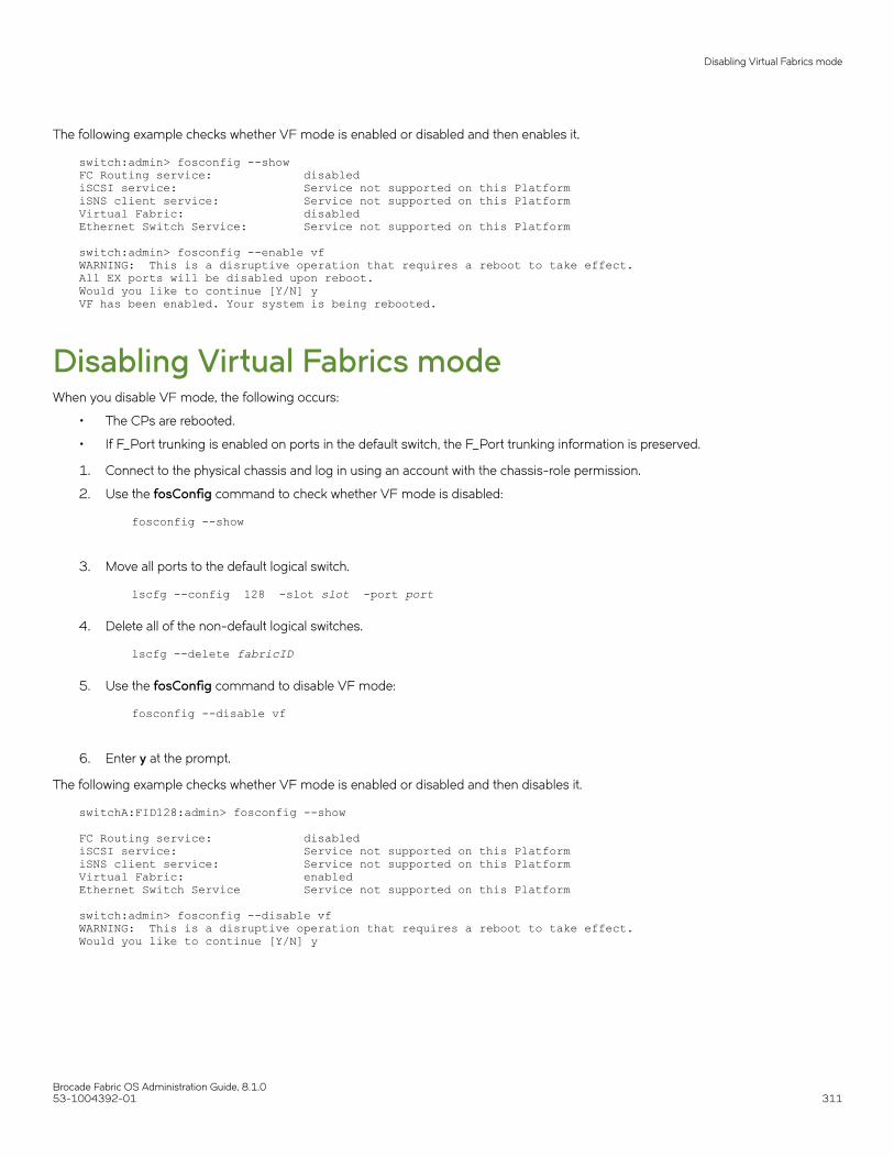
The following example checks whether VF mode is enabled or disabled and then enables it.
switch:admin> fosconfig --showFC Routing service: disablediSCSI service: Service not supported on this PlatformiSNS client service: Service not supported on this PlatformVirtual Fabric: disabledEthernet Switch Service: Service not supported on this Platform
switch:admin> fosconfig --enable vfWARNING: This is a disruptive operation that requires a reboot to take effect.All EX ports will be disabled upon reboot.Would you like to continue [Y/N] yVF has been enabled. Your system is being rebooted.
Disabling Virtual Fabrics modeWhen you disable VF mode, the following occurs:
• The CPs are rebooted.
• If F_Port trunking is enabled on ports in the default switch, the F_Port trunking information is preserved.
1. Connect to the physical chassis and log in using an account with the chassis-role permission.
2. Use the fosConfig command to check whether VF mode is disabled:
fosconfig --show
3. Move all ports to the default logical switch.
lscfg --config 128 -slot slot -port port
4. Delete all of the non-default logical switches.
lscfg --delete fabricID
5. Use the fosConfig command to disable VF mode:
fosconfig --disable vf
6. Enter y at the prompt.
The following example checks whether VF mode is enabled or disabled and then disables it.
switchA:FID128:admin> fosconfig --show FC Routing service: disablediSCSI service: Service not supported on this PlatformiSNS client service: Service not supported on this PlatformVirtual Fabric: enabledEthernet Switch Service Service not supported on this Platform
switch:admin> fosconfig --disable vfWARNING: This is a disruptive operation that requires a reboot to take effect.Would you like to continue [Y/N] y
Disabling Virtual Fabrics mode
Brocade Fabric OS Administration Guide, 8.1.053-1004392-01 311

Configuring logical switches to use basicconfiguration valuesAll switches in the fabric are configured to use the same basic configuration values. When you create logical switches, the logical switchesmight have different configuration values than the default logical switch. Use the following procedure to ensure that newly created logicalswitches have the same basic configuration values as the default logical switch.
NOTEFor most users, you do not need to run this procedure. Contact your switch service provider to determine if you need to use thisprocedure.
You need to run this procedure only once on each chassis, after you enable Virtual Fabrics but before you create logical switches. Theconfiguration settings are then preserved across reboots and firmware upgrades and downgrades.
Use the following procedure to configure logical switches to use basic configuration values:
1. Connect to the physical chassis and log in using an account with the chassis-role permission.
2. Enter the configureChassis command to ensure that newly created logical switches have the same basic configuration valuesas the default logical switch:
configurechassis
3. Enter n at the prompts to configure system and cfgload attributes. Enter y at the prompt to configure custom attributes.
System (yes, y, no, n): [no] ncfgload attributes (yes, y, no, n): [no] nCustom attributes (yes, y, no, n): [no] y
4. Enter the appropriate value at the Config Index prompt. Contact your switch service provider to determine the appropriate value.
Config Index (0 to ignore): (0..1000) [3]:
Creating a logical switch or base switchWhen a logical switch is created, it is automatically enabled and is empty--that is, it does not have any ports. After creating the logicalswitch, you must disable the switch to configure it and set the domain ID. You then assign ports to the logical switch. You can optionallydefine the logical switch to be a base switch using the -base option. Each chassis can have only one base switch.
NOTEDomain ID conflicts are detected before fabric ID conflicts. If you have both a domain ID conflict and a fabric ID conflict, onlythe domain ID conflict is reported.
1. Connect to the physical chassis and log in using an account with the chassis-role permission.
2. Enter the lsCfg command to create a logical switch:
device#> lscfg --create fabricID [ -base | -lisldisable] [-force]
The fabricID is the fabric ID that is to be associated with the logical switch.
The logical switch is enabled by default and the logical ISLs come online immediately, cause fabric merge and lead to domainID conflict if there is a conflict. To avoid this, you can use the -lisldisable option to disable the logical ports while creating.
Configuring logical switches to use basic configuration values
Brocade Fabric OS Administration Guide, 8.1.0312 53-1004392-01

3. Set the context to the new logical switch.
device#>setcontext fabricID | switchname
The fabricID parameter is the FID of the logical switch you just created. The switchname parameter is the name assigned to thelogical switch. You can only use one parameter at a time.
4. Disable the logical switch.
device#>switchdisable
5. Configure the switch attributes, including assigning a unique domain ID.
device#>configure
6. Enable the logical switch.
device#>switchenable
7. Enable the logical ISLs.
device#>lfcfg –-lislenable
Example of creating a logical switchThe following example creates a logical switch with FID 4, and then assigns domain ID 14 to it.
device#> lscfg --create 4 -lisldisableA Logical switch with FID 4 will be created with default configuration.Would you like to continue [y/n]?:yAbout to create switch with fid=4. Please wait...Logical Switch with FID (4) has been successfully created.Logical Switch has been created with default configurations.Please configure the Logical Switch with appropriate switchand protocol settings before activating the Logical Switch.sw0:FID128:admin> setcontext 4 switch_4:FID4:admin> switchdisable switch_4:FID4:admin> configure Configure...Fabric parameters (yes, y, no, n): [no] yes Domain: (1..239) [1] 100 Select Addressing Mode: (1 = Zero Based Area Assignment, 2 = Port Based Area Assignment): (1..2) [2] 2 WWN Based persistent PID (yes, y, no, n): [no] (output truncated)WARNING: The domain ID will be changed. The port level zoning may be affected
switch_4:FID4:admin> switchenableswitch_4:FID4:admin> lfcfg –-lislenable
After you create the logical switch, you assign ports to it, as described in Adding and moving ports on a logical switch on page 315.
Creating a logical switch or base switch
Brocade Fabric OS Administration Guide, 8.1.053-1004392-01 313
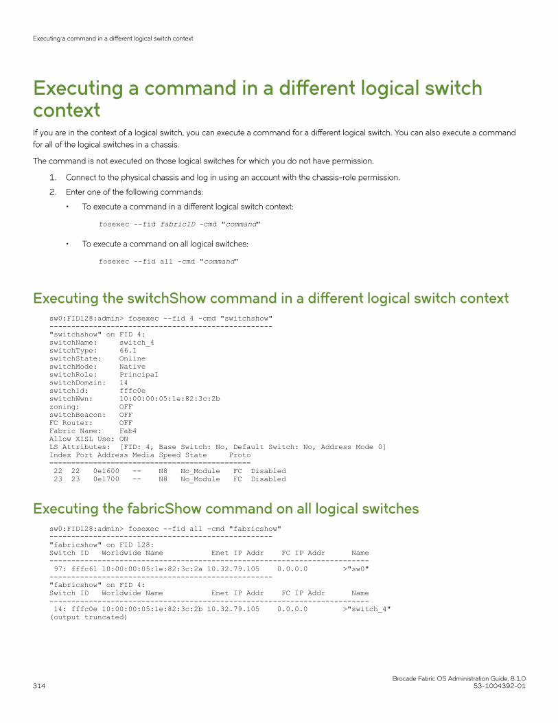
Executing a command in a different logical switchcontextIf you are in the context of a logical switch, you can execute a command for a different logical switch. You can also execute a commandfor all of the logical switches in a chassis.
The command is not executed on those logical switches for which you do not have permission.
1. Connect to the physical chassis and log in using an account with the chassis-role permission.
2. Enter one of the following commands:
• To execute a command in a different logical switch context:
fosexec --fid fabricID -cmd "command"
• To execute a command on all logical switches:
fosexec --fid all -cmd "command"
Executing the switchShow command in a different logical switch contextsw0:FID128:admin> fosexec --fid 4 -cmd "switchshow"---------------------------------------------------"switchshow" on FID 4:switchName: switch_4switchType: 66.1switchState: OnlineswitchMode: NativeswitchRole: PrincipalswitchDomain: 14switchId: fffc0eswitchWwn: 10:00:00:05:1e:82:3c:2bzoning: OFFswitchBeacon: OFFFC Router: OFFFabric Name: Fab4Allow XISL Use: ONLS Attributes: [FID: 4, Base Switch: No, Default Switch: No, Address Mode 0]Index Port Address Media Speed State Proto============================================== 22 22 0e1600 -- N8 No_Module FC Disabled 23 23 0e1700 -- N8 No_Module FC Disabled
Executing the fabricShow command on all logical switchessw0:FID128:admin> fosexec --fid all -cmd "fabricshow"---------------------------------------------------"fabricshow" on FID 128:Switch ID Worldwide Name Enet IP Addr FC IP Addr Name------------------------------------------------------------------------- 97: fffc61 10:00:00:05:1e:82:3c:2a 10.32.79.105 0.0.0.0 >"sw0"---------------------------------------------------"fabricshow" on FID 4:Switch ID Worldwide Name Enet IP Addr FC IP Addr Name------------------------------------------------------------------------- 14: fffc0e 10:00:00:05:1e:82:3c:2b 10.32.79.105 0.0.0.0 >"switch_4"(output truncated)
Executing a command in a different logical switch context
Brocade Fabric OS Administration Guide, 8.1.0314 53-1004392-01
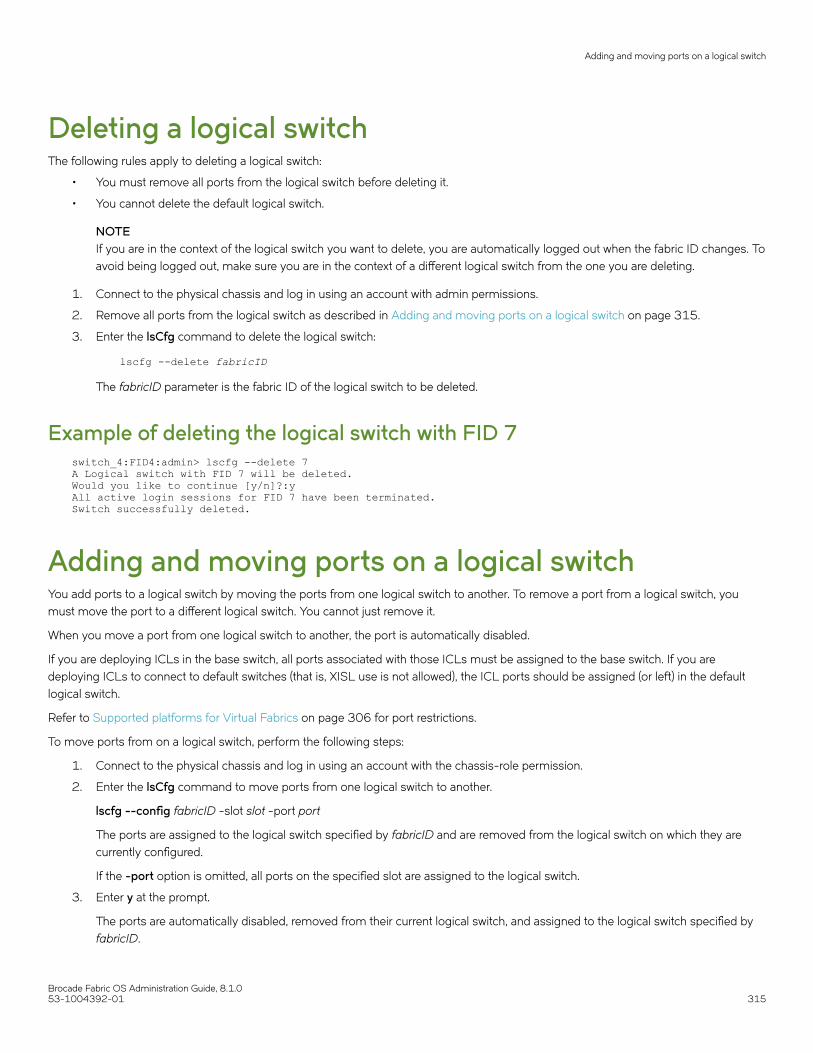
Deleting a logical switchThe following rules apply to deleting a logical switch:
• You must remove all ports from the logical switch before deleting it.
• You cannot delete the default logical switch.
NOTEIf you are in the context of the logical switch you want to delete, you are automatically logged out when the fabric ID changes. Toavoid being logged out, make sure you are in the context of a different logical switch from the one you are deleting.
1. Connect to the physical chassis and log in using an account with admin permissions.
2. Remove all ports from the logical switch as described in Adding and moving ports on a logical switch on page 315.
3. Enter the lsCfg command to delete the logical switch:
lscfg --delete fabricID
The fabricID parameter is the fabric ID of the logical switch to be deleted.
Example of deleting the logical switch with FID 7switch_4:FID4:admin> lscfg --delete 7A Logical switch with FID 7 will be deleted.Would you like to continue [y/n]?:yAll active login sessions for FID 7 have been terminated.Switch successfully deleted.
Adding and moving ports on a logical switchYou add ports to a logical switch by moving the ports from one logical switch to another. To remove a port from a logical switch, youmust move the port to a different logical switch. You cannot just remove it.
When you move a port from one logical switch to another, the port is automatically disabled.
If you are deploying ICLs in the base switch, all ports associated with those ICLs must be assigned to the base switch. If you aredeploying ICLs to connect to default switches (that is, XISL use is not allowed), the ICL ports should be assigned (or left) in the defaultlogical switch.
Refer to Supported platforms for Virtual Fabrics on page 306 for port restrictions.
To move ports from on a logical switch, perform the following steps:
1. Connect to the physical chassis and log in using an account with the chassis-role permission.
2. Enter the lsCfg command to move ports from one logical switch to another.
lscfg --config fabricID -slot slot -port port
The ports are assigned to the logical switch specified by fabricID and are removed from the logical switch on which they arecurrently configured.
If the -port option is omitted, all ports on the specified slot are assigned to the logical switch.
3. Enter y at the prompt.
The ports are automatically disabled, removed from their current logical switch, and assigned to the logical switch specified byfabricID.
Adding and moving ports on a logical switch
Brocade Fabric OS Administration Guide, 8.1.053-1004392-01 315

Example of assigning ports 18 through 20 to the logical switch with FID 5NOTEOn theBrocade DCX 8510-8, the lscfg command does not allow you to add ports 48-63 of the FC16-64 blade to the baseswitch. These ports are not supported on the base switch. The Brocade DCX 8510-4 does not have this limitation.
switch:admin> lscfg --config 5 -port 18-20This operation requires that the affected ports be disabled.Would you like to continue [y/n]?: yMaking this configuration change. Please wait...Configuration change successful.Please enable your ports/switch when you are ready to continue.
Displaying logical switch configurationUse the following procedure to display the configuration for a logical switch:
1. Connect to the physical chassis and log in using an account with the chassis-role permission.
2. Enter the lsCfg --show -n command to display information about all of the logical switches.
3. Enter the lsCfg --show command to display a list of all logical switches and the ports assigned to them.
Example of displaying basic information about all of the logical switchessw0:FID128:admin> lscfg --show -n--------------------------------------------------------Switch Information--------------------------------------------------------FID: 5SwitchType: BSDomainID: 3SwitchName: Base1FabricName: Fab1--------------------------------------------------------FID: 128SwitchType: DSDomainID: 1SwitchName: sw0FabricName: DefFab--------------------------------------------------------
Example of displaying a list of all of the logical switches and the portsassigned to them
sw0:FID128:admin> lscfg --showCreated switches: 128(ds) 4 5 Port 0 1 2 3 4 5 6 7 8 9 -------------------------------------------------------------------FID 128 | 128 | 128 | 128 | 128 | 128 | 128 | 128 | 5 | 5 |(output truncated)
Displaying logical switch configuration
Brocade Fabric OS Administration Guide, 8.1.0316 53-1004392-01

Changing the fabric ID of a logical switchThe fabric ID indicates in which fabric the logical switch participates. By changing the fabric ID, you are moving the logical switch fromone fabric to another.
Changing the fabric ID (FID) requires permission for chassis management operations. You cannot change the FID of your own logicalswitch context.
NOTEIf you are in the context of the logical switch with the fabric ID you want to change, you are automatically logged out when thefabric ID changes. To avoid being logged out, make sure you are in the context of a different logical switch from the one with thefabric ID you are changing.
1. Connect to the switch and log in using an account with admin permissions.
2. Enter the lsCfg command to change the fabric ID of a logical switch:
lscfg --change fabricID -newfid newFID
3. Enter y at the prompt.
4. Enable the logical switch.
fosexec --fid newFID -cmd "switchenable"
Example of changing the fabric ID on the logical switch from 5 to 7sw0:FID128:admin> lscfg --change 5 -newfid 7Changing of a switch fid requires that the switch be disabled.Would you like to continue [y/n]?: yDisabling switch...All active login sessions for FID 5 have been terminated.Checking and logging message: fid = 5.Please enable your switch.sw0:FID128:admin> fosexec --fid 7 -cmd "switchenable"---------------------------------------------------"switchenable" on FID 7:
Changing a logical switch to a base switchUse the following procedure to change a logical switch to a base switch.
1. Connect to the switch and log in using an account with the chassis-role permission.
2. Set the context to the logical switch you want to change, if you are not already in that context.
setcontext fabricID (or switchname)
The fabricID parameter is the FID of the logical switch you want to change to a base switch. The switchname parameter is thename assigned to the logical switch. You can only use one parameter at a time.
3. Configure the switch to not allow XISL use, as described in Configuring a logical switch for XISL use on page 318.
Changing a logical switch to a base switch
Brocade Fabric OS Administration Guide, 8.1.053-1004392-01 317

4. Enter the lsCfg command to change the logical switch to a base switch:
lscfg --change fabricID -base
The fabricID parameter is the fabric ID of the logical switch with the attributes you want to change.
5. Enable the switch.
switchenable
Example of changing the logical switch with FID 7 to a base switchsw0:FID128:admin> setcontext 7switch_25:FID7:admin> switchshowswitchName: switch_25switchType: 66.1switchState: Online switchMode: NativeswitchRole: PrincipalswitchDomain: 30switchId: fffc1eswitchWwn: 10:00:00:05:1e:82:3c:2czoning: OFFswitchBeacon: OFFFC Router: OFFFabric Name: MktFab7HIF Mode: ONAllow XISL Use: ON LS Attributes: [FID: 7, Base Switch: No, Default Switch: No, Address Mode 0](output truncated)switch_25:FID7:admin> configureNot all options will be available on an enabled switch.To disable the switch, use the "switchDisable" command.Configure... Fabric parameters (yes, y, no, n): [no] y WWN Based persistent PID (yes, y, no, n): [no] Allow XISL Use (yes, y, no, n): [yes] n WARNING!! Disabling this parameter will cause removal of LISLs to other logical switches. Do you want to continue? (yes, y, no, n): [no] y System services (yes, y, no, n): [no] switch_25:FID7:admin> lscfg --change 7 -baseCreation of a base switch requires that the proposed new base switch on this system be disabled.Would you like to continue [y/n]?: yDisabling the proposed new base switch...Disabling switch fid 7Please enable your switches when ready.switch_25:FID7:admin> switchenable
Configuring a logical switch for XISL useWhen you create a logical switch, it is configured to use XISLs by default. However, in some cases XISL use is not supported.
Use the following procedure to allow or disallow the logical switch to use XISLs in the base fabric.
Refer to Limitations and restrictions of Virtual Fabrics on page 309 for restrictions on XISL use.
To configure a logical switch for XISL use, perform the following procedure:
1. Connect to the physical chassis and log in using an account with the chassis-role permission.
Configuring a logical switch for XISL use
Brocade Fabric OS Administration Guide, 8.1.0318 53-1004392-01

2. Use the setContext command to set the context to the logical switch you want to manage, if you are not already in that context.setcontext fabricID | switchname
The fabricID parameter is the FID of the logical switch you want to switch to and manage. The switchname parameter is thename assigned to the logical switch. You can only use one parameter at a time.
3. Use the switchShow command and check the value of the Allow XISL Use parameter.
4. Enter the configure command:
5. Enter y after the Fabric Parameters prompt:
Fabric parameters (yes, y, no, n): [no] y
6. Enter y at the Allow XISL Use prompt to allow XISL use; enter n at the prompt to disallow XISL use:
Allow XISL Use (yes, y, no, n): y
7. Respond to the remaining prompts or press Ctrl-d to accept the other settings and exit.
Creating a FICON logical switchWith the FICON logical switch feature, you can create a FICON logical switch. You can also modify an existing logical switch as a FICONlogical switch.
The FICON logical switch is supported on all platforms that support Virtual Fabrics in Fabric OS 8.1.0. A FICON logical switch can becreated independent of enabling FMS mode. A FICON logical switch cannot be the default switch in the chassis nor can it be the baseswitch of the chassis.
FICON logical switch provides auto-configuration of the following, which simplifies the process of establishing a logical switch in theFICON environment:
• Insistent Domain ID (IDID) mode is set to on
• Routing policy is set to device-based routing
• Area mode is set to zero-based addressing
• SCC security policy is auto-defined with only its own WWN
• The created SCC policy is activated
• The fabric-wide consistency policy is set to strict SCC policy
• High Integrity Fabric (HIF) mode is enabled
• FMS mode is enabled if FICON CUP license is installed on the chassis
After the FICON mode logical switch is created, each port migrating into the logical switch must be bound to an address. Use theportaddress command to bind addresses. Any port that is not bound is kept disabled in the switch until it is bound to an address.
Once a FICON logical switch is created, you cannot disable HIF mode or change the address mode to any mode other than zero-basedaddressing mode. As a result, the configure command will not list the following parameters:
• IDID mode
• 256 Area (Port-based addressing mode is not provided)
• HIF mode
At the end of FICON logical switch creation, the FICON logical switch is kept offline, to allow additional configuration operations. Bycontrast, a non-FICON logical switch is online and ready for use once it is created.
Creating a FICON logical switch
Brocade Fabric OS Administration Guide, 8.1.053-1004392-01 319

Use the following procedure to create a FICON logical switch.
1. Connect to the physical chassis and log in using an account with the chassis-role permission.
2. Use the lscfg command with the -ficon option to create a FICON logical switch.
switch_128:FID128:admin> lscfg --create 50 -ficonA Logical switch with FID 50 will be created with ficon configuration.Would you like to continue [y/n]?: yAbout to create switch with fid=50. Please wait...Logical Switch with FID (50) has been successfully created.
Logical Switch has been created with ficon configurations.Please configure the Logical Switch with appropriate switchand protocol settings before activating the Logical Switch.
The command takes approximately 30 seconds to complete.
3. Use the lscfg command with the --show option to verify the logical switch creation. The output is truncated.
switch_128:FID128:admin> lscfg --show
Created switches FIDs(Domain IDs): 128(ds)(120) 50(fs)(1)Slot 1 2 3 4 5 6 7 8-------------------------------------------------------Port 0 | | | | 128 | 128 | | | 128 | 1 | | | | 128 | 128 | | | 128 | 2 | | | | 128 | 128 | | | 128 |
You can see that logical switch 50 is created as a FICON logical switch, indicated by 50(fs).
4. Use the setcontext command to set context to the FICON logical switch.
switch_128:FID128:admin> setcontext 50switch_50:FID50:admin>
5. Use the switchshow command to display switch information.
switch_50:FID50:admin> switchshowswitchName: switch_50switchType: 165.0switchState: OfflineswitchMode: NativeswitchRole: DisabledswitchDomain: 1 (unconfirmed)switchId: fffc01switchWwn: 10:00:00:27:f8:f0:a3:d1zoning: OFFswitchBeacon: OFFFC Router: OFFHIF Mode: ONAllow XISL Use: ONLS Attributes: [FID: 50, Base Switch: No, Default Switch: No, Ficon Switch: Yes, Address Mode 1]
Index Slot Port Address Media Speed State Proto============================================================================================No ports found in the system!!!
You can see HIF mode is enabled and Address Mode is set to 1 (zero-based address mode).
Creating a FICON logical switch
Brocade Fabric OS Administration Guide, 8.1.0320 53-1004392-01

6. Use the aptpolicy command to display the routing policy.
switch_50:FID50:admin> aptpolicy Current Policy: 2
3 : Default Policy 1: Port Based Routing Policy 2: Device Based Routing Policy (FICON support only) 3: Exchange Based Routing Policy
7. Refer to Adding and moving ports on a logical switch on page 315 for information on how to move ports into a logical switch.
The following command sequence shows a port migrated into the FICON logical switch.
switch:FID128:admin> lscfg --config 50 -slot 4 -port 5This operation requires that the affected ports be disabled.Would you like to continue [y/n]?: yMaking this configuration change. Please wait...Configuration change successful.Please enable your ports/switch when you are ready to continue.
switch:FID128:admin> setcontext 50switch_50:FID50:admin> switchshowswitchName: switch_50...Allow XISL Use: ONLS Attributes: [FID: 50, Base Switch: No, Default Switch: No, Ficon Switch: Yes, Address Mode 1]
Index Slot Port Address Media Speed State Proto============================================================ 69 4 5 010000 id N32 No_Sync FC Disabled (Port not bounded to Address in FICON Switch)
switch_50:FID12:admin> portaddress --bind 4/5 0xab00switch_50:FID12:admin> portenable 4/5switch_50:FID12:admin> switchshow switchName: switch_12switchType: 166.0..LS Attributes: [FID: 50, Base Switch: No, Default Switch: No, Ficon Switch: Yes, Address Mode 1]
Index Slot Port Address Media Speed State Proto============================================================ 101 11 5 01ab00 -- N32 No_Module FC
8. NOTEFor ports that are migrated into the FICON logical switch, you must bind the port by using the portaddress --bindcommand. If the port is not bound after migration, the port enable operations fails and the port is disabled with theinformation, “Port needs to be bound to area in FICON Switch.” You cannot bind ICL ports with the portaddress --bind command.
Use the portaddress --bind command to bind or unbind ports. You can specify a range of ports to bind to an area. When youspecify a range of ports, the first port is bound to the first area and each successive port is bound to the successive area.
The following examples show a range of ports used in the portaddress --bind command.
switch:FID128:admin> portaddress --bind 12/0-2 0xa000switch:FID128:admin> portaddress –-unbind 12/0-1
switch:FID128:admin> portaddress --bind 12/3-5 0xa000portaddress: The operation failed for port 5.The area 0xa200 is assigned to port 12/1.
Creating a FICON logical switch
Brocade Fabric OS Administration Guide, 8.1.053-1004392-01 321
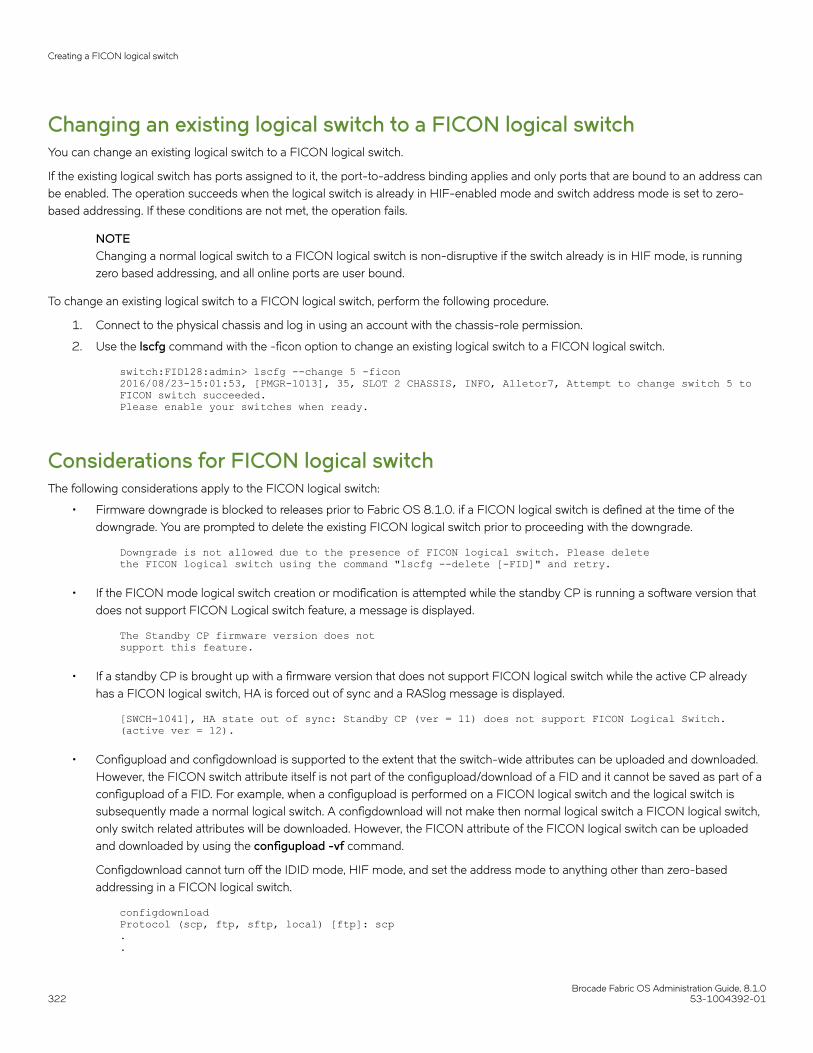
Changing an existing logical switch to a FICON logical switchYou can change an existing logical switch to a FICON logical switch.
If the existing logical switch has ports assigned to it, the port-to-address binding applies and only ports that are bound to an address canbe enabled. The operation succeeds when the logical switch is already in HIF-enabled mode and switch address mode is set to zero-based addressing. If these conditions are not met, the operation fails.
NOTEChanging a normal logical switch to a FICON logical switch is non-disruptive if the switch already is in HIF mode, is runningzero based addressing, and all online ports are user bound.
To change an existing logical switch to a FICON logical switch, perform the following procedure.
1. Connect to the physical chassis and log in using an account with the chassis-role permission.
2. Use the lscfg command with the -ficon option to change an existing logical switch to a FICON logical switch.
switch:FID128:admin> lscfg --change 5 -ficon2016/08/23-15:01:53, [PMGR-1013], 35, SLOT 2 CHASSIS, INFO, Alletor7, Attempt to change switch 5 to FICON switch succeeded.Please enable your switches when ready.
Considerations for FICON logical switchThe following considerations apply to the FICON logical switch:
• Firmware downgrade is blocked to releases prior to Fabric OS 8.1.0. if a FICON logical switch is defined at the time of thedowngrade. You are prompted to delete the existing FICON logical switch prior to proceeding with the downgrade.
Downgrade is not allowed due to the presence of FICON logical switch. Please delete the FICON logical switch using the command "lscfg --delete [-FID]" and retry.
• If the FICON mode logical switch creation or modification is attempted while the standby CP is running a software version thatdoes not support FICON Logical switch feature, a message is displayed.
The Standby CP firmware version does notsupport this feature.
• If a standby CP is brought up with a firmware version that does not support FICON logical switch while the active CP alreadyhas a FICON logical switch, HA is forced out of sync and a RASlog message is displayed.
[SWCH-1041], HA state out of sync: Standby CP (ver = 11) does not support FICON Logical Switch. (active ver = 12).
• Configupload and configdownload is supported to the extent that the switch-wide attributes can be uploaded and downloaded.However, the FICON switch attribute itself is not part of the configupload/download of a FID and it cannot be saved as part of aconfigupload of a FID. For example, when a configupload is performed on a FICON logical switch and the logical switch issubsequently made a normal logical switch. A configdownload will not make then normal logical switch a FICON logical switch,only switch related attributes will be downloaded. However, the FICON attribute of the FICON logical switch can be uploadedand downloaded by using the configupload -vf command.
Configdownload cannot turn off the IDID mode, HIF mode, and set the address mode to anything other than zero-basedaddressing in a FICON logical switch.
configdownload Protocol (scp, ftp, sftp, local) [ftp]: scp..
Creating a FICON logical switch
Brocade Fabric OS Administration Guide, 8.1.0322 53-1004392-01

.Doing configDownload on switch 4...
High Integrity Fabric mode cannot be turned off in FICON Logical switch.
Changing the context to a different logical fabricYou can change the context to a different logical fabric. Your user account must have permission to access the logical fabric.
1. Connect to the physical chassis and log in using an account with the chassis-role permission.
2. Use the setContext command to switch to a different logical switch in the chassis:
setcontext fabricID | switchname
The fabricID parameter is the fabric ID of the logical switch you want to switch to and manage. The switchname parameter isthe name assigned to the logical switch. You can only use one parameter at a time.
Example of changing the context from FID 128 to FID 4In this example, notice that the prompt changes when you change to a different logical fabric.
sw0:FID128:admin> setcontext 4switch_4:FID4:admin>
Changing the context to a different logical fabric
Brocade Fabric OS Administration Guide, 8.1.053-1004392-01 323

Brocade Fabric OS Administration Guide, 8.1.0324 53-1004392-01

Administering Advanced Zoning• Zone types.........................................................................................................................................................................................................325• Zoning overview..............................................................................................................................................................................................326• Broadcast zones............................................................................................................................................................................................. 332• Zone aliases...................................................................................................................................................................................................... 333• Zone creation and maintenance............................................................................................................................................................... 337• Default zoning mode.....................................................................................................................................................................................349• Zone database size........................................................................................................................................................................................350• Zone configurations.......................................................................................................................................................................................351• Zone object maintenance............................................................................................................................................................................362• Zone configuration management............................................................................................................................................................ 364• Security and zoning....................................................................................................................................................................................... 364• Zone merging...................................................................................................................................................................................................365• Concurrent zone transactions....................................................................................................................................................................372• Peer Zoning.......................................................................................................................................................................................................374• Target Driven Zoning.....................................................................................................................................................................................383• Supported commands for Peer Zones and Target Driven Peer Zones...................................................................................388• Boot LUN zoning............................................................................................................................................................................................388
Zone typesZones enable you to partition your fabric into logical groups of devices that can access each other. These are "regular" or "standard"zones. Unless otherwise specified, all references to zones in this chapter refer to these regular zones. Beyond this, Fabric OS has thefollowing types of special zones:
• Broadcast zones
Control which devices receive broadcast frames. A broadcast zone restricts broadcast packets to members of the broadcastzone only. Refer to Broadcast zones on page 332 for more information.
• Frame redirection zones
Re-route frames between an initiator and a target through a Virtual Initiator and Virtual Target for special processing orfunctionality, such as for storage virtualization or encryption. Refer to Frame Redirection on page 132 for more information.
• LSAN zones
Provide device connectivity between fabrics without merging the fabrics. Refer to LSAN zone configuration on page 541 formore information. LSAN zones support RFIDs.
• QoS zones
Assign high or low priority to designated traffic flows. These are regular zones with additional QoS attributes specified by addinga QoS prefix to the zone name. Refer to QoS on page 426 for more information.
• Traffic Isolation zones (TI zones)
Isolate traffic to a specific, dedicated path through the fabric. Refer to Traffic Isolation Zoning on page 393 for moreinformation.
• Peer zones
Allow a principal device port to communicate with other members of the zone. Refer to Peer Zoning on page 374 for moreinformation.
Brocade Fabric OS Administration Guide, 8.1.053-1004392-01 325

• Target driven zones
Allow targets to create or activate peer zones. Refer to Target Driven Zoning on page 383for more information.
Zoning overviewZoning is a fabric-based service that enables you to partition your storage area network (SAN) into logical groups of devices that canaccess each other.
For example, you can partition your SAN into two zones, “winzone” and “unixzone”, so that your Windows servers and storage do notinteract with your UNIX servers and storage. You can use zones to logically consolidate equipment for efficiency or to facilitate time-sensitive functions; for example, you can create a temporary zone to back up nonmember devices.
A device in a zone can communicate only with other devices connected to the fabric within the same zone. A device not included in thezone is not available to members of that zone. When zoning is enabled, devices that are not included in any zone configuration areinaccessible to all other devices in the fabric.
Zones can be configured dynamically. They can vary in size, depending on the number of fabric-connected devices, and devices canbelong to more than one zone.
Consider Figure 29, which shows a FC fabric with three configured zones: Red, Green, and Blue. Within this fabric, the following is true:
• Server 1 can communicate only with the Loop 1 storage devices. (Red zone)
• Server 2 can communicate only with the RAID storage devices. (Blue zone)
• Server 3 can communicate with the RAID and Loop 1 storage devices. (Green zone)
• Loop 2 is not assigned to a zone; no other zoned fabric device can access it.
FIGURE 29 Zoning example
Zoning overview
Brocade Fabric OS Administration Guide, 8.1.0326 53-1004392-01

Refer to Best practices for zoning on page 331 for additional information that should be kept in mind when working with zones.
To list the commands associated with zoning, use the zoneHelp command. For detailed information on the zoning commands used inthe procedures, refer to the Brocade Fabric OS Command Reference.
Approaches to zoningTable 72 lists the various approaches you can take when implementing zoning in a fabric.
TABLE 72 Approaches to fabric-based zoning
Zoning approach Description
Recommended approach
Single HBA Zoning by single HBA most closely re-creates the original SCSI bus. Eachzone created has only one HBA (initiator) in the zone; each of the targetdevices is added to the zone. Typically, a zone is created for the HBA andthe disk storage ports are added. If the HBA also accesses tape devices, asecond zone is created with the HBA and associated tape devices in it. Inthe case of clustered systems, it could be appropriate to have an HBAfrom each of the cluster members included in the zone; this is equivalentto having a shared SCSI bus between the cluster members and assumesthat the clustering software can manage access to the shared devices.
In a large fabric, zoning by single HBA requires the creation of possiblyhundreds of zones; however, each zone contains only a few members.Zone changes affect the smallest possible number of devices, minimizingthe impact of an incorrect zone change. This zoning philosophy is thepreferred method.
Alternative approaches
Application Zoning by application typically requires zoning multiple, perhapsincompatible, operating systems into the same zones. This method ofzoning creates the possibility that a minor server in the application suitecould disrupt a major server (such as a Web server disrupting a datawarehouse server). Zoning by application can also result in a zone with alarge number of members, meaning that more notifications, such asregistered state change notifications (RSCNs), or errors, go out to a largergroup than necessary.
Operating system Zoning by operating system has issues similar to zoning by application. Ina large site, this type of zone can become very large and complex. Whenzone changes are made, they typically involve applications rather than aparticular server type. If members of different operating system clusterscan see storage assigned to another cluster, they might attempt to own theother cluster’s storage and compromise the stability of the clusters.
Port allocation Avoid zoning by port allocation unless the administration team has veryrigidly enforced processes for port and device allocation in the fabric.Zoning by port allocation does, however, provide some positive features.For instance, when a storage port, server HBA, or tape drive is replaced,the change of WWN for the new device is of no consequence. As long asthe new device is connected to the original port, it continues to have thesame access rights. The ports on the edge switches can be pre-associatedto storage ports, and control of the fan-in ratio (the ratio of the input portto output port) can be established. With this pre-assigning technique, theadministrative team cannot overload any one storage port by associatingtoo many servers with it.
Not recommended
No fabric zoning Using no fabric zoning is the least desirable zoning option because itallows devices to have unrestricted access on the fabric. Additionally, anydevice attached to the fabric, intentionally or maliciously, likewise has
Zoning overview
Brocade Fabric OS Administration Guide, 8.1.053-1004392-01 327

TABLE 72 Approaches to fabric-based zoning (continued)
Zoning approach Description
unrestricted access to the fabric. This form of zoning should be utilizedonly in a small and tightly controlled environment, such as when host-based zoning or LUN masking is deployed.
Zone objectsA zone object is any device in a zone, such as:
• Physical port number or port index on the switch
• Node World Wide Name (N-WWN)
• Port World Wide Name (P-WWN)
Zone objects identified by port number or index number are specified as a pair of decimal numbers in the form D,I, where D is thedomain ID of the switch and I is the index number on that switch in relation to the port you want to specify.
For example, in Backbones, "4,30" specifies port 14 in slot number 2 (domain ID 4, port index 30). On fixed-port models, "3,13"specifies port 13 in switch domain ID 3.
The following issues affect zone membership based on the type of zone object:
• When a zone object is the physical port number, then all devices connected to that port are in the zone.
• World Wide Names are specified as 8-byte (16-digit) hexadecimal numbers, separated by colons (:), for example,10:00:00:90:69:00:00:8a.
• When a zone object is the node WWN name, only the specified device is in the zone.
• When a zone object is the port WWN name, only the single port is in the zone.
NOTEUsing a WWN in the same format as a peer property member (starting with "00") is not allowed.
The types of zone objects used to define a zone can be mixed. For example, a zone defined with the zone objects 2,12; 2,14;10:00:00:80:33:3f:aa:11 contains the devices connected to domain 2, ports 12 and 14, and a device with the WWN10:00:00:80:33:3f:aa:11 (either node name or port name) that is connected on the fabric.
Naming zone objectsZone objects such as zone configuration name, zone name, and alias name can have the following characters, if all the switches in thefabric and both the CPs in a chassis system are running Fabric OS 8.1.0 or later.
• Start with a number or a letter.
• Contain a hyphen ( - ) other than the first character.
• Contain an underscore ( _ ) other than the first character.
• Contain a dollar sign ( $ ) other than the first character.
• Contain a caret ( ^ ) other than the first character.
You can use these characters in the zone object names while creating them and subsequently on add, remove, delete, show, enable,copy, rename, and expunge commands related to zone objects.
• The following is an example of using these characters with the cfgcreate command.
switch:admin> cfgCreate 1-2_cfg, "z1;z2"; switch:admin> zoneshow Defined configuration:
Zoning overview
Brocade Fabric OS Administration Guide, 8.1.0328 53-1004392-01
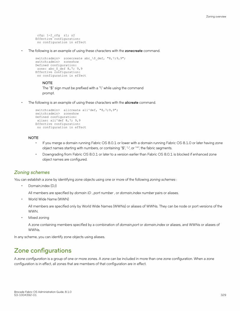
cfg: 1-2_cfg z1; z2 Effective configuration: no configuration in effect
• The following is an example of using these characters with the zonecreate command.
switch:admin> zonecreate abc_\$_def, "8,7;9,9"; switch:admin> zoneshow Defined configuration: zone: abc_$_def 8,7; 9,9 Effective configuration: no configuration in effect
NOTEThe "$" sign must be prefixed with a "\" while using the commandprompt.
• The following is an example of using these characters with the alicreate command.
switch:admin> alicreate ali^def, "8,7;9,9"; switch:admin> zoneshow Defined configuration: alias: ali^def 8,7; 9,9 Effective configuration: no configuration in effect
NOTE• If you merge a domain running Fabric OS 8.0.1 or lower with a domain running Fabric OS 8.1.0 or later having zone
object names starting with numbers, or containing "$", "-", or "^", the fabric segments.
• Downgrading from Fabric OS 8.0.1 or later to a version earlier than Fabric OS 8.0.1 is blocked if enhanced zoneobject names are configured.
Zoning schemesYou can establish a zone by identifying zone objects using one or more of the following zoning schemes :
• Domain,index (D,I)
All members are specified by domain ID , port number , or domain,index number pairs or aliases.
• World Wide Name (WWN)
All members are specified only by World Wide Names (WWNs) or aliases of WWNs. They can be node or port versions of theWWN.
• Mixed zoning
A zone containing members specified by a combination of domain,port or domain,index or aliases, and WWNs or aliases ofWWNs.
In any scheme, you can identify zone objects using aliases.
Zone configurationsA zone configuration is a group of one or more zones. A zone can be included in more than one zone configuration. When a zoneconfiguration is in effect, all zones that are members of that configuration are in effect.
Zoning overview
Brocade Fabric OS Administration Guide, 8.1.053-1004392-01 329

Several zone configurations can reside on a switch at once, and you can quickly alternate between them. For example, you might want tohave one configuration enabled during the business hours and another enabled overnight. However, only one zone configuration can beenabled at a time.
The different types of zone configurations are:
• Defined configuration
The complete set of all zone objects defined in the fabric.
• Effective configuration
A single zone configuration that is currently in effect. The effective configuration is built when you enable a specified zoneconfiguration.
• Saved configuration
A copy of the defined configuration plus the name of the effective configuration, which is saved in flash memory. (You can alsoprovide a backup of the zone configuration and restore the zone configuration.) There might be differences between the savedconfiguration and the defined configuration if you have modified any of the zone definitions and have not saved theconfiguration.
• Disabled configuration
The effective configuration is removed from flash memory.
If you disable the effective configuration, the Advanced Zoning feature is disabled on the fabric, and all devices within the fabric cancommunicate with all other devices (unless you previously set up a default zone, as described in Default zoning mode on page 349).This does not mean that the zone database is deleted, however, only that there is no configuration active in the fabric.
On power-up, the switch automatically reloads the saved configuration. If a configuration was active when it was saved, the sameconfiguration is reinstated on the local switch.
Zoning enforcementZoning enforcement describes a set of predefined rules that the switch uses to determine where to send incoming data. Fabric OS useshardware-enforced zoning. Hardware-enforced zoning means that each frame is checked by hardware (the ASIC) before it is delivered toa zone member and is discarded if there is a zone mismatch. When hardware-enforced zoning is active, the Fabric OS switch monitorsthe communications and blocks any frames that do not comply with the effective zone configuration. The switch performs this blockingat the transmit side of the port on which the destination device is located.
There are two methods of hardware enforcement:
• Frame-based hardware enforcement: All frames are checked by the hardware.
• Session-based hardware enforcement: The only frames checked by hardware are the ELS frames (such as PLOGI and RNID)used to establish a session.
The hardware-enforcement method used depends on how the zones are configured.
A zone can contain all WWN members, or all D,I members, or a combination of WWN and D,I members.
Frame-based hardware enforcement is in effect if all members of a zone are identified the same way, either using WWNs or D,I notation,but not both. If the zone includes aliases, then the aliases must also be defined the same way as the zone.
Session-based hardware enforcement is in effect if the zone has a mix of WWN and D,I members.
If a port is in multiple zones, and is defined by WWN in one zone and by D,I in another, then session-based hardware enforcement is ineffect.
Zoning overview
Brocade Fabric OS Administration Guide, 8.1.0330 53-1004392-01

Identifying the enforced zone typeUse the following procedure to identify zones and zone types:
1. Connect to the switch and log in using an account with admin permissions.
2. Enter the portZoneShow command.
Considerations for zoning architectureTable 73 lists considerations for zoning architecture.
TABLE 73 Considerations for zoning architecture
Item Description
Type of zoning enforcement: frame- orsession-based
If security is a priority, frame-based hardware enforcement is recommended. The best way to do thisis to use WWN identification exclusively for all zoning configurations.
Use of aliases The use of aliases is optional with zoning. Using aliases requires structure when defining zones.Aliases aid administrators of zoned fabrics in understanding the structure and context.
Effect of changes in a production fabric Zone changes in a production fabric can result in a disruption of I/O under conditions when an RSCNis issued because of the zone change and the HBA is unable to process the RSCN fast enough.Although RSCNs are a normal part of a functioning SAN, the pause in I/O might not be acceptable.For these reasons, you should perform zone changes only when the resulting behavior is predictableand acceptable. Ensuring that the HBA drivers are current can shorten the response time in relation tothe RSCN.
Testing Before implementing a new zone, you should run the Zone Analyzer from Web Tools to isolate anypossible problems. This is especially useful as fabrics increase in size.
Confirming operation After changing or enabling a zone configuration, you should confirm that the nodes and storage canidentify and access one another. Depending on the platform, you might need to reboot one or morenodes in the fabric with the new changes.
Zoning can be implemented and administered from any switch in the fabric, although it is recommended that you use a switch runningthe latest Fabric OS version.
The zone configuration is managed on a fabric basis. When a change in the configuration is saved, enabled, or disabled according to thetransactional model, it is automatically (by closing the transaction) distributed to all switches in the fabric, preventing a single point offailure for zone information.
NOTEZoning commands make changes that affect the entire fabric. When executing fabric-level configuration tasks, allow time for thechanges to propagate across the fabric before executing any subsequent commands. For a large fabric, you should wait severalminutes between commands.
Best practices for zoningThe following are recommendations for using zoning:
• When using a mixed fabric — that is, a fabric containing two or more switches running different release levels of Fabric OS —you should use the switch with the latest Fabric OS level to perform zoning tasks.
Switches with earlier versions of Fabric OS do not have the same capability to view all the functionality that more recentversions of Fabric OS provide, as functionality is backwards-compatible but not forward-compatible.
• Zone using the core switch in preference to using an edge switch.
• Zone using a Backbone rather than a switch. A Backbone has more resources to handle zoning changes and implementations.
Zoning overview
Brocade Fabric OS Administration Guide, 8.1.053-1004392-01 331

• When you are adding a switch to an existing fabric, prior to joining the fabric you must set the defzone policy of the switch beingadded as follows:
– If the joining switch has locally-attached devices that are online, the defzone policy of the switch being added should be setto “No Access”.
– If the joining switch has no online locally-attached devices the defzone policy of the switch being added can be set to “AllAccess”.
This is done to avoid a transitional state where the “All Access” policy might lead to excessive RSCN activity; with extreme caseshaving the potential for additional adverse effects. This is especially important for fabrics having a very high device count.
• Initial WWNs starting with ‘00’ are for engineering use only and are auto-created. Starting with Fabric OS 7.3.0, zones havinginitial WWNs starting with ‘00’ are treated as peer zones. This means that when you attempt one of the following,
– A firmware upgrade from firmware earlier than Fabric OS 7.3.0– A merge with a switch running firmware earlier than Fabric OS 7.3.0– A configuration download using firmware earlier than Fabric OS 7.3.0
and the WWN of the first zone member starts with ‘00’, Fabric OS will treat the zone as a peer zone. You must delete suchinvalid zones before continuing. Refer to Deleting invalid zones on page 357 for instructions on doing so.
Broadcast zonesFibre Channel allows sending broadcast frames to all Nx_Ports if the frame is sent to a broadcast well-known address (FFFFFF);however, many target devices and HBAs cannot handle broadcast frames. To control which devices receive broadcast frames, you cancreate a special zone, called a broadcast zone , that restricts broadcast packets to only those devices that are members of the broadcastzone.
If there are no broadcast zones or if a broadcast zone is defined but not enabled, broadcast frames are not forwarded to any F_Ports. If abroadcast zone is enabled, broadcast frames are delivered only to those logged-in Nx_Ports that are members of the broadcast zoneand are also in the same zone (regular zone) as the sender of the broadcast packet.
Devices that are not members of the broadcast zone can send broadcast packets, even though they cannot receive them.
A broadcast zone can have domain,port, WWN, and alias members.
Broadcast zones do not function in the same way as other zones. A broadcast zone does not allow access within its members in any way.If you want to allow or restrict access between any devices, you must create regular zones for that purpose. If two devices are not part ofa regular zone, they cannot exchange broadcast or unicast packets.
To restrict broadcast frames reaching broadcast-incapable devices, create a broadcast zone and populate it with the devices that arecapable of handling broadcast packets. Devices that cannot handle broadcast frames must be kept out of the broadcast zone so that theydo not receive any broadcast frames.
You create a broadcast zone the same way you create any other zone except that a broadcast zone must have the name "broadcast"(case-sensitive). To enable the broadcast zoning, use cfgenable command to add the broadcast zones to the active zone configuration.You set up and manage broadcast zones using the standard zoning commands, described in Zone creation and maintenance on page337.
Broadcast zones and FC-FC routingIf you create broadcast zones in a metaSAN consisting of multiple fabrics connected through an FC router, the broadcast zone mustinclude the IP device that exists in the edge or backbone fabric as well as the proxy device in the remote fabric. Refer to Using FC-FCRouting to Connect Fabrics on page 513 for information about proxy devices and the FC router.
Broadcast zones
Brocade Fabric OS Administration Guide, 8.1.0332 53-1004392-01

High availability considerations with broadcast zonesIf a switch has broadcast zone-capable firmware on the active CP (Fabric OS v5.3.x or later) and broadcast zone-incapable firmware onthe standby CP (Fabric OS version earlier than v5.3.0), then you cannot create a broadcast zone because the zoning behavior would notbe the same across an HA failover. If the switch failed over, then the broadcast zone would lose its special significance and would betreated as a regular zone.
Loop devices and broadcast zonesDelivery of broadcast packets to individual devices in a loop is not controlled by the switch. Consequently, adding loop devices to abroadcast zone does not have any effect. If a loop device is part of a broadcast zone, then all devices in that loop receive broadcastpackets.
Best practice: All devices in a single loop should have uniform broadcast capability. If all the devices in the loop can handle broadcastframes, then add the FL_Port to the broadcast zone.
Broadcast zones and default zoning modeThe default zoning mode defines the device accessibility behavior if zoning is not implemented or if there is no effective zoneconfiguration. The default zoning mode has two options:
• All Access--All devices within the fabric can communicate with all other devices.
• No Access--Devices in the fabric cannot access any other device in the fabric.
If a broadcast zone is active, even if it is the only zone in the effective configuration, the default zone setting is not in effect.
If the effective configuration has only a broadcast zone, then the configuration appears as a No Access configuration. To change thisconfiguration to All Access, you must put all the available devices in a regular zone.
Refer to Default zoning mode on page 349 for additional information about default zoning.
Zone aliasesA zone alias is a name assigned to a logical group of ports or WWNs. By creating an alias, you can assign a familiar name to a device orgroup multiple devices into a single name. This simplifies cumbersome data entry and allows an intuitive naming structure (such as using"NT_Hosts" to define all NT hosts in the fabric). Using zone aliases eliminates the need for long lists of individual zone member names.
Zone aliases also simplify repetitive entry of zone objects such as port numbers or a WWN. For example, you can use the name "Eng" asan alias for "10:00:00:80:33:3f:aa:11".
Naming zones for the initiator they contain can also be useful. For example, if you use the alias SRV_MAILSERVER_SLT5 to designate amail server in PCI slot 5, then the alias for the associated zone is ZNE_MAILSERVER_SLT5. This clearly identifies the server host busadapter (HBA) associated with the zone.
Zone configuration naming is flexible. One configuration should be named PROD_fabricname, where fabricname is the name that thefabric has been assigned. The purpose of the PROD configuration is to easily identify the configuration that can be implemented andprovide the most generic services. If other configurations are used for specialized purposes, names such as "BACKUP_A,""RECOVERY_2," and "TEST_18jun02" can be used. If you are creating a new alias using aliCreate w, "1,1" , and a user in another Telnetsession executes cfgEnable (or cfgDisable , or cfgSave ), the other user’s transaction will abort your transaction and you will receive anerror message. Creating a new alias while there is a zone merge taking place may also abort your transaction. For more details aboutzone merging and zone merge conflicts, refer to Zone merging on page 365.
Zone aliases
Brocade Fabric OS Administration Guide, 8.1.053-1004392-01 333

Virtual Fabrics considerations: Alias definitions should not include logical port numbers. Zoning is not enforced on logical ports.
Creating an aliasUse the following procedure to create an alias.
1. Connect to the switch and log in using an account with admin permissions.
2. Enter the aliCreate command, using the following syntax:
alicreate "aliasname", "member[; member...]"
3. Enter the cfgSave command to save the change to the defined configuration.
The cfgSave command ends and commits the current zoning transaction buffer to nonvolatile memory. If a transaction is openon a different switch in the fabric when this command is run, the transaction on the other switch is automatically aborted. Amessage displays on the other switches to indicate that the transaction was aborted.Example
switch:admin> alicreate "array1", "2,32; 2,33; 2,34; 4,4" switch:admin> alicreate "array2", "21:00:00:20:37:0c:66:23; 4,3" switch:admin> alicreate "loop1", "4,6" switch:admin> cfgsave WARNING!!!You are about to save the Defined zoning configuration. Thisaction will only save the changes on Defined configuration.If the update includes changes to one or more traffic isolationzones, you must issue the 'cfgenable' command for the changesto take effect.Do you want to save the Defined zoning configuration only? (yes, y, no, n): [no]
Adding members to an aliasUse the following procedure to add a member to an alias.
1. Connect to the switch and log in using an account with admin permissions.
2. Enter the aliAdd command, using the following syntax:
aliadd "aliasname ","member[; member...]"
Zone aliases
Brocade Fabric OS Administration Guide, 8.1.0334 53-1004392-01

3. Enter the cfgSave command to save the change to the defined configuration.
The cfgSave command ends and commits the current zoning transaction buffer to nonvolatile memory. If a transaction is openon a different switch in the fabric when this command is run, the transaction on the other switch is automatically aborted. Amessage displays on the other switches to indicate that the transaction was aborted.Example
switch:admin> aliadd "array1", "1,2" switch:admin> aliadd "array2", "21:00:00:20:37:0c:72:51" switch:admin> aliadd "loop1", "5,6" switch:admin> cfgsave WARNING!!!You are about to save the Defined zoning configuration. Thisaction will only save the changes on Defined configuration.If the update includes changes to one or more traffic isolationzones, you must issue the 'cfgenable' command for the changesto take effect.Do you want to save the Defined zoning configuration only? (yes, y, no, n): [no]
Removing members from an aliasUse the following procedure to remove a member from an alias.
1. Connect to the switch and log in using an account with admin permissions.
2. Enter the aliRemove command, using the following syntax:
aliremove "aliasname ", "member [; member...]"
3. Enter the cfgSave command to save the change to the defined configuration.
The cfgSave command ends and commits the current zoning transaction buffer to nonvolatile memory. If a transaction is openon a different switch in the fabric when this command is run, the transaction on the other switch is automatically aborted. Amessage displays on the other switches to indicate that the transaction was aborted.Example
switch:admin> aliremove "array1", "1,2" switch:admin> aliremove "array2", "21:00:00:20:37:0c:72:51" switch:admin> aliremove "loop1", "4,6" switch:admin> cfgsave WARNING!!!You are about to save the Defined zoning configuration. Thisaction will only save the changes on Defined configuration.If the update includes changes to one or more traffic isolationzones, you must issue the 'cfgenable' command for the changesto take effect.Do you want to save the Defined zoning configuration only? (yes, y, no, n): [no]
Deleting an aliasUse the following procedure to delete an alias.
1. Connect to the switch and log in using an account with admin permissions.
Zone aliases
Brocade Fabric OS Administration Guide, 8.1.053-1004392-01 335

2. Enter the aliDelete command, using the following syntax.
alidelete "aliasname"
3. Enter the cfgSave command to save the change to the defined configuration.
The cfgSave command ends and commits the current zoning transaction buffer to nonvolatile memory. If a transaction is openon a different switch in the fabric when this command is run, the transaction on the other switch is automatically aborted. Amessage displays on the other switches to indicate that the transaction was aborted.Example
switch:admin> alidelete "array1" switch:admin> cfgsave WARNING!!!You are about to save the Defined zoning configuration. Thisaction will only save the changes on Defined configuration.If the update includes changes to one or more traffic isolationzones, you must issue the 'cfgenable' command for the changesto take effect.Do you want to save the Defined zoning configuration only? (yes, y, no, n): [no]
Viewing an alias in the defined configurationTo view an alias in the defined configuration, complete the following steps.
1. Connect to the switch and log in using an account with admin permissions.
2. Enter the aliShow command, followed optionally by the --ic, "pattern", and mode operands to display the zone configurationinformation.
NOTEIf you do not specify any parameters, the entire zone database (both the defined and effective configuration) isdisplayed. Refer to the Brocade Fabric OS Command Reference for more information on this command.
Displaying all zone aliases regardless of caseThe following example shows all zone aliases beginning with “arr”, regardless of the case:
switch:admin> alishow --ic "arr*" alias: array1 20:e0:00:05:33:11:1f:00alias: ARRAY2 50:11:00:05:33:c1:37:a2alias: array3 21:00:00:20:37:0c:66:23
Displaying all zone aliasesThe following example shows all zone aliases beginning with “arr”, but not if the alias uses these characters in a different case. Here“array1” and “array3” are displayed, but not “ARRAY2”:
switch:admin> alishow "arr*" alias: array1 21:00:00:20:37:0c:76:8calias: array3 21:00:00:20:37:0c:66:23
Zone aliases
Brocade Fabric OS Administration Guide, 8.1.0336 53-1004392-01

Zone creation and maintenanceFabric OS allows you to create zones to better manage devices.
The following items should be taken into account when creating zones:
• Broadcast zone — To create a broadcast zone, use the reserved name “broadcast”. Do not give a regular zone this name. Referto Broadcast zones on page 332 for additional information about this special type of zone.
• Virtual Fabrics — Zone definitions should not include logical port numbers. Zoning is not enforced on logical ports.
Displaying existing zonesUse the following procedure to display a list of existing zones.
1. Connect to the switch and log in using an account with admin permissions.
2. Enter the cfgShow command.
Example of displaying existing zones
switch:admin> cfgshow Defined configuration:zone: matt 30:06:00:07:1e:a2:10:20; 3,2alias: bawn 3,5; 4,8alias: bolt 10:00:00:02:1f:02:00:01alias: bond 10:00:05:1e:a9:20:00:01; 3,5alias: brain 11,4; 22,1; 33,6alias: jake 4,7; 8,9; 14,11alias: jeff 30:00:00:05:1e:a1:cd:02; 40:00:00:05:1e:a1:cd:04alias: jones 7,3; 4,5alias: zeus 4,7; 6,8; 9,2Effective configuration:No Effective configuration: (No Access)
Creating a zoneATTENTIONThe zoneCreate command will add all zone member aliases that match the "aliasname_pattern" in the zone database to thenew zone.
Use the following procedure to create a zone.
1. Connect to the switch and log in using an account with admin permissions.
2. Enter the zoneCreate command, using either of the following syntaxes:
zonecreate "zonename ", "member[; member...]"zonecreate "zonename ", "aliasname_pattern *[;members]"
NOTEThe zoneCreate command supports partial pattern matching ("wildcards") of zone member aliases. This allows you toadd multiple aliases that match the "aliasname_pattern" in the command line.
To create a broadcast zone, use the reserved name "broadcast".
Zone creation and maintenance
Brocade Fabric OS Administration Guide, 8.1.053-1004392-01 337

3. Enter the cfgSave command to save the change to the defined configuration.
The cfgSave command ends and commits the current zoning transaction buffer to nonvolatile memory. If a transaction is openon a different switch in the fabric when this command is run, the transaction on the other switch is automatically aborted. Amessage displays on the other switches to indicate that the transaction was aborted.
4. Enter the cfgShow command to view the changes.
Example of creating a new zone
switch:admin> zonecreate sloth, "b*; 10:00:00:00:01:1e:20:20" switch:admin> cfgsave switch:admin> cfgenable
switch:admin> cfgshow Defined configuration:zone: matt 30:06:00:07:1e:a2:10:20; 3,2zone: sloth bawn; bolt; bond; brain; 10:00:00:00:01:1e:20:20 alias: bawn 3,5; 4,8alias: bolt 10:00:00:02:1f:02:00:01alias: bond 10:00:05:1e:a9:20:00:01; 3,5alias: brain 11,4; 22,1; 33,6alias: jake 4,7; 8,9; 14,11alias: jeff 30:00:00:05:1e:a1:cd:02; 40:00:00:05:1e:a1:cd:04alias: jones 7,3; 4,5alias: zeus 4,7; 6,8; 9,2Effective configuration:No Effective configuration: (No Access)
Adding devices (members) to a zoneATTENTIONThe zoneAdd command will add all zone member aliases that match the "aliasname_pattern" in the zone database to thespecified zone.
Use the following procedure to add members to a zone:
1. Connect to the switch and log in using an account with admin permissions.
2. Enter the zoneAdd command, using either of the following syntaxes:
zoneadd "zonename", "member [; member...]"zoneadd "zonename ", "aliasname_pattern* [;members ]"
NOTEThe zoneAdd command supports partial pattern matching ("wildcards") of zone member aliases. This allows you toadd multiple aliases that match the "aliasname_pattern" in the command line.
3. Enter the cfgSave command to save the change to the defined configuration.
The cfgSave command ends and commits the current zoning transaction buffer to nonvolatile memory. If a transaction is openon a different switch in the fabric when this command is run, the transaction on the other switch is automatically aborted. Amessage displays on the other switches to indicate that the transaction was aborted.
Zone creation and maintenance
Brocade Fabric OS Administration Guide, 8.1.0338 53-1004392-01

4. Enter the cfgShow command to view the changes.
Example for adding members to a zone
switch:admin> zoneadd matt, "ze*; bond*; j*" switch:admin> cfgsave switch:admin> cfgshow Defined configuration:zone: matt 30:06:00:07:1e:a2:10:20; 3,2; zeus; bond; jake; jeff; joneszone: sloth bawn; bolt; bond; brain; 10:00:00:00:01:1e:20:20alias: bawn 3,5; 4,8alias: bolt 10:00:00:02:1f:02:00:01alias: bond 10:00:05:1e:a9:20:00:01; 3,5alias: brain 11,4; 22,1; 33,6alias: jake 4,7; 8,9; 14,11alias: jeff 30:00:00:05:1e:a1:cd:02; 40:00:00:05:1e:a1:cd:04alias: jones 7,3; 4,5alias: zeus 4,7; 6,8; 9,2Effective configuration:No Effective configuration: (No Access)
Removing devices (members) from a zoneATTENTIONThe zoneRemove command will remove all zone member aliases that match the "aliasname_pattern" in the zone databasefrom the specified zone.
Use the following procedure to remove members from a zone:
1. Connect to the switch and log in using an account with admin permissions.
2. Enter the zoneRemove command, using either of the following syntaxes:
zoneremove "zonename ", "member [; member ...]" zoneremove "zonename ", "aliasname_pattern* [;members ]"
NOTEThis command supports partial pattern matching ("wildcards") of zone member aliases. This allows you to removemultiple aliases that match the "aliasname_pattern" in the command line.
3. Enter the cfgSave command to save the change to the defined configuration.
The cfgSave command ends and commits the current zoning transaction buffer to nonvolatile memory. If a transaction is openon a different switch in the fabric when this command is run, the transaction on the other switch is automatically aborted. Amessage displays on the other switches to indicate that the transaction was aborted.
Zone creation and maintenance
Brocade Fabric OS Administration Guide, 8.1.053-1004392-01 339

4. Enter the cfgShow command to view the changes.
Examples removing members from a zone
switch:admin> cfgshow Defined configuration:zone: matt zeus; bond; jake; jeff; jones; 3,2; 30:06:00:07:1e:a2:10:20 zone: sloth bawn; bolt; bond; brain; 10:00:00:00:01:1e:20:20alias: bawn 3,5; 4,8alias: bolt 10:00:00:02:1f:02:00:01alias: bond 10:00:05:1e:a9:20:00:01; 3,5alias: brain 11,4; 22,1; 33,6alias: jake 4,7; 8,9; 14,11alias: jeff 30:00:00:05:1e:a1:cd:02; 40:00:00:05:1e:a1:cd:04alias: jones 7,3; 4,5alias: zeus 4,7; 6,8; 9,2Effective configuration:No Effective configuration: (No Access)switch:admin> switch:admin> zoneremove matt,"30:06:00:07:1e:a2:10:20; ja*; 3,2" switch:admin> cfgsave switch:admin> cfgshow Defined configuration:zone: matt zeus; bond; jeff; jones zone: sloth bawn; bolt; bond; brain; 10:00:00:00:01:1e:20:20alias: bawn 3,5; 4,8alias: bolt 10:00:00:02:1f:02:00:01alias: bond 10:00:05:1e:a9:20:00:01; 3,5alias: brain 11,4; 22,1; 33,6alias: jake 4,7; 8,9; 14,11alias: jeff 30:00:00:05:1e:a1:cd:02; 40:00:00:05:1e:a1:cd:04alias: jones 7,3; 4,5alias: zeus 4,7; 6,8; 9,2Effective configuration:No Effective configuration: (No Access)
Replacing zone membersFabric OS allows you to replace one zone member with another zone member using a CLI command. This command takes two inputs.The first is the member to be replaced and the second is the new member. These inputs can be formatted only with WWN or D,I zoningschemes.
Notes and restrictions• To make a configuration change effective, a cfgEnable command should be issued after the zoneObjectReplace command.
Otherwise, the changes will be in the transaction buffer but not committed.
• Only members of regular zones and aliases (those identified using either D,I or WWN) can be replaced usingzoneObjectReplace .
• The zoneObjectReplace command is not applicable for Frame Redirect (FR) and Traffic Isolation (TI) zones. Only members ofregular zones can be replaced using this command.
• The zoneObjectReplace command does not work with aliases. Alias members (that is, members inside an alias) can bereplaced using zoneObjectReplace , but an alias itself cannot be directly replaced. To achieve the effect of replacement, create anew alias (with the desired new name) containing the same members, and then delete the old alias.
Use the following procedure to replace members in a zone.
1. Connect to the switch and log in using an account with admin permissions.
Zone creation and maintenance
Brocade Fabric OS Administration Guide, 8.1.0340 53-1004392-01

2. Enter the zoneObjectReplace command, using the following syntax:
zoneobjectreplace old wwn/D,I new wwn/D,I
NOTEThe zoneObjectReplace command does not support partial pattern matching ("wildcards") of zone member aliases.
3. Enter the cfgSave command to save the change to the defined configuration.
The cfgSave command ends and commits the current zoning transaction buffer to nonvolatile memory. If a transaction is openon a different switch in the fabric when this command is run, the transaction on the other switch is automatically aborted. Amessage displays on the other switches to indicate that the transaction was aborted.
4. Enter the cfgShow command to view the changes.
Example replacing zone members
switch:admin> cfgshow Defined configuration:zone: matt zeus; bond; jeff;jones; 11, 2 zone: sloth bawn; bolt; bond; brain; brit; bru; 10:00:00:00:01:1e:20:20alias: bawn 3,5 alias: bolt 10:00:00:02:1f:02:00:01alias: bond 10:00:05:1e:a9:20:00:01; 3,5alias: brain 11,4; 22,1; 33,6alias: jake 4,7; 8,9; 14,11alias: jeff 30:00:00:05:1e:a1:cd:02; 40:00:00:05:1e:a1:cd:04alias: jones 7,3; 4,5alias: zeus 4,7; 6,8; 9,2Effective configuration:No Effective configuration: (No Access)switch:admin> switch:admin> zoneobjectreplace 11,2 4,8 switch:admin> cfgsave switch:admin> cfgshow Defined configuration:zone: matt zeus; bond; jeff; 4,8zone: sloth bawn; bolt; bond; brain; 10:00:00:00:01:1e:20:20alias: bawn 3,5 alias: bolt 10:00:00:02:1f:02:00:01alias: bond 10:00:05:1e:a9:20:00:01; 3,5alias: brain 11,4; 22,1; 33,6alias: jake 4,7; 8,9; 14,11alias: jeff 30:00:00:05:1e:a1:cd:02; 40:00:00:05:1e:a1:cd:04alias: jones 7,3; 4,5alias: zeus 4,7; 6,8; 9,2Effective configuration:No Effective configuration: (No Access)
CAUTIONExecuting this command replaces all instances of the older member with the new member in the entire zonedatabase.
Deleting a zoneUse the following procedure to delete a zone.
1. Connect to the switch and log in using an account with admin permissions.
Zone creation and maintenance
Brocade Fabric OS Administration Guide, 8.1.053-1004392-01 341
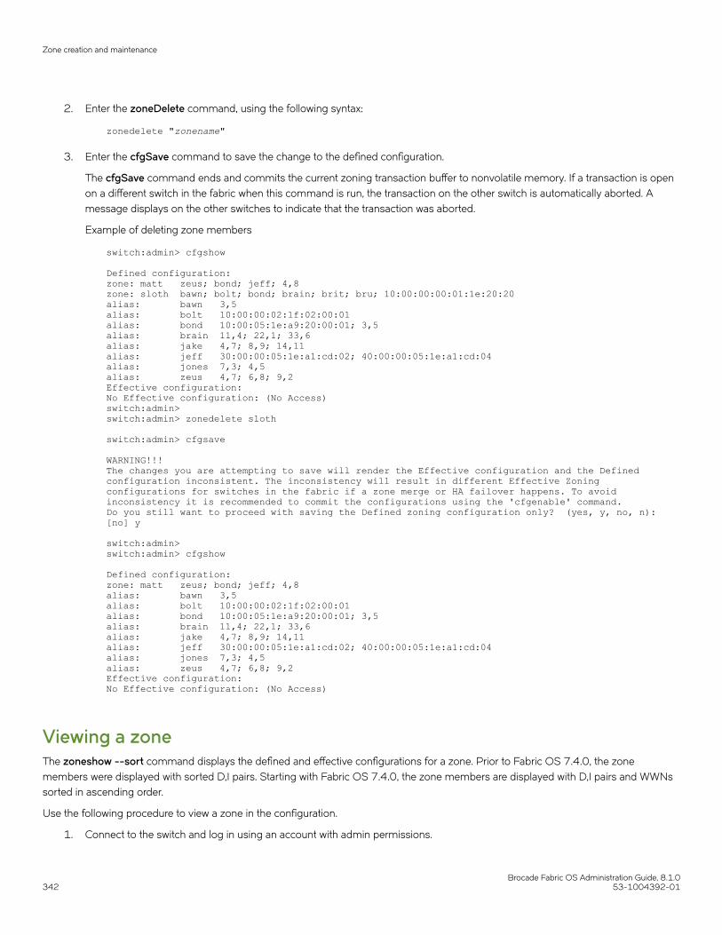
2. Enter the zoneDelete command, using the following syntax:
zonedelete "zonename"
3. Enter the cfgSave command to save the change to the defined configuration.
The cfgSave command ends and commits the current zoning transaction buffer to nonvolatile memory. If a transaction is openon a different switch in the fabric when this command is run, the transaction on the other switch is automatically aborted. Amessage displays on the other switches to indicate that the transaction was aborted.
Example of deleting zone members
switch:admin> cfgshow Defined configuration:zone: matt zeus; bond; jeff; 4,8 zone: sloth bawn; bolt; bond; brain; brit; bru; 10:00:00:00:01:1e:20:20alias: bawn 3,5 alias: bolt 10:00:00:02:1f:02:00:01alias: bond 10:00:05:1e:a9:20:00:01; 3,5alias: brain 11,4; 22,1; 33,6alias: jake 4,7; 8,9; 14,11alias: jeff 30:00:00:05:1e:a1:cd:02; 40:00:00:05:1e:a1:cd:04alias: jones 7,3; 4,5alias: zeus 4,7; 6,8; 9,2Effective configuration:No Effective configuration: (No Access)switch:admin> switch:admin> zonedelete sloth switch:admin> cfgsave WARNING!!!The changes you are attempting to save will render the Effective configuration and the Defined configuration inconsistent. The inconsistency will result in different Effective Zoning configurations for switches in the fabric if a zone merge or HA failover happens. To avoid inconsistency it is recommended to commit the configurations using the 'cfgenable' command.Do you still want to proceed with saving the Defined zoning configuration only? (yes, y, no, n): [no] y switch:admin> switch:admin> cfgshow Defined configuration:zone: matt zeus; bond; jeff; 4,8 alias: bawn 3,5 alias: bolt 10:00:00:02:1f:02:00:01alias: bond 10:00:05:1e:a9:20:00:01; 3,5alias: brain 11,4; 22,1; 33,6alias: jake 4,7; 8,9; 14,11alias: jeff 30:00:00:05:1e:a1:cd:02; 40:00:00:05:1e:a1:cd:04alias: jones 7,3; 4,5alias: zeus 4,7; 6,8; 9,2Effective configuration:No Effective configuration: (No Access)
Viewing a zoneThe zoneshow --sort command displays the defined and effective configurations for a zone. Prior to Fabric OS 7.4.0, the zonemembers were displayed with sorted D,I pairs. Starting with Fabric OS 7.4.0, the zone members are displayed with D,I pairs and WWNssorted in ascending order.
Use the following procedure to view a zone in the configuration.
1. Connect to the switch and log in using an account with admin permissions.
Zone creation and maintenance
Brocade Fabric OS Administration Guide, 8.1.0342 53-1004392-01

2. View the zone information using the zoneShow command.
If no parameters are specified, the entire zone database with both the defined and effective configurations is displayed.
Displaying a zone in a defined configuration exampleThe following example shows all zones beginning with A, B, or C, in ascending order:
switch:admin> zoneshow --sort "[A-C]*" zone: Blue_zone 1,1; array1; 1,2; array2 zone: Bobs_zone 4,5; 4,6; 4,7; 4,8; 4,9
Displaying the complete zone database exampleThe following example shows all zones in the zone database:
switch:admin> zoneshowDefined configuration: cfg: cfgnpr npr cfg: cfgz prz; diz; lsan_bb zone: diz 1,2; 4,7; 3,2; 1,1 zone: diz1 00:02:00:00:00:02:00:01; 10,4; 10,6; 10,5 zone: lsan_bb 30:12:00:05:1e:61:23:8f; 30:00:00:05:1e:61:23:8f zone: npr 20:04:00:05:33:88:bb:be; 20:06:00:05:33:88:bb:be; 20:05:00:05:33:88:bb:be zone: prz 00:02:00:00:00:03:00:01; 20:04:00:05:33:88:bb:be; 20:06:00:05:33:88:bb:be; 20:05:00:05:33:88:bb:be zone: upr 00:02:00:00:00:03:00:02; 20:06:00:05:33:88:bb:be; 20:05:00:05:33:88:bb:be; 20:04:00:05:33:88:bb:be
Effective configuration: cfg: cfgz zone: diz 1,2 4,7 3,2 1,1 zone: lsan_bb 30:12:00:05:1e:61:23:8f 30:00:00:05:1e:61:23:8f zone: prz 00:02:00:00:00:03:00:01 20:04:00:05:33:88:bb:be 20:06:00:05:33:88:bb:be 20:05:00:05:33:88:bb:be
Zone creation and maintenance
Brocade Fabric OS Administration Guide, 8.1.053-1004392-01 343

Displaying the sorted zone database exampleThe following example shows all zones in the zone database with sorted D,I pairs and WWNs:
switch:admin> zoneshow --sortDefined configuration: cfg: cfgnpr npr cfg: cfgz prz; diz; lsan_bb zone: diz 1,1; 1,2; 3,2; 4,7 zone: diz1 00:02:00:00:00:02:00:01; 10,4; 10,5; 10,6 zone: lsan_bb 30:00:00:05:1e:61:23:8f; 30:12:00:05:1e:61:23:8f zone: npr 20:04:00:05:33:88:bb:be; 20:05:00:05:33:88:bb:be; 20:06:00:05:33:88:bb:be zone: prz 00:02:00:00:00:03:00:01; 20:04:00:05:33:88:bb:be; 20:05:00:05:33:88:bb:be; 20:06:00:05:33:88:bb:be zone: upr 00:02:00:00:00:03:00:02; 20:05:00:05:33:88:bb:be; 20:06:00:05:33:88:bb:be; 20:04:00:05:33:88:bb:be
Effective configuration: cfg: cfgz zone: diz 1,1 1,2 3,2 4,7 zone: lsan_bb 30:00:00:05:1e:61:23:8f 30:12:00:05:1e:61:23:8f zone: prz 00:02:00:00:00:03:00:01 20:04:00:05:33:88:bb:be 20:05:00:05:33:88:bb:be 20:06:00:05:33:88:bb:be
Viewing zone configuration names without case distinctionUse the following procedure to view selected zone configuration names for a given pattern without case distinction.
1. Connect to the switch and log in using an account with admin permissions.
2. Use the zoneShow command to view configuration names.
zoneshow[--ic] ["pattern "] [, mode]
The following example shows all green zones using pattern search, regardless of the case:
switch:admin> zoneshow --ic GREEN* zone: GREEN 44,4; 21:00:00:20:37:0c:71:02; 8,9zone: green 2,2; 2,3; 21:00:00:20:37:0c:76:8c
Examining changes in the zone databaseFabric OS allows you to check for and display any differences between the transaction buffer and the committed database by appendingthe options - -transdiffs and - -transdiffsonly to the zoneShow and cfgShow commands.
The options use the format in the following commands:
zoneShow --transdiffs zoneShow --transdiffsonly cfgShow --transdiffs cfgShow --transdiffsonly
To reflect the changes made to the zone database (a new zone is added or an existing zone is deleted, or a zone member is added ordeleted or any other valid zone database entity is modified), the following notation is used.
• An asterisk (*) at the start indicates a change in that zone, zone configuration, alias or any other entity in the zone database.
Zone creation and maintenance
Brocade Fabric OS Administration Guide, 8.1.0344 53-1004392-01
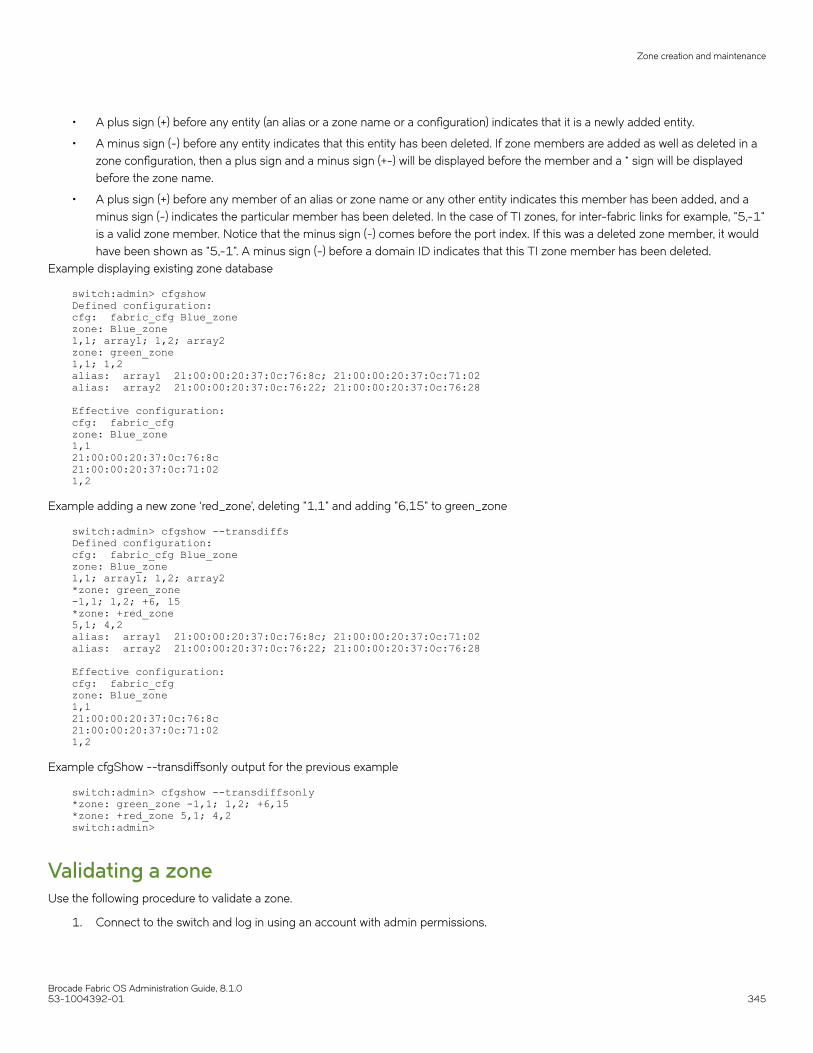
• A plus sign (+) before any entity (an alias or a zone name or a configuration) indicates that it is a newly added entity.
• A minus sign (-) before any entity indicates that this entity has been deleted. If zone members are added as well as deleted in azone configuration, then a plus sign and a minus sign (+-) will be displayed before the member and a * sign will be displayedbefore the zone name.
• A plus sign (+) before any member of an alias or zone name or any other entity indicates this member has been added, and aminus sign (-) indicates the particular member has been deleted. In the case of TI zones, for inter-fabric links for example, "5,-1"is a valid zone member. Notice that the minus sign (-) comes before the port index. If this was a deleted zone member, it wouldhave been shown as "5,-1". A minus sign (-) before a domain ID indicates that this TI zone member has been deleted.
Example displaying existing zone database
switch:admin> cfgshow Defined configuration:cfg: fabric_cfg Blue_zonezone: Blue_zone1,1; array1; 1,2; array2zone: green_zone1,1; 1,2alias: array1 21:00:00:20:37:0c:76:8c; 21:00:00:20:37:0c:71:02alias: array2 21:00:00:20:37:0c:76:22; 21:00:00:20:37:0c:76:28
Effective configuration:cfg: fabric_cfgzone: Blue_zone1,121:00:00:20:37:0c:76:8c21:00:00:20:37:0c:71:021,2
Example adding a new zone ‘red_zone’, deleting "1,1" and adding "6,15" to green_zone
switch:admin> cfgshow --transdiffs Defined configuration:cfg: fabric_cfg Blue_zonezone: Blue_zone1,1; array1; 1,2; array2*zone: green_zone-1,1; 1,2; +6, 15*zone: +red_zone5,1; 4,2alias: array1 21:00:00:20:37:0c:76:8c; 21:00:00:20:37:0c:71:02alias: array2 21:00:00:20:37:0c:76:22; 21:00:00:20:37:0c:76:28
Effective configuration:cfg: fabric_cfgzone: Blue_zone1,121:00:00:20:37:0c:76:8c21:00:00:20:37:0c:71:021,2
Example cfgShow --transdiffsonly output for the previous example
switch:admin> cfgshow --transdiffsonly *zone: green_zone -1,1; 1,2; +6,15 *zone: +red_zone 5,1; 4,2 switch:admin>
Validating a zoneUse the following procedure to validate a zone.
1. Connect to the switch and log in using an account with admin permissions.
Zone creation and maintenance
Brocade Fabric OS Administration Guide, 8.1.053-1004392-01 345

2. Enter the cfgShow command to view the zone configuration objects you want to validate.
switch:admin> cfgShow Defined configuration:cfg: USA_cfg Purple_zone; White_zone; Blue_zonezone: Blue_zone1,1; array1; 1,2; array2
zone: Purple_zone1,0; loop1
zone: White_zone
1,3; 1,4
alias: array1 21:00:00:20:37:0c:76:8c; 21:00:00:20:37:0c:71:02alias: array2 21:00:00:20:37:0c:76:22; 21:00:00:20:37:0c:76:28alias: loop1 21:00:00:20:37:0c:76:85; 21:00:00:20:37:0c:71:df
3. Enter the zone --validate command to list all zone members that are not part of the current zone enforcement table. Note thatzone configuration names are case-sensitive; blank spaces are ignored.
switch:admin> zone --validate "White_zone"
Zone creation and maintenance
Brocade Fabric OS Administration Guide, 8.1.0346 53-1004392-01

4. Enter the following command to validate all zones in the zone database in the defined configuration.
switch:admin> zone --validate -m 1 Defined configuration: cfg: cfg1 zone1 cfg: cfg2 zone1; zone2 zone: zone1 1,1; ali1 zone: zone2 1,1; ali2 alias: ali1 10:00:00:05:1e:35:81:7f*; 10:00:00:05:1e:35:81:7d* alias: ali2 10:00:00:05:1e:35:81:09*; 10:00:00:05:1e:35:81:88*------------------------------------~ - Invalid configuration* - Member does not exist
The mode flag -m can be used to specify the zone database location. Supported mode flag values are:
• 0 - Zone database from the current transaction buffer
• 1 - Zone database stored from the persistent storage
• 2 - Currently effective zone database.
If no mode options are given, the validated output of all three buffers is shown.
If the -f option is specified, all the zone members that are not enforceable would be expunged in the transaction buffer. Thispruning operation always happens on the transaction and defined buffers. You cannot specify a mode option or specify a zoneobject as an argument with the -f option. This mode flag should be used after the zone has been validated.
If the -i option is specified, all zone members for a given pattern are listed without case distinction
Example validating the zone members beginning with gre, regardless of the case
switch:admin> zone --validate -i gre*Defined configuration: zone: GREEN 44, 4; 21:00:00:20:37:0c:71:02; 8,9 zone: green 2,2*; 2,3*; 21:00:00:20:37:0c:76:8c* Effective configuration: zone: green 2,2* 2,3* 21:00:00:20:37:0c:76:8c*------------------------------------~ - Invalid configuration* - Member does not exist# - Invalid usage of broadcast zone
Inconsistencies between the defined and effective configurationsIf you edit zone objects in the defined configuration that also exist in the effective configuration and then issue the cfgSave command, awarning message stating that a mismatch is observed between the defined and effective configurations is posted, and you are asked toconfirm that you want cfgSave to continue. If you enter "y", then the updated configuration will be saved; if you enter "n", then the updatedconfiguration will be discarded.
Zone creation and maintenance
Brocade Fabric OS Administration Guide, 8.1.053-1004392-01 347

Example of warning message
switch: admin> cfgsave WARNING!!! The changes you are attempting to save will render theEffective configuration and the Defined configuration inconsistent. The inconsistency will result in different Effective Zoning configurations for switches in the fabric if a zone merge or HA failover happens. To avoid inconsistency it is recommended to commit the configurations using the 'cfgenable' command.Do you want to proceed with saving the Definedzoning configuration only? (yes, y, no, n): [no] yes
If you enter yes, and the cfgSave operation completes successfully, then the following RASlog message [ZONE-1062] will be posted. .
[ZONE-1062], 620/181, FID 128, WARNING, sw0, Defined and Effective zone configurations are inconsistent, ltime:2012/09/03-23:18:30:983609
You can then either re-enable the updated configuration or revert to the older configuration. If there is no impact to the effectiveconfiguration with the latest update to the defined configuration, then the following message will be displayed.
You are about to save the Defined zoning configuration. Thisaction will only save the changes on Defined configuration.If the update includes changes to one or more traffic isolationzones, you must issue the 'cfgenable' command for the changesto take effect.Do you want to save the Defined zoning configuration only? (yes, y, no, n): [no]
Example of Inconsistent defined and effective configuration warning to use
switch: admin> zoneShow Defined configuration:cfg: cfg1 zone1; zone2zone: zone1 10:00:00:00:00:00:00:01; 10:00:00:00:00:00:00:02zone: zone2 1,1; 1,2
Effective configuration:cfg: cfg1zone: zone1 10:00:00:00:00:00:00:01 10:00:00:00:00:00:00:02zone: zone2 1,1; 1,2
switch: admin> zoneadd zone1, 10:00:00:00:00:00:00:03 switch: admin> cfgsave WARNING!!!The changes you are attempting to save will render theEffective configuration and the Defined configuration inconsistent. The inconsistency will result in different Effective Zoning configurations for switches in the fabric if a zone merge or HA failover happens. To avoid inconsistency it is recommended to commit the configurations using the 'cfgenable' command.Do you want to proceed with saving the Defined zoning configuration only? (yes, y, no, n): [no] y Updating flash ...
switch:admin> zoneShow Defined configuration:cfg: cfg1 zone1; zone2zone: zone1 10:00:00:00:00:00:00:01; 10:00:00:00:00:00:00:02; 10:00:00:00:00:00:00:03zone: zone2 1,1; 1,2
Effective configuration:cfg: cfg1zone: zone1 10:00:00:00:00:00:00:01; 10:00:00:00:00:00:00:02zone: zone2 1,1; 1,2
Zone creation and maintenance
Brocade Fabric OS Administration Guide, 8.1.0348 53-1004392-01

Default zoning modeThe default zoning mode controls device access if zoning is not implemented or if there is no effective zone configuration. The defaultzoning mode has two options:
• All Access -- All devices within the fabric can communicate with all other devices.
• No Access -- Devices in the fabric cannot access any other device in the fabric.
The default zone mode applies to the entire fabric, regardless of switch model.
The default setting is "All Access".
Typically, when you disable the zoning configuration in a large fabric with thousands of devices, the name server indicates to all hosts thatthey can communicate with each other. Each host can receive an enormous list of PIDs, and ultimately cause other hosts to run out ofmemory or crash. To ensure that all devices in a fabric do not see each other during a configuration disable operation, set the defaultzoning mode to No Access.
NOTEFor switches in large fabrics, the default zone mode should be set to No Access. You cannot disable the effective configurationif the default zone mode is All Access and you have more than 120 devices in the fabric.
Setting the default zoning modeNOTEYou should not change the default zone mode from "No Access" to "All Access" if there is no effective zone configuration andmore than 120 devices are connected to the fabric.
Use the following procedure to set the default zoning mode.
1. Connect to the switch and log in using an account with admin permissions.
2. Enter the cfgActvShow command to view the current zone configuration.
3. Enter the defZone command with one of the following options:
defzone --noaccess
or
defzone --allaccess
This command initiates a transaction (if one is not already in progress).
Default zoning mode
Brocade Fabric OS Administration Guide, 8.1.053-1004392-01 349

4. Enter the cfgSave , cfgEnable , or cfgDisable command to commit the change and distribute it to the fabric. The change willnot be committed and distributed across the fabric if you do not enter one of these commands.
switch:admin> defzone --noaccess You are about to set the Default Zone access mode to No AccessDo you want to set the Default Zone access mode to No Access ? (yes, y, no, n): [no] y switch:admin> cfgsave WARNING!!!The changes you are attempting to save will render the Effective configuration and the Defined configuration inconsistent. The inconsistency will result in different Effective Zoning configurations for switches in the fabric if a zone merge or HA failover happens. To avoid inconsistency it is recommended to commit the configurations using the 'cfgenable' command.Do you still want to proceed with saving the Definedzoning configuration only? (yes, y, no, n): [no] y Updating flash ...
Viewing the current default zone access modeUse the following procedure to view the current default zone access mode.
1. Connect to the switch and log in using an account with admin permissions.
2. Enter the defZone --show command.
NOTEIf you perform a firmware download of an older release, then the current default zone access state will appear as it didprior to the download. For example, if the default zoning mode was No Access before the download, it will remain asNo Access afterward.
Zone database sizeThe maximum size of a zone database is the upper limit for the defined configuration, and it is determined by the amount of flashmemory available for storing the defined configuration.
To display the zone database size, enter cfgsize.
The supported maximum zone database size is 2 MB for a fabric with Brocade DCX 8510 Backbones and X6 Directors. The presenceof any other platform reduces the maximum zone database size to 1 MB. The configuration download and firmware upgrade is blockedwhen the zone DB size exceeds the allowed size for the fabric in both VF and non-VF modes.
Zone merging considerations: Whenever a new zone configuration is merged or pushed to a switch, the total size of the zoneconfiguration in all the partitions of the local and remote domains is recalculated and restricted if the size exceeds the allowed size.
When a conflict occurs during a zone merge, the output from using the switchshow command shows the reason for segmentation, whichcould be either of the following:
• The merge failed due to fabric limits, resulting in the following output:
70 9 6 014640 id N16 Online FC E-Port segmented,10:00:00:27:f8:f0:3a:75 (Fabric Zone DB Size Exceeded)
Zone database size
Brocade Fabric OS Administration Guide, 8.1.0350 53-1004392-01

• The merge failed due to chassis limits, resulting in the following output:
71 9 7 02ee00 id N16 Online FC E-Port segmented,10:00:00:27:f8:f0:3a:66 (Chassis Zone DB Size Exceeded)
HA out-of-sync considerations: Consider the following HA out-of-sync scenarios:
• When the active CP is running 8.0.1 or earlier and the standby CP is running 8.1.0 or later and HA is in sync, if you increase thezone database size of the active CP, the standby CP fails to update and the transaction is aborted with a RASLog message andthe CPs will go out of sync.
2016/07/08-04:19:58, [ZONE-1028], 201, SLOT 2 FID 8, WARNING, switch_8, Commit zone DB larger than supported - 2025005 greater than 63614.
• When there is no standby CP and the active CP is running Fabric OS 8.0.1 or earlier with the zone database size greater thanthe maximum supported size, for example, 4 MB ( 2 MB in LS10 and 2 MB in LS20), if you insert a new standby CP withFabric OS 8.1.0, the standby CP will be updated with 2 MB on LS10. The zoning transaction on LS20 will be aborted with thefollowing RASLog message. HA will be in sync.
2016/07/08-04:19:58, [ZONE-1028], 201, SLOT 2 FID 8, WARNING, switch_8, Commit zone DB larger than supported - 2025005 greater than 63614.
To recover, after StdbySyncDumpCompleteTimeOut ( approximately 15mins), reduce the zone database size in the active CPand reboot the standby CP to bring the HA in sync.
Virtual Fabrics considerations: If Virtual Fabrics is enabled, the sum of the zone database sizes on all of the logical fabrics must notexceed the maximum size allowed for the chassis. The maximum size limit is enforced per-partition and chassis-wide. The chassis-widerestriction is displayed in the output as well.
switch:admin> cfgsize Chassis-Wide Committed Zone DB size - 1086 bytes Zone DB max size - 2092741 bytesAvailable Zone DB size - 2091655 bytes committed - 74 transaction - 0
NOTEThough Fabric OS does not impose any restriction on the number of members you can have in a zone, it is not advisable tohave more than 255 members. Exceeding this limit could lead to unpredictable behavior.
ATTENTIONIn a fabric that has a mix of switches running versions of Fabric OS both earlier and later than version 7.0.0, if you run thecfgsave or cfgenable commands from a switch running a pre-7.0.0 version of Fabric OS, a zone database size of 128 KBmight be enforced. Whether this occurs depends on the specific version of pre-Fabric OS 7.0.0 firmware the switches areusing. For a detailed list of pre-Fabric OS 7.0.0 firmware compatibility versions, refer to the Zoning Compatibility Note in theRelease Notes.
Zone configurationsYou can store a number of zones in a zone configuration database. The maximum number of items that can be stored in the zoneconfiguration database depends on the following criteria:
• Number of switches in the fabric.
• Number of bytes for each item name. The number of bytes required for an item name depends on the specifics of the fabric,but cannot exceed 64 bytes for each item.
Zone configurations
Brocade Fabric OS Administration Guide, 8.1.053-1004392-01 351

When enabling a new zone configuration, ensure that the size of the defined configuration does not exceed the maximum configurationsize supported by all switches in the fabric. This is particularly important if you downgrade to a Fabric OS version that supports a smallerzone database than the current Fabric OS. In this scenario, the zone database in the current Fabric OS would have to be changed to thesmaller zone database before the downgrade.
You can use the cfgSize command to check both the maximum available size and the currently saved size on all switches. If you thinkyou are approaching the maximum, you can save a partially completed zone configuration and use the cfgSize command to determinethe remaining space. The cfgSize command reports the maximum available size on the current switch only. It cannot determine themaximum available size on other switches in the fabric.
NOTEThe minimum zone database size is 4 bytes, even if the zone database is empty.
For important considerations for managing zoning in a fabric, and more details about the maximum zone database size for each versionof the Fabric OS, refer to Zone database size on page 350.
If you create or make changes to a zone configuration, you must enable the configuration for the changes to take effect.
Creating a zone configurationUse the following procedure to create a zone configuration.
1. Connect to the switch and log in using an account with admin permissions.
2. Enter the cfgCreate command, using the following syntax:
cfgcreate "cfgname ", "member [; member ...]"
3. Enter the cfgSave command to save the change to the defined configuration.
The cfgSave command ends and commits the current zoning transaction buffer to nonvolatile memory. If a transaction is openon a different switch in the fabric when this command is run, the transaction on the other switch is automatically aborted. Amessage displays on the other switches to indicate that the transaction was aborted.
switch:admin> cfgcreate "NEW_cfg", "purplezone; bluezone; greenzone" switch:admin> cfgsave WARNING!!!The changes you are attempting to save will render the Effective configuration and the Defined configuration inconsistent. The inconsistency will result in different Effective Zoning configurations for switches in the fabric if a zone merge or HA failover happens. To avoid inconsistency it is recommended to commit the configurations using the 'cfgenable' command.Do you still want to proceed with saving the Defined zoning configuration only? (yes, y, no, n): [no] y
Adding zones to a zone configurationUse the following procedure to add members to a zone configuration.
1. Connect to the switch and log in using an account with admin permissions.
2. Enter the cfgAdd command, using the following syntax:
cfgadd "cfgname ", "member [; member ...]"
Zone configurations
Brocade Fabric OS Administration Guide, 8.1.0352 53-1004392-01

3. Enter the cfgSave command to save the change to the defined configuration.
The cfgSave command ends and commits the current zoning transaction buffer to nonvolatile memory. If a transaction is openon a different switch in the fabric when this command is run, the transaction on the other switch is automatically aborted. Amessage displays on the other switches to indicate that the transaction was aborted.
switch:admin> cfgadd "newcfg", "bluezone" switch:admin> cfgsave WARNING!!!The changes you are attempting to save will render the Effective configuration and the Defined configuration inconsistent. The inconsistency will result in different Effective Zoning configurations for switches in the fabric if a zone merge or HA failover happens. To avoid inconsistency it is recommended to commit the configurations using the 'cfgenable' command.Do you still want to proceed with saving the Defined zoning configuration only? (yes, y, no, n): [no] y
Removing members from a zone configurationUse the following procedure to remove members from a zone configuration.
1. Connect to the switch and log in using an account with admin permissions.
2. Enter the cfgRemove command, using the following syntax:
cfgremove "cfgname ", "member [; member ...]"
3. Enter the cfgSave command to save the change to the defined configuration.
The cfgSave command ends and commits the current zoning transaction buffer to nonvolatile memory. If a transaction is openon a different switch in the fabric when this command is run, the transaction on the other switch is automatically aborted. Amessage displays on the other switches to indicate that the transaction was aborted.Example
switch:admin> cfgremove "NEW_cfg", "purplezone" switch:admin> cfgsave WARNING!!!The changes you are attempting to save will render the Effective configuration and the Defined configuration inconsistent. The inconsistency will result in different Effective Zoning configurations for switches in the fabric if a zone merge or HA failover happens. To avoid inconsistency it is recommended to commit the configurations using the 'cfgenable' command.Do you still want to proceed with saving the Defined zoning configuration only? (yes, y, no, n): [no] y
Enabling a zone configurationThe following procedure ends and commits the current zoning transaction buffer to nonvolatile memory. If a transaction is open on adifferent switch in the fabric when this procedure is run, the transaction on the other switch is automatically aborted. A message displayson the other switches to indicate that the transaction was aborted.
Use the following procedure to enable a zone configuration.
1. Connect to the switch and log in using an account with admin permissions.
Zone configurations
Brocade Fabric OS Administration Guide, 8.1.053-1004392-01 353
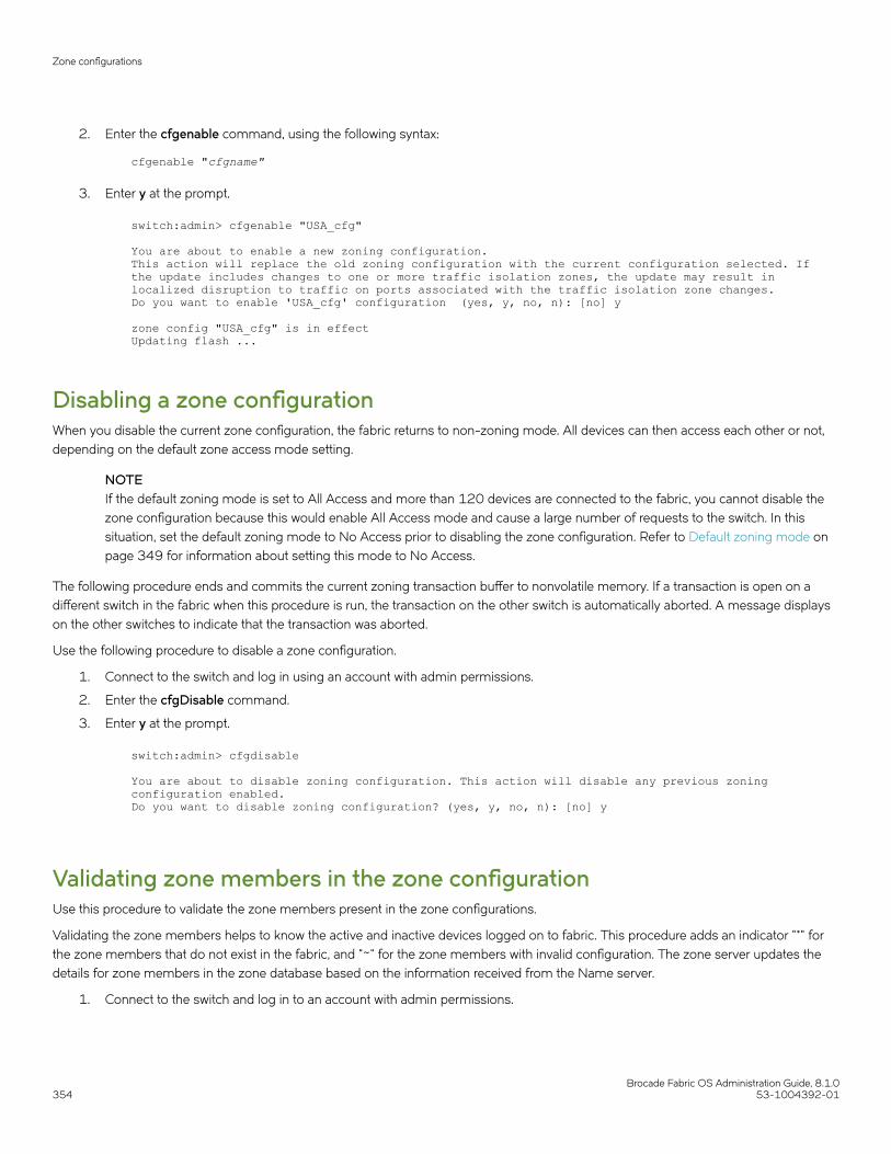
2. Enter the cfgenable command, using the following syntax:
cfgenable "cfgname"
3. Enter y at the prompt.
switch:admin> cfgenable "USA_cfg" You are about to enable a new zoning configuration.This action will replace the old zoning configuration with the current configuration selected. If the update includes changes to one or more traffic isolation zones, the update may result in localized disruption to traffic on ports associated with the traffic isolation zone changes.Do you want to enable 'USA_cfg' configuration (yes, y, no, n): [no] y zone config "USA_cfg" is in effectUpdating flash ...
Disabling a zone configurationWhen you disable the current zone configuration, the fabric returns to non-zoning mode. All devices can then access each other or not,depending on the default zone access mode setting.
NOTEIf the default zoning mode is set to All Access and more than 120 devices are connected to the fabric, you cannot disable thezone configuration because this would enable All Access mode and cause a large number of requests to the switch. In thissituation, set the default zoning mode to No Access prior to disabling the zone configuration. Refer to Default zoning mode onpage 349 for information about setting this mode to No Access.
The following procedure ends and commits the current zoning transaction buffer to nonvolatile memory. If a transaction is open on adifferent switch in the fabric when this procedure is run, the transaction on the other switch is automatically aborted. A message displayson the other switches to indicate that the transaction was aborted.
Use the following procedure to disable a zone configuration.
1. Connect to the switch and log in using an account with admin permissions.
2. Enter the cfgDisable command.
3. Enter y at the prompt.
switch:admin> cfgdisable You are about to disable zoning configuration. This action will disable any previous zoning configuration enabled.Do you want to disable zoning configuration? (yes, y, no, n): [no] y
Validating zone members in the zone configurationUse this procedure to validate the zone members present in the zone configurations.
Validating the zone members helps to know the active and inactive devices logged on to fabric. This procedure adds an indicator "*" forthe zone members that do not exist in the fabric, and "~" for the zone members with invalid configuration. The zone server updates thedetails for zone members in the zone database based on the information received from the Name server.
1. Connect to the switch and log in to an account with admin permissions.
Zone configurations
Brocade Fabric OS Administration Guide, 8.1.0354 53-1004392-01
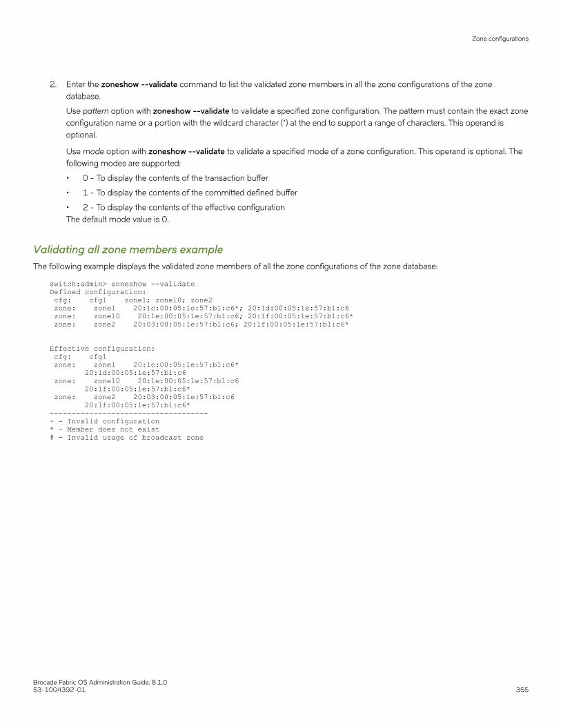
2. Enter the zoneshow --validate command to list the validated zone members in all the zone configurations of the zonedatabase.
Use pattern option with zoneshow --validate to validate a specified zone configuration. The pattern must contain the exact zoneconfiguration name or a portion with the wildcard character (*) at the end to support a range of characters. This operand isoptional.
Use mode option with zoneshow --validate to validate a specified mode of a zone configuration. This operand is optional. Thefollowing modes are supported:
• 0 - To display the contents of the transaction buffer
• 1 - To display the contents of the committed defined buffer
• 2 - To display the contents of the effective configurationThe default mode value is 0.
Validating all zone members exampleThe following example displays the validated zone members of all the zone configurations of the zone database:
switch:admin> zoneshow --validateDefined configuration: cfg: cfg1 zone1; zone10; zone2 zone: zone1 20:1c:00:05:1e:57:b1:c6*; 20:1d:00:05:1e:57:b1:c6 zone: zone10 20:1e:00:05:1e:57:b1:c6; 20:1f:00:05:1e:57:b1:c6* zone: zone2 20:03:00:05:1e:57:b1:c6; 20:1f:00:05:1e:57:b1:c6*
Effective configuration: cfg: cfg1 zone: zone1 20:1c:00:05:1e:57:b1:c6* 20:1d:00:05:1e:57:b1:c6 zone: zone10 20:1e:00:05:1e:57:b1:c6 20:1f:00:05:1e:57:b1:c6* zone: zone2 20:03:00:05:1e:57:b1:c6 20:1f:00:05:1e:57:b1:c6*------------------------------------~ - Invalid configuration* - Member does not exist# - Invalid usage of broadcast zone
Zone configurations
Brocade Fabric OS Administration Guide, 8.1.053-1004392-01 355

Validating zone members with a zone name exampleThe following example displays the validated zone members that contain a specified or a part of the zone name:
switch:admin> zoneshow --validate zone1Defined configuration: zone: zone1 20:1c:00:05:1e:57:b1:c6*; 20:1d:00:05:1e:57:b1:c6
Effective configuration: zone: zone1 20:1c:00:05:1e:57:b1:c6* 20:1d:00:05:1e:57:b1:c6------------------------------------~ - Invalid configuration* - Member does not exist# - Invalid usage of broadcast zone
switch:admin> zoneshow --validate zone*Defined configuration: zone: zone1 20:1c:00:05:1e:57:b1:c6*; 20:1d:00:05:1e:57:b1:c6 zone: zone10 20:1e:00:05:1e:57:b1:c6; 20:1f:00:05:1e:57:b1:c6* zone: zone2 20:03:00:05:1e:57:b1:c6; 20:1f:00:05:1e:57:b1:c6* zone: zone200 20:1d:00:05:1e:57:b1:c6; 20:1f:00:05:1e:57:b1:c6*
Effective configuration: zone: zone1 20:1c:00:05:1e:57:b1:c6* 20:1d:00:05:1e:57:b1:c6 zone: zone10 20:1e:00:05:1e:57:b1:c6 20:1f:00:05:1e:57:b1:c6* zone: zone2 20:03:00:05:1e:57:b1:c6 20:1f:00:05:1e:57:b1:c6*------------------------------------~ - Invalid configuration* - Member does not exist# - Invalid usage of broadcast zone
Validating zone members with modeThe following example displays the validated zone members for a specified mode of a zone configuration
switch:admin> zoneshow --validate zone200, 0Defined configuration: zone: zone200 20:1d:00:05:1e:57:b1:c6; 20:1f:00:05:1e:57:b1:c6*------------------------------------~ - Invalid configuration* - Member does not exist# - Invalid usage of broadcast zone
Deleting a zone configurationUse the following procedure to delete a zone configuration.
1. Connect to the switch and log in using an account with admin permissions.
2. Enter the cfgDelete command, using the following syntax:
cfgdelete "cfgname"
Zone configurations
Brocade Fabric OS Administration Guide, 8.1.0356 53-1004392-01

3. Enter the cfgSave command to save the change to the defined configuration.
The cfgSave command ends and commits the current zoning transaction buffer to nonvolatile memory. If a transaction is openon a different switch in the fabric when this command is run, the transaction on the other switch is automatically aborted. Amessage displays on the other switches to indicate that the transaction was aborted.
switch:admin> cfgdelete "testcfg" switch:admin> cfgsave You are about to save the Defined zoning configuration. Thisaction will only save the changes on Defined configuration.If the update includes changes to one or more traffic isolationzones, you must issue the 'cfgenable' command for the changesto take effect.Do you want to save the Defined zoning configuration only? (yes, y, no, n): [no]
Deleting invalid zonesInvalid zones can be created by a number of events, including firmware upgrades and downgrades.
Use the following steps to remove an invalid zone.
1. Log into the switch using an account with administrator privileges.
2. Enter cfgremove "zone_configuration" to remove the invalid zone from the zone configuration.
3. Enter zonedelete invalid_zone to delete the invalid zone from the fabric.
4. Enter cfgsave to save the changed configuration.
5. Enter cfgenable "zone_configuration" to re-enable the zone configuration.
The following example removes the invalid zone “dead_zone” from the “baseline” configuration, deletes the zone, then saves theconfiguration and reenables it.
switch:admin> cfgremove "baseline" "dead_zone"switch:admin> zonedelete dead_zoneswitch:admin> cfgsave switch:admin> cfgenable "baseline"
For detailed information on the zoning commands used in the procedures, refer to the Brocade Fabric OS Command Reference.
Abandoning zone configuration changesTo abandon zone configuration changes, enter the cfgTransAbort command.
When this command is executed, all changes since the last save operation (performed with the cfgSave , cfgEnable , or cfgDisablecommand) are cleared.
Example of assuming that the removal of a member from zone1 was done in error
switch:admin> zoneremove "zone1","3,5" switch:admin> cfgtransabort
Zone configurations
Brocade Fabric OS Administration Guide, 8.1.053-1004392-01 357

Viewing all zone configuration informationIf you do not specify an operand when executing the cfgShow command to view zone configurations, then all zone configurationinformation (both defined and effective) displays. If there is an outstanding transaction, then the newly edited zone configuration that hasnot yet been saved is displayed. If there are no outstanding transactions, then the committed zone configuration displays.
Use the following procedure to view all zone configuration information.
1. Connect to the switch and log in using an account with admin permissions.
2. Enter the cfgShow command with no operands.Example
switch:admin> cfgshow Defined configuration:cfg: USA1 Blue_zonecfg: USA_cfg Purple_zone; Blue_zonezone: Blue_zone 1,1; array1; 1,2; array2zone: Purple_zone 1,0; loop1alias: array1 21:00:00:20:37:0c:76:8c; 21:00:00:20:37:0c:71:02alias: array2 21:00:00:20:37:0c:76:22; 21:00:00:20:37:0c:76:28alias: loop1 21:00:00:20:37:0c:76:85; 21:00:00:20:37:0c:71:df
Effective configuration:cfg: USA_cfgzone: Blue_zone 1,1 21:00:00:20:37:0c:76:8c 21:00:00:20:37:0c:71:02 1,2 21:00:00:20:37:0c:76:22 21:00:00:20:37:0c:76:28zone: Purple_zone 1,0 21:00:00:20:37:0c:76:85 21:00:00:20:37:0c:71:df
Viewing selected zone configuration informationUse the following procedure to view the selected zone configuration information.
1. Connect to the switch and log in using an account with admin permissions.
2. Enter the cfgShow command and specify a pattern.
cfgshow [--ic][,"pattern"] [, mode]
Example displaying all zone configurations that start with "Test"
switch:admin> cfgshow "Test*" cfg: Test1 Blue_zonecfg: Test_cfg Purple_zone; Blue_zone
Example displaying all zone configurations that start with "Test", regardless of the case
switch:admin> cfgshow --ic "Test*" cfg: Test1 Blue_zonecfg: Test_2 Red zone; Blue_zone
Zone configurations
Brocade Fabric OS Administration Guide, 8.1.0358 53-1004392-01

Viewing the zone aliases in the zone configurationThe following procedure lists the zone aliases, including the user-defined aliases, in the zone configuration.
1. Log in to the switch.
Zone configurations
Brocade Fabric OS Administration Guide, 8.1.053-1004392-01 359

2. View the zone aliases using the zoneshow --alias [-ic] [pattern] command.
The zoneshow --alias command displays all the zones containing aliases matching the pattern. You can use POSIX styleregular expression for the alias pattern. The pattern can contain the following:
• A question mark (?) to match any single character.
• An asterisk (*) to match any string of characters.
• A range of characters to match any character within the range: for example, [0-9] or [a-f].
The following example demonstrates using the command to display all the zones containing the alias specified when thecomplete pattern is specified in the command (case sensitive).
switch:admin> zoneshow --alias ali1Defined configuration: zone: zone1 ali1 zone: zone3 2,2; ali1
The following examples demonstrate using the command to display all the zones containing the aliases matching the POSIX-style regular expression specified in each pattern (case sensitive).
switch:admin> zoneshow --alias ali1*Defined configuration: zone: zone1 ali1 zone: zone3 2,2; ali1 zone: zone4 21,22; ali12
switch:admin> zoneshow --alias "a*" zone: Zone3 ald1 zone: aliii aldds zone: h1 al; Ali1; dev3 zone: zone1 ali1 zone: zone4 dev2; aldds
switch:admin> zoneshow --alias "*a*" zone: Zone3 ald1 zone: aliii aldds zone: h1 al; Ali1; dev3 zone: zone1 ali1 zone: zone4 dev2; aldds
switch:admin> zoneshow --alias "*1*" zone: Zone3 ald1 zone: h1 al; Ali1; dev3 zone: zone1 ali1 zone: zone2 Ali1
switch:admin> zoneshow --alias "?l?1" zone: Zone3 ald1 zone: h1 al; Ali1; dev3 zone: zone1 ali1 zone: zone2 Ali1
switch:admin> zoneshow --alias "al[id]1" zone: Zone3 ald1 zone: zone1 ali1
You can also display a list of zones containing the alias matching the pattern that you specify (not case sensitive).
switch:admin> zoneshowDefined configuration: cfg: cfg3 Zone2zone: Zone1 dev1; dev2zone: Zone2 dev2; DEV3
alias: DEV3 1,8alias: dev1 1,2alias: dev2 1,1
Zone configurations
Brocade Fabric OS Administration Guide, 8.1.0360 53-1004392-01

Effective configuration:cfg: cfg3zone: Zone2 1,1 1,8switch:admin> zoneshow --alias –ic dev3
zone: Zone2 dev2; DEV3
Viewing the configuration in the effective zone databaseUse the following procedure to view the configuration in the effective zone database.
1. Connect to the switch and log in using an account with admin permissions.
2. Enter the cfgActvShow command.
switch:admin> cfgactvshow Effective configuration: cfg: NEW_cfgzone: Blue_zone1,121:00:00:20:37:0c:76:8c21:00:00:20:37:0c:71:021,221:00:00:20:37:0c:76:2221:00:00:20:37:0c:76:28zone: Purple_zone1,021:00:00:20:37:0c:76:8521:00:00:20:37:0c:71:df
Clearing all zone configurationsUse the following procedure to clear all zone configurations.
1. Connect to the switch and log in using an account with admin permissions.
2. Enter the cfgClear command to clear all zone information in the transaction buffer.
ATTENTIONBe careful using the cfgClear command because it deletes the definedconfiguration.
switch:admin> cfgclear The Clear All action will clear all Aliases, Zones, FA Zones and configurations in the Defined configuration.Run cfgSave to commit the transaction or cfgTransAbort to cancel the transaction.Do you really want to clear all configurations? (yes, y, no, n): [no]
3. Enter one of the following commands, depending on whether an effective zone configuration exists:
• If no effective zone configuration exists, use the cfgSave command.
• If an effective zone configuration exists, use the cfgDisable command to disable and clear the zone configuration innonvolatile memory for all switches in the fabric.
Zone configurations
Brocade Fabric OS Administration Guide, 8.1.053-1004392-01 361
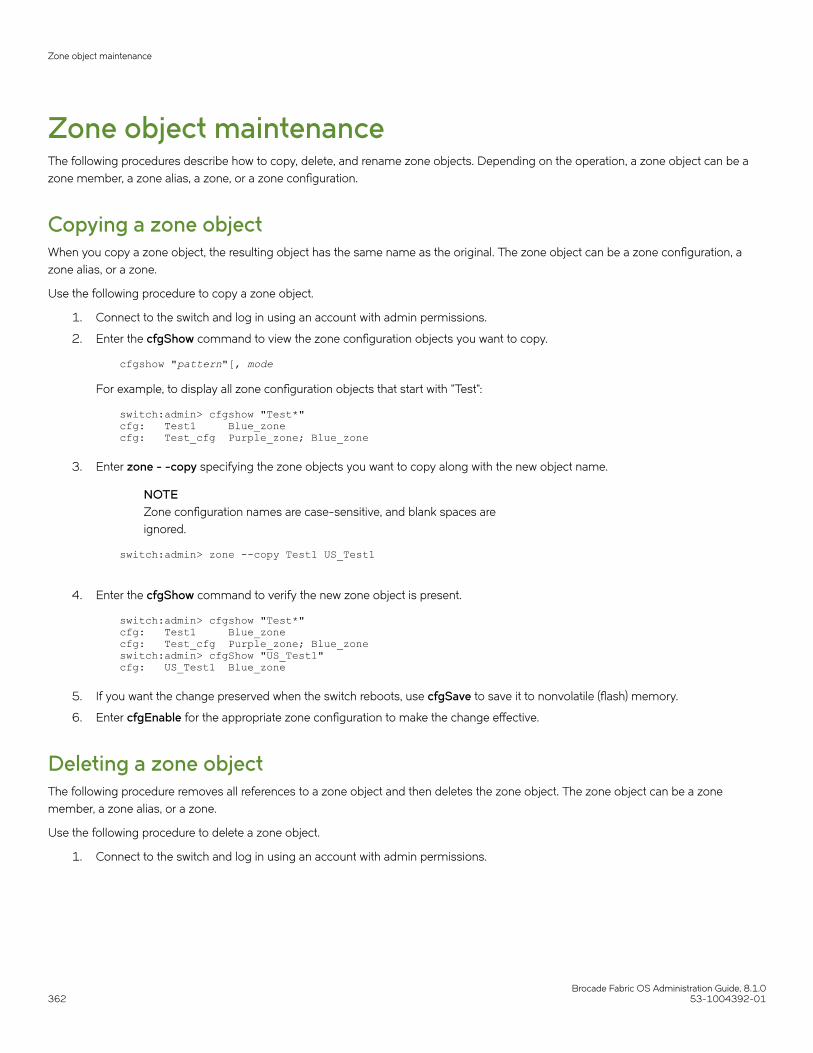
Zone object maintenanceThe following procedures describe how to copy, delete, and rename zone objects. Depending on the operation, a zone object can be azone member, a zone alias, a zone, or a zone configuration.
Copying a zone objectWhen you copy a zone object, the resulting object has the same name as the original. The zone object can be a zone configuration, azone alias, or a zone.
Use the following procedure to copy a zone object.
1. Connect to the switch and log in using an account with admin permissions.
2. Enter the cfgShow command to view the zone configuration objects you want to copy.
cfgshow "pattern"[, mode
For example, to display all zone configuration objects that start with "Test":
switch:admin> cfgshow "Test*"cfg: Test1 Blue_zonecfg: Test_cfg Purple_zone; Blue_zone
3. Enter zone - -copy specifying the zone objects you want to copy along with the new object name.
NOTEZone configuration names are case-sensitive, and blank spaces areignored.
switch:admin> zone --copy Test1 US_Test1
4. Enter the cfgShow command to verify the new zone object is present.
switch:admin> cfgshow "Test*" cfg: Test1 Blue_zonecfg: Test_cfg Purple_zone; Blue_zoneswitch:admin> cfgShow "US_Test1" cfg: US_Test1 Blue_zone
5. If you want the change preserved when the switch reboots, use cfgSave to save it to nonvolatile (flash) memory.
6. Enter cfgEnable for the appropriate zone configuration to make the change effective.
Deleting a zone objectThe following procedure removes all references to a zone object and then deletes the zone object. The zone object can be a zonemember, a zone alias, or a zone.
Use the following procedure to delete a zone object.
1. Connect to the switch and log in using an account with admin permissions.
Zone object maintenance
Brocade Fabric OS Administration Guide, 8.1.0362 53-1004392-01

2. Enter the cfgShow command to view the zone configuration objects you want to delete.
switch:admin> cfgShowDefined configuration: cfg: USA_cfg Purple_zone; White_zone; Blue_zone zone: Blue_zone 1,1; array1; 1,2; array2 zone: Purple_zone 1,0; loop1 zone: White_zone 1,3; 1,4 alias: array1 21:00:00:20:37:0c:76:8c; 21:00:00:20:37:0c:71:02 alias: array2 21:00:00:20:37:0c:76:22; 21:00:00:20:37:0c:76:28 alias: loop1 21:00:00:20:37:0c:76:85; 21:00:00:20:37:0c:71:df Effective configuration: cfg: USA_cfg zone: Blue_zone 1,1 21:00:00:20:37:0c:76:8c 21:00:00:20:37:0c:71:02 1,2 21:00:00:20:37:0c:76:22 21:00:00:20:37:0c:76:28 zone: Purple_zone 1,0 21:00:00:20:37:0c:76:85 21:00:00:20:37:0c:71:df
3. Enter zone --expunge to delete the zone object.
NOTEZone configuration names are case-sensitive and blank spaces areignored.
switch:admin> zone --expunge "White_zone"You are about to expunge one configuration or member. This action could result in removing many zoning configurations recursively. [Removing the last member of a configuration removes the configuration.] Do you want to expunge the member? (yes, y, no, n): [no] yes
4. Enter yes at the prompt.
5. Enter cfgShow to verify the deleted zone object is no longer present.
6. If you want the change preserved when the switch reboots, use cfgSave to save it to nonvolatile (flash) memory.
7. Enter cfgEnable for the appropriate zone configuration to make the change effective.
Renaming a zone objectUse the following procedure to rename a zone object.
1. Connect to the switch and log in using an account with admin permissions.
Zone object maintenance
Brocade Fabric OS Administration Guide, 8.1.053-1004392-01 363

2. Enter cfgShow to view the zone configuration objects you want to rename.
switch:admin> cfgShowDefined configuration: cfg: USA_cfg Purple_zone; White_zone; Blue_zone zone: Blue_zone 1,1; array1; 1,2; array2 zone: Purple_zone 1,0; loop1 zone: White_zone 1,3; 1,4alias: array1 21:00:00:20:37:0c:76:8c; 21:00:00:20:37:0c:71:02alias: array2 21:00:00:20:37:0c:76:22; 21:00:00:20:37:0c:76:28alias: loop1 21:00:00:20:37:0c:76:85; 21:00:00:20:37:0c:71:df
3. Enter zoneObjectRename to rename zone configuration objects.
NOTEZone configuration names are case-sensitive and blank spaces areignored.
switch:admin> zoneObjectRename "White_zone", "Purple_zone"
4. Enter the cfgShow command to verify the renamed zone object is present.
5. If you want the change preserved when the switch reboots, enter the cfgSave command to save it to nonvolatile (flash) memory.
NOTEIf the renamed zone object is still used in the effective configuration, running cfgSave before cfgEnable is notallowed.
6. Enter the cfgEnable command for the appropriate zone configuration to make the change effective.
Zone configuration managementYou can add, delete, or remove individual elements in an existing zone configuration to create an appropriate configuration for your SANenvironment. After the changes have been made, save the configuration to ensure the configuration is permanently saved in the switchand that the configuration is replicated throughout the fabric.
The switch configuration file can also be uploaded to the host for archiving and it can be downloaded from the host to a switch in thefabric. Refer to Configuration file backup on page 281, Configuration file restoration on page 282, or the configUpload andconfigDownload commands in the Brocade Fabric OS Command Reference for additional information on uploading and downloadingthe configuration file.
Security and zoningZones provide controlled access to fabric segments and establish barriers between operating environments. They isolate systems withdifferent uses, protecting individual systems in a heterogeneous environment; for example, when zoning is in secure mode, no mergeoperations occur.
Brocade Advanced Zoning is configured on the primary fabric configuration server (FCS). The primary FCS switch makes zoningchanges and other security-related changes. The primary FCS switch also distributes zoning to all other switches in the secure fabric. Allexisting interfaces can be used to administer zoning.
Zone configuration management
Brocade Fabric OS Administration Guide, 8.1.0364 53-1004392-01

You must perform zone management operations from the primary FCS switch using a zone management interface, such as Telnet orWeb Tools. You can alter a zone database, provided you are connected to the primary FCS switch.
When two secure fabrics join, the traditional zone merge does not occur. Instead, a zone database is downloaded from the primary FCSswitch of the merged secure fabric. When E_Ports are active between two switches, the name of the FCS server and a zoning policy setversion identifier are exchanged between the switches. If the views of the two secure fabrics are the same, the fabric’s primary FCS serverdownloads the zone database and security policy sets to each switch in the fabric. If there is a view conflict, the E_Ports are segmenteddue to incompatible security data.
All zones should use frame-based hardware enforcement; the best way to do this is to use WWN identification exclusively for all zoningconfigurations.
Zone mergingWhen a new switch is added to the fabric, it automatically takes on the zone configuration information from the fabric. You can verify thezone configuration on the switch using the procedure described in Viewing the configuration in the effective zone database on page 361.
If you are adding a switch that is already configured for zoning, clear the zone configuration on that switch before connecting it to thezoned fabric. Refer to Clearing all zone configurations on page 361 for instructions.
Adding a new fabric that has no zone configuration information to an existing fabric is very similar to adding a new switch. All switches inthe new fabric inherit the zone configuration data. If the existing fabric has an effective zone configuration, then the same configurationbecomes the effective configuration for the new switches.
Before the new fabric can merge successfully, it must pass the following criteria:
• Before merging - To facilitate merging, check the following before merging switches or fabrics:
– Defaultzone: The switches must adhere to the default zone merge rules, as described in Zone merging scenarios on page367.
– Effective and defined zone configuration match : Ensure that the effective and defined zone configurations match. If theydo not match, and you merge with another switch, the merge may be successful, but unpredictable zoning and routingbehavior can occur.
• Merging and segmentation
The fabric is checked for segmentation during power-up, when a switch is disabled or enabled, or when a new switch is added.
The zone configuration database is stored in nonvolatile memory by the cfgSave command. All switches in the fabric have a copy of thisdatabase. When a change is made to the defined configuration, the switch where the changes were made must close its transaction forthe changes to be propagated throughout the fabric.
If you have implemented default zoning, you must set the switch you are adding into the fabric to the same default zone mode setting asthe rest of the fabric to avoid segmentation.
• Merging rules - Observe these rules when merging zones:
– Local and adjacent configurations: If the local and adjacent zone database configurations are the same, they will remainunchanged after the merge.
– Effective configurations: If there is an effective configuration between two switches, the effective zone configurations mustmatch.
– Zone object naming: If a zoning object has the same name in both the local and adjacent defined configurations, the objecttypes and member lists must match. When comparing member lists, the content and order of the members are important.
– Objects in adjacent configurations: If a zoning object appears in an adjacent defined configuration, but not in the localdefined configuration, the zoning object is added to the local defined configuration. The modified zone database must fit inthe nonvolatile memory area allotted for the zone database.
Zone merging
Brocade Fabric OS Administration Guide, 8.1.053-1004392-01 365
– Local configuration modification: If a local defined configuration is modified because of a merge, the new zone database ispropagated to other the switches within the merge request.
– TI zones: If there is an effective configuration between two switches and TI zones are present on either switch, the TI zonesare not automatically activated after the merge. Check the TI zone enabled status using the zone --show command, and ifthe status does not match across switches, issue the cfgEnable command.
• Merging two fabrics
Both fabrics have identical zones and configurations enabled, including the default zone mode. The two fabrics will join to make onelarger fabric with the same zone configuration across the newly created fabric.
If the two fabrics have different zone configurations, they will not be merged. If the two fabrics cannot join, the ISL between the switcheswill segment.
• Merge conflicts
When a merge conflict is present, a merge will not take place and the ISL will segment. Use the switchShow or errDumpcommands to obtain additional information about possible merge conflicts, because many non-zone-related configurationparameters can cause conflicts. Refer to the Brocade Fabric OS Command Reference for detailed information about thesecommands.
If the fabrics have different zone configuration data, the system attempts to merge the two sets of zone configuration data. If thezones cannot merge, the ISL will be segmented.
A merge is not possible if any of the following conditions exist:
– Configuration mismatch: Zoning is enabled in both fabrics and the zone configurations that are enabled are different in eachfabric.
– Type mismatch: The name of a zone object in one fabric is used for a different type of zone object in the other fabric.– Content mismatch: The definition of a zone object in one fabric is different from the definition of the zone object with the
same name in the other fabric.– Zone database size: The zone database size exceeds the maximum limit of another switch.
NOTEIf the zone set members on two switches are not listed in the same order, the configuration is considered a mismatch, resultingin the switches being segmented from the fabric. For example, cfg1 = z1; z2 is different from cfg1 = z2; z1 , even
though members of the configuration are the same. If zone set members on two switches have the same names defined in theconfiguration, make sure zone set members are listed in the same order.
NOTEIn a large fabric, especially with 1 MB or more zone configuration takes some amount of time for zone merge. This may causehost device to not to discover the target in other end of the fabric for a short duration. This problem may not be seen if the youfollow the guidelines of joining the stable fabric one by one with devices offline and ensure that the zone merge operation iscompleted before enabling the devices.
Fabric segmentation and zoningIf the connections between two fabrics are no longer available, the fabric segments into two separate fabrics. Each new fabric retains thesame zone configuration.
If the connections between two fabrics are replaced and no changes have been made to the zone configuration in either of the twofabrics, then the two fabrics merge back into one single fabric. If any changes that cause a conflict have been made to either zoneconfiguration, then the fabrics may segment.
Zone merging
Brocade Fabric OS Administration Guide, 8.1.0366 53-1004392-01

Zone merging scenariosThe following tables provide information on merging zones and the expected results:
• Table 74: Defined and effective configurations
• Table 75: Different content
• Table 76: Different names
• Table 77: TI zones
• Table 78: Default access mode
• Table 82: Mixed Fabric OS versions
TABLE 74 Zone merging scenarios: Defined and effective configurations
Description Switch A Switch B Expected results
Switch A has a definedconfiguration.
Switch B does not have a definedconfiguration.
defined:cfg1: zone1: ali1;ali2effective: none
defined: none effective: none Configuration from Switch A topropagate throughout the fabric inan inactive state, because theconfiguration is not enabled.
Switch A has a defined andeffective configuration.
Switch B has a definedconfiguration but no effectiveconfiguration.
defined: cfg1zone1: ali1; ali2effective: cfg1:
defined: cfg1zone1: ali1; ali2effective: none
Configuration from Switch A topropagate throughout the fabric.The configuration is enabled afterthe merge in the fabric.
Switch A and Switch B have thesame defined configuration. Neitherhave an effective configuration.
defined: cfg1zone1: ali1; ali2effective: none
defined: cfg1zone1: ali1;ali2effective: none
No change (clean merge).
Switch A and Switch B have thesame defined and effectiveconfiguration.
defined: cfg1zone1: ali1;ali2effective: cfg1:
defined: cfg1zone1: ali1; ali2effective: cfg1:
No change (clean merge).
Switch A does not have a definedconfiguration.
Switch B has a definedconfiguration.
defined: noneeffective: none defined:cfg1zone1: ali1; ali2effective: none
Switch A will absorb theconfiguration from the fabric.
Switch A does not have a definedconfiguration.
Switch B has a definedconfiguration.
defined: noneeffective: none defined:cfg1zone1: ali1;ali2effective: cfg1
Switch A will absorb theconfiguration from the fabric, withcfg1 as the effective configuration.
Switch A and Switch B have thesame defined configuration. OnlySwitch B has an effectiveconfiguration.
defined: cfg1zone1: ali1;ali2effective: none
defined: cfg1zone1: ali1;ali2effective: cfg1
Clean merge, with cfg1 as theeffective configuration.
Switch A and Switch B havedifferent defined configurations.Neither have an enabled zoneconfiguration.
defined: cfg2zone2: ali3; ali4effective: none
defined: cfg1zone1: ali1;ali2effective: none
Clean merge. The newconfiguration will be a composite ofthe two.defined: cfg1 zone1: ali1;ali2 cfg2: zone2: ali3; ali4 effective:none
Switch A and Switch B havedifferent defined configurations.Switch B has an effectiveconfiguration.
defined: cfg2zone2: ali3;ali4effective: none
defined: cfg1zone1: ali1;ali2effective: cfg1
Clean merge. The newconfiguration will be a composite ofthe two, with cfg1 as the effectiveconfiguration.
Switch A does not have a definedconfiguration.
defined: none
effective: none
defined: cfg1
zone1: ali1; ali2
Clean merge. Switch A absorbs thedefined configuration from the
Zone merging
Brocade Fabric OS Administration Guide, 8.1.053-1004392-01 367

TABLE 74 Zone merging scenarios: Defined and effective configurations (continued)
Description Switch A Switch B Expected results
Switch B has a definedconfiguration and an effectiveconfiguration, but the effectiveconfiguration is different from thedefined configuration.
effective: cfg1
zone1: ali1; ali2
zone2: ali3, ali4
fabric, with cfg1 as the effectiveconfiguration.
In this case, however, the effectiveconfigurations for Switch A andSwitch B are different. You shouldissue a cfgenable from the switchwith the proper effectiveconfiguration.
TABLE 75 Zone merging scenarios: Different content
Description Switch A Switch B Expected results
Effective configuration mismatch. defined: cfg1 zone1: ali1;ali2effective: cfg1 zone1: ali1; ali2
defined: cfg2 zone2: ali3; ali4effective: cfg2 zone2: ali3; ali4
Fabric segments due to: ZoneConflict cfg mismatch
Configuration content mismatch. defined: cfg1 zone1: ali1;ali2effective: irrelevant
defined: cfg1 zone1: ali3; ali4effective: irrelevant
Fabric segments due to: ZoneConflict content mismatch
TABLE 76 Zone merging scenarios: Different names
Description Switch A Switch B Expected results
Same content, different effective cfgname.
defined: cfg1 zone1: ali1; ali2effective: cfg1 zone1: ali1; ali2
defined:cfg2 zone1: ali1; ali2effective: cfg2 zone1: ali1; ali2
Fabric segments due to: ZoneConflict cfg mismatch
Same content, different zone name. defined: cfg1 zone1: ali1; ali2effective: irrelevant
defined: cfg1 zone2: ali1; ali2effective: irrelevant
Fabric segments due to: ZoneConflict content mismatch
Same content, different alias name. defined: cfg1 ali1: A; B effective:irrelevant
defined:cfg1ali2: A; Beffective:irrelevant
Fabric segments due to: ZoneConflict content mismatch
Same alias name, same content,different order.
defined: cfg1ali1: A; B; Ceffective:irrelevant
defined: cfg1ali1: B; C; Aeffective:irrelevant
Fabric segments due to: ZoneConflict content mismatch
Same name, different types. effective: zone1: MARKETING effective: cfg1: MARKETING Fabric segments due to: ZoneConflict type mismatch
Same name, different types. effective: zone1: MARKETING effective: alias1: MARKETING Fabric segments due to: ZoneConflict type mismatch
Same name, different types. effective: cfg1: MARKETING effective: alias1: MARKETING Fabric segments due to: ZoneConflict type mismatch
TABLE 77 Zone merging scenarios: TI zones
Description Switch A Switch B Expected results
Switch A does not have TrafficIsolation (TI) zones.
Switch B has TI zones.
defined: cfg1
effective: cfg1
defined: cfg1
TI_zone1
effective: cfg1
Clean merge. TI zones are notautomatically activated after themerge.
Switch A has TI zones.
Switch B has identical TI zones.
defined: cfg1
TI_zone1
effective: cfg1
defined: cfg1
TI_zone1
effective: cfg1
Clean merge. TI zones are notautomatically activated after themerge.
Switch A has a TI zone.
Switch B has a different TI zone.
defined: cfg1
TI_zone1
defined: cfg1
TI_zone2
Fabric segments due to: ZoneConflict cfg mismatch. Cannotmerge switches with different TIzone configurations.
Zone merging
Brocade Fabric OS Administration Guide, 8.1.0368 53-1004392-01
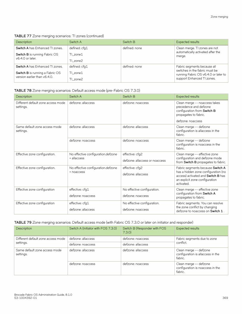
TABLE 77 Zone merging scenarios: TI zones (continued)
Description Switch A Switch B Expected results
Switch A has Enhanced TI zones.
Switch B is running Fabric OSv6.4.0 or later.
defined: cfg1
TI_zone1
TI_zone2
defined: none Clean merge. TI zones are notautomatically activated after themerge.
Switch A has Enhanced TI zones.
Switch B is running a Fabric OSversion earlier than v6.4.0.
defined: cfg1
TI_zone1
TI_zone2
defined: none Fabric segments because allswitches in the fabric must berunning Fabric OS v6.4.0 or later tosupport Enhanced TI zones.
TABLE 78 Zone merging scenarios: Default access mode (pre-Fabric OS 7.3.0)
Description Switch A Switch B Expected results
Different default zone access modesettings.
defzone: allaccess defzone: noaccess Clean merge -- noaccess takesprecedence and defzoneconfiguration from Switch Bpropagates to fabric.
defzone: noaccess
Same default zone access modesettings.
defzone: allaccess defzone: allaccess Clean merge -- defzoneconfiguration is allaccess in thefabric.
defzone: noaccess defzone: noaccess Clean merge -- defzoneconfiguration is noaccess in thefabric.
Effective zone configuration. No effective configuration.defzone= allaccess
effective: cfg2
defzone: allaccess or noaccess
Clean merge -- effective zoneconfiguration and defzone modefrom Switch B propagates to fabric.
Effective zone configuration. No effective configuration.defzone= noaccess
effective: cfg2
defzone: allaccess
Fabric segments because Switch Ahas a hidden zone configuration (noaccess) activated and Switch B hasan explicit zone configurationactivated.
Effective zone configuration effective: cfg1
defzone: noaccess
No effective configuration.
defzone: noaccess
Clean merge -- effective zoneconfiguration from Switch Apropagates to fabric.
Effective zone configuration effective: cfg1
defzone: allaccess
No effective configuration.
defzone: noaccess
Fabric segments. You can resolvethe zone conflict by changingdefzone to noaccess on Switch 1 .
TABLE 79 Zone merging scenarios: Default access mode (with Fabric OS 7.3.0 or later on initiator and responder)
Description Switch A (Initiator with FOS 7.3.0) Switch B (Responder with FOS7.3.0)
Expected results
Different default zone access modesettings.
defzone: allaccess defzone: noaccess Fabric segments due to zoneconflict.defzone: noaccess defzone: allaccess
Same default zone access modesettings.
defzone: allaccess defzone: allaccess Clean merge -- defzoneconfiguration is allaccess in thefabric.
defzone: noaccess defzone: noaccess Clean merge -- defzoneconfiguration is noaccess in thefabric.
Zone merging
Brocade Fabric OS Administration Guide, 8.1.053-1004392-01 369

TABLE 79 Zone merging scenarios: Default access mode (with Fabric OS 7.3.0 or later on initiator and responder) (continued)
Description Switch A (Initiator with FOS 7.3.0) Switch B (Responder with FOS7.3.0)
Expected results
Initiator has effective zoneconfiguration
effective: cfg1
defzone: allaccess
No effective configuration.
defzone: allaccess
Clean merge -- effective zoneconfiguration from Switch Apropagates to fabric.
effective: cfg1
defzone: allaccess
No effective configuration.
defzone: noaccess
Fabric segments because Switch Bhas a hidden zone configuration (noaccess) activated and Switch A hasan explicit zone configurationactivated.
effective: cfg1
defzone: noaccess
No effective configuration.
defzone: allaccess
Fabric merges -- effective zoneconfiguration from Switch Apropagates to fabric. Allaccess onSwitch B changes to noaccess.
effective: cfg1
defzone: noaccess
No effective configuration.
defzone: noaccess
Fabric merges -- effective zoneconfiguration from Switch Apropagates to fabric.
Responder has effective zoneconfiguration.
No effective configuration.
defzone: allaccess
effective: cfg2
defzone: allaccess
Fabric merges -- effective zoneconfiguration from Switch Bpropagates to fabric.
No effective configuration.
defzone: allaccess
effective: cfg2
defzone: noaccess
Fabric merges -- effective zoneconfiguration from Switch Bpropagates to fabric. Allaccess onSwitch A changes to noaccess.
No effective configuration.
defzone: noaccess
effective: cfg2
defzone: allaccess
Fabric segments because Switch Ahas a hidden zone configuration (noaccess) activated and Switch B hasan explicit zone configurationactivated.
No effective configuration.
defzone: noaccess
effective: cfg2
defzone: noaccess
Fabric merges -- effective zoneconfiguration from Switch Bpropagates to fabric.
TABLE 80 Zone merging scenarios: Default access mode (with Fabric OS 7.3.0 or later on initiator and pre-Fabric OS 7.3.0 onresponder)
Description Switch A (Initiator with FOS 7.3.0) Switch B (Responder with pre-FOS7.3.0)
Expected results
Different default zone access modesettings.
defzone: allaccess defzone: noaccess Fabric merges with allaccess onSwitch A changes to noaccess.
defzone: noaccess defzone: allaccess Fabric merges with allaccess onSwitch B changes to noaccess.
Same default zone access modesettings.
defzone: allaccess defzone: allaccess Clean merge -- defzoneconfiguration is allaccess in thefabric.
defzone: noaccess defzone: noaccess Clean merge -- defzoneconfiguration is noaccess in thefabric.
Initiator has effective zoneconfiguration
effective: cfg1
defzone: allaccess
No effective configuration.
defzone: allaccess
Clean merge -- effective zoneconfiguration from Switch Apropagates to fabric.
effective: cfg1
defzone: allaccess
No effective configuration.
defzone: noaccess
Fabric segments because Switch Bhas a hidden zone configuration (noaccess) activated and Switch A has
Zone merging
Brocade Fabric OS Administration Guide, 8.1.0370 53-1004392-01

TABLE 80 Zone merging scenarios: Default access mode (with Fabric OS 7.3.0 or later on initiator and pre-Fabric OS 7.3.0 onresponder) (continued)
Description Switch A (Initiator with FOS 7.3.0) Switch B (Responder with pre-FOS7.3.0)
Expected results
an explicit zone configurationactivated.
effective: cfg1
defzone: noaccess
No effective configuration.
defzone: allaccess
Fabric merges -- effective zoneconfiguration from Switch Apropagates to fabric. Allaccess onSwitch B changes to noaccess.
effective: cfg1
defzone: noaccess
No effective configuration.
defzone: noaccess
Fabric merges -- effective zoneconfiguration from Switch Apropagates to fabric.
Responder has effective zoneconfiguration.
No effective configuration.
defzone: allaccess
effective: cfg2
defzone: allaccess
Fabric merges -- effective zoneconfiguration from Switch Bpropagates to fabric.
No effective configuration.
defzone: allaccess
effective: cfg2
defzone: noaccess
Fabric merges -- effective zoneconfiguration from Switch Bpropagates to fabric. Allaccess onSwitch A changes to noaccess.
No effective configuration.
defzone: noaccess
effective: cfg2
defzone: allaccess
Fabric segments because Switch Ahas a hidden zone configuration (noaccess) activated and Switch B hasan explicit zone configurationactivated.
No effective configuration.
defzone: noaccess
effective: cfg2
defzone: noaccess
Fabric merges -- effective zoneconfiguration from Switch Bpropagates to fabric.
TABLE 81 Zone merging scenarios: Default access mode (with pre-Fabric OS 7.3.0 on initiator and Fabric OS 7.3.0 or later onresponder)
Description Switch A (Initiator with pre-FOS7.3.0)
Switch B (Responder with FOS7.3.0)
Expected results
Different default zone access modesettings.
defzone: allaccess defzone: noaccess Fabric segments due to zoneconflict.defzone: noaccess defzone: allaccess
Same default zone access modesettings.
defzone: allaccess defzone: allaccess Clean merge -- defzoneconfiguration is allaccess in thefabric.
defzone: noaccess defzone: noaccess Clean merge -- defzoneconfiguration is noaccess in thefabric.
Initiator has effective zoneconfiguration
effective: cfg1
defzone: allaccess
No effective configuration.
defzone: allaccess
Clean merge -- effective zoneconfiguration from Switch Apropagates to fabric.
effective: cfg1
defzone: allaccess
No effective configuration.
defzone: noaccess
Fabric segments because Switch Bhas a hidden zone configuration (noaccess) activated and Switch A hasan explicit zone configurationactivated.
effective: cfg1
defzone: noaccess
No effective configuration.
defzone: allaccess
Fabric merges -- effective zoneconfiguration from Switch Apropagates to fabric. Allaccess onSwitch B changes to noaccess.
Zone merging
Brocade Fabric OS Administration Guide, 8.1.053-1004392-01 371

TABLE 81 Zone merging scenarios: Default access mode (with pre-Fabric OS 7.3.0 on initiator and Fabric OS 7.3.0 or later onresponder) (continued)
Description Switch A (Initiator with pre-FOS7.3.0)
Switch B (Responder with FOS7.3.0)
Expected results
effective: cfg1
defzone: noaccess
No effective configuration.
defzone: noaccess
Fabric merges -- effective zoneconfiguration from Switch Apropagates to fabric.
Responder has effective zoneconfiguration.
No effective configuration.
defzone: allaccess
effective: cfg2
defzone: allaccess
Fabric merges -- effective zoneconfiguration from Switch Bpropagates to fabric.
No effective configuration.
defzone: allaccess
effective: cfg2
defzone: noaccess
Fabric merges -- effective zoneconfiguration from Switch Bpropagates to fabric. Allaccess onSwitch A changes to noaccess.
No effective configuration.
defzone: noaccess
effective: cfg2
defzone: allaccess
Fabric segments because Switch Ahas a hidden zone configuration (noaccess) activated and Switch B hasan explicit zone configurationactivated.
No effective configuration.
defzone: noaccess
effective: cfg2
defzone: noaccess
Fabric merges -- effective zoneconfiguration from Switch Bpropagates to fabric.
TABLE 82 Zone merging scenarios: Mixed Fabric OS versions
Description Switch A Switch B Expected results
Switch A is running Fabric OS7.0.0 or later.
Switch B is running a Fabric OSversion earlier than 7.0.0.
effective: cfg1
defzone = allaccess
No effective configuration.
defzone - noaccess
Fabric segments due to zoneconflict.
Switch A is running Fabric OS7.0.0 or later.
Switch B is running a Fabric OSversion earlier than 7.0.0.
No effective configuration.
defzone = noaccess
effective: cfg2
defzone - allaccess
Fabric segments due to zoneconflict.
NOTEWhen merging mixed versions of Fabric OS where both sides have default zone mode No Access set, the merge results varydepending on which switch initiates the merge.
Concurrent zone transactionsWhile working on zone sets, a special workspace is provided to allow you to manipulate the zone sets of your choice. These changes arenot put into effect until they are committed to the database. Once they are committed, they will replace the existing active zone sets withthe new zone sets or create more zone sets in the defined database. When updates to the zoning database are being made by multipleusers, Fabric OS warns you about the situation and allows you to choose which operation will prevail.
Example of how users are warned if there is already a pending zoning transaction in the fabric
u30:FID128:admin> zonecreate z2, "2,3" WARNING!!Multiple open transactions are pending in this fabric. Only onetransaction can be saved. Please abort all unwanted transactions
Concurrent zone transactions
Brocade Fabric OS Administration Guide, 8.1.0372 53-1004392-01

using the cfgtransabort command. Use the cfgtransshow --opentranscommand to display a list of domains with open transactions
If no other transaction is open in this fabric, no message is shown.
of what is shown if there is not a pending zoning transaction in the fabric
sw0:FID128:admin> zonecreate z7, "4,5;10,3" sw0:FID128:admin>
Similar messages are shown for cfgSave and cfgEnable:
u30:FID128:admin> cfgenable cfg You are about to enable a new zoning configuration.This action will replace the old zoning configuration with thecurrent configuration selected. If the update includes changesto one or more traffic isolation zones, the update may result inlocalized disruption to traffic on ports associated withthe traffic isolation zone changesMultiple open transactions are pending in this fabric. Only onetransaction can be saved. Please abort all unwanted transactionsusing the cfgtransabort command. Use the cfgtransshow --opentranscommand to display a list of domains with open transactionsDo you want to enable 'cfg' configuration (yes, y, no, n): [no]u30:FID128:admin> cfgsave You are about to save the Defined zoning configuration. This action will only save the changes on Defined configuration. Multiple open transactions are pending in this fabric. Only one transaction can be saved. Please abort all unwanted transactions using the cfgtransabort command. Use the cfgtransshow --opentrans command to display a list of domains with open transactionsDo you want to save the Defined zoning configuration only? (yes, y, no, n): [no] n
Viewing zone database transactionsEnter cfgtransshow to list the details of the current database transaction token.
Enter cfgtransshow --opentrans to display the local open transaction token details and the list of domains with open transactions. Referto the Fabric OS Command Reference for more details on this command.
The following example shows the output of the cfgtransshow command.
switch:admin> cfgtransshow Current transaction token is 0x571010459It is abortable
The following example shows the output with the --opentrans option.
switch:admin> cfgtransshow --opentrans Current transaction token is 0x3109It is abortableTransactions Detect: CapableCurrent Open TransactionsDomain List:------------1 2 3 4
Concurrent zone transactions
Brocade Fabric OS Administration Guide, 8.1.053-1004392-01 373

Peer ZoningPeer Zoning allows a "principal" device to communicate with the rest of the devices in the zone. The principal device manages a PeerZone. Other "non-principal" devices in the zone can communicate with the principal device only; they cannot communicate with eachother.
Prior to the introduction of Peer Zoning, Single-Initiator Zoning was considered a more efficient zoning method in terms of hardwareresources and RSCN volume. However, the added storage requirements of defining a unique zone for each host and target rapidlyexceeds zone database size limits. As the number of zones increase, it is difficult to configure and maintain the zones.
One-to-Many Zoning defines a zone having one target and other members as initiators. This approach is easy to manage and uses lessstorage, but zoning all the initiators together in this manner results in less effective use of hardware resources and greater RSCN traffic.
In a Peer Zone setup, principal to non-principal device communication is allowed, but non-principal to non-principal devicecommunication and principal to principal device communication are not allowed. This approach establishes zoning connections thatprovide the efficiency of Single-Initiator Zoning with the simplicity and lower memory characteristics of One-to-Many Zoning. Typically, aPeer Zone has a single principal device and one or more non-principal devices, but configurations having multiple principal devices areallowed. Peer Zones are not mutually exclusive with traditional zones; multiple zoning styles can coexist within the same zoningconfiguration and fabric.
Peer Zoning compared to other zoning typesThe following types of zoning methods are used in a storage area network (SAN):
FIGURE 30 Single-Initiator Zoning example
Single-Initiator Zoning: Single-Initiator Zoning eliminates the host-to-host visibility, which reduces RSCN traffic. However, the mainlimitation of Single-Initiator Zoning is that this type of zoning results in creating a large number of zones, which can lead to exceeding thecapacity of the zone database size limits. The Figure 30 shows an example of Single-Initiator Zoning with eight zones; one for each hostH1 to H8.
Peer Zoning
Brocade Fabric OS Administration Guide, 8.1.0374 53-1004392-01

FIGURE 31 One-to-many Zoning example
One-to-many Zoning: One-to-many Zoning creates a zone with multiple hosts and one target. This approach creates fewer zones ascompared to Single-Initiator Zoning, but the host-to-host connectivity generates an extraneous amount of RSCN traffic. The Figure 31shows an example of One-to-many Zoning where the hosts H1 to H8 are part of the same zone and can communicate with each other.
Peer Zoning
Brocade Fabric OS Administration Guide, 8.1.053-1004392-01 375

FIGURE 32 Flat Zoning example
Flat Zoning: Flat Zoning consists of a single zone that allows all devices to communicate with each other. This type of zoning supports alarge number of hosts. One drawback to this type of zoning is the significant increase in RSCN traffic when compared to other zoningtypes. The Figure 32 shows an example of Flat Zoning where the hosts H1 to H16 and targets T1 and T2, all form a single zone andcan communicate with all other devices in the zone.
Peer Zoning
Brocade Fabric OS Administration Guide, 8.1.0376 53-1004392-01

FIGURE 33 Peer Zoning example
Peer Zoning: Using Peer Zoning, a Peer Zone can be created with one device designated as a principal device for that zone. All non-principal devices in the Peer Zone can access only the principal device and cannot communicate with each other. The principal devicecan communicate with all other non-principal devices. The RSCN traffic generated is the same as for Single-Initiator Zoning. The zonedatabase size is the same as One-to-many Zoning. Peer Zoning results in less RSCN traffic on zoning and device changes, and createsa fewer number of zones. The Figure 33 shows an example where T1 is the principal member of the Peer Zone and hosts H1 to H8 arepeer devices.
Advantages of Peer ZoningPeer Zoning has the following advantages when compared to Single-Initiator Zoning and One-to-many Zoning types:
• The zone database memory usage is the same as One-to-many Zoning.
• RSCN and hardware resource efficiencies are the same as Single-Initiator Zoning.
Peer Zone connectivity rulesPeer Zoning adheres to the following connectivity rules:
• Non-principal devices can communicate only with the principal device.
• Non-principal devices cannot communicate with other non-principal devices, unless allowed by some other zone in the activezone set.
• Principal devices cannot communicate with other principal devices, unless allowed by some other zone in the active zone set.
Peer Zoning
Brocade Fabric OS Administration Guide, 8.1.053-1004392-01 377

• The maximum number of Peer Zones is determined by the zone database size. Refer to Zone database size on page 350 forinformation on zone database sizing.
Firmware upgrade and downgrade considerations for Peer ZoningWhen a switch containing Peer Zones is upgraded to Fabric OS 7.4.0, Peer Zoning connectivity rules are enforced on the devicesattached to the upgraded switch. If the device is a member of a Peer Zone, the upgrade can cause disruption.
When a switch containing Peer Zones is downgraded from Fabric OS 7.4.0 to an earlier version, the Peer Zones are treated as regularzones and the zones follow the regular zoning connectivity rules.
All devices in the Peer Zone must be attached to switches running Fabric OS 7.4.0 or later, for the Peer Zoning connectivity rules to beapplied. If any device that is part of the Peer Zone is attached to a switch running an earlier version of Fabric OS, the Peer Zone will betreated as a regular zone.
After downgrading to an earlier version of Fabric OS, Peer Zoning connectivity rules remain on the switch until a port of the Peer Zonedevice is toggled or a new zoning configuration is committed. In such a case, the regular zoning rules apply to the Peer Zones.
LSAN and QoS Peer Zoning considerationsLSAN and QoS Peer Zoning are supported.
LSAN Peer Zoning is supported on Edge to edge and Edge to backbone topologies. Once the zoning configuration is enabled, PeerZoning rules are followed
QoS Peer Zones are supported as long as the zone name has the prefix "QOSH" or "QOSL" in the zone name. Refer to QoS on page426 for more information.
Peer Zone configurationPeer Zones are configured and managed using zone commands with the --peerzone option.
In the Peer Zone, devices must be identified as either WWN or D,I devices. Mixing WWN and D,I device identification within a single PeerZone is not allowed. Aliases are not supported as devices for a Peer Zone.
Creating Peer ZonesTo create a Peer Zone configuration, complete the following steps.
1. Connect to the switch and log in using an account with admin permissions.
2. Create Peer Zones using the zonecreate --peerzone command. The -members operand is optional.
The following example creates two Peer Zones. The first Peer Zone is called "peerzone_wwn_mbrs", which contains"10:00:00:00:01:1e:20:20" as the principal device and "10:00:00:02:1f:02:00:01" and "10:00:05:1e:a9:20:00:01" as thenon-principal devices. The second Peer Zone is called "peerzone_di_mbrs", which contains "10,1" as the principal device and"20,1" and "20,2" as the non-principal devices.
switch:admin> zonecreate --peerzone peerzone_wwn_mbrs -principal "10:00:00:00:01:1e:20:20"/ -members "10:00:00:02:1f:02:00:01;10:00:05:1e:a9:20:00:01"
switch:admin> zonecreate --peerzone peerzone_di_mbrs -principal "10,1" -members "20,1;20,2"
Peer Zoning
Brocade Fabric OS Administration Guide, 8.1.0378 53-1004392-01

Adding devices to a Peer ZoneTo add devices to the Peer Zone, complete the following steps.
1. Connect to the switch and log in using an account with admin permissions.
2. Add Peer Zone devices using the zoneadd --peerzone command.
The following example adds the device "10:00:05:1e:a9:20:00:02" to "peerzone_wwn_mbrs".
switch:admin> zoneadd --peerzone peerzone_wwn_mbrs -members "10:00:05:1e:a9:20:00:02"
Replacing a device in a Peer ZoneTo replace devices in the Peer Zone, complete the following steps.
1. Connect to the switch and log in using an account with admin permissions.
2. Replace the existing Peer Zone device with a new device using the zoneobjectreplace command.
The zoneobjectreplace command restricts replacing the Peer Zone property member. A WWN can be replaced with a WWNonly and a D,I member can be replaced with a D,I member only.
The following example replaces the device "20:00:00:05:1e:a1:af:b2" with "10:00:00:05:1e:a1:10:c1" in a Peer Zone.
switch:admin> zoneobjectreplace "20:00:00:05:1e:a1:af:b2" "10:00:00:05:1e:a1:10:c1"
Removing devices from a Peer ZoneTo remove devices from a Peer Zone, complete the following steps.
1. Connect to the switch and log in using an account with admin permissions.
2. Remove devices from a Peer Zone using the zoneremove --peerzone command.
Removing the last principal WWN device deletes the Peer Zone.
The following example removes the device "10:00:05:1e:a9:20:00:02" from the "peerzone_wwn_mbrs" Peer Zone.
switch:admin> zoneremove --peerzone peerzone_wwn_mbrs -members "10:00:05:1e:a9:20:00:02"
Deleting Peer ZonesTo delete a Peer Zone, complete the following steps.
1. Connect to the switch and log in using an account with admin permissions.
2. Delete Peer Zones using the zonedelete command.The following example deletes the "peerzone_di_mbrs" Peer Zone.
switch:admin> zonedelete peerzone_di_mbrs
Viewing Peer ZonesTo view a Peer Zone configuration, including the devices associated with the Peer Zone, complete the following steps.
1. Connect to the switch and log in to an account.
Peer Zoning
Brocade Fabric OS Administration Guide, 8.1.053-1004392-01 379
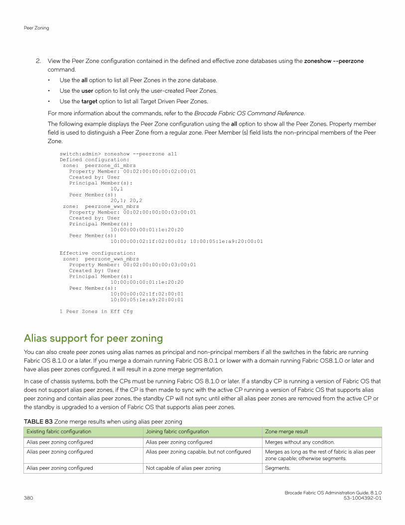
2. View the Peer Zone configuration contained in the defined and effective zone databases using the zoneshow --peerzonecommand.
• Use the all option to list all Peer Zones in the zone database.
• Use the user option to list only the user-created Peer Zones.
• Use the target option to list all Target Driven Peer Zones.
For more information about the commands, refer to the Brocade Fabric OS Command Reference.
The following example displays the Peer Zone configuration using the all option to show all the Peer Zones. Property memberfield is used to distinguish a Peer Zone from a regular zone. Peer Member (s) field lists the non-principal members of the PeerZone.
switch:admin> zoneshow --peerzone allDefined configuration: zone: peerzone_di_mbrs Property Member: 00:02:00:00:00:02:00:01 Created by: User Principal Member(s): 10,1 Peer Member(s): 20,1; 20,2 zone: peerzone_wwn_mbrs Property Member: 00:02:00:00:00:03:00:01 Created by: User Principal Member(s): 10:00:00:00:01:1e:20:20 Peer Member(s): 10:00:00:02:1f:02:00:01; 10:00:05:1e:a9:20:00:01
Effective configuration: zone: peerzone_wwn_mbrs Property Member: 00:02:00:00:00:03:00:01 Created by: User Principal Member(s): 10:00:00:00:01:1e:20:20 Peer Member(s): 10:00:00:02:1f:02:00:01 10:00:05:1e:a9:20:00:01
1 Peer Zones in Eff Cfg
Alias support for peer zoningYou can also create peer zones using alias names as principal and non-principal members if all the switches in the fabric are runningFabric OS 8.1.0 or a later. If you merge a domain running Fabric OS 8.0.1 or lower with a domain running Fabric OS8.1.0 or later andhave alias peer zones configured, it will result in a zone merge segmentation.
In case of chassis systems, both the CPs must be running Fabric OS 8.1.0 or later. If a standby CP is running a version of Fabric OS thatdoes not support alias peer zones, if the CP is then made to sync with the active CP running a version of Fabric OS that supports aliaspeer zoning and contain alias peer zones, the standby CP will not sync until either all alias peer zones are removed from the active CP orthe standby is upgraded to a version of Fabric OS that supports alias peer zones.
TABLE 83 Zone merge results when using alias peer zoning
Existing fabric configuration Joining fabric configuration Zone merge result
Alias peer zoning configured Alias peer zoning configured Merges without any condition.
Alias peer zoning configured Alias peer zoning capable, but not configured Merges as long as the rest of fabric is alias peerzone capable; otherwise segments.
Alias peer zoning configured Not capable of alias peer zoning Segments.
Peer Zoning
Brocade Fabric OS Administration Guide, 8.1.0380 53-1004392-01
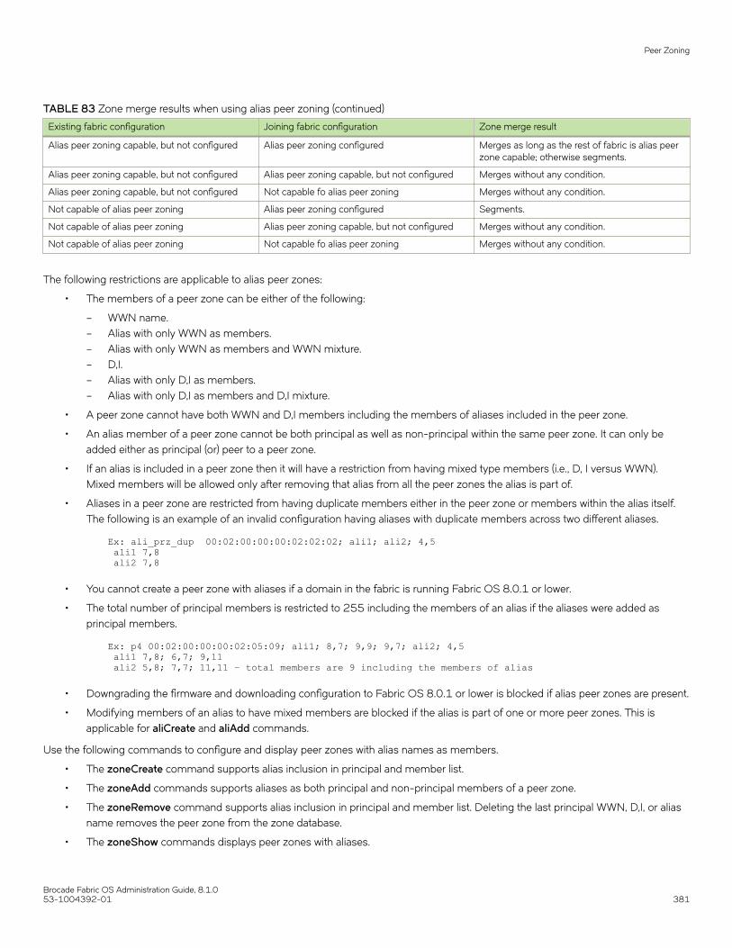
TABLE 83 Zone merge results when using alias peer zoning (continued)
Existing fabric configuration Joining fabric configuration Zone merge result
Alias peer zoning capable, but not configured Alias peer zoning configured Merges as long as the rest of fabric is alias peerzone capable; otherwise segments.
Alias peer zoning capable, but not configured Alias peer zoning capable, but not configured Merges without any condition.
Alias peer zoning capable, but not configured Not capable fo alias peer zoning Merges without any condition.
Not capable of alias peer zoning Alias peer zoning configured Segments.
Not capable of alias peer zoning Alias peer zoning capable, but not configured Merges without any condition.
Not capable of alias peer zoning Not capable fo alias peer zoning Merges without any condition.
The following restrictions are applicable to alias peer zones:
• The members of a peer zone can be either of the following:
– WWN name.– Alias with only WWN as members.– Alias with only WWN as members and WWN mixture.– D,I.– Alias with only D,I as members.– Alias with only D,I as members and D,I mixture.
• A peer zone cannot have both WWN and D,I members including the members of aliases included in the peer zone.
• An alias member of a peer zone cannot be both principal as well as non-principal within the same peer zone. It can only beadded either as principal (or) peer to a peer zone.
• If an alias is included in a peer zone then it will have a restriction from having mixed type members (i.e., D, I versus WWN).Mixed members will be allowed only after removing that alias from all the peer zones the alias is part of.
• Aliases in a peer zone are restricted from having duplicate members either in the peer zone or members within the alias itself.The following is an example of an invalid configuration having aliases with duplicate members across two different aliases.
Ex: ali_prz_dup 00:02:00:00:00:02:02:02; ali1; ali2; 4,5 ali1 7,8 ali2 7,8
• You cannot create a peer zone with aliases if a domain in the fabric is running Fabric OS 8.0.1 or lower.
• The total number of principal members is restricted to 255 including the members of an alias if the aliases were added asprincipal members.
Ex: p4 00:02:00:00:00:02:05:09; ali1; 8,7; 9,9; 9,7; ali2; 4,5 ali1 7,8; 6,7; 9,11 ali2 5,8; 7,7; 11,11 – total members are 9 including the members of alias
• Downgrading the firmware and downloading configuration to Fabric OS 8.0.1 or lower is blocked if alias peer zones are present.
• Modifying members of an alias to have mixed members are blocked if the alias is part of one or more peer zones. This isapplicable for aliCreate and aliAdd commands.
Use the following commands to configure and display peer zones with alias names as members.
• The zoneCreate command supports alias inclusion in principal and member list.
• The zoneAdd commands supports aliases as both principal and non-principal members of a peer zone.
• The zoneRemove command supports alias inclusion in principal and member list. Deleting the last principal WWN, D,I, or aliasname removes the peer zone from the zone database.
• The zoneShow commands displays peer zones with aliases.
Peer Zoning
Brocade Fabric OS Administration Guide, 8.1.053-1004392-01 381

The following examples show peer zone configuration with alias support.
device#> zonecreate --peer p1 -p "ali1;8,7;9,9" -m "4,5";
device#> zoneshow Defined configuration: zone: p1 00:02:00:00:00:02:03:05; ali1; 8,7; 9,9; 4,5 alias: ali1 7,8; 6,7; 9,11 alias: ali2 5,8; 7,7; 11,11 Effective configuration: no configuration in effect
device#> cfgcreate cp1,p1 device#> cfgenable cp1
device#> zoneadd --peer p1 -p "9,7;ali2";
device#> zoneshow Defined configuration: cfg: cp1 p1 zone: p1 00:02:00:00:00:02:05:09; ali1; 8,7; 9,9; 9,7; ali2; 4,5 alias: ali1 7,8; 6,7; 9,11 alias: ali2 5,8; 7,7; 11,11 Effective configuration: cfg: cp1 zone: p1 00:02:00:00:00:02:03:05 7,8 6,7 9,11 8,7 9,9 4,5
device#> zoneremove --peer p1 -p "ali2";
device#> zoneshow Defined configuration: cfg: cp1 p1 zone: p1 00:02:00:00:00:02:04:06; ali1; 8,7; 9,9; 9,7; 4,5 alias: ali1 7,8; 6,7; 9,11 alias: ali2 5,8; 7,7; 11,11 Effective configuration: cfg: cp1 zone: p1 00:02:00:00:00:02:03:05 7,8 6,7 9,11 8,7 9,9
device#> zoneshow --peer all Defined configuration: zone: p1 Property Member: 00:02:00:00:00:02:04:06 Created by: User Principal Member(s): ali1; 8,7; 9,9; 9,7 Peer Member(s): 4,5 Effective configuration: zone: p1 Property Member: 00:02:00:00:00:02:03:05 Created by: User Principal Member(s): 7,8 6,7 9,11 8,7 9,9 Peer Member(s):
Peer Zoning
Brocade Fabric OS Administration Guide, 8.1.0382 53-1004392-01

4,5 1 Peer Zones in Eff Cfg
device#> zoneshow Defined configuration: cfg: c1 p8 zone: p8 00:02:00:00:00:02:02:01; ali5; 86,8
device#> alicreate ali5, "30:08:00:05:33:88:e3:f3" Error: Members of alias "ali5" can either be WWN or D,I: aliases having mixed-type members are not allowed to be a part of an alias peer zone. To allow mixed members remove this alias from all peer zones.
device#> zoneshow Defined configuration: cfg: c1 p8 zone: p8 00:02:00:00:00:02:02:01; ali5; 86,8 alias: ali5 5,8; 7,7
device#> aliadd ali5, "30:08:00:05:33:88:e3:f3" Error: Members of alias "ali5" can either be WWN or D,I: aliases having mixed-type members are not allowed to be a part of an alias peer zone. To allow mixed members remove this alias from all peer zones.
Target Driven ZoningTarget Driven Zoning is a variant of Peer Zoning. Where a regular Peer Zone is defined by a user-specified configuration, Target DrivenPeer Zone is defined by the principal device. This device is usually a storage device, but not always.
Target Driven Zoning manages the zoning using a third-party management interface to manage the device and the switch interactions.To permit a Target Driven Peer Zone, Target Driven Zoning must be enabled on the F_Port that connects the principal device to thefabric. Refer to the manual for the device used as the principal device to determine the supported commands and options to construct aTarget Driven Peer Zone.
FIGURE 34 Target Driven Zoning example
Target Driven Zoning
Brocade Fabric OS Administration Guide, 8.1.053-1004392-01 383
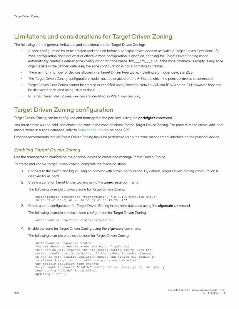
Limitations and considerations for Target Driven ZoningThe following are the general limitations and considerations for Target Driven Zoning:
• A zone configuration must be created and enabled before a principal device adds or activates a Target Driven Peer Zone. If azone configuration does not exist or effective zone configuration is disabled, enabling the Target Driven Zoning modeautomatically creates a default zone configuration with the name "tdz___cfg___auto" if the zone database is empty. If any zoneobject exists in the defined database, the zone configuration is not automatically created.
• The maximum number of devices allowed in a Target Driven Peer Zone, including a principal device is 255.
• The Target Driven Zoning configuration mode must be enabled on the F_Port to which the principal device is connected.
• Target Driven Peer Zones cannot be created or modified using Brocade Network Advisor (BNA) or the CLI; however, they canbe displayed or deleted using BNA or the CLI.
• In Target Driven Peer Zones, devices are identified as WWN devices only.
Target Driven Zoning configurationTarget Driven Zoning can be configured and managed at the port level using the portcfgtdz command.
You must create a zone, add, and enable the zone in the zone database for the Target Driven Zoning. For procedures to create, add, andenable zones in a zone database, refer to Zone configurations on page 329.
Brocade recommends that all Target Driven Zoning tasks be performed using the zone management interface on the principal device.
Enabling Target Driven ZoningUse the management interface on the principal device to create and manage Target Driven Zoning.
To create and enable Target Driven Zoning, complete the following steps.
1. Connect to the switch and log in using an account with admin permissions. By default, Target Driven Zoning configuration isdisabled for all ports.
2. Create a zone for Target Driven Zoning using the zonecreate command.
The following example creates a zone for Target Driven Zoning.
switch:admin> zonecreate "targetzone1", "10:00:00:00:c9:2b:c9:0c;50:05:07:61:00:5b:62:ed;50:05:07:61:00:49:20:b4""
3. Create a zone configuration for Target Driven Zoning in the zone database using the cfgcreate command.
The following example creates a zone configuration for Target Driven Zoning.
switch:admin> cfgcreate cfgtdz,targetzone1
4. Enable the zone for Target Driven Zoning using the cfgenable command.
The following example enables the zone for Target Driven Zoning.
switch:admin> cfgenable cfgtdz You are about to enable a new zoning configuration.This action will replace the old zoning configuration with thecurrent configuration selected. If the update includes changes to one or more traffic isolation zones, the update may result in localized disruption to traffic on ports associated with the traffic isolation zone changes Do you want to enable 'cfgtdz' configuration (yes, y, no, n): [no] yzone config "cfgtdz" is in effect Updating flash ...
Target Driven Zoning
Brocade Fabric OS Administration Guide, 8.1.0384 53-1004392-01

5. Enable Target Driven Zoning on a port or port range using the portcfgtdz --enable command.
The following example enables Target Driven Zoning. You can enable Target Driven Zoning for a single port, a range of ports, orall ports on a switch.
switch:admin> portcfgtdz --enable 8
The following example enables Target Driven Zoning on a range of ports.
switch:admin> portcfgtdz --enable 8-18
The following example enables Target Driven Zoning on all ports.
switch:admin> portcfgtdz --enable "*"
Disabling Target Driven ZoningTo disable Target Driven Zoning, complete the following steps.
1. Connect to the switch and log in using an account with admin permissions.
2. Disable Target Driven Zoning on a port or port range using the portcfgtdz --disable command.
The following example disables Target Driven Zoning on a port.
switch:admin> portcfgtdz --disable 10
The following example disables Target Driven Zoning on a range of ports.
switch:admin> portcfgtdz --disable 2-10
The following example disables Target Driven Zoning on all ports.
switch:admin> portcfgtdz --disable "*"
You will get a peer zone change RSCN if an active principle device is attached to the specified port.
Viewing Target Driven ZoningTo view the Target Driven Zoning status, complete the following steps.
1. Connect to the switch and log in using an account.
Target Driven Zoning
Brocade Fabric OS Administration Guide, 8.1.053-1004392-01 385

2. View Target Driven Zoning status on a port or port range.
The following example displays Target Driven Zoning status on the ports using the portcfgtdz --show command.
switch:admin> portcfgtdz --show 1-2 Port Mode============= 1 ON 2 OFF
The following example displays the Target Driven Zoning status on a port using the portcfgshow command.
switch:admin> portcfgshow 1Area Number: 1Octet Speed Combo: 1(16G|8G|4G|2G)Speed Level: AUTO(SW)AL_PA Offset 13: OFFTrunk Port ONLong Distance OFFVC Link Init OFFLocked L_Port OFFLocked G_Port OFFDisabled E_Port OFFLocked E_Port OFFISL R_RDY Mode OFFRSCN Suppressed OFFPersistent Disable ONLOS TOV mode 0(OFF)NPIV capability ONQOS Port AEPort Auto Disable: OFFRate Limit OFFEX Port OFFMirror Port OFFSIM Port OFFCredit Recovery ONF_Port Buffers OFFE_Port Credits OFFFault Delay: 0(R_A_TOV)NPIV PP Limit: 126NPIV FLOGI Logout: OFFCSCTL mode: OFFTDZ mode: OND-Port mode: OFFD-Port over DWDM: OFFCompression: OFFEncryption: OFF10G/16G FEC: ON16G FEC via TTS: OFFNon-DFE: OFF
Target Driven Zoning
Brocade Fabric OS Administration Guide, 8.1.0386 53-1004392-01
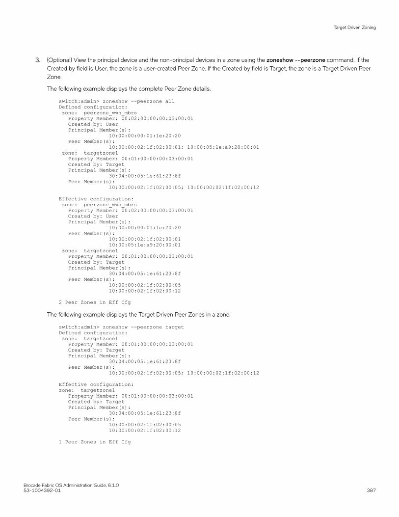
3. (Optional) View the principal device and the non-principal devices in a zone using the zoneshow --peerzone command. If theCreated by field is User, the zone is a user-created Peer Zone. If the Created by field is Target, the zone is a Target Driven PeerZone.
The following example displays the complete Peer Zone details.
switch:admin> zoneshow --peerzone allDefined configuration: zone: peerzone_wwn_mbrs Property Member: 00:02:00:00:00:03:00:01 Created by: User Principal Member(s): 10:00:00:00:01:1e:20:20 Peer Member(s): 10:00:00:02:1f:02:00:01; 10:00:05:1e:a9:20:00:01 zone: targetzone1 Property Member: 00:01:00:00:00:03:00:01 Created by: Target Principal Member(s): 30:04:00:05:1e:61:23:8f Peer Member(s): 10:00:00:02:1f:02:00:05; 10:00:00:02:1f:02:00:12
Effective configuration: zone: peerzone_wwn_mbrs Property Member: 00:02:00:00:00:03:00:01 Created by: User Principal Member(s): 10:00:00:00:01:1e:20:20 Peer Member(s): 10:00:00:02:1f:02:00:01 10:00:05:1e:a9:20:00:01 zone: targetzone1 Property Member: 00:01:00:00:00:03:00:01 Created by: Target Principal Member(s): 30:04:00:05:1e:61:23:8f Peer Member(s): 10:00:00:02:1f:02:00:05 10:00:00:02:1f:02:00:12
2 Peer Zones in Eff Cfg
The following example displays the Target Driven Peer Zones in a zone.
switch:admin> zoneshow --peerzone targetDefined configuration: zone: targetzone1 Property Member: 00:01:00:00:00:03:00:01 Created by: Target Principal Member(s): 30:04:00:05:1e:61:23:8f Peer Member(s): 10:00:00:02:1f:02:00:05; 10:00:00:02:1f:02:00:12
Effective configuration:zone: targetzone1 Property Member: 00:01:00:00:00:03:00:01 Created by: Target Principal Member(s): 30:04:00:05:1e:61:23:8f Peer Member(s): 10:00:00:02:1f:02:00:05 10:00:00:02:1f:02:00:12
1 Peer Zones in Eff Cfg
Target Driven Zoning
Brocade Fabric OS Administration Guide, 8.1.053-1004392-01 387

Supported commands for Peer Zones and TargetDriven Peer ZonesThe regular zone commands are used to configure and manage the Peer Zones and Target Driven Peer Zones.
Peer Zones are managed using the --peerzone operand with regular zone commands for some actions. You can manage Target DrivenPeer Zones using the regular zone commands, but not all commands are supported. Refer to the following table for the list ofcommands supported for Peer Zones and Target Driven Peer Zones.
TABLE 84 Supported commands for Peer Zones and Target Driven Peer Zones
Command Support for Peer Zones Support for Target Driven Peer Zones
cfgAdd Yes Yes
cfgCreate Yes Yes
cfgDelete Yes Yes
cfgDisable Yes Yes
cfgEnable Yes Yes
cfgRemove Yes Yes
cfgSave Yes Yes
cfgShow Yes Yes
zone No No
zoneAdd Yes, using --peerzone operand No
zoneCreate Yes, using --peerzone operand No
zoneDelete Yes Yes
zoneObjectCopy Yes No
zoneObjectExpunge No No
zoneObjectRename Yes No
zoneObjectReplace Yes No
zoneRemove Yes, using --peerzone operand No
zoneShow Yes, using --peerzone operand Yes, using --peerzone operand
Boot LUN zoningBoot from SAN provides rapid server provisioning, rapid recovery from server failure, improved reliability, and reduced power andcooling. Brocade/QLogic Host Bus Adapters (HBAs) support boot from SAN in all types of environments. Brocade features make bootfrom SAN easier to deploy, such as putting a label with the port World Wide Name (pWWN) on the bracket of the HBA and a featurecalled Fabric-Based Boot LUN Discovery. Fabric-Based Boot LUN Discovery can be deployed in a Brocade SAN only using Brocade/QLogic HBAs; eliminating the manual process of boot LUN configuration of each HBA from each server console. This capabilitydramatically improves configuration and reliability, containing operational costs and making the adoption of diskless servers a practicalalternative for even large data centers.
NOTEIBM UEFI and other UEFI-based servers do not support this unique Brocade feature, because of their different discoveryprocesses.
Supported commands for Peer Zones and Target Driven Peer Zones
Brocade Fabric OS Administration Guide, 8.1.0388 53-1004392-01

FIGURE 35 Boot LUN zoning
As Boot LUN zones must not be part of a fabric zone configuration, Fabric OS 7.3.0 and later blocks the creation of any zone with azone name having the format "BFA_XXXX_BLUN" (that is, starting with "BFA_" and ending in "_BLUN"). Zone names with thisconfiguration are considered to indicate an HBA Boot LUN Zone. As part of the support for peer zoning introduced in Fabric OS 7.3.0,restrictions to protect property members starting with "00:" were added. In Fabric OS 8.0.1 and later, this restriction has been extendedto exclude any WWNs that start with "00:00:00:" as this WWN value indicates a Boot LUN zone member.
In Fabric OS 8.0.1 and later, zone configuration rules now only permit creating a Boot LUN zone using the bootluncfg command. Toenable a Boot LUN configuration, you will need to create a basic zone for the host-target pair using the bootluncfg command, and thenadd this zone object to the zone configuration. This will ensure that the HBA has access to the target. Once this zone is established, GetZone Member (GZM) queries from the HBA will handle getting the Boot LUN information from the fabric.
Refer to the Fabric OS Command Reference for additional information on the bootluncfg command.
Boot LUN zoning
Brocade Fabric OS Administration Guide, 8.1.053-1004392-01 389

Setting up boot LUN zoningYou must configure the server, HBA, and Brocade switch for boot LUN zoning to work. You must also know how to flash the HBA BIOSor upload the latest version of Brocade Fabric OS (FOS) on a Brocade SAN switch or director. Note that Brocade FOS 6.2 or later andHBA BIOS version 1.1 or later are required, and we recommend always using the latest BIOS and FOS version. Other than that, noadditional hardware or extra license or software is needed to deploy Fabric-Based Boot LUN Discovery. Use the FOS Command-LineInterface (CLI) for configuration: neither Brocade DCFM nor Brocade Web Tools are required.
Configuring the server and HBA for BLUN zoneFabric OS HBAs are factory-configured to support Fabric-based Boot LUN Discovery in the default BIOS setting. Verify that the BIOS isenabled and that the Boot LUN is set to Auto Discover, as shown in the following figure.
FIGURE 36 Boot LUN zoning BIOS setting
Configuring the Brocade switch for BLUN zoneIn addition to zoning and masking, you must configure an additional Boot LUN (BLUN) zone on the switch. At server boot, the BrocadeHBA (set to Auto Discover) makes a connection to the switch, retrieves the remote pWWN and the LUN from this BLUN zone, and triesto boot from this LUN.
1. To configure a BLUN zone, use the bootLunCfg --add command.
switch:admin> bootluncfg --add 11:22:ab:44:44:ff:44:ca \1b:6c:55:55:55:3a:55:ff 9abc345fa1112410Operation Successful
Boot LUN zoning
Brocade Fabric OS Administration Guide, 8.1.0390 53-1004392-01

2. To display existing BLUN mappings, use the bootLunCfg --show command.
switch:admin> bootluncfg --show00:11:22:33:44:55:66:7700:00:00:00:aa:bb:cc:dd;00:00:00:01:ee:ff:11:22; \00:00:00:02:9a:bc:34:5f;00:00:00:03:a1:11:24:10aa:aa:aa:aa:aa:aa:aa:aa00:00:00:00:11:11:11:11;00:00:00:01:11:11:11:11; \00:00:00:02:9a:bc:34:5f;00:00:00:03:a1:11:24:10bb:aa:aa:aa:aa:aa:aa:aa00:00:00:00:11:11:11:11;00:00:00:01:11:11:11:11; \00:00:00:02:9a:bc:34:5f;00:00:00:03:a1:11:24:10
3. To remove an HBA to BLUN mapping, use the bootLunCfg --delete command.
switch:admin> bootluncfg --delete 11:22:ab:44:44:ff:44:ca \1b:6c:55:55:55:3a:55:ff 9abc345fa1112410Operation Successful
4. The Brocade Command Line Utility (BCU), loaded with the driver package, provides commands that are comparable toBrocade HCM features for configuring, troubleshooting, and monitoring the HBA and device connection.
Syntax:
swtich# bcu command --operand synopsis
Example:
switch#> bcu adapter –-query <ad_id>5. The bcu boot –blunZone command helps to create the command, which can then be copied and pasted. Here is the same
example but with a different LUN 0xff:
switch#> BCU boot –-blunZone –c BLUN –p 10:00:00:05:1e:0f:aa:21 –r 50:00:00:e0:d0:44:29:86 –l ffzonecreate "bfa_100000051e0faa21_blun", "00:00:00:00:50:00:00:e0; 00:00:00:01:d0:44:29:86; 00:00:00:02:00:ff:00:00; 00:00:00:03:00:00:00:00"
Boot LUN zoning
Brocade Fabric OS Administration Guide, 8.1.053-1004392-01 391

Brocade Fabric OS Administration Guide, 8.1.0392 53-1004392-01

Traffic Isolation Zoning• Traffic Isolation Zoning overview..............................................................................................................................................................393• FSPF routing rules and traffic isolation................................................................................................................................................. 395• Enhanced TI zones........................................................................................................................................................................................ 397• General rules for TI zones...........................................................................................................................................................................400• Limitations and restrictions of Traffic Isolation Zoning....................................................................................................................402• Creating a TI zone.......................................................................................................................................................................................... 402• Modifying TI zones........................................................................................................................................................................................ 403• Changing the state of a TI zone................................................................................................................................................................404• Deleting a TI zone.......................................................................................................................................................................................... 404• Displaying TI zones....................................................................................................................................................................................... 404• Enforcing Local TI Filtering.........................................................................................................................................................................406• Fabric-Level Traffic Isolation in a backbone fabric............................................................................................................................410• Virtual Fabrics considerations for Traffic Isolation Zoning.............................................................................................................418• Traffic Isolation Zoning over FC routers with Virtual Fabrics........................................................................................................420• Troubleshooting TI zone routing problems..........................................................................................................................................422
Traffic Isolation Zoning overviewTraffic Isolation Zoning allows you to control the flow of inter-switch traffic by creating a dedicated path for traffic flowing from a specificset of source ports (N_Ports).
You might use Traffic Isolation Zoning for the following scenarios:
• To dedicate an ISL to high priority, host-to-target traffic.
• To force high volume, low priority traffic onto a given ISL to limit the effect on the fabric of this high traffic pattern.
• To ensure that requests and responses of FCIP-based applications such as tape pipelining use the same VE_Port tunnel acrossa metaSAN.
NOTETraffic Isolation Zoning is an advanced feature, but does not require a license. A strong understanding of Fabric Shortest PathFirst (FSPF) is required.
Isolating traffic requires that you create a special zone, called a Traffic Isolation zone (TI zone). A TI zone indicates that a set of N_Portsand E_Ports are to be used only for a specific isolated traffic flow. When a TI zone is activated, the fabric attempts to isolate all inter-switch traffic entering the fabric from a member of the zone to only those E_Ports that have been included in the zone. The fabric alsoattempts to exclude traffic not in the TI zone from using E_Ports within that TI zone.
The following figure shows a fabric with a TI zone consisting of the following:
• N_Ports: "1,7", "1,8", "4,5", and "4,6"
• E_Ports: "1,1", "3,9", "3,12", and "4,7"
The dotted lines indicate the dedicated path between the initiator in Domain 1 to the target in Domain 4.
Brocade Fabric OS Administration Guide, 8.1.053-1004392-01 393

FIGURE 37 Traffic Isolation zone creating a dedicated path through the fabric
In the figure, all traffic entering Domain 1 from N_Ports 7 and 8 is routed through E_Port 1. Similarly, traffic entering Domain 3 fromE_Port 9 is routed to E_Port 12, and traffic entering Domain 4 from E_Port 7 is routed to the devices through N_Ports 5 and 6. Trafficcoming from other ports in Domain 1 would not use E_Port 1, but would use E_Port 2 instead.
TI zone failoverA TI zone can have failover enabled or disabled.
Disable failover if you want to guarantee that TI zone traffic uses only the dedicated path, and that no other traffic can use the dedicatedpath. In other words, an exclusive, members-only path.
Enable failover if you want traffic to have alternate routes when the dedicated path cannot be used, and if you want other traffic to be ableto use the dedicated path when the non-dedicated paths are not available.
ATTENTIONIf failover is disabled, use care when planning your TI zones so that non-TI zone devices are not isolated. If this feature is notused correctly, it can cause major fabric disruptions that are difficult to resolve. Refer to Additional considerations when disablingfailover on page 395 for additional information about using this feature.
The following table compares the behavior of traffic when failover is enabled and disabled.
TABLE 85 Traffic behavior when failover is enabled or disabled in TI zones
Failover enabled Failover disabled
If the dedicated path is not the shortest path or if the dedicated path isbroken, the TI zone traffic will use a non-dedicated path instead.
If the dedicated path is not the shortest path or if the dedicated path isbroken, traffic for that TI zone is halted until the dedicated path is fixed.This condition initiates a RASlog.
Traffic Isolation Zoning overview
Brocade Fabric OS Administration Guide, 8.1.0394 53-1004392-01
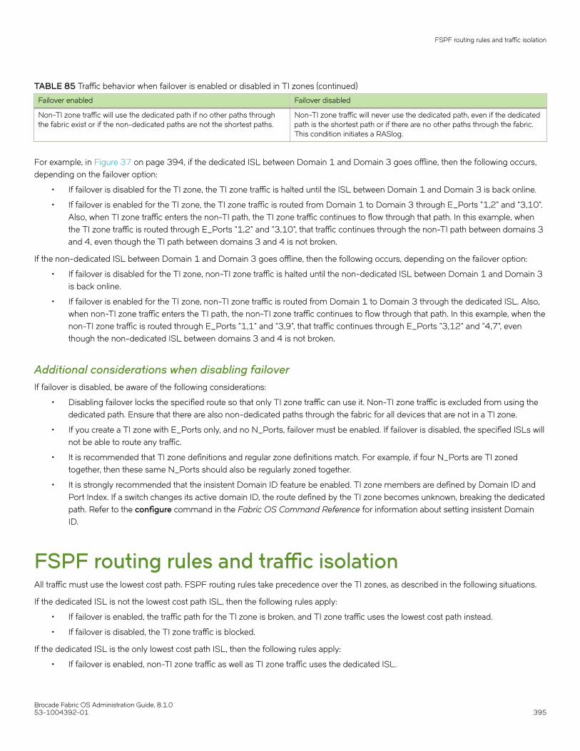
TABLE 85 Traffic behavior when failover is enabled or disabled in TI zones (continued)
Failover enabled Failover disabled
Non-TI zone traffic will use the dedicated path if no other paths throughthe fabric exist or if the non-dedicated paths are not the shortest paths.
Non-TI zone traffic will never use the dedicated path, even if the dedicatedpath is the shortest path or if there are no other paths through the fabric.This condition initiates a RASlog.
For example, in Figure 37 on page 394, if the dedicated ISL between Domain 1 and Domain 3 goes offline, then the following occurs,depending on the failover option:
• If failover is disabled for the TI zone, the TI zone traffic is halted until the ISL between Domain 1 and Domain 3 is back online.
• If failover is enabled for the TI zone, the TI zone traffic is routed from Domain 1 to Domain 3 through E_Ports "1,2" and "3,10".Also, when TI zone traffic enters the non-TI path, the TI zone traffic continues to flow through that path. In this example, whenthe TI zone traffic is routed through E_Ports "1,2" and "3,10", that traffic continues through the non-TI path between domains 3and 4, even though the TI path between domains 3 and 4 is not broken.
If the non-dedicated ISL between Domain 1 and Domain 3 goes offline, then the following occurs, depending on the failover option:
• If failover is disabled for the TI zone, non-TI zone traffic is halted until the non-dedicated ISL between Domain 1 and Domain 3is back online.
• If failover is enabled for the TI zone, non-TI zone traffic is routed from Domain 1 to Domain 3 through the dedicated ISL. Also,when non-TI zone traffic enters the TI path, the non-TI zone traffic continues to flow through that path. In this example, when thenon-TI zone traffic is routed through E_Ports "1,1" and "3,9", that traffic continues through E_Ports "3,12" and "4,7", eventhough the non-dedicated ISL between domains 3 and 4 is not broken.
Additional considerations when disabling failoverIf failover is disabled, be aware of the following considerations:
• Disabling failover locks the specified route so that only TI zone traffic can use it. Non-TI zone traffic is excluded from using thededicated path. Ensure that there are also non-dedicated paths through the fabric for all devices that are not in a TI zone.
• If you create a TI zone with E_Ports only, and no N_Ports, failover must be enabled. If failover is disabled, the specified ISLs willnot be able to route any traffic.
• It is recommended that TI zone definitions and regular zone definitions match. For example, if four N_Ports are TI zonedtogether, then these same N_Ports should also be regularly zoned together.
• It is strongly recommended that the insistent Domain ID feature be enabled. TI zone members are defined by Domain ID andPort Index. If a switch changes its active domain ID, the route defined by the TI zone becomes unknown, breaking the dedicatedpath. Refer to the configure command in the Fabric OS Command Reference for information about setting insistent DomainID.
FSPF routing rules and traffic isolationAll traffic must use the lowest cost path. FSPF routing rules take precedence over the TI zones, as described in the following situations.
If the dedicated ISL is not the lowest cost path ISL, then the following rules apply:
• If failover is enabled, the traffic path for the TI zone is broken, and TI zone traffic uses the lowest cost path instead.
• If failover is disabled, the TI zone traffic is blocked.
If the dedicated ISL is the only lowest cost path ISL, then the following rules apply:
• If failover is enabled, non-TI zone traffic as well as TI zone traffic uses the dedicated ISL.
FSPF routing rules and traffic isolation
Brocade Fabric OS Administration Guide, 8.1.053-1004392-01 395
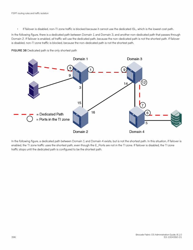
• If failover is disabled, non-TI zone traffic is blocked because it cannot use the dedicated ISL, which is the lowest cost path.
In the following figure, there is a dedicated path between Domain 1 and Domain 3, and another non-dedicated path that passes throughDomain 2. If failover is enabled, all traffic will use the dedicated path, because the non-dedicated path is not the shortest path. If failoveris disabled, non-TI zone traffic is blocked, because the non-dedicated path is not the shortest path.
FIGURE 38 Dedicated path is the only shortest path
In the following figure, a dedicated path between Domain 1 and Domain 4 exists, but is not the shortest path. In this situation, if failover isenabled, the TI zone traffic uses the shortest path, even though the E_Ports are not in the TI zone. If failover is disabled, the TI zonetraffic stops until the dedicated path is configured to be the shortest path.
FSPF routing rules and traffic isolation
Brocade Fabric OS Administration Guide, 8.1.0396 53-1004392-01
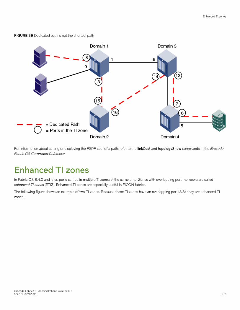
FIGURE 39 Dedicated path is not the shortest path
For information about setting or displaying the FSPF cost of a path, refer to the linkCost and topologyShow commands in the BrocadeFabric OS Command Reference.
Enhanced TI zonesIn Fabric OS 6.4.0 and later, ports can be in multiple TI zones at the same time. Zones with overlapping port members are calledenhanced TI zones (ETIZ). Enhanced TI zones are especially useful in FICON fabrics.
The following figure shows an example of two TI zones. Because these TI zones have an overlapping port (3,8), they are enhanced TIzones.
Enhanced TI zones
Brocade Fabric OS Administration Guide, 8.1.053-1004392-01 397

FIGURE 40 Enhanced TI zones
Refer to the Brocade FICON Administrator's Guide for example topologies using enhanced TI zones.
Refer to Additional configuration rules for enhanced TI zones on page 401 for more information about enhanced TI zones.
Invalid configurations with enhanced TI zonesWhen you create TI zones, ensure that all traffic from a port to all destinations on a remote domain have the same path. Do not createseparate paths from a local port to two or more ports on the same remote domain. If failover is disabled with such configurations, trafficloss can occur.
A message is sent to the RASlog if this potential error condition is detected in the TI zone configuration. You can also display a report ofexisting and potential problems with TI zone configurations, as described in Troubleshooting TI zone routing problems on page 422.
The following cases are examples of invalid enhanced TI zone configurations.
Invalid ETIZ configuration: separate paths from a port to devices on same domainThe following figure shows two enhanced TI zones (failover disabled) that are configured incorrectly because there are two paths from alocal port (port 8 on Domain 3) to two or more devices on the same remote domain (ports 1 and 4 on Domain 1).
The TI zones are enhanced TI zones because they have an overlapping member (3,8). Each zone describes a different path from theTarget to Domain 1. In this case, traffic is routed correctly from Host 1 and Host 2 to the Target; however, traffic from the Target to theHosts would be dropped in the following manner.
Traffic from (3,8) destined for Domain 1 cannot go through both port 6 and port 7. That is, two exclusive paths have been defined, butonly one path will be chosen. If port 6 is chosen (ETIZ 1 path), then frames destined for the Host at Domain 1, N_Port 4 will be droppedat Domain 1, E_Port 2, because this Host is not a member of the ETIZ 1 path. Alternatively, if port 7 is chosen (ETIZ 2 path), thenframes destined for the Host at Domain 1, N_Port 1 will be dropped since it is not a member of the ETIZ 2 path.
Enhanced TI zones
Brocade Fabric OS Administration Guide, 8.1.0398 53-1004392-01
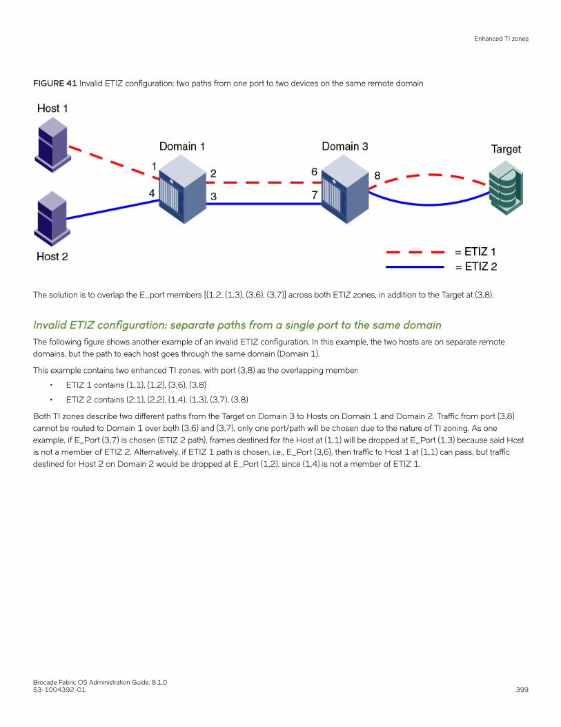
FIGURE 41 Invalid ETIZ configuration: two paths from one port to two devices on the same remote domain
The solution is to overlap the E_port members [(1,2, (1,3), (3,6), (3,7)] across both ETIZ zones, in addition to the Target at (3,8).
Invalid ETIZ configuration: separate paths from a single port to the same domainThe following figure shows another example of an invalid ETIZ configuration. In this example, the two hosts are on separate remotedomains, but the path to each host goes through the same domain (Domain 1).
This example contains two enhanced TI zones, with port (3,8) as the overlapping member:
• ETIZ 1 contains (1,1), (1,2), (3,6), (3,8)
• ETIZ 2 contains (2,1), (2,2), (1,4), (1,3), (3,7), (3,8)
Both TI zones describe two different paths from the Target on Domain 3 to Hosts on Domain 1 and Domain 2. Traffic from port (3,8)cannot be routed to Domain 1 over both (3,6) and (3,7), only one port/path will be chosen due to the nature of TI zoning. As oneexample, if E_Port (3,7) is chosen (ETIZ 2 path), frames destined for the Host at (1,1) will be dropped at E_Port (1,3) because said Hostis not a member of ETIZ 2. Alternatively, if ETIZ 1 path is chosen, i.e., E_Port (3,6), then traffic to Host 1 at (1,1) can pass, but trafficdestined for Host 2 on Domain 2 would be dropped at E_Port (1,2), since (1,4) is not a member of ETIZ 1.
Enhanced TI zones
Brocade Fabric OS Administration Guide, 8.1.053-1004392-01 399

FIGURE 42 Invalid ETIZ configuration: two paths from one port
The solution is to overlap the E_Port members [(1,2),(1,3), (3,6), (3,7)] across both ETIZ zones, in addition to the Target at (3,8); or,overlap all members of both ETIZ zones in this case.
General rules for TI zonesThe following general rules apply to TI zones:
• Ports in a TI zone must belong to switches that run Fabric OS v6.0.0 or later. For TI over FCR zones, all switches and FCrouters in both edge and backbone fabrics must be running Fabric OS v6.1.0 or later.
• For the FC8-64 and FC16-64 blades in the Brocade DCX and DCX 8510-8, ports 48-63 can be in a TI zone, only if allswitches in that TI zone are running Fabric OS v6.4.0 or later. Ports 48-63 can still be in a failover path for TI traffic. TheBrocade DCX-4S and DCX 8510-4 do not have this limitation.
• VE_Ports can be members of TI zones.
• A TI zone must include E_Ports and N_Ports that form a complete, end-to-end route from initiator to target.
• When an E_Port is a member of a TI zone that E_Port cannot have its index swapped with another port.
• If multiple E_Ports are configured that are on the lowest cost route to a domain, the various source ports for that zone are load-balanced across the specified E_Ports.
• TI zones reside only in the defined configuration and not in the effective configuration. When you make any changes to TIzones, including creating or modifying them, you must enable the effective configuration for the changes to take effect, even ifthe effective configuration is unchanged.
• A TI zone only provides traffic isolation and is not a “regular” zone.
• Routing rules imposed by TI zones with failover disabled override regular zone definitions. Regular zone definitions shouldmatch TI zone definitions.
General rules for TI zones
Brocade Fabric OS Administration Guide, 8.1.0400 53-1004392-01
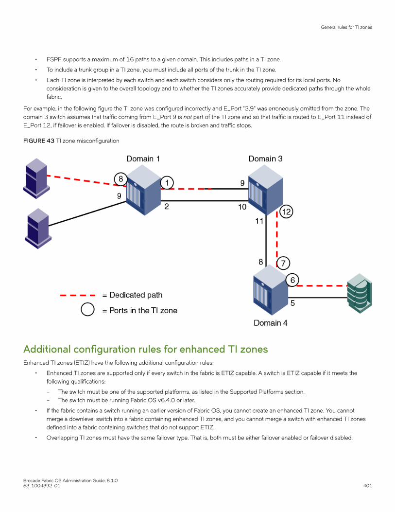
• FSPF supports a maximum of 16 paths to a given domain. This includes paths in a TI zone.
• To include a trunk group in a TI zone, you must include all ports of the trunk in the TI zone.
• Each TI zone is interpreted by each switch and each switch considers only the routing required for its local ports. Noconsideration is given to the overall topology and to whether the TI zones accurately provide dedicated paths through the wholefabric.
For example, in the following figure the TI zone was configured incorrectly and E_Port "3,9" was erroneously omitted from the zone. Thedomain 3 switch assumes that traffic coming from E_Port 9 is not part of the TI zone and so that traffic is routed to E_Port 11 instead ofE_Port 12, if failover is enabled. If failover is disabled, the route is broken and traffic stops.
FIGURE 43 TI zone misconfiguration
Additional configuration rules for enhanced TI zonesEnhanced TI zones (ETIZ) have the following additional configuration rules:
• Enhanced TI zones are supported only if every switch in the fabric is ETIZ capable. A switch is ETIZ capable if it meets thefollowing qualifications:
– The switch must be one of the supported platforms, as listed in the Supported Platforms section.– The switch must be running Fabric OS v6.4.0 or later.
• If the fabric contains a switch running an earlier version of Fabric OS, you cannot create an enhanced TI zone. You cannotmerge a downlevel switch into a fabric containing enhanced TI zones, and you cannot merge a switch with enhanced TI zonesdefined into a fabric containing switches that do not support ETIZ.
• Overlapping TI zones must have the same failover type. That is, both must be either failover enabled or failover disabled.
General rules for TI zones
Brocade Fabric OS Administration Guide, 8.1.053-1004392-01 401

NOTEFC router domains are excluded from the ETIZ platform restrictions. You can create enhanced TI zones with these switches inthe fabric.
Limitations and restrictions of Traffic Isolation ZoningThe following limitations and restrictions apply to Traffic Isolation Zoning:
• A maximum of 255 TI zones can be created in one fabric. A fabric merge resulting in greater than the maximum allowed TIzones results in merge failure and the fabrics are segmented.
• A TI zone can be created using D,I (Domain, Index) notation only, except for TI zones in a backbone fabric, which use portWWNs. Refer to Traffic Isolation Zoning over FC routers on page 406 for information about TI zones in a backbone fabric.
• To include a trunk group in a TI zone, you must include all ports of the trunk in the TI zone.
• If two N_Ports are online and have the same shared area, and one of them is configured in a TI zone, then they both must beconfigured in that same TI zone. One of the online shared area N_Ports should not remain outside the TI zone unless it isoffline, then it may remain outside the TI zone.
• Port swapping is not permitted in TI zones.
• Ports that are in different TI zones cannot communicate with each other if failover is disabled.
• TI zone members that overlap must have the same TI failover policy across all TI zones to which they belong. That is, if anoverlapping member is part of a failover-disabled zone, then it can belong only to other TI zones where the policy is alsofailover-disabled; the member cannot overlap with failover-enabled TI zones.
• TI zones that have members with port index greater than 511 are not supported with Fabric OS versions earlier than 6.4.0. Ifsuch a TI zone and Fabric OS version combination is detected, a warning is issued. These configurations are not prevented, buttheir behavior is unpredictable.
• When you merge two switches, if there is an effective configuration on the switches and TI zones are present on either switch,the TI zones are not automatically activated after the merge. Check the TI zone enabled status using the zone --showcommand, and if the TI Zone Enabled status does not match across switches, issue the cfgEnable command.
• Use care when creating TI zones on ICL ports in topologies that span more than two switches connected with ICLs. If a user-defined TI zone breaks the ICL connectivity requirements, a FSPF-1009 RASLog entry and message is generated to notifyyou of this error condition.
• In a backbone switch, if a TI zone is configured with the remote switch EX_Port even though locally the same ASIC EX_Portexists to reach the destination edge fabric, then PLOGI takes thesame local ASIC EX_Port to send the frame out instead of TIZone EX_Port. Thus, the PLOGI frame is sent out to the edge fabric without translation and gets dropped. To resolve this issue,move the connected destination EX_Port to different ASICs to route based on the configured TI zone.
• When an edge fabric is connected to both a local FC router and a remote FC router, you must configure a TI zone only on thelocal FC router EX_Port. If you have already configured the FC router TI zone on the remote FC router EX_Port, disable thelocal FC router EX_Port that is connected to the edge fabric and restart the discovery.
Creating a TI zoneYou can create TI zones using the zone --create command.
zone --create -t objtype [-o option list] name -p "port list"
The "-t" option specifies the type and should always be specified as "ti" when creating TI zones. When you create a TI zone, you canenable or disable failover mode. By default, failover mode is enabled. You can also set the state of the TI zone to activated or
Limitations and restrictions of Traffic Isolation Zoning
Brocade Fabric OS Administration Guide, 8.1.0402 53-1004392-01

deactivated. By default the zone state is set to the activated state. The following values are used to configure these behaviors using the"-o" option:
TABLE 86 Values used to configure failover mode for TI zones
Possible values for "-o"option list
Description
f Create a TI zone with failover enabled; mutually exclusive with the 'n' option
n Create a TI zone with failover disabled; mutually exclusive with the 'f' option
a Configure the TI zone as activated; mutually exclusive with the 'd' option
d Configure the TI zone as deactivated; mutually exclusive with the 'a' option
The "name" option specifies the TI zone name.
The "-p" option lets you define the members of the TI zone, typically the N_Ports and E_Ports specified using Domain and Port Index.For example, given an E_Port at Port Index 12 on Domain ID 5, the resulting TI zone member would be "5,12".
In addition to running zone --create to define a TI zone, the effective zoning configuration must also be re-enabled in order to apply theTI zone.
Use the following procedure to create a TI zone:
1. Connect to the switch and log in using an account with admin permissions.
2. Enter the zone --create command, specifying failover mode, activated/deactivated status, TI zone name, and TI zone members(N_Ports and E_Ports)
3. Enter the cfgEnable command , specifying the current effective configuration.
TI zone updates are not applied until cfgEnable is executed
Example for a TI zone named "bluezone" with failover disabled ('n' option) and an "activated" state ('a' option):
switch:admin> zone --create -t ti -o an bluezone -p "10,44; 20,44; 10,38; 20,8"switch:admin> cfgEnable “myConfiguration”
Example for a TI zone named "redzone" with failover enabled ('f' option) and a "deactivated" state ('d' option):
switch:admin> zone --create -t ti -o fd redzone -p "1,4; 2,4; 1,8; 2,7"switch:admin> cfgEnable “myConfiguration”
Modifying TI zonesUsing the zone --add command, you can do the following:
• add ports to an existing TI zone
• change the failover option
• activate or deactivate a TI zone
You must reactivate the effective configuration to apply the changes (cfgEnable). Example, changing a TI zone named "greenzone" tofailover enabled:
switch:admin> zone --add -o f greenzoneswitch:admin> cfgEnable “myConfiguration”
Using the zone --remove command, you can remove ports from existing TI zones. If you remove the last member of a TI zone, the TIzone is deleted. You must reactivate the effective configuration to apply the changes (cfgEnable).
Modifying TI zones
Brocade Fabric OS Administration Guide, 8.1.053-1004392-01 403

Example, removing "5,1" from a TI zone named "silverzone":
switch:admin> zone --remove silverzone -p "5,1"switch:admin> cfgEnable “myConfiguration”
NOTEIf you have overlapping TI zones and you want to change the failover option on these zones, you must first remove theoverlapping ports from the zones, then change the failover type, and finally re-add the overlapping members.
Changing the state of a TI zoneYou can change the configured state of an existing TI zone to activated or deactivated. As is the case with other TI zoning operations, youmust enable the current effective configuration to apply the change.
1. Connect to the switch and log in using an account with admin permissions.
2. Perform one of the following actions:
• To activate a TI zone, enter the zone --activate command.
zone --activate name
• To deactivate a TI zone, enter the zone --deactivate command.
zone --deactivatename
3. Enter the cfgEnable command to reactivate your current effective configuration and enforce the TI zones.
cfgenable "current_effective_configuration"
Deleting a TI zoneUse the zone --delete command to delete a TI zone from the defined configuration. This command deletes the entire zone; to onlyremove port members from a TI zone, use the zone --remove command, as described in Modifying TI zones on page 403.
1. Connect to the switch and log in using an account with admin permissions.
2. Enter the zone --delete command.
zone --delete name
You can delete multiple zones by separating the zone names with a semicolon and enclosing them in quotation marks.
3. Enter the cfgEnable command to reactivate your current effective configuration and apply the TI zone delete operation.
cfgenable "current_effective_configuration"
Displaying TI zonesUse the zone --show command to display information about TI zones. This command displays the following information for each zone:
• Zone name
• E_Port members
Changing the state of a TI zone
Brocade Fabric OS Administration Guide, 8.1.0404 53-1004392-01

• N_Port members
• Configured status (the latest status, which may or may not have been activated by cfgEnable )
• Enabled status (the status that has been activated by cfgEnable )
1. Connect to the switch and log in using an account with admin permissions.
2. Enter the zone --show command.
zone --show [ name ] [-ascending]
Examples of displaying TI zone informationExample: Displaying information about the TI zone purplezone
switch:admin> zone --show purplezone
Defined TI zone configuration: TI Zone Name: redzone:Port List: 1,2; 1,3; 3,3; 4,5Configured Status: Activated / Failover-EnabledEnabled Status: Activated / Failover-Enabled
Example: Displaying information about all TI zones in the defined configuration in ascending order
switch:admin> zone --show -ascending
Defined TI zone configuration: TI Zone Name: bluezone:Port List: 8,3; 8,5; 9,2; 9,3;Configured Status: Deactivated / Failover-DisabledEnabled Status: Activated / Failover-EnabledTI Zone Name: greenzone:Port List: 2,2; 3,3; 4,11; 5,3;Configured Status: Activated / Failover-EnabledEnabled Status: Activated / Failover-EnabledTI Zone Name: purplezone:Port List: 1,2; 1,3; 3,3; 4,5;Configured Status: Activated / Failover-EnabledEnabled Status: Deactivated / Failover-Enabled
Example: Displaying members for the zone "ti_red" in ascending order
switch:admin> zone --show -ascending ti_redDefined TI zone configuration:TI Zone Name: ti_redPort List: 3,3; 4,4; 5,5Configured Status: Activated / Failover-EnabledEnabled Status: Deactivated
Example: Displaying members for the zone "TI_zone", regardless of the case
switch:admin> zone --show -ic TI_zone* Defined TI zone configuration:TI Zone Name: TI_zonePort List: 7,8Configured Status: Activated / Failover-EnabledEnabled Status: DeactivatedTI Zone Name: ti_zonePort List: 3,3Configured Status: Activated / Failover-EnabledEnabled Status: Deactivated
Displaying TI zones
Brocade Fabric OS Administration Guide, 8.1.053-1004392-01 405

Enforcing Local TI FilteringLocal TI Filtering prevents or restricts unwanted traffic flow by enforcing local-to-local TI zone rules.
Prior to Fabric OS 7.4.0, if regular zoning of local-to-local flows did not reflect the same connectivity as the TI zoning, there were caseswhere the Name Server reported that the connectivity was allowed, but the connectivity was restricted at the routing layers due to TIzoning rules.
Starting with Fabric OS 7.4.0, the Local TI Filtering feature enforces the TI zone rules on local-to-local flows.
Use the configure command to configure Local TI Filtering. By default, this feature is disabled. Disable the switch before configuringLocal TI Filtering.
Configuring the Local TI Filtering exampleUse Local TI Filtering, listed under Zoning Operation parameters of the configure command, to enable or disable the feature.
switch:admin> switchdisableswitch:admin> configure
Configure...
Fabric parameters (yes, y, no, n): [no] Virtual Channel parameters (yes, y, no, n): [no] F-Port login parameters (yes, y, no, n): [no] D-Port Parameters (yes, y, no, n): [no] RDP Polling Cycle(hours)[0 = Disable Polling]: (0..24) [1] Zoning Operation parameters (yes, y, no, n): [no] y
Disable NodeName Zone Checking: (0..1) [0] Ti Zone Filtering (on, off): [off]……… <output truncated>
Traffic Isolation Zoning over FC routersTI zoning can be used with FC routed fabrics with failover enabled. To achieve end-to-end traffic isolation across the metaSAN, TI zonesmust be configured at each relevant edge fabric, and the backbone fabric, within the metaSAN.
Some VE_Port-based features, such as tape pipelining, require the request and corresponding response traffic to traverse the sameVE_Port tunnel across the metaSAN. To ensure that the request and response traverse the same VE_Port tunnel, you must set up TrafficIsolation zones in the edge and backbone fabrics.
• Set up a TI zone in an edge fabric to guarantee that traffic from a specific device in that edge fabric is routed through a particularEX_Port or VEX_Port.
• Set up a TI zone in the backbone fabric to guarantee that traffic between two devices in different fabrics is routed through aparticular ISL (VE_Ports or E_Ports) in the backbone.
This combination of TI zones in the backbone and edge fabrics ensures that the traffic between devices in different fabrics traverses thesame VE_Port tunnel in a backbone fabric. Figure 44 shows how three TI zones form a dedicated path between devices in different edgefabrics. The backbone fabric can contain one or more FC routers.
Enforcing Local TI Filtering
Brocade Fabric OS Administration Guide, 8.1.0406 53-1004392-01

FIGURE 44 Traffic Isolation Zoning over FCR
In addition to setting up TI zones, you must also ensure that the devices are in an LSAN zone so that they can communicate with eachother.
If failover is enabled and the TI path is not available, an alternate path is used. If failover is disabled and the TI path is not available, thendevices are not imported.
TI zones within an edge fabricA TI zone within an edge fabric is used to route traffic between a real device and a proxy device through a particular EX_Port.
For example, in Figure 45, you can set up a TI zone to ensure that traffic between Host 1 and the proxy target is routed through EX_Port9.
Enforcing Local TI Filtering
Brocade Fabric OS Administration Guide, 8.1.053-1004392-01 407

FIGURE 45 TI zone in an edge fabric
In the TI zone, when you designate E_Ports between the front and xlate phantom switches, you must use -1 in place of the "I" in the D,Inotation. Both the front and xlate domains must be included in the TI zone.
Using D,I notation, the members of the TI zone in Figure 45 are as follows:
• 1,8
• 1,1
• 3,-1 (E_Port for the front phantom domain)
• 4,-1 (E_Port for the xlate phantom domain)
NOTEIn this configuration the traffic between the front and xlate domains can go through any path between these two domains. The-1 does not identify any specific ISL. To guarantee a specific ISL, you need to set up a TI zone within the backbone fabric.
TI zones within a backbone fabricA TI zone within a backbone fabric is used to route traffic within the backbone fabric through a particular ISL.
For example, in Figure 46, a TI zone is set up in the backbone fabric to ensure that traffic between EX_Ports "1,1" and "2,1" is routedthrough VE_Ports "1,4" and "2,7".
Enforcing Local TI Filtering
Brocade Fabric OS Administration Guide, 8.1.0408 53-1004392-01
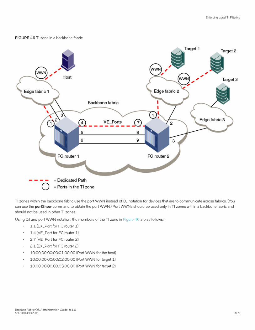
FIGURE 46 TI zone in a backbone fabric
TI zones within the backbone fabric use the port WWN instead of D,I notation for devices that are to communicate across fabrics. (Youcan use the portShow command to obtain the port WWN.) Port WWNs should be used only in TI zones within a backbone fabric andshould not be used in other TI zones.
Using D,I and port WWN notation, the members of the TI zone in Figure 46 are as follows:
• 1,1 (EX_Port for FC router 1)
• 1,4 (VE_Port for FC router 1)
• 2,7 (VE_Port for FC router 2)
• 2,1 (EX_Port for FC router 2)
• 10:00:00:00:00:01:00:00 (Port WWN for the host)
• 10:00:00:00:00:02:00:00 (Port WWN for target 1)
• 10:00:00:00:00:03:00:00 (Port WWN for target 2)
Enforcing Local TI Filtering
Brocade Fabric OS Administration Guide, 8.1.053-1004392-01 409

Limitations of TI zones over FC routersBe aware of the following when configuring TI zones over FC routers:
• A TI zone defined within the backbone fabric does not guarantee that edge fabric traffic will arrive at a particular EX_Port. Youmust set up a TI zone in the edge fabric to guarantee this.
• TI zones within the backbone fabric cannot contain more than one destination router port (DRP) per each fabric. This meansyou cannot define more than one EX_Port to any one edge fabric unless they are part of a trunk.
• Only one egress E_Port or VE_Port connected to the next hop can be defined within TI zones. Only one ISL or trunk can bedefined between two backbone switches. The E_Port in the backbone fabric TI zone should be the least cost ISL.
• TI over FCR is supported only from edge fabric to edge fabric. Traffic isolation from backbone to edge is not supported.
• Non-TI data traffic is not restricted from going through the TI path in the backbone fabric.
• For TI over FCR, failover must be enabled in the TI zones in the edge fabrics and in the backbone fabric.
• TI over FCR is not supported with FC Fast Write.
• ETIZ over FCR is not supported.
• Configuring backbone TI zone with remote FC router EX_Port is not supported if local chassis has the EX_Port to source anddestination edge fabric in the same chip/port group.
• For the FX8-24 blades only: If Virtual Fabrics is disabled, two or more shared area EX_Ports connected to the same edgefabric should not be configured in different TI zones. This configuration is not supported.
Fabric-Level Traffic Isolation in a backbone fabricFor Fibre Channel Routed (FCR) environments, you can use TI zoning if you want traffic isolation only at the fabric level and not at thedevice level.
For example, two fabrics within a MetaSAN need to communicate only with each other. There is no other traffic across the backbone thatgoes from either of these edge fabrics to any other edge fabric in the MetaSAN. In this case, all of the traffic entering the FCR backbonefrom one of these edge fabrics will go to the other edge fabric. If these two edge fabrics are connected to two different backboneswitches (FC routers), then traffic between these fabrics can be isolated to a specified set of links within the backbone fabric using one oftwo methods:
• TI over FCR, which includes the PWWN of devices and maintains device level isolation
• TI zoning in the backbone, which provides fabric level isolation
If device-level isolation is needed from one edge fabric to another, then use TI over FCR using Port World Wide Names (PWWNs).However, if there is no need for device-level isolation, but a need for fabric-level isolation, then use Fabric-Level Traffic Isolation,described in this section.
TI over FCR is described in Traffic Isolation Zoning over FC routers on page 406.
If two edge fabrics are connected to two different backbone switches, then traffic between these fabrics can be isolated to a specified setof links within the backbone fabric using TI zoning in the backbone without including device PWWNs. This is called Fabric-Level TrafficIsolation, as shown in the following figure.
Fabric-Level Traffic Isolation in a backbone fabric
Brocade Fabric OS Administration Guide, 8.1.0410 53-1004392-01

FIGURE 47 Fabric-level traffic isolation
In the figure, there are two links between each edge fabric and the backbone fabric, and there are five links between the two FC routers inthe backbone. Fabric ID 1 and Fabric ID 4 communicate only with each other. Two backbone ISLs are dedicated to traffic between FID1and FID4. These dedicated ISL are indicted in red and blue.
Fabric-Level TI zonesFabric-Level Traffic Isolation is accomplished through the use of TI zones. These zones define the dedicated set of paths between thetwo fabrics. These paths are to be restricted to just the traffic between the two fabrics.
Fabric-Level TI zones are defined in the backbone fabric, and include only EX_Ports and E_Ports in the backbone fabric. The TI zonesdo not include device PWWNs or ports in the edge fabrics.
The TI zone must include every port in the path from ingress EX_Port to egress EX_Port. The TI zone definitions must include allEX_Ports connected to the two edge fabrics. Unless all possible ingress ports are included, some traffic will not be isolated to the desiredpaths.
Fabric-Level Traffic Isolation is not enforced on the egress EX_Ports. Any available egress IFL can be used, regardless of whether it is inthe Fabric-Level TI zone.
The following rules apply to creating Fabric-Level TI zones:
• Include all EX_Ports connected to the two edge fabrics.
Fabric-Level Traffic Isolation in a backbone fabric
Brocade Fabric OS Administration Guide, 8.1.053-1004392-01 411
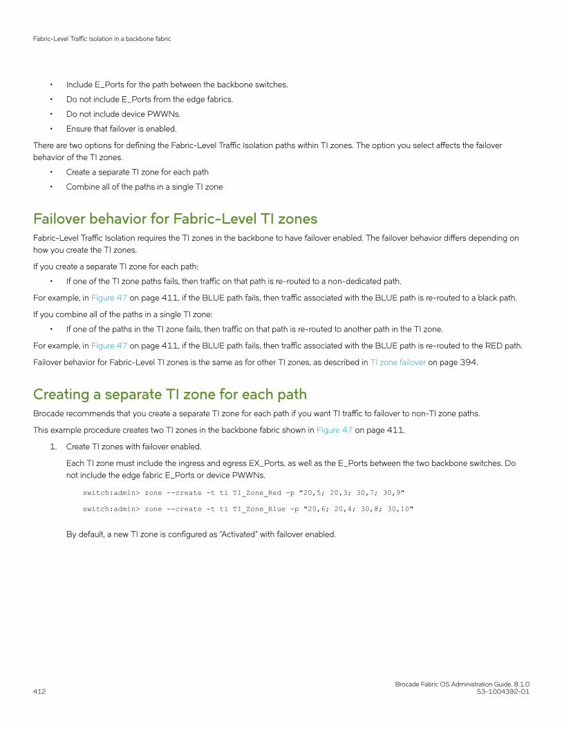
• Include E_Ports for the path between the backbone switches.
• Do not include E_Ports from the edge fabrics.
• Do not include device PWWNs.
• Ensure that failover is enabled.
There are two options for defining the Fabric-Level Traffic Isolation paths within TI zones. The option you select affects the failoverbehavior of the TI zones.
• Create a separate TI zone for each path
• Combine all of the paths in a single TI zone
Failover behavior for Fabric-Level TI zonesFabric-Level Traffic Isolation requires the TI zones in the backbone to have failover enabled. The failover behavior differs depending onhow you create the TI zones.
If you create a separate TI zone for each path:
• If one of the TI zone paths fails, then traffic on that path is re-routed to a non-dedicated path.
For example, in Figure 47 on page 411, if the BLUE path fails, then traffic associated with the BLUE path is re-routed to a black path.
If you combine all of the paths in a single TI zone:
• If one of the paths in the TI zone fails, then traffic on that path is re-routed to another path in the TI zone.
For example, in Figure 47 on page 411, if the BLUE path fails, then traffic associated with the BLUE path is re-routed to the RED path.
Failover behavior for Fabric-Level TI zones is the same as for other TI zones, as described in TI zone failover on page 394.
Creating a separate TI zone for each pathBrocade recommends that you create a separate TI zone for each path if you want TI traffic to failover to non-TI zone paths.
This example procedure creates two TI zones in the backbone fabric shown in Figure 47 on page 411.
1. Create TI zones with failover enabled.
Each TI zone must include the ingress and egress EX_Ports, as well as the E_Ports between the two backbone switches. Donot include the edge fabric E_Ports or device PWWNs.
switch:admin> zone --create -t ti TI_Zone_Red -p "20,5; 20,3; 30,7; 30,9" switch:admin> zone --create -t ti TI_Zone_Blue -p "20,6; 20,4; 30,8; 30,10"
By default, a new TI zone is configured as "Activated" with failover enabled.
Fabric-Level Traffic Isolation in a backbone fabric
Brocade Fabric OS Administration Guide, 8.1.0412 53-1004392-01

2. Display defined TI zones.
switch:admin> zone --show Defined TI zone configuration:TI Zone Name: TI_Zone_BluePort List: 20,6; 20,4; 30,8; 30,10Configured Status: Activated / Failover-EnabledEnabled Status: DeactivatedTI Zone Name: TI_Zone_RedPort List: 20,5; 20,3; 30,7; 30,9Configured Status: Activated / Failover-EnabledEnabled Status: Deactivated
Be aware that although the configured status is "Activated", the enabled status is "Deactivated".
3. Activate TI zones.
switch:admin> cfgactvshow Effective configuration:cfg: <current effective configuration>...switch:admin> cfgenable <current effective configuration> You are about to enable a new zoning configuration.This action will replace the old zoning configuration with thecurrent configuration selected. If the update includes changesto one or more traffic isolation zones, the update may result inlocalized disruption to traffic on ports associated withthe traffic isolatoin zone changesDo you want to enable ’TI_Config’ configuration (yes, y, no, n): [no] y zone config "name" is in effectUpdating flash ...switch:admin> Switch:admin> zone --show Defined TI zone configuration:TI Zone Name: TI_Zone_BluePort List: 20,6; 20,4; 30,8; 30,10Configured Status: Activated / Failover-EnabledEnabled Status: Activated / Failover-EnabledTI Zone Name: TI_Zone_RedPort List: 20,5; 20,3; 30,7; 30,9Configured Status: Activated / Failover-EnabledEnabled Status: Activated / Failover-Enabled
The enabled status now displays as "Activated".
Creating a single TI zone for all pathsBrocade recommends that you create a single TI zone for all paths if you want TI traffic to failover to other paths in the TI zone.
1. Create a single TI zone with failover enabled.
The TI zone must include the ingress and egress EX_Ports, as well as the E_Ports between the two backbone switches. Do notinclude the edge fabric E_Ports or device PWWNs.
switch:admin> zone --create -t ti TI_Zone_ALL -p "20,3; 20,4; 20,5; 20,6; 30,7; 30,8; 30,9 30,10"
By default, a new TI zone is configured as "Activated" with failover enabled.
Fabric-Level Traffic Isolation in a backbone fabric
Brocade Fabric OS Administration Guide, 8.1.053-1004392-01 413

2. Display defined TI zone.
switch:admin> zone --show Defined TI zone configuration:TI Zone Name: TI_Zone_ALLPort List: 20,3; 20,4 20,5; 20,6; 30,7; 30,8; 30,9; 30,10Configured Status: Activated / Failover-EnabledEnabled Status: Deactivated
Be aware that although the configured status is "Activated", the enabled status is "Deactivated".
3. Activate the TI zone.
switch:admin> cfgactvshow Effective configuration:cfg: <current effective configuration>...switch:admin> cfgenable <current effective configuration> You are about to enable a new zoning configuration.This action will replace the old zoning configuration with thecurrent configuration selected. If the update includes changesto one or more traffic isolation zones, the update may result inlocalized disruption to traffic on ports associated withthe traffic isolatoin zone changesDo you want to enable ’TI_Config’ configuration (yes, y, no, n): [no] y zone config "name" is in effectUpdating flash ...switch:admin> Switch:admin> zone --show Defined TI zone configuration:TI Zone Name: TI_Zone_ALLPort List: 20,3; 20,4; 20,5; 20,6; 30,7; 30,8; 30,9; 30,10Configured Status: Activated / Failover-EnabledEnabled Status: Activated / Failover-Enabled
Then enabled status now displays as "Activated".
Setting up TI zones over FCR (sample procedure)The following example shows how to set up TI zones over FCR to provide a dedicated path, as shown in Figure 48. In this example, threeTI zones are created: one in each of the edge fabrics and one in the backbone fabric. The combination of these three TI zones creates adedicated path for traffic between Host 1 in edge fabric 1 and Targets 1 and 2 in edge fabric 2.
Host 1 has port WWN 10:00:00:00:00:08:00:00
Target 1 has port WWN 10:00:00:00:00:02:00:00
Target 2 has port WWN 10:00:00:00:00:03:00:00
Fabric-Level Traffic Isolation in a backbone fabric
Brocade Fabric OS Administration Guide, 8.1.0414 53-1004392-01

FIGURE 48 TI over FCR example
NOTEIn the following procedure the three TI zones in the edge and backbone fabrics are all given the same name, TI_Zone1. It is notrequired that the TI zones have the same name, but this is done to avoid confusion. If several dedicated paths are set up acrossthe FC router, the TI zones for each path can have the same name.
1. In each edge fabric, set up an LSAN zone that includes Host 1, Target 1, and Target 2, so these devices can communicate witheach other. Refer to Using FC-FC Routing to Connect Fabrics on page 513 for information about creating LSAN zones.
Fabric-Level Traffic Isolation in a backbone fabric
Brocade Fabric OS Administration Guide, 8.1.053-1004392-01 415

2. Log in to the edge fabric 1 and set up the TI zone.
a) Enter the fabricShow command to display the switches in the fabric. From the output, you can determine the front andtranslate domains.
E1switch:admin> fabricshow Switch ID Worldwide Name Enet IP Addr FC IP Addr Name------------------------------------------------------------------------- 1: fffc01 50:00:51:e3:95:36:7e:04 0.0.0.0 0.0.0.0 "fcr_fd_1" 4: fffc04 10:00:00:60:69:80:1d:bc 10.32.72.4 0.0.0.0 >"E1switch" 6: fffc06 50:00:51:e3:95:48:9f:a0 0.0.0.0 0.0.0.0 "fcr_xd_6_9"The Fabric has 3 switches
b) Enter the following commands to create and display a TI zone:
E1switch:admin> zone --create -t ti TI_Zone1 -p "4,8; 4,5, 1,-1; 6,-1" E1switch:admin> zone --show Defined TI zone configuration:TI Zone Name: TI_Zone1Port List: 4,8; 4,5; 1,-1; 6,-1Status: Activated Failover: Enabled
c) Enter the following commands to reactivate your current effective configuration and enforce the TI zones.
E1switch:admin> cfgactvshow Effective configuration: cfg: cfg_TI zone: lsan_t_i_TI_Zone1 10:00:00:00:00:00:02:00:00 10:00:00:00:00:00:03:00:00 10:00:00:00:00:00:08:00:00E1switch:admin> cfgenable cfg_TI You are about to enable a new zoning configuration.This action will replace the old zoning configuration with thecurrent configuration selected.If the update includes changes to one or more traffic isolation zones, the update may result in localized disruption to traffic on ports associated with the traffic isolation zone changesDo you want to enable 'cfg_TI' configuration (yes, y, no, n): [no] yzone config "cfg_TI" is in effectUpdating flash ...
Fabric-Level Traffic Isolation in a backbone fabric
Brocade Fabric OS Administration Guide, 8.1.0416 53-1004392-01
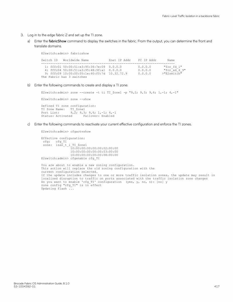
3. Log in to the edge fabric 2 and set up the TI zone.
a) Enter the fabricShow command to display the switches in the fabric. From the output, you can determine the front andtranslate domains.
E2switch:admin> fabricshow Switch ID Worldwide Name Enet IP Addr FC IP Addr Name------------------------------------------------------------------------- 1: fffc01 50:00:51:e3:95:36:7e:09 0.0.0.0 0.0.0.0 "fcr_fd_1" 4: fffc04 50:00:51:e3:95:48:9f:a1 0.0.0.0 0.0.0.0 "fcr_xd_6_9" 9: fffc09 10:00:00:05:1e:40:f0:7d 10.32.72.9 0.0.0.0 >"E2switch"The Fabric has 3 switches
b) Enter the following commands to create and display a TI zone:
E2switch:admin> zone --create -t ti TI_Zone1 -p "9,2; 9,3; 9,6; 1,-1; 4,-1" E2switch:admin> zone --show Defined TI zone configuration:TI Zone Name: TI_Zone1Port List: 9,2; 9,3; 9,6; 1,-1; 4,-1Status: Activated Failover: Enabled
c) Enter the following commands to reactivate your current effective configuration and enforce the TI zones.
E2switch:admin> cfgactvshow Effective configuration: cfg: cfg_TI zone: lsan_t_i_TI_Zone1 10:00:00:00:00:00:02:00:00 10:00:00:00:00:00:03:00:00 10:00:00:00:00:00:08:00:00E2switch:admin> cfgenable cfg_TI You are about to enable a new zoning configuration.This action will replace the old zoning configuration with thecurrent configuration selected.If the update includes changes to one or more traffic isolation zones, the update may result in localized disruption to traffic on ports associated with the traffic isolation zone changesDo you want to enable 'cfg_TI' configuration (yes, y, no, n): [no] yzone config "cfg_TI" is in effectUpdating flash ...
Fabric-Level Traffic Isolation in a backbone fabric
Brocade Fabric OS Administration Guide, 8.1.053-1004392-01 417

4. Log in to the backbone fabric and set up the TI zone.
FCR_Domain_1:admin> fabricshowSwitch ID Worldwide Name Enet IP Addr FC IP Addr Name------------------------------------------------------------------------- 1: fffc01 10:00:00:05:1e:52:3a:00 10.38.135.15 0.0.0.0 >"FCR_Domain_1" 2: fffc02 10:00:00:27:f8:f1:0b:40 10.38.135.19 0.0.0.0 "FCR_Domain_2"
The Fabric has 2 switches
The Backbone domains are represented in "D,I" notation in TI zone configuration.
a) Enter the following commands to create and display a TI zone:
FCR_Domain_1:admin> zone --create -t ti TI_Zone1 -p "1,9; 1,1; 2,4; 2,7;10:00:00:00:00:08:00:00; 10:00:00:00:00:02:00:00; 10:00:00:00:00:03:00:00"FCR_Domain_1:admin> zone --showDefined TI zone configuration:TI Zone Name: TI_Zone1Port List: 1,9; 1,1; 2,4; 2,7; 10:00:00:00:00:08:00:00;10:00:00:00:00:02:00:00; 10:00:00:00:00:03:00:00Status: Activated Failover: Enabled
b) Enter the following commands to reactivate your current effective configuration and enforce the TI zones.
FCR_Domain_1:admin> cfgactvshowEffective configuration:cfg: cfg_TIzone: lsan_t_i_TI_Zone110:00:00:00:00:00:02:00:0010:00:00:00:00:00:03:00:0010:00:00:00:00:00:08:00:00FCR_Domain_1:admin> cfgenable cfg_TIYou are about to enable a new zoning configuration.This action will replace the old zoning configuration with thecurrent configuration selected.If the update includes changes to one or more traffic isolation zones, theupdate may result in localized disruption to traffic on ports associatedwith the traffic isolation zone changesDo you want to enable 'cfg_TI' configuration (yes, y, no, n): [no] yzone config "cfg_TI" is in effectUpdating flash ...
Virtual Fabrics considerations for Traffic IsolationZoningTI zones can be created in a logical fabric like in regular fabrics, with the following exceptions:
• The disable failover option is not supported in logical fabrics that use extended ISLs (XISLs).
Although logical switches that use XISLs allow the creation of a TI zone with failover disabled, this is not a supportedconfiguration. Base switches do not allow the creation of a TI zone with failover disabled.
• To create a TI zone for a logical fabric that uses XISLs, you must create two TI zones: one in the logical fabric and one in thebase fabric. The combination of TI zones in the base fabric and logical fabric sets the path through the base fabric for logicalswitches.
The TI zone in the logical fabric includes the XISL port numbers, as well as the F_Ports and ISLs in the logical fabric.
Because base fabrics do not contain end devices, they normally do not have an effective zone configuration. To activate a TI zone in abase fabric, you must create a "dummy" configuration. TI zones are otherwise created in the same manner as a regular fabric with theexception that TI zone failover cannot be disabled with TI zones in the base fabric.
Virtual Fabrics considerations for Traffic Isolation Zoning
Brocade Fabric OS Administration Guide, 8.1.0418 53-1004392-01

The TI zone in the base fabric reserves XISLs for a particular logical fabric. The base fabric TI zone should also include ISLs that belongto logical switches participating in the logical fabric.
The following figure shows an initiator and target in a logical fabric (FID1). The dotted line indicates a dedicated path between initiator andtarget. The dedicated path passes through the base fabric over an XISL. (The figure shows only physical ISLs, not logical ISLs.) To createthe TI zones for this dedicated path, you must create a TI zone in the logical fabric (FID 1) and one in the base fabric.
FIGURE 49 Dedicated path with Virtual Fabrics
The following figure shows a logical representation of FID1 in Figure 49. To create the dedicated path, you must create and activate a TIzone in FID1 that includes the circled ports shown in the following figure.
FIGURE 50 Creating a TI zone in a logical fabric
Virtual Fabrics considerations for Traffic Isolation Zoning
Brocade Fabric OS Administration Guide, 8.1.053-1004392-01 419

You must also create and activate a TI zone in the base fabric to reserve the XISLs for the dedicated path. In the following figure, theXISLs (indicated by a dotted line) in the base fabric can be reserved for FID1 by defining and activating a base fabric TI zone thatconsists of ports 10, 12, 14, and 16. You must also include ports 3 and 8, because they belong to logical switches participating in thelogical fabric. For the TI zone, it is as though ports 3 and 8 belong to Domains 1 and 2, respectively.
FIGURE 51 Creating a TI zone in a base fabric
Using D,I notation, the port numbers for the TI zones in the logical fabric and base fabric are as follows:
TABLE 87 Port numbers used in TI zones
Port members for the TI zone in logical fabric Port members for the TI zone in base fabric
8,8 F_Port
8,1 E_Port
3,3 E_Port
3,10 E_Port
5,16 E_Port
5,8 E_Port
9,5 E_Port
9,9 F_Port
1,3 E_Port for ISL in logical switch
1,10 E_Port for XISL
7,12 E_Port for XISL
7,14 E_Port for XISL
2,16 E_Port for XISL
2,8 E_Port for ISL in logical switch
Notice that the base fabric zone contains a reference to port 1,3 even though the base switch with domain 1 does not have a port 3 inthe switch. This number refers to the port in the chassis with port index 3, which actually belongs to LS3 in FID 1.
Traffic Isolation Zoning over FC routers with VirtualFabricsThis section describes how you can set up TI zones over FC routers in logical fabrics. Figure 52 shows two physical chassis configuredinto logical switches. The initiator in FID 1 communicates with the target in FID 3 over the EX_Ports in the base switches.
Traffic Isolation Zoning over FC routers with Virtual Fabrics
Brocade Fabric OS Administration Guide, 8.1.0420 53-1004392-01

FIGURE 52 Example configuration for TI zones over FC routers in logical fabrics
Figure 53 shows a logical representation of the configuration in Figure 52. This SAN is similar to that shown in Figure 44 on page 407and you would set up the TI zones in the same way as described in Traffic Isolation Zoning over FC routers on page 406.
Traffic Isolation Zoning over FC routers with Virtual Fabrics
Brocade Fabric OS Administration Guide, 8.1.053-1004392-01 421

FIGURE 53 Logical representation of TI zones over FC routers in logical fabrics
Troubleshooting TI zone routing problemsUse the following procedure to generate a report of existing and potential problems with TI zones. The report displays an error type.
• "ERROR" indicates a problem currently exists in the fabric.
• "WARNING" indicates that there is not currently a problem, given the current set of online devices and reachable domains, butgiven the activated TI zone configuration, parallel exclusive paths between a shared device and a remote domain have beendetected, which might cause a problem for devices that join the fabric later.
1. Connect to the switch and log in using an account with admin permissions.
2. Enter the zone --showTIerrors command.
zone --showTIerrors
Here is an example report that would be generated for the illegal configuration shown in Figure 41 on page 399.
switch:admin> zone --showTIerrors My Domain: 3Error type: ERRORAffected Remote Domain: 1Affected Local Port: 8Affected TI Zones: etiz1, etiz2Affected Remote Ports: 1, 2, 3, 4
Troubleshooting TI zone routing problems
Brocade Fabric OS Administration Guide, 8.1.0422 53-1004392-01
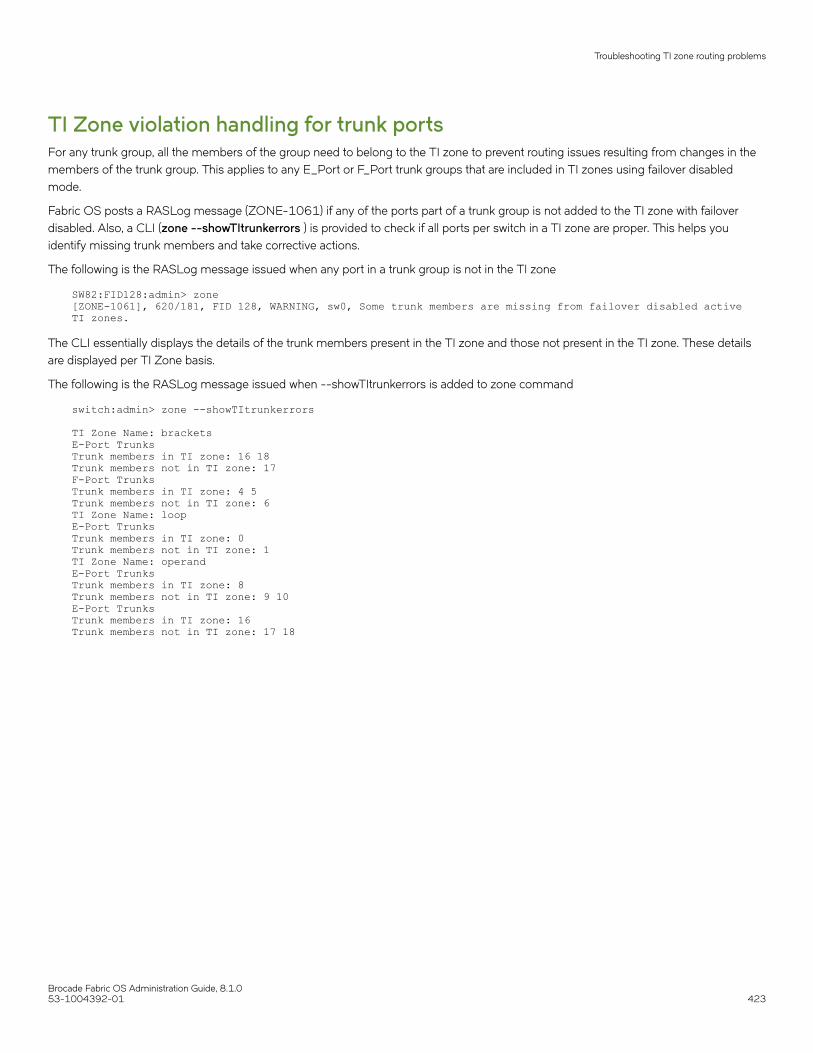
TI Zone violation handling for trunk portsFor any trunk group, all the members of the group need to belong to the TI zone to prevent routing issues resulting from changes in themembers of the trunk group. This applies to any E_Port or F_Port trunk groups that are included in TI zones using failover disabledmode.
Fabric OS posts a RASLog message (ZONE-1061) if any of the ports part of a trunk group is not added to the TI zone with failoverdisabled. Also, a CLI (zone --showTItrunkerrors ) is provided to check if all ports per switch in a TI zone are proper. This helps youidentify missing trunk members and take corrective actions.
The following is the RASLog message issued when any port in a trunk group is not in the TI zone
SW82:FID128:admin> zone [ZONE-1061], 620/181, FID 128, WARNING, sw0, Some trunk members are missing from failover disabled active TI zones.
The CLI essentially displays the details of the trunk members present in the TI zone and those not present in the TI zone. These detailsare displayed per TI Zone basis.
The following is the RASLog message issued when --showTItrunkerrors is added to zone command
switch:admin> zone --showTItrunkerrors TI Zone Name: bracketsE-Port TrunksTrunk members in TI zone: 16 18Trunk members not in TI zone: 17F-Port TrunksTrunk members in TI zone: 4 5Trunk members not in TI zone: 6TI Zone Name: loopE-Port TrunksTrunk members in TI zone: 0Trunk members not in TI zone: 1TI Zone Name: operandE-Port TrunksTrunk members in TI zone: 8Trunk members not in TI zone: 9 10E-Port TrunksTrunk members in TI zone: 16Trunk members not in TI zone: 17 18
Troubleshooting TI zone routing problems
Brocade Fabric OS Administration Guide, 8.1.053-1004392-01 423

Brocade Fabric OS Administration Guide, 8.1.0424 53-1004392-01

Optimizing Fabric Behavior• Adaptive Networking overview..................................................................................................................................................................425• Ingress Rate Limiting.................................................................................................................................................................................... 425• QoS...................................................................................................................................................................................................................... 426• CS_CTL-based frame prioritization........................................................................................................................................................ 437
Adaptive Networking overviewAdaptive Networking is a suite of tools and capabilities that enable you to ensure optimized behavior in the SAN. Under the worstcongestion conditions, Adaptive Networking can maximize the fabric behavior and provide necessary bandwidth for high-priority,mission-critical applications and connections.
The Adaptive Networking suite includes the following features:
• Traffic Isolation Zoning
Traffic Isolation Zoning (TI zoning) allows you to control the flow of interswitch traffic by creating a dedicated path for traffic flowing from aspecific set of source ports (F_Ports). Traffic Isolation Zoning does not require a license. Refer to Traffic Isolation Zoning on page 393 formore information about this feature.
• Quality of Service (QoS)
QoS allows you to categorize the traffic flow between a host and target as having a high, medium, or low priority. QoS does not require alicense. Refer to QoS on page 426 for more information about this feature.
You can use the Adaptive Networking features together to optimize the performance of your fabric. For example, you can use thefeatures in the following ways:
• You can use Top Talkers to identify the SID/DID pairs that consume the most bandwidth and can then configure them withcertain QoS attributes so they get proper priority.
• If the bottleneck detection feature detects a latency bottleneck, you can use TI zones or QoS to isolate latency device trafficfrom high-priority application traffic.
• If the bottleneck detection feature detects ISL congestion, you can use Ingress Rate Limiting to slow down low-priorityapplication traffic if it is contributing to the congestion.
Ingress Rate LimitingIngress Rate Limiting restricts the speed of traffic from a particular device to the switch port.
Use Ingress Rate Limiting for the following situations:
NOTEGen-6 platforms do not support ingress rate limiting.
• To reduce existing congestion in the network or proactively avoid congestion.
• To enable you to offer flexible bandwidth-limit services based on requirements.
• To enable more important devices to use the network bandwidth during specific services, such as network backup.
To limit the traffic, you set the maximum speed at which the traffic can flow through a particular F_Port or FL_Port. For example, if youset the rate limit at 4 Gbps, then traffic from a particular device is limited to a maximum of 4 Gbps.
Brocade Fabric OS Administration Guide, 8.1.053-1004392-01 425
Ingress Rate Limiting enforcement is needed only if the port can run at a speed higher than the rate limit. For example, if the rate limit is4 Gbps and the port is only a 2-Gbps port, then Ingress Rate Limiting is not enforced.
The Ingress Rate Limiting configuration is persistent across reboots.
You should keep in mind the following considerations about Ingress Rate Limiting:
• Ingress Rate Limiting is applicable only to F_Ports and FL_Ports.
• QoS takes precedence over Ingress Rate Limiting.
• Ingress Rate Limiting is not enforced on trunked ports.
• Ingress Rate Limiting can also be used on simulation ports (SIM ports).
Virtual Fabrics considerations for ingress rate limitingIf Virtual Fabrics is enabled and if a port is configured to have a certain rate limit value, you must first disable the rate limit on the portbefore moving it to a different logical switch. Ports cannot be moved when they have a rate limit configured on them.
Limiting traffic from a particular device1. Connect to the switch and log in using an account with admin permissions.
2. Enter the portCfgQos --setratelimit command.
portcfgqos --setratelimit [slot/]port ratelimit
Example of setting the rate limit on slot 3, port 9 to 4000 Mbps
portcfgqos --setratelimit 3/9 4000
Disabling Ingress Rate Limiting1. Connect to the switch and log in using an account with admin permissions.
2. Enter the portCfgQos --resetratelimit command.
portcfgqos --resetratelimit [slot/]port
Example of disabling Ingress Rate Limiting on slot 3, port 9
portcfgqos --resetratelimit 3/9
QoSQuality of Service (QoS) allows you to categorize the traffic flow between a host and a target as having a high, medium, or low priority.
Fabric OS supports two types of prioritization:
• Class-Specific Control (CS_CTL)-based frame prioritization
Each frame between a host and a target is assigned a specific priority, depending on the value of the CS_CTL field in the frame header.
• QoS zone-based traffic prioritization
All traffic between a host and a target is assigned a specific priority, depending on the name you define for the QoS zone.
QoS
Brocade Fabric OS Administration Guide, 8.1.0426 53-1004392-01

CS_CTL-based frame prioritization and QoS zone-based traffic prioritization are mutually exclusive. If you enable CS_CTL-based frameprioritization on F_Ports or FL_Ports, then QoS zone-based traffic prioritization cannot be used between any devices connected to theF_Ports or FL_Ports.
CS_CTL-based frame prioritization takes precedence over QoS zone-based traffic prioritization. If you enable CS_CTL-based frameprioritization on F_Ports or FL_Ports that are defined in a QoS zone, CS_CTL-based frame prioritization takes precedence over the QoSzones.
The following table shows a basic comparison between CS-CTL-based frame prioritization and QoS zone-based traffic prioritization.Refer to CS_CTL-based frame prioritization on page 437 and QoS zone-based traffic prioritization for detailed information about eachtype of prioritization scheme.
TABLE 88 Comparison between CS_CTL-based and QoS zone-based prioritization
CS_CTL-based frame prioritization QoS zone-based traffic prioritization
Must be manually enabled. Automatically enabled.
No zones are required. Requires you to create QoS zones.
Enabled on F_Ports or FL_Ports. Enabled on E_Ports.
Takes precedence over QoS zone-based traffic prioritization. Is overridden by CS_CTL-based frame prioritization.
Priority is defined by CS-CTL field in frame header. Priority is defined by name of QoS zone.
Prioritization is on a frame-basis. Prioritization is on a flow-basis.
Setup steps:
• Enable CS_CTL mode on F_Ports or FL_Ports.
• Ensure that the CS_CTL mode-enabled host and storage arezoned together.
Setup steps:
• Create QoS zones with host/target members.
• Add the QoS zones to the zone configuration.
• Save and then enable the zone configuration.
• Enable QoS on E_Ports.
License requirements for QoSIn Fabric OS 7.2.0 and later, QoS does not require the Adaptive Networking license to be explicitly installed. This license is automaticallyenabled for new switches and for existing switches that are upgraded to Fabric OS 7.2.0 or later.
If you upgrade to Fabric OS 7.2.0 and you did not previously have an Adaptive Networking license, then all ports that had QoS mode setto AE (automatically enabled) and were not using the QoS feature are automatically set to OFF after the upgrade.
QoS on E_PortsIn addition to configuring the hosts and targets in a zone, you must also enable QoS on individual E_Ports that might carry trafficbetween the host and target pairs. Path selection between the "host,target" pairs is governed by FSPF rules and is not affected by QoSpriorities. For example, in the following figure, QoS should be enabled on the encircled E_Ports.
NOTEBy default, QoS is enabled on 8-Gbps or higher ports. QoS is disabled by default on all long-distance ports.
QoS
Brocade Fabric OS Administration Guide, 8.1.053-1004392-01 427

FIGURE 54 QoS with E_Ports enabled
You must enable QoS on the E_Ports on both ISLs between domain 3 and domain 4, because either path might be selected to carry thetraffic.
You do not need to enable QoS on the E_Ports on the ISLs between domain 1 and domain 2 and between domain 2 and domain 3,because these are not the shortest paths between the hosts and the targets. However, if the ISL between domain 1 and domain 3 isbroken, then the path through domain 2 would be used.
To guarantee traffic priority, you should enable QoS on all possible E_Ports. Alternatively, you could use a TI zone to limit the E_Portsthat carry the traffic between a "host,target" pair and enable QoS on only those E_Ports.
If QoS is not enabled on an E_Port, the traffic prioritization stops at that point. For example, in the figure, if you disabled QoS on E_Ports"3,12" and "3,13," then the traffic from H1 and H2 to S3 would be low priority from the hosts to domain 3, but would change to thedefault (medium) priority from domain 3 to the target S3.
QoS over FC routersQoS over FC routers uses QoS traffic prioritization between devices in edge fabrics over an FC router. Refer to Using FC-FC Routing toConnect Fabrics on page 513 for information about FC routers, phantom switches, and the FC-FC Routing Service.
To establish QoS over FC routers, you must perform the following tasks:
• Define QoS zones in each edge fabric.
• Define LSAN zones in each edge fabric.
• Enable QoS on the E_Ports in each edge fabric.
• Enable QoS on the EX_Ports in the backbone fabric.
Refer to Setting QoS zone-based traffic prioritization over FC routers on page 435 for detailed instructions.
The following are requirements for establishing QoS over FC routers:
• QoS over FC routers is supported in Brocade native mode only. It is not supported in interopmode 2 or interopmode 3.
QoS
Brocade Fabric OS Administration Guide, 8.1.0428 53-1004392-01

• QoS over FC routers is supported for the following configurations:
– Edge-to-edge fabric configuration: Supported on all platforms.– Backbone-to-edge fabric configuration: Supported on 16-Gbps (Gen 5) and 32-Gbps (Gen 6) platforms only (Brocade
6505, 6510, 6520, G620, M6505, 6547, 6548, Brocade DCX 8510 Backbones and X6 Directors), and only if no otherplatforms are used. For all other platforms, you cannot prioritize the flow between a device in an edge fabric and a device inthe backbone fabric.
• QoS over FC routers is supported only if Virtual Fabrics is disabled in the backbone fabric. QoS over FC routers cannot beenabled if Virtual Fabrics is also enabled in the backbone fabric.
• The port WWN of the host or target and the port WWN of the proxy device must be in both an LSAN zone and a QoS zone.
• QoS over FC routers is supported on both EX_Ports and VEX_Ports.
• The EX_Ports (or VEX_Ports) in the path between the QoS devices must be on switches running Fabric OS v6.3.0 or later.
• QoS zones must use WWN notation only; D,I notation is not supported for QoS over FCRs.
vTap and QoS High Priority Zoning Compatibility modeThe vTap analytics feature utilizes VC 14 for remote flow mirroring, and requires that this VC be reserved exclusively for mirrored traffic inorder to ensure accurate results. When vTap is enabled, QoS high priority zoning ("QoSH/QoSH5") must operate in a manner that avoidsassigning flows to VC 14. You can control this behavior by a configuration setting at each relevant switch in the fabric. If you require vTapand QoS high priority zoning, you must enable vTap/QoSH compatibility on the switches having QoS high devices and/or the switcheswhere vTap needs to be configured. You can use the configureChassis command to enable the vTap and QoS High Priority ZoneCompatibility Mode.
sw:admin> configurechassis
Configure...
cfgload attributes (yes, y, no, n): [no]Custom attributes (yes, y, no, n): [no]system attributes (yes, y, no, n): [no]fos attributes (yes, y, no, n): [no] y
Reboot needed to effect new CSCTL ModeCSCTL QoS Mode (0 = default; 1 = auto mode): (0..1) [0]Chassis SDDQ Limit: (0..32) [10]vTap and QOS High Priority Zone Compatibility Mode (on, off): [off]
If vTap/QoSH compatibility is enabled and the vTap features (i.e., remote flow mirroring) are also active on the local switch, then vTap/QoSH compatibility cannot be disabled. vTap features have to be deactivated on the local switch prior to disabling vTap/QoSHcompatibility.
By default, "vTap and QOS High Priority Zone Compatibility Mode" is disabled. When disabled, the switch assigns QoS high priorityzoning VCs in the usual manner.
NOTEThe chassis must be disabled in order to enabled the new compatibility mode, but only when the effective zoning configurationhas QOSH (default VC assignment) and/or QOSH5 zones.
The configureChassis command can be issued from any logical switch partition/context, but affects a chassis-wide scope regardless ofswitch context.
QoS
Brocade Fabric OS Administration Guide, 8.1.053-1004392-01 429

QoSH5 zonesQoSH/QoSH5 zones created from non-vTap/QoSH compatible switches, can be pushed to CM mode enabled switches as part of zoneupdate. QoSH/QoSH5 zones added to the effective zoning configuration via a configDownload are permitted when vTap/QoSHcompatibility is enabled. However, creation of new QoSH5 zones using the zoneCreate command, Webtools, or BNA version 14.0.1 orhigher are not allowed when vTap/QoSH compatibility is enabled. This enforcement is only applied on and for the local switch. Forexample, if a QoSH5 zone create, rename, or update command is run in a switch that is not configured for vTap/QoSH compatibility, thezone update is accepted on those switches where vTap/QoSH compatibility is enabled.
NOTEThe presence or absence of QoSH5 zones does not have any effect on fabric build, regardless of vTap and QoSH compatibilitysettings.
The zoneCreate command does not allow creation of QoSH5 zones when vTap and QoSH compatibility is enabled and the followingmessage is displayed.
error: Operation is not allowed for QOSH5 zone "<zone name>" when vTap and QOS High Priority Zoning Compatibility Mode is enabled
The zoneRename command does not allow the renaming of a given zone such that it becomes a QoSH5 zone when vTap/QoSHcompatibility is enabled and the following message is displayed.
error: Operation is not allowed for QOSH5 zone "<zone name>" when vTap and QOS High Priority Zoning Compatibility Mode is enabled.
Activation of vTap remote flow mirroring is prevented unless vTap and QoSH compatibility is enabled.
sw:admin>flow --activate sys_analytics_vtapEnable vTap and QoS High Priority Zone Compatibility mode to activate vTap flow. Please use the configureChassis command to enable this compatibility mode.
A best practice to avoid having to disable the chassis, you can perform the following steps:
1. Temporarily enable a zoning configuration that does not have any QOS high priority zones
2. Enable vTap/QoSH compatibility via configureChassis on all switches in the fabric
3. Re-enable a zoning configuration having the desired QOS high priority zones, with the recommendation to avoid QOSH5zones with the new configuration
NOTETo ensure a non-disruptive Brocade Analytics Monitoring Platform attachment to a fabric, Brocade recommends that youenable QoSH and vTap+QoSH compatibility mode on all switches in the fabric. In addition, you must connect any devicesrequiring QoSH or QoSH5 services only through switches running versions of Fabric OS that both support this compatibilitymode and have it enabled.
Virtual Fabrics considerations for QoS zone-based traffic prioritizationYou can prioritize flows between devices in a logical fabric. The priority is retained for traffic going across ISLs and through the basefabric XISLs.
For example, the following figure shows a logical fabric that includes H1 and S1. To set the traffic between H1 and S1 to high priority,create a QoS zone in the logical fabric with H1 and S1 as members. Then enable QoS on all of the E_Ports shown circled in the figure,including all of the E_Ports in the XISLs (ports 10, 11, 12, 13, 14, 15, 16, and 17).
QoS
Brocade Fabric OS Administration Guide, 8.1.0430 53-1004392-01
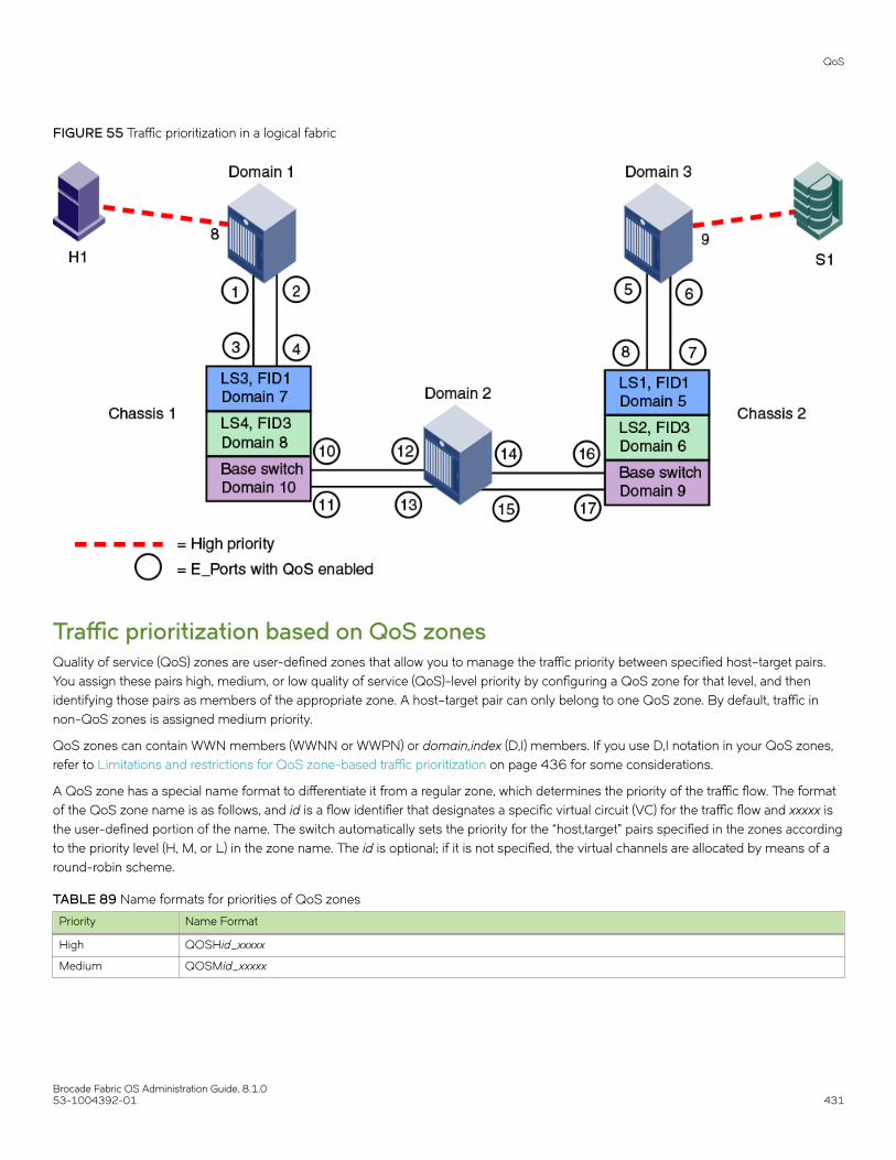
FIGURE 55 Traffic prioritization in a logical fabric
Traffic prioritization based on QoS zonesQuality of service (QoS) zones are user-defined zones that allow you to manage the traffic priority between specified host–target pairs.You assign these pairs high, medium, or low quality of service (QoS)-level priority by configuring a QoS zone for that level, and thenidentifying those pairs as members of the appropriate zone. A host–target pair can only belong to one QoS zone. By default, traffic innon-QoS zones is assigned medium priority.
QoS zones can contain WWN members (WWNN or WWPN) or domain,index (D,I) members. If you use D,I notation in your QoS zones,refer to Limitations and restrictions for QoS zone-based traffic prioritization on page 436 for some considerations.
A QoS zone has a special name format to differentiate it from a regular zone, which determines the priority of the traffic flow. The formatof the QoS zone name is as follows, and id is a flow identifier that designates a specific virtual circuit (VC) for the traffic flow and xxxxx isthe user-defined portion of the name. The switch automatically sets the priority for the “host,target” pairs specified in the zones accordingto the priority level (H, M, or L) in the zone name. The id is optional; if it is not specified, the virtual channels are allocated by means of around-robin scheme.
TABLE 89 Name formats for priorities of QoS zones
Priority Name Format
High QOSHid_xxxxx
Medium QOSMid_xxxxx
QoS
Brocade Fabric OS Administration Guide, 8.1.053-1004392-01 431

TABLE 89 Name formats for priorities of QoS zones (continued)
Priority Name Format
NOTEFor QOSM zones, the selection of flow id is not applicable; you can create a QOSM zone using the QOSMid_xxxxxformat but the VC selection might not be honored. Refer to the entry on medium-priority traffic in the followingdiscussion of valid ID ranges.
Low QOSLid_xxxxx
As examples, “QOSH3_HighPriorityTraffic” and “QOSL1_LowPriorityZone” are both valid QoS zone names.
Each priority level is allocated to different virtual channels (VCs). High-priority flows receive more fabric resources than medium-priorityflows, which receive more resources than low-priority flows. For example, you could assign online transaction processing (OLTP) to ahigh-priority zone and backup traffic to a low-priority zone. The flow id allows you to have control over the VC assignment and balancingthe flows throughout the fabric.
The id range is as follows:
• 1–5 for high-priority traffic, which corresponds to VCs 10–14.
• 1–4 for medium-priority traffic, which corresponds to VCs 2–5. Note, however, that the virtual channels for medium-prioritytraffic are always allocated by a round-robin scheme, regardless of the id value.
• 1–2 for low-priority traffic, which corresponds to VCs 8 and 9.
QoS
Brocade Fabric OS Administration Guide, 8.1.0432 53-1004392-01

The following figure shows a fabric with two hosts (H1 and H2) and three targets (S1, S2, and S3). The traffic prioritization is as follows:
• Traffic between H1 and S1 has high priority.
• Traffic between H1 and S3 and between H2 and S3 has low priority.
• All other traffic has medium priority, which is the default.
FIGURE 56 QoS traffic prioritization
For this fabric, you could set up the following QoS zones:
QOSH_Zone1 Members: H1 and S1
QOSL_Zone3 Members: H1, H2, and S3
Notes on QoS zoningThe following items should be kept in mind when working with QoS zoning:
• For new switches, QoS mode is automatically enabled on the E_Ports, except for long-distance E_Ports. For long-distanceE_Ports, you must manually enable QoS mode.
• If you upgrade to Fabric OS 7.2.0 or later from Fabric OS 7.1.x or earlier, and you did not previously have an AdaptiveNetworking license, then all ports that had QoS mode set to AE (automatically enabled) and were not using the QoS feature areautomatically set to OFF after the upgrade. You must manually configure these ports for QoS.
• If a QoS zone name prefix is specified in an LSAN zone (a zone beginning with the prefix "LSAN_"), the QoS tag is ignored.Only the first prefix in a zone name is recognized. For example, a zone with the name "LSAN_QOSH_zone1" is recognized asan LSAN zone and not a QoS zone. Refer to QoS over FC routers on page 428 for additional considerations when using QoSto prioritize traffic between device pairs in different edge fabrics.
• If there is a single low-priority flow to a destination ID (DID) and several medium-priority flows to that same DID, then it ispossible that the medium-priority flows would have less bandwidth. This is because they have to share the medium-priorityfabric resources, whereas the low-priority flow would have a separate set of fabric resources for its exclusive use.
QoS
Brocade Fabric OS Administration Guide, 8.1.053-1004392-01 433

Setting QoS zone-based traffic prioritization1. Connect to the switch and log in using an account with admin permissions.
2. Enter the zoneCreate command to create zones for high- and low-priority traffic.
• For high-priority traffic, use the following syntax:
zonecreate "QOSHid_zonename", "member[; member...]"
• For low-priority traffic, use the following syntax:
zonecreate "QOSLid_zonename", "member[; member...]"
The id range is from 1 through 5 for high-priority traffic, which corresponds to VCs 10 through 14. For low-priority traffic, the idrange is from 1 through 2, which corresponds to VCs 8 and 9. The id is optional; if it is not specified, the virtual channels areallocated by means of a round-robin scheme.
3. Enter the cfgAdd command to add the QoS zone to the zone configuration, by using the following syntax:
cfgadd "cfgname", "QOSzonename"
4. Enter the cfgSave command to save the change to the defined configuration.
5. Enter the cfgEnable command for the appropriate zone configuration to make the change effective.
cfgenable "cfgname"
QoS
Brocade Fabric OS Administration Guide, 8.1.0434 53-1004392-01
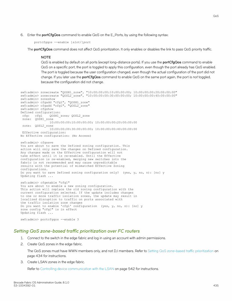
6. Enter the portCfgQos command to enable QoS on the E_Ports, by using the following syntax:
portcfgqos --enable [slot/]port
The portCfgQos command does not affect QoS prioritization. It only enables or disables the link to pass QoS priority traffic.
NOTEQoS is enabled by default on all ports (except long-distance ports). If you use the portCfgQos command to enableQoS on a specific port, the port is toggled to apply this configuration, even though the port already has QoS enabled.The port is toggled because the user configuration changed, even though the actual configuration of the port did notchange. If you later use the portCfgQos command to enable QoS on the same port again, the port is not toggled,because the configuration did not change.
sw0:admin> zonecreate "QOSH1_zone", "10:00:00:00:10:00:00:00; 10:00:00:00:20:00:00:00"sw0:admin> zonecreate "QOSL2_zone", "10:00:00:00:30:00:00:00; 10:00:00:00:40:00:00:00"sw0:admin> zoneshowsw0:admin> cfgadd "cfg1", "QOSH1_zone"sw0:admin> cfgadd "cfg1", "QOSL2_zone"sw0:admin> cfgshowDefined configuration: cfg: cfg1 QOSH1_zone; QOSL2_zone zone: QOSH1_zone 10:00:00:00:10:00:00:00; 10:00:00:00:20:00:00:00 zone: QOSL2_zone 10:00:00:00:30:00:00:00; 10:00:00:00:40:00:00:00 Effective configuration:No Effective configuration: (No Access)
sw0:admin> cfgsaveYou are about to save the Defined zoning configuration. This action will only save the changes on Defined configuration. Any changes made on the Effective configuration will not take effect until it is re-enabled. Until the Effectiveconfiguration is re-enabled, merging new switches into the fabric is not recommended and may cause unpredictableresults with the potential of mismatched Effective Zoningconfigurations.Do you want to save Defined zoning configuration only? (yes, y, no, n): [no] yUpdating flash ...
sw0:admin> cfgenable "cfg1"You are about to enable a new zoning configuration.This action will replace the old zoning configuration with thecurrent configuration selected. If the update includes changes to one or more traffic isolation zones, the update may result in localized disruption to traffic on ports associated withthe traffic isolation zone changesDo you want to enable 'cfg1' configuration (yes, y, no, n): [no] yzone config "cfg1" is in effectUpdating flash ...
sw0:admin> portcfgqos --enable 3
Setting QoS zone-based traffic prioritization over FC routers1. Connect to the switch in the edge fabric and log in using an account with admin permissions.
2. Create QoS zones in the edge fabric.
The QoS zones must have WWN members only, and not D,I members. Refer to Setting QoS zone-based traffic prioritization onpage 434 for instructions.
3. Create LSAN zones in the edge fabric.
Refer to Controlling device communication with the LSAN on page 542 for instructions.
QoS
Brocade Fabric OS Administration Guide, 8.1.053-1004392-01 435

4. Enter the portCfgQos --enable command to enable QoS on the E_Ports.
portcfgqos --enable [slot/]port
5. Repeat Step 1 through Step 3 to create QoS zones and LSAN zones on the other edge fabric.
6. Connect to the FC router in the backbone fabric and log in using an account with admin permissions.
7. Enter the portCfgQos --enable command to enable QoS on the EX_Ports.
portcfgqos --enable [slot/]port
Disabling QoS zone-based traffic prioritization1. Connect to the switch and log in using an account with admin permissions.
2. Enter the cfgRemove command to remove the QoS zones from the current zone configuration.
cfgremove "configname" "qos_zonename"
3. Enter the cfgEnable command for the appropriate zone configuration to make the change effective.
cfgenable "configname"
4. Enter the portCfgQos --disable command to disable QoS on the E_Ports.
portcfgqos --disable [slot/]port
Supported configurations for QoS zone-based traffic prioritizationThe following configuration rules apply to QoS zone-based traffic prioritization:
• All switches in the fabric must be running Fabric OS v6.0.0 or later.
ATTENTIONIf QoS traffic crosses an ISL for a switch running a firmware version earlier than Fabric OS v6.0.0, the frames aredropped.
• By default, all devices are assigned medium priority.
– To be assigned high or low priority, hosts and targets must be connected to a Brocade 8-Gbps or 16-Gbps switch or portblade.
– To preserve the priority level across ISLs, the switches must be running Fabric OS v6.0.0 or later.
• QoS is enabled by default on 8-Gbps and higher ports. QoS is disabled by default on all 4-Gbps ports and long-distance ports.
Limitations and restrictions for QoS zone-based traffic prioritization• Enabling and disabling QoS is potentially disruptive to the I/O on the affected port.
• If a host and target are included in two or more QoS zones with different priorities, the following priorities take precedence:
– High and medium zones = High priority– High and low zones = Low priority– Medium and low zones = Low priority– High, medium, and low zones = Low priority
QoS
Brocade Fabric OS Administration Guide, 8.1.0436 53-1004392-01

For example, if an effective zone configuration has QOSH_z1 (H,T) and QOSL_z2 (H,T), the traffic flow between H and T will beof low QoS priority.
• If QOSH_z1 (H,T) overlaps with a D,I (domain,index) zone at the H port, the traffic flow between H and T is dropped to mediumpriority and the H port is marked as a session-based zoning port.
• Traffic prioritization is enforced on the egress ports only, not on the ingress ports.
• Traffic prioritization is not supported on mirrored ports.
• Traffic prioritization is not supported over LSAN zones beyond L2. The traffic is always medium priority in the ingress edgefabric, the backbone fabric, and the egress edge fabric.
• Traffic prioritization is not supported on a CryptoTarget container (redirection zone). Refer to the Brocade Fabric OS EncryptionAdministrator's Guide for information about redirection zones.
• Traffic prioritization is not supported in McDATA Fabric Mode (interopmode 2) or Open Fabric Mode (interopmode 3).
• QoS zones that use D,I notation are not supported for QoS over FCR.
• QoS zones that use D,I notation should not be used for loop or NPIV ports.
• If QoS is enabled, an additional 16 buffer credits are allocated per port for 8-Gbps ports in Extended Mode (LE). Refer to Managing Long-Distance Fabrics on page 507 for information about buffer credit allocation in extended fabrics.
• If some ports in a trunk group have QoS enabled and some ports have QoS disabled, then two different trunks are formed, onewith QoS enabled and one with QoS disabled.
• QoS mode cannot be explicitly enabled on simulation ports (SIM ports). CS_CTL mode can be enabled on SIM ports.
CS_CTL-based frame prioritizationCS_CTL-based frame prioritization allows you to prioritize the frames between a host and a target as having high, medium, or lowpriority, depending on the value of the CS_CTL field in the FC frame header.
The CS_CTL field in the FC header can be used to assign a priority to a frame. This field can be populated by selected end devices(storage and host) and then honored by the switch, which assigns the frame, based on the value in the CS_CTL field, to allocateappropriate resources throughout the fabric. This method of establishing QoS is an alternative to the switch-controlled assignment thatuses zone-based QoS.
ATTENTIONCheck with your host and storage manufacturers to determine whether they support Fibre Channel CS_CTL prioritization ontheir devices.
High-, medium-, and low-priority frames are allocated to different sets of fabric resources. High-priority frames are assigned more fabricresources than medium-priority frames, which in turn are assigned more fabric resources than low-priority frames. The resources areallocated according to the CS_CTL value, as shown in Table 90. The values are enabled by default to ensure backward compatibility.
TABLE 90 Mapping of CS_CTL values to QoS priority for frame prioritization in CS_CTL default mode
CS_CTL value Priority
1-8 Low
9-16 Medium
17-24 High
CS_CTL-based frame prioritization
Brocade Fabric OS Administration Guide, 8.1.053-1004392-01 437

Alternatively, the user can apply CS_CTL auto mode. The CS_CTL auto mode uses only three CS_CTL values, as illustrated in Table 91.
TABLE 91 Mapping of CS_CTL values to QoS priority for frame prioritization in CS_CTL auto mode
CS_CTL value Priority
1 Low
2 Medium
3 High
NOTEThe values in the tables represent chassis-level configurations. For configuration details, refer to Using CS_CTL auto mode atthe chassis level on page 439, and Considerations for using CS_CTL-based frame prioritization on page 439.
Supported configurations for CS_CTL-based frame prioritizationCS_CTL-based frame prioritization is supported on all 8-, 16-, and 32-Gbps platforms.
All switches in the fabric should be running Fabric OS v6.3.0 or later.
NOTEIf a switch is running a firmware version earlier than Fabric OS v6.3.0, the outgoing frames from that switch lose theirpriority.
High availability considerations for CS_CTL-based frame prioritizationIf the standby CP is running a Fabric OS version earlier than 6.3.0 and is synchronized with the active CP, then you cannot enableCS_CTL-based frame prioritization on the active CP. If the standby CP is not synchronized or if no standby CP exists, then enablingCS_CTL-based frame prioritization succeeds.
Enabling CS_CTL-based frame prioritization on portsMake sure that the CS_CTL mode-enabled source and destination are zoned together.
When you enable CS_CTL-based frame prioritization, you must enable it on both the source port and the destination port, so that theframes returned from the destination port for a given exchange always have the same CS_CTL prioritization as the frames originatingfrom the source port.
1. Connect to the switch and log in to an account that has admin permissions.
2. Enable CS_CTL mode:
portcfgqos --enable [slot/]port csctl_mode
3. Enter y at the prompt to override QoS zone-based traffic prioritization.
Disabling CS_CTL-based frame prioritization on portsWhen you disable CS_CTL-based frame prioritization, QoS zone-based traffic prioritization is restored if it had been previously enabled.
1. Connect to the switch and log in to an account that has admin permissions.
CS_CTL-based frame prioritization
Brocade Fabric OS Administration Guide, 8.1.0438 53-1004392-01

2. Disable CS_CTL mode using the portCfgQos command with the --disable option:
portcfgqos --disable [slot/]port csctl_mode
Alternatively, you can use the --default option to disable CS_CTL mode and set QoS to auto-enable (AE):
portcfgqos --default [slot/]port
Using CS_CTL auto mode at the chassis levelYou can use the CS_CTL QoS mode options for the configureChassis command to change the chassis-wide default mode, as in thefollowing example.
switch:admin> configurechassisConfigure... cfgload attributes (yes, y, no, n): [no] Custom attributes (yes, y, no, n): [no] system attributes (yes, y, no, n): [no] fos attributes (yes, y, no, n): [no] y CSCTL QoS Mode (0 = default; 1 = auto mode): (0..1) [0] 1
Set CSCTL QoS Mode to 1 to enable auto mode, establishing the settings shown in Table 91 on page 438. Set CSCTL QoS Mode to 0to disable auto mode and revert to default settings, shown in Table 90 on page 437.
This is a chassis-level configuration. It does not provide options to enable CS_CTL QoS on the ports.
ATTENTIONAfter changing the CS_CTL QoS mode in a Chassis, you must run the slotPowerOff/On commands for all the edge blades;Whereas, in a fixed-port switch, you must reboot the switch. This is required for the new CS_CTL QoS mode to becomeeffective, because this mode change affects the persistent storage in the switch/chassis. To know the current mode, use thefollowing command:
switch:admin> configshow –all | grep csctlDefault mode – fos.csctlMode:0Auto mode – fos.csctlMode:1
Considerations for using CS_CTL-based frame prioritizationTo use CS_CTL for QoS on a given port for a given flow, proceed with the following steps.
1. Determine whether to use the default mode (refer to Table 90 on page 437) or the auto mode (refer to Table 91 on page 438).No choice results in the default mode.
2. In either case, ensure that the switch port connected to the initiator host and the switch port connected to the target host havecsctl_mode enabled, as in Enabling CS_CTL-based frame prioritization on ports on page 438.
CS_CTL-based frame prioritization
Brocade Fabric OS Administration Guide, 8.1.053-1004392-01 439

3. For a chassis based system, use the slot poweroff — slot poweron command pair for all the edge blades in the chassis. For afixed-port switch, reboot the switch.
ATTENTIONChanging the CS_CTL QoS mode using the configureChassis command is a disruptive operation. This commandupdates the chassis config and stores the information you provide in the chassis-level persistent data base. When theASIC is initialized, it retrieves this information to initialize its CSCTL-VC table. You must power cycle all the edge bladesin the chassis to have the new information be registered by the ASIC. For fixed-port switches, this requires a reboot ofthe entire switch. To know the current mode, use the following command:
switch:admin> configshow –all | grep csctlDefault mode – fos.csctlMode:0Auto mode – fos.csctlMode:1
CS_CTL-based frame prioritization
Brocade Fabric OS Administration Guide, 8.1.0440 53-1004392-01

In-flight Encryption and Compression• In-flight encryption and compression overview.................................................................................................................................441• Configuring in-flight encryption and compression on an EX_Port............................................................................................448• Configuring in-flight encryption and compression on an E_Port...............................................................................................449• Viewing the encryption and compression configuration................................................................................................................ 450• Configuring and enabling authentication for in-flight encryption............................................................................................... 451• Enabling in-flight encryption......................................................................................................................................................................453• Enabling in-flight compression.................................................................................................................................................................454• Disabling in-flight encryption.....................................................................................................................................................................455• Disabling in-flight compression................................................................................................................................................................456
In-flight encryption and compression overviewNOTECompression is supported on all supported Gen 6 (32-Gbps) platforms in Fabric OS 8.0.1 and later. However, in-flightencryption is supported only on the FC32-48 (32-Gbps) port blade starting with Fabric OS 8.1.0 and later. All other Gen 6(32-Gbps) platforms and blades such as G610, G620, and SX6 blade do not support in-flight encryption.
In-flight encryption provides security for frames while they are in flight between two switches. In-flight compression provides betterbandwidth use on the ISLs, especially over long distance.
The in-flight encryption and compression features allow frames to be encrypted or compressed at the egress point of an ISL betweentwo Brocade switches, and then to be decrypted or decompressed at the ingress point of the ISL. Frames are never left in an encryptedor compressed state when delivered to an end device.
These features use port-based encryption and compression. You can enable the in-flight encryption and compression features for bothE_Ports and EX_Ports on a per-port basis. By default, these features are initially disabled for all ports on a switch.
NOTENo license is required to configure and enable in-flight encryption orcompression.
Both ends of the ISL must terminate in 16 Gbps-capable or 32 Gbps-capable FC ports.
Encryption and compression can be enabled at the same time, or you can enable either encryption or compression selectively. Figure 57shows an example of 16 Gbps links connecting three Brocade switches. One link is configured with encryption and compression, onewith just encryption, and one with just compression.
Brocade Fabric OS Administration Guide, 8.1.053-1004392-01 441
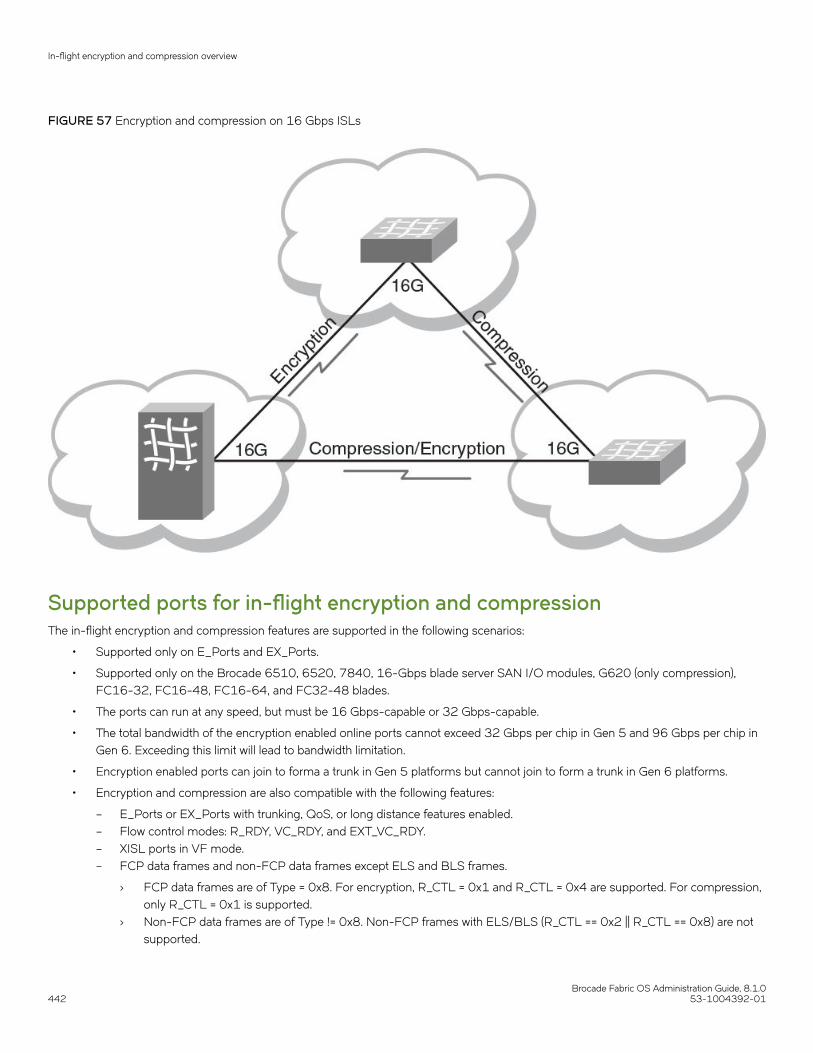
FIGURE 57 Encryption and compression on 16 Gbps ISLs
Supported ports for in-flight encryption and compressionThe in-flight encryption and compression features are supported in the following scenarios:
• Supported only on E_Ports and EX_Ports.
• Supported only on the Brocade 6510, 6520, 7840, 16-Gbps blade server SAN I/O modules, G620 (only compression),FC16-32, FC16-48, FC16-64, and FC32-48 blades.
• The ports can run at any speed, but must be 16 Gbps-capable or 32 Gbps-capable.
• The total bandwidth of the encryption enabled online ports cannot exceed 32 Gbps per chip in Gen 5 and 96 Gbps per chip inGen 6. Exceeding this limit will lead to bandwidth limitation.
• Encryption enabled ports can join to forma a trunk in Gen 5 platforms but cannot join to form a trunk in Gen 6 platforms.
• Encryption and compression are also compatible with the following features:
– E_Ports or EX_Ports with trunking, QoS, or long distance features enabled.– Flow control modes: R_RDY, VC_RDY, and EXT_VC_RDY.– XISL ports in VF mode.– FCP data frames and non-FCP data frames except ELS and BLS frames.
› FCP data frames are of Type = 0x8. For encryption, R_CTL = 0x1 and R_CTL = 0x4 are supported. For compression,only R_CTL = 0x1 is supported.
› Non-FCP data frames are of Type != 0x8. Non-FCP frames with ELS/BLS (R_CTL == 0x2 || R_CTL == 0x8) are notsupported.
In-flight encryption and compression overview
Brocade Fabric OS Administration Guide, 8.1.0442 53-1004392-01
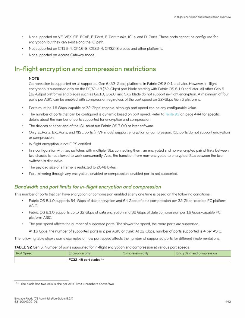
• Not supported on VE, VEX, GE, FCoE, F_Porst, F_Port trunks, ICLs, and D_Ports. These ports cannot be configured forencryption, but they can exist along the IO path.
• Not supported on CR16-4, CR16-8, CR32-4, CR32-8 blades and other platforms.
• Not supported on Access Gateway mode.
In-flight encryption and compression restrictionsNOTECompression is supported on all supported Gen 6 (32-Gbps) platforms in Fabric OS 8.0.1 and later. However, in-flightencryption is supported only on the FC32-48 (32-Gbps) port blade starting with Fabric OS 8.1.0 and later. All other Gen 6(32-Gbps) platforms and blades such as G610, G620, and SX6 blade do not support in-flight encryption. A maximum of fourports per ASIC can be enabled with compression regardless of the port speed on 32-Gbps Gen 6 platforms.
• Ports must be 16 Gbps-capable or 32 Gbps-capable, although port speed can be any configurable value.
• The number of ports that can be configured is dynamic based on port speed. Refer to Table 93 on page 444 for specificdetails about the number of ports supported for encryption and compression.
• The devices at either end of the ISL must run Fabric OS 7.0.0 or later software.
• Only E_Ports, EX_Ports, and XISL ports (in VF mode) support encryption or compression. ICL ports do not support encryptionor compression.
• In-flight encryption is not FIPS certified.
• In a configuration with two switches with multiple ISLs connecting them, an encrypted and non-encrypted pair of links betweentwo chassis is not allowed to work concurrently. Also, the transition from non-encrypted to encrypted ISLs between the twoswitches is disruptive.
• The payload size of a frame is restricted to 2048 bytes.
• Port mirroring through any encryption-enabled or compression-enabled port is not supported.
Bandwidth and port limits for in-flight encryption and compressionThis number of ports that can have encryption or compression enabled at any one time is based on the following conditions:
• Fabric OS 8.1.0 supports 64-Gbps of data encryption and 64 Gbps of data compression per 32 Gbps-capable FC platformASIC.
• Fabric OS 8.1.0 supports up to 32 Gbps of data encryption and 32 Gbps of data compression per 16 Gbps-capable FCplatform ASIC.
• The port speed affects the number of supported ports. The slower the speed, the more ports are supported.
At 16 Gbps, the number of supported ports is 2 per ASIC or trunk. At 32 Gbps, number of ports supported is 4 per ASIC.
The following table shows some examples of how port speed affects the number of supported ports for different implementations.
TABLE 92 Gen 6: Number of ports supported for in-flight encryption and compression at various port speeds
Port Speed Encryption only Compression only Encryption and compression
FC32-48 port blades 10
10 The blade has two ASICs; the per ASIC limit = numbers above/two
In-flight encryption and compression overview
Brocade Fabric OS Administration Guide, 8.1.053-1004392-01 443

TABLE 92 Gen 6: Number of ports supported for in-flight encryption and compression at various port speeds (continued)
Port Speed Encryption only Compression only Encryption and compression
32 Gbps 8 ports 8 ports 8 ports
16 Gbps 8 ports 8 ports 8 ports
10 Gbps 8 ports 8 ports 8 ports
8 Gbps 8 ports 8 ports 8 ports
4 Gbps 8 ports 8 ports 8 ports
Auto-negotiate (AN) 8 ports 8 ports 8 ports
G620 fixed-port switches 11
32 Gbps Not supported 4 ports Not supported
16 Gbps Not supported 4 ports Not supported
10 Gbps Not supported 4 ports Not supported
8 Gbps Not supported 4 ports Not supported
4 Gbps Not supported 4 ports Not supported
Auto-negotiate (AN) Not supported 4 ports Not supported
NOTEBrocade G610 does not support in-flight encryption or compression as this is an entry levelswitch.
TABLE 93 Gen 5: Number of ports supported for in-flight encryption and compression at various port speeds
Port speed Encryption only Compression only Encryption and compression
Gen 5 Blades (FC16-32, FC16-48, FC16-64)12
16 Gbps 4 ports 4 ports 4 ports
10 Gbps 6 ports 6 ports 6 ports
8 Gbps 8 ports 8 ports 8 ports
4 Gbps 8 ports 8 ports 8 ports
Auto-negotiate (AN) 4 ports 4 ports 4 ports
6510 Fixed-port switches and 16 Gbps Blade Server SAN I/O Modules13
16 Gbps 2 ports 2 ports 2 ports
10 Gbps 3 ports 3 ports 3 ports
8 Gbps 4 ports 4 ports 4 ports
4 Gbps 4 ports 4 ports 4 ports
Auto-negotiate (AN) 2 ports 2 ports 2 ports
6520 Fixed-port switches14
16 Gbps 8 ports 8 ports 8 ports
10 Gbps 12 ports 12 ports 12 ports
8 Gbps 16 ports 16 ports 16 ports
4 Gbps 16 ports 16 ports 16 ports
11 The switch has one ASIC; the per ASIC limit = numbers above/one12 The port blades have two ASICs; the per ASIC limit = numbers above/two13 The Brocade 6510 switch and 16 Gbps Blade Server SAN I/O Modules have one ASIC; the per ASIC limit = numbers above14 The Brocade 6520 has four edge ASICs; the per ASIC limit = numbers above/four
In-flight encryption and compression overview
Brocade Fabric OS Administration Guide, 8.1.0444 53-1004392-01

TABLE 93 Gen 5: Number of ports supported for in-flight encryption and compression at various port speeds (continued)
Port speed Encryption only Compression only Encryption and compression
Auto-negotiate (AN) 8 ports 8 ports 8 ports
This table does not show all the possible combinations of different speeds for the encryption and compression ports; other combinationsare also supported. The number of supported ports is automatically calculated based on the speeds chosen.
Port speed on encryption- or compression-enabled portsThe port speed determines the maximum number of ports on a device that can support the in-flight encryption and compressionfeatures.
NOTEThis section applies only to Gen 5 (16-Gbps) platforms.
If the port speed is configured as AUTO NEG, the speed of the port is taken as 16 Gbps for calculation purposes. It is recommendedthat you configure the ports to a specific speed before enabling encryption or compression.
The port speed values can be displayed through several commands, including portEncCompShow , portShow , and switchShow .
You can change the port speed on any port that has encryption or compression enabled with the portCfgSpeed command. If thecapacity is available, the port is configured with the new speed. If there is not enough capacity available, you cannot change the portspeed.
Refer to Setting port speeds on page 84 for more information.
How in-flight encryption and compression are enabledEncryption and compression capabilities and configurations from each end of the ISL are exchanged during E_Port or EX_Portinitialization. Capabilities and configurations must match, otherwise port segmentation or disablement occurs.
If the port was configured for compression, then the compression feature is enabled.
If the port was configured for encryption, authentication is performed and the keys needed for encryption are generated. The encryptionfeature is enabled if authentication is successful. If authentication fails, then the ports are segmented.
ATTENTIONAny mismatch in configuration at either end of the IFL or authentication failure results in segmentation or, in rare cases, the portbeing disabled.
The most common reasons for E_Port or EX_Port segmentation include the following situations:
• Port authentication fails. One of the following error messages is displayed:
Authentication RejectedAuthentication Failure
• Encryption or compression configurations do not match at both ends. For example, if at one end there is a switch that does notsupport encryption or compression, the port will be disabled. One of the following error messages is displayed:
Compression configuration mismatchEncryption configuration mismatch
• An encryption or compression configuration is enabled but resources are not available, or there are other failures preventingencryption or compression from being enabled. The following error message is displayed.
In-flight encryption and compression overview
Brocade Fabric OS Administration Guide, 8.1.053-1004392-01 445

Encryption/Compression enabled but resource unavailable• The number of available ports has reached the bandwidth limitation.
NOTEIf trunking is enabled, be aware that the ports creating the bandwidth limitation will form a trunk group, while the rest of the portswill be segmented.
You can also decommission any port that has in-flight encryption and compression enabled. Refer to Port decommissioning on page 83for details on decommissioning ports.
Authentication and key generation for encryption and compressionThe following points apply to authentication and key generation on the supported devices:
• Authentication and key generation only apply to ports that are configured for encryption. They do not apply to ports that are onlyconfigured for compression.
• Authentication using FCAP or DH-CHAP is supported between E_Ports and F_Ports connecting Brocade switches and AccessGateway devices. However, EX_Ports only support authentication using DH-CHAP. This means that if an inter-fabric link (IFL)must be authenticated, the authentication type on edge fabric should be set to either DH-CHAP or ALL. Configuration done inFCR using the authUtil command is applicable only for backbone fabric (E_Ports in FCR, not EX_Ports). Authenticationparameters for FCR cannot be modified.
– Default configuration:
› Authentication Type - DH-CHAP› Hash Type - SHA256, SHA1, md5› Group Type - 0,1,2,3,4› Switch Authentication Policy - Passive
– FIPS mode configuration:
› Authentication Type - DH-CHAP› Hash Type - SHA256, SHA1› Group Type - 4› Switch Authentication Policy - Passive
• The in-flight encryption protocol supports the AES-GCM authenticated encryption block cipher mode. A key, Initial Vector (IV),segment number, and salt are required to encrypt the data before it is transmitted, and to decode the data after it is received onthe other end of the link.
• In-flight encryption feature uses DH-CHAP(Diffie Hellman – Challenge Handshake Authentication Protocol) or Fibre ChannelAuthentication Protocol (FCAP) for authentication and key generation for secure frame transaction.
• In the in-flight encryption process, a session key will be generated during authentication phase and it will be used in IKE (InternetKey Exchange) protocol session to generate and exchange encryption/decryption keys for packet encryption/decryptionbetween two devices.
• For in-flight encryption using DH-CHAP, DH-CHAP must be configured along with DH group 4 and pre-shared secret keys onthe devices on both ends of the ISL as a pre-requisite. Authentication secrets greater than 32 characters are recommended forstronger encryption keys. Once the link is authenticated, the keys are generated and exchanged.
• For in-flight encryption using FCAP, FCAP must be configured along with DH group 4 and certificates (CA and switch) at bothends of ISL as a pre-requisite.
• The encryption keys never expire. While the port remains online, the keys generated for the port remain the same. When a portis disabled, segmented, or taken offline, a new set of keys is generated when the port is enabled again.
In-flight encryption and compression overview
Brocade Fabric OS Administration Guide, 8.1.0446 53-1004392-01

• All members of a trunk group use the same set of keys as the master port. Slave ports do not exchange keys. If the master portgoes offline causing an E_Port or EX_Port change, the trunk continues to use the same set of keys.
Availability considerations for encryption and compressionTo provide redundancy in the event of encryption or compression port failures, you should connect each ISL or trunk group to differentASICs on the peer switch.
For FC16-32, FC16-48, FC16-64 blades, if the two ports configured for encryption or compression within the same ASIC are notconfigured for trunking, it is recommended to connect each ISL to a different ASIC on the peer switch. Similarly, configure the two portson the other ASIC of the blade. If the ports are configured for trunking, it is recommended to connect each trunk group to different ASICson the peer switch.
For Brocade 6510 and 6520 switches, and 16 Gbps Blade Server SAN I/O Modules, if the two ports are not configured for trunking, itis recommended that you connect each ISL to different ASICs on the peer switch.
Gen 6 blades and switches do not support trunking with encryption enabled ports. The portCfgDefault command is also blocked onencryption enabled ports. You must disable the encryption configuration on these ports before running the portCfgDefault command.However, compression enabled ports support trunking.
NOTEIf any port with encryption enabled encounters rare error conditions that require error recovery to be performed on theencryption engine within that ASIC, all encryption or compression-enabled ports on that ASIC go offline.
Virtual Fabrics considerations for encryption and compressionThe E_Ports and EX_Ports in the user-created logical switch, base switch, or default switch, and the EX_Ports on base switches cansupport encryption and compression, with some exceptions.
You can configure encryption on XISL ports, but not on LISL ports. However, frames from the LISL ports are implicitly encrypted orcompressed as they pass through encryption- or compression-enabled XISL ports.
You cannot move a port from one logical switch to another logical switch if in-flight encryption or compression is enabled on the port.You must disable the encryption and compression configurations before moving the port, and then enable encryption and compressionafter the port has moved.
In-flight compression on long-distance portsWhen configuring in-flight compression on long-distance ports, it is recommended to configure the long-distance ports with double thenumber of buffers.
Configure the port to use the long-distance LS mode and specify the number of buffers to allocate to the port. You can see what theaverage compression ratio and the average frame size values are and adjust the allocated credit accordingly using theportEncCompShow and portBufferShow commands. You can then use the portBufferCalc command to estimate the assigned creditvalue to optimize performance.
Compression ratios for compression-enabled portsAn average compression ratio of 2:1 is provided. The compression ratio value is recalculated every five seconds, and is the ratio betweenthe accumulated original length and the compressed length of the data over the previous five seconds.
In-flight encryption and compression overview
Brocade Fabric OS Administration Guide, 8.1.053-1004392-01 447
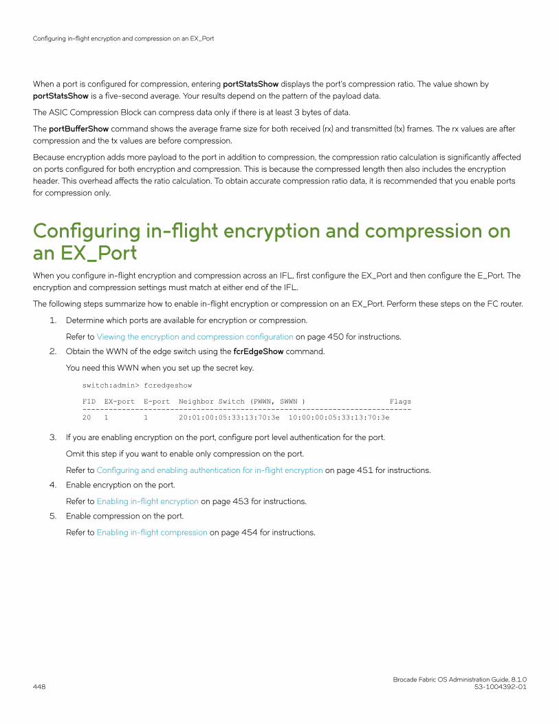
When a port is configured for compression, entering portStatsShow displays the port’s compression ratio. The value shown byportStatsShow is a five-second average. Your results depend on the pattern of the payload data.
The ASIC Compression Block can compress data only if there is at least 3 bytes of data.
The portBufferShow command shows the average frame size for both received (rx) and transmitted (tx) frames. The rx values are aftercompression and the tx values are before compression.
Because encryption adds more payload to the port in addition to compression, the compression ratio calculation is significantly affectedon ports configured for both encryption and compression. This is because the compressed length then also includes the encryptionheader. This overhead affects the ratio calculation. To obtain accurate compression ratio data, it is recommended that you enable portsfor compression only.
Configuring in-flight encryption and compression onan EX_PortWhen you configure in-flight encryption and compression across an IFL, first configure the EX_Port and then configure the E_Port. Theencryption and compression settings must match at either end of the IFL.
The following steps summarize how to enable in-flight encryption or compression on an EX_Port. Perform these steps on the FC router.
1. Determine which ports are available for encryption or compression.
Refer to Viewing the encryption and compression configuration on page 450 for instructions.
2. Obtain the WWN of the edge switch using the fcrEdgeShow command.
You need this WWN when you set up the secret key.
switch:admin> fcredgeshow FID EX-port E-port Neighbor Switch (PWWN, SWWN ) Flags---------------------------------------------------------------------------20 1 1 20:01:00:05:33:13:70:3e 10:00:00:05:33:13:70:3e
3. If you are enabling encryption on the port, configure port level authentication for the port.
Omit this step if you want to enable only compression on the port.
Refer to Configuring and enabling authentication for in-flight encryption on page 451 for instructions.
4. Enable encryption on the port.
Refer to Enabling in-flight encryption on page 453 for instructions.
5. Enable compression on the port.
Refer to Enabling in-flight compression on page 454 for instructions.
Configuring in-flight encryption and compression on an EX_Port
Brocade Fabric OS Administration Guide, 8.1.0448 53-1004392-01

6. Obtain the WWN of the front phantom domain using the portCfgExPort command.
You need this WWN when you set up the secret key on the E_Port on the other end of the IFL.
FCR:admin> portcfgexport 1 Port 1 info Admin: enabledState: OKPid format: core(N)Operate mode: Brocade NativeEdge Fabric ID: 20Front Domain ID: 160Front WWN: 50:00:53:31:37:43:ee:14 Principal Switch: 8(output truncated)
You can also specify a port range per blade in chassis based FCR. However, the range should not include a SIM_Port.
For example, the following sample sets the range of EX_Ports as FCR ports:
DCX:root> portcfgexport 1/1-2 -a 12014/09/15-07:09:12, [FCR-1071], 11763, SLOT 6 | FID 128, INFO, DCX, Port 1/1 is changed from non FCR port to FCR port.2014/09/15-07:09:13, [FCR-1071], 11764, SLOT 6 | FID 128, INFO, DCX, Port 1/2 is changed from non FCR port to FCR port.
The following sample sets the range of EX_Ports as non-FCR ports:
DCX:root> portcfgexport 1/1-2 -a 22014/09/15-07:09:17, [FCR-1072], 11765, SLOT 6 | FID 128, INFO, DCX, Port 1/1 is changed from FCR port to non FCR port.2014/09/15-07:09:18, [FCR-1072], 11766, SLOT 6 | FID 128, INFO, DCX, Port 1/2 is changed from FCR port to non FCR port.
Following successful port initialization, the configured features are enabled and active. You can use the fcrEdgeShow commandto check that the EX_Port has come online with encryption or compression enabled.
Next, configure encryption and compression on the E_Port at the other end of the IFL.
Configuring in-flight encryption and compression onan E_PortThe following steps summarize how to enable encryption or compression on an E_Port.
To configure in-flight encryption and compression, first configure encryption and compression on the E_Port.
Perform the following steps to configure the E_Port in the switch.
1. Determine which ports are available for encryption or compression.
Refer to Viewing the encryption and compression configuration on page 450 for instructions.
2. If you are enabling encryption on the port, configure port level authentication for the port.
Omit this step if you want to enable only compression on the port.
Refer to Configuring and enabling authentication for in-flight encryption on page 451 for instructions.
3. Enable encryption on the port.
Refer to Enabling in-flight encryption on page 453 for instructions.
Configuring in-flight encryption and compression on an E_Port
Brocade Fabric OS Administration Guide, 8.1.053-1004392-01 449

4. Enable compression on the port.
Refer to Enabling in-flight compression on page 454 for instructions.
Following successful port initialization, the configured features are enabled and active. You can use the islShow command tocheck that the E_Port has come online with encryption or compression enabled. Alternatively, you can use theportEncCompShow command to see which ports are active.
If port initialization is not successful, you can check for port segmentation errors with the switchShow command. Thiscommand will tell you if the segmentation was due to mismatched encryption or compression configurations on the ports ateither end of the ISL, if port-level authentication failed, or if a required resource was not available.
Viewing the encryption and compressionconfigurationBefore enabling ports for in-flight encryption or compression, you should determine which ports are available. Enabling encryption orcompression fails if you try to exceed the number of allowable ports available for encryption or compression on the ASIC.
1. Connect to the switch and log in using an account with admin permissions.
2. Enter the portEncCompShow command.
The following example shows the output for two ASICs.
ASIC 1 (below the line of dashes) already has compression configured and active on user ports 348 and 349. Given the limit oftwo ports per ASIC, ASIC 1 has no more ports available for encryption or compression.
ASIC 0 (above the dashed line) has no ports configured for either encryption or compression and therefore has any two portsavailable for this purpose.
switch:admin> portenccompshow User Encryption Compression Config Port Configured Active Configured Active Speed ---- ---------- ------ ---------- ------ ----- 17 No No No No 4G 18 No No No No 4G 19 No No No No 4G (output truncated) 149 No No No No 4G 150 No No No No 4G 151 No No No No 4G ---------------------------------------------------------------- 88 No No No No 4G 89 No No No No 4G 90 No No No No 4G (output truncated) 348 No No Yes Yes 4G 349 No No Yes Yes 4G 350 No No No No 4G 351 No No No No 4G
The output displays the user port number. For bladed switches, use the switchShow command to determine the slot number ofa specific user port.
Viewing the encryption and compression configuration
Brocade Fabric OS Administration Guide, 8.1.0450 53-1004392-01

Configuring and enabling authentication for in-flightencryptionAuthentication and a secret key must be configured and established before configuring in-flight encryption.
To enable authentication between an FC router and an edge fabric switch, you must first bring all EX_Ports online without usingauthentication. After this, the front WWN of any online EX_Port connected to the same switch can be used to configure the secret keys inthe edge fabric switch.
You must obtain the WWN of the peer switch to configure the secret key. If you are configuring an EX_Port on an FC router, you can usethe fcrEdgeShow command to obtain the WWN of the switch at the other end of the IFL.
NOTEOnly DH-CHAP authentication is supported for in-flight encryption ofEX_Ports.
1. Log in to the switch using an account with admin permissions, or an account with OM permissions for the Authentication RBACclass of commands.
ATTENTIONWhen setting a secret key pair , you are entering the shared secrets in plain text. Use a secure channel, such as SSH orthe serial console, to connect to the switch on which you are setting the secrets.
2. Configure DH-CHAP or FCAP for authentication using the authUtil --set command with the -a option.
switch:admin> authutil --set -a dhchap Authentication is set to dhchap.
You can specify any one of the following options:
• dhchap
• fcap
• allThe dhchap option sets authentication protocol to DH-CHAP. The fcap option sets authentication protocol to FCAP. Althoughall enables both FCAP and DH-CHAP, the active protocol defaults to FCAP for all ports configured for in-flight encryption.
If dhchap is specified, then all switches in the fabric must enable DH-CHAP and establish pre-shared secrets. If fcap isspecified, then all switches in the fabric must enable FCAP and use certificates (CA and switch) installed on them. If the protocolis set to all, you must establish pre-shared secrets or certificates based on the encryption method selected (DH-CHAP orFCAP).
3. Set the DH group to group 4 using the authUtil --set command with the -g option.
switch:admin> authutil --set -g "4" DH Group was set to 4.
You can specify either "4" or "*" . The "4" option explicitly enables DH group 4. Although "*" enables all DH groups (0 through4), the DH group defaults to group 4 for all ports configured for in-flight encryption.
Configuring and enabling authentication for in-flight encryption
Brocade Fabric OS Administration Guide, 8.1.053-1004392-01 451

4. Configure pre-shared keys or certificates based on the encryption method selected (DH-CHAP or FCAP):
• If DH-CHAP is the configured authentication protocol, use the secAuthSecret --set command to establish pre-sharedsecret key at each end of the ISL. It is recommended to use a 32-bit secret for an ISL carrying encrypted or compressedtraffic.
switch:admin> secauthsecret --set
When prompted, enter the WWN for the remote switch and secret strings for the local switch and the remote switch.
• If FCAP is the configured authentication protocol, use the seccertutil command to generate the public or private key, theCSR, and the passphrase and then import certificates (CA and switch) at both the ends of ISL.
switch:admin> seccertutil5. Activate the configured authentication using the authUtil --policy command to set the switch policy mode to Active or On.
switch:admin> authutil --policy -sw active
If you are configuring authentication on an EX_Port, there is no need to set the authentication policy to Active or On. EX_Portscan operate on any switch authentication policy.
Configuring and enabling authentication for in-flight encryption
Brocade Fabric OS Administration Guide, 8.1.0452 53-1004392-01

6. Verify the authentication configuration using the authUtil --show command.
The following example sets up authentication in preparation for in-flight encryption. Specifically, it configures DH-CHAP forauthentication, sets the DH group to group 4, sets up a pre-shared secret key, and activates authentication.
switch:admin> authutil --set -a dhchap Authentication is set to dhchap.switch:admin> authutil --set -g "4" DH Group was set to 4.switch:admin> secauthsecret --set This command is used to set up secret keys for the DH-CHAP authentication.The minimum length of a secret key is 8 characters and maximum 40characters. Setting up secret keys does not initiate DH-CHAPauthentication. If switch is configured to do DH-CHAP, it is performedwhenever a port or a switch is enabled. Warning: Please use a secure channel for setting secrets. Usingan insecure channel is not safe and may compromise secrets.Following inputs should be specified for each entry. 1. WWN for which secret is being set up.2. Peer secret: The secret of the peer that authenticates to peer.3. Local secret: The local secret that authenticates peer. Press enter to start setting up secrets >Enter peer WWN, Domain, or switch name (Leave blank when done): 10:00:00:05:1e:e5:cb:00 Enter peer secret: Re-enter peer secret: Enter local secret: Re-enter local secret: Enter peer WWN, Domain, or switch name (Leave blank when done): Are you done? (yes, y, no, n): [no] y Saving data to key store... Done.switch:admin> secauthsecret --show WWN DId Name-----------------------------------------------10:00:00:05:1e:e5:cb:00 150 dcx_150 switch:admin> authutil --policy -sw active Warning: Activating the authentication policy requires either DH-CHAP secrets or PKI certificates depending on the protocol selected. Otherwise, ISLs will be segmented during next E-port bring-up. ARE YOU SURE (yes, y, no, n): [no] y Auth Policy is set to ACTIVE switch:admin> authutil --show AUTH TYPE HASH TYPE GROUP TYPE--------------------------------------dhchap md5 4 Switch Authentication Policy: ACTIVEDevice Authentication Policy: OFF
For additional information about configuring DH-CHAP and FCAP authentication protocols, refer to Authentication policy forfabric elements on page 247.
Enabling in-flight encryptionEnable in-flight encryption to provide security for frames while they are in flight between two switches. Frames are encrypted at theegress point of an ISL and then decrypted at the ingress point.
Enabling in-flight encryption
Brocade Fabric OS Administration Guide, 8.1.053-1004392-01 453

Enabling encryption is an offline event. Ports must be disabled first, and then re-enabled after.
Before performing this procedure, it is recommended that you check for port availability. Enabling encryption fails if you try to exceed thenumber of allowable ports available for encryption or compression on the ASIC. Refer to Viewing the encryption and compressionconfiguration on page 450 for details.
You must also authenticate the port as described in Configuring and enabling authentication for in-flight encryption on page 451.
1. Connect to the switch and log in using an account with secure admin permissions, or an account with OM permissions for theEncryptionConfiguration RBAC class of commands.
2. Enter the portDisable command to disable the port on which you want to configure encryption.
3. Enter the portCfgEncrypt --enable command.
The following example enables encryption on port 15 of an FC16-32 blade in slot 9 of an enterprise class platform:
switch:admin> portcfgencrypt --enable 9/15
4. Enter the portEnable command to enable the port.
After manually enabling the port, the new configuration becomes active.
The following example enables in-flight encryption on port 0.
switch:admin> portdisable 0 switch:admin> portcfgencrypt --enable 0 switch:admin> portenable 0
You can verify the configuration using the portCfgShow command.
switch:admin> portcfgshow 0 Area Number: 0 Octet Speed Combo: 3(16G,10G)(output truncated)D-Port mode: OFFD-Port over DWDM .. Compression: OFF Encryption: ON
Enabling in-flight compressionEnable in-flight compression to provide better bandwidth use on the ISLs, especially over long distance. Frames are compressed at theegress point of an ISL and then decompressed at the ingress point.
Enabling compression is an offline event. Ports must be disabled first, and then re-enabled after.
Before performing this procedure, it is recommended that you check for port availability. Enabling compression fails if you try to exceedthe number of allowable ports available for encryption or compression on the ASIC. Refer to Viewing the encryption and compressionconfiguration on page 450 for details.
1. Connect to the switch and log in using an account with admin permissions, or an account with OM permissions for theSwitchPortConfiguration RBAC class of commands.
2. Enter the portDisable command to disable the port on which you want to configure compression.
Enabling in-flight compression
Brocade Fabric OS Administration Guide, 8.1.0454 53-1004392-01
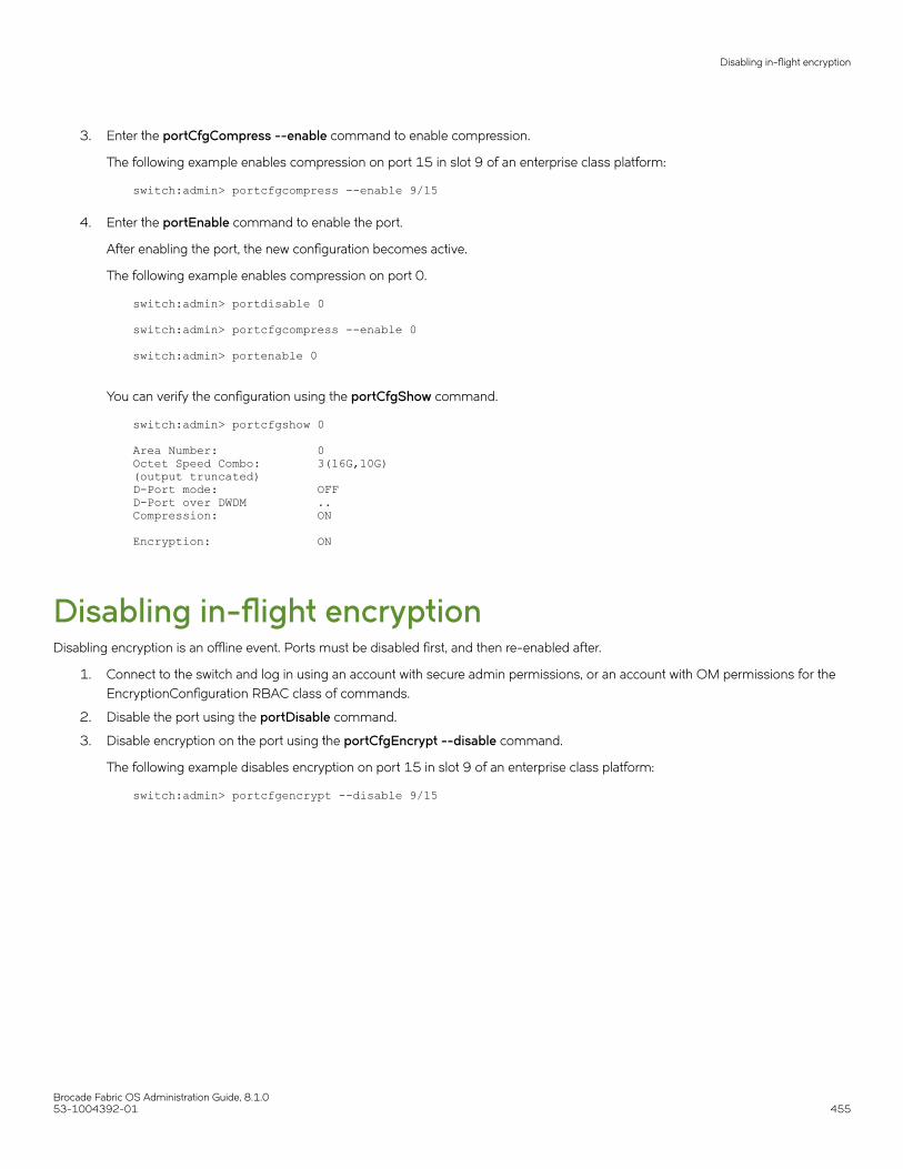
3. Enter the portCfgCompress --enable command to enable compression.
The following example enables compression on port 15 in slot 9 of an enterprise class platform:
switch:admin> portcfgcompress --enable 9/15
4. Enter the portEnable command to enable the port.
After enabling the port, the new configuration becomes active.
The following example enables compression on port 0.
switch:admin> portdisable 0 switch:admin> portcfgcompress --enable 0 switch:admin> portenable 0
You can verify the configuration using the portCfgShow command.
switch:admin> portcfgshow 0 Area Number: 0Octet Speed Combo: 3(16G,10G)(output truncated)D-Port mode: OFFD-Port over DWDM .. Compression: ON Encryption: ON
Disabling in-flight encryptionDisabling encryption is an offline event. Ports must be disabled first, and then re-enabled after.
1. Connect to the switch and log in using an account with secure admin permissions, or an account with OM permissions for theEncryptionConfiguration RBAC class of commands.
2. Disable the port using the portDisable command.
3. Disable encryption on the port using the portCfgEncrypt --disable command.
The following example disables encryption on port 15 in slot 9 of an enterprise class platform:
switch:admin> portcfgencrypt --disable 9/15
Disabling in-flight encryption
Brocade Fabric OS Administration Guide, 8.1.053-1004392-01 455
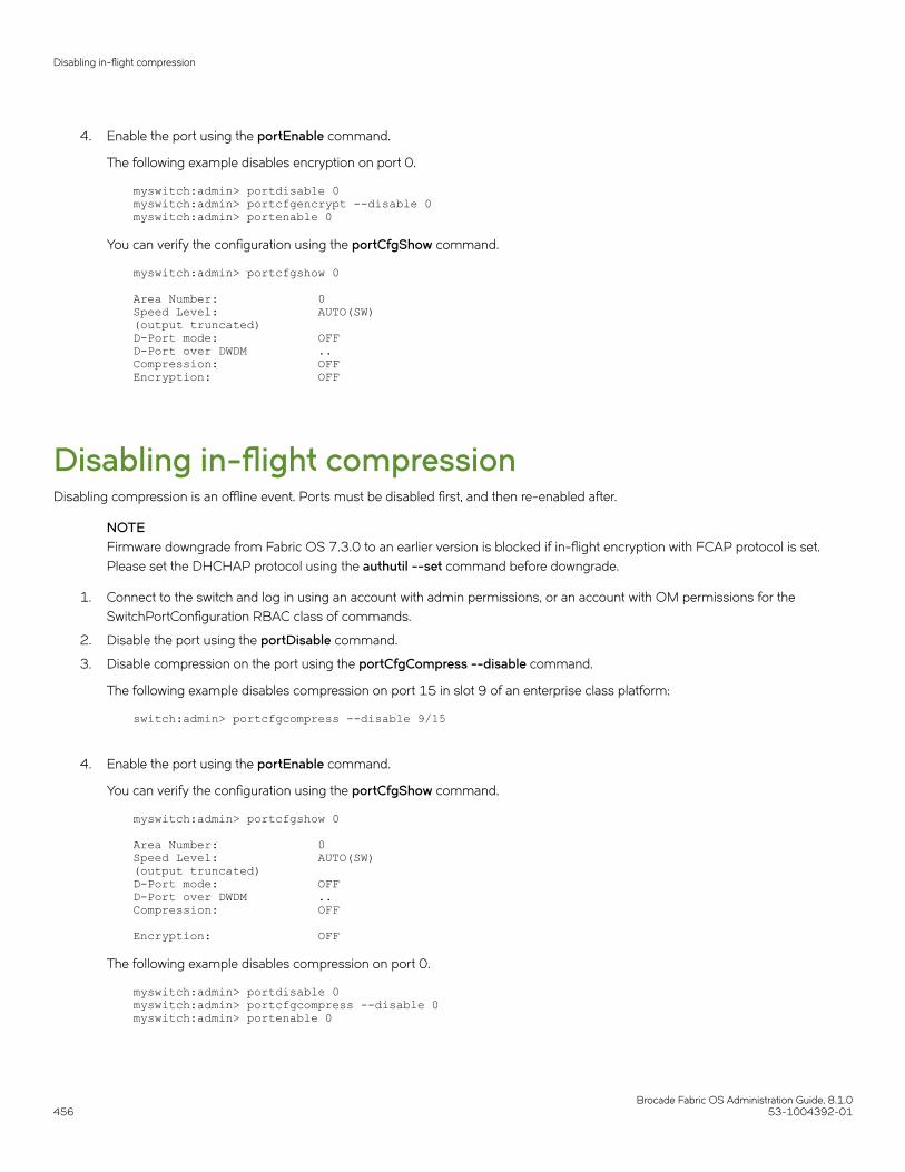
4. Enable the port using the portEnable command.
The following example disables encryption on port 0.
myswitch:admin> portdisable 0 myswitch:admin> portcfgencrypt --disable 0 myswitch:admin> portenable 0
You can verify the configuration using the portCfgShow command.
myswitch:admin> portcfgshow 0 Area Number: 0Speed Level: AUTO(SW)(output truncated)D-Port mode: OFFD-Port over DWDM .. Compression: OFF Encryption: OFF
Disabling in-flight compressionDisabling compression is an offline event. Ports must be disabled first, and then re-enabled after.
NOTEFirmware downgrade from Fabric OS 7.3.0 to an earlier version is blocked if in-flight encryption with FCAP protocol is set.Please set the DHCHAP protocol using the authutil --set command before downgrade.
1. Connect to the switch and log in using an account with admin permissions, or an account with OM permissions for theSwitchPortConfiguration RBAC class of commands.
2. Disable the port using the portDisable command.
3. Disable compression on the port using the portCfgCompress --disable command.
The following example disables compression on port 15 in slot 9 of an enterprise class platform:
switch:admin> portcfgcompress --disable 9/15
4. Enable the port using the portEnable command.
You can verify the configuration using the portCfgShow command.
myswitch:admin> portcfgshow 0 Area Number: 0Speed Level: AUTO(SW)(output truncated)D-Port mode: OFFD-Port over DWDM .. Compression: OFF Encryption: OFF
The following example disables compression on port 0.
myswitch:admin> portdisable 0myswitch:admin> portcfgcompress --disable 0myswitch:admin> portenable 0
Disabling in-flight compression
Brocade Fabric OS Administration Guide, 8.1.0456 53-1004392-01

NPIV• NPIV overview................................................................................................................................................................................................. 457• Configuring NPIV........................................................................................................................................................................................... 458• Enabling and disabling NPIV.....................................................................................................................................................................459• Base device logout.........................................................................................................................................................................................460• Viewing NPIV port configuration information.....................................................................................................................................463
NPIV overviewN_Port ID Virtualization (NPIV) enables a single Fibre Channel protocol port to appear as multiple, distinct ports, providing separate portidentification within the fabric for each operating system image behind the port (as if each operating system image had its own uniquephysical port). NPIV assigns a different virtual port ID to each Fibre Channel protocol device. NPIV is designed to enable you to allocatevirtual addresses without affecting your existing hardware implementation. The virtual port has the same properties as an N_Port, and istherefore capable of registering with all services of the fabric. This chapter does not discuss the Access Gateway feature. For moreinformation on the Access Gateway feature, refer to the Brocade Access Gateway Administrator's Guide.
Each NPIV device has a unique device PID, Port WWN, and Node WWN, and behaves the same as all other physical devices in thefabric. In other words, multiple virtual devices emulated by NPIV appear no different than regular devices connected to a non-NPIV port.
The same zoning rules apply to NPIV devices as non-NPIV devices. Zones can be defined by domain,port notation, by WWN-basedzoning, or both. However, to perform zoning to the granularity of the virtual N_Port IDs, you must use WWN-based zoning.
If you are using domain,port zoning for an NPIV port, and all the virtual PIDs associated with the port are included in the zone, then aport login (PLOGI) to a non-existent virtual PID is not blocked by the switch; rather, it is delivered to the device attached to the NPIV port.In cases where the device is not capable of handling such unexpected PLOGIs, use WWN-based zoning.
The following example shows the number of NPIV devices in the output of the switchShow command. The number of NPIV devices isequal to the sum of the base port plus the number of NPIV public devices. The base port is the N_Port listed in the switchShow output.Based on the formula, index 010000 shows only 1 NPIV device and index 010300 shows a total of 222 NPIV devices (one N_PortFLOGI device and 221 NPIV devices).
switch:admin> switchshowswitchName: 5100switchType: 71.2switchState: Online switchMode: Access Gateway ModeswitchWwn: 10:00:00:05:1e:41:49:3dswitchBeacon: OFFIndex Port Address Media Speed State Proto============================================== 0 0 010000 id N4 Online FC F-Port 20:0c:00:05:1e:05:de:e4 0xa06601 1 1 010100 id N4 Online FC F-Port 1 N Port + 4 NPIV public 2 2 010200 id N4 Online FC F-Port 1 N Port + 119 NPIV public 3 3 010300 id N4 Online FC F-Port 1 N Port + 221 NPIV public
NOTEWhen an Access Gateway is connected to the switch, the Access Gateway is counted as the base device or base login and it isnot included in the NPIV device count.
Brocade Fabric OS Administration Guide, 8.1.053-1004392-01 457

Upgrade considerationsThe maximum logins per switch decreased with Fabric OS v6.4.0. When upgrading from a release previous to Fabric OS v6.4.0, theconfigured maximum is carried forward and may exceed the Fabric OS v6.4.0 limit. It is recommended to reconfigure this parameter tobe within the range permitted in Fabric OS v6.4.0 and later.
Fixed addressing modeFixed addressing mode is the default addressing mode used in all platforms that do not have Virtual Fabrics enabled.
The number of NPIV devices supported on shared area ports (48-port blades) is reduced to 64 from 128 when Virtual Fabrics mode isenabled.
10-bit addressing modeThe 10-bit addressing mode is the default mode for all the logical switches created in the Brocade DCX 8510, and X6 Backbones. Thenumber of NPIV supported on a port is 64.
In 10-bit addressing mode, the switch can dynamically assign up to 112, 8-bit areas, after that 10-bit areas are assigned. So the 8-bitareas can have up to 255 devices, and 10-bit areas can have up to 63 devices.
The following table shows the number of NPIV devices supported on the Brocade DCX 8510, and X6 Backbones.
TABLE 94 Number of supported NPIV devices per port
Platform Virtual Fabrics Logical switchtype
NPIV support
DCX 8510-8 (or) X6-8 Disabled N/A Yes, 127 virtual device limit.
DCX 8510-8 (or) X6-8 Enabled Default switch Yes, 63 virtual device limit.
DCX 8510-8 (or) X6-8 Enabled Logical switch Yes, 255 virtual device limit.
The first 112 physical NPIV-capable devices connected to a logical switch using10-bit addressing can log in 255 logical devices. The physical NPIV-capabledevices after 112, 113, and higher, are limited to 63 logical devices. If port isassigned a 10-bit area, the number of NPIV devices supported is 63.
DCX 8510-8 (or) X6-8 Enabled Base switch No.
DCX 8510-4 (or) X6-4 Disabled N/A Yes, 255 virtual device limit.
DCX 8510-4 (or) X6-4 Enabled Default switch Yes, 255 virtual device limit.
DCX 8510-4 (or) X6-4 Enabled Logical switch Yes, 255 virtual device limit.
If port is assigned a 10-bit area, the number of NPIV devices supported is 63.
DCX 8510-4 (or) X6-4 Enabled Base switch No.
Configuring NPIVThe NPIV feature is enabled by default. You can set the number of virtual N_Port IDs per port to a value from 1 through 255 per port.The default setting is 126.
The portCfgNPIVPort command is used to specify the maximum number of virtual N_port IDs per port on a switch. It can also be usedto enable or disable NPIV. Once NPIV is enabled on the port, you can specify the number of logins per port. If the NPIV feature has beendisabled, then the NPIV port configuration does not work.
Configuring NPIV
Brocade Fabric OS Administration Guide, 8.1.0458 53-1004392-01

The addressing mode can limit the maximum number of NPIV logins to 127 or 63 depending on the mode. The portCfgNPIVPortcommand can set the maximum number of NPIV logins limit to anything from 1 through 255, regardless of the addressing mode.Whichever of these two (addressing mode or the value configured through portCfgNPIVPort) is lower will be the maximum number thatcan be logged in.
CAUTIONThe portDisable command disables the port and stops all traffic flowing to and from the port. Use this command during ascheduled maintenance.
1. Connect to the switch and log in using an account assigned to the admin role.
2. Enter the portDisable command.
3. Enter the portCfgNPIVPort --setloginlimit command with the port number and the number of logins per port.
4. Enter the portEnable command to enable the port.
switch:admin> portcfgnpivport --setloginlimit 7/0 128NPIV Limit Set to 128 for Port 128switch:admin> portcfgshow 7/0Area Number: 128Octet Speed Combo: 1(16G|8G|4G|2G)Speed Level: AUTO(SW)AL_PA Offset 13: OFFTrunk Port ONLong Distance OFFVC Link Init OFFLocked L_Port OFFLocked G_Port OFFDisabled E_Port OFFLocked E_Port OFFISL R_RDY Mode OFFRSCN Suppressed OFFPersistent Disable OFFLOS TOV enable OFFNPIV capability ONQOS E_Port AEPort Auto Disable: OFFRate Limit OFFEX Port OFFMirror Port OFFCredit Recovery ONF_Port Buffers OFFFault Delay: 0(R_A_TOV)NPIV PP Limit: 128CSCTL mode: OFFFrame Shooter Port OFFD-Port mode: OFFD-Port over DWDM .. Compression: OFFEncryption: OFFFEC: ON
Enabling and disabling NPIVNPIV is enabled for every port.
NOTENPIV is a requirement for FCoE.
1. Connect to the switch and log in using an account assigned to the admin role.
Enabling and disabling NPIV
Brocade Fabric OS Administration Guide, 8.1.053-1004392-01 459

2. To enable or disable NPIV on a port, enter the portCfgNPIVPort command with either the --enable or --disable option.
The following example shows NPIV being enabled on port 10 of a Brocade 5100:
switch:admin> portCfgNPIVPort --enable 10
NOTEIf the NPIV feature is disabled, the port is toggled if NPIV devices are logged in from that F_Port (a true NPIV port).Otherwise, the firmware considers that port as an F_Port even though the NPIV feature was enabled.
Base device logoutBase device logout is a Fibre Channel - Lin Service 2 (FC-LS2) standard-based feature in which the Fabric OS firmware allows NPIVdevices to remain logged in after the base device logs out. This feature is available on all the switches and Access Gateways starting withFabric OS 7.3.0. Any device attached to an NPIV port is able to log in and log out without affecting the login status of the other deviceson the port. This section explains the changes in F-port behavior, use case scenarios including possible changes in existing Fabric OSshow commands, new CLIs and configuration commands associated with this feature. This section explains also the possible risks,compatibility (FW upgrade/downgrade) and HA aspects of Fabric OS related to this feature.
From their inception, Brocade switches have treated a base device logout on a given port as a logout of all devices on that port. For NPIVdevices, this means that each NPIV device is logged out when the base device is logged out. This is referred to as the legacyfunctionality. When the final FC-LS2 standard was released, the functionality it defined had changed from the initial understanding.Instead of the base device logout causing all NPIV devices to log out, the base device logout affects only the base device; the NPIVdevices stay logged in.
Difference in the device logout behaviorsA base device is a device on an F_Port that has the base PID. The base device logs in with a FLOGI. An NPIV device is a device on anF_Port which has an NPIV PID. An NPIV device logs in with an FDISC.
The following table summarizes the difference in the base and NPIV device logout behaviors with and without the base device logoutfeature enabled.
TABLE 95 Base and NPIV logout behaviors
Scenario Without base device logout enabled With base device logout enabled
• No device is logged in. • Requires a device with a base PID to log into the F_Port before any NPIV device canlog in.
• Requires a device with a base PID to login to the F_Port before any NPIV devicecan log in.
• Base device is logged in. • Allows NPIV devices to log in and log out.
• Permanent Port Name (PPN) is assignedwith PWWN of the base device for all thedevices logged-in on that port (for bothbase and NPIV devices).
• Allows NPIV devices to log in and logout.
• Permanent Port Name (PPN) is assignedaccording to FC-GS-6 (5.2.3.13)standard.
• Base device is logged in.
• At least one NPIV device islogged in.
• If the base device is logged out, then all theNPIV devices are also logged out.
• Removes routing information when thebase device logs out.
• Allows base device to log out while NPIVdevices are still logged in. Indicates thatthe base device is logged out in theswitchShow command output.
• Does not remove the routing information.
• Base device is logged out.
• At least one NPIV device islogged in.
N/A • Allows base device to log back in as abase or NPIV device.
Base device logout
Brocade Fabric OS Administration Guide, 8.1.0460 53-1004392-01

TABLE 95 Base and NPIV logout behaviors (continued)
Scenario Without base device logout enabled With base device logout enabled
• Allows NPIV devices to log in and logout.
• Does not remove the routing information.
• Base device is logged out.
• All NPIV devices are alsologged out.
• Requires a device with a base PID to log into the F_Port before any NPIV device canlog in.
• Removes all the routing information.
• Requires a device with a base PID to login to the F_Port before any NPIV devicecan log in.
Enabling base device logoutBoth the active and the standby switches/AGs should be upgraded to Fabric OS 7.3.0 or later.
The purpose of this feature is to make it possible for all devices; including base device and NPIV devices on a NPIV port to log out andlog in without disrupting the remaining logged on devices. By default, the base device logout option is disabled in all the ports.
1. Enable NPIV on the required ports.
Ports that do not have NPIV capability cannot have the base device logout option enabled.
2. Disable the ports for which you want to enable base device logout, as this is a disruptive operation.
3. Enable base device logout using the portCfgFLOGILogout command.
The following example enables base device logout on all the ports in the logical switch.
portcfgflogilogout --enable –all
The following example enables base device logout on only specific ports in the logical switch.
portcfgflogilogout --disable 7/1-5
Use cases and dependenciesThe following use cases and dependencies apply to the base device logout feature:
• When the base device logs out, the remaining NPIV devices on that port remain logged in.
• The base device can log in again later on the same port as the base device with a FLOGI. However, all the existing NPIV deviceswill be dropped and only the new FLOGI information will be retained.
• The base device can log in again later on the same port with the same PWWN, but as an NPIV device. At this point, it is nolonger referred to as the base device, and it becomes a logged-in NPIV device.
• NPIV devices can log in or log out on the same port as long as at least one device (either a base device or an NPIV device)remains logged in on the port.
• The logged-out base device can log in on a different port as either the base device (with a FLOGI) or as an NPIV device (with anFDISC). If the base device logs in on a different port as a base device, it no longer is the base device for the remaining NPIVdevices on the original port.
• The logged-out base device can log in to a port on a different switch as either the base device (with a FLOGI) or as an NPIVdevice (with an FDISC). If the base device logs in to a port on a different switch as a base device, it is no longer the base devicefor the remaining NPIV devices on the original port.
• When all devices (base device and NPIV devices) have logged out of a port, a base device must be the next device to log in onthat port with a FLOGI.
Base device logout
Brocade Fabric OS Administration Guide, 8.1.053-1004392-01 461

• In Fabric OS versions prior 7.3.0, the details of devices logged in with FLOGI (base devices) with AL_PA 0x40 and 0xC0 arenot propagated to NS or FCP unless the devices are registered with NS. Because they cannot be probed, devices with theseAL_PAs must initiate NS registration. If they do register with NS and then later log out, there can be multiple LUNs losingaccess during login time because the logged out base device entry is not removed from NS. Furthermore, the logged out basedevice cannot login to the fabric again. Fabric OS 7.3.0 and later provides the ability to update NS entries when these basedevices perform logout. You can turn on this update mode to ensure NS and login database consistency using the "F-portDevice Update Mode" option under the "Fabric parameters" section of the configure CLI. This option can only be changed whena switch is disabled. After enabling this option, all other changes for this feature are completely transparent except minorchanges in fcpProbeShow output. In other words, the firmware treats all the base devices (AL_PAs 0x00, 0x40, 0x80, 0xC0) inthe same way.
• The base device logout feature is backward compatible when you do not enable base device logout for the port.
• Default switch behavior is the legacy functionality (base device logout is disabled).
• All checks for duplicate WWN remain valid.
• The base device logout feature can coexist with other switches that do not have base device logout enabled, even if they are inthe same fabric.
• Any port-related Fabric OS features that depend on the base device cannot work when the base device logs out. One exampleof this is device probing.
• Trunking is not affected by base device logout, because only Brocade switches utilize F_Port trunking, and the related AccessGateway N_Ports do not keep NPIV devices logged in when the base device logs out.
• QoS, FEC, and credit recovery features are not affected by base device logout.
• Port swap is not affected by the base device logout feature.
• Connectivity to NPIV devices is not affected when the base device logs out.
• Base device logout is not supported on ICL, VE/GE (E/Ex/LG) ports.
• Base device logout must be disabled on all the ports before downgrading from Fabric OS 7.3.0 to an earlier version.
Base device logout
Brocade Fabric OS Administration Guide, 8.1.0462 53-1004392-01

Viewing base device logout settingThe following portcfgshow command output shows ON if the base device logout option is enabled, and a ". ." if it is disabled:
Ports of Slot 1 0 1 2 3 4 5 6 7 8 9 10 11 12 13 14 15 ----------------------+---+---+---+---+-----+---+---+---+-----+---+---+---+-----+---+---+---Speed AN AN AN AN AN AN AN AN AN AN AN AN AN AN AN AN Fill Word(On Active) 0 0 0 0 0 0 0 0 0 0 0 0 0 0 0 0 Fill Word(Current) 0 0 0 0 0 0 0 0 0 0 0 0 0 0 0 0 AL_PA Offset 13 .. .. .. .. .. .. .. .. .. .. .. .. .. .. .. .. Trunk Port ON ON ON ON ON ON ON ON ON ON ON ON ON ON ON ON Long Distance .. .. .. .. .. .. .. .. .. .. .. .. .. .. .. .. VC Link Init .. .. .. .. .. .. .. .. .. .. .. .. .. .. .. .. Locked L_Port .. .. .. .. .. .. .. .. .. .. .. .. .. .. .. .. Locked G_Port .. .. .. .. .. .. .. .. .. .. .. .. .. .. .. .. Disabled E_Port .. .. .. .. .. .. .. .. .. .. .. .. .. .. .. .. Locked E_Port .. .. .. .. .. .. .. .. .. .. .. .. .. .. .. .. ISL R_RDY Mode .. .. .. .. .. .. .. .. .. .. .. .. .. .. .. .. RSCN Suppressed .. .. .. .. .. .. .. .. .. .. .. .. .. .. .. .. Persistent Disable .. .. .. .. .. .. .. .. .. .. .. .. .. .. .. .. LOS TOV enable .. .. .. .. .. .. .. .. .. .. .. .. .. .. .. .. NPIV capability ON ON ON ON ON ON ON ON ON ON ON ON ON ON ON ON NPIV PP Limit 126 126 126 126 126 126 126 126 126 126 126 126 126 126 126 126 NPIV FLOGI Logout ON ON ON .. ON ON ON ON ON ON ON ON ON ON ON ONQOS E_Port AE AE AE AE AE AE AE AE AE AE AE AE AE AE AE AE EX Port .. .. .. .. .. .. .. .. .. .. .. .. .. .. .. .. Mirror Port .. .. .. .. .. .. .. .. .. .. .. .. .. .. .. .. Rate Limit .. .. .. .. .. .. .. .. .. .. .. .. .. .. .. .. Credit Recovery ON ON ON ON ON ON ON ON ON ON ON ON ON ON ON ON Fport Buffers .. .. .. .. .. .. .. .. .. .. .. .. .. .. .. .. Port Auto Disable .. .. .. .. .. .. .. .. .. .. .. .. .. .. .. .. CSCTL mode .. .. .. .. .. .. .. .. .. .. .. .. .. .. .. .. D-Port mode .. .. .. .. .. .. .. .. .. .. .. .. .. .. .. .. Fault Delay 0 0 0 0 0 0 0 0 0 0 0 0 0 0 0 0
The switchshow command displays the number of base devices as "1" and the number of NPIV devices. If the base device is loggedout, the output displays only the number of NPIV devices.
When base device logout is enabled and the base device has logged out, the portshow command output displays a FLOGI_LOGO withother port flags, and the PWWNs of the NPIV devices.
When base device is logged out, the agshow, fdmishow, and nsshow commands do not list the base device information.
Viewing NPIV port configuration informationFabric OS allows you to see N_Port ID Virtualization (NPIV) port configuration information using the portcfgshow and switchshowcommands.
1. Connect to the switch and log in using an account assigned to the admin role.
Viewing NPIV port configuration information
Brocade Fabric OS Administration Guide, 8.1.053-1004392-01 463

2. Enter portcfgshow to view the switch ports information.
The following example shows whether a port is configured for NPIV:
switch:admin> portcfgshow
Ports of Slot 0 0 1 2 3 4 5 6 7 8 9 10 11 12 13 14 15-----------------+--+--+--+--+----+--+--+--+----+--+--+--+----+--+--+--Speed AN AN AN AN AN AN AN AN AN AN AN AN AN AN AN AN Trunk Port ON ON ON ON ON ON ON ON ON ON ON ON ON ON ON ON Long Distance .. .. .. .. .. .. .. .. .. .. .. .. .. .. .. .. VC Link Init .. .. .. .. .. .. .. .. .. .. .. .. .. .. .. .. Locked L_Port .. .. .. .. .. .. .. .. .. .. .. .. .. .. .. .. Locked G_Port .. .. .. .. .. .. .. .. .. .. .. .. .. .. .. .. Disabled E_Port .. .. .. .. .. .. .. .. .. .. .. .. .. .. .. .. ISL R_RDY Mode .. .. .. .. .. .. .. .. .. .. .. .. .. .. .. .. RSCN Suppressed .. .. .. .. .. .. .. .. .. .. .. .. .. .. .. .. Persistent Disable.. .. .. .. .. .. .. .. .. .. .. .. .. .. .. .. NPIV capability ON ON ON ON ON ON ON ON ON ON ON ON ON ON ON ON
3. Enter switchshow to view NPIV information for a given port.
If a port is an F_Port, and you enter switchshow, then the port WWN of the N_Port is returned. For an NPIV F_Port, there aremultiple N_Ports, each with a different port WWN. The switchshow command output indicates whether or not a port is an NPIVF_Port, and identifies the number of virtual N_Ports behind it.
The following example displays the typical output from the switchshow command.
switch:admin> switchshow
switchName: switchswitchType: 66.1switchState: Online switchMode: NativeswitchRole: PrincipalswitchDomain: 1switchId: fffc01switchWwn: 10:00:00:05:1e:82:3c:2azoning: OFFswitchBeacon: OFFFC Router: OFFFC Router BB Fabric ID: 128Area Port Media Speed State Proto===================================== 0 0 id N1 Online F-Port 1 Nport + 1 NPIV devices. 1 1 id N4 No_Light 2 2 id N4 Online F-Port 20:0e:00:05:1e:0a:16:59 3 3 id N4 No_Light 4 4 id N4 No_Light(output truncated)
Viewing NPIV port configuration information
Brocade Fabric OS Administration Guide, 8.1.0464 53-1004392-01
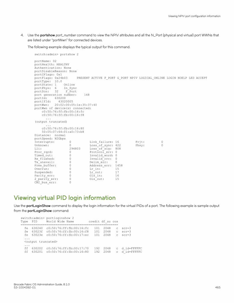
4. Use the portshow port_number command to view the NPIV attributes and all the N_Port (physical and virtual) port WWNs thatare listed under “portWwn” for connected devices.
The following example displays the typical output for this command.
switch:admin> portshow 2
portName: 02portHealth: HEALTHY Authentication: NoneportDisableReason: NoneportCFlags: 0x1portFlags: 0x24b03 PRESENT ACTIVE F_PORT G_PORT NPIV LOGICAL_ONLINE LOGIN NOELP LED ACCEPTportType: 10.0portState: 1 Online portPhys: 6 In_Sync portScn: 32 F_Port port generation number: 148portId: 630200portIfId: 43020005portWwn: 20:02:00:05:1e:35:37:40portWwn of device(s) connected: c0:50:76:ff:fb:00:16:fc c0:50:76:ff:fb:00:16:f8 ...(output truncated) ... c0:50:76:ff:fb:00:16:80 50:05:07:64:01:a0:73:b8Distance: normalportSpeed: N2GbpsInterrupts: 0 Link_failure: 16 Frjt: 0 Unknown: 0 Loss_of_sync: 422 Fbsy: 0 Lli: 294803 Loss_of_sig: 808 Proc_rqrd: 0 Protocol_err: 0 Timed_out: 0 Invalid_word: 0 Rx_flushed: 0 Invalid_crc: 0 Tx_unavail: 0 Delim_err: 0 Free_buffer: 0 Address_err: 1458 Overrun: 0 Lr_in: 15 Suspended: 0 Lr_out: 17 Parity_err: 0 Ols_in: 16 2_parity_err: 0 Ols_out: 15 CMI_bus_err: 0
Viewing virtual PID login informationUse the portLoginShow command to display the login information for the virtual PIDs of a port. The following example is sample outputfrom the portLoginShow command:
switch:admin> portloginshow 2Type PID World Wide Name credit df_sz cos===================================================== fe 630240 c0:50:76:ff:fb:00:16:fc 101 2048 c scr=3 fe 63023f c0:50:76:ff:fb:00:16:f8 101 2048 c scr=3 fe 63023e c0:50:76:ff:fb:00:17:ec 101 2048 c scr=3 ... <output truncated> ... ff 630202 c0:50:76:ff:fb:00:17:70 192 2048 c d_id=FFFFFC ff 630201 c0:50:76:ff:fb:00:16:80 192 2048 c d_id=FFFFFC
Viewing NPIV port configuration information
Brocade Fabric OS Administration Guide, 8.1.053-1004392-01 465

To view the details of the devices that were last logged in to a particular port, you can use the history option in the portLoginShowcommand. The device details such as type, PID and WWN along with the logged out timestamp in UTC format will be displayed.
Pluto:root> portloginshow 1/0 -historyType PID World Wide Name logout time=========================================================== fd 550002 30:0c:02:05:1e:61:23:8f 09/17/2014 13:56:01 fd 550001 30:0c:01:05:1e:61:23:8f 09/17/2014 13:56:02 fe 550000 30:0c:00:05:1e:61:23:8f 09/17/2014 13:56:02 fd 550001 30:0c:01:05:1e:61:23:8f 09/18/2014 05:49:37Pluto:root>
Viewing NPIV port configuration information
Brocade Fabric OS Administration Guide, 8.1.0466 53-1004392-01
Fabric-Assigned PWWN• Fabric-Assigned PWWN overview..........................................................................................................................................................467• User- and auto-assigned FA-PWWN behavior ............................................................................................................................... 468• Configuring an FA-PWWN for an HBA connected to an Access Gateway...........................................................................469• Configuring an FA-PWWN for an HBA connected to an edge switch.................................................................................... 470• Supported switches and configurations for FA-PWWN................................................................................................................ 470• Configuration upload and download considerations for FA-PWWN........................................................................................471• Security considerations for FA-PWWN.................................................................................................................................................471• Restrictions of FA-PWWN..........................................................................................................................................................................472• Access Gateway N_Port failover with FA-PWWN............................................................................................................................472
Fabric-Assigned PWWN overviewFabric-Assigned PWWN simplifies server deployment in a Fibre Channel SAN (FC SAN) environment by using a virtual port World WideName (PWWN) instead of a physical PWWN to configure zoning and LUN mapping and masking.
Server deployment typically requires that multiple administrative teams (for example, server and storage teams) coordinate with eachother to perform configuration tasks such as zone creation in the fabric and LUN mapping and masking on the storage device. Thesetasks must be completed before the server is deployed. Before you can configure WWN zones and LUN masks, you must find out thephysical PWWN of the server. This means that administrative teams cannot start their configuration tasks until the physical server arrives(and its physical PWWN is known). Because the configuration tasks are sequential and interdependent across various administrativeteams, it may take several days before the server gets deployed in an FC SAN.
You can use a fabric-assigned PWWN (FA-PWWN) to configure services such as zoning and LUN masking before you have a physicalserver. An FA-PWWN is a "virtual" port WWN that can be used instead of the physical PWWN. When the server is later attached to theSAN, the FA-PWWN is assigned to the server.
For example, you can use the FA-PWWN feature to perform the following tasks:
• Replace one server with another server, or replace failed HBAs or adapters within a server, without having to change any zoningor LUN mapping and masking configurations.
• Easily move servers across ports or Access Gateways by way of reassigning the FA-PWWN to another port.
• Use the FA-PWWN to represent a server in boot LUN zone configurations so that any physical server that is mapped to thisFA-PWWN can boot from that LUN, thus simplifying boot over SAN configuration.
NOTEThe server must use a supported HBA or adapter and must be enabled to use the FA-PWWN feature. Refer to the releasenotes for the HBA or adapter versions that support this feature.
You can configure an FA-PWWN for the following topologies:
• An FA-PWWN for an HBA device that is connected to an Access Gateway switch
• An FA-PWWN for an HBA device that is connected directly to an edge switch
Brocade Fabric OS Administration Guide, 8.1.053-1004392-01 467

FIGURE 58 Fabric-assigned port World Wide Name provisioning scenarios
User- and auto-assigned FA-PWWN behaviorEach switch port and Access Gateway port can have up to two FA-PWWNs, one assigned automatically and one assigned by the user.FA-PWWNs must be unique, and only one FA-PWWN can be active at any given time.
The automatically assigned FA-PWWN is created by default if you enable the feature without explicitly providing a virtual PWWN.
The user-assigned FA-PWWN takes precedence over the automatically assigned FA-PWWN. This means the switch will bind the user-assigned FA-PWWN to the port if both a user-assigned and an automatically assigned FA-PWWN are available. If you want to select theautomatically assigned FA-PWWN over the user-assigned FA-PWWN, you must delete the user-assigned FA-PWWN from the port towhich it has been assigned.
The switch ensures that automatically assigned FA-PWWNs are unique in a fabric. However, it is your responsibility to ensure that user-assigned FA-PWWNs are also unique throughout the fabric.
ATTENTIONYou must ensure that the same user-assigned FA-PWWN is not used in multiple chassis. There is no fabric-wide database, soadding the same FA-PWWNs in multiple chassis causes duplicate PWWNs.
User- and auto-assigned FA-PWWN behavior
Brocade Fabric OS Administration Guide, 8.1.0468 53-1004392-01

Configuring an FA-PWWN for an HBA connected toan Access GatewayTo configure an FA-PWWN, assign the FA-PWWN on the Access Gateway switch. The FA-PWWN feature is enabled by default on theHBA. Refer to the Brocade Adapters Administrator’s Guide for a list of supported HBAs.
1. Log in to the edge switch to which the Access Gateway is directly connected.
2. Assign the FA-PWWN.
• If you are manually assigning a WWN, enter the following command:
fapwwn --assign -ag AG_WWN -port AG_port -v Virtual_PWWN
• If you want the WWN to be automatically assigned, enter the following command:
fapwwn --assign -ag AG_WWN -port AG_port
3. Display the FA-PWWN.
fapwwn --show -ag all
You should see output similar to the following sample. The FA-PWWNs are in the Virtual Port WWN column. (In this example,long lines of output are shown split across two lines, for better readability.)
----------------------------------------------------------- AG Port Port Device Port WWN \-----------------------------------------------------------10:00:00:05:1e:65:8a:d5/16 -- --:--:--:--:--:--:--:-- \10:00:00:05:1e:d7:3d:dc/8 20 20:08:00:05:1e:d7:2b:74 \10:00:00:05:1e:d7:3d:dc/9 20 20:09:00:05:1e:d7:2b:73 \10:00:00:05:1e:d7:3d:dc/16 -- --:--:--:--:--:--:--:-- \------------------------------------------------------------ Virtual Port WWN PID Enable MapType------------------------------------------------------------52:00:10:00:00:0f:50:30 -- Yes AG/Auto11:22:33:44:55:66:77:88 11403 Yes AG/User52:00:10:00:00:0f:50:33 11404 Yes AG/Auto52:00:10:00:00:0f:50:38 -- Yes AG/Auto
4. Display the FA-PWWN on the HBA.
The following steps are to be executed on the server and not the switch.
a) Log in to the server as root.
b) Enter the following command to display the FA-PWWN.
# bcu port --faa_query port_id FAA state: EnabledPWWN: 11:22:33:44:55:66:77:88PWWN source: Fabric
The HBA retains the FA-PWWN until rebooted. This means you cannot unplug and plug the cable into a different port onthe Access Gateway. You must reboot the HBA before moving the HBA to a different port.
If you move an HBA to a different port on a switch running Fabric OS v7.0.0 or later, the HBA will disable its port. The portremains disabled even if you then move the HBA to a port on a switch running a version of Fabric OS earlier than 7.0.0.
Configuring an FA-PWWN for an HBA connected to an Access Gateway
Brocade Fabric OS Administration Guide, 8.1.053-1004392-01 469

Configuring an FA-PWWN for an HBA connected toan edge switchTo configure an FA-PWWN, assign the FA-PWWN on the edge switch. The FA-PWWN feature is enabled by default on the HBA. Referto the Brocade Adapters Administrator’s Guide for a list of supported HBAs.
1. Log in to the edge switch to which the device is connected.
2. Assign the FA-PWWN.
• If you are manually assigning a WWN, enter the following command:
fapwwn --assign -port [slot/]port -v Virtual_PWWN
• If you want the WWN to be automatically assigned, enter the following command:
fapwwn --assign -port [slot/]port
3. Display the FA-PWWN.
fapwwn --show -port all
You should see output similar to the following sample. The FA-PWWNs are in the VPWWN column.
----------------------------------------------------------------------- Port PPWWN VPWWN PID Enable MapType----------------------------------------------------------------------- 0 --:--:--:--:--:--:--:-- 52:00:10:00:00:0f:50:30 10101 Yes Port/Auto 1 --:--:--:--:--:--:--:-- 11:22:33:44:33:22:11:22 -- Yes Port/User 52:00:10:00:00:0f:50:4410 --:--:--:--:--:--:--:-- 52:00:10:00:00:0f:50:45 -- Yes Port/Auto
4. Display the FA-PWWN on the HBA.
The following steps are to be executed on the server and not the switch.
a) Log in to the server as root.
b) Enter the following command to display the FA-PWWN.
# bcu port --faa_query port_id FAA state: EnabledPWWN: 11:22:33:44:33:22:11:22PWWN source: Fabric
The HBA retains the FA-PWWN until it is rebooted. This means you cannot unplug and plug the cable into a different porton the switch. You must reboot the HBA before moving the HBA to a different port.
If you move an HBA to a different port on a switch running Fabric OS v7.0.0 or later, the HBA will disable its port. The portremains disabled even if you then move the HBA to a port on a switch running a version of Fabric OS earlier than 7.0.0.
Supported switches and configurations for FA-PWWNThe FA-PWWN feature is supported only on switches running Fabric OS 7.0.0 or later and only on Brocade HBAs and adapters. TheHBA can be connected to an edge switch or to an Access Gateway switch.
Configuring an FA-PWWN for an HBA connected to an edge switch
Brocade Fabric OS Administration Guide, 8.1.0470 53-1004392-01

The FA-PWWN feature is supported on the following platforms:
• Gen 6 (32-Gbps) platforms running Fabric OS 8.0.x
– Brocade G620– Brocade X6 Directors
• Switch platforms running Fabric OS v7.0.0 or later:
– Brocade DCX 8510 Backbones– Brocade 6505– Brocade 6510– Brocade 6520
• Access Gateway platforms running Fabric OS v7.0.0 or later:
– Brocade 6505– Brocade 6510
Refer to the release notes for the supported Brocade HBA or adapter versions.
Configuration upload and download considerationsfor FA-PWWNThe configuration upload and download utilities can be used to import and export the FA-PWWN configuration.
ATTENTIONBrocade recommends you delete all FA-PWWNs from the switch with the configuration being replaced before you upload ordownload a modified configuration. This is to ensure no duplicate FA-PWWNs in the fabric.
Security considerations for FA-PWWNIf security is a concern, ensure that only authorized users can configure FA-PWWNs. Device authentication and DCC policies provideadditional security between the switch and the server.
The FA-PWWN feature can be enabled only by authorized administrators. Thus, existing user-level authentication and authorizationmechanisms should be used to ensure only authorized users can configure this feature.
If you are concerned about security for FA-PWWNs, you should configure device authentication. You can use authentication at the devicelevel to ensure security between the switch and the server. Refer to Device authentication policy on page 250 for information aboutconfiguring device authentication.
You can also use the Device Connection Control (DCC) policy to ensure that only an authorized physical server can connect to a specificswitch port.
NOTEWhen creating the DCC policy, use the physical device WWN and not the FA-PWWN.
If you use DCC, a policy check is done on the physical PWWN on the servers. In the case of an HBA, the FA-PWWN is assigned to theHBA only after the DCC check is successful. Refer to DCC policy behavior with Fabric-Assigned PWWNs on page 244 for additionalinformation.
Security considerations for FA-PWWN
Brocade Fabric OS Administration Guide, 8.1.053-1004392-01 471

Restrictions of FA-PWWNThe FA-PWWN feature is not supported with some Fibre Channel fabric features.
FA-PWWN is not supported for the following:
• FCoE devices
• FL_Ports
• Swapped ports (using the portswap command)
• Cascaded Access Gateway topologies
• FICON/FMS mode
• With F_Port trunking on directly attached Brocade HBAs or adapters
NOTEFA-PWWN is supported with F_Port trunking on the supported Access Gateway platforms.
Access Gateway N_Port failover with FA-PWWNIf an Access Gateway is connected to multiple switches, you should configure the same FA-PWWNs on both switches to avoid having toreboot the host in case of failover.
If the same FA-PWWNs are not configured on the switches, and if an FA-PWWN F_Port on an Access Gateway fails over to an N_Portthat is connected to a different switch, the FA-PWWN assigned to the Access Gateway F_Port following the failover will be different thanit was before the failover occurred. This situation may require the host to reboot to bring it back online. Even after the reboot, the hostmay potentially go into a different zone because the FA-PWWN is different.
Restrictions of FA-PWWN
Brocade Fabric OS Administration Guide, 8.1.0472 53-1004392-01
Inter-chassis Links• Inter-chassis links ..........................................................................................................................................................................................473• ICLs between DCX 8510 Backbones...................................................................................................................................................475• ICLs between X6 Directors.........................................................................................................................................................................477• ICLs between DCX 8510 Backbones and X6 Directors...............................................................................................................482• Virtual Fabrics considerations for ICLs..................................................................................................................................................484• Supported topologies for ICL connections..........................................................................................................................................485
Inter-chassis linksAn inter-chassis link (ICL) is a licensed feature used to interconnect the following chassis platforms. ICL ports in the core blades are usedto interconnect the chassis platforms, potentially increasing the number of usable ports in the chassis platforms.
• Two Brocade DCX 8510 Backbones
• Two Brocade X6 Directors
• A Brocade DCX 8510 Backbone with a Brocade X6 Director
NOTETo connect a DCX 8510 Backbone to an X6 Director, you must fix the port speed on the X6 Director to 16 Gbps anduse a 16 Gbps QSFP.
When two chassis platforms are interconnected by ICLs, each chassis requires a unique domain and is managed as a separate switch.
The ICL ports appear as regular ports, with some restrictions. All port parameters associated with ICL ports are static, and all portCfgcommands are blocked from changing any of the ICL port parameters, except for EX_Port and FEC port parameters. The onlymanagement associated with ICL ports and cables is monitoring the status of the LEDs on the ICL ports and any maintenance if theAttention LED is blinking yellow.
The ICL ports are managed as E_Ports. You can also configure EX_Ports on the ICLs. Refer to Using FC-FC Routing to Connect Fabricson page 513 for instructions.
When you connect two chassis platforms, the following features are supported:
• Trunking
• Buffer-to-buffer credit
• QoS
NOTEA Brocade trunking license is not required for trunking on ICL connections.
Refer to the specific hardware reference manuals for additional information about LED status meanings and ICL connections, includinginstructions on how to cable ICLs.
License requirements for ICLsICL ports can be used only with an ICL license. An ICL license must be installed on both platforms forming the ICL connection.
Brocade Fabric OS Administration Guide, 8.1.053-1004392-01 473
All ICL ports must be disabled and then re-enabled for the license to take effect. After the addition or removal of an ICL license, thelicense enforcement is performed on the ICL ports only when you issue the portDisable and portEnable commands on the switch forthe ports or the bladeDisable and bladeEnable commands for the core blade.
Enterprise ICL (EICL) license enforcement is applicable for Inter Fabric Links(IFL) via ICL links on Gen-5 platforms and is not applicablefor Gen-6 platforms. In a mixed Gen-5 and Gen-6 environment, the edge fabric will additionally count the ICL IFL links for its licenseenforcement. When a Gen-5 chassis is connected to a Gen-6 chassis, the Gen-5 takes precedence and imposes the EICL license limiton the links. Prior to 8.0.1 release, only ICL ISLs were counted for license enforcement. In case of only Gen-6 platforms, there is norestriction on the number of switches that can be connected via ICL. In case of only Gen-5 platforms, if no EICL license is present, only3 other direct chassis are allowed to connect (total 4).
In the case of 16-Gbps Gen 5 platforms, if EICL license is present, maximum of 9 chassis are allowed to connect (total of 10). The limiton the number of chassis depends only on the physical chassis and not on the logical switches.
For more information on how license enforcement occurs, refer to the Brocade Fabric OS Software Licensing Guide.
Using the QSFPs that support 2 km on ICL portsPrior to Fabric OS 7.3.0, all the FE ports and ICL ports used the same buffer credit model. In Fabric OS 7.3.0 and later, ICL portssupport a 2 km distance. To support this distance, you must use specific QSFPs and allocate a greater number of buffer credits per port.
The following points should be considered if you are attempting to support 2 km links on ICL ports:
• Only the QSFPs that have the part number “57-1000310-01” and the serial number starting with “HME114323P00044”support 2 km on ICLs. The second character (‘M’) in this serial number indicates that the QSFP supports 2 km distance. Youcan also use the sfpShow command to identify the QSFPs that support 2 km on ICL ports.
• The new credit model does not affect the HA configuration.
• You cannot downgrade from Fabric OS 7.3.0 to any earlier version if either of the following conditions is true:
– When you have plugged in the QSFPs that support 2 km on one ore more ICL ports.– When you have configured buffer credits using the EportCredit command on one or more ICL ports.
• The portCfgEportCredits configuration cannot have less than 5 buffer credits or more than 16 buffer credits per VC in Gen 5core blades. Gen 6 core blades cannot have less than 5 buffer credits and more than 160 buffer credits per VC. If there areinsufficient buffer credits available, the default configuration is retained and the message Failed: already exceeds Buffer creditsallowed is displayed.
• Only a maximum of 10 ICL ports can be configured with 2 km QSFPs with 16 buffer credits per VC on Gen 5 core blades.
• Only a maximum of 14 ICL ports can be configured with 2 km QSFPs with 13 buffer credits per VC on Gen 5 core blades.
On the Gen 5 core blades, when you configure the 15th port using portCfgEportCredit, the message Failed: already exceedsBuffer credits allowed is displayed. The remaining two ports can have only 34 buffer credits. To remedy this, disable some portsand configure the remaining ports using 13 buffer credits per VC.
• On the Gen 5 core blades, if you are using the portCfgEportCredit command, a maximum of 16 buffer credits can beconfigured on all the ICL ports when all the 16 ICL ports are in the disabled state. After enabling all the ports, until the buffercredits are available, the ports will come up with the configured buffer credits. The remaining ports will come up in degradedmode. In case of remaining QoS-enabled ports, the ports will come up without QoS enabled. If all the ICL ports are QoSenabled, there will only be 448 buffer credits available for 2 km distance support.
• Due to the 2 km QSFP module limitation, the link failure counter is not reliable during module or cable removal or insertion.
Inter-chassis links
Brocade Fabric OS Administration Guide, 8.1.0474 53-1004392-01

ICLs between DCX 8510 BackbonesEach ICL connects the core blades of two Brocade DCX 8510 chassis and provides up to 64 Gbps of throughput within a single cable.
You can have up to 32 QSFP ports in a Brocade DCX 8510-8 chassis or 16 QSFP ports in a Brocade DCX 8510-4 chassis, with upto 2 Tbps ICL bandwidth and support for up to 100 meters on universal optical cables.
The 100-meter ICL is supported beginning in Fabric OS 7.1.0, when using 100-meter-capable QSFPs over OM4 cable only.
The Brocade DCX 8510-8 has four port groups on the CR16-8 core blade. The Brocade DCX 8510-4 has two port groups on theCR16-4 core blade. Each port group has four QSFP connectors, and each QSFP connector maps to four user ports. Refer to thehardware reference manuals for details about the port groups.
The following table shows the mappings from the numbered QSFP ports on the face of the core blade to the individual FC port numbersas shown by the slotShow command.
TABLE 96 External port to slotShow port mapping for core blades
External port number slotShow FC port numbers External port number slotShow FC port numbers
0 0-3 8 32-35
1 4-7 9 36-39
2 8-11 10 40-43
3 12-15 11 44-47
4 16-19 12 48-51
5 20-23 13 52-55
6 24-27 14 56-59
7 28-31 15 60-63
Following are ICL configuration guidelines for trunking bandwidth and High Availability:
• ICLs must be installed in groups of two. Each pair of ICLs must be in the same port group.
• The recommended minimum number of ICLs between two Brocade DCX 8510 chassis is four. Additional ICLs should beadded in increments of two, one on each core blade.
• For High Availability, you should have at least two ICLs from each core blade. Figure 59 shows two Brocade DCX 8510-8chassis connected with full redundancy using four ICL connections.
ICLs between DCX 8510 Backbones
Brocade Fabric OS Administration Guide, 8.1.053-1004392-01 475
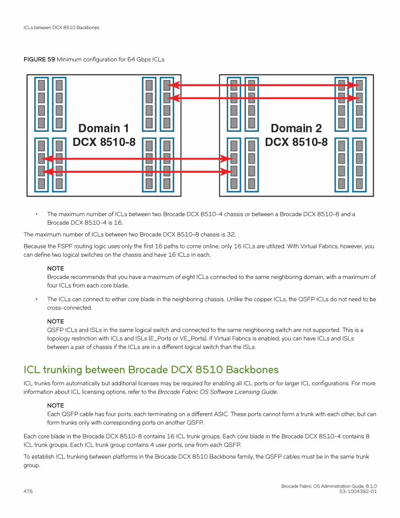
FIGURE 59 Minimum configuration for 64 Gbps ICLs
• The maximum number of ICLs between two Brocade DCX 8510-4 chassis or between a Brocade DCX 8510-8 and aBrocade DCX 8510-4 is 16.
The maximum number of ICLs between two Brocade DCX 8510-8 chassis is 32.
Because the FSPF routing logic uses only the first 16 paths to come online, only 16 ICLs are utilized. With Virtual Fabrics, however, youcan define two logical switches on the chassis and have 16 ICLs in each.
NOTEBrocade recommends that you have a maximum of eight ICLs connected to the same neighboring domain, with a maximum offour ICLs from each core blade.
• The ICLs can connect to either core blade in the neighboring chassis. Unlike the copper ICLs, the QSFP ICLs do not need to becross-connected.
NOTEQSFP ICLs and ISLs in the same logical switch and connected to the same neighboring switch are not supported. This is atopology restriction with ICLs and ISLs (E_Ports or VE_Ports). If Virtual Fabrics is enabled, you can have ICLs and ISLsbetween a pair of chassis if the ICLs are in a different logical switch than the ISLs.
ICL trunking between Brocade DCX 8510 BackbonesICL trunks form automatically but additional licenses may be required for enabling all ICL ports or for larger ICL configurations. For moreinformation about ICL licensing options, refer to the Brocade Fabric OS Software Licensing Guide.
NOTEEach QSFP cable has four ports, each terminating on a different ASIC. These ports cannot form a trunk with each other, but canform trunks only with corresponding ports on another QSFP.
Each core blade in the Brocade DCX 8510-8 contains 16 ICL trunk groups. Each core blade in the Brocade DCX 8510-4 contains 8ICL trunk groups. Each ICL trunk group contains 4 user ports, one from each QSFP.
To establish ICL trunking between platforms in the Brocade DCX 8510 Backbone family, the QSFP cables must be in the same trunkgroup.
ICLs between DCX 8510 Backbones
Brocade Fabric OS Administration Guide, 8.1.0476 53-1004392-01

The following illustration marks the 4-port ICL trunking boundaries or port groups for DCX 8510 core routing blades (CR16-8 andCR16-4 blades):
FIGURE 60 ICL trunking boundaries
The following tables summarize the possible trunking connections between DCX 8510 Backbones:
TABLE 97 Trunking connections between Backbones
Connecting blades 2 to 4-port ICL trunks
CR16-8 and CR16-8 Supported with QSFPs located within the same trunk group on each blade
CR16-8 and CR16-4 Supported with QSFPs located within the same trunk group on each blade
CR16-4 and CR16-4 Supported with QSFPs located within the same trunk group on each blade
Refer to the specific hardware reference manuals for information about port numbering, port trunk groups, and connecting the ICLcables.
ICLs between X6 DirectorsUp to eight directors can be connected through inter-chassis links (ICLs) between 4x32-Gbps QSFPs on core routing blades installed inX6 Directors
Each ICL connects the core blades of two Brocade X6 Director chassis and provides up to 128 Gbps of throughput within a single cable.
You can have up to 32 QSFP ports in a X6-8 chassis or 16 QSFP ports in a X6-4 chassis, with up to 4 Tbps ICL bandwidth andsupport for up to 100 meters on universal optical cables.
The 100-meter ICL is supported beginning in Fabric OS 8.0.1, when using 100-meter-capable QSFPs over OM4 cable only.
The Brocade X6-8 has four port groups on the CR32-8 core blade. The Brocade X6-4 has two port groups on the CR32-4 core blade.Each port group has four QSFP connectors, and each QSFP connector maps to four user ports.
ICLs between X6 Directors
Brocade Fabric OS Administration Guide, 8.1.053-1004392-01 477

The following table shows the mappings from the numbered QSFP ports on the face of the core blade to the individual FC port numbersas shown by the slotShow command.
TABLE 98 External port to slotShow port mapping for core blades
External port number slotShow FC port numbers External port number slotShow FC port numbers
0 0-3 8 32-35
1 4-7 9 36-39
2 8-11 10 40-43
3 12-15 11 44-47
4 16-19 12 48-51
5 20-23 13 52-55
6 24-27 14 56-59
7 28-31 15 60-63
Following are ICL configuration guidelines for trunking bandwidth and High Availability:
• A minimum of four ICL ports (two on each core blade) must be connected between each chassis pair.
• The dual connections on each core blade must reside within the same ICL trunk boundary on the core blades.
• If more than four ICL connections are required between a pair of X6 chassis, additional ICL connections should be added inpairs, one on each core blade with each additional pair residing within the same trunk boundary
• For High Availability, you should have at least two ICLs from each core blade. The following illustration shows two X6-8 chassisconnected with full redundancy using four ICL connections.
ICLs between X6 Directors
Brocade Fabric OS Administration Guide, 8.1.0478 53-1004392-01

FIGURE 61 Minimum configuration for 128 Gbps ICLs
1. X6-8 Chassis with two CR32-8 blades 2. X6-4 Chassis with two CR32-4 blades
• The maximum number of ICLs between two X6-4 chassis or between a X6-8 and a X6-4 is 16.
The maximum number of ICLs between two X6-8 chassis is 32.
Because the FSPF routing logic uses only the first 16 paths to come online, only 16 ICLs are utilized. With Virtual Fabrics, however, youcan define two logical switches on the chassis and have 16 ICLs in each.
NOTEBrocade recommends that you have a maximum of eight ICLs connected to the same neighboring domain, with a maximum offour ICLs from each core blade.
• The ICLs can connect to either core blade in the neighboring chassis. The QSFP ICLs do not need to be cross-connected.
ICLs between X6 Directors
Brocade Fabric OS Administration Guide, 8.1.053-1004392-01 479
NOTEQSFP ICLs and ISLs in the same logical switch and connected to the same neighboring switch are not supported. This is atopology restriction with ICLs and any ISLs that are E_Ports or VE_Ports. If Virtual Fabrics is enabled, you can have ICLs andISLs between a pair of chassis if the ICLs are in a different logical switch than the ISLs.
ICL trunking between Brocade X6 DirectorsTrunking optimizes the use of ICL bandwidth by allowing a group of links to merge into a single logical link, called a trunk. Traffic isdistributed dynamically and in order over this trunk, achieving greater performance with fewer links. Within the trunk, multiple physicalports appear as a single route, thus simplifying management. Trunking also improves system reliability by maintaining in-order deliveryof data and avoiding I/O retries if one link within the trunk fails.
Each QSFP provides four 32 Gbps FC ports. Since each port within a QSFP terminates on a different ASIC within each core blade, anICL trunk cannot be formed using the individual FC ports withing the same QSFP. A trunk has to be formed from individual FC ports indifferent QSFP ports. These QSFP ports must reside in the same trunk group. To form an ICL trunk between two devices, a minimum oftwo QSFPs within a port trunk group on a core blade installed in one device must be connected to a pair of QSFPs within a trunk groupon a core blade in another device using ICLs.
ICL trunks form automatically but additional licenses may be required for enabling all ICL ports or for larger ICL configurations. For moreinformation about ICL licensing options, refer to the Brocade Fabric OS Software Licensing Guide.
NOTEEach QSFP cable has four ports, each terminating on a different ASIC. These ports cannot form a trunk with each other, but canform trunks only with corresponding ports on another QSFP.
Each core blade in the Brocade X6-8 contains 16 ICL trunk groups. Each core blade in the Brocade X6-4 contains 8 ICL trunk groups.Each ICL trunk group contains 4 user ports, one from each QSFP. To establish ICL trunking between platforms in the Brocade X6Director family, the QSFP cables must be in the same trunk group. Up to four 4x32 Gbps QSFP ports in a trunk group can form a 512Gbps trunk between two CR32-4 or CR32-8 blades.
The following figure marks the 4-port ICL trunking boundaries or port groups for X6 core routing blades (CR32-8 and CR32-4 blades):
ICLs between X6 Directors
Brocade Fabric OS Administration Guide, 8.1.0480 53-1004392-01

FIGURE 62 ICL trunking for X6 core routing blades
Ports belonging to the same trunking groups are indicated with the same color border under the ports on the blade faceplate. Thesecolors are also applied to the port map labels on each blade faceplate to indicate ports belonging to the same trunking groups. Althougha connection between two QSFPs on one core routing blade and two QSFPs on another blade in a different device are required to formICL trunk, you can create trunks consisting of two to four QSFP connections between these blades.
NOTEYou cannot configure ISLs using ports on port blades and QSFP-based ICLs using ports on core routing blades concurrentlyon the same chassis.
The following tables summarize the possible trunking connections between X6 Directors:
TABLE 99 Trunking connections between X6 Directors
Connecting blades 2 to 4-port ICL trunks
CR32-8 and CR32-8 Supported with QSFPs located within the same trunk group on each blade
CR32-8 and CR32-4 Supported with QSFPs located within the same trunk group on each blade
CR32-4 and CR32-4 Supported with QSFPs located within the same trunk group on each blade
Refer to the specific hardware reference manuals for information about port numbering, port trunk groups, and connecting the ICLcables.
ICLs between X6 Directors
Brocade Fabric OS Administration Guide, 8.1.053-1004392-01 481
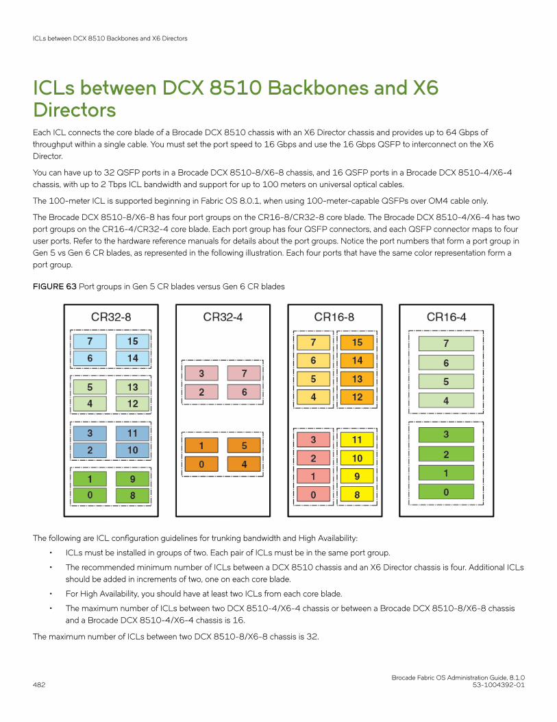
ICLs between DCX 8510 Backbones and X6DirectorsEach ICL connects the core blade of a Brocade DCX 8510 chassis with an X6 Director chassis and provides up to 64 Gbps ofthroughput within a single cable. You must set the port speed to 16 Gbps and use the 16 Gbps QSFP to interconnect on the X6Director.
You can have up to 32 QSFP ports in a Brocade DCX 8510-8/X6-8 chassis, and 16 QSFP ports in a Brocade DCX 8510-4/X6-4chassis, with up to 2 Tbps ICL bandwidth and support for up to 100 meters on universal optical cables.
The 100-meter ICL is supported beginning in Fabric OS 8.0.1, when using 100-meter-capable QSFPs over OM4 cable only.
The Brocade DCX 8510-8/X6-8 has four port groups on the CR16-8/CR32-8 core blade. The Brocade DCX 8510-4/X6-4 has twoport groups on the CR16-4/CR32-4 core blade. Each port group has four QSFP connectors, and each QSFP connector maps to fouruser ports. Refer to the hardware reference manuals for details about the port groups. Notice the port numbers that form a port group inGen 5 vs Gen 6 CR blades, as represented in the following illustration. Each four ports that have the same color representation form aport group.
FIGURE 63 Port groups in Gen 5 CR blades versus Gen 6 CR blades
The following are ICL configuration guidelines for trunking bandwidth and High Availability:
• ICLs must be installed in groups of two. Each pair of ICLs must be in the same port group.
• The recommended minimum number of ICLs between a DCX 8510 chassis and an X6 Director chassis is four. Additional ICLsshould be added in increments of two, one on each core blade.
• For High Availability, you should have at least two ICLs from each core blade.
• The maximum number of ICLs between two DCX 8510-4/X6-4 chassis or between a Brocade DCX 8510-8/X6-8 chassisand a Brocade DCX 8510-4/X6-4 chassis is 16.
The maximum number of ICLs between two DCX 8510-8/X6-8 chassis is 32.
ICLs between DCX 8510 Backbones and X6 Directors
Brocade Fabric OS Administration Guide, 8.1.0482 53-1004392-01

Because the FSPF routing logic uses only the first 16 paths to come online, only 16 ICLs are utilized. With Virtual Fabrics, however, youcan define two logical switches on the chassis and have 16 ICLs in each.
NOTEBrocade recommends that you have a maximum of eight ICLs connected to the same neighboring domain, with a maximum offour ICLs from each core blade.
• The ICLs can connect to either core blade in the neighboring chassis. Unlike the copper ICLs, the QSFP ICLs do not need to becross-connected.
NOTEQSFP ICLs and ISLs in the same logical switch and connected to the same neighboring switch are not supported. This is atopology restriction with 16 Gbps ICLs and any ISLs that are E_Ports or VE_Ports. If Virtual Fabrics is enabled, you can haveICLs and ISLs between a pair of DCX 8510 Backbone/X6 Director chassis if the ICLs are in a different logical switch than theISLs.
ICL trunking between DCX 8510 Backbones and X6 DirectorsICL trunks form automatically but additional licenses might be required for enabling all ICL ports or for larger ICL configurations. Formore information about ICL licensing options, refer to the Brocade Fabric OS Software Licensing Guide.
NOTEEach QSFP cable has four ports, each terminating on a different ASIC. These ports cannot form a trunk with each other but canform trunks only with corresponding ports on another QSFP.
Each core blade in the Brocade DCX 8510-8 and X6-8 contains 16 ICL trunk groups. Each core blade in the Brocade DCX 8510-4and X6-4 contains eight ICL trunk groups. Each ICL trunk group contains four user ports, one from each QSFP.
To establish ICL trunking between platforms in the Brocade DCX 8510 Backbone family and X6 Director family, the QSFP cables mustbe in the same trunk group. Each ICL that connects the core blades between the Gen 5 and Gen 6 platforms provides up to 64 Gbps ofthroughput within a single cable.
NOTEWhen you connect DCX 8510 Backbone ICL ports with X6 Director ICL ports, you must use the Gen 5 4x16 Gbps QSFPs onthe Gen 6 (X6 Director) ICL ports and set the port speed to 16 Gbps on the X6 Directors.
The following tables summarize the possible trunking connections between a DCX 8510 Backbone and an X6 Director:
TABLE 100 Trunking connections between a DCX 8510 Backbone and an X6 Director
Connecting blades 2 to 4-port ICL trunks
CR32-8 and CR16-8 Supported with QSFPs located within the same trunk group on each blade
CR32-8 and CR16-4 Supported with QSFPs located within the same trunk group on each blade
CR32-4 and CR16-8 Supported with QSFPs located within the same trunk group on each blade
CR32-4 and CR16-4 Supported with QSFPs located within the same trunk group on each blade
The following figure is an example of ICL trunks between DCX 8510 Backbones and X6 Directors.
ICLs between DCX 8510 Backbones and X6 Directors
Brocade Fabric OS Administration Guide, 8.1.053-1004392-01 483

FIGURE 64 ICL trunks between DCX 8510 Backbones and X6 Directors
Refer to the specific hardware reference manuals for information about port numbering, port trunk groups, and connecting the ICLcables.
Virtual Fabrics considerations for ICLsIn Virtual Fabrics, the ICL ports can be split across the logical switch, base switch, and default switch. The triangular topology requirementmust be met for each fabric individually.
Virtual Fabrics considerations for ICLs
Brocade Fabric OS Administration Guide, 8.1.0484 53-1004392-01

NOTEAll the ports within a QSFP must exist within the same logical switch, base switch, or default switch. Ports within a QSFP cannotbe split. A QSFP can establish ICL ports in one logical switch, base switch, or default switch while another QSFP can establishICL ports in another logical switch, base switch or default switch.
The following restrictions apply:
• ICL ports cannot be in a logical switch that is using XISLs. The "Allow XISL Use" attribute for the switch must be off.
Supported topologies for ICL connectionsYou can connect the Brocade Backbones and/or Directors in a mesh topology and a core-edge topology. A brief description of eachfollows. (You can also connect two DCX 8510 chassis or X Directors point-to-point.)
The illustrations in this section show sample topologies. Refer to the Brocade SAN Scalability Guidelines for details about maximumtopology configurations.
Mesh topologyYou can connect the Brocade Backbones or Directors in a mesh topology, in which every chassis is connected to every other chassis.
NOTEA maximum of nine director chassis can be connected to form a mesh topology. The mesh topology can consist of allhomogeneous chassis or a mix of Gen 5 and Gen 6 chassis which have the same slot count.
A simple form of the mesh topology is the triangular topology (shown in the following illustration). The triangular topology is supportedby three Brocade Backbone or Director chassis. The chassis for each topology must all be from the same family.
• Brocade X6 Director family (Brocade X6-4 or Brocade X6-8)
• Brocade DCX 8510 Backbone family (Brocade DCX 8510-4 or Brocade DCX 8510-8)
Supported topologies for ICL connections
Brocade Fabric OS Administration Guide, 8.1.053-1004392-01 485

FIGURE 65 Three Brocade X6-8 chassis in full mesh triangular ICL topology
During an ICL break in the triangular topology, the chassis that has the connections of the other two is the main chassis. Any errormessages relating to a break in the topology appear in the RASLog of the main chassis.
For the Brocade DCX Backbone family only: If one ICL is broken but there is a regular ISL, the triangular topology holds given that theISL cost is lower than the total cost through the ICL linear topology. If a direct ICL link between two chassis is broken, the triangulartopology is considered broken when the ISL path between the two switches is a multiple hop. In this case, the triangular topology brokenmessage is posted independently of the cost of the ISL path being lesser or greater than the ICL path between the two switches.
Another form is the full nine-mesh topology shown in Figure 66. This topology is supported by a mix of Brocade X6-4 and BrocadeX6-8 Directors or a mix of Gen 5 and Gen 6 Directors and Backbones that have the same slot count.
Supported topologies for ICL connections
Brocade Fabric OS Administration Guide, 8.1.0486 53-1004392-01

FIGURE 66 Full nine-mesh topology
Core-edge topologyYou can connect Brocade DCX 8510 Backbones or Brocade X6 Directors in a core-edge topology. For example, Figure 67 shows sixchassis connected in a core-edge topology (four edges and two cores). Although this illustration shows only the Brocade DCX 8510-8,each chassis can be either a Brocade DCX 8510-4, a Brocade DCX 8510-8, a Brocade X6-4, or a Brocade X6-8. You can have up toeight edges using Brocade DCX 8510-8 or Brocade X6-8 cores or up to four edges using Brocade DCX 8510-4 or Brocade X6-4cores.
NOTEA maximum of 12 chassis can be interconnected to form a core-edge topology using ICL links.
Each line in Figure 67 represents four QSFP cables. The cabling scheme should follow the parallel example shown in Figure 59 on page476.
Supported topologies for ICL connections
Brocade Fabric OS Administration Guide, 8.1.053-1004392-01 487
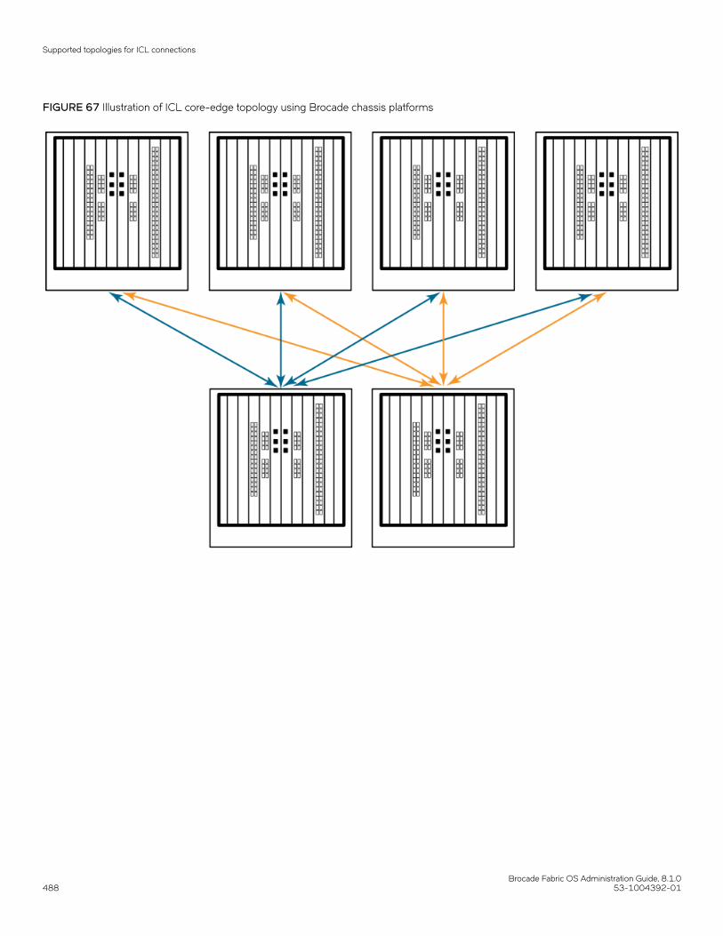
FIGURE 67 Illustration of ICL core-edge topology using Brocade chassis platforms
Supported topologies for ICL connections
Brocade Fabric OS Administration Guide, 8.1.0488 53-1004392-01

Managing Trunking Connections• Trunking overview...........................................................................................................................................................................................489• Supported platforms for trunking............................................................................................................................................................ 491• Supported configurations for trunking...................................................................................................................................................491• Requirements for trunk groups.................................................................................................................................................................492• Recommendations for trunk groups.......................................................................................................................................................492• Configuring trunk groups.............................................................................................................................................................................493• Enabling trunking............................................................................................................................................................................................493• Disabling trunking...........................................................................................................................................................................................494• Displaying trunking information................................................................................................................................................................494• ISL trunking over long-distance fabrics................................................................................................................................................ 495• EX_Port trunking.............................................................................................................................................................................................496• F_Port trunking................................................................................................................................................................................................ 497• Displaying F_Port trunking information.................................................................................................................................................504• Disabling F_Port trunking............................................................................................................................................................................505• Enabling the DCC policy on a trunk area..............................................................................................................................................505
Trunking overviewTrunking optimizes the use of bandwidth by allowing a group of links to merge into a single logical link, called a trunk group. Traffic isdistributed dynamically and in order over this trunk group, achieving greater performance with fewer links. Within the trunk group, multiplephysical ports appear as a single port, thus simplifying management. Trunking also improves system reliability by maintaining in-orderdelivery of data and avoiding I/O retries if one link within the trunk group fails.
Trunking is frame-based instead of exchange-based. Because a frame is much smaller than an exchange, this means that frame-basedtrunks are more granular and better balanced than exchange-based trunks and provide maximum utilization of links.
The Trunking license is required for any type of trunking, and must be installed on each switch that participates in trunking. For details onobtaining and installing licensed features, refer to the Brocade Fabric OS Software Licensing Guide.
Types of trunkingTrunking can be between two switches, between a switch and an Access Gateway module, or between a switch and a Brocade adapter.The types of trunking are as follows:
• ISL trunking, or E_Port trunking, is configured on an inter-switch link (ISL) between two Fabric OS switches and is applicableonly to E_Ports.
• ICL trunking is configured on an inter-chassis link (ICL) between two Brocade DCX 8510 Backbones and/or X6 Directors andis applicable only to ports on the core blades.
Refer to Inter-chassis Links on page 473 for detailed information about ICL trunking.
• EX_Port trunking is configured on an inter-fabric link (IFL) between an FC router (EX_Port) and an edge fabric (E_Port). Thetrunk ports are EX_Ports connected to E_Ports.
Refer to EX_Port trunking on page 496 for additional information about EX_Port trunking.
• F_Port trunking is configured on a link between a switch and either an Access Gateway module or a Brocade adapter. The trunkports are F_Ports (on the switch) connected to N_Ports (on the Access Gateway or adapter).
Brocade Fabric OS Administration Guide, 8.1.053-1004392-01 489

• N_Port trunking is configured on a link between a switch and either an Access Gateway module or a Brocade adapter. It issimilar to F_Port trunking. The trunk ports are N_Ports (on the Access Gateway or adapter) connected to F_Ports (on the switch).
For more information, refer to Configuring F_Port trunking for a Brocade adapter on page 501, the Brocade Access GatewayAdministrator's Guide, and the Brocade Adapters Administrators Guide .
NOTEThis chapter uses the term F_Port trunking to refer to a trunk between the F_Ports on a switch and the N_Ports on either anAccess Gateway module or a Brocade adapter. This type of trunk might be referred to as N_Port trunking in the BrocadeAccess Gateway Administrator's Guide or Brocade Adapters Administrator’s Guide
Masterless trunkingMasterless trunking means that if the master port goes offline, one of the slave ports automatically becomes the new master port, thusavoiding traffic disruption. The new master port uses the old master port area and the old master port is assigned a new, unused area. Inthis way, the port identifier (PID) of the trunk does not change if the master port goes offline.
If trunking is not masterless, and if the master port goes offline, traffic disruption can occur because the slave ports in the trunk group gooffline to select the new master port and then come back online.
Masterless trunking is supported for most platforms and trunking types:
• All F_Port trunking is masterless.
• ISL and ICL trunking are masterless.
• EX_Port trunking is masterless, except on Brocade DCX 8510 Backbones and X6 Directors with Virtual Fabrics disabled.
License requirements for trunkingTrunking of non-ICL ports (E_Ports, EX_Ports, and F_Ports) requires the Trunking license. This license must be installed on each switchthat participates in trunking.
Trunking of ICL ports (E_Ports and EX_Ports) does not require a Trunking license.
ATTENTIONAfter you add the Trunking license, to enable trunking functionality, you must disable and then re-enable each port to be used intrunking, or disable and re-enable the switch.
Refer to the Brocade Fabric OS Software Licensing Guide for information about activating licenses.
Port groups for trunkingFor trunk groups to form, several conditions must be met. One of the conditions is that all of the ports in a trunk group must belong tothe same port group. A port group is a group of eight ports, based on the user port number, such as 0-7, 8-15, 16-23, and up to thenumber of ports on the switch. The maximum number of port groups is platform-specific.
Ports in a port group are usually contiguous, but they may not be. Refer to the hardware reference manual for your switch for informationabout which ports can be used in the same port group for trunking.
Trunking overview
Brocade Fabric OS Administration Guide, 8.1.0490 53-1004392-01

FIGURE 68 Port group configuration for the Brocade G620
Supported platforms for trunkingTrunking is supported on the FC ports of all Brocade platforms and blades supported in Fabric OS v7.0.0 and later.
EX_Port trunking is supported only on those platforms that support EX_Ports. Refer to Supported platforms for FC-FC routing on page514 for more information.
Supported configurations for trunking• Links within a trunk can be 4 Gbps, 8 Gbps, 10 Gbps, 16 Gbps, or 32 Gbps depending on the Brocade platform.
NOTE32 Gbps QSFP ports can be used to create trunks between a pair ofBrocade G620for ISL, and between a pair ofBrocade X6 Directors for ICL. Refer to ICL trunking between Brocade X6 Directors on page 480 for ICL trunkingdetail.
• The maximum number of ports per trunk is generally eight, but the number of trunks per switch depends on the Brocadeplatform.
• You can have up to eight ports in one trunk group to create high-performance ISL trunks between switches, providing up to128 Gbps (based on a 16-Gbps port speed).
• An E_Port or EX_Port trunk can be up to eight ports wide. All the ports must be adjacent to each other, in the clearly markedgroups on the front of the switch.
Trunks operate best when the cable length of each trunked link is roughly equal to the length of the others in the trunk. For optimalperformance, no more than 30 meters difference is recommended. Trunks are compatible with both short-wavelength (SWL) and long-wavelength (LWL) fiber-optic cables and transceivers.
Trunking is performed according to the Quality of Service (QoS) configuration on the master and the slave ports. That is, in a given trunkgroup, if there are some ports with QoS enabled and some with QoS disabled, they form two different trunks, one with QoS enabled andthe other with QoS disabled.
High Availability support for trunkingTrunking is a High Availability (HA) supported feature. The HA protocol for trunking is as follows:
• If trunking is disabled prior to the HA failover, it remains disabled after the HA failover.
• If trunking is enabled prior to the HA failover, it remains enabled after the HA failover.
Supported configurations for trunking
Brocade Fabric OS Administration Guide, 8.1.053-1004392-01 491

Requirements for trunk groupsThe following requirements apply to all types of trunking:
• All of the ports in a trunk group must belong to the same port group.
• All of the ports in a trunk group must meet the following conditions:
– They must be running at the same speed.– They must be configured for the same distance.– They must have the same QoS and FEC state.– They must have the same encryption and compression state.
• Trunk groups must be between Brocade switches (or Brocade adapters in the case of F_Port trunking).
• There must be a direct connection between participating switches.
• Trunking cannot be done if ports are in ISL R_RDY mode. (You can disable this mode by using the portCfgIslMode command.)
• Trunking is supported only on FC ports. Virtual FC ports (VE_Ports or VEX_Ports) do not support trunking.
Recommendations for trunk groupsTo identify the most useful trunk groups, consider the following recommendations along with the standard guidelines for SAN design:
• Evaluate the traffic patterns within the fabric.
• Place trunking-capable switches adjacent to each other.
This maximizes the number of trunk groups that can form. If you are using a core and edge topology, place trunking-capableswitches at the core of the fabric and any switches that are not trunking-capable at the edge of the fabric.
• When connecting two switches with two or more ISLs, ensure that all trunking requirements are met to allow a trunk group toform.
• Determine the optimal number of trunk groups between each set of linked switches, depending on traffic patterns and portavailability.
The goal is to avoid traffic congestion without unnecessarily using ports that could be used to attach other switches or devices.
• Each physical ISL uses two ports that could otherwise be used to attach node devices or other switches.
• Trunk groups can be used to resolve ISL oversubscription if the total capability of the trunk group is not exceeded.
• Consider how the addition of a new path will affect existing traffic patterns:
– A trunk group has the same link cost as the master ISL of the group, regardless of the number of ISLs in the group. Thisallows slave ISLs to be added or removed without causing data to be rerouted, because the link cost remains constant.
– The addition of a path that is shorter than existing paths causes traffic to be rerouted through that path.– The addition of a path that is longer than existing paths may not be useful, because the traffic will choose the shorter paths
first.
• Plan for future bandwidth addition to accommodate increased traffic.
For trunk groups over which traffic is likely to increase as business requirements grow, consider leaving one or two ports in thegroup available for the future nondisruptive addition of bandwidth.
• Consider creating redundant trunk groups where additional ports are available or paths are particularly critical.
This helps to protect against oversubscription of trunk groups, multiple ISL failures in the same group, and the rare occurrenceof an ASIC failure.
Requirements for trunk groups
Brocade Fabric OS Administration Guide, 8.1.0492 53-1004392-01

• To provide the highest level of reliability, deploy trunk groups in redundant fabrics to help ensure that ISL failures do not disruptbusiness operations.
Configuring trunk groupsAfter you install the Trunking license, you must re-initialize the ports that are to be used in trunk groups so that they recognize thattrunking is enabled. This procedure needs to be performed only once, and is required for all types of trunking.
To re-initialize the ports, you can either disable and then re-enable the switch, or disable and then re-enable the affected ports.
1. Connect to the switch and log in using an account assigned to the admin role.
2. Enter the islShow command to determine which ports are used for ISLs.
switch:admin> islshow1: 0-> 0 10:00:00:05:1e:a2:f9:b1 3 SW_43 sp: 4.000G bw: 4.000G TRUNK QOS 2: 10-> 1 10:00:00:05:33:88:a1:d0 1 bodc_switch_sw_66_rename_limit sp: 16.000G bw: 16.000G TRUNK QOS CR_RECOV FEC 3: 12-> 2 10:00:00:05:33:88:a1:d0 1 bodc_switch_sw_66_rename_limit sp: 8.000G bw: 8.000G TRUNK QOS CR_RECOV 4: 16-> 0 10:00:00:05:1e:a1:99:09 5 bodc_switch_20_chars sp: 8.000G bw: 8.000G QOS
3. Enter the portDisable command for each port to be used in a trunk group.
Alternatively, you can enter the switchDisable command to disable all ports on the switch.
4. Enter the portEnable command for each port that you disabled in step 3, or enter the switchEnable command to enable all ofthe ports on the switch.
NOTEF_Port trunking requires additional steps to configure the Trunk Area (TA). Refer to Configuring F_Port trunking for anAccess Gateway on page 500 or Configuring F_Port trunking for a Brocade adapter on page 501 for information.
Enabling trunkingYou can enable trunking for a single port or for an entire switch. Because trunking is automatically enabled when you install the Trunkinglicense, you need to use this procedure only if trunking has been subsequently disabled on a port or switch. Enabling trunking disablesand re-enables the affected ports. As a result, traffic through these ports may be temporarily disrupted.
1. Connect to the switch and log in using an account assigned to the admin role.
2. Enter the portCfgTrunkPort command to enable trunking on a port. Enter the switchCfgTrunk command to enable trunking onall ports on the switch.
portcfgtrunkport[slot/]port modeswitchcfgtrunk mode
Mode 1 enables trunking.
In the following example, trunking is being enabled on slot 1, port 3.
switch:admin> portcfgtrunkport 1/3 1
Enabling trunking
Brocade Fabric OS Administration Guide, 8.1.053-1004392-01 493

Disabling trunkingYou can disable trunking for a single port or for an entire switch. Disabling trunking disables and re-enables the affected ports. As aresult, traffic through these ports may be temporarily disrupted.
Trunking on ICLs is always enabled and cannot be disabled.
Disabling trunking fails if a Trunk Area (TA) is enabled on the port. Use the portTrunkArea command to remove the TA before disablingtrunking.
1. Connect to the switch and log in using an account assigned to the admin role.
2. Enter the portCfgTrunkPort command to disable trunking on a port. Enter the switchCfgTrunk command to disable trunking onall ports on the switch.
portcfgtrunkport[slot/]port mode switchcfgtrunk mode
Mode 0 disables trunking.
switch:admin> switchcfgtrunk 0
Displaying trunking informationYou can use the trunkShow command to view the following information:
• All the trunks and members of a trunk.
• Whether the trunking port connection is the master port connection for the trunk group.
• Whether trunks are formed correctly.
• Trunking information for a switch that is part of an FC router backbone fabric interlinking several edge fabrics.
• Trunking information, including bandwidth and throughput for all the trunk groups in a switch.
Use the portPerfShow command to monitor problem areas where there are congested paths or dropped links to determine whether youneed to adjust the fabric design by adding, removing, or reconfiguring ISLs and trunking groups. For additional information on trafficmonitoring, refer to Brocade Flow Vision Administrator's Guide.
To view detailed information about F_Port trunking, refer to Displaying F_Port trunking information on page 504.
Use the following procedure to view trunking information:
1. Connect to the switch and log in using an account assigned to the admin role.
2. Enter the trunkShow command.
The following example shows trunking groups 1, 2, and 3; ports 4, 13, and 14 are masters.
switch:admin> trunkshow1: 6-> 4 10:00:00:60:69:51:43:04 99 deskew 15 MASTER2: 15-> 13 10:00:00:60:69:51:43:04 99 deskew 16 MASTER 12-> 12 10:00:00:60:69:51:43:04 99 deskew 15 14-> 14 10:00:00:60:69:51:43:04 99 deskew 17 13-> 15 10:00:00:60:69:51:43:04 99 deskew 163: 24-> 14 10:00:00:60:69:51:42:dd 2 deskew 15 MASTER
Disabling trunking
Brocade Fabric OS Administration Guide, 8.1.0494 53-1004392-01

The following example shows trunking information along with the bandwidth and throughput for all the trunk groups in a switch.
switch:admin> trunkshow -perf 1: 2-> 2 10:00:00:05:1e:81:56:8b 1 deskew 15 MASTER 3-> 3 10:00:00:05:1e:81:56:8b 1 deskew 17 Tx: Bandwidth 4.00Gbps, Throughput 1.66Gbps (48.45%) Rx: Bandwidth 4.00Gbps, Throughput 1.66Gbps (48.44%) Tx+Rx: Bandwidth 8.00Gbps, Throughput 3.33Gbps (48.44%) 2: 5->113 10:00:00:05:1e:46:42:01 3 deskew 15 MASTER 4->112 10:00:00:05:1e:46:42:01 3 deskew 15 Tx: Bandwidth 16.00Gbps, Throughput 1.67Gbps (12.12%) Rx: Bandwidth 16.00Gbps, Throughput 1.67Gbps (12.12%) Tx+Rx: Bandwidth 32.00Gbps, Throughput 3.33Gbps (12.12%) 3: 10-> 10 10:00:00:05:1e:81:56:8b 1 deskew 15 MASTER 11-> 11 10:00:00:05:1e:81:56:8b 1 deskew 15 Tx: Bandwidth 4.00Gbps, Throughput 1.66Gbps (48.45%) Rx: Bandwidth 4.00Gbps, Throughput 1.67Gbps (48.48%) Tx+Rx: Bandwidth 8.00Gbps, Throughput 3.33Gbps (48.46%) 4: 12->892 10:00:00:05:1e:46:42:01 3 deskew 15 MASTER 13->893 10:00:00:05:1e:46:42:01 3 deskew 15 Tx: Bandwidth 16.00Gbps, Throughput 1.67Gbps (12.12%) Rx: Bandwidth 16.00Gbps, Throughput 1.66Gbps (12.11%) Tx+Rx: Bandwidth 32.00Gbps, Throughput 3.33Gbps (12.11%)
ISL trunking over long-distance fabricsIn long-distance fabrics, if a port speed is set to autonegotiate, then the maximum speed is assumed for reserving buffers for the port. Ifthe port is running at only 2 Gbps, this wastes buffers. For long-distance ports, you should specify the port speed instead of setting it toautonegotiate.
In addition to the criteria listed in Supported configurations for trunking on page 491, observe the following criteria for trunking overlong-distance fabrics:
• Trunking over long-distance fabrics is supported only on switches running Fabric OS 6.1.0 and later.
• Extended Fabrics and Trunking licenses are required on all participating switches.
• When configuring long distance, you must configure the portCfgLongDistance --vc_translation_link_init parameter to be thesame on all ports in a long-distance fabric.
For additional information on configuring long distance, refer to Configuring an extended ISL on page 508.
Table 101 summarizes support for trunking over long distance for the Brocade DCX and DCX 8510 Backbones and supported blades.
TABLE 101 Trunking over long distance for the Brocade Backbones and blades
Long-distance mode Distance Number of 2-Gbps ports Number of 4-Gbps ports
LE 10 km 48 (six 8-port trunks) 48 (six 8-port trunks)
L0 Normal See note 48 (six 8-port trunks)
LD 200 km 4 (one 2-port trunk per switch) 0
LD 250 km 4 (one 2-port trunk per switch) 0
LD 500 km 0 0
LS Static See note
NOTEThe L0 mode supports up to 5 km at 2 Gbps, up to 2 km at 4 Gbps, and up to 1 km at 8/10 Gbps, 625 m at 16 Gbps and150 m at 32 Gbps. The distance for the LS mode is static. You can specify any distance greater than 10 km.
ISL trunking over long-distance fabrics
Brocade Fabric OS Administration Guide, 8.1.053-1004392-01 495

The distance that is supported depends on the available buffers, the number of back-end ports, and the number of ports that are offline.For more information about setting port speeds, refer to Performing Advanced Configuration Tasks on page 69.
EX_Port trunkingYou can configure EX_Ports to use trunking just as you do regular E_Ports. EX_Port trunking support is designed to provide the bestutilization and balance of frames transmitted on each link between the FC router and the edge fabric. You should trunk all portsconnected to the same edge fabrics.
The FC router front domain has a higher node WWN, derived from the FC router, than that of the edge fabric. Therefore, the FC routerfront domain initiates the trunking protocol on the EX_Port.
After initiation, the first port from the trunk group that comes online is designated as the master port. The other ports that come online onthe trunk group are considered to be the slave ports. Adding or removing a slave port does not cause frame drop. However, removing aslave port causes the loss of frames in transit.
If router port cost is used with EX_Port trunking, the master port and slave ports share the router port cost of the master port.
The restrictions for EX_Port frame trunking are the same as for E_Ports. All the ports must be adjacent to each other, in the clearlymarked groups on the front of the switch.
ATTENTIONEX_Port trunking should be enabled only if the entire configuration is running Fabric OS v5.2.0 orlater.
Refer to Using FC-FC Routing to Connect Fabrics on page 513 for more information about EX_Ports and the FC router.
Masterless EX_Port trunkingEX_Port trunking is masterless except for EX_Ports on Brocade DCX and DCX 8510 Backbones.
For the Backbones, Virtual Fabrics must be enabled for masterless EX_Port trunking to take effect. For the fixed-port switches, VirtualFabrics can be enabled or disabled.
If masterless EX_Port trunking is not in effect and the master port goes offline, the entire EX_Port-based trunk re-forms and is takenoffline for a short period of time. If there are no other links to the edge fabric from the Backbone, the master port going offline may causea traffic disruption in the backbone fabric.
Supported configurations and platforms for EX_Port trunkingEX_Port trunking is a Fiber Channel Routing (FCR) software feature and requires that you have a Trunking license installed on the FCrouter and on the edge fabric connected to the other side of the trunked EX_Ports. The Trunking license is not required for EX_Ports onan ICL.
EX_Port trunking is supported only with Brocade edge fabrics.
You can use EX_Port frame trunking in the following configurations and cases:
• For ports with speeds of 2 Gbps up to maximum speed and trunking over long distance.
• In the edge fabric, when the FC router is connected to a switch that supports eight ports from the trunkable group.
• When the FC router is connected to an edge fabric through a mix of trunked and nontrunked EX_Ports; all will share the samefront domain.
EX_Port trunking
Brocade Fabric OS Administration Guide, 8.1.0496 53-1004392-01

• In edge-to-edge, backbone-to-edge, and dual-backbone configurations.
Masterless EX_Port trunking has additional configuration requirements. Refer to Masterless EX_Port trunking on page 496 for theseadditional requirements.
NOTEQoS and EX_Port trunking can coexist. However, if some ports in the trunk group have QoS enabled and some have QoSdisabled, then two trunk groups will form: one with QoS enabled and one with QoS disabled.
Backward compatibility supportFor backward compatibility, an FC router that supports EX_Port trunking can continue to interoperate with older FC routers and allpreviously supported Brocade switches in the backbone fabric or Brocade edge fabric.
Configuring EX_Port trunkingWith EX_Port trunking, you use the same CLI commands as you do for E_Port trunking. Refer to Configuring trunk groups on page 493for instructions.
Displaying EX_Port trunking information1. Log in as an admin and connect to the switch.
2. Enter the switchShow command to display trunking information for the EX_Ports.
The following is an example of a master EX_Port and a slave EX_Port displayed in switchShow output.
switch:admin> switchshowIndex Slot Port Address Media Speed State==============================================16 2 0 ee1000 id N4 No_Light17 2 1 ee1100 id N4 Online EX_Port (Trunk port, master is Slot 2 Port 2 )18 2 2 ee1200 id N4 Online EX_Port 10:00:00:05:1e:35:bb:32 "MtOlympus_82" (fabric id = 2 )(Trunk master)19 2 3 ee1300 id N4 No_Light20 2 4 ee1400 id N4 Online EX_Port (Trunk port, master is Slot 2 Port 7 )21 2 5 ee1500 id N4 Online EX_Port (Trunk port, master is Slot 2 Port 7 )22 2 6 ee1600 id N4 Online EX_Port (Trunk port, master is Slot 2 Port 7 )23 2 7 ee1700 id N4 Online EX_Port 10:00:00:60:69:80:1d:bc "MtOlympus_72" (fabric id = 2 )(Trunk master)
F_Port trunkingYou can configure F_Port trunking in the following scenarios:
• Between F_Ports on a Fabric OS switch and N_Ports on an Access Gateway module
• Between F_Ports on a Fabric OS switch and N_Ports on adapters that are compatible with Brocade Trunking technology.
For F_Port trunking, you must create a Trunk Area (TA) within the trunk group. When you assign an area within a trunk group, that groupis enabled for F_Port trunking. The TA that you assign must be within the 8-port trunk group beginning with port 0 (zero). After youassign a TA to a port, the port immediately acquires the TA as the area of its PID. Likewise, after you remove a TA from a port, the portimmediately acquires the default area as its PID. F_Port trunking prevents reassignments of the Port ID (also referred to as the AddressIdentifier) when F_Ports go offline, and it increases F_Port bandwidth.
F_Port trunking
Brocade Fabric OS Administration Guide, 8.1.053-1004392-01 497

NOTEEnsure that the Trunking license is enabled on the connecting Access Gateway module before creating a TA on the edge Switch.Do not create a TA if the connecting Access Gateway Module has no trunking capability (that is, no Trunking license or theTrunking license is disabled). Doing so will cause the corresponding N_ports on the Access Gateway module to be disabled.
Refer to the Brocade Access Gateway Administrator's Guide for information about configuring the corresponding N_Port trunking on theAccess Gateway.
F_Port trunking for Access GatewayYou can configure trunking between the F_Ports on an edge switch and the N_Ports on an Access Gateway module.
NOTEYou cannot configure F_Port trunking on the F_Ports of an Access Gatewaymodule.
F_Port trunking keeps F_Ports from becoming disabled when they are mapped to an N_Port on a switch in Access Gateway (AG) mode.With F_Port trunking, any link within a trunk can go offline or become disabled, but the trunk remains fully functional and there are noreconfiguration requirements.
Figure 69 shows a switch in AG mode without F_Port masterless trunking. Figure 70 shows a switch in AG mode with F_Port masterlesstrunking.
F_Port trunking
Brocade Fabric OS Administration Guide, 8.1.0498 53-1004392-01

FIGURE 69 Switch in Access Gateway mode without F_Port masterless trunking
F_Port trunking
Brocade Fabric OS Administration Guide, 8.1.053-1004392-01 499

FIGURE 70 Switch in Access Gateway mode with F_Port masterless trunking
NOTEYou do not need to map the host to the master port manually because the Access Gateway will perform a cold failover to themaster port.
Refer to Configuring F_Port trunking for an Access Gateway on page 500 for instructions on configuring F_Port trunking.
Requirements for F_Port trunking on an Access GatewayIn addition to the requirements listed in Requirements for trunk groups on page 492, refer to the Brocade Access GatewayAdministrator's Guide for additional requirements that are specific to F_Port trunking on an Access Gateway.
Configuring F_Port trunking for an Access GatewayAccess Gateway trunking configuration is mostly on the edge switch. On the Access Gateway module, you only need to ensure that theTrunking license is applied and enabled.
Use the following procedure on the edge switch connected to the Access Gateway module to configure F_Port trunking.
1. Connect to the switch and log in using an account assigned to the admin role.
F_Port trunking
Brocade Fabric OS Administration Guide, 8.1.0500 53-1004392-01

2. Enter the portCfgShow command to ensure that the ports have trunking enabled. If trunking is not enabled, enter theportCfgTrunkPort port 1 command.
3. Enter the portDisable command for each port to be included in the TA.
4. Enter theportTrunkArea --enable command to enable the trunk area.
For example, the following command creates a TA for ports 36-39 with index number 37.
switch:admin> porttrunkarea --enable 36-39 -index 37Trunk index 37 enabled for ports 36, 37, 38 and 39.
When you assign a trunk area on a port, trunking is automatically enabled on the F_Ports. The portTrunkArea command doesnot unassign a TA if its previously assigned Area_ID is the same Address Identifier (Area_ID) of the TA unless all the ports in thetrunk group are specified to be unassigned.
5. Enter the portEnable command to re-enable the ports in the TA.
F_Port trunking for Brocade adaptersYou can configure trunking between the F_Ports on an edge switch and the Brocade adapters.
In addition to the requirements listed in Requirements for trunk groups on page 492, note the following requirements, which are specificto F_Port trunking for Brocade adapters:
• The edge switch must be running in Native mode. You cannot configure trunking between the Brocade adapters and theF_Ports of an Access Gateway module.
• You can configure only two F_Ports in one trunk group.
Refer to the Brocade Adapters Administrator’s Guide for information about configuring the corresponding N_Port trunking on theAccess Gateway and the Brocade adapter.
Configuring F_Port trunking for a Brocade adapterF_Port trunking for Brocade adapters requires configuration on the FC switch as well as on the Brocade HBAs. This section describesthe configuration steps you perform on the switch. Refer to the Brocade Adapters Administrator’s Guide for a detailed description andrequirements of N_Port trunking on the adapters.
1. On the switch side, perform the following steps:
a) Configure both ports for trunking by using the portCfgTrunkPort command.
switch:admin> portcfgtrunkport 3/40 1switch:admin> portcfgtrunkport 3/41 1
b) Disable the ports to be used for trunking by using the portDisable command.
switch:admin> portdisable 3/40 switch:admin> portdisable 3/41
c) Enable the trunk on the ports by using the portTrunkArea command.
switch:admin> porttrunkarea --enable 3/40-41 -index 296 Trunk index 296 enabled for ports 3/40 and 3/41.
2. On the host side, enable trunking as described in the Brocade Adapters Administrator’s Guide.
F_Port trunking
Brocade Fabric OS Administration Guide, 8.1.053-1004392-01 501

3. On the switch side, enable the ports by using the portEnable command.
switch:admin> portenable 3/40 switch:admin> portenable 3/41
F_Port trunking considerationsThe following table describes the F_Port masterless trunking considerations.
TABLE 102 F_Port masterless trunking considerations
Category Description
Area assignment You statically assign the area within the trunk group on the edge switch. That group is the F_Port trunk.
The static trunk area you assign must fall within the ASIC's trunk group of the switch or blade starting from port 0, andmust be one of the port’s default areas of the trunk group.
10-bit addressing is the default mode for all dynamically created partitions in the Brocade DCX and DCX 8510-8platforms.
Authentication Authentication occurs only on the F_Port trunk master port and only once per the entire trunk. This behavior is the sameas E_Port trunk master authentication. Because only one port in the trunk does FLOGI to the switch, and authenticationfollows FLOGI on that port, only that port displays the authentication details when you issue the portShow command.
NOTESwitches in Access Gateway (AG) mode do not perform authentication.
configdownload If you issue the configDownload command for a port configuration that is not compatible with F_Port trunking, and theport is Trunk Area-enabled, then the port will be persistently disabled. F_Port trunks will never be restored throughconfigDownload .
NOTELong distance, port mirroring, non-CORE_PID, and FastWrite are not compatible with F_Port trunking.
domain,index (D,I) Creating a Trunk Area may remove the Index (I) from the switch to be grouped to the Trunk Area. All ports in a Trunk Areashare the same index. This means that a domain,index (D,I), which refers to an index that might have been removed, willno longer be part of the switch.
NOTEBe sure to include zoning and DCC when creating a Trunk Area.
You can remove the port from the Trunk Area to place the index back in effect. D,I behaves as normal, but you may seethe effects of grouping ports into a single index.
Also, D,I continues to work for Trunk Area groups. The index can be used in D,I if it was the index for the Trunk Area group.
DCC Policy DCC policy enforcement for the F_Port trunk is based on the Trunk Area; the FDISC requests to a trunk port are acceptedonly if the WWN of the attached device is part of the DCC policy against the Trunk Area. The PWWN of the FLOGI sentfrom the Access Gateway will be dynamic for the F_Port trunk master. Because you do not know ahead of time whatPWWN the Access Gateway will use, the PWWN of the FLOGI will not go through DCC policy check on an F_Port trunkmaster. However, the PWWN of the FDISC will continue to go through DCC policy check.
Default Area Port X is a port that has its Default Area the same as its Trunk Area. The only time you can remove port X from the trunkgroup is when the entire trunk group has the Trunk Area disabled.
Downgrade You can have trunking on, but you must disable the trunk ports before performing a firmware downgrade.
ATTENTIONRemoving a Trunk Area on ports running traffic is disruptive because you must disable the port to disable theTrunk Area on the port. Use caution before assigning a Trunk Area if you need to downgrade to a firmwareversion earlier than Fabric OS 6.2.0.
FastWrite When you assign a Trunk Area to a trunk group, the trunk group cannot have FastWrite enabled on those ports. If a port isFastWrite-enabled, the port cannot be assigned a Trunk Area.
F_Port trunking
Brocade Fabric OS Administration Guide, 8.1.0502 53-1004392-01

TABLE 102 F_Port masterless trunking considerations (continued)
Category Description
FICON FICON is not supported on F_Port trunk ports. However, FICON can still run on ports that are not F_Port trunked withinthe same switch.
HA Sync If you plug in a standby CP with a firmware version earlier than Fabric OS 6.2.0 and a Trunk Area is present on the switch,the CP blades will become out of sync.
Long Distance Long distance is not allowed on F_Port trunks, which means that a Trunk Area is not allowed on long-distance ports. Youcannot enable long distance on ports that have a Trunk Area assigned to them.
Management Server Registered Node ID (RNID), Link Incident Record Registration (LIRR), and Query Security Attribute (QSA) ELSs are notsupported on F_Port trunks.
NPIV N_Port ID virtualization (NPIV) is supported on the F_Port master trunk.
PID format F_Port trunking is supported only in the CORE PID format.
Port mirroring Port mirroring is not supported on Trunk Area ports or on the PID of an F_Port trunk port.
Port mirroring is not supported on the Brocade Encryption Switch.
Port Swap When you assign a Trunk Area to a trunk group, the Trunk Area cannot be port swapped. If a port is swapped, then youcannot assign a Trunk Area to that port.
Port Types Only F_Port trunk ports are allowed on a Trunk Area port. All other port types are persistently disabled.
PWWN The entire Trunk Area trunk group shares the same Port WWN within the trunk group. The PWWN is the same across theentire F_Port trunk that has either 0x2f or 0x25 as the first byte of the PWWN. The Trunk Area is part of the PWWN in theformat listed in #GUID-26152955-2810-4E66-A6AF-E3004C91ECC1/TAB_1272640.
QoS QoS is supported.
Routing Routing will route against the F_Port trunk master. Bandwidth information will be modified accordingly as the F_Port trunkforms.
Trunk Master No more than one trunk master is allowed in a trunk group. The second trunk master will be persistently disabled with thereason “Area has been acquired”.
Upgrade There are no limitations on upgrading to Fabric OS 7.0.0 and later if the F_Port is present on the switch. Upgrading is notdisruptive.
PWWN formats for F_Port trunk portsThe following table describes the PWWN formats for F_Port trunk ports. The initial 5 is the default value for an F_Port trunk port in avirtual fabric. The initial 2 is the default value for an F_Port trunk port that is not in a virtual fabric.
TABLE 103 PWWN format for F_Port trunk ports
Fabric type F_Port trunk port format Valid range of xx
Virtual fabric (NAA = 5) 5n:nn:nn:nn:nn:nx:xx 0–4095
Non-virtual fabric (NAA = 2) 25:xx:nn:nn:nn:nn:nn:nn 0–255
2F:xx:nn:nn:nn:nn:nn:nn 0–255
Refer to Logical ports on page 303 for more information on PWWN construction.
F_Port trunking
Brocade Fabric OS Administration Guide, 8.1.053-1004392-01 503

F_Port trunking in Virtual FabricsF_Port trunking functionality performs the same in Virtual Fabrics as it does in non-Virtual Fabrics platforms except for the Brocade DCX8510-8. Fabric OS uses a 10-bit addressing model.
On the DCX 8510 platforms and X6 Directors, F_Port trunk ports dynamically receive an 8-bit area address that remains persistent.After F_Port trunking configurations are removed from a port in a logical switch, that port returns to the default 10-bit area addressingmodel, which supports up to 1024 F_Ports in a logical switch.
NOTEDCX 8510-8 platforms have a maximum of 576 ports. Out of the 1024 10-bit address range, addresses 448–1023 arereserved for the 10-bit address space. Addresses 0–447 are reserved for assigning to NPIV/Loop ports to support 112(448/4) NPIV/Loop ports in a logical switch with 256 devices each.
The following are the F_Port trunking considerations for Virtual Fabrics:
• If a port is enabled for F_Port trunking, you must disable the configuration before you can move a port from the logical switch.
• If the user-bound area for a port is configured by means of the portAddress command, the port cannot be configured as anF_Port trunk port. You must explicitly remove the user-bound area before enabling F_Port trunking.
• If you swap a port by using the portSwap command, you must undo the port swap before enabling F_Port trunking.
• F_Port trunks are not allowed on the base switch because you cannot have F_Ports on the base switch.
• If F_Port trunking is enabled on some ports in the default switch, and you disable Virtual Fabrics, all of the F_Port trunkinginformation is lost.
• All of the ports in an F_Port trunk must belong to a single trunk group of ports on the platform and must also belong to thesame logical switch.
Refer to Managing Virtual Fabrics on page 291 for detailed information about Virtual Fabrics.
Displaying F_Port trunking informationUse the following commands on the edge switch to verify the F_Port trunking configuration.
• Enter switchShow to display the switch and port information.
• Enter portTrunkArea --show enabled to display the Trunk Area-enabled port configuration.
switch:admin> porttrunkarea --show enabledPort Type State Master TI DI-------------------------------------36 F-port Master 36 37 3637 F-port Slave 36 37 3738 F-port Slave 36 37 3839 F-port Slave 36 37 39
• Enter portTrunkArea --show trunk to display the trunking information.
switch:admin> porttrunkarea --show trunkTrunk Index 37: 39->0 sp: 8.000G bw: 16.000G deskew 15 MASTER Tx: Bandwidth 16.00Gbps, Throughput 1.63Gbps (11.84%) Rx: Bandwidth 16.00Gbps, Throughput 1.62Gbps (11.76%) Tx+Rx: Bandwidth 32.00Gbps, Throughput 3.24Gbps (11.80%) 38->1 sp: 8.000G bw: 8.000G deskew 15 Tx: Bandwidth 16.00Gbps, Throughput 1.63Gbps (11.84%) Rx: Bandwidth 16.00Gbps, Throughput 1.62Gbps (11.76%) Tx+Rx: Bandwidth 32.00Gbps, Throughput 3.24Gbps (11.80%) 37->1 sp: 8.000G bw: 8.000G deskew 15 Tx: Bandwidth 16.00Gbps, Throughput 1.63Gbps (11.84%) Rx: Bandwidth 16.00Gbps, Throughput 1.62Gbps (11.76%)
Displaying F_Port trunking information
Brocade Fabric OS Administration Guide, 8.1.0504 53-1004392-01
Tx+Rx: Bandwidth 32.00Gbps, Throughput 3.24Gbps (11.80%) 36->1 sp: 8.000G bw: 8.000G deskew 15 Tx: Bandwidth 16.00Gbps, Throughput 1.63Gbps (11.84%) Rx: Bandwidth 16.00Gbps, Throughput 1.62Gbps (11.76%) Tx+Rx: Bandwidth 32.00Gbps, Throughput 3.24Gbps (11.80%)
Disabling F_Port trunking1. Connect to the switch and log in using an account assigned to the admin role.
2. Enter the portDisable command to disable the ports that are to be removed from the trunk area.
3. Enter the portTrunkArea --disable command to remove ports from the trunk area.
This command does not unassign a TA if its previously assigned Area_ID is the same address identifier (Area_ID) of the TA unless all theports in the trunk group are specified to be unassigned.
switch:admin> portdisable 0-2switch:admin> porttrunkarea --disable 0-2Trunk index 2 disabled for ports 0, 1, and 2.
Enabling the DCC policy on a trunk areaAfter you assign a trunk area, the portTrunkArea command checks whether there are any active DCC policies on the port with the indexTA, and then issues a warning to add all the device WWNs to the existing DCC policy with index as TA.
All DCC policies that refer to an index that no longer exists will not be in effect.
1. Add the WWN of all the devices to the DCC policy against the TA.
2. Enter the secPolicyActivate command to activate the DCC policy.
In order for security to enforce the DCC policy on the trunk ports, you must enable the TA before issuing the secPolicyActivatecommand.
3. Turn on the trunk ports.
Turn on trunk ports after issuing the secPolicyActivate command to prevent the ports from becoming disabled in case there isa DCC security policy violation.
You can configure authentication on all Brocade trunking configurations. For more information on authentication, refer to Configuring Security Policies on page 235.
Enabling the DCC policy on a trunk area
Brocade Fabric OS Administration Guide, 8.1.053-1004392-01 505

Brocade Fabric OS Administration Guide, 8.1.0506 53-1004392-01

Managing Long-Distance Fabrics• Long-distance fabrics overview................................................................................................................................................................507• Extended Fabrics device limitations........................................................................................................................................................507• Long-distance link modes..........................................................................................................................................................................508• Configuring an extended ISL.....................................................................................................................................................................508• Forward error correction on long-distance links................................................................................................................................511
Long-distance fabrics overviewThe most effective configuration for implementing long-distance SAN fabrics is to deploy Fibre Channel switches at each location in theSAN. Each switch handles local interconnectivity and multiplexes traffic across long-distance dark fiber or wave-length divisionmultiplexing (WDM) links, while the Brocade Extended Fabrics software enables SAN management over long distances.
Brocade Extended Fabrics is an optional licensed feature for Brocade SAN deployment over distances beyond 10 km. A BrocadeExtended Fabrics license is required before you can implement long-distance dynamic (LD) and long-distance static (LS) distance levels.The LD and LS settings are necessary to achieve maximum performance results over inter-switch links (ISLs) that are greater than 10km.
For details about obtaining and installing licensed features, refer to the Brocade Fabric OS Software Licensing Guide.
The Extended Fabrics feature enables the following functionality:
• Fabric interconnectivity over Fibre Channel at longer distances
ISLs can use long-distance dark fiber connections to transfer data. Wavelength-division multiplexing, such as dense wavelength-divisionmultiplexing (DWDM), coarse wavelength-division multiplexing (CWDM), and time-division multiplexing (TDM), can be used to increasethe capacity of the links. As Fibre Channel speeds increase, the maximum distance decreases for each switch.
The Extended Fabrics feature extends the distance the ISLs can reach over an extended fiber. This extension is accomplished byproviding enough buffer credits on each side of the link to compensate for latency introduced by the extended distance.
• Simplified management over distance
Each device attached to the SAN appears as a local device, which simplifies deployment and administration.
• Optimized switch buffering
When Extended Fabrics is installed on gateway switches (with E_Port connectivity from one switch to another), the ISLs (E_Ports) areconfigured with a large pool of buffer credits. The enhanced switch buffers help ensure that data transfer can occur at near-full bandwidthto use the connection over the extended links efficiently. This efficiency ensures the highest possible performance on ISLs.
Extended Fabrics device limitationsBrocade recommends that you do not use the FC8-64 and FC16-64 port blades for long distance because of their limited buffers.These blades do not support long-wavelength (LWL) fiber optics and only support limited distance. However, you can use theportCfgLongDistance command to reserve frame buffers for the ports intended to be used in long-distance mode through DWDM.
There is a limited number of reserved buffers used for long distance for each blade. If some ports are configured in long-distance modeand have buffers reserved for them, insufficient buffers may remain for the other ports. In this case, some of the remaining ports maycome up in degraded mode.
Brocade Fabric OS Administration Guide, 8.1.053-1004392-01 507

Long-distance link modesUse the portCfgLongDistance command to support long-distance links and to allocate sufficient numbers of full-size frame buffers on aspecific port. Changes made by this command are persistent across switch reboots and power cycles.
The portCfgLongDistance command supports the following long-distance link modes:
• Normal Mode (L0) — L0 is the normal (default) mode for an E_Port. It configures the E_Port as a standard (not long-distance)ISL. A total of 20 full-size frame buffers are reserved for data traffic, regardless of the E_Port’s operating speed. The maximumsupported link distance is up to 5 km at 2 Gbps, up to 2 km at 4 Gbps, and up to 1 km at 8, 10, and 16 Gbps.
• Extended Mode (LE) — LE configures the distance for an E_Port when that distance is greater than 5 km and up to 10 km. LEdoes not require an Extended Fabrics license. The baseline for the buffer credit calculation is one buffer credit per km at 2 Gbps.This allocation yields the following values for 10 km:
– 10 buffer credits per port at 2 Gbps– 20 buffer credits per port at 4 Gbps– 40 buffer credits per port at 8 Gbps– 50 buffer credits per port at 10 Gbps– 80 buffer credits per port at 16 Gbps– 160 buffer credits per port at 32 Gbps
• Dynamic Mode (LD) — LD calculates buffer credits based on the distance measured during port initialization. Brocade switchesuse a proprietary algorithm to estimate distance across an ISL. The estimated distance is used to determine the buffer creditsrequired in LD (dynamic) extended link mode based on a maximum Fibre Channel payload size of 2,112 bytes. You can placean upper limit on the calculation by providing a desired_distance value. Fabric OS confines user entries to no larger than what ithas estimated the distance to be. When the measured distance is more than the specified desired distance, the desired distance(the smaller value) is used in the calculation.
• Static Mode (LS) — LS calculates a static number of buffer credits based only on a user-defined desired_distance value. LSmode also assumes that all FC payloads are 2,112 bytes. Specify LS mode to configure a static long-distance link with a fixedbuffer allocation greater than 10 km.
Configuring an extended ISLBefore configuring an extended ISL, ensure that the following conditions are met:
• The ports on both ends of the ISL are operating at the same port speed, and can be configured for the same distance_levelwithout compromising local switch performance.
NOTEA long-distance link also can be configured to be part of a trunk group. Two or more long-distance links in a port group form atrunk group when they are configured for the same speed and distance, and their link distances are nearly equal. For informationon trunking concepts and configurations, refer to Managing Trunking Connections on page 489.
• Only qualified Brocade SFP transceivers are used. Only Brocade-branded or certain Brocade-qualified SFP transceivers aresupported.
1. Connect to the switch and log in using an account assigned to the admin role.
2. Enter the switchDisable command.
Long-distance link modes
Brocade Fabric OS Administration Guide, 8.1.0508 53-1004392-01

3. Enter the configure command to set the switch fabric-wide configurations.
Table 104 shows the fabric-wide settings that can be set:
TABLE 104 Fabric-wide settings
Field Type Default Range
Domain Number 1 Varies
R_A_TOV Number 10000 E_D_TOV * 2 to 120000
E_D_TOV Number 2000 1000 to R_A_TOV/2
WAN_TOV Number 0 0 to R_A_TOV/4
MAX_HOPS Number 7 7 to 19
4. For 8-Gbps platforms only, enter the portCfgFillword command to set ARB as the fill word. Refer to the Brocade Fabric OSCommand Reference for more information on configuring the fill word for a single 8G FC port.
portcfgfillword[slot/]port, mode
The mode parameter in this command should be set to 3 if the vc_translation_link_init parameter in the portCfgLongDistancecommand (in the next step) is set to 1.
5. Enter the portCfgLongDistance command.
portcfglongdistance[slot/]port [distance_level] [vc_translation_link_init [-distance desired_distance]
Configuring an extended ISL
Brocade Fabric OS Administration Guide, 8.1.053-1004392-01 509

6. Repeat step 4 and step 5 for the remote extended ISL port. Both the local and remote extended ISL ports must be configuredto the same distance_level. When the connection is initiated, the fabric will reconfigure.
The following example configures slot 1, port 2 to support a 100-km link in LS mode and to use the extended link initializationsequence. This example is for an 8-Gbps platform.
switch:admin> portcfgfillword 1/2 3switch:admin> portcfglongdistance 1/2 LS 1 -distance 100 Reserved Buffers = 406Warning: port may be reserving more credits depending on port speed.switch:admin> portshow 1/2portName:portHealth: OFFLINEAuthentication: NoneportDisableReason: NoneportCFlags: 0x1portFlags: 0x1 PRESENT U_PORTportType: 17.0portState: 2 OfflineProtocol: FCportPhys: 2 No_Module portScn: 0port generation number: 0portId: 010200portIfId: 4312003bportWwn: 20:02:00:05:1e:94:0f:00portWwn of device(s) connected:Distance: static (desired = 100 Km)portSpeed: N8GbpsLE domain: 0FC Fastwrite: OFFInterrupts: 0 Link_failure: 0 Frjt: 0Unknown: 0 Loss_of_sync: 0 Fbsy: 0Lli: 0 Loss_of_sig: 3Proc_rqrd: 5 Protocol_err: 0Timed_out: 0 Invalid_word: 0Rx_flushed: 0 Invalid_crc: 0Tx_unavail: 0 Delim_err: 0Free_buffer: 0 Address_err: 0Overrun: 0 Lr_in: 0Suspended: 0 Lr_out: 0Parity_err: 0 Ols_in: 02_parity_err: 0 Ols_out: 0CMI_bus_err: 0
Enabling long distance when connecting to TDM devicesUse this procedure when connecting to time-division multiplexing (TDM) devices and your Brocade switch has QoS and buffer creditrecovery enabled.
1. Connect to the switch and log in using an account assigned to the admin role.
2. Disable QoS.
switch:admin> portcfgqos --disable[slot/]port
If you do not disable QoS, after the second or third link reset (LR), ARB fill words display. Refer to the Brocade Fabric OSCommand Reference for more for more information on setting fill words.
3. Disable buffer credit recovery. Buffer credit recovery is not compatible with the IDLE mode. If you do not disable buffer creditrecovery, it continues to perform a link reset.
switch:admin> portcfgcreditrecovery --disable [slot/]port
Configuring an extended ISL
Brocade Fabric OS Administration Guide, 8.1.0510 53-1004392-01
4. Configure the port to support long-distance links.
switch:admin> portcfglongdistance [slot/]port,LS,0,-distance 100
Forward error correction on long-distance linksForward error correction (FEC) on user ports is supported for LD and LS long-distance modes. Use the portCfgLongDistancecommand with the -fecEnable or -fecDisable options to enable or disable FEC, respectively, on a user port. Alternatively, you can usethe portCfgFec command with the --enable or --disable option as you would for any regular port.
For additional details about FEC, refer to Forward error correction on page 109.
Enabling FEC on a long-distance link1. Connect to the switch and log in using an account assigned to the admin role.
2. Enter the portCfgLongDistance command and include the -fecEnable option, or issue the portCfgFec command with the --enable option.
3. Enter the portCfgFec --show command to verify the configuration.
switch:admin> portcfglongdistance 1/20 LS 1 -distance 122 -fecenableFEC has been enabled. Reserved Buffers = 982Warning: port (132) may be reserving more credits depending on port speed.switch:admin> portcfgfec --show 1/20Port: 20FEC Capable: YES10G/16G FEC Configured: ON16G FEC via TTS Configured: OFFFEC State: Inactive
Disabling FEC on a long-distance link1. Connect to the switch and log in using an account assigned to the admin role.
2. Enter the portCfgLongDistance command and include the -fecDisable option, or issue the portCfgFec command with the --disable option.
3. Enter the portCfgFec --show command to verify the configuration.
switch:admin> portcfglongdistance 1/20 LS 1 -buffers 500 -fecdisableFEC has been disabled. Reserved Buffers = 982Warning: port (132) may be reserving more credits depending on port speed.switch:admin> portcfgfec --show 1/20Port: 20FEC Capable: YES10G/16G FEC Configured: OFF16G FEC via TTS Configured: OFFFEC State: Inactive
Forward error correction on long-distance links
Brocade Fabric OS Administration Guide, 8.1.053-1004392-01 511

Brocade Fabric OS Administration Guide, 8.1.0512 53-1004392-01

Using FC-FC Routing to Connect Fabrics• FC-FC routing overview.............................................................................................................................................................................. 513• Fibre Channel routing concepts................................................................................................................................................................515• Setting up FC-FC routing........................................................................................................................................................................... 525• Backbone fabric IDs......................................................................................................................................................................................527• Assigning alias names to fabric IDs........................................................................................................................................................528• FCIP tunnel configuration........................................................................................................................................................................... 529• Inter-fabric link configuration..................................................................................................................................................................... 529• FC router port cost configuration.............................................................................................................................................................535• Shortest IFL cost configuration................................................................................................................................................................ 537• EX_Port frame trunking configuration................................................................................................................................................... 541• LSAN zone configuration............................................................................................................................................................................541• Location embedded LSAN zones...........................................................................................................................................................556• Peer LSAN zone support............................................................................................................................................................................560• Proxy PID configuration...............................................................................................................................................................................560• Fabric parameter considerations..............................................................................................................................................................561• Inter-fabric broadcast frames.................................................................................................................................................................... 561• Resource monitoring.....................................................................................................................................................................................562• FC-FC routing and Virtual Fabrics.......................................................................................................................................................... 563• Upgrade and downgrade considerations for FC-FC routing....................................................................................................... 567• Displaying the range of output ports connected to xlate domains............................................................................................ 568• FC-FC routing scalability limits.................................................................................................................................................................568
FC-FC routing overviewThe FC-FC routing service provides Fibre Channel routing between two or more fabrics without merging those fabrics.
For example, using FC-FC routing, you can share tape drives across multiple fabrics without the administrative problems, such aschange management, network management, scalability, reliability, availability, and serviceability, that might result from merging thefabrics.
Be aware that there are different routing terminologies in use:
• FC routing is only in a single fabric (Layer 2 routing). This type of routing is discussed in Routing Traffic on page 115.
• FC-FC routing is routing between two fabrics (Layer 3 routing) and is discussed in this chapter.
FC-FC routing supports connectivity between the following types of fabrics:
• Fabric OS and Fabric OS
• Fabric OS and Brocade Network OS
A Fibre Channel router (FC router) is a switch running the FC-FC routing service. The FC-FC routing service can be simultaneously usedas an FC router and as a SAN extension over wide area networks (WANs) using FCIP.
You can set up QoS traffic prioritization over FC routers. Refer to QoS on page 426 for information about QoS and instructions forsetting traffic prioritization over an FC router.
Brocade Fabric OS Administration Guide, 8.1.053-1004392-01 513

License requirements for FC-FC routingA software license might be required for FC-FC routing, depending on the types of fabrics that are connected.
The Integrated Routing license is required for FC-FC routing between Fabric OS fabrics.
The Integrated Routing license is not required for connectivity between Fabric OS and Brocade Network OS fabrics or between BrocadeNetwork OS fabrics connected by an FC router.
The Integrated Routing license allows 8-Gbps and 16-Gbps FC ports on Gen 5 platforms to be configured as EX_Ports (or VEX_Ports)supporting FC-FC routing.
To enable EX_Port on the Brocade G620 switch, Integrated Routing License needs to be installed. To enable EX_Port on Gen-6 32-Gbps platform switches excluding the Brocade G620 switch, Integrated Routing Port on Demand License needs to be installed.
Enabling the Integrated Routing license and capability does not require a switch reboot.
NOTEBrocade recommends that all FC routers in a backbone fabric either have the Integrated Routing license or not. You should notmix licensed and unlicensed FC routers in the backbone fabric.
Supported platforms for FC-FC routingFC-FC routing is supported on the following Gen 5 (16 Gbps) Fabric OS platforms:
• Brocade 6510 switch
• Brocade 6520 switch
• Brocade 7840 Extension Switch, with the following conditions:
– VEX_Ports are not supported.– EX_Ports are supported in the base switch.
• Brocade DCX 8510 Backbones:
– 16-Gbps port blades (FC16-32, FC16-48, FC16-64)– 8-Gbps port blades (FC8-32E, FC8-48E, FC8-64)– FX8-24 extension blade– ICL ports on the core blades. EX-Port on ICL is supported only in DCX 8510-8 and DCX 8510-4 when all the port
blades in the chassis belong to one of these blade types: FC16-32, FC16-48, FC16-64.
NOTEDevice discovery will not occur properly with ICL EX_Port connected edge fabrics if the FC router has unsupportedblades that are not mentioned in the previous list.
For the Brocade Backbone families, the backbones have a limit of 128 EX_Ports for each chassis.
FC-FC routing is supported on the following Gen 6 (32 Gbps) Fabric OS platforms:
• Brocade G620
• Brocade X6 Directors:
– FC32-48 port blades– SX6 extension blade
› VEX_Ports are not supported.› EX_Ports are supported.
– ICL ports on the core blades. EX-Port on ICL is supported only in X6-8 and X6-4 when all the port blades in the chassisare FC32-48.
FC-FC routing overview
Brocade Fabric OS Administration Guide, 8.1.0514 53-1004392-01

NOTEBoot from SAN FCR is not a supported if devices are not imported in the backbone.
Supported configurations for FC-FC routingFC-FC routing supports the following configurations:
• FC router connected to a Fabric OS nonsecured edge fabric.
• FC router connected to a Fabric OS secured edge fabric.
• FC router connected to a Brocade Network OS edge fabric (Refer to the Release Notes for the supported Network OS version).
• FC router interoperating with legacy FC routers (Brocade 7500 switch).
In configurations with two backbone fabrics connected to the same edge fabric, routing is not supported between edge fabrics that arenot directly attached to the same backbone fabric. Routing over multiple backbone fabrics is a multi-hop topology and is not allowed.
VEX edge to VEX edge device sharing is not supported.
NOTEWhen there are multiple EX or VEX ports between edge and backbone fabric they will be considered equal cost routes. FSPFdoes not apply from edge to edge. This needs to be taken into consideration when designing FCR fabrics.
Network OS connectivity limitationsYou should be aware of the following configuration limitations for Network OS connectivity:
• All of the platforms listed in Supported platforms for FC-FC routing on page 514 support FC-FC routing to a Brocade NetworkOS fabric, except for the Brocade Encryption Switch.
• VEX_Ports do not support Network OS connectivity.
Refer to the Brocade Network OS Administration Guide for supported Network OS platforms.
Fibre Channel routing conceptsFibre Channel routing introduces the following concepts:
• Fibre Channel router (FC router)
A switch running the FC-FC routing service. Refer to Supported platforms for FC-FC routing on page 514 for a list of platformsthat can be FC routers.
• Backbone fabric
A backbone fabric is an intermediate network that connects one or more edge fabrics. In a SAN, the backbone fabric consists ofat least one FC router and possibly a number of Fabric OS-based Fibre Channel switches (refer to Figure 73).
• Inter-fabric link (IFL)
The link between an E_Port and EX_Port, or VE_Port and VEX_Port, is called an inter-fabric link (IFL). You can configuremultiple IFLs from an FC router to an edge fabric.
Figure 71 shows a metaSAN consisting of three edge fabrics connected through a Brocade DCX with inter-fabric links.
Fibre Channel routing concepts
Brocade Fabric OS Administration Guide, 8.1.053-1004392-01 515

FIGURE 71 A metaSAN with inter-fabric links
• EX_Port and VEX_Port
An EX_Port and VEX_Port function similarly to an E_Port and VE_Port respectively, but terminate at the switch and do notpropagate fabric services or routing topology information from one edge fabric to another. Refer to the Brocade Fabric OSFCIP Administrator's Guide for details about VE_Ports.
• Edge fabric
An edge fabric is a Fibre Channel fabric with targets and initiators connected through the supported platforms.
• Logical SANs (LSANs)
An LSAN is defined by zones in two or more edge or backbone fabrics that contain the same devices. You can create LSANsthat span fabrics. These LSANs enable Fibre Channel zones to cross physical SAN boundaries without merging the fabricswhile maintaining the access controls of zones.
An LSAN device can be a physical device , meaning that it physically exists in the fabric, or it can be a proxy device .
Figure 72 shows a metaSAN with a backbone consisting of one FC router connecting hosts in edge fabrics 1 and 3 withstorage in edge fabric 2 and the backbone fabric through the use of LSANs. Three LSAN zones allow device sharing betweenthe backbone fabric and edge fabric 1, between edge fabric 1 and edge fabric 2, and between edge fabric 2 and edge fabric 3.
Fibre Channel routing concepts
Brocade Fabric OS Administration Guide, 8.1.0516 53-1004392-01

FIGURE 72 A metaSAN with edge-to-edge and backbone fabrics and LSAN zones
• Proxy device
A proxy device is a virtual device imported into a fabric by a Fibre Channel router, and represents a real device on another fabric.It has a name server entry and is assigned a valid port ID. When a proxy device is created in a fabric, the real Fibre Channeldevice is considered to be imported into this fabric. The presence of a proxy device is required for inter-fabric devicecommunication. Refer to Proxy devices on page 520 for additional information about proxy devices.
• Proxy PID
A proxy PID is the port ID (PID) of the proxy device. The proxy device appears to the fabric as a real Fibre Channel device, has aname server entry, and is assigned a valid port ID. The port ID is relevant only on the fabric in which the proxy device has beencreated.
• Fabric ID (FID)
Every EX_Port and VEX_Port uses the fabric ID (FID) to identify the fabric at the opposite end of the inter-fabric link. The FIDfor every edge fabric must be unique from the perspective of each backbone fabric.
– If multiple EX_Ports (or multiple VEX_Ports) are attached to the same edge fabric, they must be configured with the sameFID.
Fibre Channel routing concepts
Brocade Fabric OS Administration Guide, 8.1.053-1004392-01 517

– If EX_Ports and VEX_Ports are attached to different edge fabrics, they must be configured with a unique FID for each edgefabric.
NOTEBackbone fabrics that share connections to the same edge fabrics must have unique backbone fabric IDs.
If two different backbone fabrics are connected to the same edge fabric, the backbone fabric IDs must be different, but the edgefabric IDs must be the same. If you configure the same fabric ID for two backbone fabrics that are connected to the same edgefabric, a RASLog message displays a warning about fabric ID overlap.
You can optionally assign an alias name to the FID.
• MetaSAN
A metaSAN is the collection of all SANs interconnected with Fibre Channel routers.
A simple metaSAN can be constructed using an FC router to connect two or more separate fabrics. Additional FC routers canbe used to increase the available bandwidth between fabrics and to provide redundancy.
Figure 73 shows a metaSAN consisting of a host in Edge SAN 1 connected to storage in Edge SAN 2 through a backbonefabric connecting two FC routers.
Fibre Channel routing concepts
Brocade Fabric OS Administration Guide, 8.1.0518 53-1004392-01
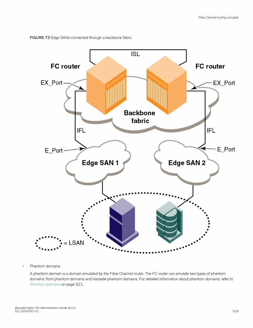
FIGURE 73 Edge SANs connected through a backbone fabric
• Phantom domains
A phantom domain is a domain emulated by the Fibre Channel router. The FC router can emulate two types of phantomdomains: front phantom domains and translate phantom domains. For detailed information about phantom domains, refer to Phantom domains on page 521.
Fibre Channel routing concepts
Brocade Fabric OS Administration Guide, 8.1.053-1004392-01 519

Proxy devicesAn FC router achieves inter-fabric device connectivity by creating proxy devices (hosts and targets) in attached fabrics that represent realdevices in other fabrics.
For example, a host in Fabric 1 can communicate with a target in Fabric 2 as follows:
• A proxy target in Fabric 1 represents the real target in Fabric 2.
• Likewise, a proxy host in Fabric 2 represents the real host in Fabric 1.
The host discovers and sends Fibre Channel frames to the proxy target. The FC router receives these frames, translates themappropriately, and then delivers them to the destination fabric for delivery to the target.
The target responds by sending frames to the proxy host. Hosts and targets are exported from the edge SAN to which they are attachedand, correspondingly, imported into the edge SAN reached through Fibre Channel routing. The following figure illustrates this concept.
FIGURE 74 MetaSAN with imported devices
Fibre Channel routing concepts
Brocade Fabric OS Administration Guide, 8.1.0520 53-1004392-01

FC-FC routing topologiesThe FC-FC routing service provides two types of routing:
• Edge-to-edge : Occurs when devices in one edge fabric communicate with devices in another edge fabric through one or moreFC routers.
• Backbone-to-edge : Occurs when devices in the FC routers communicate with devices in an edge fabric--known as abackbone fabric --through E_Ports.
A backbone fabric can be used as a transport fabric that interconnects edge fabrics. FC routers also enable hosts and targets in edgefabrics to communicate with devices in the backbone fabric, known as backbone-to-edge routing . From the perspective of the edgefabric, the backbone fabric is like any other edge fabric. For the edge fabric and backbone fabric devices to communicate, the shareddevices must be presented to each other's native fabric.
To do so, at least one translate phantom domain is created in the backbone fabric. This translate phantom domain represents the entireedge fabric. The shared physical devices in the edge have corresponding proxy devices on the translate phantom domain.
Each edge fabric has one and only one translate phantom domain to the backbone fabric. The backbone fabric device communicateswith the proxy devices whenever it needs to contact the shared physical devices in the edge. The FC-FC routing service receives theframes from the backbone switches destined to the proxy devices, and redirects the frames to the actual physical devices. Whenconnected to edge fabrics, the translate phantom domain can never be the principal switch of the backbone fabric. Front domains are notcreated, only translate phantom domains are created in the backbone fabric.
Devices are exported from the backbone fabric to one or more edge fabrics using LSANs. Refer to LSAN zone configuration on page541 for more information.
Phantom domainsA phantom domain is a domain created by the Fibre Channel router. The FC router creates two types of phantom domains: frontphantom domains and translate phantom domains.
A front phantom domain, or front domain, is a domain that is projected from the FC router to the edge fabric. There is one front phantomdomain from each FC router to an edge fabric, regardless of the number of EX_Ports connected from that router to the edge fabric.Another FC router connected to the same edge fabric projects a different front phantom domain.
A translate phantom domain, also referred to as translate domain or xlate domain, is a router virtual domain that represents an entirefabric. The EX_Ports present xlate domains in edge fabrics as being topologically behind the front domains; if the xlate domain is in abackbone fabric, then it is topologically present behind the FC router because there is no front domain in a backbone fabric.
If an FC router is attached to an edge fabric using an EX_Port, it creates xlate domains in the fabric corresponding to the imported edgefabrics with active LSANs defined. If you import devices into the backbone fabric, then an xlate domain is created in the backbone devicein addition to the one in the edge fabric.
The following figure shows a sample physical topology with four FC routers in a backbone fabric and four edge fabrics connected to theFC routers.
Fibre Channel routing concepts
Brocade Fabric OS Administration Guide, 8.1.053-1004392-01 521

FIGURE 75 Sample topology (physical topology)
The following figure shows a phantom topology for the physical topology shown in Figure 75. In this figure, the dashed lines and shapesrepresent the phantom topology from the perspective of Fabric 1. Fabrics 2 and 3 also exhibit phantom topologies, but they are notshown in this example. In this figure, note the following:
• Front domain 1 and Front domain 2 are front domains for EX_Ports connecting to Fabric 1. There is one front domain for eachFC router that is connected to Fabric 1.
• Xlate domain 1 and Xlate domain 2 represent Fabrics 2 and 3, respectively. No xlate domain is created for Fabric 4 becausethere are no LSAN devices in Fabric 4.
• Target 1’, Target 2’, and Target 3’ are proxy devices for Target 1, Target 2, and Target 3, respectively.
Fibre Channel routing concepts
Brocade Fabric OS Administration Guide, 8.1.0522 53-1004392-01

FIGURE 76 EX_Port phantom switch topology
All EX_Ports or VEX_Ports connected to an edge fabric use the same xlate domain ID for an imported edge fabric; this value persistsacross switch reboots and fabric reconfigurations.
If you lose connectivity to the edge fabric because of link failures or the IFL being disabled, xlate domains remain visible. This preventsunnecessary fabric disruptions caused by xlate domains repeatedly going offline and online due to corresponding IFL failures. To removethe xlate domain from the backbone, refer to Identifying and deleting stale xlate domains on page 524.
The combination of front domains and xlate domains allows routing around path failures, including path failures through the routers. Themultiple paths to an xlate domain provide additional bandwidth and redundancy.
There are some differences in how the xlate domain is presented in the backbone fabric. The backbone xlate domains are topologicallyconnected to FC routers and participate in FC-FC routing protocol in the backbone fabric. Front domains are not needed in thebackbone fabric. As in the case of an xlate domain in an edge fabric, backbone fabric xlate domains provide additional bandwidth andredundancy by being able to present themselves as connected to single or multiple FC routers with each FC router capable ofconnecting multiple IFLs to edge fabrics.
Fibre Channel routing concepts
Brocade Fabric OS Administration Guide, 8.1.053-1004392-01 523

Use the fcrxlateconfig command to display or assign a preferred domain ID to a translate domain or, in some scenarios, to prevent thecreation of an unnecessary xlate domain.
Identifying and deleting stale xlate domainsIf a remote edge fabric goes unreachable, the xlate domains created in other edge fabrics for this remote edge fabric are retained and notremoved unless there is any disruption in the local edge fabric or unless you remove them manually.
You can use the fcrXlateConfig command to identify and remove these stale xlate domains without disrupting the fabric.
1. Connect to the FC router and log in using an account with admin permissions.
2. Enter the fcrXlateConfig --show command to identify any stale xlate domains.
3. Enter the fcrXlateConfig --del command to delete the stale xlate domains.
sw0:root> fcrxlateconfig --show stalexdImported FID Stale XD Owner Domain-------------------------------------------------- 012 002 007 ( this FCR )sw0:root> fcrxlateconfig --del stalexd 12 2Xlate domain 2 is deleted
Domain ID range for front and translate phantom domainsIn the releases prior to Fabric OS 7.4.0, the following domain IDs were assigned:
• The FC router front domain is assigned 160 as the domain ID if the insistent domain ID is not configured using theportCfgExport command.
• The FC router translate domain is assigned 1 as the domain ID for importing proxies to the edge fabric if the insistent domainID is not configured using the fcrXlateConfig command.
Starting with Fabric OS 7.4.0, to avoid FC router phantom domains taking over the real switch domain ID, the principal switch assignsthe domain ID based on the following rules:
• The front domain ID for an FC router is assigned within the range 160 through 199.
• The translate domain ID for an FC router is assigned within the range 200 through 239
• If the preferred domain ID is not configured on an FC router for front or translate domain, the FC router requests 160 for thefront domain and 200 for the translate domain. If the preferred domain ID is configured on the FC router for either the front ortranslate domain, the FC router will still request for the front domain ID of 160 and the translate domain ID of 200 at thediscretion of the principal switch in the edge fabric. Depending on whether there are any domain ID conflicts in the fabric,switches can either be merged with the fabric using a different domain ID (front or translate domain ID) or they are segmentedfrom the fabric.
• If preferred domain ID is configured on an FC router for front and/or translate domain, the FC router requests the preferreddomain ID. Phantom domain IDs are stored persistently and used in RDI request. To utilize the new range (160 to 239), do oneof the following tasks:
Option 1:
1. Convert the EX_Port to non-FC router port remove existing Xlate configuration using the fcrXlateConfig command.
2. Apply the default configuration, and then configure the EX_Ports again and remove existing Xlate configuration using thefcrXlateConfig command..
Fibre Channel routing concepts
Brocade Fabric OS Administration Guide, 8.1.0524 53-1004392-01

Option 2:
1. Disable all EX_Ports in the same edge farbic and persistent XD feature, and then reset the persistent phantom domainusing the fcrConfigure –resetPhantomDomain command.
switch:admin> fcrconfigure --resetphantomdomainThis operation will reset all the phantom domain to be default rangeDo you want to continue (Y/N):yPhantom Domain IDs were successfully reset to default range
Using the –force option to force the reset phantom domain.
switch:admin> fcrconfigure –resetphantomdomain -forcePhantom Domain IDs were successfully reset to default range
2. Enable all the EX_Ports.
TABLE 105 Front and translate domain IDs
Firmware version in FC router Front domain ID requested Translate domain ID requested
Prior to Fabric OS 7.4.0 160 1
Fabric OS 7.4.0 and later 160 200
When an FC router is running Fabric OS 7.4.0 and the edge FC router is running Fabric OS 7.3.0, or vice versa, you need to use adifferent FID to reconstruct the EX_Ports or disable the EX_Port or use the fcrXlateConfig command to delete the stale translatedomains when moving from Fabric OS 7.3.0 to Fabric OS 7.4.0 as the old translate domains are still in effect.
FC router authenticationA Brocade FC router is capable of forming a secure link across fabrics. The EX_Port-enabled router exchanges DH-CHAP informationwith the edge fabric to enable authentication.
Note that while setting secret keys in the edge switch, the front phantom WWN should be used as the remote switch WWN in the edgefabric. The front phantom domain's WWN is available through the portCfgExport command of the EX_Port connecting to the edgefabric. The FC router switch should use the edge switch's WWN to configure the secret keys. Refer to Secret key pairs for DH-CHAP onpage 252 for more details.
FC-FC routing behaves passively to the authentication requests received from edge fabric switches. An FC router never initiatesauthentication on an EX_Port and only responds to the edge fabric requests.
NOTEChanging the switch authentication policy mode does not affect online EX_Ports, so it is acceptable to leave the default Passivepolicy configured on the FC router while the Active or On policy is required on the edge switch.
Setting up FC-FC routingTo set up FC-FC routing, perform the following tasks in the order listed.
1. Verify that you have the proper setup for FC-FC routing. (Refer to Verifying the setup for FC-FC routing on page 526.)
2. Assign backbone fabric IDs. (Refer to Backbone fabric IDs on page 527.)
3. Configure FCIP tunnels if you are connecting Fibre Channel SANs over IP-based networks.
4. Configure IFLs for edge and backbone fabric connection. (Refer to Inter-fabric link configuration on page 529.)
Setting up FC-FC routing
Brocade Fabric OS Administration Guide, 8.1.053-1004392-01 525

5. Modify port cost for EX_Ports, if you want to change from the default settings. (Refer to FC router port cost configuration onpage 535.)
6. Enable shortest IFL mode if you want to choose a lowest cost IFL path in the backbone fabric. (Refer to Shortest IFL costconfiguration on page 537.)
7. Configure trunking on EX_Ports that are connected to the same edge fabric. (Refer to EX_Port frame trunking configuration onpage 541.)
8. Configure LSAN zones to enable communication between devices in different fabrics. (Refer to LSAN zone configuration onpage 541.)
Refer to Performing Advanced Configuration Tasks on page 69 for more details about configuration options for BrocadeBackbones.
Verifying the setup for FC-FC routingBefore configuring a fabric to connect to another fabric, you must perform verification checks on the FC router.
1. Log in to the FC router as admin and enter the version command. Verify that Fabric OS v7.3.0 or later is installed on the FCrouter, as shown in the following example.
switch:admin> versionKernel: 2.6.14.2Fabric OS: v7.3.0Made on: Fri Feb 21 01:15:34 2014Flash: Wed Feb 26 20:53:48 2014BootProm: 1.0.11
2. If you are configuring a Brocade DCX 8510 Backbone, enter the slotShow command to verify that an FX8-24 blade is presentor 16-Gbps port blade is present. The following example shows slots 1, 2, 3, 4, 9, 10, and 12 with 16-Gbps port bladesenabled.
switch:admin> slotshow -mSlot Blade Type ID Model Name Status -------------------------------------------------- 1 SW BLADE 96 FC16-48 ENABLED 2 SW BLADE 96 FC16-48 ENABLED 3 SW BLADE 96 FC16-48 ENABLED 4 SW BLADE 96 FC16-48 ENABLED 5 CORE BLADE 98 CR16-8 ENABLED 6 CP BLADE 50 CP8 ENABLED 7 CP BLADE 50 CP8 ENABLED 8 CORE BLADE 98 CR16-8 ENABLED 9 SW BLADE 96 FC16-48 ENABLED 10 SW BLADE 96 FC16-48 ENABLED 11 UNKNOWN VACANT 12 SW BLADE 96 FC16-48 ENABLED
Refer to Performing Advanced Configuration Tasks on page 69 for a list of blades and their corresponding IDs.
3. Enter the licenseShow command to verify that the Integrated Routing license is installed.
switch:admin> licenseshow S9bddb9SQbTAceeCbzbzRcbcSc0c0SYRyeSzRScycazfT0G: Integrated Routing Ports on Demand license Capacity 128
If you are connecting to a Fabric OS and the Integrated Routing license is not installed, you must install it, as described in theBrocade Fabric OS Software Licensing Guide. The Integrated Routing license is not required if you are connecting to a BrocadeNetwork OS fabric.
For configuring EX_Ports on an ICL, both the Integrated Routing license and the ICL POD license are required.
Setting up FC-FC routing
Brocade Fabric OS Administration Guide, 8.1.0526 53-1004392-01

4. If all switches in the fabric are running Fabric OS 7.3.0 or later, skip this step. If any switch is running a Fabric OS version earlierthan 7.3.0, then enter the fddCfg --showall command to verify that the Fabric-Wide Consistency Policy is not in "strict" mode.
When it is in strict mode, an ACL cannot support Fibre Channel routing in the fabric.
switch:admin> fddcfg --showallLocal Switch Configuration for all Databases:- DATABASE - Accept/Reject--------------------------------------- SCC - accept DCC - accept PWD - accept FCS - accept AUTH - accept
Fabric-Wide Consistency Policy :- "SCC:S;DCC"
If the Fabric-Wide Consistency Policy has the letter "S" in it in the edge fabric or the backbone fabric, do not connect the edgefabric to the FC router. The letter "S" (shown in the preceding sample output) indicates the policy is strict. The Fabric-WideConsistency Policy must be tolerant before you can connect fabrics to the FC router. Refer to Configuring Security Policies onpage 235 for information about configuring the Fabric-Wide Consistency Policy.
5. For 8-Gbps platforms, delete fabric mode Top Talker monitors, if they are configured.
FC-FC routing and fabric mode Top Talker monitors are not concurrently supported on 8-Gbps platforms.
FC-FC routing and fabric mode Top Talker monitors are concurrently supported only on the Brocade 6510 and 6520switches, and on the Brocade DCX Backbone family with only 16-Gbps capable ports.
Backbone fabric IDsIf your configuration has only one backbone fabric, then you do not need to assign a backbone fabric ID because the backbone fabric IDin this situation defaults to a value of 128. The default backbone fabric ID is 1 if Virtual Fabrics is disabled.
All switches in a backbone fabric must have the same backbone fabric ID. You can configure the backbone fabric ID using thefcrConfigure command. The backbone fabric ID must be unique from the perspective of every attached edge fabric. Fabric ID changesmade on a switch are not propagated to other switches in the backbone fabric. The backbone fabric administrator is responsible formaking sure that all switches in the backbone have the same fabric ID. Because fabric IDs are used heavily by the routing protocolbetween the Fibre Channel routers, using the wrong fabric ID can affect both edge-to-edge and backbone-to-edge routing.
In addition to ensuring that the backbone fabric IDs are the same within the same backbone, you must make sure that when two differentbackbones are connected to the same edge fabric, the backbone fabric IDs are different, but the edge fabric ID should be the same.Configuration of two backbones with the same backbone fabric ID that are connected to the same edge is invalid. In this configuration, aRASLog message displays a warning about fabric ID overlap. When two backbone fabrics are not connected to the same edge, they canhave the same backbone fabric ID.
ATTENTIONIn a multi-switch backbone fabric, modification of the FID within the backbone fabric will cause disruption to localtraffic.
Assigning backbone fabric IDs1. Log in to the switch or backbone.
2. Enter the switchDisable command if EX_Ports are online.
Backbone fabric IDs
Brocade Fabric OS Administration Guide, 8.1.053-1004392-01 527

3. Enter the fosConfig --disable fcr command to disable the FC-FC routing service.
The default state for the FC router is disabled.
4. Enter the fcrConfigure --bbfid command. At the prompt, enter the fabric ID, or press Enter to keep the current fabric ID, whichis displayed in brackets.
5. Verify the backbone fabric ID is different from that set for edge fabrics.
Multiple FC routers attached to the same backbone fabric must have the same backbone fabric ID.
6. Enter the fosConfig --enable fcr command.
7. Enter the switchEnable command.
switch:admin> switchdisableswitch:admin> fosconfig --disable fcrFC Router service is disabledswitch:admin> fcrconfigure --bbfidFC Router parameter set. <cr> to skip a parameterPlease make sure new Backbone Fabric ID does not conflict with any configured EX-Port's Fabric IDBackbone fabric ID: (1-128)[128] switch:admin> fosconfig --enable fcrFC Router service is enabledswitch:admin> switchenable
Assigning alias names to fabric IDsYou can assign an alias name to each fabric ID for easier configuration and manageability.
The alias name is a user friendly name that you can use instead of a fabric ID (FID) in the portcfgexport and portcfgvexport commands.
There is no relation between the FID alias name and the fabric name, which you configure with the fabricname command.
1. Log in to the switch or backbone.
2. Set the FID alias using the fcrconfigure --add command.
fcrconfigure --add -alias alias_name -fid fid
3. Verify the configured alias names using the fcrconfigure --show -alias command.
fcrconfigure --show -alias
Assigning alias names to fabric IDs
Brocade Fabric OS Administration Guide, 8.1.0528 53-1004392-01

The following example configures alias names for three fabrics, and then configures an EX_Port using the FID alias name.
switch:admin> fcrconfigure --add -alias Green_fabric -fid 10 switch:admin> fcrconfigure --add -alias Blue_fabric -fid 12switch:admin> fcrconfigure --add -alias Yellow_fabric -fid 15switch:admin> fcrconfigure --show -alias FID Alias========================10 Green_fabric12 Blue_fabric15 Yellow_fabric switch:admin> portcfgexport 3 -a 1 -f Green_fabric; portenable 3switch:admin> portcfgexport 3Port 3 infoAdmin: enabledState: OKPid format: core(N)Operate mode: Brocade NativeEdge Fabric ID: 10Alias Name: Green_fabricFront Domain ID: 5(output truncated)
FCIP tunnel configurationThe optional Fibre Channel over IP (FCIP) Tunneling Service enables you to use tunnels to connect instances of Fibre Channel SANsover IP-based networks to transport all Fibre Channel ISL and IFL traffic. FCIP is a prerequisite for configuring VEX_Ports. If you are onlyusing FC_Ports, then there is no need to configure FCIP tunnels.
If using FCIP in your FC-FC routing configuration, you must first configure FCIP tunnels. Once a tunnel is created, it defaults to adisabled state. Then configure the VE_Port or VEX_Port. After the appropriate ports are configured, enable the tunnel.
NOTEFCIP tunnel configuration is applicable only to Fabric OS fabrics and does not apply to Brocade Network OSfabrics.
Refer to the Brocade Fabric OS FCIP Administrator's Guide for instructions on how to configure FCIP tunnels.
Inter-fabric link configurationConfiguring an inter-fabric link (IFL) involves disabling ports and cabling them to other fabrics, configuring those ports for their intendeduses, and then enabling the ports.
Before configuring an inter-fabric link, be aware that you cannot configure both IFLs (EX_Ports, VEX_Ports) and ISLs (E_Ports) from abackbone fabric to the same edge fabric.
ATTENTIONTo ensure that fabrics remain isolated, disable the port prior to inserting the cable. If you are configuring an EX_Port, disable theport prior to making the connection.
Inter-fabric link configuration
Brocade Fabric OS Administration Guide, 8.1.053-1004392-01 529

Configuring an IFL for both edge and backbone connections1. On the FC router, disable the port that you are configuring as an EX_Port (the one connected to the Fabric OS switch) by
issuing the portDisable command.
switch:admin> portdisable 7/10
You can verify that the port has been disabled by issuing the portShow command for the port.
2. Configure each port that connects to an edge fabric as an EX_Port or VEX_Port using either the portCfgVEXPort orportCfgEXPort command.
• portCfgVEXPort works only on VE_Ports.
• portCfgEXPort (only on the FC ports on the FC router) commands work only on ports that are capable of FC-FC routing.
The following example configures an EX_Port and assigns a Fabric ID of 30 to port 10.
switch:admin> portcfgexport 7/10 -a 1 -f 30 switch:admin> portcfgexport 7/10Port 7/10 infoAdmin: enabledState: OKPid format: Not ApplicableOperate mode: Brocade NativeEdge Fabric ID: 30Preferred Domain ID: 160Front WWN: 50:06:06:9e:20:38:6e:1eFabric Parameters: Auto NegotiateR_A_TOV: Not ApplicableE_D_TOV: Not ApplicableAuthentication Type: NoneDH Group: N/AHash Algorithm: N/AEdge fabric's primary wwn: N/AEdge fabric's version stamp: N/A
This port can now connect to another switch.The following example configures an EX_Port for connecting to a Brocade Network OS fabric. The -m 5 option indicatesNetwork OS connectivity.
switch:admin> portcfgexport 1/5 -a 1 -f 15 -m 5switch:admin> portcfgexport 1/5Port 1/5 infoAdmin: enabledState: OKPid format: Not ApplicableOperate mode: Brocade NOSEdge Fabric ID: 15(output truncated)
The following example shows configuring a port range:
DCX:root> portcfgexport 1/1-2 -a 12014/09/15-07:09:12, [FCR-1071], 11763, SLOT 6 | FID 128, INFO, DCX, Port 1/1 is changed from non FCR port to FCR port.2014/09/15-07:09:13, [FCR-1071], 11764, SLOT 6 | FID 128, INFO, DCX, Port 1/2 is changed from non FCR port to FCR port.
For related FC-FC routing commands, refer to fcrEdgeShow, fcrXlateConfig, fcrConfigure, and fcrProxyConfig in the BrocadeFabric OS Command Reference.
A Fibre Channel router can interconnect multiple fabrics. EX_Ports or VEX_Ports attached to more than one edge fabric mustconfigure a different fabric ID for each edge fabric.
3. (Optional ) Configure FC router port cost if you want to change the default values. For information about using FC router portcost operations, refer to FC router port cost configuration on page 535.
Inter-fabric link configuration
Brocade Fabric OS Administration Guide, 8.1.0530 53-1004392-01

4. (Optional ) Set up ISL or EX_Port trunking. For information on trunking setup, refer to Configuring EX_Port trunking on page497.
5. Physically attach ISLs from the Fibre Channel router to the edge fabric.
6. Enter the portEnable command to enable the ports that you disabled in step 1.
switch:admin> portenable 7/10
7. Enter the portCfgShow command to view ports that are persistently disabled.
FC ports on the Brocade 7800 and 7840 switches and FX8-24 blades are configured as persistently disabled by default toavoid inadvertent fabric merges when installing a new FC router.
switch:admin> portcfgshow 7/10Area Number: 74Speed Level: AUTOTrunk Port OFFLong Distance OFFVC Link Init OFFLocked L_Port OFFLocked G_Port OFFDisabled E_Port OFFISL R_RDY Mode OFFRSCN Suppressed OFFPersistent Disable OFFNPIV capability ONEX Port ONMirror Port ONFC Fastwrite ON
8. After identifying such ports, enter the portCfgPersistentEnable command to enable the port, and then the portCfgShowcommand to verify the port is enabled.
switch:admin> portcfgpersistentenable 7/10switch:admin> portcfgshow 7/10Area Number: 74Speed Level: AUTOTrunk Port OFFLong Distance OFFVC Link Init OFFLocked L_Port OFFLocked G_Port OFFDisabled E_Port OFFISL R_RDY Mode OFFRSCN Suppressed OFFPersistent Disable OFFNPIV capability ONEX Port ONMirror Port ONFC Fastwrite ON
Inter-fabric link configuration
Brocade Fabric OS Administration Guide, 8.1.053-1004392-01 531

9. Enter either the portCfgEXPort or portShow command to verify that each port is configured correctly.
switch:admin> portcfgexport 7/10Port 7/10 infoAdmin: enabledState: OKPid format: Not ApplicableOperate mode: Brocade NativeEdge Fabric ID: 30Preferred Domain ID: 160Front WWN: 50:06:06:9e:20:38:6e:1eFabric Parameters: Auto NegotiateR_A_TOV: Not ApplicableE_D_TOV: Not ApplicableAuthentication Type: NoneDH Group: N/AHash Algorithm: N/AEdge fabric's primary wwn: N/AEdge fabric's version stamp: N/Aswitch:admin_06> portshow 7/10portName:portHealth: OFFLINEAuthentication: NoneEX_Port Mode: EnabledFabric ID: 30Front Phantom: state = Not OK Pref Dom ID: 160Fabric params: R_A_TOV: 0 E_D_TOV: 0 PID fmt: autoAuthentication Type: NoneHash Algorithm: N/ADH Group: N/AEdge fabric's primary wwn: N/AEdge fabric's version stamp: N/AportDisableReason: NoneportCFlags: 0x1portFlags: 0x1 PRESENT U_PORT EX_PORTportType: 10.0portState: 2 OfflineportPhys: 2 No_ModuleportScn: 0port generation number: 0portId: 014a00portIfId: 4372080fportWwn: 20:4a:00:60:69:e2:03:86portWwn of device(s) connected:Distance: normalportSpeed: N4GbpsLE domain: 0FC Fastwrite: ONInterrupts: 0 Link_failure: 0 Frjt : 0Unknown: 0 Loss_of_sync: 0 Fbsy : 0Lli: 0 Loss_of_sig: 2Proc_rqrd: 0 Protocol_err: 0Timed_out: 0 Invalid_word: 0Rx_flushed: 0 Invalid_crc: 0Tx_unavail: 0 Delim_err: 0Free_buffer: 0 Address_err: 0Overrun: 0 Lr_in: 0Suspended: 0 Lr_out: 0Parity_err: 0 Ols_in: 02_parity_err: 0 Ols_out: 0CMI_bus_err: 0Port part of other ADs: No
10. Enter the switchShow command to verify the EX_Port (or VEX_Port), edge fabric ID, and name of the edge fabric switch(containing the E_Port or VE_Port) are correct.
Inter-fabric link configuration
Brocade Fabric OS Administration Guide, 8.1.0532 53-1004392-01
11. Enter the fcrFabricShow command to view any edge fabric switch names and ensure links are working as expected.
NOTEThe fcrFabricShow command displays the static IPv6 addresses for each FC router and each edge fabric switchconnected to the EX_Ports.
switch:admin> fcrfabricshowFCR WWN: 10:00:00:05:1e:13:59:00, Dom ID: 2, Info: 10.32.156.52 1080::8:800:200C:1234/64,"Spirit-2""fcr_5300"EX_Port FID Neighbor Switch Info (WWN, enet IP, name)---------------------------------------------------------------7 10 10:00:00:05:1e:34:11:e5 10.32.156.33 "5300" 1080::8:8FF:FE0C:417A/644 116 10:00:00:05:1e:37:00:44 10.32.156.34 "5300"FCR WWN: 10:00:00:05:1e:12:e0:00, Dom ID: 100, Info:10.32.156.50 1080::8:60F:FE0C:456A/64"fcr_5300"EX_Port FID Neighbor Switch Info (WWN, enet IP, name)------------------------------------------------------------------------4 95 10:00:00:05:1e:37:00:45 10.32.156.31 "5300"FCR WWN: 10:00:00:05:1e:12:e0:00, Dom ID: 100, Info: 10.32.156.50, "fcr_Brocade 5300"EX_Port FID Neighbor Switch Info (WWN, enet IP, name)------------------------------------------------------------------------4 95 10:00:00:05:1e:37:00:45 10.32.156.31 "Brocade 5300"5 95 10:00:00:05:1e:37:00:45 10.32.156.31 "Brocade 5300"6 95 10:00:00:05:1e:37:00:45 10.32.156.31 "Brocade 5300"
12. Enter the iflshow command to display the FC router details and ensure the fabric is functioning correctly.
switch:FID128:root> iflshow E-Port EX-Port FCR-WWN FCR-FID FCR-Name Speed BW -------------------------------------------------------------------------------- 1 : 350 --> 12 10:00:08:00:88:04:93:94 39 fcr_sw 4G 8G TRUNK
Configuring EX_Ports on an ICLThe following restrictions apply when configuring EX_Ports on an ICL:
• Both the active and standby CP must be running Fabric OS 7.2.0 or later in the case of DCX 8510 Backbone.
• EX_Port on ICL is supported in DCX 8510 Backbones and X6 Directors when all the port blades in the chassis belong to oneof these blade types: FC16-32, FC16-48, FC16-64, FC32-48.
NOTEDevice discovery will not occur properly with ICL EX_Port connected edge fabrics if the FC router has unsupportedblades that are not mentioned in the previous restriction.
• Switches must have Virtual Fabrics enabled.
• EX_Ports on ICLs are allowed only on the base switch. F_Ports are not supported in the base switch.
• You must be in Brocade native mode.
• You cannot configure a VEX_Port on an ICL .
• The ICLs must be in a symmetric topology. For more information on topologies, refer to the chapter on Inter-Chassis Links(ICLs).
• Bladeless configuration (where the chassis has core blades but no application blades) is not supported.
Inter-fabric link configuration
Brocade Fabric OS Administration Guide, 8.1.053-1004392-01 533

To configure EX_Ports on an ICL, perform the following steps:
1. Configure an 8-bit zero-based Dynamic Area mode or a 10-bit Dynamic Area mode on the FC router to bring up ICLEX_Ports.
Configure...Enable a 256 Area Limit(0 = No, 1 = Zero Based Area Assignment, 2 = Port Based Area Assignment): (0..2) [0]
The following options are available:
• 0: 10-bit Dynamic Area Mode. ICL EX_Ports, F_Ports, and regular EX_Ports have 8-bit areas.
• 1: 8-bit Dynamic Area Mode. ICL_EX ports have 8-bit areas.
• 2: Not permitted if ICL ports are present in the logical switch.
2. On the FC router, disable all QSFP ports by issuing the portDisable command.
switch:admin> portdisable 6/20-23
You can verify that all ports have been disabled by issuing the portShow command for the ports.
3. Configure EX_Ports on the ICL by issuing the portCfgEXPort command. If you configure EX_Port on one of the QSFP ports,the configuration is automatically propagated to the other 3 QSFP ports.
The following example configures EX_Port on one of the QSFP ports.
switch:admin> portcfgexport 6/20 -a 1 -f 452013/04/25-21:21:54, [FCR-1071], 29805, SLOT 4 | FID 2, INFO, Pluto, Port 6/20 is changed from non FCR port to FCR port.2013/04/25-21:21:54, [FCR-1071], 29806, SLOT 4 | FID 2, INFO, Pluto, Port 6/21 is changed from non FCR port to FCR port.2013/04/25-21:21:55, [FCR-1071], 29807, SLOT 4 | FID 2, INFO, Pluto, Port 6/22 is changed from non FCR port to FCR port.2013/04/25-21:21:55, [FCR-1071], 29808, SLOT 4 | FID 2, INFO, Pluto, Port 6/23 is changed from non FCR port to FCR port.
4. (Optional) Configure FC router port cost if you want to change the default values. For information about using FC router portcost operations, refer to FC router port cost configuration on page 535.
5. Enter the portEnable command to enable the QSFP ports that you disabled in step 1.
switch:admin> portenable 6/20-23
6. Enter either the portCfgEXPort or portShow command to verify that each port is configured correctly.
switch:admin> portcfgexport 6/20Port 6/20 infoAdmin: enabledState: OKPid format: Not ApplicableOperate mode: Brocade NativeEdge Fabric ID: 50Preferred Domain ID: 160Front WWN: 50:00:51:e7:54:c0:0e:32Fabric Parameters: Auto NegotiateR_A_TOV: Not ApplicableE_D_TOV: Not ApplicableAuthentication Type: NoneDH Group: N/AHash Algorithm: N/AEdge fabric's primary wwn: N/AEdge fabric's version stamp: N/A
7. Enter the switchShow command to verify the EX_Port and edge fabric ID are correct.
Inter-fabric link configuration
Brocade Fabric OS Administration Guide, 8.1.0534 53-1004392-01

8. Enter the fcrEdgeShow command to display the FIDs of all configured EX_Ports.
switch:admin> fcredgeshow FID EX-port E-port Neighbor Switch (PWWN, SWWN )------------------------------------------------------------------------ 50 3/12 1180 50:00:51:e4:8f:8f:74:9c 10:00:00:05:1e:48:f8:00 50 3/13 1181 50:00:51:e4:8f:8f:74:9d 10:00:00:05:1e:48:f8:00 50 3/14 1182 50:00:51:e4:8f:8f:74:9e 10:00:00:05:1e:48:f8:00 50 3/15 1183 50:00:51:e4:8f:8f:74:9f 10:00:00:05:1e:48:f8:00
9. Enter the fcrIclPathBwMonitor command to monitor and report path bandwidth imbalances for each edge fabric.
The following example enables the monitoring and reporting of bandwidth balances and imbalances, and displays the ICL pathbandwidth state for each fabric:
switch:admin> fcriclpathbwmonitor --showICL Path Bandwidth state :Disabledswitch:admin> fcriclpathbwmonitor --enableICL bandwidth balance functionality is enabledPluto:FID2:root> fcriclpathbwmonitor --showICL Path Bandwidth state :EnabledFABRIC SLOT-3 BW SLOT-6 BW STATE=============================================== 48 128 128 BALANCED 126 64 128 UNBALANCED
FC router port cost configurationFC routers optimize the usage of the router port links by directing traffic to the link with the smallest router port cost.
The FC router port cost is similar to the link cost setting available on E_Ports, which allows you to customize traffic flow. The router portlink cost values are either 0, 1,000, or 10,000. The router module chooses the router port path based on the lowest cost for each FIDconnection. If multiple paths exist where one path costs less than the others, then the lowest cost path is used. If exchange-based routinghas not been disabled and multiple paths exist with the same lowest cost, there will be load sharing over these paths.
Every IFL has a default cost. The default router port cost values are as follows:
• 1,000 for a legacy (v5.1 or XPath FCR) IFL
• 1,000 for an EX_Port IFL
• 10,000 for a VEX_Port IFL
The FC router port cost settings are 0, 1,000, or 10,000. If the cost is set to 0, the default cost will be used for that IFL. The FC routerport cost is persistent and is saved in the existing port configuration file.
FC router port cost is passed to other routers in the same backbone. Link costs from the front domain to the translate (xlate) domainremain at 10,000. You can use the lsDbShow command from the edge fabric to display these link costs.
The FC router port cost is set automatically. You can modify the cost for a port if you want to change the default value.
Port cost considerationsThe router port cost has the following considerations:
• Router port sets are defined as follows:
– 0-7 and FCIP Tunnel 16-23– 8-15 and FCIP Tunnel 24-31
FC router port cost configuration
Brocade Fabric OS Administration Guide, 8.1.053-1004392-01 535

• The router port cost does not help distinguish one IFL (or EX_ and VEX_Port link) from another, if all the IFLs are connected tothe same port set. Therefore, if you connect IFL1 and IFL2 to the same edge fabric in port set 0-7 and then configure them todifferent router port costs, traffic is still balanced across all the IFLs in the same port set.
• Use proper SAN design guidelines to connect the IFLs to different port sets for effective router port cost use. For example, ifboth a low-speed IFL and a high-speed IFL are going to the same edge fabric, connect the lower router cost IFL to a separateport group (for example, ports 0-7) than the higher router cost IFL (for example, ports 8-15). For VEX_Ports, you would useports in the range of 16-23 or 24-31.
You can connect multiple EX_Ports or VEX_Ports to the same edge fabric. The EX_Ports can all be on the same FC router, or they canbe on multiple routers. Multiple EX_Ports create multiple paths for frame routing. Multiple paths can be used in two different, butcompatible, ways:
• Failing over from one path to another.
• Using multiple paths in parallel to increase effective data transmission rates.
EX_Ports and VEX_Ports, when connected, are assigned different router port costs and traffic will flow only through the EX_Ports.Routing failover is automatic, but it can result in frames arriving out of order when frames take different routes. The FC router can forcein-order delivery, although frame delivery is delayed immediately after the path failover.
Source EX_Ports can balance loads across multiple destination EX_Ports attached to the same edge fabric using exchange IDs from therouted frames as keys to distribute the traffic.
Setting router port cost for an EX_PortThe router port cost value for an EX_Port is set automatically when the EX_Port is created. You can modify the cost for that port to forcea path to have a higher or lower cost.
You can configure the EX_Port or VEX_Port with values of either 1,000 or 10,000. For example, if you want to differentiate between twoEX_Port links with different speeds, you can assign 1,000 to one link and 10,000 to the other link.
1. Enter the portDisable command to disable any port on which you want to set the router port cost.
switch:admin> portdisable 7/10
2. Enable EX_Port or VEX_Port mode with the portCfgEXPort or portCfgVEXPort command.
switch:admin> portcfgexport 7/10 -a 1
3. Enter the fcrRouterPortCost command to display the router port cost for each EX_Port.
switch:admin> fcrrouterportcost Port Cost------------------------7/3 10007/4 10007/9 10007/10 10007/13 100010/0 1000
You can also use the fcrRouteShow command to display the router port cost.
To display the router port cost for a single EX_Port, enter the fcrRouterPortCost command with a port and slot number.
switch:admin> fcrrouterportcost 7/10 Port Cost------------------------7/10 1000
FC router port cost configuration
Brocade Fabric OS Administration Guide, 8.1.0536 53-1004392-01
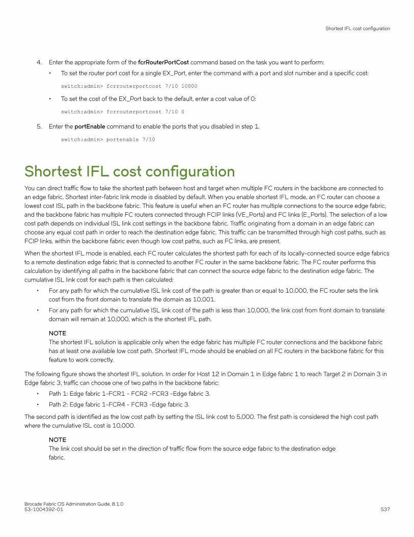
4. Enter the appropriate form of the fcrRouterPortCost command based on the task you want to perform:
• To set the router port cost for a single EX_Port, enter the command with a port and slot number and a specific cost:
switch:admin> fcrrouterportcost 7/10 10000
• To set the cost of the EX_Port back to the default, enter a cost value of 0:
switch:admin> fcrrouterportcost 7/10 0
5. Enter the portEnable command to enable the ports that you disabled in step 1.
switch:admin> portenable 7/10
Shortest IFL cost configurationYou can direct traffic flow to take the shortest path between host and target when multiple FC routers in the backbone are connected toan edge fabric. Shortest inter-fabric link mode is disabled by default. When you enable shortest IFL mode, an FC router can choose alowest cost ISL path in the backbone fabric. This feature is useful when an FC router has multiple connections to the source edge fabric,and the backbone fabric has multiple FC routers connected through FCIP links (VE_Ports) and FC links (E_Ports). The selection of a lowcost path depends on individual ISL link cost settings in the backbone fabric. Traffic originating from a domain in an edge fabric canchoose any equal cost path in order to reach the destination edge fabric. This traffic can be transmitted through high cost paths, such asFCIP links, within the backbone fabric even though low cost paths, such as FC links, are present.
When the shortest IFL mode is enabled, each FC router calculates the shortest path for each of its locally-connected source edge fabricsto a remote destination edge fabric that is connected to another FC router in the same backbone fabric. The FC router performs thiscalculation by identifying all paths in the backbone fabric that can connect the source edge fabric to the destination edge fabric. Thecumulative ISL link cost for each path is then calculated:
• For any path for which the cumulative ISL link cost of the path is greater than or equal to 10,000, the FC router sets the linkcost from the front domain to translate the domain as 10,001.
• For any path for which the cumulative ISL link cost of the path is less than 10,000, the link cost from front domain to translatedomain will remain at 10,000, which is the shortest IFL path.
NOTEThe shortest IFL solution is applicable only when the edge fabric has multiple FC router connections and the backbone fabrichas at least one available low cost path. Shortest IFL mode should be enabled on all FC routers in the backbone fabric for thisfeature to work correctly.
The following figure shows the shortest IFL solution. In order for Host 12 in Domain 1 in Edge fabric 1 to reach Target 2 in Domain 3 inEdge fabric 3, traffic can choose one of two paths in the backbone fabric:
• Path 1: Edge fabric 1-FCR1 - FCR2 -FCR3 -Edge fabric 3.
• Path 2: Edge fabric 1-FCR4 - FCR3 -Edge fabric 3.
The second path is identified as the low cost path by setting the ISL link cost to 5,000. The first path is considered the high cost pathwhere the cumulative ISL cost is 10,000.
NOTEThe link cost should be set in the direction of traffic flow from the source edge fabric to the destination edgefabric.
Shortest IFL cost configuration
Brocade Fabric OS Administration Guide, 8.1.053-1004392-01 537

FIGURE 77 Shortest IFL solution
Shortest IFL cost configuration
Brocade Fabric OS Administration Guide, 8.1.0538 53-1004392-01

Configuring shortest IFL cost1. Enter the fcrFabricShow command to view the FC routers on the backbone fabric.
switch:admin>fcrfabricshowFC Router WWN: 10:00:00:05:1e:58:bd:69, Dom ID: 10, Info: 10.17.33.59, "DID_10"EX_Port FID Neighbor Switch Info (enet IP, WWN, name) ------------------------------------------------------------------------ 34 1 10.17.33.68 10:00:00:05:1e:61:28:22 "DID_4_1"switch:admin>fcrfabricshowFC Router WWN: 10:00:00:05:1e:58:be:69, Dom ID: 20, Info: 10.17.33.60, "DID_20"EX_Port FID Neighbor Switch Info (enet IP, WWN, name) ------------------------------------------------------------------------ 2 2 10.17.33.88 10:00:00:05:33:00:90:48 "DID_1_2"switch:admin>fcrfabricshowFC Router WWN: 10:00:00:05:1e:58:be:68, Dom ID: 30, Info: 10.17.33.61, "DID_30"EX_Port FID Neighbor Switch Info (enet IP, WWN, name) ------------------------------------------------------------------------ 31 3 10.17.33.153 10:00:00:05:33:7e:e8:7c "DID_3_3"switch:admin>fcrfabricshowFC Router WWN: 10:00:00:05:1e:58:be:67, Dom ID: 40, Info: 10.17.33.62, "DID_40"EX_Port FID Neighbor Switch Info (enet IP, WWN, name) ------------------------------------------------------------------------ 34 1 10.17.33.68 10:00:00:05:1e:61:28:22 "DID_4_1"
2. Enter the islshow command to identify the connections between the FC routers and the destination edge fabric.
switch:admin>islshow1: 10->1010:00:00:05:1e:58:be:69 20 DID_20 sp: 8.000G bw: 8.000G TRUNK QOS
3. Identify all paths in the backbone fabric through which traffic can flow from the source edge fabric to the destination edge fabricby examining the output generated in step 1 and step 2.
The following example step shows how to identify the number of paths from the source edge fabric 1 to the destination edgefabric 2 in the backbone fabric based on the configuration shown in step 1 and step 2:
• The path from FC router Domain ID 10 to FC router Domain ID 20.
• The path from FC router Domain 20: This FC router has no local connection to source edge fabric 1, so cannot beconsidered for path identification.
• The path from FC router Domain 30: This FC router has no local connection to source edge fabric 1, so cannot beconsidered for path identification.
• The path from FC router Domain ID 40 to FC router Domain ID 30 to FC router Domain ID 20.
Therefore, there are two available paths in the backbone fabric through which traffic can flow from the source edge fabric 1 tothe destination edge fabric 2.
Shortest IFL cost configuration
Brocade Fabric OS Administration Guide, 8.1.053-1004392-01 539

4. Enter the linkcost command to obtain the cumulative ISL cost for each path identified by adding all individual link costs, andselect one single path to be the only low cost path.
• The following example shows the cumulative ISL cost for the first path identified in step 3: from FC router ID Domain 10 toFC router ID Domain 20.
switch:admin>linkcost 10Interface10 (E_PORT) Cost 500
The cumulative link cost for this path is 500. This path is now known as path 1.
• The following example shows the cumulative ISL cost for the second path identified in step 3: first from FC router IDDomain 40 to FC router ID Domain 30, and then from FC router Domain ID 30 to FC router ID Domain 20.
switch:admin>linkcost 10Interface10 (E_PORT) Cost 500switch:admin>linkcost 10Interface10 (E_PORT) Cost 500
The cumulative link cost for this path is 1000. This path is now known as path 2.
Path 1 is selected as the low cost path.
5. Enter the linkcost command to set low cost values, ensuring that the cumulative ISL cost for the selected path is lower than thatof all other paths. A low cost path should have a cumulative ISL cost of less than 10,000.
• In the following example, the ISL link cost of path 2 from FC router ID Domain 40 to FC router Domain ID 30 is modified.
switch:admin>linkcost 10 5000Interface10 (E_PORT) Cost 5000
• In the following example, the ISL link cost of path 2 from FC router Domain 30 to FC router Domain 20 is modified.
switch:admin>linkcost 10 5000Interface10 (E_PORT) Cost 5000
The modified cumulative link cost for path 2 is 10,000.
6. Enter the fcrConfigure --enable -shortestifl command to enable the shortest IFL mode in all the FC routers in the backbonefabric.
switch:admin> fcrconfigure --enable -shortestiflShortest IFL path is enabled
7. Enter the fcrConfigure -show command to verify that the shortest IFL mode is enabled in all the FC routers in the backbonefabric.
switch:admin> fcrconfigure --showBackbone fabric ID: 128Shortest IFL feature is enabled
8. Verify that the link cost of both the front domain and translate domain in the source edge fabric have been modified using thelsDbShow command.
linkCnt = 2, flags = 0x0LinkId = 160, out port = 160 rem port = 241, cost = 10001, costCnt = 0, type = 1LinkId = 161, out port = 161, rem port = 242, cost = 10000, costCnt = 0, type = 1
Shortest IFL cost configuration
Brocade Fabric OS Administration Guide, 8.1.0540 53-1004392-01

EX_Port frame trunking configurationEX_Port frame trunking provides the best utilization and balance of frames transmitted on each link between the FC router and the edgefabric. You should trunk all ports connected to the same edge fabrics.
You configure EX_Ports to use frame-based trunking just as you do regular E_Ports. The restrictions for EX_Port frame trunking are thesame as for E_Ports. All the ports must be adjacent to each other using the clearly marked groups on the front of the product.
The FC router front domain has a higher node WWN, derived from the FC router, than that of the edge fabric. Therefore, the FC routerfront domain initiates the trunking protocol on the EX_Port.
After initiation, the first port from the trunk group that comes online is designated as the master port. The other ports that come online onthe trunk group are considered the slave ports. Adding or removing a slave port does not cause frame drop. However, removing a slaveport causes the loss of frames in transit.
If router port cost is used with EX_Port trunking, the master port and slave ports share the router port cost of the master port.
For information about setting up E_Port trunking on an edge fabric, refer to Managing Trunking Connections on page 489.
LSAN zone configurationAn LSAN consists of zones in two or more edge or backbone fabrics that contain the same devices. LSANs provide selective deviceconnectivity between fabrics without forcing you to merge those fabrics. FC routers provide multiple mechanisms to manage inter-fabricdevice connectivity through extensions to existing switch management interfaces. You can define and manage LSANs using BrocadeAdvanced Zoning.
NOTEFor performance reasons, Brocade recommends that you do not configure LSANs for device sharing between Fabric OSfabrics until after you activate the Integrated Routing license.
Zone definition and namingZones are defined locally on a switch or backbone. Names and memberships, with the exception of hosts and targets exported from onefabric to another, do not need to be coordinated with other fabrics. For example, in Figure 73 on page 519, when the zones for EdgeSAN 1 are defined, you do not need to consider the zones in Edge SAN 2, and vice versa.
Zones that contain hosts and targets that are shared between the two fabrics must be explicitly coordinated. To share devices betweenany two fabrics, you must create an LSAN zone in both fabrics containing the port WWNs of the devices to be shared. Although anLSAN is managed using the same tools as any other zone on the edge fabric, two behaviors distinguish an LSAN from a conventionalzone:
• A required naming convention. The name of an LSAN begins with the prefix "LSAN_". The LSAN name is not case-sensitive; forexample, "lsan_" is equivalent to "LSAN_", "Lsan_", and so on.
• Members must be identified by their port WWN because port IDs are not necessarily unique across fabrics. The names of thezones need not be explicitly the same, and membership lists of the zones need not be in the same order.
NOTEThe "LSAN_" prefix must appear at the beginning of the zone name. LSAN zones may not be combined with QoS zones. Referto QoS zones for more information about the naming convention for QoS zones.
To enable device sharing across multiple fabrics, you must create LSAN zones on the edge fabrics (and optionally on the backbonefabric as well), using normal zoning operations to create zones with names that begin with the special prefix "LSAN_", and adding host
LSAN zone configuration
Brocade Fabric OS Administration Guide, 8.1.053-1004392-01 541

and target port WWNs from both local and remote fabrics to each local zone as desired. Zones on the backbone and on multiple edgefabrics that share a common set of devices will be recognized as constituting a single multi-fabric LSAN zone, and the devices that theyhave in common will be able to communicate with each other across fabric boundaries.
LSAN zones and fabric-to-fabric communicationsZoning is enforced by all involved fabrics and any communication from one fabric to another must be allowed by the zoning setup onboth fabrics. If the LSANs are under separate administrative control, then separate administrators maintain access control.
Controlling device communication with the LSANThe following procedure illustrates how LSANs control which devices can communicate with each other. The procedure shows thecreation of two LSANs (called "lsan_zone_fabric75" and "lsan_zone_fabric2"), which involve the following devices and connections:
• Switch1 and the host in fabric75
• Switch2, Target A, and Target B in fabric2
• Switch1 is connected to the FC router using an EX_Port or VEX_Port
• Switch2 is connected to the FC router using another EX_Port or VEX_Port
• Host has WWN 10:00:00:00:c9:2b:c9:0c (connected to switch1)
• Target A has WWN 50:05:07:61:00:5b:62:ed (connected to switch2)
• Target B has WWN 50:05:07:61:00:49:20:b4 (connected to switch2)
1. Log in as admin and connect to switch1.
2. Enter nshow to identify the WWN of the host. (Here it is 10:00:00:00:c9:2b:c9:0c.)
The nsshow output displays the LSAN zone status of a device, the port WWN, and the node WWN; the port WWN must beused for LSANs.
NOTEIn the following output FC4s: FCP APS means FibreChannel Protocol Application Services.
switch:admin> nsshow{ Type Pid COS PortName NodeName TTL(sec) N 060f00; 2,3; 10:00:00:00:c9:2b:c9:0c; 20:00:00:00:c9:2b:c9:0c; na FC4s: FCP APS NodeSymb: [35] "Emulex LP9002 FV3.91A3 DV5-5.20A6 " Fabric Port Name: 20:0f:00:05:1e:37:00:44 Permanent Port Name: 10:00:00:00:c9:2b:c9:0c LSAN: Yes Connected through AG: Yes Real device behind AG: Yes The Local Name Server has 1 entry }
3. Enter zonecreate "lsan_zone_fabric75", "10:00:00:00:c9:2b:c9:0c". This creates the LSAN "lsan_zone_fabric75", whichincludes the host.
switch:admin> zonecreate "lsan_zone_fabric75", "10:00:00:00:c9:2b:c9:0c"
4. Enter zoneadd. This adds Target A to the LSAN.
FID75Domain5:admin> zoneadd "lsan_zone_fabric75", "50:05:07:61:00:5b:62:ed"
LSAN zone configuration
Brocade Fabric OS Administration Guide, 8.1.0542 53-1004392-01

5. Enter cfgadd "zone_cfg", "lsan_zone_fabric75" to add the LSAN configuration. (Alternatively, you can use the cfgcreatecommand.)
switch:admin> cfgadd "zone_cfg", "lsan_zone_fabric75"
6. Enter cfgenable "zone_cfg"to enable the LSAN configuration. You will be asked to confirm this action.
switch:admin> cfgenable "zone_cfg"You are about to enable a new zoning configuration.This action will replace the old zoning configuration with thecurrent configuration selected.Do you want to enable 'zone_cfg' configuration (yes, y, no, n): [no] yzone config "zone_cfg" is in effectUpdating flash ...
7. Log in as admin to fabric2.
8. Enter nsshow to identify Target A (50:05:07:61:00:5b:62:ed) and Target B (50:05:07:61:00:49:20:b4).
switch:admin> nsshow{ Type Pid COS PortName NodeName TTL(sec) NL 0508e8; 3; 50:05:07:61:00:5b:62:ed; 50:05:07:61:00:1b:62:ed; na FC4s: FCP [IBM DNEF-309170 F90F] Fabric Port Name: 20:08:00:05:1e:34:11:e5 Permanent Port Name: 50:05:07:61:00:5b:62:ed NL 0508ef; 3; 50:05:07:61:00:49:20:b4; 50:05:07:61:00:09:20:b4; na FC4s: FCP [IBM DNEF-309170 F90F] Fabric Port Name: 20:08:00:05:1e:34:11:e5 Permanent Port Name: 50:05:07:61:00:49:20:b4 LSAN: Yes Connected through AG: Yes Real device behind AG: Yes The Local Name Server has 2 entries }
9. Enter zonecreate "lsan_zone_fabric2", "10:00:00:00:c9:2b:c9:0c;50:05:07:61:00:5b:62:ed;50:05:07:61:00:49:20:b4" tocreate the LSAN "lsan_zone_fabric2", which includes the host (10:00:00:00:c9:2b:6a:2c), Target A, and Target B.
switch:admin> zonecreate "lsan_zone_fabric2", "10:00:00:00:c9:2b:c9:0c;50:05:07:61:00:5b:62:ed;50:05:07:61:00:49:20:b4"
10. Enter cfgshow. This allows you to verify that the zones are correct.
switch:admin> cfgshowDefined configuration: zone: lsan_zone_fabric2 10:00:00:00:c9:2b:c9:0c; 50:05:07:61:00:5b:62:ed; 50:05:07:61:00:49:20:b4Effective configuration: no configuration in effect
11. Enter cfgadd "zone_cfg", "lsan_zone_fabric2" to create the LSAN configuration.
switch:admin> cfgadd "zone_cfg", "lsan_zone_fabric2" switch:admin> cfgenable "zone_cfg"You are about to enable a new zoning configuration.This action will replace the old zoning configuration with thecurrent configuration selected.Do you want to enable 'zone_cfg' configuration (yes, y, no, n): [no] yzone config "zone_cfg" is in effectUpdating flash ...
LSAN zone configuration
Brocade Fabric OS Administration Guide, 8.1.053-1004392-01 543

12. Enter cfgenable to enable the LSAN configuration.
switch:admin> cfgenable "zone_cfg"You are about to enable a new zoning configuration.This action will replace the old zoning configuration with thecurrent configuration selected.Do you want to enable 'zone_cfg' configuration (yes, y, no, n): [no] yzone config "zone_cfg" is in effectUpdating flash ...
13. Log in as admin and connect to the FC router.
14. Enter the following commands to display information about the LSANs:
• lsanzoneshow -d displays the fabric ID of the LSAN devices and whether the device physically exists in the fabric or isimported from another fabric.
switch:admin> lsanzoneshow -dFabric ID: 2 Zone Name: lsan_zone_fabric2 10:00:00:00:c9:2b:c9:0c Imported from FID 75 50:05:07:61:00:5b:62:ed EXIST in FID 2 50:05:07:61:00:49:20:b4 EXIST in FID 2Fabric ID: 75 Zone Name: lsan_zone_fabric75 10:00:00:00:c9:2b:c9:0c EXIST in FID 75 50:05:07:61:00:5b:62:ed Imported from FID 2
• lsanzoneshow -o -sortdisplays the WWNs in sorted order. The lsanzoneshow -ocommand applies to peer zone rules anddisplays the WWNs in sorted order if LSAN zones are peer zones.
• fcrphydevshow shows the physical devices in the LSAN.
switch:admin> fcrphydevshow Device WWN Physical Exists PID in Fabric ----------------------------------------- 75 10:00:00:00:c9:2b:c9:0c c70000 2 50:05:07:61:00:49:20:b4 0100ef 2 50:05:07:61:00:5b:62:ed 0100e8 Total devices displayed: 3
• fcrproxydevshow shows the proxy devices in the LSAN.
switch:admin> fcrproxydevshow Proxy WWN Proxy Device Physical State Created PID Exists PIDin Fabric in Fabric---------------------------------------------------------------------------- 75 50:05:07:61:00:5b:62:ed 01f001 2 0100e8 Imported 2 10:00:00:00:c9:2b:c9:0c 02f000 75 c70000 ImportedTotal devices displayed: 2
On the FC router, the host and Target A are imported, because both are defined by "lsan_zone_fabric2" and"lsan_zone_fabric75". However, Target B is defined by "lsan_zone_fabric2" and is not imported because "lsan_zone_fabric75"does not allow it.
When a PLOGI, PDISC, or ADISC arrives at the FC router, the SID and DID of the frame are checked. If they are LSAN-zonedat both SID and DID edge fabrics, the frame is forwarded to the DID. If they are not zoned, only the PLOGI is dropped and theremaining frames zoning enforcement takes place in the edge fabrics.
LSAN zone configuration
Brocade Fabric OS Administration Guide, 8.1.0544 53-1004392-01

Configuring interconnectivity between backbone and edge fabricsIf you want devices in backbone fabrics to communicate with devices in edge fabrics, set up the LSANs as described Controlling devicecommunication with the LSAN on page 542. However, instead of configuring the LSAN in the second edge fabric, configure the LSANin the backbone fabric.
Setting the maximum LSAN countFabric OS allows you to set the maximum number of LSAN zones, also called the LSAN count, that can be configured on the backbonefabric.
By default, the maximum LSAN count is set to 3,000. You can increase the maximum LSAN count to 5,000 without disabling theswitch. The maximum number of LSAN devices supported is 10,000 (this includes both physical and proxy devices). If you have 3,000LSAN zones but have not exceeded the 10,000 device limit, you can increase the LSAN count to 5,000. All FC routers in the samebackbone fabric should have the same maximum LSAN count defined, to prevent the FC routers from running into indefinite state.Asymmetric LSAN configurations due to different maximum LSAN counts may lead to different devices being imported on different FCrouters.
With Fabric OS 8.1.0 running on a fixed-port switch or both CPs of a chassis system, the scalability limits are increased. To achievethese new FC router scalability numbers, only DCX 8510, Brocade X6 Directors and Gen 6 fixed-port switches are recommended asFC router domains in the metaSAN. Having only Gen 5 or older fixed-port switches as the FC router domain in the metaSAN is notrecommended. Downgrading to an older Fabric OS version is blocked when the configuration exceeds the scalability numbers for theearlier version.
• Maximum number of FC routers in the backbone fabric are increased from 12 to 16.
• Maximum number of LSAN zones in a metaSAN are increased from 5000 to 7500. This can be scaled beyond 7500 byusing the location-embedded LSAN zones.
• Maximum number of LSAN devices in a metaSAN from 10000 to 15000
1. Enter fcrlsancount with no parameters to display the current LSAN limit.
switch:admin> fcrlsancount LSAN Zone Limit 3000
LSAN zone configuration
Brocade Fabric OS Administration Guide, 8.1.053-1004392-01 545

2. Enter fcrlsancount and specify the new LSAN zone limit.
switch:admin> fcrlsancount 5000LSAN Zone Limit 5000
For information on how to display the maximum allowed and currently used LSAN zones and devices, refer to Resourcemonitoring on page 562.
NOTEBecause the maximum number of LSANs is configured for each switch, if there is a different maximum LSAN counton the switches throughout the metaSAN, then the device import and export will not be identical on the FC routers.You should enter the same maximum LSAN count for all the FC routers in the same backbone that support thisfeature. Verify the configured maximum limit against the LSANs configured using the fcrresourceshow command.
Firmware downgrade from Fabric OS 8.1.0 is blocked if the limits are higher than that is supported in Fabric OS 8.0.1 or earlier.The lsanzoneshow command is enhanced with following two new options to display which LSAN Zones/Devices need to beremoved to downgrade successfully.
switch:admin> lsanzoneshow -mList of LSAN Zones need to be removed before downgrade to pre-FOS v8.1.0:Fabric IDZone Name-----------------------------------------30lsan_5Total unsupported LSAN Zones: 1List of LSAN Devices need to be removed before downgrade to pre-FOS v8.1.0:-------------------------------------------------------------------------------Fabric IDPortStateImportedZone NameWWNFabric ID-------------------------------------------------------------------------------3030:08:03:05:1e:61:28:22EXIST-lsan_43030:0c:03:05:1e:61:28:22Imported60lsan_4Total unsupported LSAN Devices: 2
switch:admin> lsanzoneshow-rList of LSAN Zones need to be removed before downgrade to pre-FOS v8.1.0:-------------------------------------------------------------------LSAN Zones need to be removed from fabric: 30 ----cfgremove"<active_cfg_name>","lsan_5"Total unsupported LSAN Zones: 1List of LSAN Devices need to be removed before downgrade to pre-FOS v8.1.0:----------------------------------------------------------------------LSAN Devices need to be removed from fabric 30 ----zoneremove"lsan_4","30:08:03:05:1e:61:28:22"zoneremove"lsan_4","30:0c:03:05:1e:61:28:22“Total unsupported LSAN Devices: 2Note: User has to enable the zone configuration in respective edge fabric once devices/zones are removed.
HA and downgrade considerations for LSAN zonesBe aware of how LSAN zones impact high availability and firmware downgrades:
• The LSAN zone matrix is synchronized to the standby CP.
• On a dual CP switch, both CPs must have Fabric OS v5.3.0 or later.
• If the feature is enabled on the active CP, introducing a CP with an earlier version of Fabric OS as a standby will cause HAsynchronization to fail.
• If the feature is enabled, before downgrading to an earlier Fabric OS version, you will be asked to go back to the default mode.
• This feature does not have any impact on current HA functionality. LSANs will be synchronized as usual after the limit isincreased and new LSANs are created.
LSAN zone configuration
Brocade Fabric OS Administration Guide, 8.1.0546 53-1004392-01

• In a Backbone-to-edge routing topology, if the "FCR state" in the switch is disabled and the switch is downgraded to pre-FabricOS 8.0.1 and then subsequently the "FCR state" is enabled, you must re-enable the zone configuration in the backbone fabric if"lsanzoneshow -s" for the backbone fabric ID is not displayed.
LSAN zone policies using LSAN taggingYou can create tags for LSAN zones to give them a special meaning.
LSAN zones are zones with names that start with the "lsan_" prefix. You can specify a tag to append to this prefix that causes the LSANzone to be treated differently.
You can specify two types of tags:
• Enforce tag - Specifies which LSANs are to be enforced in an FC router.
• Speed tag - Specifies which LSANs are to be imported or exported faster than other LSANs.
The LSAN tags are persistently saved and support configupload and configdownload.
Enforce tagUse the Enforce tag to achieve better scalability in the FC router by limiting the number of LSAN zones that are enforced in that FCrouter.
The Enforce tag reduces the resources used in an FC router by limiting the number of LSAN zones that will be enforced in that FC router.Use the Enforce tag to achieve better scalability in the FC router.
The Enforce tag is useful in the following scenarios:
• Multiple FC routers are connected to the same edge fabric.
• The backbone fabric contains multiple FC routers with multiple edge fabrics.
In these scenarios, often an FC router does not need to know about all edge fabrics and their respective LSAN zones. You can use theEnforce tag to indicate which LSAN zones are imported by which FC routers. Without the Enforce tag, all FC routers import all LSANzones, even those that are not needed.
For example, the following figure shows a metaSAN with three FC routers in the backbone, and each FC router has one edge fabricconnected to it. In this scenario, LSAN zones communicate between edge fabric 1 and edge fabric 2, and between edge fabric 2 andedge fabric 3. There is no communication between edge fabric 1 and edge fabric 3.
LSAN zone configuration
Brocade Fabric OS Administration Guide, 8.1.053-1004392-01 547

FIGURE 78 Example of setting up Enforce LSAN tag
FC router 1 does not need to know about the LSAN between edge fabrics 2 and 3. Likewise, FC router 3 does not need to know aboutthe LSAN between edge fabrics 1 and 2.
In this scenario, you could set up two Enforce tags, one for each LSAN. On FC router 2, both Enforce tags would be needed, since FCrouter 2 uses both LSANs. FC router 1 and FC router 3 each need only one tag, for their respective LSANs.
Setting up Enforce tags in this way keeps resources on FC router 1 and FC router 3 at a minimum. This is a simple example, but couldbecome more complex as more FIDs are added to each FC router or as additional FC routers are added to the backbone.
How the Enforce tag works
The FC router automatically accepts all zones with names that start with "lsan_". You can specify an Enforce tag to indicate that aparticular FC router should accept only zones that start with the prefix "lsan_tag". For example, if you specify an Enforce tag of "abc", theFC router accepts only those LSAN zones that start with "lsan_abc" and does not import or export any other LSAN zones.
The Enforce tag can be up to eight characters long and can contain only letters and numbers.
The Enforce tag is not case-sensitive; for example, the tag "abc" is equivalent to "ABC" and "Abc".
If you specify "abc", "xyz", and "fab1" as Enforce tags, then the FC router accepts only those LSAN zones with names that start with anyof the following:
• lsan_abc
• lsan_xyz
• lsan_fab1
In this example, the following LSAN zones would all be accepted:
• lsan_abc
• Lsan_xyz123456
• LSAN_FAB1_abc
LSAN zone configuration
Brocade Fabric OS Administration Guide, 8.1.0548 53-1004392-01

You can specify up to eight Enforce tags on an FC router.
For example, in the previous figure, you could configure the following Enforce tags on the FC routers:
• For FC router 1, configure one Enforce tag, "21".
FC router 1 would accept all LSAN zones starting with "LSAN_21", and so would accept LSAN_21_fab, but notLSAN_23fabrics.
• For FC router 2, configure two Enforce tags, "21" and "23".
FC router 2 would accept all LSAN zones starting with "LSAN_21" and "LSAN_23", and so would accept both "LSAN_21_fab"and "LSAN_23fabrics".
Alternatively, you could configure only one Enforce tag, "2", which would handle both of the LSANs.
• For FC router 3, configure one Enforce tag, "23".
FC router 3 would accept all LSAN zones starting with "LSAN_23", and so would accept LSAN_23fabrics, but notLSAN_21_fab.
Speed tagThe Speed tag allows you to speed up the discovery process by importing devices into the remote edge fabrics when the devices comeonline, regardless of the state of the host.
During target discovery, the FC router process of presenting proxy devices and setting up paths to the proxy devices may cause somesensitive hosts to time out or fail. Using the Speed tag helps sensitive hosts to quickly discover the devices without timing out.
The Speed tag is used primarily when there are boot over SAN devices across an LSAN.
You set the Speed tag on the FC router, and then configure the LSANs in the target edge fabrics with the tag.
The FC router automatically accepts all zones with names that start with "lsan_". You can specify a Speed tag to indicate that devices inLSAN zones that start with the prefix "lsan_tag", should be imported into the remote edge fabrics when the devices come online.
For example, in the following figure, assume that the host, H1, needs fast access to target devices D1 and D2. You could set up theSpeed tag as follows:
1. In FC router 1 and FC router 2, configure the Speed tag as "super".
2. In Edge fabric 2, configure two LSANs:
lsan_f2_f1 (H1, D1)
lsan_f2_f3 (H1, D2)
The LSAN in the host fabric does not need the tag.
3. In Edge fabric 1, configure the following LSAN:
lsan_super_f1_f2 (H1, D1)
4. In Edge fabric 3, configure the following LSAN:
lsan_super_f3_f2 (H1, D2)
5. Choose either the host or target to trigger the fast import process.
The "super" tag is needed only in the LSANs of the target fabrics.
The target proxies D1 and D2 are always present in the host fabric (Edge fabric 2), even if the host is brought down. A target proxy isremoved from the host fabric when the target device is offline.
LSAN zone configuration
Brocade Fabric OS Administration Guide, 8.1.053-1004392-01 549

FIGURE 79 Example of setting up Speed LSAN tag
Rules for LSAN taggingNote the following rules for configuring LSAN tags:
• You configure the tags on the FC router, and not on the edge switches. If Virtual Fabrics is enabled, you configure the tags onthe base switch on which the EX_Ports and VEX_Ports are located. You then must ensure that the LSAN zones in the edgefabrics incorporate the tags correctly.
• The LSAN tags are configured per FC router, not per fabric. If the backbone fabric has multiple FC routers, it is recommendedthat you configure the LSAN tags on all of the FC routers.
• The FC router must be disabled before you configure the Enforce tag. Configuring the Speed tag does not require that the FCrouter be disabled. However, after configuring the Speed tag, you must select the host or target port to trigger the fast importprocess.
• The tag is from 1 through 8 alphanumeric characters.
• You can configure only one Speed tag on an FC router, and up to eight Enforce tags on an FC router. The maximum number oftags (Enforce and Speed) on an FC router is eight.
• Up to 500 Speed LSAN tags are supported.
LSAN zone configuration
Brocade Fabric OS Administration Guide, 8.1.0550 53-1004392-01

Configuring an Enforce LSAN tag1. Log in to the FC router as admin.
2. Enter the following command to disable the FC router:
switchdisable
3. Enter the following command to create an Enforce LSAN tag:
fcrlsan --add -enforce tagname
The tagname variable is the name of the LSAN tag you want to create.
4. Enter the following command to enable the FC router:
switchenable
5. Change the names of the LSAN zones in the edge fabrics to incorporate the tag in the names.
sw0:admin> switchdisablesw0:admin> fcrlsan --add -enforce enftag1LSAN tag set successfullysw0:admin> switchenable
Configuring a Speed LSAN tag1. Log in to the FC router as admin.
2. Enter the fcrlsan --add -speed tagname command to create a Speed LSAN tag:
The tagname variable is the name of the LSAN tag you want to create.
3. Change the names of the LSAN zones in the edge fabrics to incorporate the tag in the names.
4. Choose the host or target port to trigger the fast import process.
The following example creates a Speed LSAN tag named “fasttag2”.
switch:admin> fcrlsan --add -speed fasttag2LSAN tag set successfully
Removing an LSAN tagWhen you remove an LSAN tag, the tag is deactivated so that LSAN zones with this tag in the name now behave as regular LSAN zones.Removing an LSAN tag does not remove the LSAN zone.
You must disable the switch before removing an Enforce LSAN tag. You do not need to disable the switch to remove a Speed LSAN tag.
1. Log in to the FC router as admin.
2. Enter the fcrlsan --remove command to remove an existing LSAN tag.
If you remove an Enforce LSAN tag, you must disable the switch first.
Example of removing an Enforce LSAN tag
sw0:admin> switchdisablesw0:admin> fcrlsan --remove -enforce enftag1LSAN tag removed successfullysw0:admin> switchenable
LSAN zone configuration
Brocade Fabric OS Administration Guide, 8.1.053-1004392-01 551

Example of removing a Speed LSAN tag
sw0:admin> fcrlsan --remove -speed fasttag2LSAN tag removed successfully
Displaying the LSAN tag configuration1. Log in to the FC router as admin.
2. Enter the fcrlsan --show command.
sw0:admin> fcrlsan --show -enforceTotal LSAN tags : 1 ENFORCE : enftag1sw0:admin> fcrlsan --show -speedTotal SPEED tags : 1 SPEED : fasttag2sw0:admin> fcrlsan --show -allTotal LSAN tags : 2 ENFORCE : enftag1 SPEED : fasttag2
LSAN zone bindingLSAN zone binding is an optional, advanced feature that increases the scalability envelope for very large metaSANs.
Without LSAN zone binding, every FC router in the backbone fabric maintains the entire LSAN zone and device state database. The sizeof this database limits the number of FC routers and devices you can have.
With LSAN zone binding, each FC router in the backbone fabric stores only the LSAN zone entries of the remote edge fabrics that canaccess its local edge fabrics. The LSAN zone limit supported in the backbone fabric is not limited by the capability of one FC router. Inaddition, due to the lower LSAN count, the CPU consumption by the FC router is lower. If you configure the metaSAN such that thebackbone fabric has two groups of FC routers and there is no LSAN zone sharing and device access between the two groups, thenumber of FC routers and devices supported in the backbone fabric can be higher.
The following figure shows a sample metaSAN with four FC routers in the backbone fabric. Without LSAN zone binding, each FC routerin the backbone fabric would store information about LSAN zones 1, 2, 3, and 4.
LSAN zone configuration
Brocade Fabric OS Administration Guide, 8.1.0552 53-1004392-01

FIGURE 80 LSAN zone binding
LSAN zone configuration
Brocade Fabric OS Administration Guide, 8.1.053-1004392-01 553
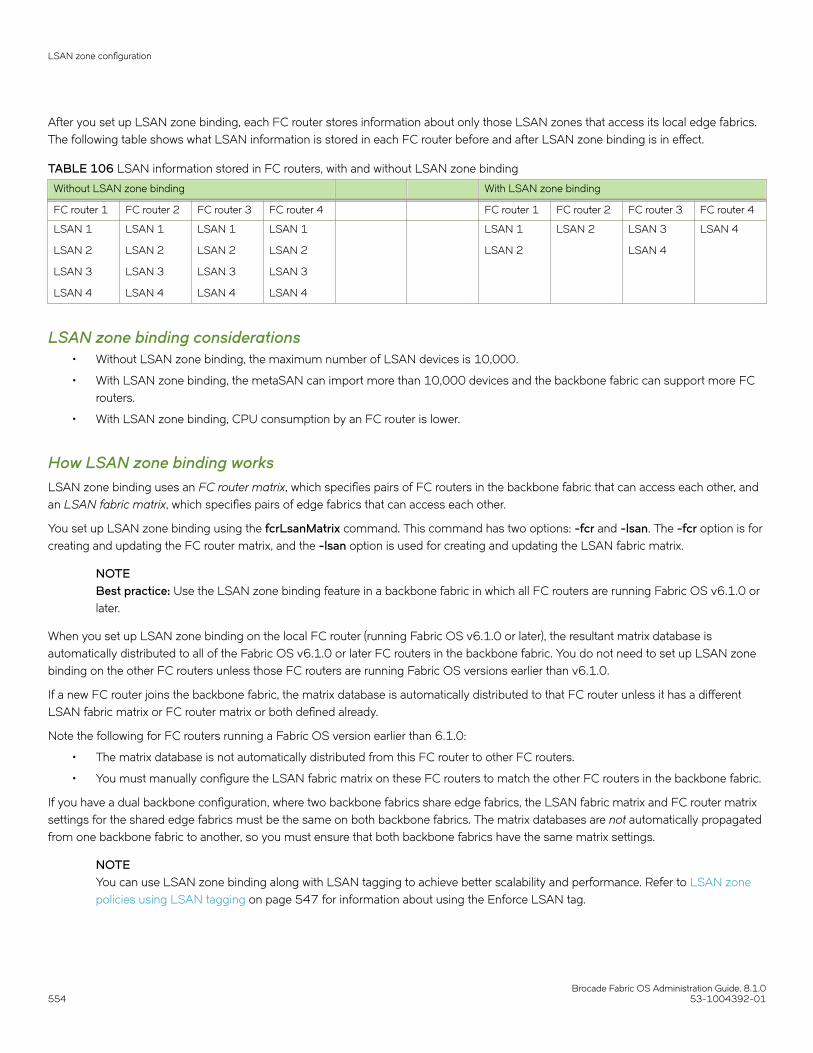
After you set up LSAN zone binding, each FC router stores information about only those LSAN zones that access its local edge fabrics.The following table shows what LSAN information is stored in each FC router before and after LSAN zone binding is in effect.
TABLE 106 LSAN information stored in FC routers, with and without LSAN zone binding
Without LSAN zone binding With LSAN zone binding
FC router 1 FC router 2 FC router 3 FC router 4 FC router 1 FC router 2 FC router 3 FC router 4
LSAN 1
LSAN 2
LSAN 3
LSAN 4
LSAN 1
LSAN 2
LSAN 3
LSAN 4
LSAN 1
LSAN 2
LSAN 3
LSAN 4
LSAN 1
LSAN 2
LSAN 3
LSAN 4
LSAN 1
LSAN 2
LSAN 2 LSAN 3
LSAN 4
LSAN 4
LSAN zone binding considerations• Without LSAN zone binding, the maximum number of LSAN devices is 10,000.
• With LSAN zone binding, the metaSAN can import more than 10,000 devices and the backbone fabric can support more FCrouters.
• With LSAN zone binding, CPU consumption by an FC router is lower.
How LSAN zone binding worksLSAN zone binding uses an FC router matrix, which specifies pairs of FC routers in the backbone fabric that can access each other, andan LSAN fabric matrix, which specifies pairs of edge fabrics that can access each other.
You set up LSAN zone binding using the fcrLsanMatrix command. This command has two options: -fcr and -lsan. The -fcr option is forcreating and updating the FC router matrix, and the -lsan option is used for creating and updating the LSAN fabric matrix.
NOTEBest practice: Use the LSAN zone binding feature in a backbone fabric in which all FC routers are running Fabric OS v6.1.0 orlater.
When you set up LSAN zone binding on the local FC router (running Fabric OS v6.1.0 or later), the resultant matrix database isautomatically distributed to all of the Fabric OS v6.1.0 or later FC routers in the backbone fabric. You do not need to set up LSAN zonebinding on the other FC routers unless those FC routers are running Fabric OS versions earlier than v6.1.0.
If a new FC router joins the backbone fabric, the matrix database is automatically distributed to that FC router unless it has a differentLSAN fabric matrix or FC router matrix or both defined already.
Note the following for FC routers running a Fabric OS version earlier than 6.1.0:
• The matrix database is not automatically distributed from this FC router to other FC routers.
• You must manually configure the LSAN fabric matrix on these FC routers to match the other FC routers in the backbone fabric.
If you have a dual backbone configuration, where two backbone fabrics share edge fabrics, the LSAN fabric matrix and FC router matrixsettings for the shared edge fabrics must be the same on both backbone fabrics. The matrix databases are not automatically propagatedfrom one backbone fabric to another, so you must ensure that both backbone fabrics have the same matrix settings.
NOTEYou can use LSAN zone binding along with LSAN tagging to achieve better scalability and performance. Refer to LSAN zonepolicies using LSAN tagging on page 547 for information about using the Enforce LSAN tag.
LSAN zone configuration
Brocade Fabric OS Administration Guide, 8.1.0554 53-1004392-01

FC router matrix definitionDepending on the structure of the backbone fabric, you can specify pairs of FC routers that can access each other. For the metaSANshown in Figure 80 on page 553, the following FC routers can access each other:
• FC router 1 and FC router 2
• FC router 3 and FC router 4
Because there is no device sharing between the two groups of FC routers, you can use the fcrLsanMatrix command with the -fcr optionto create the corresponding FC router matrix:
fcrlsanmatrix --add -fcr wwn1 wwn2fcrlsanmatrix --add -fcr wwn3 wwn4
The variables wwn1, wwn2, wwn3, and wwn4 are the WWNs of the four FC routers.
Now edge fabrics 1, 2, 3, 7, and 8 can access each other, and edge fabrics 4, 5, 6, and 9 can access each other; however, edge fabricsin one group cannot access edge fabrics in the other group. The edge fabrics can still communicate with the backbone fabric.
LSAN fabric matrix definitionWith LSAN zone binding, you can specify pairs of fabrics that can access each other. Using the metaSAN shown in Figure 80 on page553 as an example, the following edge fabrics can access each other:
• Fabric 1 and Fabric 2
• Fabric 2 and Fabric 3
• Fabric 4 and Fabric 5
• Fabric 5 and Fabric 6
You can use the fcrLsanMatrix command with the -lsan option to create the corresponding LSAN fabric matrix:
fcrlsanmatrix --add -lsan 1 2fcrlsanmatrix --add -lsan 2 3fcrlsanmatrix --add -lsan 4 5fcrlsanmatrix --add -lsan 5 6
Fabrics that are not specified are part of the default binding and can access other edge fabrics that are not specified. Thus, fabrics 7, 8,and 9 can access each other, but cannot access fabrics 1 through 6.
ATTENTIONThe fcrLsanMatrix --add -lsan 0 0 command will erase the entire LSAN fabric matrix settings in the cache.
The FC router matrix and the LSAN fabric matrix are used together to determine which fabrics can access each other, with the LSANfabric matrix providing more specific binding.
Setting up LSAN zone binding1. Log in to the FC router as admin.
2. Enter the following command to add a pair of FC routers that can access each other:
FCR:Admin> fcrlsanmatrix --add -fcrwwn1 wwn2
The variables wwn1 and wwn2 are the WWNs of the FC routers.
LSAN zone configuration
Brocade Fabric OS Administration Guide, 8.1.053-1004392-01 555

3. Enter the following command to add a pair of edge fabrics that can access each other:
FCR:Admin> fcrlsanmatrix --add -lsan fid1fid2
The variables fid1 and fid2 are the fabric IDs of the edge fabrics.
4. Enter the following command to apply the changes persistently:
FCR:Admin> fcrlsanmatrix --apply -all
FCR:Admin> fcrlsanmatrix --add -fcr 10:00:00:60:69:c3:12:b2 10:00:00:60:69:c3:12:b3FCR:Admin> fcrlsanmatrix --add -lsan 4 5FCR:Admin> fcrlsanmatrix --add -lsan 4 7FCR:Admin> fcrlsanmatrix --add -lsan 10 19FCR:Admin> fcrlsanmatrix --apply -all
Viewing the LSAN zone binding matrices1. Log in to the FC router as admin.
2. Enter fcrlsanmatrix --fabricview -fcr to view the FC router matrix.
3. Enter fcrlsanmatrix --fabricview -fcr to view the LSAN fabric matrix.
The following example displays both fabric matrices.
device:admin> fcrlsanmatrix --fabricview -fcrSAVED FCR PAIRS======================================================FCR FCR------------------------------------------------------10:00:00:60:69:c3:12:b2 (2) 10:00:00:60:69:c3:12:b3 (unknown)
device:admin> fcrlsanmatrix --fabricview -lsanLSAN MATRIX is activated Fabric ID Fabric ID-------------------------------------- 4 5 4 7 10 19
Location embedded LSAN zonesStarting with Fabric OS 7.4.0, location embedded LSAN zones help to increase the limit of LSAN zones in the backbone fabric byproviding a mechanism to store only the applicable LSAN zones in each FC router. You can configure the LSAN zones appropriately inthe edge fabric, at the same time retaining all the FC router features and characteristics such as any-to-any connectivity. You can havemore than 10,000 LSAN devices in the entire backbone fabric or metaSAN.
Prior to Fabric OS 7.4.0, every FC router switch in the backbone fabric maintains the entire LSAN database having all LSAN zone entriesin all edge fabrics subject to the maximum LSAN zone limit. In many cases, the device sharing is done between a few edge fabrics andnot with all the edge fabrics that are connected in the backbone. The location embedded LSAN zones feature allows you to specify orembed the remote fabric ID in the LSAN zone names that share devices. The FC router uses the location information embedded in theLSAN zone name to store only relevant LSAN zone entries. The advantage is that an individual FC router stores less LSAN zone entriesand allows you to configure more LSAN zones per FC router which helps to exceed the maximum LSAN zone limit across the backbonefabric.
NOTEIn a backbone fabric having a mix of Fabric OS 7.4.0 and previous releases, there can be mismatch in location embeddedLSAN zones in FC routers running Fabric OS pre-v7.4.0. Hence, such mixed combination is not recommended for this feature.
Location embedded LSAN zones
Brocade Fabric OS Administration Guide, 8.1.0556 53-1004392-01
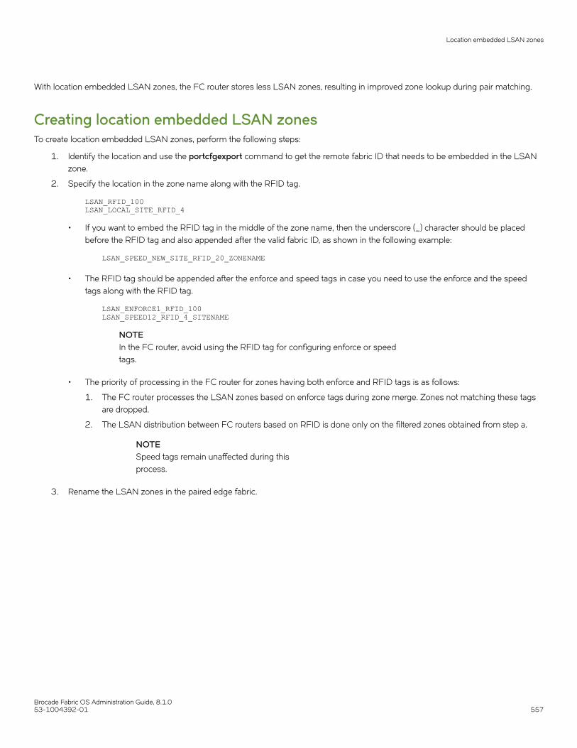
With location embedded LSAN zones, the FC router stores less LSAN zones, resulting in improved zone lookup during pair matching.
Creating location embedded LSAN zonesTo create location embedded LSAN zones, perform the following steps:
1. Identify the location and use the portcfgexport command to get the remote fabric ID that needs to be embedded in the LSANzone.
2. Specify the location in the zone name along with the RFID tag.
LSAN_RFID_100LSAN_LOCAL_SITE_RFID_4
• If you want to embed the RFID tag in the middle of the zone name, then the underscore (_) character should be placedbefore the RFID tag and also appended after the valid fabric ID, as shown in the following example:
LSAN_SPEED_NEW_SITE_RFID_20_ZONENAME
• The RFID tag should be appended after the enforce and speed tags in case you need to use the enforce and the speedtags along with the RFID tag.
LSAN_ENFORCE1_RFID_100LSAN_SPEED12_RFID_4_SITENAME
NOTEIn the FC router, avoid using the RFID tag for configuring enforce or speedtags.
• The priority of processing in the FC router for zones having both enforce and RFID tags is as follows:
1. The FC router processes the LSAN zones based on enforce tags during zone merge. Zones not matching these tagsare dropped.
2. The LSAN distribution between FC routers based on RFID is done only on the filtered zones obtained from step a.
NOTESpeed tags remain unaffected during thisprocess.
3. Rename the LSAN zones in the paired edge fabric.
Location embedded LSAN zones
Brocade Fabric OS Administration Guide, 8.1.053-1004392-01 557

Example configuration of LSAN zones environment
FIGURE 81 Sample location-embedded LSAN zones environment
The following are the LSAN configurations made in the respective fabrics.
FID 1: LSAN_A : dev1 dev2 FID 3: LSAN_A : dev3 dev2FID 1: LSAN_B : dev1 dev4 FID 3: LSAN_B : dev3 dev4FID 2: LSAN_A : dev2 dev1 FID 4: LSAN_A : dev4 dev1FID 2: LSAN_B : dev2 dev3 FID 4: LSAN_B : dev3 dev4
After you change the zone name by embedding the remote fabric ID and re-enabling the zone configuration in all the fabrics, LSAN zoneconfiguration changes to the following:
FID 1: LSAN_A_RFID_2: dev1 dev2 FID 3: LSAN_RFID_2_A: dev3 dev2FID 1: LSAN_B_RFID_4: dev1 dev4 FID 3: LSAN_RFID_4_B: dev3 dev4FID 2: LSAN_RFID_1_A: dev2 dev1 FID 4: LSAN_A_RFID_1: dev4 dev1FID 2: LSAN_RFID_3_B: dev2 dev3 FID 4: LSAN_B_RFID_3: dev3 dev4
FCR 1 has the following zones:
FID 1: LSAN_A_RFID_2: dev1 dev2FID 1: LSAN_B_RFID_4: dev1 dev4FID 2: LSAN_RFID_1_A: dev2 dev1FID 4: LSAN_A_RFID_1: dev4 dev1
Location embedded LSAN zones
Brocade Fabric OS Administration Guide, 8.1.0558 53-1004392-01

FID 4: LSAN_B_RFID_3: dev3 dev4FID 3: LSAN_B_RFID_4: dev3 dev4
FCR 2 has the following zones:
FID 2: LSAN_RFID_1_A: dev2 dev1FID 2: LSAN_RFID_3_B: dev2 dev3FID 1: LSAN_A_RFID_2: dev1 dev2FID 1: LSAN_B_RFID_4: dev1 dev4FID 4: LSAN_A_RFID_1: dev4 dev1FID 4: LSAN_B_RFID_3: dev3 dev4FID 3: LSAN_RFID_2_A: dev3 dev2FID 3: LSAN_RFID_4_B: dev3 dev4
FCR 3 has the following zones:
FID 3: LSAN_RFID_2_A: dev3 dev2FID 3: LSAN_RFID_4_B: dev3 dev4FID 2: LSAN_RFID_3_B: dev2 dev3FID 4: LSAN_A_RFID_1: dev4 dev1FID 4: LSAN_B_RFID_3: dev3 dev4FID 1: LSAN_B_RFID_4: dev1 dev4
Migrating LSAN zones to location embedded LSAN zones in the edgefabricYou must identify a set of LSAN zones for which you want to embed the location. For such LSAN zones, you must reconfigure theLSAN zones in the edge fabric by completing the following steps. Using this procedure, you can scale beyond the maximum limits in themetaSAN.
1. In the FC router running a release prior to Fabric OS 7.4.0, use the lsanZoneShow –d –f <fid> command to find the remotefabric ID from which devices are imported for each LSAN zone per configured edge fabric.
2. Rename the LSAN zone name by appending the special _RFID_”imported FID” tag.
3. If the LSAN zone has the devices that are imported from more than one edge fabric, split them into multiple LSAN zones basedon the number of imported fabrics in RFID_”imported FID” tag format and ensure that all newly created LSAN zones have onlythose imported device pairs.
4. Once all the LSAN zones are converted into RFID_imported FID format, enable the zone configuration.
5. Repeat the previous steps in all the edge fabrics.LSAN zones that are not configured with location information will operate as per legacy FC router behavior.
Limitations of location embedded LSAN zones• Each FC router has different LSAN zones based on the location embedded in the LSAN zone name. If each FC router has
5000 LSANs, after firmware downgrade to a pre-7.4.0 version, any disruptive action in the metaSAN triggers import or exportissues because the pre-7.4.0 FC router accepts only the first 5000 LSAN zones. In such an FC router, you will notice the RASlog FCR-1020 indicates that the FC router LSAN zones are exhausted. Also, the filter will apply depending on where thepre-7.4.0 switch is in the backbone fabric.
• The location embedded LSAN zone feature is not applicable for backbone-to-edge fabric LSAN zones. If you configure anRFID in a backbone fabric LSAN zone, it will not impact anything on resource utilization.
• The entries of fcrProxyDevShow –a, fcrPhyDevShow –a, and lsanZoneShow may not be same across FC routers in thebackbone fabric.
Location embedded LSAN zones
Brocade Fabric OS Administration Guide, 8.1.053-1004392-01 559

• If you need to change the fabric ID for an EX_Port whose FID is already being used as an RFID value in other edge fabricLSAN zones, you must modify the LSAN zone configuration to new a RFID value. The recommended steps are as follows:
1. Disable the EX_Ports that need an FID change.
2. Configure the EX_Ports with the new FID value.
3. Enable the zone configuration in the respective edge fabrics with the new RFID value.
4. Enable the EX_Ports that were disabled in step 1.
• If you configure Backbone Fabric ID value for the RFID field, the LSAN zone is treated as regular LSAN zone and will bedistributed to other FCRs in the backbone fabric.
Peer LSAN zone supportStarting with Fabric OS 7.4.0, the FC router supports the peer LSAN zones if you have configured them in the edge fabric. Peer zoningrules are applied by the edge fabric switch. The FC router treats peer LSAN zones as normal LSAN zones and imports the devices in theedge fabric as per a pair-matching algorithm. RSCNs of proxy devices present in peer zones generated by the FC router are distributedto the edge fabric switches and controlled by the edge fabric name server as per peer zoning rules. The FC Router supports peer LSANzones configured in a backbone fabric.
For more details, refer to Peer Zoning on page 374.
NOTEInitial WWNs starting with '00' are for internal use only and are auto-created. From Fabric OS 7.3.0 onwards, zones havingsuch initial WWNs are treated as peer zones. If you upgrade the firmware from pre-7.3.0, or merge with a switch that haspre-7.3.0 firmware, or download configuration from pre-7.3.0 switch, and the first zone member WWN starts with '00', FabricOS treats the zone as a peer zone. Please delete such invalid zones by first using the cfgRemove command, then thezoneDelete command and finally the cfgSave/cfgEnable commands.
NOTEIf you are using peer zone over FC router, both edges or backbones should use peer zone. You cannot combine regular LSANzone on one end with a peer LSAN zone on another end. Peer zone over FC router is not supported with NOS edge.
Proxy PID configurationWhen an FC router is first configured, the PIDs for the proxy devices are automatically assigned. Proxy PIDs (as well as phantom domainIDs) persist across reboots.
The most common situation in which you would set a proxy PID is when you replace a switch. If you replace the switch and want tocontinue using the old PID assignments, you can configure it to do so; this value remains in the system even if the blade is replaced. Tominimize disruption to the edge fabrics, set the proxy PIDs to the same values used with the old hardware.
The fcrProxyConfig command displays or sets the persistent configuration of proxy devices. Used with the -s option, it can alsoinfluence the assignment of the xlate domain port number (which is used to determine the Area_ID field of the PID) and the Port_ID field.Like the PIDs in a fabric, a proxy PID must be unique. If the slot argument results in a duplicate PID, it will be ignored. Proxy PIDs areautomatically assigned to devices imported into a fabric, starting at f001.
Use the fcrXlateConfig command to display or assign a preferred domain ID to a translate domain.
Peer LSAN zone support
Brocade Fabric OS Administration Guide, 8.1.0560 53-1004392-01

Fabric parameter considerationsBy default, EX_Ports and VEX_Ports detect, autonegotiate, and configure the fabric parameters without user intervention. You canoptionally configure these parameters manually.
• To change the fabric parameters on a switch in the edge fabric, use the configure command.
Note that to access all of the fabric parameters controlled by this command, you must disable the switch using theswitchDisable command. If executed on an enabled switch, only a subset of attributes is configurable.
• To change the fabric parameters of an EX_Port on the FC router, use the portCfgEXPort command.
• To change the fabric parameters of a VEX_Port, use the portCfgVEXPort command.
The backbone fabric PID mode and the edge fabric PID mode do not need to match, but the PID mode for the EX_Port or VEX_Portand the edge fabric to which it is attached must match. You can statically set the PID mode for the fabric by using the -p option with theportCfgEXPort command. Use the -t option to disable the negotiate fabric parameter feature; otherwise, the PID mode isautonegotiated. The various edge fabrics may have different PID modes.
Fabric parameter settings, namely, E_D_TOV (error-detect timeout value), R_A_TOV (resource-allocation timeout value), and PID format,must be the same on EX_Ports or VEX_Ports and on the fabrics to which they are connected. You can set the PID format on an EX_Portwhen you configure an inter-fabric link.
The default values for E_D_TOV and R_A_TOV for an EX_Port or VEX_Port must match those values on other Fabric OS switches. Youdo not need to adjust these parameters for an EX_Port or VEX_Port unless you have adjusted them for the edge fabric.
The default values for R_A_TOV and E_D_TOV are the recommended values for all but very large fabrics (ones requiring four or morehops) or high-latency fabrics (such as ones using long-distance FCIP links).
Inter-fabric broadcast framesThe FC router can receive and forward broadcast frames between edge fabrics and between the backbone fabric and edge fabrics. Manytarget devices and HBAs cannot handle broadcast frames. In this case, you can set up broadcast zones to control which devices receivebroadcast frames. (Refer to Broadcast zones on page 332 for information about setting up broadcast zones.)
By default, broadcast frames are not forwarded from the FC router to the edge fabrics.
Displaying the current broadcast configuration1. Log in to the FC router as admin.
2. Enter the following command:
fcr:admin> fcrbcastconfig --show
This command displays only the FIDs that have the broadcast frame option enabled. The FIDs that are not listed have thebroadcast frame option disabled.
Enabling broadcast frame forwarding1. Log in to the FC router as admin.
Inter-fabric broadcast frames
Brocade Fabric OS Administration Guide, 8.1.053-1004392-01 561
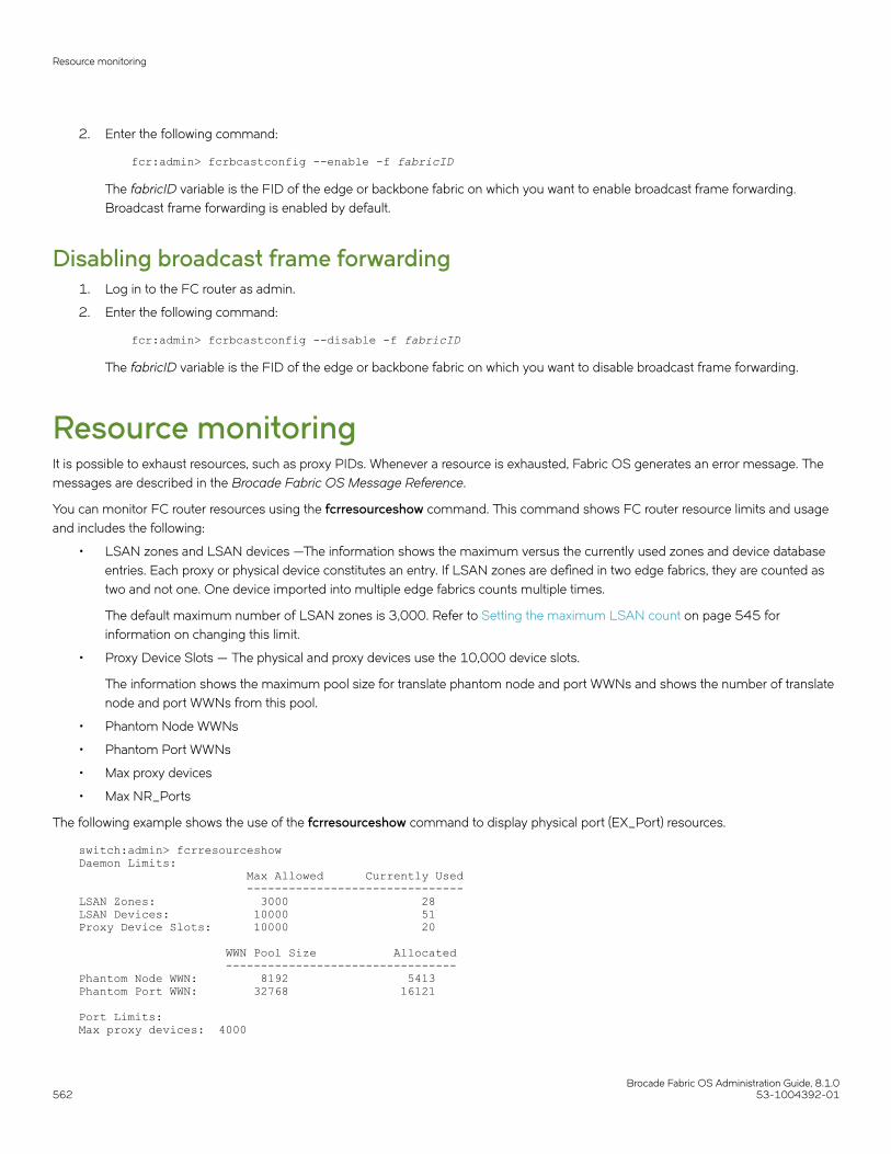
2. Enter the following command:
fcr:admin> fcrbcastconfig --enable -f fabricID
The fabricID variable is the FID of the edge or backbone fabric on which you want to enable broadcast frame forwarding.Broadcast frame forwarding is enabled by default.
Disabling broadcast frame forwarding1. Log in to the FC router as admin.
2. Enter the following command:
fcr:admin> fcrbcastconfig --disable -f fabricID
The fabricID variable is the FID of the edge or backbone fabric on which you want to disable broadcast frame forwarding.
Resource monitoringIt is possible to exhaust resources, such as proxy PIDs. Whenever a resource is exhausted, Fabric OS generates an error message. Themessages are described in the Brocade Fabric OS Message Reference.
You can monitor FC router resources using the fcrresourceshow command. This command shows FC router resource limits and usageand includes the following:
• LSAN zones and LSAN devices —The information shows the maximum versus the currently used zones and device databaseentries. Each proxy or physical device constitutes an entry. If LSAN zones are defined in two edge fabrics, they are counted astwo and not one. One device imported into multiple edge fabrics counts multiple times.
The default maximum number of LSAN zones is 3,000. Refer to Setting the maximum LSAN count on page 545 forinformation on changing this limit.
• Proxy Device Slots — The physical and proxy devices use the 10,000 device slots.
The information shows the maximum pool size for translate phantom node and port WWNs and shows the number of translatenode and port WWNs from this pool.
• Phantom Node WWNs
• Phantom Port WWNs
• Max proxy devices
• Max NR_Ports
The following example shows the use of the fcrresourceshow command to display physical port (EX_Port) resources.
switch:admin> fcrresourceshowDaemon Limits: Max Allowed Currently Used -------------------------------LSAN Zones: 3000 28LSAN Devices: 10000 51Proxy Device Slots: 10000 20 WWN Pool Size Allocated ---------------------------------Phantom Node WWN: 8192 5413Phantom Port WWN: 32768 16121
Port Limits:Max proxy devices: 4000
Resource monitoring
Brocade Fabric OS Administration Guide, 8.1.0562 53-1004392-01
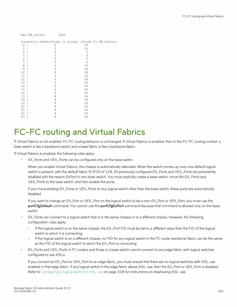
Max NR_Ports: 1000
Currently Used(column 1: proxy, column 2: NR_Ports): 0 | 0 34 1 | 3 34 4 | 0 0 5 | 0 0 6 | 0 0 7 | 0 0 8 | 6 34 9 | 6 3410 | 6 3411 | 6 3412 | 6 3413 | 6 3414 | 6 3415 | 6 3416 | 8 3417 | 8 3418 | 8 3419 | 8 3420 | 8 3421 | 8 3422 | 8 3423 | 8 34
FC-FC routing and Virtual FabricsIf Virtual Fabrics is not enabled, FC-FC routing behavior is unchanged. If Virtual Fabrics is enabled, then in the FC-FC routing context, abase switch is like a backbone switch and a base fabric is like a backbone fabric.
If Virtual Fabrics is enabled, the following rules apply:
• EX_Ports and VEX_Ports can be configured only on the base switch.
When you enable Virtual Fabrics, the chassis is automatically rebooted. When the switch comes up, only one default logicalswitch is present, with the default fabric ID (FID) of 128. All previously configured EX_Ports and VEX_Ports are persistentlydisabled with the reason ExPort in non base switch. You must explicitly create a base switch, move the EX_Ports andVEX_Ports to the base switch, and then enable the ports.
If you move existing EX_Ports or VEX_Ports to any logical switch other than the base switch, these ports are automaticallydisabled.
If you want to change an EX_Port or VEX_Port on the logical switch to be a non-EX_Port or VEX_Port, you must use theportCfgDefault command. You cannot use the portCfgExPort command because that command is allowed only on the baseswitch.
• EX_Ports can connect to a logical switch that is in the same chassis or in a different chassis. However, the followingconfiguration rules apply:
– If the logical switch is on the same chassis, the EX_Port FID must be set to a different value than the FID of the logicalswitch to which it is connecting.
– If the logical switch is on a different chassis, no FID for any logical switch in the FC router backbone fabric can be the sameas the FID of the logical switch to which the EX_Port is connecting.
• EX_Ports and VEX_Ports in FC routers and those in a base switch cannot connect to any edge fabric with logical switchesconfigured to use XISLs.
If you connect an EX_Port or VEX_Port to an edge fabric, you must ensure that there are no logical switches with XISL useenabled in that edge fabric. If any logical switch in the edge fabric allows XISL use, then the EX_Port or VEX_Port is disabled.Refer to Configuring a logical switch for XISL use on page 318 for instructions on disallowing XISL use.
FC-FC routing and Virtual Fabrics
Brocade Fabric OS Administration Guide, 8.1.053-1004392-01 563

Because XISL use is disallowed, dedicated links must be configured to route traffic across switches in the same logical fabric.
ATTENTIONIf you connect an EX_Port or VEX_Port from an FC router running Fabric OS v6.1.x or earlier to a logical switch thatallows XISL use, the EX_Port or VEX_Port is not disabled. However, this configuration is not supported.
• Backbone-to-edge routing is not supported in the base switch. Refer to Figure 24 on page 299 for information about how toconfigure legacy FC routers to allow backbone-to-edge routing with Virtual Fabrics.
• All FC router commands can be executed only in the base switch context.
• The fcrConfigure command is not allowed when Virtual Fabrics is enabled. Instead, use the lsCfg command to configure theFID.
• Although the Brocade 6510 and 6520 support up to four logical switches, if you are using FC-FC routing, they can have amaximum of only three logical switches.
• In the Brocade 7840, FC-FC routing is not supported on the base switch.
• When a VF enabled switch is part of backbone, only the base switch will be able to route frames between edge fabrics. If anyother (default or logical) switch is included as a hop between edge fabrics, packets will be dropped.
Logical switch configuration for FC routingFigure 82 shows an example of two chassis partitioned into logical switches. This configuration allows the device in Fabric 128 tocommunicate with the device in Fabric 15 without merging the fabrics.
The following conditions are considered:
• The base switch in Physical chassis 1 serves as an FC router and contains EX_Ports that connect to logical switches in the twoedge fabrics, Fabric 128 and Fabric 15.
• The other logical switches in Fabric 128 and Fabric 15 must be connected with physical ISLs, and do not use the XISLconnection in the base fabric.
• The logical switches in Fabric 1 are configured to allow XISL use. You cannot connect an EX_Port to these logical switches, sothe device in Fabric 1 cannot communicate with the other two devices.
FC-FC routing and Virtual Fabrics
Brocade Fabric OS Administration Guide, 8.1.0564 53-1004392-01

FIGURE 82 EX_Ports in a base switch
Figure 83 shows a logical representation of the physical chassis and devices in Figure 82. As shown in Figure 83, Fabric 128 and Fabric15 are edge fabrics connected to a backbone fabric. Fabric 1 is not connected to the backbone, so the device in Fabric 1 cannotcommunicate with any of the devices in the other fabrics.
FC-FC routing and Virtual Fabrics
Brocade Fabric OS Administration Guide, 8.1.053-1004392-01 565

FIGURE 83 Logical representation of EX_Ports in a base switch
Backbone-to-edge routing with Virtual FabricsBackbone-to-edge routing is not supported in the base switch, unless you use a legacy FC router. A legacy FC router is an FC routerconfigured on a Brocade 7500 switch.
Base switches can participate in a backbone fabric with legacy FC routers. You cannot connect devices to the base switch because thebase switch does not allow F_Ports. You can, however, connect devices to the legacy FC router, thus enabling backbone-to-edge routing.
If you connect a legacy FC router to a base switch, you must set the backbone FID of the FC router to be the same as that of the baseswitch.
In Figure 82 on page 565, no devices can be connected to the backbone fabric (Fabric 8) because base switches cannot have F_Ports. Figure 84 shows an FC router in legacy mode connected to a base switch. This FC router can have devices connected to it, and so youcan have backbone-to-edge routing through this FC router. In this figure, Host A in the backbone fabric can communicate with device Bin the edge fabric with FID 20; Host A cannot communicate with device C, however, because the base switches do not supportbackbone-to-edge routing.
FC-FC routing and Virtual Fabrics
Brocade Fabric OS Administration Guide, 8.1.0566 53-1004392-01

FIGURE 84 Backbone-to-edge routing across base switch using FC router in legacy mode
If a backbone fabric has both a Virtual Fabrics-enabled FC router and a Virtual Fabrics-disabled FC router, EX_Ports are not allowedfrom the base switch of the Virtual Fabrics-enabled FC router to the same edge fabric that is performing backbone-to-edge routing withthe Virtual Fabrics-disabled FC router.
For example, in the above figure, you should not connect EX_Ports from the base switch (logical switch 4 or logical switch 8) to the edgefabric FID 20, which is performing backbone-to-edge routing with a legacy FC router.
Upgrade and downgrade considerations for FC-FCroutingWhen you upgrade to Fabric OS v7.0.0 or later, EX_Ports remain functional and you can continue to perform all FC router operations onthe switch.
Brocade recommends that you save your FC-FC routing configuration (using the configUpload command) before performing anydowngrades.
Before upgrading the Brocade G620 switch from Fabric OS 8.0.0 to 8.0.1, ensure that an Integrated Routing License is installed ifEX_Port is enabled in the switch. This avoids EX_Port getting disabled after upgrade.
Upgrade and downgrade considerations for FC-FC routing
Brocade Fabric OS Administration Guide, 8.1.053-1004392-01 567

How replacing port blades affects EX_Port configurationIf you replace an FR4-18i blade with an 8-Gbps port blade or FX8-24 blade, the EX_Port configuration remains the same for the first16 ports on the 8-Gbps port blade (and for the first 12 FC ports on the FX8-24 blade). For all other ports on the blade, the EX_Portconfiguration is cleared. No ports are persistently disabled.
If you replace an 8-Gbps port blade with an FX8-24 blade, the EX_Port configuration remains the same for the first 12 FC ports on theFX8-24 blade.
If you replace an 8-Gbps port blade or FX8-24 blade with another 8-Gbps port blade, the EX_Port configuration remains the same.
Displaying the range of output ports connected toxlate domainsThe edge fabric detects only one front domain from an FC router connected through multiple output ports. The output port of the frontdomain is not fixed to 0; the values can be in a range from 129 through 255. The range of the output ports connected to the xlatedomain is from 1 through 128. This range enables the front domain to connect to 127 remote xlate domains.
1. Log in to a switch in the edge fabric.
2. Enter the lsDbShow command on the edge fabric.
In the lsDbShow output, ports in the range from 129 through 255 are the output ports on the front domain.
Displaying the range of output portsThe following example shows the range of output ports.
linkCnt = 2, flags = 0x0LinkId = 53, out port = 1, rem port = 35, cost = 500, costCnt = 0, type = 1LinkId = 57, out port = 129, rem port = 18, cost = 500, costCnt = 0, type = 1
Displaying ports on the edge fabricThe following example shows the use of the lsDbShow display on the edge fabric. The front domain, domain 3, has two linksrepresenting two EX_Port connections with output ports 129 and 132.
Domain = 3, Link State Database Entry pointer = 0x100bbcc0.........linkCnt = 4, flags = 0x0LinkId = 199, out port = 129, rem port = 2, cost = 10000, costCnt = 0, type = 1LinkId = 199, out port = 132, rem port = 3, cost = 10000, costCnt = 0, type = 1LinkId = 2, out port = 1, rem port = 2, cost = 10000, costCnt = 0, type = 1LinkId = 1, out port = 32, rem port = 2, cost = 10000, costCnt = 0, type = 1
FC-FC routing scalability limitsThe following table outlines the scalability limits for FC-FC routing.
Displaying the range of output ports connected to xlate domains
Brocade Fabric OS Administration Guide, 8.1.0568 53-1004392-01

TABLE 107 FC-FC routing scalability limits
Scalability feature Supported limits Supported limits with enhanced Backbones
Maximum number of Fabric OS edge fabricsper metaSAN (with edge fabrics containingup to 1500 WWNs)
48 (DCX8510-4, DCX8510-8)
24 (6510/520)
8 (DCX/ DCX-4S/DCX8510/5300/6510/6520)
Maximum number of Fabric OS edge fabricsper metaSAN (with edge fabrics containingup to 2000 WWNs)
32 (DCX8510-4, DCX8510-8)
12 (6510/6520)
8 (DCX/ DCX-4S/DCX8510/5300/6510/6520)
Maximum number of edge fabrics perchassis (Edge fabrics per chassis may neverexceed maximum number of edge fabricsper metaSAN noted in previous rows - insome cases depending on the number ofdevices in an edge fabric or type of switches,the maximum number of edge fabrics permetaSAN might be lower than that supportedper chassis)
30 (DCX8510-4, DCX8510-8)
12 (6510/6520)
8 (DCX/ DCX-4S/DCX8510/5300/6510/6520)
Maximum number of switches per edgefabric (only Fabric OS switches in edgefabric )
26 26 (24 in case of Network OS fabric)
Maximum number of WWNs per edge fabric(only Fabric OS switches in edge fabric )
4000 4000
Maximum number of imported devices fromeach edge fabric
4000 4000 (1000 imported from BB)
Maximum number of L2 switchesparticipating in backbone fabric
12 40 (additional 8 XDs from 8 edge fabrics).
Maximum number of FC routers perbackbone fabric
16 (DCX8510-4, DCX8510-8, Gen6 switches) 2 (These 2 FC routers are 2 of the 40 L2switches supported in BB and are FC routingcapable.)
Maximum number of local WWNs perbackbone fabric (not including importeddevices)
512 2000
Maximum number of LSAN devices permetaSAN (total number of devices importedfrom all edge fabrics)
15000 (with only DCX8510-8/ DCX8510-4 andGen6 switches as routers)
5000 (with any 6510/ 6520 as routers)
15000 (with only DCX/ DCX-4S/DCX8510-8/ DCX8510-4 and Gen6switches as routers)
5000 (with 5300 routers)
Maximum number of LSAN zones permetaSAN
7500* 7500*
Maximum number of devices per LSAN zone 64 64
Maximum number of hops between edgeswitches
19 19
EX_Ports per chassis with Integrated Routing 128 (DCX8510)
To the maximum port count (6510/6520)
128 (DCX/DCX-4S/ DCX8510)
To the maximum port count (5300)
NOTEIPFC over FCR is supported only for edge to edge. FC Fast Write is supported only for edge to edge. Maximum number ofLSAN zones in metaSAN can be scaled beyond 7500 by using location embedded LSAN zone feature. For 4K proxy devicesthrough EX_Port, the DCX family of switches are recommended for better performance.
FC-FC routing scalability limits
Brocade Fabric OS Administration Guide, 8.1.053-1004392-01 569

Brocade Fabric OS Administration Guide, 8.1.0570 53-1004392-01

Port IndexingThis section shows how to use the switchShow command to determine the mapping among the port index, slot or port numbers, andthe 24-bit port ID (PID) on any Brocade Backbone. Enter the switchShow command without parameters to show the port indexmapping for the entire platform. Enter the switchShow -slot command for port mapping information for the ports on the blade in aspecific slot. Include the --qsfp option to list also the QSFP number, for slots that contain core blades.
This example shows the output of the switchShow command for a CR16-4 core blade in slot 3 of a Brocade DCX 8510-4 Backbone.The leftmost column shows the unique port index. The second and third columns show the corresponding physical slot and portnumbers, respectively. The corresponding QSFP number for the port is also shown. For a core blade, no PID exists in the Addresscolumn.
switch:FID128:admin> switchshow -slot 3 -qsfp switchName: switch nameswitchType: 121.3switchState: OnlineswitchMode: NativeswitchRole: SubordinateswitchDomain: 75switchId: fffc4bswitchWwn: 10:00:00:05:1e:4f:eb:00zoning: ON (zoning name)switchBeacon: OFFFC Router: OFFHIF Mode: ONAllow XISL Use: OFFLS Attributes: [FID: 128, Base Switch: No, Default Switch: Yes, Address Mode 0]Index Slot Port QSFP Address Media Speed State Proto==========================================================================256 3 0 0 ------ id 16G No_SigDet FC257 3 1 0 ------ id 16G No_SigDet FC258 3 2 0 ------ id 16G No_SigDet FC259 3 3 0 ------ id 16G No_SigDet FC260 3 4 1 ------ -- 16G No_Module FC261 3 5 1 ------ -- 16G No_Module FC262 3 6 1 ------ -- 16G No_Module FC263 3 7 1 ------ -- 16G No_Module FC264 3 8 2 ------ -- 16G No_Module FC265 3 9 2 ------ -- 16G No_Module FC266 3 10 2 ------ -- 16G No_Module FC267 3 11 2 ------ -- 16G No_Module FC268 3 12 3 ------ -- 16G No_Module FC269 3 13 3 ------ -- 16G No_Module FC270 3 14 3 ------ -- 16G No_Module FC271 3 15 3 ------ -- 16G No_Module FC736 3 16 4 ------ -- 16G No_Module FC737 3 17 4 ------ -- 16G No_Module FC738 3 18 4 ------ -- 16G No_Module FC739 3 19 4 ------ -- 16G No_Module FC740 3 20 5 ------ -- 16G No_Module FC741 3 21 5 ------ -- 16G No_Module FC742 3 22 5 ------ -- 16G No_Module FC743 3 23 5 ------ -- 16G No_Module FC744 3 24 6 ------ -- 16G No_Module FC745 3 25 6 ------ -- 16G No_Module FC746 3 26 6 ------ -- 16G No_Module FC747 3 27 6 ------ -- 16G No_Module FC748 3 28 7 ------ id 16G Online FC E-Port 10:00:00:05:1e:39:e4:5a trunkmaster name (Trunk master)749 3 29 7 ------ id 16G Online FC E-Port 10:00:00:05:1e:39:e4:5a trunkmaster name (Trunk master)750 3 30 7 ------ id 16G Online FC E-Port 10:00:00:05:1e:39:e4:5a trunkmaster name (Trunk master)
Brocade Fabric OS Administration Guide, 8.1.053-1004392-01 571

751 3 31 7 ------ id 16G Online FC E-Port 10:00:00:05:1e:39:e4:5a trunkmaster name (Trunk master)
This example shows the truncated output of the switchShow command for an FC16-32 port blade in slot 1 of a Brocade DCX 8510-8Backbone. The Address column shows the PID.
switch:FID128:admin> switchshow -slot 1 switchName: DCX8510_8(output truncated)LS Attributes: [FID: 128, Base Switch: No, Default Switch: Yes, Address Mode 0]Index Slot Port Address Media Speed State Proto=======================================================================0 1 0 500000 -- N16 No_Module FC1 1 1 500100 -- N16 No_Module FC2 1 2 500200 -- N16 No_Module FC(output truncated)
This example shows the truncated switchShow output for an FC16-64 port blade on the Brocade DCX 8510 Backbone. Theassignment of port index numbers to PIDs will vary depending on blade type, platform type, and slot number.
DCX:admin> switchshow Index Slot Port Address Media Speed State============================================================= 0 1 0 0a0040 -- N16 No_Module 1 1 1 0a0140 -- N16 No_Module 2 1 2 0a0240 -- N16 No_Module(output truncated)768 1 48 0a00c0 -- N16 No_Module769 1 49 0a01c0 -- N16 No_Module770 1 50 0a02c0 -- N16 No_Module(output truncated)784 1 62 0a0ec0 -- N16 No_Module783 1 63 0a0fc0 -- N16 No_Module 16 2 0 0a1040 -- N16 No_Module 17 2 1 0a1140 -- N16 No_Module(output truncated)
This example shows the truncated switchShow output for an FX8-24 application blade on the Brocade DCX 8510-8 Backbone. Theassignment of port index numbers to PIDs will vary depending on blade type, platform type, and slot number.
switch:FID128:admin> switchshow -slot 10 switchName: my8510-8(output truncated)Slot Blade Type ID Model Name Status--------------------------------------------------10 AP BLADE 75 FX8-24 ENABLEDIndex Slot Port Address Media Speed State Proto============================================================= 80 10 0 505000 id 4G No_Light FC 81 10 1 505100 -- 4G No_Module FC 82 10 2 505200 id 4G Mod_Inv FC "Speed Mismatch / Incompatible SFP" 83 10 3 505300 -- 4G No_Module FC 84 10 4 505400 -- 4G No_Module FC(output truncated) 95 10 15 505f00 -- -- Offline VE208 10 16 50d000 -- -- Offline VE209 10 17 50d100 -- 4G Offline VE(output truncated)
Brocade Fabric OS Administration Guide, 8.1.0572 53-1004392-01

Switch and Blade Sensors• Brocade switch sensors...............................................................................................................................................................................573• Brocade blade temperature sensors...................................................................................................................................................... 573• System temperature monitoring.............................................................................................................................................................. 574
Brocade switch sensorsThe following table lists the number of temperature sensors, fans, and PSUs for each Brocade switch model for Fabric OS 8.0.1. The“swNum / connUnitNum” column is the sum of the values in the previous three columns.
TABLE 108 Brocade switch sensor counts
Platform Temperaturesensors
Fans Power supplyunits
swNum /connUnitNum
Brocade 6505 4 2 2 8
Brocade 6510 4 2 2 8
Brocade 6520 4 2 2 8
Brocade 7840 extension switch 4 5 2 11
Brocade DCX 8510-4 Director 35+ 2 2 39+
Brocade DCX 8510-8 Director 58+ 3 4 65+
Brocade G610 6 4(minimum2 must beworking)
1 11
Brocade G620 5 6 2 13
Brocade X6-4 Director 35+ 2 2 39+
Brocade X6-8 Director 58+ 3 4 (3 minimum) 65+
Brocade M6505 Blade Server SAN I/O Module 3 0 0 3
Brocade 6542 Blade Server SAN I/O Module 5 2 0 7
Brocade 6543 Blade Server SAN I/O Module 2 0 0 2
Brocade 6545 Blade Server SAN I/O Module 3 0 0 3
Brocade 6546 Blade Server SAN I/O Module 3 0 0 3
Brocade 6547 Blade Server SAN I/O Module 3 0 0 3
Brocade 6548 Blade Server SAN I/O Module 2 0 0 2
Brocade 6549 Blade Server SAN I/O Module 3 0 0 3
Brocade 6558 Blade Server SAN I/O Module 2 0 0 2
Brocade 6559 Blade Server SAN I/O Module 7 0 0 7
Brocade blade temperature sensorsThe following table lists the number of temperature sensors for each Brocade blade model supported in Fabric OS 8.0.1. Not all bladesare supported in all chassis; refer to the release notes for the version of Fabric OS 8.0.1 you are working with for any restrictions orconsiderations.
Brocade Fabric OS Administration Guide, 8.1.053-1004392-01 573

TABLE 109 Brocade blade temperature sensors
Model Temperature sensors
FC16-32 5
FC16-48 5
FC16-64 5
FC32-48 5
FX8-24 3
SX6 7
System temperature monitoringBrocade blades, chassis, and fixed-port switches are continuously monitored for thermal safety. Fabric OS thermal policies are based ona matrix of sensor values particular to each device. Different versions of Fabric OS may also have different thermal policies, as theselimits are determined by testing and real-world experience. For all Brocade devices, fan speeds alter to accommodate temperaturechanges. As a general rule, devices in danger of overheating will be shut down after a two-minute warning. The blades may shutdownsooner if the temperature continues to rise drastically.
System temperature monitoring
Brocade Fabric OS Administration Guide, 8.1.0574 53-1004392-01

Hexadecimal Conversion• Hexadecimal overview..................................................................................................................................................................................575
Hexadecimal overviewHexadecimal, also known as hex, is a numeral system with a base of 16, usually written by means of symbols 0-9 and A-F (or a-f). Itsprimary purpose is to represent the binary code that computers interpret in a format easier for humans to remember. It acts as a form ofshorthand, in which one hexadecimal digit takes the place of four binary bits. For example, the decimal numeral 79, with the binaryrepresentation of 01001111, is 4F (or 4f) in hexadecimal where 4 = 0100, and F = 1111.
Hexadecimal numbers can have either a 0x prefix or ah suffix. The address 0xFFFFFA is the same address as FFFFFAh. This type ofaddress with 6 digits representing 3 bytes is called a hex triplet. Fibre Channel uses hexadecimal notation in hex triplets to specify well-known addresses and port IDs.
Example conversion of the hexadecimal triplet 0x616000Notice the PID (610600 - bolded) in the nsShow output is in hexadecimal.
switch:admin> nsshow{ Type Pid COS PortName NodeName TTL(sec) N 610600; 2,3;10:00:00:00:c9:29:b3:84;20:00:00:00:c9:29:b3:84; na FC4s: FCP NodeSymb: [36] "Emulex LP9002 FV3.90A7 DV5-5.10A10 " Fabric Port Name: 20:08:00:05:1e:01:23:e0 Permanent Port Name: 10:00:00:00:c9:29:b3:84 Port Index: 6 Share Area: No Device Shared in Other AD: No Redirect: No LSAN: Yes Device link speed: 8GThe Local Name Server has 1 entry }
1. Separate the six digits into three numbers by inserting a space after every two digits: 61 06 00
2. Convert each hexadecimal value to a decimal representation:
61 = Domain ID = 97
06 = Area (port number) = 06
00 = Port (ALPA) = 00 (not used in this instance, but is used in loop, shared areas in PID assignments on blades, NPIV, andAccess Gateway devices)
Result: hexadecimal triplet 610600 = decimal triplet 97,06,00
Decimal-to-hexadecimal conversion tableDecimal 01 02 03 04 05 06 07 08 09 10
Hex 01 02 03 04 05 06 07 08 09 0a
Decimal 11 12 13 14 15 16 17 18 19 20
Brocade Fabric OS Administration Guide, 8.1.053-1004392-01 575

Hex 0b 0c 0d 0e 0f 10 11 12 13 14
Decimal 21 22 23 24 25 26 27 28 29 30
Hex 15 16 17 18 19 1a 1b 1c 1d 1e
Decimal 31 32 33 34 35 36 37 38 39 40
Hex 1f 20 21 22 23 24 25 26 27 28
Decimal 41 42 43 44 45 46 47 48 49 50
Hex 29 2a 2b 2c 2d 2e 2f 30 31 32
Decimal 51 52 53 54 55 56 57 58 59 60
Hex 33 34 35 36 37 38 39 3a 3b 3c
Decimal 61 62 63 64 65 66 67 68 69 70
Hex 3d 3e 3f 40 41 42 43 44 45 46
Decimal 71 72 73 74 75 76 77 78 79 80
Hex 47 48 49 4a 4b 4c 4d 4e 4f 50
Decimal 81 82 83 84 85 86 87 88 89 90
Hex 51 52 53 54 55 56 57 58 59 5a
Decimal 91 92 93 94 95 96 97 98 99 100
Hex 5b 5c 5d 5e 5f 60 61 62 63 64
Decimal 101 102 103 104 105 106 107 108 109 110
Hex 65 66 67 68 69 6a 6b 6c 6d 6e
Decimal 111 112 113 114 115 116 117 118 119 120
Hex 6f 70 71 72 73 74 75 76 77 78
Decimal 121 122 123 124 125 126 127 128 129 130
Hex 79 7a 7b 7c 7d 7e 7f 80 81 82
Decimal 131 132 133 134 135 136 137 138 139 140
Hex 83 84 85 86 87 88 89 8a 8b 8c
Decimal 141 142 143 144 145 146 147 148 149 150
Hex 8d 8e 8f 90 91 92 93 94 95 96
Decimal 151 152 153 154 155 156 157 158 159 160
Hex 97 98 99 9a 9b 9c 9d 9e 9f a0
Decimal 161 162 163 164 165 166 167 168 169 170
Hex a1 a2 a3 a4 a5 a6 a7 a8 a9 aa
Decimal 171 172 173 174 175 176 177 178 179 180
Hex ab ac ad ae af b0 b1 b2 b3 b4
Decimal 181 182 183 184 185 186 187 188 189 190
Hex b5 b6 b7 b8 b9 ba bb bc bd be
Decimal 191 192 193 194 195 196 197 198 199 200
Hex bf c0 c1 c2 c3 c4 c5 c6 c7 c8
Decimal 201 202 203 204 205 206 207 208 209 210
Hex c9 ca cb cc cd ce cf d0 d1 d2
Decimal 211 212 213 214 215 216 217 218 219 220
Hex d3 d4 d5 d6 d7 d8 d9 da db dc
Decimal 221 222 223 224 225 226 227 228 229 230
Hex dd de df e0 e1 e2 e3 e4 e5 e6
Hexadecimal overview
Brocade Fabric OS Administration Guide, 8.1.0576 53-1004392-01

Decimal 231 232 233 234 235 236 237 238 239 240
Hex e7 e8 e9 ea eb ec ed ef ee f0
Decimal 241 242 243 244 245 246 247 248 249 250
Hex f1 f2 f3 f4 f5 f6 f7 f8 f9 fa
Decimal 251 252 253 254 255
Hex fb fc fd fe ff
Hexadecimal overview
Brocade Fabric OS Administration Guide, 8.1.053-1004392-01 577