Embed Size (px)
Citation preview

Bridgeport Peaking Station Bridgeport, CT
Permit to Construct Application
June 2007
Prepared For:
Bridgeport Energy II, LLC c/o LS Power Development, LLC Two Tower Center, 11th Floor East Brunswick, NJ 08816 (732) 249-6750 Submitted By:
Earth Tech, Inc. 300 Baker Avenue Suite 290 Concord, Massachusetts 01742 (978) 371-4000

EXECUTIVE SUMMARY
Bridgeport Energy II, LLC (BEII) is proposing to build and operate a new 350 MW nominal simple cycle combustion turbine generating facility in Bridgeport, CT. The combustion turbines will fire natural gas as the primary fuel with limited backup firing of ultra low sulfur diesel (ULSD) fuel oil. The project will be called the Bridgeport Peaking Station (BPS). The new facility will be located south of the existing Bridgeport Energy facility on a parcel of land adjacent to the western boundary of the existing Bridgeport Harbor Station property. The BEII facility will be owned and operated separately from the existing Bridgeport Energy generating station.
The Project will utilize either two (2) General Electric (GE) model 7FA or two Siemens model SGT6-5000F turbines. BEII is currently evaluating the availability and cost of these turbine models but has not yet made a final decision on turbine technology. Accordingly, this application presents information for both turbine models. BEII will provide the Connecticut Department of Environment Protection (CTDEP) with the selected turbine model prior to commencing construction.
BEII is proposing to limit total annual operating hours and annual hours firing ULSD, and proposes to install selective catalytic reduction (SCR) to minimize NOx emissions. The application of these operation and pollution controls will limit emissions of all pollutants below the Prevention of Significant Deterioration (PSD) major source thresholds with the exception of CO and NOx. BPS will also be a non-attainment new source review (NNSR) new major source for NOx emissions with potential emissions above 25 tons per year (tpy).
The NNSR regulations require that a new major source install Lowest Achievable Emission Rate (LAER) technology to reduce emissions to the lowest level technically feasible. Therefore, BEII has proposed to install SCR on the turbines to achieve the lowest NOx emissions of any simple-cycle “F” class turbine operating in the United States. Additionally, CTDEP regulations require the application of Best Available Control Technology (BACT) for all pollutants with a potential to emit above 5 tpy. A BACT analysis is also provided for emissions of sulfur dioxide (SO2), particulate matter (PM/PM10/PM2.5), carbon monoxide (CO), volatile organic compounds (VOCs) and ammonia (NH3).
The two proposed combustion turbines will comprise the two primary air pollutant emission sources from the project. BPS will also include a 1.2 million gallon backup fuel oil tank that will have minor VOC emissions. The project will not include any supporting diesel fired emergency engines or cooling towers.

Table of Contents Page i Permit App June07.doc
TABLE OF CONTENTS
Page
EXECUTIVE SUMMARY I
1. INTRODUCTION 1-1
2. PROJECT DESCRIPTION & EMISSIONS 2-1 2.1 Project Description 2-1 2.2 Baseload Emissions 2-1 2.3 Start-up/Shutdown Emissions 2-3 2.4 Criteria Pollutant Potential Annual Emissions 2-4 2.5 Non-Criteria Pollutant Potential Emissions 2-5
3. REGULATORY APPLICABILITY & COMPLIANCE ANALYSIS 3-1 3.1 Federal Clean Air Act and Amendments 3-1
3.1.1 Ambient Air Quality 3-1 3.1.2 Prevention of Significant Deterioration (PSD) Review 3-2 3.1.3 New Source Performance Standards (NSPS) 3-4 3.1.4 Applicability of National Emission Standards for Hazardous Air
Pollutants 3-4 3.1.5 Federal Acid Rain Program - 40 CFR 72 and 75 3-5 3.1.6 Accidental Release Prevention Program 3-5
3.2 Connecticut Regulations and Policies 3-6 3.2.1 Maximum Allowable Stack Concentration (MASC) 3-6 3.2.2 Particulate Matter and Visible Emissions 3-6 3.2.3 SO2 Emissions 3-7 3.2.4 NOx Emission Limitations 3-7 3.2.5 Title V Permit Program 3-7 3.2.6 Emissions Offsets 3-7
4. ANALYSIS OF ALTERNATIVES, INCLUDING CONTROL TECHNOLOGY 4-1 4.1 Analysis of Alternatives 4-1 4.2 Lowest Achievable Emission Rate (LAER) Analysis for Nitrogen Oxide 4-3
4.2.1 Evaluation of Emissions Limiting Techniques 4-4 4.2.1.1 Change in Raw Materials 4-4 4.2.1.2 Process Modifications 4-5 4.2.1.3 Add-On Controls 4-5
4.1.2 Sources Consulted to Determine LAER 4-8 4.1.3 LAER Proposal 4-9
4.3 BACT Analysis 4-10 4.3.1 Sulfur Dioxide (SO2) 4-10 4.3.2 Carbon Monoxide (CO) and Volatile Organic Compounds
(VOC) 4-11
Table of Contents Page ii Permit App June07.doc
4.3.3 Particulate Matter (PM10/PM2.5) 4-13 4.3.4 Ammonia (NH3) 4-13
4.4 Proposed Project Emissions Summary 4-14

Table of Contents Page iii Permit App June07.doc
APPENDICES
Appendix A – CTDEP Application Forms
Appendix B – Supporting Calculations for Emission Rates and BACT Analysis
Appendix C –Preliminary Site Plan and Elevation Drawing
LIST OF FIGURES
Page
Figure 1-1: Facility Location 1-3
LIST OF TABLES
Page Table 2-1 Criteria Pollutant Maximum Emission Rates Per Turbine 2-2 Table 2-2 Startup/Shutdown Emissions (per turbine) 2-4 Table 2-3 Potential Facility-Wide Criteria Pollutant Annual Emissions (tpy) 2-5 Table 3-1 Potential Emissions vs. PSD Thresholds 3-3 Table 4-1 Recent PSD Permits for Large Simple Cycle Combustion Turbine Projects 4-9 Table 4-2 GE 7FA LAER and BACT Emission Rates 4-15 Table 4-3 Siemens SGT6-5000F LAER and BACT Emission Rates 4-15

Table of Contents Page iv Permit App June07.doc
LIST OF ACRONYMS Acronym Definition μg/m3 microgram per cubic meter AAQS Ambient Air Quality Standard BACT Best Available Control Technology BEII Bridgeport Energy II, LLC BPIP Building Profile Input Program BPS Bridgeport Peaking Station Btu/hr British thermal units per hour Btu/kW British thermal units per kilowatt Btu/kWh British thermal units per kilowatt-hour CAAA Clean Air Act Amendment CEMS Continuous Emissions Monitoring System CFR Code of Federal Regulations CH4 Methane CO Carbon Monoxide CO2 Carbon Dioxide CTDEP Connecticut Department of Environmental Protection DLN Dry Low NOx EPA U.S. Environmental Protection Agency ERCs Emission Reduction Credits g/s grams per second H2O Water H2SO4 Sulfuric Acid Mist Km Kilometer lb/hr Pounds per hour lb/MMBtu Pounds per million British thermal units LAER Lowest Achievable Emission Rate M Meter MACT Maximum Available Control Technology MASC Maximum Allowable Stack Concentration m/s Meters per second MMBtu Million British Thermal Units MMBtu/hr Million British thermal units per hour Msl Mean Sea Level MW Megawatt N2 Nitrogen NAAQS National Ambient Air Quality Standards NH3 Ammonia (NH4)SO4 Ammonium Sulfate Salts NMHC Non-Methane Hydrocarbon NNSR Non-attainment New Source Review NO2 Nitrogen Dioxide NOx Nitrogen Oxides NSPS New Source Performance Standards NSR New Source Review

Table of Contents Page v Permit App June07.doc
LIST OF ACRONYMS Acronym Definition O2 Oxygen OC Oxidation Catalyst Pb Lead PM Particulate Matter PM10 Particulate Matter with a diameter of 10 microns or less PM2.5 Particulate Matter with a diameter of 2.5 microns or less Ppm Parts per million Ppmvd Parts per million volume dry Ppmw Parts per million weight PSD Prevention of Significant Deterioration RBLC RACT/BACT/LAER Clearinghouse RH Relative humidity SCF Standard cubic feet SCR Selective Catalytic Reduction Sec Second Sf Square feet SIC Standard Industrial Classification SILs Significant Impact Levels SO2 Sulfur Dioxide SO3 Sulfur Trioxide SUSD Startup/Shutdown Tpy Tons per year ULSD Ultra Low Sulfur Diesel fuel oil USGS United States Geological Survey VOC Volatile Organic Compounds

Introduction Page 1-1 Permit App June07.doc
1. INTRODUCTION
BEII Development, LLC is proposing to build and operate a new 350 MW nominal simple cycle combustion turbine generating facility in Bridgeport, CT. The combustion turbines will fire natural gas as the primary fuel with limited backup firing of ultra low sulfur diesel (ULSD) fuel oil. The project will be called the Bridgeport Peaking Station (BPS). The new facility will be located south of the existing Bridgeport Energy facility on a parcel adjacent to the western boundary of the existing Bridgeport Harbor Station property. The BEII facility will owned and operated separately from the existing Bridgeport Energy generating station.
The Project will utilize either two (2) General Electric (GE) model 7FA or two Siemens model SGT6-5000F turbines. These are “F” Class turbines that utilize specialty materials for a higher hot gas path temperature resulting in higher generating capacities and efficiencies. BEII is currently evaluating the availability and cost of these turbine models but has not yet made a final decision on turbine technology. Accordingly, this application presents information for both turbine models. In preparing the permit application, a “worst-case hybrid” approach was employed to determine potential emissions and inputs for modeling. BEII will provide the Connecticut Department of Environment Protection (CTDEP) with the selected turbine model prior to commencing construction.
BEII is proposing to limit total annual operating hours and annual hours firing ULSD, and proposes to install selective catalytic reduction (SCR) to minimize NOx emissions. The project will be a new major source for emissions of nitrogen oxides (NOx) and carbon monoxide (CO). Additionally, potential emissions of particulate matter (PM/PM10) will exceed its significant emission rate. Accordingly, the proposed project will be subject to Prevention of Significant Deterioration (PSD) review for these pollutants. Since the project is located in a non-attainment area for ozone, it will be subject to non-attainment new source review (NNSR) for NOx emissions.
The NNSR regulations require that a new major source install Lowest Achievable Emission Rate (LAER) technology to reduce emissions to the lowest level technically feasible. Therefore, BEII has proposed to install SCR on the turbines to achieve the lowest NOx emissions of any simple-cycle “F” class turbine operating in the United States. Additionally, CTDEP regulations require the application of Best Available Control Technology (BACT) for all pollutants with a potential to emit above 5 tpy. A BACT analysis is also provided for emissions of sulfur dioxide (SO2), particulate matter (PM/PM10/PM2.5), carbon monoxide (CO), volatile organic compounds (VOCs) and ammonia (NH3).

Introduction Page 1-2 Permit App June07.doc
The two proposed combustion turbines will comprise the two primary air pollutant emission sources from the project. BPS will also include a 1.2 million gallon backup fuel oil tank that will have minor VOC emissions. The project will not include any supporting diesel fired emergency engines or cooling towers.
This application is divided into four sections, including this Introduction, and three appendices containing supporting material. The air dispersion modeling analysis associated with this application will be submitted under separate cover. The information provided meets all of the applicable CTDEP New Source Review (NSR) permit application requirements.
The application is organized as follows:
• Section 2 - Project Description & Emissions • Section 3 - Regulatory Applicability & Compliance Analysis; • Section 4 - BACT Analysis; • Appendix A - CTDEP Permit Application Forms; • Appendix B - Supporting Calculations for Emission Rates and BACT
Analysis; • Appendix C - Preliminary Site Plan and Elevation Drawings.

0 2,000 4,0001,000Feet
Portion of Bridgeport USGS 7.5' quadrangle.Scanned image provided by CT DEP.
Project Location
Figure 1Site Locus Map
Map D
ocum
ent: (
M:\w
ork\B
ridge
portC
T\Loc
usMa
p.mxd
)11
/6/20
06 --
1:35:4
4 PM
Location Map

Project Emissions Page 2-1 Permit App June07.doc
2. PROJECT DESCRIPTION & EMISSIONS
2.1 Project Description
The Project will utilize either two (2) General Electric (GE) model 7FA or Siemens model SGT6-5000F turbines operating in simple-cycle (peaking) mode. The turbines will have a collective nominal generating capacity of approximately 350 MW. The combustion turbines will fire natural gas as the primary fuel with limited backup firing of ultra low sulfur diesel (ULSD) fuel oil. Commercial operation is scheduled to commence in 2008.
The simple-cycle turbines will utilize state-of-the-art dry low NOx (DLN) combustors to minimize emissions from the project, prior to any post-combustion control. The proposed operating limitations for the facility also reduce potential annual emissions. These limitations include: annual operating hours of ≤2,500 hours per year (hr/yr) per turbine; ≤500 hours per year (hr/yr) of backup oil firing (400 hr/yr for the SGT6-5000F); and using ULSD as the backup fuel with a maximum sulfur content of 15 ppmw. An SCR control system will be incorporated to reduce NOx emissions and meet LAER requirements. Due to the application of SCR, there will be some ammonia emissions (i.e. “ammonia slip”) associated with the project. The station is also proposing to restrict normal operation to turbine loads that achieve permit limits, and to limit the number of starts per year to 250 per turbine (200 starts per year for the SGT6-5000F) to minimize emissions during startup and shutdown (SUSD) operation.
As outlined in Section 2.0, the primary emission sources will be the two combustion gas turbines. Emissions from the turbines were estimated for both typical operations and start-up/shutdown conditions. VOC emissions from the backup fuel oil tank were estimated but do not contribute significantly to total project emissions.
2.2 Baseload Emissions
The combustion turbine manufacturers provided emission rate data for all criteria pollutants during normal operation. Normal operation has been defined as all operating modes above 50% load for which permit limits can be achieved, AND with the SCR catalyst at its minimum operating temperature. From the emissions data and the estimated control efficiencies of the SCR, stack emissions of NOx, CO, VOC, SO2 and PM/PM10/PM2.5 were calculated. SO2 emissions were calculated using fuel consumption rates provided by the turbine vendors in combination with the estimated maximum sulfur content of the natural gas (0.5 grains/100 scf) and ULSD (15 ppmw).

Project Emissions Page 2-2 Permit App June07.doc
Maximum hourly emission rates for each pollutant were established after reviewing the vendor data over the range of potential ambient temperatures and proposed operating loads. Emission rates are specified at three standard (ASTM) ambient temperatures: 3°F, 59°F and 94°F. These temperatures are representative of the range of expected conditions at Bridgeport. The climatological mean annual temperature at Bridgeport is 52°F; maximum daily temperatures exceed 90°F for an average of only 6 days per year, while minimum daily temperatures do not go below 0°F in an average year. Table 2-1 presents a summary of the maximum hourly emission rates for the turbines (worst case for either turbine model). Detailed emissions data for each turbine are provided in Appendix B.
Table 2-1: Criteria Pollutant Maximum Emission Rates Per Turbine
Natural Gas Firing
3°F 59°F 94°F
NOx, ppmvd at 15% O2 3.0 3.0 3.0
NOx, lb/hr 25.0 23.0 21.0
CO, ppmvd at 15% O2 8.0 8.0 8.0
CO, lb/hr 36.0 33.0 31.0
VOC, ppmvd at 15% O2 1.10 1.10 1.10
VOC, lb/hr 3.4 3.1 3.0
SO2, lb/hr 2.6 2.3 2.2
PM/PM10/PM2.5, lb/hr 15.0 15.0 15.0
ULSD Firing
3°F 59°F 94°F
NOx, ppmvd at 15% O2 15.0 15.0 15.0
NOx, lb/hr 125 114 107
CO, ppmvd at 15% O2 16.0 16.0 16.0
CO, lb/hr 80 75 70
VOC, ppmvd at 15% O2 4.60 4.60 4.60
VOC, lb/hr 15.0 13.5 12.6
SO2, lb/hr 3.3 3.0 2.8
PM/PM10/PM2.5, lb/hr 60.0 60.0 60.0

Project Emissions Page 2-3 Permit App June07.doc
BEII has evaluated the anticipated maximum dispatch of the facility. Based upon this evaluation, the maximum annual operating hours for each turbine are projected to be no greater than 2,500 hr/yr. Within this limit on annual operating hours, the project is proposing to limit ULSD firing to no greater than 500 hr/yr per turbine (400 hr/yr for the Siemens SGT6-5000F).
Potential emissions from the combustion turbines were estimated based upon a worst-case operating scenario developed using the expected maximum dispatch of the turbines. The potential emissions from each turbine must also incorporate any increase during startup and shutdown (SUSD) operation. Section 2.3 discusses SUSD emissions, and Section 2.4 provides a summary of estimated potential criteria pollutant emissions from the project taking into account baseload and SUSD operation. The specific scenario used for calculating potential emissions for each pollutant is provided in Appendix B.
2.3 Start-up/Shutdown Emissions
The plant will be operate as a “peaking” plant meaning that it will operate during periods of peak demand, which are generally during weekdays with high or low ambient temperatures. Consequently, the turbines may be turned on and off on a daily basis. Under this operating scenario, the turbines would be started up and shut down each weekday. Accordingly, the project estimates that the maximum number of starts, and associated shutdowns, per year will be 250 (200 per year for the Siemens SGT6-5000F).
Emissions of NOx, CO and VOC from combustion turbines may be significantly higher during start-up and shutdown (SUSD) conditions than during normal operation. During start-up, the turbines cannot initially operate in lean pre-mix mode which results in higher emissions. A similar transition from lean pre-mix combustion to standard combustion occurs during shutdown. Also, the SCR catalyst is not effective until it reaches a minimum temperature of about 500°F. To account for this potential increase in emissions, an analysis was conducted to estimate emissions for SUSD and their impact on facility-wide potential annual emissions.
The duration of startups and shutdowns for a combustion turbine in simple-cycle mode is relatively short. Data was provided by each of the turbine vendors to quantify the NOx, CO, and VOC emissions during a startup/shutdown event and its duration. Table 2-2 summarizes SUSD emissions for each turbine. Turbine operation during SUSD events will be counted toward the annual limit on operating hours; the net impact of SUSD operation on annual emissions depends on the

Project Emissions Page 2-4 Permit App June07.doc
difference between emission rates for SUSD and emission rates for normal operations. The table therefore presents the net impact of SUSD operations on potential annual emissions. A more detailed breakdown of SUSD data for each turbine is provided in Appendix B.
Emissions of SO2 and PM during SUSD operation are at or below their respective emission rates during normal operation; there is no increase in emissions of these two pollutants as a result of SUSD operation.
Table 2-2: Startup/Shutdown Emissions (per turbine)
Startup & Shutdown Emissions – Summary
Pollutant PTE Increase – GE-7FA
(tpy) PTE Increase - Siemens
SGT6-5000F (tpy) NOx 17.1 5.2 CO 64.6 131.0
VOC 6.1 6.2 Total Number of Starts Per Year 250 for GE-7FA; 200 for SGT6-5000F Number of Oil Starts Per Year 50 for GE-7FA; 30 for SGT6-5000F Startup/Shutdown Hours Per Year 288 for GE-7FA; 219 for SGT6-5000F
2.4 Criteria Pollutant Potential Annual Emissions
Table 2-3 summarizes the estimated potential annual criteria pollutant emissions from the project. The potential annual emissions estimates assume that natural gas firing occurs on average at the daytime annual temperature of 59°F. Since ULSD firing is most likely to occur during the winter when natural gas demand and prices are at their highest, the potential annual emissions assume ULSD firing at the low ambient temperature of 3°F. The annual potential emissions also include the net increase from SUSD emissions (for two turbines) as described in Section 2.3.

Project Emissions Page 2-5 Permit App June07.doc
Table 2-3: Potential Facility-Wide Criteria Pollutant Annual Emissions (tpy)
Potential Emissions for GE-7FA Potential Emissions for Siemens
SGT6-5000F Facility
PTE
Pollutant Baseload
(tpy)
SUSD Net
Increase Total (tpy)
Baseload (tpy)
SUSD Net
Increase Total (tpy)
(tpy)
NOx 101.5 34.2 135.7 98.3 10.4 108.7 135.7
CO 106.0 129.1 235.1 68.5 262.1 330.6 330.6
PM/PM10 47.0 0 47.0 49.2 0 49.2 49.2
SO2 5.72 0 5.72 6.18 0 6.2 5.72
VOC 12.5 12.2 24.8* 12.1 12.4 24.7* 24.8*
NH3 39.0 0 39.0 41.7 0 41.7 41.7
H2SO4 1.0 0 1.0 0.8 0 0.8 1.0 * VOC total includes 0.2 tpy from the fuel oil storage tank.
2.5 Non-Criteria Pollutant Potential Emissions
The Project will emit federally listed non-criteria pollutants and hazardous air pollutants (HAPs) primarily as a result of incomplete combustion. The non-criteria pollutants include both federal HAPs as defined by EPA in Title III of the 1990 Clean Air Act Amendments and PSD regulated non-criteria pollutants. Emission rates have not been estimated for several PSD regulated pollutants including asbestos, fluorides, vinyl chloride, hydrogen sulfide, total reduced sulfur and reduced sulfur compounds, and radionuclides. None of these PSD pollutants are expected to be emitted from the Project.
The calculated non-criteria and HAP emissions for the facility are provided in Appendix B. HAP emissions for the combustion turbines were estimated using emission factors contained in EPA’s Compilation of Air Pollutant Emission factors, AP-42, Section 3.1. Total potential combined HAP emissions are 5.7 tpy from the GE 7FA turbines and 6.3 tpy from the Siemens SGT6-5000F turbines. Therefore, the project will be a minor source of HAP emissions.

PSD and Regulatory Applicability Analysis Page 3-1 Permit App June07.doc
3. REGULATORY APPLICABILITY & COMPLIANCE ANALYSIS
This section presents a review of the federal and state air quality regulations that are applicable to operations of the proposed project.
3.1 Federal Clean Air Act and Amendments
In 1970 Congress passed Public Law 91-064, comprehensive Amendments to the 1967 Air Quality Act. The 1970 Clean Air Act Amendments (1970 Amendments) included the authority to establish NAAQS and to designate areas as either in “attainment” with the NAAQS or in “non-attainment” with the NAAQS. Areas where there is not sufficient monitoring data to prove that the area has met the NAAQS, were designated as “unclassifiable.” The EPA and CTDEP treat areas designated as “unclassifiable” as attainment areas for permitting purposes. The 1970 Amendments also required states to develop plans, called State Implementation Plans (SIPs), to attain and maintain the NAAQS for non-attainment areas.
In 1977 Congress passed Public Law 95-95, the 1977 Clean Air Act Amendments (1977 Amendments), which adjusted the attainment dates for areas in non-attainment, codified requirements for major sources in attainment areas (called the PSD program), and required EPA to establish the minimum New Source Performance Standards (NSPS) for major new sources standards and National Emission Standards for Hazardous Air Pollutant (NESHAP) emissions.
In 1990 Congress again amended the Clean Air Act through Public Law 101-549 (1990 Amendments). The 1990 Amendments required each state to classify the severity of each non-attainment area for ozone. A non-attainment area could be classified as “moderate,” “serious,” “severe” or “extreme.” Different attainment schedules for each non-attainment classification were specified by the 1990 Amendments. The 1990 Amendments also established requirements for a federally enforceable operating permit program, modified the law to further regulate emissions of HAPs, and established new requirements for Acid Rain precursors (NOx and SO2). Each of these programs is discussed in more detail below.
3.1.1 Ambient Air Quality
The 1970 Amendments required the EPA to establish and periodically review the maximum concentrations of pollutants in the ambient air to protect the public health and welfare. The federally promulgated standards are presented in Section 6 (Table 6-1).
Many areas of the country did not achieve the ozone standard in the timeframes established in either the 1970 or 1977 Amendments. The 1990 Amendments called for another review and classification of the ambient air quality of all regions of the United

PSD and Regulatory Applicability Analysis Page 3-2 Permit App June07.doc
States. Areas of the country which had air quality equal to or better than these standards (i.e., ambient concentrations less than a standard) as of March 15, 1991 became designated as “attainment areas,” while those areas where monitoring indicated air quality was worse than the standards became known as “non-attainment areas.” The states were also required to propose a classification for each non-attainment area. The designation of an area has particular importance for a proposed project, as it determines the type of permit review to which an application will be subject.
New major sources or major modifications to existing major sources that are located in attainment areas are required to obtain a PSD permit prior to initiation of construction. Major new sources or major modifications to existing major sources located in areas designated as non-attainment (or that adversely impact such areas) must meet the more stringent non-attainment new source review (NNSR) requirements. Major new sources can be subject to both PSD and NNSR for NOx since NOx is both a criteria pollutant under PSD and is a precursor to the formation of ozone under NNSR.
The Project is located in an area designated as attainment or unclassified for all criteria pollutants with the exception of the 8-hour ozone1 and annual PM2.5 ambient air quality standards. Bridgeport is located in a region classified as “moderate non-attainment” for ozone. Ozone attainment is achieved through regulation of NOx and VOC emissions. The major source threshold for NOx and VOC emissions in the location of the proposed project is 25 tpy. Therefore, the project will be a major source of NOx emissions and subject to Non-Attainment New Source Review.
In accordance with the implementation requirements of the PM2.5 standard, Connecticut is required to submit revisions of their State Implementation Plan (SIP) no later than December 2007 to implement regulations to achieve attainment of the PM2.5 standard. In the interim, the EPA has issued guidance that PM10 shall be used as a surrogate for meeting New Source Review (NSR) requirements. Since project potential emissions are below the PM10 major source threshold of 100 tpy, the project is not a major source subject to NNSR with respect to PM10/PM2.5 emissions.
3.1.2 Prevention of Significant Deterioration (PSD) Review
PSD permit review is a federal program for new major sources of regulated pollutants and for major modifications to existing major sources, mandated by the 1970 Clean Air Act and promulgated as regulations at 40 CFR 52.21. The federal PSD program
1 The 1-hour ozone standard was revoked effective June 15, 2005 for all areas in Connecticut. Despite this change, the major source threshold of 25 tpy for NOx and VOC emissions, and the requirement for emissions offsets at a ratio of 1.3 to 1, remain in force for the area that had been designated as “severe non-attainment” based on the 1-hour standard.

PSD and Regulatory Applicability Analysis Page 3-3 Permit App June07.doc
is administered by CTDEP pursuant to RCSA Section 22a-174-3a under the Abatement of Air Pollution regulations.
Under Connecticut’s PSD program, a new project is considered a major stationary source subject to PSD review if potential emissions of any criteria pollutant are greater than 100 tpy. Based upon the emissions presented in Tables 2-5 and 2-6, the proposed project will be a PSD major source for CO and NOx emissions. Additionally, potential PM/PM10 emissions exceed their significant emission rate threshold as defined in RCSA Section 22a-174-3a, Table 3a(k)-1. Table 3-1 compares potential emissions from the project to the PSD thresholds for all PSD regulated pollutants.
Table 3-1: Potential Emissions vs. PSD Thresholds
Pollutant
Project Potential Emissions
(tpy)
PSD Significant Emission Rate
(tpy) PSD
Applicable?
NOx 135.7 25 Yes
CO 330.6 100 Yes
PM 49.2 25 Yes
PM10/PM2.5 49.2 15 Yes
SO2 5.72 40 No
VOC 24.8 25 No
Lead (Pb) 0.015 0.6 No
Mercury (Hg) 0.0013 0.1 No Sulfuric Acid Mist (H2SO4) 1.0 7 No
Accordingly, the project will be subject to PSD permitting requirements for NOx, CO, and PM/PM10 emissions. In addition to the information provided for a standard permit to construct, the CT DEP regulations require the following additional information for PSD subject pollutants:
• Application of BACT controls;
• An evaluation of the proposed project’s impact on ambient air quality ;
• An evaluation of the project’s impact on visibility, soils, and vegetation; and
• A construction schedule

PSD and Regulatory Applicability Analysis Page 3-4 Permit App June07.doc
A BACT analysis is provided in Section 4 of this report. The analysis of the project’s impact on ambient air quality, visibility, soils, and vegetation will be contained within the air dispersion modeling analysis to be provided under separate cover.
3.1.3 New Source Performance Standards (NSPS)
As required under the Clean Air Act, EPA has promulgated standards of performance for new sources that define minimum control requirements, recordkeeping, and reporting for all new sources in specific source categories. The combustion turbines will be subject to Subpart GG of 40 CFR 60. The proposed combustion turbines will meet or exceed the requirements of NSPS Subpart GG.
NSPS Subpart GG places restrictions on emissions of NOx and SO2 from the turbines. The allowable NOx emission concentration is limited to a nominal value of 75 parts per million dry volume at 15 percent O2 (ppmvd). An upward correction to this 75 ppmvd limit is allowed for fuel bound nitrogen content and turbine thermal efficiencies greater than 25 percent. The turbines will be equipped with DLN combustors and SCR in order to limit NOx emissions to no greater than 3.0 ppm2, which is well below the nominal NSPS limit of 75 ppmvd.
Under NSPS Subpart GG, SO2 is limited to 150 ppmvd corrected to 15 percent O2, and fuel sulfur content is limited to less than 0.8 wt%. The Project will meet these criteria by using natural gas as the primary fuel with ULSD as backup fuel. The sulfur content of natural gas is expected to be no greater than 0.5 grains/100 scf (<0.01%). The ULSD will have a maximum fuel sulfur content of 15 ppmw, or 0.0015 wt%. Therefore, the fuel sulfur content for the project will be well below the NSPS requirements. The corresponding maximum flue gas SO2 concentrations will also be well below the NSPS standards, with SO2 emissions of about 1 ppmvd corrected to 15 percent O2.
3.1.4 Applicability of National Emission Standards for Hazardous Air Pollutants
Realizing that numerous pollutants did not meet the specific criteria for development of a NAAQS, Congress included Section 112 in the 1970 Amendments to specifically address this problem. Section 112 provides the EPA with a vehicle for developing standards for potentially hazardous pollutants.
The regulations that have been developed to implement Section 112(b) are presented in 40 CFR Parts 61 and 63. Unlike the NSPS, emission limits or control requirements developed to implement Section 112 of the Act, as amended, are applicable to both new and existing sources. As noted in Section 2.3, the project will be a minor source of HAP emissions. The EPA had issued a Maximum Achievable
2 All ppm values are ppmvd at 15% O2.

PSD and Regulatory Applicability Analysis Page 3-5 Permit App June07.doc
Control Technology (MACT) standard for gas-fired combustion turbines that were major HAP sources or were located at a major HAP source. However, on August 18, 2004 the EPA stayed the effectiveness of the MACT standard for lean pre-mix and diffusion flame gas-fired turbines until such time that these two subcategories could be deleted from the MACT standard. Since the proposed project is a minor HAP source and will incorporate lean pre-mix turbines, there are currently no MACT standards applicable to the project.
3.1.5 Federal Acid Rain Program - 40 CFR 72 and 75
EPA promulgated regulations to implement Title IV of the 1990 Amendments at 40 CFR 72 and 75. As one feature of the Acid Rain Program, EPA established a program to reduce SO2 emissions from power plants by allocating a limited number of marketable allowances primarily to existing power plants and by requiring all plants, including new plants, that were not allocated allowances to hold or obtain allowances equal to their actual annual SO2 emissions. Allowances are available through the Chicago Board of Trade and other sources, and will be secured by the Project in the amount required.
According to 40 CFR 72, the Project will be designated as a Phase II Acid Rain “New Affected Unit” 90 days after commencement of commercial operation. The regulations allow a review period of 24 months for reviewing and issuing acid rain permits. In practice, Phase II Acid Rain applications are typically approved in considerably less time than the 24 months allowed in the regulations. BEII will file the required application for the acid rain permit for the Project.
Under 40 CFR 72, the project will be required to install a continuous emissions monitoring system (CEMS). CEMS requirements are specified in 40 CFR 75 for monitoring of SO2, NOx, and CO2 emissions as well as opacity and volumetric flow of the flue gas. As an option, natural gas and oil-fired facilities may conduct fuel quality and fuel flow monitoring in place of SO2 monitoring and flue gas flow monitoring (40 CFR 75). CEMS reports provide the basis for demonstrating compliance with permit requirements. The project will install CEMS designed to meet the requirements under 40 CFR 75 for NOx and CO2. For SO2 emissions and flue gas monitoring, the project will comply with the alternative monitoring requirements contained in 40 CFR 75, Appendix D.
3.1.6 Accidental Release Prevention Program
Ammonia is required by the SCR systems proposed to control NOx emissions. The Accidental Release Program promulgated under Section 112(r) of the 1990 Clean Air Act Amendments governs the storage and handling of chemicals identified as extremely hazardous substances. For the SCR system, the project will utilize either anhydrous ammonia or aqueous ammonia with a maximum concentration no greater

PSD and Regulatory Applicability Analysis Page 3-6 Permit App June07.doc
than 31 percent. BEII is evaluating the storage, transportation, and cost issues associated with both anhydrous and aqueous ammonia of varying concentrations in making its decision on which type of ammonia to implement. If anhydrous ammonia or aqueous ammonia at or above 20% is selected, the maximum quantity of ammonia stored will most likely be greater than 10,000 pounds and consequently the Project will be subject to the requirements of the Accidental Release Program under 112(r). The Accidental Release Program requires preparation of a Risk Management Plan (RMP) to evaluate the potential for a catastrophic release of the stored ammonia and to implement mitigation measures to minimize potential impacts.
If aqueous ammonia less than 20 percent is selected, the Project will not be subject to the specific provisions of the program, as the program does not regulate aqueous ammonia less than 20 percent concentration.
Regardless of the type of ammonia selected, the Project will incorporate state-of-the-art collection and mitigation measures to minimize the impacts from the storage and handling of the ammonia.
3.2 Connecticut Regulations and Policies
In addition to the federal NSR, NSPS, and Title IV provisions, there are a number of CTDEP air quality requirements that apply to the proposed Project. The applicable requirements of the Connecticut regulations are summarized below.
3.2.1 Maximum Allowable Stack Concentration (MASC)
Section 22-174-29 of the CTDEP regulations limits emissions of state regulated hazardous air pollutants (HAP) as defined in Tables 29-1, 29-2, and 29-3 of this regulation. The regulation establishes a Maximum Allowable Stack Concentration (MASC) for each state regulated HAP. The project will comply with the CTDEP MASC requirements. The compliance demonstration will be contained in the air dispersion modeling analysis report to be provided under separate cover.
3.2.2 Particulate Matter and Visible Emissions
Section 22-174-18 limits particulate matter and visible emissions from stationary sources. Visible emissions are limited to a 6-minute block average of no greater than 20 percent or a one minute average of not more than 40 percent opacity. The Project will be fired with natural gas and ULSD and will also incorporate state-of-the-art combustion controls, which will minimize visible emissions from the Project. Visible emissions will not exceed 20 percent from the turbines.
Particulate matter emissions are limited to no greater than 0.10 pounds per million Btu (lb/MMBtu). As detailed in Appendix B, the particulate matter emissions from the turbines will not exceed 0.044 lbs/MMBtu under all operating loads and fuels.

PSD and Regulatory Applicability Analysis Page 3-7 Permit App June07.doc
3.2.3 SO2 Emissions
Section 22-174-19a limits SO2 emissions from “power plants”. The regulation limits the sulfur content of all fuels to no greater than 0.3% by weight (wt%) or SO2 emissions to no greater than 0.33 lbs/MMBtu. The project will fire natural gas as the primary fuel with ULSD as backup fuel. The ULSD will have a maximum sulfur content of 15 ppmw, which is equivalent to 0.0015 wt%. As detailed in Appendix B, the SO2 emissions from the turbines will not exceed 0.0015 lbs/MMBtu under all operating loads and fuels.
The regulation also requires that subject sources retire one Acid Rain allowance for each ton of SO2 emitted above the Acid Rain allowance requirements under 40 CFR 72.
3.2.4 NOx Emission Limitations
Sections 22-174-22 and 22-174-22b govern NOx emissions from the project. Section 22-174-22 limits NOx emissions from the turbines to no greater than 0.15 lb/MMBtu during the non-ozone season (October 1st through April 30th). With the application of SCR, the turbines emissions during ULSD firing will not exceed 15 ppmvd at 15% O2,, which is equivalent to 0.058 lb/MMBtu.
Section 22-174-22b implements the post-2002 NOx Budget Trading Program in Connecticut. The NOx Budget Trading Program requires that subject sources secure NOx Budget Allowances for each ton of emissions during the ozone season (May 1st through September 30th) each year. The turbines are defined as New Units under the regulation since their operation will commence after May 1, 2001. As a New Unit, the station may request allowances from the state’s new unit set aside account to cover emission during the first two years of operation. Following the first two years, the station will be allocated allowances from the general pool.
3.2.5 Title V Permit Program
BEII will be a Title V major stationary source as a result of its NOx and CO emissions. As a new major source, the facility is required to submit a Title V Operating Permit Application within 12-months from the commencement of operation in accordance with Section 22-174-33 of the CTDEP regulations.
3.2.6 Emissions Offsets
BEII will be located in a non-attainment area for ozone and will be major source of NOx emissions and is therefore subject to NNSR for NOx. Section 22-174-3a of the CTDEP regulations implements the NNSR program in Connecticut. In accordance with these regulations, BEII must secure NOx emissions offsets at a ratio of 1.3:1 to offset the project’s potential NOx emissions prior to the commencement of operation.

PSD and Regulatory Applicability Analysis Page 3-8 Permit App June07.doc
BEII will obtain certified NOx emissions offsets prior the commencement of operation. The amount of offsets required will be based upon the final turbine selection for the project.
Best Available Control Technology Analysis Page 4-1 Permit App June07.doc
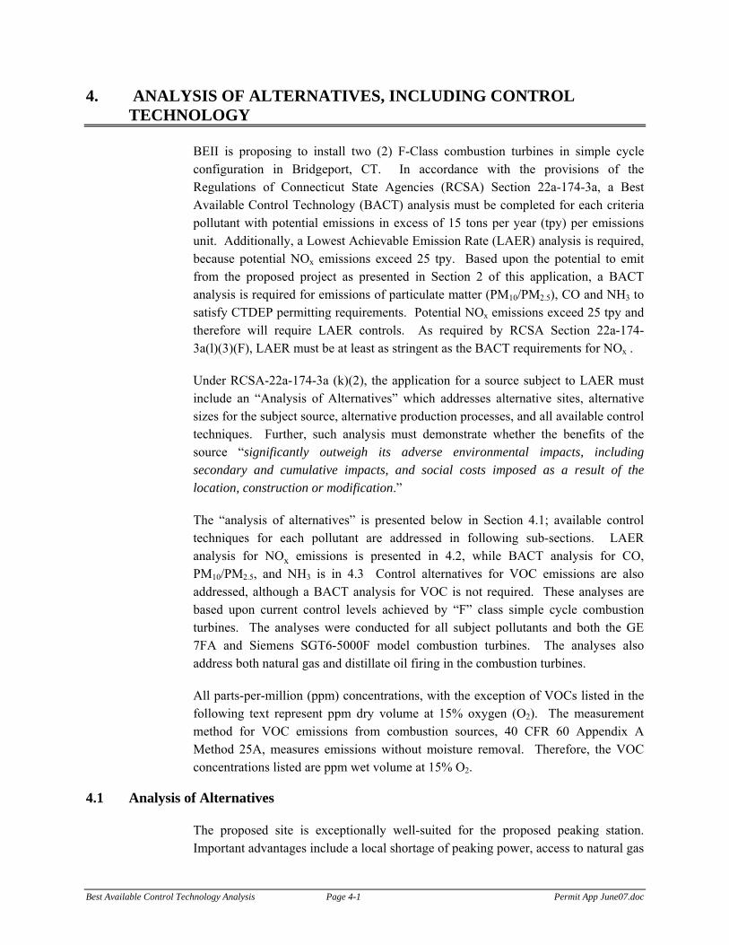
4. ANALYSIS OF ALTERNATIVES, INCLUDING CONTROL TECHNOLOGY
BEII is proposing to install two (2) F-Class combustion turbines in simple cycle configuration in Bridgeport, CT. In accordance with the provisions of the Regulations of Connecticut State Agencies (RCSA) Section 22a-174-3a, a Best Available Control Technology (BACT) analysis must be completed for each criteria pollutant with potential emissions in excess of 15 tons per year (tpy) per emissions unit. Additionally, a Lowest Achievable Emission Rate (LAER) analysis is required, because potential NOx emissions exceed 25 tpy. Based upon the potential to emit from the proposed project as presented in Section 2 of this application, a BACT analysis is required for emissions of particulate matter (PM10/PM2.5), CO and NH3 to satisfy CTDEP permitting requirements. Potential NOx emissions exceed 25 tpy and therefore will require LAER controls. As required by RCSA Section 22a-174-3a(l)(3)(F), LAER must be at least as stringent as the BACT requirements for NOx .
Under RCSA-22a-174-3a (k)(2), the application for a source subject to LAER must include an “Analysis of Alternatives” which addresses alternative sites, alternative sizes for the subject source, alternative production processes, and all available control techniques. Further, such analysis must demonstrate whether the benefits of the source “significantly outweigh its adverse environmental impacts, including secondary and cumulative impacts, and social costs imposed as a result of the location, construction or modification.”
The “analysis of alternatives” is presented below in Section 4.1; available control techniques for each pollutant are addressed in following sub-sections. LAER analysis for NOx emissions is presented in 4.2, while BACT analysis for CO, PM10/PM2.5, and NH3 is in 4.3 Control alternatives for VOC emissions are also addressed, although a BACT analysis for VOC is not required. These analyses are based upon current control levels achieved by “F” class simple cycle combustion turbines. The analyses were conducted for all subject pollutants and both the GE 7FA and Siemens SGT6-5000F model combustion turbines. The analyses also address both natural gas and distillate oil firing in the combustion turbines.
All parts-per-million (ppm) concentrations, with the exception of VOCs listed in the following text represent ppm dry volume at 15% oxygen (O2). The measurement method for VOC emissions from combustion sources, 40 CFR 60 Appendix A Method 25A, measures emissions without moisture removal. Therefore, the VOC concentrations listed are ppm wet volume at 15% O2.
4.1 Analysis of Alternatives
The proposed site is exceptionally well-suited for the proposed peaking station. Important advantages include a local shortage of peaking power, access to natural gas

Best Available Control Technology Analysis Page 4-2 Permit App June07.doc
on-site, proximity to the regional electrical transmission system through the adjacent Singer Substation being constructed as part of the electric transmission line improvements being made in Southwestern Connecticut, and existing (larger) generating facilities on adjacent sites. Fairfield County is recognized as an area with a chronic shortage of peak generating capacity, and the regional transmission system does not provide the transmission capacity to import sufficient power from outside the region to meet local demand. The proposed facility is located in an industrial area; the proposed use is consistent with current zoning and neighboring land uses. With adjacent electric generating and transmission facilities, the proposed peaking station will not alter the character of the neighborhood.
Since the proposed site is the only one under the ownership and control of the applicant, other sites were not evaluated. However, as the Connecticut Siting Council stated in its Review of the Ten Year Forecast of Connecticut Electric Loads and Resources 2006-2015, the “most critical and constrained transmission area in the state, as well as New England, is the 54 town region referred to as Southwest Connecticut. . . .” (page 19) Therefore, locating new generation assets in southwest Connecticut, and especially near new transmission facilities, like the Singer Substation, is the most efficient and effective way to address the critical need for additional peaking generation capacity in Southwest Connecticut. The proposed site is perfectly situated to address this important need.
The 350-MW capacity of the proposed peaking station will make a substantial contribution to meeting the local demand for peaking power, and represents the maximum capacity that can be accommodated on this site. The choice of two 175-MW F-Class turbines provides greater operating flexibility to meet peaking demand, compared to a single larger turbine, and provides greater fuel efficiency, compared to a larger number of smaller turbines. For example, the Siemens SGT6-5000F (simple cycle) achieves a nominal fuel efficiency of 37.7 %, compared to 34.2 % efficiency for the smaller (118 MW) SSC-3000F.
Dual-fuel simple-cycle turbines represent the optimal method of generating power to meet peak demand. The use of ULSD as a back-up fuel provides reliability during periods of high demand for natural gas. No alternative types of power generating facilities provide the necessary combination of rapid demand response, reliability, and fuel efficiency. Coal-fired boilers, nuclear generating facilities, hydropower and combined-cycle turbines require longer times for start-up and cannot respond rapidly to shifting demand. Wind and solar power are intermittent and are only available during favorable weather conditions.
Alternative control technologies are addressed below by pollutant in Sections 4.2 and 4.3.

Best Available Control Technology Analysis Page 4-3 Permit App June07.doc
The proposed peaking facility will provide important social benefits by helping to ensure an adequate supply of electrical power to Bridgeport and surrounding communities. Increased peaking capacity in Fairfield County has been identified by ISO-New England, the Connecticut Department of Public Utility Control, and the Connecticut Siting Council as a critical need. At the proposed site, the peaking station will have minimal impact on the neighboring community. The installation of SCR to control NOx emissions and the acquisition of emissions offsets at 1.3 to one will minimize Project impacts on regional ozone levels. The dispersion modeling analysis will ensure that cumulative impacts on ambient air quality for CO, PM and SO2 are acceptable.
4.2 Lowest Achievable Emission Rate (LAER) Analysis for Nitrogen Oxide
BEII will be a new major source of potential NOx emissions in excess of 25 tpy. Therefore, the Project is subject to NNSR for NOx including application of LAER controls. LAER is defined as “the most stringent emission limitation contained in the implementation plan of any state for such class or category of source unless the owner or operator of the proposed source demonstrates that such limitations are not achievable, or the most stringent emission limitation achieved in practice by such class or category of source.”3
LAER is expressed as an emission rate and may be achieved from one or more of the following emissions reduction methods:
• Change in raw material(s);
• Process modification(s); and
• Installation of add-on pollution controls.
In determining LAER, the Project evaluated CTDEP’s and EPA’s recommended sources of information, specifically:
• State Implementation Plan (SIP) limits for the appropriate class or category of sources;
• Preconstruction and/or operating permits issued; and
• The Reasonably Available Control Technology (RACT)/BACT/LAER Clearinghouse (RBLC).
3 EPA, Office of Air Quality Planning and Standards, “New Source Review Workshop Manual,” October 1990, p. G.2; Section 171(3) of the Federal Clean Air Act.

Best Available Control Technology Analysis Page 4-4 Permit App June07.doc
In addition to the sources of information listed above, a review of EPA’s National Combustion Turbine Projects Spreadsheet4 (last updated 07/20/2004) was also conducted. Following is an analysis of each emissions limiting option and applicable NOx emission limits for other “F” class simple-cycle CTG facilities.
4.2.1 Evaluation of Emissions Limiting Techniques
NOx is formed during the combustion of fuel in the turbine. The formation of NOx from combustion is generally classified as either thermal NOx or fuel-related NOx. Thermal NOx results when atmospheric nitrogen is oxidized at high temperatures to yield NO, NO2, and other oxides of nitrogen. Fuel-related NOx is formed from the oxidization of chemically bound nitrogen in the fuel.
Reductions in NOx emissions can be achieved using combustion controls or add-on controls or a combination of these control techniques. Available combustion controls for CTGs include water or steam injection and DLN combustors. The application of add-on controls for simple-cycle CTGs is limited. Selective catalytic reduction (SCR) is a commonly used add-on control technology for combustion turbines operating in combined-cycle mode. Combined-cycle turbines allow for installation of the SCR at its ideal operating temperature within a heat recovery steam generator (HRSG). Simple-cycle turbines do not include a HRSG and consequently exhaust temperatures are significantly higher. Additionally, “F” class combustion turbines have higher exhaust rates than smaller, less efficient, combustion turbines, which further complicates the application of SCR. As a result of these high exhaust temperatures, there has been very limited application of SCR on “F” Class simple cycle combustion turbines.
4.2.1.1 Change in Raw Materials
Limiting emissions through a change in raw materials is typically considered for industrial processes that use chemicals where substitution with a lower emitting chemical may be feasible. In this case, the “raw material” is a fuel to be combusted for the generation of electricity. The lowest emitting fuel for combustion processes is natural gas. Natural gas contains virtually no fuel bound nitrogen thereby eliminating this portion of NOx from the combustion process. CTG manufacturers have also made significant technological improvements in DLN combustor design using a lean pre-mix fuel injection system to minimize thermal NOx formation.
The Project will fire natural gas as the primary fuel resulting in the lowest NOx emissions from the CTG. In addition to natural gas, BEII is proposing limited firing of distillate oil as backup fuel for the project. Distillate fuel firing is required as
4 http://www.epa.gov/ttn/catc/dir1/natlturb.xls

Best Available Control Technology Analysis Page 4-5 Permit App June07.doc
backup due to the constrained natural gas supply in New England and the critical power supply needs of Southwest Connecticut. Distillate oil firing will be limited to no greater than 500 hours per rolling 12-month period for each combustion turbine. Additionally, ultra-low sulfur diesel (ULSD) distillate oil will be used by the project. ULSD has been shown to contain lower amounts of fuel-bound nitrogen than standard diesel fuel and may help to lower NOx emissions as compared to other distillate oil simple cycle combustion turbines.
4.2.1.2 Process Modifications
Process modifications are typically considered for industrial processes that use chemicals where a change in the process methods or conditions may result in lower emissions. In this case, the “process” is a combustion turbine firing natural gas. The Project will use either GE 7FA or Siemens SGT6-5000F combustion turbines equipped with lean pre-mix DLN combustors, which is the lowest NOx emitting combustion technology for “F” class combustion turbines that is commercially available
The formation of both thermal and fuel NOx depend upon combustion conditions. In a conventional combustor, the fuel and air are introduced directly into the combustion zone with fuel-air mixing and combustion taking place simultaneously. This approach does not optimize fuel-air mixing and results in fuel-rich pockets that produce areas of high temperatures causing increased thermal NOx emissions.
In a DLN combustor, lean combustion techniques are utilized to reduce peak temperatures in the combustor and thereby minimize NOx formation. In a lean premixed combustor design, the air and fuel are premixed at very lean air-to-fuel ratios prior to introduction in the combustion zone. The premixing of the air and fuel results in a homogeneous mixture that minimizes local fuel-rich zones. In addition, the excess air in the lean mixture acts as a heat sink that further minimizes peak combustion temperatures and thermal NOx formation.
The combustion turbines will also incorporate advanced combustion control systems to monitor combustor operation and ensure efficient combustion. The combination of lean pre-mix DLN combustors with advanced combustion controls will limit NOx emissions at the proposed operating loads. The Project has, therefore, selected the lowest NOx emitting combustion turbines available.
4.2.1.3 Add-On Controls
Add-on controls can be classified as either front-end or back-end controls. Add-on controls for combustion turbines have historically been back-end applications. A front-end control currently being researched for combustion turbines is catalytic combustion. Catalytic combustion uses an oxidation catalyst within the combustor to

Best Available Control Technology Analysis Page 4-6 Permit App June07.doc
oxidize the fuel at a lower temperature and consequently lower NOx emissions. At this time, catalytic combustion is available for very small turbines (<3MW) but not for the “F” Class machines proposed for the project. At this time there are no commercially available front-end controls available for large combustion turbines and therefore, front-end controls were eliminated as a LAER control option.
Back-end controls remove NOx from the exhaust gas stream once NOx has been formed. The most efficient and widely used NOx control technology for combustion turbines is SCR. SCR technology uses ammonia (NH3) to reduce NOx to N2 and H2O in the presence of a catalyst. The reactions that occur in an SCR system are:
4NO + 4NH3 + O2 4N2 + 6H2O, and
2NO2 + 4NH3 + O2 3N2 + 6H2O
An SCR system is composed of an ammonia storage tank, ammonia forwarding pumps and controls, an injection grid (a system of nozzles that spray ammonia into the exhaust gas ductwork), a reactor that contains the catalyst, and instrumentation and controls. The injection grid disperses NH3 in the flue gas upstream of the catalyst, where NH3 and NOx are reduced to nitrogen (N2) and water (H2O).
To maximize NOx reduction, ammonia is generally injected into the SCR in excess of stoichiometric amounts. This results in some unreacted ammonia that passes through the SCR reactor and is exhausted to the atmosphere. This ammonia that passes through the SCR unreacted is called the “ammonia slip.”
SCR systems are common on combustion turbines operating in combined-cycle mode and have been applied to smaller simple cycle combustion turbines. There has been very limited application of SCR on larger “F” class combustion turbines. The primary technical concern for implementing an SCR system on an “F” class combustion turbine in simple-cycle mode is the very high exhaust gas temperature, which can exceed 1,200°F during certain operating conditions. The upper end operating temperature of SCR systems is typically 850°F, which is several hundred degrees below the maximum exhaust temperature of an “F” class combustion turbine.
The GE 7FA and Siemens SGT6-5000F combustion turbines proposed by the Project will have exhaust gas temperatures as high as 1,200°F and typically greater than 1,100°F as documented in Appendix B of this application. These temperatures greatly exceed the upper end operating temperature of SCR systems. Therefore, in order to operate an SCR system on the proposed combustion turbines, a cooling air system will be required to lower the exhaust temperature below the maximum operating temperature of the SCR.
A review of available sources of information, as described in Section 4.1, identified only two simple cycle combustion projects that incorporated SCR with a cooling air

Best Available Control Technology Analysis Page 4-7 Permit App June07.doc
system. The first installation of SCR with a cooling air system was at the Puerto Rico Electric Power Authority (PREPA) Central Cambalache facility in Arecibo, Puerto Rico. The PREPA facility operates three ABB GT11N turbines firing No. 2 oil only (≤0.2 wt% S). An SCR system was installed on these turbines to reduce NOx emissions from 42 ppm down to 10 ppm.
From July 1997 through September 2001, the SCR systems failed to operate as designed despite the efforts of PREPA, the combustion turbine provider (ABB Alstom), and the catalyst manufacturer (Englehard). The expected cause of the SCR system failure was catalyst poisoning due to high SO2 emissions resulting in sulfuric acid mist (H2SO4) emissions as well as emissions of heavy metals. In September 2001, the EPA and PREPA agreed to remove the SCR systems and the facility’s permit was revised to the uncontrolled NOx emission level of 42 ppm.
The second known installation of an SCR with cooling air system is at the Riverside Generating Company facility in Frankfort, KY. The facility operates five Siemens 501F combustion turbines, which are equivalent to the Siemens SGT6-5000F turbines, that fire natural gas only. Two of the five combustion turbines are equipped with SCR systems. However, a review of the facility’s air permit shows that the NOx emission limit for all five combustion turbines is the same at 20 ppm. Further review of the permit indicates that the facility voluntarily elected to install SCR on two of the turbines so that operating hours could be increased without triggering the PSD threshold of 250 tpy for NOx emissions.
A review of annual Acid Rain emissions data was conducted to determine the NOx emission level achieved by the two turbines at Riverside Generating that are equipped with SCR. This review showed that the NOx emission level for these two turbines was equivalent to the NOx emission level achieved by the other three turbines without SCR. The lowest annual NOx emission level achieved by the two turines with SCR since their initial operation in 2001 was 0.06 pounds per million BTU, or roughly 16 ppm. This data indicates that these two turbines have operated very little with operation of the SCRs.
In summary, there are no known successful applications of SCR on a large “F” class combustion turbine in simple cycle mode for an extended period of time. However, the installation of SCR at the Riverside Generating facility in Kentucky and discussions with SCR vendors indicates that the application of SCR to the project is technically feasible. The utilization of ULSD should mitigate the SCR catalyst poisoning concerns that occurred at the PREPA facility. A cooling air system will be necessary to prevent thermal degradation of the SCR catalyst such that the temperature at the catalyst face must not exceed 850°F based upon a maximum exhaust gas temperature of 1200°F.

Best Available Control Technology Analysis Page 4-8 Permit App June07.doc
4.1.2 Sources Consulted to Determine LAER
A review of the RBLC and other known preconstruction permits for large gas-fired simple cycle combustion turbine projects was conducted to evaluate permitted BACT and LAER NOx emission rates since the beginning of 2002. Provided in Table 4-1 is a summary of known BACT and LAER NOx emission rates for projects permitted since the beginning of 2000.
All of the limits identified in Table 2-1 are BACT limits with the exception of the Sithe West Medway project in Massachusetts, which was a LAER project for NOx emissions. Based upon these projects, the lowest permitted NOx emission limit for an “F” class simple cycle combustion turbine project identified is 9 ppm on a one-hour basis for natural gas and 42 ppm on a three-hour basis for oil.

Best Available Control Technology Analysis Page 4-9 Permit App June07.doc
Table 4-1: Recent NOx Permit Limits for Large Simple Cycle Projects
NOx (ppm) Facility Permit Date
Combustion Turbine Gas Oil
Controls
Faribault Energy Park - MN 07/2004 Mitsubishi 501F 25 (3-hr) 42 (3-hr) DLNC / WI
Cass County Power – NE 06/2004 West. 501F 20 NA DLNC
Currant Creek Power – UT 05/2004 GE 7FA 9 (18-hr) NA DLNC
Broad River Energy – SC 05/2003 GE 7FA 9 12 w/ P.A.
42 DLNC / WI
Chickahominy Power – VA 01/2003 Siemens 501F 15 NA DLNC
White Oak Power – VA 08/2002 GE 7FA 9 NA DLNC
Sithe West Medway – MA 04/2002 GE 7FA 9 (1-hr) NA DLNC
Rowan Generating – NC 01/2002 GE 7FA 9 (24-hr) 42 (24-hr) DLNC / WI
Note: EPA’s National Combustion Turbine Projects Spreadsheet incorrectly lists the following combined-cycle projects as simple-cycle: ExxonMobil – TX (06/13/03); BP Amoco Chemical – TX (03/24/03); OxyVinyls, LP – TX (12/20/02); Hartburg Power – TX (07/05/02); Connectiv Bethlehem North – PA (11/16/02); Mobil Oil – TX (03/14/00); and Lost Pines Power – TX (09/30/99).
4.1.3 LAER Proposal
Based upon this review of available control technologies and previously permitted “F” class simple-cycle combustion turbine projects, BEII proposes to incorporate the following NOx emission controls to achieve LAER for the project:
1. Utilize natural gas as the primary fuel restricted to ≤2,500 hr/yr/turbine (5,000 hr/yr both turbines combined); and
2. Restricted use of ULSD as backup fuel restricted to ≤500 hr/yr/turbine (1,000 hr/yr both turbines combined); and
3. DLN Combustors to limit NOx emissions during both natural gas and ULSD firing; and
4. Water Injection to limit NOx emissions during ULSD firing; and
5. Post-combustion control with a dilution air system and Selective Catalytic Reduction.
The application of these controls will achieve the following NOx emission levels:
• 3.0 ppm on a 3-hr block average basis during natural gas firing; and

Best Available Control Technology Analysis Page 4-10 Permit App June07.doc
• 15 ppm on a 3-hr block average basis during ULSD firing.
The proposed controls and emission limits represent the most stringent NOx controls on an “F” class simple cycle combustion turbine project in the United States. By definition, these proposed controls meet LAER requirements.
4.3 BACT Analysis
Connecticut’s air regulations require the application of BACT for each regulated pollutant emitted from a project that exceeds the thresholds listed in Table 3-1, or for any regulated pollutant emitted by an individual emissions unit at greater than 15 tpy. The pollutants subject to Connecticut’s BACT requirements are SO2, CO, PM10/PM2.5, and NH3.
BACT is defined in Connecticut’s regulations as “an emissions limitation...based on the maximum degree of reduction for each applicable pollutant emitted...which the commissioner, on a case-by-case basis, determines is achievable. The commissioner shall take into account energy, economic, and environmental impacts, including secondary and cumulative impacts, and other costs”.
The CT DEP requires a “top-down” approach to BACT analysis. The process begins with the identification of control technology alternatives for each pollutant. Technically infeasible technologies are eliminated and the remaining technologies are ranked by control efficiency. These technologies are evaluated based on economic, energy and environmental impacts. If an alternative, starting with the most stringent, is eliminated based on these criteria, the next most stringent technology is evaluated until BACT is selected.
A BACT analysis is presented below for emissions of SO2, CO, and PM10/PM2.5 from the Project. Because the more stringent LAER is applied to NOx, the LAER analysis for NOx is presumed to meet BACT requirements and therefore no additional BACT information is provided for NO2. The same sources of information reviewed to determine LAER for NOx emissions as described in Section 4.1 were reviewed to determine BACT for each subject pollutant.
4.3.1 Sulfur Dioxide (SO2)
SO2 is emitted from combustion turbines as a result of the oxidation of the sulfur in the fuel. Therefore, utilization of low sulfur fuels is the simplest and best means for limiting SO2 emissions. Natural gas generally has the lowest sulfur content of all fossil fuels. Based on the maximum expected sulfur content in the natural gas supply (0.5 grain/100 scf), SO2 emissions during gas firing will not exceed 0.0012 lb/MMBtu. The facility will use ULSD oil with a maximum sulfur content of no greater than 15 ppm (≤0.0015 wt%), which is equivalent to an SO2 emission rate of 0.0015 lb/MMBtu. These are the lowest fuel sulfur limits identified for each fuel

Best Available Control Technology Analysis Page 4-11 Permit App June07.doc
type during review of the sources consulted to determine BACT. Add-on pollution controls (such as scrubber systems) for SO2 reduction have never been applied to a combustion turbine. The extremely high gas flow rate and low fuel sulfur produce a very dilute exhaust gas stream, which makes add-on control both technically and economically unfeasible.
Therefore, the use of natural gas as the primary fuel and limited firing of ULSD represents BACT for control of SO2 emissions from the project.
4.3.2 Carbon Monoxide (CO) and Volatile Organic Compounds (VOC)
CO and VOC are emitted from combustion turbines as a result of incomplete oxidation of the fuel. Similar to NOx emissions, these pollutants are minimized by the use of proper combustor design and good combustion practices. The BACT analysis for CO includes discussion of VOC, since the same control methods are appropriate for both.
In reviewing the BACT alternatives for the Project, two CO control techniques have been considered: efficient combustion resulting from proper design and operation of the turbine; and catalytic oxidation add-on control technology.
The most stringent CO control technology is a catalytic oxidation system. This system is a passive reactor that consists of a honeycomb grid of metal panels coated with a platinum catalyst. The catalyst grid is placed in the engine exhaust where the optimum reaction temperature can be maintained (>500°F). In these systems, typically 80-90 percent of the CO is oxidized to CO2. In addition, the catalyst may provide some reduction in VOC emissions dependent upon the specific organic species in the turbine exhaust.
A review of available sources of information did not identify any “F” class simple cycle combustion turbine projects that were required to install an oxidation catalyst. There are potentially significant environmental impacts associated with the use of a catalytic oxidation system because of the oxidation of SO2 to SO3. Catalyst vendors predict that from 20 to 80 percent of the SO2 in the turbine exhaust will be further oxidized to SO3 by the catalyst, depending upon its actual operating temperature. The additional SO3 will most likely react with water to form H2SO4 or with the ammonia slip to form ammonium salts. Each of these two pollutants will most certainly be emitted in the form of PM10/PM2.5. Bridgeport is located in an area designated as non-attainment for the current PM2.5 national ambient air quality standard (NAAQS). EPA has recently proposed to lower the PM2.5 NAAQS in half in order to provide greater protection of public health. Therefore, an oxidation catalyst would increase emissions of PM2.5 in an area that is currently designated as non-attainment and may have difficulty achieving attainment of the newly proposed standard.

Best Available Control Technology Analysis Page 4-12 Permit App June07.doc
The project is located in an area that is in attainment with the CO NAAQS. Based upon preliminary air dispersion modeling data, the maximum predicted ambient air concentrations of CO from the project will be well below the PSD Significant Impact Levels (SILs) based upon the proposed BACT emission rates. This result is expected to be formalized when the final air dispersion modeling analysis is submitted under separate cover. Therefore, the CO emissions from the project, without add-on controls, are presumed not to cause or contribute to a PSD increment or NAAQS violation and to have essentially no impact on the existing air quality for CO. Assuming the additional SO3 was completely converted to H2SO4/PM2.5, there would be an increase in potential H2SO4/PM2.5 emissions of more than 10 tpy. Therefore, installation of an oxidation catalyst would reduce emissions of one pollutant that is having no impact on the existing air quality and increase emissions of a secondary pollutant in an area that is designated as non-attainment for that secondary pollutant.
The performance penalty associated with a CO catalyst system represents a further dis-benefit of add-on control. The estimated performance loss (0.12 percent) has the effect of increasing emissions of all other pollutants, per kW of electrical power delivered to the grid. From a greenhouse gas perspective, it would require an increase of 7 lb of CO2 emissions, for every lb of CO controlled, to make up for this performance loss.
A cost to control analysis was also conducted for the application of an oxidation catalyst on the turbines. This analysis, as presented in Appendix B, shows that the CO cost to control for the turbines is between $7,300/ton and $7,800/ton. These costs are based upon a baseload control level of 1 ppm during gas firing. This cost to control is excessive for the control of CO emissions.
Taking into account that no known large combustion turbine simple-cycle project has installed an oxidization catalyst, the catalyst will result in a net negative impact to the environment, and the excessive cost to control, an oxidation catalyst was determined to not be BACT for the project.
The next level of control for CO/VOC emissions is efficient combustion control. As discussed previously, the combustion turbines proposed for the Project incorporate state of-the-art DLN combustors and advanced combustion controls to maximize combustion efficiency and minimize CO/VOC emissions. The proposed BACT CO/VOC emission levels (at 15% O2) for the project are as follows:
GE 7FA Turbines
• CO ≤8.0 ppm 3-hr block average, natural gas firing;
• CO ≤16.0 ppm 3-hr block average, ULSD firing;

Best Available Control Technology Analysis Page 4-13 Permit App June07.doc
• VOC ≤1.1 ppm, natural gas firing; and
• VOC ≤3.9 ppm, ULSD firing.
Siemens SGT6-5000F Turbines
• CO ≤4.5 ppm 3-hr block average, natural gas firing;
• CO ≤12.0 ppm 3-hr block average, ULSD firing;
• VOC ≤0.9 ppm, natural gas firing;
• VOC ≤4.6 ppm, ULSD firing.
4.3.3 Particulate Matter (PM10/PM2.5)
Emissions of particulate matter result from trace quantities of ash (non-combustibles) in the fuel. Particulate emissions will be minimized by use of natural gas as the primary fuel with limited firing of ULSD, which contains virtually no ash. There are no applications of particulate matter add-on controls on combustion turbines due to the already low emissions from combustion turbines and the large exhaust volume. The proposed PM10/PM2.5 emissions from both the GE 7FA and Siemens SGT6-5000F combustion turbines, based upon vendor guarantees, are as follows:
GE 7FA Turbines
• ≤0.011 lb/MMBtu, natural gas firing;
• ≤0.023 lb/MMBtu, ULSD firing.
Siemens SGT6-5000F Turbines
• ≤0.0083 lb/MMBtu, natural gas firing;
• ≤0.035 lb/MMBtu, ULSD firing.
4.3.4 Ammonia (NH3)
Ammonia is used in the SCR systems for the reduction of NOx emissions as described in Section 4.1.1.3. Some of the injected NH3 will pass through the SCR catalyst unreacted and be emitted to the atmosphere. This unreacted NH3 is referred to as the SCR’s “ammonia slip”. The ammonia slip is limited by proper SCR design and NH3 injection control systems. BEII proposes to limit the ammonia slip to 6 ppm based upon vendor specification for the system.

Best Available Control Technology Analysis Page 4-14 Permit App June07.doc
4.4 Proposed Project Emissions Summary
Tables 4-2 and 4-3 summarize the proposed LAER/BACT emission rates and the annual emissions for criteria pollutants from the GE 7FA and Siemens SGT6-5000F combustion turbines, respectively. The resulting annual emissions from these BACT emission rates were presented in Tables 2-5 and 2-6.

Best Available Control Technology Analysis Page 4-15 Permit App June07.doc
Table 4-2: GE 7FA LAER and BACT Emission Rates
Pollutant Fuel ppm(1) (lb/MMBtu)(1) lb/hr(2)
Nat. Gas 3.0 (3-hr) 0.011 22.0 NOx
ULSD 15.0 (3-hr) 0.058 123.0
Nat. Gas 8.0 (3-hr) 0.018 36.0 CO
ULSD 16.0 (3-hr) 0.038 80.0
Nat. Gas 1.1 (1-hr) 0.0017 3.4 VOC
ULSD 3.9 (1-hr) 0.0059 12.5
Nat. Gas NA 0.011 15.0 PM/PM10/PM2.5
ULSD NA 0.023 34.0
Nat. Gas NA 0.0012 2.23 SO2
ULSD NA 0.0015 3.24 Notes:
(1) For all operating loads above 50% of full load. (2) Maximum hourly emission rate per turbine based on an ambient temperature of 3°F.
Table 4-3: Siemens SGT6-5000F LAER and BACT Emission Rates
Pollutant Fuel ppm(1) (lb/MMBtu) lb/hr(2)
Nat. Gas 3.0 (3-hr) 0.011 25.0 NOx
ULSD 15.0 (3-hr) 0.058 125.0
Nat. Gas 4.5 (3-hr) 0.010 23.0 CO
ULSD 12.0 (3-hr) 0.0285 61.0
Nat. Gas 0.9 (1-hr) 0.0014 3.2 VOC
ULSD 4.6 (1-hr) 0.0070 15.0
Nat. Gas NA 0.0083 12.0 PM/PM10/PM2.5
ULSD NA 0.035 60.0
Nat. Gas NA 0.0012 2.6 SO2
ULSD NA 0.0015 3.3 Notes:
(1) For all operating loads above 75% of full load. (2) Maximum hourly emission rate per turbine based on an ambient temperature of 3°F.

Appendix A
CTDEP Application Forms
Application Forms
Public Notice in this Appendix
DEP-AIR-APP-200 in this Appendix
Attachment A: Executive Summary in this Appendix
Attachment B: Applicant Background Information in this Appendix
Attachment C: Site Plan provided in Appendix C
Attachment D: USGS Map and Latitude/Longitude Form Map provided in report as Figure 1-1; Lat/Lon Form included in this Appendix
Attachment E: Supplemental Application Forms
Stack Parameters (AIR-APP-211) - in this Appendix
Unit Emissions-(AIR-APP-212) – in this Appendix. Details in Appendix B
Air Pollution Control Equipment-(AIR-APP-210)-in this Appendix
Fuel Burning Equipment (AIR-APP-202) - in this Appendix
Volatile Liquid Storage (APP-204) - in this Appendix
Attachment F: Major Premise Pollutant Summary not applicable (new facility)
Attachment G: BACT Determination information provided in Section 4 of report
Attachment H: Emergency Episode Standby Plan in this Appendix
Attachment I: Operation and Maintenance Plan in this Appendix
Attachment J: Ambient Air Quality Analysis provided under separate cover
Attachment K: Applicant Compliance Information in this Appendix
Attachment L: Conformance Certification in this Appendix


Bureau of Air Management DEP-AIR-APP-200 1 of 6 Rev. 08/21/03
Permit Application for New Source Review Stationary Sources of Air Pollution
Please complete this form in accordance with CGS Section 22a-174, RCSA Sections 22a-174-1 and 3, and the instructions (DEP-AIR-INST-200). Print or type unless otherwise noted. Part I: Application and Source Type
Please read the instructions (DEP-AIR-INST-200) in order to properly complete the table below. Please reproduce this page if additional space is necessary. You may apply for more than one permit on one application if the sources originate from the same premise. Each unit or process line requires a separate permit.
DEP Use Only
Unit No. Source Type
App. Type (N, R, M)
If renewal or modification,
indicate existing permit/reg. no. Application No. Permit No. EPE No.
U1
fuel burn
N
U2
fuel burn
N

Bureau of Air Management DEP-AIR-APP-200 2 of 6 Rev. 08/21/03
Part II: Fee Information
Please note: effective August 21, 2003 an initial fee of $750.00 is to be submitted for each permit that you are applying for. Each unit or process line requires a separate permit. For municipalities, the 50% discount applies. The application will not be processed without the initial fee. If a permit is required, an invoice will be sent for the permit fee. See RCSA Section 22a-174-26 for information regarding the amount of the permit fee.
Part III: Applicant Information
1. Fill in the name of the applicant(s) as indicated on the Permit Application Transmittal Form (DEP-APP-001). Applicant: Bridgeport Energy II, LLC
Applicant's interest in property at which the proposed activity is to be located:
site owner option holder lessee
easement holder operator other (specify)
Enter a check mark if there are co-applicants. If so, label and attach additional sheet(s) with the required information as supplied above.
2. List primary contact for departmental correspondence and inquiries, during processing of application, if
different than the applicant.
Name: Earth Tech, Inc. Mailing Address: 300 Baker Avenue, Suite 290
City/Town: Concord State: MA Zip Code: 01742-
Business Phone: 978-371-4258 ext. Fax: 978-371-2468
Contact Person: Richard Londergan Title: Senior Program Director 3. List primary contact for departmental correspondence and inquiries, after permit is issued, if different than
the applicant.
Name:
Mailing Address:
City/Town: State: Zip Code: -
Business Phone: - - ext. Fax: - -
Contact Person: Title: 4. List attorney or other representative, if applicable.
Firm Name: Murtha Cullina LLP
Mailing Address: City Place I, 185 Asylum Street
City/Town: Hartford State: CT Zip Code: 06103-3469
Business Phone: 860-240-6034 ext. Fax: 860-240-5834
Attorney Name: Mark Sussman Title: Attorney

Bureau of Air Management DEP-AIR-APP-200 3 of 6 Rev. 08/21/03
Part III: Applicant Information (continued)
5. List equipment operator, if different than the applicant.
Name:
Mailing Address:
City/Town: State: Zip Code: -
Business Phone: - - ext. Fax: - -
Contact Person: Title: 6. List equipment owner, if different than the applicant.
Name:
Mailing Address:
City/Town: State: Zip Code: -
Business Phone: - - ext. Fax: - -
Contact Person: Title: 7. List any engineer(s) or other consultant(s) employed or retained to assist in preparing the application or in
designing or constructing the activity. Please enter a check mark if additional sheets are necessary, and label and attach them to this sheet. Name: Earth Tech, Inc.
Mailing Address: 300 Baker Avenue, Suite 290
City/Town: Concord State: MA Zip Code: 01742-
Business Phone: 978-371-4258 ext. Fax: 978-371-2468
Contact Person: Richard Londergan Title: Senior Program Director
Service Provided: Environmental Consultant
Part IV: Premise Information
1. Name of facility, if applicable: Bridgeport Peaking Station
Street Address or Description of Location: Atlantic Avenue at Russell Street City/Town: Bridgeport State: CT Zip Code: 06604-
Latitude and Longitude of the approximate "center of the site" in degrees, minutes, and seconds:
Latitude: 41 deg 10 min 05.16 s N Longitude: 73 deg 11 min 01.68 s W
Method of determination (check one): GPS USGS MAP other
If a USGS Map was used, provide the quadrangle name:
2. Is or will the premise be located on federally recognized Indian lands? Yes No

Bureau of Air Management DEP-AIR-APP-200 4 of 6 Rev. 08/21/03
Part IV: Premise Information (continued)
3. Identify the air quality attainment status of the area in which the premise is or will be located.
(Check all that apply. See instructions for the air quality attainment status of Connecticut municipalities).
Non-Attainment for Ozone Standard: Severe Serious
Carbon Monoxide:
Moderate Non-Attainment Unclassified Non-Attainment Unclassified Attainment
Non-Attainment for PM10: 4. SIC Codes:
Primary 4911 Secondary Other Other
Part V: Supporting Documents Be sure to read the instructions (DEP-AIR-INST-200) to determine whether the attachments listed are applicable to your specific activity. Please enter a check mark by the attachments as verification that all applicable attachments have been submitted with this Permit Application Form. When submitting any supporting documents, please label the documents as indicated in this Part (e.g., Attachment A, etc.) and be sure to include the applicant's name as indicated on the Permit Application Transmittal Form.
Attachment A: Executive Summary (DEP-AIR-APP-222)
Attachment B: Applicant Background Information (DEP-APP-008)
Attachment C: Site Plan
Attachment D: An 82" X 11" copy of the relevant portion, or a full size original, of a USGS Quadrangle Map indicating the exact location of the facility or site and, if applicable, Latitude and Longitude (DEP-APP-003)
Attachment E: Supplemental Application Forms
In the space provided by each supplemental application form, indicate the quantity of each form attached as part of this application. For each supplemental application form submitted, please provide a process flow diagram indicating all units, air pollution control equipment and stacks, as applicable. See sample diagram in instructions (DEP-AIR-INST-200).
Manufacturing or Processing Operations (DEP-AIR-APP-201): Attach a process
flow diagram indicating all units, air pollution control equipment, and stacks, as applicable.
Fuel Burning Equipment (DEP-AIR-APP-202): Attach a process flow diagram
indicating all units, air pollution control equipment, and stacks, as applicable.
Stationary Reciprocating Internal Combustion Engine - Compliance Assurance Form (DEP-AIR-COMP-001), if applicable.
Incinerators (DEP-AIR-APP-203): Attach a process flow diagram indicating all units,
air pollution control equipment, and stacks, as applicable. Also, attach documentation of waste heat contents and waste analysis.

Bureau of Air Management DEP-AIR-APP-200 5 of 6 Rev. 08/21/03
Part V: Supporting Documents (continued)
Attachment E: Supplemental Application Forms (continued)
Volatile Liquid Storage (DEP-AIR-APP-204): Attach a process flow diagram indicating all units, air pollution control equipment, and stacks, as applicable. Also, attach a MSDS for each product stored.
Surface Coating or Printing Operations (DEP-AIR-APP-205): Attach a process flow
diagram indicating all applicator identifications, air pollution control equipment, and stacks, as applicable. Also, attach a MSDS for each coating, ink, thinner, catalyst, cleanup solvent, or other compound to be used in this type of operation. Also, attach documentation to support transfer efficiency of spray applicators, if applicable.
Metal Plating and Surface Treatment Operations (DEP-AIR-APP-206): Attach a
process flow diagram indicating all units, air pollution control equipment, and stacks, as applicable. Also, attach a MSDS for each product stored in a tank.
Metal Cleaning Degreasers (DEP-AIR-APP-207): Attach a process flow diagram
indicating all units, air pollution control equipment, and stacks, as applicable. Also, attach a MSDS for each solvent used.
Concrete, Asphalt, Aggregate, Coal, Feed, Flour, & Grain (DEP-AIR-APP-208):
Attach a process flow diagram indicating all units, air pollution control equipment, and stacks, as applicable.
Site Remediation Equipment (DEP-AIR-APP-209): Attach a process flow diagram
indicating all units, air pollution control equipment, and stacks, as applicable. Also, submit documentation, such as pilot test data, which characterizes the site’s degree of contamination.
Air Pollution Control Equipment (DEP-AIR-APP-210), if applicable
Stack Parameters (DEP-AIR-APP-211)
Unit Emissions (DEP-AIR-APP-212): Attach all calculations by which emissions
were determined.
Attachment F: Major Premise Pollutant Summary (DEP-AIR-APP-213), if applicable
Attachment G BACT Determination Form (DEP-AIR-APP-214), if applicable
Attachment H: Emergency Episode Standby Plan, if applicable
Attachment I: Operation and Maintenance Plan, if applicable
Attachment J: Ambient Air Quality Analysis, if applicable
Attachment K: Applicant Compliance Information (DEP-APP-002)
Attachment L: Conformance Certification Form (DEP-AIR-APP-215)


Bureau of Air Management DEP-AIR-APP-222 1 of 2 Rev. 06/22/01
Attachment A: Executive Summary
Applicant Name as indicated on the Permit Application Transmittal Form (DEP-APP-001):
Bridgeport Energy II, LLC
Location of Facility or Activity: Atlantic Street and Russell Street, Bridgeport, CT 06640
Contact Person: Blake Wheatley Phone: 636-532-2200 For Renewals, Modifications, and Revisions provide the following:
Existing Permit or Registration #: Expiration Date: / / Provide a Table of Contents of the application which includes the Permit Application Transmittal Form (DEP-APP-001), the Permit Application Form (DEP-AIR-APP-100 or 200), and a list of all supplemental application forms, plans, drawings, reports, studies, or other supporting documentation which are attached as part of the application, along with the corresponding attachment label and the number of pages (e.g., Executive Summary - Attachment A - 4 pgs.). The attached Application Document contains the Executive Summary and Table of Contents, plus a narrative description of the proposed source and associated emission controls. Completed Application Forms, aside from APP-AIR-200 and APP-AIR-222, are provided in Appendix A of the Application Document. Bridgeport Energy II, LLC (BEII) is proposing to build and operate a new 350 MW nominal simple cycle combustion turbine generating facility in Bridgeport, CT. The combustion turbines will fire natural gas as the primary fuel with limited backup firing of ultra low sulfur diesel (ULSD) fuel oil. The project will be called the Bridgeport Peaking Station (BPS). The new facility will be located south of the existing Bridgeport Energy facility on a parcel adjacent to the western boundary of the existing Bridgeport Harbor Station property. The BEII facility will owned and operated separately from the existing Bridgeport Energy generating station. The Project will utilize either two (2) General Electric (GE) model 7FA or Siemens model SGT-5000F turbines. BEII is currently evaluating the availability and cost of these two turbines but has not yet made a final decision on turbine technology. Accordingly, this application presents information for both turbine models. BEII will provide the Connecticut Department of Environment Protection (CTDEP) with the selected turbine model prior to commencing construction. (continued next page)
(OVER)

Bureau of Air Management DEP-AIR-APP-222 2 of 2 Rev. 06/22/01
Attachment A: Executive Summary (continued)
Provide a brief project description which includes: a description of the proposed regulated activities; a synopsis of the environmental and engineering analyses; summaries of data analysis; a conclusion of any environmental impacts and the proposed timeline for construction. For renewals, modifications, and revisions, provide a list of changes in circumstances or information on which the previous permit was based. BEII is proposing to limit total annual operating hours and annual hours firing ULSD, and proposes to install selective catalytic reduction (SCR) to minimize NOx emissions. The application of these operation and pollution controls will limit emissions of all pollutants below the Prevention of Significant Deterioration (PSD) major source thresholds with the exception of CO and NOx. BPS will also be a non-attainment new source review (NNSR) new major source for NOx emissions with potential emissions above 25 tons per year (tpy). The NNSR regulations require that a new major source install Lowest Achievable Emission Rate (LAER) technology to reduce emissions to the lowest level technically feasible. Therefore, BEII has proposed to install SCR on the turbines to achieve the lowest NOx emissions of any simple-cycle “F” class turbine operating in the United States. Additionally, CTDEP regulations require the application of Best Available Control Technology (BACT) for any pollutants with a potential to emit above 15 tpy for any emission unit. A BACT analysis is also provided for emissions of SO2, particulate matter (PM/PM10/PM2.5), carbon monoxide, VOCs and ammonia (NH3). The two proposed combustion turbines will comprise the two primary air pollutant emission sources from the project. BPS will also include a 1.2 million gallon backup fuel oil tank that will have minor VOC emissions. The project will not include any supporting diesel fired emergency engines or cooling towers.
If additional sheets are necessary, please label and attach them to this sheet and enter a check mark.

DEP-APP-008 1 of 5 Rev. 07/11/01
Applicant Background Information
Please enter a check mark by the entity which best describes the applicant and complete the requested information. You must choose one of the following.
Corporation
1. Parent Corporation
Name:
Mailing Address:
City/Town: State: Zip Code: -
Business Phone: - - ext. Fax: - -
Contact Person: Title: 2. Subsidiary Corporation:
Name:
Mailing Address:
City/Town: State: Zip Code: -
Business Phone: - - ext. Fax: - -
Contact Person: Title: 3. Directors:
Name:
Mailing Address:
City/Town: State: Zip Code: -
Business Phone: - - ext. Fax: - -
Name:
Mailing Address:
City/Town: State: Zip Code: -
Business Phone: - - ext. Fax: - -
Please enter a check mark, if additional sheets are necessary. If so, label and attach additional
sheet(s) to this sheet with the required information as supplied above. 4. Officers:
Name:
Mailing Address:
City/Town: State: Zip Code: -
Business Phone: - - ext. Fax: - -
Please enter a check mark, if additional sheets are necessary. If so, label and attach additional
sheet(s) to this sheet with the required information as supplied above.

DEP-APP-008 2 of 5 Rev. 07/11/01
Applicant Background Information (continued) Limited Liability Company
1. List each member.
Name: LS Power Generation, LLC
Mailing Address: Two Tower Center, 11th Floor City/Town: East Brunswick State: NJ Zip Code: 08816-
Business Phone: 732-249-6750 ext. Fax: 732-249-7290
Name:
Mailing Address:
City/Town: State: Zip Code: -
Business Phone: - - ext. Fax: - -
Name:
Mailing Address:
City/Town: State: Zip Code: -
Business Phone: - - ext. Fax: - -
Please enter a check mark, if additional sheets are necessary. If so, label and attach additional
sheet(s) to this sheet with the required information as supplied above.
2. List any manager(s) who, through the articles of organization, are vested the management of the business, property and affairs of the limited liability company. Name: Paul G. Thessen, Executive Vice President Mailing Address: 400 Chesterfield Center, Suite 110
City/Town: St. Louis State: MO Zip Code: 63017-
Business Phone: 636-532-2200 ext. Fax: 636-532-2250
Name:
Mailing Address:
City/Town: State: Zip Code: -
Business Phone: - - ext. Fax: - -
Name:
Mailing Address:
City/Town: State: Zip Code: -
Business Phone: - - ext. Fax: - -
Please enter a check mark, if additional sheets are necessary. If so, label and attach additional
sheet(s) to this sheet with the required information as supplied above.

DEP-APP-008 3 of 5 Rev. 07/11/01
Applicant Background Information (continued) Limited Partnership
1. General Partners:
Name:
Mailing Address:
City/Town: State: Zip Code: -
Business Phone: - - ext. Fax: - -
Name:
Mailing Address:
City/Town: State: Zip Code: -
Business Phone: - - ext. Fax: - -
Name:
Mailing Address:
City/Town: State: Zip Code: -
Business Phone: - - ext. Fax: - -
Please enter a check mark, if additional sheets are necessary. If so, label and attach additional
sheet(s) to this sheet with the required information as supplied above.
2. Limited Partners:
Name:
Mailing Address:
City/Town: State: Zip Code: -
Business Phone: - - ext. Fax: - -
Name:
Mailing Address:
City/Town: State: Zip Code: -
Business Phone: - - ext. Fax: - -
Name:
Mailing Address:
City/Town: State: Zip Code: -
Business Phone: - - ext. Fax: - -
Please enter a check mark, if additional sheets are necessary. If so, label and attach additional
sheet(s) to this sheet with the required information as supplied above.

DEP-APP-008 4 of 5 Rev. 07/11/01
Applicant Background Information (continued) General Partnership
1. General Partners:
Name:
Mailing Address:
City/Town: State: Zip Code: -
Business Phone: - - ext. Fax: - -
Name:
Mailing Address:
City/Town: State: Zip Code: -
Business Phone: - - ext. Fax: - -
Name:
Mailing Address:
City/Town: State: Zip Code: -
Business Phone: - - ext. Fax: - -
Name:
Mailing Address:
City/Town: State: Zip Code: -
Business Phone: - - ext. Fax: - -
Name:
Mailing Address:
City/Town: State: Zip Code: -
Business Phone: - - ext. Fax: - -
Name:
Mailing Address:
City/Town: State: Zip Code: -
Business Phone: - - ext. Fax: - -
Name:
Mailing Address:
City/Town: State: Zip Code: -
Business Phone: - - ext. Fax: - -
Please enter a check mark, if additional sheets are necessary. If so, label and attach additional sheet(s) to this sheet with the required information as supplied above.

DEP-APP-008 5 of 5 Rev. 07/11/01
Applicant Background Information (continued) Voluntary Association
1. List authorized persons of association or list all members of association.
Name:
Mailing Address:
City/Town: State: Zip Code: -
Business Phone: - - ext. Fax: - - Name:
Mailing Address:
City/Town: State: Zip Code: -
Business Phone: - - ext. Fax: - - Name:
Mailing Address:
City/Town: State: Zip Code: -
Business Phone: - - ext. Fax: - - Name:
Mailing Address:
City/Town: State: Zip Code: -
Business Phone: - - ext. Fax: - - Name:
Mailing Address:
City/Town: State: Zip Code: -
Business Phone: - - ext. Fax: - -
Please enter a check mark, if additional sheets are necessary. If so, label and attach additional sheet(s) to this sheet with the required information as supplied above.
Individual or Other Business Type
1. Name:
Mailing Address:
City/Town: State: Zip Code: -
Business Phone: - - ext. Fax: - -
2. State other names by which the applicant is known, including business names.
Name:
Please enter a check mark, if additional sheets are necessary. If so, label and attach additional sheet(s) to this sheet with the required information as supplied above.

DEP-APP-003 1 of 1 Rev. 12/10/99
Latitude and Longitude Applicant Name: Bridgeport Energy II, LLC (as indicated on the Permit Application Transmittal Form) Method of latitude and longitude determination (check one):
Global Positioning System (GPS) USGS Map Other (please specify)
In the table below, label each point for which latitude and longitude were measured, being consistent with identification numbers assigned throughout the application (e.g., 100, 101, etc.). For renewals or modifications of existing permits, please provide the existing permit number. Also provide: a brief description of the point (e.g., monitoring well, pipe outlet, air stack, etc.); latitude and longitude in degrees, minutes and seconds (e.g., 41E 16' 29" ); and the name of the USGS quadrangle map(s) the points described are located on.
ID
Number
Permit
Number
Description
Latitude
Longitude Quad Map Name
For DEP Use Only: GIS ID
S1 Stack for Unit 1 41d 10m 06.08s N 73d 11m 00.53s W
S2 Stack for Unit 2 41d 10m 04.97s N 73d 11m 00.18s W

Bureau of Air Management DEP-AIR-APP-211 1 of 1 Rev. 06/22/01
Supplemental Application Form Stack Parameters
Applicant Name: Bridgeport Energy II, LLC (As indicated on Permit Application Transmittal Form) Section I. Stack Parameters (Make additional copies, if necessary)
Stack No. (1)
Unit No.(s)
(2)
Control
Equipment No.(s)
(3)
Height
ft. (4)
Diameter
ft. (5)
Temp
oF (6)
Flow
ACFM (7)
Exit Dir. H or
V (8)
Rain Hat Y or N
(9)
Stack Lining
(10)
Distance to Property Line
ft. (11)
S1
U1
C1
213.25
24.0
820
233,6645
V
N
N
56.
S2
U2
C2
213.25
24.0
820
233,6645
V
N
N
52.
DEP USE ONLY App. No.:
EPE No.:


Bureau of Air Management DEP-AIR-APP-210 1 of 7 Rev. 03/23/04
Supplemental Application Form Air Pollution Control Equipment
Applicant Name: Bridgeport Energy II, LLC (As indicated on Permit Application Transmittal Form) Section I. Summary Sheet (Make additional copies, if necessary)
Control Equipment
Unit Number
(1)
Unit Description
(2) No. (3)
Type (4)
Overall Control
Efficiency % (5)
Pollutants
Controlled (6)
*Basis
(7)
Stack No.
(8) U1
comb. turbine
C1
SCR
66.6 NG
NOx
manufacturer
S1
U1
comb. turbine
C1
SCR
64.3 oil
NOx
manufacturer
S1
U2
comb. turbine
C2
SCR
66.6 NG
NOx
manufacturer
S2
U2
comb. turbine
C2
SCR
64.3 oil
NOx
manufacturer
S2
* Attach supporting documentation with this form, e.g., stack test data, manufacturer’s guarantee, etc.
DEP USE ONLY App. No.:
EPE No.:

Bureau of Air Management DEP-AIR-APP-210 2 of 7 Rev. 03/23/04
Section II: Specific Control Equipment (Complete the appropriate subsection for each distinct piece of control equipment you utilize. You may reproduce the pages of the form as necessary.) Adsorption Device
1a. Designated Reference Number of Adsorption Unit:
1b. Designated Reference Number of Unit which uses Adsorber:
2. Manufacturer:
3. Model Name & Number:
4. Construction Date: / /
5. Adsorbent:
Activated Charcoal Type:
Other (specify):
6. Number of Beds:
7. Dimensions of Bed
Bed No.1
Thickness in direction of gas flow(inches): Cross-section area (sq. inches):
Bed No.2
Thickness in direction of gas flow(inches): Cross-section area (sq. inches):
Bed No.3
Thickness in direction of gas flow(inches): Cross-section area (sq. inches):
8. Inlet Gas Temperature: oF or oC
9. Design Pressure Drop Across Unit: inches H2O
10. Type of Regeneration
Replacement Steam Other (specify):
11. Method of Regeneration
Alternate use of beds Source shut down Other (specify):
Describe procedures used to ensure that emissions from regeneration process are treated or minimized:
12. Maximum Operation Time Before Regeneration:
13. Is adsorber equipped with a break-through detector? Yes No
14. a) Control Efficiency(s) of Adsorber (%):
b) Collection Efficiency(s) of Adsorber (%):
15. Pollutant(s) Controlled:

Bureau of Air Management DEP-AIR-APP-210 3 of 7 Rev. 03/23/04
Afterburner (Incinerator for Air Pollution Control)
1a. Designated Reference Number of Afterburner:
1b. Designated Reference Number of Unit which uses Afterburner:
2. Manufacturer:
3. Model Name & Serial Number:
4. Construction Date: / /
5. Type of Afterburner: Thermal Catalytic Other (specify):
6. Combustion Chamber Dimensions
Length (inches): Cross-section area (sq. inches):
7. Inlet Gas Temperature: oF or oC
8. Operating Temperature of Chamber: oF or oC
9. Type of Auxiliary Fuel: Higher Heating Value:
10. a)% Sulfur: b)% Ash: c)% Nitrogen:
11. Maximum Auxiliary Fuel Usage (specify units): a) Hourly:
b) Annually:
12. Number of Burners Per Afterburner:
Burner No. 1 @: BTU per hour
Burner No. 2 @: BTU per hour
Burner No. 3 @: BTU per hour
13. Catalyst Used: Yes No
Type of Catalyst:
14. Catalyst Sampling Interval:
15. Heat Exchanger Used: Yes No
Type of Heat Exchanger:
Heat Recovery:
16. Gas Flow Rate (scfm):
17. Combustion Chamber Design Residence Time (seconds):
18. Moisture Content of Exhaust Gas (%):
19. a) Control Efficiency of Afterburner (%):
b) Collection Efficiency of Afterburner (%):
20. Pollutant(s) Controlled:

Bureau of Air Management DEP-AIR-APP-210 4 of 7 Rev. 03/23/04
Condenser
1a. Designated Reference Number of Condenser Unit:
1b. Designated Reference Number of Unit which uses Condenser:
2. Manufacturer:
3. Model Name & Number:
4. Construction Date: / /
5. Heat Exchange Area (sq. ft.):
6. Coolant Flow Rate: Water: gpm Air: scfm (at 68o F)
Other (specify) : Type: Flow Rate:
7. Gas Flow Rate: scfm (at 68o F)
8. Coolant Temperature (oF): In: Out:
9. Gas Temperature (oF): In: Out:
10. a) Control Efficiency(s) of Condenser:
b) Collection Efficiency(s) of Condenser (%):
11. Pollutant(s) Controlled:
Electrostatic Precipitator
1a. Designated Reference Number of Electrostatic Precipitator:
1b. Designated Reference Number of Unit which uses Electrostatic Precipitator:
2. Manufacturer:
3. Model Name & Serial Number:
4. Construction Date: / /
5. Collecting Electrode Area (sq ft):
6. Gas Flow Rate (scfm):
7. Voltage Across the Precipitator Plates (kv):
8. Resistivity of Pollutants (ohms):
9. Number of Fields in the Precipitator:
10. Grain Loading (grains/scf @ 68o F): a) Inlet: b) Outlet:
11. a) Control Efficiency(s) of Electrostatic Precipitator (%):
b) Collection Efficiency(s) of Electrostatic Precipitator (%):
12. Pollutant(s) Controlled:

Bureau of Air Management DEP-AIR-APP-210 5 of 7 Rev. 03/23/04
Filter
1a. Designated Reference Number of Filter:
1b. Designated Reference Number of Unit which uses Filter:
2. Manufacturer:
3. Model Name & Serial Number:
4. Construction Date: / /
5. Filtering Material:
6. Air to Cloth Ratio (sq ft):
7. Cleaning Method: Shaker Reverse Air Pulse Air
Pulse Jet Other (specify):
8. Gas Cooling Method: Ductwork Length (ft): Diameter (inches):
Heat Exchanger Bleed-in Air Water Spray Other (specify):
9. Gas Flow Rate (from source): scfm (at 68� F)
10. Cooling Gas Flow Rate
Bleed-in Air: scfm (at 68� F) Water Spray: gpm
11. Inlet Gas Condition Temperature (�F): Dew Point (�F):
12. Grain Loading (grains/scf @ 68o F): a) Inlet: b) Outlet:
13. Design Pressure Drop Across Unit (inches H2O):
14. a) Control Efficiency of Filter (%):
b) Collection Efficiency of Filter (%):
15. Pollutant(s) Controlled:
Cyclone
1a. Designated Reference Number of Cyclone: 1b. Designated Reference Number of Unit which uses Cyclone: 2. Manufacturer: 3. Model Name & Serial Number: 4. Construction Date: / / 5. Type of Cyclone: Single Multiple 6. Number of Cyclones in Multiple Cyclone: 7. Gas Flow Rate: scfm (at 68o F) 8. Grain Loading (grains/SCF @ 68o F): a) Inlet: b) Outlet: 9. Design Pressure Drop Across Unit (inches H2O): 10. a) Control Efficiency of Cyclone (%):
b) Collection Efficiency of Cyclone (%): 11. Pollutant(s) Controlled:

Bureau of Air Management DEP-AIR-APP-210 6 of 7 Rev. 03/23/04
Scrubber
1a. Designated Reference Number of Scrubber:
1b. Designated Reference Number of Unit which uses Scrubber:
2. Manufacturer:
3. Model Name & Serial Number:
4. Construction Date: / /
5. Type of Scrubber: Venturi Wet Fan
Packed: Packing Material:
Size: Packed Height (inches):
Spray: Number of Nozzles:
Nozzle No. 1 Pressure (psig):
Nozzle No. 2 Pressure (psig):
Nozzle No. 3 Pressure (psig):
Nozzle No. 4 Pressure (psig):
Other (specify): (Attach description and sketch with dimensions)
6. Design Pressure Drop Across the Scrubber (inches H2O):
7. Type of Flow: Concurrent Countercurrent Crossflow
8. Scrubber Geometry
Length in direction of Gas Flow (ft): Cross Sectional Area (sq ft):
9. Chemical Composition of Scrubbing Liquid:
10. a. Scrubbing Liquid Flow Rate (gpm):
b. Fresh Liquid Make-Up Rate (gpm):
11. Scrubber Liquid: One Pass Recirculated
12. Gas Flow Rate: scfm (at 68� F)
13. Inlet Gas Temperature (oF):
14. a) Control Efficiency(s) of Scrubber (%):
b) Collection Efficiency(s) of Scrubber (%):
15. Pollutant(s) Controlled:

Bureau of Air Management DEP-AIR-APP-210 7 of 7 Rev. 03/23/04
Mist Eliminator
1a. Designated Reference Number of Mist Eliminator:
1b. Designated Reference Number of Unit which uses Mist Eliminator:
2. Manufacturer:
3. Model Name & Number:
4. Construction Date: / /
5. Face Velocity (feet per second):
Vertical Flow Horizontal Flow Diagonal
6. Design Pressure Drop Across Mist Eliminator (inches H2O):
7. a) Control Efficiency of Mist Eliminator at:
1 mm Hg: 5 mm Hg: 10 mm Hg:
b) Collection Efficiency of Mist Eliminator (%):
8. Pollutant(s) Controlled:
Other Type of Control Equipment for Degreasing Equipment
1a. Designated Reference Number of Equipment:
1b. Designated Reference Number of Unit which uses Equipment:
2. Manufacturer:
3. Model Name & Serial Number:
4. Construction Date: / /
5. Method of Controls
Refrigerator Chiller Water Spray Other (specify):
6. a) Control Efficiency of Other Type of Control Equipment (%):
b) Collection Efficiency of Other Type of Control Equipment (%):
7. Pollutant(s) Controlled:
Other Type of Control Equipment 1a. Designated reference number of other type of control equipment: C1 and C2
1b. Designated reference number of unit which uses other type of control equipment: U1 and U2
2. Manufacturer: Peerless
3. Model Name & Serial Number: N/A (custom)
4. Construction Date: / /
5. Generic name of other equipment: Selective catalytic reduction unit
6. a) Control efficiency of other type of control equipment (%): 64.3
b) Collection efficiency of other type of control equipment (%):100
7. Pollutant(s) Controlled: NOx


Bureau of Air Management DEP-AIR-APP-202 Page 1 of 2 Rev. 06/22/01
Supplemental Application Form Fuel Burning Equipment
Applicant Name: Bridgeport Energy II, LLC (As indicated on the Permit Application Transmittal Form) Please complete a separate form for each fuel burning unit. (You may reproduce this form as necessary.) Unit #: 1 Is this unit subject to Title 40 CFR Part 60, NSPS? Yes or No If yes, indicate the subpart(s): GG Is this unit subject to Title 40 CFR Part 63, MACT? Yes or No If yes, indicate the subpart(s): Section I: General
1. Type of Unit (make, model, serial no.): General Electric 7FA
2. Burner (make, model, serial no.): N/A
3. Construction Date: / /
4. Unit Rated Capacity - Input (BTU/hr): 2,100,000,000
5. Burner Rated Capacity - Input (if different) (BTU/hr): N/A
6. Engine Brake Horsepower (for internal combustion engines): N/A
7. Equipment is: Emergency Non-emergency
8. Maximum Operating Schedule for this Unit: 24 hours/day 2,500 hours/year
9. Percentage of Use in Each Category:
Space Heat: 0 % Process Heat: 0 % Power: 100 %
Section II: Fuel
1. Type of Primary Fuel (check one):
Fuel Oil Grade (check one) 1 2 3 4 5 6
Coal Natural Gas Propane Butane Wood Landfill Gas
Other (specify):
a. Maximum Fuel Firing Rate (specify units): 87,000 lb/hr
2. List Secondary Fuel(s): No. 2 fuel oil a. Maximum Fuel Firing Rate for each secondary fuel listed (specify units): 108,300 lb/hr
Section II: Fuel (continued)
DEP USE ONLY App. No.:
EPE No.:

Bureau of Air Management DEP-AIR-APP-202 Page 2 of 2 Rev. 06/22/01
3. Fuel Characteristics
Type
Percent Ash
(a)
Percent Sulfur
(b)
Percent Nitrogen
(c)
Heating Value
(d)
Annual Usage
(e)
Primary Negl. 0.0008 N/A 20,423 2.175e8
Secondary Negl. 0.0015 N/A 18,300 5.415e7
Secondary
Secondary
4. Percent of Annual Fuel Use by Quarter:
1st: 25 % 2nd: 25 % 3rd: 25 % 4th: 25 %
Section III: Equipment
1. Oil-Fired/Gas-Fired Unit
Tangentially Fired Horizontally Opposed (normal) Fired
Other (specify): Combustion turbine
2. Coal Fired Units
Pulverized Coal Fired:
Dry Bottom Wet Bottom Wall Fired Tangentially Fired
Stoker:
Overfeed Underfeed Spreader Hand Fed
Other (specify):
Fluidized Bed Combuster:
Circulating Bed Bubbling Bed Cyclone Furnace
3. Wood-Fired Unit
Dutch Oven/Fuel Cell Oven Stoker
Suspension Firing Fluidized Bed Combustion (FBC)
Section IV: Combustion Controls
1. Fly Ash Reinjection 2. Flue Gas Recirculation 3. Low NOx Burners
4. Advanced Combustion Controls:
Selective Catalytic Reduction Coal Reburn Gas Reburn Other
If other, please specify:
Check here if a Stationary Reciprocating Internal Combustion Engine – Compliance Assurance Form (DEP-
AIR-COMP-001) is attached.

Bureau of Air Management DEP-AIR-APP-202 Page 1 of 2 Rev. 06/22/01
Supplemental Application Form Fuel Burning Equipment
Applicant Name: Bridgeport Energy II, LLC (As indicated on the Permit Application Transmittal Form) Please complete a separate form for each fuel burning unit. (You may reproduce this form as necessary.) Unit #: 2 Is this unit subject to Title 40 CFR Part 60, NSPS? Yes or No If yes, indicate the subpart(s): GG Is this unit subject to Title 40 CFR Part 63, MACT? Yes or No If yes, indicate the subpart(s): Section I: General
1. Type of Unit (make, model, serial no.): General Electric 7FA
2. Burner (make, model, serial no.): N/A
3. Construction Date: / /
4. Unit Rated Capacity - Input (BTU/hr): 2,100,000,000
5. Burner Rated Capacity - Input (if different) (BTU/hr): N/A
6. Engine Brake Horsepower (for internal combustion engines): N/A
7. Equipment is: Emergency Non-emergency
8. Maximum Operating Schedule for this Unit: 24 hours/day 2,500 hours/year
9. Percentage of Use in Each Category:
Space Heat: 0 % Process Heat: 0 % Power: 100 %
Section II: Fuel
1. Type of Primary Fuel (check one):
Fuel Oil Grade (check one) 1 2 3 4 5 6
Coal Natural Gas Propane Butane Wood Landfill Gas
Other (specify):
a. Maximum Fuel Firing Rate (specify units): 87,000 lb/hr
2. List Secondary Fuel(s): No. 2 fuel oil a. Maximum Fuel Firing Rate for each secondary fuel listed (specify units): 108,300 lb/hr
Section II: Fuel (continued)
DEP USE ONLY App. No.:
EPE No.:

Bureau of Air Management DEP-AIR-APP-202 Page 2 of 2 Rev. 06/22/01
3. Fuel Characteristics
Type
Percent Ash
(a)
Percent Sulfur
(b)
Percent Nitrogen
(c)
Heating Value
(d)
Annual Usage
(e)
Primary Negl. 0.0008 N/A 20,423 2.175e8
Secondary Negl. 0.0015 N/A 18,300 5.415e7
Secondary
Secondary
4. Percent of Annual Fuel Use by Quarter:
1st: 25 % 2nd: 25 % 3rd: 25 % 4th: 25 %
Section III: Equipment
1. Oil-Fired/Gas-Fired Unit
Tangentially Fired Horizontally Opposed (normal) Fired
Other (specify): Combustion turbine
2. Coal Fired Units
Pulverized Coal Fired:
Dry Bottom Wet Bottom Wall Fired Tangentially Fired
Stoker:
Overfeed Underfeed Spreader Hand Fed
Other (specify):
Fluidized Bed Combuster:
Circulating Bed Bubbling Bed Cyclone Furnace
3. Wood-Fired Unit
Dutch Oven/Fuel Cell Oven Stoker
Suspension Firing Fluidized Bed Combustion (FBC)
Section IV: Combustion Controls
1. Fly Ash Reinjection 2. Flue Gas Recirculation 3. Low NOx Burners
4. Advanced Combustion Controls:
Selective Catalytic Reduction Coal Reburn Gas Reburn Other
If other, please specify:
Check here if a Stationary Reciprocating Internal Combustion Engine – Compliance Assurance Form (DEP-
AIR-COMP-001) is attached.

Bureau of Air Management DEP-AIR-APP-202 Page 1 of 2 Rev. 06/22/01
Supplemental Application Form Fuel Burning Equipment
Applicant Name: Bridgeport Energy II, LLC (As indicated on the Permit Application Transmittal Form) Please complete a separate form for each fuel burning unit. (You may reproduce this form as necessary.) Unit #: U1 Is this unit subject to Title 40 CFR Part 60, NSPS? Yes or No If yes, indicate the subpart(s): GG Is this unit subject to Title 40 CFR Part 63, MACT? Yes or No If yes, indicate the subpart(s): Section I: General
1. Type of Unit (make, model, serial no.): Siemens SGT6-5000F
2. Burner (make, model, serial no.): N/A
3. Construction Date: / /
4. Unit Rated Capacity - Input (BTU/hr): 2,257,000,000 HHV
5. Burner Rated Capacity - Input (if different) (BTU/hr): N/A
6. Engine Brake Horsepower (for internal combustion engines): N/A
7. Equipment is: Emergency Non-emergency
8. Maximum Operating Schedule for this Unit: 24 hours/day 2,500 hours/year
9. Percentage of Use in Each Category:
Space Heat: 0 % Process Heat: 0 % Power: 100 %
Section II: Fuel
1. Type of Primary Fuel (check one):
Fuel Oil Grade (check one) 1 2 3 4 5 6
Coal Natural Gas Propane Butane Wood Landfill Gas
Other (specify):
a. Maximum Fuel Firing Rate (specify units): 100,500 lb/hr
2. List Secondary Fuel(s): No. 2 fuel oil a. Maximum Fuel Firing Rate for each secondary fuel listed (specify units): 109,300 lb/hr
Section II: Fuel (continued)
DEP USE ONLY App. No.:
EPE No.:
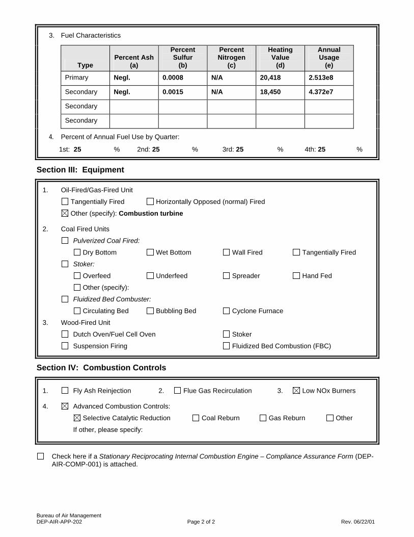
Bureau of Air Management DEP-AIR-APP-202 Page 2 of 2 Rev. 06/22/01
3. Fuel Characteristics
Type
Percent Ash
(a)
Percent Sulfur
(b)
Percent Nitrogen
(c)
Heating Value
(d)
Annual Usage
(e)
Primary Negl. 0.0008 N/A 20,418 2.513e8
Secondary Negl. 0.0015 N/A 18,450 4.372e7
Secondary
Secondary
4. Percent of Annual Fuel Use by Quarter:
1st: 25 % 2nd: 25 % 3rd: 25 % 4th: 25 %
Section III: Equipment
1. Oil-Fired/Gas-Fired Unit
Tangentially Fired Horizontally Opposed (normal) Fired
Other (specify): Combustion turbine
2. Coal Fired Units
Pulverized Coal Fired:
Dry Bottom Wet Bottom Wall Fired Tangentially Fired
Stoker:
Overfeed Underfeed Spreader Hand Fed
Other (specify):
Fluidized Bed Combuster:
Circulating Bed Bubbling Bed Cyclone Furnace
3. Wood-Fired Unit
Dutch Oven/Fuel Cell Oven Stoker
Suspension Firing Fluidized Bed Combustion (FBC)
Section IV: Combustion Controls
1. Fly Ash Reinjection 2. Flue Gas Recirculation 3. Low NOx Burners
4. Advanced Combustion Controls:
Selective Catalytic Reduction Coal Reburn Gas Reburn Other
If other, please specify:
Check here if a Stationary Reciprocating Internal Combustion Engine – Compliance Assurance Form (DEP-
AIR-COMP-001) is attached.

Bureau of Air Management DEP-AIR-APP-202 Page 1 of 2 Rev. 06/22/01
Supplemental Application Form Fuel Burning Equipment
Applicant Name: Bridgeport Energy II, LLC (As indicated on the Permit Application Transmittal Form) Please complete a separate form for each fuel burning unit. (You may reproduce this form as necessary.) Unit #: U2 Is this unit subject to Title 40 CFR Part 60, NSPS? Yes or No If yes, indicate the subpart(s): GG Is this unit subject to Title 40 CFR Part 63, MACT? Yes or No If yes, indicate the subpart(s): Section I: General
1. Type of Unit (make, model, serial no.): Siemens SGT6-5000F
2. Burner (make, model, serial no.): N/A
3. Construction Date: / /
4. Unit Rated Capacity - Input (BTU/hr): 2,257,000,000 HHV
5. Burner Rated Capacity - Input (if different) (BTU/hr): N/A
6. Engine Brake Horsepower (for internal combustion engines): N/A
7. Equipment is: Emergency Non-emergency
8. Maximum Operating Schedule for this Unit: 24 hours/day 2,500 hours/year
9. Percentage of Use in Each Category:
Space Heat: 0 % Process Heat: 0 % Power: 100 %
Section II: Fuel
1. Type of Primary Fuel (check one):
Fuel Oil Grade (check one) 1 2 3 4 5 6
Coal Natural Gas Propane Butane Wood Landfill Gas
Other (specify):
a. Maximum Fuel Firing Rate (specify units): 100,500 lb/hr
2. List Secondary Fuel(s): No. 2 fuel oil a. Maximum Fuel Firing Rate for each secondary fuel listed (specify units): 109,300 lb/hr
Section II: Fuel (continued)
DEP USE ONLY App. No.:
EPE No.:

Bureau of Air Management DEP-AIR-APP-202 Page 2 of 2 Rev. 06/22/01
3. Fuel Characteristics
Type
Percent Ash
(a)
Percent Sulfur
(b)
Percent Nitrogen
(c)
Heating Value
(d)
Annual Usage
(e)
Primary Negl. 0.0008 N/A 20,418 2.513e8
Secondary Negl. 0.0015 N/A 18,450 4.372e7
Secondary
Secondary
4. Percent of Annual Fuel Use by Quarter:
1st: 25 % 2nd: 25 % 3rd: 25 % 4th: 25 %
Section III: Equipment
1. Oil-Fired/Gas-Fired Unit
Tangentially Fired Horizontally Opposed (normal) Fired
Other (specify): Combustion turbine
2. Coal Fired Units
Pulverized Coal Fired:
Dry Bottom Wet Bottom Wall Fired Tangentially Fired
Stoker:
Overfeed Underfeed Spreader Hand Fed
Other (specify):
Fluidized Bed Combuster:
Circulating Bed Bubbling Bed Cyclone Furnace
3. Wood-Fired Unit
Dutch Oven/Fuel Cell Oven Stoker
Suspension Firing Fluidized Bed Combustion (FBC)
Section IV: Combustion Controls
1. Fly Ash Reinjection 2. Flue Gas Recirculation 3. Low NOx Burners
4. Advanced Combustion Controls:
Selective Catalytic Reduction Coal Reburn Gas Reburn Other
If other, please specify:
Check here if a Stationary Reciprocating Internal Combustion Engine – Compliance Assurance Form (DEP-
AIR-COMP-001) is attached.

U1 Combustion Turbine
C1 Selective Catalytic
Reduction
S1 Stack
U2 Combustion Turbine
C2 Selective Catalytic
Reduction
S2 Stack
PROCESS FLOW DIAGRAM Bridgeport Energy II, LLC
DEP-AIR-APP-202

Bureau of Air Management DEP-AIR-APP-204 1 of 4 Rev. 06/22/01
Supplemental Application Form Volatile Liquid Storage
Applicant Name: Bridgeport Energy II, LLC (As indicated on the Permit Application Transmittal Form) Please complete a separate form for each premise or tank farm. (Reproduce this form as necessary.) Unit No.: 1 Is this unit subject to Title 40 CFR Part 60, NSPS? Yes or No If yes, indicate the subpart(s): Is this unit subject to Title 40 CFR Part 63, MACT? Yes or No If yes, indicate the subpart(s): Is the EPA Tank Software Program Output Attached? Yes or No
Section I: Product Information
True Vapor Pressure (psi)
Tank ID No. (1a)
Product Type (1b)
Density (lb/gal)
(1c)
Molecular Weight
(1d)
At Maximum
Storage Temperature
(1e)
At Annual
Average Storage Temperature
(1f) 1
#2 oil
7.2
~130
0.02
0.01
Section II: Bulk Gasoline Plants and Terminals Only
DEP USE ONLY App. No.:
EPE No.:

Bureau of Air Management DEP-AIR-APP-204 2 of 4 Rev. 06/22/01
1. Is the tank farm a : Bulk Gasoline Plant? Bulk Gasoline Terminal?
2. For loading incoming gasoline into the storage tanks, is there a:
Submerged fill pipe? Yes No
Bottom fill? Yes No
Splash fill? Yes No
3. Is there a vapor balance system for:
Filling storage tanks from transport vehicle tanks? Yes No
Filling transport vehicle tanks from storage tanks? Yes No
4a. Is there a vapor recovery system for filling gasoline transport vehicles from storage tanks?
Yes No
4b. If yes, what type of vapor control device is used? (please specify)

Bureau of Air Management DEP-AIR-APP-204 3 of 4 Rev. 06/22/01
Section III: Storage Tank Information Part A: All New, Modified or Replacement Storage Tanks
Tank ID No. (1)
Constructio
n Date (2)
Tank
Diameter (ft) (3)
Tank Height or
Length (ft) (4)
Maximum Hourly Filling
Rate (gal/hr) (5)
Maximum Annual
Throughput (gal/yr) (6)
Tank Capacity
(gallon) (7)
T1 67.0 48.0 7,590,300 1,200,000
Part B: Fixed Roof Tanks Only Part C: Variable Vapor Space Tanks Only
Paint Color
Tank ID No.
(1)
Roof (2)
Sides
(3)
Average
Vapor Space Height (ft)
(4)
Horizontal (H) or Vertical (V)
(5)
Underground (Yes/No)
(6)
Tank ID No.
(1)
Volume
Expansion Capacity (gal)
(2)
Number of
Transfers into the Tanks per
Year (3)
T1 White White No

Bureau of Air Management DEP-AIR-APP-204 4 of 4 Rev. 06/22/01
Section III: Storage Tank Information (continued) Part D: All Floating Roof Tanks
Tank ID No. (1)
Riveted (R) or Welded (W) Tank
Sides (2)
Type of Primary Seal (3)
Type of Secondary Seal(4)
Shell Condition (5)
Number of
Support Columns
(6)
Effective Column Diameter (ft)
(7)
Part E: Internal Floating Roof Tanks Only
Tank ID No. (1)
Types of Deck Fittings (2)
Number of Each Type
(3)
Design of Each Deck Fitting (4)
Number of Each Design
(5)
Bolted Decks Only
Length of Deck Seam (ft)
(6)

Bureau of Air Management DEP-AIR-APP-204 1 of 4 Rev. 06/22/01
Supplemental Application Form Volatile Liquid Storage
Applicant Name: Bridgeport Energy II, LLC (As indicated on the Permit Application Transmittal Form) Please complete a separate form for each premise or tank farm. (Reproduce this form as necessary.) Unit No.: 2 Is this unit subject to Title 40 CFR Part 60, NSPS? Yes or No If yes, indicate the subpart(s): Is this unit subject to Title 40 CFR Part 63, MACT? Yes or No If yes, indicate the subpart(s): Is the EPA Tank Software Program Output Attached? Yes or No
Section I: Product Information
True Vapor Pressure (psi)
Tank ID No. (1a)
Product Type (1b)
Density (lb/gal)
(1c)
Molecular Weight
(1d)
At Maximum
Storage Temperature
(1e)
At Annual
Average Storage Temperature
(1f) 2
Ammonia
7.35
17.7
~25
~8
Section II: Bulk Gasoline Plants and Terminals Only
DEP USE ONLY App. No.:
EPE No.:

Bureau of Air Management DEP-AIR-APP-204 2 of 4 Rev. 06/22/01
1. Is the tank farm a : Bulk Gasoline Plant? Bulk Gasoline Terminal?
2. For loading incoming gasoline into the storage tanks, is there a:
Submerged fill pipe? Yes No
Bottom fill? Yes No
Splash fill? Yes No
3. Is there a vapor balance system for:
Filling storage tanks from transport vehicle tanks? Yes No
Filling transport vehicle tanks from storage tanks? Yes No
4a. Is there a vapor recovery system for filling gasoline transport vehicles from storage tanks?
Yes No
4b. If yes, what type of vapor control device is used? (please specify)

Bureau of Air Management DEP-AIR-APP-204 3 of 4 Rev. 06/22/01
Section III: Storage Tank Information Part A: All New, Modified or Replacement Storage Tanks
Tank ID No. (1)
Constructio
n Date (2)
Tank
Diameter (ft) (3)
Tank Height or
Length (ft) (4)
Maximum Hourly Filling
Rate (gal/hr) (5)
Maximum Annual
Throughput (gal/yr) (6)
Tank Capacity
(gallon) (7)
T2 8 30 115,000 12,000
Part B: Fixed Roof Tanks Only Part C: Variable Vapor Space Tanks Only
Paint Color
Tank ID No.
(1)
Roof (2)
Sides
(3)
Average
Vapor Space Height (ft)
(4)
Horizontal (H) or Vertical (V)
(5)
Underground (Yes/No)
(6)
Tank ID No.
(1)
Volume
Expansion Capacity (gal)
(2)
Number of
Transfers into the Tanks per
Year (3)

Bureau of Air Management DEP-AIR-APP-204 4 of 4 Rev. 06/22/01
Section III: Storage Tank Information (continued) Part D: All Floating Roof Tanks
Tank ID No. (1)
Riveted (R) or Welded (W) Tank
Sides (2)
Type of Primary Seal (3)
Type of Secondary Seal(4)
Shell Condition (5)
Number of
Support Columns
(6)
Effective Column Diameter (ft)
(7)
Part E: Internal Floating Roof Tanks Only
Tank ID No. (1)
Types of Deck Fittings (2)
Number of Each Type
(3)
Design of Each Deck Fitting (4)
Number of Each Design
(5)
Bolted Decks Only
Length of Deck Seam (ft)
(6)

Attachment H Emergency Episode Standby Plan
Regulations of Connecticut State Agencies (RCSA) Section 22a-174-6 identify the Air pollution emergency episode procedures. These regulations outline the criteria for determining the stage of an air pollution industrial emergency episode exists. Air pollutant concentrations are monitored by the Department and if indicated that short term high pollutant levels may be expected which are likely to have an adverse impact on human health, the Commissioner shall prepare for declaration of an appropriate air pollution emergency episode. There are three stages each determined by the concentration level of specific pollutants for a specific time period. The pollutants for all three stages are SO2, PM10, and NOx. Once any stage of air pollution emergency episode has been declared, it shall remain in effect until the Commissioner announces it termination. The Commissioner can declare an industrial air pollution emergency episode in the aid of a sister state. The regulation defines plans of action at each stage of an industrial air pollution emergency episode. Bridgeport Energy II, LLC (BEII) is in the process of proposing to build and operate a new 350 MW nominal simple cycle combustion turbine generating facility in Bridgeport, CT. The combustion turbines will fire natural gas as the primary fuel with limited backup firing of ultra low sulfur diesel (ULSD) fuel oil. The Project will utilize two turbines. The Emergency Standby Plan will take effect once the plant is constructed and in operation. The combustion turbines and associated equipment will emit emissions of nitrogen oxides (NOx), sulfur dioxide (SO2), particulate matter (PM/PM10/PM2.5), carbon monoxide (CO), volatile organic compounds (VOC), and ammonia (NH3). BEII will follow the plan of action as defined at each stage. Since the facility will have the potential to emit more than 100 tons per year of pollutants as determined before the application of control equipment, the facility shall put into effect the preplanned abatement strategy for an industrial air pollution alert. The preplanned abatement strategy is for the facility to prepare a standby plan for reducing the emission of air pollutants during each of the three stages of the industrial air pollution emergency episode. The three stages are Industrial Alert, Industrial Warnings and Industrial Emergency. The standby plan will be designed to reduce or eliminate emissions of air pollutant in accordance with the requirements set forth in the regulations for each of the three stages. More specific details on the amount of reduction to be achieved and the manner in which it will be accomplished will be provided once the turbines are in operation. First Stage – Industrial Alert: Electric power generation shall, when ever possible, be diverted to facilities outside the alert area. BEII will if possible not operate during the alert. If BEII must remain in operation, fuels having low ash and sulfur content will be used as per the regulations.

BEII will institute actions that will result in the reduction of air pollutants from their activities to the extent possible without causing injury to persons or damage to equipment while still providing necessary power. Reduction in power for example may occur through the use of using only one combustion turbine unit instead of two or limiting hours of operation during the period of time. Until the facility is in operation and is part of the power grid, specific details regarding the amount of reduction to be achieved and the manner in which the reduction will be accomplished can not be provided. The regulations also list that any boiler lancing or soot blowing required from fuel burning equipment shall be performed only be performed during the hours of 12 noon and 4 pm. BEII will not conduct these types of operations. Steam loads demands and heat load demands for processing are required to be reduced by the regulations. Therefore, the demand for BEII maybe reduced during the alert. Second Stage- Industrial Warning Electric power generation shall, to the maximum extent possible, be diverted to facilities outside the warning area. BEII will if possible not operate during the alert. If BEII must remain in operation, fuels having low ash and sulfur content will be used and will operate at the most minimum level possible. BEII will institute actions that will result in the reduction of air pollutants from their activities to the most extent possible without causing injury to persons or damage to equipment while still providing power that has been deemed necessary. Reduction in power for example may occur through the use of using only one combustion turbine unit instead of two or limiting hours of operation during the period of time. Until the facility is in operation and is part of the power grid, specific details regarding the amount of reduction to be achieved and the manner in which the reduction will be accomplished can not be provided. The regulations also list that any boiler lancing or soot blowing required from fuel burning equipment shall be performed only be performed during the hours of 12 noon and 4 pm. BEII will not conduct these types of operations. Steam loads demands and heat load demands for processing are required to be reduced to the maximum extent possible by the regulations. Manufacturing operations shall be ceased, curtailed, postponed, or deferred. Therefore, the demand for BEII may be reduced during the alert. BEII will conduct no open burning.

Third Stage- Industrial Air Pollution Emergency During the third stage there are a number of enterprises and activities that shall immediately cease operations, including, but not limited to, construction work, wholesale trade establishments, state and local government offices except those necessary for public safety and welfare including any involved in combating the industrial air pollution emergency, all retail trade establishments except pharmacies, and stores primarily engaged in the sale of food, banks, real estate offices, offices of insurance carriers, laundry services, beauty shops, advertising offices, all offices, clerical and professional service enterprises including law and accounting offices but excluding doctors’ offices and medical laboratories, all schools of any kind, and establishments rendering amusement and recreational services. Therefore, the electrical demand of the area would be significantly reduced. BEII will, to the maximum extent possible without causing injury to persons or damage to equipment, institute actions that will result in the maximum reduction of air pollutants from their activities by ceasing curtailing, or postponing operations which emit air pollutants. Reduction in power for example may occur through the use of using only one combustion turbine unit instead of two or limiting hours of operation during the period of time or not operating the turbines during the emergency. Until the facility is in operation and is part of the power grid, specific details regarding the amount of reduction to be achieved and the manner in which the reduction will be accomplished can not be provided. BEII will conduct no open burning. Updates to the plan will be prepared as necessary when the facility is in operation.

Attachment I Operation and Maintenance Manual
The Project will utilize either two (2) General Electric (GE) model 7FA or Siemens model SGT-5000F turbines operating in simple-cycle (peaking) mode. The turbines will have a collective nominal generating capacity of approximately 350 MW. The combustion turbines will fire natural gas as the primary fuel with limited backup firing of ultra low sulfur diesel (ULSD) fuel oil. Both the GE 7FA and Siemens SGT-5000F turbines will utilize state-of-the-art dry low NOx (DLN) combustors to minimize uncontrolled emissions of all pollutants from the project. An SCR will be incorporated to control NOx emissions and meet LAER requirements. The proposed operating limitations for the facility also reduce potential annual emissions. These limitations include: annual operating hours of ≤2,500 hours per year (hr/yr) per turbine; ≤500 hours per year (hr/yr) of backup oil firing; and using ULSD as the backup fuel with a maximum sulfur content of 15 ppmw. Due to the application of SCR, there will be some ammonia emissions (i.e. “ammonia slip”) associated with the project. Baseload Operation
The combustion turbine manufacturers provided emission rate data for all criteria pollutants during normal operation. Normal operation has been defined as all operating modes above 75% load and with the SCR catalyst at its minimum operating temperature of about 500°F. The turbines will be operated in accordance with these guidelines and the operation procedures provided by the turbine vendor and by the SCR system vendor. The facility will also comply with the requirements for the operation of air pollution control equipment in Sec. 22a-174-7(b) of the Regulations of Connecticut State Agencies. These requirements prohibit the deliberate shutdown of any air pollution control equipment while the turbines are operating, except for necessary maintenance that cannot be performed offline. Startup/Shutdown Operation The plant will be operate as a “peaking” plant meaning that it will operate during periods of peak demand, which are generally during weekdays with high or low ambient temperatures. Consequently, the turbines may be turned on and off on a daily basis. Under this operating scenario, the turbines would be started up and shut down each weekday. Accordingly, the project estimates that the maximum number of starts, and associated shutdowns, per year will be 250. Emissions of NOx, CO and VOC from combustion turbines may be significantly higher during start-up and shutdown (SUSD) conditions than during normal operation. Emissions of SO2 and PM during SUSD operation are at or below their respective emission rates during normal operation and therefore there is no increase in emissions of
these two pollutants as a result of SUSD operation. During start-up, the turbines cannot initially operate in lean pre-mix mode which results in higher emissions. A similar transition from lean pre-mix combustion to standard combustion occurs during shutdown. Also, the SCR catalyst is not effective until it reaches a minimum temperature of about 500°F. The duration of startups and shutdowns for a combustion turbine in simple-cycle mode is relatively short. The facility will employ best management practices, in addition to operation procedures provided by the turbine vendor, to minimize emissions during startup and shutdown operation and to limit the number of starts per year to 250 per turbine. Malfunctions
The turbines will be operated in accordance with operation procedures provided by the turbine vendor and by the SCR system vendor in cases of equipment malfunction. The facility will also comply with the requirements for the breakdown, failure, and deliberate shutdown of air pollution control equipment in Sec. 22a-174-7(a) of the Regulations of Connecticut State Agencies. These requirements state that if the facility continues to operate an emission source while any air pollution control equipment is inoperative, the owner or operator will exercise due diligence to minimize emissions, continue the use of monitoring equipment, and give notice to the commissioner as required by Sec. 22a-174-7(d) and (e). Maintenance The facility will follow maintenance procedures provided by the turbine vendor and by the SCR system vendor. Continuous Emission Monitoring Systems (CEMS) The facility will operate CEMS for the measurement of NOx, SO2, NH3, and opacity emissions from the turbine stacks. Each CEMS will be operated and maintained in accordance with monitoring plans and quality assurance/quality control (QA/QC) plans prepared to satisfy the requirements of 40 CFR 75.

DEP-APP-002 1 of 2 Rev. 05/07/04
Applicant Compliance Information
Applicant Name: Bridgeport Energy II, LLC (as indicated on the Permit Application Transmittal Form)
If you answer yes to any of the questions below, you must complete the Table of Enforcement Actions on the reverse side of this sheet as directed in the instructions for your permit application. A. During the five years immediately preceding submission of this application, has the applicant been
convicted in any jurisdiction of a criminal violation of any environmental law? Yes No
B. During the five years immediately preceding submission of this application, has a civil penalty been
imposed upon the applicant in any state, including Connecticut, or federal judicial proceeding for any violation of an environmental law?
Yes No
C. During the five years immediately preceding submission of this application, has a civil penalty exceeding
five thousand dollars been imposed on the applicant in any state, including Connecticut, or federal administrative proceeding for any violation of an environmental law?
Yes No
D. During the five years immediately preceding submission of this application, has any state, including
Connecticut, or federal court issued any order or entered any judgement to the applicant concerning a violation of any environmental law?
Yes No E. During the five years immediately preceding submission of this application, has any state, including
Connecticut, or federal administrative agency issued any order to the applicant concerning a violation of any environmental law?
Yes No
DEP ONLY
App. No. _____________________________
Co./Ind. No. ___________________________

DEP-APP-002 2 of 2 Rev. 05/07/04
Table of Enforcement Actions
(1)
Type of Action
(2a)
Date Commenced
(2b)
Date Terminated
(3)
Jurisdiction
(4)
Case/Docket/ Order No.
(5)
Description of Violation
Check the box if additional sheets are attached. Copies of this form may be duplicated for additional space.


Appendix B
Supporting Calculations for Emission Rates and BACT Analysis

Pollutant 100% 75% 100% 75%
NOx 20.0 17.0 123.0 99.0 101.5 34.2 135.7
CO 33.0 27.0 80.0 65.0 106.0 129.1 235.1
PM/PM10 15.0 15.0 34.0 34.0 47.0 0 47.0
SO2 2.05 1.67 3.24 2.61 5.72 0 5.72
VOC 3.10 2.60 12.5 10.1 12.5 12.2 24.8
NH3 14.8 11.9 18.7 14.9 39.0 0 39.0
H2SO4 0.37 0.30 0.58 0.47 1.0 0 1.0
Maximum Hours Per Year 2500 per CTGMaximum Hours On Oil 500 per CTGNumber Of Starts Per Year 250 per CTGStartup/Shutdown Hours Per Year 288 per CTGVOC total includes 0.2 tpy from fuel oil storage tank
Gas (lb/hr @ 59F) Oil (lb/hr @ 3F)Facility PTE
(tpy)
GE 7FA POTENTIAL EMISSIONS
Baseload PTE (tpy)
SUSD PTE Net Increase
(tpy)
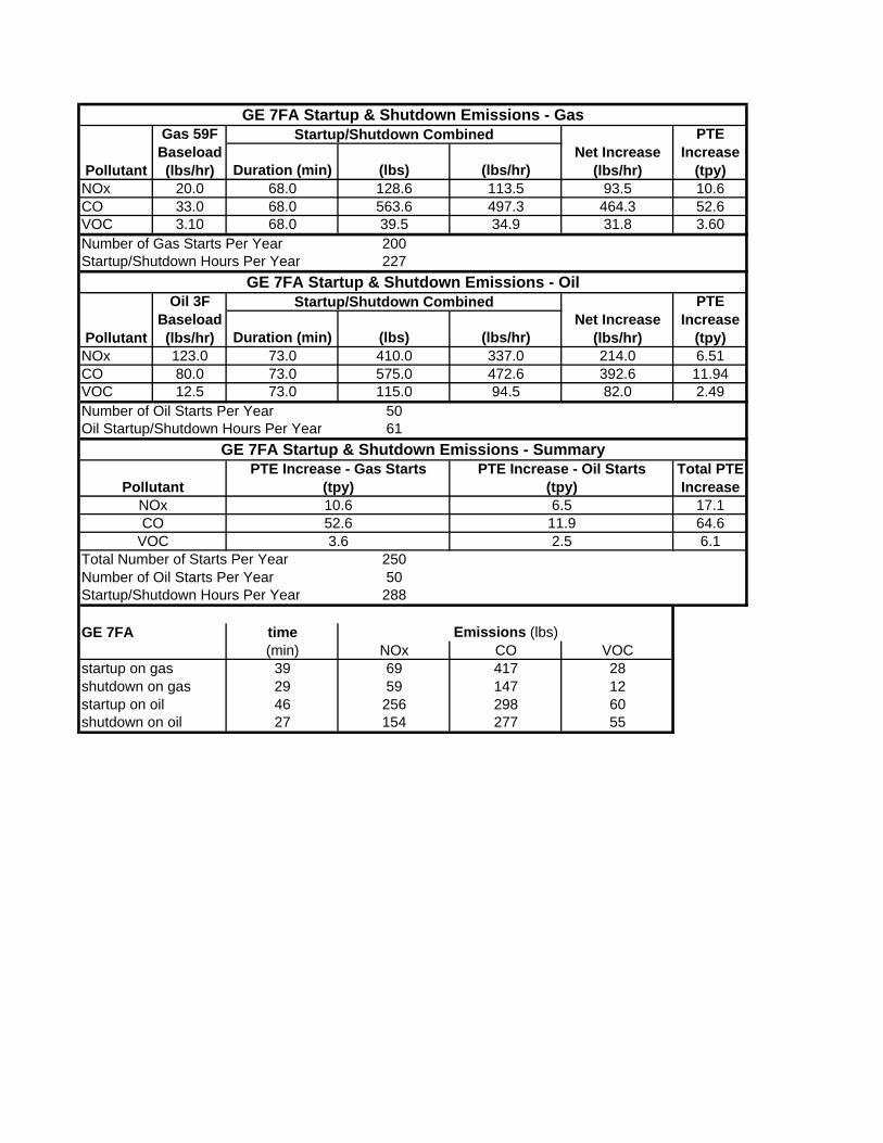
Duration (min) (lbs) (lbs/hr)NOx 20.0 68.0 128.6 113.5 93.5 10.6CO 33.0 68.0 563.6 497.3 464.3 52.6VOC 3.10 68.0 39.5 34.9 31.8 3.60Number of Gas Starts Per Year 200Startup/Shutdown Hours Per Year 227
Duration (min) (lbs) (lbs/hr)NOx 123.0 73.0 410.0 337.0 214.0 6.51CO 80.0 73.0 575.0 472.6 392.6 11.94VOC 12.5 73.0 115.0 94.5 82.0 2.49Number of Oil Starts Per Year 50Oil Startup/Shutdown Hours Per Year 61
17.164.66.1
Total Number of Starts Per Year 250Number of Oil Starts Per Year 50Startup/Shutdown Hours Per Year 288
GE 7FA time Emissions (lbs)(min) NOx CO VOC
startup on gas 39 69 417 28shutdown on gas 29 59 147 12startup on oil 46 256 298 60shutdown on oil 27 154 277 55
GE 7FA Startup & Shutdown Emissions - Gas
Pollutant
Gas 59F Baseload (lbs/hr)
Startup/Shutdown CombinedNet Increase
(lbs/hr)
PTE Increase
(tpy)
GE 7FA Startup & Shutdown Emissions - Oil
Pollutant
Oil 3F Baseload (lbs/hr)
Startup/Shutdown CombinedNet Increase
(lbs/hr)
PTE Increase
(tpy)
GE 7FA Startup & Shutdown Emissions - Summary
PollutantPTE Increase - Gas Starts
(tpy)PTE Increase - Oil Starts
(tpy)Total PTE Increase
VOC 3.6 2.5
NOx 10.6 6.5CO 52.6 11.9
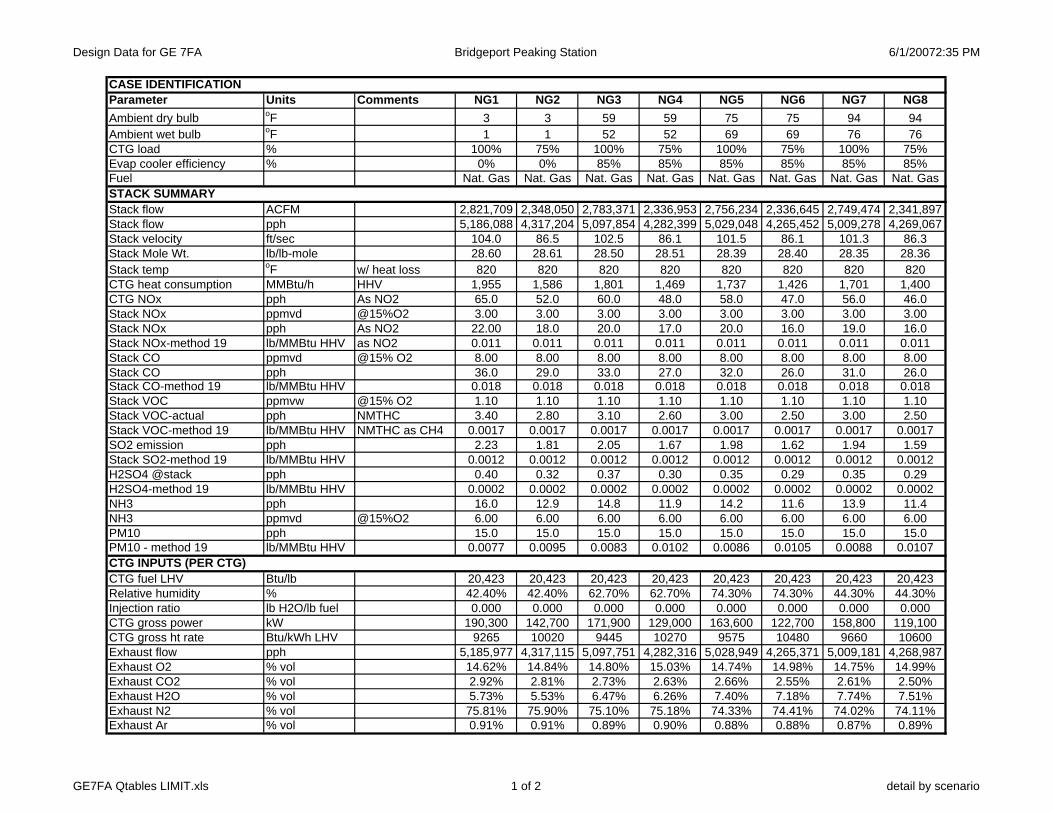
Design Data for GE 7FA Bridgeport Peaking Station 6/1/20072:35 PM
CASE IDENTIFICATIONParameter Units Comments NG1 NG2 NG3 NG4 NG5 NG6 NG7 NG8Ambient dry bulb oF 3 3 59 59 75 75 94 94Ambient wet bulb oF 1 1 52 52 69 69 76 76CTG load % 100% 75% 100% 75% 100% 75% 100% 75%Evap cooler efficiency % 0% 0% 85% 85% 85% 85% 85% 85%Fuel Nat. Gas Nat. Gas Nat. Gas Nat. Gas Nat. Gas Nat. Gas Nat. Gas Nat. GasSTACK SUMMARYStack flow ACFM 2,821,709 2,348,050 2,783,371 2,336,953 2,756,234 2,336,645 2,749,474 2,341,897Stack flow pph 5,186,088 4,317,204 5,097,854 4,282,399 5,029,048 4,265,452 5,009,278 4,269,067Stack velocity ft/sec 104.0 86.5 102.5 86.1 101.5 86.1 101.3 86.3Stack Mole Wt. lb/lb-mole 28.60 28.61 28.50 28.51 28.39 28.40 28.35 28.36Stack temp oF w/ heat loss 820 820 820 820 820 820 820 820CTG heat consumption MMBtu/h HHV 1,955 1,586 1,801 1,469 1,737 1,426 1,701 1,400CTG NOx pph As NO2 65.0 52.0 60.0 48.0 58.0 47.0 56.0 46.0Stack NOx ppmvd @15%O2 3.00 3.00 3.00 3.00 3.00 3.00 3.00 3.00Stack NOx pph As NO2 22.00 18.0 20.0 17.0 20.0 16.0 19.0 16.0Stack NOx-method 19 lb/MMBtu HHV as NO2 0.011 0.011 0.011 0.011 0.011 0.011 0.011 0.011Stack CO ppmvd @15% O2 8.00 8.00 8.00 8.00 8.00 8.00 8.00 8.00Stack CO pph 36.0 29.0 33.0 27.0 32.0 26.0 31.0 26.0Stack CO-method 19 lb/MMBtu HHV 0.018 0.018 0.018 0.018 0.018 0.018 0.018 0.018Stack VOC ppmvw @15% O2 1.10 1.10 1.10 1.10 1.10 1.10 1.10 1.10Stack VOC-actual pph NMTHC 3.40 2.80 3.10 2.60 3.00 2.50 3.00 2.50Stack VOC-method 19 lb/MMBtu HHV NMTHC as CH4 0.0017 0.0017 0.0017 0.0017 0.0017 0.0017 0.0017 0.0017SO2 emission pph 2.23 1.81 2.05 1.67 1.98 1.62 1.94 1.59Stack SO2-method 19 lb/MMBtu HHV 0.0012 0.0012 0.0012 0.0012 0.0012 0.0012 0.0012 0.0012H2SO4 @stack pph 0.40 0.32 0.37 0.30 0.35 0.29 0.35 0.29H2SO4-method 19 lb/MMBtu HHV 0.0002 0.0002 0.0002 0.0002 0.0002 0.0002 0.0002 0.0002NH3 pph 16.0 12.9 14.8 11.9 14.2 11.6 13.9 11.4NH3 ppmvd @15%O2 6.00 6.00 6.00 6.00 6.00 6.00 6.00 6.00PM10 pph 15.0 15.0 15.0 15.0 15.0 15.0 15.0 15.0PM10 - method 19 lb/MMBtu HHV 0.0077 0.0095 0.0083 0.0102 0.0086 0.0105 0.0088 0.0107CTG INPUTS (PER CTG)CTG fuel LHV Btu/lb 20,423 20,423 20,423 20,423 20,423 20,423 20,423 20,423Relative humidity % 42.40% 42.40% 62.70% 62.70% 74.30% 74.30% 44.30% 44.30%Injection ratio lb H2O/lb fuel 0.000 0.000 0.000 0.000 0.000 0.000 0.000 0.000CTG gross power kW 190,300 142,700 171,900 129,000 163,600 122,700 158,800 119,100CTG gross ht rate Btu/kWh LHV 9265 10020 9445 10270 9575 10480 9660 10600Exhaust flow pph 5,185,977 4,317,115 5,097,751 4,282,316 5,028,949 4,265,371 5,009,181 4,268,987Exhaust O2 % vol 14.62% 14.84% 14.80% 15.03% 14.74% 14.98% 14.75% 14.99%Exhaust CO2 % vol 2.92% 2.81% 2.73% 2.63% 2.66% 2.55% 2.61% 2.50%Exhaust H2O % vol 5.73% 5.53% 6.47% 6.26% 7.40% 7.18% 7.74% 7.51%Exhaust N2 % vol 75.81% 75.90% 75.10% 75.18% 74.33% 74.41% 74.02% 74.11%Exhaust Ar % vol 0.91% 0.91% 0.89% 0.90% 0.88% 0.88% 0.87% 0.89%
GE7FA Qtables LIMIT.xls 1 of 2 detail by scenario

Design Data for GE 7FA Bridgeport Peaking Station 6/1/20072:35 PM
CASE IDENTIFICATIONParameter Units CommentsAmbient dry bulb oFAmbient wet bulb oFCTG load %Evap cooler efficiency %FuelSTACK SUMMARYStack flow ACFMStack flow pphStack velocity ft/secStack Mole Wt. lb/lb-moleStack temp oF w/ heat lossCTG heat consumption MMBtu/h HHVCTG NOx pph As NO2Stack NOx ppmvd @15%O2Stack NOx pph As NO2Stack NOx-method 19 lb/MMBtu HHV as NO2Stack CO ppmvd @15% O2Stack CO pphStack CO-method 19 lb/MMBtu HHVStack VOC ppmvw @15% O2Stack VOC-actual pph NMTHCStack VOC-method 19 lb/MMBtu HHV NMTHC as CH4SO2 emission pphStack SO2-method 19 lb/MMBtu HHVH2SO4 @stack pphH2SO4-method 19 lb/MMBtu HHVNH3 pphNH3 ppmvd @15%O2PM10 pphPM10 - method 19 lb/MMBtu HHVCTG INPUTS (PER CTG)CTG fuel LHV Btu/lbRelative humidity %Injection ratio lb H2O/lb fuelCTG gross power kWCTG gross ht rate Btu/kWh LHVExhaust flow pphExhaust O2 % volExhaust CO2 % volExhaust H2O % volExhaust N2 % volExhaust Ar % vol
ULSD1 ULSD2 ULSD3 ULSD4 ULSD5 ULSD6 ULSD7 ULSD83 3 59 59 75 75 94 941 1 52 52 69 69 76 76
100% 75% 100% 75% 100% 75% 100% 75%0% 0% 85% 0% 85% 0% 85% 0%
ULSD ULSD ULSD ULSD ULSD ULSD ULSD ULSD
2,887,241 2,401,194 2,859,065 2,416,197 2,830,556 2,382,252 2,820,266 2,401,4555,289,348 4,405,503 5,223,269 4,423,445 5,156,644 4,348,944 5,132,853 4,381,855
106.4 88.5 105.3 89.0 104.3 87.8 103.9 88.528.50 28.55 28.43 28.49 28.35 28.40 28.32 28.39820 820 820 820 820 820 820 820
2,101 1,694 1,955 1,586 1,877 1,518 1,831 1,487352.0 281.0 328.0 263.0 315.0 252.0 307.0 247.015.0 15.0 15.0 15.0 15.0 15.0 15.0 15.0
123.0 99.0 114.0 93.0 110.0 89.0 107.0 87.00.058 0.058 0.058 0.058 0.058 0.058 0.058 0.05816.00 16.00 16.00 16.00 16.00 16.00 16.00 16.0080.0 65.0 75.0 61.0 72.0 58.0 70.0 57.0
0.038 0.038 0.038 0.038 0.038 0.038 0.038 0.0383.90 3.90 3.90 3.90 3.90 3.90 3.90 3.90
12.50 10.10 11.60 9.50 11.20 9.10 10.90 8.900.0059 0.0059 0.0059 0.0059 0.0059 0.0059 0.0059 0.0059
3.24 2.61 3.02 2.45 2.90 2.34 2.83 2.290.0014 0.0015 0.0014 0.0015 0.0014 0.0015 0.0014 0.0015
0.58 0.47 0.54 0.44 0.52 0.42 0.51 0.410.0003 0.0003 0.0003 0.0003 0.0003 0.0003 0.0003 0.0003
18.7 14.9 17.4 14.0 16.7 13.4 16.3 13.16.00 6.00 6.00 6.00 6.00 6.00 6.00 6.0034.0 34.0 34.0 34.0 34.0 34.0 34.0 34.0
0.0162 0.0201 0.0174 0.0214 0.0181 0.0224 0.0186 0.0229
18,300 18,300 18,300 18,300 18,300 18,300 18,300 18,30042.40% 42.40% 62.70% 62.70% 74.30% 74.30% 44.30% 44.30%1.371 1.284 1.341 1.251 1.273 1.165 1.236 1.166
196,700 147,500 181,600 136,200 172,700 129,500 167,500 125,60010050 10810 10130 10960 10230 11030 10290 11140
5,288,978 4,405,208 5,222,924 4,423,169 5,156,313 4,348,679 5,132,530 4,381,59613.35% 13.70% 13.60% 14.03% 13.64% 14.05% 13.71% 14.19%4.34% 4.17% 4.08% 3.88% 3.96% 3.77% 3.88% 3.66%8.37% 7.81% 8.85% 8.11% 9.46% 8.73% 9.63% 8.75%
73.07% 73.45% 72.59% 73.10% 72.08% 72.58% 71.92% 72.53%0.87% 0.87% 0.88% 0.88% 0.86% 0.86% 0.86% 0.86%
GE7FA Qtables LIMIT.xls 2 of 2 detail by scenario

SIEMENS SGT-5000F POTENTIAL EMISSIONS
Oil (lb/hr @ 3F)
100% 75% 100%
NOx 23.0 18.0 125.0 98.3 10.4 108.7
CO 21.0 17.0 61.0 68.5 262.1 330.6
PM 12.0 12.0 60.0 49.2 0 49.2
SO2 2.32 1.83 3.27 6.18 0 6.2
VOC 2.90 2.30 15.00 12.1 12.4 24.7
NH3 16.4 12.9 18.4 41.7 0 41.7
H2SO4 0.31 0.25 0.44 0.8 0 0.8
Maximum Hours Per Year 2500 per CTGMaximum Hours On Oil 400 per CTGNumber Of Starts Per Year 200 per CTGStartup/Shutdown Hours Per Year 219 per CTGVOC emissions include 0.2 tpy from fuel oil storage tank
Pollutant
SUSD Net Increase
(tpy)Facility PTE
(tpy)
Gas (lb/hr @ 59F) Baseload PTE (tpy)

Duration (min) (lbs) (lbs/hr)NOx 23.00 66.0 70.6 64.1 41.1 3.8CO 21.00 66.0 1,179.6 1,072.3 1051.3 98.3VOC 2.90 66.0 48.0 43.6 40.7 3.81Number of Gas Starts Per Year 170Startup/Shutdown Hours Per Year 187
Duration (min) (lbs) (lbs/hr)NOx 125.0 64.0 223.8 209.8 84.8 1.36CO 61.0 64.0 2,247.5 2,107.0 2,046.0 32.74VOC 15.00 64.0 176.0 165.0 150.0 2.40Number of Oil Starts Per Year 30Oil Startup/Shutdown Hours Per Year 32
5.2131.0
6.2Total Number of Starts Per Year 200Number of Oil Starts Per Year 30Startup/Shutdown Hours Per Year 219
Siemens SGT6-5000F time Emissions (lbs)(min) NOx CO VOC
startup on gas 45 52 598 29shutdown on gas 21 18 581 19startup on oil 44 115 1199 94shutdown on oil 20 109 1049 82
VOC 3.8 2.4
NOx 3.8 1.4CO 98.3 32.7
Siemens SGT6-5000F Startup & Shutdown Emissions - Summary
PollutantPTE Increase - Gas Starts
(tpy)PTE Increase - Oil Starts
(tpy)Total PTE Increase
Siemens SGT6-5000F Startup & Shutdown Emissions - Oil
Pollutant
Oil 3F Baseload (lbs/hr)
Startup/Shutdown CombinedNet Increase
(lbs/hr)
PTE Increase
(tpy)
Siemens SGT6-5000F Startup & Shutdown Emissions - Gas
Pollutant
Gas 59F Baseload (lbs/hr)
Startup/Shutdown CombinedNet Increase
(lbs/hr)
PTE Increase
(tpy)

Siemens SGT6-5000F Design Data Bridgeport Peaking Station 6/1/2007
CASE IDENTIFICATION A A A A A A A AParameter Units Comments NG1 NG2 NG3 NG4 NG5 NG6 NG7 NG8Ambient dry bulb oF 3 3 59 59 75 75 94 94Ambient wet bulb oF 1 1 52 52 69 69 76 76CTG load % 100% 75% 100% 75% 100% 75% 100% 75%Evap cooler efficiency % 0% 0% 85% 85% 85% 85% 85% 85%Fuel Nat. Gas Nat. Gas Nat. Gas Nat. Gas Nat. Gas Nat. Gas Nat. Gas Nat. GasSTACK SUMMARYStack flow ACFM 3126112 2572505 3030173 2494342 2977782 2458530 2958962 2412591Stack flow pph 5743359 4728363 5548232 4572223 5431828 4489163 5389412 4403647Stack velocity ft/sec 115 95 112 92 110 91 109 89Stack Mole wt. lb/lb-mole 28.58 28.60 28.49 28.52 28.38 28.41 28.34 28.40Stack temp oF w/ heat loss 820 820 820 820 820 820 820 820CTG heat consum MMBtu/h HHV 2,256.7 1,793.1 2,036.7 1,601.8 1,945.4 1,534.7 1,894.6 1,450.9CTG Nox pph As NO2 76.0 60.4 68.6 54.0 65.6 51.7 63.8 48.9Stack NOx ppmvd @15%O2 3.00 3.00 3.00 3.00 3.00 3.00 3.00 3.00Stack NOx pph As NO2 25.0 20.0 23.0 18.0 22.0 17.0 21.0 16.0Stack NOx-method 19 lb/MMBtu HHV as NO2 0.0111 0.0111 0.0111 0.0111 0.0111 0.0111 0.0111 0.0111Stack CO ppmvd @15% O2 4.50 4.50 4.50 4.50 4.50 4.50 4.50 4.50Stack CO pph 23.0 19.0 21.0 17.0 20.0 16.0 20.0 15.0Stack CO-method 19 lb/MMBtu HHV 0.0101 0.0101 0.0101 0.0101 0.0101 0.0101 0.0101 0.0101Stack VOC ppmvw @15%O2 0.90 0.90 0.90 0.90 0.90 0.90 0.90 0.90Stack VOC pph NMTHC 3.20 2.60 2.90 2.30 2.80 2.20 2.70 2.10Stack VOC-method 19 lb/MMBtu HHV NMTHC as CH4 0.0014 0.0014 0.0014 0.0014 0.0014 0.0014 0.0014 0.0014SO2 emission pph 2.57 2.04 2.32 1.83 2.22 1.75 2.16 1.65SO2-method 19 lb/MMBtu HHV 0.0012 0.0012 0.0012 0.0012 0.0012 0.0012 0.0012 0.0012H2SO4 @stack pph 0.35 0.28 0.31 0.25 0.30 0.24 0.29 0.22H2SO4-method 19 lb/MMBtu HHV 0.0002 0.0002 0.0002 0.0002 0.0002 0.0002 0.0002 0.0002NH3 pph 18.2 14.4 16.4 12.9 15.6 12.3 15.2 11.7NH3 ppmvd @15%O2 6.00 6.00 6.00 6.00 6.00 6.00 6.00 6.00PM10 pph 12.0 12.0 12.0 12.0 12.0 12.0 12.0 12.0PM10 - method 19 lb/MMBtu HHV 0.0053 0.0067 0.0059 0.0075 0.0062 0.0078 0.0063 0.0083CTG INPUTS (PER CTG)CTG fuel LHV Btu/lb 20418 20418 20418 20418 20418 20418 20418 20418Bar. Pressure psia 14.691 14.691 14.691 14.691 14.691 14.691 14.691 14.691Relative humidity % 41.64% 41.64% 62.64% 62.64% 74.18% 74.18% 44.09% 44.09%Injection ratio lb wtr/lb fuel 0.000 0.000 0.000 0.000 0.000 0.000 0.000 0.000CTG gross power kW 231,191 173,393 202,955 148,921 190,329 139,548 183,169 128,166CTG gross ht rate Btu/kWh LHV 8802 9325 9049 9699 9217 9917 9327 10208Exhaust flow pph 5,743,226 4,728,256 5,548,111 4,572,128 5,431,712 4,489,072 5,389,300 4,403,561Exhaust O2 % vol 14.44% 14.67% 14.66% 14.96% 14.60% 14.89% 14.63% 15.05%Exhaust CO2 % vol 3.00% 2.90% 2.80% 2.67% 2.72% 2.60% 2.66% 2.50%Exhaust H2O % vol 5.89% 5.69% 6.61% 6.21% 7.52% 7.16% 7.86% 7.18%Exhaust N2 % vol 75.78% 75.85% 75.06% 75.27% 74.28% 74.47% 73.97% 74.39%Exhaust Ar % vol 0.89% 0.89% 0.88% 0.89% 0.87% 0.88% 0.87% 0.88%
Siemens LIMIT June07.xls 1 of 2 detail by scenario

Siemens SGT6-5000F Design Data Bridgeport Peaking Station 6/1/2007
CASE IDENTIFICATIONParameter Units CommentsAmbient dry bulb oFAmbient wet bulb oFCTG load %Evap cooler efficiency %FuelSTACK SUMMARYStack flow ACFMStack flow pphStack velocity ft/secStack Mole wt. lb/lb-moleStack temp oF w/ heat lossCTG heat consum MMBtu/h HHVCTG Nox pph As NO2Stack NOx ppmvd @15%O2Stack NOx pph As NO2Stack NOx-method 19 lb/MMBtu HHV as NO2Stack CO ppmvd @15% O2Stack CO pphStack CO-method 19 lb/MMBtu HHVStack VOC ppmvw @15%O2Stack VOC pph NMTHCStack VOC-method 19 lb/MMBtu HHV NMTHC as CH4SO2 emission pphSO2-method 19 lb/MMBtu HHVH2SO4 @stack pphH2SO4-method 19 lb/MMBtu HHVNH3 pphNH3 ppmvd @15%O2PM10 pphPM10 - method 19 lb/MMBtu HHVCTG INPUTS (PER CTG)CTG fuel LHV Btu/lbBar. Pressure psiaRelative humidity %Injection ratio lb wtr/lb fuelCTG gross power kWCTG gross ht rate Btu/kWh LHVExhaust flow pphExhaust O2 % volExhaust CO2 % volExhaust H2O % volExhaust N2 % volExhaust Ar % vol
C C C CULSD1 ULSD3 ULSD5 ULSD7
3 59 75 941 52 69 76
100% 100% 100% 100%0% 85% 85% 85%
ULSD ULSD ULSD ULSD
3028957 2934899 2881880 28633795613518 5417631 5298775 5255942
112 108 106 10528.83 28.72 28.61 28.56820 820 820 820
2,138.1 1,927.1 1,839.9 1,791.2359.8 324.3 309.6 301.415.0 15.0 15.0 15.0
125.0 113.0 108.0 105.00.0583 0.0583 0.0583 0.058312.00 12.00 12.00 12.0061.0 61.0 61.0 61.0
0.0284 0.0284 0.0284 0.02844.60 4.60 4.60 4.60
15.00 13.50 12.90 12.600.0070 0.0070 0.0070 0.0070
3.27 2.95 2.82 2.740.0015 0.0015 0.0015 0.0015
0.44 0.40 0.38 0.370.0002 0.0002 0.0002 0.0002
18.4 16.6 15.8 15.46.00 6.00 6.00 6.0060.0 60.0 60.0 60.0
0.0281 0.0311 0.0326 0.0335
18450 18450 18450 1845014.691 14.691 14.691 14.69141.64% 62.64% 74.18% 44.09%0.400 0.400 0.400 0.400
222,414 194,657 182,286 175,2839047 9317 9499 9617
5,613,127 5,417,279 5,298,439 5,255,61414.37% 14.60% 14.54% 14.57%4.06% 3.78% 3.68% 3.60%5.05% 5.83% 6.76% 7.13%
75.62% 74.91% 74.14% 73.83%0.89% 0.88% 0.87% 0.87%
Siemens LIMIT June07.xls 2 of 2 detail by scenario

HAP
Natural Gas Emission
Factor (lb/MMBtu)
Distillate Oil Emission Factor
(lb/MMBtu)
GE 7FA 59F Gas Emission
Rate (lb/hr)
GE 7FA Maximum
ULSD Emission Rate
(lb/hr)
GE 7FA Potential Emissions
(tpy)
Siemens SGT6-5000F
59F Gas Emission Rate
(lb/hr)
Siemens SGT6-5000F
Maximum ULSD Emission Rate
(lb/hr)
Siemens SGT6-5000F
Potential Emissions
(tpy)1,3-Butadiene 4.30E-07 1.60E-05 7.74E-04 3.36E-02 1.84E-02 8.76E-04 3.42E-02 1.55E-02Acetaldehyde 4.00E-05 7.20E-02 1.80E-01 8.15E-02 2.04E-01Acrolein 6.40E-06 1.15E-02 2.88E-02 1.30E-02 3.26E-02Benzene 1.20E-05 5.50E-05 2.16E-02 1.16E-01 1.01E-01 2.44E-02 1.18E-01 9.84E-02Ethylbenzene 3.20E-05 5.76E-02 1.44E-01 6.52E-02 1.63E-01Formaldehyde 7.10E-04 2.80E-04 1.28E+00 5.88E-01 3.20E+00 1.45E+00 5.99E-01 3.62E+00Naphthalene 1.30E-06 3.50E-05 2.34E-03 7.35E-02 4.14E-02 2.65E-03 7.48E-02 3.55E-02PAH 2.20E-06 9.62E-06 3.96E-03 2.02E-02 1.80E-02 4.48E-03 2.06E-02 1.76E-02Propylene Oxid 2.90E-05 5.22E-02 1.31E-01 5.91E-02 1.48E-01Toluene 1.30E-04 2.34E-01 5.85E-01 2.65E-01 6.62E-01Xylenes 6.40E-05 1.15E-01 2.88E-01 1.30E-01 3.26E-01Arsenic 1.96E-06 4.11E-03 2.06E-03 4.18E-03 1.67E-03Beryllium 3.10E-07 6.51E-04 3.26E-04 6.63E-04 2.65E-04Cadmium 4.80E-06 1.01E-02 5.04E-03 1.03E-02 4.11E-03Chromium 1.10E-05 2.31E-02 1.16E-02 2.35E-02 9.41E-03Lead 1.40E-05 2.94E-02 1.47E-02 2.99E-02 1.20E-02Manganese 7.90E-04 1.66E+00 8.30E-01 1.69E+00 6.76E-01Mercury 1.20E-06 2.52E-03 1.26E-03 2.57E-03 1.03E-03Nickel 4.60E-06 9.66E-03 4.83E-03 9.84E-03 3.93E-03Selenium 2.50E-05 5.25E-02 2.63E-02 5.35E-02 2.14E-02TOTALS 5.6 6.0
Bridgeport Peaking StationPotential HAP Emissions
Turbine potential annual emission rates based upon 500 hr/yr firing ULSD (400 hours for Siemens SGT6-5000) for those HAPS with a higher emission factor furing oil firing versus gas firing.
NOTES:
Distillate oil emission factors for arsenic and PAH are from CATEF database. Arsenic is max value and PAH is the sum of 11 components (mean valu
Potential emissions for both turbine models is the total combined emissions for two turbines.The turbine HAP emission factors are from AP-42 Section 3.1 (April 2000),except for distillate oil emission factors for arsenic and PAH

HAP
Max Emission
RateActual Stack
Concentration HLV MASCMASC > actual?
g/s ug/m31,3-Butadiene 4.31E-03 3.91 22000 1027865 yesAcetaldehyde 1.03E-02 9.31 3600 168196 yesAcrolein 1.64E-03 1.49 5 234 yesBenzene 1.48E-02 13.44 150 7008 yesEthylbenzene 8.21E-03 7.45 8700 406474 yesFormaldehyde 1.82E-01 165.22 12 561 yesNaphthalene 9.43E-03 8.55 1000 46721 yesPAH 2.59E-03 2.35 0.1 4.67 yesPropylene Oxide 7.44E-03 6.75 1000 46721 yesToluene 3.34E-02 30.25 7500 350408 yesXylenes 1.64E-02 14.89 8680 405539 yesAmmonia 2.3184 2102.34 360 16820 yesSulfuric Acid 7.31E-02 66.27 20 934 yesArsenic 5.27E-04 0.48 0.05 2.34 yesBeryllium 8.35E-05 0.08 0.01 0.47 yesCadmium 1.29E-03 1.17 0.4 18.69 yesChromium 2.96E-03 2.69 0.5 23.36 yesLead 3.77E-03 3.42 3 140.16 yesManganese 2.13E-01 192.99 N/A N/AMercury 3.23E-04 0.29 1 46.72 yesNickel 1.24E-03 1.12 5 233.61 yesSelenium 6.74E-03 6.11 4 186.9 yes

Turbine Output @ Average Annual Temp. (MW) 181.6 Total Hours 2,500 Catalyst Volume (ft3) 1820 EstimateCO Emissions (tpy) 117.6 PTE per turbine
Equipment Cost (EC) (Factor)
Catalytic Oxidizer $750,000 Estimate Instrumentation (10% of Oxidizer Equipment Costs) $75,000 OAQPS Taxes and Freight (5% of Oxidizer Equipment Costs) $37,500 OAQPS
Total Equipment Cost (TEC) $862,500
Direct Installation Costs
Foundation (TEC*0.08) $69,000 OAQPSErection and Handling (TEC*0.14) $120,750 OAQPSElectrical (TEC*0.04) $34,500 OAQPSPiping (TEC*0.02) $17,250 OAQPSInsulation (TEC*0.01) $8,625 OAQPSPainting (TEC*0.01) $8,625 OAQPSInlet/Outlet Transitions and Vanes Estimate $50,000
Total Direct Installation Cost $308,750
Indirect Installation Costs
Engineering and Supervision (TEC*0.1) $86,250 OAQPSConstruction and Field Expenses (TEC*0.05) $43,125 OAQPSConstruction Fee (TEC*0.1) $86,250 OAQPSStart Up (TEC*0.02) $17,250 OAQPSPerformance Test (TEC*0.01) $8,625 OAQPSContingencies (TEC*0.03) $25,875 OAQPS
Total Indirect Installation Cost $267,375
Total Capital Investment (TCI) $1,438,625
Direct Annual Costs ($/yr)Operating Labor (negligible) $0Supervisory Labor (15% of Operating Labor) $0Maintenance Labor (3 shifts/day, 0.5 hr/shift, $30/hr) $5,475 365 day/yr, 1 sh/dayMaintenance Materials (1.0 * Maintenance Labor) $5,475 OAQPSCatalyst Replacement (3 yrs @ 8% interest, CFR=0.388) $218,267Catalyst Disposal ($15/ft3*0.388) $10,592Electricity (negligible) $0Performance Loss (0.6 in. @ 0.2% per in. @ $.05/kWh) $27,240Production Loss (negligible) $0
Total Direct Annual Cost $267,049
Indirect Annual Costs ($/yr)Overhead (60% of Operating, Supervisory and Maintenance Labor) $3,285Property Taxes, Insurance and Administration (0.04 x TCI) $57,545Capital Recovery (0.14903 x [TCI - Catalyst Replacement/0.38803]) $130,569
Total Indirect Annual Cost $191,399
Total Annual Cost $458,448CO Controlled (tons/yr) 62.5 87.5% Baseload, 25% SUSD
Control Cost ($/ton CO) $7,333
Notes: Catalyst replacement cost based upon 75% of purchased equipment cost. Other costs from OAQPS Control Cost Manual (USEPA 1990a)
Bridgeport Energy II, LLCEconomic Analysis For CO Oxidation Catalyst - GE 7FA Turbines

Turbine Output @ Average Annual Temp. (MW) 203.0 Total Hours 2,500 Catalyst Volume (ft3) 2034 EstimateCO Emissions (tpy) 165.3 PTE per turbine
Equipment Cost (EC) (Factor)
Catalytic Oxidizer $750,000 Estimate Instrumentation (10% of Oxidizer Equipment Costs) $75,000 OAQPS Taxes and Freight (5% of Oxidizer Equipment Costs) $37,500 OAQPS
Total Equipment Cost (TEC) $862,500
Direct Installation Costs
Foundation (TEC*0.08) $69,000 OAQPSErection and Handling (TEC*0.14) $120,750 OAQPSElectrical (TEC*0.04) $34,500 OAQPSPiping (TEC*0.02) $17,250 OAQPSInsulation (TEC*0.01) $8,625 OAQPSPainting (TEC*0.01) $8,625 OAQPSInlet/Outlet Transitions and Vanes Estimate $50,000
Total Direct Installation Cost $308,750
Indirect Installation Costs
Engineering and Supervision (TEC*0.1) $86,250 OAQPSConstruction and Field Expenses (TEC*0.05) $43,125 OAQPSConstruction Fee (TEC*0.1) $86,250 OAQPSStart Up (TEC*0.02) $17,250 OAQPSPerformance Test (TEC*0.01) $8,625 OAQPSContingencies (TEC*0.03) $25,875 OAQPS
Total Indirect Installation Cost $267,375
Total Capital Investment (TCI) $1,438,625
Direct Annual Costs ($/yr)Operating Labor (negligible) $0Supervisory Labor (15% of Operating Labor) $0Maintenance Labor (3 shifts/day, 0.5 hr/shift, $30/hr) $5,475 365 day/yr, 1 sh/dayMaintenance Materials (1.0 * Maintenance Labor) $5,475 OAQPSCatalyst Replacement (3 yrs @ 8% interest, CFR=0.388) $218,267Catalyst Disposal ($15/ft3*0.388) $11,838Electricity (negligible) $0Performance Loss (0.6 in. @ 0.2% per in. @ $.05/kWh) $30,443Production Loss (negligible) $0
Total Direct Annual Cost $271,498
Indirect Annual Costs ($/yr)Overhead (60% of Operating, Supervisory and Maintenance Labor) $3,285Property Taxes, Insurance and Administration (0.04 x TCI) $57,545Capital Recovery (0.14903 x [TCI - Catalyst Replacement/0.38803]) $130,569
Total Indirect Annual Cost $191,399
Total Annual Cost $462,897CO Controlled (tons/yr) 59.4 77.8% Baseload, 25% SUSD
Control Cost ($/ton CO) $7,794
Notes: Catalyst replacement cost based upon 75% of purchased equipment cost. Other costs from OAQPS Control Cost Manual (USEPA 1990a)
Bridgeport Energy II, LLCEconomic Analysis For CO Oxidation Catalyst - Siemens SGT6-5000F Turbines

Appendix C
Preliminary Site Plan and Elevation Drawing