Embed Size (px)
Citation preview
Bridge operations
Strain gauges
AppNote
v 1.4
www.dewesoft.com
DEWESoft™ DEWESoft™ DEWESoft™ DEWESoft™ DEWESoft™ DEWESoft™ DEWESoft™ DEWESoft™ DEWESoft™ DEWESoft™ DEWESoft™ DEWESoft™
measurement innovation measurement innovation measurement innovation measurement innovation measurement innovation measurement innovation measurement innovation
InhaltsverzeichnisIntroduction..........................................................................................................................................3Set up the sensor (with TEDS).............................................................................................................3Balance the bridge................................................................................................................................4Reset the balancing...............................................................................................................................5Short.....................................................................................................................................................5Shunt.....................................................................................................................................................6Shunt cal check – preparation...............................................................................................................7Shunt cal check.....................................................................................................................................8Shunt cal check – with custom shunt...................................................................................................9Lead wire compensation.....................................................................................................................10Zero.....................................................................................................................................................10Group operations................................................................................................................................11Group – Bridge balance......................................................................................................................12Group – Shunt Cal Check...................................................................................................................12Group – Balance amplifiers................................................................................................................13Group operations with different groups..............................................................................................13Group operations in Measure mode...................................................................................................14Shunt/Short at beginning and end of measurement............................................................................15Hint : Strain gage configurations in DEWESoft X............................................................................17Hint : Rosette Math............................................................................................................................19
Introduction
Scope of this document is to explain how the bridge operations like "Balance", "Reset", "Short", "Shunt", "Shunt cal check", "Compensate" ... work in DEWESoft X.It also covers using bridge sensors with TEDS interface.
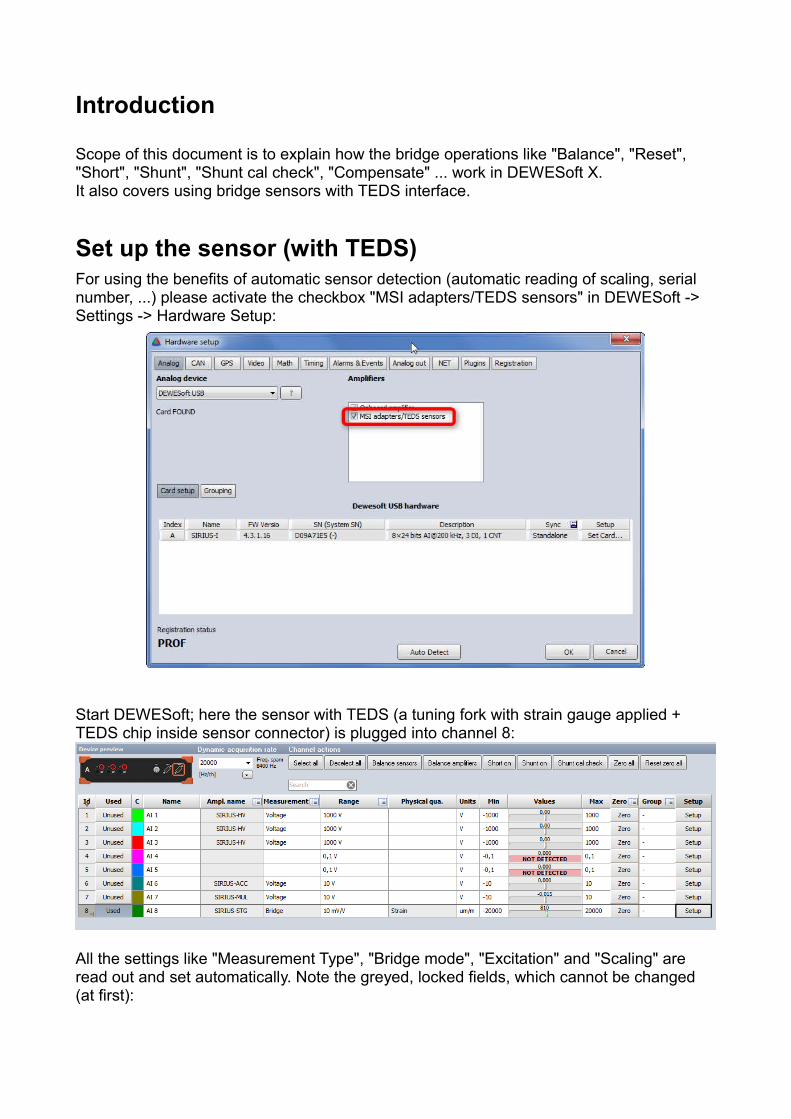
Set up the sensor (with TEDS)For using the benefits of automatic sensor detection (automatic reading of scaling, serial number, ...) please activate the checkbox "MSI adapters/TEDS sensors" in DEWESoft -> Settings -> Hardware Setup:
Start DEWESoft; here the sensor with TEDS (a tuning fork with strain gauge applied + TEDS chip inside sensor connector) is plugged into channel 8:
All the settings like "Measurement Type", "Bridge mode", "Excitation" and "Scaling" are read out and set automatically. Note the greyed, locked fields, which cannot be changed (at first):
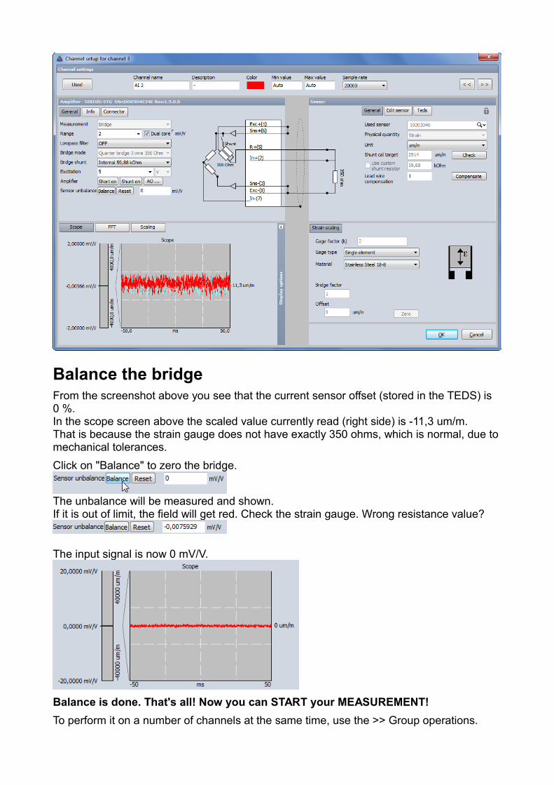
Balance the bridgeFrom the screenshot above you see that the current sensor offset (stored in the TEDS) is 0 %.In the scope screen above the scaled value currently read (right side) is -11,3 um/m.That is because the strain gauge does not have exactly 350 ohms, which is normal, due tomechanical tolerances.
Click on "Balance" to zero the bridge.
The unbalance will be measured and shown.If it is out of limit, the field will get red. Check the strain gauge. Wrong resistance value?
The input signal is now 0 mV/V.
Balance is done. That's all! Now you can START your MEASUREMENT!
To perform it on a number of channels at the same time, use the >> Group operations.
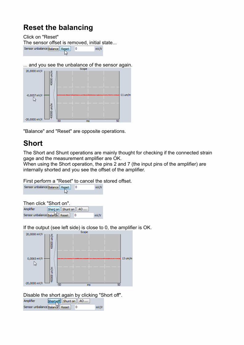
Reset the balancingClick on "Reset"The sensor offset is removed, initial state...
... and you see the unbalance of the sensor again.
"Balance" and "Reset" are opposite operations.
ShortThe Short and Shunt operations are mainly thought for checking if the connected strain gage and the measurement amplifier are OK.When using the Short operation, the pins 2 and 7 (the input pins of the amplifier) are internally shorted and you see the offset of the amplifier.
First perform a "Reset" to cancel the stored offset.
Then click "Short on".
If the output (see left side) is close to 0, the amplifier is OK.
Disable the short again by clicking "Short off".
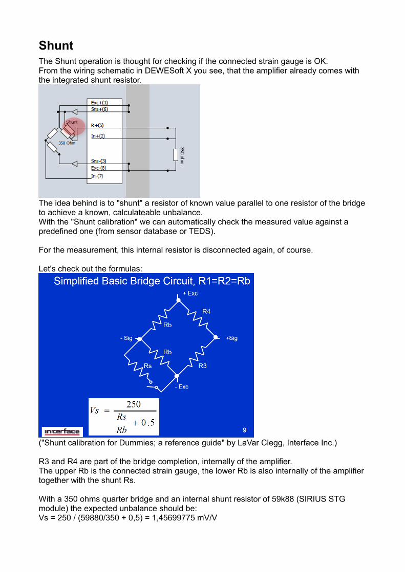
ShuntThe Shunt operation is thought for checking if the connected strain gauge is OK.From the wiring schematic in DEWESoft X you see, that the amplifier already comes with the integrated shunt resistor.
The idea behind is to "shunt" a resistor of known value parallel to one resistor of the bridgeto achieve a known, calculateable unbalance.With the "Shunt calibration" we can automatically check the measured value against a predefined one (from sensor database or TEDS).
For the measurement, this internal resistor is disconnected again, of course.
Let's check out the formulas:
("Shunt calibration for Dummies; a reference guide" by LaVar Clegg, Interface Inc.)
R3 and R4 are part of the bridge completion, internally of the amplifier.The upper Rb is the connected strain gauge, the lower Rb is also internally of the amplifier together with the shunt Rs.
With a 350 ohms quarter bridge and an internal shunt resistor of 59k88 (SIRIUS STG module) the expected unbalance should be:Vs = 250 / (59880/350 + 0,5) = 1,45699775 mV/V
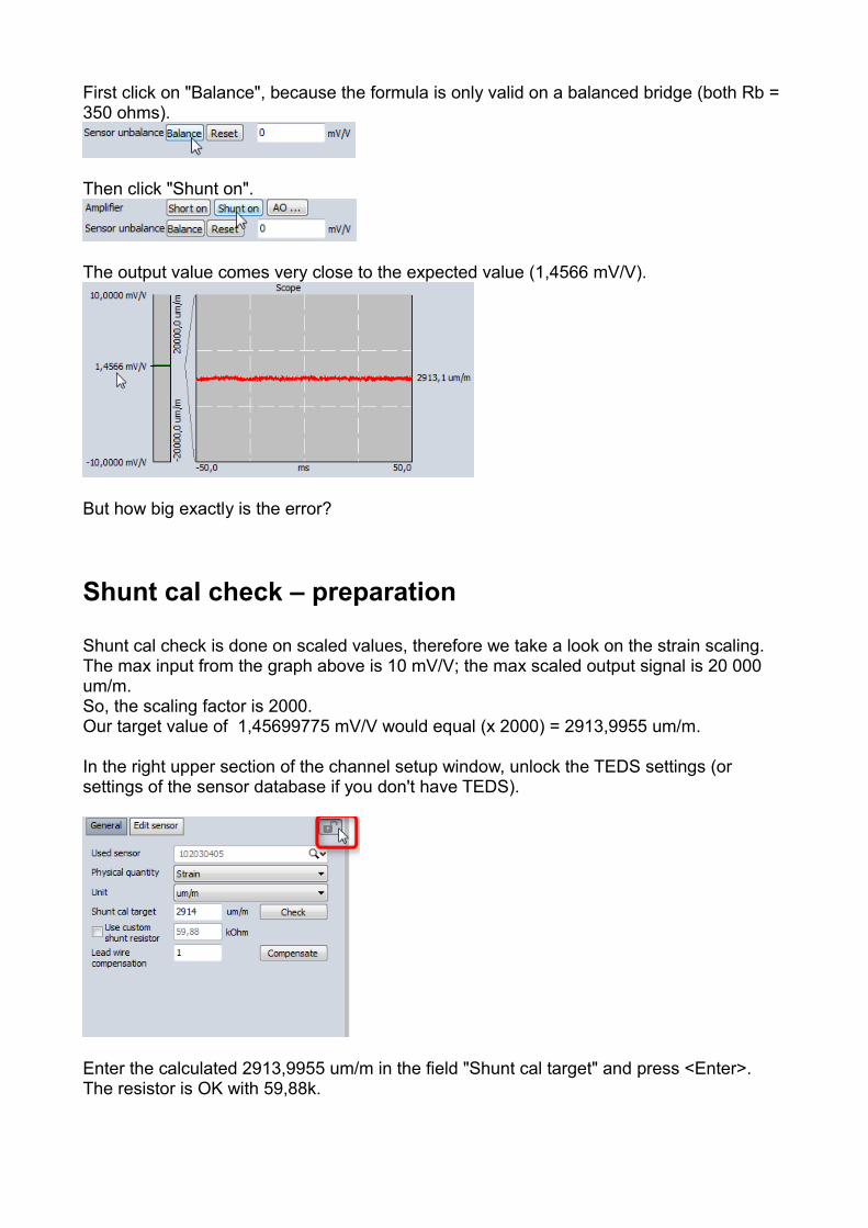
First click on "Balance", because the formula is only valid on a balanced bridge (both Rb = 350 ohms).
Then click "Shunt on".
The output value comes very close to the expected value (1,4566 mV/V).
But how big exactly is the error?
Shunt cal check – preparation
Shunt cal check is done on scaled values, therefore we take a look on the strain scaling.The max input from the graph above is 10 mV/V; the max scaled output signal is 20 000 um/m.So, the scaling factor is 2000.Our target value of 1,45699775 mV/V would equal (x 2000) = 2913,9955 um/m.
In the right upper section of the channel setup window, unlock the TEDS settings (or settings of the sensor database if you don't have TEDS).
Enter the calculated 2913,9955 um/m in the field "Shunt cal target" and press <Enter>.The resistor is OK with 59,88k.
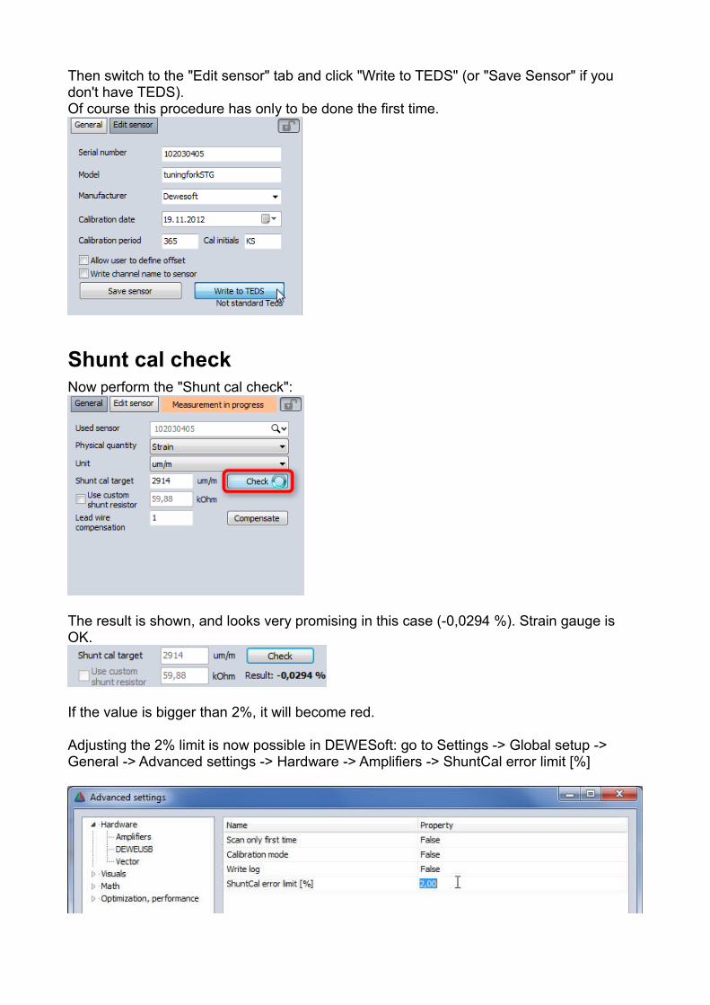
Then switch to the "Edit sensor" tab and click "Write to TEDS" (or "Save Sensor" if you don't have TEDS).Of course this procedure has only to be done the first time.
Shunt cal checkNow perform the "Shunt cal check":
The result is shown, and looks very promising in this case (-0,0294 %). Strain gauge is OK.
If the value is bigger than 2%, it will become red.
Adjusting the 2% limit is now possible in DEWESoft: go to Settings -> Global setup -> General -> Advanced settings -> Hardware -> Amplifiers -> ShuntCal error limit [%]
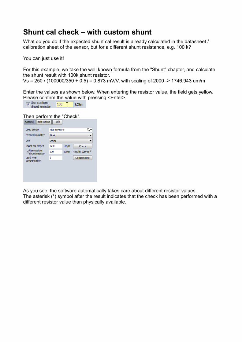
Shunt cal check – with custom shuntWhat do you do if the expected shunt cal result is already calculated in the datasheet / calibration sheet of the sensor, but for a different shunt resistance, e.g. 100 k?
You can just use it!
For this example, we take the well known formula from the "Shunt" chapter, and calculate the shunt result with 100k shunt resistor.Vs = 250 / (100000/350 + 0,5) = 0,873 mV/V, with scaling of 2000 -> 1746,943 um/m
Enter the values as shown below. When entering the resistor value, the field gets yellow. Please confirm the value with pressing <Enter>.
Then perform the "Check".
As you see, the software automatically takes care about different resistor values.The asterisk (*) symbol after the result indicates that the check has been performed with a different resistor value than physically available.
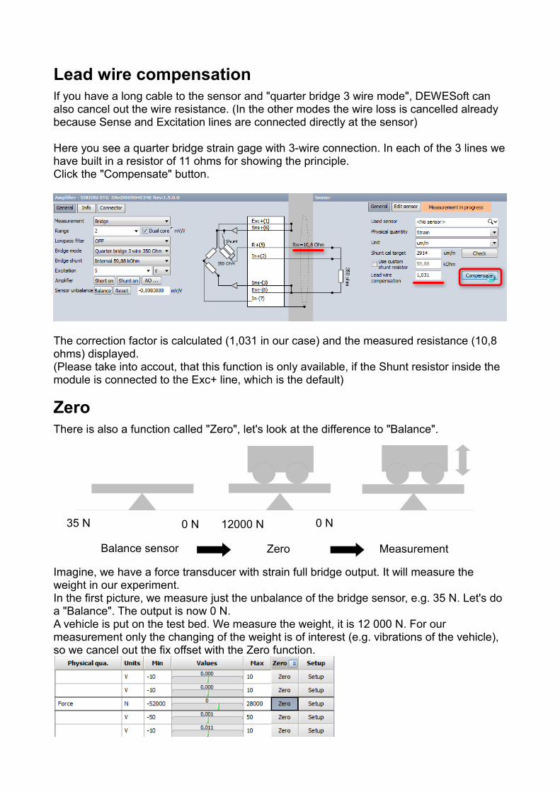
Lead wire compensationIf you have a long cable to the sensor and "quarter bridge 3 wire mode", DEWESoft can also cancel out the wire resistance. (In the other modes the wire loss is cancelled already because Sense and Excitation lines are connected directly at the sensor)
Here you see a quarter bridge strain gage with 3-wire connection. In each of the 3 lines wehave built in a resistor of 11 ohms for showing the principle.Click the "Compensate" button.
The correction factor is calculated (1,031 in our case) and the measured resistance (10,8 ohms) displayed.(Please take into accout, that this function is only available, if the Shunt resistor inside the module is connected to the Exc+ line, which is the default)
ZeroThere is also a function called "Zero", let's look at the difference to "Balance".
Imagine, we have a force transducer with strain full bridge output. It will measure the weight in our experiment.In the first picture, we measure just the unbalance of the bridge sensor, e.g. 35 N. Let's do a "Balance". The output is now 0 N.A vehicle is put on the test bed. We measure the weight, it is 12 000 N. For our measurement only the changing of the weight is of interest (e.g. vibrations of the vehicle), so we cancel out the fix offset with the Zero function.
Zero MeasurementBalance sensor
35 N 0 N 12000 N 0 N
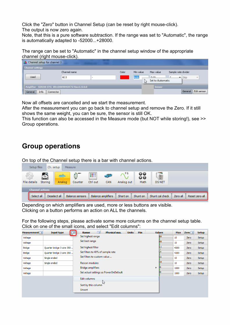
Click the "Zero" button in Channel Setup (can be reset by right mouse-click).The output is now zero again.Note, that this is a pure software subtraction. If the range was set to "Automatic", the rangeis automatically adapted to -52000...+28000.
The range can be set to "Automatic" in the channel setup window of the appropriate channel (right mouse-click).
Now all offsets are cancelled and we start the measurement.After the measurement you can go back to channel setup and remove the Zero. If it still shows the same weight, you can be sure, the sensor is still OK.This function can also be accessed in the Measure mode (but NOT while storing!), see >> Group operations.
Group operations
On top of the Channel setup there is a bar with channel actions.
Depending on which amplifiers are used, more or less buttons are visible.Clicking on a button performs an action on ALL the channels.
For the following steps, please activate some more columns on the channel setup table.Click on one of the small icons, and select "Edit columns":
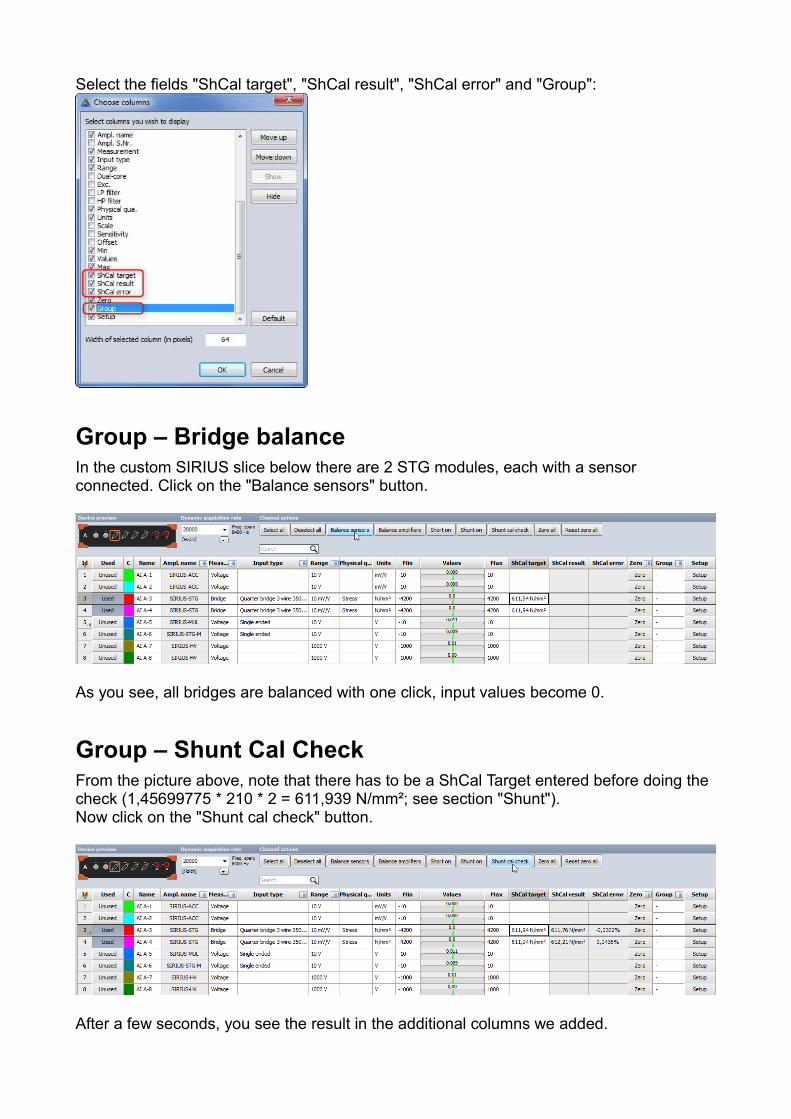
Select the fields "ShCal target", "ShCal result", "ShCal error" and "Group":
Group – Bridge balanceIn the custom SIRIUS slice below there are 2 STG modules, each with a sensor connected. Click on the "Balance sensors" button.
As you see, all bridges are balanced with one click, input values become 0.
Group – Shunt Cal CheckFrom the picture above, note that there has to be a ShCal Target entered before doing the check (1,45699775 * 210 * 2 = 611,939 N/mm²; see section "Shunt").Now click on the "Shunt cal check" button.
After a few seconds, you see the result in the additional columns we added.
Group – Balance amplifiers
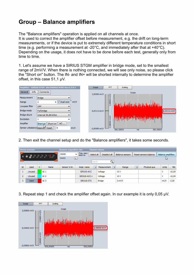
The "Balance amplifiers" operation is applied on all channels at once.It is used to correct the amplifier offset before measurement, e.g. the drift on long-term measurements, or if the device is put to extremely different temperature conditions in shorttime (e.g. performing a measurement at -20°C, and immediately after that at +40°C).Depending on the usage, it does not have to be done before each test, generally only fromtime to time.
1. Let's assume we have a SIRIUS STGM amplifier in bridge mode, set to the smallest range of 2mV/V. When there is nothing connected, we will see only noise, so please click the "Short on" button. The IN- and IN+ will be shorted internally to determine the amplifier offset, in this case 51,1 µV.
2. Then exit the channel setup and do the "Balance amplifiers", it takes some seconds.
3. Repeat step 1 and check the amplifier offset again. In our example it is only 0,05 µV.
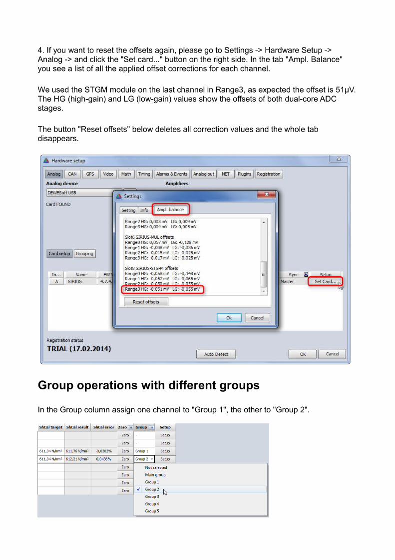
4. If you want to reset the offsets again, please go to Settings -> Hardware Setup -> Analog -> and click the "Set card..." button on the right side. In the tab "Ampl. Balance" you see a list of all the applied offset corrections for each channel.
We used the STGM module on the last channel in Range3, as expected the offset is 51µV.The HG (high-gain) and LG (low-gain) values show the offsets of both dual-core ADC stages.
The button "Reset offsets" below deletes all correction values and the whole tab disappears.
Group operations with different groups
In the Group column assign one channel to "Group 1", the other to "Group 2".
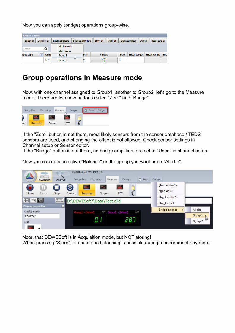
Now you can apply (bridge) operations group-wise.
Group operations in Measure mode
Now, with one channel assigned to Group1, another to Group2, let's go to the Measure mode. There are two new buttons called "Zero" and "Bridge".
If the "Zero" button is not there, most likely sensors from the sensor database / TEDS sensors are used, and changing the offset is not allowed. Check sensor settings in Channel setup or Sensor editor.If the "Bridge" button is not there, no bridge amplifiers are set to "Used" in channel setup.
Now you can do a selective "Balance" on the group you want or on "All chs".
Note, that DEWESoft is in Acquisition mode, but NOT storing!When pressing "Store", of course no balancing is possible during measurement any more.
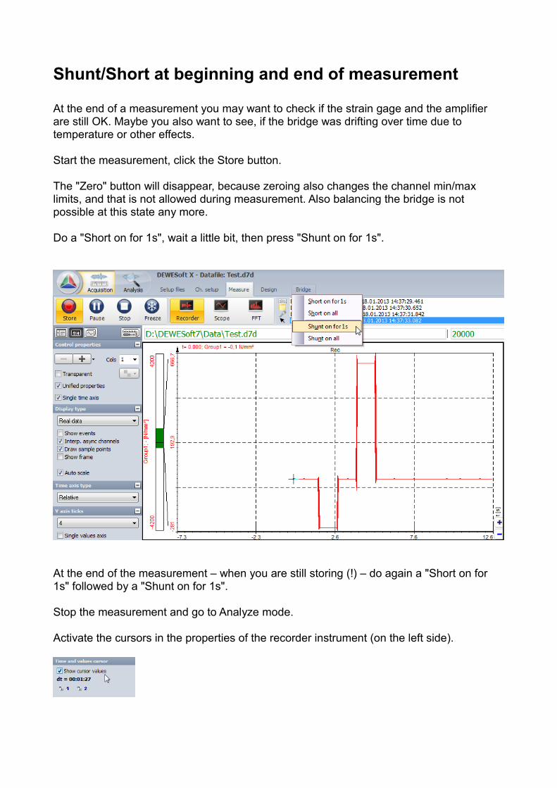
Shunt/Short at beginning and end of measurement
At the end of a measurement you may want to check if the strain gage and the amplifier are still OK. Maybe you also want to see, if the bridge was drifting over time due to temperature or other effects.
Start the measurement, click the Store button.
The "Zero" button will disappear, because zeroing also changes the channel min/max limits, and that is not allowed during measurement. Also balancing the bridge is not possible at this state any more.
Do a "Short on for 1s", wait a little bit, then press "Shunt on for 1s".
At the end of the measurement – when you are still storing (!) – do again a "Short on for 1s" followed by a "Shunt on for 1s".
Stop the measurement and go to Analyze mode.
Activate the cursors in the properties of the recorder instrument (on the left side).
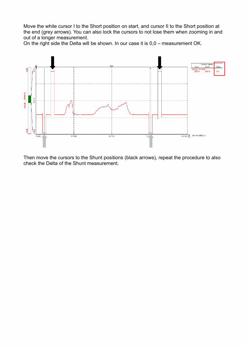
Move the white cursor I to the Short position on start, and cursor II to the Short position at the end (grey arrows). You can also lock the cursors to not lose them when zooming in andout of a longer measurement.On the right side the Delta will be shown. In our case it is 0,0 – measurement OK.
Then move the cursors to the Shunt positions (black arrows), repeat the procedure to also check the Delta of the Shunt measurement.

Hint : Strain gage configurations in DEWESoft X
Until now it was rather difficult to select the proper strain configuration. You had to find out the bridge factor in the tutorials table and look for materials coefficients.
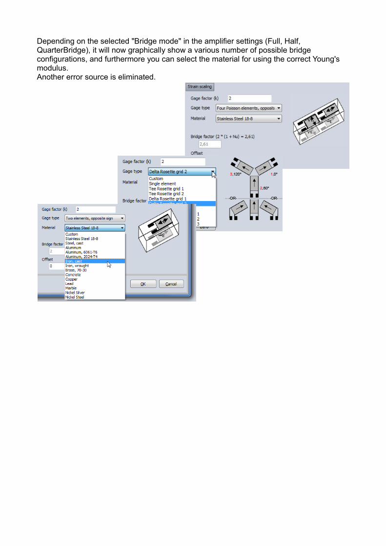
Depending on the selected "Bridge mode" in the amplifier settings (Full, Half, QuarterBridge), it will now graphically show a various number of possible bridge configurations, and furthermore you can select the material for using the correct Young's modulus.Another error source is eliminated.
Hint : Rosette Math
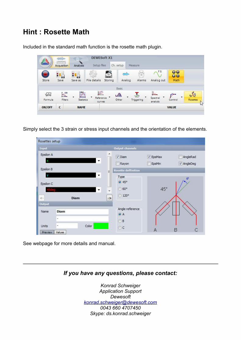
Included in the standard math function is the rosette math plugin.
Simply select the 3 strain or stress input channels and the orientation of the elements.
See webpage for more details and manual.
If you have any questions, please contact:
Konrad SchweigerApplication Support
0043 660 4707450Skype: ds.konrad.schweiger