Embed Size (px)
Citation preview
Oracle® Communications SessionBorder ControllerAccounting Guide
Release S-CZ7.4.0February 2019

Oracle Communications Session Border Controller Accounting Guide, Release S-CZ7.4.0
Copyright © 2014, 2019, Oracle and/or its affiliates. All rights reserved.
This software and related documentation are provided under a license agreement containing restrictions on use anddisclosure and are protected by intellectual property laws. Except as expressly permitted in your license agreement orallowed by law, you may not use, copy, reproduce, translate, broadcast, modify, license, transmit, distribute, exhibit,perform, publish, or display any part, in any form, or by any means. Reverse engineering, disassembly, or decompilationof this software, unless required by law for interoperability, is prohibited.
The information contained herein is subject to change without notice and is not warranted to be error-free. If you findany errors, please report them to us in writing.
If this is software or related documentation that is delivered to the U.S. Government or anyone licensing it on behalf ofthe U.S. Government, then the following notice is applicable:
U.S. GOVERNMENT END USERS: Oracle programs, including any operating system, integrated software, anyprograms installed on the hardware, and/or documentation, delivered to U.S. Government end users are "commercialcomputer software" pursuant to the applicable Federal Acquisition Regulation and agency-specific supplementalregulations. As such, use, duplication, disclosure, modification, and adaptation of the programs, including any operatingsystem, integrated software, any programs installed on the hardware, and/or documentation, shall be subject to licenseterms and license restrictions applicable to the programs. No other rights are granted to the U.S. Government.
This software or hardware is developed for general use in a variety of information management applications. It is notdeveloped or intended for use in any inherently dangerous applications, including applications that may create a risk ofpersonal injury. If you use this software or hardware in dangerous applications, then you shall be responsible to take allappropriate fail-safe, backup, redundancy, and other measures to ensure its safe use. Oracle Corporation and its affiliatesdisclaim any liability for any damages caused by use of this software or hardware in dangerous applications.
Oracle and Java are registered trademarks of Oracle and/or its affiliates. Other names may be trademarks of theirrespective owners.
Intel and Intel Xeon are trademarks or registered trademarks of Intel Corporation. All SPARC trademarks are used underlicense and are trademarks or registered trademarks of SPARC International, Inc. AMD, Opteron, the AMD logo, andthe AMD Opteron logo are trademarks or registered trademarks of Advanced Micro Devices. UNIX is a registeredtrademark of The Open Group.
This software or hardware and documentation may provide access to or information about content, products, andservices from third parties. Oracle Corporation and its affiliates are not responsible for and expressly disclaim allwarranties of any kind with respect to third-party content, products, and services unless otherwise set forth in anapplicable agreement between you and Oracle. Oracle Corporation and its affiliates will not be responsible for any loss,costs, or damages incurred due to your access to or use of third-party content, products, or services, except as set forth inan applicable agreement between you and Oracle.
Contents
About this Guide
1 Using RADIUS with the SBC
Introduction 1-1Licensing 1-1
Overview 1-1Standard RADIUS Attributes 1-2
Standard RADIUS Attributes Dictionary 1-2RADIUS Accounting Termination Causes 1-4
VSAs 1-4Oracle RADIUS VSAs 1-4
R-Factor and MOS 1-5Notes on Media Flow Attributes 1-6IPv6 Support 1-18Oracle VSA Values 1-19Authentication VSAs 1-22
Cisco Systems RADIUS Decodes 1-22Mappings and Disconnect Cause Values 1-23
SIP H.323 and Q.850 Mappings 1-23SIP Status to H.323 Disconnect Reason Mapping 1-23SIP Status to H.323 RAS Error Mapping 1-24SIP Status to H.323 Release Complete Reason Error Mapping 1-24Q.850 Cause to H.323 Release Complete Reason Mapping 1-25
SIP-SIP Calls 1-25SIP-H.323 Calls with Interworking 1-25
SIP Events and Errors 1-26H.323 Events and Errors 1-26H.225 RAS Errors 1-27
SIP Call Tear Down Due to Media Guard Timer Expiration 1-28CDR Output 1-28Explanation 1-28
iii
RTP Traffic Reporting per Call 1-28
2 Configuring Accounting
Overview 2-1Accounting for SIP and H.323 2-1
Call Detail Records 2-1RAS Overview 2-1
RADIUS Accounting Client 2-2Session Accounting 2-3
Interim RADIUS Records for Recursive Attempts 2-3RADIUS Messages 2-4Session Termination 2-4
ACLI Instructions and Examples 2-5Accessing the Accounting and Accounting Servers Configuration 2-5Setting Up the Account Configuration 2-5Setting Up Accounting Servers 2-7
SIP CDR Stop Time 2-8ACLI Instructions and Examples 2-9Set Acct-session-time attribute to milliseconds 2-9
Configure acct-session-time for millisecond granularity 2-9Per Realm Accounting Control 2-10
ACLI Instructions 2-10Configurable Intermediate Period 2-10Media Stop Time VSA in CDRs 2-11
Media Stop Time VSAs 2-11Media Stop Time Calculation 2-11HA Caveat 2-12
RADIUS CDR Content Control 2-12ACLI Instructions and Examples 2-12
Accessing the Accounting Configuration 2-12Preventing Duplicate RADIUS Attributes 2-13RADIUS Attribute Selection 2-13
Custom RADIUS CDR VSAs for SIP 2-13About User-Defined VSAs for SIP Calls 2-14
HMR Adaptations 2-14HMR String Variable 2-15ACLI Instructions and Examples User-Defined VSAs 2-15ACLI Instructions and Examples String Variable 2-17
Trunk-Group VSA Generation 2-18ACLI Instructions and Examples 2-18
iv
RADIUS Account Server Prioritization 2-19How You Might User Server Prioritization 2-19ACLI Instructions and Examples 2-19
Accounting Configuration Example 2-20Local CDR Storage and FTP Push 2-21
Local CDR File Format 2-22Local CDR File Format Consistency 2-22Generate Local CDR Layout Files 2-22Requirements 2-24
Local CDR File Naming Convention 2-24Call Detail Record Sequence Number in Filename 2-24
CDR Sequence Number in Filename Configuration 2-25Temp-remote-file creation for CDR files during transfer Configuration 2-25
Local CDR File Storage Directories 2-25Local CDR File Size and Rotation 2-26
More About File Rotation Time 2-26RADIUS CDR Redundancy 2-26
Caveats for H.323 2-26FTP Push 2-26
Deprecated ACLI Configuration 2-26Multiple Push Receivers 2-27Push Receivers 2-27Secure FTP Push Configuration 2-27
ACLI Instructions and Examples 2-28Accessing the Accounting Configuration 2-28Enabling Local CDR Storage 2-28Configuring a Push Receiver Fallback Method 2-29Setting the CSV File Format 2-30Enabling FTP Push 2-30
Creating a Public Key Profile 2-31SSH Operations 2-31
ACLI Instructions and Examples 2-32Configure SSH Properties 2-32Import an SSH host Key 2-33Create the Public Key Record 2-34Generate an SSH key pair 2-35Copy the RSA Public Key to the SFTP Server 2-36View a Public key on the SBC 2-36
Temporary File Naming for an Open CDR File 2-39Operational Details 2-40HA Considerations 2-40
v
Caveats 2-41Temporary Local CDR File Renaming Configuration 2-41Enhanced Stop CDR Reporting for Exceeded Ingress Session Constraints 2-41
3 RADIUS Accounting Management
Overview 3-1Alarm Generation and Monitoring 3-1
RADIUS Alarms 3-1Status and Statistics Monitoring 3-2
ACLI Show RADIUS Display 3-2Monitoring CDR Push Receivers 3-4
SNMP Support 3-5CDR File Transfer Failure Alarm 3-5
4 Storage Expansion Module
Storage Expansion Module Use With Local CDRs FTP Push 4-1Local CDR Storage Directory 4-1FTP Push Backup 4-1Local CDR File Compression 4-1ACLI Configuration and Examples 4-1
Identify Volumes 4-2Configure File Path 4-2
Storage Expansion Module Management 4-2Storage Expansion Module Monitoring 4-2
Low Disk Space Warning 4-2Low Disk Space Threshold Alarm 4-3Low Disk Space Threshold SNMP Trap 4-3
ACLI Configuration and Examples 4-3Local CDR File Delete Warning 4-4
Local CDR File Delete Alarm 4-4Local CDR File Delete SNMP Trap 4-4
Querying Storage Space 4-5ACLI 4-5
Unmounting The Storage Expansion Module 4-5ACLI Instructions and Examples 4-5
SNMP MIB 4-5HDR 4-6
vi
5 Diameter Rf Accounting
Diameter Accounting 5-1Diameter Accounting Messages 5-1
Resending ACRs 5-1Postponement Feature 5-1Call Flow Examples 5-1
ACR AVP Descriptions 5-3Session-Id AVP (263) 5-3Origin-Host AVP (264) 5-4Origin-Realm AVP (296) 5-4Destination-Realm AVP (283) 5-4Destination-Host AVP (293) 5-4Accounting-Record-Type AVP (480) 5-4Accounting-Record-Number AVP (485) 5-4Acct-Application-Id AVP (259) 5-6User-Name AVP (1) 5-6Event-Timestamp AVP (55) 5-6Event-Type AVP (823) 5-6Role-of-Node AVP (829) 5-6User-Session-Id AVP (830) 5-7Calling-Party-Address AVP (831) 5-7Called-Party-Address AVP (832) 5-7Time-Stamps AVP (833) 5-7Inter-Operator-Identifier AVP (838) 5-7SDP-Session-Description AVP (842) 5-7Session-Media-Component AVP (845) 5-8Cause AVP (860) 5-8Values for Cause Code AVP (861) 5-8
ACR Event Records 5-9ACR Event Message Construction 5-9Event-Type AVP 5-9
Expires Value 5-10Event ACRs Generated for Unsuccessful Session Attempts 5-10Event ACRs Generated for Receipt of SIP Messages 5-12Event Local CSV File 5-13
Diameter Heartbeat for Rf 5-14Configuring Diameter-based Accounting 5-14
Configure the Global Diameter-based Accounting (Rf) Features 5-14Configure Accounting Servers 5-16
Additional Rf Features Alarms and Traps 5-18
vii
Service-Context-ID Format 5-18Acme Excluded Attribute Range 5-18
Configure Account 5-19SNMP Trap Behavior 5-19Alarms 5-21SNMP MIBs and Traps 5-21
ApDiamResultCode Textual Convention 5-21apDiameterSrvrErrorResultTrap 5-22apDiameterSrvrSuccessResultTrap 5-22apDiamACCTResultObjectsGroup Object Group 5-22apDiamACCTResultNotificationsGroup Notification Group 5-23SNMP Varbind Definitions 5-23
Diameter Rf Charging Buffering and Storage 5-23About Buffering 5-23About Storage 5-23
Monitoring Storage Space 5-24ACLI Instructions and Examples 5-24SNMP 5-24
DIAMETER Rf Charging Failure & Recovery Detection 5-25Associated Traps 5-25
A Appendix A
B Appendix B
C Comma-Delimited Local Files for Diameter Rf Accounting
D Appendix D
Oracle Rf Interface Support D-1Diameter AVP Notation D-1Table Explanation D-1Root ACR Message Format D-1Service Information AVP D-2Subscription ID AVP D-2IMS Information AVP D-2Event-Type AVP D-3Time Stamps AVP D-4Inter-Operator-Identifier AVP D-4
viii
SDP-Media-Component AVP D-4Early-Media-Description AVP D-4SDP-Timestamps AVP D-5Message-Body AVP D-5Acme-Packet-Specific-Extension-Rf AVP D-5
AVP Definitions D-9System Alarming Based on Received Result-Code (268) AVP D-11Interim ACR Message Creation Interval per Acct-Interim-Interval AVP D-12
ix
About this Guide
Overview
The Oracle Communications Session Border Controller Accounting Guide describes:
• The Oracle Communications Session Border Controller’s accounting-based options onRemote Authentication Dial-in User Service (RADIUS)
• How to configure RADIUS accounting support, and the features related to it
• Local CDR storage and FTP file push
• Use and maintenance of the Storage Expansion Module
• Diameter-based Rf Accounting
It includes the Acme Packet accounting Vendor-Specific Attributes (VSAs), and the CiscoSystems, Inc.™ VSAs supported by the Oracle Communications Session Border Controller.This reference guide indicates the Cisco Systems’ VSAs supported by Oracle’s products.
This guide also includes RADIUS-related statistics and alarm information and associated AcmePacket Command Line Interface (ACLI) configuration element examples. Appendix A of thisguide contains a selection of examples of RADIUS logs for purposes of reference.
Related Documentation
The following table lists the members that comprise the documentation set for this release:
Document Name Document Description
Acme Packet 4500 Hardware InstallationGuide
Contains information about the components andinstallation of the Acme Packet 4500.
Acme Packet 3820 Hardware InstallationGuide
Contains information about the components andinstallation of the Acme Packet 3820.
Acme Packet 4600 Hardware InstallationGuide
Contains information about the components andinstallation of the Acme Packet 4600.
Acme Packet 6100 Hardware InstallationGuide
Contains information about the components andinstallation of the Acme Packet 6100.
Acme Packet 6300 Hardware InstallationGuide
Contains information about the components andinstallation of the Acme Packet 6300.
Release Notes Contains information about the current documentation setrelease, including new features and management changes.
ACLI Configuration Guide Contains information about the administration andsoftware configuration of the Service Provider OracleCommunications Session Border Controller.
ACLI Reference Guide Contains explanations of how to use the ACLI, as analphabetical listings and descriptions of all ACLIcommands and configuration parameters.
About this Guide
x
Document Name Document Description
Maintenance and Troubleshooting Guide Contains information about Oracle CommunicationsSession Border Controller logs, performanceannouncements, system management, inventorymanagement, upgrades, working with configurations, andmanaging backups and archives.
MIB Reference Guide Contains information about Management Information Base(MIBs), Oracle Communication's enterprise MIBs, generaltrap information, including specific details about standardtraps and enterprise traps, Simple Network ManagementProtocol (SNMP) GET query information (includingstandard and enterprise SNMP GET query names, objectidentifier names and numbers, and descriptions), examplesof scalar and table objects.
Accounting Guide Contains information about the Oracle CommunicationsSession Border Controller’s accounting support, includingdetails about RADIUS and Diameter accounting.
HDR Resource Guide Contains information about the Oracle CommunicationsSession Border Controller’s Historical Data Recording(HDR) feature. This guide includes HDR configurationand system-wide statistical information.
Administrative Security Essentials Contains information about the Oracle CommunicationsSession Border Controller’s support for its AdministrativeSecurity license.
Security Guide Contains information about security considerations andbest practices from a network and application securityperspective for the Oracle Communications SessionBorder Controller family of products.
Installation and Platform Preparation Guide Contains information about upgrading system images andany pre-boot system provisioning.
Call Traffic Monitoring Guide Contains information about traffic monitoring and packettraces as collected on the system. This guide also includesWebGUI configuration used for the SIP Monitor and Traceapplication.
Revision History
This section contains a revision history for this document.
Date Description
November 2016 Initial ReleaseMarch 2017 • Corrects the account-config > file-rotate-
time parameter's minimum valid value.May 2017 • Updates the file-rotate-time and max-file-size
parameter descriptions for clarity.• Adds a note to the account-config > max-file-
size description clarifying that the trafficenvironment in which the SBC is running mayaffect how this value is configured.
July 2017 • Replace inappropriate M&T file handlingappendix with Diameter-based local CDRformat
About this Guide
xi
Date Description
August 2017 • Adds missing fields to Local CSV (Radius)Stop Record
• Updates descriptions of the Calling-Party-Address AVP and Called-Party-Address AVP.
September 2017 • Updates the account-config > file-pathproperty for accuracy.
October 2017 • Updates "Local CDR File FormatConsistency" and "Appendix B" for accuracyand adds "Generate Local CDR Layout Files".
November 2017 • Corrects accounting flow attributes descriptionto indicate packet count data
January 2018 • Updates the "Acme-Packet-Specific-Extension-Rf AVP" table for accuracy.
August 2018 • Adds dump csv format layout to Appendix CFebruary 2019 • Adds the "RTP Traffic Reporting" topic.
About this Guide
xii
1Using RADIUS with the SBC
IntroductionRADIUS is an accounting, authentication, and authorization (AAA) system. In general,RADIUS servers are responsible for receiving user connection requests, authenticating users,and returning all configuration information necessary for the client to deliver service to theuser.
You can configure your SBC to send call accounting information to one or more RADIUSservers. This information can help you to see usage and QoS metrics, monitor traffic, and eventroubleshoot your system. For more information about QoS, refer to the Admission Control andQoS chapter of the ACLI Configuration Guide.
For information about how to configure the SBC for RADIUS accounting use, refer to thisguide’s Configuring Accounting chapter.
LicensingIn order to use RADIUS with your SBC, you must have the accounting license installed andactivated on your system. For more information about licensing, see the Software Licensingsection of the ACLI Configuration Guide’s Getting Started chapter. This chapter providesdetails about Oracle software licensing, including instructions for how to obtain and installlicenses.
OverviewFor H.323, SIP, and calls being interworked between H.323 and SIP (IWF), you can obtain setsof records that contain information to help you with accounting and that provide a quantitativeand qualitative measurement of the call. For H.323 and SIP calls, the SBC generates one set ofrecords; for calls requiring IWF, the SBC generates two sets of records.
You can use the RADIUS records generated by your SBC to assist you with:
• Usage accounting—See the calling and called parties for a call, the protocol used, therealm the call traversed (as well as local and remote IP address and port information), andthe codec used
• Traffic monitoring—You can see information about the setup, connect, and disconnecttimes, as well as the SIP or H.323 disconnect cause
• SLA monitoring—The SBC supports RADIUS attributes that provide information aboutjitter, latency, and loss for H.323, SIP, and calls that require interworking between H.323and SIP
• Troubleshooting—Obtain information about calls that can help you to identify and addressissues with quality and how calls are setup and torn down.
1-1
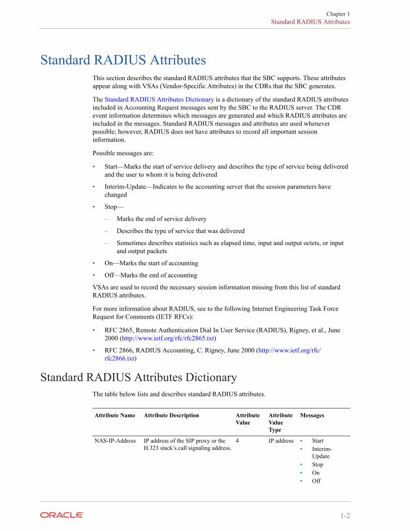
Standard RADIUS AttributesThis section describes the standard RADIUS attributes that the SBC supports. These attributesappear along with VSAs (Vendor-Specific Attributes) in the CDRs that the SBC generates.
The Standard RADIUS Attributes Dictionary is a dictionary of the standard RADIUS attributesincluded in Accounting Request messages sent by the SBC to the RADIUS server. The CDRevent information determines which messages are generated and which RADIUS attributes areincluded in the messages. Standard RADIUS messages and attributes are used wheneverpossible; however, RADIUS does not have attributes to record all important sessioninformation.
Possible messages are:
• Start—Marks the start of service delivery and describes the type of service being deliveredand the user to whom it is being delivered
• Interim-Update—Indicates to the accounting server that the session parameters havechanged
• Stop—
– Marks the end of service delivery
– Describes the type of service that was delivered
– Sometimes describes statistics such as elapsed time, input and output octets, or inputand output packets
• On—Marks the start of accounting
• Off—Marks the end of accounting
VSAs are used to record the necessary session information missing from this list of standardRADIUS attributes.
For more information about RADIUS, see to the following Internet Engineering Task ForceRequest for Comments (IETF RFCs):
• RFC 2865, Remote Authentication Dial In User Service (RADIUS), Rigney, et al., June2000 (http://www.ietf.org/rfc/rfc2865.txt)
• RFC 2866, RADIUS Accounting, C. Rigney, June 2000 (http://www.ietf.org/rfc/rfc2866.txt)
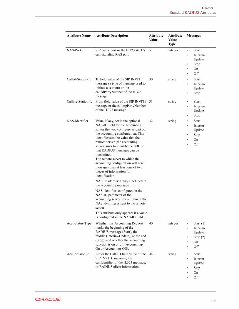
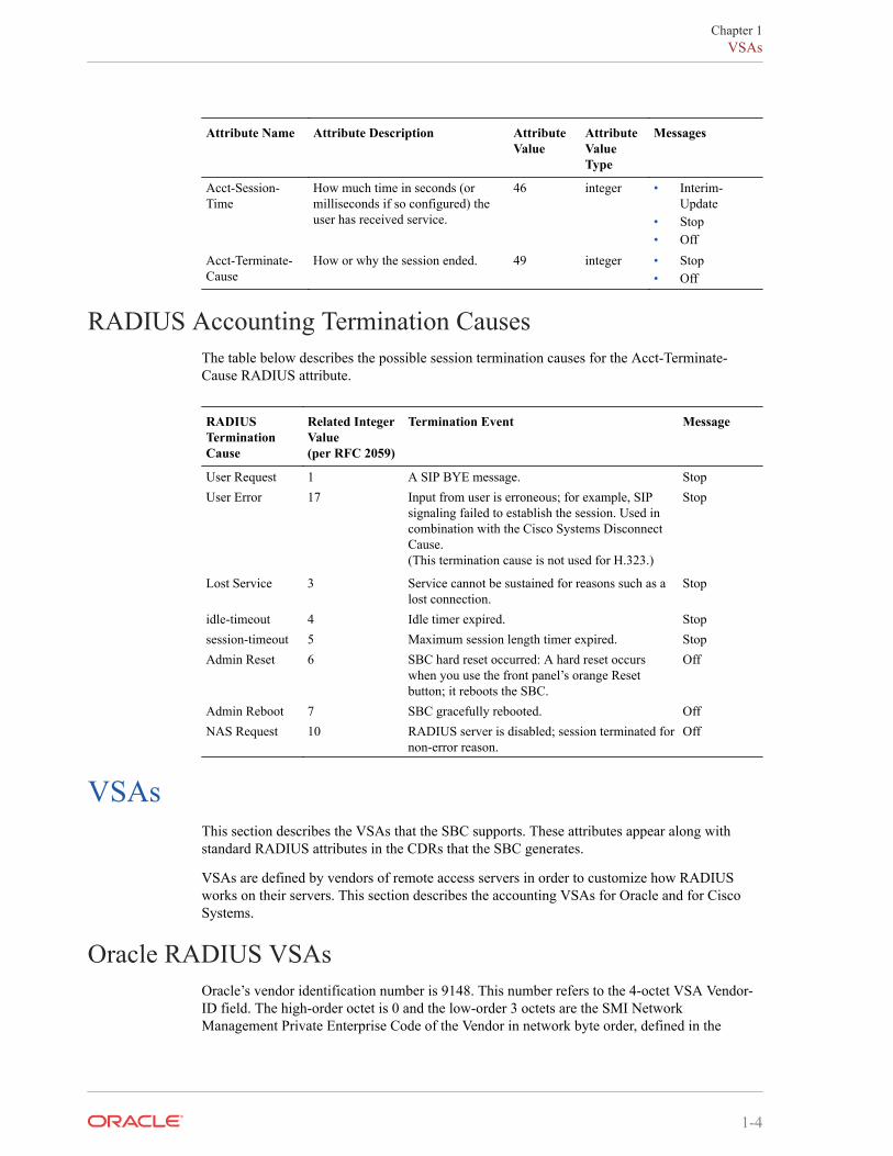
Standard RADIUS Attributes DictionaryThe table below lists and describes standard RADIUS attributes.
Attribute Name Attribute Description AttributeValue
AttributeValueType
Messages
NAS-IP-Address IP address of the SIP proxy or theH.323 stack’s call signaling address.
4 IP address • Start• Interim-
Update• Stop• On• Off
Chapter 1Standard RADIUS Attributes
1-2
Attribute Name Attribute Description AttributeValue
AttributeValueType
Messages
NAS-Port SIP proxy port or the H.323 stack’scall signaling RAS port.
5 integer • Start• Interim-
Update• Stop• On• Off
Called-Station-Id To field value of the SIP INVITEmessage (a type of message used toinitiate a session) or thecalledPartyNumber of the H.323message.
30 string • Start• Interim-
Update• Stop
Calling-Station-Id From field value of the SIP INVITEmessage or the callingPartyNumberof the H.323 message.
31 string • Start• Interim-
Update• Stop
NAS-Identifier Value, if any, set in the optionalNAS-ID field for the accountingserver that you configure as part ofthe accounting configuration. Thisidentifier sets the value that theremote server (the accountingserver) uses to identify the SBC sothat RADIUS messages can betransmitted.The remote server to which theaccounting configuration will sendmessages uses at least one of twopieces of information foridentification:NAS IP address: always included inthe accounting messageNAS identifier: configured in theNAS-ID parameter of theaccounting server; if configured, theNAS identifier is sent to the remoteserverThis attribute only appears if a valueis configured in the NAS-ID field.
32 string • Start• Interim-
Update• Stop• On• Off
Acct-Status-Type Whether this Accounting Requestmarks the beginning of theRADIUS message (Start), themiddle (Interim-Update), or the end(Stop), and whether the accountingfunction is on or off (Accounting-On or Accounting-Off).
40 integer • Start (1)• Interim-
Update• Stop (2)• On• Off
Acct-Session-Id Either the Call-ID field value of theSIP INVITE message, thecallIdentifier of the H.323 message,or RADIUS client information.
44 string • Start• Interim-
Update• Stop• On• Off
Chapter 1Standard RADIUS Attributes
1-3
Attribute Name Attribute Description AttributeValue
AttributeValueType
Messages
Acct-Session-Time
How much time in seconds (ormilliseconds if so configured) theuser has received service.
46 integer • Interim-Update
• Stop• Off
Acct-Terminate-Cause
How or why the session ended. 49 integer • Stop• Off
RADIUS Accounting Termination CausesThe table below describes the possible session termination causes for the Acct-Terminate-Cause RADIUS attribute.
RADIUSTerminationCause
Related IntegerValue(per RFC 2059)
Termination Event Message
User Request 1 A SIP BYE message. StopUser Error 17 Input from user is erroneous; for example, SIP
signaling failed to establish the session. Used incombination with the Cisco Systems DisconnectCause.(This termination cause is not used for H.323.)
Stop
Lost Service 3 Service cannot be sustained for reasons such as alost connection.
Stop
idle-timeout 4 Idle timer expired. Stopsession-timeout 5 Maximum session length timer expired. StopAdmin Reset 6 SBC hard reset occurred: A hard reset occurs
when you use the front panel’s orange Resetbutton; it reboots the SBC.
Off
Admin Reboot 7 SBC gracefully rebooted. OffNAS Request 10 RADIUS server is disabled; session terminated for
non-error reason.Off
VSAsThis section describes the VSAs that the SBC supports. These attributes appear along withstandard RADIUS attributes in the CDRs that the SBC generates.
VSAs are defined by vendors of remote access servers in order to customize how RADIUSworks on their servers. This section describes the accounting VSAs for Oracle and for CiscoSystems.
Oracle RADIUS VSAsOracle’s vendor identification number is 9148. This number refers to the 4-octet VSA Vendor-ID field. The high-order octet is 0 and the low-order 3 octets are the SMI NetworkManagement Private Enterprise Code of the Vendor in network byte order, defined in the
Chapter 1VSAs
1-4
Assigned Numbers RFC (http://www.faqs.org/rfcs/rfc1700.html; Reynolds, J. and J. Postel,Assigned Numbers, STD 2, RFC 1700, October 1994).
The table in this section is a dictionary of Oracle’s accounting VSAs. You can use thisinformation to translate the Oracle VSAs in SBC RADIUS messages into human-readableform. Oracle maintains VSA dictionary definition files for the most popular RADIUSdistributions; ask your Oracle account representative for details.
Grouped according to attribute function, this table contains the following sections:
• General Flow Attributes—Overall traits of the media flow, these attributes appear in allCDRs regardless of the session’s protocol; these attribute fields are only populated if thereare media flows
• Inbound Flow Attributes—Detailed traits of the inbound media flow (including realm,remote IP address and port, and local IP address and port); these attribute fields are onlypopulated if there are media flows
• Outbound Flow Attributes—Detailed traits of the outbound media flow (including realm,remote IP address and port, and local IP address and port); these attribute field are onlypopulated if there are media flows
• Session Attributes—Information about the protocol type, ingress and egress realms used,and an identifier that links the H.323 and SIP legs of a call requiring IWF
• QoS Attributes—RADIUS call records are instantiated by individual signaling applicationson the SBC. The SBC writes the following additional parameters to the call record for QoS(Quality of Service):
– RTP Lost packets
– RTP Jitter
– RTP Maximum Jitter
– RTCP Lost packets
– RTCP Jitter
– RTCP Latency
– RTCP Maximum Latency
– RTP Total Packets
– RTP Total Octets
Only RADIUS Stop records contain QoS information. For non-QoS calls, the attributesappear in the record, but their values are always be zero (0). When you review the list ofQoS VSAs, please note that “calling” in the attribute name means the information is sentby the calling party and called in the attribute name means the information is sent by thecalled party.
Examples of how this information appears in CDRs appears in Appendix A of this guide.Please note that the contents of Interim-Update messages do not depend on what events cause aStart message to be generated.
R-Factor and MOSThe SBC reports R-Factor and MOS data for the calling and called segments at the end of asession. This information appears in RADIUS CDRs, and in the Oracle VSA dictionary:
• Acme-Calling-R-Factor (151)
Chapter 1VSAs
1-5
• Acme-Calling-MOS (152)
• Acme-Called-R-Factor (153)
• Acme-Called-MOS (154)
Note:
These values are reported as * 100 in order to appear as integers.
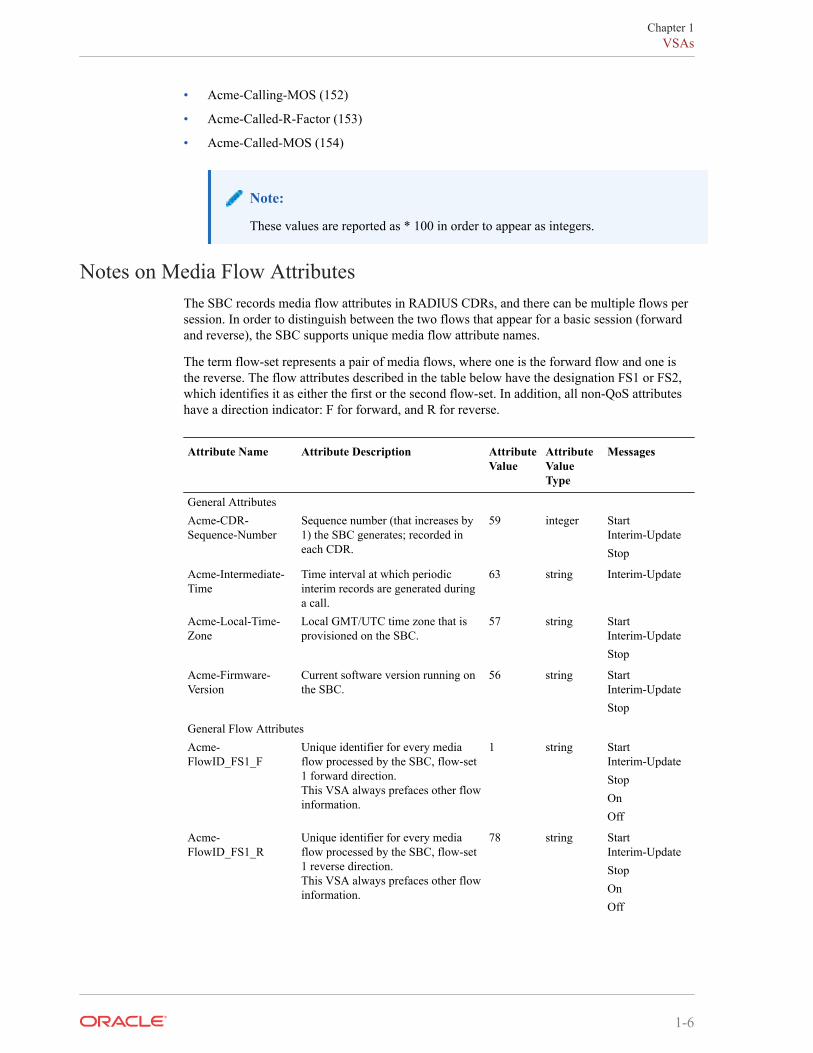
Notes on Media Flow AttributesThe SBC records media flow attributes in RADIUS CDRs, and there can be multiple flows persession. In order to distinguish between the two flows that appear for a basic session (forwardand reverse), the SBC supports unique media flow attribute names.
The term flow-set represents a pair of media flows, where one is the forward flow and one isthe reverse. The flow attributes described in the table below have the designation FS1 or FS2,which identifies it as either the first or the second flow-set. In addition, all non-QoS attributeshave a direction indicator: F for forward, and R for reverse.
Attribute Name Attribute Description AttributeValue
AttributeValueType
Messages
General AttributesAcme-CDR-Sequence-Number
Sequence number (that increases by1) the SBC generates; recorded ineach CDR.
59 integer StartInterim-UpdateStop
Acme-Intermediate-Time
Time interval at which periodicinterim records are generated duringa call.
63 string Interim-Update
Acme-Local-Time-Zone
Local GMT/UTC time zone that isprovisioned on the SBC.
57 string StartInterim-UpdateStop
Acme-Firmware-Version
Current software version running onthe SBC.
56 string StartInterim-UpdateStop
General Flow AttributesAcme-FlowID_FS1_F
Unique identifier for every mediaflow processed by the SBC, flow-set1 forward direction.This VSA always prefaces other flowinformation.
1 string StartInterim-UpdateStopOnOff
Acme-FlowID_FS1_R
Unique identifier for every mediaflow processed by the SBC, flow-set1 reverse direction.This VSA always prefaces other flowinformation.
78 string StartInterim-UpdateStopOnOff
Chapter 1VSAs
1-6
Attribute Name Attribute Description AttributeValue
AttributeValueType
Messages
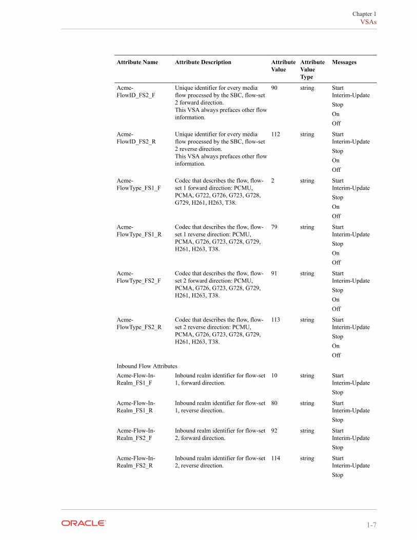
Acme-FlowID_FS2_F
Unique identifier for every mediaflow processed by the SBC, flow-set2 forward direction.This VSA always prefaces other flowinformation.
90 string StartInterim-UpdateStopOnOff
Acme-FlowID_FS2_R
Unique identifier for every mediaflow processed by the SBC, flow-set2 reverse direction.This VSA always prefaces other flowinformation.
112 string StartInterim-UpdateStopOnOff
Acme-FlowType_FS1_F
Codec that describes the flow, flow-set 1 forward direction: PCMU,PCMA, G722, G726, G723, G728,G729, H261, H263, T38.
2 string StartInterim-UpdateStopOnOff
Acme-FlowType_FS1_R
Codec that describes the flow, flow-set 1 reverse direction: PCMU,PCMA, G726, G723, G728, G729,H261, H263, T38.
79 string StartInterim-UpdateStopOnOff
Acme-FlowType_FS2_F
Codec that describes the flow, flow-set 2 forward direction: PCMU,PCMA, G726, G723, G728, G729,H261, H263, T38.
91 string StartInterim-UpdateStopOnOff
Acme-FlowType_FS2_R
Codec that describes the flow, flow-set 2 reverse direction: PCMU,PCMA, G726, G723, G728, G729,H261, H263, T38.
113 string StartInterim-UpdateStopOnOff
Inbound Flow AttributesAcme-Flow-In-Realm_FS1_F
Inbound realm identifier for flow-set1, forward direction.
10 string StartInterim-UpdateStop
Acme-Flow-In-Realm_FS1_R
Inbound realm identifier for flow-set1, reverse direction.
80 string StartInterim-UpdateStop
Acme-Flow-In-Realm_FS2_F
Inbound realm identifier for flow-set2, forward direction.
92 string StartInterim-UpdateStop
Acme-Flow-In-Realm_FS2_R
Inbound realm identifier for flow-set2, reverse direction.
114 string StartInterim-UpdateStop
Chapter 1VSAs
1-7
Attribute Name Attribute Description AttributeValue
AttributeValueType
Messages
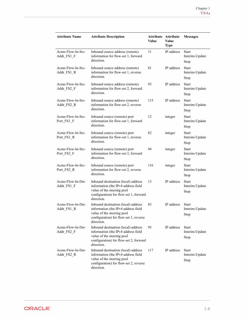
Acme-Flow-In-Src-Addr_FS1_F
Inbound source address (remote)information for flow-set 1, forwarddirection.
11 IP address StartInterim-UpdateStop
Acme-Flow-In-Src-Addr_FS1_R
Inbound source address (remote)information for flow-set 1, reversedirection.
81 IP address StartInterim-UpdateStop
Acme-Flow-In-Src-Addr_FS2_F
Inbound source address (remote)information for flow-set 2, forwarddirection.
93 IP address StartInterim-UpdateStop
Acme-Flow-In-Src-Addr_FS2_R
Inbound source address (remote)information for flow-set 2, reversedirection.
115 IP address StartInterim-UpdateStop
Acme-Flow-In-Src-Port_FS1_F
Inbound source (remote) portinformation for flow-set 1, forwarddirection.
12 integer StartInterim-UpdateStop
Acme-Flow-In-Src-Port_FS1_R
Inbound source (remote) portinformation for flow-set 1, reversedirection.
82 integer StartInterim-UpdateStop
Acme-Flow-In-Src-Port_FS2_F
Inbound source (remote) portinformation for flow-set 2, forwarddirection.
94 integer StartInterim-UpdateStop
Acme-Flow-In-Src-Port_FS2_R
Inbound source (remote) portinformation for flow-set 2, reversedirection.
116 integer StartInterim-UpdateStop
Acme-Flow-In-Dst-Addr_FS1_F
Inbound destination (local) addressinformation (the IPv4 address fieldvalue of the steering poolconfiguration) for flow-set 1, forwarddirection.
13 IP address StartInterim-UpdateStop
Acme-Flow-In-Dst-Addr_FS1_R
Inbound destination (local) addressinformation (the IPv4 address fieldvalue of the steering poolconfiguration) for flow-set 1, reversedirection.
83 IP address StartInterim-UpdateStop
Acme-Flow-In-Dst-Addr_FS2_F
Inbound destination (local) addressinformation (the IPv4 address fieldvalue of the steering poolconfiguration) for flow-set 2, forwarddirection.
95 IP address StartInterim-UpdateStop
Acme-Flow-In-Dst-Addr_FS2_R
Inbound destination (local) addressinformation (the IPv4 address fieldvalue of the steering poolconfiguration) for flow-set 2, reversedirection.
117 IP address StartInterim-UpdateStop
Chapter 1VSAs
1-8
Attribute Name Attribute Description AttributeValue
AttributeValueType
Messages
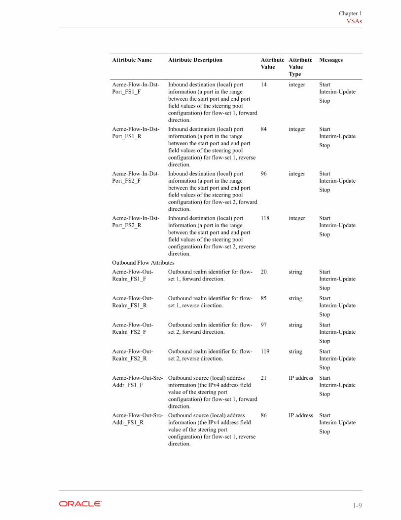
Acme-Flow-In-Dst-Port_FS1_F
Inbound destination (local) portinformation (a port in the rangebetween the start port and end portfield values of the steering poolconfiguration) for flow-set 1, forwarddirection.
14 integer StartInterim-UpdateStop
Acme-Flow-In-Dst-Port_FS1_R
Inbound destination (local) portinformation (a port in the rangebetween the start port and end portfield values of the steering poolconfiguration) for flow-set 1, reversedirection.
84 integer StartInterim-UpdateStop
Acme-Flow-In-Dst-Port_FS2_F
Inbound destination (local) portinformation (a port in the rangebetween the start port and end portfield values of the steering poolconfiguration) for flow-set 2, forwarddirection.
96 integer StartInterim-UpdateStop
Acme-Flow-In-Dst-Port_FS2_R
Inbound destination (local) portinformation (a port in the rangebetween the start port and end portfield values of the steering poolconfiguration) for flow-set 2, reversedirection.
118 integer StartInterim-UpdateStop
Outbound Flow AttributesAcme-Flow-Out-Realm_FS1_F
Outbound realm identifier for flow-set 1, forward direction.
20 string StartInterim-UpdateStop
Acme-Flow-Out-Realm_FS1_R
Outbound realm identifier for flow-set 1, reverse direction.
85 string StartInterim-UpdateStop
Acme-Flow-Out-Realm_FS2_F
Outbound realm identifier for flow-set 2, forward direction.
97 string StartInterim-UpdateStop
Acme-Flow-Out-Realm_FS2_R
Outbound realm identifier for flow-set 2, reverse direction.
119 string StartInterim-UpdateStop
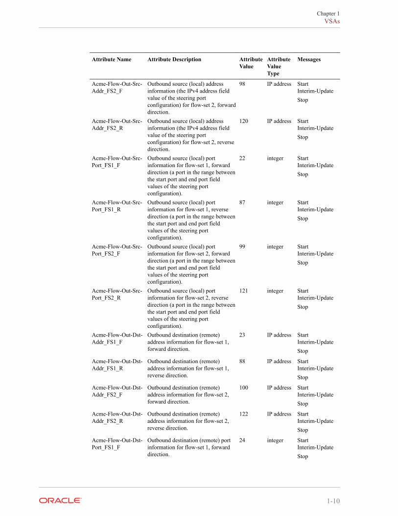
Acme-Flow-Out-Src-Addr_FS1_F
Outbound source (local) addressinformation (the IPv4 address fieldvalue of the steering portconfiguration) for flow-set 1, forwarddirection.
21 IP address StartInterim-UpdateStop
Acme-Flow-Out-Src-Addr_FS1_R
Outbound source (local) addressinformation (the IPv4 address fieldvalue of the steering portconfiguration) for flow-set 1, reversedirection.
86 IP address StartInterim-UpdateStop
Chapter 1VSAs
1-9
Attribute Name Attribute Description AttributeValue
AttributeValueType
Messages
Acme-Flow-Out-Src-Addr_FS2_F
Outbound source (local) addressinformation (the IPv4 address fieldvalue of the steering portconfiguration) for flow-set 2, forwarddirection.
98 IP address StartInterim-UpdateStop
Acme-Flow-Out-Src-Addr_FS2_R
Outbound source (local) addressinformation (the IPv4 address fieldvalue of the steering portconfiguration) for flow-set 2, reversedirection.
120 IP address StartInterim-UpdateStop
Acme-Flow-Out-Src-Port_FS1_F
Outbound source (local) portinformation for flow-set 1, forwarddirection (a port in the range betweenthe start port and end port fieldvalues of the steering portconfiguration).
22 integer StartInterim-UpdateStop
Acme-Flow-Out-Src-Port_FS1_R
Outbound source (local) portinformation for flow-set 1, reversedirection (a port in the range betweenthe start port and end port fieldvalues of the steering portconfiguration).
87 integer StartInterim-UpdateStop
Acme-Flow-Out-Src-Port_FS2_F
Outbound source (local) portinformation for flow-set 2, forwarddirection (a port in the range betweenthe start port and end port fieldvalues of the steering portconfiguration).
99 integer StartInterim-UpdateStop
Acme-Flow-Out-Src-Port_FS2_R
Outbound source (local) portinformation for flow-set 2, reversedirection (a port in the range betweenthe start port and end port fieldvalues of the steering portconfiguration).
121 integer StartInterim-UpdateStop
Acme-Flow-Out-Dst-Addr_FS1_F
Outbound destination (remote)address information for flow-set 1,forward direction.
23 IP address StartInterim-UpdateStop
Acme-Flow-Out-Dst-Addr_FS1_R
Outbound destination (remote)address information for flow-set 1,reverse direction.
88 IP address StartInterim-UpdateStop
Acme-Flow-Out-Dst-Addr_FS2_F
Outbound destination (remote)address information for flow-set 2,forward direction.
100 IP address StartInterim-UpdateStop
Acme-Flow-Out-Dst-Addr_FS2_R
Outbound destination (remote)address information for flow-set 2,reverse direction.
122 IP address StartInterim-UpdateStop
Acme-Flow-Out-Dst-Port_FS1_F
Outbound destination (remote) portinformation for flow-set 1, forwarddirection.
24 integer StartInterim-UpdateStop
Chapter 1VSAs
1-10
Attribute Name Attribute Description AttributeValue
AttributeValueType
Messages
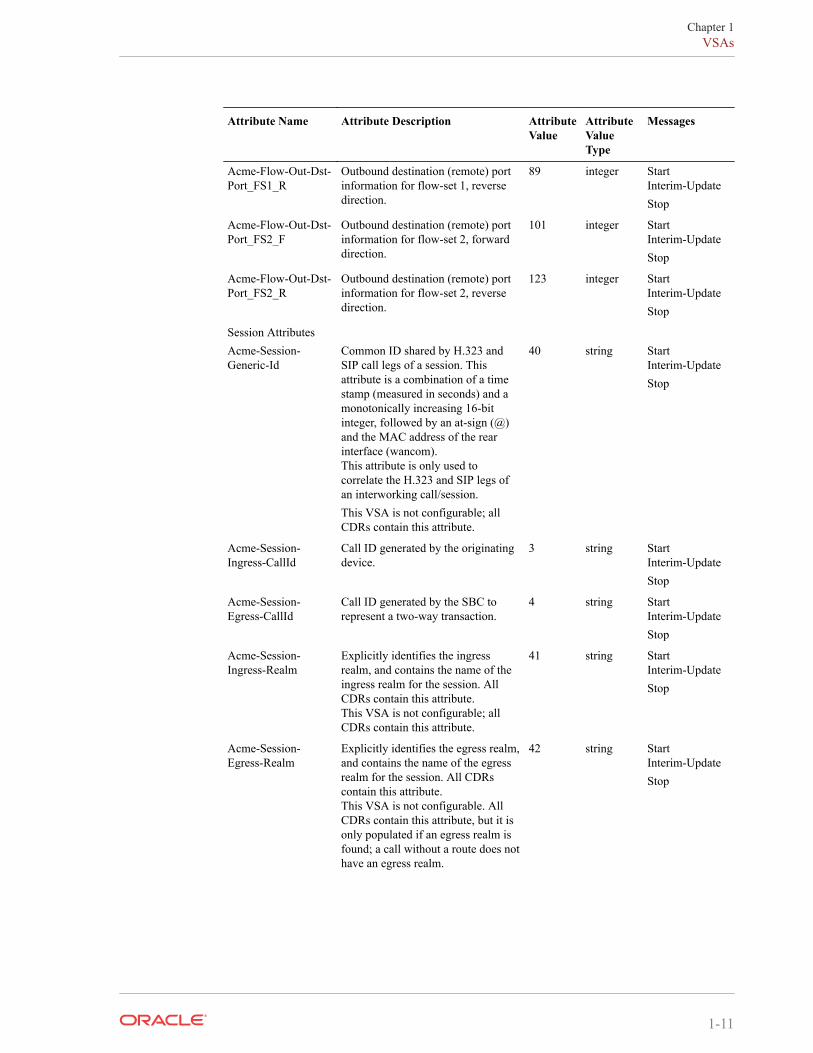
Acme-Flow-Out-Dst-Port_FS1_R
Outbound destination (remote) portinformation for flow-set 1, reversedirection.
89 integer StartInterim-UpdateStop
Acme-Flow-Out-Dst-Port_FS2_F
Outbound destination (remote) portinformation for flow-set 2, forwarddirection.
101 integer StartInterim-UpdateStop
Acme-Flow-Out-Dst-Port_FS2_R
Outbound destination (remote) portinformation for flow-set 2, reversedirection.
123 integer StartInterim-UpdateStop
Session AttributesAcme-Session-Generic-Id
Common ID shared by H.323 andSIP call legs of a session. Thisattribute is a combination of a timestamp (measured in seconds) and amonotonically increasing 16-bitinteger, followed by an at-sign (@)and the MAC address of the rearinterface (wancom).This attribute is only used tocorrelate the H.323 and SIP legs ofan interworking call/session.This VSA is not configurable; allCDRs contain this attribute.
40 string StartInterim-UpdateStop
Acme-Session-Ingress-CallId
Call ID generated by the originatingdevice.
3 string StartInterim-UpdateStop
Acme-Session-Egress-CallId
Call ID generated by the SBC torepresent a two-way transaction.
4 string StartInterim-UpdateStop
Acme-Session-Ingress-Realm
Explicitly identifies the ingressrealm, and contains the name of theingress realm for the session. AllCDRs contain this attribute.This VSA is not configurable; allCDRs contain this attribute.
41 string StartInterim-UpdateStop
Acme-Session-Egress-Realm
Explicitly identifies the egress realm,and contains the name of the egressrealm for the session. All CDRscontain this attribute.This VSA is not configurable. AllCDRs contain this attribute, but it isonly populated if an egress realm isfound; a call without a route does nothave an egress realm.
42 string StartInterim-UpdateStop
Chapter 1VSAs
1-11
Attribute Name Attribute Description AttributeValue
AttributeValueType
Messages
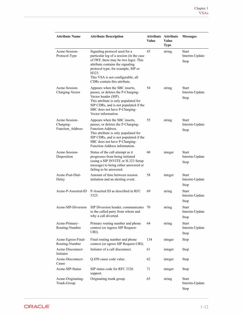
Acme-Session-Protocol-Type
Signaling protocol used for aparticular leg of a session (in the caseof IWF, there may be two legs). Thisattribute contains the signalingprotocol type; for example, SIP orH323.This VSA is not configurable; allCDRs contain this attribute.
43 string StartInterim-UpdateStop
Acme-Session-Charging-Vector
Appears when the SBC inserts,passes, or deletes the P-Charging-Vector header (SIP).This attribute is only populated forSIP CDRs, and is not populated if theSBC does not have P-Charging-Vector information.
54 string StartInterim-UpdateStop
Acme-Session-Charging-Function_Address
Appears when the SBC inserts,passes, or deletes the P-Charging-Function-Address.This attribute is only populated forSIP CDRs, and is not populated if theSBC does not have P-Charging-Function-Address information.
55 string StartInterim-UpdateStop
Acme-Session-Disposition
Status of the call attempt as itprogresses from being initiated(using a SIP INVITE or H.323 Setupmessage) to being either answered orfailing to be answered.
60 integer StartInterim-UpdateStop
Acme-Post-Dial-Delay
Amount of time between sessioninitiation and an alerting event.
58 integer StartInterim-UpdateStop
Acme-P-Asserted-ID P-Asserted ID as described in RFC3325.
69 string StartInterim-UpdateStop
Acme-SIP-Diversion SIP Diversion header; communicatesto the called party from whom andwhy a call diverted.
70 string StartInterim-UpdateStop
Acme-Primary-Routing-Number
Primary routing number and phonecontext (or ingress SIP Request-URI).
64 string StartInterim-UpdateStop
Acme-Egress-Final-Routing-Number
Final routing number and phonecontext (or egress SIP Request-URI).
134 integer Stop
Acme-Disconnect-Initiator
Initiator of a call disconnect. 61 integer Stop
Acme-Disconnect-Cause
Q.850 cause code value. 62 integer Stop
Acme-SIP-Status SIP status code for RFC 3326support.
71 integer Stop
Acme-Originating-Trunk-Group
Originating trunk group. 65 string StartInterim-UpdateStop
Chapter 1VSAs
1-12
Attribute Name Attribute Description AttributeValue
AttributeValueType
Messages
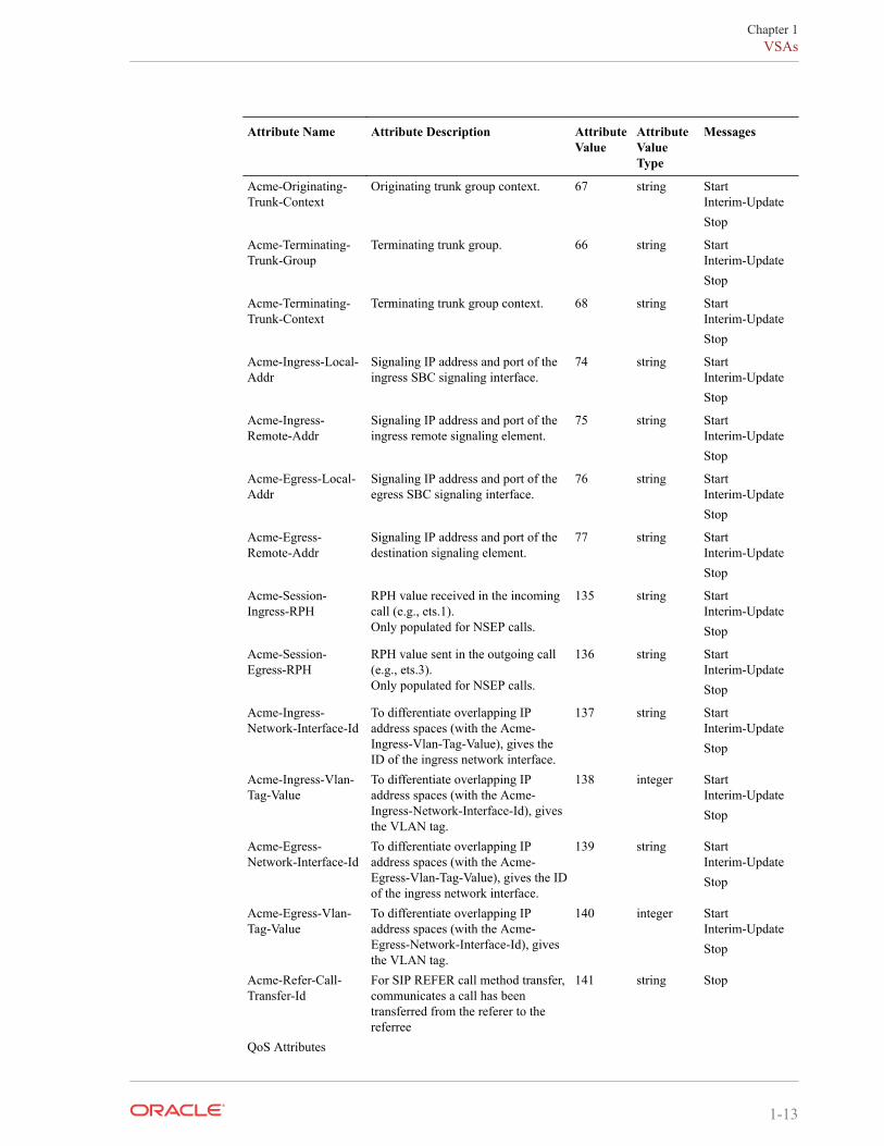
Acme-Originating-Trunk-Context
Originating trunk group context. 67 string StartInterim-UpdateStop
Acme-Terminating-Trunk-Group
Terminating trunk group. 66 string StartInterim-UpdateStop
Acme-Terminating-Trunk-Context
Terminating trunk group context. 68 string StartInterim-UpdateStop
Acme-Ingress-Local-Addr
Signaling IP address and port of theingress SBC signaling interface.
74 string StartInterim-UpdateStop
Acme-Ingress-Remote-Addr
Signaling IP address and port of theingress remote signaling element.
75 string StartInterim-UpdateStop
Acme-Egress-Local-Addr
Signaling IP address and port of theegress SBC signaling interface.
76 string StartInterim-UpdateStop
Acme-Egress-Remote-Addr
Signaling IP address and port of thedestination signaling element.
77 string StartInterim-UpdateStop
Acme-Session-Ingress-RPH
RPH value received in the incomingcall (e.g., ets.1).Only populated for NSEP calls.
135 string StartInterim-UpdateStop
Acme-Session-Egress-RPH
RPH value sent in the outgoing call(e.g., ets.3).Only populated for NSEP calls.
136 string StartInterim-UpdateStop
Acme-Ingress-Network-Interface-Id
To differentiate overlapping IPaddress spaces (with the Acme-Ingress-Vlan-Tag-Value), gives theID of the ingress network interface.
137 string StartInterim-UpdateStop
Acme-Ingress-Vlan-Tag-Value
To differentiate overlapping IPaddress spaces (with the Acme-Ingress-Network-Interface-Id), givesthe VLAN tag.
138 integer StartInterim-UpdateStop
Acme-Egress-Network-Interface-Id
To differentiate overlapping IPaddress spaces (with the Acme-Egress-Vlan-Tag-Value), gives the IDof the ingress network interface.
139 string StartInterim-UpdateStop
Acme-Egress-Vlan-Tag-Value
To differentiate overlapping IPaddress spaces (with the Acme-Egress-Network-Interface-Id), givesthe VLAN tag.
140 integer StartInterim-UpdateStop
Acme-Refer-Call-Transfer-Id
For SIP REFER call method transfer,communicates a call has beentransferred from the referer to thereferree
141 string Stop
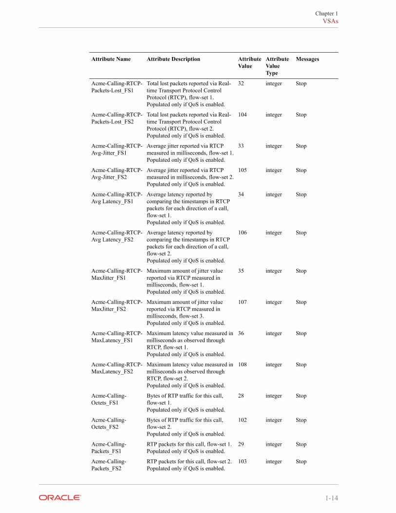
QoS Attributes
Chapter 1VSAs
1-13
Attribute Name Attribute Description AttributeValue
AttributeValueType
Messages
Acme-Calling-RTCP-Packets-Lost_FS1
Total lost packets reported via Real-time Transport Protocol ControlProtocol (RTCP), flow-set 1.Populated only if QoS is enabled.
32 integer Stop
Acme-Calling-RTCP-Packets-Lost_FS2
Total lost packets reported via Real-time Transport Protocol ControlProtocol (RTCP), flow-set 2.Populated only if QoS is enabled.
104 integer Stop
Acme-Calling-RTCP-Avg-Jitter_FS1
Average jitter reported via RTCPmeasured in milliseconds, flow-set 1.Populated only if QoS is enabled.
33 integer Stop
Acme-Calling-RTCP-Avg-Jitter_FS2
Average jitter reported via RTCPmeasured in milliseconds, flow-set 2.Populated only if QoS is enabled.
105 integer Stop
Acme-Calling-RTCP-Avg Latency_FS1
Average latency reported bycomparing the timestamps in RTCPpackets for each direction of a call,flow-set 1.Populated only if QoS is enabled.
34 integer Stop
Acme-Calling-RTCP-Avg Latency_FS2
Average latency reported bycomparing the timestamps in RTCPpackets for each direction of a call,flow-set 2.Populated only if QoS is enabled.
106 integer Stop
Acme-Calling-RTCP-MaxJitter_FS1
Maximum amount of jitter valuereported via RTCP measured inmilliseconds, flow-set 1.Populated only if QoS is enabled.
35 integer Stop
Acme-Calling-RTCP-MaxJitter_FS2
Maximum amount of jitter valuereported via RTCP measured inmilliseconds, flow-set 3.Populated only if QoS is enabled.
107 integer Stop
Acme-Calling-RTCP-MaxLatency_FS1
Maximum latency value measured inmilliseconds as observed throughRTCP, flow-set 1.Populated only if QoS is enabled.
36 integer Stop
Acme-Calling-RTCP-MaxLatency_FS2
Maximum latency value measured inmilliseconds as observed throughRTCP, flow-set 2.Populated only if QoS is enabled.
108 integer Stop
Acme-Calling-Octets_FS1
Bytes of RTP traffic for this call,flow-set 1.Populated only if QoS is enabled.
28 integer Stop
Acme-Calling-Octets_FS2
Bytes of RTP traffic for this call,flow-set 2.Populated only if QoS is enabled.
102 integer Stop
Acme-Calling-Packets_FS1
RTP packets for this call, flow-set 1.Populated only if QoS is enabled.
29 integer Stop
Acme-Calling-Packets_FS2
RTP packets for this call, flow-set 2.Populated only if QoS is enabled.
103 integer Stop
Chapter 1VSAs
1-14
Attribute Name Attribute Description AttributeValue
AttributeValueType
Messages
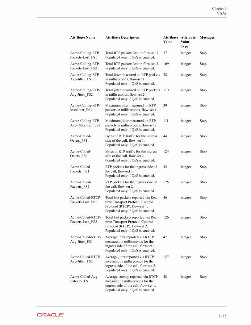
Acme-Calling-RTP-Packets-Lost_FS1
Total RTP packets lost in flow-set 1.Populated only if QoS is enabled.
37 integer Stop
Acme-Calling-RTP-Packets-Lost_FS2
Total RTP packets lost in flow-set 2.Populated only if QoS is enabled.
109 integer Stop
Acme-Calling-RTP-Avg-Jitter_FS1
Total jitter measured on RTP packetsin milliseconds, flow-set 1.Populated only if QoS is enabled.
38 integer Stop
Acme-Calling-RTP-Avg-Jitter_FS2
Total jitter measured on RTP packetsin milliseconds, flow-set 2.Populated only if QoS is enabled.
110 integer Stop
Acme-Calling-RTP-MaxJitter_FS1
Maximum jitter measured on RTPpackets in milliseconds, flow-set 1.Populated only if QoS is enabled.
39 integer Stop
Acme-Calling-RTP-Avg- MaxJitter_FS2
Maximum jitter measured on RTPpackets in milliseconds, flow-set 2.Populated only if QoS is enabled.
111 integer Stop
Acme-Called-Octets_FS1
Bytes of RTP traffic for the ingressside of the call, flow-set 1.Populated only if QoS is enabled.
44 integer Stop
Acme-Called-Octets_FS2
Bytes of RTP traffic for the ingressside of the call, flow-set 2.Populated only if QoS is enabled.
124 integer Stop
Acme-Called-Packets_FS1
RTP packets for the ingress side ofthe call, flow-set 1.Populated only if QoS is enabled.
45 integer Stop
Acme-Called-Packets_FS2
RTP packets for the ingress side ofthe call, flow-set 2.Populated only if QoS is enabled.
125 integer Stop
Acme-Called-RTCP-Packets-Lost_FS1
Total lost packets reported via Real-time Transport Protocol ControlProtocol (RTCP), flow-set 1.Populated only if QoS is enabled.
46 integer Stop
Acme-Called-RTCP-Packets-Lost_FS2
Total lost packets reported via Real-time Transport Protocol ControlProtocol (RTCP), flow-set 2.Populated only if QoS is enabled.
126 integer Stop
Acme-Called-RTCP-Avg-Jitter_FS1
Average jitter reported via RTCPmeasured in milliseconds for theingress side of the call, flow-set 1.Populated only if QoS is enabled.
47 integer Stop
Acme-Called-RTCP-Avg-Jitter_FS2
Average jitter reported via RTCPmeasured in milliseconds for theingress side of the call, flow-set 2.Populated only if QoS is enabled.
127 integer Stop
Acme-Called-Avg-Latency_FS1
Average latency reported via RTCPmeasured in milliseconds for theingress side of the call, flow-set 1.Populated only if QoS is enabled.
48 integer Stop
Chapter 1VSAs
1-15
Attribute Name Attribute Description AttributeValue
AttributeValueType
Messages
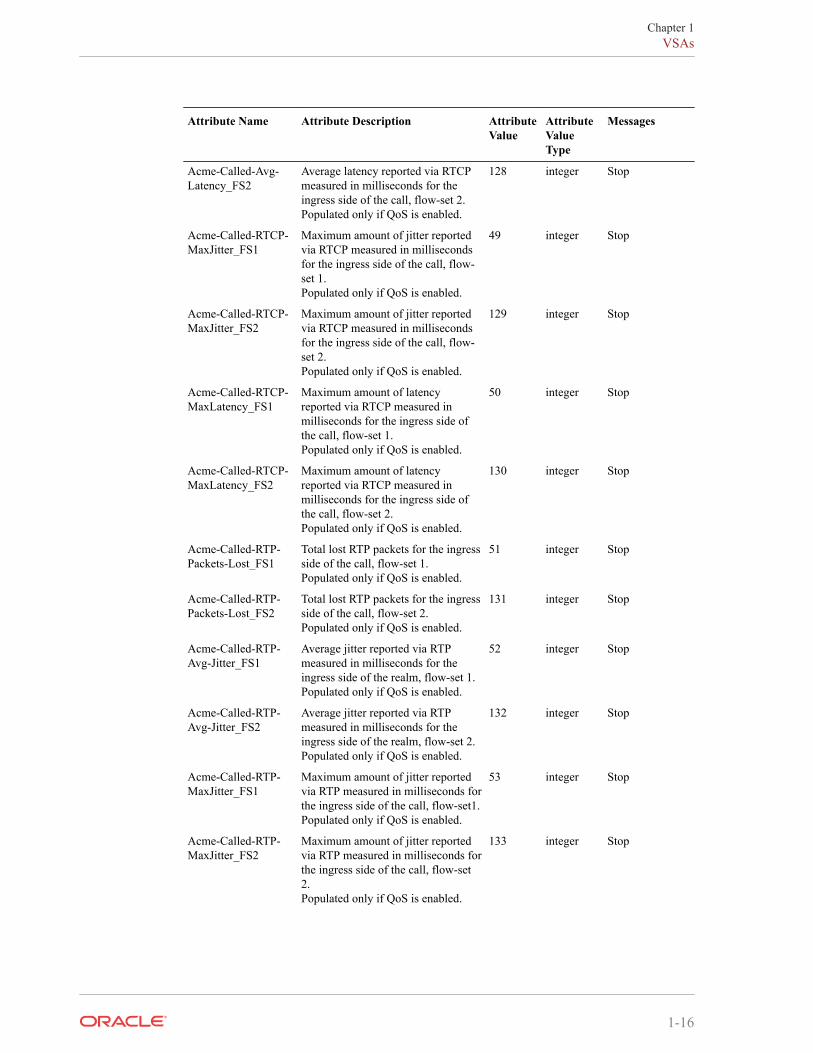
Acme-Called-Avg-Latency_FS2
Average latency reported via RTCPmeasured in milliseconds for theingress side of the call, flow-set 2.Populated only if QoS is enabled.
128 integer Stop
Acme-Called-RTCP-MaxJitter_FS1
Maximum amount of jitter reportedvia RTCP measured in millisecondsfor the ingress side of the call, flow-set 1.Populated only if QoS is enabled.
49 integer Stop
Acme-Called-RTCP-MaxJitter_FS2
Maximum amount of jitter reportedvia RTCP measured in millisecondsfor the ingress side of the call, flow-set 2.Populated only if QoS is enabled.
129 integer Stop
Acme-Called-RTCP-MaxLatency_FS1
Maximum amount of latencyreported via RTCP measured inmilliseconds for the ingress side ofthe call, flow-set 1.Populated only if QoS is enabled.
50 integer Stop
Acme-Called-RTCP-MaxLatency_FS2
Maximum amount of latencyreported via RTCP measured inmilliseconds for the ingress side ofthe call, flow-set 2.Populated only if QoS is enabled.
130 integer Stop
Acme-Called-RTP-Packets-Lost_FS1
Total lost RTP packets for the ingressside of the call, flow-set 1.Populated only if QoS is enabled.
51 integer Stop
Acme-Called-RTP-Packets-Lost_FS2
Total lost RTP packets for the ingressside of the call, flow-set 2.Populated only if QoS is enabled.
131 integer Stop
Acme-Called-RTP-Avg-Jitter_FS1
Average jitter reported via RTPmeasured in milliseconds for theingress side of the realm, flow-set 1.Populated only if QoS is enabled.
52 integer Stop
Acme-Called-RTP-Avg-Jitter_FS2
Average jitter reported via RTPmeasured in milliseconds for theingress side of the realm, flow-set 2.Populated only if QoS is enabled.
132 integer Stop
Acme-Called-RTP-MaxJitter_FS1
Maximum amount of jitter reportedvia RTP measured in milliseconds forthe ingress side of the call, flow-set1.Populated only if QoS is enabled.
53 integer Stop
Acme-Called-RTP-MaxJitter_FS2
Maximum amount of jitter reportedvia RTP measured in milliseconds forthe ingress side of the call, flow-set2.Populated only if QoS is enabled.
133 integer Stop
Chapter 1VSAs
1-16
Attribute Name Attribute Description AttributeValue
AttributeValueType
Messages
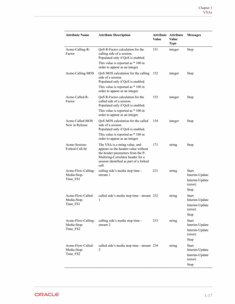
Acme-Calling-R-Factor
QoS R-Factor calculation for thecalling side of a session.Populated only if QoS is enabled.This value is reported as * 100 inorder to appear as an integer.
151 integer Stop
Acme-Calling-MOS QoS MOS calculation for the callingside of a session.Populated only if QoS is enabled.This value is reported as * 100 inorder to appear as an integer.
152 integer Stop
Acme-Called-R-Factor
QoS R-Factor calculation for thecalled side of a session.Populated only if QoS is enabled.This value is reported as * 100 inorder to appear as an integer.
153 integer Stop
Acme-Called-MOSNew in Release
QoS MOS calculation for the calledside of a session.Populated only if QoS is enabled.This value is reported as * 100 inorder to appear as an integer.
154 integer Stop
Acme-Session-Forked-Call-Id
The VSA is a string value, andappears as the header-value withoutthe header parameters from the P-Multiring-Correlator header for asession identified as part of a forkedcall.
171 string Stop
Acme-Flow-Calling-Media-Stop-Time_FS1
calling side’s media stop time -stream 1
231 string StartInterim-UpdateInterim-Update(error)Stop
Acme-Flow-Called-Media-Stop-Time_FS1
called side’s media stop time - stream1
232 string StartInterim-UpdateInterim-Update(error)Stop
Acme-Flow-Calling-Media-Stop-Time_FS2
calling side’s media stop time -stream 2
233 string StartInterim-UpdateInterim-Update(error)Stop
Acme-Flow-Called-Media-Stop-Time_FS2
called side’s media stop time - stream2
234 string StartInterim-UpdateInterim-Update(error)Stop
Chapter 1VSAs
1-17
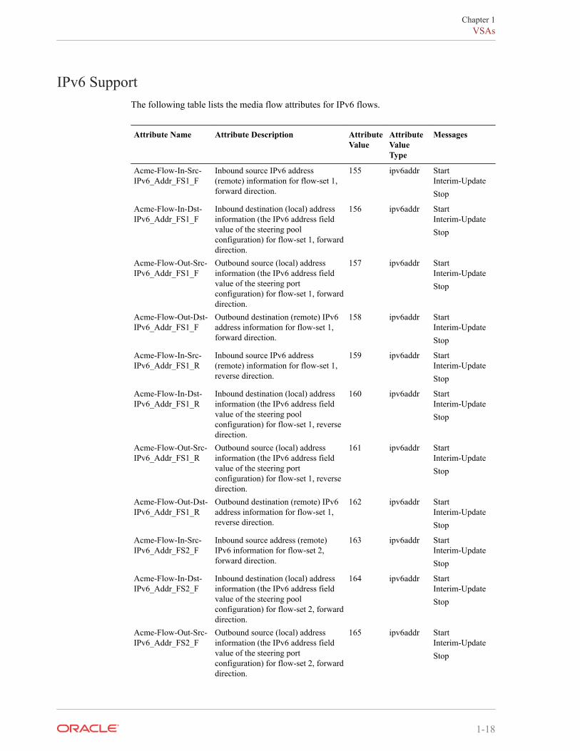
IPv6 SupportThe following table lists the media flow attributes for IPv6 flows.
Attribute Name Attribute Description AttributeValue
AttributeValueType
Messages
Acme-Flow-In-Src-IPv6_Addr_FS1_F
Inbound source IPv6 address(remote) information for flow-set 1,forward direction.
155 ipv6addr StartInterim-UpdateStop
Acme-Flow-In-Dst-IPv6_Addr_FS1_F
Inbound destination (local) addressinformation (the IPv6 address fieldvalue of the steering poolconfiguration) for flow-set 1, forwarddirection.
156 ipv6addr StartInterim-UpdateStop
Acme-Flow-Out-Src-IPv6_Addr_FS1_F
Outbound source (local) addressinformation (the IPv6 address fieldvalue of the steering portconfiguration) for flow-set 1, forwarddirection.
157 ipv6addr StartInterim-UpdateStop
Acme-Flow-Out-Dst-IPv6_Addr_FS1_F
Outbound destination (remote) IPv6address information for flow-set 1,forward direction.
158 ipv6addr StartInterim-UpdateStop
Acme-Flow-In-Src-IPv6_Addr_FS1_R
Inbound source IPv6 address(remote) information for flow-set 1,reverse direction.
159 ipv6addr StartInterim-UpdateStop
Acme-Flow-In-Dst-IPv6_Addr_FS1_R
Inbound destination (local) addressinformation (the IPv6 address fieldvalue of the steering poolconfiguration) for flow-set 1, reversedirection.
160 ipv6addr StartInterim-UpdateStop
Acme-Flow-Out-Src-IPv6_Addr_FS1_R
Outbound source (local) addressinformation (the IPv6 address fieldvalue of the steering portconfiguration) for flow-set 1, reversedirection.
161 ipv6addr StartInterim-UpdateStop
Acme-Flow-Out-Dst-IPv6_Addr_FS1_R
Outbound destination (remote) IPv6address information for flow-set 1,reverse direction.
162 ipv6addr StartInterim-UpdateStop
Acme-Flow-In-Src-IPv6_Addr_FS2_F
Inbound source address (remote)IPv6 information for flow-set 2,forward direction.
163 ipv6addr StartInterim-UpdateStop
Acme-Flow-In-Dst-IPv6_Addr_FS2_F
Inbound destination (local) addressinformation (the IPv6 address fieldvalue of the steering poolconfiguration) for flow-set 2, forwarddirection.
164 ipv6addr StartInterim-UpdateStop
Acme-Flow-Out-Src-IPv6_Addr_FS2_F
Outbound source (local) addressinformation (the IPv6 address fieldvalue of the steering portconfiguration) for flow-set 2, forwarddirection.
165 ipv6addr StartInterim-UpdateStop
Chapter 1VSAs
1-18
Attribute Name Attribute Description AttributeValue
AttributeValueType
Messages
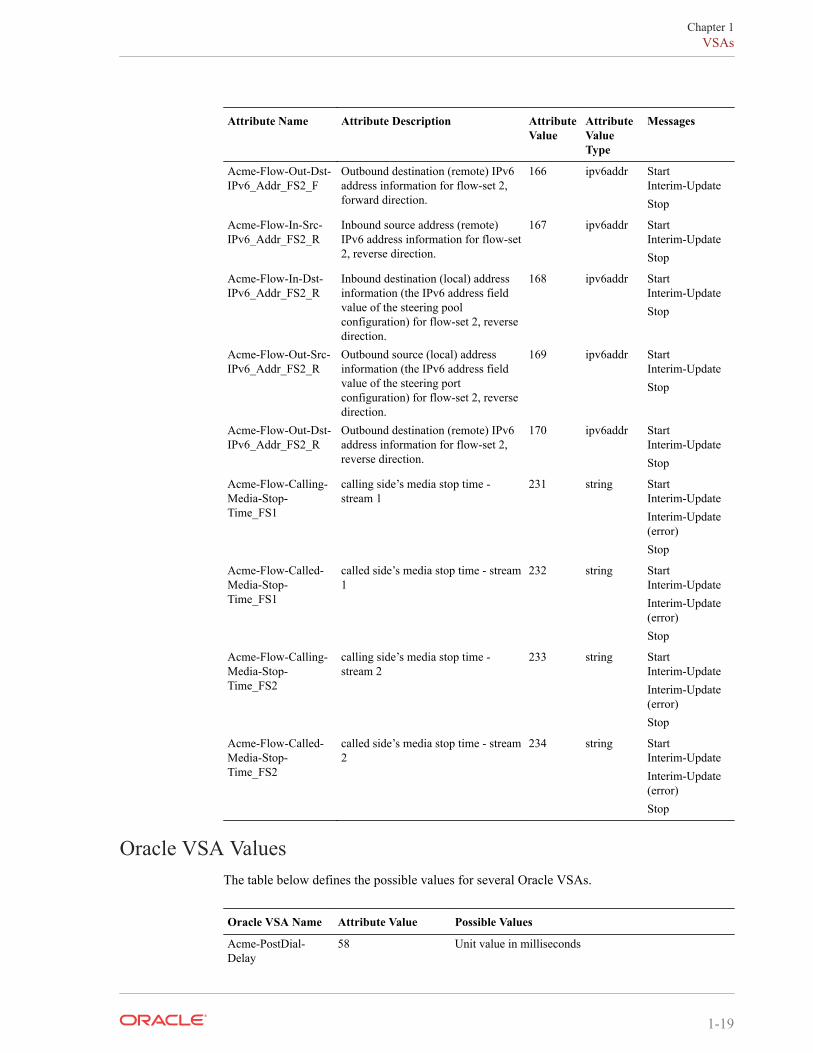
Acme-Flow-Out-Dst-IPv6_Addr_FS2_F
Outbound destination (remote) IPv6address information for flow-set 2,forward direction.
166 ipv6addr StartInterim-UpdateStop
Acme-Flow-In-Src-IPv6_Addr_FS2_R
Inbound source address (remote)IPv6 address information for flow-set2, reverse direction.
167 ipv6addr StartInterim-UpdateStop
Acme-Flow-In-Dst-IPv6_Addr_FS2_R
Inbound destination (local) addressinformation (the IPv6 address fieldvalue of the steering poolconfiguration) for flow-set 2, reversedirection.
168 ipv6addr StartInterim-UpdateStop
Acme-Flow-Out-Src-IPv6_Addr_FS2_R
Outbound source (local) addressinformation (the IPv6 address fieldvalue of the steering portconfiguration) for flow-set 2, reversedirection.
169 ipv6addr StartInterim-UpdateStop
Acme-Flow-Out-Dst-IPv6_Addr_FS2_R
Outbound destination (remote) IPv6address information for flow-set 2,reverse direction.
170 ipv6addr StartInterim-UpdateStop
Acme-Flow-Calling-Media-Stop-Time_FS1
calling side’s media stop time -stream 1
231 string StartInterim-UpdateInterim-Update(error)Stop
Acme-Flow-Called-Media-Stop-Time_FS1
called side’s media stop time - stream1
232 string StartInterim-UpdateInterim-Update(error)Stop
Acme-Flow-Calling-Media-Stop-Time_FS2
calling side’s media stop time -stream 2
233 string StartInterim-UpdateInterim-Update(error)Stop
Acme-Flow-Called-Media-Stop-Time_FS2
called side’s media stop time - stream2
234 string StartInterim-UpdateInterim-Update(error)Stop
Oracle VSA ValuesThe table below defines the possible values for several Oracle VSAs.
Oracle VSA Name Attribute Value Possible Values
Acme-PostDial-Delay
58 Unit value in milliseconds
Chapter 1VSAs
1-19
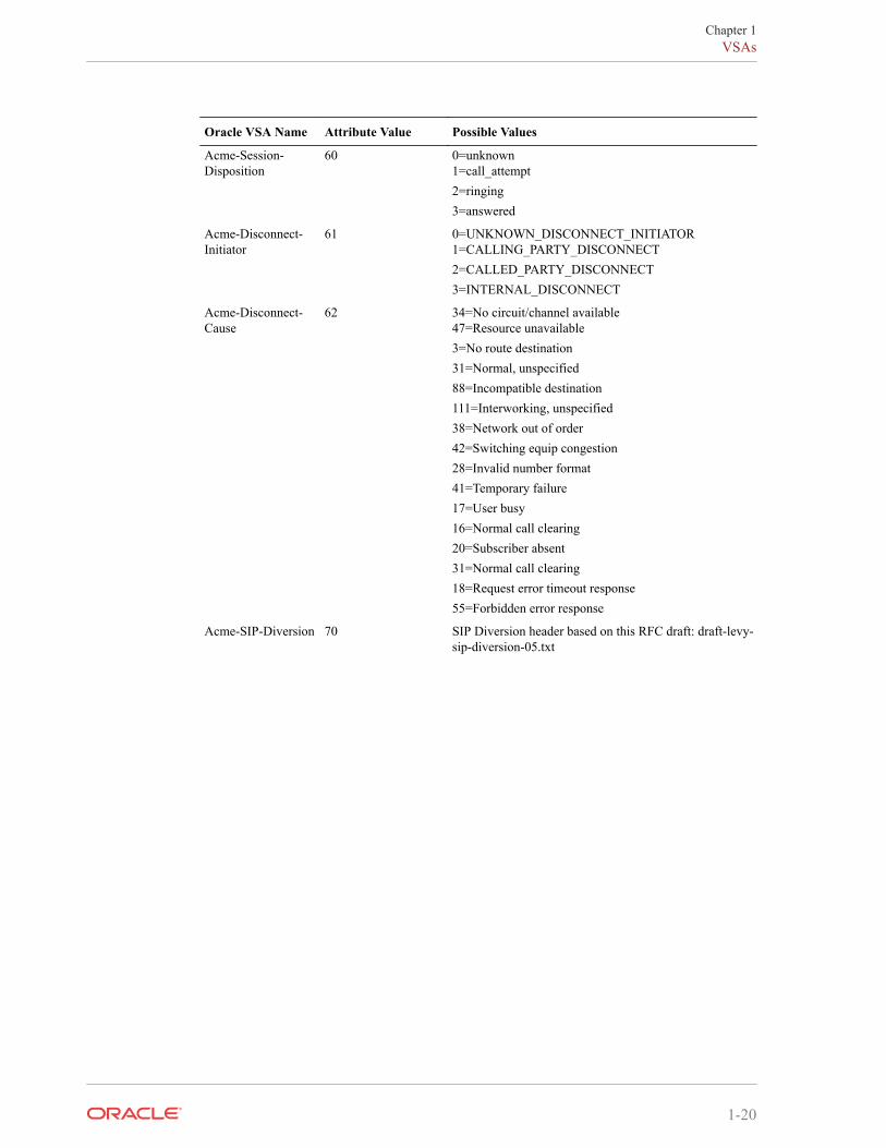
Oracle VSA Name Attribute Value Possible Values
Acme-Session-Disposition
60 0=unknown1=call_attempt2=ringing3=answered
Acme-Disconnect-Initiator
61 0=UNKNOWN_DISCONNECT_INITIATOR1=CALLING_PARTY_DISCONNECT2=CALLED_PARTY_DISCONNECT3=INTERNAL_DISCONNECT
Acme-Disconnect-Cause
62 34=No circuit/channel available47=Resource unavailable3=No route destination31=Normal, unspecified88=Incompatible destination111=Interworking, unspecified38=Network out of order42=Switching equip congestion28=Invalid number format41=Temporary failure17=User busy16=Normal call clearing20=Subscriber absent31=Normal call clearing18=Request error timeout response55=Forbidden error response
Acme-SIP-Diversion 70 SIP Diversion header based on this RFC draft: draft-levy-sip-diversion-05.txt
Chapter 1VSAs
1-20
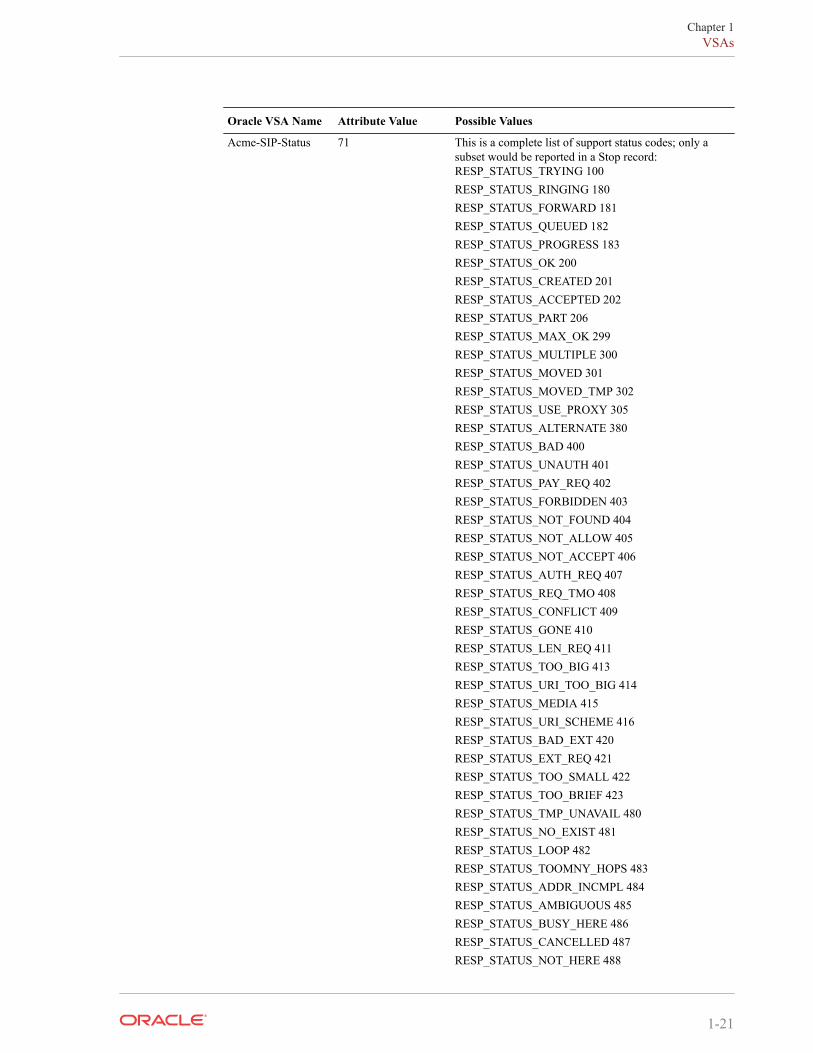
Oracle VSA Name Attribute Value Possible Values
Acme-SIP-Status 71 This is a complete list of support status codes; only asubset would be reported in a Stop record:RESP_STATUS_TRYING 100RESP_STATUS_RINGING 180RESP_STATUS_FORWARD 181RESP_STATUS_QUEUED 182RESP_STATUS_PROGRESS 183RESP_STATUS_OK 200RESP_STATUS_CREATED 201RESP_STATUS_ACCEPTED 202RESP_STATUS_PART 206RESP_STATUS_MAX_OK 299RESP_STATUS_MULTIPLE 300RESP_STATUS_MOVED 301RESP_STATUS_MOVED_TMP 302RESP_STATUS_USE_PROXY 305RESP_STATUS_ALTERNATE 380RESP_STATUS_BAD 400RESP_STATUS_UNAUTH 401RESP_STATUS_PAY_REQ 402RESP_STATUS_FORBIDDEN 403RESP_STATUS_NOT_FOUND 404RESP_STATUS_NOT_ALLOW 405RESP_STATUS_NOT_ACCEPT 406RESP_STATUS_AUTH_REQ 407RESP_STATUS_REQ_TMO 408RESP_STATUS_CONFLICT 409RESP_STATUS_GONE 410RESP_STATUS_LEN_REQ 411RESP_STATUS_TOO_BIG 413RESP_STATUS_URI_TOO_BIG 414RESP_STATUS_MEDIA 415RESP_STATUS_URI_SCHEME 416RESP_STATUS_BAD_EXT 420RESP_STATUS_EXT_REQ 421RESP_STATUS_TOO_SMALL 422RESP_STATUS_TOO_BRIEF 423RESP_STATUS_TMP_UNAVAIL 480RESP_STATUS_NO_EXIST 481RESP_STATUS_LOOP 482RESP_STATUS_TOOMNY_HOPS 483RESP_STATUS_ADDR_INCMPL 484RESP_STATUS_AMBIGUOUS 485RESP_STATUS_BUSY_HERE 486RESP_STATUS_CANCELLED 487RESP_STATUS_NOT_HERE 488
Chapter 1VSAs
1-21
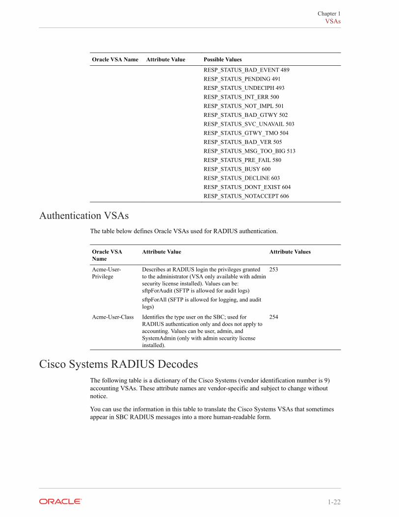
Oracle VSA Name Attribute Value Possible Values
RESP_STATUS_BAD_EVENT 489RESP_STATUS_PENDING 491RESP_STATUS_UNDECIPH 493RESP_STATUS_INT_ERR 500RESP_STATUS_NOT_IMPL 501RESP_STATUS_BAD_GTWY 502RESP_STATUS_SVC_UNAVAIL 503RESP_STATUS_GTWY_TMO 504RESP_STATUS_BAD_VER 505RESP_STATUS_MSG_TOO_BIG 513RESP_STATUS_PRE_FAIL 580RESP_STATUS_BUSY 600RESP_STATUS_DECLINE 603RESP_STATUS_DONT_EXIST 604RESP_STATUS_NOTACCEPT 606
Authentication VSAsThe table below defines Oracle VSAs used for RADIUS authentication.
Oracle VSAName
Attribute Value Attribute Values
Acme-User-Privilege
Describes at RADIUS login the privileges grantedto the administrator (VSA only available with adminsecurity license installed). Values can be:sftpForAudit (SFTP is allowed for audit logs)sftpForAll (SFTP is allowed for logging, and auditlogs)
253
Acme-User-Class Identifies the type user on the SBC; used forRADIUS authentication only and does not apply toaccounting. Values can be user, admin, andSystemAdmin (only with admin security licenseinstalled).
254
Cisco Systems RADIUS DecodesThe following table is a dictionary of the Cisco Systems (vendor identification number is 9)accounting VSAs. These attribute names are vendor-specific and subject to change withoutnotice.
You can use the information in this table to translate the Cisco Systems VSAs that sometimesappear in SBC RADIUS messages into a more human-readable form.
Chapter 1VSAs
1-22
Attribute Name Attribute Description AttributeValue
AttributeValueType
Messages
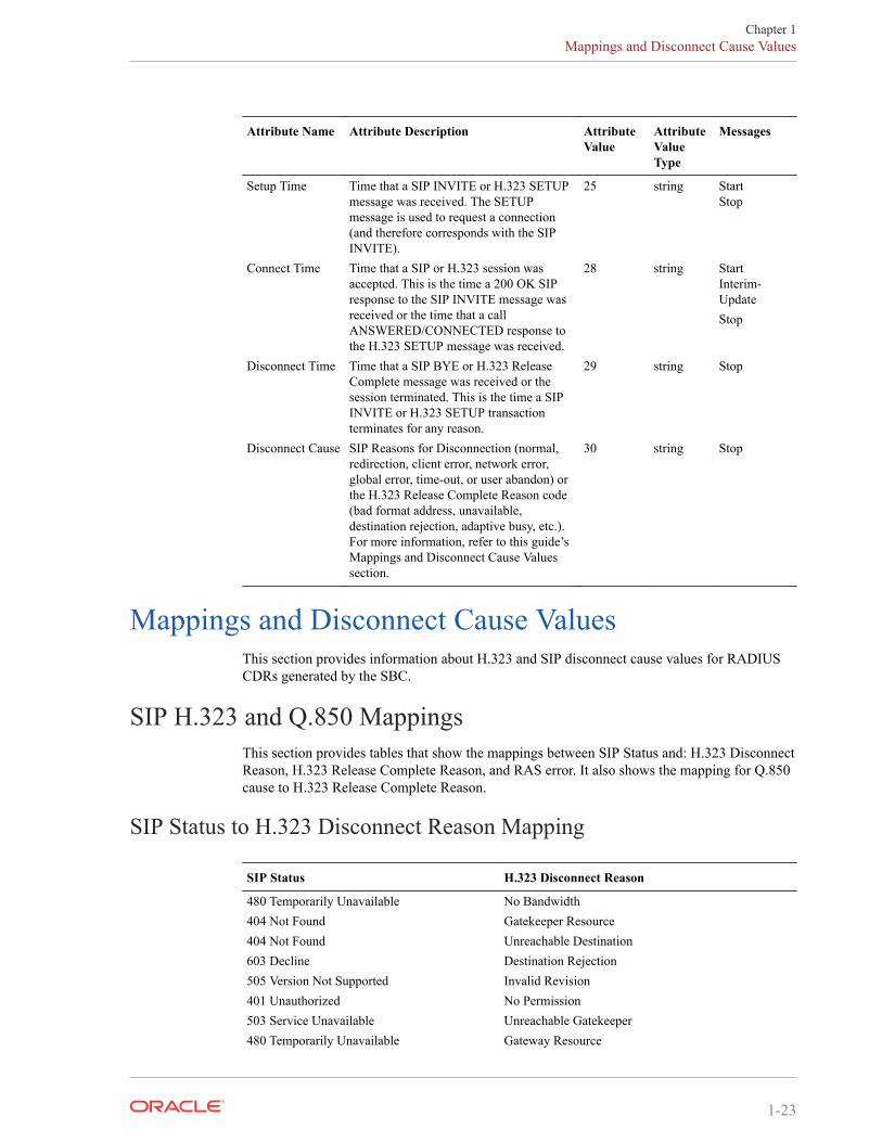
Setup Time Time that a SIP INVITE or H.323 SETUPmessage was received. The SETUPmessage is used to request a connection(and therefore corresponds with the SIPINVITE).
25 string StartStop
Connect Time Time that a SIP or H.323 session wasaccepted. This is the time a 200 OK SIPresponse to the SIP INVITE message wasreceived or the time that a callANSWERED/CONNECTED response tothe H.323 SETUP message was received.
28 string StartInterim-UpdateStop
Disconnect Time Time that a SIP BYE or H.323 ReleaseComplete message was received or thesession terminated. This is the time a SIPINVITE or H.323 SETUP transactionterminates for any reason.
29 string Stop
Disconnect Cause SIP Reasons for Disconnection (normal,redirection, client error, network error,global error, time-out, or user abandon) orthe H.323 Release Complete Reason code(bad format address, unavailable,destination rejection, adaptive busy, etc.).For more information, refer to this guide’sMappings and Disconnect Cause Valuessection.
30 string Stop
Mappings and Disconnect Cause ValuesThis section provides information about H.323 and SIP disconnect cause values for RADIUSCDRs generated by the SBC.
SIP H.323 and Q.850 MappingsThis section provides tables that show the mappings between SIP Status and: H.323 DisconnectReason, H.323 Release Complete Reason, and RAS error. It also shows the mapping for Q.850cause to H.323 Release Complete Reason.
SIP Status to H.323 Disconnect Reason Mapping
SIP Status H.323 Disconnect Reason
480 Temporarily Unavailable No Bandwidth404 Not Found Gatekeeper Resource404 Not Found Unreachable Destination603 Decline Destination Rejection505 Version Not Supported Invalid Revision401 Unauthorized No Permission503 Service Unavailable Unreachable Gatekeeper480 Temporarily Unavailable Gateway Resource
Chapter 1Mappings and Disconnect Cause Values
1-23

SIP Status H.323 Disconnect Reason
400 Bad Request Bad Format Request486 Busy Here Adaptive Busy486 Busy Here In Conference500 Internal Server Error Undefined Reason486 Busy Here Facility Call Deflection401 Unauthorized Security Denied
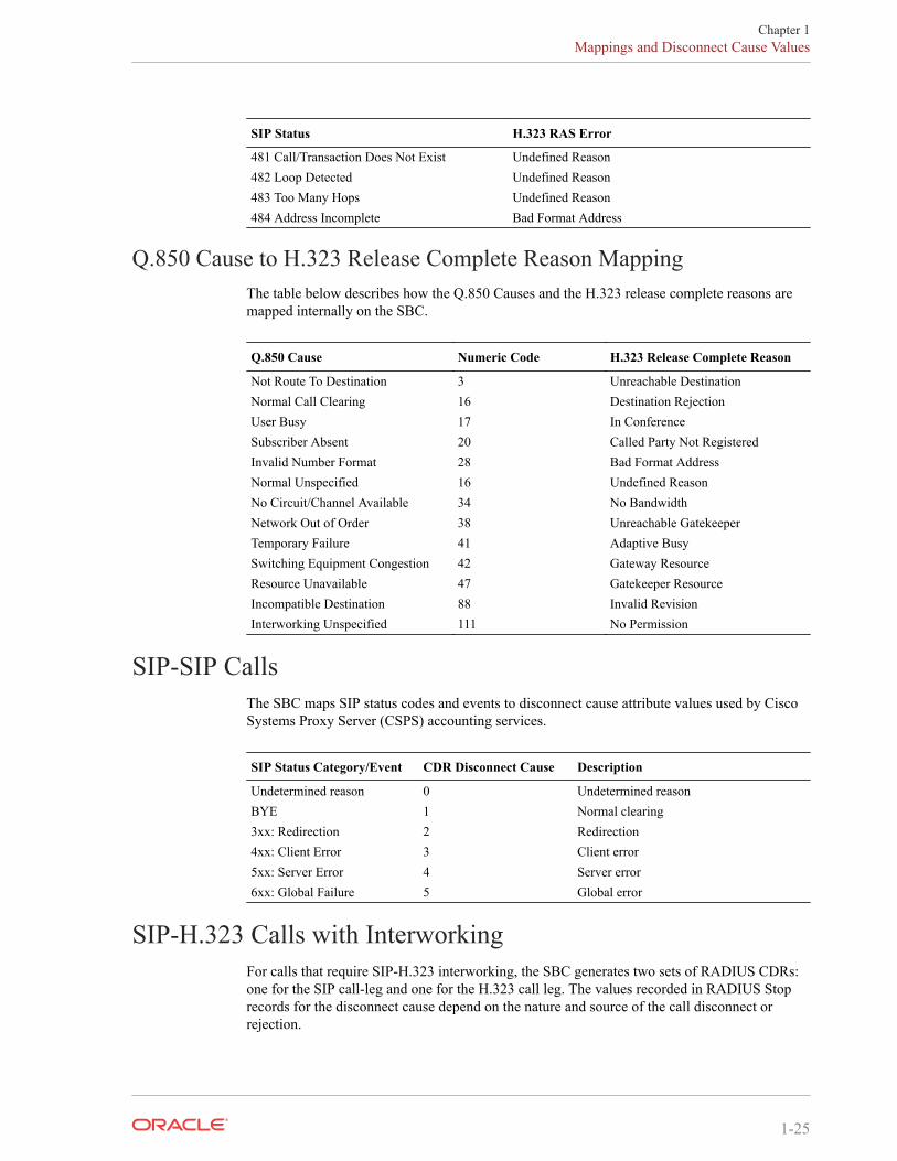
SIP Status to H.323 RAS Error Mapping
SIP Status H.323 RAS Error
404 Not Found Gatekeeper Resource401 Unauthorized Invalid Permission503 Service Unavailable Request Denied500 Internal Server Error Undefined401 Unauthorized Caller Not Registered305 User Proxy Route Call to Gatekeeper500 Internal Server Error Invalid Endpoint ID503 Service Unavailable Resource Unavailable401 Unauthorized Security Denial501 Not Implemented QoS Control Not Supported484 Address Incomplete Incomplete Address302 Moved Temporarily Route Call to SCN485 Ambiguous Aliases Inconsistent401 Unauthorized Not Currently Registered
SIP Status to H.323 Release Complete Reason Error Mapping
SIP Status H.323 RAS Error
300 Multiple Choices Undefined Reason401 Unauthorized Security Denied402 Payment Required Undefined Reason403 Forbidden No Permission404 Not Found Unreachable Destination405 Method Not Allowed Undefined Reason606 Not Acceptable Undefined Reason407 Proxy Authentication Required Security Denied408 Request Timeout Adaptive Busy409 Conflict Undefined Reason410 Gone Unreachable Destination411 Length Required Undefined Reason414 Request-URI Too Large Bad Format Address415 Unsupported Media Type Undefined Reason420 Bad Extension Bad Format Address480 Temporarily Unavailable Adaptive Busy
Chapter 1Mappings and Disconnect Cause Values
1-24
SIP Status H.323 RAS Error
481 Call/Transaction Does Not Exist Undefined Reason482 Loop Detected Undefined Reason483 Too Many Hops Undefined Reason484 Address Incomplete Bad Format Address
Q.850 Cause to H.323 Release Complete Reason MappingThe table below describes how the Q.850 Causes and the H.323 release complete reasons aremapped internally on the SBC.
Q.850 Cause Numeric Code H.323 Release Complete Reason
Not Route To Destination 3 Unreachable DestinationNormal Call Clearing 16 Destination RejectionUser Busy 17 In ConferenceSubscriber Absent 20 Called Party Not RegisteredInvalid Number Format 28 Bad Format AddressNormal Unspecified 16 Undefined ReasonNo Circuit/Channel Available 34 No BandwidthNetwork Out of Order 38 Unreachable GatekeeperTemporary Failure 41 Adaptive BusySwitching Equipment Congestion 42 Gateway ResourceResource Unavailable 47 Gatekeeper ResourceIncompatible Destination 88 Invalid RevisionInterworking Unspecified 111 No Permission
SIP-SIP CallsThe SBC maps SIP status codes and events to disconnect cause attribute values used by CiscoSystems Proxy Server (CSPS) accounting services.
SIP Status Category/Event CDR Disconnect Cause Description
Undetermined reason 0 Undetermined reasonBYE 1 Normal clearing3xx: Redirection 2 Redirection4xx: Client Error 3 Client error5xx: Server Error 4 Server error6xx: Global Failure 5 Global error
SIP-H.323 Calls with InterworkingFor calls that require SIP-H.323 interworking, the SBC generates two sets of RADIUS CDRs:one for the SIP call-leg and one for the H.323 call leg. The values recorded in RADIUS Stoprecords for the disconnect cause depend on the nature and source of the call disconnect orrejection.
Chapter 1Mappings and Disconnect Cause Values
1-25
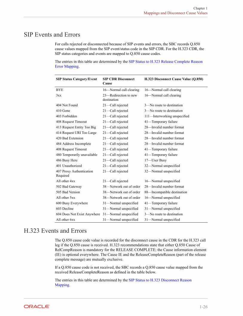
SIP Events and ErrorsFor calls rejected or disconnected because of SIP events and errors, the SBC records Q.850cause values mapped from the SIP event/status code in the SIP CDR. For the H.323 CDR, theSIP status categories and events are mapped to Q.850 cause codes.
The entries in this table are determined by the SIP Status to H.323 Release Complete ReasonError Mapping.
SIP Status Category/Event SIP CDR DisconnectCause
H.323 Disconnect Cause Value (Q.850)
BYE 16—Normal call clearing 16—Normal call clearing3xx 23—Redirection to new
destination16—Normal call clearing
404 Not Found 21—Call rejected 3—No route to destination410 Gone 21—Call rejected 3—No route to destination403 Forbidden 21—Call rejected 111—Interworking unspecified408 Request Timeout 21—Call rejected 41—Temporary failure413 Request Entity Too Big 21—Call rejected 28—Invalid number format414 Request URI Too Large 21—Call rejected 28—Invalid number format420 Bad Extension 21—Call rejected 28—Invalid number format484 Address Incomplete 21—Call rejected 28—Invalid number format408 Request Timeout 21—Call rejected 41—Temporary failure480 Temporarily unavailable 21—Call rejected 41—Temporary failure486 Busy Here 21—Call rejected 17—User Busy401 Unauthorized 21—Call rejected 32—Normal unspecified407 Proxy AuthenticationRequired
21—Call rejected 32—Normal unspecified
All other 4xx 21—Call rejected 16—Normal unspecified502 Bad Gateway 38—Network out of order 28—Invalid number format505 Bad Version 38—Network out of order 88—Incompatible destinationAll other 5xx 38—Network out of order 16—Normal unspecified600 Busy Everywhere 31—Normal unspecified 41—Temporary failure603 Decline 31—Normal unspecified 31—Normal unspecified604 Does Not Exist Anywhere 31—Normal unspecified 3—No route to destinationAll other 6xx 31—Normal unspecified 31—Normal unspecified
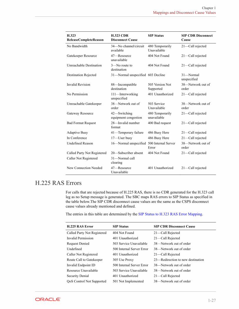
H.323 Events and ErrorsThe Q.850 cause code value is recorded for the disconnect cause in the CDR for the H.323 callleg if the Q.850 cause is received. H.323 recommendations state that either Q.850 Cause ofRelCompReason is mandatory for the RELEASE COMPLETE; the Cause information element(IE) is optional everywhere. The Cause IE and the ReleaseCompleteReason (part of the releasecomplete message) are mutually exclusive.
If a Q.850 cause code is not received, the SBC records a Q.850 cause value mapped from thereceived ReleaseCompleteReason as defined in the table below.
The entries in this table are determined by the SIP Status to H.323 Disconnect ReasonMapping.
Chapter 1Mappings and Disconnect Cause Values
1-26
H.323ReleaseCompleteReason
H.323 CDRDisconnect Cause
SIP Status SIP CDR DisconnectCause
No Bandwidth 34—No channel/circuitavailable
480 TemporarilyUnavailable
21—Call rejected
Gatekeeper Resource 47—Resourceunavailable
404 Not Found 21—Call rejected
Unreachable Destination 3—No route todestination
404 Not Found 21—Call rejected
Destination Rejected 31—Normal unspecified 603 Decline 31—Normalunspecified
Invalid Revision 88—Incompatibledestination
505 Version NotSupported
38—Network out oforder
No Permission 111—Interworkingunspecified
401 Unauthorized 21—Call rejected
Unreachable Gatekeeper 38—Network out oforder
503 ServiceUnavailable
38—Network out oforder
Gateway Resource 42—Switchingequipment congestion
480 Temporarilyunavailable
21—Call rejected
Bad Format Request 28—Invalid numberformat
400 Bad request 21—Call rejected
Adaptive Busy 41—Temporary failure 486 Busy Here 21—Call rejectedIn Conference 17—User busy 486 Busy Here 21—Call rejectedUndefined Reason 16—Normal unspecified 500 Internal Server
Error38—Network out oforder
Called Party Not Registered 20—Subscriber absent 404 Not Found 21—Call rejectedCaller Not Registered 31—Normal call
clearingNew Connection Needed 47—Resource
Unavailable401 Unauthorized 21—Call rejected
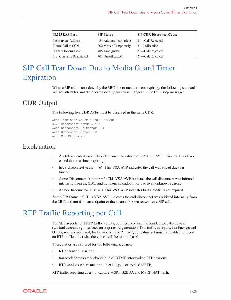
H.225 RAS ErrorsFor calls that are rejected because of H.225 RAS, there is no CDR generated for the H.323 callleg as no Setup message is generated. The SBC maps RAS errors to SIP Status as specified inthe table below.The SIP CDR disconnect cause values are the same as the CSPS disconnectcause values already mentioned and defined.
The entries in this table are determined by the SIP Status to H.323 RAS Error Mapping.
H.225 RAS Error SIP Status SIP CDR Disconnect Cause
Called Party Not Registered 404 Not Found 21—Call RejectedInvalid Permission 401 Unauthorized 21—Call RejectedRequest Denied 503 Service Unavailable 38—Network out of orderUndefined 500 Internal Server Error 38—Network out of orderCaller Not Registered 401 Unauthorized 21—Call RejectedRoute Call to Gatekeeper 305 Use Proxy 23—Redirection to new destinationInvalid Endpoint ID 500 Internal Server Error 38—Network out of orderResource Unavailable 503 Service Unavailable 38—Network out of orderSecurity Denial 401 Unauthorized 21—Call RejectedQoS Control Not Supported 501 Not Implemented 38—Network out of order
Chapter 1Mappings and Disconnect Cause Values
1-27
H.225 RAS Error SIP Status SIP CDR Disconnect Cause
Incomplete Address 484 Address Incomplete 21—Call RejectedRoute Call to SCN 302 Moved Temporarily 2—RedirectionAliases Inconsistent 485 Ambiguous 21—Call RejectedNot Currently Registered 401 Unauthorized 21—Call Rejected
SIP Call Tear Down Due to Media Guard TimerExpiration
When a SIP call is torn down by the SBC due to media timers expiring, the following standardand VS attributes and their corresponding values will appear in the CDR stop message:
CDR OutputThe following five CDR AVPs must be observed in the same CDR.
Acct-Terminate-Cause = Idle-Timeouth323-disconnect-cause = "6"Acme-Disconnect-Initiator = 3Acme-Disconnect-Cause = 0Acme-SIP-Status = 0
Explanation• Acct-Terminate-Cause = Idle-Timeout: This standard RADIUS AVP indicates the call was
ended due to a timer expiring.
• h323-disconnect-cause = "6": This VSA AVP indicates the call was ended due to atimeout.
• Acme-Disconnect-Initiator = 3: This VSA AVP indicates the call disconnect was initiatedinternally from the SBC, and not from an endpoint or due to an unknown reason.
• Acme-Disconnect-Cause = 0: This VSA AVP indicates that a media timer expired.
Acme-SIP-Status = 0: This VSA AVP indicates the call disconnect was initiated internally fromthe SBC, and not from an endpoint or due to an unknown reason for a SIP call.
RTP Traffic Reporting per CallThe SBC reports total RTP traffic counts, both received and transmitted for calls throughstandard accounting interfaces on stop record generation. This traffic is reported in Packets andOctets, sent and received, for flow-sets 1 and 2. The QoS feature set must be enabled to reporton RTP traffic, otherwise the values will be reported as 0
These statics are captured for the following scenarios
• RTP pass-thru sessions
• transcoded/transrated/inband (audio) DTMF-interworked RTP sessions
• RTP sessions where one or both call legs is encrypted (SRTP)
RTP traffic reporting does not capture MSRP B2BUA and MSRP NAT traffic.
Chapter 1SIP Call Tear Down Due to Media Guard Timer Expiration
1-28
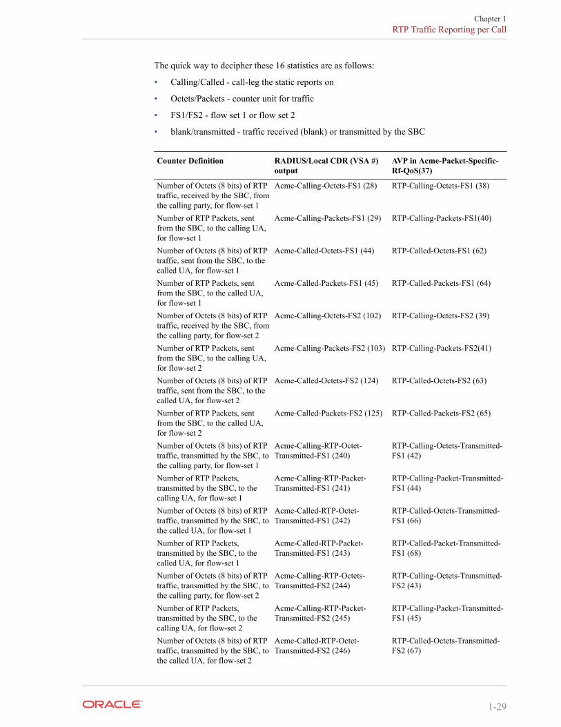
The quick way to decipher these 16 statistics are as follows:
• Calling/Called - call-leg the static reports on
• Octets/Packets - counter unit for traffic
• FS1/FS2 - flow set 1 or flow set 2
• blank/transmitted - traffic received (blank) or transmitted by the SBC
Counter Definition RADIUS/Local CDR (VSA #)output
AVP in Acme-Packet-Specific-Rf-QoS(37)
Number of Octets (8 bits) of RTPtraffic, received by the SBC, fromthe calling party, for flow-set 1
Acme-Calling-Octets-FS1 (28) RTP-Calling-Octets-FS1 (38)
Number of RTP Packets, sentfrom the SBC, to the calling UA,for flow-set 1
Acme-Calling-Packets-FS1 (29) RTP-Calling-Packets-FS1(40)
Number of Octets (8 bits) of RTPtraffic, sent from the SBC, to thecalled UA, for flow-set 1
Acme-Called-Octets-FS1 (44) RTP-Called-Octets-FS1 (62)
Number of RTP Packets, sentfrom the SBC, to the called UA,for flow-set 1
Acme-Called-Packets-FS1 (45) RTP-Called-Packets-FS1 (64)
Number of Octets (8 bits) of RTPtraffic, received by the SBC, fromthe calling party, for flow-set 2
Acme-Calling-Octets-FS2 (102) RTP-Calling-Octets-FS2 (39)
Number of RTP Packets, sentfrom the SBC, to the calling UA,for flow-set 2
Acme-Calling-Packets-FS2 (103) RTP-Calling-Packets-FS2(41)
Number of Octets (8 bits) of RTPtraffic, sent from the SBC, to thecalled UA, for flow-set 2
Acme-Called-Octets-FS2 (124) RTP-Called-Octets-FS2 (63)
Number of RTP Packets, sentfrom the SBC, to the called UA,for flow-set 2
Acme-Called-Packets-FS2 (125) RTP-Called-Packets-FS2 (65)
Number of Octets (8 bits) of RTPtraffic, transmitted by the SBC, tothe calling party, for flow-set 1
Acme-Calling-RTP-Octet-Transmitted-FS1 (240)
RTP-Calling-Octets-Transmitted-FS1 (42)
Number of RTP Packets,transmitted by the SBC, to thecalling UA, for flow-set 1
Acme-Calling-RTP-Packet-Transmitted-FS1 (241)
RTP-Calling-Packet-Transmitted-FS1 (44)
Number of Octets (8 bits) of RTPtraffic, transmitted by the SBC, tothe called UA, for flow-set 1
Acme-Called-RTP-Octet-Transmitted-FS1 (242)
RTP-Called-Octets-Transmitted-FS1 (66)
Number of RTP Packets,transmitted by the SBC, to thecalled UA, for flow-set 1
Acme-Called-RTP-Packet-Transmitted-FS1 (243)
RTP-Called-Packet-Transmitted-FS1 (68)
Number of Octets (8 bits) of RTPtraffic, transmitted by the SBC, tothe calling party, for flow-set 2
Acme-Calling-RTP-Octets-Transmitted-FS2 (244)
RTP-Calling-Octets-Transmitted-FS2 (43)
Number of RTP Packets,transmitted by the SBC, to thecalling UA, for flow-set 2
Acme-Calling-RTP-Packet-Transmitted-FS2 (245)
RTP-Calling-Packet-Transmitted-FS1 (45)
Number of Octets (8 bits) of RTPtraffic, transmitted by the SBC, tothe called UA, for flow-set 2
Acme-Called-RTP-Octet-Transmitted-FS2 (246)
RTP-Called-Octets-Transmitted-FS2 (67)
Chapter 1RTP Traffic Reporting per Call
1-29

Counter Definition RADIUS/Local CDR (VSA #)output
AVP in Acme-Packet-Specific-Rf-QoS(37)
Number of RTP Packets,transmitted by the SBC, to thecalled UA, for flow-set 2
Acme-Called-RTP-Packet-Transmitted-FS2 (247)
RTP-Called-Packet-Transmitted-FS2 (69)
Chapter 1RTP Traffic Reporting per Call
1-30
2Configuring Accounting
OverviewThis chapter provides you with information about configuring RADIUS accounting on yourSBC including these essential configurations and specialized features:
• Accounting for SIP and H.323
• Local CDR storage on the SBC, including CSV file format settings-
• The ability to send CDRs via FTP to a RADIUS sever
• Per-realm accounting control
• Configurable intermediate period
• RADIUS CDR redundancy
• RADIUS CDR content control
Accounting for SIP and H.323This section explains SIP and H.323 accounting using the RADIUS Accounting System (RAS).
For accounting purposes, the SBC uses RADIUS to send accounting messages. These messagesare transmitted to one of a predefined list of accounting servers using a predefined forwardingstrategy. RAS provides a mechanism for temporarily storing session initiation and completionstatistics and for delivering these statistics to accounting servers located elsewhere in thenetwork.
Call Detail RecordsThe SBC supports CDRs through RADIUS reporting with additional VSAs to includeinformation that is not available with the standard RADIUS session information. CDRs providebilling information on sessions traversed through a system, as well as troubleshootinginformation, fraud detection, fault diagnostics, and service monitoring.
CDRs can contain information about recent system usage such as the identities of sources(points of origin), the identities of destinations (endpoints), the duration of each call, theamount billed for each call, the total usage time in the billing period, the total free timeremaining in the billing period, and the running total charged during the billing period.VSAsare defined by vendors of remote access servers in order to customize how RADIUS works ontheir servers.
RAS OverviewThe RAS acts as a RADIUS client. It provides a mechanism for generating accountinginformation in CDRs. The CDRs are transmitted to a RADIUS server in UDP datagrams, usingRADIUS Accounting Request messages.
2-1
The RAS receives RADIUS accounting messages when different events occur. The event andCDR event trigger list information determines which RADIUS messages, if any, are included,as well as which RADIUS attributes are included. The library adds RADIUS messages to thewaiting queue only when the message is ready to be sent. The SIP proxy needs to populate theCDR as session information becomes available so, by the time the session ends, it contains theinformation necessary to generate all of the messages.
The RADIUS accounting client process manages its queue and a list of servers. The serverseach have a UDP connection and manage their own pending message queues. Changes in thestate of the server connection might cause interaction with the client process waiting queue.
When RADIUS messages are added to the RAS waiting queue, the RAS sends them to a serverbased on strategy. If the RAS is configured to transmit all the messages when the session ends,all the messages are sent to the same server. Each session continues logging messagesaccording to the event logging scheme in effect when the session began (for example, when theCDR was created).
The RAS notifies the RADIUS server with Accounting-On/Off messages when the RAS’s entryfor that server is enabled/disabled. The response to the Accounting-On message is the RAS’sfirst determination of RTT, and serves as notification that the server is reachable. Until theAccounting-On response is received, the server cannot send other messages.
RADIUS Accounting ClientThe RADIUS accounting client process has a local socket at which it accepts RADIUSmessages. RADIUS messages received on the local socket are added to the waiting queue fortransmission to a RADIUS server. The waiting queue is a first-in, first-out (FIFO) queue.
The RADIUS accounting client process sends messages to a server queue based on theconfiguration (servers configured/enable/connected, as well as the strategy). Messages thatreturn from a server (due to server failure/disabling) are first in the FIFO queue.
The RADIUS accounting client process interfaces with the RADIUS accounting servers usingthe RADIUS protocol with the VSAs outlined above.
The RADIUS server collects a variety of information that can be used for accounting and forreporting on network activity. The RADIUS client sends information to designated RADIUSservers when the user logs on and logs off. The RADIUS client might send additional usageinformation on a periodic basis while the session is in progress. The requests sent by the clientto the server to record logon/logoff and usage information are generally called accountingrequests.
RADIUS accounting permits a RADIUS server to track when users commence and terminatetheir connections. Typical accounting information includes the following:
• Full user name
• RAS identification name or IP address
• RAS port number
• Time connection started
When a client is configured to use RADIUS accounting, it generates an Accounting Startpacket describing the type of service being delivered and the user it is being delivered to at thestart of service delivery. It sends that packet to the RADIUS Accounting server, which sendsback an acknowledgement that the packet has been received. At the end of service delivery, theclient generates an Accounting Stop packet describing the type of service that was deliveredand, optionally, statistics such as elapsed time, input and output octets, or input and output
Chapter 2Accounting for SIP and H.323
2-2
packets. It sends that packet to the RADIUS Accounting server, which sends back anacknowledgement that the packet has been received. The Accounting-Request (whether forStart or Stop) is submitted to the RADIUS accounting server through the network.
Transactions between the client and RADIUS accounting server are authenticated through theuse of a shared secret, which is never sent over the network.
Session AccountingThe RAS client can record SIP, H.323, and IWF session activity based on configuration and aCDR. The CDR determines which messages are generated and determines the RADIUSattributes included in the messages. The RAS client must be capable of sending CDRs to anynumber of RADIUS accounting servers, using the defined hunt, failover, round robin, fewestpending, or fastest server strategies.
The establishment, failed establishment, change, or removal of a session can trigger RADIUSAccounting Request messages. The RAS might also send notification of its status (enabled/disabled). RADIUS Accounting Request messages include the following:
• Start—Session has started.
• Interim-Update—Session parameters have changed.
• Stop—Session has ended.
• Accounting-On—Creation of a new RADIUS client.
• Accounting-Off—RADIUS client has shut down.
Each session might generate Start, Interim-Update, and Stop messages based on the localconfiguration when the session is initiated. Each Start message tells the RADIUS server that asession has started. Each Interim-Update message changes the session parameters, and mayreport the session characteristics for the session to that point. Each Stop message informs theRADIUS server that a session has ended and reports session characteristics.
The RAS has the ability to transmit all RADIUS messages related to a session at the end of thesession, regardless of which messages are generated and when they are generated. Somecustomers might choose this option to reduce the likelihood of the RADIUS messages beinglogged to different servers, or in different log files on the same server.
The RAS always generates a RADIUS Stop message when the session ends, regardless of thesession termination cause. The termination cause and the session characteristics are reported.
Interim RADIUS Records for Recursive AttemptsWhen the SBC routes calls, it performs local policy look-ups that can return several next hops,ordered by preference. This can also happen as a results of an LRT lookup, an ENUM queryresponse, or SIP redirect. To set up sessions, the SBC uses—in ordered preference—andrecurses through the list if it encounters failures.
You can configure SIP accounting to send RADIUS Interim records when the SBC encountersthese failures. The interim message contains: the destination IP address, the disconnect reason,a timestamp for the failure, and the number that was called. This feature is enabled by settingthe generate-interim parameter to unsuccessful-attempt. Please refer to Appendix B to viewthe format of an unsuccessful-attempt interim record.
Chapter 2Accounting for SIP and H.323
2-3
RADIUS MessagesThe following table identifies the relationship between the signaling elements and the RADIUSattributes included in Accounting Request messages to the RADIUS server.
RADIUS Attribute Data Element Message
NAS IP-Address IP address of the SIP proxy or the H.323 stack’scall signal address.
Start, Interim-Update,Stop, On, Off
NAS Port SIP proxy port or the H.323 stack’s call signalingRAS port.
Start, Interim-Update,Stop, On, Off
NAS Identifier Value, if any, set in the optional NAS-ID field forthe accounting server that you configure as partof the accounting configuration. This identifiersets the value that the remote server (theaccounting server) uses to identify the SBC sothat RADIUS messages can be transmitted.The remote server to which the accountingconfiguration will send messages uses at least oneof two pieces of information for identification:NAS IP address: always included in theaccounting messageNAS identifier: configured in the NAS-IDparameter of the accounting server; if configured,the NAS identifier is sent to the remote serverThis attribute only appears if a value isconfigured in the NAS-ID field.
Start, Interim-Update,Stop, On, Off
Acct-Session-ID Either the Call-ID field value of the SIP INVITEmessage, the callIdentifier of the H.323 message,or RADIUS client information.
Start, Interim-Update,Stop, On, Off
Called Station ID To field value of the SIP INVITE message (a typeof message used to initiate a session) or thecalledPartyNumber of the H.323 message.
Start, Interim-Update,Stop
Calling Station ID From field value of the SIP INVITE message orthe callingPartyNumber of the H.323 message.
Start, Interim-Update,Stop
Acct-Terminate-Cause Reason for session ending (refer to SessionTermination session).
Stop, Off
Acct-Session-Time Length of session (time in seconds, ormilliseconds if so configured).
Interim-Update, Stop,Off
Session TerminationSessions are terminated for reasons that include normal termination, signaling failure, timeout,or network problems. The following table maps RADIUS accounting termination cause codesto network events.
RADIUS TerminationCause
Event Message
User request SIP BYE message or H.323 StopUser error SIP signaling failed to establish session
(accompanied by disconnect cause)Stop
NAS request RADIUS server disabled Off
Chapter 2Accounting for SIP and H.323
2-4
ACLI Instructions and ExamplesThis section tells you how to access and set parameters for RADIUS accounting support. Touse the SBC with external RADIUS (accounting) servers to generate CDRs and provide billingservices requires, you need to configure account configuration and account server list.
Accessing the Accounting and Accounting Servers ConfigurationTo configure the account configuration and account servers:
1. In Superuser mode, navigate to the account-config parameter.
ORACLE# configure terminalORACLE(configure)# session-routerORACLE(session-router)# account-configORACLE(account-config)#
2. To configure account server parameters (a subset of the account configuration parameters),type account-servers and press Enter. The system prompt changes to let you know thatyou can begin configuring individual parameters.
ORACLE(account-config)# account-serversORACLE(account-server)#
Setting Up the Account ConfigurationYou set the account configuration parameters to indicate where you want accounting messagessent, when accounting messages you want them sent, and the strategy you want used to selectaccount servers.
To configure the account configuration:
1. hostname—Defaults to and must remain localhost.
2. port—Retain the default value of 1813 or enter the number of the UDP port associatedwith the SBC from which RADIUS messages are sent.
• minimum: 1025
• maximum: 65535
3. strategy—Indicate the strategy you want used to select the accounting servers to which theSBC will send its accounting messages. The following table lists the available strategies:
Strategy Description
hunt Selects accounting servers in the order in which they are listed.If the first accounting server is online, working, and has notexceeded any of the defined constraints, all traffic is sent to it.Otherwise the second accounting server is selected. If the firstand second accounting servers are offline or exceed any definedconstraints, the third accounting server is selected. And so onthrough the entire list of configured servers
failover Uses the first server in the list of predefined accounting serversuntil a failure is received from that server. Once a failure isreceived, it moves to the second accounting server in the listuntil a failure is received. And so on through the entire list ofconfigured servers.
Chapter 2Accounting for SIP and H.323
2-5
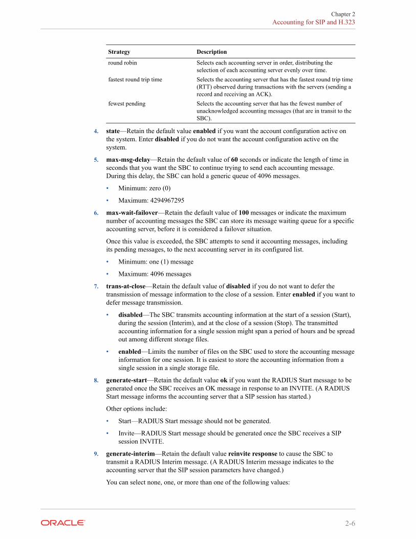
Strategy Description
round robin Selects each accounting server in order, distributing theselection of each accounting server evenly over time.
fastest round trip time Selects the accounting server that has the fastest round trip time(RTT) observed during transactions with the servers (sending arecord and receiving an ACK).
fewest pending Selects the accounting server that has the fewest number ofunacknowledged accounting messages (that are in transit to theSBC).
4. state—Retain the default value enabled if you want the account configuration active onthe system. Enter disabled if you do not want the account configuration active on thesystem.
5. max-msg-delay—Retain the default value of 60 seconds or indicate the length of time inseconds that you want the SBC to continue trying to send each accounting message.During this delay, the SBC can hold a generic queue of 4096 messages.
• Minimum: zero (0)
• Maximum: 4294967295
6. max-wait-failover—Retain the default value of 100 messages or indicate the maximumnumber of accounting messages the SBC can store its message waiting queue for a specificaccounting server, before it is considered a failover situation.
Once this value is exceeded, the SBC attempts to send it accounting messages, includingits pending messages, to the next accounting server in its configured list.
• Minimum: one (1) message
• Maximum: 4096 messages
7. trans-at-close—Retain the default value of disabled if you do not want to defer thetransmission of message information to the close of a session. Enter enabled if you want todefer message transmission.
• disabled—The SBC transmits accounting information at the start of a session (Start),during the session (Interim), and at the close of a session (Stop). The transmittedaccounting information for a single session might span a period of hours and be spreadout among different storage files.
• enabled—Limits the number of files on the SBC used to store the accounting messageinformation for one session. It is easiest to store the accounting information from asingle session in a single storage file.
8. generate-start—Retain the default value ok if you want the RADIUS Start message to begenerated once the SBC receives an OK message in response to an INVITE. (A RADIUSStart message informs the accounting server that a SIP session has started.)
Other options include:
• Start—RADIUS Start message should not be generated.
• Invite—RADIUS Start message should be generated once the SBC receives a SIPsession INVITE.
9. generate-interim—Retain the default value reinvite response to cause the SBC totransmit a RADIUS Interim message. (A RADIUS Interim message indicates to theaccounting server that the SIP session parameters have changed.)
You can select none, one, or more than one of the following values:
Chapter 2Accounting for SIP and H.323
2-6
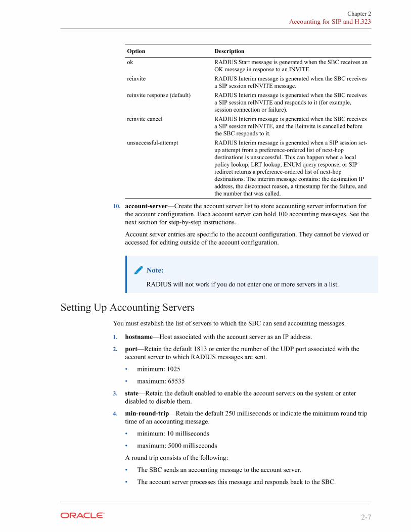
Option Description
ok RADIUS Start message is generated when the SBC receives anOK message in response to an INVITE.
reinvite RADIUS Interim message is generated when the SBC receivesa SIP session reINVITE message.
reinvite response (default) RADIUS Interim message is generated when the SBC receivesa SIP session reINVITE and responds to it (for example,session connection or failure).
reinvite cancel RADIUS Interim message is generated when the SBC receivesa SIP session reINVITE, and the Reinvite is cancelled beforethe SBC responds to it.
unsuccessful-attempt RADIUS Interim message is generated when a SIP session set-up attempt from a preference-ordered list of next-hopdestinations is unsuccessful. This can happen when a localpolicy lookup, LRT lookup, ENUM query response, or SIPredirect returns a preference-ordered list of next-hopdestinations. The interim message contains: the destination IPaddress, the disconnect reason, a timestamp for the failure, andthe number that was called.
10. account-server—Create the account server list to store accounting server information forthe account configuration. Each account server can hold 100 accounting messages. See thenext section for step-by-step instructions.
Account server entries are specific to the account configuration. They cannot be viewed oraccessed for editing outside of the account configuration.
Note:
RADIUS will not work if you do not enter one or more servers in a list.
Setting Up Accounting ServersYou must establish the list of servers to which the SBC can send accounting messages.
1. hostname—Host associated with the account server as an IP address.
2. port—Retain the default 1813 or enter the number of the UDP port associated with theaccount server to which RADIUS messages are sent.
• minimum: 1025
• maximum: 65535
3. state—Retain the default enabled to enable the account servers on the system or enterdisabled to disable them.
4. min-round-trip—Retain the default 250 milliseconds or indicate the minimum round triptime of an accounting message.
• minimum: 10 milliseconds
• maximum: 5000 milliseconds
A round trip consists of the following:
• The SBC sends an accounting message to the account server.
• The account server processes this message and responds back to the SBC.
Chapter 2Accounting for SIP and H.323
2-7
If the fastest RTT is the strategy for the account configuration, the value you enter here canbe used to determine an order of preference (if all the configured account servers areresponding in less than their minimum RTT).
5. max-inactivity—Retain the default 60 seconds or indicate the length of time in secondsthat you want the SBC with pending accounting messages to wait when it has not receiveda valid response from the target account server.
• minimum: 1 second
• maximum: 300 seconds
Once this timer value is exceeded, the SBC marks the unresponsive account server asdisabled in its failover scheme. When a server connection is marked as inactive, theSBC attempts to restart the connection and transfers pending messages to anotherqueue for transmission. RADIUS messages might be moved between different accountservers as servers become inactive or disabled.
6. restart-delay—Retain the default 30 seconds or indicate the length of time in seconds youwant the SBC to wait before resending messages to a disabled account server.
• minimum: 1 second
• maximum: 300 seconds
7. bundle-vsa—Retain the default enabled if you want the account server to bundle the VSAswithin RADIUS accounting messages. Enter disabled if you do not want the VSAs to bebundled. (Bundling means including multiple VSAs within the vendor value portion of themessage.)
In a bundled accounting message, the RADIUS message type is vendor-specific, the lengthis determined for each individual message, and the vendor portion begins with a 4-byteidentifier, and includes multiple vendor type, vendor length, and vendor value attributes.
8. secret—Enter the secret passed from the account server to the client in text format.Transactions between the client and the RADIUS server are authenticated by the sharedsecret; which is determined by the source IPv4 address of the received packet.
9. NAS-ID—Optional. Enter the NAS ID in text format (FQDN allowed). The account serveruses this value to identify the SBC for the transmittal of accounting messages.
The remote server to which the account configuration sends messages uses at least one oftwo potential pieces of information for purposes of identification. The SBC accountingmessages always includes in the first of these:
• Network Access Server (NAS) IP address (the IP address of the SBC’s SIP proxy)
• NAS ID (the second piece of information) provided by this value. If you enter a valuehere, the NAS ID is sent to the remote server.
If you have more than one SBC pointing to the same account server, the NAS ID canbe used to identify which SBC generated the record.
SIP CDR Stop TimeYou can set up your global SIP configuration so the disconnect time reflected in a RADIUSCDR is the time when the SBC receives a BYE. Enabling this parameter also means thedisconnect time is defined when the SBC sends a BYE to the UAS and UAC. Otherwise, thethe CDR’s value is based on when the 200 OK confirms the BYE.
The applicable RADIUS CDR in this case is the standard RADIUS attribute Acct-Session-Time, number 46.
Chapter 2Accounting for SIP and H.323
2-8
ACLI Instructions and ExamplesTo enable definition of the disconnect time based on the BYE:
1. Access the sip-config configuration element.
ORACLE# configure terminalORACLE(configure)# session-routerORACLE(session-router)# sip-configORACLE(sip-config)#
2. Select the sip-config object to edit.
ORACLE(sip-config)# select
ORACLE(sip-config)#
3. set-disconnect-time-on-bye—Set this parameter to enabled if you want to use the BYEmessage as the defining factor for the disconnect time. This parameter is disabled bydefault.
4. Type done to save your configuration.
Set Acct-session-time attribute to millisecondsSome accounting features require greater precision. The attribute acct-session-time can beconfigured to be in milliseconds.
The RADIUS attribute acct-session-time uses seconds as its default. You can set this to amillisecond granularity in the account-config configuration element using the optionmillisecond-duration. This option setting is required for the RADIUS CDR display, DiameterRF accounting and locally-generated CDR comma separated value (CSV) files behaviors.
Note:
Changing to millisecond granularity violates RFC 2866.
Configure acct-session-time for millisecond granularitySet the option for millsecond granularity for the acct-session-time attribute.
1. Access the account-config configuration element.
ORACLE# configure terminalORACLE(configure)# session-routerORACLE(session-router)# account-configORACLE(account-config)#
2. Type select to begin configuring this object.
3. options—Set the options parameter by typing +options, a Space, the option namemillsecond-duration and then press Enter.
4. Type done to save your configuration.
Chapter 2Accounting for SIP and H.323
2-9
Per Realm Accounting ControlYou can enable or disable accounting control for specific realms by setting one parameter. Thisfeature is enabled by default.
The SBC’s SIP and H.323 tasks check whether this parameter is set to enabled or disabled, andsends record on that basis.
ACLI InstructionsTo configure per realm accounting:
1. Access the realm-config configuration element.
ORACLE# configure terminalORACLE(configure)# media-managerORACLE(media-manager)# realm-configORACLE(realm-config)#
2. Select the realm-config object to edit.
ORACLE(realm-config)# selectidentifier:1: realm01 left-left:0 0.0.0.0
selection: 1ORACLE(realm-config)#
3. accounting-enable—Either leave this parameter set to enabled (default) to generate CDRsfor this realm, or change it to disabled.
4. Type done to save your configuration.
Configurable Intermediate PeriodYou can set how often the SBC generates periodic interim records for H.323 and for SIP.
• H.323—The periodic timer (set to the value you specify in the accounting configuration) isdynamically created when the SBC receives a Connect message and an H.323 call answermethod is invoked. The SBC deletes the timer when the H.323 session is terminated.
• SIP—The periodic timer (set to the value you specify in the accounting configuration) isdynamically created when the SBC receives an initial INVITE message. The SBC deletesthe timer when the session is terminated.To set the timer for periodic interim records:
1. In Superuser mode, type configure terminal and press Enter.
ORACLE# configure terminal
2. Type session-router and press Enter.
ORACLE(configure)# session-router
3. Type account-config and press Enter.
ORACLE(session-router)# account-config
Chapter 2Per Realm Accounting Control
2-10
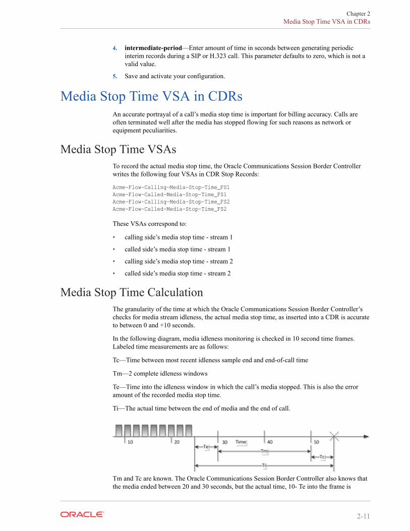
4. intermediate-period—Enter amount of time in seconds between generating periodicinterim records during a SIP or H.323 call. This parameter defaults to zero, which is not avalid value.
5. Save and activate your configuration.
Media Stop Time VSA in CDRsAn accurate portrayal of a call’s media stop time is important for billing accuracy. Calls areoften terminated well after the media has stopped flowing for such reasons as network orequipment peculiarities.
Media Stop Time VSAsTo record the actual media stop time, the Oracle Communications Session Border Controllerwrites the following four VSAs in CDR Stop Records:
Acme-Flow-Calling-Media-Stop-Time_FS1Acme-Flow-Called-Media-Stop-Time_FS1Acme-Flow-Calling-Media-Stop-Time_FS2Acme-Flow-Called-Media-Stop-Time_FS2
These VSAs correspond to:
• calling side’s media stop time - stream 1
• called side’s media stop time - stream 1
• calling side’s media stop time - stream 2
• called side’s media stop time - stream 2
Media Stop Time CalculationThe granularity of the time at which the Oracle Communications Session Border Controller’schecks for media stream idleness, the actual media stop time, as inserted into a CDR is accurateto between 0 and +10 seconds.
In the following diagram, media idleness monitoring is checked in 10 second time frames.Labeled time measurements are as follows:
Tc—Time between most recent idleness sample end and end-of-call time
Tm—2 complete idleness windows
Te—Time into the idleness window in which the call’s media stopped. This is also the erroramount of the recorded media stop time.
Ti—The actual time between the end of media and the end of call.
Tm and Tc are known. The Oracle Communications Session Border Controller also knows thatthe media ended between 20 and 30 seconds, but the actual time, 10- Te into the frame is
Chapter 2Media Stop Time VSA in CDRs
2-11
unknown. Thus, the time recorded in the CDR is quantized up to the end of the media stopframe at 30 seconds. This time, as written to the CDR, must be interpreted with possible errorof 0 ≤ Te < 10 seconds.
HA CaveatWhen a switchover occurs between media stop time and end of call, the media stop timewritten to the CDR is the failover time.
RADIUS CDR Content ControlThe SBC’s RADIUS support has been enhanced so that you can limit the size of RADIUSCDRs. The SBC’s RADIUS accounting provides a detailed set of records that can contain, forexample, multiple media flow descriptions for forked calls that can contain multiple sets ofmedia and QoS attributes. While the level of detail might be required for some networks, inothers the large CDRs generated to reflect that level of granularity can cause issues for theapplication receiving the records.
You can use the following enhancements to control the size of the RADIUS CDRs your SBCproduces:
• Duplicate RADIUS attribute prevention—Using this feature, you can configure the SBC tosend only one set of RADIUS attributes in CDR for a forked call. (When a forked SIPINVITE contains media information, media and QoS attributes can potentially beduplicated.)
• RADIUS attribute selection—You can set a list of the Oracle VSAs you want included in aRADIUS CDR, and the SBC will exclude the others from the record; standard attributesare always included. You specify attributes using their unique identifier in a comma-delimited list, and you can list them in any order. However, entering an invalid rangedisables this feature.The SBC excludes attributes from the records in which they are already defined. If anattributes only appears in a Stop record, then it will be deleted from Stop records.
The configuration provides a mechanism to make entries flexible and easy.
ACLI Instructions and ExamplesYou enable these enhancements using two parameters in the accounting configuration.
Accessing the Accounting ConfigurationTo access the accounting configuration:
1. In Superuser mode, type configure terminal and press Enter.
ORACLE# configure terminal
2. Type session-router and press Enter.
ORACLE(configure)# session-router
3. Type account-config and press Enter.
ORACLE(session-router)# account-config
Chapter 2RADIUS CDR Content Control
2-12
From this point, you can reach the individual parameters for duplicate RADIUS attributeprevention and for RADIUS attribute selection.
Preventing Duplicate RADIUS AttributesTo enable duplicate RADIUS attribute prevention:
1. prevent-duplicate-attrs—.
Enable this parameter to prevent the SBC from duplicating attributes in the accountingrecords it generates. This duplication can be caused, for example, by multiple mediasessions within the context of a call. Retaining the default (disabled) allows the SBC toinclude duplicate attributes in RADIUS, Diameter and Local accounting records. This canresult in attribute placement and counts that are less consistent."
ORACLE(account-config)# prevent-duplicate-attrs enabled
2. Save and activate your configuration.
RADIUS Attribute SelectionYou enter the list of VSAs that you want included as a comma-delimited list. There are specialentry types you can use in the comma-delimited list to set ranges and make entries easier:
• X- — Where X is a VSA identifier, the SBC will include all attributes with an identifierequal to or greater than X.
• -X — Where X is a VSA identifier, the SBC will include all attributes with an identifierequal to or less than X.
• - — Use the minus sign (-) alone when you want to turn off attribute selection, includingall VSAs in the CDR.To enter a list of RADIUS attributes to include in a CDR:
1. vsa-id-range—Enter a comma-delimited list that represents the VSA you want to appearin the RADIUS CDR. There is no default for this parameter.
Do not use <Spaces> when typing in your comma-delimited list.
ORACLE(account-config)# vsa-id-range -5,7,10-
This entry specifies that CDRs contain VSA with identifiers equal to and less than 5, VSA7, and VSAs with identifiers equal to and greater than 10.
Limit this list to accounting VSAs. For example, VSA 254 is an authentication VSA, so itshould not be included in the range. The system generates validate-config errors if yourrange includes VSAs that are not accounting VSAs.
2. Save and activate your configuration.
Custom RADIUS CDR VSAs for SIPThis section describes these additions to the SBC’s RADIUS accounting capabilities forcustomizing your call detail records (CDRs):
• Generating CDRs with call detail information from a SIP message—The SBC reserves aset of vender-specific attributes (VSAs) and then populates them according to your headermanipulation (HMR) configuration
Chapter 2Custom RADIUS CDR VSAs for SIP
2-13
• Generating CDRs with trunk group information—You can enable your SBC to provideterminating trunk-group and trunk-context data even when the SBC is not performingtrunk-group routing.
Both support using the CSV file for RADIUS records, which you can either save locally orpush to a defined FTP server.
About User-Defined VSAs for SIP CallsThe SBC reserves VSAs 200-229 for you to define for use with SIP calls. These VSAs shouldnever be used for other purposes, and their use should never conflict with the need to add newVSAs in the future. Because this leaves a significant number of VSAs unused, there is stillample space for any new VSAs that might be required.
Since RADIUS START records are created on session initiation, their content cannot beupdated. However, the content for INTERIM and STOP records can be.
To configure user-defined VSAs for a SIP call, you use HMR. For example, when you set upHMR correctly, the SBC reports originating or terminating country codes in CDRs in whateverformat they appear in the SIP username field. The HMR rules you configure uses the SIPheader name P-Acme-VSA, adding it to the SIP header from any part of the SIP message. Thenthe SBC searches for the P-Acme-VSA header, generates a VSA for it, and then includes thatVSA in the CDR for the call.
You can include multiple custom VSAs per CDR by adding the corresponding number of rules;in essence, you add in the header as many times as required.
HMR AdaptationsThe following HMR element rule types support user-defined VSA for SIP calls:
• uri-user-only—The uri-user-only element rule type represents the URI username withoutthe URI user parameters. You can perform these actions for the uri-user-only type: store,replaces, delete, and add. This means, for example, that you can add a username string toSIP or TEL URI without having any impact on other parameters.
• uri-phone-number-only—The uri-phone-number-only applies when all rules are met. Itrefers to the user part of the SIP/TEL URI without the user parameters when the userqualifies for the BNF shown here:
uri-phone-number-only = [+]1*(phone-digit / dtmf-digit / pause-character)phone-digit = DIGIT / visual-separatorDIGIT = "0" / "1" / "2" / "3" / "4" / "5" / "6" / "7" / "8" / "9"visual-separator = "-" / "." / "(" / ")"dtnf-digit = "*" / "#" / "A" / "B" / "C" / "D"pause-character = "p" / "w"
Once the URI user part qualifies as a uri-phone-number-only based on this BNF, the SBCignores the visual separators when comparing it against a match value. Furthermore, theSBC performs on or using the uri-phone-number-only after the excluding the visualseparators.
But anew value being added as a uri-phone-number-only or replacing a uri-phone-number-only does not have to match the BNF noted above. That is, you can use the uri-phone-number-only type knowing that:
– The action only occurs if the URI username matches the BNF defined here.
Chapter 2Custom RADIUS CDR VSAs for SIP
2-14
– Even so, you can also replace the uri-phone-number-only with one that does not match—using the same rule.
HMR String VariableHMR supports the use of a string variable that you can use to populate headers and elements.You set this value in the hmr-string parameter for a realm, SIP session agent, or SIP interface.Then, you reference it as the $HMR_STRING variable.
When a message arrives, the SBC matches the string you provision to the closest session agent,realm, or SIP interface. The precedence for matching is in this order: session agent, realm, andthen SIP interface. For example, the SBC populates messages matching a session agent usingthe $HMR_STRING variable, but it leaves the value empty for session agents that do notmatch.
You can use the string variable, for instance, for values specific to realms and session agentssuch as country code values when the regular expression pattern used to match a country codefails to do so.
ACLI Instructions and Examples User-Defined VSAsThis section shows you how to configure user-defined VSAs for SIP calls. It also containssubsections with configuration examples so you can see how this feature is put to use.
This section also shows you two configuration examples for this feature.
To create a header manipulation rule that generates user-defined VSAs for SIP calls:
1. In Superuser mode, type configure terminal and press Enter.
ORACLE# configure terminalORACLE(configure)#
2. Type session-router and press Enter.
ORACLE(configure)# session-routerORACLE(session-router)#
3. Type sip-manipulation and press Enter.
ORACLE(session-router)# sip-manipulationORACLE(sip-manipulation)#
4. Type header-rules and press Enter.
ORACLE(session-router)# header-rulesORACLE(sip-header-rules)#
5. name—Enter a meaningful name for the header rule you are creating. For example, if youwant to add VSA 200 to your CDRs for SIP calls, you might name your rulegenerateVSA200. There is no default for this parameter, and it is required.
6. header-name—Set this parameter to P-Acme-VSA so the SBC will add this accountinginformation to CDRs for the call.
7. action—Set this parameter to add.
8. new-value—Enter the regular expression value for the new value you want to add. Forexample, to add VSA 200 that contains the value from the SIP From header, you wouldenter 200:+$storeFrom.$0.
9. Save and activate your configuration.
Chapter 2Custom RADIUS CDR VSAs for SIP
2-15

The first example shows you how to generate custom VSA for the To and From headers in SIPmessages.
• VSA 200 contains the header value from the SIP From header.
• VSA 220 contains the header value from the SIP To header.
sip-manipulation namecustom VSA1 description header-rule name storeFrom header-name from action store comparison-type pattern-rule match-value .* msg-type request new-value methods INVITE header-rule name storeTo header-name to action store comparison-type pattern-rule match-value .* msg-type request new-value methods INVITE header-rule name generateVSA200 header-name P-Acme-VSA action add comparison-type case-sensitive match-valuemsg-type any new-value 200:+$storeFrom.$0 methods INVITE header-rule name generateVSA220 header-name P-Acme-VSA action add comparison-type case-sensitive match-value msg-type any new-value 220:+$storeTo.$0 methods INVITE
The second example shows you how to configure HMR to generate VSA 225, which containsthe customer P_From header when it is present. When that header is not present, the ruleinstructs the SBC to include the header value from the SIP From header for VSA 225.
sip-manipulation name customVSA1 description header-rule name storePfrom header-name P_From action store comparison-type pattern-rule match-value .* msg-type request new-value
Chapter 2Custom RADIUS CDR VSAs for SIP
2-16
methods INVITE header-rule name storeFrom header-name from action store comparison-type pattern-rule match-value .* msg-type request new-valuemethods INVITE header-rule name generateVSA225_1 header-name P-Acme-VSA action add comparison-type case-sensitive match-value msg-type request new-value 225:+$storeFrom.$0 methods INVITE header-rule name generateVSA225_2 header-name P-Acme-VSA action manipulate comparison-type pattern-rule match-value $storePfrom msg-type request new-value methods INVITEelement-rule name one parameter-name type header-value action delete-element match-val-type any comparison-type pattern-rule match-value ^225.* new-value element-rule name two parameter-name type header-value action add match-val-type any comparison-type case-sensitive match-value new-value 225:+$storePfrom.$0
ACLI Instructions and Examples String VariableTo use the HMR string variable, you set the hmr-string value in the SIP session agent, realm,or SIP interface where you want the feature applied. The following sample shows you how toconfigure the hmr-string parameter for SIP session agent.
1. In Superuser mode, type configure terminal and press Enter.
ORACLE# configure terminalORACLE(configure)#
2. Type session-router and press Enter.
Chapter 2Custom RADIUS CDR VSAs for SIP
2-17
ORACLE(configure)# session-routerORACLE(session-router)#
3. Type session-agent and press Enter.
ORACLE(session-router)# session-agentORACLE(session-agent)#
If you are adding this feature to an existing configuration, you need to select theconfiguration (using the ACLI select command) before making your changes.
4. manipulation-string—Enter a value that references the $HMR_STRING variable that willbe used to populate SIP headers and elements using HMR. There is no default value forthis parameter.
5. Save and activate your configuration.
Trunk-Group VSA GenerationYou can force the SBC to generate VSAs related to trunk groups even when you are not usingthe trunk group feature. With the force-report-trunk-info parameter turned on in the sessionrouter configuration:
• The SBC reports terminating trunk group and trunk-context information even though it hasnot perform trunk-group routing.The appropriate VSAs report the terminating trunk-group (VSA 65) and trunk context(VSA 67) with the information of the matching ingress session agent and realm of theoriginator.
• The SBC reports the terminating trunk-group (VSA 66) and trunk context (VSA 68) as thereceived trunk group and context from the call’s SIP REQUEST message. If the SIPmessage has none, then the SBC uses the information from the matching egress sessionagent (or egress realm, when available) and next-hop realm.Note that information is reported after HMR processing—meaning that headermanipulation has been performed on the message information reported.
ACLI Instructions and ExamplesYou enable trunk-group VSA generation on a system-wide basis in the session-routerconfiguration.
To enable forced trunk-group VSA generation:
1. In Superuser mode, type configure terminal and press Enter.
ORACLE# configure terminalORACLE(configure)#
2. Type session-router and press Enter.
ORACLE(configure)# session-routerORACLE(session-router)#
3. Type session-agent and press Enter.
ORACLE(session-router)# session-routerORACLE(session-router)#
4. forced-report-trunk-info—Change this parameter to enabled if you want to turn on theSBC’s ability to generate VSAs for trunk group information even when you are not usingtrunk-group routing. The SBC uses VSAs 65-68 to report originating and terminating trunk
Chapter 2Custom RADIUS CDR VSAs for SIP
2-18
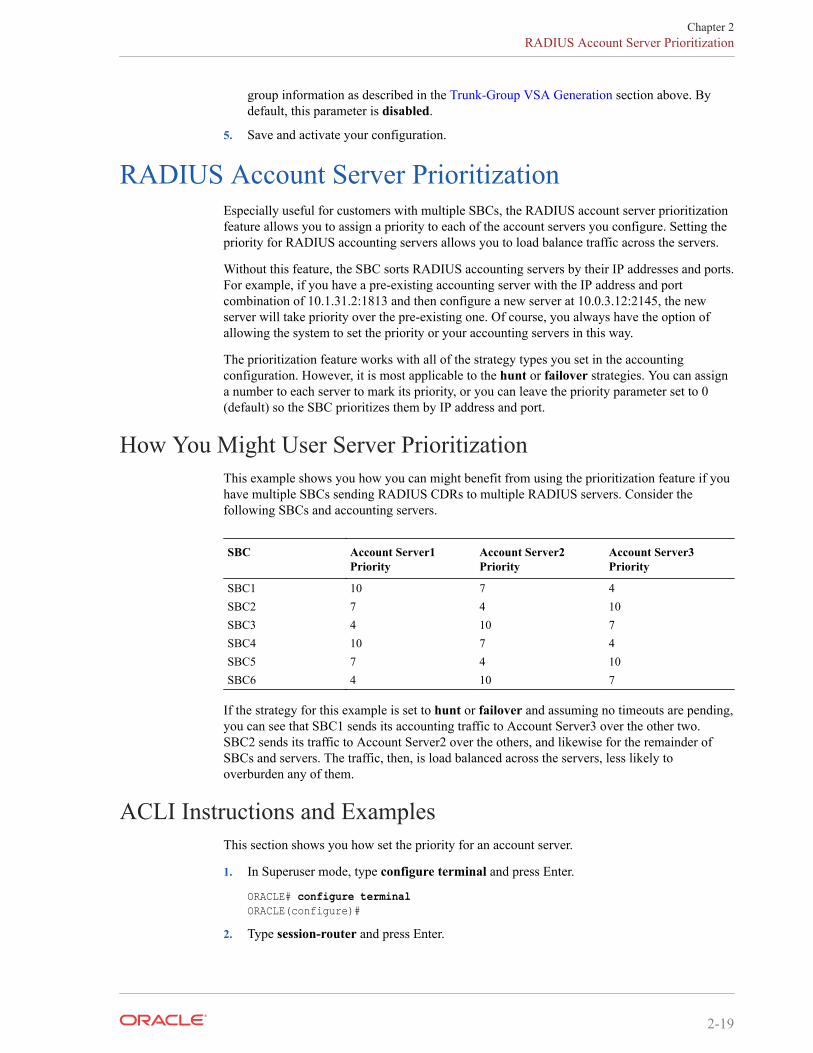
group information as described in the Trunk-Group VSA Generation section above. Bydefault, this parameter is disabled.
5. Save and activate your configuration.
RADIUS Account Server PrioritizationEspecially useful for customers with multiple SBCs, the RADIUS account server prioritizationfeature allows you to assign a priority to each of the account servers you configure. Setting thepriority for RADIUS accounting servers allows you to load balance traffic across the servers.
Without this feature, the SBC sorts RADIUS accounting servers by their IP addresses and ports.For example, if you have a pre-existing accounting server with the IP address and portcombination of 10.1.31.2:1813 and then configure a new server at 10.0.3.12:2145, the newserver will take priority over the pre-existing one. Of course, you always have the option ofallowing the system to set the priority or your accounting servers in this way.
The prioritization feature works with all of the strategy types you set in the accountingconfiguration. However, it is most applicable to the hunt or failover strategies. You can assigna number to each server to mark its priority, or you can leave the priority parameter set to 0(default) so the SBC prioritizes them by IP address and port.
How You Might User Server PrioritizationThis example shows you how you can might benefit from using the prioritization feature if youhave multiple SBCs sending RADIUS CDRs to multiple RADIUS servers. Consider thefollowing SBCs and accounting servers.
SBC Account Server1Priority
Account Server2Priority
Account Server3Priority
SBC1 10 7 4SBC2 7 4 10SBC3 4 10 7SBC4 10 7 4SBC5 7 4 10SBC6 4 10 7
If the strategy for this example is set to hunt or failover and assuming no timeouts are pending,you can see that SBC1 sends its accounting traffic to Account Server3 over the other two.SBC2 sends its traffic to Account Server2 over the others, and likewise for the remainder ofSBCs and servers. The traffic, then, is load balanced across the servers, less likely tooverburden any of them.
ACLI Instructions and ExamplesThis section shows you how set the priority for an account server.
1. In Superuser mode, type configure terminal and press Enter.
ORACLE# configure terminalORACLE(configure)#
2. Type session-router and press Enter.
Chapter 2RADIUS Account Server Prioritization
2-19
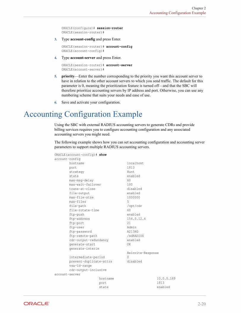
ORACLE(configure)# session-routerORACLE(session-router)#
3. Type account-config and press Enter.
ORACLE(session-router)# account-configORACLE(account-config)#
4. Type account-server and press Enter.
ORACLE(session-router)# account-serverORACLE(account-server)#
5. priority—Enter the number corresponding to the priority you want this account server tohave in relation to the other account servers to which you send traffic. The default for thisparameter is 0, meaning the prioritization feature is turned off—and that the SBC willtherefore prioritize accounting servers by IP address and port. Otherwise, you can use anynumbering scheme that suits your needs and ease of use.
6. Save and activate your configuration.
Accounting Configuration ExampleUsing the SBC with external RADIUS accounting servers to generate CDRs and providebilling services requires you to configure accounting configuration and any associatedaccounting servers you might need.
The following example shows how you can set accounting configuration and accounting serverparameters to support multiple RADIUS accounting servers.
ORACLE(account-config)# showaccount-config hostname localhost port 1813 strategy Hunt state enabled max-msg-delay 60 max-wait-failover 100 trans-at-close disabled file-output enabled max-file-size 1000000 max-files 5 file-path /opt/cdr file-rotate-time 60 ftp-push enabled ftp-address 154.0.12.4 ftp-port 21 ftp-user Admin ftp-password A213HG ftp-remote-path /sdRADIUS cdr-output-redundancy enabled generate-start OK generate-interim Reinvite-Response intermediate-period 0 prevent-duplicate-attrs disabled vsa-id-range cdr-output-inclusiveaccount-server hostname 10.0.0.189 port 1813 state enabled
Chapter 2Accounting Configuration Example
2-20
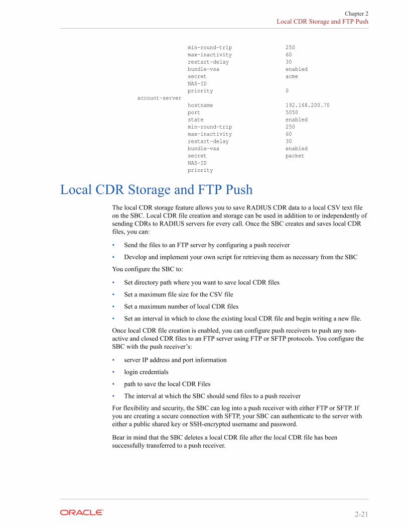
min-round-trip 250 max-inactivity 60 restart-delay 30 bundle-vsa enabled secret acme NAS-ID priority 0 account-server hostname 192.168.200.70 port 5050 state enabled min-round-trip 250 max-inactivity 60 restart-delay 30 bundle-vsa enabled secret packet NAS-ID priority
Local CDR Storage and FTP PushThe local CDR storage feature allows you to save RADIUS CDR data to a local CSV text fileon the SBC. Local CDR file creation and storage can be used in addition to or independently ofsending CDRs to RADIUS servers for every call. Once the SBC creates and saves local CDRfiles, you can:
• Send the files to an FTP server by configuring a push receiver
• Develop and implement your own script for retrieving them as necessary from the SBC
You configure the SBC to:
• Set directory path where you want to save local CDR files
• Set a maximum file size for the CSV file
• Set a maximum number of local CDR files
• Set an interval in which to close the existing local CDR file and begin writing a new file.
Once local CDR file creation is enabled, you can configure push receivers to push any non-active and closed CDR files to an FTP server using FTP or SFTP protocols. You configure theSBC with the push receiver’s:
• server IP address and port information
• login credentials
• path to save the local CDR Files
• The interval at which the SBC should send files to a push receiver
For flexibility and security, the SBC can log into a push receiver with either FTP or SFTP. Ifyou are creating a secure connection with SFTP, your SBC can authenticate to the server witheither a public shared key or SSH-encrypted username and password.
Bear in mind that the SBC deletes a local CDR file after the local CDR file has beensuccessfully transferred to a push receiver.
Chapter 2Local CDR Storage and FTP Push
2-21
Local CDR File FormatThe CDRs are written as comma-delimited ASCII records to files on the SBC. The types ofrecords are controlled by the same accounting configuration parameters used for RADIUS. Thefields of the comma-delimited entries correspond to RADIUS START, INTERIM, and STOPrecords. Using the accounting configuration, you can configure the SBC to record STOPrecords only.
Because the record types do not have consistent field positioning, any server parsing themwould need to read the first field to determine the type and learn how to parse the remainingfields.
Local CDR File Format ConsistencyUnpopulated or unused fields in the RADIUS CDR are omitted from the locally-stored CSVfile. This means that there is no fixed position for a RADIUS attribute across all CSV files.Instead, the missing values are skipped in the CSV file so that the order and appearance forattribute values can differ from record to record.
You can optionally guarantee the placement of attributes in locally-stored CSV files with thecdr-output-inclusive parameter. With this enhancement enabled, RADIUS records sent to aRADIUS client contain even empty attributes with an integer, date and time, or IP addressformat; the default value is zero. In other words, when there is no value to report:
• An IP address attribute will report as 0.0.0.0
• A date and time attribute will report as 00:00:00.000 UTC Jan 01 1970
• An integer attribute value will report as 0
To maintain RFC 2865 and 2866 compliance, the Oracle Communications Session BorderController will not send empty attributes that are string values to a RADIUS client. And whenyou enable this feature, the Oracle Communications Session Border Controller adds allattributes to the locally-stored CSV file.
Refer to Appendix B of this document for an example of where VSAs appear in a locally-generated CSV file for a successful Interim record.
Generate Local CDR Layout FilesNumerous factors determine the layout of local CDR files. In order to obtain an accurate localCDR layout, the SBC can write a special CDR layout file that only includes the data layout foryour local CDRs based on your configuration. You can then use this file to interpret local CDRfiles with the proper data field order, source and identification label.
You can configure the system to produce CDR layout files with the dump_csv_formatcommand at the superuser prompt.
ORACLE# dump_csv_format
This function uses the same process, input and output mechanisms the system uses to producelocal CDRs. While this command is activated, the system produces layout files instead of actualCDRs. Once the layout files have been obtained, turn the generation feature off with theno_dump_csv_format command at the superuser prompt.
Chapter 2Local CDR Storage and FTP Push
2-22
Format files are written to the same directory as local CDR files, and they use the same namingconvention as local CDR files. Refer to local CDR generation instructions to identify the filesyou intend to retrieve, based on your configuration for rotation, naming, file size, and so forth.
Note that the push-receiver configuration may not be an efficient means of retrieving your localCDR format files because they are configured for time and size windows appropriate for CDRcollection. Use SFTP manually to control what and when you retrieve.
Preform this procedure in a maintenance window. You must have complete control overprototype calls. Limit them to a single successful, and depending on your configuration, singleunsuccessful call. The following is the general procedure used to capture local CDR layoutfiles.
1. Turn on dump_csv_format from the system's enable prompt. The system stops generatinglocal CDR files, generating local CDR format files instead.
2. Place a successful call.
3. Complete the call.
4. If you are configured for INTERIM generation upon an unsuccessful call, place anunsuccessful call.
5. Depending on your configuration, identify the file that has the format. For example, ifusing rotation you may decide to wait for the data to rotate from the temp file to be sure thefile is closed.
6. Use SFTP to retrieve the layout file from the local CDR directory.
7. Turn off the feature using no_dump_csv_format. The system begins to generate local CDRfiles again.
8. Use the files to identify your CDR format and establish your collection and collationprocess.
Local CDR Layout File Reference and Example
Local CDR Layout File Reference and Example
The first line of every record contains the following comma-delimited information:
"1", "Accounting Status", ,"40",["## START ##" | "## INTERIM ##" | "##STOP##"]
Each line after the initial line of each record contains the following comma-delimitedinformation:
<CDR Attribute position>,<CDR Attribute Name>,<VSA Vendor>,<VSA Number>
The CDR Attribute name only presents the shorthand of the attribute. Cross-reference the VSAnumber with the RADIUS dictionary to obtain the full VSA name.
The following is an example of the first 10 rows of a CDR Layout file, start record.
1,"Accounting Status",,40,## START ##2,"NAS IP Address",,43,"NAS Port",,54,"Accounting Session ID",,445,"Ingress Session ID",ACME,36,"Egress Session ID",ACME,47,"Session Protocol Type",ACME,438,"Session-Forked-Call-Id",ACME,1719,"Generic ID",ACME,4010,"Calling Station ID",,31
Chapter 2Local CDR Storage and FTP Push
2-23
RequirementsIf you want to guarantee the CSV placement for RADIUS attribute values, you must use theentire RADIUS dictionary. You cannot use the RADIUS CDR abbreviation feature. Using anabbreviated form of the RADIUS dictionary results in adverse effects for the CSV file.
In your configuration, then, you must set the vsa-id-range parameter to use the entire range ofattributes. Leaving this parameter blank disables abbreviation and all attributes are included.Alternatively, you can specify all of the parameters (by attribute number) that are used in theOS release loaded on your system.
See the RADIUS CDR Content Control section for more information.
Local CDR File Naming ConventionFilenames are derived from the date and time that the CDR file is opened for writing. Theformat is cdrYYYYMMDDHHMM[a-j], where:
• YYYY=the year
• MM=the month
• DD=the day
• HH=the hour
• MM=the minute
• [a-j]=a suffix that provides additional discrimination in case of changing system time,setting the rotation time for this feature to one minute, or in case of another occurrence thatmight compromise the date and time
Your file name will resemble the following sample: cdr200511151200.
Call Detail Record Sequence Number in FilenameTo assist in the identification of lost Call Detail Record (CDR) files, the customer can enablethe file-seq-number attribute to assign a sequence number to append to the file. A separateconfiguration element, temp-remote-file, allows for the prepending of the characters "tmp-" toCDR files during transfer.
Sometimes there are failures in the transmission of CDR files due to underlying network orinfrastructure issues. Customers can identify missing files through the combination of atimestamp (YYYYMMDDMM) and 9-digit unique sequence numbers (SNs) appended to thefile. This behavior is enabled through the file-seq-number attribute. The SN will start from oneat boot time. This attribute replaces the use of alpha characters (a-z) appended to the CDR filename when more than one file is created in the same minute.
Separately, one can set the temp-remote-file attribute so the characters "tmp-" are prepended tothe CDR file during transfer. Once delivered, the file will be renamed on the remote host toremove "tmp-".
For example, with both attributes enabled, a file named tmp-cdr<timestamp>-<9-digit-sequence-number> would be created and upon complete transfer to the destination renamedcdr<timestamp>-<9-digit-sequence-number>.
Chapter 2Local CDR Storage and FTP Push
2-24
CDR Sequence Number in Filename ConfigurationTo assist in the identification of lost Call Detail Record (CDR) files, the customer can enablethe file-seq-number attribute to allow a sequence number to append to the file.
1. Access the account-config configuration element.
ORACLE# configure terminalORACLE(configure)# session-routerORACLE(session-router)# account-configORACLE(account-config)#
2. Type select to begin configuring this object.
3. file-seq-number—set this to enabled for the system to assign a 9 digit file sequencenumber to append to a CDR file. The default is disabled.
• enabled | disabled
4. Type done to save your configuration.
Temp-remote-file creation for CDR files during transfer ConfigurationThe configuration element temp-remote-file allows for the prepending of the characters "tmp-"to Call Detail Record (CDR) files during transfer. When the transfer ends successfully, thesystem removes the characters "tmp-".
1. Access the push-receiver configuration element.
ORACLE# configure terminalORACLE(configure)# session-routerORACLE(session-router)# account-configORACLE(account-config)# push-receiverORACLE(push-receiver)#
2. Select the push-receiver object to edit.
ORACLE(push-receiver)# selectserver:1: server = 192.168.100.101, port = 21
selection: 1ORACLE(push-receiver)#
3. temp-remote-file—set the state of this element to enabled for the system to prepend thecharacters "tmp-" to a CDR file during transfer. The default is disabled
• enabled | disabled
4. Type done to save your configuration.
Local CDR File Storage DirectoriesThe SBC only allows local storage of ASCII CDRs to the /opt and /opt/logs directories. If youtry to save to another directory (such as /code or /boot), you will receive an error message.
If you are using the ACLI and enter an inappropriate directory, the ACLI will issue an errormessage.
Chapter 2Local CDR Storage and FTP Push
2-25
Local CDR File Size and RotationYou can configure maximum file size, maximum number of local CSV files to store, and theinterval at which the files rotate.
The SBC saves up to the file size limit (max file size) and maintains only number of files thatyou configure (max files). When the maximum file size is reached, the SBC closes that file andbegins writing VSA attributes and values to a new local CDR file. When it is time for the SBCto write the max files + 1 file, the oldest file is deleted so that the newest one can be stored.
More About File Rotation TimeYou can use the CDR local storage feature on its own, without enabling the ftp push feature.The SBC uses a period of time that you set to periodically rotate the files. The file rotate timeparameter rotates the local CSV files regardless of whether you use the FTP push feature.
RADIUS CDR RedundancyWhen you are using the RADIUS CDR storage and FTP push feature, the SBC can create aredundant copy of the comma-delimited CDR files that it stores on the standby system in theHA node.
This enhancement to the CDR storage feature ensures against data loss if, for example, anactive SBC fails immediately before an FTP push. The standby has a duplicate set of recordsthat it sends. This feature is enabled with the CDR output redundancy parameter found in theaccount config configuration element.
Caveats for H.323H.323 calls proceed without interruption over an HA node in the event of a failover from oneSBC to another, and RADIUS records are generated and duplicated across the active andstandby systems in an HA node. However if a switchover occurs during an H.323 call (that hasbeen initiated, but not completed), the newly active (formerly standby) system will not generateRADIUS Stop records when the call completes.
FTP PushThe FTP push feature is used to copy local CDR files to a remote FTP server on a periodicbasis. This feature is configured by defining push receivers which contain standard login andFTP server credentials of the remote machine. At the configured time interval (file rotatetime), the SBC closes the current file, and pushes the files that are complete and have not yetbeen pushed; including the just-closed-file.
Deprecated ACLI ConfigurationThe following parameters in the account-config configuration element are deprecated:
• ftp-address
• ftp-port
• ftp-user
• ftp-password
Chapter 2Local CDR Storage and FTP Push
2-26
• ftp-remote-path
These parameters will only be used if no account-config > push-receiver configurationelements have been defined. All new push receivers must be defined in the account-config >push-receiver configuration element.
Multiple Push ReceiversSBC now supports up to five CDR push receivers for use with the local file storage and FTPpush feature. For each receiver you configure, you can set the file transfer protocol you want touse—either FTP or SFTP. The system uses the push receivers according to the priorities you setby giving a 0 through 4 priority number to the server when you configure it; 0 is the highestpriority, and 4 is the lowest. By default, push receivers always have their priority at the lowestsetting (4).
Based on the priority level you set, the SBC uses a strategy (which you also set) to select aCDR push receiver. If the highest priority push receiver selected using the strategy becomesunavailable (i.e., times out), the SBC uses the strategy (hunt, round robin, etc.) to selectanother.
This feature is dynamically configurable. When you change the configuration, the SBC updatesthe list of push receivers if it has changed.
Push ReceiversA push receiver configuration includes all the credentials that the SBC needs to log into an FTPserver and upload any recent local CDR files. Push receiver configurations must include:
• the server’s IP address and port
• remote path of where to upload the local CDR files
• protocol used to connect to the server
• account login credentials
Secure FTP Push ConfigurationYou can configure the Oracle Communications Session Border Controller (SBC) to securelylog on to a push receiver using one of the following methods that creates a secure connection.
Password authentication—Set the protocol parameter on the push receiver to SFTP, configure ausername and password, and leave the public-key parameter blank. Note that you must alsoimport the host key from the SFTP server to the SBC for this type of authentication.
Public key authentication—Set the protocol parameter on the push receiver to SFTP, set thepublic-key parameter to a configured public key record name including an account username,and configure your SFTP server with the public key pair from the SBC.
It is often difficult to determine whether the SFTP server uses its RSA key or its DSA key forits server application. For this reason, Oracle recommends that you import both the RSA keyand the DSA key to the SBC to ensure a successful FTP Push.
It is also common for the SFTP server to run the Linux operating system. For Linux, thecommand ssh-keygen-e creates the public key that you need to import to the SBC. The ssh-keygen-e command sequence requires you to specify the file export type, as follows.
Chapter 2Local CDR Storage and FTP Push
2-27
[linux-vpn-1 ~]# ssh-keygen -eEnter file in which the key is (/root/.ssh/id_rsa/): /etc/ssh/ssh_host_rsa_key.pub
If you cannot access the SFTP server directly, but you can access it from another Linux host,use the ssh-keyscan command to get the key. An example command line follows.
root@server:~$ssh-keyscan -t dsa sftp.server.com
ACLI Instructions and ExamplesThis section shows you how to configure Local CDR storage and FTP push on your SBC.
Accessing the Accounting ConfigurationTo configure parameter for these features, you must access the accounting configuration.
To access the accounting configuration:
1. In Superuser mode, type configure terminal and press Enter.
ORACLE# configure terminal
2. Type session-router and press Enter.
ORACLE(configure)# session-router
3. Type account-config and press Enter.
ORACLE(session-router)# account-configORACLE(account-config)#
From here, you can enable local CDR storage and FTP push.
Enabling Local CDR StorageTo enable local CDR storage:
1. file-output—Enable this parameter for the SBC to create comma-delimited CDRs(generated from RADIUS records). By default, this parameter is disabled.
2. file-path—You must configure this path for the CDR push feature to work. Set the path touse on the SBC for file storage:
• /opt
• /opt/logs
To use FTP push, you must configure a usable path.
Note:
When a Hard Disk Drive is available, you may opt to store CDRs in the data-disk.
3. max-file-size—Set the maximum CDR file size in bytes. The default and minimum valueis 1000000. If the configured file-rotate-time value is reached first, the max-file-size isdisregarded and the files are pushed.
Chapter 2Local CDR Storage and FTP Push
2-28
Note:
Based on the traffic environment, there are many variables that affect the size andquantity of CDR records and subsequent CDR files. Because of this, Oraclerecommends starting with the default configuration value (1,000,000) and adjustaccording to the observed CDR file activity. For example, if there are too many filerotates over time (files with a letter suffix appended to the timestamp), then betterperformance may be gained by increasing the max-file-size.
4. max-files—Set the maximum number of files to be stored on the SBC at one time. Theparameter's value range is from 0 to unlimited. The user should consider the max-file-sizesetting, the 30M recommendation, and their preferences to specify this value. The defaultis 5.
5. file-rotate-time—Set how often in minutes you want to rotate the stored files; the SBCwill overwrite the oldest file first. The minimum rotation time is 0 and the maximum is2147483647 minutes; the default is 60 minutes. Configuring a value of 0 for this parameterdisables this functionality. If the configured max-file-size value is reached first, the file-rotate-time is disregarded and the files are pushed.
6. cdr-output-redundancy—Set this parameter to enabled for the SBC to store a redundantcopy of the local CSV file to the standby HA node.
Configuring a Push Receiver Fallback MethodYou set the push receiver strategy and define the maximum timeout in seconds in the mainaccounting configuration.
Note:
You may ignore the following two parameters if only one push receiver is configured.
1. ftp-strategy—Set the strategy you want the SBC to use when selecting from multiple pushreceivers. The default is hunt.
Strategy Description
Hunt The SBC selects the push receiver from the available list according thepriority level. The system uses this strategy as its default.
Failover The SBC selects the push receiver based on priority level and will continue touse that same push receiver until it fails over.
RoundRobin The SBC selects push receivers systematically one after another, balancingthe load among all responsive push receivers.
FastestRTT The SBC selects the push receiver based on best average throughput. For thissituation, throughput is the number of bytes transferred divided by theresponse time. The system uses a running average of the five most recentthroughput values to accommodate for network load fluctuations.
2. ftp-max-wait-failover—Enter the amount of time in seconds to wait before the SBCdeclares a push receiver to have failed over. This default value for this parameter is 60.
Chapter 2Local CDR Storage and FTP Push
2-29
Setting the CSV File FormatThis section shows you how to guarantee the CSV placement for RADIUS attribute values byusing the entire RADIUS dictionary.
To enable fixed value placement in CSV files for RADIUS CDRs:
1. In Superuser mode, type configure terminal and press Enter.
ORACLE# configure terminalORACLE(configure)#
2. Type session-router and press Enter.
ORACLE(configure)# session-router
3. Type account-config and press Enter.
ORACLE(session-router)# account-configORACLE(account-config)#
If you are adding support for this feature to a pre-existing accounting configuration, thenyou must use the ACLI select command so that you can edit it.
4. vsa-id-range—Either leave this parameter blank (default), or enter the complete range ofVSAs loaded on your system. The following example shows what you mightenter to useall of the VSAs for for a system that is not running QoS.
ORACLE(account-config)# vsa-id-range 1-4,10-14,20-24,28,29,32-71,74-136
5. cdr-output-inclusive—When disabled (default), the system excludes fields that have nodata from the CSV file. Set to enabled to make the system include all fields in every CSVfile. This ensures that there are always the same number of fields in all equivalent records.Start records would always have the same number of fields. The same would be true ofinterim and stop records.
Enabling FTP PushTo enable FTP push:
1. In Superuser mode, type configure terminal and press Enter.
ORACLE# configure terminalORACLE(configure)#
2. Type session-router and press Enter.
ORACLE(configure)# session-router
3. Type account-config and press Enter.
ORACLE(session-router)# account-config
If you are adding support for this feature to a pre-existing accounting configuration, thenyou must use the ACLI select command so that you can edit it.
4. ftp-push—Set the state of FTP push feature to enabled. It is disabled by default.
5. Type push-receiver and press Enter.
ORACLE(account-config)# push-receiver
6. server—Enter the IP address of this push receiver FTP server.
Chapter 2Local CDR Storage and FTP Push
2-30
7. port—Enter the port number of this push receiver FTP server.
8. remote-path—Enter the remote pathname to which you want CDR files to be sent on thepush receiver. There is no default for this parameter.
9. filename-prefix—Enter the filename prefix (as a string) to prepend to the to the CDR filesthe SBC sends to the push receiver. The SBC does not rename local files. There is nodefault for this parameter.
10. protocol—Enter SFTP if you want to change the transport protocol for this push receiverfrom its default, FTP.
11. username—Enter the username the SBC uses when connecting to this push receiver.There is no default for this parameter. This parameter is always required.
12. password—Enter the password corresponding to the username the SBC uses whenconnecting to this push receiver. There is no default for this parameter. You can leave thisfield blank if you are using public key authentication. Profile configuration is required forboth password and public key authentication.
13. public-key—Enter the public key profile to use for authentication to this push receiver anddecryption of this servers packets. Note the procedure below, which tells you how to createa public key profile. You can leave this field blank if you are using passwordauthentication. Profile configuration is required for both password and public keyauthentication.
14. Save and activate your configuration.
Creating a Public Key ProfileThe Secure Shell (SSH) and related Secure Shell File Transfer (SFTP) protocols provide for thesecure transfer of audit files and for the secure transfer of management traffic across thewancom0 interface. When using password or public key authentication with push receiverconfigurations, use the procedures described below to create your profiles.
Create your profile by configuring:
• SSH Properties
• Import an SSH Host Key
• Create the public key profile
The following two tasks are required for public key authentication mode only.
• Generate an SSH Key Pair
• Copy the SBC public key to the SFTP server
After the above, you can use this profile within the context of your FTP push configuration.
SSH OperationsSSH Version 2.0, the only version supported on the Oracle SBC, is defined by a series of fiveRFCs.
• RFC 4250, The Secure Shell (SSH) Protocol Assigned Numbers
• RFC 4251, The Secure Shell (SSH) Protocol Architecture
• RFC 4252, The Secure Shell (SSH) Authentication Protocol
• RFC 4253, The Secure Shell (SSH) Transport Layer Protocol
Chapter 2Local CDR Storage and FTP Push
2-31
• RFC 4254, The Secure Shell (SSH) Connection Protocol
RFCs 4252 and 4253 are most relevant to SBC operations.
The transport layer protocol (RFC 4253) provides algorithm negotiation and key exchange. Thekey exchange includes server authentication and results in a cryptographically securedconnection that provides integrity, confidentiality and optional compression. Forward securityis provided through a Diffie-Hellman key agreement. This key agreement results in a sharedsession key. The rest of the session is encrypted using a symmetric cipher, currently 128-bitAES, Blowfish, 3DES, CAST128, Arcfour, 192-bit AES, or 256-bit AES. The client selectsthe encryption algorithm to use from those offered by the server. Additionally, session integrityis provided through a crypto-graphic message authentication code (hmac-md5, hmac-sha1,umac-64 or hmac-ripemd160).
The authentication protocol (RFC 4252) uses this secure connection provided and supported bythe transport layer. It provides several mechanisms for user authentication. Two modes aresupported by the SBC: traditional password authentication and public-key authentication.
ACLI Instructions and ExamplesThis section provides ACLI procedures for SFTP push configurations, including SSH propertyconfiguration, certificate import, and public key profile configuration on your SBC.
Configure SSH PropertiesThe single instance ssh-config configuration element specifies SSH re-keying thresholds.
1. From admin mode, use the following command path to access the ssh configurationelement: configure terminal > security > admin-security > ssh-config.
The ssh configuration element properties are shown below with their default values.
rekey-interval 60 rekey-byte-count 31
2. rekey-interval—specifies the maximum allowed interval, in minutes, between SSH keynegotiations.
Allowable values are integers within the range 60 through 600, with a default of 60(minutes). Shorter lifetimes provide more secure connections.
Works in conjunction with rekey-byte-count, which sets a packet-based threshold, totrigger an SSH renegotiation. If either trigger is activated, an SSH renegotiation is begun.
Retain the default value, or specify a new value.
ragnarok(ssh-config)# rekey-interval 20ragnarok(ssh-config)
3. rekey-byte-count—specifies the maximum allowed send and receive packet count, inpowers of 2, between SSH key negotiations
Allowable values are integers within the range 20 (1,048,576 packets) through 31(2,147,483,648 packets), with a default of 31 (231). Smaller packet counts provide moresecure connections.
Works in conjunction with rekey-interval, which sets a time-based threshold, to trigger anSSH renegotiation. If either trigger is activated, an SSH renegotiation is begun.
Retain the default value, or specify a new value.
Chapter 2Local CDR Storage and FTP Push
2-32
ragnarok(ssh-config)# rekey-packet-count 24ragnarok(ssh-config)
A sample SSH configuration appears below:
ragnarok(ssh-config)# rekey-interval 20 ragnarok(ssh-config)# done ragnarok(ssh-config)# exit ragnarok(admin-security)#
Specifies a key renegotiation every 20 minutes, or at the reception/transmission of2,147,483,648 packets, whichever comes first.
Import an SSH host KeyImporting a host key requires access to the SFTP server or servers which receive audit logtransfers. Access is generally most easily accomplished with a terminal emulation programsuch as PuTTY, SecureCRT, or TeraTerm.
1. Use a terminal emulation program to access the SSH file system on a configured SFTPserver.
2. Copy the server’s base64 encoded public file making sure in include the Begin and Endmarkers as specified by RFC 4716, The Secure Shell (SSH) Public Key File Format.
For OpenSSH implementations host files are generally found at /etc/ssh/ssh_host_dsa_key.pub, or /etc/ssh/sss_host_rsa.pub. Other SSHimplementations can differ.
3. From admin mode use the ssh-pub-key command to import the host key to the SBC.
For importing a host key, this command takes the format:
ssh-pub-key import known-host <name>
where name is an alias or handle assigned to the imported host key, generally the servername or a description of the server function.
ORACLE# ssh-pub-key import known-host fedallah
IMPORTANT:Please paste ssh public key in the format defined in rfc4716.Terminate the key with ";" to exit.......
4. Paste the public key with the bracketing Begin and End markers at the cursor point.
5. Enter a semi-colon (;) to signal the end of the imported host key.
6. Follow directions to save and activate the configuration.
The entire import sequence is shown below.
ORACLE# ssh-pub-key import known-host fedallah
IMPORTANT: Please paste ssh public key in the format defined in rfc4716. Terminate the key with ";" to exit.......
---- BEGIN SSH2 PUBLIC KEY ----Comment: "2048-bit RSA, converted from OpenSSH by klee@acme54"AAAAB3NzaC1yc2EAAAABIwAAAQEA7OBf08jJe7MSMgerjDTgZpbPblrX4n17LQJgPC7clLcDGEtKSiVt5MjcSav3v6AEN2pYZihOxd2Zzismpoo019kkJ56s/IjGstEzqXMKHKUr9mBVqvqIEOTqbowEi5sz2AP31GUjQTCKZRF1XOQx8A44vHZCum93/jfNRsnWQ1mhHmaZMmT2LS
Chapter 2Local CDR Storage and FTP Push
2-33
hOr4J/Nlp+vpsvpdrolV6Ftz5eiVfgocxrDrjNcVtsAMyLBpDdL6e9XebQzGSS92TPuKP/yqzLJ2G5NVFhxdw5i+FvdHz1vBdvB505y2QPj/iz1u3TA/3O7tyntBOb7beDyIrg64Azc8G7E3AGiH49LnBtlQf/aw==---- END SSH2 PUBLIC KEY ----;SSH public key imported successfully....WARNING: Configuration changed, run "save-config" command to save itand run "activate-config" to activate the changesORACLE# save-configchecking configuration---------------------------------------------------------------------.........---------------------------------------------------------------------Save-Config received, processing.waiting for request to finishRequest to 'SAVE-CONFIG' has Finished,Save completeCurrently active and saved configurations do not match!To sync & activate, run 'activate-config' or 'reboot activate'.ORACLE# activate-configActivate-Config received, processing.waiting for request to finishSD is not QOS-capableRequest to 'ACTIVATE-CONFIG' has Finished,Activate CompleteORACLE#
It is important to note that it is often difficult to determine whether the server is using RSAor DSA keys for your application. Unless you can definitively determine this, bear in mindthat you need to try importing both.
Create the Public Key RecordThe initial step in generating an SSH key pair is to configure a public key record which willserve as a container for the generated key pair.
1. Navigate to the public-key configuration element.
ORACLE# configure terminalORACLE(configure)# securityORACLE(security)# public-keyORACLE(public-key)#
2. Use the name command to provide the object name, and the show command to verifyobject creation.
ORACLE(public-key)# name KeyTestORACLE(public-key)# showpublic-key name KeyTest type rsa size 1024 last-modified-by last-modified-date
This command creates a public key record named tashtego.
3. Use the done command to complete object creation.
Chapter 2Local CDR Storage and FTP Push
2-34
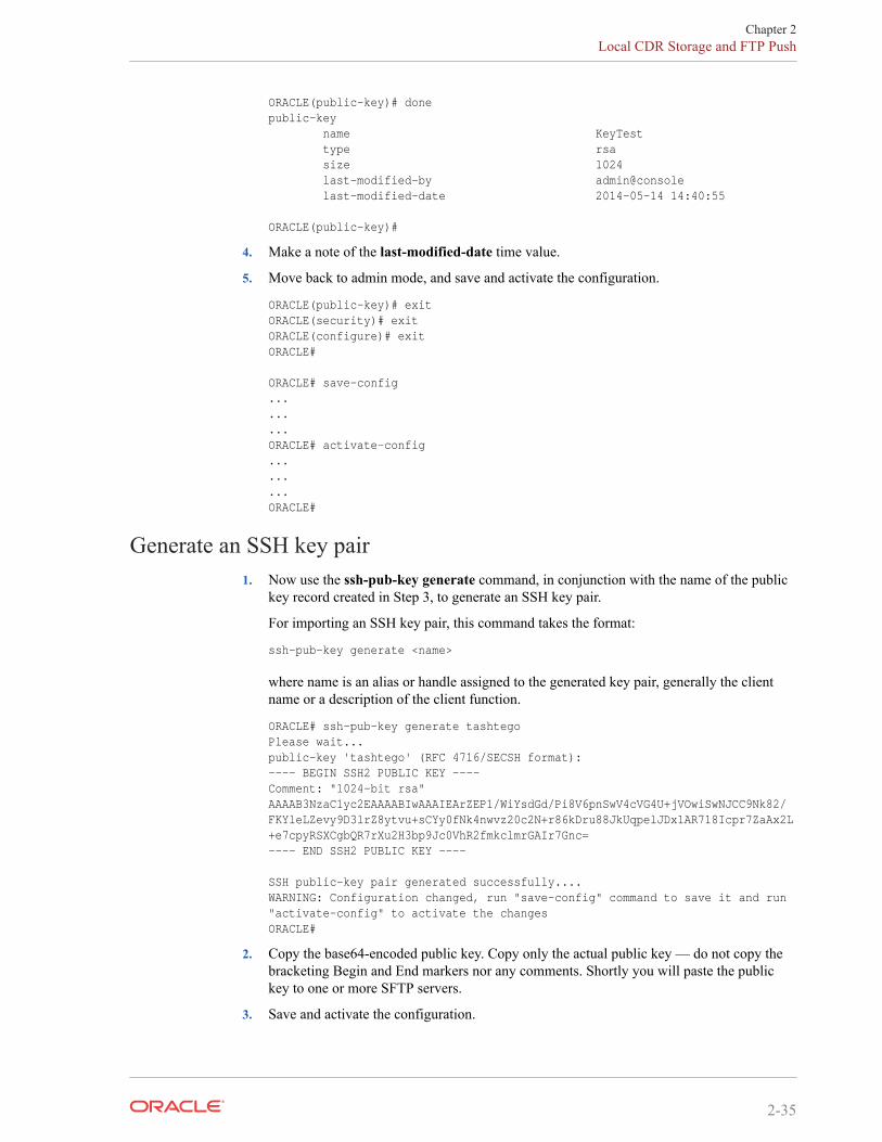
ORACLE(public-key)# donepublic-key name KeyTest type rsa size 1024 last-modified-by admin@console last-modified-date 2014-05-14 14:40:55
ORACLE(public-key)#
4. Make a note of the last-modified-date time value.
5. Move back to admin mode, and save and activate the configuration.
ORACLE(public-key)# exit ORACLE(security)# exit ORACLE(configure)# exit ORACLE#
ORACLE# save-config ... ... ... ORACLE# activate-config ... ... ... ORACLE#
Generate an SSH key pair1. Now use the ssh-pub-key generate command, in conjunction with the name of the public
key record created in Step 3, to generate an SSH key pair.
For importing an SSH key pair, this command takes the format:
ssh-pub-key generate <name>
where name is an alias or handle assigned to the generated key pair, generally the clientname or a description of the client function.
ORACLE# ssh-pub-key generate tashtegoPlease wait...public-key 'tashtego' (RFC 4716/SECSH format):---- BEGIN SSH2 PUBLIC KEY ----Comment: "1024-bit rsa"AAAAB3NzaC1yc2EAAAABIwAAAIEArZEP1/WiYsdGd/Pi8V6pnSwV4cVG4U+jVOwiSwNJCC9Nk82/FKYleLZevy9D3lrZ8ytvu+sCYy0fNk4nwvz20c2N+r86kDru88JkUqpelJDx1AR718Icpr7ZaAx2L+e7cpyRSXCgbQR7rXu2H3bp9Jc0VhR2fmkclmrGAIr7Gnc=---- END SSH2 PUBLIC KEY ----
SSH public-key pair generated successfully....WARNING: Configuration changed, run "save-config" command to save it and run "activate-config" to activate the changesORACLE#
2. Copy the base64-encoded public key. Copy only the actual public key — do not copy thebracketing Begin and End markers nor any comments. Shortly you will paste the publickey to one or more SFTP servers.
3. Save and activate the configuration.
Chapter 2Local CDR Storage and FTP Push
2-35
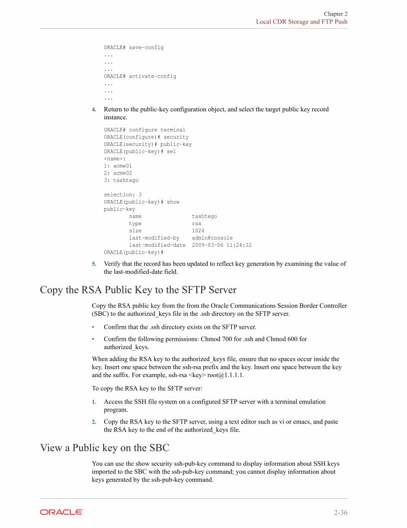
ORACLE# save-config.........ORACLE# activate-config.........
4. Return to the public-key configuration object, and select the target public key recordinstance.
ORACLE# configure terminalORACLE(configure)# securityORACLE(security)# public-keyORACLE(public-key)# sel<name>:1: acme012: acme023: tashtego
selection: 3ORACLE(public-key)# showpublic-key name tashtego type rsa size 1024 last-modified-by admin@console last-modified-date 2009-03-06 11:24:32ORACLE(public-key)#
5. Verify that the record has been updated to reflect key generation by examining the value ofthe last-modified-date field.
Copy the RSA Public Key to the SFTP ServerCopy the RSA public key from the from the Oracle Communications Session Border Controller(SBC) to the authorized_keys file in the .ssh directory on the SFTP server.
• Confirm that the .ssh directory exists on the SFTP server.
• Confirm the following permissions: Chmod 700 for .ssh and Chmod 600 forauthorized_keys.
When adding the RSA key to the authorized_keys file, ensure that no spaces occur inside thekey. Insert one space between the ssh-rsa prefix and the key. Insert one space between the keyand the suffix. For example, ssh-rsa <key> [email protected].
To copy the RSA key to the SFTP server:
1. Access the SSH file system on a configured SFTP server with a terminal emulationprogram.
2. Copy the RSA key to the SFTP server, using a text editor such as vi or emacs, and pastethe RSA key to the end of the authorized_keys file.
View a Public key on the SBCYou can use the show security ssh-pub-key command to display information about SSH keysimported to the SBC with the ssh-pub-key command; you cannot display information aboutkeys generated by the ssh-pub-key command.
Chapter 2Local CDR Storage and FTP Push
2-36
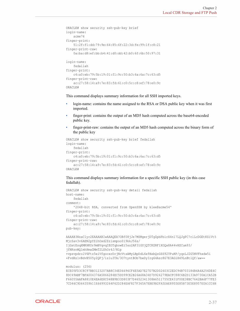
ORACLE# show security ssh-pub-key brieflogin-name: acme74finger-print: 51:2f:f1:dd:79:9e:64:85:6f:22:3d:fe:99:1f:c8:21finger-print-raw: 0a:ba:d8:ef:bb:b4:41:d0:dd:42:b0:6f:6b:50:97:31
login-name: fedallahfinger-print: c4:a0:eb:79:5b:19:01:f1:9c:50:b3:6a:6a:7c:63:d5finger-print-raw: ac:27:58:14:a9:7e:83:fd:61:c0:5c:c8:ef:78:e0:9cORACLE#
This command displays summary information for all SSH imported keys.
• login-name: contains the name assigned to the RSA or DSA public key when it was firstimported.
• finger-print: contains the output of an MD5 hash computed across the base64-encodedpublic key.
• finger-print-raw: contains the output of an MD5 hash computed across the binary form ofthe public key
ORACLE# show security ssh-pub-key brief fedallah login-name: fedallah finger-print: c4:a0:eb:79:5b:19:01:f1:9c:50:b3:6a:6a:7c:63:d5 finger-print-raw: ac:27:58:14:a9:7e:83:fd:61:c0:5c:c8:ef:78:e0:9c ORACLE#
This command displays summary information for a specific SSH public key (in this casefedallah).
ORACLE# show security ssh-pub-key detail fedallah host-name: fedallah comment: "2048-bit RSA, converted from OpenSSH by klee@acme54" finger-print: c4:a0:eb:79:5b:19:01:f1:9c:50:b3:6a:6a:7c:63:d5 finger-print-raw: ac:27:58:14:a9:7e:83:fd:61:c0:5c:c8:ef:78:e0:9c pub-key:
AAAAB3NzaC1yc2EAAAABIwAAAQEA7OBf08jJe7MSMgerjDTgZpbPblrX4n17LQJgPC7clLcDGEtKSiVt5MjcSav3v6AEN2pYZihOxd2Zzismpoo019kkJ56s/IjGstEzqXMKHKUr9mBVqvqIEOTqbowEi5sz2AP31GUjQTCKZRF1XOQx8A44vHZCum93/jfNRsnWQ1mhHmaZMmT2LShOr4J/Nlp+vpsvpdrolV6Ftz5eiVfgocxrDrjNcVtsAMyLBpDdL6e9XebQzGSS92TPuKP/yqzLJ2G5NVFhxdw5i+FvdHz1vBdvB505y2QPj/iz1u3TA/3O7tyntBOb7beDyIrg64Azc8G7E3AGiH49LnBtlQf/aw==
modulus: (256) ECE05FD3C8C97BB3123207AB8C34E06696CF6E5AD7E27D7B2D02603C2EDC94B703184B4A4A256DE4C8DC49ABF7BFA004376A5866284EC5DD99CE2B26A68A34D7D924279EACFC88C6B2D133A9730A1CA52BF66055AAFA8810E4EA6E8C048B9B33D803F7D4652341308A6511755CE431F00E38BC7642BA6F77FE37CD46C9D64359A11E66993264F62D284EAF827F365A7EBE9B2FA5DAE8955E85B73E5E8957E0A1CC6B
Chapter 2Local CDR Storage and FTP Push
2-37
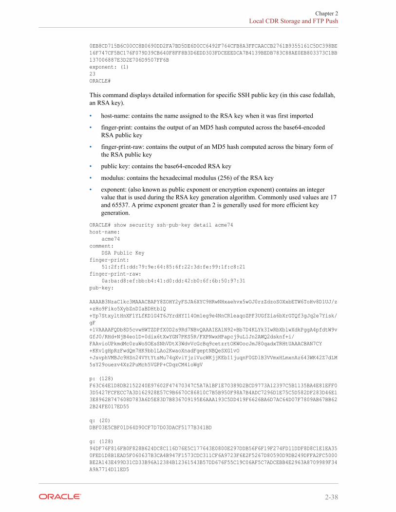
0EB8CD715B6C00CC8B0690DD2FA7BD5DE6D0CC6492F764CFB8A3FFCAACCB2761B9355161C5DC398BE16F747CF5BC176F079D39CB640F8FF8B3D6EDD303FDCEEEDCA7B4139BEDB783C88AE0EB803373C1BB137006887E3D2E706D9507FF6B exponent: (1) 23 ORACLE#
This command displays detailed information for specific SSH public key (in this case fedallah,an RSA key).
• host-name: contains the name assigned to the RSA key when it was first imported
• finger-print: contains the output of an MD5 hash computed across the base64-encodedRSA public key
• finger-print-raw: contains the output of an MD5 hash computed across the binary form ofthe RSA public key
• public key: contains the base64-encoded RSA key
• modulus: contains the hexadecimal modulus (256) of the RSA key
• exponent: (also known as public exponent or encryption exponent) contains an integervalue that is used during the RSA key generation algorithm. Commonly used values are 17and 65537. A prime exponent greater than 2 is generally used for more efficient keygeneration.
ORACLE# show security ssh-pub-key detail acme74 host-name: acme74 comment: DSA Public Key finger-print: 51:2f:f1:dd:79:9e:64:85:6f:22:3d:fe:99:1f:c8:21 finger-print-raw: 0a:ba:d8:ef:bb:b4:41:d0:dd:42:b0:6f:6b:50:97:31 pub-key:
AAAAB3NzaC1kc3MAAACBAPY8ZOHY2yFSJA6XYC9HRwNHxaehvx5wOJ0rzZdzoSOXxbETW6ToHv8D1UJ/z+zHo9Fiko5XybZnDIaBDHtblQ+Yp7StxyltHnXF1YLfKD1G4T6JYrdHYI14Om1eg9e4NnCRleaqoZPF3UGfZia6bXrGTQf3gJq2e7Yisk/gF+1VAAAAFQDb8D5cvwHWTZDPfX0D2s9Rd7NBvQAAAIEAlN92+Bb7D4KLYk3IwRbXblwXdkPggA4pfdtW9vGfJ0/RHd+NjB4eo1D+0dix6tXwYGN7PKS5R/FXPNwxHPapcj9uL1Jn2AWQ2dsknf+i/FAAvioUPkmdMc0zuWoSOEsSNhVDtX3WdvVcGcBq9cetzrtOKWOocJmJ80qadxTRHtUAAACBAN7CY+KKv1gHpRzFwdQm7HK9bb1LAo2KwaoXnadFgeptNBQeSXG1vO+JsvphVMBJc9HSn24VYtYtsMu74qXviYjziVucWKjjKEb11juqnF0GDlB3VVmxHLmxnAz643WK42Z7dLM5sY29ouezv4Xz2PuMch5VGPP+CDqzCM4loWgV
p: (128) F63C64E1D8DB2152240E97602F47470347C5A7A1BF1E70389D2BCD9773A12397C5B1135BA4E81EFF03D5427FCFECC7A3D162928E57C9B6670C86810C7B5B950F98A7B4ADC7296D1E75C5D582DF283D46E13E8962B747608D783A6D5E83D7B836709195E6AAA193C5DD419F6626BA6D7AC64D07F7809AB67BB622B24FE017ED55
q: (20) DBF03E5CBF01D64D90CF7D7D03DACF5177B341BD
g: (128) 94DF76F816FB0F828B624DC8C116D76E5C177643E0800E297DDB56F6F19F274FD11DDF8D8C1E1EA350FED1D8B1EAD5F060637B3CA4B947F1573CDC311CF6A9723F6E2F5267D80590D9DB249DFFA2FC5000BE2A143E499D31CD33B96A12384B12361543B57DD676F55C19C06AF5C7ADCEBB4E2963A8709989F34A9A7714D11ED5
Chapter 2Local CDR Storage and FTP Push
2-38
pub_key: (128) DEC263E28ABF5807A51CC5C1D426EC72BD6DBD4B028D8AC1AA179DA74581EA6D34141E4971B5BCEF89B2FA6154C04973D1D29F6E1562D62DB0CBBBE2A5EF8988F3895B9C58A8E32846F5D63BAA9C5D060E50775559B11CB9B19C0CFAE3758AE3667B74B339B18DBDA2E7B3BF85F3D8FB8C721E5518F3FE083AB308CE25A16815 ORACLE#
This command displays detailed information for specific SSH public key (in this case acme74,a DSA key).
• host name: contains the name assigned to the DSA public key when it was first imported
• comment: contains any comments associated with the DSA key
• finger-print: contains the output of an MD5 hash computed across the base64-encodedDSA public key
• finger-print-raw: contains the output of an MD5 hash computed across the binary form ofthe DSA public key
• public key: contains the base64 encoded DSA key
• p: contains the first of two prime numbers used for key generation
• q: contains the second of two prime numbers used for key generation
• g: contains an integer that together with p and q are the inputs to the DSA key generationalgorithm
ORACLE# show security ssh-pub-key detail ... ... ... ORACLE#
This command displays detailed information for all SSH imported keys.
Temporary File Naming for an Open CDR FileAs of Release S-C(X)6.0.0M7, the SBC uses a temporary naming convention that makes iteasier for you to retrieve CDR files you want.
Before this release was introduced, the SBC used the same naming format for all CDR files:cdrYYYYMMDDHHMM[a-j]. If this is the naming convention you still want to use, you cando so simply by adding the disable-temp-file option to your accounting configuration. Thismode offers no means of differentiating a file to which the SBC is writing information from anyother closed file(s).
If you decide to use the new default behavior, then you will now see a the temp-prefix added tothe file format. So the file format for the temp file is: temp-cdrYYYYMMDDHHMM[a-j].The prefix helps you differentiate the file that is currently open from the other CDR files youencounter; this is the file to which the SBC is currently writing information and is open. Assoon as the file is closed during rotation, the temp- disappears and the file bears only name inthe cdrYYYYMMDDHHMM[a-j]. In other words, files in the cdrYYYYMMDDHHMM[a-j] are closed files.
Without this differentiation, it is possible for you to retrieve different versions of the same fileand to even do so more than once. In addition, without the temp- differentiation, the SBC FTPserver is liable to return error messages when move or delete operations occur. Theseoccurrences can trigger false alarms and are not consistent with other vendors’ products.
Chapter 2Temporary File Naming for an Open CDR File
2-39
Operational DetailsThis section offers details of SBC operations that effect temporary CDR file naming.
• Reboot—A system reboot can happen unexpectedly, or might be caused by yourintentionally rebooting the system using the ACLI reboot command. When a rebootoccurs, SBC closes the CDR file that was most recently opened (before the reboot) andnames it according to the cdrYYYYMMDDHHMM[a-j] convention. It also opens a newfile, which bears the temp- differentiation.
• Activating a configuration—If temporary CDR naming is enabled before and after you usethe activate-config command, then the last opened file will be closed and have thecdrYYYYMMDDHHMM[a-j] name format. The SBC also opens a new file with thetemp- prefix to which it will write data.In the case where temporary CDR naming is enabled before you activate a configurationand disabled after it, the last open file is named according to thecdrYYYYMMDDHHMM[a-j] name format. The new file to which the SBC will writedata is also in the cdrYYYYMMDDHHMM[a-j] name format. In other words, the SBCdoes not use the temp- prefix designation at all.
In the case where temporary CDR naming is disabled before you activate a configurationand enabled after it, the SBC closes the most recently opened file—which must have beenin the cdrYYYYMMDDHHMM[a-j] name format. The SBC also opens a new file withthe temp- prefix to which it will write data.
• Changing the accounting configuration’s administrative state—When you disable theaccounting configuration, the SBC renames the most recently opened file with the temp-prefix to the cdrYYYYMMDDHHMM[a-j] name format.
HA ConsiderationsThe considerations in this section describes the Oracle Communications Session BorderController’s behavior when CDR output redundancy is enabled or disabled. You set CDRoutput redundancy in the accounting configurations cdr-output-redundancy parameter.
• Enabled—When you enable CDR output redundancy, both the Active and Standbysystems rotate files. During CDR file rotation, if either the Active or the Standby rotates afile with the temp- prefix, the prefix disappears and the file name appears in thecdrYYYYMMDDHHMM[a-j] name format.The Active and the Standby systems always have the same files, including the CDR filewith the temp- prefix. So the file exists on both systems.
• Disabled—When you have disables CDR output redundancy and switchover happens forany reason, it is key that there are no residual files with the temp- prefix. For this reason,the SBC handles the situation as follows:Becoming Active—When it transitions from Standby to Active, a SBC checks for any fileswith the temp- prefix, closes the file if it is open, and renames it according to thecdrYYYYMMDDHHMM[a-j] name format. These actions means that the file is not onlyrenamed, but that it is also rotated. Rotation triggers the creation of a new CDR file withthe temp- prefix to use for new CDR data.
Becoming Standby—When it transitions from Active to Standby, a SBC closes the opentemp- prefix file and renames it according to the cdrYYYYMMDDHHMM[a-j] nameformat. Rotation creates a new temp- prefix file on the Standby, which remains empty untilit transitions back to the Active state.
Chapter 2Temporary File Naming for an Open CDR File
2-40
Note:
Before you upgrade from a release prior to S-CZ7.2.0 to S-CZ7.2.0 or later, you mustset the cdr-output-redundancy parameter to enabled for the Standby to upgrade andsync properly. You can then change the parameter to disabled afterwards, if needed.
CaveatsAs described above, when the system reboots for any reason or when you issue an activate-config, the SBC checks for CDR files with the temp- prefix and renames to the usualcdrYYYYMMDDHHMM[a-j] format.
However, if you change the accounting configuration’s file-path value and subsequently thesystem either reboots or you activate your configuration, the SBC will be unable to check forfiles with the temp- prefix in the old file path. And so it will also be unable to rename them.The SBC checks the new path only.
Temporary Local CDR File Renaming ConfigurationTo turn off temporary CDR file naming:
1. Access the account-config configuration element.
ORACLE# configure terminalORACLE(configure)# session-routerORACLE(session-router)# account-configORACLE(account-config)#
2. Type select to begin configuring this object.
3. options—Follow your entry with this value:
• +disable-temp-file
ORACLE(account-config)# options +disable-temp-file
This value turns off the temporary CDR file naming the SBC, so it does not use thetemp- prefix for open file. Instead, all files follow the cdrYYYYMMDDHHMM[a-j]name format.
To enable temporary CDR file naming, you must use a minus sign (-) before thedisable-temp-file value.
ORACLE(account-config)# options -disable-temp-file
4. Type done to save your configuration.
Enhanced Stop CDR Reporting for Exceeded Ingress SessionConstraints
This release addresses an inconsistency in the generation of RADIUS Stop records when callsare rejected for exceeding configured session ingress or egress constraints. On the egress path,prior releases rejected such calls with a 503 (Service Unavailable) response and the generationof a RADIUS STOP record. On the ingress path, however, while calls were rejected with a 503response, RADIUS Stop records were not generated.
Chapter 2Temporary File Naming for an Open CDR File
2-41
A new SIP Configuration option (enhanced-cdr) enables consistent generation of RADIUSStop records on both ingress and egress paths. With enhanced-cdr enabled, RADIUS Stoprecords are generated in response to any ingress path rejection of a dialog creating SIP INVITErequest. The contents of RADIUS Stop records are also written to Call Detail Records stored onthe Oracle Oracle Communications Session Border Controller.
Use the following command syntax to enable more consistent generation of RADIUS Stoprecords.
This capability is disabled by default.
ORACLE(sip-config)# options +enhanced-cdrORACLE(sip-config)#
Chapter 2Temporary File Naming for an Open CDR File
2-42
3RADIUS Accounting Management
OverviewThis chapter provides information about management and monitoring of RADIUS accountingfunctions on your SBC.
• SBC alarm generation and monitoring
• Status and statistics monitoring
Alarm Generation and MonitoringThe products generate alarms when certain hardware and software events occur. For moreinformation about SBC alarms for RADIUS, refer to the Maintenance and TroubleshootingGuide.
The RADIUS ACCOUNTING CONNECTION DOWN alarm, detailed in the table below, isdirectly associated with the SBC’s RADIUS functionality. When enabled connections toRADIUS servers have timed-out without a response from the RADIUS server, the alarm isactivated. The RADIUS ACCOUNTING CONNECTION DOWN alarm triggers a SimpleNetwork Management Protocol (SNMP) trap that is sent via the syslog ManagementInformation Base (MIB) (ap-syslog.mib). For a list of all SNMP-related alarms and theirassociated traps, refer to the table of SNMP trap correlation to SBC’s alarms in Oracle’s MIBReference Guide.
This alarm has no impact on a the health score of a SBC that is part of an HA Node.
RADIUS AlarmsThe table below describes the SBC’s alarms for RADIUS.
3-1
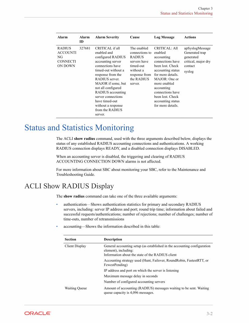
Alarm AlarmID
Alarm Severity Cause Log Message Actions
RADIUSACCOUNTINGCONNECTION DOWN
327681 CRITICAL if allenabled andconfigured RADIUSaccounting serverconnections havetimed-out without aresponse from theRADIUS server.MAJOR if some, butnot all configuredRADIUS accountingserver connectionshave timed-outwithout a responsefrom the RADIUSserver.
The enabledconnections toRADIUSservers havetimed-outwithout aresponse fromthe RADIUSserver.
CRITICAL: Allenabledaccountingconnections havebeen lost. Checkaccounting statusfor more details.MAJOR: One ormore enabledaccountingconnections havebeen lost. Checkaccounting statusfor more details.
apSyslogMessageGenerated trapgeneratedcritical, major drycontactsyslog
Status and Statistics MonitoringThe ACLI show radius command, used with the three arguments described below, displays thestatus of any established RADIUS accounting connections and authentications. A workingRADIUS connection displays READY, and a disabled connection displays DISABLED.
When an accounting server is disabled, the triggering and clearing of RADIUSACCOUNTING CONNECTION DOWN alarms is not affected.
For more information about SBC about monitoring your SBC, refer to the Maintenance andTroubleshooting Guide.
ACLI Show RADIUS DisplayThe show radius command can take one of the three available arguments:
• authentication—Shows authentication statistics for primary and secondary RADIUSservers, including: server IP address and port; round trip time; information about failed andsuccessful requests/authentications; number of rejections; number of challenges; number oftime-outs, number of retransmissions
• accounting—Shows the information described in this table:
Section Description
Client Display General accounting setup (as established in the accounting configurationelement), including:Information about the state of the RADIUS clientAccounting strategy used (Hunt, Failover, RoundRobin, FastestRTT, orFewestPending)IP address and port on which the server is listeningMaximum message delay in secondsNumber of configured accounting servers
Waiting Queue Amount of accounting (RADIUS) messages waiting to be sent. Waitingqueue capacity is 4,096 messages.
Chapter 3Status and Statistics Monitoring
3-2
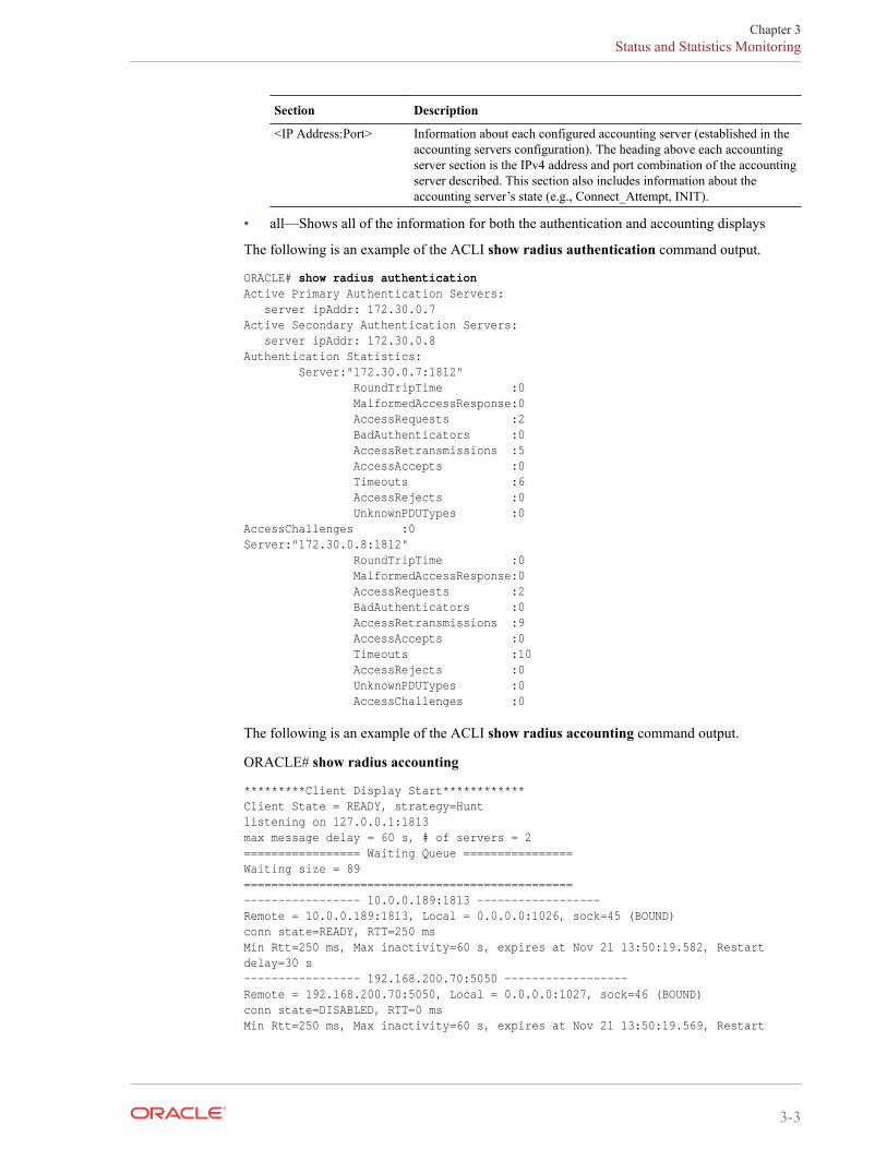
Section Description
<IP Address:Port> Information about each configured accounting server (established in theaccounting servers configuration). The heading above each accountingserver section is the IPv4 address and port combination of the accountingserver described. This section also includes information about theaccounting server’s state (e.g., Connect_Attempt, INIT).
• all—Shows all of the information for both the authentication and accounting displays
The following is an example of the ACLI show radius authentication command output.
ORACLE# show radius authenticationActive Primary Authentication Servers: server ipAddr: 172.30.0.7Active Secondary Authentication Servers: server ipAddr: 172.30.0.8Authentication Statistics: Server:"172.30.0.7:1812" RoundTripTime :0 MalformedAccessResponse:0 AccessRequests :2 BadAuthenticators :0 AccessRetransmissions :5 AccessAccepts :0 Timeouts :6 AccessRejects :0 UnknownPDUTypes :0AccessChallenges :0Server:"172.30.0.8:1812" RoundTripTime :0 MalformedAccessResponse:0 AccessRequests :2 BadAuthenticators :0 AccessRetransmissions :9 AccessAccepts :0 Timeouts :10 AccessRejects :0 UnknownPDUTypes :0 AccessChallenges :0
The following is an example of the ACLI show radius accounting command output.
ORACLE# show radius accounting
*********Client Display Start************Client State = READY, strategy=Huntlistening on 127.0.0.1:1813max message delay = 60 s, # of servers = 2 ================= Waiting Queue ================Waiting size = 89 ================================================ ----------------- 10.0.0.189:1813 ------------------Remote = 10.0.0.189:1813, Local = 0.0.0.0:1026, sock=45 (BOUND)conn state=READY, RTT=250 msMin Rtt=250 ms, Max inactivity=60 s, expires at Nov 21 13:50:19.582, Restart delay=30 s ----------------- 192.168.200.70:5050 ------------------Remote = 192.168.200.70:5050, Local = 0.0.0.0:1027, sock=46 (BOUND)conn state=DISABLED, RTT=0 msMin Rtt=250 ms, Max inactivity=60 s, expires at Nov 21 13:50:19.569, Restart
Chapter 3Status and Statistics Monitoring
3-3
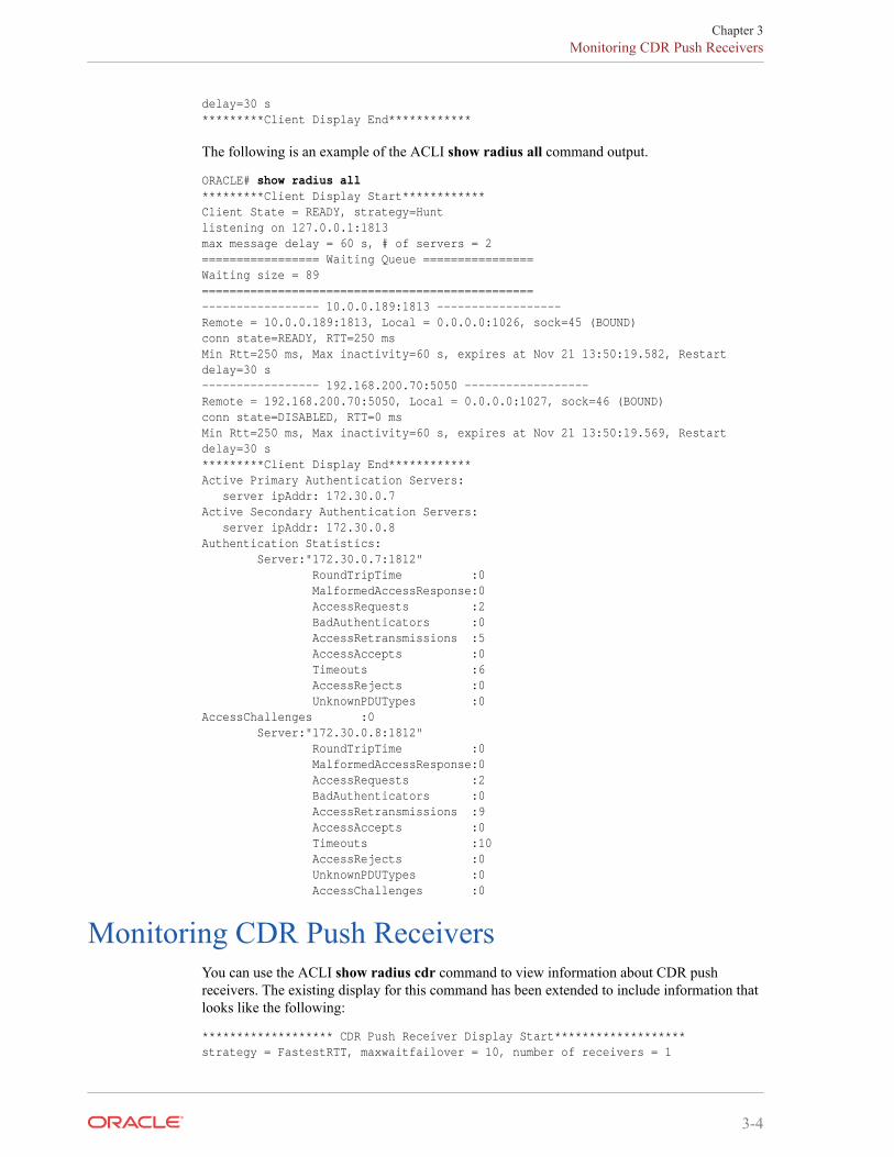
delay=30 s *********Client Display End************
The following is an example of the ACLI show radius all command output.
ORACLE# show radius all*********Client Display Start************Client State = READY, strategy=Huntlistening on 127.0.0.1:1813max message delay = 60 s, # of servers = 2 ================= Waiting Queue ================Waiting size = 89 ================================================ ----------------- 10.0.0.189:1813 ------------------Remote = 10.0.0.189:1813, Local = 0.0.0.0:1026, sock=45 (BOUND)conn state=READY, RTT=250 msMin Rtt=250 ms, Max inactivity=60 s, expires at Nov 21 13:50:19.582, Restart delay=30 s ----------------- 192.168.200.70:5050 ------------------Remote = 192.168.200.70:5050, Local = 0.0.0.0:1027, sock=46 (BOUND)conn state=DISABLED, RTT=0 msMin Rtt=250 ms, Max inactivity=60 s, expires at Nov 21 13:50:19.569, Restart delay=30 s *********Client Display End************Active Primary Authentication Servers: server ipAddr: 172.30.0.7Active Secondary Authentication Servers: server ipAddr: 172.30.0.8Authentication Statistics: Server:"172.30.0.7:1812" RoundTripTime :0 MalformedAccessResponse:0 AccessRequests :2 BadAuthenticators :0 AccessRetransmissions :5 AccessAccepts :0 Timeouts :6 AccessRejects :0 UnknownPDUTypes :0AccessChallenges :0 Server:"172.30.0.8:1812" RoundTripTime :0 MalformedAccessResponse:0 AccessRequests :2 BadAuthenticators :0 AccessRetransmissions :9 AccessAccepts :0 Timeouts :10 AccessRejects :0 UnknownPDUTypes :0 AccessChallenges :0
Monitoring CDR Push ReceiversYou can use the ACLI show radius cdr command to view information about CDR pushreceivers. The existing display for this command has been extended to include information thatlooks like the following:
******************* CDR Push Receiver Display Start*******************strategy = FastestRTT, maxwaitfailover = 10, number of receivers = 1
Chapter 3Monitoring CDR Push Receivers
3-4
--------------------- 172.30.0.70:21 ---------------------cdrpush-receiver = 172.30.0.70:21, state = READY, priority = 4remote path = /home/acme, remote prefix = vik, protocol = ftpusername = acme, password = ********, publickey =FTP rtt = 0, FTP successes = 0, FTP failures = 0FTP timeouts = 0, FTP Delays = 0, FTP Put failures = 0FTP conn failures = 0, FTP terminates = 0, FTP triggered terminates = 0
SNMP SupportThe SBC sends traps when a single push receiver or all push receivers become unavailable.
• When one CDR push receiver becomes unavailable, theCDR_PUSH_RECEIVER_FAIL_TRAP trap is sent and a minor alarm is generated.
• When all of the configured CDR push receivers become unavailable, theCDR_ALL_PUSH_RECEIVERS_FAIL_TRAP is sent and a major alarm is generated.
When one or more of the push receivers comes back, the CDR_ALL_PUSH_RECEIVERS_FAIL_CLEAR_TRAP is sent and the alarm is cleared.
CDR File Transfer Failure AlarmThe SBC sends out traps and triggers corresponding alarms when it encounters failure whenattempting to transfer locally stored CDR files via FTP or SFTP. One set of traps is used forinstances when one CDR push receiver fails; another is used when all enabled CDR receiversfail. They are part of the apSysMgmtCDRPushReceiverNotificationsGroup.
All of the traps contain information about the type of push receiver, the address of the pushreceiver, and the failure reason code.
All of the traps contain information about the type of push receiver, the address of the pushreceiver, and the failure reason code.
The trap and corresponding clearing trap for single push receiver failure are:
• apSysMgmtCDRPushReceiverFailureTrap
• apSysMgmtCDRPushReceiverFailureClearTrap
The trap and corresponding clearing trap for global push receiver failure are:
• apSysMgmtCDRAllPushReceiversFailureTrap
• apSysMgmtCDRAllPushReceiverFailuresClearTrap
Chapter 3CDR File Transfer Failure Alarm
3-5
4Storage Expansion Module
Storage Expansion Module Use With Local CDRsFTP Push
The AcmePacket suite of engineered systems can be configured with an optional StorageExpansion Module that extends the system's internal storage beyond the fixed amount of flashRAM. When configuring local CDR creation, you can configure the SBC to use the StorageExpansion Module for local CDR files instead of the limited internal flash RAM.
Disk space on the Storage Expansion Module appears as a local volume on the SBC. Whereveryou specify a volume name for a configuration parameter value, you can enter a volume locatedon the Storage Expansion Module, (unless the parameter is otherwise specified).
Local CDR Storage DirectoryTo save local CDR files to the Storage Expansion Module, configure the file path parameter inthe account config with a volume and directory located on the Storage Expansion Module.
FTP Push BackupWhen FTP push is enabled, if all FTP push servers are unreachable, then local CDR files arewritten to local file system until the FTP push servers return to service. Once an FTP Pushserver becomes reachable, the SBC transfers all local CDR files to the remote serverautomatically. After all local CDR files have been successfully transferred to the FTP serverfrom the SBC, they are deleted from the local volume.
Local CDR File CompressionYou can configure the SBC to compress local CDRs in zip format to save disk space. The localCDRs will be compressed and appear with a .zip file extension. This feature is enabled with thecdr compression parameter.
ACLI Configuration and ExamplesThe following ACLI configuration procedure describes:
• identifying volumes on the Storage Expansion Module
• configuring Storage Expansion Module volumes as the destination for local CDR files
These procedures are only a portion of local CDR file generation and FTP Push configuration.Please refer to the Local CDR Storage and FTP Push section for a full explanation and allprerequisites before referencing the following procedure.
4-1
Identify VolumesTo identify the volumes on the Storage Expansion Module to use with local CDR storage:
1. Note the volume name on the Storage Expansion Module you wish to use for local CDRoutput using the show space hard-disk command.
SYSTEM# show space hard-disk/opt: 19695716352/19695749120 bytes (99%) remaining/opt/logs: 19693335040/19693367808 bytes (99%) remainingSYSTEM#
Note:
The check-space-remaining hard-disk command is identical to the show spacehard-disk command.
Configure File PathTo configure an Oracle Communications Session Border Controller to write local CDRs to theStorage Expansion Module:
1. In Superuser mode, type configure terminal and press Enter.
ORACLE# configure terminal
2. Type session-router and press Enter.
ORACLE(configure)# session-router
3. Type account-config and press Enter.
ORACLE(session-router)# account-configORACLE(account-config)#
4. file-path—Set this parameter to the volume you identified to use for local CDR filestorage in the previous section. Ensure the path begins with a forward slash, /.
5. Save and activate your configuration.
Storage Expansion Module ManagementThe SBC provides you with a set of tools to manage the Storage Expansion Module.
See the Maintenance and Troubleshooting Guide’s File System Maintenance chapter for moreinformation.
Storage Expansion Module MonitoringLow Disk Space Warning
The SBC can initiate an alarm and an SNMP trap when a volume reaches a configuredthreshold of remaining free disk space, configured as a percentage of volume. You canconfigure multiple alarms, each with increasing severity that indicate less free disk space.
Chapter 4Storage Expansion Module Management
4-2
Low Disk Space Threshold AlarmThe low disk space threshold alarm is configured in alarm threshold configuration element. Itis non-health affecting. The threshold alarm appears as follows:
SYSTEM# display-alarms1 alarms to showID Task Severity First Occurred Last Occurred131142 547896076 4 2009-08-25 13:36:26 2009-08-25 13:36:26Count Description1 Volume /misc space used 81% is over major threshold of 80%.
Low Disk Space Threshold SNMP TrapFor any threshold reached, an SNMP trap will be sent to all configured trap-receivers. TheapSysMgmtStorageSpaceAvailThresholdTrap trap contains the following information:
• VolumeName—name of the volume where a threshold was exceeded
• CurrentValue—current percentage of disk space value that is exceeding one of thethresholds.
• MinorThreshold—configured minor threshold for this volume, if none then this is 0.
• MajorThreshold—configured major threshold for this volume, if none then this is 0.
• CriticalThreshold—configured critical threshold for this volume, if none then this is 0.
ACLI Configuration and ExamplesTo configure alarm thresholds for monitoring free disk space:
1. In Superuser mode, type configure terminal and press Enter.
ORACLE# configure terminal
2. Type system and press Enter.
ORACLE(configure)# systemORACLE(system)#
3. Type system-config and press Enter.
ORACLE(system)# system-configORACLE(system-config)#
4. Type select and press Enter.
ORACLE(system-config)# selectORACLE(system-config)#
5. Type alarm-threshold and press Enter.
ORACLE(system-config)# alarm-thresholdORACLE(alarm-threshold)#
The system prompt changes to let you know that you can begin configuring individualparameters.
6. type—Set this parameter to space to create an alarm based on reduced free disk space.
7. volume—Set this parameter to the volume name you wish to monitor. Generally this stringshould be the same as the file-path parameter located in the account-config.
Chapter 4Storage Expansion Module Monitoring
4-3
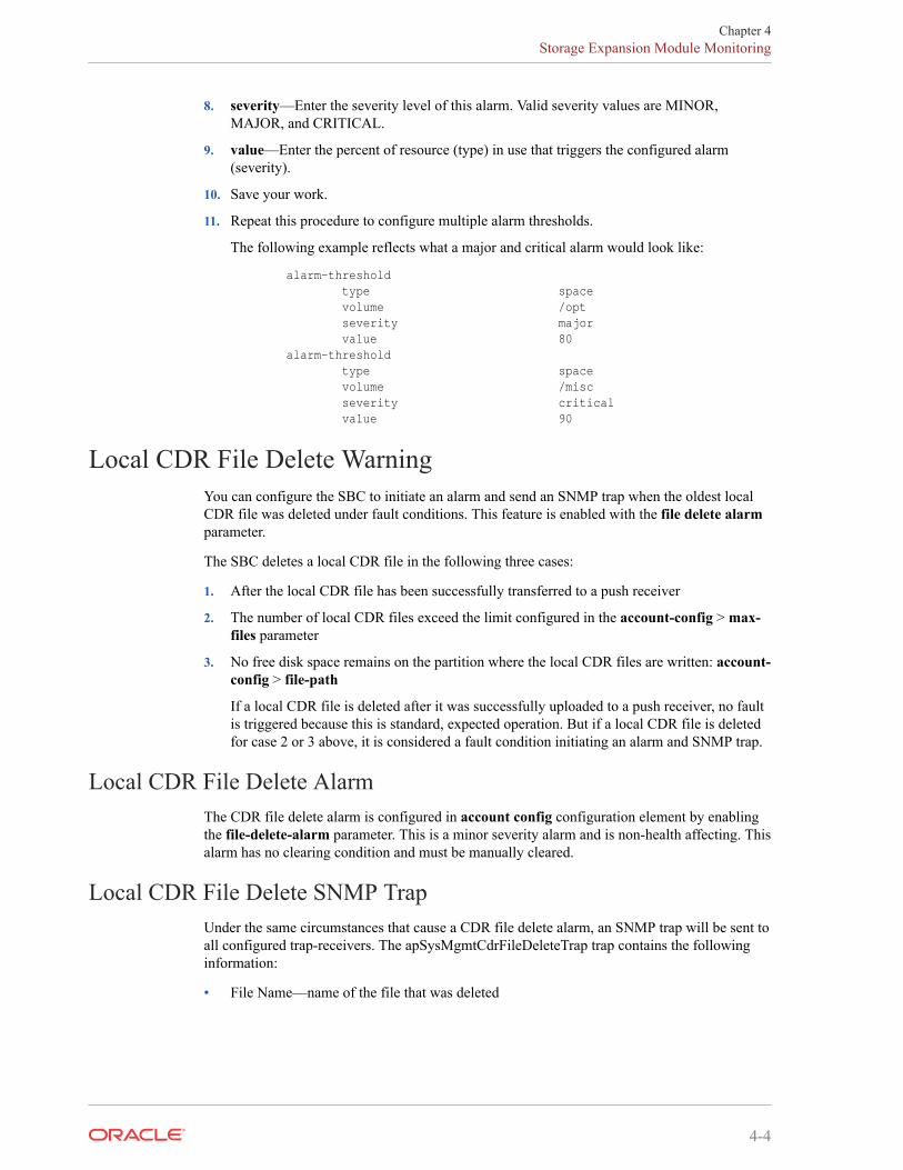
8. severity—Enter the severity level of this alarm. Valid severity values are MINOR,MAJOR, and CRITICAL.
9. value—Enter the percent of resource (type) in use that triggers the configured alarm(severity).
10. Save your work.
11. Repeat this procedure to configure multiple alarm thresholds.
The following example reflects what a major and critical alarm would look like:
alarm-threshold type space volume /opt severity major value 80 alarm-threshold type space volume /misc severity critical value 90
Local CDR File Delete WarningYou can configure the SBC to initiate an alarm and send an SNMP trap when the oldest localCDR file was deleted under fault conditions. This feature is enabled with the file delete alarmparameter.
The SBC deletes a local CDR file in the following three cases:
1. After the local CDR file has been successfully transferred to a push receiver
2. The number of local CDR files exceed the limit configured in the account-config > max-files parameter
3. No free disk space remains on the partition where the local CDR files are written: account-config > file-path
If a local CDR file is deleted after it was successfully uploaded to a push receiver, no faultis triggered because this is standard, expected operation. But if a local CDR file is deletedfor case 2 or 3 above, it is considered a fault condition initiating an alarm and SNMP trap.
Local CDR File Delete AlarmThe CDR file delete alarm is configured in account config configuration element by enablingthe file-delete-alarm parameter. This is a minor severity alarm and is non-health affecting. Thisalarm has no clearing condition and must be manually cleared.
Local CDR File Delete SNMP TrapUnder the same circumstances that cause a CDR file delete alarm, an SNMP trap will be sent toall configured trap-receivers. The apSysMgmtCdrFileDeleteTrap trap contains the followinginformation:
• File Name—name of the file that was deleted
Chapter 4Storage Expansion Module Monitoring
4-4
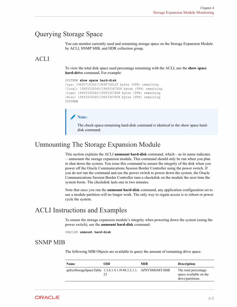
Querying Storage SpaceYou can monitor currently used and remaining storage space on the Storage Expansion Moduleby ACLI, SNMP MIB, and HDR collection group.
ACLITo view the total disk space used percentage remaining with the ACLI, use the show spacehard-drive command. For example:
SYSTEM# show space hard-disk/sys: 19695716352/19695749120 bytes (99%) remaining/local: 19693335040/19693367808 bytes (99%) remaining/logs: 19693335040/19693367808 bytes (99%) remaining/misc: 19693335040/19693367808 bytes (99%) remainingSYSTEM#
Note:
The check-space-remaining hard-disk command is identical to the show space hard-disk command.
Unmounting The Storage Expansion ModuleThis section explains the ACLI unmount hard-disk command, which—as its name indicates—unmounts the storage expansion module. This command should only be run when you planto shut down the system. You issue this command to ensure the integrity of the disk when youpower off the Oracle Communications Session Border Controller using the power switch. Ifyou do not run the command and use the power switch to power down the system, the OracleCommunications Session Border Controller runs a checkdisk on the module the next time thesystem boots. The checkdisk lasts one to two minutes.
Note that once you run the unmount hard-disk command, any application configuration set touse a module partition will no longer work. The only way to regain access is to reboot or powercycle the system.
ACLI Instructions and ExamplesTo ensure the storage expansion module’s integrity when powering down the system (using thepower switch), use the unmount hard-disk command:
ORACLE# unmount hard-disk
SNMP MIBThe following MIB Objects are available to query the amount of remaining drive space.
Name OID MIB Description
apSysStorageSpaceTable 1.3.6.1.4.1.9148.3.2.1.1.23
APSYSMGMT-MIB The total percentagespace available on thedrive/partitions.
Chapter 4Storage Expansion Module Monitoring
4-5
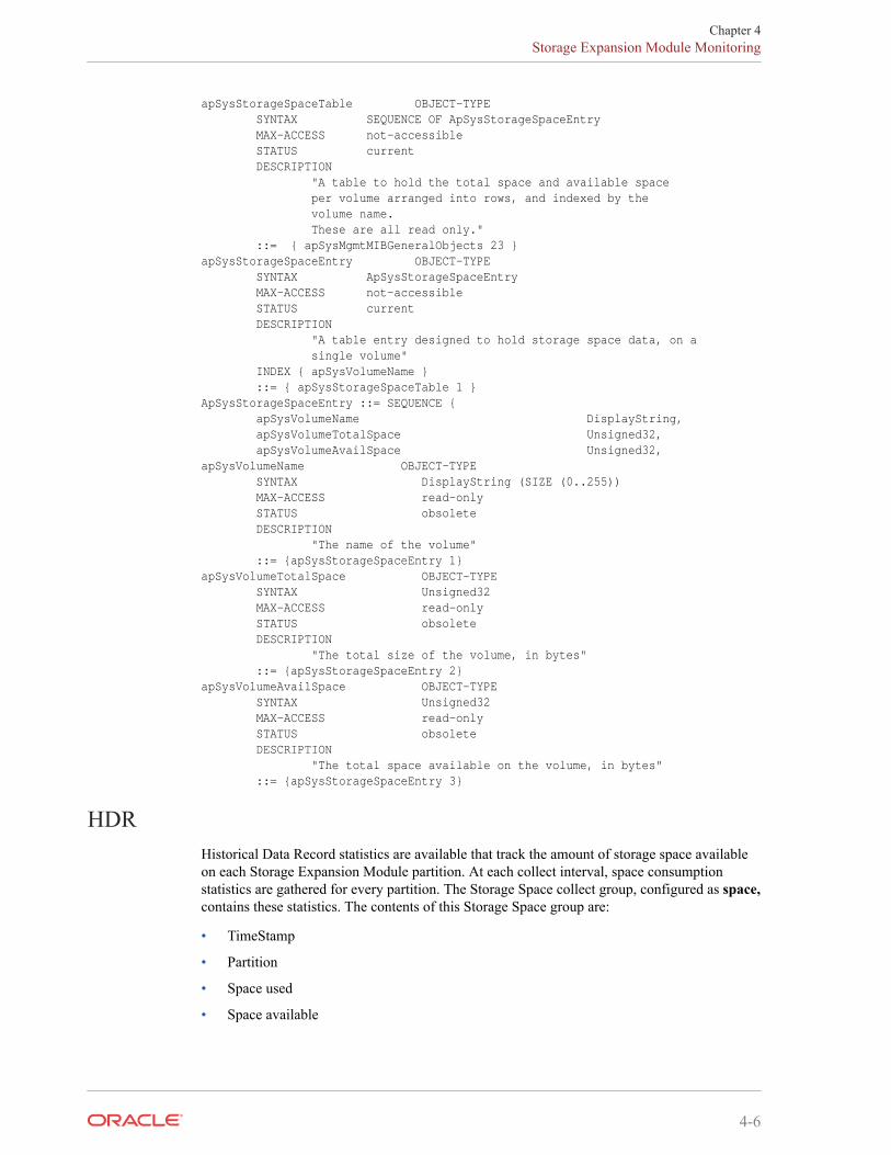
apSysStorageSpaceTable OBJECT-TYPE SYNTAX SEQUENCE OF ApSysStorageSpaceEntry MAX-ACCESS not-accessible STATUS current DESCRIPTION "A table to hold the total space and available space per volume arranged into rows, and indexed by the volume name. These are all read only." ::= { apSysMgmtMIBGeneralObjects 23 }apSysStorageSpaceEntry OBJECT-TYPE SYNTAX ApSysStorageSpaceEntry MAX-ACCESS not-accessible STATUS current DESCRIPTION "A table entry designed to hold storage space data, on a single volume" INDEX { apSysVolumeName } ::= { apSysStorageSpaceTable 1 }ApSysStorageSpaceEntry ::= SEQUENCE { apSysVolumeName DisplayString, apSysVolumeTotalSpace Unsigned32, apSysVolumeAvailSpace Unsigned32,apSysVolumeName OBJECT-TYPE SYNTAX DisplayString (SIZE (0..255)) MAX-ACCESS read-only STATUS obsolete DESCRIPTION "The name of the volume" ::= {apSysStorageSpaceEntry 1}apSysVolumeTotalSpace OBJECT-TYPE SYNTAX Unsigned32 MAX-ACCESS read-only STATUS obsolete DESCRIPTION "The total size of the volume, in bytes" ::= {apSysStorageSpaceEntry 2}apSysVolumeAvailSpace OBJECT-TYPE SYNTAX Unsigned32 MAX-ACCESS read-only STATUS obsolete DESCRIPTION "The total space available on the volume, in bytes" ::= {apSysStorageSpaceEntry 3}
HDRHistorical Data Record statistics are available that track the amount of storage space availableon each Storage Expansion Module partition. At each collect interval, space consumptionstatistics are gathered for every partition. The Storage Space collect group, configured as space,contains these statistics. The contents of this Storage Space group are:
• TimeStamp
• Partition
• Space used
• Space available
Chapter 4Storage Expansion Module Monitoring
4-6
5Diameter Rf Accounting
Diameter AccountingThe SBC supports the Diameter charging interface, Rf. This interface provides similarfunctionality to the RADIUS interface, but utilizes Diameter as the underlying application layerprotocol. As a result, the SBC can integrate more thoroughly with IMS standards as well asprovide a more dynamic, secure, and robust accounting interface.
Diameter Accounting MessagesThe Rf interface can send messages based on the signaling application’s actions. Thesemessages are Accounting Charging Request (ACR) Start messages, ACR Stop messages, Eventmessages and Interim messages.
Resending ACRs• If an ACA is not received to acknowledge the reception of an ACR, the SBC attempts to
resend an ACR and buffers all subsequent ACRs for the same session until theacknowledgement is received. Once the acknowledgement is received from the CCF, allbuffered ACRs for that same session may be sent to the CCF in the appropriate order. If theSBC does not receive the ACA after the user-specified number of retries, then the SBCsends all of the buffered ACR records for a session to the secondary CCF. (The number ofACR retries as well as the wait time in between retries is configurable by using the max-acr-retries account configuration parameters and acr-retry-interval, respectively.)
Postponement Feature• Any number of ACRs can be sent during a session, including Start, Stop, Interim and ACR
messages. The ACR postponement feature (non-configurable) ensures that the next ACR isnot sent until the previous ACR is acknowledged with an ACA.
Call Flow Examples• The following call flow example shows success in receiving an ACA for a session after
resending the ACR message three times.
5-1
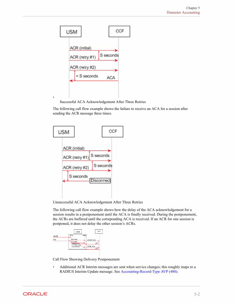
•Successful ACA Acknowledgement After Three Retries
The following call flow example shows the failure to receive an ACA for a session aftersending the ACR message three times.
Unsuccessful ACA Acknowledgement After Three Retries
The following call flow example shows how the delay of the ACA acknowledgement for asession results in a postponement until the ACA is finally received. During the postponement,the ACRs are buffered until the correponding ACA is received. If an ACR for one session ispostponed, it does not delay the other session’s ACRs.
Call Flow Showing Delivery Postponement
• Additional ACR Interim messages are sent when service changes; this roughly maps to aRADIUS Interim-Update message. See Accounting-Record-Type AVP (480).
Chapter 5Diameter Accounting
5-2
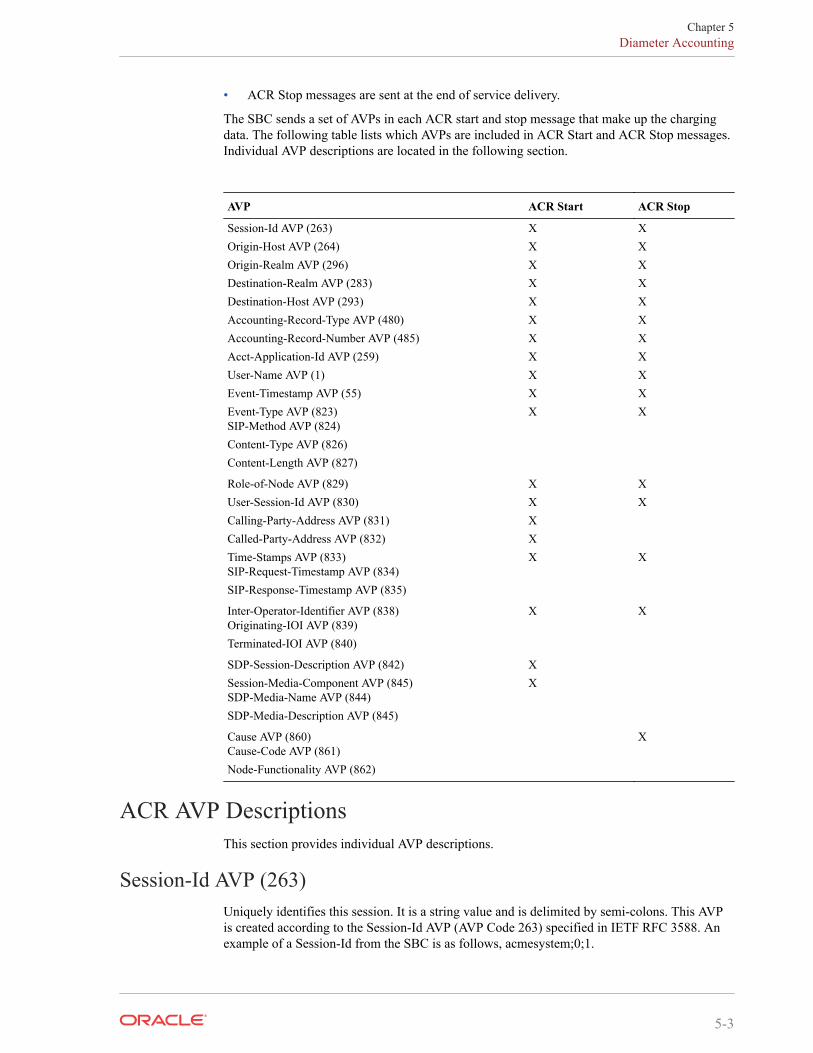
• ACR Stop messages are sent at the end of service delivery.
The SBC sends a set of AVPs in each ACR start and stop message that make up the chargingdata. The following table lists which AVPs are included in ACR Start and ACR Stop messages.Individual AVP descriptions are located in the following section.
AVP ACR Start ACR Stop
Session-Id AVP (263) X XOrigin-Host AVP (264) X XOrigin-Realm AVP (296) X XDestination-Realm AVP (283) X XDestination-Host AVP (293) X XAccounting-Record-Type AVP (480) X XAccounting-Record-Number AVP (485) X XAcct-Application-Id AVP (259) X XUser-Name AVP (1) X XEvent-Timestamp AVP (55) X XEvent-Type AVP (823)SIP-Method AVP (824)Content-Type AVP (826)Content-Length AVP (827)
X X
Role-of-Node AVP (829) X XUser-Session-Id AVP (830) X XCalling-Party-Address AVP (831) XCalled-Party-Address AVP (832) XTime-Stamps AVP (833)SIP-Request-Timestamp AVP (834)SIP-Response-Timestamp AVP (835)
X X
Inter-Operator-Identifier AVP (838)Originating-IOI AVP (839)Terminated-IOI AVP (840)
X X
SDP-Session-Description AVP (842) XSession-Media-Component AVP (845)SDP-Media-Name AVP (844)SDP-Media-Description AVP (845)
X
Cause AVP (860)Cause-Code AVP (861)Node-Functionality AVP (862)
X
ACR AVP DescriptionsThis section provides individual AVP descriptions.
Session-Id AVP (263)Uniquely identifies this session. It is a string value and is delimited by semi-colons. This AVPis created according to the Session-Id AVP (AVP Code 263) specified in IETF RFC 3588. Anexample of a Session-Id from the SBC is as follows, acmesystem;0;1.
Chapter 5Diameter Accounting
5-3
Origin-Host AVP (264)Contains the account-server configuration element’s hostname parameter followed by the "@"character, followed by the account-server configuration element’s origin-realm parameter. Forexample: [email protected].
Origin-Realm AVP (296)Contains the account server configuration element’s origin-realm and domain-name-suffixparameters where the server request is sent.
Destination-Realm AVP (283)Contains the value of the Origin-Realm AVP in the CEA received from the accounting serverfor this connection.
Destination-Host AVP (293)Contains the value of the Origin-Host AVP in the CEA received from the accounting server forthis connection.
Accounting-Record-Type AVP (480)Contains the value indicating the type of accounting message being sent.
• event record = 1
• start record = 2
• interim record = 3
• stop record = 4
Accounting-Record-Number AVP (485)A value that uniquely identifies this message in the session (i.e., a sequence number for thisconnection). The sequence number is assigned sequentially starting with 0 as described below.This is compliant with RFC 3588. The combination of the Accounting-Record-Number AVPand the Session-Id AVP (both of which are unique for the given session) are used to matchaccounting records with confirmations. This is done by assigning the noted values to therecords listed below:
• Event Record — the system assigns this record a value of 0 to this record.
• Start Record — the system assigns this record a value of 0 to this record.
• Interim Record — the system assigns this record a value of 1 to the first record of this typefor the session, and increments the value by 1 for each subsequent Interim_record until thevalue for the Stop_record is more for the last Interim_record for the session.
• Stop Record — (see description for Interim_record in the previous bullet) — If there is noInterim_record for the session, the system assigns a value to this record of 1.
The following example call flow shows a Register Event that shows that the Event record in theAccounting-Record-Number AVP is always populated with 0.
Chapter 5Diameter Accounting
5-4
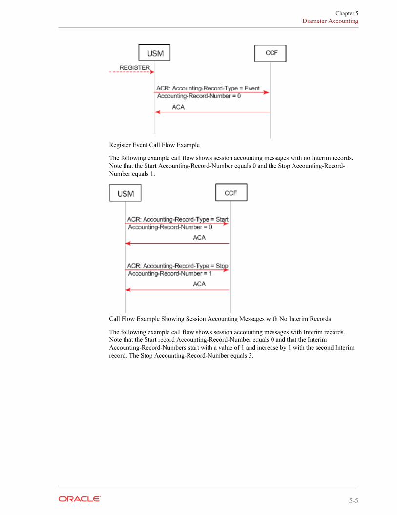
Register Event Call Flow Example
The following example call flow shows session accounting messages with no Interim records.Note that the Start Accounting-Record-Number equals 0 and the Stop Accounting-Record-Number equals 1.
Call Flow Example Showing Session Accounting Messages with No Interim Records
The following example call flow shows session accounting messages with Interim records.Note that the Start record Accounting-Record-Number equals 0 and that the InterimAccounting-Record-Numbers start with a value of 1 and increase by 1 with the second Interimrecord. The Stop Accounting-Record-Number equals 3.
Chapter 5Diameter Accounting
5-5
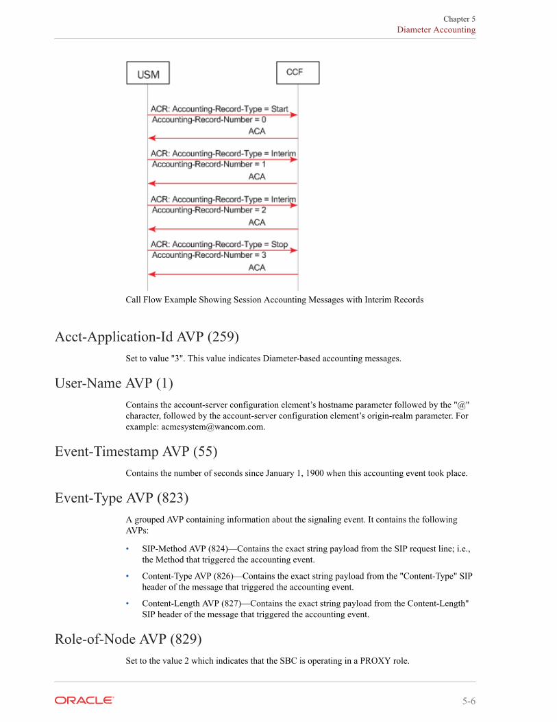
Call Flow Example Showing Session Accounting Messages with Interim Records
Acct-Application-Id AVP (259)Set to value "3". This value indicates Diameter-based accounting messages.
User-Name AVP (1)Contains the account-server configuration element’s hostname parameter followed by the "@"character, followed by the account-server configuration element’s origin-realm parameter. Forexample: [email protected].
Event-Timestamp AVP (55)Contains the number of seconds since January 1, 1900 when this accounting event took place.
Event-Type AVP (823)A grouped AVP containing information about the signaling event. It contains the followingAVPs:
• SIP-Method AVP (824)—Contains the exact string payload from the SIP request line; i.e.,the Method that triggered the accounting event.
• Content-Type AVP (826)—Contains the exact string payload from the "Content-Type" SIPheader of the message that triggered the accounting event.
• Content-Length AVP (827)—Contains the exact string payload from the Content-Length"SIP header of the message that triggered the accounting event.
Role-of-Node AVP (829)Set to the value 2 which indicates that the SBC is operating in a PROXY role.
Chapter 5Diameter Accounting
5-6
User-Session-Id AVP (830)Contains VSA 44 as used in the RADIUS interface.
Calling-Party-Address AVP (831)The Calling-Party-Address AVP (AVP code 831) is of type UTF8String and holds the address(SIP URI or TEL URI) which identifies the party (Public User Identity or Public ServiceIdentity) initiating a SIP transaction. . It is obtained from the P-Asserted-Identity header of anynon-REGISTER SIP Request, either initiating a dialog or a standalone transaction. This AVPmay appear several times when the P-Asserted-Identity header contains both a SIP URI and aTEL URI. In case no P-Asserted-Identity is known, this AVP list shall include one item withthe value "unknown".
Called-Party-Address AVP (832)The Called-Party-Address AVP (AVP code 832) is of type UTF8String. In IMS charging(except for SIP Register and SIP Subscription transactions), it holds the address (SIP URI, TELURI or URN) of the party (Public User ID or Public Service ID) to whom the SIP transaction isposted. The Called Party Address shall be populated with the SIP URI or TEL URI containedin the Request-URI of the outgoing request.
For a registration procedure, this field holds the party (Public User ID) to be registered. In thiscase, the Called Party Address field is obtained from the To SIP header of the SIP Request. Fora subscription procedure this field holds the address of the resource for which the originatorwants to receive notifications of change of states. In this case, the Called Party Address field isobtained from the outgoing Request-URI of the SIP Request.
Time-Stamps AVP (833)A grouped AVP that contains timestamps for the related SIP signaling. It contains the followingAVPs.
• SIP-Request-Timestamp AVP (834)—A UTC formatted timestamp that corresponds towhen the SIP INVITE that started the session was received.
• SIP-Response-Timestamp AVP (835)—A UTC formatted timestamp that corresponds towhen the SIP 200 OK response to the INVITE that started the session was received.
Inter-Operator-Identifier AVP (838)A grouped AVP that indicates the ingress and egress networks from the SBC’s perspective. Itcontains the following AVPs.
• Originating-IOI AVP (839)—The realm where the SBC received the SIP signalingmessages.
• Terminated-IOI AVP (840)—The realm where the SIP signaling message exit the SBC.
SDP-Session-Description AVP (842)This AVP may occur multiple times in an ACR message. It is populated with SDP attribute-lines from the SIP messages to which this ACR Stop message refers. Thus, all "i=", "c=", "b=","k=", "a=", etc.., lines comprise multiple instances of this AVP.
Chapter 5Diameter Accounting
5-7
If the SBC is configured to generate Start events on the INVITE, the calling SDP will be used;if the SBC is configured to generate Start events on the OK, the called SDP will be used.ONLY IN ACR Start.
Session-Media-Component AVP (845)A grouped AVP that contains information about the media session. It contains the followingAVPs. ONLY IN ACR Start.
• SDP-Media-Name AVP (844)—populated with the "m=" line from the SDP being used.
• SDP-Media-Description AVP (845)—this AVP may occur multiple times in this groupedAVP. It is populated with SDP attribute-lines from the media component as specified bythe media described in the SDP-Media-Name AVP. Thus, all "i=", "c=", "b=", "k=", "a=",etc..., lines related to the above specified "m=" line comprise multiple instances of thisAVP.
Cause AVP (860)A grouped AVP that contains the reason for the termination event and the role/function of thenode where the call was terminated. It contains the following AVPs.
• Cause-Code AVP (861)—See Values for Cause Code AVP (861) below.
• Node-Functionality AVP (862)—Set to value 0.
Values for Cause Code AVP (861)As described in 3GPP TS32.229, the Cause-Code AVP 861 includes the cause code value sentby the IMS node. It is used in stop and/or event messages.
If the session terminated as a result of a specific known SIP error code, the SIP error code isused as the cause code value. Otherwise, cause code values less than or equal to 0 are used forsuccessful causes while values greater than or equal to 1 are used for failure causes.
• Cause code value set to 0 — indicates "Normal end of session" and is used in Accounting-request[stop] message to indicate that an ongoing SIP session has been normally releasedeither by the user or by the network (SIP BYE message initiated by the user or initiated bythe network has been received by the IMS node after the reception of the SIP ACKmessage).
• Cause code value set to "2xx Final Response" (except 200) — used when the SIPtransaction is terminated due to an IMS node receiving/initiating a 2xx Final response.
• Cause code value set to "2xx Final Redirection"— used when the SIP transaction isterminated due to an IMS node receiving/initiating a 3xx response.
• Cause code value set to "1"— indicates "Unspecified error" and is used when the SIPtransaction is terminated due to an unknown error.
• Cause code value set to "4xx Request failure"— used when the SIP transaction isterminated due to an IMS node receiving/initiating a 4xx error response.
• Cause code value set to "5xx Server failure"— used when the SIP transaction is terminateddue to an IMS node receiving/initiating a 5xx error response.
• Cause code value set to "6xx Global failure"— used when the SIP transaction is terminateddue to an IMS node receiving/initiating a 6xx error response.
Chapter 5Diameter Accounting
5-8
• Cause code value set to "Unsuccessful session setup"— used in the Accounting-request[stop] when the SIP session has not been successfully established (i.e. Timer Hexpires and SIP ACK is not received or SIP BYE is received after reception of the 200OKfinal response and SIP ACK is not received).
• Cause code value set to "Internal error"— used when the SIP transaction is terminated dueto an IMS node internal error (e.g. error in processing a request/response).
ACR Event RecordsThe SBC supports ACR [Event] records, according to 3GPP TS 32.260. This is in addition tostart, stop and interim records. These records reflect a preset type of SIP event. The ACRs arethen sent to the CCF.
The SBC can create Event ACR messages on REGISTER and/or local-re-REGISTER requests.A local re-register is when registration caching is enabled and the REGISTER from ancurrently registered endpoint occurs before half of the registration expiration time. In suchcases the SBC sends a 200 OK to the re-registering endpoint and does not forward the re-REGISTER to the registrar.
Event record creation is enabled with the generate-event parameter in the account config. Thisparameter can be set to register, local-register or both values. The configured value indicatesthe type of message that initiates an event ACR message sent to a CCF. Register only promptsthe SBC to create Event ACRs at a REGISTER, local-register prompts the SBC to create EventACRs on a re-REGISTER that was replied to by the SBC.
Event messages are created when the SBC receives a SIP Final Response 2xx or SIP FinalResponse (4xx or 5xx), that indicates an unsuccessful REGISTER.
Event ACR messages are also generated to indicate there has been an unsuccessful sessionattempt. Upon receiving a 4xx, 5xx or 6xx response to a SIP Invite, an Event message iscreated.
ACR Event Message ConstructionAn Event ACR is generated according to the tables that describe the AVPs present in the SBC’sACR message. Refer to the checked items in the Event column to see all included AVPs. Notethat the Accounting-Record-Type AVP (480) is set to Event_Record (1).
Event-Type AVPThe Event-Type AVP (AVP code 823) is a Grouped AVP and contains information about thetype of chargeable telecommunication service/event for which the accounting-request and/orcredit control request message(s) is generated.
It is used in an AAR Event record. In this context, refer to the following:
AVP Number Acme # Definition
[ SIP-Method ] 824 173 Contains the name of the SIP Method (this will beREGISTER) causing a accounting request to be sent to theCCF.
[ Event ] 825 245 Holds the content of the "Event:" header.This is not present in a REGISTER or re-REGISTERmessage
Chapter 5ACR Event Records
5-9
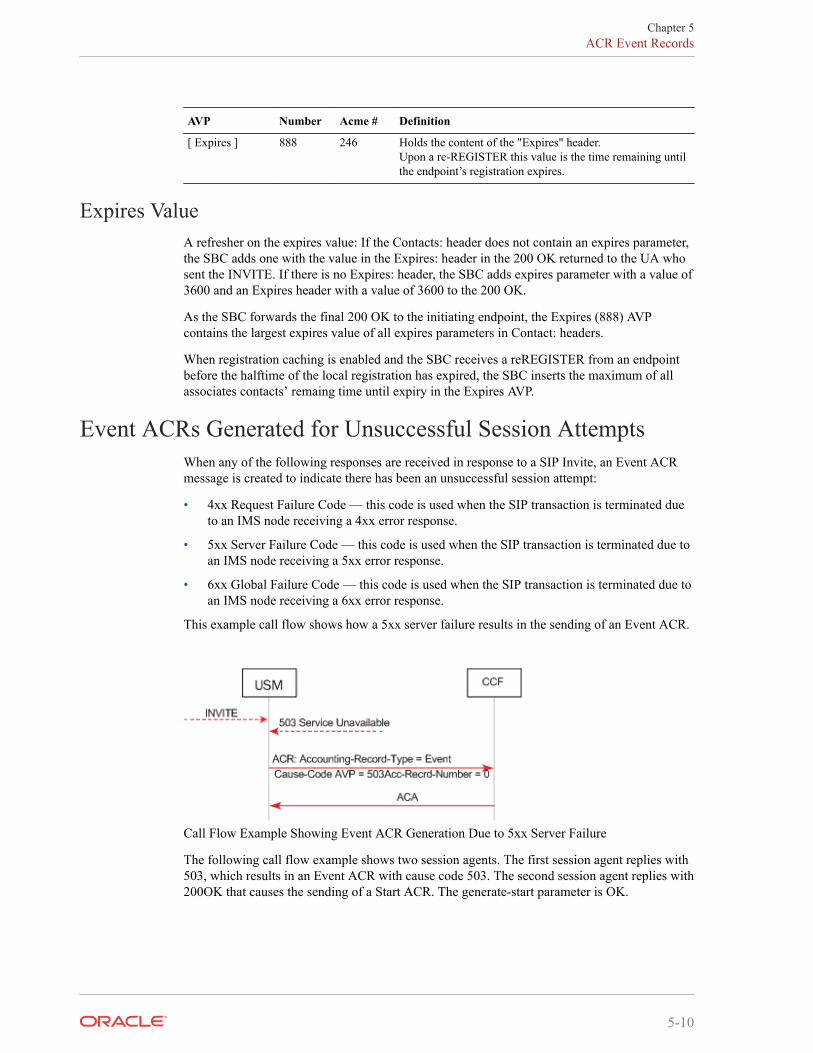
AVP Number Acme # Definition
[ Expires ] 888 246 Holds the content of the "Expires" header.Upon a re-REGISTER this value is the time remaining untilthe endpoint’s registration expires.
Expires ValueA refresher on the expires value: If the Contacts: header does not contain an expires parameter,the SBC adds one with the value in the Expires: header in the 200 OK returned to the UA whosent the INVITE. If there is no Expires: header, the SBC adds expires parameter with a value of3600 and an Expires header with a value of 3600 to the 200 OK.
As the SBC forwards the final 200 OK to the initiating endpoint, the Expires (888) AVPcontains the largest expires value of all expires parameters in Contact: headers.
When registration caching is enabled and the SBC receives a reREGISTER from an endpointbefore the halftime of the local registration has expired, the SBC inserts the maximum of allassociates contacts’ remaing time until expiry in the Expires AVP.
Event ACRs Generated for Unsuccessful Session AttemptsWhen any of the following responses are received in response to a SIP Invite, an Event ACRmessage is created to indicate there has been an unsuccessful session attempt:
• 4xx Request Failure Code — this code is used when the SIP transaction is terminated dueto an IMS node receiving a 4xx error response.
• 5xx Server Failure Code — this code is used when the SIP transaction is terminated due toan IMS node receiving a 5xx error response.
• 6xx Global Failure Code — this code is used when the SIP transaction is terminated due toan IMS node receiving a 6xx error response.
This example call flow shows how a 5xx server failure results in the sending of an Event ACR.
Call Flow Example Showing Event ACR Generation Due to 5xx Server Failure
The following call flow example shows two session agents. The first session agent replies with503, which results in an Event ACR with cause code 503. The second session agent replies with200OK that causes the sending of a Start ACR. The generate-start parameter is OK.
Chapter 5ACR Event Records
5-10
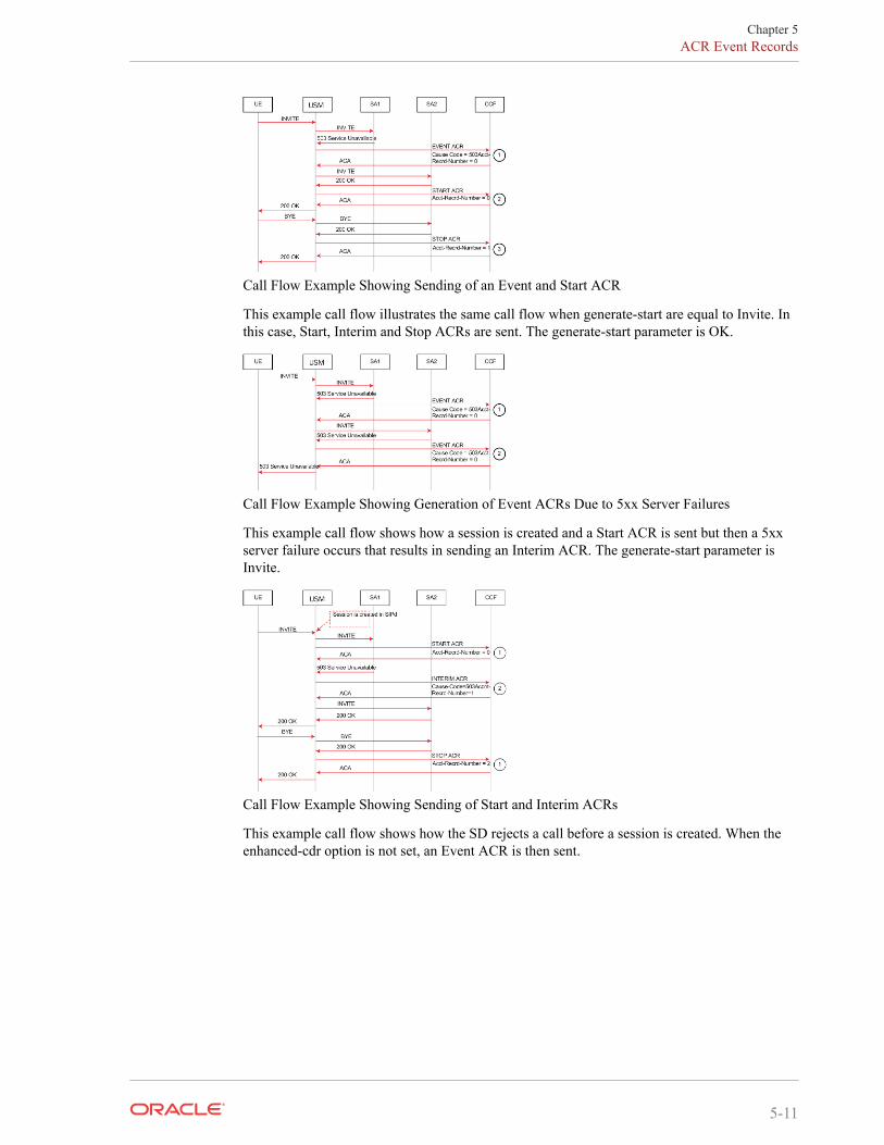
Call Flow Example Showing Sending of an Event and Start ACR
This example call flow illustrates the same call flow when generate-start are equal to Invite. Inthis case, Start, Interim and Stop ACRs are sent. The generate-start parameter is OK.
Call Flow Example Showing Generation of Event ACRs Due to 5xx Server Failures
This example call flow shows how a session is created and a Start ACR is sent but then a 5xxserver failure occurs that results in sending an Interim ACR. The generate-start parameter isInvite.
Call Flow Example Showing Sending of Start and Interim ACRs
This example call flow shows how the SD rejects a call before a session is created. When theenhanced-cdr option is not set, an Event ACR is then sent.
Chapter 5ACR Event Records
5-11
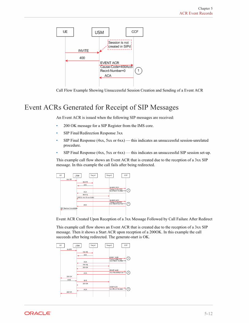
Call Flow Example Showing Unsuccessful Session Creation and Sending of a Event ACR
Event ACRs Generated for Receipt of SIP MessagesAn Event ACR is issued when the following SIP messages are received:
• 200 OK message for a SIP Register from the IMS core.
• SIP Final/Redirection Response 3xx
• SIP Final Response (4xx, 5xx or 6xx) — this indicates an unsuccessful session-unrelatedprocedure.
• SIP Final Response (4xx, 5xx or 6xx) — this indicates an unsuccessful SIP session set-up.
This example call flow shows an Event ACR that is created due to the reception of a 3xx SIPmessage. In this example the call fails after being redirected.
Event ACR Created Upon Reception of a 3xx Message Followed by Call Failure After Redirect
This example call flow shows an Event ACR that is created due to the reception of a 3xx SIPmessage. Then it shows a Start ACR upon reception of a 200OK. In this example the callsucceeds after being redirected. The generate-start is OK.
Chapter 5ACR Event Records
5-12
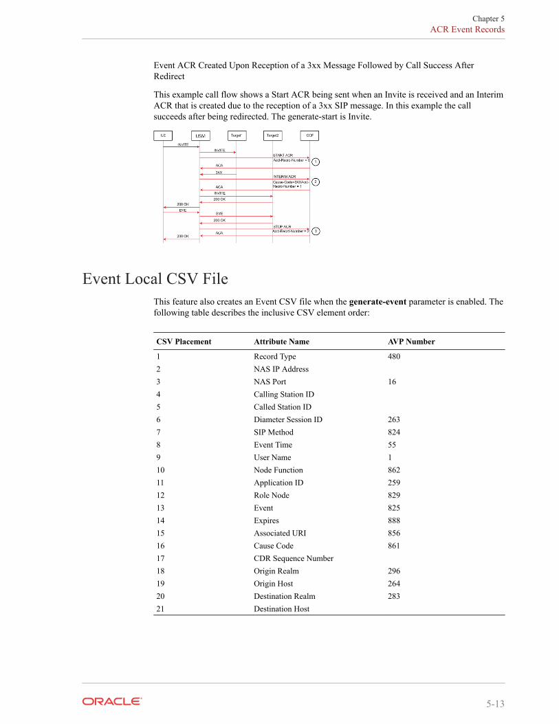
Event ACR Created Upon Reception of a 3xx Message Followed by Call Success AfterRedirect
This example call flow shows a Start ACR being sent when an Invite is received and an InterimACR that is created due to the reception of a 3xx SIP message. In this example the callsucceeds after being redirected. The generate-start is Invite.
Event Local CSV FileThis feature also creates an Event CSV file when the generate-event parameter is enabled. Thefollowing table describes the inclusive CSV element order:
CSV Placement Attribute Name AVP Number
1 Record Type 4802 NAS IP Address3 NAS Port 164 Calling Station ID5 Called Station ID6 Diameter Session ID 2637 SIP Method 8248 Event Time 559 User Name 110 Node Function 86211 Application ID 25912 Role Node 82913 Event 82514 Expires 88815 Associated URI 85616 Cause Code 86117 CDR Sequence Number18 Origin Realm 29619 Origin Host 26420 Destination Realm 28321 Destination Host
Chapter 5ACR Event Records
5-13
Diameter Heartbeat for RfDevice-Watchdog-Request (DWR) and Device-Watchdog-Answer (DWA) messages are used todetect transport failures at the application layer between the SBC communicating with a policyserver via Diameter. The request/answer message pair forms a heartbeat mechanism that canalert the requesting side if the answering side is not reachable.
The SBC always responds to a DWR by replying with a DWA message. In addition, the SBCcan be configured to initiate DWR messages toward a policy server or other Diameter-basednetwork device.
You configure the watchdog ka timer to indicate the period between the DWRs the SBC sendsto a Diameter Agent, an Rf based server in this case.
If the SBC fails to receive a DWA response from the Server within 1/4 of the configuredwatchdog ka timer parameter, then the connection towards that Server is considered failed andtorn down. The SBC attempts to recreate the TCP connection, followed by the recreating theDiameter connection by issuing a CEA toward the policy server.
When other Rf traffic to/from the accounting server is present, DWRs are suspended. The othertraffic indicates that the server is up. The SBC upon detection of DWR failure can sendaccounting data towards another configured accounting server by failover/strategy mechanisms.
Configuring Diameter-based AccountingDiameter-based Rf accounting relies on many of the same configuration elements used forRADIUS based accounting. The following two sections explain how to configure both theaccount-config and account-servers configuration elements. In addition, you must ensure thataccounting is enabled for each realm where you want it to occur. The accounting-enableparameter in the realm-config is enabled by default.
Configure the Global Diameter-based Accounting (Rf) FeaturesTo configure the global Diameter-based accounting (Rf) features in the account-config:
1. In Superuser mode, type configure terminal and press Enter.
ORACLE# configure terminal
2. Type session-router and press Enter.
ORACLE(configure)# session-router
3. Type account-config and press Enter.
ORACLE(session-router)# account-configORACLE(account-config)#
4. hostname—Enter a hostname for this system.
5. port—Enter 3868 for the RFC-recommended Diameter port number. You may enter adifferent port number.
• minimum: 1025
• maximum: 65535
6. strategy—Set the strategy used to select the accounting server which the SBC sendsaccounting messages. The following table lists the available strategies:
Chapter 5Diameter Heartbeat for Rf
5-14
Value Description
hunt Selects accounting servers in the order in which they are listed.If the first accounting server is online, working, and has notexceeded any of the defined constraints, all traffic is sent to it.Otherwise the second accounting server is selected. If the firstand second accounting servers are offline or exceed any definedconstraints, the third accounting server is selected. And so onthrough the entire list of configured servers
failover Uses the first server in the list of predefined accounting serversuntil a failure is received from that server. Once a failure isreceived, it moves to the second accounting server in the listuntil a failure is received. And so on through the entire list ofconfigured servers.
round robin Selects each accounting server in order, distributing theselection of each accounting server evenly over time.
fastest round trip time Selects the accounting server that has the fastest round trip time(RTT) observed during transactions with the servers (sending arecord and receiving an ACK).
fewest pending Selects the accounting server that has the fewest number ofunacknowledged accounting messages (that are in transit to theSBC).
7. protocol—Set this parameter to diameter to use the Rf accounting interface with aDiameter-based accounting server.
8. state— Enter enabled to use accounting on this system.
9. max-msg-delay—Retain the default value of 60 seconds or indicate the length of time inseconds that you want the SBC to continue trying to send each accounting message.During this delay, the SBC can hold a generic queue of 4096 messages.
• Minimum: zero (0)
• Maximum: 4294967295
10. acr-retry-interval — Retain the default value of 10 seconds or enter the time in secondsfor the SBC to wait before resending an ACR for a session.
• Minimum: 5
• Maximum: 20
11. max-acr-retries — Retain the default value of zero (0) or enter the maximum number oftimes that the SBC can resend an ACR for a session.
• Minimum: zero (0)
• Maximum: 4
12. max-wait-failover—Retain the default value of 100 messages or indicate the maximumnumber of accounting messages the SBC can store its message waiting queue for a specificaccounting server, before it is considered a failover situation.
Once this value is exceeded, the SBC attempts to send it accounting messages, includingits pending messages, to the next accounting server in its configured list.
• Minimum: one (1) message
• Maximum: 4096 messages
13. trans-at-close—Retain the default value of disabled if you do not want to defer thetransmission of message information to the close of a session. Enter enabled if you want todefer message transmission.
Chapter 5Configuring Diameter-based Accounting
5-15
• disabled—The SBC transmits accounting information at the start of a session (Start),during the session (Interim), and at the close of a session (Stop). The transmittedaccounting information for a single session might span a period of hours and be spreadout among different storage files.
• enabled—Limits the number of files on the SBC used to store the accounting messageinformation for one session. It is easiest to store the accounting information from asingle session in a single storage file.
14. generate-start—Retain the default value ok if you want the ACR Start message to begenerated once the SBC receives an OK message in response to an INVITE.
Other options include:
• none—Accounting Start message should not be generated.
• invite—Accounting Start message should be generated once the SBC receives a SIPINVITE.
15. generate-interim—Retain the default value reinvite-response to cause the SBC to sendan Interim charging message to the accounting server.
You can select none, one, or more than one of the following values:
Value Description
ok Start message is generated when the SBC receives an OKmessage in response to an INVITE.
reinvite Interim message is generated when the SBC receives a SIPsession reINVITE message.
reinvite-response (default) Interim message is generated when the SBC receives a SIPsession reINVITE and responds to it (for example, sessionconnection or failure).
reinvite-cancel Interim message is generated when the SBC receives a SIPsession reINVITE, and the Reinvite is cancelled before the SBCresponds to it.
unsuccessful-attempt Interim message is generated when a SIP session set-up attemptfrom a preference-ordered list of next-hop destinations isunsuccessful. This can happen when a local policy lookup, LRTlookup, ENUM query response, or SIP redirect returns apreference-ordered list of next-hop destinations. The interimmessage contains: the destination IP address, the disconnectreason, a timestamp for the failure, and the number that wascalled.
16. intermediate-period—Enter amount of time in seconds between generating periodicinterim ACR messages during a SIP call. This parameter defaults to zero, which disablescontinuous Interim charging messages.
17. vsa-id-range—Ensure that this parameter is left blank when communicating with aDiameter-based Rf accounting server.
18. generate-event—Enter one or more valid events that prompt creation of an Event record.Current valid values are register and local-register. Multiple values are entered enclosedin parenthesis and separated by spaces.
19. Save your work.
Configure Accounting ServersYou must create one or more servers to which the SBC can send accounting messages.
Chapter 5Configuring Diameter-based Accounting
5-16
1. Continuing from the previous account-config configuration, enter the account server sub-element by typing account-servers Enter.
AZALEA(account-config)# account-serversAZALEA(account-server)#
2. hostname—Set this to the IP address of the Diameter-based Rf accounting server.
3. port—Enter 3868 for the RFC-recommended Diameter port number. You may enter adifferent port number if desired.
• minimum: 1025
• maximum: 65535
4. state—Retain the default enabled to enable this account server or enter disabled to disableit.
5. min-round-trip—Retain the default 250 milliseconds or indicate the minimum round triptime of an accounting message.
• minimum: 10 milliseconds
• maximum: 5000 milliseconds
A round trip consists of the following:
The SBC sends an accounting message to the account server.
The account server processes this message and responds back to the SBC.
If the fastest RTT is the strategy for the account configuration, the value you enterhere can be used to determine an order of preference (if all the configured accountservers are responding in less than their minimum RTT).
6. max-inactivity—Retain the default 60 seconds or indicate the length of time in secondsthat you want the SBC with pending accounting messages to wait when it has not receiveda valid response from the target account server.
• minimum: 1 second
• maximum: 300 seconds
Once this timer value is exceeded, the SBC marks the unresponsive account server asdisabled in its failover scheme. When a server connection is marked as inactive, the SBCattempts to restart the connection and transfers pending messages to another queue fortransmission. Accounting messages might be moved between different account servers asservers become inactive or disabled.
7. restart-delay—Retain the default 30 seconds or indicate the length of time in seconds youwant the SBC to wait before resending messages to a disabled account server.
• minimum: 1 second
• maximum: 300 seconds
8. priority—Enter the number corresponding to the priority of this account server, for usewith server prioritization. The default for this parameter is 0, meaning the prioritizationfeature is turned off—and that the SBC will therefore prioritize accounting servers by IPaddress and port.
9. origin-realm—Enter the realm in which the SBC communicates with the Diameter Rfaccounting server.
10. domain-name-suffix—Enter the suffix to be appended to any Diameter FQDN orDiameter Identity used when the SBC communicates with the Diameter Rf accountingserver. Your value can be any string, to which the SBC will prepend with a dot.
Chapter 5Configuring Diameter-based Accounting
5-17
11. watchdog-ka-timer—Set this parameter to the value in seconds that the SBC waitsbetween sending DWRs. 0 disables this feature. Valid non-zero values are 6 - 65535
12. Save your work.
Additional Rf Features Alarms and TrapsService-Context-ID Format
The Service-Context-ID AVP (461) located in the root ACR message is formatted as follows:
[[["extensions".]MNC.MCC.]"Release".][email protected]
where
• extensions—This is operator specific information to any extensions in a service specificdocument. The value is configured by setting the diam-srvc-ctx-ext parameter.
• MNC.MCC—This identifies the operator implementing the service specific document,which is used to determine the specific requirements for the operator configurableparameters. Both MNC and MCC must be specified separated by a dot(.). The value isconfigured by setting the diam-srvc-ctx-mnc-mcc parameter as two integers separated bya dot. For example: 012.310
• Release—This indicates the 3GPP Release the service specific document is based upone.g. 6 for Release 6. The value is configured by setting the diam-srvc-ctx-rel parameterwith valid values are >=1.
Note:
"[email protected]" is fixed.
Acme Excluded Attribute RangeYou can select certain ACME specific AVPs to include in the Rf accounting records with thediam-acme-attr-id-range parameter. If this parameter is configured with one or more values,then all other valid Acme-specific AVPs, by number, are excluded. If by configuration, the SBCwill exclude one (or more) individual ACME attributes, there will be no effect. If byconfiguration an Acme-specific attribute number that refers to a group is excluded, the SBCremoves the complete grouped AVP from the ACR message.
Consider:
• Acme-specific attribute 1—The grouped AVP
• Acme-specific attributes 2-35—The individual AVPs that make up the group
If you configure diam-acme-attr-id-range 1,3- the SBC includes all attributes in the Acmegroup; This configuration aims to exclude only attribute 3 but is has no effect.
If you configure diam-acme-attr-id-range 2-, the SBC excludes the full Acme-specific groupbecause Acme-Packet-Specific-Extension-Rf AVP (1) was not included.
The diam-acme-attr-id-range parameter’s syntax is as follows:
Chapter 5Additional Rf Features Alarms and Traps
5-18
Syntax Meaning
X-Y include range of attribute IDs from X to Y (X and Y are included)-Y include any attribute ID <= YX- include any attribute ID >= X- include any attribute IDX include attribute ID = X
Configure Account1. In Superuser mode, type configure terminal and press Enter.
ORACLE# configure terminal
2. Type session-router and press Enter.
ORACLE(configure)# session-router
3. Type account-config and press Enter.
ORACLE(session-router)# account-configORACLE(account-config)#
4. diam-srvc-ctx-ext—Enter the extension portion of the Service-Context-ID AVP value.This value can be any string.
5. diam-srvc-ctx-mnc-mcc—Enter the MNC.MCC portion of the Service-Context-ID AVPvalue. This value must follow the NUM1.NUM2 format.
6. diam-srvc-ctx-rel—Enter the release portion of the Service-Context-ID AVP value. Thisvalue can be any number >= 1..
7. diam-acme-attr-id-range—Enter the range of Acme-specific AVPs to include in ACRmessages. Leaving this parameter blank or configured with a - includes all AVPs.
8. Type done to save your work.
SNMP Trap BehaviorThe SBC sends an SNMP trap (apDiameterSrvrErrorResult) upon a CCF returning an error-containing ACA. See the list of four errors (3002, 3004, 4002. 5012) which generate traps inthe Alarms section. The frequency at which subsequent traps are sent is based upon configuringthe diam result code trap grade period option configured in the account config.
When the SBC has sent a trap after receiving a bad ACA, it goes into an error state. The SBCwaits one grace period before checking if it is still in an error state. If the state has not switchedfrom errored back to pending, the SBC sends another error trap, after that first grace periodends (counting from the initial error) and then after the next error message is received.
Chapter 5Additional Rf Features Alarms and Traps
5-19
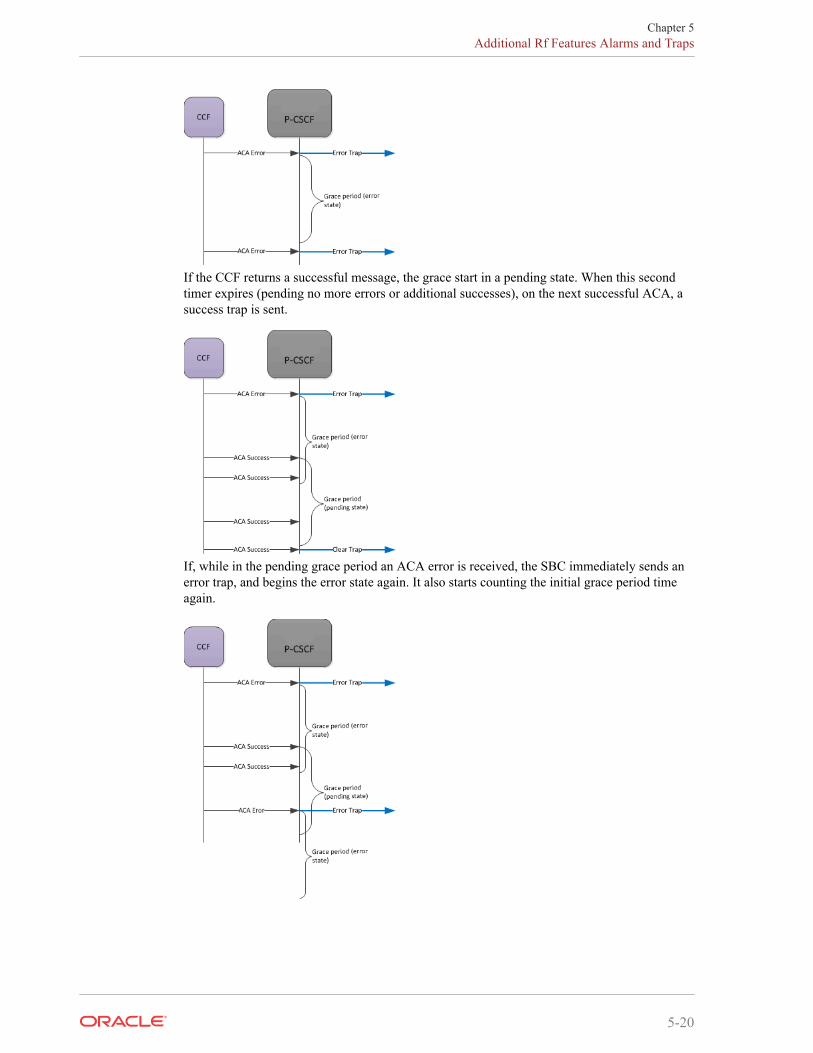
If the CCF returns a successful message, the grace start in a pending state. When this secondtimer expires (pending no more errors or additional successes), on the next successful ACA, asuccess trap is sent.
If, while in the pending grace period an ACA error is received, the SBC immediately sends anerror trap, and begins the error state again. It also starts counting the initial grace period timeagain.
Chapter 5Additional Rf Features Alarms and Traps
5-20
AlarmsA MINOR non health affecting Diameter Accounting Server Error alarm will be generatedwhen one of the following Result Codes is received:
• 3002 (DIAMETER_UNABLE_TO_DELIVER)
• 3004 (DIAMETER_TOO_BUSY)
• 4002 (DIAMETER_OUT_OF_SPACE)
• 5012 (DIAMETER_UNABLE_TO_COMPLY)
The alarm is cleared when a success (2XXX) code is received.
The rules for setting state of the failed server alarm are the same as the grace period rulesdescribed in the SNMP Trap Behavior section.
For example:
327703 835778540 5 2012-03-13 13:03:34 2012-03-13 13:03:34Count Description1 Diameter Accounting Server Returned Error Result Code|172.30.0.135:3869-5012|172.30.69.211:3868-3002
SNMP MIBs and Traps
ApDiamResultCode Textual ConventionApDiamResultCode ::= TEXTUAL-CONVENTION STATUS current DESCRIPTION "The Result-Code AVP (268) value RFC 3588, 7.1. Result-Code AVP" SYNTAX INTEGER { diameterMultiRoundAuth(1001), diameterSuccess(2001), diameterLimitedSuccess(2002), diameterCommandUnsupported(3001), diameterUnableToDeliver(3002), diameterRealmNotServed(3003), diameterTooBusy(3004), diameterLoopDetected(3005), diameterRedirectIndicatoion(3006), diameterApplicationUnsupported(3007), diameterInvalidHdrBits(3008), diameterInvalidAvpBits(3009), diameterUnknownPeer(3010), diameterAuthenticationRejected(4001), diameterOutOfSpace(4002), electionLost(4003), diameterAvpUnsupported(5001), diameterUnknownSessionId(5002), diameterAuthoriszationRejected(5003), diameterInvalidAvpValue(5004), diameterMissingAvp(5005), diameterResourcesExceeded(5006), diameterContradictingAvps(5007), diameterAvpNotAllowed(5008),
Chapter 5Additional Rf Features Alarms and Traps
5-21
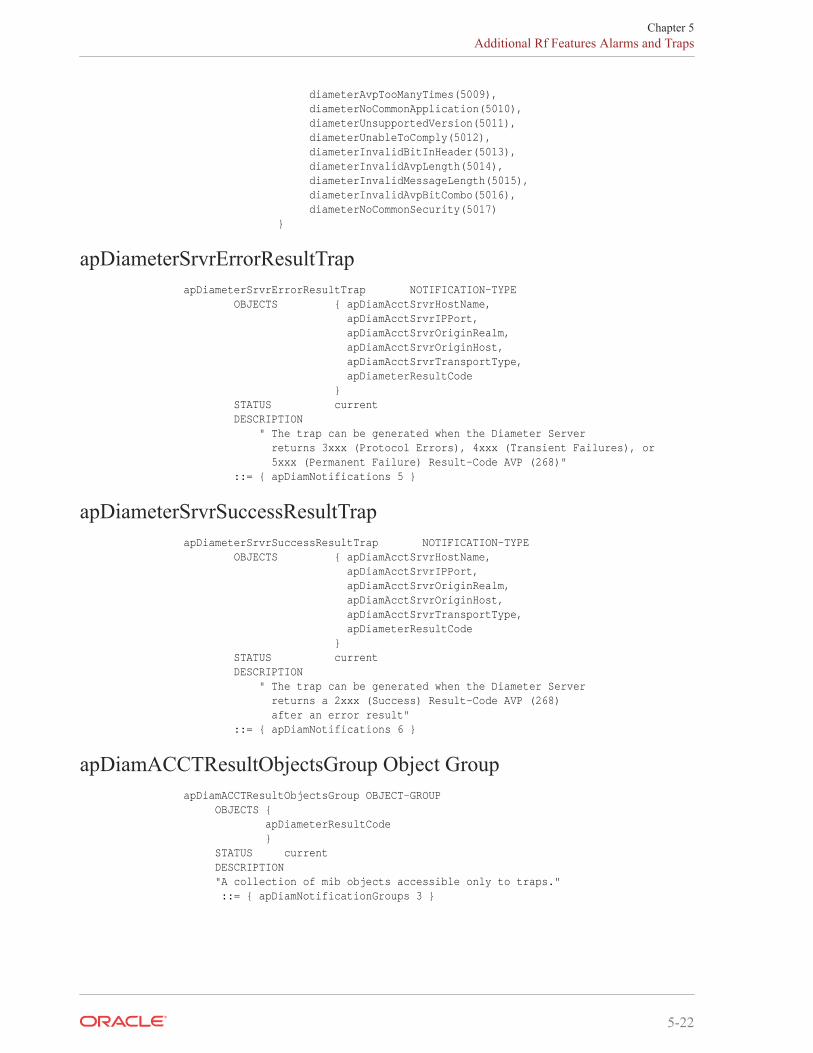
diameterAvpTooManyTimes(5009), diameterNoCommonApplication(5010), diameterUnsupportedVersion(5011), diameterUnableToComply(5012), diameterInvalidBitInHeader(5013), diameterInvalidAvpLength(5014), diameterInvalidMessageLength(5015), diameterInvalidAvpBitCombo(5016), diameterNoCommonSecurity(5017) }
apDiameterSrvrErrorResultTrapapDiameterSrvrErrorResultTrap NOTIFICATION-TYPE OBJECTS { apDiamAcctSrvrHostName, apDiamAcctSrvrIPPort, apDiamAcctSrvrOriginRealm, apDiamAcctSrvrOriginHost, apDiamAcctSrvrTransportType, apDiameterResultCode } STATUS current DESCRIPTION " The trap can be generated when the Diameter Server returns 3xxx (Protocol Errors), 4xxx (Transient Failures), or 5xxx (Permanent Failure) Result-Code AVP (268)" ::= { apDiamNotifications 5 }
apDiameterSrvrSuccessResultTrapapDiameterSrvrSuccessResultTrap NOTIFICATION-TYPE OBJECTS { apDiamAcctSrvrHostName, apDiamAcctSrvrIPPort, apDiamAcctSrvrOriginRealm, apDiamAcctSrvrOriginHost, apDiamAcctSrvrTransportType, apDiameterResultCode } STATUS current DESCRIPTION " The trap can be generated when the Diameter Server returns a 2xxx (Success) Result-Code AVP (268) after an error result" ::= { apDiamNotifications 6 }
apDiamACCTResultObjectsGroup Object GroupapDiamACCTResultObjectsGroup OBJECT-GROUP OBJECTS { apDiameterResultCode } STATUS current DESCRIPTION "A collection of mib objects accessible only to traps." ::= { apDiamNotificationGroups 3 }
Chapter 5Additional Rf Features Alarms and Traps
5-22
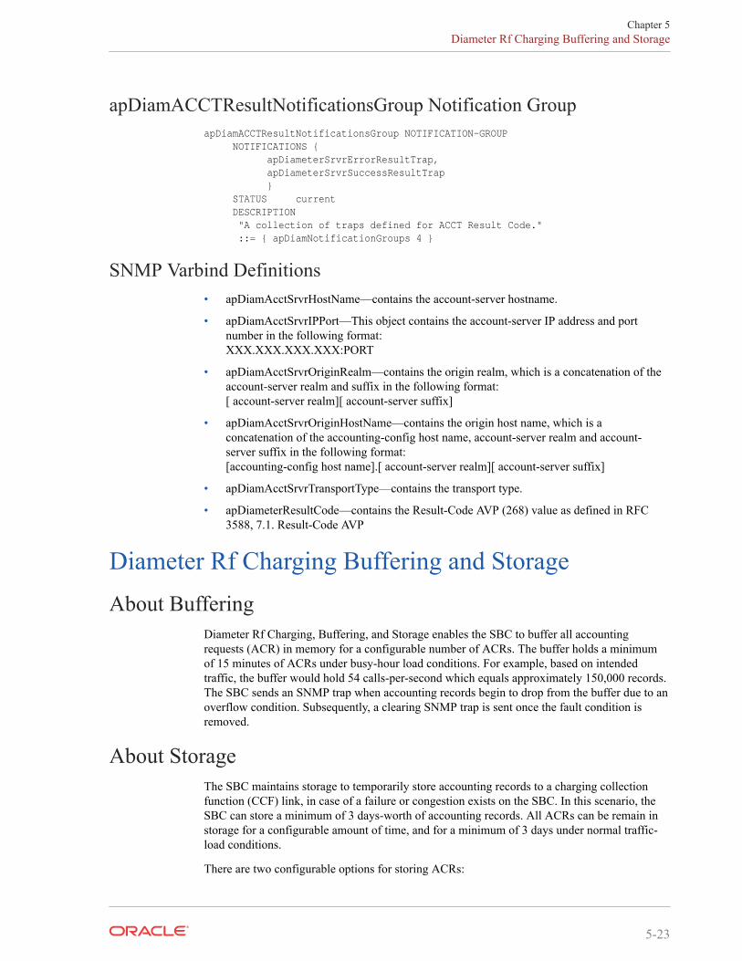
apDiamACCTResultNotificationsGroup Notification GroupapDiamACCTResultNotificationsGroup NOTIFICATION-GROUP NOTIFICATIONS { apDiameterSrvrErrorResultTrap, apDiameterSrvrSuccessResultTrap } STATUS current DESCRIPTION "A collection of traps defined for ACCT Result Code." ::= { apDiamNotificationGroups 4 }
SNMP Varbind Definitions• apDiamAcctSrvrHostName—contains the account-server hostname.
• apDiamAcctSrvrIPPort—This object contains the account-server IP address and portnumber in the following format:XXX.XXX.XXX.XXX:PORT
• apDiamAcctSrvrOriginRealm—contains the origin realm, which is a concatenation of theaccount-server realm and suffix in the following format:[ account-server realm][ account-server suffix]
• apDiamAcctSrvrOriginHostName—contains the origin host name, which is aconcatenation of the accounting-config host name, account-server realm and account-server suffix in the following format:[accounting-config host name].[ account-server realm][ account-server suffix]
• apDiamAcctSrvrTransportType—contains the transport type.
• apDiameterResultCode—contains the Result-Code AVP (268) value as defined in RFC3588, 7.1. Result-Code AVP
Diameter Rf Charging Buffering and StorageAbout Buffering
Diameter Rf Charging, Buffering, and Storage enables the SBC to buffer all accountingrequests (ACR) in memory for a configurable number of ACRs. The buffer holds a minimumof 15 minutes of ACRs under busy-hour load conditions. For example, based on intendedtraffic, the buffer would hold 54 calls-per-second which equals approximately 150,000 records.The SBC sends an SNMP trap when accounting records begin to drop from the buffer due to anoverflow condition. Subsequently, a clearing SNMP trap is sent once the fault condition isremoved.
About StorageThe SBC maintains storage to temporarily store accounting records to a charging collectionfunction (CCF) link, in case of a failure or congestion exists on the SBC. In this scenario, theSBC can store a minimum of 3 days-worth of accounting records. All ACRs can be remain instorage for a configurable amount of time, and for a minimum of 3 days under normal traffic-load conditions.
There are two configurable options for storing ACRs:
Chapter 5Diameter Rf Charging Buffering and Storage
5-23
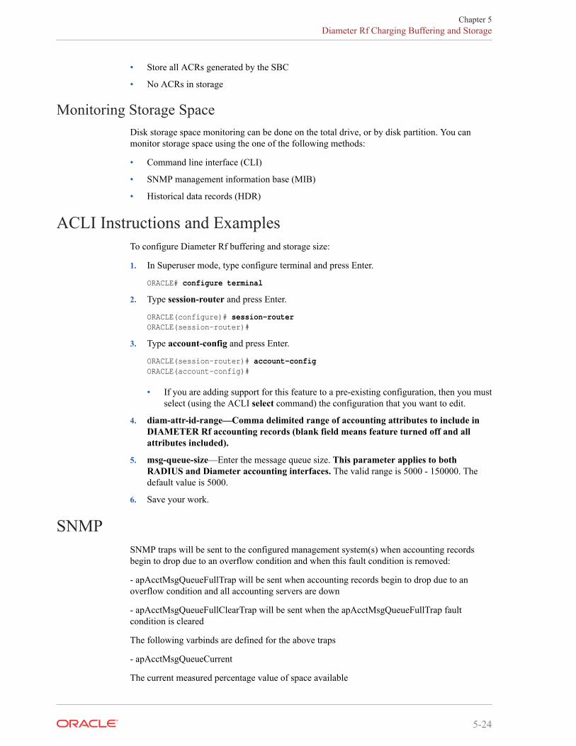
• Store all ACRs generated by the SBC
• No ACRs in storage
Monitoring Storage SpaceDisk storage space monitoring can be done on the total drive, or by disk partition. You canmonitor storage space using the one of the following methods:
• Command line interface (CLI)
• SNMP management information base (MIB)
• Historical data records (HDR)
ACLI Instructions and ExamplesTo configure Diameter Rf buffering and storage size:
1. In Superuser mode, type configure terminal and press Enter.
ORACLE# configure terminal
2. Type session-router and press Enter.
ORACLE(configure)# session-routerORACLE(session-router)#
3. Type account-config and press Enter.
ORACLE(session-router)# account-configORACLE(account-config)#
• If you are adding support for this feature to a pre-existing configuration, then you mustselect (using the ACLI select command) the configuration that you want to edit.
4. diam-attr-id-range—Comma delimited range of accounting attributes to include inDIAMETER Rf accounting records (blank field means feature turned off and allattributes included).
5. msg-queue-size—Enter the message queue size. This parameter applies to bothRADIUS and Diameter accounting interfaces. The valid range is 5000 - 150000. Thedefault value is 5000.
6. Save your work.
SNMPSNMP traps will be sent to the configured management system(s) when accounting recordsbegin to drop due to an overflow condition and when this fault condition is removed:
- apAcctMsgQueueFullTrap will be sent when accounting records begin to drop due to anoverflow condition and all accounting servers are down
- apAcctMsgQueueFullClearTrap will be sent when the apAcctMsgQueueFullTrap faultcondition is cleared
The following varbinds are defined for the above traps
- apAcctMsgQueueCurrent
The current measured percentage value of space available
Chapter 5Diameter Rf Charging Buffering and Storage
5-24
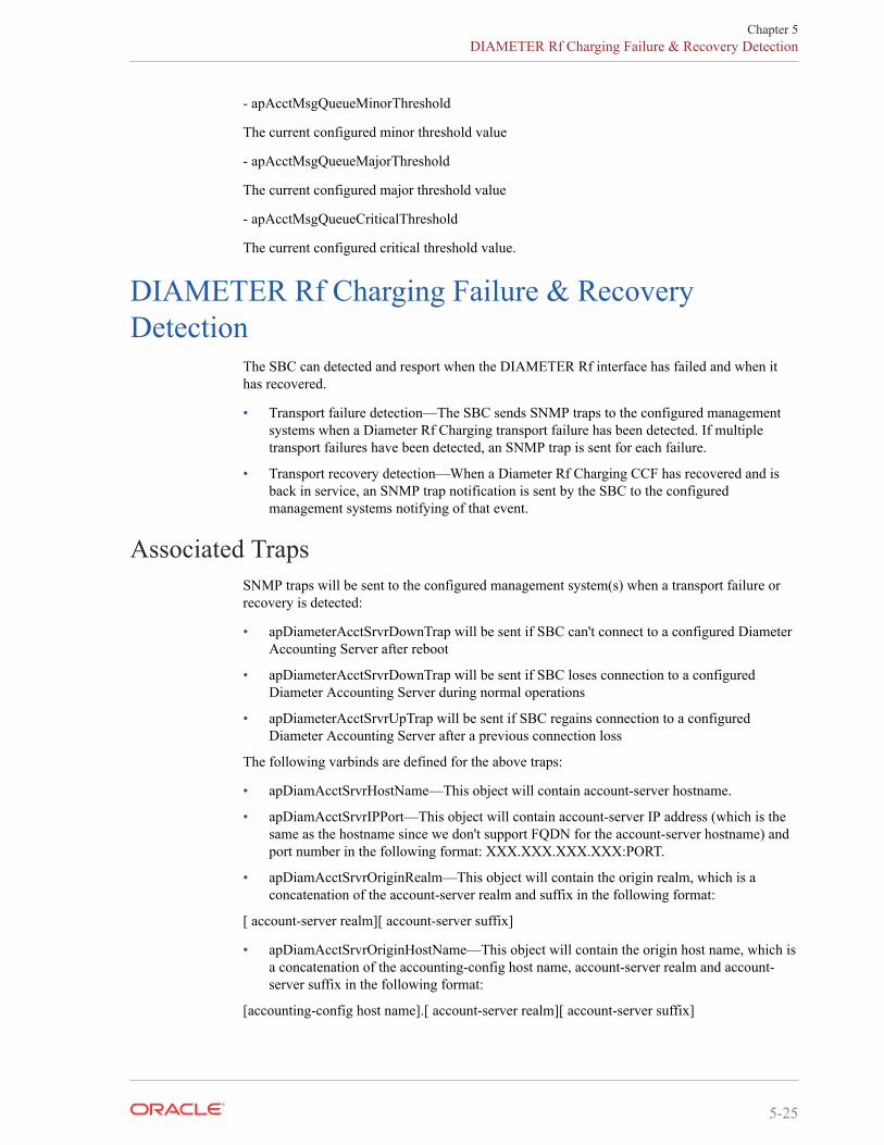
- apAcctMsgQueueMinorThreshold
The current configured minor threshold value
- apAcctMsgQueueMajorThreshold
The current configured major threshold value
- apAcctMsgQueueCriticalThreshold
The current configured critical threshold value.
DIAMETER Rf Charging Failure & RecoveryDetection
The SBC can detected and resport when the DIAMETER Rf interface has failed and when ithas recovered.
• Transport failure detection—The SBC sends SNMP traps to the configured managementsystems when a Diameter Rf Charging transport failure has been detected. If multipletransport failures have been detected, an SNMP trap is sent for each failure.
• Transport recovery detection—When a Diameter Rf Charging CCF has recovered and isback in service, an SNMP trap notification is sent by the SBC to the configuredmanagement systems notifying of that event.
Associated TrapsSNMP traps will be sent to the configured management system(s) when a transport failure orrecovery is detected:
• apDiameterAcctSrvrDownTrap will be sent if SBC can't connect to a configured DiameterAccounting Server after reboot
• apDiameterAcctSrvrDownTrap will be sent if SBC loses connection to a configuredDiameter Accounting Server during normal operations
• apDiameterAcctSrvrUpTrap will be sent if SBC regains connection to a configuredDiameter Accounting Server after a previous connection loss
The following varbinds are defined for the above traps:
• apDiamAcctSrvrHostName—This object will contain account-server hostname.
• apDiamAcctSrvrIPPort—This object will contain account-server IP address (which is thesame as the hostname since we don't support FQDN for the account-server hostname) andport number in the following format: XXX.XXX.XXX.XXX:PORT.
• apDiamAcctSrvrOriginRealm—This object will contain the origin realm, which is aconcatenation of the account-server realm and suffix in the following format:
[ account-server realm][ account-server suffix]
• apDiamAcctSrvrOriginHostName—This object will contain the origin host name, which isa concatenation of the accounting-config host name, account-server realm and account-server suffix in the following format:
[accounting-config host name].[ account-server realm][ account-server suffix]
Chapter 5DIAMETER Rf Charging Failure & Recovery Detection
5-25

• apDiamAcctSrvrTransportType—This object will contain the transport type. At this timeonly the TCP transport type is supported
Chapter 5DIAMETER Rf Charging Failure & Recovery Detection
5-26

AAppendix A
RADIUS Dictionary
For RADIUS dictionary content, refer to the radius file in this version's documentation library.
A-1
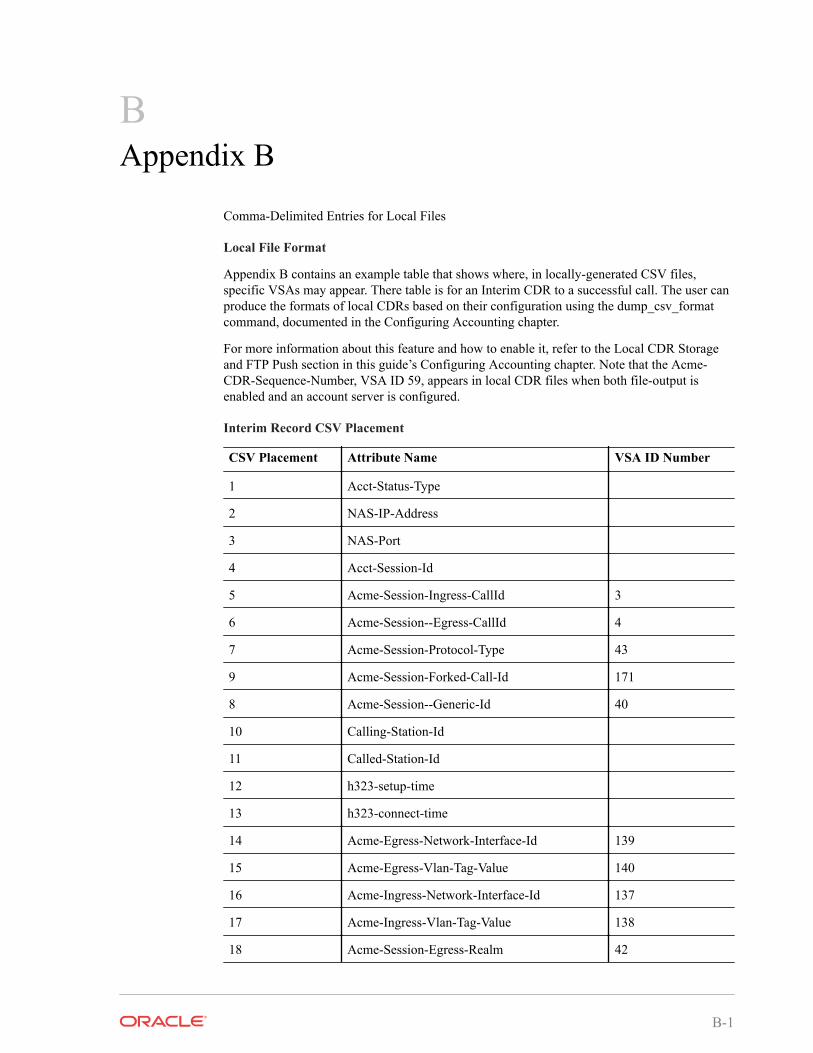
BAppendix B
Comma-Delimited Entries for Local Files
Local File Format
Appendix B contains an example table that shows where, in locally-generated CSV files,specific VSAs may appear. There table is for an Interim CDR to a successful call. The user canproduce the formats of local CDRs based on their configuration using the dump_csv_formatcommand, documented in the Configuring Accounting chapter.
For more information about this feature and how to enable it, refer to the Local CDR Storageand FTP Push section in this guide’s Configuring Accounting chapter. Note that the Acme-CDR-Sequence-Number, VSA ID 59, appears in local CDR files when both file-output isenabled and an account server is configured.
Interim Record CSV Placement
CSV Placement Attribute Name VSA ID Number
1 Acct-Status-Type
2 NAS-IP-Address
3 NAS-Port
4 Acct-Session-Id
5 Acme-Session-Ingress-CallId 3
6 Acme-Session--Egress-CallId 4
7 Acme-Session-Protocol-Type 43
9 Acme-Session-Forked-Call-Id 171
8 Acme-Session--Generic-Id 40
10 Calling-Station-Id
11 Called-Station-Id
12 h323-setup-time
13 h323-connect-time
14 Acme-Egress-Network-Interface-Id 139
15 Acme-Egress-Vlan-Tag-Value 140
16 Acme-Ingress-Network-Interface-Id 137
17 Acme-Ingress-Vlan-Tag-Value 138
18 Acme-Session-Egress-Realm 42
B-1
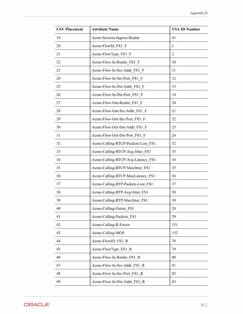
CSV Placement Attribute Name VSA ID Number
19 Acme-Session-Ingress-Realm 41
20 Acme-FlowId_FS1_F 1
21 Acme-FlowType_FS1_F 2
22 Acme-Flow-In-Realm_FS1_F 10
23 Acme-Flow-In-Src-Addr_FS1_F 11
24 Acme-Flow-In-Src-Port_FS1_F 12
25 Acme-Flow-In-Dst-Addr_FS1_F 13
26 Acme-Flow-In-Dst-Port_FS1_F 14
27 Acme-Flow-Out-Realm_FS1_F 20
28 Acme-Flow-Out-Src-Addr_FS1_F 21
29 Acme-Flow-Out-Src-Port_FS1_F 22
30 Acme-Flow-Out-Dst-Addr_FS1_F 23
31 Acme-Flow-Out-Dst-Port_FS1_F 24
32 Acme-Calling-RTCP-Packets-Lost_FS1 32
33 Acme-Calling-RTCP-Avg-Jitter_FS1 33
34 Acme-Calling-RTCP-Avg-Latency_FS1 34
35 Acme-Calling-RTCP-MaxJitter_FS1 35
36 Acme-Calling-RTCP-MaxLatency_FS1 36
37 Acme-Calling-RTP-Packets-Lost_FS1 37
38 Acme-Calling-RTP-Avg-Jitter_FS1 38
39 Acme-Calling-RTP-MaxJitter_FS1 39
40 Acme-Calling-Octets_FS1 28
41 Acme-Calling-Packets_FS1 29
42 Acme-Calling-R-Factor 151
43 Acme-Calling-MOS 152
44 Acme-FlowID_FS1_R 78
45 Acme-FlowType_FS1_R 79
46 Acme-Flow-In-Realm_FS1_R 80
47 Acme-Flow-In-Src-Addr_FS1_R 81
48 Acme-Flow-In-Src-Port_FS1_R 82
49 Acme-Flow-In-Dst-Addr_FS1_R 83
Appendix B
B-2
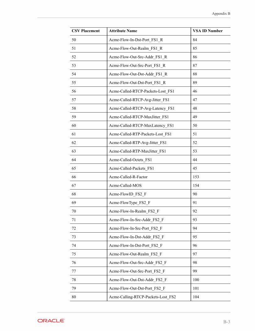
CSV Placement Attribute Name VSA ID Number
50 Acme-Flow-In-Dst-Port_FS1_R 84
51 Acme-Flow-Out-Realm_FS1_R 85
52 Acme-Flow-Out-Src-Addr_FS1_R 86
53 Acme-Flow-Out-Src-Port_FS1_R 87
54 Acme-Flow-Out-Dst-Addr_FS1_R 88
55 Acme-Flow-Out-Dst-Port_FS1_R 89
56 Acme-Called-RTCP-Packets-Lost_FS1 46
57 Acme-Called-RTCP-Avg-Jitter_FS1 47
58 Acme-Called-RTCP-Avg-Latency_FS1 48
59 Acme-Called-RTCP-MaxJitter_FS1 49
60 Acme-Called-RTCP-MaxLatency_FS1 50
61 Acme-Called-RTP-Packets-Lost_FS1 51
62 Acme-Called-RTP-Avg-Jitter_FS1 52
63 Acme-Called-RTP-MaxJitter_FS1 53
64 Acme-Called-Octets_FS1 44
65 Acme-Called-Packets_FS1 45
66 Acme-Called-R-Factor 153
67 Acme-Called-MOS 154
68 Acme-FlowID_FS2_F 90
69 Acme-FlowType_FS2_F 91
70 Acme-Flow-In-Realm_FS2_F 92
71 Acme-Flow-In-Src-Addr_FS2_F 93
72 Acme-Flow-In-Src-Port_FS2_F 94
73 Acme-Flow-In-Dst-Addr_FS2_F 95
74 Acme-Flow-In-Dst-Port_FS2_F 96
75 Acme-Flow-Out-Realm_FS2_F 97
76 Acme-Flow-Out-Src-Addr_FS2_F 98
77 Acme-Flow-Out-Src-Port_FS2_F 99
78 Acme-Flow-Out-Dst-Addr_FS2_F 100
79 Acme-Flow-Out-Dst-Port_FS2_F 101
80 Acme-Calling-RTCP-Packets-Lost_FS2 104
Appendix B
B-3
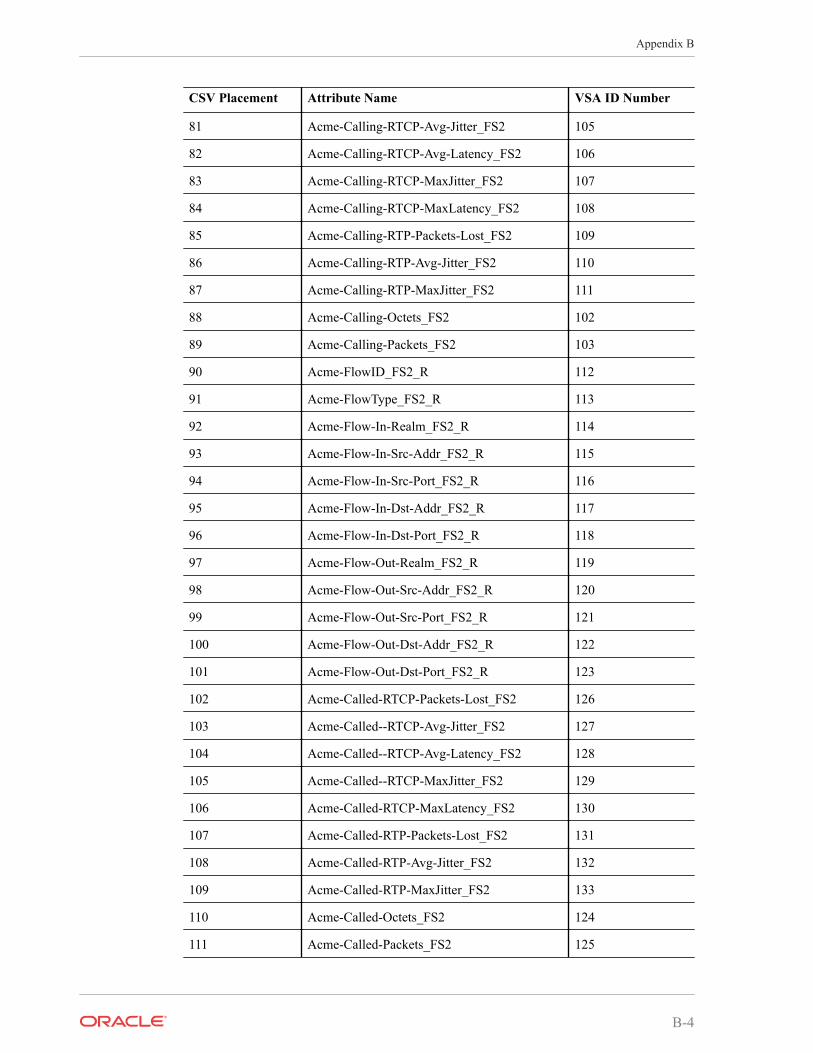
CSV Placement Attribute Name VSA ID Number
81 Acme-Calling-RTCP-Avg-Jitter_FS2 105
82 Acme-Calling-RTCP-Avg-Latency_FS2 106
83 Acme-Calling-RTCP-MaxJitter_FS2 107
84 Acme-Calling-RTCP-MaxLatency_FS2 108
85 Acme-Calling-RTP-Packets-Lost_FS2 109
86 Acme-Calling-RTP-Avg-Jitter_FS2 110
87 Acme-Calling-RTP-MaxJitter_FS2 111
88 Acme-Calling-Octets_FS2 102
89 Acme-Calling-Packets_FS2 103
90 Acme-FlowID_FS2_R 112
91 Acme-FlowType_FS2_R 113
92 Acme-Flow-In-Realm_FS2_R 114
93 Acme-Flow-In-Src-Addr_FS2_R 115
94 Acme-Flow-In-Src-Port_FS2_R 116
95 Acme-Flow-In-Dst-Addr_FS2_R 117
96 Acme-Flow-In-Dst-Port_FS2_R 118
97 Acme-Flow-Out-Realm_FS2_R 119
98 Acme-Flow-Out-Src-Addr_FS2_R 120
99 Acme-Flow-Out-Src-Port_FS2_R 121
100 Acme-Flow-Out-Dst-Addr_FS2_R 122
101 Acme-Flow-Out-Dst-Port_FS2_R 123
102 Acme-Called-RTCP-Packets-Lost_FS2 126
103 Acme-Called--RTCP-Avg-Jitter_FS2 127
104 Acme-Called--RTCP-Avg-Latency_FS2 128
105 Acme-Called--RTCP-MaxJitter_FS2 129
106 Acme-Called-RTCP-MaxLatency_FS2 130
107 Acme-Called-RTP-Packets-Lost_FS2 131
108 Acme-Called-RTP-Avg-Jitter_FS2 132
109 Acme-Called-RTP-MaxJitter_FS2 133
110 Acme-Called-Octets_FS2 124
111 Acme-Called-Packets_FS2 125
Appendix B
B-4
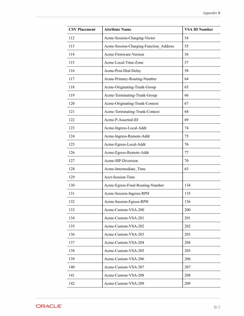
CSV Placement Attribute Name VSA ID Number
112 Acme-Session-Charging-Vector 54
113 Acme-Session-Charging-Function_Address 55
114 Acme-Firmware-Version 56
115 Acme-Local-Time-Zone 57
116 Acme-Post-Dial-Delay 58
117 Acme-Primary-Routing-Number 64
118 Acme-Originating-Trunk-Group 65
119 Acme-Terminating-Trunk-Group 66
120 Acme-Originating-Trunk-Context 67
121 Acme-Terminating-Trunk-Context 68
122 Acme-P-Asserted-ID 69
123 Acme-Ingress-Local-Addr 74
124 Acme-Ingress-Remote-Addr 75
125 Acme-Egress-Local-Addr 76
126 Acme-Egress-Remote-Addr 77
127 Acme-SIP-Diversion 70
128 Acme-Intermediate_Time 63
129 Acct-Session-Time
130 Acme-Egress-Final-Routing-Number 134
131 Acme-Session-Ingress-RPH 135
132 Acme-Session-Egress-RPH 136
133 Acme-Custom-VSA-200 200
134 Acme-Custom-VSA-201 201
135 Acme-Custom-VSA-202 202
136 Acme-Custom-VSA-203 203
137 Acme-Custom-VSA-204 204
138 Acme-Custom-VSA-205 205
139 Acme-Custom-VSA-206 206
140 Acme-Custom-VSA-207 207
141 Acme-Custom-VSA-208 208
142 Acme-Custom-VSA-209 209
Appendix B
B-5
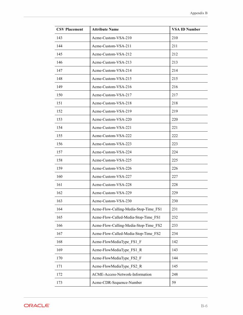
CSV Placement Attribute Name VSA ID Number
143 Acme-Custom-VSA-210 210
144 Acme-Custom-VSA-211 211
145 Acme-Custom-VSA-212 212
146 Acme-Custom-VSA-213 213
147 Acme-Custom-VSA-214 214
148 Acme-Custom-VSA-215 215
149 Acme-Custom-VSA-216 216
150 Acme-Custom-VSA-217 217
151 Acme-Custom-VSA-218 218
152 Acme-Custom-VSA-219 219
153 Acme-Custom-VSA-220 220
154 Acme-Custom-VSA-221 221
155 Acme-Custom-VSA-222 222
156 Acme-Custom-VSA-223 223
157 Acme-Custom-VSA-224 224
158 Acme-Custom-VSA-225 225
159 Acme-Custom-VSA-226 226
160 Acme-Custom-VSA-227 227
161 Acme-Custom-VSA-228 228
162 Acme-Custom-VSA-229 229
163 Acme-Custom-VSA-230 230
164 Acme-Flow-Calling-Media-Stop-Time_FS1 231
165 Acme-Flow-Called-Media-Stop-Time_FS1 232
166 Acme-Flow-Calling-Media-Stop-Time_FS2 233
167 Acme-Flow-Called-Media-Stop-Time_FS2 234
168 Acme-FlowMediaType_FS1_F 142
169 Acme-FlowMediaType_FS1_R 143
170 Acme-FlowMediaType_FS2_F 144
171 Acme-FlowMediaType_FS2_R 145
172 ACME-Access-Network-Information 248
173 Acme-CDR-Sequence-Number 59
Appendix B
B-6
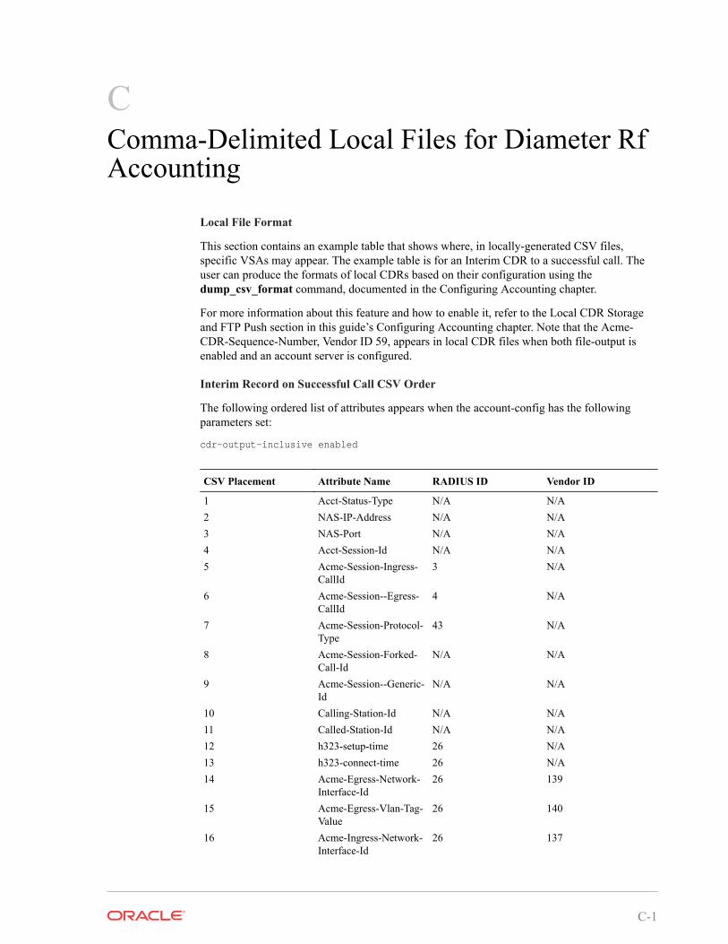
CComma-Delimited Local Files for Diameter RfAccounting
Local File Format
This section contains an example table that shows where, in locally-generated CSV files,specific VSAs may appear. The example table is for an Interim CDR to a successful call. Theuser can produce the formats of local CDRs based on their configuration using thedump_csv_format command, documented in the Configuring Accounting chapter.
For more information about this feature and how to enable it, refer to the Local CDR Storageand FTP Push section in this guide’s Configuring Accounting chapter. Note that the Acme-CDR-Sequence-Number, Vendor ID 59, appears in local CDR files when both file-output isenabled and an account server is configured.
Interim Record on Successful Call CSV Order
The following ordered list of attributes appears when the account-config has the followingparameters set:
cdr-output-inclusive enabled
CSV Placement Attribute Name RADIUS ID Vendor ID
1 Acct-Status-Type N/A N/A2 NAS-IP-Address N/A N/A3 NAS-Port N/A N/A4 Acct-Session-Id N/A N/A5 Acme-Session-Ingress-
CallId3 N/A
6 Acme-Session--Egress-CallId
4 N/A
7 Acme-Session-Protocol-Type
43 N/A
8 Acme-Session-Forked-Call-Id
N/A N/A
9 Acme-Session--Generic-Id
N/A N/A
10 Calling-Station-Id N/A N/A11 Called-Station-Id N/A N/A12 h323-setup-time 26 N/A13 h323-connect-time 26 N/A14 Acme-Egress-Network-
Interface-Id26 139
15 Acme-Egress-Vlan-Tag-Value
26 140
16 Acme-Ingress-Network-Interface-Id
26 137
C-1
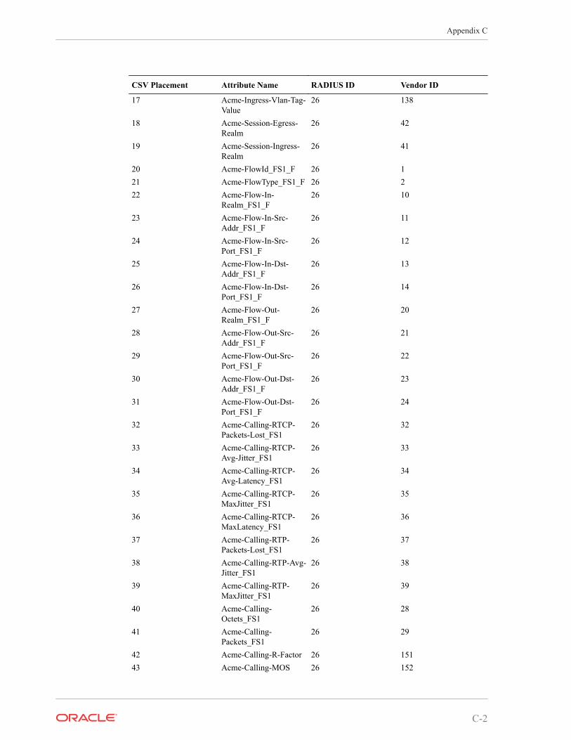
CSV Placement Attribute Name RADIUS ID Vendor ID
17 Acme-Ingress-Vlan-Tag-Value
26 138
18 Acme-Session-Egress-Realm
26 42
19 Acme-Session-Ingress-Realm
26 41
20 Acme-FlowId_FS1_F 26 121 Acme-FlowType_FS1_F 26 222 Acme-Flow-In-
Realm_FS1_F26 10
23 Acme-Flow-In-Src-Addr_FS1_F
26 11
24 Acme-Flow-In-Src-Port_FS1_F
26 12
25 Acme-Flow-In-Dst-Addr_FS1_F
26 13
26 Acme-Flow-In-Dst-Port_FS1_F
26 14
27 Acme-Flow-Out-Realm_FS1_F
26 20
28 Acme-Flow-Out-Src-Addr_FS1_F
26 21
29 Acme-Flow-Out-Src-Port_FS1_F
26 22
30 Acme-Flow-Out-Dst-Addr_FS1_F
26 23
31 Acme-Flow-Out-Dst-Port_FS1_F
26 24
32 Acme-Calling-RTCP-Packets-Lost_FS1
26 32
33 Acme-Calling-RTCP-Avg-Jitter_FS1
26 33
34 Acme-Calling-RTCP-Avg-Latency_FS1
26 34
35 Acme-Calling-RTCP-MaxJitter_FS1
26 35
36 Acme-Calling-RTCP-MaxLatency_FS1
26 36
37 Acme-Calling-RTP-Packets-Lost_FS1
26 37
38 Acme-Calling-RTP-Avg-Jitter_FS1
26 38
39 Acme-Calling-RTP-MaxJitter_FS1
26 39
40 Acme-Calling-Octets_FS1
26 28
41 Acme-Calling-Packets_FS1
26 29
42 Acme-Calling-R-Factor 26 15143 Acme-Calling-MOS 26 152
Appendix C
C-2
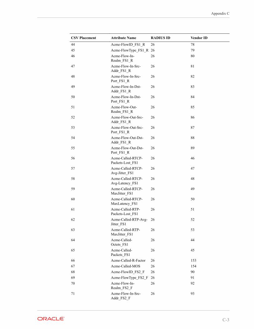
CSV Placement Attribute Name RADIUS ID Vendor ID
44 Acme-FlowID_FS1_R 26 7845 Acme-FlowType_FS1_R 26 7946 Acme-Flow-In-
Realm_FS1_R26 80
47 Acme-Flow-In-Src-Addr_FS1_R
26 81
48 Acme-Flow-In-Src-Port_FS1_R
26 82
49 Acme-Flow-In-Dst-Addr_FS1_R
26 83
50 Acme-Flow-In-Dst-Port_FS1_R
26 84
51 Acme-Flow-Out-Realm_FS1_R
26 85
52 Acme-Flow-Out-Src-Addr_FS1_R
26 86
53 Acme-Flow-Out-Src-Port_FS1_R
26 87
54 Acme-Flow-Out-Dst-Addr_FS1_R
26 88
55 Acme-Flow-Out-Dst-Port_FS1_R
26 89
56 Acme-Called-RTCP-Packets-Lost_FS1
26 46
57 Acme-Called-RTCP-Avg-Jitter_FS1
26 47
58 Acme-Called-RTCP-Avg-Latency_FS1
26 48
59 Acme-Called-RTCP-MaxJitter_FS1
26 49
60 Acme-Called-RTCP-MaxLatency_FS1
26 50
61 Acme-Called-RTP-Packets-Lost_FS1
26 51
62 Acme-Called-RTP-Avg-Jitter_FS1
26 52
63 Acme-Called-RTP-MaxJitter_FS1
26 53
64 Acme-Called-Octets_FS1
26 44
65 Acme-Called-Packets_FS1
26 45
66 Acme-Called-R-Factor 26 15367 Acme-Called-MOS 26 15468 Acme-FlowID_FS2_F 26 9069 Acme-FlowType_FS2_F 26 9170 Acme-Flow-In-
Realm_FS2_F26 92
71 Acme-Flow-In-Src-Addr_FS2_F
26 93
Appendix C
C-3
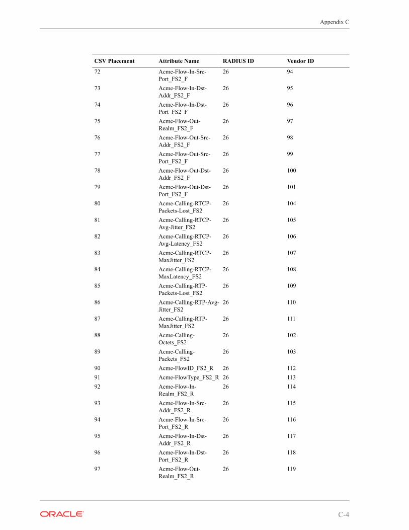
CSV Placement Attribute Name RADIUS ID Vendor ID
72 Acme-Flow-In-Src-Port_FS2_F
26 94
73 Acme-Flow-In-Dst-Addr_FS2_F
26 95
74 Acme-Flow-In-Dst-Port_FS2_F
26 96
75 Acme-Flow-Out-Realm_FS2_F
26 97
76 Acme-Flow-Out-Src-Addr_FS2_F
26 98
77 Acme-Flow-Out-Src-Port_FS2_F
26 99
78 Acme-Flow-Out-Dst-Addr_FS2_F
26 100
79 Acme-Flow-Out-Dst-Port_FS2_F
26 101
80 Acme-Calling-RTCP-Packets-Lost_FS2
26 104
81 Acme-Calling-RTCP-Avg-Jitter_FS2
26 105
82 Acme-Calling-RTCP-Avg-Latency_FS2
26 106
83 Acme-Calling-RTCP-MaxJitter_FS2
26 107
84 Acme-Calling-RTCP-MaxLatency_FS2
26 108
85 Acme-Calling-RTP-Packets-Lost_FS2
26 109
86 Acme-Calling-RTP-Avg-Jitter_FS2
26 110
87 Acme-Calling-RTP-MaxJitter_FS2
26 111
88 Acme-Calling-Octets_FS2
26 102
89 Acme-Calling-Packets_FS2
26 103
90 Acme-FlowID_FS2_R 26 11291 Acme-FlowType_FS2_R 26 11392 Acme-Flow-In-
Realm_FS2_R26 114
93 Acme-Flow-In-Src-Addr_FS2_R
26 115
94 Acme-Flow-In-Src-Port_FS2_R
26 116
95 Acme-Flow-In-Dst-Addr_FS2_R
26 117
96 Acme-Flow-In-Dst-Port_FS2_R
26 118
97 Acme-Flow-Out-Realm_FS2_R
26 119
Appendix C
C-4
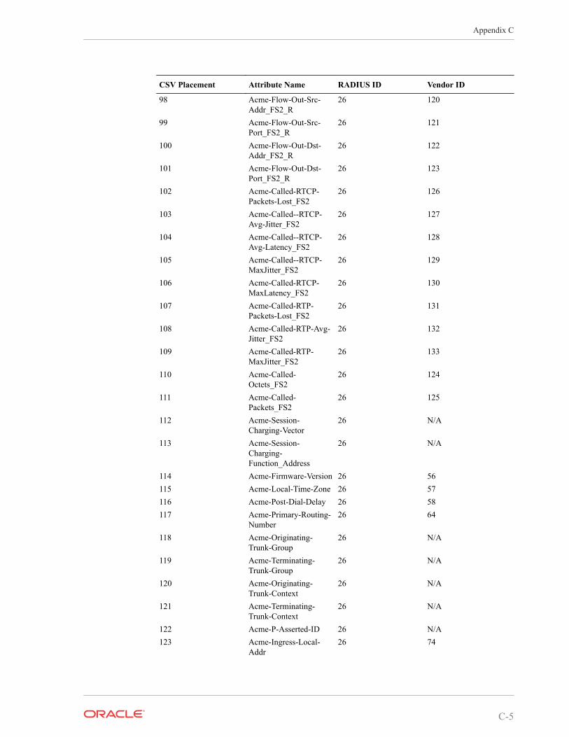
CSV Placement Attribute Name RADIUS ID Vendor ID
98 Acme-Flow-Out-Src-Addr_FS2_R
26 120
99 Acme-Flow-Out-Src-Port_FS2_R
26 121
100 Acme-Flow-Out-Dst-Addr_FS2_R
26 122
101 Acme-Flow-Out-Dst-Port_FS2_R
26 123
102 Acme-Called-RTCP-Packets-Lost_FS2
26 126
103 Acme-Called--RTCP-Avg-Jitter_FS2
26 127
104 Acme-Called--RTCP-Avg-Latency_FS2
26 128
105 Acme-Called--RTCP-MaxJitter_FS2
26 129
106 Acme-Called-RTCP-MaxLatency_FS2
26 130
107 Acme-Called-RTP-Packets-Lost_FS2
26 131
108 Acme-Called-RTP-Avg-Jitter_FS2
26 132
109 Acme-Called-RTP-MaxJitter_FS2
26 133
110 Acme-Called-Octets_FS2
26 124
111 Acme-Called-Packets_FS2
26 125
112 Acme-Session-Charging-Vector
26 N/A
113 Acme-Session-Charging-Function_Address
26 N/A
114 Acme-Firmware-Version 26 56115 Acme-Local-Time-Zone 26 57116 Acme-Post-Dial-Delay 26 58117 Acme-Primary-Routing-
Number26 64
118 Acme-Originating-Trunk-Group
26 N/A
119 Acme-Terminating-Trunk-Group
26 N/A
120 Acme-Originating-Trunk-Context
26 N/A
121 Acme-Terminating-Trunk-Context
26 N/A
122 Acme-P-Asserted-ID 26 N/A123 Acme-Ingress-Local-
Addr26 74
Appendix C
C-5
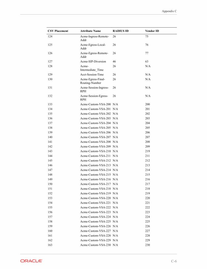
CSV Placement Attribute Name RADIUS ID Vendor ID
124 Acme-Ingress-Remote-Addr
26 75
125 Acme-Egress-Local-Addr
26 76
126 Acme-Egress-Remote-Addr
26 77
127 Acme-SIP-Diversion 46 63128 Acme-
Intermediate_Time26 N/A
129 Acct-Session-Time 26 N/A130 Acme-Egress-Final-
Routing-Number26 N/A
131 Acme-Session-Ingress-RPH
26 N/A
132 Acme-Session-Egress-RPH
26 N/A
133 Acme-Custom-VSA-200 N/A 200134 Acme-Custom-VSA-201 N/A 201135 Acme-Custom-VSA-202 N/A 202136 Acme-Custom-VSA-203 N/A 203137 Acme-Custom-VSA-204 N/A 204138 Acme-Custom-VSA-205 N/A 205139 Acme-Custom-VSA-206 N/A 206140 Acme-Custom-VSA-207 N/A 207141 Acme-Custom-VSA-208 N/A 208142 Acme-Custom-VSA-209 N/A 209143 Acme-Custom-VSA-210 N/A 219144 Acme-Custom-VSA-211 N/A 211145 Acme-Custom-VSA-212 N/A 212146 Acme-Custom-VSA-213 N/A 213147 Acme-Custom-VSA-214 N/A 214148 Acme-Custom-VSA-215 N/A 215149 Acme-Custom-VSA-216 N/A 216150 Acme-Custom-VSA-217 N/A 217151 Acme-Custom-VSA-218 N/A 218152 Acme-Custom-VSA-219 N/A 219153 Acme-Custom-VSA-220 N/A 220154 Acme-Custom-VSA-221 N/A 221155 Acme-Custom-VSA-222 N/A 222156 Acme-Custom-VSA-223 N/A 223157 Acme-Custom-VSA-224 N/A 224158 Acme-Custom-VSA-225 N/A 225159 Acme-Custom-VSA-226 N/A 226160 Acme-Custom-VSA-227 N/A 227161 Acme-Custom-VSA-228 N/A 228162 Acme-Custom-VSA-229 N/A 229163 Acme-Custom-VSA-230 N/A 230
Appendix C
C-6
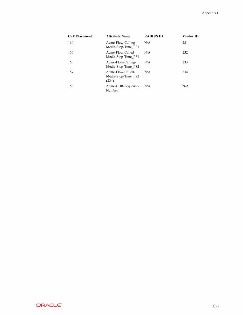
CSV Placement Attribute Name RADIUS ID Vendor ID
164 Acme-Flow-Calling-Media-Stop-Time_FS1
N/A 231
165 Acme-Flow-Called-Media-Stop-Time_FS1
N/A 232
166 Acme-Flow-Calling-Media-Stop-Time_FS2
N/A 233
167 Acme-Flow-Called-Media-Stop-Time_FS2(234)
N/A 234
168 Acme-CDR-Sequence-Number
N/A N/A
Appendix C
C-7
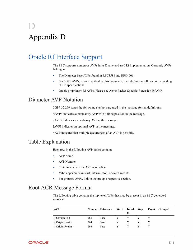
DAppendix D
Oracle Rf Interface SupportThe SBC supports numerous AVPs in its Diameter-based Rf implementation. Currently AVPsbelong to:
• The Diameter base AVPs found in RFC3588 and RFC4006.
• For 3GPP AVPs, if not specified by this document, their definition follows corresponding3GPP specifications.
• Oracle proprietary Rf AVPs. Please see Acme-Packet-Specific-Extension-Rf AVP.
Diameter AVP Notation3GPP 32.299 states the following symbols are used in the message format definitions:
<AVP> indicates a mandatory AVP with a fixed position in the message.
{AVP} indicates a mandatory AVP in the message.
[AVP] indicates an optional AVP in the message.
*AVP indicates that multiple occurrences of an AVP is possible.
Table ExplanationEach row in the following AVP tables contain:
• AVP Name
• AVP Number
• Reference where the AVP was defined
• Valid appearance in start, interim, stop, or event records
• For grouped AVPs, link to the group’s respective section.
Root ACR Message FormatThe following table contains the top level AVPs that may be present in an SBC-generatedmessage.
AVP Number Reference Start Interim
Stop Event Grouped
{ Session-Id } 263 Base Y Y Y Y{ Origin-Host } 264 Base Y Y Y Y{ Origin-Realm } 296 Base Y Y Y Y
D-1
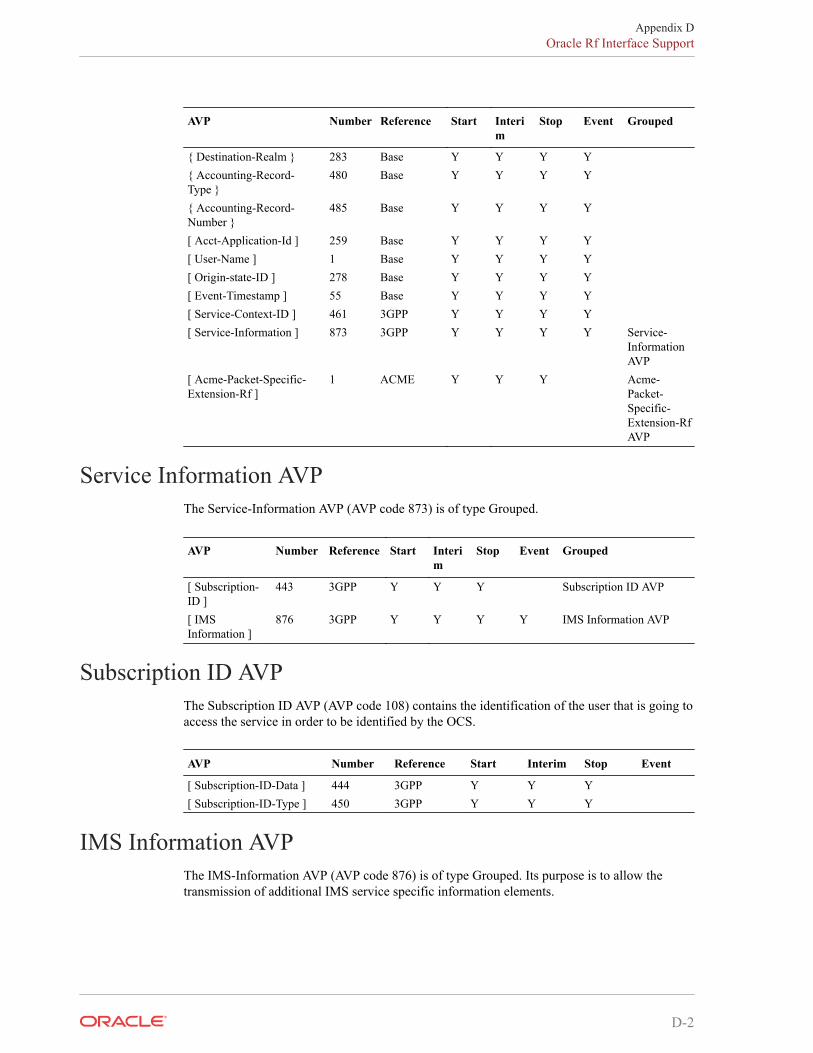
AVP Number Reference Start Interim
Stop Event Grouped
{ Destination-Realm } 283 Base Y Y Y Y{ Accounting-Record-Type }
480 Base Y Y Y Y
{ Accounting-Record-Number }
485 Base Y Y Y Y
[ Acct-Application-Id ] 259 Base Y Y Y Y[ User-Name ] 1 Base Y Y Y Y[ Origin-state-ID ] 278 Base Y Y Y Y[ Event-Timestamp ] 55 Base Y Y Y Y[ Service-Context-ID ] 461 3GPP Y Y Y Y[ Service-Information ] 873 3GPP Y Y Y Y Service-
InformationAVP
[ Acme-Packet-Specific-Extension-Rf ]
1 ACME Y Y Y Acme-Packet-Specific-Extension-RfAVP
Service Information AVPThe Service-Information AVP (AVP code 873) is of type Grouped.
AVP Number Reference Start Interim
Stop Event Grouped
[ Subscription-ID ]
443 3GPP Y Y Y Subscription ID AVP
[ IMSInformation ]
876 3GPP Y Y Y Y IMS Information AVP
Subscription ID AVPThe Subscription ID AVP (AVP code 108) contains the identification of the user that is going toaccess the service in order to be identified by the OCS.
AVP Number Reference Start Interim Stop Event
[ Subscription-ID-Data ] 444 3GPP Y Y Y[ Subscription-ID-Type ] 450 3GPP Y Y Y
IMS Information AVPThe IMS-Information AVP (AVP code 876) is of type Grouped. Its purpose is to allow thetransmission of additional IMS service specific information elements.
Appendix DOracle Rf Interface Support
D-2
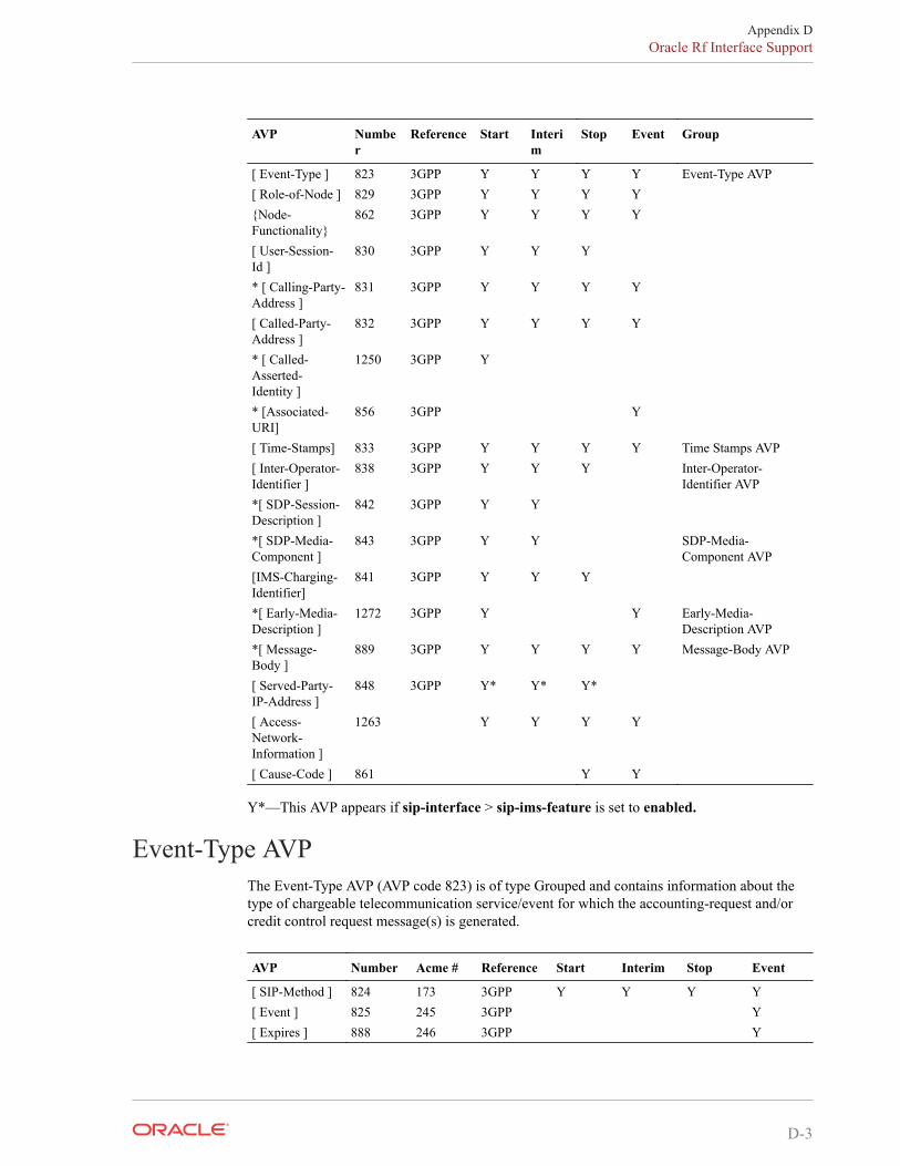
AVP Number
Reference Start Interim
Stop Event Group
[ Event-Type ] 823 3GPP Y Y Y Y Event-Type AVP[ Role-of-Node ] 829 3GPP Y Y Y Y{Node-Functionality}
862 3GPP Y Y Y Y
[ User-Session-Id ]
830 3GPP Y Y Y
* [ Calling-Party-Address ]
831 3GPP Y Y Y Y
[ Called-Party-Address ]
832 3GPP Y Y Y Y
* [ Called-Asserted-Identity ]
1250 3GPP Y
* [Associated-URI]
856 3GPP Y
[ Time-Stamps] 833 3GPP Y Y Y Y Time Stamps AVP[ Inter-Operator-Identifier ]
838 3GPP Y Y Y Inter-Operator-Identifier AVP
*[ SDP-Session-Description ]
842 3GPP Y Y
*[ SDP-Media-Component ]
843 3GPP Y Y SDP-Media-Component AVP
[IMS-Charging-Identifier]
841 3GPP Y Y Y
*[ Early-Media-Description ]
1272 3GPP Y Y Early-Media-Description AVP
*[ Message-Body ]
889 3GPP Y Y Y Y Message-Body AVP
[ Served-Party-IP-Address ]
848 3GPP Y* Y* Y*
[ Access-Network-Information ]
1263 Y Y Y Y
[ Cause-Code ] 861 Y Y
Y*—This AVP appears if sip-interface > sip-ims-feature is set to enabled.
Event-Type AVPThe Event-Type AVP (AVP code 823) is of type Grouped and contains information about thetype of chargeable telecommunication service/event for which the accounting-request and/orcredit control request message(s) is generated.
AVP Number Acme # Reference Start Interim Stop Event
[ SIP-Method ] 824 173 3GPP Y Y Y Y[ Event ] 825 245 3GPP Y[ Expires ] 888 246 3GPP Y
Appendix DOracle Rf Interface Support
D-3
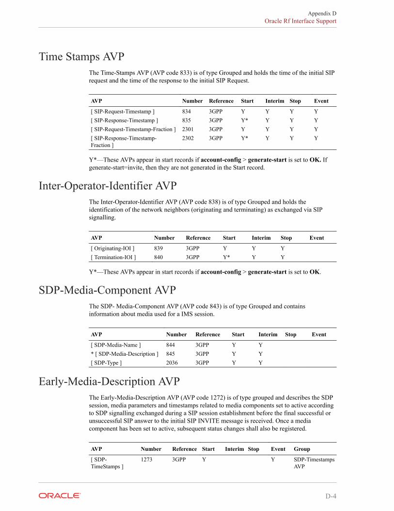
Time Stamps AVPThe Time-Stamps AVP (AVP code 833) is of type Grouped and holds the time of the initial SIPrequest and the time of the response to the initial SIP Request.
AVP Number Reference Start Interim Stop Event
[ SIP-Request-Timestamp ] 834 3GPP Y Y Y Y[ SIP-Response-Timestamp ] 835 3GPP Y* Y Y Y[ SIP-Request-Timestamp-Fraction ] 2301 3GPP Y Y Y Y[ SIP-Response-Timestamp-Fraction ]
2302 3GPP Y* Y Y Y
Y*—These AVPs appear in start records if account-config > generate-start is set to OK. Ifgenerate-start=invite, then they are not generated in the Start record.
Inter-Operator-Identifier AVPThe Inter-Operator-Identifier AVP (AVP code 838) is of type Grouped and holds theidentification of the network neighbors (originating and terminating) as exchanged via SIPsignalling.
AVP Number Reference Start Interim Stop Event
[ Originating-IOI ] 839 3GPP Y Y Y[ Termination-IOI ] 840 3GPP Y* Y Y
Y*—These AVPs appear in start records if account-config > generate-start is set to OK.
SDP-Media-Component AVPThe SDP- Media-Component AVP (AVP code 843) is of type Grouped and containsinformation about media used for a IMS session.
AVP Number Reference Start Interim Stop Event
[ SDP-Media-Name ] 844 3GPP Y Y* [ SDP-Media-Description ] 845 3GPP Y Y[ SDP-Type ] 2036 3GPP Y Y
Early-Media-Description AVPThe Early-Media-Description AVP (AVP code 1272) is of type grouped and describes the SDPsession, media parameters and timestamps related to media components set to active accordingto SDP signalling exchanged during a SIP session establishment before the final successful orunsuccessful SIP answer to the initial SIP INVITE message is received. Once a mediacomponent has been set to active, subsequent status changes shall also be registered.
AVP Number Reference Start Interim Stop Event Group
[ SDP-TimeStamps ]
1273 3GPP Y Y SDP-TimestampsAVP
Appendix DOracle Rf Interface Support
D-4
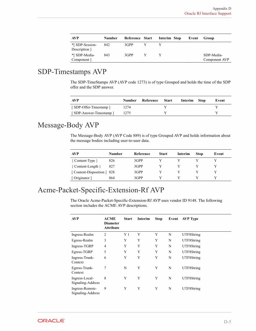
AVP Number Reference Start Interim Stop Event Group
*[ SDP-Session-Description ]
842 3GPP Y Y
*[ SDP-Media-Component ]
843 3GPP Y Y SDP-Media-Component AVP
SDP-Timestamps AVPThe SDP-TimeStamps AVP (AVP code 1273) is of type Grouped and holds the time of the SDPoffer and the SDP answer.
AVP Number Reference Start Interim Stop Event
[ SDP-Offer-Timestamp ] 1274 Y Y[ SDP-Answer-Timestamp ] 1275 Y Y
Message-Body AVPThe Message-Body AVP (AVP Code 889) is of type Grouped AVP and holds information aboutthe message bodies including user-to-user data.
AVP Number Reference Start Interim Stop Event
{ Content-Type } 826 3GPP Y Y Y Y{ Content-Length } 827 3GPP Y Y Y Y[ Content-Disposition ] 828 3GPP Y Y Y Y[ Originator ] 864 3GPP Y Y Y Y
Acme-Packet-Specific-Extension-Rf AVPThe Oracle Acme-Packet-Specific-Extension-Rf AVP uses vendor ID 9148. The followingsection includes the ACME AVP descriptions.
AVP ACMEDiameterAttribute
Start Interim Stop Event AVP Type
Ingress-Realm 2 Y 1 Y Y N UTF8StringEgress-Realm 3 Y Y Y N UTF8StringIngress-TGRP 4 Y Y Y N UTF8StringEgress-TGRP 5 Y Y Y N UTF8StringIngress-Trunk-Context
6 Y Y Y N UTF8String
Egress-Trunk-Context
7 N Y Y N UTF8String
Ingress-Local-Signaling-Address
8 Y Y Y N UTF8String
Ingress-Remote-Signaling-Address
9 Y Y Y N UTF8String
Appendix DOracle Rf Interface Support
D-5
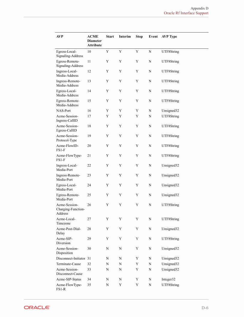
AVP ACMEDiameterAttribute
Start Interim Stop Event AVP Type
Egress-Local-Signaling-Address
10 Y Y Y N UTF8String
Egress-Remote-Signaling-Address
11 Y Y Y N UTF8String
Ingress-Local-Media-Address
12 Y Y Y N UTF8String
Ingress-Remote-Media-Address
13 Y Y Y N UTF8String
Egress-Local-Media-Address
14 Y Y Y N UTF8String
Egress-Remote-Media-Address
15 Y Y Y N UTF8String
NAS-Port 16 Y Y Y N Unsigned32Acme-Session-Ingress-CallID
17 Y Y Y N UTF8String
Acme-Session-Egress-CallID
18 Y Y Y N UTF8String
Acme-Session-Protocol-Type
19 Y Y Y N UTF8String
Acme-FlowID-FS1-F
20 Y Y Y N UTF8String
Acme-FlowType-FS1-F
21 Y Y Y N UTF8String
Ingress-Local-Media-Port
22 Y Y Y N Unsigned32
Ingress-Remote-Media-Port
23 Y Y Y N Unsigned32
Egress-Local-Media-Port
24 Y Y Y N Unsigned32
Egress-Remote-Media-Port
25 Y Y Y N Unsigned32
Acme-Session-Charging-Function-Address
26 Y Y Y N UTF8String
Acme-Local-Timezone
27 Y Y Y N UTF8String
Acme-Post-Dial-Delay
28 Y Y Y N Unsigned32
Acme-SIP-Diversion
29 Y Y Y N UTF8String
Acme-Session-Disposition
30 N N Y N Unsigned32
Disconnect-Initiator 31 N N Y N Unsigned32Terminate-Cause 32 N N Y N Unsigned32Acme-Session-Disconnect-Cause
33 N N Y N Unsigned32
Acme-SIP-Status 34 N N Y N Integer32Acme-FlowType-FS1-R
35 N Y Y N UTF8String
Appendix DOracle Rf Interface Support
D-6
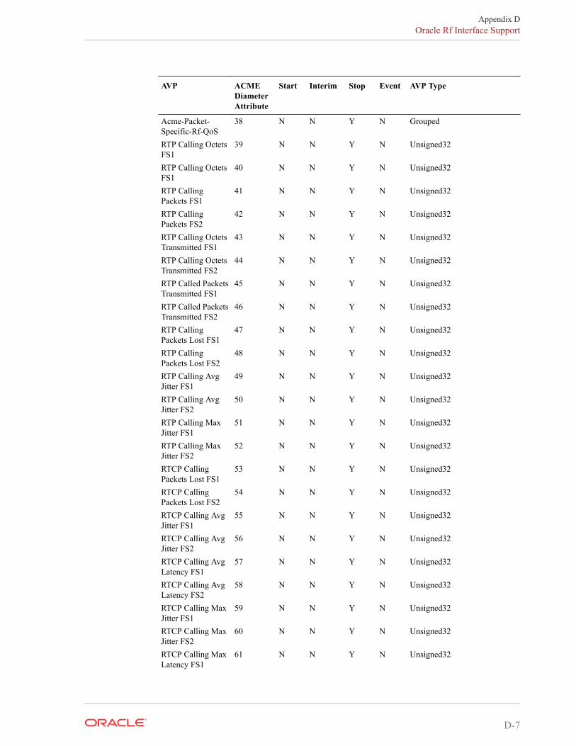
AVP ACMEDiameterAttribute
Start Interim Stop Event AVP Type
Acme-Packet-Specific-Rf-QoS
38 N N Y N Grouped
RTP Calling OctetsFS1
39 N N Y N Unsigned32
RTP Calling OctetsFS1
40 N N Y N Unsigned32
RTP CallingPackets FS1
41 N N Y N Unsigned32
RTP CallingPackets FS2
42 N N Y N Unsigned32
RTP Calling OctetsTransmitted FS1
43 N N Y N Unsigned32
RTP Calling OctetsTransmitted FS2
44 N N Y N Unsigned32
RTP Called PacketsTransmitted FS1
45 N N Y N Unsigned32
RTP Called PacketsTransmitted FS2
46 N N Y N Unsigned32
RTP CallingPackets Lost FS1
47 N N Y N Unsigned32
RTP CallingPackets Lost FS2
48 N N Y N Unsigned32
RTP Calling AvgJitter FS1
49 N N Y N Unsigned32
RTP Calling AvgJitter FS2
50 N N Y N Unsigned32
RTP Calling MaxJitter FS1
51 N N Y N Unsigned32
RTP Calling MaxJitter FS2
52 N N Y N Unsigned32
RTCP CallingPackets Lost FS1
53 N N Y N Unsigned32
RTCP CallingPackets Lost FS2
54 N N Y N Unsigned32
RTCP Calling AvgJitter FS1
55 N N Y N Unsigned32
RTCP Calling AvgJitter FS2
56 N N Y N Unsigned32
RTCP Calling AvgLatency FS1
57 N N Y N Unsigned32
RTCP Calling AvgLatency FS2
58 N N Y N Unsigned32
RTCP Calling MaxJitter FS1
59 N N Y N Unsigned32
RTCP Calling MaxJitter FS2
60 N N Y N Unsigned32
RTCP Calling MaxLatency FS1
61 N N Y N Unsigned32
Appendix DOracle Rf Interface Support
D-7
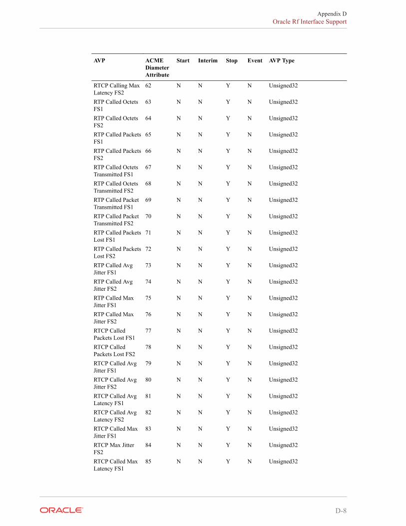
AVP ACMEDiameterAttribute
Start Interim Stop Event AVP Type
RTCP Calling MaxLatency FS2
62 N N Y N Unsigned32
RTP Called OctetsFS1
63 N N Y N Unsigned32
RTP Called OctetsFS2
64 N N Y N Unsigned32
RTP Called PacketsFS1
65 N N Y N Unsigned32
RTP Called PacketsFS2
66 N N Y N Unsigned32
RTP Called OctetsTransmitted FS1
67 N N Y N Unsigned32
RTP Called OctetsTransmitted FS2
68 N N Y N Unsigned32
RTP Called PacketTransmitted FS1
69 N N Y N Unsigned32
RTP Called PacketTransmitted FS2
70 N N Y N Unsigned32
RTP Called PacketsLost FS1
71 N N Y N Unsigned32
RTP Called PacketsLost FS2
72 N N Y N Unsigned32
RTP Called AvgJitter FS1
73 N N Y N Unsigned32
RTP Called AvgJitter FS2
74 N N Y N Unsigned32
RTP Called MaxJitter FS1
75 N N Y N Unsigned32
RTP Called MaxJitter FS2
76 N N Y N Unsigned32
RTCP CalledPackets Lost FS1
77 N N Y N Unsigned32
RTCP CalledPackets Lost FS2
78 N N Y N Unsigned32
RTCP Called AvgJitter FS1
79 N N Y N Unsigned32
RTCP Called AvgJitter FS2
80 N N Y N Unsigned32
RTCP Called AvgLatency FS1
81 N N Y N Unsigned32
RTCP Called AvgLatency FS2
82 N N Y N Unsigned32
RTCP Called MaxJitter FS1
83 N N Y N Unsigned32
RTCP Max JitterFS2
84 N N Y N Unsigned32
RTCP Called MaxLatency FS1
85 N N Y N Unsigned32
Appendix DOracle Rf Interface Support
D-8
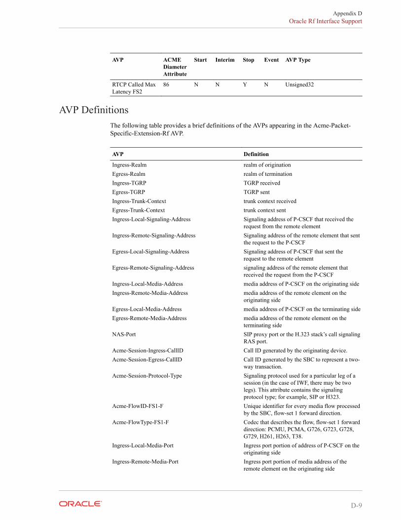
AVP ACMEDiameterAttribute
Start Interim Stop Event AVP Type
RTCP Called MaxLatency FS2
86 N N Y N Unsigned32
AVP DefinitionsThe following table provides a brief definitions of the AVPs appearing in the Acme-Packet-Specific-Extension-Rf AVP.
AVP Definition
Ingress-Realm realm of originationEgress-Realm realm of terminationIngress-TGRP TGRP receivedEgress-TGRP TGRP sentIngress-Trunk-Context trunk context receivedEgress-Trunk-Context trunk context sentIngress-Local-Signaling-Address Signaling address of P-CSCF that received the
request from the remote elementIngress-Remote-Signaling-Address Signaling address of the remote element that sent
the request to the P-CSCFEgress-Local-Signaling-Address Signaling address of P-CSCF that sent the
request to the remote elementEgress-Remote-Signaling-Address signaling address of the remote element that
received the request from the P-CSCFIngress-Local-Media-Address media address of P-CSCF on the originating sideIngress-Remote-Media-Address media address of the remote element on the
originating sideEgress-Local-Media-Address media address of P-CSCF on the terminating sideEgress-Remote-Media-Address media address of the remote element on the
terminating sideNAS-Port SIP proxy port or the H.323 stack’s call signaling
RAS port.Acme-Session-Ingress-CallID Call ID generated by the originating device.Acme-Session-Egress-CallID Call ID generated by the SBC to represent a two-
way transaction.Acme-Session-Protocol-Type Signaling protocol used for a particular leg of a
session (in the case of IWF, there may be twolegs). This attribute contains the signalingprotocol type; for example, SIP or H323.
Acme-FlowID-FS1-F Unique identifier for every media flow processedby the SBC, flow-set 1 forward direction.
Acme-FlowType-FS1-F Codec that describes the flow, flow-set 1 forwarddirection: PCMU, PCMA, G726, G723, G728,G729, H261, H263, T38.
Ingress-Local-Media-Port Ingress port portion of address of P-CSCF on theoriginating side
Ingress-Remote-Media-Port Ingress port portion of media address of theremote element on the originating side
Appendix DOracle Rf Interface Support
D-9
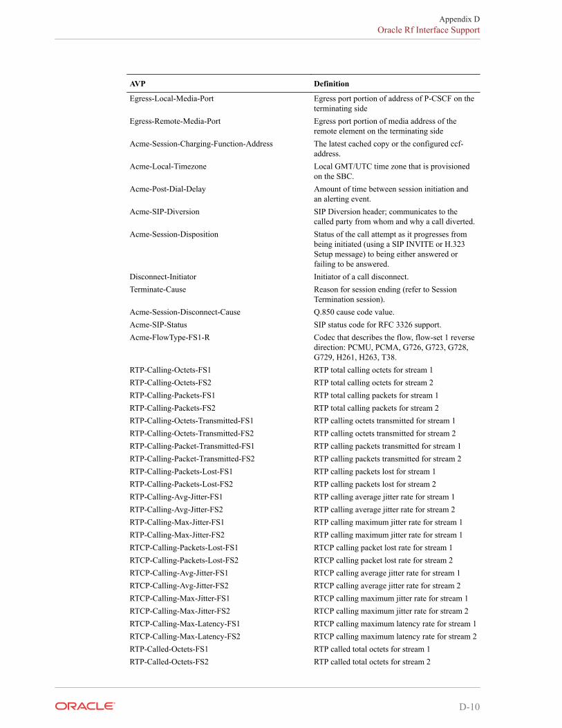
AVP Definition
Egress-Local-Media-Port Egress port portion of address of P-CSCF on theterminating side
Egress-Remote-Media-Port Egress port portion of media address of theremote element on the terminating side
Acme-Session-Charging-Function-Address The latest cached copy or the configured ccf-address.
Acme-Local-Timezone Local GMT/UTC time zone that is provisionedon the SBC.
Acme-Post-Dial-Delay Amount of time between session initiation andan alerting event.
Acme-SIP-Diversion SIP Diversion header; communicates to thecalled party from whom and why a call diverted.
Acme-Session-Disposition Status of the call attempt as it progresses frombeing initiated (using a SIP INVITE or H.323Setup message) to being either answered orfailing to be answered.
Disconnect-Initiator Initiator of a call disconnect.Terminate-Cause Reason for session ending (refer to Session
Termination session).Acme-Session-Disconnect-Cause Q.850 cause code value.Acme-SIP-Status SIP status code for RFC 3326 support.Acme-FlowType-FS1-R Codec that describes the flow, flow-set 1 reverse
direction: PCMU, PCMA, G726, G723, G728,G729, H261, H263, T38.
RTP-Calling-Octets-FS1 RTP total calling octets for stream 1RTP-Calling-Octets-FS2 RTP total calling octets for stream 2RTP-Calling-Packets-FS1 RTP total calling packets for stream 1RTP-Calling-Packets-FS2 RTP total calling packets for stream 2RTP-Calling-Octets-Transmitted-FS1 RTP calling octets transmitted for stream 1RTP-Calling-Octets-Transmitted-FS2 RTP calling octets transmitted for stream 2RTP-Calling-Packet-Transmitted-FS1 RTP calling packets transmitted for stream 1RTP-Calling-Packet-Transmitted-FS2 RTP calling packets transmitted for stream 2RTP-Calling-Packets-Lost-FS1 RTP calling packets lost for stream 1RTP-Calling-Packets-Lost-FS2 RTP calling packets lost for stream 2RTP-Calling-Avg-Jitter-FS1 RTP calling average jitter rate for stream 1RTP-Calling-Avg-Jitter-FS2 RTP calling average jitter rate for stream 2RTP-Calling-Max-Jitter-FS1 RTP calling maximum jitter rate for stream 1RTP-Calling-Max-Jitter-FS2 RTP calling maximum jitter rate for stream 1RTCP-Calling-Packets-Lost-FS1 RTCP calling packet lost rate for stream 1RTCP-Calling-Packets-Lost-FS2 RTCP calling packet lost rate for stream 2RTCP-Calling-Avg-Jitter-FS1 RTCP calling average jitter rate for stream 1RTCP-Calling-Avg-Jitter-FS2 RTCP calling average jitter rate for stream 2RTCP-Calling-Max-Jitter-FS1 RTCP calling maximum jitter rate for stream 1RTCP-Calling-Max-Jitter-FS2 RTCP calling maximum jitter rate for stream 2RTCP-Calling-Max-Latency-FS1 RTCP calling maximum latency rate for stream 1RTCP-Calling-Max-Latency-FS2 RTCP calling maximum latency rate for stream 2RTP-Called-Octets-FS1 RTP called total octets for stream 1RTP-Called-Octets-FS2 RTP called total octets for stream 2
Appendix DOracle Rf Interface Support
D-10
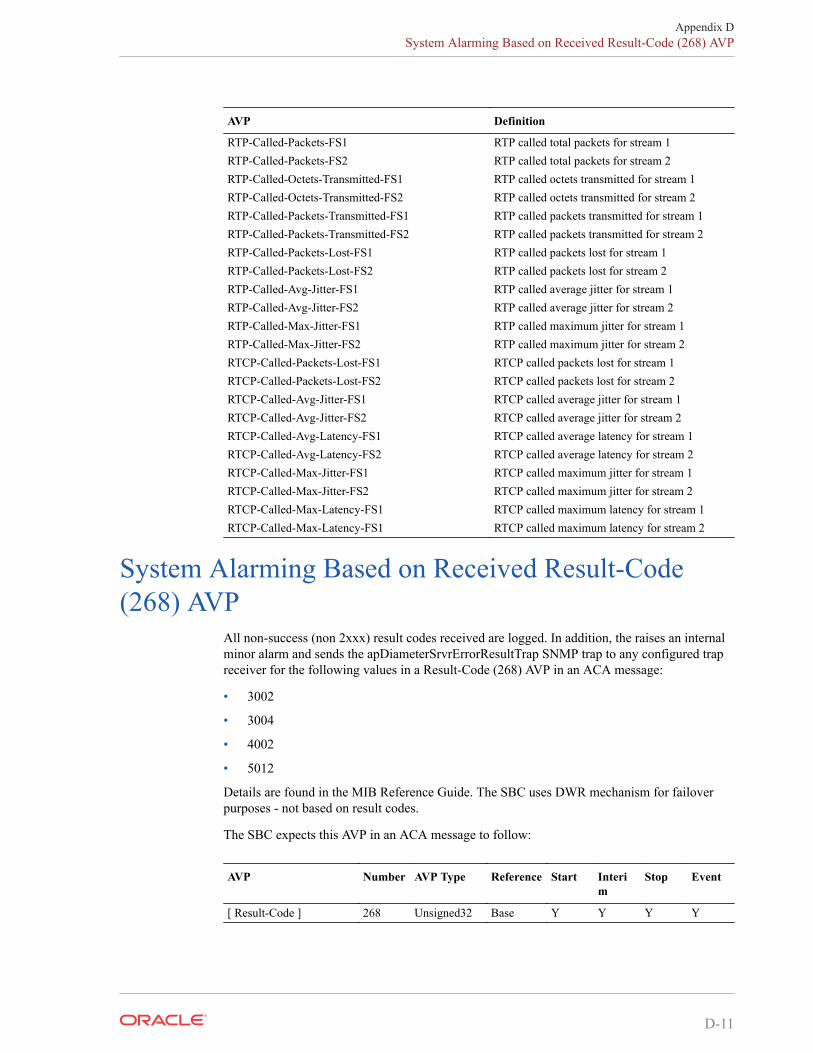
AVP Definition
RTP-Called-Packets-FS1 RTP called total packets for stream 1RTP-Called-Packets-FS2 RTP called total packets for stream 2RTP-Called-Octets-Transmitted-FS1 RTP called octets transmitted for stream 1RTP-Called-Octets-Transmitted-FS2 RTP called octets transmitted for stream 2RTP-Called-Packets-Transmitted-FS1 RTP called packets transmitted for stream 1RTP-Called-Packets-Transmitted-FS2 RTP called packets transmitted for stream 2RTP-Called-Packets-Lost-FS1 RTP called packets lost for stream 1RTP-Called-Packets-Lost-FS2 RTP called packets lost for stream 2RTP-Called-Avg-Jitter-FS1 RTP called average jitter for stream 1RTP-Called-Avg-Jitter-FS2 RTP called average jitter for stream 2RTP-Called-Max-Jitter-FS1 RTP called maximum jitter for stream 1RTP-Called-Max-Jitter-FS2 RTP called maximum jitter for stream 2RTCP-Called-Packets-Lost-FS1 RTCP called packets lost for stream 1RTCP-Called-Packets-Lost-FS2 RTCP called packets lost for stream 2RTCP-Called-Avg-Jitter-FS1 RTCP called average jitter for stream 1RTCP-Called-Avg-Jitter-FS2 RTCP called average jitter for stream 2RTCP-Called-Avg-Latency-FS1 RTCP called average latency for stream 1RTCP-Called-Avg-Latency-FS2 RTCP called average latency for stream 2RTCP-Called-Max-Jitter-FS1 RTCP called maximum jitter for stream 1RTCP-Called-Max-Jitter-FS2 RTCP called maximum jitter for stream 2RTCP-Called-Max-Latency-FS1 RTCP called maximum latency for stream 1RTCP-Called-Max-Latency-FS1 RTCP called maximum latency for stream 2
System Alarming Based on Received Result-Code(268) AVP
All non-success (non 2xxx) result codes received are logged. In addition, the raises an internalminor alarm and sends the apDiameterSrvrErrorResultTrap SNMP trap to any configured trapreceiver for the following values in a Result-Code (268) AVP in an ACA message:
• 3002
• 3004
• 4002
• 5012
Details are found in the MIB Reference Guide. The SBC uses DWR mechanism for failoverpurposes - not based on result codes.
The SBC expects this AVP in an ACA message to follow:
AVP Number AVP Type Reference Start Interim
Stop Event
[ Result-Code ] 268 Unsigned32 Base Y Y Y Y
Appendix DSystem Alarming Based on Received Result-Code (268) AVP
D-11
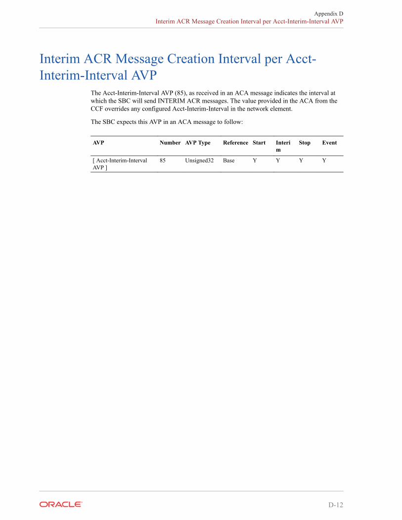
Interim ACR Message Creation Interval per Acct-Interim-Interval AVP
The Acct-Interim-Interval AVP (85), as received in an ACA message indicates the interval atwhich the SBC will send INTERIM ACR messages. The value provided in the ACA from theCCF overrides any configured Acct-Interim-Interval in the network element.
The SBC expects this AVP in an ACA message to follow:
AVP Number AVP Type Reference Start Interim
Stop Event
[ Acct-Interim-IntervalAVP ]
85 Unsigned32 Base Y Y Y Y
Appendix DInterim ACR Message Creation Interval per Acct-Interim-Interval AVP
D-12