Embed Size (px)
Citation preview
Booster 15Hz Operation
John Reid
March 4, 2014
Fermilab March 4, 2014 J. Reid 2
Scope
• Brief History of Booster RF systems
• RF system description
• Modifications over the years
• Booster Solid State RF upgrade project.
• Upgrades required to achieve 15 Hz beam operation.
• Booster RF cavity
• Other RF issues.
• Summary
Fermilab
Brief History
• Booster cavity design started at Lawrence Radiation
Laboratory in the 1960’s.
• Comprehensive study to evaluate ferrite toroid
manufactures with specific properties suitable for
electronic tuning a coaxial accelerating cavity over a
frequency range of 30Mhz to 52.8MHz. Toroid size: 8”
OD x 5” ID x 1” thick.
• Settled on NiZn toroids manufactured by Stackpole
(mu=12) & & Toshiba (mu=40).
• Producton cavites & tuners built by GE in
Schenectady, NY
March 4, 2014 J. Reid 3
Fermilab
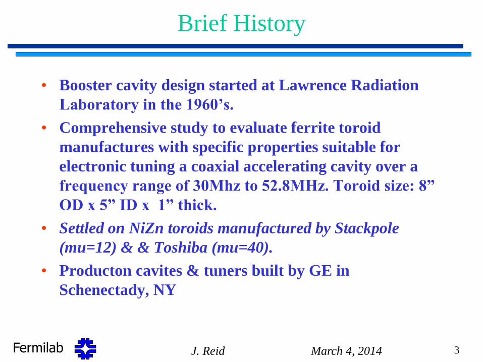
Booster RF Cavity Pair Delivery X-Gallery
March 4, 2014 J. Reid 4
July 1970
Flatbed semi
delivering
Booster RF
cavity pair
with original
one piece
girder to X-
Gallery.
Fermilab
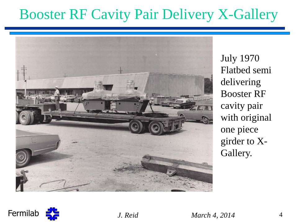
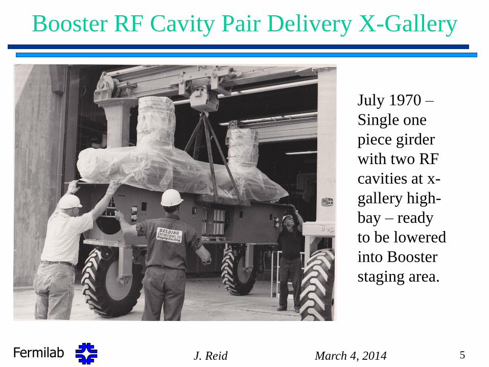
Booster RF Cavity Pair Delivery X-Gallery
March 4, 2014 J. Reid 5
July 1970 –
Single one
piece girder
with two RF
cavities at x-
gallery high-
bay – ready
to be lowered
into Booster
staging area.
Fermilab
RF System Description
• Normally 19 High level RF stations installed and operational but
with current cavity refurbishment only have 17 stations active.
• Typical RF station consists of a fast slewing 0 to 2500 Amp Ferrite
Bias Supply, 30 kV Series tube modulator, 150 kW power amplifier,
RF cavity with 3 tuners + HOM dampers, & local station controls.
– 10 stations in the West Gallery run off one outdoor anode supply.
– 9 stations in the East Gallery run off another outdoor anode supply.
• All 19 stations are upgraded with 4kW Solid state driver assembly,
new 30kV Series Tube Modulators, new 150 kW Power Amplifiers (St
12 upgraded in 2001 (prototype) and St 19 in 2005).
• Booster cavity parameters
– Frequency sweep – 30 to 52.813 MHz, present sweep 37 to 52.8 MHz
due to 400MeV Linac upgrade.
– Q at injection (37MHz) ~ 325, Q at extraction (52.8MHz) ~ 1250
– Peak accelerating voltage per cavity ~ 50 kv
March 4, 2014 J. Reid 6
Fermilab
Modifications / Upgrades – Early Years
• Booster RF cavities were modified in the mid to late 70’s with the following upgrades:
– Upgraded spark detection system.
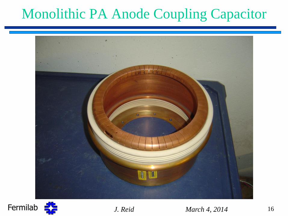
– Monolithic RF coupling capacitor with metalized interface to copper spinning's for coupling PA output to RF cavity.
– Girders split into two separate structures to facilitate change-out
– Tuners rebuilt using new lower loss ferrite to replace M4C21A
• Replaced 10 Toshiba M4c21 cores (mu=40) with 10 Toshiba M4D21a cores (mu=20) in each tuner.
• 18 Stackpole CeraMag 14 material toroids (mu=12) remain unchanged.
– Cavities
• Tuners removed for rebuilding
• All components thoroughly cleaned
• Electrical joints tin plated
• Mode damper mounts add
March 4, 2014 J. Reid 7
Fermilab
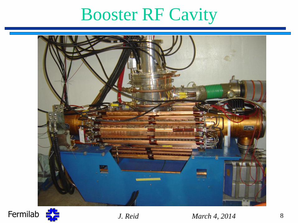
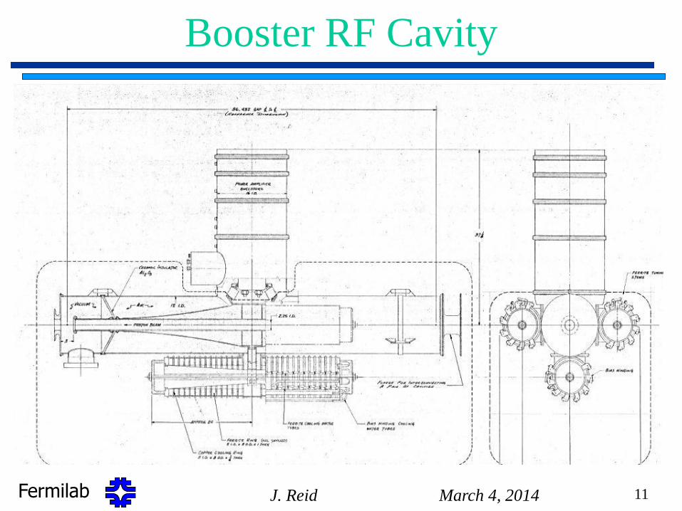
Booster RF Cavity
March 4, 2014 J. Reid 8
Fermilab March 4, 2014 J. Reid 9
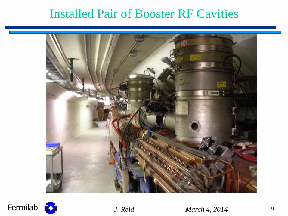
Installed Pair of Booster RF Cavities
Fermilab March 4, 2014 J. Reid 10
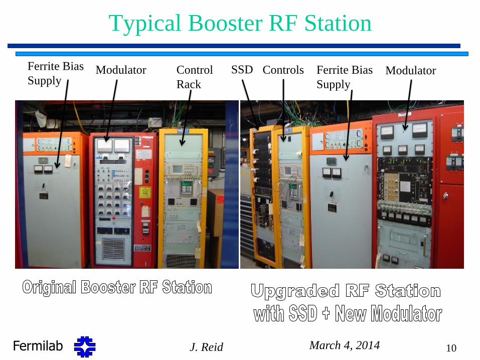
Typical Booster RF Station
Ferrite Bias
Supply
Modulator Modulator Control
Rack
Ferrite Bias
Supply SSD Controls
Fermilab
Booster RF Cavity
March 4, 2014 J. Reid 11
Fermilab
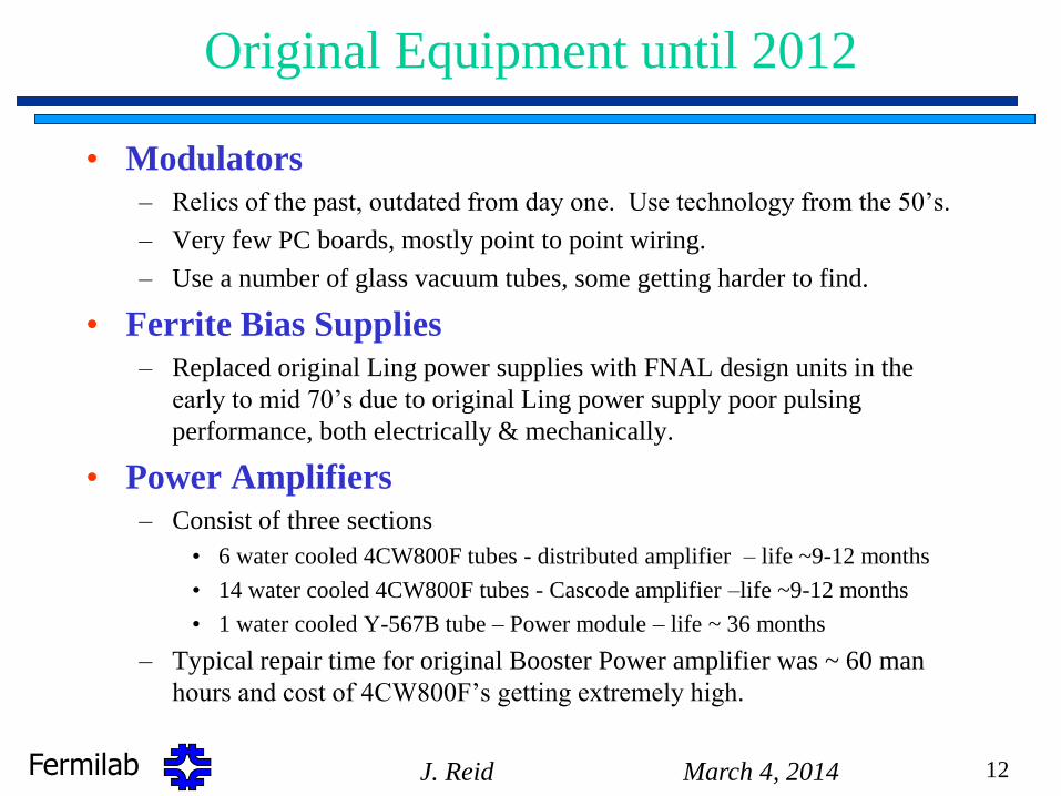
Original Equipment until 2012
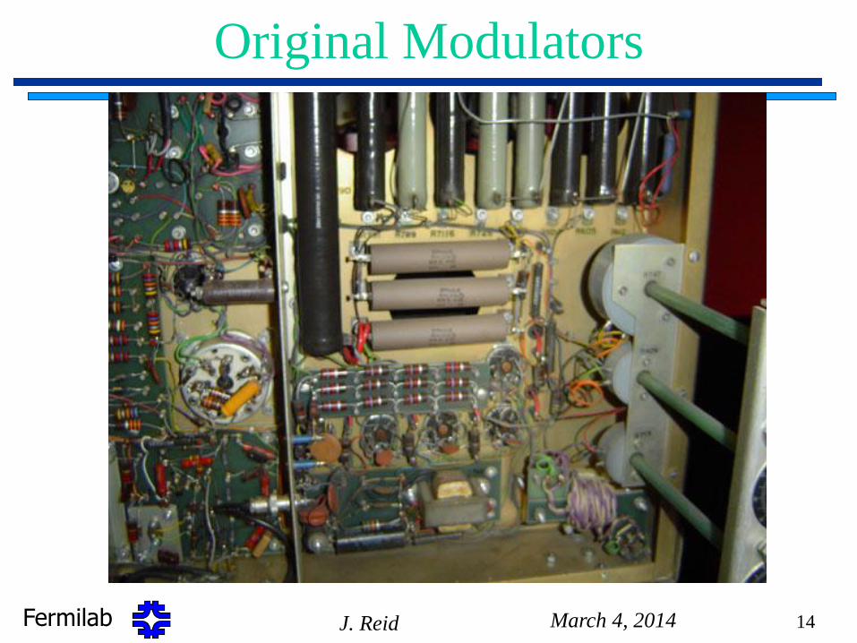
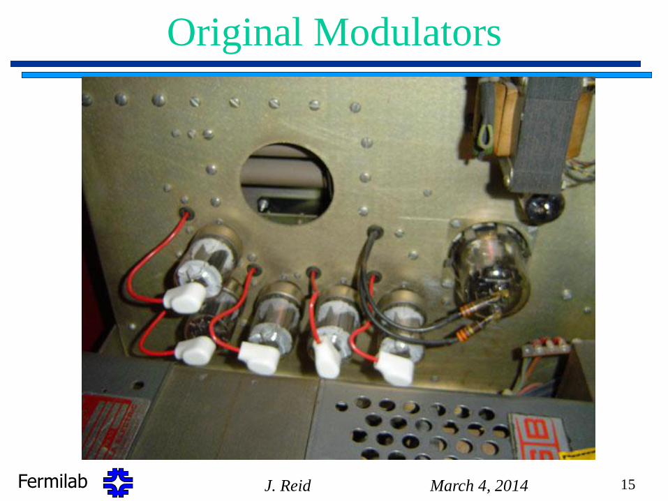
• Modulators
– Relics of the past, outdated from day one. Use technology from the 50’s.
– Very few PC boards, mostly point to point wiring.
– Use a number of glass vacuum tubes, some getting harder to find.
• Ferrite Bias Supplies
– Replaced original Ling power supplies with FNAL design units in the
early to mid 70’s due to original Ling power supply poor pulsing
performance, both electrically & mechanically.
• Power Amplifiers
– Consist of three sections
• 6 water cooled 4CW800F tubes - distributed amplifier – life ~9-12 months
• 14 water cooled 4CW800F tubes - Cascode amplifier –life ~9-12 months
• 1 water cooled Y-567B tube – Power module – life ~ 36 months
– Typical repair time for original Booster Power amplifier was ~ 60 man
hours and cost of 4CW800F’s getting extremely high.
March 4, 2014 J. Reid 12
Fermilab March 4, 2014 J. Reid 13
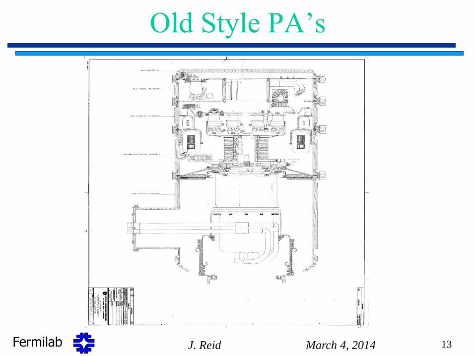
Old Style PA’s
Fermilab March 4, 2014 J. Reid 14
Original Modulators
Fermilab March 4, 2014 J. Reid 15
Original Modulators
Fermilab
Monolithic PA Anode Coupling Capacitor
March 4, 2014 J. Reid 16
Fermilab
Preparing for 15 Hz RF System Operation
• Booster RF presently running at ~ 7.5 Hz.
• To satisfy program demands, need to run 15 Hz continuous.
• Booster RF reliability has been a significant matter for discussion
over the last 12 + years.
– RF system never capable of operating at a continuous 15 Hz, only
ran in burst mode at moderate duty factor.
– Increased demands on the duty factor started with the beginning of
MiniBooNE operations in 2002
– NuMI/MINOS demands have greatly increased the demands on
Booster.
– Original equipment > 40 years old.
– Need to maintain a minimum of 900Kvolts / turn ~ 50kV/ station
– Spare Station 19 acts as hot spare to compensate for a down
station.
March 4, 2014 J. Reid 17
Fermilab
Modifications to Achieve 15 Hz
• Required Modifications for 15Hz operation,
– Completed the Solid State Driver Upgrade project, March 2013.
– Reconnect the ferrite cone cooling lines which were disconnected many
years ago due to low duty factor operation.
– Install new copper clad skins on tuner cone castings
– Machine cavity tuner interface surfaces flat and parallel for good high
power RF connections.
• This requires removing cavities from tunnel and cycling tuners & cavities
through a rebuilding process.
• All cavities are run through the MI-60 test station and tested at a 15 Hz rate
for a minimum of 168 hours of which 120 hours at full gradient before
reinstallation in Booster tunnel.
• Would like to have a second high power test stand at F0
to do long term testing of a refurbished cavity
March 4, 2014 J. Reid 18
Fermilab
Solid State Driver Upgrade Program
• Upgrade Program
– Build 22 new FNAL designed modulators (identical to MIRF).
– Build 22 new FNAL designed 150kW power amplifiers
– Build 22 new FNAL designed 4kW solid state driver amplifier
assemblies.
– Replace all RF station cabling to the tunnel (HV, ½” Heliax,
– & all control cables.
• Present Status
– Completed solid state driver upgrade project in March 2013.
– Final project cost was under original cost estimate.
March 4, 2014 J. Reid 19
Fermilab
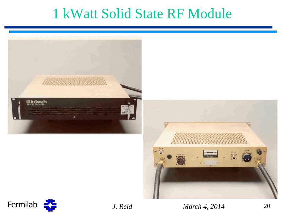
1 kWatt Solid State RF Module
March 4, 2014 J. Reid 20
Fermilab March 4, 2014 J. Reid 21
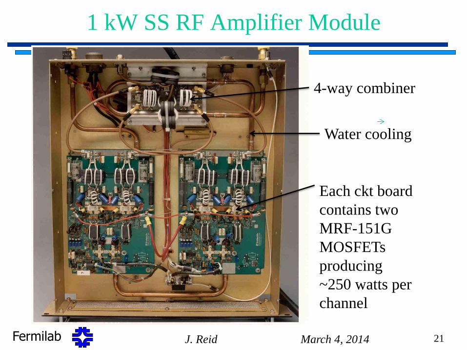
1 kW SS RF Amplifier Module
Each ckt board
contains two
MRF-151G
MOSFETs
producing
~250 watts per
channel
4-way combiner
Water cooling
Fermilab March 4, 2014 J. Reid 22
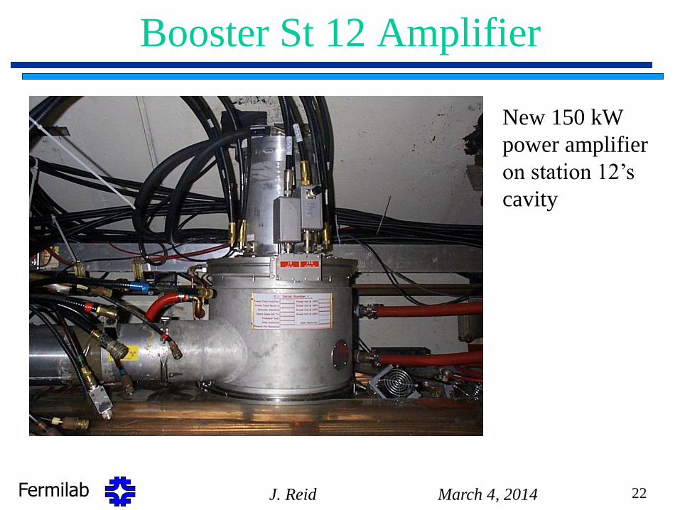
Booster St 12 Amplifier
New 150 kW
power amplifier
on station 12’s
cavity
Fermilab March 4, 2014 J. Reid 23
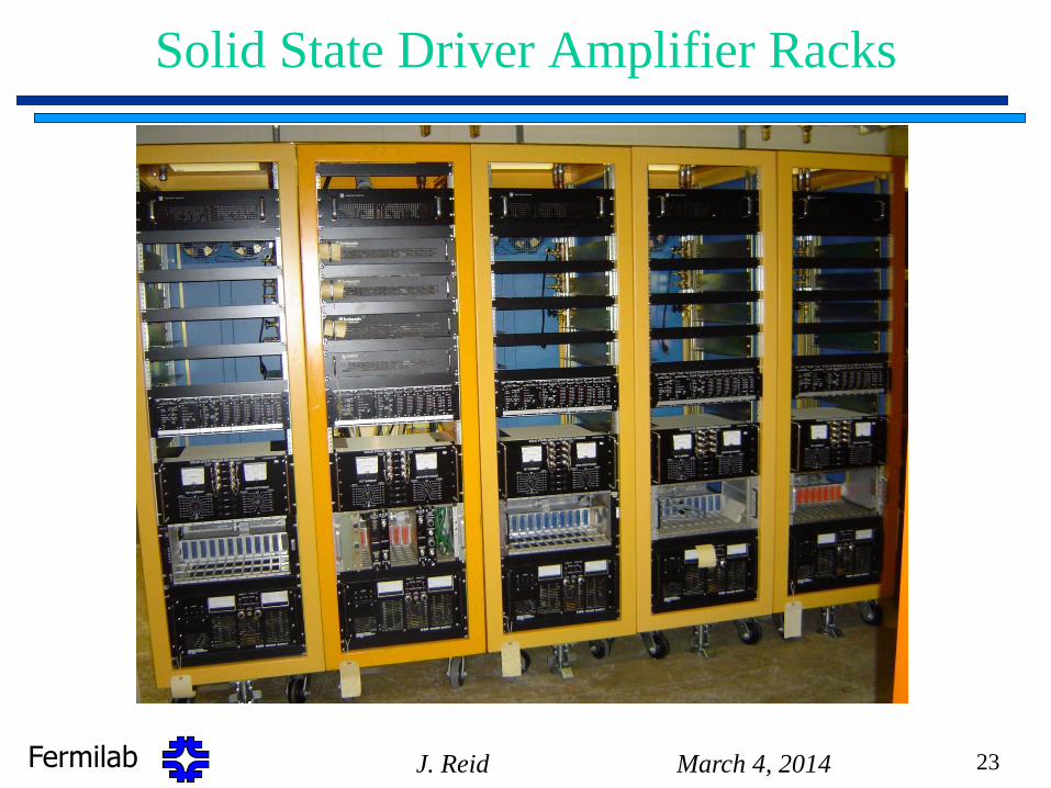
Solid State Driver Amplifier Racks
Fermilab
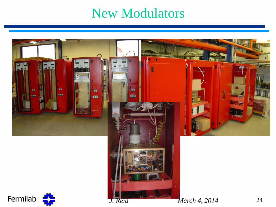
New Modulators
March 4, 2014 J. Reid 24
Fermilab
Additional Scheduled Booster RF Upgrades - PIP
• Anode Power Supplies
– Two new power supplies to replace original 1970 power supplies
• Includes new 13.8kV Step Start VCB contactors
• New 2MVA transformers
• New outdoor DC Cabinets with HV components
• New controls
• Completion in FY15-FY16
• Ferrite Bias Supplies
– Replace marginal Main Rectifier Transformer & SCR packages in 10 West Gallery
Supplies.
– Project started in FY14 and scheduled to be complete in FY15.
– Completion does not limit prior 15 Hz operation.
• Build 3 new Booster Cavities with slightly larger aperture 3.25”
– Would install cavities for NEW Booster Stations 21 and 22.
– Preliminary design considerations based on modeling (Simulation from M. Hassan
in TD) is underway.
March 4, 2014 J. Reid 25
Fermilab
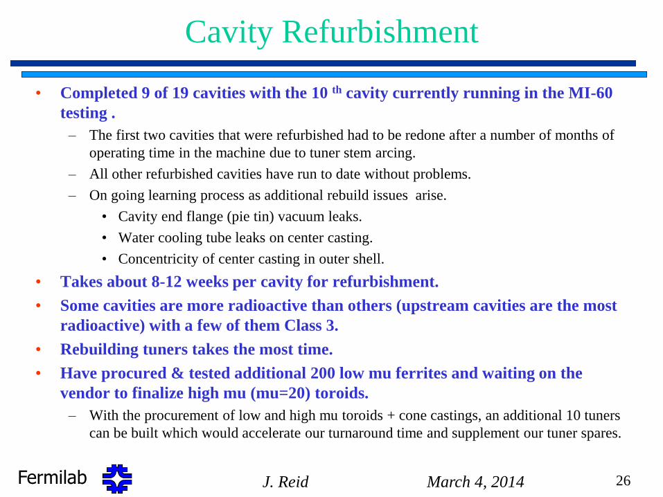
Cavity Refurbishment
• Completed 9 of 19 cavities with the 10 th cavity currently running in the MI-60
testing .
– The first two cavities that were refurbished had to be redone after a number of months of
operating time in the machine due to tuner stem arcing.
– All other refurbished cavities have run to date without problems.
– On going learning process as additional rebuild issues arise.
• Cavity end flange (pie tin) vacuum leaks.
• Water cooling tube leaks on center casting.
• Concentricity of center casting in outer shell.
• Takes about 8-12 weeks per cavity for refurbishment.
• Some cavities are more radioactive than others (upstream cavities are the most
radioactive) with a few of them Class 3.
• Rebuilding tuners takes the most time.
• Have procured & tested additional 200 low mu ferrites and waiting on the
vendor to finalize high mu (mu=20) toroids.
– With the procurement of low and high mu toroids + cone castings, an additional 10 tuners
can be built which would accelerate our turnaround time and supplement our tuner spares.
March 4, 2014 J. Reid 26
Fermilab
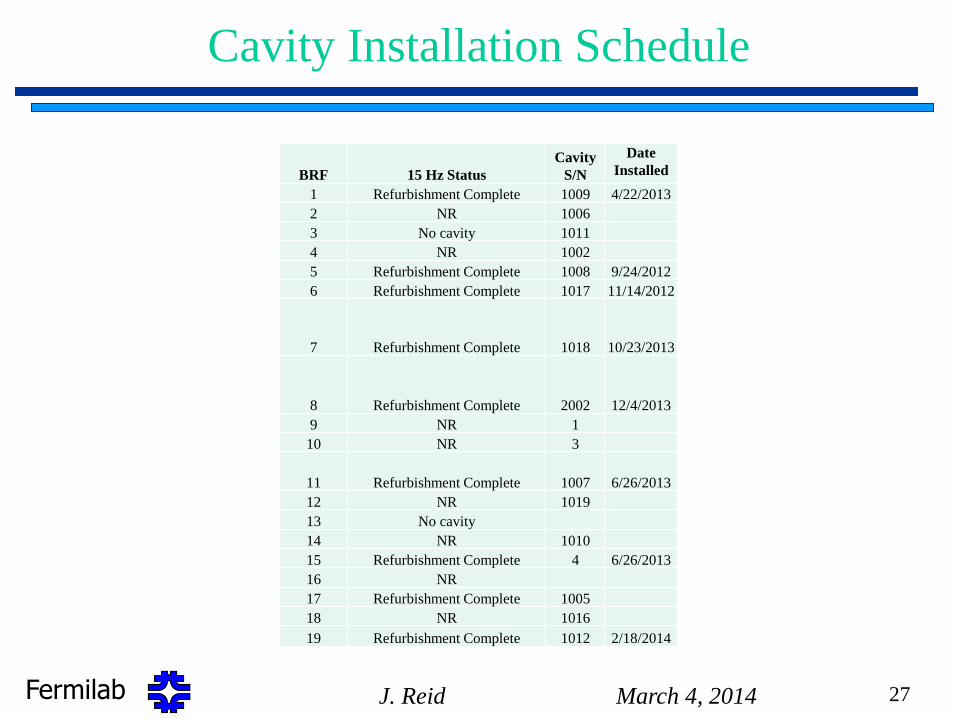
Cavity Installation Schedule
BRF 15 Hz Status
Cavity
S/N
Date
Installed
1 Refurbishment Complete 1009 4/22/2013
2 NR 1006
3 No cavity 1011
4 NR 1002
5 Refurbishment Complete 1008 9/24/2012
6 Refurbishment Complete 1017 11/14/2012
7 Refurbishment Complete 1018 10/23/2013
8 Refurbishment Complete 2002 12/4/2013
9 NR 1
10 NR 3
11 Refurbishment Complete 1007 6/26/2013
12 NR 1019
13 No cavity
14 NR 1010
15 Refurbishment Complete 4 6/26/2013
16 NR
17 Refurbishment Complete 1005
18 NR 1016
19 Refurbishment Complete 1012 2/18/2014
March 4, 2014 J. Reid 27
Fermilab March 4, 2014 J. Reid 28
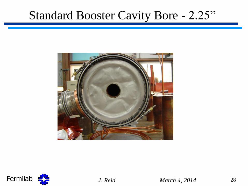
Standard Booster Cavity Bore - 2.25”
Fermilab March 4, 2014 J. Reid 29
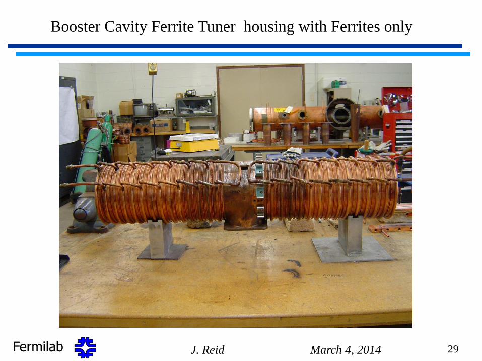
Booster Cavity Ferrite Tuner housing with Ferrites only
Fermilab March 4, 2014 J. Reid 30
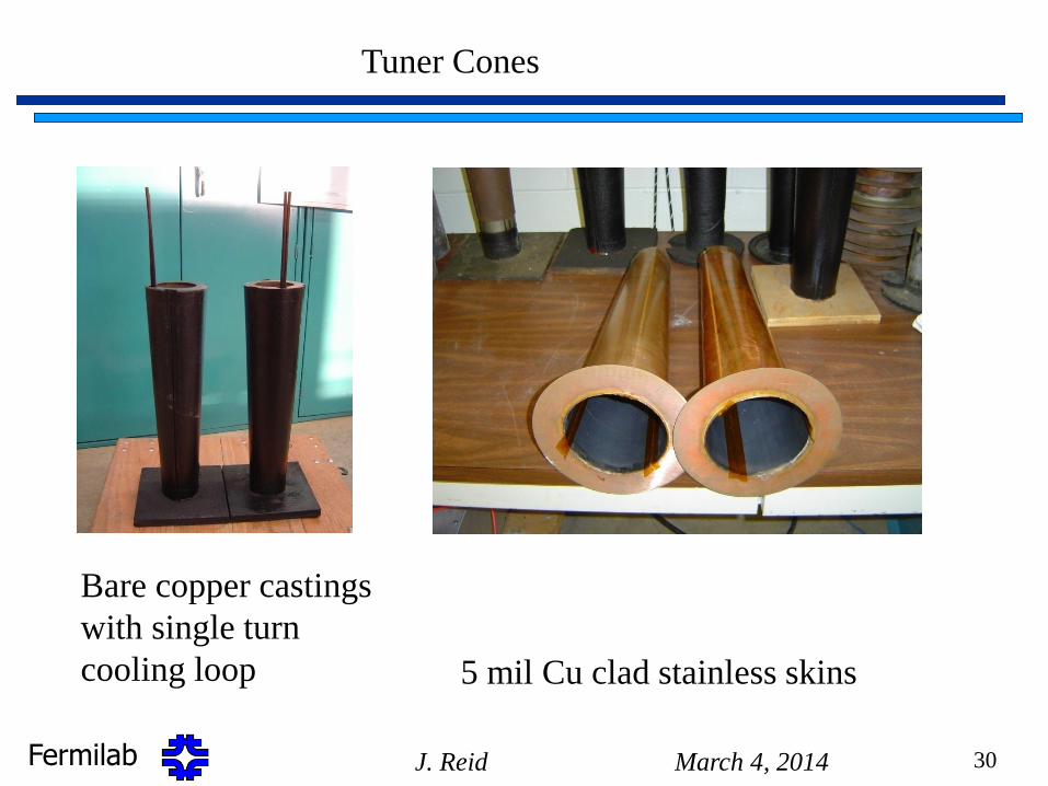
Tuner Cones
Bare copper castings
with single turn
cooling loop 5 mil Cu clad stainless skins
Fermilab
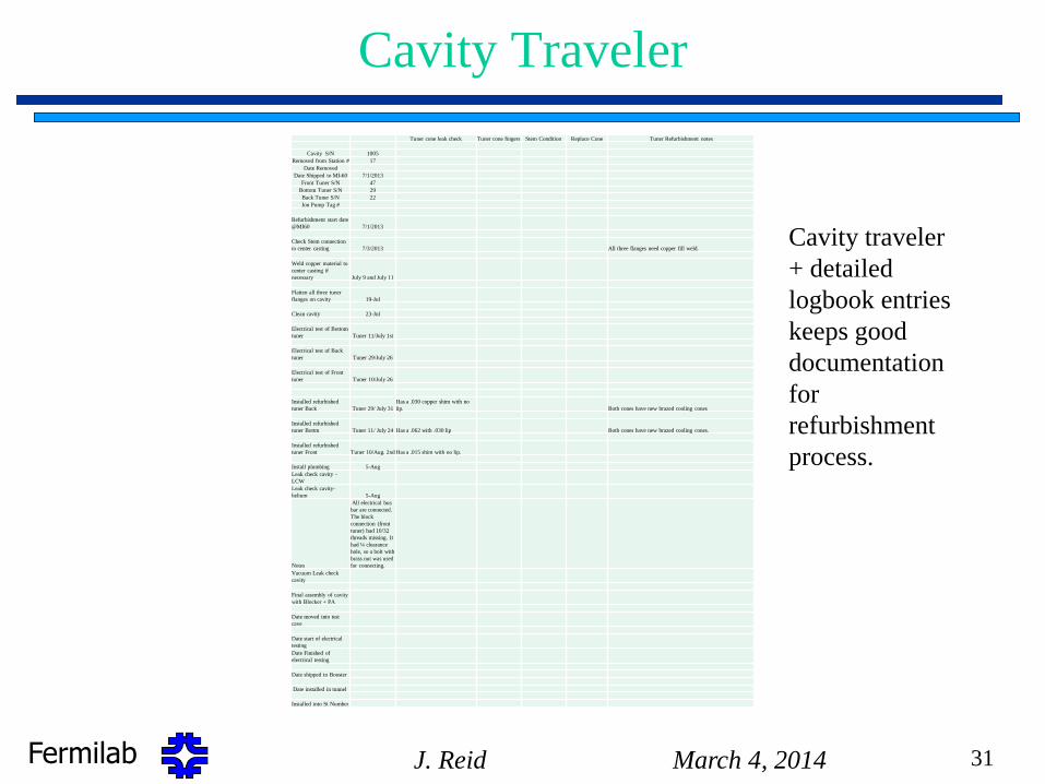
Cavity Traveler
Tuner cone leak check Tuner cone fingers Stem Condition Replace Cone Tuner Refurbishment notes
Cavity S/N 1005
Removed from Station # 17
Date Removed
Date Shipped to MI-60 7/1/2013
Front Tuner S/N 47
Bottom Tuner S/N 29
Back Tuner S/N 22
Ion Pump Tag #
Refurbishment start date
@MI60 7/1/2013
Check Stem connection
to center casting 7/3/2013 All three flanges need copper fill weld.
Weld copper material to
center casting if
necessary July 9 and July 11
Flatten all three tuner
flanges on cavity 19-Jul
Clean cavity 23-Jul
Electrical test of Bottom
tuner Tuner 11/July 1st
Electrical test of Back
tuner Tuner 29/July 26
Electrical test of Front
tuner Tuner 10/July 26
Installed refurbished
tuner Back Tuner 29/ July 31 Has a .030 copper shim with no
lip. Both cones have new brazed cooling cones
Installed refurbished
tuner Bottm Tuner 11/ July 24 Has a .062 with .030 lip Both cones have new brazed cooling cones.
Installed refurbished
tuner Front Tuner 10/Aug. 2nd Has a .015 shim with no lip.
Install plumbing 5-Aug
Leak check cavity -
LCW
Leak check cavity-
helium 5-Aug
Notes
All electrical bus
bar are connected.
The block
connection (front
tuner) had 10/32
threads missing. It
had ¼ clearance
hole, so a bolt with
brass nut was used
for connecting.
Vacuum Leak check
cavity
Final assembly of cavity
with Blocker + PA
Date moved into test
cave
Date start of electrical
testing
Date Finished of
electrical testing
Date shipped to Booster
Date installed in tunnel
Installed into St Number
March 4, 2014 J. Reid 31
Cavity traveler
+ detailed
logbook entries
keeps good
documentation
for
refurbishment
process.

Fermilab
Other RF Issues
• Increase mode damper power dissipation (load).
• Replace old rf sum balancing circuit with new global
amplitude & phase regulator circuits so amplitude and
phase of “A” stations and “B” stations track the request.
• Rebuild prototype Booster rf cavity using spare
production center castings (inner & outer) to achieve a
good operational spare. Start Jan 1, 2011.
• Need to get acceptable mu=20 toroids from vendor before
starting assembly of 10 spare tuners.
• Add direct RF feedback to each station to reduce beam
loading effects for added stability under possible higher
beam currents.
March 4, 2014 J. Reid 32
Fermilab
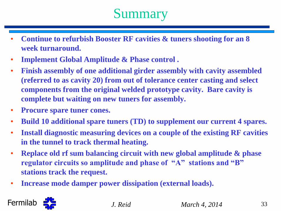
Summary
• Continue to refurbish Booster RF cavities & tuners shooting for an 8
week turnaround.
• Implement Global Amplitude & Phase control .
• Finish assembly of one additional girder assembly with cavity assembled
(referred to as cavity 20) from out of tolerance center casting and select
components from the original welded prototype cavity. Bare cavity is
complete but waiting on new tuners for assembly.
• Procure spare tuner cones.
• Build 10 additional spare tuners (TD) to supplement our current 4 spares.
• Install diagnostic measuring devices on a couple of the existing RF cavities
in the tunnel to track thermal heating.
• Replace old rf sum balancing circuit with new global amplitude & phase
regulator circuits so amplitude and phase of “A” stations and “B”
stations track the request.
• Increase mode damper power dissipation (external loads).
March 4, 2014 J. Reid 33