Embed Size (px)
Citation preview
Bob Cunningham www.TrainingMagic.com A basic overview of MPLS (800) 531-6573
___________________________________________________________________________________________________________________ Page 1
Bob�’s MPLS OverviewAn overview of MPLS Concepts & Technology
This material is provided freely for individual, non-commercial use.
Any and all commercial use is prohibited. All rights are reserved by TrainingMagic, inc.
Bob Cunningham www.TrainingMagic.com A basic overview of MPLS (800) 531-6573
___________________________________________________________________________________________________________________ Page 2
Copyright © 2005 by TrainingMagic, Inc. Call 800 531-6573 for consulting & training or to report commercial use of this material
MPLS �– Objectives (1)
�• Identify networking challenges facing Service Providers and Business Users
�• Compare MPLS data forwarding to other methods�• Describe components of an MPLS system�• Explain how MPLS can address contemporary
networking challenges�• Cite relevant Standards, Organizations, & Vendors
involved with MPLS solutions

Bob Cunningham www.TrainingMagic.com A basic overview of MPLS (800) 531-6573
___________________________________________________________________________________________________________________ Page 3
Copyright © 2005 by TrainingMagic, Inc. Call 800 531-6573 for consulting & training or to report commercial use of this material
Business Networking Challenges
�• Reduce costs�• Increase reliability & availability�• Maintain performance & QoS�• Ensure security�• Communicate flexibly
- within company, inter-department- with Business Partners & Customers
Bob Cunningham www.TrainingMagic.com A basic overview of MPLS (800) 531-6573
___________________________________________________________________________________________________________________ Page 4
Copyright © 2005 by TrainingMagic, Inc. Call 800 531-6573 for consulting & training or to report commercial use of this material
MPLS Details �– Objectives (3)
�• Explain how LDP, CR-LDP, and RSVP-TE protocols operate
�• Identify the role of MPLS in VPN deployment�• Describe how BGP-4 is used with MPLS VPNs
Bob Cunningham www.TrainingMagic.com A basic overview of MPLS (800) 531-6573
___________________________________________________________________________________________________________________ Page 5
Copyright © 2005 by TrainingMagic, Inc. Call 800 531-6573 for consulting & training or to report commercial use of this material
Service Provider Challenges
�• Reduce Operational costs�• Maintain performance & QoS�• Expand & Grow network�• Retain current customers, add new�• Derive new revenue streams from
existing infrastructure
Service Provider Challenges The communications industry in general has experienced great difficulties in recent years following the implosion of �“.com�” industries. Never in recent memory, has maintaining a competitive posture been more important. As major shifts in supply and demand cause competitive price cutting, reduced operational costs become imperative to survival. Yet, cutting costs is only part of the equation. In order to please existing customers, network performance levels and any Quality/Class-of-Service assurances must be maintained. As traffic levels continue to grow, it�’s necessary to expand and grow the network in order to maintain performance. The age old network design question remains: How should a network operator optimize expenditures in pursuit of performance, capacity, and reliability? Some solutions are more costly. Some solutions are more flexible. As margins fall on existing products, service providers are challenged to find new ways of making money with the equipment they�’ve got. This often means finding new customers for existing services. But perhaps there are ways to create and offer new services, and enter new markets, by reconfiguring existing network infrastructure.
Bob Cunningham www.TrainingMagic.com A basic overview of MPLS (800) 531-6573
___________________________________________________________________________________________________________________ Page 6
Copyright © 2005 by TrainingMagic, Inc. Call 800 531-6573 for consulting & training or to report commercial use of this material
Business Networking Challenges
�• Reduce costs�• Increase reliability & availability�• Maintain performance & QoS�• Ensure security�• Communicate flexibly
- within company, inter-department- with Business Partners & Customers
Business Networking Challenges The recent economic downturns have left few business sectors untouched. Many businesses are faced with lower growth expectations if not actual revenue reductions. As always, businesses strive to reduce their voice and data communications costs in an effort to better the �“bottom line.�” But low-cost means little if the service fails to meet requirements. Reliability, performance, and security are always part of this constrained optimization. With data networks having nearly completed a full transition to TCP/IP protocols, most corporate networkers compare services with an eye toward transporting IP. But as corporate backbones are asked to carry non-traditional traffic including live audio, video, and teleconferencing traffic, Quality-of-Service and traffic prioritization become important considerations.

Bob Cunningham www.TrainingMagic.com A basic overview of MPLS (800) 531-6573
___________________________________________________________________________________________________________________ Page 7
Copyright © 2005 by TrainingMagic, Inc. Call 800 531-6573 for consulting & training or to report commercial use of this material
The MPLS Edge
�• Uses existing infrastructure�– IP router, ATM switch, Ethernet, all*
�• Traffic Engineering�– Optimizes existing resources, increases capacity�– Can differentiate Prioritized vs Best-Effort traffic
�• Basis for new service offerings, revenue streams�– Virtual Private Networks�– Circuit Emulation, Voice/Video-over-MPLS
�• Simplifies Operations Management�– All equipment managed via IP & Link State Database
The MPLS Edge Few businesses can routinely afford the �“forklift�” upgrade approach. Whenever possible or feasible, equipment and infrastructure are reused to reduce costs. Service providers and carriers have invested billions of dollars over the past decade in optical & electrical transmission equipment, ATM & Frame Relay switchgear, and most recently in IP-routers and Ethernet switches. You can anticipate how welcome MPLS would be were it to require scrapping that investment. The good news is: MPLS capabilities can be added using software upgrades to many existing systems.
Bob Cunningham www.TrainingMagic.com A basic overview of MPLS (800) 531-6573
___________________________________________________________________________________________________________________ Page 8
Copyright © 2005 by TrainingMagic, Inc. Call 800 531-6573 for consulting & training or to report commercial use of this material
What is MPLS?
�• OSI Network Layer functionality�• Standards-based�• Connection-oriented
�– Virtual Circuit, Label-swapping�• Operates with variety of existing equipment�• Optimizes network resources
What is MPLS? MultiProtocol Label Switching is a standards-based, connection-oriented, OSI-Network-Layer functionality designed to optimize resources in service-provider core networks. It uses classic label-swapping techniques to simplify and expedite data forwarding. And does this via deterministic, virtual-circuit paths implemented atop a variety of existing switching and transmission equipment including IP-routers, Frame Relay switches, and ATM switches.

Bob Cunningham www.TrainingMagic.com A basic overview of MPLS (800) 531-6573
___________________________________________________________________________________________________________________ Page 9
Copyright © 2005 by TrainingMagic, Inc. Call 800 531-6573 for consulting & training or to report commercial use of this material
Standards ? Interoperability?
�• MPLS derived from many vendor methods�• IETF Established Standards under:
�– RFC3031- 3038: MPLS Architecture, etc.�– RFC2702: Traffic Engineering�– RFC2547: MPLS VPN�’s�– Many Draft Proposals
�• MPLS Forum
Standards Interoperability? MPLS was developed in response to several label-based vendor initiatives begun in 1995 to expedite IP forwarding speeds. Unfortunately these various techniques, such as Ipsilon�’s IP-switching, IBM�’s ARIS, and Cisco�’s Tag Switching, were all incompatible with one another. The IETF realizing advantages inherent in each of these systems established MPLS in an effort to provide a label-based solution which might prove interoperable in heterogeneous vendor environments. Unfortunately, there exist numerous implementation options within the MPLS standards. As you might expect, different vendors have selected incompatible options making interoperability often difficult. Some vendors, such as Cisco and Juniper, have selected implementation options that allow their respective equipment to interoperate. But be forewarned, other vendors, such as Nortel, have favored alternative options not compatible with Cisco. The MPLS forum also establishes recommendations in areas where the IETF won�’t tread. Citing �“layer violations�”, the IETF has in the past refused to standardize certain circuit emulation and Voice-over-MPLS direct encapsulations. The MPLS forum has provided vendor guidance for these applications and others. See www.mplsforum.org for more information.
Bob Cunningham www.TrainingMagic.com A basic overview of MPLS (800) 531-6573
___________________________________________________________________________________________________________________ Page 10
Copyright © 2005 by TrainingMagic, Inc. Call 800 531-6573 for consulting & training or to report commercial use of this material
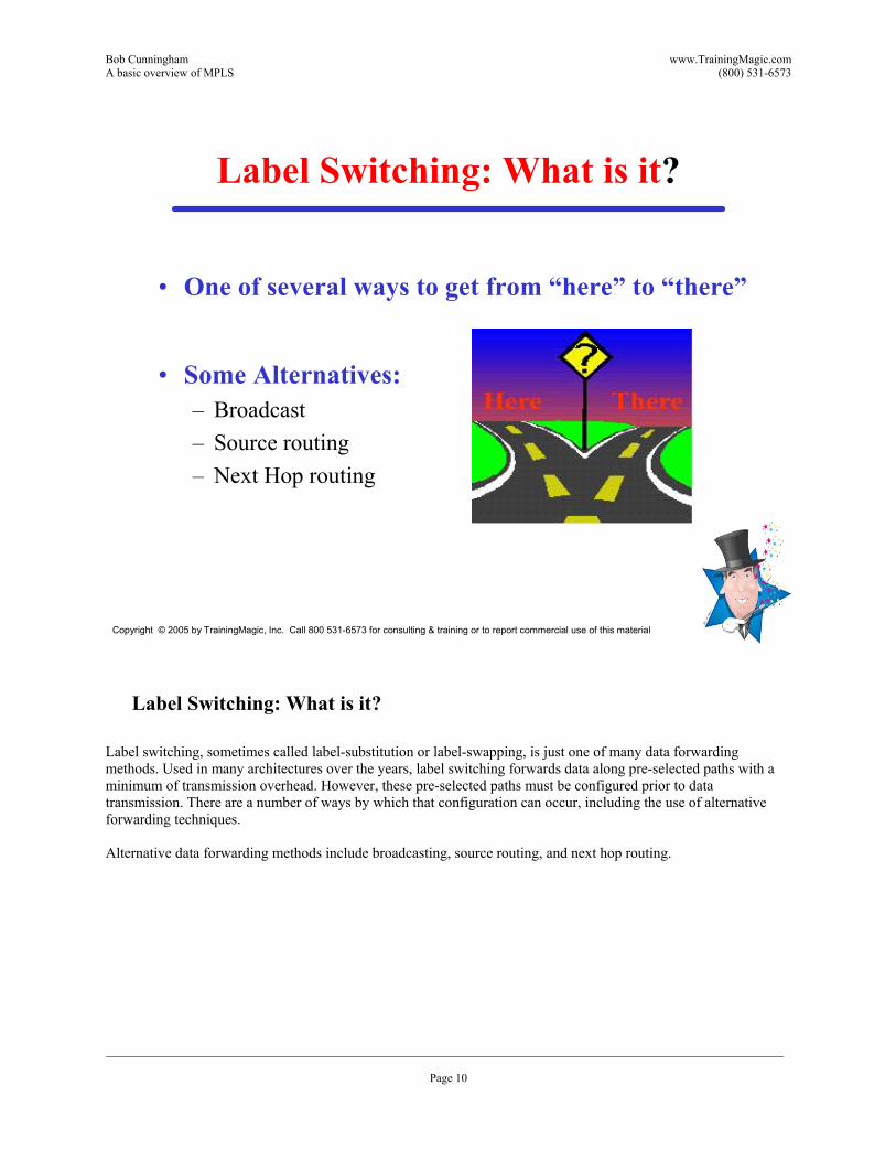
Label Switching: What is it?
�• One of several ways to get from �“here�” to �“there�”
�• Some Alternatives:�– Broadcast�– Source routing�– Next Hop routing
Label Switching: What is it? Label switching, sometimes called label-substitution or label-swapping, is just one of many data forwarding methods. Used in many architectures over the years, label switching forwards data along pre-selected paths with a minimum of transmission overhead. However, these pre-selected paths must be configured prior to data transmission. There are a number of ways by which that configuration can occur, including the use of alternative forwarding techniques. Alternative data forwarding methods include broadcasting, source routing, and next hop routing.

Bob Cunningham www.TrainingMagic.com A basic overview of MPLS (800) 531-6573
___________________________________________________________________________________________________________________ Page 11
Copyright © 2005 by TrainingMagic, Inc. Call 800 531-6573 for consulting & training or to report commercial use of this material
Broadcast
�• Go Everywhere�• Stop when you reach �“There�”
Satellite Phones broadcast �“everywhere�”
Broadcasting Broadcasting is a common delivery method used in wireless systems. However, it is seldom used in store and forward packet networks for data delivery because of its tendency to cause congestion along with obvious security ramifications. Instead, broadcasting is employed for protocol updates and resource location. Once a resource has been located, and a path to it discovered, alternatives are used for data forwarding which traverse a single path rather than all.
Bob Cunningham www.TrainingMagic.com A basic overview of MPLS (800) 531-6573
___________________________________________________________________________________________________________________ Page 12
Copyright © 2005 by TrainingMagic, Inc. Call 800 531-6573 for consulting & training or to report commercial use of this material
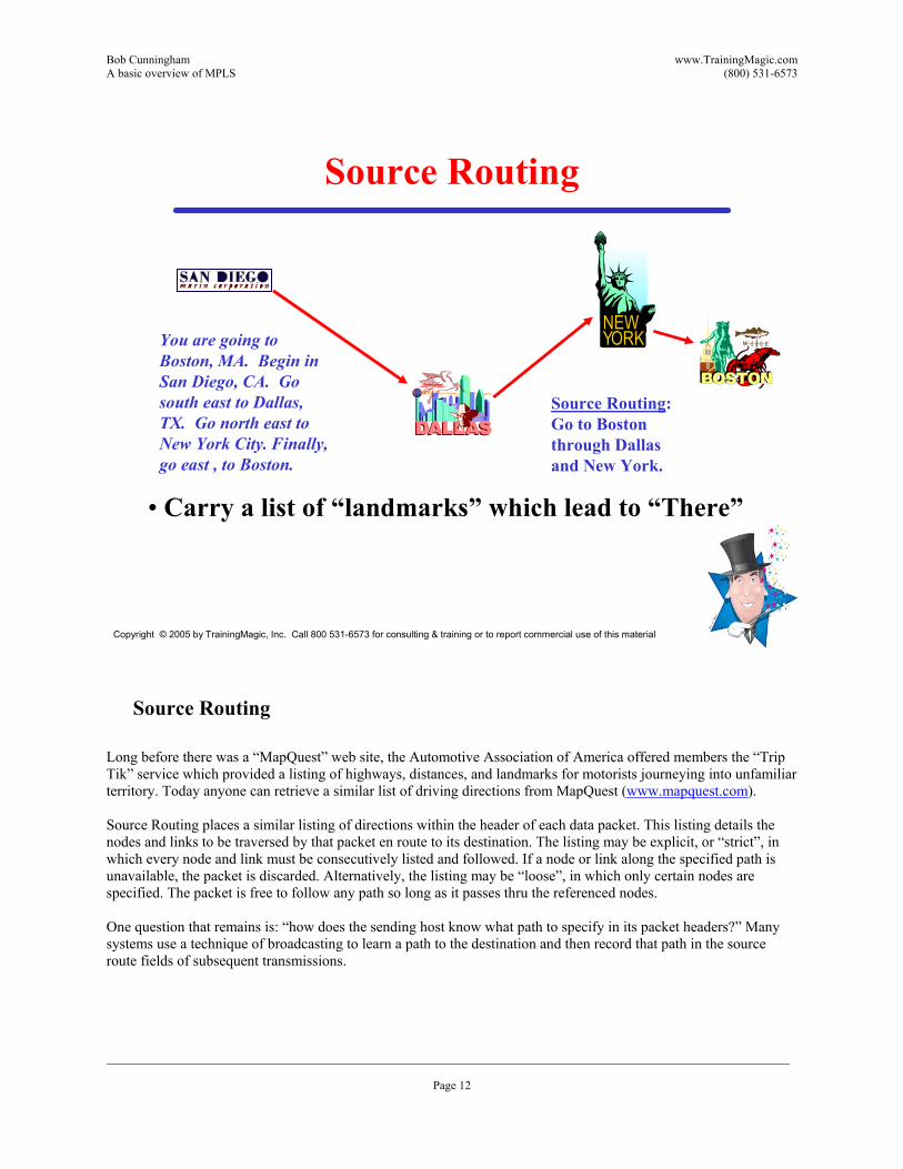
Source Routing
�• Carry a list of �“landmarks�” which lead to �“There�”
NEWYORKYou are going to
Boston, MA. Begin in San Diego, CA. Go south east to Dallas, TX. Go north east to New York City. Finally, go east , to Boston.
Source Routing: Go to Boston through Dallas and New York.
Source Routing Long before there was a �“MapQuest�” web site, the Automotive Association of America offered members the �“Trip Tik�” service which provided a listing of highways, distances, and landmarks for motorists journeying into unfamiliar territory. Today anyone can retrieve a similar list of driving directions from MapQuest (www.mapquest.com). Source Routing places a similar listing of directions within the header of each data packet. This listing details the nodes and links to be traversed by that packet en route to its destination. The listing may be explicit, or �“strict�”, in which every node and link must be consecutively listed and followed. If a node or link along the specified path is unavailable, the packet is discarded. Alternatively, the listing may be �“loose�”, in which only certain nodes are specified. The packet is free to follow any path so long as it passes thru the referenced nodes. One question that remains is: �“how does the sending host know what path to specify in its packet headers?�” Many systems use a technique of broadcasting to learn a path to the destination and then record that path in the source route fields of subsequent transmissions.
Bob Cunningham www.TrainingMagic.com A basic overview of MPLS (800) 531-6573
___________________________________________________________________________________________________________________ Page 13
Copyright © 2005 by TrainingMagic, Inc. Call 800 531-6573 for consulting & training or to report commercial use of this material
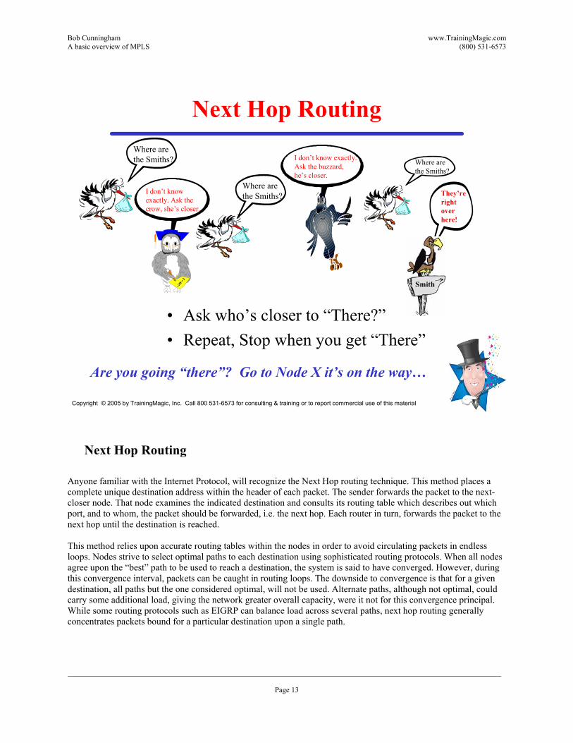
Next Hop Routing
�• Ask who�’s closer to �“There?�”�• Repeat, Stop when you get �“There�”
Are you going �“there�”? Go to Node X it�’s on the way�…
Where are the Smiths?
Where are the Smiths?
Where are the Smiths?
I don�’t know exactly. Ask the crow, she�’s closer.
I don�’t know exactly. Ask the buzzard, he�’s closer.
They�’re right over here!
Next Hop Routing Anyone familiar with the Internet Protocol, will recognize the Next Hop routing technique. This method places a complete unique destination address within the header of each packet. The sender forwards the packet to the next-closer node. That node examines the indicated destination and consults its routing table which describes out which port, and to whom, the packet should be forwarded, i.e. the next hop. Each router in turn, forwards the packet to the next hop until the destination is reached. This method relies upon accurate routing tables within the nodes in order to avoid circulating packets in endless loops. Nodes strive to select optimal paths to each destination using sophisticated routing protocols. When all nodes agree upon the �“best�” path to be used to reach a destination, the system is said to have converged. However, during this convergence interval, packets can be caught in routing loops. The downside to convergence is that for a given destination, all paths but the one considered optimal, will not be used. Alternate paths, although not optimal, could carry some additional load, giving the network greater overall capacity, were it not for this convergence principal. While some routing protocols such as EIGRP can balance load across several paths, next hop routing generally concentrates packets bound for a particular destination upon a single path.
Bob Cunningham www.TrainingMagic.com A basic overview of MPLS (800) 531-6573
___________________________________________________________________________________________________________________ Page 14
Copyright © 2005 by TrainingMagic, Inc. Call 800 531-6573 for consulting & training or to report commercial use of this material
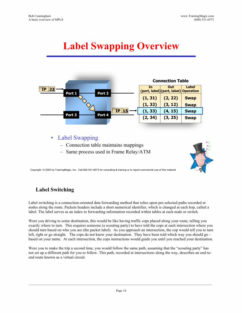
Label Swapping Overview
�• Label Swapping�– Connection table maintains mappings�– Same process used in Frame Relay/ATM
Port 1
Port 3
Port 2
Port 4
Connection TableConnection TableIn
(port, label)Out
(port, label)
(1, 31)(1, 32)
(1, 33)(2, 34)
(2, 22)(3, 12)
(4, 15)(3, 25)
LabelOperation
Swap
SwapSwap
Swap
33IP
15IP
Label Switching Label switching is a connection-oriented data forwarding method that relies upon pre-selected paths recorded at nodes along the route. Packets headers include a short numerical identifier, which is changed at each hop, called a label. The label serves as an index to forwarding information recorded within tables at each node or switch. Were you driving to some destination, this would be like having traffic cops placed along your route, telling you exactly where to turn. This requires someone (a scouting party) to have told the cops at each intersection where you should turn based on who you are (the packet label). As you approach an intersection, the cop would tell you to turn left, right or go straight. The cops do not know your destination. They have been told which way you should go �– based on your name. At each intersection, the cops instructions would guide you until you reached your destination. Were you to make the trip a second time, you would follow the same path, assuming that the �“scouting party�” has not set up a different path for you to follow. This path, recorded at intersections along the way, describes an end-to-end route known as a virtual circuit.
Bob Cunningham www.TrainingMagic.com A basic overview of MPLS (800) 531-6573
___________________________________________________________________________________________________________________ Page 15
Copyright © 2005 by TrainingMagic, Inc. Call 800 531-6573 for consulting & training or to report commercial use of this material
Virtual Circuits
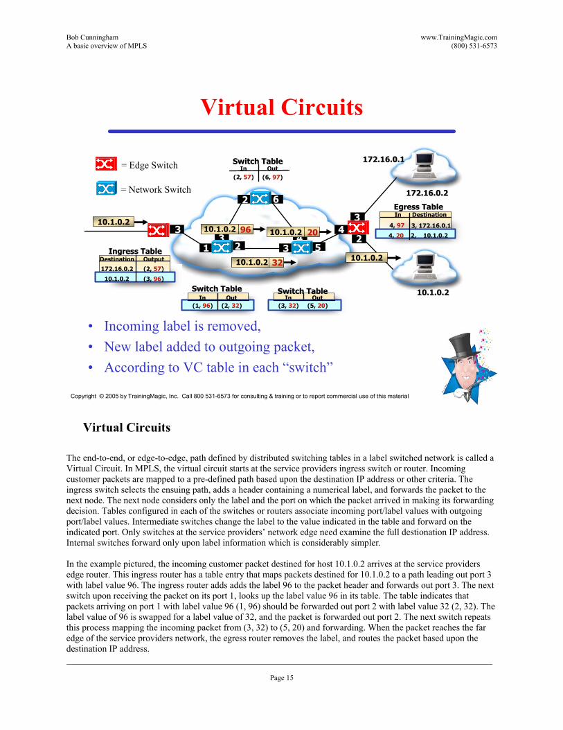
�• Incoming label is removed, �• New label added to outgoing packet,�• According to VC table in each �“switch�”
43969610.1.0.2
172.16.0.2172.16.0.2
1 2
172.16.0.1172.16.0.1
Ingress TableIngress TableDestination Output
172.16.0.2
10.1.0.2
(2, 57)
(3, 96)
Switch TableSwitch TableIn Out
(1, 96) (2, 32)
Switch TableSwitch TableIn Out
(3, 32) (5, 20)
InEgress TableEgress Table
Destination
4, 97
4, 20
3, 172.16.0.1
2, 10.1.0.2
10.1.0.2202010.1.0.2
Switch TableSwitch TableIn Out
(2, 57) (6, 97)
10.1.0.2323210.1.0.2
3 5
3
2 6
10.1.0.210.1.0.2
42
3
= Edge Switch
= Network Switch
Virtual Circuits The end-to-end, or edge-to-edge, path defined by distributed switching tables in a label switched network is called a Virtual Circuit. In MPLS, the virtual circuit starts at the service providers ingress switch or router. Incoming customer packets are mapped to a pre-defined path based upon the destination IP address or other criteria. The ingress switch selects the ensuing path, adds a header containing a numerical label, and forwards the packet to the next node. The next node considers only the label and the port on which the packet arrived in making its forwarding decision. Tables configured in each of the switches or routers associate incoming port/label values with outgoing port/label values. Intermediate switches change the label to the value indicated in the table and forward on the indicated port. Only switches at the service providers�’ network edge need examine the full destionation IP address. Internal switches forward only upon label information which is considerably simpler. In the example pictured, the incoming customer packet destined for host 10.1.0.2 arrives at the service providers edge router. This ingress router has a table entry that maps packets destined for 10.1.0.2 to a path leading out port 3 with label value 96. The ingress router adds adds the label 96 to the packet header and forwards out port 3. The next switch upon receiving the packet on its port 1, looks up the label value 96 in its table. The table indicates that packets arriving on port 1 with label value 96 (1, 96) should be forwarded out port 2 with label value 32 (2, 32). The label value of 96 is swapped for a label value of 32, and the packet is forwarded out port 2. The next switch repeats this process mapping the incoming packet from (3, 32) to (5, 20) and forwarding. When the packet reaches the far edge of the service providers network, the egress router removes the label, and routes the packet based upon the destination IP address.
Bob Cunningham www.TrainingMagic.com A basic overview of MPLS (800) 531-6573
___________________________________________________________________________________________________________________ Page 16
Copyright © 2005 by TrainingMagic, Inc. Call 800 531-6573 for consulting & training or to report commercial use of this material
Labels: A.K.A.
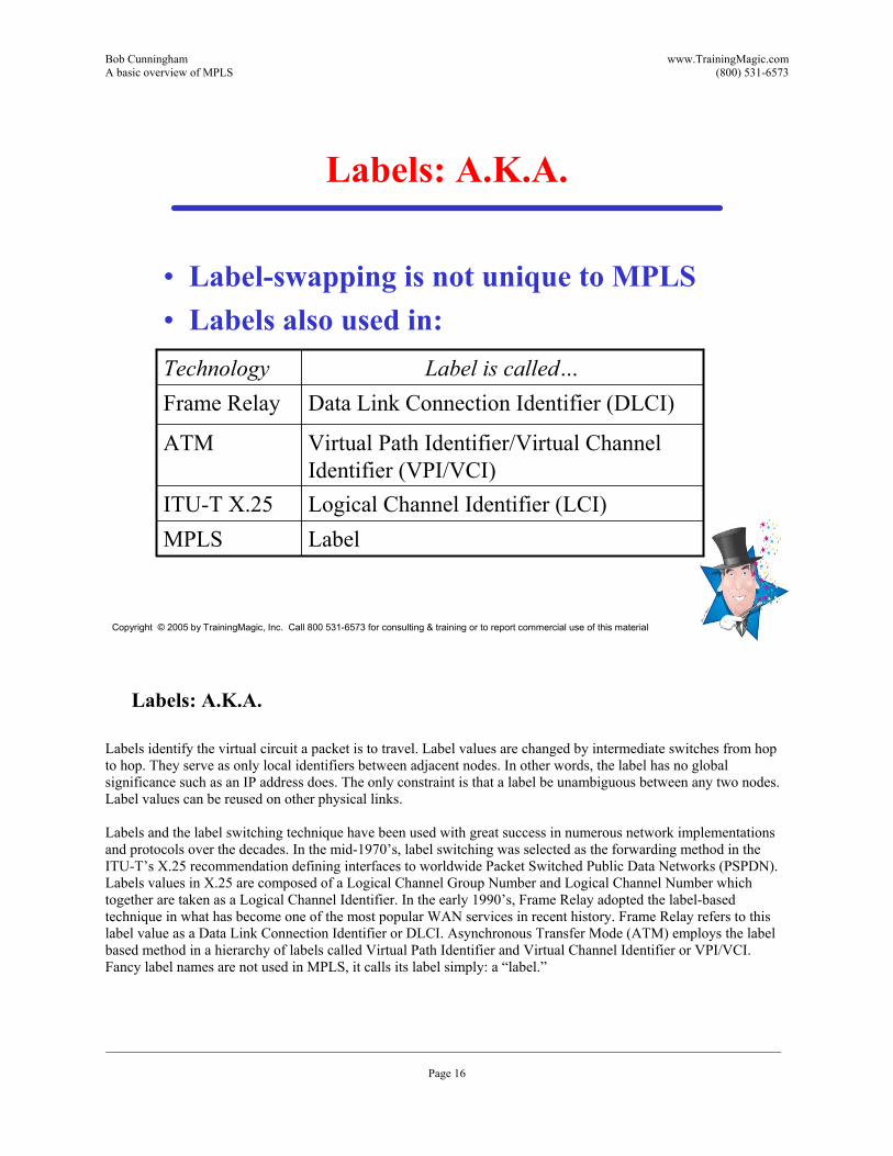
�• Label-swapping is not unique to MPLS�• Labels also used in:
LabelMPLSLogical Channel Identifier (LCI)ITU-T X.25
Virtual Path Identifier/Virtual Channel Identifier (VPI/VCI)
ATM
Data Link Connection Identifier (DLCI)Frame RelayLabel is called�…Technology
Labels: A.K.A. Labels identify the virtual circuit a packet is to travel. Label values are changed by intermediate switches from hop to hop. They serve as only local identifiers between adjacent nodes. In other words, the label has no global significance such as an IP address does. The only constraint is that a label be unambiguous between any two nodes. Label values can be reused on other physical links. Labels and the label switching technique have been used with great success in numerous network implementations and protocols over the decades. In the mid-1970�’s, label switching was selected as the forwarding method in the ITU-T�’s X.25 recommendation defining interfaces to worldwide Packet Switched Public Data Networks (PSPDN). Labels values in X.25 are composed of a Logical Channel Group Number and Logical Channel Number which together are taken as a Logical Channel Identifier. In the early 1990�’s, Frame Relay adopted the label-based technique in what has become one of the most popular WAN services in recent history. Frame Relay refers to this label value as a Data Link Connection Identifier or DLCI. Asynchronous Transfer Mode (ATM) employs the label based method in a hierarchy of labels called Virtual Path Identifier and Virtual Channel Identifier or VPI/VCI. Fancy label names are not used in MPLS, it calls its label simply: a �“label.�”
Bob Cunningham www.TrainingMagic.com A basic overview of MPLS (800) 531-6573
___________________________________________________________________________________________________________________ Page 17
Copyright © 2005 by TrainingMagic, Inc. Call 800 531-6573 for consulting & training or to report commercial use of this material
MPLS Terminology
�• LSR: Label Switching Router�• LER: Label Edge Router�• LSP: Label Switched Path�• FEC: Forwarding Equivalence Class�• Push, Swap, Pop
MPLS Terminology Like most technologies, MPLS has its share of jargon. A Label Switching Router (LSR) is any device that can perform MPLS label switching functions. This functionality is typically added to an IP router, ATM switch, or Frame Relay switch thru software upgrade. A LSR which lies at the service provider�’s network edge is called a Label Edge Router (LER). An LER interfaces both with customer routers (which typically do not use MPLS) and internal LSR�’s. The Ingress LER accepts customer packets and is said to �“Push�” or add a label before forwarding data onward. Adding the label inherently selects the pre-defined path or virtual circuit that packet will take thru the network. That virtual circuit is called a Label Switched Path or LSP. In addition to a label, the MPLS header includes a priority field which can designate a higher or lower queuing status. All packets which travel the same LSP and have the same priority are said to share the same Forwarding Equivalency Class or FEC. Intermediate LSRs simply �“Swap�” labels as they forward data across the network. The Egress LER removes or �“Pops�” the label as packets leave the service providers network.

Bob Cunningham www.TrainingMagic.com A basic overview of MPLS (800) 531-6573
___________________________________________________________________________________________________________________ Page 18
Copyright © 2005 by TrainingMagic, Inc. Call 800 531-6573 for consulting & training or to report commercial use of this material
Where do Labels come from?
�• Label added to customer packet by Service-Provider�’s ingress router. (Push)
�• Label removed as packet leaves Service-provider network (Pop)�– Customer device unaware of label�– Unlike ATM, FR, X.25�…
Where do Labels come from? MPLS today is implemented exclusively within service providers�’ networks to provide Traffic Engineering and Virtual Private Networking functions. It is not generally used in corporate networks, between service providers, or as a User-to-Network interface protocol. As such, labels are added by the service providers LER in the Push process and used within that service provider�’s network only. Labels are removed or Popped as packets leave that provider�’s network. The customer equipment is unaware of, and has no control over, the label used to forward traffic across the provider�’s backbone. This has several benefits. First, the customer�’s equipment needn�’t be upgraded with MPLS software in order to take advantage of MPLS features. Secondly, the inability of customer equipment to influence label processing in any way provides inherent protection from outside hackers attempting to compromise an MPLS VPN. As MPLS popularity increases, deployment becomes more widespread, and vendor interoperability progresses, it�’s not inconceivable that inter-carrier MPLS agreements could emerge. As corporate networks reach larger proportions, it�’s entirely possible that MPLS could be used in that context for Traffic Engineering. Could MPLS someday serve as a User-to-Network interface protocol used between customer and service provider?
Bob Cunningham www.TrainingMagic.com A basic overview of MPLS (800) 531-6573
___________________________________________________________________________________________________________________ Page 19
Copyright © 2005 by TrainingMagic, Inc. Call 800 531-6573 for consulting & training or to report commercial use of this material
MPLS Components
Ingress LERPE router
Egress LERPE router
LSR�’sP router
CE routerCE router
Penultimate router
LSP
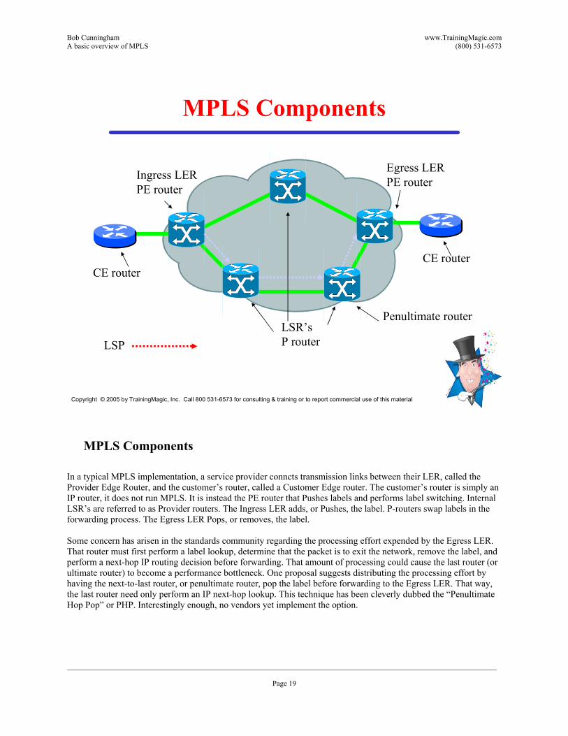
MPLS Components In a typical MPLS implementation, a service provider conncts transmission links between their LER, called the Provider Edge Router, and the customer�’s router, called a Customer Edge router. The customer�’s router is simply an IP router, it does not run MPLS. It is instead the PE router that Pushes labels and performs label switching. Internal LSR�’s are referred to as Provider routers. The Ingress LER adds, or Pushes, the label. P-routers swap labels in the forwarding process. The Egress LER Pops, or removes, the label. Some concern has arisen in the standards community regarding the processing effort expended by the Egress LER. That router must first perform a label lookup, determine that the packet is to exit the network, remove the label, and perform a next-hop IP routing decision before forwarding. That amount of processing could cause the last router (or ultimate router) to become a performance bottleneck. One proposal suggests distributing the processing effort by having the next-to-last router, or penultimate router, pop the label before forwarding to the Egress LER. That way, the last router need only perform an IP next-hop lookup. This technique has been cleverly dubbed the �“Penultimate Hop Pop�” or PHP. Interestingly enough, no vendors yet implement the option.
Bob Cunningham www.TrainingMagic.com A basic overview of MPLS (800) 531-6573
___________________________________________________________________________________________________________________ Page 20
Copyright © 2005 by TrainingMagic, Inc. Call 800 531-6573 for consulting & training or to report commercial use of this material
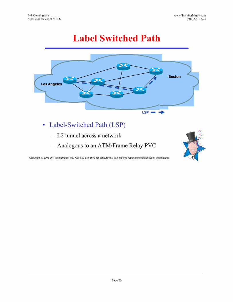
Label Switched Path
�• Label-Switched Path (LSP)�– L2 tunnel across a network
�– Analogous to an ATM/Frame Relay PVC
Los AngelesLos Angeles
BostonBoston
LSPLSP
Bob Cunningham www.TrainingMagic.com A basic overview of MPLS (800) 531-6573
___________________________________________________________________________________________________________________ Page 21
Copyright © 2005 by TrainingMagic, Inc. Call 800 531-6573 for consulting & training or to report commercial use of this material
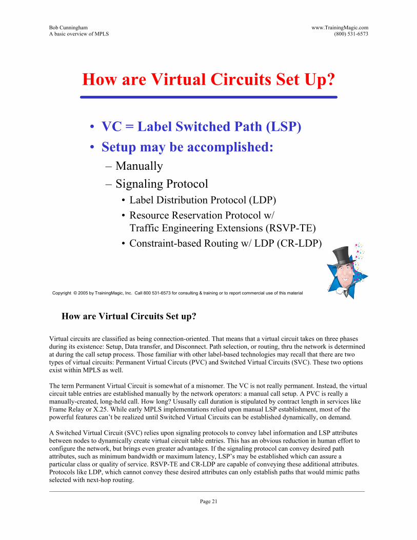
How are Virtual Circuits Set Up?
�• VC = Label Switched Path (LSP)�• Setup may be accomplished:
�– Manually�– Signaling Protocol
�• Label Distribution Protocol (LDP)�• Resource Reservation Protocol w/
Traffic Engineering Extensions (RSVP-TE)�• Constraint-based Routing w/ LDP (CR-LDP)
How are Virtual Circuits Set up? Virtual circuits are classified as being connection-oriented. That means that a virtual circuit takes on three phases during its existence: Setup, Data transfer, and Disconnect. Path selection, or routing, thru the network is determined at during the call setup process. Those familiar with other label-based technologies may recall that there are two types of virtual circuits: Permanent Virtual Circuts (PVC) and Switched Virtual Circuits (SVC). These two options exist within MPLS as well. The term Permanent Virtual Circuit is somewhat of a misnomer. The VC is not really permanent. Instead, the virtual circuit table entries are established manually by the network operators: a manual call setup. A PVC is really a manually-created, long-held call. How long? Ususally call duration is stipulated by contract length in services like Frame Relay or X.25. While early MPLS implementations relied upon manual LSP establishment, most of the powerful features can�’t be realized until Switched Virtual Circuits can be established dynamically, on demand. A Switched Virtual Circuit (SVC) relies upon signaling protocols to convey label information and LSP attributes between nodes to dynamically create virtual circuit table entries. This has an obvious reduction in human effort to configure the network, but brings even greater advantages. If the signaling protocol can convey desired path attributes, such as minimum bandwidth or maximum latency, LSP�’s may be established which can assure a particular class or quality of service. RSVP-TE and CR-LDP are capable of conveying these additional attributes. Protocols like LDP, which cannot convey these desired attributes can only establish paths that would mimic paths selected with next-hop routing.
Bob Cunningham www.TrainingMagic.com A basic overview of MPLS (800) 531-6573
___________________________________________________________________________________________________________________ Page 22
Copyright © 2005 by TrainingMagic, Inc. Call 800 531-6573 for consulting & training or to report commercial use of this material
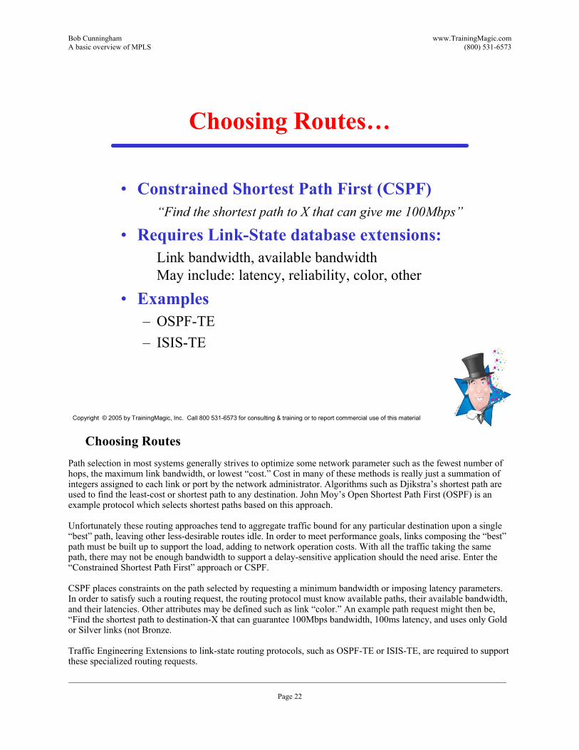
Choosing Routes�…
�• Constrained Shortest Path First (CSPF)�“Find the shortest path to X that can give me 100Mbps�”
�• Requires Link-State database extensions:Link bandwidth, available bandwidth May include: latency, reliability, color, other
�• Examples�– OSPF-TE�– ISIS-TE
Choosing Routes
Path selection in most systems generally strives to optimize some network parameter such as the fewest number of hops, the maximum link bandwidth, or lowest �“cost.�” Cost in many of these methods is really just a summation of integers assigned to each link or port by the network administrator. Algorithms such as Djikstra�’s shortest path are used to find the least-cost or shortest path to any destination. John Moy�’s Open Shortest Path First (OSPF) is an example protocol which selects shortest paths based on this approach. Unfortunately these routing approaches tend to aggregate traffic bound for any particular destination upon a single �“best�” path, leaving other less-desirable routes idle. In order to meet performance goals, links composing the �“best�” path must be built up to support the load, adding to network operation costs. With all the traffic taking the same path, there may not be enough bandwidth to support a delay-sensitive application should the need arise. Enter the �“Constrained Shortest Path First�” approach or CSPF. CSPF places constraints on the path selected by requesting a minimum bandwidth or imposing latency parameters. In order to satisfy such a routing request, the routing protocol must know available paths, their available bandwidth, and their latencies. Other attributes may be defined such as link �“color.�” An example path request might then be, �“Find the shortest path to destination-X that can guarantee 100Mbps bandwidth, 100ms latency, and uses only Gold or Silver links (not Bronze. Traffic Engineering Extensions to link-state routing protocols, such as OSPF-TE or ISIS-TE, are required to support these specialized routing requests.
Bob Cunningham www.TrainingMagic.com A basic overview of MPLS (800) 531-6573
___________________________________________________________________________________________________________________ Page 23
Copyright © 2005 by TrainingMagic, Inc. Call 800 531-6573 for consulting & training or to report commercial use of this material
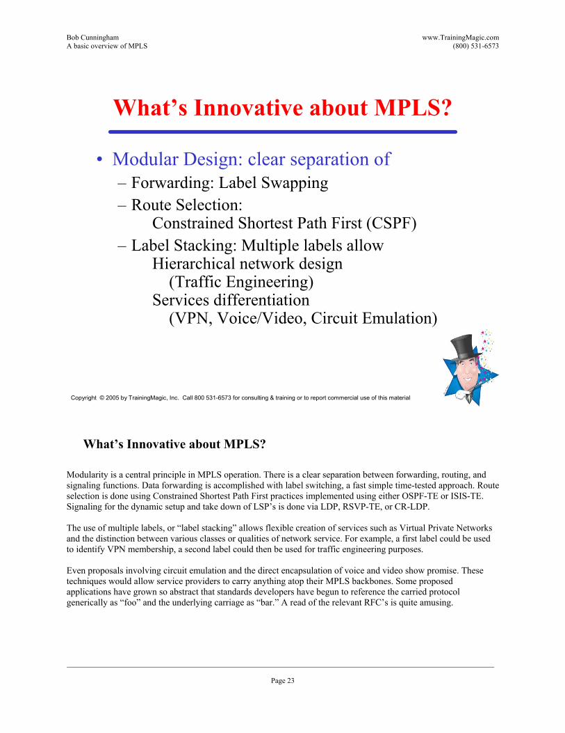
What�’s Innovative about MPLS?
�• Modular Design: clear separation of�– Forwarding: Label Swapping�– Route Selection:
Constrained Shortest Path First (CSPF)�– Label Stacking: Multiple labels allow
Hierarchical network design(Traffic Engineering)
Services differentiation(VPN, Voice/Video, Circuit Emulation)
What�’s Innovative about MPLS? Modularity is a central principle in MPLS operation. There is a clear separation between forwarding, routing, and signaling functions. Data forwarding is accomplished with label switching, a fast simple time-tested approach. Route selection is done using Constrained Shortest Path First practices implemented using either OSPF-TE or ISIS-TE. Signaling for the dynamic setup and take down of LSP�’s is done via LDP, RSVP-TE, or CR-LDP. The use of multiple labels, or �“label stacking�” allows flexible creation of services such as Virtual Private Networks and the distinction between various classes or qualities of network service. For example, a first label could be used to identify VPN membership, a second label could then be used for traffic engineering purposes. Even proposals involving circuit emulation and the direct encapsulation of voice and video show promise. These techniques would allow service providers to carry anything atop their MPLS backbones. Some proposed applications have grown so abstract that standards developers have begun to reference the carried protocol generically as �“foo�” and the underlying carriage as �“bar.�” A read of the relevant RFC�’s is quite amusing.
Bob Cunningham www.TrainingMagic.com A basic overview of MPLS (800) 531-6573
___________________________________________________________________________________________________________________ Page 24
Copyright © 2005 by TrainingMagic, Inc. Call 800 531-6573 for consulting & training or to report commercial use of this material
Who�’s doing MPLS?
�• Major Service Providers using MPLS for�– Traffic Engineering�– VPN services
Who�’s doing MPLS? MPLS is not (all) hype. Major service providers are currently using it for two major functions: Traffic Engineering and Provider Provisioned VPN's. Who's running it? AT&T, BT, C&W, Equant, France Telecom, Global Crossing, Level3, NTT, UUnet, Worldcom. (Just to name a few.) IP service providers are using MPLS to facilitate Traffic Engineering and spread packet flows destined for a single egress across many paths, thereby balancing load. This is not easy to do in Next-Hop-routed system. (By definition in next-hop systems, if all routers have converged, they all pass traffic onto a common path for a particular destination, leaving other less-desirable paths empty!) By establishing multiple virtual circuits across different network paths to the same destination, MPLS can map traffic bound for the same destination to different virtual circuits and paths. This allows the service provider to provide more service with fewer facilities. While the process of Network Engineering says, �“Put the bandwidth where the traffic is�” by building out higher-speed links, Traffic Engineering says, �“Put the traffic where the bandwidth is�” using what you�’ve already got. Generalized-MPLS (formerly MP-Lambda-S) is being adapted to allow Peer-to-Peer or Client-Server relationships between traditional MPLS switchgear and Optical switches. This will allow MPLS endpoints to request, route, and control circuit-switched connections over optical switches and fiber/WDM links. The MPLS forum and IETF are working with the Optical Internetworking Forum (OIF) www.oiforum.com to standardize operations between traditional "packet-switching" (IP/ATM/FR) gear and optical equipment (SONET/SDH/DWDM muxes and cross connects.)

Bob Cunningham www.TrainingMagic.com A basic overview of MPLS (800) 531-6573
___________________________________________________________________________________________________________________ Page 25
Copyright © 2005 by TrainingMagic, Inc. Call 800 531-6573 for consulting & training or to report commercial use of this material
The MPLS Soup of Protocols
�• Network Layer Protocols�– ATM �– Asynchronous Transfer Mode�– IP �– Internet protocol�– Frame Relay�– PoS �– Packet over Sonet�– DWDM?
�• Label Distribution protocols�– LDP �– Label Distribution Protocol�– CR-LDP �– Constrained Based Label Distribution Protocol �– RSVP-TE �– Resource Reservation Protocol
�• Routing Protocols�– BGP4 �– Border Gateway Protocol version 4�– OSPF �– Open Shortest Path First�– IS-IS �– Intermediate System to Intermediate System
Bob Cunningham www.TrainingMagic.com A basic overview of MPLS (800) 531-6573
___________________________________________________________________________________________________________________ Page 26
Copyright © 2005 by TrainingMagic, Inc. Call 800 531-6573 for consulting & training or to report commercial use of this material
Forward Equivalence Classes
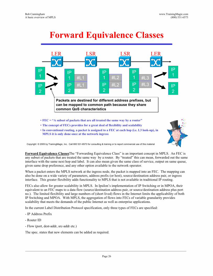
�• FEC = �“A subset of packets that are all treated the same way by a router�”�• The concept of FECs provides for a great deal of flexibility and scalability�• In conventional routing, a packet is assigned to a FEC at each hop (i.e. L3 look-up), in
MPLS it is only done once at the network ingress
Packets are destined for different address prefixes, but can be mapped to common path because they share common QoS characteristics
Packets are destined for different address prefixes, but can be mapped to common path because they share common QoS characteristics
IP1
IP2
IP1
IP2
IP1 #L1IP2
#L1
IP1 #L2IP2
#L2
IP1 #L3IP2
#L3
LER LSR LSR LER
Forward Equivalence ClassesThe �“Forwarding Equivalence Class�” is an important concept in MPLS. An FEC is any subset of packets that are treated the same way by a router. By �“treated�” this can mean, forwarded out the same interface with the same next hop and label. It can also mean given the same class of service, output on same queue, given same drop preference, and any other option available to the network operator.
When a packet enters the MPLS network at the ingress node, the packet is mapped into an FEC. The mapping can also be done on a wide variety of parameters, address prefix (or host), source/destination address pair, or ingress interface. This greater flexibility adds functionality to MPLS that is not available in traditional IP routing.
FECs also allow for greater scalability in MPLS. In Ipsilon�’s implementation of IP Switching or in MPOA, their equivalent to an FEC maps to a data flow (source/destination address pair, or source/destination address plus port no.). The limited flexibility and large numbers of (short lived) flows in the Internet limits the applicability of both IP Switching and MPOA. With MPLS, the aggregation of flows into FECs of variable granularity provides scalability that meets the demands of the public Internet as well as enterprise applications.
In the current Label Distribution Protocol specification, only three types of FECs are specified:
- IP Address Prefix
- Router ID
- Flow (port, dest-addr, src-addr etc.)
The spec. states that new elements can be added as required.

Bob Cunningham www.TrainingMagic.com A basic overview of MPLS (800) 531-6573
___________________________________________________________________________________________________________________ Page 27
Copyright © 2005 by TrainingMagic, Inc. Call 800 531-6573 for consulting & training or to report commercial use of this material
Forward Equivalence Classes (2)
�• Address based�– Source IP Address/Subnet�– Destination IP Address/Subnet�– Ingress/Egress router port�– TCP/UDP port number
�• QoS based�– Peak Cell Rate�– Sustainable Cell Rate �– Burst Tolerance�– Cell Delay Variation Tolerance�– Cell Loss Ratio
Forward Equivalence Classes (2)The forward equivalence class (FEC) is a representation of a group of packets that share the same requirements for their transport. All packets in such a group are provided the same treatment en route to the destination. As opposed to conventional IP forwarding, in MPLS, the assignment of a particular packet to a particular FEC is done just once, as the packet enters the network. FECs are based on service requirements for a given set of packets or simply for an address prefix. The application of the FEC is limitless�—we could define FECs based upon source address, TCP/UDP port number, a destination IP subnet , application specific information, incoming router port, but it also might correspond to any traffic class that the Edge-LSR considers significant. The finer the FEC, the more flexibility we have in controlling the flow of data, but the more LSPs that need to be defined. The coarser the FEC, the more scalable the network is (less LSPs needed), but it is less flexible
Bob Cunningham www.TrainingMagic.com A basic overview of MPLS (800) 531-6573
___________________________________________________________________________________________________________________ Page 28
Copyright © 2005 by TrainingMagic, Inc. Call 800 531-6573 for consulting & training or to report commercial use of this material
Push, Pop, Swap
�• PUSH �– Placing a label or a label stack onto the existing one.
�• POP �– Removing a label from the label stack and forward the packet using the label underneath.
�• SWAP �– Replacing the existing label with a new label and forwarding the packet using a new label.
Push, Pop, Swap Pushing applies an additional label to a packet. MPLS can support multiple stacked labels. Pushing is usually implemented at the label edge router (LER) at the input (ingress) edge of the network. Popping removes the outer-most label from the packet. Because MPLS supported stacks of multiple labels, one or more labels might still be inside. Popping is usually implemented by the LER at the egress edge of the network. Swapping replaces one label with another. As always, MPLS is agnostic regarding the content of the packet. So, the LSR simply swaps the labels without examining the content of the packet.
Bob Cunningham www.TrainingMagic.com A basic overview of MPLS (800) 531-6573
___________________________________________________________________________________________________________________ Page 29
Copyright © 2005 by TrainingMagic, Inc. Call 800 531-6573 for consulting & training or to report commercial use of this material
SHIM Header
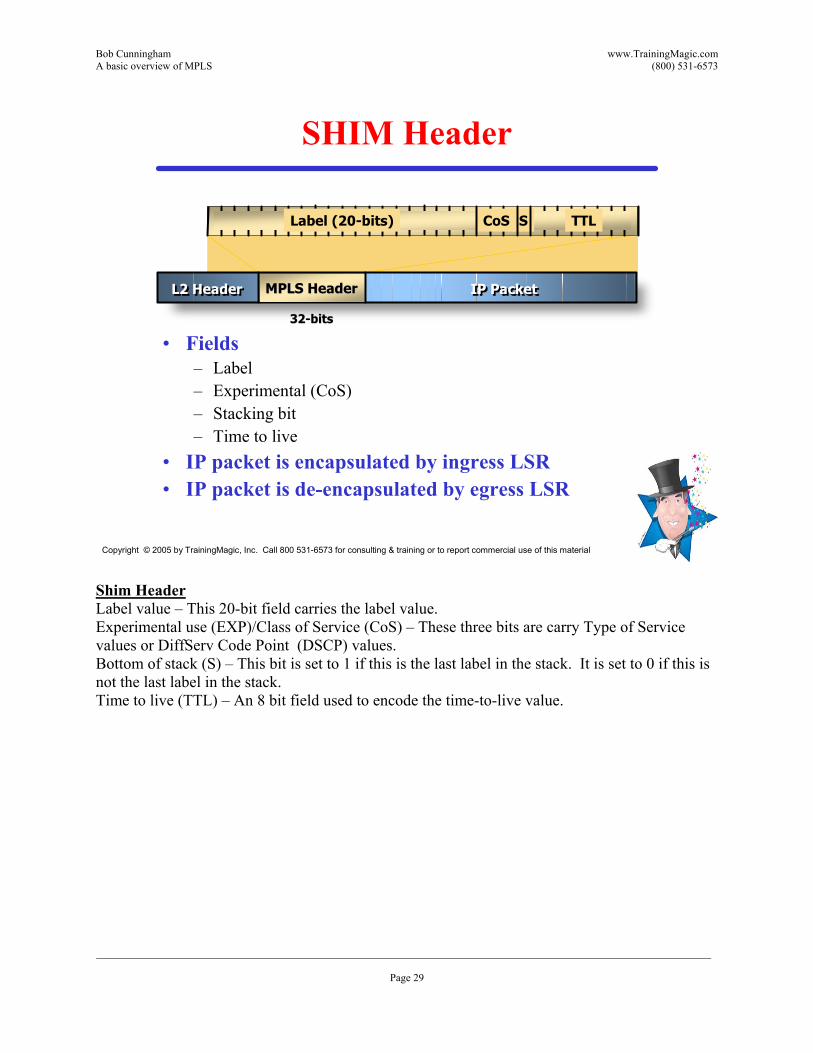
�• Fields�– Label�– Experimental (CoS)�– Stacking bit�– Time to live
�• IP packet is encapsulated by ingress LSR�• IP packet is de-encapsulated by egress LSR
TTLLabel (20-bits) CoS S
IP PacketIP Packet
3232--bitsbits
L2 HeaderL2 Header MPLS HeaderMPLS Header
Shim Header Label value �– This 20-bit field carries the label value. Experimental use (EXP)/Class of Service (CoS) �– These three bits are carry Type of Service values or DiffServ Code Point (DSCP) values. Bottom of stack (S) �– This bit is set to 1 if this is the last label in the stack. It is set to 0 if this is not the last label in the stack. Time to live (TTL) �– An 8 bit field used to encode the time-to-live value.
Bob Cunningham www.TrainingMagic.com A basic overview of MPLS (800) 531-6573
___________________________________________________________________________________________________________________ Page 30
Copyright © 2005 by TrainingMagic, Inc. Call 800 531-6573 for consulting & training or to report commercial use of this material
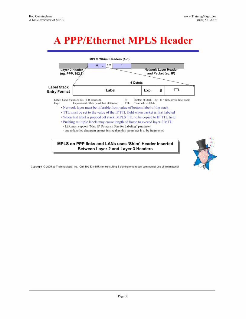
A PPP/Ethernet MPLS Header
Label Exp. S TTL
Label: Label Value, 20 bits (0-16 reserved)Exp.: Experimental, 3 bits (was Class of Service)
Layer 2 Header(eg. PPP, 802.3)
�•�•�•Network Layer Header
and Packet (eg. IP)
4 Octets
MPLS �‘Shim�’ Headers (1-n)
1n
�• Network layer must be inferable from value of bottom label of the stack�• TTL must be set to the value of the IP TTL field when packet is first labeled�• When last label is popped off stack, MPLS TTL to be copied to IP TTL field�• Pushing multiple labels may cause length of frame to exceed layer-2 MTU
- LSR must support �“Max. IP Datagram Size for Labeling�” parameter- any unlabelled datagram greater in size than this parameter is to be fragmented
MPLS on PPP links and LANs uses �‘Shim�’ Header Inserted Between Layer 2 and Layer 3 Headers
MPLS on PPP links and LANs uses �‘Shim�’ Header Inserted Between Layer 2 and Layer 3 Headers
Label StackEntry Format
S: Bottom of Stack, 1 bit (1 = last entry in label stack)TTL: Time to Live, 8 bits

Bob Cunningham www.TrainingMagic.com A basic overview of MPLS (800) 531-6573
___________________________________________________________________________________________________________________ Page 31
Copyright © 2005 by TrainingMagic, Inc. Call 800 531-6573 for consulting & training or to report commercial use of this material
A Frame Relay MPLS Header
�•�•�•n 1
DLCI C/R
EA DLCI FE
CNBECN
DE
EA
Q.922Header
Generic Encap.(PPP/LAN Format) Layer 3 Header and Packet
DLCI Size = 10, 17, 23 Bits
�• Current label value carried in DLCI field of Frame Relay header
�• Can use either 2 or 4 octet Q.922 Address
�• Generic encapsulation contains the additional labels (if any)- The top label contains the TTL which the FR header cannot carry
A Frame Relay MPLS HeaderUsing Frame Relay for MPLS is a little tricky. There must always be at least two labels. The active or top level label is the Frame relay header. The two or four octet addresses of the DLCI field is the label itself. Because the Frame Relay header has no place to put the TTL information needed by MPLS, an additional label, called a shim is used to carry the TTL information. The shim is placed between the FR header and the payload (IP) information. The shim is invisible to FR.

Bob Cunningham www.TrainingMagic.com A basic overview of MPLS (800) 531-6573
___________________________________________________________________________________________________________________ Page 32
Copyright © 2005 by TrainingMagic, Inc. Call 800 531-6573 for consulting & training or to report commercial use of this material
ATM MPLS LabelATM LSR constrained by the cell format imposed by existing ATM standardsATM LSR constrained by the cell format imposed by existing ATM standards
VPI PT CLP HEC
5 OctetsATM Header
Format VCI
AAL5 Trailer
�•�•�•Network Layer Header
and Packet (eg. IP)
1n
AAL 5 PDU Frame (nx48 bytes)
Generic Label Encap.(PPP/LAN format)
ATMSAR
ATM Payload
�• Top 1 or 2 labels are contained in the VPI/VCI fields of ATM header- one in each or single label in combined field, negotiated by LDP
�• Further fields in stack are encoded with �‘shim�’ header in PPP/LAN format- must be at least one, with bottom label distinguished with �‘explicit NULL�’
�• TTL is carried in top label in stack, as a proxy for ATM header (that lacks TTL)
48 Bytes
Label LabelOption 1Option 2 Combined Label
Option 3 LabelATM VPI (Tunnel)
ATM MLS Label When MPLS uses ATM as it�’s underlying path switching technology, the VCI field is used only to represent the label. ATM switching devices look at the VPI/VCI field, whether it is an ATM VPI/VCI or a MPLS label is irrelevant at the ATM Switching Layer. Inside the ATM cells, the MPLS-labeled packet is formatted using standard ATM Adaptation Layer 5 (AAL5). The start of the AAL PDU has no multiprotocol-encapsulated header, but a �“null�” label is always present. The ATM cell header is where the MPLS is stored. However, like Frame Relay, no room exists in that header for the other fields in a standard label (i.e., the EXP, S, and TTL bits). Thus, a label of value �“0�” is present as a place holder for this information. This label, however, is never used to do a label lookup.

Bob Cunningham www.TrainingMagic.com A basic overview of MPLS (800) 531-6573
___________________________________________________________________________________________________________________ Page 33
Copyright © 2005 by TrainingMagic, Inc. Call 800 531-6573 for consulting & training or to report commercial use of this material
Generalized MPLS
�• Each wavelength (lambda) represent a label�• TTL and other information is carried on shim
Wavelength (nm)
1525
1530
1535
1540
1545
1550
1555
1560
1565
Generalized MPLS Over the past few years, the number of wavelengths that can be placed on a fiber by Dense Wave Division Multiplexing technology has exploded. Some systems can place over 700 wavelengths (known as Lambdas) on to a single fiber. With hundreds of wavelengths available, there is enough flexibility to put forward the abstraction of a wavelength as a label. This technology has been known as MPLambda Switching. This technology now called Generalized MPLS (GMPLS). Once a lambda (or optical path) is established between two points, the encapsulation of the data in the lambda could be Ethernet, PPP, FDDI, or any thing else.
Bob Cunningham www.TrainingMagic.com A basic overview of MPLS (800) 531-6573
___________________________________________________________________________________________________________________ Page 34
Copyright © 2005 by TrainingMagic, Inc. Call 800 531-6573 for consulting & training or to report commercial use of this material
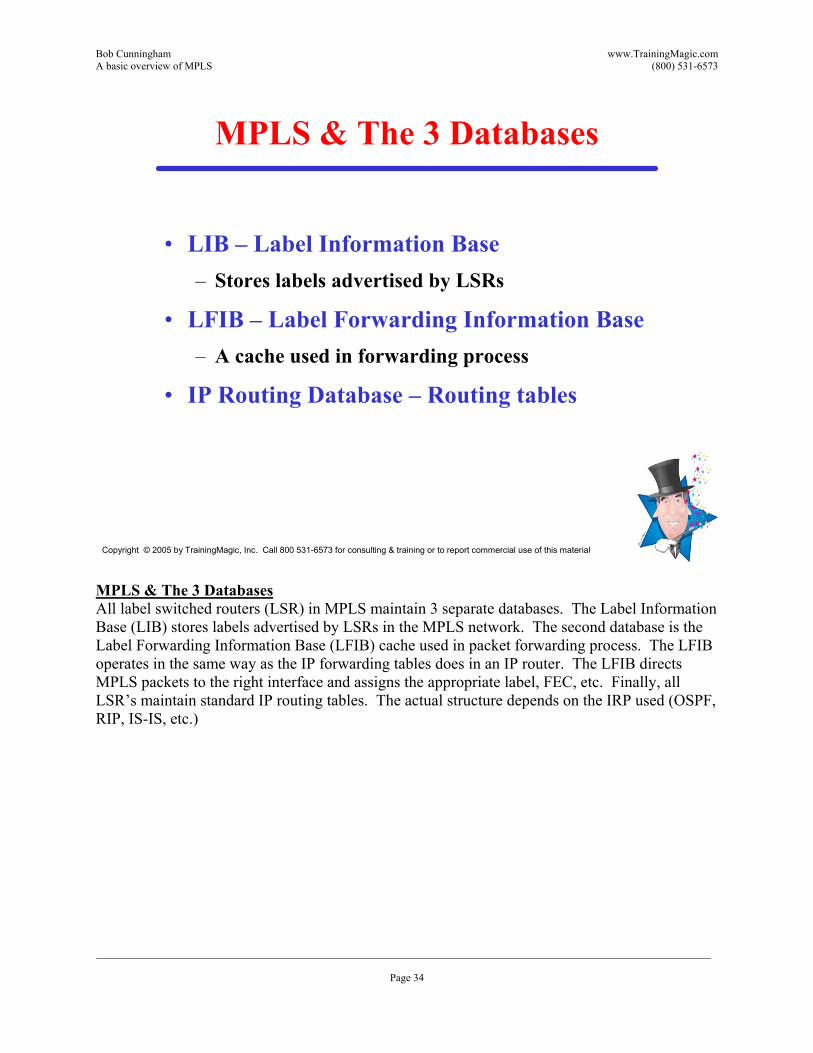
MPLS & The 3 Databases
�• LIB �– Label Information Base�– Stores labels advertised by LSRs
�• LFIB �– Label Forwarding Information Base�– A cache used in forwarding process
�• IP Routing Database �– Routing tables
MPLS & The 3 DatabasesAll label switched routers (LSR) in MPLS maintain 3 separate databases. The Label Information Base (LIB) stores labels advertised by LSRs in the MPLS network. The second database is the Label Forwarding Information Base (LFIB) cache used in packet forwarding process. The LFIB operates in the same way as the IP forwarding tables does in an IP router. The LFIB directs MPLS packets to the right interface and assigns the appropriate label, FEC, etc. Finally, all LSR�’s maintain standard IP routing tables. The actual structure depends on the IRP used (OSPF, RIP, IS-IS, etc.)

Bob Cunningham www.TrainingMagic.com A basic overview of MPLS (800) 531-6573
___________________________________________________________________________________________________________________ Page 35
Copyright © 2005 by TrainingMagic, Inc. Call 800 531-6573 for consulting & training or to report commercial use of this material
Label Distribution Principals
�• Downstream and Upstream
�• Downstream vs. Downstream-on-Demand
�• Ordered vs. Independent stream
�• Hop-by-Hop vs. Explicit Routing
�• Liberal vs. Conservative Retention
Bob Cunningham www.TrainingMagic.com A basic overview of MPLS (800) 531-6573
___________________________________________________________________________________________________________________ Page 36
Copyright © 2005 by TrainingMagic, Inc. Call 800 531-6573 for consulting & training or to report commercial use of this material
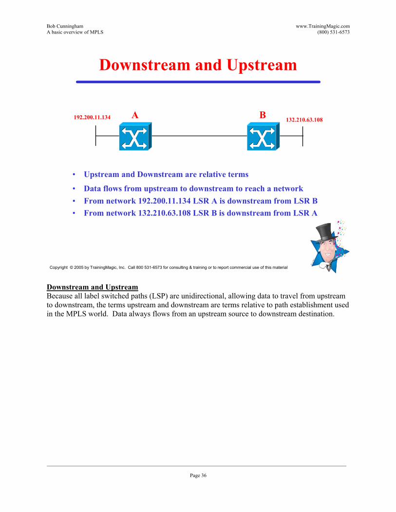
Downstream and Upstream
�• Upstream and Downstream are relative terms
�• Data flows from upstream to downstream to reach a network�• From network 192.200.11.134 LSR A is downstream from LSR B�• From network 132.210.63.108 LSR B is downstream from LSR A
192.200.11.134 132.210.63.108A B
Downstream and Upstream Because all label switched paths (LSP) are unidirectional, allowing data to travel from upstream to downstream, the terms upstream and downstream are terms relative to path establishment used in the MPLS world. Data always flows from an upstream source to downstream destination.
Bob Cunningham www.TrainingMagic.com A basic overview of MPLS (800) 531-6573
___________________________________________________________________________________________________________________ Page 37
Copyright © 2005 by TrainingMagic, Inc. Call 800 531-6573 for consulting & training or to report commercial use of this material
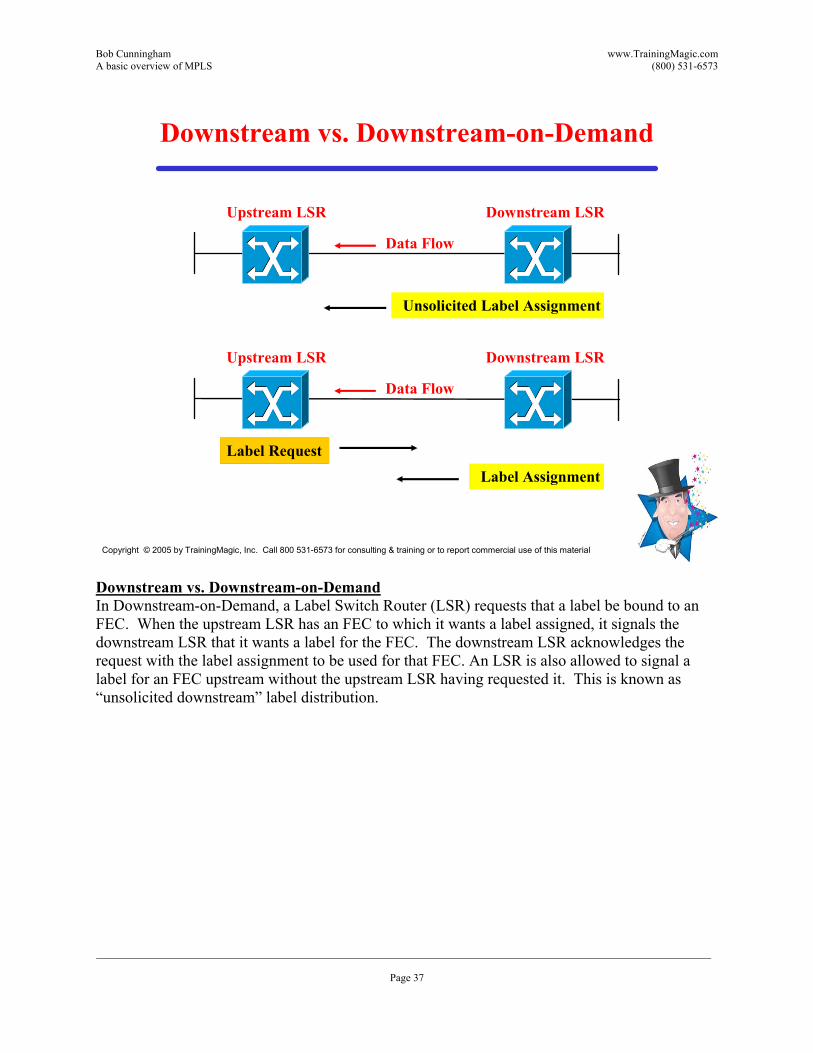
Downstream vs. Downstream-on-Demand
Upstream LSR Downstream LSR
Data Flow
Upstream LSR Downstream LSR
Data Flow
Unsolicited Label Assignment
Label RequestLabel Assignment
Downstream vs. Downstream-on-Demand In Downstream-on-Demand, a Label Switch Router (LSR) requests that a label be bound to an FEC. When the upstream LSR has an FEC to which it wants a label assigned, it signals the downstream LSR that it wants a label for the FEC. The downstream LSR acknowledges the request with the label assignment to be used for that FEC. An LSR is also allowed to signal a label for an FEC upstream without the upstream LSR having requested it. This is known as �“unsolicited downstream�” label distribution.
Bob Cunningham www.TrainingMagic.com A basic overview of MPLS (800) 531-6573
___________________________________________________________________________________________________________________ Page 38
Copyright © 2005 by TrainingMagic, Inc. Call 800 531-6573 for consulting & training or to report commercial use of this material
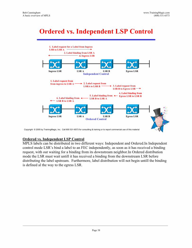
Ordered vs. Independent LSP Control
2. Label binding from LSR Ato Ingress LSR
1. Label request for a Label from Ingress LSR to LSR A
Independent ControlIngress LSR LSR A LSR B Egress LSR
Ordered ControlIngress LSR LSR A LSR B Egress LSR
2. Label request from LSRA to LSR B
1. Label request fromfrom ingress to LSR A
3. Label request from LSR B to Egress LSR
4. Label binding from Egress LSR to LSR B5. Label binding from
LSR B to LSR A6. Label binding from LSR B to LSR A
Ordered vs. Independent LSP ControlMPLS labels can be distributed in two different ways: Independent and Ordered.In Independent control mode LSR�’s bind a label to an FEC independently, as soon as it has received a binding request, with out waiting for a binding from its downstream neighbor.In Ordered distribution mode the LSR must wait untill it has received a binding from the downstream LSR before distributing the label upstream. Furthermore, label distribution will not begin untill the binding is defined al the way to the egress LSR.
Bob Cunningham www.TrainingMagic.com A basic overview of MPLS (800) 531-6573
___________________________________________________________________________________________________________________ Page 39
Copyright © 2005 by TrainingMagic, Inc. Call 800 531-6573 for consulting & training or to report commercial use of this material
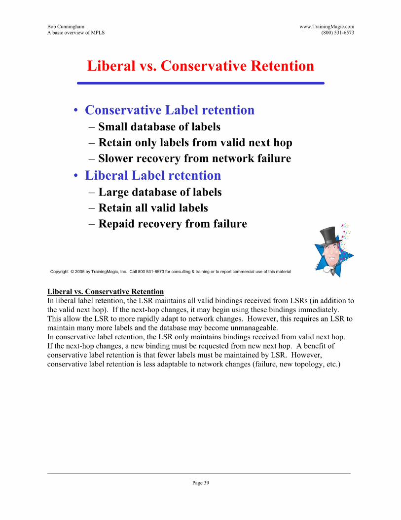
Liberal vs. Conservative Retention
�• Conservative Label retention�– Small database of labels�– Retain only labels from valid next hop�– Slower recovery from network failure
�• Liberal Label retention�– Large database of labels�– Retain all valid labels�– Repaid recovery from failure
Liberal vs. Conservative RetentionIn liberal label retention, the LSR maintains all valid bindings received from LSRs (in addition to the valid next hop). If the next-hop changes, it may begin using these bindings immediately. This allow the LSR to more rapidly adapt to network changes. However, this requires an LSR to maintain many more labels and the database may become unmanageable. In conservative label retention, the LSR only maintains bindings received from valid next hop. If the next-hop changes, a new binding must be requested from new next hop. A benefit of conservative label retention is that fewer labels must be maintained by LSR. However, conservative label retention is less adaptable to network changes (failure, new topology, etc.)
Bob Cunningham www.TrainingMagic.com A basic overview of MPLS (800) 531-6573
___________________________________________________________________________________________________________________ Page 40
Copyright © 2005 by TrainingMagic, Inc. Call 800 531-6573 for consulting & training or to report commercial use of this material
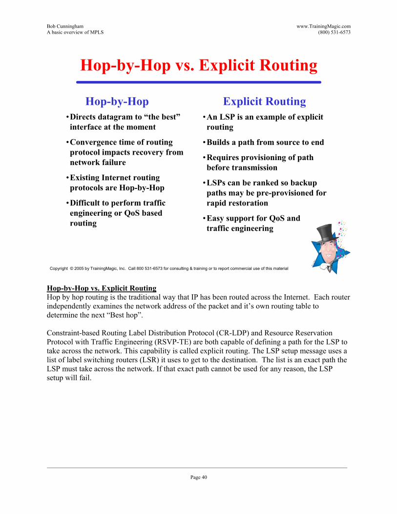
Hop-by-Hop vs. Explicit Routing
�•Directs datagram to �“the best�” interface at the moment
�•Convergence time of routing protocol impacts recovery from network failure
�•Existing Internet routing protocols are Hop-by-Hop
�•Difficult to perform traffic engineering or QoS based routing
�•An LSP is an example of explicit routing
�•Builds a path from source to end
�•Requires provisioning of path before transmission
�•LSPs can be ranked so backup paths may be pre-provisioned for rapid restoration
�•Easy support for QoS and traffic engineering
Hop-by-Hop Explicit Routing
Hop-by-Hop vs. Explicit Routing Hop by hop routing is the traditional way that IP has been routed across the Internet. Each router independently examines the network address of the packet and it�’s own routing table to determine the next �“Best hop�”. Constraint-based Routing Label Distribution Protocol (CR-LDP) and Resource Reservation Protocol with Traffic Engineering (RSVP-TE) are both capable of defining a path for the LSP to take across the network. This capability is called explicit routing. The LSP setup message uses a list of label switching routers (LSR) it uses to get to the destination. The list is an exact path the LSP must take across the network. If that exact path cannot be used for any reason, the LSP setup will fail.
Bob Cunningham www.TrainingMagic.com A basic overview of MPLS (800) 531-6573
___________________________________________________________________________________________________________________ Page 41
Copyright © 2005 by TrainingMagic, Inc. Call 800 531-6573 for consulting & training or to report commercial use of this material
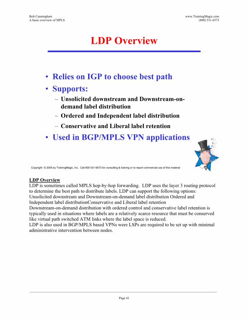
LDP Overview
�• Relies on IGP to choose best path�• Supports:
�– Unsolicited downstream and Downstream-on-demand label distribution
�– Ordered and Independent label distribution�– Conservative and Liberal label retention
�• Used in BGP/MPLS VPN applications
LDP Overview LDP is sometimes called MPLS hop-by-hop forwarding. LDP uses the layer 3 routing protocol to determine the best path to distribute labels. LDP can support the following options: Unsolicited downstream and Downstream-on-demand label distribution Ordered and Independent label distributionConservative and Liberal label retention Downstream-on-demand distribution with ordered control and conservative label retention is typically used in situations where labels are a relatively scarce resource that must be conserved like virtual path switched ATM links where the label space is reduced. LDP is also used in BGP/MPLS based VPNs were LSPs are required to be set up with minimal administrative intervention between nodes.
Bob Cunningham www.TrainingMagic.com A basic overview of MPLS (800) 531-6573
___________________________________________________________________________________________________________________ Page 42
Copyright © 2005 by TrainingMagic, Inc. Call 800 531-6573 for consulting & training or to report commercial use of this material
Label Merging
�• Label merging�– Bind multiple incoming with a common FEC to one labels
�– Once merged, the previous label information is lost
�• Non-merging LSRs�– MPLS supports both Merging and Non-merging LSRs
�– In ATM, merging may cause interleaving of cells from various packets
�– Techniques exist which allow ATM switches to implement label merging
Label MergingA LSR is said to be capable of label merging if it can receive two packets from different incoming interfaces, and/or with different labels, and send both packets out the same outgoing interface with the same label. What is the benefit of label merging? Without label merging, when two packets with the same FEC arrive with different incoming labels, they must be forwarded with different outgoing labels. The number of outgoing labels per FEC could become as large the number of nodes in the network. The larger the forwarding table, the more difficult that tabel is to manage. The MPLS architecture accommodates both merging and non-merging LSRs, but allows for the fact that there may be LSRs that do not support label merging. This leads to the issue of ensuring correct interoperation between merging LSRs and non-merging LSRs. The issue is somewhat different in the case of datagram media versus the case of ATM. The different media types will therefore be discussed separately. Label merging in ATM may result the interleaving of cells from various packets. If cells with different VPIs/VCIs are interleaved into a common VPI/VCI then it is impossible to separate the packets into distinct data flows because all distinguishing information has been lost. This is not only a problem for ATM. . Some Frame Relay switches use cell switching on their backplanes. These switches may also be incapable of supporting label merging. If so, then if cells of different packets are interleaved there is then no way recover the distinct IP datagrams they carry.
Bob Cunningham www.TrainingMagic.com A basic overview of MPLS (800) 531-6573
___________________________________________________________________________________________________________________ Page 43
Copyright © 2005 by TrainingMagic, Inc. Call 800 531-6573 for consulting & training or to report commercial use of this material
Label Merging - ATM
�• VP Merge (SVP multipoint encoding)�– Packet from different sources are distinguished by using different
VCs within the VP�– Advantage : no new hardware�– Disadvantage : requires coordination of the VCI space
�• VC Merge�– Switches are required to buffer cells from one packet until the
entire packet is received�– Advantage : straightforward application of VC switching�– Disadvantage :
�• New hardware (based on per-VC queuing)�• Delays at the merge points
Label Merging �– ATMThere are two methods that can be used to eliminate the cell interleaving problem in ATM, thereby allowing ATM switches to support label merging: The first method is called VP Merging. When multiple VPI�’s are merged into a single virtual path, packets from different sources can be distinguished by using different VCIs within the VP. This method has the advantage that it is compatible with most existing ATM switch implementations. Additionally, VP Merge does not incur the delay of the second method (VC Merge). However, VP Merge has the disadvantage that it requires coordination of the VCI space within each VP. The second method is called VC merging. In VC merging, switches buffer and examine cells at the SAR sublayer. Cells are stored untill the entire AAL PDU has been received. The AALPDU is then transmitted contiguously (and therefore not interleaved). The buffer space required for VC merging can be large and added delay can be considerable
Bob Cunningham www.TrainingMagic.com A basic overview of MPLS (800) 531-6573
___________________________________________________________________________________________________________________ Page 44
Copyright © 2005 by TrainingMagic, Inc. Call 800 531-6573 for consulting & training or to report commercial use of this material
Label Distribution Protocol
�• Provides Link State Route discovery�• Reliable TCP connection to neighbor�• Messages define length, type and value�• Four classes of messages
�– DISCOVERY messages�– ADJACENCY messages (initialization, keep alive, and
shutdown sessions between LSRs)�– LABLE ADVERSTISMENT messages (request, withdraw and
release binding advertisements)�– NOTIFICATION messages (error and advisory information)
Label Distribution ProtocolLabels are created based on the forwarding equivalence classes (FECs) created through the layer 3 routing protocol. In order for label swapping to be possible, common understanding of which FECs map to which labels must be achieved between adjacent routers. The communication of label binding information (I.e. the binding of an FEC to a specific label value) between LSRs is accomplished by label distribution. Label distribution can occur either by piggybacking binding information on an existing routing protocol, or through the creation of a dedicated label distribution protocol (LDP). In either case, a router would communicate binding information after a specific label value is assigned to an FEC. The LSR receiving this binding information would, assuming the information comes from the correct next hop, insert the label value into the label information base associated with the corresponding FEC. After this information is communicated, the upstream LSR knows that if it is forwarding a packet associated with the particular FEC, it can use the associated label value and the downstream LSR that the packet is forwarded to will recognize it as belonging to that FEC. As this information is communicated along a chain of LSRs, a path will be set up along which a number of hops can use label swapping and avoid the full layer 3 look-up.
Bob Cunningham www.TrainingMagic.com A basic overview of MPLS (800) 531-6573
___________________________________________________________________________________________________________________ Page 45
Copyright © 2005 by TrainingMagic, Inc. Call 800 531-6573 for consulting & training or to report commercial use of this material
Label Distribution Protocol Example
Upstream LDP peer Down stream LDP peer
Discovery (Hello messages)
TCP Session Establishment
Initialization Messages
Label Request Messages
Label Mapping Messages
�•�• Distributes label binding informationDistributes label binding information�–�– Runs on Runs on LSRsLSRs in conjunction with IP in conjunction with IP
routing protocols routing protocols �–�– Labels are periodically refreshedLabels are periodically refreshed
�•�• LDP messages typesLDP messages types�–�– Discovery: Locate potential LDP peersDiscovery: Locate potential LDP peers�–�– Session: Manage peerSession: Manage peer--toto--peer TCP sessionspeer TCP sessions�–�– Advertisement: Create, change, or delete label Advertisement: Create, change, or delete label
mappingsmappings�–�– Notification: Provide advisory informationNotification: Provide advisory information
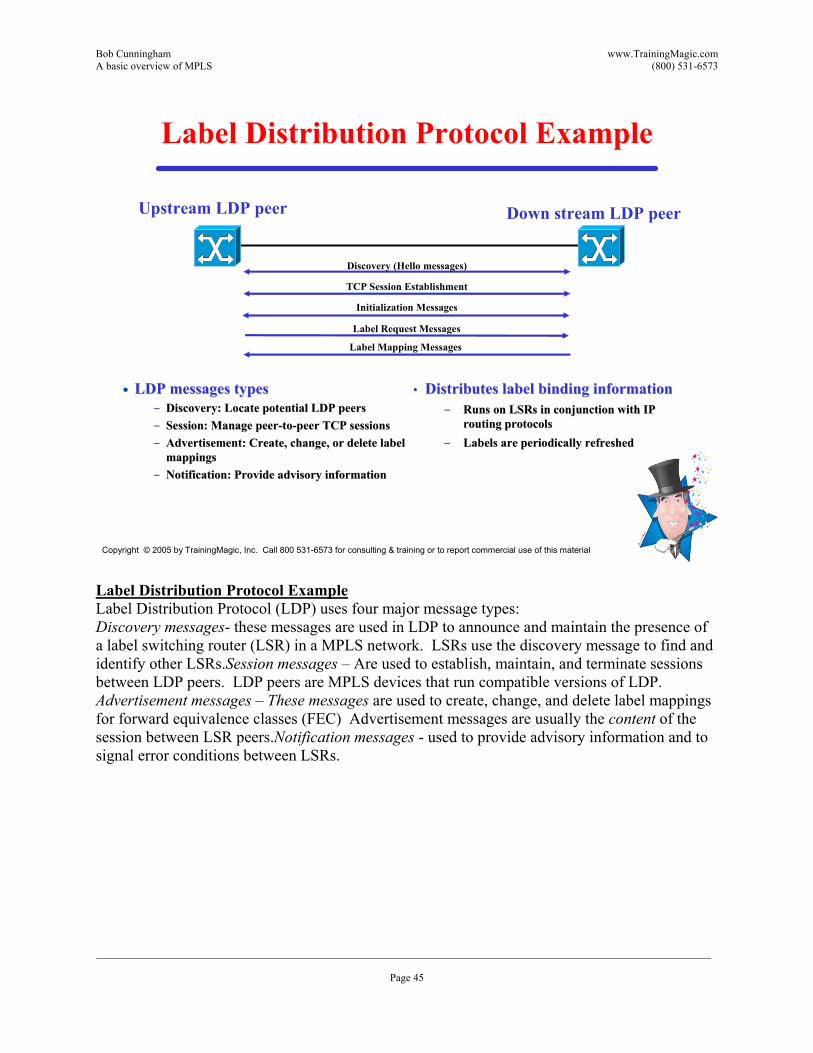
Label Distribution Protocol ExampleLabel Distribution Protocol (LDP) uses four major message types: Discovery messages- these messages are used in LDP to announce and maintain the presence of a label switching router (LSR) in a MPLS network. LSRs use the discovery message to find and identify other LSRs.Session messages �– Are used to establish, maintain, and terminate sessions between LDP peers. LDP peers are MPLS devices that run compatible versions of LDP. Advertisement messages �– These messages are used to create, change, and delete label mappings for forward equivalence classes (FEC) Advertisement messages are usually the content of the session between LSR peers.Notification messages - used to provide advisory information and to signal error conditions between LSRs.

Bob Cunningham www.TrainingMagic.com A basic overview of MPLS (800) 531-6573
___________________________________________________________________________________________________________________ Page 46
Copyright © 2005 by TrainingMagic, Inc. Call 800 531-6573 for consulting & training or to report commercial use of this material
CR-LDP Features
�• Constraint-based Routing-LDP �• Extends LDP features
�– Source routing (strict and loose)�– Route pinning�– CR-LSP pre-emption�– Traffic Parameters�– Resource class
CR-LDP Features The Constraint-based Routing Label Distribution Protocol (CR-LDP) extends the features of Label Distribution Protocol (LDP) by adding additional fields to the LDP messages. Instead of only carrying FEC and label information, CR-LDP adds extra fields applicable to traffic engineering. The most significant features include the following:Strict and loose explicit routing (similar to IP source routing)Specification of traffic parameters (frequency, weight, peak rate, committed rate and excess burst size) Route pinning �– allow no change to route after it has been established.
Pre-emption �– allow a higher priority user to �“bump�” off a lower priority user.
Resource class �– Assign a resource category (like satellite) to a link

Bob Cunningham www.TrainingMagic.com A basic overview of MPLS (800) 531-6573
___________________________________________________________________________________________________________________ Page 47
Copyright © 2005 by TrainingMagic, Inc. Call 800 531-6573 for consulting & training or to report commercial use of this material
CR-LDP Example
TCP congestion control may over ride traffic parameters
Can I m
ake a
connect
ion (1
) ?
Yes (1)
!
Can I make a connection (2) ?
Yes (2)!
Can I m
ake a connection (3) ?
Yes (3)!
Hop by HopTCP connections
CR-LDP process
A
B C
D
CR-LDP ExampleConstraint-Based Routing-Label Distribution Protocol modifies LDP by adding a set of extensions to LDP. The two most important new features are Explicit Routing and Traffic Parameters. Traffic Parameters will be discussed in a subsequent slide. The Explicit Route Objects allow the originating LSR to using its L3 routing tables to request a connection while specifying all of the LSRs to be used in that connection. In this case, LSR A requests an LSP to LSR D. CR-LDP sends a message to LSR B that includes the request for a label, traffic parameters and an Explicit Route object that lists LSR D, C, and D. LSR B responds to this request with a mapping message identifying the assigned label. LSR B and LSR C repeat this process. If any LSR cannot fulfill the requirements of this request the connection fails.
Bob Cunningham www.TrainingMagic.com A basic overview of MPLS (800) 531-6573
___________________________________________________________________________________________________________________ Page 48
Copyright © 2005 by TrainingMagic, Inc. Call 800 531-6573 for consulting & training or to report commercial use of this material
Length
Peak Data Rate (PDR)
Peak Burst Size (PBS)
Committed Data Rate (CDR)
Committed Burst Size (CBS)
Excess Burst Size (EBS)
Traf. Param. TLV U F
Reserved Weight Frequency Flags
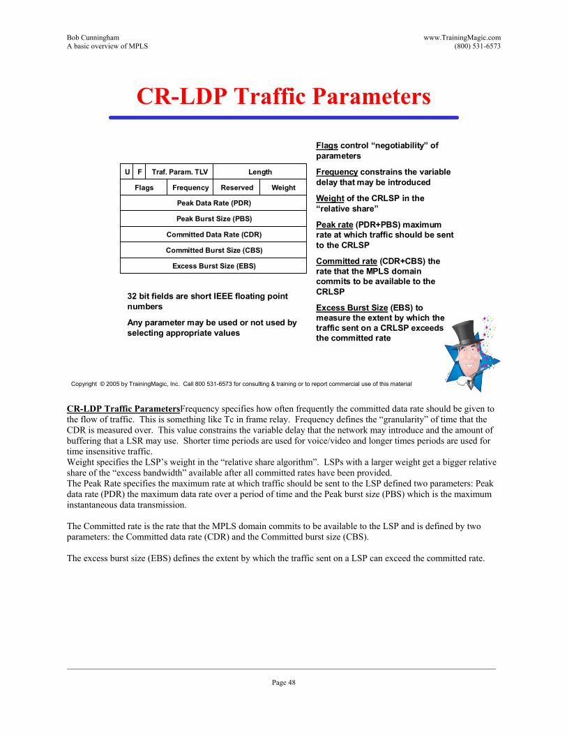
Flags control �“negotiability�” of parameters
Frequency constrains the variable delay that may be introduced
Weight of the CRLSP in the �“relative share�”
Peak rate (PDR+PBS) maximum rate at which traffic should be sent to the CRLSP
Committed rate (CDR+CBS) the rate that the MPLS domain commits to be available to the CRLSP
Excess Burst Size (EBS) to measure the extent by which the traffic sent on a CRLSP exceeds the committed rate
32 bit fields are short IEEE floating point numbers
Any parameter may be used or not used by selecting appropriate values
CR-LDP Traffic Parameters
CR-LDP Traffic ParametersFrequency specifies how often frequently the committed data rate should be given to the flow of traffic. This is something like Tc in frame relay. Frequency defines the �“granularity�” of time that the CDR is measured over. This value constrains the variable delay that the network may introduce and the amount of buffering that a LSR may use. Shorter time periods are used for voice/video and longer times periods are used for time insensitive traffic. Weight specifies the LSP�’s weight in the �“relative share algorithm�”. LSPs with a larger weight get a bigger relative share of the �“excess bandwidth�” available after all committed rates have been provided. The Peak Rate specifies the maximum rate at which traffic should be sent to the LSP defined two parameters: Peak data rate (PDR) the maximum data rate over a period of time and the Peak burst size (PBS) which is the maximum instantaneous data transmission. The Committed rate is the rate that the MPLS domain commits to be available to the LSP and is defined by two parameters: the Committed data rate (CDR) and the Committed burst size (CBS). The excess burst size (EBS) defines the extent by which the traffic sent on a LSP can exceed the committed rate.
Bob Cunningham www.TrainingMagic.com A basic overview of MPLS (800) 531-6573
___________________________________________________________________________________________________________________ Page 49
Copyright © 2005 by TrainingMagic, Inc. Call 800 531-6573 for consulting & training or to report commercial use of this material
Resource Reservation Protocol-TE
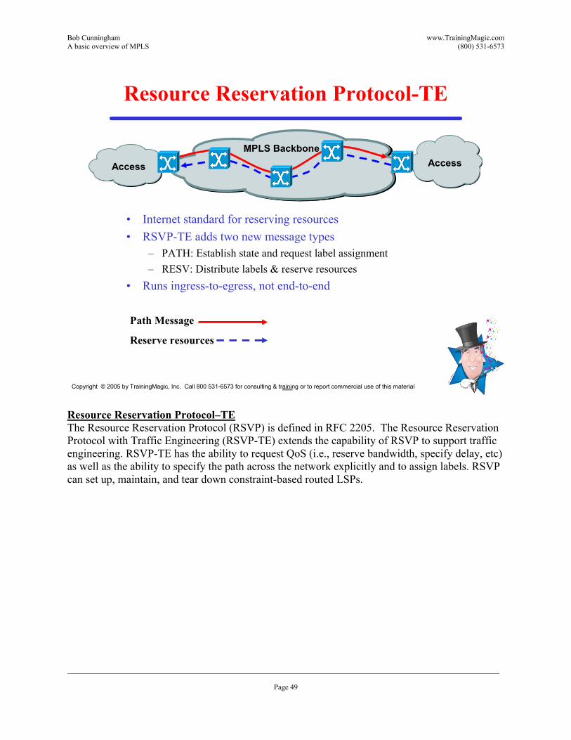
�• Internet standard for reserving resources�• RSVP-TE adds two new message types
�– PATH: Establish state and request label assignment�– RESV: Distribute labels & reserve resources
�• Runs ingress-to-egress, not end-to-end
Access AccessMPLS Backbone
Path Message
Reserve resources
Resource Reservation Protocol�–TEThe Resource Reservation Protocol (RSVP) is defined in RFC 2205. The Resource Reservation Protocol with Traffic Engineering (RSVP-TE) extends the capability of RSVP to support traffic engineering. RSVP-TE has the ability to request QoS (i.e., reserve bandwidth, specify delay, etc) as well as the ability to specify the path across the network explicitly and to assign labels. RSVP can set up, maintain, and tear down constraint-based routed LSPs.
Bob Cunningham www.TrainingMagic.com A basic overview of MPLS (800) 531-6573
___________________________________________________________________________________________________________________ Page 50
Copyright © 2005 by TrainingMagic, Inc. Call 800 531-6573 for consulting & training or to report commercial use of this material
PATH Message & RESV Message
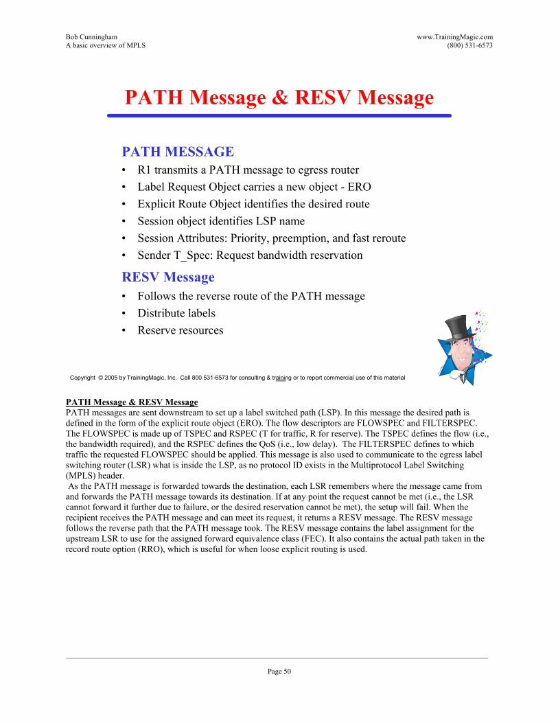
PATH MESSAGE�• R1 transmits a PATH message to egress router�• Label Request Object carries a new object - ERO�• Explicit Route Object identifies the desired route �• Session object identifies LSP name�• Session Attributes: Priority, preemption, and fast reroute�• Sender T_Spec: Request bandwidth reservation
RESV Message�• Follows the reverse route of the PATH message �• Distribute labels �• Reserve resources
PATH Message & RESV MessagePATH messages are sent downstream to set up a label switched path (LSP). In this message the desired path is defined in the form of the explicit route object (ERO). The flow descriptors are FLOWSPEC and FILTERSPEC. The FLOWSPEC is made up of TSPEC and RSPEC (T for traffic, R for reserve). The TSPEC defines the flow (i.e., the bandwidth required), and the RSPEC defines the QoS (i.e., low delay). The FILTERSPEC defines to which traffic the requested FLOWSPEC should be applied. This message is also used to communicate to the egress label switching router (LSR) what is inside the LSP, as no protocol ID exists in the Multiprotocol Label Switching (MPLS) header. As the PATH message is forwarded towards the destination, each LSR remembers where the message came from and forwards the PATH message towards its destination. If at any point the request cannot be met (i.e., the LSR cannot forward it further due to failure, or the desired reservation cannot be met), the setup will fail. When the recipient receives the PATH message and can meet its request, it returns a RESV message. The RESV message follows the reverse path that the PATH message took. The RESV message contains the label assignment for the upstream LSR to use for the assigned forward equivalence class (FEC). It also contains the actual path taken in the record route option (RRO), which is useful for when loose explicit routing is used.
Bob Cunningham www.TrainingMagic.com A basic overview of MPLS (800) 531-6573
___________________________________________________________________________________________________________________ Page 51
Copyright © 2005 by TrainingMagic, Inc. Call 800 531-6573 for consulting & training or to report commercial use of this material
BGP/MPLS VPN
�• RFC 2547bis/RFC 2858�• Scalable�• No real security�• QoS�• BGP is used to exchange VPN routes
BGP/MPLS VPNMPLS can be used as a VPN technology. This application is defined in RFC2547bis. MPLS provides a flexible and scalable way to provision virtual circuits for VPNs with QoS parameters. MPLS VPNs can support thousands of routes. Because it is both scalable and proven, BGP is used to carry MPLS label information. The extensions needed carry label information is carried RFC 2858. It is important to note that MPLS VPNs provides no security. Other technologies must be employed to provide secure communications.
Bob Cunningham www.TrainingMagic.com A basic overview of MPLS (800) 531-6573
___________________________________________________________________________________________________________________ Page 52
Copyright © 2005 by TrainingMagic, Inc. Call 800 531-6573 for consulting & training or to report commercial use of this material
BGP/MPLS Terms
�• Provider Network (P network)�• Provider Router (P router)�• Provider edge router (PE router)�• PE-CE link�• Customer edge router (CE router)�• Route Target�• Tunnels
BGP/MPLS TermsProvider Network (P network) �– The backbone network under the control of the service provider.
Provider Router (P router) �– This router has no knowledge of VPNs.
Provider edge router (PE router) �– This router is the part of the P network that interfaces to CE routers.
PE-CE link �– This is the connection between the PE and CE. This may be an ATM, Frame relay, Ethernet, PPP, or any other type of data link.
Customer edge router (CE router) �– A part of the C network that interfaces to a PE router. This device will usually be a router, although it can be a switch or even a work station.
Route Targets are used to identify VPN sites and to limit the distribution of private forwarding tables
Tunnels refer in this case to MPLS tunnels. Specifically, MPLS labels on top of IPSec or GRE.
Bob Cunningham www.TrainingMagic.com A basic overview of MPLS (800) 531-6573
___________________________________________________________________________________________________________________ Page 53
Copyright © 2005 by TrainingMagic, Inc. Call 800 531-6573 for consulting & training or to report commercial use of this material
BGP/MPLS: PE Details
�• PE-P interaction�– PE and P routers run IGP.�– Establish LSPs between PE routers using LDP or RSVP.�– SP network functions as is.�– SP network not VPN-aware.
�• Virtual Routing and Forwarding Table�– One VRF for every CE-PE interface.�– One VRF for a set of customer sites that share the same routes.�– Contains routes for all VPNs of which the site is a member.
BGP/MPLS: PE DetailsThe VPN Routing and Forwarding (VRF) Selection feature allows a specified interface on a provider edge (PE) router to route packets to different Virtual Private Networks (VPNs) based on the source IP address of the packet. This feature is an improvement over using a policy-based router to route packets to different VPNs. One of the key points about a VPN is the maintenance of security and separation of data; it must prevent communication between sites that are not in the same VPN. One of the ways in which this is achieved is by ensuring that VPNs have their own routing and forwarding tables in the PE router, so a customer site that belongs to a VPN can access only the set of routes contained in that routing table.Each PE router maintains a number of separate forwarding tables known as VRFs (VPN Routing and Forwarding tables), and each site (ie, each PE interface or sub-interface connected to a CE device) must be mapped to one of those VRFs.Note that a VRF table does not necessarily correspond to a particular VPN. Its purpose is to hold the routes that are available to a particular site connected to a PE device. If a site is in multiple VPNs, the VRF associated with that site contains routes from all the VPNs of which it is a member.From a logical point of view, each VRF table maps on to a site. However, having one VRF table for each site connected to a PE router can cause scaleability problems. For this reason, where two or more sites connected to the same PE belong to the same set of VPNs they will require exactly the same set of routes, and they can use the same VRF table. This is known as VRF re-use.
Bob Cunningham www.TrainingMagic.com A basic overview of MPLS (800) 531-6573
___________________________________________________________________________________________________________________ Page 54
Copyright © 2005 by TrainingMagic, Inc. Call 800 531-6573 for consulting & training or to report commercial use of this material
BGP/MPLS: PE-PE Interaction
�• Exchange VPN routes via MP-BGP (RFC2283)�• Route Distinguishers allows overlapping addresses
�– Convert IPv4 addresses into unique VPN-IPv4 addresses�– RFC2547bis
�• Controls route distribution with Route Targets�– draft-ietf-idr-bgp-ext-communities-05.txt
�• PE device assign MPLS label for VPN route�– Carried via BGP.�– draft-ietf-mpls-bgp4-mpls-01.txt
BGP/MPLS: PE-PE InteractionVRF tables are propagated to other PE devices. But since a VRF table is not mapped directly on to a VPN, it is necessary to identify the VPN to which each route applies. This is achieved by means of route targets. Every route that is distributed from a VRF is tagged with an export route target attribute identifying its VPN. Each VRF is tagged with one or more import route target attributes, indicating the VPNs that it wants to import routes for. When routes are distributed, any route marked with a particular export route target attribute will be installed in VRF tables marked with the same import route target attribute. For a fully-meshed VPN, each site's VRF table imports and exports the same routes. For a hub and spoke VPN, the VRF table at the hub site imports routes from all sites, while the VRF tables at the spoke sites import only routes from the hub site VRF.