Embed Size (px)
Citation preview

www.sunhydraulics.com ©2018 Sun Hydraulics Corporation Pub.#999-901-850
sunhydraulics.com/models/electronics/i-o-modules/xmd-series
BLUETOOTH-CONFIGURABLE ELECTRO-HYDRAULIC DRIVERS,CAN CAPABLE
XMD-01/-02
CONFIGURABLESimple, safe & fast setup
via free Bluetooth app within a 30-foot-radius
RUGGEDDesigned for extreme
environmental conditions for the mobile hydraulic industry
UNIVERSAL Use with any electro-proportional
or solenoid-operated on/off valves
XMD Mobile App
C O R P O R A T I O N
®
hydraulics
TABLE OF CONTENTS
XMD Overview 2
Technical Specifications 3
Equipment Installation 4
LED Operation 5
Capabilities 6
Accessories 8

©2018 Sun Hydraulics Corporation2 www.sunhydraulics.com
XMD Series
XMD Intended UseThe XMD module is an electro-hydraulic driver for use with mobile and industrial hydraulic equipment.
Configurable using Sun’s FREE XMD Mobile app readily available worldwide for control of electrically operated hydraulic actuators used in many applications for on- and off-highway equipment including but not limited to agriculture, forestry, construction, marine, earth moving, and material handling.
Tuned for optimal flow and pressure control using Sun valves, the XMD driver delivers repeatable and reliable solutions for your application demands.
Please read and observe any precautions wherever this symbol is used in this document.
Exceptional Sun performance at a competitive priceSUN XMD Series
OVERVIEW
SAE J1939 CAN Communication Configure CAN sensors and joysticks as inputs or configure as a remote node to be used with any CAN-capable programmable controller or display. The XMD is also designed to transmit the analog universal inputs as CAN messages for enhanced intelligence and diagnostic information.
Quick Setup Profiles Select between single- and dual-coil pre-defined profiles for typical pressure and flow configurations for fast, reliable solutions.
Diagnostic ModeAllows technicians worldwide to access alarm and operational conditions without editing password- protected engineered settings.
Input/Output Function Curves Create a custom output curve for finely tuned joystick control or custom flow/pressure curves with the use of the universal inputs and CAN-received messages.
XMD Features
Qui
ck S
etup
Dia
gnos
tic M
ode
Input / Output Curves
CAN Capable Display
Notes:1) No HAZARDOUS LIVE parts are present in the equipment. Terminals are rated to 32 Vdc maximum.2) Recommended supply voltage 12 Vdc or 24 Vdc with negative to earth. 6Vdc protection for engine cranking events.3) Use twisted or twisted shielded-pair cable for CAN per the applicable standard.
www.sunhydraulics.com ©2018 Sun Hydraulics Corporation 3
XMD Series TECHNICAL SPECIFICATIONSOperational SpecificationsSupply Voltage 9 - 32 Vdc
Supply CurrentXMD-01: 3 A max
XMD-02: 6 A max
Weight 0.3 lbs (0.136 kg)
Dimensions (L x W x H)3.38 in x 2.30 in x 1.40 in (85.87 x 58.49 x 35.62 mm)
Enclosure PBT, 30% glass-filled
IP Rating IP69K
CertificationCE, E-Mark, E11 10R-05100024 2014/53/EU (Radio Equipment Directive), 2014/35/EU (Low Voltage Directive)
Communication
CAN 2.0B (Maximum voltage + 32 Vdc)
Baud Rates 125 kbit/s, 250 kbit/s, 500 kbit/s, 1 Mbit/s
Default Baud Rates 250 kbit/s
Protocol SAE J1939
Inputs
Universal InputsXMD-01 (1 universal input) 0 - 5 Vdc, 0 - 10 Vdc, 4-20 mA, digital, frequency (60 Hz-10 kHz), PWM (60 Hz –10
kHz), resistive (0 – 100 kΩ), software configurable XMD-02 (2 universal inputs)
Input Range
Current Input Mode: 0 to +20 mA. Maximum allowable current: +22 mA (impedance Z = ~200 Ω). Active circuit protection above 22 mA and limited to 32 V. Digital Input: 0 to +Supply, not to exceed 32 Vdc (impedance Z = ~10 kΩ).Digital Input: Debounce time 200 ms fixed in device firmware. Maximum voltage on any input pin +32 Vdc and -0.7 Vdc.
Outputs
PWM OutputsXMD-01 (1 PWM output) 0-3.0 Amps Peak -40°C + 75°C continuous per channel
0-2.7 Amps Peak +75°C + 85°C continuous per channelXMD-02 (2 PWM outputs)
Current Regulation ± 1mA above 35 mA
PWM Frequency 33 Hz - 5 kHz
Dither Frequency 33 Hz - 500 Hz
Dither Amplitude 0 - 25% of PWM Period
Diagnostics Open/short-circuit detection
Flyback Protection Integrated diode protection
Ramp Time 0 - 65 seconds, 1-mS increments
Reference Output 5 Vdc, ±0.1 Vdc (250 mA max.)
Operating Temperature -40°C to +85°C (-40°F to +185°F) Vibration 33.3 Hz 6.8g Peak (Spec: S-367 Section 11.0)
Storage Temperature -60°C to +120°C (-76°F to +248°F) Shock 49g Peak (Spec: S-367 Section 12.0)
EMC/EMI EN 55024, EN 55032, EN 13309, EN/ISO 14982, ISO 13766, ISO 16750-2, J1113-4/11/12/13/26, ISO 1142-2/10, CISPR 25, FCC 15B, ICES-003, UNECE Reg 10.5, EN 61326-1:2013, EN 301 489-1 V2.2.0, EN 301 489-17, EN 12895
Environmental
Patent Number Patent Pending
Patent
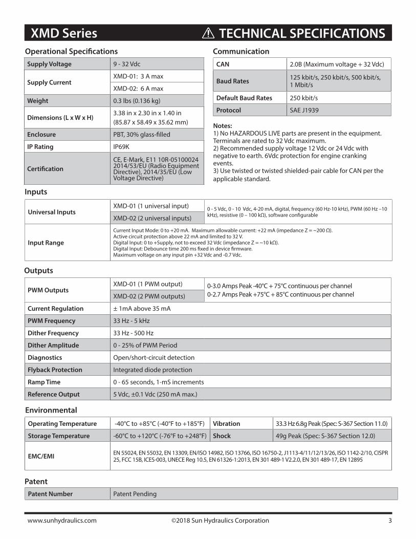
Recommended Wiring Practices:
1) For best grounding practices, isolate pin 7, supply ground, from pins 3 and 5, command, +5Vdc reference, and output grounds.
2) Use twisted or twisted shielded-pair cable for CAN per the applicable standard.
3) Confirm that the CAN network is properly terminated using 120-Ω resistors.
4) Make certain that the harness is designed and constructed to minimize induced interference resulting from EMI coupling between signal wires.
5) Keep high-voltage AC cables separate from low-voltage DC signal and supply cables.
6) Check ALL wire connections to and from this unit to ensure NO short or open circuits are present.
7) Ensure that any unused wires/connections are terminated safely and not shorted together.
8) Isolate the amplifier if any battery charging or battery boosting takes place on the installation.
9) Follow and abide by all applicable health and safety standards – protect yourself and others.
10) Never disconnect or connect wires to or from this unit unless it is isolated from the power supply.
11) Use best practice wiring standards
©2018 Sun Hydraulics Corporation4 www.sunhydraulics.com
XMD SeriesEQUIPMENT INSTALLATION
Equipment Installation
Pin XMD-01 /-02Description
1 CAN_LO
2 CAN_HI
3 GND (Inputs, Outputs & 5Vref )
4XMD-01 No Connection
XMD-02 PWM Output, Coil B
5 GND (Inputs, Outputs & 5 Vref )
6 PWM Output, Coil A
7 Supply GND
8 Supply PWR
9 Enable
10 +5 Vref (250 mA max)
11 Universal Input 1
12XMD-01 No Connection
XMD-02 Universal Input 2
Mechanical Installation:
The controller should be mounted on a flat surface. Provide sufficient clearance from moving parts.
1) Recommend mounting hardware: #8-32 x ½ T18-8 stainless screws, suggested torque 22 in-lbf
2) Do not mount in a location that will re-sult in ambient temperatures greater than specified operational temperature limits.
3) The XMD is compatible with standard 35-mm DIN Rail.
The XMD drivers should be installed and operated by a competent electrician, technician or engineer. Improper installation and use of these products can result in significant threat to both individuals and equipment. In the event of an equipment breakdown, do not attempt to repair the driver as there are no user-serviceable parts inside the product. Evidence of tampering will invalidate the warranty.
Installation BracketNotes:
1) Use size 16 contact sockets for wire sizes: 16, 18, and 20 AWG.
2) Use crimp tool: HDT-48-00
3) Compatible with any DT06-12SA-XXX mating connector
4) Preferred mating connectors: - DT06-12SA - DT06-12SA-P012
5) Use standard Deutsch back shell for IP69K rating, DT12S-BT
Warning: Prior to weldingIn order to avoid damage to the product, ensure that all electrical connections are fully disconnected from the XMD driver prior to welding on the machine.
Wiring Pin Out
A 10A ATC or ATO fuse is required to be installed ahead of the equipment.
www.sunhydraulics.com ©2018 Sun Hydraulics Corporation 5
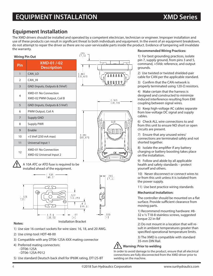
XMD Series LED OPERATION
LED Operation
Comm / Fault LED OperationMode of Operation Status Description
Normal Operating mode, OFF OFF
Connected to mobile phone app / Configuration Mode
Blink/Green - 1 blink 125 ms ON/OFF 500 ms
Receiving CAN messagesBlink / Green – 2 blinks 125 ms ON/ pause OFF 500 ms
CAN Message TimeoutBlink / Red – 2 blinks 125 ms ON/pause OFF 500 ms
Coil Short, ON RED ON/Red
Coil Open Blink/Red - 3 blinks 125 ms ON/ pause OFF 500 ms
Command % out of range Blink/Red - 1 blink ON/ pause OFF 500 ms
Power LED OperationMode of Operation Status Description
Normal Operating mode, no faults ON GREEN
Supply Voltage Below 9VDC ON Red
Supply Voltage Above 32VDC Blink / Red - 1 blink ON/ pause OFF 500 ms
If the equipment is used in a manner not specified by the manufacturer, the protection by the equip-ment may be impaired.
This unit is intended only for connection to vehicle electrical systems and voltage above the identified ratings should never be connected to the unit.
This equipment has not been investigated as a safety rated component and shall not be relied upon as a safety device. Separate emergency stop equipment must be integrated on the machine in accordance with the machinery directive. The operator of the equipment shall always be in sight of the controlled machine and be prepared to use emergency stop equipment if any malfunction occurs.
The +5V reference, pin 10, is intended to source stable voltage to external equipment and must not be connected to +Supply Power or Ground, or permanent damage to the XMD will result.
©2018 Sun Hydraulics Corporation6 www.sunhydraulics.com
XMD SeriesCAPABILITIES
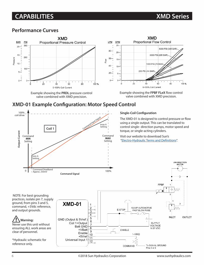
Performance Curves
Example showing the PRDL pressure control valve combined with XMD precision.
Example showing the FPBF FLeX flow control valve combined with XMD precision.
100%0
CommandMIN
Setting
100%coil drive
CommandMAX
Setting
Imin ASetting
Imax ASetting
Command Input Signal
Command DeadbandApprox. 250mV
Coil 1
Out
put C
urre
nt
Command Signal
XMD-01 Example Configuration: Motor Speed ControlSingle-Coil Configuration
The XMD-01 is designed to control pressure or flow using a single output. This can be translated to control single- direction pumps, motor speed and torque, or single-acting cylinders.
Visit our website to download Sun’s “Electro-Hydraulic Terms and Definitions”.
Never use this unit without ensuring ALL work areas are clear of personnel.
*Hydraulic schematic for reference only.
Warning:
NOTE: For best grounding practices, isolate pin 7, supply ground, from pins 3 and 5, command, +5Vdc reference, and output grounds.
www.sunhydraulics.com ©2018 Sun Hydraulics Corporation 7
XMD Series CAPABILITIES
100%0
CommandMIN
Setting
100%coil drive
CommandMAX
Setting
Imin ASetting
Imax ASetting
Command Input Signal
Coil 2
Out
put C
urre
nt
50%Command Signal
Imin BSetting
Coil 1
CommandMID
Setting
Imax BSetting
XMD-02 Example Configuration: Cylinder Direction & Speed Control
The XMD-02 is designed to control pressure or flow using two outputs that can be configured for direc-tional or independent use. This can be translated to control bi-directional variable speed pumps, bi-directional motors and bi-directional cylinders.
Visit our website to download Sun’s “Electro-Hydraulic Terms and Definitions”.
Dual-Coil Configuration
The XMD Mobile App is designed to offer single- and dual-output applications for the XMD-02. Both outputs can be configured to operate idependently, simultaneously or inverted for directional control as shown here.
XMD Mobile App Configuration
ConnectionsThe XMD open architecture offers a wide range of connection and coil compatiblity. Connections include Deutsch, DIN 43650-A, Amp Junior Timer, twin-lead and metri-pack.
Metri-packTwin-lead DIN Amp JuniorDeutsch Exp. proof
Never use this unit without ensuring ALL work areas are clear of personnel.
*Hydraulic schematic for reference only.
Warning:
NOTE: For best grounding practices, isolate pin 7, supply ground, from pins 3 and 5, command, +5Vdc reference, and output grounds.
Deutsch backshell Mfg P/N: DT12S-BT
The XMD product is compatible with the
standard Deutsch backshell and can be
sourced separately.
2-pin Deutsch backshell
Mfg P/N: DT2S-BTSourced separately
www.sunhydraulics.com ©2018 Sun Hydraulics Corporation Pub.#999-901-850
MODEL CODE CONFIGURATIONXMD SeriesACCESSORIES
®
C O R P O R A T I O Nhydraulics
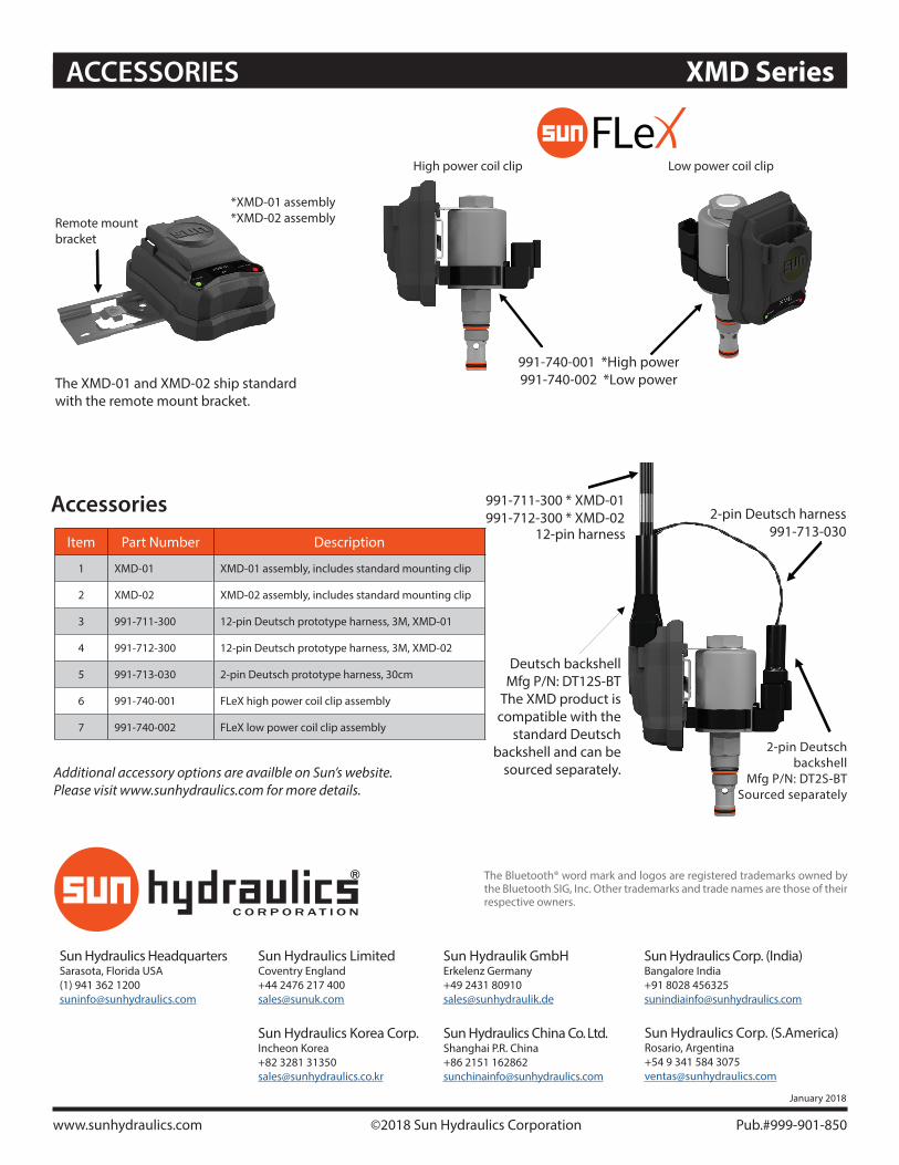
Accessories
The Bluetooth® word mark and logos are registered trademarks owned by the Bluetooth SIG, Inc. Other trademarks and trade names are those of their respective owners.
Item Part Number Description
1 XMD-01 XMD-01 assembly, includes standard mounting clip
2 XMD-02 XMD-02 assembly, includes standard mounting clip
3 991-711-300 12-pin Deutsch prototype harness, 3M, XMD-01
4 991-712-300 12-pin Deutsch prototype harness, 3M, XMD-02
5 991-713-030 2-pin Deutsch prototype harness, 30cm
6 991-740-001 FLeX high power coil clip assembly
7 991-740-002 FLeX low power coil clip assembly
The XMD-01 and XMD-02 ship standard with the remote mount bracket.
Remote mountbracket
*XMD-01 assembly*XMD-02 assembly
991-740-001 *High power991-740-002 *Low power
High power coil clip Low power coil clip
991-711-300 * XMD-01 991-712-300 * XMD-02
12-pin harness 2-pin Deutsch harness
991-713-030
Additional accessory options are availble on Sun’s website.Please visit www.sunhydraulics.com for more details.
January 2018
Sun Hydraulics HeadquartersSarasota, Florida USA(1) 941 362 [email protected]
Sun Hydraulics Korea Corp.Incheon Korea+82 3281 [email protected]
Sun Hydraulics LimitedCoventry England+44 2476 217 [email protected]
Sun Hydraulics China Co. Ltd.Shanghai P.R. China+86 2151 [email protected]
Sun Hydraulik GmbHErkelenz Germany+49 2431 [email protected]
Sun Hydraulics Corp. (India)Bangalore India+91 8028 [email protected]
Sun Hydraulics Corp. (S.America)Rosario, Argentina+54 9 341 584 [email protected]


![Produktkatalog differenzdrucktransmitter - diribo...5 XMD Differenz-Druckmessumformer Technische Daten druck und füllstand Druckbereiche Nenndruck [bar] 0,075 0,4 2 7 20 zulässiger](https://img.dokumen.tips/doc/110x75/5e92d5308e2d1f056007e9b5/produktkatalog-differenzdrucktransmitter-diribo-5-xmd-differenz-druckmessumformer.jpg)