Embed Size (px)
Citation preview
BLIND CHANNEL ESTIMATION AND
MULTIUSER DETECTION FOR MULTI-RATE
CDMA COMMUNICATIONS
Lei Huang
B.Sc., M.Sc.
SUBMITTED IN FULFILLMENT OF THE REQUIREMENTS FOR THE DEGREE OF
DOCTOR OF PHILOSOPHY
School of Electrical Engineering
Faculty of Science, Engineering and Technology
Victoria University of Technology
Melbourne, Australia
August 2003

To my dear wife, Lingfeng Liu
ii

Table of Contents
Table of Contents iii
Abstract v
Acknowledgements vi
Abbreviations vii
1 Introduction 1
1.1 Cellular Wireless Communications . . . . . . . . . . . . . . . . . . . . . . . 1
1.2 Multiuser Detection for DS/CDMA . . . . . . . . . . . . . . . . . . . . . . . 3
1.3 Blind Channel Estimation and Multiuser Detection . . . . . . . . . . . . . . 6
1.4 Multicarrier DS/CDMA . . . . . . . . . . . . . . . . . . . . . . . . . . . . . 9
1.5 Contribution of The Thesis . . . . . . . . . . . . . . . . . . . . . . . . . . . 11
1.6 Thesis Overview . . . . . . . . . . . . . . . . . . . . . . . . . . . . . . . . . 15
2 Multiuser Detection for Multi-rate DS/CDMA 17
2.1 Multi-rate CDMA Transmission . . . . . . . . . . . . . . . . . . . . . . . . . 18
2.2 Multi-rate Signal Modelling . . . . . . . . . . . . . . . . . . . . . . . . . . . 21
2.3 Multi-rate Multiuser Detection for DS/CDMA . . . . . . . . . . . . . . . . 24
2.4 Multi-rate Blind Channel Estimation and Multiuser Detection . . . . . . . . 28
2.5 Multi-rate Multicarrier DS/CDMA . . . . . . . . . . . . . . . . . . . . . . . 30
2.6 Summary . . . . . . . . . . . . . . . . . . . . . . . . . . . . . . . . . . . . . 32
3 Space-time Blind Multiuser Detection for Multi-rate DS/CDMA Sig-
nals 33
3.1 Signal Models . . . . . . . . . . . . . . . . . . . . . . . . . . . . . . . . . . . 35
3.2 ST Dual-rate Blind Linear Detectors . . . . . . . . . . . . . . . . . . . . . . 38
3.2.1 ST Low-rate Blind Linear Detectors . . . . . . . . . . . . . . . . . . 38
3.2.2 ST High-rate Blind Linear Detectors . . . . . . . . . . . . . . . . . . 40
3.2.3 A Comparison of ST Low-rate and High-rate Blind Linear Detectors 43
iii
3.3 Asynchronous Extension . . . . . . . . . . . . . . . . . . . . . . . . . . . . . 48
3.4 Adaptive Implementations . . . . . . . . . . . . . . . . . . . . . . . . . . . . 52
3.5 Two-stage ST Dual-rate Blind Detectors . . . . . . . . . . . . . . . . . . . . 54
3.6 Numerical Examples . . . . . . . . . . . . . . . . . . . . . . . . . . . . . . . 57
3.7 Summary . . . . . . . . . . . . . . . . . . . . . . . . . . . . . . . . . . . . . 63
4 Blind Channel Estimation in Dual-rate DS/CDMA Systems 66
4.1 Signal Models . . . . . . . . . . . . . . . . . . . . . . . . . . . . . . . . . . . 67
4.1.1 Low-rate Signal Model . . . . . . . . . . . . . . . . . . . . . . . . . . 69
4.1.2 High-rate Signal Model . . . . . . . . . . . . . . . . . . . . . . . . . 73
4.2 Dual-rate Blind Channel Estimation . . . . . . . . . . . . . . . . . . . . . . 75
4.2.1 Low-rate Blind Channel Estimation . . . . . . . . . . . . . . . . . . 75
4.2.2 High-rate Blind Channel Estimation . . . . . . . . . . . . . . . . . . 77
4.3 Adaptive Implementations . . . . . . . . . . . . . . . . . . . . . . . . . . . . 79
4.4 Dual-rate Blind MMSE Detection . . . . . . . . . . . . . . . . . . . . . . . . 82
4.5 Numerical Examples . . . . . . . . . . . . . . . . . . . . . . . . . . . . . . . 83
4.6 Summary . . . . . . . . . . . . . . . . . . . . . . . . . . . . . . . . . . . . . 85
5 Blind Timing Acquisition and Channel Estimation for Multi-rate Mul-
ticarrier DS/CDMA 89
5.1 Signal Model . . . . . . . . . . . . . . . . . . . . . . . . . . . . . . . . . . . 91
5.2 Problem Formulation . . . . . . . . . . . . . . . . . . . . . . . . . . . . . . . 94
5.3 Timing Acquisition and Channel Estimation . . . . . . . . . . . . . . . . . . 95
5.4 Numerical Examples . . . . . . . . . . . . . . . . . . . . . . . . . . . . . . . 99
5.5 Performance Analysis . . . . . . . . . . . . . . . . . . . . . . . . . . . . . . 104
5.6 Summary . . . . . . . . . . . . . . . . . . . . . . . . . . . . . . . . . . . . . 109
6 Conclusions 111
6.1 Thesis Summary . . . . . . . . . . . . . . . . . . . . . . . . . . . . . . . . . 111
6.2 Suggestions for Further Study . . . . . . . . . . . . . . . . . . . . . . . . . . 113
Bibliography 115
A Publications 127
A.1 Journal Papers . . . . . . . . . . . . . . . . . . . . . . . . . . . . . . . . . . 127
A.2 Conference Papers . . . . . . . . . . . . . . . . . . . . . . . . . . . . . . . . 127
iv

Abstract
The future wireless communications systems should be able to offer wide variety of applica-
tions, which have vastly different quality of service (QoS) requirements. The time-variable
QoS may require the support of variable bit rates on the wireless links to the individual
users. Multi-rate DS/CDMA is a promising basis on which to support the variable bit
rates on the individual wireless links. Currently, the study on channel estimation and mul-
tiuser detection for multi-rate DS/CDMA, which makes full use of the nature of multi-rate
signals, is still at its early stage.
The thesis deals with the application of subspace-based techniques to blind channel
estimation and multiuser detection for multi-rate DS/CDMA, including single-carrier and
multicarrier scenarios. For the single-carrier case, space-time blind linear multiuser de-
tection is investigated for synchronous dual-rate systems over the AWGN channel. The
performance is evaluated analytically. The multi-rate generalization and the asynchronous
extension are discussed. Two-stage space-time dual-rate blind detectors are also presented.
Furthermore, blind adaptive channel estimation and detection schemes for asynchronous
dual-rate systems over frequency-selective multipath channels are developed. In the con-
text of multicarrier DS/CDMA, based on a finite-length truncation approximation on the
band-limited chip waveform, blind timing acquisition and channel estimation scheme is
proposed for multi-rate systems. The channel estimation error due to the finite-length chip
waveform truncation is analyzed by exploiting a first-order perturbation approximation.
v

Acknowledgements
First of all I would like to thank my principal supervisor, Associate Professor Fu-Chun
Zheng, for his continual financial support and research guidance. He brought me to the
field of signal processing for wireless communications, and constantly entertained me with
intriguing discussions and questions. His knowledge, experience and commitment have
benefited me tremendously during this research. It is my great pleasure to have such an
opportunity to work with him.
My deep gratitude goes to Professor Mike Faulkner, my co-supervisor, for his support
and help in my research. His enthusiasm for research and devotion to work have been
constant sources of inspiration and encouragement for my advancement.
I am truly indebted to Associate Professor Jack Singh, Dr. Ying Tan, Ms. Shukonya
Benka and Ms. Shirley Herrewyn for their genuine help.
My thanks should also go to my colleagues at Center for Telecommunications and
Microelectronics and my friends. The memories I shared with Leon, Alex, Mladen, Ronny,
Hai, Melvyn, Nghia, Don, Wei, Kai, Trung, Gavin, Edward, Shane, and Holly will always
remain with me.
Special thanks should go to Australian Telecommunications Cooperative Research Cen-
ter (ATcrc) for its financial support.
Finally, I wish to express my foremost gratitude for the support and encouragement I
have received from my parents as well as my two sisters.
vi
Abbreviations
3G Third-generation
AWGN Additive white Gaussian noise
BER Bit-error-rate
BPSK Binary phase-shift keying
CDMA Code division multiple access
DDFD Decorrelating decision feedback detector
DS Direct-sequence
DOA Direction of arrival
EVD Eigenvalue decomposition
FDD Frequency division duplexing
FDMA Frequency division multiple access
FFT Fast Fourier transform
FIR Finite impulse response
GSIC Groupwise successive interference cancellation
HRD High-rate decorrelator
ISI Inter-symbol interference
LMS Least-mean-square
LRD Low-rate decorrelator
MAI Multiple access interference
MC Multicode
ML Maximum-likelihood
MMSE Minimum mean-squared error
vii

MOE Minimum output energy
MRC Maximal ratio combining
MSC Mobile switching center
MVDR Minimum-variance distortionless response
NFR Near-far resistance
OFDM Orthogonal frequency division multiplexing
OVSF Orthogonal variable spreading factor
PAST Projection approximation subspace tracking
PIC Parallel interference cancellation
PSTN Public switching telephone network
QoS Quality of service
RLS Recursive least-squares
RMSE Root mean-squared error
SNR Signal-to-noise ratio
SIC Successive interference cancellation
SINR Signal-to-interference-plus-noise ratio
ST Space-time
STBC Space-time block coding
SVD Singular value decomposition
TDD Time division duplexing
TDMA Time division multiple access
VCR Variable chip rate
VSF Variable spreading factor
WLAN Wireless local area network
viii

Chapter 1
Introduction
1.1 Cellular Wireless Communications
Cellular wireless communications has undergone enormous growth over the past two
decades, and nearly all market projections have indicated that this trend will last well
into the future. In fact, it is expected that the number of wireless customers will surpass
that of conventional wireline customers in most developed countries in the near future.
The main challenges that the wireless communications industry now faces come from the
limited resources in terms of frequency spectrum and the hostile radio propagation envi-
ronment. As a consequence, how to increase spectrum efficiency and improve link quality
is of great commercial interest.
The success of cellular radio systems is mainly due to the cellular concept [1]. By
dividing a large geographic area into small areas known as cells and then using the same
radio channels in the cells located some distance away from each other, cellular radio
systems can support a large number of users over a large geographic area using a limited
frequency spectrum. In addition, sophisticated handoff techniques enable a call to proceed
1
2
without being interrupted when the user moves from one cell to another.
A basic cellular radio system consists of mobile units, base stations, and a mobile
switching center (MSC). Each cell contains a base station, which is responsible for com-
municating to mobile units in the cell by radio links. The base station then connects the
simultaneous mobile calls via cables or microwave links to the MSC. The MSC coordinates
the activities of all the base stations and connects the entire cellular system to the public
switching telephone network (PSTN). Cellular radio systems allow simultaneous bidirec-
tional transmission between the mobile units and their base station, which can be achieved
either via frequency division duplexing (FDD) or via time division duplexing (TDD). The
transmission from a base station to a mobile unit is called downlink or forward link, and
that from a mobile unit to a base station is named uplink or reverse link.
Frequency division multiple access (FDMA), time division multiple access (TDMA),
and code division multiple access (CDMA) are the three major access schemes which
allow multiple users to access the cellular network simultaneously. Unlike FDMA and
TDMA, which allocate different frequency bands or time slots to different subscribers,
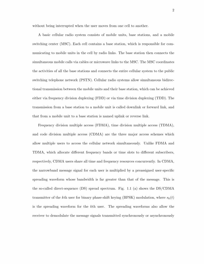
respectively, CDMA users share all time and frequency resources concurrently. In CDMA,
the narrowband message signal for each user is multiplied by a preassigned user-specific
spreading waveform whose bandwidth is far greater than that of the message. This is
the so-called direct-sequence (DS) spread spectrum. Fig. 1.1 (a) shows the DS/CDMA
transmitter of the kth user for binary phase-shift keying (BPSK) modulation, where sk(t)
is the spreading waveform for the kth user. The spreading waveforms also allow the
receiver to demodulate the message signals transmitted synchronously or asynchronously

3
by multiple users of the channel.
Since a CDMA system has valuable properties such as soft capacity, soft handoff,
and anti-multipath capabilities, it is particularly suitable for applications such as mobile
cellular telephony and personal communications. As a result, all the proposals for third-
generation (3G) wireless networks, e.g., Wideband CDMA and cdma2000, employ CDMA-
based air interfaces [1], [2], [67], [102].
1.2 Multiuser Detection for DS/CDMA
In a multipath propagation environment, several time-shifted and scaled versions of the
transmitted signal arrive at the receiver. In existing DS/CDMA systems, such as IS-95,
a RAKE structure is used to combine the time-delayed versions of the original signal in
order to improve the signal-to-noise ratio (SNR) at the receiver and to enhance the system
performance. A single-user DS/CDMA RAKE receiver is shown in Fig. 1.1 (b), where
D is the number of resolvable paths and di (i = 1, . . . , D) is the delay of the ith path.
However, the conventional RAKE receiver treats multiple access interference (MAI) as
noise, and therefore is interference-limited [3], [4]. Moreover, it encounters the near-
far problem, which occurs when users far away from the receiver are received at lower
powers than those situated nearby. A stringent power control mechanism is employed in
the IS-95 system to combat this problem [3], [4].
For the sake of overcoming the above restrictions of the conventional RAKE receiver,
multiuser detection techniques, which exploit the structure of the MAI rather than treat
it as noise, have been proposed (see [5] and references therein). It has been shown that
4
(b) RAKE receiver
(a) Transmitter
Data stream
Time
Time
d 1
Path gain 1
Path gain D
) ( t s k
Received signal
d D
Decision
) cos( 0 t w
) cos( 0 t w
s k ( t - d 1 )
s k ( t - d D )
Figure 1.1: A DS/CDMA transmitter/receiver.

5
multiuser detection can not only increase capacity by suppressing interference, but also
relax the power control requirement by alleviating the near-far problem.
The effectiveness of multiuser detection was first rigorously demonstrated by Verdu
in [6], where it is shown, under a mild condition, that the near-far problem does not
occur if optimal maximum-likelihood (ML) detection is used. However, the complexity of
implementing ML detection is exponential in the number of active users. Much effort has
therefore focused on the design of suboptimal receivers with lower complexity. Most of
these bit-level receivers fall into the following three categories:
• linear multiuser detectors, such as the decorrelating detector [7] and the minimum
mean-squared error (MMSE) detector [8];
• subtractive interference cancellation receivers, e.g., parallel interference cancellation
(PIC) [9], successive interference cancellation (SIC) [10], and a hybrid of PIC and
SIC [11]; and
• combined schemes, such as decorrelating decision feedback detector (DDFD) [12]
and the decorrelator/PIC detector [13].
All these approaches assume a front end consisting of a bank of filters matched to the
spreading waveforms and the channels of active users, where each filter is synchronized
to the corresponding user, even if only a particular user is of interest. As is well known,
however, accurate channel estimation can be difficult in a wireless environment. Further-
more, only spreading waveform of the desired user is available to mobile units and only
spreading waveforms of all intracell users are attainable to base stations.

6
Note that in DS/CDMA systems based on short spreading codes, where a specific
spreading code is selected for a particular user and then repeated for each data symbol of
that user, the MAI is clearly cyclostationary provided that the channels for the users vary
relatively slowly. This observation inspired the invention of several adaptive chip-level
receiver structures based on the MMSE criterion [14], [15], [17] which process the samples
obtained by chip-matched filtering followed by sampling at (a multiple of) chip rate. The
only knowledge required by the receiver is a training sequence transmitted by the desired
user, which allows the receiver to be implemented adaptively using standard least-mean-
square (LMS) algorithm or recursive least-squares (RLS) algorithm [16]. It has been
shown that adaptive MMSE reception not only suppresses interference, but also provides
automatic multipath combining for the desired user [4]. In addition to the adaptive MMSE
receiver, adaptive techniques based on decorrelator and interference cancellation have also
been invented [14].
1.3 Blind Channel Estimation and Multiuser Detection
It is noteworthy that in order to track the severe time variations of a wireless channel,
adaptive multiuser receivers need to be regularly trained using periodically transmitted
pilot symbols. Unfortunately, frequent use of training sequences decreases the spectral
efficiency. As a consequence, blind techniques for multiuser detection, which only require
prior knowledge of the spreading sequence of the user of interest [4], [17]-[26], have been
explored for DS/CDMA to eliminate the need for training sequences. Obviously, a blind

7
scheme is very attractive when considering implementation of multiuser detection strate-
gies in portable handset terminals. Among the existing techniques for blind multiuser de-
tect suitable for the CDMA downlink, constrained optimization and subspace-based
methods are the two main categories.
The first solution based on constrained optimization was developed in [20], where it
is shown that an MMSE receiver can be obtained by minimizing the receiver’s output
energy with the response of the desired user constrained to remaining constant. This
so-called minimum output energy (MOE) detector is very sensitive to signal mismatch
created by multipath effects or timing errors. An extension of the MOE detector to the
multipath case was provided in [21], by forcing the receiver response to delayed copies of
the signal of interest to zero. The additional constraints alleviate the signal cancellation
due to mismatch, but this method still suffers from inferior performance since it treats
part of the useful signal as interference. An improvement was proposed in [22], where the
constraint values are optimized by a max/min approach rather than being set to one or
zero. The performance of this method tends to be close to that of the optimal MMSE
receiver at high SNR in the presence of multipath. However, the complexity is higher
too due to the use of an eigen-decomposition. In [23], Tian et al. developed a robust
constrained receiver by employing multiple linear constraints, which match a nominal
multipath profile, and a quadratic inequality constraint. The latter constraint provides
robustness to residual mismatch. This scheme has relatively low complexity compared to
methods using optimized constrained parameters. Notably, adaptive implementations of
these constrained linear detectors have been proposed using LMS and RLS techniques,

8
and no explicit channel estimation is required for these detectors.
So far as the subspace-based methods are concerned, the subspace-based blind adaptive
detector was constructed in closed form based on signal subspace estimation [24]. This
detector has been shown to outperform the blind MOE detector [20] in steady state. Since
the method in [24] only deals with low rate CDMA systems where inter-symbol interference
(ISI) is negligible, an extension was presented in [26] to combat both MAI and ISI in high
rate dispersive CDMA systems. In this scheme, the ISI channel is estimated first, and
then the receiver is constructed based on channel estimates. Apart from such a two-
step procedure, a low-complexity subspace-based blind adaptive detector was constructed
in [25] without channel estimation as an intermediate step.
Additionally, the application of subspace-based techniques for channel parameter esti-
mation in CDMA systems, such as delay and channel estimation [26]-[31], is also currently
an active area of research. It is worth noting that differential encoding at the transmit-
ter and differential detection at the receiver can be used to solve the problem of phase
ambiguity in channel estimates, encountered by subspace-based blind methods.
The subspace-based blind approaches typically require not only a long duration of
observation, but also some form of eigen-decomposition. The computational burden can
therefore be prohibitively high. Furthermore, the channel is often required to be time-
invariant during this long observation period, which typically makes these algorithms
impractical for wireless communications. One feasible solution to this issue is to develop
low complexity adaptive algorithms with capability for tracking the time variation of a
wireless channel (e.g., [24]). Another interesting strategy is semi-blind methods [32],

9
which exploit the statistics of the unknown data as well as the known pilot signal and
require a short duration of observation to achieve the same performance as the blind
methods.
The above blind techniques for multiuser detection in the CDMA downlink aim to
demodulating a given user’s data with prior knowledge of only the spreading sequence of
that user. In the CDMA uplink, however, typically the base station receiver has knowl-
edge of the spreading sequences of all intracell users. In such scenarios, a substantial
amount of work is available in the literature about blind multiuser detection [33]-[38]. Es-
pecially, group-blind techniques have received much interest [35]-[38]. They make use of
the spreading sequences and the estimated multipath channels of all known users to sup-
press the intracell interference, while blindly suppressing the intercell interference. It has
been demonstrated that the group-blind linear multiuser detection techniques offer sub-
stantial performance gains over the blind linear multiuser detection methods in a CDMA
uplink environment.
1.4 Multicarrier DS/CDMA
As described above, the interest in applying DS/CDMA techniques to wireless commu-
nications is mainly due to its multiple access capability, robustness against fading, and
anti-interference characteristics. On the other hand, multicarrier modulation schemes,
often denoted as orthogonal frequency division multiplexing (OFDM), are highlighted as
emerging signaling methods for broadband wireless access. Recently, OFDM has been ac-
cepted as the next generation standard for wireless local area network (WLAN) systems,

10
including IEEE 802.11 as well as HIPERLAN/2 [39], [40]. The main advantage of OFDM
systems is that they can resolve the difficult ISI problems occurring with high data rate
transmission in multipath channels.
Naturally, it is interesting to combine multicarrier modulation with CDMA, which
forms a new multiple access scheme, denoted as multicarrier CDMA [41], [42]. Multicarrier
CDMA signals can be easily transmitted and received using a fast Fourier transform (FFT)
device without increasing the transmitter and receiver complexities. Furthermore, they
have the attractive feature of high spectral efficiency.
Multicarrier CDMA systems may be classified into two categories, depending upon
whether time domain or frequency domain spreading is employed. In the first class (the
so-called multicarrier DS/CDMA), the transmitted symbols are multiplied by low rate
spreading sequences in time, yielding conventional, narrowband DS waveforms. The com-
plete DS/CDMA waveform is then transmitted at different carrier frequencies, such that
the net bandwidth allocation is equal to that of a single-carrier DS/CDMA system using
a higher rate spreading waveform [43]-[48]. In the second class, however, the spreading
sequence is serial-to-parallel converted such that each chip modulates a different carrier
frequency, and thus, the data symbol is transmitted in parallel [49]-[54]. This means
that the number of carriers should be equal to the spreading factor. Both classes of
multicarrier CDMA systems show a similar capability in mitigating the effects of fading.
However, the time spreading class, in general, employs a smaller number of
carriers relative to the frequency spreading class, and thus, is less complex
[43]. As a consequence, only the class of time spreading multicarrier CDMA systems, i.e.,
11
multicarrier DS/CDMA, is considered in this thesis.
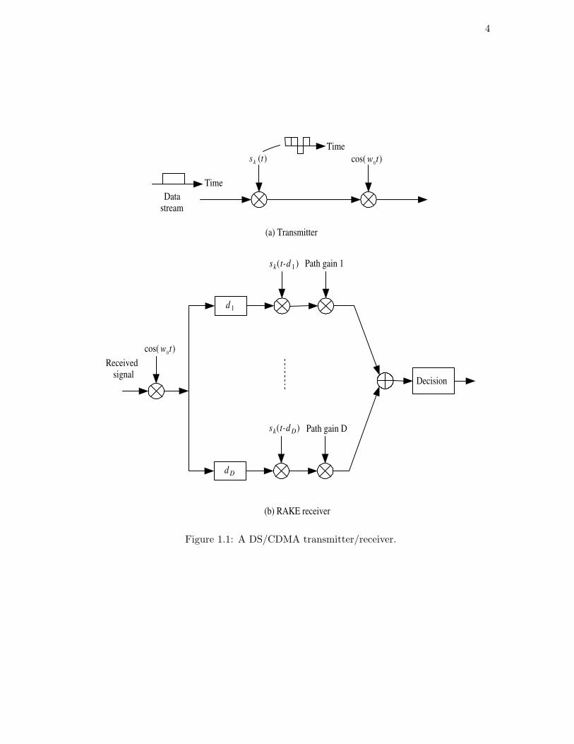
In multicarrier DS/CDMA systems, to achieve frequency diversity, the same data bit
spread by a narrowband DS waveform is usually transmitted over each carrier, and then
the signals received from all carriers are combined to give a more robust data estimate [41].
As an example, Fig. 1.2 (a) shows the multicarrier DS/CDMA transmission scheme pro-
posed in [43], where a band-limited DS waveform modulates C carriers. For such a scheme,
the maximal ratio combining (MRC) receiver proposed in [43] is shown in Fig. 1.2 (b).
Other detection strategies, such as MMSE detection [45] and SIC technique [47], have been
successfully applied to multicarrier DS/CDMA. Among the existing blind techniques for
channel estimation and multiuser detection, an interesting solution is the subspace-based
approach [46]. Since the employed band-limited chip waveform results in a null noise sub-
space, which disables subspace-based techniques, a finite-length truncation approximation
to the chip waveform is performed. Although this approximation causes performance
degradation of the subspace-based estimators, it is shown that such a scheme is robust to
moderate near-far problems.
1.5 Contribution of The Thesis
Recently, wireless communications services have shifted their focus from voice only to
multimedia connections in line with the increasing popularity of Internet services in fixed
networks. A combination of wireless communications and Internet services will enable our
society to enter a wireless Internet era. Thus, future wireless communications systems
should be able to offer a wide variety of applications, such as Web browsing, voice over IP,

12
(b) Maximal ratio combining receiver
Data stream
Time
Time
) ( t s k
) ( t s k
) ( t s k
Received signal
(a) Transmitter
) cos( 1 t w
) cos( t w C
) cos( t w C
) cos( 1 t w Branch gain 1
Branch gain C
Decision
Figure 1.2: Multicarrier DS/CDMA transmitter/receiver
13
and video on demand, which have vastly different quality of service (QoS) requirements,
e.g., bandwidth, delay, and loss [55]. The time-variable QoS may require support of
variable bit rates on the wireless links to the individual users. Considering that CDMA
has been proposed as the wireless access technology for 3G wireless systems and beyond,
multi-rate DS/CDMA is a promising basis on which to support variable bit
rates on individual wireless links [55].
Receiver design plays a crucial role in implementing wireless systems. As mentioned
above, so far a multitude of research results regarding multiuser detection for single-rate
DS/CDMA have been reported, including single-carrier and multicarrier cases. Although
multi-rate multiuser detectors have their roots in their single-rate counterparts, multi-rate
multiuser detectors should be more elaborately designed due to the inherent properties of
multi-rate signals.
As described later in Section 2.4, some results regarding blind channel estimation and
multiuser detection for multi-rate DS/CDMA are available in the literature, focusing on
constrained optimization methods for single-carrier systems. However, little has been
reported on the subspace-based techniques. The thesis deals with the application of
subspace-based techniques to blind channel estimation and multiuser detection
for multi-rate DS/CDMA systems. Most research results in this thesis have been
presented, accepted or submitted for publication in IEEE conferences and journals [56]-
[62]. For multi-rate single-carrier DS/CDMA, the following contributions are made.
• Space-time (ST) dual-rate blind linear detectors, i.e., blind decorrelating detectors

14
and blind MMSE detectors, for synchronous systems over additive white Gaussian
noise (AWGN) channels are proposed. Purely temporal versions can be obtained as
special cases [57], [61], [62].
• Theoretical analyses on the performances of ST dual-rate blind linear detectors are
carried out. The conclusions are extended to more general synchronous multi-rate
scenarios [57], [61].
• Extension of ST dual-rate blind linear detectors to asynchronous systems is described
[57].
• Adaptive implementation for ST dual-rate blind MMSE detection is developed [57],
[61].
• Two-stage ST dual-rate blind detectors, which combine purely temporal adaptive
dual-rate blind MMSE detectors with non-adaptive beamformer, are presented [57],
[61].
• Discrete received signal models for dual-rate systems over frequency-selective mul-
tipath channels are established, which take into account both ISI and MAI [56],
[60].
• Batch algorithms and their adaptive versions for dual-rate blind channel estimation
are developed [56], [60].
• Dual-rate blind MMSE detection for AWGN channels is extended to frequency-
selective multipath channels.

15
For multi-rate multicarrier DS/CDMA, the following contributions are made.
• A discrete-time, chip rate, received signal model is derived for a general multi-rate
multicarrier DS/CDMA system, [58], [59].
• Based on the finite-length truncation on the band-limited chip waveform, an approx-
imation to the received signal model is described, which enables the subspace-based
techniques [58], [59].
• The algorithms are developed to jointly estimate timing and channel parameters of
the desired user [58].
• The channel estimation error due to the finite-length truncation of chip waveform is
analyzed by exploiting a first-order perturbation approximation.
1.6 Thesis Overview
The remainder of the thesis is organized as follows. Chapter 2 reviews multiuser detec-
tion techniques for multi-rate DS/CDMA. Chapter 3 discusses ST multi-rate blind detec-
tors for single-carrier DS/CDMA systems over AWGN channels. In Chapter 4, dual-rate
blind channel estimation algorithms in single-carrier DS/CDMA systems over frequency-
selective multipath channels are developed. Blind timing acquisition and channel estima-
tion in multi-rate multicarrier DS/CDMA systems are investigated in Chapter 5. Finally,
the conclusions and some discussion on future research are given in Chapter 6.
Throughout the thesis, uppercase letters in boldface denote matrices; lowercase letters
in boldface stand for vectors; (·)∗, (·)T , (·)H , and (·)† represent conjugate, transpose,
16
Hermitian transpose, and Moore-Penrose pseudo-inverse, respectively; [A]i,j indicates the
(i, j)th element of matrix A; sgn(·) denotes Signum function; diag(·) represents diagonal
matrix; Re[·] stands for the real part of a complex; E is expectation operator; ‖ · ‖ is
two-norm; ⊗ is Kronecker product; Id is the d × d identity matrix.
Chapter 2
Multiuser Detection for Multi-rateDS/CDMA
The future multimedia wireless communication networks will have to accommodate a
heterogeneous variety of information streams, which inherently possess different data rates,
and are to be transmitted with different QoS requirements. As a result, the CDMA-
based standards for 3G wireless networks have been designed to support the provision
of multi-rate traffic with different QoS requirements. It is thus of primary interest
to investigate possible modulation formats able to accommodate information
streams with different data rates over a CDMA network, as well as to devise
proper detection structures taking into account the multi-rate nature of the
received signal.
The layout of this chapter is as follows. Section 2.1 summarizes the multi-rate access
strategies for CDMA, which form a basis for designing multi-rate multiuser receivers.
Multi-rate CDMA signal modelling is discussed in Section 2.2. Section 2.3 reviews the
non-blind multiuser detection schemes for multi-rate DS/CDMA. An overview of blind
17
18
techniques for multi-rate channel estimation and multiuser detection is given in Section
2.4. In Section 2.5, multi-rate multicarrier DS/CDMA is addressed. Section 2.6 concludes
this chapter.
2.1 Multi-rate CDMA Transmission
In DS/CDMA systems, there are three main options to implement multi-rate multiuser
communications, i.e., variable spreading factor (VSF), multicode (MC), and variable chip
rate (VCR) transmission [63]–[66]. The VSF systems employ the same chip rate for all
the users, and data streams at different rates are modulated by spreading codes of the
different length. In other words, for a VSF CDMA system with I different data rates, we
have
Tc =T0
N0= · · · =
TI−1
NI−1, (2.1.1)
where Tc is the chip duration, and Ti and Ni (i = 0, . . . , I − 1) are the symbol period and
the spreading factor of rate i users, respectively. This indicates
T0q0 = T1q1 = · · · = TI−1qI−1 = Tbr, (2.1.2)
where q0, q1, . . . , qI−1 are co-prime integers which represent the rate ratio, and Tbr is the
least common multiple of T0, . . . , TI−1. 1/Tbr is called basic rate.
In the MC systems, all data rates are assumed to be multiples of a basic rate. Each
data stream is converted into several parallel basic-rate substreams, followed by spreading
with different codes. Orthogonal codes are used to prevent interference between the sub-
streams [64]. However, the presence of a dispersive wireless channel results in loss of this

19
orthogonality. It is easy to see from (2.1.2) that each user at rate i can be viewed as qi
virtual users at the basic rate. Note that all the users share the same bandwidth in both
VSF and MC systems.
In the VCR systems, data streams at different rates are spread with different codes
of the same length, i.e., different rate users use different chip rates. This means that the
available bandwidth for the different rate users is different.
Fig. 2.1 shows an example of how two different rate users would be supported by these
three access methods, where the rate ratio is 2:3. In this example, for the VSF scheme,
if N1 is set to be 9, N2 should be equal to 6. For the MC scheme, each data stream is
converted into two (for rate 1 users) or three (for rate 2 users) parallel basic-rate streams,
which are spread by the spreading codes with length 18. In the VCR case, the spreading
factor is set to be 6 for all the users, while the ratio of the chip duration between rate 1
and rate 2 users is 3:2.
The selection of multi-rate CDMA transmission scheme depends on many other fac-
tors rather than the performance only. Since the VCR scheme introduces extra
difficulty for chip synchronization and frequency planning [71], it seems that
MC and VSF solutions are preferred over the VCR scheme. Furthermore, 3G
wireless networks indeed employ the VSF and MC multi-rate access strate-
gies [67], [102]. As a result, only VSF and MC multi-rate access schemes are considered
in this thesis.
It is a more challenging question which one of the VSF and MC schemes is better. The
MC solution can provide orthogonal channels in the forward link which is more difficult for

20
Rate 1 1 2 3 4 N =9
N =6 1 2 3 4 5 6 Rate 2
Rate 1 1 2 3 4 N =6
N =6 1 2 3 4 5 6 Rate 2
(a) Variable spreading factor scheme
( c ) Variable chip rate scheme
Rate 1
Rate 2
1 2 3 4
1 2 3 4 5 6
1 3
2 4
N =18
N =18
(b) Multicode scheme
Figure 2.1: Three main multi-rate CDMA access strategies
21
the VSF solution. This is because for the VSF scheme, orthogonal codes can be found only
if the spreading factors are constrained to 2n where n is a positive integer, e.g., orthogonal
variable spreading factor (OVSF) codes used in the 3G wireless systems [67], [102]. In
addition, because of the larger spreading factor, MC multi-rate signals experience less
ISI than VSF multi-rate signals. This leads to the complexity of the receiver in the MC
case being lower than that in the VSF solution. On the other hand, the MC system
requires a linear amplifier, especially in the reverse link direction, since multiple channels
for a particular user give rise to large amplitude variations. The right choice of multi-rate
transmission schemes depends, apart from the above points, also on the power control
implementation and code allocation. All these factors must be considered before the
decision of the technique is made.
2.2 Multi-rate Signal Modelling
Modelling the received multi-rate signal plays a vital role in developing efficient multi-
rate multiuser detectors. Let us consider a general VSF multi-rate DS/CDMA system
as defined in (2.1.1) and (2.1.2) [74], [79], [92], [95]. All the users are grouped into I
classes in accordance with their data rates. In class i, there are Ki users at data rate 1Ti
where Ti = Tbr
qi. Without loss of generality, assume that 1
T0< 1
T1< · · · < 1
TI−1, and thus
q0 < q1 < · · · < qI−1. Users are indexed by two variables: i indicates the class and k
indicates the user number within the class.

22
The received baseband signal can be modelled as
y(t) =I−1∑
i=0
Ki∑
k=1
Akixki(t) + z(t), (2.2.1)
where z(t) is an AWGN process with power spectral density σ2z , and Aki is the received
amplitude for user ki. The received signal xki(t) for user ki is given by
xki(t) =∞∑
l=−∞bki(l)ski(t − lTi), (2.2.2)
where bki(l) is the information stream for user ki and E|bki(l)|2 = 1. For simplicity
of presentation, BPSK modulation is assumed. The information bits are assumed to be
independent from user to user and in time. The effective spreading waveform ski(t) is
the convolution of the channel impulse response hki(t) and the preassigned transmitted
spreading code cki(l), i.e.,
ski(t) =
Ni∑
l=1
cki(l)hki(t − lTc), (2.2.3)
where cki(l) ∈ −1, +1, and hki(t) is the composite channel for user ki, which includes the
fixed transmit/receive pulse shaping filters and the unknown multipath physical channel,
and can be described as [68]
hki(t) =
Dki∑
j=1
αj(t)φ(t − τj), (2.2.4)
where Dki is the number of distinct paths, αj(t) is the complex gain of the path, τj is the
propagation delay, and φ(t) is pulse function (e.g., raised cosine pulse). In this thesis, we
will assume static multipath, i.e., the channel amplitudes and delays are fixed over the
observation duration. For practical purposes, hki(t) can be modelled as a finite impulse
response (FIR) filter [68].

23
Discretization of the above continuous-time signal model is indispensable for the sub-
sequent digital signal processing. Generally, the received signal y(t) is first filtered by a
chip-matched filter and then sampled at the chip rate. After the discrete-time received
signal is obtained, the processing interval needs to be determined. It has been shown
that the received signal y(t) is cyclostationary with period Tbr for a multi-rate DS/CDMA
system employing short spreading codes [92]. Naturally, the processing interval can be
set to be (a multiple of) Tbr [74], [79], [95]. This is called basic-rate modelling. As an
alternative to basic-rate modelling, which inherently introduces detection delay for all the
users, the received signal can also be modelled based on the symbol period of rate i users
for the purpose of detecting rate i users [92]. This is referred to as rate i modelling.
Since rate i symbols experience periodically time-varying interference with period qi, qi
different signal models need to be established corresponding to qi symbol periods within
a basic-rate symbol period.
In practice, a special type of multi-rate DS/CDMA systems is often taken into account
in which the higher rates are multiples of the lower rates [69]-[72], [76], [78], [81], [84], [86]-
[88], [90], [91], [94], [96], [99]. Unless otherwise stated, this type of multi-rate systems is
assumed in this thesis. For such multi-rate systems, most of the research results deal with
dual-rate (i.e., I = 2) cases, where one data rate is M multiples of the other and M is an
integer greater than 1. This is because all dual-rate results can be easily generalized to
multi-rate scenarios where more than two data rates exist [90]. In dual-rate DS/CDMA
systems, the lower data rate is actually the basic rate, and thus basic-rate modelling
becomes low-rate modelling and rate i modelling reduces to high-rate modelling.

24
It is worth noting that the single-rate system is a special case of the VSF multi-rate
system when I = 1. Considering that the MC multi-rate system is equivalent to the
single-rate system with more virtual users at basic rate, the basic-rate (i.e., low-rate in
dual-rate cases) signal model for the VSF case is also applicable to the MC case.
2.3 Multi-rate Multiuser Detection for DS/CDMA
Depending on the form of multi-rate signal modelling, multi-rate multiuser detectors can
be classified as basic-rate or rate i detectors. Apparently, rate i detectors are not applicable
to MC multi-rate systems. It is also noteworthy that basic-rate detectors can be used for
detecting any user; while rate i detectors can generally only be used for the detection of
rate i users1.
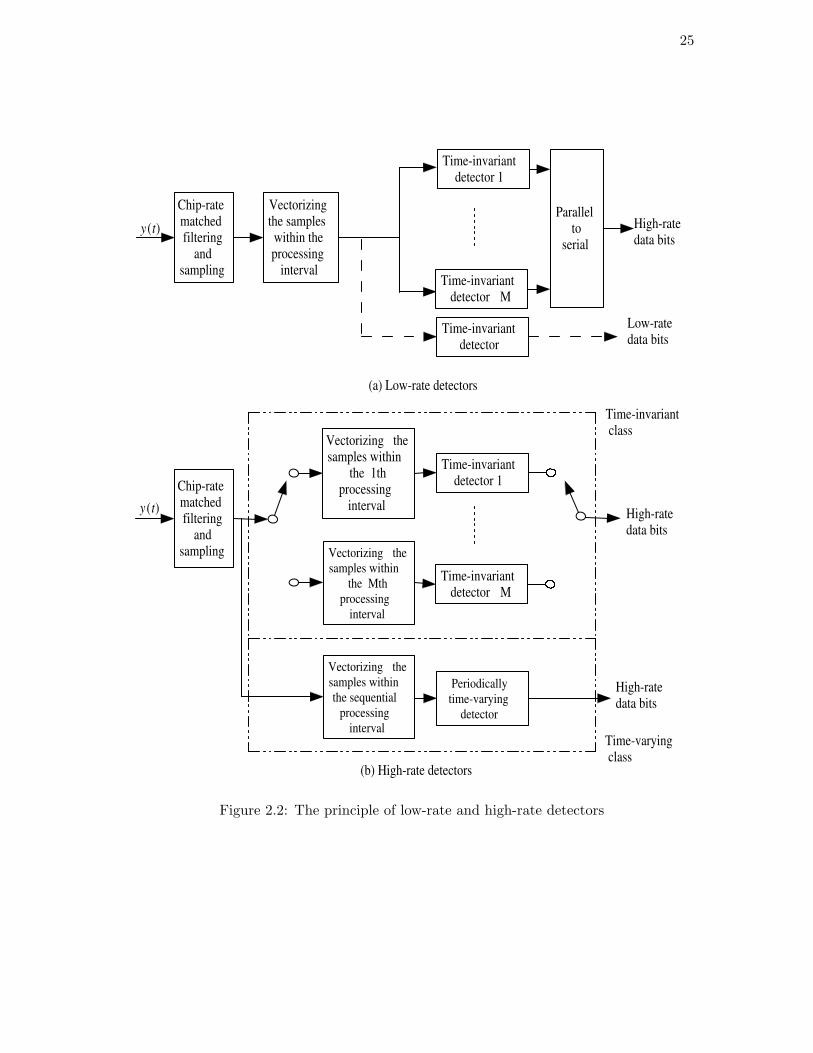
Taking dual-rate cases as an example, Fig. 2.2 illustrates the principles of basic-rate
(i.e., low-rate) and rate i (i.e., high-rate) detectors. For low-rate detectors, a single time-
invariant receiver can be used for detection of each low-rate user. Comparatively, M
time-invariant receivers must be deployed for each high-rate user, where the mth receiver
is in charge of detecting the mth high-rate symbol within a low-rate symbol period. On
the other hand, depending on how to handle the fact that high-rate symbols undergo the
periodically time-varying interference with period M , the high-rate detectors can further
be partitioned into time-invariant and time-varying classes. In the first class, M
time-invariant receivers are employed corresponding to M high-rate signal models; while
in the second class, a single periodically time-varying receiver with period M is used.
1In certain situations, however, rate i detectors can also be used for the detection of the users different
from rate i ones.
25
Chip-rate matched filtering
and sampling
Vectorizing the samples within the processing
interval
Parallel to
serial
Low-rate data bits
High-rate data bits
y ( t )
(a) Low-rate detectors
Chip-rate matched filtering
and sampling Vectorizing the
samples within
the Mth
processing
interval
Time-invariant detector M
High-rate data bits
y ( t )
Periodically
time-varying
detector
High-rate data bits
Time-invariant detector 1
Time-invariant detector M
Time-invariant detector 1
Time-invariant detector
(b) High-rate detectors
Time-invariant class
Time-varying class
Vectorizing the samples within
the 1th processing
interval
Vectorizing the
samples within
the sequential
processing
interval
Figure 2.2: The principle of low-rate and high-rate detectors

26
In comparison with the former, time-varying high-rate detectors have a simpler receiver
structure but need a much more complicated algorithm.
A number of results regarding multiuser detection have been reported for multi-rate
DS/CDMA systems. In [69], the performance of low-rate ML detectors was compared for
MC and VSF cases, using particular realizations of spreading sequences. This makes global
comparison of multi-rate access schemes problematic [72]. To tackle this problem, in [72],
the optimum near-far resistance (NFR) measure was used for performance comparison
based on the random signature sequence analysis. It is found that for a high-rate user,
the performance in the VSF scheme is better than that in the MC scheme; while for a
low-rate user, the performance in the MC scheme is not inferior to the VSF scheme.
Similar to single-rate DS/CDMA, the high complexity of the optimal ML detector has
motivated the invention of many suboptimal multi-rate multiuser detectors with lower
complexity. In the context of linear multiuser detection, both decorrelator-based re-
ceivers [71]–[75], [90] and MMSE receivers [76], [77], [90] have been studied for multi-
rate DS/CDMA. A typical example is the dual-rate decorrelator for synchronous VSF
systems [71]. This includes a time-invariant high-rate decorrelator (HRD) and a low-rate
decorrelator (LRD). Note that the time-invariant HRD is also used for detection of low-
rate users by utilizing soft decisions and MRC. Although LRD offers superior performance
to HRD for all the users, it does incur additional computational complexity as well as a
processing delay for high-rate users. The above dual-rate results were further generalized
to synchronous multi-rate cases [70].
In addition, there is much work on the application of interference cancellation for

27
Detection
Estimation
of MAI
Detection
Estimation
of MAI
Detection
high b
medium b
low b
_
_
Delay
Delay
y ( t )
Figure 2.3: General structure for the GSIC receiver
multi-rate DS/CDMA [70], [78]–[84]. One interesting solution is the dual-rate DDFD
for synchronous VSF systems [70], which consists of two stages. In the first stage, each
high-rate data bit in the first M − 1 subintervals is detected by an HRD, and then the
corresponding signals of high-rate users are reconstructed. In the second stage, the recon-
structed signals are subtracted from the received signal and an LRD is used to demodulate
the high-rate data bits in the last subinterval and all the low-rate data bits. This scheme
incurs no demodulation delay for each high-rate data bit and improves the performance
for low-rate users by eliminating the interference from the high-rate data bits in the first
M − 1 subintervals.
Another example is the basic-rate groupwise successive interference cancellation (GSIC)
receiver [79]. The application of GSIC to the VSF system is especially appealing due to

28
the natural grouping of users based on spreading factors. Normally, the same link quality
(e.g., the ratio of energy per information data bit to noise power) has to be maintained for
different rate users [94]. This implies that a signal with a lower spreading factor has to be
transmitted with much larger power than a signal with a high spreading factor, and thus
the higher rate users are expected to cause more interference to other users. Based on this
observation, for the basic-rate GSIC receiver, the cancellation is started with the users
transmitting at the highest data rate. After the highest rate users have been detected
and the MAI is cancelled, the users with second highest data rate are detected. A GSIC
receiver for a three-rate system is shown in Fig. 2.3. The detection within groups can, in
principle, apply any known multiuser detector, such as the decorrelating detector or the
PIC detector.
It should be pointed out that a closely related issue to multi-rate multiuser detection is
channel estimation for multi-rate DS/CDMA. This is because high performance detectors,
such as coherent detectors, need explicit channel information. To this end, multi-rate
channel estimation based on training sequence has been investigated in [85] and [86].
2.4 Multi-rate Blind Channel Estimation and Multiuser De-tection
Besides the aforementioned non-blind multi-rate multiuser detectors, blind channel esti-
mation and multiuser detection in multi-rate DS/CDMA systems are also active areas
of research. Various blind MMSE detection schemes have been derived and analyzed for

29
multi-rate DS/CDMA systems over AWGN channels [87]-[90] and multipath fading chan-
nels [91], [92], [96]. In [87] and [88], based on the inverse of the correlation matrix of the
received signal, both low-rate and high-rate blind MMSE detectors were constructed for
dual-rate systems over AWGN channels, which have capability of detecting both high-
rate and low-rate users. However, the time-invariant high-rate blind MMSE detector is
not strictly blind because knowledge of the noise level and interfering users is required
to detect a low-rate data bit. On the other hand, blind implementation of periodically
time-varying MMSE detection for high-rate users was proposed in [90] by developing a
blind cyclic RLS algorithm.
For multipath channels, the design of multi-rate blind multiuser detectors without
channel estimation is possible. Such dual-rate blind multiuser detectors were proposed
in [91] by applying the MOE criterion. It is observed that a high-rate user experiences
the same frequency-selective channel during its M consecutive symbol durations within
a low-rate symbol period. A bank of M time-invariant high-rate detectors are derived
jointly to detect those M symbols for a high-rate user by minimizing the total output
power of these detectors subject to a common constraint for all M high-rate detectors.
However, this constrained optimization approach only deals with the case where the delay
spread is only a small fraction of the symbol period. Moreover, its performance degrades
greatly at low SNR.
Alternatively, the channel can be estimated before the multiuser detection process.
Blind channel estimation for multi-rate DS/CDMA has been suggested using subspace-
based techniques [95], [96], the correlation matching approach [97] and the frequency
30
domain method [98]. Semi-blind channel estimation for dual-rate systems has also been
investigated in [99]. As an additional dimension to blind channel estimation, the problem
of blind time delay estimation in multi-rate asynchronous DS/CDMA systems was also
addressed in [101]. Both subspace and non-parametric methods are considered for MC
and VSF schemes.
In addition, blind techniques for interference cancellation have been proposed for multi-
rate DS/CDMA, such as the blind adaptive DDFD detector [93]. The dual-rate blind
adaptive DDFD detector differs from the dual-rate non-blind DDFD [70] in that the
time-invariant HRD and LRD in the latter are replaced by time-invariant high-rate blind
adaptive bootstrap decorrelator and low-rate adaptive decorrelating detector, respectively.
In comparison with its non-blind counterpart, the dual-rate blind adaptive DDFD has a
lower computational complexity. Moreover, it is shown that at low SNR, the dual-rate
blind adaptive DDFD provides a better performance for low-rate users than the non-blind
LRD and a better performance for high-rate users than the dual-rate non-blind DDFD.
2.5 Multi-rate Multicarrier DS/CDMA
The above mentioned multi-rate multiuser detection techniques target primarily single-
carrier systems. Multi-rate single-carrier DS/CDMA requires very wide transmission
bandwidth to support high data rate multimedia services. It is well known that a signal
of wider bandwidth can resolve more multipath [68]. For example, as Wideband CDMA
has four times as much bandwidth as IS-95, the channel experienced by the Wideband
CDMA signal exhibits higher dispersion. Moreover, multi-rate single-carrier DS/CDMA
31
can utilize the VSF scheme to provide various transmission data rates. In this case, the
multipath delay spread can be comparable to or much longer than the bit duration. For
instance, when the IMT-2000 vehicular channel A model is taken into consideration [102],
the maximum delay spread is about 2.5µs. If the data rate is 2Mbps, then the chan-
nel spans almost 5 bit periods. Consequently, multi-rate single-carrier DS/CDMA suffers
much more severe ISI than its single-rate counterpart. On the other hand, as mentioned
in Section 1.4, multicarrier DS/CDMA experiences less ISI than single-carrier DS/CDMA
having the same transmission bandwidth. Thus, compared to its single-carrier rival,
multi-rate multicarrier DS/CDMA seems to be a more promising solution as
the wireless access technology for future wireless communications systems.
Considering that both single-carrier and multicarrier DS/CDMA employ time-domain
spreading, VSF and MC multi-rate access strategies can also be applied to multicarrier
DS/CDMA. In addition, multi-rate multicarrier DS/CDMA receivers generally consist of
multiple branches, each of which being in charge of one carrier. The received baseband
signal at each branch can be modelled in a similar manner to a multi-rate single-carrier
signal.
In comparison with single-carrier systems, much less results regarding multi-rate mul-
tiuser detection for multicarrier DS/CDMA have been reported in the literature. In [103],
MRC receivers were considered for multi-rate multicarrier DS/CDMA systems, where the
basic-rate and rate i detectors are used in MC and VSF cases, respectively. The BER
of each multi-rate system is obtained by analysis and simulation in a Rayleigh fading
channel with perfect channel estimation. It is shown that the MC system has a slightly
32
better performance than the VSF system. Both systems achieve significant performance
improvement by applying SIC techniques.
2.6 Summary
In this chapter, multi-rate access schemes for DS/CDMA are described, followed by
multi-rate signal modelling. The existing multiuser detection techniques for multi-rate
DS/CDMA are reviewed, including non-blind and blind solutions. Finally, multi-rate
multicarrier DS/CDMA is introduced.

Chapter 3
Space-time Blind MultiuserDetection for Multi-rateDS/CDMA Signals
As described in Chapter 2, for VSF dual-rate DS/CDMA systems, the received signal
models can be established by low-rate and high-rate modelling, whose processing intervals
are (a multiple of) symbol periods of low-rate users and high-rate users, respectively. Var-
ious low-rate and high-rate detectors have been developed for the AWGN and multipath
fading channels, including non-blind and blind solutions.
In the case of AWGN channels, typical non-blind multi-rate linear detectors are the
time-invariant LRD and HRD for synchronous dual-rate systems with a single receive
antenna [71], [72], which can be used for the demodulation of both low-rate and high-
rate users. It has been proven that the LRD is not inferior to the HRD in terms of
probability of error, and the dual-rate results are further generalized to multi-rate scenarios
where more than two data rates exist [72]. Typical examples of existing dual-rate blind
multiuser detectors are the time-invariant low-rate and high-rate blind MMSE detectors
33
34
for synchronous and asynchronous CDMA systems proposed in [87] and [88]. However,
the high-rate blind MMSE detector in [87] and [88] is not strictly blind. This is because
for the sake of detecting a low-rate user, the signal-to-interference-plus-noise ratio (SINR)
of this low-rate user within each subinterval, which involves knowledge of the noise level
and interfering users, is required for decision-making. In addition, the performances of
low-rate and high-rate blind MMSE detectors in [87] and [88] were compared only by
numerical simulations. Note that the above dual-rate blind MMSE detectors, which are
based on the inverse of the covariance matrix of the received signals, do not operate in
the signal subspace.
Blind adaptive multiuser detection and antenna array processing have recently been
viewed as powerful methods for mitigating cochannel interference inherent to non-orthogonal
CDMA systems [19], [104], [105], [107]. For instance, Chkeif et al. presented the subspace-
based ST blind decorrelator and blind MMSE detector for synchronous single-rate systems
[107]. Adaptive implementation for ST blind MMSE detection based on the orthonormal
projection approximation subspace tracking (PAST) algorithm [108] has also been devel-
oped. However, so far little has been reported on ST multiuser detection for
multi-rate DS/CDMA. This chapter extends the results in [72] and [107] and proposes
the subspace-based ST low-rate and high-rate blind linear detectors, i.e., blind decorrela-
tors and blind MMSE detectors, for a synchronous dual-rate DS/CDMA system over an
AWGN channel. An effective blind strategy is proposed to detect low-rate users using ST
high-rate blind linear detectors, and theoretical analyses on the performances of these pro-
posed detectors are carried out. The extension to asynchronous systems is also described.

35
Finally, after adaptive algorithms for ST dual-rate blind MMSE detectors are developed,
two-stage ST dual-rate blind detectors are presented, which combine the adaptive purely
temporal dual-rate blind MMSE detectors with the non-adaptive beamformer.
This chapter is organized as follows. In Section 3.1, signal models for a synchronous
VSF dual-rate system are established. Section 3.2 presents ST low-rate and high-rate
blind linear detectors and compares their performances. The asynchronous extension is
addressed in Section 3.3. Section 3.4 gives adaptive implementations for ST dual-rate blind
MMSE detection. In Section 3.5, two-stage ST dual-rate blind detectors are proposed.
Simulation results are described in Section 3.6. Section 3.7 gives some concluding remarks.
Most results presented in this chapter can also be found in [57], [61], [62].
3.1 Signal Models
Let us consider a VSF dual-rate DS/CDMA system over an AWGN channel, in which one
data rate is M multiples of the other and M is an integer greater than 1. The system is
assumed to be synchronous at this stage of problem formulation, and the asynchronous
case will be discussed later in Section 3.3. As for the notation used below, unless otherwise
stated, please refer to Sections 1.6 and 2.2.
Assume that an array of P antenna elements is employed at the receiver. At the pth
antenna element, in accordance with (2.2.1) and (2.2.2), the received complex baseband

36
signal within the jth low-rate symbol period [jT0, (j + 1)T0] is
yp(t) =
K0∑
k=1
Ak0bk0(j)sk0(t − jT0)gpk0
+
K1∑
k=1
M−1∑
m=0
Ak1bk1(jM + m)sk1(t − mT1 − jT0)gpk1 + z(t), (3.1.1)
where
ski(t) =
Ni∑
l=1
cki(l)φ(t − lTc), i = 0, 1, (3.1.2)
is the signature waveform for user ki. The chip waveform φ(t) is assumed to be rectangular.
Generally, the signature waveform is normalized so that
∫ Ti
0ski(t)dt = 1, i = 0, 1. (3.1.3)
The complex vector gki = [g1ki, . . . , g
Pki]
T expresses the spatial signature for user ki. For a
linear array, the pth component of this spatial signature is given by
gpki =
1√P
exp
(j2πd(p − 1)
λsin(θki)
), i = 0, 1, (3.1.4)
where d is the inter-element spacing, λ is the wavelength of the carrier, and θki is user ki
signal’s direction of arrival (DOA).
Below both low-rate and high-rate signal models will be established, in which the
processing intervals are set to be the symbol periods of low-rate users and high-rate users,
respectively. For presentation, we define the spatio-temporal signature for user ki
to be ski∆= gki ⊗ ski, where the temporal signature ski = 1√
Ni[cki(1), . . . , cki(Ni)]
T .
For the continuous-time signal model (3.1.1), chip-matched filtering followed by chip-rate
37
sampling yields an N0-vector
yp(j) =
K0∑
k=1
Ak0bk0(j)sk0gpk0 +
K1∑
k=1
M−1∑
m=0
Ak1bk1(jM + m)s(m)k1 gp
k1 + zp(j), (3.1.5)
where s(m)k1 = [0, . . . , 0︸ ︷︷ ︸
mN1
, sTk1, 0, . . . , 0︸ ︷︷ ︸
N0−(m+1)N1
]T , and zp(j) is a complex AWGN vector with co-
variance matrix σ2zIN0 . Using (3.1.5), the output of P -element antenna array can be
written as
y(j) =
K0∑
k=1
Ak0bk0(j)sk0 +
K1∑
k=1
M−1∑
m=0
Ak1bk1(jM + m)s(m)k1 + z(j), (3.1.6)
where y(j) = [yT1 (j), . . . ,yT
P (j)]T , s(m)k1 = gk1 ⊗ s
(m)k1 , and z(j) = [zT
1 (j), . . . , zTP (j)]T .
Let us introduce the following notation:
Si = [s1i, . . . , sKii], i = 0, 1,
S(m)1 = [s
(m)11 , . . . , s
(m)K11],
S = [S0, S(0)1 , . . . , S
(M−1)1 ],
Ai = diagA1i, . . . , AKii, i = 0, 1,
A = diagA0,A1, . . . ,A1︸ ︷︷ ︸M
,
b0(j) = [b10(j), . . . , bK00(j)]T ,
b(m)1 (j) = [b11(jM + m), . . . , bK11(jM + m)]T ,
and
b(j) = [bT0 (j),b
(0)T
1 (j), . . . ,b(M−1)T
1 (j)]T .
Then, (3.1.6) can be rewritten as
y(j) = SAb(j) + z(j). (3.1.7)

38
By employing Matlab notation, we denote the mth segment of sk0 as s(m)k0
∆= sk0(mN1+
1 : (m + 1)N1) and s(m)k0
∆= gk0 ⊗ s
(m)k0 . Obviously, M successive subintervals need to be
considered for high-rate modelling. Corresponding to the mth subinterval within the jth
low-rate symbol period, the output of the antenna array can be represented as a PN1-
vector
y(m)(j) = S(m)Ab(m)(j) + z(m)(j) (m = 0, . . . , M − 1), (3.1.8)
where S(m) = [s(m)10 , . . . , s
(m)K00, S1], A = diagA0,A1, and b(m)(j) = [bT
0 (j),b(m)T
1 (j)]T ,
and z(m)(j) is the corresponding complex noise vector.
3.2 ST Dual-rate Blind Linear Detectors
Based on the above signal models, this section will derive the subspace-based time-
invariant ST low-rate and high-rate blind linear detectors, including blind decorrelators
and blind MMSE detectors.
3.2.1 ST Low-rate Blind Linear Detectors
It is easy to see from (3.1.7) that each high-rate user can be viewed as M virtual low-rate
users within a low-rate symbol period. Therefore, within a low-rate symbol period, a
dual-rate system with K0 low-rate users and K1 high-rate users is equivalent to a single-
rate system with KL low-rate users, where KL∆= K0 + MK1. For convenience, it is
assumed that the data bit, the temporal signature, the spatial signature, the spatio-
temporal signature and the received amplitude of the kth user are represented by bk(j),

39
sk, gk, sk (i.e., gk ⊗ sk), and Ak, respectively, whose physical meanings can readily be
understood via (3.1.7).
Assume that S is of full column rank. By performing an eigen-decomposition, the
autocorrelation matrix of the received signal y(j) can be represented by
R∆= Ey(j)yH(j)
= UsΛsUHs + UnΛnU
Hn , (3.2.1)
where Us is an orthonormal basis of the signal subspace and Un is that of the noise
subspace orthogonal to Us. Λs contains KL largest eigenvalues of R and Λn = σ2zIPN0−KL
.
Based on these subspace parameters, a linear detector for demodulating the kth user can
be written as [107]
bk(j) = sgn[Re(dHk y(j))], (3.2.2)
where
dk =Dsk
sHk Dsk
. (3.2.3)
Here D = Us(Λs − σ2zIKL
)−1UHs for ST low-rate blind decorrelator and D = UsΛ
−1s UH
s
for ST low-rate blind MMSE detector. The scalar constant 1sHk
Dskis always positive
and thus has no effect on signal detection and can be removed. For ST low-rate blind
decorrelator, the BER of the kth user can be given as [107]
P lrbk
= Q
Ak
σz
√[R−1]k,k
, (3.2.4)
40
where
Q(x) =
∫ ∞
x
1√2π
exp
(−t2
2
)dt, (3.2.5)
and R = SH S.
Note that the implicit assumption that the exact signal covariance matrix and thus
its eigen-components are known is impractical. Generally, the subspace parameters must
be estimated from the received signals using batch eigenvalue decomposition (EVD) of
the sample covariance matrix, batch singular value decomposition (SVD) of the sample
matrix, or adaptive subspace tracking algorithms. More importantly, the desired spatial
signature gk is often unknown and thus has to be estimated.
Due to the orthogonality between the signal subspace and the noise subspace and the
fact that sk is within the range of Us, we have
UHn sk = UH
n (gk ⊗ sk) = 0. (3.2.6)
The above equation set contains PN0−KL equations (for each low-rate user) or M(PN0−
KL) equations (for each high-rate user) and P unknown variables. Therefore, if P ≥ KL−1N0−1
(for low-rate users) or P ≥ MKL−1MN0−1 (for high-rate users), (3.2.6) is generally an over-
determined linear equation set and has a unique nontrivial solution. The principle of ST
low-rate blind linear detectors is shown in Fig. 3.1.
3.2.2 ST High-rate Blind Linear Detectors
It can be observed from (3.1.8) that within the mth subinterval, user k1 transmits a data
bit using sk1, and user k0 transmits the mth segment of a data bit using s(m)k0 . Equivalently,

41
Detection
Temporal signature of the desired user
Estimation of the spatial signature
) ( j y
) ( ˆ j b k
Subspace decomposition
Figure 3.1: The principle of ST low-rate blind linear detectors
it can be perceived that there exist KH high-rate users simultaneously transmitting one
data bit within each subinterval, where KH∆= K0 + K1. For convenience, we enumerate
all active users such that user k0 is numbered k while user k1 is numbered K0 + k.
Assume that S(m) has full column rank. The eigen-decomposition can be performed
on the autocorrelation matrix of the received signal y(m)(j), and the subspace parameters
such as U(m)s and Λ
(m)s can then be obtained. Within the mth subinterval, a linear detector
for detecting bk1(jM + m) can be written as
d(m)k1 =
D(m)sk1
sHk1D
(m)sk1, (3.2.7)
where D(m) = U(m)s (Λ
(m)s − σ2
zIKH)−1U
(m)H
s for ST high-rate blind decorrelator and
D(m) = U(m)s Λ
(m)−1
s U(m)H
s for ST high-rate blind MMSE detector. As in (3.2.3), the
scalar constant 1sHk1D
(m)sk1can also be dropped. For ST high-rate blind decorrelator, the
42
BER of the kth high-rate user within the mth subinterval can be determined by
P hrbk1(m) = Q
Ak1
σz
√[R(m)−1 ]K0+k,K0+k
, (3.2.8)
where R(m) = S(m)H
S(m).
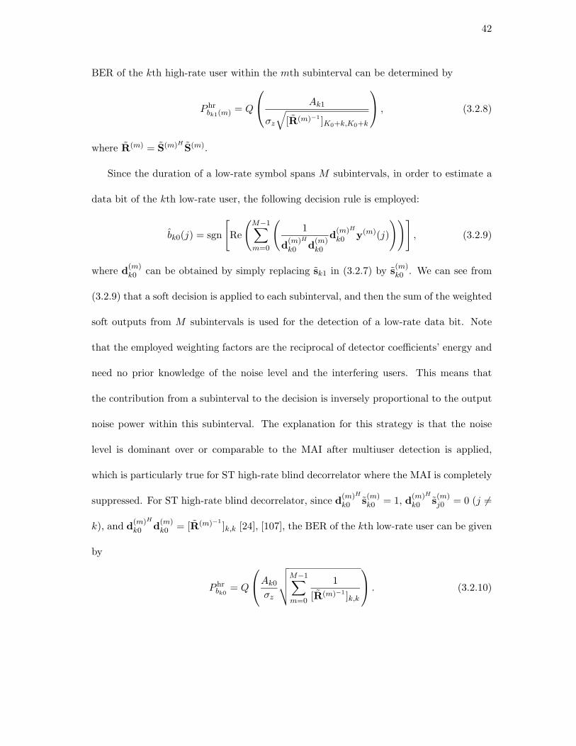
Since the duration of a low-rate symbol spans M subintervals, in order to estimate a
data bit of the kth low-rate user, the following decision rule is employed:
bk0(j) = sgn
[Re
(M−1∑
m=0
(1
d(m)H
k0 d(m)k0
d(m)H
k0 y(m)(j)
))], (3.2.9)
where d(m)k0 can be obtained by simply replacing sk1 in (3.2.7) by s
(m)k0 . We can see from
(3.2.9) that a soft decision is applied to each subinterval, and then the sum of the weighted
soft outputs from M subintervals is used for the detection of a low-rate data bit. Note
that the employed weighting factors are the reciprocal of detector coefficients’ energy and
need no prior knowledge of the noise level and the interfering users. This means that
the contribution from a subinterval to the decision is inversely proportional to the output
noise power within this subinterval. The explanation for this strategy is that the noise
level is dominant over or comparable to the MAI after multiuser detection is applied,
which is particularly true for ST high-rate blind decorrelator where the MAI is completely
suppressed. For ST high-rate blind decorrelator, since d(m)H
k0 s(m)k0 = 1, d
(m)H
k0 s(m)j0 = 0 (j 6=
k), and d(m)H
k0 d(m)k0 = [R(m)−1
]k,k [24], [107], the BER of the kth low-rate user can be given
by
P hrbk0
= Q
Ak0
σz
√√√√M−1∑
m=0
1
[R(m)−1 ]k,k
. (3.2.10)

43
A similar strategy to (3.2.6) can be used to estimate the desired spatial signature for
ST high-rate blind linear detectors. Since the spatial signature information is included in
M subintervals, the received signals within M subintervals are exploited for the estimation
of the desired spatial signature. Therefore, in this case, the number of available equations
for each high-rate or low-rate user is M(PN1 − KH). Therefore, if P ≥ MKH−1N0−1 , a
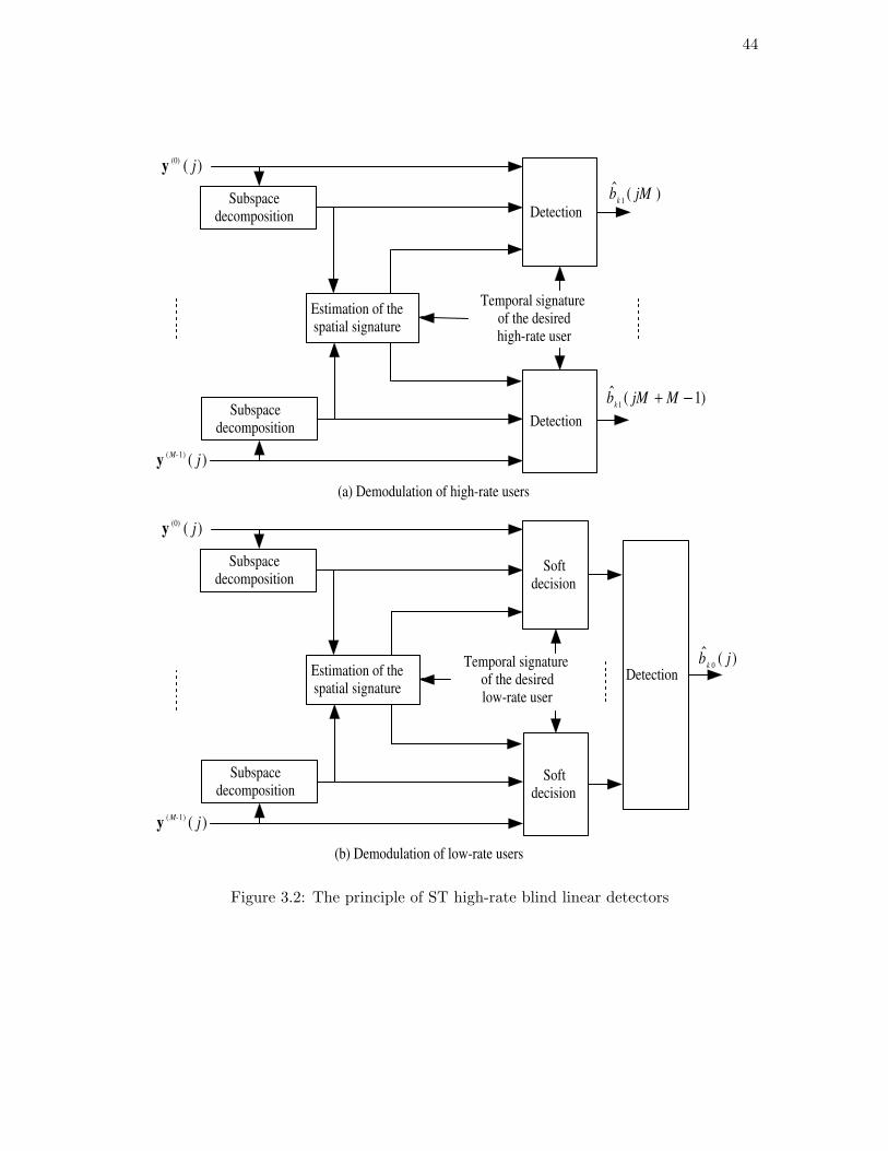
unique nontrivial solution exists. The principle of ST high-rate blind linear detectors is
summarized in Fig. 3.2.
3.2.3 A Comparison of ST Low-rate and High-rate Blind Linear Detec-tors
The ST low-rate and high-rate blind linear detectors involve the computation of the sub-
space parameters and the desired spatial signature. Obviously, the computational com-
plexity of ST low-rate blind linear detectors is much higher than that of their high-rate
counterparts as the rate ratio M increases. Moreover, it is easy to see that the use of ST
low-rate blind linear detectors incurs a detection delay for high-rate users.
As mentioned before, for the sake of identifying the desired spatial signature, the
number of antenna elements should satisfy P ≥ maxKL−1N0−1 , MKL−1
MN0−1 for ST low-rate blind
linear detectors and P ≥ MKH−1N0−1 for ST high-rate blind linear detectors. Since MKH−1
N0−1 >
KL−1N0−1 and MKH−1
N0−1 > MKL−1MN0−1 for M ≥ 2, the ST low-rate blind linear detectors can
support no less users than the ST-HR blind linear detectors as long as the desired spatial
signature is identifiable (assuming that all the other system parameters are the same).
This conclusion can be extended to synchronous multi-rate systems with I different data
rates where the higher rates are multiples of the lower rates. The ST rate i (i = 1, . . . , I)
44
Detection
) ( (0) j y
Temporal signature of the desired high-rate user
Estimation of the spatial signature
Detection
) ( ) 1 ( j
M- y
) ( ˆ 1
jM b k
) 1 ( ˆ 1
- + M jM b k
) ( ˆ 0
j b k
(a) Demodulation of high-rate users
(b) Demodulation of low-rate users
Subspace decomposition
Subspace decomposition Detection
Soft decision
) ( (0) j y
Estimation of the spatial signature
) ( ) 1 ( j
M- y
Subspace decomposition
Subspace decomposition
Soft decision
Temporal signature of the desired low-rate user
Figure 3.2: The principle of ST high-rate blind linear detectors

45
blind linear detectors can be developed to match symbol period of rate i users, where a
decision rule similar to (3.2.9) can be used to detect those users with rates lower than rate
i.
Proposition 3.2.1. In a synchronous multi-rate system with I different data rates where
the higher rates are multiples of the lower rates, if rate l is lower than rate j (1 ≤ l, j ≤ I),
the ST rate l blind linear detectors can support no less users than the ST rate j blind linear
detectors as long as the desired spatial signature is identifiable (assuming that all the other
system parameters are the same).
Proof. Assume that the number of rate i users is Ki, the symbol period is Ti, and the
spreading factor is Ni. It is also assumed that 1T1
> 1T2
> · · · > 1TI
and Tl
Tj= Mlj for
1 ≤ j < l ≤ I where Mlj is a positive integer.
Considering that the received signal is cyclostationary with period TI , MIj rate j bit
intervals should be considered for ST rate j blind linear detectors. Within each rate j bit
interval, the number of data bits is∑j
q=1 MjqKq +∑I
q=j+1 Kq. So the number of available
equations for determining the spatial signature of the desired rate d user is MId(PNj −∑j
q=1 MjqKq −∑I
q=j+1 Kq) for d < j, and MIj(PNj −∑j
q=1 MjqKq −∑I
q=j+1 Kq) for
d ≥ j. Therefore, in order to ensure that the desired spatial signature is identifiable, we
must have
P ≥ maxP⊥jd, 1 ≤ d < j, P>
j , (3.2.11)

46
where
P⊥jd =
MId(∑j
q=1 MjqKq +∑I
q=j+1 Kq) − 1
MIdNj − 1(3.2.12)
P>j =
MIj(∑j
q=1 MjqKq +∑I
q=j+1 Kq) − 1
MIjNj − 1. (3.2.13)
Similarly, for ST rate l blind linear detectors, we must have
P ≥ maxP⊥ld , 1 ≤ d < l, P>
l , (3.2.14)
where P⊥ld and P>
l are defined by (3.2.12) and (3.2.13), respectively.
Note that
P⊥ld <
MId(∑l
q=1 MlqKq +∑I
q=l+1 Kq)
MIdNl − 1
<MIl(
∑lq=1 MlqKq +
∑Iq=l+1 Kq)
MIlNl − 1
=
∑lq=1 MIqKq +
∑Iq=l+1 MIlKq)
NI − 1
∆= Pl, (3.2.15)
where the second inequality is due to MId > MIl when d < l, and the equality is due to
MIlMlq = MIq and MIlNl = NI . Since Pl > P>l and
P>j − Pl =
(MIj − MIl)∑I
q=l+1 Kq +∑l
q=j+1(MIj − MIq)Kq − 1
NI − 1> 0, (3.2.16)
where the inequality is due to the assumption that the higher rates are multiples of the
lower rates, Proposition 3.2.1 is proven.
On the other hand, we have the following proposition for the BER performances of ST
low-rate and high-rate blind decorrelators.
47
Proposition 3.2.2. For a synchronous dual-rate system, if the desired spatial signature
and the exact subspace parameters are known, then
P hrbki(m) ≥ P lr
bki(m), i = 0, 1, (3.2.17)
where P lrbki(m) and P hr
bki(m) are the BERs of ST low-rate and high-rate blind decorrelators
for user ki’s data bits in any subinterval, respectively. Especially, both achieve the same
BER for each low-rate user if the temporal signatures for low-rate users are the same in
every high-rate symbol period, i.e., the repetition code is employed.
Proof. Note that the ST low-rate and high-rate blind decorrelators have similar BER
expressions as the non-blind LRD and HRD [71], [72], respectively. They differ as follows:
The BER of LRD (HRD) involves a special diagonal element of R−1(R(m)−1), i.e., the
inverse of the temporal signature correlation matrix within the low-rate (mth high-rate)
symbol period, which can be accurately calculated using the known temporal signatures of
all active users. On the other hand, the BER of ST low-rate (high-rate) blind decorrelator
involves the corresponding element of R−1(R(m)−1), i.e., the inverse of the spatio-temporal
signature correlation matrix within the low-rate (mth high-rate) symbol period, which
depends upon the subspace parameters and the desired spatio-temporal signature. Hence,
the BER of ST low-rate (high-rate) blind decorrelator can only be approximately estimated
from the received signals.
Therefore, inequality (3.2.17) must hold due to the following reasons: i) the special
diagonal element of R−1(R(m)−1) for ST low-rate (high-rate) blind decorrelator can be
accurately obtained under the condition that the desired spatial signature and the exact
48
subspace parameters are known; ii) R(R(m)) for ST low-rate (high-rate) blind decorre-
lator has the same matrix structure as R(R(m)) for LRD (HRD), since R(R(m)) can be
written as the Schur, or element by element, product of R(R(m)) and the spatial signature
correlation matrix without zero elements. In fact, a similar proposition has been proven
for the non-blind LRD and HRD based on the above matrix structures [71], [72].
In accordance with Proposition 3.2.2 and the fact that the Q function defined by (3.2.5)
is monotonically descending, we can conclude that the NFR performances of ST low-rate
blind linear detectors are not inferior to those of their high-rate rivals. Furthermore, the
above proposition and inference can be extended to synchronous multi-rate systems since
a similar extension for the non-blind dual-rate decorrelators has been proven in [72].
3.3 Asynchronous Extension
The ST dual-rate blind linear detectors can be applied to asynchronous DS/CDMA. The
same formulae in the synchronous case can be used for asynchronous systems with an
increased dimension. This is due to the fact that the number of virtual bits and the
number of their associated virtual signatures within the processing interval are larger
than those in the synchronous case [87]. For ST low-rate blind linear detectors, if the
desired user is a low-rate user, the desired low-rate user is then viewed as the reference
user, whose bit interval is taken as the processing interval. Otherwise an arbitrary low-rate
user can be chosen as the reference user. For each user other than the reference one, there
might be two virtual bits located at both ends of the processing interval, whose full-length

49
signatures are partitioned into two virtual ones. Therefore, within the processing interval,
the number of data bits (including actual and virtual bits) is between K0 + MK1 and
2K0 + (M + 1)K1 − 1. For the detection of the high-rate data bit that is divided into
two virtual bits, a similar strategy to (3.2.9) can be used to weight the partial estimates
over two successive processing intervals before a final decision is made. It should be noted
that for ST low-rate blind linear detectors, the number of data bits and their associated
signatures are the same among the different processing intervals.
For ST high-rate blind linear detectors, if the desired user is a low-rate user, an arbi-
trary high-rate user can be chosen as the reference user. Otherwise the desired high-rate
user is viewed as the reference user. Within the processing interval, there might be two
virtual bits for each high-rate user other than the reference one and either one or two
virtual bits for each low-rate user, resulting in the number of data bits being between
K0 + K1 and 2K0 + 2K1 − 1. A similar strategy to (3.2.9) can be used to demodulate a
low-rate data bit. Note that for ST high-rate blind linear detectors, the number of data
bits and their associated signatures might change among the different processing intervals.
Therefore, special attention should be paid to the implementation of ST high-rate blind
linear detectors for asynchronous systems.
For a general asynchronous dual-rate system, the number of data bits within the
processing interval, which determines the number of available equations for determining
the desired spatial signature, depends on the relative delays of all the users and the choice
of the reference user. As a consequence, it is difficult to theoretically compare the number
of users which can be supported by ST low-rate and high-rate blind linear detectors.

50
Fortunately, such a comparison can be performed on some special asynchronous systems.
Let us investigate a special asynchronous dual-rate system where only the different rate
users are asynchronous. Obviously, for ST low-rate blind linear detectors, the number
of data bits within the processing interval is K0 + (M + 1)K1, and thus the number of
available equations for determining the spatial signature is PN0−K0− (M +1)K1 for the
desired low-rate user or (M + 1)(PN0 − K0 − (M + 1)K1) for the desired high-rate user.
Consequently, in order to ensure that the desired spatial signature is identifiable, we must
have
P ≥ max
K0 + (M + 1)K1 − 1
N0 − 1,(M + 1)(K0 + (M + 1)K1) − 1
(M + 1)N0 − 1
∆= PL. (3.3.1)
For ST high-rate blind linear detectors, the number of data bits is 2K0 + K1 within one
of M processing intervals and K0 + K1 within the others. As a result, the number of
available equations for determining the spatial signature is PN0 − (M + 1)K0 − MK1
for the desired high-rate user. As for the desired low-rate user, the number of available
equations is 2(PN1 − 2K0 − K1) within the processing interval with 2K0 + K1 data bits,
while it is (M − 1)(PN1 − K0 − K1) within the others. The total number of available
equations is thus equal to P (N0 + N1) − (M + 3)K0 − (M + 1)K1. So we must have
P ≥ max
(M + 1)K0 + MK1 − 1
N0 − 1,(M + 3)K0 + (M + 1)K1 − 1
N0 + N1 − 1
∆= PH . (3.3.2)
Since PH is not always greater than PL, Proposition 3.2.1 is invalid for such an asyn-
chronous system. This means that the validity of Proposition 3.2.1 can not be warranted
for an asynchronous multi-rate system.

51
On the other hand, it is easy to see from (3.2.4), (3.2.8) and (3.2.10) that the BER
performances of ST dual-rate blind decorrelators are related to the DOAs, the temporal
signatures and the delays of all the users as well as the choice of the reference user.
This renders it impractical to make a theoretical comparison on the performances of ST
dual-rate blind decorrelators. However, it is possible to compare their performances by
qualitative analysis.
Intuitively, for asynchronous dual-rate systems, the detection performance would be
better as the processing interval is enlarged. On the other hand, it would be worse when a
weighting combination strategy similar to (3.2.9) is employed. As a result, the ST low-rate
blind decorrelator would outperform the ST high-rate blind decorrelator for detecting the
high-rate users due to its actual processing interval being much larger than (more exactly,
at least M multiples of) a high-rate bit interval. As for the detection of the low-rate
data bit, unlike the ST low-rate blind decorrelator, the ST high-rate blind decorrelator
adopts the weighting combination strategy and its actual processing interval is at most
M+1M
multiples of a low-rate bit interval. Considering that the actual processing interval of
ST high-rate blind decorrelator may be only slightly larger than that of ST low-rate blind
decorrelator, the latter should outperform the former for detecting the low-rate users in
most cases. This is verified by the simulation results in Section 3.6, where the DOAs, the
temporal signatures and the delays of all the users are randomly generated. However, it
is still possible that the ST high-rate blind decorrelator offers a better performance than
its low-rate counterpart for detecting the low-rate users.

52
Let us investigate an asynchronous dual-rate system with a low-rate user and a high-
rate user, where the rate ratio is two and the high-rate user lags three chips to the
low-rate user. For the high-rate user, the DOA is 0 and the signature sequence is
1,−1,−1, 1, 1, 1,−1. For the low-rate user, the DOA is 40 and the signature sequence is
−1, 1, 1,−1,−1, 1, 1,−1, 1, 1,−1,−1, 1, 1. Both signature sequences are normalized. In
accordance with (3.2.4) and (3.2.10), the BERs of the low-rate user are Q(0.9952×A10/σ)
and Q(0.9971 × A10/σ) for ST low-rate and high-rate blind decorrelators, respectively.
Since the Q function defined by (3.2.5) is monotonically descending, we can conclude
that in the above case, the performance of ST low-rate blind decorrelator is inferior to
that of ST high-rate blind decorrelator for detecting the low-rate user. In other words,
Proposition 3.3.2 is invalid for such an asynchronous dual-rate system.
3.4 Adaptive Implementations
At first, let us derive the adaptive algorithm for ST low-rate blind MMSE detection. Note
that (3.2.6) can also be solved by using the following optimization procedure [107]:
gk = arg max‖gk‖=1
gHk Wgk. (3.4.1)
The solution of this optimization problem is simply the principal unit-norm eigenvector
of the matrix
W = (IP ⊗ sHk )UsU
Hs (IP ⊗ sk) (3.4.2)

53
for low-rate users, or
W =
M−1∑
m=0
(IP ⊗ sHkm
)UsUHs (IP ⊗ skm
) (3.4.3)
for high-rate users, where the virtual user km (m = 0, . . . , M − 1) corresponds to the
desired high-rate user. This implies that besides prior knowledge of the desire temporal
signature, only an orthonormal basis of the signal subspace is required for the estimation
of the desired spatial signature. As an alternative to high complexity batch EVD or SVD,
adaptive subspace tracking algorithms with lower complexity, e.g., orthonormal PAST
algorithm [108], can be employed to estimate an orthonormal basis of the signal subspace.
The recursive orthonormal PAST algorithm updates the subspace in a sample-by-sample
fashion, which can guarantee the orthogonality of matrix Us at each iteration without
attendant increase in computational complexity.
By following a similar line to [107], the adaptive algorithm for ST low-rate blind MMSE
detection can be summarized as follows:
1. Estimation of an orthonormal basis of the signal subspace from y(j) using the or-
thonormal PAST algorithm;
2. Computation of matrix W via (3.4.2) or (3.4.3);
3. Estimation of the desired spatial signature using the simple power method [106];
4. Construction of the desired spatio-temporal signature;
5. Estimation of the ST low-rate blind MMSE detector based on the updated signal
subspace and an intermediate variable of the orthonormal PAST algorithm.

54
The further details can be found in Table 3.1.
In a similar manner to its low-rate counterpart, the adaptive algorithm for ST high-rate
blind MMSE detection can also be obtained easily, in which matrices
W =
M−1∑
m=0
(IP ⊗ s(m)H
k0 )U(m)s U(m)H
s (IP ⊗ s(m)k0 ) (3.4.4)
and
W =M−1∑
m=0
(IP ⊗ sHk1)U
(m)s U(m)H
s (IP ⊗ sk1) (3.4.5)
are used instead of (3.4.2) and (3.4.3), respectively.
3.5 Two-stage ST Dual-rate Blind Detectors
The ST dual-rate blind linear detectors can also operate at the output of a single antenna
by using the temporal signatures instead of the corresponding spatio-temporal signatures
in all associated equations. In this case, they are referred to as purely temporal dual-
rate blind decorrelators and blind MMSE detectors. Their performances are surely inferior
to their ST counterparts because angle diversity among all the users is not used. However,
they need no estimation of the spatial signature. Moreover, the adaptive algorithms for
purely temporal low-rate and high-rate blind MMSE detection will have a much faster
convergence than their ST counterparts. This is because the signal subspace can be
recursively estimated using the orthonormal PAST algorithm in much less iterations for
the former than for the latter due to the smaller dimension of signal vector.
Rather than the adaptive ST dual-rate blind MMSE detectors employing joint spatial-
temporal processing, the basic idea of two-stage ST dual-rate blind detectors is to

55
Table 3.1: The adaptive algorithm for ST low-rate blind MMSE detection
Update of the signal subspace using the orthonormal PAST algorithm,where α is a forgetting factor in (0,1]
r(n) = UHs (n − 1)y(n)
q(n) = 1αZ(n − 1)r(n)
γ(n) = 11+rH(n)q(n)
p(n) = γ(n)(y(n) − Us(n − 1)r(n))
τ(n) = 1‖q(n)‖2
(1√
1+‖p(n)‖2‖q(n)‖2− 1
)
p(n) = τ(n)Us(n − 1)q(n) + (1 + τ(n)‖q(n)‖2)p(n)
Z(n) = 1αZ(n − 1) − γ(n)q(n)qH(n)
Us(n) = Us(n − 1) + p(n)qH(n)
Update of the spatial signature using the power method
W(n) = (IP ⊗ sHk )Us(n)UH
s (n)(IP ⊗ sk)
a(n) = W(n)gk(n − 1)
gk(n) = a(n)‖a(n)‖
Update of the ST low-rate blind MMSE detector
sk(n) = gk(n) ⊗ sk
dk(n) = Us(n)Z(n)UHs (n)sk(n)

56
cascade temporal processing and spatial processing. Our aim is to design some two-
stage ST dual-rate blind detectors which are comparable to the corresponding adaptive ST
dual-rate blind MMSE detectors. At the first stage of temporal processing, an adaptive
purely temporal dual-rate blind MMSE detector for each element is a natural choice.
Depending upon whether the adaptive purely temporal low-rate or high-rate blind MMSE
detector is used at the first stage, it is referred to as two-stage ST low-rate or high-rate
blind detector. Although the first stage has the same number of adaptive weights as the
corresponding adaptive ST dual-rate blind MMSE detector, the former surely converges
much faster than the latter due to its parallel structure. Based on the results in [107], the
computational complexity of the former is comparable to that of the latter1. At the second
stage, a non-adaptive beamformer based on the minimum variance distortionless response
(MVDR) criterion is chosen as the spatial processor, since the MVDR beamformer is
optimal in the sense that the output SINR is maximized [109]. For two-stage ST low-rate
blind detector, the MVDR beamformer always operates at the low-rate symbol rate. For
two-stage ST high-rate blind detector, it operates at the low-rate symbol rate for low-rate
users while at the high-rate symbol rate for high-rate users.
It is well known that among the linear detectors, the MMSE detectors can maximize the
output SINR [5]. Therefore, the two-stage ST dual-rate blind detectors, which combine the
adaptive purely temporal dual-rate blind MMSE detectors and the MVDR beamformer,
are reasonable counterparts to the adaptive ST dual-rate blind MMSE detectors. We
take the two-stage ST low-rate blind detector as an example to see how it works. The
1For adaptive ST dual-rate blind MMSE detector, the computational complexity associated with the
estimation of the desired spatial signature is not included.

57
soft output of the pth adaptive purely temporal low-rate blind MMSE detector can be
represented by
epk(j) = dpH
k yp(j), (3.5.1)
where dpk is a vector of filter tap weights for user k. Then the input of the MVDR
beamformer is ek(j) = [e1k(j), . . . , e
Pk (j)]T , whose weights can be computed as [109]
wk =R−1
k gk
gHk R−1
k gk
, (3.5.2)
where Rk = Eek(j)eHk (j). The desired spatial signature can be estimated using Capon’s
method [109]
gk = arg max‖gk‖=1
1
gHk R−1
k gk
. (3.5.3)
The solution of this optimization problem is the eigenvector corresponding to the minimal
eigenvalue of R−1k or the maximal eigenvalue of Rk. Since the number of antenna elements
is generally small, the calculation of the beamformer weights is not computationally cum-
bersome.
3.6 Numerical Examples
The performances of the proposed ST and purely temporal dual-rate blind detectors have
been investigated via numerical simulations. Assume that there are five low-rate users
and five high-rate users in the system. User 1 is the desired low-rate user and user
6 is the desired high-rate user. A uniform linear array with two elements (spacing =
λ2 ) is considered. The spreading factor for high-rate users is 31, and the rate ratio is

58
2. Therefore, the spreading factor for low-rate users is 62. In order to eliminate any
dependence of performance on the spatial-temporal signature correlations, the DOAs of
all the users are randomly selected over [0, 2π). Also, the binary temporal signatures are
randomly generated where the assignment of the low-rate temporal signatures employs
the repetition-code scheme [71]. 1500 realizations are used to generate all results.
Fig. 3.3 and Fig. 3.4 show the BER performances of ST dual-rate blind linear de-
tectors and their purely temporal versions versus the near-far ratio2 in the synchronous
and asynchronous cases, respectively, where the SNR of the desired user is 8dB. In these
simulations, batch EVD is used for subspace decomposition, and the desired spatial sig-
nature is assumed to be known. In the asynchronous case, user 1 and user 6 are chosen as
the reference users for low-rate and high-rate blind linear detectors, respectively, and the
delay for the kth rate i user is set to be γki chips, where γki is a randomly selected positive
integer between 0 and Ni−1. As proven in Proposition 3.2.2, in the synchronous case, the
ST (purely temporal) low-rate blind decorrelator outperforms the ST (purely temporal)
high-rate blind decorrelator for high-rate users and they offer the same performances for
low-rate users. On the other hand, in the asynchronous case, the ST (purely temporal)
low-rate blind decorrelator outperforms its high-rate counterpart for both low-rate and
high-rate users. This implies that Proposition 3.3.2 is valid for asynchronous systems in
most cases, due to the fact that the DOAs, the temporal signatures and the delays of
all the users are randomly generated. In addition, it is obvious that the ST dual-rate
blind linear detectors outperform the corresponding purely temporal counterparts, and
2Near-far ratio is defined as the power ratio of all the other users to the desired user.
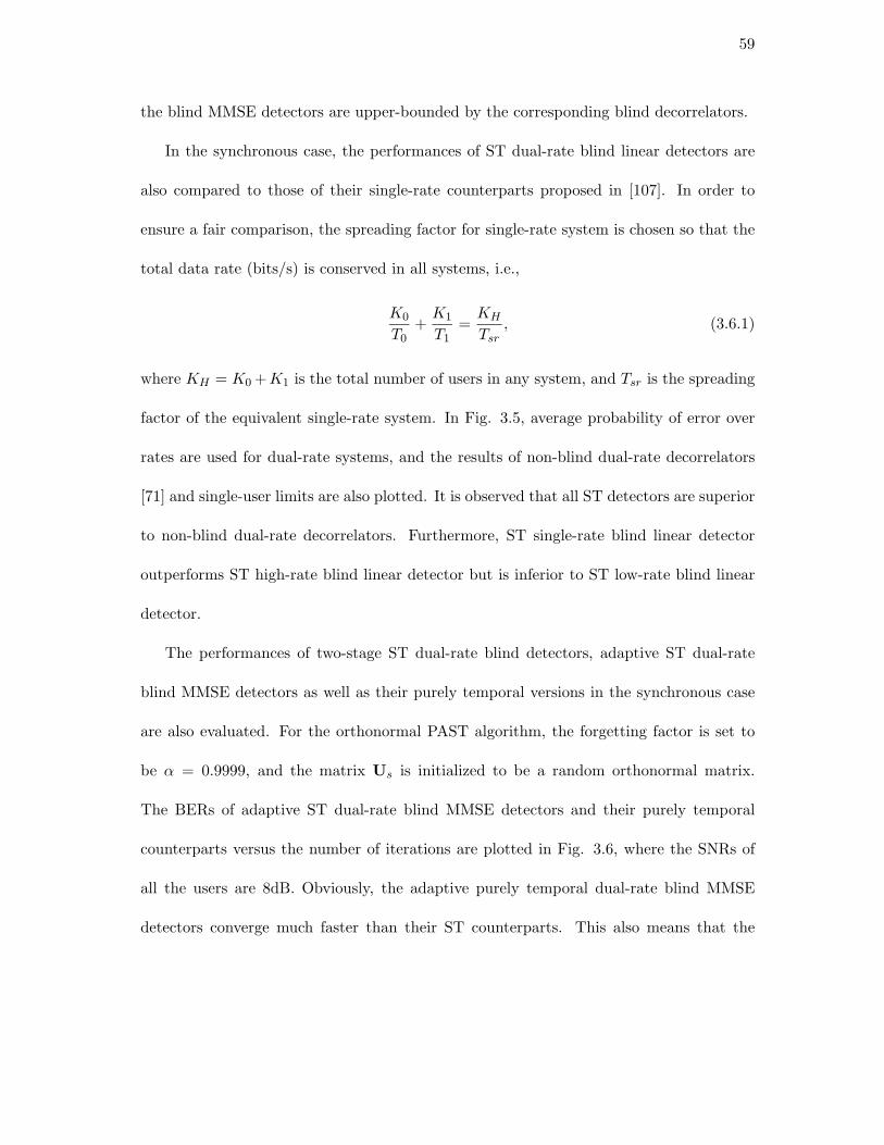
59
the blind MMSE detectors are upper-bounded by the corresponding blind decorrelators.
In the synchronous case, the performances of ST dual-rate blind linear detectors are
also compared to those of their single-rate counterparts proposed in [107]. In order to
ensure a fair comparison, the spreading factor for single-rate system is chosen so that the
total data rate (bits/s) is conserved in all systems, i.e.,
K0
T0+
K1
T1=
KH
Tsr
, (3.6.1)
where KH = K0 +K1 is the total number of users in any system, and Tsr is the spreading
factor of the equivalent single-rate system. In Fig. 3.5, average probability of error over
rates are used for dual-rate systems, and the results of non-blind dual-rate decorrelators
[71] and single-user limits are also plotted. It is observed that all ST detectors are superior
to non-blind dual-rate decorrelators. Furthermore, ST single-rate blind linear detector
outperforms ST high-rate blind linear detector but is inferior to ST low-rate blind linear
detector.
The performances of two-stage ST dual-rate blind detectors, adaptive ST dual-rate
blind MMSE detectors as well as their purely temporal versions in the synchronous case
are also evaluated. For the orthonormal PAST algorithm, the forgetting factor is set to
be α = 0.9999, and the matrix Us is initialized to be a random orthonormal matrix.
The BERs of adaptive ST dual-rate blind MMSE detectors and their purely temporal
counterparts versus the number of iterations are plotted in Fig. 3.6, where the SNRs of
all the users are 8dB. Obviously, the adaptive purely temporal dual-rate blind MMSE
detectors converge much faster than their ST counterparts. This also means that the
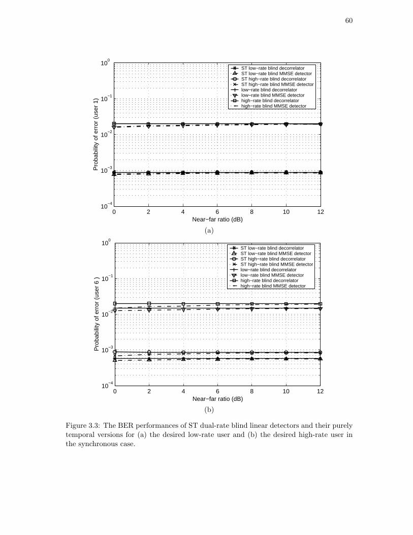
60
0 2 4 6 8 10 1210
−4
10−3
10−2
10−1
100
Near−far ratio (dB)
Pro
babi
lity
of e
rror
(us
er 1
)
ST low−rate blind decorrelatorST low−rate blind MMSE detectorST high−rate blind decorrelatorST high−rate blind MMSE detectorlow−rate blind decorrelatorlow−rate blind MMSE detectorhigh−rate blind decorrelatorhigh−rate blind MMSE detector
(a)
0 2 4 6 8 10 1210
−4
10−3
10−2
10−1
100
Near−far ratio (dB)
Pro
babi
lity
of e
rror
(us
er 6
)
ST low−rate blind decorrelatorST low−rate blind MMSE detectorST high−rate blind decorrelatorST high−rate blind MMSE detectorlow−rate blind decorrelatorlow−rate blind MMSE detectorhigh−rate blind decorrelatorhigh−rate blind MMSE detector
(b)
Figure 3.3: The BER performances of ST dual-rate blind linear detectors and their purelytemporal versions for (a) the desired low-rate user and (b) the desired high-rate user inthe synchronous case.

61
0 2 4 6 8 10 1210
−4
10−3
10−2
10−1
100
Near−far ratio (dB)
Pro
babi
lity
of e
rror
(us
er 1
)
ST low−rate blind decorrelatorST low−rate blind MMSE detectorST high−rate blind decorrelatorST high−rate blind MMSE detectorlow−rate blind decorrelatorlow−rate blind MMSE detectorhigh−rate blind decorrelatorhigh−rate blind MMSE detector
(a)
0 2 4 6 8 10 1210
−4
10−3
10−2
10−1
100
Near−far ratio (dB)
Pro
babi
lity
of e
rror
(us
er 6
)
ST low−rate blind decorrelatorST low−rate blind MMSE detectorST high−rate blind decorrelatorST high−rate blind MMSE detectorlow−rate blind decorrelatorlow−rate blind MMSE detectorhigh−rate blind decorrelatorhigh−rate blind MMSE detector
(b)
Figure 3.4: The BER performances of ST dual-rate blind linear detectors and their purelytemporal versions for (a) the desired low-rate user and (b) the desired high-rate user inthe asynchronous case.

62
0 2 4 6 8 10 1210
−4
10−3
10−2
10−1
Near−far ratio (dB)
Pro
babi
lity
of e
rror
ST low−rate blind decorrelator ST low−rate blind MMSE detector ST high−rate blind decorrelator ST high−rate blind MMSE detector non−blind LRDnon−blind HRDST single−rate blind decorrelator ST single−rate blind MMSE detectorsingle−user limit
Figure 3.5: Performance comparison between ST dual-rate blind linear detectors and theirsingle-rate counterparts in the synchronous case.
first stages of two-stage ST dual-rate blind detectors have faster convergence than the
corresponding adaptive ST dual-rate blind MMSE detectors. Fig. 3.7 indicates the BERs
of these dual-rate blind detectors versus the near-far ratio after the adaptive algorithms
have converged, where the SNR of the desired user is 8dB. It is shown that the BER
performances of adaptive ST dual-rate blind MMSE detectors are superior to those of the
corresponding two-stage ST dual-rate blind detectors, while the latter outperform their
purely temporal counterparts.

63
3.7 Summary
This chapter proposes the subspace-based time-invariant ST low-rate and high-rate blind
linear detectors for synchronous DS/CDMA systems. It is shown that a) the ST low-rate
blind linear detectors can support no less users than their high-rate rivals as long as the
desired spatial signature is identifiable (assuming that all the other system parameters
are same); b) the BER performance of ST low-rate blind decorrelator is not inferior to
that of its high-rate counterpart. The asynchronous extension is also described. Finally,
the two-stage ST dual-rate blind detectors, which combine the adaptive purely temporal
dual-rate blind MMSE filters with the non-adaptive MVDR beamformer, are presented.
Their adaptive stages with parallel structures converge much faster than the corresponding
adaptive ST dual-rate blind MMSE detectors, while having a comparable computational
complexity to the latter.

64
0 500 1000 1500 2000 2500 300010
−4
10−3
10−2
10−1
100
Number of iterations
Pro
babi
lity
of e
rror
(us
er 1
)
Adaptive ST low−rate blind MMSE detectorAdaptive ST high−rate blind MMSE detectorAdaptive low−rate blind MMSE detector Adaptive high−rate blind MMSE detector
(a)
0 500 1000 1500 2000 2500 300010
−4
10−3
10−2
10−1
100
Number of iterations
Pro
babi
lity
of e
rror
(us
er 6
)
Adaptive ST low−rate blind MMSE detectorAdaptive ST high−rate blind MMSE detectorAdaptive low−rate blind MMSE detector Adaptive high−rate blind MMSE detector
(b)
Figure 3.6: The convergence performances of adaptive ST dual-rate blind MMSE detectorsand their purely temporal versions for (a) the desired low-rate user and (b) the desiredhigh-rate user.

65
0 2 4 6 8 10 1210
−4
10−3
10−2
10−1
100
Near−far ratio (dB)
Pro
babi
lity
of e
rror
(us
er 1
)
Adaptive ST low−rate blind MMSE detectorAdaptive ST high−rate blind MMSE detectorTwo−stage ST low−rate blind detector Two−stage ST high−rate blind detector Adaptive low−rate blind MMSE detector Adaptive high−rate blind MMSE detector
(a)
0 2 4 6 8 10 1210
−4
10−3
10−2
10−1
100
Near−far ratio (dB)
Pro
babi
lity
of e
rror
(us
er 6
)
Adaptive ST low−rate blind MMSE detectorAdaptive ST high−rate blind MMSE detectorTwo−stage ST low−rate blind detector Two−stage ST high−rate blind detector Adaptive low−rate blind MMSE detector Adaptive high−rate blind MMSE detector
(b)
Figure 3.7: The BER performances of adaptive ST dual-rate blind MMSE detectors, two-stage ST dual-rate blind detectors, and their purely temporal versions for (a) the desiredlow-rate user and (b) the desired high-rate user.

Chapter 4
Blind Channel Estimation inDual-rate DS/CDMA Systems
Chapter 3 handles the application of blind techniques for ST multiuser detection to multi-
rate DS/CDMA systems over the ideal AWGN channels. Unfortunately, in practice, multi-
rate CDMA signals experience multipath fading channels. Furthermore, as described in
Chapter 2, they suffer much more severe ISI than their single-rate counterparts.
For multipath fading channels, the design of multi-rate blind multiuser detectors with-
out channel estimation is possible. Such dual-rate blind multiuser detectors were proposed
in [91] by applying the MOE criterion. However, this constrained optimization approach
only deals with the case where the delay spread is only a small fraction of the symbol
period. Moreover, their performances degrade significantly at low SNR.
Alternatively, the channel can be estimated before the multiuser detection process.
To this end, the subspace-based blind approaches for channel estimation and multiuser
detection in multi-rate DS/CDMA systems have been investigated in [95] and [96], which
can handle the case of a large delay spread. In both papers, the basic-rate blind channel
66

67
estimators and multiuser detectors are taken into account. However, they have higher
computational complexity and do not make full use of the nature of dual-rate signals.
This chapter proposes the subspace-based low-rate and high-rate blind channel es-
timation algorithms for asynchronous dual-rate DS/CDMA. Compared to the above two
works, this work is carried out independently and simultaneously. Especially, the proposed
dual-rate blind channel estimation schemes can be implemented adaptively. Moreover, the
dual-rate blind MMSE detection for the AWGN channels proposed in Chapter 3 can be
extended to frequency-selective multipath channels.
This chapter is organized as follows. In Section 4.1, signal models for an asynchronous
dual-rate system over a frequency-selective multipath channel are established. Section 4.2
proposes low-rate and high-rate blind channel estimation schemes. Section 4.3 addresses
adaptive algorithms for dual-rate blind channel estimation. The dual-rate blind MMSE
detection is presented in Section 4.4. Simulation results are described in Section 4.5.
Section 4.6 gives some concluding remarks. Most results in this chapter can also be found
in [56] and [60].
4.1 Signal Models
Let us consider an asynchronous VSF dual-rate DS/CDMA system over a frequency se-
lective multipath channel, in which the rate ratio M is an integer greater than 1. As for
the notation used below, unless otherwise stated, please refer to Sections 1.6 and 2.2.
At the receiver, in accordance with (2.2.1) and (2.2.2), the received complex baseband
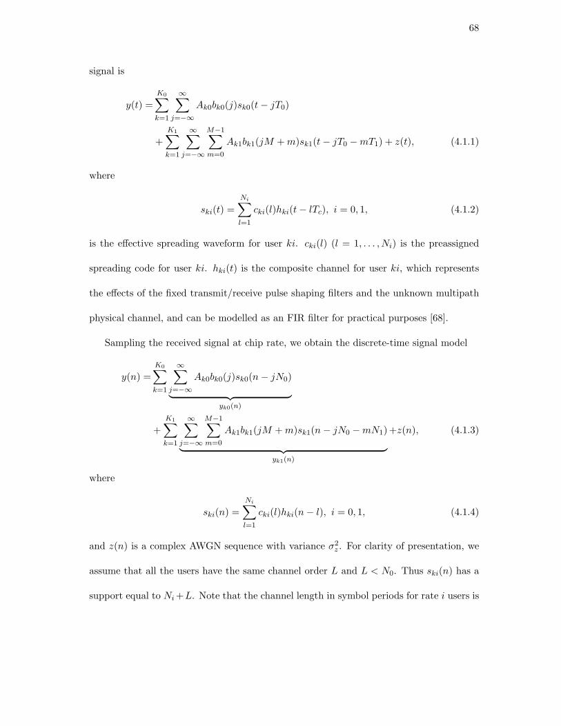
68
signal is
y(t) =
K0∑
k=1
∞∑
j=−∞Ak0bk0(j)sk0(t − jT0)
+
K1∑
k=1
∞∑
j=−∞
M−1∑
m=0
Ak1bk1(jM + m)sk1(t − jT0 − mT1) + z(t), (4.1.1)
where
ski(t) =
Ni∑
l=1
cki(l)hki(t − lTc), i = 0, 1, (4.1.2)
is the effective spreading waveform for user ki. cki(l) (l = 1, . . . , Ni) is the preassigned
spreading code for user ki. hki(t) is the composite channel for user ki, which represents
the effects of the fixed transmit/receive pulse shaping filters and the unknown multipath
physical channel, and can be modelled as an FIR filter for practical purposes [68].
Sampling the received signal at chip rate, we obtain the discrete-time signal model
y(n) =
K0∑
k=1
∞∑
j=−∞Ak0bk0(j)sk0(n − jN0)
︸ ︷︷ ︸yk0(n)
+
K1∑
k=1
∞∑
j=−∞
M−1∑
m=0
Ak1bk1(jM + m)sk1(n − jN0 − mN1)
︸ ︷︷ ︸yk1(n)
+z(n), (4.1.3)
where
ski(n) =
Ni∑
l=1
cki(l)hki(n − l), i = 0, 1, (4.1.4)
and z(n) is a complex AWGN sequence with variance σ2z . For clarity of presentation, we
assume that all the users have the same channel order L and L < N0. Thus ski(n) has a
support equal to Ni +L. Note that the channel length in symbol periods for rate i users is

69
Lsi∆= d(Ni +L)/Nie, where dxe is the smallest integer greater than or equal to x. Clearly,
Ls0 = 2. We denote the effective spreading sequence with length LsiNi for user ki to be
ski = [ski(1), . . . , ski(Ni + L), 0, . . . , 0]T , i = 0, 1. (4.1.5)
In the light of (4.1.4), (4.1.5) can further be written as
ski =
cki(1) 0...
. . .
cki(Ni) cki(1)
. . ....
cki(Ni)
0
︸ ︷︷ ︸Cki
hki(0)...
hki(L)
︸ ︷︷ ︸hki
. (4.1.6)
Matrix Cki can be divided into Lsi sub-matrices with dimension Ni × (L + 1), i.e., Cki =
[CHki(1), . . . ,CH
ki(Lsi)]H . Our aim is to estimate the composite channel vector hki from
the observation y(n), only with the prior knowledge of cki(l) (l = 1, . . . , Ni). The low-rate
and high-rate signal models will be established below.
4.1.1 Low-rate Signal Model
In order to mitigate the effect of ISI, a processing interval of P0 low-rate symbol periods
should be considered for low-rate signal modelling (See Fig. 4.1). P0 is termed as low-rate
smoothing factor.
For user k0, collecting the chip-rate samples within an interval of P0T0 yields yk0(j) =
[yk0(jN0), . . . , yk0((j + P0)N0 − 1)]T , which can be represented as
yk0(j) = Ak0Sk0Hk0bk0(j), (4.1.7)

70
Low-rate processing interval ( M =3; P 0 =2)
The 1st high-rate processing interval
The 2nd high-rate processing interval
( M =3; P 1 =2)
The 3rd high-rate processing interval
Low-rate
High-rate
Figure 4.1: The low-rate and high-rate processing intervals
where
Sk0 =
Ck0(2) Ck0(1)
. . .. . .
Ck0(2) Ck0(1)
︸ ︷︷ ︸P0N0×(P0+1)(L+1)
, (4.1.8)
Hk0 =
hk0
. . .
hk0
︸ ︷︷ ︸P0+1 blocks
, (4.1.9)
and
bk0(j) = [bk0(j − 1), . . . , bk0(j + P0 − 1)]T . (4.1.10)
Furthermore, for each high-rate user, there are Ls1 = M +Ls1−1 data bits presenting
within a low-rate symbol period. Using Matlab notation, we define
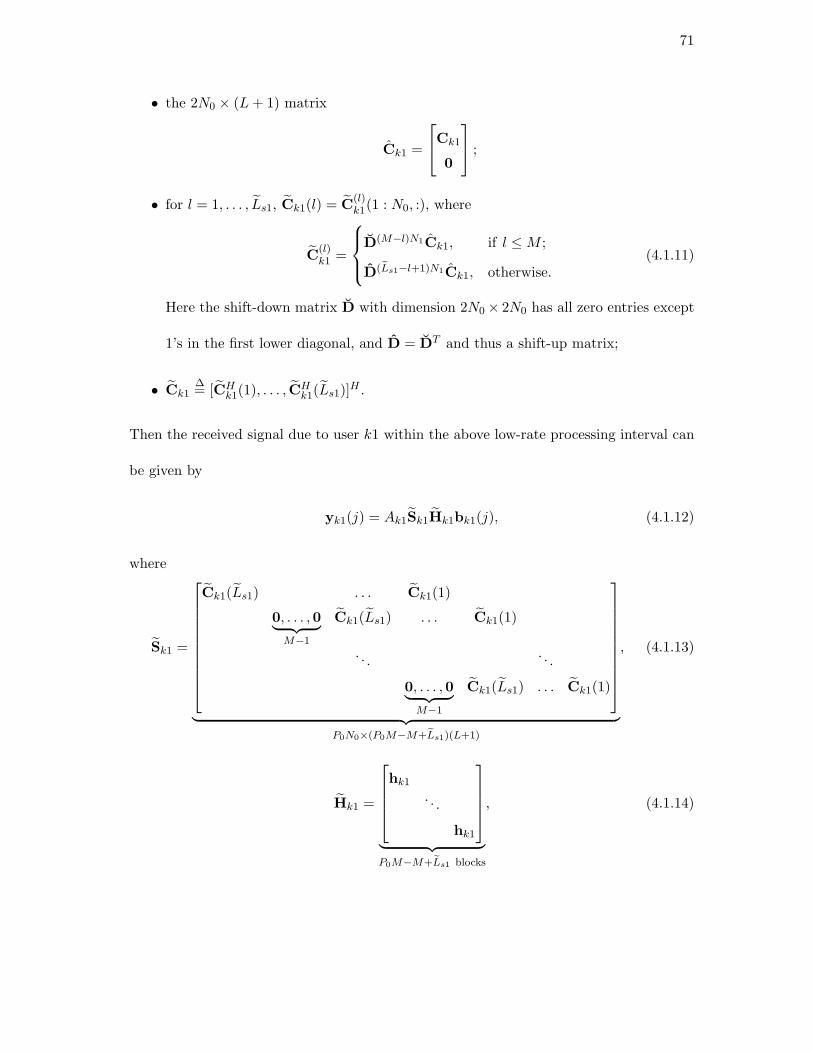
71
• the 2N0 × (L + 1) matrix
Ck1 =
Ck1
0
;
• for l = 1, . . . , Ls1, Ck1(l) = C(l)k1(1 : N0, :), where
C(l)k1 =
D(M−l)N1Ck1, if l ≤ M ;
D(Ls1−l+1)N1Ck1, otherwise.(4.1.11)
Here the shift-down matrix D with dimension 2N0 × 2N0 has all zero entries except
1’s in the first lower diagonal, and D = DT and thus a shift-up matrix;
• Ck1∆= [CH
k1(1), . . . , CHk1(Ls1)]
H .
Then the received signal due to user k1 within the above low-rate processing interval can
be given by
yk1(j) = Ak1Sk1Hk1bk1(j), (4.1.12)
where
Sk1 =
Ck1(Ls1) . . . Ck1(1)
0, . . . ,0︸ ︷︷ ︸M−1
Ck1(Ls1) . . . Ck1(1)
. . .. . .
0, . . . ,0︸ ︷︷ ︸M−1
Ck1(Ls1) . . . Ck1(1)
︸ ︷︷ ︸P0N0×(P0M−M+Ls1)(L+1)
, (4.1.13)
Hk1 =
hk1
. . .
hk1
︸ ︷︷ ︸P0M−M+Ls1 blocks
, (4.1.14)

72
and
bk1(j) = [bk1(jM − Ls1 + 1), . . . , bk1((j + P0)M − 1)]T . (4.1.15)
If we introduce the following notations:
Gk0 = Ak0Sk0Hk0,
Gk1 = Ak1Sk1Hk1,
G = [G10, . . . ,GK00, G11, . . . , GK11],
and
b(j) = [bT10(j), . . . ,b
TK00(j),b
T11(j), . . . ,b
TK11(j)]
T ,
then the resulting received signal within the above low-rate processing interval is
y(j) =
K0∑
k=1
yk0(j) +
K1∑
k=1
yk1(j) + z(j)
= Gb(j) + z(j), (4.1.16)
where z(j) is the corresponding noise vector. A data matrix is formed by concatenating
the received signal vectors
Y = [y(j), . . . ,y(j + J0 − P0)]
= G [b(j), . . . ,b(j + J0 − P0)]︸ ︷︷ ︸B
+ [z(j), . . . , z(j + J0 − P0)]︸ ︷︷ ︸Z
. (4.1.17)
73
4.1.2 High-rate Signal Model
For high-rate signal modelling, M processing intervals should be considered. As shown
in Fig. 4.1, the mth high-rate processing interval consists of all the mth high-rate bit
durations of P1 successive low-rate symbol periods, where P1 is referred to as high-rate
smoothing factor.
For user k0, we denote C(m)k0
∆= [C
(m)H
k0 (1),C(m)H
k0 (2)]H , where C(m)k0 (l) = Ck0(l)(mN1+
1 : (m + 1)N1, :), l = 1, 2. Collecting the chip-rate samples within the mth high-rate pro-
cessing interval yields y(m)k0 (j) = [yk0(jN0+mN1), . . . , yk0(jN0+(m+1)N1−1), . . . , yk0((j+
P1 − 1)N0 + mN1), . . . , yk0((j + P1 − 1)N0 + (m + 1)N1 − 1)]T , which can be written as
y(m)k0 (j) = Ak0S
(m)k0 Hk0bk0(j), (4.1.18)
where
S(m)k0 =
C(m)k0 (2) C
(m)k0 (1)
. . .. . .
C(m)k0 (2) C
(m)k0 (1)
︸ ︷︷ ︸P1N1×(P1+1)(L+1)
. (4.1.19)
Note that for each low-rate user, the actual number of data bits present within the mth
high-rate processing interval might change with the index m. If 0 ≤ m < Ls1 − 1, the
actual number of data bits is P1 + 1; otherwise P1.
The received signal due to user k1 within the mth high-rate processing interval can be
written as
y(m)k1 (j) = Ak1Sk1Hk1b
(m)k1 (j), (4.1.20)

74
where
Sk1 =
Ck1(Ls1) . . . Ck1(1)
0, . . . ,0︸ ︷︷ ︸M−1
Ck1(Ls1) . . . Ck1(1)
. . .. . .
0, . . . ,0︸ ︷︷ ︸M−1
Ck1(Ls1) . . . Ck1(1)
︸ ︷︷ ︸P1N1×(P1M−M+Ls1)(L+1)
, (4.1.21)
Hk1 =
hk1
. . .
hk1
︸ ︷︷ ︸P1M−M+Ls1 blocks
, (4.1.22)
and
b(m)k1 (j) = [bk1(jM + m − Ls1 + 1), . . . , bk1((j + P1 − 1)M + m)]T . (4.1.23)
Note that for each high-rate user, the actual number of data bits presenting within each
high-rate processing interval depends on the values of M and Ls1. If Ls1 ≥ M , the actual
number of data bits is P1M − M + Ls1; otherwise P1Ls1.
If we introduce the following notations:
G(m)k0 = Ak0S
(m)k0 Hk0,
Gk1 = Ak1Sk1Hk1,
G(m) = [G(m)10 , . . . ,G
(m)K00,G11, . . . ,GK11],
b(m)(j) = [bT10(j), . . . ,b
TK00(j),b
(m)T
11 (j), . . . ,b(m)T
K11 (j)]T ,
then the resulting received signal within the mth high-rate processing interval is
y(m)(j) = G(m)b(m)(j) + z(m)(j), (4.1.24)

75
where z(m)(j) is the corresponding noise vector. The data matrix can be formed by
Y(m) = [y(m)(j), . . . ,y(m)(j + J1 − P1)]
= G(m) [b(m)(j), . . . ,b(m)(j + J1 − P1)]︸ ︷︷ ︸B(m)
+ [z(m)(j), . . . , z(m)(j + J1 − P1)]︸ ︷︷ ︸Z(m)
.
(4.1.25)
4.2 Dual-rate Blind Channel Estimation
Based on the above signal models, this section develops the low-rate and high-rate blind
channel estimators for dual-rate DS/CDMA by exploiting the subspaces of Y and Y(m)
that contain the relevant channel information due to (4.1.17) and (4.1.25).
4.2.1 Low-rate Blind Channel Estimation
We first consider the noise free case. As in the standard subspace algorithm, a subspace
decomposition can be performed on Y by an SVD
Y =[Us Un
]Λs 0
0 0
V
Hs
VHn
, (4.2.1)
where the vectors in Us, associated with the singular values in diagonal matrix Λs, span
the signal subspace defined by the columns of G, whereas the vectors in Un, associated
with the zero singular values, span the orthogonal complement of Us (and hence of G).
The dimension of the signal subspace is ds = K0(P0 + 1) + K1(P0M −M + Ls1), and that
of its orthogonal complement is dn = P0N0 − ds. In order to achieve blind identifiability,
we assume that B is full row rank and G is full column rank [27]. This means that the
values of J0 and P0 need to be carefully specified.
76
For convenience of presentation, let us define Un = [UHn (1), . . . ,UH
n (P0)]H and Us =
[UHs (1), . . . ,UH
s (P0)]H , where Un(p) and Us(p) (p = 1, . . . , P0) are N0 × dn and N0 × ds
sub-matrices, respectively. Since Un is orthogonal to the columns of G, we have
UHn Gk0 = 0, (4.2.2)
and
UHn Gk1 = 0. (4.2.3)
For user k0, substituting Gk0 = Ak0Sk0Hk0 into (4.2.2), we have
UHn Sk0Hk0 = 0, (4.2.4)
which can be rewritten as
QH0 Ck0hk0 = 0, (4.2.5)
where
Q0 =
Un(P0) . . . Un(1)
Un(P0) . . . Un(1)
︸ ︷︷ ︸2N0×(P0+1)dn
. (4.2.6)
Equation (4.2.5) yields a set of (P0+1)dn linear equations with (L+1) unknown variables.
To determine hk0 up to a scalar, a necessary condition is
(P0 + 1)dn ≥ L. (4.2.7)
In the presence of noise, since only a perturbed version of Q0 can be obtained, (4.2.5)
can be replaced by the least-squares criterion [107]
hk0 = arg min‖hk0‖=1
hHk0C
Hk0Q0Q
H0 Ck0hk0. (4.2.8)

77
The solution of this optimization problem is the eigenvector corresponding to the minimum
eigenvalue of CHk0Q0Q
H0 Ck0.
Similarly, for user k1, substituting Gk1 = Ak1Sk1Hk1 into (4.2.3), we have
UHn Sk1Hk1 = 0, (4.2.9)
of which an alternative form is
QH1 Ck1hk1 = 0, (4.2.10)
where
Q1 =
Un(P0) . . . Un(2) 0, . . . ,0︸ ︷︷ ︸M−1
Un(1)
. . .. . .
Un(P0) . . . Un(2) 0, . . . ,0︸ ︷︷ ︸M−1
Un(1)
︸ ︷︷ ︸Ls1N0×(P0M−M+Ls1)dn
. (4.2.11)
Equation (4.2.10) yields a set of (P0M−M +Ls1)dn linear equations, and thus a necessary
condition for determining hk1 up to a scalar is
(P0M − M + Ls1)dn ≥ L. (4.2.12)
Also, it is easy to see from (4.2.10) that in the least-squares sense, the estimate hk1
of hk1 can be obtained as the eigenvector corresponding to the minimum eigenvalue of
CHk1Q1Q
H1 Ck1.
4.2.2 High-rate Blind Channel Estimation
Similar to its low-rate counterpart, for the high-rate blind channel estimator, an SVD
can be performed on Y(m), and then U(m)s , whose columns span the signal subspace, and
78
U(m)n , whose columns span the orthogonal complement of U
(m)s , can be obtained. The
dimension of the signal subspace is d(m)s , which is equal to the actual number of data bits
presenting within the mth high-rate processing interval. From our previous analysis in
Section 4.1, it can be seen that d(m)s might change with the index m and has a maximum
of K0(P1 + 1)+K1(PM −M + Ls1). The dimension of the orthogonal complement of the
signal subspace is d(m)n = P1N1 − d
(m)s . In order to achieve blind identifiability, we assume
that matrix G(m) has full column rank, and matrix B(m) is of full row rank [27]. As a
result, the values of J1 and P1 need to be carefully specified.
Let U(m)n = [U
(m)H
n (1), . . . ,U(m)H
n (P1)]H , where U
(m)n (p) (p = 1, . . . , P1) are N1×d
(m)n
sub-matrices. For user k0, we can derive
Q(m)H
0 C(m)k0 hk0 = 0 (4.2.13)
from
U(m)H
n S(m)k0 Hk0 = 0, (4.2.14)
where
Q(m)0 =
U
(m)n (P1) . . . U
(m)n (1)
U(m)n (P1) . . . U
(m)n (1)
︸ ︷︷ ︸2N1×(P1+1)d
(m)n
. (4.2.15)
Considering that channel information of each low-rate user spans one complete low-rate
symbol period, in the least-squares sense, (4.2.13) can be solved by the following opti-
mization problem
hk0 = arg min‖hk0‖=1
M−1∑
m=0
C(m)H
k0 Q(m)0 Q
(m)H
0 C(m)k0 . (4.2.16)

79
Obviously, hk0 can be estimated as the eigenvector corresponding to the minimum eigen-
value of∑M−1
m=0 (C(m)H
k0 Q(m)0 Q
(m)H
0 C(m)k0 ). Additionally, a necessary condition for deter-
mining hk0 up to a scalar is∑M−1
m=0 (P1 + 1)d(m)n ≥ L.
For user k1, from
U(m)H
n Sk1Hk1 = 0, (4.2.17)
we can obtain
Q(m)H
1 Ck1hk1 = 0, (4.2.18)
where
Q(m)1 =
U(m)n (P1) . . . U
(m)n (2) 0, . . . ,0︸ ︷︷ ︸
M−1
U(m)n (1)
. . .. . .
U(m)n (P1) . . . U
(m)n (2) 0, . . . ,0︸ ︷︷ ︸
M−1
U(m)n (1)
︸ ︷︷ ︸Ls1N1×(P1M−M+Ls1)d
(m)n
. (4.2.19)
Then hk1 can be estimated as the eigenvector corresponding to the minimum eigenvalue
of CHk1(∑M−1
m=0 Q(m)1 Q
(m)H
1 )Ck1. Also, a necessary condition for determining hk1 up to a
scalar is∑M−1
m=0 (P1M − M + Ls1)d(m)n ≥ L.
4.3 Adaptive Implementations
It is noteworthy that for low-rate blind channel estimation, in accordance with (4.2.6), we
can obtain
Q0QH0 =
F(1) F(2)
FH(2) F(1)
. (4.3.1)

80
where
F(l) =
P0∑
p=l
Un(p − l + 1)UHn (p), l = 1, 2. (4.3.2)
Considering that UnUHn + UsU
Hs = IP0N0 , we have
F(1) = P0IN0 −P0∑
p=1
Us(p)UHs (p) (4.3.3)
F(l) = −P0∑
p=l
Us(p − l + 1)UHs (p), l 6= 1. (4.3.4)
Therefore, (4.2.8) can also be represented only using the information of the signal subspace.
Let us factorize Ls1 as Ls1 = ηM+q, where both η and q are integers and 0 ≤ q ≤ M−1.
Based on (4.2.11), it is found that the structure of the Ls1N0 × Ls1N0 matrix Q1QH1
depends on the value of M . For example, when M = 3, q ∈ 0, 1, 2. For q = 2, we have
Q1QH1 =
F(1) 0 0 . . . F(η) 0 0 F(η + 1) 0
0. . . F(η + 1)
0. . . 0
.... . . 0
FH(η). . . F(η)
0. . .
...
0. . . 0
FH(η + 1). . . 0
0 FH(η + 1) 0 0 FH(η) . . . 0 0 F(1)
,
(4.3.5)
where F(l) (l = 1, . . . , η + 1) are defined by (4.3.3) and (4.3.4). For q = 1 and q = 0, the
last one and two, respectively, block matrix rows and columns should be removed from
(4.3.5). This means that an equivalent form of Q1QH1 , which only employs the information

81
of the signal subspace, is also available. Similarly, for high-rate blind channel estimation,
both Q(m)0 Q
(m)H
0 and Q(m)1 Q
(m)H
1 can also be expressed by only using the information
of the signal subspace. Therefore, for the proposed dual-rate blind channel estimation
schemes, channel estimates can be obtained as long as an orthonormal basis of the signal
subspace is identified.
As a consequence, the adaptive algorithm for low-rate blind channel estimation can be
summarized as follows:
1. Estimation of an orthonormal basis of the signal subspace Us from y(j) using the
orthonormal PAST algorithm [108];
2. Computation of matrix CHk0Q0Q
H0 Ck0 (for low-rate users) or matrix CH
k1Q1QH1 Ck1
(for high-rate users);
3. Estimation of hki by performing the SVD on the matrice obtained in Step 2.
The adaptive algorithm for high-rate blind channel estimation can likewise be derived. As
to the details of the orthonormal PAST algorithm, please refer to Table 3.1. The main
computational burden of the above algorithms comes from the estimation of the signal
subspace. In fact, it can be shown that the computational complexity for low-rate blind
channel estimation is 4P0N0ds + O(d2s) flops per iteration, and that for high-rate blind
channel estimation is 4P1N1∑M−1
m=0 d(m)s + O(
∑M−1m=0 d
(m)2
s ) flops per iteration. Therefore,
in the case that P0 = P1, the complexity of adaptive low-rate blind channel estimation
becomes much higher than that of its high-rate rival as the rate ratio M increases.
82
4.4 Dual-rate Blind MMSE Detection
As mentioned in Section 3.4, after the desired spatial signature is obtained based on the
orthonormal PAST algorithm, the desired spatio-temporal signature can be constructed.
The adaptive ST dual-rate blind MMSE detection for the AWGN channel can then be
developed based on the updated signal subspace and an intermediate variable of the or-
thonormal PAST algorithm. Accordingly, in the context of frequency selective multipath
channel, the adaptive dual-rate blind MMSE detection can also be derived based on the
orthonormal PAST algorithm as long as the desired signal vector is identified. The issue
to be addressed below is how the desired signal vector is related to the desired channel
vector.
For low-rate blind MMSE detection, in accordance with (4.1.7) and (4.1.12), the signal
vector corresponding to the data bit bk0(j) can be represented by
vk0 = Sk0(:, L + 2 : 2L + 2)hk0, (4.4.1)
while the signal vector corresponding to the data bit bk1(jM + m) (m = 0, . . . , M − 1)
can be written by
v(m)k1 = Sk1(:, (Ls1 + m − 1)(L + 1) + 1 : (Ls1 + m)(L + 1))hk1. (4.4.2)
For high-rate blind MMSE detection, in terms of (4.1.18), for the data bit bk0(j), the
corresponding signal vector within the mth high-rate processing interval can be represented
by
v(m)k0 = S
(m)k0 (:, L + 2 : 2L + 2)hk0. (4.4.3)

83
For the data bit bk1(jM + m) (m = 0, . . . , M − 1), in accordance with (4.1.20), the
corresponding signal vector can be given by
vk1 = Sk1(:, (Ls1 − 1)(L + 1) + 1 : Ls1(L + 1))hk1. (4.4.4)
4.5 Numerical Examples
In all the simulations, a dual-rate system with three low-rate users and two high-rate users
has been considered. User 1 is the desired low-rate user and user 4 is the desired high-rate
user. The spreading factor for high-rate users is 16, and the rate ratio is 2. The spreading
factor for low-rate users is thus 32. Both low-rate and high-rate smoothing factors are set
to be 3. For all the users, the binary code sequences and the channels with order 31 are
generated randomly. The near-far ratio is 10dB. For the orthonormal PAST algorithm,
the forgetting factor is set to be α = 0.9999, and the matrix Us is initialized to be a
random orthonormal matrix.
First, the performances of the proposed adaptive dual-rate blind channel estimation
algorithms are validated. The performance measure is the averaged root mean-squared
error (RMSE) between estimated channel and true channel. Note that there is a com-
plex constant ambiguity involved in the channel estimates. During the simulations, the
real constant part of ambiguity is handled by assigning the true channels hki unit norm.
However, without further processing, we can not resolve the phase ambiguity. Thus, to cal-
culate the simulated RMSE, the complex phase ambiguity is compensated by multiplying
the estimates by ejθ, where the phase estimate θ is obtained by minimizing the distance
84
‖hki − ejθhki‖2 and is equal to θ = phase(hHkihki). As a consequence, the averaged RMSE
is
RMSE =1
P
P∑
i=1
√2 − 2‖hH
kihki‖, (4.5.1)
where the number of algorithm runs is P = 1500.
Fig. 4.2 shows the channel estimation RMSE versus the number of iterations, where
the SNR of the desired user is 10dB. Clearly, the adaptive algorithms for both low-rate
and high-rate blind channel estimation converge. However, the low-rate algorithm per-
forms better than the high-rate algorithm, with a cost of increasing the computational
complexity. Fig. 4.3 shows the channel estimation RMSE versus the SNR of the desired
user after the proposed adaptive algorithms have converged. Note that both algorithms
perform better as the SNR of the desired user increases.
Based on channel estimates obtained in the above simulations, the performances of the
proposed dual-rate blind MMSE detection algorithms have also been evaluated. Fig. 4.4
shows the output SINR versus the SNR of the desired user after the proposed adaptive
algorithms have converged. As a comparison, the single-rate results are also plotted, where
the spreading factor for the equivalent single-rate system is determined by (3.6.1), and
other system parameters are the same. Obviously, the low-rate and single-rate algorithms
outperform the high-rate algorithm. It should also be noted that other than the detection
of the desired low-rate user, the performance of the low-rate algorithm is remarkably
superior to that of the high-rate algorithm for detecting the desired high-rate user. This
is because when the high-rate algorithm is used to detect a high-rate data bit, which

85
spans multiple high-rate bit durations due to multipath delay spread, it only exploits
partial information of this high-rate data bit within the corresponding high-rate processing
interval.
4.6 Summary
This chapter has proposed a new adaptive blind channel estimation algorithm for dual-
rate DS/CDMA systems in multipath channels. Based on subspace decomposition, this
algorithm is capable of dealing with large delay spread channels. Its effectiveness has
been confirmed by simulations. Additionally, after the channels are estimated using these
algorithms, the adaptive dual-rate blind MMSE detectors developed in Chapter 3 can be
extended to multipath fading channels.

86
0 500 1000 1500 2000 2500 300010
−3
10−2
10−1
100
101
Number of iterations
Cha
nnel
est
imat
ion
RM
SE
(us
er 1
)
low−rate algorithmhigh−rate algorithm
(a)
0 500 1000 1500 2000 2500 300010
−3
10−2
10−1
100
101
Number of iterations
Cha
nnel
est
imat
ion
RM
SE
(us
er 4
)
low−rate algorithm high−rate algorithm
(b)
Figure 4.2: The channel estimation RMSE versus the number of iterations for (a) thedesired low-rate user and (b) the desired high-rate user.

87
0 2 4 6 8 10 12 14 16 18 2010
−3
10−2
10−1
100
SNR (dB)
Cha
nnel
est
imat
ion
RM
SE
(us
er 1
)
low−rate algorithm high−rate algorithm
(a)
0 2 4 6 8 10 12 14 16 18 2010
−3
10−2
10−1
100
SNR (dB)
Cha
nnel
est
imat
ion
RM
SE
(us
er 4
)
low−rate algorithm high−rate algorithm
(b)
Figure 4.3: The channel estimation RMSE versus the SNR for (a) the desired low-rateuser and (b) the desired high-rate user.

88
0 2 4 6 8 10 12 14 16 18 2010
12
14
16
18
20
22
24
26
28
30
SNR (dB)
Out
put S
INR
for
user
1 (
dB)
low−rate algorithmhigh−rate algorithmsingle−rate case
(a)
0 2 4 6 8 10 12 14 16 18 2010
12
14
16
18
20
22
24
26
28
30
SNR (dB)
Out
put S
INR
for
user
4 (
dB)
low−rate algorithmhigh−rate algorithmsingle−rate case
(b)
Figure 4.4: The output SINR versus the SNR for (a) the desired low-rate user and (b) thedesired high-rate user.

Chapter 5
Blind Timing Acquisition andChannel Estimation for Multi-rateMulticarrier DS/CDMA
In the preceding two chapters, the subspace-based blind approaches for channel estimation
and multiuser detection in multi-rate DS/CDMA systems have been proposed. These
approaches target primarily at single-carrier systems. There has been considerable interest
in multicarrier CDMA systems due to their robustness to multipath fading channels.
However, little has been reported on channel estimation and multiuser detection
for multi-rate multicarrier CDMA.
As stated in Section 1.4, multicarrier CDMA systems may be classified into two cate-
gories, depending upon whether frequency domain or time domain spreading is employed.
Both classes of multicarrier CDMA systems show a similar capability in mitigating the ef-
fects of fading. However, the time spreading class (the so-called multicarrier DS/CDMA),
in general, employs a smaller number of carriers relative to the frequency spreading class,
89

90
and thus, is less complex [43]. As a consequence, only multicarrier DS/CDMA is consid-
ered in this chapter.
In multicarrier DS/CDMA systems, to achieve frequency diversity, the same data bit
spread by a narrowband DS waveform is usually transmitted over each carrier and the
received signals are combined to give a more robust data estimate [41]. Such a diversity
scheme incurs lower spectral efficiency, and one possible remedy is to employ higher order
modulation. For such multicarrier DS/CDMA systems, several receiver structures have
been constructed for single-rate systems [43]-[46]. Among these receivers, [46] employed
subspace-based techniques to estimate channel coefficients and to construct a multiuser
detector.
The major contribution of this chapter is that it addresses the application of the
subspace-based technique to timing acquisition and channel estimation issues for multi-
rate multicarrier DS/CDMA. Based on a unified signal model, a joint timing acquisition
and channel estimation scheme is proposed for both MC and VSF multi-rate systems.
It is well known that the operation of any subspace-based technique requires a nonnull
noise subspace. Unfortunately, a nonnull noise subspace is unavailable for multicarrier
DS/CDMA due to the employed band-limited chip waveform. To tackle this problem,
following a similar idea to [46], a finite-length truncation approximation on the chip wave-
form is performed. Numerical results and theoretical analysis show that this approxima-
tion hardly caused any performance degradation of the subspace-based estimators under
moderate near-far situations.
The rest of this chapter is organized as follows. Section 5.1 outlines the received

91
signal model. Problem formulation is described in Section 5.2. The channel estimation
and timing acquisition scheme is described in Section 5.3. Simulation results are given
in Section 5.4. In Section 5.5, the effect of the finite-length chip waveform truncation on
the performance of the proposed scheme is investigated. Section 5.6 concludes the work.
Most results presented in this chapter can also be found in [58], [59].
5.1 Signal Model
It has been shown in Section 2.5 that, similar to single-carrier DS/CDMA, MC and VSF
access strategies can also be used for multicarrier DS/CDMA to implement multi-rate
multiuser communications. In addition, the signal model for a multi-rate multicarrier
DS/CDMA system can be established by basic-rate modelling or rate i modelling. Espe-
cially, the basic-rate signal model for the VSF case is also applicable to the MC case.
Let us consider a general VSF multi-rate multicarrier DS/CDMA system defined in
(2.1.1) and (2.1.2), in which there are I different data rates. As for the notation used
below, unless otherwise stated, please refer to Sections 1.6 and 2.2.
Assume that each user uses the same M carriers. The frequency of the mth carrier is
wm. The spreading waveform for the mth carrier of user ki is
skim(t) =
Ni−1∑
l=0
ckim(l)φ(t − lTc), (5.1.1)
where ckim(l) (l = 0, . . . , Ni − 1) is the preassigned spreading code for the mth carrier of
user ki. Assume that the chip waveform φ(t) is band-limited, and the carrier frequencies
are well separated so that adjacent frequency bands do not interfere with each other. Also,
92
φ(t) is normalized so that∫∞−∞ ‖φ(t)‖2dt = Tc.
The channel is assumed to be a slowly varying frequency selective Rayleigh channel.
The system parameters (e.g., the number of carriers M) can be chosen suitably so that
each frequency band can undergo independent flat fading [43]. Then the received complex
signal is given by
y(t) =I∑
i=1
Ki∑
k=1
M∑
m=1
Akixkim(t) exp(jwmt) + z(t), (5.1.2)
The signal component xkim(t) due to the mth carrier of user ki is given by
xkim(t) = αkim
∞∑
r=−∞bki(r)skim(t − rTi − τki), (5.1.3)
where αkim includes the overall effects of phase shifts and fading for the mth carrier of
user ki, and τki ∈ [0, Ti) represents the delay of user ki’s signal with respect to the start
of the processing interval.
The receiver consists of M branches, each of which is in charge of demodulating one
carrier. Assume that the front end filtering at each branch is perfect so that each carrier
can be separated. After down-conversion and filtering, the received signal passes through
a chip-matched filter followed by chip-rate sampling. At the mth branch, the output of
the matched filter at time nTc is given by
ym(n) =I∑
i=1
Ki∑
k=1
Akixkim(n) + zm(n), (5.1.4)
93
where zm(n) denotes the component due to AWGN, and
xkim(n) =
∫ ∞
−∞xkim(t)φ∗(t − nTc)dt
= αkim
∞∑
r=−∞bki(r)
Ni−1∑
l=0
ckim(l)φ((n − l − rNi)Tc − τki), (5.1.5)
where the function φ(t) is the output of chip waveform through chip-matched filter, i.e.,
φ(t) =∫∞−∞ φ(s)φ∗(s − t)ds. To avoid interchip interference for the desired signal when
it is chip synchronous, the chip waveform is chosen to satisfy the Nyquist criterion, i.e.,
φ(nTc) = Tc for n = 0 and φ(nTc) = 0 for n 6= 0 [46].
Considering that the received signal y(t) is a cyclostationary stochastic process with
period Tbr, to mitigate the effect of interchip interference in the case of chip asynchronism,
we set the processing interval with duration PTbr, where P is defined as the smoothing
factor. It is evident that for each rate i user, at least Pqi data symbols appear within
this processing interval. Assume that Nbr is the spreading factor for basic rate. At the
mth branch, by collecting PNbr samples within the processing interval, we can define the
following vectors
ym(r) = [ym(rNbr), . . . , ym(rNbr + PNbr − 1)]T ,
xkim(r) = [xkim(rNbr), . . . , xkim(rNbr + PNbr − 1)]T ,
zm(r) = [zm(rNbr), . . . , zm(rNbr + PNbr − 1)]T ,
for i = 1, . . . , I, k = 1, . . . , Ki, and m = 1, . . . , M . Then, the corresponding vectors from

94
M branches can be concatenated into the PMNbr-dimensional vectors
y(r) = [yT1 (r), . . . ,yT
M (r)]T ,
xki(r) = [xTki1(r), . . . , r
TkiM (r)]T ,
z(r) = [zT1 (r), . . . , zT
M (r)]T ,
for i = 1, . . . , I and k = 1, . . . , Ki. Now, (5.1.4) can be rewritten as
y(r) =I∑
i=1
Ki∑
k=1
Akixki(r) + z(r). (5.1.6)
5.2 Problem Formulation
It is necessary to further explore the structure of xki(r) so that the received vector y(r)
can be represented in a more refined manner. According to (5.1.5), by defining
hn′
kim(p) =
Ni−1∑
l=0
ckim(l)φ((n′Ni + p − l)Tc − τki),
where n′ = jqi − n, and then introducing the following notation:
gn′
kim = [hn′
kim(0), . . . , hn′
kim(PNbr − 1)]T ,
gn′
ki = [gn′Tki1 , . . . ,gn′T
kiM ]T ,
we can obtain an equivalent form of (5.1.6) as
y(r) =I∑
i=1
Ki∑
k=1
AkiHki
∞∑
n′=−∞gn′
kibki(rqi − n′) + z(r), (5.2.1)
where the PMNbr × PMNbr diagonal matrix
Hki = diag
αki1, . . . , αki1︸ ︷︷ ︸
PNbr
, . . . , αkiM , . . . , αkiM︸ ︷︷ ︸PNbr
.
95
We observe from (5.2.1) that the received signal vector y(r) is a linear combination of an
infinite number of signal vectors. This leads to the null noise subspace and thus disables
the subspace-based techniques. To tackle this problem, following the ideas in [46], a fast
decaying φ(t) should be chosen in practice. We further assume that φ(t) decays fast
enough so that a given symbol of rate i users makes a significant contribution only to
2Qi (Qi ≥ 1) adjacent symbols. So we can neglect the vectors in (5.2.1) except for those
corresponding to bki(rqi − Qi), . . . , bki(rqi), . . . , bki(rqi + Pqi + Qi − 2) for user ki1. As a
result, (5.2.1) becomes
y(r) =I∑
i=1
Ki∑
k=1
AkiHki
Qi∑
n′=−Pqi−Qi+2
gn′
kibki(rqi − n′) + z(r)
=I∑
i=1
Ki∑
k=1
AkiHkiGkibki(r) + z(r), (5.2.2)
where
Gki = [gQi
ki , . . . ,g−Pqi−Qi+2ki ],
bki(r) = [bki(rqi − Qi), . . . , bki(rqi + Pqi + Qi − 2)]T .
Our aim is to estimate the channel vector hki = [αki1, . . . , αkiM ]T and the delay τki from
the received vector y(r), only with the knowledge of spreading sequences of the desired
user.
5.3 Timing Acquisition and Channel Estimation
At first, let us estimate the channel vector hki on the assumption that τki is known. For
convenience and without loss of generality, we assume that the columns of matrix G are
1In fact, in the case of τki = 0, only g0ki, . . . ,g
−Pqi+1ki exist.

96
linear independent [95], where
G = [A11H11G11, . . . , AK11HK11GK11, . . . , A1IH1IG1I , . . . , AKIIHKIIGKII ].
The rank of matrix G, ds, is equal to the number of data symbols within the processing
interval. Its value depends on how many users are symbol- or chip-synchronous with
respect to the start of the processing interval. ds has a maximum of∑I
i=1 KiLi where
Li∆= Pqi + 2Qi − 1.
An eigen-decomposition can be performed on the autocorrelation matrix R of the
received vector y(r) by
R∆= Ey(r)yH(r)
=[Us Un
]Λs
Λn
U
Hs
UHn
, (5.3.1)
where Λs = diag(λ1, . . . , λds) contains the ds largest eigenvalues of R in descending or-
der, and Us = [u1, . . . ,uds] contains the corresponding orthonormal eigenvectors; Λn =
σ2IPMNbr−ds, and Un = [uds+1, . . . ,uPMNbr
] contains dn = PMNbr − ds orthonormal
eigenvectors that corresponding to the eigenvalue σ2. The vectors in matrix Us span the
signal subspace defined by the columns of G whereas the vectors in Un span the noise
subspace, orthogonal complement of the signal subspace.
Due to the orthogonality between the noise subspace and the signal subspace, we have
UHn HkiGki = 0, i = 1, . . . , I; k = 1, . . . , Ki. (5.3.2)

97
It is desirable to represent (5.3.2) in terms of the channel vector hki. By defining
Un =
Un
. . .
Un
︸ ︷︷ ︸Li blocks
,
and
Gnki =
gnki1
. . .
gnkiM
, n = −Pqi − Qi + 2, . . . , Qi,
Gki =
GQi
ki
...
G−Pqi−Qi+2ki
,
for i = 1, . . . , I and k = 1, . . . , Ki, we can obtain an equivalent form of (5.3.2), i.e.,
UHn Gkihki = 0, i = 1, . . . , I; k = 1, . . . , Ki. (5.3.3)
Since UHn Gki has dnLi rows, hki can be uniquely determined up to a multiplicative constant
only if dnLi ≥ M − 1.
Considering that in practice, the noise subspace can just be derived from spectral
decomposition of the time-average estimate of R, (5.3.3) can be solved in the least-squares
sense [107]
hki = arg min‖hki‖=1
hHkiWhki. (5.3.4)
The solution of this optimization problem is the eigenvector corresponding to the minimum
eigenvalue of W, where
W∆= GH
kiUnUHn Gki. (5.3.5)
98
The above channel estimation scheme assumes that τki is known. In practice, we
must perform joint timing and channel estimation for the desired user because of the
unavailable value of τki. Following a similar approach in [46], the procedure for joint
timing and channel estimation can be summarized as follows:
1. Hypothesize a value for τki ∈ [0, Ti) and construct the matrices Gki(τki) and W(τki);
2. Obtain a estimate hki(τki) for this τki via (5.3.4);
3. Calculate the cost function
C(τki) =hH
ki(τki)W(τki)hki(τki)
hHki(τki)GH
ki(τki)Gki(τki)hki(τki); (5.3.6)
4. Repeat step 1 to 3 for different values of τki;
5. Choose the timing estimate τki which minimizes the cost function C(τki) and the
corresponding channel estimate is hki(τki).
Obviously, in practice, a finite number of hypothesized values of τki should be selected in
the interval [0, Ti). Since the cost function C(τki) is a one-dimensional continuous function
of τki, an optimal estimate τki can be approximated if a sufficient number of hypotheses
are given. After the noise subspace is estimated, the overall computational complexity
of joint timing and channel estimation algorithm is directly proportional to the number
of hypotheses. Therefore, it is necessary to make a performance/complexity tradeoff. In
addition, in order to improve computational efficiency, we can store gnki1, . . . ,g
nkiM (n =
−Pqi−Qi+2, . . . , Qi) for all hypotheses in a lookup table, with a cost of increasing storage
requirements.

99
After timing and channel estimates are obtained via the above scheme, the subspace-
based blind MMSE detector can easily be constructed as long as the desired signal vector
is identified. The issue now is how the desired signal vector is related to the desired
channel vector. In accordance with (5.2.2), the signal vector corresponding to the data
bit bki(rqi − n) (n = −qi + 1, . . . , 0) can be represented by
pnki = Hkig
nki = Gn
kihki. (5.3.7)
Then the linear MMSE detector for demodulating bki(rqi −n) (n = −qi +1, . . . , 0) can be
given by [24]
wn = UsΛ−1s UH
s pnki. (5.3.8)
5.4 Numerical Examples
We compare the performance of the joint timing and channel estimation scheme for dual-
rate MC and VSF systems. The batch EVD is used for subspace decomposition. For a
fair comparison, in terms of [95], we established the following baseline:
• Both systems have the same chip rate and thus same system bandwidth;
• The numbers of rate i users are same in both systems;
• Identical duration of observation in both systems;
• Identical length of observation vector y(r) in both systems, which can be imple-
mented by the suitable choice of the smoothing factor;

100
Table 5.1: Simulation Settings
Parameters VSF System MC System
Number of users K1 = 3, K2 = 2 12 basic-rate users
Spreading Factor N1 = 15, N2 = 10 30
Smoothing Factor 2 2
Number of Carriers 2 2
Duration of Observation 1800 high rate or 600 basic-rate symbols1200 low rate symbols
• The channel coefficients αkim are generated according to a complex Gaussian distri-
bution with zero mean and unit variance, and the delay τki is uniformly generated
in [0, Ti);
• The binary spreading sequences are randomly generated in both systems in order to
eliminate any dependence of performance on the code correlations.
Let us consider a dual-rate case where the rate ratio is 2:3, i.e., q1 = 2 and q2 = 3.
In terms of the above baseline, simulation parameters are shown in Table 5.1. In both
systems, a raised-cosine function with roll-off factor 0.15 is used as chip waveform, i.e.,
φ(t) =sin(πt/Tc)
πt/Tc
cos(0.15πt/Tc)
1 − 0.09t2/T 2c
. (5.4.1)
The dimension of the signal subspace is set to be its maximum, i.e., ds =∑I
i=1 KiLi.
Assume that a given symbol of each user only influences two adjacent symbols. Therefore,
ds = 36 for the VSF system and ds = 45 for the MC system. The hypothesized values of
τki are selected within [0, Ti) with spacing 0.05Tc. Thus, for the VSF system, the number
of hypotheses is 300 for low-rate users and 200 for high-rate users; while it is 600 for the
MC system. 1500 realizations are used to generate all results.

101
For both VSF and MC systems, Fig. 5.1 shows the probability of acquisition of the
desired user under various near-far ratios. When the obtained timing estimate is more
than 0.5Tc away from the true value, we assume that an acquisition failure occurs [29].
We can observe that the probability of acquisition for both low-rate and high-rate users
can approach 1 as the SNR of the desired user increases. In contrast, an increase of the
near-far ratio may cause the probability of acquisition to decrease. However, even in severe
near-far situations (near-far ratio=40dB), the probability of acquisition is still larger than
0.983 when the SNR of the desired user is greater than 14dB.
Fig. 5.2 summarizes the RMSE of channel estimation for both VSF and MC systems.
It can be seen from Fig. 5.2 that the channel estimation scheme is resistant to moderate
near-far effects (near-far ratio≤10dB) for both low-rate and high-rate users. However,
in severe near-far situations (near-far ratio=40dB), the channel estimation scheme fails.
The reason behind this is that the NFR of the subspace-based channel estimator for
multicarrier DS/CDMA with band-limited chip waveform is zero [46]. It is noteworthy
that for mild near-far situations (near-far ratio≤10dB) and moderate range of the SNR,
the VSF system outperforms the MC system. This is because the desired symbol in the
VSF system suffers from less MAI than that in the MC system. However, we can observe
that the MC system is less vulnerable to severe near-far situations than the VSF system
since the longer spreading factor increases the tolerance of the system toward the MAI.
We employ timing and channel estimates obtained previously to construct the MMSE
receivers and investigate their performances. The employed performance measure is the
output SINR. As a comparison, the results of the MRC receiver with perfect channel

102
6 8 10 12 14 16 18 20 220.955
0.96
0.965
0.97
0.975
0.98
0.985
0.99
0.995
1
SNR(dB)
Pro
babi
lity
of a
cqui
sitio
n (lo
w−
rate
use
r)
MC, near−far ratio=0dBMC, near−far ratio=10dBMC, near−far ratio=40dBVSF, near−far ratio=0dBVSF, near−far ratio=10dBVSF, near−far ratio=40dB
(a)
6 8 10 12 14 16 18 20 220.955
0.96
0.965
0.97
0.975
0.98
0.985
0.99
0.995
1
SNR(dB)
Pro
babi
lity
of a
cqui
sitio
n (h
igh−
rate
use
r)
MC, near−far ratio=0dBMC, near−far ratio=10dBMC, near−far ratio=40dBVSF, near−far ratio=0dBVSF, near−far ratio=10dBVSF, near−far ratio=40dB
(b)
Figure 5.1: The probability of acquisition for (a) the desired low-rate user and (b) thedesired high-rate user.
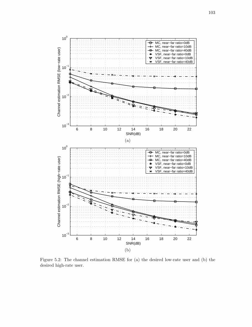
103
6 8 10 12 14 16 18 20 2210
−3
10−2
10−1
100
SNR(dB)
Cha
nnel
est
imat
ion
RM
SE
(lo
w−
rate
use
r)
MC, near−far ratio=0dBMC, near−far ratio=10dBMC, near−far ratio=40dBVSF, near−far ratio=0dBVSF, near−far ratio=10dBVSF, near−far ratio=40dB
(a)
6 8 10 12 14 16 18 20 2210
−3
10−2
10−1
100
SNR(dB)
Cha
nnel
est
imat
ion
RM
SE
(hi
gh−
rate
use
r)
MC, near−far ratio=0dBMC, near−far ratio=10dBMC, near−far ratio=40dBVSF, near−far ratio=0dBVSF, near−far ratio=10dBVSF, near−far ratio=40dB
(b)
Figure 5.2: The channel estimation RMSE for (a) the desired low-rate user and (b) thedesired high-rate user.

104
information and the single-rate case are also plotted. For equivalent single-rate system,
the spreading factor is determined by (3.6.1) and equal to 12. Thus, in terms of the
above baseline, the smoothing factor is 5, and the duration of observation includes 1,500
equivalent single-rate symbols. It can be seen from Fig. 5.3 that for mild near-far situations
(near-far ratio≤10dB) and moderate range of the SNR, the output SINR of the VSF
system is better than the single-rate system, while the latter outperforms the MC system.
In addition, as the SNR of the desired user increases, the MMSE receiver has a prominent
advantage over the MRC receiver.
5.5 Performance Analysis
In the development of the subspace-based channel estimator, each rate i user is assumed to
contribute at most Li linearly independent vectors to the received vector y(r). However, in
fact, each user contributes an infinite number of signal vectors because the employed chip
waveform is not time-limited. In this section, we analyze the channel estimation error due
to the finite-length truncation of chip waveform by exploiting the first-order perturbation
approximation in [110]. Similar to [46], we treat the vectors in (5.2.1) from symbols other
than bki(rqi − n) (n = −Pqi − Qi + 2, . . . , Qi), for k = 1, . . . , Ki and i = 1, . . . , I, as
perturbations to the unperturbed observation vector y(r) obtained by the finite-length
truncation approximation in (5.2.2). For convenience, we assume that the perturbation
vectors are numbered starting from ds + 1.
As stated before, ul (l = 1, . . . , PMNbr) denote the eigenvectors corresponding to the
eigenvalues (in descending order) of the unperturbed correlation matrix R. The first ds

105
6 8 10 12 14 16 18 20 225
10
15
20
SNR(dB)
Out
put S
INR
for
low
−ra
te u
ser
(dB
)
MMSE, MC, NFR=0dBMMSE, MC, NFR=10dBMRC, MC, NFR=0dBMMSE, VSF, NFR=0dBMMSE, VSF, NFR=10dBMRC, VSF, NFR=0dBMMSE, single−rate, NFR=0dBMMSE, single−rate, NFR=10dB
(a)
6 8 10 12 14 16 18 20 225
10
15
20
SNR(dB)
Out
put S
INR
for
high
−ra
te u
ser
(dB
)
MMSE, MC, NFR=0dBMMSE, MC, NFR=10dBMRC, MC, NFR=0dBMMSE, VSF, NFR=0dBMMSE, VSF, NFR=10dBMRC, VSF, NFR=0dBMMSE, single−rate, NFR=0dBMMSE, single−rate, NFR=10dB
(b)
Figure 5.3: The output SINR for (a) the desired low-rate user and (b) the desired high-rateuser.
106
eigenvectors span the unperturbed signal subspace, and the remaining eigenvectors span
the unperturbed noise subspace. Since the signal vectors from all the users span the entire
PMNbr-dimensional space [46], the perturbation vectors in (5.2.1), denoted by vr, for
r ≥ ds + 1, can be represented as
vr =
PMNbr∑
l=1
erlul. (5.5.1)
By defining a PMNbr×PMNbr matrix Ω, whose (k, l)th element, for k, l = 1, . . . , PMNbr,
is given by εkl =∑∞
r=ds+1 erke∗rl, and using (5.5.1), we obtain the perturbed correlation
matrix R as
R = R + E, (5.5.2)
where
E =
PMNbr∑
k=1
PMNbr∑
l=1
εklukuHl
=[Us Un
]Ω
U
Hs
UHn
. (5.5.3)
For simplicity, we assume that a perfect estimate of the perturbed correlation matrix R
is obtained from the samples of the perturbed vector. An eigen-decomposition can be
performed on the perturbed correlation matrix
R =[Us Un
]Λs
Λn
U
Hs
UHn
, (5.5.4)
where Λn = σ2Idnand the vectors in Un span the perturbed noise subspace. Let us
introduce ∆Un as the difference between Un and Un as well as ∆Λn as the difference
between Λn and Λn.

107
From (5.3.3), the first-order approximation of perturbation to the channel estimation
assumes the form [110]
∆hki ≈ −(UHn Gki)
†∆UHn Gkihki. (5.5.5)
What remains is to derive the first-order approximation of ∆UHn . Note that in accordance
with (5.5.4), we have
UHn R = ΛnU
Hn
= (σ2Idn+ ∆Λn)(Un + ∆Un)H
= σ2UHn + ∆ΛnU
Hn + σ2∆UH
n + ∆Λn∆UHn . (5.5.6)
We can obtain from (5.5.2) and (5.5.3)
UHn R = (Un + ∆Un)H(R + E)
= UHn R + ∆UH
n R + ∆UHn E. (5.5.7)
By neglecting the second-order terms ∆Λn∆UHn in (5.5.6) and ∆UH
n E in (5.5.7), we have
∆UHn (R − σ2IPMNbr
) ≈ ∆ΛnUHn − UH
n (R − σ2IPMNbr). (5.5.8)
Right-multiplying both sides of (5.5.8) by Us(Λs − σ2Ids)−1UH
s Gnkihki (n = −Pqi −Qi +
2, . . . , Qi) and noting that Gnkihki (n = −Pqi −Qi + 2, . . . , Qi) lies in the column space of
Us, we have
∆UHn Gn
kihki ≈ −UHn (R − σ2IPMNbr
)Us(Λs − σ2Ids)−1UH
s Gnkihki. (5.5.9)
Note that it is easy to derive from (5.5.2),
UHn R = σ2UH
n + Υ
U
Hs
UHn
, (5.5.10)

108
where Υ is the dn × PMNbr submatrix of Ω defined by Υ = [0dn×dsIdn
]Ω. Substituting
(5.5.10) into (5.5.9) leads to
∆UHn Gn
kihki ≈ −Γ(Λs − σ2Ids)−1UH
s Gnkihki, (5.5.11)
where Γ is the dn × ds submatrix of Υ defined by Γ = Υ[Ids0ds×dn
]H . As a result, in
accordance with (5.5.5), we have
∆hki ≈ (UHn Gki)
†
Γ(Λs − σ2Ids)−1UH
s pQi
ki
...
Γ(Λs − σ2Ids)−1UH
s p−Pqi−Qi+2ki
. (5.5.12)
We can see from (5.5.12) that the channel estimation error is determined by ‖Γ‖ and
the projections of the signal vectors from the desired user onto the eigenvectors of the
unperturbed signal subspace, as well as the reciprocals of their corresponding eigenvalues.
Intuitively, ‖Γ‖ can be made small (relative to ‖R‖) by using a fast decaying chip wave-
form. Moreover, when the powers of the interferers increase, ‖Γ‖ and the eigenvalues of
the unperturbed subspaces increase at roughly the same rate. Hence, the channel estima-
tion error can be made small in moderate near-far situations. However, the increase in
interferer powers changes the structure of the signal subspace, which is the basis of the
subspace-based techniques. As a consequence, the channel estimation error increases as
the near-far effect gets more severe.
To illustrate the discussion above with numerical examples, we reconsider the dual-rate
system in Section 5.4. Here we assume that the receiver is synchronized to the desired
user. Fig. 5.4 shows the exact value of ‖∆hki‖ and its first-order approximation given
by (5.5.12). It can be observed that the finite truncation effect is negligible (‖∆hki‖ is
109
small) in the moderate near-far situation (near-far ratio=10dB). Moreover, the first-order
approximation is very accurate.
5.6 Summary
This chapter addresses the timing acquisition and channel estimation issue for multi-rate
multicarrier DS/CDMA. Based on finite-length truncated approximation on the band-
limited chip waveform, a subspace based scheme has been proposed, which is capable of
dealing with both MC and VSF multi-rate systems. The effectiveness of the proposed
timing and channel estimation schemes has been confirmed by numerical simulations and
theoretical analysis.
Note that a main computational burden of the proposed scheme comes from subspace
decomposition using batch EVD. It can be seen from (5.3.5) that an orthonormal basis
of the noise subspace, rather than the complete subspace information, is required for the
calculation of the matrix W. It is worth noting that UnUHn can be further represented by
UnUHn =
UnUHn
. . .
UnUHn
︸ ︷︷ ︸Li blocks
. (5.6.1)
Since UsUHs +UnU
Hn = IPMNbr
, an alternative form of (5.3.5), which is based on the signal
subspace representation, has been obtained. Therefore, the adaptive subspace tracking
algorithms with lower complexity, such as the orthonormal PAST algorithm [108], can be
used instead of the batch EVD to estimate an orthonormal basis of the signal subspace,
leading to a much reduced complexity.

110
6 8 10 12 14 16 18 20 2210
−3
10−2
10−1
100
SNR(dB)
Cha
nnel
est
imat
ion
RM
SE
(lo
w−
rate
use
r)
MC, simulation, near−far ratio=10dBMC, analytical, near−far ratio=10dBVSF, simulation, near−far ratio=10dBVSF, analytical, near−far ratio=10dB
(a)
6 8 10 12 14 16 18 20 2210
−3
10−2
10−1
100
SNR(dB)
Cha
nnel
est
imat
ion
RM
SE
(hi
gh−
rate
use
r)
MC, simulation, near−far ratio=10dBMC, analytical, near−far ratio=10dBVSF, simulation, near−far ratio=10dBVSF, analytical, near−far ratio=10dB
(b)
Figure 5.4: The channel estimation RMSE for (a) the desired low-rate user and (b) thedesired high-rate user.

Chapter 6
Conclusions
6.1 Thesis Summary
This thesis consists of two parts. The first part includes the first two chapters. Chapter
1 starts with the basic concepts of cellular wireless communications. The non-blind and
blind approaches for multiuser detection and channel estimation in single-rate DS/CDMA
systems are then reviewed for both single-carrier and multicarrier cases. Chapter 2 deals
with the multiuser detection issue for multi-rate DS/CDMA. After a brief description of
multi-rate CDMA access strategies, the methodology for multi-rate signal modelling is
summarized. Then the existing multiuser detection and channel estimation techniques for
multi-rate DS/CDMA are reviewed, with an emphasis on blind approaches.
It is found that the existing blind approaches for multi-rate multiuser detection focus
on constrained optimization methods, which only deal with the case where the delay
spread is only a small fraction of the symbol period. Note that for single-rate systems, the
subspace-based techniques have been proved to have capability for handling large delay
spread cases. As a consequence, the second part of this thesis has investigated the use
111

112
of the subspace-based techniques for blind channel estimation and multiuser detection in
multi-rate DS/CDMA systems, involving in the following three chapters. Chapters 3 and
4 handle the single-carrier cases, while Chapter 5 deals with multicarrier scenarios.
In Chapter 3, ST low-rate and high-rate blind linear detectors, i.e., blind decorrelators
and blind MMSE detectors, are proposed for synchronous dual-rate systems over AWGN
channels. It has been proven that a) ST low-rate blind linear detectors can support no less
users than their high-rate counterparts (assuming that all the other system parameters
are same); b) the BER performance of low-rate blind decorrelator is not inferior to that of
high-rate blind decorrelator. The above conclusions are further generalized to synchronous
multi-rate scenarios, and the asynchronous extension is discussed. Additionally, the two-
stage ST dual-rate blind detectors, which combine the adaptive purely temporal dual-rate
blind MMSE detectors and the non-adaptive MVDR beamformer, are presented.
Chapter 4 presents the low-rate and high-rate blind channel estimation schemes for
asynchronous dual-rate systems over frequency-selective multipath channels. After adap-
tive implementations are developed based on the orthonormal PAST algorithm, the dual-
rate blind MMSE detection for the AWGN channels is extended to multipath channels. It
has been shown that the low-rate algorithm outperforms the high-rate algorithm for both
channel estimation and detection.
In Chapter 5, based on a finite-length truncation approximation of the band-limited
chip waveform, a blind timing acquisition and channel estimation scheme is developed
for multi-rate multicarrier DS/CDMA. It is shown by numerical results and theoreti-
cal analysis that this approximation hardly caused any performance degradation of the
113
subspace-based channel estimation scheme under moderate near-far situations.
6.2 Suggestions for Further Study
In this thesis, subspace-based techniques have been successfully applied to blind chan-
nel estimation and multiuser detection for multi-rate DS/CDMA. However, as stated in
Section 1.3, the computational complexity of subspace-based approaches is usually pro-
hibitively high, since they typically require not only a long duration of observation, but
also some form of eigen-decomposition. Moreover, the channel is often required to be
time-invariant during this long observation period, which potentially makes these algo-
rithms impractical for wireless communications. Recently, there has been some interest in
semi-blind methods for single-rate systems [32], [111], which exploit the statistics of the
unknown data as well as the known pilot signal, and require a shorter duration of obser-
vation to achieve the same performance as the blind methods. As a result, the study on
semi-blind channel estimation and multiuser detection for multi-rate DS/CDMA is very
promising and should become a major area for further study.
One of the new technologies that is being considered for 3G wireless systems and
beyond is ST processing. Generally speaking, ST processing involves the exploitation of
spatial diversity using multiple transmit and/or receive antennas and, perhaps, some form
of coding, e.g., space-time block coding (STBC) that has been adopted in the 3G Wideband
CDMA standards. The ST dual-rate blind multiuser detectors proposed in Chapter 3
focus on systems that use one transmit antenna and multiple receive antennas. Recently,

114
some work has been completed on ST multiuser detection using multiple antennas at both
transmitter and receiver. For example, [19] analyzed and compared two different linear
receiver structures appropriate for CDMA systems with multiple transmit and receive
antennas. It has been shown that the ST structure has many advantages over linear
diversity combining, including better BER performance, low complexity, and higher user
capacity. Blind adaptive implementation of the ST structure for synchronous CDMA
in flat-fading channels and for asynchronous CDMA in fading multipath channels has
also been developed. However, the above works target primarily at single-rate systems.
Consequently, another interesting option for further study is blind channel estimation and
multiuser detection for multi-rate CDMA systems using multiple transmit and receiver
antennas.

Bibliography
[1] T.S. Rappaport: Wireless Communications: Principles and Practice, Second Edition,
Prentice Hall, Upper Saddle River, NJ, 2002.
[2] M. Zeng, A. Annamalai and V.K. Bhargava, “Harmonization of global third-generation
mobile systems,” IEEE Commun. Mag., vol. 38, pp. 94–104, Dec. 2000.
[3] D. Koulakiotis and A.H. Aghvami, “Data detection techniques for DS/CDMA mobile
systems: a review,” IEEE Personal Commun. Mag., vol. 7, pp. 24–34, Jun. 2000.
[4] U. Madhow, “Blind adaptive interference suppression for direct-sequence CDMA,”
Proc. IEEE, vol. 86, pp. 2049–2069, Oct. 1998.
[5] S. Verdu: Multiuser Detection, Cambridge Univ. Press, UK, 1998.
[6] S. Verdu, “Minimum probability of error for asynchronous Gaussian multiple access
channels,” IEEE Trans. Inform. Theory, vol. 32, pp. 85–96, Jan. 1986.
[7] R. Lupas and S. Verdu, “Linear multiuser detector for synchronous code-division
multiple-access channels,” IEEE Trans. Inform. Theory, vol. 35, pp. 123–136, Jan.
1989.
[8] Z. Xie, R.T. Short and C.K. Rushforth, “A family of suboptimum detectors for coherent
multiuser communications,” IEEE J. Select. Areas Commun., vol. 8, pp. 683–690, May
1990.
115

116
[9] M.K. Varanasi and B. Aazhang, “Multistage detection in asynchronous CDMA com-
munications,” IEEE Trans. Commun., vol. 38, pp. 509–519, Apr. 1990.
[10] P. Putel and J. Holtzman, “Analysis of simple successive interference scheme in a
DS/CDMA system,” IEEE J. Select. Areas Commun., vol. 12, pp. 796–807, Jun. 1994.
[11] D. Koulakiotis and A.H. Aghvami, “Evaluation of a DS/CDMA multiuser receiver
employing a hybrid form of interference cancellation in Rayleigh fading channels,”
IEEE Commun. Lett., vol. 2, pp. 61–63, Mar. 1998.
[12] A. Duel-Hallen, “Decorrelating decision-feedback multiuser detector for synchronous
CDMA channel,” IEEE Trans. Commun., vol. 41, pp. 285–290, Feb. 1993.
[13] M.K. Varanasi and B. Aazhang, “Near-optimum detection in synchronous code-
division multiple-access systems,” IEEE Trans. Commun., vol. 39, pp. 725–736, May
1991.
[14] G. Woodward and B.S. Vucetic, “Adaptive detection for DS-CDMA,” Proc. IEEE,
vol. 86, pp. 1413–1434, Jul. 1998.
[15] P.B. Rapajic and B.S. Vucetic, “Adaptive receiver structures for asynchronous CDMA
systems,” IEEE J. Select. Areas Commun., vol. 12, pp. 685–697, May 1994.
[16] S. Haykin: Adaptive Filter Theory, Third Edition, Prentice-Hall, Englewood Cliffs,
NJ, 1996.
[17] M. Honig and M.K. Tsatsanis, “Adaptive techniques for multiuser CDMA receivers,”
IEEE Signal Processing Mag., vol. 17, pp. 49–61, May 2000.
[18] D. Samardzija, N. Mandayam and I. Seskar, “Blind successive interference cancella-
tion for DS-CDMA systems Communications,” IEEE Trans. Commun., vol. 50, pp.
276–290, Feb. 2002.

117
[19] D. Reynolds, X. Wang and H.V. Poor, “Blind adaptive space-time multiuser detection
with multiple transmitter and receiver antennas,” IEEE Trans. Signal Processing, vol.
50, pp. 1261–1276, Jun. 2002.
[20] M. Honig, U. Madhow and S. Verdu, “Blind adaptive multiuser detection,” IEEE
Trans. Inform. Theory, vol. 41, pp. 944–960, Jul. 1995.
[21] M.K. Tsatsanis, “Inverse filtering criteria for CDMA systems,” IEEE Trans. Signal
Processing, vol. 45, pp. 102–112, Jan. 1997.
[22] M.K. Tsatsanis and Z. Xu, “Performance analysis of minimum variance CDMA re-
ceivers,” IEEE Trans. Signal Processing, vol. 46, pp. 3014–3022, Nov. 1998.
[23] Z. Tian, K.L. Bell and H.L. Van Trees, “Robust constrained linear receivers for CDMA
wireless systems,” IEEE Trans. Signal Processing, vol. 49, pp. 1510–1522, Jul. 2001.
[24] X.D. Wang and H.V. Poor, “Blind Multiuser detection: a subspace approach,” IEEE
Trans. Inform. Theory, vol. 44, pp. 677–690, Mar. 1998.
[25] Y. Song and S. Roy, “Blind adaptive reduced-rank detection for DS-CDMA signals
in multipath channels,” IEEE J. Select. Areas Commun., vol. 17, pp. 1960–1971, Nov.
1999
[26] X.D. Wang and H.V. Poor, “Blind equalization and multiuser detection in dispersive
CDMA channels,” IEEE Trans. Commun., vol. 46, pp. 91–103, Jan. 1998.
[27] M. Torlak and G. Xu, “Blind multiuser channel estimation in asynchronous CDMA
systems,” IEEE Trans. Signal Processing, vol. 48, pp. 137–147, Jan. 1997.
[28] H. Liu and G. Xu, “A subspace method for signature waveform estimation in syn-
chronous CDMA systems,” IEEE Trans. Commun., vol. 44, pp. 1346–1354, Oct. 1996.
[29] E. G. Strom, S. Parkvall, S. L. Miller and B. E. Ottersen, “Propagation delay esti-
mation in asynchronous direct-sequence code-division multiple access sytems,” IEEE
Trans. Commun., vol. 44, pp. 84–92, Jan. 1996.

118
[30] S. Bensley and B. Aazhang, “Subspace-based channel estimation for code division
multiple access communication systems,” IEEE Trans. Commun., vol. 44, pp. 1009-
1020, Aug. 1996.
[31] E. Aktas and U. Mitra, “Complexity reduction in subspace-based blind channel iden-
tification for DS/CDMA systems,” IEEE Trans. Commun., vol. 48, pp. 1392-1404,
Aug. 2000.
[32] V. Buchoux, O. Cappe, E. Moulines and A. Gorokhov, “On the performance of semi-
blind subspace-based channel estimation,” IEEE Trans. Signal Processing, vol. 48, pp.
1750–1759, Jun. 2000.
[33] A. Høst-Madsen and K.S. Cho, “MMSE/PIC multiuser detection for DS/CDMA
systems with inter- and intra-cell interference”, IEEE Trans. Commun., vol. 47, pp.
291–299, Feb. 1999.
[34] H. Ping and T.T. Tjhung, “Decision-feedback blind adaptive multiuser detector for
synchronous CDMA systems,” IEEE Trans. Veh. Technol., vol. 49, pp. 159–166, Jan.
2000.
[35] X. Wang and A. Høst-Madsen, “Group-blind multiuser detection for uplink CDMA”,
IEEE J. Select. Areas Commun., vol. 17, pp. 1971–1984, Nov. 1999.
[36] P. Spasojevic, X. Wang and A. Høst-Madsen, “Nonlinear group-blind multiuser de-
tection,” IEEE Trans. Commun., vol. 49, pp. 1631–1641, Sep. 2001.
[37] D. Reynolds and X. Wang, “Adaptive group-blind multiuser detection based on a
new subspace tracking algorithm,” IEEE Trans. Commun., Vol. 49, pp. 1135–1141,
Jul. 2001.
[38] A. Høst-Madsen and X. Wang, “Performance of blind and group-blind multiuser
detectors,” IEEE Trans. Inform. Theory, vol. 48, pp. 1849 –1872, Jul. 2002.
119
[39] T.S. Rappaport, A. Annamalai, R.M. Buehrer and W. H. Tranter, “Wireless commu-
nications: past events and a future perspective,” IEEE Commun. Mag., vol. 40, pp.
148–161, May 2002.
[40] R. Van Nee and R. Prasad: OFDM for Wireless Multimedia Communications, Artech
House, Boston, 2000.
[41] A.C. McCormick and E.A. Al-Susa, “Multicarrier CDMA for future generation mobile
communication,” Electronics & Communication Engineering Journal, vol. 14, pp. 52–
60, Apr. 2002.
[42] S. Hara and R. Prasad, “Overview of multicarrier CDMA,” IEEE Commun. Mag.,
vol. 35, pp. 126–133, Dec. 1997.
[43] S. Kondo and L.B. Milstein, “Performance of multicarrier DS CDMA systems,” IEEE
Trans. Commun., vol. 44, pp. 238–246, Feb. 1996.
[44] T.M. Lok, T.F. Wong and J.S. Lehnert, “Blind adaptive signal reception for MC-
CDMA systems in Rayleigh fading channels,” IEEE Trans. Commun., vol. 47, pp.
464–471, Mar. 1999.
[45] S.L. Miller and B.J. Rainbolt, “MMSE detection of multicarrier CDMA,” IEEE J.
Select. Areas Commun., vol. 18, pp. 2356–2362, Nov. 2000.
[46] J. Namgoong, T.F. Wong and J.S. Lehnert, “Subspace multiuser detection for mul-
ticarrier DS-CDMA,” IEEE Trans. Commun., vol. 48, pp. 1897–1908, Nov. 2000.
[47] L. Fang and L.B. Milstein, “Successive interference cancellation in multicarrier
DS/CDMA,” IEEE Trans. Commun., vol. 48, pp. 1530–1540, Sep. 2000.
[48] H. Liu and H. Yin, “Receiver design in multicarrier direct-sequence CDMA commu-
nications,” IEEE Trans. Commun., vol. 49, pp. 1479–1487, Aug. 2001.
[49] N.Yee, J.P. Linnartz and G. Fettweis, “Multi-carrier CDMA in indoor wireless radio
networks,” in Proc. PIMRC 1993, Yokohama, Japan, Sep. 1993, pp. 109–113.

120
[50] Z. Yang, B. Lu and X. Wang, “Bayesian Monte Carlo multiuser receiver for space-
time coded multicarrier CDMA systems,” IEEE J. Select. Areas Commun., vol. 19,
pp. 1625–1637, Aug. 2001.
[51] J. Wu, Y. Wang and K.K.M. Cheng, “Blind channel estimation based on subspace
for multicarrier CDMA,” in Proc. VTC 2001-Spring, Rhodes, Greece, May 2001, vol.
4, pp. 2374–2378.
[52] U. Tureli, D. Kivanc and H. Liu, “Channel estimation for Multicarrier CDMA,” In
Proc. ICASSP 2000, Istanbul, Turkey, Jun. 2000, vol. 5, pp. 2909-2912.
[53] P. Zong, K. Wang and Y. Bar-Ness, “Partial sampling MMSE interference suppression
in asynchronous multicarrier CDMA system,” IEEE J. Select. Areas Commun., vol.
19, pp. 1605–1613, Aug. 2001.
[54] J.H. Deng, G.J. Lin and T.S. Lee, “A multistage multicarrier CDMA receiver with
blind adaptive MAI suppression,” in Proc. ICASSP 2001, Salt Lake City, UT, May
2001, vol. 4, pp. 2289–2292.
[55] F. Fitzek, A. Kopsel, A. Wolisz, M. Krishnam and M. Reisslein, “Providing
application-level QoS in 3G/4G wireless systems: a comprehensive framework based
on multirate CDMA,” IEEE Wireless Commun. Mag., vol. 9, pp. 42–47, Apr. 2002.
[56] L. Huang, F.-C. Zheng and M. Faulkner, “Blind adaptive channel estimation for
dual-rate DS/CDMA signals,” IEEE Commun. Let., vol. 6, pp. 129–131, Apr. 2002.
[57] L. Huang and F.-C. Zheng, “Space-time multirate blind multiuser detection for
DS/CDMA signals,” Accepted for publication by IEEE Trans. Veh. Technol., Apr.
2003.
[58] L. Huang and F.-C. Zheng, “Blind timing acquisition and channel estimation for
multi-rate multicarrier DS-CDMA commmnications,” in Proc. GLOBECOM 2002,
Taipei, Taiwan, Nov. 2002.

121
[59] L. Huang and F.-C. Zheng, “Blind channel estimation in multi-rate multicarrier DS-
CDMA systems,” in Proc. PIMRC 2002, Lisbon, Portugal, Sept. 2002, vol. 4, pp.
1545–1549.
[60] L. Huang and F.-C. Zheng, “Blind channel estimation for dual-rate DS/CDMA,” in
Proc. VTC 2002-Spring, Birmingham, AL, May 2002, vol. 3, pp. 1438–1442.
[61] L. Huang, F.-C. Zheng and M. Faulkner, “Space-time multirate blind multiuser detec-
tion for synchronous DS/CDMA systems,” in Proc. GLOBECOM 2001, San Antonio,
TX, Nov. 2001, vol. 1, pp. 146–150.
[62] L. Huang, F.-C. Zheng and M. Faulkner, “Subspace-based blind adaptive multiuser
detection for multirate DS/CDMA signals,” in Proc. 11th IEEE Workshop on Statis-
tical Signal Processing, Singapore, Aug. 2001, pp. 106–109.
[63] T. Ottosson and A. Svensson, “Multi-rate schemes in DS/CDMA systems,” in Proc.
VTC 1995, Chicago, IL, Jul. 1995, vol. 2, pp. 1006–1010.
[64] C.L. I and R.D. Gitlin, “Multi-code CDMA wireless personal communications net-
works,” in Proc. ICC 1995, Seattle, WA, Jun. 1995, vol. 2, pp. 1060–1064.
[65] T.H. Wu and E. Geraniotis, “CDMA with multiple chip rates for multi-media commu-
nications,” in Proc. 28th Annual Conf. Information Sciences and Systems, Princeton
Univ., Mar. 1994, pp. 992–997.
[66] A.L. Johansson and A. Svensson, “On multirate DS/CDMA schemes with interference
cancellation,” Wireless Personal Commun., vol. 9, pp. 1–29, Jan. 1999.
[67] H. Holma and A. Toskala: WCDMA for UMTS: Radio Access for Third Generation
Mobile Communications, John Wiley & Sons, West Sussex, England, 2000.
[68] J.G. Proakis: Digital Communications, Fourth Edition, New York: McGraw-Hill,
2001.
122
[69] U. Mitra, “Comparison of maximum-likelihood-based detection for two multirate ac-
cess schemes for CDMA signals,” IEEE Trans. Commun., vol. 47, pp. 64–77, Jan.
1999.
[70] J.X. Chen and U. Mitra, “Optimum near-far resistance for dual rate DS/CDMA
signals: random signature sequence analysis,” IEEE Trans. Inform. Theory, vol. 45,
pp. 2434–2447, Nov. 1999.
[71] M. Saquib and R. Yates and N. Mandayam, “Decorrelating detectors for a dual-rate
synchronous DS/CDMA system,” Wireless Personal Commun., vol. 9, pp. 197–216,
May 1998.
[72] J.X. Chen and U. Mitra, “Analysis of decorrelator-based detectors for multirate
DS/CDMA communications,” IEEE Trans. Vehi. Technol., vol. 48, pp. 1966–1983,
Nov. 1999.
[73] M. Saquib and R.D. Yates and A. Ganti, “An asynchronous multirate decorrelator,”
IEEE Trans. Commun., vol. 48, pp. 739–742, May 2000.
[74] H. Hiraiwa, M. Katayama and T. Yamazato, “Decorrelating detector for multi-
processing gain CDMA systems,” IEICE Trans. Fundamentals, vol. E82-A, pp. 2774–
2777, Dec. 1999.
[75] M.F. Madkour and S.C. Gupta, “Performance analysis of a wireless multirate direct-
sequence CDMA using fast Walsh transform and decorrelating detection,” IEEE Trans.
Commun., vol. 48, pp. 1405–1412, Aug. 2000.
[76] J.W. Ma and H. Ge, “Modified multi-rate detection for frequency selective Rayleigh
fading CDMA channels,” in Proc. PIMRC 1998, Boston, MA, Sep. 1998, vol. 3, pp.
1304–1307.
[77] R. Srinivasan, U. Mitra and R. L. Moses, “Design and analysis of receiver filters for
multiple chip-rate DS-CDMA systems,” IEEE J. Select. Areas Commun., vol. 17, pp.
2096–2109, Dec. 1999.

123
[78] M. Saquib, R. Yates and N. Mandayam, “A decision feedback decorrelator for a dual
rate synchronous DS/CDMA system,” in Proc. GLOBECOM 1996, London, UK, Nov.
1996, vol. 3, pp. 1804–1809.
[79] M.J. Juntti, “Performance of multiuser detection in multirate CDMA systems,” Wire-
less Personal Commun., vol. 11, pp. 293–311, Dec. 1999.
[80] A.L. Johansson and A. Svensson, “Multistage interference cancellation in multirate
DS/CDMA on a mobile radio channel,” in Proc. VTC 1996, Atlanta, GA, Apr. 1996,
vol. 2, pp. 666–670.
[81] S.R. Chaudry and A.U.H Sheikh, “Performance of a dual-rate DS-CDMA-DFE in an
overlaid cellular system,” IEEE Trans. Vehi. Technol., vol. 48, pp. 683–695, May 1999.
[82] D.S. Yoo and W.E. Stark, “Interference cancellation for multirate multiuser systems,”
in Proc. VTC 2001-Spring, Rhodes, Greece, May 2001, vol. 3, pp. 1584–1588.
[83] A. Boariu and R.E. Ziemer, “Multiuser detection in multipath environments for vari-
able spreading-factor CDMA systems,” IEEE Trans. Commun., vol. 49, pp. 1520–1524,
Sep. 2001.
[84] S.H. Han and J.H. Lee, “Objective function based group-wise successive interference
cancellation receiver for dual-rate DS-CDMA system,” in Proc. VTC 2002-Spring,
Birmingham, AL, May 2002, vol. 4, pp. 1685–1688.
[85] X. Mestre and J.R. Fonollosa, “ML approaches to channel estimation for pilot-aided
multirate DS/CDMA systems,” IEEE Trans. Signal Processsing, vol. 50, pp. 696–709,
Mar. 2002.
[86] S. Bhashyam, A. Sabharwala and U. Mitra, “Channel estimation for multirate DS-
CDMA systems,” in Proc. Asilomar Conf. Signals, Systems and Computers, Pacific
Grove, CA, Oct. 2000, vo1. 2, pp. 960–964.
124
[87] H. Ge, “Multiuser detection for integrated multi-rate CDMA,” in Proc. Internat.
Conf. Information, Commun. and Signal Processing, Singapore, Sep. 1997, pp. 858–
862.
[88] H. Ge and J.W. Ma, “Multirate LMMSE detectors for asynchronous multi-rate
CDMA systems,” in Proc. ICC 1998, Atlanta, GA, Jun. 1998, vol. 2, pp. 714–718.
[89] N. Seidl, V. Howitt and J. Richie, “Blind adaptive linear multiuser detection for
multirate CDMA systems,” in Proc. VTC 2000-Fall, Boston, MA, Sep. 2000, vol. 3,
pp. 1296–1303.
[90] S. Buzzi, M. Lops and A.M. Tulino, “Blind adaptive multiuser detection for asyn-
chronous dual-rate DS-CDMA systems,” IEEE J. Select. Areas Commun., vol. 19, pp.
233–244, Feb. 2001.
[91] M.K. Tsatsanis, Z. Xu and X. Lu, “Blind multiuser detectors for dual rate DS-
CDMA systems over frequency selective channels,” in Proc. EUSIPCO 2000, Tampere,
Finland, Sep. 2000, vol. 2, pp. 631–634.
[92] R. Srinivasan, U. Mitra and R. L. Moses, “MMSE receivers for multirate DS-CDMA
systems,” IEEE Trans. Commun., vol. 49, pp. 2184–2197, Dec. 2001.
[93] V. Kaweevat, S. Jitapunkul, C. Archavawanitchakol, S. Wanichpakdeedecha and N.
Rasrikriangkrai, “Blind adaptive decorrelating decision-feedback multiuser detection
for multirate synchronous DS/CDMA communications,” in Proc. SPAWC 2001, Tai-
wan, China, Mar. 2001, pp. 178–181.
[94] M.F. Madkour, S.C. Gupta and Y.P. Wang, “Successive interference cancellation al-
gorithms for downlink W-CDMA communications,” IEEE Trans. Wireless Commun.,
vol. 1, pp. 169–177, Jan. 2002.
[95] S. Roy and H.B. Yan, “Blind channel estimation for multi-rate CDMA systems,”
IEEE Trans. Commun., vol. 50, pp. 995–1004, Jun. 2002.

125
[96] Z. Xu, “Asymptotic performance of subspace methods for synchronous multirate
CDMA system,” IEEE Trans. Signal Processing, vol. 50, pp. 2015–2026, Aug. 2002.
[97] P. Liu and Z. Xu, “Correlation matching in channel estimation for multirate
DS/CDMA,” in Proc. ICASSP 2002, Orlando, FL, May 2002, vol. 3, pp. 2581–2584.
[98] H. Yan and S. Roy, “A frequency domain method for channel estimation in multirate
communication systems,” in Proc. ICASSP 2001, Salt Lake City, UT, May 2001, vol.
4, pp. 2057–2060.
[99] S.Y. Park, H.S. Oh, W.Y. Lee and C.G. Kang, “Performance of pilot/data-combined
channel estimation and power allocations for dual-rate DS/CDMA system over mobile
radio channels,” in Proc. VTC 2000-Spring, Tokyo, Japan, May 2000, vol. 3, pp. 1945–
1949.
[100] I. Ghauri and D.T.M. Slock, “Blind channel identification and projection receiver
determination for multicode and multirate situations in DS-CDMA systems,” in Proc.
ICASSP 2001, Salt Lake City, UT, May 2001, vol. 4, pp. 2197–2200.
[101] Z.Y. Pi and U. Mitra, “Blind delay estimation in multi-rate asynchronous DS-CDMA
systems,” Submitted to IEEE Trans. Commun., 2000.
[102] T. Ojanpera and R. Prasad: Wideband CDMA and Third Generation Mobile Com-
munications, Artech House, Boston, MA, 1998.
[103] K.S. Lim and J.H. Lee, “Performance of multirate transmission schemes for a mul-
ticarrier DS/CDMA system,” in Proc. VTC 2001-Fall, Atlantic City, NJ, Oct. 2001,
vol. 2, pp. 767–771.
[104] H. Dai and H.V. Poor, “Iterative space-time processing for multiuser detection in
multipath CDMA channels,” IEEE Trans. Signal Processing, vol. 50, pp. 2116–2127,
Sep. 2002.
[105] X. Wang and H.V. Poor, “Space-time multiuser detection in multipath CDMA chan-
nels,” IEEE Trans. Signal Processing, vol. 47, pp. 2356–2374, Sep. 1999.

126
[106] G.H. Golub and C.F. Van Loan: Matrix Computations, The John Hopkins Univ.
Press, Baltimore, MD, 1996.
[107] A. Chkeif, K.A. Meraim, G.K. Kaleh and Y.B. Hua, “Spatio-temporal blind adaptive
multiuser detection,” IEEE Trans. Commun., vol. 48, pp. 729-732, May 2000.
[108] K.A. Meraim, A. Chkeif and Y. Hua, “Fast orthonormal PAST algorithm,” IEEE
Signal Processing Lett., vol. 7, pp. 60–62, Jul. 2000.
[109] L.C. Godara, “Applications of antenna arrays to mobile communications, Part II:
beam-forming and direction-of-arrival considerations,” Proc. IEEE, vol. 85, pp. 1195–
1245, Aug. 1997.
[110] F. Li, H. Liu, and R.J. Vaccaro, “Performance analysis for DOA estimation algo-
rithms: unification, simplification, and observations,” IEEE Trans. Aerosp. Electron.
Syst., vol. 29, pp. 1170–1183, Oct. 1993.
[111] B. Muquet, M. Courville, and P. Duhamel, “Subspace-based blind and semi-blind
channel estimation for OFDM systems,” IEEE Trans. Signal Processing, vol. 50, pp.
1699–1712, Jul. 2002.

Appendix A
Publications
A.1 Journal Papers
1. L. Huang and F.-C. Zheng, “Space-time multirate blind multiuser detection for
DS/CDMA signals,” Accepted for publication by IEEE Trans. Veh. Technol., Apr.
2003.
2. L. Huang, F.-C. Zheng and M. Faulkner, “Blind adaptive channel estimation for
dual-rate DS/CDMA signals,” IEEE Commun. Let., vol. 6, pp. 129–131, Apr.
2002.
A.2 Conference Papers
3. L. Huang and F.-C. Zheng, “Blind timing acquisition and channel estimation for
multi-rate multicarrier DS-CDMA commmnications,” in Proc. GLOBECOM 2002,
Taipei, Taiwan, Nov. 2002.
127

128
4. L. Huang and F.-C. Zheng, “Multiuser detection and channel estimation for multi-
rate DS/CDMA,” in Proc. 2nd ATcrc Telecommunications and Networking Confer-
ence, Perth, Australia, Oct. 2002, pp. 114–118.
5. L. Huang and F.-C. Zheng, “Blind channel estimation in multi-rate multicarrier DS-
CDMA systems,” in Proc. PIMRC 2002, Lisbon, Portugal, Sept. 2002, vol. 4, pp.
1545–1549.
6. L. Huang and F.-C. Zheng, “Blind channel estimation for dual-rate DS/CDMA,” in
Proc. VTC 2002-Spring, Birmingham, AL, May 2002, vol. 3, pp. 1438–1442.
7. L. Huang, F.-C. Zheng and M. Faulkner, “Space-time multirate blind multiuser
detection for synchronous DS/CDMA systems,” in Proc. GLOBECOM 2001, San
Antonio, TX, Nov. 2001, vol. 1, pp. 146–150.
8. L. Huang, F.-C. Zheng and M. Faulkner, “Subspace-based blind adaptive multiuser
detection for multirate DS/CDMA signals,” in Proc. 11th IEEE Workshop on Sta-
tistical Signal Processing, Singapore, Aug. 2001, pp. 106–109.
9. L. Huang, F.-C. Zheng and M. Faulkner, “Blind multiuser detection for multirate
synchronous DS/CDMA signals,” in Proc. 1st ATcrc Telecommunications and Net-
working Conference, Perth, Australia, Apr. 2001, pp. 37–38.
10. L. Huang and F.-C. Zheng, “Adaptive neural network based receivers for multirate
synchronous DS-CDMA systems,” in Proc. 5th CDMA International Conference,
Seoul, Korea, Nov. 2000, vol. 2, pp. 160–163.


![SGD Frequency-Domain Space-Frequency Semiblind Multiuser ... · Blind multiuser detection and channel estimation receivers based on subspace decomposition are proposed in [14-16]](https://img.dokumen.tips/doc/110x75/5fbcf1b8ce8bf14ede352c24/sgd-frequency-domain-space-frequency-semiblind-multiuser-blind-multiuser-detection.jpg)


![[IEEE]Blind Adaptive DSCDMA Receivers for Multipath and Multiuser Environments](https://img.dokumen.tips/doc/110x75/58a283b71a28ab891a8b6715/ieeeblind-adaptive-dscdma-receivers-for-multipath-and-multiuser-environments.jpg)