Embed Size (px)
Citation preview

Atlas Copco BHMTAtlas Copco BHMT
Rotary Drill Bits

Options
Elements of a Rotary Rock Bit Rock Breakage Drilling Parameters Drill Bits Drilling Problems Bit Selection Dull Grade Analysis Troubleshooting Back to start

Elements of a Rotary Rock BitElements of a Rotary Rock Bit

Elements of a Rock Bit

Cones
1. Tungsten Carbide Inserts – Which are pressed into the softer steel material with interference fit to hold them in place.
2. Cone Thrust Button – Made of a wear resistant material use to take axial bearing loads.
3. Outer Cone Shell – Insert land’s and cone grooves.
4. Cone Bore – Internal ball and roller bearing races.
Cones make up the cutting elements of the rock bit and comprises of the following:
Carbide Insert Rows
A. Nose
B. Inner
C. Next to Gage
D. Gage
E. Gage Bevel

Lugs

Inserts
The Conical insert is used primarily in Medium/Medium- Hard rock. It is designated in the bit nomenclature with a suffix of C.
The Chisel insert is used in Soft/Medium-Soft rock. It is the standard insert in soft bits (40’s & 50’s) and has no suffix in the bit nomenclature.
The Ogive insert is used in areas were the aggressiveness of the conical insert is required with additional toughness. The Ogive is designated as a G in the bit nomenclature.

Inserts
The Super-Scoop is used in very soft rock. With the patented offset tip, digging and gouging help penetrate in sticky materials. The Super-Scoop is designated as an S in the bit nomenclature. The Trimmer is used
specifically in the MAG product line. It enhances the gage rows ability to cut the bore hole wall. The MAG feature is used in Soft to Medium brittle rock formations.
The Ovoid is use in the hardest formations. Its blunt geometry gives it the most fracture resistant design. The ovoid is the standard insert in hard bits (60’s, 70’s & 80’s) and has no suffix in the bit nomenclature.

The IADC (International Association of Drilling Contractors) Code is a three numbered system to classify the hardness and type for all roller cone rock bits.
First Digit – Identifies the Bit Type and Major Hardness class:
1 – Steel Tooth for soft formations
2 – Steel Tooth for medium formations
3 – Steel Tooth for hard formations
4 – Insert for soft formations
5 – Insert for soft/medium, formations
6 – Insert for medium/hard, formations
7 – Insert for hard, formations
8 – Insert for extremely hard formations
Nomenclature

Second Digit – Designates the Hardness Subclass of the Major Hardness class. This ranges from 1 to 4, where 1 is classified as the softest subclass and 4 is the hardest subclass.
Third Digit – Designates the Bit’s features:
1 – Standard Roller Bearing
2 – Roller Bearing Air-Cooled*
3 – Roller Bearing with Gage Bevel Inserts
4 – Sealed Roller Bearing
5 – Sealed Roller Bearing with Gage Bevel Insets
6 – Sealed Friction Bearing
7 – Sealed Friction Bearing with Gage Bevel Inserts
8 – Directional
9 – Other/Special
*All AC BHMT Inc. air bearing bits are classed as #2 bearing type regardless if they have gage protection inserts or not.
Nomenclature

Example:
IADC 5-3-2 This is a Medium hardness Air-Cooled Roller Bearing.
Example:
12 ¼ MAG53CA 12 ¼ – Size MAG – Product Line 53 – First two digits of the IADC code (Rock Class ’5’, subclass ’3’) C – Insert Type (Conical Inserts) A – Full Armored Lug (Nevada Package)
Examples

MAG – Maximum Active Gage use in soft/medium material. HD+ – New generation Hard Drilling used in hard formations. BH – Standard Product Insert Type:
C – Conical
G – Ogive
S – Super Scoop
*Chisel and Ovoid (round top) are standard inserts and do not have suffixes.
Product lines

5 Classifications 40, 50, 60, 70, 80 Based on cutting structure/rock formation
• Tooth spacing
• Number of rows/teeth
• Compact projection
Tungsten Carbide Bit Selection and Operation

40 Series
The 40 series bits are typically characterized by large diameter widely spaced, long projection super scoop, chisel or conical inserts. This configuration promotes maximum penetration rates in softer formations that have a tendency to stick and ball up the cutting structure.
Applications: Soft formations such as shale, siltstone, soft limestone and alluvial formations.
Suggested Operating Parameters:
Weight on Bit – 1,000 to 5,000 lb/inch of diameter.
Rotation Speed – 50 to 150 RPM.

50 Series
The 50 series bits are typically characterized by more densely spaced chisel or conical inserts. This configuration promotes maximum penetration rates in soft/medium formations that are fractured or have varying degrees of hardness.
Applications: Soft/medium formations such as sandstone, shale, granite and some marble.
Suggested Operating Parameters:
Weight on Bit – 3,000 to 6,500 lb/inch of diameter.
Rotation Speed – 50 to 150 RPM.

60 Series
The 60 series bits are typically characterized by a more densely spaced, shorter projecting chisel, conical or ogive inserts. This configuration promotes maximum penetration rates in medium/hard formations.
Applications: Medium/hard formations such as hard limestone, hard shale, basalt and quartzite.
Suggested Operating Parameters:
Weight on Bit – 4,000 to 7,000 lb/inch of diameter.
Rotation Speed – 50 to 120 RPM.

70 Series
The 70 series bits are typically characterized by densely spaced, shorter projecting conical or ogive inserts with a conical or ovoid gage insert. This configuration promotes maximum penetration rates in hard formations.
Applications: Hard formations such as taconite, banded iron, skarn and quartzite.
Suggested Operating Parameters:
Weight on Bit – 4,000 to 8,000 lb/inch of diameter.
Rotation Speed – 50 to 90 RPM.

Options
Elements of a Rotary Rock Bit Rock Breakage Drilling Parameters Drill Bits Drilling Problems Bit Selection Dull Grade Analysis Troubleshooting Back to start

Rock BreakageRock Breakage

In ALL cases, the bit’s teeth must stress the rock enough to cause the rock to fail.
The rock’s mechanical properties determine the level of stress needed.
Rock Properties

U.C.S. - Unconfined Compressive Strength - How much ”push” it takes to break a rock in a static condition.
Young’s Modulus - How ”elastic” a rock is.
Poisson’s Ratio - How much a rock deforms under a given pressure.
Rock Properties

High UCS = the rock is ”hard”. Steel vs. wood.
High Young’s Modulus = the rock is elastic and resists impact, bouncing back, much like a rubber ball.
High Poisson’s Ratio = the rock absorbs energy without breaking. Bit teeth ”dent” the rock without forming a chip. Putty- or clay- like. Ductile.
Rock Properties

Low UCS - RPM is primary factor in ROP. Not much bit
weight needed to break rock.
High UCS - WOB is the primary factor in ROP. Need to
adequately push teeth into the rock to break it efficiently.
Operating Bits: UCS

Operating Bits: UCS
Operating Parameters vs. Rock Hardness
2,000
3,000
4,000
5,000
6,000
7,000
8,000
9,000
10,000
5,00
0
10,0
00
15,0
00
20,0
00
25,0
00
30,0
00
35,0
00
40,0
00
45,0
00
50,0
00
Rock Hardness, UCS, Psi
WO
B, L
b./I
nch
of
Bit
D
iam
eter
0
20
40
60
80
100
120
140
RP
M
WOB RPM

Low Young’s Modulus (Elasticity) - Rock is elastic, and absorbs impact without
breaking. The rock is ”tough”. The rock must be given time - stressed longer - to break. Needs heavier WOB at slower RPM.
High Young's Modulus- Rock is ’stiff’ or brittle. Rock will need heavier
WOB, but may respond to increased RPM once correct WOB is applied.
Bit Operation: Elastic Modulus

Low Poisson’s Ratio - Rock breaks with little change in shape. The
rock is more brittle.
High Poisson’s Ratio- Rock deforms a lot before breaking. Can ’dent’
rock without it chipping very much. Drilling energy is absorbed. The rock is more plastic or elastic.
Operating Bits: Poisson's Ratio

Rock Cutting, Abrasion – Very small cracks, insert grinds surface.
Rock Cutting, Deeper Abrasion – Deeper cracking, but does not connect. Next cone must crack rock between these teeth.

Rock Cutting, Spalling Starts – Enough weight applied to card rock deeper. Cracks connect. Chips will come free with air blast.

Rock Cutting, Deep Spalling – Cracks connecting at deeper levels. Cracks connect between teeth and between rows.

Rock Cutting, Overpenetration – Cuttings trapped between cone shell and rock. Cannot be blown out by air blast from nozzles.

Rock Strength BHMT Bit Series UCS (Psi) UCS (Mpa) 40 50 60 70 80
Rock Type
Lower Lower Claystone, Mudstone 8,000 55 Soft Shale & Sandstone
10,000 69 Consolidates Sandstone 12,000 83 Medium Shale 14,000 97 Tuff, Soft Schist 16,000 110 Andesite, Rhyolite 18,000 124 Quartzite (Sand & Silt) 20,000 138 Limestone, Marble 22,000 152 Monzonite, Granite 24,000 165 Gneiss 26,000 179 Diorite, Diabase 28,000 193 Hard Shale, Slate 30,000 207 Limestone, Dolomite 32,000 221 Basalt 34,000 234 Tactite, Skarn 36,000 248 Granodiorite 38,000 262 Taconite 40,000 276 Quartzite 42,000 290 Syenite 44,000 303 Gabbro 46,000 317 48,000 331 Banded Iron 50,000 345 Taconite 52,000 359 Chert 54,000 372 56,000 386 Quartzite 58,000 400 60,000 414 Amphibolite Higher Higher Hornfels, Hematite Ore
Rock UCS is only one factor that controls drillability. Hardness and Elasticity will also effect bit
selection.

Options
Elements of a Rotary Rock Bit Rock Breakage Drilling Parameters Drill Bits Drilling Problems Bit Selection Dull Grade Analysis Troubleshooting Back to start

The effects of WOB, RPM, Air
Drilling ParametersDrilling Parameters

WOB causes the rock to break.
Bit teeth must create a sufficiently high stress level to cause the rock to fail.
Low UCS rocks require low stress levels to fail. High UCS rocks require high stress levels. Low Young’s Mod requires lower stress levels.
(Elastic). High Young’s Mod requires higher levels.
(Non elastic).
Weight on Bit – WOB
Low Poisson’s may require lower stress levels to form chips. (Brittle).
High Poisson’s may require higher stress levels to form chips. (Ductile).
Poisson’s is not directly related to UCS or Young’s.
Weight on Bit – WOB (cont.)

RPM is required to move the cutting teeth to the next rock cutting position.
The faster you move the teeth to the next position, the faster you will drill.
HOWEVER
If the rock resists indentation by the teeth, there will be minimal rock breakage, and ROP will not increase proportionally with higher RPM.
Softer rock = higher RPM. Harder rock = lower RPM
RPM

Maximum Cut Efficiency
Maximum Cut Efficiency
With rotation speed (rpm) fixed, this illustration shows the effect of weight increases on the rate of penetration. After the formation has been ”spalled” additional weight will reduce or not increase the drilling rate.

Maximize ROP
Maximize ROP
With the bit drilling in the Spalling Phase, it is possible to increase the penetration rate by maintaining the optimum weight, while increasing the rotation speed (rpm). The amount of increase possible in the penetration rate is variable and will be determined by the experience of the driller, the capabilities of the drill, and the formation characteristics.

Maximum Drilling Efficiency
Maximum Drilling Efficiency
The preceding illustrate that: SPALLING WEIGHT plus ROTATION SPEED equals PENETRATION RATE.Therefore, optimum drilling efficiency may be reached as follows:At a set RPM, determine best weight on bit – WOB – to produce maximum cut efficiency. See Fig. 20.At maximum cut efficiency WOB, determine RPM to produce best rate of penetration. See Fig. 21.Note: High rotary speeds do not necessarily produce high penetration rates.

Bailing and Chip Exit Velocity
Bailing Velocity is the speed of the air going up the hole.
Settling Velocity is the speed that chips want to fall down the hole.
Chip Exit Velocity is the difference between the two. It is how fast the chips travel up the hole.

Bailing and Chip Exit Velocity
A 3/4” chip of 2.6 SG (162 #/CuFt) rock falls at 4,168 feet per minute.
A Bailing Velocity of 4,000 ft./min. will NOT carry a 3/4” chip out of the hole.
Chip Exit Velocity is -168 feet/min.
The chip must be reground before it can come out.

Bailing Velocity should be 5,000-7,000 ft/min for light, dry material.
Bailing Velocity should be 7,000-9,000 ft/min for heavy or wet material.
Water makes cuttings stick together, making bigger, heavier pieces to bail.
Bailing and Chip Exit Velocity

Bailing and Chip Exit Velocity
Chip Exit Velocity recommendation:
1,000 feet/minute with drill pipe worn to replacement is recommended.
This gives excellent bailing in all situations.

Bailing and Chip Exit Velocity
Do not use large pipe in a small hole to increase BV: The annulus will be restricted. Chips will not pass freely. Turbulence will increase. The pressure differential between the bit and
annulus will decrease. Bit and pipe erosion and bearing failure will
increase.

Annular Clearance

Bailing and Chip Exit Velocity
Try to use drill pipe 2-3 inches smaller than the bit if you have enough air.
Try not to use pipe that is less than 1 1/2 inches smaller than the bit if you do not have good air. Keep 3/4” minimum clearance (each side) in the annulus.

Bit Air Pressure
Increased Bit Air Pressure = increased hole bottom cleaning force.
(Nozzle velocity increases as V2). increased air to bearings.
(>psi = >volume). increased penetration rates.
(Cleaner hole bottom = >ROP). reduced shirttail erosion.
(Volume & psi = cleaner ST lip).
Bit Air Pressure
Recommend 40-45 psi at the bit. Cab pressure will be higher, depending on
system pressure losses.
Bit pressure should not cause compressor intake modulation.
Make sure compressors are correctly adjusted to give rated volumes at rated pressures.
• Check linkages, pressure regulator diaphragms, air filters.
• Do thorough and frequent PM’s.

Air requirements
Sufficient volume and pressure for cooling and cleaning bearings and cuttings removal
Required annular return velocity of 5000-9000ft/min depending on ground conditions
Q = Cubic feet/min required to obtain 5000ft/min
D = Hole Diameter
d = Pipe Diameter
)(35.183
22 dDxV
Q
)(27.27 22 dDQ

D. Hole diameter in inches
d. Pipe O.D. in inches
Q for 5000 Ft./Min. Bailing Velocity
Q for 7000 Ft./Min. Bailing Velocity
6 3/4
4 1/2
5
5 1/2
690
560
408
966
784
571
7 3/8
3 1/2
4 1/2
5 1/2
1,150
932
658
1,610
1,305
921
7 7/8
3 1/2
4 1/2
5 1/2
6 1/2
6 5/8
7
1,358
1,138
867
625
493
355
1,900
1,503
1,214
875
690
497
9
4 1/2
5 1/2
6 5/8
7
7 3/4
1,665
1,383
1,063
873
570
2,331
1,936
1,488
1,222
798
9 7/8
7
7 3/4
8 5/8
9
1,323
1,022
627
450
1,852
1,431
878
630
11
7
7 3/4
8 5/8
9
1,964
1,662
1,272
1,090
2,749
2,326
1,779
1,526
12 1/4
8 5/8
9
10
10 3/4
2,063
1,882
1,365
941
2,888
2,635
1,911
1,317

Nozzle Size Selection
Selected such that pressure inside bit = 40 - 45psi.
This is typically lower than cab gauge indicated pressure.
Air tests necessary to calibrate.

Record Keeping
To determine proper bit usage/best operating parameters.
Evaluate rock bit performance.
Meters drilled and ROP can lead to erroneous conclusions.

Total Drill Cost
gSpeedBitDrillinHour
RigCost
BitMeters
BitCostmTDC /$
Total Drill Cost
Includes everything it takes to run a drill: Labor. Power: fuel or electricity. Drilling tools and supplies. Maintenance labor & parts. Supervision, administration. Cost of equipment ownership (lease, purchase,
or rental payments).
Drill costs may exceed US$ 300 per operating hour.

Scenario 1
Bit Price 25000 Rand
Meters drilled 800 m
Drill cost/hour 255 Dollar
ROP 26 m/hour
FX 6 R/$
TDC 90.09615
Scenario 2
Bit Price 25000 Rand
Meters drilled 600 m
Drill cost/hour 255 Dollar
ROP 35 m/hour
FX 6 R/$
TDC 85.38095
Two Scenarios

Options
Elements of a Rotary Rock Bit Rock Breakage Drilling Parameters Drill Bits Drilling Problems Bit Selection Dull Grade Analysis Troubleshooting Back to start
Care and Maintenance
Drill BitsDrill Bits

Bit Care – Handling/Installation
Do not drop bits. Damage to cutting structures or pin threads may result.
Protect the threads. Damaged threads can lead to bit damage later.
Use small amounts of ”anti-galling” grease. Barely cover the threads. Too much grease gets
into air tubes and can block them off, causing ruined bearings.

Bit Care – Starting a New Bit
Rule of the 1/3’s:
In the first 1/3 of the 1st hole drilled: use 1/3 of the normal Pulldown and 1/3 of
normal RPM.
In the second 1/3 of the 1st hole, use: 2/3 of the normal Pulldown and 2/3 of the
normal RPM.
In the last 1/3 of the 1st hole, use: Normal Pulldown and normal RPM.
The bit is now ready to drill normally.

Bit Care – Use
Always rotate the bit when in the hole.
Always have the air on when the bit is moving in the hole.
Never leave the bit in the bottom of a wet hole.
Put on an old bit to leave the pipe in a ”rig service” hole.
Doing none of the above is guaranteed to plug a bit.
Bit Care – Use
Clean the bit and oil the bearings if the drill rig gets parked. Even better, remove the bit, clean, oil and store it.
If cleaning a plugged bit, be sure to clean from the inside out. Get water to come freely through all parts of the bearings.

Bit Care – Dull Bits
Organize your dulls. This will help the Bit Man when he inspects the dull bits.
If he can easily line up the last several dull bits, he can make a better diagnosis of any problems you may be having.

Options
Elements of a Rotary Rock Bit Rock Breakage Drilling Parameters Drill Bits Drilling Problems Bit Selection Dull Grade Analysis Troubleshooting Back to start

Drilling ProblemsDrilling Problems

Collaring Holes, Drilling Crest Holes and Rough Drilling
Collaring Holes, Drilling Crest Holes, and Rough Drilling are all about the same:
You are drilling in broken or fractured ground. The bit wants to bounce and the pipe wants to shake, and you want to eat lunch. Advance is slow.

Collaring Holes, Drilling Crest Holes and Rough Drilling
Maintain weight, decrease RPM. The weight will allow the bit to better crush the
loose rock. Reduced RPM keeps the bit from jumping
around badly. Less bouncing will cause less damage to bearings and teeth.

Soft to hard transitions: The hole must be ”recollared” at each transition:
• Reduce RPM and maintain or slightly decrease the weight to establish the ”new” hole.
• Ease the bit into the hard ground, then return to normal or hard ground parameters.
Changing Formations, Soft to Hard Transition

Changing Formations, Soft to Hard Transition
Entering hard ground too fast can result in broken teeth.
Tooth breakage may not happen immediately. It may start as chipping, and progress to become broken teeth.
Be easy on the bit when entering hard ground from soft ground.

Changing Formations, Hard to Soft Transition
Plugging of the bit is a problem when entering soft ground from hard ground:
Heavy WOB in hard ground may cause very high ROP in soft ground.
High ROP can clog the hole with cuttings. This lowers the pressure differential between the bit and annulus.

Changing Formations, Hard to Soft Transition
A clogged hole may force cuttings into the bit through the nozzles and the bearings due to the lowered pressure differential.
A clogged hole prevents cuttings from getting to the surface, increasing the chance of a plugged bit or a stuck bit.

Changing Formations
Reduce weight going from hard to soft. Don’t plug the bit.
Reduce RPM going from soft to hard. Don’t break the teeth.
Be alert. Estimate where the formation changes will be on your next hole, and adjust before getting to the change.

Drilling Problems: Vibration
Vibration is caused by: Bit design. Bit operation. The rock. Drill string harmonic vibration. Rig harmonic vibration. Cutting of 3 lobed hole bottom. Bent pipe improperly loading bit.

Vibration Causes
Bit Design: A ”hard” design can slide around on the bottom
of the hole because it cannot engage and break the rock properly.
A ’soft’ design might vibrate due to the tooth spacing: a wide tooth spacing might give a rough ride.
Tooth count can initiate harmonic vibration of the pipe at certain RPM’s.
Tracking or Off Center wear forces a bit slide around.

Vibration Causes
The Rock Hard rock will resist breaking. This may cause
the bit to slip on the bottom of the hole. Bit design may combine with the rock breakage
to force the bit teeth to slip forward or backward, causing vibration.
Fractures may let the bit drop each time a cone passes the fracture.

Vibration Causes
Drill String Harmonics Can cause drilling a ”3 lobed” hole: 3 high spots,
3 low spots. This forces the bit up and down 3 times per
revolution. Drill string length and RPM may combine to
cause harmonic vibration of the drill string.
Vibration Causes
Rig harmonics The ”free” length of mast at a certain depth of
hole may act the same as the drill string:• The back and forth motion of the rotary head may
want to set up a harmonic situation.
Vibration Causes
Worn pipe bends easier, allowing the bit to start bouncing in response to small influences.
Worn pipe has less mass, so it cannot dampen vibrational forces as well as new, heavier pipe.

Vibration Cures
Change RPM. Get out of the harmonic vibration range for the drill pipe.
Add WOB. By keeping the bit on the bottom, it is not free to slip or bounce.
Use a shock absorber. This is better for the drill and driller.
Use heavier pipe - 2” or greater wall thickness - in the bottom section of the drill string to provide dampening.
Vibration Cures
Change bit design. The design of a bit influences how it acts on bottom. If a particular bit type vibrates all the time, on different drills, it may be the bit design is causing the problem. Try a different design of the same type.
This is especially true if a bit tracks or runs off center.
Use a computer program to determine if your system is likely to vibrate.

Caving and Sloughing Holes
Incompetent ground. Hole collars collapse. Hole walls collapse at depth. Drill pipe and bits get stuck. Large amounts of fill when hole is finished.

Caving or Sloughing Holes
Cure: Paste it. In sloughing zones, or with caving drill hole
collars, drill with lots of water to saturate the rock until you are through the caving zone.
Then drill dry for 2-4 meters (6-12 feet). The dry cuttings will form a ”wall cake” over the sloughing zone, and paste it in place.
Return to normal water injection.

Groundwater
Keep the Bailing Velocity high. Don’t let the pipe wear down too much.
Use a Backflow Valve in the bits. This is an absolute necessity in multi-pass
drilling.
Do not leave the bit in the hole.
Keep bit pressure high. Use smaller nozzles.
Guides for Best Bit Performance
Care in make up and break out to avoid thread/pin damage.
When a new bit is installed run at reduced weight for a while – 1/3 2/3 rule.
Provide adequate air for bearing performance and abrasion reduction.
Turn air on before collaring. Rotate bit whenever inserting or removing bit.

Guides for Best Bit Performance (cont.)
Maintain high pressure drop when in wet holes.
Regularly inspect bearings.
Never allow bit to drop.
Check air pressure to ensure no obstructions.
Supply sufficient weight to spall rock.
Select rotary speed.

Options
Elements of a Rotary Rock Bit Rock Breakage Drilling Parameters Drill Bits Drilling Problems Bit Selection Dull Grade Analysis Troubleshooting Back to start

Bit SelectionBit Selection

Selecting the ”First” Bit
Establish bit performance objectives in terms of Penetration Rate and Total Drilling Cost.
The local bit representative will then suggest appropriate bits for your geologic conditions and production requirements.
Run the bits according to his suggestions and recommendations.
Monitor the bits closely. Measure their performance.

40 Series
50 Series
60 Series
70 Series 80 Series
Bit Types

The ”First” Dull: What does it tell?
Evaluate the first dull bits performance to determine if the objectives were reached.
If not, determine what caused the shortfall: incorrect operating parameters, abuse, wrong application, poor air, etc.: Broken gage row = high RPM or hard carbide. Broken middle rows = excessive WOB for the bit
cutting structure in this rock.

The ”First” Dull: What does it tell?
Cone/Shirttail Erosion = Low air volume and/or low air pressure.
Bearing failure = Low air pressure. Plugged bit = Low air pressure and/or low air
volume. Flat Crested Wear = Bit is too hard. Broken teeth = Bit is too soft.
These are general conditions.
Detailed analysis by manufacturers rep is required.
Choosing Operating Parameters
Operating parameters are site and bit specific.
Operate the first several bits according to manufacturers suggestions.
Evaluate the dull bits.
Evaluate the TDC.
Conduct ”drill off” tests.

Establishing Operating Parameters: Drill Off Test
The mines’ production requirements must be known and drilling performance objectives established that fulfill those production requirements.
Use ”Drill Off Tests” to determine the best bit operating parameters:
Hold RPM constant, vary WOB, record ROP and TDC.
Hold WOB constant, vary RPM, record ROP and TDC.

Choosing Operating Parameters
Drill off testing may show that the best parameters for lowest TDC are quite different from what you originally started out with.
Do drill off testing for every rock type in the mine. Find the best RPM and WOB for each rock type.

One Bit, or More Than One Bit
For the lowest total drilling cost, a mine should use a different type of bit for each major rock type.
A bit designed for hard gabbro will not drill efficiently in soft, altered andesite.
The TDC of the single ”mine wide” bit will be higher than the combined TDC of two different, but more ”formation specific” bits.

Options
Elements of a Rotary Rock Bit Rock Breakage Drilling Parameters Drill Bits Drilling Problems Bit Selection Dull Grade Analysis Troubleshooting Back to start

Dull Grade AnalysisDull Grade Analysis

Dull Grading – Why
Evaluate performance and failure mode.
Make informed decisions in order to improve drilling economies.
Provide info about bit designs under a variety of operating conditions.
Design new bits to suit conditions.

Dull Grading – How
Consider condition of cutting structure and bearings.
Can grade before bit failure – since want to know what is happening throughout bit life.
Record condition in simple but accurate way.
Modified IADC dull grading system specifically for blasthole drilling.

Application
Applicable to all types of roller bits. Steel tooth and TCI
B BL
Inner Rows
Gage Rows
Dull Char.
Location Worst Bearing
Worst Loc’n
Other Dull
Shirttail Wear
(I) (G) (D) (L) (B) (L) (O) (ST)
CUTTING STRUCTURET REMARKS

Column 1 – (I)
Used to report condition of cutting structure on all rows of teeth not touching the hole wall.
Linear scale from 1-8.
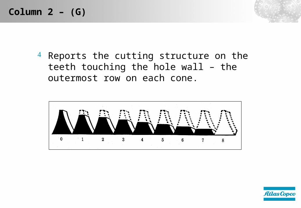
Column 2 – (G)
Reports the cutting structure on the teeth touching the hole wall – the outermost row on each cone.

Column 3 – (D)
Uses 2 letter code to indicate dull characteristic of the cutting structure.
DULL/OTHER DULL CHARACTERISTICS
*BC – Broken Cone *LC – Lost ConeBT – Broken Teeth/Cutters LN – Lost NozzleBU – Balled Up LT – Lost Teeth/Cutters*CC – Cracked Cone PB- Pinched Bit*CD – Cone Dragged PN – Plugged NozzleCI – Cone Interference RG – Rounded GageCR – Cored SD – Shirttail DamageCT – Clipped Teeth SS – Self-Sharpening WearER – Erosion TR – TrackingFC – Flat Crested Wear WT – Worn Teeth/CuttersHC – Heat Checking NO – No Dull/Other WearJD – Junk Damage
* Show cones or #’s under location (L), column 4

Column 4 – (L)
Uses a letter or number code to indicate the location on the face of the bit, where the cutting structure dulling occurs.
LOCATION(ROLLER CONE BITS)
N – Nose Rows Cone # or #´sM – Middle Rows 1H – Heel (Gage) Row 2A – All Rows 3
Column 5 – (B)
Condition of the single worst bearing on the bit.
Uses number code to indicate bearings condition.
For regular bits 0-8 is used.
0 indicates a new bearing and 8 indicates all bearing life has been used (locked or lost).

Column 6 – (L)
Location of the WORST bearing on the bit.
LOCATION(ROLLER CONE BITS)
N – Nose Rows Cone # or #´sM – Middle Rows 1H – Heel (Gage) Row 2A – All Rows 3
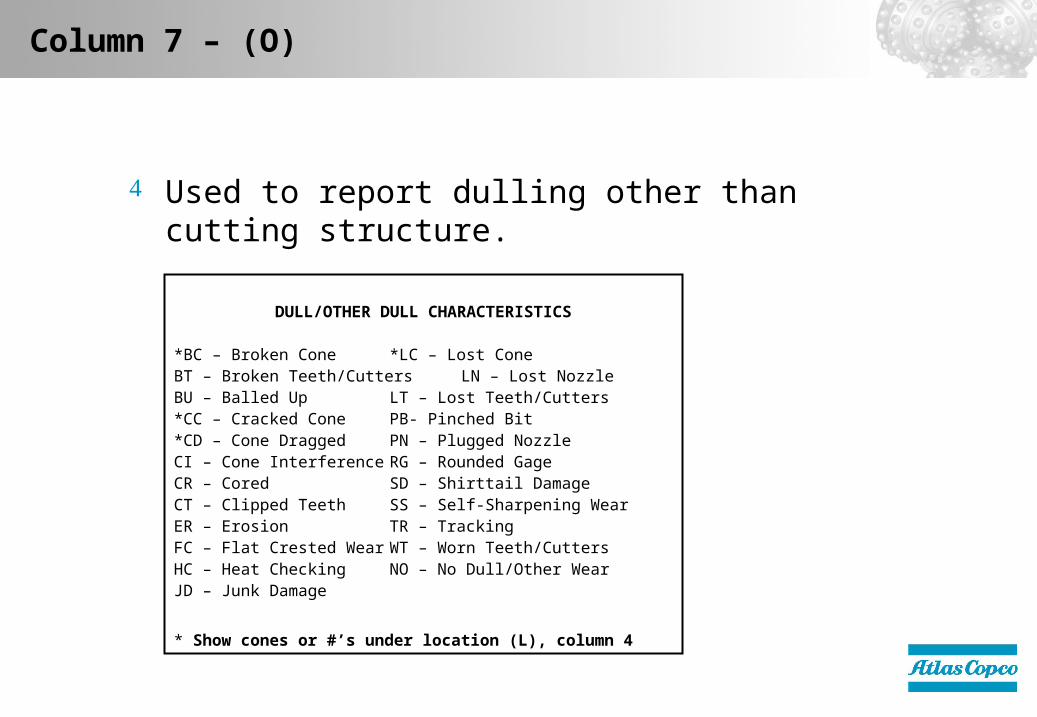
Column 7 – (O)
Used to report dulling other than cutting structure.
DULL/OTHER DULL CHARACTERISTICS
*BC – Broken Cone *LC – Lost ConeBT – Broken Teeth/Cutters LN – Lost NozzleBU – Balled Up LT – Lost Teeth/Cutters*CC – Cracked Cone PB- Pinched Bit*CD – Cone Dragged PN – Plugged NozzleCI – Cone Interference RG – Rounded GageCR – Cored SD – Shirttail DamageCT – Clipped Teeth SS – Self-Sharpening WearER – Erosion TR – TrackingFC – Flat Crested Wear WT – Worn Teeth/CuttersHC – Heat Checking NO – No Dull/Other WearJD – Junk Damage
* Show cones or #’s under location (L), column 4

Column 8 – (ST)
The wear condition of the Shirttail and Lug: L – Light
Some erosion and/or wear around the ST and lug inserts, but shirttail still covers the bearings completely
M – Medium Erosion/wear has exposed the roots of the ST and lug
inserts, and the roller bearings are beginning to be exposed.
H – Heavy ST and lug inserts are being lost, roller bearings are very
exposed.

Broken Cones (BC)
BROKEN CONES (BC) – This describes a bit with one or more cones that have been broken into two or more pieces, but with most of the cone still attached to the bit. Broken cones can be caused in several ways. Some of the causes of BC are:
Cone interference - where the cones run on each other after a bearing failure and break one or more of the cones.
Dropped drill string.

Broken Teeth (BT)
BROKEN TEETH (BT) – In some formations BT is a normal wear characteristic of tungsten carbide insert bits and is not necessarily an indicator of any problem in bit selection or operating practices. However if the bit run was uncommonly short, broken teeth could indicate one or more of the following: the need for a shock sub, too much WOB and/or RPM, or improper bit applications. Some causes of BT are:
Excessive WOB for application. Indicated by broken teeth on the heel or gage row.
Formation too hard for bit type. Indicated by broken teeth on inner rows.
Bit run on junk.
Bit hitting a ledge or hitting bottom suddenly.

Balled Up (BU)
BALLED UP (BU) – A balled up bit will show tooth wear caused by a cone, or cones, not turning due to formation being packed between the cones. The bit will look as if a bearing had locked up even though the bearings are still good. Some causes of balling up are:
Inadequate cleaning of the bottom of the hole.
Forcing the bit into formation cuttings with the air off.
Drilling a sticky formation (wet mudstone/shale).

Cracked Cone (CC)
CRACKED CONE (CC) – A cracked cone is the starting of a broken or lost cone and has many of the same possible causes. Some of these causes are:
Junk on the bottom of the hole.
Bit hitting a ledge or bottom.
Dropped drill string.
Overheating of the bit. (Poor air through the bearings).
Cone shell erosion.

Cone Dragged (CD)
CONE DRAGGED (CD) – This dull characteristic indicates that one or more of the cones did not turn during part of the bit run, indicated by one or more flat wear spots. Some of the possible causes are:
Bearing failure on one or more of the cones.
Junk lodging between the cones.
Pinched bit causing cone interference.
Bit balling up.
Plugged air courses.

Cone Interference (CI)
CONE INTERFERENCE (CI) – Cone interference often leads to cone grooving and broken teeth and is sometimes mistaken for formation damage. Broken teeth caused by cone interference are not an indicator of improper bit selection. Some of the causes of cone interference are:
Bit being pinched.
Bearing failure on one or more cones.

Cored (CR)
CORED (CR) – A bit is cored when its center most teeth are worn and/or broken off. A bit can also be cored when the nose part of one or more cones is broken. Some things that can cause bits to become cored are:
Abrasiveness of formation exceeds the wear.
Resistance of the center of the cutters.
Cone shell erosion resulting in lost cutters.
Junk in the hole causing breakage of the center cutters.
Low air volume causing cuttings to pile up in center of the hole.

Chipped Teeth (CT)
CHIPPED TEETH (CT) – On tungsten carbide insert bits, chipped teeth often become broken teeth. A tooth is considered chipped, as opposed to broken, if a substantial part of the tooth remains above the cone shell. Chipped teeth are not usually a sign of any problems in bit application or operating practices. Some causes of chipped teeth are:
Impact loading due to rough drilling.
Slight cone interference.

Erosion (ER)
EROSION (ER) – Abrasion or ”sandblast” erosion leads to a cutter reduction and/or loss of cone shell material. The loss of cone shell material on tungsten carbide insert bits can lead to a loss of inserts due to the reduced support and grip of the cone shell material. Erosion can be caused by:
Abrasive formation contacting the cone shell.
Between the cutters, caused by tracking, off center wear, or excessive WOB.
Abrasive formation cuttings eroding the cone.
Shell due to inadequate air. (Running on cuttings).
Excessive air resulting in high velocity erosion.

Flat Crested Wear (FC)
FLAT CRESTED WEAR (FC) – Flat crested wear is an even reduction in height of all teeth, . Flat crested wear occurs when the not enough weight is applied for the tooth to overcome the compressive strength of the rock. The causes of flat crested wear are:
Low WOB (and high RPM) for the formation.
Bit selected is too soft for the formation being drilled.

Heat Checking (HC)
HEAT CHECKING (HC) – Heat Checking happens when an insert is repeatedly heated due to working against, twisting, or dragging on the formation, and is then rapidly cooled either by ground water or by water used for dust suppression over many cycles. HC usually occurs in hard, tough, and abrasive formations. It is not always a cause of tooth failure, although tooth failure can result from extensive heat checking.

Junk Damage (JD)
JUNK DAMAGE (JD) – Junk damage can be detected by marks on any part of the bit. Junk damage can lead to broken teeth and shortened bit runs and therefore can become a problem. It is sometimes necessary to clear the junk out of the hole before continuing to drill. Some common sources of junk, and therefore causes of junk damage are:
Junk dropped in the hole from the surface.
Junk from the drill string (reamer pins, stabilizer blades, etc).
Junk from the bit itself (tungsten carbide inserts. etc).

Lost Cone (LC)
LOST CONE (LC) – It is possible to lose one or more cones in many ways. With few exceptions, the lost cone must be cleared from the hole before drilling can resume. Some of the causes of lost cones are:
Bit hitting hole bottom or a ledge.
Bearing failure (causing the cone retention system to fail).
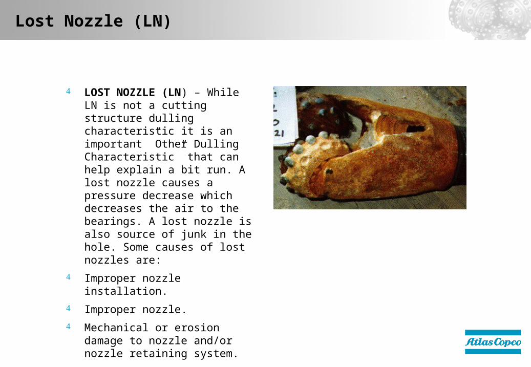
Lost Nozzle (LN)
LOST NOZZLE (LN) – While LN is not a cutting structure dulling characteristic it is an important ”Other Dulling Characteristic” that can help explain a bit run. A lost nozzle causes a pressure decrease which decreases the air to the bearings. A lost nozzle is also source of junk in the hole. Some causes of lost nozzles are:
Improper nozzle installation.
Improper nozzle.
Mechanical or erosion damage to nozzle and/or nozzle retaining system.

Lost Teeth (LT)
LOST TEETH (LT) – This dulling characteristic leaves entire tungsten carbide inserts in the hole which are far more detrimental to the rest of the bit than are broken inserts. Lost teeth often cause junk damage. Lost teeth are sometimes preceded by rotated inserts. Lost teeth can be caused by:
Cone shell erosion.
A crack in the cone that loosens the grip on the insert.
Pinched Bit (PB)
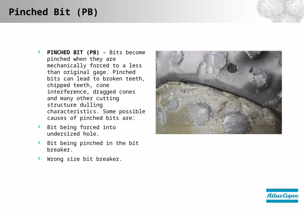
PINCHED BIT (PB) – Bits become pinched when they are mechanically forced to a less than original gage. Pinched bits can lead to broken teeth, chipped teeth, cone interference, dragged cones and many other cutting structure dulling characteristics. Some possible causes of pinched bits are:
Bit being forced into undersized hole.
Bit being pinched in the bit breaker.
Wrong size bit breaker.
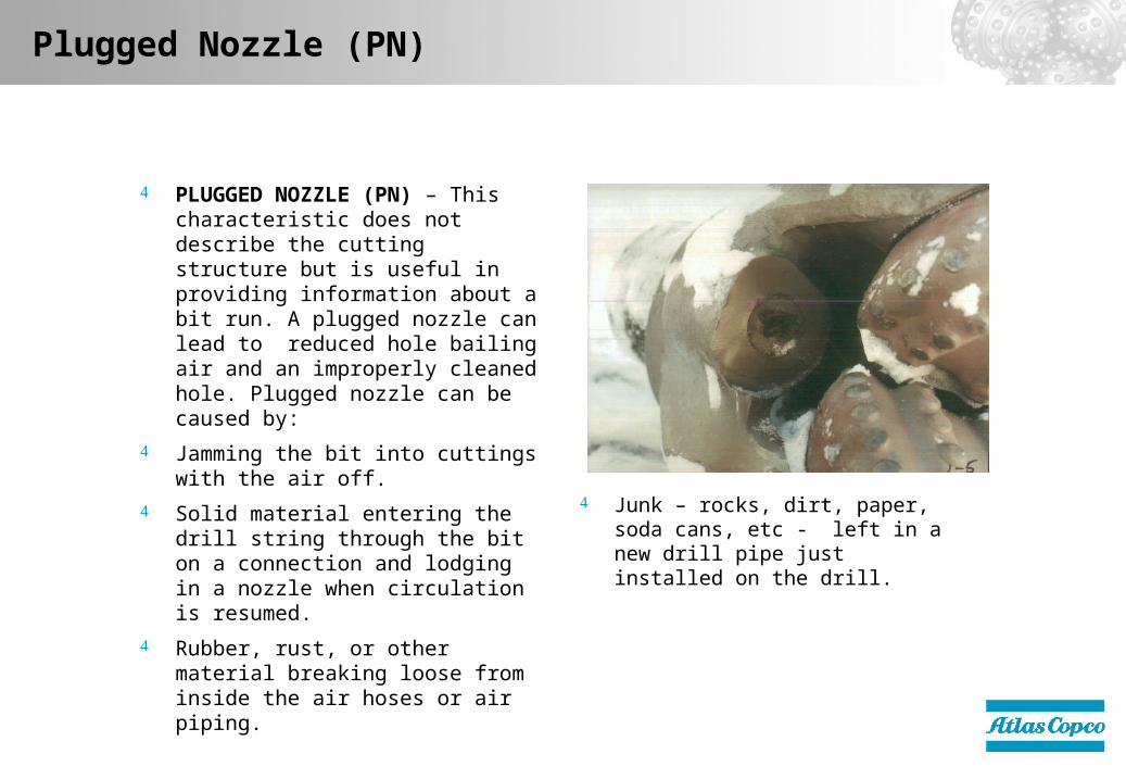
Plugged Nozzle (PN)
PLUGGED NOZZLE (PN) – This characteristic does not describe the cutting structure but is useful in providing information about a bit run. A plugged nozzle can lead to reduced hole bailing air and an improperly cleaned hole. Plugged nozzle can be caused by:
Jamming the bit into cuttings with the air off.
Solid material entering the drill string through the bit on a connection and lodging in a nozzle when circulation is resumed.
Rubber, rust, or other material breaking loose from inside the air hoses or air piping.
Junk – rocks, dirt, paper, soda cans, etc - left in a new drill pipe just installed on the drill.

Rounded Gage (RG)
ROUNDED GAGE (RG) – This describes a bit that experiences gage wear that rounds the gage inserts over. Caused by:
Drilling an abrasive formation.
Excessive RPM.
Reaming an undersize hole.
Bit too soft for formation.

Shirttail Damage (SD)
SHIRTAIL DAMAGE (SD) – Shirttail damage may be different than junk damage and is not a cutting structure dulling characteristic. Shirttail wear can lead to bearing failures. Some causes of shirttail damage are:
Junk in the hole.
A pinched bit causing the shirttails to be the outermost part of the bit.

Self-Sharpening Wear (SS)
SELF-SHARPENING WEAR (SS) – A dull characteristic which occurs when teeth wear in a manner such that they retain somewhat of a cutting edge. This characteristic is often considered an indication of proper bit selection and operating parameters.

Tracking (TR)
TRACKING (TR) – This dulling characteristic occurs when the teeth mesh like a gear into the bottom hole pattern. The tooth wear on a bit that has been tracking will resemble a ”tear drop” whereas the cone shell will wear between the rows. Tracking can sometimes be alleviated by using a softer bit to drill the formation or using a different cutting structure pattern. Tracking can be caused by:
Formation changes from brittle to plastic.
Hard formations.

Worn Teeth (WT)
WORN TEETH (WT) – This is a normal dulling characteristic of the tungsten carbide.
Insert bits as well as for the steel tooth bits. When WT is noted for steel tooth bits, it is also often appropriate to note self-sharpening (SS) or flat-crested (FC) wear.

No Dull/No Other Wear (NO)
NO DULL/NO OTHER WEAR (NO) – This code is used to indicate that the dull shows no sign of the other dulling characteristics described. This is often used when a bit is pulled after a short run for a reason not related to the bit, as drill string wash out.

Options
Elements of a Rotary Rock Bit Rock Breakage Drilling Parameters Drill Bits Drilling Problems Bit Selection Dull Grade Analysis Troubleshooting Back to start

TroubleshootingTroubleshooting

Dulling Characteristic Possible Problems Corrective Actions
Broken Inner Inserts Too much weight on bit Reduce WOB
Too soft of a bit Select harder Bit
Broken Gage Inserts Too high rotation speed Reduce rotation Speed
Too soft of a bit Select harder Bit
Worn Inserts Too hard of a bit Select softer bit
(Flat Crested Wear) Too high rotation speed Reduce rotation Speed
Not enough WOB Increase WOB
Lost Inserts Erosion due to over drilling Reduce WOB
(Gage/NTG) Erosion due to 'Air Blast' Increase Rotation Speed
Increase nozzle size
Worn Bearing Low air volume to bearings Check System for leaks
Too much weight on bit Check compressor output
Plugged Air passages Check Air tubes
Reduce nozzle size
Reduce WOB
Bit Body Erosion Too high air volume Reduce compressor output
Hole Cave in Select a back reaming bit
Worn Shirttail Failure to clear cuttings Check compressor output
Bit worn undersize Reduce rotation Speed
Reduce water injection rate
Single Worn Shirttail Bent drill pipe Check drill string
(on one lug) Cross threaded bit Inspect Bit connection
Grooves Formed Between inserts Over Drilling Reduce WOB
(Same row) Too hard of a bit Increase Rotation Speed
Select a softer bit

Options
Elements of a Rotary Rock Bit Rock Breakage Drilling Parameters Drill Bits Drilling Problems Bit Selection Dull Grade Analysis Troubleshooting Back to start