Embed Size (px)
Citation preview

Biomedical Instrumentation II
Dr. Hugh Blanton
ENTC 4370
Dr. Blanton - ENTC 4370 - ULTRASONICS 2
More ULTRASONOGRAPHY

CHARACTERISTICS OF SOUND
Dr. Blanton - ENTC 4370 - ULTRASONICS 4
Propagation of SoundPropagation of Sound
• Sound is mechanical energy that propagates through a continuous, elastic medium by the compression and rarefaction of “particles” that compose it.
Dr. Blanton - ENTC 4370 - ULTRASONICS 5
Propagation of SoundPropagation of Sound• Compression is caused by a mechanical deformation
induced by an external force, with a resultant increase in the pressure of the medium.
• Rarefaction occurs following the compression event. • The compressed particles transfer their energy to adjacent
particles, with a subsequent reduction in the local pressure amplitude.
• While the medium itself is necessary for mechanical energy transfer (i.e., sound propagation), the constituent “particles” of the medium act only to transfer mechanical energy; these particles experience only very small back-and-forth displacements.
• Energy propagation occurs as a wave front in the direction of energy travel, known as a Iongitudinal wave.

Dr. Blanton - ENTC 4370 - ULTRASONICS 6
Wavelength, Frequency, and Speed
Wavelength, Frequency, and Speed
• The wavelength () of the ultrasound is the distance (usually expressed in millimeters or micrometers) between compressions or rarefactions, or between any two points that repeat on the sinusoidal wave of pressure amplitude.
• The frequency (f) is the number of times the wave oscillates through a cycle each second (sec).
Dr. Blanton - ENTC 4370 - ULTRASONICS 7
• Sound waves with frequencies less than 15 cycles/sec (Hz) are called infrasound, and the range between 15 Hz and 20 kHz comprises the audible acoustic spectrum.
• Ultrasound represents the frequency range above 20 kHz. • Medical ultrasound uses frequencies in the range
of 2 MHz to 10 MHz, with specialized ultrasound applications up to 50 MHz.
Dr. Blanton - ENTC 4370 - ULTRASONICS 8
• The period is the time duration of one wave cycle, and is equal to 1/f where f is expressed in cycles/sec. • The speed of sound is the distance traveled by
the wave per unit time and is equal to the wavelength divided by the period.
Dr. Blanton - ENTC 4370 - ULTRASONICS 9
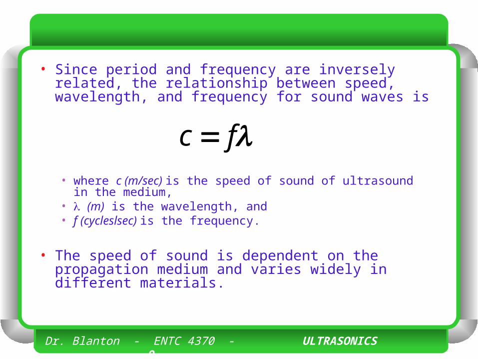
• Since period and frequency are inversely related, the relationship between speed, wavelength, and frequency for sound waves is
• where c (m/sec) is the speed of sound of ultrasound in the medium,
• (m) is the wavelength, and • f (cycleslsec) is the frequency.
• The speed of sound is dependent on the propagation medium and varies widely in different materials.
fc
Dr. Blanton - ENTC 4370 - ULTRASONICS 10
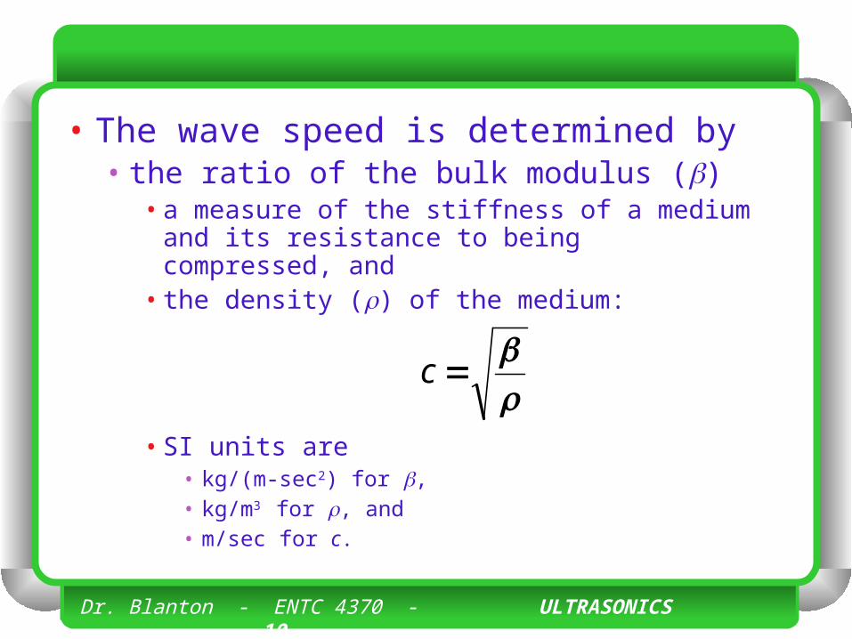
• The wave speed is determined by • the ratio of the bulk modulus ()
• a measure of the stiffness of a medium and its resistance to being compressed, and
• the density () of the medium:
• SI units are • kg/(m-sec2) for , • kg/m3 for , and • m/sec for c.
c
Dr. Blanton - ENTC 4370 - ULTRASONICS 11
• A highly compressible medium, such as air, has a low speed of sound, while a less compressible medium, such as bone, has a higher speed of sound. • A less dense medium has a higher speed
of sound than a denser medium (e.g.. dry air vs. humid air).
Dr. Blanton - ENTC 4370 - ULTRASONICS 12
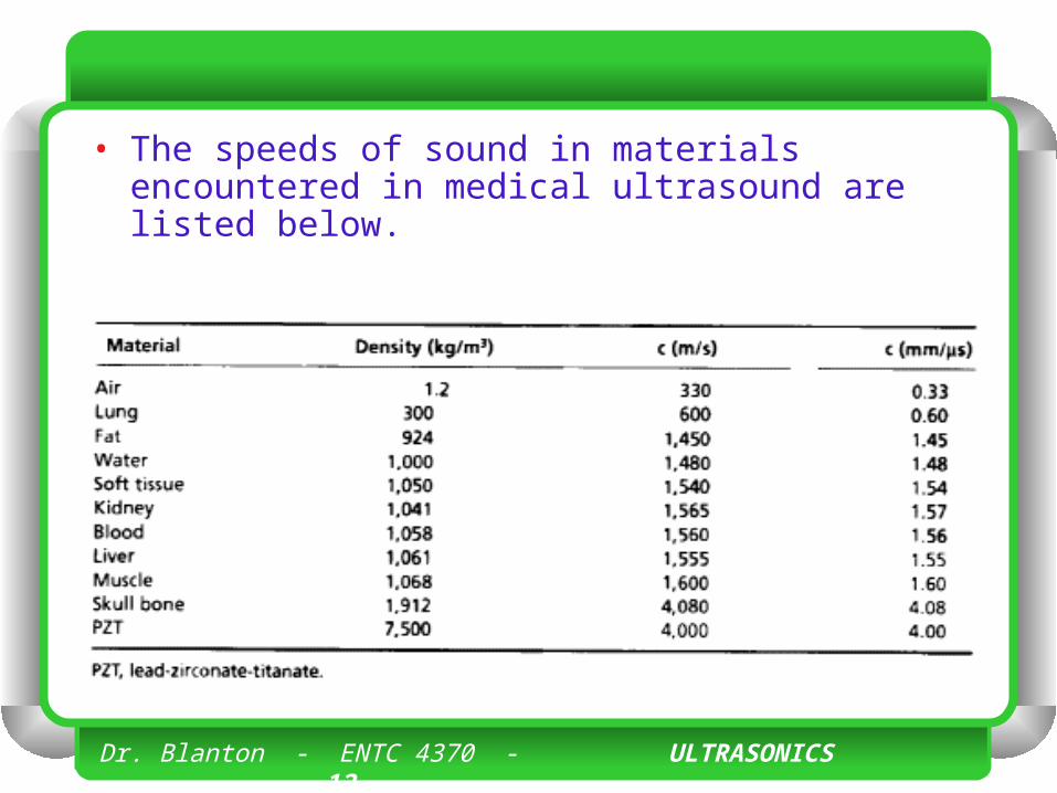
• The speeds of sound in materials encountered in medical ultrasound are listed below.
Dr. Blanton - ENTC 4370 - ULTRASONICS 13
• Of major importance are • the speed of sound in air (330 m/sec), • the average speed for soft tissue (1,540
m/sec), and • fatty tissue (1,450 m/sec).
Dr. Blanton - ENTC 4370 - ULTRASONICS 14
• The difference in the speed of sound at tissue boundaries is a fundamental cause of contrast in an ultrasound image.
Dr. Blanton - ENTC 4370 - ULTRASONICS 15
• Medical ultrasound machines assume a speed of sound of 1,540 in/sec. • The speed of sound in soft tissue can be
expressed in other units such as 154,000 cm/sec and 1.54 mm/sec.
Dr. Blanton - ENTC 4370 - ULTRASONICS 16
• The ultrasound frequency is unaffected by changes in sound speed as the acoustic beam propagates through various media. • Thus, the ultrasound wavelength is dependent on
the medium.
Dr. Blanton - ENTC 4370 - ULTRASONICS 17
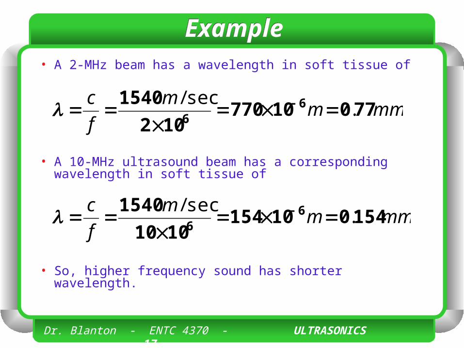
ExampleExample• A 2-MHz beam has a wavelength in soft tissue of
• A 10-MHz ultrasound beam has a corresponding wavelength in soft tissue of
• So, higher frequency sound has shorter wavelength.
mmmm
f
c77010770
102
1540 66
.sec/
mmmm
f
c154010154
1010
1540 66
.sec/
Dr. Blanton - ENTC 4370 - ULTRASONICS 18
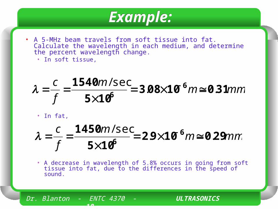
Example:Example:• A 5-MHz beam travels from soft tissue into fat. Calculate the
wavelength in each medium, and determine the percent wavelength change.• In soft tissue,
• In fat,
• A decrease in wavelength of 5.8% occurs in going from soft tissue into fat, due to the differences in the speed of sound.
mmmm
f
c31010083
105
1540 66
..sec/
mmmm
f
c2901092
105
1450 66
..sec/
Dr. Blanton - ENTC 4370 - ULTRASONICS 19
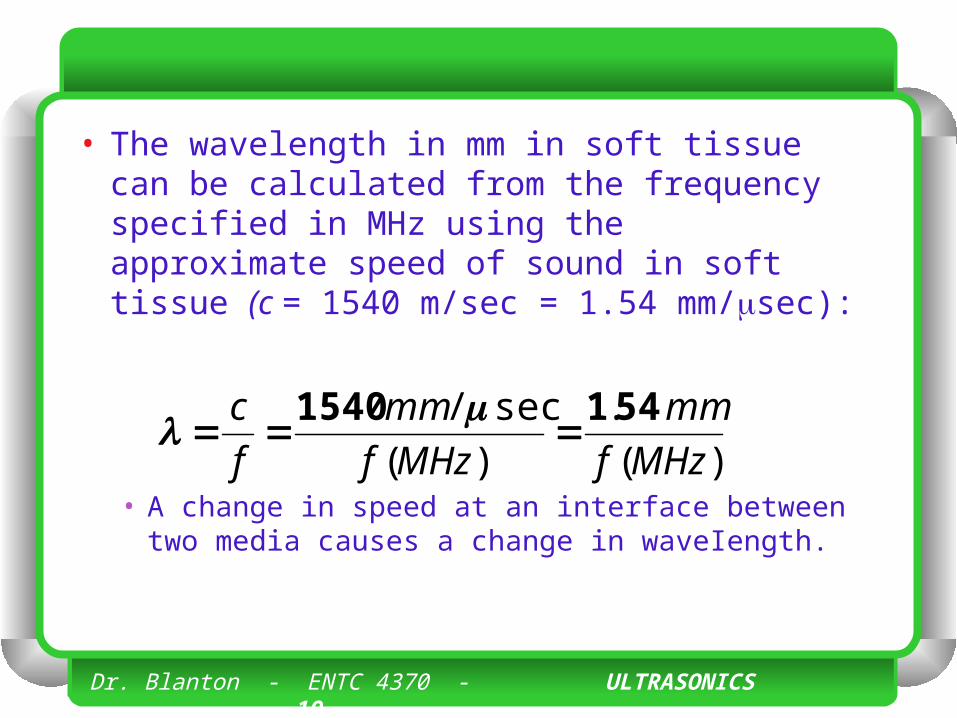
• The wavelength in mm in soft tissue can be calculated from the frequency specified in MHz using the approximate speed of sound in soft tissue (c = 1540 m/sec = 1.54 mm/sec):
• A change in speed at an interface between two media causes a change in waveIength.
)(
.
)(
sec/
MHzf
mm
MHzf
mm
f
c 5411540
Dr. Blanton - ENTC 4370 - ULTRASONICS 20
• The resolution of the ultrasound image and the attenuation of the ultrasound beam energy depend on the wavelength and frequency. • Ultrasound wavelength determines the spatial
resolution achievable along the direction of the beam.
• A high-frequency ultrasound beam (small wavelength) provides superior resolution and image detail than a low-frequency beam.
• However, the depth of beam penetration is reduced at higher frequency.
• Lower frequency ultrasound has longer wavelength and less resolution, but a greater penetration depth.
Dr. Blanton - ENTC 4370 - ULTRASONICS 21
• Ultrasound frequencies selected for imaging are determined by the imaging application. • For thick body parts (e.g., abdominal imaging), a
lower frequency ultrasound wave is used (3.5 to 5 MHz) to image structures at significant depths, whereas
• For small body parts or organs close to the skin surface (e.g., thyroid, breast), a higher frequency is employed (7.5 to 10 MHz).
• Most medical imaging applications use frequencies in the range of 2 to 10 MHz.
Dr. Blanton - ENTC 4370 - ULTRASONICS 22
• Modern ultrasound equipment consists of multiple sound transmitters that create sound beams independent of each other. • Interaction of two or more separate ultrasound
beams in a medium results in constructive and/or destructive wave interference.
• Constructive wave interference results in an increase in the amplitude of the beam, while destructive wave interference results in a loss of amplitude.
Dr. Blanton - ENTC 4370 - ULTRASONICS 23
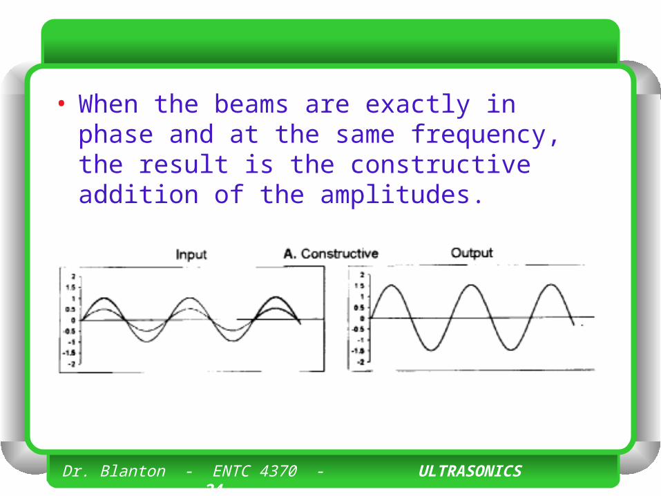
• The amount of constructive or destructive interference depends on several factors, but the most important are the phase (position of the periodic wave with respect to a reference point) and amplitude of the interacting beams. • When the beams are exactly in phase and at the same
frequency, the result is the constructive addition of the amplitudes.
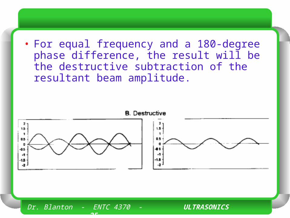
• For equal frequency and a 180-degree phase difference, the result will be the destructive subtraction of the resultant beam amplitude.
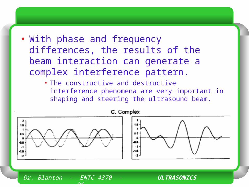
• With phase and frequency differences, the results of the beam interaction can generate a complex interference pattern.
• The constructive and destructive interference phenomena are very important in shaping and steering the ultrasound beam.
Dr. Blanton - ENTC 4370 - ULTRASONICS 24
• When the beams are exactly in phase and at the same frequency, the result is the constructive addition of the amplitudes.
Dr. Blanton - ENTC 4370 - ULTRASONICS 25
• For equal frequency and a 180-degree phase difference, the result will be the destructive subtraction of the resultant beam amplitude.
Dr. Blanton - ENTC 4370 - ULTRASONICS 26
• With phase and frequency differences, the results of the beam interaction can generate a complex interference pattern.
• The constructive and destructive interference phenomena are very important in shaping and steering the ultrasound beam.
Pressure, Intensity, and the dB Scale
Dr. Blanton - ENTC 4370 - ULTRASONICS 28
• Sound energy causes particle displacements and variations in local pressure in the propagation medium. • The pressure variations are most often
described as pressure amplitude (P). • Pressure amplitude is defined as the peak
maximum or peak minimum value from the average pressure on the medium in the absence of a sound wave.
Dr. Blanton - ENTC 4370 - ULTRASONICS 29
• In the case of a symmetrical waveform, the positive and negative pressure amplitudes are equal; however, in most diagnostic ultrasound applications, the compressional amplitude significantly exceeds the rarefactional amplitude.
Dr. Blanton - ENTC 4370 - ULTRASONICS 30
• The SI unit of pressure is the pascal (Pa), defined as one newton per square meter (N/m2). • The average atmospheric pressure on
earth at sea level of 14.7 pounds per square inch is approximately equal to 100,000 Pa.
• Diagnostic ultrasound beams typically deliver peak pressure levels that exceed ten times the earth’s atmospheric pressure, or about 1 MPa (megapascal).
Dr. Blanton - ENTC 4370 - ULTRASONICS 31
• Intensity, I, is the amount of power (energy per unit time) per unit area and is proportional to the square of the pressure amplitude:
• A doubling of the pressure amplitude quadruples the intensity.
2PI
Dr. Blanton - ENTC 4370 - ULTRASONICS 32
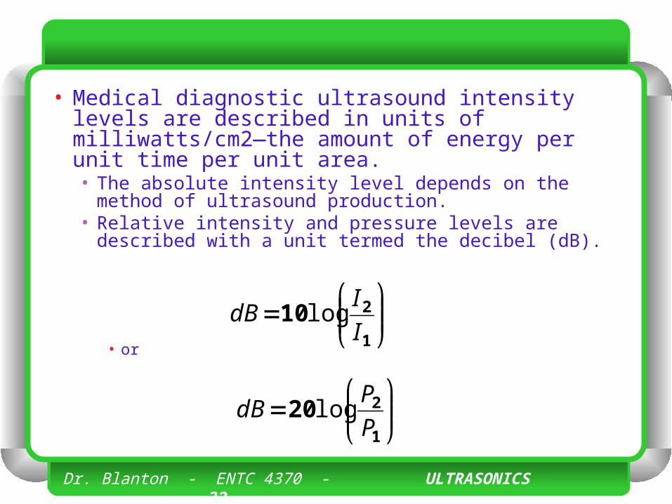
• Medical diagnostic ultrasound intensity levels are described in units of milliwatts/cm2—the amount of energy per unit time per unit area. • The absolute intensity level depends on the
method of ultrasound production. • Relative intensity and pressure levels are
described with a unit termed the decibel (dB).
• or
1
210I
IdB log
1
220P
PdB log
Dr. Blanton - ENTC 4370 - ULTRASONICS 33
• In diagnostic ultrasound, the ratio of the intensity of the incident pulse to thar of the returning echo can span a range of 1 million times or more! • The logarithm function compresses the
large and expands the small values into a more manageable number range.
Dr. Blanton - ENTC 4370 - ULTRASONICS 34
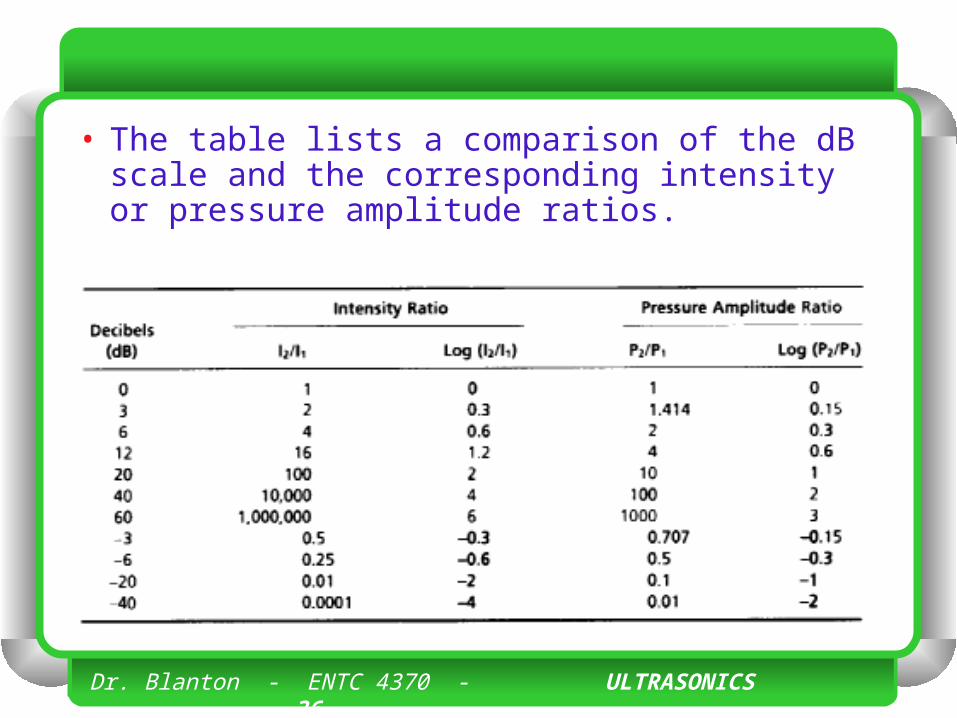
• An intensity ratio of 106 (e.g., an incident intensity 1 million times greater than the returning echo intensity) is equal to 60 dB, whereas an intensity ratio of 102 is equal to 20 dB. • A change of 10 in the dB scale corresponds to an
order of magnitude (ten times) change in intensity;
• A change of 20 corresponds to two orders of magnitude (100 times) change, and so forth.
Dr. Blanton - ENTC 4370 - ULTRASONICS 35
• When the intensity ratio is greater than 1 (e.g., the incident ultrasound intensity to the detected echo intensity), the dB values are positive; when less than 1, the dB values are negative. • A loss of 3 dB (-3 dB) represents a 50%
loss of signal intensity. • The tissue thickness that reduces the
ultrasound intensity by 3 dB is considered the “half-value” thickness.
Dr. Blanton - ENTC 4370 - ULTRASONICS 36
• The table lists a comparison of the dB scale and the corresponding intensity or pressure amplitude ratios.
Dr. Blanton - ENTC 4370 - ULTRASONICS 37
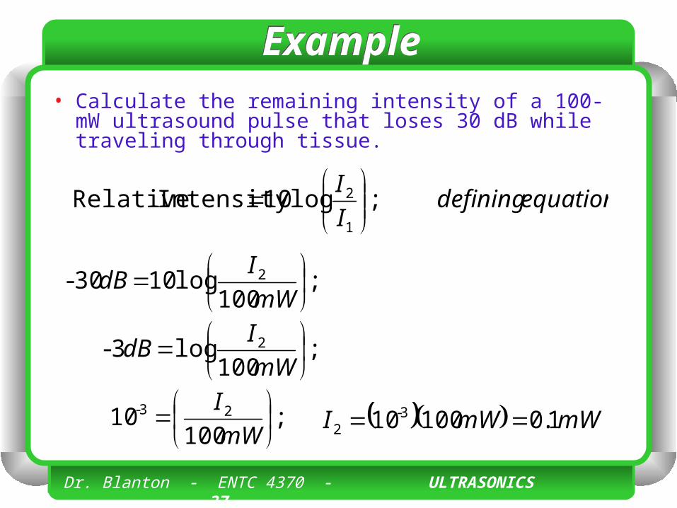
ExampleExample• Calculate the remaining intensity of a 100-mW
ultrasound pulse that loses 30 dB while traveling through tissue.
equationdefiningI
I;log10Intensity Relative
1
2
;100
log1030- 2
mW
IdB
;100
log3- 2
mW
IdB
;100
10 23-
mW
I mWmWI 1.010010 3-2
INTERACTIONS OF ULTRASOUND WITH MATTER
Dr. Blanton - ENTC 4370 - ULTRASONICS 39
• Ultrasound interactions are determined by the acoustic properties of matter. • As ultrasound energy propagates through
a medium, interactions that occur include • reflection, • refraction, • scattering, and • absorption.
Dr. Blanton - ENTC 4370 - ULTRASONICS 40
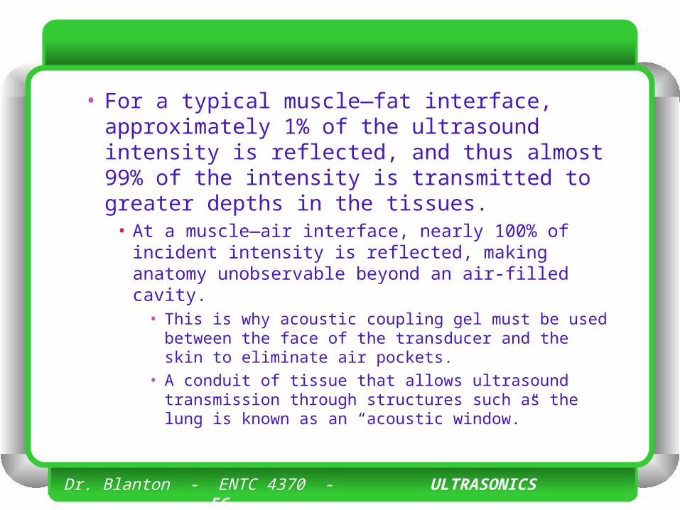
• Reflection occurs at tissue boundaries where there is a difference in the acoustic impedance of adjacent materials. • When the incident beam is perpendicular
to the boundary, a portion of the beam (an echo) returns directly back to the source, and the transmitted portion of the beam continues in the initial direction.
Dr. Blanton - ENTC 4370 - ULTRASONICS 41
• Refraction describes the change in direction of the transmitted ultrasound energy with non-perpendicular incidence.
Dr. Blanton - ENTC 4370 - ULTRASONICS 42
• Scattering occurs by reflection or refraction, usually by small particles within the tissue medium, causes the beam to diffuse in many directions, and gives rise to the characteristic texture and gray scale in the acoustic image.
Dr. Blanton - ENTC 4370 - ULTRASONICS 43
• Absorption is the process whereby acoustic energy is converted to heat energy. • In this situation, sound energy is lost and
cannot be recovered.
Dr. Blanton - ENTC 4370 - ULTRASONICS 44
• Attenuation refers to the loss of intensity of the ultrasound beam from absorption and scattering in the medium.
Dr. Blanton - ENTC 4370 - ULTRASONICS 45
Acoustic impedanceAcoustic impedance
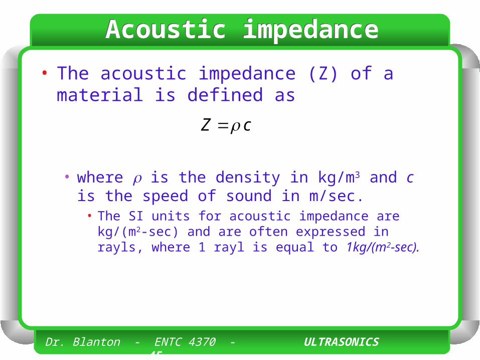
• The acoustic impedance (Z) of a material is defined as
• where is the density in kg/m3 and c is the speed of sound in m/sec.
• The SI units for acoustic impedance are kg/(m2-sec) and are often expressed in rayls, where 1 rayl is equal to 1kg/(m2-sec).
cZ
Dr. Blanton - ENTC 4370 - ULTRASONICS 46
Acoustic impedanceAcoustic impedance
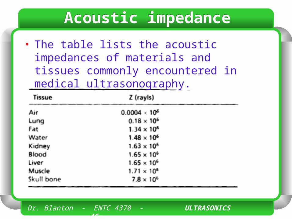
• The table lists the acoustic impedances of materials and tissues commonly encountered in medical ultrasonography.
Dr. Blanton - ENTC 4370 - ULTRASONICS 47
Acoustic impedanceAcoustic impedance
• In a simplistic way, the acoustic impedance can be likened to the stiffness and flexibility of a compressible medium such as a spring. • When springs with different compressibility are
connected together, the energy transfer from one spring to another depends mostly on stiffness.
• A large difference in the stiffness results in a large reflection of energy, an extreme example of which is a spring attached to a wall.
• Minor differences in stiffness or compressibility allow the continued propagation of energy, with little reflection at the interface.
Dr. Blanton - ENTC 4370 - ULTRASONICS 48
Acoustic impedanceAcoustic impedance
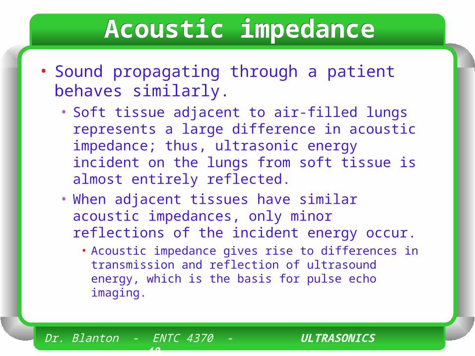
• Sound propagating through a patient behaves similarly. • Soft tissue adjacent to air-filled lungs represents
a large difference in acoustic impedance; thus, ultrasonic energy incident on the lungs from soft tissue is almost entirely reflected.
• When adjacent tissues have similar acoustic impedances, only minor reflections of the incident energy occur.
• Acoustic impedance gives rise to differences in transmission and reflection of ultrasound energy, which is the basis for pulse echo imaging.
Dr. Blanton - ENTC 4370 - ULTRASONICS 49
ReflectionReflection
• The reflection of ultrasound energy at a boundary between two tissues occurs because of the differences in the acoustic impedances of the two tissues. • The reflection coefficient describes the
fraction of sound intensity incident on an interface that is reflected.
Dr. Blanton - ENTC 4370 - ULTRASONICS 50
ReflectionReflection
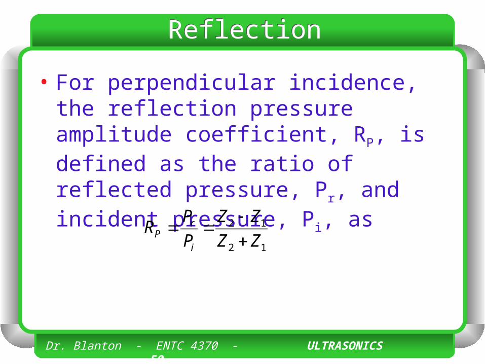
• For perpendicular incidence, the reflection pressure amplitude coefficient, RP, is defined as the ratio of reflected pressure, Pr, and incident pressure, Pi, as
12
12
ZZ
ZZ
P
PR
i
rP
Dr. Blanton - ENTC 4370 - ULTRASONICS 51
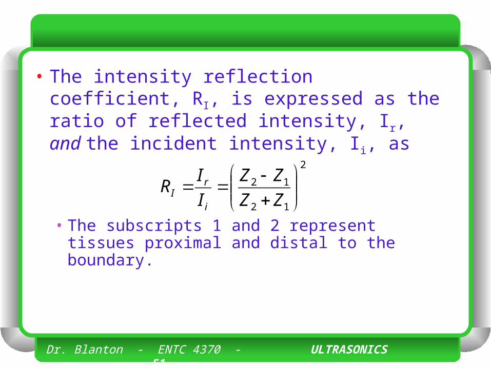
• The intensity reflection coefficient, RI, is expressed as the ratio of reflected intensity, Ir, and the incident intensity, Ii, as
• The subscripts 1 and 2 represent tissues proximal and distal to the boundary.
2
12
12
ZZ
ZZ
I
IR
i
rI
Dr. Blanton - ENTC 4370 - ULTRASONICS 52
• The intensity transmission coefficient, T1, is defined as the fraction of the incident intensity that is transmitted across an interface. • With conservation of energy, the intensity
transmission coefficient is T1 = 1 - RI.
Dr. Blanton - ENTC 4370 - ULTRASONICS 53
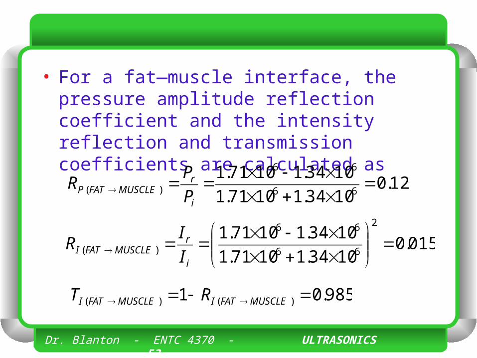
• For a fat—muscle interface, the pressure amplitude reflection coefficient and the intensity reflection and transmission coefficients are calculated as
12.01034.11071.1
1034.11071.166
66
)(
i
rMUSCLEFATP P
PR
015.01034.11071.1
1034.11071.12
66
66
)(
i
rMUSCLEFATI I
IR
985.01 )()( MUSCLEFATIMUSCLEFATI RT
Dr. Blanton - ENTC 4370 - ULTRASONICS 54
• The actual intensity reflected at a boundary is the product of the incident intensity and the reflection coefficient. • For example, an intensity of 40 mW/cm2
incident on a boundary with RI = 0.015 reflects 40 x 0.015 = 0.6 mW/cm2.
Dr. Blanton - ENTC 4370 - ULTRASONICS 55
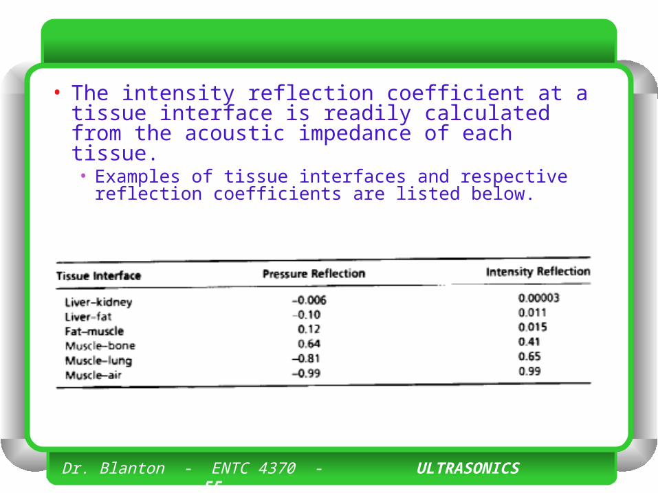
• The intensity reflection coefficient at a tissue interface is readily calculated from the acoustic impedance of each tissue. • Examples of tissue interfaces and respective
reflection coefficients are listed below.
Dr. Blanton - ENTC 4370 - ULTRASONICS 56
• For a typical muscle—fat interface, approximately 1% of the ultrasound intensity is reflected, and thus almost 99% of the intensity is transmitted to greater depths in the tissues.
• At a muscle—air interface, nearly 100% of incident intensity is reflected, making anatomy unobservable beyond an air-filled cavity.
• This is why acoustic coupling gel must be used between the face of the transducer and the skin to eliminate air pockets.
• A conduit of tissue that allows ultrasound transmission through structures such as the lung is known as an “acoustic window.”
Dr. Blanton - ENTC 4370 - ULTRASONICS 57
Dr. Blanton - ENTC 4370 - ULTRASONICS 58
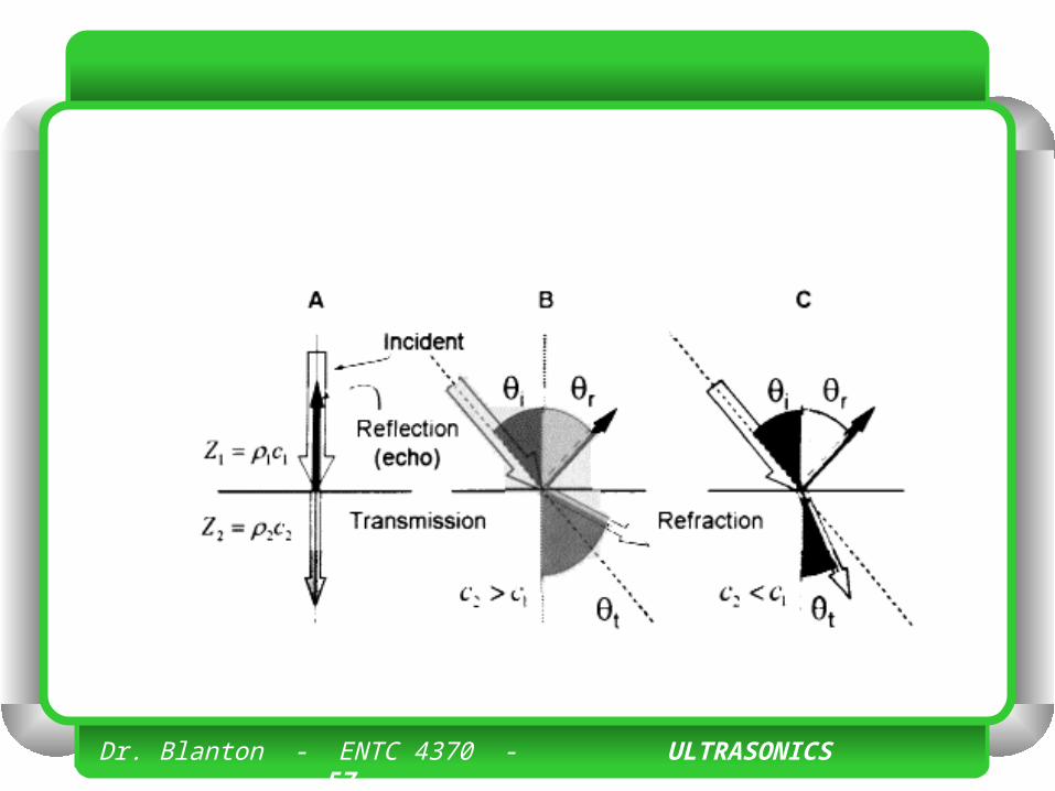
• When the beam is perpendicular to the tissue boundary, the sound is returned back to the transducer as an echo. • As sound travels from a medium of lower acoustic
impedance into a medium of higher acoustic impedance, the reflected wave experiences a 180-degree phase shift in pressure amplitude (note the negative sign on some of the pressure amplitude values in the previous table).
• The above discussion assumes a “smooth” boundary between tissues, where the wavelength of the ultrasound beam is much greater than the structural variations of the boundary.

Dr. Blanton - ENTC 4370 - ULTRASONICS 59
• With higher frequency ultrasound beams, the wavelength becomes smaller, and the boundary no longer appears smooth relative to the wavelength. • In this case, returning echoes are diffusely scattered
throughout the medium, and only a small fraction of the incident intensity returns to the source (the ultrasound transducer, as described below).
• For nonperpendicular incidence at an angle i , the ultrasound energy as reflected at an angle r equal to the incident angle, i = r.
• Echoes are directed away from the source of ultrasound, causing loss of the returning signal from the boundary.

Dr. Blanton - ENTC 4370 - ULTRASONICS 60

Dr. Blanton - ENTC 4370 - ULTRASONICS 61
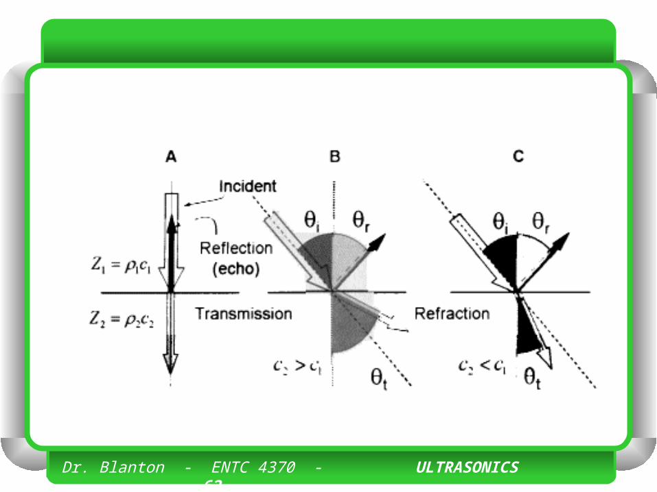
RefractionRefraction
• Refraction describes the change in direction of the transmitted ultrasound energy at a tissue boundary when the beam is not perpendicular to the boundary. • Ultrasound frequency does not change
when propagating into the next tissue, but a change in the speed of sound may occur.
Dr. Blanton - ENTC 4370 - ULTRASONICS 62
Dr. Blanton - ENTC 4370 - ULTRASONICS 63
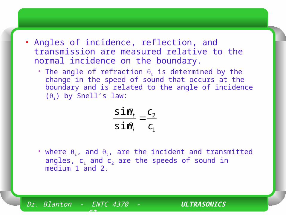
• Angles of incidence, reflection, and transmission are measured relative to the normal incidence on the boundary. • The angle of refraction t is determined by the change in
the speed of sound that occurs at the boundary and is related to the angle of incidence (i) by Snell’s law:
• where i, and t, are the incident and transmitted angles, c1 and c2 are the speeds of sound in medium 1 and 2.
1
2
sin
sin
c
c
i
t
Dr. Blanton - ENTC 4370 - ULTRASONICS 64
• For small angles of incidence and transmission, Snell’s law can be approximated as
1
2
c
c
i
t
Dr. Blanton - ENTC 4370 - ULTRASONICS 65
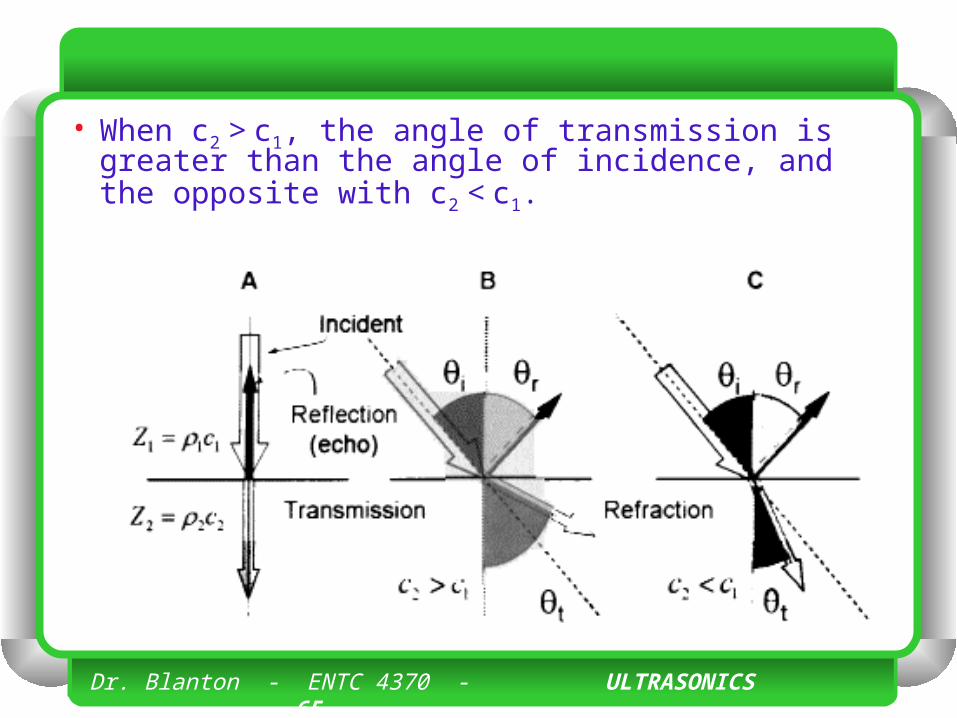
• When c2 > c1, the angle of transmission is greater than the angle of incidence, and the opposite with c2 < c1.
Dr. Blanton - ENTC 4370 - ULTRASONICS 66
• No refraction occurs when the speed of sound is the same in the two media, or with perpendicular incidence, and thus a straight-line trajectory occurs. • This straight-line propagation is assumed
in ultrasound machines, and when refraction occurs, it can cause artifacts in the image.
Dr. Blanton - ENTC 4370 - ULTRASONICS 67
• A situation called total reflection occurs when c2 > c1 and the angle of incidence of the sound beam with a boundary between two media exceeds an angle called the critical angle. • In his case, the refracted portion of the beam does not
penetrate the second medium at all, but travels along the boundary.
• The critical angle (c) is calculated by setting (t) = 90 degrees in Snell’s law where sin (90) = 1, producing the equation
2
1sinc
cc
Dr. Blanton - ENTC 4370 - ULTRASONICS 68
ScatteringScattering
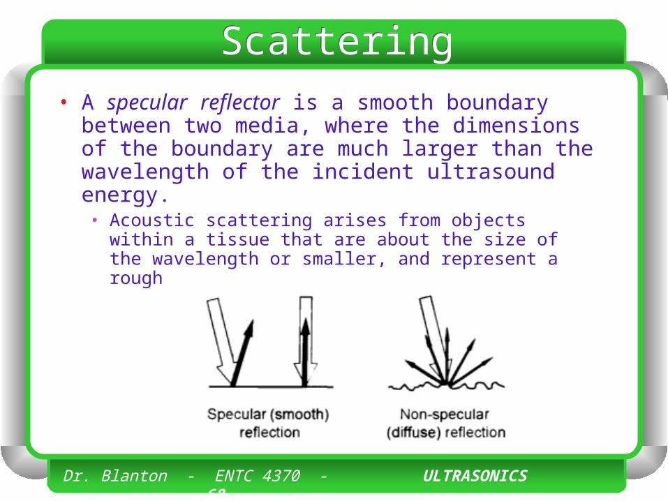
• A specular reflector is a smooth boundary between two media, where the dimensions of the boundary are much larger than the wavelength of the incident ultrasound energy. • Acoustic scattering arises from objects within a tissue that
are about the size of the wavelength or smaller, and represent a rough or nonspecular reflector surface.

Dr. Blanton - ENTC 4370 - ULTRASONICS 69
Dr. Blanton - ENTC 4370 - ULTRASONICS 70
• Most organs have a characteristic structure that gives rise to a defined scatter “signature” and provides much of the diagnostic information contained in the ultrasound image. • Because nonspecular reflectors reflect sound in all
directions, the amplitudes of the returning echoes are significantlv weaker than echoes from tissue boundaries.
• Fortunately, the dynamic range of the ultrasound receiver is sufficient to detect echo information over a wide range of amplitudes.
• In addition, the intensities of returning echoes from nonspecular reflectors in the tissue parenchyma are not greatly affected by beam direction, unlike the strong directional dependence of specular reflectors.
Dr. Blanton - ENTC 4370 - ULTRASONICS 71
• Thus, parenchyma-generated echoes typically have similar echo strengths and gray-scale levels in the image. • Differences in scatter amplitude that occur
from one region to another cause corresponding brightness changes on the ultrasound display.
Dr. Blanton - ENTC 4370 - ULTRASONICS 72
• In general, the echo signal amplitude from the insonated tissues depends on • the number of scatterers per unit volume, • the acoustic impedance differences at the
scatterer interfaces, • the sizes of the scatterers, and • the ultrasonic frequency.
Dr. Blanton - ENTC 4370 - ULTRASONICS 73
• The terms hyperechoic (higher scatter amplitude) and hypoechoic (lower scarier amplitude) describe the scatter characteristics relative to the average background signal.
Dr. Blanton - ENTC 4370 - ULTRASONICS 74
• Hyperechoic areas usually have • greater numbers of scatterers, • larger acoustic impedance differences, and • larger scatterers.
Dr. Blanton - ENTC 4370 - ULTRASONICS 75
• Acoustic scattering from nonspecular reflectors increases with frequency. while specular reflection is relatively independent of frequency; thus, it is often possible to enhance the scattered echo signals over the specular echo signals by using higher ultrasound frequencies.
Dr. Blanton - ENTC 4370 - ULTRASONICS 76
AttenuationAttenuation• Ultrasound attenuation, the loss of
acoustic energy with distance traveled, is caused chiefly by scattering and tissue absorption of the incident beam.
Dr. Blanton - ENTC 4370 - ULTRASONICS 77
AttenuationAttenuation• Absorbed acoustic energy is converted
to heat in the tissue. • The attenuation coefficient, expressed
in units of dB/cm, is the relative intensity loss per centimeter of travel for a given medium.
Dr. Blanton - ENTC 4370 - ULTRASONICS 78
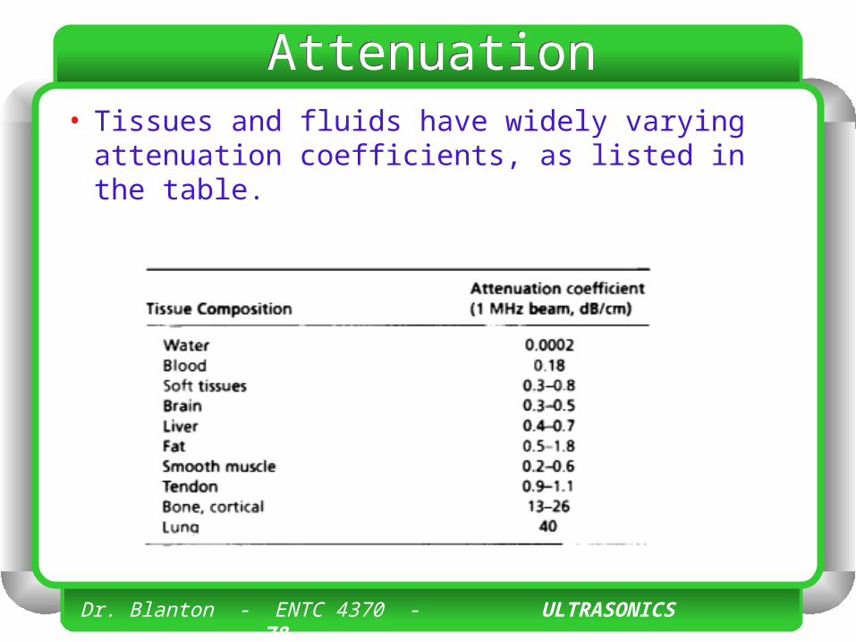
AttenuationAttenuation• Tissues and fluids have widely varying
attenuation coefficients, as listed in the table.
Dr. Blanton - ENTC 4370 - ULTRASONICS 79
AttenuationAttenuation• Ultrasound attenuation expressed in dB
is approximately proportional to frequency. • An approximate rule of thumb for “soft
tissue” is 0.5 dB per cm per MHz, or 0.5 (dB/cm)/MHz.
Dr. Blanton - ENTC 4370 - ULTRASONICS 80
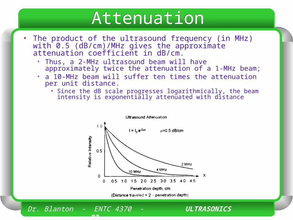
AttenuationAttenuation• The product of the ultrasound frequency (in MHz) with 0.5
(dB/cm)/MHz gives the approximate attenuation coefficient in dB/cm. • Thus, a 2-MHz ultrasound beam will have approximately twice the
attenuation of a 1-MHz beam; • a 10-MHz beam will suffer ten times the attenuation per unit
distance. • Since the dB scale progresses logarithmically, the beam intensity is
exponentially attenuated with distance
Dr. Blanton - ENTC 4370 - ULTRASONICS 81
• The ultrasound half value thickness (HVT) is the thickness of tissue necessary no attenuate the incident intensity by 50%, which is equal to a 3-dB reduction in intensity (6 dB drop in pressure amplitude). • As the frequency increases, the HVT decreases,
as demonstrated by the examples below.
Dr. Blanton - ENTC 4370 - ULTRASONICS 82
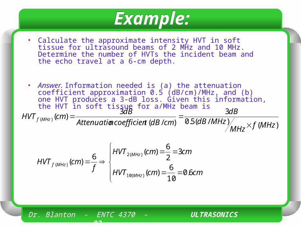
Example:Example:• Calculate the approximate intensity HVT in soft tissue for ultrasound
beams of 2 MHz and 10 MHz. Determine the number of HVTs the incident beam and the echo travel at a 6-cm depth.
• Answer. Information needed is (a) the attenuation coefficient approximation 0.5 (dB/cm)/MHz, and (b) one HVT produces a 3-dB loss. Given this information, the HVT in soft tissue for a/MHz beam is
)()/(5.03
)/(
3)()(
MHzfMHzMHzdB
dB
cmdBtcoefficiennAttenuatio
dBcmHVT MHzf
cmcmHVT
cmcmHVT
fcmHVT
MHz
MHz
MHzf
6.010
6)(
32
6)(
6)(
)(10
)(2
)(
Dr. Blanton - ENTC 4370 - ULTRASONICS 83
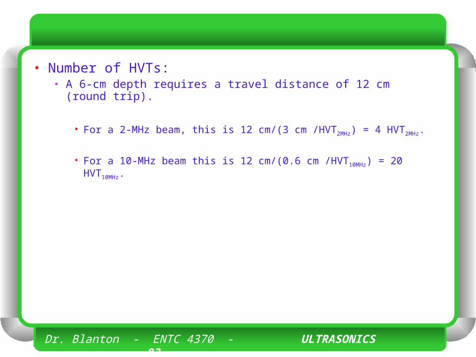
• Number of HVTs:• A 6-cm depth requires a travel distance of 12 cm (round
trip).
• For a 2-MHz beam, this is 12 cm/(3 cm /HVT2MHz) = 4 HVT2MHz.
• For a 10-MHz beam this is 12 cm/(0.6 cm /HVT10MHz) = 20 HVT10MHz.
Dr. Blanton - ENTC 4370 - ULTRASONICS 84
• EXAMPLE
Dr. Blanton - ENTC 4370 - ULTRASONICS 85
• The echo intensity is one hundredth of the incident intensity in this example (20 dB). • If the boundary reflected just 1% of the incident
intensity (a typical value), the returning echo intensity would be or 10,000 times less than the incident intensity (40 dB).
• Considering the depth and travel distance of the ultrasound energy, the detector system must have a dynamic range of 120 to 140 dB in pressure amplitude variations (up to a 10,000,000 times range) to be sensitive to acoustic signals generated in rhe medium.
Dr. Blanton - ENTC 4370 - ULTRASONICS 86
• When penetration to deeper structures is important, lower frequency ultrasound transducers must be used, because of the strong dependence of attenuation with frequency. • Another consequence of frequency-
dependent attenuation is the preferential removal of the highest frequency components in a broadband ultrasound pulse and a shift to lower frequencies.