Embed Size (px)
Citation preview

1
Biomechanics of Human Body Motion:
Engineering a Glove for Hand Motor Disabilities
Ezra Brooks, Justin Perez, Ilse Sweldens, Annie Wang, Lucy Zhang
Mentor: Catherine Connolly
RTA: Eamon Collins
Abstract
Using SolidWorks, a three-
dimensional engineering design program, a
glove was created to help people with fine
motor skill impairments maintain a desired
hand position. The glove, in order to hold
the hand in the specified position, is rigid,
but it features locking mechanisms on the
finger joints that enable users to adjust it
into whichever hand position is needed.
Poor fine motor abilities are highly prevalent
due to a range of neurological and physical
disorders. The glove was designed to assist
patients in basic hand functions such as
writing; the prototype model is dimensioned
to fit the hand of a child at the age where
writing skills are developing. The glove’s
locking mechanism allows for patients to
achieve easily adjustable hand positions.
SolidWorks was used not only to design the
glove, but also to create an animation of the
assembly of the device, to produce
engineering drawings, and to simulate the
effects of forces on the pieces.
1. Introduction
Hand motility is a crucial aspect of
human function and occupies a significant
portion of the brain’s processes Hands are
capable of touching, grasping, feeling,
manipulating, and more. However, many
people are unable to fully utilize their hands
due to disabilities; 22% of children in
second grade have dysgraphia, the inability
to write properly.1
The following chart depicts the
normal progression of motor skill
development for young children.
Conversely, children with impaired physical
abilities have delayed development.
\
Dysgraphia results from flawed
motor and information processing skills
such as visual-spatial and language
processing. Symptoms include illegible
Figure 1: Development of children including
fine motor2
2
handwriting and awkward pencil grip and
position. Issues with writing and other fine
motor skills can affect people of all ages,
and can result from various conditions.
Dyspraxia is a neurological disorder
throughout the brain that inhibits motor skill
development.3
Autism spectrum disorders
and attention deficit hyperactive disorder
can also lead to motor skill defects.
Parkinson’s disease creates tremors that can
greatly inhibit hand motion.2 Cerebral palsy,
a physical disability that affects movement
and posture, can weaken muscle control,
muscle coordination, and balance.4
From a purely physical perspective,
the primary cause of fine motor control
problems is a lack or overabundance of
muscle mass.5 Children in particular may
have low muscle mass and thus struggle to
maintain control over something as simple
as a pencil or scissors. Genetic and
environmental factors are also causes of
these motor skill impairments. Further,
premature children of substance abusers are
at high risk for this condition. Likewise,
people who have undergone certain types of
surgery frequently have trouble regaining
physical coordination, resulting in difficulty
controlling the fine motor skills of their
hands.
A glove that stabilizes the hands
would mitigate the effects of these disorders,
improving the hand function for people with
impaired fine motor skills. By supporting
the hand with a specially designed glove,
patients should be able to improve hand
motility, rendering activities such as writing
and holding utensils easier. In addition,
wearing the glove for an extended period of
time would allow muscle memory to
develop, so the patient would be able to
instinctively be able to remember the correct
positioning for holding pencils, or utensils.
2. Fine Motor Skills and
Hand Data
2.1 Fine Motor Skills and Children’s
Writing Ability
Fine motor skills affect a person’s
ability to hold, to pick up, or to move
objects. Often, impaired fine motor skills
result in a social stigma, as young children
are unable to perform basic tasks. Problems
related to fine motor skills are common, as
about 20% of children are affected with
dysgraphia, the inability to write correctly,
legibly, or, in some cases, at all.6 These
skills develop slowly as children age, but
can often be overcome with practice.
However, if unaddressed, these problems
may develop into chronic diseases that can
cause many difficulties later in life.
Currently, the side effects of
impaired fine motors skills are difficult to
alleviate. Children who struggle with writing
are given rubber pencil grips and larger
pencils that help students assume the proper
writing position. However, these methods
merely skirt the issue, without addressing
the actual problem, the improvement of fine
motor skills. The children will still struggle
to use normal pencils in the future, as this is
not a permanent fix. For others with
disabilities such as autism or cerebral palsy,
trainers and aides often use a hand-over-
hand7 method in which they guide the
patients hand into forming proper grips and

3
motions to grab and use items. This method
is not entirely effective because the trainer’s
grip is not entirely rigid and it cannot be
used when the trainer is unavailable.
Another attempted solution is the weighted
glove.8 These gloves provide stability and
target fitness, but make basic hand motions
more difficult largely due to the added
weight that requires greater hand strength to
achieve the same functionality as one who
does not use the gloves.
Children are given toys and
worksheets that focus on fine hand
movements, mainly line tracing. These
methods focus on training, but do not give
the basic structure or technique necessary to
easily learn fine motor skills. Therapeutic
weighted gloves contain weights on the top
of the hand. However, these weights must be
adjusted when the hand position is changed,
resulting in both inconvenience and
potential pain.
The other problem is the lack of
proper writing technique. Most people do
not hold the pencil in the optimal position
for writing efficiently and clearly. The
pencil is supposed to be held between the
thumb and index fingers alone. 7
Further, the
pencil should be moved through the use of
shoulder, back, and forearm muscles, as
opposed to the fingers. This problem is
caused by the lack of good instruction of
writing techniques as well as the lack of a
good guide for how to hold a pencil.
2.2 Conditions Related to Poor Fine
Motor Skills
Many diseases that impede motor
development are neurological. For example,
dysgraphia often overlaps with other
learning disabilities such as cerebral palsy
and autism. Brain surgery also creates side
effects that affect motility. To prepare for
surgical procedures, surgeons often use
anesthesia, which generally alters pain
perception, aids muscle relaxation, and
induces a state of unconscious throughout
the body. Motor skills can be temporarily
impaired after anesthesia.10
Similar side
effects are also common after cancer
treatment such as chemotherapy.
Cerebral palsy is also a consequence
of damage to parts of the brain that manage
motor movement, rendering the brain
incapable of sending the appropriate signal
to muscles to make them move properly.
The specific damaged sections of the brain
determine the type of cerebral palsy that the
individual develops. Severely afflicted
individuals may have uncontrollable hand
motions.
For diseases that do not affect the
nervous system, muscle memory provides a
physical method that can make the effects of
temporary solutions permanent. Muscle
memory is stored in the brain as a form of
Figure 2: A weighted glove9

4
procedural memory that improves ability
through repetition. Muscle fibers maintain a
long lasting structural change.
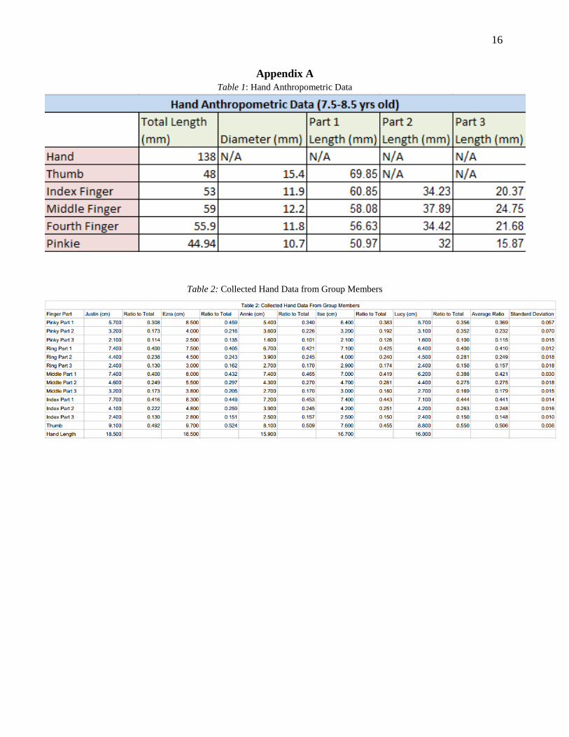
2.3 Anthropometric Data
Anthropometric data describes
average human body measurements and
proportions for a population. In this study
anthropometric hand data was utilized to
ensure that the glove would fit the average
child in need of fine motor skill aid. The
standard deviation of the measurements is
also included in Appendix A, and its small
values show that the glove would fit the vast
majority of children in need.
2.4 Joints Responsible for Writing
Position
The primary joints that determine the
hand’s position while writing consist of the
carpometacarpal, metacarpophalangeal
(MCP as shown in the yellow arrow), and
proximal interphalangeal (PIP as shown by
the blue arrow) joints. The hand joints,
wrist, and bone account for the body's
support and flexibility to manipulate objects,
rendering the stability of the joints as
imperative.
Figure 3: Hand Skeletal Structure11
Figure 4: Joints in the hand12
Figure 5: Primary hand muscles13
5
3. The Design Process:
Brainstorming, Drawing,
and Modeling the Glove
3.1 Experimental Procedure
In determining what biological
disorder to target, general ideas were
discussed based on common diseases as well
as personal experiences. An article on a
possible alternative to using drugs provided
an example of a product that started as an
ambitious idea and is still in the research and
developmental processes. However, one of
the main hindrances to the brainstorming
process was the lack of technical and
scientific knowledge, eliminating many
possible ideas such as miniaturizing
monitors and dialysis machines to fit inside
the body.
Once the glove idea was chosen, it
had to be designed in more detail and drawn
on graph paper with dimensions. The first
step taken was to determine the target
audience of the glove, which was deemed to
be people with fine motor skills
impairments. The glove focuses on the
physical and mechanical aspects only, using
a rigid yet dynamic adjustable brace to lock
the fingers into specified positions. It was
decided that the prototype glove would help
young children with basic functions such as
writing and holding utensils since these
essential skills should, ideally, be learned
and addressed at a younger age. The glove
would also ultimately allow for more
independence and confidence for patients
with fine motor skill disabilities as well as
provide enough support so that patients may
be able to use muscle memory to correct
their positions.
Next, ideas were developed for the
glove’s locking mechanism and structure,
the most important components of the glove.
Both the functionality of the glove and the
appeal to the possible customers were
considered in the design. A completely rigid
glove with fixed fingers was considered at
one point, but it would mean that the glove
could only be used to help patients with one
problem. In addition, it would be difficult
for people to fit their hands into a glove
already in the proper writing position. For
the locking mechanism, the first general idea
was to allow movement for all the joints. A
couple of ideas were considered, many taken
from moving joint parts on knee braces, but
they were all variations of the same basic
mechanism: a locking mechanism that kept
the fingers in a position through interlocking
gears placed at finger joints.
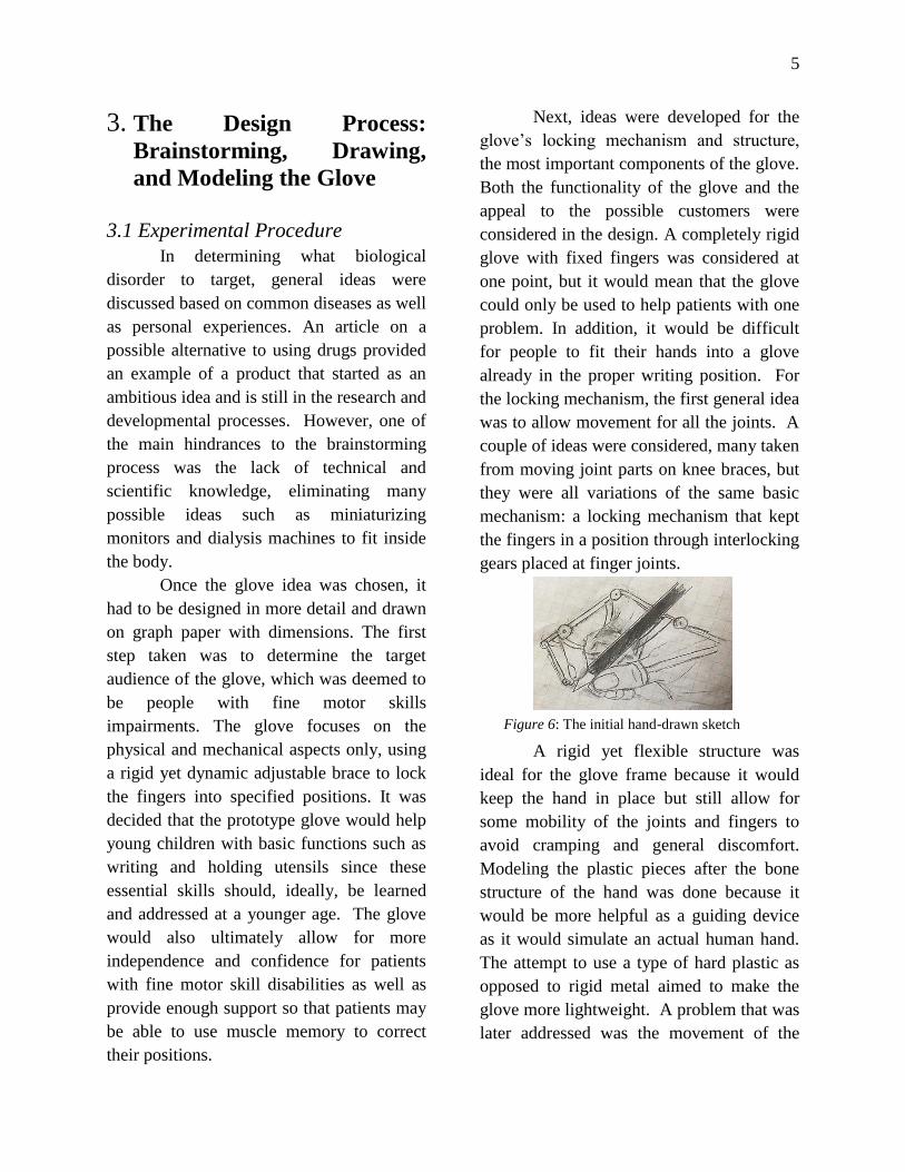
A rigid yet flexible structure was
ideal for the glove frame because it would
keep the hand in place but still allow for
some mobility of the joints and fingers to
avoid cramping and general discomfort.
Modeling the plastic pieces after the bone
structure of the hand was done because it
would be more helpful as a guiding device
as it would simulate an actual human hand.
The attempt to use a type of hard plastic as
opposed to rigid metal aimed to make the
glove more lightweight. A problem that was
later addressed was the movement of the
Figure 6: The initial hand-drawn sketch
6
thumb, which usually requires more
mobility and dexterity than the other fingers
do. It was debated whether or not a piece
specific to the thumb should be designed to
allow for maximum rotational and mobile
functionalities, but it was challenging to
incorporate all the additional parts into the
design considering the added weight as well
as placement and design possibilities.
However, because the positioning of the
thumb is similar when writing and eating, it
was decided that the thumb’s PIP would be
kept entirely rigid with a solid plastic ring.
Although the glove was intended to
target children and patients of all ages, the
prototype was chosen to be modeled for a
seven to eight year old child, mostly for
convenience for 3D printing. Hand
anthropometric data for children aged 7.5-
8.5 from a study in Britain was used to
devise finger measurements for modeling, as
shown in the charts Table 1 in Appendix A.
Because the anthropometric data only
included measurements for the first three
fingers and the lengths and diameters of
those, there was a lack of data on the ring
finger and pinkie and distance between
finger joints. As a result, detailed
measurements were taken of each group
member’s hands, and the ratios of the
lengths of distances between joints were
calculated and averaged to compensate for
the lack of researched data. According to
the data chart in Appendix A, Part 1 refers to
the length of the hand starting at the wrist
and ending at the knuckles. Part 2 of each
finger refers to the distance between the
knuckle and the middle joint. Part 3 is the
distance between the middle joint and the
last joint, where the glove will end in a
velcro-adjustable strap.
As the brainstorming progressed, the
basic functions of SolidWorks were learned
in preparation for the modeling of the glove
design later on. Two-dimensional functions,
such as sketching shapes, creating
dimensions, and assigning constraints, were
essential for defining and constructing the
various shapes necessary for the glove
design. The four major 3D features,
extrusion, loft, revolve, and sweep, could be
manipulated to create the three-dimensional
figures from the 2D sketches. After these
skills were mastered, the assembly feature
was learned. The gearbox that was created
had parts that were fully constrained along
with parts that were intentionally partially
defined to allow for motion. The assembly
feature allows for the different parts, made
separately for precision and efficiency, to be
attached to each other to construct a
complete model.
After discussion of the locking
mechanism, thumb mechanism, and
dimensions with the project mentor,
modeling the device on SolidWorks began.
At the beginning, everyone experimented
with creating new parts on SolidWorks to
test the easiest and best ways to construct
the different parts including the locking
gears as well as the thumb and wrist pieces.
Once the more complicated pieces were
created, the remaining tasks were split
among the group members due to the limited
time available and the amount of work left.
Some group members continued to work to
refine and complete the existing parts while
others created rudimentary models and
worked on the engineering drawings,

7
analysis reports, and animation of the 3D
model in SolidWorks.
3.2 Physical Description of the
Device
The glove has a fingerless fabric
piece covered by rigid plastic supports. The
plastic used is ABSplus-P43014
, a
production-grade thermoplastic used with
Dimension 3D Printers.
The supports begin at a plastic wrist
brace and follow the skeletal structure of the
hand, with one support for finger including
the thumb. The supports ends anterior to the
distal interphalangeal joint, leaving the
fingertips free for comfort and grip. They
end in a slit for a Velcro band to wrap
around the finger. At the two joints, the
metacarpophalangeal and proximal
interphalangeal joints, there is a gear shell
that allows rotation of the finger joint, but
can provide rigidity at any angle of rotation.
For the most effective application,
the gloves are adaptable to different hand
conformations, but are rigid in the selected
one to provide the support and structure
necessary for improving fine motor skills. In
order to achieve this, the gloves have small
gear knobs above the joints, which are
shown in Appendix B.
Within these knobs, two interlocking
gears are layered next to each other
vertically. These gears are rigid, but have
inward teeth that allow interlocking. For the
easiest modeling, these gears are 20-sided
polygons. The left gear (assuming a right
hand glove) has a central hole for a push
button. This gear also has a circular ridge
extrusion at its base that sits on an inverse
ridge in the shell. The hole is filled with a
cylinder connected to the right gear. This
gear sits on a small spring. As the digit is
moved, the right gear rotates, clicking into
place, maintaining rigidity. In order to
unlock the gears, the cylinder button is
pushed in so the two gears’ teeth unlock
allowing rotation back to normal hand
position. The cylinder button must be
pushed in to rotate the joint in either
direction because the teeth are not sloped,
ensuring full rigidity in any position. This
mechanism sits slightly anterior to the top of
the knuckle.
Figure 7: A 3D Model of the glove
Figure 8: Index finger brace 1.

8
The shell mechanism is a basic
hollow cylinder with a hole for the button at
one end and a rigid base with an extruded
circle for the spring to sit in at the other end.
The shell has two slits in it that allow the
finger plastic pieces to connect to their gears
by a thin connector piece. The slit on the
left of the right hand is fitted to the small
plastic connector, whereas the slit on the
right extends down on the opposite side
around 180˚ to allow for the joint to rotate
with the bottom gear. The mechanism has a
length of 7.5mm and a diameter of 5mm.
However, the thumb requires a
different approach. The distal phalanx of the
thumb has an extremely minimal range of
motion. Conversely, the remainder of the
thumb is capable of a wider range motion,
powered by several strong muscles,
including the abductor pollicis brevis, the
abductor pollicis, the first dorsal
interosseous, the flexor pollicis brevis, and
the opponens pollicis.15
To enable the thumb
to adjust positions while still maintaining
rigidity, a similar locking mechanism to the
one described before is attached to the hard
plastic structure around the wrist, right
above the carpometacarpal joint. The
original mechanism is simply rotated onto
its side with the button facing upward, and
the shell is mounted on the wrist brace.
Furthermore, a hard piece of plastic is
attached from above the extrinsic thumb
muscle to above the intrinsic thumb
muscles, restricting the thumb’s motion.
This piece of plastic follows the thumb’s
straight conformation to before the nailbed
ensuring full thumb rigidity.
Designing the glove structure on
SolidWorks required slight revision of the
original sketch. The actual skeletal structure
that functions similar to braces was created
such that the bottom portion has a rounded
surface while the top surface is flat, as to
simplify the addition of the locking
mechanism on top. The gears in the locking
mechanism have differing teeth, trapezoidal
teeth on the gear closest to the cylinder and
the rectangular teeth on the mobile gear. The
differing types of teeth allow for the two
gears to interlock precisely in the assembly
function of SolidWorks. The shell in which
the locking mechanism is contained required
little alterations. The slits which allow for
the plastic material to enter the shell and
attach to the locking mechanism are also of
differing lengths, one that allows for
extensive range of finger motion and one
simply to keep rigidity. The longer slit
Figure 9: Shell
Figure 10: Wrist and thumb brace

9
permits the finger to bend a minimum of 90
degrees.
In order to ensure a certain degree of
mobility and stability for the wrist, there is a
rigid plastic brace over the top of the wrist
that connects to all of the fingers. However,
this brace is secured to the wrist using
Velcro allowing adjustability and rigidity.
The brace only covers the top half of the
wrist. This is placed a little forward of the
wrist joint to allow wrist motion, but still
provide hand rigidity.
At the end of the glove at each
finger, there is an adjustable strap with
Velcro to allow for patients to change the
straps for comfort according to their finger
width. The strap is sewn to the rest of the
glove, with a plastic buckle in the middle. A
flap of the strip with Velcro on it goes
through one side of the buckle so that the
patient can adjust how much of the strap
goes through the buckle and therefore how
tight the strap will be. The portion of the
strap that goes through the buckle comes
into contact with the Velcro piece on the
part of the strap sewn onto the rest of the
glove.
3.3 Dimensions and Descriptions:
The fingers are composed of three
main structural parts: two springs, four
gears, and two shells. Each structural part is
curved to a radius of 9.5mm to match the
curve of the fingers, as well as filleted along
the top to a distance of 3mm to prevent
sharp edges. Each part has a width of
10mm, but the pinky finger uses a 9mm
wide part. The dimensions of the structural
parts along the backs of the hands between
the wrist and the MCP are 45.72mm on the
pinky, 51.38mm on the ring finger, 52.83 on
the middle finger, and 58.10mm on the
index finger. The lengths of the parts
between the next two joints, the MCP and
the PIP, are 26.25 on the pinky 28.67 on the
ring finger, 32.14mm on the middle finger,
and 28.48mm on the index finger. Lastly,
the lengths of the supports after the PIP
before the DIP are 12.62mm on the pinky,
18.43mm on the ring finger, 21.50mm on
the middle finger, and 17.12mm on the
index finger.
The thumb has one structural part,
one spring, two gears, and one shell. The
thumb’s shell, unlike the fingers’ shells, is
positioned with its button facing up from the
back of the palm. The side of the structural
Figure 11: Wrist component
Figure 12: Velcro strap model
10
part that touches the skin is curved with a
radius of 9.50mm, and the other side of this
part has a 3mm fillet. The part is 69.85mm
long and 10.0mm wide, including the gears
and the attachments. The thumb piece ends
in a ring, unlike the others which end in
Velcro straps, to ensure maximum rigidity.
The ring has a diameter of 17mm and is
1mm wide.
Located between the supports on the
fingers are the shells containing the gears
and springs.
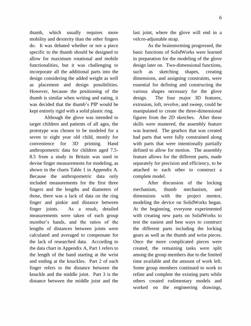
The shell is a cylinder with a length
of 7.5mm and diameter of 5mm. The shell
is 0.65mm thick, but has a ridge for the gear
to fit into at one end that is only 0.25mm
thick. 0.70mm from this side of the shell is
located a 0.25mm slit that extends 180
degrees. 2.3mm from this side is another slit
1.75mm in width that extends 180°. This
slit is directly opposite from the original slit.
These slits allow the gears to connect to the
finger supports and for the gears to rotate the
finger pieces. The wider slit allows for the
gear to remain connected to the finger
support as the cylinder button is pushed in.
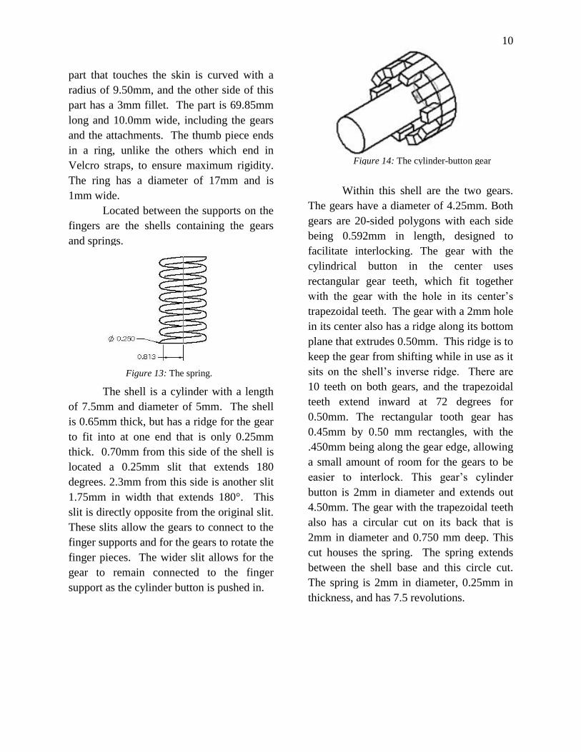
Within this shell are the two gears.
The gears have a diameter of 4.25mm. Both
gears are 20-sided polygons with each side
being 0.592mm in length, designed to
facilitate interlocking. The gear with the
cylindrical button in the center uses
rectangular gear teeth, which fit together
with the gear with the hole in its center’s
trapezoidal teeth. The gear with a 2mm hole
in its center also has a ridge along its bottom
plane that extrudes 0.50mm. This ridge is to
keep the gear from shifting while in use as it
sits on the shell’s inverse ridge. There are
10 teeth on both gears, and the trapezoidal
teeth extend inward at 72 degrees for
0.50mm. The rectangular tooth gear has
0.45mm by 0.50 mm rectangles, with the
.450mm being along the gear edge, allowing
a small amount of room for the gears to be
easier to interlock. This gear’s cylinder
button is 2mm in diameter and extends out
4.50mm. The gear with the trapezoidal teeth
also has a circular cut on its back that is
2mm in diameter and 0.750 mm deep. This
cut houses the spring. The spring extends
between the shell base and this circle cut.
The spring is 2mm in diameter, 0.25mm in
thickness, and has 7.5 revolutions.
Figure 13: The spring.
Figure 14: The cylinder-button gear
11
4. Results and Discussion
The end product functions as a
therapeutic glove with a skeletal structure
that stabilizes hand mobility and position,
facilitating typical hand movements for
patients with fine motor skill impairments.
The locking mechanism, which contains two
mobile and interlocking gears, allows for
movement of the joints as well as the
function to lock the fingers in a defined,
rigid position. In addition, each
mechanism’s movement is constrained to a 0
to 70 degree range of movement to permit
controlled hand motion.
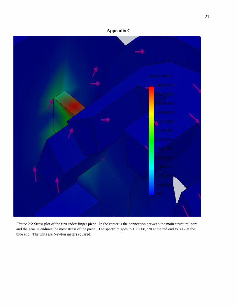
Finite Element Analysis (FEA) was
also conducted on SolidWorks, using the
Simulation feature. The purpose of the FEA
is to identify the effects of various forces on
the glove’s pieces. The first step taken was
to draw out the hand and identify the
different forces, such as stress, rotational,
and torque, thought to be experienced by
both the hand and the mechanisms attached
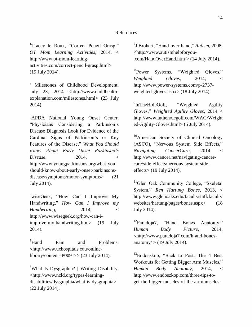
to it. The simulations were performed with
the structural piece between the index finger
and the wrist. In the first simulation, the face
touching the wrist piece was considered a
fixed plane, and 1 N was applied to the sides
of the gear’s teeth at the other end of the
piece. This simulated when the finger
attempts to bend while the button is not
pressed and the gears are locked. In the
second, the fixed plane was the same, but
the force was a 1 N pull on the gear, making
the piece experience tension. This replicated
how the pieces are stretched when fingers
bend. Instead of the ABSplus-P430 material
used in the printing of the device, the
simulation modeled the device with the
features of standard ABS plastic. The
ABSplus-P430 plastic has a Young’s
modulus of 2320 mPa, and the simulation’s
ABS has a similar Young’s modulus, at
2000 mPa. The simulation created strain and
stress plots for the piece and revealed that
the section that undergoes the most stress
and strain is the connection between the
main structural piece and the gear. This
section is the one that is most at risk of
breaking.
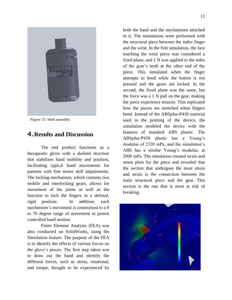
Figure 15: Shell assembly
12
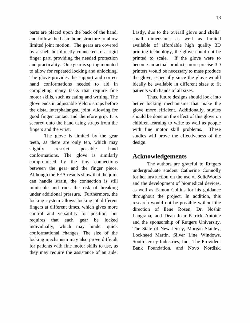
Figure 18: Strain plot of the first index finger piece
in isometric view
Afterwards, the forces were applied to the
parts in SolidWorks and analysis reports
were generated. The locking mechanism and
the brace attachments were tested for stress
and strain. When bent, the attachments are
stretched slightly by tensile force. When the
brace on the finger returns to a straight
position, it experiences compressive forces.
These situations were simulated using forces
first pulling then pushing each end of the
brace piece. The locking mechanism was
specifically analyzed for the torque which is
exerted when the brace attachments rotate
via the gear. In addition, force was applied
to the center of the brace to test how the
piece would handle collisions when the
glove is in use. The simulation provided
information on the stress and displacement
of the piece in the various scenarios.
In SolidWorks, items with miniscule
dimensions such as the small locking
mechanism components can be easily drawn
and assembled together. However, these
items are not so easily translated into the
physical world. The initial plan to 3D print
the parts did not work out as intended
because the pieces were too small. The gears
failed to interlock as they did in SolidWorks
due to the 3D printer’s lack of precision and
tolerances to properly print items as small as
the parts involved in the finger locking
mechanism. In the commercial world, there
are printers that can print these parts with
accuracy, but these printers are much more
expensive and slower than the ones available
to this research project. In the initial
printing, the STL files had to be scaled to
two times the parts’ original sizes in order to
be printed using the available machine. As it
stands, the gloves will take too long to print,
cost too much, and have too much error if
produced through traditional 3D printing.
5. Conclusion
A glove to aid in fine motor skill
treatment and improvement was created in
SolidWorks, a three-dimensional computer
aided design software. The glove utilizes an
interlocking gear mechanism to provide
rigidity to different finger joints. The rigid
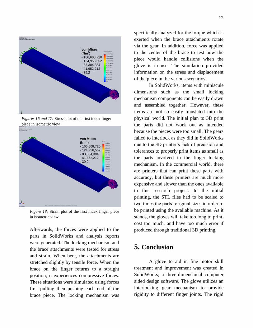
Figures 16 and 17: Stress plot of the first index finger
piece in isometric view
von Mises (Nm
2)
- 166,608,720
- 124,956,552
- 83,304,384 - 41,652,212
- 39.2
von Mises (Nm
2)
- 166,608,720 - 124,956,552
- 83,304,384
- 41,652,212 - 39.2
13
parts are placed upon the back of the hand,
and follow the basic bone structure to allow
limited joint motion. The gears are covered
by a shell but directly connected to a rigid
finger part, providing the needed protection
and practicality. One gear is spring mounted
to allow for repeated locking and unlocking.
The glove provides the support and correct
hand conformations needed to aid in
completing many tasks that require fine
motor skills, such as eating and writing. The
glove ends in adjustable Velcro straps before
the distal interphalangeal joint, allowing for
good finger contact and therefore grip. It is
secured onto the hand using straps from the
fingers and the wrist.
The glove is limited by the gear
teeth, as there are only ten, which may
slightly restrict possible hand
conformations. The glove is similarly
compromised by the tiny connections
between the gear and the finger piece.
Although the FEA results show that the joint
can handle strain, the connection is still
miniscule and runs the risk of breaking
under additional pressure. Furthermore, the
locking system allows locking of different
fingers at different times, which gives more
control and versatility for position, but
requires that each gear be locked
individually, which may hinder quick
conformational changes. The size of the
locking mechanism may also prove difficult
for patients with fine motor skills to use, as
they may require the assistance of an aide.
Lastly, due to the overall glove and shells’
small dimensions as well as limited
available of affordable high quality 3D
printing technology, the glove could not be
printed to scale. If the glove were to
become an actual product, more precise 3D
printers would be necessary to mass produce
the glove, especially since the glove would
ideally be available in different sizes to fit
patients with hands of all sizes.
Thus, future designs should look into
better locking mechanisms that make the
glove more efficient. Additionally, studies
should be done on the effect of this glove on
children learning to write as well as people
with fine motor skill problems. These
studies will prove the effectiveness of the
design.
Acknowledgements
The authors are grateful to Rutgers
undergraduate student Catherine Connolly
for her instruction on the use of SolidWorks
and the development of biomedical devices,
as well as Eamon Collins for his guidance
throughout the project. In addition, this
research would not be possible without the
direction of Ilene Rosen, Dr. Noshir
Langrana, and Dean Jean Patrick Antoine
and the sponsorship of Rutgers University,
The State of New Jersey, Morgan Stanley,
Lockheed Martin, Silver Line Windows,
South Jersey Industries, Inc., The Provident
Bank Foundation, and Novo Nordisk.
14
References
1Tracey le Roux, “Correct Pencil Grasp,”
OT Mom Learning Activities, 2014, <
http://www.ot-mom-learning-
activities.com/correct-pencil-grasp.html>
(19 July 2014).
2 Milestones of Childhood Development.
July 23, 2014 <http://www.childhealth-
explanation.com/milestones.html> (23 July
2014).
3APDA National Young Onset Center,
“Physicians Considering a Parkinson’s
Disease Diagnosis Look for Evidence of the
Cardinal Signs of Parkinson’s or Key
Features of the Disease,” What You Should
Know About Early Onset Parkinson’s
Disease, 2014, <
http://www.youngparkinsons.org/what-you-
should-know-about-early-onset-parkinsons-
disease/symptoms/motor-symptoms> (21
July 2014).
4wiseGeek, “How Can I Improve My
Handwriting,” How Can I Improve my
Handwriting, 2014, <
http://www.wisegeek.org/how-can-i-
improve-my-handwriting.htm> (19 July
2014).
5Hand Pain and Problems.
<http://www.uchospitals.edu/online-
library/content=P00917> (23 July 2014).
6What Is Dysgraphia? | Writing Disability.
<http://www.ncld.org/types-learning-
disabilities/dysgraphia/what-is-dysgraphia>
(22 July 2014).
7J Brohart, “Hand-over-hand,” Autism, 2008,
<http://www.autismhelpforyou-
.com/HandOverHand.htm > (14 July 2014).
8Power Systems, “Weighted Gloves,”
Weighted Gloves, 2014, <
http://www.power-systems.com/p-2737-
weighted-gloves.aspx> (18 July 2014).
9InTheHoleGolf, “Weighted Agility
Gloves,” Weighted Agility Gloves, 2014 <
http://www.intheholegolf.com/WAG/Weight
ed-Agility-Gloves.html> (5 July 2014).
10American Society of Clinical Oncology
(ASCO), “Nervous System Side Effects,”
Navigating CancerCare, 2014 <
http://www.cancer.net/navigating-cancer-
care/side-effects/nervous-system-side-
effects> (19 July 2014).
11
Glen Oak Community College, “Skeletal
System,” Ren Hartung Bones, 2013, <
http://www.glenoaks.edu/facultystaff/faculty
websites/hartung/pages/bones.aspx> (18
July 2014).
12
Paradoja7, “Hand Bones Anatomy,”
Human Body Picture, 2014,
<http://www.paradoja7.com/h-and-bones-
anatomy/ > (19 July 2014).
13
Endoszkop, “Back to Post: The 4 Best
Workouts for Getting Bigger Arm Muscles,”
Human Body Anatomy, 2014, <
http://www.endoszkop.com/three-tips-to-
get-the-bigger-muscles-of-the-arm/muscles-

15
of-the-arm-picture-labeled/ > (18 July
2014).
14
Javelin Technologies, “Colors with
Standard Thermoplastic,” ABSplus-P430
Production-Grade Thermoplastic for
Dimension 3D Printers, 2014, <
http://www.javelin-tech.com/3d-
printer/materials/fdm-
thermoplastic/absplus/> (18 July 2014).
15
Dimitrios Danikas, “Anatomy of the
muscles of the hand,” Intrinsic Hand
Deformity, 20 December 2013, <
http://emedicine.medscape.com/article/1243
669-overview> (18 July 2014).
16
Appendix A
Table 1: Hand Anthropometric Data
Table 2: Collected Hand Data from Group Members

17
Appendix B
Figure 19: Diagram of index finger brace 1.
Depicted above is the brace with the structure in which the locking mechanism is attached. The long brace is found
on the PIP; the attached gear is found on the first joint. The stationary gear is linked to a mobile gear that allows for
finger position adjustment before locking it in place.
Figure 20: Gear with push button.
The above gear includes the push button in which the wearer can lock or unlock the brace to position his or her
hand.

18
Figure 21: Shell cylinder body which contains the interlocking gears.
The two interlocking gears are contained inside a shell, designed such that there are slits to allow attachment of the
brace to the gears.
Figure 22: The spring.
Additionally, a spring is attached in the locking mechanism, within the shell, between the gear with the push button
and the wall of the cylinder body. This spring facilitates the actual alteration of finger position when using the
locking mechanism. The elastic energy prevents to the second gear from falling away from its counterpart gear and
thus losing stability.

19
Figure 23: An assembled finger part.
The above is a depiction of a single part of the finger assembly that lies on the thumb. This assembly includes the
two interlocking gears, the push button, the outer shell and shell lids, and finger support brace. On the right of the
drawing are two isometric views of the part, one including a view of the inner gears and one simply depicting the
outside of the mechanism.
Figure 24: Finger velcro that attaches brace to finger.
This piece of velcro extends from small slits in the brace around the finger, keeping the finger and brace firmly
attached to each other to prevent sliding.

20
Figure 25: The whole finger brace, including locking mechanisms.
This piece fits on the ring finger. The velcro straps are not shown.
21
Appendix C
Figure 26: Stress plot of the first index finger piece. In the center is the connection between the main structural part
and the gear. It endures the most stress of the piece. The spectrum goes to 166,608,720 at the red end to 39.2 at the
blue end. The units are Newton meters squared.
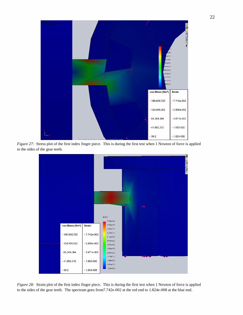
22
Figure 27: Stress plot of the first index finger piece. This is during the first test when 1 Newton of force is applied
to the sides of the gear teeth.
Figure 28: Strain plot of the first index finger piece. This is during the first test when 1 Newton of force is applied
to the sides of the gear teeth. The spectrum goes from7.742e-002 at the red end to 1.824e-008 at the blue end.

23
.
Figure 29: Strain plot of the first index finger piece. This is during the second test, when 1 Newton of force is
applied to the side of the gear. The spectrum goes from 5.184e-002 at the red end to 1.933-008 at the blue end.
Figure 30: Displacement plot of the first index finger piece during the second test. The spectrum goes from 1.528e-
000 at the red end to 1.00e-030 at the blue end. The units are millimeters.
Displacement (mm) 1.528e-000
1.146e-000
7.641e-000
3.8203-001
1.000e-030
von Mises (Nm2)
- 111,561,032 - 83,670,784 - 55,780,536 - 27,890,290 - 41.6