Embed Size (px)
Citation preview

Prosthetics and Orthotics International, 1998, 22, 54-67
Biomechanical evaluation of the Milwaukee brace
M. S. W O N G and J. H. E V A N S
Jockey Club Rehabilitation Engineering Centre, The Hong Kong Polytechnic University, Hong Kong, China.
Abstract Although, the history of orthotic treatment for
idiopathic scoliosis goes back more than fifty years, the mechanism of curve control by spinal orthosis is still controversial . Hypothetical explanations have been provided but few, if any, have been tested clinically. This study aims at the biomechanical evaluation of a spinal orthosis (Milwaukee brace) in order to improve understanding about the mechanism of curves control in orthotic movement.
From the results of the study, the change of the interface pressure between the patient 's body and thoracic pad, and the tension of the thoracic strap were highly correlated (r= 0.84) as patients performed different lying postures and daily activities. Lying on the thoracic pad is found to have the highest correctional force among different lying postures that may be favourable for preventing curve deterioration.
The findings indicate that an increase in tension of the thoracic strap will increase the interface pressure on the thoracic pad and thus increase the resultant force exerted on the patient 's body by the thoracic pad. Care must be taken as an excessive strap tension will increase discomfort and restrict body shifting exercises. The results also suggest that in scoliosis with thoracic lordosis, a short outrigger (small pulling angle of the thoracic strap) should be used as it will decrease the anteriorly directed force component so as to prevent exaggerating the thoracic lordosis.
Introduction The Milwaukee brace was designed by Blount
and Moe in 1945. It is commonly used for the non-operative treatment of the thoracic curve of adolescent idiopathic scoliosis with moderate severity (Cobb angle: 25°-45°). Clinical experience with the brace has led to many improvements, both in the design of the brace itself and in the manner in which it is used. However, little study had been devoted to the relationship between the forces that the brace elicits, either passively or through muscle action, although it is accepted that these forces are a major factor in whatever correction is obtained.
The Mi lwaukee brace is a mechanically complex device which is different from low profile spinal orthoses such as the Boston brace and New York Orthopaedic Hospital orthosis which were believed to supply only passive forces (Winter and Carlson, 1977; Laurnen et al., 1983; Willner 1984; Wynarsky and Schmitz, 1990). The Mi lwaukee brace can apply longitudinal as well as transverse forces (Blount and Moe, 1980; Bradford et al., 1987; Winter et al., 1986) The shoulder sling, thoracic pad and lumbar pad of the brace can apply forces of different magnitudes, in different directions and at different points. The brace may be used to correct single, double and triple scoliotic curves variously situated (Adriacchi et al., 1976).
However, the corrective forces applied to the spine will be limited by the nature of the areas on the body 's surface through which force can be transmitted. The spine cannot be directly accessed by external forces but rather through its corresponding ribs and soft t issues. These forces, applied across specific contact areas, may be sufficient to produce substantial stress and strain within the soft tissues, which can impair the blood supply and lymphatic drainage. If these interface conditions are prolonged, cell necrosis will result and may lead to the eventual development of tissue breakdown and
All correspondence to be addressed to Mr M. S. Wong, Jockey Cub Rehabilitation Engineering Centre, The Hong Kong Polytechnic University, Hong Kong, China. Tel: (852)-2766-7680. Fax: (852)-2362-4365. E-mail: R C M S W O N G @ P O L Y U , E D U . H K
54
Biomechanical evaluation of the Milwaukee brace 55
ulceration. Therefore, the control of the interface pressure distribution in orthotic treatment is very important especially beneath the thoracic pad and pelvic girdle where the pressure is likely to be highest.
A possible method of objectively defining the action of the brace is to study the forces exerted by the brace on the patient. Knowledge of the range and characteristics of these forces could then be used to evaluate the accuracy of fit, efficiency of support and effectiveness of any design modification. It could also lead to a better understanding of the mechanisms of correction involved.
The study of the forces exerted on the patient's body by bracing may be accomplished by measuring the forces in all major brace components such as throat mould, occipital pads, shoulder ring, uprights, thoracic pad, lumbar pad and hip girdle but the measurements involved for all the above components are very complicated and need many brace modifications, and as a result the brace may be too greatly modified to allow the patient to perform normal activities. It is better to simplify the methods of measurement, have the fewest brace modifications and collect those data with greatest clinical value. Therefore, the force/pressure on the thoracic pad and the tension of the thoracic strap were investigated in this study. The thoracic strap is used to fit over and exert forces on the thoracic pad. The variation of the tension and direction of pull of the thoracic strap with have an effect on the magnitude and direction of the correctional forces exerted on the body by the thoracic pad. These are among the most important variables in obtaining optimum performance from a brace (Andriacchi et al., 1976; Winter and Carlson, 1977; Bunch and Patwardhan, 1989).
The objectives of this study are to measure the changes which occur in the interface pressure distribution and the net correctional force of the thoracic pad on the patient 's body by altering the posture, activity, thoracic strap tension and pulling direction of the thoracic strap. The correlation between the change of the thoracic strap tension and the pressure on the thoracic pad will also be studied.
Material and methods Patient source
Scoliotic patients were selected from those
attending the Spinal Clinic which is held twice a month in the Duchess of Kent Chi ldren ' s Hospital at Sandy Bay, Hong Hong. The patients attending this clinic were mainly referred from the out-patient clinic of the same hospital or from doctors in private practice.
Each patient had a full clinical evaluation including a detailed medical history (patient's spinal deformity, general health, family history and maturity status). The physical examinations included anthropometric measurements, range of motion of the spine, forward bending test, neurology assessment, cardiorespiratory system and the secondary sexual characteristics. All patients had the following radiographs of the spine: standing anteroposterior, standing lateral, supine anteroposterior and supine bending. From these radiographs, data related to the skeletal maturi ty, curve pattern and curve magnitude were obtained.
Patient selection criteria The following criteria were used for selection
of patients as subjects within this study: 1. progressive adolescent idiopathic scoliosis
(according to Lonstein and Carlson, 1984); 2. age 10-14 years; 3. Skeletally immature patient (Risser sign 4 or
less); and 4. Cobb angle ranged from 25 to 40 degrees and
undergoing orthotic treatment.
Methods of measurement There were two measured parameters, strap
tension and interface pressure. The measurement methods were as follows:
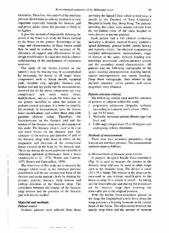
a) Measurement of thoracic strap tension A purpose designed buckle force-transducer
(Fig. 1) is used to measure the tension in the thoracic strap and may be used in other straps such as the shoulder strap. The device is small (35 x 35 x 5mm). The tension in the strap can be measured in situ without modification to the brace or strap. It is simple to install - by taklng out the removable pin and placing the transducer on the thoracic strap then inserting the removable pin to the original position.
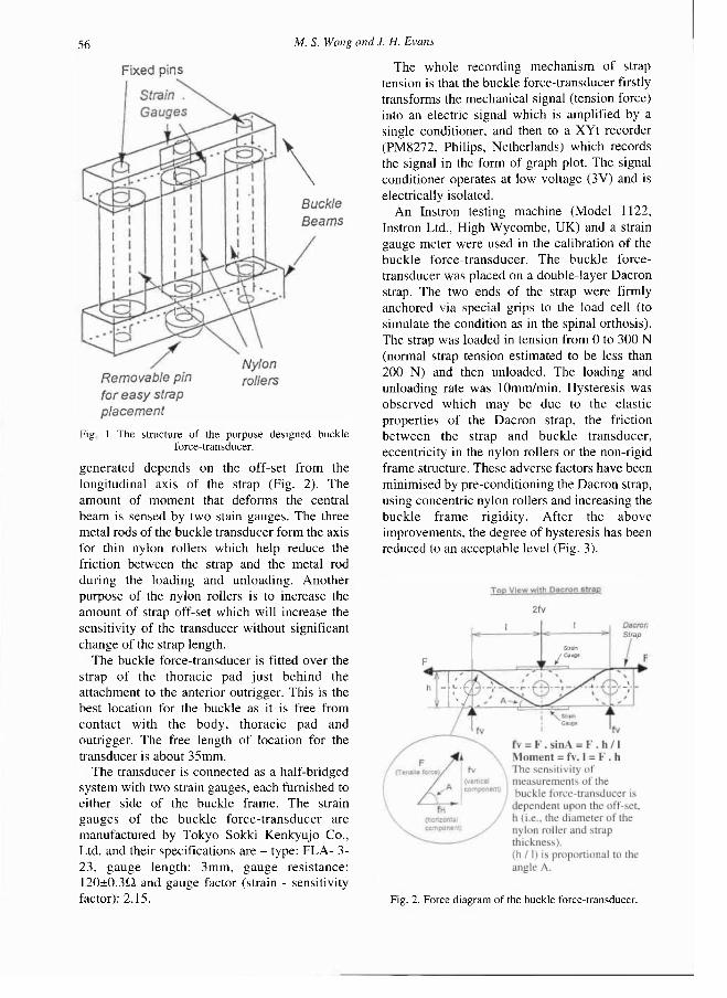
With the buckle force-transducer placed on the strap, the longitudinal tensile force along the strap generates a bending moment on the central beam of the frame. The relationship between the tensile strap force and the amount of moment
56 M. S. Wong and J. H. Evans
generated depends on the off-set from the longitudinal axis of the strap (Fig. 2). The amount of moment that deforms the central beam is sensed by two stain gauges. The three metal rods of the buckle transducer form the axis for thin nylon rollers which help reduce the friction between the strap and the metal rod during the loading and unloading. Another purpose of the nylon rollers is to increase the amount of strap off-set which will increase the sensitivity of the transducer without significant change of the strap length.
The buckle force-transducer is fitted over the strap of the thoracic pad just behind the attachment to the anterior outrigger. This is the best location for the buckle as it is free from contact with the body, thoracic pad and outrigger. The free length of location for the transducer is about 35mm.
The transducer is connected as a half-bridged system with two strain gauges, each furnished to either side of the buckle frame. The strain gauges of the buckle force-transducer are manufactured by Tokyo Sokki Kenkyujo Co., Ltd. and their specifications are - type: FLA- 3-23 , gauge length: 3mm, gauge resistance: 120±0.3Ω and gauge factor (strain - sensitivity factor): 2.15.
The whole recording mechanism of strap tension is that the buckle force-transducer firstly transforms the mechanical signal (tension force) into an electric signal which is amplified by a single conditioner, and then to a XYt recorder (PM8272, Philips, Netherlands) which records the signal in the form of graph plot. The signal conditioner operates at low voltage (3V) and is electrically isolated.
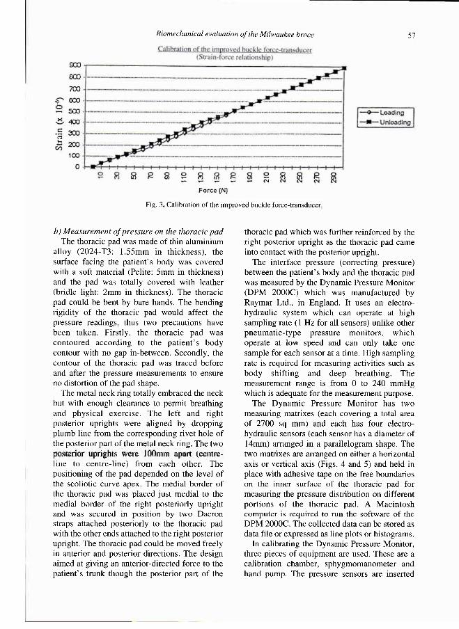
An Instron testing machine (Model 1122, Instron Ltd., High Wycombe, UK) and a strain gauge meter were used in the calibration of the buckle force-transducer. The buckle force-transducer was placed on a double-layer Dacron strap. The two ends of the strap were firmly anchored via special grips to the load cell (to simulate the condition as in the spinal orthosis). The strap was loaded in tension from 0 to 300 N (normal strap tension estimated to be less than 200 N) and then unloaded. The loading and unloading rate was 10mm/min. Hysteresis was observed which may be due to the elastic properties of the Dacron strap, the friction between the strap and buckle transducer, eccentricity in the nylon rollers or the non-rigid frame structure. These adverse factors have been minimised by pre-conditioning the Dacron strap, using concentric nylon rollers and increasing the buckle frame rigidity. After the above improvements, the degree of hysteresis has been reduced to an acceptable level (Fig. 3).
Fig 1 The structure of the purpose designed buckle force-transducer.
Fig. 2. Force diagram of the buckle force-transducer.
Biomechanical evaluation of the Milwaukee brace 57
b) Measurement of pressure on the thoracic pad The thoracic pad was made of thin aluminium
alloy (2024-T3: 1.55mm in thickness), the surface facing the patient 's body was covered with a soft material (Pelite: 5mm in thickness) and the pad was totally covered with leather (bridle light: 2mm in thickness). The thoracic pad could be bent by bare hands. The bending rigidity of the thoracic pad would affect the pressure readings, thus two precautions have been taken. Firstly, the thoracic pad was contoured according to the pat ient ' s body contour with no gap in-between. Secondly, the contour of the thoracic pad was traced before and after the pressure measurements to ensure no distortion of the pad shape.
The metal neck ring totally embraced the neck but with enough clearance to permit breathing and physical exercise. The left and right posterior uprights were aligned by dropping plumb line from the corresponding rivet hole of the posterior part of the metal neck ring. The two posterior uprights were 100mm apart (centre-line to centre-line) from each other. The positioning of the pad depended on the level of the scoliotic curve apex. The medial border of the thoracic pad was placed just medial to the medial border of the right posteriorly upright and was secured in position by two Dacron straps attached posteriorly to the thoracic pad with the other ends attached to the right posterior upright. The thoracic pad could be moved freely in anterior and posterior directions. The design aimed at giving an anterior-directed force to the patient's trunk though the posterior part of the
thoracic pad which was further reinforced by the right posterior upright as the thoracic pad came into contact with the posterior upright.
The interface pressure (correcting pressure) between the patient 's body and the thoracic pad was measured by the Dynamic Pressure Monitor (DPM 2000C) which was manufactured by Raymar Ltd., in England. It uses an electro-hydraulic system which can operate at high sampling rate ( 1 Hz for all sensors) unlike other pneumatic- type pressure monitors , which operate at low speed and can only take one sample for each sensor at a time. High sampling rate is required for measuring activities such as body shifting and deep breathing. The measurement range is from 0 to 240 mmHg which is adequate for the measurement purpose.
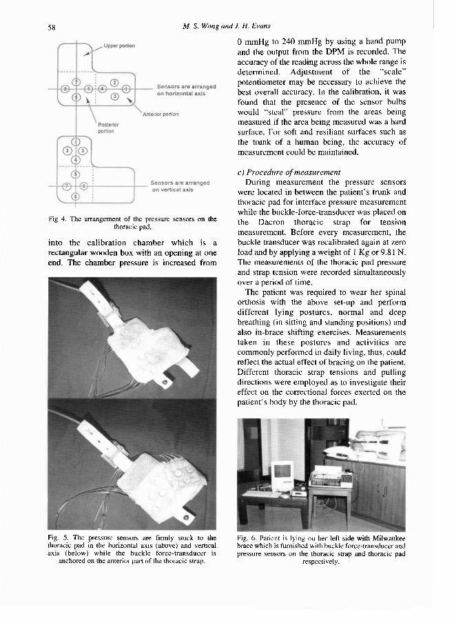
The Dynamic Pressure Monitor has two measuring matrixes (each covering a total area of 2700 sq mm) and each has four electro-hydraulic sensors (each sensor has a diameter of 14mm) arranged in a parallelogram shape. The two matrixes are arranged on either a horizontal axis or vertical axis (Figs. 4 and 5) and held in place with adhesive tape on the free boundaries on the inner surface of the thoracic pad for measuring the pressure distribution on different portions of the thoracic pad. A Macintosh computer is required to run the software of the DPM 2000C. The collected data can be stored as data file or expressed as line plots or histograms.
In calibrating the Dynamic Pressure Monitor, three pieces of equipment are used. These are a calibration chamber, sphygmomanometer and hand pump. The pressure sensors are inserted
Fig. 3. Calibration of the improved buckle force-transducer.
58 M. S. Wong and J. H. Evans
into the calibration chamber which is a rectangular wooden box with an opening at one end. The chamber pressure is increased from
0 mmHg to 240 mmHg by using a hand pump and the output from the DPM is recorded. The accuracy of the reading across the whole range is determined. Adjustment of the "sca le" potentiometer may be necessary to achieve the best overall accuracy. In the calibration, it was found that the presence of the sensor bulbs would "steal" pressure from the areas being measured if the area being measured was a hard surface. For soft and resiliant surfaces such as the trunk of a human being, the accuracy of measurement could be maintained.
c) Procedure of measurement During measurement the pressure sensors
were located in between the patient 's trunk and thoracic pad for interface pressure measurement while the buckle-force-transducer was placed on the Dacron thoracic strap for tension measurement. Before every measurement, the buckle transducer was recalibrated again at zero load and by applying a weight of 1 Kg or 9.81 N. The measurements of the thoracic pad pressure and strap tension were recorded simultaneously over a period of time.
The patient was required to wear her spinal orthosis with the above set-up and perform different lying postures , normal and deep breathing (in sitting and standing positions) and also in-brace shifting exercises. Measurements taken in these postures and activities are commonly performed in daily living, thus, could reflect the actual effect of bracing on the patient. Different thoracic strap tensions and pulling directions were employed as to investigate their effect on the correctional forces exerted on the patient 's body by the thoracic pad.
-ig 4. The arrangement of the pressure sensors on the thoracic pad.
Fig. 5 . The pressure sensors are firmly stuck to the thoracic pad in the horizontal axis (above) and vertical axis (below) while the buckle force-transducer is
anchored on the anterior part of the thoracic strap.
Fig. 6. Patient is lying on her left side with Milwaukee brace which is furnished with buckle force-transducer and pressure sensors on the thoracic strap and thoracic pad
respectively.
Biomechanical evaluation of the Milwaukee brace 59
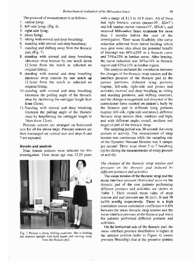
The protocol of measurement is as follows: 1. supine lying; 2. left-side lying; (Fig. 6) 3. right-side lying; 4. prone lying; 5. sitting with normal and deep breathing; 6. standing with normal and deep breathing; 7. standing and shifting away from the thoracic
pad; (Fig. 7) 8. standing with normal and deep breathing
(decrease strap tension by one notch down (2.5cm) from the notch as selected on original fitting;
9. standing with normal and deep breathing (increase strap tension by one notch up (2.5cm) from the notch as selected on original fitting;
10. standing with normal and deep breathing (decrease the pulling angle of the thoracic strap by shortening the outrigger length 8cm from 12cm);
11. Standing with normal and deep breathing (increase the pulling angle of the thoracic strap by lengthening the outrigger length to 18cm from 12cm).
Pressure sensors are arranged on horizontal axis for all the above steps. Pressure sensors are then rearranged on vertical axis and steps 6 and 7 are repeated.
Results and analysis Nine female patients were selected for this
investigation. Their mean age was 13.25 years
with a range of 11.5 to 14.8 years. All of them had right thoracic curves (mean=39°, SD=7°) and left lumbar curves (mean=33°, SD=6°), and received Milwaukee brace treatment for more than 3 months before the start of the investigation. Their mean flexibility (the curve reduction achieved from lateral bending which may give some idea about the potential benefit of bracing) was 60%±20% in a thoracic curve and 74%±22% in lumbar curve. After bracing, the curve reduction was 30%±14% in thoracic region and 4 2 % ± 1 1 % in lumbar region.
The analysis included the correlation between the changes of the thoracic strap tension and the interface pressure of the thoracic pad as the patient performs different lying postures (supine, left-side, right-side and prone) and activities (normal and deep breathing in sitting and standing positions, and shifting exercise), and the change in magnitude and direction of the correctional force exerted on patient 's body by the thoracic pad in different lying postures (supine, left-side, right-side and prone), different thoracic strap tension (low, medium and high, and with different angles (small, medium and large) of pull of the thoracic strap.
The sampling period was 30 seconds for every posture or activity. The measurement of strap tension was continuous while the sampling rate of the Dynamic Pressure Monitor was 1 sample per second. There were about 5 to 7 breathing cycles during the measurements of every posture or activity.
The changes of the thoracic strap tension and pressure on the thoracic pad induced by different postures and activities
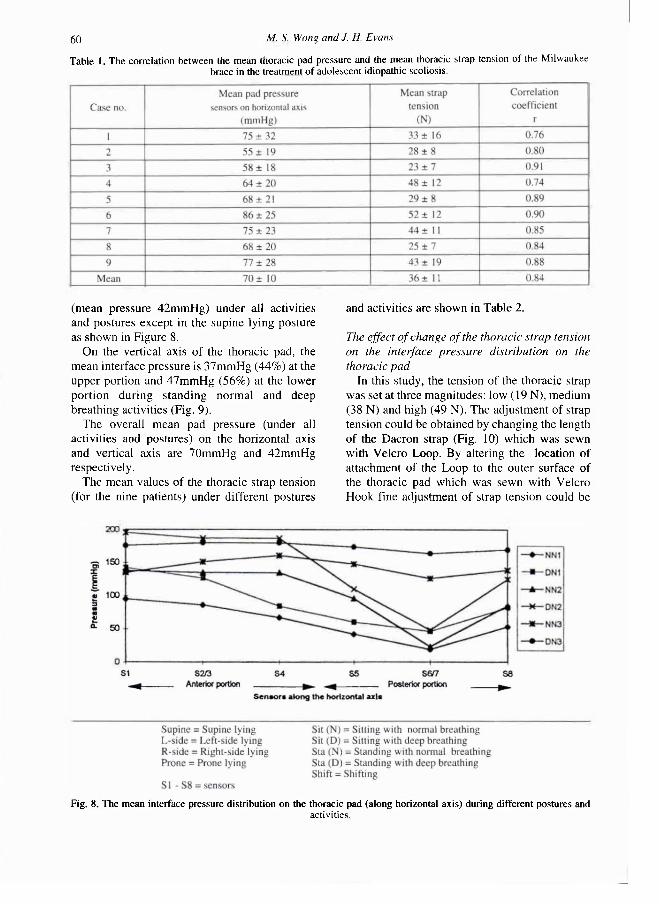
The mean tension of the thoracic strap and the mean interface pressure (horizontal axis) on the thoracic pad of the nine patients performing different postures and activities are shown in Table 1. Their overall mean value of strap tension and pad pressure are 36 (±11, N and 70 (±10) mmHg respectively. There is a high correlation (mean correlation coefficient = 0.84) between the mean thoracic strap tension and the mean interface pressure of the thoracic pad when the patients performed different postures and activities.
On the horizontal axis of the thoracic pad, the mean interface pressure distribution is higher at the anterior portion (refer to Figure 4) (mean pressure 98mmHg) that at the posterior portion
Fig 7. Patient is doing shifting exercises. She is holding the anterior upright with both hands and moving away
from the thoracic pad.
60 M. S. Wong and J. H. Evans
(mean pressure 42mmHg) under all activities and postures except in the supine lying posture as shown in Figure 8.
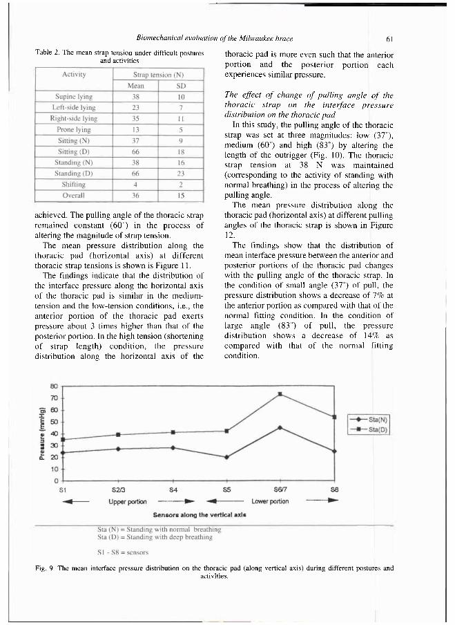
On the vertical axis of the thoracic pad, the mean interface pressure is 37mmHg (44%) at the upper portion and 47mmHg (56%) at the lower portion during standing normal and deep breathing activities (Fig. 9).
The overall mean pad pressure (under all activities and postures) on the horizontal axis and vertical axis are 70mmHg and 42mmHg respectively.
The mean values of the thoracic strap tension (for the nine patients) under different postures
and activities are shown in Table 2.
The effect of change of the thoracic strap tension on the interface pressure distribution on the thoracic pad
In this study, the tension of the thoracic strap was set at three magnitudes: low (19 N), medium (38 N) and high (49 N). The adjustment of strap tension could be obtained by changing the length of the Dacron strap (Fig. 10) which was sewn with Velcro Loop. By altering the location of attachment of the Loop to the outer surface of the thoracic pad which was sewn with Velcro Hook fine adjustment of strap tension could be
Table 1. The correlation between the mean thoracic pad pressure and the mean thoracic strap tension of the Milwaukee brace in the treatment of adolescent idiopathic scoliosis.
Fig. 8. The mean interface pressure distribution on the thoracic pad (along horizontal axis) during different postures and activities.
Biomechanical evaluation of the Milwaukee brace 61
achieved. The pulling angle of the thoracic strap remained constant (60°) in the process of altering the magnitude of strap tension.
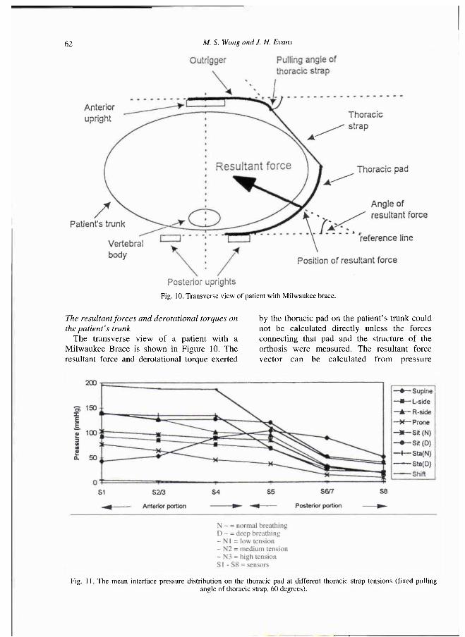
The mean pressure distribution along the thoracic pad (horizontal axis) at different thoracic strap tensions is shown is Figure 11.
The findings indicate that the distribution of the interface pressure along the horizontal axis of the thoracic pad is similar in the medium-tension and the low-tension conditions, i.e., the anterior portion of the thoracic pad exerts pressure about 3 times higher than that of the posterior portion. In the high tension (shortening of strap length) condit ion, the pressure distribution along the horizontal axis of the
thoracic pad is more even such that the anterior portion and the posterior portion each experiences similar pressure.
The effect of change of pulling angle of the thoracic strap on the interface pressure distribution on the thoracic pad
In this study, the pulling angle of the thoracic strap was set at three magnitudes: low (37°), medium (60°) and high (83°) by altering the length of the outrigger (Fig. 10). The thoracic strap tension at 38 N was maintained (corresponding to the activity of standing with normal breathing) in the process of altering the pulling angle.
The mean pressure distribution along the thoracic pad (horizontal axis) at different pulling angles of the thoracic strap is shown in Figure 12.
The findings show that the distribution of mean interface pressure between the anterior and posterior portions of the thoracic pad changes with the pulling angle of the thoracic strap. In the condition of small angle (37°) of pull, the pressure distribution shows a decrease of 7% at the anterior portion as compared with that of the normal fitting condition. In the condition of large angle (83°) of pull, the pressure distribution shows a decrease of 14% as compared with that of the normal fitting condition.
Table 2. The mean strap tension under difficult postures and activities
Fig. 9. The mean interface pressure distribution on the thoracic pad (along vertical axis) during different postures and activities.
62 M. S. Wong and J. H. Evans
The resultant forces and derotational torques on the patient's trunk
The transverse view of a patient with a Milwaukee Brace is shown in Figure 10. The resultant force and derotational torque exerted
by the thoracic pad on the patient 's trunk could not be calculated directly unless the forces connecting that pad and the structure of the orthosis were measured. The resultant force vector can be calculated from pressure
Fig. 10. Transverse view of patient with Milwaukee brace.
Fig. 11. The mean interface pressure distribution on the thoracic pad at different thoracic strap tensions (fixed pulling angle of thoracic strap, 60 degrees).
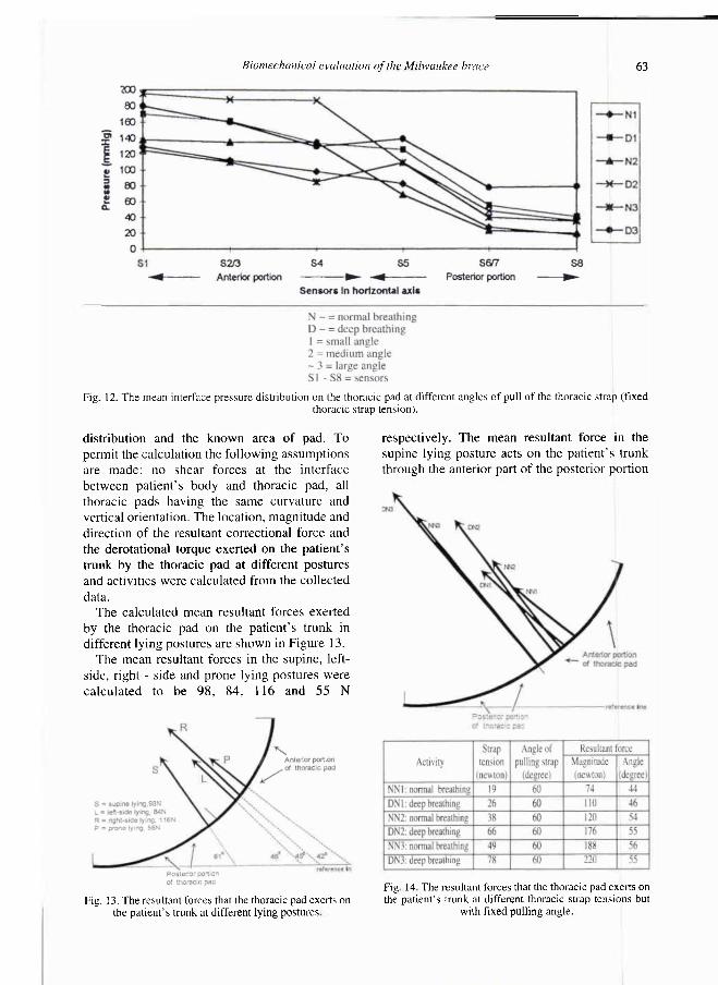
Biomechanical evaluation of the Milwaukee brace 63
distribution and the known area of pad. To permit the calculation the following assumptions are made: no shear forces at the interface between patient 's body and thoracic pad, all thoracic pads having the same curvature and vertical orientation. The location, magnitude and direction of the resultant correctional force and the derotational torque exerted on the patient 's trunk by the thoracic pad at different postures and activities were calculated from the collected data.
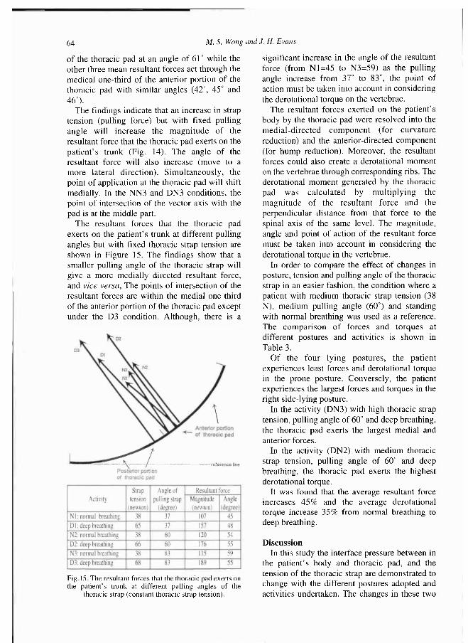
The calculated mean resultant forces exerted by the thoracic pad on the patient 's trunk in different lying postures are shown in Figure 13.
The mean resultant forces in the supine, left-side, right - side and prone lying postures were calculated to be 98 , 84, 116 and 55 N
respectively. The mean resultant force in the supine lying posture acts on the patient 's trunk through the anterior part of the posterior portion
Fig. 12. The mean interface pressure distribution on the thoracic pad at different angles of pull of the thoracic strap (fixed thoracic strap tension).
Fig. 13. The resultant forces that the thoracic pad exerts on the patient's trunk at different lying postures
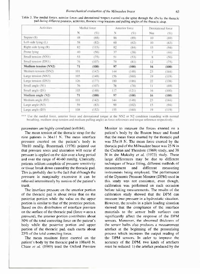
Fig 14 The resultant forces that the thoracic pad exerts on the patient's trunk at different thoracic strap tensions but
with fixed pulling angle.
64 M. S. Wong and J. H. Evans
of the thoracic pad at an angle of 61° while the other three mean resultant forces act through the medical one-third of the anterior portion of the thoracic pad with similar angles (42°, 45° and 46°).
The findings indicate that an increase in strap tension (pulling force) but with fixed pulling angle will increase the magni tude of the resultant force that the thoracic pad exerts on the patient 's trunk (Fig. 14). The angle of the resultant force will also increase (move to a more lateral direction). Simultaneously, the point of application at the thoracic pad will shift medially. In the NN3 and DN3 conditions, the point of intersection of the vector axis with the pad is at the middle part.
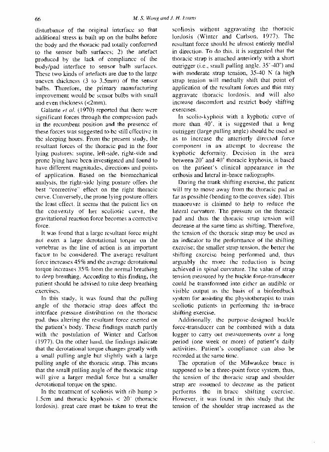
The resultant forces that the thoracic pad exerts on the patient 's trunk at different pulling angles but with fixed thoracic strap tension are shown in Figure 15. The findings show that a smaller pulling angle of the thoracic strap will give a more medially directed resultant force, and vice versa, The points of intersection of the resultant forces are within the medial one-third of the anterior portion of the thoracic pad except under the D3 condition. Although, there is a
significant increase in the angle of the resultant force (from N1=45 to N3=59) as the pulling angle increase from 37° to 83°, the point of action must be taken into account in considering the derotational torque on the vertebrae.
The resultant forces exerted on the patient's body by the thoracic pad were resolved into the medial-directed component (for curvature reduction) and the anterior-directed component (for hump reduction). Moreover, the resultant forces could also create a derotational moment on the vertebrae through corresponding ribs. The derotational moment generated by the thoracic pad was calculated by multiplying the magnitude of the resultant force and the perpendicular distance from that force to the spinal axis of the same level. The magnitude, angle and point of action of the resultant force must be taken into account in considering the derotational torque in the vertebrae.
In order to compare the effect of changes in posture, tension and pulling angle of the thoracic strap in an easier fashion, the condition where a patient with medium thoracic strap tension (38 N), medium pulling angle (60°) and standing with normal breathing was used as a reference. The comparison of forces and torques at different postures and activities is shown in Table 3.
Of the four lying postures, the patient experiences least forces and derotational torque in the prone posture. Conversely, the patient experiences the largest forces and torques in the right side-lying posture.
In the activity (DN3) with high thoracic strap tension, pulling angle of 60° and deep breathing, the thoracic pad exerts the largest medial and anterior forces.
In the activity (DN2) with medium thoracic strap tension, pulling angle of 60° and deep breathing, the thoracic pad exerts the highest derotational torque.
It was found that the average resultant force increases 4 5 % and the average derotational torque increase 3 5 % from normal breathing to deep breathing.
Discussion In this study the interface pressure between in
the patient 's body and thoracic pad, and the tension of the thoracic strap are demonstrated to change with the different postures adopted and activities undertaken. The changes in these two
Fig. 15. The resultant forces that the thoracic pad exerts on the patient's trunk at different pulling angles of the
thoracic strap (constant thoracic strap tension).
Biomechanical evaluation of the Milwaukee brace 65
parameters are highly correlated (r=0.84). The mean tension of the thoracic strap for the
nine patients is 36± 11 N. The mean interface pressure exerted on the pat ient ' s body is 70±10 mmHg. Branemark (1976) pointed out that pressure sores and ulceration will occur if pressure is applied on the skin over a long period and over the range of 40-60 mmHg. Clinically, patients seldom complain of pressure sensitivity or tissue break down caused by the thoracic pad. This is probably due to the fact that although the pressure is marginally excessive it can be relieved intermittently by motion of the patient's trunk.
The interface pressure on the anterior portion of the thoracic pad is about twice that on the posterior portion while the value on the upper portion is similar to that of the posterior portion. Based on this distribution of interface pressure on the surface of the thoracic pad (force = area x pressure), the anterior portion contributes about 50% of the total correcting force on the patient 's body while the posterior portion and upper portion of the thoracic pad, each exerts about 2 5 % of the total correcting force.
The mean resultant force exerted on the patient's body by the thoracic pad is 108±41 N. Chase et al. (1989) used the Oxford Pressure
Monitor to measure the forces exerted on a patient's body by the Boston brace and found that the mean force exerted by the thoracic pad was 55±18 N. The mean force exerted by the thoracic pad of the Milwaukee brace was 25 N in the Cochran and Theodore (1969) study, and 38 N in the Mulcahy et al. (1973) study. These large differences may be due to different techniques of brace fitting, different methods of measurement and different measuring instruments being employed. The performance of the Dynamic Pressure Monitor (DPM) used in this study was not consistent, even though, calibration was performed on each occasion before taking measurements. The results of the calibration study showed that the DPM can measure true pressure in a hydrostatic situation. However, the results in a plain loading situation showed that the compliance of the interface materials to the sensor bulb surfaces can significantly affect the response of the DPM sensors. Moreover, the abnormal thickness of the sensor bulbs also produces a measurement artefact at the beginning of the pressurising process which increases the output reading of the DPM sensors. In order to improve the accuracy of the DPM, two kinds of artefacts must be reduced: 1) the artefact produced by the
Table 3. The medial forces, anterior forces and derotational torques exerted on the spine through the ribs by the thoracic pad during different postures, actitivies, thoracic strap tensions and pulling angles of the thoracic strap.
66 M. S. Wong and J. H. Evans
disturbance of the original interface so that additional stress is built up on the bulbs before the body and the thoracic pad totally conformed to the sensor bulb surfaces; 2) the artefact produced by the lack of compliance of the body/pad interface to sensor bulb surfaces. These two kinds of artefacts are due to the large uneven thickness (3 to 3.5mm) of the sensor bulbs. Therefore, the primary manufacturing improvement would be sensor bulbs with small and even thickness (<2mm).
Galante et al. (1970) reported that there were significant forces through the compression pads in the recumbent position and the presence of these forces was suggested to be still effective in the sleeping hours. From the present study, the resultant forces of the thoracic pad in the four lying postures: supine, left-side, right-side and prone lying have been investigated and found to have different magnitudes, directions and points of application. Based on the biomechanical analysis, the right-side lying posture offers the best "corrective" effect on the right thoracic curve. Conversely, the prone lying posture offers the least effect. It seems that the patient lies on the convexity of her scoliotic curve, the gravitational reaction force becomes a corrective force.
It was found that a large resultant force might not exert a large derotational torque on the vertebrae as the line of action is an important factor to be considered. The average resultant force increases 4 5 % and the average derotational torque increases 3 5 % from the normal breathing to deep breathing. According to this finding, the patient should be advised to take deep breathing exercises.
In this study, it was found that the pulling angle of the thoracic strap does affect the interface pressure distribution on the thoracic pad, thus altering the resultant force exerted on the patient 's body. These findings match partly with the postulation of Winter and Carlson (1977). On the other hand, the findings indicate that the derotational torque changes greatly with a small pulling angle but slightly with a large pulling angle of the thoracic strap. This means that the small pulling angle of the thoracic strap will give a larger medial force but a smaller derotational torque on the spine.
In the treatment of scoliosis with rib hump > 1.5cm and thoracic kyphosis < 20° (thoracic lordosis), great care must be taken to treat the
scoliosis without aggravating the thoracic lordosis (Winter and Carlson, 1977). The resultant force should be almost entirely medial in direction. To do this, it is suggested that the thoracic strap is attached anteriorly with a short outrigger (i.e., small pulling angle, 35°-40°) and with moderate strap tension, 35-40 N (a high strap tension will medially shift that point of application of the resultant forces and this may aggravate thoracic lordosis, and will also increase discomfort and restrict body shifting exercises.
In scolio-kyphois with a kyphotic curve of more than 40°, it is suggested that a long outrigger (large pulling angle) should be used so as to increase the anteriorly directed force component in an attempt to decrease the kyphotic deformity. Decision in the area between 20° and 40° thoracic kyphosis, is based on the pat ient 's clinical appearance in the orthosis and lateral in-brace radiographs.
During the trunk shifting exercise, the patient will try to move away from the thoracic pad as far as possible (bending to the convex side). This manoeuvre is claimed to help to reduce the lateral curvature. The pressure on the thoracic pad and thus the thoracic strap tension will decrease at the same time as shifting. Therefore, the tension of the thoracic strap may be used as an indicator to the performance of the shifting exercise; the smaller strap tension, the better the shifting exercise being performed and, thus arguably the more the reduction is being achieved in spinal curvature. The value of strap tension measured by the buckle force-transducer could be transformed into either an audible or visible output as the basis of a biofeedback system for assisting the physiotherapist to train scoliotic patients in performing the in-brace shifting exercise.
Additionally, the purpose-designed buckle force-transducer can be combined with a data logger to carry out measurements over a long period (one week or more) of patient 's daily activities. Pat ient 's compliance can also be recorded at the same time.
The operation of the Milwaukee brace is supposed to be a three-point force system, thus, the tension of the thoracic strap and shoulder strap are assumed to decrease as the patient performs the in-brace shifting exercise. However, it was found in this study that the tension of the shoulder strap increased as the
Biomechanical evaluation of the Milwaukee brace 67
patient shifted the body away from the thoracic pad. This raises the question as to whether an in-brace shifting exercise just moves the patient 's body away from the thoracic pad and the forces generated by the hands on the anterior upright are transmitted to the trunk through the shoulders at the level of the shoulder strap, i.e., list to the concave side rather than attempt to decrease spinal curvature? A further investigation is required to evaluate the contribution of the in-brace shifting exercise in the treatment of scoliosis.
Conclusion A biomechanical analysis of a conventional
spinal orthosis, Milwaukee brace, was carried out. This involved direct and indirect measurements of the forces transmitted to the body and an analysis of the corrective effect they exerted on the spine. The principal measurements were related to thoracic strap tension and the interface pressure distribution between the thoracic pad and the patient 's body. There is a high correlations between changes in the thoracic strap tension and the interface pressure of the thoracic pad in different lying postures and during various activities. The change in tension and pulling angle of the thoracic strap can vary in magnitude, direction and line of action of the resultant force which the thoracic pad exerts on the patient's body. A knowledge of the magnitude, direction and line of action of the resultant force can be used to evaluate the accuracy of fit and the efficiency of support, the progress of treatment and the effectiveness of various design modifications.
REFERENCES
A N D R E N (1978). L'orthopaedia, ou, l'art de prévenir et de corriger dans les enfants deformite a du corps. In: Scoliosis and other spinal deformities/by J H Moe, RB Winter, DS Bradford, JE Lonstein. - Philadelphia: WB Saunders.
ANDRIACCHI TP, S H U L T Z A B , B E L Y T S C H K O TB, D E W A L D RL (1976). Milwaukee brace correction of idiopathic scoliosis: a biomechanical analysis and retrospective study. J Bone Joint Surg 5 8 A , 806-815.
B L O U N T W P , M O E J H ( 1 9 8 0 ) . Milwaukee brace. -Baltimore: Williams & Wilkins.
B R A D F O R D DS, L O N S T E I N JE, MOE JH, O G I L V I E JW, W I N T E R RB (1987). Scoliosis and other spinal deformities. - Philadelphia: Saunders Co.
B R A N E Μ A R K PI (1976). Microvascular function of reduced flow rates. In: Bed sore biomechanics. -London: Macmillan Co p.63-68
B U N C H W H , P A T W A R D H A m A G ( 1 9 8 9 ) . Scoliosis: making clinical decisions. - St. Louis: CV Mosby.
C H A S E AP, B A D E R D L , H O U G T O N G R (1989). The biomechanical effectiveness of the Boston brace in the management of adolescent idiopathic scoliosis. Spine 1 4 , 636-642.
C O C H R A N GVB, T H E O D O R E RW (1969). The external forces in correction of idiopathic scoliosis (abstract). J Bone Joint Surg 5 1 A , 2 0 1 .
G A L A N T E J, S H U L T Z AB, D E W A L D RL, R A Y RD (1970). Forces acting on the Milwaukee brace on patients undergoing treatment for idiopathic scoliosis. J Bone Joint Surg 5 2 A , 498-506.
L A U R N E N EL, T U P P E R JW, MULLEN MP (1983). The Boston brace in thoracic scoliosis: a preliminary report Spine 8 , 388-395.
L O N S T E I N JE, C A R L S O N JM (1984). The prediction of curve progression in untreated idiopathic scoliosis during growth. J Bone Joint Surg 6 6 A , 1061-1071.
M U L A C H A Y T, G A L A N T E J, D E W A L D R (1973). A follow-up study of forces acting on the Milwaukee brace on patients undergoing treatment for idiopathic scoliosis. Clin Orthop 9 3 , 53-68.
W I L L N E R S (1984). Effect of the Boston thoracic brace on the frontal and sagittal curves of the spine. Acta Orthop Scand 5 5 , 457-450.
W I N T E R RB, L O N S T E I N JE, D R O G T J, N O R E N CA (1986). The effectiveness of bracing in the non-operative treatment of idiopathic scoliosis. Spine 1 1 , 790-791.
W I N T E R RB, C A R L S O N JM (1977). Modern orthotics for spinal deformities. Clin Orthop 1 2 6 , 74-86.
W Y N A R S K Y GT, S H U L T Z AB, (1990). Trunk muscle activities in braced scoliosis patients. Spine 1 4 , 1283-1287.