Embed Size (px)
Citation preview
Bioimpedance Measurements and the Electroporation Phenomenon Quim Castellví (DTIC, Universitat Pompeu Fabra, Barcelona, Spain) [email protected]
Abstract:
Bioimpedance measurements are used to determine physiological aspects of biological tissues. On the
other hand, the electroporation phenomenon causes a variation in the electrical properties of tissue, so
it is possible use bioimpedance measurement with the aim of monitor the electroporation phenomenon
in real time. The objective of this article is present the basic concepts required to understand
bioimpedance measurements and the utility of these for detecting the electroporation effects.
1 Introduction
Bioimpedance measurement is an emerging tool in the
field of biomedical engineering. It consists in studying
the passive electrical properties of biological materials
to indirectly determine certain physiological aspects.
These measurements usually are employed as a method
for monitoring physiological variations. This
monitoring method presents three main advantages.
First, it is a simple technique that can be applied with
just two electrode setup. Also it requires low-cost
instrumentation and is able to monitoring in real time.
The bioimpedance applications are continuously rising.
Currently this kind of measurements are, for example,
used in cell culture count applications, to estimate
blood volume (plethysmography), to detect the
breathing (pneumography), to detect ischemia
(restriction in blood supply) in tissue or to determine
the amount of fat present in the human body.
Recently it has been proposed that bioimpedance
measurements can provide real time feedback on the
outcome of the electroporation treatments. There is
currently no alternative on-line system to easily
determine the effects that electrical pulses cause in
cells, so there, it exists a certain degree of uncertainty
after applying electroporation techniques.
1.1 Impedance and electrical passive properties
The term impedance ( ) describes the opposition that
one element offers to the circulation of alternating
current. This value is represented as a complex number
which expresses the relationship between the measured
voltage ( ) and the current flow ( ).
The impedance measurements in a material depend on
both material properties (conductivity σ and
permittivity ε) and the geometry setup used during the
measurements. The impedance of a material can be
transformed into electrical properties of the material by
applying a scale factor called cell constant ( ) which
reflects the dependence on the geometry used in the
measurements.
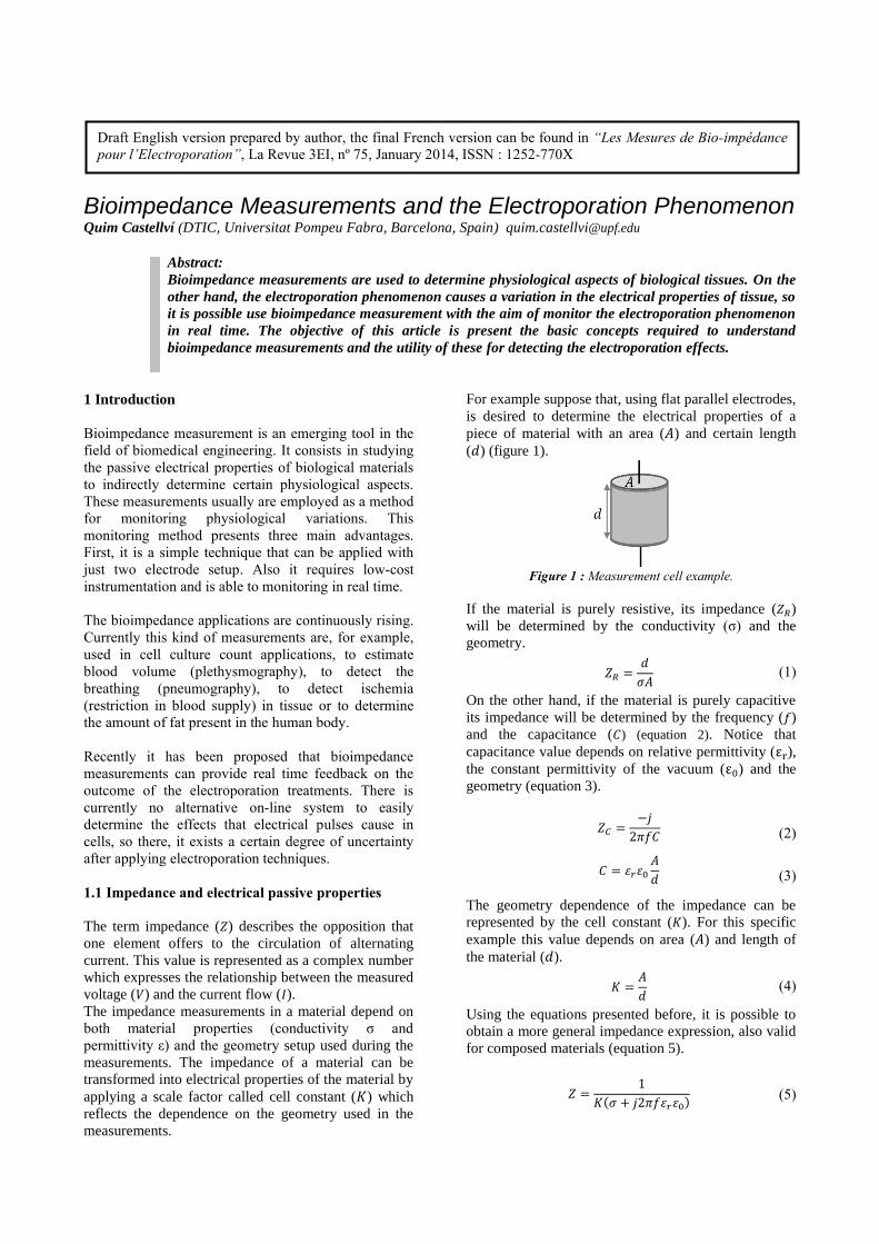
For example suppose that, using flat parallel electrodes,
is desired to determine the electrical properties of a
piece of material with an area ( ) and certain length
( ) (figure 1).
Figure 1 : Measurement cell example.
If the material is purely resistive, its impedance ( )
will be determined by the conductivity (σ) and the
geometry.
(1)
On the other hand, if the material is purely capacitive
its impedance will be determined by the frequency ( )
and the capacitance ( ) (equation 2). Notice that
capacitance value depends on relative permittivity ( ), the constant permittivity of the vacuum ( ) and the
geometry (equation 3).
(2)
(3)
The geometry dependence of the impedance can be
represented by the cell constant ( ). For this specific
example this value depends on area ( ) and length of
the material ( ).
(4)
Using the equations presented before, it is possible to
obtain a more general impedance expression, also valid
for composed materials (equation 5).
(5)
Draft English version prepared by author, the final French version can be found in “Les Mesures de Bio-impédance
pour l’Electroporation”, La Revue 3EI, nº 75, January 2014, ISSN : 1252-770X
In the field of impedance measurements, it is usual to
work in terms of admittance (Y) corresponding to the
inverse of impedance.
(6)
According to the previous formula, and knowing the
cell constant value of the setup, the conductivity and
the relative permittivity for each frequency can be
obtained from the measured impedance, therefore
electrical properties of the material can be determined.
2 Bioimpedance
2.1 Equivalent circuits and models
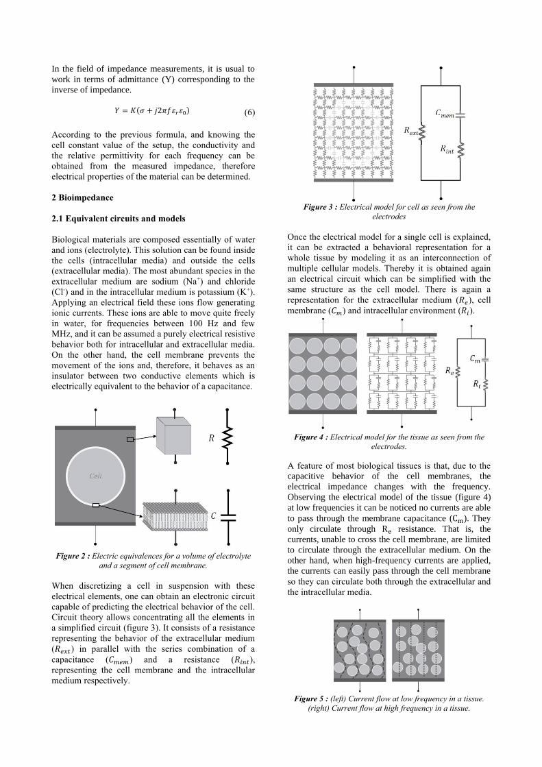
Biological materials are composed essentially of water
and ions (electrolyte). This solution can be found inside
the cells (intracellular media) and outside the cells
(extracellular media). The most abundant species in the
extracellular medium are sodium (Na+) and chloride
(Cl-) and in the intracellular medium is potassium (K+).
Applying an electrical field these ions flow generating
ionic currents. These ions are able to move quite freely
in water, for frequencies between 100 Hz and few
MHz, and it can be assumed a purely electrical resistive
behavior both for intracellular and extracellular media.
On the other hand, the cell membrane prevents the
movement of the ions and, therefore, it behaves as an
insulator between two conductive elements which is
electrically equivalent to the behavior of a capacitance.
Figure 2 : Electric equivalences for a volume of electrolyte
and a segment of cell membrane.
When discretizing a cell in suspension with these
electrical elements, one can obtain an electronic circuit
capable of predicting the electrical behavior of the cell.
Circuit theory allows concentrating all the elements in
a simplified circuit (figure 3). It consists of a resistance
representing the behavior of the extracellular medium
( ) in parallel with the series combination of a
capacitance ( ) and a resistance ( ),
representing the cell membrane and the intracellular
medium respectively.
Figure 3 : Electrical model for cell as seen from the
electrodes
Once the electrical model for a single cell is explained,
it can be extracted a behavioral representation for a
whole tissue by modeling it as an interconnection of
multiple cellular models. Thereby it is obtained again
an electrical circuit which can be simplified with the
same structure as the cell model. There is again a
representation for the extracellular medium ( ), cell
membrane ( ) and intracellular environment ( ).
Figure 4 : Electrical model for the tissue as seen from the
electrodes.
A feature of most biological tissues is that, due to the capacitive behavior of the cell membranes, the
electrical impedance changes with the frequency.
Observing the electrical model of the tissue (figure 4)
at low frequencies it can be noticed no currents are able
to pass through the membrane capacitance ( ). They
only circulate through resistance. That is, the
currents, unable to cross the cell membrane, are limited
to circulate through the extracellular medium. On the
other hand, when high-frequency currents are applied,
the currents can easily pass through the cell membrane
so they can circulate both through the extracellular and
the intracellular media.
Figure 5 : (left) Current flow at low frequency in a tissue.
(right) Current flow at high frequency in a tissue.
2.2 Bioimpedance representation
When impedance measurements at different
frequencies are performed in biological tissue, those
values can be graphically represented in different ways.
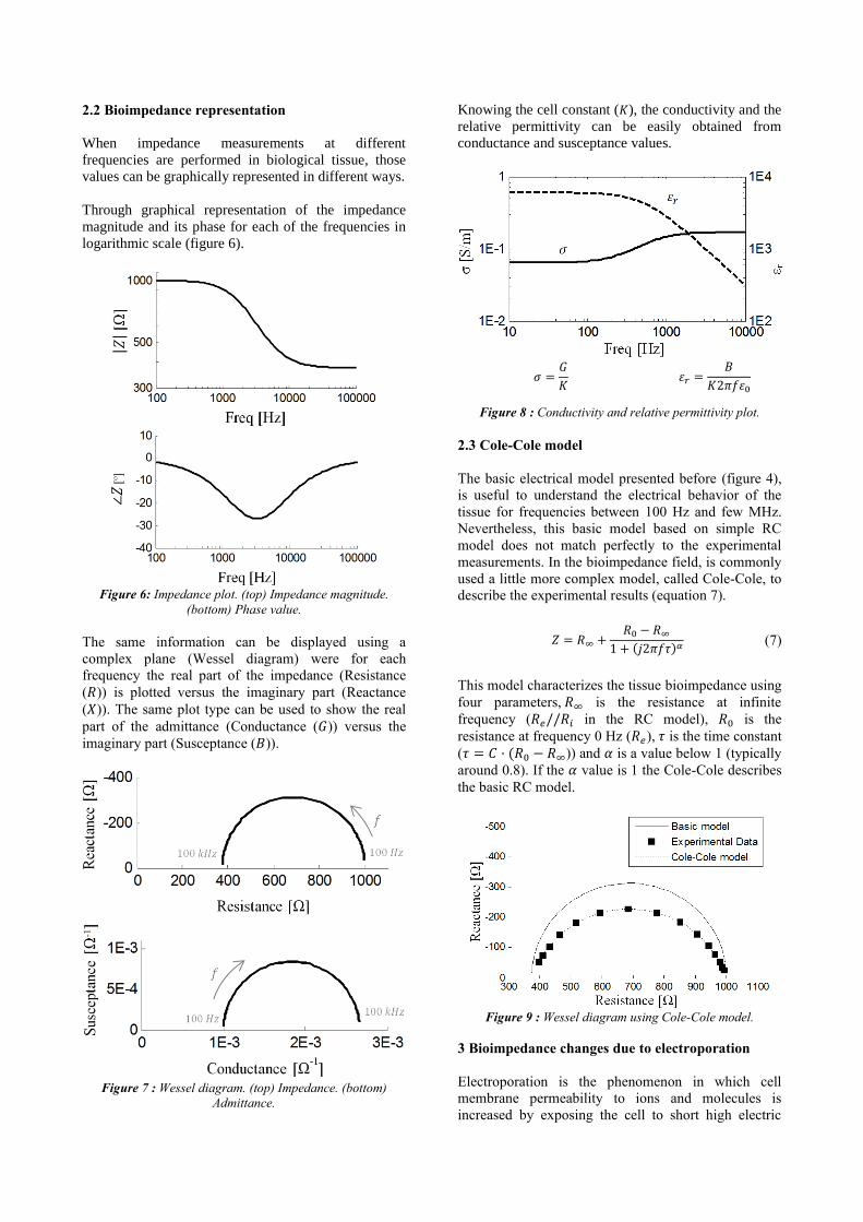
Through graphical representation of the impedance
magnitude and its phase for each of the frequencies in
logarithmic scale (figure 6).
Figure 6: Impedance plot. (top) Impedance magnitude.
(bottom) Phase value.
The same information can be displayed using a
complex plane (Wessel diagram) were for each
frequency the real part of the impedance (Resistance
( )) is plotted versus the imaginary part (Reactance
( )). The same plot type can be used to show the real
part of the admittance (Conductance ( )) versus the
imaginary part (Susceptance ( )).
Figure 7 : Wessel diagram. (top) Impedance. (bottom)
Admittance.
Knowing the cell constant ( ), the conductivity and the
relative permittivity can be easily obtained from
conductance and susceptance values.
Figure 8 : Conductivity and relative permittivity plot.
2.3 Cole-Cole model
The basic electrical model presented before (figure 4),
is useful to understand the electrical behavior of the
tissue for frequencies between 100 Hz and few MHz.
Nevertheless, this basic model based on simple RC
model does not match perfectly to the experimental
measurements. In the bioimpedance field, is commonly
used a little more complex model, called Cole-Cole, to
describe the experimental results (equation 7).
(7)
This model characterizes the tissue bioimpedance using
four parameters, is the resistance at infinite
frequency ( in the RC model), is the
resistance at frequency 0 Hz ( ), is the time constant
( )) and is a value below 1 (typically
around 0.8). If the value is 1 the Cole-Cole describes
the basic RC model.
Figure 9 : Wessel diagram using Cole-Cole model.
3 Bioimpedance changes due to electroporation
Electroporation is the phenomenon in which cell
membrane permeability to ions and molecules is
increased by exposing the cell to short high electric
field pulses. This permeabilization of the cell
membrane can be used in order to enhance the
penetration of drugs, DNA molecules (gene
transfection) or to destroy undesirable cells.
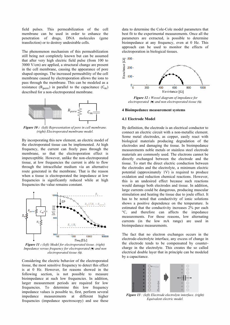
The phenomenon mechanism of this permeabilization
still being not completely known but can be assumed
that after very high electric field pulse (from 100 to
3000 V/cm) are applied, a structural change are present
in the cell membrane, causing the appearance of pore
shaped openings. The increased permeability of the cell
membrane caused by electroporation allows the ions to
pass through the membrane. This can be modeled as a
resistance ( ) in parallel to the capacitance ( )
described for a non-electroporated membrane.
Figure 10 : (left) Representation of pore in cell membrane.
(right) Electroporated membrane model.
By incorporating this new element, an electric model of
the electroporated tissue can be implemented. At high
frequency, the current can freely pass through the
membrane, so that the electroporation effect is
imperceptible. However, unlike the non-electroporated
tissue, at low frequencies the current is able to flow
through the intracellular medium via an alternative
route generated in the membrane. That is the reason
when a tissue is electroporated the impedance at low
frequencies is significantly reduced while at high
frequencies the value remains constant.
Figure 11 : (left) Model for electroporated tissue. (right)
Impedance versus frequency for electroporated ( ) and non
electroporated tissue (ο).
Considering the electric behavior of the electroporated
tissue, the most sensitive frequency to detect this effect
is at 0 Hz. However, for reasons showed in the
following section, is not possible to measure
bioimpedance at such low frequencies. In addition,
larger measurement periods are required for low
frequencies. To determine this low frequency
impedance values is possible to, first, perform several
impedance measurements at different higher
frequencies (impedance spectroscopy) and use these
data to determine the Cole-Cole model parameters that
best fit to the experimental measurements. Once all the
parameters are extracted, is possible to determine
bioimpedance at any frequency, even at 0 Hz. This
approach can be used to monitor the effects of
electroporation in biological tissues.
Figure 12 : Wessel diagram of impedance for
electroporated ( ) and non electroporated tissue (ο).
4 Bioimpedance measurement systems
4.1 Electrode Model
By definition, the electrode is an electrical conductor to
connect an electric circuit with a non-metallic element.
Some metal electrodes, as copper, easily react with
biological materials producing degradation of the
electrodes and damaging the tissue. In bioimpedance
measurements noble metals or stainless steel electrode
materials are commonly used. The electrons cannot be
directly exchanged between the electrode and the
tissue. To start the direct electric conduction between
the electrodes and the electrolyte, a minimum electric
potential (approximately 1V) is required to produce
oxidation and reduction chemical reactions. However,
this is an undesired effect because such reactions
would damage both electrodes and tissue. In addition,
large currents could be dangerous, producing muscular
stimulation and heating the tissue due to joule effect. It
has to be noted that conductivity of ionic solutions
shows a positive dependence on the temperature. Is
estimated that the conductivity increases 2% per each
°C, and therefore can affects the impedance
measurements. For those reasons, low alternating
currents (in the low mA range) are used in
bioimpedance measurements.
The fact that no electron exchanges occurs in the
electrode-electrolyte interface, any excess of change in
the electrode tends to be compensated by counter-
charge in the electrolyte. This creates the so called
electrical double layer that in principle can be modeled
by a capacitance.
Figure 13 : (left) Electrode electrolyte interface. (right)
Equivalent electric model.
This electronic equivalence is only true in cases with
perfectly smooth electrode surface. At microscopic
level any solid metal electrodes present some
roughness producing a frequency dependence behavior.
This interface impedance, called constant phase
element (CPE), can be approximately modeled by
equation 8. Observe that if β=1, the impedance
equation is equivalent to that of a capacitance.
However β value is around 0.8 that is why CPE is also
known as a pseudo-capacitance.
(8)
This interface impedance disturbs the bioimpedance
measurements, particularly al low frequencies, and
must be kept as low as possible. Increasing the area or
the roughness (effective area) of the electrodes, a large
capacitance ( ) could be obtained and therefore
lower interface impedance.
4.2 Four-electrode method
Taking into account the impedance contribution of the
electrode ( ), if a couple of electrodes are used both
inject the current and to measure the voltage drop, the
final measured impedance ( ) is the desired
impedance measurement ( ) plus two times the
impedance of the electrodes ( ) (figure 14). In certain
circumstances where small electrode areas or
frequencies below 10 kHz are used, the parasitic
impedance is sufficiently large to disturb the
measurements. Because of that, an alternative
measuring method, called four-electrode or tetrapolar
method, is commonly used in bioimpedance. It consist
on inject the current with a couple of electrodes and the
resulting voltage drop is measured with another couple
of electrodes. As current does not flow across the
voltage measurement electrodes, it ideally cancels the
influence of the electrode impedance in the final
measure.
Figure 14 : Schematic concept for the two electrode method.
Figure 15 : Schematic concept for the four-electrodes
method.
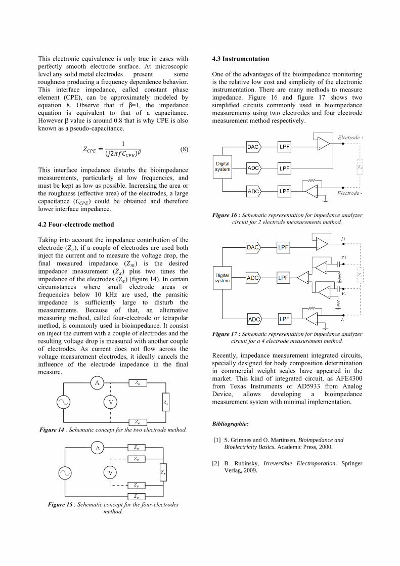
4.3 Instrumentation
One of the advantages of the bioimpedance monitoring
is the relative low cost and simplicity of the electronic
instrumentation. There are many methods to measure
impedance. Figure 16 and figure 17 shows two
simplified circuits commonly used in bioimpedance
measurements using two electrodes and four electrode
measurement method respectively.
Figure 16 : Schematic representation for impedance analyzer
circuit for 2 electrode measurements method.
Figure 17 : Schematic representation for impedance analyzer
circuit for a 4 electrode measurement method.
Recently, impedance measurement integrated circuits,
specially designed for body composition determination
in commercial weight scales have appeared in the
market. This kind of integrated circuit, as AFE4300
from Texas Instruments or AD5933 from Analog
Device, allows developing a bioimpedance
measurement system with minimal implementation.
Bibliographie:
[1] S. Grimnes and O. Martinsen, Bioimpedance and
Bioelectricity Basics. Academic Press, 2000.
[2] B. Rubinsky, Irreversible Electroporation. Springer
Verlag, 2009.