Embed Size (px)
Citation preview
Bio-FilterTM Stormwater Biofiltration System
Inspection and Maintenance Manual
March 2017
AquaShield,TM Inc. 2733 Kanasita Drive, Suite 111
Chattanooga, TN 37343 Phone: (423) 870-8888
Fax: (423) 826-2112 Email: [email protected]
© AquaShieldTM, Inc. 2017
AquaShield,TM Inc. Bio-FilterTM
Table of Contents
AquaShieldTM Bio-FilterTM Overview
Bio-FilterTM Operation
Bio-FilterTM Inspection & Maintenance
Appendix
2733 Kanasita Drive, Suite 111, Chattanooga, Tennessee 37343 Phone (423) 870-8888 Fax (423) 870-2112
www.AquaShieldInc.com
AquaShieldTM Bio-FilterTM Overview
The highest priority of AquaShieldTM, Inc. (AquaShield™) is to protect waterways by providing stormwater treatment solutions to businesses across the world. These solutions have a reliable foundation based on over 20 years of water treatment experience. Local regulators, engineers, and contractors have praised the AquaShieldTM systems for their simple design and ease of installation. All the systems are fabricated from lightweight, durable materials, and contractors prefer the quick and simple installation of our structures that saves them money.
The AquaShieldTM line of patented stormwater treatment products provide high levels of stormwater treatment. AquaShieldTM manufactures the following integrated product solutions:
Aqua-Swirl® Stormwater Treatment System Aqua-FilterTM Stormwater Filtration System Aqua-GuardianTM Catch Basin Insert AquaShieldTM Bio-FilterTM Stormwater Biofiltration System
The Bio-FilterTM Stormwater Biofiltration System is capable of gross contaminant removal, coarse- and fine-grained sediment removal, oil removal, as well as the removal of heavy metals and phosphorus.
This Inspection and Maintenance Manual provides important information for continued effective operation of the AquaShieldTM Bio-FilterTM system.
The Bio-FilterTM Stormwater Biofiltration System is a modular “tree box” design that provides an innovative and sustainable green infrastructure solution to meet the growing challenges of Low Impact Development (LID) practices. The Bio-FilterTM is a water quality treatment device capable of removing coarse and fine sediment, trash and debris, heavy metals bound to particulate matter, and oil by utilizing elements of pretreatment and biofiltration. Biofiltration is accomplished by a proprietary engineered soil biomedia as well as uptake by the selected tree. The Bio-FilterTM provides advanced pretreatment for rainwater collection structures, or can be used as a standalone device for discharges to sensitive receiving waters. Each system is custom engineered for site-specific needs using proven lightweight and durable Polymer Coated Steel (PCS). The system operates under gravitational and hydrodynamic forces with no moving parts which simplifies the treatment process. The standard Bio-FilterTM system utilizes
an internal bypass design with custom system footprints ranging from 4 x 4 feet to 8 x 8 feet (16 to 64 square feet). An optional cylindrically shaped Bio-FilterTM model uses an external bypass structure(s) in lieu of the internal bypass, having similar surface areas as the standard models. All Bio-FilterTM systems use a 3 inch top layer of mulch underlain by 18 or 24 inches of engineered biomedia, and an 8 inch gravel base containing an underdrain pipe. Two 15-inch diameter metal access port covers to the Trash Shelf, Pretreatment Chamber and Underdrain Pipe are also included for each unit. A metal tree grate is available in several colors and patterns. A non-skid surface material is used for the top of the unit and can be applied to the unit’s sides on request. No heavy lifting equipment is needed for installation. All filter media is typically shipped separately, and replacement biomedia is available from AquaShieldTM. AquaShieldTM is not responsible for tree specification, purchase, delivery, installation or maintenance.
Bio-FilterTM Media Installation After the Bio-Filter™ is installed and before media installation, ensure that the filtration chamber is free from debris and that the perforated underdrain pipe is connected and in place (refer to SHOP drawing). The first step in media installation is to fill the bottom 8 inches of the filtration chamber with gravel (contractor furnished). Fill to the one inch flatbar reinforcements that are attached to the front and back chamber walls at this elevation. The top of the gravel bed should be smooth and level and the underdrain pipe should be fully covered. A layer of geotextile fabric (contractor furnished) is lain on top of the gravel bed. Fabric should be smooth and cover the entire surface to the filtration chamber walls. Next the AquaShield™ Bio-Filter™ media is installed. The soil matrix should be installed in 6 inch lifts and the surface of each lift smoothed and leveled before proceeding to the next lift. Media should be filled to the upper 1-inch flatbar reinforcements on the front and back filtration chamber walls. At this point a solid cover should be placed over the tree grate opening and the curb inlet blocked off to minimize construction debris from contaminating the Bio-Filter™ media bed during the final site construction phases.
After all construction activities are complete, the cover should be removed from the tree grate opening and the specified vegetation planted in the Bio-Filter™ media. After planting, the 3-inch layer of mulch (contractor furnished) should be placed on top of the filter media bed. Note that mulch should not extend above the bottom of the water distribution rails along the walls of the filtration chamber. Refer to the AquaShield™ Bio-Filter™ Activation Guide to finalize operation of the bio-filtration system.
Bio-FilterTM Operation
The five internal design elements of the Bio-FilterTM unit include the following:
1. Inlet and Trash Shelf 2. Pretreatment Chamber 3. Biofiltration Chamber 4. Outlet Chamber 5. Internal Bypass
These system components are identified in Figure 1. The five steps of Bio-FilterTM treatment are described in the sections below.
Step 1: Inlet and Trash Shelf Operation begins when water enters the Bio-Filter™, such as a curb inlet, and flows onto the screened Trash Shelf. As water flow spreads out across the shelf, debris is removed and retained. Both the internal structural wall of the Trash Shelf and the weir wall of the Internal Bypass Weir serve to retain the influent debris. The water quality treatment flow volume exits the Trash Shelf and enters the Pretreatment Chamber. Flow volume in excess of the water treatment flow can flow over the weir wall of the Internal Bypass, configured on the edge of the Trash Shelf, and into the underlying Outlet Chamber. Bypass flows are screened in order to retain trash and debris.
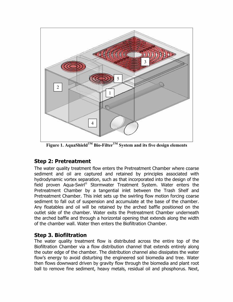
Figure 1. AquaShieldTM Bio-FilterTM System and its five design elements
Step 2: Pretreatment The water quality treatment flow enters the Pretreatment Chamber where coarse sediment and oil are captured and retained by principles associated with hydrodynamic vortex separation, such as that incorporated into the design of the field proven Aqua-Swirl® Stormwater Treatment System. Water enters the Pretreatment Chamber by a tangential inlet between the Trash Shelf and Pretreatment Chamber. This inlet sets up the swirling flow motion forcing coarse sediment to fall out of suspension and accumulate at the base of the chamber. Any floatables and oil will be retained by the arched baffle positioned on the outlet side of the chamber. Water exits the Pretreatment Chamber underneath the arched baffle and through a horizontal opening that extends along the width of the chamber wall. Water then enters the Biofiltration Chamber. Step 3. Biofiltration The water quality treatment flow is distributed across the entire top of the Biofiltration Chamber via a flow distribution channel that extends entirely along the outer edge of the chamber. The distribution channel also dissipates the water flow’s energy to avoid disturbing the engineered soil biomedia and tree. Water then flows downward driven by gravity flow through the biomedia and plant root ball to remove fine sediment, heavy metals, residual oil and phosphorus. Next,
1 2
3
4
5
filtered water enters a 4-inch inner diameter perforated Schedule 40 PVC Underdrain Pipe placed within 8 inches of gravel at the base of the chamber. Treated water is conveyed within the pipe to the adjacent Outlet Chamber positioned directly underneath the Trash Shelf. Step 4. Outlet Chamber Both the water quality treatment flow from the Biofiltration Chamber and any associated bypass flow is routed into the Outlet Chamber prior to discharge. The outlet pipe can be placed on either of the two sides of the chamber to facilitate installation designs. Step 5. Internal Bypass Weir The standard Bio-FilterTM design includes an Internal Bypass designed not only to accommodate high flow conditions, but also to minimize the device’s installation footprint by eliminating the need for any external bypass structures. Internal bypass occurs when the head level rises within the unit such that flows in excess of the water quality treatment flow will spill across the overflow weir on the Trash Shelf and downward into the underlying Outlet Chamber. The bypass weir is screened to prevent escape of trash and debris during high-flow events.
Bio-FilterTM Biomedia The natural proprietary engineered biomedia used in the Bio-FilterTM system is capable of removing waterborne pollutants such as fine silts and clays, oil and heavy metals bound to particulate matter (copper, lead, zinc) and phosphorus. The media is configured within the Biofiltration Chamber from top to bottom as follows:
Three (3) inches of mulch, 18 to 24 inches of a proprietary blend of natural biomedia having an
infiltration capacity between 120 and 135 inches per hour. 8 inches of gravel containing a 4 inch inner diameter Schedule 40 PVC
underdrain pipe perforated on the underside.
Bio-FilterTM Inspection & Maintenance
The long-term performance of the stormwater treatment structures (including manufactured systems, ponds, swales, etc.), and the effective protection of receiving waters, depends on a consistent maintenance plan. Inspection and maintenance (I & M) functions are simple and easy for AquaShield™ Stormwater Treatment Systems allowing all inspections to be performed from the surface. It is important that a consistent and routine I & M program be established for each unit based on (1) the volume or load of the contaminants of concern, (2) the frequency of releases of contaminants at the facility or location, and (3) the nature of the area being drained. In order to ensure that our systems are being properly maintained, AquaShield™ offers a maintenance solution to all of our customers. We can arrange to have a maintenance event performed. Inspection and Maintenance Data Sheets are provided in the Appendix of this Manual.
Bio-FilterTM Inspection
The AquaShieldTM Bio-FilterTM can be inspected from the surface, eliminating the need to enter the system to determine when cleanout should be performed. In most cases, AquaShield™ initially recommends a frequent inspection cycle following installation. Inspection frequency will be dependent on site loading conditions. At a minimum following installation and/or activation, we recommend
a quarterly inspection of the system for the first year of operation to develop an appropriate schedule of maintenance. Based on experience of the system’s first year in operation, we further recommend that the inspection schedule be revised to reflect the site-specific conditions encountered. Inspections for Bio-FilterTM components of the Inlet, Trash Shelf, Pretreatment Chamber, Biofiltration Chamber, Outlet Chamber and the tree should be performed generally on a quarterly basis, but at least annually. Conditions of both metal covers, metal tree grate, and any external bypass structure(s) should also be noted. Information gathered during the first year of service can often be used to create a maintenance plan appropriate for the site.
Bio-FilterTM Maintenance
Inlet and Trash Shelf Inspections of the Inlet and Trash Shelf can be viewed at the Inlet itself and through a 15 inch diameter metal access cover located closest to the Inlet. It is important to consistently keep both the Inlet and Trash Shelf significantly free of accumulated materials to ensure proper operation of the Bio-FilterTM unit. Materials can be removed by the use of a vacuum truck while performing maintenance of the other Bio-FilterTM components. Given the nature of typical curb inlet designs, manual removal of debris may be necessary depending on site-specific conditions. Pretreatment Chamber Access to the Pretreatment Chamber for inspections and maintenance tasks can be accomplished at the surface through a 15 inch diameter metal access port (located furthest from Inlet). The Pretreatment Chamber retains coarse material and sediment and any free floating oil. Underground entry to the Pretreatment Chamber is not needed given its accessibility through the access port. Maintenance is triggered when no more than six (6) inches of sediment depth (thickness) accumulates in the Pretreatment Chamber. The sediment pile thickness is easily determined by comparing the distance to the top of the sediment pile to the distance to the base of the chamber. The distance to the base of the Pretreatment Chamber can be obtained (a) in the field by using a stadia rod or other rigid measuring device or (b) reviewing a model specification drawing.
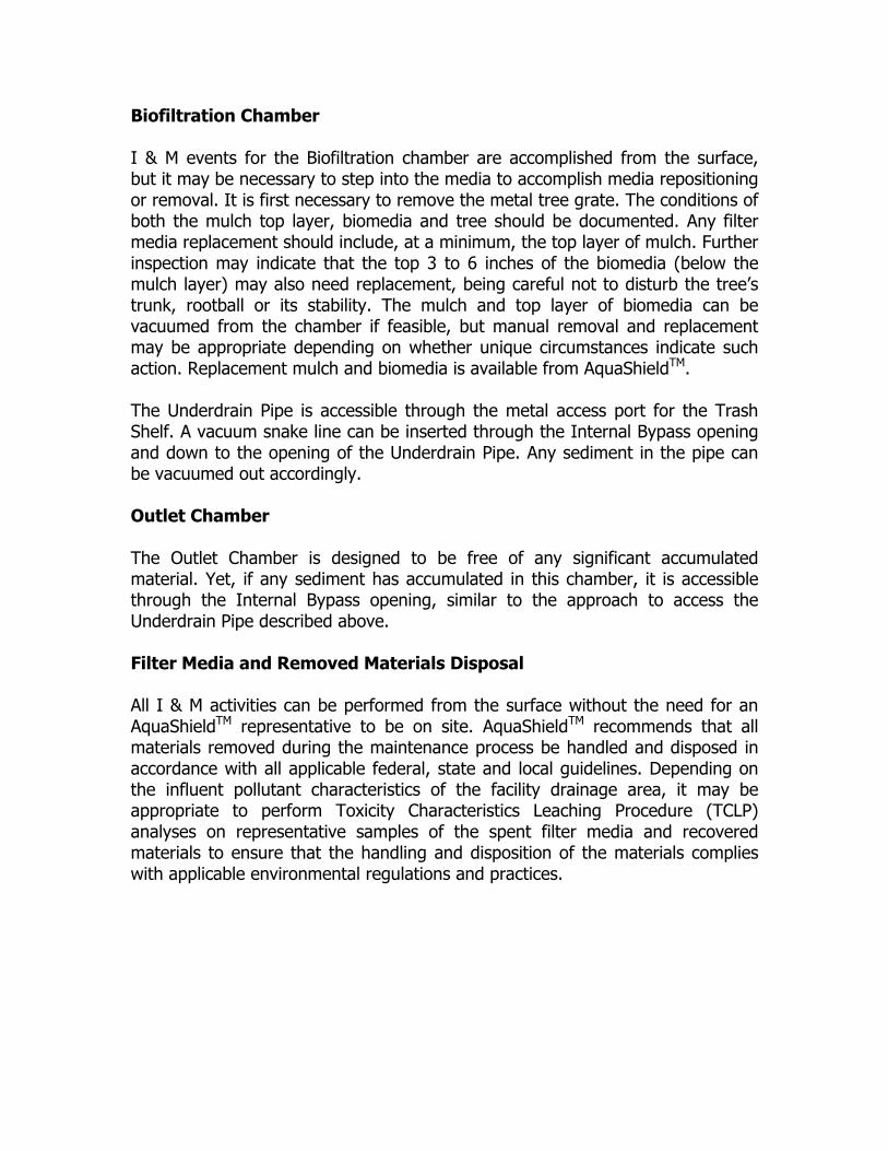
Biofiltration Chamber I & M events for the Biofiltration chamber are accomplished from the surface, but it may be necessary to step into the media to accomplish media repositioning or removal. It is first necessary to remove the metal tree grate. The conditions of both the mulch top layer, biomedia and tree should be documented. Any filter media replacement should include, at a minimum, the top layer of mulch. Further inspection may indicate that the top 3 to 6 inches of the biomedia (below the mulch layer) may also need replacement, being careful not to disturb the tree’s trunk, rootball or its stability. The mulch and top layer of biomedia can be vacuumed from the chamber if feasible, but manual removal and replacement may be appropriate depending on whether unique circumstances indicate such action. Replacement mulch and biomedia is available from AquaShieldTM. The Underdrain Pipe is accessible through the metal access port for the Trash Shelf. A vacuum snake line can be inserted through the Internal Bypass opening and down to the opening of the Underdrain Pipe. Any sediment in the pipe can be vacuumed out accordingly. Outlet Chamber The Outlet Chamber is designed to be free of any significant accumulated material. Yet, if any sediment has accumulated in this chamber, it is accessible through the Internal Bypass opening, similar to the approach to access the Underdrain Pipe described above. Filter Media and Removed Materials Disposal All I & M activities can be performed from the surface without the need for an AquaShieldTM representative to be on site. AquaShieldTM recommends that all materials removed during the maintenance process be handled and disposed in accordance with all applicable federal, state and local guidelines. Depending on the influent pollutant characteristics of the facility drainage area, it may be appropriate to perform Toxicity Characteristics Leaching Procedure (TCLP) analyses on representative samples of the spent filter media and recovered materials to ensure that the handling and disposition of the materials complies with applicable environmental regulations and practices.

APPENDIX
Inspection and Maintenance Data Sheets
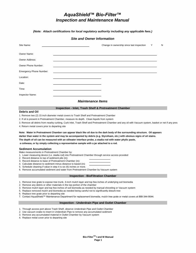
Site Name: Change in ownership since last inspection? Y N
Debris and Oil
1. Remove two (2) 15 inch diameter metal covers to Trash Shelf and Pretreatment Chamber
2. If oil is present in Pretreatment Chamber, measure its depth. Clean liquids from system
3. Remove all debris from nearby curbing, Curb Inlet, Trash Shelf and Pretreatment Chamber and any oil with Vacuum system, basket or net if any present
4. Return metal covers prior to departing site
Note: Water in Pretreatment Chamber can appear black like oil due to the dark body of the surrounding structure. Oil appears
darker than water in the system and may be accompanied by debris (e.g. Styrofoam, etc.) with obvious signs of oil stains.
The depth of oil can be measured with an oil/water interface probe, a stadia rod with water phylic paste,
a coliwasa, or by simply collecting a representative sample with a jar attached to a rod.
Sediment AccumulationMake measurements in Pretreatment Chamber by:
1. Lower measuring device (i.e. stadia rod) into Pretreatment Chamber through service access provided
2. Record distance to top of sediment pile (in):
3. Record distance to base of Pretreatment Chamber (in):
4. Calculate distance to sediment minus distance to based (in):
5. Schedule cleaning if value in step 4 is six (6) inches or more.
6. Remove accumulated sediment and water from Pretreatment Chamber by Vacuum system
1. Remove tree grate to expose tree trunk, 3-inch mulch layer and top few inches of underlying soil biomedia
2. Remove any debris or other materials in the top portion of the chamber
3. Remove mulch layer and top few inches of soil biomedia as needed by manual shoveling or Vacuum system
5. Replace removed mulch and biomedia as needed being careful not to significantly disturb tree
6. Replace tree grate prior to departing site
7. Contact AquaShield™ Maintenance Department for replacement biomedia, mulch tree grate or metal covers at 888-344-9044.
1. Through access port above Trash Shelf, observe Underdrain Pipe and Outlet Chamber
2. Use vacuum snake to insert in Underdrain Pipe to remove any accumulated sediment
3. Remove any accumulated material in Outlet Chamber by Vacuum system
4. Replace metal cover prior to departing site
Owner Address:
Owner Phone Number:
Emergency Phone Number:
Inspector Name:
AquaShield™ Bio-Filter™
Inspection - Inlet, Trash Shelf & Pretreatment Chamber
Maintenance Items
Inspection and Maintenance Manual
(Note: Attach certifications for local regulatory authority including any applicable fees.)
Owner Name:
Site and Owner Information
Location:
Date:
Time:
Inspection - BioFiltration Chamber
Inspection - Underdrain Pipe and Outlet Chamber
Bio-FilterTM
I and M Manual
Page 1
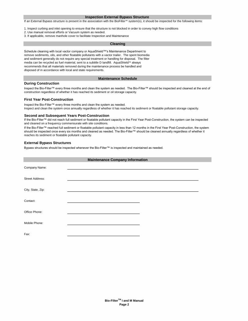
If an External Bypass structure is present in the association with the BioFilter™ system(s), it should be inspected for the following items:
1. Inspect curbing and inlet opening to ensure that the structure is not blocked in order to convey high flow conditions
2. Use manual removal efforts or Vacuum system as needed.
3. If applicable, remove manhole cover to facilitate Inspection and Maintenance
During Construction
First Year Post-Construction
Inspect the Bio-Filter™ every three months and clean the system as needed.
Inspect and clean the system once annually regardless of whether it has reached its sediment or floatable pollutant storage capacity.
Second and Subsequent Years Post-Construction
External Bypass Structures
Bypass structures should be inspected whenever the Bio-Filter™ is inspected and maintained as needed.
Company Name:
Street Address:
City, State, Zip:
Contact:
Office Phone:
Mobile Phone:
Fax:
Maintenance Company Information
Maintenance Schedule
Cleaning
Schedule cleaning with local vactor company or AquaShield™'s Maintenance Department to
remove sediments, oils, and other floatable pollutants with a vactor trailer. The spent biomedia
and sediment generally do not require any special treatment or handling for disposal. The filter
media can be recycled as fuel material, sent to a subtitle D landfill. AquaShield™ always
recommends that all materials removed during the maintenance process be handled and
disposed of in accordance with local and state requirements.
Inspect the Bio-Filter™ every three months and clean the system as needed. The Bio-Filter™ should be inspected and cleaned at the end of
construction regardless of whether it has reached its sediment or oil storage capacity.
If the Bio-Filter™ reached full sediment or floatable pollutant capacity in less than 12 months in the First Year Post-Construction, the system
should be inspected once every six months and cleaned as needed. The Bio-Filter™ should be cleaned annually regardless of whether it
reaches its sediment or floatable pollutant capacity.
If the Bio-Filter™ did not reach full sediment or floatable pollutant capacity in the First Year Post-Construction, the system can be inspected
and cleaned on a frequency commensurate with site conditions.
Inspection External Bypass Structure
Bio-FilterTM
I and M Manual
Page 2
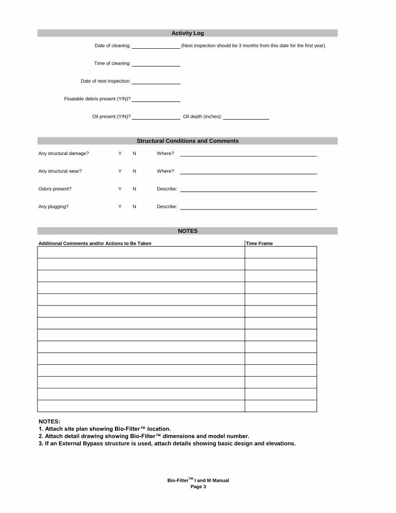
(Next inspection should be 3 months from this date for the first year).
Oil depth (inches):
Any structural damage? Y N Where?
Any structural wear? Y N Where?
Odors present? Y N Describe:
Any plugging? Y N Describe:
Additional Comments and/or Actions to Be Taken Time Frame
NOTES:
1. Attach site plan showing Bio-Filter™ location.
2. Attach detail drawing showing Bio-Filter™ dimensions and model number.
3. If an External Bypass structure is used, attach details showing basic design and elevations.
Oil present (Y/N)?
Activity Log
Structural Conditions and Comments
Date of next inspection:
Date of cleaning:
Time of cleaning:
NOTES
Floatable debris present (Y/N)?
Bio-FilterTM
I and M Manual
Page 3
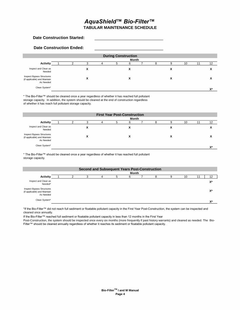
Activity 1 2 3 4 5 6 7 8 9 10 11 12
Clean System*X*
* The Bio-Filter™ should be cleaned once a year regardless of whether it has reached full pollutant
storage capacity. In addition, the system should be cleaned at the end of construction regardless
of whether it has reach full pollutant storage capacity.
Activity 1 2 3 4 5 6 7 8 9 10 11 12
Clean System*X*
* The Bio-Filter™ should be cleaned once a year regardless of whether it has reached full pollutant
storage capacity.
Activity 1 2 3 4 5 6 7 8 9 10 11 12
Clean System*X*
If the Bio-Filter™ reached full sediment or floatable pollutant capacity in less than 12 months in the First Year
Inspect and Clean as
Needed
Inspect Bypass Structures
(if applicable) and Maintain
As Needed
Second and Subsequent Years Post-ConstructionMonth
During ConstructionMonth
First Year Post-ConstructionMonth
Date Construction Started:
AquaShield™ Bio-Filter™TABULAR MAINTENANCE SCHEDULE
Date Construction Ended:
X X X
X X
X
X
X
Inspect Bypass Structures
(if applicable) and Maintain
As Needed
X
Inspect and Clean as
NeededXXX
X
X
Inspect and Clean as
Needed*
XX
Post-Construction, the system should be inspected once every six months (more frequently if past history warrants) and cleaned as needed. The Bio-
Filter™ should be cleaned annually regardless of whether it reaches its sediment or floatable pollutant capacity.
*If the Bio-Filter™ did not reach full sediment or floatable pollutant capacity in the First Year Post-Construction, the system can be inspected and
cleaned once annually.
Inspect Bypass Structures
(if applicable) and Maintain
As Needed
X*
X*
Bio-FilterTM
I and M Manual
Page 4