Embed Size (px)
Citation preview

Barcode Handy Terminal
BHT-904B/BHT-914B User’s Manual
i
BHT-904B/BHT-914B
Preface
Thank you for using the BHT-904B/BHT-914B DENSO WAVE Barcode Handy Terminal.
Please read this manual thoroughly prior to operation to ensure full use of the product’s functionality, and store safely
in a convenient location for quick reference even after reading.
Liability Limitations
DENSO WAVE INCORPORATED does not assume any product liability (including damages for lost profits,
interruption of operations, or the loss of business-related information) arising out of, or in connection with, the
use of, or inability to use the BHT system software or related manuals.
DENSO WAVE INCORPORATED (“DENSO WAVE”) takes reasonable precautions to ensure its products do
not infringe upon any patents or other intellectual property rights of other(s), however, DENSO WAVE cannot
be responsible for any patent or other intellectual property right infringement(s) or violation(s) arising from any
of the following.
1) The use of DENSO WAVE’s products in connection or in combination with other components, products,
devices, data processing systems or software not supplied by DENSO WAVE.
2) The use of DENSO WAVE’s products in a manner for which they were not intended nor designed.
3) The modification of DENSO WAVE’s products by parties other than DENSO WAVE.
If it is judged by DENSO WAVE INCORPORATED that malfunction of the product is due to the product
having been dropped or subjected to impact, repairs will be made at a reasonable charge even within the
warranty period.
ii
Barcode Handy Terminal
Customer Registration and Inquiries Customer Registration
To allow us to provide our customers with comprehensive service and support, we request that all customers
complete a Member Registration Form. Registered members will be offered the following privileges.
The latest upgrade information
Free exhibition and event information for new products
Free Web-information service “QBdirect”.
QBdirect Service Contents
Information search service (FAQ) Offers detailed information on each product.
Download service Offers downloads of repair modules for the latest BHT Series
systems or software, and sample programs.
E-mail inquiries Product related queries can be sent in by e-mail.
* Please note that these privileges may be subject to change without prior notice.
How to Register
Access the URL below and follow the instructions provided.
http://www.qbdirect.net/
Inquiries
Technical Inquiries (QBdirect)
BHT product programming method
Product setup method, usage
Other technical questions
Inquires relating to the above can be made at our exclusive Web site for registered users (QBdirect).
Access the link below to log on or register.
http://www.qbdirect.net/
iii
BHT-904B/BHT-914B
About this Manual
Due to improvements and so on, the content of this manual may be subject to change without prior notice.
The reproduction or duplication of the whole or part of this manual is strictly prohibited without prior consent.
Every attempt has been made to ensure that the content of this manual is thorough and up to date, however,
we kindly ask that any questionable content, mistakes, or omissions be reported to DENSO WAVE.
The copyright for this User’s Manual belongs to DENSO WAVE INCORPORATED.
Manual Composition
This manual is made up of the following 9 chapters.
Chapter 1 Outline
Describes the BHT system and provides an overall outline of the BHT.
Chapter 2 BHT Preparation
Describes information required by the user and procedures that must be performed prior to
commencing operation.
Chapter 3 Basic Operation
Describes basic operations performed by the operator and how to make basic changes to settings such
as the beeper volume
Chapter 4 System Operation
Describes how to initialize and update the system, start up a user program, and operate System Mode.
Chapter 5 Communication
Describes interfaces and communication specifications.
Chapter 6 Maintenance
Describes battery replacement and daily procedures for taking care of the BHT.
Chapter 7 Error Messages
Describes causes and countermeasures for error messages expected to occur during basic operation.
Chapter 8 Specifications
Describes specifications for hardware, readable barcodes, and interfaces.
Chapter 9-1 CU-900, CH-900 Specifications (Option)
Describes the main specifications for the CU-900, CH-900 Series (option).
Chapter 9-2 When File Transfer is Not Possible Using the Transfer Utility
Describes causes and countermeasures when unable to transfer files.
iv
Barcode Handy Terminal
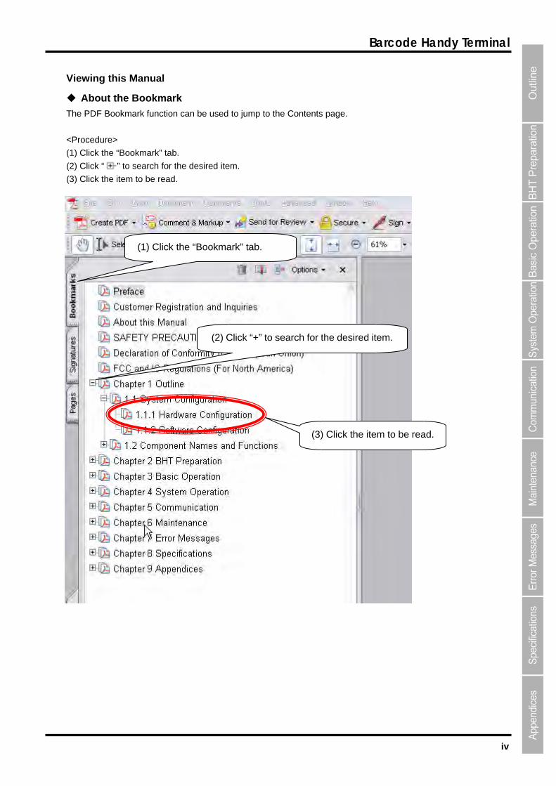
Viewing this Manual
About the Bookmark
The PDF Bookmark function can be used to jump to the Contents page.
<Procedure>
(1) Click the “Bookmark” tab.
(2) Click “ ” to search for the desired item.
(3) Click the item to be read.
(1) Click the “Bookmark” tab.
(2) Click “+” to search for the desired item.
(3) Click the item to be read.
v
BHT-904B/BHT-914B
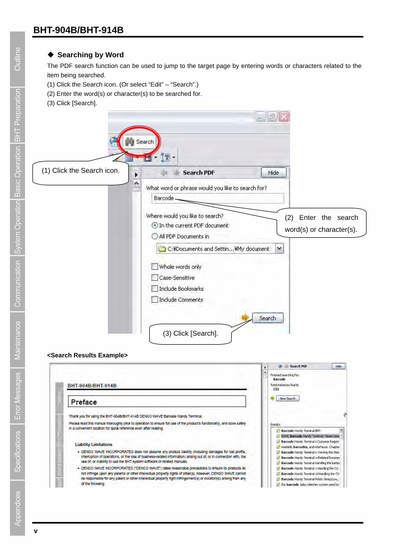
Searching by Word
The PDF search function can be used to jump to the target page by entering words or characters related to the
item being searched.
(1) Click the Search icon. (Or select “Edit” – “Search”.)
(2) Enter the word(s) or character(s) to be searched for.
(3) Click [Search].
(2) Enter the search
word(s) or character(s).
(1) Click the Search icon.
(3) Click [Search].
<Search Results Example>
vi
Barcode Handy Terminal
Related Documentation
BHT-BASIC Programmer’s Manual (BHT-900 Series)
This is an instruction manual used to create handy terminal programs with BHT-BASIC.
BHT-BASIC 4.0 Transfer Utility User’s Guide
This is an instruction manual for software relating to data transfer between the computer and BHT-900 and
comes bundled with the BHT-BASIC 4.0 Transfer Utility.
Easy Pack Ad for BHT-900 User’s Manual
This is an instruction manual for the easy operation application software installed before shipping of the
BHT-900.

vii
BHT-904B/BHT-914B
SAFETY PRECAUTIONS
Be sure to observe all these safety precautions. Please READ through this manual carefully. It will enable you to use the BHT and CU correctly.
Always keep this manual nearby for speedy reference.
Strict observance of these warnings and cautions is a MUST for preventing accidents that could result in bodily
injury and substantial property damage. Make sure you fully understand all definitions of these terms and
symbols given below before you proceed to the text itself.
Alerts you to those conditions that could cause serious bodily injury or death if the instructions are not followed correctly.
Alerts you to those conditions that could cause minor bodily injury or substantial property damage if the instructions are not followed correctly.
Meaning of Symbols
A triangle ( ) with a picture inside alerts you to a warning of danger. Here you see the warning for electrical shock.
A diagonal line through a circle ( ) warns you of something you should not do; it may or may not have a picture inside. Here you see a screwdriver inside the circle, meaning that you should not disassemble.
A black circle (●) with a picture inside alerts you to something you MUST do. This example shows that you MUST unplug the power cord.
viii
Barcode Handy Terminal
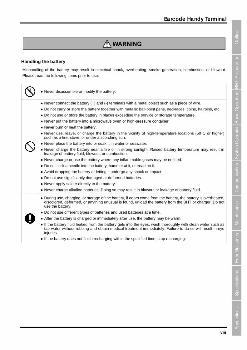
Handling the battery
Mishandling of the battery may result in electrical shock, overheating, smoke generation, combustion, or blowout.
Please read the following items prior to use.
Never disassemble or modify the battery.
Never connect the battery (+) and (-) terminals with a metal object such as a piece of wire.
Do not carry or store the battery together with metallic ball-point pens, necklaces, coins, hairpins, etc.
Do not use or store the battery in places exceeding the service or storage temperature.
Never put the battery into a microwave oven or high-pressure container.
Never burn or heat the battery.
Never use, leave, or charge the battery in the vicinity of high-temperature locations (50C or higher) such as a fire, stove, or under a scorching sun.
Never place the battery into or soak it in water or seawater.
Never charge the battery near a fire or in strong sunlight. Raised battery temperature may result in leakage of battery fluid, blowout, or combustion.
Never charge or use the battery where any inflammable gases may be emitted.
Do not stick a needle into the battery, hammer at it, or tread on it.
Avoid dropping the battery or letting it undergo any shock or impact.
Do not use significantly damaged or deformed batteries.
Never apply solder directly to the battery.
Never charge alkaline batteries. Doing so may result in blowout or leakage of battery fluid.
During use, charging, or storage of the battery, if odors come from the battery, the battery is overheated, discolored, deformed, or anything unusual is found, unload the battery from the BHT or charger. Do not use the battery.
Do not use different types of batteries and used batteries at a time.
After the battery is charged or immediately after use, the battery may be warm.
If the battery fluid leaked from the battery gets into the eyes, wash thoroughly with clean water such as tap water without rubbing and obtain medical treatment immediately. Failure to do so will result in eye injuries.
If the battery does not finish recharging within the specified time, stop recharging.
ix
BHT-904B/BHT-914B
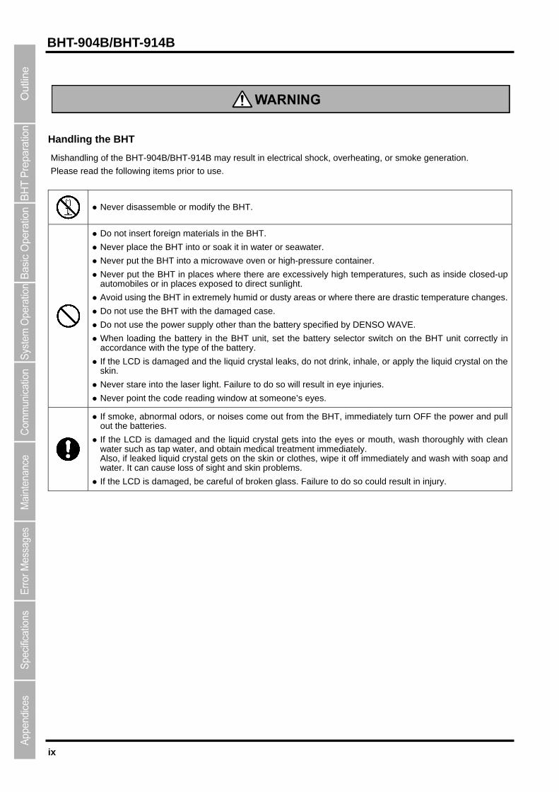
Handling the BHT
Mishandling of the BHT-904B/BHT-914B may result in electrical shock, overheating, or smoke generation.
Please read the following items prior to use.
Never disassemble or modify the BHT.
Do not insert foreign materials in the BHT.
Never place the BHT into or soak it in water or seawater.
Never put the BHT into a microwave oven or high-pressure container.
Never put the BHT in places where there are excessively high temperatures, such as inside closed-up automobiles or in places exposed to direct sunlight.
Avoid using the BHT in extremely humid or dusty areas or where there are drastic temperature changes.
Do not use the BHT with the damaged case.
Do not use the power supply other than the battery specified by DENSO WAVE.
When loading the battery in the BHT unit, set the battery selector switch on the BHT unit correctly in accordance with the type of the battery.
If the LCD is damaged and the liquid crystal leaks, do not drink, inhale, or apply the liquid crystal on the skin.
Never stare into the laser light. Failure to do so will result in eye injuries.
Never point the code reading window at someone’s eyes.
If smoke, abnormal odors, or noises come out from the BHT, immediately turn OFF the power and pull out the batteries.
If the LCD is damaged and the liquid crystal gets into the eyes or mouth, wash thoroughly with clean water such as tap water, and obtain medical treatment immediately. Also, if leaked liquid crystal gets on the skin or clothes, wipe it off immediately and wash with soap and water. It can cause loss of sight and skin problems.
If the LCD is damaged, be careful of broken glass. Failure to do so could result in injury.
x
Barcode Handy Terminal
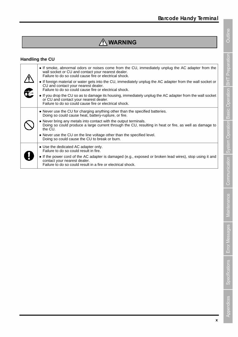
Handling the CU
If smoke, abnormal odors or noises come from the CU, immediately unplug the AC adapter from the wall socket or CU and contact your nearest dealer. Failure to do so could cause fire or electrical shock.
If foreign material or water gets into the CU, immediately unplug the AC adapter from the wall socket or CU and contact your nearest dealer. Failure to do so could cause fire or electrical shock.
If you drop the CU so as to damage its housing, immediately unplug the AC adapter from the wall socket or CU and contact your nearest dealer. Failure to do so could cause fire or electrical shock.
Never use the CU for charging anything other than the specified batteries. Doing so could cause heat, battery-rupture, or fire.
Never bring any metals into contact with the output terminals. Doing so could produce a large current through the CU, resulting in heat or fire, as well as damage to the CU.
Never use the CU on the line voltage other than the specified level. Doing so could cause the CU to break or burn.
Use the dedicated AC adapter only. Failure to do so could result in fire.
If the power cord of the AC adapter is damaged (e.g., exposed or broken lead wires), stop using it and contact your nearest dealer. Failure to do so could result in a fire or electrical shock.
xi
BHT-904B/BHT-914B
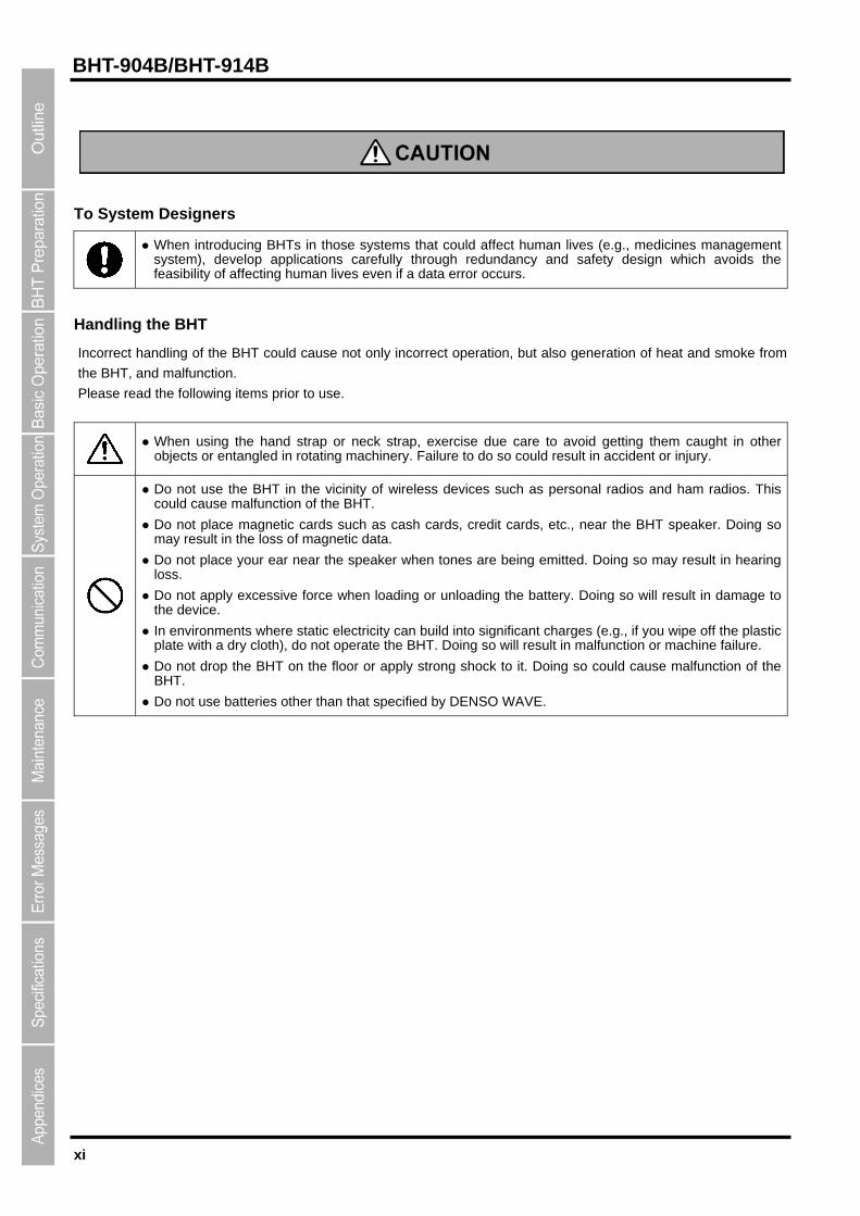
To System Designers
When introducing BHTs in those systems that could affect human lives (e.g., medicines management system), develop applications carefully through redundancy and safety design which avoids the feasibility of affecting human lives even if a data error occurs.
Handling the BHT
Incorrect handling of the BHT could cause not only incorrect operation, but also generation of heat and smoke from
the BHT, and malfunction.
Please read the following items prior to use.
When using the hand strap or neck strap, exercise due care to avoid getting them caught in other objects or entangled in rotating machinery. Failure to do so could result in accident or injury.
Do not use the BHT in the vicinity of wireless devices such as personal radios and ham radios. This could cause malfunction of the BHT.
Do not place magnetic cards such as cash cards, credit cards, etc., near the BHT speaker. Doing so may result in the loss of magnetic data.
Do not place your ear near the speaker when tones are being emitted. Doing so may result in hearing loss.
Do not apply excessive force when loading or unloading the battery. Doing so will result in damage to the device.
In environments where static electricity can build into significant charges (e.g., if you wipe off the plastic plate with a dry cloth), do not operate the BHT. Doing so will result in malfunction or machine failure.
Do not drop the BHT on the floor or apply strong shock to it. Doing so could cause malfunction of the BHT.
Do not use batteries other than that specified by DENSO WAVE.
xii
Barcode Handy Terminal
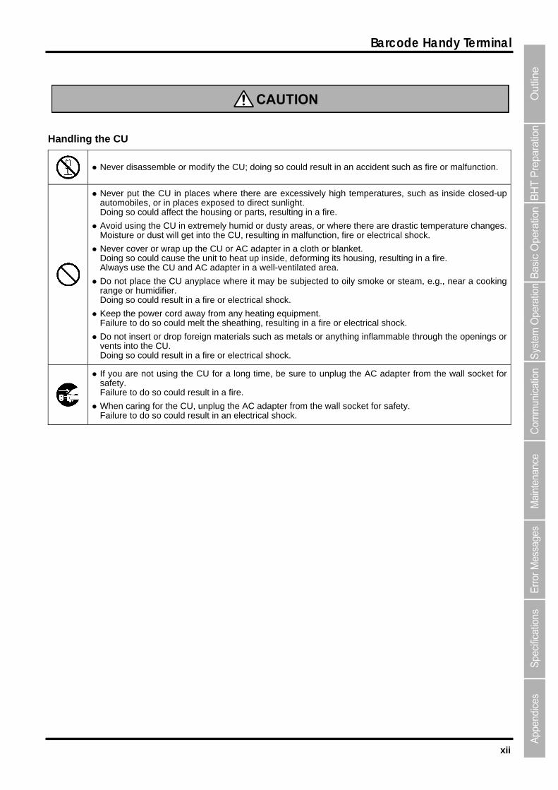
Handling the CU
Never disassemble or modify the CU; doing so could result in an accident such as fire or malfunction.
Never put the CU in places where there are excessively high temperatures, such as inside closed-up automobiles, or in places exposed to direct sunlight. Doing so could affect the housing or parts, resulting in a fire.
Avoid using the CU in extremely humid or dusty areas, or where there are drastic temperature changes.Moisture or dust will get into the CU, resulting in malfunction, fire or electrical shock.
Never cover or wrap up the CU or AC adapter in a cloth or blanket. Doing so could cause the unit to heat up inside, deforming its housing, resulting in a fire. Always use the CU and AC adapter in a well-ventilated area.
Do not place the CU anyplace where it may be subjected to oily smoke or steam, e.g., near a cooking range or humidifier. Doing so could result in a fire or electrical shock.
Keep the power cord away from any heating equipment. Failure to do so could melt the sheathing, resulting in a fire or electrical shock.
Do not insert or drop foreign materials such as metals or anything inflammable through the openings or vents into the CU. Doing so could result in a fire or electrical shock.
If you are not using the CU for a long time, be sure to unplug the AC adapter from the wall socket for safety. Failure to do so could result in a fire.
When caring for the CU, unplug the AC adapter from the wall socket for safety. Failure to do so could result in an electrical shock.

xiii
BHT-904B/BHT-914B

BHT-904B/BHT-914B
1.1 System Configuration・・・・・・・・・・・・・・・・・・・・・・・・・・・・・・・・・・・・・・・・・・・・・・ 2
Chapter 1
Outline
This chapter describes the BHT system and provides an overall outline of the BHT.
1.1.1 Hardware Configuration ・・・・・・・・・・・・・・・・・・・・・・・・・・・・・・・・・・・・・・・・・・・・ 2 1.1.2 Software Configuration ・・・・・・・・・・・・・・・・・・・・・・・・・・・・・・・・・・・・・・・・・・・・・ 4
1.2 Component Names and Functions ・・・・・・・・・・・・・・・・・・・・・・・・・・・・・・・・・・ 7 1.2.1 BHT Front/Rear・・・・・・・・・・・・・・・・・・・・・・・・・・・・・・・・・・・・・・・・・・・・・・・・・・・・ 7 1.2.2 Keypad/BHT Screen ・・・・・・・・・・・・・・・・・・・・・・・・・・・・・・・・・・・・・・・・・・・・・・・ 8
2
BHT-904B/BHT-914B
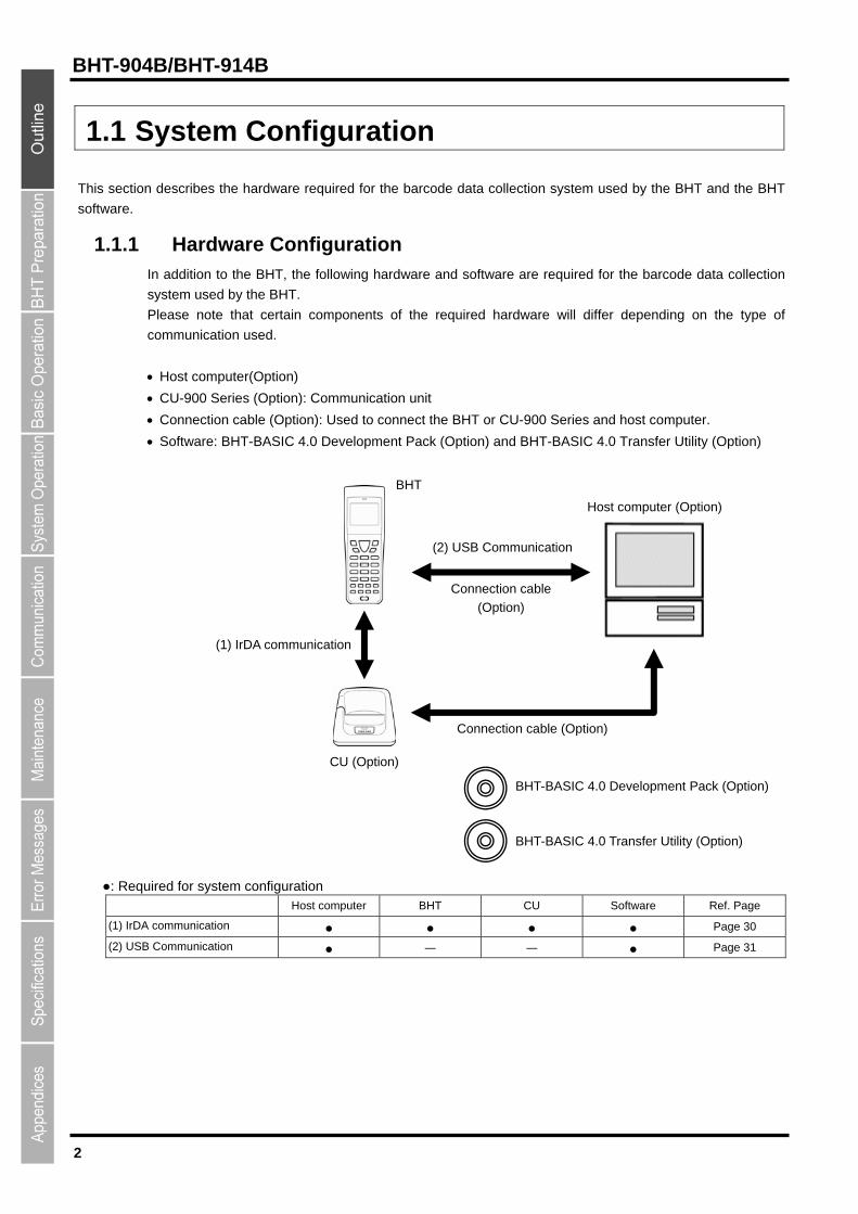
1.1 System Configuration
This section describes the hardware required for the barcode data collection system used by the BHT and the BHT
software.
1.1.1 Hardware Configuration In addition to the BHT, the following hardware and software are required for the barcode data collection
system used by the BHT.
Please note that certain components of the required hardware will differ depending on the type of
communication used.
Host computer(Option)
CU-900 Series (Option): Communication unit
Connection cable (Option): Used to connect the BHT or CU-900 Series and host computer.
Software: BHT-BASIC 4.0 Development Pack (Option) and BHT-BASIC 4.0 Transfer Utility (Option)
BHT Host computer (Option)
(2) USB Communication
Connection cable
(Option)
(1) IrDA communication
Connection cable (Option)
CU (Option)
BHT-BASIC 4.0 Development Pack (Option)
BHT-BASIC 4.0 Transfer Utility (Option)
●: Required for system configuration
Host computer BHT CU Software Ref. Page
(1) IrDA communication ● ● ● ● Page 30
(2) USB Communication ● - - ● Page 31
3
Barcode Handy Terminal
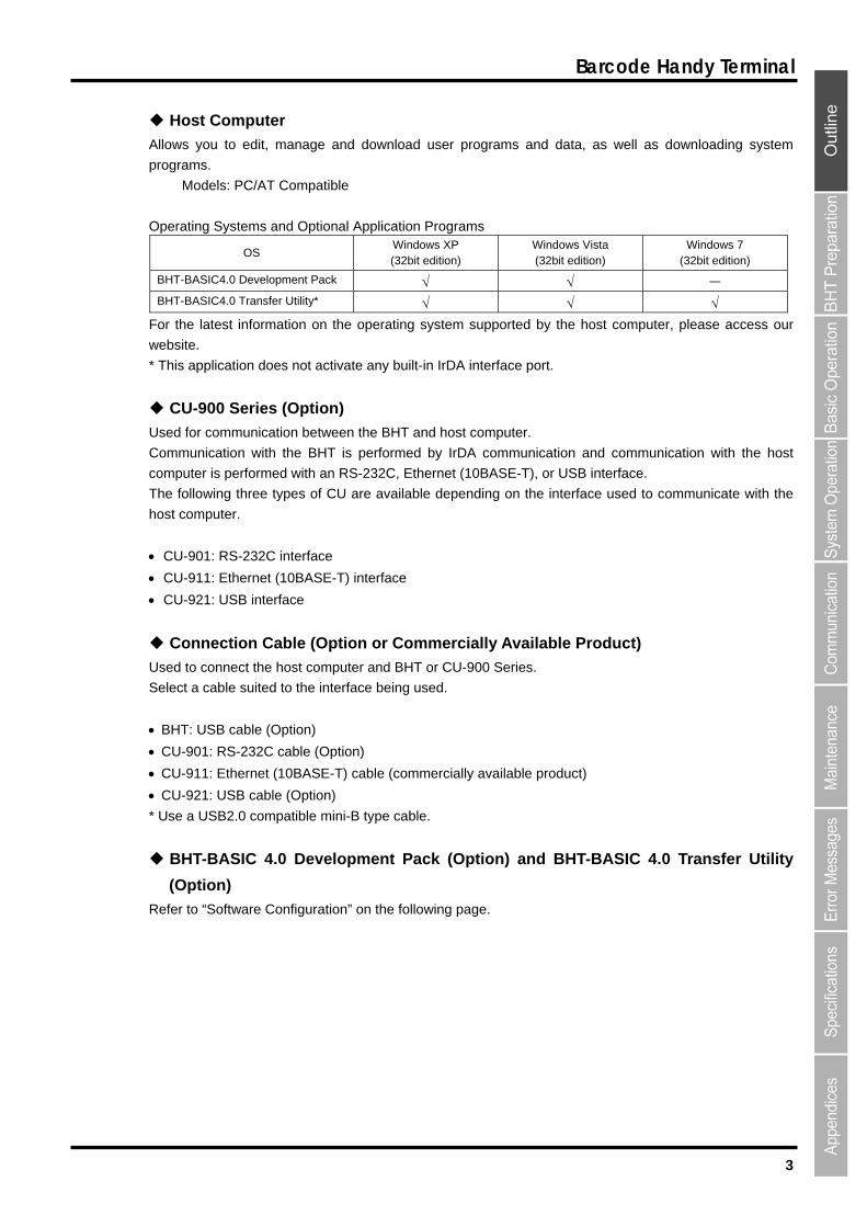
Host Computer
Allows you to edit, manage and download user programs and data, as well as downloading system
programs.
Models: PC/AT Compatible
Operating Systems and Optional Application Programs
OS Windows XP (32bit edition)
Windows Vista (32bit edition)
Windows 7 (32bit edition)
BHT-BASIC4.0 Development Pack - BHT-BASIC4.0 Transfer Utility*
For the latest information on the operating system supported by the host computer, please access our
website.
* This application does not activate any built-in IrDA interface port.
CU-900 Series (Option)
Used for communication between the BHT and host computer.
Communication with the BHT is performed by IrDA communication and communication with the host
computer is performed with an RS-232C, Ethernet (10BASE-T), or USB interface.
The following three types of CU are available depending on the interface used to communicate with the
host computer.
CU-901: RS-232C interface
CU-911: Ethernet (10BASE-T) interface
CU-921: USB interface
Connection Cable (Option or Commercially Available Product)
Used to connect the host computer and BHT or CU-900 Series.
Select a cable suited to the interface being used.
BHT: USB cable (Option)
CU-901: RS-232C cable (Option)
CU-911: Ethernet (10BASE-T) cable (commercially available product)
CU-921: USB cable (Option)
* Use a USB2.0 compatible mini-B type cable.
BHT-BASIC 4.0 Development Pack (Option) and BHT-BASIC 4.0 Transfer Utility
(Option)
Refer to “Software Configuration” on the following page.

4
BHT-904B/BHT-914B
1.1.2 Software Configuration This section describes the software used for BHT Series application development and application in
addition to the software used at the BHT unit.
Please note that the above-mentioned software can be downloaded (Certain versions may be for trial
use.) from the QBNet service discussed at “Customer Registration” on page ii.
[1] Application Development Procedure
The procedure for BHT Series program development is as follows.
Program creation
Program generation (compiling and linking)
Program download
Program execution and debugging
[2] Software Used for Application
BHT-BASIC Programmer’s Manual for BHT-900 Series
This is an instruction manual used to create handy terminal programs with BHT-BASIC.
BHT-BASIC 4.0 Development Pack (option)
This is a package containing two software products required for BHT-900 Series application development
and accessories.
The BHT-BASIC 4.0 Development Pack contains the following products.
BHT-BASIC 4.0 Compiler
Compiles and links a source program written in BHT-BASIC 4.0 to create a user program executable on
the BHT (*.PD4).
BHT-BASIC4.0 Transfer Utility
BHT-BASIC 4.0 specification files such as application programs and data files are transferred using
YMODEM protocol.
BHT-BASIC4.0 Transfer Utility (Option)
This is the same BHT-BASIC 4.0 Transfer Utility that comes bundled with the BHT-BASIC 4.0
Development Pack.
5
Barcode Handy Terminal
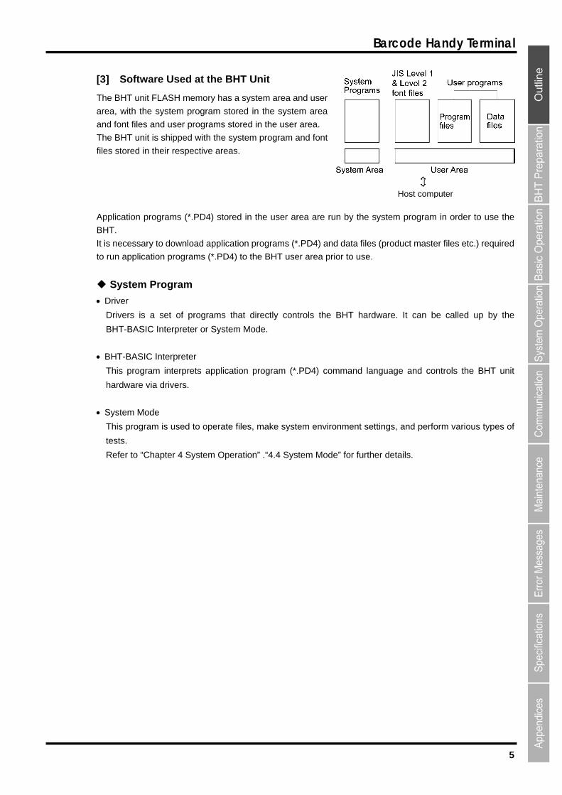
[3] Software Used at the BHT Unit
The BHT unit FLASH memory has a system area and user
area, with the system program stored in the system area
and font files and user programs stored in the user area.
The BHT unit is shipped with the system program and font
files stored in their respective areas.
Host computer
Application programs (*.PD4) stored in the user area are run by the system program in order to use the
BHT.
It is necessary to download application programs (*.PD4) and data files (product master files etc.) required
to run application programs (*.PD4) to the BHT user area prior to use.
System Program
Driver
Drivers is a set of programs that directly controls the BHT hardware. It can be called up by the
BHT-BASIC Interpreter or System Mode.
BHT-BASIC Interpreter
This program interprets application program (*.PD4) command language and controls the BHT unit
hardware via drivers.
System Mode
This program is used to operate files, make system environment settings, and perform various types of
tests.
Refer to “Chapter 4 System Operation” .“4.4 System Mode” for further details.
6
BHT-904B/BHT-914B
Font File
These files are required to display JIS 1 and 2 standard Kanji characters at the BHT unit LCD display.
By using font files, the BHT unit is able to display 12 or 16 dot Kanji in application programs (*.PD4).
Point If you do not need to display Kanji characters, you may delete these JIS font files. After deletion, thememory area which was occupied by these files can be used as a user area.
For the deleting procedure, refer to "Chapter 4 System Operation" - "4.1.4 Performing System Initialization" or "4.5.11 Deleting Font Files (DELETE FILE Menu)."
The names of the font file: FNT16J1.FN4 (JIS Level 1 font, 16-dot)
: FNT16J2.FN4 (JIS Level 2 font, 16-dot)
: FNT12J1.FN4 (JIS Level 1 font, 12-dot)
: FNT12J2.FN4 (JIS Level 2 font, 12-dot)
: FNTFSGB.FN4 (Simplified Chinese font)
: FNT16BG5.FN4 (Traditional Chinese font, 16-dot)
: FNT12BG5.FN4 (Traditional Chinese font, 12-dot)
: FNT16HG.FN4 (Hangul font, 16-dot)
: FNT12HG.FN4 (Hangul font, 12-dot)
: FNT16TH.FN4 (Thai font, 16-dot)
: FNT12TH.FN4 (Thai font, 12-dot)
User Programs
Application programs and data files are downloaded to the BHT user area and are collectively known as
user programs.
To download a BHT-BASIC 4.0 specification user program to the BHT unit, the BHT-BASIC 4.0 Transfer
Utility is required.
By using “drag & drop” function in windows explorer after connecting the BHT unit to a PC, a user
program can also be downloaded without using the BHT-BASIC 4.0 Transfer Utility.
Refer to “5.2 USB Communication” for further details.
7
Barcode Handy Terminal
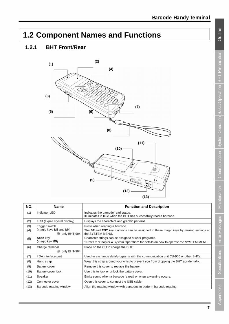
1.2 Component Names and Functions
1.2.1 BHT Front/Rear
(2)(1)
(4)
(3)
(7)(5) (6)
(8)
(11)
(10)
(9)
(12)
(13)
NO. Name Function and Description
(1) Indicator LED Indicates the barcode read status. Illuminates in blue when the BHT has successfully read a barcode.
(2) LCD (Liquid crystal display) Displays the characters and graphic patterns.
(3) (4)
(5)
Trigger switch (magic keys M3 and M4)
※ only BHT-904 Scan key (magic key M5)
Press when reading a barcode. The SF and ENT key functions can be assigned to these magic keys by making settings at the SYSTEM MENU. Character strings can be assigned at user programs. * Refer to “Chapter 4 System Operation” for details on how to operate the SYSTEM MENU.
(6) Charge terminal ※ only BHT-904
Place on the CU to charge the BHT.
(7) IrDA interface port Used to exchange data/programs with the communication unit CU-900 or other BHTs.
(8) Hand strap Wear this strap around your wrist to prevent you from dropping the BHT accidentally.
(9) Battery cover Remove this cover to replace the battery.
(10) Battery cover lock Use this to lock or unlock the battery cover.
(11) Speaker Emits sound when a barcode is read or when a warning occurs.
(12) Connector cover Open this cover to connect the USB cable.
(13) Barcode reading window Align the reading window with barcodes to perform barcode reading.
8
BHT-904B/BHT-914B
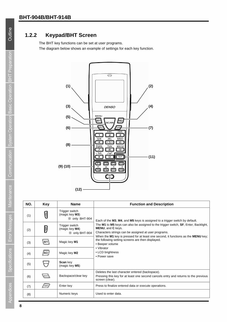
1.2.2 Keypad/BHT Screen The BHT key functions can be set at user programs.
The diagram below shows an example of settings for each key function.
(1) (2)
(3) (4)
(5)
(6) (7)
(8)
(11)
(9) (10)
(12)
NO. Key Name Function and Description
(1)
Trigger switch (magic key M3)
※ only BHT-904
(2)
Trigger switch (magic key M4)
※ only BHT-904
(3) Magic key M1
(4) Magic key M2
(5)
Scan key (magic key M5)
Each of the M3, M4, and M5 keys is assigned to a trigger switch by default. The M1 to M5 keys can also be assigned to the trigger switch, SF, Enter, Backlight, MENU, and C keys. Characters strings can be assigned at user programs. When the M1 key is pressed for at least one second, it functions as the MENU key; the following setting screens are then displayed. • Beeper volume • Vibrator • LCD brightness • Power save
(6) Backspace/clear key Deletes the last character entered (backspace). Pressing this key for at least one second cancels entry and returns to the previous screen (clear).
(7) Enter key Press to finalize entered data or execute operations.
(8) Numeric keys Used to enter data.
9
Barcode Handy Terminal
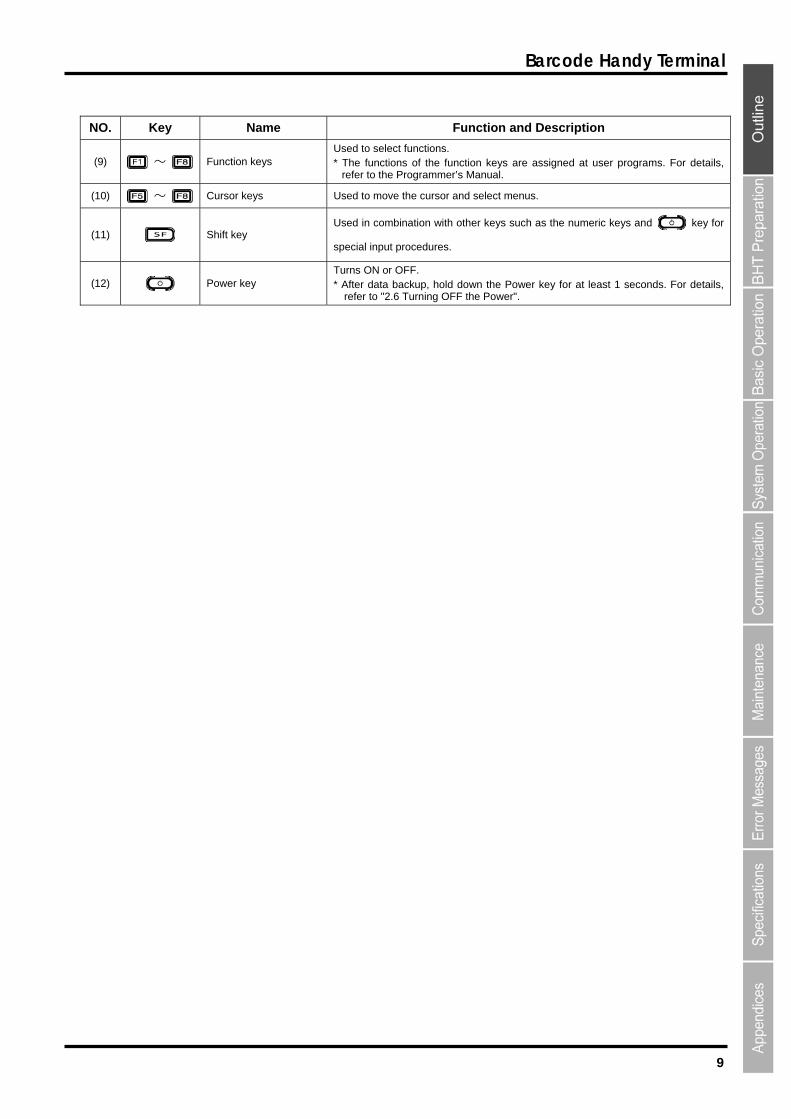
NO. Key Name Function and Description
(9) ~ Function keys Used to select functions. * The functions of the function keys are assigned at user programs. For details,
refer to the Programmer’s Manual.
(10) ~ Cursor keys Used to move the cursor and select menus.
(11) Shift key Used in combination with other keys such as the numeric keys and key for
special input procedures.
(12) Power key Turns ON or OFF. * After data backup, hold down the Power key for at least 1 seconds. For details,
refer to "2.6 Turning OFF the Power".
10
BHT-904B/BHT-914B
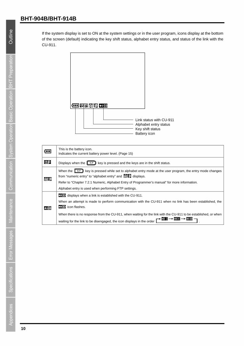
If the system display is set to ON at the system settings or in the user program, icons display at the bottom
of the screen (default) indicating the key shift status, alphabet entry status, and status of the link with the
CU-911.
Link status with CU-911 Alphabet entry status Key shift status Battery icon
This is the battery icon. Indicates the current battery power level. (Page 15)
Displays when the key is pressed and the keys are in the shift status.
When the key is pressed while set to alphabet entry mode at the user program, the entry mode changes
from “numeric entry” to “alphabet entry” and displays.
Refer to “Chapter 7.2.1 Numeric, Alphabet Entry of Programmer’s manual” for more information.
Alphabet entry is used when performing FTP settings.
displays when a link is established with the CU-911.
When an attempt is made to perform communication with the CU-911 when no link has been established, the
icon flashes.
When there is no response from the CU-911, when waiting for the link with the CU-911 to be established, or when
waiting for the link to be disengaged, the icon displays in the order .

BHT-904B/BHT-914B
Chapter 2
BHT Preparation
This chapter presents information on how to load the battery, turn ON/OFF the BHT
power, and on the use of the hand strap.
2.1 “BHT Preparation” Procedure ・・・・・・・・・・・・・・・・・・・・・・・・・・・・・・・・・・・・・12
2.2 Loading the Battery ・・・・・・・・・・・・・・・・・・・・・・・・・・・・・・・・・・・・・・・・・・・・・・13 2.2.1 Battery Power Level Indicator ・・・・・・・・・・・・・・・・・・・・・・・・・・・・・・・・・・・・・・ 15
2.3 Wearing the Hand Strap ・・・・・・・・・・・・・・・・・・・・・・・・・・・・・・・・・・・・・・・・・・16 2.3.1 Attaching the Hand Strap ・・・・・・・・・・・・・・・・・・・・・・・・・・・・・・・・・・・・・・・・・・ 16 2.3.2 Holding the BHT ・・・・・・・・・・・・・・・・・・・・・・・・・・・・・・・・・・・・・・・・・・・・・・・・・・ 16
2.4 Initial Setup (Setting the date, time, and message language)・・・・・・・・・・・17 2.5 Easy Pack Ad for BHT-900 ・・・・・・・・・・・・・・・・・・・・・・・・・・・・・・・・・・・・・・・・18
2.5.1 Features ・・・・・・・・・・・・・・・・・・・・・・・・・・・・・・・・・・・・・・・・・・・・・・・・・・・・・・・・・ 18 2.5.2 Activating the Application ・・・・・・・・・・・・・・・・・・・・・・・・・・・・・・・・・・・・・・・・・・ 18
2.6 Turning OFF the Power ・・・・・・・・・・・・・・・・・・・・・・・・・・・・・・・・・・・・・・・・・・・19 2.6.1 Normal Power OFF ・・・・・・・・・・・・・・・・・・・・・・・・・・・・・・・・・・・・・・・・・・・・・・・ 19 2.6.2 Turning the Power OFF after Data Back-up・・・・・・・・・・・・・・・・・・・・・・・・・・・ 20 2.6.3 Auto Power OFF・・・・・・・・・・・・・・・・・・・・・・・・・・・・・・・・・・・・・・・・・・・・・・・・・・ 20 2.6.4 If the BHT Is Shut Down Abnormally・・・・・・・・・・・・・・・・・・・・・・・・・・・・・・・・・ 20 2.6.5 If Broken Files Are Found ・・・・・・・・・・・・・・・・・・・・・・・・・・・・・・・・・・・・・・・・・・ 22
12
BHT-904B/BHT-914B
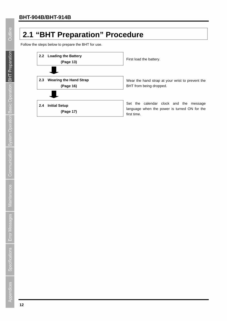
2.1 “BHT Preparation” Procedure Follow the steps below to prepare the BHT for use.
2.2 Loading the Battery
(Page 13) First load the battery.
2.3 Wearing the Hand Strap
(Page 16)
Wear the hand strap at your wrist to prevent the
BHT from being dropped.
2.4 Initial Setup
(Page 17)
Set the calendar clock and the message
language when the power is turned ON for the
first time.
13
Barcode Handy Terminal
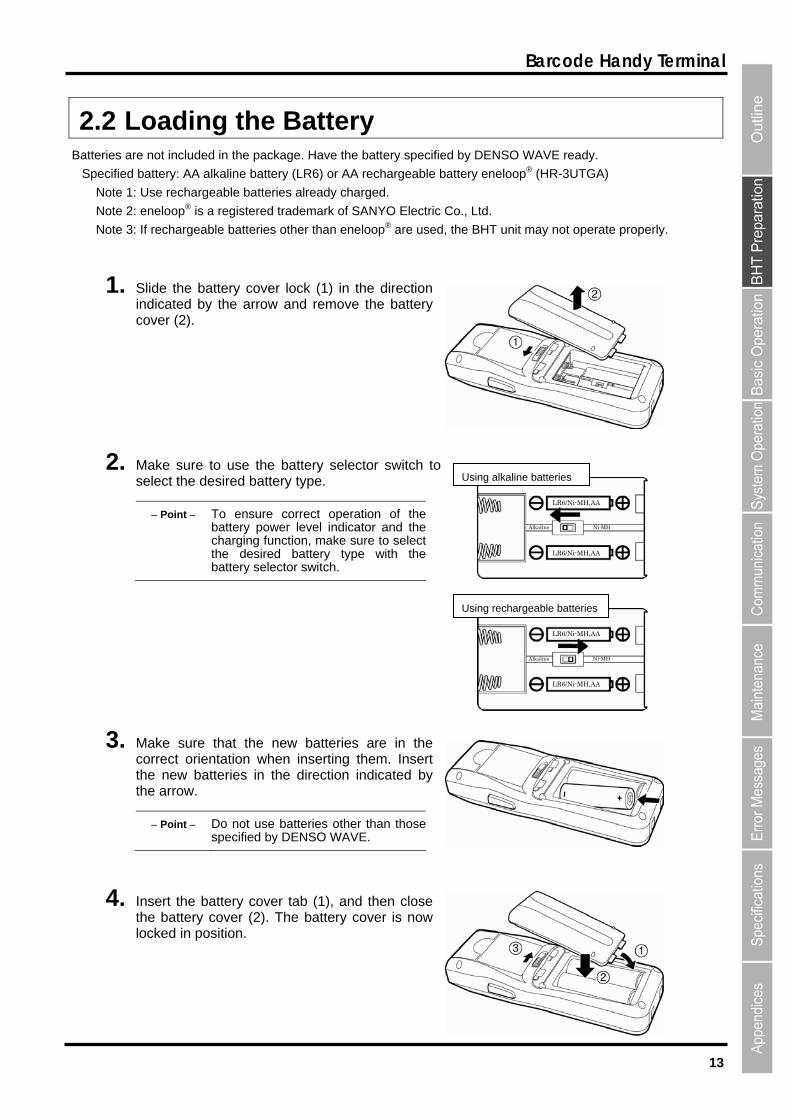
2.2 Loading the Battery Batteries are not included in the package. Have the battery specified by DENSO WAVE ready.
Specified battery: AA alkaline battery (LR6) or AA rechargeable battery eneloop® (HR-3UTGA)
Note 1: Use rechargeable batteries already charged.
Note 2: eneloop® is a registered trademark of SANYO Electric Co., Ltd.
Note 3: If rechargeable batteries other than eneloop® are used, the BHT unit may not operate properly.
1. Slide the battery cover lock (1) in the direction indicated by the arrow and remove the battery cover (2).
2. Make sure to use the battery selector switch to select the desired battery type.
LR6/Ni-MH,AA
Alkaline Ni-MH
LR6/Ni-MH,AA
Using alkaline batteries
Point To ensure correct operation of thebattery power level indicator and thecharging function, make sure to selectthe desired battery type with thebattery selector switch.
Using rechargeable batteries
LR6/Ni-MH,AA
LR6/Ni-MH,AA
Alkaline Ni-MH
3. Make sure that the new batteries are in the correct orientation when inserting them. Insert the new batteries in the direction indicated by the arrow.
Point Do not use batteries other than thosespecified by DENSO WAVE.
4. Insert the battery cover tab (1), and then close the battery cover (2). The battery cover is now locked in position.
14
BHT-904B/BHT-914B
Mishandling of the battery may result in electrical shock, overheating, smoke generation,combustion, or blowout. Please read the following items prior to use.
Never disassemble or modify the batteries.
Never connect the battery (+) and (-) terminals with a metal object such as a piece of wire.
Never carry or store the batteries together with metallic necklaces, hairpins and so on.
Never expose the batteries to fire or apply heat.
Never use or leave the batteries in the vicinity of high-temperature locations (60° C or higher)such as a fire or stove.
Never place the batteries into or soak them in water or seawater.
Never charge or use the battery where any inflammable gases may be emitted.
Never hammer nails into the batteries, hit them with a hammer, or trample on them.
Never apply strong impact to or throw the batteries.
Never use significantly damaged or deformed batteries.
Never apply solder directly to the batteries.
During use, charging, or storage of the battery, if odors come from the battery, the battery isoverheated, discolored, deformed, or anything unusual is found, unload the battery from theBHT. Do not use the battery.
If battery fluid leaked from the batteries get into the eyes or come into contact with the skin,wash thoroughly with clean water such as tap water without rubbing, and obtain medicaltreatment immediately. Failure to do so will result in eye or skin injuries.
Important If the BHT unit is left with the battery removed for an extended period, the memory contents willno longer be backed up and the message “Contact your administrator. Note the error number.(XXXX)” or “Set the current date and time.” may appear on the LCD.
Refer to “Chapter 6 Maintenance” – “6.2.3 Using the BHT after Long Periods” for details ofhandling the BHT after long periods of time.
Do not touch the BHT and battery terminals by hand or stain them. Doing so may result in aBHT malfunction. It is recommended that dirt on the battery terminals or BHT battery terminalsbe periodically wiped with a soft and dry cloth.
15
Barcode Handy Terminal
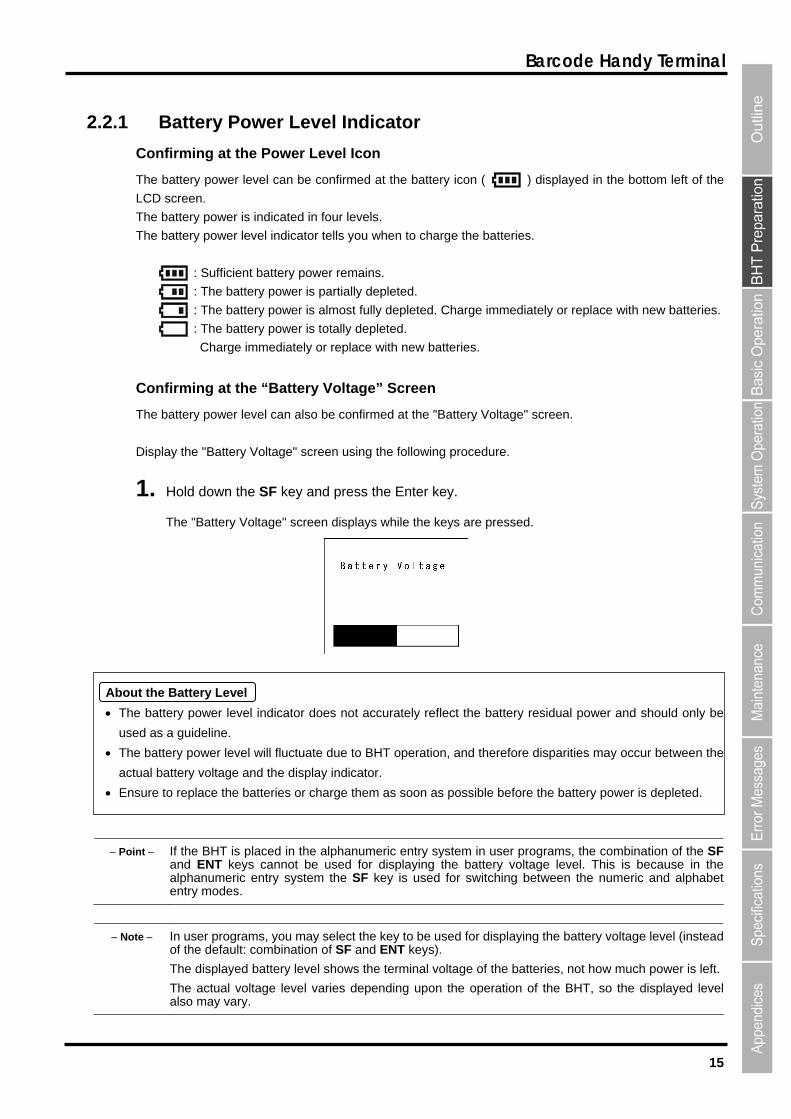
2.2.1 Battery Power Level Indicator
Confirming at the Power Level Icon
The battery power level can be confirmed at the battery icon ( ) displayed in the bottom left of the
LCD screen.
The battery power is indicated in four levels.
The battery power level indicator tells you when to charge the batteries.
: Sufficient battery power remains.
: The battery power is partially depleted.
: The battery power is almost fully depleted. Charge immediately or replace with new batteries.
: The battery power is totally depleted.
Charge immediately or replace with new batteries.
Confirming at the “Battery Voltage” Screen
The battery power level can also be confirmed at the "Battery Voltage" screen.
Display the "Battery Voltage" screen using the following procedure.
1. Hold down the SF key and press the Enter key.
The "Battery Voltage" screen displays while the keys are pressed.
About the Battery Level
The battery power level indicator does not accurately reflect the battery residual power and should only be
used as a guideline.
The battery power level will fluctuate due to BHT operation, and therefore disparities may occur between the
actual battery voltage and the display indicator.
Ensure to replace the batteries or charge them as soon as possible before the battery power is depleted.
Point If the BHT is placed in the alphanumeric entry system in user programs, the combination of the SFand ENT keys cannot be used for displaying the battery voltage level. This is because in thealphanumeric entry system the SF key is used for switching between the numeric and alphabetentry modes.
Note In user programs, you may select the key to be used for displaying the battery voltage level (insteadof the default: combination of SF and ENT keys).
The displayed battery level shows the terminal voltage of the batteries, not how much power is left.
The actual voltage level varies depending upon the operation of the BHT, so the displayed levelalso may vary.

16
BHT-904B/BHT-914B
2.3 Wearing the Hand Strap
Wear the hand strap to prevent the BHT from being accidentally dropped during use.
2.3.1 Attaching the Hand Strap Attach the hand strap to the BHT as shown below.
2.3.2 Holding the BHT Wear the hand strap to your wrist and hold the BHT as shown below.
or
17
Barcode Handy Terminal
2.4 Initial Setup (Setting the date, time, and
message language)
Turn ON the power after inserting the batteries into the BHT.
Note that the clock and message language are not set at the time of purchase. Therefore, it is necessary to make
those settings when turning ON the power for the first time.
When resetting the date and time, operate the BHT according to the following procedures.
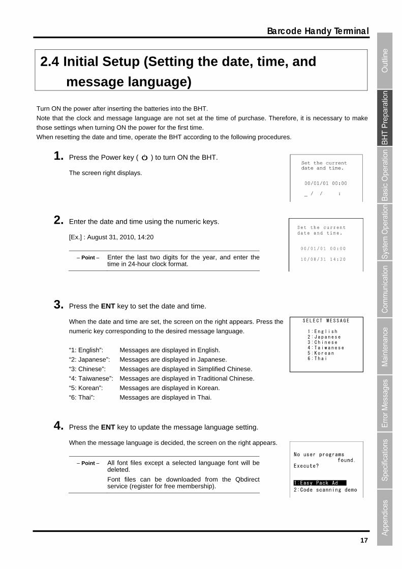
1. Press the Power key ( ) to turn ON the BHT.
The screen right displays.
2. Enter the date and time using the numeric keys.
[Ex.] : August 31, 2010, 14:20
Point Enter the last two digits for the year, and enter thetime in 24-hour clock format.
3. Press the ENT key to set the date and time.
When the date and time are set, the screen on the right appears. Press the
numeric key corresponding to the desired message language.
“1: English”: Messages are displayed in English.
“2: Japanese”: Messages are displayed in Japanese.
“3: Chinese”: Messages are displayed in Simplified Chinese.
“4: Taiwanese”: Messages are displayed in Traditional Chinese.
“5: Korean”: Messages are displayed in Korean.
“6: Thai”: Messages are displayed in Thai.
S E L E C T M E S S A G E
1 : E n g l i s h 2 : J a p a n e s e 3 : C h i n e s e 4 : T a i w a n e s e 5 : K o r e a n 6 : T h a i
4. Press the ENT key to update the message language setting.
When the message language is decided, the screen on the right appears.
Point All font files except a selected language font will be deleted.
Font files can be downloaded from the Qbdirectservice (register for free membership).

18
BHT-904B/BHT-914B
5. Press numeric key [1] or [2] and ENT key to select either of the following items.
1: Easy Pack Ad
Activates the easy operation application software.
For details, refer to the manual accompanying with the application.
2: Code scanning demo
A scanning demo commences.
The scanning demo is a program that allows barcodes to be read without a user program. Press the
trigger switch to enable barcode reading.
Refer to "Chapter 3 Basic Operation" – “3.1 Reading Barcodes” and read a barcode.
Point The easy operation application software “Easy Pack Ad for BHT-900” is activated by selecting [1: Easy Pack Ad].
2.5 Easy Pack Ad for BHT-900
The BHT-900 is shipped with the simple job application [Easy Pack Ad for BHT-900] that was used with the BHT.
2.5.1 Features [Easy Pack Ad for BHT-900] has the features listed below.
・[Easy Pack Ad for BHT-900] is prepared with the following jobs. Collect : Enter multiple part numbers (Part No.) and the corresponding quantities (Qty.), and then save a
record of the data in the "JISSEKI.CSV" file.
1:1 Verify : Two sets of data are read in order, and then compared. If the two sets of data do not match, an error is reported.
1:n Verify : A set of data is read and repeatedly compared to a master data file. If the data does not match with the master data, an error is reported.
・When the BHT is directly connected to a PC using a USB cable, achievement files can be obtained in the desired folder via drag-and-drop in Windows Explore. Refer to "5.2 USB Communication" for further details.
2.5.2 Activating the Application
1. Select “1: Easy Pack Ad” in step 4 of 2.4 and then press the ENT key.
The screen on the right appears.
19
Barcode Handy Terminal
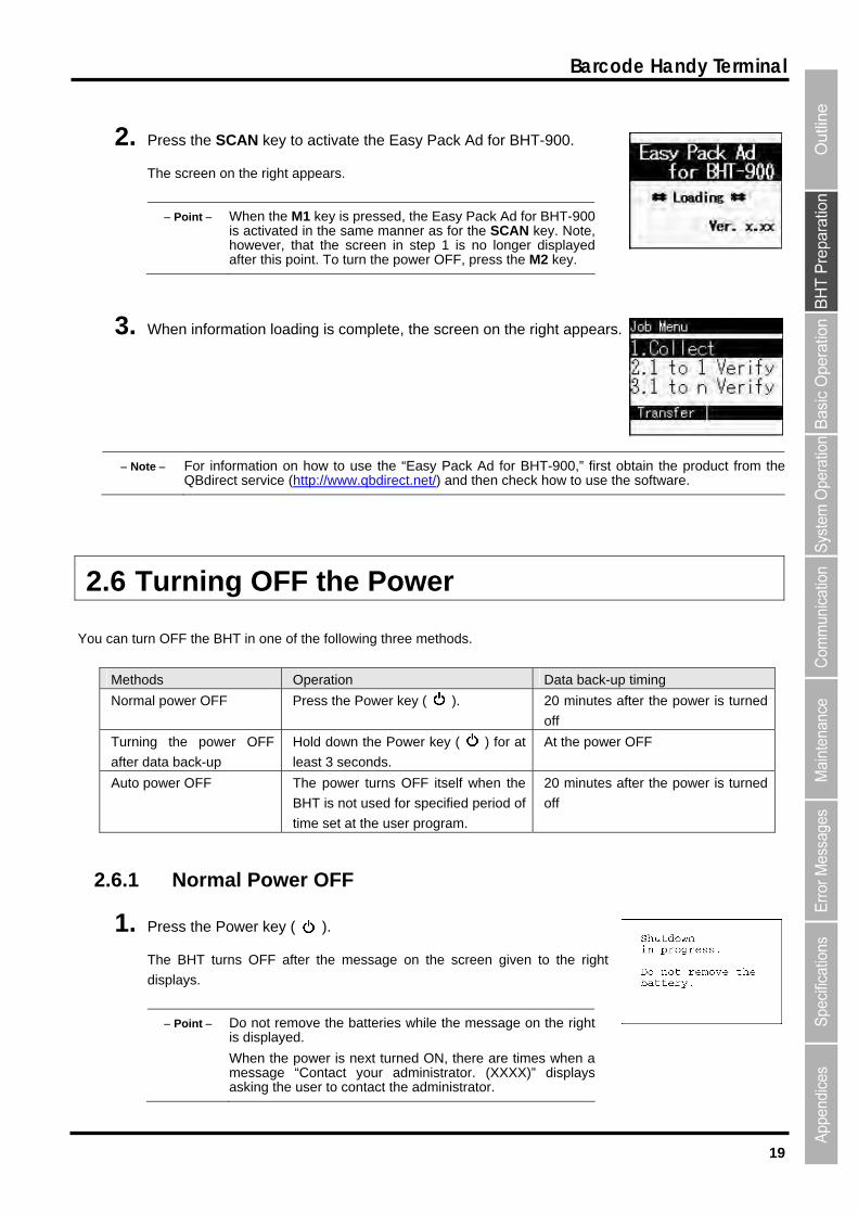
2. Press the SCAN key to activate the Easy Pack Ad for BHT-900.
The screen on the right appears.
Point When the M1 key is pressed, the Easy Pack Ad for BHT-900 is activated in the same manner as for the SCAN key. Note, however, that the screen in step 1 is no longer displayedafter this point. To turn the power OFF, press the M2 key.
3. When information loading is complete, the screen on the right appears.
Note For information on how to use the “Easy Pack Ad for BHT-900,” first obtain the product from the QBdirect service (http://www.qbdirect.net/) and then check how to use the software.
2.6 Turning OFF the Power
You can turn OFF the BHT in one of the following three methods.
Methods Operation Data back-up timing
Normal power OFF Press the Power key ( ). 20 minutes after the power is turned
off
Turning the power OFF
after data back-up
Hold down the Power key ( ) for at
least 3 seconds.
At the power OFF
Auto power OFF The power turns OFF itself when the
BHT is not used for specified period of
time set at the user program.
20 minutes after the power is turned
off
2.6.1 Normal Power OFF
1. Press the Power key ( ).
The BHT turns OFF after the message on the screen given to the right
displays.
Point Do not remove the batteries while the message on the rightis displayed.
When the power is next turned ON, there are times when amessage “Contact your administrator. (XXXX)” displaysasking the user to contact the administrator.
20
BHT-904B/BHT-914B
2.6.2 Turning the Power OFF after Data Back-up
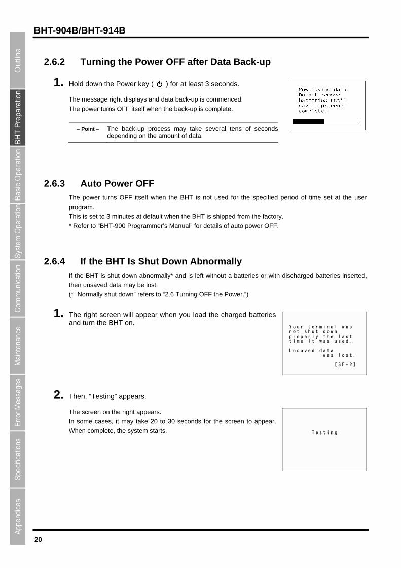
1. Hold down the Power key ( ) for at least 3 seconds.
The message right displays and data back-up is commenced.
The power turns OFF itself when the back-up is complete.
Point The back-up process may take several tens of secondsdepending on the amount of data.
2.6.3 Auto Power OFF The power turns OFF itself when the BHT is not used for the specified period of time set at the user
program.
This is set to 3 minutes at default when the BHT is shipped from the factory.
* Refer to “BHT-900 Programmer’s Manual” for details of auto power OFF.
2.6.4 If the BHT Is Shut Down Abnormally If the BHT is shut down abnormally* and is left without a batteries or with discharged batteries inserted,
then unsaved data may be lost.
(* “Normally shut down” refers to “2.6 Turning OFF the Power.”)
1. The right screen will appear when you load the charged batteries and turn the BHT on.
2. Then, “Testing” appears.
The screen on the right appears.
In some cases, it may take 20 to 30 seconds for the screen to appear.
When complete, the system starts.
21
Barcode Handy Terminal
If Scandisk finds a broken file or files, the screen on the right appears.
(If any broken files exist, the screen on the right appears each time the
BHT starts.)
(Refer to “About “$$BRKLST.SYS” on the following page.)
After a few seconds with the screen displayed, the system starts.
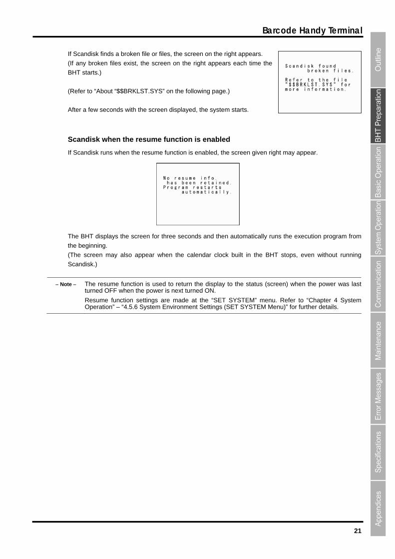
Scandisk when the resume function is enabled
If Scandisk runs when the resume function is enabled, the screen given right may appear.
The BHT displays the screen for three seconds and then automatically runs the execution program from
the beginning.
(The screen may also appear when the calendar clock built in the BHT stops, even without running
Scandisk.)
Note The resume function is used to return the display to the status (screen) when the power was lastturned OFF when the power is next turned ON.
Resume function settings are made at the “SET SYSTEM” menu. Refer to “Chapter 4 SystemOperation” – “4.5.6 System Environment Settings (SET SYSTEM Menu)” for further details.
22
BHT-904B/BHT-914B
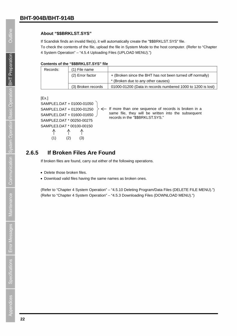
About “$$BRKLST.SYS”
If Scandisk finds an invalid file(s), it will automatically create the "$$BRKLST.SYS" file.
To check the contents of the file, upload the file in System Mode to the host computer. (Refer to “Chapter
4 System Operation” – “4.5.4 Uploading Files (UPLOAD MENU).”)
Contents of the “$$BRKLST.SYS” file
(1) File name
(2) Error factor + (Broken since the BHT has not been turned off normally)
* (Broken due to any other causes)
Records:
(3) Broken records 01000-01200 (Data in records numbered 1000 to 1200 is lost)
[Ex.]
SAMPLE1.DAT + 01000-01050 If more than one sequence of records is broken in a same file, they will be written into the subsequent records in the "$$BRKLST.SYS."
SAMPLE1.DAT + 01200-01250
SAMPLE1.DAT + 01600-01650
SAMPLE2.DAT * 00250-00275
SAMPLE3.DAT * 00100-00150
(1) (2) (3)
2.6.5 If Broken Files Are Found If broken files are found, carry out either of the following operations.
Delete those broken files.
Download valid files having the same names as broken ones.
(Refer to “Chapter 4 System Operation” – “4.5.10 Deleting Program/Data Files (DELETE FILE MENU).”)
(Refer to “Chapter 4 System Operation” – “4.5.3 Downloading Files (DOWNLOAD MENU).")
BHT-904B/BHT-914B
Chapter 3
Basic Operation
This chapter describes basic operations such as barcode reading, numeric data
entry and item selection using the BHT, basic changes to settings, and BHT data
transmission.
3.1 Reading Barcodes ・・・・・・・・・・・・・・・・・・・・・・・・・・・・・・・・・・・・・・・・・・・・・・・24 3.2 Numeric Data Entry ・・・・・・・・・・・・・・・・・・・・・・・・・・・・・・・・・・・・・・・・・・・・・・26 3.3 Task Selection・・・・・・・・・・・・・・・・・・・・・・・・・・・・・・・・・・・・・・・・・・・・・・・・・・・26 3.4 Changing the Default Settings ・・・・・・・・・・・・・・・・・・・・・・・・・・・・・・・・・・・・・27
3.4.1 Procedure ・・・・・・・・・・・・・・・・・・・・・・・・・・・・・・・・・・・・・・・・・・・・・・・・・・・・・・・ 27 3.5 Transmitting Data ・・・・・・・・・・・・・・・・・・・・・・・・・・・・・・・・・・・・・・・・・・・・・・・・29
3.5.1 IrDA communication・・・・・・・・・・・・・・・・・・・・・・・・・・・・・・・・・・・・・・・・・・・・・・・ 30 3.5.2 USB Communication ・・・・・・・・・・・・・・・・・・・・・・・・・・・・・・・・・・・・・・・・・・・・・・ 31
24
BHT-904B/BHT-914B
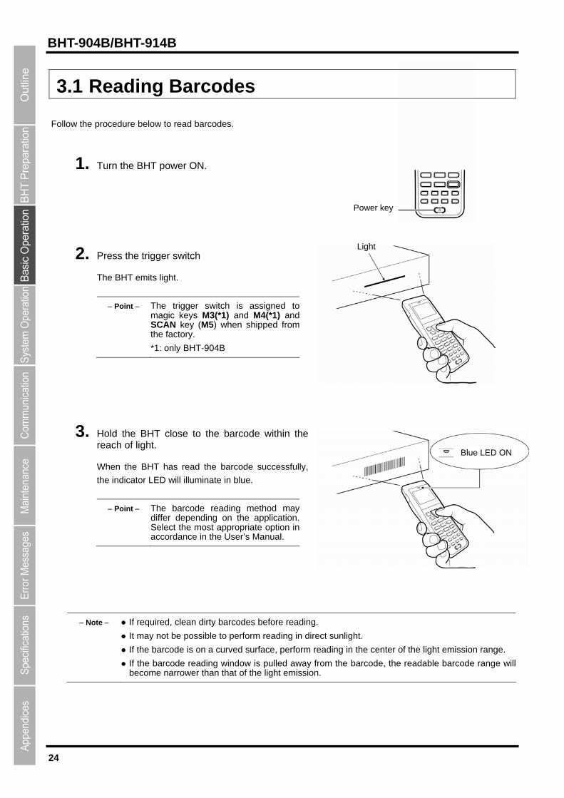
3.1 Reading Barcodes
Follow the procedure below to read barcodes.
1. Turn the BHT power ON.
Blue LED ON
Power key
Light 2. Press the trigger switch
The BHT emits light.
Point The trigger switch is assigned tomagic keys M3(*1) and M4(*1) and SCAN key (M5) when shipped fromthe factory.
*1: only BHT-904B
3. Hold the BHT close to the barcode within the reach of light.
When the BHT has read the barcode successfully,
the indicator LED will illuminate in blue.
Point The barcode reading method maydiffer depending on the application.Select the most appropriate option in accordance in the User’s Manual.
Note If required, clean dirty barcodes before reading.
It may not be possible to perform reading in direct sunlight.
If the barcode is on a curved surface, perform reading in the center of the light emission range.
If the barcode reading window is pulled away from the barcode, the readable barcode range willbecome narrower than that of the light emission.
25
Barcode Handy Terminal
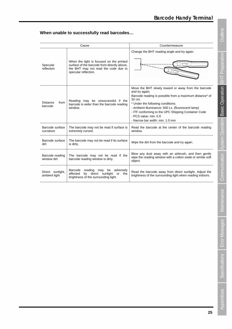
When unable to successfully read barcodes…
Cause Countermeasure
Specular reflection
When the light is focused on the printed surface of the barcode from directly above, the BHT may not read the code due to specular reflection.
Change the BHT reading angle and try again.
Distance from barcode
Reading may be unsuccessful if the barcode is wider than the barcode reading window.
Move the BHT slowly toward or away from the barcode and try again. Barcode reading is possible from a maximum distance* of 32 cm. * Under the following conditions: - Ambient illuminance: 500 Lx. (fluorescent lamp) - ITF conforming to the UPC Shipping Container Code - PCS value: min. 0.9 - Narrow bar width: min. 1.0 mm
Barcode surface curvature
The barcode may not be read if surface is extremely curved.
Read the barcode at the center of the barcode reading window.
Barcode surface dirt
The barcode may not be read if its surface is dirty.
Wipe the dirt from the barcode and try again.
Barcode reading window dirt
The barcode may not be read if the barcode reading window is dirty.
Blow any dust away with an airbrush, and then gently wipe the reading window with a cotton swab or similar soft object.
Direct sunlight, ambient light
Barcode reading may be adversely affected by direct sunlight or the brightness of the surrounding light.
Read the barcode away from direct sunlight. Adjust the brightness of the surrounding light when reading indoors.

26
BHT-904B/BHT-914B
3.2 Numeric Data Entry
Enter numeric data such as product volume with the numeric keys and Enter ( ) key.
If numeric data is entered incorrectly, use the Backspace/clear key ( ) to delete the data and then reenter with
the numeric keys.
When Entering “120” Key Operation
Press numeric keys [1], [2], and [0] followed by the
Enter key.
3.3 Task Selection
If a selection item "such as “1: XXX 2: XXX” with numeric values displays, enter the values with the numeric entry
keys and then press the Enter key.
When Selecting Task 2: XXX Key Operation
Press numeric key [2] followed by the Enter key.
If a YES/NO selection screen such as “1: YES 2: NO” displays, press numeric key [1] to select “YES”, and [2] to select
“NO”.
When Selecting “1: YES” Key Operation
Press numeric key [1] followed by the Enter key.
27
Barcode Handy Terminal
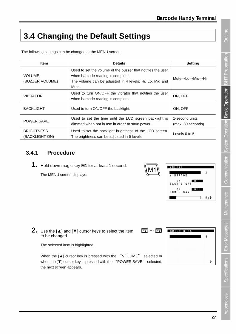
3.4 Changing the Default Settings
The following settings can be changed at the MENU screen.
Item Details Setting
VOLUME
(BUZZER VOLUME)
Used to set the volume of the buzzer that notifies the user
when barcode reading is complete.
The volume can be adjusted in 4 levels: Hi, Lo, Mid and
Mute.
Mute→Lo→Mid→Hi
VIBRATOR Used to turn ON/OFF the vibrator that notifies the user
when barcode reading is complete. ON, OFF
BACKLIGHT Used to turn ON/OFF the backlight. ON, OFF
POWER SAVE Used to set the time until the LCD screen backlight is
dimmed when not in use in order to save power.
1-second units
(max. 30 seconds)
BRIGHTNESS
(BACKLIGHT ON)
Used to set the backlight brightness of the LCD screen.
The brightness can be adjusted in 6 levels. Levels 0 to 5
3.4.1 Procedure
1. Hold down magic key M1 for at least 1 second.
The MENU screen displays.
2. Use the [▲] and [▼] cursor keys to select the item to be changed.
The selected item is highlighted.
When the [▲] cursor key is pressed with the “VOLUME” selected or
when the [▼] cursor key is pressed with the “POWER SAVE” selected,
the next screen appears.
~
28
BHT-904B/BHT-914B
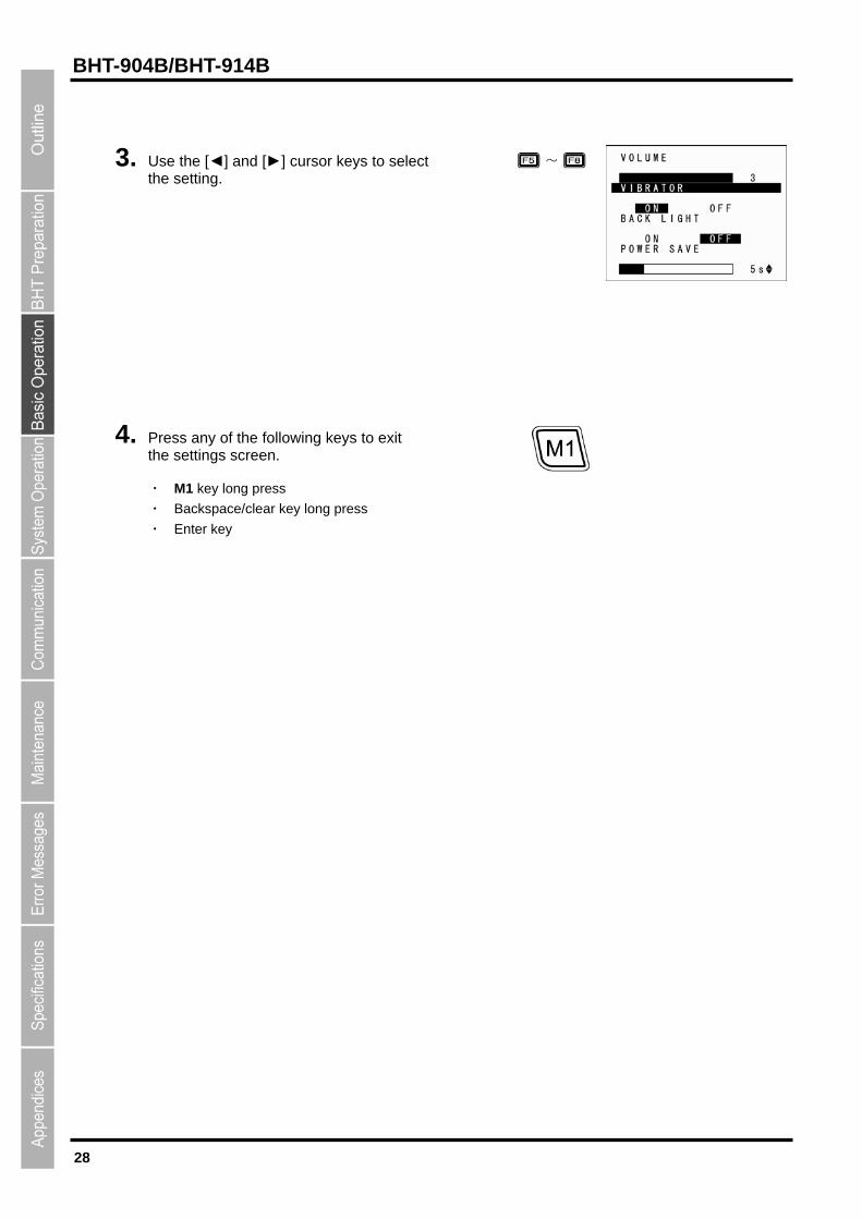
3. Use the [◄] and [►] cursor keys to select the setting.
~
4. Press any of the following keys to exit the settings screen.
・ M1 key long press
・ Backspace/clear key long press
・ Enter key

29
Barcode Handy Terminal
3.5 Transmitting Data
Three methods for transmitting data which the BHT collects to the host computer are possible; via IrDA, or USB.
When performing data communication between BHT units, use the IrDA communication.
The data transmission method and BHT setting method will differ depending on the system used, and therefore the
system administrator should be contacted for details of operation.
Request
Data gathered by the BHT should be promptly uploaded to the host computer.
Host computer
USB communication
CU-901 : RS232C
CU-921 : USB
CU-911 : Ethernet
IrDA communication
CU-901
CU-921
CU-911
IrDA communication
30
BHT-904B/BHT-914B
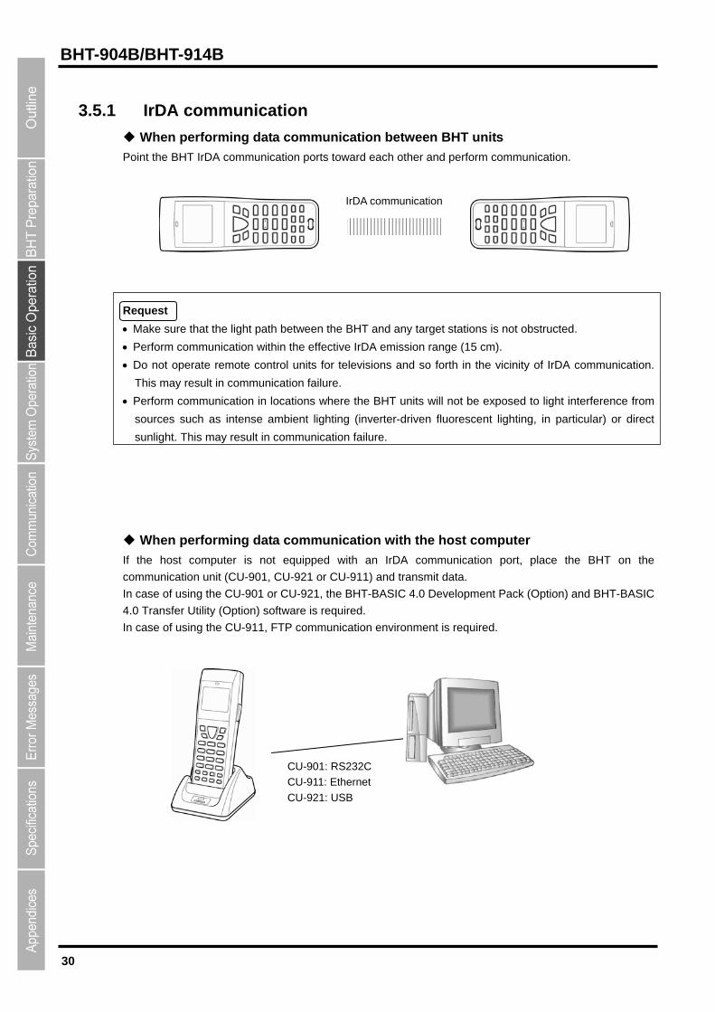
3.5.1 IrDA communication
When performing data communication between BHT units
Point the BHT IrDA communication ports toward each other and perform communication.
IrDA communication
Request
Make sure that the light path between the BHT and any target stations is not obstructed.
Perform communication within the effective IrDA emission range (15 cm).
Do not operate remote control units for televisions and so forth in the vicinity of IrDA communication.
This may result in communication failure.
Perform communication in locations where the BHT units will not be exposed to light interference from
sources such as intense ambient lighting (inverter-driven fluorescent lighting, in particular) or direct
sunlight. This may result in communication failure.
When performing data communication with the host computer
If the host computer is not equipped with an IrDA communication port, place the BHT on the
communication unit (CU-901, CU-921 or CU-911) and transmit data.
In case of using the CU-901 or CU-921, the BHT-BASIC 4.0 Development Pack (Option) and BHT-BASIC
4.0 Transfer Utility (Option) software is required.
In case of using the CU-911, FTP communication environment is required.
CU-901: RS232C
CU-911: Ethernet
CU-921: USB
31
Barcode Handy Terminal
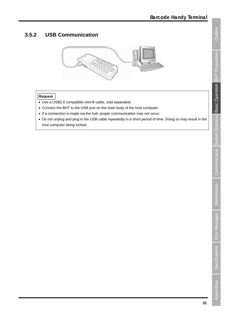
3.5.2 USB Communication
Request
Use a USB2.0 compatible mini-B cable, sold separately.
Connect the BHT to the USB port on the main body of the host computer.
If a connection is made via the hub, proper communication may not occur.
Do not unplug and plug in the USB cable repeatedly in a short period of time. Doing so may result in the
host computer being locked.

32
BHT-904B/BHT-914B
BHT-904B/BHT-914B
Chapter 4
System Operation This chapter describes how to initialize and update the system, start up a user
program, and operate System Mode.
4.1 Initializing the BHT System ・・・・・・・・・・・・・・・・・・・・・・・・・・・・・・・・・・・・・・・・34 4.1.1 Selecting the Memory Area to be Initialized・・・・・・・・・・・・・・・・・・・・・・・・・・・ 35 4.1.2 Selecting the Message Version
(English/Japanese/Simplified Chinese/Traditional Chinese/Korean/Thai) 36 4.1.3 Confirming the Memory Area Selected for Initialization・・・・・・・・・・・・・・・・・ 36 4.1.4 Performing System Initialization ・・・・・・・・・・・・・・・・・・・・・・・・・・・・・・・・・ 37
4.2 Updating the System ・・・・・・・・・・・・・・・・・・・・・・・・・・・・・・・・・・・・・・・・・・・・・38 4.2.1 Updating the BHT System・・・・・・・・・・・・・・・・・・・・・・・・・・・・・・・・・・・・・・・・・・ 38 4.2.2 CU-911 System Update・・・・・・・・・・・・・・・・・・・・・・・・・・・・・・・・・・・・・・・・・・・・ 39
4.3 Executing User Programs ・・・・・・・・・・・・・・・・・・・・・・・・・・・・・・・・・・・・・・・・・40 4.3.1 Executing from the SYSTEM MENU “EXECUTE PROGRAM” ・・・・・・・・・・ 40 4.3.2 Automatically Executing the Program Set at the SYSTEM MENU
when Turning the Power ON ・・・・・・・・・・・・・・・・・・・・・・・・・・・・・・・・・・・・・・ 40 4.3.3 Executing the First Registered Program by Turning the Power ON
(BHT System Directory Management Program Function)・・・・・・・・・・・・・・ 40 4.3.4 Executing by Wake-up・・・・・・・・・・・・・・・・・・・・・・・・・・・・・・・・・・・・・・・・・・・・・ 42 4.3.5 Executing by Remote Wake-up ・・・・・・・・・・・・・・・・・・・・・・・・・・・・・・・・・・・・・ 42 4.3.6 Executing the Auto-start Execution Program from the Point of Start-up ・・・ 42
4.4 System Mode ・・・・・・・・・・・・・・・・・・・・・・・・・・・・・・・・・・・・・・・・・・・・・・・・・・・43 4.4.1 Starting Up System Mode ・・・・・・・・・・・・・・・・・・・・・・・・・・・・・・・・・・・・・・・・・・ 43 4.4.2 System Mode Basic Operation・・・・・・・・・・・・・・・・・・・・・・・・・・・・・・・・・・・・・・ 44 4.4.3 SYSTEM MENU Configuration ・・・・・・・・・・・・・・・・・・・・・・・・・・・・・・・・・・・・・ 46
4.5 SYSTEM MENU ・・・・・・・・・・・・・・・・・・・・・・・・・・・・・・・・・・・・・・・・・・・・・・・・・49 4.5.1 Executing Setup (“SETUP” menu) ・・・・・・・・・・・・・・・・・・・・・・・・・・・・・・・・・・ 49 4.5.2 Executing User Programs (EXECUTE PROGRAM Menu) ・・・・・・・・・・・・・・ 53 4.5.3 Downloading Files (DOWNLOAD Menu) ・・・・・・・・・・・・・・・・・・・・・・・・・・・・・ 54 4.5.4 Uploading Files (UPLOAD Menu) ・・・・・・・・・・・・・・・・・・・・・・・・・・・・・・・・・・・ 57 4.5.5 Copying Files between 2 BHT Units ・・・・・・・・・・・・・・・・・・・・・・・・・・・・・・・・・ 60 4.5.6 System Environment Settings (SET SYSTEM Menu) ・・・・・・・・・・・・・・・・・・ 62 4.5.7 BHT Operation Test (TEST Menu)・・・・・・・・・・・・・・・・・・・・・・・・・・・・・・・・・・・ 99 4.5.8 System Information (SYSTEM INFORMATION Menu) ・・・・・・・・・・・・・・・ 119 4.5.9 Downloading/Uploading Files by FTP (FTP MENU) ・・・・・・・・・・・・・・・・・ 122 4.5.10 USB Communication settings (“DEVICE” MENU) ・・・・・・・・・・・・・・・・・・・ 128 4.5.11 Deleting Program/Data Files (“DELETE FILE” Menu) ・・・・・・・・・・・・・・・・ 132 4.5.12 Deleting Font Files (DELETE FILE Menu) ・・・・・・・・・・・・・・・・・・・・・・・・・・ 133 4.5.13 Downloading/Uploading the BHT System Parameter File
(SYSTEM PARAMETER Menu)・・・・・・・・・・・・・・・・・・・・・・・・・・・・・・・・・ 135 4.5.14 Setting the Remote Wake-up (SET REMOTE WAKEUP Menu) ・・・・・・・ 138 4.5.15 Downloading/Uploading the System Message File
(SYSTEM MESSAGE Menu) ・・・・・・・・・・・・・・・・・・・・・・・・・・・・・・・・・・・ 139 4.5.16 Updating the System (MODIFY MENU) ・・・・・・・・・・・・・・・・・・・・・・・・・・・・ 142
34
BHT-904B/BHT-914B
4.1 Initializing the BHT System
By initializing the system, program files and data files downloaded to the BHT user area are deleted, and system
settings are returned to the default status when shipped from the factory.
The system must be initialized when:
● Deleting all program files and data files downloaded to the BHT user area (Font files are also deleted by
selecting the area subject to initialization.)
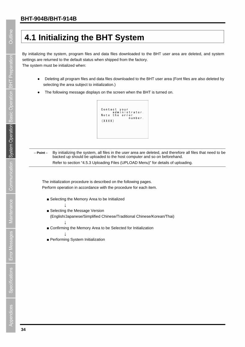
● The following message displays on the screen when the BHT is turned on.
Point By initializing the system, all files in the user area are deleted, and therefore all files that need to be backed up should be uploaded to the host computer and so on beforehand.
Refer to section “4.5.3 Uploading Files (UPLOAD Menu)” for details of uploading.
The initialization procedure is described on the following pages.
Perform operation in accordance with the procedure for each item.
■ Selecting the Memory Area to be Initialized
↓
■ Selecting the Message Version
(English/Japanese/Simplified Chinese/Traditional Chinese/Korean/Thai)
↓
■ Confirming the Memory Area to be Selected for Initialization
↓
■ Performing System Initialization
35
Barcode Handy Terminal
4.1.1 Selecting the Memory Area to be Initialized
1. Press the Power key ( ) while holding down the SF, M1 and [0] keys together.
2. Select the memory area to be initialized.
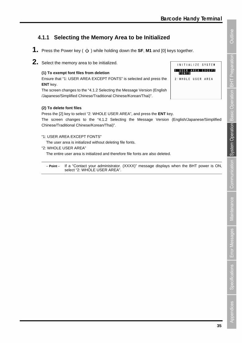
(1) To exempt font files from deletion
Ensure that “1: USER AREA EXCEPT FONTS” is selected and press the
ENT key.
The screen changes to the “4.1.2 Selecting the Message Version (English
/Japanese/Simplified Chinese/Traditional Chinese/Korean/Thai)”.
(2) To delete font files
t “2: WHOLE USER AREA”, and press the ENT key.
nglish/Japanese/Simplified
: USER AREA EXCEPT FONTS”
deleting file fonts.
“2
itialized and therefore file fonts are also deleted.
Point If a “Contact your administrator. (XXXX)” message displays when the BHT power is ON,
Press the [2] key to selec
The screen changes to the “4.1.2 Selecting the Message Version (E
Chinese/Traditional Chinese/Korean/Thai)”.
“1
The user area is initialized without
: WHOLE USER AREA”
The entire user area is in
select “2: WHOLE USER AREA”.
36
BHT-904B/BHT-914B
4.1.2 Selecting the Message Version (English/Japanese/Simplified Chinese/Traditional Chinese/Korean/Thai)
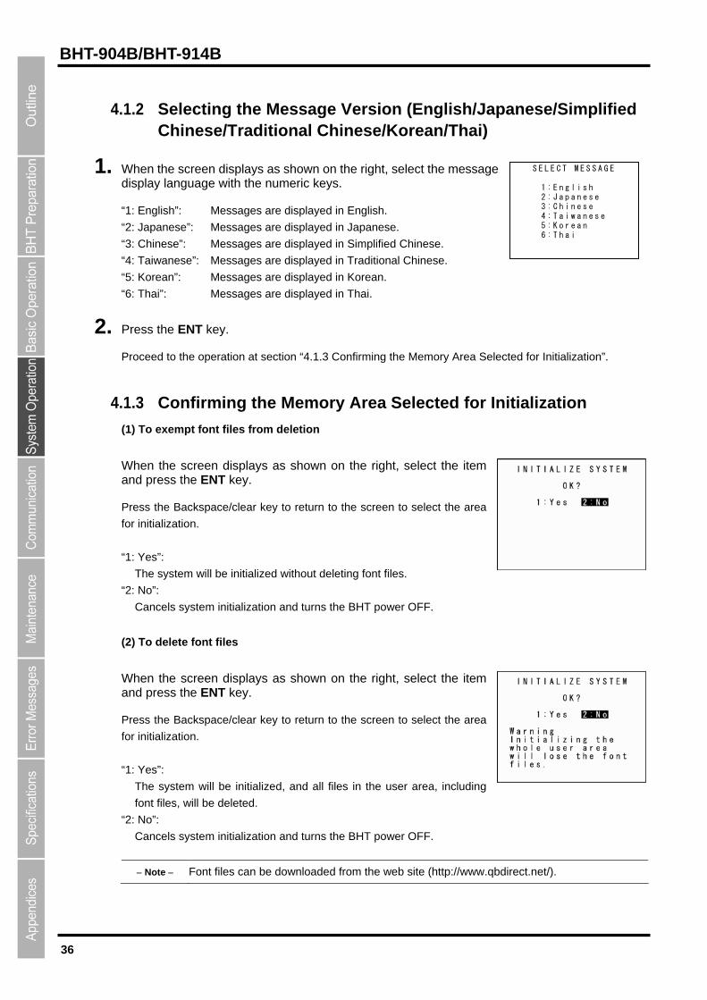
1. When the screen displays as shown on the right, select the message display language with the numeric keys.
“1: English”: Messages are displayed in English.
“2: Japanese”: Messages are displayed in Japanese.
“3: Chinese”: Messages are displayed in Simplified Chinese.
“4: Taiwanese”: Messages are displayed in Traditional Chinese.
“5: Korean”: Messages are displayed in Korean.
“6: Thai”: Messages are displayed in Thai.
S E L E C T M E S S A G E
1 : E n g l i s h 2 : J a p a n e s e 3 : C h i n e s e 4 : T a i w a n e s e 5 : K o r e a n 6 : T h a i
2. Press the ENT key.
Proceed to the operation at section “4.1.3 Confirming the Memory Area Selected for Initialization”.
4.1.3 Confirming the Memory Area Selected for Initialization
(1) To exempt font files from deletion
When the screen displays as shown on the right, select the item and press the ENT key.
Press the Backspace/clear key to return to the screen to select the area
for initialization.
“1: Yes”:
The system will be initialized without deleting font files.
“2: No”:
Cancels system initialization and turns the BHT power OFF.
(2) To delete font files
When the screen displays as shown on the right, select the item and press the ENT key.
Press the Backspace/clear key to return to the screen to select the area
for initialization.
“1: Yes”:
The system will be initialized, and all files in the user area, including
font files, will be deleted.
“2: No”:
Cancels system initialization and turns the BHT power OFF.
Note Font files can be downloaded from the web site (http://www.qbdirect.net/).
37
Barcode Handy Terminal
4.1.4 Performing System Initialization
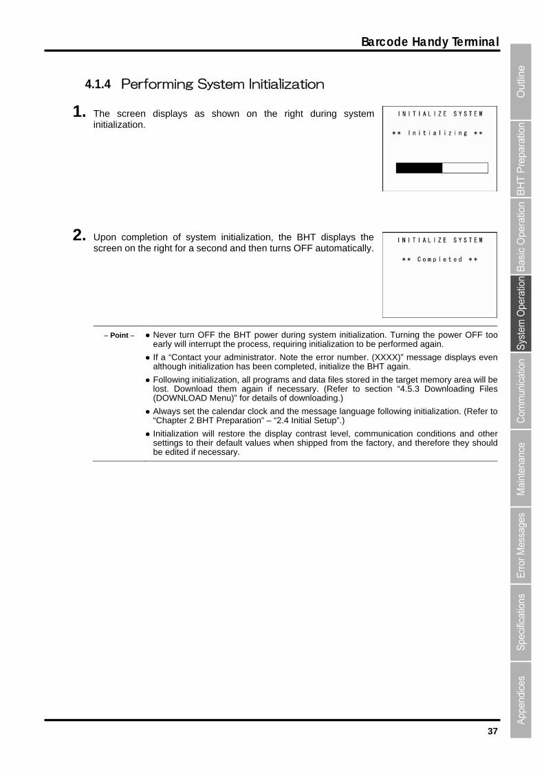
1. The screen displays as shown on the right during system initialization.
2. Upon completion of system initialization, the BHT displays the screen on the right for a second and then turns OFF automatically.
Point Never turn OFF the BHT power during system initialization. Turning the power OFF tooearly will interrupt the process, requiring initialization to be performed again.
If a “Contact your administrator. Note the error number. (XXXX)” message displays evenalthough initialization has been completed, initialize the BHT again.
Following initialization, all programs and data files stored in the target memory area will belost. Download them again if necessary. (Refer to section “4.5.3 Downloading Files (DOWNLOAD Menu)” for details of downloading.)
Always set the calendar clock and the message language following initialization. (Refer to “Chapter 2 BHT Preparation” – “2.4 Initial Setup”.)
Initialization will restore the display contrast level, communication conditions and othersettings to their default values when shipped from the factory, and therefore they should be edited if necessary.

38
BHT-904B/BHT-914B
4.2 Updating the System
4.2.1 Updating the BHT System The BHT system update procedure is as follows.
BHT System Update File Download
↓
BHT System Update
BHT System Update File Download
Refer to sections “4.5.3 Downloading Files (DOWNLOAD Menu)” and “4.5.9 Downloading/Uploading Files
by FTP (FTP MENU)”, and download the BHT system update file to the BHT.
Note The BHT system update file can be downloaded from the following Web site.
http://www.qbdirect.net/
BHT System Update
Refer to section “4.5.15 Updating the System (MODIFY MENU)” and update the BHT system.
Important In order to prevent the battery running low during the system update process, perform thesystem update with the batteries sufficiently charged, with the batteries charging via a USB cable, or with the BHT placed in the CU-900 Series. During system update, the power will not turn OFF even if the Power key ( ) is pressed. Wait until the system update process is complete before operating the BHT.

39
Barcode Handy Terminal
4.2.2 CU-911 System Update The CU-911 system update procedure is as follows.
CU-911 System Update File Download
↓
CU-911 System Update
CU-911 System Update File Download
Refer to sections “4.5.3 Downloading Files (DOWNLOAD Menu)” and “4.5.9 Downloading/Uploading Files
by FTP (FTP MENU)”, and download the CU-911 system update file to the BHT.
Download the CU-911 system update file as a data file with field length of 64 bytes.
Important If the Transfer Utility is used to download in BHT protocol, select the “Perform binary filetransfer (F)” check box at the Transfer Utility Options screen and then download.
Note The CU-911 system update file can be downloaded from the following Web site.
http://www.qbdirect.net/
CU-911 System Update
Refer to section “4.5.15 Updating the System (MODIFY MENU)” and update the CU-911 system.
The CU-911 LED flashes during CU-911 system update.
Important Never remove the BHT from the CU-911 or turn the BHT power OFF during the system update process.
If the BHT is removed from the CU-911 or the BHT power is turned OFF during system update, a system update error will occur, and the CU-911 will wait for the update to be retried.
In such a case, either perform the CU-911 system update again, or reboot the CU-911.
Point If the CU-911 power is turned OFF during the system update, when the power is next turned ON, either the system prior to updating or system after updating will run.
The system running can be verified at the CU-911 System Information display. (Refer to section “4.5.8 System Information (SYSTEM INFORMATION Menu)” for details.)
40
BHT-904B/BHT-914B
4.3 Executing User Programs
User programs (application programs) can be executed using the following methods.
Select the most appropriate method to meet the objective.
4.3.1 Executing from the SYSTEM MENU “EXECUTE PROGRAM” Select the program to be executed at the SYSTEM MENU “EXECUTE PROGRAM” menu.
In such a case, the selected program will always be executed from the start.
Refer to section “4.5.2 Executing User Programs (EXECUTE PROGRAM Menu)” for details.
4.3.2 Automatically Executing the Program Set at the SYSTEM MENU when Turning the Power ON
Select the program to be executed at the SYSTEM MENU “EXECUTE PROGRAM” menu, and then turn
the BHT power OFF. The selected program will executed automatically the next time the BHT power is
turned ON.
If the resume function has been set, the BHT will resume from the position in the program that was
stopped when the BHT power was last turned OFF.
Refer to section “4.5.6 [1] Setting the auto-start execution program” for details.
4.3.3 Executing the First Registered Program by Turning the Power ON (BHT System Directory Management Program Function)
If no program has been selected at the SYSTEM MENU “EXECUTE PROGRAM” menu and the BHT
power turned ON, control will switch to the directory management program, and the first of the programs
(.PD4) registered in the BHT will executed.
If the resume function has been set, the BHT will resume from the position in the program that was
stopped when the BHT power was last turned OFF.
If downloading multiple programs after system initialization, programs are registered in the system in the
order in which they are downloaded, and therefore ensure that the program to be executed is the first
program downloaded.
If a program is later downloaded for purpose of upgrading the version, use the same program name. The
order in which programs are registered in the system will not change, and therefore the same program will
be executed even after upgrading the version. (*)
* The system directory management program also manages files with other extensions simultaneously. If
the top file from the first registered program is deleted and a new program is downloaded, the new
program will be registered in the position vacated by the deleted file and therefore caution is advised. It
is recommended that the program to be execute after turning on the BHT power is first downloaded
following system initialization.
41
Barcode Handy Terminal
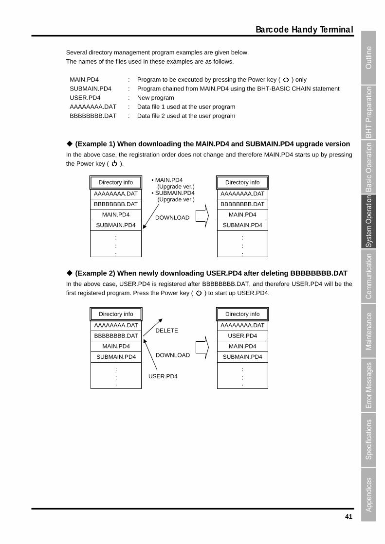
Several directory management program examples are given below.
The names of the files used in these examples are as follows.
MAIN.PD4 : Program to be executed by pressing the Power key ( ) only
SUBMAIN.PD4 : Program chained from MAIN.PD4 using the BHT-BASIC CHAIN statement
USER.PD4 : New program
AAAAAAAA.DAT : Data file 1 used at the user program
BBBBBBBB.DAT : Data file 2 used at the user program
(Example 1) When downloading the MAIN.PD4 and SUBMAIN.PD4 upgrade version
In the above case, the registration order does not change and therefore MAIN.PD4 starts up by pressing
the Power key ( ).
(Example 2) When newly downloading USER.PD4 after deleting BBBBBBBB.DAT
In the above case, USER.PD4 is registered after BBBBBBBB.DAT, and therefore USER.PD4 will be the
first registered program. Press the Power key ( ) to start up USER.PD4.
AAAAAAAA.DAT
• MAIN.PD4 (Upgrade ver.) • SUBMAIN.PD4 (Upgrade ver.)
:
:
:
SUBMAIN.PD4
MAIN.PD4
BBBBBBBB.DAT
AAAAAAAA.DAT
Directory infoDirectory info
BBBBBBBB.DAT
MAIN.PD4 DOWNLOADSUBMAIN.PD4
:
:
:
:
:
:
SUBMAIN.PD4
MAIN.PD4
BBBBBBBB.DAT
AAAAAAAA.DAT
Directory info
:
:
:
SUBMAIN.PD4
MAIN.PD4
USER.PD4
AAAAAAAA.DAT
Directory info
DELETE
DOWNLOAD
USER.PD4
42
BHT-904B/BHT-914B
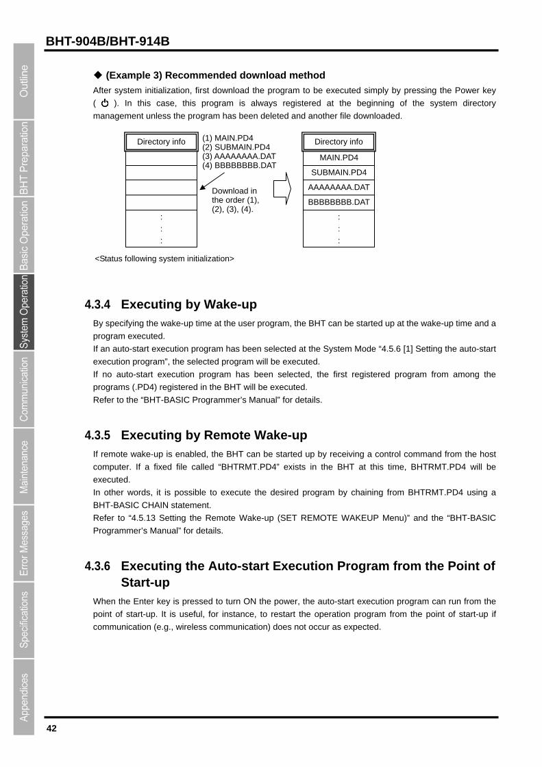
(Example 3) Recommended download method
After system initialization, first download the program to be executed simply by pressing the Power key
( ). In this case, this program is always registered at the beginning of the system directory
management unless the program has been deleted and another file downloaded.
Directory info
:
:
:
(1) MAIN.PD4(2) SUBMAIN.PD4 (3) AAAAAAAA.DAT(4) BBBBBBBB.DAT
SUBMAIN.PD4
MAIN.PD4
Directory info
:
:
:
BBBBBBBB.DAT
AAAAAAAA.DATDownload in the order (1), (2), (3), (4).
<Status following system initialization>
4.3.4 Executing by Wake-up By specifying the wake-up time at the user program, the BHT can be started up at the wake-up time and a
program executed.
If an auto-start execution program has been selected at the System Mode “4.5.6 [1] Setting the auto-start
execution program”, the selected program will be executed.
If no auto-start execution program has been selected, the first registered program from among the
programs (.PD4) registered in the BHT will be executed.
Refer to the “BHT-BASIC Programmer’s Manual” for details.
4.3.5 Executing by Remote Wake-up If remote wake-up is enabled, the BHT can be started up by receiving a control command from the host
computer. If a fixed file called “BHTRMT.PD4” exists in the BHT at this time, BHTRMT.PD4 will be
executed.
In other words, it is possible to execute the desired program by chaining from BHTRMT.PD4 using a
BHT-BASIC CHAIN statement.
Refer to “4.5.13 Setting the Remote Wake-up (SET REMOTE WAKEUP Menu)” and the “BHT-BASIC
Programmer’s Manual” for details.
4.3.6 Executing the Auto-start Execution Program from the Point of Start-up
When the Enter key is pressed to turn ON the power, the auto-start execution program can run from the
point of start-up. It is useful, for instance, to restart the operation program from the point of start-up if
communication (e.g., wireless communication) does not occur as expected.

43
Barcode Handy Terminal
4.4 System Mode
By starting up the BHT in System Mode and selecting each menu, the following operations can be performed
individually.
● Executing setup
● Executing user programs
● File download/upload
● System environment settings
● BHT operation test
● System information display
● Downloading/uploading files by FTP
● USB communication settings
● File deletion
● Font file deletion
● System settings parameter file download/upload
● Remote wake-up settings
● System message file download/upload
● System update
Refer to each item at the “4.5 SYSTEM MENU” for details of the above operations.
4.4.1 Starting Up System Mode Use the following procedure to start up System Mode.
1. Press the Power key ( ) while holding down the SF and [1] keys.
System Mode starts up and the SYSTEM MENU (screen on right)
displays.
Select and display each menu from the SYSTEM MENU and perform
each operation.
Hold down the SF key and press the appropriate numeric key to display items not displayed at the
SYSTEM MENU.
Refer to “4.4.3 SYSTEM MENU Configuration” for details.

44
BHT-904B/BHT-914B
4.4.2 System Mode Basic Operation
Menu Selection and Display
Use the following procedure to select and display each menu.
1. Press the numeric key corresponding to the menu to be selected. Alternatively, press the cursor keys ([▲] [▼]) to select the menu.
The selected menu item will be
highlighted.
“SETUP” will be highlighted when
the System Mode is started.
Operation example
2. Press the ENT key.
The selected item is set and the
next screen displays.
Press the Backspace/clear key to return to the previous screen.
The selected item will be highlighted when returning to the previous screen.
3. Repeat the above operation to display the target menu.
ENT key
Select [4: SET SYSTEM] w
the [4] or [▲]/[▼] keys.
ith
Select [2: DISPLAY] with the
[2] or [▲]/[▼] keys.
BS/C key
45
Barcode Handy Terminal
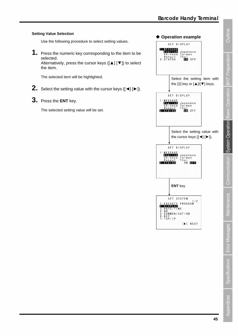
Setting Value Selection Operation example
Use the following procedure to select setting values.
Select the setting item with
the [2] key or [▲]/[▼] keys.
Select the setting value with
the cursor keys ([◄] [►]).
ENT key
1. Press the numeric key corresponding to the item to be selected. Alternatively, press the cursor keys ([▲] [▼]) to select the item.
The selected item will be highlighted.
2. Select the setting value with the cursor keys ([◄] [►]).
3. Press the ENT key.
The selected setting value will be set.
46
BHT-904B/BHT-914B
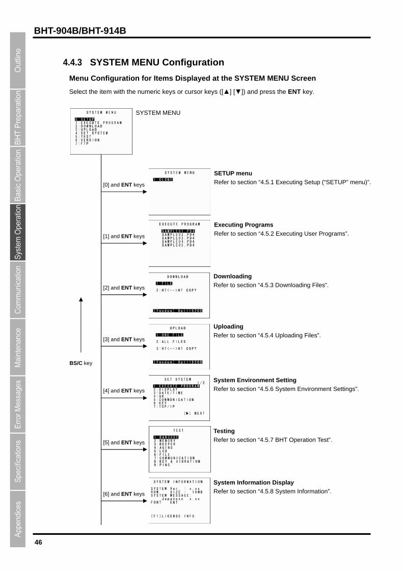
4.4.3 SYSTEM MENU Configuration
Menu Configuration for Items Displayed at the SYSTEM MENU Screen
Select the item with the numeric keys or cursor keys ([▲] [▼]) and press the ENT key.
SYSTEM MENU
[4] and ENT keys
[3] and ENT keys
[1] and ENT keys
[5] and ENT keys
[2] and ENT keys
[0] and ENT keys
SETUP menu
Refer to section “4.5.1 Executing Setup (“SETUP” menu)”.
Downloading
Refer to section “4.5.2 Executing User Programs”.
Executing Programs
Refer to section “4.5.3 Downloading Files”.
Uploading Refer to section “4.5.4 Uploading Files”.
BS/C key
System Environment Setting Refer to section “4.5.6 System Environment Settings”.
Testing Refer to section “4.5.7 BHT Operation Test”.
System Information Display
Refer to section “4.5.8 System Information”. [6] and ENT keys

47
Barcode Handy Terminal
[8] and ENT keys
[7] and ENT keys
Downloading/Uploading by FTP
Refer to section “4.5.9 Downloading/Uploading Files by
FTP”. BS/C key
DEVICE MENU
1:USB
DEVICE menu
Refer to section “4.5.10 USB Communication”.
48
BHT-904B/BHT-914B
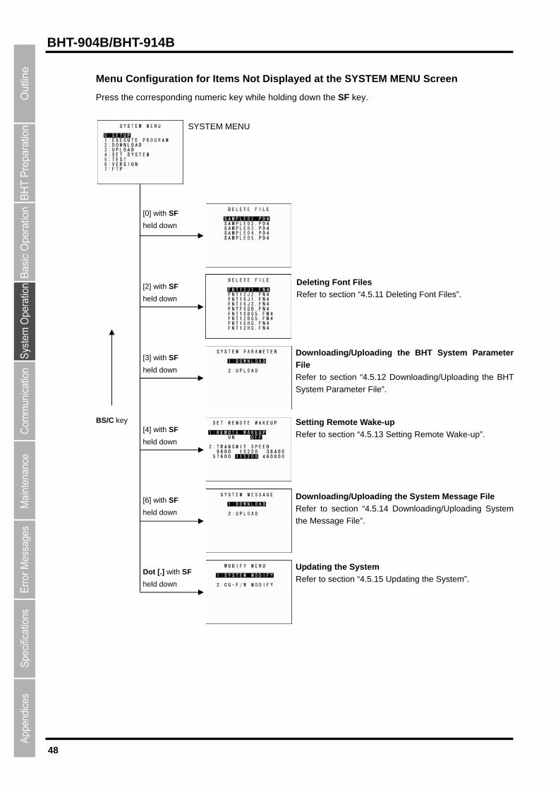
Menu Configuration for Items Not Displayed at the SYSTEM MENU Screen
Press the corresponding numeric key while holding down the SF key.
SYSTEM MENU
[3] with SF
held down
[4] with SF
held down
[0] with SF
held down
Deleting Font Files [2] with SF
held down Refer to section “4.5.11 Deleting Font Files”.
Downloading/Uploading the BHT System Parameter
File
Refer to section “4.5.12 Downloading/Uploading the BHT
System Parameter File”.
BS/C key Setting Remote Wake-up
Refer to section “4.5.13 Setting Remote Wake-up”.
Downloading/Uploading the System Message File [6] with SF
held down Refer to section “4.5.14 Downloading/Uploading System
the Message File”.
Updating the System Dot [.] with SF
held down Refer to section “4.5.15 Updating the System”.
49
Barcode Handy Terminal
4.5 SYSTEM MENU
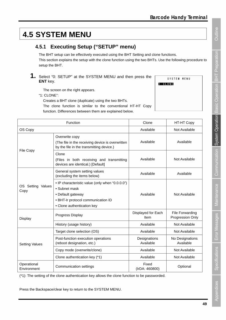
4.5.1 Executing Setup (“SETUP” menu) The BHT setup can be effectively executed using the BHT Setting and clone functions.
This section explains the setup with the clone function using the two BHTs. Use the following procedure to
setup the BHT.
1. Select “0: SETUP” at the SYSTEM MENU and then press the ENT key.
The screen on the right appears.
“1: CLONE”:
Creates a BHT clone (duplicate) using the two BHTs.
The clone function is similar to the conventional HT-HT Copy
function. Differences between them are explained below.
Function Clone HT-HT Copy
OS Copy Available Not Available
Overwrite copy
(The file in the receiving device is overwritten by the file in the transmitting device.)
Available Available
File Copy Clone
(Files in both receiving and transmitting devices are identical.) [Default]
Available Not Available
General system setting values (excluding the items below)
Available Available
OS Setting Values Copy
• IP characteristic value (only when “0.0.0.0”)
• Subnet mask
• Default gateway
• BHT-Ir protocol communication ID
• Clone authentication key
Available Not Available
Progress Display Displayed for Each
Item File Forwarding
Progression Only Display
History (usage history) Available Not Available
Target clone selection (OS) Available Not Available
Post-function execution operations (reboot designation, etc.)
Designations Available
No Designations Available
Copy mode (overwrite/clone) Available Not Available
Setting Values
Clone authentication key (*1) Available Not Available
Operational Environment
Communication settings Fixed
(IrDA: 460800) Optional
(*1): The setting of the clone authentication key allows the clone function to be passworded.
Press the Backspace/clear key to return to the SYSTEM MENU.
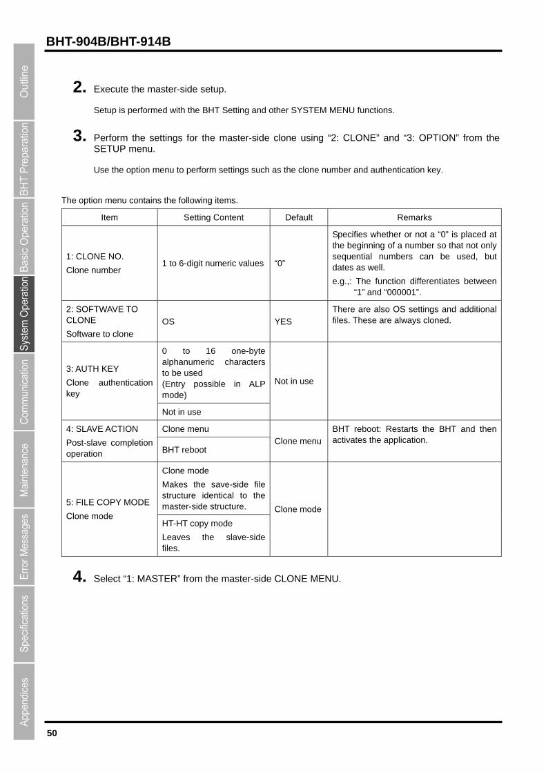
50
BHT-904B/BHT-914B
2. Execute the master-side setup.
Setup is performed with the BHT Setting and other SYSTEM MENU functions.
3. Perform the settings for the master-side clone using “2: CLONE” and “3: OPTION” from the SETUP menu.
Use the option menu to perform settings such as the clone number and authentication key.
The option menu contains the following items.
Item Setting Content Default Remarks
1: CLONE NO.
Clone number 1 to 6-digit numeric values “0”
Specifies whether or not a “0” is placed at the beginning of a number so that not only sequential numbers can be used, but dates as well.
e.g.,: The function differentiates between “1” and “000001”.
2: SOFTWAVE TO CLONE
Software to clone
OS YES
There are also OS settings and additional files. These are always cloned.
0 to 16 one-byte alphanumeric characters to be used
ALP mode) (Entry possible in
3: AUTH KEY
Clone authentication key
Not in use
Not in use
Clone menu 4: SLAVE ACTION
Post-slave completion operation BHT reboot
Clone menu
BHT reboot: Restarts the BHT and then activates the application.
Clone mode
Makes the save-side file structure identical to the master-side structure. 5: FILE COPY MODE
Clone mode HT-HT copy mode
Leaves the slave-side files.
Clone mode
4. Select “1: MASTER” from the master-side CLONE MENU.

51
Barcode Handy Terminal
5. Select “2: SLAVE” from the slave-side CLONE MENU.
Master Side Slave Side
6. Align the BHTs as shown below and then press ENT key on the transmitting device.
The status of the data transmission progress is displayed as shown on the screens below.
“
Slave Side
→
Slave BHT (to be tested)
Data
Max. 15 cm
Master BHT
“v”: Data transmission is complete.
”: When flashing, data transmission is in progress.
Master Side
→

52
BHT-904B/BHT-914B
When communication is complete, the CLONE MENU (screen 1) reappears.
In the event of a communication error, screen 2 appears.
Screen 1: Error occurrence Screen 2: Error/Correctly completed
List of possible errors when cloning
Processing
Phase Outline Displayed Message Detail Operations followed by an error
BHT models are different.
Different model on
master side (slave side).
Continue?
Different model on
master side (slave side).
Continue?
When screen 1 appears, select
YES/NO.
Y: Processing continues. (the
OS and OS settings will not
be copied.)
N: Processing is suspended.
OS update is not possible
(when the HT-HT copy
mode designation and
initialization are required).
OS cannot be updated.
Cloning will be stopped.
OS cannot be updated.
Cloning will be stopped.
Number of files are
exceeded.
Too many files.
Cloning will be stopped.
Too many files.
Cloning will be stopped.
Immediately
After Clone Start
Memory capacity is
exceeded.
Insufficient memory on
slave side.
Cloning will be stopped.
Insufficient memory on
slave side.
Cloning will be stopped.
Screen 2 appears; processing
is suspended.
When Clone is
Complete
OS setting is not possible
(No items/Outside value
range).
Some items could not be
set on slave side. (N
items)
Some items could not be
set on slave side. (N
items)
Out of memory Out of memory
File mismatch File mismatch
Too many files Too many files
File error File error
Program file error Program file error
During
Communication Communication error
Communication error Communication error
Screen 2 appears; processing
is complete.
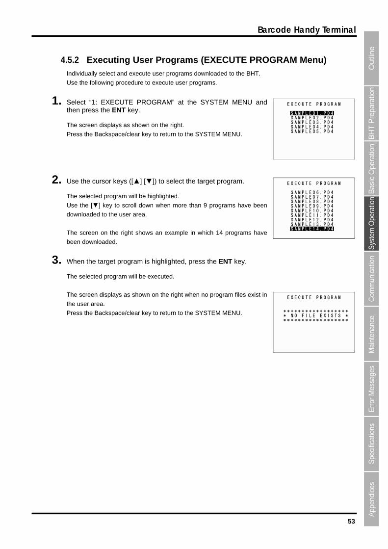
53
Barcode Handy Terminal
4.5.2 Executing User Programs (EXECUTE PROGRAM Menu) Individually select and execute user programs downloaded to the BHT.
Use the follow
1. Select “1: SYSthen press the
Press the Ba
] [▼]) to select the target program.
The selected ill be high
Use the [▼] key to scroll down when more than 9 programs have been
downloaded to the user area.
The s ws h
been downloaded.
3. Whe highlighted, press the ENT key.
s
The screen displays as shown on the right when no program files exist in
the u
Press pace/clear key E
ing procedure to execute user programs.
EXECUTE PROGRAM” at the ENT key.
The screen displays as shown on the right.
ckspace/clear key to return to the SYSTEM
TEM MENU and
MENU.
2. Use the cursor keys ([▲
program w lighted.
creen on the right sho an example in whic 14 programs have
n the target program is
elected program will be exThe ecuted.
ser area.
the Backs to return to the SYST M MENU.
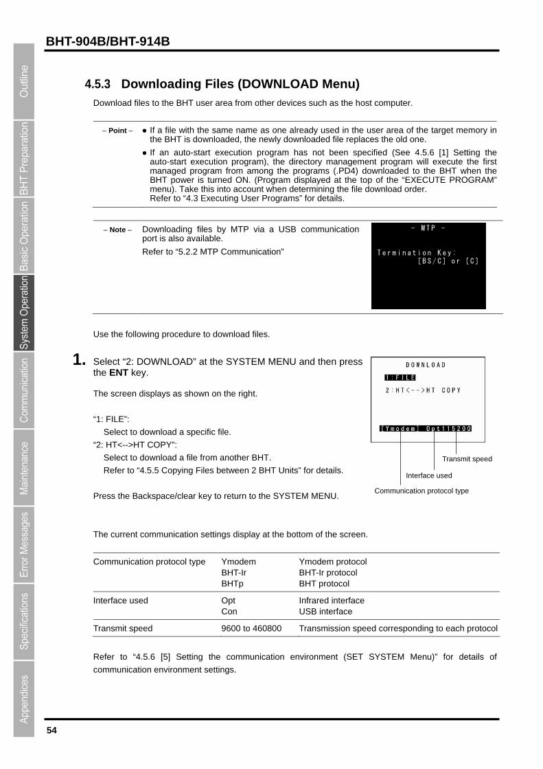
54
BHT-904B/BHT-914B
4.5.3 Downloading Files (DOWNLOAD Menu) Download files to the BHT user area from other devices such as the host computer.
Point If a file with the same name as one already used in the user area of the target memory in
art execution program has not been spececution program), the directory management program will e
ng the programs (.PD4) dow the toe file
Refer to “4.3 Executing User Programs” for details.
the BHT is downloaded, the newly downloaded file replaces
If an auto-stauto-start ex
the old one.
ified (See 4.5.6 [1] Setting the xecute the first
nloaded to the BHT when the p of the “EXECUTE PROGRAM”
download order.
managed program from amoBHT power is turned ON. (Program displayed atmenu). Take this into account when determining th
Note Downloading files by MTP via a USB communication port is also available.
Refer to “5.2.2 MTP Communication”
- M T P -
T e r m i n a t i o n K e y : [ B S / C ] o r [ C ]
ocedure to download files.
ss
t.
Select to download a file from another BHT.
Refer to “4.5.5 Copying Files between 2 BHT Units” for details.
ress the Backspace/clear key to return to the SYSTEM MENU.
he current communication settings display at the bottom of the screen.
Communication protocol type Ymodem BHT-Ir BHTp
Ymodem protocol BHT-Ir protocol BHT protocol
Use the following pr
1. Select “2: DOWNLOAD” at the SYSTEM MENU and then prethe ENT key.
The screen displays as shown on the righ
“1: FILE”:
Select to download a specific file.
: HT<-->HT COPY”: “2
P
T
Communication protocol type
Interface used
Transmit speed
Interface used Opt Con
Infrared interface USB interface
Transmit speed 9600 to 460800 Transmission speed corresponding to each protocol
Refer to “4.5.6 [5] Setting the communication environment (SET SYSTEM Menu)” for details of
communication environment settings.
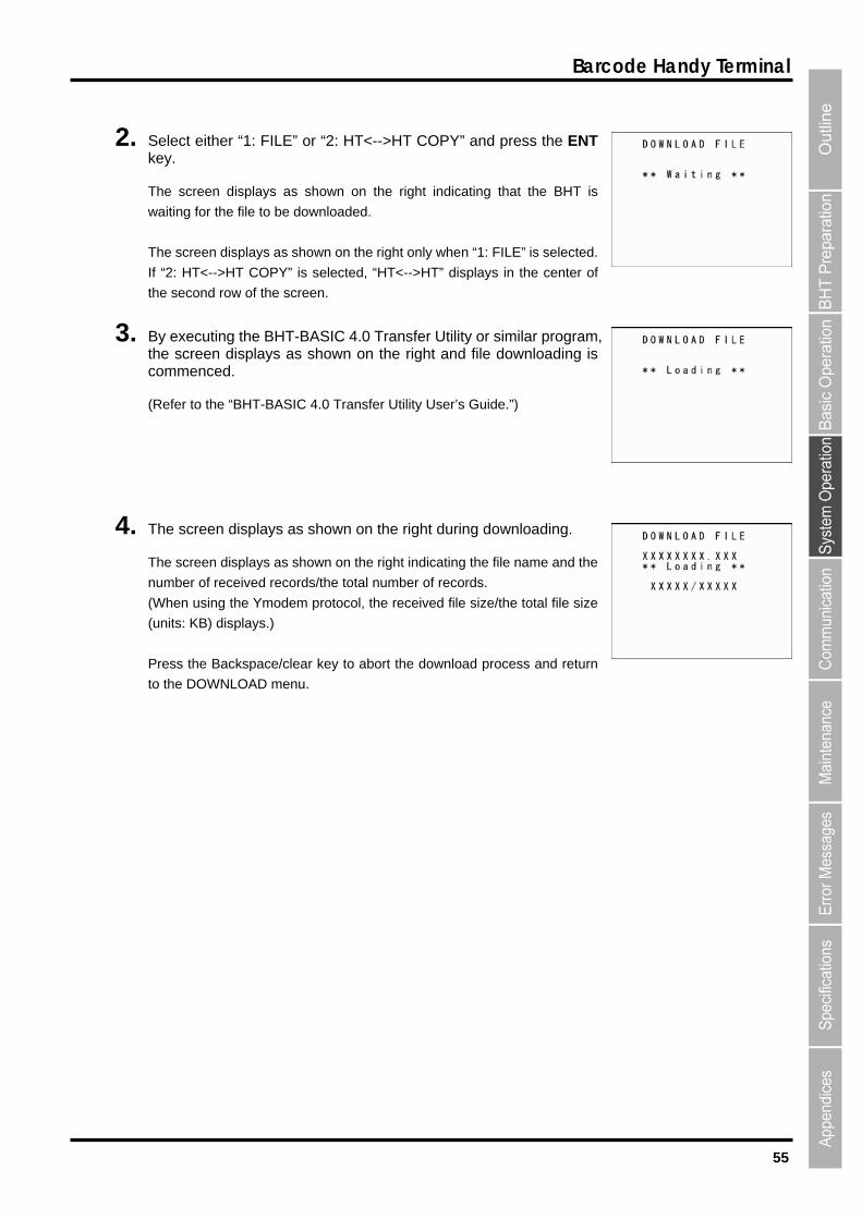
55
Barcode Handy Terminal
2. Select either “1: FILE” or “2: HT<-->HT COPY” and press the ENT
The screen displays as shown on the right indicating that the BHT is
wa
The
If “2:
the s
3. By executing the BHT-BASIC 4.0 Transfer Utility or similar program, the screen dco
(Refer to the s Guide.”)
4. during downloading.
e
rotocol, the received file size/the total file siz
ackspace/clear key to abort the download process and return
to
key.
iting for the file to be downloaded.
screen displays as shown on the right only when “1: FILE” is selected.
HT<-->HT COPY” is selected, “HT<-->HT” displays in the center of
econd row of the screen.
isplays as shown on the right and file downloading is d. mmence
“BHT-BASIC 4.0 Transfer Utility User’
The screen displays as shown on the right
The screen displays as shown on the right indicating the file name and th
number of received records/the total number of records.
(When using the Ymodem p e
(units: KB) displays.)
Press the B
the DOWNLOAD menu.
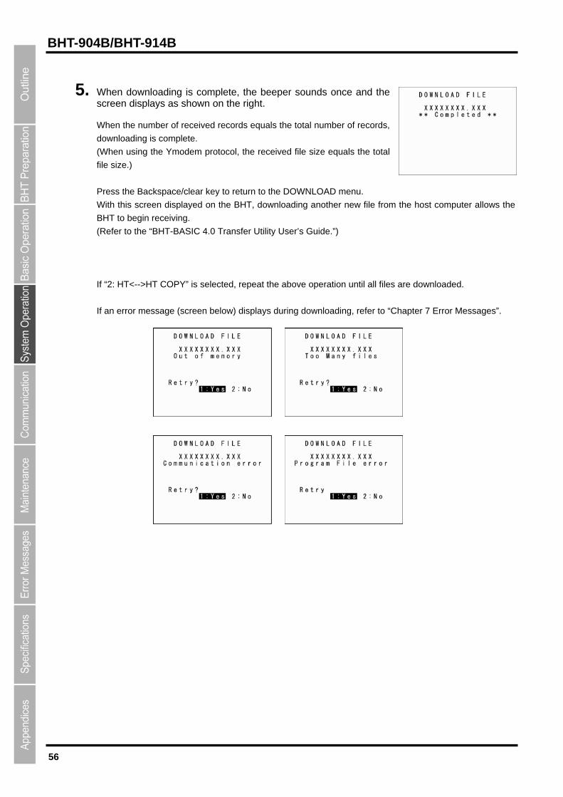
56
BHT-904B/BHT-914B
5. When downloading is complete, the beeper sounds once and the screen displays as shown on the right.
hen using the Ymodem protocol, the received file size equals the total
to return to the DOWNLOAD menu.
With this screen displayed on the BHT, downloading another new file from the host computer allows the
“2: HT<-->HT COPY” is selected, repeat the above operation until all fi
ssage (screen below) displays during downloading, refer to “Chapter 7 Error Messages”.
When the number of received records equals the total number of records,
downloading is complete.
(W
file size.)
Press the Backspace/clear key
BHT to begin receiving.
(Refer to the “BHT-BASIC 4.0 Transfer Utility User’s Guide.”)
If les are downloaded.
If an error me
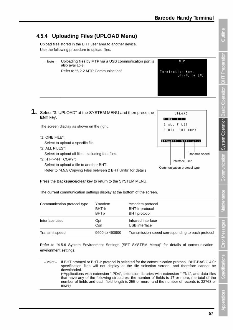
57
Barcode Handy Terminal
4.5.4 Uploading Files (UPLOAD Menu) Upload files stored in the BHT user area to another device.
Refer to “5.2.2 MTP Communication”
Use the following procedure to upload files.
Note Uploading files by MTP via a USB communication port is also available.
- M T P - T e r m i n a t i o n K e y :
[ B S / C ] o r [ C ]
1. elect “3: UPLOAD” at the SYSTEM MENU and then press the
: ONE FILE
Select to uplo
: ALL FILE
Select to uplo
: HT<-->HT
Select to uplo
ress the Bac
he current c
Communicatio
SENT key.
The screen display as shown on the right.
“1 ”:
ad a specific file.
S”:
ad all files, excluding font files.
COPY”:
ad a file to another BHT.
Refer to “4.5.5 Copying Files betwe
“2
“3
Communication protocol type
Interface used
Transmit speed
en 2 BHT Units” for details.
P kspace/clear
ommunication settings display
n protocol type Ymodem BHT-Ir BHTp
key to return to the SYSTEM MENU.
at the bottom of the screen.
Ymodem protocol BHT-Ir protocol BHT protocol
T
Interface used Opt Con
Infrared interface USB interface
Transmit speed 9600 to 460800 Transmission speed corresponding to each protocol
Refer to “4.5.6 System Environment Settings (SET SYSTEM Menu)” for details of communication
environment settings.
Point If BHT protocol or BHT-Ir protocol is selected for the communication protocol, BHT-BASIC 4.0* specification files will not display at the file selection screen, and therefore cannot bedownloaded. (*Applications with extension “.PD4”, extension libraries with extension “.FN4”, and data filesthat have any of the following structures: the number of fields is 17 or more, the total of thenumber of fields and each field length is 255 or more, and the number of records is 32768 ormore)

58
BHT-904B/BHT-914B
2. Select “1: FILE”, “2: ALL FILES” or “3: HT<-->HT COPY” and press the ENT key.
he screen displays as shown on the right. Select the file to be uploaded
an th
Nex c e
When “2: ALL FILES” or “3: HT<-->HT COPY” is selected:
Proceed to step 3.
wn on the right if no files that can be uploaded
xist in the user area.
3. lays as shown on the right indicating that the BHT is
when “1: FILE” is select
If “2: ALL FIL
o
ente
When “1: FILE” is selected:
T
d press
t, pro e
e ENT key.
d to step 3.
The screen displays as sho
e
Press the Backspace/clear key to return to the UPLOAD menu.
The screen dispwaiting for the file to be uploaded.
The screen displays as shown on the right only
ES” is selected, “ALL” displays in the center of the sec
w of the screen.
ed.
on
r of
d
r
If “3: HT<-->HT COPY” is selected, “HT<-->HT” displays in the c
he second row of the screen. t
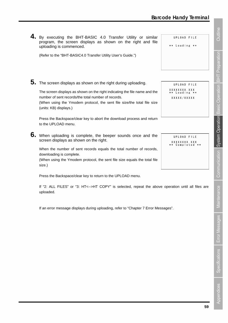
59
Barcode Handy Terminal
4. By executing the BHT-BASIC 4.0 Transfer Utility or similar program, the screen displays as shown on the right and file
5. ys as shown on the right during uploading.
he screen displays as shown on the right indicating the file name and the
dem protocol, the sent file size/the total file size
ress the Backspace/clear key to abort the download process and return
the UPLOAD menu.
6. hen uploading is complete, the beeper sounds once and the screen displays as shown on the right.
ls the total number of records,
downloading is complete.
e/clear key to return to the UPLOAD menu.
->HT COPY” is selected, repeat the above operation until all files are
ploaded.
an error message displays during uploading, refer to “Chapter 7 Error Messages”.
uploading is commenced.
(Refer to the “BHT-BASIC4.0 Transfer Utility User’s Guide.”)
The screen displa
T
number of sent records/the total number of records.
(When using the Ymo
(units: KB) displays.)
P
to
W
When the number of sent records equa
(When using the Ymodem protocol, the sent file size equals the total file
size.)
Press the Backspac
If “2: ALL FILES” or “3: HT<-
u
If
60
BHT-904B/BHT-914B
4.5.5 Copying Files between 2 BHT Units Copy “all files (excluding font files)”, “setting data”, and the “date and time” s
another BHT.
tored in the BHT user area to
Use the following procedure to copy files between 2 BHT units.
1. et the same interface at both BHT units.
ommunication (Optical) interface is used.
2. ” → “FIELD SPACE” (spac
Ignore”.
3. of the BHTs face-to-face.
.
5. elect “3: UPLOAD” → “3: HT<-->HT COPY” at the SYSTEM MENU of the BHT that is
“4.5.4 Uploading Files (UPLOAD Menu)” for details.
hen copying only the system parameter file, use the SYSTEM PARAMETER transfer menu. Refer to
.5.12 Downloading/Uploading the BHT System Parameter File (SYSTEM PARAMETER Menu)” for
6. reparation at both BHT units is now complete and file copying will be commenced.
S
An IrDA c
The default interface is set to infrared communication (Optical).
Set “COMMUNICATION PROTOCOL OPTION e at the end of the
ing the interface.
field) to “Ignore” at both BHT units.
The default setting is “
Refer to “4.5.6 [5] System Environment Settings (SET SYSTEM Menu)” when chang
Place the IrDA communication ports
4. Select “2: DOWNLOAD” → “2: HT<-->HT COPY” at the SYSTEM MENU of tdownloading to await downloading.
he BHT that is
TER transfer menu. Refer to
EM PARAMETER Menu)” for
Refer to “4.5.3 Downloading Files (DOWNLOAD Menu)” for details.
When copying only the system parameter file, use the SYSTEM PARAME
“4.5.12 Downloading/Uploading the BHT System Parameter File (SYST
etailsd
Suploading to await uploading.
Refer to the
W
“4
details.
P
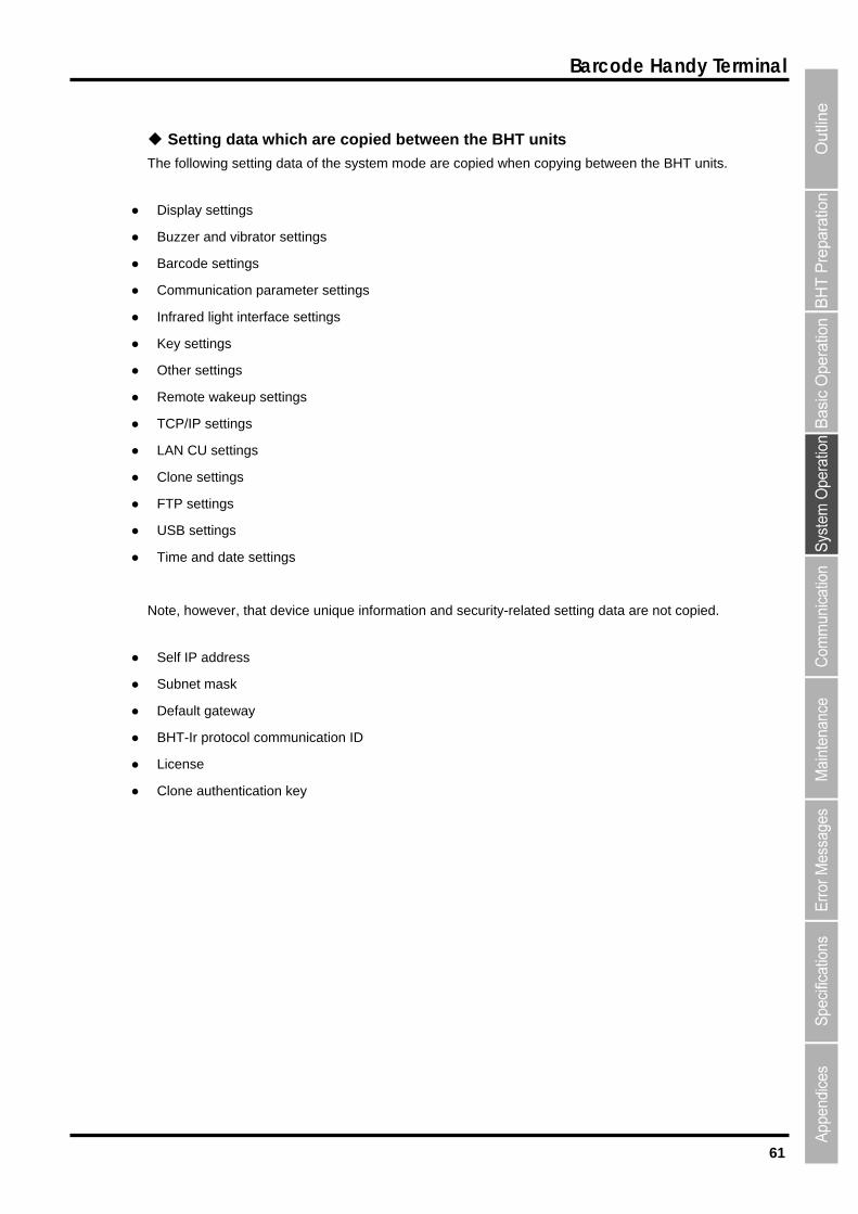
61
Barcode Handy Terminal
Setting data which are copied between the BHT units
●
settings
●
● Infrared light interface settings
Key settings
● Remote wakeup settings
●
● LAN CU settings
FTP settings
● Time and date settings
Self IP address
● Default gateway
●
●
● authentication key
The following setting data of the system mode are copied when copying between the BHT units.
Display settings
● Buzzer and vibrator settings
● Barcode
Communication parameter settings
●
● Other settings
TCP/IP settings
● Clone settings
●
● USB settings
Note, however, that device unique information and security-related setting data are not copied.
●
● Subnet mask
BHT-Ir protocol communication ID
License
Clone

62
BHT-904B/BHT-914B
4.5.6 System Environment Settings (SET SYSTEM Menu)
STEM” at the SYSTEM MENU and then press the ENT key.
nu screen displays as shown on the right.
ecution program to be executed when the power
English/Japanese/ Simplified Chinese
e/Korean/Thai).
r clock (date and time).
rcode reading conditions (black/white inverted barcode
n and decode level) and minimum number of barcode
(ITF, STF, Codabar).
Sets the communication environment (interface port and communication parameters).
“7: TCP/IP”:
g menu for TCP/IP, FTP and DHCP.
nu
ption.
OL”:
ration.
Sets the operation log.
Refer to the following section for details of the above items.
Press the Backspace/clear key to return to the SYSTEM MENU.
Use the following procedure to set the system environment.
1. Select “4: SET SY
The SET SYSTEM me
SET SYSTEM 1/2 menu
“1: EXECUTE PROGRAM”:
Sets the auto-start ex
is turned ON.
“2: DISPLAY”:
Sets the message version (
/Traditional Chines
“3: DATE/TIME”:
Sets the calenda
“4: BARCODE”:
Sets the ba
reading functio
digits to be read
“5: COMMUNICATION”:
“6: KEY”:
Defines the functions of the shift key and magic keys.
Displays the settin
SET SYSTEM 2/2 me
“1: EXEC PROG OPT”:
Sets the user program execution o
“2: DRIVE TO
Sets the drive-related ope
“3: OPERATION LOG”:

63
Barcode Handy Terminal
[1] Setting the auto-start execution program
Use the following procedure to set the auto-start execution program.
1. Select “1: EXECUTE PROGRAM” at the SET SYSTEM menu andthen press the ENT key.
n on the
be the program currently set as the auto-start
2. Use the cursor keys ([
3. Pr
Th e auto-start execution program.
Pr he SET SYSTEM menu.
Th
do
Pr
The SET EXECUTE PROGRAM menu screen displays as show
right.
The highlighted program will
execution program.
▲] [▼]) to highlight the target program.
ess the ENT key.
e selected program will be set as th
ess the Backspace/clear key to return to t
e screen displays as shown on the right if no programs have been
wnloaded.
ess the Backspace/clear key to return to the SET SYSTEM menu.

64
BHT-904B/BHT-914B
[2] Setting the message version, system status indication and screen display compatible mode
tatus indication and screen display
compatible mode.
[▼]) or numeric keys ([1] [2]) to highlight
2.
Press the Backspace/clear key to return to the SET SYSTEM menu.
“1: MESSAGE”:
f messages to be displayed on the screen.
The default is the message version selected at the system initializing process.
tting (English/Japanese/Simplified
Chinese/Traditional Chinese/Korean/Thai).
Indications relating to the LCD contrast
itching
: STATUS”:
Sets whether to display or hide the system status displayed at the bottom of the screen.
Refer to “System Status Indication” on the following page for details of the system status indication.
“ON”: The system status is displayed.
“OFF”: The system status is hidden.
Note The system status indication can be turned ON or OFF using the OUT statement in use
Use the following procedure to set the display language, system s
1. Use the cursor keys ([▲] “1: MESSAGE” or ”2: STATUS”.
Highlight the target setting with the cursor keys ([◄] [►]) and press the ENT key.
S E T D I S P L A Y 1 : M E S S A G E
E n g l i s h J a p a n e s e C h i n e s e T a i w a n e s e K o r e a n T h a i
2 : S T A T U S O N O F F
Sets the language o
The following messages can be displayed according to the se
System error messages
Beeper volume
Beeper & vibrator sw
Messages on the battery voltage level screen
“2
rprograms. Refer to the “BHT-BASIC Programmer’s Manual.”
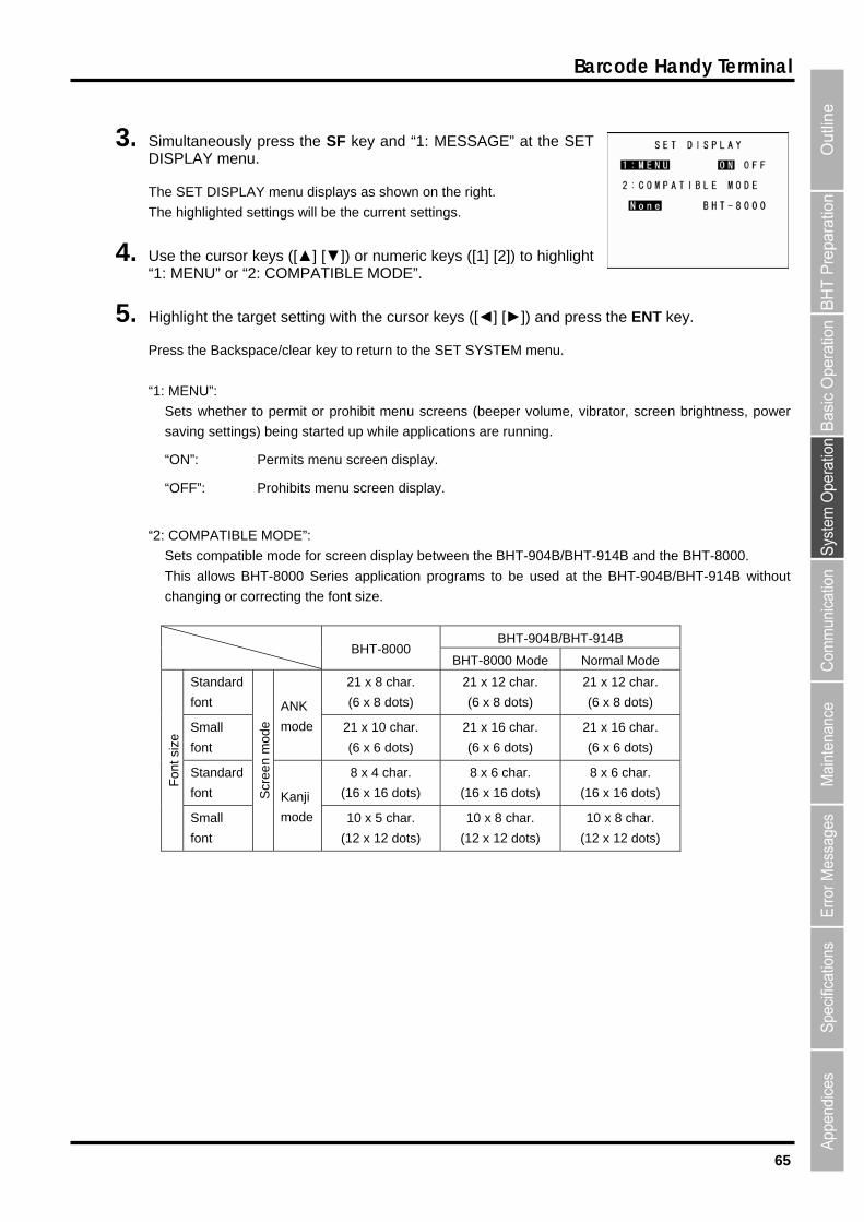
65
Barcode Handy Terminal
3.
The SET DISPLAY menu displays as shown on the right.
Use the cursor keys ([▲] [▼]) or numeric keys ([1] [2]) to highlight
5. ress the ENT key.
ss the Backspace/clear key to return to the SET SYSTEM menu.
“1
reen brightness, power
.
u screen display.
“2: COMPATIBLE MODE”:
reen display between the BHT-904B/BHT-914B and the BHT-8000.
This allows BHT-8000 Series application programs to be used at the BHT-904B/BHT-914B without
BHT-904B/BHT-914B
Simultaneously press the SF key and “1: MESSAGE” at the SET DISPLAY menu.
The highlighted settings will be the current settings.
4. “1: MENU” or “2: COMPATIBLE MODE”.
Highlight the target setting with the cursor keys ([◄] [►]) and p
Pre
: MENU”:
Sets whether to permit or prohibit menu screens (beeper volume, vibrator, sc
saving settings) being started up while applications are running.
“ON”: Permits menu screen display
“OFF”: Prohibits men
Sets compatible mode for sc
changing or correcting the font size.
BHT-8000 BHT-8000 Mode Normal Mode
Standard 21 x 8 char. 21 x 12 char. 21 x 12 char.
fon (6 x 8 dots) t (6 x 8 dots) (6 x 8 dots)
Sma mode 21 x 10 char. ll
font (6 x 6 dots)
21 x 16 char.
(6 x 6 dots)
21 x 16 char.
(6 x 6 dots)
ANK
Standard 8 x 4 char.
(16 x 16 dots)
8 x 6 char.
(16 x 16 dots)
8 x 6 char.
(16 x 16 dots) font
Fon
t siz
e
Small
font
Scr
een
mo
mode 10 x 5 char.
(12 x 12 dots)
10 x 8 char.
(12 x 12 dots)
10 x 8 char.
(12 x 12 dots)
de
Kanji

66
BHT-904B/BHT-914B
System Status Indication
Descripti
Turning ON the system status indication displays the following icons at the bottom of the screen.
on Indication Icon
Key Shift status Displays when the keys on the keypad are in Shift mode.
Alphabet entry mode
(If the alphanumeric entry system has bepressing the
Displays when the BHT is set to alphabet entry mode.
en selected in user programs, SF key switches from the numeric entry mode to alphabet
entry mode.)
to the table below.
[2] : ‘A’, ‘B’, ‘C’, ‘a’, ‘b’, ‘c’
[3] : ‘D’, ‘E’, ‘F’, ‘d’, ‘e’, ‘f’
, ‘n’, ‘o’
‘V’, ‘t’, ‘u’, ‘v’
[9] : ‘W’, ‘X’, ‘Y’, ‘Z’, ‘w’, ‘x’, ‘y’, ‘z’
[0] : ‘,’, ‘/’, ‘ ’, ‘*’, ‘#’, ‘&’, ‘~’, ‘?’ (*1)
ch of ‘@’, ‘$’, ‘¥’, ‘#’, and ‘~’ is displayed differently depending on country$ setting.
Each of the keys corresponds to the key data according
Key Key data
[4] : ‘G’, ‘H’, ‘I’, ‘g’, ‘h’, ‘i’
[5] : ‘J’, ‘K’, ‘L’, ‘j’, ‘k’, ‘l’
[6] : ‘M’, ‘N’, ‘O’, ‘m’
[7] : ‘P’, ‘Q’, ‘R’, ‘S’, ‘p’, ‘q’, ‘r’, ‘s’
[8] : ‘T’, ‘U’,
[.] : ‘-’, ‘%’, ‘$’, ‘_’, ‘¥’, ‘=’, ‘@’ (*1)
*1 Ea
Communicatiowith the CU-91
n link 1
Displays w
Flashes w
hen a comm hed with the CU-911.
hen t mm U-911 that has not with
unication link is establis
he BHT tries to co unicate with a Cbeen linked the BHT.
Displays cyclicall BHT r response from the whe or th tablished with or the
y when the eceives no CU-911, or severed from
n it is waiting f CU-911.
e link to be es
[3] Setting the calendar clock
When resetting the date and time, refer to “Chapter 2 BHT Preparation”
– “2.4 Initial Setup.”
Select “3: DATE/TIME” at the SET SYSTEM menu and press the ENT
key to display the SET DATE/TIME menu screen on the right.
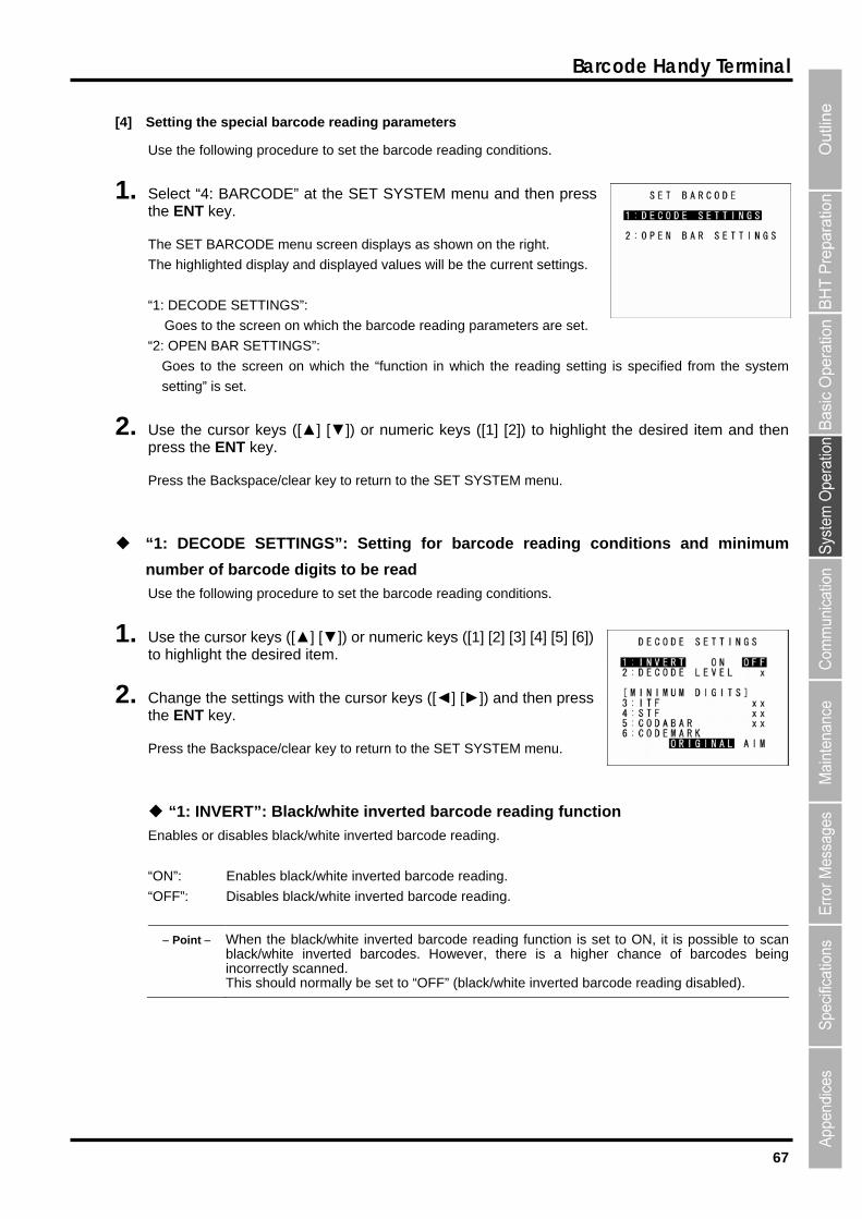
67
Barcode Handy Terminal
[4] Setting the special barcode reading parameters
1. Select “4: BARCODE” at the SET SYSTEM menu and tht
The SET BARCODE menu screen
The highlighted display and displa
“1: DECODE SETTINGS”:
Goes to the screen on which the barcode reading parameters are set.
“2: OPEN BAR SETTINGS”:
Goes to the screen on which th u t ing setting is specified from the system
setting” is set.
2. Use the cursor keys ([▲] [▼]) u to highlight the desired item and then press the ENT key.
Press the Backspace/clear key to n
“1: DECODE SETTINGS”: Setti g itions and minimum
number of barcode digits to be read
Use the following procedure to set
1. U s ([▲] [▼]) oto highlight the desired item.
2. Change the settings with the cuthe ENT key.
Press the Backspace/clear key to return to the SET SYSTEM menu.
“1: INVERT”: Black/white inverted barcode reading function
Enables or disables black/white inverted barcode reading.
hite inverted barcode reading.
hite inverted barcode reading.
e black/white inverted barcode reading function is s
invert
Use the following procedure to set the barcode reading conditions.
en press he ENT key.
displays as shown on the right.
yed values will be the current settings.
e “f nc ion in which the read
or n meric keys ([1] [2])
retur to the SET SYSTEM menu.
ng for barcode readin cond
the barcode reading conditions.
se the cursor key r numeric keys ([1] [2] [3] [4] [5] [6])
rsor keys ([◄] [►]) and then press
“ON”: Enables black/w
“OFF”: Disables black/w
Point When th et to ON, it is possible to scan er chance of barcodes being
ed barcode reading disabled).
black/white inverted barcodes. However, there is a highincorrectly scanned. This should normally be set to “OFF” (black/white

68
BHT-904B/BHT-914B
“2: DECODE LEVEL”: Decode level
Set the decode level (barcode reading tolerance level).
Press [◄] to decrease the setting value and [►] to increase the setting value.
we
n the other hand, increasing the level decreases the barcode reading efficiency, but w
g.
mber of barcode digits to be read for ITF
“5: CODABAR”: Minimum number of barcode digits to be read for Codabar
the setting value and [►] to increase the setting value.
STF entry range: 1 to 20 Default: 3
Codabar entry range: 3 to 20 Default: 4
he frequency of missing digits when reading or incorrectly
des.
On the other hand, setting a large number will decrease the possibility of such errors.
Sets the type of the codemark.
Codemark system specified for DENSO
Codemark system complies with the AIM US “Guidelines on Symbology Identifiers”
Decode level entry range: 1 to 9 Default: 4
Decreasing the level increases the barcode reading efficiency, ho ver, the BHT may incorrectly read
ill decrease the
low-quality (split or stained) barcodes.
O
possibility of incorrect readin
“3: ITF”: Minimum nu
“4: STF”: Minimum number of barcode digits to be read for STF
Sets the minimum number of barcode digits to be read.
Press [◄] to decrease
ITF entry range: 2 to 20 Default: 4
Setting a small number of digits increases t
reading depending on how barcodes are read or the quality of barco
“6: CODEMARK”: Setting for the codemark type
ORIGINAL
AIM

69
Barcode Handy Terminal
“2: OPEN BAR SETTINGS”: Setting for the “function in which the reading setting is
1. e BARCODE menu an
E screen.
: BUZZER/LED”: Buzzer/LED control
ions.
2. se the cursor keys ([▲] [▼]) or numeric keys ([1] [2] [3]) to select the desired item and then pr .
3. Pr le e SET BARCODE menu.
[1]
1. enu and
he SET READ MODE screen appears.
ted setting is the current setting.
TO OFF”: Auto off mode
light goes off.
“2: MOMENTARY”: Momentary mode
The light is illuminated continuously when the trigger switch is pressed and held.
“3: ALTERNATE”: Alternate mode
The light brinks (turns ON/OFF) when the trigger switch is pressed.
“4: CONTINUOUS”: Continuous-illumination mode
The light is on continuously.
2. Use the cursor keys ([▲] [▼]) or numeric keys ([1] [2] [3] [4]) to select the desired setting.
3. Press the ENT or Backspace/clear key to update the setting and return to the OPEN BAR SETTING screen.
specified from the system setting”
S lect “2: OPEN BAR SETTINGS” at the SETd then press the ENT key.
The OPEN BAR SETTING menu screen appears.
“1: READ MODE”: Read mode
Goes to the SET READ MOD
“2
Goes to the SET BUZZER/LED screen.
“3: READ CODE”: Read barcode
Goes to the SET BARCODE screen.
For details of the items above, refer to the following sect
Uess the ENT key
ess the Backspace/c ar key to return to th
Read mode
Select “1: READ MODE” at the OPEN BAR SETTING mthen press the ENT key.
T
The highligh
“1: AU
When the specified time elapses after the trigger operation ends, the
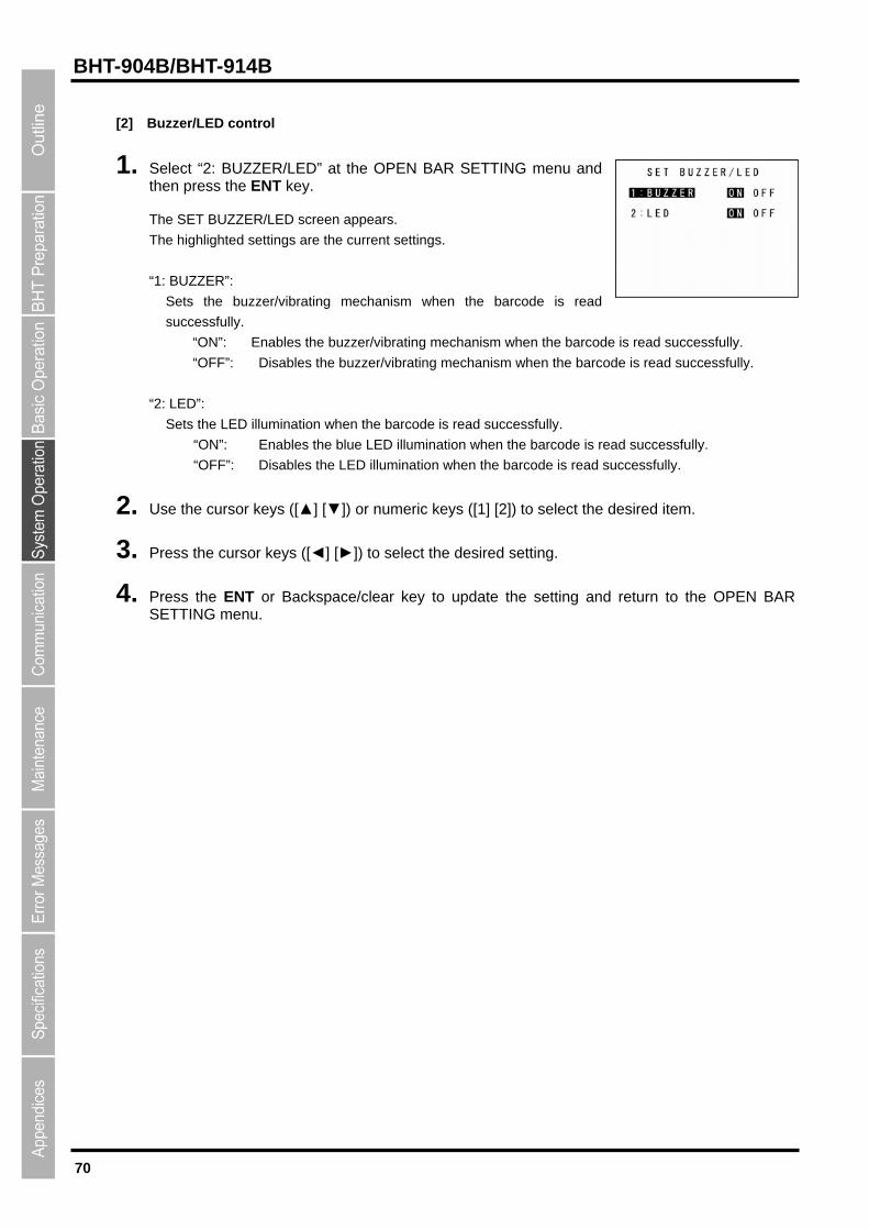
70
BHT-904B/BHT-914B
[2] Buzzer/LED control
1. Select “2: BUZZER/LED” at the OPEN BAR SETTING menu and
ppears.
when the barcode is read
g mechanism when the barcode is read successfully.
vibrating mechanism when the barcode is read successfully.
:
fully.
lly.
Use the cursor keys ([▲] [▼]) or numeric keys ([1] [2]) to select the desired item.
Press the cursor keys ([◄] [►]) to select the desired setting.
NT or Backspace/clear key to update the setting and return to the OPEN BAR SETTING menu.
then press the ENT key.
The SET BUZZER/LED screen a
The highlighted settings are the current settings.
“1: BUZZER”:
Sets the buzzer/vibrating mechanism
successfully.
“ON”: Enables the buzzer/vibratin
“OFF”: Disables the buzzer/
LED”: “2
Sets the LED illumination when the barcode is read success
“ON”: Enables the blue LED illumination when the barcode is read successfu
“OFF”: Disables the LED illumination when the barcode is read successfully.
2.
3.
4. Press the E
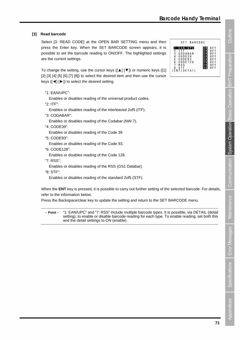
71
Barcode Handy Terminal
[3] Read barcode
Select [3: READ CODE] at the OPEN BAR SETTING menu and then
reading to ON/OFF. The highlighted settings
o change the setting, use the cursor keys ([▲] [▼]) or numeric keys ([1]
] [7] [8]) to select the desired item and then use the cursor
ke
“1: E C”
En d
: ITF”:
es or disables reading of the interleaved 2of5 (ITF).
En r d
“4: CODE39”:
Enables or disables reading of the Code 39
“7: RSS”:
Enables or disables reading of the standard 2of5 (STF).
When the ENT key is pressed, it is possible to carry out further setting of the selected barcode. For details,
refer to the information below.
Press the Backspace/clear key to update the setting and return to the SET BARCODE menu.
Point “1: EAN/UPC” and “7: RSS” include multiple barcode types. It is possible, via DETAIL (detail setting), to enable or disable barcode reading for each type. To enable reading, set both this and the detail settings to ON (enable).
press the Enter key. When the SET BARCODE screen appears, it is
possible to set the barcode
are the current settings.
T
[2] [3] [4] [5] [6
ys ([◄] [►]) to select the desired setting.
AN/UP :
ables or isables reading of the universal product codes.
“2
Enabl
“3: CODABAR”:
ables o isables reading of the Codabar (NW-7).
“5: CODE93”:
Enables or disables reading of the Code 93.
“6: CODE128”:
Enables or disables reading of the Code 128.
Enables or disables reading of the RSS (GS1 Databar).
“8: STF”:
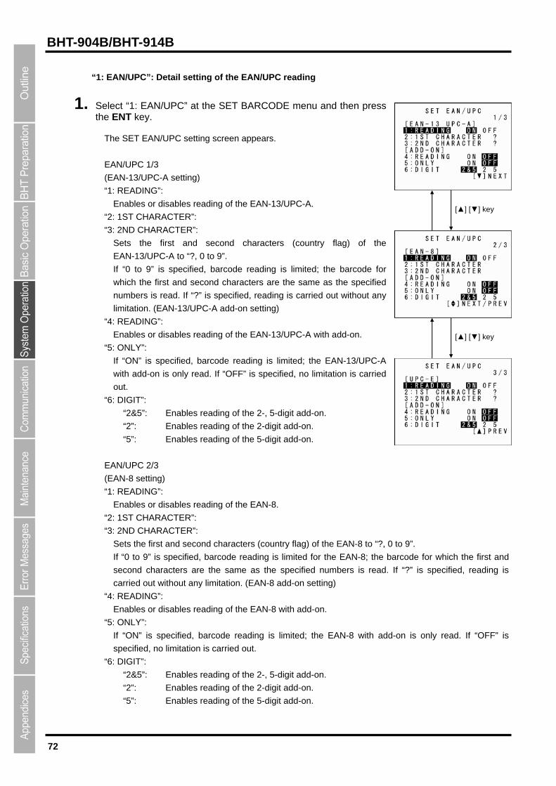
72
BHT-904B/BHT-914B
“1: EAN/UPC”: Detail setting of the EAN/UPC reading
1.
tting screen appears.
Enables or disables reading of the EAN-13/UPC-A.
CTER”:
“3
he first and second characters (country flag) of the
pecified, barcode reading is limited; the barcode for
as the specified
ead. If “?” is specified, reading is carried out without any
PC-A with add-on.
d; the EAN-13/UPC-A
-on is only read. If “OFF” is specified, no limitation is carried
:
“2”: Enables reading of the 2-digit add-on.
(EAN-8 setting)
I
Enables
“2: 1ST CHARA
“3: 2ND CHARACTER”:
Sets the first and second characters (country flag) of the EAN-8 to “?, 0 to 9”.
If “0 to 9” is specified, barcode reading is limited for the EAN-8; the barcode for which the first and
second characters are the same as the specified numbers is read. If “?” is specified, reading is
carried out without any limitation. (EAN-8 add-on setting)
“4: READING”:
Enables or disables reading of the EAN-8 with add-on.
“5: ONLY”:
If “ON” is specified, barcode reading is limited; the EAN-8 with add-on is only read. If “OFF” is
specified, no limitation is carried out.
“6: DIGIT”:
“2&5”: Enables reading of the 2-, 5-digit add-on.
“2”: Enables reading of the 2-digit add-on.
“5”: Enables reading of the 5-digit add-on.
[▲] [▼] key
Select “1: EAN/UPC” at the SET BARCODE menu and then press the ENT key.
The SET EAN/UPC se
EAN/UPC 1/3
(EAN-13/UPC-A setting)
“1: READING”:
“2: 1ST CHARA
: 2ND CHARACTER”:
Sets t
EAN-13/UPC-A to “?, 0 to 9”.
If “0 to 9” is s
which the first and second characters are the same
numbers is r
limitation. (EAN-13/UPC-A add-on setting)
“4: READING”:
Enables or disables reading of the EAN-13/U [▲] [▼] key
“5: ONLY”:
If “ON” is specified, barcode reading is limite
with add
out.
“6: DIGIT”
“2&5”: Enables reading of the 2-, 5-digit add-on.
“5”: Enables reading of the 5-digit add-on.
EAN/UPC 2/3
“1: READ NG”:
or disables reading of the EAN-8.
CTER”:

73
Barcode Handy Terminal
EAN/UPC 3/3
(UPC-E setting)
disables reading of the UPC-E.
“2: 1ST CHARACTER”:
Sets the first and second characters (country flag) of the UPC-E to “?, 0 to 9”.
specified, barcode reading is limited for the UPC-E; the
the same as the specified numbers is read.
hout any limitation. (UPC-E add-on setting)
“4
ading of the UPC-E with add-on.
d out.
“6
add-on.
2. Use 6
3. Pre
4. P or Backspace/clear key to update the m
“1: READING”:
Enables or
“3: 2ND CHARACTER”:
If “0 to 9” is barcode for which the first and
If “?” is specified, reading is
on is only read. If “OFF” is
]) to select the desired item.
setting and return to the SET BARCODE
second characters are
carried out wit
: READING”:
Enables or disables re
“5: ONLY”:
If “ON” is specified, barcode reading is limited; the UPC-E with add-
specified, no limitation is carrie
: DIGIT”:
“2&5”: Enables reading of the 2-, 5-digit add-on.
“2”: Enables reading of the 2-digit add-on.
“5”: Enables reading of the 5-digit
the cursor keys ([▲] [▼]) or numeric keys ([1] [2] [3] [4] [5] [
ss the cursor keys ([◄] [►]) to select the desired setting.
ress the ENTenu.
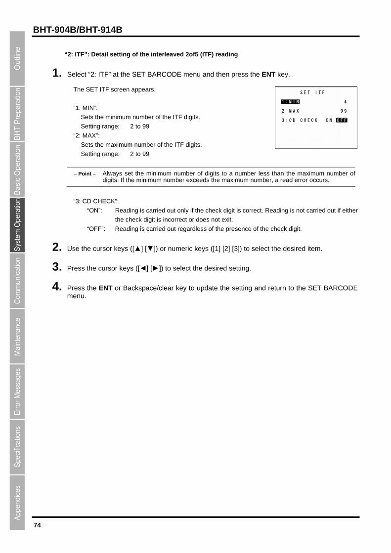
74
BHT-904B/BHT-914B
“2 tting of the interleaved 2of5 (ITF) reading
1. S the SET BARCODE menu and then press the ENT key.
ears.
“1
“2
mum number of the ITF digits.
: ITF”: Detail se
elect “2: ITF” at
The SET ITF screen app
: MIN”:
Sets the minimum number of the ITF digits.
Setting range: 2 to 99
: MAX”:
Sets the maxi
Setting range: 2 to 99
Point Always set the minimum number of digits to a number less than the maximum number of digits. If the minimum number exceeds the maximum number, a read error occurs.
“3: C K
igit is correct. Reading is not carried out if either
xit.
“OFF”: Reading is carried out regardless of the presence of the check digit.
Use the cursor keys ([▲] [▼]) or numeric keys ([1] [2] [3]) to select the desired item.
Press the cursor keys ([◄] [►]) to select the desired setting.
e ENT or Backspace/clear key to update the setting and return to the SET BARCODE menu.
D CHEC ”:
“ON”: Reading is carried out only if the check d
the check digit is incorrect or does not e
2.
3.
4. Press th
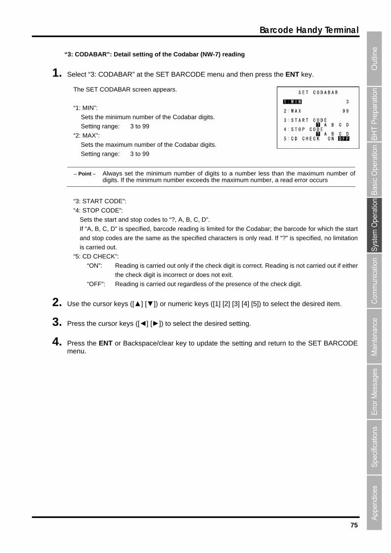
75
Barcode Handy Terminal
“3: CODABAR”: Detail setting of the Codabar (NW-7) reading
key.
pears.
gits.
gits.
1. Select “3: CODABAR” at the SET BARCODE menu and then press the ENT
The SET CODABAR screen ap
“1: MIN”:
Sets the minimum number of the Codabar di
Setting range: 3 to 99
“2: MAX”:
Sets the maximum number of the Codabar di
Setting range: 3 to 99
Point Always set the minimum number of digits to a number less than the maximum number of digits. If the minimum number exceeds the maximum number, a read error occurs
”:
“4: STOP COD
Sets the star
If D for which the start
and stop codes are the same as the specified characters is only read. If “?” is specified, no limitation
“5: CD CHECK”:
ct. Reading is not carried out if either
the check digit is incorrect or does not exit.
2. Use the cursor keys ([▲] [▼]) or numeric keys ([1] [2] [3] [4] [5]) to select the desired item.
3. Press the cursor keys ([◄] [►]) to select the desired setting.
4. Press the ENT or Backspace/clear key to update the setting and return to the SET BARCODE menu.
“3: START CODE
E”:
t and stop codes to “?, A, B, C, D”.
“A, B, C, ” is specified, barcode reading is limited for the Codabar; the barcode
is carried out.
“ON”: Reading is carried out only if the check digit is corre
“OFF”: Reading is carried out regardless of the presence of the check digit.
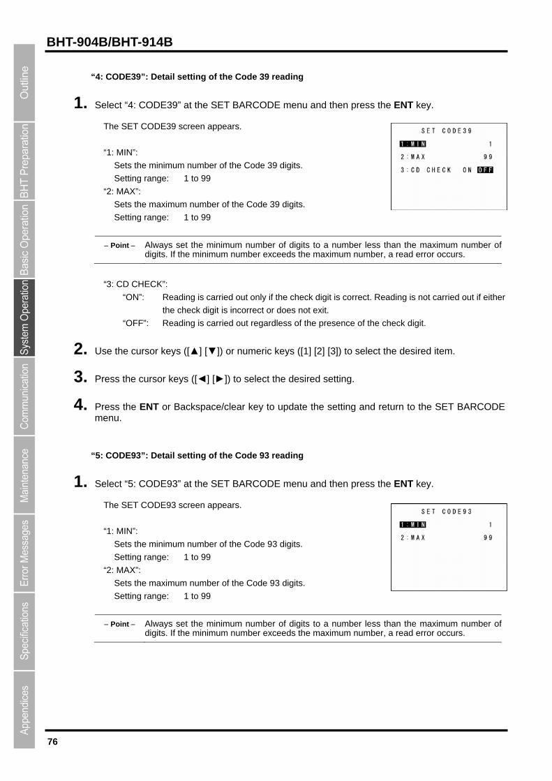
76
BHT-904B/BHT-914B
“4: CODE39”: Detail setting of the Code 39 reading
1. Select “4: CODE39” at the SET BARCODE menu and then press the ENT key.
The SET CODE39 screen appears.
“1: MIN”:
Sets the minimum number of the Code 39 digits.
Setting range: 1 to 99
“2: MAX”:
Sets the maximum number of the Code 39 digits.
Setting range: 1 to 99
Point Always set the minimum number of digits to a number less than the maximum number of digits. If the minimum number exceeds the maximum number, a read error occurs.
“3: CD CHECK”:
“ON”: Reading is carried out only if the check digit is correct. Reading is not carried out if either
ot exit.
2. Use the cursor keys ([▲] [▼]) or numeric keys ([1] [2] [3]) to select the desired item.
3. Press
4. Press T SET BARCODE menu.
The SET CODE93 screen appears.
“1: MIN”:
Sets the minimum number of the Code 93 digits.
Setting range: 1 to 99
“2: MAX”:
Sets the maximum number of the Code 93 digits.
Setting range: 1 to 99
Point Always set the minimum number of digits to a number less than the maximum number o
the check digit is incorrect or does n
“OFF”: Reading is carried out regardless of the presence of the check digit.
the cursor keys ([◄] [►]) to select the desired setting.
the EN or Backspace/clear key to update the setting and return to the
“5: CODE93”: Detail setting of the Code 93 reading
1. Select “5: CODE93” at the SET BARCODE menu and then press the ENT key.
f digits. If the minimum number exceeds the maximum number, a read error occurs.
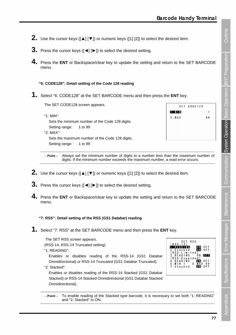
77
Barcode Handy Terminal
2. Use the cursor keys ([▲] [▼]) or numeric keys ([1] [2]) to select the desired item.
Press the cursor keys ([◄] [►]) to select the desired setting.
4. Press the or Backspace/clear key to update the m
“6 ”: Detail setting of the Code 128 reading
1. Sele 8 SET BARCODE menu and then press the ENT key.
C
: MIN”:
um number of the Code 128 digits.
S ng
“2: MAX”:
Sets the ma
Setting range: 1 to 99
Point Always set the minimum number of digits to a number less than the maximum number o
3.
ENTenu.
setting and return to the SET BARCODE
: CODE128
ct “6: CODE12 ” at the
The SET ODE128 screen appears.
“1
Sets the minim
etting ra e: 1 to 99
ximum number of the Code 128 digits.
f umber, a read error occurs. digits. If the minimum number exceeds the maximum n
2. Use the cursor keys ([▲] [▼]) or numeric keys ([1] [2]) to select the desired item.
3. Press the cursor keys ([◄] [►]) to select the desired setting.
4. the setting and return to the SET BARCODE menu.
“7 S1 Databar) reading
1. Select “7: R ENT
The SET RSS screen appears.
SS-14 Truncated setting)
“1
isa ading of the RSS-14 (GS1 Databar
mnidirectional) or RSS-14 Truncated (GS1 Databar Truncated).
e
Enable
Stacked) or RSS-14 Stacked Omnidirectional (GS1 Databar Stacked
Omnidirectional).
Point To enable reading of the Stacked type barcode, it is necessary to set both “1: READING” and “2: Stacked” to ON.
Press the ENT or Backspace/clear key to update
: RSS”: Detail setting of the RSS (G
SS” at the SET BARCODE menu and then press the key.
(RSS-14, R
: READING”:
Enables or d bles re
O
“2: Stack d”:
s or disables reading of the RSS-14 Stacked (GS1 Databar
78
BHT-904B/BHT-914B
(RSS-Limited setting)
Enables or disables reading of the RSS-Limited (GS1 Databar Limited). (RSS-Expanded setting)
Enables or disables reading of the RSS-Expanded (GS1 Databar Expanded).
Stacked (GS1 Databar Expanded Stacked) digits.
Setting range: 1 to 99
Sets the maximum number of the RSS-Expanded (GS1 Databar Expanded) or RSS-Expanded
Point Always set the minimum number of digits to a number
“3: READING”:
“4: READING”:
“5: MIN”:
Sets the minimum number of the RSS-Expanded (GS1 Databar Expanded) or RSS-Expanded
“6: MAX”:
Stacked (GS1 Databar Expanded Stacked) digits.
Setting range: 1 to 99
less than the maximum number of mber, a read error occurs. digits. If the minimum number exceeds the maximum nu
“7
or disables reading of the RSS-Expanded Stacked (GS1 Databar Expanded Stacked).
ble of the Stacked type barcode, it is necessary to set both “4: READING” and “7: Stacked” to ON.
: Stacked”:
Enables
Point To ena reading
2. Use the cursor keys ([
and return to the SET BARCODE menu.
▲] [▼]) or numeric keys ([1] [2] [3] [4] [5] [6] [7]) to select the desired item.
3. Press the cursor keys ([◄] [►]) to select the desired setting.
4. Press the ENT or Backspace/clear key to update the setting
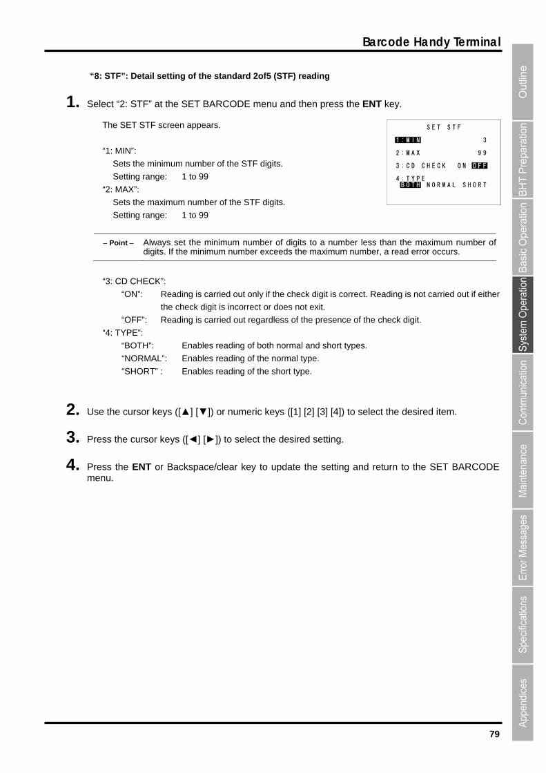
79
Barcode Handy Terminal
“8: STF”: Detail setting of the standard 2of5 (STF) reading
1. Selec
Th
“1
Point Always set the minimum number of digits to a number less than the maximum number o
t “2: STF” at the SET BARCODE menu and then press the ENT key.
e SET STF screen appears.
: MIN”:
Sets the minimum number of the STF digits.
Setting range: 1 to 99
“2: MAX”:
Sets the maximum number of the STF digits.
Setting range: 1 to 99
f digits. If the minimum number exceeds the maximum number, a read error occurs.
“3: CD CHECK”:
Reading is carried out only if the check digit is correct. Reading is not carried out if either
“OFF”: Reading is carried out regardless of the presence of the check digit.
”
“BOT g of both normal and short types.
“NORMAL”: Enables reading of the normal type.
select the desired item.
4. Press the ENT or Backspace/clear key to update the setting and return to the SET BARCODE menu.
“ON”:
the check digit is incorrect or does not exit.
“4: TYPE :
H”: Enables readin
“SHORT” : Enables reading of the short type.
2. Use the cursor keys ([▲] [▼]) or numeric keys ([1] [2] [3] [4]) to
3. Press the cursor keys ([◄] [►]) to select the desired setting.
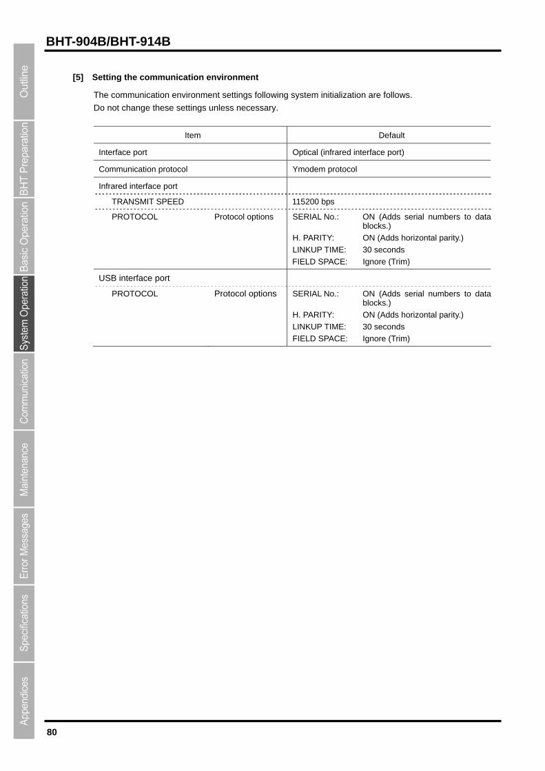
80
BHT-904B/BHT-914B
[5]
Setting the communication environment
The communication environment settings following system initialization are follows.
Do not change these settings unless necessary.
Item Default
Interface port Optical (infrared interface port)
Co Ymodem protocol mmunication protocol
Infrared interface port
TRANSMIT SPEED 115200 bps
PROTOCOL Protocol options SERIAL No.: ON (Adds serial numbers to data blocks.)
FIELD SPACE: Ignore (Trim)
H. PARITY: ON (Adds horizontal parity.)
LINKUP TIME: 30 seconds
U SB interface port
PR OLblocks.)
tal parity.)
LINKUP TIME: 30 seconds
ore (Trim)
OTOC Protocol options SERIAL No.: ON (Adds serial numbers to data
H. PARITY: ON (Adds horizon
FIELD SPACE: Ign
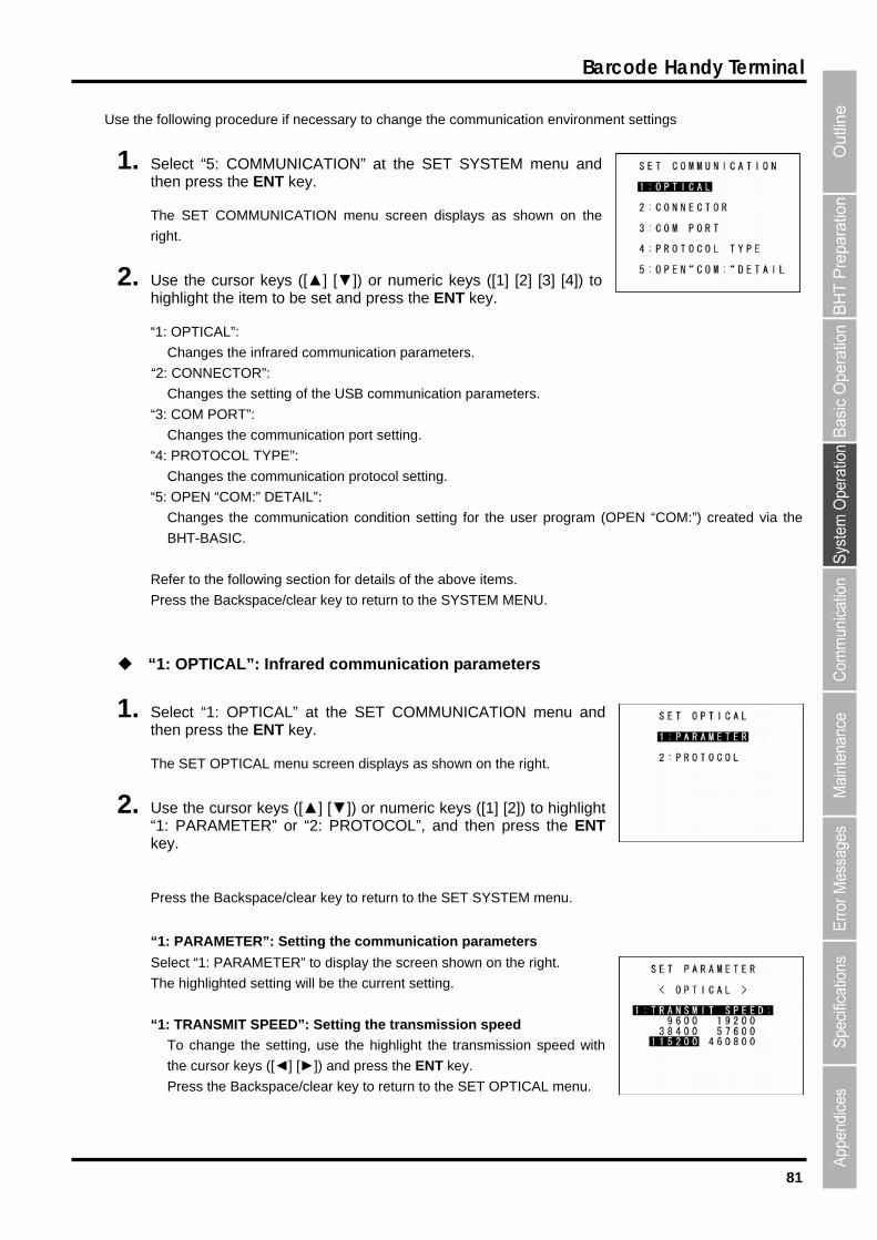
81
Barcode Handy Terminal
U the communication environment settings
1.
The SET COMMUNIC menu screen displays as shown on the
r
2. U ] [▼]) or numeric key to highlight the item to be set and press the ENT key.
“1: O
C frared comm ters
“2: CONNECTOR”:
Changes the setting of the USB communication p
“3: COM PORT”:
port setting.
“ E”:
C mmunication
“5: OPEN “COM:” DETAIL”:
Changes the communication condition setting f ra the
BHT-BASIC.
Refer to the following section for details of the above items.
Press the Backspace/clear key to return to the SYSTEM MENU.
“1: OPTICAL”: Infrared communication parameters
1. Select “1: OPTICAL” at the SET COMMUNICATION menu and then press the ENT key.
The SET OPTICAL menu screen displays as shown on the right.
2. Use the cursor keys ([▲] [▼]) or numeric keys ([1] [2]) to highlight “1: PARAMETER” or “2: PROTOCOL”, and then press the ENT key.
Press the Backspace/clear key to return to the SET SYSTEM menu.
“1: PARAMETER”: Setting the communication parameters
Select “1: PARAMETER” to display the screen shown on the right.
The highlighted setting will be the current setting.
“1: TRANSMIT SPEED”: Setting the transmission speed
To change the setting, use the highlight the transmission speed with
the cursor keys ([◄] [►]) and press the ENT key.
Press the Backspace/clear key to return to the SET OPTICAL menu.
se the following procedure if necessary to change
Select “5: COMMUNICATION” at the SET then press the ENT key.
SYSTEM menu and
ATION
ight.
se the cursor keys ([▲ s ([1] [2] [3] [4])
PTICAL”:
hanges the in unication parame .
arameters.
Changes the communication
4: PROTOCOL TYP
hanges the co protocol setting.
or the user prog m (OPEN “COM:”) created via
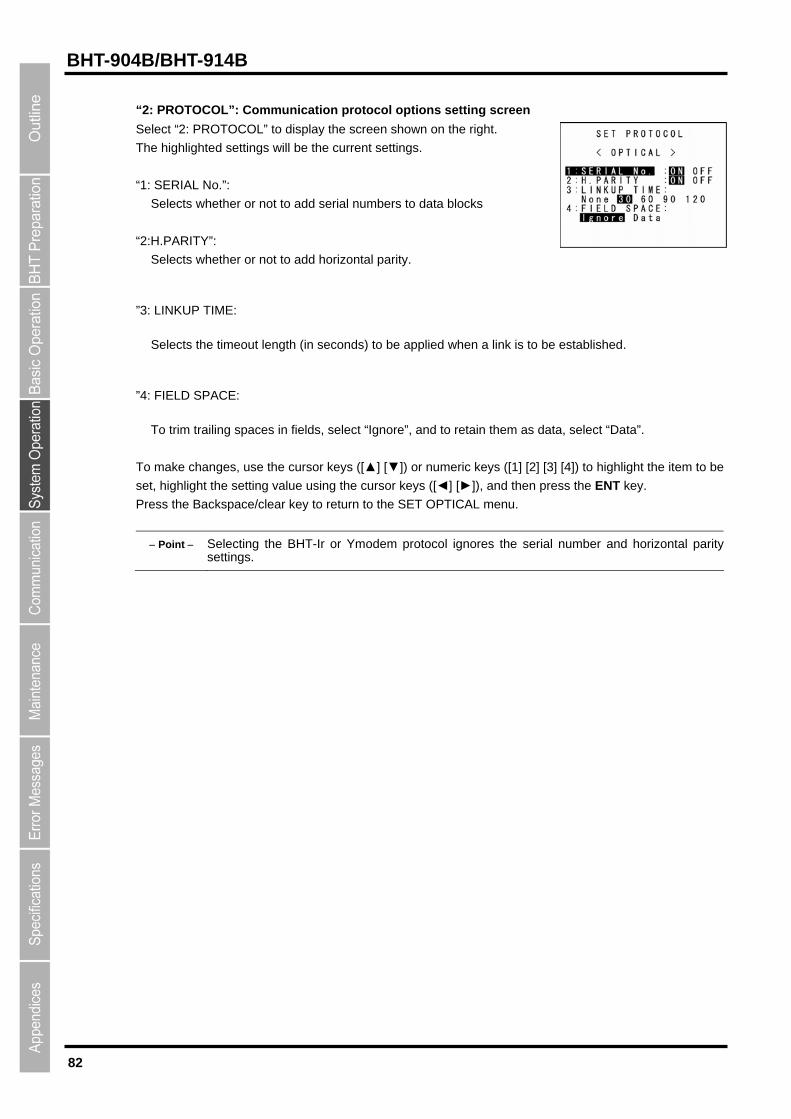
82
BHT-904B/BHT-914B
“2: PROTOCOL”: Communication protocol options setting screen
Select “2: PROTOCOL” to display the screen shown on the right.
be established.
”4
and to retain them as data, select “Data”.
To
se setting value using the cursor keys ([◄] [►]), and then press the ENT key.
ress the Backspace/clear key to return to the SET OPTICAL menu.
the serial number and horizontal parity settings.
The highlighted settings will be the current settings.
“1: SERIAL No.”:
Selects whether or not to add serial numbers to data blocks
“2:H.PARITY”:
Selects whether or not to add horizontal parity.
”3: LINKUP TIME:
Selects the timeout length (in seconds) to be applied when a link is to
: FIELD SPACE:
To trim trailing spaces in fields, select “Ignore”,
make changes, use the cursor keys ([▲] [▼]) or numeric keys ([1] [2] [3] [4]) to highlight the item to be
t, highlight the
P
Point Selecting the BHT-Ir or Ymodem protocol ignores
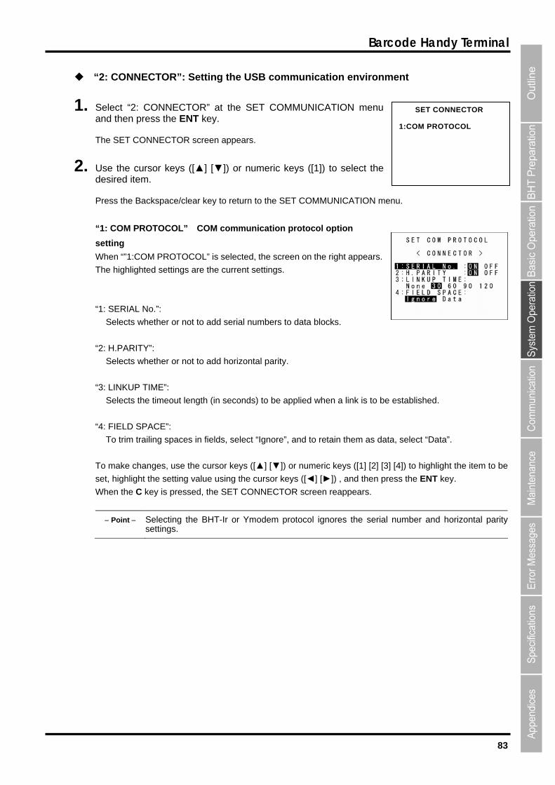
83
Barcode Handy Terminal
nment
1. NICATION menu nd then press the ENT key.
Th
2. r keys ([▲] [▼]) or numeric keys ([1]) to select the de
ress the Backspace/clear key to return to the SET COMMUNICATION menu.
“1: COM PROTOCOL” COM communication protocol option
se
hen “”1:COM PROTOCOL” is selected, the screen on the right appears.
:
Selects the timeout length (in seconds) to be applied when a link is to be established.
“4: FIELD SPACE”:
To trim trailing spaces in fields, select “Ignore”, and to retain them as data, select “Data”.
To make changes, use the cursor keys ([▲] [▼]) or numeric keys ([1] [2] [3] [4]) to highlight the item to be
set, highlight the setting value using the cursor keys ([◄] [►]) , and then press the ENT key.
When the C key is pressed, the SET CONNECTOR screen reappears.
Point Selecting the BHT-Ir or Ymodem protocol ignores the serial number and horizontal parity settings.
“2: CONNECTOR”: Setting the USB communication enviro
Select “2: CONNECTOR” at the SET COMMU SET CONNECTOR 1:COM PROTOCOL
a
e SET CONNECTOR screen appears.
Use the cursosired item.
P
tting
W
The highlighted settings are the current settings.
“1 SERIAL No.”:
Selects whether or not to add serial numbers to data blocks.
“2: H.PARITY”:
Selects whether or not to add horizontal parity.
“3: LINKUP TIME”:
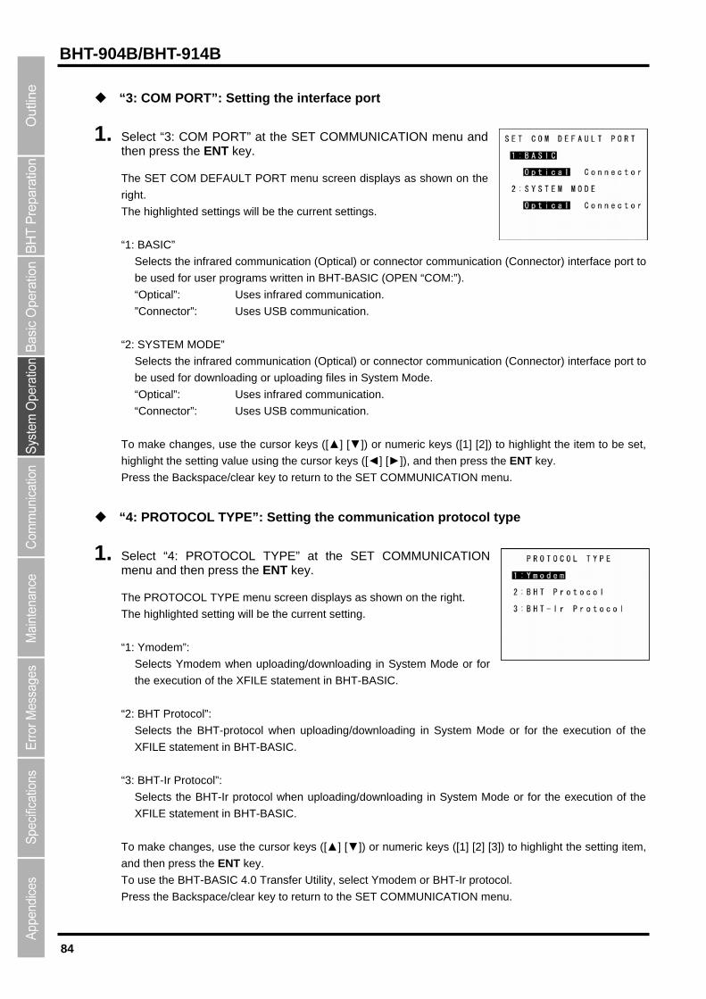
84
BHT-904B/BHT-914B
“3: COM PORT”: Setting the interface port
1. Select “3: COM PORT” at the SET COMMUNICATION menu and then press the ENT key.
The SET COM DEFAULT PORT menu screen displays as shown on the
right.
“1: BASIC”
nnector) interface port to
be used for user programs written in BHT-BASIC (OPEN “COM:”).
ector”: Uses USB communication.
MODE”
connector communicatio
be used for downloading or uploading files in System Mode.
“Optical”: Uses infrared communication.
Uses USB communication.
o make changes, use the cursor keys ([▲] [▼]) or numeric keys ([1] [2]) to highlight the item to be set,
ing value using the cursor keys ([◄] [►]), and then press the ENT key.
Pr COMMUNICATION menu.
“4: PROT
1. COL TYPE” at the SET COMMUNICATION m
he PROTOCOL TYPE menu screen displays as shown on the right.
Selects Ymodem when uploading/downloading in System Mode or for
u
“2: BHT Protocol”:
Selects the BHT-protocol when uploading/downloading in System Mode or for the execution of the
XFILE statement in BHT-BASIC.
“3: BHT-Ir Protocol”:
Selects the BHT-Ir protocol when uploading/downloading in System Mode or for the execution of the
XFILE statement in BHT-BASIC.
To make changes, use the cursor keys ([▲] [▼]) or numeric keys ([1] [2] [3]) to highlight the setting item,
and then press the ENT key.
To use the BHT-BASIC 4.0 Transfer Utility, select Ymodem or BHT-Ir protocol.
Press the Backspace/clear key to return to the SET COMMUNICATION menu.
The highlighted settings will be the current settings.
Selects the infrared communication (Optical) or connector communication (Co
“Optical”: Uses infrared communication.
”Conn
“2: SYSTEM
Selects the infrared communication (Optical) or n (Connector) interface port to
“Connector”:
T
highlight the sett
ess the Backspace/clear key to return to the SET
OCOL TYPE”: Setting the communication protocol type
Select “4: PROTOenu and then press the ENT key.
T
The highlighted setting will be the current setting.
“1: Ymodem”:
the exec tion of the XFILE statement in BHT-BASIC.
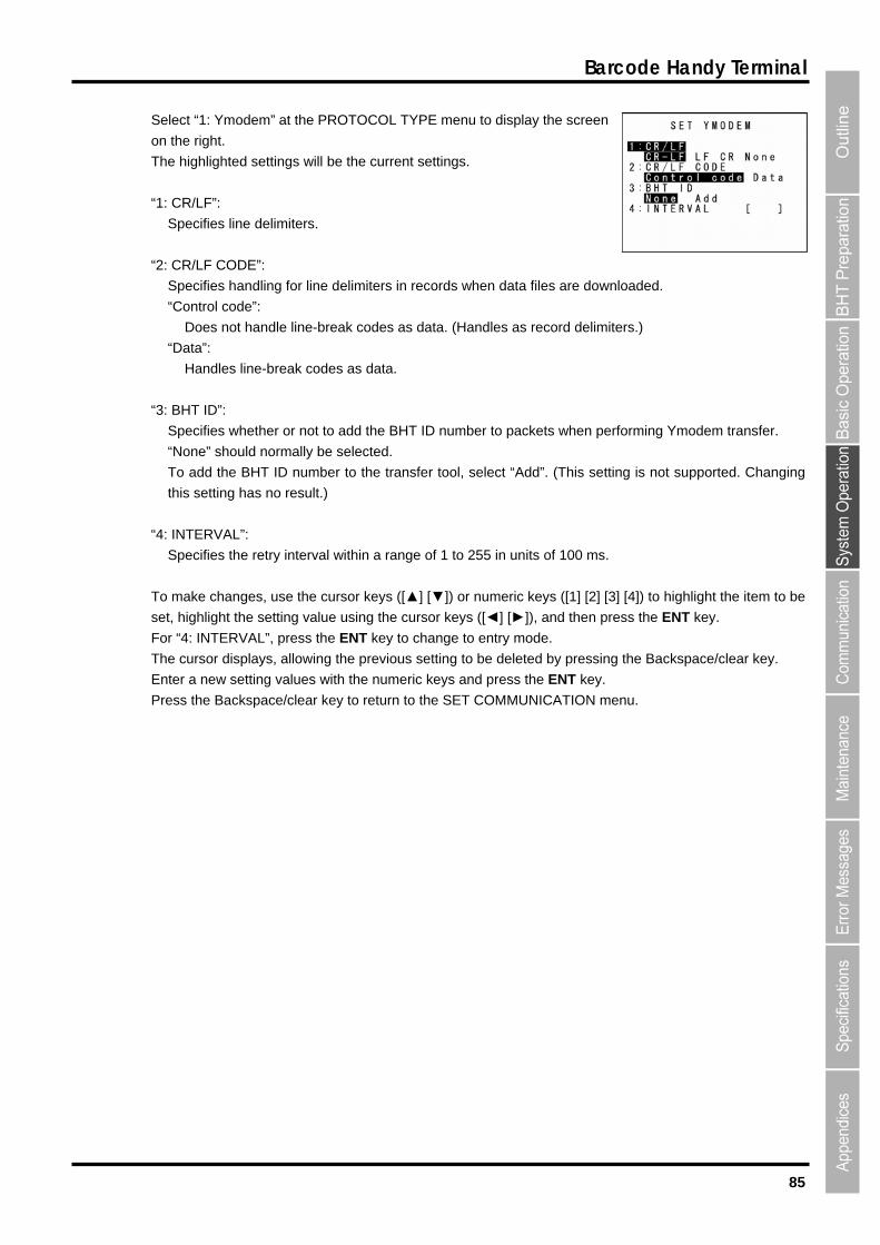
85
Barcode Handy Terminal
Select “1: Ymodem” at the PROTOCOL TYPE menu to display the screen
on the right.
“1: CR/LF”:
Specifies handling for line delimiters in records when data files are do
ode”:
: BHT ID”:
r not to add the BHT ID number to packets when performing Ymodem transfer.
(This setting is not supported. Changing
: INTERVAL”:
to highlight the item to be
t, highlight the setting value using the cursor keys ([◄] [►]), and then press the ENT key.
ckspace/clear key.
The highlighted settings will be the current settings.
Specifies line delimiters.
“2: CR/LF CODE”:
wnloaded.
“Control c
Does not handle line-break codes as data. (Handles as record delimiters.)
“Data”:
Handles line-break codes as data.
“3
Specifies whether o
“None” should normally be selected.
To add the BHT ID number to the transfer tool, select “Add”.
this setting has no result.)
“4
Specifies the retry interval within a range of 1 to 255 in units of 100 ms.
To make changes, use the cursor keys ([▲] [▼]) or numeric keys ([1] [2] [3] [4])
se
For “4: INTERVAL”, press the ENT key to change to entry mode.
The cursor displays, allowing the previous setting to be deleted by pressing the Ba
Enter a new setting values with the numeric keys and press the ENT key.
Press the Backspace/clear key to return to the SET COMMUNICATION men
u.
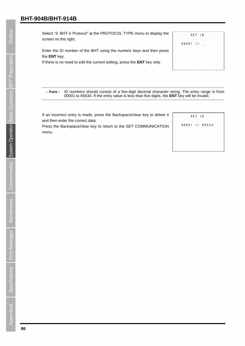
86
BHT-904B/BHT-914B
Select “3: BHT-Ir Protocol” at the PROTOCOL TYPE menu to display the
screen on the right.
nter the ID number of the BHT using the numeric keys and then press
.
If there is no need to edit the current setting, press the ENT key only.
P The entry range is from 00001 to 65534. If the entry value is less than five digits, the ENT key will be invalid.
E
the ENT key
oint ID numbers should consist of a five-digit decimal character string.
t entry is made, press the Backspace/clear key to delete it
an
Pr to the SET COMMUNICATION
m
If an incorrec
d then enter the correct data.
ess the Backspace/clear key to return
enu.
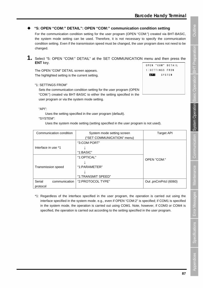
87
Barcode Handy Terminal
on condition setting for the user program (OPEN “COM:”) crea
e system mode setting can be used. Therefore, it is not necessa
1. elect “5: OPEN “COM:” DETAIL” at the SET COMMUNICATION NT key.
he OPEN “COM” DETAIL screen appears.
Th
: SETTINGS FROM”
Sets the communication condition setting for the user program (OPEN
mode setting.
:
Uses the setting specified in the user program (default).
“SYSTEM”:
Uses the system mode setting (setting specified in the us
Communication condition System mode setting screen
(“SET COMMUNICATION” menu)
Target API
“5: OPEN “COM:” DETAIL”: OPEN “COM:” communication c
For the communicati
ondition setting
ted via BHT-BASIC,
ry to specify the communication
r program does not need to be
menu and then press the
th
condition setting. Even if the transmission speed must be changed, the use
changed.
SE
T
e highlighted setting is the current setting.
“1
“COM:”) created via BHT-BASIC to either the setting specified in the
user program or via the system
“API”
er program is not used).
terface in use *1
“3:COM PORT”
↓
“1:BASIC”
In
Transmission speed
“1:OPTICAL”
↓
“1:PARAMETER”
↓
“1:TRANSMIT SPEED”
OPEN "COM:"
Serial communication
protocol
“2:PROTOCOL TYPE” Out .pnCmPrtcl (6060)
*1: Regardless of the interface specified in the user program, the operation is carried out using the
interface specified in the system mode. e.g., even if OPEN “COM:2” is specified; if COM1 is specified
in the system mode, the operation is carried out using COM1. Note, however, if COM3 or COM4 is
specified, the operation is carried out according to the setting specified in the user program.

88
BHT-904B/BHT-914B
[6] Defining the functions of the Shift key and Magic keys
1.
2. s ([1] [2] [3] [4] [5] [6] then press the ENT key.
: SHIFT KEY”: Displays the SF key definition screen.
M1 key definition screen.
“3
“4
“5 d trigger switch) key definition screen.
“6: M5 KEY”: Displays the M5 key (SCAN key) definition screen.
“7 : Displays the Backspace/clear key definition screen.
“8: ME screen.
Refer t
ress the Backspace/clear key to return to the SET COMMUNICATION menu.
“1: SHIFT KEY”: Definin function
1. Select “1: SHIFT KEY” at EY menu and then press the ENT key.
menu s hown on the right.
The highlighted setting will be the current setting.
he keypad only when the SF key is held down.
S
(
2. se the cursor keys ([▲] [▼]) or numeric keys ([1] [2]) to highlight the item to be set, and then press the ENT key.
The selected item will be set and the screen will return to the SET KEY menu.
Use the following procedure to change the key settings.
Select “6: KEY” at the SET SYSTEM menu and then press the ENT key.
The SET KEY menu screen displays as shown on the right.
Use the cursor keys ([▲] [▼]) or numeric key[7] [8]) to highlight the item to be set, and
tion screen.
“1
“2: M1 KEY”: Displays the
: M2 KEY”: Displays the M2 key definition screen.
: M3 KEY”: Displays the M3 (left-hand trigger switch) key defini
: M4 KEY”: Displays the M4 (right-han
: BS/C KEY”
NU KEY”: Displays the M1 - M5 key menu definition
o the following section for details of the above items.
P
g the Shift key
the SET K
The SET SHIFT KEY creen displays as s
“1: Nonlock”:
Shifts t
“2: Onetime”:
hifts only the key pressed immediately after the SF key is pressed.
The following keys will not be shifted.)
U
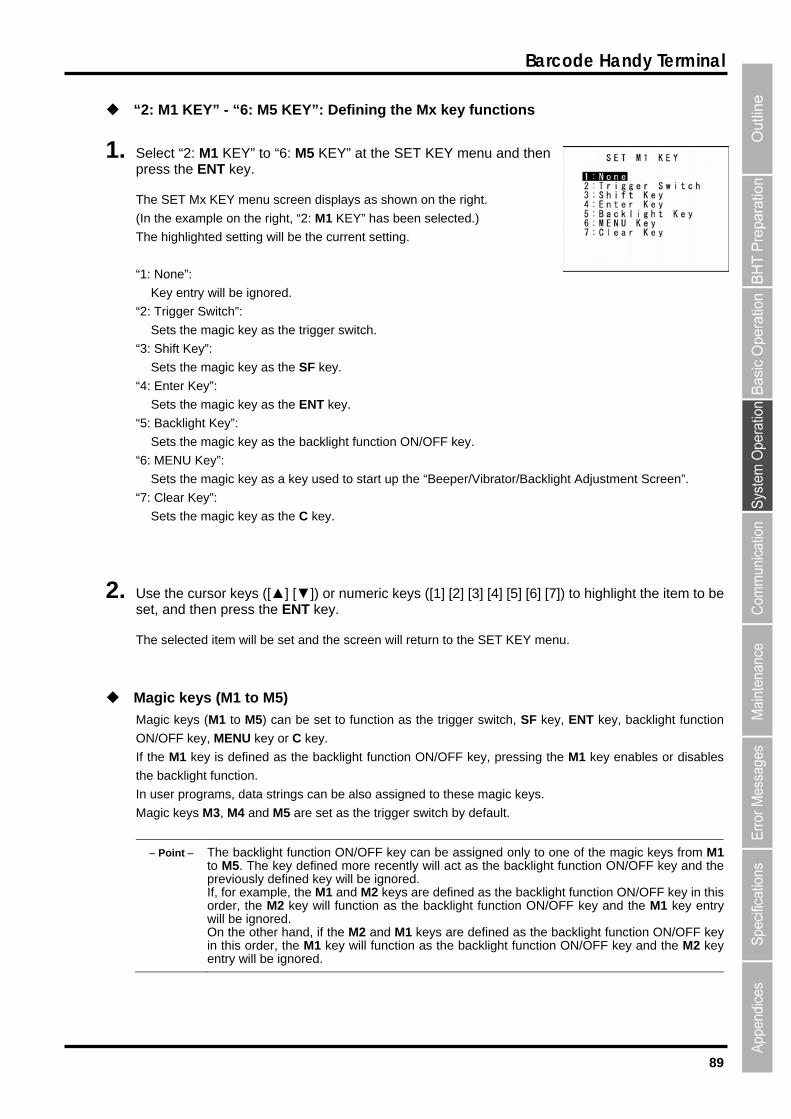
89
Barcode Handy Terminal
“2: M1 KEY” - “6: M5 KEY”: Defining the Mx key functions
1. Select “2: M1 KEY” to “6: M5 KEY” at the SET KEY menu and then
ET Mx KEY menu screen displays as shown on the right.
)
The highlighted setting will be the current setting.
: MENU Key”:
ibrator/Backlight Adjustment Screen”.
Sets the magic key as the C key.
EY menu.
M ger switch, SF key, ENT key, backlight function
N/OFF key, MENU key or C key.
s defined as the backlight function ON/OFF key, pressing the M1 key enables or disables
th
In hese magic keys.
Magic keys M3, M4 and M5 are set as the trigger switch by default.
ight function ON/OFF key can be assigned only to one of the magic keys from M1to M5. The key defined more recently will act as the backlight function ON/OFF key and thepreviously defined key will be ignored.
nction ON/OFF key in thiskey and the M1 key entry
will be ignored. On the other hand, if the M2 and M1 keys are defined as the backlight function ON/OFF key in this order, the M1 key will function as the backlight function ON/OFF key and the M2 key entry will be ignored.
press the ENT key.
The S
(In the example on the right, “2: M1 KEY” has been selected.
“1: None”:
Key entry will be ignored.
“2: Trigger Switch”:
Sets the magic key as the trigger switch.
“3: Shift Key”:
Sets the magic key as the SF key.
“4: Enter Key”:
Sets the magic key as the ENT key.
“5: Backlight Key”:
Sets the magic key as the backlight function ON/OFF key.
“6
Sets the magic key as a key used to start up the “Beeper/V
“7: Clear Key”:
2. Use the cursor keys ([▲] [▼]) or numeric keys ([1] [2] [3] [4] [5] [6] [7]set, and then press the ENT key.
) to highlight the item to be
The selected item will be set and the screen will return to the SET K
Magic keys (M1 to M5)
agic keys (M1 to M5) can be set to function as the trig
O
If the M1 key i
e backlight function.
user programs, data strings can be also assigned to t
Point The backl
If, for example, the M1 and M2 keys are defined as the backlight fuorder, the M2 key will function as the backlight function ON/OFF
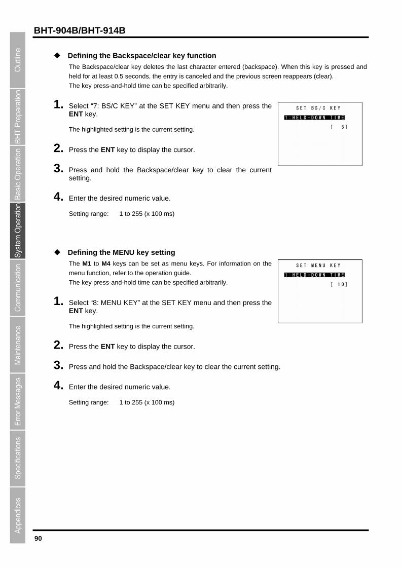
90
BHT-904B/BHT-914B
Defining the Backspace/clear key function
The Backspace/clear key deletes the last character entered (backspace). When this key is pressed and
d time can be specified arbitrarily.
1.
he highlighted setting is the current setting.
2. Pr ay the cursor.
3. Press and hold the Backspace/clear key to clear the current
4. ed numeric value.
to 255 (x 100 ms)
ENU key setting
enu keys. For information on the
menu function, refer to the operation guide.
The key press-and-hold time can be specified arbitrarily.
2. ress the ENT key to display the cursor.
3.
held for at least 0.5 seconds, the entry is canceled and the previous screen
The key press-and-hol
reappears (clear).
Select “7: BS/C KEY” at the SET KEY menu and then press the ENT key.
T
ess the ENT key to displ
setting.
Enter the desir
Setting range: 1
Defining the M
The M1 to M4 keys can be set as m
1. Select “8: MENU KEY” at the SET KEY menu and then press the ENT key.
The highlighted setting is the current setting.
P
Press and hold the Backspace/clear key to clear the current setting.
4. Enter the desired numeric value.
Setting range: 1 to 255 (x 100 ms)
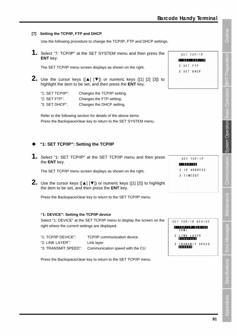
91
Barcode Handy Terminal
[7] Setting the TCP/IP, FTP and DHCP
Use the following procedure to change the TCP/IP, FTP and DHCP settings.
1. then press the ENT key.
P/IP menu screen displays as shown on the right.
2. s ([1] [2] [3]) to highlight the item to be set, and then press the ENT key.
“1: SET TCP/IP”: Changes the TCP/IP setting.
HCP”: Changes the DHCP setting.
ils of the above items.
Press the Backspace/clear key to return to the SET SYSTEM menu.
: SET TCP/IP”: Setting the TCP/IP
1.
The SET TCP/IP menu screen displays as shown on the right.
rsor keys ([▲] [▼]) or numeric keys ([1] [2]) to highlighte set, and then press the ENT key.
Press the Backspace/clear key to return to the SET TCP/IP menu.
yed.
munication device
“2: LINK LAYER”: Link layer
“3: TRANSMIT SPEED”: Communication speed with the CU
Press the Backspace/clear key to return to the SET TCP/IP menu.
Select “7: TCP/IP” at the SET SYSTEM menu and
The SET TC
Use the cursor keys ([▲] [▼]) or numeric key
“2: SET FTP”: Changes the FTP setting.
“3: SET D
Refer to the following section for deta
“1
Select “1: SET TCP/IP” at the SET TCP/IP menu and then presthe ENT key.
s
2. Use the cuthe item to b
“1: DEVICE”: Setting the TCP/IP device
Select “1: DEVICE” at the SET TCP/IP menu to display the screen on the
right where the current settings are displa
“1: TCP/IP DEVICE”: TCP/IP com
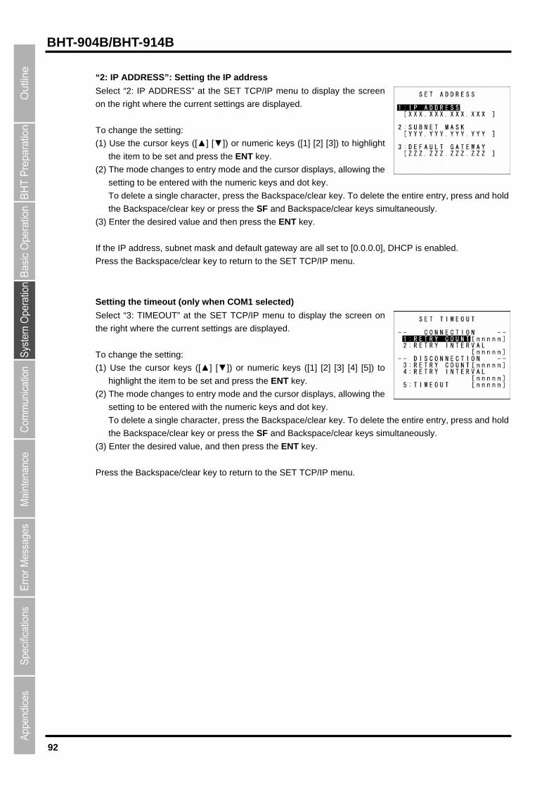
92
BHT-904B/BHT-914B
“2: IP ADDRESS”: Setting the IP address
cursor keys ([▲] [▼]) or numeric keys ([1] [2] [3]) to highlight
(2) The mode changes to entry mode and the cursor displays, allowing the
To delete
the Backspace/clear key or press the SF and Backspace/clear keys si
ey.
are all set to [0.0.0.0], DHCP is enabled.
ress the Backspace/clear key to return to the SET TCP/IP menu.
etting the timeout (only when COM1 selected)
elect “3: TIMEOUT” at the SET TCP/IP menu to display the screen on
e right where the current settings are displayed.
To change the setting:
item to be set and press the ENT key.
wing the
To delete a single character, press the Backspace/clear key. To delete
ey.
ress the Backspace/clear key to return to the SET TCP/IP menu.
Select “2: IP ADDRESS” at the SET TCP/IP menu to display the screen
on the right where the current settings are displayed.
To change the setting:
(1) Use the
the item to be set and press the ENT key.
setting to be entered with the numeric keys and dot key.
To delete a single character, press the Backspace/clear key. the entire entry, press and hold
multaneously.
(3) Enter the desired value and then press the ENT k
If the IP address, subnet mask and default gateway
P
S
S
th
(1) Use the cursor keys ([▲] [▼]) or numeric keys ([1] [2] [3] [4] [5]) to
highlight the
(2) The mode changes to entry mode and the cursor displays, allo
setting to be entered with the numeric keys and dot key.
the entire entry, press and hold
ltaneously. the Backspace/clear key or press the SF and Backspace/clear keys simu
(3) Enter the desired value, and then press the ENT k
P
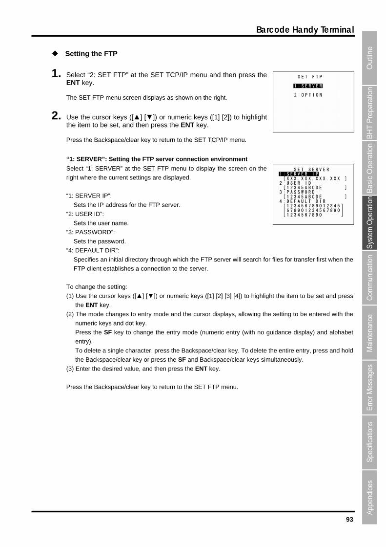
93
Barcode Handy Terminal
1. nd then press the NT key.
2. the
Pre
ironment
: SERVER IP”:
lays, allowing the setting to be entered with the
lay) and alphabet
entry).
To delete a single character, press the Backspace/clear key. To delete the entire entry, press and hold
the Backspace/clear key or press the SF and Backspace/clear keys simultaneously.
(3) Enter the desired value, and then press the ENT key.
Press the Backspace/clear key to return to the SET FTP menu.
Setting the FTP
Select “2: SET FTP” at the SET TCP/IP menu aE
The SET FTP menu screen displays as shown on the right.
Use the cursor keys ([▲] [▼]) or numeric keys ([1] [2]) to highlight item to be set, and then press the ENT key.
ss the Backspace/clear key to return to the SET TCP/IP menu.
1: SERVER”: Setting the FTP server connection env“
Select “1: SERVER” at the SET FTP menu to display the screen on the
right where the current settings are displayed.
“1
Sets the IP address for the FTP server.
“2: USER ID”:
Sets the user name.
“3: PASSWORD”:
Sets the password.
“4: DEFAULT DIR”:
Specifies an initial directory through which the FTP server will search for files for tran
FTP client establishes a connection to the server.
sfer first when the
To change the setting:
(1) Use the cursor keys ([▲] [▼]) or numeric keys ([1] [2] [3] [4]) to highlight the item to be set and press
the ENT key.
(2) The mode changes to entry mode and the cursor disp
numeric keys and dot key.
Press the SF key to change the entry mode (numeric entry (with no guidance disp
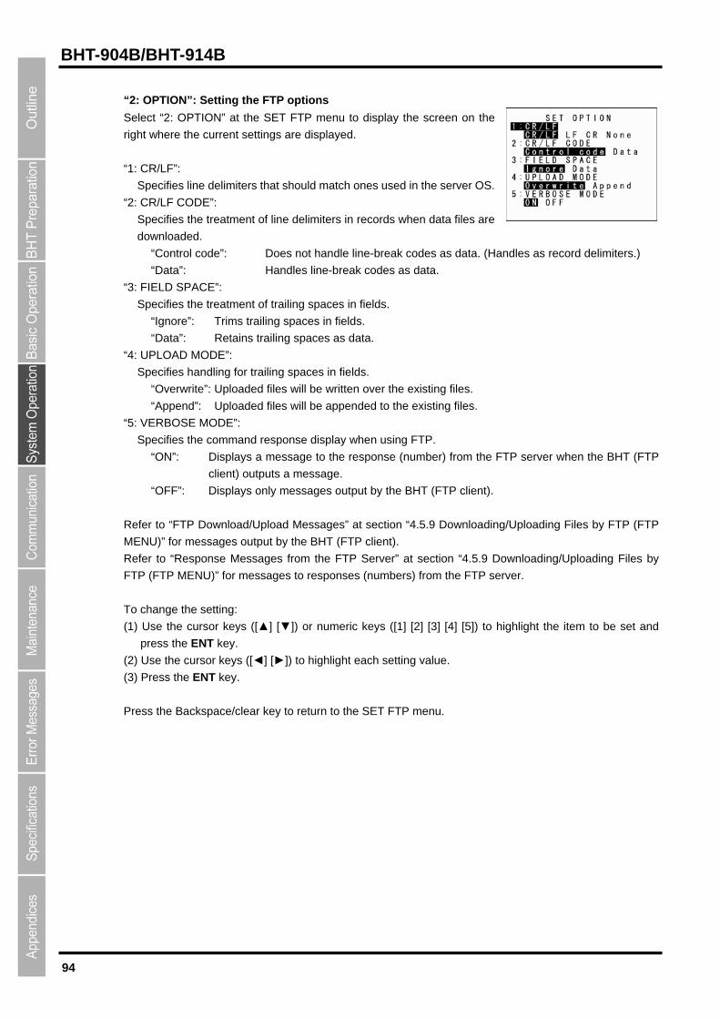
94
BHT-904B/BHT-914B
“2: OPTION”: Setting the FTP options
Select “2: OPTION” at the SET FTP menu to display the screen on the
“1: CR/LF”:
e server OS.
“2: CR/LF CODE”:
ta. (Handles as record delimiters.)
ta.
lds.
ten over the existing files.
will be appended to the existing files.
and response display when using FTP.
ys a message to the response (number) from the FTP server when the BHT (FTP
load Messages” at section “4.5.9 Downloading/Uploading Files by FTP (FTP
To
(1)
(2)
right where the current settings are displayed.
Specifies line delimiters that should match ones used in th
Specifies the treatment of line delimiters in records when data files are
downloaded.
“Control code”: Does not handle line-break codes as da
“Data”: Handles line-break codes as data.
“3: FIELD SPACE”:
Specifies the treatment of trailing spaces in fields.
“Ignore”: Trims trailing spaces in fields.
“Data”: Retains trailing spaces as da
“4: UPLOAD MODE”:
Specifies handling for trailing spaces in fie
“Overwrite”: Uploaded files will be writ
“Append”: Uploaded files
: VERBOSE MODE”: “5
Specifies the comm
“ON”: Displa
client) outputs a message.
“OFF”: Displays only messages output by the BHT (FTP client).
Refer to “FTP Download/Up
MENU)” for messages output by the BHT (FTP client).
Refer to “Response Messages from the FTP Server” at section “4.5.9 Downloading/Uploading Files by
FTP (FTP MENU)” for messages to responses (numbers) from the FTP server.
change the setting:
Use the cursor keys ([▲] [▼]) or numeric keys ([1] [2] [3] [4] [5]) to highlight the item to be set and
press the ENT key.
Use the cursor keys ([◄] [►]) to highlight each setting value.
Press the ENT key. (3)
Press the Backspace/clear key to return to the SET FTP menu.
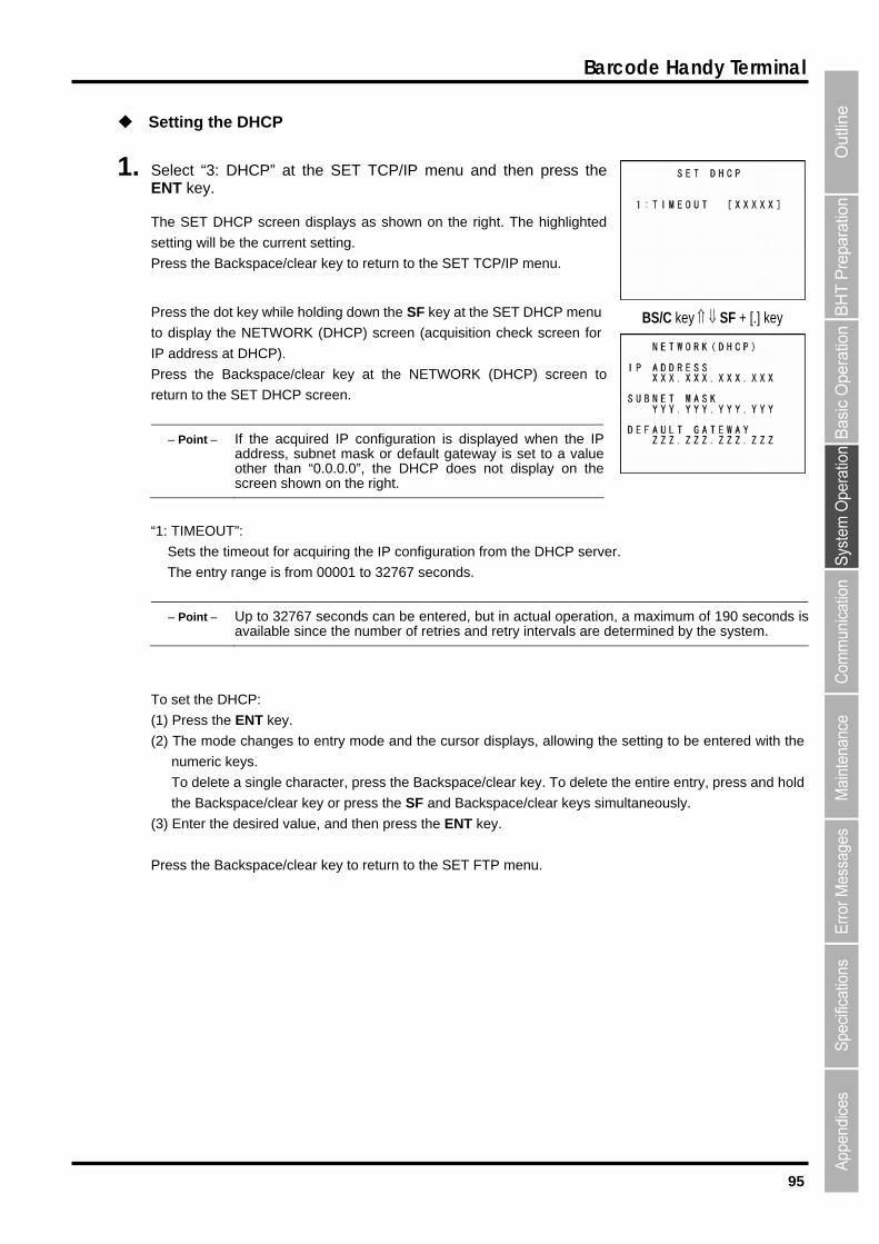
95
Barcode Handy Terminal
1. nu and then press the NT key.
Th
rrent setting.
Pr
Pres
to display the NETWORK ( creen for
.
Pr (DHCP) screen to
retur T
quired IP configuration is displayed when the IPteway is set to a value
the
Setting the DHCP
Select “3: DHCP” at the SET TCP/IP meE
e SET DHCP screen displays as shown on the right. The highlighted
setting will be the cu
ess the Backspace/clear key to return to the SET TCP/IP menu.
s the dot key while holding down the SF key at the SET DHCP menu
DHCP) screen (acquisition check s
IP address at DHCP)
ess the Backspace/clear key at the NETWORK
n to the SE DHCP screen.
Point If the acaddress, subnet mask or default gaother than “0.0.0.0”, the DHCP does not display on screen shown on the right.
BS/C key SF + [.] key
“1
Se imeo
The entry ran econds.
Point Up to 32767 seconds can be entered, but in actual operation, a maximum of 190 seconds is
: TIMEOUT”:
ts the t ut for acquiring the IP configuration from the DHCP server.
ge is from 00001 to 32767 s
available since the number of retries and retry intervals are determined by the system.
To set the DHCP:
(1) Press the ENT key.
to entry mode and the cursor displays, allowing the setting to be entered with the
aracter, press the Backspace/clear key. To delete the entire entry, press and hold
keys simultaneously.
ue, and then press the ENT key.
(2) The mode changes
numeric keys.
To delete a single ch
the Backspace/clear key or press the SF and Backspace/clear
(3) Enter the desired val
Press the Backspace/clear key to return to the SET FTP menu.

96
BHT-904B/BHT-914B
[8] Setting the user prog ram execution option
Use the following procedure to set the user program execution option.
1. EXEC PROG OPTION” at the SET SYSTEM 2/2 menu
appears.
2.
“ON”: Enables the re
“2: RESTART
Sets the p screen when the auto-start execution program is re-launched.
For the function where the auto-start execution program is re-launched, refer to “4.3.6 Executing the
cution Program from the Point of Start-up”.
.
Select “1: and then press the ENT key.
The EXEC PROG OPTION screen
The highlighted settings are the current settings.
Use the cursor keys ([▲] [▼]) or numeric keys ([1] [2]) to changethe setting and then press the ENT key.
Press the Backspace/clear key to return to the SET SYSTEM menu.
: RESUME”: “1
sume function.
Disables the resume function.
DIALOG”:
resence of the confirmation
“OFF”:
Auto-start Exe
“ON”: The confirmation screen is displayed.
“OFF”: The confirmation screen is not displayed
The resume function is used to return the BHT to the status (screen) when the BHT powerwas turned OFF previously.
Note
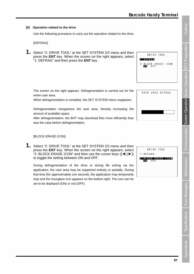
97
Barcode Handy Terminal
[9] Operation related to the drive
Use the following procedure to carry out the operation related to the drive.
1. TEM 2/2 menu and then right appears, select
the right appears. Defragmentation is carried out for the
en r a
When defrag SYSTEM menu reappears.
De
am
Af iciently than
wa
[B
1. Select “2: DRIVE TOOL” at the SET SYSTEM 2/2 menu and then press the ENT key. When the screen on the right appears, select “2: BLOCK ERASE ICON” and then use the cursor keys ([◄] [►]) to toggle the setting between ON and OFF.
During defragmentation of the drive or during file writing via the
application, the user area may be organized entirely or partially. During
that time (for approximately one second), the application may temporarily
stop and the hourglass icon appears on the bottom right. The icon can be
set to be displayed (ON) or not (OFF).
[DEFRAG]
Select “2: DRIVE TOOL” at the SET SYSpress the ENT key. When the screen on the“1: DEFRAG” and then press the ENT key.
The screen on
tire use rea.
mentation is complete, the SET
fragmentation reorganizes the user area, thereby increasing the
ount of available space.
ter defragmentation, the BHT may download files more eff
s the case before defragmentation.
LOCK ERASE ICON]

98
BHT-904B/BHT-914B
[10] Setting the operation log
Use the following procedure to set the operation log.
1. OPERATION LOG” at the SET SYSTEM 2/2 menu and then press the ENT key.
2. se the cursor keys ([◄] [►]) to change the setting and then ress the ENT key.
N”: An operation log file is created.
FF”: An operation log file is not created.
3. ey.
Select “3:
The SET OPERATION LOG menu appears.
The highlighted setting is the current setting.
Up
“O
“O
Press the ENT k
ENT key
The setting is then updated.
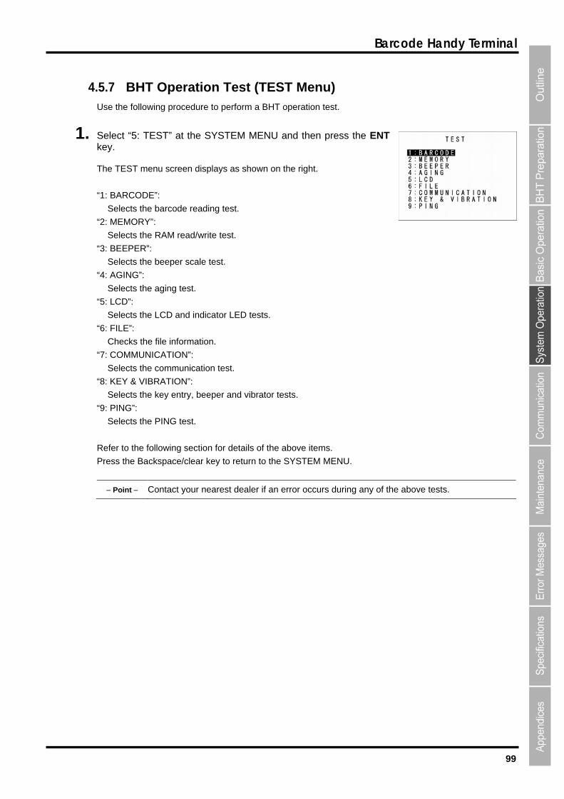
99
Barcode Handy Terminal
4.5.7 BHT Operation Test (TEST Menu) Use the following procedure to perform a BHT operation test.
the right.
cts th
PER
Selects the beeper scale test.
Selects the aging test.
Selects the LCD and indicator LED tests.
: FILE”:
Checks the file information.
: COMMUNICATION”:
Selects the communication test.
: KEY & VIBRATION”:
Selects the key entry, beeper and vibrator tests.
: PING”:
Selects the PING test.
Refer to the following section for details of the above items.
Press the Backspace/clear key to return to the SYSTEM MENU.
Point Contact your nearest dealer if an error occurs during any of the above tests.
1. Select “5: TEST” at the SYSTEM MENU and then press the ENTkey.
The TEST menu screen displays as shown on
“1: BARCODE”:
Selects the barcode reading test.
“2: MEMORY”:
Sele e RAM read/write test.
“3: BEE ”:
“4: AGING”:
“5: LCD”:
“6
“7
“8
“9
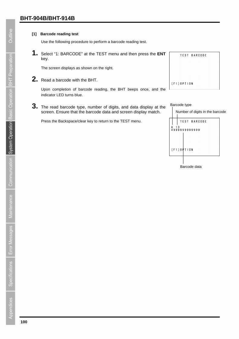
100
BHT-904B/BHT-914B
[1]
2. with the BHT.
Up g, the BHT beeps once, and the
rns blue.
3. digits, and data display at the sc e data and screen display match.
Pr r key to return to the TEST menu.
Barcode reading test
Use the following procedure to perform a barcode reading test.
1. Select “1: BARCODE” at the TEST menu and then press the ENT key.
The screen displays as shown on the right.
Read a barcode
on completion of barcode readin
indicator LED tu
The read barcode type, number of reen. Ensure that the barcod
ess the Backspace/clea
Barcode type
Barcode data
Number of digits in the barcode
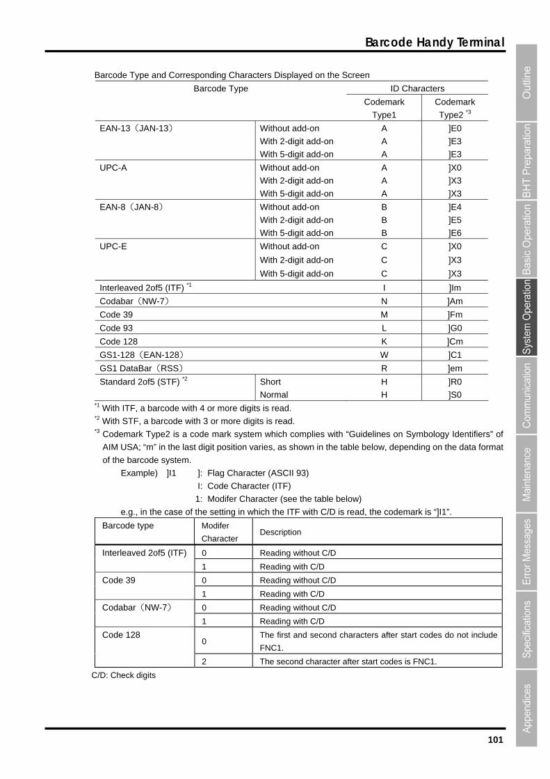
101
Barcode Handy Terminal
Barcode Type and Corresponding Characters Displayed on the Screen
ID Characters Barcode Type
Codemark
Type1
Codemark
Type2 *3
EAN-13(JAN-13) Without add-on A ]E0
With 2-digit add-on A ]E3
With 5-digit add-on A ]E3
UPC-A Without add-on A ]X0
With 2-digit add-on A ]X3
With 5-digit add-on A ]X3
EAN-8(JAN-8) Without add-on B ]E4
With 2-digit add-on B ]E5
With 5-digit add-on B ]E6
UPC-E Without add-on C ]X0
With 2-digit add-on C ]X3
With 5-digit add-on C ]X3
Interleaved 2of5 (ITF) I ]Im *1
Codabar(NW-7) N ]Am
Code 39 M ]Fm
Code 93 L ]G0
Code 128 K ]Cm
GS1-128(EAN-128) W ]C1
GS1 DataBar(RSS) R ]em
Standard 2of5 (STF) *2 Short H ]R0
Normal H ]S0 *1 With ITF, a barcode with 4 or more digits is read. *2 With STF, a barcode with 3 or more digits is read. *3 Codemark Type2 is a code mark system which complies with “Guidelines on Symbology Identifiers” of
AIM USA; “m” in the last digit position varies, as shown in the table below, depending on the data format
of the barcode system.
Example) ]I1 ]: Flag Character (ASCII 93)
I: Code Character (ITF)
1: Modifer Character (see the table below)
e.g., in the case of the setting in which the ITF with C/D is read, the codemark is “]I1”.
Barcode type Modifer
Character Description
0 Reading without C/D Interleaved 2of5 (ITF)
1 Reading with C/D
0 Reading without C/D Code 39
1 Reading with C/D
0 Reading without C/D Codabar(NW-7)
1 Reading with C/D
0 The first and second characters after start codes do not include
FNC1.
Code 128
2 The second character after start codes is FNC1.
C/D: Check digits

102
BHT-904B/BHT-914B
Setting the Barcode reading Test Options
Press F1 key at the TES reen to set the barcode reading
test options. The screen displays as shown on the right.
The highlighted settings will be the current settings.
To change the setting, use the cursor k ghlight the
desired setting.
Press the F1, ENT, or Backspace/clear ke T BARCO screen.
G”:
Sets the read conditions of the barcod
“DEFAULT”: Rea g to the de lt read condit
YSTEM PARAMETER”: Sets on via the sy setting. It a the read
cond recisely.
Whe ystem set , refer to the g for the
“function in which the read setting is specified from the system
settings” in “4.5.6 [4] Setting the special ba reading
parameters”.
rcodes allowed to be read in the “DEFAULT” setting
T BARCODE sc
eys ([◄] [►]) to hi
y to return to the TES DE
“1: READ SETTIN
e reading test.
ds barcodes accordin fau ion.
“S the read conditi stem llows
ition to be set more p
n carrying out the s ting settin
rcode
Ba
EAN-13 (JAN-13), UPC-A *1
EAN-8 (JAN-8) *1
Interleaved 2of5 (ITF) *2
ar)
(S
UPC-E *1
Codabar (NW-7)
Code 39
Code 93
Code 128, GS1-128 (EAN-128)
RSS (GS1 DataB
Standard 2of5 TF) *3 *1 Excludes those with add-on. *2 b ode with 4 or more digits is read. *3 With STF, a barcode with 3 or more digits is read.
With ITF, a arc
Point To read the EA rcod n in the barcode reading test, it is necessary to set the system set en set to “SYSTEM PARAMETER”.
N/UPC bating and th
e with add-o
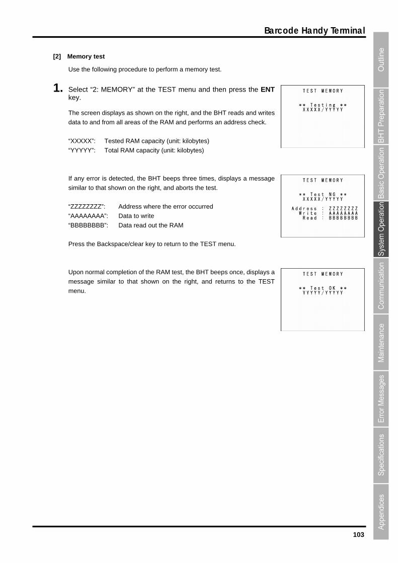
103
Barcode Handy Terminal
[2]
1. en press the ENT ey.
ays as shown on the right, and the BHT reads and writes
ata to and from all areas of the RAM and performs an address check.
XXXX”: Tested RAM capacity (unit: kilobytes)
“Y apacity (unit: kilobytes)
If any
similar to that shown on the right, and
“ZZZZZZZZ”: Address where the
“AAAAAAAA”: Data to write
“BBBBBBBB”: Data read out the R
Press the
Upon nor etion of the RAM test, the BHT beeps once, displays a
message n the right, and returns to the TEST
menu.
Memory test
Use the following procedure to perform a memory test.
Select “2: MEMORY” at the TEST menu and thk
The screen displ
d
“X
YYYY”: Total RAM c
error is detected, the BHT beeps three times, displays a message
aborts the test.
error occurred
AM
Backspace/clear key to return to the TEST menu.
mal compl
similar to that shown o
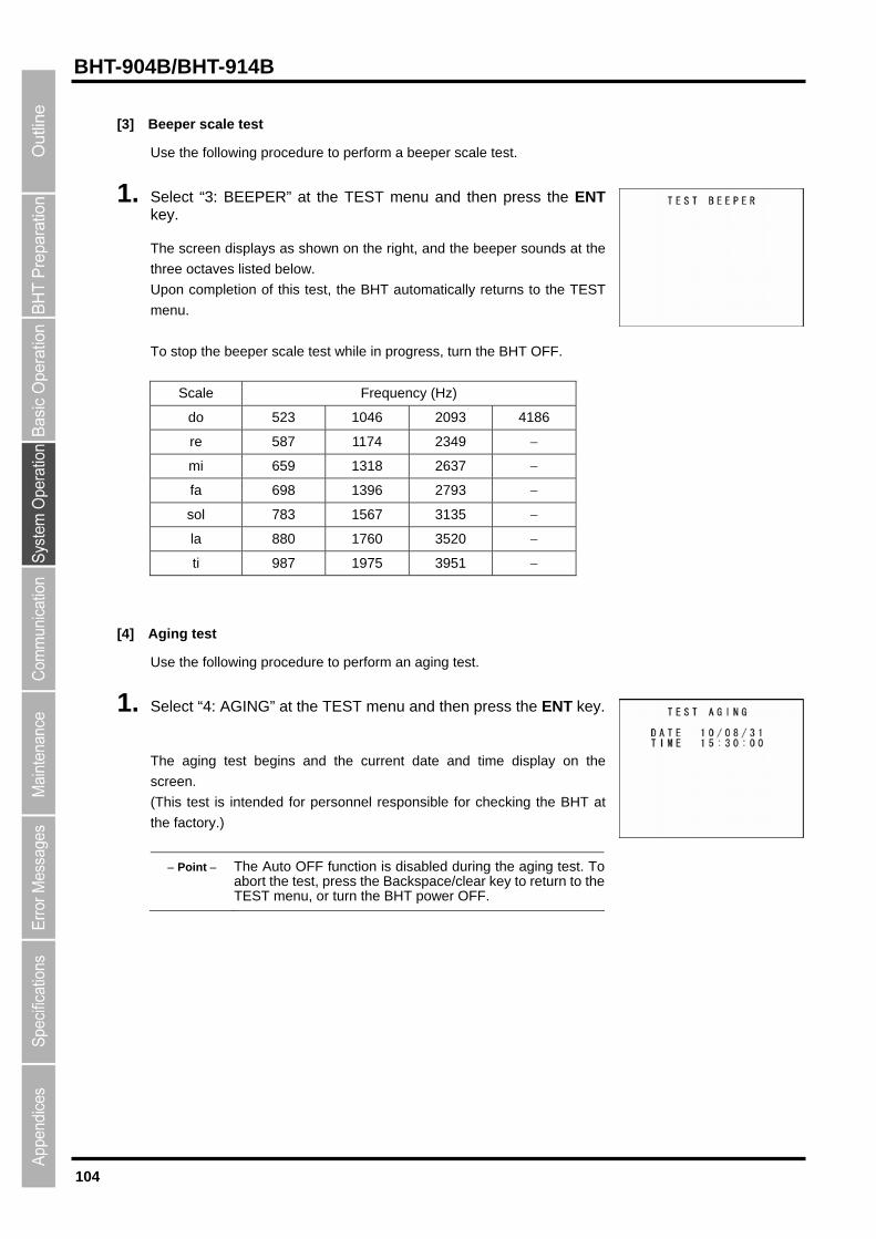
104
BHT-904B/BHT-914B
[3] Beeper scale test
Use the following procedure to perform a beeper scale test.
pon completion of this test, the BHT automatically returns to the TEST
o stop the beeper scale test while in progress, turn the BHT OFF.
1. Select “3: BEEPER” at the TEST menu and then press the ENT key.
The screen displays as shown on the right, and the beeper sounds at the
three octaves listed below.
U
menu.
T
Scale Frequency (Hz)
do 523 1046 2093 4186
re 587 1174 2349
mi 659 1318 2637
fa 698 1396 2793
sol 783 1567 3135
la 880 1760 3520
ti 987 1975 3951
[4]
se the following procedure to perform an aging test.
1. elect “4: AGING” at the TEST menu and then press the ENT key.
he aging test begins and the current date and time display on the
creen.
his test is intended for personnel responsible for checking the BHT at
e factory.)
Point The Auto OFF function is disabled during the aging test. Toabort the test, press the Backspace/clear key to return to theTEST menu, or turn the BHT power OFF.
Aging test
U
S
T
s
(T
th

105
Barcode Handy Terminal
[5] LCD and indicator LED tests
LED test.
The TEST BEEPER screen displays as shown on the right.
2. ress the ENT key.
The entire screen turns black and the indicator LED illuminates in green.
Press the Backspace/clear key to return to the previous screen.
Press and hold kspace/clear key or press the SF and
Backspace/clear keys simultaneously to return to the testing.
3. Press the ENT key. The entire screen is displayed in white and the LED is illuminated in red simultaneously.
s screen.
s the SF and
Use the following procedure to perform an LCD and indicator
1. Select “5: LCD” at the TEST menu and then press the ENT key.
The indicator LED is OFF at this time.
Press the Backspace/clear key to return to the TEST menu.
P
the Bac
Press the Backspace/clear key to return to the previou
Press and hold the Backspace/clear key or pres
Backspace/clear keys simultaneously to return to the TEST menu.

106
BHT-904B/BHT-914B
4. A 1-dot frame is displayed around the screen and the LED is illuminated
en.
ar key or press the SF and
5. ress the ENT key.
The beeper sounds once, and the display returns to the TEST menu.
Press the ENT key.
in blue simultaneously.
Press the Backspace/clear key to return to the previous scre
Press and hold the Backspace/cle
Backspace/clear keys simultaneously to return to the TEST menu.
P
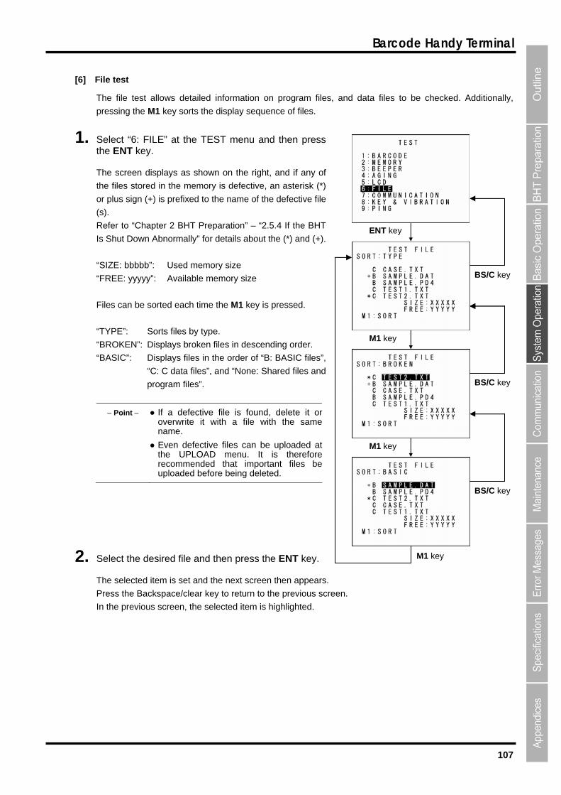
107
Barcode Handy Terminal
[6] F
The file test allows de
ile test
tailed information on program fi
1. elect “6: FILE” at the TEST menu and then press
ed to the name of the defective file
Is Shut Down Abnormally” for details about the (*) and (+).
“SIZE: bbbbb”: Used memory size
“FREE: yyyyy”: Available memory size
Files can be sorted each time the M1 key is pressed.
“TYPE”: Sorts files by type.
“BROKEN”: Displays broken files in descending order.
“BASIC”: Displays files in the order of “B: BASIC files”,
“C: C data files”, and “None: Shared files and
program files”.
Point If a defective file is found, delete it o
les, and data files to be checked. Additionally,
pressing the M1 key sorts the display sequence of files.
Sthe ENT key.
The screen displays as shown on the right, and if any of
the files stored in the memory is defective, an asterisk (*)
or plus sign (+) is prefix
(s).
Refer to “Chapter 2 BHT Preparation” – “2.5.4 If the BHT
roverwrite it with a file with the samename.
Even defective files can be uploaded atthe UPLOAD menu. It is thereforerecommended that important files beuploaded before being deleted.
2. Select the desired file and then press the ENT key.
The selected item is set and the next screen then appears.
Press the Backspace/clear key to return to the previous screen.
In the previous screen, the selected item is highlighted.
ENT key
M1 key
BS/C key
BS/C key
M1 key
M1 key
BS/C key
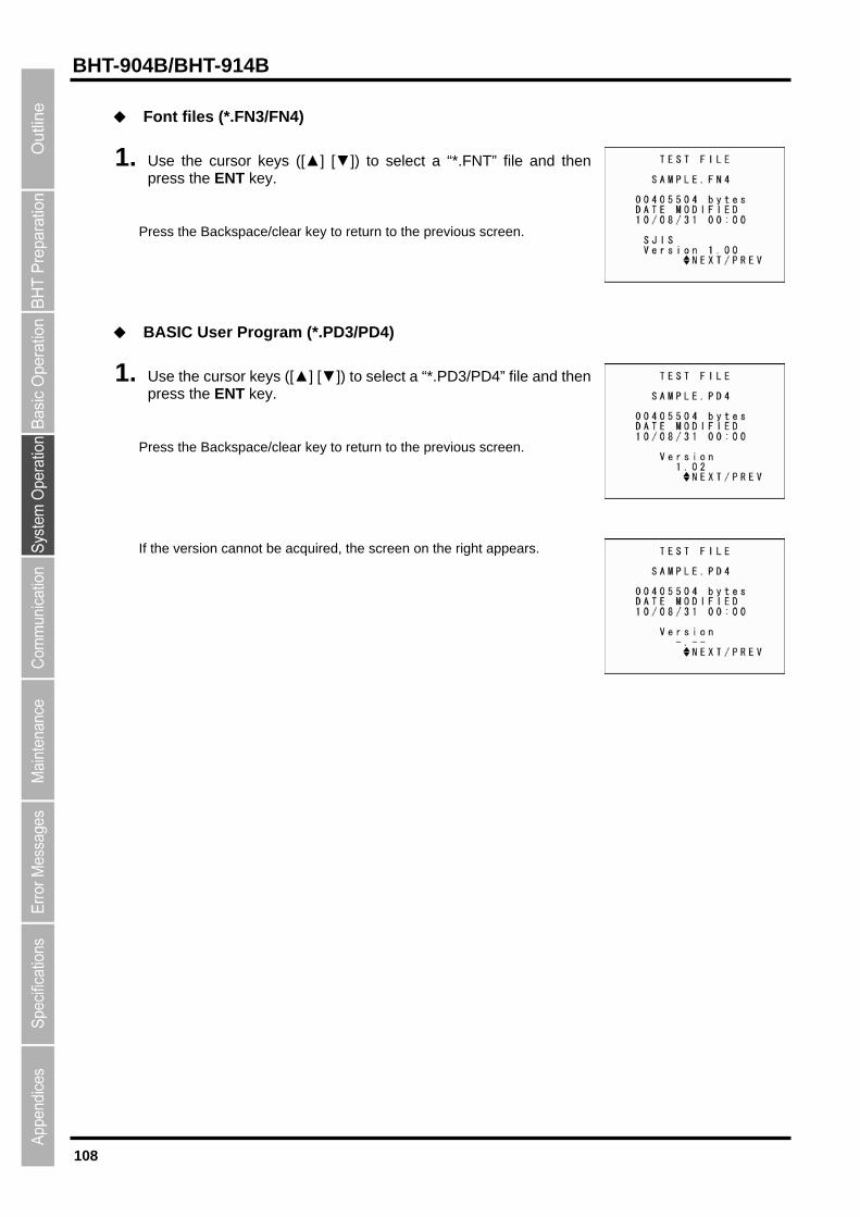
108
BHT-904B/BHT-914B
◆ Font files (*.FN3/FN4)
1.
ace/clear key to return to the previous sc
◆
1. key
Press the Backspace/clear key to return to the previous sc
If n
Use the cursor keys ([▲] [▼]) to select a “*.FNT” file and then press the ENT key.
Press the Backsp reen.
reen.
ears.
BASIC User Program (*.PD3/PD4)
se the cursor keys ([▲] [▼]) to select a “*.PD3/PD4” file and thenUpress the ENT .
the versio cannot be acquired, the screen on the right app
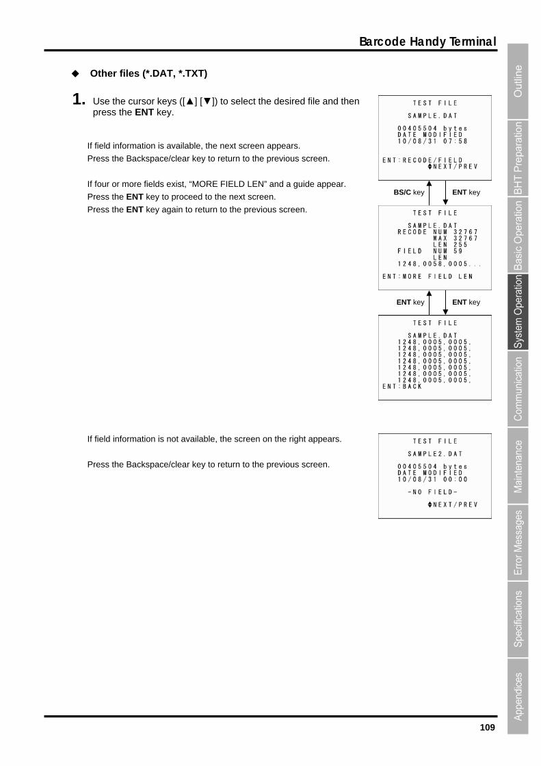
109
Barcode Handy Terminal
◆ Other files (*.DAT, *.TXT)
Press the Backspace/clear key to return to the previous screen.
If four or more fields exist, “MORE FIELD LEN” and a guide appear.
Press the ENT key to proceed to the next screen.
vious screen.
If field information is not available, the screen on the right appears.
Press the Backspace/clear key to return to the previous screen.
1. Use the cursor keys ([▲] [▼]) to select the desired file and then press the ENT key.
If field information is available, the next screen appears.
BS/C key
Press the ENT key again to return to the pre
ENT key
ENT key ENT key

110
BHT-904B/BHT-914B
[7] Communication test
Use the following procedure to perform a communication test.
1. Select “7: COMMUNICATION” at the TEST menu and then prthe ENT key.
right.
Refer to the following section for details of the above items.
Press the Backspace/clear key to return to the TEST menu.
Infrared Communication Test
1. Arrange two BHTs, one as a master station and the other as a their IrDA interface ports facing each other as illustrated below.
This test involves transmitting data from the test BHT and the master BHT returnin
BHT.
2. Select “1: OPTICAL” at the TEST COMMUNICATION menu and then press the ENT key.
The TEST COMMUNICATION screen displays as shown on the right.
ess
slave station (to be tested) with
g the data to the test
The TEST COMMUNICATION screen displays as shown on the
“1: OPTICAL”: Performs an infrared communication test.
ion test. “2: CONNECTOR”: Performs the USB connect
Master BHT Slave BHT (to be tested)
Data
Max. 15 cm
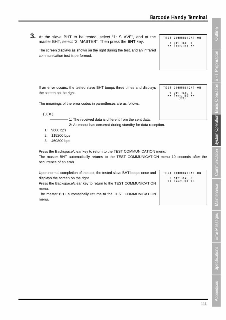
111
Barcode Handy Terminal
3. d at the y.
an error occurs, the tested slave BHT beeps three times and displays
s.
( X X )
ta is different from the sent data.
2: A timeout has occurred during standby for data reception.
the Backspace/clear key to return to the TEST COMMUNICATION menu.
he master BHT automatically returns to the TEST COMMUNICATION menu 10 seconds after the
ccurren
pon no
isplays
ress th
enu.
he master BHT automatically returns to the TEST COMMUNICATION
menu.
At the slave BHT to be tested, select “1: SLAVE”, anmaster BHT, select “2: MASTER”. Then press the ENT ke
The screen displays as shown on the right during the test, and an infrared
communication test is performed.
If
the screen on the right.
The meanings of the error codes in parentheses are as follow
1: The received da
1: 9600 bps
2: 115200 bps
3: 460800 bps
Press
T
o ce of an error.
rmal completion of the test, the tested eps once and
the screen on the right.
e Backspa return to the TEST COMMUNICATION
U slave BHT be
d
P ce/clear key to
m
T

112
BHT-904B/BHT-914B
USB conne
Have a USB cable ready and then connect the BHT to the ho
ction test
1. st.
2. TEST COMMUNICATION screen an
uring test, the screen on the right is displayed and the USB connection
st is carried out.
ress the Backspace/clear key to abort the test and return to the TEST
OMMUNICATION menu.
If no connection is s
and the screen on
Pre
me
e, a buzzer sounds once and the screen on the
Select “2: CONNECTOR” at the d then press the ENT key.
D
te
P
C
made within 15 seconds, a buzzer sounds three time
the right then appears.
e/clear key to return to the TEST COMMUNICATION ss the Backspac
nu.
the connection is madIf
right then appears.
Press the Backspace/clear key to return to the TEST COMMUNICATION
menu.
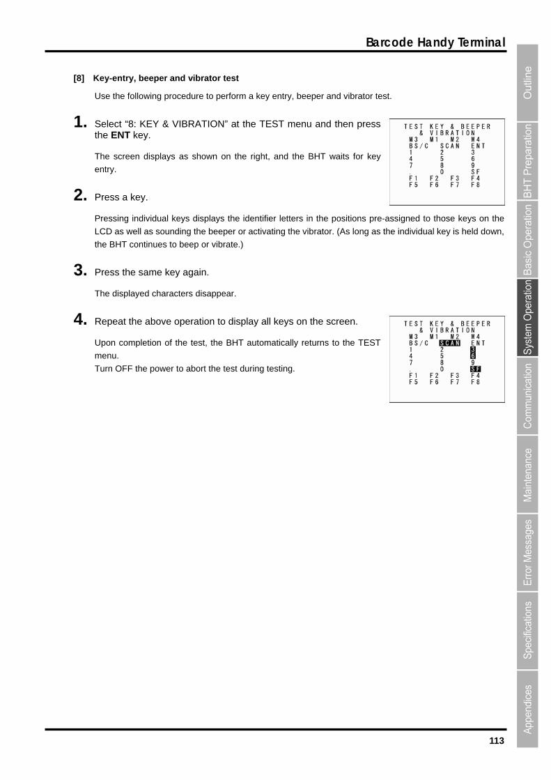
113
Barcode Handy Terminal
[8] Key-entry, beeper and vibrator test
Use the following procedure to perform a key entry, beeper and vibrator test.
Select “8: KEY & VIBRATION” at the TEST menu and then press
2. ressing individual keys displays the identifier letters in the positions
CD as well as sounding the beeper or activating the vibrator. (As long
e BHT continues to beep or vibrate.)
3. ress the same key again.
4. t the above operation to display all keys on the screen.
pon completion of the test, the BHT automatically returns to the TEST
enu.
urn OFF the power to abort the test during testing.
1. the ENT key.
The screen displays as shown on the right, and the BHT waits for key
entry.
Press a key.
P pre-assigned to those keys on the
as the individual key is held down, L
th
P
The displayed characters disappear.
Repea
U
m
T
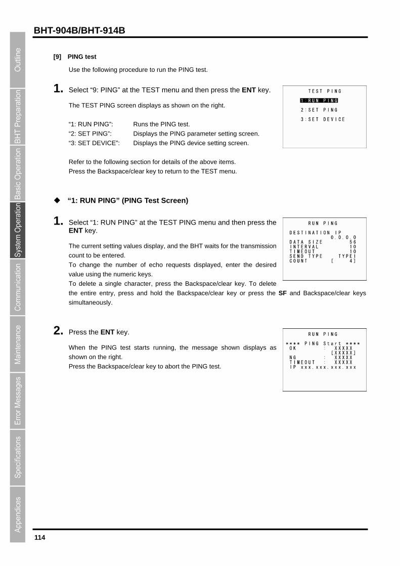
114
BHT-904B/BHT-914B
[9] PING test
Use the following procedure to run the PING test.
1. Select “9: PING” at the TEST menu and then press the ENT key.
The TEST PING screen displays as shown on the right.
PING”: Runs the PING test.
“2: SET PING”: Displays the PING parameter setting screen.
E”: Displays the PING device setting screen.
t Screen)
1. Select “1: RUN PING” at the TEST PING menu and then press the
be entered.
, enter the desired
alue using the numeric keys.
o delete a single character, press the Backspace/clear key. To delete
the entire entry, press and hold the Backspace/clear key or press the
simultaneously.
2. Press the ENT key.
When the PING test starts running, the message shown displays as
shown on the right.
Press the Backspace/clear key to abort the PING test.
“1: RUN
“3: SET DEVIC
Refer to the following section for details of the above items.
Press the Backspace/clear key to return to the TEST menu.
“1: RUN PING” (PING Tes
ENT key.
The current setting values display, and the BHT waits for the transmission
count to
To change the number of echo requests displayed
v
T
SF and Backspace/clear keys

115
Barcode Handy Terminal
Upon completion of the PING test, the screen displays as shown on the
und during the PING test.
ok pl
r of screen)
right.
The PING result may include the following:
OK: Displays the number of echo replies.
XXXX]: Echo reply time in milliseconds. [X
NG: Displays the number of errors fo
TIMEOUT: Displays the number of timeouts (for echo replies) that to
nly.
ace during the PING test.
IP: Displays the BHT IP address during the PING test o
Messages displayed during PING test (displayed in cente
Opening device: Opening devices.
P/IP communication pathway.
t.
Device error: Failed to open a device.
Waiting: Setting up the PING test.
Routing TCP/IP: Connecting to the TC
PING start: Starting the PING tes
TCP/IP error: Failed to connect to the TCP/IP communication pathway.
PING termination messages (displayed at bottom of screen)
PING end: The PING test has ended normally.
has occurred during the PING test.
PING aborted: The PING test has been aborted.
PING error: An error

116
BHT-904B/BHT-914B
1. elect “2: SET PING” at the TEST PING menu and then press the NT key.
ATA SIZ
Specifies the data size of the echo request.
[3: INTERVAL]:
[4: TIMEOUT]:
ou 100 ms) for the echo request.
[5
number of echo requests to be sent.
[6: SEND TYPE]:
(Refer to “PING Echo Request Transmission Timing (SEND TYPE)” on the following page for details.)
2. Us r k ys 3] [4] [5] [6]) to highlight the item to be set, an e E
h ge to e
r keys ([◄] [►]) to highlight the “6: SEND TYPE” setting.
3. Enter the setting values with the numeric keys and dot key.
“Use the cursor keys ([◄] [►]) to select the “6: SEND TYPE” setting.
To delete a single character, press the Backspace/clear key. To delete the entire entry, press and hold the
Backspace/clear key or press the SF and Backspace/clear keys simultaneously
4. Enter the setting values and then press the ENT key.
Press the Backspace/clear key to return to the TEST PING menu.
Entry Range for DATA SIZE, INTERVAL, TIMEOUT, and COUNT
Item Allowable Entry range Default
“2: SET PING” (PING Options Setting Screen)
SE
The current settings are displayed.
[1: DESTINATION IP]:
Specifies the IP address of the host computer to be pinged.
[2: D E]:
Specifies the echo request interval (in units of 100 ms).
Specifies the time t period (in units of
: COUNT]:
Specifies the
Selects the echo request send timing (TYPE 1 or TYPE 2).
e the curso e ([▲] [▼]) or numeric keys ([1] [2] [d then press th NT key.
T
Use the curso
e mode chan s ntry mode and the cursor displays.
DATA SIZE 4 to 1472 56
INTERVAL 0 to 65535 10
TIMEOUT 0 to 65535 10
COUNT 0* to 65535 4
* Specifying zero (0) will set the number of echo requests to “infinite,” meaning that echo requests will be
sent continuously until the PING test is aborted.
If a value outside the allowable entry range listed above is specified, the nearest value within the range
will automatically be applied.

117
Barcode Handy Terminal
PING Echo Request Transmission Timing (SEND TYPE)
Two types of echo request send timings are available: TYPE 1 and TYPE 2.
After sending an echo request, PING waits for the period specified at IN
ionship between the INTERVAL a
NTERVAL TIMEOUT.”
Af
:
If a timeout occurs:
■TYPE1
TERVAL and then sends an echo
nd TIMEOUT should be request again. For TYPE 1, the relat
“I
■TYPE2
ter sending an echo request, PING waits for an echo reply to
Sends an echo request
Receives an echo reply
Timeout period
Interval
Sends an echo request
be received or for a timeout to occur.
Following that, PING waits for the period specified at INTERVAL and then sends the next PING echo
request. For TYPE 2, no relationship between the INTERVAL and TIMEOUT is required.
If PING receives an echo reply
Sends an echo request
Receives an echo reply
Interval
Sends an echo request
Sends an echo request
Timeout period
Timeout occurs
Interval
Sends an echo request
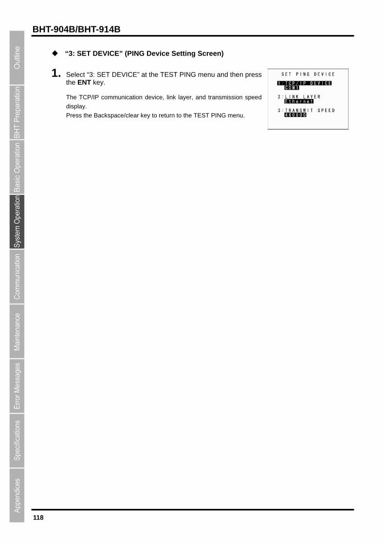
118
BHT-904B/BHT-914B
1. elect “3: SET DEVICE” at the TEST PING menu and then press .
c ey to return to the TEST PING menu.
“3: SET DEVICE” (PING Device Setting Screen)
Sthe ENT key
The TCP/IP communication device, link layer, and transmission speed
display.
ress the Ba kspace/clear kP
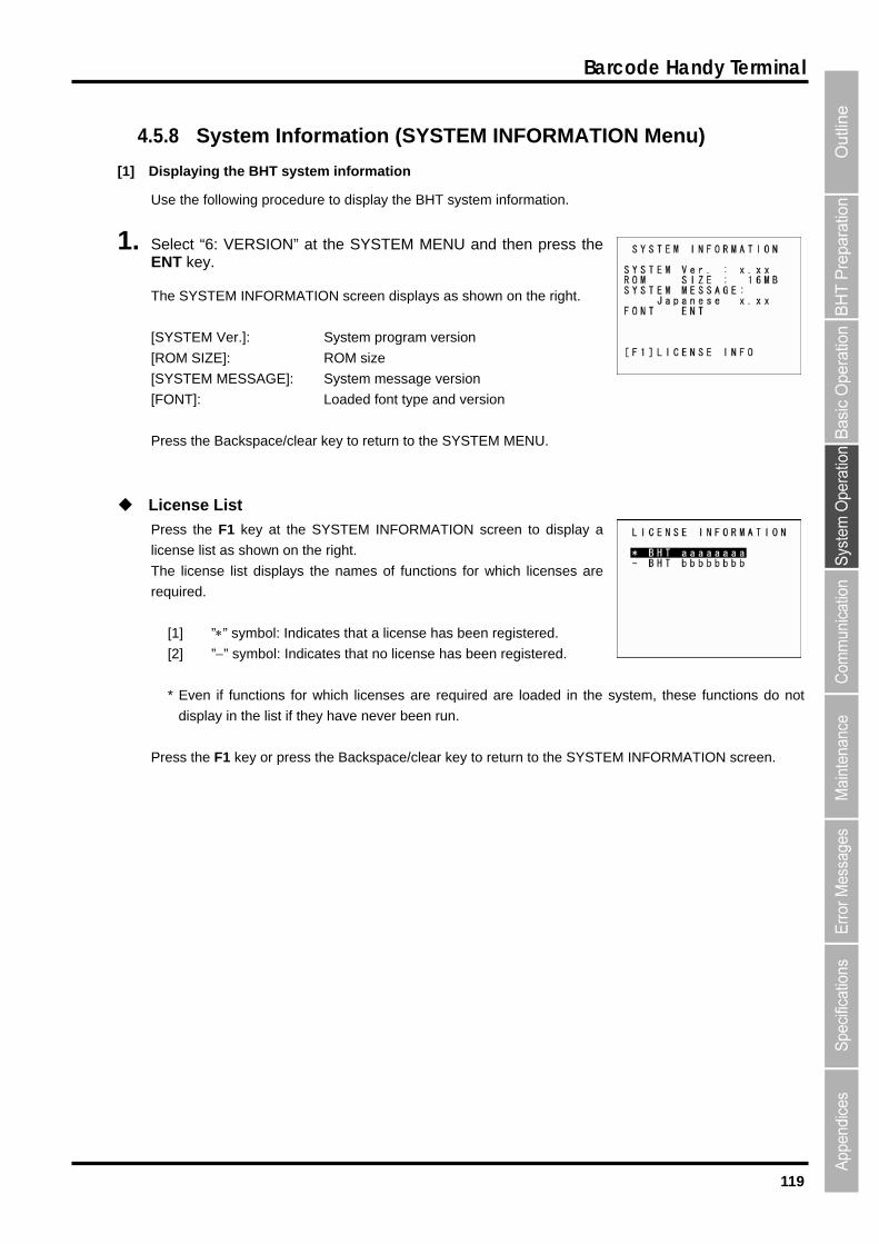
119
Barcode Handy Terminal
4.5.8
BHT system information.
1. 6: VERSION” at the SYSTEM MENU and then press the
he SYSTEM INFORMATION screen displays as shown on the right.
YSTEM Ver.]: System program version
OM SIZE]: ROM size
YSTEM MESSAGE]: System message version
ONT]: Loaded font type and version
ress the Backspace/clear key to return to the SYSTEM MENU.
icense List
ress the F1 key at the SYSTEM INFORMATION screen to display a
cense list as shown on the right.
The license list displays the names of functions for which licenses are
required.
[1] ”” symbol: Indicates that a license has been registered.
[2] ”” symbol: Indicates that no license has been registered.
* Even if functions for which licenses are required are loaded in the system, these functions do not
display in the list if they have never been run.
Press the F1 key or press the Backspace/clear key to return to the SYSTEM INFORMATION screen.
System Information (SYSTEM INFORMATION Menu)
[1] Displaying the BHT system information
Use the following procedure to display the
Select “ENT key.
T
[S
[R
[S
[F
P
L
P
li
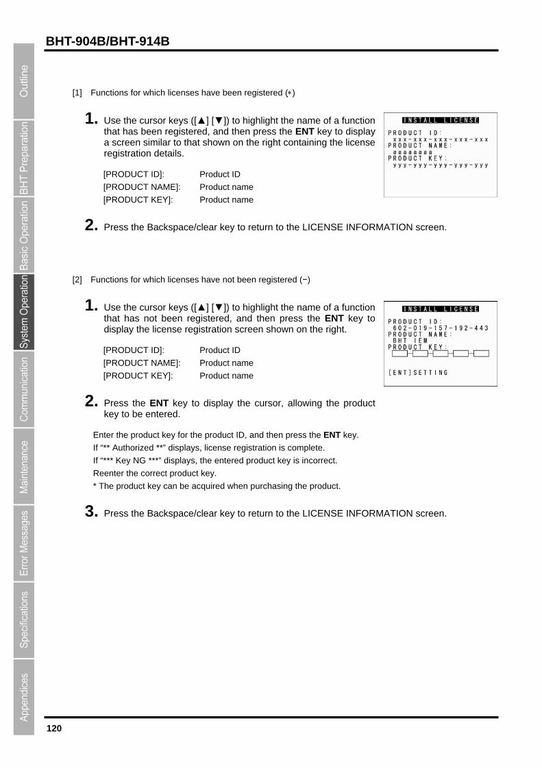
120
BHT-904B/BHT-914B
Functions for which licenses have been registered ( )
[1]
1 ction that has been registered, and then press the ENT key to display
[PRODUCT ID]: Product ID
[PRODUCT KEY]: Product name
[2]
or keys ([▲] [▼]) to highlight the name of a function t been registered, and then press the ENT key to
CT NAME]: Product name
[PRODUCT KEY]: Product name
2. ductkey to be entered.
En
f “** complete.
* The product key can be acquired when purchasing the product.
3. Press the Backspace/clear key to return to the LICENSE INFORMATION screen.
. Use the cursor keys ([▲] [▼]) to highlight the name of a fun
a screen similar to that shown on the right containing the license registration details.
[PRODUCT NAME]: Product name
2. Press the Backspace/clear key to return to the LICENSE INFORMATION screen.
Functions for which licenses have not been registered (−)
1. Use the cursthat has nodisplay the license registration screen shown on the right.
[PRODUCT ID]: Product ID
[PRODU
Press the ENT key to display the cursor, allowing the pro
ter the product key for the product ID, and then press the ENT key.
Authorized **” displays, license registration is I
If “*** Key NG ***” displays, the entered product key is incorrect.
Reenter the correct product key.
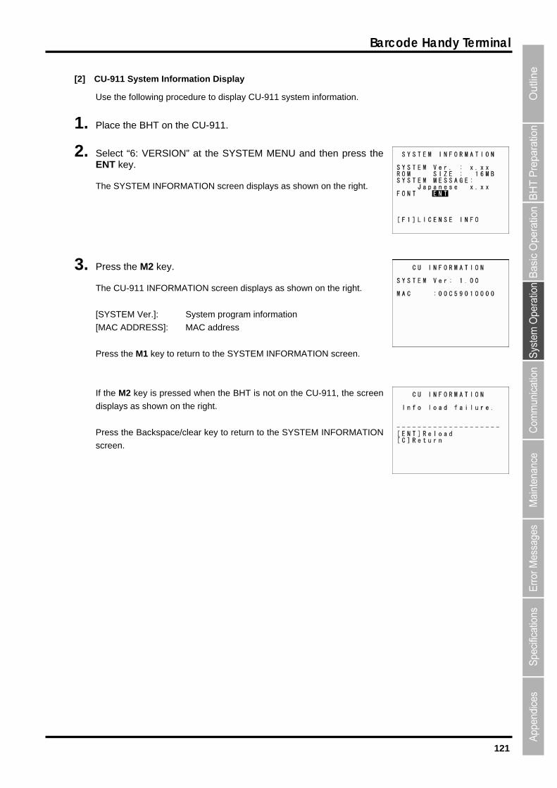
121
Barcode Handy Terminal
[2] U-911 System Information Display
information.
1.
2. Select “6: VERSION” at the ENT
ays as shown on the right.
ress the M2 key.
the right.
Pr re rn M INFORMATION screen.
e CU-911, the screen
ear key to return to the SYSTEM INFORMATION
C
Use the following procedure to display CU-911 system
Place the BHT on the CU-911.
SYSTEM MENU and then press the key.
The SYSTEM INFORMATION screen displ
3. P
The CU-911 INFORMATION screen displays as shown on
[SYSTEM Ver.]: System program information
[MAC ADDRESS]: MAC address
ess the M1 key to tu to the SYSTE
If the M2 key is pressed when the BHT is not on th
displays as shown on the right.
Press the Backspace/cl
screen.
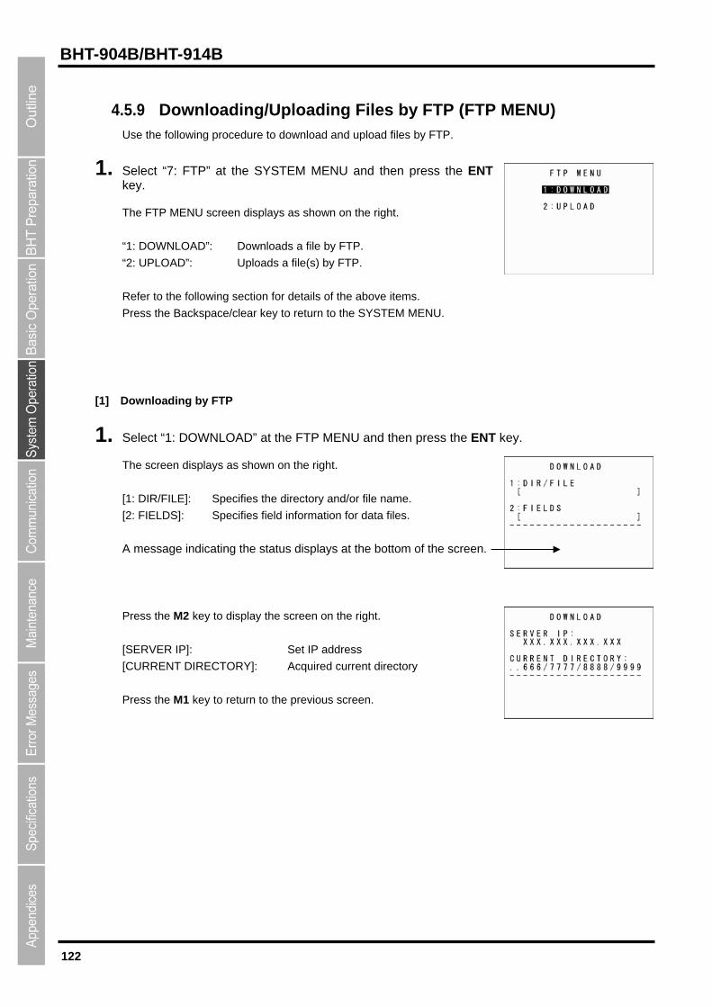
122
BHT-904B/BHT-914B
4.5.9 Downloading/Uploading Files by FTP (FTP MENU) Use the following procedure to download and upload files by FTP.
the ENT
NU screen displays as shown on the right.
: UPLOAD”: Uploads a file(s) by FTP.
efer to the following section for details of the above items.
ckspace/clear key to return to the SYSTEM MENU.
[1] TP
1. elect “1: DOWNLOAD” at the FTP MENU and then press the ENT
he screen displays as shown on the right.
information for data files.
ress the M2 key to display the screen on the right.
ERVER IP]: Set IP address
URRENT DIRECTORY]: Acquired current directory
Press the M1 key to return to the previous screen.
1. Select “7: FTP” at the SYSTEM MENU and then press key.
The FTP ME
: DOWNLOAD”: Downloads a file by FTP. “1
“2
R
Press the Ba
Downloading by F
S key.
T
[1: DIR/FILE]: Specifies the directory and/or file name.
[2: FIELDS]: Specifies field
A message indicating the status displays at the bottom of the screen.
P
[S
[C
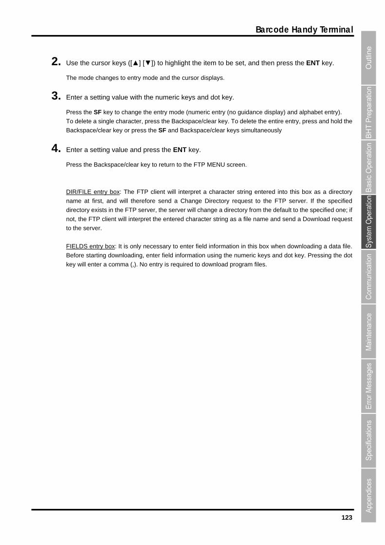
123
Barcode Handy Terminal
2. ENT key.
try (no guidance di
o delete a single character, press the Backspace/clear
ace/clear keys simult
4. nter a setting value and press the ENT key.
n.
IR/FILE entry box
Use the cursor keys ([▲] [▼]) to highlight the item to be set, and then press the
The mode changes to entry mode and the cursor displays.
3. Enter a setting value with the numeric keys and dot key.
Press the SF key to change the entry mode (numeric en splay) and alphabet entry).
key. To delete the entire entry, press and hold the
aneously
T
Backspace/clear key or press the SF and Backsp
E
Press the Backspace/clear key to return to the FTP MENU scree
D : The FTP client will interpret a character string entered into this box as a directory
ame at first, and will therefore send a Change Directory request to the FTP server. If the specified
irectory exists in the FTP server, the server will change a directory from the default to the specified one; if
terpret the entered character string as a file name and send a Download request
to the server.
S entry box
n
d
not, the FTP client will in
FIELD : It is only necessary to enter field information in this box
mation using the numeric
wnload program files.
when downloading a data file.
keys and dot key. Pressing the dot Before starting downloading, enter field infor
ey will enter a comma (,). No entry is required to dok

124
BHT-904B/BHT-914B
[2] Uploading by FTP
1. the ENT key.
The screen displays as shown on the right if uploadable files exist.
.
RECTORY]: Acquired current directory
2. se the cursor keys ([▲] [▼]) to highlight the item to be set, and then press the ENT key.
When “1: DIR/FILE” is Selected
The mode changes to entry mode and the cursor displays, allowing directory and file names to be entered
using the numeric keys and dot key.
Press the SF key to change the entry mode (numeric entry (no guidance display) and alphabet entry).
To delete a single character, press the Backspace/clear key. To delete the entire entry, press and hold the
Backspace/clear key or press the SF and Backspace/clear keys simultaneously
When “2: SELECT FILE” is Selected
The screen displays as shown on the right.
Use the cursor keys ([▲] [▼]) to highlight the upload file and then press
the ENT key.
Return to the previous screen to display the selected file name in
[2: FIELDS].
Select “2: UPLOAD” at the FTP MENU and then press
[1: DIR/FILE]:
Entry box for the directory and/or file name
[2: SELECT FILE]:
File name currently selected (Nothing is displayed at the FTP client
initial status.)
A message indicating the status displays at the bottom of the screen
Press the M2 key to display the screen on the right.
[SERVER IP]: Set IP address
[CURRENT DI
Press the M1 key to return to the previous screen.
U

125
Barcode Handy Terminal
3. Enter the directory and file name, or select a file, and then press the ENT key.
DI
Press the Backspace/clear key to return to the FTP MENU screen.
R/FILE entry box: The FTP client will interpret a character string en ctory
will therefore send a Change Directory request to the FTP se d
dir
no t will interpret the entered character string as a file na
the server.
e
TP client will upload with the file name specified in the DIR/FILE entry
the ENT key is pressed without entering a character string in the DIR/FILE entry box, the FTP client will
file name.
tered into this box as a dire
rver. If the specifie
the default to the specified one; if
me and send a Download request
ied in the DIR/FILE entry box, th
box.
name at first, and
ectory exists in the FTP server, the server will change a directory from
t, the FTP clien
to
If the SELECT FILE entry box file name differs from the file name specif
F
If
upload to the server with the SELECT FILE entry box
SELECT FILE entry box: For uploading, it is necessary to select a file to me
box, up
the attributes (e.g., PD4, FN4, EX4, PD3, FN3, EX3, and data file ex
box, an error will res
If No Uploadable Files Exist
ing by FTP is selected, the
ress the Backspace/clear key to return to the FTP MENU screen.
be uploaded to display the na
loading will result in an error.
tensions) of the selected file are
ult.
in this entry box beforehand. Without a file name in this entry
If
different from those specified in the DIR/FILE entry
If no file exists in the BHT when upload
message shown on the right displays.
P
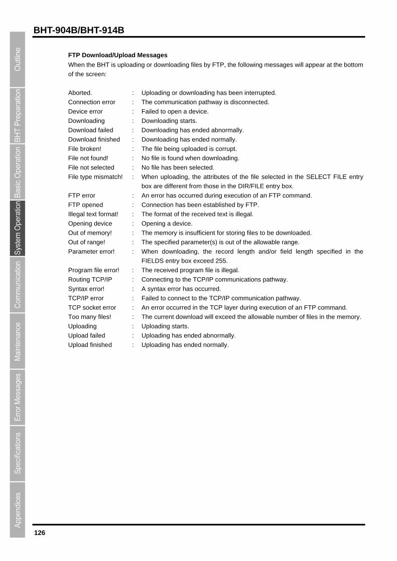
126
BHT-904B/BHT-914B
FTP Download/Upload Messages
When the BHT is uploading or downloading files by FTP, the following messages will appear at the bottom
upted.
onnection error : The communication pathway is disconnected.
evice error : Failed to open a device.
: No file is found when downloading.
in the SELECT FILE entry
box are different from those in the DIR/FILE entry box.
TP.
legal text format! : The format of the received text is illegal.
ield length specified in the
FIELDS entry box exceed 255.
rogram file error! : The received program file is illegal.
outing TCP/IP : Connecting to the TCP/IP communications pathway.
tax error has occurred.
rred in the TCP layer during execut
oo many files! : The current download will exceed the allowabl
pload failed : Uploading has ended abnormally.
pload finished : Uploading has ended normally.
of the screen:
Aborted. : Uploading or downloading has been interr
C
D
Downloading : Downloading starts.
Download failed : Downloading has ended abnormally.
Download finished : Downloading has ended normally.
File broken! : The file being uploaded is corrupt.
File not found!
File not selected : No file has been selected.
File type mismatch! : When uploading, the attributes of the file selected
FTP error : An error has occurred during execution of an FTP command.
FTP opened : Connection has been established by F
Il
Opening device : Opening a device.
Out of memory! : The memory is insufficient for storing files to be downloaded.
Out of range! : The specified parameter(s) is out of the allowable range.
Parameter error! : When downloading, the record length and/or f
P
R
Syntax error! : A syn
TCP/IP error : Failed to connect to the TCP/IP communication p
TCP socket error : An error occu
athway.
ion of an FTP command.
e number of files in the memory.T
Uploading : Uploading starts.
U
U

127
Barcode Handy Terminal
Response Messages from the FTP server
w.
estart marke e
ady a
connecti rt transferring.
atus oka ection.
d oka
e t h e.
m status r
ry statu
s.
ge
215 : NAME system typ
rvice ready r
e closin
cti
ata c n
Pass
gged in
d file r
257 : “PATHNAME” cre
ok .
count q
sted file r tion.
e not av a
esta is
ion cl
quested file c
sted ac n
ed ac n
500 : Syntax error; command not recognized.
501 : Syntax error in parameters or arguments.
502 : Command not supported.
503 : Incorrect command sequence.
504 : Command parameter not supported.
530 : Not logged in.
532 : File storage account required.
550 : Requested action not taken.
551 : Requested action aborted: page type unknown.
552 : Requested file processing aborted.
553 : Requested action not taken.
The messages that FTP servers send during and after FTP operations vary, but servers all use the same
reply codes as listed belo
110 : R r r ply.
120 : Service re in pprox. nnn minutes.
125 : Data on has been established. Sta
150 : File st y: establishing data conn
200 : Comman y.
202 : No respons o t is command. Not required at this sit
211 : Syste , o system help reply
212 : Directo s.
213 : File statu
214 : Help messa .
e.
220 : Se fo new users.
221 : Servic g control connection.
225 : Data conne on established: no transfer in progress.
226 : Closing d on ection.
227 : Entering ive Mode.
230 : User lo . Proceed.
250 : Requeste p ocess completed normally.
ated.
331 : User name ay Password required.
332 : Login ac re uired.
350 : Reque p ocess awaiting further informa
421 : Servic ail ble. Closing control connection.
425 : Unable to bl h data connection.
426 : Connect osed: transfer aborted.
450 : Re a tion not taken.
451 : Reque tio aborted: processing local error.
452 : Request tio not taken.
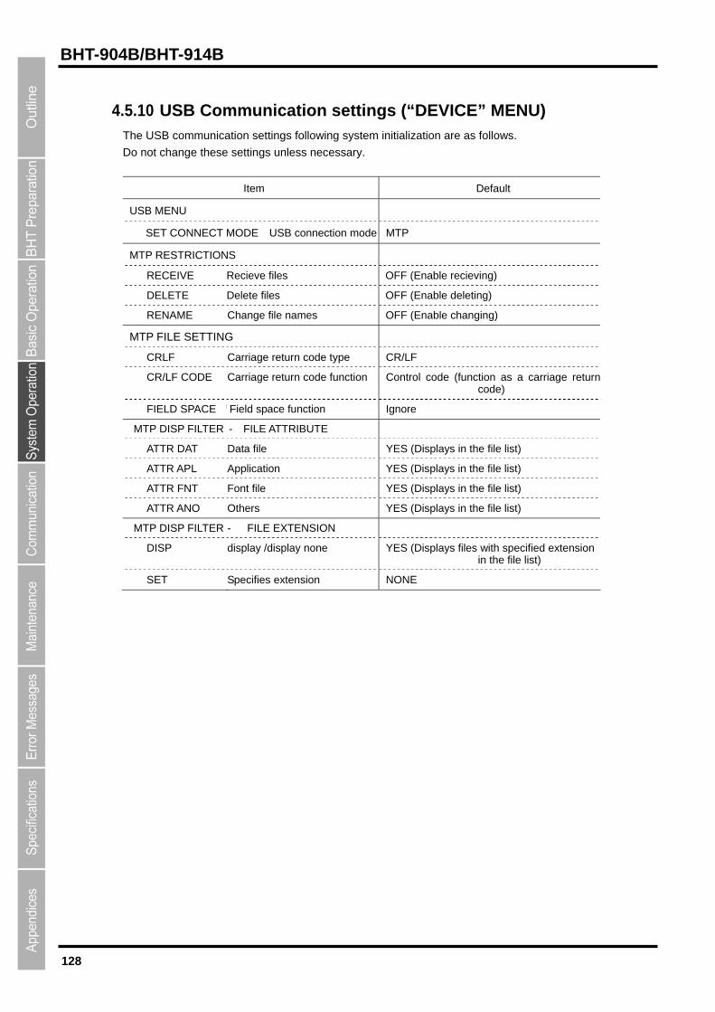
128
BHT-904B/BHT-914B
4tings following system initialization are as follows.
o not change these settings unless necessary.
Default
.5.10 USB Communication settings (“DEVICE” MENU) The USB communication set
D
Item
USB MENU
SET CONNECT MODE USB connection mode MTP
MTP RESTRICTIONS
RECEIVE Recieve files OFF (Enable recieving)
DELETE Delete files OFF (Enable deleting)
RENAME Change file names OFF (Enable changing)
M TP FILE SETTING
CRLF Carriage return code type CR/LF
CR/LF CODE Carriage return code function Control code (function as a carriage return code)
FIELD SPACE f Field space function Ignore
IBUTE MTP DISP FILTER - FILE ATTR
ATTR DAT Data file YES (Displays in the file list)
ATTR APL Application YES (Displays in the file list)
ATTR FNT Font file YES (Displays in the file list)
ATTR ANO Others YES (Displays in the file list)
MTP DISP FILTER - FILE EXTENSION
DISP display /display none YES (Displays files with specified extension in the file list)
SET Specifies extension NONE
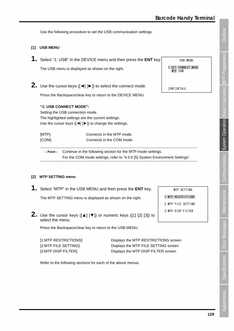
129
Barcode Handy Terminal
Use the following procedure to set the USB communication settings.
[1]
1. Select “1: USB” in the ICE menu and then press the ENT k
The USB menu is displayed as shown on the right.
2. Use the cursor keys ([◄] [►]) to select the connect mode.
Pres return to the DEV
“1: USB CONNECT MODE”:
Setting the USB connection mode.
The highlighted settings are the current settings.
Use s g
[MT e MTP mode.
e COM mode.
ntin owing section for th
r the de settings, refer to “4 t Settings”.
USB MENU
DEV ey.
s the Backspace/clear key to ICE MENU.
the cursor key ([◄] [►]) to change the settin s.
P]: Connects in th
[COM]: Connects in th
Point Co ue in the foll e MTP mode settings.
Fo COM mo .5.6 [5] System Environmen
[2] MTP ING men
1. Select “MTP” then pres T key.
The MTP SETTING menu is displayed as shown on the right.
2. Use the cursor keys ([▲] [▼]) or numeric keys ([1] [2] [3]) to select the menu.
Press the Backspace/clear key to return to the USB MENU.
[1:MTP RESTRICTIONS]: Displays the MTP RESTRICTIONS screen
[2:MTP FILE SETTING]: Displays the MTP FILE SETTING screen
[3:MTP DISP FILTER]: Displays the MTP DISP FILTER screen
Refer to the following sections for each of the above menus.
SETT u
in the USB MENU and s the EN
USB MENU
1:SET CONNECT MODE MTP COM
[ENT]DETAIL
MTP SETTING
1:MTP RESTRICTIONS
2:MTP FILE SETTING
3:MTP DISP FILTER
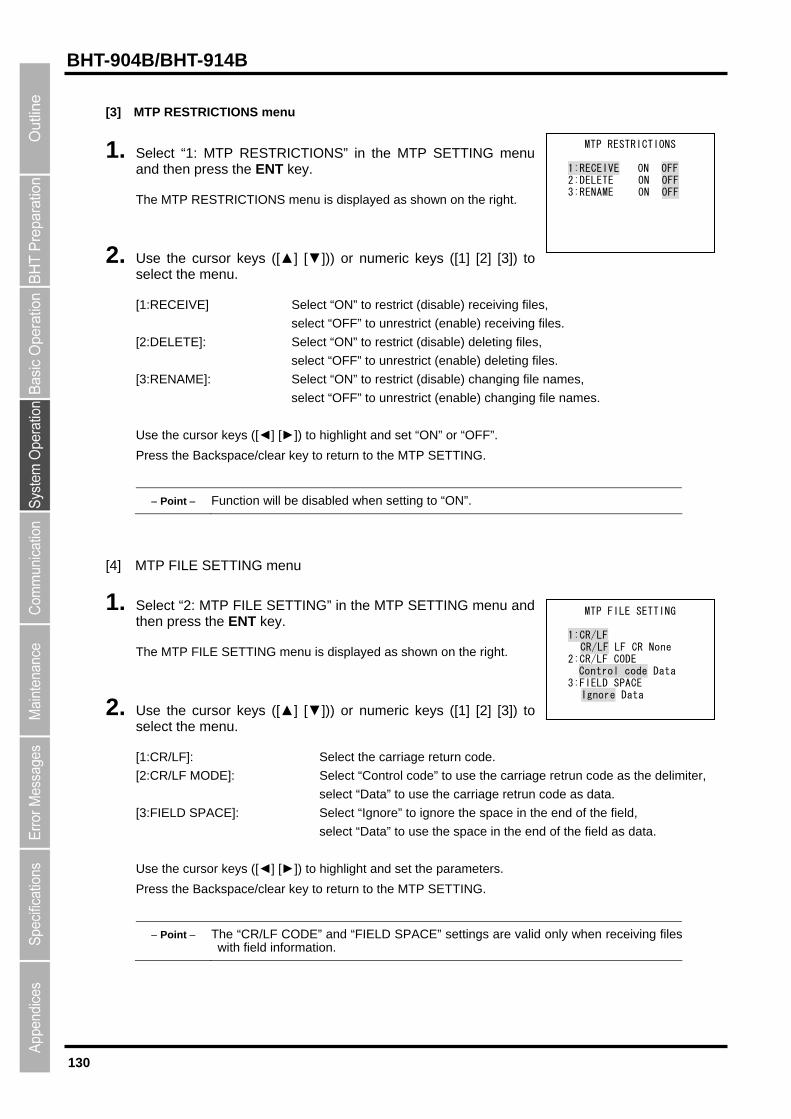
130
BHT-904B/BHT-914B
[3]
TP RESTRICTIONS” in the MTP SETTING menu ss the ENT key.
2. Use the cursor keys ([▲] [▼])) or numeric keys ([1] [2] [3]) to select the menu.
[1:RECEIVE] Select “ON” to restrict (disable) receiving files,
ceiving files.
:DELETE]: Select “ON” to restrict (disable) deleting files,
ct “OFF” to unrestrict (enable) deleting files.
ON” to restrict (disable) changing file names,
rict (enable) changing file names.
se the cursor keys ([◄] [►]) to highlight and set “ON” or “OFF”.
Point Function will be disabled when setting to “ON”.
MTP RESTRICTIONS menu
1. Select “1: Mand then pre
The MTP RESTRICTIONS menu is displayed as shown on the right.
select “OFF” to unrestrict (enable) re
[2
sele
MTP RESTRICTIONS
1:RECEIVE ON OFF 2:DELETE ON OFF 3:RENAME ON OFF
[3:RENAME]: Select “
select “OFF” to unrest
U
Press the Backspace/clear key to return to the MTP SETTING.
[4] TP FILE SETTING menu
SETTING” in the MTP SETTING menu and then press the ENT key.
The MTP FILE SETTING menu is displayed as shown on
Use the cursor keys ([▲] [▼])) or numeric keys ([1] [2] [3]) to
[1:CR/LF]: Select the carriage return code.
the carriage retrun code as the delimiter,
select “Data” to use the carriage retrun code as data.
d,
s data.
Use the cursor keys ([◄] [►]) to highlight and set the parameters.
.
Point The “CR/LF CODE” and “FIELD SPACE” settings are valid only when receiving fileswith field information.
M
1. Select “2: MTP FILE
the right.
MTP FILE SETTING
1:CR/LF CR/LF LF CR None 2:CR/LF CODE
Control code Data 3:FIELD SPACE
Ignore Data 2.
select the menu.
[2:CR/LF MODE]: Select “Control code” to use
[3:FIELD SPACE]: Select “Ignore” to ignore the space in the end of the fiel
select “Data” to use the space in the end of the field a
Press the Backspace/clear key to return to the MTP SETTING
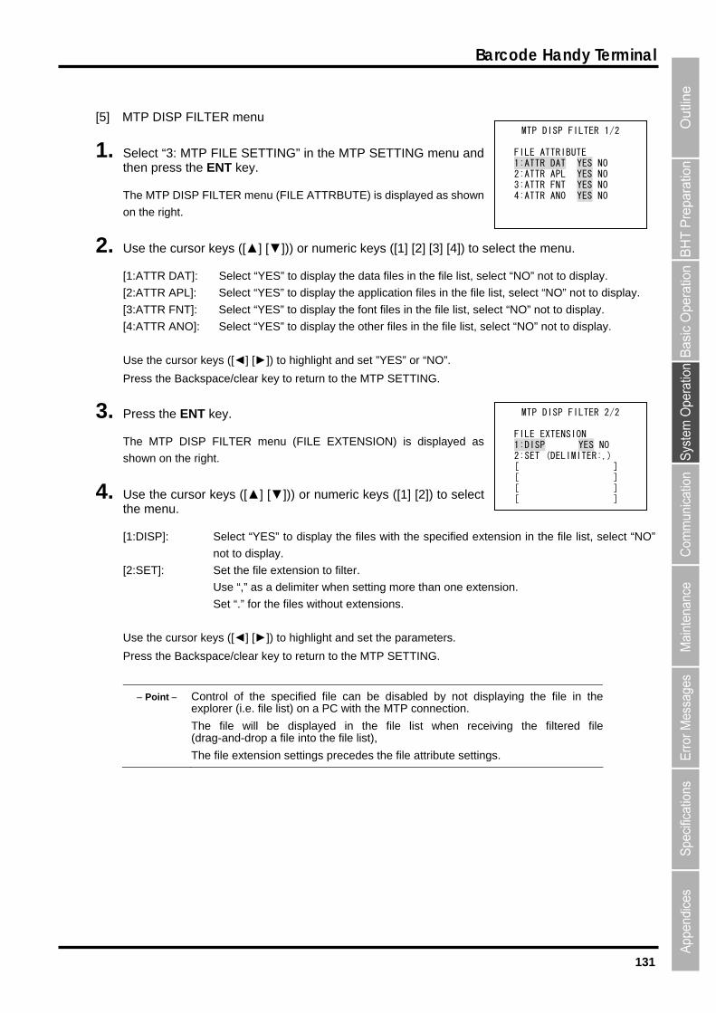
131
Barcode Handy Terminal
[5] MTP DISP FILTER menu
” in the MTP SETTING menu and then press the ENT key.
The MTP DISP FILTER menu (FILE ATTRBUTE) is displayed as shown
on the right.
ys ([▲] [▼])) or numeric keys ([1] [2] [3] [4]) to select the menu.
t “Y “NO” not to display.
:ATTR APL : ect “NO” not to display.
: Sel t “Y “NO” not to display.
:ATTR AN ]: Sel t “Y O” not to isplay.
r keys ([◄] [►
Press the Backspace/clear key to return to the MTP SETTING.
The MTP DISP FILTER menu (FILE EXTENSION) is displayed as
sh
4. Use the cursor keys ([▲] [▼])) or numeric keys ([1] [2]) to select
nsion in the file list, select “NO”
extension to filter.
extension
Set “.” for the files without extensions.
e/clear key to return to the MTP SETTING.
ol o the spe
ill e fileand dro a fi
he le e tens n s
1. Select “3: MTP FILE SETTING
2. Use the cursor ke
[1:ATTR DAT]: Selec ES” to display the data files in the file list, select
[2 ] Select “YES” to display the application files in the file list, sel
[3:ATTR FNT] ec ES” to display the font files in the file list, select
[4 O ec ES” to display the other files in the file list, select “N d
Use the curso ]) to highlight and set ”YES” or “NO”.
3. Press the ENT key.
own on the right.
the menu.
[1:DISP]: Select “YES” to display the files with the specified exte
not to display.
[2:SET]: Set the file
Use “,” as a delimiter when setting more than one .
Use the cursor keys ([◄] [►]) to highlight and set the parameters.
Press the Backspac
Point Contr f cified file can be disabled by not displaying the file in theexplorer (i.e. file list) on a PC with the MTP connection.
The file w b displayed in the file list when receiving the filtered(drag- - p le into the file list),
T fi x io ettings precedes the file attribute settings.
M TP DISP FILTER 1/2
FILE ATTRIBUTE 1:ATTR DAT YES NO 2:ATTR APL YES NO 3:ATTR FNT YES NO 4:ATTR ANO YES NO
MTP DISP FILTER 2/2
FILE EXTENSION 1:DISP YES NO 2:SET (DELIMITER:,) [ ] [ ] [ ] [ ]
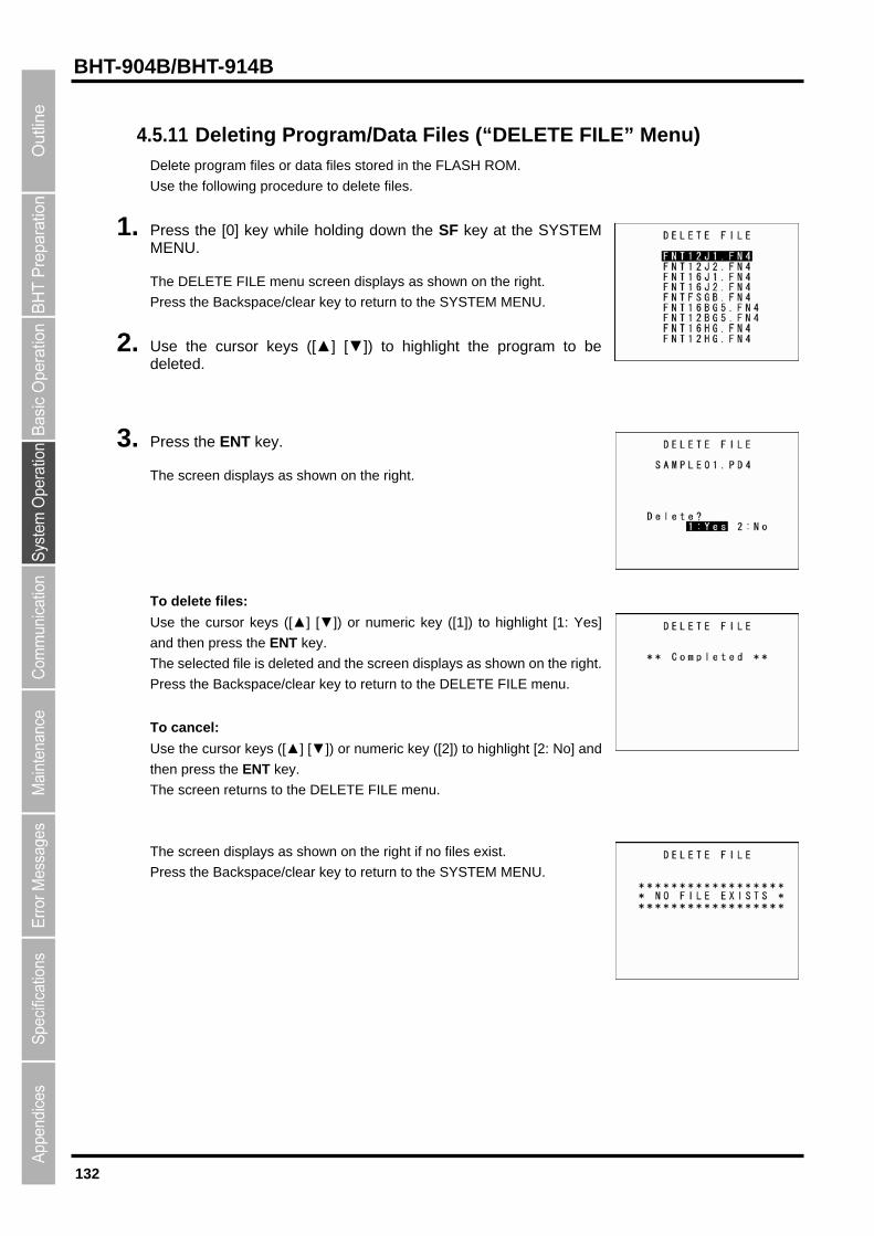
132
BHT-904B/BHT-914B
4.5.11 Deleting Program/Data Files (“DELETE FILE” Menu)
Delete program files or data files stored in the FLASH ROM.
1.
The DELETE FILE menu screen displays as shown on the right.
3. The screen displays as shown on the right.
or keys ([▲] [▼]) or numeric key ([1]) to highlight [1: Yes]
ksp ELETE FILE menu.
o cancel:
light [2: No] and
Th
Press the Ba
Use the following procedure to delete files.
Press the [0] key while holding down the SF key at the SYSTEMMENU.
Press the Backspace/clear key to return to the SYSTEM MENU.
2. Use the cursor keys ([▲] [▼]) to highlight the program to be deleted.
Press the ENT key.
To delete files:
Use the curs
and then press the ENT key.
The selected file is deleted and the screen displays as shown on the right.
ace/clear key to Press the Bac return to the D
T
r numeric key ([2]) to highUse the cursor keys ([▲] [▼]) o
then press the ENT key.
The screen returns to the DELETE FILE menu.
e screen displays as shown on the right if no files exist.
ckspace/clear key to return to the SYSTEM MENU.

133
Barcode Handy Terminal
4.5.12 Deleting Font Files (DELETE FILE Menu) Delete font files stored in the FLASH ROM.
If there is insufficient user area, by deleting font files, a user area equal to the size of the deleted font files
can be secured.
laying Japanese fonts at the user program:
ing font files, upload the font files to the host computer and so on to ensure that they are
acked up.
Refer to section “4.5.4 Uploading Files (UPLOAD Menu)” for details of uploading.
Use the following procedure to delete font files.
1. ress the [2] key while holding down the SF key at the SYSTEM ENU.
he DELETE FILE menu screen displays as shown on the right.
ress the Backspace/clear key to return to the SYSTEM MENU.
2.
3. isplays as shown on the right.
Not disp
All font files can be deleted.
Using only 16 dots or 12 dots at the user program:
Font files that are not used can be deleted.
When delet
b
PM
T
P
Use the cursor keys ([▲] [▼]) to highlight the font file to be deleted.
Press the ENT key.
The screen d
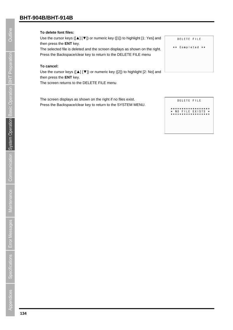
134
BHT-904B/BHT-914B
To delete font files:
Use the cursor keys ([▲] [▼]) or numeric key ([1]) to highlight [1: Yes] and
ace/clear key to return to the DELETE FILE menu
ey ([2]) to highlight [2: No] and
en press the ENT key.
ckspace/clear key to return to the SYSTEM MENU.
then press the ENT key.
The selected file is deleted and the screen displays as shown on the right.
Press the Backsp
To cancel:
Use the cursor keys ([▲] [▼]) or numeric k
th
The screen returns to the DELETE FILE menu
The screen displays as shown on the right if no files exist.
Press the Ba
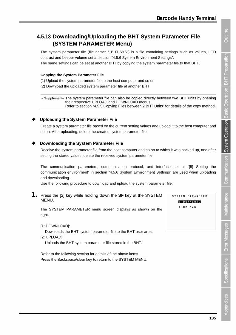
135
Barcode Handy Terminal
4ARAMETER Menu)
t
he same settings can be set at another BHT by copying the system pa
t computer and so on.
le at another BHT.
etwmenus.
T Unit
.5.13 Downloading/Uploading the BHT System P(SYSTEM P
arameter File
settings such as values, LCD
Settings”.
rameter file to that BHT.
The system parameter file (file name: “_BHT.SYS”) is a file containing
contrast and beeper volume set at section “4.5.6 System Environmen
T
Copying the System Parameter File
(1) Upload the system parameter file to the hos
(2) Download the uploaded system parameter fi
Supplement The system parameter file can also be copied directly btheir respective UPLOAD and DOWNLOAD
een two BHT units by opening
s” for details of the copy method.Refer to section “4.5.5 Copying Files between 2 BH
ploading the System Parameter File
reate a system parameter file based on the current setting values and upload it to the host computer and
o on. After uploading, delete the created system parameter file.
ownloading the System Parameter File
eceive the system parameter file from the host computer and so on to which it was backed up, and after
etting the stored values, delete the received system parameter file.
The communication parameters, communication protocol, and interface set at “[5] Setting the
communication environment” in section “4.5.6 System Environment Settings” are used when uploading
and downloading.
Use the following procedure to download and upload the system parameter file.
1. Press the [3] key while holding down the SF key at the SYSTEM MENU.
The SYSTEM PARAMETER menu screen displays as shown on the
right.
[1: DOWNLOAD]:
Downloads the BHT system parameter file to the BHT user area.
[2: UPLOAD]:
Uploads the BHT system parameter file stored in the BHT.
Refer to the following section for details of the above items.
Press the Backspace/clear key to return to the SYSTEM MENU.
U
C
s
D
R
s
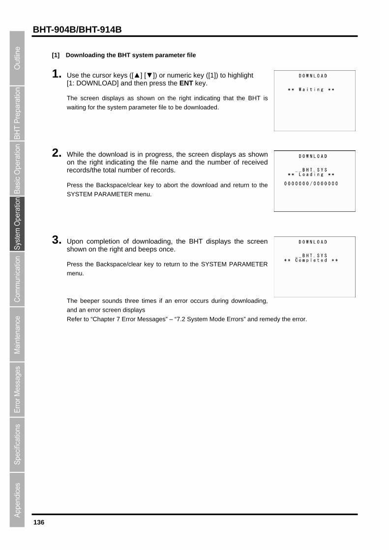
136
BHT-904B/BHT-914B
[1]
1. Use th o highlight
2. hile the download is in progress, the screen displays as shown
records/the to
ress the Backspace/clear key to abort the download and return to the
ress the Backspace/clear key to return to the SYSTEM PARAMETER
and an error screen displays
Downloading the BHT system parameter file
e cursor keys ([▲] [▼]) or numeric key ([1]) t[1: DOWNLOAD] and then press the ENT key.
The screen displays as shown on the right indicating that the BHT is
waiting for the system parameter file to be downloaded.
Won the right indicating the file name and the number of received
tal number of records.
P
SYSTEM PARAMETER menu.
3. Upon completion of downloading, the BHT displays the screen shown on the right and beeps once.
P
menu.
The beeper sounds three times if an error occurs during downloading,
Refer to “Chapter 7 Error Messages” – “7.2 System Mode Errors” and rem
edy the error.
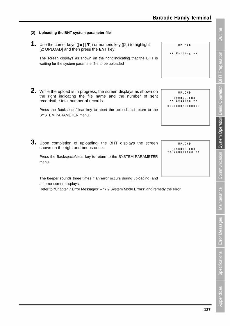
137
Barcode Handy Terminal
[2] Uploading the BHT system parameter file
1. Use the cursor keys ([▲] [▼]) or numeric key ([2]) to highlight [2: UPLOAD] and then press the ENT key.
The screen displays as shown on the right indicating that the BHT is
waiting for the system parameter file to be uploaded
2. While the upload is in progress, the screen displays as shown on the right indicating the file name and the number of sent records/the total number of records.
Press the Backspace/clear key to abort the upload and return to the
SYSTEM PARAMETER menu.
3. Upon completion of uploading, the BHT displays the screen shown on the right and beeps once.
Press the Backspace/clear key to return to the SYSTEM PARAMETER
menu.
The beeper sounds three times if an error occurs during uploading, and
an error screen displays.
Refer to “Chapter 7 Error Messages” – “7.2 System Mode Errors” and remedy the error.
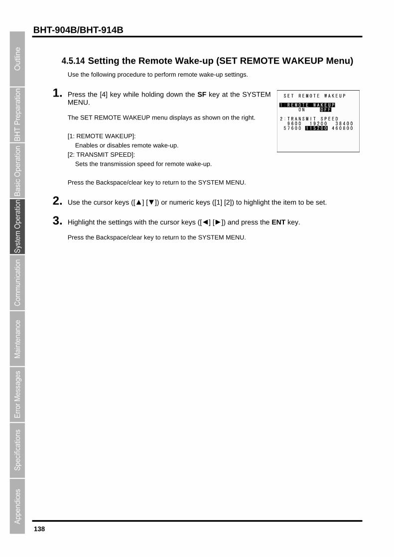
138
BHT-904B/BHT-914B
4.5.14 REMOTE WAKEUP Menu)
1.
he SET REMOTE WAKEUP menu displays as shown on the right.
: REMOTE WAKEUP]:
Enables or disables remote wake-up.
2. se the cursor keys ([▲] [▼]) or numeric keys ([1] [2]) to highlight the item
3. ighlight the settings with the cursor keys ([◄] [►]) and press the ENT key.
Press the Backspace/clear key to return to the SYSTEM MENU.
Setting the Remote Wake-up (SETUse the following procedure to perform remote wake-up settings.
Press the [4] key while holding down the SF key at the SYSTEM MENU.
T
[1
[2: TRANSMIT SPEED]:
Sets the transmission speed for remote wake-up.
Press the Backspace/clear key to return to the SYSTEM MENU.
U to be set.
H

139
Barcode Handy Terminal
4.5.15 Downloading/Uploading the System Message File (SYSTEM MESSAGE Menu)
The system message file is a file (file name: “_B90MSG.FN3”) used by the system to display messages
) Upload the system message file to the host computer and so on.
d system message file at another BHT.
Up
reate a system message file based on the current system message settings and upload it to the host
essage file.
Receive the system message file from the host computer and so on to which it was backed up, and after
nd interface set at “[5] Setting the
ommunication environment” in section “4.5.6 System Environment Settings” are used when uploading
nd downloading.
Supplement System messages are normally set when the BHT is shipped from the factory, andtherefore operation at this menu is unnecessary.
such as “Shutdown in progress. Do not remove the battery.” or “Charge the
battery!”.
Downloading/Uploading the System Message File
(1
(2) Download the uploade
loading the System Message File
C
computer and so on. After uploading, delete the created system m
Downloading the system message file
setting the stored system messages, delete the received system message file.
The communication parameters, communication protocol, a
c
a
Use the following procedure to download and upload the system message file.
1. Press the [6] key while holding down the SF key at the SYSTEM MENU.
The SYSTEM MESSAGE menu displays as shown on the right.
[1: DOWNLOAD]:
Downloads the system message file.
[2: UPLOAD]:
Uploads the system message file.
Refer to the following section for details of the above items
Press the Backspace/clear key to return to the SYSTEM MENU.

140
BHT-904B/BHT-914B
[1]
1. Use th 1]) to highlight
aiting for the system message file to be downloaded.
2. hile the download is in progress, the screen displays as shown the number of received
ress the Backspace/clear key to return to the SYSTEM PARAMETER
and an error screen displays.
Point When downloading the system message file, the BHT heref
reated temporary file will automatically be deleted after dow
Downloading the system message file
e cursor keys ([▲] [▼]) or numeric key ([[1: DOWNLOAD] and then press the ENT key.
The screen displays as shown on the right indicating that the BHT is
w
Won the right indicating the file name andrecords/the total number of records.
Press the Backspace/clear key to abort the download and return to the
SYSTEM MESSAGE menu.
3. Upon completion of downloading, the BHT displays the screen shown on the right and beeps once.
P
menu.
The beeper sounds three times if an error occurs during downloading,
Refer to “Chapter 7 Error Messages” – “7.2 System Mode Errors” and reme
dy the error.
creates a temporary file named ore occur if there is insufficient
nloading is complete.
“_B90MSG.FN3” in the user area. An error will tspace in the user area to create the temporary file.
The c
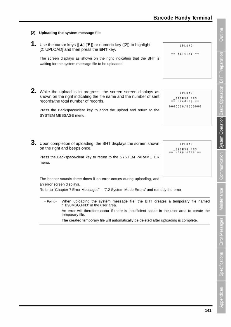
141
Barcode Handy Terminal
[2] Uploading the system message file
1. Use the cursor keys ([▲] [▼]) or numeric key ([2]) to highlight [2: UPLOAD] and then press the ENT key.
The screen displays as shown on the right indicating that the BHT is
waiting for the system message file to be uploaded.
2. While the upload is in progress, the screen screen displays as shown on the right indicating the file name and the number of sent records/the total number of records.
Press the Backspace/clear key to abort the upload and return to the
SYSTEM MESSAGE menu.
3. Upon completion of uploading, the BHT displays the screen shown on the right and beeps once.
Press the Backspace/clear key to return to the SYSTEM PARAMETER
menu.
The beeper sounds three times if an error occurs during uploading, and
an error screen displays.
Refer to “Chapter 7 Error Messages” – “7.2 System Mode Errors” and remedy the error.
Point When uploading the system message file, the BHT creates a temporary file named“_B90MSG.FN3” in the user area.
An error will therefore occur if there is insufficient space in the user area to create the
The created temporary file will automatically be deleted after uploading is complete.
temporary file.
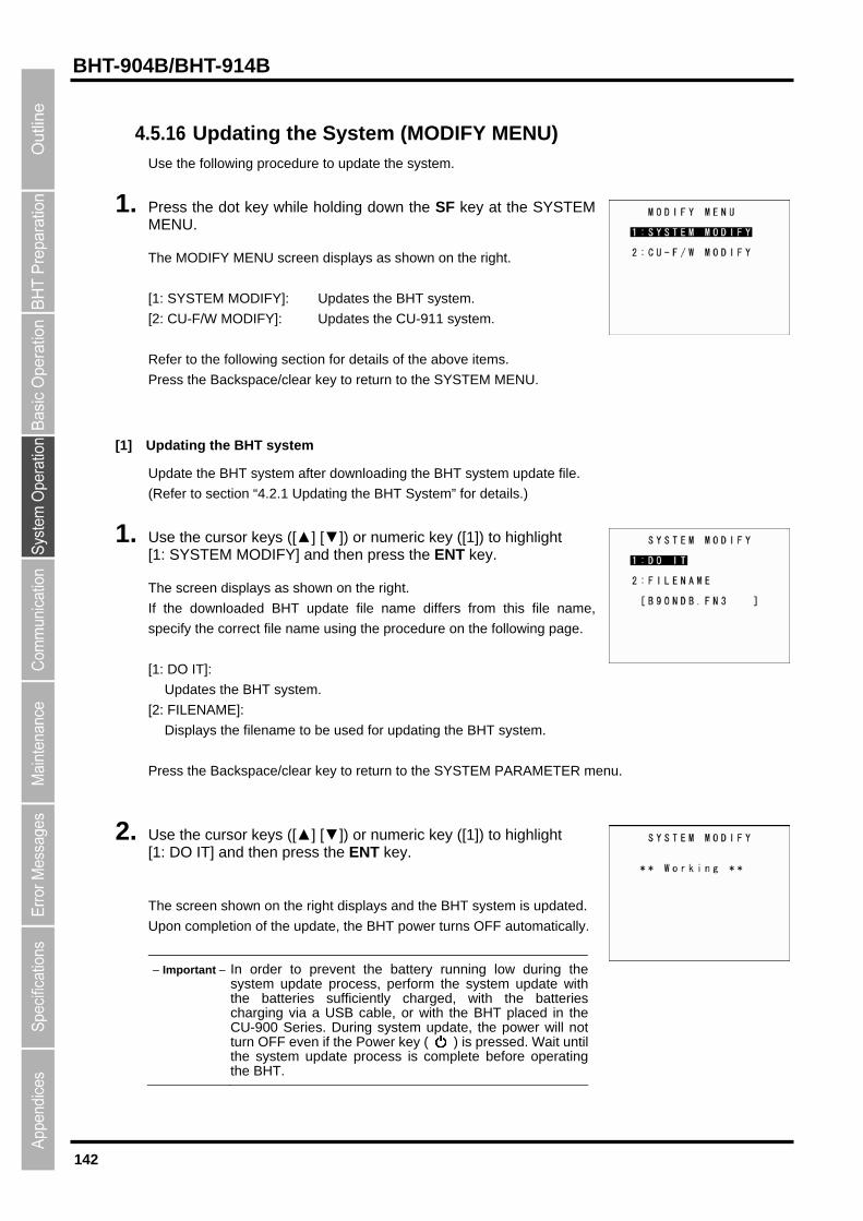
142
BHT-904B/BHT-914B
4.5.16
1.
he MODIFY MENU screen displays as shown on the right.
: SYSTEM MODIFY]: Updates the BHT system.
[2: CU-F/W MODIFY]: Updates the CU-911 system.
o the SYSTEM MENU.
[1] Updating the BHT system
pdate the BHT system after downloading the BHT system update file.
efer to section “4.2.1 Updating the BHT System” for details.)
n press the ENT key.
ownloaded BHT update file name differs from this file name,
pecify the correct file name using the procedure on the following page.
m.
Displays the filename to be used for updating the BHT system.
Press the Ba STEM PARAMETER menu.
2. Use the cursor keys ([[1: DO IT] and then press the ENT key.
The screen shown on the right displays and the BHT system is updated.
Upon completion of the update, the BHT power turns OFF automatically.
Important In order to prevent the battery running low during the system update process, perform the system update withthe batteries sufficiently charged, with the batteriescharging via a USB cable, or with the BHT placed in the CU-900 Series. During system update, the power will notturn OFF even if the Power key (
Updating the System (MODIFY MENU) Use the following procedure to update the system.
Press the dot key while holding down the SF key at the SYSTEM MENU.
T
[1
Refer to the following section for details of the above items.
Press the Backspace/clear key to return t
U
(R
1. Use the cursor keys ([▲] [▼]) or numeric key ([1]) to highlight [1: SYSTEM MODIFY] and the
The screen displays as shown on the right.
If the d
s
[1: DO IT]:
Updates the BHT syste
[2: FILENAME]:
ckspace/clear key to return to the SY
▲] [▼]) or numeric key ([1]) to highlight
) is pressed. Wait until the system update process before operatingthe BHT.
is complete

143
Barcode Handy Terminal
date File
me of the BHT system update file to
ile name.
key.
2. rect file name.
ress the SF key to change the entry mode (numeric entry (no guidance display) and
To delete the entire entry, press and hold the
imultaneously.
3. ress the ENT key to set the entered file name.
ting the BHT System
The screen displays as shown on the right if the system update file does
system again.
e MODIFY MENU.
When the Displayed File Name Differs from the BHT System Up
If the name of the file displayed at [2: FILENAME] differs from the na
be used for updating the system, enter the correct f
1. Use the cursor keys ([▲] [▼]) or numeric key ([2]) to highlight [2: Fthe ENT
ILENAME] and then press
alphabet entry).
The mode changes to entry mode and the cursor displays.
Use the numeric keys and dot key to enter the cor
P
To delete a single character, press the Backspace/clear key.
Backspace/clear key or press the SF and Backspace/clear keys s
P
If the System Update File Does not Exist when Upda
not exist when updating the BHT system.
Download the BHT system update file and update the BHT
Press the Backspace/clear key to return to th
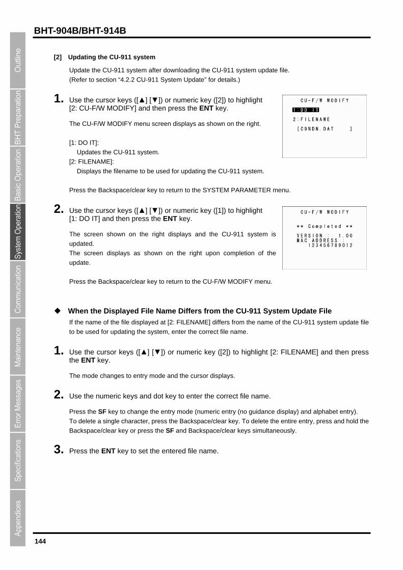
144
BHT-904B/BHT-914B
[2] Updating the CU-911 system
Update the CU-911 system after downloading the CU-911 system update file.
(Refer to section “4.2.2 CU-911 System Update” for details.)
1. Use the cursor keys ([▲] [▼]) or numeric key ([2]) to highlight [2: CU-F/W MODIFY] and then press the ENT key.
e right.
PARAMETER menu.
2. se the cursor keys ([▲] [▼]) or numeric key ([1]) to highlight : DO IT] and then press the ENT key.
right upon completion of the
ress the Backspace/clear key to return to the CU-F/W MODIFY menu.
hen the Displayed File Name Differs from the CU-911 System Update File
the name of the file displayed at [2: FILENAME] differs from the name of the CU-911 system update file
be used for updating the system, enter the correct file name.
1. ▲] [▼]) or numeric key ([2]) to highlight [2: FILENAME] and then press the ENT key.
The mode changes to entry mode and the cursor displays.
2. Use the numeric keys and dot key to enter the correct file name.
Press the SF key to change the entry mode (numeric entry (no guidance display) and alphabet entry).
To delete a single character, press the Backspace/clear key. To delete the entire entry, press and hold the
Backspace/clear key or press the SF and Backspace/clear keys simultaneously.
3. Press the ENT key to set the entered file name.
The CU-F/W MODIFY menu screen displays as shown on th
[1: DO IT]:
Updates the CU-911 system.
[2: FILENAME]:
Displays the filename to be used for updating the CU-911 system.
Press the Backspace/clear key to return to the SYSTEM
U[1
The screen shown on the right displays and the CU-911 system is
updated.
The screen displays as shown on the
update.
P
W
If
to
Use the cursor keys ([
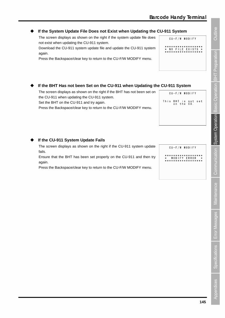
145
Barcode Handy Terminal
If the System Update File Does not Exist when Updating the CU-911 System
Download the CU-911 system update file and update the CU-911 system
.
If t on the CU-911 when Up
ys as shown on the right if the BHT has not been set on
th
et the BHT on the CU-911 and try again.
en displays as shown on the right if the CU-911 system update
ils.
y
gain.
ress the Backspace/clear key to return to the CU-F/W MODIFY menu.
The screen displays as shown on the right if the system update file does
not exist when updating the CU-911 system.
again.
Press the Backspace/clear key to return to the CU-F/W MODIFY menu
the BHT Has not been Se dating the CU-911 System
The screen displa
e CU-911 when updating the CU-911 system.
S
Press the Backspace/clear key to return to the CU-F/W MODIFY menu.
If the CU-911 System Update Fails
The scre
fa
Ensure that the BHT has been set properly on the CU-911 and then tr
a
P

146
BHT-904B/BHT-914B

BHT-904B/BHT-914B
Chapter 5
Communication
This chapter describes technical information relating to the IrDA communication
functions with which the BHT is equipped.
5.1 IrDA Communication・・・・・・・・・・・・・・・・・・・・・・・・・・・・・・・・・・・・・・・・・ 148 5.1.1 IrDA Communication Port Transmission Speed ・・・・・・・・・・・・・・・・・・・・・ 149 5.1.2 BHT Hardware (Physical Layer) and Communication Protocols ・・・・・・・ 149
5.2 USB Communication・・・・・・・・・・・・・・・・・・・・・・・・・・・・・・・・・・・・・・・・・ 150 5.2.1 USB communication by COM・・・・・・・・・・・・・・・・・・・・・・・・・・・・・・・・・・・・・ 150 5.2.2 USB communication by MTP ・・・・・・・・・・・・・・・・・・・・・・・・・・・・・・・・・・・・・ 151
5.3 Basic Communication Specifications and Parameters ・・・・・・・・・・・ 153 5.3.1 Basic Communication Specifications ・・・・・・・・・・・・・・・・・・・・・・・・・・・・・・ 153 5.3.2 Communications Parameters・・・・・・・・・・・・・・・・・・・・・・・・・・・・・・・・・・・・・ 155

148
BHT-904B/BHT-914B
5.1 IrDA Communication
The BHT has a built-in IrDA communication device that enables wireless transfer of programs and data both between
the BHT and the host computer and between BHTs without the need for a cable.
IrDA communication offers the following benefits over other forms of communication.
Communication without the need for a cable
High communication speed
Freedom from regulations and licenses that differ from country to country when using wireless devices
Communication is performed by arranging the BHT and other IrDA-compliant devices with their IrDA (infrared)
interface ports facing one another. The communication distance and angle and so on will differ depending on the
devices used. Refer to the instructions given in the manuals provided with such equipment.
Point When communication is not possible, move the respective devices closer together or change theangle of the IrDA interface ports and try again.
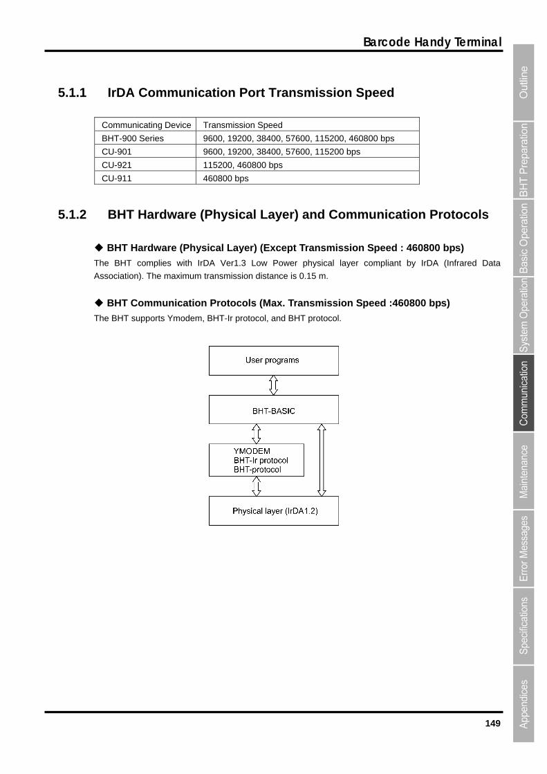
149
Barcode Handy Terminal
5.1.1 IrDA Communication Port Transmission Speed
Communicating Device Transmission Speed
BHT-900 Series 9600, 19200, 38400, 57600, 115200, 460800 bps
CU-901 9600, 19200, 38400, 57600, 115200 bps
CU-921 115200, 460800 bps
CU-911 460800 bps
5.1.2 BHT Hardware (Physical Layer) and Communication Protocols
BHT Hardware (Physical Layer) (Except Transmission Speed : 460800 bps)
The BHT complies with IrDA Ver1.3 Low Power physical layer compliant by IrDA (Infrared Data
Association). The maximum transmission distance is 0.15 m.
BHT Communication Protocols (Max. Transmission Speed :460800 bps)
The BHT supports Ymodem, BHT-Ir protocol, and BHT protocol.
150
BHT-904B/BHT-914B
5.2 USB Communication The BHT can communicate with the host computer via the USB communication port.
The Connection method “COM” and “MTP” are available for the BHT USB communication.
“COM” is for the serial communication, and “MTP” is for the file transfer to the host computer without the device driver.
5.2.1 USB communication by COM
1. Install the Active USB-COM port driver in the host computer.
* The Active USB-COM port driver can be downloaded from the QBdirect service
(http://www.qbdirect.net/).
* Even though our USB device (e.g., CU, scanner) has been used, the Active USB-COM port driver has
been installed, and the USB port has been allocated as a COM port, the USB port is not recognized as a
COM port even by connecting the BHT-900 to the port.
To use the BHT-900 for COM connection, carry out the following steps in the order:
(1) Remove all of our USB devices from the host computer.
(2) Execute the Setup file of the Active USB-COM port driver.
(3) Connect the BHT-900 to an arbitrary USB port.
(4) Install the USB driver.
The COM port is now allocated to the USB port.
For the procedures for installing the Active USB-COM port driver, refer to the driver’s installation guide.
2. Set the BHT USB connection mode to COM. For details, refer to “4.5.10 USB Communication settings.
3. Set the BHT USB communication protocol options. For details, refer to “4.5.6.[5] Setting the communication environment”.
4. Connect the host computer to the BHT using a USB cable.
* Use a USB2.0 compatible mini-B cable, sold separately.
5. The device is detected and the installation of the Active USB-COM port driver is now complete.
Point Check the COM number using the device manager, etc. Even though our products have beenused and the BHT is connected to the same port, the COM port number may be different.
It may happen that communication is impossible, depending on the destination or cable.
Connect the BHT to the USB port on the main body of the host computer.
If a connection is made via the hub, proper communication may not occur.
Do not unplug and plug in the USB cable repeatedly in a short period of time. Doing so may result in the host computer being locked.
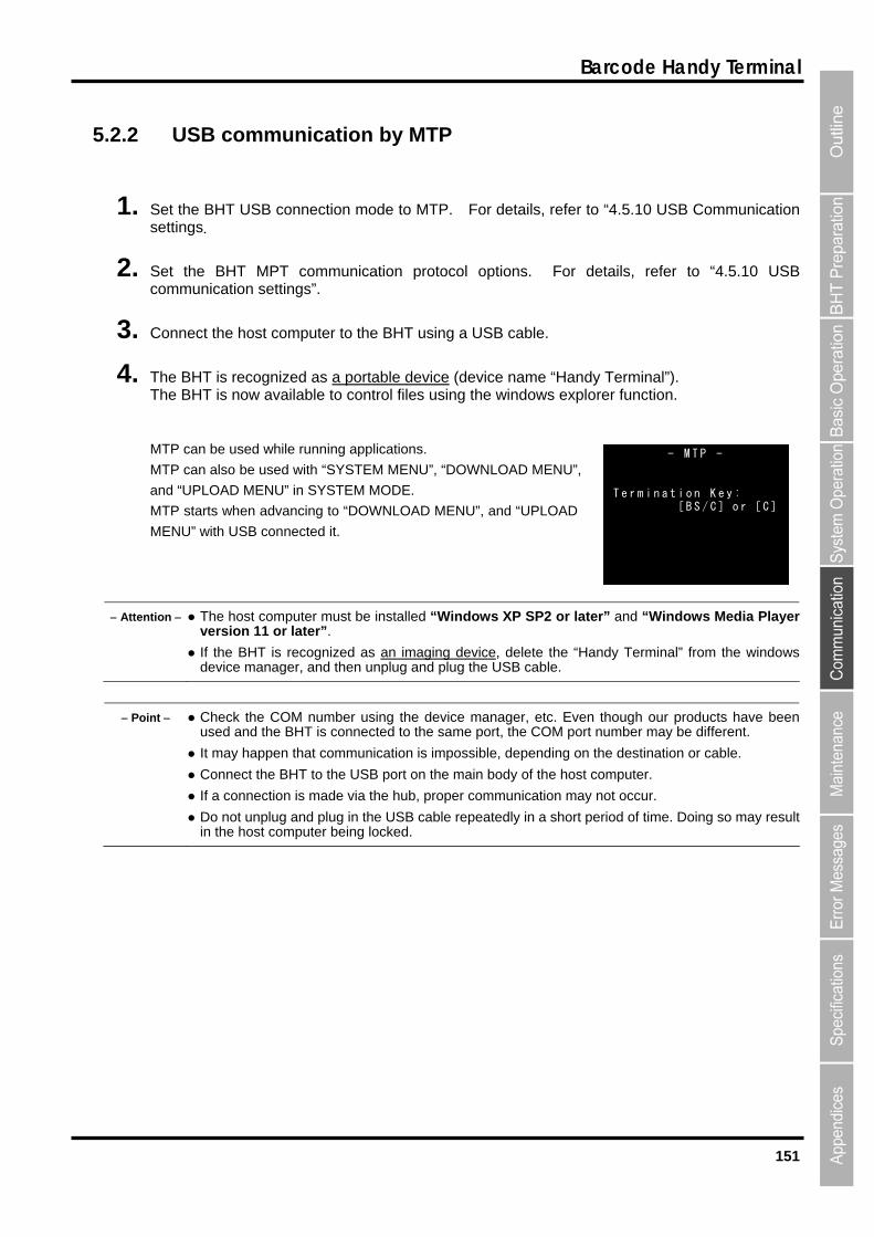
151
Barcode Handy Terminal
5.2.2 USB communication by MTP
1. Set the BHT USB connection mode to MTP. For details, refer to “4.5.10 USB Communication settings.
2. Set the BHT MPT communication protocol options. For details, refer to “4.5.10 USB communication settings”.
3. Connect the host computer to the BHT using a USB cable.
4. The BHT is recognized as a portable device (device name “Handy Terminal”). The BHT is now available to control files using the windows explorer function.
MTP can be used while running applications.
MTP can also be used with “SYSTEM MENU”, “DOWNLOAD MENU”,
and “UPLOAD MENU” in SYSTEM MODE.
MTP starts when advancing to “DOWNLOAD MENU”, and “UPLOAD
MENU” with USB connected it.
- M T P - T e r m i n a t i o n K e y :
[ B S / C ] o r [ C ]
Attention The host computer must be installed “Windows XP SP2 or later” and “Windows Media Player version 11 or later”.
If the BHT is recognized as an imaging device, delete the “Handy Terminal” from the windowsdevice manager, and then unplug and plug the USB cable.
Point Check the COM number using the device manager, etc. Even though our products have been used and the BHT is connected to the same port, the COM port number may be different.
It may happen that communication is impossible, depending on the destination or cable.
Connect the BHT to the USB port on the main body of the host computer.
If a connection is made via the hub, proper communication may not occur.
Do not unplug and plug in the USB cable repeatedly in a short period of time. Doing so may resultin the host computer being locked.
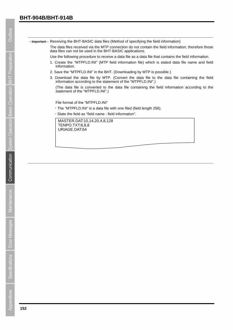
152
BHT-904B/BHT-914B
Important Receiving the BHT-BASIC data files (Method of specifying the field information)
The data files received via the MTP connection do not contain the field information; therefore those data files can not be used in the BHT-BASIC applications.
Use the following procedure to receive a data file as a data file that contains the field information.
1. Create the “MTPFLD.INI” (MTP field information file) which is stated data file name and fieldinformation.
2. Save the “MTPFLD.INI” in the BHT. (Downloading by MTP is possible.)
3. Download the data file by MTP. (Convert the data file to the data file containing the field information according to the statement of the “MTPFLD.INI”.)
(The data file is converted to the data file containing the field information according to the statement of the “MTPFLD.INI”.)
File format of the “MTPFLD.INI”
・The “MTPFLD.INI” is a data file with one filed (field length 256).
・State the field as “field name : field information”.
MASTER.DAT:10,14,20,4,8,128TENPO.TXT:8,8,8 URIAGE.DAT:64
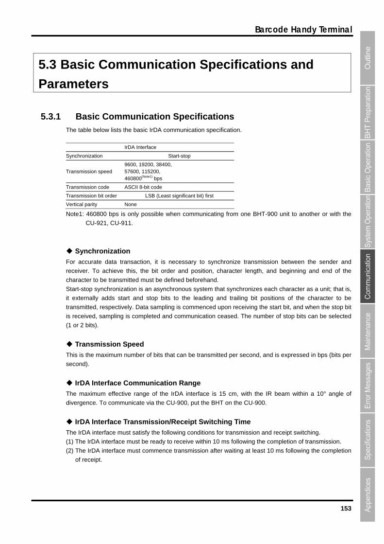
153
Barcode Handy Terminal
5.3 Basic Communication Specifications and
Parameters
5.3.1 Basic Communication Specifications The table below lists the basic IrDA communication specification.
IrDA Interface
Synchronization Start-stop
Transmission speed 9600, 19200, 38400, 57600, 115200, 460800(Note1) bps
Transmission code ASCII 8-bit code
Transmission bit order LSB (Least significant bit) first
Vertical parity None
Note1: 460800 bps is only possible when communicating from one BHT-900 unit to another or with the
CU-921, CU-911.
Synchronization
For accurate data transaction, it is necessary to synchronize transmission between the sender and
receiver. To achieve this, the bit order and position, character length, and beginning and end of the
character to be transmitted must be defined beforehand.
Start-stop synchronization is an asynchronous system that synchronizes each character as a unit; that is,
it externally adds start and stop bits to the leading and trailing bit positions of the character to be
transmitted, respectively. Data sampling is commenced upon receiving the start bit, and when the stop bit
is received, sampling is completed and communication ceased. The number of stop bits can be selected
(1 or 2 bits).
Transmission Speed
This is the maximum number of bits that can be transmitted per second, and is expressed in bps (bits per
second).
IrDA Interface Communication Range
The maximum effective range of the IrDA interface is 15 cm, with the IR beam within a 10° angle of
divergence. To communicate via the CU-900, put the BHT on the CU-900.
IrDA Interface Transmission/Receipt Switching Time
The IrDA interface must satisfy the following conditions for transmission and receipt switching.
(1) The IrDA interface must be ready to receive within 10 ms following the completion of transmission.
(2) The IrDA interface must commence transmission after waiting at least 10 ms following the completion
of receipt.
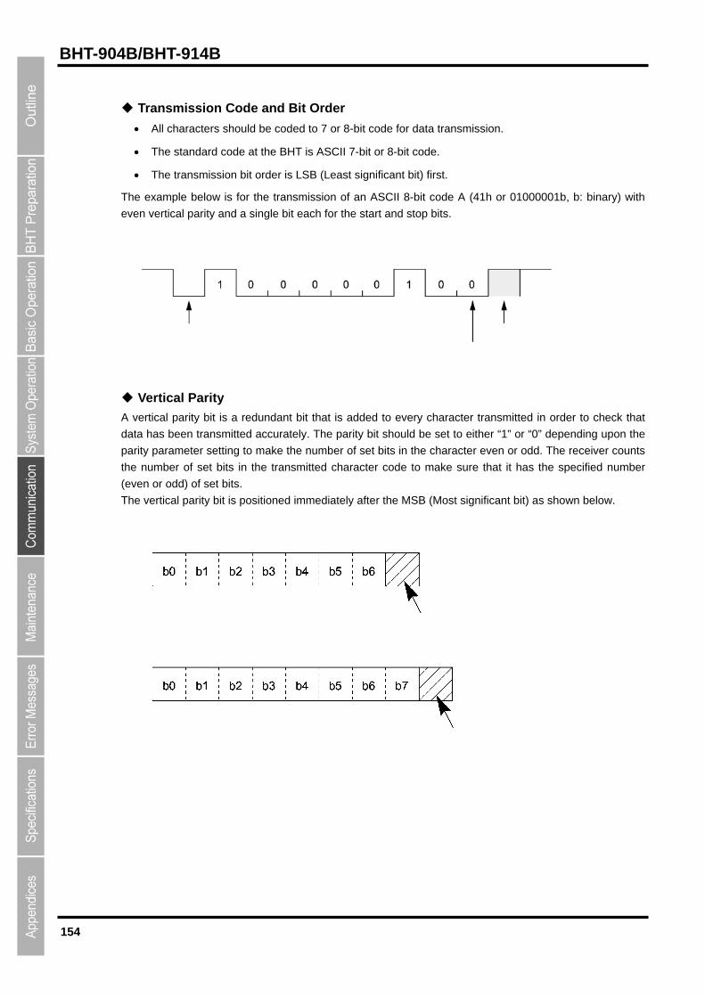
154
BHT-904B/BHT-914B
Transmission Code and Bit Order
All characters should be coded to 7 or 8-bit code for data transmission.
The standard code at the BHT is ASCII 7-bit or 8-bit code.
The transmission bit order is LSB (Least significant bit) first.
The example below is for the transmission of an ASCII 8-bit code A (41h or 01000001b, b: binary) with
even vertical parity and a single bit each for the start and stop bits.
Vertical Parity
A vertical parity bit is a redundant bit that is added to every character transmitted in order to check that
data has been transmitted accurately. The parity bit should be set to either “1” or “0” depending upon the
parity parameter setting to make the number of set bits in the character even or odd. The receiver counts
the number of set bits in the transmitted character code to make sure that it has the specified number
(even or odd) of set bits.
The vertical parity bit is positioned immediately after the MSB (Most significant bit) as shown below.
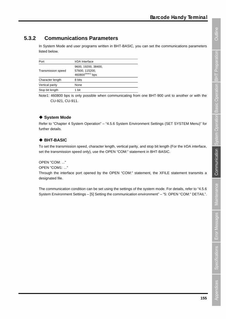
155
Barcode Handy Terminal
5.3.2 Communications Parameters In System Mode and user programs written in BHT-BASIC, you can set the communications parameters
listed below.
Port IrDA Interface
Transmission speed 9600, 19200, 38400, 57600, 115200, 460800(Note1) bps
Character length 8 bits
Vertical parity None
Stop bit length 1 bit
Note1: 460800 bps is only possible when communicating from one BHT-900 unit to another or with the
CU-921, CU-911.
System Mode
Refer to “Chapter 4 System Operation” – “4.5.6 System Environment Settings (SET SYSTEM Menu)” for
further details.
BHT-BASIC
To set the transmission speed, character length, vertical parity, and stop bit length (For the IrDA interface,
set the transmission speed only), use the OPEN “COM:” statement in BHT-BASIC.
OPEN "COM: ..."
OPEN "COM1: ..."
Through the interface port opened by the OPEN “COM:” statement, the XFILE statement transmits a
designated file.
The communication condition can be set using the settings of the system mode. For details, refer to “4.5.6
System Environment Settings – [5] Setting the communication environment” – “5: OPEN “COM:” DETAIL”.
156
BHT-904B/BHT-914B
BHT-904B/BHT-914B
Chapter 6
Maintenance
This chapter describes battery replacement and daily procedures for taking care of
the BHT.
6.1 Replacing the Battery・・・・・・・・・・・・・・・・・・・・・・・・・・・・・・・・・・・・・・・・・・・ 158
6.1.1 Replacing the Battery・・・・・・・・・・・・・・・・・・・・・・・・・・・・・・・・・・・・・・・・・・・・ 158 6.1.2 Charging rechargeable batteries ・・・・・・・・・・・・・・・・・・・・・・・・・・・・・・・・・・ 160 6.1.3 Rechargeable Battery Service Life ・・・・・・・・・・・・・・・・・・・・・・・・・・・・・・・・ 161
6.2 Daily Maintenance ・・・・・・・・・・・・・・・・・・・・・・・・・・・・・・・・・・・・・・・・・・・・・ 162 6.2.1 Proper Care of the BHT・・・・・・・・・・・・・・・・・・・・・・・・・・・・・・・・・・・・・・・・・・ 162 6.2.2 Proper Care of the CU/CH ・・・・・・・・・・・・・・・・・・・・・・・・・・・・・・・・・・・・・・・ 162 6.2.3 Using the BHT after Long Periods・・・・・・・・・・・・・・・・・・・・・・・・・・・・・・・・・ 162
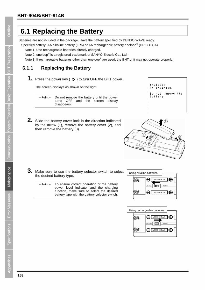
158
BHT-904B/BHT-914B
6.1 Replacing the Battery Batteries are not included in the package. Have the battery specified by DENSO WAVE ready.
Specified battery: AA alkaline battery (LR6) or AA rechargeable battery eneloop® (HR-3UTGA)
Note 1: Use rechargeable batteries already charged.
Note 2: eneloop® is a registered trademark of SANYO Electric Co., Ltd.
Note 3: If rechargeable batteries other than eneloop® are used, the BHT unit may not operate properly.
6.1.1 Replacing the Battery
1. Press the power key ( ) to turn OFF the BHT power.
The screen displays as shown on the right.
Point Do not remove the battery until the powerturns OFF and the screen displaydisappears.
2. Slide the battery cover lock in the direction indicated by the arrow (1), remove the battery cover (2), and then remove the battery (3).
3. Make sure to use the battery selector switch to select the desired battery type.
Alkaline Ni-MH
LR6/Ni-MH,AA
LR6/Ni-MH,AA
Using alkaline batteries
Point To ensure correct operation of the batterypower level indicator and the chargingfunction, make sure to select the desiredbattery type with the battery selector switch.
LR6/Ni-MH,AA
LR6/Ni-MH,AA
Alkaline Ni-MH
Using rechargeable batteries
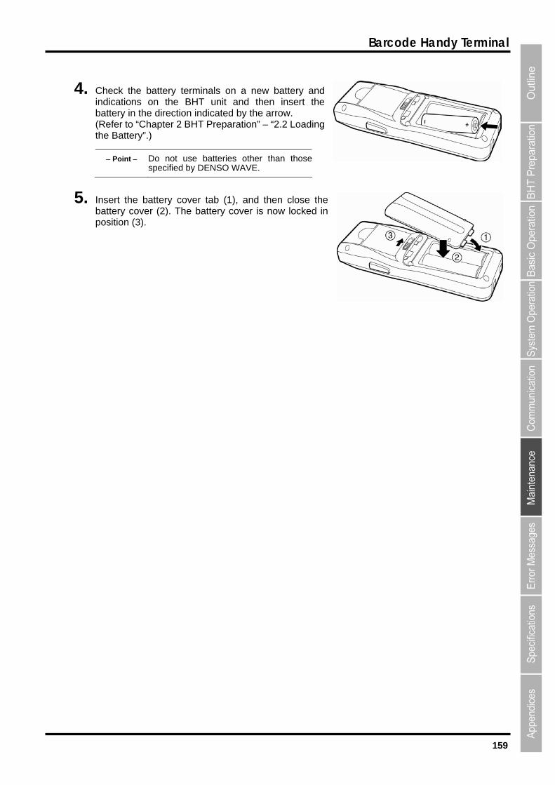
159
Barcode Handy Terminal
4. Check the battery terminals on a new battery and indications on the BHT unit and then insert the battery in the direction indicated by the arrow. (Refer to “Chapter 2 BHT Preparation” – “2.2 Loading the Battery”.)
Point Do not use batteries other than thosespecified by DENSO WAVE.
5. Insert the battery cover tab (1), and then close the battery cover (2). The battery cover is now locked in position (3).
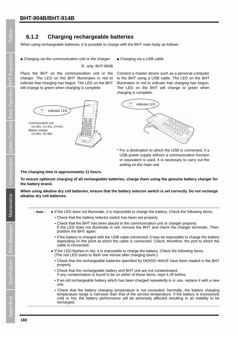
160
BHT-904B/BHT-914B
6.1.2 Charging rechargeable batteries When using rechargeable batteries, it is possible to charge with the BHT main body as follows.
■ Charging via the communication unit or the charger
※ only BHT-904B
■ Charging via a USB cable
Place the BHT on the communication unit or the charger. The LED on the BHT illuminates in red to indicate that charging has begun. The LED on the BHT will change to green when charging is complete.
Connect a master device such as a personal computer to the BHT using a USB cable. The LED on the BHT illuminates in red to indicate that charging has begun. The LED on the BHT will change to green when charging is complete.
* For a destination to which the USB is connected, if a USB power supply without a communication function or equivalent is used, it is necessary to carry out the setting on the main unit.
indicator LED
indicator LED
Communication unit CU-901, CU-911, CH-921 Battery charger CH-951, CH-954
The charging time is approximately 11 hours.
To ensure optimum charging of all rechargeable batteries, charge them using the genuine battery charger for the battery brand.
When using alkaline dry cell batteries, ensure that the battery selector switch is set correctly. Do not recharge alkaline dry cell batteries.
Note If the LED does not illuminate, it is impossible to charge the battery. Check the following items.
• Check that the battery selector switch has been set properly.
• Check that the BHT has been placed in the communication unit or charger properly. If the LED does not illuminate in red, remove the BHT and check the charger terminals. Then,position the BHT again.
• If the battery is charged with the USB cable connected, it may be impossible to charge the batterydepending on the point at which the cable is connected. Check, therefore, the port to which thecable is connected.
If the LED flashes in red, it is impossible to charge the battery. Check the following items. (The red LED starts to flash one minute after charging starts.)
• Check that the rechargeable batteries specified by DENSO WAVE have been loaded in the BHTproperly.
• Check that the rechargeable battery and BHT unit are not contaminated. If any contamination is found to be on either of these items, wipe it off before.
• If an old rechargeable battery which has been charged repeatedly is in use, replace it with a newone.
• Check that the battery charging temperature is not exceeded. Normally, the battery chargingtemperature range is narrower than that of the service temperature. If the battery is excessively cold or hot, the battery performance will be adversely affected resulting in an inability to berecharged.
161
Barcode Handy Terminal
Note If the LED flashes in green, it is impossible to charge the battery. When the LED flashes in green, stop charging and turn OFF the power and then charge the batteries again. If the LED does not stop flashing in green even after going through above measure, there is a possibility that the equipment is broken. Contact your system administrator.
6.1.3 Rechargeable Battery Service Life Rechargeable batteries are consumable products. The longevity of the battery varies depending on the use condition of the individual battery. The performance of the rechargeable battery will deteriorate gradually with repeated charging and discharging, even during normal use. When the battery operation time becomes shorter even after charging for the specified length of time, replace the battery with a new one.
Never disassemble batteries.
Contact your nearest rechargeable battery recycling centre or local sales office for information on disposal
procedures.
Used batteries must not be disposed of as combustibles.
Rechargeable batteries use sparse resources which can be recycled. We kindly ask for your cooperation in
recycling to ensure reuse of these resources.
Rechargeable battery recycling request
Note Replace the battery promptly.
Always turn the BHT power OFF before replacing the rechargeable battery. Replace therechargeable battery with a new one within three minutes to avoid data loss. Then, turn the BHTpower ON and check the operation.
Mishandling may result in rechargeable battery overheating, smoke generation, blowout, or combustion. Please read the following items prior to use.
Never charge the battery in the vicinity of fire or under a scorching sun.
Always use a dedicated charger to charge the battery.
Mishandling may result in rechargeable battery overheating, smoke generation, blowout, orcombustion. Please read the following items prior to use.
Terminate charging if not completed even after the specified time has elapsed.
162
BHT-904B/BHT-914B
6.2 Daily Maintenance
6.2.1 Proper Care of the BHT Wipe any dirt from the BHT housing, charge terminals, and BHT or battery cartridge terminals with a dry,
soft cloth. Make sure to turn OFF the BHT before cleaning.
Note Never use substances such as benzene or alcohol, as this may cause the housing to be marredor paint to peel off.
Never rub or strike the LCD screen with anything hard, as this may result in scratches on thescreen or breakage.
When cleaning the keypad, do not scrub the surface too hard or pull on the keys, as this maybreak the keys.
If excessively dirty, wipe with a soft cloth that has been soaked in soapy water (always useneutral detergent) and wrung out thoroughly.
Any dirt or dust adhering to the red clear plate of the barcode reading window will adversely affect reading
performance.
When using in dusty areas, perform periodic inspections to check whether any dust has accumulated on
the clear plate of the barcode reading window, and if so, clean the plate as described below.
First blow the dust away with an airbrush, and then gently wipe the plate with a cotton swab or similar
soft object.
If sand or hard particles have accumulated, rubbing the plate will result in scratches. Blow the particles
away with an airbrush or wipe with a soft brush.
6.2.2 Proper Care of the CU/CH Wipe any dirt from the housing or charge terminals with a dry, soft cloth.
In the interests of safety, unplug the AC adapter from the socket when cleaning the CU or CH.
6.2.3 Using the BHT after Long Periods When not using the BHT for an extended period of time, remove the batteries from the BHT main body
and store them in a cool, dry place, avoiding high-temperature and high-humidity environment.
If the BHT is left unused for an extended period, the BHT calendar clock may stop. Reset the clock.
BHT-904B/BHT-914B
Chapter 7
Error Messages
This chapter describes causes and countermeasures for error messages that
display during BHT use.
About error messages during executing application program, refer to “Appendix A
Error Codes and Error Messages of Programmer’s manual”.
7.1 System Errors ・・・・・・・・・・・・・・・・・・・・・・・・・・・・・・・・・・・・・・・・・・・・・・・・・ 164 7.2 System Mode Errors ・・・・・・・・・・・・・・・・・・・・・・・・・・・・・・・・・・・・・・・・・・・ 167
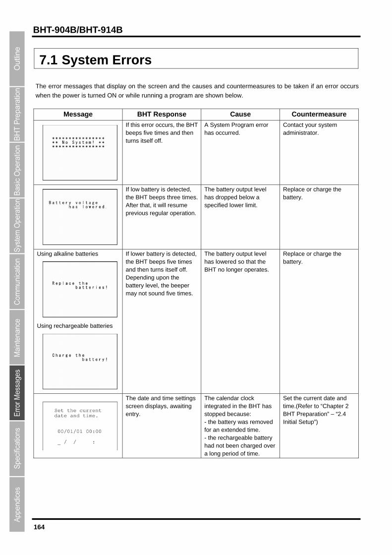
164
BHT-904B/BHT-914B
7.1 System Errors
The error messages that display on the screen and the causes and countermeasures to be taken if an error occurs
when the power is turned ON or while running a program are shown below.
Message BHT Response Cause Countermeasure
If this error occurs, the BHT beeps five times and then turns itself off.
A System Program error has occurred.
Contact your system administrator.
If low battery is detected, the BHT beeps three times. After that, it will resume previous regular operation.
The battery output level has dropped below a specified lower limit.
Replace or charge the battery.
Using alkaline batteries
Using rechargeable batteries
If lower battery is detected, the BHT beeps five times and then turns itself off. Depending upon the battery level, the beeper may not sound five times.
The battery output level has lowered so that the BHT no longer operates.
Replace or charge the battery.
The date and time settings screen displays, awaiting entry.
The calendar clock integrated in the BHT has stopped because: - the battery was removed for an extended time. - the rechargeable battery had not been charged over a long period of time.
Set the current date and time.(Refer to “Chapter 2 BHT Preparation” – “2.4 Initial Setup”)

165
Barcode Handy Terminal
Message BHT Response Cause Countermeasure
The BHT displays this error message and automatically runs the execution program from the point of start-up.
Operation was terminated without turning OFF the power normally and therefore the application resume information has been lost. The application is relaunched.
If this error occurs frequently, contact your system administrator.
The message continues to display.
After shut down abnormally, so unsaved data was lost.
Contact your system administrator.
If this error occurs, the BHT beeps five times.
During execution of System Program, the System Program has attempted to write onto the write-protected area of the memory. (xxxxxxxx: Error address)
Unload and reload the battery and then turn the BHT ON. If this error occurs frequently, make a note of the displayed message and codes and contact your system administrator.
If this error occurs, the BHT beeps five times.
During execution of System Program, the System Program has received an invalid command code. (xxxxxxxx: Error address)
Unload and reload the battery and then turn the BHT ON. If this error occurs frequently, make a note of the displayed message and codes and contact your system administrator.
The message continues to display.
System Program error has occurred. The application restarts from the beginning.
If this error occurs frequently, contact your system administrator.
The message continues to display.
System Program error which is caused by the application has occurred. The application restarts from the beginning.
Check the application.
P r o g r a m r e s t a r t s a u t o m a t i c a l l y . P r e s s t h e [ E N T ] k e y
( A p p l i c a t i o n E r r o r )
P r o g r a m r e s t a r t s a u t o m a t i c a l l y . P r e s s t h e [ E N T ] k e y
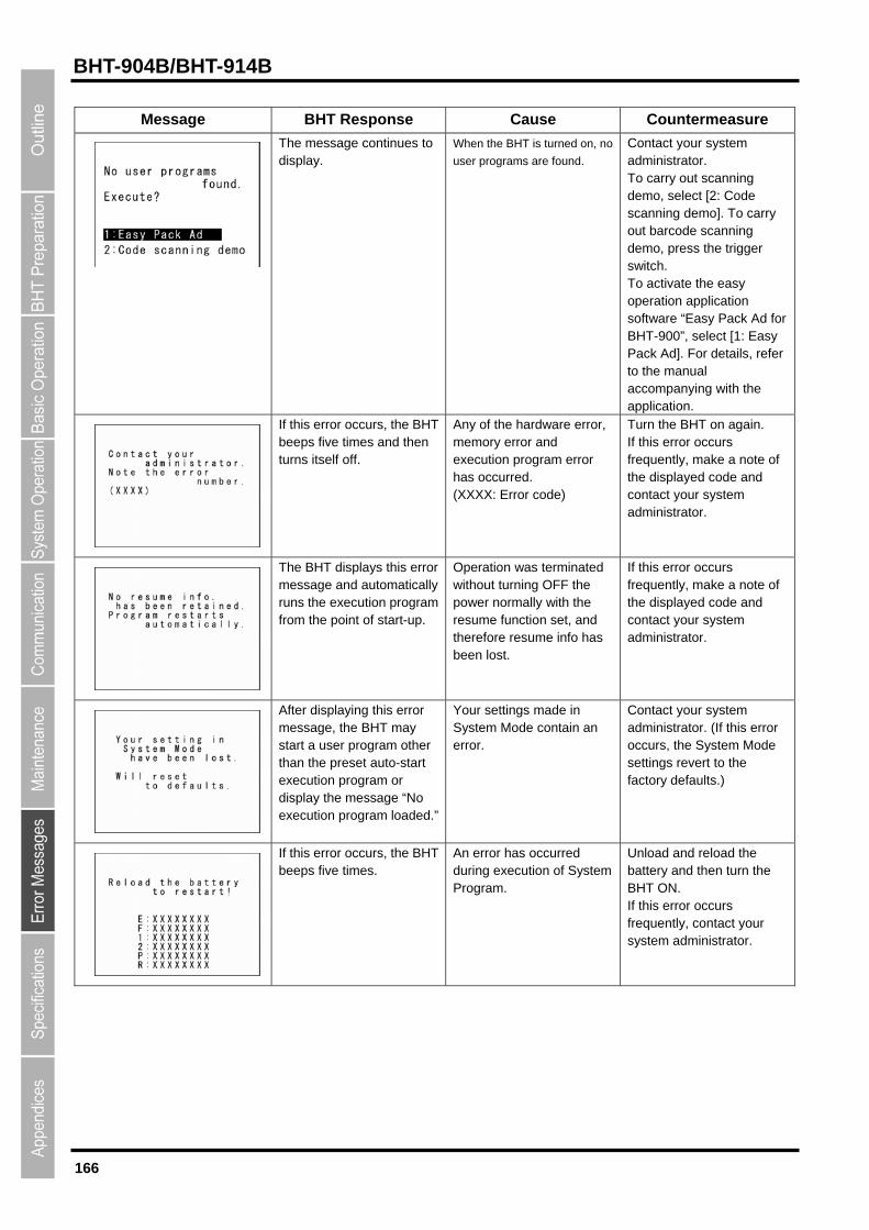
166
BHT-904B/BHT-914B
Message BHT Response Cause Countermeasure
The message continues to display.
When the BHT is turned on, no
user programs are found. Contact your system administrator. To carry out scanning demo, select [2: Code scanning demo]. To carry out barcode scanning demo, press the trigger switch. To activate the easy operation application software “Easy Pack Ad for BHT-900”, select [1: Easy Pack Ad]. For details, refer to the manual accompanying with the application.
If this error occurs, the BHT beeps five times and then turns itself off.
Any of the hardware error, memory error and execution program error has occurred. (XXXX: Error code)
Turn the BHT on again. If this error occurs frequently, make a note of the displayed code and contact your system administrator.
The BHT displays this error message and automatically runs the execution program from the point of start-up.
Operation was terminated without turning OFF the power normally with the resume function set, and therefore resume info has been lost.
If this error occurs frequently, make a note of the displayed code and contact your system administrator.
After displaying this error message, the BHT may start a user program other than the preset auto-start execution program or display the message “No execution program loaded.”
Your settings made in System Mode contain an error.
Contact your system administrator. (If this error occurs, the System Mode settings revert to the factory defaults.)
If this error occurs, the BHT beeps five times.
An error has occurred during execution of System Program.
Unload and reload the battery and then turn the BHT ON. If this error occurs frequently, contact your system administrator.

167
Barcode Handy Terminal
7.2 System Mode Errors
When error messages display while running System Mode, refer to the following table and take appropriate
measures.
Message Cause Countermeasure
You attempted to execute a user program in the EXECUTE PROGRAM menu, but no user program files had been stored in the memory.
Press the Backspace/clear key to return to the SYSTEM MENU, then download user programs.
The memory is insufficient for storing files to be downloaded.
Press the [2] key to return to the SYSTEM MENU, then delete unnecessary files in the memory or decrease the size of the file to be downloaded.
In the SYSTEM PARAMETER transfer menu, you attempted to download a file other than the BHT system parameter file. Or in the SYSTEM MESSAGE transfer menu, you attempted to download a file other than the system message file.
Check the file you attempted to download and then download the file in the appropriate menu (DOWNLOAD menu, SYSTEM PARAMETER transfer menu, or SYSTEM MESSAGE transfer menu).
The current download will exceed the maximum allowable number of files (420 files) in the memory.
Press the [2] key to return to the SYSTEM MENU, then delete unnecessary files in the memory (or decrease the number of files to be downloaded if you attempted to download more than one file in the DOWNLOAD menu.)
• Downloading has failed. • Uploading has failed.
• To retry downloading/uploading, press the [1] key.
• To return to the SYSTEM MENU, press the [2] key. Check the interface port, communications parameters, and communications protocol in the SET SYSTEM menu or perform the communications test in the TEST menu.
You attempted to download an invalid program file.
Check whether the program file you attempted to download is available to the BHT-900 model. If it is not available, download the appropriate program.
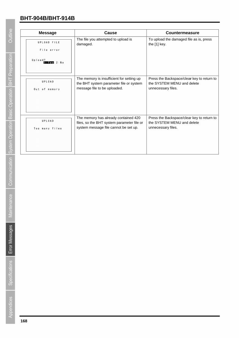
168
BHT-904B/BHT-914B
Message Cause Countermeasure
The file you attempted to upload is damaged.
To upload the damaged file as is, press the [1] key.
The memory is insufficient for setting up the BHT system parameter file or system message file to be uploaded.
Press the Backspace/clear key to return to the SYSTEM MENU and delete unnecessary files.
The memory has already contained 420 files, so the BHT system parameter file or system message file cannot be set up.
Press the Backspace/clear key to return to the SYSTEM MENU and delete unnecessary files.
BHT-904B/BHT-914B
Chapter 8
Specifications
This chapter describes the BHT-904B/BHT-914B specifications.
8.1 BHT-904B/BHT-914B Specification・・・・・・・・・・・・・・・・・・・・・・・・・・・・・・ 170
8.1.1 Hardware Specifications ・・・・・・・・・・・・・・・・・・・・・・・・・・・・・・・・・・・・・・・・・ 170 8.1.2 Barcode Specifications ・・・・・・・・・・・・・・・・・・・・・・・・・・・・・・・・・・・・・・・・・・ 171 8.1.3 Reading Performance ・・・・・・・・・・・・・・・・・・・・・・・・・・・・・・・・・・・・・・・・・・・ 172 8.1.4 Interface Specifications ・・・・・・・・・・・・・・・・・・・・・・・・・・・・・・・・・・・・・・・・・・ 174

170
BHT-904B
8.1 BHT-904B/BHT-914B Specification
8.1.1 Hardware Specifications
Power supply (main power): AA alkaline battery (LR6) (x 2) or AA rechargeable battery eneloop® (HR-3UTGA) (x 2)
Dimensions (W) x (L) x (H): 51×49×29 mm
Weight: Approx. 121 g (excluding the batteries)
Ambient operating temperature: -5 to 50 C (excluding the batteries)
Ambient operating humidity: 20 to 80% (with no dew condensation)
Ambient operating brightness: 500 to 3000 Lx (Depth of field: 45 mm, PCS value: 0.9 min., Reflection intensity: 85% min. for white and 5%max. for black, Narrow bar width: min. 0.125 mm) 20 to 10000 Lx (Depth of field: 100 mm, PCS value: 0.9 min., Reflection intensity: 85% min. for white and 5% max. for black, ITF: 0.625 magnification)
Controller: CPU: 32-bit RISC Flash memory: 16MB
Keypad: Magic keys: 5(BHT-904B), 3(BHT-914B) Function keys: 8 Numeric keys etc.: 15
Display: Type: Dot-matrix, liquid crystal display (LCD) with white backlight (monochrome)
Formation: 128 dots wide by 96 dots high
Calendar clock: Year, month, day, hour, minute, and second Year: 2 digits Auto leap year correction up until 2099
Indicator LED Colors: Red, green and blue
(Note) Due to the characteristic of the white LED used for the LCD backlight, there may be individual
differences in screen color and brightness.
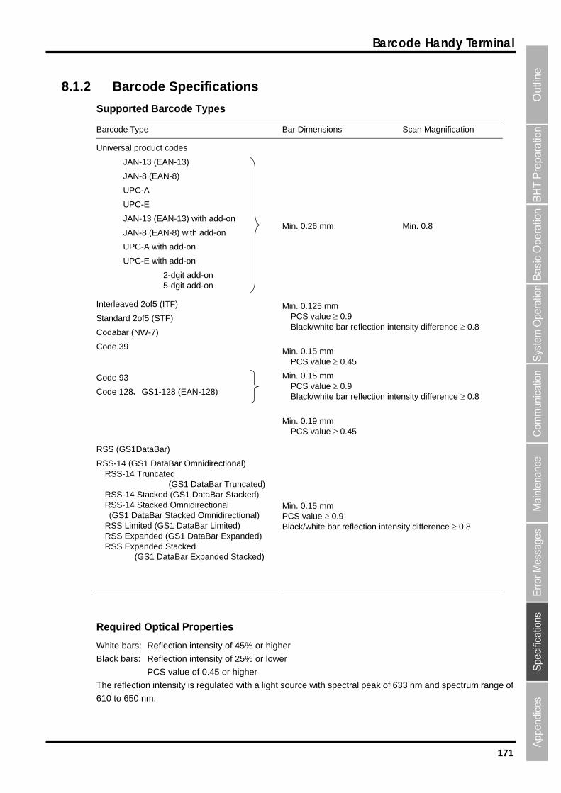
171
Barcode Handy Terminal
8.1.2 Barcode Specifications
Supported Barcode Types
Barcode Type Bar Dimensions Scan Magnification
Universal product codes
JAN-13 (EAN-13)
JAN-8 (EAN-8)
UPC-A
UPC-E
JAN-13 (EAN-13) with add-on
JAN-8 (EAN-8) with add-on
UPC-A with add-on
UPC-E with add-on
2-dgit add-on 5-dgit add-on
Min. 0.26 mm
Min. 0.8
Interleaved 2of5 (ITF)
Standard 2of5 (STF)
Codabar (NW-7)
Code 39
Min. 0.125 mm PCS value 0.9 Black/white bar reflection intensity difference 0.8
Min. 0.15 mm PCS value 0.45
Code 93
Code 128、GS1-128 (EAN-128)
Min. 0.15 mm PCS value 0.9 Black/white bar reflection intensity difference 0.8
Min. 0.19 mm PCS value 0.45
RSS (GS1DataBar)
RSS-14 (GS1 DataBar Omnidirectional) RSS-14 Truncated (GS1 DataBar Truncated) RSS-14 Stacked (GS1 DataBar Stacked) RSS-14 Stacked Omnidirectional (GS1 DataBar Stacked Omnidirectional) RSS Limited (GS1 DataBar Limited) RSS Expanded (GS1 DataBar Expanded) RSS Expanded Stacked (GS1 DataBar Expanded Stacked)
Min. 0.15 mm PCS value 0.9 Black/white bar reflection intensity difference 0.8
Required Optical Properties
White bars: Reflection intensity of 45% or higher
Black bars: Reflection intensity of 25% or lower
PCS value of 0.45 or higher
The reflection intensity is regulated with a light source with spectral peak of 633 nm and spectrum range of
610 to 650 nm.
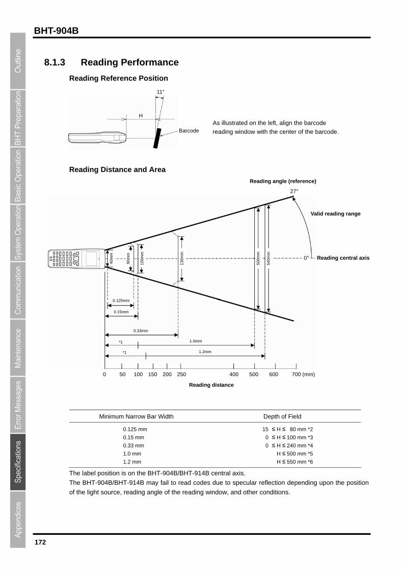
172
BHT-904B
8.1.3 Reading Performance
Reading Reference Position
Minimum Na ar Width Depth of Field
Reading Distance and Area
H
11°
As illustrated on the left, align the barcode
reading window with the center of the barcode.Barcode
0.125mm
Reading angle (reference)
rrow B
0.125 mm
0.15 mm
0.33 mm
1.0 mm
≤ H ≤ 80 mm *2
0 ≤ H ≤ 100 mm *3
0 ≤ H ≤ 240 mm *4
H ≤ 500 mm *5
1.2 mm H ≤ 550 mm *6
15
The label position is on the BHT-904B/BHT-914B central axis.
The BHT-904B/BHT-914B may fail to read codes due to specular reflection depending upon the position
of the light source, reading angle of the reading window, and other conditions.
50
0m
m
54
0m
m
13
0m
m
10
0m
m
40
mm
9
0.15mm
0.33mm
1.0mm
1.2mm
*1
*1
0 50 100 150 200 250 400 500 600 700
0m
m
27°
0° Reading central axis
Valid reading range
(mm)
Reading distance
173
Barcode Handy Terminal
*1 The dotted line ( ndicates that the width o
the barcode label (* the readable widththe BHT-904B/BHT
bar: Wide bar = 1 : 2.5
*3 Under the following conditions:
- Ambient illuminance: 500 Lx. (Xenon arc lamp)
- EAN-13
- Reflection intensity of white bars: 85% min.
Reflection intensity of black bars: 5% max.
- 1.0 magnification, PCS value: 0.9 min.
*4 Under the following conditions:
- Ambient illuminance: 500 Lx. (Xenon arc lamp)
- ITF conforming to the UPC Shipping Container Code
- Reflection intensity of white bars: 85% min.
Reflection intensity of black bars: 5% max.
- 1.0 magnifications, PCS value: 0.9 min.
*5 Under the following conditions:
- Ambient illuminance: 500 Lx. (Xenon arc lamp)
- ITF conforming to the UPC Shipping Container Code
- Reflection intensity of white bars: 85% min.
Reflection intensity of black bars: 5% max.
- 1.0 magnifications, PCS value: 0.9 min.
*6 Under the following conditions:
- Ambient illuminance: 500 Lx. (fluorescent lamp)
- ITF conforming to the UPC Shipping Container Code
- Reflection intensity of white bars: 85% min.
Reflection intensity of black bars: 5% max.
- 1.2 magnifications.
) i5, *6) exceeds -914B.
f of
*2 Under the following conditions: - Ambient illuminance: 500 Lx. (Xenon arc lamp) - Code 39, 4 digits Narrow - Reflection intensity of white bars: 85% min. Reflection intensity of black bars: 5% max. PCS value: 0.9 min.

174
BHT-904B
8.1.4
IrDA Interfa
Specification: IrDA Ver1.3 Low Power phys a
(Except transmission speed:
speed: Between BHT units: 9600 to
15200 bps
460800 bps
bps
Interface Specifications
ce
ic l layer compliant
460800 bps)
Input signals: RD
Output signals: SD
Transmission 460800 bps
CU-901: 9600 to 1
CU-921: 115200,
CU-911: 460800
USB interface
Specification: USB2.0
Device consumption current: 500 mA
BHT-904B/BHT-914B
Chapter 9
Appendices
This chapter describes the principal specifications of the CU-900 and CH-900
Series (option). It also provides information on causes and countermeasures when
file transfer is not possible using the transfer utility.
9.1 CU-900, CH-900 Specifications ・・・・・・・・・・・・・・・・・・・・・・・・・・・・・・・・・・ 176
9.1.1 Hardware Specifications ・・・・・・・・・・・・・・・・・・・・・・・・・・・・・・・・・・・・・・・・・ 176 9.1.2 Charging Requirements・・・・・・・・・・・・・・・・・・・・・・・・・・・・・・・・・・・・・・・・・・ 176 9.1.3 Interface Specifications ・・・・・・・・・・・・・・・・・・・・・・・・・・・・・・・・・・・・・・・・・・ 177
9.2 When File Transfer is Not Possible ・・・・・・・・・・・・・・・・・・・・・・・・・・・・・・・ 179
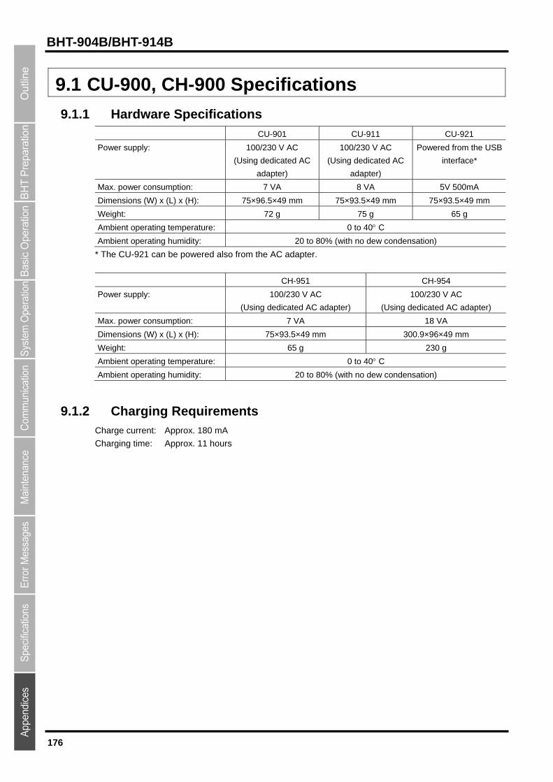
176
BHT-904B/BHT-914B
9.1 CU-900, CH-900 Specifications
9.1.1 Hardware Specifications
CU-901 CU-911 CU-921
Power supply: 100/230 V AC
(Using dedicated AC
adapter)
100/230 V AC
(Using dedicated AC
adapter)
Powered from the USB
interface*
Max. power consumption: 7 VA 8 VA 5V 500mA
Dimensions (W) x (L) x (H): 75×96.5×49 mm 75×93.5×49 mm 75×93.5×49 mm
Weight: 72 g 75 g 65 g
Ambient operating temperature: 0 to 40 C
Ambient operating humidity: 20 to 80% (with no dew condensation)
* The CU-921 can be powered also from the AC adapter.
CH-951 CH-954
Power supply: 100/230 V AC
(Using dedicated AC adapter)
100/230 V AC
(Using dedicated AC adapter)
Max. power consumption: 7 VA 18 VA
Dimensions (W) x (L) x (H): 75×93.5×49 mm 300.9×96×49 mm
Weight: 65 g 230 g
Ambient operating temperature: 0 to 40 C
Ambient operating humidity: 20 to 80% (with no dew condensation)
9.1.2 Charging Requirements Charge current: Approx. 180 mA
Charging time: Approx. 11 hours

177
Barcode Handy Terminal
9.1.3 Interface Specifications
CU-901
The CU-901 RS-232C interface connector uses Dsub-9P.
Signal Direction Pin. No. Signal Name Function
CU-901 ↔ External Device
2
3
4
5
6
7
8
RD
SD
ER
SG
DR
RS
CS
Receipt data
Transmission data
Data terminal ready
Signal ground
Data set ready
Transmission request
Transmission ready
←
→
→
―
―
―
―
TIP The CU-901 internal wiring is shown below.
Host computer, modem, or other devices
Signal Name
2
3 SD
RD
Pin No.
IrDA Interface
RS-232C Interface Circuitry
IrDA Communications Interface Circuitry
BHT-900
4
6
ER
DR
7 RS
8 CS
5 SG
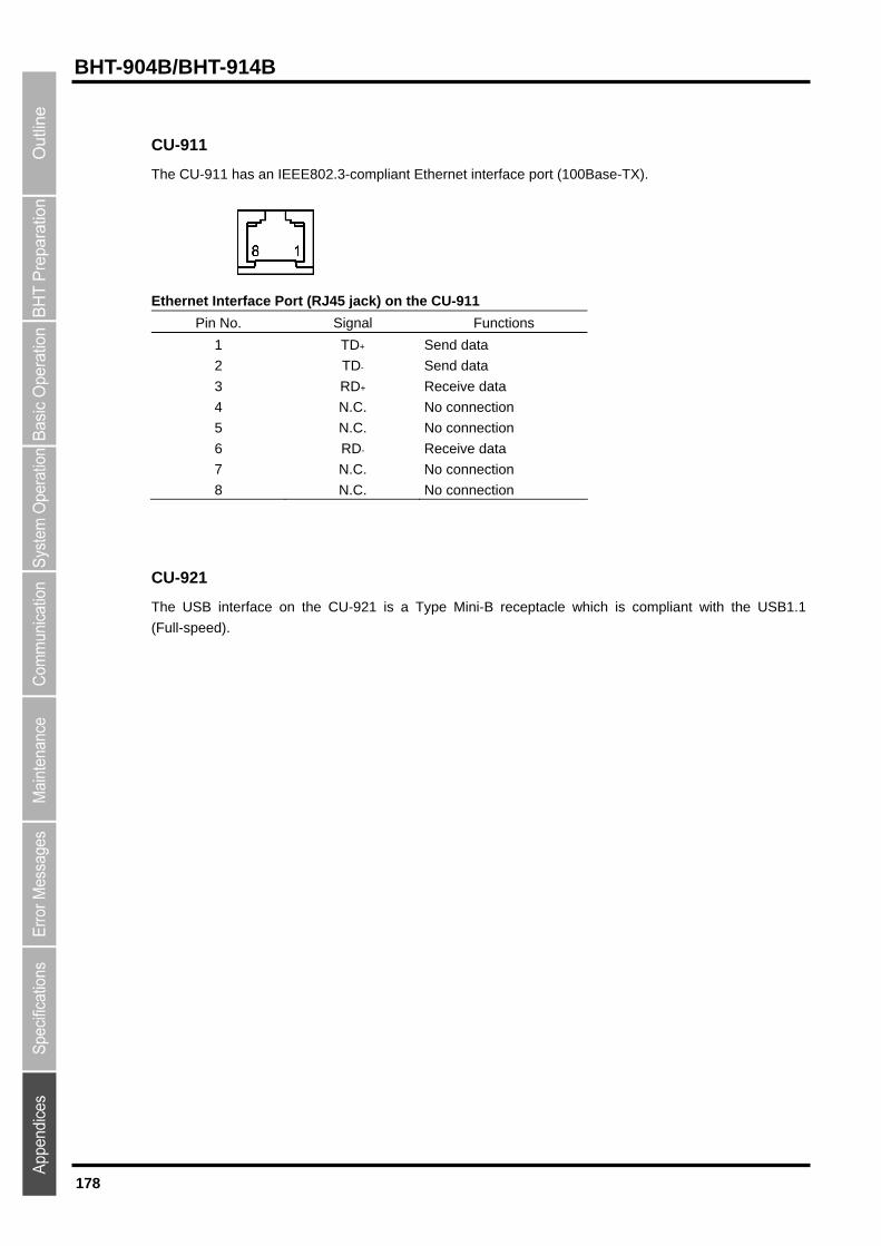
178
BHT-904B/BHT-914B
CU-911
The CU-911 has an IEEE802.3-compliant Ethernet interface port (100Base-TX).
Ethernet Interface Port (RJ45 jack) on the CU-911
Pin No. Signal Functions
1
2
3
4
5
6
7
8
TD+
TD-
RD+
N.C.
N.C.
RD-
N.C.
N.C.
Send data
Send data
Receive data
No connection
No connection
Receive data
No connection
No connection
CU-921
The USB interface on the CU-921 is a Type Mini-B receptacle which is compliant with the USB1.1
(Full-speed).
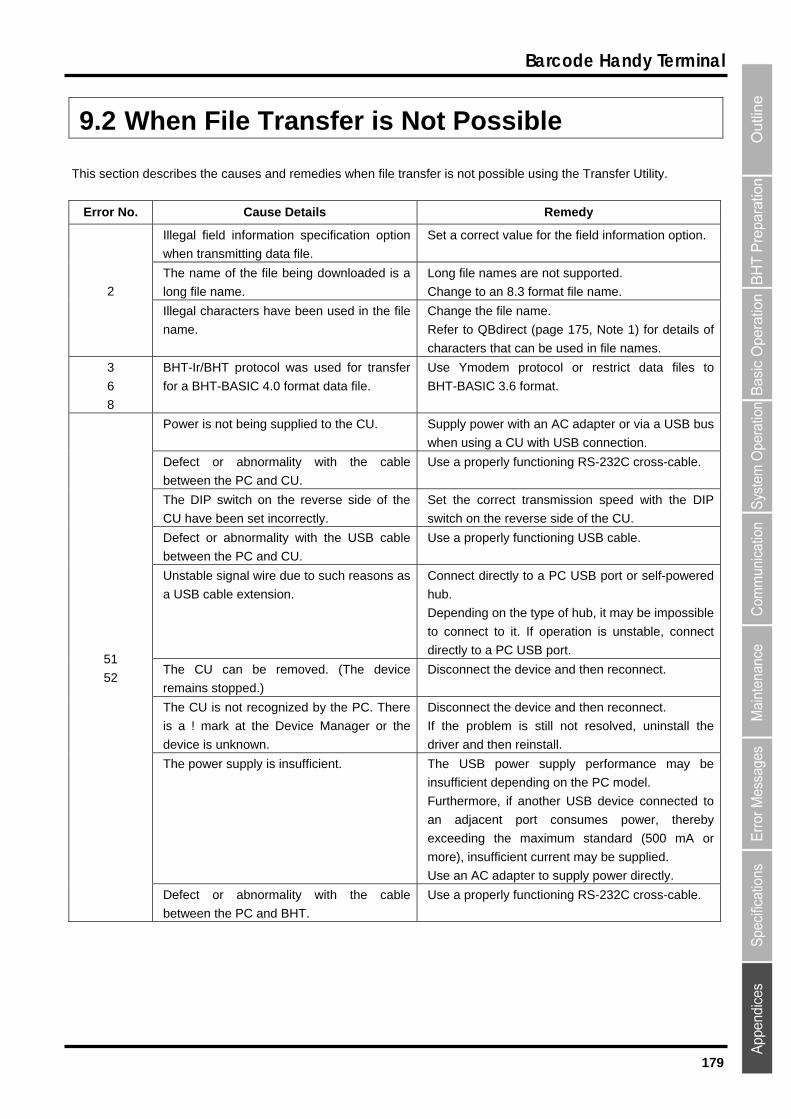
179
Barcode Handy Terminal
9.2 When File Transfer is Not Possible
This section describes the causes and remedies when file transfer is not possible using the Transfer Utility.
Error No. Cause Details Remedy
Illegal field information specification option
when transmitting data file.
Set a correct value for the field information option.
The name of the file being downloaded is a
long file name.
Long file names are not supported.
Change to an 8.3 format file name. 2
Illegal characters have been used in the file
name.
Change the file name.
Refer to QBdirect (page 175, Note 1) for details of
characters that can be used in file names.
3
6
8
BHT-Ir/BHT protocol was used for transfer
for a BHT-BASIC 4.0 format data file.
Use Ymodem protocol or restrict data files to
BHT-BASIC 3.6 format.
Power is not being supplied to the CU. Supply power with an AC adapter or via a USB bus
when using a CU with USB connection.
Defect or abnormality with the cable
between the PC and CU.
Use a properly functioning RS-232C cross-cable.
The DIP switch on the reverse side of the
CU have been set incorrectly.
Set the correct transmission speed with the DIP
switch on the reverse side of the CU.
Defect or abnormality with the USB cable
between the PC and CU.
Use a properly functioning USB cable.
Unstable signal wire due to such reasons as
a USB cable extension.
Connect directly to a PC USB port or self-powered
hub.
Depending on the type of hub, it may be impossible
to connect to it. If operation is unstable, connect
directly to a PC USB port.
The CU can be removed. (The device
remains stopped.)
Disconnect the device and then reconnect.
The CU is not recognized by the PC. There
is a ! mark at the Device Manager or the
device is unknown.
Disconnect the device and then reconnect.
If the problem is still not resolved, uninstall the
driver and then reinstall.
The power supply is insufficient. The USB power supply performance may be
insufficient depending on the PC model.
Furthermore, if another USB device connected to
an adjacent port consumes power, thereby
exceeding the maximum standard (500 mA or
more), insufficient current may be supplied.
Use an AC adapter to supply power directly.
51
52
Defect or abnormality with the cable
between the PC and BHT.
Use a properly functioning RS-232C cross-cable.
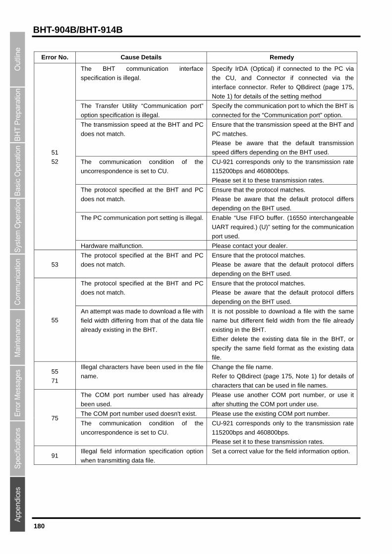
180
BHT-904B/BHT-914B
Error No. Cause Details Remedy
The BHT communication interface
specification is illegal.
Specify IrDA (Optical) if connected to the PC via
the CU, and Connector if connected via the
interface connector. Refer to QBdirect (page 175,
Note 1) for details of the setting method
The Transfer Utility “Communication port”
option specification is illegal.
Specify the communication port to which the BHT is
connected for the “Communication port” option.
The transmission speed at the BHT and PC
does not match.
Ensure that the transmission speed at the BHT and
PC matches.
Please be aware that the default transmission
speed differs depending on the BHT used.
The communication condition of the
uncorrespondence is set to CU.
CU-921 corresponds only to the transmission rate
115200bps and 460800bps.
Please set it to these transmission rates.
The protocol specified at the BHT and PC
does not match.
Ensure that the protocol matches.
Please be aware that the default protocol differs
depending on the BHT used.
The PC communication port setting is illegal. Enable “Use FIFO buffer. (16550 interchangeable
UART required.) (U)” setting for the communication
port used.
51
52
Hardware malfunction. Please contact your dealer.
53
The protocol specified at the BHT and PC
does not match.
Ensure that the protocol matches.
Please be aware that the default protocol differs
depending on the BHT used.
The protocol specified at the BHT and PC
does not match.
Ensure that the protocol matches.
Please be aware that the default protocol differs
depending on the BHT used.
55
An attempt was made to download a file with
field width differing from that of the data file
already existing in the BHT.
It is not possible to download a file with the same
name but different field width from the file already
existing in the BHT.
Either delete the existing data file in the BHT, or
specify the same field format as the existing data
file.
55
71
Illegal characters have been used in the file
name.
Change the file name.
Refer to QBdirect (page 175, Note 1) for details of
characters that can be used in file names.
The COM port number used has already
been used.
Please use another COM port number, or use it
after shutting the COM port under use.
The COM port number used doesn't exist. Please use the existing COM port number. 75
The communication condition of the
uncorrespondence is set to CU.
CU-921 corresponds only to the transmission rate
115200bps and 460800bps.
Please set it to these transmission rates.
91 Illegal field information specification option
when transmitting data file.
Set a correct value for the field information option.
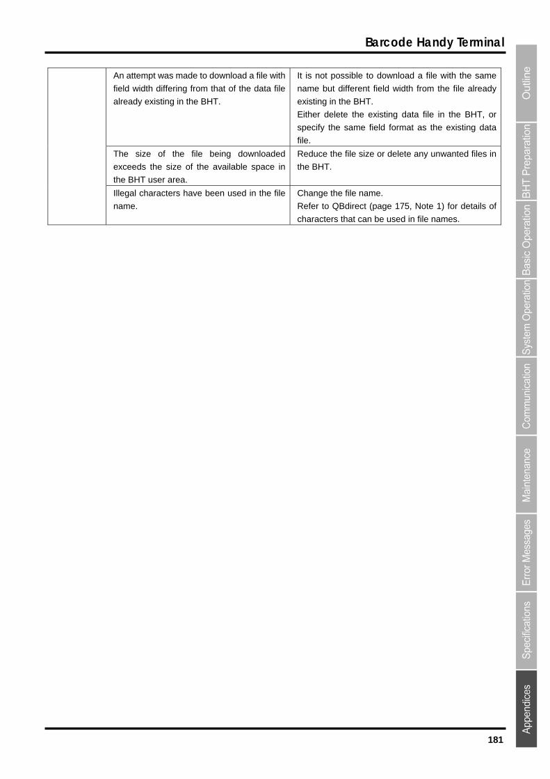
181
Barcode Handy Terminal
An attempt was made to download a file with
field width differing from that of the data file
already existing in the BHT.
It is not possible to download a file with the same
name but different field width from the file already
existing in the BHT.
Either delete the existing data file in the BHT, or
specify the same field format as the existing data
file.
The size of the file being downloaded
exceeds the size of the available space in
the BHT user area.
Reduce the file size or delete any unwanted files in
the BHT.
Illegal characters have been used in the file
name.
Change the file name.
Refer to QBdirect (page 175, Note 1) for details of
characters that can be used in file names.
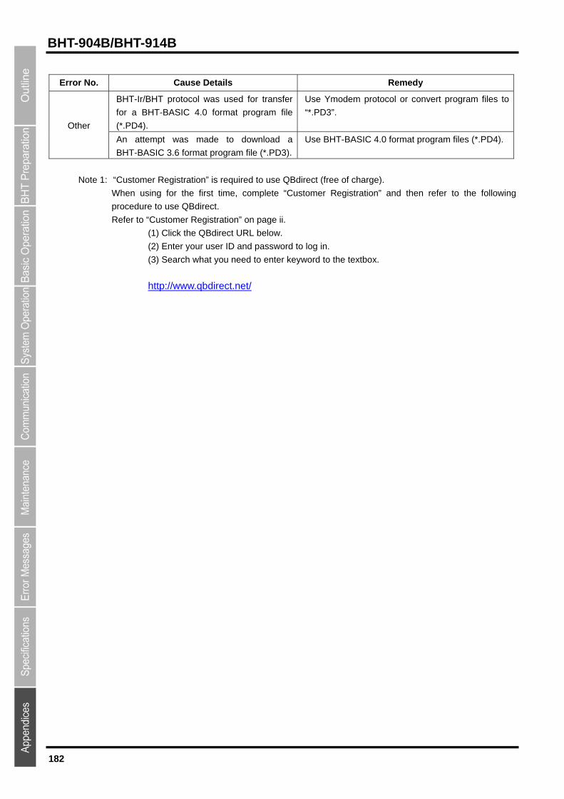
182
BHT-904B/BHT-914B
Error No. Cause Details Remedy
BHT-Ir/BHT protocol was used for transfer
for a BHT-BASIC 4.0 format program file
(*.PD4).
Use Ymodem protocol or convert program files to
“*.PD3”.
Other
An attempt was made to download a
BHT-BASIC 3.6 format program file (*.PD3).
Use BHT-BASIC 4.0 format program files (*.PD4).
Note 1: “Customer Registration” is required to use QBdirect (free of charge).
When using for the first time, complete “Customer Registration” and then refer to the following
procedure to use QBdirect.
Refer to “Customer Registration” on page ii.
(1) Click the QBdirect URL below.
(2) Enter your user ID and password to log in.
(3) Search what you need to enter keyword to the textbox.
http://www.qbdirect.net/

183
Barcode Handy Terminal
Barcode Handy Terminal
BHT-904B/BHT-914B
User’s Manual
First Edition, November 2010
Second Edition, March 2011
The purpose of this manual is to provide accurate information in the handling and operating of
the BHT-904B/BHT-914B. Please feel free to send your comments regarding any errors or
omissions you may have found, or any suggestions you may have for generally improving the
manual.
In no event will DENSO WAVE be liable for any direct or indirect damages resulting from the
application of the information in this manual.


![[BHT Technology] Tu Dien.compressed](https://img.dokumen.tips/doc/110x75/577c77a81a28abe0548cf861/bht-technology-tu-diencompressed.jpg)