Embed Size (px)
Citation preview

Beton Trowel nv
Nijverheidsstraat 11 1840 Londerzeel/Belgium Tel: +32 (0)52 315 350 - Tel: +32 (0)52 315 351 Fax: +32 (0)52 303 739 E-mail: [email protected] BE 0821.249.312 www.betontrowel.com
BNP FORTIS: ING:
BE81 0015 9813 5624 BE
- GEBABEBB BBRUBEBB
Pag. 1/22
OPERATING & PARTS MANUAL
BTSP8H – BTSP8E

Beton Trowel nv
Nijverheidsstraat 11 1840 Londerzeel/Belgium Tel: +32 (0)52 315 350 - Tel: +32 (0)52 315 351 Fax: +32 (0)52 303 739 E-mail: [email protected] BE 0821.249.312 www.betontrowel.com
BNP FORTIS: ING:
BE81 0015 9813 5624 BE
- GEBABEBB BBRUBEBB
Pag. 2/22
SAFETY PRECAUTIONS
DANGER
EXPLOSION HAZARD Never operate the machine in an explosive atmosphere, near combustible materials or where ventilation does not clear exhaust fumes.
WARNING
BURN HAZARD Never come into contact with the engine or muffler when engine is operating or shortly after it is turned off. Serious burns may occur.
CAUTION
MOVING PARTS Before starting the machine ensure that all guards and safety devices are in place and functioning properly
CAUTION
MACHINE DAMAGE Advance cutter depth in small increments to avoid premature blade wear or damage.
ATTENTION
READ OWNERS MANUAL Read and understand operator's manual before using this machine. Failure to follow operating instructions could result in serious injury or death.

Beton Trowel nv
Nijverheidsstraat 11 1840 Londerzeel/Belgium Tel: +32 (0)52 315 350 - Tel: +32 (0)52 315 351 Fax: +32 (0)52 303 739 E-mail: [email protected] BE 0821.249.312 www.betontrowel.com
BNP FORTIS: ING:
BE81 0015 9813 5624 BE
- GEBABEBB BBRUBEBB
Pag. 3/22
TABLE OF CONTENTS QUALITY ASSURANCE/MACHINE BREAK-IN .................................................................... 4 SURFACE PREPARATION SYSTEM WARRANTY.............................................................. 5 MAINTENANCE RECORD ..................................................................................................... 6 ROUTINE SERVICE INTERVALS.......................................................................................... 7 FOREWORD........................................................................................................................... 9 SAFETY PRECAUTIONS....................................................................................................... 9 OPERATING PRINCIPLE....................................................................................................... 9 WORKING WITH THE SPS.................................................................................................... 9 CUTTER LIFE......................................................................................................................... 10 ASSEMBLY INSTRUCTIONS .............................................................................................. 11 1. HANDLE INSTALLATION ................................................................................................. 11 2. EDGER INSTALLATION................................................................................................... 12 3. STOP-SWITCH INSTALLATION....................................................................................... 12 STARTING AND STOPPING PROCEDURE........................................................................ 13 MAINTENANCE.................................................................................................................... 13 BEARING REPLACEMENT PROCEDURES....................................................................... 14 A. SEALED BEARING REPLACEMENT - OUTBOARD SIDE.............................................. 14 B. BEARING REPLACEMENT - DRIVER OR "V" BELT SIDE ............................................. 14 CUTTER CAGE REMOVAL & CUTTER CHANGE.............................................................. 14 EDGER CAGE REMOVAL ................................................................................................... 14 STORAGE............................................................................................................................. 15 LUBRICATION, ENGINE OIL............................................................................................... 15 ASSEMBLY DRAWINGS AND PARTS LIST....................................................................... 16 EC DECLARATION .............................................................................................................. 22

Beton Trowel nv
Nijverheidsstraat 11 1840 Londerzeel/Belgium Tel: +32 (0)52 315 350 - Tel: +32 (0)52 315 351 Fax: +32 (0)52 303 739 E-mail: [email protected] BE 0821.249.312 www.betontrowel.com
BNP FORTIS: ING:
BE81 0015 9813 5624 BE
- GEBABEBB BBRUBEBB
Pag. 4/22
QUALITY ASSURANCE / MACHINE BREAK IN The Beton Trowel nv Surface Preparation System is the product of extensive engineering development designed to give long life and unmatched performance. The SPS’s are shipped completely assembled with the exception of attaching the handle, and only require filling with fuel and a brief check of lubricant levels in preparation for operation. You can help ensure that your Surface Preparation machine will perform at top levels by observing a simple routing on first use. Consider that your new SPS is like a new car. Just as you would break in a new car to the road or any new machine to the job, you should start gradually and build up to full use. Learn what your machine can do and how it will respond. Refer to the engine manufacturer’s manual for run-in times. Full throttle and control may be used after this time period, as allowed by material. This will serve to further break in the machine on your specific application, as well as provide you with additional practice using the machine. We thank you for the confidence you have placed in us by purchasing a Beton Trowel nv Surface Preparation System and wish you many years of satisfied use.

Beton Trowel nv
Nijverheidsstraat 11 1840 Londerzeel/Belgium Tel: +32 (0)52 315 350 - Tel: +32 (0)52 315 351 Fax: +32 (0)52 303 739 E-mail: [email protected] BE 0821.249.312 www.betontrowel.com
BNP FORTIS: ING:
BE81 0015 9813 5624 BE
- GEBABEBB BBRUBEBB
Pag. 5/22
SURFACE PREPARATION SYSTEM WARRANTY Beton Trowel nv agrees to furnish without charge, F.O.B. our plant, a replacement for any part or portion thereof, Beton Trowel nv SPS Machine, save and except, all cutting tools andf holders, drive belts, power units, and/or electrical controls which prove upon our examination, to be defective in either material or workmanship within a period of 90 days from date of purchase, provided that notice of such defective part or portion thereof is given to Beton Trowel nv Ltd. within the said period of 90 days. No further or other guarantee or warranty expressed or implied in connection with the sale of the SPS Machine is given and our sole liability consists in replacing defective parts or portions aforesaid. We shall not be responsible for any special, indirect or consequential damages arising in any manner whatsoever. This guarantee is for the sole benefit of the original purchaser. Our responsibility under this guarantee ends in the case the original purchaser transfers ownership of the SPS Machine, makes any changes or adds any parts or devices not of our manufacture to the SPS Machine.

Beton Trowel nv
Nijverheidsstraat 11 1840 Londerzeel/Belgium Tel: +32 (0)52 315 350 - Tel: +32 (0)52 315 351 Fax: +32 (0)52 303 739 E-mail: [email protected] BE 0821.249.312 www.betontrowel.com
BNP FORTIS: ING:
BE81 0015 9813 5624 BE
- GEBABEBB BBRUBEBB
Pag. 6/22
MAINTENANCE RECORD
PREVENTATIVE MAINTENANCE AND ROUTINE SERVICE PLAN This Beton Trowel Preparation System has been assembled with care and will provide years of service. Preventative maintenance and routine service are essential to the long life of your SPS Machine. Your dealer is interested in your new machine and has the desire to help you get the most value from it. After reading through this manual thoroughly, you will find that you can do some of the regular maintenance yourself. However, when in need of parts or major service be sure to see your dealer. For your convenience we have provided this space to record relevant data about your Surface Preparation System. When in need of parts or service be prepared to provide your SPS serial number. Locate the serial number now and record in the space below.
Date Purchased:
Type of Machine:
Dealer Name:
Model:
Dealer Phone:
Serial Number:
REPLACEMENT PARTS USED MAINTENANCE LOG PART NO. QUANTITY COST DATE DATE OPERATION

Beton Trowel nv
Nijverheidsstraat 11 1840 Londerzeel/Belgium Tel: +32 (0)52 315 350 - Tel: +32 (0)52 315 351 Fax: +32 (0)52 303 739 E-mail: [email protected] BE 0821.249.312 www.betontrowel.com
BNP FORTIS: ING:
BE81 0015 9813 5624 BE
- GEBABEBB BBRUBEBB
Pag. 7/22
Routine Service Intervals Each use
After 1.5 months
or 50 hrs
Each 3 months
or 100 hrs
Each 6 months
or 200 hrs
Each 9 months
or 300 hrs
Each 12 months
or 400 hrs
General Inspection: Guards Check o o o o o Warning stickers Check o o o o o Wheels Check
operation o o o o o o
Test run Check operation
o o o o o
Engine Engin oil Check level o o o o o o Change o o o Engine oil filter Replace o o Oil cooler Clean o o o o Cooler Fins Clean o o o o o Air cleaner Check –
clean o o o o o o
Replace o Air Intake Line Check o Replace 2 yrs Fan Belt Check
tightness o o
Replace 500 hrs Valve clearance Check-adjust o o Fuel filter Check &
clean o o o o
Replace o o Fuel Tank Clean 500 hrs Engine Wiring Check o
Cage: Teeth: (see individual Cage for specifications)
Check wear o o o o o o
Change Shaft: (see Individual Cage for specifications)
Check wear o o o o o o
Change

Beton Trowel nv
Nijverheidsstraat 11 1840 Londerzeel/Belgium Tel: +32 (0)52 315 350 - Tel: +32 (0)52 315 351 Fax: +32 (0)52 303 739 E-mail: [email protected] BE 0821.249.312 www.betontrowel.com
BNP FORTIS: ING:
BE81 0015 9813 5624 BE
- GEBABEBB BBRUBEBB
Pag. 8/22
Routine Service Intervals
The machine is generally run in very dusty conditions. Engine life will be extended by maintaining a clean engine and using a proper dust control system. Keep the air filter clean at all times. Wash the element in a non-oil based solvent. Squeeze out any residue and allow the filter to dry before reinstalling the air cleaner. Some general maintenance guidelines will extend the useful life of your trowel.
• The initial service for your SPS Machine should be performed after 25 hours of use, at which time your mechanic (or authorized repair shop) should complete all of the recommended checks in the schedule above. The chart on page 6 (six) is handy for keeping a record of the maintenance performed and the parts used for servicing your trowel.
• Regular service according to the schedule above will prolong the life of the surface preparation system and prevent expensive repairs.
• Keeping your SPS Machine clean and free from debris is the single most important regular maintenance operation, over and above the checks in the service schedule above, that can be performed. After each use your SPS Machine should be cleaned to remove any dust and debris from the undercarriage and surrounding components. Use of a power washer will make clean up quick and easy, especially if a nonstick coating was applied prior to use.
• In the Service Schedule above, items that should be checked, replaced or adjusted are indicated by “o” in the appropriate column. Not all SPS models include the same features and options and as such not all service operations may have to be performed. For ease of recording place a checkmark (V) through the “o” when the item is complete. If an item is not required or not completed place an “x” through the “o” in the box.
• All SPS Machines have governed engine speed of 3600 rpm. See engine manufacturer’s manual for exact specifications. Care should be used when making any adjustments to the SPS Machine not to change the governed speed. Running the engine at lower rpm’s will cause the cutters to skip over the surface rather than cut into it. It will create excessive “out-of-synch” vibrations resulting in poor surface results, handling, maneuverability, and discomfort to the operator.
• Failure to have your Surface Preparation System regularly serviced and properly maintained in accordance with the manufacturer’s instructions will lead to premature failure and void the warranty.

Beton Trowel nv
Nijverheidsstraat 11 1840 Londerzeel/Belgium Tel: +32 (0)52 315 350 - Tel: +32 (0)52 315 351 Fax: +32 (0)52 303 739 E-mail: [email protected] BE 0821.249.312 www.betontrowel.com
BNP FORTIS: ING:
BE81 0015 9813 5624 BE
- GEBABEBB BBRUBEBB
Pag. 9/22
FOREWORD It is important that the following information be read carefully in order that the operational characteristics and performance of the Surface Preparation System be fully understood. Proper adherence to operation and maintenance procedures will ensure long life and top performance of your equipment. SAFETY PRECAUTIONS - Always keep unauthorized, inexperienced, untrained people away from this machine. - Rotating and moving parts will cause injury if contacted. Make sure guards are in place. Keep hands and feet away from moving parts. - Fuel the machine only when the engine is stopped, using all necessary safety precautions. - The engine must always be stopped before attempting any repair or adjustments. Ignition switch should be off. Danger: Never operate the machine in an explosive atmosphere, near combustible materials or where ventilation does not clear exhaust fumes. Repair fuel leaks immediately. Refer to your engine owner’s manual for more safety instructions. - Be careful not to come in contact with the muffler when the engine is hot, serious burns may result! - Do not run the air motor without sufficient oil in the lubrication system. The lubricant levels should be checked regularly on gas and air powered units. Refer to manufacturer’s manual for amounts. - Before starting you SPS machine, always raise the cutter cage assembly using the hand knob adjustment, so that cutters do not contact the surface. OPERATING PRINCIPLE The SPS employs a belt-pulley drive, for the cages which contact the surfaces to be prepared. The hand knob adjustment allows the cages to be raised or lowered as necessary to perform efficient work. The vibration isolators on the bridge make it easier on the operator and the machine, while the hexagonal drive bearing produces more positive cutter engagement. A dust control vacuum should be used to provide a clean work area. The SPS Machine is designed to run at an engine speed (engine take off shaft) of 3600 rpm. (normally considered full throttle). Never force the cutter head into the surface to a
WORKING WITH THE SPS We have found that working the machine in a figure “8” pattern, when milling misaligned concrete slabs or joints will produce more aggressive removal of material. The cutters will work against the cut and tend to produce more consistent and faster removal of material. Moving the machine in a straight line tends to create grooves that the cutters will follow. The Tungsten Carbide Tipped cutters produce the longest life in milling applications and should be considered as the best choice, in spite of the higher initial costs. Your time is valuable and when you have to change cutters or even cutter assemblies you are not using the machine to make money. When using the SPS to mill concrete, work the left side or belt guard side, riding on the high side of the cut, if possible. This will avoid the possibility of the drive pulley engaging the work surface. Regularly check that the drive pulley is aligned properly and secured to the drive shaft. When using any Cutter Cage Assemblies, there will be variations in the floor. The depth of cut should be adjusted with the hand knob to maintain an equal penetration of the work surface. Grooving set ups are possible with the SPS in as many configurations as you need. The normal set up of the R123 uses cutters spaced with 1” centers, braced by tension springs. They could also be set up with other centers, but bear in mind that they must always be tensioned to maintain the path you require. Checkerboard effects are possible by working the machine at 90° to the path first established. When using the Edger attachment for crack chasing, try the following method. Mark the front of the edger with a chalk guide line to correspond to the starting point of the crack. Lower the head into the crack and push the machine forward along the fault line using the chalk mark as the steering guide. Using carbides gives the longest life, but B-2 and B-3 cutters may also be used in the set up. Always tension the cutters in the cage with spring load to maintain a consistent path.

Beton Trowel nv
Nijverheidsstraat 11 1840 Londerzeel/Belgium Tel: +32 (0)52 315 350 - Tel: +32 (0)52 315 351 Fax: +32 (0)52 303 739 E-mail: [email protected] BE 0821.249.312 www.betontrowel.com
BNP FORTIS: ING:
BE81 0015 9813 5624 BE
- GEBABEBB BBRUBEBB
Pag. 10/22
point where the machine starts to bounce. This will minimize results and do more damage to the machine than the work surface. Let the cutters do the work, but make sure you have the best cutter/cage assembly for the job.
CUTTER LIFE How long cutters and cages last on a particular job is a difficult thing to predict. There are a number of variables involved which must always be considered. How old/hard is the material you are working with? Are there any hardeners on additives that will slow you down? Are you forcing the cage into the surface? Is the equipment properly maintained? Is the operator familiar with the machine and its capabilities? Do you have the proper cutter/cage set up for the application? There are additional cutters and cages to those below, but this is a fair representation of estimated rates for production and cutter life. We preset them as a guide only, due to variables such as above

Beton Trowel nv
Nijverheidsstraat 11 1840 Londerzeel/Belgium Tel: +32 (0)52 315 350 - Tel: +32 (0)52 315 351 Fax: +32 (0)52 303 739 E-mail: [email protected] BE 0821.249.312 www.betontrowel.com
BNP FORTIS: ING:
BE81 0015 9813 5624 BE
- GEBABEBB BBRUBEBB
Pag. 11/22
ASSEMBLY INSTRUCTIONS Your new Surface Preparation System has been shipped to you fully assembled with some exceptions. Gas powered units require only filling with fuel and a brief check of lubricant levels in preparation for operation. Engine crank case is not pre-serviced with oil at the factory: levels should be checked. Electric Power Units are pre-wired at the factory and require only properly sized extension cable and fusing to comply with local by-laws. To facilitate assembly of handles for various models together with the respective kill switch, electric harness or air valve, see the appropriate section for your machine.
1) HANDLE INSTALLATION
a. Remove the pin (67) from the handle assembly. Align the lift plate (68) and re-insert the top pin (67). Place flat washer (64) on pin. Insert spring clip (126) through hole in pin. Feed threaded bolt end of cable (61) through hole on lift plates b. Tighten cable by attaching nut (123)

Beton Trowel nv
Nijverheidsstraat 11 1840 Londerzeel/Belgium Tel: +32 (0)52 315 350 - Tel: +32 (0)52 315 351 Fax: +32 (0)52 303 739 E-mail: [email protected] BE 0821.249.312 www.betontrowel.com
BNP FORTIS: ING:
BE81 0015 9813 5624 BE
- GEBABEBB BBRUBEBB
Pag. 12/22
ASSEMBLY INSTRUCTIONS (Cont.) c. Remove the four bolts (70) and lock washers (69) from machine housing (104). Match up the holes on the handle assembly to the machine housing and insert the bolts (70) and the washers (69). Tighten bolts corner-to-corner. Before final tightening, place the machine on a flat surface to ensure all wheels contact the surface.
2) EDGER INSTALLATION Make sure that the power source is disconnected; unplug the electric unit; disconnect spark plug and turn off fuel supply on gas unit; disconnect air supply on air unit. 1. Tilt machine back onto handle (if your unit is equipped with a Honda GX engine, unit must be tilted forward or cylinders will be flooded with oil).
2. Remove cutter cage and retainer shaft. 3. Facing underside of machine, slide dummy shaft (110) through outboard bearing on left side (if engine is a Honda GX this will be on the right side of the housing). 4. Slide retainer shaft (108) through edger cage. The roll pin in the shaft head should fit into the slot on the end plate of the cage. 5. Slide retainer shaft through the outboard bearing and the dummy shaft. 6. Using a 15/16” socket or wrench tighten the retainer shaft by turning counter clockwise. 7. Install edger housing (106) using the three bolts supplied (107). 8. NOTE: Edger operation is not to be performed with main SPS cage in place. 3) STOP-SWITCH INSTALLATION a. On gas powered models, feed the attached stop wire under the bridge and through the circular hole on the machine housing, from below engine, up to attached terminal on the engine. Secure it to the terminal by clamping with a pair of pliers. b. On electric models, attach bracket to the handle with screws and lockwashers provided. Wiring diagrams shown are for reference only: Figure 2a is for 220 volt and figure 2b is for 440 volt

Beton Trowel nv
Nijverheidsstraat 11 1840 Londerzeel/Belgium Tel: +32 (0)52 315 350 - Tel: +32 (0)52 315 351 Fax: +32 (0)52 303 739 E-mail: [email protected] BE 0821.249.312 www.betontrowel.com
BNP FORTIS: ING:
BE81 0015 9813 5624 BE
- GEBABEBB BBRUBEBB
Pag. 13/22
STARTING PROCEDURE (GAS OPERATED): 14B* WARM CLIMATE IMPORTANT: Set the machine in an upright position and adjust the cutter cage to maximum height by turning the height adjustment knob (51) to its farthest position. (This will ensure clearance for the rotation cage.) Open fuel valve on gas tank. Set throttle lever to “Fast” idle position, set choke to closed position, start engine. Open choke slightly to prevent flooding. Move to “Open” or “Run” position when engine is warm, increase throttle to maximum operation position (3600 rpm).
STARTING PROCEDURE (GAS OPERATED): * COLD CLIMATE With the machine in upright position, follow same procedure as above but allow longer warm-up period – 3 to 5 minutes. In cold weather, oil is much heavier to move and requires more time to work its way into the moving parts. If maximum power is not attained, allow further warm-up time. Fill fuel tank with clean gasoline, use safety approved gas containers. DO NOT MIX OIL WITH GASOLINE (USE UNLEADED GAS ONLY.)
STARTING PROCEDURE (ELECTRIC): With the cage in maximum raised position, plug in power cord to power source. Press the start button. Run-in for two (2) minutes. Press the stop button, then re-start. Ensure your cable is of sufficient size to run the motor properly. (14/3 type S for 220 volt; 16/3 type S for 440 volt.)
STARTING PROCEDURE (AIR): With cage in maximum raised position, attach air supply (minimum 90 C.F.M. at 90 P.S.I.) turn quick opening valve on. Run in for two (2) minutes. Turn off valve, then restart. The air regulator is equipped with a pressure gauge. The recommended operating pressure is 90 P.S.I. at 90 C.F.M.; however when the unit is running with no load (cutters not engaged) the gauge will read 40 P.S.I. When the cutters are engaged the indicator needle should rise to 90 P.S.I.
STOPPING PROCEDURE: With machine in upright position, adjust the cutter cage to maximum height by turning the height adjustment knob (51) to its farthest position. (This ensures clearance for the rotating cage.) GAS UNIT – Stop engine by depressing kill switch button (53) located at top of handle. AIR UNIT – Turn off air supply valve (25). ELECTRIC UNIT – Turn off switch on handle (11).
MAINTENANCE The SPS Machine is generally run in very dusty conditions. Engine life will be extended by maintaining a clean engine and using a dust control system. See owner’s manual for a complete maintenance schedule. AIR CLEANER (GAS UNIT) - Keep air filter clean at all times. Wash away dust and debris using a non-oil based cleaning solvent. Let the filter dry before reinstalling. MAINTENANCE (Cont.) LUBRICATION – Always check engine oil regularly. Use proper engine oil as recommended. See chart below. Fill crankcase to levels as recommended in manufacture’s engine manual. SPARK PLUG (GAS UNIT)– Check and clean spark plugs regularly. A fouled, dirty or carboned spark plug causes hard starting and poor engine performance. Set spark plug gap to recommended clearance. Refer to engine manual. BELT TENSION – IMPORTANT! If there is excessive belt play, there will be a decrease in the cutting/grinding action, which could cause cage and machine damage. The normal belt play should be 3/8” to 1/2” which is attained by depressing the top section of the belt at the belt guard mounting bracket location. When adjusting the belt make sure that the drive pulley is in alignment with cage pulley. Tighten
all engine mount bolts, adjust the two engine-stop bolts, and tighten lock nuts. DRIVE SHAFT – Keep a coating of grease on the drive shaft and threads for easy installation or removal and longer bushing life. SPOT CHECKS – Perform as required. Machine should be inspected with ignition in “OFF” position or power disconnected. Do not perform inspections while machine is running.
• Check all fasteners for tightness – machine is subject to vibration.
• Check “V” belt for wear; adjust or replace as required.
• Check that wheels are clean and rotation freely.
• Check that inside of housing is clean; remove any build-up as required.
• Check that pulleys are aligned properly to ensure that “V” belt is running true. (i.e. not at an angle.)
Beton Trowel nv
Nijverheidsstraat 11 1840 Londerzeel/Belgium Tel: +32 (0)52 315 350 - Tel: +32 (0)52 315 351 Fax: +32 (0)52 303 739 E-mail: [email protected] BE 0821.249.312 www.betontrowel.com
BNP FORTIS: ING:
BE81 0015 9813 5624 BE
- GEBABEBB BBRUBEBB
Pag. 14/22
BEARING REPLACEMENT PROCEDURES IMPORTANT: Disengage power supply. Do not attempt replacement while machine is operable. A) SEALED BEARING REPLACEMENT –
OUTBOARD SIDE Remove drive shaft and cutter cage assembly as per cutter change procedure below. Loosen and remove bearing block flange by removing screws and lockwashers. Using a soft drift, drive out and remove old bearing. Clean parts which will be re- used. Carefully press new bearing into flange. Take extreme care to maintain aligned installation. Do not press sleeve into position if misaligned. Mount bearing block to side of housing and tighten bolts when bearing block is in a free spin position. B) BEARING REPLACEMENT – DRIVER OR “V”
BELT SIDE Remove belt guard and “V” belt. Loosen two set screws, remove pulley and remove key. Remove bearing block assembly by removing screws and lock washers. Remove snap ring and slip ring. Using a soft drift, drive out spindle. Take care not to burr or flare spindle. Remove cover plate being certain the plate fits flush. Carefully press new bearing into block, clean and install bearing cover plate. Press drive spindle into block. Install slip ring and snap ring. Center and install spindle assembly to housing. Reinstall pulley and key. Ensure pulley butts flush against shoulder or spindle. NOTE: When removing spindle or sleeve, care must be taken not to damage or distort these parts. A soft drift is recommended to prevent damage. CUTTER CAGE REMOVAL & CUTTER CHANGE To remove the cutter cage from the machine. 1. Make sure that the power source is disconnected. With gas models turn off fuel supply to engine and disconnect sparkplug; unplug electric unit; disconnect air supply on air unit. 2. Tilt machine back onto the handle. (If your unit is equipped with a Honda GX engine, unit must be tilted forward to change cutters or cylinders will be flooded with oil)
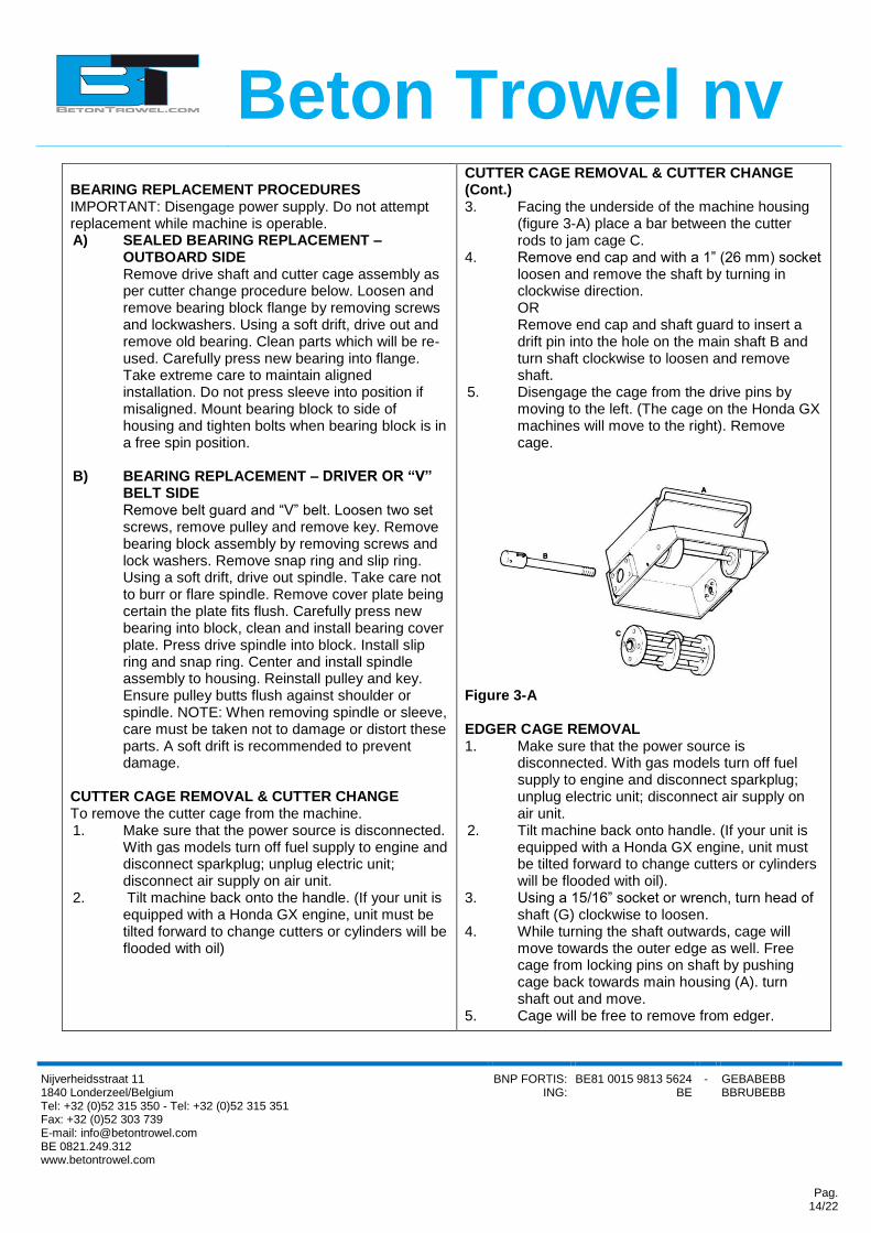
CUTTER CAGE REMOVAL & CUTTER CHANGE (Cont.) 3. Facing the underside of the machine housing
(figure 3-A) place a bar between the cutter rods to jam cage C.
4. Remove end cap and with a 1” (26 mm) socket loosen and remove the shaft by turning in clockwise direction. OR Remove end cap and shaft guard to insert a drift pin into the hole on the main shaft B and turn shaft clockwise to loosen and remove shaft. 5. Disengage the cage from the drive pins by
moving to the left. (The cage on the Honda GX machines will move to the right). Remove cage.
Figure 3-A EDGER CAGE REMOVAL 1. Make sure that the power source is
disconnected. With gas models turn off fuel supply to engine and disconnect sparkplug; unplug electric unit; disconnect air supply on air unit.
2. Tilt machine back onto handle. (If your unit is equipped with a Honda GX engine, unit must be tilted forward to change cutters or cylinders will be flooded with oil).
3. Using a 15/16” socket or wrench, turn head of shaft (G) clockwise to loosen. 4. While turning the shaft outwards, cage will move towards the outer edge as well. Free cage from locking pins on shaft by pushing cage back towards main housing (A). turn shaft out and move. 5. Cage will be free to remove from edger.

Beton Trowel nv
Nijverheidsstraat 11 1840 Londerzeel/Belgium Tel: +32 (0)52 315 350 - Tel: +32 (0)52 315 351 Fax: +32 (0)52 303 739 E-mail: [email protected] BE 0821.249.312 www.betontrowel.com
BNP FORTIS: ING:
BE81 0015 9813 5624 BE
- GEBABEBB BBRUBEBB
Pag. 15/22
CHANGING CUTTERS/SHAFTS Once the cage has been removed use a 5/32” Allen Key and 7/16” open end wrench, remove screws and cover plate from cage. With drift pin tap rods from the drive side until free of cage. Replace cutters or shafts as required. Replace cover plate. To re-install cutter cage in machine, reverse procedure for removal. Ensure that the shaft is tight.
STORAGE - Before The following steps should be taken to prepare your SPS gas unit for extended storage. 1 Close fuel shut off valve. 2. Remove excess gasoline from tank. 3. Start engine until it stops from lack of fuel. This will use up all the fuel in the carburetor and prevent formation of deposits due to evaporation of fuel. 4. Remove spark plug and pour 2 oz. of SAE-30 or SAE- 40 motor oil into the cylinder. Slowly crank the engine 2 or 3 times to distribute the oil throughout the cylinder. This will help prevent rust during storage. Replace spark plug. 5. Store the unit in an upright position in a cool, dry, well ventilated area. STORAGE - After The following steps are recommended to ensure a smooth, proper startup after a prolonged storage. 1 Refuel 2. Open shut off valve 3. Start engine. Any excess oil residue will quickly burn off without harming operation.
Season Temperature All Seasons
LUBRICATION ENGINE OIL Always check engine oil before starting and at regular intervals thereafter. Use proper engine oil as recommended – see chart below. Keep engine oil clean, change accordingly. Fill crankcase to levels as recommended in manufacturer’s engine manual.
Grade of Engine Oil SAE 10W - 30

Beton Trowel nv
Nijverheidsstraat 11 1840 Londerzeel/Belgium Tel: +32 (0)52 315 350 - Tel: +32 (0)52 315 351 Fax: +32 (0)52 303 739 E-mail: [email protected] BE 0821.249.312 www.betontrowel.com
BNP FORTIS: ING:
BE81 0015 9813 5624 BE
- GEBABEBB BBRUBEBB
Pag. 16/22
AASSSSEEMMBBLLYY DDRRAAWWIINNGGSS AANNDD PPAARRTTSS LLIISSTT

Beton Trowel nv
Nijverheidsstraat 11 1840 Londerzeel/Belgium Tel: +32 (0)52 315 350 - Tel: +32 (0)52 315 351 Fax: +32 (0)52 303 739 E-mail: [email protected] BE 0821.249.312 www.betontrowel.com
BNP FORTIS: ING:
BE81 0015 9813 5624 BE
- GEBABEBB BBRUBEBB
Pag. 17/22
Beton Trowel nv
Nijverheidsstraat 11 1840 Londerzeel/Belgium Tel: +32 (0)52 315 350 - Tel: +32 (0)52 315 351 Fax: +32 (0)52 303 739 E-mail: [email protected] BE 0821.249.312 www.betontrowel.com
BNP FORTIS: ING:
BE81 0015 9813 5624 BE
- GEBABEBB BBRUBEBB
Pag. 18/22

Beton Trowel nv
Nijverheidsstraat 11 1840 Londerzeel/Belgium Tel: +32 (0)52 315 350 - Tel: +32 (0)52 315 351 Fax: +32 (0)52 303 739 E-mail: [email protected] BE 0821.249.312 www.betontrowel.com
BNP FORTIS: ING:
BE81 0015 9813 5624 BE
- GEBABEBB BBRUBEBB
Pag. 19/22
Parts list 1
PART NO. DESCRIPTION QTY
810001-1 ENGINE HONDA 5.5HP 1
810001-2 ENGINE ROBIN 5.0HP 1
810002 KEY 3/16” SO X 1 ½” 1
810003-1 PULLEY FOR HONDA 1
810003-2 PULLEY FOR ROBIN 1
810004 SET SCREW 4
810005 BELT GUARD 1
810006 WASHER 4
810007 LOCKWASHER 4
810008 SCREW 4
810009 BELT 2
810010 BELT-ELECTRIC 2
810011 SLIDER NUT 2
810012 SCREW 4
810013 LOCKWASHER 4
810014 ENGINE MOUNTING PLATE-GAS 1
810015 GROUND STRAP 1
810016 HOUSING 1
810017 RUBBER ANTIVIBRATION MOUNTS 4
810018 SPACER 4
810019 CAGE HOUSING ASSM 1
810020 PULLEY 1
810021 SCREW 8
810022 LOCKWASHER 8
810023 END FLANGE ASSM 1
810024 SNAP RING 1
810025 RING SPACER 1
810026 FELT WASHER SM. 1
810027 DRIVE FLANGE 1
810028 BEARING COVER PLATE 1
810029 FELT WASHER LG. 1
810030 BEARING 1
810031 KEY 1
810032 DRIVE SPINDLE 1
810033 DRIVE FLANGE ASSM 1
810034 FELT WASHER 1
810035 BEARING HEX ID 1
810036 END CAP FLANGE 1

Beton Trowel nv
Nijverheidsstraat 11 1840 Londerzeel/Belgium Tel: +32 (0)52 315 350 - Tel: +32 (0)52 315 351 Fax: +32 (0)52 303 739 E-mail: [email protected] BE 0821.249.312 www.betontrowel.com
BNP FORTIS: ING:
BE81 0015 9813 5624 BE
- GEBABEBB BBRUBEBB
Pag. 20/22
810037 HEX DRIVE SHAFT 1
810038 SNAP RING 2
810039 FLAT WASHER 2
810040 FRONT WHEEL 2
810041 FRONT AXLE 1
820000 “A” CAGE ASSEMBLY 1
820001 SCREW 2
820002 SHAFT RETAINING PLATE 1
820003 CUTTER SHAFT 4
820004 LOCKNUT 2
820005 TYPE “A” CAGE 1
823000 EDGER CAGE ASSEMBLY 1
820004 LOCKNUT 2
823001 EDGER CAGE 1
823002 EDGER SHAFT 4
820002 SHAFT RETAINING PLATE 1
820001 SCREW 2
821000 “B” CAGE ASSEMBLY 1
820001 SCREW 2
820002 CAGE RETAINING PLATE 1
820003 CUTTER SHAFT 4
820004 LOCKNUT 2
821001 TYPE “B”CAGE 1
824000 EDGER ASSEMBLY 1
824001 EDGER GUARD 1
810022 LOCKWASHER 3
824002 BOLT 3
824003 EDGER GUARD 1
824004 EDGER DRIVE SHAFT 1

Beton Trowel nv
Nijverheidsstraat 11 1840 Londerzeel/Belgium Tel: +32 (0)52 315 350 - Tel: +32 (0)52 315 351 Fax: +32 (0)52 303 739 E-mail: [email protected] BE 0821.249.312 www.betontrowel.com
BNP FORTIS: ING:
BE81 0015 9813 5624 BE
- GEBABEBB BBRUBEBB
Pag. 21/22
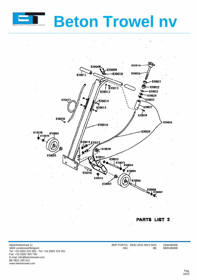
Parts list 2
PART NO. DESCRIPTION QTY
810038 SNAP RING 2
810039 FLAT WASHER 2
830004 WHEEL 2
830005 WHEEL BUSHING 4
830006 REAR AXLE 1
830008 SCREW 2
830009 STAR WASHER 2
830010 STOP SWITCH 1
830011 HANDLE GRIPS 2
830012 LOCKWASHER 1
830013 SCREW 1
830014 STAR WASHER 4
830015 SCREW 4
830016 HANDLE 1
830017 SCREW 4
830018 LOCKWASHER 4
830019 HAND KNOB 1
830020 SCRE SHAFT 1
830021 BEARING 1
830022 BUSHING 1
830023 WAVE WASHER 1
830024 WASHER 1
830025 RETAINER 1
830026 CABLE ASSM 1
830027 SLIDE BUSHING 1
830028 PIN 1
830029 CABLE 1
830030 PULLEY 1
830031 LIFT PLATE 1
830032 PIN-LIFT PLATE 1
830033 FLAT WASHER 2
830034 SNAP RING 2
830035 LOCKNUT 1
830036 SPIRAL PIN 1
830037 WIRE ASSY 1
830038 TERMINAL SPLICE 1

Beton Trowel nv
Nijverheidsstraat 11 1840 Londerzeel/Belgium Tel: +32 (0)52 315 350 - Tel: +32 (0)52 315 351 Fax: +32 (0)52 303 739 E-mail: [email protected] BE 0821.249.312 www.betontrowel.com
BNP FORTIS: ING:
BE81 0015 9813 5624 BE
- GEBABEBB BBRUBEBB
Pag. 22/22