Embed Size (px)
Citation preview
Best Available Techniques (BAT) Reference Document for the
Production of Wood–based Panels
Best Available Techniques (BAT) Reference Document for the Production of Wood-based Panels
Industrial Emissions Directive
2010/75/EU
(Integrated Pollution
Prevention and Control)
third subtitle line
<Main subtitle, Verdana 16,Italic, line spacing 20pt>
Kristine Raunkjær Stubdrup, Panagiotis Karlis, Serge Roudier, Luis Delgado Sancho
2016
EUR 27732 EN
This publication is a Science for Policy report by the Joint Research Centre, the European Commission’s in-house science
service. It aims to provide evidence-based scientific support to the European policy-making process.
The scientific output expressed does not imply a policy position of the European Commission. Neither the European
Commission nor any person acting on behalf of the Commission is responsible for the use which might be made of this
publication.
Contact information
European IPPC Bureau
Address: Joint Research Centre, Edificio Expo c/ Inca Garcilaso 3, E-41092 Seville, Spain
E-mail: [email protected]
Tel.: +34 95 4488 284
Fax: +34 95 4488 426
https://ec.europa.eu/jrc
Legal Notice
Under the Commission Decision of 12 December 2011 on the Re-use of Commission Documents (2011/833/EU), the
present BREF document is subject to free re-use, except for parts covered by any third-party rights which may be present
in the document (such as images, tables, data, written material, or similar, the rights to which need to be acquired
separately from their respective rights-holders for further use). The European Commission is not liable for any
consequence stemming from the re-use of this publication. Any re-use is subject to the acknowledgement of the source
and non-distortion of the original meaning or message
JRC100269
EUR 27732 EN
PDF ISBN 978-92-79-54949-6 ISSN 1831-9424 doi:10.2791/21807 LF-NA-27732-EN-N
© European Union, 2016
Reproduction is authorised provided the source is acknowledged.
How to cite: Kristine Raunkjær Stubdrup, Panagiotis Karlis, Serge Roudier, Luis Delgado Sancho; Best Available
Techniques (BAT) Reference Document for the Production of Wood-based Panels; EUR 27732 EN; doi:10.2791/21807
All images © European Union 2016, except: Cover pictures credits © Fotolia.com—Petair
Abstract
The BAT reference document (BREF) entitled ‘Production of Wood-based Panels' forms part of a series presenting the
results of an exchange of information between EU Member States, the industries concerned, non-governmental
organisations promoting environmental protection, and the Commission, to draw up, review and, where necessary, update
BAT reference documents as required by Article 13(1) of the Directive 2010/75/EU on industrial emissions. This document
is published by the European Commission pursuant to Article 13(6) of the Directive. This BREF for the production of wood-
based panels covers the activities specified in Section 6.1(c) of Annex I to Directive 2010/75/EU. In particular, this
document addresses the following processes and activities:
• the manufacture of wood-based panels by dry or wet processes; including the production of:
• particleboard (PB);
• oriented strand board (OSB);
• medium density fibreboard (MDF), including low density fibreboard (LDF) and high density fibreboard (HDF),
produced in a dry process;
• fibreboard, including rigidboard (RB) and flexboard (FB), produced in a dry process;
• fibreboard, including softboard (SB) and hardboard (HB), produced in a wet process.
This document covers all activities from the storage of raw materials to the finished raw board ready for storage.
This document additionally addresses the following activities which are considered activities directly associated to the main
Annex I, Section 6.1(c) activity, even if the directly associated activity is not necessarily an Annex I activity itself:
• on-site combustion plants (including engines) generating hot gases for directly heated dryers without restriction of
capacity;
• the manufacture of impregnated paper with resins.
Important issues for the implementation of Directive 2010/75/EU in the wood-based panels industry are the emissions to
air from dryers and presses of dust, formaldehyde, and volatile organic compounds. This BREF contains seven chapters.
Chapters 1 and 2 provide general information on the wood-based panels industry and on the common industrial processes
and techniques used within the whole sector. Chapters 3 and 4 provide information and data concerning the applied
processes and techniques in the sector; the environmental performance of installations in terms of current emissions,
consumption of raw materials, water and energy, as well as on generation of waste; the techniques to prevent and/or
reduce emissions from the wood-based panels production plants. In Chapter 5, the BAT conclusions, as defined in
Article 3(12) of the Directive, are presented for the wood-based panels industry. In Chapter 6, the emerging techniques
are presented. Chapter 7 is dedicated to concluding remarks and recommendations for future work regarding the
sector.
Title Best Available Techniques (BAT) Reference Document for the Production of Wood-based Panels
Best Available Techniques (BAT)
Reference Document for the
Production of Wood-based
Panels
Industrial Emissions Directive 2010/75/EU
Integrated Pollution Prevention and control
Authors: Kristine Raunkjær Stubdrup
Panagiotis Karlis Serge Roudier
Luis Delgado Sancho
2016
EUR 27732 EN


Acknowledgements
This report was produced by the European Integrated Pollution Prevention and Control Bureau (EIPPCB) at the European Commission's Joint Research Centre – Institute for Prospective Technological Studies (IPTS) under the
supervision of Serge Roudier (Head of the EIPPCB) and Luis Delgado Sancho (Head of the Sustainable Production and Consumption Unit).
The authors of this BREF were Ms Kristine R. Stubdrup and Mr Panagiotis Karlis.
This report was drawn up in the framework of the implementation of the
Industrial Emissions Directive (2010/75/EU) and is the result of the exchange of information provided for in Article 13 of the Directive.
Major contributors of information were:
• among EU Member States: Austria, Belgium, Czech Republic, Denmark, Finland, France, Germany, Ireland, Italy, the Netherlands,
Poland, Portugal, Romania, Slovakia, Spain, and the United Kingdom; • among industry: the European Panel Federation (EPF), Fedustria, the
Wood Panel Industries Federation (WPIF), and the European
Confederation of Woodworking Industries (CEI-Bois).
The whole EIPPCB team provided contributions and peer reviewing. This report is dedicated to the memory of the TWG members Martin
Steinwender and Harry Earl.

This document is one from the series of documents listed below (at the time of writing, the
following documents have been drafted):
Reference Document on Best Available Techniques Code
Ceramic Manufacturing Industry CER
Common Waste Water and Waste Gas Treatment/Management Systems in the Chemical
Sector CWW
Emissions from Storage EFS
Energy Efficiency ENE
Ferrous Metals Processing Industry FMP
Food, Drink and Milk Industries FDM
Industrial Cooling Systems ICS
Intensive Rearing of Poultry or Pigs IRPP
Iron and Steel Production IS
Large Combustion Plants LCP
Large Volume Inorganic Chemicals – Ammonia, Acids and Fertilisers LVIC-AAF
Large Volume Inorganic Chemicals – Solids and Others Industry LVIC-S
Large Volume Organic Chemical Industry LVOC
Management of Tailings and Waste-rock in Mining Activities MTWR
Manufacture of Glass GLS
Manufacture of Organic Fine Chemicals OFC
Non-ferrous Metals Industries NFM
Production of Cement, Lime and Magnesium Oxide CLM
Production of Chlor-alkali CAK
Production of Polymers POL
Production of Pulp, Paper and Board PP
Production of Speciality Inorganic Chemicals SIC
Production of Wood-based Panels WBP
Refining of Mineral Oil and Gas REF
Slaughterhouses and Animals By-products Industries SA
Smitheries and Foundries Industry SF
Surface Treatment of Metals and Plastics STM
Surface Treatment Using Organic Solvents STS
Tanning of Hides and Skins TAN
Textiles Industry TXT
Waste Incineration WI
Waste Treatment WT
Reference Document
Economics and Cross-media Effects ECM
Monitoring of Emissions to Air and Water from IED-installations ROM
Electronic versions of draft and finalised documents are publicly available and can be
downloaded from http://eippcb.jrc.ec.europa.eu/.


Preface
Production of Wood–based Panels i
PREFACE
1. Status of this document
Unless otherwise stated, references to ‘the Directive’ in this document refer to Directive
2010/75/EU of the European Parliament and the Council on industrial emissions (integrated
pollution prevention and control) (Recast).
This BAT reference document for the Production of Wood-based Panels forms part of a series
presenting the results of an exchange of information between EU Member States, the industries
concerned, non-governmental organisations promoting environmental protection and the
Commission, to draw up, review, and where necessary, update BAT reference documents as
required by Article 13(1) of the Directive. This document is published by the European
Commission pursuant to Article 13(6) of the Directive.
As set out in Article 13(5) of the Directive, the Commission Implementing Decision
2015/2119/EU on the BAT conclusions contained in Chapter 5 was adopted on 20 November
2015 and published on 24 November 2015.1
2. Participants in the information exchange
As required in Article 13(3) of the Directive, the Commission has established a forum to
promote the exchange of information, which is composed of representatives from Member
States, the industries concerned and non-governmental organisations promoting environmental
protection (Commission Decision of 16 May 2011 establishing a forum for the exchange of
information pursuant to Article 13 of the Directive 2010/75/EU on industrial emissions
(2011/C 146/03), OJ C 146, 17.05.2011, p. 3).
Forum members have nominated technical experts constituting the technical working group
(TWG) that was the main source of information for drafting this document. The work of the
TWG was led by the European IPPC Bureau (of the Commission's Joint Research Centre).
3. Structure and contents of this document
Chapters 1 and 2 provide general information on the production of wood-based panels and on
the industrial processes and techniques used within this sector.
Chapter 3 provides data and information concerning the environmental performance of
installations within the sector, and in operation at the time of writing, in terms of current
emissions, consumption and nature of raw materials, water consumption, use of energy and the
generation of waste.
Chapter 4 describes in more detail the techniques to prevent or, where this is not practicable, to
reduce the environmental impact of installations in this sector that were considered in
determining the BAT. This information includes, where relevant, the environmental
performance levels (e.g. emission and consumption levels) which can be achieved by using the
techniques, the associated monitoring and the costs and the cross-media issues associated with
the techniques.
Chapter 5 presents the BAT conclusions as defined in Article 3(12) of the Directive.
Chapter 6 presents information on 'emerging techniques' as defined in Article 3(14) of the
Directive.
Concluding remarks and recommendations for future work are presented in Chapter 7.
1 OJ L306, 24.11.2015, p. 31.
Preface
ii Production of Wood–based Panels
4. Information sources and the derivation of BAT
This document is based on information collected from a number of sources, in particular
through the TWG that was established specifically for the exchange of information under
Article 13 of the Directive. The information has been collated and assessed by the European
IPPC Bureau (of the Commission's Joint Research Centre) who led the work on determining
BAT, guided by the principles of technical expertise, transparency and neutrality. The work of
the TWG and all other contributors is gratefully acknowledged.
The BAT conclusions have been established through an iterative process involving the
following steps:
identification of the key environmental issues for the sector;
examination of the techniques most relevant to address these key issues;
identification of the best environmental performance levels, on the basis of the available
data in the European Union and worldwide;
examination of the conditions under which these environmental performance levels were
achieved, such as costs, cross-media effects, and the main driving forces involved in the
implementation of the techniques;
selection of the best available techniques (BAT), their associated emission levels (and
other environmental performance levels) and the associated monitoring for this sector
according to Article 3(10) of, and Annex III to, the Directive.
Expert judgement by the European IPPC Bureau and the TWG has played a key role in each of
these steps and in the way in which the information is presented here.
Where available, economic data have been given together with the descriptions of the
techniques presented in Chapter 4. These data give a rough indication of the magnitude of the
costs and benefits. However, the actual costs and benefits of applying a technique may depend
strongly on the specific situation of the installation concerned, which cannot be evaluated fully
in this document. In the absence of data concerning costs, conclusions on the economic viability
of techniques are drawn from observations on existing installations.
5. Review of BAT reference documents (BREFs)
BAT is a dynamic concept and so the review of BREFs is a continuing process. For example,
new measures and techniques may emerge, science and technologies are continuously
developing and new or emerging processes are being successfully introduced into the industries.
In order to reflect such changes and their consequences for BAT, this document will be
periodically reviewed and, if necessary, updated accordingly.
6. Contact information
All comments and suggestions should be made to the European IPPC Bureau at the Institute for
Prospective Technological Studies at the following address:
European Commission
JRC Institute for Prospective Technological Studies
European IPPC Bureau
Edificio Expo
c/ Inca Garcilaso, 3
E-41092 Seville, Spain
Telephone: +34 95 4488 284
Fax: +34 95 4488 426
E-mail: [email protected]
Internet: http://eippcb.jrc.ec.europa.eu
Production of Wood–based Panels iii
Reference Document on Best Available Techniques for the Production of Wood-Based Panels
PREFACE ........................................................................................................................ I
SCOPE ....................................................................................................................... XIII
1 GENERAL INFORMATION ................................................................................. 1
1.1 PRODUCTS COVERED BY THIS DOCUMENT .................................................................... 1
1.1.1 Main products and their manufacture .................................................................. 1
1.2 PRODUCTION PROCESSES ADDRESSED BY THIS DOCUMENT ......................................... 7
1.3 ENVIRONMENTAL ISSUES COVERED BY THIS DOCUMENT ............................................. 8
1.4 STRUCTURE OF THE SECTOR ....................................................................................... 10
1.4.1 Market structure ................................................................................................ 10
1.4.2 Size and number of wood-based panel plants ................................................... 12
1.4.3 Raw material costs for panel manufacture ........................................................ 14
1.4.4 Environmental cost for panel manufacture ....................................................... 15
1.4.5 Technical characteristics of wood-based panel installations ............................. 15
1.4.6 Location trends for wood-based panel sites ...................................................... 16
1.4.7 Challenges and trends for the wood-based panel sector .................................... 16
2 APPLIED PROCESSES AND TECHNIQUES .................................................. 19
2.1 THE STORAGE OF WOOD RAW MATERIALS AND THE PREPARATION OF WOOD
PARTICLES ................................................................................................................... 21
2.1.1 Origin of raw materials ..................................................................................... 21
2.1.2 Receipt and storage of raw wood material ........................................................ 21
2.1.2.1 Log yard operations ................................................................................................ 21 2.1.2.2 Environmental issues related to storage of raw wood material .............................. 22
2.1.3 Cleaning of recovered wood raw materials ....................................................... 23
2.1.3.1 Environmental issues related to the cleaning of recovered wood materials ........... 25
2.1.4 Debarking .......................................................................................................... 25
2.1.4.1 Environmental issues related to debarking ............................................................. 26
2.1.5 Breakdown of wood to produce flakes, strands or wood particles .................... 26
2.1.5.1 Environmental issues related to the breakdown of wood to produce flakes,
strands or wood particles ........................................................................................ 27
2.1.6 Storage of wood particles and flakes before drying .......................................... 28
2.1.6.1 Environmental issues related to storage of wood particles ..................................... 29
2.1.7 Internal transport of wood materials in general ................................................. 29
2.2 DRYING OF WOOD PARTICLES AND FIBRES ................................................................. 30
2.2.1 Drying of wood particles for particleboard and OSB production ..................... 30
2.2.2 Drying of wood fibres ....................................................................................... 33
2.2.2.1 Environmental issues related to drying .................................................................. 33 2.2.2.1.1 Environmental issues related to drying of fibres ............................................ 35
2.2.3 Refining of fibres for MDF and other fibreboards ............................................ 35
2.2.3.1 Environmental issues related to the refining of fibres ............................................ 37
2.2.4 Storage of wood particles/flakes/fibres after drying ......................................... 37
2.2.4.1 Sorting and dry storage of dried chips and flakes .................................................. 37 2.2.4.2 Sorting and dry storage of fibres ............................................................................ 38

iv Production of Wood–based Panels
2.2.4.3 Environmental issues related to sorting and dry storage ......................................... 38
2.3 PANEL MANUFACTURE ................................................................................................ 39
2.3.1 Blending and mat forming ................................................................................. 39
2.3.1.1 Mixing of resins and additives in the glue kitchen ................................................. 39 2.3.1.2 Blending of resin mix with wood and mat forming ................................................ 39
2.3.2 Pressing .............................................................................................................. 40
2.3.2.1 Environmental issues related to pressing ................................................................ 43 2.3.2.2 Pressing of rigidboard and flexboard ...................................................................... 44 2.3.2.3 Mat forming and the pressing of softboards ........................................................... 45 2.3.2.4 Mat forming and pressing of hardboards ................................................................ 45
2.3.3 Cutting and cooling of panels ............................................................................ 46
2.3.3.1 Environmental issues related to cutting and cooling of panels ............................... 47
2.4 FINISHING OF RAW BOARD .......................................................................................... 49
2.4.1 Sanding and cutting to size ................................................................................ 49
2.4.1.1 Environmental issues related to sanding and cutting to size ................................... 49
2.4.2 Storage ............................................................................................................... 49
2.5 AUXILIARY SUBSTANCES AND MATERIALS ................................................................. 50
2.5.1 Resins ................................................................................................................. 50
2.5.2 Hardening agents ............................................................................................... 51
2.5.3 Release agents and other additives .................................................................... 51
2.6 ENERGY PRODUCTION ................................................................................................. 52
2.6.1 Environmental issues related to energy production ........................................... 53
2.7 IMPREGNATION OF PAPER ............................................................................................ 55
2.7.1 Environmental issues related to impregnation of paper ..................................... 55
2.8 LAMINATION AND OTHER VALUE-ADDING OPERATIONS ............................................. 57
2.8.1 Environmental issues related to lamination and other value-adding
operations ........................................................................................................... 58
2.9 WASTE WATER TREATMENT PLANTS ........................................................................... 59
2.9.1 Environmental issues related to waste water treatment ..................................... 59
3 CURRENT CONSUMPTION AND EMISSION LEVELS ............................... 61
3.1 INPUTS TO PRODUCTION .............................................................................................. 63
3.1.1 Wood raw material............................................................................................. 63
3.1.2 Fuels ................................................................................................................... 64
3.1.3 Resin and additives ............................................................................................ 66
3.1.4 Energy consumption .......................................................................................... 67
3.1.5 Water consumption ............................................................................................ 70
3.2 EMISSIONS TO AIR ....................................................................................................... 72
3.2.1 Emissions from dryers ....................................................................................... 72
3.2.1.1 Dust in dryer emissions .......................................................................................... 73 3.2.1.2 Formaldehyde in dryer emissions ........................................................................... 80 3.2.1.3 Organic compounds in dryer emissions .................................................................. 87 3.2.1.4 Additional collected data on dust and organic emissions from dryers .................... 95 3.2.1.5 Emissions of NOX and SOX to air from directly heated dryers ............................... 98 3.2.1.6 Additional monitoring of dryer emissions ............................................................ 103
3.2.2 Emissions from presses .................................................................................... 104

Production of Wood–based Panels v
3.2.3 Emissions from downstream and upstream processing ................................... 109
3.2.4 Emissions from combustion plants ................................................................. 110
3.2.4.1 Additional monitoring data .................................................................................. 114
3.2.5 Emissions from paper impregnation lines ....................................................... 116
3.2.6 Odour ............................................................................................................... 117
3.3 EMISSIONS TO WATER ............................................................................................... 119
3.3.1 Emissions from surface run-off water ............................................................. 119
3.3.2 Emissions from treated process water ............................................................. 120
3.4 WASTE GENERATION ................................................................................................ 123
3.5 EMISSIONS TO SOIL AND GROUNDWATER ................................................................. 125
3.6 NUISANCE FROM NOISE AND ODOUR ........................................................................ 126
3.7 MONITORING OF EMISSIONS ..................................................................................... 128
3.7.1 Reference conditions for expressing air emissions data .................................. 130
3.7.2 Monitoring of emissions to air ........................................................................ 131
3.7.2.1 Dust ...................................................................................................................... 131 3.7.2.2 Formaldehyde ....................................................................................................... 132 3.7.2.3 Monitoring of organic compounds ....................................................................... 132 3.7.2.4 Monitoring of odour ............................................................................................. 132 3.7.2.5 Blue haze .............................................................................................................. 133
4 TECHNIQUES TO CONSIDER IN THE DETERMINATION OF BAT ..... 135
4.1 INTRODUCTION ......................................................................................................... 135
4.2 TECHNIQUES TO PREVENT OR REDUCE EMISSIONS TO AIR ........................................ 136
4.2.1 Introduction ..................................................................................................... 136
4.2.2 Primary techniques to prevent or reduce emissions to air from dryers ........... 138
4.2.2.1 Management of the drying operation ................................................................... 138 4.2.2.2 Recirculation of waste gases ................................................................................ 139 4.2.2.3 UTWS or Combined heat and dryer systems for particleboard and OSB ............ 140 4.2.2.4 Reduction of SOX emissions ................................................................................ 143 4.2.2.5 Reduction of NOX emissions in hot gases from combustion plants ..................... 144 4.2.2.6 Reduction of dust emissions in hot gases ............................................................. 146
4.2.2.6.1 Electrostatic precipitators (ESPs) ................................................................. 146 4.2.2.6.2 Bag filters ..................................................................................................... 147 4.2.2.6.3 Cyclones ....................................................................................................... 147
4.2.3 Primary techniques to prevent or reduce emissions to air from presses .......... 148
4.2.3.1 Selection of resin and appropriate press operating conditions ............................. 148
4.2.4 Secondary techniques to prevent or reduce emissions to air from dryers and
presses ............................................................................................................. 149
4.2.4.1 Wet electrostatic precipitator ............................................................................... 149 4.2.4.2 Bag filters ............................................................................................................. 155 4.2.4.3 Electrified filter bed ............................................................................................. 159 4.2.4.4 Wet scrubbers ....................................................................................................... 161 4.2.4.5 Bioscrubbers ......................................................................................................... 164 4.2.4.6 Thermal oxidation ................................................................................................ 166 4.2.4.7 Incineration of press waste gases in an on-site combustion plant ........................ 168
4.2.5 Techniques to prevent or reduce emissions from other sources ...................... 168
4.2.5.1 Bag filters and cyclofilters ................................................................................... 169 4.2.5.2 Cyclones ............................................................................................................... 170

vi Production of Wood–based Panels
4.2.6 Techniques to reduce channelled emissions from paper impregnation line
dryer ovens ....................................................................................................... 170
4.2.6.1 Resin selection ...................................................................................................... 170 4.2.6.2 Biofilters ............................................................................................................... 171 4.2.6.3 Addition of dryer oven waste gas to main treatment systems ............................... 172 4.2.6.4 Thermal oxidation ................................................................................................. 173
4.2.7 Techniques to reduce diffuse emissions .......................................................... 174
4.2.7.1 Implementation of good housekeeping measures to minimise diffuse dust
emissions from the log yard .................................................................................. 174 4.2.7.2 Minimisation of diffuse emissions from the conveying of wood raw materials ... 175 4.2.7.3 Qualification of fugitive emissions using Reverse Dispersion Modelling ............ 176
4.3 TECHNIQUES TO PREVENT OR REDUCE EMISSIONS TO WATER .................................. 177
4.3.1 Primary techniques to prevent or reduce emissions to water ........................... 177
4.3.1.1 Minimisation of the pollution load in collected waste water streams ................... 177 4.3.1.2 Recirculation of process waste water from wood fibre production ...................... 178
4.3.2 Treatment of surface run-off water .................................................................. 180
4.3.2.1 Preliminary treatment, screening and sieving ....................................................... 180 4.3.2.2 Sedimentation in retention basins and settlement tanks ........................................ 181 4.3.2.3 Sand filters ............................................................................................................ 183 4.3.2.4 Reed bed ............................................................................................................... 185
4.3.3 Treatment of process water from fibre production .......................................... 186
4.3.3.1 Preliminary treatment, removal of larger solids.................................................... 186 4.3.3.2 Primary treatment by physical separation of particles and suspended solids ........ 186 4.3.3.3 Biological treatment.............................................................................................. 188 4.3.3.4 Tertiary treatment of waste water ......................................................................... 189
4.4 TECHNIQUES TO REDUCE EMISSIONS TO LAND .......................................................... 191
4.4.1 Safe handling of auxiliary materials ................................................................ 191
4.5 TECHNIQUES TO REDUCE WATER CONSUMPTION ...................................................... 193
4.5.1 Collection of lightly contaminated water for plant cleaning and other
purposes ........................................................................................................... 193
4.6 TECHNIQUES TO INCREASE ENERGY EFFICIENCY ...................................................... 195
4.6.1 Recovery of energy in hot air emissions .......................................................... 195
4.6.2 Combustion control.......................................................................................... 196
4.6.3 Dewatering of bark and sludge ........................................................................ 197
4.6.4 Combined heat and power (CHP) plants ......................................................... 198
4.6.5 Heat recovery from steam during refining ....................................................... 199
4.7 CONSUMPTION OF CHEMICALS AND RAW MATERIALS .............................................. 201
4.7.1.1 Optimisation of the use of resins according to the product to be produced .......... 201
4.8 TECHNIQUES FOR MANAGEMENT OF WASTE/RESIDUE GENERATION ........................ 202
4.8.1 Raw material control by applying a control programme to externally
collected waste wood ....................................................................................... 202
4.8.2 Optimisation of fuel quantity by the collection of wood fines and dust .......... 203
4.8.3 Safe storage, transport and reuse of bottom ash and slag from biomass
combustion plants ............................................................................................ 204
4.8.4 Reuse of internal collected wood residues in production ................................ 205
4.9 ENVIRONMENTAL MANAGEMENT SYSTEMS .............................................................. 206
4.10 REDUCTION OF NOISE ................................................................................................ 209
Production of Wood–based Panels vii
5 BEST AVAILABLE TECHNIQUES (BAT) CONCLUSIONS ....................... 211
SCOPE 211
GENERAL CONSIDERATIONS ................................................................................................ 211
DEFINITIONS AND ACRONYMS ............................................................................................. 213
5.1 GENERAL BAT CONCLUSIONS .................................................................................. 215
5.1.1 Environmental management system ................................................................ 215
5.1.2 Good housekeeping ......................................................................................... 216
5.1.3 Noise ............................................................................................................... 217
5.1.4 Emissions to soil and groundwater .................................................................. 217
5.1.5 Energy management and energy efficiency .................................................... 218
5.1.6 Odour ............................................................................................................... 219
5.1.7 Management of waste and residues ................................................................. 219
5.1.8 Monitoring ....................................................................................................... 220
5.2 EMISSIONS TO AIR ..................................................................................................... 223
5.2.1 Channelled emissions ...................................................................................... 223
5.2.2 Diffuse emissions ............................................................................................ 227
5.3 EMISSIONS TO WATER ............................................................................................... 228
5.4 DESCRIPTION OF TECHNIQUES .................................................................................. 230
5.4.1 Emissions to air ............................................................................................... 230
5.4.2 Emissions to water .......................................................................................... 231
6 EMERGING TECHNIQUES ............................................................................. 233
6.1 SUPERHEATED STEAM DRYERS ................................................................................. 233
6.2 RECOVERY OF ORGANIC COMPOUNDS FROM WOOD ................................................. 234
6.3 REUSE OF REJECT PAPERS FROM THE PAPER IMPREGNATION LINE ........................... 235
7 CONCLUDING REMARKS AND RECOMMENDATIONS FOR FUTURE
WORK................................................................................................................... 237
GLOSSARY ................................................................................................................. 241
REFERENCES ............................................................................................................ 253
viii Production of Wood–based Panels
List of Figures Figure 1.1: Particleboard (PB) .................................................................................................................. 1 Figure 1.2: Oriented strand board (OSB) .................................................................................................. 2 Figure 1.3: Fibreboard (MDF) .................................................................................................................. 3 Figure 1.4: Flexboard and rigidboards with a tongue-and-groove finish .................................................. 4 Figure 1.5: Layered softboard (SB), and thin green softboard for underfloor insulation ......................... 4 Figure 1.6: Hardboard (HB) ..................................................................................................................... 5 Figure 1.7: Particleboard pallet and pallet blocks ..................................................................................... 5 Figure 1.8: Global distribution of PB, OSB and MDF production, 2010 ............................................... 11 Figure 1.9: Relative production capacity share of wood-based panels in the EU-27 ............................. 12 Figure 1.10: Nominal production capacities for the panel products covered in this document,
including all plants in the EU-27 .......................................................................................... 13 Figure 1.11: Number and nominal capacities of installations producing hardboard and softboard by
the wet process and flexboard/rigidboard by the dry process ............................................... 14 Figure 2.1: Production flow for particleboard (PB), oriented strand board (OSB), dry process
fibreboard (MDF), rigid and flexboard, softboard (SB) and hardboard (HB) ...................... 20 Figure 2.2: Storage of roundwood in a log yard ..................................................................................... 22 Figure 2.3: Example of standard steps in a cleaning plant for recovered wood...................................... 24 Figure 2.4: Flow sheet for chipping and milling for PB, OSB and MDF ............................................... 26 Figure 2.5: Rotary dryer ......................................................................................................................... 31 Figure 2.6: Example of chip dryer characteristics (indicative values) .................................................... 32 Figure 2.7: Standard process steps in a refiner plant with optional washing and pre-cooking of wood
chips ..................................................................................................................................... 35 Figure 2.8: OSB mat after forming and trimming .................................................................................. 40 Figure 2.9: Press types used in dry process panel production................................................................. 41 Figure 2.10: Multi-opening press ............................................................................................................. 42 Figure 2.11: Example of main production steps for rigidboards .............................................................. 44 Figure 2.12: Production flow for wet process softboards ......................................................................... 45 Figure 2.13: Production steps in the manufacture of wet process hardboards .......................................... 46 Figure 3.1: Year of production start for PB, OSB or MDF installations included in the data
collection .............................................................................................................................. 62 Figure 3.2: Distribution of wood raw materials used in different panel products in the EU-27 ............. 63 Figure 3.3: Distribution of raw materials used in particleboard production in different Member
States .................................................................................................................................... 64 Figure 3.4: Resins used in production of particleboard at 35 different production lines or
installations .......................................................................................................................... 66 Figure 3.5: Resins used in MDF production at 13 different production lines or installations, data
from 2010–11 ....................................................................................................................... 67 Figure 3.6: Values for dust in emissions to air from directly heated PB dryers and the applied
abatement techniques, based on data from 50 production lines ........................................... 73 Figure 3.7: Values for dust in emissions to air from PB dryers applying a WESP including when
waste gas from both the dryer and press are treated together ............................................... 75 Figure 3.8: Values for dust in emissions to air from directly heated OSB dryers and the applied
abatement techniques, based on data from 11 production lines ........................................... 76 Figure 3.9: Values for dust in emissions to air from MDF dryers and the applied abatement
techniques, based on data from 32 production lines ............................................................. 78 Figure 3.10: Values for formaldehyde in emissions to air from PB dryers and the applied abatement
techniques, based on data from 34 production lines ............................................................. 80 Figure 3.11: Values for formaldehyde in emissions to air from MDF dryers, based on data from 15
production lines .................................................................................................................... 84 Figure 3.12: Illustration of the variation in the contents of organic compounds in emissions to air
from PB dryers ..................................................................................................................... 87 Figure 3.13: Values for volatile organic compounds in emissions to air from PB dryers, based on
data from 41 production lines ............................................................................................... 89 Figure 3.14: Values for volatile organic compounds in emissions to air from MDF dryers, based on
data from 24 production lines ............................................................................................... 92 Figure 3.15: NOX emissions to air from directly heated PB dryers with the corresponding emission
airflow ................................................................................................................................ 100 Figure 3.16: NOX emissions to air from directly heated MDF dryers with the corresponding emission
airflow ................................................................................................................................ 102

Production of Wood–based Panels ix
Figure 3.17: An EPF study showing formaldehyde emissions from presses and the related abatement
techniques .......................................................................................................................... 108 Figure 3.18: Average values of TSS, BOD5 and COD in the discharge of treated surfce run-off water 119 Figure 3.19: Example of variation of daily average values for a closed loop dryer and combustion
plant ................................................................................................................................... 129 Figure 3.20: Example of variation of daily average values of continuous FID measurements (at 18 %
O2) of TVOC during one year from a particleboard dryer equipped with a WESP ........... 130 Figure 4.1: Principles of a combined heat and dryer system (UTWS) with recirculation of dryer
waste gas ............................................................................................................................ 141 Figure 4.2: Principles of a double WESP, which includes a waste water treatment unit, scrubber,
and one-stage ESP ............................................................................................................. 150 Figure 4.3: Continuous improvement in an EMS model ...................................................................... 206

x Production of Wood–based Panels
List of Tables Table 1.1: Densities and process types for different wood-based panel products ................................... 6 Table 1.2: Panel products of wood-based panel installations in the EU-27 and buyers of panel
products in 2010 ................................................................................................................... 10 Table 1.3: Production figures for wood-based panel products .............................................................. 11 Table 1.4: Breakdown of direct material costs in 2009 for PB, OSB and MDF raw panels ................. 15 Table 1.5: Increase of production input costs in the wood-based panel sector from 2007 to 2010 ....... 15 Table 2.1: Origin of raw materials and related products ....................................................................... 21 Table 2.2: Main resin types ................................................................................................................... 50 Table 3.1: Composition of a raw finished panel in weight (%) ............................................................. 67 Table 3.2: Yearly energy consumption levels illustrated for the three main energy-consuming
processes and for the total energy consumption at the site level .......................................... 68 Table 3.3: Comparison of energy consumption per unit of product in MDF production ...................... 69 Table 3.4: Total water consumption in OSB, PB and MDF production ................................................ 70 Table 3.5: Reported emission levels of dust, TVOC and formaldehyde from dryers for
particleboard, OSB and MDF lines ...................................................................................... 72 Table 3.6: Reporting details on reference conditions for data presented in Figure 3.6 concerning
emission to air of dust from directly heated PB dryers ........................................................ 74 Table 3.7: Emissions data for dust from indirectly heated dryers in PB production, based on data
from periodic monitoring ..................................................................................................... 76 Table 3.8: Reporting details on reference conditions for data presented in Figure 3.8 concerning
emission to air of dust from directly heated OSB dryers...................................................... 77 Table 3.9 Reporting details on reference conditions for data presented in Figure 3.9 concerning
emission to air of dust from MDF dryers ............................................................................. 79 Table 3.10: Reporting details on reference conditions for data presented in Figure 3.10 concerning
emission to air of formaldehyde from PB dryers ................................................................. 81 Table 3.11: Specific mass load of formaldehyde in emissions to air from PB dryers ............................. 82 Table 3.12: Emission to air of formaldehyde from directly heated OSB dryers ..................................... 83 Table 3.13: Supporting information and details on reference conditions concerning formaldehyde in
emissions to air from dryers for MDF production lines shown in Figure 3.11 .................... 85 Table 3.14: Specific mass load of formaldehyde from MDF fibre dryers ............................................... 86 Table 3.15: Examples of contents of organic compounds in dryer emissions expressed by different
parameters ............................................................................................................................ 88 Table 3.16: Supporting information and details on reference conditions presented in Figure 3.13
concerning volatile organic compounds in emissions to air from PB dryers ....................... 90 Table 3.17: Emission to air of volatile organic compounds from directly heated OSB dryers ............... 91 Table 3.18: Supporting information and details on reference conditions for data presented in
Figure 3.14 concerning volatile organic compounds in emissions to air from MDF
dryers .................................................................................................................................... 93 Table 3.19: Emission to air of volatile organic compounds and the related specific mass load from
fibre dryers, using cyclones and wet scrubbers as the abatement technique ........................ 94 Table 3.20: Emission levels from particleboard and MDF lines in Germany ......................................... 95 Table 3.21: Specific mass loads from production sites in France ........................................................... 95 Table 3.22: Emission levels from particleboard and MDF lines in Austria ............................................ 96 Table 3.23: Measurement of dryer emissions from one installation's test runs with a mix of fuel and
raw material .......................................................................................................................... 97 Table 3.24: Measurement of three main VOC constituents in a particleboard plant using maritime
pine as the raw material ........................................................................................................ 97 Table 3.25: Comparison of quantitative dryer emissions from a particleboard plant .............................. 98 Table 3.26: NOX and CO emissions to air from directly heated PB dryers ............................................. 99 Table 3.27: Emissions to air of NOX and CO from directly heated OSB dryers with the
corresponding specific load of NOX in kg/m3 of finished panel ......................................... 101
Table 3.28: Emissions to air of NOX and CO from directly heated MDF dryers (dry basis) ................ 102 Table 3.29: Metals in emissions from dryers ........................................................................................ 103 Table 3.30: Emission of HCl, HF and SOX from dryers ........................................................................ 104 Table 3.31: Diffuse emissions of VOC compounds along a press line ................................................. 104 Table 3.32: Emissions of dust and TOC in waste gas collected at press lines....................................... 106 Table 3.33: Emissions of formaldehyde in waste gas collected at press lines ....................................... 107 Table3.34: Emission levels of dust, NOX, SOX and CO in flue-gases from combustion plants ........... 111 Table 3.35: NOX, SOX, CO and dust emissions from heavy fuel-fired engines for generating hot
gases for direct drying ........................................................................................................ 113

Production of Wood–based Panels xi
Table 3.36: Emission levels from closed loop combustion plants ........................................................ 113 Table 3.37: HCl and HF emissions from heavy fuel-fired engines for generating hot gases for direct
drying ................................................................................................................................. 114 Table 3.38: Emissions of metals from combustion plants .................................................................... 115 Table 3.39: Emissions of organic compounds and dust from paper impregnation lines ....................... 117 Table 3.40: Odour emissions from stack emission sources .................................................................. 118 Table 3.41: Treatment steps and removal efficiencies in waste water treatment plants treating
process water from refining ............................................................................................... 121 Table 3.42: Example from one installation producing MDF and PB of the composition of separately
collected waste water from plant cleaning and production ................................................ 122 Table 3.43: Monitoring data from two production lines covering several years ................................... 128 Table 4.1: Information for each technique .......................................................................................... 135 Table 4.2: Emissions data from combined heat and dryer systems (UTWS) ...................................... 142 Table 4.3: Emission levels from combustion plants for steam generation .......................................... 145 Table 4.4: Emission levels from a combustion plant firing 100 % recovered wood ........................... 145 Table 4.5: Average of periodic sampling of dust, volatile organic compounds and formaldehyde in
dryer emissions after treatment in a WESP ....................................................................... 152 Table 4.6: Emission levels for TOC and formaldehyde in emissions from OSB dryers after
treatment in a WESP .......................................................................................................... 153 Table 4.7: Emission levels for dust, TOC/NMVOC and formaldehyde in emissions from press
lines after treatment in a WESP ......................................................................................... 153 Table 4.8: Emissions of dust in dryer waste gases treated in bag filters ............................................. 156 Table 4.9: Average values of periodic dust measurements in dryer emissions after treatment in a
cyclone ............................................................................................................................... 158 Table 4.10: Result of pilot tests of EFB treating dryer emissions ......................................................... 160 Table 4.11: Average values of periodic measurements, including minimum and maximum values, of
measured dust levels in dryer emissions after treatment in a wet scrubber ....................... 162 Table 4.12: Emissions of formaldehyde and related specific mass loads from MDF fibre dryers with
wet scrubbers ..................................................................................................................... 163 Table 4.13: Emission of dust, TVOC/CVOCs and formaldehyde from press waste gas treated with
wet scrubbers ..................................................................................................................... 163 Table 4.14: Average values of periodic measurements of dust, organic compounds and
formaldehyde in dryer emissions after treatment in a bioscrubber .................................... 165 Table 4.15: Emissions of TVOC from paper impregnation lines at one WBP installation with no
abatement but using resin types with a low free VOC content .......................................... 170 Table 4.16: Emissions of organic compounds from drying ovens for impregnation of paper lines
treated by thermal oxidation .............................................................................................. 173 Table 4.17: Emission levels associated with sedimentation/oil-water separation ................................. 182 Table 5.1: BAT-associated emission levels (BAT-AELs) for emissions to air from the dryer and
for combined treated emissions from the dryer and the press ............................................ 224 Table 5.2: BAT-associated emission levels (BAT-AELs) for NOX emissions to air from a directly
heated dryer ....................................................................................................................... 224 Table 5.3: BAT-associated emission levels (BAT-AELs) for emissions to air from the press ........... 225 Table 5.4: BAT-associated emission levels (BAT-AELs) for channelled dust emissions to air from
upstream and downstream wood processing, conveying of wood materials and mat
forming .............................................................................................................................. 226 Table 5.5: BAT-associated emission levels (BAT-AELs) for TVOC and formaldehyde emissions
to air from the drying ovens for the impregnation of paper ............................................... 226 Table 5.6: BAT-associated emission levels (BAT-AELs) for TSS for the direct discharge of
surface run-off water to a receiving water body ................................................................ 228 Table 5.7: BAT-associated emission levels (BAT-AELs) for the direct discharge to a receiving
water body of process waste water from wood fibre production ....................................... 229 Table 7.1: Key milestones in the drafting of the BREF for the Production of Wood-based Panels ... 237 Table 7.2: Split views ......................................................................................................................... 237


Scope
Production of Wood–based Panels xiii
SCOPE
This BREF covers certain industrial activities within the scope of Annex I to Directive
2010/75/EU, namely:
6.1. Production in industrial installations of:
(c) one or more of the following wood-based panels: oriented strand board,
particleboard or fibreboard with a production capacity exceeding 600 m3 per day.
In particular, this document addresses the following processes and activities:
the manufacture of wood-based panels by dry or wet processes; including the production
of:
particleboard (PB);
oriented strand board (OSB);
medium density fibreboard (MDF), including low density fibreboard (LDF) and
high density fibreboard (HDF), produced in a dry process;
fibreboard, including rigidboard (RB) and flexboard (FB), produced in a dry
process;
fibreboard, including softboard (SB) and hardboard (HB), produced in a wet
process.
This document covers all activities from the storage of raw materials to the finished raw board
ready for storage.
This document additionally addresses the following activities which are considered activities
directly associated to the main Annex I, Section 6.1(c) activity, even if the directly associated
activity is not necessarily an Annex I activity itself:
on-site combustion plants (including engines) generating hot gases for directly heated
dryers without restriction of capacity;
the manufacture of impregnated paper with resins.
This document does not address the following activities:
On-site combustion plants (including engines) not generating hot gases for directly heated
dryers, including where energy is used for steam generation, indirect heating or electricity
generation only. Combustion plants which are not process-integrated and > 50 MW
aggregated are covered by the Large Combustion Plants (LCP) BREF [ 24, COM 2006 ].
Incineration plants which are not process-integrated are covered by the Waste
Incineration BREF [ 26, COM 2006 ].
In order to avoid duplication of information in the BREFs, this document contains information
specific to the wood-based panel sector. This means, in particular, that:
Generally applicable information on the storage of chemicals and hazardous substances,
cooling systems, energy efficiency, monitoring or economics and cross-media effects
pertains to other relevant BREFs or JRC reference reports and may be found in these
documents. Some general issues are clarified in this document because of the specific
characteristics of the wood-based panels sector.
Generally applicable information and specific information on particular processes or units
covered by other sectorial BREFs have not been covered, for example:
Scope
xiv Production of Wood–based Panels
o The occasional on-site primary production of melamine and formaldehyde resin.
This is already covered in the Large Volume Organic Chemicals (LVOC) BREF
[ 5, EC 2003 ],
o Basic energy production techniques (i.e. boilers, CHP plants, combustion plants,
incineration). These are already covered in the Large Combustion Plants (LCP)
BREF [ 24, COM 2006 ] or, in the case of incineration, in the Waste Incineration
BREF [ 26, COM 2006 ].
Other reference documents which are relevant for the sector covered in this document are the
following:
Reference document Subject
Monitoring of Emissions from IED installations
(ROM) Monitoring of emissions to air and water
Large Combustion Plants (LCP) Combustion techniques
Waste Incineration (WI) Waste incineration
Energy Efficiency (ENE) Energy efficiency
Waste Treatment (WT) Waste treatment
Emissions from Storage (EFS) Storage, loading and unloading of materials in
general
Economics and Cross-Media Effects (ECM) Economics and cross-media effects of techniques
Large Volume Organic Chemical Industry
(LVOC)
Melamine, urea-formaldehyde resins and
methylenediphenyl diisocyanate production
The scope of the BREF does not include matters that concern:
off-site transport of raw materials or finished products;
the quality assurance of products;
the marketing and distribution of products;
The scope of this document does not include matters that only concern safety in the workplace
or the safety of products because these matters are not covered by the Directive. They are
discussed only where they affect matters within the scope of the Directive.

Chapter 1
Production of Wood–based Panels 1
1 GENERAL INFORMATION
1.1 Products covered by this document
The wood-based panel products described in this document all relate to Section 6.1(c) of Annex
I to the Industrial Emissions Directive (IED). The production capacity threshold in the definition
given therein is 600 m3/day of wood-based panels. The installations which are considered in this
document have an aggregated capacity of individual production lines exceeding this threshold.
1.1.1 Main products and their manufacture
Particleboard (PB)
Particleboard, also called chipboard, constitutes dried wood chips which are glued together with
a resin which cures under the influence of high pressure and heat. Wood chips are derived from
wood raw materials, such as roundwood, sawdust, shavings, flakes, and wood recovered from
various sources. Other lignocellulos material, e.g. from flax shaves, hemp shaves and bagasse
fragments, can also be used, but this is not yet an important raw material. The wood chips are
dried in heated rotating dryers. Resins and other additives are mixed with the dried wood chips
and a mat of the resinated chips is formed and cured in a hot press applying high pressure. The
mat is usually formed of at least three layers, with finer outer layers and a coarser core.
Particleboards are produced in various thicknesses from 3 mm to > 40 mm and in various
densities, see Table 1.1. Examples of particleboard are shown in Figure 1.1.
Source: [ 108, Egger 2011 ]
Figure 1.1: Particleboard (PB)
Oriented strand board (OSB)
Oriented strand board constitutes dried wood strands which are glued together with a resin
which cures under the influence of high pressure and heat. An example of the product is shown
in Figure 1.2. The manufacturing process is similar to that of particleboard. The strands are
layered, or oriented, in at least three perpendicular layers during the forming of the mat. Wood
flakes are derived exclusively from roundwood.

Chapter 1
2 Production of Wood–based Panels
Oriented strand board is produced in a smaller range of densities than particleboard and in
thicknesses from 6 mm to 40 mm, see Table 1.1.
Source:[ 109, Egger 2011 ]
Figure 1.2: Oriented strand board (OSB)
Fibreboard (HDF, MDF, LDF)
MDF (medium density fibreboard) is the common name for fibreboards. Unless otherwise
stated, the term MDF also covers LDF (low density fibreboard) and HDF (high density
fibreboard).
This fibreboard is produced from dry wood fibres. The fibres are glued together with a resin
which cures under the influence of high pressure and heat. The standard panel is a one-layer
structure. Wood fibres are mainly derived from roundwood, which is chipped or flaked and
refined in a thermo-mechanical pulping process. The refined wet fibres are dosed with resin and
additives and dried in tube dryers. The forming of the mat and the pressing process are
essentially identical to in the production of particleboard and oriented strand board. Three
examples are shown in Figure 1.3.
Fibreboards are produced in various thicknesses from 4 mm to 60 mm and in various densities,
see Table 1.1.
Chapter 1
Production of Wood–based Panels 3
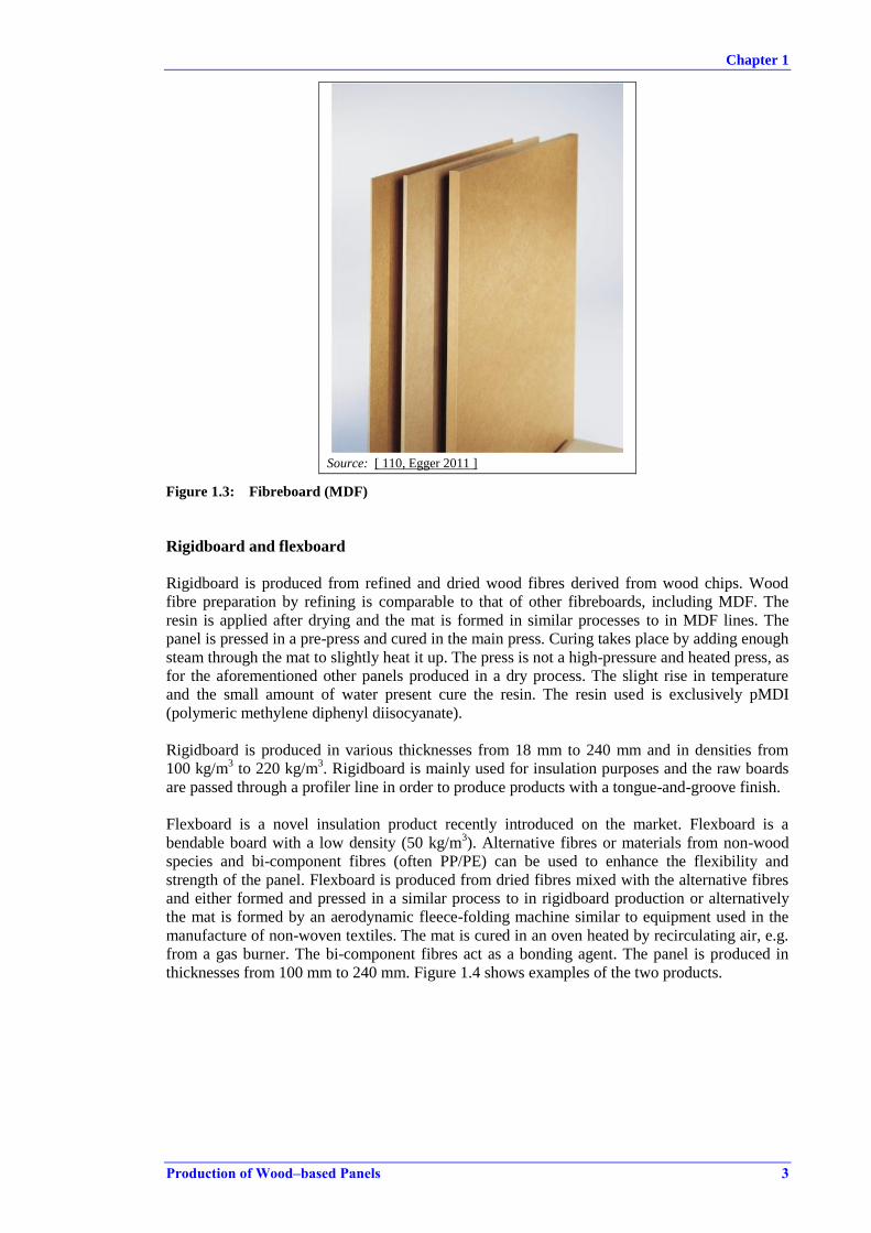
Source: [ 110, Egger 2011 ]
Figure 1.3: Fibreboard (MDF)
Rigidboard and flexboard
Rigidboard is produced from refined and dried wood fibres derived from wood chips. Wood
fibre preparation by refining is comparable to that of other fibreboards, including MDF. The
resin is applied after drying and the mat is formed in similar processes to in MDF lines. The
panel is pressed in a pre-press and cured in the main press. Curing takes place by adding enough
steam through the mat to slightly heat it up. The press is not a high-pressure and heated press, as
for the aforementioned other panels produced in a dry process. The slight rise in temperature
and the small amount of water present cure the resin. The resin used is exclusively pMDI
(polymeric methylene diphenyl diisocyanate).
Rigidboard is produced in various thicknesses from 18 mm to 240 mm and in densities from
100 kg/m3 to 220 kg/m
3. Rigidboard is mainly used for insulation purposes and the raw boards
are passed through a profiler line in order to produce products with a tongue-and-groove finish.
Flexboard is a novel insulation product recently introduced on the market. Flexboard is a
bendable board with a low density (50 kg/m3). Alternative fibres or materials from non-wood
species and bi-component fibres (often PP/PE) can be used to enhance the flexibility and
strength of the panel. Flexboard is produced from dried fibres mixed with the alternative fibres
and either formed and pressed in a similar process to in rigidboard production or alternatively
the mat is formed by an aerodynamic fleece-folding machine similar to equipment used in the
manufacture of non-woven textiles. The mat is cured in an oven heated by recirculating air, e.g.
from a gas burner. The bi-component fibres act as a bonding agent. The panel is produced in
thicknesses from 100 mm to 240 mm. Figure 1.4 shows examples of the two products.
Chapter 1
4 Production of Wood–based Panels
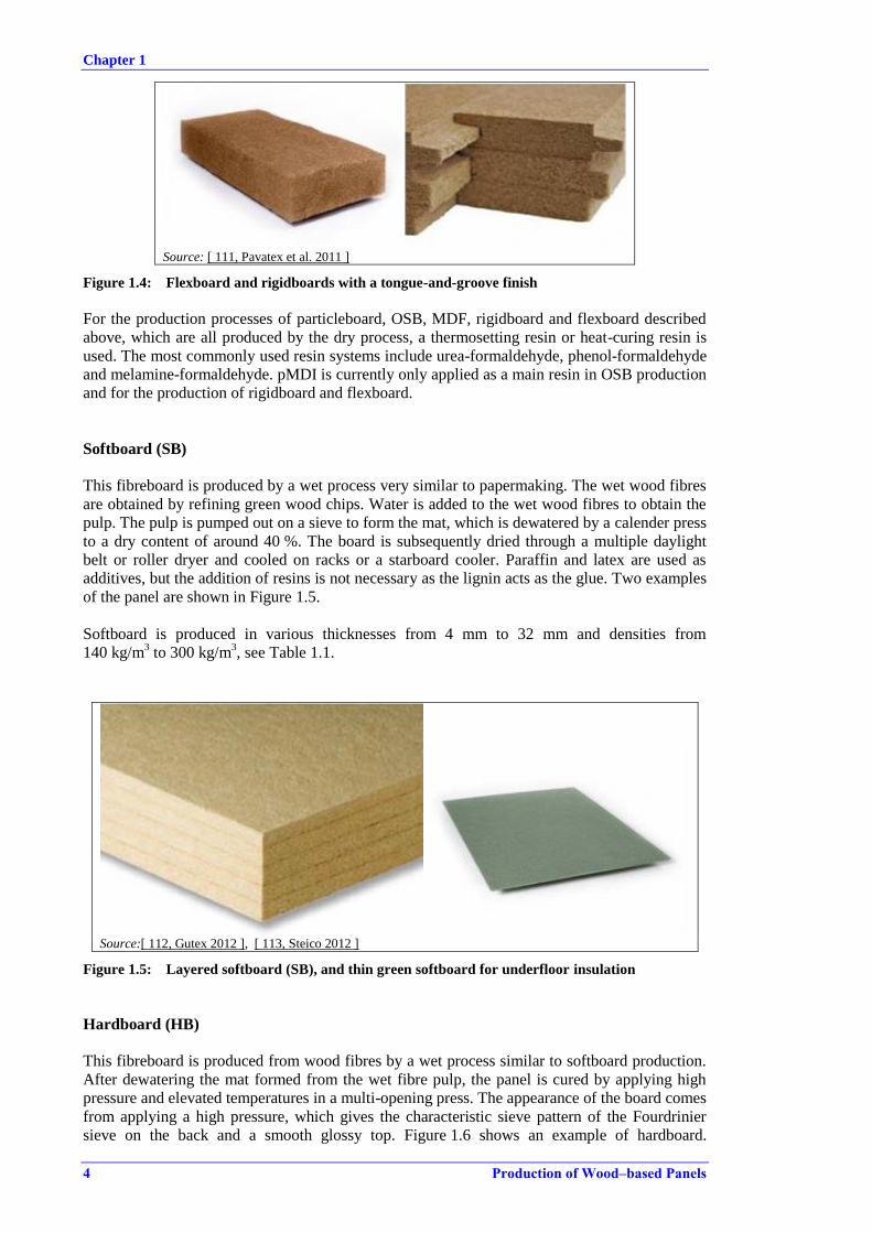
Source: [ 111, Pavatex et al. 2011 ]
Figure 1.4: Flexboard and rigidboards with a tongue-and-groove finish
For the production processes of particleboard, OSB, MDF, rigidboard and flexboard described
above, which are all produced by the dry process, a thermosetting resin or heat-curing resin is
used. The most commonly used resin systems include urea-formaldehyde, phenol-formaldehyde
and melamine-formaldehyde. pMDI is currently only applied as a main resin in OSB production
and for the production of rigidboard and flexboard.
Softboard (SB)
This fibreboard is produced by a wet process very similar to papermaking. The wet wood fibres
are obtained by refining green wood chips. Water is added to the wet wood fibres to obtain the
pulp. The pulp is pumped out on a sieve to form the mat, which is dewatered by a calender press
to a dry content of around 40 %. The board is subsequently dried through a multiple daylight
belt or roller dryer and cooled on racks or a starboard cooler. Paraffin and latex are used as
additives, but the addition of resins is not necessary as the lignin acts as the glue. Two examples
of the panel are shown in Figure 1.5.
Softboard is produced in various thicknesses from 4 mm to 32 mm and densities from
140 kg/m3 to 300 kg/m
3, see Table 1.1.
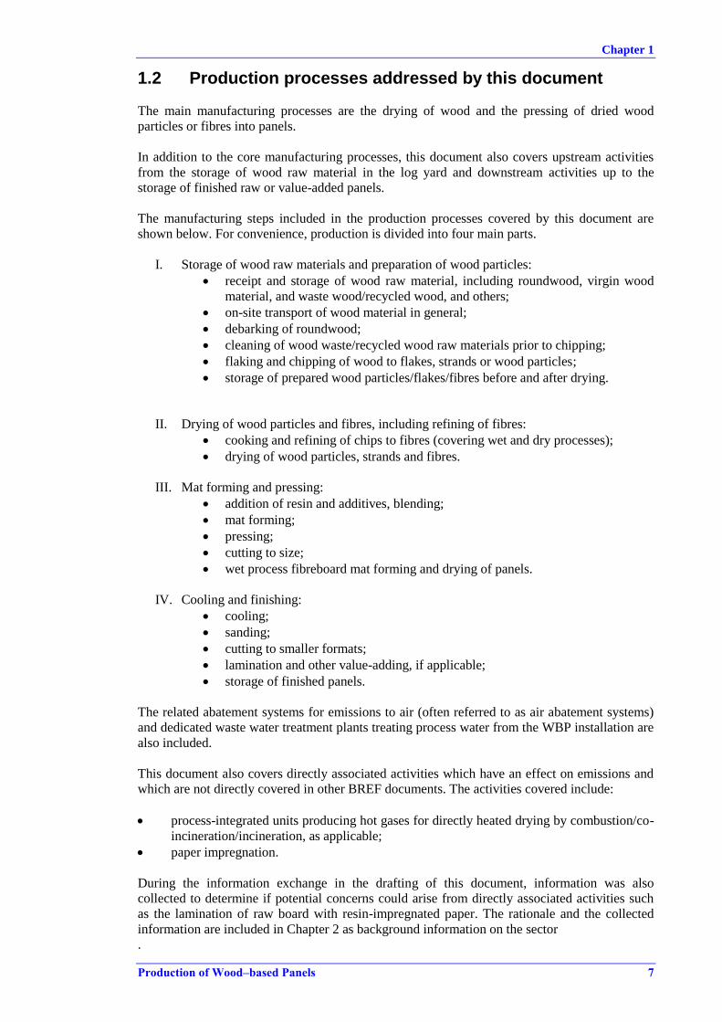
Source:[ 112, Gutex 2012 ], [ 113, Steico 2012 ]
Figure 1.5: Layered softboard (SB), and thin green softboard for underfloor insulation
Hardboard (HB)
This fibreboard is produced from wood fibres by a wet process similar to softboard production.
After dewatering the mat formed from the wet fibre pulp, the panel is cured by applying high
pressure and elevated temperatures in a multi-opening press. The appearance of the board comes
from applying a high pressure, which gives the characteristic sieve pattern of the Fourdrinier
sieve on the back and a smooth glossy top. Figure 1.6 shows an example of hardboard.

Chapter 1
Production of Wood–based Panels 5
Hardboard is produced in several value-added varieties, e.g. tempered hardboard. Hardboard
was the first panel variety to be produced on an industrial scale. It was invented in the early
1930s and patented under the name Masonite.
Hardboard is produced in a small range of thicknesses up to 5.5 mm, see Table 1.1.
Source: [ 114, Lessa 2012 ]
Figure 1.6: Hardboard (HB)
Particleboard pallets and pallet blocks
Particleboard pallets are produced from wood particles in a process almost identical to that of
particleboard. The raw material is often recycled solid wood pallets. The mat forming and press
step differs, since each pallet needs to be formed and pressed individually in a single-opening
press. The pallet blocks have a thickness that requires additional heat transfer, which is
obtained, for example, by steam injection in special presses. The resins used are similar to those
applied in particleboard production. Figure 1.7 shows examples of pallet-related products.
Source: [ 115, Presswood 2012 ]
Figure 1.7: Particleboard pallet and pallet blocks
Table 1.1 summarises the panel products mentioned, their range of densities and whether they
are produced in a dry process or a wet process. The majority of panel types are produced using a
dry process.

Chapter 1
6 Production of Wood–based Panels
Table 1.1: Densities and process types for different wood-based panel products
Panel Production process Density
(kg/m3)
Particleboard (PB) Dry 500 – 800(1)
Oriented strand board (OSB) Dry 580 – 680
High density fibreboard (HDF) Dry > 800
Medium density fibreboard
(MDF) Dry 700 – 800
Low density fibreboard (LDF) Dry < 650
Hardboard (HB) Wet 900 – 1100
Mediumboard (MB) Wet 400 – 900
Softboard (SB) Wet 140 – 400
Rigidboard Dry 100 – 240
Flexboard Dry 50
Pallets and pallet blocks Dry - (1) The particleboard variety flaxboard is produced in densities of 350–600 kg/m3.
Source: [ 30, EPF 2011 ], [ 34, WPIF 2002 ]
Also, the European market includes producers manufacturing speciality products with distinct
production techniques, such as thin particleboards, extruded boards, honeycomb boards and
moulded products from wood chips. The production techniques for these special boards and
moulded parts, like door skins and moulded pallets, are comparable with the standard
particleboard or MDF production processes and the emissions are of a comparable composition
during production. A few installations have provided emissions data on extruded panels and the
information is included in the following chapters.
Chapter 1
Production of Wood–based Panels 7
1.2 Production processes addressed by this document
The main manufacturing processes are the drying of wood and the pressing of dried wood
particles or fibres into panels.
In addition to the core manufacturing processes, this document also covers upstream activities
from the storage of wood raw material in the log yard and downstream activities up to the
storage of finished raw or value-added panels.
The manufacturing steps included in the production processes covered by this document are
shown below. For convenience, production is divided into four main parts.
I. Storage of wood raw materials and preparation of wood particles:
receipt and storage of wood raw material, including roundwood, virgin wood
material, and waste wood/recycled wood, and others;
on-site transport of wood material in general;
debarking of roundwood;
cleaning of wood waste/recycled wood raw materials prior to chipping;
flaking and chipping of wood to flakes, strands or wood particles;
storage of prepared wood particles/flakes/fibres before and after drying.
II. Drying of wood particles and fibres, including refining of fibres:
cooking and refining of chips to fibres (covering wet and dry processes);
drying of wood particles, strands and fibres.
III. Mat forming and pressing:
addition of resin and additives, blending;
mat forming;
pressing;
cutting to size;
wet process fibreboard mat forming and drying of panels.
IV. Cooling and finishing:
cooling;
sanding;
cutting to smaller formats;
lamination and other value-adding, if applicable;
storage of finished panels.
The related abatement systems for emissions to air (often referred to as air abatement systems)
and dedicated waste water treatment plants treating process water from the WBP installation are
also included.
This document also covers directly associated activities which have an effect on emissions and
which are not directly covered in other BREF documents. The activities covered include:
process-integrated units producing hot gases for directly heated drying by combustion/co-
incineration/incineration, as applicable;
paper impregnation.
During the information exchange in the drafting of this document, information was also
collected to determine if potential concerns could arise from directly associated activities such
as the lamination of raw board with resin-impregnated paper. The rationale and the collected
information are included in Chapter 2 as background information on the sector
.
Chapter 1
8 Production of Wood–based Panels
1.3 Environmental issues covered by this document
The wood-based panels sector covers the production of a range of products and, while the
production flow differs from product to product, there are some common features in terms of the
key environmental issues.
In Chapter 3 the potential environmental issues identified in Chapter 2 related to each process
are illustrated through the data collected and other information received. Not all issues are
present at every installation and not all issues are equally relevant in terms of potential
environmental impact. Below, the key environmental issues identified for the sector are
mentioned.
The available primary and secondary techniques for the abatement of these identified key
environmental issues are described in Chapter 4.
Emissions of dust, organic compounds and formaldehyde are the main components that are
covered in this document.
Dust
Fine particulate matter emissions contribute to dust emissions from wood-based panel
production, where particles below 3 µm can constitute up to 50 % of the total dust measured.
In addition, the dust is a contributing factor to the formation of blue haze and odour. Blue haze
and odour is an issue which is related to the local area immediately surrounding the site, but the
contribution of TOC to the deposition of fine particulate matter is also relevant in terms of
environmental impact. The measures to lower emissions of particles below 10 µm (PM10, PM2,5
and PM1), due to their potential for causing health and environmental problems, is high on the
environmental policy agenda.
Current emission levels and the characterisation of dust are described in Section 3.2.
TVOC
TVOC emissions from wood-based panel production contribute to the emission of fine
particulate matter and the creation of blue haze and odour. The purpose of preventing or
reducing the emission of TVOC is to limit blue haze and odour, and to lower the fraction of
very fine dust derived from condensable organics and other sources. Volatile organic
compounds are considered, according to the UNECE definition, as any organic compound
which is emitted from non-natural processes and has a photochemical ozone creation potential
(POCP), which means any organic compound released to the atmosphere from an industrial
plant or process, excluding methane.
The main constituents of the volatile organic fraction in wood are generally not considered in
the literature as possessing toxic properties. An exception is formaldehyde. The environmental
impact of formaldehyde is described below.
The composition of the TOC fraction in dryer emissions and emission levels are described in
Section 3.2.
Formaldehyde
Formaldehyde emissions from wood-based panel production contribute to a minor part of the
volatile organics. The formaldehyde content is around 5 % compared to that of TOC.
Formaldehyde is not condensable and the contribution of formaldehyde to the creation of blue
haze and odour is not considered a major issue.
Emissions of formaldehyde are abated because of its properties as a potential precursor for
causing ozone depletion in the lower ozone layer. Formaldehyde is marked as an irritant for
eyes and the respiratory system and as a possible human carcinogen. The formaldehyde levels in

Chapter 1
Production of Wood–based Panels 9
ambient air are relevant, in terms of the toxicological aspects, regarding workplace health and
safety and for the end use of the panel in indoor applications [ 51, CLP ECHA 2013 ], [ 50,
Program 2011 ]. Emissions of formaldehyde from industrial processes are regulated in the
majority of Member States.
The formaldehyde emission from the finished panel is an important issue in terms of indoor use
of the panel products and hence the final products are classified according to strict emission
limits. However, the final product's formaldehyde content and formaldehyde emission are not
considered in this document.
The current emission levels of formaldehyde are discussed further in Section 3.2.
Other key environmental issues divided by production process are given below.
Particleboard, OSB and MDF production
i. Emissions of total particulate matter/dust from dryers, consisting of wood dust and
condensable organic compounds and emissions of non-condensable natural VOCs,
including formaldehyde. The humid dust emission with aerosols gives rise to blue haze and
odour, if not treated. The particulate matter/dust is composed of wood dust measuring
between 2 µm and 100 µm and aerosols of condensable organics of 0.1–3 µm.
The composition of air emissions from dryers depends on the natural content of VOCs in
the wood raw material and the drying conditions.
For MDF, the resin is generally applied before drying and the composition of organic
compounds and the formaldehyde content in the emissions differ from PB and OSB for
example.
ii. Emissions from presses applying high temperature and pressure include volatile organic
compounds, including formaldehyde and a low content of wood dust. The volatile organic
compounds are partly derived from the wood, while formaldehyde emissions are related to
the use of formaldehyde-containing resins. The press emission is humid, sticky, odorous
and, depending on the resin type used, prone to ignition when collected and channelled.
iii. Emissions of NOX from directly heated dryers. The NOX is mainly created during the
combustion of fuel in the combustion plant generating hot gases for drying.
MDF and all other fibreboard production processes
iv. Process water with a high concentration of COD and TSS.
v. Water consumption.
All WBP production sites
vi. Consumption of energy.
vii. Surface run-off water from outdoor areas.
viii. Emissions from combustion plants.
ix. Noise.
[ 2, VITO, BIO and IEEP 2007 ], [ 27, WBP TWG subgroup 2012 ], [ 8, TWG WBP 2012 ],
[ 67, VITO 2011 ], [ 86, DEFRA 2010 ], [ 85, EPA 2010 ], [ 68, VDI 2013 ], [ 58, UBA Austria
2013 ] [ 83, Barbu et al. 2014 ].
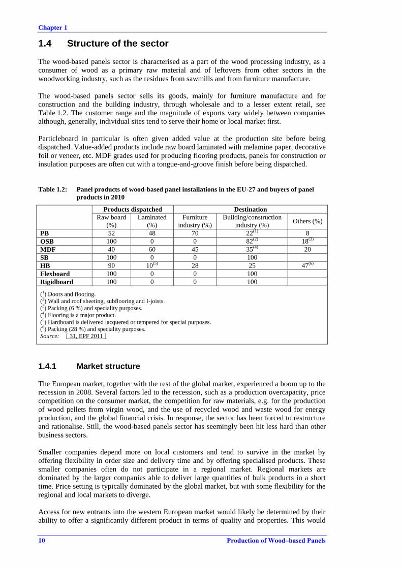
Chapter 1
10 Production of Wood–based Panels
1.4 Structure of the sector
The wood-based panels sector is characterised as a part of the wood processing industry, as a
consumer of wood as a primary raw material and of leftovers from other sectors in the
woodworking industry, such as the residues from sawmills and from furniture manufacture.
The wood-based panels sector sells its goods, mainly for furniture manufacture and for
construction and the building industry, through wholesale and to a lesser extent retail, see
Table 1.2. The customer range and the magnitude of exports vary widely between companies
although, generally, individual sites tend to serve their home or local market first.
Particleboard in particular is often given added value at the production site before being
dispatched. Value-added products include raw board laminated with melamine paper, decorative
foil or veneer, etc. MDF grades used for producing flooring products, panels for construction or
insulation purposes are often cut with a tongue-and-groove finish before being dispatched.
Table 1.2: Panel products of wood-based panel installations in the EU-27 and buyers of panel
products in 2010
Products dispatched Destination
Raw board
(%)
Laminated
(%)
Furniture
industry (%)
Building/construction
industry (%) Others (%)
PB 52 48 70 22(1)
8
OSB 100 0 0 82(2)
18(3)
MDF 40 60 45 35(4)
20
SB 100 0 0 100
HB 90 10(5)
28 25 47(6)
Flexboard 100 0 0 100
Rigidboard 100 0 0 100
(1) Doors and flooring.
(2) Wall and roof sheeting, subflooring and I-joists.
(3) Packing (6 %) and speciality purposes.
(4) Flooring is a major product.
(5) Hardboard is delivered lacquered or tempered for special purposes.
(6) Packing (28 %) and speciality purposes.
Source: [ 31, EPF 2011 ]
1.4.1 Market structure
The European market, together with the rest of the global market, experienced a boom up to the
recession in 2008. Several factors led to the recession, such as a production overcapacity, price
competition on the consumer market, the competition for raw materials, e.g. for the production
of wood pellets from virgin wood, and the use of recycled wood and waste wood for energy
production, and the global financial crisis. In response, the sector has been forced to restructure
and rationalise. Still, the wood-based panels sector has seemingly been hit less hard than other
business sectors.
Smaller companies depend more on local customers and tend to survive in the market by
offering flexibility in order size and delivery time and by offering specialised products. These
smaller companies often do not participate in a regional market. Regional markets are
dominated by the larger companies able to deliver large quantities of bulk products in a short
time. Price setting is typically dominated by the global market, but with some flexibility for the
regional and local markets to diverge.
Access for new entrants into the western European market would likely be determined by their
ability to offer a significantly different product in terms of quality and properties. This would
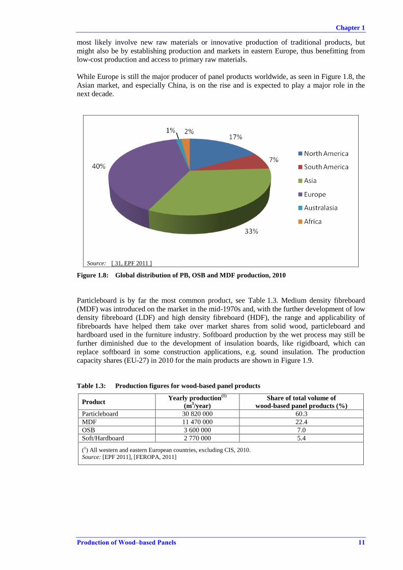
Chapter 1
Production of Wood–based Panels 11
most likely involve new raw materials or innovative production of traditional products, but
might also be by establishing production and markets in eastern Europe, thus benefitting from
low-cost production and access to primary raw materials.
While Europe is still the major producer of panel products worldwide, as seen in Figure 1.8, the
Asian market, and especially China, is on the rise and is expected to play a major role in the
next decade.
Source: [ 31, EPF 2011 ]
Figure 1.8: Global distribution of PB, OSB and MDF production, 2010
Particleboard is by far the most common product, see Table 1.3. Medium density fibreboard
(MDF) was introduced on the market in the mid-1970s and, with the further development of low
density fibreboard (LDF) and high density fibreboard (HDF), the range and applicability of
fibreboards have helped them take over market shares from solid wood, particleboard and
hardboard used in the furniture industry. Softboard production by the wet process may still be
further diminished due to the development of insulation boards, like rigidboard, which can
replace softboard in some construction applications, e.g. sound insulation. The production
capacity shares (EU-27) in 2010 for the main products are shown in Figure 1.9.
Table 1.3: Production figures for wood-based panel products
Product Yearly production
(1)
(m3/year)
Share of total volume of
wood-based panel products (%)
Particleboard 30 820 000 60.3
MDF 11 470 000 22.4
OSB 3 600 000 7.0
Soft/Hardboard 2 770 000 5.4
(1) All western and eastern European countries, excluding CIS, 2010.
Source: [EPF 2011], [FEROPA, 2011]
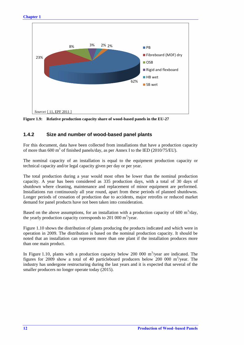
Chapter 1
12 Production of Wood–based Panels
Source: [ 11, EPF 2011 ]
Figure 1.9: Relative production capacity share of wood-based panels in the EU-27
1.4.2 Size and number of wood-based panel plants
For this document, data have been collected from installations that have a production capacity
of more than 600 m3 of finished panels/day, as per Annex I to the IED (2010/75/EU).
The nominal capacity of an installation is equal to the equipment production capacity or
technical capacity and/or legal capacity given per day or per year.
The total production during a year would most often be lower than the nominal production
capacity. A year has been considered as 335 production days, with a total of 30 days of
shutdown where cleaning, maintenance and replacement of minor equipment are performed.
Installations run continuously all year round, apart from these periods of planned shutdowns.
Longer periods of cessation of production due to accidents, major retrofits or reduced market
demand for panel products have not been taken into consideration.
Based on the above assumptions, for an installation with a production capacity of 600 m3/day,
the yearly production capacity corresponds to 201 000 m3/year.
Figure 1.10 shows the distribution of plants producing the products indicated and which were in
operation in 2009. The distribution is based on the nominal production capacity. It should be
noted that an installation can represent more than one plant if the installation produces more
than one main product.
In Figure 1.10, plants with a production capacity below 200 000 m3/year are indicated. The
figures for 2009 show a total of 40 particleboard producers below 200 000 m3/year. The
industry has undergone restructuring during the last years and it is expected that several of the
smaller producers no longer operate today (2015).

Chapter 1
Production of Wood–based Panels 13
Source: [ 11, EPF 2011 ], [ 8, TWG WBP 2012 ].
Figure 1.10: Nominal production capacities for the panel products covered in this document,
including all plants in the EU-27
The distribution of wood-based panel installations is spread unevenly across the EU-27, with the
largest capacity and number of installations found in Germany, Italy, Spain and France.
Main panel products
MDF and OSB plants have a fairly even average nominal capacity of 320 000 m3/year for MDF
and 380 000 m3/year for OSB, see Figure 1.10.
The particleboard sector is more uneven, mostly as a consequence of the production lines in
most Member States being older than the more recently introduced MDF and OSB plants. New
installations tend to be bigger than older ones, and the average capacity of particleboard
installations which exceed 200 000 m3/year is 470 000 m
3/year, and much higher than for other
panel products, see Figure 1.10. Particleboard installations which have a nominal capacity
below 200 000 m3/year represented only 9 % of the total nominal production capacity in 2009,
but 35 % of the total number of installations. The smaller production installations can be found
throughout Europe, but for larger productions ones, the majority are found in Italy, France,
Germany and Spain [ 11, EPF 2011 ], [ 10, Popescu 2008 ].
Niche panel products
Fibreboard-based special products including softboard, hardboard, and mediumboard are all
produced in a wet process. Hardboard is the oldest panel product, with industrial production in
Europe starting as early as the beginning of the 1950s.
Rigidboard and flexboard constitute a niche within the industry and have only been produced in
the EU-27 since around 2005, and are produced in a dry process.
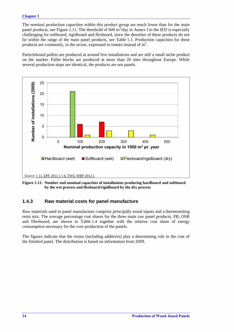
Chapter 1
14 Production of Wood–based Panels
The nominal production capacities within this product group are much lower than for the main
panel products, see Figure 1.11. The threshold of 600 m3/day in Annex I to the IED is especially
challenging for softboard, rigidboard and flexboard, since the densities of these products do not
lie within the range of the main panel products, see Table 1.1. Production capacities for these
products are commonly, in the sector, expressed in tonnes instead of m3.
Particleboard pallets are produced at around five installations and are still a small niche product
on the market. Pallet blocks are produced at more than 20 sites throughout Europe. While
several production steps are identical, the products are not panels.
Source: [ 11, EPF 2011 ], [ 8, TWG WBP 2012 ].
Figure 1.11: Number and nominal capacities of installations producing hardboard and softboard
by the wet process and flexboard/rigidboard by the dry process
1.4.3 Raw material costs for panel manufacture
Raw materials used in panel manufacture comprise principally wood inputs and a thermosetting
resin mix. The average percentage cost shares for the three main raw panel products, PB, OSB
and fibreboard, are shown in Table 1.4 together with the relative cost share of energy
consumption necessary for the core production of the panels.
The figures indicate that the resins (including additives) play a determining role in the cost of
the finished panel. The distribution is based on information from 2009.

Chapter 1
Production of Wood–based Panels 15
Table 1.4: Breakdown of direct material costs in 2009 for PB, OSB and MDF raw panels
Material Percentage
cost share
Percentage of
finished product
Wood 31 % 90 %
Resin 43 % 10 %
Energy 26 % -
Source: [ 43, EU economics 2010 ], [ 31, EPF 2011 ]
Wood raw materials have, since 2009, experienced a rise in costs, due to the competition from
pellet producers and biomass energy production. The accessibility and competition for raw
materials depend on the local market and vary throughout Europe. It is estimated that the cost
share for wood raw material could be considerably higher in the future. Resins have also
experienced a rise in price, which is connected to the fact that resin production is based on by-
products from the oil refining industry and will follow the general prices on the oil market. The
cost evolution from 2007 to 2010 of expenses for production input materials is shown in
Table 1.5.
Table 1.5: Increase of production input costs in the wood-based panel sector from 2007 to 2010
Material Cost increase (%)
2007 – 2010
Wood 8
Roundwood 6
Post-consumer wood 8
Resins 15
Energy 10
Transport 5
Source: [ 11, EPF 2011 ]
1.4.4 Environmental cost for panel manufacture
While the overall investment for a new medium-sized plant on a greenfield site is over
EUR 150 million, around 20 % of the cost is related to emission reduction equipment. The
operating and maintenance costs of the emission reduction equipment can be more than
EUR 3 million per year.
Emission reduction schemes also play a role in the sector as all sites operate combustion plants
[ 81, AEA 2009 ].
1.4.5 Technical characteristics of wood-based panel installations
The layout of different wood-based panel installations contains the same main features, but has
very different footprints according to the age, directly associated activities, and the extent of
retrofitting. While new production lines can be accommodated at a greenfield site to obtain
optimum conditions for a logical production flow, this can sometimes be a difficult task at an
existing site.
Key areas include the dryer and combustion units, followed by the press complex, which
contains the mat forming station, press line and cooling station. For directly heated dryers
especially, combustion units are conveniently placed close to the dryers. The cooking and
refining of fibres for fibreboard production is closely linked to the fibre dryer and is directly
connected to the dryer.
Chapter 1
16 Production of Wood–based Panels
The press has an operating lifetime of at least 30 years. In the past 20 years, older plants have
installed continuous presses instead of multi-opening presses (daylight presses), and continuous
presses are, at the time of writing the norm in most plants. Presses are often retrofitted, e.g. to
increase production capacities by adding more length to a continuous press or installing better
suction systems in the mat forming, trimming or press section.
Dryers have a rather long lifetime, but the energy efficiency and quality of the dried product can
be improved through various choices of retrofits, such as improved dryer configuration, choice
of energy source, management of waste gases and by taking advantage of the heat energy in
waste gases.
For all equipment, continuous cleaning, maintenance and repairs are necessary and are
performed on a regular basis.
Few installations produce raw panels alone. In all installations, the raw board is cut to size,
according to the dimensions determined by the market and the actual order placed. Several
larger producers operating multiple production sites offer a wide range of value-added products,
e.g. flooring, door skins, worktops, kitchen furniture and self-assembly furniture.
1.4.6 Location trends for wood-based panel sites
The location of a production site can be influenced by a tendency to agglomerate in regions with
sawmills or with direct access to virgin wood. Some companies own forests and harvest their
own raw material. This was common before 1990, but is less prevalent at the time of writing.
The transport possibilities for raw materials play an important role, since the daily turnover of
received wood raw material is over 350 tonnes. Easy access to the main road network or to
waterways is therefore an advantage. Potential noise, dust and odour nuisances are additional
elements to consider when planning the location and layout of a production site.
1.4.7 Challenges and trends for the wood-based panel sector
Several factors influence the quality and price of panel products, which challenges the industry
in the search for new raw materials and new production patterns.
Wood raw material
The wood-based panel sector is influenced by the availability of wood raw materials. In
competition for raw materials, both fresh virgin wood and recycled wood are increasingly used
for producing fuels for biomass-fired combustion plants. Pellet producers use either virgin wood
or production residues from the furniture industry and have become an increasingly fierce
competitor on the raw material market. Post-consumer waste wood or recovered wood is also
increasingly used as biomass-based fuel. There is a tendency for the more uniform and clean
fractions of recovered wood to be directed to energy production, while recovered wood of a
lower quality and hence the cheaper fractions are economically available for particleboard
producers.
The European Panel Federation has published a charter for the use of waste wood in
particleboard production, which prescribes a voluntary standard for the quality and handling of
wood waste for its members.
For the sector, it has been important to give out a clear message that it supports sustainable
production, in terms of using recovered wood as a raw material and as a fuel. Virgin wood used
as a raw material is increasingly being harvested from certified forests, where harvest and
growth are sustainable. For the latter, certification schemes such as the Forest Stewardship
Council certification (FSC) and the Programme for the Endorsement of Forest Certification
(PEFC) are widely applied.
Chapter 1
Production of Wood–based Panels 17
Resins and formaldehyde in the final product
The majority of resins used are based on urea-formaldehyde. The raw panels adhere to EN
standards, which not only prescribe the physical characteristics of the panel such as bending
strength, stability, load bearings and swelling properties, but also classification according to the
amount of free formaldehyde in the finished board. For indoor and furniture applications, a
lower formaldehyde content is required, if classified under the E1 emission class.
Formaldehyde emission classes in finished panels, defined in Annex B of EN 13986 are as
follows:
Class E1: ≤ 8mg/100g dry board or < 0.124 mg/m3 according to EN 717-1;
Class E2: > 8 to < 30mg/100g dry board or > 0.124– < 0.3 mg/m3 according to EN 717-1.
Besides EN product standards, the production of panels is increasingly influenced by product
emission quality standards applied outside Europe, most importantly CARB standards,
originating from Californian legislation [ 95, ATCM 2007 ] The emission limit values in panels
used for furniture applications are at levels much lower than the corresponding lowest emitting
standard in the EN standards.
Formaldehyde emission classes defined by ATCM 93120 are as follows:
CARB phase 2 standard for MDF: 0.11 ppm;
CARB phase 2 standard for Particleboard: 0.09 ppm.
In order to be able to act on a global scale, several producers in the EU-27 are producing low-
formaldehyde-emitting panels for interior applications adhering to CARB standards. This can be
achieved by using a non-formaldehyde-based resin. The amount of free formaldehyde in the
final panel could be limited by using a resin where the formaldehyde versus urea proportion is
balanced with an excess of urea, typically by adding urea, more hardening agent and adjusting
the press time and temperature.
Research is focused on identifying alternatives to the formaldehyde-based resin, and one resin
group especially used in OSB, flexboard and rigidboard production is isocyanate resins,
primarily pMDI. The potential of the resin is strongly limited by the global production, which is
not sufficient to cover the demand from the wood-based panels sector. In order to use pMDI,
major changes in the set-up and operation of wood-resin blending, mat forming and presses will
be needed.
Despite the obstacle of using a formaldehyde-based resin, an alternative is not foreseen in the
near future. In the longer term, other factors could force the development of alternatives, mainly
due to limitations in the supply of petrochemicals, which are the raw material for resin
production.
The range of final products should adhere to the requirements in EN standards, EU Ecolabel
criteria and national ecolabel criteria, which this document does not take further into account,
although it is clear that developments in new production methods with new raw materials are
influenced by demands set in certification schemes.
The following standards are examples specifying the physical properties of wood-based panels
applicable for different classes of wood-based panel products; defining panels according to use
in interior, exterior, humid and load-bearing applications:
EN 309 Particleboards - Definition and classification;
EN 312 Particleboards defining P1-P7 types for particleboard;
EN 300 OSB defining OSB/1-OSB/4 types for OSB;
EN 316 Wood fibre boards - Definition, classification and symbols;

Chapter 1
18 Production of Wood–based Panels
EN 622-3 defines three classes of low density mediumboard and seven classes of high
density mediumboard derived from wet processes;
EN 622-2 concerns the specifications and requirements for hardboard in six technical
classes;
EN 622-4 concerns the specifications and requirements for softboards, of which there are
five technical classes;
EN 662-5 concerns the specifications of and requirements for six technical classes of
MDF dry process fibreboards;
EN 14755 determines the qualities of extruded particleboards;
EN 15197 determines four technical classes of flaxboard (particleboard using flax as a
raw material).
Product quality and product standardisation are not discussed further in this document.

Chapter 2
Production of Wood–based Panels 19
2 APPLIED PROCESSES AND TECHNIQUES
All the main process steps, from the storage of raw material to the storage of finished product,
take place at the wood-based panel installation. More than 50 % of the raw boards are further
processed, to give them added value, at the installation prior to dispatch.
The production of wood-based panels is a continuous process, where the core processes, drying
and pressing, are especially interlinked. The production depends on the functionality of all the
intermediary steps. While the preparation of wood particles can run with an overproduction and
intermediary storage of prepared chips before the drying step, there are generally only a few
hours of storage capacity for dried wood particles, to keep the mat forming station and panel
press running continuously.
For convenience, the production process is divided into the following main steps:
I. The storage of wood raw materials and the preparation of wood particles.
II. Drying of wood particles and fibres, including refining of fibres.
III. Mat forming and pressing.
IV. Cooling and finishing.
Figure 2.1 shows a schematic production flow for the different products covered in this
document, and also the main common processes.
In the first four sections of this chapter, the main process steps are described. If necessary, they
are linked to the relevant products, if there are significant changes in the production process
which could especially affect the related environmental issues.
The range of possible environmental impacts is mentioned for each process along with the
measures currently applied to prevent or reduce these impacts.
It is important to recognise that not all the possible environmental issues mentioned in this
chapter will arise at all sites with the same impact, since they will depend on the applied
production methods, consumption patterns, raw material selection, local conditions, the age of
the installation and the measures applied to prevent or reduce the emissions. In Chapter 3,
related data for the environmental issues currently monitored in the EU are presented.
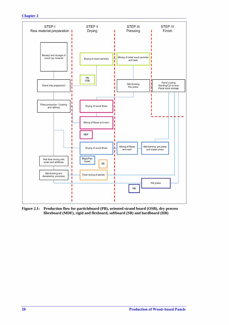
Chapter 2
20 Production of Wood–based Panels
Figure 2.1: Production flow for particleboard (PB), oriented strand board (OSB), dry process
fibreboard (MDF), rigid and flexboard, softboard (SB) and hardboard (HB)
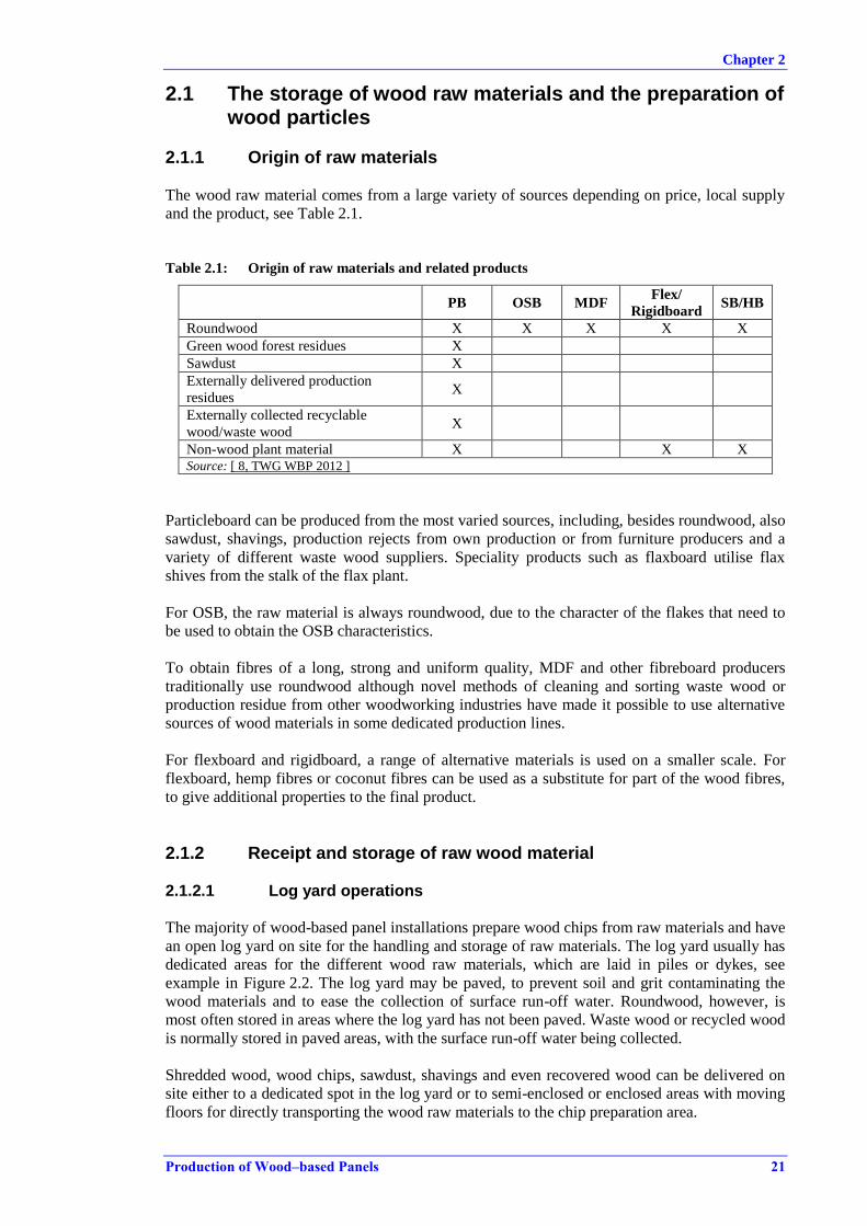
Chapter 2
Production of Wood–based Panels 21
2.1 The storage of wood raw materials and the preparation of wood particles
2.1.1 Origin of raw materials
The wood raw material comes from a large variety of sources depending on price, local supply
and the product, see Table 2.1.
Table 2.1: Origin of raw materials and related products
PB OSB MDF Flex/
Rigidboard SB/HB
Roundwood X X X X X
Green wood forest residues X
Sawdust X
Externally delivered production
residues X
Externally collected recyclable
wood/waste wood X
Non-wood plant material X X X Source: [ 8, TWG WBP 2012 ]
Particleboard can be produced from the most varied sources, including, besides roundwood, also
sawdust, shavings, production rejects from own production or from furniture producers and a
variety of different waste wood suppliers. Speciality products such as flaxboard utilise flax
shives from the stalk of the flax plant.
For OSB, the raw material is always roundwood, due to the character of the flakes that need to
be used to obtain the OSB characteristics.
To obtain fibres of a long, strong and uniform quality, MDF and other fibreboard producers
traditionally use roundwood although novel methods of cleaning and sorting waste wood or
production residue from other woodworking industries have made it possible to use alternative
sources of wood materials in some dedicated production lines.
For flexboard and rigidboard, a range of alternative materials is used on a smaller scale. For
flexboard, hemp fibres or coconut fibres can be used as a substitute for part of the wood fibres,
to give additional properties to the final product.
2.1.2 Receipt and storage of raw wood material
2.1.2.1 Log yard operations
The majority of wood-based panel installations prepare wood chips from raw materials and have
an open log yard on site for the handling and storage of raw materials. The log yard usually has
dedicated areas for the different wood raw materials, which are laid in piles or dykes, see
example in Figure 2.2. The log yard may be paved, to prevent soil and grit contaminating the
wood materials and to ease the collection of surface run-off water. Roundwood, however, is
most often stored in areas where the log yard has not been paved. Waste wood or recycled wood
is normally stored in paved areas, with the surface run-off water being collected.
Shredded wood, wood chips, sawdust, shavings and even recovered wood can be delivered on
site either to a dedicated spot in the log yard or to semi-enclosed or enclosed areas with moving
floors for directly transporting the wood raw materials to the chip preparation area.
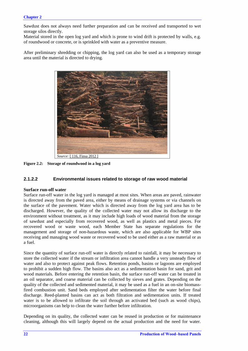
Chapter 2
22 Production of Wood–based Panels
Sawdust does not always need further preparation and can be received and transported to wet
storage silos directly.
Material stored in the open log yard and which is prone to wind drift is protected by walls, e.g.
of roundwood or concrete, or is sprinkled with water as a preventive measure.
After preliminary shredding or chipping, the log yard can also be used as a temporary storage
area until the material is directed to drying.
Source: [ 116, Finsa 2012 ]
Figure 2.2: Storage of roundwood in a log yard
2.1.2.2 Environmental issues related to storage of raw wood material
Surface run-off water
Surface run-off water in the log yard is managed at most sites. When areas are paved, rainwater
is directed away from the paved area, either by means of drainage systems or via channels on
the surface of the pavement. Water which is directed away from the log yard area has to be
discharged. However, the quality of the collected water may not allow its discharge to the
environment without treatment, as it may include high loads of wood material from the storage
of sawdust and especially from recovered wood, as well as plastics and metal pieces. For
recovered wood or waste wood, each Member State has separate regulations for the
management and storage of non-hazardous waste, which are also applicable for WBP sites
receiving and managing wood waste or recovered wood to be used either as a raw material or as
a fuel.
Since the quantity of surface run-off water is directly related to rainfall, it may be necessary to
store the collected water if the stream or infiltration area cannot handle a very unsteady flow of
water and also to protect against peak flows. Retention ponds, basins or lagoons are employed
to prohibit a sudden high flow. The basins also act as a sedimentation basin for sand, grit and
wood materials. Before entering the retention basin, the surface run-off water can be treated in
an oil separator, and coarse material can be collected by sieves and grates. Depending on the
quality of the collected and sedimented material, it may be used as a fuel in an on-site biomass-
fired combustion unit. Sand beds employed after sedimentation filter the water before final
discharge. Reed-planted basins can act as both filtration and sedimentation units. If treated
water is to be allowed to infiltrate the soil through an activated bed (such as wood chips),
microorganisms can help to clean the water further before infiltration.
Depending on its quality, the collected water can be reused in production or for maintenance
cleaning, although this will largely depend on the actual production and the need for water.

Chapter 2
Production of Wood–based Panels 23
Cleaning water uses include the washdown of dryers or in the glue kitchen. Reuse in production
includes water addition for resin or additive preparation or chip washing and cooking before
refining. If there is no possibility of reuse in production, it is discharged to a stream or
infiltrated, or, if local conditions dictate further treatment, it is directed to an on-site or off-site
waste water treatment plant.
Surface run-off water can have high TSS values. TSS and COD values are interlinked since both
are directly related to the wood debris.
Directive 2008/15/EC on environmental quality standards in the field of water policy includes in
its Annex I a list of priority substances. None of the listed substances are used directly in the
production process. It is however possible for some of the priority substances, e.g. nickel,
cadmium and lead, to be present in the collected surface run-off water, due for example to
storage of recovered wood. Surveys indicate that there could also be a potential release of
cadmium, copper, lead and zinc.
See Section 3.3.1 for current emission levels in surface run-off water discharges.
Diffuse dust emissions
Diffuse dust emissions from stored wood raw material in the log yard are common when
handling all materials and under the influence of wind drift. Diffuse emissions are higher in dry
climates and on windy days. The sprinkling of wood raw materials is not common, since it is
not an advantage that the wood raw material is wet. In order to reduce the spread of dust,
transport routes, storage areas and vehicles are cleaned regularly on most sites. Cleaning also
reduces the amount of dispersed wood material washed away by surface run-off water.
Noise
Noise arises from the transport and handling of raw wood materials, mainly from lorries
arriving at and leaving the site and internal transport by trucks. The unloading and handling of
roundwood is a point source of noise and is most pronounced when the roundwood is unloaded
for debarking or flaking. Noise can be diminished by unloading in semi-enclosed areas and by
limiting the fall height of the roundwood. On sites where the proximity to neighbours could
result in a noise nuisance, barriers of soil or other materials often enclose the site borders. This
is relevant for diminishing the noise both from log yard operations and also from the site in
general. The walls also act as a windshield for finer raw materials. Often it is possible to reduce
the noise at night by not receiving raw material from outside, and by limiting the handling to the
minimum necessary to keep production running.
Odour
Odour nuisance from the storage of fresh green wood and roundwood is occasionally registered.
It depends on local conditions and the sensitivity of the immediate surroundings. It can be
limited by storing less wood raw material or by changing the location of the most odorous
material. However, odour nuisance is normally more directly related to the emissions to air from
the drying of wood material, see Section 2.2.
2.1.3 Cleaning of recovered wood raw materials
Recovered wood contains a variety of non-wood materials that cannot be accepted in the
finished panel and hence it must be cleaned prior to entering the production line. Metals are
especially damaging to the production equipment, e.g. for the chippers and mills that prepare the
wood particles before drying, since metal grit will blunt and destroy the knives. Plastics and
metals in the press will cause blisters and burn the surface of the panels during pressing.
Dedicated cleaning plants for recovered wood are operated at sites where recovered wood is
used as a raw material. Recovered wood is not a uniform product and comes from various
suppliers. The most clean recovered wood is mainly wood residue from the furniture industry
which can frequently be used directly without further cleaning. Recovered wood from very

Chapter 2
24 Production of Wood–based Panels
diverse sources will need cleaning, such as post-consumer wood from public collection systems,
and special care should be taken in the cleaning of this material. Cleaning consists of the
following main steps in a typical cleaning plant, also shown in Figure 2.3:
shredding of material;
mechanical screening, e.g. vibrating, shaking, cascades;
removal of ferrous metals with detectors and magnets;
removal of non-ferrous metals with detectors and magnets;
removal of plastics, paper, etc. by air shifting;
shifting and sorting of wood particles for further reduction or transfer to wet raw storage.
Figure 2.3: Example of standard steps in a cleaning plant for recovered wood
On most sites, the cleaning plant for recovered wood was introduced after recovered wood and
especially post-consumer wood became relevant and accessible raw materials and after the
panel production plant was established on site. The cleaning plant is often a separate
construction on the site and not an integrated part of the building complex of the production
line. This is an advantage since the storage location for the recovered wood, noise abatement
and transport of collected dust to on-site combustion plants from the cleaning plant can be taken
into consideration in the planning of the site layout.
Recovered wood and especially post-consumer wood are controlled prior to cleaning.
Recovered wood is potentially contaminated and typical indicator pollutants can be identified.
Depending on the source of the recovered wood, sites have control programmes in place
[ 90, EA UK 2007 ], [ 73, UBA AT 2010 ], [ 64, EPF 2002 ].

Chapter 2
Production of Wood–based Panels 25
2.1.3.1 Environmental issues related to the cleaning of recovered wood materials
Emissions to air
Recovered wood has a moisture content of around 15–40 %, and is drier than other wood raw
materials. When the recovered wood, especially reclaimed wood fractions, is shredded, hacked,
chipped, and sorted over mechanical sieves, dust emissions will likely arise. Dust will not only
contain wood particles, but also particulate matter, like metals, plastics, paint and laminates.
Dust emissions from the cleaning plant are commonly collected at the various points of
operation and treated, e.g. by bag filters.
In order to avoid diffuse dust emissions, the equipment, indoor and outdoor premises, transport
routes and storage areas are cleaned regularly.
Waste handling
During the cleaning and sorting of the wood, the different waste fractions are collected
individually in hoppers. All oversize wood fractions are reintroduced for further chipping.
Undersized material collected in hoppers and dust collected in bag filters are used as a fuel on
site. The sorted fractions of metals and plastics and debris are dispatched off site.
Noise
Noise from the processing machines is pronounced and it will normally be necessary to enclose
or shield equipment in order to diminish it. The cleaning plant could have a production
overcapacity, which would make it possible to halt the operation of the plant in the most
sensitive hours during the night.
2.1.4 Debarking
Debarking is applied for roundwood if the final product needs a certain quality, and is always
performed in OSB production. Bark in fibreboard production is generally unwanted. For lower
qualities of MDF panel, a certain amount of bark is acceptable. The debarking operation will
also depend on the species of wood, so while pine and fir are often debarked, poplar or beech
often do not need debarking. For particleboard production, a specific debarking step is not
necessary and therefore not used. During the preparation of the chips for particleboard
production by chipping and milling, bark particles are sorted during one of several sorting steps
to remove fines and unwanted material.
Debarking can be achieved in rotating drums, where the friction between logs and the abrasive
surfaces removes the bark efficiently. Removed bark and waste wood fractions are collected
from the drum in hoppers or chutes. A drum debarker can process up to 50 tonnes per hour on a
dry basis and is typically connected directly to the flaker or strander for further processing
without intermediary storage of the debarked roundwood.
Wet debarking is not known to be used regularly in the sector today (2014), but was formerly
more widespread. In wet debarking, roundwood is sprinkled with hot water or steam in the
debarking drum. The purpose is to ease the bark off the log and to rinse the log before chipping.
During winter, the application of water or steam additionally thaws snow and ice off.
Bark is used as a valuable fuel. Bark derived from the debarking of roundwood is further
shredded before it is fed to the burning chamber. If too humid, the bark can be screw-pressed to
remove excess liquid. In dedicated large combustion plants, the bark is further dried before it is
fed to the furnace. Pre-drying is not known to be regularly used in the sector.
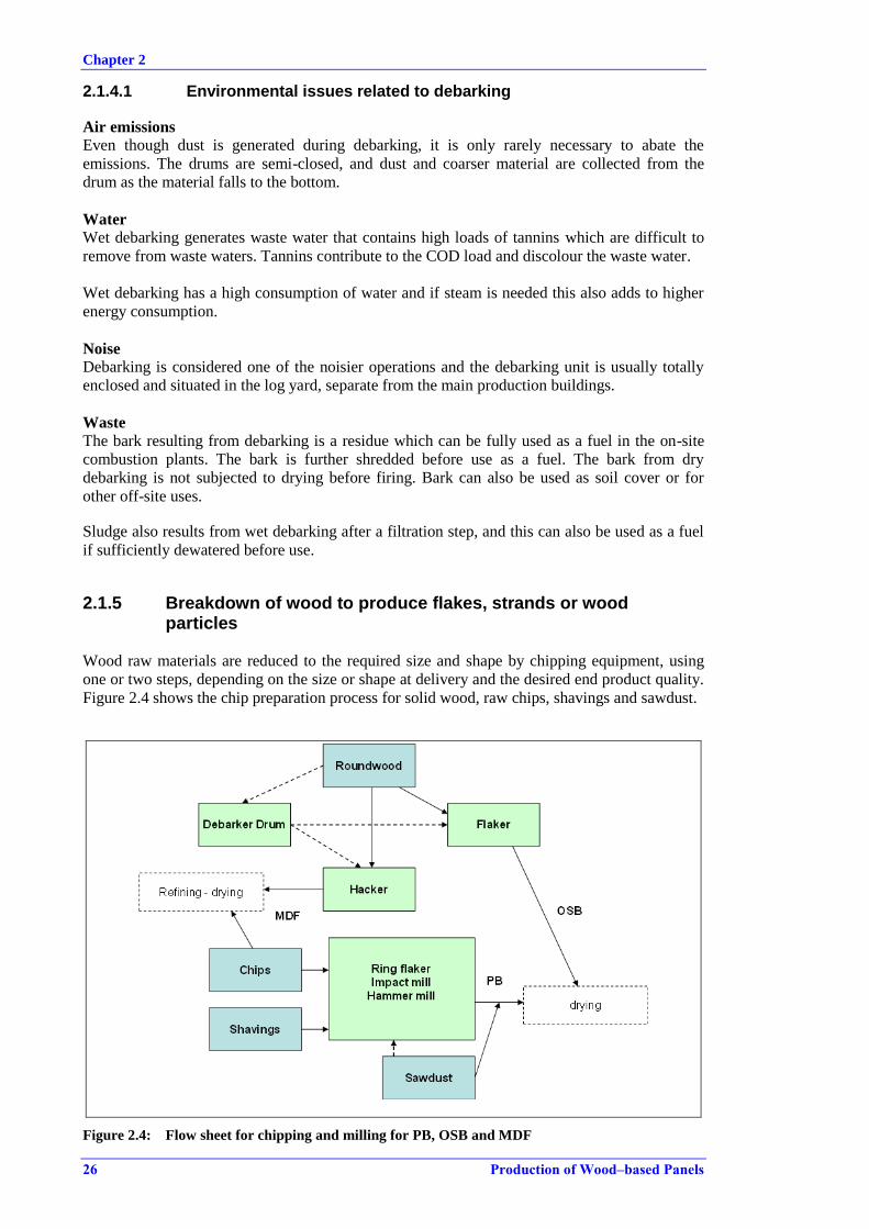
Chapter 2
26 Production of Wood–based Panels
2.1.4.1 Environmental issues related to debarking
Air emissions
Even though dust is generated during debarking, it is only rarely necessary to abate the
emissions. The drums are semi-closed, and dust and coarser material are collected from the
drum as the material falls to the bottom.
Water
Wet debarking generates waste water that contains high loads of tannins which are difficult to
remove from waste waters. Tannins contribute to the COD load and discolour the waste water.
Wet debarking has a high consumption of water and if steam is needed this also adds to higher
energy consumption.
Noise
Debarking is considered one of the noisier operations and the debarking unit is usually totally
enclosed and situated in the log yard, separate from the main production buildings.
Waste
The bark resulting from debarking is a residue which can be fully used as a fuel in the on-site
combustion plants. The bark is further shredded before use as a fuel. The bark from dry
debarking is not subjected to drying before firing. Bark can also be used as soil cover or for
other off-site uses.
Sludge also results from wet debarking after a filtration step, and this can also be used as a fuel
if sufficiently dewatered before use.
2.1.5 Breakdown of wood to produce flakes, strands or wood particles
Wood raw materials are reduced to the required size and shape by chipping equipment, using
one or two steps, depending on the size or shape at delivery and the desired end product quality.
Figure 2.4 shows the chip preparation process for solid wood, raw chips, shavings and sawdust.
Figure 2.4: Flow sheet for chipping and milling for PB, OSB and MDF
Chapter 2
Production of Wood–based Panels 27
Installations can apply both a primary breakdown and a secondary chipping of the wood
material. Equipment used includes hackers, flakers and different types of attrition mills. The
electrical energy demand per tonne of dry wood is higher for the primary breakdown of
roundwood than for the milling of smaller particles.
For primary breakdown, hackers with drum diameters of up to 2.4 m can be used for
roundwoods of random lengths and diameters. Hackers cut the wood with two to five knives,
holding back large particles with a breaker screen. They produce long, thick particles of
< 10 mm thickness and < 40–80 mm in length, with a wide size distribution. Particle surfaces
tend to be rough and fractured since they are produced more by splitting than by cutting. A
hacker with a 1000 kW motor can convert logs with a diameter of up to 1 m, producing about
150 tonnes/h of wet chips (70 tonnes/h of dry chips). Chips for the production of fibres are
produced mainly from a single primary breakdown with hackers.
Flakes for OSB production are made in a one-step primary flaking operation, directly from
debarked roundwood. Current drum flakers and vertical disc flakers use random length logs.
Knives are set at an oblique angle to the axis of the drum, to reduce vibration and strain on the
drum. A 2 m diameter 500 kW flaker with six knives produces 50 dry tonnes/h. Smaller
particles are collected in hoppers and used as fuel, or as raw material if particleboard is
produced at the installation.
For secondary breakdown, knife ring flakers are used with ring diameters of up to 2000 mm,
including 28 to 92 knives. The inner ring forces the wood particles against the outer ring. They
either work with a static outer ring or with a counter-rotating ring, the latter being more
appropriate for wet material and allowing higher capacities. Capacities are between 2 tonnes/h
and 14 tonnes/h of dry chips. The outer ring consumes about 10–55 kW, and the inner impeller
about 100–630 kW. The air circulated by the impeller varies between 4000 m3/h and
18 000 m3/h.
Impact mills are characterised by a solid anvil in the centre of the outer ring, breaking larger
particles accumulating at the inner spinning propeller. Impact mills are preferred for the
preparation of surface particles for particleboard. They have a diameter of 0.8–1.8 m and are
powered by motors of 100–1000 kW, producing 1–7 tonnes/h of dry chips.
Hammer mills are attached to a central shaft, allowing the hammers to swing back if they
collide with large particles. Particles are broken by a series of blows. Particle size depends on
the holes of the screen installed. Rotor diameters vary from 230 mm to 1800 mm, rotor lengths
from 250 mm to 2000 mm, and motor sizes from 160 kW to 500 kW, producing 1–10 tonnes/h
of dry chips [8, TWG WBP 2012 ], [1, Thoemen 2010 ].
Particleboard production often applies both a primary and secondary step. If recovered wood is
used, a primary and even a secondary breakdown are included in the cleaning plant
configuration.
The choice of equipment for chip preparation depends on the size, shape and evenness of the
particles required for the product being produced at the specific installation. Energy
consumption, stable chip production in terms of quality and reliability, and cost of maintenance
are the main driving forces when selecting the combination of chipping equipment.
2.1.5.1 Environmental issues related to the breakdown of wood to produce flakes, strands or wood particles
Dust emissions
Raw wood typically has a moisture content of around 20–140 % depending on the source of the
wood. Chips and flakes are less humid than roundwood, and roundwood during winter periods
holds more moisture than in summer. Hardwood creates more fine dust than softwood.
Chapter 2
28 Production of Wood–based Panels
Recovered wood is drier than fresh wood. Dust emissions therefore depend on the actual raw
material and can vary widely. Dust emissions from chipping and milling operations are captured
by bag filters or cyclones and used as fuel in dust burners and combustion plants.
When roundwood is hacked and flaked in a primary breakdown, there are less dust emissions
than when milled and chipped. When the final chips are sorted over mechanical sieves or
pneumatically sorted, dust emissions will also arise and need to be captured. The emissions
from the chipping operations are commonly collected at the various points of operation and
treated, e.g. by bag filters.
In order to avoid spreading diffuse dust emissions, the equipment, indoor and outdoor premises,
transport routes and storage areas are cleaned regularly.
Waste handling
All oversize wood fractions that are collected are reintroduced for further chipping. Undersized
material collected in hoppers and dust collected in bag filters are generally used as a fuel on site.
During hacking, flaking or chipping, any waste fractions are sorted from the wood chips and
collected in hoppers. The sorted and collected fractions containing metals, plastics and debris
are dispatched off site.
Noise
Noise from the processing machines is pronounced and it will normally be necessary to enclose
or shield equipment in order to diminish it. The flakers which process roundwood to flakes for
OSB production are contained entirely indoors, due to the high noise levels of the flaking
operation.
Energy consumption
The equipment used for chipping operations and the related abatement equipment for emissions
to air have high electrical consumption. Energy consumption is carefully monitored since a rise
in energy demand would indicate that knives need changing. Energy savings are achieved by
replacing older equipment and applying a formal maintenance programme.
2.1.6 Storage of wood particles and flakes before drying
Wet storage of prepared chips and flakes
Prepared chips for particleboard production are commonly stored in wet silos before drying.
Dedicated silos for each type of raw material can be applied and, depending on the panel quality
produced, the raw materials are mixed when conveyed to the dryer. In installations using one
single source of raw material, there might only be one wet storage silo. In some installations,
dryers for particleboards can be dedicated to drying either outer or core layers and a first sorting
of the chips takes place before wet storage. For OSB and for fibreboard, only one type of raw
material is stored. The filling levels of bunkers and silos are monitored to prevent overfilling.
Since sawdust does not need further milling and chipping, it is stored as received, until it is
sorted and mixed with other raw materials before drying. Closed silos and self-contained storage
areas (where no excessive dust emissions result) are used for the unloading and storage of
sawdust.
Between a primary and secondary chipping, the intermediate raw chips are stored in the log yard
if necessary. Otherwise, the process is continuous and there is no intermediary storage of chips
before the last milling step and wet product silos.
Chapter 2
Production of Wood–based Panels 29
2.1.6.1 Environmental issues related to storage of wood particles
When the storage of wet particles takes place in the log yard before the last milling step, the
same issues could arise as for other log yard operations, see Section 2.1.2.2.
Air emissions
Dust emissions are not directly related to the storage of the wood material in silos. The dust
emissions from the wet silos arise when transport to and from the silos takes place. But as most
operations are continuous the wet silo is constantly being loaded and material taken from the
silo to the dryer line. The internal transport of wood is described in Section 2.1.7.
Noise
Noise arises from abatement equipment such as bag filters and cyclones, and from the transport
of wood particles to and from storage. Noise levels can be kept down by the use of standard
silencers.
2.1.7 Internal transport of wood materials in general
The internal transport of wet and dry wood material is performed with either pneumatic or
mechanical systems.
Closed or covered mechanical conveyors are used for transport of both wet and dry particles and
flakes. Pneumatic transport is widely applied for both wet and dry particles and flakes and for
dry fibres.
Air discharged from pneumatic transport is treated for dust in bag filters, cyclofilters or
cyclones.

Chapter 2
30 Production of Wood–based Panels
2.2 Drying of wood particles and fibres
The drying of the prepared wood material, in the form of chips, flakes, strands or fibres, is the
core element of the dry manufacturing process for panels, in the sense that the wood particles
need a prescribed moisture content to obtain the desired level of curing of added resin and the
desired properties of the panel in the press. This is achieved by an active drying process that is
similar to drying processes in other industrial sectors. The drying process is also the process
with the highest energy demand in panel production, and the reason why combustion plants of
different configurations can be found on almost all sites.
The choice and configuration of dryers depends on the heat sources available, the available
space, the required throughput, the emissions generated and their abatement as well as the
overall cost of investment, operation and maintenance.
The drying of fibres for dry process fibreboards takes place under different conditions and with
different equipment. Drying of fibres is described separately in Section 2.2.2.
2.2.1 Drying of wood particles for particleboard and OSB production
Raw wood particles have a moisture content of between 20 % and 140 % depending on the
source and conditions of the wood. Humidity can be as high as 140 % in very fresh wood and
during wet periods. Chips, slabs and sawdust are less humid than roundwood. Roundwood and
other virgin wood stored and used during winter periods holds more moisture than in summer.
Recycled wood is the driest material, but its moisture content can also vary depending on the
composition and prior conditions.
The desired moisture content is balanced to match the resin system used. For particleboard, the
main resin systems are based on urea-formaldehyde and the desired final moisture content of the
wood particles after drying is from 2 % to 3 %. The moisture content should not be too high
since high moisture will cause an uneven pressing of the panel. Steam pressure from moisture
builds up in the panel and if it is released instantaneously at the outlet of the press, it can cause
blistering and delamination of the panel.
The moisture content should not drop too low either during drying, as the drier the material
becomes, the more resin is consumed. Drying to a low humidity is also avoided because of the
fire risk of hot, dry wood dust in the dryer, in the sorting of particles after the dryer and of
collected dust in a bag filter for example. The higher the drying temperature applied and the
drier the wood particles, the higher the potential for burnt fines. Any burnt fines cause a rise in
the condensable dust emissions and a rise in emissions of polycyclic aromatic hydrocarbons
(PAHs).
A final moisture content of 5 % to 10 % in the dried wood strands is optimal for the
formaldehyde-free resin, polymeric methylene diphenyl diisocyanate (pMDI) used in OSB
production.
Dryer types
Dryers used in the sector are rotary bundle or drum dryers, which are heated directly by hot gas
or indirectly by radiation heat. Other dryer types include directly heated flash dryers or jet
dryers, which are mainly added as a pre-dryer before the main rotating dryer. Figure 2.5 shows a
rotary dryer.
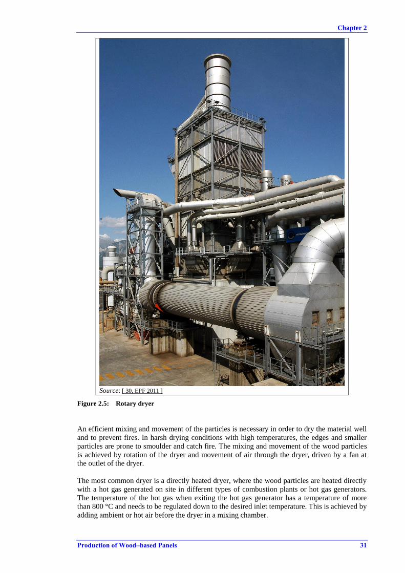
Chapter 2
Production of Wood–based Panels 31
Source: [ 30, EPF 2011 ]
Figure 2.5: Rotary dryer
An efficient mixing and movement of the particles is necessary in order to dry the material well
and to prevent fires. In harsh drying conditions with high temperatures, the edges and smaller
particles are prone to smoulder and catch fire. The mixing and movement of the wood particles
is achieved by rotation of the dryer and movement of air through the dryer, driven by a fan at
the outlet of the dryer.
The most common dryer is a directly heated dryer, where the wood particles are heated directly
with a hot gas generated on site in different types of combustion plants or hot gas generators.
The temperature of the hot gas when exiting the hot gas generator has a temperature of more
than 800 °C and needs to be regulated down to the desired inlet temperature. This is achieved by
adding ambient or hot air before the dryer in a mixing chamber.

Chapter 2
32 Production of Wood–based Panels
The hot gas can be mixed with hot recirculated waste gas from the dryer or another hot
airstream, e.g. air collected from the press. Depending on the mixing point, the VOC content in
recirculated hot waste gas, e.g. from the dryer, could be incinerated by the hot gases. Adding hot
air to the hot gas additionally saves energy.
Dryers can be single-pass or triple-pass; in a single-pass dryer, the wood particles travel from
the entrance of the dryer to the outlet in one pass. In a triple-pass dryer, the wood particles are
dried subsequently in three different chambers of the dryer, each with a temperature lower than
the previous one. Single-pass dryers are only applied for directly heated dryers, according to the
data collection. Single-pass and triple-pass dryers apply hot gas temperatures from 200 °C to
more than 370 °C at the inlet of the dryer.
Other types of rotary dryers are drum dryers and tubular dryers. The temperature applied in a
drum dryer can be as high as 500 °C at the inlet of the dryer. In Figure 2.6, a selection of dryer
types is shown.
The drying time or residence time varies from 5 to 30 minutes. Short drying residence times are
achieved when applying two drying stages, where the first stage is a directly heated flash dryer,
and the second stage a traditional rotary dryer. Between the two stages, cyclones can be applied
to distribute and feed the second dryer. The temperature in the first dryer stage is higher than in
the second dryer stage. In theory, the main dust and VOC emissions arise from the first dryer
stage.
The outlet temperature of the waste gas lies between 100 °C and 130 °C for directly heated
dryers and between 80 °C and 120 °C for indirectly heated dryers.
Dryers generally have evaporation capacities of up to 40 tonnes of water per hour and dry
between 10 and 50 tonnes of wood material on a dry basis per hour. Even larger dryers are
available on the market.
Source: [ 1, Thoemen 2010 ] based on Ressel, 2008, acc. to Deppe and Ernst, 2000.
Figure 2.6: Example of chip dryer characteristics (indicative values)
In an indirectly heated dryer, the wood particles are heated by radiation heat, e.g. from steam
coils. Steam is generated on site in steam boilers served by on-site combustion plants or gas
Chapter 2
Production of Wood–based Panels 33
engines. The recirculation of dryer exhaust air or addition of hot gas is possible in some
indirectly heated dryers, which are referred to as combination dryers.
A recently developed direct dryer is a closed loop dryer, where the dryer and combustion plant
operate in a slightly different mode to normal. The dryer waste gases are recirculated and
thermally treated in a hot mixing chamber before being reused as dryer hot air. The waste gases
which are released originate from the combustion plant only.
Dryers operate continuously but are shut down for regular maintenance at planned intervals.
During regular maintenance, the dryer is cleaned to remove tar and dust build-up. Cleaning is
done with water and often manually with a sweeper. The regular maintenance period is less than
one working shift every 4–8 weeks. The related combustion plant and the abatement systems for
emissions to air continue to run during this short period. When the dryer is ready to operate, all
abatement systems for emissions to air are operational at the same time.
After drying, the wood particles leave the dryer unit and are recovered through a primary
cyclone. The wood particles are sorted according to size before entering the mat forming station,
see Section 2.3.1.
2.2.2 Drying of wood fibres
When the fibres leave the refiner unit, they enter a blowline of 20–30 m in length and with a
small diameter, where the fibre mix is uniformed and wetted. The blowline also serves the
purpose of adding resins, hardening agents and additives. All are added as aqueous solutions
into the blowline. Only in a few MDF production lines are the resins added after drying. The
drying of fibres for dry process rigidboard and flexboard is identical, but while hardening agents
and additives are added in the blowline, the resin is added after drying.
From the blowline, the fibres enter the dryer, where they are dried and thereafter continuously
fed to the mat forming station. The fibre dryers applied are mainly directly heated tube dryers of
150–180 m in length. The tube dryers can also be indirectly heated by steam coils or by a
combination of indirect heating and additional hot gas. The fibres remain in the tube for 3–10
seconds and the drying inlet temperature is between 120 °C and 140 °C, occasionally up to
220 °C, which is generally slightly lower than that applied for PB chips and OSB strands. The
outlet temperature is also lower and lies between 60 °C and around 100 °C.
The heat energy for drying comes from similar sources to those mentioned for drying wood
particles and strands for PB and OSB.
After the mat forming station, the production process is similar to the production of PB and
OSB.
2.2.2.1 Environmental issues related to drying
Waste gases from drying are collected and generally conducted into a dust abatement system. In
this document the waste gases from dryers are considered as the resulting emission, after the
product has been separated by cyclones.
Air emissions
The emission from a dryer after product separation contains water vapour, since this is the main
constituent that is removed from the wood particles and indeed its removal is the purpose of the
dryer. The humid and hot emission contains wood dust and VOC compounds, including
formaldehyde, all of which contribute to total particulate matter content, since the condensable
part of the VOCs will tend to create aerosols or droplets. Depending on the fuel used, the firing
technique, and the combustion conditions, the hot gases will also contain other particles and

Chapter 2
34 Production of Wood–based Panels
compounds which will be present in the waste gases from directly heated dryers, see
Section 2.6.
Diffuse emissions are not an issue in the drying process itself, since it is a closed system.
Diffuse emissions could arise later after the product is separated in cyclones during sorting and
shifting, and before being directed to dry storage bins at the mat forming station.
VOCs and formaldehyde in air emissions from dryers
During drying, volatile natural organic compounds are released from the wood raw material.
The most abundant species are α- and β-pinenes. Formaldehyde, other aldehydes and organic
acids are found in much lower levels. The levels of formaldehyde emitted from different wood
species are reported in studies to range from 2 ppb to 9 ppb, which corresponds to less than 1 %
of the total organic compounds emitted [ 9, Roffael 2006 ] [ 7, Meyer et al. 1997 ],
[ 38, Risholm-Sundman 1998 ].
The α- and β-pinenes can theoretically undergo oxidation to hydroxyls, aldehydes and ketones
during drying, but only a minor amount of these compounds, e.g. myrtenal, has been recorded.
It is expected that major oxidation reactions do not take place during the drying performed in
the sector, which could be because of either the temperature applied or the lack of oxygen.
When the individual volatile organic compounds are determined, the α- and β-pinene content
represents more than 80 % of the total VOC content in softwood species, such as pine.
Some of the natural organic compounds are condensable compounds and these are released as
condensed particles (aerosols), together with the wood dust and water vapour present, in the hot
air emission.
Air emissions released into the atmosphere, which contain a combination of water vapour,
aerosols of condensed volatile organics and wood dust, create the phenomenon 'blue haze'.
The range of organic compounds and the properties of these, together with the water vapour,
make the wood dust particles sticky. The wood dust is also prone to catch fire and it is therefore
better to apply a wet abatement system for the abatement of the dust fraction. A range of
abatement techniques are applied, such as wet electrostatic precipitators, high efficiency
cyclones, wet bioscrubbers, and Venturi scrubbers, individually or in combination. The
electrostatic precipitator (ESP), a common dry dust abatement technique for flue-gases from
combustion plants, is not used after the dryer because of the fire risk. As one of the few dry
abatement methods, bag filters are applied at plants operating indirectly heated dryers. Common
to most of the above-mentioned abatement techniques is that the content of volatile organic
compounds in the dryer emissions is not reduced with the same efficiency. An effective
technique for the removal of the volatile organic compounds is regenerative thermal oxidation,
which is applied at one PB plant in Austria. Cyclones or bag filters alone have no efficiency for
organic compounds [ 67, VITO 2011 ], [ 58, UBA Austria 2013 ], [ 68, VDI 2013 ], [ 83, Barbu
et al. 2014 ].
Waste
The dryer is cleaned regularly to remove tar and dust build-up. Cleaning is done with water and
often manually with a sweeper. The waste water needs to be dealt with [ 62, Swedspan 2013 ].
Noise
Drying and cyclone systems may give rise to duct and fan noise. Housing and/or suitable
silencers are used on relevant ducts and fans, where necessary, to minimise noise emissions.
Energy consumption
Drying is the most energy-intensive process in the production of panels. Drying demands
primarily thermal heat, but also power for the dryer and equipment related to fans and product
transport.
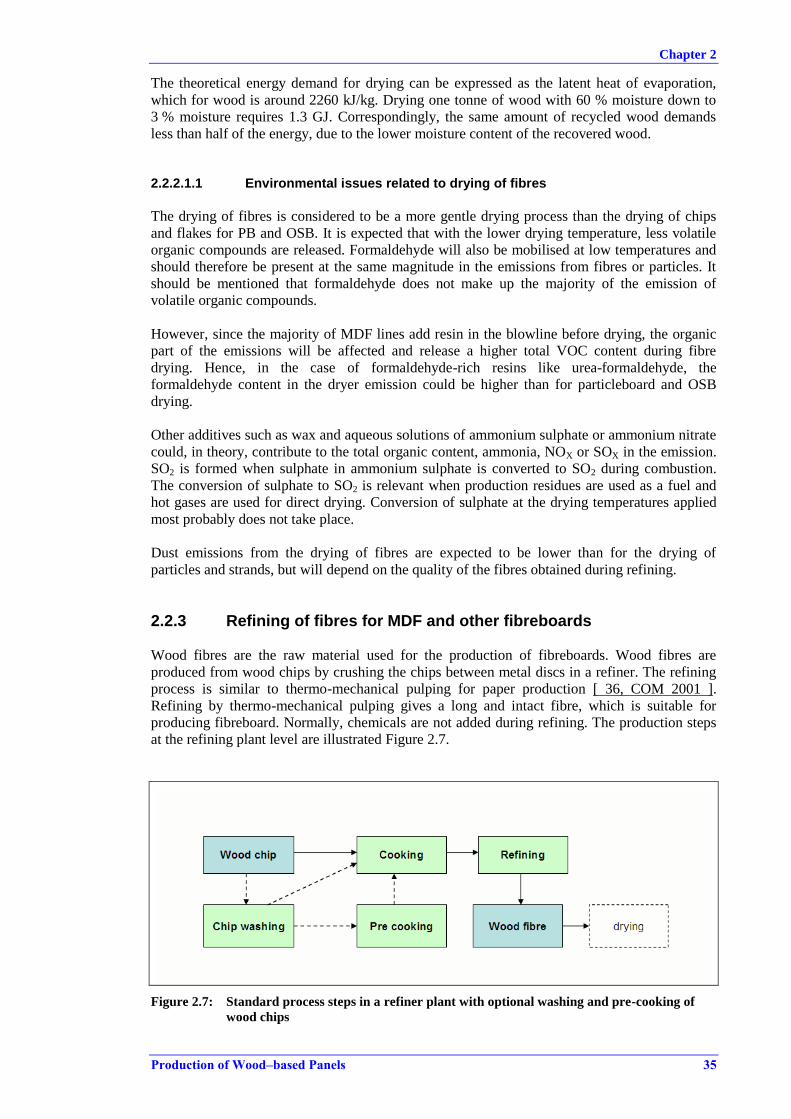
Chapter 2
Production of Wood–based Panels 35
The theoretical energy demand for drying can be expressed as the latent heat of evaporation,
which for wood is around 2260 kJ/kg. Drying one tonne of wood with 60 % moisture down to
3 % moisture requires 1.3 GJ. Correspondingly, the same amount of recycled wood demands
less than half of the energy, due to the lower moisture content of the recovered wood.
2.2.2.1.1 Environmental issues related to drying of fibres
The drying of fibres is considered to be a more gentle drying process than the drying of chips
and flakes for PB and OSB. It is expected that with the lower drying temperature, less volatile
organic compounds are released. Formaldehyde will also be mobilised at low temperatures and
should therefore be present at the same magnitude in the emissions from fibres or particles. It
should be mentioned that formaldehyde does not make up the majority of the emission of
volatile organic compounds.
However, since the majority of MDF lines add resin in the blowline before drying, the organic
part of the emissions will be affected and release a higher total VOC content during fibre
drying. Hence, in the case of formaldehyde-rich resins like urea-formaldehyde, the
formaldehyde content in the dryer emission could be higher than for particleboard and OSB
drying.
Other additives such as wax and aqueous solutions of ammonium sulphate or ammonium nitrate
could, in theory, contribute to the total organic content, ammonia, NOX or SOX in the emission.
SO2 is formed when sulphate in ammonium sulphate is converted to SO2 during combustion.
The conversion of sulphate to SO2 is relevant when production residues are used as a fuel and
hot gases are used for direct drying. Conversion of sulphate at the drying temperatures applied
most probably does not take place.
Dust emissions from the drying of fibres are expected to be lower than for the drying of
particles and strands, but will depend on the quality of the fibres obtained during refining.
2.2.3 Refining of fibres for MDF and other fibreboards
Wood fibres are the raw material used for the production of fibreboards. Wood fibres are
produced from wood chips by crushing the chips between metal discs in a refiner. The refining
process is similar to thermo-mechanical pulping for paper production [ 36, COM 2001 ].
Refining by thermo-mechanical pulping gives a long and intact fibre, which is suitable for
producing fibreboard. Normally, chemicals are not added during refining. The production steps
at the refining plant level are illustrated Figure 2.7.
Figure 2.7: Standard process steps in a refiner plant with optional washing and pre-cooking of
wood chips

Chapter 2
36 Production of Wood–based Panels
The refining process consists of two main steps where the raw chips are preheated and cooked
by applying steam and pressure to the wood chips. Excess water is removed from the cooked
wood chips before they enter the refiner. The refiner discs defiberise the wood chips and the
fibres are injected directly into a blowline for drying. The refiner discs can be pressurised or can
operate at atmospheric pressure. Water is added in the refiner step, both for cleaning and
cooling of the refiner discs, aiding the refining process and to create a sufficient pulp flow in the
blowline. The humidity of the fibres when entering the blowline and dryer is between 50 % and
95 %, depending on the refiner and dryer equipment [ 8, TWG WBP 2012 ].
Prior to the steam cooking stage, a pre-cooking stage is frequently applied. In the pre-cooking
stage, the wood chips are moistened and saturated with hot water under atmospheric conditions
or preheated with steam. Applying this step preheats the chips, and therefore less energy is used
later to raise the temperature in the chips in the cooking step.
Depending on the quality of the wood chips, a cleaning step is performed, where wood chips are
washed before entering the one-step process of cooking and refining. If the raw material chips
contain sand and dust from outdoor storage or are received at the installation in already chipped
form or as uneven material with wood fines or are very dry, a chip washing step is applied. The
impurities of sand, metal and stones can wear refiner discs and shorten the period between
changes of the discs. Wear of refiner discs also raises the energy consumption. The washing of
chips also softens the chips and adds humidity before the chips are cooked and refined. A chip
washing step could replace a pre-cooking step, especially when hot water is used for washing.
The process water from each of the steps of chip washing, pre-cooking, cooking and from the
refiner is either recycled or treated in a waste water treatment plant. In chip washing, the wash
water needs to be treated in order to remove the wood fines plus sand and other impurities that
have not previously been captured in gravitation vessels if present during washing. The chip
washer is therefore combined with dewatering screws, decanters, hydrocyclones, rotary screens
and/or settling chambers. The fines can be reused in a particleboard production line if present at
the installation or used as fuel, if sufficiently dewatered. Sand and grit are removed and
disposed of.
Process water is recycled at the refiner plant level and also reused for other purposes at the site.
The amount of refiner process water recycling ranges from 0 % to 100 %. Internal process water
recycling focuses on removing suspended solids (SS) and COD and is achieved by primarily
mechanical and physical methods such as simple filtration, decanting, sedimentation,
coagulation/flocculation, and microfiltration, while the resulting sludge is removed by filter
presses and screw feeders. The quality of the treated water is determined by the intended use for
the recycled water. The sludge derived is generally used as a fuel on site.
The refining of fibres for the production of wet process fibreboards uses the same equipment
and process but, as the fibres are not dried, the resulting pulp fibres are mixed with water in
storage tanks to make a pulp slurry. The slurry of water-suspended fibres can be gently heated
and pumped to the mat forming station. The temperature rise in the slurry further activates the
natural lignin and hemicellulose, which bind the wood fibres together in the following step in
which the mats are drained and dried in ovens. All water which is used for washing, pre-
cooking, cooking, and refining and drained pulp slurry water are recycled in a semi-closed or
closed loop by simple filtration, decanting and sedimentation, while the sludge is removed and
dewatered as already described. Sawdust is used as a secondary raw material for wet process
fibreboard. The sawdust is refined separately and added as a surface layer during mat forming,
on the sieve and press.
When process water is directed to a central waste water treatment plant (WWTP) on site, the
quality and quantity of the resulting waste water stream from the preparation of the fibres vary
depending on the amount of recycling. The waste water which leaves the refiner plant to be
treated at a central WWTP is treated by different classical treatment methods. Primary treatment
methods using physical separation prevail and remove the major part of the fibres and wood

Chapter 2
Production of Wood–based Panels 37
particles. Also, coagulation, flocculation, sedimentation and secondary aerobic biological
treatment steps are applied. Sludge from the different treatment steps can be used as a fuel on
site, for agricultural purposes or may be disposed of.
2.2.3.1 Environmental issues related to the refining of fibres
Energy consumption
The refiner plant has a high energy demand, e.g. for the generation of steam for the cooking
stage and electrical energy for the refiner. The system of dewatering screws and pumps in the
system demands electrical energy, in the range of 20–40 kW, with a throughput of up to
400 m3/h.
Examples of energy savings include replacing older equipment and reusing excess heat in the
steam.
Water consumption and waste water generation
Water is consumed in chip washing, in pre-cooking and for the generation of steam used in the
cooking step.
Water for chip washing can be of a lower quality than can be accepted for steam generation.
Secondary water sources include recycled chip washing water, rainwater collected from roofs
and recycled water from the cooking stage.
Water consumption savings can be obtained by closing water circuits and recycling process
water in integrated treatment plants at the washing plant unit or at the cooking and refiner unit.
Waste water from the overall refining process needs to be treated before discharge, if it is not
recycled in the refiner plant. The process waste water has a high TSS, COD and BOD load.
Also, nitrogen and phosphorus could be relevant parameters to take into account.
Directive 2008/15/EC on environmental quality standards in the field of water policy includes in
its Annex I a list of priority substances. None of the listed substances are used directly in the
refining process or arise from other types of waste water generated in a WBP plant. It is
however possible for some of the priority substances, e.g. nickel, cadmium and lead, to be
present in the emissions from waste water treatment plants, either due to the use of recovered
wood (in PB production) or from surface run-off water via storage of recovered wood. Surveys
indicate that there could be a potential release of cadmium, copper, lead and zinc.
Waste
Sludge is generated from the treatment of process water. Depending on the quality of the sludge,
it is either used as a fuel in an on-site biomass combustion plant or handled off site. The sludge
generated from the initial screening of chip washer water can occasionally be used in the
production of particleboard, if such a product line is in operation at the installation.
2.2.4 Storage of wood particles/flakes/fibres after drying
2.2.4.1 Sorting and dry storage of dried chips and flakes
The dry material from the dryers is collected and separated in cyclones and shifted by
mechanical or pneumatic means to sort the dry particles into the required sizes.
In order to prevent fires in the dry, hot wood material, a fire-suppressant silo designed to
suppress any glows and prevent the self-ignition of the dried chips and flakes can be applied
immediately after the dryer and cyclones.

Chapter 2
38 Production of Wood–based Panels
After passing the fire-suppressant silo, the dried chips for particleboard production are
mechanically sorted or air-shifted before entering dry silos. Shifting sorts the finer chips for the
outer layer from the coarser chips for the core layer. Any oversize chips are recirculated back
into the chipping station, while small chips and dust are collected and used as fuel in dust
burners or combustion plants. The shifting stations and dry silos are mounted with bag filters or
closed cyclones. It is preferable to remove the finest dust efficiently from the product, since dust
absorbs more resin, resulting in higher resin consumption.
Odd-sized material separated from the dried flakes from OSB production is collected and used
as fuel. If there is a particleboard production line at the same installation, this material can be
used as raw material and is then directed to the chipping station.
Chips from dry storage feed directly into the mat forming station without further steps. The dry
storage capacity usually represents only a few production hours for the press. Chips or strands
from dry storage silos are transported to the mat forming station mechanically or in closed
pneumatic systems.
2.2.4.2 Sorting and dry storage of fibres
Dried fibres are collected from the dryers and separated in cyclones, where they are air-shifted
to sort larger fibres, lumps of pre-cured resin, clogged fibres and fines from the final fibres.
The fibres are directed to the mat forming line directly into a 20–50 m3 bunker or bin with a
moving floor, from where the fibres are continuously fed.
2.2.4.3 Environmental issues related to sorting and dry storage
Dust emissions
Dry wood materials generate dust emissions. After the smaller fines, particles and dust are
removed, the resulting chips are less prone to create dust emissions. Any handling of the dry and
sorted chips is performed in closed systems, and shifting stations and dry silos are mounted with
bag filters or closed cyclones. The product separation is closely connected to the dust abatement
in the drying process, see Section 2.2.
Fire risk
During drying and the handling of the dried material immediately afterwards, fire-suppressant
silos are used and, during mechanical or pneumatic shifting of the chips, fire detectors and fire-
suppressant intermediary steps, such as possible isolation, help lower the risk of self-ignition
and fire outbreak. The inlet area of the dryer to the inlet of the mat forming station would rate as
areas with a potentially explosive atmosphere (ATEX). Sprinkler systems and explosion
venting, together with good housekeeping and maintenance, are employed as minimum
requirements.
Noise
Noise arises from both mechanical sorting of air shifters and from cyclones. These operations
often take place inside a building or an enclosed area. Noise may also be related to the dust
abatement equipment employed and, as a standard solution, silencers are employed at such
locations on roofs.
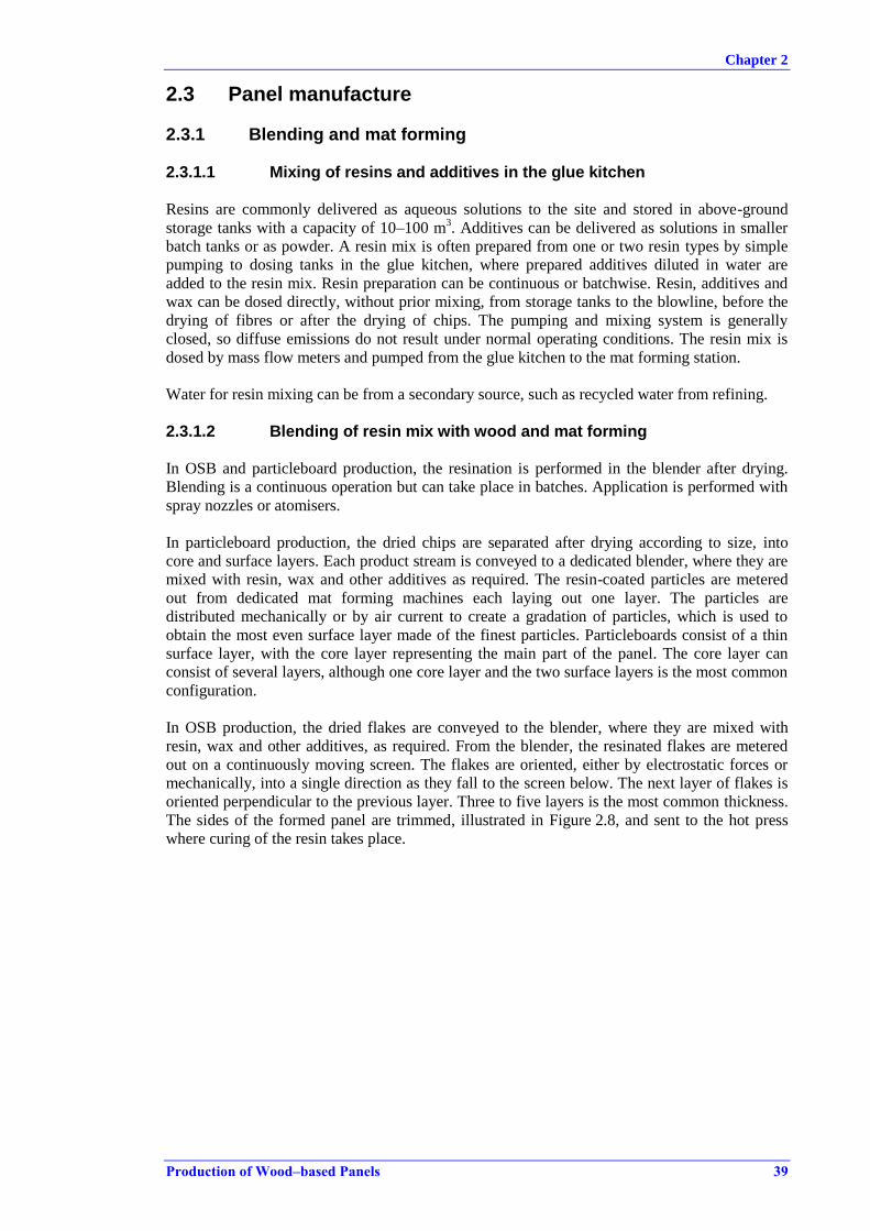
Chapter 2
Production of Wood–based Panels 39
2.3 Panel manufacture
2.3.1 Blending and mat forming
2.3.1.1 Mixing of resins and additives in the glue kitchen
Resins are commonly delivered as aqueous solutions to the site and stored in above-ground
storage tanks with a capacity of 10–100 m3. Additives can be delivered as solutions in smaller
batch tanks or as powder. A resin mix is often prepared from one or two resin types by simple
pumping to dosing tanks in the glue kitchen, where prepared additives diluted in water are
added to the resin mix. Resin preparation can be continuous or batchwise. Resin, additives and
wax can be dosed directly, without prior mixing, from storage tanks to the blowline, before the
drying of fibres or after the drying of chips. The pumping and mixing system is generally
closed, so diffuse emissions do not result under normal operating conditions. The resin mix is
dosed by mass flow meters and pumped from the glue kitchen to the mat forming station.
Water for resin mixing can be from a secondary source, such as recycled water from refining.
2.3.1.2 Blending of resin mix with wood and mat forming
In OSB and particleboard production, the resination is performed in the blender after drying.
Blending is a continuous operation but can take place in batches. Application is performed with
spray nozzles or atomisers.
In particleboard production, the dried chips are separated after drying according to size, into
core and surface layers. Each product stream is conveyed to a dedicated blender, where they are
mixed with resin, wax and other additives as required. The resin-coated particles are metered
out from dedicated mat forming machines each laying out one layer. The particles are
distributed mechanically or by air current to create a gradation of particles, which is used to
obtain the most even surface layer made of the finest particles. Particleboards consist of a thin
surface layer, with the core layer representing the main part of the panel. The core layer can
consist of several layers, although one core layer and the two surface layers is the most common
configuration.
In OSB production, the dried flakes are conveyed to the blender, where they are mixed with
resin, wax and other additives, as required. From the blender, the resinated flakes are metered
out on a continuously moving screen. The flakes are oriented, either by electrostatic forces or
mechanically, into a single direction as they fall to the screen below. The next layer of flakes is
oriented perpendicular to the previous layer. Three to five layers is the most common thickness.
The sides of the formed panel are trimmed, illustrated in Figure 2.8, and sent to the hot press
where curing of the resin takes place.

Chapter 2
40 Production of Wood–based Panels
Figure 2.8: OSB mat after forming and trimming
In MDF production, the fibres are mainly resinated in the blowline, immediately after the
refining and before the drying of the fibres. As discussed in Section 2.2.2.1.1, this affects the
composition of the organic components in the air emissions from the dryer.
Resin in rigidboard and flexboard production is applied after the drying of the fibres, although
some additives like wax and hardeners are still added in the blowline before drying. In
rigidboard production, the resin used is solely pMDI and is added after drying, either by
spraying the fibres when they are deposited on the conveyer before entering a pre-press or by
spray nozzles before entering an intermediary bunker at the mat forming station.
In softboard and hardboard production by the wet process, resins are not applied although some
wax and other additives are added to the additional water added after the refiner.
2.3.2 Pressing
The raw panel is produced in the press by applying high pressure and high temperature for a
sufficient amount of time to compress the mat to the required thickness and to densify and fixate
the particles or fibres by resin curing. The temperature at the core of the panel needs to reach a
certain level depending on the resin, normally above 100 °C, in order for water to evaporate.
Before entering the press, the mat leaving the mat forming station is normally pre-pressed at
ambient temperature in a roller press to remove air from the mat, and the sides of the panel are
trimmed. Pre-pressing is not necessary in OSB production. If the main press is a multi-opening
press, the pre-pressed panel is cut to fit and be loaded individually to the press.
The press belts in a continuous press or the press plates in a multi-opening press are heated with
thermal oil with a contact temperature normally not exceeding 260 °C. Press plates in a multi-
opening press generally operate with a lower temperature.

Chapter 2
Production of Wood–based Panels 41
The majority of presses in Europe for the production of particleboard, OSB and MDF are
continuous presses, with lengths of 20 m to 60 m. The press process is divided into three phases
which are distinct for each type of panel variety produced. The temperature applied is highest in
the first part of the press, but generally only slightly reduced along the press line. In the first
phase, the highest pressure is applied and the panel obtains its nominal thickness. In the second
phase, the pressure is reduced and the panel is cured at the high temperature now present in the
core of the panel. In the last phase, the pressure is relieved gradually before the panel leaves the
continuous press. The specific pressure applied in the press is 3–5 N/mm2.
The press operates with three main controls: the temperature, the pressure and the press time.
For continuous presses the time is varied by the speed of the press. The operating conditions are
varied by the pressure that is applied and the time, while the temperature is generally constant.
The heat is achieved by hot oil-heated plates and is not varied from batch to batch.
Source: [ 68, VDI 1995 ]
Figure 2.9: Press types used in dry process panel production
The continuous press was introduced in the 1970s and today (2014) has almost completely
replaced the single-opening daylight press and the multi-opening press; see Figure 2.9 for a
schematic presentation of the main press types. The daylight press runs in cycles, in which the
pre-pressed panels are loaded and the press closes. During pressing and when the press opens,
water vapour and emissions to air are released over the whole extension of the press.
Figure 2.10 shows a daylight press. When the press closes, the plates are pressed together
towards the top of the press and the suction hood captures some of the released press gases.

Chapter 2
42 Production of Wood–based Panels
Source:[ 30, EPF 2011 ]
Figure 2.10: Multi-opening press
The major release point of press gases in a continuous press line is at the end of the press, where
the press releases the pressed panel. At the press release, it is possible to collect the majority of
press gases by use of an efficient enclosure and suction system. Along the press line, it is also
common to have suction and collection systems. In practice, the collection and handling of press
gases shows a wide variation, and depends mostly on the regulatory regime applied and
available abatement techniques.
When press gases are collected, the abatement focuses on the TVOC content and dust. The
collected gases are quenched by spraying in the collector tubing immediately after the press, in
order to prevent fires in the hot air containing fine dust and organic compounds. The following
techniques are currently applied:
Direct discharge over the roof.
Wet ESP.
Venturi-type scrubbers.
Stack scrubber, including filtration of water for wood dust.
Bioscrubber.
Incineration in a combustion plant using waste gas as combustion air or mixing the waste
gas with hot gas before the direct PB or OSB dryer inlet. Press waste gases are often
pretreated by wet scrubbing to remove dust and to diminish the risk of fire.
For multi-opening presses, the collection of press gases is not as straightforward as for
continuous presses. The press release area is, by nature, not well defined and efficient collection
of press gases is more difficult. Room ventilation with non-channelled direct discharge over the
roof is commonly applied. Door skins are also produced in special multi-opening presses.
Extruded or moulded pallets are produced in a single-opening press, where chips are dosed
directly into the hot form which is pressed, producing one or more pallets in one press round. It
has been reported that emissions are easily collected from a single-opening pallet press.

Chapter 2
Production of Wood–based Panels 43
Extruded panels, e.g. for doors, are made using special presses that produce one panel at a time,
by dosing the chips directly to the press, where the panel is pressed and extruded at the same
time.
2.3.2.1 Environmental issues related to pressing
Dust, water vapour and organic compounds are released during pressing. The organic fraction of
the emission comes primarily from the resin system used, see Section 2.5.1.
Dust develops along the press line and consists of both coarser dust from trimming the sides of
the panel before entering the main press and of finer dust. Suction points along the press line,
including the distance from the mat forming station and the pre-press to the entrance of the main
press, will ensure a sufficient abatement of diffuse dust emissions.
Air emissions
The composition of air emissions from presses depends on the resin used. While the majority of
the volatile organic compounds in the wood are released during drying, the contribution of
formaldehyde in press emissions is more related to the resin used. Data collected show that the
amount of TVOC is still significant, but is less than for dryers. Some of the organic compounds
could be related to wax, which is applied as a release agent, but there are no concrete data to
confirm the amount derived from wax and whether it is a major part of the TVOC emission.
The amount of formaldehyde emitted during drying is much higher than from the press if the
wood material is resinated before drying with a formaldehyde-based resin. This is the case for
the majority of MDF production lines, which use urea-formaldehyde.
Emissions of NH3, NOX or SOX in the press exhaust are theoretically possible. Additives such as
ammonium nitrate or ammonium sulphate are used as standard in most production processes,
either added with the resin at the blending stage or earlier, i.e. before drying, in the case of
fibres. No data have been collected so far that could confirm substantial emissions of the
mentioned parameters in the production lines in Europe.
Other organic compounds, such as tetrahydrofuran and acetic acid, could arise in air emissions
from presses when producing MDF, because of the high temperature reached at the panel
surface. Tetrahydrofuran is a degradation product of cellulose, which could be created when the
panel is pressed at temperatures over 200 °C [ 37, He Z, et al. 2011 ]. Acetic acid is created
during pressing as a by-product of the degradation of hemicellulose, which takes place at
temperatures even lower than 200 °C, which according to studies corresponds to a higher
amount of acetic acid detected compared to tetrahydrofuran. [ 39, Jiang T, et al. 2002 ]. No data
are yet available to support the studies mentioned concerning the production lines in Europe.
While tetrahydrofuran is not monitored, acetic acid has been included in some surveys under the
organic acids parameter. The registered amount of organic acids is negligible [ 22, TWG 2012 ].
Formaldehyde-free resins such as pMDI, used widely in OSB production, result in no
formaldehyde or TVOC emissions related to the resin. Emissions from the wax release agents
and from the wood itself are still relevant.
Energy consumption
The hydraulic press is a major consumer of electrical energy, but it is the heat energy used for
heating the thermal oil that is the second most energy-intensive activity, after drying, at
particleboard and OSB production lines.

Chapter 2
44 Production of Wood–based Panels
Accidental spills
Hydraulic systems for pressing may leak oil and emulsions during repairs and maintenance.
Taking preventive measures and applying quality assurance of maintenance is part of an
environmental management system, which could help minimise the risk of spills.
Consumption of thermal oil
Thermal oil is circulated in a closed ring system and only a very small amount is further added
or replaced when necessary.
The closed thermal ring system can experience leakages at the seals in the press cylinders,
especially when operating speed and fluid pressure are increased, which can be the case when
optimising production capacity.
Waste
Dust and wood particles from trimming and along the press line are collected and used as a fuel
or reintroduced as raw material.
2.3.2.2 Pressing of rigidboard and flexboard
After the mat is formed by the same methods as for MDF production, the mat is pressed in a
pre-press similar to MDF lines, which compresses and forms the panel at ambient temperature.
The resulting mat is transferred to a press unit, where only slight additional pressure is added
while the curing of the resin is activated by steam. Figure 2.11 shows an example of the
production flow for rigidboards.
Source: [ 30, EPF 2011 ]
Figure 2.11: Example of main production steps for rigidboards
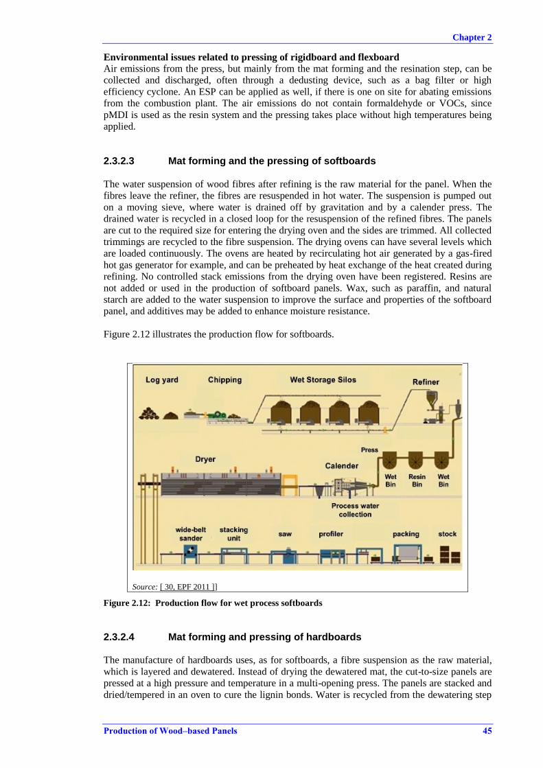
Chapter 2
Production of Wood–based Panels 45
Environmental issues related to pressing of rigidboard and flexboard
Air emissions from the press, but mainly from the mat forming and the resination step, can be
collected and discharged, often through a dedusting device, such as a bag filter or high
efficiency cyclone. An ESP can be applied as well, if there is one on site for abating emissions
from the combustion plant. The air emissions do not contain formaldehyde or VOCs, since
pMDI is used as the resin system and the pressing takes place without high temperatures being
applied.
2.3.2.3 Mat forming and the pressing of softboards
The water suspension of wood fibres after refining is the raw material for the panel. When the
fibres leave the refiner, the fibres are resuspended in hot water. The suspension is pumped out
on a moving sieve, where water is drained off by gravitation and by a calender press. The
drained water is recycled in a closed loop for the resuspension of the refined fibres. The panels
are cut to the required size for entering the drying oven and the sides are trimmed. All collected
trimmings are recycled to the fibre suspension. The drying ovens can have several levels which
are loaded continuously. The ovens are heated by recirculating hot air generated by a gas-fired
hot gas generator for example, and can be preheated by heat exchange of the heat created during
refining. No controlled stack emissions from the drying oven have been registered. Resins are
not added or used in the production of softboard panels. Wax, such as paraffin, and natural
starch are added to the water suspension to improve the surface and properties of the softboard
panel, and additives may be added to enhance moisture resistance.
Figure 2.12 illustrates the production flow for softboards.
Source: [ 30, EPF 2011 ]]
Figure 2.12: Production flow for wet process softboards
2.3.2.4 Mat forming and pressing of hardboards
The manufacture of hardboards uses, as for softboards, a fibre suspension as the raw material,
which is layered and dewatered. Instead of drying the dewatered mat, the cut-to-size panels are
pressed at a high pressure and temperature in a multi-opening press. The panels are stacked and
dried/tempered in an oven to cure the lignin bonds. Water is recycled from the dewatering step
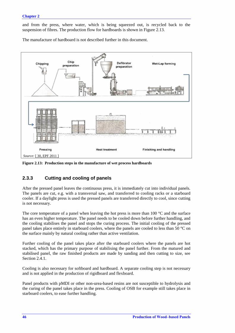
Chapter 2
46 Production of Wood–based Panels
and from the press, where water, which is being squeezed out, is recycled back to the
suspension of fibres. The production flow for hardboards is shown in Figure 2.13.
The manufacture of hardboard is not described further in this document.
Source: [ 30, EPF 2011 ]
Figure 2.13: Production steps in the manufacture of wet process hardboards
2.3.3 Cutting and cooling of panels
After the pressed panel leaves the continuous press, it is immediately cut into individual panels.
The panels are cut, e.g. with a transversal saw, and transferred to cooling racks or a starboard
cooler. If a daylight press is used the pressed panels are transferred directly to cool, since cutting
is not necessary.
The core temperature of a panel when leaving the hot press is more than 100 °C and the surface
has an even higher temperature. The panel needs to be cooled down before further handling, and
the cooling stabilises the panel and stops the curing process. The initial cooling of the pressed
panel takes place entirely in starboard coolers, where the panels are cooled to less than 50 °C on
the surface mainly by natural cooling rather than active ventilation.
Further cooling of the panel takes place after the starboard coolers where the panels are hot
stacked, which has the primary purpose of stabilising the panel further. From the matured and
stabilised panel, the raw finished products are made by sanding and then cutting to size, see
Section 2.4.1.
Cooling is also necessary for softboard and hardboard. A separate cooling step is not necessary
and is not applied in the production of rigidboard and flexboard.
Panel products with pMDI or other non-urea-based resins are not susceptible to hydrolysis and
the curing of the panel takes place in the press. Cooling of OSB for example still takes place in
starboard coolers, to ease further handling.
Chapter 2
Production of Wood–based Panels 47
2.3.3.1 Environmental issues related to cutting and cooling of panels
Air emissions
Air emissions from cutting the panel immediately after the continuous press not only generate
dust but also release a minor amount of organic compounds from the cuts in hot unstabilised
panels. The saw is often entirely enclosed and air emissions are collected. It is enclosed in order
both to abate the high-pitched noise and to efficiently collect and channel dust emissions. Dust
is collected in bag filters and used as a fuel. The development of dust is no different from in
other woodworking processes.
The room where starboard coolers are placed has been surveyed at some installations as part of
occupational health campaigns. If formaldehyde is detected, this would normally be caused by
an inefficient closure of the press and cutting station, and not from the cooling. Data on
emissions of formaldehyde and other VOC-related compounds during the cooling of the panels
have not yet become available.
When a starboard cooler is equipped with active ventilation it is claimed that it helps the cooling
efficiency and shortens the cooling time. Other producers claim that forced ventilation in
cooling equipment can cause deformation in the planarity of boards. Only a few installations
have active ventilation directed at the starboard cooler, though it is common for the space for
panel cooling to be well ventilated through roof openings or doors to the outside or by a semi-
enclosure of the starboard cooler with passive ventilation through the roof.
Noise
The noise from the cutting of the panel after the continuous press is pronounced, so normally an
enclosure is applied to abate the high-pitched noise.
Noise issues are generally not significant in the operational steps immediately after the press,
except for the cutting of the panel. The main noise sources are compressors and conveyor belts
that transport raw panels to cooling and further finishing.

Chapter 2
Production of Wood–based Panels 49
2.4 Finishing of raw board
2.4.1 Sanding and cutting to size
Sanding smoothes the surface of the raw board and is a common operation for particleboard and
most MDF grades. Sanding operations use standard sanding equipment with built-in suction
hoods to channel any dust emission arising during sanding.
The cooled panels are sanded before dispatch or an additional on-site value-adding process. Belt
sanders have a high sanding speed of up to 1500 metres per minute to obtain a high quality
sanding.
Raw panels are often sold in sizes depending on the customer's needs, and cutting to size and
applying a tongue-and-groove finish are performed at most sites.
Cutting and sanding are performed with machinery that is used throughout the wood processing
sector in general. Equipment is delivered with the necessary means of noise and dust protection.
Its operation in relation to dust extraction and safety is described in EN 12779:2004
[ 33, EN 2004 ].
For OSB, sanding is generally not performed, except for special purposes. Other products like
rigidboards, flexboards and softboards are cut and manipulated into specific sizes, but not
normally sanded.
2.4.1.1 Environmental issues related to sanding and cutting to size
Air emissions
Dust arises from cutting operations and is generally handled by enclosing the equipment or
directing the suction at the point of release of the dust from the saw. Diffuse dust emissions are
generally not a problem if the equipment supplier's instructions are followed, since all wood
processing equipment has built-in suction systems. The channelled air from sanding operations
and cutting operations is primarily filtered in bag filters or cyclofilters to remove wood dust.
Noise
All woodworking machines generate noise and sanding and cutting operations are no exception.
Waste
The wood dust which is collected is generally used as a fuel directly from the collection point.
The collected dust makes an important contribution to the fuel needed in the combustion plants.
Used sanding belts are waste and are dispatched off site for disposal. The format of the used
sanding belts makes them unsuitable to be used as a fuel in the combustion installations on site.
Energy
The energy consumption for the running of all the equipment and the related dust abatement
systems in the finishing of the raw panel can contribute to a significant part of the site's overall
energy consumption.
2.4.2 Storage
The storage of finished product, whether raw panels or value-added products, takes place in dry
covered storage facilities in order to protect them from moisture and dust before dispatch.
Storage facilities can be highly automated, requiring very little labour input. No related potential
environmental issues have been identified and the finished product storage is not mentioned
further.
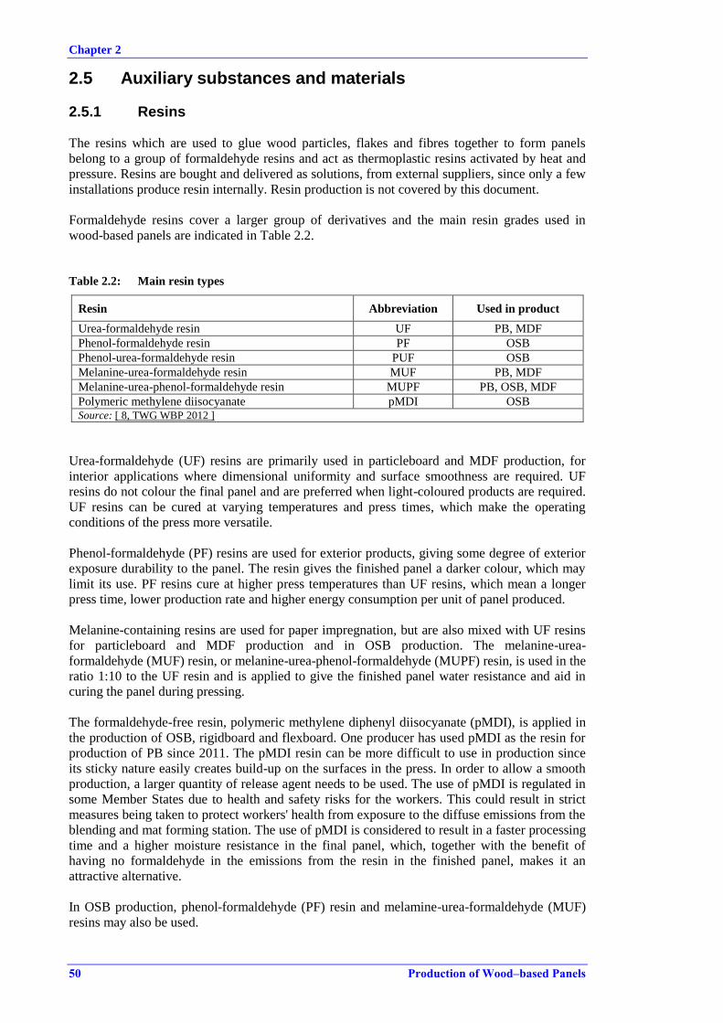
Chapter 2
50 Production of Wood–based Panels
2.5 Auxiliary substances and materials
2.5.1 Resins
The resins which are used to glue wood particles, flakes and fibres together to form panels
belong to a group of formaldehyde resins and act as thermoplastic resins activated by heat and
pressure. Resins are bought and delivered as solutions, from external suppliers, since only a few
installations produce resin internally. Resin production is not covered by this document.
Formaldehyde resins cover a larger group of derivatives and the main resin grades used in
wood-based panels are indicated in Table 2.2.
Table 2.2: Main resin types
Resin Abbreviation Used in product
Urea-formaldehyde resin UF PB, MDF
Phenol-formaldehyde resin PF OSB
Phenol-urea-formaldehyde resin PUF OSB
Melanine-urea-formaldehyde resin MUF PB, MDF
Melanine-urea-phenol-formaldehyde resin MUPF PB, OSB, MDF
Polymeric methylene diisocyanate pMDI OSB Source: [ 8, TWG WBP 2012 ]
Urea-formaldehyde (UF) resins are primarily used in particleboard and MDF production, for
interior applications where dimensional uniformity and surface smoothness are required. UF
resins do not colour the final panel and are preferred when light-coloured products are required.
UF resins can be cured at varying temperatures and press times, which make the operating
conditions of the press more versatile.
Phenol-formaldehyde (PF) resins are used for exterior products, giving some degree of exterior
exposure durability to the panel. The resin gives the finished panel a darker colour, which may
limit its use. PF resins cure at higher press temperatures than UF resins, which mean a longer
press time, lower production rate and higher energy consumption per unit of panel produced.
Melanine-containing resins are used for paper impregnation, but are also mixed with UF resins
for particleboard and MDF production and in OSB production. The melanine-urea-
formaldehyde (MUF) resin, or melanine-urea-phenol-formaldehyde (MUPF) resin, is used in the
ratio 1:10 to the UF resin and is applied to give the finished panel water resistance and aid in
curing the panel during pressing.
The formaldehyde-free resin, polymeric methylene diphenyl diisocyanate (pMDI), is applied in
the production of OSB, rigidboard and flexboard. One producer has used pMDI as the resin for
production of PB since 2011. The pMDI resin can be more difficult to use in production since
its sticky nature easily creates build-up on the surfaces in the press. In order to allow a smooth
production, a larger quantity of release agent needs to be used. The use of pMDI is regulated in
some Member States due to health and safety risks for the workers. This could result in strict
measures being taken to protect workers' health from exposure to the diffuse emissions from the
blending and mat forming station. The use of pMDI is considered to result in a faster processing
time and a higher moisture resistance in the final panel, which, together with the benefit of
having no formaldehyde in the emissions from the resin in the finished panel, makes it an
attractive alternative.
In OSB production, phenol-formaldehyde (PF) resin and melamine-urea-formaldehyde (MUF)
resins may also be used.
Chapter 2
Production of Wood–based Panels 51
Wood fibres have a certain self-adhesion due to hemicelluloses and especially lignin, which are
activated under wet conditions and at elevated temperatures. In hardboard production, the lignin
is cured during pressing with high pressure. In softboard production, the lignin bond is cured
during the drying of the pre-pressed panel.[ 49, Pizzi et al. 2003 ]
2.5.2 Hardening agents
Hardening agents or curing catalysts are used for accelerating the curing of the resin, thus
reducing the press time. The curing depends among other factors on the temperature of the press
and acidity of the wood particles, where lower values result in slower curing; the hardening
agent also compensates for this.
The most common hardening agents used are ammonium nitrate and ammonium sulphate. The
ammonium salt is either delivered as a crystalline salt or in an aqueous solution. An aqueous
solution of the hardening agent is added to the resin in the glue kitchen, before blending with the
wood particles. For wood fibres, the salt solution is more commonly added directly in the
blowline before fibre drying.
The agents also act to enhance the fire resistance of the finished panel.
2.5.3 Release agents and other additives
Release agents or mould agents serve the purpose of preventing the build-up of resin on the
panel surface in the press. Especially for fibreboard and OSB the release agent is vital. The
release agent is mixed with the resin before blending with the wood particles. For wood fibres,
the release agent is added in the blowline.
The especially sticky nature of the resinated mat when using pMDI demands a rigorous use of
the release agent, which must be applied, by rolling or spraying, directly on the press belt.
Wax or paraffin emulsions are most commonly used and also add to the water-resistant
properties of the finished panel.
To add fire resistance to the panel, the most common agent is ammonium sulphate, which is also
used as a hardening agent.
Colouring agents are added to panels in order to distinguish between panels which have added
properties in terms of moisture resistance (green) and fire resistance (red).

Chapter 2
52 Production of Wood–based Panels
2.6 Energy production
All WBP sites operate energy-producing units to serve primarily the dryer and the thermal oil
system for the press. Depending on the character of the wood-based fuel and the relation to
waste regulation, the energy-producing units can be regulated as combustion plants, co-
incineration plants or incineration plants. The firing techniques applied do not vary between
combustion and incineration plants in the sector. The monitoring requirements will differ
according to the classification of the combustion plant.
The combustion plants differ in size from 10 MW to over 50 MW, and are used for producing
hot gases for directly heated dryers and for heating thermal oil. The larger combustion units can
be combined heat and power (CHP) plants, with the generation of steam and electricity, where
steam is used for indirectly heated dryers and for cooking and refining and electricity is either
for internal use or sold off site. The cogeneration of heat and electrical energy in larger gas
engines or liquid fuel-fired engines is also carried out.
The individual set-up of the installations differs depending on the accessibility of fuels, the
production size and the age of the installation. Combustion units which produce only hot gas for
direct drying are called hot gas generators (HGG) in the sector. When drying is direct, smaller
dust burners of 6–15 MW for each dryer are often used and the thermal oil is heated separately
by a gas-fired engine of 3–10 MW.
Larger combustion plants producing heat, power or steam for multiple processes are commonly
operated in the sector. Spreader firing is widely used with a moving grate, where coarser and
heavier wood-derived fuels are distributed by a stoker or other equipment. The combustion units
are preferably designed to be fired with different sizes of biomass. Sawdust or wood dust are fed
into the over-fire air and ignited in suspension, creating a fluidised bed. Grate systems distribute
the biomass across the grate and move it forward. Biomass is burnt with excess air and primary
air is fed through the grate with a secondary air supply above it. The secondary air supply can
constitute not only ambient air, but also waste gas from the press and the drying and other waste
gas streams can be added and post-combusted above the grate. Fluidised, bubbling and
circulating fluidised bed combustion systems use collected wood dust and prepared pulverised
solid wood as fuel. Preheated air from other waste gas sources, e.g. the press fumes or from the
heat exchange with dryer waste gases, can be used for preheating the air to fluidise the bed or to
preheat the air in the mixing chamber for dryer air in direct drying.
The main fuels used are wood-derived fuels and secondarily natural gas and liquid fuel. These
are further described in the following list:
Production residues:
collected wood dust from sanding lines and cutting operations;
collected trimmings at the mat forming station and after the press;
rejected panels;
wood sludge material from the abatement systems, such as from the WESP and waste
water treatment plants;
wood residues from the cleaning plant for recycled wood;
wood residues from chipping and milling;
bark derived from debarking;
impregnated paper.
Externally delivered wood material:
sawdust;
post-consumer wood materials;
roots and stubs.

Chapter 2
Production of Wood–based Panels 53
Conventional fuels:
natural gas;
light or heavy fuel oil;
Bark is often pretreated before firing, by shredding it together with larger rejects from the
production. Roots and stubs contain soil and stones and need a separate crushing, shredding and
cleaning step. Bark and sludge can be dewatered by filters and screens or presses to improve the
overall energy efficiency.
Small utility boilers and burners producing steam or heat for heating, e.g. thermal oil for heating
the press, are widely applied. Gas-fired burners and/or liquid fuel-fired burners are common
throughout a site.
2.6.1 Environmental issues related to energy production
Combustion and incineration processes generate air emissions; dust, NOX, CO, SOX and
greenhouse gases are the most important, but other substances, such as metals and organic
compounds, are also emitted in smaller quantities.
For general information on combustion and related environmental issues, it is advised to consult
the LCP BREF and the WI BREF [ 24, COM 2006 ], [ 3, COM 2006 ].
Air emissions
The flue-gases from biomass combustion used for direct drying and also for steam generation
for indirect drying are sometimes treated before entering the dryer. This will depend on the fuel,
the combustion unit and the combustion process.
The formation of nitrogen oxides (NOX) depends on the fuel-bound nitrogen content and the
combustion temperature. The combustion temperatures for biomass are lower than for gaseous
or liquid fuels, so the conditions for creation of thermal NOX are not so favourable. The fuel-
bound nitrogen content in wood-based biomass varies between 0.2 % and 0.5 %, depending on
the wood source, which is lower than for liquid fuels.
The staged combustion obtained in fluidised bed combustion or by air staging in moving grate
furnaces is widely applied and can minimise NOX and CO levels. Reduction of NOX is applied
at some biomass-fired combustion plants, using selective non catalytic reduction (SNCR) in the
combustion chamber. When using SNCR the potential related emissions of ammonia (NH3)
would be subject to control. The combustion plants are mainly stand-alone plants and few
examples have been identified for hot gas production for directly heated dryers.
Emissions of sulphur oxides (SOX) depend on the fuel-bound sulphur content and liquid fossil
fuels can contain sulphur, which gives high SOX emissions. The majority of sulphur oxides are
produced as sulphur dioxide (SO2). High SOX emissions are generally not an issue when using
biomass as a fuel, but there are examples of dry sorbent injection to prevent elevated SOX
emissions. The design of the combustion unit is decisive for the use of specific SOX abatement
techniques.
The dust emitted during the burning of the biomass arises almost entirely from the mineral
fraction of the fuel. A small proportion of the dust may consist of very small particles formed by
the condensation of compounds volatilised during combustion. Moving grate boilers, which are
the most commonly applied type in the sector, produce a relatively small amount of fly ash (20–
40 % of total ash). The combustion of liquid fuels is also a source of particulate emissions, in
the form of soot particles, and is related to poor combustion conditions.
The abatement of dust emissions in the hot gases before they are used for direct drying is carried
out at a few combustion plants that use biomass as a fuel, where fabric filters and ESP
Chapter 2
54 Production of Wood–based Panels
applications are the most common abatement techniques. These are generally only used in
combustion plants/units over 20 MW.
Bark fuel has a high mineral content (2–3 %) and a tannin content of more than 20 %. If the
combustion is not complete, the flue-gases will contain resinous tar and contribute to the dust
emissions in the dryer waste gas. In order to complete the combustion and thermal
decomposition of the tannins, temperatures above 1200 °C are needed together with an efficient
recirculation of the flue-gases for post-combustion.
Certain fuels, such as recovered wood or fossil fuels, could be a source of metals, dioxins, HCl,
HF and other unwanted compounds in the flue-gases. Using recovered wood as a fuel would
often qualify as co-incineration or as waste incineration. Potential emissions of the metals
copper, chromium and arsenic are related to the presence of wood preservatives in chemically
treated wood. Chemically treated wood is rarely accepted as a fuel without strict measures on
combustion control and abatement of emissions.
Waste
Large amounts of bottom ash are produced when firing with biomass and this needs to be
managed. The amount and quality will depend on the composition and quality of the biomass
fuel, the firing technique and the efficiency of the combustion process. The heavy metal content
is generally not a limiting factor for the further use of the bottom ash in off-site applications.
The PAH content can be high if combustion is not complete. The bottom ash can contain
considerable amounts of oxides of alkali metals [ 44, Pels et al. 2011 ]. Calcium and potassium
oxides could, with special care, be used as a fertiliser after further treatment off site
[ 16, Pitman 2006 ]. Bottom ash is also used for construction purposes, but the amount of PAHs
can be a limiting factor. The use of bottom ash in cement production has been studied and
tested, but has not yet been successfully implemented.
The use of bottom ash in off-site applications is largely steered by national rulings on the
allowable content in waste to be used for specific purposes.
The bottom ash is collected from the furnace as a dry ash or wet ash. The purpose of adding
water to the ash is to ease the handling of the bottom ash during transport and further treatment
and to minimise fire risks, which is relevant for grid firing. Secondary water sources are used
for wetting the ash.
In biomass firing, the amount of fly ash is considerably less than the amount of bottom ash
produced. The fly ash is collected with dust reduction systems, if in place, or after the drying
stage in the general emissions abatement system.
Water
Emissions to water from combustion plants are related to cooling water and certain waste water
streams, such as alkaline water from slag/bottom ash flushing or wetting, and acidic water from
boiler cleaning and wet abatement systems.
Cooling water represents by far the highest quantity of treated and discharged water. Depending
on the raw water source and the applied treatment, the cooling water contains various pollutants.
The environmental impact of cooling and the cooling techniques used in combustion plants are
described in the ICS BREF [ 28, COM 2001 ].
Chapter 2
Production of Wood–based Panels 55
2.7 Impregnation of paper
Impregnated decorative papers are laminated and bonded (thermally fused) to the raw panels in
cyclic hot presses. The production of impregnated decorative paper takes place on wood-based
panel sites, as well as on dedicated production sites outside the wood-based panel sector. The
following information has been collected at wood-based panel installations and this document
does not take into consideration whether the production process applied in the dedicated
decorative paper sector differs in terms of the processes, emissions or the abatement techniques
applied.
The raw decorative papers are delivered from papermakers. The paper is saturated with resins
mixed with additives such as hardeners and anti-blocking agents, which are then partially cured,
to aid the storage and handling of the paper. Full curing is achieved in the laminating cyclic hot
press, when the resin forms hard, permanent bonds between the paper and the panel, see
Section 1.1.
Melamine-based resins are the most used and versatile type of resin. Urea-formaldehyde resin is
not used alone, but in applications where two subsequent layers of resin are applied in a double-
stage impregnation, e.g. saturating the core of the paper with urea-formaldehyde resin and
adding a melamine resin layer on top. This reduces the amount spent on the more expensive
melamine resin. Melamine resin impregnation alone is used for speciality products.
The storage and mixing of resins and additives takes place in closed systems, where each batch
of resin is dosed from above-ground storage tanks to a mixing tank, from where it is pumped to
the resin bath or the coating roller. The composition of the resin gives the unique features of the
finished laminated panel. The decorative paper is saturated and coated by dipping it in a bath of
resin. If two applications of resin are performed, the second application is generally performed
by coating rollers and not in a bath. The paper is transported on rollers and dried in a belt drying
oven for each resin bath stage. The drying does not cure the resin fully since it will need a
higher temperature and pressure to cure. Full curing is performed in the lamination step of the
raw panels. The drying ovens are primarily heated by natural gas-fired engines producing hot air
for the drying process, by infrared (IR) heating or by thermal oil or steam heating systems.
The process is continuous and is only stopped during the changing of the rolls of raw decorative
paper. Lamination lines run at speeds from 5 m/min to 80 m/min, with capacities from 10
000 m2/day up to 120 000 m
2/day. After drying, the paper is either cut to individual sheets of the
size that is needed at the installation for further lamination of its products, or rolled for shipment
for further sale. The impregnated paper has a short shelf life and the storage of the paper is
controlled in order to avoid both high and low humidity.
The impregnated paper has a resin content of between 50 % and 65 %. The raw decorative paper
used ranges from 60 g/m2 to 130 g/m
2 and the resin content in the paper after impregnation
varies between 40 g/m2 and 200 g/m
2.
Impregnation of paper is common at sites where the majority of the production is laminated and
when finished flooring products are produced.
2.7.1 Environmental issues related to impregnation of paper
Air emissions
The emission from the dryer oven contains VOC compounds and formaldehyde, but very little
dust.
The composition of the VOCs and the amount of formaldehyde will depend on the resin system
used. In general, all resin compositions are based on aqueous solutions and solvents are not
used. Phenolic resins are not used in the sector for impregnation of decorative paper. Phenolic
Chapter 2
56 Production of Wood–based Panels
resins are, however, used when producing high pressure laminates (HPL) on dedicated
production sites for example, which is not covered by this document.
The dryer emissions are collected and channelled, while treatment before discharge depends on
the resin system, drying oven temperature and the resulting load of VOC compounds and
formaldehyde. Waste gas treatment systems, if implemented, include regenerative thermal
oxidisers, catalytic thermal oxidisers, wet scrubbers, wet biofilters and post-combustion
chambers.
The resin baths are open and there are no emissions registered to air from the aqueous resin
solutions. No use of solvent-based resins has been recorded. Phenol-based resins are not used
either, but are applied for other non-wood-based panel products such as high pressure laminates,
which are not covered in this document.
Handling of chemicals
Storage and transport of chemicals and mixing of resins are performed in closed systems and
should not be an issue as long as the system is tight. Resin mixes are water-based and if spilled
they do not evaporate. The storage of chemicals takes place in above-ground storage tanks in
dedicated impermeable areas designed to hold possible spills.
Waste
There will always be some paper that ends up as waste when loading new paper rolls or with a
break in the paper flow. Paper could be burnt in the on-site combustion plant if the combustion
plant accepts the format of the fuel. Under other circumstances, the paper waste is dispatched
off site.
A small amount of water mixed with resin is collected discontinuously when cleaning the rolls
and resin baths.
Chapter 2
Production of Wood–based Panels 57
2.8 Lamination and other value-adding operations
Depending on the customers' requirements, the raw panels are often given an added finish. This
includes delivering panels in specific sizes, with specific features. The cutting of tongue-and-
groove is common for all panels used for construction purposes: walls, flooring, under-roof
plates and insulation. Flooring production includes lamination of the raw panel, cutting to size,
tongue-and-groove cutting and edge sealing, see also Section 2.4.
Almost 50 % of the raw panels are laminated at the wood-based panel site where they are
produced to give an added value. The variety in the overlays to panels reflects the different final
products and desired stability, e.g. with regards to wear, abrasion, heat resistance and moisture
sensitivity.
Lamination is the process in which a layer of resin-saturated decorative paper or foil is
thermally fused to the raw panel by adding pressure and heat. Melamine-impregnated decor
paper or foil is the most commonly used overlay. It is often produced at the wood-based panel
site and the raw panel is laminated there too, see Section 1.1. The resin-saturated decorative
paper is self-bonding and no adhesives are added to the panel.
Lamination is often connected to the panel production plant in terms of sharing energy sources
for heating thermal oil for the cyclic presses. Thermal oil rings are used at some plants to serve
both panel presses and lamination presses. Lamination lines are often situated next to the
storage areas for the finished product. The cyclic press laminates one panel at a time, either on
one face only or on both sides. A cyclic tandem press laminates two panels for each cycle and
continuous presses are also available. As indicated, the most commonly used paper is
melamine-impregnated paper. The melamine thermosetting resin in the paper becomes liquid
upon heating and sets and cures onto the panel and creates a thin cured layer of resin on the
surface. The press time is between 15 and 40 seconds. The presses are often heated with thermal
oil. The curing and lamination takes place at temperatures between 130 °C and 200 °C, which is
lower than in presses used in panel production. The pressure is also lower than that used in
panel production.
Other products, such as high pressure laminates (HPL), decorative foils, vinyl and wood veneer,
are used for overlays and are more commonly applied to the panels at furniture production sites.
These are added with an adhesive and not fused with the panel by the lamination process
described. High pressure laminates consist of specially produced laminates where several layers
of Kraft paper, impregnated with a phenolic resin, are layered and finished with a top layer of
melamine-impregnated decorative paper. The sandwich formed by the layers of paper is pressed
in cyclic presses and laminated to a panel using an adhesive. The production of HPL takes place
at dedicated sites and not normally on WBP sites. Decor foils are impregnated and fully cured
decorative papers that are roll- or stamp-laminated to the panel using an adhesive. The uses for
and processes related to HPL, foils, vinyl and veneer will not be described further in this
document.
The edges of MDF for example are more absorbent than the surfaces and, depending on the
final use of the panels, may require sealing with shellac, polyurethane, diluted PVAC, or
specially formulated high solid content sealers when producing grades for specific purposes.
The actual processes performed are highly diverse and will not be described further. The use of
shellac or other solvent-based sealers are not included in this document and the reader is advised
to consult the BREF for Surface Treatment Using Organic Solvents (STS BREF)
[29, European Commission 2007 ].
Chapter 2
58 Production of Wood–based Panels
2.8.1 Environmental issues related to lamination and other value-adding operations
Air emissions
Dust arises from cutting operations and is generally handled by enclosing the equipment or
directing the suction at the point of release of the dust from the saw.
Dust emissions or emissions of TOC from cyclic presses for lamination are not monitored
according to the collection of data and the information exchange.
Noise
Noise arises from the cyclic presses used for lamination, but they are rarely the most
pronounced noise source on a site.
Waste
Reject laminated panels and paper waste are generated from the lamination line when a batch is
rejected. The paper waste is collected and used as fuel. Reject laminated panels can be chipped
and used as raw material or as fuel.

Chapter 2
Production of Wood–based Panels 59
2.9 Waste water treatment plants
A waste water treatment plant may be present on a WBP site and they are mentioned separately
in this section as they can be an independent entity at the WBP site. Waste water treatment
plants are operated where process water, especially from the refining of fibres, occurs. If there is
a treatment plant other minor waste water streams are also treated; otherwise they would be
discharged either to an off-site urban waste water treatment plant or handled by other means. If
the refiner plant recycles water completely by treating the process water in an integrated way in-
line, only a little waste water is generated and a further independent waste water treatment plant
is usually not necessary. Waste water treatment includes filtration and sedimentation,
coagulation and flocculation. Further treatment is sometimes necessary and could include a
biological treatment, sludge treatment and aeration before discharge or recycling. On-site waste
water treatment plants can discharge both to receiving water bodies and to an off-site
downstream urban waste water treatment plant (UWWTP). See Section 3.3.2 for further details.
Simple waste water treatment plants for treating surface run-off water from log yards and other
outdoor areas are common. The main techniques used are a first stage screen filtration to
remove stones, larger pieces of wood and other larger items. The waste water is then led to
retention basins or settlement ponds for a simple sedimentation and discharged. The discharge is
mainly released directly to a receiving water body, but infiltration to soil is used at a few
installations and, depending on local conditions, the discharge could be further treated at an
urban waste water treatment plant. See Section 3.3.1 for further details.
The internal treatment of process water is carried out as mentioned, to recycle water in the
refining of fibres and for water used in wet abatement systems. Wet electrostatic precipitators
and bioscrubbers have built-in systems to remove precipitated wood dust from the water by
simple sedimentation and screw pumps, decantation or by coagulation/flocculation.
2.9.1 Environmental issues related to waste water treatment
Environmental issues related to the discharge of water from refining are described in
Section 2.2.3.
Environmental issues related to the collection and treatment of surface run-off water are
described in Section 2.1.2.2.
Energy consumption
Waste water treatment plants require electrical energy for pumps, filter presses and other
equipment.
Chemicals
Coagulators, flocculating agents and pH regulators are used in general in the treatment of
process-related waste water. The addition of nutrients in biological treatment steps is sometimes
necessary.


Chapter 3
Production of Wood–based Panels 61
3 CURRENT CONSUMPTION AND EMISSION LEVELS
This chapter provides information on the current ranges of consumption and emission levels
from the WBP sector covering the scope of processes described in Chapter 2 and taking each
main product into consideration. The environmental issues already described in Chapter 2 are
further supported by data in this chapter, and key environmental issues are identified.
The main environmental issues for the sector are emissions to air and energy consumption.
Emissions to water are a less prominent issue, but the difference between the product being
produced and the abatement systems applied gives a variability in the significance of the
environmental issues. While process waste water is found in most fibreboard production
processes, this is not the case for particleboard or OSB production. Drying and pressing are a
prerequisite for all dry process panels, and drying is especially energy-intensive. Cooking and
refining of chips to produce fibres are also highly energy-intensive and take place in all types of
fibreboard production, both for wet and dry process fibreboards.
The specific environmental footprint and issues can differ from site to site and the purpose of
this chapter is not to cover all issues for all sites and production processes possible, but to cover
the general issues common to all sites and specific issues arising from the production of certain
products.
As a consequence, emission sources and/or parameters not considered in this document may be
encountered as site-specific issues and it will be at the discretion of the site and the competent
authority to take any extra issues into consideration.
Emission and consumption data in this chapter are mainly derived from the general data
collected at individual sites from 15 Member States, and provided to support this document.
Other sources of aggregated data and site-specific data have been received from Member States
and Industry, and are also included in this chapter. Data gathered from the data collected for this
document are of a comparable standard and background, while data from other sources may
have been gathered beforehand for a range of different purposes and therefore may not be
readily comparable. Wherever relevant, data from other sources have also been included. Data
presented in this chapter have the purpose of illustrating the current emission levels found in the
sector, with the related consumption levels for energy and water, and including data and details
on the raw materials used for the manufacture of the various panel products.
Existing production plants or sites from which data have been collected represent both newer
plants and plants which have been in operation for a number of years, with the age distribution
shown in Figure 3.1. Most of the older installations in the figure rarely have the same equipment
as when first operated; some may have retrofitted or upgraded existing equipment, and enlarged
production sizes and the product range.
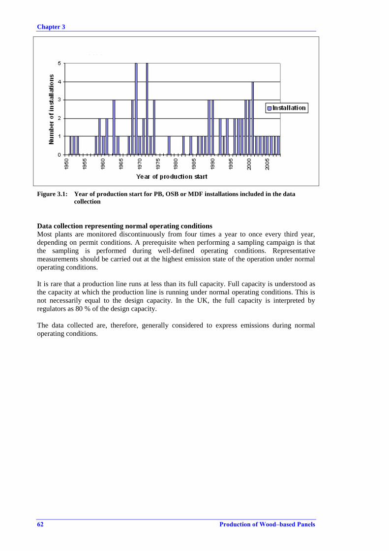
Chapter 3
62 Production of Wood–based Panels
Figure 3.1: Year of production start for PB, OSB or MDF installations included in the data
collection
Data collection representing normal operating conditions
Most plants are monitored discontinuously from four times a year to once every third year,
depending on permit conditions. A prerequisite when performing a sampling campaign is that
the sampling is performed during well-defined operating conditions. Representative
measurements should be carried out at the highest emission state of the operation under normal
operating conditions.
It is rare that a production line runs at less than its full capacity. Full capacity is understood as
the capacity at which the production line is running under normal operating conditions. This is
not necessarily equal to the design capacity. In the UK, the full capacity is interpreted by
regulators as 80 % of the design capacity.
The data collected are, therefore, generally considered to express emissions during normal
operating conditions.

Chapter 3
Production of Wood–based Panels 63
3.1 Inputs to production
3.1.1 Wood raw material
Raw materials for the production of panels cover a large range of sources. Originally only virgin
wood, such as round logs and production residues from sawmills, especially sawdust and
shavings, were used in the production of particleboard.
Other green wood materials were included later, such as from forest thinning. Market conditions
and new legislation paved the way for the use of recovered wood. With greater focus on
recycling and collection systems for post-consumer products and production residues from the
woodworking and furniture industries, a new range of raw material became available for the
sector. The use of recovered wood requires prior cleaning, to rid the wood-based material of
debris such as plastic and metals, which represents an additional processing step.
After the development of the market for pellets for biomass-fired combustion plants and for
retail sale, green wood from forests and from the woodworking industry, especially sawdust, has
now become less accessible for the wood-based panel industry, in terms of price and quantity.
The selection of raw material is dictated by the product to be produced, but raw material
selection is constantly under development. Until recently, recovered wood was only used as a
raw material in the production of particleboard but, with careful selection of the source and
quality of the recovered wood and efficient cleaning, recovered wood is today also used in the
production of MDF, although pure fractions of post-consumer wood are still only applied in
particleboard production.
In Figure 3.2, the composition of wood raw material for the three main products is shown. The
data are based on information collected for one production year from 38 particleboard plants, 14
MDF plants including HDF, and 6 OSB plants.
Source: [ 8, TWG WBP 2012 ]
Figure 3.2: Distribution of wood raw materials used in different panel products in the EU-27
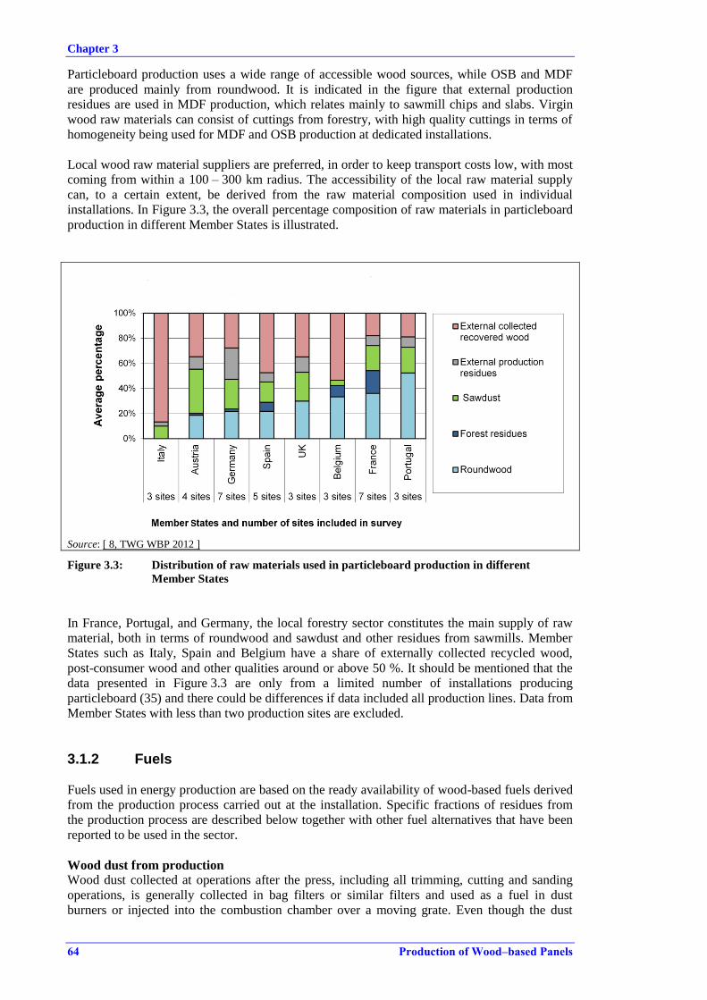
Chapter 3
64 Production of Wood–based Panels
Particleboard production uses a wide range of accessible wood sources, while OSB and MDF
are produced mainly from roundwood. It is indicated in the figure that external production
residues are used in MDF production, which relates mainly to sawmill chips and slabs. Virgin
wood raw materials can consist of cuttings from forestry, with high quality cuttings in terms of
homogeneity being used for MDF and OSB production at dedicated installations.
Local wood raw material suppliers are preferred, in order to keep transport costs low, with most
coming from within a 100 – 300 km radius. The accessibility of the local raw material supply
can, to a certain extent, be derived from the raw material composition used in individual
installations. In Figure 3.3, the overall percentage composition of raw materials in particleboard
production in different Member States is illustrated.
Source: [ 8, TWG WBP 2012 ]
Figure 3.3: Distribution of raw materials used in particleboard production in different
Member States
In France, Portugal, and Germany, the local forestry sector constitutes the main supply of raw
material, both in terms of roundwood and sawdust and other residues from sawmills. Member
States such as Italy, Spain and Belgium have a share of externally collected recycled wood,
post-consumer wood and other qualities around or above 50 %. It should be mentioned that the
data presented in Figure 3.3 are only from a limited number of installations producing
particleboard (35) and there could be differences if data included all production lines. Data from
Member States with less than two production sites are excluded.
3.1.2 Fuels
Fuels used in energy production are based on the ready availability of wood-based fuels derived
from the production process carried out at the installation. Specific fractions of residues from
the production process are described below together with other fuel alternatives that have been
reported to be used in the sector.
Wood dust from production
Wood dust collected at operations after the press, including all trimming, cutting and sanding
operations, is generally collected in bag filters or similar filters and used as a fuel in dust
burners or injected into the combustion chamber over a moving grate. Even though the dust

Chapter 3
Production of Wood–based Panels 65
collected from different sources is sometimes collected individually and transported manually to
the combustion plant, a central dust ring collection system with central bag filters is also used.
Wood dust and trimmings collected before the press are generally recycled in production by
either adding the material for shifting after drying or adding the collected material to the raw
wood before drying.
In fibreboard production, the collected dust fibres are shifted and added to the dry fibre storage.
Rejected panels
OSB and fibreboards that are rejected after the press and further down the finishing line are
collected and used as fuel. In particleboard production, the rejects can often be reused as raw
material instead of being used as fuel. Rejects from OSB production cannot be reprocessed due
to the character of the strands. The rejects from OSB can be used as raw material for
particleboard production, which is feasible when the two products are produced at the same
installation. If this is not the case, the OSB rejects are used as fuel.
Bark
Bark is a major fuel source at installations that use roundwood as a raw material. Bark is derived
as a residue from debarking and from the sorting of chips after a primary chipping step and
secondary milling step.
Sludge from abatement systems
Wet dust abatement systems are preferred for abating the sticky and moist air emissions from
dryers and from presses. Sludge is generated and collected from the abatement systems. The
collected sludge is not produced in large quantities and does not constitute a significant source
of fuel. The sludge generated is primarily wood dust and has a moisture content of between
15 % and 60 % after dewatering by screw presses or decantation of the sedimented material.
There are no data available on the composition of the sludge.
Sludge and filtration sludge from a waste water treatment plant are also used as fuel at some
installations, but this depends on the quality of the sludge and the treatment step from which it
was derived.
Wood residues from the cleaning plant for recycled wood
Recycled wood from external sources used as raw material creates large quantities of waste
residues when cleaning the material. Metals and plastics are collected separately and are
unsuited for use as fuels, but the wood-based fractions are readily used as fuels. The amount of
wood-based fuel derived from cleaning plants for recycled wood will depend on the
composition of the raw material received, the desired quality of the end product, and the
efficiency of the cleaning plant.
Externally delivered wood material
If the internally produced wood residues are not sufficient for the fuel demand, externally
delivered wood material is used. Wood material could be production residues from the furniture
industry which are generally of a quality that can be used as raw material in the production
process. Wood material received for use as a fuel is mostly of a lower quality and includes post-
consumer wood, collectively called recovered wood. This material could be defined as wood
waste depending on individual MS' waste regulations. The term recovered wood is used for
differentiating between virgin wood, internal or external production residues and collected post-
consumer wood. Sawdust is an important raw material for particleboard production but also
serves as a fuel, especially in larger combustion units firing over a moving grate.
Roots and stubs from wood harvesting require special equipment for shredding and preparation
before it is possible to use them as fuel and hence they are rarely used. The roots are
contaminated with soil and are not used in the production of panels.
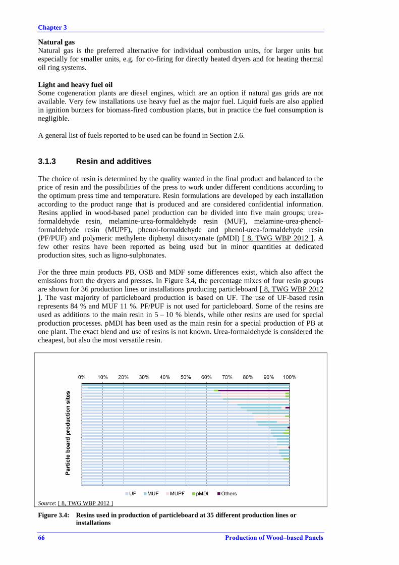
Chapter 3
66 Production of Wood–based Panels
Natural gas
Natural gas is the preferred alternative for individual combustion units, for larger units but
especially for smaller units, e.g. for co-firing for directly heated dryers and for heating thermal
oil ring systems.
Light and heavy fuel oil
Some cogeneration plants are diesel engines, which are an option if natural gas grids are not
available. Very few installations use heavy fuel as the major fuel. Liquid fuels are also applied
in ignition burners for biomass-fired combustion plants, but in practice the fuel consumption is
negligible.
A general list of fuels reported to be used can be found in Section 2.6.
3.1.3 Resin and additives
The choice of resin is determined by the quality wanted in the final product and balanced to the
price of resin and the possibilities of the press to work under different conditions according to
the optimum press time and temperature. Resin formulations are developed by each installation
according to the product range that is produced and are considered confidential information.
Resins applied in wood-based panel production can be divided into five main groups; urea-
formaldehyde resin, melamine-urea-formaldehyde resin (MUF), melamine-urea-phenol-
formaldehyde resin (MUPF), phenol-formaldehyde and phenol-urea-formaldehyde resin
(PF/PUF) and polymeric methylene diphenyl diisocyanate (pMDI) [ 8, TWG WBP 2012 ]. A
few other resins have been reported as being used but in minor quantities at dedicated
production sites, such as ligno-sulphonates.
For the three main products PB, OSB and MDF some differences exist, which also affect the
emissions from the dryers and presses. In Figure 3.4, the percentage mixes of four resin groups
are shown for 36 production lines or installations producing particleboard [ 8, TWG WBP 2012
]. The vast majority of particleboard production is based on UF. The use of UF-based resin
represents 84 % and MUF 11 %. PF/PUF is not used for particleboard. Some of the resins are
used as additions to the main resin in 5 – 10 % blends, while other resins are used for special
production processes. pMDI has been used as the main resin for a special production of PB at
one plant. The exact blend and use of resins is not known. Urea-formaldehyde is considered the
cheapest, but also the most versatile resin.
Source: [ 8, TWG WBP 2012 ]
Figure 3.4: Resins used in production of particleboard at 35 different production lines or
installations
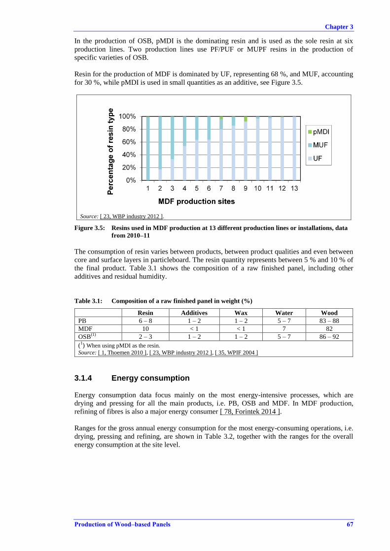
Chapter 3
Production of Wood–based Panels 67
In the production of OSB, pMDI is the dominating resin and is used as the sole resin at six
production lines. Two production lines use PF/PUF or MUPF resins in the production of
specific varieties of OSB.
Resin for the production of MDF is dominated by UF, representing 68 %, and MUF, accounting
for 30 %, while pMDI is used in small quantities as an additive, see Figure 3.5.
Source: [ 23, WBP industry 2012 ].
Figure 3.5: Resins used in MDF production at 13 different production lines or installations, data
from 2010–11
The consumption of resin varies between products, between product qualities and even between
core and surface layers in particleboard. The resin quantity represents between 5 % and 10 % of
the final product. Table 3.1 shows the composition of a raw finished panel, including other
additives and residual humidity.
Table 3.1: Composition of a raw finished panel in weight (%)
Resin Additives Wax Water Wood
PB 6 – 8 1 – 2 1 – 2 5 – 7 83 – 88
MDF 10 < 1 < 1 7 82
OSB(1)
2 – 3 1 – 2 1 – 2 5 – 7 86 – 92
(1) When using pMDI as the resin.
Source: [ 1, Thoemen 2010 ], [ 23, WBP industry 2012 ], [ 35, WPIF 2004 ]
3.1.4 Energy consumption
Energy consumption data focus mainly on the most energy-intensive processes, which are
drying and pressing for all the main products, i.e. PB, OSB and MDF. In MDF production,
refining of fibres is also a major energy consumer [ 78, Forintek 2014 ].
Ranges for the gross annual energy consumption for the most energy-consuming operations, i.e.
drying, pressing and refining, are shown in Table 3.2, together with the ranges for the overall
energy consumption at the site level.
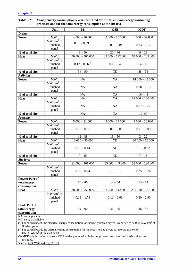
Chapter 3
68 Production of Wood–based Panels
Table 3.2: Yearly energy consumption levels illustrated for the three main energy-consuming
processes and for the total energy consumption at the site level
Unit PB OSB MDF(3)
Drying
Power MWh 4 000 – 26 000 8 000 – 13 000 6 000 – 32 000
MWh/m3 of
finished
panel
0.01 – 0.09(1)
0.03 – 0.04 0.03 – 0.12
% of total site 6 – 50 22 – 36 9 – 28
Heat MWh 50 000 – 407 000 33 000 – 192 000 64 000 – 205 000
MWh/m3 of
finished
panel
0.17 – 0.86(2)
0.1 – 0.4 0.4 – 1.1
% of total site 34 – 90 ND 28 – 58
Refining
Power MWh NA NA 14 000 – 43 000
MWh/m3 of
finished
panel
NA NA 0.08 – 0.15
% of total site NA NA 16 – 45
Heat MWh NA NA 52 000 – 186 000
MWh/m3 of
finished
panel
NA NA 0.27 –0.79
% of total site NA NA 10–60
Pressing
Power MWh 5 000 – 21 000 5 000 – 19 000 4 000 – 26 000
MWh/m3 of
finished
panel
0.02 – 0.06 0.01 – 0.06 0.01 – 0.09
% of total site 12 – 38 13 – 50 3 – 22
Heat MWh 13 000 – 50 000 ND 20 000 – 50 000
MWh/m3 of
finished
panel
0.05 – 0.14 ND 0.1 – 0.32
% of total site 7 – 15 ND 7 – 15
Site level
Power 11 000 – 101 000 35 000 – 49 000 53 000 – 230 000
MWh/m3 of
finished
panel
0.07 – 0.24 0.10 – 0.13 0.25 – 0.76
Power: Part of
total energy
consumption
10 – 46 14 – 54 13 – 64
Heat MWh 28 000 – 750 000 33 000 – 112 000 231 000 – 887 000
MWh/m3 of
finished
panel
0.18 – 1.73 0.11 – 0.69 0.30 – 2.90
Heat: Part of
total energy
consumption
54 – 90 46 – 86 36 – 87
NA: not applicable.
ND: no data available.
(1) For particleboard, the electrical energy consumption for indirectly heated dryers is reported to be 0.01 MWh/m3 of
finished panel.
(2) For particleboard, the thermal energy consumption for indirectly heated dryers is reported to be 0.46–
0.60 MWh/m3 of finished panel.
(3) MDF only includes data from MDF grades produced with the dry process. Insulation and flexboard are not
included.
Source: [ 23, WBP industry 2012 ]
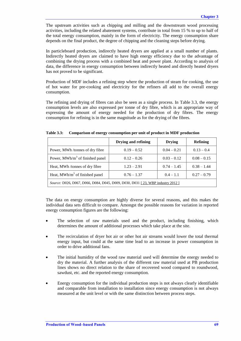
Chapter 3
Production of Wood–based Panels 69
The upstream activities such as chipping and milling and the downstream wood processing
activities, including the related abatement systems, contribute in total from 15 % to up to half of
the total energy consumption, mainly in the form of electricity. The energy consumption share
depends on the final product, the degree of chipping and the cleaning steps before drying.
In particleboard production, indirectly heated dryers are applied at a small number of plants.
Indirectly heated dryers are claimed to have high energy efficiency due to the advantage of
combining the drying process with a combined heat and power plant. According to analysis of
data, the difference in energy consumption between indirectly heated and directly heated dryers
has not proved to be significant.
Production of MDF includes a refining step where the production of steam for cooking, the use
of hot water for pre-cooking and electricity for the refiners all add to the overall energy
consumption.
The refining and drying of fibres can also be seen as a single process. In Table 3.3, the energy
consumption levels are also expressed per tonne of dry fibre, which is an appropriate way of
expressing the amount of energy needed for the production of dry fibres. The energy
consumption for refining is in the same magnitude as for the drying of the fibres.
Table 3.3: Comparison of energy consumption per unit of product in MDF production
Drying and refining Drying Refining
Power, MWh /tonnes of dry fibre 0.19 – 0.52 0.04 – 0.21 0.13 – 0.4
Power, MWh/m3 of finished panel 0.12 – 0.26 0.03 – 0.12 0.08 – 0.15
Heat, MWh /tonnes of dry fibre 1.23 – 2.91 0.74 – 1.45 0.38 – 1.44
Heat, MWh/m3 of finished panel 0.76 – 1.37 0.4 – 1.1 0.27 – 0.79
Source: D026, D067, D066, D084, D045, D009, D030, D031 [ 23, WBP industry 2012 ]
The data on energy consumption are highly diverse for several reasons, and this makes the
individual data sets difficult to compare. Amongst the possible reasons for variation in reported
energy consumption figures are the following:
The selection of raw materials used and the product, including finishing, which
determines the amount of additional processes which take place at the site.
The recirculation of dryer hot air or other hot air streams would lower the total thermal
energy input, but could at the same time lead to an increase in power consumption in
order to drive additional fans.
The initial humidity of the wood raw material used will determine the energy needed to
dry the material. A further analysis of the different raw material used at PB production
lines shows no direct relation to the share of recovered wood compared to roundwood,
sawdust, etc. and the reported energy consumption.
Energy consumption for the individual production steps is not always clearly identifiable
and comparable from installation to installation since energy consumption is not always
measured at the unit level or with the same distinction between process steps.
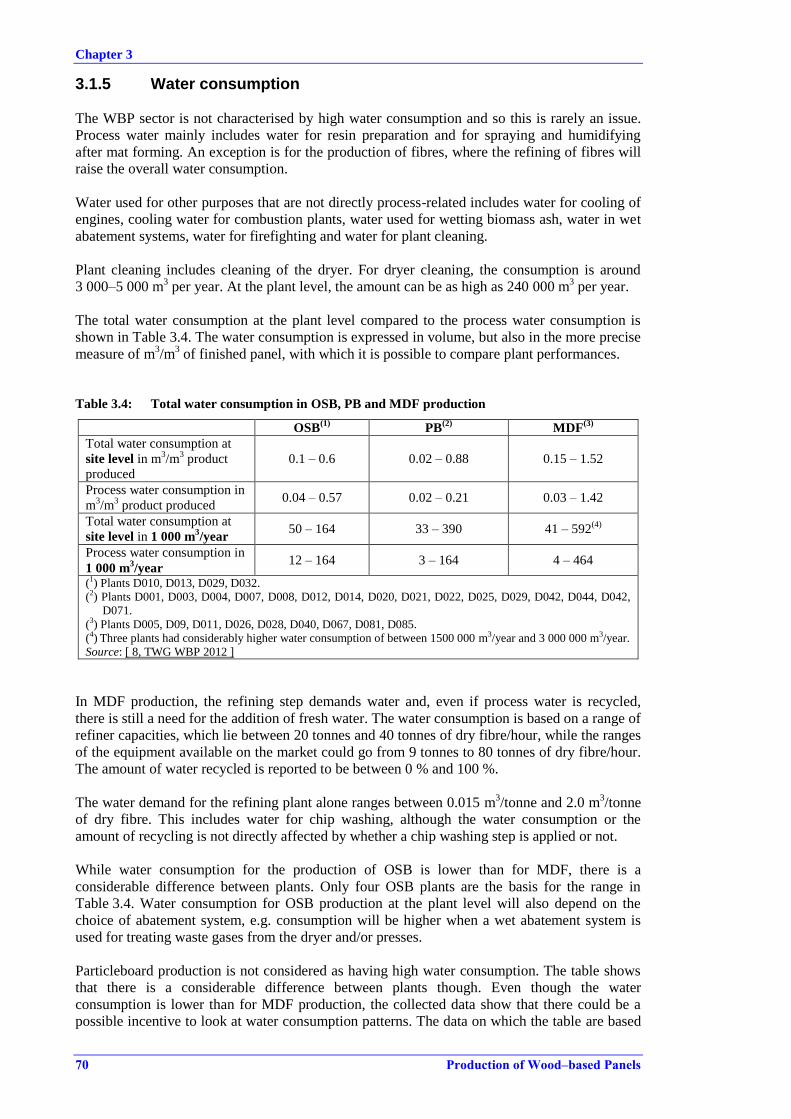
Chapter 3
70 Production of Wood–based Panels
3.1.5 Water consumption
The WBP sector is not characterised by high water consumption and so this is rarely an issue.
Process water mainly includes water for resin preparation and for spraying and humidifying
after mat forming. An exception is for the production of fibres, where the refining of fibres will
raise the overall water consumption.
Water used for other purposes that are not directly process-related includes water for cooling of
engines, cooling water for combustion plants, water used for wetting biomass ash, water in wet
abatement systems, water for firefighting and water for plant cleaning.
Plant cleaning includes cleaning of the dryer. For dryer cleaning, the consumption is around
3 000–5 000 m3 per year. At the plant level, the amount can be as high as 240 000 m
3 per year.
The total water consumption at the plant level compared to the process water consumption is
shown in Table 3.4. The water consumption is expressed in volume, but also in the more precise
measure of m3/m
3 of finished panel, with which it is possible to compare plant performances.
Table 3.4: Total water consumption in OSB, PB and MDF production
OSB(1)
PB(2)
MDF(3)
Total water consumption at
site level in m3/m
3 product
produced
0.1 – 0.6 0.02 – 0.88 0.15 – 1.52
Process water consumption in
m3/m
3 product produced
0.04 – 0.57 0.02 – 0.21 0.03 – 1.42
Total water consumption at
site level in 1 000 m3/year
50 – 164 33 – 390 41 – 592(4)
Process water consumption in
1 000 m3/year
12 – 164 3 – 164 4 – 464
(1) Plants D010, D013, D029, D032.
(2) Plants D001, D003, D004, D007, D008, D012, D014, D020, D021, D022, D025, D029, D042, D044, D042,
D071.
(3) Plants D005, D09, D011, D026, D028, D040, D067, D081, D085.
(4) Three plants had considerably higher water consumption of between 1500 000 m3/year and 3 000 000 m3/year.
Source: [ 8, TWG WBP 2012 ]
In MDF production, the refining step demands water and, even if process water is recycled,
there is still a need for the addition of fresh water. The water consumption is based on a range of
refiner capacities, which lie between 20 tonnes and 40 tonnes of dry fibre/hour, while the ranges
of the equipment available on the market could go from 9 tonnes to 80 tonnes of dry fibre/hour.
The amount of water recycled is reported to be between 0 % and 100 %.
The water demand for the refining plant alone ranges between 0.015 m3/tonne and 2.0 m
3/tonne
of dry fibre. This includes water for chip washing, although the water consumption or the
amount of recycling is not directly affected by whether a chip washing step is applied or not.
While water consumption for the production of OSB is lower than for MDF, there is a
considerable difference between plants. Only four OSB plants are the basis for the range in
Table 3.4. Water consumption for OSB production at the plant level will also depend on the
choice of abatement system, e.g. consumption will be higher when a wet abatement system is
used for treating waste gases from the dryer and/or presses.
Particleboard production is not considered as having high water consumption. The table shows
that there is a considerable difference between plants though. Even though the water
consumption is lower than for MDF production, the collected data show that there could be a
possible incentive to look at water consumption patterns. The data on which the table are based

Chapter 3
Production of Wood–based Panels 71
do not contain enough information to fully clarify the amount of water used in specific parts of
the plant, or the related measures already in place to reduce water consumption.
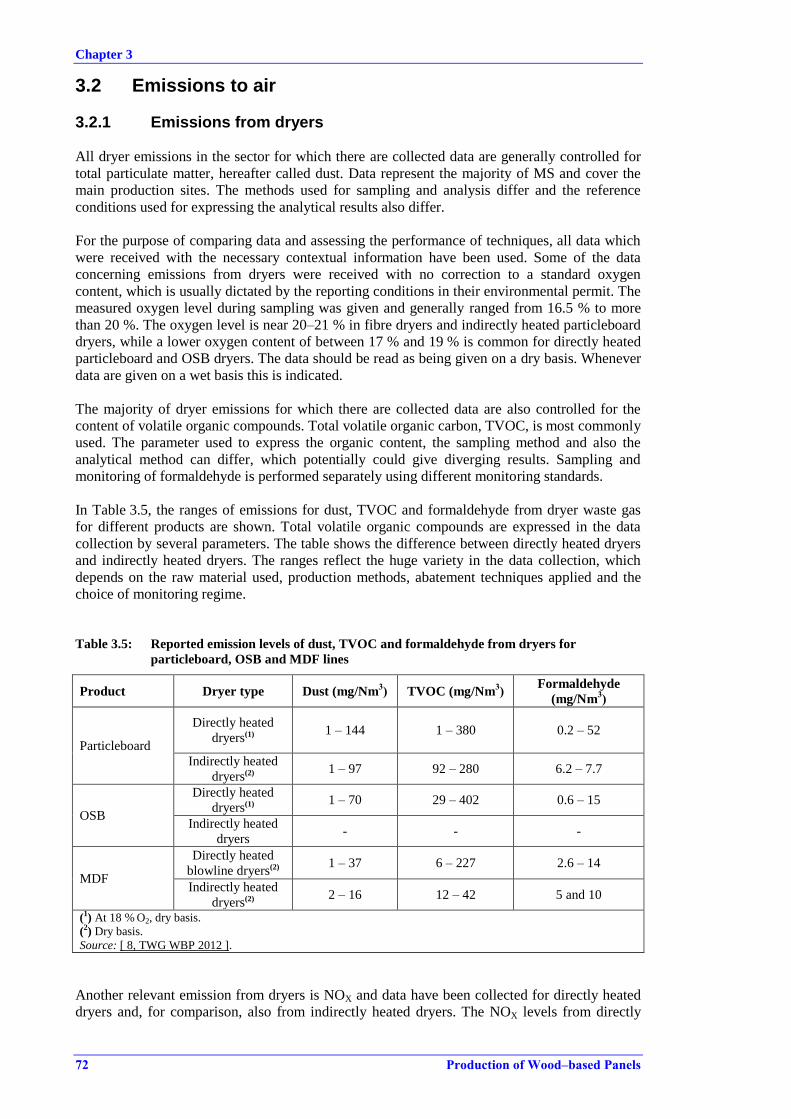
Chapter 3
72 Production of Wood–based Panels
3.2 Emissions to air
3.2.1 Emissions from dryers
All dryer emissions in the sector for which there are collected data are generally controlled for
total particulate matter, hereafter called dust. Data represent the majority of MS and cover the
main production sites. The methods used for sampling and analysis differ and the reference
conditions used for expressing the analytical results also differ.
For the purpose of comparing data and assessing the performance of techniques, all data which
were received with the necessary contextual information have been used. Some of the data
concerning emissions from dryers were received with no correction to a standard oxygen
content, which is usually dictated by the reporting conditions in their environmental permit. The
measured oxygen level during sampling was given and generally ranged from 16.5 % to more
than 20 %. The oxygen level is near 20–21 % in fibre dryers and indirectly heated particleboard
dryers, while a lower oxygen content of between 17 % and 19 % is common for directly heated
particleboard and OSB dryers. The data should be read as being given on a dry basis. Whenever
data are given on a wet basis this is indicated.
The majority of dryer emissions for which there are collected data are also controlled for the
content of volatile organic compounds. Total volatile organic carbon, TVOC, is most commonly
used. The parameter used to express the organic content, the sampling method and also the
analytical method can differ, which potentially could give diverging results. Sampling and
monitoring of formaldehyde is performed separately using different monitoring standards.
In Table 3.5, the ranges of emissions for dust, TVOC and formaldehyde from dryer waste gas
for different products are shown. Total volatile organic compounds are expressed in the data
collection by several parameters. The table shows the difference between directly heated dryers
and indirectly heated dryers. The ranges reflect the huge variety in the data collection, which
depends on the raw material used, production methods, abatement techniques applied and the
choice of monitoring regime.
Table 3.5: Reported emission levels of dust, TVOC and formaldehyde from dryers for
particleboard, OSB and MDF lines
Product Dryer type Dust (mg/Nm3) TVOC (mg/Nm
3)
Formaldehyde
(mg/Nm3)
Particleboard
Directly heated
dryers(1) 1 – 144 1 – 380 0.2 – 52
Indirectly heated
dryers(2) 1 – 97 92 – 280 6.2 – 7.7
OSB
Directly heated
dryers(1) 1 – 70 29 – 402 0.6 – 15
Indirectly heated
dryers - - -
MDF
Directly heated
blowline dryers(2) 1 – 37 6 – 227 2.6 – 14
Indirectly heated
dryers(2) 2 – 16 12 – 42 5 and 10
(1) At 18 % O2, dry basis.
(2) Dry basis.
Source: [ 8, TWG WBP 2012 ].
Another relevant emission from dryers is NOX and data have been collected for directly heated
dryers and, for comparison, also from indirectly heated dryers. The NOX levels from directly

Chapter 3
Production of Wood–based Panels 73
heated dryers range from 2 mg/Nm3 to around 350 mg/Nm
3. All data are expressed with a
standard oxygen content of 18 %.
Several other parameters such as CO, SOX, heavy metals, HCl and dioxins in waste gases from
dryers are monitored, but infrequently. The data have been included in this document, when
available
3.2.1.1 Dust in dryer emissions
In Figure 3.6, the distribution of all collected emissions data, as the data were received, for
average dust emissions from 50 PB production lines is shown with the applied dust abatement
technique.
Source: [ 22, TWG 2012 ], [ 23, WBP industry 2012 ]
Figure 3.6: Values for dust in emissions to air from directly heated PB dryers and the applied
abatement techniques, based on data from 50 production lines
The difference in reported emission levels between dryer lines not only in Figure 3.6, but also in
the remaining figures in Sections 3.2.1.1, 3.2.1.2 and 3.2.1.3, reflects the chosen abatement
system and in part the reference conditions. The related information on reference conditions for
the individual data in Figure 3.6 is shown in Table 3.6. A WESP is applied on more than half of
the production lines, with multicyclones being the other most commonly applied technique.
Even though a distinction is made between cyclones and multicyclones, based on the
information collected, the two could be taken as the same dust separation technique.
Several sites not only in Figure 3.6, but also in the remaining figures in Sections 3.2.1.1, 3.2.1.2
and 3.2.1.3, show a large difference between the reported minimum and maximum values for
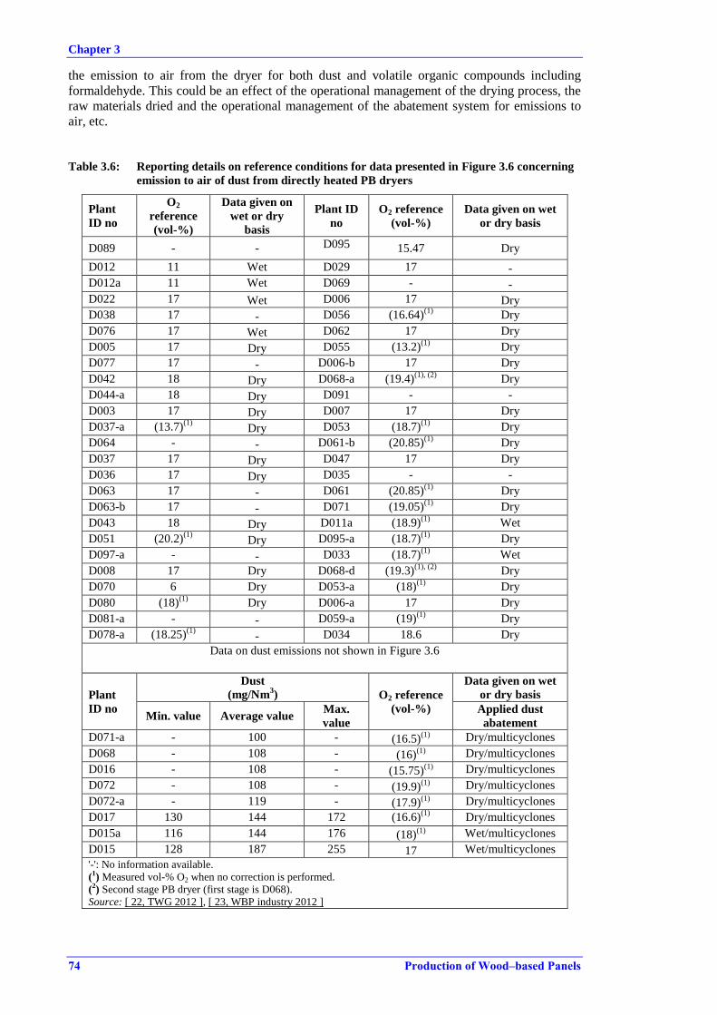
Chapter 3
74 Production of Wood–based Panels
the emission to air from the dryer for both dust and volatile organic compounds including
formaldehyde. This could be an effect of the operational management of the drying process, the
raw materials dried and the operational management of the abatement system for emissions to
air, etc.
Table 3.6: Reporting details on reference conditions for data presented in Figure 3.6 concerning
emission to air of dust from directly heated PB dryers
Plant
ID no
O2
reference
(vol-%)
Data given on
wet or dry
basis
Plant ID
no
O2 reference
(vol-%)
Data given on wet
or dry basis
D089 - - D095 15.47 Dry
D012 11 Wet D029 17 -
D012a 11 Wet D069 - -
D022 17 Wet D006 17 Dry
D038 17 - D056 (16.64)(1)
Dry
D076 17 Wet D062 17 Dry
D005 17 Dry D055 (13.2)(1)
Dry
D077 17 - D006-b 17 Dry
D042 18 Dry D068-a (19.4)(1), (2)
Dry
D044-a 18 Dry D091 - -
D003 17 Dry D007 17 Dry
D037-a (13.7)(1)
Dry D053 (18.7)(1)
Dry
D064 - - D061-b (20.85)(1)
Dry
D037 17 Dry D047 17 Dry
D036 17 Dry D035 - -
D063 17 - D061 (20.85)(1)
Dry
D063-b 17 - D071 (19.05)(1)
Dry
D043 18 Dry D011a (18.9)(1)
Wet
D051 (20.2)(1)
Dry D095-a (18.7)(1)
Dry
D097-a - - D033 (18.7)(1)
Wet
D008 17 Dry D068-d (19.3)(1), (2)
Dry
D070 6 Dry D053-a (18)(1)
Dry
D080 (18)(1)
Dry D006-a 17 Dry
D081-a - - D059-a (19)(1)
Dry
D078-a (18.25)(1)
- D034 18.6 Dry
Data on dust emissions not shown in Figure 3.6
Plant
ID no
Dust
(mg/Nm3) O2 reference
(vol-%)
Data given on wet
or dry basis
Min. value Average value Max.
value
Applied dust
abatement
D071-a - 100 - (16.5)(1)
Dry/multicyclones
D068 - 108 - (16)(1)
Dry/multicyclones
D016 - 108 - (15.75)(1)
Dry/multicyclones
D072 - 108 - (19.9)(1)
Dry/multicyclones
D072-a - 119 - (17.9)(1)
Dry/multicyclones
D017 130 144 172 (16.6)(1)
Dry/multicyclones
D015a 116 144 176 (18)(1)
Wet/multicyclones
D015 128 187 255 17 Wet/multicyclones '-': No information available.
(1) Measured vol-% O2 when no correction is performed.
(2) Second stage PB dryer (first stage is D068).
Source: [ 22, TWG 2012 ], [ 23, WBP industry 2012 ]

Chapter 3
Production of Wood–based Panels 75
Press waste gases can also be collected and treated together with dryer waste gases, but this is
applied mainly with a WESP. The additional source from the press emissions does not
contribute significantly to the dust levels in the treated emissions from the WESP compared to a
WESP treating only dryer waste gas, see Figure 3.7.
This is, first of all, an indication of the possibilities for treating various similar sources with the
same technique, but it is a prerequisite that the technique is designed to receive and treat all of
the different waste gas streams.
Source: [ 22, TWG 2012 ], [ 23, WBP industry 2012 ]
Figure 3.7: Values for dust in emissions to air from PB dryers applying a WESP including when
waste gas from both the dryer and press are treated together
Indirectly heated dryers are used at a limited number of plants. The values for dust in emissions
to air are shown in Table 3.7. As for directly heated dryers, WESPs and cyclones are used. Bag
filters are used in a small number of PB production lines, i.e. at four installations. Dust
emissions from the bag filters are continuously measured photometrically and with periodic
monitoring every third year, as shown in Table 3.7. The resulting mass load of dust released per
tonne of dried product is correspondingly low when using a bag filter. Bag filters are efficient
dust collectors, but have no abatement efficiency for organic volatile compounds.
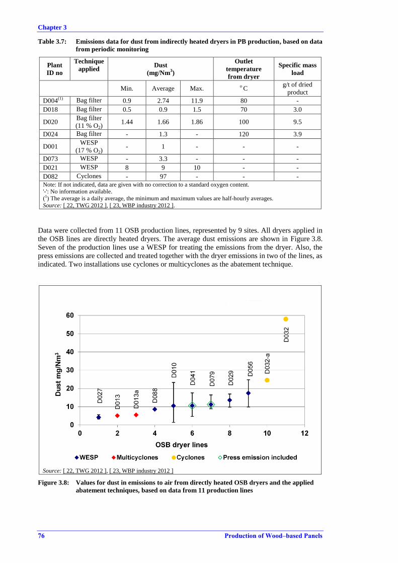
Chapter 3
76 Production of Wood–based Panels
Table 3.7: Emissions data for dust from indirectly heated dryers in PB production, based on data
from periodic monitoring
Plant
ID no
Technique
applied Dust
(mg/Nm3)
Outlet
temperature
from dryer
Specific mass
load
Min. Average Max. o C
g/t of dried
product
D004(1)
Bag filter 0.9 2.74 11.9 80 -
D018 Bag filter 0.5 0.9 1.5 70 3.0
D020 Bag filter
(11 % O2) 1.44 1.66 1.86 100 9.5
D024 Bag filter - 1.3 - 120 3.9
D001 WESP
(17 % O2) - 1 - - -
D073 WESP - 3.3 - - -
D021 WESP 8 9 10 - -
D082 Cyclones - 97 - - -
Note: If not indicated, data are given with no correction to a standard oxygen content.
'-': No information available.
(1) The average is a daily average, the minimum and maximum values are half-hourly averages.
Source: [ 22, TWG 2012 ], [ 23, WBP industry 2012 ].
Data were collected from 11 OSB production lines, represented by 9 sites. All dryers applied in
the OSB lines are directly heated dryers. The average dust emissions are shown in Figure 3.8.
Seven of the production lines use a WESP for treating the emissions from the dryer. Also, the
press emissions are collected and treated together with the dryer emissions in two of the lines, as
indicated. Two installations use cyclones or multicyclones as the abatement technique.
Source: [ 22, TWG 2012 ], [ 23, WBP industry 2012 ]
Figure 3.8: Values for dust in emissions to air from directly heated OSB dryers and the applied
abatement techniques, based on data from 11 production lines
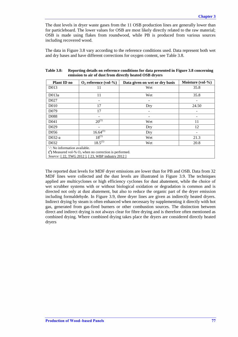
Chapter 3
Production of Wood–based Panels 77
The dust levels in dryer waste gases from the 11 OSB production lines are generally lower than
for particleboard. The lower values for OSB are most likely directly related to the raw material;
OSB is made using flakes from roundwood, while PB is produced from various sources
including recovered wood.
The data in Figure 3.8 vary according to the reference conditions used. Data represent both wet
and dry bases and have different corrections for oxygen content, see Table 3.8.
Table 3.8: Reporting details on reference conditions for data presented in Figure 3.8 concerning
emission to air of dust from directly heated OSB dryers
Plant ID no O2 reference (vol-%) Data given on wet or dry basis Moisture (vol-%)
D013 11 Wet 35.8
D013a 11 Wet 35.8
D027 - - -
D010 17 Dry 24.50
D079 17 - -
D088 - - -
D041 20(1)
Wet 11
D029 - Dry 12
D056 16.64(1)
Dry -
D032-a 18(1)
Wet 21.3
D032 18.5(1)
Wet 20.8
'-': No information available.
(1) Measured vol-% O2 when no correction is performed.
Source: [ 22, TWG 2012 ], [ 23, WBP industry 2012 ]
The reported dust levels for MDF dryer emissions are lower than for PB and OSB. Data from 32
MDF lines were collected and the dust levels are illustrated in Figure 3.9. The techniques
applied are multicyclones or high efficiency cyclones for dust abatement, while the choice of
wet scrubber systems with or without biological oxidation or degradation is common and is
directed not only at dust abatement, but also to reduce the organic part of the dryer emission
including formaldehyde. In Figure 3.9, three dryer lines are given as indirectly heated dryers.
Indirect drying by steam is often enhanced when necessary by supplementing it directly with hot
gas, generated from gas-fired burners or other combustion sources. The distinction between
direct and indirect drying is not always clear for fibre drying and is therefore often mentioned as
combined drying. Where combined drying takes place the dryers are considered directly heated
dryers
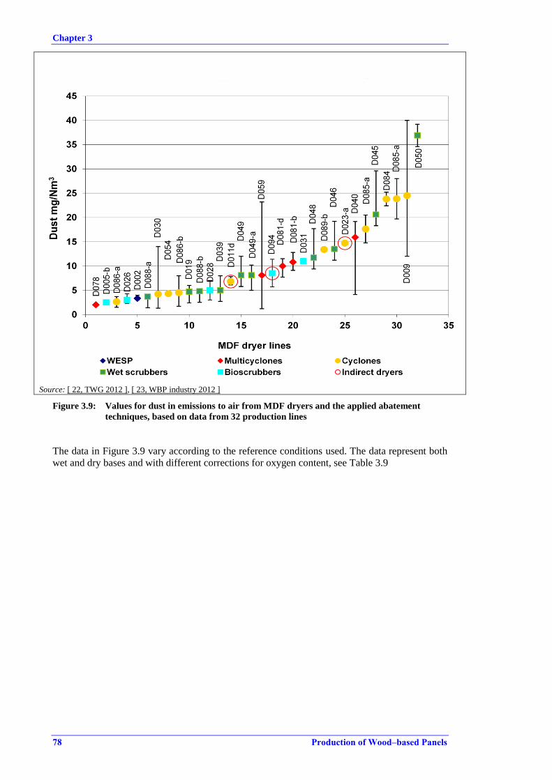
Chapter 3
78 Production of Wood–based Panels
Source: [ 22, TWG 2012 ], [ 23, WBP industry 2012 ]
Figure 3.9: Values for dust in emissions to air from MDF dryers and the applied abatement
techniques, based on data from 32 production lines
The data in Figure 3.9 vary according to the reference conditions used. The data represent both
wet and dry bases and with different corrections for oxygen content, see Table 3.9
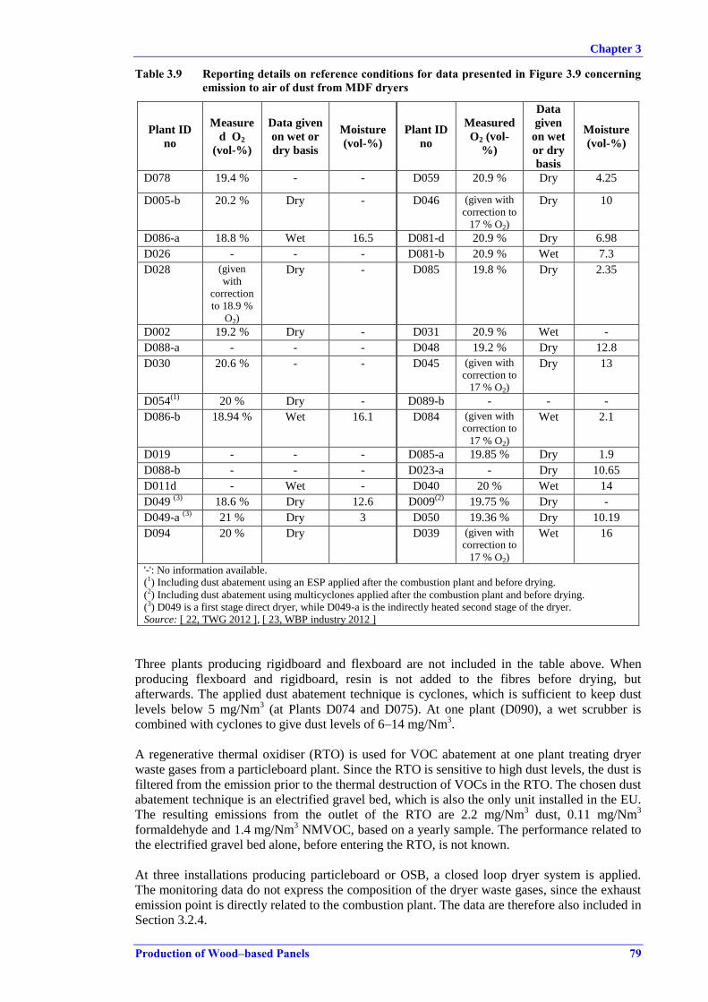
Chapter 3
Production of Wood–based Panels 79
Table 3.9 Reporting details on reference conditions for data presented in Figure 3.9 concerning
emission to air of dust from MDF dryers
Plant ID
no
Measure
d O2
(vol-%)
Data given
on wet or
dry basis
Moisture
(vol-%)
Plant ID
no
Measured
O2 (vol-
%)
Data
given
on wet
or dry
basis
Moisture
(vol-%)
D078 19.4 % - - D059 20.9 % Dry 4.25
D005-b 20.2 % Dry - D046 (given with
correction to
17 % O2)
Dry 10
D086-a 18.8 % Wet 16.5 D081-d 20.9 % Dry 6.98
D026 - - - D081-b 20.9 % Wet 7.3
D028 (given
with
correction
to 18.9 %
O2)
Dry - D085 19.8 % Dry 2.35
D002 19.2 % Dry - D031 20.9 % Wet -
D088-a - - - D048 19.2 % Dry 12.8
D030 20.6 % - - D045 (given with
correction to
17 % O2)
Dry 13
D054(1)
20 % Dry - D089-b - - -
D086-b 18.94 % Wet 16.1 D084 (given with
correction to
17 % O2)
Wet 2.1
D019 - - - D085-a 19.85 % Dry 1.9
D088-b - - - D023-a - Dry 10.65
D011d - Wet - D040 20 % Wet 14
D049 (3)
18.6 % Dry 12.6 D009(2)
19.75 % Dry -
D049-a (3)
21 % Dry 3 D050 19.36 % Dry 10.19
D094 20 % Dry D039 (given with
correction to
17 % O2)
Wet 16
'-': No information available.
(1) Including dust abatement using an ESP applied after the combustion plant and before drying.
(2) Including dust abatement using multicyclones applied after the combustion plant and before drying.
(3) D049 is a first stage direct dryer, while D049-a is the indirectly heated second stage of the dryer.
Source: [ 22, TWG 2012 ], [ 23, WBP industry 2012 ]
Three plants producing rigidboard and flexboard are not included in the table above. When
producing flexboard and rigidboard, resin is not added to the fibres before drying, but
afterwards. The applied dust abatement technique is cyclones, which is sufficient to keep dust
levels below 5 mg/Nm3 (at Plants D074 and D075). At one plant (D090), a wet scrubber is
combined with cyclones to give dust levels of 6–14 mg/Nm3.
A regenerative thermal oxidiser (RTO) is used for VOC abatement at one plant treating dryer
waste gases from a particleboard plant. Since the RTO is sensitive to high dust levels, the dust is
filtered from the emission prior to the thermal destruction of VOCs in the RTO. The chosen dust
abatement technique is an electrified gravel bed, which is also the only unit installed in the EU.
The resulting emissions from the outlet of the RTO are 2.2 mg/Nm3 dust, 0.11 mg/Nm
3
formaldehyde and 1.4 mg/Nm3 NMVOC, based on a yearly sample. The performance related to
the electrified gravel bed alone, before entering the RTO, is not known.
At three installations producing particleboard or OSB, a closed loop dryer system is applied.
The monitoring data do not express the composition of the dryer waste gases, since the exhaust
emission point is directly related to the combustion plant. The data are therefore also included in
Section 3.2.4.

Chapter 3
80 Production of Wood–based Panels
Contribution of dust from the hot gases used for direct drying
For direct drying, the dryer waste gases are mixed with hot gases from the combustion process,
and the original dust content in the hot gases contributes to the total dust level. The contribution
of dust depends on the fuel used, the combustion technology, and the dust abatement techniques
applied before the hot gas is directed to the dryer. While dust abatement systems applied to
combustion plants producing steam and electricity for indirectly heated dryers are common
practice, dust abatement systems are not always applied at combustion plants producing hot gas
for direct drying. The dust contribution from the hot gas is discussed in Section 3.2.4.
3.2.1.2 Formaldehyde in dryer emissions
Formaldehyde is monitored in most waste gas emissions from dryers.
While dust is monitored regularly, as mentioned in Section 3.2.1.1, formaldehyde and VOCs are
not necessarily monitored with the same frequency, especially when only dedicated dust
abatement techniques are applied, such as cyclones.
All reported emissions of formaldehyde for particleboard lie in the range from the limit of
detection to a maximum value of 74 mg/Nm3; see Figure 3.10, where the data from 34 PB
productions lines are presented.
Source: [ 22, TWG 2012 ], [ 23, WBP industry 2012 ]
Figure 3.10: Values for formaldehyde in emissions to air from PB dryers and the applied
abatement techniques, based on data from 34 production lines
The related information on reference conditions and the measurement standards used is
summarised in Table 3.10.
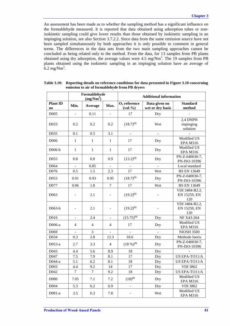
Chapter 3
Production of Wood–based Panels 81
An assessment has been made as to whether the sampling method has a significant influence on
the formaldehyde measured. It is reported that data obtained using adsorption tubes or non-
isokinetic sampling could give lower results than those obtained by isokinetic sampling in an
impinging solution, see also Section 3.7.2.2. Since data from the same emission source have not
been sampled simultaneously by both approaches it is only possible to comment in general
terms. The differences in the data sets from the two main sampling approaches cannot be
concluded as being related only to the method. From the data, for 13 samples from PB plants
obtained using dry adsorption, the average values were 4.5 mg/Nm3. The 19 samples from PB
plants obtained using the isokinetic sampling in an impinging solution have an average of
6.2 mg/Nm3.
Table 3.10: Reporting details on reference conditions for data presented in Figure 3.10 concerning
emission to air of formaldehyde from PB dryers
Formaldehyde
(mg/Nm3)
Additional information
Plant ID
no Min. Average Max.
O2 reference
(vol-%)
Data given on
wet or dry basis
Standard
method
D005 - 0.11 - 17 Dry -
D033 0.2 0.2 0.2 (18.7)(1) Wet
2,4 DNPH
impinging
solution
D035 0.1 0.5 3.1 - - -
D006 1 1 1 17 Dry Modified US
EPA M316
D006-b 1 1 1 17 Dry Modified US
EPA M316
D055 0.8 0.8 0.9 (13.2)(1) Dry PN-Z-040030-7,
PN-ISO-10396
D064 - 0.85 - - - Local standard
D076 0.5 1.5 2.3 17 Wet BS EN 13649
D053 0.91 0.93 0.95 (18.7)(1) Dry PN-Z-040030-7,
PN-ISO-10396
D077 0.06 1.8 7 17 Wet BS EN 13649
D063 - 2.1 - (19.2)(1) -
VDI 3484-B2.2,
EN 15259, EN
120
D063-b - 2.1 - (19.2)(1) -
VDI 3484-B2.2,
EN 15259, EN
120
D016 - 2.4 - (15.75)(1) Dry NF X43-264
D006-a 4 4 4 17 Dry Modified US
EPA M316
D069 - 3 - - - NIOSH 3500
D034 0.3 2.8 12.3 18.6 Dry Methode Ineris
D053-a 2.7 3.3 4 (18 %)(1) Dry PN-Z-040030-7,
PN-ISO-10396
D043 4.4 5.6 8.9 18 Dry -
D047 7.5 7.9 8.1 17 Dry US EPA-TO11/A
D044-a 5.1 6.2 8.1 18 Dry US EPA-TO11/A
D003 4.4 9.2 14 17 Dry VDI 3862
D042 7 7 9.2 18 Dry US EPA-TO11/A
D080 7.05 7.1 7.2 (18)(1) Dry Modified US
EPA M316
D004 5.3 6.2 6.9 - Dry VDI 3862
D081-a 3.5 6.3 7.8 - Wet Modified US
EPA M316
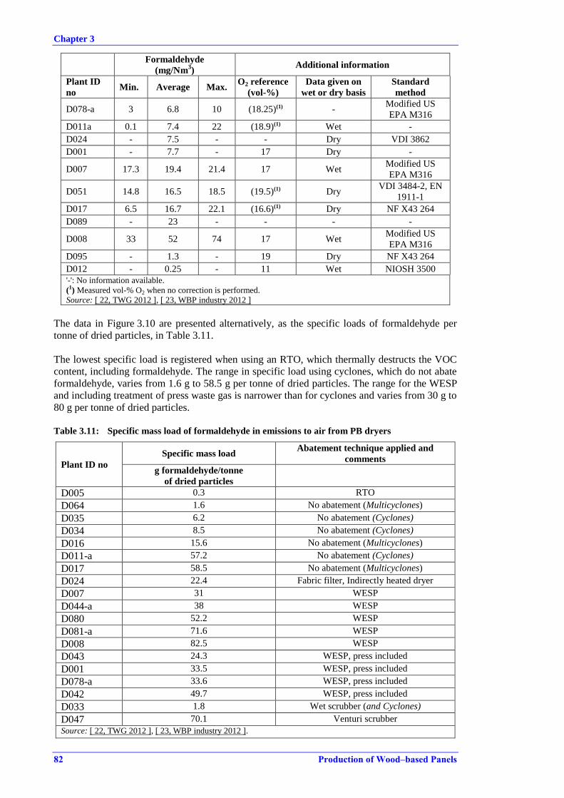
Chapter 3
82 Production of Wood–based Panels
Formaldehyde
(mg/Nm3)
Additional information
Plant ID
no Min. Average Max.
O2 reference
(vol-%)
Data given on
wet or dry basis
Standard
method
D078-a 3 6.8 10 (18.25)(1) - Modified US
EPA M316
D011a 0.1 7.4 22 (18.9)(1) Wet -
D024 - 7.5 - - Dry VDI 3862
D001 - 7.7 - 17 Dry -
D007 17.3 19.4 21.4 17 Wet Modified US
EPA M316
D051 14.8 16.5 18.5 (19.5)(1) Dry VDI 3484-2, EN
1911-1
D017 6.5 16.7 22.1 (16.6)(1) Dry NF X43 264
D089 - 23 - - - -
D008 33 52 74 17 Wet Modified US
EPA M316
D095 - 1.3 - 19 Dry NF X43 264
D012 - 0.25 - 11 Wet NIOSH 3500
'-': No information available.
(1) Measured vol-% O2 when no correction is performed.
Source: [ 22, TWG 2012 ], [ 23, WBP industry 2012 ]
The data in Figure 3.10 are presented alternatively, as the specific loads of formaldehyde per
tonne of dried particles, in Table 3.11.
The lowest specific load is registered when using an RTO, which thermally destructs the VOC
content, including formaldehyde. The range in specific load using cyclones, which do not abate
formaldehyde, varies from 1.6 g to 58.5 g per tonne of dried particles. The range for the WESP
and including treatment of press waste gas is narrower than for cyclones and varies from 30 g to
80 g per tonne of dried particles.
Table 3.11: Specific mass load of formaldehyde in emissions to air from PB dryers
Plant ID no
Specific mass load Abatement technique applied and
comments
g formaldehyde/tonne
of dried particles
D005 0.3 RTO
D064 1.6 No abatement (Multicyclones)
D035 6.2 No abatement (Cyclones)
D034 8.5 No abatement (Cyclones)
D016 15.6 No abatement (Multicyclones)
D011-a 57.2 No abatement (Cyclones)
D017 58.5 No abatement (Multicyclones)
D024 22.4 Fabric filter, Indirectly heated dryer
D007 31 WESP
D044-a 38 WESP
D080 52.2 WESP
D081-a 71.6 WESP
D008 82.5 WESP
D043 24.3 WESP, press included
D001 33.5 WESP, press included
D078-a 33.6 WESP, press included
D042 49.7 WESP, press included
D033 1.8 Wet scrubber (and Cyclones)
D047 70.1 Venturi scrubber
Source: [ 22, TWG 2012 ], [ 23, WBP industry 2012 ].
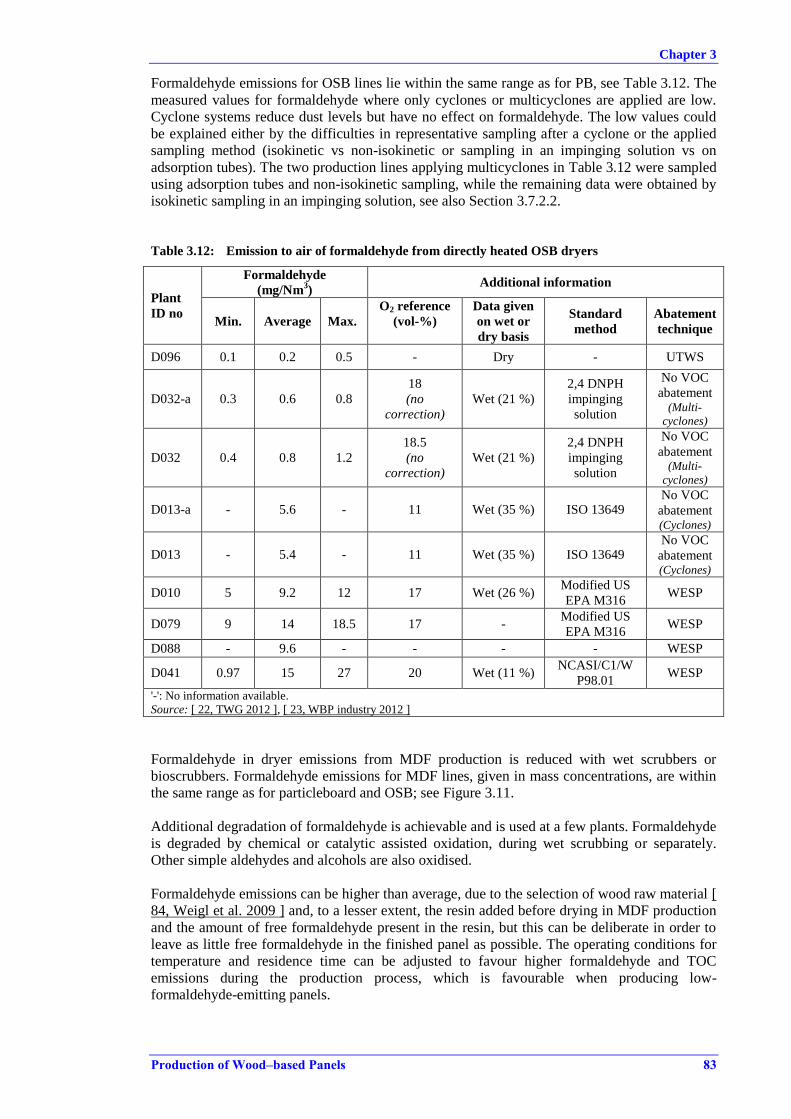
Chapter 3
Production of Wood–based Panels 83
Formaldehyde emissions for OSB lines lie within the same range as for PB, see Table 3.12. The
measured values for formaldehyde where only cyclones or multicyclones are applied are low.
Cyclone systems reduce dust levels but have no effect on formaldehyde. The low values could
be explained either by the difficulties in representative sampling after a cyclone or the applied
sampling method (isokinetic vs non-isokinetic or sampling in an impinging solution vs on
adsorption tubes). The two production lines applying multicyclones in Table 3.12 were sampled
using adsorption tubes and non-isokinetic sampling, while the remaining data were obtained by
isokinetic sampling in an impinging solution, see also Section 3.7.2.2.
Table 3.12: Emission to air of formaldehyde from directly heated OSB dryers
Plant
ID no
Formaldehyde
(mg/Nm3)
Additional information
Min. Average Max.
O2 reference
(vol-%)
Data given
on wet or
dry basis
Standard
method
Abatement
technique
D096 0.1 0.2 0.5 - Dry - UTWS
D032-a 0.3 0.6 0.8
18
(no
correction)
Wet (21 %) 2,4 DNPH
impinging
solution
No VOC
abatement (Multi-
cyclones)
D032 0.4 0.8 1.2
18.5
(no
correction)
Wet (21 %) 2,4 DNPH
impinging
solution
No VOC
abatement (Multi-
cyclones)
D013-a - 5.6 - 11 Wet (35 %) ISO 13649 No VOC
abatement (Cyclones)
D013 - 5.4 - 11 Wet (35 %) ISO 13649 No VOC
abatement (Cyclones)
D010 5 9.2 12 17 Wet (26 %) Modified US
EPA M316 WESP
D079 9 14 18.5 17 - Modified US
EPA M316 WESP
D088 - 9.6 - - - - WESP
D041 0.97 15 27 20 Wet (11 %) NCASI/C1/W
P98.01 WESP
'-': No information available.
Source: [ 22, TWG 2012 ], [ 23, WBP industry 2012 ]
Formaldehyde in dryer emissions from MDF production is reduced with wet scrubbers or
bioscrubbers. Formaldehyde emissions for MDF lines, given in mass concentrations, are within
the same range as for particleboard and OSB; see Figure 3.11.
Additional degradation of formaldehyde is achievable and is used at a few plants. Formaldehyde
is degraded by chemical or catalytic assisted oxidation, during wet scrubbing or separately.
Other simple aldehydes and alcohols are also oxidised.
Formaldehyde emissions can be higher than average, due to the selection of wood raw material [
84, Weigl et al. 2009 ] and, to a lesser extent, the resin added before drying in MDF production
and the amount of free formaldehyde present in the resin, but this can be deliberate in order to
leave as little free formaldehyde in the finished panel as possible. The operating conditions for
temperature and residence time can be adjusted to favour higher formaldehyde and TOC
emissions during the production process, which is favourable when producing low-
formaldehyde-emitting panels.
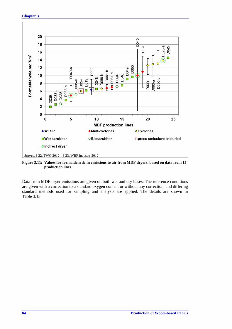
Chapter 3
84 Production of Wood–based Panels
Source: [ 22, TWG 2012 ], [ 23, WBP industry 2012 ]
Figure 3.11: Values for formaldehyde in emissions to air from MDF dryers, based on data from 15
production lines
Data from MDF dryer emissions are given on both wet and dry bases. The reference conditions
are given with a correction to a standard oxygen content or without any correction, and differing
standard methods used for sampling and analysis are applied. The details are shown in
Table 3.13.
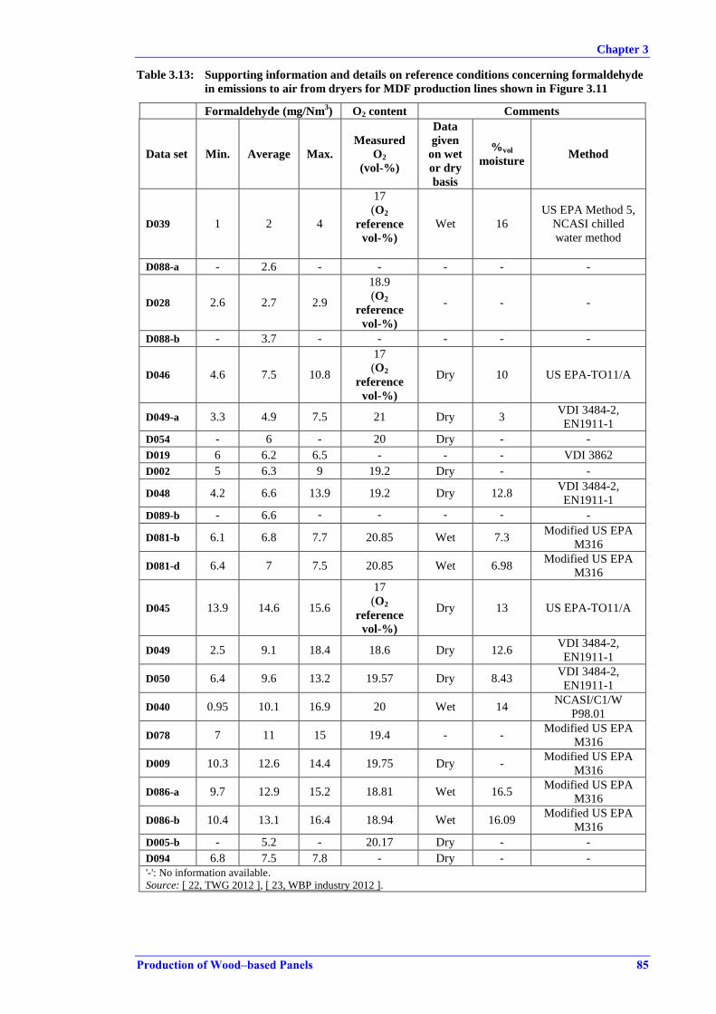
Chapter 3
Production of Wood–based Panels 85
Table 3.13: Supporting information and details on reference conditions concerning formaldehyde
in emissions to air from dryers for MDF production lines shown in Figure 3.11
Formaldehyde (mg/Nm3) O2 content Comments
Data set Min. Average Max.
Measured
O2
(vol-%)
Data
given
on wet
or dry
basis
%vol
moisture Method
D039 1 2 4
17
(O2
reference
vol-%)
Wet 16
US EPA Method 5,
NCASI chilled
water method
D088-a - 2.6 - - - - -
D028 2.6 2.7 2.9
18.9
(O2
reference
vol-%)
- - -
D088-b - 3.7 - - - - -
D046 4.6 7.5 10.8
17
(O2
reference
vol-%)
Dry 10 US EPA-TO11/A
D049-a 3.3 4.9 7.5 21 Dry 3 VDI 3484-2,
EN1911-1
D054 - 6 - 20 Dry - -
D019 6 6.2 6.5 - - - VDI 3862
D002 5 6.3 9 19.2 Dry - -
D048 4.2 6.6 13.9 19.2 Dry 12.8 VDI 3484-2,
EN1911-1
D089-b - 6.6 - - - - -
D081-b 6.1 6.8 7.7 20.85 Wet 7.3 Modified US EPA
M316
D081-d 6.4 7 7.5 20.85 Wet 6.98 Modified US EPA
M316
D045 13.9 14.6 15.6
17
(O2
reference
vol-%)
Dry 13 US EPA-TO11/A
D049 2.5 9.1 18.4 18.6 Dry 12.6 VDI 3484-2,
EN1911-1
D050 6.4 9.6 13.2 19.57 Dry 8.43 VDI 3484-2,
EN1911-1
D040 0.95 10.1 16.9 20 Wet 14 NCASI/C1/W
P98.01
D078 7 11 15 19.4 - - Modified US EPA
M316
D009 10.3 12.6 14.4 19.75 Dry - Modified US EPA
M316
D086-a 9.7 12.9 15.2 18.81 Wet 16.5 Modified US EPA
M316
D086-b 10.4 13.1 16.4 18.94 Wet 16.09 Modified US EPA
M316
D005-b - 5.2 - 20.17 Dry - -
D094 6.8 7.5 7.8 - Dry - -
'-': No information available.
Source: [ 22, TWG 2012 ], [ 23, WBP industry 2012 ].

Chapter 3
86 Production of Wood–based Panels
Instead of mass concentrations, the specific mass load per tonne of dried fibre could illustrate
more accurately the actual emission of formaldehyde for example. In order to express the
specific mass load, average values of early production of dried fibre in tonnes have been used,
together with an average airflow and measured formaldehyde concentration. In Table 3.14, the
specific mass loads are indicated, together with the related abatement technique for a selection
of the MDF production lines.
Table 3.14: Specific mass load of formaldehyde from MDF fibre dryers
Plant ID no
Specific mass load Abatement technique and comments
g formaldehyde/tonne of dried
fibre
D049 20 No VOC
abatement (Multicyclones), indirect dryer
D078 70 No VOC
abatement (Multicyclones)
D009 100 No VOC
abatement (cyclones)
D081 150 No VOC
abatement (Multicyclones)
D040 160 No VOC
abatement (cyclones)
D002 70 WESP with press waste gas
D048 105 Wet scrubber
Chemical oxidation
D049 120 Wet scrubber
Chemical oxidation
D050 130 Wet scrubber
Chemical oxidation
D046 170 Wet scrubber
D045 200 Wet scrubber
D028 30 Bioscrubber
Source: [ 22, TWG 2012 ], [ 23, WBP industry 2012 ].
The specific loads should be taken as indications only, since several estimations need to be
included in the calculation. Depending on the accuracy of the sampling and the comparability
between the measured concentrations, the raw material and the quantity of product dried at the
moment of sampling and during the year, there will be differences that cannot be accounted for.
The specific mass load depends on the incoming load in the waste gas and the efficiency of the
abatement technique. At three plants, a chemical oxidation, targeting formaldehyde, is
performed as the operating conditions favour an almost complete transfer of any free
formaldehyde, present in the raw material and resin, to air. Even if the efficiency of the scrubber
and chemical oxidation is high, there is still a residual amount of formaldehyde emitted.
When applying a wet scrubber, the specific mass load ranges between 100 g and 200 g
formaldehyde per tonne of dried fibre. Cyclones show lower values than wet scrubbers even
though cyclones do not reduce formaldehyde. This could be due to difficult sampling
conditions, which do not favour a representative sample.
The corresponding specific loads of formaldehyde per tonne of dried flakes in OSB production
emitted from the dryer after treatment are given for four production lines:
33 g formaldehyde/tonne of dried flakes (D010, direct dryer, WESP);
194 g formaldehyde/tonne of dried flakes (D041, direct dryer, press emissions, WESP);
13 g formaldehyde/tonne of dried flakes (D013, direct dryer 1, no abatement (cyclones));

Chapter 3
Production of Wood–based Panels 87
37 g formaldehyde/tonne of dried flakes (D013, direct dryer 2, no abatement (cyclones)).
The specific load for a range of PB lines has been shown in Table 3.11. The specific loads of
formaldehyde in both OSB and PB dryer emissions are generally lower than for MDF lines.
3.2.1.3 Organic compounds in dryer emissions
Organic compounds are determined as either a single pollutant such as formaldehyde or acetic
acid or as a sum or group of organic compounds. There is a considerable variety in the choice of
sampling and analytical standards and when expressing the total amount of organic compounds.
Figure 3.12 shows the variation in the quantity of organic content in dryer emissions from PB
lines and related to the analytical parameters. The values are not directly comparable. The
variation is mainly due to the reporting conditions (dry or wet basis), the raw material and the
actual performance of the production plant and the abatement technique applied, but the choice
of parameter and the related standard cannot be neglected.
NB: Data are not directly comparable because of variation in: reporting conditions (dry or wet basis), raw materials
and actual performance of the production plant.
Source: [ 22, TWG 2012 ]
Figure 3.12: Illustration of the variation in the contents of organic compounds in emissions to air
from PB dryers
The parameters covering the organic fraction reported in the data collection vary between the
following:
TOC (total organic compounds);
VOCs/TVOC (volatile organic compounds/total volatile organic compounds);
NMVOC (non-methane volatile organic compounds);
TC (total carbon, including inorganic carbon);
CVOCs (condensable volatile organic compounds).
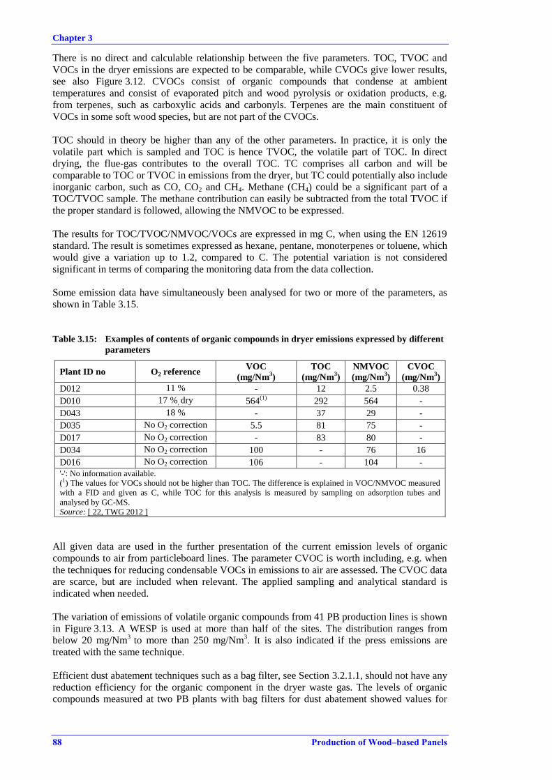
Chapter 3
88 Production of Wood–based Panels
There is no direct and calculable relationship between the five parameters. TOC, TVOC and
VOCs in the dryer emissions are expected to be comparable, while CVOCs give lower results,
see also Figure 3.12. CVOCs consist of organic compounds that condense at ambient
temperatures and consist of evaporated pitch and wood pyrolysis or oxidation products, e.g.
from terpenes, such as carboxylic acids and carbonyls. Terpenes are the main constituent of
VOCs in some soft wood species, but are not part of the CVOCs.
TOC should in theory be higher than any of the other parameters. In practice, it is only the
volatile part which is sampled and TOC is hence TVOC, the volatile part of TOC. In direct
drying, the flue-gas contributes to the overall TOC. TC comprises all carbon and will be
comparable to TOC or TVOC in emissions from the dryer, but TC could potentially also include
inorganic carbon, such as CO, CO2 and CH4. Methane (CH4) could be a significant part of a
TOC/TVOC sample. The methane contribution can easily be subtracted from the total TVOC if
the proper standard is followed, allowing the NMVOC to be expressed.
The results for TOC/TVOC/NMVOC/VOCs are expressed in mg C, when using the EN 12619
standard. The result is sometimes expressed as hexane, pentane, monoterpenes or toluene, which
would give a variation up to 1.2, compared to C. The potential variation is not considered
significant in terms of comparing the monitoring data from the data collection.
Some emission data have simultaneously been analysed for two or more of the parameters, as
shown in Table 3.15.
Table 3.15: Examples of contents of organic compounds in dryer emissions expressed by different
parameters
Plant ID no O2 reference VOC
(mg/Nm3)
TOC
(mg/Nm3)
NMVOC
(mg/Nm3)
CVOC
(mg/Nm3)
D012 11 % - 12 2.5 0.38
D010 17 %, dry 564(1)
292 564 -
D043 18 % - 37 29 -
D035 No O2 correction 5.5 81 75 -
D017 No O2 correction - 83 80 -
D034 No O2 correction 100 - 76 16
D016 No O2 correction 106 - 104 -
'-': No information available.
(1) The values for VOCs should not be higher than TOC. The difference is explained in VOC/NMVOC measured
with a FID and given as C, while TOC for this analysis is measured by sampling on adsorption tubes and
analysed by GC-MS.
Source: [ 22, TWG 2012 ]
All given data are used in the further presentation of the current emission levels of organic
compounds to air from particleboard lines. The parameter CVOC is worth including, e.g. when
the techniques for reducing condensable VOCs in emissions to air are assessed. The CVOC data
are scarce, but are included when relevant. The applied sampling and analytical standard is
indicated when needed.
The variation of emissions of volatile organic compounds from 41 PB production lines is shown
in Figure 3.13. A WESP is used at more than half of the sites. The distribution ranges from
below 20 mg/Nm3
to more than 250 mg/Nm3. It is also indicated if the press emissions are
treated with the same technique.
Efficient dust abatement techniques such as a bag filter, see Section 3.2.1.1, should not have any
reduction efficiency for the organic component in the dryer waste gas. The levels of organic
compounds measured at two PB plants with bag filters for dust abatement showed values for
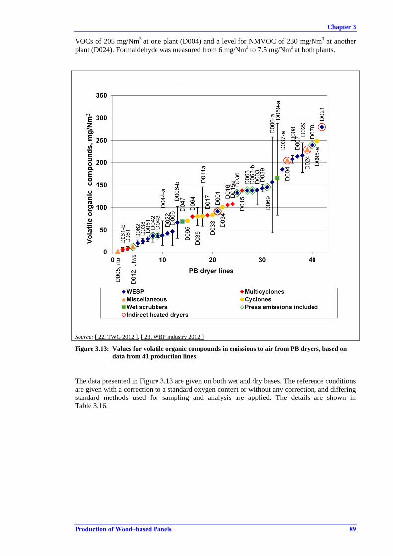
Chapter 3
Production of Wood–based Panels 89
VOCs of 205 mg/Nm3
at one plant (D004) and a level for NMVOC of 230 mg/Nm3 at another
plant (D024). Formaldehyde was measured from 6 mg/Nm3 to 7.5 mg/Nm
3 at both plants.
Source: [ 22, TWG 2012 ], [ 23, WBP industry 2012 ]
Figure 3.13: Values for volatile organic compounds in emissions to air from PB dryers, based on
data from 41 production lines
The data presented in Figure 3.13 are given on both wet and dry bases. The reference conditions
are given with a correction to a standard oxygen content or without any correction, and differing
standard methods used for sampling and analysis are applied. The details are shown in
Table 3.16.

Chapter 3
90 Production of Wood–based Panels
Table 3.16: Supporting information and details on reference conditions presented in Figure 3.13
concerning volatile organic compounds in emissions to air from PB dryers
Plant
Volatile organic
compounds (mg/Nm3)
O2 content Additional information
Min. Average Max.
O2
reference
(vol-%)
O2 (vol-%)
(no
correction)
Wet/
dry Parameter Method
D005 - 1.4 - 17 14.02 Dry NMVOC -
D061-
b 1 5.9 10.8 - 20.85 Dry TOC US EPA 25A
D061 3 7.7 12.4 - 20.85 Dry TOC US EPA 25A
D012 - 12 - 11 - Wet TOC EN 13526
D062 12.5 19.8 27.1 17 18.8 Dry TOC US EPA 25A
D038 19.5 24.4 30.8 17 - Dry TOC -
D051 24 29.7 37 - 19.2 Dry TOC EN 13526
D042 22.3 37.1 43.7 18 - Dry TOC EN 12619-1
D043 34 37.6 43.3 18 17.5 Dry TOC -
D044-
a 15.3 38.5 70.6 18 - Dry TOC EN 12619-1
D022 39 43 46 17 - Wet TOC -
D006 14 47 47 - - Wet TOC EN 13526
D006-
b 31 67 103 - - Wet TOC EN 13526
D047 73 69 65 - - Dry TOC EN 12619-1
D064 - 80 - - - - TOC EN 13526
D035 61 80.5 100 - - - TOC -
D011a 59 81 146 - 18.9 Wet TOC -
D017 - 83.2 - 16.6 - Dry TOC EN 12619
D033 - 84 - - 18.7 Wet NMVOC NFX 43-300,
NFX 43-301
D001 - 92 - 17 - Dry TOC -
D034 - 101 - 19 - Dry VOC -
D016 - 106 - - 15.75 Dry VOC EN 12619
D015a - 108 - - 18 Wet VOC -
D036 130 133 139 17 - - TOC -
D015 - 138 - - 18 Wet VOC -
D063 - 138 - 19.2 - - TOC EN 12619
D063-
b - 138 - 19.2 - - TOC EN 12619
D003 106 139 139 17 - Dry TOC EN 12619
D089 135 143 152 - - - TOC -
D069 - 145 - - - - TOC
VDI 3481.
adsorption on
silica gel
D006-
a 44 156 258 - - Wet TOC EN 13526
D059-
a 83 165 288 - 19 Dry TOC
Continuous
measurement.
FID analyser
D037-
a - 185 - 17 - TOC -
D008 199 208 217 17 - Dry TOC EN 13526
D007 - 215 - 17 - Wet TOC EN 13526
D029 178 217 245 - - - TOC -
D024 - 230 - - - - NMVOC EN 12619
D004 190 205 219 - - Dry VOC EN 12619
D070 - 240 - 6 - Dry VOC -

Chapter 3
Production of Wood–based Panels 91
Plant
Volatile organic
compounds (mg/Nm3)
O2 content Additional information
Min. Average Max.
O2
reference
(vol-%)
O2 (vol-%)
(no
correction)
Wet/
dry Parameter Method
D021 270 280 300 - - Wet NMVOC -
D095 - 70.9 - 19 - Dry NMVOC EN 12619
D095-
a - 249 - 19 - Dry NMVOC EN 12619
'-': No information available.
Source: [ 22, TWG 2012 ], [ 23, WBP industry 2012 ].
The specific mass loads calculated from the PB production lines show a variation from 150 g to
950 g TVOC per tonne of dried particles. The range related to a WESP is 160–340 g TVOC per
tonne of dried particles (six plants). The range for cyclones and multicyclones is quite wide,
from 150 g to 950 g TOC per tonne of dried particles (four plants), reflecting the possible
variation in the contribution from raw material and resins, since cyclones do not have the
potential to abate volatile organic compounds.
The variation of emissions to air of volatile organic compounds from OSB dryers is shown in
Table 3.17. The WESP is used at more than half of the sites. One plant treats the press
emissions in the WESP together with the dryer emission and has a higher value than the other
three plants.
Table 3.17: Emission to air of volatile organic compounds from directly heated OSB dryers
Plant ID no TOC
(mg/Nm3)
Abatement technique applied and comments
D013a 182 No VOC abatement (multicyclones), at 11 % O2, wet, EN 12619
D013 226 No VOC abatement (multicyclones), at 11 % O2, wet, EN 12619
D088 673 WESP, unknown reference conditions
D029 217 WESP, dry, O2 unknown
Mixed with PB dryer waste gases
D010 216 WESP, at 17 % O2, wet, EN 13649
VOC
D027 402 WESP, unknown reference conditions
D010 999 WESP, at 14 % O2, dry, EN 12619
CVOC
D041 29 WESP, unknown reference conditions
D079 52 WESP, unknown reference conditions
NMVOC
D032 349 No VOC abatement (cyclones), at 18.5 % O2, wet, NFX 43–300 and NFX
43–301
D032-a 259 No VOC abatement (cyclones), at 18 %, O2, wet, NFX 43–300 and NFX
43–301 Source: [ 22, TWG 2012 ]
The data on volatile organic compounds in emissions to air from OSB dryers are in general not
supported by sufficient information. Comparing these levels with the levels from PB and MDF
dryer lines is therefore difficult. The data from OSB dryers applying abatement techniques that
would have some efficiency for volatile organic compounds are related to WESPs only. From
the data it could however be deduced that TVOC levels before abatement are in general higher
from OSB dryer lines, owing to the effect of the use of 100 % fresh log wood as the only raw
material. The raw material and also the choice of abatement techniques and the operation of the
dryer should be taken into account when comparing the emission levels of volatile organic
compounds from OSB, PB and MDF production.
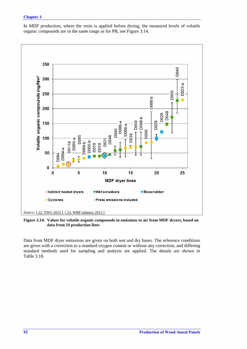
Chapter 3
92 Production of Wood–based Panels
In MDF production, where the resin is applied before drying, the measured levels of volatile
organic compounds are in the same range as for PB, see Figure 3.14.
Source: [ 22, TWG 2012 ], [ 23, WBP industry 2012 ]
Figure 3.14: Values for volatile organic compounds in emissions to air from MDF dryers, based on
data from 24 production lines
Data from MDF dryer emissions are given on both wet and dry bases. The reference conditions
are given with a correction to a standard oxygen content or without any correction, and differing
standard methods used for sampling and analysis are applied. The details are shown in
Table 3.18.
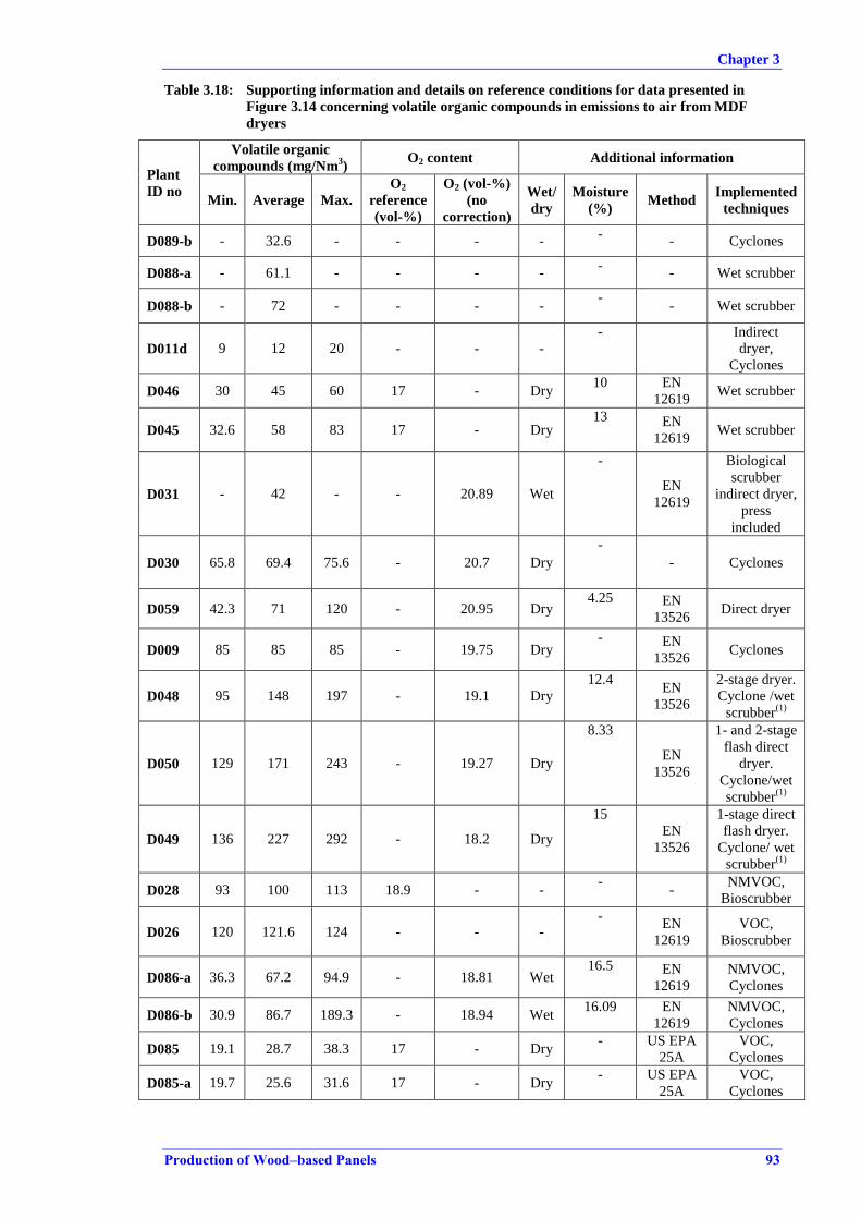
Chapter 3
Production of Wood–based Panels 93
Table 3.18: Supporting information and details on reference conditions for data presented in
Figure 3.14 concerning volatile organic compounds in emissions to air from MDF
dryers
Plant
ID no
Volatile organic
compounds (mg/Nm3)
O2 content Additional information
Min. Average Max.
O2
reference
(vol-%)
O2 (vol-%)
(no
correction)
Wet/
dry
Moisture
(%) Method
Implemented
techniques
D089-b - 32.6 - - - - -
- Cyclones
D088-a - 61.1 - - - - -
- Wet scrubber
D088-b - 72 - - - - -
- Wet scrubber
D011d 9 12 20 - - -
-
Indirect
dryer,
Cyclones
D046 30 45 60 17 - Dry 10 EN
12619 Wet scrubber
D045 32.6 58 83 17 - Dry 13 EN
12619 Wet scrubber
D031 - 42 - - 20.89 Wet
-
EN
12619
Biological
scrubber
indirect dryer,
press
included
D030 65.8 69.4 75.6 - 20.7 Dry
-
- Cyclones
D059 42.3 71 120 - 20.95 Dry 4.25 EN
13526 Direct dryer
D009 85 85 85 - 19.75 Dry - EN
13526 Cyclones
D048 95 148 197 - 19.1 Dry
12.4 EN
13526
2-stage dryer.
Cyclone /wet
scrubber(1)
D050 129 171 243 - 19.27 Dry
8.33
EN
13526
1- and 2-stage
flash direct
dryer.
Cyclone/wet
scrubber(1)
D049 136 227 292 - 18.2 Dry
15
EN
13526
1-stage direct
flash dryer.
Cyclone/ wet
scrubber(1)
D028 93 100 113 18.9 - - -
- NMVOC,
Bioscrubber
D026 120 121.6 124 - - - -
EN
12619
VOC,
Bioscrubber
D086-a 36.3 67.2 94.9 - 18.81 Wet 16.5 EN
12619
NMVOC,
Cyclones
D086-b 30.9 86.7 189.3 - 18.94 Wet 16.09 EN
12619
NMVOC,
Cyclones
D085 19.1 28.7 38.3 17 - Dry - US EPA
25A
VOC,
Cyclones
D085-a 19.7 25.6 31.6 17 - Dry - US EPA
25A
VOC,
Cyclones
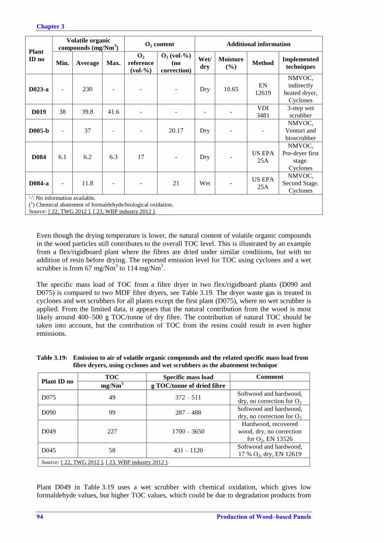
Chapter 3
94 Production of Wood–based Panels
Plant
ID no
Volatile organic
compounds (mg/Nm3)
O2 content Additional information
Min. Average Max.
O2
reference
(vol-%)
O2 (vol-%)
(no
correction)
Wet/
dry
Moisture
(%) Method
Implemented
techniques
D023-a - 230 - - - Dry 10.65 EN
12619
NMVOC,
indirectly
heated dryer,
Cyclones
D019 38 39.8 41.6 - - - - VDI
3481
3-step wet
scrubber
D005-b - 37 - - 20.17 Dry - -
NMVOC,
Venturi and
bioscrubber
D084 6.1 6.2 6.3 17 - Dry - US EPA
25A
NMVOC,
Pre-dryer first
stage.
Cyclones
D084-a - 11.8 - - 21 Wet - US EPA
25A
NMVOC,
Second Stage.
Cyclones '-': No information available.
(1) Chemical abatement of formaldehyde/biological oxidation.
Source: [ 22, TWG 2012 ], [ 23, WBP industry 2012 ].
Even though the drying temperature is lower, the natural content of volatile organic compounds
in the wood particles still contributes to the overall TOC level. This is illustrated by an example
from a flex/rigidboard plant where the fibres are dried under similar conditions, but with no
addition of resin before drying. The reported emission level for TOC using cyclones and a wet
scrubber is from 67 mg/Nm3 to 114 mg/Nm
3.
The specific mass load of TOC from a fibre dryer in two flex/rigidboard plants (D090 and
D075) is compared to two MDF fibre dryers, see Table 3.19. The dryer waste gas is treated in
cyclones and wet scrubbers for all plants except the first plant (D075), where no wet scrubber is
applied. From the limited data, it appears that the natural contribution from the wood is most
likely around 400–500 g TOC/tonne of dry fibre. The contribution of natural TOC should be
taken into account, but the contribution of TOC from the resins could result in even higher
emissions.
Table 3.19: Emission to air of volatile organic compounds and the related specific mass load from
fibre dryers, using cyclones and wet scrubbers as the abatement technique
Plant ID no TOC Specific mass load Comment
mg/Nm3
g TOC/tonne of dried fibre
D075 49 372 – 511 Softwood and hardwood,
dry, no correction for O2
D090 99 287 – 488 Softwood and hardwood,
dry, no correction for O2
D049 227 1700 – 3650
Hardwood, recovered
wood, dry, no correction
for O2, EN 13526
D045 58 431 – 1120 Softwood and hardwood,
17 % O2, dry, EN 12619
Source: [ 22, TWG 2012 ], [ 23, WBP industry 2012 ].
Plant D049 in Table 3.19 uses a wet scrubber with chemical oxidation, which gives low
formaldehyde values, but higher TOC values, which could be due to degradation products from
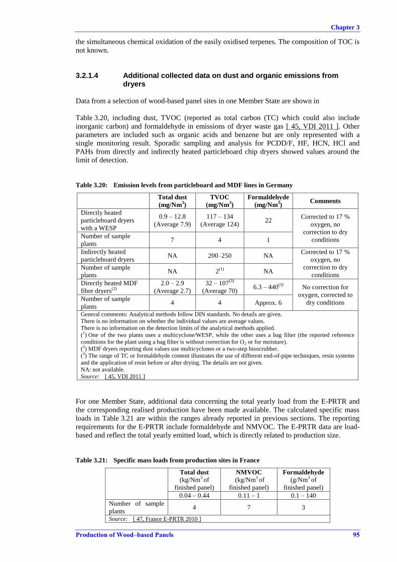
Chapter 3
Production of Wood–based Panels 95
the simultaneous chemical oxidation of the easily oxidised terpenes. The composition of TOC is
not known.
3.2.1.4 Additional collected data on dust and organic emissions from dryers
Data from a selection of wood-based panel sites in one Member State are shown in
Table 3.20, including dust, TVOC (reported as total carbon (TC) which could also include
inorganic carbon) and formaldehyde in emissions of dryer waste gas [ 45, VDI 2011 ]. Other
parameters are included such as organic acids and benzene but are only represented with a
single monitoring result. Sporadic sampling and analysis for PCDD/F, HF, HCN, HCl and
PAHs from directly and indirectly heated particleboard chip dryers showed values around the
limit of detection.
Table 3.20: Emission levels from particleboard and MDF lines in Germany
Total dust
(mg/Nm3)
TVOC
(mg/Nm3)
Formaldehyde
(mg/Nm3)
Comments
Directly heated
particleboard dryers
with a WESP
0.9 – 12.8
(Average 7.9)
117 – 134
(Average 124) 22
Corrected to 17 %
oxygen, no
correction to dry
conditions Number of sample
plants 7 4 1
Indirectly heated
particleboard dryers NA 200–250 NA
Corrected to 17 %
oxygen, no
correction to dry
conditions Number of sample
plants NA 2
(1) NA
Directly heated MDF
fibre dryers(2)
2.0 – 2.9
(Average 2.7)
32 – 107(3)
(Average 70) 6.3 – 440
(3) No correction for
oxygen, corrected to
dry conditions Number of sample
plants 4 4 Approx. 6
General comments: Analytical methods follow DIN standards. No details are given.
There is no information on whether the individual values are average values.
There is no information on the detection limits of the analytical methods applied.
(1) One of the two plants uses a multicyclone/WESP, while the other uses a bag filter (the reported reference
conditions for the plant using a bag filter is without correction for O2 or for moisture).
(2) MDF dryers reporting dust values use multicyclones or a two-step bioscrubber.
(3) The range of TC or formaldehyde content illustrates the use of different end-of-pipe techniques, resin systems
and the application of resin before or after drying. The details are not given.
NA: not available.
Source: [ 45, VDI 2011 ]
For one Member State, additional data concerning the total yearly load from the E-PRTR and
the corresponding realised production have been made available. The calculated specific mass
loads in Table 3.21 are within the ranges already reported in previous sections. The reporting
requirements for the E-PRTR include formaldehyde and NMVOC. The E-PRTR data are load-
based and reflect the total yearly emitted load, which is directly related to production size.
Table 3.21: Specific mass loads from production sites in France
Total dust
(kg/Nm3 of
finished panel)
NMVOC
(kg/Nm3 of
finished panel)
Formaldehyde (g/Nm
3 of
finished panel)
0.04 – 0.44 0.11 – 1 0.1 – 140
Number of sample
plants 4 7 3
Source: [ 47, France E-PRTR 2010 ]

Chapter 3
96 Production of Wood–based Panels
Data from nine PB and MDF dryer lines in one Member State are shown in Table 3.22. Some of
the data are also reported in the data collection. The emission data cover both directly and
indirectly heated dryers. The monitoring is periodic and the results represent one or more
sampling events. NOX is monitored on a regular basis and the lower levels are most likely to be
related to indirectly heated dryers. Other parameters such as organic acids, phenol and PCDD/F
are monitored at a few lines. At one plant the organic acids content is markedly higher and
between 4 mg/Nm3 and 9.9 mg/Nm
3.
Table 3.22: Emission levels from particleboard and MDF lines in Austria
Plant Dust
(mg/Nm3)
NOX
(mg/Nm3)
CO
(mg/Nm3)
Organic
C
(mg/Nm3)
Formaldeh
yde
(mg/Nm3)
Organic
acids
(mg/Nm3)
Phenol
(mg/Nm3)
1(1), (3)
0.8 – 4 100 70 106–139 4.4 – 14 - -
2(1)
20 – 28 19 – 25 26 – 41 98 – 116 2.9 – 7.0 - -
3(1)
14 – 22 19 – 30 66 – 85 126 – 132 4.4 – 7.2 -
4(2)
2 – 4 - - 190 – 219 3.8 – 4 4–9.9 < 1
5(2), (4)
< 1 – 2.5 1–3 1.9 – 2 28.7 –
37.0 1.9 – 5.22
< 0.2 – 1.0(5)
< 0.5 – 3.3(6)
0.01
6(1)
2 – 3 186 – 288 11 – 13 1.4 – 1.9 0.11 – 0.13 - -
7(2)
3 - - - 6 - -
8(2)
0.6 – 0.8 1 6.6 – 11.0 18 – 40(7)
4.9 – 8.7 - 0.01 – 0.36
9(1)
0.5 – 5 5 – 155 9.0 – 24 9.0 – 9.3(7)
1.2 – 3.3 - 0.1 – 0.4 '-': No information available.
(1) Reference 17 % O2.
(2) Given with no O2 correction.
(3) PCDD/F < 0.05 ng/m3.
(4) PCDD/F < 0.1 ng/m3.
(5) HCOOH.
(6) CH3COOH.
(7) CVOC.
Source: [ 58, UBA Austria 2013 ]
Variation in the composition of VOC emissions
Studies concerning the composition of dryer waste gas identified the VOC fraction released
during drying from two different wood species. The total quantity of VOC emissions differs
between softwood and hardwood species, e.g. the softwood species maritime pine clearly
contains higher levels of volatile compounds [ 48, Sonae Industria 2012 ].
The most abundant group in the dryer waste gas is the terpenes, which are a constituent in every
plant material. In softwood, the highly volatile α- and β-pinenes are dominant. Some
compounds detected when studying air emissions from dryers are oxidation products from the
pinenes such as acids or aldehydes.
The composition and quantity of VOCs in the dryer waste gas depend on the wood species used
and the drying temperature. Moreover, even within single wood species the distribution will
vary depending on harvest time, cultivation conditions, storage time and storage conditions.
The composition of the VOC fraction in the emission from dryers has been studied, with the
purpose of determining the main constituents and to illustrate the difference in emissions from
various wood species.
In a study 43 different VOC compounds were identified in the dryer emissions from a
particleboard plant using maritime pine as the only raw material. The main constituent was α-
pinene, followed by β-pinene, limonene, beta-caryophyllene and longifolene. All compounds
detected were terpenes. The total VOCs measured were on average 100 mg/Nm3 (19 % O2). The
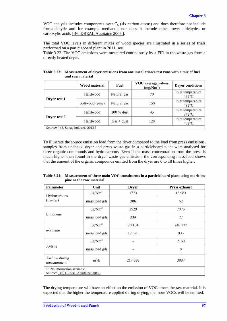
Chapter 3
Production of Wood–based Panels 97
VOC analysis includes components over C6 (six carbon atoms) and does therefore not include
formaldehyde and for example methanol, nor does it include other lower aldehydes or
carboxylic acids [ 46, DREAL Aquitaine 2005 ].
The total VOC levels in different mixes of wood species are illustrated in a series of trials
performed on a particleboard plant in 2011, see
Table 3.23. The VOC emissions were measured continuously by a FID in the waste gas from a
directly heated dryer.
Table 3.23: Measurement of dryer emissions from one installation's test runs with a mix of fuel
and raw material
Wood material Fuel VOC average values
(mg/Nm3)
Dryer conditions
Dryer test 1
Hardwood Natural gas 70 Inlet temperature
432°C
Softwood (pine) Natural gas 150 Inlet temperature
432°C
Dryer test 2
Hardwood 100 % dust 45 Inlet temperature
372°C
Hardwood Gas + dust 120 Inlet temperature
432°C Source: [ 48, Sonae Industria 2012 ]
To illustrate the source emission load from the dryer compared to the load from press emissions,
samples from unabated dryer and press waste gas in a particleboard plant were analysed for
three organic compounds and hydrocarbons. Even if the mass concentration from the press is
much higher than found in the dryer waste gas emission, the corresponding mass load shows
that the amount of the organic compounds emitted from the dryer are 6 to 18 times higher.
Table 3.24: Measurement of three main VOC constituents in a particleboard plant using maritime
pine as the raw material
Parameter Unit Dryer Press exhaust
Hydrocarbons
(C6-C12)
µg/Nm3 1773 15 983
mass load g/h 386 62
Limonene
µg/Nm3 1529 7076
mass load g/h 334 27
α-Pinene
µg/Nm3 78 134 240 737
mass load g/h 17 028 935
Xylene
µg/Nm3 - 2160
mass load g/h - 8
Airflow during
measurement m
3/h 217 938 3887
'-': No information available.
Source: [ 46, DREAL Aquitaine 2005 ]
The drying temperature will have an effect on the emission of VOCs from the raw material. It is
expected that the higher the temperature applied during drying, the more VOCs will be emitted.
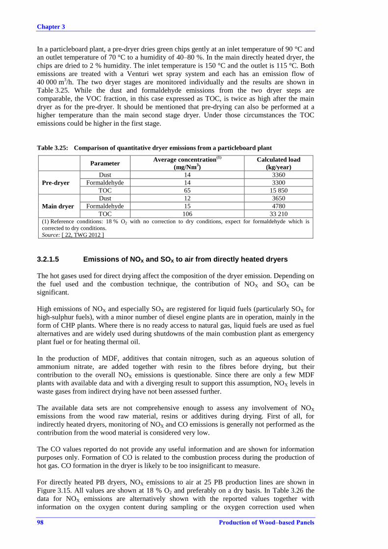
Chapter 3
98 Production of Wood–based Panels
In a particleboard plant, a pre-dryer dries green chips gently at an inlet temperature of 90 °C and
an outlet temperature of 70 °C to a humidity of 40–80 %. In the main directly heated dryer, the
chips are dried to 2 % humidity. The inlet temperature is 150 °C and the outlet is 115 °C. Both
emissions are treated with a Venturi wet spray system and each has an emission flow of
40 000 m3/h. The two dryer stages are monitored individually and the results are shown in
Table 3.25. While the dust and formaldehyde emissions from the two dryer steps are
comparable, the VOC fraction, in this case expressed as TOC, is twice as high after the main
dryer as for the pre-dryer. It should be mentioned that pre-drying can also be performed at a
higher temperature than the main second stage dryer. Under those circumstances the TOC
emissions could be higher in the first stage.
Table 3.25: Comparison of quantitative dryer emissions from a particleboard plant
Parameter Average concentration
(1)
(mg/Nm3)
Calculated load
(kg/year)
Pre-dryer
Dust 14 3360
Formaldehyde 14 3300
TOC 65 15 850
Main dryer
Dust 12 3650
Formaldehyde 15 4780
TOC 106 33 210 (1) Reference conditions: 18 % O2 with no correction to dry conditions, expect for formaldehyde which is
corrected to dry conditions.
Source: [ 22, TWG 2012 ]
3.2.1.5 Emissions of NOX and SOX to air from directly heated dryers
The hot gases used for direct drying affect the composition of the dryer emission. Depending on
the fuel used and the combustion technique, the contribution of NOX and SOX can be
significant.
High emissions of NOX and especially SOX are registered for liquid fuels (particularly SOX for
high-sulphur fuels), with a minor number of diesel engine plants are in operation, mainly in the
form of CHP plants. Where there is no ready access to natural gas, liquid fuels are used as fuel
alternatives and are widely used during shutdowns of the main combustion plant as emergency
plant fuel or for heating thermal oil.
In the production of MDF, additives that contain nitrogen, such as an aqueous solution of
ammonium nitrate, are added together with resin to the fibres before drying, but their
contribution to the overall NOX emissions is questionable. Since there are only a few MDF
plants with available data and with a diverging result to support this assumption, NOX levels in
waste gases from indirect drying have not been assessed further.
The available data sets are not comprehensive enough to assess any involvement of NOX
emissions from the wood raw material, resins or additives during drying. First of all, for
indirectly heated dryers, monitoring of NOX and CO emissions is generally not performed as the
contribution from the wood material is considered very low.
The CO values reported do not provide any useful information and are shown for information
purposes only. Formation of CO is related to the combustion process during the production of
hot gas. CO formation in the dryer is likely to be too insignificant to measure.
For directly heated PB dryers, NOX emissions to air at 25 PB production lines are shown in
Figure 3.15. All values are shown at 18 % O2 and preferably on a dry basis. In Table 3.26 the
data for NOX emissions are alternatively shown with the reported values together with
information on the oxygen content during sampling or the oxygen correction used when

Chapter 3
Production of Wood–based Panels 99
reporting values. The corresponding CO values are also shown and the fuels used for producing
the hot gases for drying are indicated as well.
Table 3.26: NOX and CO emissions to air from directly heated PB dryers
Plant ID no NOX
(mg/Nm3)
O2 in waste gas
during sampling
(%)
CO
(mg/Nm3)
Fuel mix and comments
D051 10 19 79 100 % PR/RW. SNCR
D064 47 18.5 14 98 % PR 2 % G
D062 88 (1)
215 45 % PR 45 % RW 10 % HFO
D076 77 (1)
67 50 % PR 50 % G
D071 45 19.1 134 80 % B 20 % G
D003 100 (1)
70 80 % PR 20 % G
D034 65 18.6 173 35 % PR 65 % RW
D017 148 16.6 872 50 % PR 50 % G
D012 286 (2)
261 PR/G (UTWS)
D069 110 18.5 - 35 % RW, 50 % PR, 15 % HFO
D029 114 18.5 121 45 % PR 45 % RW 10 % G
D022 170 (1)
60 75 % PR 25 % HFO
D072 44 19.9 37 20 % PR 80 % G
D035 113 18.5 154 72 % PR 22 % RW 6 % G
D005 186 (1)
13 PR/G (after RTO)
D072-a 192 16.9 442 100 % PR
D080 141 (3)
173 70 % PR 30 % G
D006-a 498 (2)
1988 95 % PR 5 % G
D043 171 (3)
111 56 % PR 33 % RW 11 % G
D011a 137 18.9 17 62 % PR 38 % HFO
D001 175 (1)
160 10 % PR 90 % RW SNCR
D005-a 288 (1)
11 PR/G (after RTO)
D006-b 696 (2)
283 90 % PR 10 % HFO
D006 967 (2)
797 95 % PR 5 % HFO
D068 158 19.3 53 PR/HFO (1) Reported at 17 % O2.
(2) Reported at 11 % O2.
(2) Reported at 18 % O2.
PR: production residues.
RW: recovered wood.
HFO: heavy fuel oil.
G: natural gas.
B: biomass.
Source: [ 22, TWG 2012 ], [ 23, WBP industry 2012 ].
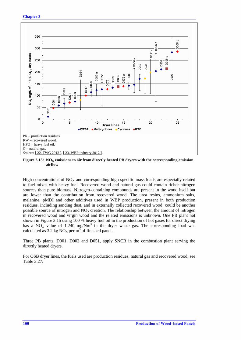
Chapter 3
100 Production of Wood–based Panels
PR – production residues.
RW – recovered wood.
HFO – heavy fuel oil.
G – natural gas.
Source: [ 22, TWG 2012 ], [ 23, WBP industry 2012 ].
Figure 3.15: NOX emissions to air from directly heated PB dryers with the corresponding emission
airflow
High concentrations of NOX and corresponding high specific mass loads are especially related
to fuel mixes with heavy fuel. Recovered wood and natural gas could contain richer nitrogen
sources than pure biomass. Nitrogen-containing compounds are present in the wood itself but
are lower than the contribution from recovered wood. The urea resins, ammonium salts,
melanine, pMDI and other additives used in WBP production, present in both production
residues, including sanding dust, and in externally collected recovered wood, could be another
possible source of nitrogen and NOX creation. The relationship between the amount of nitrogen
in recovered wood and virgin wood and the related emissions is unknown. One PB plant not
shown in Figure 3.15 using 100 % heavy fuel oil in the production of hot gases for direct drying
has a NOX value of 1 240 mg/Nm3 in the dryer waste gas. The corresponding load was
calculated as 3.2 kg NOX per m3 of finished panel.
Three PB plants, D001, D003 and D051, apply SNCR in the combustion plant serving the
directly heated dryers.
For OSB dryer lines, the fuels used are production residues, natural gas and recovered wood, see
Table 3.27.
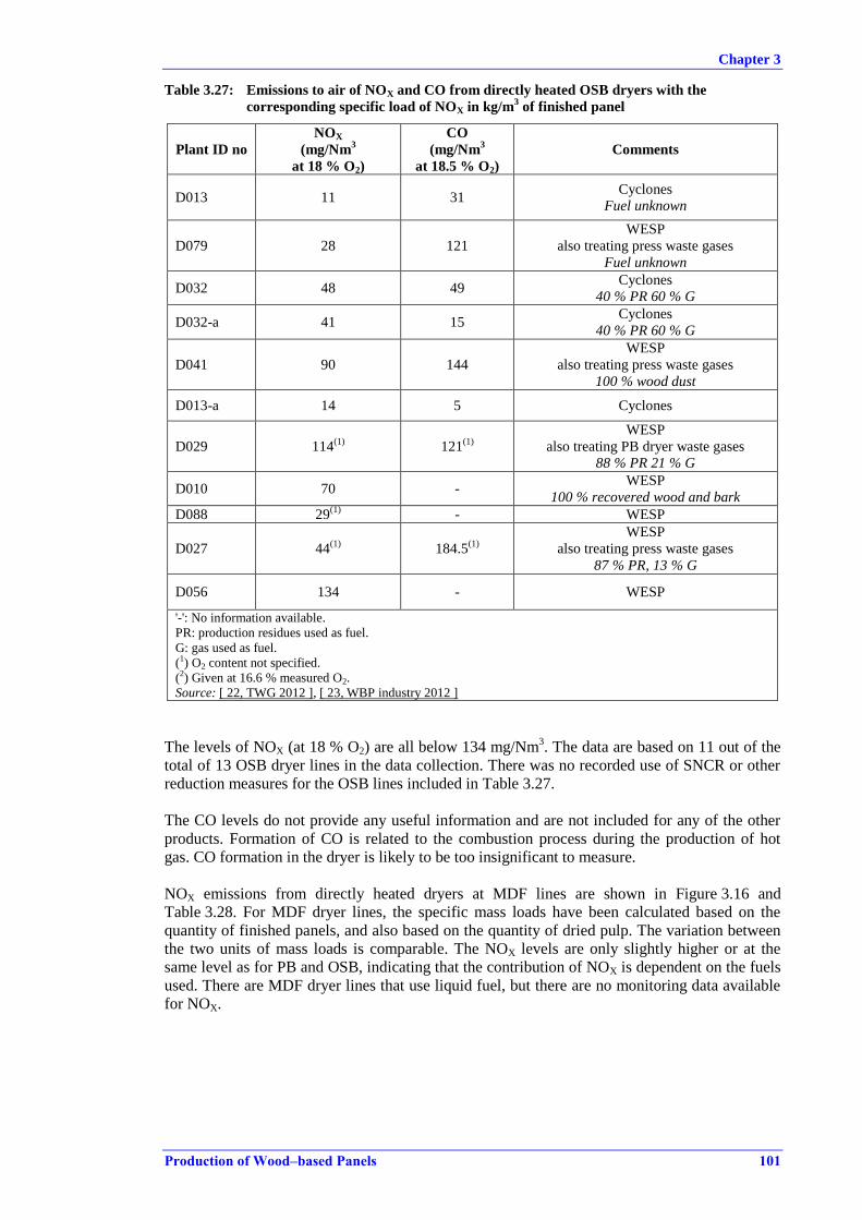
Chapter 3
Production of Wood–based Panels 101
Table 3.27: Emissions to air of NOX and CO from directly heated OSB dryers with the
corresponding specific load of NOX in kg/m3 of finished panel
Plant ID no
NOX
(mg/Nm3
at 18 % O2)
CO
(mg/Nm3
at 18.5 % O2)
Comments
D013 11 31 Cyclones
Fuel unknown
D079 28 121
WESP
also treating press waste gases
Fuel unknown
D032 48 49 Cyclones
40 % PR 60 % G
D032-a 41 15 Cyclones
40 % PR 60 % G
D041 90 144
WESP
also treating press waste gases
100 % wood dust
D013-a 14 5 Cyclones
D029 114(1)
121(1)
WESP
also treating PB dryer waste gases
88 % PR 21 % G
D010 70 - WESP
100 % recovered wood and bark
D088 29(1)
- WESP
D027 44(1)
184.5(1)
WESP
also treating press waste gases
87 % PR, 13 % G
D056 134 - WESP
'-': No information available.
PR: production residues used as fuel.
G: gas used as fuel.
(1) O2 content not specified.
(2) Given at 16.6 % measured O2.
Source: [ 22, TWG 2012 ], [ 23, WBP industry 2012 ]
The levels of NOX (at 18 % O2) are all below 134 mg/Nm3. The data are based on 11 out of the
total of 13 OSB dryer lines in the data collection. There was no recorded use of SNCR or other
reduction measures for the OSB lines included in Table 3.27.
The CO levels do not provide any useful information and are not included for any of the other
products. Formation of CO is related to the combustion process during the production of hot
gas. CO formation in the dryer is likely to be too insignificant to measure.
NOX emissions from directly heated dryers at MDF lines are shown in Figure 3.16 and
Table 3.28. For MDF dryer lines, the specific mass loads have been calculated based on the
quantity of finished panels, and also based on the quantity of dried pulp. The variation between
the two units of mass loads is comparable. The NOX levels are only slightly higher or at the
same level as for PB and OSB, indicating that the contribution of NOX is dependent on the fuels
used. There are MDF dryer lines that use liquid fuel, but there are no monitoring data available
for NOX.
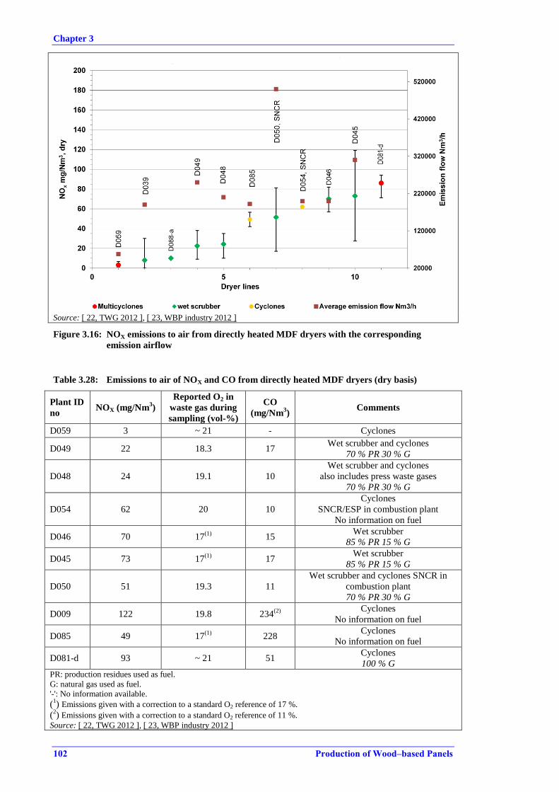
Chapter 3
102 Production of Wood–based Panels
Source: [ 22, TWG 2012 ], [ 23, WBP industry 2012 ]
Figure 3.16: NOX emissions to air from directly heated MDF dryers with the corresponding
emission airflow
Table 3.28: Emissions to air of NOX and CO from directly heated MDF dryers (dry basis)
Plant ID
no NOX (mg/Nm
3)
Reported O2 in
waste gas during
sampling (vol-%)
CO
(mg/Nm3)
Comments
D059 3 ~ 21 - Cyclones
D049 22 18.3 17 Wet scrubber and cyclones
70 % PR 30 % G
D048 24 19.1 10
Wet scrubber and cyclones
also includes press waste gases
70 % PR 30 % G
D054 62 20 10
Cyclones
SNCR/ESP in combustion plant
No information on fuel
D046 70 17(1)
15 Wet scrubber
85 % PR 15 % G
D045 73 17(1)
17 Wet scrubber
85 % PR 15 % G
D050 51 19.3 11
Wet scrubber and cyclones SNCR in
combustion plant
70 % PR 30 % G
D009 122 19.8 234(2)
Cyclones
No information on fuel
D085 49 17(1)
228 Cyclones
No information on fuel
D081-d 93 ~ 21 51 Cyclones
100 % G PR: production residues used as fuel.
G: natural gas used as fuel.
'-': No information available.
(1) Emissions given with a correction to a standard O2 reference of 17 %.
(2) Emissions given with a correction to a standard O2 reference of 11 %.
Source: [ 22, TWG 2012 ], [ 23, WBP industry 2012 ]
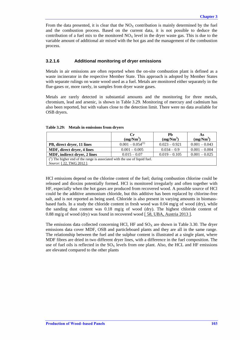
Chapter 3
Production of Wood–based Panels 103
From the data presented, it is clear that the NOX contribution is mainly determined by the fuel
and the combustion process. Based on the current data, it is not possible to deduce the
contribution of a fuel mix to the monitored NOX level in the dryer waste gas. This is due to the
variable amount of additional air mixed with the hot gas and the management of the combustion
process.
3.2.1.6 Additional monitoring of dryer emissions
Metals in air emissions are often reported when the on-site combustion plant is defined as a
waste incinerator in the respective Member State. This approach is adopted by Member States
with separate rulings on waste wood used as a fuel. Metals are monitored either separately in the
flue-gases or, more rarely, in samples from dryer waste gases.
Metals are rarely detected in substantial amounts and the monitoring for three metals,
chromium, lead and arsenic, is shown in Table 3.29. Monitoring of mercury and cadmium has
also been reported, but with values close to the detection limit. There were no data available for
OSB dryers.
Table 3.29: Metals in emissions from dryers
Cr
(mg/Nm3)
Pb
(mg/Nm3)
As
(mg/Nm3)
PB, direct dryer, 11 lines 0.001 – 0.054(1)
0.023 – 0.921 0.001 – 0.043
MDF, direct dryer, 4 lines 0.001 – 0.005 0.034 – 0.9 0.001 – 0.004
MDF, indirect dryer, 2 lines 0.015 – 0.07 0.019 – 0.105 0.001 – 0.025 (1) The higher end of the range is associated with the use of liquid fuel.
Source: [ 22, TWG 2012 ].
HCl emissions depend on the chlorine content of the fuel; during combustion chlorine could be
released and dioxins potentially formed. HCl is monitored irregularly and often together with
HF, especially when the hot gases are produced from recovered wood. A possible source of HCl
could be the additive ammonium chloride, but this additive has been replaced by chlorine-free
salt, and is not reported as being used. Chloride is also present in varying amounts in biomass-
based fuels. In a study the chloride content in fresh wood was 0.04 mg/g of wood (dry), while
the sanding dust content was 0.18 mg/g of wood (dry). The highest chloride content of
0.88 mg/g of wood (dry) was found in recovered wood [ 58, UBA, Austria 2013 ].
The emissions data collected concerning HCl, HF and SOX are shown in Table 3.30. The dryer
emissions data cover MDF, OSB and particleboard plants and they are all in the same range.
The relationship between the fuel and the sulphur content is illustrated at a single plant, where
MDF fibres are dried in two different dryer lines, with a difference in the fuel composition. The
use of fuel oils is reflected in the SOX levels from one plant. Also, the HCL and HF emissions
are elevated compared to the other plants

Chapter 3
104 Production of Wood–based Panels
Table 3.30: Emission of HCl, HF and SOX from dryers
Plant ID no HCl
(mg/Nm3)
HF
(mg/Nm3)
SOX
(mg/Nm3)
D003, D036, D042, D044, D050, D051,
D061, D076, D080, D081. 0.002 – 7.1 0.005 – 0.8 0.2 – 30.1
D006
PB, fuel: 95 % biomass, 5 % natural gas;
11 vol-% O2 reference
6.9 0.5 47(1)
D085
MDF, fuel: 60 % biomass, 40 % heavy fuel
oil; 17 vol-% O2 reference
1.1 – 37.8 1.1 – 1.6 12.9 – 194
(1) Given at 17 vol-% O2 reference.
3.2.2 Emissions from presses
Waste gases from the main press outlet and also along the press line are often, but not always,
collected. Press lines, where no active capture systems for the waste gases are established,
usually have a room ventilation system which leads the waste gases over the roof, but in an
uncontrolled manner. It is estimated from the data that less than 6 % of the press lines in
operation collect the waste gas from the press, although they do have a room ventilation system.
Venting over the roof is common for waste gases from multi-opening presses, where effective
collection of the waste gases is challenging. Of the press lines where waste gas is collected at
the press outlet, around 15–20 % do not collect waste gas along the press line.
Press waste gas monitoring includes dust, formaldehyde, organic compounds, and only a few
other parameters.
Due to the lack of data, it has not been possible to establish a relationship between additives,
such as ammonium sulphate and ammonium nitrate, and possible emissions of ammonia, NOX
or SOX, etc.
The distribution of diffuse emissions along a continuous press line is illustrated in Table 3.31.
The measurements are taken in the press room under the roof and are measurements of the
diffuse emissions from the press, before room emissions are vented through the roof openings.
The measurements are only of interest to show the relative distribution along the press line. The
most intense emission of organic compounds included in the survey is found in the second half
of the press line, although there are emissions all the way along the press line.
Table 3.31: Diffuse emissions of VOC compounds along a press line
Hydrocarbons (C6-C12)
(1)
(mg/Nm3)
Limonene
(mg/Nm3)
α-Pinene
(mg/Nm3)
Entrance of press 0.21 0.04 3.65
First half of press 0.61 0.19 9.80
Centre of press line 1.14 0.42 22.27
Second half of press 2.25 0.42 23.16
Release of press 1.29 0.54 23.30
(1) Sum of hydrocarbons, other than those quantified as limonene or α-pinene. Source: [ 46, DREAL Aquitaine 2005 ]
The collected press waste gases are generally quenched by spraying in the collector tubing
immediately after the press, in order to prevent fires in the hot air containing fine dust and
organic compounds.
Chapter 3
Production of Wood–based Panels 105
The characteristics of the waste gas collected from a press line will depend on the established
extraction system and enclosure. The composition of the emission depends on multiple factors,
amongst others: press speed, temperature, the thickness of the product, the resin system and the
applied abatement techniques.
For multi-opening presses, the collection of press gases is not as straightforward as for
continuous presses. The press release area is not well defined and the targeted collection of
press gases is more difficult. There are no reliable data supporting the possible difference in the
mass load emitted and the related collection efficiency for the two main press types: the
continuous press and the multi-opening press.
The available emissions data from press lines are, by nature, not easily comparable, and
Table 3.32, which summarises the data, provides more specific information, e.g. on press
temperatures and press types. The table shows monitored levels of dust and TOC. Where TOC
data were not available, the NMVOC or CVOC values are given instead.
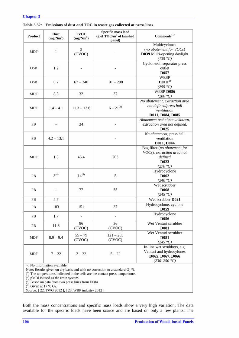
Chapter 3
106 Production of Wood–based Panels
Table 3.32: Emissions of dust and TOC in waste gas collected at press lines
Product Dust
(mg/Nm3)
TVOC
(mg/Nm3)
Specific mass load
(g of TOC/m3 of finished
panel)
Comments(1)
MDF 1 3
(CVOC) -
Multicyclones
(no abatement for VOCs)
D039 Multi-opening daylight
(135 °C)
OSB 1.2 - -
Cyclone/oil separator press
outlet
D057
OSB 0.7 67 – 240 91 – 298
WESP
D010(2)
(255 °C)
MDF 8.5 32 37 WESP D086
(200 °C)
MDF 1.4 – 4.1 11.3 – 12.6 6 – 21(3)
No abatement, extraction area
not defined/press hall
ventilation
D011, D084, D085
PB - 34 -
Abatement technique unknown,
extraction area not defined.
D025
PB 4.2 – 13.1 -
No abatement, press hall
ventilation
D011, D044
MDF 1.5 46.4 203
Bag filter (no abatement for
VOCs), extraction area not
defined
D023 (270 °C)
PB 3(4)
14(4)
5
Hydrocyclone
D062 (240 °C)
PB - 77 55
Wet scrubber
D068 (245 °C)
PB 5.7 - - Wet scrubber D021
PB 183 151 37 Hydrocyclone, cyclone
D059
PB 1.7 - - Hydrocyclone
D056
PB 11.6 86
(CVOC)
36
(CVOC)
Wet Venturi scrubber
D081
MDF 8.9 – 9.4 55 – 79
(CVOC)
121 – 255
(CVOC)
Wet Venturi scrubber
D081
(245 °C)
MDF 7 – 22 2 – 32 5 – 22
In-line wet scrubbers, e.g.
Venturi and hydrocylones
D065, D067, D066
(230–250 °C) '-': No information available.
Note: Results given on dry basis and with no correction to a standard O2 %.
(1) The temperatures indicated in the cells are the contact press temperature.
(2) pMDI is used as the resin system.
(3) Based on data from two press lines from D084.
(4) Given at 17 % O2.
Source: [ 22, TWG 2012 ], [ 23, WBP industry 2012 ]
Both the mass concentrations and specific mass loads show a very high variation. The data
available for the specific loads have been scarce and are based on only a few plants. The

Chapter 3
Production of Wood–based Panels 107
specific loads for two press lines with the collection of press waste gases, which are vented over
the roof and therefore with no specific treatment applied, show a variation from 6 g to 21 g
NMVOC/m3 of finished panel.
The levels of formaldehyde in emissions from press lines are shown in Table 3.33. The specific
mass loads have been calculated and are also indicated. The formaldehyde loads from the press
are generally at a lower level than the loads observed from dryers.
Table 3.33: Emissions of formaldehyde in waste gas collected at press lines
Product
Formaldehyde
(mg/Nm3)
(dry gas, no
correction for
O2)
Airflow
(103
Nm3/hour)
(dry gas)
Specific mass
load
(g of
formaldehyde/m3
of finished panel)
Comments
MDF 5.2(2) 122 -
Multicyclones, MUF, Multi-opening
press. Door skin production.
D039
OSB 0.62(2) 83 1 WESP, pMDI. D010
MDF 7.5(2) 93 9 WESP, MUF. D086
MDF(1) 1.5(4) 87.5 12 No abatement, press hall ventilation,
UF. D011, multi-opening press
PB(1) 3.5(4) 74 14 No abatement, press hall ventilation,
UF, D011, multi-opening press
PB 0.44(3) 120 1.3 No abatement, press hall ventilation,
UF. D044
PB 1.6(3) 110 2.2 No abatement, press hall ventilation
except press outlet, UF. D042
MDF 7.4(2) 145 32 Press entry and outlet, UF, Bag filter
D023
PB - 52 38 Wet scrubber, press outlet,
UF/MUPF. D021 Cont. press
PB - 146 47 Wet scrubber, UF/MUPF. D021,
multi-opening press
PB 3.7(2) 28 1.4 Venturi scrubber, UF. D081
MDF 2.8(2) 75 & 87 6–9 Venturi scrubber, UF. D081, 2 lines
MDF - 146 49 Wet scrubber, UF. D030
PB - 24 11 Measured before incinerated, UF,
D036
PB 17.2(2) 95 35 No information on abatement
technique, UF, D025
OSB 3.14(4) 40.5 - Cyclone/oil separator press outlet,
D057 '-': No information available.
(1) Result and airflow refer to wet gas.
(2) Isokinetic sampling in an impinging solution.
(3) Non-isokinetic sampling on adsorption tubes.
(4) Monitoring/sampling method not known.
Source: [ 22, TWG 2012 ], [ 23, WBP industry 2012 ]
At a MDF plant (D092), the collected waste gas from the press line was monitored before
treatment in a wet scrubber, corresponding to the raw waste gas before abatement. The TOC
content was 46 mg/Nm3 and the formaldehyde content was 17 mg/Nm
3, with a specific mass
load of 49 g formaldehyde per m3 of produced panel. The press is completely enclosed and its
emissions and the diffuse emissions in the press room are collected. The collected waste gas is
discharged without further treatment and the monitoring showed values of 3.7 mg/Nm3 for
TOC, and 3.6 mg/Nm3 for
formaldehyde, with a specific mass load of 9 g formaldehyde per m
3
of produced panel.

Chapter 3
108 Production of Wood–based Panels
The difference between the specific mass load of formaldehyde and TOC in Table 3.32 and
Table 3.33 can, besides the abatement techniques applied, be related to the resin used and the
press technique, where the press temperature could have a determining role. The differences in
both measured concentrations and mass loads would also largely depend on the areas of the
press from where the air is extracted and the amount of air extracted.
Considering the margin of uncertainty in the calculations of the specific load, the specific load
data are not used further. Emission factors have however been developed for the sector by the
US EPA and could be consulted [ 93, USEPA 2014 ]. The difference in the emission factors of
TOC and formaldehyde is not significant.
The abatement techniques applied are more diverse than reflected in Table 3.32 and Table 3.33.
Press waste gas is often treated together with the dryer waste gas in a WESP, see Figure 3.7.
Since the abatement equipment would be designed to receive and treat both waste gas streams,
the emission levels of a WESP treating both waste gas streams and one treating only dryer waste
gas are comparable. A very commonly applied reduction measure is post-combustion after an
initial quench or after a wet scrubber. The post-combustion of the dryer waste gas destructs the
VOC content, but also contributes to the energy balance of the operations on site. No data are
available on the abatement efficiencies of either of the techniques for the dryer waste gas.
Formaldehyde emissions from presses strongly depend on the resin system used. Since the resin
system will change with the thickness of the product and the operating conditions, the actual
values measured could vary.
Figure 3.17 shows a data set from presses for PB, OSB and MDF collected by EPF during 2011.
For the data presented in Figure 3.17, the reported formaldehyde concentrations are difficult to
compare due to variations in airflows, collection points for waste gases and types of press. In
Figure 3.17, values below 2 mg/Nm3, which are related to press waste gases without a related
abatement technique, could be explained by very high airflows. The data set clearly shows that a
direct comparison of emissions from presses is not possible without the necessary contextual
information. The data in Figure 3.17 are not further used.
Source: [ 42, EIPPCB/EPF 2012 ]
Figure 3.17: An EPF study showing formaldehyde emissions from presses and the related
abatement techniques

Chapter 3
Production of Wood–based Panels 109
There are a few examples of other parameters monitored occasionally depending on the MS.
Among these are phenol and formic acid. For example, Plant D025 reported levels of phenol of
0.03 mg/Nm3, and of formic acid of 1.32 mg/Nm
3
3.2.3 Emissions from downstream and upstream processing
This section presents data from all wood processing activities at the site, except for refining,
drying and pressing. The processes included are described in Sections 2.1, 2.3.1 2.3.3 and 2.4.
The only parameter monitored regularly is dust. Control of emissions from dust treatment at the
cleaning plant for recovered wood could occasionally include a selection of metals and
benzo[a]pyrene.
As a standard practice, emissions from dusty operations, such as chipping and milling, mat
forming, and cutting and sanding, are collected and treated to remove dust. Bag filters are
applied at most sites, and cyclofilters or similar equipment are also used. For all operations, the
collected dust is recycled in the production process or used as a fuel in the on-site combustion
plant.
The emission level achieved by the dust abatement equipment is generally below 5 mg/m3. The
monitoring of the filter performance is carried out indirectly and continuously, by recording the
differential pressure. The dust abatement equipment is tested at intervals, which range from
performance monitoring at the start of production to once a year or once every three years.
On a few occasions, the data have shown values of up to 10 mg/m3, but any values over
5 mg/m3 are usually obtained under conditions which are considered other than normal
operating conditions, and indeed it was reported that the continuous monitoring showed a leak
developing in the bag filter material.
Collected emissions from cleaning plants for recovered wood do not differ substantially from
the other wood processing steps. Bag filters are applied as the chosen technique for dust
abatement. One plant reported the use of wet scrubbing of collected dust for the cleaning plant,
because of the fire risk from the dry wood dust.
No data have been made available concerning any emissions of dust from panel lamination lines
or on diffuse emissions of dust in general from the site.
Diffuse emissions of formaldehyde were measured in a study in 2009, which included the mat
forming station, the starboard cooler and the sanding line at four particleboard plants and one
MDF plant. Also, the main press outlet emissions were measured for comparison. The highest
formaldehyde content in the ambient air was found at the main press outlet, while the starboard
cooler area showed formaldehyde values exceeding the values measured at the mat forming
station and the sanding line:
main press outlet: from 0.017 mg/m3 to 1.23 mg/m
3;
mat forming station: from 0.04 mg/m3 to 0.28 mg/m
3;
starboard cooler: from 0.171 mg/m3 to 1.25 mg/m
3;
sanding line: from 0.073 mg/m3 to 0.210 mg/m
3.
The variation in the press emissions is affected by the degree of effective enclosure and
extraction both at the main press outlet and along the press line [ 40, EPF 2010 ].
Chapter 3
110 Production of Wood–based Panels
3.2.4 Emissions from combustion plants
The hot gases used in direct drying will affect the composition of the dryer emission. Depending
on the fuel used and the combustion technique, the contribution of NOX and SOX can be
significant.
Emissions data have been collected for a range of combustion units that produce hot gases for
directly heated drying. Combustion plants used for generating the hot gases also deliver energy
for thermal oil, and for generating power and steam. Steam is used for example in refining,
while power and excess heat are used on site or exported off site to a grid. The energy balance at
the site level is optimised to reflect the local supply of fuel and the need for energy on site. The
demand for heat and power in the surrounding areas of the site is taken into account and
biomass CHP plants are operated, as well as diesel engine-driven CHP plants.
Non-biomass fuels are used in the sector, although biomass is the most prominent fuel both for
generating hot gases for direct drying and for producing steam for refining or indirect drying.
Grate-fired furnaces and fluidised bed furnaces are standard in the sector, accepting a range of
different biomass fuels. These combustion plants have sizes from around 15 MW to more than
50 MW. For direct drying, smaller wood dust burners are also used with sizes of around 5 MW
to 10 MW.
On all sites, several auxiliary energy-producing units are in operation. Generally, the smaller
units principally heat thermal oil and are heated by natural gas or liquid fuel or used as standby
units.
For combustion plants or incinerators, the monitoring data for NOX, SOX and CO at four
example plants are shown in Table3.34. All data are measured at the hot gas outlet of the
combustion plant before being mixed with other air sources and added to the dryer. Monitoring
data from four sites with combustion units used for producing steam for indirectly heated dryers
are also included in the table.

Chapter 3
Production of Wood–based Panels 111
Table3.34: Emission levels of dust, NOX, SOX and CO in flue-gases from combustion plants
Dust
(mg/Nm3)
NOX
(mg/Nm3)
SOX
(mg/Nm3)
CO
(mg/Nm3)
NH3
(mg/Nm3)
Comme
nts
Combustion plants for directly heated dryers
D002
48 MW
100 % biomass.
Moving grate
SNCR, cyclone
208 161 - 31 25
(periodic
measurement)
Continuo
us
measure
ment,
half-
hourly
average,
13 % O2,
dry
D0030
28 MW
99 % biomass.
Pulverised solid
fuel-firing, dry
bottom.
Multicyclone
124 263 - 125 -
Periodic
measure
ment 11
% O2,
dry
D038
23MW
60 % biomass,
40 % heavy fuel
oil
11 375 53 13 -
Periodic
measure
ment 11
% O2,
dry
D010
48 MW
100 % biomass
(recovered wood).
Intermittent grate
Incinerator
10.5 240(1)
13
(periodic
measurement)
1.7(2)
-
Continuo
us
measure
ment,
yearly
average,
11 % O2.
dry
Combustion plants for indirectly heated dryers
D001
49.5 MW
100 % biomass.
Circulating
fluidised bed,
CHP plant.
SNCR, cyclone,
dry sorption
injection, bag
filter
1.6 180 0.05 60
0.2 (periodic
measurement
at 11 % O2)
Continuo
us
measure
ment,
daily
average
7 % O2,
dry
D004
40 MW
70 % production
residues (dust), 30
% bark.
Intermittent grate
SNCR, cyclone,
dry sorbent
injection, bag
filter
1.8 216 20 47 1
Continuo
us
measure
ment,
half-
hourly
average,
13 % O2,
dry
D031
3 units, 110 MW
Boiler 1
10 % production
residues, 90 %
recovered wood.
Moving grate
SNCR, bag filters
1.4 193 24 -
Continuo
us
measure
ment,
unknown
average
period,
11 % O2,
dry

Chapter 3
112 Production of Wood–based Panels
Boiler 1 & 2
Moving grate
10 % production
residues, 90 %
recovered wood.
SNCR, cyclone,
dry sorbent
injection, fabric
filters
2.6 193 45 40 -
Continuo
us
measure
ment,
yearly
average,
11 % O2,
dry
'-': No information available.
(1) The 95th percentile of NOX is 282 mg/Nm3.
(2) The 95th percentile of CO is 2.2 mg/m3.
Source: [ 22, TWG 2012 ]
Combustion plants are reported to run at full load, with one major shutdown a year for
renovation and maintenance, which includes the whole site and production lines. When
maintenance is performed during the rest of the year, such as cleaning of the dryer or abatement
systems, the combustion plants are maintained at minimum combustion with a supplementary
fuel, which is usually gas. These periods last less than a day and, depending on the site, the
combustion plants can have 6–20 warm starts-ups during a year. During warm start-ups, the
abatement systems will normally be functioning.
SNCR is applied at a number of combustion plants, even though it is not common practice. The
appliance of SNCR reduces the NOX levels from the combustion process. SNCR is either
applied with aqueous urea injection or carbamide injection.
Sulphur reduction is applied at a few combustion plants, even though it is not common practice.
The use of dry sorbent requires a dust abatement technique, such as a bag filter, which is not
reportedly used for dust reduction before hot gases are used for direct drying. Sulphur reduction
with injection of dry or wet sorbent is efficient in reducing SOX levels if using a biomass source
with a critical sulphur content. Recovered wood and production residues with residual sulphate
salts could have a higher sulphur content than other types of biomass. Reduction of sulphur also
reduces other acidic compounds at the same time, such as HCl, HF and PCDD/F, see Section
3.2.4.1.
The TOC content in the hot gases from the combustion of biomass can be high, due to an
inefficient combustion process, although high TOC levels are rarely recorded in the data
collection from combustion plants. The TOC content derived from the hot gas is considered
negligible in comparison with the contribution from the wood raw material and it is not possible
to directly track it in the dryer waste gas afterwards.
As for NOX, SOX, CO and dust, it is important to ensure that the combustion process is efficient
in terms of limiting the amount of TOC released in the hot gases. In order to show the probable
insignificance of the contribution of volatile organic compounds from combustion, data from a
combustion plant are included at this point. The combustion process is characterised as
inefficient, with high levels of dust, NOX and CO, and is using production residues as the main
fuel source. The combustion plant produces hot gas for two directly heated dryers and the mass
concentrations for the measured VOCs are between 16 mg/Nm3 and 786 mg/Nm
3 (6 % O2), and
the yearly load is 9933 kg of VOCs. The mass concentrations measured at the dryer outlets were
between 56 mg/Nm3 and 203 mg/Nm
3 (17 % O2). The total load of VOCs from the dryers is
reported to be 206 000 kg VOC. The contribution from combustion is, at this specific plant,
negligible.
Liquid fuels
High emissions of NOX and SOX are registered for liquid fuels in particular, but only a minor
number of diesel engine plants are in operation, mainly as CHP plants. Where there is no easy
access to natural gas, liquid fuels are also used as alternatives during the shutdown of the main
plant, as emergency plant fuel or for heating thermal oil.

Chapter 3
Production of Wood–based Panels 113
The CHP plants with heavy fuel-fired cogeneration engines produce hot gases for direct drying,
heat for thermal oil heating and steam for refining. The majority of the energy is exported off
site. The related emissions to air show high levels of NOX and SOX, see Table 3.35 where five
data sets are presented. The techniques to reduce SOX in particular include only primary
techniques, such as use of a fuel with a low sulphur content, removal of impurities and metals
by centrifugation of the fuel and control of combustion.
Table 3.35: NOX, SOX, CO and dust emissions from heavy fuel-fired engines for generating hot
gases for direct drying
Unit NOX CO SOX Dust
D067 I mg/Nm3 2030 216 578 15
D067 II mg/Nm3 2170 47 472 28
D068 mg/Nm3 1720 94 182 25
D066 I mg/Nm3 1660 77 228 29
D066 II mg/Nm3 1900 57 401 28
Note: All data given at 15 % O2.
Source: [ 22, TWG 2012 ]
Secondary abatement techniques to reduce the levels of NOX or SOX are not applied.
Combustion plants acting as part of a closed loop dryer treat all dryer waste gases partly by
thermal incineration in a heat exchanger and partly by incinerating some of the waste gas in the
furnace. The stack emission from the combustion plant is treated, e.g. by ESPs or bag filters,
before being emitted. The stack emission contains the flue-gas from the combustion of biomass
and, for example, natural gas, and the flue-gas from incineration of the dryer waste gas. Other
waste gas sources such as press waste gas can be post-combusted/incinerated within the furnace.
The emissions from three plants applying the closed loop dryer and combustion technique are
shown in Table 3.36.
Table 3.36: Emission levels from closed loop combustion plants
D012
PB
32 MW, ESP
D096
OSB
40 MW, ESP
D091
PB
ESP
Parameter
Periodic measurement,
1–4 times a year,
mg/Nm3, 11 % oxygen, dry
Periodic measurement,
4 times a year, average,
mg/Nm3, dry
Continuous
measurement, daily
average values,
mg/Nm3, dry
Dust 4 11 20
(95th percentile: 40)
NOX 286 54 -
CO 261 80 -
Formaldehyde 0.25 0.2 -
TOC 12 54 110
(95th percentile: 163)
NMVOC 2.5 - -
'-': No information available.
Source: [ 22, TWG 2012 ]
All three plants apply an ESP for dust abatement after the combustion plant. The closed loop
dryer and combustion plants operate under different conditions to a combustion plant used for

Chapter 3
114 Production of Wood–based Panels
direct drying. The energy produced is used for heating the heat exchanger, where the majority of
the dryer waste gas is thermally treated. The burning conditions of the combustion plant must be
adapted to efficiently incinerate part of the dryer waste gas, and, in the examples, the press
waste gas too. The dryer waste gas volume which is incinerated is reported to be around 20 %.
Additionally, one OSB production line is applying the closed loop dryer technology and the
emission levels reported were 5.1 mg/Nm3 of dust, 1.2 mg/Nm
3 of CVOC and 0.4 mg/Nm
3 of
formaldehyde, all given at 17 % O2 [ 52, LIFE05 2007 ], [ 58, UBA, Austria 2013 ].
3.2.4.1 Additional monitoring data
Monitoring data on other parameters such as HCl, HF, dioxins and metals are included in this
section. The data generally show that only under very local and specific conditions do any of the
parameters call for special attention. Nevertheless, monitoring of metal compounds is of interest
if the dust emissions from combustion are high and if no efficient dust reduction takes place at
the plant. Dioxins and furans could be emitted if using fuel with a high chloride content and
suboptimal combustion processes. The data on the parameters mentioned are not sufficient to
define techniques to prevent or reduce the emissions. The general measures used at combustion
plants to prevent or reduce emissions of all the parameters mentioned are described in the BREF
on Large Combustion Plants (LCP) [5, EC 2003].
Table 3.37 shows the few values of HCl and HF collected from combustion plants producing
hot gases for direct drying. For comparison, the levels of HCl and HF from other combustion
plants primarily producing steam for indirect drying are also shown. For these plants, it should
be taken into account that recovered wood is used as a fuel and that they are considered waste
incinerators. Some of the plants use sorbent injection to remove acidic compounds, such as SOX,
HCl and HF.
Table 3.37: HCl and HF emissions from heavy fuel-fired engines for generating hot gases for
direct drying
Plant ID no HCl
(mg/Nm3)
HF
(mg/Nm3)
Comment O2 reference
(vol-%)
D001 0.1 0.06 Daily average, cont.
measurement 7
D031
(100 % biomass) 4.24 -
Daily average, cont.
measurement 11
D030
(100 % biomass) 2.5 - - 11
D060 0.02 0.05 - 8
D018, D020,
D021, D023 2.6 – 9.2 0.1 – 0.4 SOX:5 – 37 mg/Nm
3 11
'-': No information available.
Source: [ 22, TWG 2012 ]
Metals are monitored especially when the fuel is classified as waste wood and when the
combustion under those circumstances is considered an incineration process. As for the
parameters, there are three groups considered and which coincide with the classifications of
toxic metals according to Directive 2000/76/EC:
Hg;
Cd, Tl;
Sb, As, Pb, Cr, Co, Cu, Mn, Ni, V.

Chapter 3
Production of Wood–based Panels 115
There are significant differences in the metal parameters monitored. Table 3.38 shows the
monitoring of a range of the metals or metal groups. In general, the monitoring shows low
values for most metals.
Table 3.38: Emissions of metals from combustion plants
Parameter mg/Nm3 Plant ID no O2 reference (%)
As 0.13 D015 6
0.02 D060 8
Pb
10.54(1)
D015 6
0.07 D060 8
0.08 D010 11
Cr 0.002–0.06
D060
D018 (indirect)
D023 (indirect)
8
Cu 0.22 D010 11
Sum of: Cd, Tl 0.0001 D001 11
0.012 D031 11
Sum of: Pb, Cr, Cu 0.16
D060 8 Sum of: As, Ni 0.035
Sum of: Cd, Hg 0.027
Sum of:
As, Pb, Sb, Cr, Co, Cu, Sn, Ni, V
0.005 D001 11
0.078 D031 11
0.19 D010 11
Sum of:
Sb, Cr, Co, Cu, Sn, Mn, Ni, V, Zn 73.93
(1) D015 13
(1) High levels of dust from 425 mg/Nm3 to 2020 mg/Nm3.
Source: [ 22, TWG 2012 ]
Dioxins and furans are monitored very infrequently and range from 0.004 ng I-TEQ/Nm3 to
0.07 ng I-TEQ/Nm3 at 11 % O2 (D015, D010, D031).
The measured dioxin levels from five combustion plants producing hot gas for indirect drying
range from 0.00125 ng I-TEQ/Nm3 to 0.07 ng I-TEQ/Nm
3 at 11 % O2 (D001, D004, D020,
D023, D021). The lower value is near the limit of detection.
All the combustion plants mentioned use a fuel mix with recovered wood or production residues
as the main fuel. The creation of dioxin compounds is, amongst others, related to the chlorine
content in the fuel and the organic precursors like phenols and lignin present in wood.
Recovered wood and wood harvested near the sea can have an elevated amount of chlorine.
Production residues such as sanding dust have a reported chloride concentration of 0.01 % to
0.29 % [ 41, RWP 2011 ]. Treated wood and varnished or PVC-coated wood do have a higher
chloride content and this could be present in recovered wood. Dioxin formation from the
combustion of wood and even wood waste is considered lower than for other biomass fuels,
such as straw, but especially low compared to coal and municipal solid waste.
Additionally, limited collected emission data exist for other combustion units used for heating
thermal oil or generation of steam, etc. When these conventional utility boilers are not included
in the production of hot gases for direct drying, the emissions data have not been assessed
further and are not included [ 8, TWG WBP 2012 ].
Chapter 3
116 Production of Wood–based Panels
3.2.5 Emissions from paper impregnation lines
The sources of emissions from paper impregnation lines are the collected and channelled waste
gases from the drying ovens. The emissions contain VOC compounds and formaldehyde, but
very little dust.
During the collection of data, 19 out of 69 WBP production sites reported details of the on-site
paper impregnation lines operated.
The capacity of the production lines ranges from 10 million m2/year to 60 million m
2/year.
Together, the 19 production sites rounded up to a total of at least 1060 million m2 paper/year in
2010.
The resin dosage depends on the resin system used and the required finish of the laminated
panels. The reported resin dosages, per m2 of paper, range from 40 g/m
2 to 214 g/m
2.
All 19 sites use an aqueous solution of melamine-based resin, and the majority use two-stage
impregnation with urea-formaldehyde in the first dip bath and melamine resin in the second
step, applied in a second dip bath or by coating rollers.
The dryers are air flotation dryers, where hot air dries the paper in 4–12 drying fields, depending
on the capacity of the impregnation line. The hot air is produced by heat exchange of thermal oil
or steam, or by direct drying by air from natural gas-fired engines. Infrared (IR) heating after the
first impregnation step is carried out at some production lines.
The 19 sites operate one or more paper impregnation lines with the following treatment systems
applied:
Three sites use the panel production line and its combustion plant for post-combustion of
the waste gas from the paper impregnation line or for preheating the wood dryer air.
Three sites use thermal oxidation, either a regenerative thermal oxidiser or a catalytic
oxidiser, and reuse the thermal energy from the exhaust of the thermal oxidiser as drying
air for wood dryers or by heat exchange for other processes.
Four sites apply a wet abatement system based on either simple scrubbing or with a
biodegradation step. One site adds the waste gases to a common wet electrostatic
precipitator, serving all waste gases from the core panel production.
Nine sites do not apply an end-of-pipe treatment system for the waste gases, but reported
the use of primary measures, such as low-temperature drying and resin with a low
formaldehyde content.
Emissions data from six impregnation plants are shown in Table 3.39 including TOC and
formaldehyde. The sites represent capacities from 55 000 m2/day to 160 000 m
2/day, from a
single line or more than five lines.
The data supporting an expression in mass loads are scarce and not easy to compare, e.g. in
terms of the uncertainty of reference airflows, actual production during sampling, and actual
resin composition. Assumptions were made on the basis of the contextual information received
and it can be further noted that all of the techniques produce mass concentrations of TOC in the
same range. The TOC and the values for CVOCs are not directly comparable, which could in
turn mean that the levels at the last plant mentioned in the table, D077, could be higher than
indicated.

Chapter 3
Production of Wood–based Panels 117
Table 3.39: Emissions of organic compounds and dust from paper impregnation lines
Plant
ID no
TOC
(mg/Nm3)
Formaldehyde
(mg/Nm3)
Specific mass
load
(g TOC/m2
impregnated
paper)
Abatement technique
D068 3 – 47 - 0.04 – 0.37 Selection of raw materials and
gentle drying
D003 7 – 17 1 – 8.8 0.07 – 0.19 Catalytic thermal oxidation
D063 26 - 0.07 Catalytic thermal oxidation
D094 4.6 0.7 - Regenerative thermal oxidation
D077 (CVOC)
3.2 – 34.7 1.6 – 4.1 0.008 – 0.17
Regenerative thermal oxidation
(2011)
D077 (CVOC) 16 1 – 3 0.07 Wet biofilter (2012)
'-': No information available.
The percentage of TOC that is stripped from the aqueous resin solution applied to the paper
during drying is negligible, compared to the amount of resin added to the paper. From data on
the average amount of resin applied to the paper, the range of resin stripped off and emitted is
from 0.007 % to 0.38 % among the example plants [ 23, WBP industry 2012 ].
3.2.6 Odour
Odour from WBP production sites can be related to both the outdoor storage of wood raw
material and the range of different processes in production. The main source of odour is the
dryer waste gas and the terpenes which are released. Odour and blue haze are connected to this
and if the VOC content in the dryer waste gas is reduced the blue haze and odour are reduced
too.
Odour is measured as part of the permit compliance in several Member States. Data from one
Member State, regarding odour monitoring at the stack level from the dryer abatement system
emission, is shown in Table 3.40, together with odour monitoring for other stack emission
sources. The odour data are related to point sources and not to ambient air monitoring.

Chapter 3
118 Production of Wood–based Panels
Table 3.40: Odour emissions from stack emission sources
Plant ID no TOC
(mg/m3)
Odour
(ge/m3)
Comments
a 68 (6 %) 2040
ESP
Combustion plant. (PB, closed loop dryer).
53 tonnes panel/h
b - 656
MDF, directly heated dryer, cyclone and wet
scrubber.
Dry blending
c - 1100 MDF, directly heated dryer, cyclone and wet
scrubber. Blowline blending. 17 dry tonnes/h
d - 790 – 944 MDF, directly heated dryer, cyclone and wet
scrubber
e 200 – 250 1600 – 1750 PB, indirectly heated dryers, multicyclones, WESP,
37dry tonnes/h
f 200 – 230 2500 PB, indirectly heated dryer, bag filter
g 139 2900 PB, directly heated dryer, WESP, 36 tonnes/h
h 87 – 142 2170 PB, directly heated dryer, WESP, 57 m3 panel/h
D090 60 512 Rigid/flexboard fibre dryer,
high efficiency cyclones
D094 4.6 45 Paper impregnation,
Regenerative thermal oxidation '-': No information available.
Source: [ 22, TWG 2012 ], [ 45, VDI 2011 ]

Chapter 3
Production of Wood–based Panels 119
3.3 Emissions to water
3.3.1 Emissions from surface run-off water
Handling of surface run-off water in the log yard and other outdoor areas is performed at the
majority of sites. If surface run-off water is collected and discharged, it is usually monitored.
The level of monitoring varies and, when determining the monitoring frequency, the sensitivity
of the receiving water to which the collected surface run-off water is discharged is taken into
account by the competent authority. If the concentration is highly variable, more frequent
monitoring could be needed to protect the surface water and/or the urban waste water treatment
plant. The variability of the composition of the water to be discharged is due to the amount of
rain and wind and the exchange and transport of stored materials during the year, etc.
Storage of dusty materials or dust from outdoor wood processing areas contributes to the level
of TSS, BOD5 and COD in the surface run-off water, while traffic could contribute to
hydrocarbon levels.
Data have been collected from 11 sites where surface run-off water is collected from the log
yard area and directly discharged or further treated in an off-site urban waste water treatment
plant (UWWTP). Before discharge, the collected surface run-off water is pretreated by
mechanical or stationary screens removing the largest wood pieces. In Figure 3.18, the average
value of periodic monitoring of COD is shown together with the TSS and BOD5 average values,
if monitored. Retention basins are used at most sites.
Note: SW: discharge to surface water; UWT: discharge to sewer and further off-site treatment.
Source: [ 22, TWG 2012 ]
Figure 3.18: Average values of TSS, BOD5 and COD in the discharge of treated surfce run-off
water
The majority of sites that collect and handle surface run-off water have retention basins to store
the water before discharge. The variation in the three parameters shown in Figure 3.18 depends
on the efficiency of the screens that pretreat the water and on the retention volume of the basin
or basins in series. If no alternative options are available, cleaner rainwater from roof areas
could be collected and discharged together with the surface run-off water from the log yard. The

Chapter 3
120 Production of Wood–based Panels
effect of dilution would lower concentration values. Some of the plants, e.g. D067 and D072,
are examples where roof water also forms part of the discharge.
For a stable composition of the collected water, it is possible over time to establish a correlation
between COD and BOD5. Since the data in Figure 3.18 are based on comparable sources the
COD/BOD5 ratio could be set between 6 and 10. The ratio will however need to be set at the site
level with a longer monitoring period before a correlation is possible. It should be noted that
generally COD is a more convenient parameter for monitoring oxygen demand in emissions
discharged to water, while BOD5 is more applicable as a process control parameter for
biological treatment techniques. COD is increasingly being replaced with TOC for economic
and environmental reasons in other industrial sectors. A correlation between TOC and COD
should also be established at site level. TOC is not presently used in the wood-based panel
industry when monitoring surface run-off water.
3.3.2 Emissions from treated process water
Waste water treatment plants treating process water are operated at installations where fibres are
produced by refining. The process water that arises is treated and recycled internally at the
refiner plant in dedicated treatment plants at some installations. Data have not been collected for
the internal treatment of process water, where the water is recycled in production either to the
refiner and cooking stage or to the chip washing.
At a limited number of installations the process water from refining is treated in a central waste
water treatment plant at the site. The majority of the treated water is from refining but other
water streams might be sent for treatment and mixed with the process water from refining. The
waste water treatment plants operated at WBP installations apply primary treatment steps to
remove most of the TSS. An aerobic biological treatment is commonly applied to treat the COD
and BOD5. Ultrafiltration and reverse osmosis are employed when either the receiving surface
water is especially sensitive or when the recycling of the treated water into production is
possible.
Treatment efficiency
No data have been collected on the incoming concentration or load of the untreated process
water, so it is not possible to calculate the removal or treatment efficiency of the steps applied in
the waste water treatment plant. The efficiency of different treatment steps applied was reported
together with emissions data and is shown in Table 3.41.
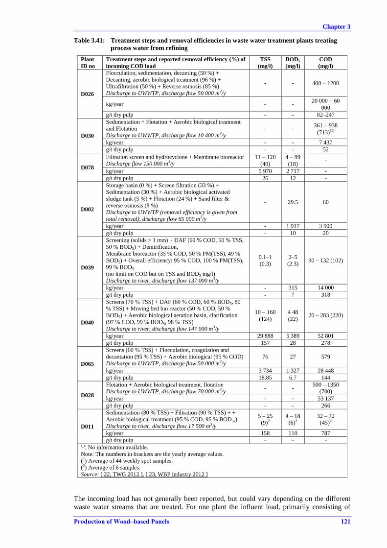
Chapter 3
Production of Wood–based Panels 121
Table 3.41: Treatment steps and removal efficiencies in waste water treatment plants treating
process water from refining
Plant
ID no
Treatment steps and reported removal efficiency (%) of
incoming COD load
TSS
(mg/l)
BOD5
(mg/l)
COD
(mg/l)
D026
Flocculation, sedimentation, decanting (50 %) +
Decanting, aerobic biological treatment (96 %) +
Ultrafiltration (50 %) + Reverse osmosis (85 %)
Discharge to UWWTP, discharge flow 50 000 m3/y
- - 400 – 1200
kg/year - - 20 000 – 60
000
g/t dry pulp - - 82–247
D030
Sedimentation + Flotation + Aerobic biological treatment
and Flotation
Discharge to UWWTP, discharge flow 10 400 m3/y
- - 361 – 938
(713)(1)
kg/year - - 7 437
g/t dry pulp - - 52
D078
Filtration screen and hydrocyclone + Membrane bioreactor
Discharge flow 150 000 m3/y 11 – 120
(40)
4 – 99
(18) -
kg/year 5 970 2 717 -
g/t dry pulp 26 12 -
D002
Storage basin (0 %) + Screen filtration (33 %) +
Sedimentation (30 %) + Aerobic biological activated
sludge tank (5 %) + Flotation (24 %) + Sand filter &
reverse osmosis (8 %)
Discharge to UWWTP (removal efficiency is given from
total removal), discharge flow 65 000 m3/y
- 29.5 60
kg/year - 1 917 3 900
g/t dry pulp - 10 20
D039
Screening (solids > 1 mm) + DAF (60 % COD, 50 % TSS,
50 % BOD5) + Denitrification,
Membrane bioreactor (35 % COD, 50 % PM(TSS), 49 %
BOD5) + Overall efficiency: 95 % COD, 100 % PM(TSS),
99 % BOD5
(no limit on COD but on TSS and BOD5 mg/l)
Discharge to river, discharge flow 137 000 m3/y
0.1–1
(0.3)
2–5
(2.3) 90 – 132 (102)
kg/year - 315 14 000
g/t dry pulp - 7 318
D040
Screens (70 % TSS) + DAF (60 % COD, 60 % BOD5, 80
% TSS) + Moving bed bio reactor (50 % COD, 50 %
BOD5) + Aerobic biological aeration basin, clarification
(97 % COD, 99 % BOD5, 98 % TSS)
Discharge to river, discharge flow 147 000 m3/y
10 – 160
(124)
4 48
(22) 20 – 283 (220)
kg/year 29 888 5 389 52 801
g/t dry pulp 157 28 278
D065
Screens (60 % TSS) + Flocculation, coagulation and
decantation (95 % TSS) + Aerobic biological (95 % COD)
Discharge to UWWTP, discharge flow 50 000 m3/y
76 27 579
kg/year 3 734 1 327 28 448
g/t dry pulp 18.85 6.7 144
D028
Flotation + Aerobic biological treatment, flotation
Discharge to UWWTP, discharge flow 70.000 m3/y - -
500 – 1350
(700)
kg/year - - 53 137
g/t dry pulp - - 266
D011
Sedimentation (80 % TSS) + Filtration (90 % TSS) + +
Aerobic biological treatment (95 % COD, 95 % BOD5,)
Discharge to river, discharge flow 17 500 m3/y
5 – 25
(9)2 4 – 18
(6)2
32 – 72
(45)2
kg/year 158 110 787
g/t dry pulp - - -
'-': No information available.
Note: The numbers in brackets are the yearly average values.
(1) Average of 44 weekly spot samples.
(2) Average of 6 samples.
Source: [ 22, TWG 2012 ], [ 23, WBP industry 2012 ]
The incoming load has not generally been reported, but could vary depending on the different
waste water streams that are treated. For one plant the influent load, primarily consisting of
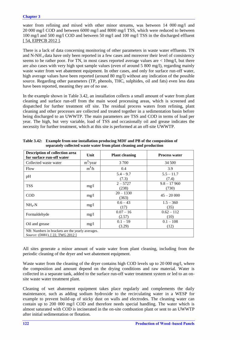
Chapter 3
122 Production of Wood–based Panels
water from refining and mixed with other minor streams, was between 14 000 mg/l and
20 000 mg/l COD and between 6000 mg/l and 8000 mg/l TSS, which were reduced to between
100 mg/l and 500 mg/l COD and between 50 mg/l and 100 mg/l TSS in the discharged effluent
[ 54, EIPPCB 2012 ].
There is a lack of data concerning monitoring of other parameters in waste water effluents. TN
and N-NH 4 data have only been reported in a few cases and moreover their level of consistency
seems to be rather poor. For TN, in most cases reported average values are < 10mg/l, but there
are also cases with very high spot sample values (even of around 5 800 mg/l), regarding mainly
waste water from wet abatement equipment. In other cases, and only for surface run-off water,
high average values have been reported (around 80 mg/l) without any indication of the possible
source. Regarding other parameters (TP, phenols, THC, sulphides, oil and fats) even less data
have been reported, meaning they are of no use.
In the example shown in Table 3.42, an installation collects a small amount of water from plant
cleaning and surface run-off from the main wood processing areas, which is screened and
dispatched for further treatment off site. The residual process waters from refining, plant
cleaning and other processes are collected and treated together in a sedimentation basin before
being discharged to an UWWTP. The main parameters are TSS and COD in terms of load per
year. The high, but very variable, load of TSS and occasionally oil and grease indicates the
necessity for further treatment, which at this site is performed at an off-site UWWTP.
Table 3.42: Example from one installation producing MDF and PB of the composition of
separately collected waste water from plant cleaning and production
Description of collection area
for surface run-off water Unit Plant cleaning Process water
Collected waste water m3/year 3 700 34 500
Flow m3/h 0.4 3.9
pH 5.4 – 9.7
(7.3)
5.5 – 11.7
(7.4)
TSS mg/l 2 – 5727
(238)
9.8 – 17 960
(730)
COD mg/l 20 – 1330
(363) 45 – 20 000
NH4-N mg/l 0.6 – 43
(17)
1.5 – 360
(35)
Formaldehyde mg/l 0.07 – 16
(2.57)
0.62 – 112
(10)
Oil and grease mg/l 0.1 – 59
(3.29)
0.1 – 108
(12) NB: Numbers in brackets are the yearly averages.
Source: (D081), [ 22, TWG 2012 ]
All sites generate a minor amount of waste water from plant cleaning, including from the
periodic cleaning of the dryer and wet abatement equipment.
Waste water from the cleaning of the dryer contains high COD levels up to 20 000 mg/l, where
the composition and amount depend on the drying conditions and raw material. Water is
collected in a separate tank, added to the surface run-off water treatment system or led to an on-
site waste water treatment plant.
Cleaning of wet abatement equipment takes place regularly and complements the daily
maintenance, such as adding sodium hydroxide to the recirculating water in a WESP for
example to prevent build-up of sticky dust on walls and electrodes. The cleaning water can
contain up to 200 000 mg/l COD and therefore needs special handling. The water which is
almost saturated with COD is incinerated in the on-site combustion plant or sent to an UWWTP
after initial sedimentation or flotation.

Chapter 3
Production of Wood–based Panels 123
3.4 Waste generation
The majority of waste generated is wood-based residues which are either recycled in the
production process or used as fuel in an on-site biomass combustion plant.
The installation with its auxiliary activities generates a wide range of waste fractions that are
common to most industrial production sites:
lubrication oil and other oil wastes from maintenance of equipment;
packaging waste from warehouses;
mixed metals, scrap, plastics.
For the sector, the following waste fractions have been noted:
used metal saw blades;
used sandpaper;
a minor amount of chemical waste from the product testing laboratory;
paper waste from impregnation lines and impregnated paper from lamination lines;
waste water with glue emulsion from the glue kitchen.
All waste fractions are dispatched off site for further treatment or disposal according to local
regulations.
Production residues
Production residues are collected all along the production line.
Undersized chipped material is sorted and collected before and after the dryer. The material is
used as a fuel. The quantity depends on the raw material and the product produced. After mat
forming, the sides of the mat are trimmed and this material is most often directly recycled in the
production line. There is no information regarding the amount of wood material collected and
recycled directly.
After the press, the dust collected from wood processing machines is the main production
residue. Rejected particleboard panels, which constitute a minor fraction, are recycled for
chipping and recycling into production as a first choice, while OSB and MDF are crushed and
used as a fuel. The processes downstream from the press, including cutting and sanding,
produce wood dust which is collected by dust filters at all plants. Depending on the product and
production parameters, the amount of residues collected by dust abatement filters can be
considerable and provides an important part of the fuel used in dust burners or combustion
plants, which deliver heat to the dryers. The collected dust, in the production of the main
products, represents a loss of 3–9 % of finished particleboard, a loss 4–7 % of finished OSB and
a loss of 2–10 % of finished MDF [ 8, TWG WBP 2012 ].
The total amount of wood dust, wood granulates and other internal wood waste used as a fuel
for energy recovery lies in the range of 46 000–58 000 tonnes/year or 90–150 kg/m3 of finished
panel (based on [ 8, TWG WBP 2012 ] from the following sites: D003, D004, D009, D049,
D063).
Sludge
Sludge is generated by wet abatement systems for emissions to air, central waste water
treatment plants, and from the internal recycling loops of process water.
Sludge from waste water treatment plants comes from the pretreatment of process water,
especially waste water from refining, where the coarsest material is separated by screens or
other simple mechanical filtration methods. Sludge from primary filtration and sedimentation of
waste water in MDF production plants is used as fuel or exported off-site for disposal or to

Chapter 3
124 Production of Wood–based Panels
different recovery operations, such as for agricultural purposes. Even though the sludge from
pretreatment steps is mainly wood particles and fibres, the quality of the material is often not
sufficient to recycle this back to the production of MDF. An exception is when wood particles
can be used in PB production [ 92, EIPPCB 2014 ]. The amounts can be considerable and range
from 150 tonnes/year to 5600 tonnes/year, or 1.5–16 kg/m3 of MDF produced (based on [ 8,
TWG WBP 2012 ] from the following sites: D011, D018, D026, D028, D065, D039).
Sludge is also generated from flotation steps and from aerobic biological treatments. The sludge
can be used as fuel, especially if dewatered efficiently following the treatment process, or
alternatively it is further treated off site or disposed of. The activated sludge needs sufficient
dewatering before it can be handled. The amount of sludge generated ranges from
11 tonnes/year to 6000 tonnes/year (based on [ 8, TWG WBP 2012 ] from the following sites:
D026, D039, D065).
Sludge from retention and sedimentation basins treating surface run-off water is generated when
the basins are cleaned. The sludge is dispatched off site. The amount will strongly depend on the
water streams collected and the amount of water, the retention time and the efficiency of the
retention.
Sludge generated from chip washing consists of both soil and wood grit, and is well suited to be
used as a fuel, especially if the sludge fraction is further treated so that the soil part is
minimised. The amount of sludge collected in chip washing could be as much as 8300 tonnes
(30 % solids) or 10–20 kg/m3 of finished panel.
Sludge generated in wet abatement systems, such as a WESP, wet scrubber, bioscrubber,
Venturi scrubber, or dissolved air flotation (DAF), consists mainly of small, coarse wood
particles and is generally used directly as a fuel. The sludge is dewatered by decanting or
sedimentation followed by screw presses or similar equipment to remove excess water. The
sludge can, with dewatering treatment, reach a moisture content of 20–25 %, which is sufficient
for handling. The amount of sludge collected is recorded as being in the range of 1000 dry
tonnes/year to 2500 dry tonnes/year (based on [ 8, TWG WBP 2012 ] from the following sites:
D040, D018, D003).
Slag and ashes
From biomass combustion plants, bottom ash and slag are wastes that need to be disposed of or
reused off site, depending on quality.
The quality and quantity depend on the fuel composition and combustion conditions. Reported
levels of generated ash are in the range of 2500–5000 tonnes/year from production plants
producing on average 450 000 m3 of panels/year with biomass as the main fuel source (based on
[ 8, TWG WBP 2012 ] from the following sites: D001, D002, D003, D009, D010, D049, D053).
Chapter 3
Production of Wood–based Panels 125
3.5 Emissions to soil and groundwater
The overall quality and characteristics of groundwater that is monitored will vary depending on
the local geological setting. Data from groundwater monitoring will therefore only be of use on
a site level. A few operators have reported having a groundwater monitoring grid of wells in
place and that there are requirements for monitoring. This was reported by Member States as
being one of the national requirements for industrial sites in general.
Chapter 3
126 Production of Wood–based Panels
3.6 Nuisance from noise and odour
Specific data from noise measurements have not been collected since each site has its own
characteristics in terms of more or less pronounced nuisance issues generated by noise.
Regular measurements of noise in the area surrounding the site and at site boundaries are
common practice as part of the conditions of the environmental permit for the activity.
Elevated levels of noise are abated by common methods not specific to the wood-based panel
sector but generally applied in industry.
Sources of noise are distributed over the whole production chain from traffic to and from the
site, and unloading of wood raw material, to the shipping of final products. The most relevant
sources of permanent noise are:
all transport to and from the site, including railways;
internal traffic of trucks for unloading and loading;
debarking of roundwood;
equipment for mechanical treatment such as hackers, flakers, mills, mechanical sieves, air
shifters, etc.;
transport of chips and fibres in pipelines and other systems such as conveyors;
steam releases in the refiner building;
the press area;
all wood processing of final raw panels including sawing, sanding, etc.;
fans, motors, compressors.
The operation of a wood-based panel installation tends to be a 24-hour continuous operation on
a daily basis, seven days a week, and where operation halts for only a few weeks each year for
maintenance purposes. Noise from activities on the site tends to be a more pronounced problem
at night because of the very low background noise from the surrounding areas. Limiting
transport to and from the site and limiting outdoor handling and transport of wood in the log
yard are primary measures applied at most sites to reduce noise during the night.
One of the major singular sources of noise that needs particular attention is the debarking of
roundwood and flaking of strands (mainly OSB), which is solved by proper enclosure in
separate insulated buildings. Except for this, no other major distinction has been noted among
installations producing different products.
Noise is abated throughout the sector with common primary measures, such as insulation of
noise sources, and secondary measures, such as embankments sheltering the site boundaries.
Primary measures applied generally and throughout the sector are reported as:
strategic planning of plant layout to accommodate most noisy operations so on-site
buildings act as insulation, e.g. noisy operations located in the middle of the plant;
developing and maintaining noise mapping for the site as part of an active noise reduction
programme;
regular maintenance of all equipment;
housing, encapsulation and isolation of equipment, compressors;
sound insulation of buildings in general;
limiting the transmission of vibrations by decoupling individual equipment;
speed limits for trucks;
limiting the time for primary and secondary chipping operations and debarking to
daytime;
closed gates and doors.

Chapter 3
Production of Wood–based Panels 127
Secondary measures generally applied are [ 8, TWG WBP 2012 ], [ 67, VITO 2011 ]:
silencers, noise attenuators on fans, filters mounted with acoustic enclosures, cyclones
with acoustic vents/mufflers, exhaust mufflers at stacks;
noise barriers, such as noise protection walls near sources, and embankments or berms
along the site boundary.
Some data have been received with stack level odour measurements of the dryer emissions.

Chapter 3
128 Production of Wood–based Panels
3.7 Monitoring of emissions
Sampling of emissions varies depending on the parameter to be sampled and the location of the
discharge point. Monitoring results depend not only on the sampling method applied, but also
on the conditions under which the abatement system is operating and the actual production
taking place in the time range of the sampling. The composition of emissions depending on the
product produced and, for example, the fuel used in direct drying should also be taken into
account.
Monitoring of the main emission points is, according to the data collection, most often
performed by one yearly sampling campaign to show compliance, even though some Member
States require up to four or more samples per year or as little as one sampling campaign every
third year. It should be mentioned that the sites could apply additional internal monitoring to
support the operation of the site, which is generally not addressed or reflected in the collected
data.
Data from several sites, presented in Sections 3.2.1.1, 3.2.1.2 and 3.2.1.3, show a large
difference between the reported minimum and maximum values for the emissions to air from
the dryer for both dust and volatile organic compounds including formaldehyde. This is the case
for data representing both one sample campaign, e.g. with three samples taken during one day,
and for data representing more than one sampling campaign, e.g. three times a year. This can
depend on the operational management of the drying process, the raw materials dried and the
operational management of the abatement system for emissions to air. Seasonal variations in
humidity and temperature could also affect the raw material during storage.
Member States indicate limit values in permits as mass concentrations, but can also determine
both specific mass loads and mass emission rates. The mass emission rate used is the mass
emitted per hour or year. The monitoring result of a parameter when controlling air or water
emissions can be expressed as the mass concentration in mass per Nm3 or further calculated
from the mass concentration to a specific mass load expressed as mass per unit of product
produced by the process causing the emission.
From the collected data, it has been assessed that the emissions of VOCs in particular in dryer
waste gas could differ throughout the year and even during one day. An example of the
variations in the measured VOC values are shown in Table 3.43, showing data from a
particleboard plant using solely pine from one harvest area as the raw material and from a MDF
line.
Table 3.43: Monitoring data from two production lines covering several years
D035 (PB) VOC
(mg/Nm3)
D094 (MDF) Total C
(mg/Nm3)
Dust
(mg/Nm3) (dry)
2010 Q 1 195 2009 147 8
2010 Q 3 320 2010 Q 1 - 12.3
2011 Q 1 40 2010 Q 2 195.4 12.5
2011 Q 3 55 2010 Q 3 - 8.1
2011 Q 4 190 2010 Q 4 126.9 9.8
2012 Q 1 240 2011 1st trimester - 12.4
2011 2nd
trimester 103 8
2011 3nd
trimester - 8
2012 1st trimester 82 11
2012 2nd
trimester - 16
2012 3nd
trimester 82 9
'-': No information available.
Source: [ 22, TWG 2012 ]
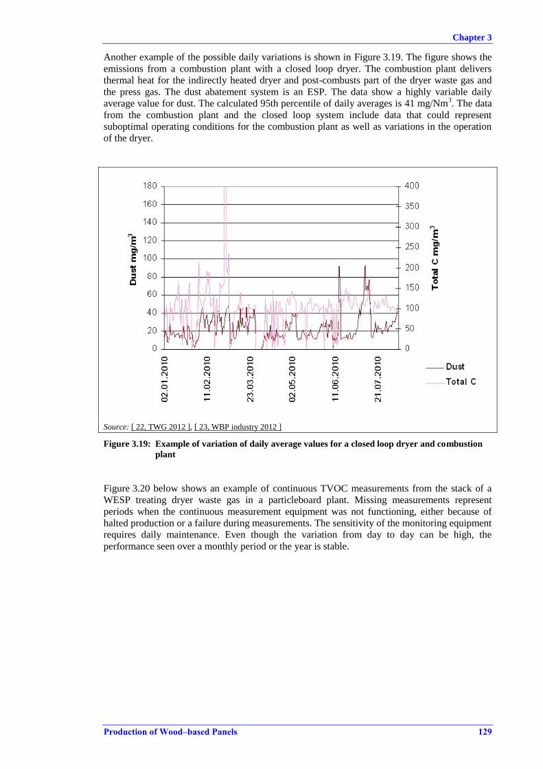
Chapter 3
Production of Wood–based Panels 129
Another example of the possible daily variations is shown in Figure 3.19. The figure shows the
emissions from a combustion plant with a closed loop dryer. The combustion plant delivers
thermal heat for the indirectly heated dryer and post-combusts part of the dryer waste gas and
the press gas. The dust abatement system is an ESP. The data show a highly variable daily
average value for dust. The calculated 95th percentile of daily averages is 41 mg/Nm3. The data
from the combustion plant and the closed loop system include data that could represent
suboptimal operating conditions for the combustion plant as well as variations in the operation
of the dryer.
Source: [ 22, TWG 2012 ], [ 23, WBP industry 2012 ]
Figure 3.19: Example of variation of daily average values for a closed loop dryer and combustion
plant
Figure 3.20 below shows an example of continuous TVOC measurements from the stack of a
WESP treating dryer waste gas in a particleboard plant. Missing measurements represent
periods when the continuous measurement equipment was not functioning, either because of
halted production or a failure during measurements. The sensitivity of the monitoring equipment
requires daily maintenance. Even though the variation from day to day can be high, the
performance seen over a monthly period or the year is stable.

Chapter 3
130 Production of Wood–based Panels
Note: Green lines represent TVOC measurement during one year.
The blue line is the permit emission limit value.
Source: [ 22, TWG 2012 ], [ 23, WBP industry 2012 ]
Figure 3.20: Example of variation of daily average values of continuous FID measurements (at 18
% O2) of TVOC during one year from a particleboard dryer equipped with a WESP
3.7.1 Reference conditions for expressing air emissions data
The individual installations report emission data to the competent authority according to permit
conditions, and the reference conditions for reporting values for air emissions will vary. The
data collection performed for this document reflects this difference in monitoring and reference
conditions.
The air emissions from dryers have distinct features which make reference conditions different
to those determined for combustion processes for example. The emissions are characterised as
hot and dust-laden. The dust is wet and sticky, due to the content of natural VOC components
from the wood, other complex wood constituents carried by the humidity from the wood during
drying, and the amount of PAHs created from burnt submicron particles. Continuous monitoring
of the main pollutants, such as dust, VOCs/TOC and formaldehyde, is not common.
The environment in the dryer is close to the atmospheric oxygen content, reflecting that drying
is not an oxygen-consuming combustion process. Data collected are either corrected to a
specific reference oxygen content or given without any corrections to a standard. From the data
collection, the actual oxygen content is reported for most stack emissions from dryers. The
oxygen content varies between 16.5 % and 20.9 %, and in a few cases is below 16 %. The
variation of the oxygen content depends on the dryer type. For indirectly heated dryers, oxygen
is near the atmospheric content of 20.9 %. In directly heated PB and OSB dryers, the oxygen
content is generally from 16.5 % up to around 19.3 %. For directly heated fibre (MDF) dryers,
the oxygen content varies from 19 % to 20.2 %.
The moisture content measured in the dryer emissions ranges from 8 % to around 15 %. From
the data, OSB dryer lines mostly record higher moisture levels up to 20 %. The moisture content
does not depend on whether the dryer emission is treated in cyclones or a wet abatement system
before being discharged, since the waste gas is inherently humid. The wet abatement systems
include WESPs, wet scrubbers and bioscrubbers. The difference between a result corrected to
Chapter 3
Production of Wood–based Panels 131
dry or not will vary between a 5 % difference at a moisture content of 5 vol-% and a 25 %
difference at 20 vol-% moisture. Based on the difference in the actual moisture content, it is
appropriate to have a correction to dry conditions for the emissions from the dryer when
expressing the concentration in mg/Nm3.
Reference conditions for a specific dryer and combustion plant set-up can be developed at site
level when optimising the combustion and related emissions, e.g. of NOX, CO and TOC. The
oxygen content which occurs at optimised conditions is used as a reference. When two or more
waste gas sources are treated together, e.g. in a WESP, the oxygen content can be near the
atmospheric content of 20.9 %. Based on the flow of the different waste gases, the oxygen
contribution from each can help in determining a reference condition for this specific set-up.
For emissions from presses, the correction to a specific oxygen content or dry condition is
generally not performed. The reported moisture content in emissions from press lines treated by
wet scrubbing is below 8 % and the possible error due to moisture is less pronounced than for
the dryer emissions.
The formula for calculating the emission concentration at a reference oxygen level is as follows:
ER = 21 – OR
21 – OM × EM
where: ER (mg/Nm3): emission concentration corrected to the reference oxygen level;
OR (vol-%): reference oxygen level;
EM (mg/Nm3): emission concentration referred to the measured oxygen level;
OM (vol-%): measured oxygen level.
3.7.2 Monitoring of emissions to air
3.7.2.1 Dust
Dust measured as total particulate matter is one of the key parameters to monitor at a WBP site.
Only a few plants have continuous monitoring of dust from dryers, applying photometric
measurements or according to EN 15267.
All presses and minor sources are monitored regularly from every third year to several times a
year. The combustion plants are often fitted with a system for the continuous monitoring of
dust.
The dust fraction from dryers, which is emitted after applying a reasonable dust reduction
technique, consists primarily of PM10, where up to 80 % could be PM2.5. The PM2.5 are aerosols
created from the condensation of organic compounds.
The sampling is crucial to a representative monitoring result and it is important that, if and when
the sampling probe is heated or the sampled air dried, the condensable fraction is considered and
taken into account.
Amongst the methods used are EN 13284-1, EN 14385, EN 15259, ISO 9096, CEN and
national standards and guidelines such as VDI 2066 Bl.1, NF X 44-052 [ 89, COM 2014 ].

Chapter 3
132 Production of Wood–based Panels
3.7.2.2 Formaldehyde
Periodic sampling of formaldehyde (including other lower aldehydes, alcohols and phenol) is
performed using two different approaches with a potential for difference in the results. High
volume isokinetic sampling in an impinging solution tends to give higher results than low
volume non-isokinetic sampling on adsorption tubes. International standards such as US EPA
M316, US EPA Method 5, NCASI/C1/WP98.01, NIOSH 3500 (chromotropic acid method) and
national standards from Member States including VDI 3862Bl.2 (DE) and guide FDX 43-319
(FR) prescribe sampling in impinging solutions, while EPA-TO11 and EN 13649 are standards
for sampling on adsorption tubes.
The sampling of formaldehyde using isokinetic sampling in an impinging solution is more
frequently used, according to the data collected for the drafting of this document.
[ 8, TWG WBP 2012 ], [ 17, ECS 2001 ], [ 18, EPA et al. 1998 ], [ 19, EPA 1998 ],
[ 20, EPA 1999 ], [ 21, VDI 2000 ].
The analytical methods applied for formaldehyde monitoring are either spectrophotometric, GC
or HPLC methods and it is not expected that there would be a great difference in the results
obtained using any of these analytical methods [ 94, EPF and EUROFINS Italy 2014 ].
Automatic sampling and measurement of formaldehyde in dryer waste gas emissions has
recently been applied at several PB plants in Italy. It is reported that a MDF plant in Italy is also
installing continuous measurement in general for a range of parameters including formaldehyde
(automated sampling) and TVOC (on-line FID measurements).
3.7.2.3 Monitoring of organic compounds
The volatile organic compounds content in emissions is most commonly measured by FID.
Continuous on-line measurements are performed, but only at a very few plants because of the
sticky properties of the dust.
When analysing for volatile organic compounds (e.g. TOC, Total C, VOCs, CVOVs or
NMVOC), a range of standards prescribing sampling and analysis are used, including EN
15267, EN 12619, EN 13526, DIN EN 14385, EPA 25A, EN 14181 (continuous monitoring)
and national standards and guidelines; NF X43-301, NF X43-300, VDI, NIOSH 1500 (used for
CVOCs, and hydrocarbons with a boiling point of 36–126 °C). EN 12619 is most commonly
used [ 98, CEN 2013 ].
3.7.2.4 Monitoring of odour
Odour monitoring is carried out using analytical methods (i.e. physical and chemical) or
sensorial approaches (based on human sensors). Both approaches are used in source odour
quantifications and in the assessment and quantification of odour in the environment. Odour is
given in ouE/m3 (international odour units) or in sniffing units.
Analytical techniques for the assessment of odours include emission isolation flux chambers,
portable wind tunnels, and electronic noses [ 88, INERIS 2009 ].
Sensorial techniques are dynamic olfactometry with human assessors, odour surveys, odour
wheels, and odour intensity mapping [ 97, UK MCERTS 2013 ].
Odour monitoring is a very useful tool for both initial odour mapping and for compliance
purposes. Odour monitoring is further described in the Reference Report on Monitoring (ROM)
[ 89, COM 2014 ].
Chapter 3
Production of Wood–based Panels 133
3.7.2.5 Blue haze
For day-to-day compliance purposes, the percentage of opacity or the apparent density of stack
emissions from dryers and presses are monitored by qualified observers to demonstrate
compliance (e.g. EPA Method 9), e.g. by using a Ringelmann chart. The observation is
performed from a distance, several times a day. It can be optimised with a permanent camera
monitoring the stack emission, and is associated to operating conditions and performance of the
process and abatement system. With experience, a visual check of the stack emission is used as
an excellent indicator of the performance of abatement systems.
The development of a procedure for observing and reacting to the appearance of the stack
emissions is largely dependent on the locally applied abatement systems, the production
characteristics and the daily weather conditions. Visual monitoring cannot replace sampling for
compliance purposes and only gives an indication of when the particulate emissions are too
high.


Chapter 4
Production of Wood–based Panels 135
4 TECHNIQUES TO CONSIDER IN THE DETERMINATION OF BAT
4.1 Introduction
This chapter describes techniques (or combinations thereof), and associated monitoring,
considered to have the potential for achieving a high level of environmental protection in the
activities within the scope of this document. The techniques described will include both the
technology used and the way in which the installations are designed, built, maintained, operated
and decommissioned.
It covers environmental management systems, process-integrated techniques and end-of-pipe
measures. Waste prevention and management, including waste minimisation and recycling
procedures are also considered, as well as techniques that reduce the consumption of raw
materials, water and energy by optimising use and reuse. The techniques described also cover
measures used to prevent or to limit the environmental consequences of accidents and incidents,
as well as site remediation measures. They also cover measures taken to prevent or reduce
emissions under other than normal operating conditions (such as start-up and shutdown
operations, leaks, malfunctions, momentary stoppages and the definitive cessation of
operations).
Annex III to the Directive lists a number of criteria for determining BAT, and the information
within this chapter will address these considerations. As far as possible, the standard structure in
Table 4.1 is used to outline the information on each technique, to enable a comparison of
techniques and the assessment against the definition of BAT in the Directive.
This chapter does not necessarily provide an exhaustive list of techniques which could be
applied in the sector. Other techniques may exist, or may be developed, which could be
considered in the determination of BAT for an individual installation.
Table 4.1: Information for each technique
Headings within the sections
Description
Technical description
Achieved environmental benefits
Environmental performance and operational data
Cross-media effects
Technical considerations relevant to applicability
Economics
Driving force for implementation
Example plants
Reference literature
Chapter 4
136 Production of Wood–based Panels
4.2 Techniques to prevent or reduce emissions to air
4.2.1 Introduction
The techniques covered in this section focus mainly on the reduction of the pollutants dust,
volatile organic compounds and formaldehyde.
Dust
For the purposes of this document, the term dust means all material that is measured as total
particulate matter at the point of measurement, since the particulate matter in the dryer
emissions includes both inorganic and organic solid matter, and liquid material as droplets and
aerosols from condensable volatile organic compounds.
The primary source of dust in dryer emissions is the wood material itself. In direct drying,
where combustion flue-gases are mixed with the wood material, the dust in the flue-gases also
contributes to the overall dust emission. When resin is applied before drying, which is the case
for MDF fibre drying, formaldehyde, methanol and condensable organic compounds also
contribute to the overall emission of particulate matter.
Metals are rarely detected in substantial amounts and do not frequently contribute to the
composition of the dust emissions.
It is important to take note of the fact that the dried product that leaves the dryer is first
separated in product separation cyclones and then the exhaust from the dryers is treated or
cleaned after this initial product separation. The efficiency of the product separation cyclones is
dictated by the product to be separated and it is expected that they capture all material that is
usable in further production. The sizes of particles leaving the product separation cyclones are
expected to be between 5 µm and 100 µm and condensable particles mainly from soot and
organic compounds range from 5 µm down to below 0.1 µm.
There are three main approaches for controlling dust emissions from dryers:
1. controlled dryer operation as a primary measure;
2. dust abatement by microcyclones, electrostatic precipitators or bag filters for flue-gases,
before they are used for direct drying, as a primary measure;
3. secondary dust abatement techniques applied to the dryer emissions, particularly wet
scrubbing, wet electrostatic precipitators and high efficiency cyclones.
The choice of primary techniques alone to prevent dust formation would not be sufficient, since
the main dust generation takes place in the dryer and an additional secondary dust abatement
technique is necessary. However, the implementation of primary techniques which reduce the
inlet dust concentration may result in an overall improvement in the end-of-pipe techniques'
performance.
For dust, the majority of dryer emissions are therefore abated by applying secondary dust
abatement techniques, in order to reach sufficiently low levels of dust.
TVOC
TVOC is used as the parameter to describe the volatile organic fraction of the emissions from
dryers, and also the press emissions.
For the purpose of this document, the term TVOC should be considered as representing the
fraction of volatile organics that covers organic compounds with a boiling point below 250 °C.
At the same time, it should be recognised that volatile organic compounds which are released
from the wood during drying are of biogenic origin, where the main part of the organic
compounds measured consists of terpenes.
Chapter 4
Production of Wood–based Panels 137
The contribution of volatile organic compounds from combustion flue-gases is not considered
important when the combustion process is efficient and controlled. TVOC levels, on the other
hand, could be affected by an inefficient combustion process, with increased contributions of
unburnt carbon.
When resin is applied before drying, which is the case for MDF fibre drying, formaldehyde,
methanol and condensable organic compounds could contribute to the overall emissions of
volatile organic compounds.
The TVOC level will depend on the wood raw material used, see Section 3.2.1.3.
Approaches for controlling TVOC emissions from dryers are divided into three main groups:
1. appropriate dryer operation as a primary measure;
2. selection of wood raw materials with a low VOC content as a primary measure;
3. secondary abatement techniques applied to the dryer emissions, particularly wet scrubbers
and bioscrubbers, which address VOC emissions.
VOC emissions from wood raw material could in theory be lowered by operating dryers at a
minimum temperature, but some of the terpenes in the wood material will be mobilised and will
evaporate, even at low drying temperatures. For all drying operations, the goal is to obtain a
humidity of 2–10 % in the dried material, which cannot be obtained if not applying heat.
The VOC emissions could be lowered using wood materials with a low VOC content. For
fibreboard and OSB, but also for particleboard, the raw material is almost exclusively locally
harvested roundwood and virgin wood chips. It is not considered feasible to limit the choice of
raw materials.
Volatile organic compounds in dryer emissions are reduced by applying secondary abatement
techniques. The abatement techniques used do not generally address only volatile organic
compounds, but also dust, and hence the abatement of volatile organic compounds is carried out
together with a dust abatement technique. It is the TVOC content in the dust fraction that creates
blue haze and odour, including both the condensable organic fraction of TVOC, submicron soot
particles and polycyclic aromatic compounds. At the same time, it should be noted that the
implementation of specific abatement systems for TVOC alone constitute a major investment
and involve high running costs and could have adverse environmental cross-media effects.
Formaldehyde
Formaldehyde is, as previously mentioned, a minor part of the volatile constituents of wood
released during drying.
When resin is applied before drying, which is the case for MDF fibre drying, elevated
formaldehyde levels are registered compared to the drying of non-resinated fibres or chips. The
release of non-biogenic formaldehyde depends mainly on the resin used and the drying
temperature. Also, in press emissions from all products, formaldehyde is an issue, and the main
source is the resin.
The four main approaches for controlling formaldehyde emissions from dryers are:
1. appropriate dryer operation as a primary measure;
2. selection of resins with a low free formaldehyde content for the drying of resinated fibres
as a primary measure;
3. the use of formaldehyde scavengers in the resin mix as a primary measure;
4. secondary abatement techniques applied to the dryer emissions, particularly biofilters or
scrubbers which tackle formaldehyde and the use of chemical oxidation.

Chapter 4
138 Production of Wood–based Panels
Formaldehyde in the wood material will be mobilised and will evaporate even at low drying
temperatures. The formaldehyde contribution from the wood material is in a range where
specific formaldehyde abatement is often seen as unnecessary. Formaldehyde levels are higher
when using recovered wood and enhanced abatement focused on formaldehyde is sometimes
applied.
Primary measures, such as the selection of resins and the addition of scavengers, have the
potential for limiting the release of non-biogenic formaldehyde related to the resins.
Applying a specific abatement technique for formaldehyde alone is not common. Individual
installations have however introduced specific operational measures to reduce the emission of
formaldehyde from the final product and the knowledge obtained has been used to develop
novel techniques for the abatement of formaldehyde in air emissions. Techniques that are
developed through companies' internal research might not yet be commercially available.
For the purpose of describing techniques to prevent or abate formaldehyde in air emissions from
the production of panels, it is important to bear in mind that efforts to lower formaldehyde
emissions in the final product do not necessarily cause an additional lower emission of
formaldehyde in the air emissions during production.
4.2.2 Primary techniques to prevent or reduce emissions to air from dryers
Operating conditions for dryers are determined largely by the available heating source, the
variable humidity in the raw wood material, and the desired final humidity in the wood
particles. The two main factors that affect the levels of dust and also TVOC in the dryer
emissions are the raw material and the drying temperature. The initial concentration of dust in
the hot gas, used for directly heated dryers, could also contribute to the total emissions of dust.
Depending on the fuel used and the combustion technique, the dust, NOX and CO contributions
can be significant. The sulphur content in the fuel can be elevated and abatement of SOX is
sometimes necessary. Elevated levels of NOX and SOX are registered, especially for liquid fuels.
The abatement techniques for dust, NOX and SOX treatment are well known and applied at
combustion plants across many industrial sectors.
4.2.2.1 Management of the drying operation
Description
Appropriate operation of the dryer includes balancing the drying temperature and the residence
time for an efficient use of energy and choosing the lowest optimum drying temperature, whilst
achieving the necessary final moisture content.
Technical description
Running a controlled operation of the dryer, with the regulation of temperature, airflow and
residence time in the dryer according to the desired moisture content at the outlet is a goal in
itself. This gives the most uniform dried product and a steady flow of dried material to the press.
The temperature for drying has an upper limit because of the increased risk of fire in dry wood
dust. The lower limit of the drying temperature is determined by the balance of running an
energy-efficient dryer operation. A lower inlet drying temperature will mobilise a lower amount
of VOCs from the wood.
Very fine wood dust particles will dry first and release more VOCs because of the elevated
temperature in the particles compared to that of bigger particles. A good control of particle sizes
Chapter 4
Production of Wood–based Panels 139
by optimum milling/flaking, and by shifting and sorting the chipped and milled raw material
enhances the possibility of a more controlled drying process and a lower VOC emission.
Achieved environmental benefits
Efficient use of energy.
Reduction of emissions of volatile organic compounds.
Environmental performance and operational data
Operational data to support the technique have not been made available.
Cross-media effects
None reported.
Technical considerations relevant to applicability
It is not always appropriate to operate at lower temperatures, since this could affect the energy
efficiency and yield a lower overall production of panels.
Economics
No information or data were submitted.
Driving force for implementation
Efficient use of energy.
Example plants
No information or data were submitted.
Reference literature
[ 74, E. Benetto et al. 2009 ], [ 77, Sujit Banerjee et al 2006 ], [ 79, Sujit Banerjee et al. 2014 ]
4.2.2.2 Recirculation of waste gases
Description
Recirculation of dryer waste gas back to the front of the dryer, where the waste gas is reheated
by mixing with the hot gas generated from the combustion plant. The heat transferred from the
dryer waste gas to the hot gas improves the overall energy efficiency of the process, and the
TOC content in the dryer waste gas is also incinerated, thus lowering the total emissions of
volatile organic compounds from the dryer.
Technical description
The dryer waste gas is recirculated in the dryer by either adding the waste gas stream as
additional air for the combustion plant or more commonly by adding the waste gas to the mixing
chamber of the hot gases.
Directing the waste gas from the dryer to the combustion chamber is effectively post-
combustion or incineration of the waste gas. Directing the dryer waste gas to the mixing
chamber incinerates the TOC present in the dryer waste gas and also uses the heat in the dryer
waste gas to preheat the air in the mixing chamber. Recirculating the dryer waste gas over a heat
exchanger recovers the excess heat in the dryer waste gas.
Other hot waste gas streams can be added and used in a similar manner to the dryer waste gas. It
is common to recover the energy and treat the press waste gas by incineration. Waste gas from
paper impregnation lines for example can also be incinerated.
Chapter 4
140 Production of Wood–based Panels
Achieved environmental benefits
Volatile organic compounds and dust in the recirculated dryer waste gas and other gases are
efficiently incinerated by post-combustion in the combustion chamber and this hence reduces
the emission load to be treated by a downstream abatement system.
Higher energy efficiency can be obtained when preheating the mixing air for directly heated
dryers with hot waste gases.
Environmental performance and operational data
The recirculation of dryer waste gases is reportedly used at more than half of the particleboard
production lines. The actual percentages of recirculation have not been reported, nor are there
data to estimate savings achieved in energy consumption. The incineration abatement efficiency
is not determined either.
Cross-media effects
None reported.
Technical considerations relevant to applicability
More frequent cleaning of the dryer could be necessary when waste gases are recirculated to the
drying air because of the resulting higher content of organic compounds and dust. When heat
exchangers are used these can become inefficient over time due to the fouling with sticky dust.
Recirculation of dryer waste gases may have limited applicability for MDF dryers and for
indirectly heated PB dryers.
Economics
No information or data were submitted.
Driving force for implementation
To save energy and, if post-combusted, at the same time reduce the load of volatile organic
compounds in the dryer waste gas.
Example plants
The general technique is widely applied throughout the sector, each plant with its own
specificities.
Reference literature
None.
4.2.2.3 UTWS or Combined heat and dryer systems for particleboard and OSB
Description
Combined heat and dryer systems with a heat exchanger and thermal treatment of discharged
dryer waste gases.
The recirculating air dryer system is sometimes called UTWS from the German: 'Umluft'
(recirculating air), 'Teilluftstromverbrennung' (combustion of a part of the drying air),
'Wärmerückgewinnung' (heat recovery) and 'Staubabscheidung' (dust collection).
Technical description
A closed recirculation of dryer waste gases has been developed for the drying of wood particles
and is applied in particleboard and OSB production processes. In Figure 4.1 the principles of the
recirculation of hot gases and material flow is shown.
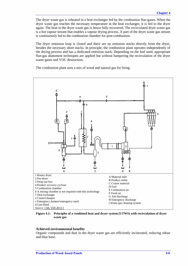
Chapter 4
Production of Wood–based Panels 141
The dryer waste gas is reheated in a heat exchanger fed by the combustion flue-gases. When the
dryer waste gas reaches the necessary temperature in the heat exchanger, it is fed to the dryer
again. The heat in the dryer waste gas is hence fully recovered. The recirculated dryer waste gas
is a hot vapour stream that enables a vapour drying process. A part of the dryer waste gas stream
is continuously led to the combustion chamber for post-combustion.
The dryer emission loop is closed and there are no emission stacks directly from the dryer,
besides the necessary abort stacks. In principle, the combustion plant operates independently of
the drying process and has a dedicated emission stack. Depending on the fuel used, appropriate
flue-gas abatement techniques are applied but without hampering the recirculation of the dryer
waste gases and VOC destruction.
The combustion plant uses a mix of wood and natural gas for firing.
1 Rotary dryer
2 Pre-dryer
3 Drop-out box
4 Product recovery cyclone
5 Combustion chamber
6 A mixing chamber is not required with this technology
7 Heat exchanger
a Control damper
c Emergency damper/emergency stack
d Line blind
Source: [ 68, VDI 2013 ]
A Material inlet
B Product outlet
C Coarse material
D Fuel
E Combustion air
F Fresh air
G Ash discharge
H Emergency discharge
I Waste gas cleaning system
Figure 4.1: Principles of a combined heat and dryer system (UTWS) with recirculation of dryer
waste gas
Achieved environmental benefits
Organic compounds and dust in the dryer waste gas are efficiently incinerated, reducing odour
and blue haze.
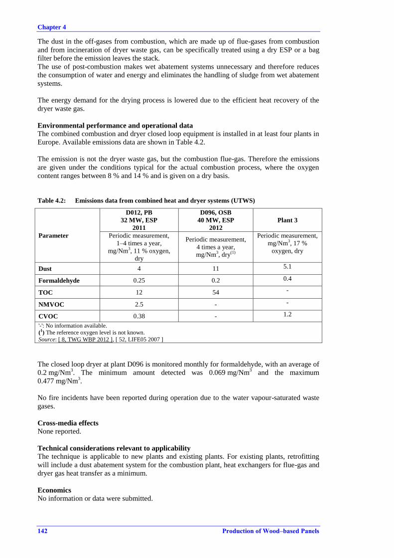
Chapter 4
142 Production of Wood–based Panels
The dust in the off-gases from combustion, which are made up of flue-gases from combustion
and from incineration of dryer waste gas, can be specifically treated using a dry ESP or a bag
filter before the emission leaves the stack.
The use of post-combustion makes wet abatement systems unnecessary and therefore reduces
the consumption of water and energy and eliminates the handling of sludge from wet abatement
systems.
The energy demand for the drying process is lowered due to the efficient heat recovery of the
dryer waste gas.
Environmental performance and operational data
The combined combustion and dryer closed loop equipment is installed in at least four plants in
Europe. Available emissions data are shown in Table 4.2.
The emission is not the dryer waste gas, but the combustion flue-gas. Therefore the emissions
are given under the conditions typical for the actual combustion process, where the oxygen
content ranges between 8 % and 14 % and is given on a dry basis.
Table 4.2: Emissions data from combined heat and dryer systems (UTWS)
Parameter
D012, PB
32 MW, ESP
2011
D096, OSB
40 MW, ESP
2012
Plant 3
Periodic measurement,
1–4 times a year,
mg/Nm3, 11 % oxygen,
dry
Periodic measurement,
4 times a year,
mg/Nm3, dry
(1)
Periodic measurement,
mg/Nm3, 17 %
oxygen, dry
Dust 4 11 5.1
Formaldehyde 0.25 0.2 0.4
TOC 12 54 -
NMVOC 2.5 - -
CVOC 0.38 - 1.2
'-': No information available.
(1) The reference oxygen level is not known.
Source: [ 8, TWG WBP 2012 ], [ 52, LIFE05 2007 ]
The closed loop dryer at plant D096 is monitored monthly for formaldehyde, with an average of
0.2 mg/Nm3. The minimum amount detected was 0.069 mg/Nm
3 and the maximum
0.477 mg/Nm3.
No fire incidents have been reported during operation due to the water vapour-saturated waste
gases.
Cross-media effects
None reported.
Technical considerations relevant to applicability
The technique is applicable to new plants and existing plants. For existing plants, retrofitting
will include a dust abatement system for the combustion plant, heat exchangers for flue-gas and
dryer gas heat transfer as a minimum.
Economics
No information or data were submitted.

Chapter 4
Production of Wood–based Panels 143
Driving force for implementation
Reduction of odour, TOC and dust emissions.
Lowering the energy demand for drying.
Example plants
The technique was developed in Europe in around 2000 and is currently installed at four
installations in Europe.
Reference literature
[ 68, VDI 2013 ], [ 52, LIFE05 2007 ], [ 74, E. Benetto et al. 2009 ] [ 71, Kronoplus 2010 ]
4.2.2.4 Reduction of SOX emissions
Description
Using a fuel with a low sulphur content as a primary measure is very effective, if there is a
range of equally accessible alternative fuels.
As secondary measures, dry sorbent injections either by limestone injection in the furnace for
fluidised bed boilers or calcium hydrate in-duct injection before a bag filter or ESP can be
applied as reduction measures.
Technical description
Desulphurisation is described in the LCP BREF [ 24, COM 2006 ].
Biomass, which is the most used and accessible fuel, does not in itself contain high levels of
sulphur. Recovered wood and some production residues could have higher levels of sulphur.
Achieved environmental benefits
Reduction of the emission of SOX from combustion processes.
Environmental performance and operational data
No data available.
Cross-media effects
None reported.
Technical considerations relevant to applicability
Most of the desulphurisation techniques require a dust treatment system before the flue-gases
are emitted. This could be a limiting factor if the hot gases are to be used for direct drying.
Economics
No information or data were submitted.
Driving force for implementation
Reducing SOX formation in the flue-gas from combustion plants.
Example plants
One PB plant is cited in [ 67, VITO 2011 ] as having a wet scrubber with addition of caustic soda
before the directly heated dryer. No data are available from the plant. Other combustion plants
identified have been related to only indirectly heated dryers.
Reference literature
[ 67, VITO 2011 ], [ 58, UBA Austria 2013 ]
Chapter 4
144 Production of Wood–based Panels
4.2.2.5 Reduction of NOX emissions in hot gases from combustion plants
Description
A reduction of NOX in flue-gases is achieved by considering the fuel mix, controlling the
combustion process, and, if applicable, applying selective non-catalytic reduction (SNCR),
which reduces the amount of NOX formed.
Technical description
Primary measures to prevent the formation of NOX include fuel staging and air staging, which
control the temperature and the oxygen content during combustion. The necessary controls
applied for combustion are described in Section 4.6.2 and in general in the LCP BREF
[24, COM 2006].
Selective non-catalytic reduction (SNCR) uses an injection of aqueous ammonia, urea or
carbamide, which reduces nitrogen oxides to N2. The reduction takes place at high temperatures
and the injection is performed in the upper part of the furnace. The operating window is from
850 °C to 1100 °C, with the higher temperatures leading to NOX formation from the oxidation
of ammonia from the added ammonia source. SNCR is widely applied for combustion processes
in general, but for combustion units producing hot gas for directly heated dryers this has a
general drawback. The operating window in terms of a stable high temperature and a sufficient
reaction time is not always obtainable.
Achieved environmental benefits
Reduction of emissions of NOX in the flue-gases from combustion processes in general, and
specifically reduction of NOX emissions when used in direct drying.
Environmental performance and operational data
SNCR is applied and used in other industrial sectors and generally achieves a removal
efficiency of 30–70 %. SNCR is applied at some combustion units in this sector, but the
reduction efficiencies have not been reported. Only two plants using the flue-gas for directly
heated dryers currently report applying SNCR; while two plants producing heat for steam
generation for indirect drying also report data.
One plant (D002) using SNCR with cyclones for dust abatement before using the flue-gas for
direct drying reported 161 mg NOX/Nm3 as a half-hourly average based on continuous
measurements. The CO level was 31 mg/Nm3, while the NH3 slip was 25 mg/Nm
3, all given at
13 % O2.
Another plant (D001) using SNCR with cyclones, dry sorption injection and a bag filter before
using the flue-gas for direct drying and, also, a minor part for indirect drying reported
180 mg NOX/Nm3 as a daily average (continuous measurement). The CO level was 60 mg/Nm
3
(daily average, continuous measurement), given at 17 % O2. The NH3 slip was 0.2 mg/Nm3,
measured periodically (11 % O2). The fuel used was 40 % production residues and 60 % other
biomass.
The background contribution of NOX is estimated to range between 0.2 kg and 0.4 kg of NOX
per m3 of produced panel. The data are based on two indirectly heated dryers. The
corresponding mass concentration is 108–122 mg/Nm3 at 18.5 % O2.
Even though not directly comparable, and partially referred to indirect drying, the data from two
combustion plants for steam generation reported levels as indicated in Table 4.3. In order to
compare the data in Table 4.3, the levels were calculated at 11 % O2, and range between
193 mg/Nm3 and 290 mg/Nm
3.

Chapter 4
Production of Wood–based Panels 145
Table 4.3: Emission levels from combustion plants for steam generation
NOX
(mg/Nm3)
CO
(mg/Nm3)
NH3
(mg/Nm3)
Comments
D004
40 MW
70 % production residues (dust), 30
% bark.
Intermittent grate
SNCR, cyclone, dry sorbent
injection, bag filter
290 24 6.4
Continuous
measurement
(periodic for NH3),
half-hourly
average,
11 % O2, dry
D031
3 units, 110 MW
Moving grate
10 % production residues, 90 %
recovered wood.
SNCR, cyclone, (dry sorbent
injection, fabric filters)
193 20 – 40 -
Continuous
measurement,
yearly average,
based on daily
average,
11 % O2, dry
'-': No information available.
NOX levels tended to be higher if recovered wood, natural gas with a high nitrogen content or
heavy fuel oil is used. One plant (D010) is applying efficient combustion control, with
correspondingly low levels of all pollutant parameters, see Table 4.4.
Table 4.4: Emission levels from a combustion plant firing 100 % recovered wood
Dust
(mg/Nm3)
NOX
(mg/Nm3)
SOX
(mg/Nm3)
CO
(mg/Nm3)
Comments
D010
48 MW
100 % recovered wood.
Intermittent grate incinerator
10.5 240
13 (periodic
measurement) 1.7
Continuous
measurement
yearly average,
11 % O2, dry
Cross-media effects
Ammonia slip emissions from the added ammonia source, when using SNCR.
Technical considerations relevant to applicability
It is necessary to carefully control the gas and furnace temperature at the injection point, in
order to avoid ammonia slip or additional NOX formation.
SNCR application is limited to consistent and stable combustion processes. If the generation of
hot gases in the combustion plant is highly variable, e.g. due to the variation in dryer demand, it
can be difficult to maintain the ideal temperature operating window necessary for the efficient
conversion of NOX.
Economics
The investment costs for a SNCR system applied to a 40 MW combustion plant using mainly
recovered wood is EUR 250 000–350 000. The maintenance costs are negligible, while the
annual operating costs for the SNCR are reported to be around EUR 150 000. Not all existing
combustion designs can accommodate the SNCR directly and additional installation costs could
be high. Operating costs include the ammonia source, e.g. urea solution.
Driving force for implementation
To reduce NOX emissions from combustion processes.
Example plants
Applying SNCR: D001, D003, D004, D031, D051.
Several installations show efficient combustion control and combustion management.

Chapter 4
146 Production of Wood–based Panels
Reference literature
[ 24, COM 2006 ], [ 26, COM 2006 ]
4.2.2.6 Reduction of dust emissions in hot gases
4.2.2.6.1 Electrostatic precipitators (ESPs)
Description
Electrostatic precipitators (ESPs) use electrostatic forces to separate and retain dust in the flue-
gas from combustion plants.
Technical description
The ESP charges the particles in the flue-gas in an electrical field and subsequently these are
deposited on collector plates, which are transferred to collector hoppers.
Electrostatic precipitators are commonly applied for large combustion plants using a wide range
of fuels. A detailed description of ESPs can also be found in the BREF on Large Combustion
Plants (LCP) [ 24, COM 2006 ].
The abatement efficiency can depend on the number of fields, residence time (size), catalyst
properties, and any particulate removal devices installed upstream.
Achieved environmental benefits
An effective reduction of dust in the flue-gases from combustion units before the flue-gas is
used as a hot gas in directly heated dryers.
Cross-media effects
An ESP uses electrical energy. The collected dust is a waste and will need to be dealt with.
Environmental performance and operational data ESPs have high removal efficiencies for dust and particulates. According to the literature,
efficiencies can be as high as 99 % and operating experience with ESPs has proved their
effectiveness. General performance data can be found in the LCP BREF [ 24, COM 2006 ].
In the wood-based panel sector, the majority of combustion plants or hot gas generators use
biomass or a combination of biomass and natural gas as a fuel. The application of ESPs is not
widespread and generally they are only applied at biomass combustion units with a rated
thermal input over 20 MW. Four production sites have an ESP installed. Three of the sites have
a combined heat and dryer system where the drying is considered indirect, see Section 4.2.2.3.
At one site producing MDF, an ESP is installed at the outlet of the combustion plant to remove
dust prior to the directly heated dryers. The fuel is 100 % biomass from internal and external
sources. The monitoring data to show the performances of the applied ESPs are not available
although, indirectly, the performances can be compared to that of ESPs in other biomass-fired
combustion plants given in the LCP BREF [ 24, COM 2006 ].
Technical considerations relevant to applicability ESPs are generally applicable to larger combustion units. The applicability may be restricted
when the combustion plant is serving a directly heated dryer. An ESP is not applied to the hot
gases from small individual dust burners alone. For existing plants the possibility to apply an
ESP may be restricted. (The ESP cannot be applied to treat dryer waste gas since the fire risk is
too high due to the sticky dust, the high content of volatile organic compounds and the high
oxygen content).

Chapter 4
Production of Wood–based Panels 147
Economics
No information or data were submitted.
Driving force for implementation
The pretreatment of hot gases to remove fine particulate matter from combustion flue-gas.
Example plants
See above.
Reference literature [ 24, COM 2006 ]
4.2.2.6.2 Bag filters
Description
Bag filters collect dust and particulate matter when the flue-gases pass through a fabric.
Technical description
For a general description of bag filters' performance, applicability and use in combustion plants,
consult the LCP BREF [ 24, COM 2006 ],.
Environmental performance and operational data
There is no available information on the performance and applicability, of bag filters applied for
hot gases to be used in directly heated drying.
Various non-combustion dust sources at a WBP installation are treated with a bag filter. For a
description of the techniques and the related data, see Sections 4.2.4.2 and 4.2.5.1.
4.2.2.6.3 Cyclones
Description
Cyclones collect dust and particulate matter by use of inertia when a gas flows through the
cone-shaped cyclone.
Technical description
For a general description of cyclones' performance, applicability and use in combustion plants,
consult the LCP BREF [ 24, COM 2006 ].
Environmental performance and operational data
There is no available information on the performance and applicability of cyclones applied for
hot gases to be used in directly heated drying.
Example plants
D009: cyclone applied before a directly heated MDF blowline dryer.
Chapter 4
148 Production of Wood–based Panels
4.2.3 Primary techniques to prevent or reduce emissions to air from presses
4.2.3.1 Selection of resin and appropriate press operating conditions
Description
Selection of a resin with a low degree of free formaldehyde and use of the correct press
operating conditions for the resin type, including a combination of optimal press time and
temperature, in order to reduce emissions of formaldehyde.
Technical description
Formaldehyde levels in the finished panel and in the process emissions are mainly a result of the
resin system used, especially where the resin used is urea-formaldehyde resin, where the
formaldehyde is more loosely bound than in other resin systems such as phenol-formaldehyde
resin. Using a resin with a low level of free formaldehyde could influence the end product and
formaldehyde emission levels.
pMDI is a formaldehyde-free resin, which is applied as the main resin in OSB production and
for fibreboards produced in a dry process, such as flexboard and rigidboard. pMDI has not been
applied with great success in MDF or PB production.
Achieved environmental benefits
Reduction of the emissions to air of formaldehyde.
Environmental performance and operational data
No specific data were submitted.
Cross-media effects
No cross-media effects were reported.
Technical considerations relevant to applicability
Product quality requirements could necessitate the use of a certain resin mix. Also, there may be
limitations on the ability to change operating conditions.
When using pMDI, an efficient release agent is crucial. Release agents are waxes which are
applied at the press belt. The necessary additional wax could give rise to higher TOC emissions.
Economics
Alternatives to urea-formaldehyde resins are generally more expensive. The price of pMDI is
much higher than for the formaldehyde-containing urea resins. Melamine-containing resins also
have less free formaldehyde, but the price of the resin is also comparably higher.
Driving force for implementation
The requirement for reduced emissions of formaldehyde from the final product.
Example plants
None.
Reference literature
[ 67, VITO 2011 ]
Chapter 4
Production of Wood–based Panels 149
4.2.4 Secondary techniques to prevent or reduce emissions to air from dryers and presses
4.2.4.1 Wet electrostatic precipitator
Description
A wet electrostatic precipitator (WESP) abates dust in waste gases mainly from dryers and,
secondarily, presses. In a WESP, waste gas is wet scrubbed to remove a part of the organic
compounds and dust, and the waste gas is subsequently passed through an electrical field, where
dust is captured and collected from electrodes.
Technical description
The basic principle is that the hot dryer waste gases are cooled down to saturation dew point
temperature by a water (absorbent) quench in the duct after the dryer separation cyclones or at
the entrance of the WESP. When the gas enters the bottom part of the WESP, the gas is
distributed and washed in a wet scrubbing stage. The quenching water and the wet scrubbing
stage lower the temperature of the waste gas; in this way, condensable organics are more
effectively dissolved and captured in the water phase.
The gases move up through the electrical corona field in the electrostatic precipitator, where
dust is precipitated on the positive tubes. The dust is washed down by water added at the top of
the plates in washing cycles or continuously and moved by gravitational forces down to the
bottom decanter. The washing cycle is performed every 2 to 12 hours for a few minutes and
during this time there is no precipitation in the ESP stage. The ESP units are most commonly a
tubular honeycomb structure or bundled pipes and a wire electrode design with a vertical gas
flow.
Water-soluble organic compounds in the gas are trapped in the first scrubbing/quench stage. A
part of the condensable organic compounds which condense to aerosols after the quench and
washing is trapped by adsorption onto wood dust particles on the precipitator plates in the ESP
stage.
The WESP was implemented in the late 1980s and several modifications have since been
introduced.
The WESP can be built with two parallel ESP units which are alternately cleaned, which also
ensures precipitation during washing cycles.
Ambient air can be used for cooling the precipitators with the pipe bundle design, where the
cooler air passes the bundles and creates a thin condensation film on the inside of the pipes. The
advantage is a more effective capture of aerosols in the water phase that is washed down during
the washing cycles. The condensation film prevents a build-up of dirt on the precipitator surfaces.
When the treated waste gases leave the stack, it is common to have a droplet separator to
remove droplets before discharge. The droplet separator is efficient in abating excess droplets
during cleaning wash cycles of the electrodes.
The resulting visual plume of steam can be almost completely removed by a demister, which
adds hot air at the exit of the stack. The heat is supplied from energy recovered from heat
exchange in the WESP or from other parts of the production process.
Heat from the water phase can be recovered, e.g. to preheat the dryer combustion air or for
demisting the stack release.
The scrubber water which is recycled contains solids from the capture of dust during scrubbing
and is washed down during wash cycles. The solids are precipitated in a sludge decanter at the
bottom of the WESP. The precipitated substances are removed from the absorbent water phase
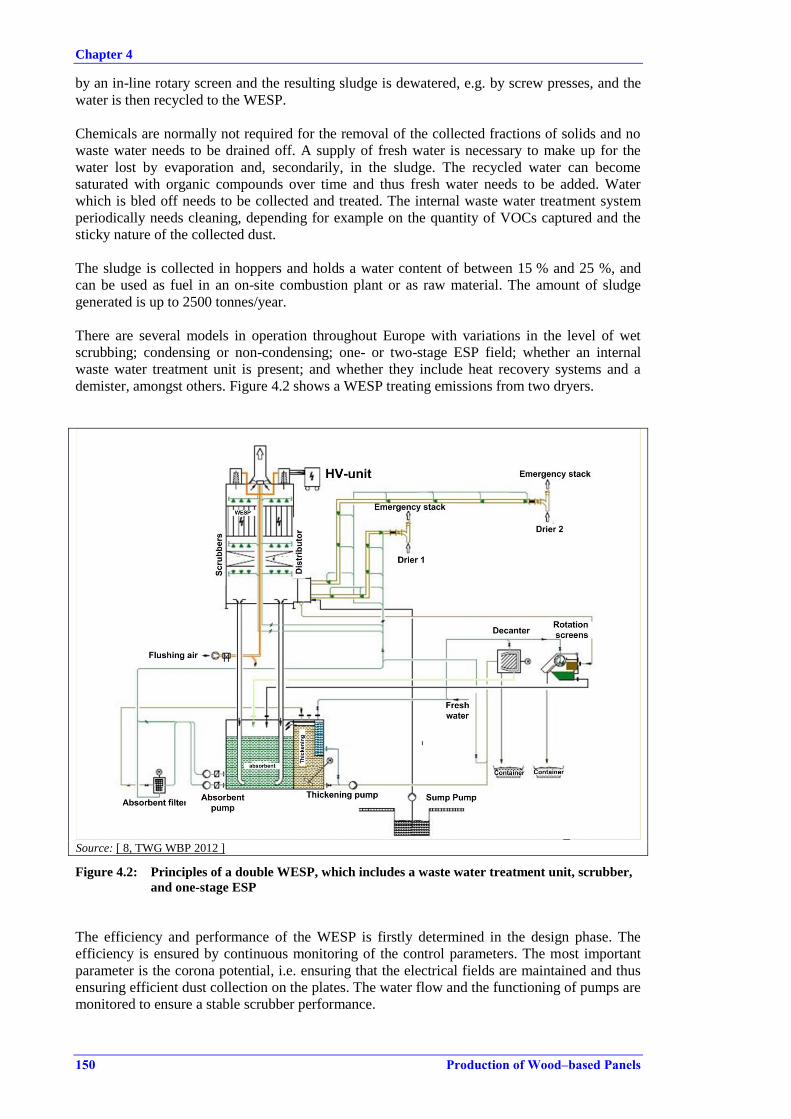
Chapter 4
150 Production of Wood–based Panels
by an in-line rotary screen and the resulting sludge is dewatered, e.g. by screw presses, and the
water is then recycled to the WESP.
Chemicals are normally not required for the removal of the collected fractions of solids and no
waste water needs to be drained off. A supply of fresh water is necessary to make up for the
water lost by evaporation and, secondarily, in the sludge. The recycled water can become
saturated with organic compounds over time and thus fresh water needs to be added. Water
which is bled off needs to be collected and treated. The internal waste water treatment system
periodically needs cleaning, depending for example on the quantity of VOCs captured and the
sticky nature of the collected dust.
The sludge is collected in hoppers and holds a water content of between 15 % and 25 %, and
can be used as fuel in an on-site combustion plant or as raw material. The amount of sludge
generated is up to 2500 tonnes/year.
There are several models in operation throughout Europe with variations in the level of wet
scrubbing; condensing or non-condensing; one- or two-stage ESP field; whether an internal
waste water treatment unit is present; and whether they include heat recovery systems and a
demister, amongst others. Figure 4.2 shows a WESP treating emissions from two dryers.
Source: [ 8, TWG WBP 2012 ]
Figure 4.2: Principles of a double WESP, which includes a waste water treatment unit, scrubber,
and one-stage ESP
The efficiency and performance of the WESP is firstly determined in the design phase. The
efficiency is ensured by continuous monitoring of the control parameters. The most important
parameter is the corona potential, i.e. ensuring that the electrical fields are maintained and thus
ensuring efficient dust collection on the plates. The water flow and the functioning of pumps are
monitored to ensure a stable scrubber performance.
Chapter 4
Production of Wood–based Panels 151
Achieved environmental benefits
WESPs are useful for reducing wood dust, fine dust (aerosols) and odour in dryer waste gases
and also from the press. Formaldehyde and other organic compounds are reduced to a certain
degree.
Environmental performance and operational data
The operation of WESPs is documented through the data collected from 30 production lines in
operation throughout Europe. The majority of these installations produce PB and OSB. In
Table 4.5 a selection of the best performing WESPs is shown.
The data results below 2.5 mg/Nm3 might be correct but lie at the limit of quantification.
Data not included in this section showed distinctively higher average values and at the same
time a considerable variation between the minimum and maximum values. At one installation,
dust levels varied during one sample campaign, with three individual samplings carried out
during the same day, showing a dust content from 7 mg/Nm3
up to 143 mg/Nm3. Whether the
variation is due to the sampling or variation in product composition or a less well-managed
dryer and WESP operation is not known and hence these data sets were not further used. These
results could be within the normal variation, due to the operating conditions of the dryer, but are
not considered as being representative.
It should be noted that the majority of the results given in the table are based on periodic
sampling during one sampling campaign, with at least three samples, where the average value is
the average of the (at least) three samples.

Chapter 4
152 Production of Wood–based Panels
Table 4.5: Average of periodic sampling of dust, volatile organic compounds and formaldehyde
in dryer emissions after treatment in a WESP
Plant ID
no
Dust Volatile organic
compounds Formaldehyde
Product Comment Average value, mg/Nm3, dry basis
D010 OSB (17 % O2) 6.5 - -
D079 OSB
Also press
(17 % O2) 11.2 - -
D041 OSB
Also press,
(20 % O2) 11.9 - -
D056 OSB&PB - 9.8 - -
D001 PB (17 % O2) 1 92 7.7
D003 PB (17 % O2) 1.5 139 9.2
D077 PB - 2.9 - -
D042 PB
Also press
(18 % O2) 3.2 37 7
D073 PB Indirect 3.3 - -
D044-a PB (18 % O2) 3.3 38.5 6.2
D036 PB
Also press
(17 % O2) 4.5 133 -
D037-a PB (17 % O2) 5.6 185 -
D055 PB - 5.6 - -
D043 PB
Also press
(18 % O2) 6.5 37 5.6
D063 PB
Also press
(17 % O2) 7.4 138 2.1
D051 PB (19.2 % O2) 8.2 29.7 16.5
D080 PB - 9.4 - 7.1
D006 PB
Wet basis
(17 % O2) 10.5 47 1
D078-a PB Also press 10.8 - 6.7
D062 PB (17 % O2) 10.9 19.8 -
D038 PB (17 % O2) - 24.4 -
D006-b PB
Wet basis
(17 % O2) 11.5 67 1
D007 PB (17 % O2) 12.6 215 26
D069 PB Also press 16.2 145 -
D053 PB - 26.9 - - '-': No information available.
Source: [ 22, TWG 2012 ]
The load of dust in the dryer waste gas could depend on the contribution from the fuel and the
combustion process. The plants included in the table primarily use biomass combined with
additional natural gas burners. Liquid fuels, such as heavy fuel oil, are used as additional fuels,
at a fuel share of 2–10 %. There are no data supporting the actual contribution of dust from the
fuel, which is expected to be related mainly to biomass.
Multicyclones or cyclones are often used as a pretreatment for the dryer waste gases before they
are treated in the WESP. Cyclones remove the coarser fraction of the dust, which is sometimes
necessary for the effective operation of the WESP.
The performance of a well-operated WESP, concerning the organic part of the emission, varies
in the range of 6–10 mg/Nm3 for formaldehyde at PB production lines. The corresponding
formaldehyde load is 24–49 g per tonne of dried particles and the corresponding specific mass
load is 160–260 g TOC per tonne of dried particles.
For the drying of fibres, a WESP is not commonly used. At one plant (D002), a well-performing
WESP achieves 6.3 mg/Nm3 of formaldehyde (dry basis, no correction for O2).

Chapter 4
Production of Wood–based Panels 153
Table 4.6 indicates the emission levels for OSB production dryers applying WESPs, where a
low level of dust is achieved, but the performances reported for organic compounds and
formaldehyde are more varied.
Table 4.6: Emission levels for TOC and formaldehyde in emissions from OSB dryers after
treatment in a WESP
Plant ID
no
Organic compounds
(mg/Nm3)
Formaldehyde
(mg/Nm3)
Product Comment
D010 TVOC (FID) 217 12 OSB Softwood, 18 % O2,
dry, pMDI resin
D041 CVOC 29.80 - OSB
Including press
waste gases.
Softwood, dry basis,
not corrected to O2
reference
D079 CVOC 46 – 60 13.5 OSB
Including press
waste gases.
Softwood, 18 % O2,
dry
D027 VOC 150 – 650 - OSB Softwood and
hardwood '-': No information available.
Source: [ 22, TWG 2012 ]
The contribution of volatile organic compounds from the raw material depends for example on
the species used. The data on TVOC emissions, i.e. illustrating the performance of the WESP
and the related raw material, do not give an indication of the variation in TOC emissions due to
the raw material alone.
In the wet scrubber and electrostatic precipitator, water-soluble emissions, dust, particles and
aerosols, which together create blue haze, are reduced by 50–95 %. It is recognised that the
efficiency for the organic fraction is much lower than for the dust fraction. The reported level of
reduction efficiencies is up to 95 % for the dust fraction, while the organic compounds are
reduced by between 20 % and 50 %. The reduction efficiency for water-miscible compounds
and condensable organic compounds is higher than for the remaining part of the TOC fraction.
When dryer waste gas and also press waste gas are treated together in the WESP, the same
range of emission levels for dust, formaldehyde, and TOC are reported.
At two plants a dedicated WESP treats the press emissions, see Table 4.7. The OSB line uses
pMDI and the formaldehyde level is therefore low in general. The specific mass load for
formaldehyde is 1 g per m3 of finished OSB panel, while it is 9 g per m
3 of finished panel for
the MDF line.
Table 4.7: Emission levels for dust, TOC/NMVOC and formaldehyde in emissions from press
lines after treatment in a WESP
Plant ID
no Dust
TOC
(mg/Nm3)
Formaldehyde
(mg/Nm3)
Product
D010 0.5 – 0.8 47 – 154 0.4 – 0.8 OSB
D086 2.7 – 18.2 24.4 – 38.3 (NMVOC) 5.4 – 10.5 MDF
D089 13.4 - 12.5 -
'-': No information available.
Source: [ 22, TWG 2012 ]

Chapter 4
154 Production of Wood–based Panels
Control parameters which are monitored continuously to ensure a correct operation include, as a
minimum, the water flow, corona potential/or secondary voltage and the outlet temperature.
Cross-media effects
Sludge generated with an appropriate quality can be recycled into production or used as a fuel in
an on-site combustion plant. If these alternatives are not feasible, the sludge needs to be
disposed of off site.
Waste water with dissolved solids needs further treatment.
As for other wet scrubbing systems without chemical or biological oxidation, the condensable
organic compounds and water-soluble organic compounds in the treated emission are
transferred to the water phase.
In the operation of a WESP, the consumption of water and electricity needs to be considered.
Technical considerations relevant to applicability
The WESP operates in a flow range determined by the design. The performance is dependent on
the dwell time of the crude gas within the system. With lower airflows than envisaged by the
design, the efficiency will be lower.
When fresh wood with a high content of resins and fatty acids is used, especially pine, the dryer
emissions will be very sticky and an antifoaming agent may be necessary in the recirculation
water to prevent the sticky compounds depositing on walls and electrodes.
The WESP is not considered applicable when using a hot gas source for direct drying that
contains sulphur or chloride in significant amounts [53, FINSA 2007 ]. If heavy fuel was used
for generating hot gas for directly heated dryers, the sulphur content in the fuel would form
sulphuric acid when entering the scrubber and would oxidise the plates/tubes and the equipment
in general and lower the pH of the scrubber water. The water would hence need a constant
regulation of pH, and the consequent addition of a neutralising agent or fresh water. The sodium
sulphate salt formed by neutralisation crystallises out and a bleed-off of water is needed. The
closed water loop in most WESPs would be broken, since a higher amount of make-up water
and a higher proportion of water would need to be discharged and managed.
An elevated chloride content in the hot gases could be released during the incineration of some
types of waste wood. However, this has not been reported as a problem in the data received.
Economics
Installing a WESP is a major investment and the operation and maintenance costs are also
comparably high.
The investment will depend on the model and treatment capacity:
For a WESP with a one-stage ESP field, designed to treat dryer emissions from a 1500 m3 PB
production line including a built-in scrubber unit, waste water treatment unit for recycling the
scrubber water and collection of sludge, the equipment investment starts at EUR 2.5 million; the
yearly operating costs, including maintenance, are above EUR 350 000, of which 15–20 % is for
maintenance costs. If the capacity is higher, the cost grows proportionally.
One example reported is a WESP system for a 2500 m3 PB plant with four indirectly heated
dryers, where the installation costs were EUR 4–5 million, with yearly maintenance costs of
about EUR 65 000. Additional operational costs for the electrical energy consumption should be
taken into account. In the example given, consumption would be around 300 kW.
At an example OSB plant with a yearly capacity of 500 000 m3 and with a WESP installed, the
investment costs were more than EUR 9 million and included high efficiency cyclones for
Chapter 4
Production of Wood–based Panels 155
pretreatment of the dryer waste gases. The yearly maintenance and operating costs for the
combined system were reported to be around EUR 550 000–600 000.
Driving force for implementation
The WESP effectively abates dust in dryer emissions, and some organic compounds, blue haze
and odour emissions can also be reduced considerably.
Example plants
There are around 35 WESP units operating in the sector in the EU-27.
Reference literature
[ 82, Lanzerstorfer 2000 ], [ 83, Barbu et al. 2014 ], [ 87, Swedspan 2011 ]
4.2.4.2 Bag filters
Description
Bag filters or fabric filters collect dust when the waste gas is passed through a fabric. Bag filters
are cleaned periodically and the collected dust is used as fuel.
Technical description
Bag filters or fabric filters are used for treating dust collected at various sources throughout the
production site. Bag filters are applied in the sector to treat dryer waste gas from indirect drying
and all dust sources from wood processing, including the following:
chipping and milling to wood particles;
pneumatic or mechanical transport of wood particles;
mat forming;
saws;
sanding lines.
The waste gas is passed through a fabric, where particulate matter is collected on the surface.
The dust caking on the fabric increases the likelihood of more dust adhering to the fabric and
hence increases the removal efficiency.
The bag is cleaned by distorting the bag using different methods, so that the collected dust falls
out into hoppers. Bag filters can also be reverse-air cleaned, pulse-jet cleaned or mechanically
shaken clean. The cleaning should not remove all dust from the fabric since this would lower
the efficiency of the filter for a period until a new layer of dust had built up on the fabric.
Bag filters are standard equipment and can be designed to abate dust in specific and challenging
applications. The size, type of filter cloth, and cleaning mechanism are designed for each
particular purpose. Bag filters are configured as groups of bags and compartmentalised, so that
cleaning or replacement can be performed without taking the total capacity of the filter system
out of use.
The operating conditions of the bag filter, the waste gas characteristics, and the waste gas flow
determine the choice of fabric and the size and configuration of bags. The filter capacity should
be high enough to prevent high pressure. Bag filters can be used for high waste gas volumes and
for temperatures well above what is encountered in the sector.
The efficiency of bag filters is affected by wet emissions and emissions which contain
condensable compounds.
Achieved environmental benefits
Bag filters effectively capture and collect dust from various sources.

Chapter 4
156 Production of Wood–based Panels
Environmental performance and operational data
Bag filters applied at all dry dust sources can usually achieve, with very few exceptions,
emission levels of less than 5 mg/Nm3. Bag filters are considered standard equipment for dust
treatment and enable constantly low levels of dust to be achieved after the filter.
Data on the performance of bag filters treating dryer emissions are limited to indirectly heated
dryers and are represented by data from four particleboard production lines, see Table 4.8. At all
four installations, the bag filters were installed at the same time as the dryers. The data show
that the bag filters demonstrate efficient dust removal.
Table 4.8: Emissions of dust in dryer waste gases treated in bag filters
Plant ID no
Dust
(mg/Nm3)
NMVOC & Formaldehyde
(mg/Nm3)
Half-hourly average Periodic additional measurements
D004 2.74 NMVOC: 190 – 219
Formaldehyde: 6.2
D018 0.5 – 1.5(1) -
D020 1.66 -
D024 1.3(1)
NMVOC: 230
Formaldehyde: 7.5 '-': No information available. (1) Based on a periodic measurement.
Source: [ 22, TWG 2012 ]
The average flows for which the bag filters are designed range between 90 000 m3/h and
270 000 m3/h. Depending on the fabric chosen, condensable compounds present in the dryer
waste gas could affect the efficiency of the filter. The outlet temperature of the dryer waste gas
was reported to be lower than 100 °C for three of the four plants, but there is not enough
information to conclude whether the temperature has a proportional influence on the
performance of the filter.
The level of volatile organic compounds including formaldehyde is related to the raw material,
which for D004 includes a mix of virgin softwood and recovered wood, while for D024 it
includes a mix of softwood, hardwood and recovered wood. Bag filters do not have any reported
efficiency for treating or reducing organic compounds.
The constant functionality of the bag filter is ensured by monitoring the differential pressure,
and by frequent visual checks. A pressure drop indicates a less efficient filter performance,
which could cause a rupture of the filter. Rupture of a bag filter will be seen clearly in the area
surrounding the bag filter. The performance of the bag filter will stay constant as long as the
pressure remains constant. Continuous measurement of dust by photometric measurements can
equally be used as an indicator of the continued integrity of the filter.
The majority of sites reported through the data collection that the daily performance of
traditional dust abatement techniques, such as a bag filter, is controlled by continuous control of
the differential pressure.
Cross-media effects
The collected dust needs further treatment.
Technical considerations relevant to applicability Bag filters alone do not reduce the amount of volatile organic compounds including
formaldehyde.

Chapter 4
Production of Wood–based Panels 157
The efficiency of bag filters is affected by wet emissions and emissions which contain
condensable compounds. The temperature in the waste gas should not fall below the dew point
of the condensable compounds.
Bag filters have been applied only for indirectly heated dryers in particleboard production.
Bag filters used for treating dryer waste gases should be constructed from materials that can
withstand the stickiness of the collected dust.
Economics
Investment costs for the application of a bag filter treating waste gases from an indirectly heated
rotary dryer of 25–40 t/h capacity are about EUR 600 000–800 000 for a waste gas volume of
70 000 Nm3/h to 130 000 Nm
3/h. Annual maintenance costs are about EUR 60 000–80 000,
including for changing the filter material. The maintenance costs have been reported to be even
higher at some plants.
Additional operational costs for the electrical energy consumption should be taken into account.
In the above example, consumption would be about 200 kW.
Driving force for implementation
Reduction of dust emissions.
Example plants
Four production lines producing particleboard in the EU have applied bag filters for reducing
emissions from indirectly heated dryers.
Reference literature None.
Description
Cyclones use inertia in order to remove dust from a waste gas stream. A cyclone is cone-shaped,
and when a gas flows through the cyclone, the particles in the gas spiral down the walls of the
cyclone, while the treated waste gas moves upward though the centre.
Technical description
Multicyclones are small diameter cyclones that efficiently collect smaller particles in the range
of 5–400 µm, depending on the design. Multicyclones are applied after standard product
separation cyclones, in batteries of 6 to 24 or more individual parallel cyclones with inner
diameters of 15 cm to 40 cm. Multicyclones can be applied in stages and enhance the collection
efficiency.
According to conventional theory for cyclone design and collection efficiency, the small
diameter cyclone promotes the fast spinning of the particles, which follow the shortest travelling
distance to the wall of the cyclone, from where the particles drop down and are collected.
Multicyclones that are based on a small diameter could collect dust particles down to a diameter
of 5 µm, according to literature.
Cyclones will not capture aerosols of condensable organic compounds.
Cyclones are used as a pretreatment step for dryer waste gases, e.g. before a wet scrubber or a
WESP. Sometimes cyclones are used as stand-alone equipment for fibre dryers when the dust
load is not high.
Achieved environmental benefits
Cyclones reduce dust in dryer waste gas.
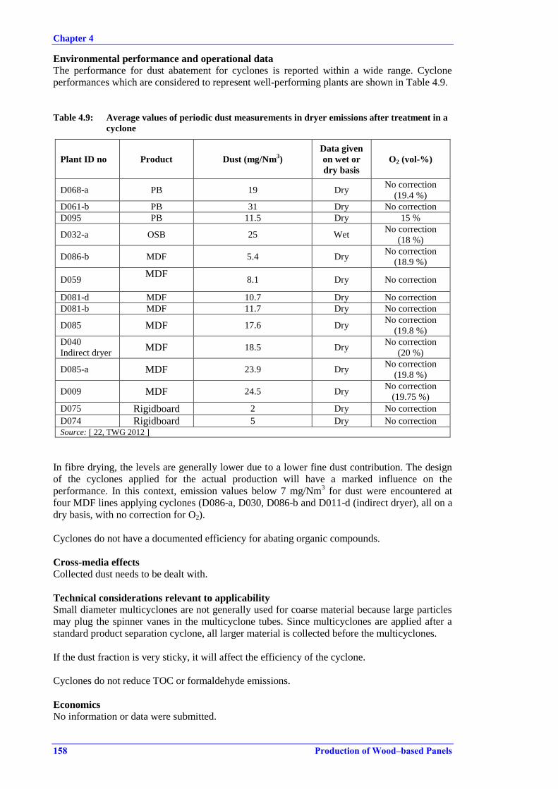
Chapter 4
158 Production of Wood–based Panels
Environmental performance and operational data
The performance for dust abatement for cyclones is reported within a wide range. Cyclone
performances which are considered to represent well-performing plants are shown in Table 4.9.
Table 4.9: Average values of periodic dust measurements in dryer emissions after treatment in a
cyclone
Plant ID no Product Dust (mg/Nm3)
Data given
on wet or
dry basis
O2 (vol-%)
D068-a PB 19 Dry No correction
(19.4 %)
D061-b PB 31 Dry No correction
D095 PB 11.5 Dry 15 %
D032-a OSB 25 Wet No correction
(18 %)
D086-b MDF 5.4 Dry No correction
(18.9 %)
D059 MDF
8.1 Dry No correction
D081-d MDF 10.7 Dry No correction
D081-b MDF 11.7 Dry No correction
D085 MDF 17.6 Dry No correction
(19.8 %)
D040
Indirect dryer MDF 18.5 Dry
No correction
(20 %)
D085-a MDF 23.9 Dry No correction
(19.8 %)
D009 MDF 24.5 Dry No correction
(19.75 %)
D075 Rigidboard 2 Dry No correction
D074 Rigidboard 5 Dry No correction
Source: [ 22, TWG 2012 ]
In fibre drying, the levels are generally lower due to a lower fine dust contribution. The design
of the cyclones applied for the actual production will have a marked influence on the
performance. In this context, emission values below 7 mg/Nm3 for dust were encountered at
four MDF lines applying cyclones (D086-a, D030, D086-b and D011-d (indirect dryer), all on a
dry basis, with no correction for O2).
Cyclones do not have a documented efficiency for abating organic compounds.
Cross-media effects
Collected dust needs to be dealt with.
Technical considerations relevant to applicability
Small diameter multicyclones are not generally used for coarse material because large particles
may plug the spinner vanes in the multicyclone tubes. Since multicyclones are applied after a
standard product separation cyclone, all larger material is collected before the multicyclones.
If the dust fraction is very sticky, it will affect the efficiency of the cyclone.
Cyclones do not reduce TOC or formaldehyde emissions.
Economics
No information or data were submitted.

Chapter 4
Production of Wood–based Panels 159
Driving force for implementation
Reduction of dust emissions.
Example plants
More than 20 plants, mainly MDF production plants, use cyclones as the main dust abatement
technique for dryer waste gas or as a pretreatment.
Reference literature
None.
4.2.4.3 Electrified filter bed
Description
The electrified filter bed (EFB) removes particulates and, to some extent, condensable organic
compounds by electrostatic filtration.
Technical description
The electrified filter bed, or electrostatic gravel filtration bed, consists of a packed column of
gravel media which are electrically polarised by a bed electrode. The particulate matter in the
waste gas is negatively charged by a corona field created by an array of metal pins at the waste
gas entrance, where it is captured and attached to the gravel. The dust is transported with the
gravel, which circulates in pulse modes, and the particulate matter is collected at the bottom.
Since the dust is dry when collected, no sludge is generated. The technique was developed in the
1970s.
The exhaust air from the bed can be further treated by a bag filter for additional dust abatement
or by other abatement techniques to remove organic compounds present in the treated dryer
waste gas.
Achieved environmental benefits
Reduction of dust emissions without additional water consumption.
Reduction of blue haze and odour.
Environmental performance and operational data
There are, at the time of writing (2014), no operational data on the performance of the system in
the EU. At one particleboard production line, the technique is applied as a pretreatment for dust.
The efficiency is expected to be high since the waste gases are thereafter treated in an RTO,
which requires low dust levels for a consistent performance.
Suppliers of the technique report achievable dust reduction efficiencies of over 90 % and also
the collection of PM2.5 and condensable organic compounds. The efficiency of aerosol
collection is claimed to be between 20 % and 99 %, according to laboratory testing using a
surrogate aerosol. The collection efficiency for PM2.5 depends on the applied voltage.
The technique is applied in the US for OSB dryers with an additional RTO for VOC control.
Modules are connected in series and, depending on the source, more can be added in order to
obtain maximum efficiency. Airflows are reported to be over 100 000 m3 per module, with up to
three modules per dryer. The filter bed is operated at temperatures from 70 °C to over 140 °C,
where temperatures over 120 °C would be above the condensation temperatures of most of the
condensable compounds. Therefore, it is most likely necessary that a subsequent secondary
treatment of the VOC content would be needed. No data were available from the sites.
Pilot tests have recently been performed at two sites in Europe, where a part of the dryer waste
gas was led through a test unit. The results are summarised in Table 4.10.
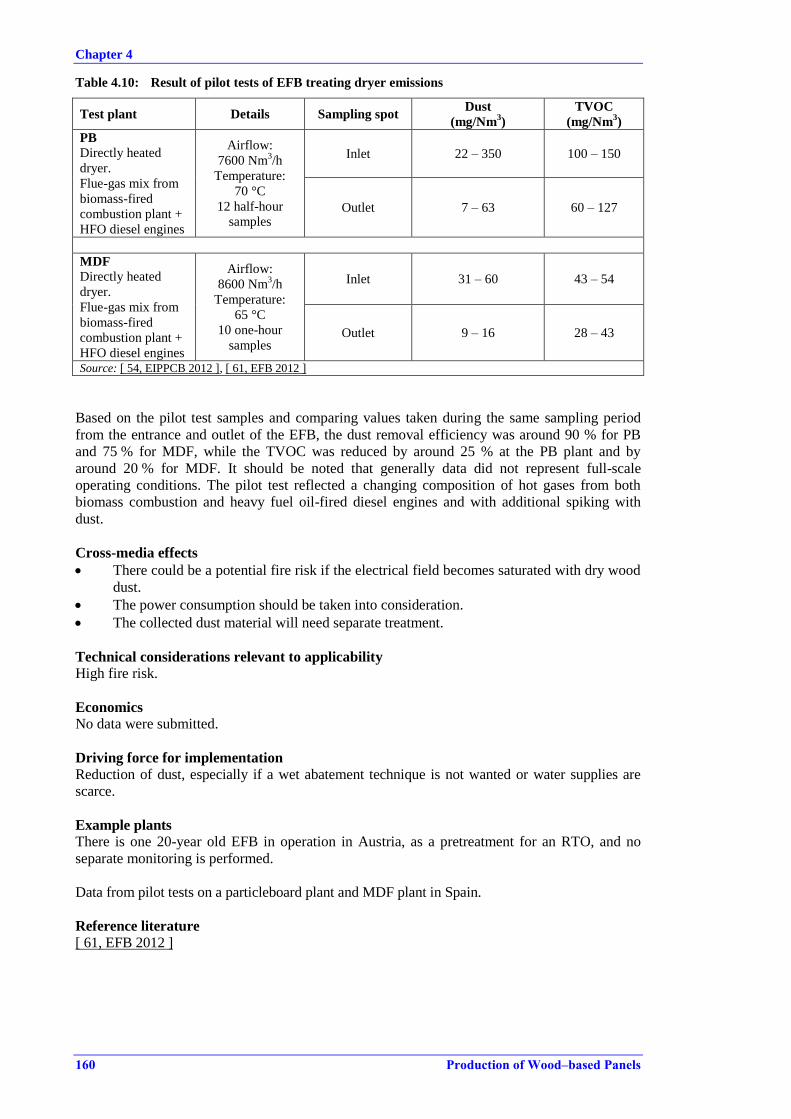
Chapter 4
160 Production of Wood–based Panels
Table 4.10: Result of pilot tests of EFB treating dryer emissions
Test plant Details Sampling spot Dust
(mg/Nm3)
TVOC
(mg/Nm3)
PB
Directly heated
dryer.
Flue-gas mix from
biomass-fired
combustion plant +
HFO diesel engines
Airflow:
7600 Nm3/h
Temperature:
70 °C
12 half-hour
samples
Inlet 22 – 350 100 – 150
Outlet 7 – 63 60 – 127
MDF
Directly heated
dryer.
Flue-gas mix from
biomass-fired
combustion plant +
HFO diesel engines
Airflow:
8600 Nm3/h
Temperature:
65 °C
10 one-hour
samples
Inlet 31 – 60 43 – 54
Outlet 9 – 16 28 – 43
Source: [ 54, EIPPCB 2012 ], [ 61, EFB 2012 ]
Based on the pilot test samples and comparing values taken during the same sampling period
from the entrance and outlet of the EFB, the dust removal efficiency was around 90 % for PB
and 75 % for MDF, while the TVOC was reduced by around 25 % at the PB plant and by
around 20 % for MDF. It should be noted that generally data did not represent full-scale
operating conditions. The pilot test reflected a changing composition of hot gases from both
biomass combustion and heavy fuel oil-fired diesel engines and with additional spiking with
dust.
Cross-media effects
There could be a potential fire risk if the electrical field becomes saturated with dry wood
dust.
The power consumption should be taken into consideration.
The collected dust material will need separate treatment.
Technical considerations relevant to applicability
High fire risk.
Economics
No data were submitted.
Driving force for implementation
Reduction of dust, especially if a wet abatement technique is not wanted or water supplies are
scarce.
Example plants
There is one 20-year old EFB in operation in Austria, as a pretreatment for an RTO, and no
separate monitoring is performed.
Data from pilot tests on a particleboard plant and MDF plant in Spain.
Reference literature
[ 61, EFB 2012 ]
Chapter 4
Production of Wood–based Panels 161
4.2.4.4 Wet scrubbers
Description
Wet scrubbing removes dust particles and some gaseous organic compounds from waste gas by
bringing the gas stream into contact with water and obtaining inertial and/or diffusion
interception in the water phase.
Technical description
Wet scrubbing technology is relatively simple and gives a stable and consistent abatement.
Wet scrubbers cover a large range of models, offering specific affinities and capacities.
Venturi scrubbers can be used for pretreatment of dust, e.g. before a bioscrubber. Venturi
scrubbers are efficient at removing dust, particles and part of the condensable organic
compounds by impaction and inertia of the jet stream of water in the scrubber. Because of the
high power consumption and its low overall efficiency however, other solutions may be
preferable when treating dryer waste gas. Waste gas from the press has a much lower volume
and small-scale Venturi scrubbers are commonly applied for the removal of particulate material,
prior to further treatment of the organic compounds in the waste gas.
Packed bed wet scrubbers operate by letting the gas travel countercurrently from the bottom of a
tower through a packed bed material sprayed continuously with recirculated water.
Waste gases from the dryer and the press are collected and sprayed with water by spray nozzles
in the duct before discharge to further treatment. The main objective of water spraying or
quenching is to cool the collected waste gases, which at the same time prevents the build-up of
sticky dust in the ducts. This greatly lowers the fire risk. Quenching of dryer waste gases is part
of the condensation of the waste gas, which aids the capture of condensable organics in the
water phase.
Mist eliminators can be installed in the upper part of the wet scrubber to prevent droplet carry-
over.
The recirculated water in the wet scrubber needs to be treated by removing solids. Depending on
the model, the internal water treatment system can be a simple sedimentation of solids and
removal of the sludge by decanting. In-line screw presses dewater the sedimented sludge and
return the water phase to the scrubber. Dissolved Air Flotation (DAF) can be an integrated part of
the unit and effectively removes the sedimented and suspended solids by coagulation and
flotation.
Additional measures, such as chemical oxidation, can be implemented to give high removal
efficiencies for formaldehyde, e.g. by dosing sodium bisulphite and sodium hydroxide to the
scrubber water or in a subsequent reaction tank. Chemical oxidation is applied in a few plants
where the oxidation methods have been developed as an in-house research development project.
Chemical oxidation of the lower aldehydes and lower alcohols could be developed by a
polishing step after other reduction systems where condensable organics and dust have already
been reduced by other methods.
Targeted chemical oxidation such as catalytic gas treatment is an additional treatment step that is
applied to the waste gas after removal of particulate matter in particular and, secondly,
condensable organic compounds, e.g. with a Venturi scrubber or WESP. The chemical oxidation
is accomplished by hydrogen peroxide, aided by different metal catalysts and initiated by UV
light for example.
Water discharge, sludge handling and use of chemicals need to be considered carefully.
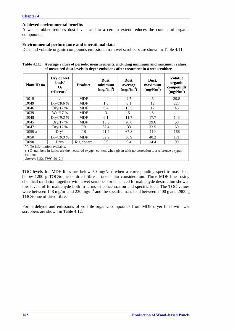
Chapter 4
162 Production of Wood–based Panels
Achieved environmental benefits
A wet scrubber reduces dust levels and to a certain extent reduces the content of organic
compounds.
Environmental performance and operational data
Dust and volatile organic compounds emissions from wet scrubbers are shown in Table 4.11.
Table 4.11: Average values of periodic measurements, including minimum and maximum values,
of measured dust levels in dryer emissions after treatment in a wet scrubber
Plant ID no
Dry or wet
basis/
O2
reference(1)
Product
Dust,
minimum
(mg/Nm3)
Dust,
average
(mg/Nm3)
Dust,
maximum
(mg/Nm3)
Volatile
organic
compounds
(mg/Nm3)
D019 -/- MDF 4.4 4.7 6 39.8
D049 Dry/18.6 % MDF 1.8 8.1 12 227
D046 Dry/17 % MDF 9.4 13.5 17 45
D039 Wet/17 % MDF 3 5 8 -
D048 Dry/19.2 % MDF 6.1 11.7 17.7 148
D045 Dry/17 % MDF 13.3 20.6 29.6 58
D047 Dry/17 % PB 32.4 33 33.5 69
D059-a Dry/- PB 21.7 67.8 110 166
D050 Dry/19.3 % MDF 32.9 36.9 40.2 171
D090 Dry/- Rigidboard 5.9 9.4 14.4 99 '-': No information available.
(1) O2 numbers in italics are the measured oxygen content when given with no correction to a reference oxygen
content.
Source: [ 22, TWG 2012 ]
TOC levels for MDF lines are below 50 mg/Nm3
when a corresponding specific mass load
below 1200 g TOC/tonne of dried fibre is taken into consideration. Three MDF lines using
chemical oxidation together with a wet scrubber for enhanced formaldehyde destruction showed
low levels of formaldehyde both in terms of concentration and specific load. The TOC values
were between 148 mg/m3 and 230 mg/m
3 and the specific mass load between 2400 g and 2900 g
TOC/tonne of dried fibre.
Formaldehyde and emissions of volatile organic compounds from MDF dryer lines with wet
scrubbers are shown in Table 4.12.
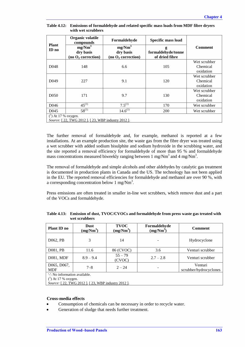
Chapter 4
Production of Wood–based Panels 163
Table 4.12: Emissions of formaldehyde and related specific mass loads from MDF fibre dryers
with wet scrubbers
Plant
ID no
Organic volatile
compounds Formaldehyde Specific mass load
Comment mg/Nm3
dry basis
(no O2 correction)
mg/Nm3
dry basis
(no O2 correction)
g
formaldehyde/tonne
of dried fibre
D048 148 6.6 105
Wet scrubber
Chemical
oxidation
D049 227 9.1 120
Wet scrubber
Chemical
oxidation
D050 171 9.7 130
Wet scrubber
Chemical
oxidation
D046 45(1)
7.5(1)
170 Wet scrubber
D045 58(1)
14.6(1)
200 Wet scrubber
(1) At 17 % oxygen.
Source: [ 22, TWG 2012 ], [ 23, WBP industry 2012 ].
The further removal of formaldehyde and, for example, methanol is reported at a few
installations. At an example production site, the waste gas from the fibre dryer was treated using
a wet scrubber with added sodium bisulphite and sodium hydroxide in the scrubbing water, and
the site reported a removal efficiency for formaldehyde of more than 95 % and formaldehyde
mass concentrations measured biweekly ranging between 1 mg/Nm3 and 4 mg/Nm
3.
The removal of formaldehyde and simple alcohols and other aldehydes by catalytic gas treatment
is documented in production plants in Canada and the US. The technology has not been applied
in the EU. The reported removal efficiencies for formaldehyde and methanol are over 90 %, with
a corresponding concentration below 1 mg/Nm3.
Press emissions are often treated in smaller in-line wet scrubbers, which remove dust and a part
of the VOCs and formaldehyde.
Table 4.13: Emission of dust, TVOC/CVOCs and formaldehyde from press waste gas treated with
wet scrubbers
Plant ID no Dust
(mg/Nm3)
TVOC
(mg/Nm3)
Formaldehyde
(mg/Nm3)
Comment
D062, PB 3 14 - Hydrocyclone
D081, PB 11.6 86 (CVOC) 3.6 Venturi scrubber
D081, MDF 8.9 – 9.4 55 – 79
(CVOC) 2.7 – 2.8 Venturi scrubber
D065, D067,
MDF 7–8 2 – 24 -
Venturi
scrubber/hydrocyclones '-': No information available.
(1) At 17 % oxygen.
Source: [ 22, TWG 2012 ], [ 23, WBP industry 2012 ].
Cross-media effects
Consumption of chemicals can be necessary in order to recycle water.
Generation of sludge that needs further treatment.
Chapter 4
164 Production of Wood–based Panels
Technical considerations relevant to applicability
Wet scrubbers are mainly applied at MDF production lines. The higher dust levels from PB
dryers would require pretreatment of the dust fraction.
Economics
The consumption of water and power has to be taken into consideration.
No plant-specific data or information were submitted.
Driving force for implementation
To reduce dust and the organic compounds present in dryer and press waste gases.
Example plants
Smaller wet scrubbers are widely applied to treat press waste gas. In MDF production, wet
scrubbers are commonly used to treat dryer waste gas.
Reference literature
[ 42, EIPPCB/EPF 2012 ],
4.2.4.5 Bioscrubbers
Description
A bioscrubber uses biological oxidation to degrade the condensable and non-condensable VOC
compounds adsorbed onto a packed bed containing bacteria culture, and it also reduces dust by a
prior scrubbing step.
Technical description
The bioscrubber consists of a column of packed material of plastic, ceramics or other bed
material which is flooded with water. The waste gas enters at the bottom of the column and
travels up through the packed material to the discharge stack. The water is recycled
continuously; it is discharged from the bottom of the column and transported to the top of the
column, where it is sprayed or sprinkled over the top of the packed bed. Organic compounds
such as the VOC fraction of dryer and press emissions will be degraded by biological oxidation
when adsorbed onto the packed material.
The bottom discharge contains some absorbed organic compounds, dust and washdown water
from the column. The water is led to a settlement tank or decanter before being pumped to the
top of the column. Biological oxidation takes place in the packed bed and also in the settlement
tank. In the settlement tank, automatic adjustment of the pH and the addition of nutrients can
optimise the conditions there and also in the packed bed column.
The temperature in the bioscrubber should be kept within a narrow range, in order to maintain a
stable and efficient biological activity. A bioscrubber will need time to stabilise before the
bacteria culture is established and the correct operating temperature is determined. To lower the
temperature, a pre-scrubber such as a Venturi scrubber or hydrocyclone can be used, which also
serves the purpose of removing the most coarse dust fractions. A pretreatment is sometimes
necessary in order to remove excess dust, since the efficiency of the bioscrubber is influenced
by dust, which can clog the filter material.
The pretreatment for coarser dust can also be achieved with efficient spraying and quenching in
the ductwork, before entering the bioscrubber, and capture of the dust fraction when entering the
bioscrubber. The collected dust is brought together with the bottom discharge of the bioscrubber
and led to the settlement tank.
The two main control parameters for a stable efficiency are control of the temperature and of the
water quality regarding the pH and TSS content.

Chapter 4
Production of Wood–based Panels 165
Achieved environmental benefits
Degradation of VOCs in low concentrations by biological oxidation and also removal of dust.
Environmental performance and operational data
Bioscrubbers are so far only applied at MDF production lines and data are shown in Table 4.14.
Prior to the bioscrubber the dust levels are brought down to an acceptable level by cyclones, a
Venturi scrubber or scrubbing towers. The dust pretreatment is designed according to the
requirements of the bioscrubber.
At one MDF plant (D031) the press waste gas is also treated in the bioscrubber.
The organic part of the emission is analysed using different parameters. There is no information
regarding the constituents of the volatile organic compounds and whether the biological
degradation could contribute not fully degraded organic compounds. The dust levels and
formaldehyde levels are low.
Table 4.14: Average values of periodic measurements of dust, organic compounds and
formaldehyde in dryer emissions after treatment in a bioscrubber
Plant ID no Product Dust
(mg/Nm3)
Volatile organic
compounds (mg/Nm3)
Formaldehyde (mg/Nm3)
D005 MDF 2.5 37 (NMVOC) 5.2
D026 MDF 3 122 (VOC, wet basis) -
D028 MDF 5
100 (NMVOC, wet basis)
2.7
D031 MDF 11.0 42 (TOC, wet basis) -
D094 MDF 8.5 82 (TOC, wet basis) 7.2 '-': No information available.
Note: If not indicated all data are given on a dry basis with no correction of O2.
Source: [ 22, TWG 2012 ]
The biological activity of the bacteria requires a stable and optimum temperature that will vary
slightly between scrubbers. An optimum temperature is considered to be around 35 °C.
Thermophilic bacteria performing at a temperature between 55 °C and 65 °C have been reported
at one site. While the bacteria degrade more slowly at a temperature below the optimum, too
high a temperature will destroy the bacteria culture and therefore be detrimental.
Sludge generation is reported to be around 1 m3/h for a bioscrubber treating waste gases from a
MDF dryer and its MDF press line.
For a constant, good performance, it is necessary to monitor the pH and flow in the water and
perform internal control sampling of formaldehyde, TOC, COD and TSS.
Cross-media effects
Consumption of chemicals may be necessary in order to recycle water.
The sludge generated needs treatment.
Consumption of power needs to be taken into consideration.
Technical considerations relevant to applicability
For the bioscrubber to be very efficient, dust abatement is necessary before the waste gas enters
the bioscrubber.
Economics
Installing a bioscrubber is a major investment and the operation and maintenance costs are
comparably high.

Chapter 4
166 Production of Wood–based Panels
At an MDF example plant with a yearly capacity of 350 000 m3, the investment cost of the
bioscrubber was around EUR 6 million. The yearly operating and maintenance costs were more
than EUR 1 million.
Driving force for implementation
To reduce the organic compounds present in dryer and press waste gases.
Example plants
The bioscrubber is mainly applied in MDF production. It has been applied in the sector for more
than 10 years.
Reference literature
None.
4.2.4.6 Thermal oxidation
Description
Destruction of organic compounds by thermal oxidation of combustible materials, and
conversion of all the carbon present in the waste gas into CO2.
Technical description
A thermal incinerator consists of a combustion chamber where a flame from combustion of a
fuel, normally natural gas and the VOCs present in the waste gas, heats up the incoming waste
gas stream. The temperature in a simple once-through thermal incinerator is between 650 °C
and 1000 °C.
Regenerative thermal oxidisers (RTOs) have two or more chambers where the combustion heat
in the treated waste gas from one incineration cycle in the first chamber is used to preheat the
packed ceramic bed in the second chamber, where a new incoming waste gas treatment cycle
begins. The incineration temperature in the RTO reaches 800–1100 °C. Before the treated waste
gas is released, the heat energy contained can be recovered for other uses.
Achieved environmental benefits
Destruction of VOC compounds and elimination of odour.
Environmental performance data
In the US, RTOs are applied to treat VOCs in dryer and press waste gases. Commonly, the dryer
waste gases are pretreated, e.g. in a WESP, wet scrubber or Venturi scrubber, to remove dust.
The emission level achieved for VOC destruction is reported to be between 0.1 mg/Nm3 and
5 mg/Nm3.
One RTO system is operated in Austria to treat dryer waste gas from a directly heated PB dryer.
Before the RTO, the dust in the dryer waste gas is removed in an electrified filter bed, which is
currently also the only one operated in Europe. The emission levels after the RTO are measured
every second year. At 17 % O2, dust is 2.8 mg/Nm3, NOX 288 mg/Nm
3, CO 11 mg/Nm
3,
formaldehyde 0.013 mg/Nm3 and NMVOC 1.9 mg/Nm
3.
Cross-media effects
High energy consumption.
Additional energy input mainly from natural gas is needed to maintain the high temperatures for
thermal oxidation. This will increase the fossil fuel-based CO2 emissions.
The combustion of waste gas in an RTO generates NOX, and similarly an insufficient oxidation
will give rise to elevated CO levels.
Chapter 4
Production of Wood–based Panels 167
If the waste gas contains chloride or sulphur compounds, acid gases can be formed and create
salt deposits in the bed material. This will destroy the packed bed and additional pretreatment of
the waste gas will be needed. Frequent cleaning by washing the bed material with water is
necessary and will create waste water, which needs proper treatment before discharge.
Experience of operating thermal oxidation abatement in the US has identified that the build-up
of carbonaceous material from particulate matter within the oxidation chamber has to be
periodically 'burnt out' to prevent uncontrolled fires and to maintain the efficiency. The cleaning
operation of burning out the ceramic chambers will lead to extraordinary emissions of mainly
PAH compounds and tar oils. The energy consumption will also increase during burn-out
operations.
Technical considerations relevant to applicability
An RTO is generally applicable, but economic and energy constraints can be decisive when
choosing this technique for targeted VOC destruction. Efficient upstream dust treatment and
control is needed, both for maintaining a good performance and to reduce the risk of fire.
In order to achieve acceptable energy efficiency, recovery of heat energy in the treated waste
gases needs to be considered.
While the RTO can also be operated at low VOC concentrations, the thermal incinerator is
better suited for much higher VOC concentrations, since the combustion of VOCs in the flame
contributes to a temperature rise. If the concentration is not high enough, additional fuel needs
to be used in order to keep the flame temperature high. Under these operating conditions, the
thermal incinerator is not a cost-effective or energy-efficient solution.
Economics
RTO systems are generally seen as expensive to install and as having high running costs, due to
both the additional fuel and maintenance required.
Driving force for implementation
A strict control of VOC and odour emissions.
Example plants
An RTO is applied at one particleboard plant in Austria treating dryer waste gas. For the
necessary dust abatement prior to the RTO, an electrified gravel bed is applied. This is the only
example of this dust abatement technology in Europe.
Thermal oxidation including RTOs for VOC abatement is widely used in other sectors.
In the US, the RTO is applied to specifically treat VOCs in dryer and press waste gases. The
dryer waste gases are commonly pretreated, e.g. in a WESP, to remove dust.
Reference literature
[ 69, AT UBA 2013 ], [ 63, US EPA 2002 ], [ 60, US EPA 2004 ], [ 70, Sauer 2002 ],
[ 102, EPA (US) 2003 ].

Chapter 4
168 Production of Wood–based Panels
4.2.4.7 Incineration of press waste gases in an on-site combustion plant
Description
Collected waste gas from the press is incinerated after an initial dust removal by quenching or
wet scrubbing.
Technical description
The incineration or post-combustion of press waste gases after an initial quench or after a wet
scrubber is widely applied to destroy the VOC content in the press emissions, but this also
contributes to the positive energy balance of the operations on site. No emissions data or mass
balances have been made available nor has information on abatement efficiencies for the press
waste gas, when incinerated or post-combusted.
Incineration is performed by adding the press waste gas directly as an air source for air staging
in the furnace. However, it is just as common for the press waste gas to be added to the mixing
chamber, where the hot gas is mixed with fresh air to obtain the desired hot gas temperature.
Achieved environmental benefits
Reduction of VOC emissions from press waste gases, including formaldehyde.
Environmental performance and operational data
None reported.
Cross-media effects
None reported.
Technical considerations relevant to applicability
The applicability is determined by the design of the combustion plant.
Economics
No information or data were submitted.
Driving force for implementation
To save energy and at the same time reduce the VOC load in the press waste gas.
Example plants
The technique is widely applied throughout the sector.
Reference literature
None.
4.2.5 Techniques to prevent or reduce emissions from other sources
This section covers emissions to air other than the emissions from dryers and from pressing. The
activities and the related emissions to air include upstream activities including all wood storage,
processing, and transport before drying and mat forming, and all activities downstream from the
press. The downstream activities include sanding and cutting-to-size operations which are
performed on all sites. Moreover, the techniques to prevent or abate emissions from paper
impregnation lines are covered. Other emission sources from channelled emissions can be very
specific to the individual installation, but should generally be comparable with the emissions
sources mentioned in this section.
The channelled emissions are characterised as arising from woodworking processes, where the
removal of dust is necessary in order to prevent spreading of dust around the workplace, causing
a potential fire risk.
Chapter 4
Production of Wood–based Panels 169
4.2.5.1 Bag filters and cyclofilters
Description
Bag filters collect particulate matter when the flue-gas is passed through a fabric. A cyclofilter
combines the gravitational forces from cyclone technology to separate coarser dust and capture
finer dust with a reverse-air or pulse-jet bag filter.
Technical description
Various dust sources are treated with a bag filter. For a further description of bag filters, see
Section 4.2.4.2.
The collection of product residues by the extraction of air at all dust-laden sources and a
subsequent dust collection by applying a bag filter or cyclofilter maximise the quantity of
production residue-derived fuel. Dust collection and transport to the combustion plant can be
optimised if a central ring collection system is used and the collected dust is transported in
closed conveyers to the fuel storage.
Due to the effective dust abatement achieved by bag filters and cyclofilters, the filtered clean air
can usually be recirculated into the production buildings, as room heating or ventilation.
Achieved environmental benefits
Reduction of waste to be transported off site.
Reduced diffuse emissions.
Environmental performance and operational data
Bag filters and cyclofilters are applied in general in the wood processing industry. Very little
data have been available for the WBP sector. The emission level achieved by bag filters or
cyclofilters is generally below 5 mg/m3.
Cross-media effects
Energy consumption for fan and filter operations.
Potentially higher NOX and dust emissions when sanding dust is combusted.
Technical considerations relevant to applicability
Internal production residues such as sanding dust could demand a more rigorous control of the
combustion process concerning emission of NOX and may have the potential for higher dust
emissions.
Dust from cleaning recovered wood could contain polluting substances and should not be mixed
with other collected dust types before a qualitative assessment is performed.
Economics
Bag filters for downstream activities would treat smaller sources, but can equally serve a ring
collection system. For bag filters dimensioned to treat 100 000 Nm3/h, the investment costs
would start at EUR 100 000–150 000. If the waste gas source is humid or sticky, or if the treated
air is returned as room heating, the investment could be higher.
The operating costs are above EUR 35 000 and include electrical consumption and replacement
of the filter material.
At some example plants, with yearly capacities of 350 000–650 000 m3 of finished panel, bag
filters for all smaller sources upstream and downstream represented an investment of EUR 3–
4.5 million.
The operation of fans, filters and transport systems for the collected dust can account for as
much as 20 % of the total power consumption on a production site.
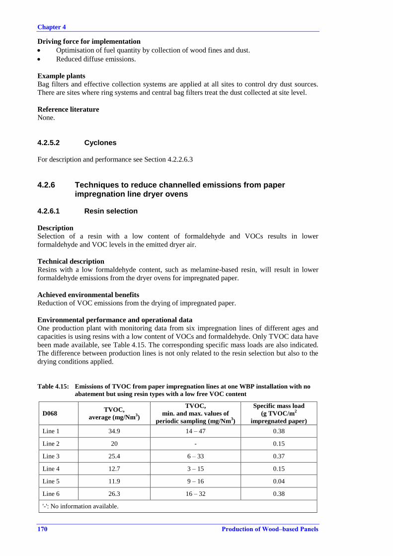
Chapter 4
170 Production of Wood–based Panels
Driving force for implementation
Optimisation of fuel quantity by collection of wood fines and dust.
Reduced diffuse emissions.
Example plants
Bag filters and effective collection systems are applied at all sites to control dry dust sources.
There are sites where ring systems and central bag filters treat the dust collected at site level.
Reference literature
None.
4.2.5.2 Cyclones
For description and performance see Section 4.2.2.6.3
4.2.6 Techniques to reduce channelled emissions from paper impregnation line dryer ovens
4.2.6.1 Resin selection
Description
Selection of a resin with a low content of formaldehyde and VOCs results in lower
formaldehyde and VOC levels in the emitted dryer air.
Technical description
Resins with a low formaldehyde content, such as melamine-based resin, will result in lower
formaldehyde emissions from the dryer ovens for impregnated paper.
Achieved environmental benefits
Reduction of VOC emissions from the drying of impregnated paper.
Environmental performance and operational data
One production plant with monitoring data from six impregnation lines of different ages and
capacities is using resins with a low content of VOCs and formaldehyde. Only TVOC data have
been made available, see Table 4.15. The corresponding specific mass loads are also indicated.
The difference between production lines is not only related to the resin selection but also to the
drying conditions applied.
Table 4.15: Emissions of TVOC from paper impregnation lines at one WBP installation with no
abatement but using resin types with a low free VOC content
D068 TVOC,
average (mg/Nm3)
TVOC,
min. and max. values of
periodic sampling (mg/Nm3)
Specific mass load
(g TVOC/m2
impregnated paper)
Line 1 34.9 14 – 47 0.38
Line 2 20 - 0.15
Line 3 25.4 6 – 33 0.37
Line 4 12.7 3 – 15 0.15
Line 5 11.9 9 – 16 0.04
Line 6 26.3 16 – 32 0.38
'-': No information available.

Chapter 4
Production of Wood–based Panels 171
Cross-media effects
None reported.
Technical considerations relevant to applicability
Some product ranges and varieties of impregnated paper could be difficult to produce with a
limited resin choice. The final quality and properties of the product are defined by the market
and the selection of resin is necessarily related to the balance of cost and product performance.
Economics
No information or data were submitted.
Driving force for implementation
Prevention of VOC emissions.
Example plants
D068.
Reference literature None.
4.2.6.2 Biofilters
Description
A biofilter performs biological degradation of condensable and non-condensable VOC
compounds adsorbed on a packed bed with bacteria culture.
Technical description
The biofilter consists of a column of packed material of plastic, ceramics or other bed material.
The waste gas enters at the bottom of the column and travels up through the packed material to
the discharge stack. The water is recycled continuously; it is discharged from the bottom of the
column and transported to the top of the column, where it is sprayed or sprinkled over the top of
the packed bed. Organic compounds will be degraded by biological oxidation when adsorbed
onto the packed material.
The temperature in the biofilter should be kept within a narrow range, in order to maintain a
stable and efficient biological activity. Biofilters will need time to stabilise before the bacteria
culture is established and the correct operating temperature is determined. To lower the
temperature, a pre-scrubber such as a Venturi scrubber or hydrocyclone can be used, which also
serves the purpose of removing any dust, if present. Dust in emissions from the dryer oven from
impregnation lines is generally at a low level.
To maintain a constant, good performance, it is necessary to monitor the pH and flow in the
water and perform internal control sampling of formaldehyde, TOC, COD and TSS.
Achieved environmental benefits
Degradation of VOCs in low concentrations by biological oxidation.
Environmental performance and operational data
Data available for the biofilter are scarce and are mostly derived from one plant that recently
installed a biofilter. One plant in Italy has operated a biofilter to abate formaldehyde, but there
are no data available. Nevertheless, the technique is applied in other industrial sectors.
However, use of the biofilter and its performance with regards to organic compounds can be
compared with the use of bioscrubbers applied at MDF lines treating dryer waste gases and
press waste gases.

Chapter 4
172 Production of Wood–based Panels
The reported level of CVOCs was 16 mg/Nm3, with a corresponding specific load of
0.07 g CVOCs/m2 of impregnated paper. The formaldehyde concentration in the emission was
measured as between 1 mg/Nm3 and 3 mg/Nm
3.
Cross-media effects
Consumption of chemicals may be necessary in order to recycle water.
A prior wet scrubbing step to remove dust might be necessary.
Technical considerations relevant to applicability
For the biofilter to be very efficient, dust abatement may sometimes be necessary before the
waste gas enters the biofilter.
Economics
Not reported.
Driving force for implementation
To reduce the organic compounds present in dryer and press waste gases.
Example plants
Two plants have installed a stand-alone biofilter for the impregnation lines.
Reference literature
None.
4.2.6.3 Addition of dryer oven waste gas to main treatment systems
Description
The hot waste gas from drying ovens can be treated in the abatement systems that already treat
organic compounds present at the site.
Technical description
Since the hot gas contains very little dust, reduction systems that treat and reduce the organic
compounds should be preferred.
Bioscrubbers are applied for fibre dryer waste gas and biofilters for dryer oven waste gas from
impregnation of paper, but the simultaneous treatment of both has not yet been applied in the
sector. It should be noted that a stand-alone biofilter only treating waste gas from the
impregnation oven is currently in operation in the sector on at least two sites.
Post-combustion of waste gas from drying ovens is applied at a few sites. The VOC content is
incinerated in the combustion plant or in the mixing chamber for hot gases used for direct
drying. No data are available on the efficiency, but it is assumed that the VOC fraction is easily
thermally destructed at temperatures typical in the hot gases before the addition of air.
Treatment in a WESP is also used at one site, even though the ability of the WESP to treat the
organic compounds is most likely limited.
Cross-media effects
Not reported.
Technical considerations relevant to applicability
Post-combustion or incineration of waste gases from the drying ovens in an on-site combustion
plant will depend on the technical limitations of the combustion plant and the firing technique.
Dust burners or gas burners exclusively producing hot gases for direct drying would rarely be
suitable for waste gas incineration. For incineration of waste gases a sufficient and stable
temperature is needed.

Chapter 4
Production of Wood–based Panels 173
Economics
Not reported.
Driving force for implementation
Not reported.
Example plants
Austria (D003, post-combustion), Spain (D070, WESP).
Reference literature
None.
4.2.6.4 Thermal oxidation
Description
Destruction of organic compounds by thermal oxidation of combustible materials, and
conversion of all carbon present in the waste gas into CO2 and water.
Technical description
For technical description see also Section 4.2.4.6.
The regenerative thermal oxidiser (RTO) uses a ceramic packed bed in the chamber, whereas
the catalytic thermal oxidiser (CTO) uses a catalyst material in the packed bed. The incineration
temperature in the RTO reaches 800–1100 °C, while the RCO (regenerative catalytic oxidation)
operates at a lower temperature of 400–700 °C.
Achieved environmental benefits
Destruction of VOC compounds and elimination of odour.
Environmental performance data
Both RTOs and CTOs are applied in the sector. Data from four plants using thermal oxidation
are shown in Table 4.16 for treating waste gases from the drying ovens for impregnation of
paper.
Table 4.16: Emissions of organic compounds from drying ovens for impregnation of paper lines
treated by thermal oxidation
Plant
ID no
TVOC
(mg/Nm3)
Formaldehyde
(mg/Nm3)
Specific mass load
(g TVOC/m2
impregnated paper)
Abatement technique
D003 7 – 17 1 – 8.8 0.07 – 0.19 Catalytic thermal oxidiser
D063 26 - 0.07 Catalytic thermal oxidiser
D094 4.6 0.7 - Regenerative thermal oxidiser
D077 (CVOC)
3.2 – 34.7 1.6 – 4.1 0.008 – 0.17
Regenerative thermal oxidiser
(decommissioned 2011)
'-': No information available.
The emission levels achieved for TVOC are reported to be between 7 mg/Nm3 and 35 mg/Nm
3,
while formaldehyde levels are reported to be between 0.7 mg/Nm3 and 8.8 mg/Nm
3.
Cross-media effects
High energy consumption.
NOX formation is reported to be possible and should be taken into account, and similarly
insufficient oxidation will give rise to elevated CO levels.
Chapter 4
174 Production of Wood–based Panels
Technical considerations relevant to applicability
An RTO/CTO is generally applicable, but economic and energy constraints can be decisive
when choosing this technique.
In order to achieve high energy efficiency, the recovery of heat energy in the treated waste gases
needs to be considered.
Economics
No specific economic data for the use of thermal oxidation in paper impregnation were
received.
Driving force for implementation
Reduction of VOC and formaldehyde emissions.
Example plants
Currently, at least three plants operate an RTO or CTO.
Reference literature
[ 101, EPA 1999 ], [ 102, EPA (US) 2003 ].
4.2.7 Techniques to reduce diffuse emissions
4.2.7.1 Implementation of good housekeeping measures to minimise diffuse dust emissions from the log yard
Description
Regular cleaning and mechanical sweeping of internal transport routes, the log yard, and
vehicles delivering raw wood material.
Sprinkling water on stockpiles of dust-prone material and transport routes.
Technical description
The regular cleaning of transport routes, storage areas and vehicles forms part of good
housekeeping measures.
Sites apply manual or climate-adapted automatic sprinkling systems during dry periods and can
use collected rainwater or surface run-off water. Sprinkling is also performed to keep the
moisture in logs at a sufficient level, e.g. above 50 %, to prevent biological degradation.
Achieved environmental benefits
With regular cleaning of the premises, dust emissions are minimised. An additional benefit is a
lower load of wood dust in the surface run-off water, which eases the treatment of collected
water.
With controlled water sprinkling, diffuse emissions created by wind drift are reduced.
Environmental performance and operational data
No specific information was received.
Cross-media effects
During cleaning, dust can be mobilised and may spread in the surroundings.
Added water consumption and increased volume of water discharge when sprinkling is
used in the log yard. This is only relevant if water is added unnecessarily.

Chapter 4
Production of Wood–based Panels 175
Technical considerations relevant to applicability
Sprinkling is generally applicable to sites on paved areas with a collection of surface run-off
water.
Economics
Not relevant.
Driving force for implementation
Reduction of diffuse emissions from the log yard during dry and windy periods.
Example plants
Regular cleaning is applied throughout the sector.
Reference literature
None.
4.2.7.2 Minimisation of diffuse emissions from the conveying of wood raw materials
Description Use of closed mechanical conveyers and pneumatic transport for the transport of dust-prone
material, in order to prevent or reduce diffuse emissions.
Technical description
Pneumatic conveying systems for wood materials use low-pressure or high-pressure systems
and transport up to 100 t/h of wood chips. Fans are used in low-pressure conveying systems to
transport material from the dryer or to and from storage silos.
Achieved environmental benefits
Reduction of diffuse emissions of raw material.
Environmental performance and operational data
No information received.
Cross-media effects
Consumption of energy.
Technical considerations relevant to applicability
A dust separator should be applied to clean the air channelled from pneumatic transport
equipment.
Economics
No information or data were submitted.
Driving force for implementation
To reduce the spread of diffuse dust emissions in the surroundings of the site.
Example plants
Most plants choose a combination of transport solutions to minimise diffuse emissions and losses
of raw material.
Reference literature
None.
Chapter 4
176 Production of Wood–based Panels
4.2.7.3 Qualification of fugitive emissions using Reverse Dispersion Modelling
Description
Reverse Dispersion Modelling is a method to qualify the fugitive emission rate of diffuse dust
emissions to the atmosphere from a WBP site. The method is described in EN 15445:2008.
Technical description
Fugitive dust is not emitted at a fixed flow rate and the emitted matter is dispersed in air. In
many cases, different dust sources contribute to the dust concentration in a sampling location.
All diffuse sources, such as windblown dust from stockpiles in a log yard, dust from the
handling of raw materials in general, and diffuse dust from manufacturing buildings, should be
included.
The calculations made in the modelling scenario take field data from the site into consideration,
such as the number, heights and widths of diffuse dust sources, meteorological information and
sampling locations.
Reverse Dispersion Modelling is a tool to define and manage improvements in minimising
diffuse dust emissions.
Achieved environmental benefits
Reverse Dispersion Modelling is a tool for the site to identify the most significant dust emission
sources and to use the information to implement measures to reduce diffuse emissions. The
measures taken aim to apply good housekeeping and related improvement processes, as part of
an Environmental Management System for the plant.
Environmental performance and operational data
Not reported.
Cross-media effects
There are no registered cross-media effects.
Technical considerations relevant to applicability
The method cannot be used to control dust emissions from a site, nor is it possible to use the
method to compare the fugitive emissions from diffuse sources between two or more sites.
Economics
The creation of the initial Reverse Dispersion Model and regular follow-ups would be similar to
other investigations or status reports produced on a regular basis at an industrial site.
Driving force for implementation
Determination of possible improvements for controlling diffuse dust emissions, as part of an
Environmental Management System.
Example plants
Not specified.
Reference literature
EN 15445:2008.

Chapter 4
Production of Wood–based Panels 177
4.3 Techniques to prevent or reduce emissions to water
Waste water is water composed of any combination of water discharged from domestic,
industrial or commercial premises, surface run-off water, and any accidentally released sewer
infiltration water.
Even though emissions to water are generally low for most production processes in the sector,
there are some activities for which the control of emissions to water is necessary. The main
potential sources identified in Section 0 are the following:
process water from refining and fibre production;
surface run-off water and drainage from the log yard and other outdoor areas with wood
processing activities.
Discharges are characterised by a high wood-based solids content, giving rise to high TSS, COD
and BOD5 values, while other pollutants such as ammonium, nitrates and total hydrocarbons
could be present under specific circumstances.
Some other less significant contributing streams that should be handled were identified as:
water used for plant cleaning;
wet abatement systems' water;
spillages and leaks from stored chemicals;
glue water.
Ultimately, there may also be differences among installations and other process water streams or
waste water streams. The handling and discharge of domestic waste water from offices and
auxiliary activities are not considered, but it is expected that these issues will be common to
industrial sites across sectors and they are covered in the existing literature on waste water
collection, handling and treatment.
4.3.1 Primary techniques to prevent or reduce emissions to water
4.3.1.1 Minimisation of the pollution load in collected waste water streams
Description The sealing of the log yard surface with paving, concrete or asphalt, and the segregation of
wood raw material storage areas and outdoor wood processing areas and other areas with added
pollution potential.
Separately, the surface run-off water from wood fibre production waste water is collected, in
order to perform a separate treatment.
Technical description
Sand and soil are unwanted in the raw material since they will require more rigorous cleaning
and will generate a higher energy demand in the chip preparation process, both in terms of
added cleaning and of wear and tear of the chipping mills.
Paving of the log yard prevents direct contact with the soil and eases the collection of water
from the log yard. The surface run-off water collected from a paved log yard will carry less
sand- and soil-derived TSS, and hence lower the pollution load. The collected surface run-off
water still contains high amounts of wood material, especially if material other than roundwood
or bark is stored, that will need to be reduced before discharge.

Chapter 4
178 Production of Wood–based Panels
Segregation and separate treatment of surface run-off water and waste water from wood fibre
production could be beneficial, since surface streams can easily be treated in simple
sedimentation basins.
Achieved environmental benefits
The raw material is kept clean of soil and stones.
Reduction of the pollutant load of collected surface run-off water and waste water from
wood fibre production.
Prevention of percolation to soil.
Efficient collection of water.
Management of different qualities of surface run-off water.
Reduction of leaching of potentially contaminated surface run-off water from the log yard
to soil and groundwater.
Individual management of different qualities of process water, cooling water and cleaning
water streams.
Environmental performance and operational data
No data are available on the actual effects of sealing log yard surfaces compared to not sealing,
besides the obvious environmental benefits mentioned above.
By collecting waste water from separate smaller collection areas with high COD/BOD5 loads,
waste water treatment can be optimised.
Cross-media effects
Paving increases the amount of water that is discharged into surface water.
Technical considerations relevant to applicability
The local sensitivity of the receiving environment could be a constraint for a direct discharge
and in this case the collected water would need treatment.
Regarding segregation and separate treatment of surface run-off water and waste water from
wood fibre production, the applicability may be restricted for existing plants due to the
configuration of the existing drainage infrastructure.
Economics
The investment includes the cost of paving. Maintenance costs are low.
Driving force for implementation
To reduce the pollution load of collected surface run-off water from outdoor areas.
Example plants
The majority of WBP installations have paving on most of the log yard on site.
Reference literature
None.
4.3.1.2 Recirculation of process waste water from wood fibre production
Description
Recirculation of water from the refiner, the cooking stage and chip washing by intermediary
physical removal of solids.
Technical description
The filtration of process waste water from wood fibre production can be performed by a simple
screening and decanting. The water can be recycled back to the chip washing stage directly. The
sludge mainly consists of wood fines and can be used directly as fuel, especially if screw
Chapter 4
Production of Wood–based Panels 179
presses are applied to remove excess liquid. The sludge can additionally be used as raw material
in PB production.
Between the cooking stage, where chips are softened and cooked with steam, and the refiner,
water is removed from the chips with a plug screw. The water phase can be used to add to the
refiner disc during refining or immediately afterwards when entering the blowline. The
remaining concentrated water can be further treated in-line, e.g. by evaporation, flotation or
dissolved air flotation.
Circulating water in wet abatement systems contains dust and organic compounds. Wet
electrostatic precipitators and bioscrubbers generally have in-line systems to remove
precipitated wood dust from the water by simple sedimentation and screw pumps or by
dissolved air flotation or coagulation/flocculation.
Achieved environmental benefits
Lower water consumption.
Reduced waste water flows to be treated.
Environmental performance and operational data
No data on the performance or reduction efficiencies were reported.
One supplier gave the following reduction efficiencies from cooking: ≥ 92 % for TSS and ≥ 80
% for COD.
Cross-media effects
The sludge generated needs treatment.
Technical considerations relevant to applicability
Not reported.
Economics
No plant-specific information or data were submitted.
One supplier gave the following key figures for a dissolved air flotation system treating process
water from the cooking of wood chips before refining:
Capacity: 10 m3 process water/h; investment cost: ~ EUR 250 000; operation and maintenance
cost: ~ EUR 78 000; low fresh water consumption; energy: ~ 700 W/m3.
One supplier gave the following key figures for a dissolved air flotation system treating
scrubbing and cleaning water in a WESP:
Capacity: 10 m3 process water/h; investment cost: ~ EUR 180 000; operation and maintenance
cost: ~ EUR 45 000; low fresh water consumption; energy: ~ 250 W/m3.
Driving force for implementation
To treat process water at source to avoid operating an extensive waste water treatment
plant facility on site.
Reduction of the consumption of water in refining.
Reduction of the water consumption in wet abatement systems and to maintain a high
degree of dust separation.
Example plants
In-line filtration steps at refiner level are commonly applied.
For wet abatement systems, a WESP, on-line dissolved air flotation or decantation followed by
screw presses, etc. are standard equipment at newer plants.

Chapter 4
180 Production of Wood–based Panels
Reference literature
None.
4.3.2 Treatment of surface run-off water
Collected water from surface run-off from outdoor areas is characterised by a high level of
solids, and a common step is therefore separation of the suspended solids from the water stream.
The techniques covered are mainly physical separation techniques:
screening to remove coarse solids; followed by either:
sedimentation in sand traps, settlement tanks and followed by a retention basin to remove
settleable solids; preceded by oil-water separation if necessary; or
filtration and degradation in a reed bed.
The treated surface run-off water is discharged either directly to a receiving water body or to
further treatment in a waste water treatment plant. Infiltration to soil is also applied at some
installations.
4.3.2.1 Preliminary treatment, screening and sieving
Description
Physical screening and sieving removes coarse solids from waste water by interception.
Screening is the basic separation step used at all sites for the pretreatment of both surface run-
off water and process water, e.g. from refining.
Technical description
Physical screening and sieving can be carried out using a range of different equipment.
Screening techniques applied for the treatment of surface run-off water include fixed inclined or
curved screens or rotary drum screens. Curved screens need cleaning regularly to remove
collected material that has built up. Rotary drum screens consist of a cylinder rotating in a flow
channel, where particles are collected either on the outer surface or inside the cylinder,
depending on the direction of the flow. The collected material on the screen is continuously
removed and the screen is sometimes sprayed with water to keep it clean.
Centrifuges or the use of rotary disc screens that remove solids including grit and sand are
applied as a pretreatment before treatment in a waste water treatment plant. The removal of grit
protects equipment in the waste water treatment plant from abrasion. Reducing the level of
solids also reduces the amount of solids to be removed by flocculation or sedimentation later.
Rotary disc screens can remove very fine settleable solids and can be applied as an alternative to
a settlement or sedimentation basin.
Screened material, especially from the pretreatment of fibre waste water, is dewatered using
screw presses or belt presses, before further handling.
Achieved environmental benefits
Coarse particles, grit and settleable solids are removed from the collected waste water.
Environmental performance and operational data
Screening or sieving is a preliminary step before other primary waste water treatment steps,
though there are no data to show its efficiency when treating surface run-off water. The purpose
of the screen is to remove large and coarse material which could disturb the further downstream
treatment. The removal efficiencies are near 100 % for the size of wood material that a screen is
designed to obstruct. TSS can be reduced considerably, while BOD5 and COD are reduced less.
Cross-media effects
Depending on the content of the screened material, it might need further treatment before
handling.

Chapter 4
Production of Wood–based Panels 181
Technical considerations relevant to applicability
None identified.
Economics
The investment costs for curved screens are low and normally just involve passive equipment,
while rotary drum screens or centrifuges for example have higher investment costs and need
power to operate. Maintenance costs are low.
Driving force for implementation
To remove coarse particles before further treatment.
Example plants
All sites handling surface run-off water apply screens as a primary pretreatment.
Reference literature
[ 22, TWG 2012 ]
4.3.2.2 Sedimentation in retention basins and settlement tanks
Description
A retention basin or a settlement tank withholds coarser material by passive sedimentation.
Technical description
Collected surface run-off water from the log yard is led through a retention basin or settlement
tank to allow for the sedimentation of coarse wood material, stones, sand and grit. The collected
and channelled surface run-off water is generally pretreated in a sieve or screen removing larger
stones and wood.
The retention basin is constructed with an impermeable bottom, in order to avoid leaching of
TSS-rich water to the soil. The impermeable bottom layer can consist of an artificial or natural
barrier of barely permeable clay or, as an alternative, a heavy-duty plastic membrane. The
retention basin is dimensioned so as to allow control of the peak flow effluents into the
receiving water or downstream waste water treatment plant and to allow for a sufficient
residence time for the coarse materials to sediment. More than one retention basin can be
employed in series, to further control peak effluents and to enhance the sedimentation of
suspended solids. Also, sand traps and smaller settlement tanks can be used before the retention
basin. The sedimented material is regularly removed according to the dimensioned residence
time of the retention basin.
Although some biological activity can take place in the retention basin, there are no data to
prove that retention basins alone have a specific performance for the degradation of organic
material in the water or in the sedimented material.
A settlement tank operates in the same way but holds a lower volume and has a lower retention
time.
In many cases, oil-water separation is performed as a pretreatment. Applied oil-water separators
(OWS) are typically standard gravity separators. Standard gravity separators are liquid
containment structures that provide sufficient hydraulic retention time to allow oil droplets to
rise to the surface. The oil forms a separate layer that can then be removed by skimmers, pumps,
or other methods. The outlet is located below the oil level so that water leaving the separator
and entering the retention basin/settlement tank is free of oil.
Chapter 4
182 Production of Wood–based Panels
Achieved environmental benefits
A retention basin enables the removal of solids and wood debris from the surface run-off water
from log yards and prevents a strain on receiving waters or on downstream waste water
treatment plants, by controlling peak effluents.
Settlement tanks provide pretreatment, where settleable solids and wood debris and grit are
sedimented.
Oil-water separators separate oil from waste water, reducing the discharge of oil and
hydrocarbons to receiving waters.
Environmental performance and operational data
The effluent concentration does not change markedly over time if the retention basin is
sufficiently large, since the volume will level out the peak inlet flows from heavy or sudden
rainfall after periods with no precipitation. The emission level therefore accurately describes the
efficiency of the retention basin. Monitoring is most often performed with spot sampling, which
relates to the unsteady flow and as the concentration over time does not change or vary very
much.
Emission levels of the main parameters analysed for treated surface run-off water discharged to
receiving waters are shown in Table 4.17. Not all parameters are analysed at all installations.
Table 4.17: Emission levels associated with sedimentation/oil-water separation
Parameter Discharge to receiving water,
emission average (mg/l) Comments
TSS 9 – 29 6 installations
BOD5 2.3 – 14 4 installations
COD 18 – 122 6 installations
NH4-N 1, 2 2 installations
TN 1.5 – 11.5 3 installations Note: Data from D015, D017, D039-a, D065-a, D068, D070, D086.
The difference in emission levels observed is due to a combination of the following reasons:
input load of contaminated water;
retention time;
local permit conditions, reflecting the sensitivity of the surface water.
It has not been possible to derive the actual removal efficiency from the emission data received
for the sector. Estimated levels have been reported to be around 50–80 % for TSS.
Operation of the retention basin is achieved by proper maintenance, including:
Daily inspections of sieves, the oil-water separator, the embankments of the retention
basin and the discharge point. Daily inspections prevent overflooding by checking sieves
for stops and blockages by larger fragments, as well as checking the structural integrity
and pumps.
Visual inspection of the level of sedimentation and removal of sediment before the
retention time becomes too short and causes unforeseen overflows of untreated water.
Cross-media effects
The sedimented material has the characteristics of sludge and, when removed from the retention
basin, it needs further handling or disposal.
Chapter 4
Production of Wood–based Panels 183
Technical considerations relevant to applicability
Retention basins are generally applicable to retain and separate solids, e.g. from collected
surface run-off water. A retention basin is considered a simple but effective means to remove
solids.
Basins are not applicable to treat more complex waste water streams that require more
sophisticated treatment than sedimentation alone.
Depending on the local quality demands for the final discharge from the site to the receiving
water or further off-site treatment, sedimentation might not be sufficient to achieve the required
levels of COD and TOC.
Retention basins occupy rather large areas of outdoor space and a lack of sufficient space might
prevent the use of basins.
Economics
The cost of establishing retention basins and the related connection to drainage will vary
depending on the state of the area where the basin is to be established and the access to raw
materials if built above ground. Operating and maintenance costs also depend on the need for
pumps, the frequency of sedimented material removal and the equipment needed to control the
flow.
Driving force for implementation
The main driving force for implementation is to handle surface water with high loads of TSS in a
controlled way, in order to reduce the strain on the receiving surface waters or on the off-site
waste water treatment plants.
The need for large amounts of readily available firefighting water makes retention basins
desirable.
Example plants
Retention basins and smaller settlement tanks are used throughout the sector to handle surface
run-off water.
Reference literature
[ 54, EIPPCB 2012 ], [ 55, EIPPCB 2012 ], [ 99, US EPA 1999 ].
4.3.2.3 Sand filters
Description
Sand filters remove fine suspended solids after an initial sedimentation of coarser solids and
material.
Technical description
Sand filters can be applied as a second step for removing suspended solids from surface run-off
water from the log yard and other outdoor areas. The first step is a retention basin or
sedimentation chamber for the sedimentation of larger solids and debris. Sand filters are also
applied as a filtration step for treating process water combined with sedimentation or flotation.
The sand filter filters suspended solids, solid BOD5 and therefore lowers the overall level of
COD. The sand filter is cleaned by backflushing into the sedimentation chamber or to a separate
collection point.
The filter material can consist of sand and stones or peat, which also promotes the degradation
of the organic material, such as wood-derived suspended solids.
Chapter 4
184 Production of Wood–based Panels
Achieved environmental benefits
Correctly dimensioned sand filters effectively remove suspended solids and solid BOD5 and
hence lower the COD levels in treated surface run-off water and in process waters. Also, some
biological degradation can occur in the filter material.
Environmental performance and operational data
While the majority of installations collect and treat surface water, only a few have reported the
dedicated use of sand filters.
Sand filters are commonly used in handling lightly contaminated water, such as surface run-off
water, and are also well documented in other sectors as the final filtration and separation stage
before discharge.
The good performance of the sand filter is achieved by proper maintenance, including:
Daily inspections of sieves, the oil-water separator, the sedimentation chamber/retention
basin, the sand filter chamber and the discharge point. Daily inspections prevent
overflooding by checking sieves for stops and blockages caused by larger fragments, and
checking filter bed conditions and pumps.
Maintenance of the filter by removing larger fragments and debris on the surface of the
filter.
Visual inspection of the sand filter, in order to control channelling in the filter material,
which otherwise markedly lowers the filter efficiency and the hydraulic residence time.
Regular replacement of filter media, such as for backflushing.
Cross-media effects
The sludge resulting from backflushing the sand filter material needs to be collected and
disposed of, either together with sedimented material from the retention basin or sedimentation
chamber or separately.
Technical considerations relevant to applicability
Sand filters are generally applicable to retain and separate solids from collected surface run-off
water from log yards and process water sources with only suspended solids. Sand filters have a
small footprint and can be accommodated at most sites.
Sand filters alone are not sufficient to treat more complex waste water streams.
Depending on the local quality demands in the final discharge from the site to the receiving
water or further off-site treatment, a sand filter in combination with a sedimentation chamber
might not be sufficient to achieve the required levels of COD and TOC.
Economics
The cost of establishing a sand filter depends on the model of sand filter chosen. The sand filter
can be an open surface basin, an underground vault sand filter, or another model which are all
standard structural entities common for handling rainwater on industrial sites.
Operation and maintenance costs also depend on the need for pumps, the backflushing
frequency of the filter, the handling of the resulting sludge, the amount of added filter material,
and the necessary equipment to control flows.
Driving force for implementation
The main driving force for implementation is to handle surface water with high loads of TSS,
BOD5 and COD in a controlled way in order to reduce the strain on receiving surface waters or
on off-site waste water treatment plants.

Chapter 4
Production of Wood–based Panels 185
Example plants
Sand filters are applied for pretreatment of process water, but rarely for collected surface water in
the sector.
Reference literature
[ 100, US EPA 1999 ].
4.3.2.4 Reed bed
Description
A reed bed is a shallow pond populated with reeds and other wetland plants. The pond has a
long hydraulic residence time for water entering the reed bed, allowing the reed bed time to
biologically degrade organic components in the water. The reed bed covers a large area and is
applied as a last step before discharge to surface waters.
Technical description
The reed bed acts by the filtration of suspended solids, absorption of metals by plants and by the
biological degradation of easily accessible organic compounds. The reed bed should be
constructed so as to give a high attenuation time for the water to pass through, which will
promote biological activity and the settlement of particles.
Achieved environmental benefits
Treatment and attenuation of lightly contaminated surface water, removing TSS and COD by
filtration and biological degradation using the plants in the reed bed.
Nitrogen removal can also be achieved.
Cross-media effects
None.
Environmental performance and operational data
Reed beds are used in various applications for treating lightly contaminated rainwater, e.g. in
the treatment of road water. Application in the wood-based panel sector has been documented at
one installation. The reed bed has a length of 800 m and receives surface run-off water from
outdoor areas collected in surface drains and pumped to the reed bed. The reed bed discharges
into a sensitive stream and is monitored for pH, formaldehyde and ammonium only. The
discharge of TSS and COD is negligible and is not monitored. The level of ammonium NH4-N
is between 0.6 mg/l and 4.8 mg/l with a yearly average of 2.6 mg/l and a pH between 7.2 and
8.1. Both parameters are measured daily with spot sampling. Formaldehyde is monitored daily
and the yearly average is 1.1 mg/l, with variations between 0.27 mg/l and 1.97 mg/l. Mass loads
are not given as the exact amount of discharged water is not known. The discharge flow is, on
average, 10 m3/h and fluctuates with precipitation.
Technical considerations relevant to applicability
The reed bed can be used as a last polishing step before release to surface waters, if necessary.
The reed bed can treat more complex waste water streams containing dissolved salts. The reed
bed cannot be used alone, since larger solids, debris, and easily sedimented material should be
removed prior to entering the reed bed. A heavy load of readily sedimented material will block
the reed bed if not filtered beforehand.
In cold climates, the efficiency of the reed bed will be low during winter since the biological
activity and the uptake by the reeds will be low.
The reed bed and its biology are sensitive to the concentration of chemicals and so should be
protected against contaminated water, e.g. from spills and used firefighting water.
Chapter 4
186 Production of Wood–based Panels
A reed bed needs time to establish a sufficient filtering capacity and with age it will perform
better.
Economics
The capital cost is dependent on the size of the reed bed and can vary widely. Maintenance and
energy costs are low.
Driving force for implementation
Local requirements related to the surface water sensitivity can dictate a higher quality of the
water to be discharged.
Example plants
Reed beds are used for handling lightly contaminated surface run-off waters and have been
reported as being installed by at least one site.
Reference literature
[ 65, Scholz 2011 ].
4.3.3 Treatment of process water from fibre production
Water used in refining has high loads of fibres and partly dissolved fibres. The process water
needs a certain minimum level of treatment before the water is suitable for reuse for refining or
in other parts of the production process or before it is discharged from the site.
The techniques applied for the treatment of process water from refining range from simple
filtration equipment integrated into the refining plant in order to recycle water, to full-scale
waste water treatment plants treating process water for recycling or discharge.
Filtration and primary physico-chemical treatment of waste water are carried out to remove
wood fines and solids, to lower the initial concentration of TSS, prior to a secondary treatment
such as a biological treatment. If the quality of the treated water is crucial before reuse or
discharge, a tertiary treatment and polishing step is carried out. The techniques are described
below in the logical order of treatment.
4.3.3.1 Preliminary treatment, removal of larger solids
Description
For a common description and further information, please see Section 4.3.2.1.
Environmental performance and operational data
Removal efficiencies when applying the screening of incoming waste water before further
treatment are reported as 60–70 % of the incoming TSS loads at two MDF production plants.
4.3.3.2 Primary treatment by physical separation of particles and suspended solids
Description
Physical separation of particles and suspended solids prior to further treatment by flocculation
and/or flotation aided by coagulation. Flocs created by mechanical agitation or by coagulation
are removed by either gravitational sedimentation or flotation.
Technical description
The primary purpose of physical separation techniques is to remove solids (TSS), which in the
waste water in this sector are primarily wood dust and fibres. The very coarse material is
Chapter 4
Production of Wood–based Panels 187
removed by screening, while smaller particles and suspended solids are removed by filtration,
coagulation and flocculation, etc.
Flocculation promotes the aggregation of smaller particles into larger particles to enhance their
removal by gravity separation. Flocculation is obtained by mechanical stirring or air agitation.
Flocculation takes place in separate basins. An in-line addition of coagulators can be performed
beforehand to aid the floc formation.
Flotation is the removal of suspended solids and particles with densities close to that of water.
In dissolved air flotation (DAF), the flocculation is aided by high pressure air that agitates and
aggregates the flocs. In the basin, the light flocs are concentrated at the surface and are removed
by overflow or by a scraper onto a belt press, which removes and dewaters the solids. A DAF
unit is compact and takes up little space. DAF is commonly used as an internal on-line treatment
for wet abatement techniques and for refiner process water. Larger coagulation and flocculation
basins with mechanical stirring and aeration are applied as a pretreatment before biological
treatment at independent waste water treatment plants.
Sedimentation provides for the removal of settleable solids and generates sludge at the bottom
of the sedimentation tank. Oil and grease, together with floating material, settle on the surface
and can be removed in an oil-water separator afterwards or with surface skimmers. Retention
basins used for handling surface run-off water essentially employ sedimentation. Sedimentation
removes a part of the organic material, depending on the nature of the COD. Sludge needs to be
removed regularly from the bottom, which is achieved by sludge removal flights or other
standard equipment.
Sludge from the above-mentioned processes consists mainly of the intercepted or settled solids
and is dewatered, for example by decanting, followed by screw presses, belt presses or similar
equipment, to remove excess water.
Achieved environmental benefits
Reduction of the load of TSS, BOD5 and COD before further biological treatment.
Environmental performance and operational data
The reported removal efficiencies indicate that the physical separation methods are important
steps in removing solids from the waste water. The following data were reported from four
MDF production plants:
50 % TSS removal by flocculation, sedimentation and decanting;
30 % COD removal by sedimentation;
60 % COD, 50 % TSS, and 50 % BOD5 removal by DAF;
95 % TSS removal by flocculation, coagulation and decanting.
The removal efficiencies are not accompanied by mass concentrations since the separation step
is a step in a water treatment process. From general waste water treatment, it is expected that up
to 70 % of TSS and up to 40 % of BOD5 are removed.
The sludge generated in the flocculation, flotation and DAF is easily transferred to belt or screw
presses. The sludge can, with dewatering treatment, achieve a moisture content of at least 20–
25 %, which is sufficient to be handled safely.
Sludge from a DAF unit installed in-line in a wet abatement system is of a quality that allows it
to be used as fuel. The sludge obtained from more mixed waste water streams cannot always be
used as fuel, but may need further treatment.
Cross-media effects
None reported.
Chapter 4
188 Production of Wood–based Panels
Technical considerations relevant to applicability
As for retention basins, sedimentation depends on the retention time in the tank and the
available surface area. Settling and sedimentation also depend on temperature and in cold
climates sedimentation takes place at a much slower rate.
Economics
No information or data were submitted.
Driving force for implementation
Reduction of TSS and COD before further treatment in biological treatment systems.
Example plants
Various plants use in-line DAF systems at the refiner level or with wet abatement systems. The
methods mentioned are applied at all sites with an independent waste water treatment plant.
Reference literature
None.
4.3.3.3 Biological treatment
Description
Biological treatment removes colloidal or soluble organic material and substances by biological
degradation.
Technical description
Biological treatment is a well-known technology worldwide and is applied at sites where
process water is produced mainly from MDF production and also at other fibre panel production
sites. The biological treatment is a secondary treatment step and is applied after the primary
treatment steps (e.g. filtration, coagulation and flocculation).
Biological treatment covers several processes, most commonly activated sludge treatment,
aerated lagoons, biotrickling filters and also membrane bioreactors.
For a full description of the biological waste water treatment methods, the reader is advised to
consult the literature and the CWW BREF [ 3, EC 2003 ].
Achieved environmental benefits
Reduction of the emissions of organic matter (COD, BOD5).
Environmental performance and operational data
The reported removal efficiencies indicate that biological treatment can be very effective in
removing COD from the waste water.
The reported COD removal efficiencies are between 30 % and 97 % for biological treatment
followed by flotation or clarification basins. The performance includes results from plants with
activated sludge treatment, a membrane bioreactor or combined solutions, such as biotrickling
and aeration basins. High efficiencies (> 95 %) of TSS and BOD5 were reported in connection
with membrane bioreactors.
The mass concentration at the outlet of the waste water treatment plant varies for COD between
20 mg/l and 940 mg/l. The average values for COD vary between 60 mg/l and 700 mg/l.
The corresponding specific loads vary between 52 g and 320 g COD/tonnes of dry pulp. The
data derived from five plants. With an additional sand filter and reverse osmosis step, one plant
reported a specific load of 20 g COD/tonne of dry pulp. The results vary greatly between plants,
reflecting the initial composition and load of COD in the waste water.

Chapter 4
Production of Wood–based Panels 189
The overall removal efficiencies for a waste water treatment plant using screening for removing
solids of over 1 mm, DAF, a denitrification step and a membrane bioreactor were reported as
95 % COD, 100 % TSS and 99 % BOD5, resulting in mass concentrations of TSS below 1 mg/l,
BOD5 below 5 mg/l and COD between 90 mg/l and 130 mg/l.
Cross-media effects
Sludge needs further treatment and handling.
Technical considerations relevant to applicability
Not reported.
Economics
The investment and also the running costs for a full-scale waste water treatment plant are high.
In an example of a full-scale plant treating process water from MDF production, the investment
was around EUR 4–6 million, while the yearly operating cost is around EUR 600 000–800 000.
The steps included in the treatment plant are flocculation, sedimentation and biological
treatment with a final filtration. The additional costs of sludge handling and discharge and
further downstream treatment are not included in the operating costs.
Driving force for implementation
To reduce the pollution load of process waste water before discharge, either to comply with limit
values for the discharge to surface waters or to lower the cost for further downstream treatment at
an UWWTP.
The activated sludge process is preferably used when high or very high treatment efficiencies
are required and especially when levels of ammonia should be limited.
Example plants
The majority of installed specific stand-alone waste water treatment plants have a biological
degradation step.
Reference literature
[ 3, EC 2003 ], [ 56, J. M. Fernández et al. 2001 ].
4.3.3.4 Tertiary treatment of waste water
Description
Tertiary techniques include the removal of settleable solids and nitrogen compounds from
treated waste water before recycling or discharge. Filtration is applied for the removal of
suspended solids from the treated waste water before discharge. Biological nitrification and
denitrification techniques convert ammonia and nitrates. Reverse osmosis removes residual
nitrogen compounds. The use of tertiary techniques is strongly influenced by the downstream
fate of the waste water.
Technical description
Filtration is widely applied for the last treatment step, either by the use of a sand filter before
discharge or supplemented by microfiltration. Settlement lagoons for sedimentation, and
aeration and clarifier basins after biological treatment precede the sand filter as a pretreatment,
see also Section 4.3.2.3 on sand filters. Microfiltration is performed with similar screening
equipment as is used for primary treatment, such as rotary drum screens, but with openings in
the range of 20–35 µm.
Reverse osmosis separates dissolved salts and dissolved organic compounds from the treated
waste water treatment stream. Reverse osmosis should be preceded by microfiltration.
Ammonium, organic nitrogen and nitrates are removed by reverse osmosis, but if the influent

Chapter 4
190 Production of Wood–based Panels
concentration from the waste water streams is high, conversion steps need to be implemented in
the biological treatment before reverse osmosis is carried out.
Part of the organic nitrogen such as urea can be transformed to ammonia/ammonium during
biological treatment and in aeration steps. Nitrification and denitrification can be applied for
ammonia/ammonium and nitrate conversion, but is only recorded at a few plants.
For a full description of the biological waste water treatment methods, the reader is advised to
consult the literature and the CWW BREF [ 3, EC 2003 ].
Achieved environmental benefits
Polishing of waste waters, reducing COD, BOD5, TSS and nutrients (nitrogen, phosphorus), to
enhance recycling or to comply with local restrictions on discharge levels.
Environmental performance and operational data
When recycling part of the treated waste water, e.g. for steam generation for refining, the
quality is important. At one plant (D002), the treated waste water was reused for preparing the
resin mix and for the preparation of urea solution for SNCR and steam generation for refining.
The waste water is mainly from refining. The treatment steps applied included the following in a
simplified form:
Pretreatment:
o storage basin, 0 % removal of influent COD load;
o curved screen, 33 % removal of influent COD load.
Primary physical separation:
o sedimentation basin, 30 % removal of influent COD load.
Secondary biological treatment:
o activated sludge tank, 5 % removal of influent COD load;
o flotation, 24 % removal of influent COD load.
Tertiary treatment:
o filtration by sand filter;
o reverse osmosis, 8 % removal of incoming COD load.
Around 85 000 m3 of waste water are treated yearly. Spot sample monitoring showed 60 mg/l
COD, 29 mg/l BOD5, while Total N was 1.13 mg/l.
Cross-media effects
Energy consumption for reverse osmosis can be high.
Technical considerations relevant to applicability
Reverse osmosis requires efficient pretreatment not only of solids, but also of COD. If present
in high levels, nitrogen compounds and colloidal matter can foul the membrane.
Economics
Reverse osmosis has a high operating cost.
No plant-specific information or data were submitted.
Driving force for implementation
Not reported.
Example plants
D002.
Reference literature None.
Chapter 4
Production of Wood–based Panels 191
4.4 Techniques to reduce emissions to land
Other techniques such as paving of log yards and applying an impermeable bottom layer to
waste water storage tanks also provide measures to reduce emissions to land, see Sections
4.3.1.1 and 4.3.2.2.
4.4.1 Safe handling of auxiliary materials
Description
Managing the handling, storage and transport of chemicals, liquid fuels and process waste water
reduces the risk of emissions to land.
Technical description
Resins and auxiliary materials are handled safely by applying the following common principles:
I. The loading and unloading of resins and other auxiliary materials are carried out only in
designated areas protected against leakage run-off.
II. Whilst awaiting disposal, all materials are collected and stored in designated areas
protected against leakage run-off.
III. All pump sumps or other intermediary storage facilities from which spillages might
occur are equipped with alarms which are activated by high levels of liquid.
IV. A programme for the testing and inspection of tanks and pipelines carrying resin,
additives and resin mixes, liquid fuels, ammonia solutions, waste water or other liquids
is established and carried out.
V. Inspections are carried out for leaks on all flanges and valves on pipes used to transport
materials other than clean water and wood; a log of these inspections is maintained.
VI. A catchment system is provided to collect any leaks from flanges and valves on pipes
used to transport materials other than clean water and wood, except when the
construction of flanges or valves is technically tight.
VII. An adequate supply of containment booms and suitable absorbent material is provided.
VIII. Underground piping is avoided when transporting anything other than clean water and
wood. An exception is for waste water infrastructure.
Techniques for the storage, transfer and handling of liquid or solid auxiliary materials,
especially chemicals, are described in the EFS BREF [ 6, EC 2006 ].
Achieved environmental benefits Low risk of accidents resulting in the contamination of soil and groundwater.
Environmental performance and operational data
None reported.
Cross-media effects
None reported.
Technical considerations relevant to applicability
None.
Economics
No information or data were submitted.
Driving force for implementation
To manage the overall handling of chemicals and other substances safely.
Example plants
None reported.

Chapter 4
192 Production of Wood–based Panels
Reference literature
EMS systems in general. EFS BREF [ 6, EC 2006 ].
Chapter 4
Production of Wood–based Panels 193
4.5 Techniques to reduce water consumption
Water consumption is mainly from the refining of chips to fibres and the operation of wet
abatement systems.
Water consumption at the site level is also managed through the Environmental Management
System, see Section 4.9.
The in-line treatment of process water streams at the refiner and the recycling of water decrease
the consumption of raw water and reduce the influent load of on-site waste water treatment
plants. The techniques are described under primary measures for preventing or reducing
emissions to water, see Section 4.3.1. The recycling of refining water by evaporation is
described under techniques to increase energy efficiency, see Section 4.6.5.
4.5.1 Collection of lightly contaminated water for plant cleaning and other purposes
Description
Collection of lightly contaminated water and the reuse of this water for purposes other than
production.
Technical description
At the site level, lightly contaminated water is used for purposes for which the quality of water
is less important. This lightly contaminated water is obtained by the collection of the following
water streams, among others:
clean roof rainwater;
decanted used glue water from cleaning or which is left over;
collected and pretreated surface run-off water.
The lightly contaminated or even clean water can be used for the following purposes:
cleaning of the dryer and plant in general;
chip washing;
resin mixing.
The collection and storage infrastructure depends on the source of the water. Outdoor open
basins are used for almost clean water, and at the same time act as storage for water for
firefighting.
Achieved environmental benefits
Reduction in water consumption from the grid or well.
Environmental performance and operational data
Several sites throughout the sector report the use of lightly contaminated water or clean
rainwater.
The potential savings in water consumption are not known.
Cross-media effects
None.
Technical considerations relevant to applicability
If the recycled water needs to have a certain quality, a constant control of the water quality
could be necessary.

Chapter 4
194 Production of Wood–based Panels
Economics
Expected low cost.
Driving force for implementation
Reduction of raw water consumption.
Example plants
Several plants in the sector.
Reference literature
None.

Chapter 4
Production of Wood–based Panels 195
4.6 Techniques to increase energy efficiency
Increasing energy efficiency and lowering the overall energy consumption at the site level is
part of an environmental management system. General measures to obtain high energy
efficiency are:
proper design of the installation;
proper maintenance of the plants within the installation, including processing equipment
and related fans, motors and abatement systems.
In the sector, it is in the energy-intensive operations in particular, including drying, pressing and
refining, where the development of energy-efficient solutions have taken place.
4.6.1 Recovery of energy in hot air emissions
Description
Recovery of heat from hot air emissions by evaporative condensation, heat exchangers,
preheating the air supply to the dryer and recirculation of hot waste gases.
Technical description
Drying requires a large energy input, so the system design should consider opportunities to
recover process heat, which is otherwise released through the final emitted waste gas from the
dryer.
Latent heat can be recovered from the dryer waste gas using evaporative condensation and heat
exchangers. Direct heat recovery is carried out by heat exchangers. A heat exchanger is a device
in which energy is transferred from one fluid or gas to another across a solid surface. They are
used to either heat up or cool down processes or systems. Heat transfer happens by both
convection and conduction [ 4, EC 2009 ].
Recirculation of a part of the waste gas from the dryer is widely applied. Recirculation of dryer
waste gas from a directly heated dryer is obtained by directing a smaller part, generally less than
20 % of the waste gas, to post-combustion. See also Section 4.2.2.2 and Section 4.2.2.3.
Recovery of heat for use off site in local district heating systems is a solution, when heat in low-
temperature streams is recovered.
Achieved environmental benefits
Increased energy efficiency at the plant level.
Environmental performance and operational data
No data or information on the energy savings or overall energy efficiency obtained were
received.
Cross-media effects
None reported.
Technical considerations relevant to applicability
Fouling of heat exchangers can decrease the efficiency of heat recovery.
Recirculation of dryer waste gas to the rotary dryer can increase the dryer cleaning frequency
required.
The recovery of heat from a low-temperature source with a difference in temperature of even
only 20 °C can be beneficial, but a cost-benefit balance should be taken into account.
Chapter 4
196 Production of Wood–based Panels
Economics
No plant-specific information or data were submitted.
The implementation of recirculation of waste gases can be performed in retrofits and the
payback time is expected to be short.
Driving force for implementation
Increase in the energy efficiency at the plant level.
Example plants
The energy recovery measures are applied at all plants and most are designed for the plant and as
part of a retrofit of one or several processes.
Reference literature
[ 4, EC 2009 ].
4.6.2 Combustion control
Description
Improving the combustion performance, and optimising the operation of the combustion plants
by monitoring and controlling the key combustion parameters.
Technical description
Combustion performance is enhanced by taking into account and controlling the following
variables:
combustion temperature;
inlet air excess and air/fuel ratio;
air staging, if applicable;
temperature profile;
temperature at the combustion chamber outlet before mixing with additional air;
flue-gas oxygen content;
NOX/CO balance, especially for nitrogen-containing fuels;
fuel feeding.
Depending on the actual furnace and boiler design, the monitoring of these parameters will
allow the combustion to be enhanced, thus improving the thermal efficiency, lowering the
unburnt carbon in ash, and reducing the CO and NOX concentrations in the flue-gas.
The emissions of unburnt carbon, such as CO and organic hydrocarbons, are a consequence of
incomplete combustion by excessively low combustion temperatures; too short a residence time
in the combustion zone; or by an inefficient mixing of the fuel and combustion air, leading to
local areas of oxygen deficiency.
Carbon monoxide is the most important unburnt gas. It is a stable compound even at high
temperatures if there is no oxygen present. Hydrocarbons, on the contrary, can be decomposed
and form soot at high temperatures in an oxygen-poor atmosphere. In general, it can be said that
emissions of unburnt hydrocarbons may be generated when a low combustion zone temperature
and inefficient mixing of fuel and air occur together. Soot contributes to the creation of blue
haze when the hot gas is used for direct drying.
Some measures to reduce NOX emissions, such as combustion with lower excess air or strong
air staging, can increase emissions of the unburnt carbon gases. In these cases, the importance of
ensuring the efficient mixing of air and fuel in the combustion system must be emphasised. NOX
reduction with the SNCR method can also cause higher CO emissions. CO emissions can be
decreased when limestone feeding is increased in fluidised bed combustion boilers (generally

Chapter 4
Production of Wood–based Panels 197
not applicable for directly heated dryers). This is not generally applied in combustion plants in
the sector.
The boiler efficiency and NOX generation depend largely on the correct distribution of fuel and
air in the furnace. An efficient control system allows gas concentration measurements to be
taken inside the furnace, especially near the burners.
Achieved environmental benefits
Increased thermal efficiency.
Reduction of NOX, CO and TOC.
Reduction of soot giving rise to dust.
Improved quality of bottom ash, with a low level of unburnt carbon in ash.
Limited formation of dioxins due to a more stable process in the furnace.
Environmental performance and operational data
Broad operational experience.
Generally, CO emissions from combustion can be kept under 50 mg/Nm3 if the combustion
process is well controlled. Hydrocarbon emissions in modern power plant boilers are negligible,
typically below 5 mg/Nm3. [ 24, COM 2006 ].
Cross-media effects
None reported.
Applicability consideration
Generally applicable.
Economics
Plant-specific.
Driving force for implementation
Reduction of the emissions of NOX, CO and TOC.
Control of the combustion process and enhancement of efficiency.
Example plants
All plants carrying out combustion operations.
Reference literature
[ 24, COM 2006 ].
4.6.3 Dewatering of bark and sludge
Description
Pretreatment of fuels by lowering the water content of biomass fuels through the use of
mechanical dewatering equipment.
Technical description
Dewatering equipment includes filters and screens, screw presses, belt presses, drum presses
and centrifuges that remove excess water from wet bark, biomass-based sludge from abatement
systems for emissions to air, and for waste water treatment.
Dewatering equipment is most often directly connected to the collection of sludge where it is
produced, mainly to ease its handling and transportation to the combustion plant. After or during
the shredding process of the inhomogeneous bark obtained during debarking, the bark material
can be dewatered in a press and then fed to the combustion plant. Dewatering can be a seasonal

Chapter 4
198 Production of Wood–based Panels
practice, since during winter and in freezing conditions roundwood needs to be thawed with
steam, which leads to an increase in the moisture content.
Achieved environmental benefits
The energy efficiency of the combustion process can be enhanced.
Environmental performance and operational data
No information available.
Cross-media effects
Dewatering equipment can be energy-intensive and the degree of dewatering should be weighed
up against the achievable energy efficiency in the combustion process.
Technical considerations relevant to applicability
No information available.
Economics
No information or data were submitted.
Driving force for implementation
To improve the energy efficiency of the combustion process.
Example plants
Dewatering of sludge is common practice for sludge derived from the internal wet abatement
systems of dryers and presses and from some treatment steps in waste water treatment plants.
There are also examples of sites where the dewatering of bark is not performed because of the
quality of the bark or due to the use of a completely dry debarking procedure.
Reference literature
None.
4.6.4 Combined heat and power (CHP) plants
Description
Combined heat and power (CHP) plants.
Technical description
CHP combustion plants that generate steam for indirect drying and power allow for the
maximum freedom in energy output.
All residues and recovered wood, which are also considered waste, are used as fuels. Using the
more problematic part of the biomass-derived fuels implies, in practice, operating an incinerator
for wood waste. The hot gases are not used for direct drying but for steam generation for
indirect drying, for heating thermal oil, and for producing electricity.
For a description of CHP plants using biomass or combined fuels, see the LCP BREF [ 24,
COM 2006 ].
Achieved environmental benefits
For an independent combustion plant producing heat for steam generation for indirect drying
and power for the grid, fuel is saved by maximising the use of biomass fuel sources.
For an independent combustion plant, the energy efficiency can be high, since energy output can
be regulated to make maximum use of heat and power.
Chapter 4
Production of Wood–based Panels 199
Environmental performance and operational data
No information available.
Cross-media effects
None identified.
Technical considerations relevant to applicability
For a biomass-fired CHP plant, the fuel accessibility is crucial and large CHP plants demand
very high amounts of fuel. The supply from internal production residues is not enough to cover
the fuel need. In order not to use virgin biomass, which is a raw material for the sector,
recovered wood is the main fuel for biomass-fired CHP plants. However, the recovered wood
market can be too unstable to provide a secure fuel supply.
Diesel engines can be an energy-efficient choice if established primarily for power generation
for the grid or for additional steam generation for indirect drying or simply for hot gas
generation for direct drying and transfer of thermal energy to heat thermal oil. CHP plants
operating on liquid fuels could create emissions that are not suitable for direct drying and which
will generally need an additional emission control system.
Economics
The investment costs for a new biomass-fired CHP plant of 40 MW generating steam for
indirect drying and power are about EUR 30 million, with an approximate yearly fuel
consumption of 250 000 tonnes of wood biomass. If contaminated wood waste is used as a fuel,
the additional costs for an abatement system should be added.
Example plants
CHP plants using a variety of fuels are in operation in the sector.
Reference literature
[ 24, COM 2006 ].
4.6.5 Heat recovery from steam during refining
Description
Heat recovery from steam during refining using heat exchangers and evaporation of used steam.
Technical description
The recovery of heat from steam used in the cooking stage of refining takes place using heat
exchangers, falling film evaporators, and plate evaporators that in turn preheat water for steam
generation and heat water for chip washing and pre-cooking stages.
Steam recovery can be implemented by vacuum evaporation, where water is separated from the
fibres and other wood constituents, producing distilled hot water. The condensate can be used as
fuel and the water for steam generation. The result is zero discharge of effluent from the
refining plant.
Low-pressure steam can be recompressed to a higher pressure if there is no need for low-
pressure steam at the site.
Achieved environmental benefits
The overall energy consumption for refining and the water consumption are lowered.
Closed evaporation systems and vacuum evaporation eliminate the need to handle effluent from
the refiner plant.
Chapter 4
200 Production of Wood–based Panels
Environmental performance and operational data
No data were submitted.
Cross-media effects
Vacuum evaporation can have a high energy consumption.
Technical considerations relevant to applicability
The need for the different types of recoverable energy (steam at low and high pressures, water at
various temperature levels) varies between refiner plants.
The usability of high-pressure heat recovery is limited by the required cleaning of the heat
exchangers and the starts and stops in the refiner plant.
Economics
Economic efficiency is to be assessed for each situation.
Driving forces
Cost reduction by energy savings in steam generation and a closed system for the treatment of
waste water from the refiner plant.
Example plants
MDF plants in the sector have applied the technique, but no reference plants were reported.
Reference literature
[ 91, EC 2014 ], [ 36, COM 2001 ].
Chapter 4
Production of Wood–based Panels 201
4.7 Consumption of chemicals and raw materials
4.7.1.1 Optimisation of the use of resins according to the product to be produced
Description
Optimising the use of resins according to the product to be produced is a generic technique
inherent to the sector.
The recirculation of rejects from the press could, in principle, slightly lower the use of resin in
particleboard production, due to the surface properties of the chipped rejects containing cured
resin.
No data from plant-specific production are available.
Chapter 4
202 Production of Wood–based Panels
4.8 Techniques for management of waste/residue generation
4.8.1 Raw material control by applying a control programme to externally collected waste wood
Description
Controlling the quality of externally collected waste wood by physical and chemical testing to
determine if the material is adequate for storing on site and for use as raw material or as a fuel.
Technical description
A control programme includes both standard conditions to ensure the quality of the raw material
to be delivered to the installation and the internal controls performed by the operator upon
receipt of the material.
Both physical and chemical testing are performed and include all or a selection of the following:
Suppliers of recovered wood should be given clear indications of the quality expected and
that can be admitted.
Material received is inspected before unloading to determine that it conforms to the
declaration given by the supplier. The material should not be humid or wet, since this will
provoke rot and degradation of the quality.
Depending on the level of sorting possibilities and the efficiency of cleaning the material,
this should be free of soil, grit and debris, such as plastics, metals, fibreboard and paper.
Testing the content of heavy metals related to wood impregnation is performed regularly
with a combination of laboratory tests and spray testing, where a colour reaction detects
specific metals.
Chemical or physical testing on site can be performed in the same testing laboratory as the
daily product testing.
There is no European standard determining the acceptable content of pollutants or the range of
pollutants to be examined when controlling recovered wood as a raw material. National
standards or guidance exist alongside industry specifications of the minimum requirements for
the control of recovered wood received and used as a raw material. Individual furniture
producers or panel producers can have individual internal standards to document specific
features for a product, e.g. labelling as an environmentally sustainable product or more focused
on user safety.
The content of pollutants in different raw materials is strongly related to the use of recovered
wood and especially post-consumer wood [ 80, Schinagl et al. 2008 ].
Achieved environmental benefits
Safe handling on site of recovered wood materials.
Environmental performance and operational data
None.
Cross-media effects
None identified.
Technical considerations relevant to applicability
Generally applicable.
Economics
None reported.

Chapter 4
Production of Wood–based Panels 203
Driving force for implementation
Product quality.
Stable production.
National legislation or industry standards.
Example plants
Not specified.
Reference literature
[ 64, EPF 2002 ], [ 72, BS 2004 ], [ 73, UBA AT 2010 ]
4.8.2 Optimisation of fuel quantity by the collection of wood fines and dust
Description
Maximise the collection of product residues by the extraction of air at all dust-laden sources and
subsequent dust collection by applying a bag filter or cyclofilter.
Technical description
Optimising the dust collection by applying bag filters or cyclofilters, followed by the use of the
dust as fuel in an on-site combustion plant. Dust collection and transport to the combustion
plant are optimised if central ring collection systems are used and the collected dust is
transported in closed conveyers to the fuel storage area.
Achieved environmental benefits
Reduction of waste to be transported off site.
Reduction of diffuse emissions.
Environmental performance and operational data
The collection of dust from upstream and downstream processing varies according to the wood
processing equipment and collection efficiency.
Examples include around 27 000 tonnes/year collected by cyclones and bag filters from a
particleboard plant producing around 1 700 m3/day. The same amount was collected from a
particleboard plant producing around 1 200 m3/day. One plant producing OSB and MDF with
extensive downstream processing collected around 90 000 tonnes/year from bag filters and
cyclones.
Cross-media effects
Potentially higher NOX and dust emissions when combusted.
Energy consumption for operation of fans and filters.
Technical considerations relevant to applicability
Internal production residues such as sanding dust could demand a more rigorous control of the
combustion process concerning emission of NOX and have the potential for higher dust
emissions.
Economics
Bag filters and effective collection systems are applied at all sites to control dry dust sources.
Operation of fans, filters and transport systems for the collection and transport of dust can
account for as much as 20 % of the total power consumption on a production site.
Driving force for implementation
Maximisation of the collection of dust, which can be used as fuel.
Chapter 4
204 Production of Wood–based Panels
Reduction of diffuse emissions.
Example plants
Bag filters and effective collection systems are applied at all sites to control dry dust sources.
There are sites where ring collection systems and central bag filters treat dust collected at the
site level.
Reference literature
None.
4.8.3 Safe storage, transport and reuse of bottom ash and slag from biomass combustion plants
Description
Bottom ash and slag from a biomass grid-fired combustion plant are often wetted with a
secondary water source to cool the bottom ash and slag. The cooled bottom ash and slag is stored
separately on site in an impermeable area where run-off water is collected. The humidified
bottom ash is easy to transport and store.
Bottom ash can be used for different purposes besides landfilling. Depending on the quality and
quantity, different uses include: cement production, soil improver in forests, and road
construction
Achieved environmental benefits
Reduction of accidental releases to soil.
Reuse of bottom and slags instead of landfilling.
Reduction of fire risk during handling of hot ashes and slags.
Environmental performance and operational data
None reported.
Cross-media effects
None identified.
Technical considerations relevant to applicability
Wetting of bottom ash is relevant for grid firing only. If small quantities of bottom ash are
handled, it is convenient to collect it in hoppers for direct transport off site.
Economics
None reported.
Driving force for implementation
Minimisation of the fire risk from collected bottom ashes and slags related to grid firing.
Example plants
Not specified.
Reference literature
None.
Chapter 4
Production of Wood–based Panels 205
4.8.4 Reuse of internal collected wood residues in production
Description
The rejects, trimmings and oversize material in the screening steps are collected and introduced
into the production process directly.
Technical description
Wood material that can readily be reintroduced into the production process consists of oversize
particles that are screened out during milling and chipping and after drying. The wood particles
are reintroduced at the milling step. The material is collected in hoppers or conveyed directly to
milling.
Trimmings collected before the press are also transferred to screening and milling if necessary.
Trimmings contain uncured resin and are suitable as raw material.
Rejects are automatically sorted and taken out of the production flow if the quality of the panel
is not satisfactory. Collection of rejected panels takes place along the downstream processing
line after the press until the storage area.
Rejects need to be handled, which involves transport to hoppers and shredding before they can
be chipped. Rejects can also be used as fuel, but there is an additional effect when using already
resinated panels, since this could lower the resin consumption.
Achieved environmental benefits
Saving primary wood raw material.
Environmental performance and operational data
None.
Cross-media effects
None identified.
Technical considerations relevant to applicability
The use of production residues in MDF and OSB production can be limited. On the other hand,
residues from OSB could be a raw material for PB panels.
Economics
Not provided.
Driving force for implementation
To save raw materials.
Example plants
All plants recycle material that has the potential to be used as raw material for panel production.
Reference literature
None.

Chapter 4
206 Production of Wood–based Panels
4.9 Environmental management systems
Description
A formal system to demonstrate compliance with environmental objectives.
Technical description
The Directive defines ‘techniques’ (under the definition of 'best available techniques') as ‘both
the technology used and the way in which the installation is designed, built, maintained, operated
and decommissioned’.
In this respect, an environmental management system (EMS) is a technique allowing operators of
installations to address environmental issues in a systematic and demonstrable way. EMSs are
most effective and efficient where they form an inherent part of the overall management and
operation of an installation.
An EMS focuses the attention of the operator on the environmental performance of the
installation; in particular through the application of clear operating procedures for both normal
and other than normal operating conditions, and by setting out the associated lines of
responsibility.
All effective EMSs incorporate the concept of continuous improvement, meaning that
environmental management is an ongoing process, not a project which eventually comes to an
end. There are various process designs, but most EMSs are based on the plan-do-check-act cycle
(which is widely used in other company management contexts). The cycle is an iterative dynamic
model, where the completion of one cycle flows into the beginning of the next (see Figure 4.3).
Figure 4.3: Continuous improvement in an EMS model
Chapter 4
Production of Wood–based Panels 207
An EMS can take the form of a standardised or non-standardised (‘customised’) system.
Implementation and adherence to an internationally accepted standardised system, such as EN
ISO 14001:2004, can give higher credibility to the EMS especially when subjected to a properly
performed external verification. EMAS provides additional credibility due to the interaction with
the public through the environmental statement and the mechanism to ensure compliance with
the applicable environmental legislation. However, non-standardised systems can, in principle, be
equally effective provided that they are properly designed and implemented.
While both standardised systems (EN ISO 14001:2004 or EMAS) and non-standardised systems
apply in principle to organisations, this document takes a narrower approach, not including all
activities of an organisation, e.g. with regard to their products and services, due to the fact that
the Directive only regulates installations/plants.
An EMS can contain the following components:
1. commitment of management, including senior management;
2. definition of an environmental policy that includes the continuous improvement of the
installation by the management;
3. planning and establishing the necessary procedures, objectives and targets, in
conjunction with financial planning and investment;
4. implementation of procedures paying particular attention to:
(a) structure and responsibility,
(b) training, awareness and competence,
(c) communication,
(d) employee involvement,
(e) documentation,
(f) efficient process control,
(g) maintenance programmes,
(h) emergency preparedness and response,
(i) safeguarding compliance with environmental legislation;
5. checking performance and taking corrective action paying particular attention to:
(a) monitoring and measurement (see also the Reference Report on Monitoring (ROM) [
89, COM 2014 ],
(b) corrective and preventive action,
(c) maintenance of records,
(d) independent (where practicable) internal and external auditing in order to determine
whether or not the EMS conforms to planned arrangements and has been properly
implemented and maintained;
6. review of the EMS and its continuing suitability, adequacy and effectiveness by senior
management;
7. preparation of a regular environmental statement;
8. validation by a certification body or an external EMS verifier;
9. following the development of cleaner technologies;
10. consideration for the environmental impacts from the eventual decommissioning of the
installation at the stage of designing a new plant, and throughout its operating life;
11. application of sectoral benchmarking on a regular basis.
Achieved environmental benefits
An EMS promotes and supports the continuous improvement of the environmental performance
of the installation. If the installation already has a good overall environmental performance, an
EMS helps the operator to maintain the high performance level.
Chapter 4
208 Production of Wood–based Panels
Environmental performance and operational data
No specific information was received.
Cross-media effects
None reported. The systematic analysis of the initial environmental impacts and scope for
improvements in the context of the EMS sets the basis for assessing the best solutions for all
environmental media.
Technical considerations relevant to applicability
The components described above can typically be applied to all installations within the scope of
this document. The scope (e.g. level of detail) and nature of the EMS (e.g. standardised or non-
standardised) will be related to the nature, scale and complexity of the installation, and the range
of environmental impacts it may have.
Economics
It is difficult to determine accurately the costs and economic benefits of introducing and
maintaining a good EMS. There are also economic benefits that are the result of using an EMS
and these vary widely from sector to sector.
External costs relating to verification of the system can be estimated from guidance issued by the
International Accreditation Forum [ 96, IAF 2010 ].
Driving forces for implementation
The driving forces for the implementation of an EMS include:
improved environmental performance;
improved insight into the environmental aspects of the company which can be used to fulfil
the environmental requirements of customers, regulatory authorities, banks, insurance
companies or other stakeholders (e.g. people living or working in the vicinity of the
installation);
improved basis for decision-making;
improved motivation of personnel (e.g. managers can have confidence that environmental
impacts are controlled and employees can feel that they are working for an environmentally
responsible company);
additional opportunities for operational cost reduction and product quality improvement;
improved company image;
reduced liability, insurance and non-compliance costs.
Example plants
EMSs are applied in a number of installations throughout the EU.
Reference literature
EMAS Regulation (EC) No 1221/2009 [ 15, Reg. 1221/ 2009 ].
DG Environment EMAS website [ 14, DG Environment 2010 ].
EN ISO 14001: 2004.
ISO 14000 family of standards website [ 12, ISO 2004 ].
ISO 14000 technical committee [ 13, ISO 2010 ].
Chapter 4
Production of Wood–based Panels 209
4.10 Reduction of noise
Description
Effective reduction of noise levels is either achieved by directly applying measures/techniques
at the source of the noise, or noise barriers that reduce the propagation of noise from the noise
source to the receptor of the noise. The most effective combination of measures/techniques has
to be identified individually for each plant or production site.
Technical description
Sources of noise arise from all activities taking place at the site, from the traffic to and from the
site to the unloading of wood raw material, and from the production process to the shipping of
final products. Various measures for noise abatement can be applied in order to reduce the noise
levels from the installation outside the site boundaries, including primary and secondary
measures.
Primary general measures are the following:
I. strategic planning of plant layout to accommodate most noisy operations, so that on-
site buildings can act as insulation;
II. develop and maintain a noise reduction programme, which would consist of the
following elements in a more or less elaborate form depending on the actual local
conditions and issues:
developing and maintaining noise mapping for the site with noise sources
according to their relevance for individual affected areas;
determination of affected areas outside the site boundaries;
modelling of noise propagation on the site and in its surroundings,
supported by noise surveys outside the site boundaries at sensitive
receptors;
evaluation of noise abatement measures with regard to their relevance for
the noise level in affected areas and their estimated costs.
Primary measures targeting the source of noise that are applied generally and throughout the
sector are reported as:
III. regular maintenance of all equipment;
IV. housing, encapsulation and/or insulation of equipment, compressors and engines,
etc.;
V. sound insulation of buildings in general;
VI. limiting the transmission of vibrations and resonance by decoupling individual
equipment, such as fans, mechanical sieves and air shifters;
VII. insulation of ducts and application of silencers and damping on fans, ductwork,
machine guards, conveyors etc.;
VIII. speed limits for trucks;
IX. limiting operation time during the night for most noisy operations like debarking,
flakers, milling, and general transport in the log yard, etc.;
X. avoid dropping, and reduce the fall height for roundwood when loading debarker
line;
XI. keep gates and doors closed at all times.
Secondary measures generally applied are:
XII. silencers, noise attenuators on fans, filters mounted with acoustic enclosures,
cyclones with acoustic vents/mufflers, exhaust mufflers at stacks;
XIII. noise barriers such as noise protection walls near sources, and embankments or
berms along the site boundary.
Chapter 4
210 Production of Wood–based Panels
Monitoring: Perform regular noise monitoring campaigns according to the local sensitivity
determined in the noise management plan.
Achieved environmental benefits
The effects of reduced noise emissions by applying primary and/or secondary measures are
primarily related to minimising nuisance issues in the environment outside the site. Another
important effect of applying measures at the noise source is to protect workers' health.
Cross-media effects
No significant issues are reported.
Operational data
Permits require that the noise must not exceed certain noise emission levels which are normally
set on a case-by-case basis and separately for residential and industrial areas, differing between
daytime and night-time.
The operator of a plant normally has to give information on noise dissemination and measures
taken to abate noise.
By nature it is not possible to present generally applicable noise measurement results, since the
necessary noise abatement is determined by the absolute value in dB(A) at a certain location
from a specific noise source combined with the distance to receptors and the applied noise
abatement measures. The noise and spreading of noise to receptors will vary from site to site.
Technical considerations relevant to applicability
Measures/techniques for noise reduction are generally applicable.
Existing installations may lack space to construct larger noise barriers outdoors and might find it
difficult to transfer units within a linked production layout.
Economics
Additional investment is needed and maintenance costs usually occur due to the addition of
noise protection measures/techniques. This is especially valid for existing installations. The
exact cost level depends on the local conditions. Specific cost data on noise reduction depend on
the types of noise source to be muted, their quantity and how far from the noise source the
results are to be achieved.
Driving force for implementation
Noise is regulated in the environmental permit of the installation. The nuisance from noise will
depend on the sensitivity of the local area. Depending on the distance to receptors, nuisance
from noise will be more or less pronounced, which will dictate the need for the amount of noise
reduction.
Example plants
The noise reduction measures mentioned are applied not only in the wood-based panel sector
but are also general measures for noise reduction from industrial activities.
Chapter 5
Production of Wood–based Panels 211
5 BEST AVAILABLE TECHNIQUES (BAT) CONCLUSIONS
Scope
These BAT conclusions concern the activities specified in Section 6.1(c) of Annex I to
Directive 2010/75/EU, namely:
production in industrial installations of one or more of the following wood-based panels:
oriented strand board, particleboard or fibreboard with a production capacity exceeding
600 m3 per day.
In particular, these BAT conclusions cover the following:
the manufacture of wood-based panels;
on-site combustion plants (including engines) generating hot gases for directly heated
dryers;
the manufacture of impregnated paper with resins.
These BAT conclusions do not address the following activities and processes:
on-site combustion plants (including engines) not generating hot gases for directly heated
dryers;
the lamination, lacquering or painting of raw board.
Other reference documents which are relevant for the activities covered by these BAT
conclusions are the following:
Reference document Subject
Monitoring of Emissions to air and water from
IED installations (ROM) Monitoring of emissions to air and water
Large Combustion Plants (LCP) Combustion techniques
Waste Incineration (WI) Waste incineration
Energy Efficiency (ENE) Energy efficiency
Waste Treatment (WT) Waste treatment
Emissions from Storage (EFS) Storage and handling of materials
Economics and Cross-Media Effects (ECM) Economics and cross-media effects of techniques
Large Volume Organic Chemical industry
(LVOC)
Production of melamine, urea-formaldehyde
resins and methylene diphenyl diisocyanate
General considerations
Best Available Techniques
The techniques listed and described in these BAT conclusions are neither prescriptive nor
exhaustive. Other techniques may be used that ensure at least an equivalent level of
environmental protection.
Unless stated otherwise, the BAT conclusions are generally applicable.
Emission levels associated with BAT (BAT-AELs) for emissions to air
Unless stated otherwise, the BAT-AELs for emissions to air given in these BAT conclusions
refer to concentrations expressed as mass of emitted substance per volume of waste gas under
standard conditions (273.15 K, 101.3 kPa) and on a dry basis, expressed in the unit mg/Nm3.
Chapter 5
212 Production of Wood–based Panels
The reference oxygen levels are the following:
Emission source Reference oxygen levels
Directly heated PB or directly heated OSB dryers alone or combined
with the press 18 % oxygen by volume
All other sources No correction for oxygen
The formula for calculating the emission concentration at the reference oxygen level is:
ER = 21 – OR
21 – OM × EM
where: ER (mg/Nm3): emission concentration at the reference oxygen level;
OR (vol-%): reference oxygen level;
EM (mg/Nm3): measured emission concentration;
OM (vol-%): measured oxygen level.
The BAT-AELs for emissions to air refer to the average over the sampling period, meaning the
following:
Average value of three consecutive measurements of at least 30 minutes each(1)
(1) A more suitable measurement period may be employed for any parameter where, due to sampling or analytical
limitations, a 30-minute measurement is inappropriate.
Emission levels associated with BAT (BAT-AELs) for emissions to water
The BAT-AELs for emissions to water given in these BAT conclusions refer to values of
concentrations (mass of emitted substances per volume of water), expressed in the unit mg/l.
These BAT-AELs refer to the average of samples obtained during one year, meaning the flow-
weighted average of all 24-hour flow-proportional composite samples, taken in one year with
the minimum frequency set for the relevant parameter and under normal operating conditions.
The formula for calculating the flow-weighted average of all 24-hour flow-proportional
composite samples is::
where: cw = flow-weighted average concentration of the parameter;
n = number of measurements;
ci = average concentration of the parameter during ith time period;
qi = average flow rate during ith time period.
Time-proportional sampling can be used provided that sufficient flow stability can be
demonstrated.
All BAT-AELs given for emissions to water apply at the point where the emission leaves the
installation.

Chapter 5
Production of Wood–based Panels 213
Definitions and acronyms
For the purpose of these BAT conclusions, the following definitions apply:
Term Definition
COD
Chemical oxygen demand; the amount of oxygen needed for the total oxidation of
the organic matter to carbon dioxide (normally in reference to analysis with
dichromate oxidation).
Continuous
measurement
Continuous determination of a measurand using a permanently installed 'automated
measuring system' (AMS) or 'continuous emission monitoring system' (CEM).
Continuous
press A panel press that presses a continuous mat.
Diffuse
emissions
Non-channelled emissions that are not released via specific emission points such as
stacks.
Directly
heated dryer
A dryer where hot gases from a combustion plant, or any other source, are in direct
contact with the particles, strands or fibres to be dried. The drying is achieved by
convection.
Dust Total particulate matter.
Existing plant A plant that is not a new plant.
Fibre
Lignocellulosic components of wood or other plant materials derived by mechanical
or thermo-mechanical pulping using a refiner. Fibres are used as the starting material
for the production of fibreboard.
Fibreboard As defined in EN 316, i.e. 'panel material with a nominal thickness of 1,5 mm or
greater, manufactured from lignocellulosic fibres with application of heat and/or
pressure'. Fibreboards include wet process boards (hardboard, mediumboard,
softboard) and dry-process fibreboard (MDF).
Hardwood Group of wood species including aspen, beech, birch and eucalyptus. The term
hardwood is used as an opposite to the term softwood.
Indirectly
heated dryer A dryer where the drying is exclusively achieved by radiation and conduction heat
Mat forming The process of laying out particles, strands or fibres to create the mat, which is
directed to the press.
Multi-opening
press A panel press that presses one or more individually formed panels.
New plant
A plant first permitted at the site of the installation following the publication of these
BAT conclusions or a complete replacement of a plant following the publication of
these BAT conclusions.
NOX The sum of nitrogen oxide (NO) and nitrogen dioxide (NO2), expressed as NO2.
OSB Oriented strand board, as defined in EN 300, i.e. 'multi-layered board mainly made
from strands of wood together with a binder. The strands in the external layer are
aligned and parallel to the board length or width. The strands in the internal layer or
layers can be randomly orientated or aligned, generally at right angles to the strands
in the external layers'.
PB Particleboard, as defined in EN 309, i.e. 'panel material manufactured under pressure
and heat from particles of wood (wood flakes, chips, shavings, saw-dust and similar)
and/or other lignocellulosic material in particle form (flax shives, hemp shives,
bagasse fragments and similar), with the addition of an adhesive'.
PCDD/F Polychlorinated dibenzo-dioxins and -furans
Periodic
measurement
Measurement at specified time intervals using manual or automated reference
methods.
Process water Waste water derived from processes and activities within the production plant,
excluding surface run-off water.
Recovered
wood
Material predominantly containing wood. Recovered wood can consist of 'reclaimed
wood' and 'wood residues'. 'Reclaimed wood' is a material predominantly containing
wood derived directly from post-consumer recycled wood.
Refining Transforming wood chips to fibres using a refiner.
Roundwood A wood log.
Softwood Wood from conifers including pine and spruce. The term softwood is used as an
opposite to the term hardwood.
Surface run-
off water
Water from precipitation run-off and drainage, collected from outdoor log yard
areas, including outdoor process areas.
TSS Total suspended solids (in waste water); mass concentration of all suspended solids
Chapter 5
214 Production of Wood–based Panels
Term Definition
as measured by filtration through glass fibre filters and gravimetry.
TVOC Total Volatile Organic Compounds, expressed as C (in air).
Upstream and
downstream
wood
processing
All active handling and manipulation, storage or transport of wood particles, chips,
strands or fibres and of pressed panels. Upstream processing includes all wood
processing from the point that the wood raw material leaves the storage yard.
Downstream processing includes all processes after the panel leaves the press and
until the raw panel or the value-added panel product is directed to storage. Upstream
and downstream wood processing do not include the drying process or the pressing
of panels.

Chapter 5
Production of Wood–based Panels 215
5.1 General BAT conclusions
5.1.1 Environmental management system
BAT 1. In order to improve the overall environmental performance, BAT is to
implement and adhere to an environmental management system (EMS) that incorporates
all of the following features:
I. commitment of the management, including senior management;
II. definition of an environmental policy that includes the continuous improvement of the
installation by the management;
III. planning and establishing the necessary procedures, objectives and targets, in conjunction
with financial planning and investment;
IV. implementation of procedures paying particular attention to:
(a) structure and responsibility,
(b) recruitment, training, awareness and competence,
(c) communication,
(d) employee involvement,
(e) documentation,
(f) effective process control,
(g) maintenance programmes,
(h) emergency preparedness and response,
(i) safeguarding compliance with environmental legislation;
V. checking performance and taking corrective action, paying particular attention to:
(a) monitoring and measurement (see also the Reference Report on Monitoring),
(b) corrective and preventive action,
(c) maintenance of records,
(d) independent (where practicable) internal and external auditing in order to
determine whether or not the EMS conforms to planned arrangements and has been
properly implemented and maintained;
VI. review of the EMS and its continuing suitability, adequacy and effectiveness by
senior management;
VII. following the development of cleaner technologies;
VIII. consideration for the environmental impacts from the eventual decommissioning of the
installation at the stage of designing a new plant, and throughout its operating life;
IX. application of sectoral benchmarking on a regular basis.
In some cases, the following features are part of the EMS:
X. waste management plan (see BAT 11);
XI. quality control plan for recovered wood used as raw material for panels and used as a fuel
(see BAT 2b);
XII. noise management plan (see BAT 4);
XIII. odour management plan (see BAT 9);
XIV. dust management plan (see BAT 23).
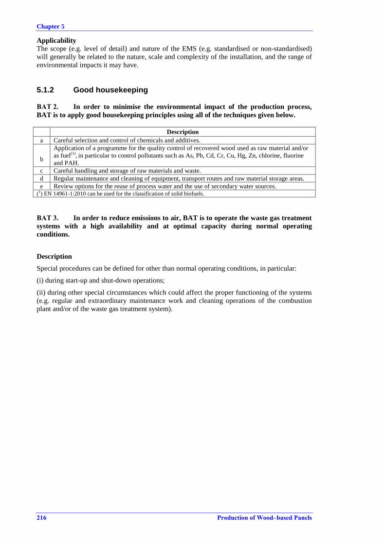
Chapter 5
216 Production of Wood–based Panels
Applicability
The scope (e.g. level of detail) and nature of the EMS (e.g. standardised or non-standardised)
will generally be related to the nature, scale and complexity of the installation, and the range of
environmental impacts it may have.
5.1.2 Good housekeeping
BAT 2. In order to minimise the environmental impact of the production process,
BAT is to apply good housekeeping principles using all of the techniques given below.
Description
a Careful selection and control of chemicals and additives.
b
Application of a programme for the quality control of recovered wood used as raw material and/or
as fuel(1)
, in particular to control pollutants such as As, Pb, Cd, Cr, Cu, Hg, Zn, chlorine, fluorine
and PAH.
c Careful handling and storage of raw materials and waste.
d Regular maintenance and cleaning of equipment, transport routes and raw material storage areas.
e Review options for the reuse of process water and the use of secondary water sources. (1) EN 14961-1:2010 can be used for the classification of solid biofuels.
BAT 3. In order to reduce emissions to air, BAT is to operate the waste gas treatment
systems with a high availability and at optimal capacity during normal operating
conditions.
Description
Special procedures can be defined for other than normal operating conditions, in particular:
(i) during start-up and shut-down operations;
(ii) during other special circumstances which could affect the proper functioning of the systems
(e.g. regular and extraordinary maintenance work and cleaning operations of the combustion
plant and/or of the waste gas treatment system).

Chapter 5
Production of Wood–based Panels 217
5.1.3 Noise
BAT 4. In order to prevent or, where that is not practicable, to reduce noise and
vibrations, BAT is to use one or a combination of the techniques given below.
Description Applicability
Techniques for the prevention of noise and vibrations
a
Strategic planning of the plant layout in order to accommodate
the noisiest operations, e.g. so that on-site buildings act as
insulation.
Generally applicable in new
plants. The layout of a site
may limit the applicability
on existing plants
b
Applying a noise reduction programme which includes noise
source mapping, determination of off-site receptors, modelling of
noise propagation and evaluation of the most cost-effective
measures and their implementation. Generally applicable
c Performing regular noise surveys with monitoring of noise levels
outside the site boundaries.
Techniques for reduction of noise and vibrations from point sources
d Enclosing noisy equipment in housing or by encapsulation and by
soundproofing buildings.
Generally applicable
e Decoupling individual equipment to pre-empt and limit
propagation of vibrations and resonance noise.
f
Point source insulation using silencer, damping, attenuators on
noise sources, e.g. fans, acoustic vents, mufflers, and acoustic
enclosures of filters.
g Keeping gates and doors closed at all times when not in use.
Minimising the fall height when unloading roundwood.
Techniques for reduction of noise and vibrations at the site level
h Reducing noise from traffic by limiting the speed of internal
traffic and for trucks entering the site.
Generally applicable i Limiting outdoor activities during the night.
j Regular maintenance of all equipment.
k Using noise protection walls, natural barriers or embankments to
screen noise sources.
5.1.4 Emissions to soil and groundwater
BAT 5. In order to prevent emissions to soil and groundwater, BAT is to use the
techniques given below.
I. load and unload resins and other auxiliary materials only in designated areas that are
protected against leakage run-off;
II. whilst awaiting disposal, collect all material and store in designated areas protected
against leakage run-off;
III. equip all pump sumps or other intermediary storage facilities from which spillages may
occur with alarms activated by high levels of liquid;
IV. establish and implement a programme for the testing and inspection of tanks and pipelines
carrying resins, additives and resin mixes;
V. carry out inspections for leaks on all flanges and valves on pipes used to transport
materials other than water and wood; maintain a log of these inspections;
VI. provide a containment system to collect any leaks from flanges and valves on pipes used
to transport materials other than water and wood, except when the construction of flanges
or valves is technically tight;
VII. provide an adequate supply of containment booms and suitable absorbent material;
VIII. avoid underground piping for transporting substances other than water and wood;
IX. collect and safely dispose of all water from firefighting;
X. construct impermeable bottoms in retention basins for surface run-off water from outdoor
wood storage areas.
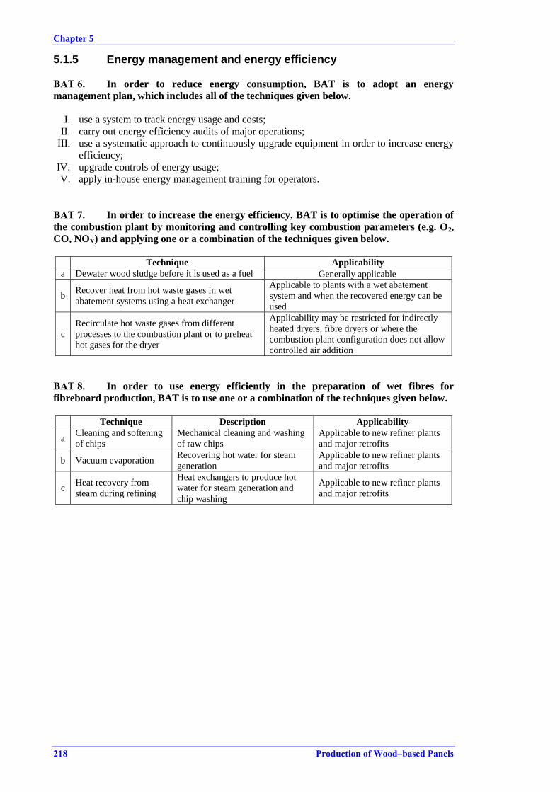
Chapter 5
218 Production of Wood–based Panels
5.1.5 Energy management and energy efficiency
BAT 6. In order to reduce energy consumption, BAT is to adopt an energy
management plan, which includes all of the techniques given below.
I. use a system to track energy usage and costs;
II. carry out energy efficiency audits of major operations;
III. use a systematic approach to continuously upgrade equipment in order to increase energy
efficiency;
IV. upgrade controls of energy usage;
V. apply in-house energy management training for operators.
BAT 7. In order to increase the energy efficiency, BAT is to optimise the operation of
the combustion plant by monitoring and controlling key combustion parameters (e.g. O2,
CO, NOX) and applying one or a combination of the techniques given below.
Technique Applicability
a Dewater wood sludge before it is used as a fuel Generally applicable
b Recover heat from hot waste gases in wet
abatement systems using a heat exchanger
Applicable to plants with a wet abatement
system and when the recovered energy can be
used
c
Recirculate hot waste gases from different
processes to the combustion plant or to preheat
hot gases for the dryer
Applicability may be restricted for indirectly
heated dryers, fibre dryers or where the
combustion plant configuration does not allow
controlled air addition
BAT 8. In order to use energy efficiently in the preparation of wet fibres for
fibreboard production, BAT is to use one or a combination of the techniques given below.
Technique Description Applicability
a Cleaning and softening
of chips
Mechanical cleaning and washing
of raw chips
Applicable to new refiner plants
and major retrofits
b Vacuum evaporation Recovering hot water for steam
generation
Applicable to new refiner plants
and major retrofits
c Heat recovery from
steam during refining
Heat exchangers to produce hot
water for steam generation and
chip washing
Applicable to new refiner plants
and major retrofits
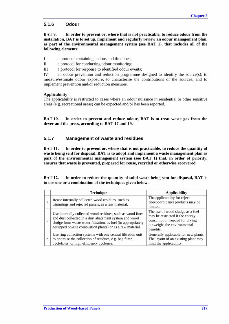
Chapter 5
Production of Wood–based Panels 219
5.1.6 Odour
BAT 9. In order to prevent or, where that is not practicable, to reduce odour from the
installation, BAT is to set up, implement and regularly review an odour management plan,
as part of the environmental management system (see BAT 1), that includes all of the
following elements:
I a protocol containing actions and timelines;
II a protocol for conducting odour monitoring;
III a protocol for response to identified odour events;
IV an odour prevention and reduction programme designed to identify the source(s); to
measure/estimate odour exposure; to characterise the contributions of the sources; and to
implement prevention and/or reduction measures.
Applicability The applicability is restricted to cases where an odour nuisance in residential or other sensitive
areas (e.g. recreational areas) can be expected and/or has been reported.
BAT 10. In order to prevent and reduce odour, BAT is to treat waste gas from the
dryer and the press, according to BAT 17 and 19.
5.1.7 Management of waste and residues
BAT 11. In order to prevent or, where that is not practicable, to reduce the quantity of
waste being sent for disposal, BAT is to adopt and implement a waste management plan as
part of the environmental management system (see BAT 1) that, in order of priority,
ensures that waste is prevented, prepared for reuse, recycled or otherwise recovered.
BAT 12. In order to reduce the quantity of solid waste being sent for disposal, BAT is
to use one or a combination of the techniques given below.
Technique Applicability
a Reuse internally collected wood residues, such as
trimmings and rejected panels, as a raw material.
The applicability for reject
fibreboard panel products may be
limited.
b
Use internally collected wood residues, such as wood fines
and dust collected in a dust abatement system and wood
sludge from waste water filtration, as fuel (in appropriately
equipped on-site combustion plants) or as a raw material.
The use of wood sludge as a fuel
may be restricted if the energy
consumption needed for drying
outweighs the environmental
benefits.
c
Use ring collection systems with one central filtration unit
to optimise the collection of residues, e.g. bag filter,
cyclofilter, or high efficiency cyclones.
Generally applicable for new plants.
The layout of an existing plant may
limit the applicability.
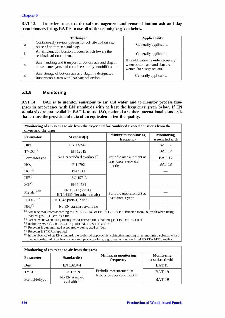
Chapter 5
220 Production of Wood–based Panels
BAT 13. In order to ensure the safe management and reuse of bottom ash and slag
from biomass-firing, BAT is to use all of the techniques given below.
Technique Applicability
a Continuously review options for off-site and on-site
reuse of bottom ash and slag. Generally applicable.
b An efficient combustion process which lowers the
residual carbon content. Generally applicable.
c Safe handling and transport of bottom ash and slag in
closed conveyers and containers, or by humidification.
Humidification is only necessary
when bottom ash and slag are
wetted for safety reasons.
d Safe storage of bottom ash and slag in a designated
impermeable area with leachate collection. Generally applicable.
5.1.8 Monitoring
BAT 14. BAT is to monitor emissions to air and water and to monitor process flue-
gases in accordance with EN standards with at least the frequency given below. If EN
standards are not available, BAT is to use ISO, national or other international standards
that ensure the provision of data of an equivalent scientific quality.
Monitoring of emissions to air from the dryer and for combined treated emissions from the
dryer and the press
Parameter Standard(s) Minimum monitoring
frequency
Monitoring
associated with
Dust EN 13284-1
Periodic measurement at
least once every six
months
BAT 17
TVOC(1)
EN 12619 BAT 17
Formaldehyde No EN standard available(6)
BAT 17
NOX E 14792 BAT 18
HCl(4)
EN 1911 —
HF(4)
ISO 15713 —
SO2(2)
EN 14791
Periodic measurement at
least once a year
—
Metals(3) (4)
EN 13211 (for Hg),
EN 14385 (for other metals) —
PCDD/F(4)
EN 1948 parts 1, 2 and 3 —
NH3(5)
No EN standard available — (1) Methane monitored according to EN ISO 25140 or EN ISO 25139 is subtracted from the result when using
natural gas, LPG, etc. as a fuel. (2) Not relevant when using mainly wood-derived fuels, natural gas, LPG, etc. as a fuel. (3) Including As, Cd, Co, Cr, Cu, Hg, Mn, Ni, Pb, Sb, Tl and V. (4) Relevant if contaminated recovered wood is used as fuel. (5) Relevant if SNCR is applied. (6) In the absence of an EN standard, the preferred approach is isokinetic sampling in an impinging solution with a
heated probe and filter box and without probe washing, e.g. based on the modified US EPA M316 method.
Monitoring of emissions to air from the press
Parameter Standard(s) Minimum monitoring
frequency
Monitoring
associated with
Dust EN 13284-1
Periodic measurement at
least once every six months
BAT 19
TVOC EN 12619 BAT 19
Formaldehyde No EN standard
available(2)
BAT 19

Chapter 5
Production of Wood–based Panels 221
Monitoring of emissions to air from paper impregnation drying ovens
Parameter Standard(s) Minimum monitoring
frequency
Monitoring
associated with
TVOC(1)
EN 12619 Periodic measurement at
least once a year
BAT 21
Formaldehyde No EN standard
available(2)
BAT 21
(1) Methane monitored according to EN ISO 25140 or EN ISO 25139 is subtracted from the result when using
natural gas, LPG, etc. as a fuel. (2)
In the absence of an EN standard, the preferred approach is isokinetic sampling in an impinging solution with
a heated probe and filter box and without probe washing, e.g. based on the modified US EPA M316 method.
Monitoring of channelled emissions to air from upstream and downstream processing
Parameter Standard(s) Minimum monitoring
frequency
Monitoring
associated with
Dust EN 13284-1(1) Periodic measurement at least
once a year(1)
BAT 20
(1) Sampling from bag filters and cyclofilters can be replaced by continuous monitoring of the pressure drop
across the filter as an indicative surrogate parameter.
Monitoring of combustion process flue-gas that is subsequently used for directly heated dryers(1)
Parameter Standard(s)
Minimum
monitoring
frequency
Monitoring
associated with
NOX
Periodic: EN 14792
Continuous: EN 15267-1 to 3 and EN
14181
Periodic
measurement at
least once a year or
continuous
measurement
BAT 7
CO
Periodic: EN 15058
Continuous: EN 15267-1 to 3 and EN
14181
BAT 7
(1) The measurement point is before the mixing of the flue-gas with other airstreams and only if technically
feasible.
Monitoring of emissions to water from wood fibre production
Parameter Standard(s) Minimum monitoring frequency Monitoring
associated with
TSS EN 872
Periodic measurement at least
once a week.
BAT 27
COD(1)
No EN standard
available BAT 27
TOC (Total organic
carbon, expressed as C) EN 1484 _
Metals(2)
, if relevant
(e.g. when recovered
wood is used)
Various EN
standards
available
Periodic measurement at least
once every six months.
_
(1) There is a tendency to replace COD with TOC for economic and environmental reasons. A correlation between
the two parameters should be established on a site-specific basis. (2) Including As, Cr, Cu, Ni, Pb and Zn.
Monitoring of emissions to water from surface run-off water
Parameter Standard(s) Minimum monitoring frequency Monitoring
associated with
TSS EN 872 Periodic measurement at least once every
three months(1)
BAT 25
(1) Flow-proportional sampling can be replaced by another standard sampling procedure if the flow is insufficient
for representative sampling.
Chapter 5
222 Production of Wood–based Panels
BAT 15. In order to ensure the stability and efficiency of techniques used to prevent
and reduce emissions, BAT is to monitor appropriate surrogate parameters.
Description
The surrogate parameters monitored may include: waste gas airflow; waste gas temperature;
visual appearance of emissions; water flow and water temperature for scrubbers; voltage drop
for electrostatic precipitators; fan speed and pressure drop across bag filters. The selection of
surrogate parameters depends on the techniques implemented for the prevention and reduction
of emissions.
BAT 16. BAT is to monitor key process parameters relevant for emissions to water
from the production process, including waste water flow, pH and temperature.

Chapter 5
Production of Wood–based Panels 223
5.2 Emissions to air
5.2.1 Channelled emissions
BAT 17. In order to prevent or reduce emissions to air from the dryer, BAT is to
achieve and manage a balanced operation of the drying process and to use one or a
combination of the techniques given below.
Technique Main pollutants abated Applicability
a
Dust abatement of inlet hot gas to a
directly heated dryer in combination
with one or a combination of the
other techniques listed below
Dust
Applicability may be
restricted, e.g. in cases of
existing smaller wood dust
burners.
b Bag filter(1)
Dust
Applicable to indirectly heated
dryers only. Due to safety
concerns, special care should
be taken when using
exclusively recovered wood.
c Cyclone(1)
Dust Generally applicable.
d
UTWS dryer and combustion with
heat exchanger and thermal
treatment of discharged dryer waste
gas(1)
Dust, volatile organic
compounds
Not applicable to fibre dryers.
Applicability may be limited
for existing combustion plants
not suitable for post-
combustion of the partial dryer
waste gas flow.
e Wet electrostatic precipitator(1) Dust, volatile organic
compounds Generally applicable.
f Wet scrubber(1) Dust, volatile organic
compounds Generally applicable.
g Bioscrubber(1) Dust, volatile organic
compounds
Applicability may be limited
by high dust concentrations
and high temperatures in the
waste gas from the dryer.
h
Chemical degradation or capture of
formaldehyde with chemicals in
combination with a wet scrubbing
system
Formaldehyde Generally applicable in wet
abatement systems.
(1) Descriptions of the techniques are given in Section 5.4.1.
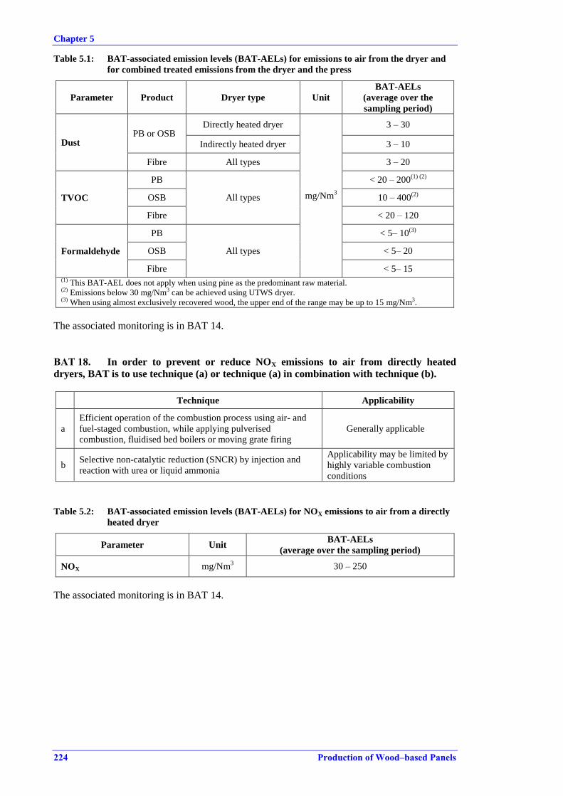
Chapter 5
224 Production of Wood–based Panels
Table 5.1: BAT-associated emission levels (BAT-AELs) for emissions to air from the dryer and
for combined treated emissions from the dryer and the press
Parameter Product Dryer type Unit
BAT-AELs
(average over the
sampling period)
Dust PB or OSB
Directly heated dryer
mg/Nm3
3 – 30
Indirectly heated dryer 3 – 10
Fibre All types 3 – 20
TVOC
PB
All types
< 20 – 200(1) (2)
OSB 10 – 400(2)
Fibre < 20 – 120
Formaldehyde
PB
All types
< 5– 10(3)
OSB < 5– 20
Fibre < 5– 15 (1) This BAT-AEL does not apply when using pine as the predominant raw material. (2) Emissions below 30 mg/Nm3 can be achieved using UTWS dryer. (3) When using almost exclusively recovered wood, the upper end of the range may be up to 15 mg/Nm3.
The associated monitoring is in BAT 14.
BAT 18. In order to prevent or reduce NOX emissions to air from directly heated
dryers, BAT is to use technique (a) or technique (a) in combination with technique (b).
Technique Applicability
a
Efficient operation of the combustion process using air- and
fuel-staged combustion, while applying pulverised
combustion, fluidised bed boilers or moving grate firing
Generally applicable
b Selective non-catalytic reduction (SNCR) by injection and
reaction with urea or liquid ammonia
Applicability may be limited by
highly variable combustion
conditions
Table 5.2: BAT-associated emission levels (BAT-AELs) for NOX emissions to air from a directly
heated dryer
Parameter Unit BAT-AELs
(average over the sampling period)
NOX mg/Nm3 30 – 250
The associated monitoring is in BAT 14.
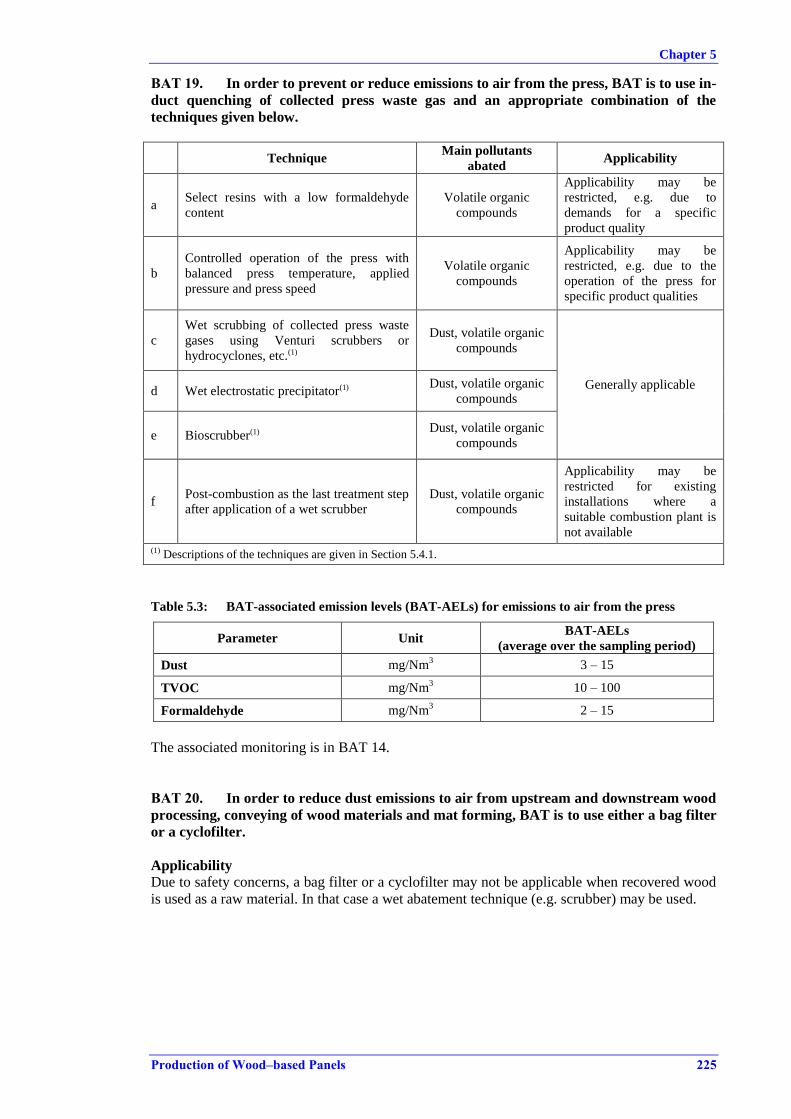
Chapter 5
Production of Wood–based Panels 225
BAT 19. In order to prevent or reduce emissions to air from the press, BAT is to use in-
duct quenching of collected press waste gas and an appropriate combination of the
techniques given below.
Technique Main pollutants
abated Applicability
a Select resins with a low formaldehyde
content
Volatile organic
compounds
Applicability may be
restricted, e.g. due to
demands for a specific
product quality
b
Controlled operation of the press with
balanced press temperature, applied
pressure and press speed
Volatile organic
compounds
Applicability may be
restricted, e.g. due to the
operation of the press for
specific product qualities
c
Wet scrubbing of collected press waste
gases using Venturi scrubbers or
hydrocyclones, etc.(1)
Dust, volatile organic
compounds
Generally applicable d Wet electrostatic precipitator(1)
Dust, volatile organic
compounds
e Bioscrubber(1) Dust, volatile organic
compounds
f Post-combustion as the last treatment step
after application of a wet scrubber
Dust, volatile organic
compounds
Applicability may be
restricted for existing
installations where a
suitable combustion plant is
not available
(1) Descriptions of the techniques are given in Section 5.4.1.
Table 5.3: BAT-associated emission levels (BAT-AELs) for emissions to air from the press
Parameter Unit BAT-AELs
(average over the sampling period)
Dust mg/Nm3 3 – 15
TVOC mg/Nm3 10 – 100
Formaldehyde mg/Nm3 2 – 15
The associated monitoring is in BAT 14.
BAT 20. In order to reduce dust emissions to air from upstream and downstream wood
processing, conveying of wood materials and mat forming, BAT is to use either a bag filter
or a cyclofilter.
Applicability
Due to safety concerns, a bag filter or a cyclofilter may not be applicable when recovered wood
is used as a raw material. In that case a wet abatement technique (e.g. scrubber) may be used.

Chapter 5
226 Production of Wood–based Panels
Table 5.4: BAT-associated emission levels (BAT-AELs) for channelled dust emissions to air from
upstream and downstream wood processing, conveying of wood materials and mat
forming
Parameter Unit BAT-AELs
(average over the sampling period)
Dust mg/Nm3 < 3–5
(1)
(1) When a bag filter or a cyclofilter is not applicable, the upper end of the range can be up to 10 mg/Nm3.
The associated monitoring is in BAT 14.
BAT 21. In order to reduce emissions of volatile organic compounds to air from the
drying ovens for the impregnation of paper, BAT is to use one or a combination of the
techniques given below.
Technique Applicability
a Select and use resins with a low formaldehyde
content
Generally applicable b Controlled operation of ovens with balanced
temperature and speed
c Thermal oxidation of waste gas in a regenerative
thermal oxidiser or a catalytic thermal oxidiser(1)
d Post-combustion or incineration of waste gas in a
combustion plant
Applicability may be restricted for
existing installations where a suitable
combustion plant is not available on site
e Wet scrubbing of waste gas followed by treatment
in a biofilter(1) Generally applicable
(1) Descriptions of the techniques are given in Section 5.4.1.
Table 5.5: BAT-associated emission levels (BAT-AELs) for TVOC and formaldehyde emissions
to air from the drying ovens for the impregnation of paper
Parameter Unit BAT-AELs
(average over the sampling period)
TVOC mg/Nm3 5 – 30
Formaldehyde mg/Nm3 <5 – 10
The associated monitoring is in BAT 14.
Chapter 5
Production of Wood–based Panels 227
5.2.2 Diffuse emissions
BAT 22. In order to prevent or, where that is not practicable, to reduce diffuse
emissions to air from the press, BAT is to optimise the efficiency of the off-gas collection
and to channel the off-gases for treatment (see BAT 19).
Description
Effective collection and treatment of waste gases (see BAT 19) both at the press exit and along
the press line for continuous presses. For existing multi-opening presses the applicability of
enclosing the press may be restricted due to safety reasons.
BAT 23. In order to reduce diffuse dust emissions to air from the transport, handling,
and storage of wood materials, BAT is to set up and implement a dust management plan,
as part of the environmental management system (see BAT 1) and to apply one or a
combination of the techniques given below.
Technique Applicability
a Regularly clean transport routes, storage areas and vehicles
Generally
applicable
b Unload sawdust using covered drive-through unloading areas
c Store sawdust dust-prone material in silos, containers, roofed piles, etc. or
enclose bulk storage areas
d Suppress dust emissions by water sprinkling
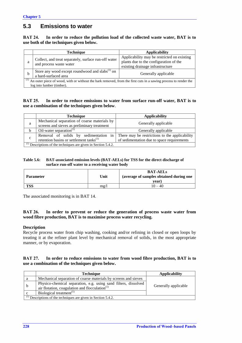
Chapter 5
228 Production of Wood–based Panels
5.3 Emissions to water
BAT 24. In order to reduce the pollution load of the collected waste water, BAT is to
use both of the techniques given below.
Technique Applicability
a Collect, and treat separately, surface run-off water
and process waste water
Applicability may be restricted on existing
plants due to the configuration of the
existing drainage infrastructure
b Store any wood except roundwood and slabs
(1) on
a hard-surfaced area Generally applicable
(1) An outer piece of wood, with or without the bark removed, from the first cuts in a sawing process to render the
log into lumber (timber).
BAT 25. In order to reduce emissions to water from surface run-off water, BAT is to
use a combination of the techniques given below.
Technique Applicability
a Mechanical separation of coarse materials by
screens and sieves as preliminary treatment Generally applicable
b Oil-water separation(1)
Generally applicable
c Removal of solids by sedimentation in
retention basins or settlement tanks(1)
There may be restrictions to the applicability
of sedimentation due to space requirements (1) Descriptions of the techniques are given in Section 5.4.2.
Table 5.6: BAT-associated emission levels (BAT-AELs) for TSS for the direct discharge of
surface run-off water to a receiving water body
Parameter Unit
BAT-AELs
(average of samples obtained during one
year)
TSS mg/l 10 – 40
The associated monitoring is in BAT 14.
BAT 26. In order to prevent or reduce the generation of process waste water from
wood fibre production, BAT is to maximise process water recycling.
Description
Recycle process water from chip washing, cooking and/or refining in closed or open loops by
treating it at the refiner plant level by mechanical removal of solids, in the most appropriate
manner, or by evaporation.
BAT 27. In order to reduce emissions to water from wood fibre production, BAT is to
use a combination of the techniques given below.
Technique Applicability
a Mechanical separation of coarse materials by screens and sieves
Generally applicable b Physico-chemical separation, e.g. using sand filters, dissolved
air flotation, coagulation and flocculation(1)
c Biological treatment(1)
(1) Descriptions of the techniques are given in Section 5.4.2.
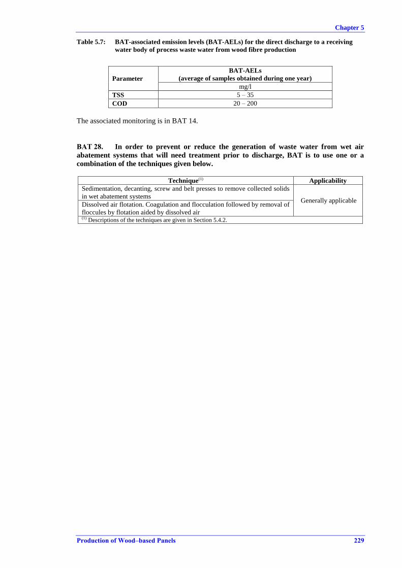
Chapter 5
Production of Wood–based Panels 229
Table 5.7: BAT-associated emission levels (BAT-AELs) for the direct discharge to a receiving
water body of process waste water from wood fibre production
Parameter
BAT-AELs
(average of samples obtained during one year)
mg/l
TSS 5 – 35
COD 20 – 200
The associated monitoring is in BAT 14.
BAT 28. In order to prevent or reduce the generation of waste water from wet air
abatement systems that will need treatment prior to discharge, BAT is to use one or a
combination of the techniques given below.
Technique(1) Applicability
Sedimentation, decanting, screw and belt presses to remove collected solids
in wet abatement systems Generally applicable Dissolved air flotation. Coagulation and flocculation followed by removal of
floccules by flotation aided by dissolved air (1) Descriptions of the techniques are given in Section 5.4.2.
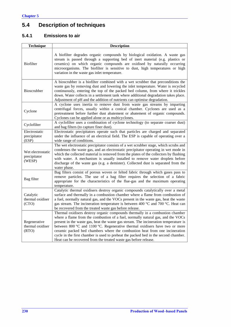
Chapter 5
230 Production of Wood–based Panels
5.4 Description of techniques
5.4.1 Emissions to air
Technique Description
Biofilter
A biofilter degrades organic compounds by biological oxidation. A waste gas
stream is passed through a supporting bed of inert material (e.g. plastics or
ceramics) on which organic compounds are oxidised by naturally occurring
microorganisms. The biofilter is sensitive to dust, high temperatures or high
variation in the waste gas inlet temperature.
Bioscrubber
A bioscrubber is a biofilter combined with a wet scrubber that preconditions the
waste gas by removing dust and lowering the inlet temperature. Water is recycled
continuously, entering the top of the packed bed column, from where it trickles
down. Water collects in a settlement tank where additional degradation takes place.
Adjustment of pH and the addition of nutrients can optimise degradation.
Cyclone
A cyclone uses inertia to remove dust from waste gas streams by imparting
centrifugal forces, usually within a conical chamber. Cyclones are used as a
pretreatment before further dust abatement or abatement of organic compounds.
Cyclones can be applied alone or as multicyclones.
Cyclofilter A cyclofilter uses a combination of cyclone technology (to separate coarser dust)
and bag filters (to capture finer dust).
Electrostatic
precipitator
(ESP)
Electrostatic precipitators operate such that particles are charged and separated
under the influence of an electrical field. The ESP is capable of operating over a
wide range of conditions.
Wet electrostatic
precipitator
(WESP)
The wet electrostatic precipitator consists of a wet scrubber stage, which scrubs and
condenses the waste gas, and an electrostatic precipitator operating in wet mode in
which the collected material is removed from the plates of the collectors by flushing
with water. A mechanism is usually installed to remove water droplets before
discharge of the waste gas (e.g. a demister). Collected dust is separated from the
water phase.
Bag filter
Bag filters consist of porous woven or felted fabric through which gases pass to
remove particles. The use of a bag filter requires the selection of a fabric
appropriate for the characteristics of the flue-gas and the maximum operating
temperature.
Catalytic
thermal oxidiser
(CTO)
Catalytic thermal oxidisers destroy organic compounds catalytically over a metal
surface and thermally in a combustion chamber where a flame from combustion of
a fuel, normally natural gas, and the VOCs present in the waste gas, heat the waste
gas stream. The incineration temperature is between 400 °C and 700 °C. Heat can
be recovered from the treated waste gas before release.
Regenerative
thermal oxidiser
(RTO)
Thermal oxidisers destroy organic compounds thermally in a combustion chamber
where a flame from the combustion of a fuel, normally natural gas, and the VOCs
present in the waste gas, heat the waste gas stream. The incineration temperature is
between 800 °C and 1100 °C. Regenerative thermal oxidisers have two or more
ceramic packed bed chambers where the combustion heat from one incineration
cycle in the first chamber is used to preheat the packed bed in the second chamber.
Heat can be recovered from the treated waste gas before release.

Chapter 5
Production of Wood–based Panels 231
UTWS dryer
and combustion
with heat
exchanger and
thermal
treatment of
discharged dryer
waste gas
UTWS is a German acronym: 'Umluft' (recirculation of dryer waste gas),
'Teilstromverbrennung' (post-combustion of partial directed dryer waste gas
stream), 'Wärmerückgewinnung' (heat recovery of dryer waste gas),
'Staubabsheidung' (dust treatment of air emission discharge from the combustion
plant).
UTWS is a combination of a rotary dryer with a heat exchanger and a combustion
plant with recirculation of dryer waste gas. The recirculated dryer waste gas is a hot
vapour stream that enables a vapour drying process. The dryer waste gas is reheated
in a heat exchanger heated by the combustion flue-gases and is fed back to the
dryer. Part of the dryer waste gas stream is continuously fed to the combustion
chamber for post-combustion. Pollutants emitted from the wood drying are
destroyed over the heat exchanger and by the post-combustion. The flue-gases
discharged from the combustion plant are treated by a bag filter or electrostatic
precipitator.
Wet scrubber
Wet scrubbers capture and remove dust by inertial impaction, direct interception
and absorption in the water phase. Wet scrubbers can have various designs and
operating principles, e.g. spray scrubber, impingement plate scrubber or Venturi
scrubber, and can be used as a dust pretreatment or a stand-alone technique. Some
removal of organic compounds may be achieved and can be further enhanced by
using chemicals in the scrubbing water (achieving chemical oxidation or another
conversion). The resulting liquid has to be treated by separating the collected dust
by sedimentation or filtration.
5.4.2 Emissions to water
Technique Description
Biological
treatment
The biological oxidation of dissolved organic substances using the metabolism of
microorganisms, or the breakdown of organic content in waste water by the action
of microorganisms in the absence of air. The biological action is usually followed
by the removal of suspended solids, e.g. by sedimentation.
Coagulation and
flocculation
Coagulation and flocculation are used to separate suspended solids from waste
water and are often carried out in successive steps. Coagulation is carried out by
adding coagulants with charges opposite to those of the suspended solids.
Flocculation is carried out by adding polymers, so that collisions of microfloc
particles cause them to bond to produce larger flocs.
Flotation The separation of large flocs or floating particles from the effluent by bringing
them to the surface of the suspension.
Dissolved air
flotation
Flotation techniques relying on the use of dissolved air to achieve separation of
coagulated and flocculated material.
Filtration
The separation of solids from a waste water carrier by passing them through a
porous medium. It includes different types of techniques, e.g. sand filtration,
microfiltration and ultrafiltration.
Oil-water
separation
The separation and extraction of insoluble hydrocarbons, relying on the principle
of the difference in gravity between the phases (liquid-liquid or solid-liquid). The
higher density phase settles and the lower density phase floats to the surface.
Retention basins Large surface area lagoons for the passive gravitational settlement of solids.
Sedimentation The separation of suspended particles and material by gravitational settling.

Chapter 6
Production of Wood–based Panels 233
6 EMERGING TECHNIQUES
6.1 Superheated steam dryers
Steam dryers are, in principle, already in operation, since the introduction of the UTWS dryer,
where all dryer waste gas is recirculated through a heat exchanger and a part of it is sent to the
combustion chamber, which thermally destructs the organic compounds present in the waste
gas.
The energy-saving potential of superheated steam dryers, where the excess energy in the steam
vaporised from the wood material could be used for generating power or be heat-exchanged for
other uses, seems not yet to have been developed in the wood-based panel sector. Superheated
steam drying is already applied in other industrial sectors. A few wood industry plants are
operating with these dryers, such as for the drying of wood pellets or the drying of fibres
[ 59, Deventer 2004 ].
Chapter 6
234 Production of Wood–based Panels
6.2 Recovery of organic compounds from wood
VOC compounds may be recovered from dryer waste gas and burnt in the boiler to increase
energy efficiency or they can alternatively be used as raw material for other products.
In superheated steam dryers and indirectly fired steam-tube dryers in which no combustion air is
added, steam vented from the dryer can be condensed and the condensate collected in a
separator, where oils and terpenes are extracted. These VOCs can then be burnt in a suitable
combustion plant as a fuel or used for other products, e.g. production of bioethanol.
Superheated steam drying is comparable to steam distillation, which is used in other sectors to
extract essential oils from plant material, e.g. for the food industry. High steam temperatures
result in the extraction of a significant amount of VOCs from the material. The wood oils,
hemicellulose and terpenes extracted from the wood chips, bark and sawdust of softwood
species, especially from the Pinus family, are used in the manufacture of fragrances and in
cosmetics, cleaning products, paint thinners, surfactants, and pharmaceuticals and for
biorefining [ 57, Northwest CHP 2008 ].
In the pulp industry, the use of water, for example from the pre-cooking step before refining, as
a source for production of bioethanol, etc. has been tested and the first biorefineries are being
established in Europe. The development of biorefineries as secondary production options in the
industry sectors related to the use of forest products could also be relevant for the wood-based
panel industry. At the research level, it is suggested that wet extraction of OSB flakes prior to
drying would yield an extract suitable for biorefining and additionally reduce the level of
volatile organic compounds emitted during drying and pressing [ 75, VTT 2012 ] [ 76, Mason
Earles et al. 2011 ].
Chapter 6
Production of Wood–based Panels 235
6.3 Reuse of reject papers from the paper impregnation line
Studies performed in Hungary indicate that impregnated paper could be recycled in
particleboard production, and thus lower the amount of resin needed for the particleboard and at
the same time reduce disposal costs.
Melamine paper can be used in fine powder form as a binding product for wood chip plates and
as a replacement product for melamine.
Due to problems associated with an excessive increase in the viscosity, a maximum of 25 % of
the melamine content in melamine resin can be replaced during the formulation and preparation
of liquid MUF glue.
[ 66, Alpar et al. 2006 ], [ 67, VITO 2011 ].


Chapter 7
Production of Wood–based Panels 237
7 CONCLUDING REMARKS AND RECOMMENDATIONS FOR FUTURE WORK
Timing of the drafting process
The key milestones of the drafting process are summarised in Table 7.1.
Table 7.1: Key milestones in the drafting of the BREF for the Production of Wood-based Panels
Key Milestone Date Activation of the TWG 24 March 2011
Kick-off TWG meeting 8 – 10 November 2011
Collection of information and bulk of installation-
specific data March – November 2012
First draft of the WBP BREF 30 July 2013
End of commenting period on the first draft
(791 comments received) 15 October 2013
Final TWG meeting 1 to 4 April 2014
During the drafting process, a total of 21 sites were visited in eight Member States.
Sources of information and information gaps
During the drafting process, several hundred documents were shared by the TWG via the
Commission’s BAT information system (BATIS). This included approximately 80 installation-
specific questionnaires covering a total of 55 particleboard production lines, 11 OSB production
lines, 28 dry fibre (MDF) production lines and 8 speciality product production lines. The
installation-specific questionnaires were collected from the individual operators of the
approximately 80 sites mainly by EU Member States (Austria, Belgium, the Czech Republic,
Denmark, France, Germany, Ireland, Italy, Poland, Portugal, Spain, Sweden and the United
Kingdom) and Turkey. Industry provided information from one site in Romania and from one
site in Slovakia. Further information was provided by the European Panel Federation (EPF), and
Member States, primarily Austria, Belgium, France, Germany, Italy, Spain and the United
Kingdom. All these documents were assessed by the EIPPCB together with additional
documents that could not be shared via BATIS due for example to copyright restrictions or
confidentiality issues. Among the approximately 80 installation-specific questionnaires, around
55 installations provided further sensitive business information as additional contextual
information. This information has not been shared on BATIS.
As a result, around 100 references are included in the WBP BREF (see the REFERENCES
section).
Degree of consensus reached during the information exchange
At the final TWG meeting in April 2014, a high degree of consensus was reached on the BAT
conclusions. However, two dissenting views were expressed by TWG members, see Table 7.2.
Table 7.2: Split views
BAT conclusion View expressed by Split view
BAT 17 Austria
A dissenting view was expressed by Austria, which
considers that regenerative thermal oxidation is a
BAT for the reduction of volatile organic compounds
and odour and should be listed under BAT 17.
BAT 17, Table 5.1 Austria, Belgium
and Germany
A dissenting view was expressed by Austria,
Belgium and Germany, which consider that the
upper end of the BAT-AEL range for dust emissions
to air from a directly heated PB or OSB dryer should
be 20 mg/Nm3 (18 % O2, dry basis).
Chapter 7
238 Production of Wood–based Panels
In addition, the reference conditions related to the different BAT-AELs in Tables 5.1, 5.3 and
5.4 of the BAT conclusions were heavily debated during the final TWG meeting. The
discussions focused on the best way to express measured emissions to air, especially whether or
not corrections for moisture content should be applied. Furthermore, the use of a reference
oxygen content to express the BAT-AELs in Table 5.1 for directly heated PB or OSB dryers
alone or combined with the press was also heavily debated.
Consultation of the Forum and subsequent formal adoption procedure of the BAT
conclusions
In accordance with Article 13(3) of the Directive, the Forum gave its opinion on the draft Best
Available Techniques (BAT) reference document for the Production of Wood-based Panels as
presented at the meeting of the forum of 24 September 2014:
1. The Forum welcomed the draft Best Available Techniques (BAT) reference document for the
Production of Wood-based Panels as presented by the Commission.
2. The Forum acknowledged the discussions held at its meeting of 24 September 2014 and
agreed that the changes to the draft Best Available Techniques (BAT) reference document for
the Production of Wood-based Panels, as proposed in Annex A, should be included in the final
document.
3. The Forum reaffirmed the comments in Annex B as representing the views of certain
members of the forum but on which no consensus existed within the Forum to include them in
the final document.
Subsequently, the Commission took the opinion of the IED Article 13 Forum into account when
preparing the draft Commission Implementing Decision establishing best available techniques
(BAT) conclusions for the Production of Wood-based Panels. The IED Article 75 Committee, at
its meeting of 30 June 2015, gave a positive opinion on this draft Commission Implementing
Decision.
Subsequently:
the Commission Implementing Decision 2015/2119/EU establishing best available
techniques (BAT) conclusions for the production of wood-based panels was adopted on
20 November 2015 and published in the Official Journal of the European Union (OJ L
306, 24.11.2015, p. 31).
Recommendations for future work
The information exchange revealed a number of issues that should be addressed during the
review of the WBP BREF. The issues include:
Consideration should be given to revisiting the question over the use of standard
conditions corrected for moisture content or with no correction for moisture content.
Further collection of detailed information on treatment of waste gases from different
sources, e.g. when waste gases from the dryer and the press are mixed with waste gases
from other processes.
Further collection of detailed information on the specificities of the drying operation for
OSB strands; plant-specific emissions data on volatile organic compounds from both
the dryer and the press; and the potential primary measures also applied outside Europe
to reduce emissions to air of volatile organic compounds from OSB production.
Consideration should be given to collecting information about the plant-specific
abatement efficiencies of techniques (especially of WESPs and wet abatement systems)
for different groups of volatile compounds, in particular terpenes and condensable
organic compounds, and related to the raw material.
Consideration should be given to collecting further information on the formaldehyde
content of different raw materials including different wood species, recovered wood and
production residues and the relation to formaldehyde emissions to air during processing
Chapter 7
Production of Wood–based Panels 239
Further collection of information on the economics and cross-media effects of thermal
oxidation techniques that can be used to abate volatile organic compounds and odour in
dryer waste gas.
The need to collect and review data on emissions of ammonia, total nitrogen and certain
metals to water from collected and treated process waste water and from collected
surface run-off water.
Further collection of information on dust emissions and their abatement from upstream
and downstream processing.
Further collection of information on the applicability of dust treatment of flue-gases
before these are used for directly heated dryers and technical information on the barriers
to applying it more widely.
Consideration of different production equipment used in unit operations as potential
BAT candidate techniques and further collection of information on economics and
cross-media effects, e.g. using continuous presses versus multi-opening presses and
directly heated dryers versus indirectly heated dryers, especially in terms of energy
efficiency.
The applicability and the added advantage of applying primary measures to reduce
emissions to air and water have not been fully explored in the document. The main
reason is that technical information was not submitted during the drafting of the
document. Research and emerging techniques should be taken further into account since
research strongly suggests that primary measures could account for a major emissions
reduction, especially in the emission to air of both dust and volatile organic compounds,
including formaldehyde.
Consideration of determining the abatement performance of candidate techniques and
BAT-AELs based on mass of emitted substance per tonne of dried material for the dryer
and mass of emitted substance per m3 of produced panel for the press.
The need to collect information about the specific fuel types, techniques applied and
related emission levels, especially of NOX, from combustion processes applied in the
sector, and consideration of potential inclusion in the scope of a reviewed WBP BREF
of combustion plants other than those used for the production of hot gases for directly
heated dryers.
Suggested topics for future R&D work
Research and development of emerging technologies should be a priority since research strongly
suggests that novel primary techniques could account for a major emissions reduction,
especially in the emission to air of both dust and volatile organic compounds, including
formaldehyde.
The Commission is launching and supporting, through its Research and Technological
Development programmes, a series of projects dealing with clean technologies, emerging
effluent treatment and recycling technologies and management strategies. Potentially, these
projects could provide a useful contribution to future BREF reviews. Readers are therefore
invited to inform the European IPPC Bureau of any research results which are relevant to the
scope of this document (see also the fifth section of the Preface of this document).

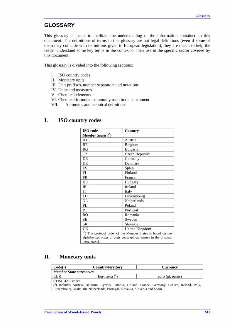
Glossary
Production of Wood–based Panels 241
GLOSSARY
This glossary is meant to facilitate the understanding of the information contained in this
document. The definitions of terms in this glossary are not legal definitions (even if some of
them may coincide with definitions given in European legislation), they are meant to help the
reader understand some key terms in the context of their use in the specific sector covered by
this document.
This glossary is divided into the following sections:
I. ISO country codes
II. Monetary units
III. Unit prefixes, number separators and notations
IV. Units and measures
V. Chemical elements
VI. Chemical formulae commonly used in this document
VII. Acronyms and technical definitions
I. ISO country codes
ISO code Country
Member States (*)
AT Austria
BE Belgium
BG Bulgaria
CZ Czech Republic
DE Germany
DK Denmark
ES Spain
FI Finland
FR France
HU Hungary
IE Ireland
IT Italy
LU Luxembourg
NL Netherlands
PL Poland
PT Portugal
RO Romania
SE Sweden
SK Slovakia
UK United Kingdom (*) The protocol order of the Member States is based on the
alphabetical order of their geographical names in the original
language(s).
II. Monetary units
Code(1) Country/territory Currency
Member State currencies
EUR Euro area (2) euro (pl. euros)
(1) ISO 4217 codes.
(2) Includes Austria, Belgium, Cyprus, Estonia, Finland, France, Germany, Greece, Ireland, Italy,
Luxembourg, Malta, the Netherlands, Portugal, Slovakia, Slovenia and Spain.
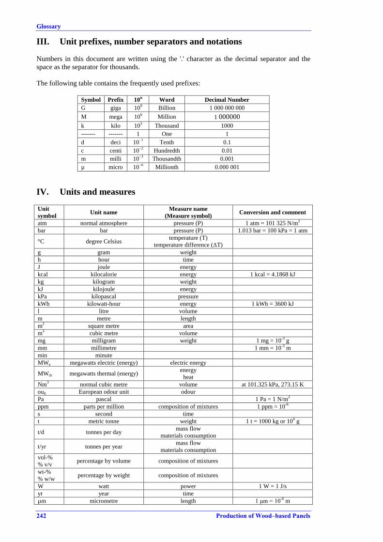
Glossary
242 Production of Wood–based Panels
III. Unit prefixes, number separators and notations
Numbers in this document are written using the '.' character as the decimal separator and the
space as the separator for thousands.
The following table contains the frequently used prefixes:
Symbol Prefix 10
n Word Decimal Number
G giga 109 Billion 1 000 000 000
M mega 106 Million 1 000000
k kilo 103 Thousand 1000
------- ------- 1 One 1
d deci 10−1
Tenth 0.1
c centi 10−2
Hundredth 0.01
m milli 10−3
Thousandth 0.001
µ micro 10−6
Millionth 0.000 001
IV. Units and measures Unit
symbol Unit name
Measure name
(Measure symbol) Conversion and comment
atm normal atmosphere pressure (P) 1 atm = 101 325 N/m2
bar bar pressure (P) 1.013 bar = 100 kPa = 1 atm
°C degree Celsius temperature (T)
temperature difference (ΔT)
g gram weight
h hour time
J joule energy
kcal kilocalorie energy 1 kcal = 4.1868 kJ
kg kilogram weight
kJ kilojoule energy
kPa kilopascal pressure
kWh kilowatt-hour energy 1 kWh = 3600 kJ
l litre volume
m metre length
m2 square metre area
m3 cubic metre volume
mg milligram weight 1 mg = 10-3
g
mm millimetre 1 mm = 10-3
m
min minute
MWe megawatts electric (energy) electric energy
MWth megawatts thermal (energy) energy
heat
Nm3 normal cubic metre volume at 101.325 kPa, 273.15 K
ouE European odour unit odour
Pa pascal 1 Pa = 1 N/m2
ppm parts per million composition of mixtures 1 ppm = 10-6
s second time
t metric tonne weight 1 t = 1000 kg or 106 g
t/d tonnes per day mass flow
materials consumption
t/yr tonnes per year mass flow
materials consumption
vol-%
% v/v percentage by volume composition of mixtures
wt-%
% w/w percentage by weight composition of mixtures
W watt power 1 W = 1 J/s
yr year time
µm micrometre length 1 μm = 10-6
m

Glossary
Production of Wood–based Panels 243
V. Chemical elements
Symbol Name Symbol Name
Al Aluminium Li Lithium
As Arsenic Mg Magnesium
B Boron Mn Manganese
Br Bromine Mo Molybdenum
C Carbon N Nitrogen
Ca Calcium Na Sodium
Cd Cadmium Ni Nickel
Cl Chlorine O Oxygen
Co Cobalt P Phosphorus
Cr Chromium Pb Lead
Cu Copper S Sulphur
F Fluorine Sb Antimony
Fe Iron Se Selenium
H Hydrogen Si Silicon
He Helium Sn Tin
Hg Mercury Tl Thallium
I Iodine V Vanadium
K Potassium Zn Zinc
VI. Chemical formulae
Chemical formula Name (explanation)
(NH4)2SO4 Ammonium sulphate
H2SO4 Sulphuric acid
NH4NO3 Ammonium nitrate
NH4Cl Ammonium chloride
HCl Hydrochloric acid
NaOH Sodium hydroxide. Also called caustic soda
H2O2 Hydrogen peroxide
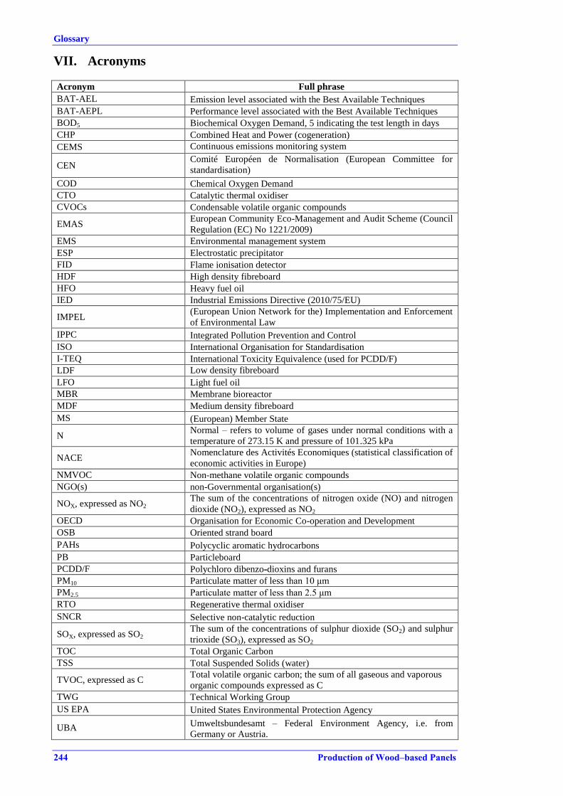
Glossary
244 Production of Wood–based Panels
VII. Acronyms
Acronym Full phrase
BAT-AEL Emission level associated with the Best Available Techniques
BAT-AEPL Performance level associated with the Best Available Techniques
BOD5 Biochemical Oxygen Demand, 5 indicating the test length in days
CHP Combined Heat and Power (cogeneration)
CEMS Continuous emissions monitoring system
CEN Comité Européen de Normalisation (European Committee for
standardisation)
COD Chemical Oxygen Demand
CTO Catalytic thermal oxidiser
CVOCs Condensable volatile organic compounds
EMAS European Community Eco-Management and Audit Scheme (Council
Regulation (EC) No 1221/2009)
EMS Environmental management system
ESP Electrostatic precipitator
FID Flame ionisation detector
HDF High density fibreboard
HFO Heavy fuel oil
IED Industrial Emissions Directive (2010/75/EU)
IMPEL (European Union Network for the) Implementation and Enforcement
of Environmental Law
IPPC Integrated Pollution Prevention and Control
ISO International Organisation for Standardisation
I-TEQ International Toxicity Equivalence (used for PCDD/F)
LDF Low density fibreboard
LFO Light fuel oil
MBR Membrane bioreactor
MDF Medium density fibreboard
MS (European) Member State
N Normal – refers to volume of gases under normal conditions with a
temperature of 273.15 K and pressure of 101.325 kPa
NACE Nomenclature des Activités Economiques (statistical classification of
economic activities in Europe)
NMVOC Non-methane volatile organic compounds
NGO(s) non-Governmental organisation(s)
NOX, expressed as NO2 The sum of the concentrations of nitrogen oxide (NO) and nitrogen
dioxide (NO2), expressed as NO2
OECD Organisation for Economic Co-operation and Development
OSB Oriented strand board
PAHs Polycyclic aromatic hydrocarbons
PB Particleboard
PCDD/F Polychloro dibenzo-dioxins and furans
PM10 Particulate matter of less than 10 μm
PM2.5 Particulate matter of less than 2.5 μm
RTO Regenerative thermal oxidiser
SNCR Selective non-catalytic reduction
SOX, expressed as SO2 The sum of the concentrations of sulphur dioxide (SO2) and sulphur
trioxide (SO3), expressed as SO2
TOC Total Organic Carbon
TSS Total Suspended Solids (water)
TVOC, expressed as C Total volatile organic carbon; the sum of all gaseous and vaporous
organic compounds expressed as C
TWG Technical Working Group
US EPA United States Environmental Protection Agency
UBA Umweltsbundesamt – Federal Environment Agency, i.e. from
Germany or Austria.
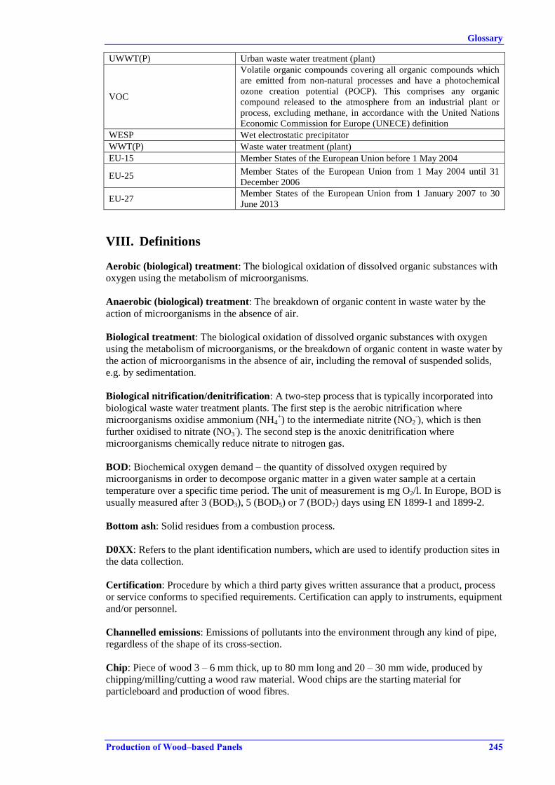
Glossary
Production of Wood–based Panels 245
UWWT(P) Urban waste water treatment (plant)
VOC
Volatile organic compounds covering all organic compounds which
are emitted from non-natural processes and have a photochemical
ozone creation potential (POCP). This comprises any organic
compound released to the atmosphere from an industrial plant or
process, excluding methane, in accordance with the United Nations
Economic Commission for Europe (UNECE) definition
WESP Wet electrostatic precipitator
WWT(P) Waste water treatment (plant)
EU-15 Member States of the European Union before 1 May 2004
EU-25 Member States of the European Union from 1 May 2004 until 31
December 2006
EU-27 Member States of the European Union from 1 January 2007 to 30
June 2013
VIII. Definitions
Aerobic (biological) treatment: The biological oxidation of dissolved organic substances with
oxygen using the metabolism of microorganisms.
Anaerobic (biological) treatment: The breakdown of organic content in waste water by the
action of microorganisms in the absence of air.
Biological treatment: The biological oxidation of dissolved organic substances with oxygen
using the metabolism of microorganisms, or the breakdown of organic content in waste water by
the action of microorganisms in the absence of air, including the removal of suspended solids,
e.g. by sedimentation.
Biological nitrification/denitrification: A two-step process that is typically incorporated into
biological waste water treatment plants. The first step is the aerobic nitrification where
microorganisms oxidise ammonium (NH4+) to the intermediate nitrite (NO2
-), which is then
further oxidised to nitrate (NO3-). The second step is the anoxic denitrification where
microorganisms chemically reduce nitrate to nitrogen gas.
BOD: Biochemical oxygen demand – the quantity of dissolved oxygen required by
microorganisms in order to decompose organic matter in a given water sample at a certain
temperature over a specific time period. The unit of measurement is mg O2/l. In Europe, BOD is
usually measured after 3 (BOD3), 5 (BOD5) or 7 (BOD7) days using EN 1899-1 and 1899-2.
Bottom ash: Solid residues from a combustion process.
D0XX: Refers to the plant identification numbers, which are used to identify production sites in
the data collection.
Certification: Procedure by which a third party gives written assurance that a product, process
or service conforms to specified requirements. Certification can apply to instruments, equipment
and/or personnel.
Channelled emissions: Emissions of pollutants into the environment through any kind of pipe,
regardless of the shape of its cross-section.
Chip: Piece of wood 3 – 6 mm thick, up to 80 mm long and 20 – 30 mm wide, produced by
chipping/milling/cutting a wood raw material. Wood chips are the starting material for
particleboard and production of wood fibres.

Glossary
246 Production of Wood–based Panels
COD: Chemical oxygen demand indicating the amount of organic matter in waste waters
susceptible to oxidation by a strong chemical oxidant (normally referring to analysis with
dichromate oxidation) according to ISO 15705:2002.
Coagulation and flocculation: Coagulation and flocculation are used to separate suspended
solids from waste water and are often carried out as successive steps. Coagulation is carried out
by adding coagulants with charges opposite to those of the suspended solids. Flocculation is
carried out by adding polymers, so that collisions of microfloc particles cause them to bond to
producer larger flocs.
Containment boom: A boom that can contain spillages and prevent them from entering drains to
watercourses or from further contaminating water sources.
Continuous measurement: Measuring using an 'automated measuring system' (AMS) or
'continuous emission monitoring system' (CEM) permanently installed on site.
Cooling water: Water used for energy transfer (heat removal from components and industrial
equipment), which is kept in a network separated from industrial water and which can be
released back to receiving waters without further treatment.
Corrosion: Surface chemical reaction, especially on metals, by the action of moisture, air or
chemicals.
Decommissioning: The shutting down of an installation including decontamination and/or
dismantling.
Diffuse emissions: Non-channelled emissions that are not released via specific emission points
such as stacks.
Emissions arising from the direct contact of volatile or light dusty substances with the
environment under normal operating circumstances. These can result from:
inherent design of the equipment (e.g. filters, dryers);
operating conditions (e.g. during transfer of material);
type of operation (e.g. maintenance activities);
a gradual release to other media (e.g. to cooling water or waste water).
Fugitive emissions are a subset of diffuse emissions.
Directly heated dryer: A dryer where hot gases from a combustion plant or any other source are
in direct contact with the particles, strands or fibres to be dried. The drying is achieved by
convection.
Discharge: Physical release of a pollutant through a defined outlet (i.e. channelled) system, (e.g.
sewer, stack, vent, curbing area, outfall).
Drainage: Natural or artificial removal of surface and subsurface water from an area, including
surface streams and groundwater pathways.
Dry process: Production of panels where the drying of particles or fibres is applied.
Dust: Dust includes all particulate matter including PM10 and aerosols below PM1.0.
Emission factor: The estimated average emission rate of a given pollutant for a given source,
relative to units of activity.

Glossary
Production of Wood–based Panels 247
Emissions to air:
1. Concentration: mass of emitted substance related to the volume of waste gas under standard
conditions (273.15 K, 101.325 kPa), expressed in g/Nm3, mg/Nm
3, µg/Nm
3 or ng/Nm
3.
Further reference conditions can be defined, e.g. deduction of water vapour content (result
given on dry basis), and corrected to a specific oxygen content.
2. Mass flow: mass of emitted substances related to time, expressed in kg/y, kg/h, g/h or mg/h.
3. Specific mass load: ratio of mass of emitted substances to the mass of finished product
produced or processed (consumption or emission factors), expressed in kg/t, g/t or mg/t or
µg/t.
Emissions to water:
1. Concentration: Mass of emitted substances related to the volume of waste water, expressed
in g/m3, g/l, mg/l or µg/l.
2. Mass flow: mass of emitted substances related to time, expressed in kg/y, kg/h, g/h or mg/h.
3. Specific mass load: ratio of mass of emitted substances to the mass of products generated or
processed (consumption or emission factors), expressed in kg/t, g/t or mg/t or µg/t.
Existing plant: A plant that is not a new plant.
Existing installation: An installation that is not a new installation.
Fibre: Fibres are used as the starting material for the production of fibre panels. Fibres are
cellulosic elements of wood or other plant materials derived by mechanical or thermo-
mechanical pulping using a refiner.
Filtration: The separation of solids from a waste water carrier by passing them through a
porous medium. It includes different types of techniques, e.g. sand filtration, microfiltration and
ultrafiltration.
Flotation: A process where solid or liquid particles are separated from the waste water phase by
attaching to fine gas bubbles, usually air. The buoyant particles accumulate at the water surface
and are collected with skimmers. A specific example is dissolved air flotation (DAF).
Flue-gas: The exhaust gas exiting a unit after an oxidation step, generally combustion.
Fly ash: The fine fraction of the ash that leaves the combustion chamber with the flue-gas
Fouling: The process of becoming dusty or clogged, e.g. in which undesirable foreign matter
accumulates in a bed of filter or ion exchange media, clogging pores and coating surfaces, thus
inhibiting or delaying proper bed operation. The fouling of a heat exchanger consists of the
accumulation of dirt and other materials on the wall of a heat exchanger, causing corrosion,
roughness and ultimately leading to a lowered rate of efficiency.
GC-MS: Gas Chromotography – Mass Spectroscopy. Analytical laboratory equipment for
separation, qualification and quantification of individual organic compounds.
Groundwater: Subsurface water in the zones of saturation. Different to surface water.
Hardwood: Wood from deciduous tree species, such as beech, oak, poplar, maple, ash.
Heavy metals: Metals with a density greater than 4.5 g/ml, according to the 1998 Aarhus
Protocol on Heavy Metals.
Humidity: There are different ways to express the amount of moisture that is dissolved in air.
The relative humidity is most often used when expressing the moisture content in a waste gas.
Relative humidity: Ratio of the amount of water vapour actually in the air compared with the
Glossary
248 Production of Wood–based Panels
amount of water vapour required for saturation at that particular temperature and pressure. The
relative humidity is expressed as a percentage.
IED: Directive 2010/75/EU of the European Parliament and of the Council of 24 November
2010 on industrial emissions (integrated pollution prevention and control (Recast). Under the
framework of the Industrial Emissions Directive (see IED art. 13), a consultation body, the IED
Forum (IEDF), is regularly convened by the Commission.
Indirectly heated dryer: A dryer where the drying is carried out using radiation and conduction
heat.
Internal wood residues: The by-products from processing at WBP sites.
IPPC Directive: Directive 2008/1/EC of the European Parliament and of the Council of 15
January 2008 concerning integrated pollution prevention and control (IPPC Directive) which
has been replaced by Directive 2010/75/EU on industrial emissions (see IED).
Leachate: Solution obtained by leaching. Liquid that, in passing through matter, extracts
solutes, suspended solids or any other component of the material through which it has passed. It
is most commonly used in the context of landfilling or industrial waste.
Leakage: Gaseous or liquid spills from system/equipment due to system/equipment failure.
Limit of detection (LOD): The minimum concentration of a substance being analysed that can
be detected by the method or instrumentation used.
Limit of quantification (LOQ): The minimum concentration of a substance being analysed that
can be determined within the uncertainty of the method or instrumentation used. The LOQ is
higher than the LOD.
Mat forming: The process of laying out particles, strands or fibres creating the mat, which is
directed to the press.
Metals: When sampling air emissions: metals and metal compounds, independent of their state
(gaseous, dissolved in droplets, solid, adsorbed on particles), and sampled according to EN
14385:2004. The standard specifies the determination of the mass concentration of the following
specific elements: antimony (Sb), arsenic (As), cadmium (Cd), chromium (Cr), cobalt (Co),
copper (Cu), lead (Pb), manganese (Mn), nickel (Ni), thallium (Tl), and vanadium (V).
Moisture content: See Humidity.
New installation: An installation (as defined in Article 3(3) of Directive 2010/75/EU) first
permitted following the publication of these BAT conclusions or a complete replacement of an
installation following the publication of these BAT conclusions.
New plant: A plant first permitted at the site of the installation following the publication of
these BAT conclusions or a complete replacement of a plant following the publication of these
BAT conclusions.
Nitrification: A biological process by which ammonia is converted first to nitrite and then to
nitrate.
Odour: Odour can be defined as a perception involving a set of complex processes
(neurosensory process, cognitive process and amnesic process). This perception results from
interactions between the olfactory mucosa (located in the nasal cavity) and gaseous substances,
in particular volatile organic compounds (VOCs).

Glossary
Production of Wood–based Panels 249
Odour concentration: Conventionally defined (EN 13725) as the dilution factor to be applied
to an effluent in order for it to be no longer perceived as odorant by 50 % of people in a sample
of the population. The odour concentration at the limit of detection is by definition 1 ouE/m3. It
is expressed in European Odour Units per cubic metre air (ouE/m3) and it is measured by
olfactometric analyses in accordance with the European CEN standard (EN 13725). 1 ouE/m3 =
2 ge/m3 (Dutch odour units).
Osmosis: The passage of a liquid from a weak solution to a more concentrated solution across a
semi-permeable membrane that allows the passage of the solvent (water) but not of the
dissolved solids. (See Reverse osmosis.)
Oxidant: Oxidiser/oxidising agent (e.g. peroxides), a material that can react highly
exothermically when brought into contact with other materials, flammables in particular.
PAHs: Polycyclic aromatic hydrocarbons. Group of fused aromatic ring compounds of which
naphthalene is the simplest example. Regarding environmental impact and although individual
health effects are not the same, 17 PAHs are considered as a group. Among them,
benzo[a]pyrene was the first listed as a carcinogen.
Particulate matter (PM): A collective name for all solid or liquid particles suspended in air
including dust, smoke, soot, pollen and soil particles. This complex mixture includes both
organic and inorganic particles and varies greatly in size, composition and origin. Based on size,
particulate matter is often divided into two main groups. The coarse fraction contains the larger
particles with a size ranging from 2.5 μm to 10 μm (PM10 – PM2.5). The fine fraction contains
the smaller ones with a size up to 2.5 μm (PM2.5). The particles in the fine fraction which are
smaller than 0.1 μm are called ultrafine particles.
Periodic sampling: Discrete/individual/separate/discontinuous/grab/spot sampling – individual
time- or volume-dependent samples.
Periodic measurement: Determination of a measurand (particular quantity subject to
measurement) at specified time intervals using manual or automated reference methods.
Plant:
Machinery or equipment used in industry.
One piece of equipment or part of a whole process line.
The production line facility where such machinery or equipment is used.
Plume: Visible or measurable discharge of a contaminant from a given point of origin.
Post-combustion: Ignition and burning of exhaust gas through the injection of air or the use of
a burner (e.g. in order to reduce the amount of CO or other pollutants).
Primary measure/technique: A measure/technique that changes the way in which the core
process operates, thereby reducing raw emissions or consumption (see also the counterpart:
Secondary technique).
Process water: Waste water derived from processes and activities within the production plant.
Receiving water: All distinct bodies of water that receive run-off or waste water discharges,
such as streams, rivers, ponds, lakes, and estuaries.
Production residue: Material from the production of wood-based panels consisting mainly of
wood, and which could be recycled as a raw material for producing a wood-based panel at the
same installation where it was produced or used as a fuel for producing energy for the
production of a wood-based panel at the same installation where it was produced.

Glossary
250 Production of Wood–based Panels
Reclaimed wood: Material predominantly containing wood derived directly from post-
consumer recycled wood.
Recovery: Any operation of which the principal result is waste serving a useful purpose by
replacing other materials which would otherwise have been used to fulfil a particular function,
or waste being prepared to fulfil that function, in the plant or in the wider economy. (Waste
Directive 2008/98/EC)
Recovered wood: Material predominantly containing wood. Recovered wood can consist of
reclaimed wood and wood residues.
Recycling: Any recovery operation by which waste materials are reprocessed into products,
materials or substances whether for the original purpose or others. (Waste Directive
2008/98/EC)
Refining: Transforming wood chips to fibres using a refiner.
Reuse: Any operation by which products or components that are not waste are used again for
the same purpose for which they were conceived. (Waste Directive 2008/98/EC)
Reference conditions: Conditions that are specified, e.g. in this document especially in relation
to expression of monitoring results and in relation to comparing a monitoring result with a
BAT-AEL. Reference conditions can refer to an emission level given under standard conditions
(mg/Nm3) and corrected or not to a specific oxygen content in percentage and given on a dry or
wet basis.
Release: Actual discharge (routine, usual or accidental) of emissions into the environment.
Remediation: The containment and/or decontamination of contaminated environmental media
such as soil, groundwater, sediment, or surface water from a contaminated site intended for
further use. The area of the site may be larger than the fenced area.
Residue: A material that is not deliberately produced in a production process and may or may
not be waste.
Reverse osmosis: A membrane process with small pore sizes (< 0.002 μm). The pores allow
water to pass through but retain the solute (e.g. salts, metal ions and certain organic
compounds).
Roundwood: Forest-harvested logs.
Run-off: Part of the precipitation and snowmelt that does not infiltrate but moves as overland
flow.
Sampling, sample: Sampling is the process by which a portion of a substance is collected to
form a representative part (the sample) of the whole, for the purpose of examination of the
substance or material under consideration. (see also Continuous sampling, Periodic sampling).
Secondary measure/technique: End-of-pipe emission abatement measure/technique.
Sedimentation: Separation of suspended particles and suspended material by gravitational
settling.
Slabs: An outside piece of wood with or without the bark removed from the first cuts in a
sawing process to convert the log into lumber (timber).
Slag: A vitrified or partially vitrified residue.

Glossary
Production of Wood–based Panels 251
Sludge: A suspension with a high solids content such as the type precipitated by sewage
treatment.
Slurry: A suspension of solid particles in a liquid but at a lower concentration than found in
sludge.
Spot measurement: A periodic measurement. A measurement relating to a specific point in
time; not a continuous measurement.
Spot sample: A periodic sample. A sample related to a single point in time.
Standard conditions: Referring to a temperature of 273.15 K and a pressure of 101.325 kPa.
(see Reference conditions).
Start-up, shutdown operations: Operations for bringing an activity, equipment item or tank
into or out of service or into or out of an idling state. Regularly oscillating activity phases are
not considered start-ups and shutdowns.
Strand: Piece of wood of a predetermined shape with a length of more than 50 mm and a
typical thickness of less than 2 mm. Strands are used as the final particulate in OSB [EN 300].
Surface run-off water: Water from precipitation run-off and drainage, collected from outdoor
log yard areas, including outdoor process areas.
Site: Geographical area which may contain more than one installation, plant or facility.
Softwood: Wood from conifer species, such as Sylvester pine, maritime pine and larch.
TEQ: International toxicity equivalent (dioxins and furans). Also called I-TEQ or TE. The last
revision of the equivalency methodology (WHO-TEQDFP) now also includes PCBs.
Total Organic Carbon: Total organic carbon, expressed as C, includes all organic compounds.
Total nitrogen (TN): The sum of organic nitrogen, ammonia, nitrite and nitrate in the chemical
analysis of soil, water, or waste water. Total nitrogen, expressed as N, includes free ammonia
and ammonium (NH4–N), nitrites (NO2–N), nitrates (NO3–N) and organic nitrogen compounds.
Total phosphorus (Total P): Total phosphorus, expressed as P, includes all inorganic and
organic phosphorus compounds, dissolved or bound to particles.
Total suspended solids (TSS): Mass concentration of all suspended solids, measured via
filtration through glass fibre filters and gravimetry.
Treated wood: Wood treated with a preservation chemical.
Unit: A part of the plant in which a specific processing operation is conducted.
Upstream and downstream wood processing: All active handling and manipulation, storage
or transport of wood particles, chips, strands or fibres. Upstream processing includes all wood
processing from when the wood raw material leaves the storage yard. Downstream processing
includes all processes which are included after the panel leaves the press and until the raw panel
or the value-added panel product is sent to storage.
VOC: The definition used in this document is the United Nations Economic Commission for
Europe (UNECE) definition, which defines a VOC as any organic compound which is emitted
from non-natural processes and has a photochemical ozone creation potential (POCP). In the

Glossary
252 Production of Wood–based Panels
BREF context this means any organic compound released to the atmosphere from an industrial
plant or process, excluding methane, in accordance with the UNECE definition.
Waste gas: Any gas leaving a process which is not a product (includes exhaust gas, off-gas and
flue-gas).
Waste water: Aqueous effluent from chemical processes, product make-up, raw material
preparation, equipment cleaning, storage facilities and loading activities. Rainwater and indirect
cooling water are not included because of the different definitions in the Member States for
waste water.
Water consumption: The consumption of water consumed directly in the process and which is
discharged either to air or surface waters.
Wet process: Production of panels where the drying of particles or fibres is not applied.
Wood-based panel: Manufactured panel, board or sheet made primarily from wood particles or
wood fibres.
Wood chip: see 'Chip'.
Wood fibre: see 'Fibre'.
Wood residues: By-products from processing and manufacturing sites (pre-consumer recycled
wood).
Wood processing: All active handling and manipulation, storage or transport of wood particles,
chips, strands or fibres and of pressed panels. Upstream and downstream wood processing does
not include the drying process or the pressing of panels.

References
Production of Wood–based Panels 253
REFERENCES
[1] Thoemen, Wood-Based Panels. An Introduction for Specialists
ISBN 978-1-902316-82-6, 2010.
[2] VITO, BIO and IEEP , Annex II, Data Gathering and Impact Assessment for a Possible
Review of the IPPC Directive- Part II, Final Report, 2007.
[3] COM, Best Available Techniques (BAT) Reference Document in the Common Waste
Water and Waste Gas Treatment/Management Systems in the Chemical Sector (CWW
BREF), European Commission, JRC IPTS EIPPCB, 2003.
[4] COM, Best Available Techniques (BAT) Reference Document for Energy Efficiency (ENE
BREF), European Commission, JRC IPTS EIPPCB, 2009.
[5] COM, Best Available Techniques (BAT) Reference Document for the Large Volume
Organic Chemicals Industry (LVOC BREF), European Commission, JRC IPTS EIPPCB,
2003.
[6] COM, Best Available Techniques (BAT) Reference Document on Emissions from Storage
(EFS BREF), European Commission, JRC IPTS EIPPCB, 2006.
[7] Meyer et al., 'Formaldehyde emission from solid wood', Forest Products Journal, Vol.
47, 1997, pp. 45-8.
[8] TWG WBP, Data collection for the drafting of the WBP BREF document , 2012.
[9] Roffael, 'Volatile organic compounds and formaldehyde in nature, wood and wood based
panels', , Vol. 64, 2006, pp. 144-9.
[10] Popescu, Production and trade of wood products in 2006 , 2008.
[11] EPF, Annual Report 2010-2011, 2011.
[12] ISO, ISO 14001: 2004 , 2004.
[13] ISO, Technical committee 207 , 2010.
[14] DG Environment, What is Emas? , 2010.
[15] Reg. 1221/, 'Regulation (EC) No 1221/2009 of the European Parliament and of the
Council of 25 November 2009 on the voluntary participation by organisations in a
Community eco-management and audit scheme (EMAS), repealing Regulation (EC) No
761/2001 and Commission Decisions 2001/681/EC and 2006/193/EC', Official Journal of
the European Union, Vol. L 342, 22.12.2009, 2009, pp. 1-45.
[16] Pitman, 'Wood ash use in forestry - a review of the environmental impacts.', , Vol.
Published November 1, 2006, 2006, p. 26.
[17] ECS, EN 13649:2001 Stationary source emissions - Determination of the mass
concentration of individual gaseous organic compounds - Active carbon and solvent
desorption method , 2001.
[18] EPA, EPA Method 316 - Sampling and Analysis for Formaldehyde Emissions from
Stationary Sources in the Mineral Wool and Wool Fiberglass Industries , 1998.
[19] EPA, NCASI CI/WP-98.01 , 1998.
[20] EPA, EPA TO-11A: Determination of Formaldehyde in Ambient Air Using Adsorbent
Cartridge , 1999.
[21] VDI, Technical Rule VDI 3862 Blatt 2:2000-12: Gaseous emission measurement -
Measurement of aliphatic and aromatic aldehydes and ketones by DNPH method -
Impinger method , 2000.
[22] TWG, WBP Emission data from data collection , 2012.

References
254 Production of Wood–based Panels
[23] WBP industry, WBP. Collection of site specific production, energy and consumption data
, 2012.
[27] WBP TWG subgroup , Information collection on key environmental issues , 2012.
[29] COM, Best Available Techniques (BAT) Reference Document on Surface Treatment using
Organic Solvents (STS BREF), European Commission, JRC IPTS EIPPCB, 2007.
[30] EPF, Proposal for chapter 2 of a BREF document for the wood-based panel industry.
Draft July 2011., 2011.
[31] EPF, Contribution for chapter 1 for the BREF document on wood based pabel
production. Draft version July 2011., 2011.
[33] EN, safety of woodworking machines - chip and dust extraction systems with fixed
installation. , 2004.
[34] WPIF, Industry standard for wood-based panels, UK, 2002.
[35] WPIF, TRADA Panel Guide, Annex 2, 2004.
[36] COM, Best Available Techniques (BAT) Reference Document for the Pulp and Paper
Industry (PP BREF), European Commission, JRC IPTS EIPPCB, 2001.
[37] He Z, et al. , 'Formaldehyde and VOC emissions at diffrent manufacturing stages of wood
based panels', , 2011.
[38] Risholm-Sundman, 'Emissions of acetic acid and other volatile organic compounds from
different species of solid wood', , 1998.
[39] Jiang T, et al. , 'Volatile organic compound emissions arising from the hot-pressing of
mixed-hardwood particleboard.', , 2002.
[40] EPF, Reduction of formaldehyde exposure in the woodworking industries , 2010.
[41] RWP, Materials Characterization Paper In Support of the Proposed Rulemaking:
Identification of Non-hazardous Secondary Materials That Are Solid Waste , 2011.
[42] COM & EPF, Presentation slides from sub-group meeting 23/02/2012. , 2012.
[43] EU economics, Development of cost of raw material, 2010. Based on confidential
industry data, EPF 2009. , 2010.
[44] Pels et al. , '10 Utilization of Biomass Ashes', , Vol. 978-1-84996-392-3, 2011.
[45] VDI, 'Background data for the revision of VDI 3462 Blatt 2', Personal Communication,
2011.
[46] DREAL Aquitaine, 'Control of emissions, 2005 A305007-5 0501, Egger Rol', Personal
Communication, 2005.
[47] France E-PRTR, 'Extract of wood panel industries in national french emission register. ',
Personal Communication, 2010.
[48] Sonae Industria, 'Data delivered during mission to France, 2012', Personal
Communication, 2012.
[49] Pizzi et al., 'Handbook of Adhesive Technology. Chapter 47: Adhesives in the Wood
Industry, M. Dunky', , 2003.
[50] NTP, Report on Carcinogens, 12. Edition. Formaldehyde CAS No. 50-00-0 , 2011.
[51] CLP ECHA, Formaldehyde CAS No. 50-00-0. Summary Of Classification and Labelling.
Harmonised classification - Annex VI of Regulation (EC) No 1272/2008 (CLP
Regulation). , 2013.
[52] LIFE05, New and environmentally friendly OSB panels. Life III Environment - Laymans
report, 2007.
References
Production of Wood–based Panels 255
[53] FINSA, 'Applicability of WESP, when using SO2 and HCL rich hot gases for direct
drying. ', Personal Communication, 2007.
[54] COM, Mission report, Spain 2012, European Commission, JRC IPTS EIPPCB, 2012.
[55] COM, Mission report, France 2012, European Commission, JRC IPTS EIPPCB, 2012.
[56] J. M. Fernández et al. , 'Anaerobic treatment of fibreboard manufacturing waste waters in
a pilot scale hybrid USBF reactor', Wat. Res., Vol. Vol. 35, No. 17, 2001, p. pp. 4150–
4158.
[57] Northwest CHP, Biomass drying and dewatering for clean heat and power, 2008.
[58] UBA Austria, STATE OF THE ART OF PLANTS OF THE PARTICLE- AND
FIBREBOARD INDUSTRY, Description of Plants in Austria and Luxemburg, 2013.
[59] Deventer, Industrial superheated steam drying., TNO Environment, Energy and process
Innovation, 2004.
[60] US EPA, PCWP Mact ruling, 2004.
[61] EFB, EFB ® Particulate Control System, presentation, EPF Braunschweig workshop,
Oct. 2012., 2012.
[62] Swedspan, 'Analytical data for recirculating water from WESP. ', Personal
Communication, 2013.
[63] US EPA, abatement of VOC emissions, regulatory impact analysis - NESHAP, 2002.
[64] EPF, EPF Standard for delivery conditions of recycled wood , 2002.
[65] Scholz, Wetland Systems, Storm Water Management Control, chapter 2: Wetland Case
Studies, 2011.
[66] Alpar et al., 'Recycling of impregnated Décor paper in particle board', Acta Silv. Lign.
Hung., Vol. Vol. 2, 2006, pp. 113-116.
[67] VITO, 03.1 Eindrapport houtverwerkende nijverheid, 2011.
[68] VDI, VDI Guideline 3462 part 2 , 2013.
[69] AT UBA, Comparative energy study of wet abatement systems and regenerative thermal
oxidation, 2013.
[70] Sauer , 'Environmental tradeoffs: Life cycle approach to evaluate the burdens and benefits
of emission control systems in the wood panel industry', , 2002.
[71] Kronoplus, UTWS for Wood chips and flakes dryers , 2010.
[72] BS, PAS 104. Wood recycling in the panel board manufacturing industry , 2004.
[73] UBA AT, Austrian Recycling Wood Ordinance (Draft), 2010.
[74] E. Benetto et al., 'Life cycle assessment of oriented strand boards (OSB): from Process
Innovation to Ecodesign', Environmental Science and Technology, Vol. 43, 2009, pp.
6003-6009.
[75] VTT, 'NWBC. The 4th Nordic Wood Biorefinery Conference
Helsinki, 2012', , 2012.
[76] Mason Earles et al., 'Improving the environmentals profile of wood panels via co-
production of Ethanol and Acetic Acid', environmental science and technology, Vol. 45,
2011, pp. 9743-9749.
[77] Sujit Banerjee et al, Implementing strategies for drying and pressing wood without
emission controls. Final Report for Project DE-FC36-96ID13439, Georgia Institute of
Technology, 2007.
[78] Forintek, Status of Energy Use in the Canadian Wood Products Sector, Project no. 6014,
2009.

References
256 Production of Wood–based Panels
[79] Sujit Banerjee et al., 'Wet line extension reduces VOCs from softwood drying', , 2014.
[80] Schinagl et al., Statistische Analyse von Stoffströmen bei der Spanplattenerzeugung,
2008.
[81] AEA, Climate change agreement, fifth period assessment , 2009.
[82] Lanzerstorfer, 'Solid/Liquid - Gas separation with wet scrubbers and wet electrostatic
precipitators: A review', , 2000.
[83] Barbu et al., 'Environment impact of the wood based panel industry', , 2014.
[84] Weigl et al., 'Wood-borne formaldehyde varying with species, wood grade and cambial
age; Forest Prod. J. 59(1/2):88–92', , 2009.
[85] EPA, Final Draft BAT Guidance Note on Best Available Techiniques for the Production
of Paper Pulp, Paper and Board, 2010.
[86] DEFRA, DEFRA - particleboard, oriented strand board and dry process fibre board
sector, 2010.
[87] Swedspan, WESP description, 2011.
[88] INERIS, Monitoring of odour emissions - Electronic noses, INERIS, 2009.
[90] EA UK, Wood. A technical report for the manufacture of products from waste wood.
Waste resources action programme, 2007.
[91] COM, Best Available Techniques (BAT) Reference Document for the production of Pulp,
Paper and Board (PP BREF), European Commission, JRC IPTS EIPPCB, 2015.
[92] COM, Mission report Italy, Fantoni Osoppo, 2014.
[93] USEPA, Emission Factor Documentation for AP-42. Section 10.6 Reconstituted Wood
Products 2002-2003 http://www.epa.gov/ttn/chief/ap42/ch10/index.html, 2014.
[94] EPF and EUROFINS Italy, Sampling and analysis for E.P.F. Plant Emission Project.
28/03/2014, 2014.
[95] ATCM, Final regulation order, Airborne toxic control measure to reduce formaldehyde
emissions from composite wood products, ATCM 93120 , 2007.
[96] IAF, International Accreditation Forum website , 2010.
[97] UK MCERTS, Stack Emissions Monitoring - Method Implementation Document for EN
13725 Air Quality - Determination of odour concentration by dynamic olfactometry;
Measurement of odour in stack gas emissions, 2013.
[98] CEN, EN 12619:2013 Stationary source emissions - Determination of the mass
concentration of total gaseous organic carbon - Continuous flame ionisation detector
method, 2013.
[99] US EPA, Technology Fact Sheet - Retention Basins, 1999.
[100] US EPA, Technology Fact Sheet - Sand Filters, 1999.
[101] EPA, Catalytic Incinerator, EPA, 1999.
[102] EPA (US), Regenerative Incinerator, EPA, 2003.
[109] Egger , Photo of Oriented strand board (OSB) , 2011.
[110] Egger, Photo of Fibreboard (MDF) , 2011.
[111] Pavatex et al., Photos of Flexboard and rigidboards with a tongue-and-groove finish ,
2011.
[112] Gutex, Photo of Layered softboard (SB) , 2012.
[113] Steico, Photo of Thin green softboard for underfloor insulation , 2012.
[114] Lessa, Photo of Hardboard (HB) , 2012.

References
Production of Wood–based Panels 257
[115] Presswood, Photo of Particleboard pallet and pallet blocks , 2012.
[116] Finsa, Photo of Storage of roundwood in a log yard , 2012.

Europe Direct is a service to help you find answers to your questions about the European Union
Free phone number (*): 00 800 6 7 8 9 10 11
(*) Certain mobile telephone operators do not allow access to 00 800 numbers or these calls may be billed.
A great deal of additional information on the European Union is available on the Internet.
It can be accessed through the Europa server http://europa.eu
How to obtain EU publications
Our publications are available from EU Bookshop (http://bookshop.europa.eu),
where you can place an order with the sales agent of your choice.
The Publications Office has a worldwide network of sales agents.
You can obtain their contact details by sending a fax to (352) 29 29-42758.

LF-N
A-2
7732-E
N-N
JRC Mission
As the Commission’s
in-house science service,
the Joint Research Centre’s
mission is to provide EU
policies with independent,
evidence-based scientific
and technical support
throughout the whole
policy cycle.
Working in close
cooperation with policy
Directorates-General,
the JRC addresses key
societal challenges while
stimulating innovation
through developing
new methods, tools
and standards, and sharing
its know-how with
the Member States,
the scientific community
and international partners.
Serving society Stimulating innovation Supporting legislation
doi:10.2791/21807 ISBN 978-92-79-54949-6