Embed Size (px)
Citation preview
Maße / Dimensions in mm GE – 11/2012
< 6 arcmin
Übersicht BG-Servo-Kegelradgetriebe <6’Survey of BG-bevel gear units <6’
Seite / Page
BG-Servo-Kegelradgetriebe mit <6’ Zahnspiel BG-bevel gear units with <6’ backlashBaugröße 50 Construction-size 50 GE2 – GE3Baugröße 63 Construction-size 63 GE4 – GE5Baugröße 80 Construction-size 80 GE6 – GE7
Kupplungen und Schrumpfscheiben Couplings and shrink-discs GE8 – GE9
Auswahl und Belastungstabellen Selection and load tables GE10
Kurzbeschreibung Short description GE11 Einbau und Wartung Mounting and maintenance GE12 – GE13
Motoren-Applikationen Motor applications GI5 – GI9
Maße / Dimensions in mmGE – 2 1/2012
< 6 arcmin
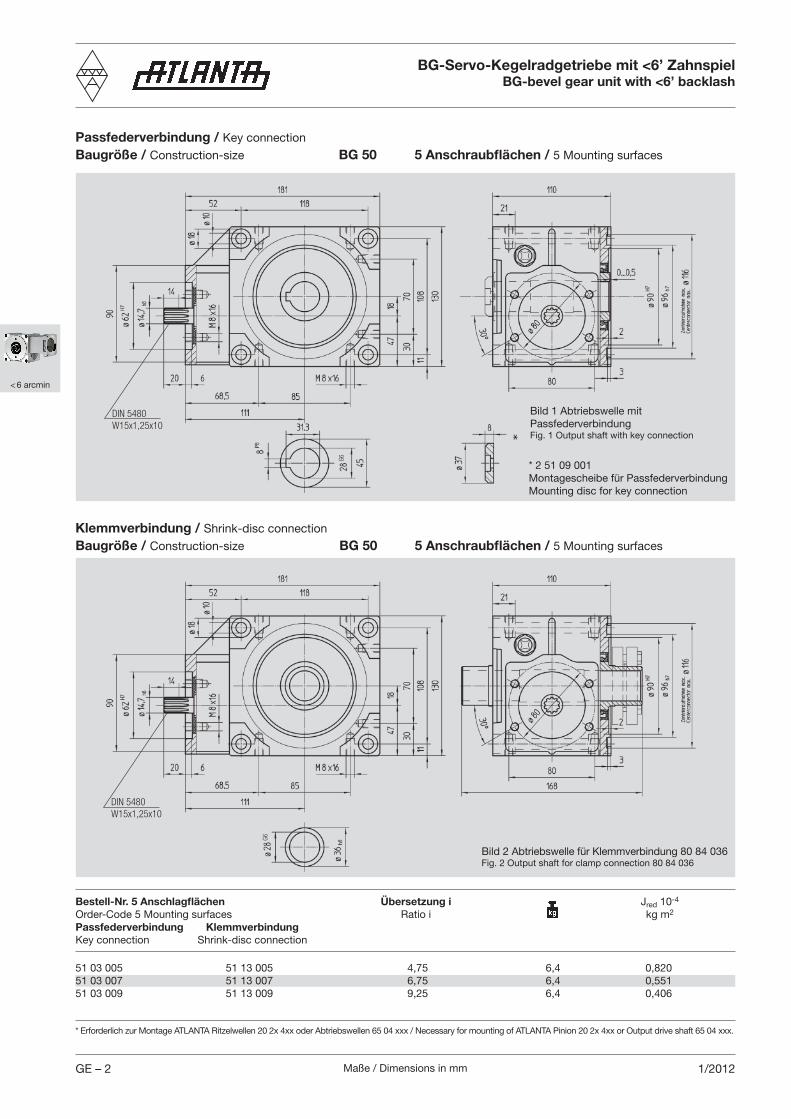
BG-Servo-Kegelradgetriebe mit <6’ ZahnspielBG-bevel gear unit with <6’ backlash
51 03 005 51 13 005 4,75 6,4 0,82051 03 007 51 13 007 6,75 6,4 0,55151 03 009 51 13 009 9,25 6,4 0,406
Bestell-Nr. 5 Anschlagflächen Übersetzung i Jred 10-4
Order-Code 5 Mounting surfaces Ratio i kg m2
Passfederverbindung KlemmverbindungKey connection Shrink-disc connection
Passfederverbindung / Key connection
Baugröße / Construction-size BG 50 5 Anschraubflächen / 5 Mounting surfaces
Klemmverbindung / Shrink-disc connection
Baugröße / Construction-size BG 50 5 Anschraubflächen / 5 Mounting surfaces
* Erforderlich zur Montage ATLANTA Ritzelwellen 20 2x 4xx oder Abtriebswellen 65 04 xxx / Necessary for mounting of ATLANTA Pinion 20 2x 4xx or Output drive shaft 65 04 xxx.
Bild 2 Abtriebswelle für Klemmverbindung 80 84 036Fig. 2 Output shaft for clamp connection 80 84 036
Bild 1 Abtriebswelle mit PassfederverbindungFig. 1 Output shaft with key connection
* 2 51 09 001Montagescheibe für PassfederverbindungMounting disc for key connection
DIN 5480W15x1,25x10
DIN 5480W15x1,25x10
G6
G6
Maße / Dimensions in mm GE – 31/2012
< 6 arcmin
BG-Servo-Kegelradgetriebe mit <6’ ZahnspielBG-bevel gear unit with <6’ backlash
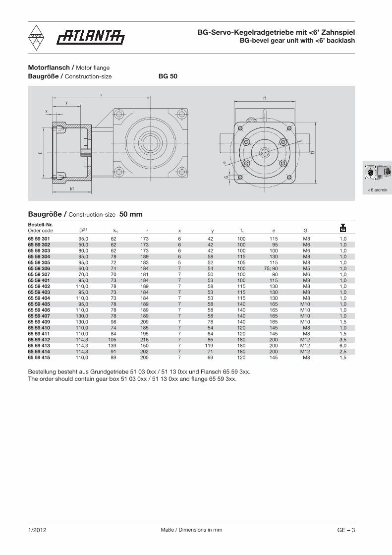
Motorflansch / Motor flange
Baugröße / Construction-size BG 50
Baugröße / Construction-size 50 mmBestell-Nr. Order code DG7 k1 r x y f1 e G
65 59 301 95,0 62 173 6 42 100 115 M8 1,065 59 302 50,0 62 173 6 42 100 95 M6 1,065 59 303 80,0 62 173 6 42 100 100 M6 1,065 59 304 95,0 78 189 6 58 115 130 M8 1,065 59 305 95,0 72 183 5 52 105 115 M8 1,065 59 306 60,0 74 184 7 54 100 75; 90 M5 1,065 59 307 70,0 70 181 7 50 100 90 M6 1,065 59 401 95,0 73 184 7 53 100 115 M8 1,065 59 402 110,0 78 189 7 58 115 130 M8 1,065 59 403 95,0 73 184 7 53 115 130 M8 1,065 59 404 110,0 73 184 7 53 115 130 M8 1,065 59 405 95,0 78 189 7 58 140 165 M10 1,065 59 406 110,0 78 189 7 58 140 165 M10 1,065 59 407 130,0 78 189 7 58 140 165 M10 1,065 59 409 130,0 98 209 7 78 140 165 M10 1,565 59 410 110,0 74 185 7 54 120 145 M8 1,065 59 411 110,0 84 195 7 64 120 145 M8 1,565 59 412 114,3 105 216 7 85 180 200 M12 3,565 59 413 114,3 139 150 7 119 180 200 M12 6,065 59 414 114,3 91 202 7 71 180 200 M12 2,565 59 415 110,0 89 200 7 69 120 145 M8 1,5
Bestellung besteht aus Grundgetriebe 51 03 0xx / 51 13 0xx und Flansch 65 59 3xx.The order should contain gear box 51 03 0xx / 51 13 0xx and flange 65 59 3xx.
Maße / Dimensions in mmGE – 4 1/2012
< 6 arcmin
BG-Servo-Kegelradgetriebe mit <6’ ZahnspielBG-bevel gear unit with <6’ backlash
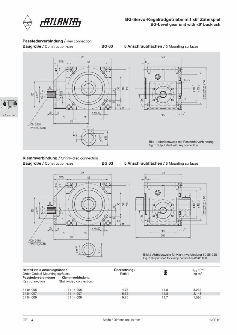
51 04 005 51 14 005 4,75 11,8 3,234 51 04 007 51 14 007 6,75 11,8 2,148 51 04 009 51 14 009 9,25 11,7 1,595
Bestell-Nr. 5 Anschlagflächen Übersetzung i Jred 10-4
Order-Code 5 Mounting surfaces Ratio i kg m2
Passfederverbindung KlemmverbindungKey connection Shrink-disc connection
Passfederverbindung / Key connection
Baugröße / Construction-size BG 63 5 Anschraubflächen / 5 Mounting surfaces
Klemmverbindung / Shrink-disc connection
Baugröße / Construction-size BG 63 5 Anschraubflächen / 5 Mounting surfaces
Bild 1 Abtriebswelle mit PassfederverbindungFig. 1 Output shaft with key connection
Bild 2 Abtriebswelle für Klemmverbindung 80 85 050Fig. 2 Output shaft for clamp connection 80 85 050
DIN 5480W25x1,25x18
DIN 5480W25x1,25x18
G6
G6

Maße / Dimensions in mm GE – 51/2012
< 6 arcmin
BG-Servo-Kegelradgetriebe mit <6’ ZahnspielBG-bevel gear unit with <6’ backlash
Motorflansch / Motor flange
Baugröße / Construction-size BG 63
Bestellung besteht aus Grundgetriebe 51 04 0xx / 51 14 0xx und Flansch 65 59 4xx.The order should contain gear box 51 04 0xx / 51 14 0xx and flange 65 59 4xx.
Baugröße / Construction-size 63 mmBestell-Nr. Order code DG7 k1 r x y f1 e G
65 59 301 95,0 62 192 6 37 100 115 M8 1,065 59 302 50,0 62 192 6 37 100 95 M6 1,065 59 303 80,0 62 192 6 37 100 100 M6 1,065 59 304 95,0 78 208 6 53 115 130 M8 1,065 59 305 95,0 72 202 5 47 105 115 M8 1,065 59 306 60,0 74 204 7 49 100 75; 90 M5 1,065 59 307 70,0 70 200 7 45 100 90 M6 1,065 59 401 95,0 73 203 7 48 100 115 M8 1,065 59 402 110,0 78 208 7 53 115 130 M8 1,065 59 403 95,0 73 203 7 48 115 130 M8 1,065 59 404 110,0 73 203 7 48 115 130 M8 1,065 59 405 95,0 78 208 7 53 140 165 M10 1,065 59 406 110,0 78 208 7 53 140 165 M10 1,065 59 407 130,0 78 208 7 53 140 165 M10 1,065 59 409 130,0 98 228 7 73 140 165 M10 1,565 59 410 110,0 74 204 7 49 120 145 M8 1,065 59 411 110,0 84 214 7 59 120 145 M8 1,565 59 412 114,3 105 235 7 80 180 200 M12 3,565 59 413 114,3 139 269 7 114 180 200 M12 6,065 59 414 114,3 91 221 7 66 180 200 M12 2,565 59 415 110,0 89 219 7 64 120 145 M8 1,5
Maße / Dimensions in mmGE – 6 1/2012
< 6 arcmin
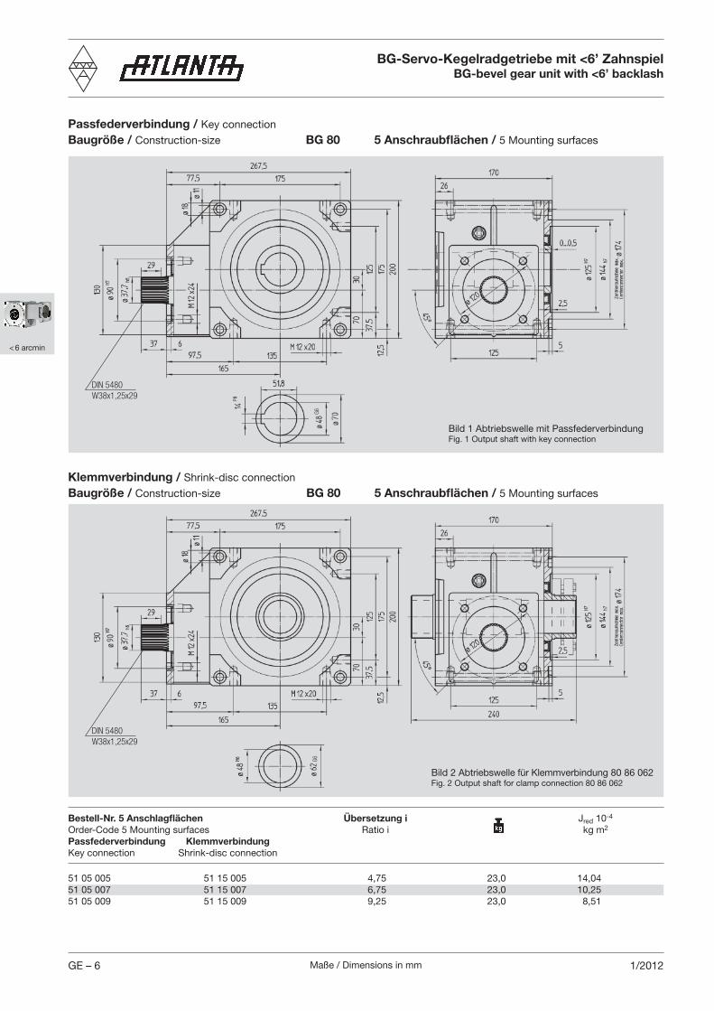
51 05 005 51 15 005 4,75 23,0 14,04 51 05 007 51 15 007 6,75 23,0 10,25 51 05 009 51 15 009 9,25 23,0 8,51
Bestell-Nr. 5 Anschlagflächen Übersetzung i Jred 10-4
Order-Code 5 Mounting surfaces Ratio i kg m2
Passfederverbindung KlemmverbindungKey connection Shrink-disc connection
Passfederverbindung / Key connection
Baugröße / Construction-size BG 80 5 Anschraubflächen / 5 Mounting surfaces
Klemmverbindung / Shrink-disc connection
Baugröße / Construction-size BG 80 5 Anschraubflächen / 5 Mounting surfaces
BG-Servo-Kegelradgetriebe mit <6’ ZahnspielBG-bevel gear unit with <6’ backlash
Bild 1 Abtriebswelle mit PassfederverbindungFig. 1 Output shaft with key connection
Bild 2 Abtriebswelle für Klemmverbindung 80 86 062Fig. 2 Output shaft for clamp connection 80 86 062
DIN 5480W38x1,25x29
DIN 5480W38x1,25x29
G6G6
Maße / Dimensions in mm GE – 71/2012
< 6 arcmin
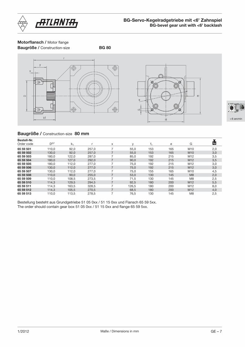
Motorflansch / Motor flange
Baugröße / Construction-size BG 80
BG-Servo-Kegelradgetriebe mit <6’ ZahnspielBG-bevel gear unit with <6’ backlash
Bestellung besteht aus Grundgetriebe 51 05 0xx / 51 15 0xx und Flansch 65 59 5xx.The order should contain gear box 51 05 0xx / 51 15 0xx and flange 65 59 5xx.
Baugröße / Construction-size 80 mmBestell-Nr. Order code DG7 k1 r x y f1 e G
65 59 501 110,0 92,0 257,0 7 55,0 153 165 M10 2,065 59 502 130,0 92,0 257,0 7 55,0 153 165 M10 3,065 59 503 180,0 122,0 287,0 7 85,0 192 215 M12 3,565 59 504 180,0 127,0 292,0 7 90,0 192 215 M12 3,565 59 505 180,0 112,0 277,0 7 75,0 192 215 M12 3,065 59 506 130,0 112,0 277,0 7 75,0 192 215 M12 3,065 59 507 130,0 112,0 277,0 7 75,0 155 165 M10 4,565 59 508 110,0 90,0 255,0 7 53,0 130 145 M8 2,065 59 509 110,0 108,5 273,5 7 71,5 130 145 M8 2,565 59 510 114,3 129,5 294,5 7 92,5 180 200 M12 5,565 59 511 114,3 163,5 328,5 7 126,5 180 200 M12 8,065 59 512 114,3 105,5 270,5 7 68,5 180 200 M12 4,065 59 513 110,0 113,5 278,5 7 76,5 130 145 M8 2,5
Maße / Dimensions in mmGE – 8 1/2016
< 6 arcmin
VerbindungselementeConnecting elements
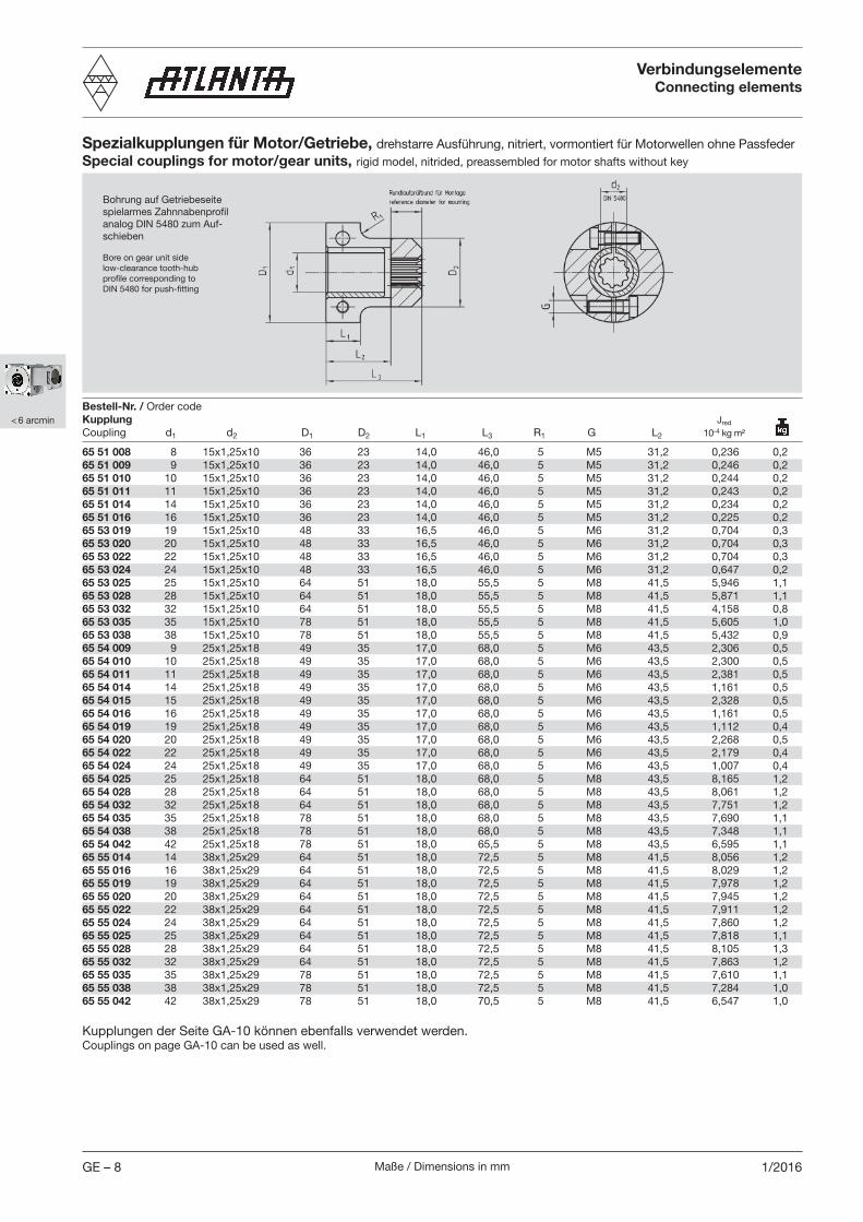
Spezialkupplungen für Motor/Getriebe, drehstarre Ausführung, nitriert, vormontiert für Motorwellen ohne PassfederSpecial couplings for motor/gear units, rigid model, nitrided, preassembled for motor shafts without key
Bohrung auf Getriebeseitespielarmes Zahnnabenprofilanalog DIN 5480 zum Auf-schieben
Bore on gear unit side low-clearance tooth-hubprofile corresponding toDIN 5480 for push-fitting
Bestell-Nr. / Order codeKupplungCoupling d1 d2 D1 D2 L1 L3 R1 G L2
Kupplungen der Seite GA-10 können ebenfalls verwendet werden.Couplings on page GA-10 can be used as well.
65 51 008 8 15x1,25x10 36 23 14,0 46,0 5 M5 31,2 0,236 0,265 51 009 9 15x1,25x10 36 23 14,0 46,0 5 M5 31,2 0,246 0,265 51 010 10 15x1,25x10 36 23 14,0 46,0 5 M5 31,2 0,244 0,265 51 011 11 15x1,25x10 36 23 14,0 46,0 5 M5 31,2 0,243 0,265 51 014 14 15x1,25x10 36 23 14,0 46,0 5 M5 31,2 0,234 0,265 51 016 16 15x1,25x10 36 23 14,0 46,0 5 M5 31,2 0,225 0,265 53 019 19 15x1,25x10 48 33 16,5 46,0 5 M6 31,2 0,704 0,365 53 020 20 15x1,25x10 48 33 16,5 46,0 5 M6 31,2 0,704 0,365 53 022 22 15x1,25x10 48 33 16,5 46,0 5 M6 31,2 0,704 0,365 53 024 24 15x1,25x10 48 33 16,5 46,0 5 M6 31,2 0,647 0,265 53 025 25 15x1,25x10 64 51 18,0 55,5 5 M8 41,5 5,946 1,165 53 028 28 15x1,25x10 64 51 18,0 55,5 5 M8 41,5 5,871 1,165 53 032 32 15x1,25x10 64 51 18,0 55,5 5 M8 41,5 4,158 0,865 53 035 35 15x1,25x10 78 51 18,0 55,5 5 M8 41,5 5,605 1,065 53 038 38 15x1,25x10 78 51 18,0 55,5 5 M8 41,5 5,432 0,965 54 009 9 25x1,25x18 49 35 17,0 68,0 5 M6 43,5 2,306 0,565 54 010 10 25x1,25x18 49 35 17,0 68,0 5 M6 43,5 2,300 0,565 54 011 11 25x1,25x18 49 35 17,0 68,0 5 M6 43,5 2,381 0,565 54 014 14 25x1,25x18 49 35 17,0 68,0 5 M6 43,5 1,161 0,565 54 015 15 25x1,25x18 49 35 17,0 68,0 5 M6 43,5 2,328 0,565 54 016 16 25x1,25x18 49 35 17,0 68,0 5 M6 43,5 1,161 0,565 54 019 19 25x1,25x18 49 35 17,0 68,0 5 M6 43,5 1,112 0,465 54 020 20 25x1,25x18 49 35 17,0 68,0 5 M6 43,5 2,268 0,565 54 022 22 25x1,25x18 49 35 17,0 68,0 5 M6 43,5 2,179 0,465 54 024 24 25x1,25x18 49 35 17,0 68,0 5 M6 43,5 1,007 0,465 54 025 25 25x1,25x18 64 51 18,0 68,0 5 M8 43,5 8,165 1,265 54 028 28 25x1,25x18 64 51 18,0 68,0 5 M8 43,5 8,061 1,265 54 032 32 25x1,25x18 64 51 18,0 68,0 5 M8 43,5 7,751 1,265 54 035 35 25x1,25x18 78 51 18,0 68,0 5 M8 43,5 7,690 1,165 54 038 38 25x1,25x18 78 51 18,0 68,0 5 M8 43,5 7,348 1,165 54 042 42 25x1,25x18 78 51 18,0 65,5 5 M8 43,5 6,595 1,165 55 014 14 38x1,25x29 64 51 18,0 72,5 5 M8 41,5 8,056 1,265 55 016 16 38x1,25x29 64 51 18,0 72,5 5 M8 41,5 8,029 1,265 55 019 19 38x1,25x29 64 51 18,0 72,5 5 M8 41,5 7,978 1,265 55 020 20 38x1,25x29 64 51 18,0 72,5 5 M8 41,5 7,945 1,265 55 022 22 38x1,25x29 64 51 18,0 72,5 5 M8 41,5 7,911 1,265 55 024 24 38x1,25x29 64 51 18,0 72,5 5 M8 41,5 7,860 1,265 55 025 25 38x1,25x29 64 51 18,0 72,5 5 M8 41,5 7,818 1,165 55 028 28 38x1,25x29 64 51 18,0 72,5 5 M8 41,5 8,105 1,365 55 032 32 38x1,25x29 64 51 18,0 72,5 5 M8 41,5 7,863 1,265 55 035 35 38x1,25x29 78 51 18,0 72,5 5 M8 41,5 7,610 1,165 55 038 38 38x1,25x29 78 51 18,0 72,5 5 M8 41,5 7,284 1,065 55 042 42 38x1,25x29 78 51 18,0 70,5 5 M8 41,5 6,547 1,0
Jred 10-4 kg m²
Maße / Dimensions in mm GE – 91/2016
< 6 arcmin
Jred =J
i2
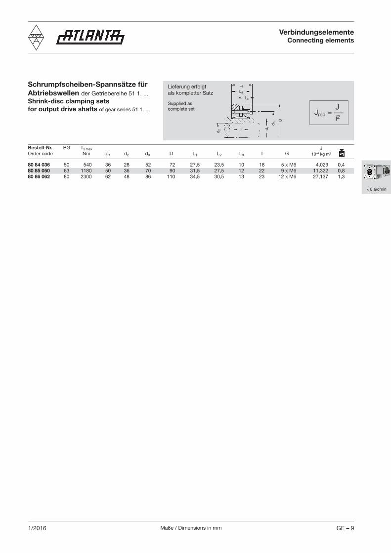
80 84 036 50 540 36 28 52 72 27,5 23,5 10 18 5 x M6 4,029 0,480 85 050 63 1180 50 36 70 90 31,5 27,5 12 22 9 x M6 11,322 0,880 86 062 80 2300 62 48 86 110 34,5 30,5 13 23 12 x M6 27,137 1,3
Lieferung erfolgtals kompletter Satz
Supplied ascomplete set
d2 d
1
d3 D
L1
L2
L3
l
J 10-4 kg m²
Schrumpfscheiben-Spannsätze für Abtriebswellen der Getriebereihe 51 1. ...Shrink-disc clamping sets for output drive shafts of gear series 51 1. ...
VerbindungselementeConnecting elements
Bestell-Nr. BG T2 max Order code Nm d1 d2 d3 D L1 L2 L3 l G
Maße / Dimensions in mmGE – 10 1/2014
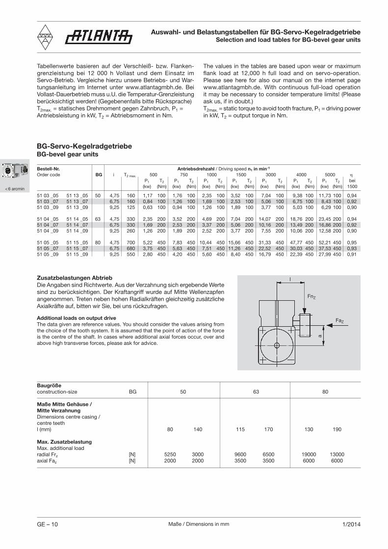
Zusatzbelastungen AbtriebDie Angaben sind Richtwerte. Aus der Verzahnung sich ergebende Werte sind zu berücksichtigen. Der Kraftangriff wurde auf Mitte Wellenzapfen angenommen. Treten neben hohen Radialkräften gleichzeitig zusätzliche Axialkräfte auf, bitten wir Sie, bei uns rückzufragen.
Additional loads on output driveThe data given are reference values. You should consider the values arising from the choice of the tooth system. It is assumed that the point of action of the force is the centre of the shaft. In cases where additional axial forces occur, over and above high transverse forces, please ask for advice.
l
FnZ
FaZa
Auswahl- und Belastungstabellen für BG-Servo-KegelradgetriebeSelection and load tables for BG-bevel gear units
Bestell-Nr. Antriebsdrehzahl / Driving speed n1 in min-1 Order code BG i T2 max. 500 750 1000 1500 3000 4000 5000 η P1 T2 P1 T2 P1 T2 P1 T2 P1 T2 P1 T2 P1 T2 bei (kw) (Nm) (kw) (Nm) (kw) (Nm) (kw) (Nm) (kw) (Nm) (kw) (Nm) (kw) (Nm) 1500
51 03 _05 51 13 _05 50 4,75 160 1,17 100 1,76 100 2,35 100 3,52 100 7,04 100 9,38 100 11,73 100 0,9451 03 _07 51 13 _07 6,75 160 0,84 100 1,26 100 1,69 100 2,53 100 5,06 100 6,75 100 8,43 100 0,9251 03 _09 51 13 _09 9,25 125 0,63 100 0,94 100 1,26 100 1,89 100 3,77 100 5,03 100 6,29 100 0,90 51 04 _05 51 14 _05 63 4,75 330 2,35 200 3,52 200 4,69 200 7,04 200 14,07 200 18,76 200 23,45 200 0,9451 04 _07 51 14 _07 6,75 330 1,69 200 2,53 200 3,37 200 5,06 200 10,16 200 13,49 200 16,86 200 0,9251 04 _09 51 14 _09 9,25 260 1,26 200 1,89 200 2,52 200 3,77 200 7,55 200 10,06 200 12,58 200 0,90 51 05 _05 51 15 _05 80 4,75 700 5,22 450 7,83 450 10,44 450 15,66 450 31,33 450 47,77 450 52,21 450 0,9551 05 _07 51 15 _07 6,75 680 3,75 450 5,63 450 7,51 450 11,26 450 22,52 450 30,03 450 37,53 450 0,9351 05 _09 51 15 _09 9,25 550 2,80 450 4,20 450 5,60 450 8,40 450 16,79 450 22,39 450 27,99 450 0,91
BG-Servo-Kegelradgetriebe BG-bevel gear units
Baugrößeconstruction-size BG 50 63 80
Maße Mitte Gehäuse /Mitte Verzahnung Dimensions centre casing /centre teeth l (mm) 80 140 115 170 130 190
Max. ZusatzbelastungMax. additional loadradial Frz [N] 5250 3000 9600 6500 19000 13000axial Faz [N] 2000 2000 3500 3500 6000 6000
Tabellenwerte basieren auf der Verschleiß- bzw. Flanken-grenzleistung bei 12 000 h Vollast und dem Einsatz im Servo-Betrieb. Vergleiche hierzu unsere Betriebs- und War-tungsanleitung im Internet unter www.atlantagmbh.de. Bei Vollast-Dauerbetrieb muss u.U. die Temperatur-Grenzleistung berücksichtigt werden! (Gegebenenfalls bitte Rücksprache)T2max. = statisches Drehmoment gegen Zahnbruch, P1 = Antriebsleistung in kW, T2 = Abtriebsmoment in Nm.
The values in the tables are based upon wear or maximum flank load at 12,000 h full load and on servo-operation. Please see here for also our manual on the internet page www.atlantagmbh.de. With continuous full-load operation it may be necessary to consider temperature limits! (Please ask us, if in doubt.)T2max. = static torque to avoid tooth fracture, P1 = driving power in kW, T2 = output torque in Nm.
< 6 arcmin
Maße / Dimensions in mm GE – 111/2012
< 6 arcmin
BG-Servo-KegelradgetriebeBG-bevel gear units
Kurzbeschreibung
ATLANTA-BG-Servo-Kegelradgetriebe sind speziell zum Einsatz mit Dreh- und Gleichstrom-Servomotoren der neuen Generation entwickelt worden. Sie sind, ebenso wie alle an-deren Artikel dieses Kataloges, in der Regel ab Lager bzw. kurzfristig lieferbar.
Folgende Merkmale zeichnen unsere Servo-Kegelradgetriebe aus:– ähnliche, teilweise identische Übersetzungen wie bei den
Getrieben der Reihen 98, 58 und 59 – spielarme Verzahnung (Spiel < 6’) – Gehäuse aus Leichtmetall für optimale Wärmeabfuhr– robuste Kegelrollen-Lagerung der Abtriebs-Hohlwelle für
hohe Zusatzkräfte– geringe Massenträgheitsmomente für hohe Dynamik
Bei den Baugrößen und Übersetzungen haben wir uns an den bestehenden Servo-Schneckengetriebereihen orientiert. Die Kegelräder werden tragbildoptimiert gefertigt und eingebaut. Der Einsatz satzweise endgeläppter Kegelräder gewährleistet einen ruhigen Lauf in beiden Drehrichtungen. Das allseitig bearbeitete Gehäuse mit seinen vielen Befestigungs- und Gewindebohrungen erlaubt die Montage in jeder beliebigen Einbaulage.
Der Antrieb bzw. die Verbindung mit dem Antriebsmotor erfolgt durch eine Spezialkupplung, deren Innenverzahnung,zusammen mit der längsballig verzahnten Antriebswelle unserer Kegelradgetriebe, einen spielfreien Kraftfluss ge-währleistet.
Für den Abtrieb steht eine ganze Reihe von Abtriebswellen mit Gerad- und Schrägverzahnung, jeweils mit verschiedenen Zähnezahlen, zur Verfügung. Neben verzahnten Ritzelwellen kann darüber hinaus eine Vielzahl von weiteren Zähnezahlen aus unserem Zahnradprogramm mit passenden Spezial-Abtriebswellen kombiniert und eingesetzt werden. Die ganze Abtriebswellenpalette ist selbstverständlich analog unseren Getrieben nicht nur für Passfederverbindung, sondern auch für Schrumpfverbindung lieferbar.
Zahnstangen ergänzen in sinnvoller Weise unser Angebot in Normelementen für Servo-Antriebe. Von der relativ einfachen, weichen Zahnstange über die gehärtete, wahlweise gerade oder für ruhigen Lauf auch in schrägverzahnter Ausführung, bis zu unseren allseitig in engen Toleranzen geschliffenen Typen, spannt sich der Bogen unserer am Lager vorrätigen Teile.
Für Not-Stopp sind die maximal übertragbaren Drehmomente des Getriebes gegen Zahnbruch (siehe Seite GE-10) und der Schrumpfscheibe (siehe Seite GH-1) zu beachten. Eine Passfederverbindung am Abtrieb muss separat nachgerech-net werden.
Short description
ATLANTA BG servo bevel gear units have been specially developed for use with new generation three-phase AC motors and DC motors. Like all other items in this catalogue they are usually available from stock or within very short time.
Our servo bevel gear units feature:
– gear ratios which are similar, sometimes identical with those of the series 98, 58, and 59
– low-clearance gearing (backlash < 6’)– light-alloy housing for optimal heat dissipation– robust tapered-roller bearing of the output hollow shaft for
high additional forces– low moments of inertia for high dynamics
Sizes and gear ratios correspond with those of the existing servo worm-gear unit series. The bevel gears are manufac-tured and installed with optimal tooth bearing. The use of bevel gears end-lapped in sets guarantees smooth running in both directions of rotation. The housing is machined on all sides and provided with many fixing holes and threaded bores and can thus be installed in any mounting position desired.
The drive or the connection to the driving motor, is realized via a special clutch. The internal gearing of this clutch in combination with the barrelled profile of the driving shaft of our bevel gear units assures the flow of forces without play.
For the output drive we offer quite a number of output shafts with straight or helical tooth systems and with different num-bers of teeth. Besides toothed pinion shafts it is possible to combine and use a large variety of other numbers of teeth from our gear-wheel program with matching special output shafts. It goes without saying that analogous to our gear units the complete range of output shafts is not only available for key fitting but also for shrink-disc fitting.
Our wide range of standard elements for servo drives is sup-plemented by toothed racks. The ex-stock program comprises many different types from rather simple, soft racks through hardened versions with straight tooth system or optionally with helical tooth system for smooth running, to racks ground on all sides to very narrow tolerances.
For safety-stop is the maximum transmittable torque of the gear unit (see page GE-10) and shrink disc (see page GH-1) has to be checked. The output keyway has to be calculated separately.
Maße / Dimensions in mmGE – 12 1/2015
< 6 arcmin
Einbau und Wartung BG-Servo-Kegelradgetriebe Mounting, maintenance and spare parts for BG-bevel gear units
Montageanleitung
KegelradgetriebeEs stehen 5 bearbeitete Anbauflächen mit ausreichend di-mensionierten Befestigung- und Gewindebohrungen für eine verspannungsfreie Montage in allen Einbaulagen zur Verfügung. Bei voller Ausnutzung der Zusatzkräfte (s. Seite GE-10) empfeh-len wir die Montage an den größten Anlageflächen, d.h. an der Seite des Deckels bzw. gegenüberliegend vorzunehmen. Die Schmierbedingungen sind in allen Einbaulagen nahezu gleich.
Kupplung Die Kupplung wird vormontiert geliefert. Vor Befestigung auf der Motorwelle müssen sämtliche Kontaktflächen sauber gereinigt und durch leichten Ölfilm geschützt sein. Für dieMontage ist das Maß “X1” wichtig (vergleiche Seite GI – 5 bis GI – 9).
Empfohlener Arbeitsablauf:– Kontaktflächen sauber reinigen und durch leichten Ölfilm
schützen– Kupplung im Abstand des Maß “X1” (vergleiche Seiten GI
– 5 bis GI – 9) auf die Motorwelle aufsetzen, zur Ermittlung des Maßes ist ein Tiefenmaß hilfreich
– Spannschrauben leicht anziehen und Kupplung auf Rund-lauf prüfen
– Schrauben abwechselnd gleichmäßig anziehen– Anzugsmoment lt. Betriebs- und Wartungsanleitung einhal-
ten und hierbei beachten, dass der Spalt in der Kupplung auf beiden Seiten gleich breit bleibt
– Eine nochmalige, abschließende Rundlaufkontrolle am dafür vorgesehenen Prüfbund ist zu empfehlen!
Einen Montageführer finden Sie auf der Seite GI-5 bis GI-9
Motormit montierter Kupplung in die Getriebezentrierung einschie-ben und mit Getriebegehäuse verschrauben.
Abtriebs-(Ritzel)WelleSofern die Abtriebs-(Ritzel)welle nicht bereits bei der Lieferung montiert ist, empfehlen wir folgenden Arbeitsablauf:Abtriebs-(Ritzel)welle und Getriebe-Abtriebshohlwelle säubern und anschließend ölen. Für Sonderabtriebswellen empfehlen wir die Toleanz h6 (DIN ISO 286). Das Material muss eine Mindest-streckgrenze von 385 N/mm2 aufweisen. Eine Nachrechnung der Festigkeit muss aber dennoch erfolgen.
Abtriebswelle für Schrumpfscheiben-VerbindungSchrumpf scheibe auf Getriebe-Hohlwelle aufschieben (Schrauben vorher bitte nicht anziehen!). Abtriebswelle von der gewünschten Seite bis auf Anschlag in die Hohlwelle einschieben. Herstellen der Querpressverbindung durch gleichmäßiges Anziehen der Spannschrauben. Schrauben der Reihe nach in mehreren Umläufen auf Drehmoment nach Betriebs- und Wartungsanleitung anziehen (nicht überkreuz).
Mounting Instructions
Bevel-gear unit Five machined mounting surfaces with sufficiently dimensioned fixing holes and threaded bores are provided for tension-free installation in any mounting position. In order to make full use of the additional dynamic forces (see p. GE-10) we recommend to choose the largest available contact surfaces, i.e. on the side of the cover or on the opposite side. Lubrication conditions are almost the same in all mounting positions.
CouplingThe coupling is supplied pre-assembled. Before fixing it on the motor shaft carefully clean all contact surfaces and protect them with a thin oil film. An important dimension for mounting is ”X1” (compare pages GI – 5 to GI – 9)
We recommend to proceed as follows: – Clean the contact surfaces and protect them with a thin oil
film.– Position the coupling on the motor shaft at the distance
”X1” (see pages GI – 5 to GI – 9) using a depth gauge for determining this dimension.
– Slightly tighten the screws alternately and check the cou-pling for true running
– Observe the tightening torque indicated in the operation and maintenance instructions bearing in mind that the width of the gap on both sides of the clutch must remain the same.
– It is advisable to make another final concentricity check at the reference collar.
A mounting guide can be found on page GI-5 to GI-9
MotorInsert the motor with coupling mounted into the gear centering piece and bolt it to the gearbox.
Output drive (pinion) shaftUnless the output pinion shaft comes already fully assembled, we recommend to proceed as follows:Clean pinion shaft and hollow shaft extension and then oil them. For the special output drive shaft we recommend to-lerance h6 (DIN ISO286). the material must have a minimum yield point of 385 N/mm². A recalculation of the strength is necessary.
Output drive shaft for shrink-disc connec tionSlide shrink disc onto the hollow shaft extension of the gear unit (please do not tighten the screws beforehand!).Insert the output shaft from the desired side into the hollow shaft fully up to the stop. Make the transverse pressure connection by evenly tightening the clamping screws. Tighten the screws one after the other (not crosswise) in several passes to the torque indicated in the operation and maintenance instructions.
Maße / Dimensions in mm GE – 131/2015
< 6 arcmin
Abtriebswelle für Passfeder-VerbindungDer mit der Abtriebswelle mitgelieferte Sicherungsring, die Scheibe und Schraube dienen der axialen Befestigung der Abtriebswelle. Dazu wird der Sicherungsring in den ent-sprechenden Einstich der Getriebe-Hohlwelle montiert, die Abtriebswelle von der gewünschten Seite bis auf Anschlag in die Hohlwelle eingeschoben. Die Scheibe und Schraube werden von der anderen Getriebeseite mit der Abtriebswelle verschraubt. Der Sicher ungs ring muss zwischen Scheibe und Ritzelwelle eingespannt sein.
Wartung
SchmierstoffwechselATLANTA Servo-Kegelradgetriebe sind mit synthetischem Polyglykol-Öl befüllt.Dies ist unter folgenden Voraussetzungen eine Lebensdau-erschmierung:Die Auslegung des Getriebes erfolgte ausschließlich nach den im ATLANTA-Katalog vorgegebenen Richtlinien und das Ge-triebe wird ausschließlich innerhalb der zulässigen Kenn- und Grenzwerte betrieben. Der Betreiber kontrolliert das Getriebe regelmäßig (alle 4 Wochen) auf Ölverlust. Die Oberflächentem-peratur beträgt max. 80°C. Bei Servo-Betrieb (Aussetzbetrieb) wird diese Temperatur erfahrungsgemäß nicht erreicht.
Wir empfehlen folgenden synthetischen Ge triebe schmierstoff:Klübersynth GH 6 - 220 Bestell-Nr. 65 90 010 (1 Liter)
alternativ:SHELL Tivela S 220, BP Enersyn SG-XP 220, ARAL Degol GS 220
SchutzartSchutzart: IP65/67 in Anlehnung an ISO 20653 (Schutz gegen Korrosion muss gesondert betrachtet werden).
Output drive shaft for key connectionThe retaining ring, the disc and the screw supplied with the output drive shaft serve for locking the output shaft in axial direction. For this purpose insert the retaining ring in the ap-plicable recess of the hollow shaft and slide the output drive shaft from the desired side into the hollow shaft up to the stop. Disc and screw are screwed to the output shaft from the other side of the gear unit. The retaining ring must be clamped between disc and pinion shaft.
Maintenance
Lubricant changeATLANTA servo-assisted bevel-gear units are filled with syn-thetic polyclycol oil.Under the following conditions this means lifetime lubricaca-ton:The layout of the gear unit is made strictly in conformance with the guidelines specified in the ATLANTA catalogue and the gear unit is operated exclusively within the permissible characteristic values and limits. The operator checks the gear regularly (every 4 weeks) for oil leakage. The surface tem-perature does not exceed max. 80° C. Experience has shown that this temperature is not reached with servo-operation (intermittent operation).
We recommend the following synthetic gear lubricant:Klübersynth GH 6 - 220Order code: 65 90 010 (1 litre)
alternative:SHELL Tivela S 220, BP Enersyn SG-XP 220, ARAL Degol GS 220
Degree of protectionDegree of protection: IP65/67 according to ISO 20653 (Corrosion has to be verified separately).
Baugröße ÖlmengeConstruction size Oil quantity
BG 50 0,3 lBG 63 0,5 lBG 80 1,2 l
Einbau und Wartung BG-Servo-Kegelradgetriebe Mounting, maintenance and spare parts for BG-bevel gear units