Embed Size (px)
Citation preview

Berminghammer Introduction to STATNAMIC Profound
Berminghammer Foundation Solutions, Profound BV 1
STATNAMIC : Pile Load Testing Equipment Today's taller buildings, heavier loads, and increased construction costs require the use of large-diameter, drilled pier foundation systems. As such, the demand for high capacity piles over 5.0 MN has increased dramatically. Traditionally, static pile loading have been used to verify geotechnical design parameters, pile load capacity, and, in some cases, the integrity of the pile. However, static pile loading test methods are expensive, time consuming and cumbersome. Dynamic load tests have also been used to predict static capacity and load-displacement behavior. However, the dynamic response of a pile is controlled by stress waves, the analysis of which requires highly-experienced engineers. Dynamic load testing also creates tensile stresses which can cause pile damage in concrete piles. STATNAMIC testing overcomes the practical difficulties of both static loading and dynamic load tests. STAT NAMIC is capable of producing a given force using only 5-10% of the mass in an equivalent static test. During STAT NAMIC loading, an axial load is applied for a duration of 120 milliseconds; long enough to compress the entire pile. Pile behavior is not dominated by stress wave propagation and the pile acceleration is relatively low (1 to 3 g’s). Load duration and the loading rate are controlled by the vent height, the amount of fuel and the amount of reaction mass. Development Background STATNAMIC development began in 1988 with a 0.1 MN test device. Today, test devices are capable of producing loads up to 30 MN.
STATNAMIC Loads up to 30 MN
STATNAMIC load tests have been conducted in Canada, the United States, the Netherlands, Japan, Germany, Israel, Korea, Taiwan, United Arab Emirates, Egypt, United Kingdom, Malaysia, Indonesia Australia, China, Belgium, Hungary, Grenada, Argentina.
Equipment Range
1988 0.1 MN 1989 0.6 MN 1990 5.0 MN 1991 8.0 MN 1992 16.0 MN 1994 30.0 MN
30 MN test in Florida, USA
16 MN test in Malaysia
Berminghammer Introduction to STATNAMIC Profound
Berminghammer Foundation Solutions, Profound BV 2
-10
-5
0
5
Dis
plac
emen
t (m
m)
L
oad
(MN
)
0 20 40 60 80 100 120 140 160 Time (ms)
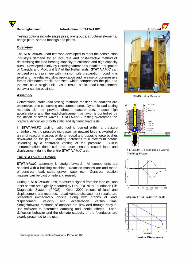
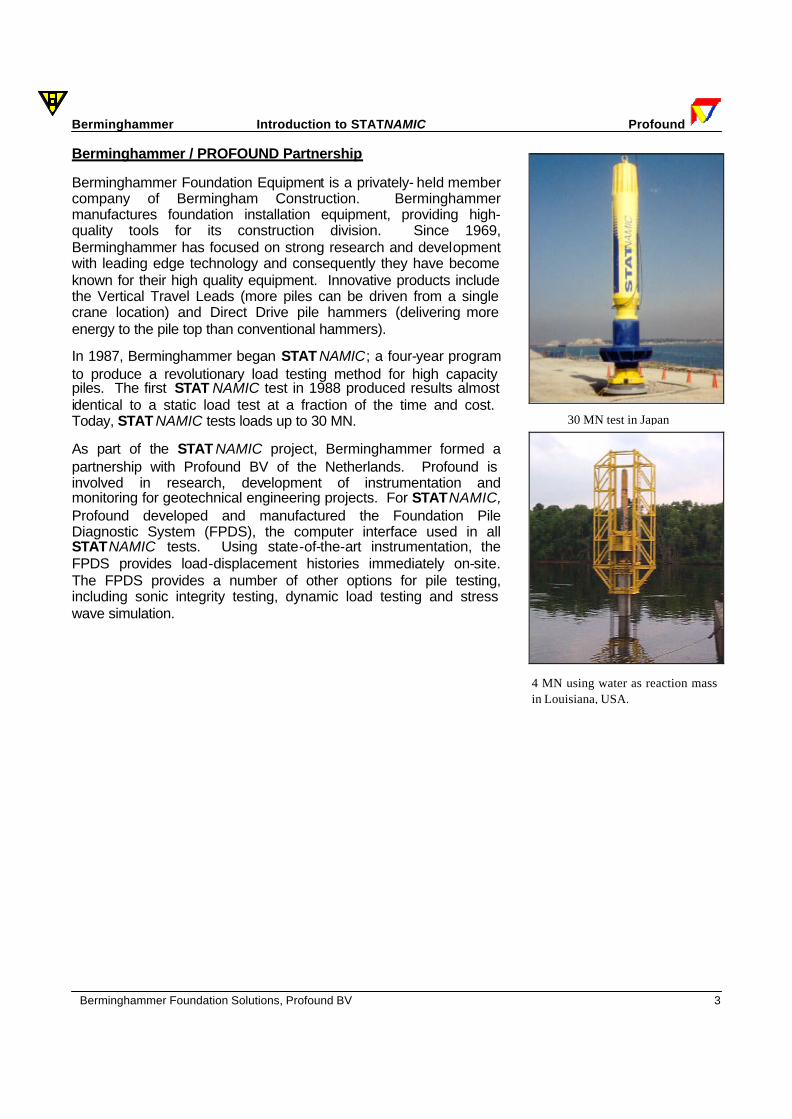
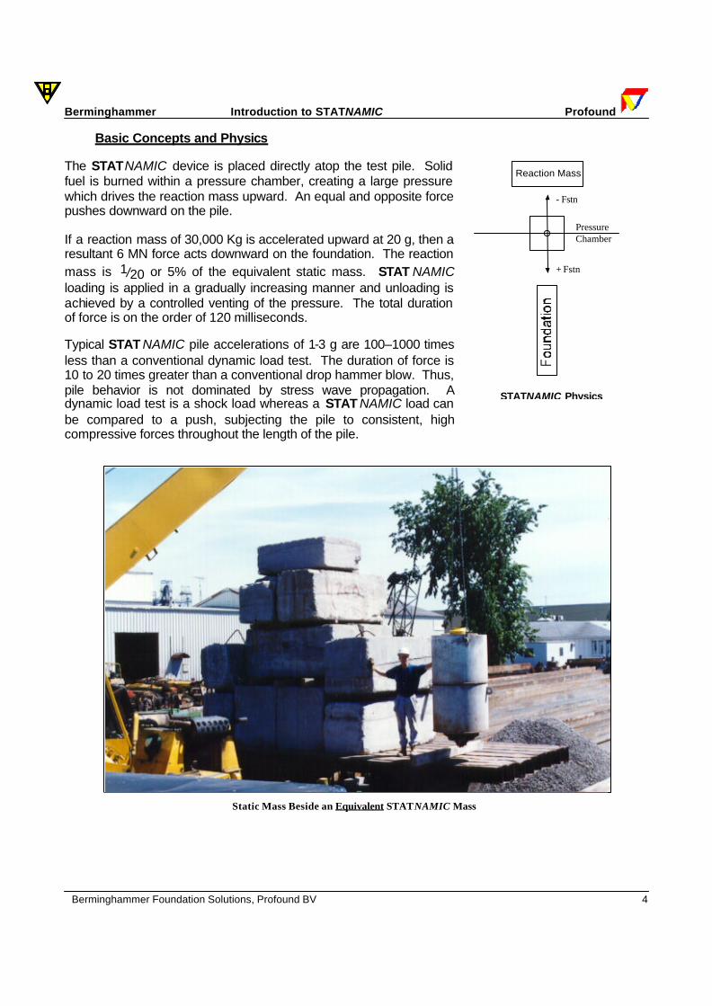
Testing options include single piles, pile groups, structural elements, bridge piers, spread footings and plates. Overview The STATNAMIC load test was developed to meet the construction industry's demand for an accurate and cost-effective method of determining the load bearing capacity of caissons and high capacity piles. Developed jointly by Berminghammer Foundation Equipment of Canada and Profound BV of the Netherlands, STAT NAMIC can be used on any pile type with minimum pile preparation. Loading is axial and the relatively slow application and release of compressive forces eliminates tensile stresses, which compresses the pile and the soil as a single unit. As a result, static Load-Displacement behavior can be obtained. Assembly Conventional static load testing methods for deep foundations are expensive, time consuming and cumbersome. Dynamic load testing methods do not provide direct measurements, induce high accelerations and the load-displacement behavior is controlled by the action of stress waves. STAT NAMIC testing overcomes the practical difficulties of both static and dynamic load tests. In STAT NAMIC testing, solid fuel is burned within a pressure chamber. As the pressure increases, an upward force is exerted on a set of reaction masses while an equal and opposite force pushes downward on the pile. Loading increases to a maximum before unloading by a controlled venting of the pressure. Built-in instrumentation (load cell and laser sensor) record load and displacement during the entire STAT NAMIC test. The STATNAMIC Device STATNAMIC assembly is straightforward. All components are handled with a hoisting machine. Reaction masses are and made of concrete, lead, steel, gravel, water etc. Concrete reaction masses can be cast on-site and reused. During a STATNAMIC test, measured signals from the load cell and laser sensor are digitally recorded by PROFOUND's Foundation Pile Diagnostic System (FPDS). Over 2000 values of load and displacement are recorded. Load versus displacement results are presented immediately on-site along with graphs of load, displacement, velocity and acceleration versus time. Straightforward methods of analysis are provided through easy-to-use software to determine damping and inertial effects. Load-deflection behavior and the ultimate capacity of the foundation are clearly presented to the user.
-6
-5
-4
-3
-2
-1
0
Dis
plac
emen
t (m
m)
0 1 2 3 4 5 Load (MN)
Measured STATNAMIC Signals
Load vs. Displacement
30 MN test in Malaysia
STATNAMIC setup using a Gravel Catching System
Berminghammer Introduction to STATNAMIC Profound
Berminghammer Foundation Solutions, Profound BV 3
Berminghammer / PROFOUND Partnership Berminghammer Foundation Equipment is a privately- held member company of Bermingham Construction. Berminghammer manufactures foundation installation equipment, providing high-quality tools for its construction division. Since 1969, Berminghammer has focused on strong research and development with leading edge technology and consequently they have become known for their high quality equipment. Innovative products include the Vertical Travel Leads (more piles can be driven from a single crane location) and Direct Drive pile hammers (delivering more energy to the pile top than conventional hammers). In 1987, Berminghammer began STAT NAMIC; a four-year program to produce a revolutionary load testing method for high capacity piles. The first STAT NAMIC test in 1988 produced results almost identical to a static load test at a fraction of the time and cost. Today, STAT NAMIC tests loads up to 30 MN. As part of the STAT NAMIC project, Berminghammer formed a partnership with Profound BV of the Netherlands. Profound is involved in research, development of instrumentation and monitoring for geotechnical engineering projects. For STATNAMIC, Profound developed and manufactured the Foundation Pile Diagnostic System (FPDS), the computer interface used in all STATNAMIC tests. Using state-of-the-art instrumentation, the FPDS provides load-displacement histories immediately on-site. The FPDS provides a number of other options for pile testing, including sonic integrity testing, dynamic load testing and stress wave simulation.
30 MN test in Japan
4 MN using water as reaction mass in Louisiana, USA.
Berminghammer Introduction to STATNAMIC Profound
Berminghammer Foundation Solutions, Profound BV 4
Reaction Mass
PressureChamber
- Fstn
+ Fstn
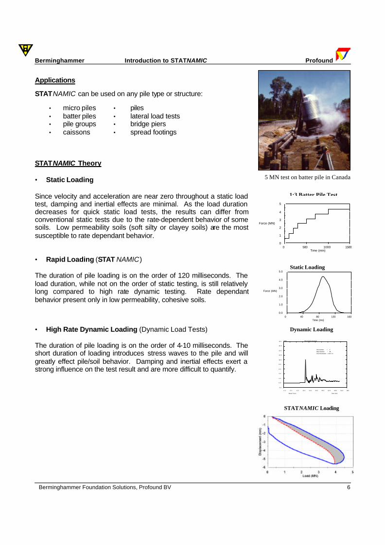
Basic Concepts and Physics The STATNAMIC device is placed directly atop the test pile. Solid fuel is burned within a pressure chamber, creating a large pressure which drives the reaction mass upward. An equal and opposite force pushes downward on the pile. If a reaction mass of 30,000 Kg is accelerated upward at 20 g, then a resultant 6 MN force acts downward on the foundation. The reaction mass is 1/20 or 5% of the equivalent static mass. STAT NAMIC loading is applied in a gradually increasing manner and unloading is achieved by a controlled venting of the pressure. The total duration of force is on the order of 120 milliseconds. Typical STAT NAMIC pile accelerations of 1-3 g are 100–1000 times less than a conventional dynamic load test. The duration of force is 10 to 20 times greater than a conventional drop hammer blow. Thus, pile behavior is not dominated by stress wave propagation. A dynamic load test is a shock load whereas a STAT NAMIC load can be compared to a push, subjecting the pile to consistent, high compressive forces throughout the length of the pile.
STATNAMIC Physics
Static Mass Beside an Equivalent STATNAMIC Mass

Berminghammer Introduction to STATNAMIC Profound
Berminghammer Foundation Solutions, Profound BV 5
STATNAMIC can be described using each of Newton's three Laws of Motion: 1st Law (Law of Inertia): A body will continue in a state of rest or uniform motion unless compelled to change that state by an external force. In a load test, two external forces act on a pile - the loading force which sets the pile in motion and the pile's resistance to that motion. Pile resistance is partly a function of the inertia of the pile mass, and partly a function of pile stiffness and soil stiffness along the pile shaft and at the pile toe. By measuring the pile displacement during test loading, a measurement of the pile’s resistance and thus the pile/soil behaviour can be measured. 2nd Law (Law of Acceleration): When acted upon by an external force, a body accelerates in the direction of that external force and is proportional to the magnitude of that force.
F = ma In static, STATNAMIC, and dynamic load testing, the same net force can be applied to a pile by different means. Compare:
Static: F = M × g = Mg
STAT NAMIC: F = M × 20g = Mg 20
Dynamic: F = M × 500g = Mg 500
where M is the total mass of a static test M/20 is the reaction mass (STATNAMIC) M/500 is the drop hammer mass g is the acceleration due to gravity 20g is the acceleration of the reaction mass (STAT NAMIC) 500g is the acceleration of the drop hammer
3rd Law (Action and Reaction): For every action there is an equal and opposite reaction.
F12 = -F21
During STAT NAMIC loading, the STAT NAMIC device exerts an upward force on the reaction masses, while an equal and opposite force reacts downward on the pile.
5 MN test using wa ter as reaction mass in Louisiana
Concept drawing of water used as reaction mass.
Berminghammer Introduction to STATNAMIC Profound
Berminghammer Foundation Solutions, Profound BV 6
1:3 Batter Pile Test
Applications STATNAMIC can be used on any pile type or structure:
• micro piles • piles • batter piles • lateral load tests • pile groups • bridge piers • caissons • spread footings
STATNAMIC Theory • Static Loading Since velocity and acceleration are near zero throughout a static load test, damping and inertial effects are minimal. As the load duration decreases for quick static load tests, the results can differ from conventional static tests due to the rate-dependent behavior of some soils. Low permeability soils (soft silty or clayey soils) are the most susceptible to rate dependant behavior. • Rapid Loading (STAT NAMIC) The duration of pile loading is on the order of 120 milliseconds. The load duration, while not on the order of static testing, is still relatively long compared to high rate dynamic testing. Rate dependant behavior present only in low permeability, cohesive soils. • High Rate Dynamic Loading (Dynamic Load Tests) The duration of pile loading is on the order of 4-10 milliseconds. The short duration of loading introduces stress waves to the pile and will greatly effect pile/soil behavior. Damping and inertial effects exert a strong influence on the test result and are more difficult to quantify.
Static Loading
STATNAMIC Loading
Dynamic Loading
5 MN test on batter pile in Canada
0
1
2
3
4
5
Force (MN)
0 500 1000 1500Time (min)
0.0 6 .0 12.0 18.0 24.0 30.0 36.0 42.0 48.0 54.0 60.0
-2.0
0 .0
2 .0
4 .0
6 .0
8 .0
10.0
12.0
14.0
16.0
18.0 Pile Driving Analysis[MN]
Time [ms] _____ Mean Force
Pile Number = 1Blow Number = 35Pile Penetration = 16.17 m
0.0
1.0
2.0
3.0
4.0
5.0
Force (MN)
0 40 80 120 160 Time (ms)
Berminghammer Introduction to STATNAMIC Profound
Berminghammer Foundation Solutions, Profound BV 7
Pyrotechnics
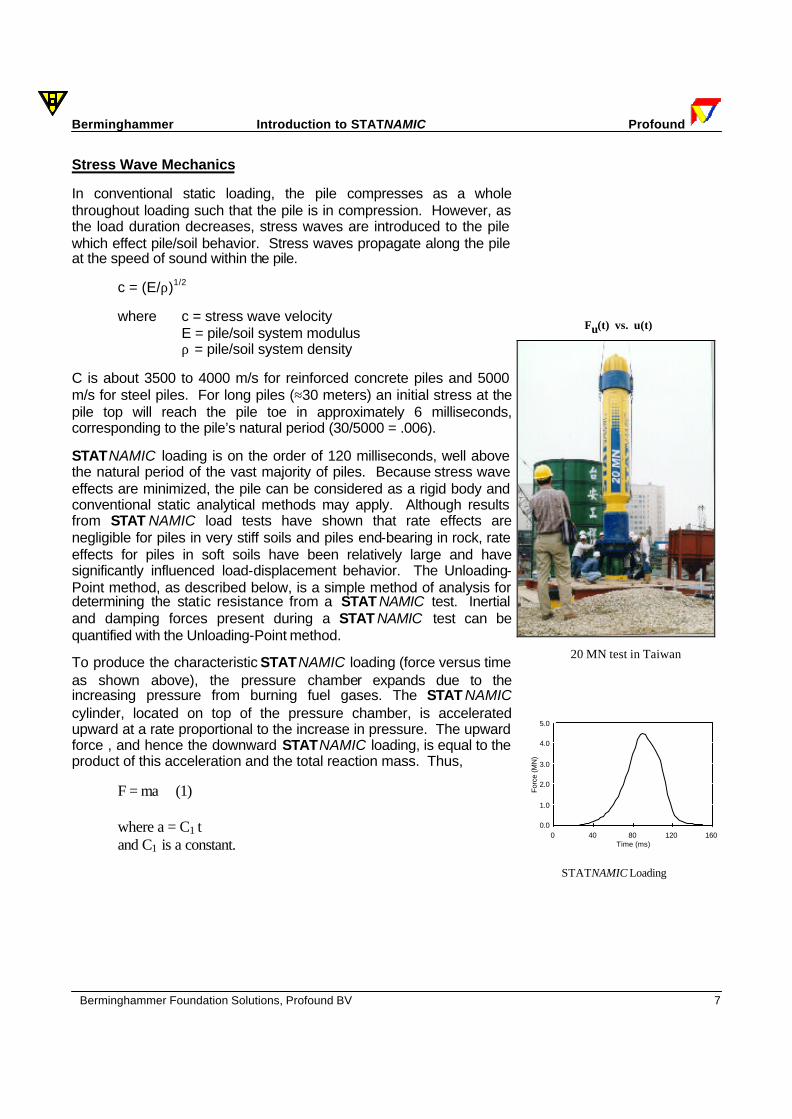
Stress Wave Mechanics In conventional static loading, the pile compresses as a whole throughout loading such that the pile is in compression. However, as the load duration decreases, stress waves are introduced to the pile which effect pile/soil behavior. Stress waves propagate along the pile at the speed of sound within the pile.
c = (E/ρ)1/2 where c = stress wave velocity E = pile/soil system modulus ρ = pile/soil system density
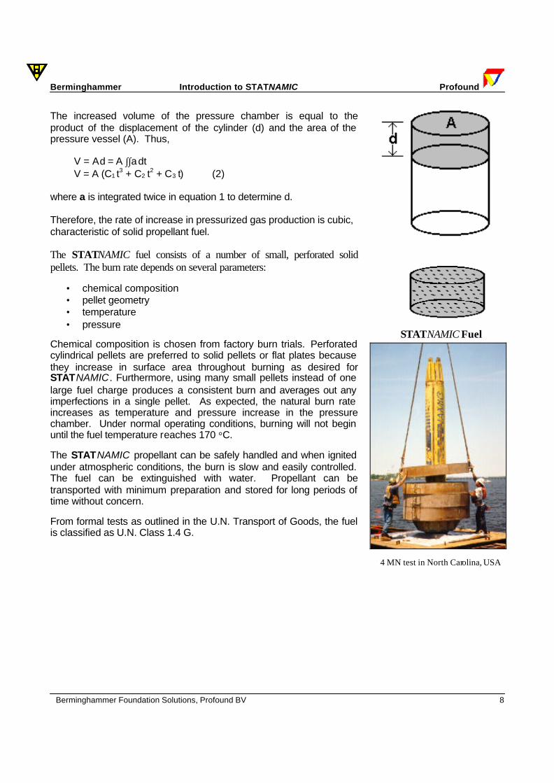
C is about 3500 to 4000 m/s for reinforced concrete piles and 5000 m/s for steel piles. For long piles (≈30 meters) an initial stress at the pile top will reach the pile toe in approximately 6 milliseconds, corresponding to the pile’s natural period (30/5000 = .006). STATNAMIC loading is on the order of 120 milliseconds, well above the natural period of the vast majority of piles. Because stress wave effects are minimized, the pile can be considered as a rigid body and conventional static analytical methods may apply. Although results from STAT NAMIC load tests have shown that rate effects are negligible for piles in very stiff soils and piles end-bearing in rock, rate effects for piles in soft soils have been relatively large and have significantly influenced load-displacement behavior. The Unloading-Point method, as described below, is a simple method of analysis for determining the static resistance from a STAT NAMIC test. Inertial and damping forces present during a STAT NAMIC test can be quantified with the Unloading-Point method. To produce the characteristic STATNAMIC loading (force versus time as shown above), the pressure chamber expands due to the increasing pressure from burning fuel gases. The STAT NAMIC cylinder, located on top of the pressure chamber, is accelerated upward at a rate proportional to the increase in pressure. The upward force , and hence the downward STATNAMIC loading, is equal to the product of this acceleration and the total reaction mass. Thus,
F = ma (1) where a = C1⋅t and C1 is a constant.
Fu(t) vs. u(t)
0.0
1.0
2.0
3.0
4.0
5.0
Forc
e (M
N)
0 40 80 120 160 Time (ms)
STATNAMIC Loading
20 MN test in Taiwan
Berminghammer Introduction to STATNAMIC Profound
Berminghammer Foundation Solutions, Profound BV 8
The increased volume of the pressure chamber is equal to the product of the displacement of the cylinder (d) and the area of the pressure vessel (A). Thus,
V = A⋅d = A ∫∫a⋅dt V = A (C1⋅t3 + C2⋅t2 + C3⋅t) (2)
where a is integrated twice in equation 1 to determine d. Therefore, the rate of increase in pressurized gas production is cubic, characteristic of solid propellant fuel. The STATNAMIC fuel consists of a number of small, perforated solid pellets. The burn rate depends on several parameters:
• chemical composition • pellet geometry • temperature • pressure
Chemical composition is chosen from factory burn trials. Perforated cylindrical pellets are preferred to solid pellets or flat plates because they increase in surface area throughout burning as desired for STATNAMIC. Furthermore, using many small pellets instead of one large fuel charge produces a consistent burn and averages out any imperfections in a single pellet. As expected, the natural burn rate increases as temperature and pressure increase in the pressure chamber. Under normal operating conditions, burning will not begin until the fuel temperature reaches 170 °C. The STATNAMIC propellant can be safely handled and when ignited under atmospheric conditions, the burn is slow and easily controlled. The fuel can be extinguished with water. Propellant can be transported with minimum preparation and stored for long periods of time without concern. From formal tests as outlined in the U.N. Transport of Goods, the fuel is classified as U.N. Class 1.4 G.
STATNAMIC Fuel
4 MN test in North Carolina, USA
Berminghammer Introduction to STATNAMIC Profound
Berminghammer Foundation Solutions, Profound BV 9
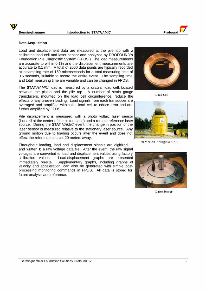
Data Acquisition Load and displacement data are measured at the pile top with a calibrated load cell and laser sensor and analyzed by PROFOUND’s Foundation Pile Diagnostic System (FPDS.) The load measurements are accurate to within 0.1% and the displacement measurements are accurate to 0.1 mm. A total of 2000 data points are typically recorded at a sampling rate of 150 microseconds for a total measuring time of 0.5 seconds, suitable to record the entire event. The sampling time and total measuring time are variable and can be changed in FPDS. The STATNAMIC load is measured by a circular load cell, located between the piston and the pile top. A number of strain gauge transducers, mounted on the load cell circumference, reduce the effects of any uneven loading. Load signals from each transducer are averaged and amplified within the load cell to reduce error and are further amplified by FPDS. Pile displacement is measured with a photo voltaic laser sensor (located at the center of the piston base) and a remote reference laser source. During the STAT NAMIC event, the change in position of the laser sensor is measured relative to the stationary laser source. Any ground motion due to loading occurs after the event and does not effect the reference source, 20 meters away. Throughout loading, load and displacement signals are digitized and written to a raw voltage data file. After the event, the raw signal voltages are converted to load and displacement values using factory calibration values. Load-displacement graphs are presented immediately on-site. Supplementary graphs, including graphs of velocity and acceleration, can also be generated with simple post-processing monitoring commands in FPDS. All data is stored for future analysis and reference.
Laser Sensor
Load Cell
30 MN test in Virginia, USA
Berminghammer Introduction to STATNAMIC Profound
Berminghammer Foundation Solutions, Profound BV 10
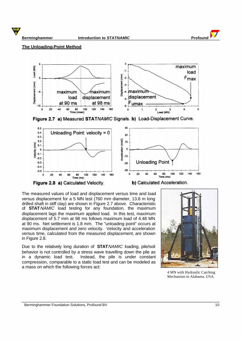
The Unloading-Point Method
The measured values of load and displacement versus time and load versus displacement for a 5 MN test (760 mm diameter, 13.8 m long drilled shaft in stiff clay) are shown in Figure 2.7 above. Characteristic of STAT NAMIC load testing for any foundation, the maximum displacement lags the maximum applied load. In this test, maximum displacement of 5.7 mm at 98 ms follows maximum load of 4.48 MN at 90 ms. Net settlement is 1.8 mm. The "unloading point” occurs at maximum displacement and zero velocity. Velocity and acceleration versus time, calculated from the measured displacement, are shown in Figure 2.8. Due to the relatively long duration of STATNAMIC loading, pile/soil behavior is not controlled by a stress wave travelling down the pile as in a dynamic load test. Instead, the pile is under constant compression, comparable to a static load test and can be modeled as a mass on which the following forces act:
4 MN with Hydraulic Catching Mechanism in Alabama, USA.
Berminghammer Introduction to STATNAMIC Profound
Berminghammer Foundation Solutions, Profound BV 11
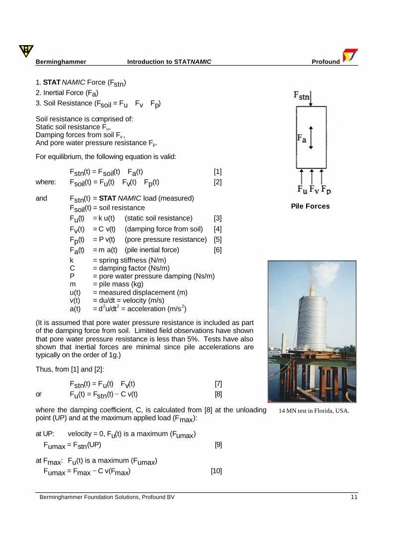
1. STAT NAMIC Force (Fstn) 2. Inertial Force (Fa) 3. Soil Resistance (Fsoil = Fu + Fv + Fp) Soil resistance is comprised of: Static soil resistance Fu, Damping forces from soil Fv , And pore water pressure resistance Fp. For equilibrium, the following equation is valid:
Fstn(t) = Fsoil(t) + Fa(t) [1] where: Fsoil(t) = Fu(t) + Fv(t) + Fp(t) [2] and Fstn(t) = STAT NAMIC load (measured)
Fsoil(t) = soil resistance Fu(t) = k⋅u(t) (static soil resistance) [3] Fv(t) = C ⋅v(t) (damping force from soil) [4] Fp(t) = P⋅v(t) (pore pressure resistance) [5] Fa(t) = m ⋅a(t) (pile inertial force) [6] k = spring stiffness (N/m) C = damping factor (Ns/m) P = pore water pressure damping (Ns/m) m = pile mass (kg) u(t) = measured displacement (m) v(t) = du/dt = velocity (m/s) a(t) = d2u/dt2 = acceleration (m/s2)
(It is assumed that pore water pressure resistance is included as part of the damping force from soil. Limited field observations have shown that pore water pressure resistance is less than 5%. Tests have also shown that inertial forces are minimal since pile accelerations are typically on the order of 1g.) Thus, from [1] and [2]:
Fstn(t) = Fu(t) + Fv(t) [7] or Fu(t) = Fstn(t) − C⋅v(t) [8] where the damping coefficient, C, is calculated from [8] at the unloading point (UP) and at the maximum applied load (Fmax): at UP: velocity = 0, Fu(t) is a maximum (Fumax) ∴ Fumax = Fstn(UP) [9] at Fmax: Fu(t) is a maximum (Fumax) ∴ Fumax = Fmax − C⋅v(Fmax) [10]
Pile Forces
14 MN test in Florida, USA.
Berminghammer Introduction to STATNAMIC Profound
Berminghammer Foundation Solutions, Profound BV 12
Thus, from [9] and [10]: C = F - F
v(F )max umax
max [11]
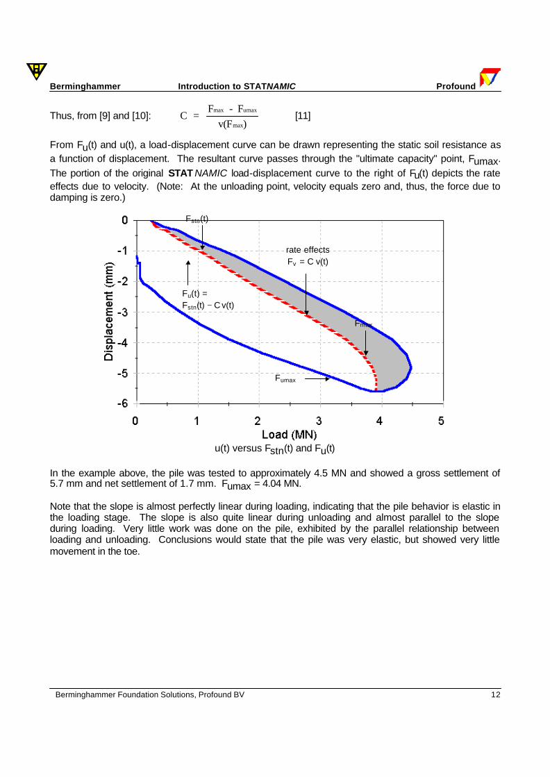
From Fu(t) and u(t), a load-displacement curve can be drawn representing the static soil resistance as a function of displacement. The resultant curve passes through the "ultimate capacity" point, Fumax. The portion of the original STAT NAMIC load-displacement curve to the right of Fu(t) depicts the rate effects due to velocity. (Note: At the unloading point, velocity equals zero and, thus, the force due to damping is zero.)
u(t) versus Fstn(t) and Fu(t)
In the example above, the pile was tested to approximately 4.5 MN and showed a gross settlement of 5.7 mm and net settlement of 1.7 mm. Fumax = 4.04 MN. Note that the slope is almost perfectly linear during loading, indicating that the pile behavior is elastic in the loading stage. The slope is also quite linear during unloading and almost parallel to the slope during loading. Very little work was done on the pile, exhibited by the parallel relationship between loading and unloading. Conclusions would state that the pile was very elastic, but showed very little movement in the toe.
Fmax
rate effects Fv = C⋅v(t)
Fstn(t)
Fu(t) = Fstn(t) − C⋅v(t)
Fumax