Embed Size (px)
Citation preview
COMPOSITES & POLYCON 2009
American Composites Manufacturers Association
January 15-17, 2009
Tampa, FL USA
Behavior of FRP Tubes-Encased
Concrete Columns under
Concentric and Eccentric Loads
by
Hamdy Mohamed, Department of Civil Engineering,
University of Sherbrooke
Radhouane Masmoudi, Department of Civil Engineering,
University of Sherbrooke
Abstract
Recently, Concrete filled fiber-reinforced polymers
(FRP) tube (CFFT) columns have gained approval in civ-
il engineering for different structural applications. A re-
search program is currently being carried out at the la-
boratories of the Department of Civil Engineering, Uni-
versity of Sherbrooke. The objective of that program is
to investigate the compressive behavior of the FRP tube-
encased concrete columns. This paper experimentally
investigates the performance of the CFFT columns under
concentric and eccentric loads. The experimental pro-
gram was conducted on ten unconfined cylinders, eight
CFFT columns. The results were compared to steel spiral
reinforcement which have the same confinement pres-
sure of the FRP tubes. The diameter of the FRP tubes
was 152 mm and the fibers orientation were mainly in
the hoop direction. The results indicated that the beha-
vior of CFFT is affected by the presence of steel bars,
laminate thickness and eccentricity load.
Introduction
Fiber reinforced polymer (FRP) composites have
been increasingly used in concrete construction. The ap-
plication of concrete filled FRP tubes (CFFT) technique,
such as precast piles, girders, and pier columns [1, 2, 3
and 4]. Several experimental and analytical investiga-
tions were conducted to study the behaviors of the CFFT
columns. However, most of the research studies were
focused on the behavior of CFFT under uniaxial or flex-
ural load. In fact, structural concrete columns under axi-
al loads are exhibited to eccentric load. This occurs for
the edge and corner columns in the residential or office
building and opened garages. In addition, the designed
axially loaded columns can be affected from the eccen-
tricity due to unintentional load eccentricities, possible
construction error, lateral deformation and buckling phe-
nomenon. In addition, there are many columns intended
to carry an eccentric loads. Therefore, it is important to
understand the behavior of the CFFT columns under ec-
centric load.
Experimental test and analytical model was intro-
duced to describe the behavior of CFFT tubes subjected
to combined axial compression loads and bending mo-
ment. The study evaluated the confinement as affected
by the eccentricity of the applied axial loads as well as
the influence of the FRP laminate structure. The results
indicated that the interaction curves are significantly af-
fected by both the laminate structure and diameter-to-
thickness ratios of the tubes [5]. The behavior of FRP
jacketed square concrete columns subjected to eccentric
loading was investigated [6]. Nine (108x108x305 mm)
square concrete column stubs with zero, one, and two
plies of unidirectional carbon FRP fabric were tested un-
der axial loading and various eccentricities. It was con-
cluded that the FRP jacket can greatly enhance the
strength and ductility of concrete columns under eccen-
tric loading and that the strain gradient reduces the retro-
fit efficiency of the FRP jacket for concrete columns.
Three different groups of the internally reinforced high
strength concrete columns were tested under concentric
and eccentric load [7]. Two eccentricities where used (25
and 50 mm), the columns wrapped with two different
materials E-glass fiber and carbon fiber. It was con-
cluded that: As the eccentricity was increased the load
carrying capacity of the columns was significantly re-
duced and directly related to the magnitude of eccentrici-
ty, a larger eccentricity results in a smaller maximum
load. The axial deflection was reduced while the lateral
deflection increased with eccentricity.
The objective of this paper is to examine the beha-
vior of CFFT concrete circular columns under concentric
and eccentric loading. Ten unconfined cylinders, eight
CFFT columns and two control steel spiral reinforcement
concrete columns were cast and tested under concentric
and eccentric loading. Four CFFT columns loaded with
different eccentricity 15, 30, 45 and 60 mm from the cen-
ter of the columns. An experimental result in term of
strengths, lateral and axial deformation, and failure mode
was obtained for each column.
Experimental Work
GFRP Tubes
Three types of glass-fiber reinforced polymer
GFRP tubes were used. The GFRP tubes were fabricated
using filament winding technique; E-glass fiber and
Epoxy resin were utilized for manufacturing these tubes.
The internal diameter of the tubes is constant and equals
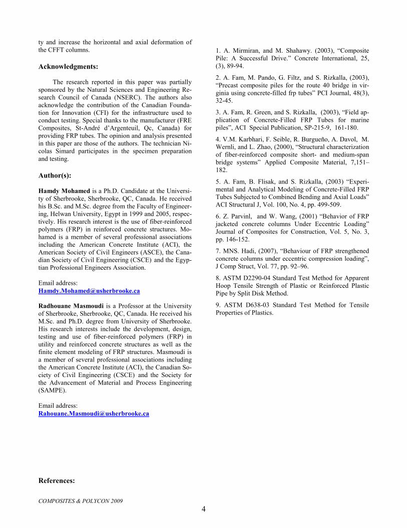
152 mm. Table 1 presents the details for the three types
A, B and C of the GFRP tubes, where EX and EY are the
Young’s modulus in the longitudinal and hoop direc-
COMPOSITES & POLYCON 2009
2
tions. The split-disk test and coupon tensile test were
performed according to ASTM D-2290-04 and ASTM D
638-03 standard [8, 9], respectively, on five specimens
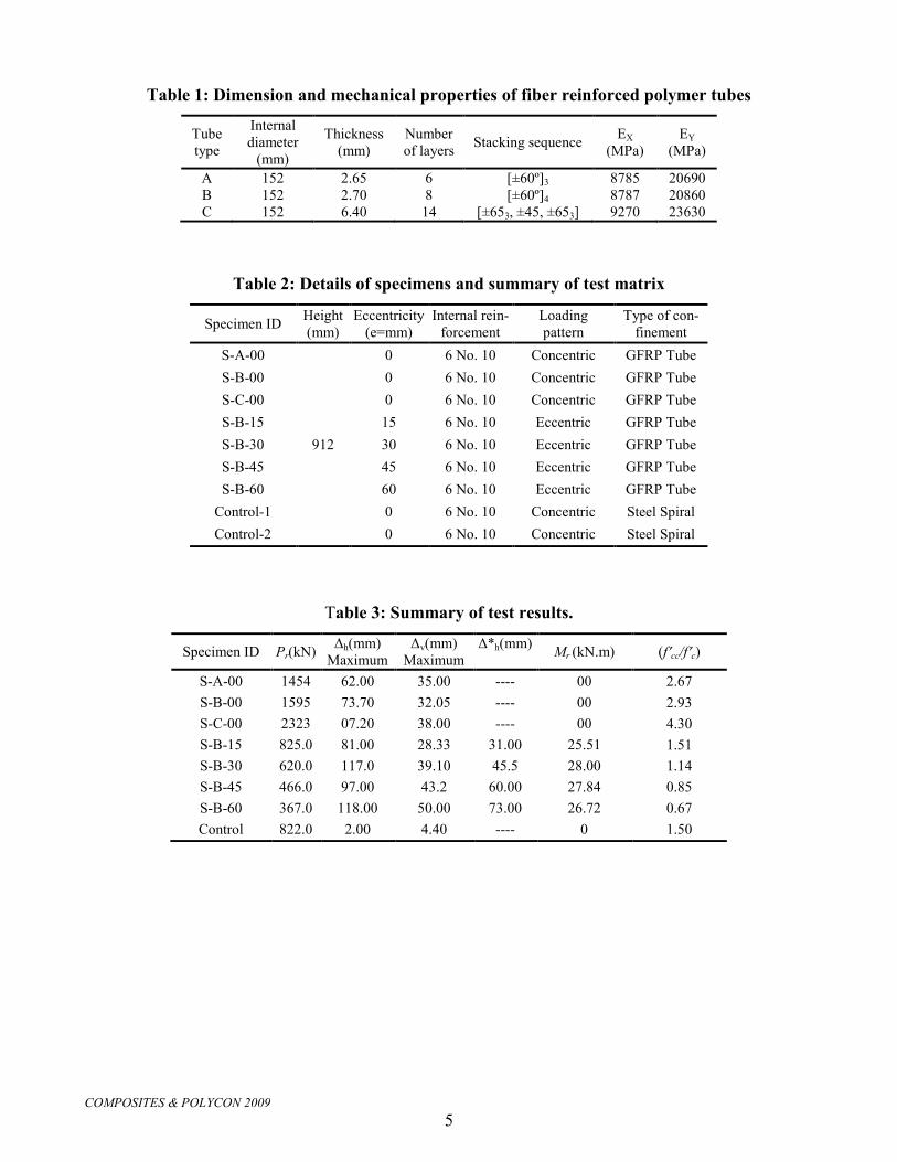
from each type of the tubes. Figure 1 presents the axial
tensile stress-strain responses for the three types of the
GFRP tube resulted from the coupon tests. Figure 2
shows the average load-strain relationship for each type
of the tubes for the split-disk test, and as expected, the
highest hoop tensile force values were obtained for the
specimens of tube type C which has the largest thickness.
In addition, the load-strain curve for the split-disk test
was linear up to failure for specimen A and B, however
bilinear for tube C.
Concrete Mixes
All specimens were constructed from the same
batch of the concrete using a ready mix concrete suppli-
er. The concrete mixture was intended to provide 30
MPa a concrete compressive strength. The materials by
kg per m3 for concrete mixture were 335 cements, 169
water, 331 gravel (aggregate size 2.5-10 mm), 628 gravel
(aggregate size 10-20 mm), 856 sand, 70ml/100 kg air-
entraining admixture, air content 5-8%, 350ml/100 kg
mid-range water reducing admixture (EUCON MRC).
Ten plain concrete cylinders (152 x 305 mm) were pre-
pared at the time of casting of CFFT specimens. The av-
erage concrete strength at 28-days testing of all cylinders
was found to be 30 ± 1 MPa.
Steel Bars
Deformed and mild steel bars No. 10 M and 3.2
mm diameter, respectively, were used to reinforce the
CFFT columns and control specimens. Steel bars No. 10
M were used as a longitudinal reinforcement and steel
bars 3.2 mm diameter were used as spiral reinforcement
for the control specimens. Tensile test for five specimens
conducted for each type of the steel bars. The results in-
dicated that the yield tensile strengths were 462 and 675
MPa, also the ultimate tensile strengths were 577 and
820 MPa for steel bars No. 10 M and 3.2 mm diameter,
respectively.
Test Matrix and Specimen Preparation
Test matrix and details of the CFFT columns are
presented in Table 2. The experimental program for this
paper includes four (152 x 912 mm) CFFT and two con-
trol specimens subjected to concentric load, also four
CFFT columns subjected to variable eccentric load, (15,
30, 45 and 60 mm). The slenderness ratio: height to di-
ameter ratio (H/D) for columns is equal to 6. The CFFT
columns were internally reinforced with six deformed
steel longitudinal bars 10 M with constant reinforcement
ratio equal to 2.60 %, see Figure 3. The bars were distri-
buted uniformly inside the cross section of the GFRP
tube. The bars were welded at the top and the bottom of
the height by two steel stirrups of 3.2 mm diameter, to
fix the bars during casting. The distance between the bars
and the tubes was 8 mm. A concrete cover of 10 mm was
provided between the ends of the longitudinal steel bars
and the top and bottom surfaces of the specimens to
avoid the stress concentration at the steel bars area. Fi-
nally, the last two specimens in Table 2 present a spirally
steel reinforced concrete column. These specimens pre-
pared to be as a control specimen to obtain the ultimate
load capacity under a concentric load.
Test Setup and Instrumentation
The specimens were tested under concentric load
using a 6,000 kN capacity FORNEY machine as shown
in Figure 4. The columns were setup vertically at the
center of the loading plates of the machine. However,
two rigid steel frames designed and fabricated to test the
CFFT specimens under variable eccentric loads. The
steel frames placed over the two ends of the CFFT spe-
cimens, see Figure 5. Two longitudinal steel rebar, in the
tension side of the columns were instrumented at mid
height by two electrical resistances strain gages, before
casting for each CFFT columns. Also, two axial and two
transverse electrical resistances strain gages were
mounted 180 degree apart along the hoop direction for
each specimen on the external surface of the GFRP tubes
at the mid height.
The axial displacement for each column was meas-
ured by two linear variable displacement transducers
(LVDTs) 180 degrees apart along the hoop direction of
the specimen. Moreover, to measure the horizontal dis-
placement, which was expected for all specimens due to
the eccentric load, four LVDTs were placed horizontally
on the mid-height of the column 90 degrees around the
column. The FORNEY machine, strain gages and
LVDTs were connected by a 20 channels Data Acquisi-
tion System. The data were recorded every one second
during the test. The loading rate range was 400 to 600
N/s during the test by manually controlling the loading
rate of the hydraulic pump.
Test Results and Discussion
The peak loads (Pr), moment at peak load (Mr), cor-
responding horizontal displacements at the mid-height of
the columns (∆*h), the maximum axial and horizontal
deformation (∆v) and (∆h), respectively, and the confined
concrete compressive strength to the unconfined concrete
compressive strength ratio (f′cc/f′c) are given in Table 3.
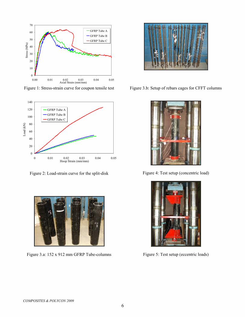
Figure 6 shows the failure modes for 912 mm
height, CFFT columns. The failure of the concentric
CFFT columns occurred due to buckling immediately
followed by the rupture of the GFRP tube. For CFFT
specimens, typical failure was generally recorded by rup-
ture of the GFRP tubes between the one end and the mid-
COMPOSITES & POLYCON 2009
3
height of the specimen. All specimens failed in single
curvature buckling mode. Distortions of the cross section
and outward bulging of the tube near the middle height
of the CFFT occurred for all specimens. This resulted
from the sliding of the concrete core and local buckling
of the internal rebars inside the GFRP tube. Sound snap-
ping was heard even after stopping the test and removal
of the specimens from the setup, until the stored energy
in the hoop direction and the interaction between fiber
and the prestressed concrete core was released.
For eccentrically loaded CFFT columns the failure
was generally marked by a ductile failure. Significant
decrease in the ultimate load capacity was observed for
all eccentrically specimens as compared with the ulti-
mate load capacity of concentrically loaded CFFT col-
umns. Excessive horizontal deformation at the mid
height of the CFFT columns was observed beyond the
peak load. The final failure mode for the eccentrically
loaded CFFT columns was permanent with single curva-
ture buckling in the direction of the tension side. Also,
tensile failure in the tension side with minor local buck-
ling in the compression side for the GFRP tube at the
mid height occurred for all specimens beyond the peak
load due to the increases in the lateral deformations, see
Figure 7.
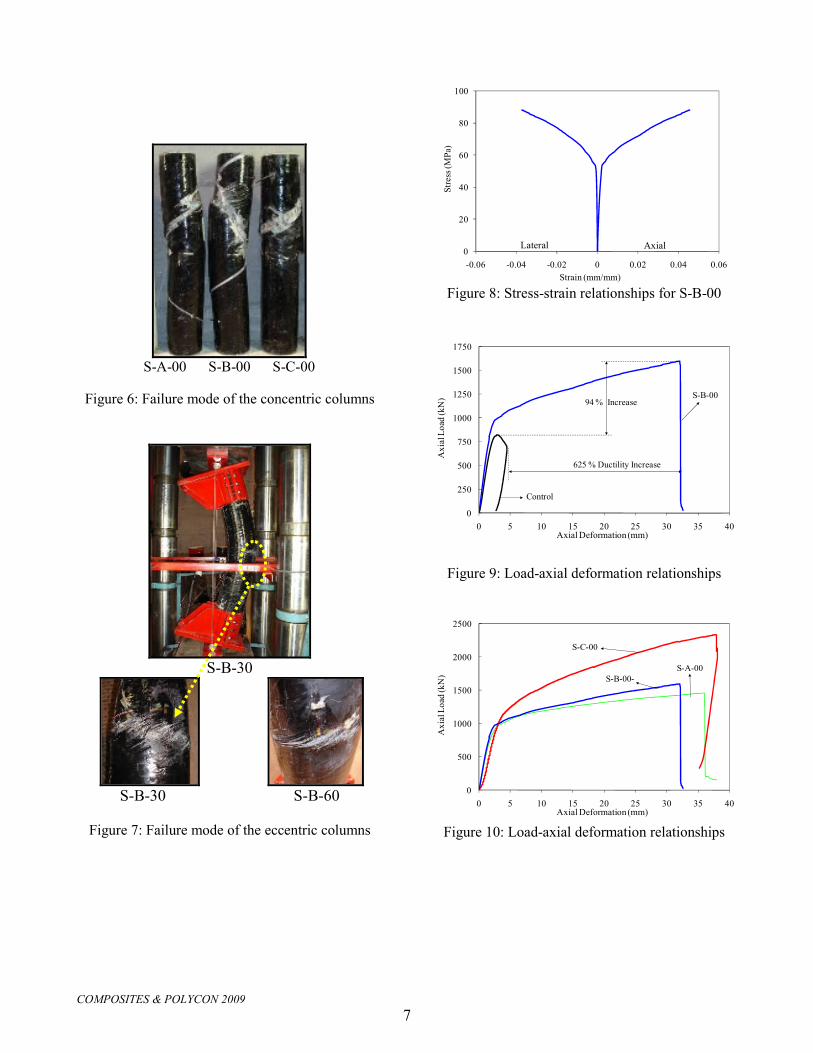
The axial stress- axial and hoop strain relationship
for the S-B-00 specimens is bilinear as shown in Figure
8. The average ratios of confined concrete compressive
strength to unconfined concrete cylinder strength (f′cc/f′c)
for S-A-00, S-B-00 and S-C-00 are 2.67, 2.93 and 4.30.
The axial displacement data were plotted against the
axial load for each specimen. To study the effect of
thickness and the effect of the confinement, the load-
axial deflection curves for CFFT-00 and control column
are shown in Figure 9. The ultimate load capacity of the
CFFT column was increased by 94 % as compared to the
ultimate load capacity of the control specimen. Also a
significant improvement in the ductility (axial deforma-
tion at the ultimate load) was observed for the CFFT col-
umn. Figure 10 shows the axial deformation against the
axial load for concentric CFFT columns. It is clear that
the ductility of the CFFT columns increased significantly
due to the confinement action. In addition, the increase in
the ultimate strength increased from 1454 and 1597 to
2323 kN for S-A-00, S-B-00 and S-C-00, respectively. It
is clear that by increasing the thickness of the GFRP
tube, the ultimate strength of the CFFT columns is in-
creased.
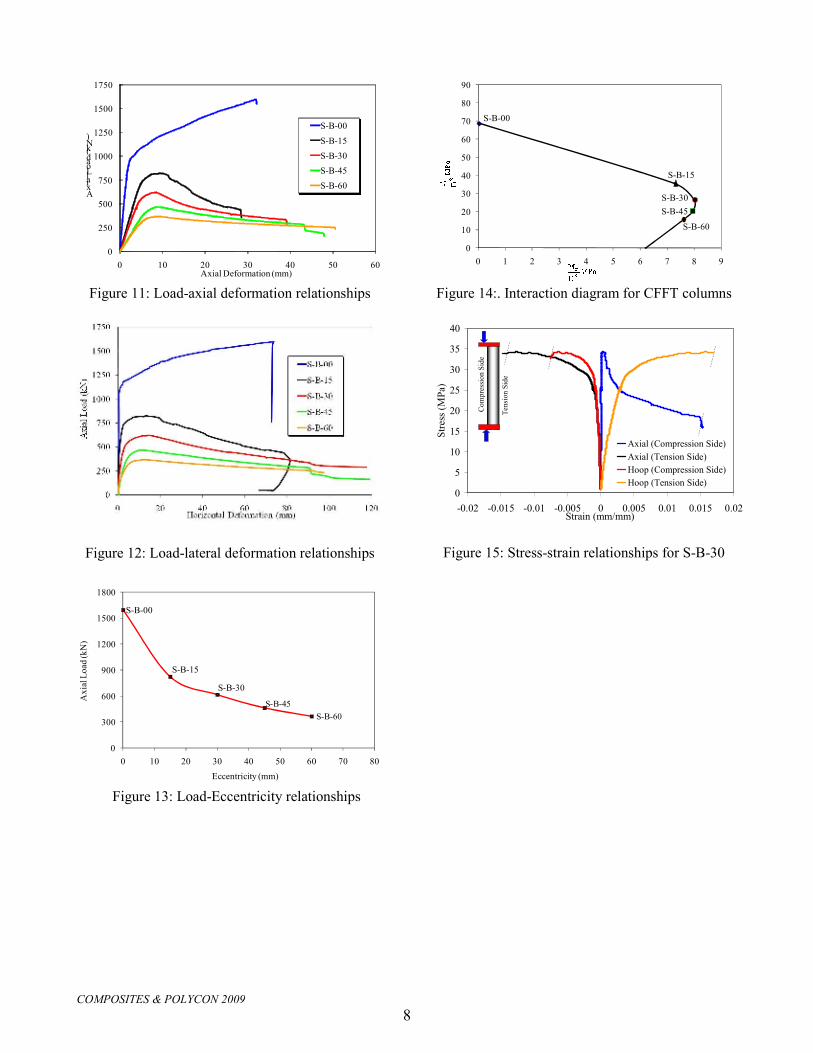
The load-axial deflection curves for the eccentrical-
ly loaded CFFT columns are presented in Figure 11. The
initial tangent modulus for the eccentrically loaded CFFT
columns decreased with increasing the eccentricity val-
ues; however the load-deflection curves for these speci-
mens are nonlinear and presented softening response
beyond the peak loads opposite to the response of the
concentrically column which presented hardening beha-
vior. It was noticed that at the same load level the axial
deformation increased with increasing the values of the
eccentricity. The largest axial displacement was recorded
for S-B-60 which equal to 50 mm. The load-horizontal
deflection curves for CFFT columns are plotted in Figure
12. The horizontal deformation for specimen S-B-00 was
approximately approached to zero up to load level 80 %
of the ultimate load, after that increased to the maximum
value at the ultimate load. The lateral deformation of the
eccentrically columns increased gradually with load in-
crease up to the peak load, after that the deformation in-
creased progressively with decreasing the load. From
Figures 11 and 12, it was observed that the ultimate load
capacity of the CFFT columns significantly decreased
with the eccentric load and increasing the value of the
eccentricity for the same cross section.
Figure 13 shows the relationships between the ec-
centricity value and the axial load on the CFFT columns.
The ultimate load capacity for specimens S-B-15, S-B-
30, S-B-45 and S-B-60 decreased 48, 61, 70 and 77 %,
respectively as compared to the ultimate load capacity of
specimen S-B-00. The experimental results were used to
establish interaction diagram for the CFFT columns, see
Figure 14. Figure 15 shows the stress-strain curves for S-
B-30 specimen. The tension and compression strains are
plotted in the left and right side of the figures, respective-
ly. The stress- axial strain curve for the S-B-30 on the
compression side presented linear response up to the
peak load with the maximum value equal to 0.0007, then
descending occurred for the curve with nonlinear re-
sponse up to failure. In addition, the stress-axial tension
strain showed linear response up to 82 % of the peak
load with tension-strain equal to .0017, the strain after
that increased nonlinearly up to failure, the axial tension
strain value at the peak load presented 0.015, this value
approximately equal to the yield strain of steel bars. The
hoop strain in the compression and tension side showed
positive and negative strain values, respectively up to
failure.
Conclusions
The behaviors of internally reinforced CFFT col-
umns under concentric and different eccentric load val-
ues were presented. The behavior of the concrete filled
GFRP tubes is significantly affected by the eccentric
load. The test results indicate that by increasing the
thickness of the GFRP tubes a significant improvement
is achieved in the confinement efficiency. The confine-
ment provided by the GFRP tubes improves both the
load-carrying capacity and the ductility of the concrete
columns under concentric load. The stress-strain curve of
the CFFT tube columns is bilinear and nonlinear for the
concentric and eccentric loading, respectively. Increasing
the eccentricity values decrease the ultimate load capaci-
COMPOSITES & POLYCON 2009
4
ty and increase the horizontal and axial deformation of
the CFFT columns.
Acknowledgments:
The research reported in this paper was partially
sponsored by the Natural Sciences and Engineering Re-
search Council of Canada (NSERC). The authors also
acknowledge the contribution of the Canadian Founda-
tion for Innovation (CFI) for the infrastructure used to
conduct testing. Special thanks to the manufacturer (FRE
Composites, St-André d’Argenteuil, Qc, Canada) for
providing FRP tubes. The opinion and analysis presented
in this paper are those of the authors. The technician Ni-
colas Simard participates in the specimen preparation
and testing.
Author(s):
Hamdy Mohamed is a Ph.D. Candidate at the Universi-
ty of Sherbrooke, Sherbrooke, QC, Canada. He received
his B.Sc. and M.Sc. degree from the Faculty of Engineer-
ing, Helwan University, Egypt in 1999 and 2005, respec-
tively. His research interest is the use of fiber-reinforced
polymers (FRP) in reinforced concrete structures. Mo-
hamed is a member of several professional associations
including the American Concrete Institute (ACI), the
American Society of Civil Engineers (ASCE), the Cana-
dian Society of Civil Engineering (CSCE) and the Egyp-
tian Professional Engineers Association.
Email address:
Radhouane Masmoudi is a Professor at the University
of Sherbrooke, Sherbrooke, QC, Canada. He received his
M.Sc. and Ph.D. degree from University of Sherbrooke.
His research interests include the development, design,
testing and use of fiber-reinforced polymers (FRP) in
utility and reinforced concrete structures as well as the
finite element modeling of FRP structures. Masmoudi is
a member of several professional associations including
the American Concrete Institute (ACI), the Canadian So-
ciety of Civil Engineering (CSCE) and the Society for
the Advancement of Material and Process Engineering
(SAMPE).
Email address:
References:
1. A. Mirmiran, and M. Shahawy. (2003), “Composite
Pile: A Successful Drive.” Concrete International, 25,
(3), 89-94.
2. A. Fam, M. Pando, G. Filtz, and S. Rizkalla, (2003),
“Precast composite piles for the route 40 bridge in vir-
ginia using concrete-filled frp tubes” PCI Journal, 48(3),
32-45.
3. A. Fam, R. Green, and S. Rizkalla, (2003), “Field ap-
plication of Concrete-Filled FRP Tubes for marine
piles”, ACI Special Publication, SP-215-9, 161-180.
4. V.M. Karbhari, F. Seible, R. Burgueño, A. Davol, M.
Wernli, and L. Zhao, (2000), “Structural characterization
of fiber-reinforced composite short- and medium-span
bridge systems” Applied Composite Material, 7,151–
182.
5. A. Fam, B. Flisak, and S. Rizkalla, (2003) “Experi-
mental and Analytical Modeling of Concrete-Filled FRP
Tubes Subjected to Combined Bending and Axial Loads”
ACI Structural J, Vol. 100, No. 4, pp. 499-509.
6. Z. Parvinl, and W. Wang, (2001) “Behavior of FRP
jacketed concrete columns Under Eccentric Loading”
Journal of Composites for Construction, Vol. 5, No. 3,
pp. 146-152.
7. MNS. Hadi, (2007), “Behaviour of FRP strengthened
concrete columns under eccentric compression loading”,
J Comp Struct, Vol. 77, pp. 92–96.
8. ASTM D2290-04 Standard Test Method for Apparent
Hoop Tensile Strength of Plastic or Reinforced Plastic
Pipe by Split Disk Method.
9. ASTM D638-03 Standard Test Method for Tensile
Properties of Plastics.
COMPOSITES & POLYCON 2009
5
Table 1: Dimension and mechanical properties of fiber reinforced polymer tubes
Tube
type
Internal
diameter
(mm)
Thickness
(mm)
Number
of layers Stacking sequence
EX
(MPa)
EY
(MPa)
A 152 2.65 6 [±60º]3 8785 20690
B 152 2.70 8 [±60º]4 8787 20860
C 152 6.40 14 [±653, ±45, ±653] 9270 23630
Table 2: Details of specimens and summary of test matrix
Table 3: Summary of test results.
Specimen ID Height
(mm)
Eccentricity
(e=mm)
Internal rein-
forcement
Loading
pattern
Type of con-
finement
S-A-00
912
0 6 No. 10 Concentric GFRP Tube
S-B-00 0 6 No. 10 Concentric GFRP Tube
S-C-00 0 6 No. 10 Concentric GFRP Tube
S-B-15 15 6 No. 10 Eccentric GFRP Tube
S-B-30 30 6 No. 10 Eccentric GFRP Tube
S-B-45 45 6 No. 10 Eccentric GFRP Tube
S-B-60 60 6 No. 10 Eccentric GFRP Tube
Control-1 0 6 No. 10 Concentric Steel Spiral
Control-2 0 6 No. 10 Concentric Steel Spiral
Specimen ID Pr(kN) ∆h(mm)
Maximum
∆v(mm)
Maximum
∆*h(mm)
Mr (kN.m) (f′cc/f′c)
S-A-00 1454 62.00 35.00 ---- 00 2.67
S-B-00 1595 73.70 32.05 ---- 00 2.93
S-C-00 2323 07.20 38.00 ---- 00 4.30
S-B-15 825.0 81.00 28.33 31.00 25.51 1.51
S-B-30 620.0 117.0 39.10 45.5 28.00 1.14
S-B-45 466.0 97.00 43.2 60.00 27.84 0.85
S-B-60 367.0 118.00 50.00 73.00 26.72 0.67
Control 822.0 2.00 4.40 ---- 0 1.50
COMPOSITES & POLYCON 2009
6
0
10
20
30
40
50
60
70
0.00 0.01 0.02 0.03 0.04 0.05Axial Strain (mm/mm)
Str
ess
(MP
a)
GFRP Tube A
GFRP Tube B
GFRP Tube C
Figure 1: Stress-strain curve for coupon tensile test
0
20
40
60
80
100
120
140
0 0.01 0.02 0.03 0.04 0.05Hoop Strain (mm/mm)
Lo
ad (
kN
)
GFRP Tube A
GFRP Tube B
GFRP Tube C
Figure 2: Load-strain curve for the split-disk
Figure 3.a: 152 x 912 mm GFRP Tube-columns
Figure 3.b: Setup of rebars cages for CFFT columns
Figure 4: Test setup (concentric load)
Figure 5: Test setup (eccentric loads)
COMPOSITES & POLYCON 2009
7
S-A-00 S-B-00 S-C-00
Figure 6: Failure mode of the concentric columns
S-B-30
S-B-30 S-B-60
Figure 7: Failure mode of the eccentric columns
0
20
40
60
80
100
-0.06 -0.04 -0.02 0 0.02 0.04 0.06
Str
ess
(MP
a)
Strain (mm/mm)
Lateral Axial
Figure 8: Stress-strain relationships for S-B-00
0
250
500
750
1000
1250
1500
1750
0 5 10 15 20 25 30 35 40
Ax
ial L
oad
(k
N)
Axial Deformation (mm)
Control
S-B-0094 % Increase
625 % Ductility Increase
Figure 9: Load-axial deformation relationships
0
500
1000
1500
2000
2500
0 5 10 15 20 25 30 35 40
Ax
ial L
oad
(k
N)
Axial Deformation (mm)
S-A-00
S-B-00-
S-C-00
Figure 10: Load-axial deformation relationships
COMPOSITES & POLYCON 2009
8
0
250
500
750
1000
1250
1500
1750
0 10 20 30 40 50 60
Axial Load (kN)
Axial Deformation (mm)
S-B-00
S-B-15
S-B-30
S-B-45
S-B-60
Figure 11: Load-axial deformation relationships
Figure 12: Load-lateral deformation relationships
0
300
600
900
1200
1500
1800
0 10 20 30 40 50 60 70 80
Ax
ial L
oad
(k
N)
Eccentricity (mm)
S-B-00
S-B-15
S-B-30
S-B-45
S-B-60
Figure 13: Load-Eccentricity relationships
0
10
20
30
40
50
60
70
80
90
0 1 2 3 4 5 6 7 8 9
S-B-00
S-B-15
S-B-30
S-B-45
S-B-60
Figure 14:. Interaction diagram for CFFT columns
0
5
10
15
20
25
30
35
40
-0.02 -0.015 -0.01 -0.005 0 0.005 0.01 0.015 0.02Strain (mm/mm)
Str
ess
(MP
a)Axial (Compression Side)
Axial (Tension Side)
Hoop (Compression Side)
Hoop (Tension Side)C
om
pre
ssio
n S
ide
Ten
sio
n S
ide
Figure 15: Stress-strain relationships for S-B-30