Embed Size (px)
Citation preview
Compaq Presario Series Maintenance and Service Guide
United States December 9, 2002
Presario 305 Model
Before You Begin Specifications Parts Catalog
Removal Sequence Troubleshooting Battery Operations
Product Description Pin Assignments Index
Before You Begin
Product Description
Troubleshooting
Illustrated Parts Catalog
Removal & Replacement Procedures
Specifications
Connector Pin Assignments
Battery Pack Operations
See Notice for
copyright and trademark information, and see Preface for symbol conventions, Technician Notes and Serial Number locations on the unit.
This MSG will be periodically maintained and updated as needed. To report a technical problem, contact your Regional Support Center or IM Help Center. For content comments or questions, contact Compaq.
privacy and legal statement
http://h18000.www1.hp.com/athome/support/msgs/305/index.html [12/9/2002 2:10:48 PM]
Compaq Presario Series Maintenance and Service Guide
United States December 9, 2002
Presario 305 Model
Before You Begin Specifications Parts Catalog
Removal Sequence Troubleshooting Battery Operations
Product Description Pin Assignments Index
Notice
The information in this guide is subject to change without notice.
COMPAQ COMPUTER CORPORATION SHALL NOT BE LIABLE FOR TECHNICAL OR EDITORIAL ERRORS OR OMISSIONS CONTAINED HEREIN, NOR FOR INCIDENTAL OR CONSEQUENTIAL DAMAGES RESULTING FROM THE FURNISHING, PERFORMANCE, OR USE OF THIS MATERIAL.
This guide contains information protected by copyright. No part of this guide may be photocopied or reproduced in any form without prior written consent from Compaq Computer Corporation.
© 1999 Compaq Computer Corporation.All rights reserved. Printed in the U.S.A.
Compaq and Presario are registered in the U. S. Patent and Trademark Office.
Microsoft, MS-DOS, Windows and Windows NT are registered trademarks of Microsoft Corporation. Windows 98 is a trademark of Microsoft Corporation.
The software described in this guide is furnished under a license agreement or nondisclosure agreement. The software may be used or copied only in accordance with the terms of the agreement.
Product names mentioned herein may be trademarks and/or registered trademarks of their respective companies.
Maintenance and Service Guide
Compaq Presario 305 Model Portable Computers
First Edition (July 1999)Compaq Computer Corporation
privacy and legal statement
http://h18000.www1.hp.com/athome/support/msgs/305/notice.html [12/9/2002 2:11:43 PM]
Compaq Presario Series Maintenance and Service Guide
United States December 9, 2002
Presario 305 Model
Before You Begin Specifications Parts Catalog
Removal Sequence Troubleshooting Battery Operations
Product Description Pin Assignments Index
Preface
This Maintenance and Service Guide is a troubleshooting reference that can be used when servicing the Compaq Presario 305 Model Portable Computers. Compaq Computer Corporation reserves the right to make changes to the Compaq Presario 305 Model Portable Computers without notice.
Symbols
The following words and symbols mark special messages throughout this guide.
WARNING: Text set off in this manner indicates that failure to follow directions in the warning could result in bodily harm or loss of life.
CAUTION: Text set off in this manner indicates that failure to follow directions could result in damage to equipment or loss of data.
IMPORTANT:Text set off in this manner presents clarifying information or specific instructions.
NOTE:Text set off in this manner presents commentary, sidelights, or interesting points of information.
Technician Notes
WARNING: Only authorized technicians trained by Compaq should repair this equipment. All troubleshooting and repair procedures are detailed to allow only subassembly/module level repair. Because of the complexity of the individual boards and subassemblies, the user should not attempt to make repairs at the component level or to make modifications to any printed circuit board. Improper repairs can create a safety hazard. Any indications of component replacement or printed circuit board modifications may void any warranty.
WARNING: The computer is designed to be electrically grounded. To ensure proper operation, plug the AC power cord into a properly grounded electrical outlet only.
CAUTION: To properly ventilate the system, you must provide at least 3 inches (7.62 cm) of clearance on the left and right sides of the computer.
Serial Number
When requesting information or ordering spare parts, the computer serial number should be provided to Compaq. The serial number is located on the bottom of the computer.
Locating Additional Information
The following documentation is available to support this product:
● Compaq Presario 305 Model Portable Computer documentation set● Introducing Windows 98 Guide● Compaq Service Training Guides● Compaq Service Advisories and Bulletins● Compaq QuickFind● Compaq Service Quick Reference Guide● Compaq Internet site at http://Compaq.com
privacy and legal statement
http://h18000.www1.hp.com/athome/support/msgs/305/preface.html [12/9/2002 2:12:05 PM]
Compaq Presario Series Maintenance and Service Guide
United States December 9, 2002
Presario 305 Model
Before You Begin Specifications Parts Catalog
Removal Sequence Troubleshooting Battery Operations
Product Description Pin Assignments Index
Product Description
Models and Features
Upper Unit Components
Front Components
Left Side Components
Right Side Components
Bottom of Unit
Rear Connectors
Multi-media Expansion Unit
Power Management for Windows 98
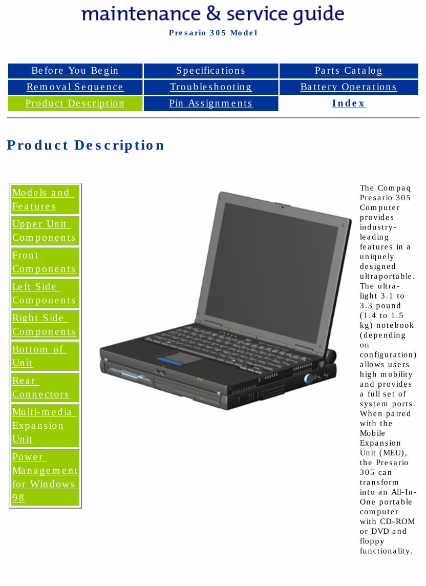
The Compaq Presario 305 Computer provides industry-leading features in a uniquely designed ultraportable. The ultra-light 3.1 to 3.3 pound (1.4 to 1.5 kg) notebook (depending on configuration) allows users high mobility and provides a full set of system ports. When paired with the Mobile Expansion Unit (MEU), the Presario 305 can transform into an All-In-One portable computer with CD-ROM or DVD and floppy functionality.
privacy and legal statement
http://h18000.www1.hp.com/athome/support/msgs/305/product.html [12/9/2002 2:12:32 PM]
Compaq Presario Series Maintenance and Service Guide
United States December 9, 2002
Presario 305 Model
Before You Begin Specifications Parts Catalog
Removal Sequence Troubleshooting Battery Operations
Product Description Pin Assignments Index
Models and Features
Models and Features
Upper Unit Components
Front Components
Left Side Components
Right Side Components
Bottom of Unit
Rear Connectors
Multi-media Expansion Unit
Power Management for Windows 98
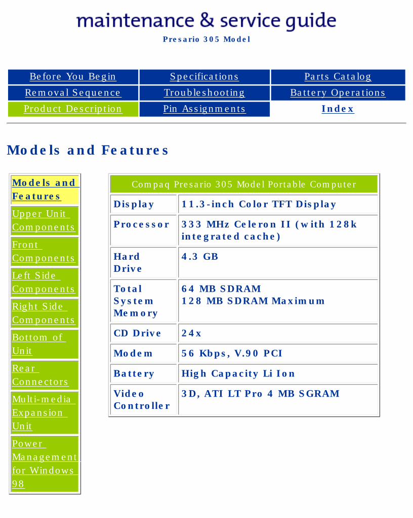
Compaq Presario 305 Model Portable Computer
Display 11.3-inch Color TFT Display
Processor 333 MHz Celeron II (with 128k integrated cache)
Hard Drive
4.3 GB
Total System Memory
64 MB SDRAM128 MB SDRAM Maximum
CD Drive 24x
Modem 56 Kbps, V.90 PCI
Battery High Capacity Li Ion
Video Controller
3D, ATI LT Pro 4 MB SGRAM
privacy and legal statement
http://h18000.www1.hp.com/athome/support/msgs/305/models.html [12/9/2002 2:12:52 PM]
Compaq Presario Series Maintenance and Service Guide
United States December 9, 2002
Presario 305 Model
Before You Begin Specifications Parts Catalog
Removal Sequence Troubleshooting Battery Operations
Product Description Pin Assignments Index
Upper Unit Components
Models and Features
Upper Unit Components
Front Components
Left Side Components
Right Side Components
Bottom of Unit
Rear Connectors
Multi-media Expansion Unit
Power Management for Windows 98
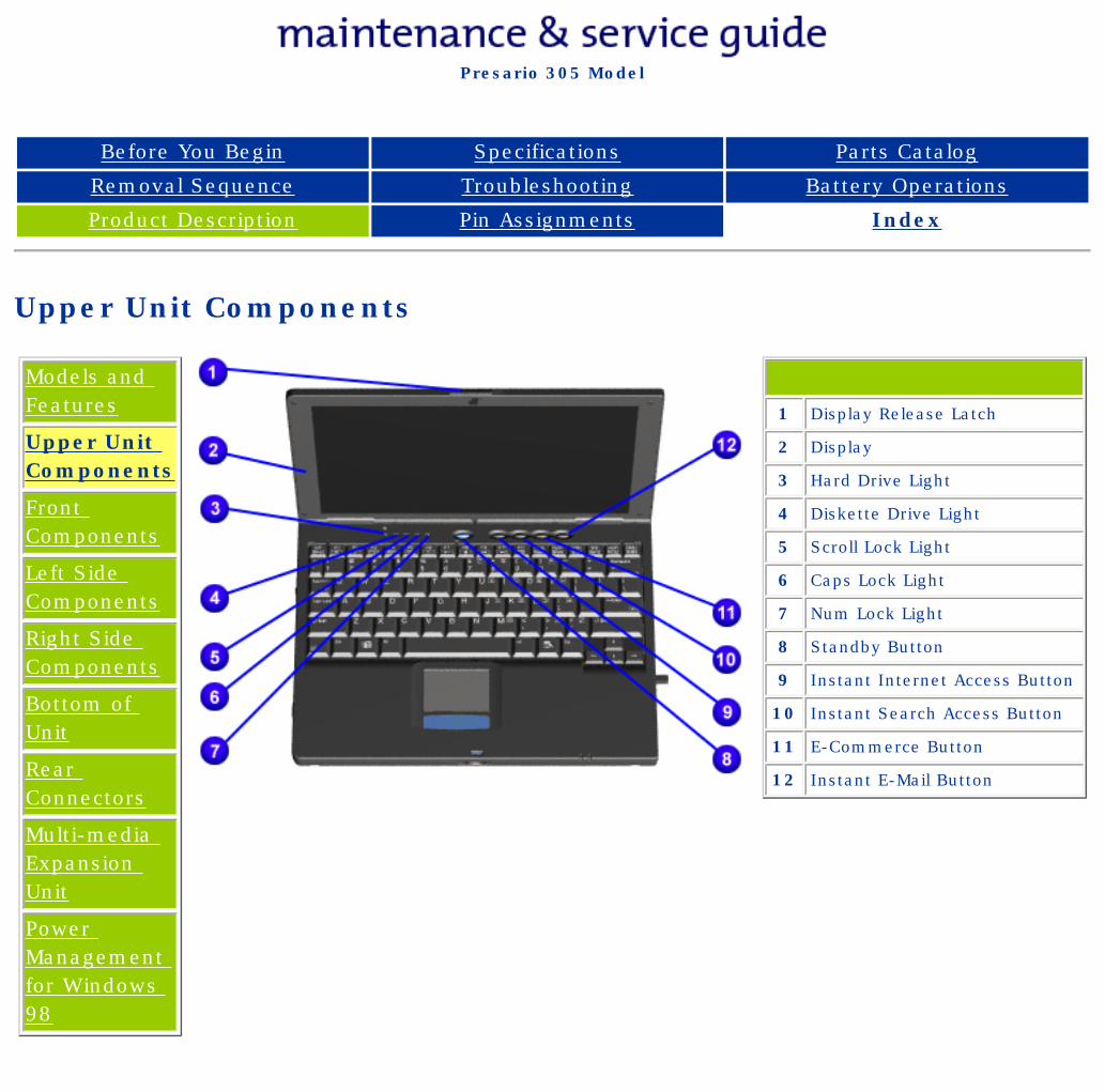
1 Display Release Latch
2 Display
3 Hard Drive Light
4 Diskette Drive Light
5 Scroll Lock Light
6 Caps Lock Light
7 Num Lock Light
8 Standby Button
9 Instant Internet Access Button
10 Instant Search Access Button
11 E-Commerce Button
12 Instant E-Mail Button
privacy and legal statement
http://h18000.www1.hp.com/athome/support/msgs/305/contrls.html [12/9/2002 2:13:06 PM]
Compaq Presario Series Maintenance and Service Guide
United States December 9, 2002
Presario 305 Model
Before You Begin Specifications Parts Catalog
Removal Sequence Troubleshooting Battery Operations
Product Description Pin Assignments Index
Front Components
Models and Features
Upper Unit Components
Front Components
Left Side Components
Right Side Components
Bottom of Unit
Rear Connectors
Multi-media Expansion Unit
Power Management for Windows 98
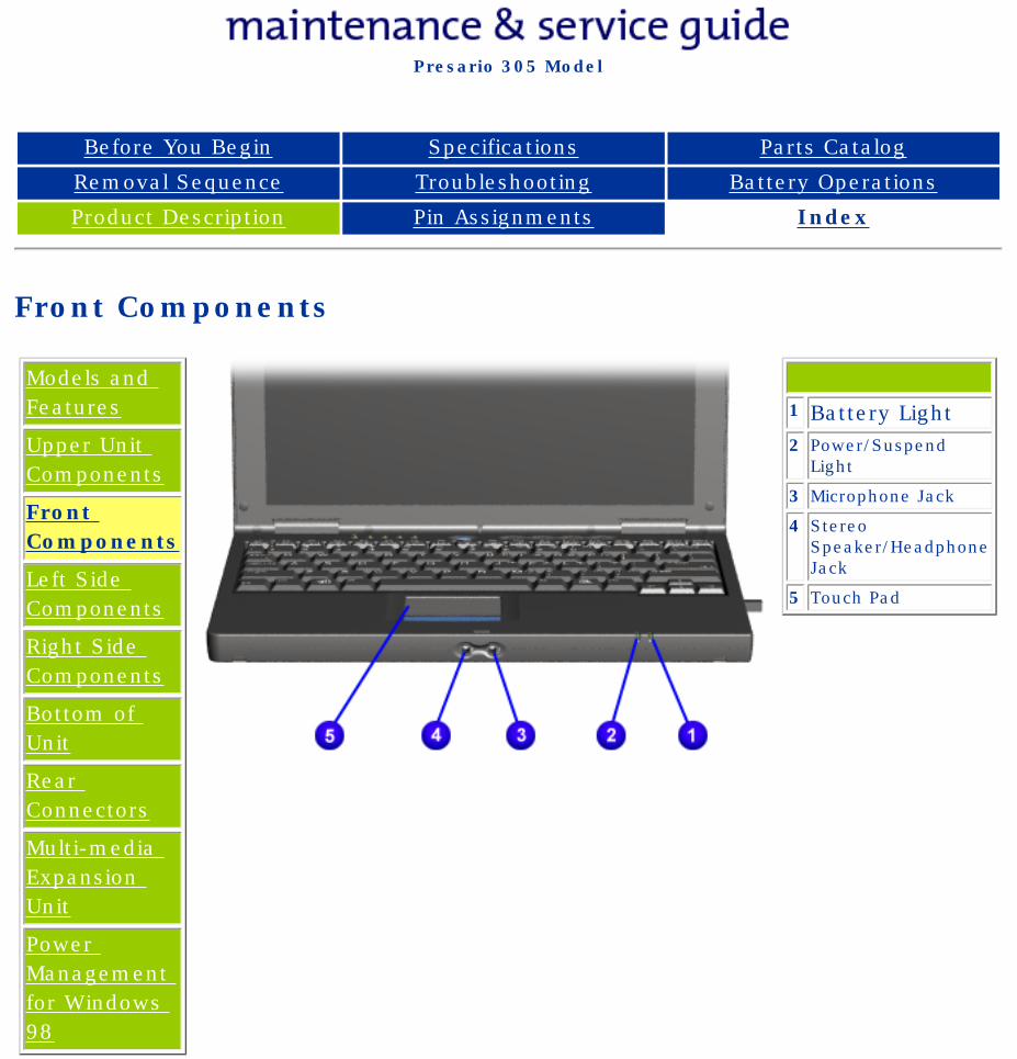
1 Battery Light2 Power/Suspend
Light
3 Microphone Jack
4 Stereo Speaker/Headphone Jack
5 Touch Pad
privacy and legal statement
http://h18000.www1.hp.com/athome/support/msgs/305/frncomp.html [12/9/2002 2:13:22 PM]
Compaq Presario Series Maintenance and Service Guide
United States December 9, 2002
Presario 305 Model
Before You Begin Specifications Parts Catalog
Removal Sequence Troubleshooting Battery Operations
Product Description Pin Assignments Index
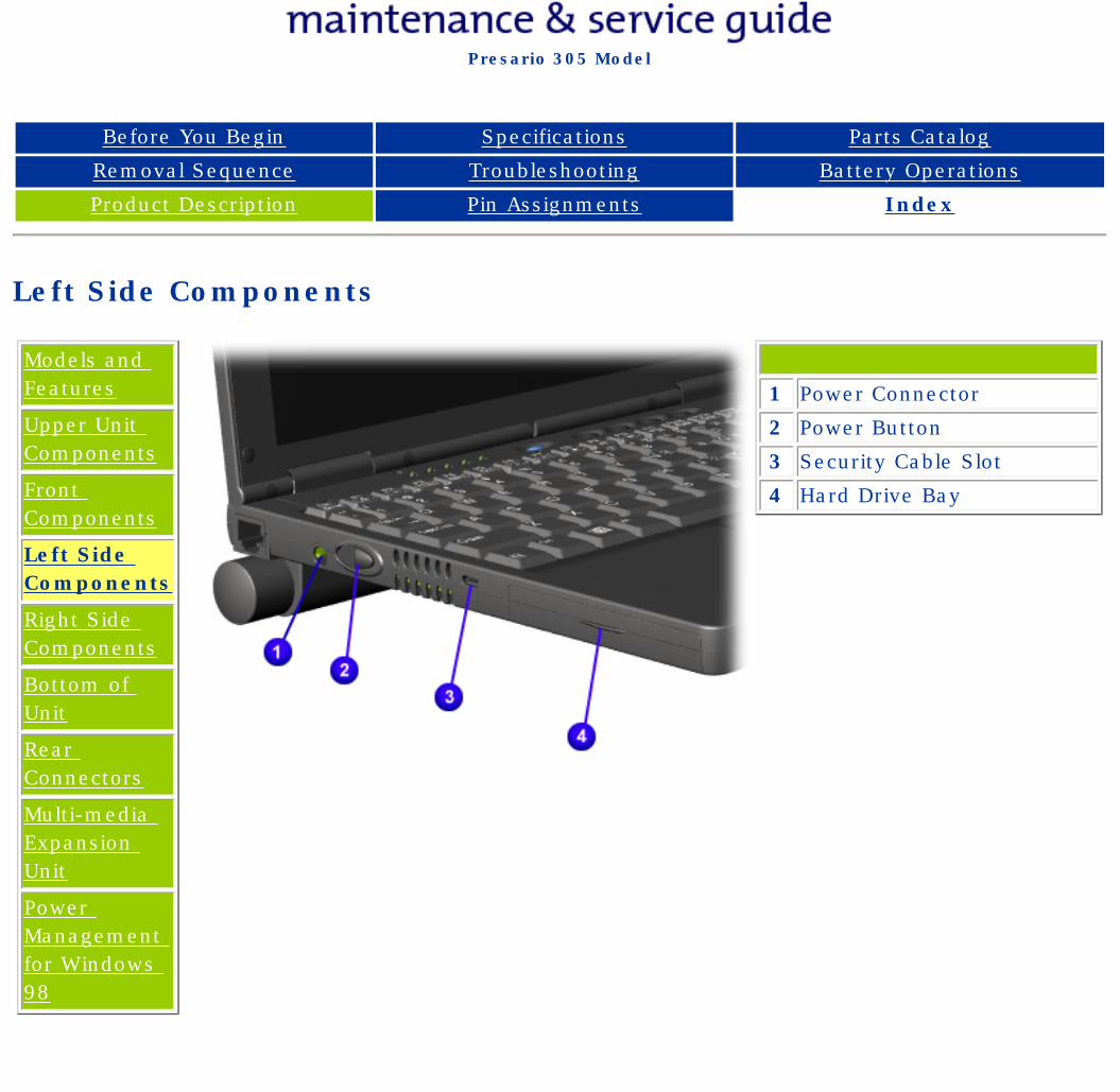
Left Side Components
Models and Features
Upper Unit Components
Front Components
Left Side Components
Right Side Components
Bottom of Unit
Rear Connectors
Multi-media Expansion Unit
Power Management for Windows 98
1 Power Connector
2 Power Button
3 Security Cable Slot
4 Hard Drive Bay
privacy and legal statement
http://h18000.www1.hp.com/athome/support/msgs/305/leftsid.html [12/9/2002 2:13:37 PM]
Compaq Presario Series Maintenance and Service Guide
United States December 9, 2002
Presario 305 Model
Before You Begin Specifications Parts Catalog
Removal Sequence Troubleshooting Battery Operations
Product Description Pin Assignments Index
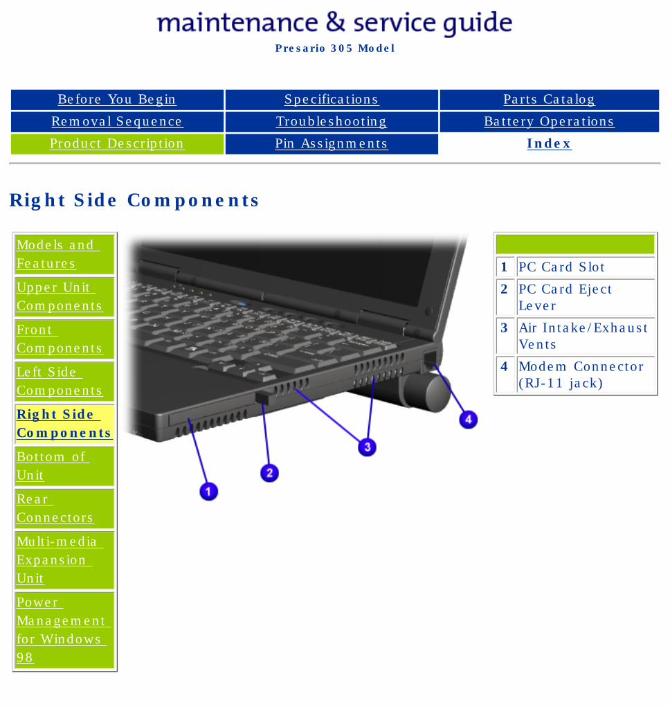
Right Side Components
Models and Features
Upper Unit Components
Front Components
Left Side Components
Right Side Components
Bottom of Unit
Rear Connectors
Multi-media Expansion Unit
Power Management for Windows 98
1 PC Card Slot
2 PC Card Eject Lever
3 Air Intake/Exhaust Vents
4 Modem Connector (RJ-11 jack)
privacy and legal statement
http://h18000.www1.hp.com/athome/support/msgs/305/right.html [12/9/2002 2:13:39 PM]
Compaq Presario Series Maintenance and Service Guide
United States December 9, 2002
Presario 305 Model
Before You Begin Specifications Parts Catalog
Removal Sequence Troubleshooting Battery Operations
Product Description Pin Assignments Index
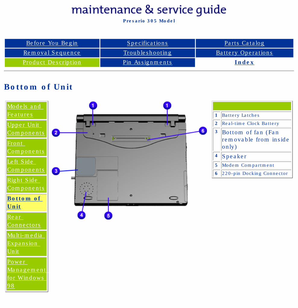
Bottom of Unit
Models and Features
Upper Unit Components
Front Components
Left Side Components
Right Side Components
Bottom of Unit
Rear Connectors
Multi-media Expansion Unit
Power Management for Windows 98
1 Battery Latches
2 Real-time Clock Battery
3 Bottom of fan (Fan removable from inside only)
4 Speaker5 Modem Compartment
6 220-pin Docking Connector
privacy and legal statement
http://h18000.www1.hp.com/athome/support/msgs/305/bottom.html [12/9/2002 2:13:41 PM]
Compaq Presario Series Maintenance and Service Guide
United States December 9, 2002
Presario 305 Model
Before You Begin Specifications Parts Catalog
Removal Sequence Troubleshooting Battery Operations
Product Description Pin Assignments Index
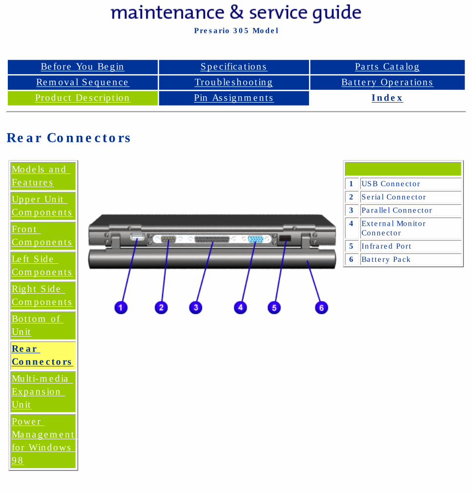
Rear Connectors
Models and Features
Upper Unit Components
Front Components
Left Side Components
Right Side Components
Bottom of Unit
Rear Connectors
Multi-media Expansion Unit
Power Management for Windows 98
1 USB Connector
2 Serial Connector
3 Parallel Connector
4 External Monitor Connector
5 Infrared Port
6 Battery Pack
privacy and legal statement
http://h18000.www1.hp.com/athome/support/msgs/305/rearcon.html [12/9/2002 2:13:44 PM]
Compaq Presario Series Maintenance and Service Guide
United States December 9, 2002
Presario 305 Model
Before You Begin Specifications Parts Catalog
Removal Sequence Troubleshooting Battery Operations
Product Description Pin Assignments Index
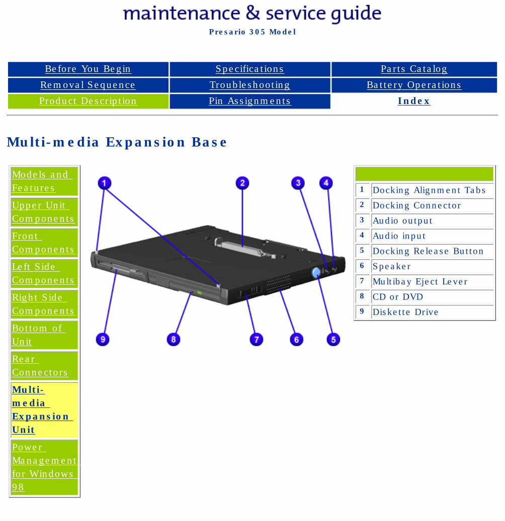
Multi-media Expansion Base
Models and Features
Upper Unit Components
Front Components
Left Side Components
Right Side Components
Bottom of Unit
Rear Connectors
Multi-media Expansion Unit
Power Management for Windows 98
1 Docking Alignment Tabs2 Docking Connector3 Audio output4 Audio input5 Docking Release Button6 Speaker7 Multibay Eject Lever8 CD or DVD9 Diskette Drive
privacy and legal statement
http://h18000.www1.hp.com/athome/support/msgs/305/wedge.html [12/9/2002 2:13:46 PM]
Compaq Presario Series Maintenance and Service Guide
United States December 9, 2002
Presario 305 Model
Before You Begin Specifications Parts Catalog
Removal Sequence Troubleshooting Battery Operations
Product Description Pin Assignments Index
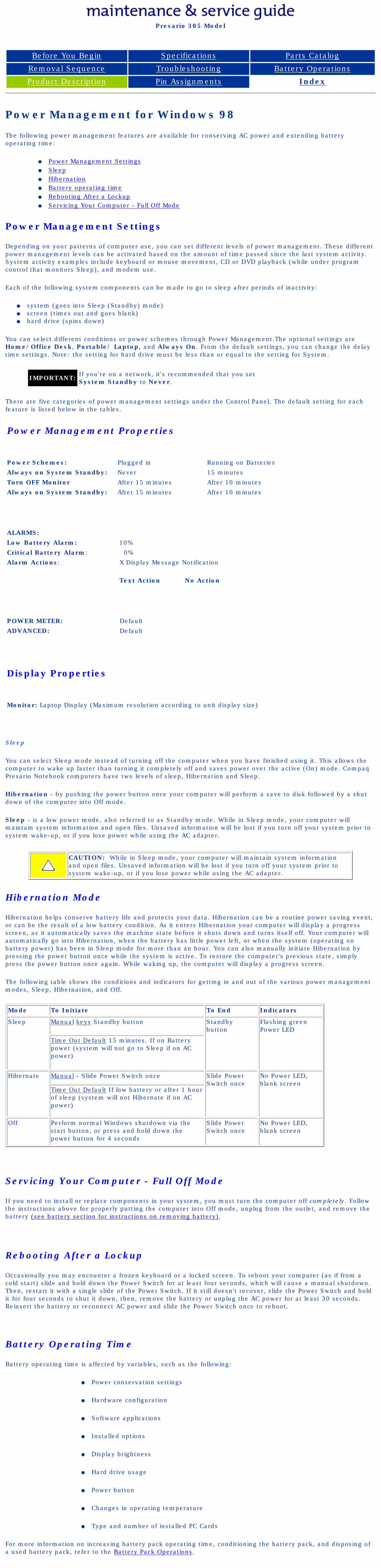
Power Management for Windows 98
The following power management features are available for conserving AC power and extending battery operating time:
● Power Management Settings● Sleep● Hibernation● Battery operating time● Rebooting After a Lockup● Servicing Your Computer - Full Off Mode
Power Management Settings
Depending on your patterns of computer use, you can set different levels of power management. These different power management levels can be activated based on the amount of time passed since the last system activity. System activity examples include keyboard or mouse movement, CD or DVD playback (while under program control that monitors Sleep), and modem use.
Each of the following system components can be made to go to sleep after periods of inactivity:
● system (goes into Sleep (Standby) mode)● screen (times out and goes blank)● hard drive (spins down)
You can select different conditions or power schemes through Power Management.The optional settings are Home/Office Desk, Portable/ Laptop, and Always On. From the default settings, you can change the delay time settings. Note: the setting for hard drive must be less than or equal to the setting for System.
IMPORTANT: If you're on a network, it's recommended that you set System Standby to Never.
There are five categories of power management settings under the Control Panel. The default setting for each feature is listed below in the tables.
Power Management Properties
Power Schemes: Plugged in Running on Batteries
Always on System Standby: Never 15 minutes
Turn OFF Monitor After 15 minutes After 10 minutes
Always on System Standby: After 15 minutes After 10 minutes
ALARMS:
Low Battery Alarm: 10%
Critical Battery Alarm: 0%
Alarm Actions: X Display Message Notification
Text Action No Action
POWER METER: Default
ADVANCED: Default
Display Properties
Monitor: Laptop Display (Maximum resolution according to unit display size)
Sleep
You can select Sleep mode instead of turning off the computer when you have finished using it. This allows the computer to wake up faster than turning it completely off and saves power over the active (On) mode. Compaq Presario Notebook computers have two levels of sleep, Hibernation and Sleep.
Hibernation - by pushing the power button once your computer will perform a save to disk followed by a shut down of the computer into Off mode.
Sleep - is a low power mode, also referred to as Standby mode. While in Sleep mode, your computer will maintain system information and open files. Unsaved information will be lost if you turn off your system prior to system wake-up, or if you lose power while using the AC adapter.
CAUTION: While in Sleep mode, your computer will maintain system information and open files. Unsaved information will be lost if you turn off your system prior to system wake-up, or if you lose power while using the AC adapter.
Hibernation Mode
Hibernation helps conserve battery life and protects your data. Hibernation can be a routine power saving event, or can be the result of a low battery condition. As it enters Hibernation your computer will display a progress screen, as it automatically saves the machine state before it shuts down and turns itself off. Your computer will automatically go into Hibernation, when the battery has little power left, or when the system (operating on battery power) has been in Sleep mode for more than an hour. You can also manually initiate Hibernation by pressing the power button once while the system is active. To restore the computer's previous state, simply press the power button once again. While waking up, the computer will display a progress screen.
The following table shows the conditions and indicators for getting in and out of the various power management modes, Sleep, Hibernation, and Off.
Mode To Initiate To End Indicators
Sleep Manual keys Standby button Standby button
Flashing green Power LED
Time Out Default 15 minutes. If on Battery power (system will not go to Sleep if on AC power)
Hibernate Manual - Slide Power Switch once Slide Power Switch once
No Power LED, blank screen
Time Out Default If low battery or after 1 hour of sleep (system will not Hibernate if on AC power)
Off Perform normal Windows shutdown via the start button, or press and hold down the power button for 4 seconds
Slide Power Switch once
No Power LED, blank screen
Servicing Your Computer - Full Off Mode
If you need to install or replace components in your system, you must turn the computer off completely. Follow the instructions above for properly putting the computer into Off mode, unplug from the outlet, and remove the battery (see battery section for instructions on removing battery).
Rebooting After a Lockup
Occasionally you may encounter a frozen keyboard or a locked screen. To reboot your computer (as if from a cold start) slide and hold down the Power Switch for at least four seconds, which will cause a manual shutdown. Then, restart it with a single slide of the Power Switch. If it still doesn't recover, slide the Power Switch and hold it for four seconds to shut it down, then, remove the battery or unplug the AC power for at least 30 seconds. Reinsert the battery or reconnect AC power and slide the Power Switch once to reboot.
Battery Operating Time
Battery operating time is affected by variables, such as the following:
● Power conservation settings
● Hardware configuration
● Software applications
● Installed options
● Display brightness
● Hard drive usage
● Power button
● Changes in operating temperature
● Type and number of installed PC Cards
For more information on increasing battery pack operating time, conditioning the battery pack, and disposing of a used battery pack, refer to the Battery Pack Operations.
privacy and legal statement
http://h18000.www1.hp.com/athome/support/msgs/305/pwrmgt.html [12/9/2002 2:13:48 PM]
Compaq Presario Series Maintenance and Service Guide
United States December 9, 2002
Presario 305 Model
Before You Begin Specifications Parts Catalog
Removal Sequence Troubleshooting Battery Operations
Product Description Pin Assignments Index
Removing the Battery Pack
Removal Sequence
Serial Number Location
Preparing for Disassembly
Electrostatic Discharge
Service Considerations
Cables and Connectors
Multi-media Expansion Unit
Battery Pack
Hard Drive
Modem Card
RTC Battery
Keyboard
Memory Board
Switch Cover
Display Panel
Deck
Voltage Converter Board
Modem Connector Board
PC Card
PC Card Assembly
System Board
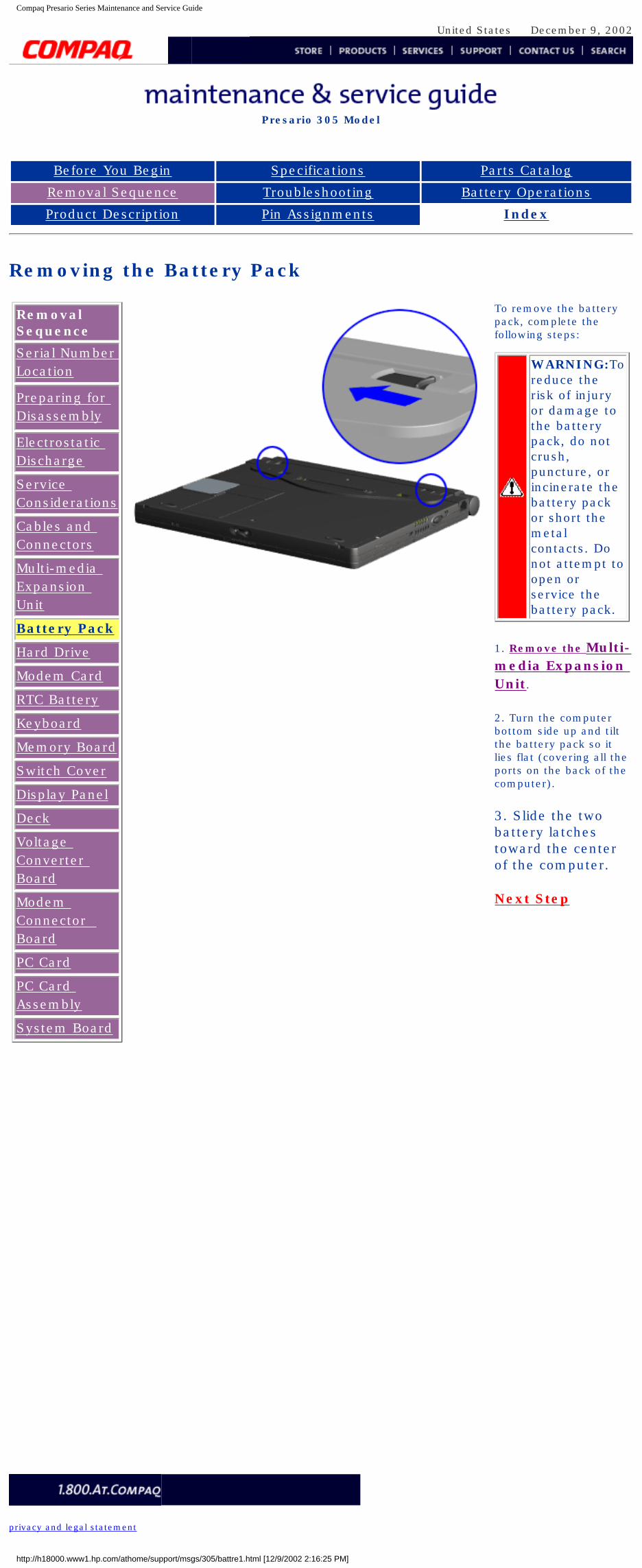
To remove the battery pack, complete the following steps:
WARNING:To reduce the risk of injury or damage to the battery pack, do not crush, puncture, or incinerate the battery pack or short the metal contacts. Do not attempt to open or service the battery pack.
1. Remove the Multi-media Expansion Unit.
2. Turn the computer bottom side up and tilt the battery pack so it lies flat (covering all the ports on the back of the computer).
3. Slide the two battery latches toward the center of the computer.
Next Step
privacy and legal statement
http://h18000.www1.hp.com/athome/support/msgs/305/battre1.html [12/9/2002 2:16:25 PM]
Compaq Presario Series Maintenance and Service Guide
United States December 9, 2002
Presario 305 Model
Before You Begin Specifications Parts Catalog
Removal Sequence Troubleshooting Battery Operations
Product Description Pin Assignments Index
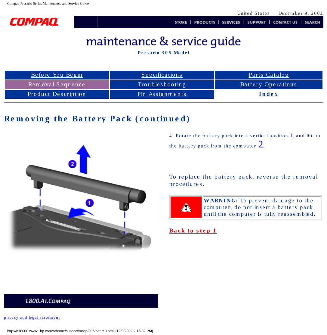
Removing the Battery Pack (continued)
4. Rotate the battery pack into a vertical position 1, and lift up
the battery pack from the computer 2.
To replace the battery pack, reverse the removal procedures.
WARNING: To prevent damage to the computer, do not insert a battery pack until the computer is fully reassembled.
Back to step 1
privacy and legal statement
http://h18000.www1.hp.com/athome/support/msgs/305/battre3.html [12/9/2002 2:16:32 PM]
Compaq Presario Series Maintenance and Service Guide
United States December 9, 2002
Presario 305 Model
Before You Begin Specifications Parts Catalog
Removal Sequence Troubleshooting Battery Operations
Product Description Pin Assignments Index
Removing the Multi-media Expansion unit
Removal Sequence
Serial Number Location
Preparing for Disassembly
Electrostatic Discharge
Service Considerations
Cables and Connectors
Multi-media Expansion Unit
Battery Pack
Hard Drive
Modem Card
RTC Battery
Keyboard
Memory Board
Switch Cover
Display Panel
Deck
Voltage Converter Board
Modem Connector Board
PC Card
PC Card Assembly
System Board
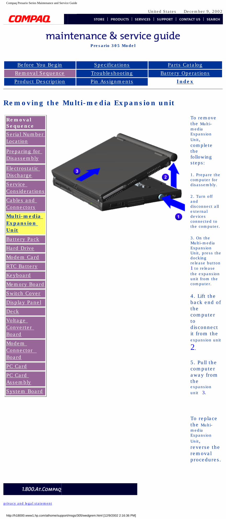
To remove the Multi-media Expansion Unit, complete the following steps:
1. Prepare the computer for disassembly.
2. Turn off and disconnect all external devices connected to the computer.
3. On the Multi-media Expansion Unit, press the docking release button 1 to release the expansion unit from the computer.
4. Lift the back end of the computer to disconnect it from the expansion unit
2.
5. Pull the computer away from the expansion unit 3.
To replace the Multi-media Expansion Unit, reverse the removal procedures.
privacy and legal statement
http://h18000.www1.hp.com/athome/support/msgs/305/wedgrem.html [12/9/2002 2:16:36 PM]
Compaq Presario Series Maintenance and Service Guide
United States December 9, 2002
Presario 305 Model
Before You Begin Specifications Parts Catalog
Removal Sequence Troubleshooting Battery Operations
Product Description Pin Assignments Index
Serial Number Location
Removal Sequence
Serial Number Location
Preparing for Disassembly
Electrostatic Discharge
Service Considerations
Cables and Connectors
Multi-media Expansion Unit
Battery Pack
Hard Drive
Modem Card
RTC Battery
Keyboard
Memory Board
Switch Cover
Display Panel
Deck
Voltage Converter Board
Modem Connector Board
PC Card
PC Card Assembly
System Board
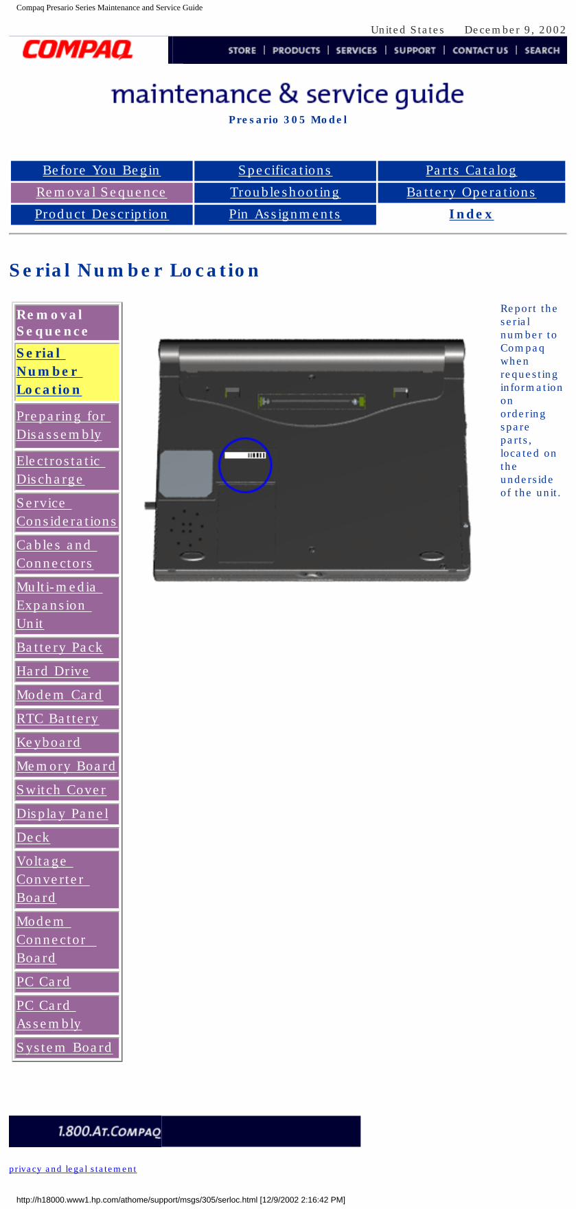
Report the serial number to Compaq when requesting information on ordering spare parts, located on the underside of the unit.
privacy and legal statement
http://h18000.www1.hp.com/athome/support/msgs/305/serloc.html [12/9/2002 2:16:42 PM]
Compaq Presario Series Maintenance and Service Guide
United States December 9, 2002
Presario 305 Model
Before You Begin Specifications Parts Catalog
Removal Sequence Troubleshooting Battery Operations
Product Description Pin Assignments Index
Preparing for Disassembly
Removal Sequence
Serial Number Location
Preparing for Disassembly
Electrostatic Discharge
Service Considerations
Cables and Connectors
Multi-media Expansion Unit
Battery Pack
Hard Drive
Modem Card
RTC Battery
Keyboard
Memory Board
Switch Cover
Display Panel
Deck
Voltage Converter Board
Modem Connector Board
PC Card
PC Card Assembly
System Board
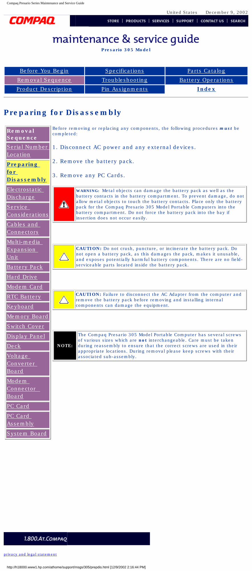
Before removing or replacing any components, the following procedures must be completed:
1. Disconnect AC power and any external devices.
2. Remove the battery pack.
3. Remove any PC Cards.
WARNING: Metal objects can damage the battery pack as well as the battery contacts in the battery compartment. To prevent damage, do not allow metal objects to touch the battery contacts. Place only the battery pack for the Compaq Presario 305 Model Portable Computers into the battery compartment. Do not force the battery pack into the bay if insertion does not occur easily.
CAUTION: Do not crush, puncture, or incinerate the battery pack. Do not open a battery pack, as this damages the pack, makes it unusable, and exposes potentially harmful battery components. There are no field-serviceable parts located inside the battery pack.
CAUTION: Failure to disconnect the AC Adapter from the computer and remove the battery pack before removing and installing internal components can damage the equipment.
NOTE:
The Compaq Presario 305 Model Portable Computer has several screws of various sizes which are not interchangeable. Care must be taken during reassembly to ensure that the correct screws are used in their appropriate locations. During removal please keep screws with their associated sub-assembly.
privacy and legal statement
http://h18000.www1.hp.com/athome/support/msgs/305/prepdis.html [12/9/2002 2:16:44 PM]
Compaq Presario Series Maintenance and Service Guide
United States December 9, 2002
Presario 305 Model
Before You Begin Specifications Parts Catalog
Removal Sequence Troubleshooting Battery Operations
Product Description Pin Assignments Index
Removal and Replacement Procedures
Electrostatic Discharge
A sudden discharge of static electricity from a finger or other conductor can destroy static-sensitive devices or microcircuitry. Often the spark is neither felt nor heard, but damage occurs. An electronic device exposed to electrostatic discharge (ESD) may not be affected at all and will work perfectly throughout a normal cycle. Although, it may function normally for a while, then degrade in the internal layers, reducing its life expectancy.
Networks built into many integrated circuits provide some protection, but in many cases, the discharge contains enough power to alter device parameters or melt silicon junctions.
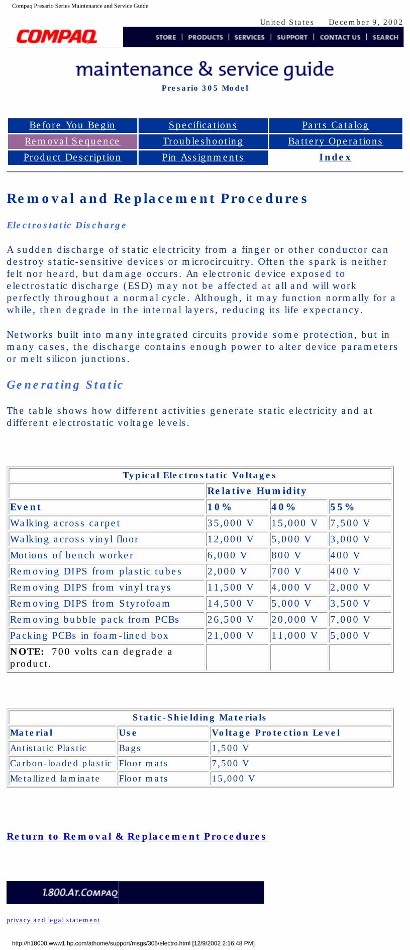
Generating Static
The table shows how different activities generate static electricity and at different electrostatic voltage levels.
Typical Electrostatic Voltages
Relative Humidity
Event 10% 40% 55%
Walking across carpet 35,000 V 15,000 V 7,500 V
Walking across vinyl floor 12,000 V 5,000 V 3,000 V
Motions of bench worker 6,000 V 800 V 400 V
Removing DIPS from plastic tubes 2,000 V 700 V 400 V
Removing DIPS from vinyl trays 11,500 V 4,000 V 2,000 V
Removing DIPS from Styrofoam 14,500 V 5,000 V 3,500 V
Removing bubble pack from PCBs 26,500 V 20,000 V 7,000 V
Packing PCBs in foam-lined box 21,000 V 11,000 V 5,000 V
NOTE: 700 volts can degrade a product.
Static-Shielding Materials
Material Use Voltage Protection Level
Antistatic Plastic Bags 1,500 V
Carbon-loaded plastic Floor mats 7,500 V
Metallized laminate Floor mats 15,000 V
Return to Removal & Replacement Procedures
privacy and legal statement
http://h18000.www1.hp.com/athome/support/msgs/305/electro.html [12/9/2002 2:16:48 PM]
Compaq Presario Series Maintenance and Service Guide
United States December 9, 2002
Presario 305 Model
Before You Begin Specifications Parts Catalog
Removal Sequence Troubleshooting Battery Operations
Product Description Pin Assignments Index
Removal and Replacement Procedures
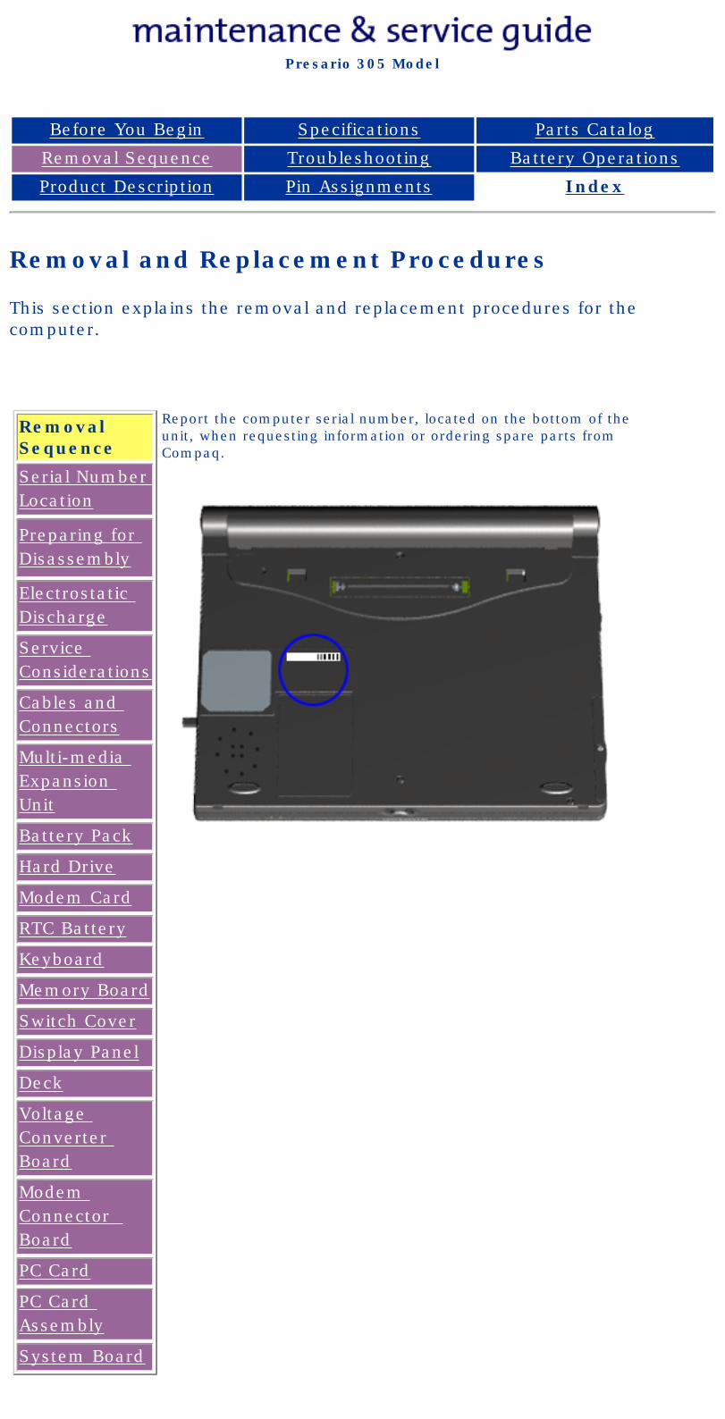
This section explains the removal and replacement procedures for the computer.
Removal Sequence
Serial Number Location
Preparing for Disassembly
Electrostatic Discharge
Service Considerations
Cables and Connectors
Multi-media Expansion Unit
Battery Pack
Hard Drive
Modem Card
RTC Battery
Keyboard
Memory Board
Switch Cover
Display Panel
Deck
Voltage Converter Board
Modem Connector Board
PC Card
PC Card Assembly
System Board
Report the computer serial number, located on the bottom of the unit, when requesting information or ordering spare parts from Compaq.
privacy and legal statement
http://h18000.www1.hp.com/athome/support/msgs/305/rmvrep.html [12/9/2002 2:16:52 PM]
Compaq Presario Series Maintenance and Service Guide
United States December 9, 2002
Presario 305 Model
Before You Begin Specifications Parts Catalog
Removal Sequence Troubleshooting Battery Operations
Product Description Pin Assignments Index
Service Considerations
Listed below are some of the considerations that you should keep in mind during the disassembly and reassembly of the computer.
Tool and Software Requirements
To service the computer, you need the following:
● Compaq screwdriver kit ● Torx T-8 screwdriver● 3/16-inch and 5mm nut drivers (for screwlocks and standoffs)● Small, standard screwdriver● Small, Phillips screwdriver● Diagnostics software
Screws
The screws used in the computer are not interchangeable. If an incorrect screw is used during the reassembly process, it can damage the unit. Compaq strongly recommends that all screws removed during disassembly be kept with the part that was removed, then returned to their proper locations.
Fan and RJ11
The Fan and RJ11 are spared with the base assembly. They are not available separately, and may only be obtained by ordering the entire base assembly. This Maintenance and Service Guide contains no removal and replacement procedures for these components.
IMPORTANT:As each subassembly is removed from the computer, it should be placed away from the work area to prevent damage.
Return to Removal & Replacement Procedures
privacy and legal statement
http://h18000.www1.hp.com/athome/support/msgs/305/service.html [12/9/2002 2:16:55 PM]
Compaq Presario Series Maintenance and Service Guide
United States December 9, 2002
Presario 305 Model
Before You Begin Specifications Parts Catalog
Removal Sequence Troubleshooting Battery Operations
Product Description Pin Assignments Index
Cables and Connectors
Most cables used throughout the unit are ribbon cables. Cables must be handled with extreme care to avoid damage. Apply only the tension required to seat or unseat the cables during insertion or removal from the connector. Handle cables by the connector whenever possible. In all cases, avoid bending, twisting, or tearing the cables, and ensure that the cables are routed in such a way that they cannot be caught or snagged by parts being removed or replaced.
Use the following precautions when handling cables to avoid damage to the cable or computer:
● Always handle cables by their connectors.● Avoid bending, twisting, or pulling on the cables.● Apply minimum required force when seating or unseating the cables from
their connectors.● Place the cables in such a manner that they cannot be caught or snagged by
parts being removed or replaced.● Handle flex cables with extreme care; they can tear easily.
CAUTION: When servicing these computers, ensure that cables are placed in their proper location during the reassembly process. Improper cable placement can cause severe damage to the unit.
Removing a cable from a ZIF Connector
Display panel cable location
Inverter cable location
Audio cable location
Touchpad cable location
Fan cable location
Light board cable location
Speaker cable location
Battery cable location
Plastic Parts
Plastic parts can be damaged by the use of excessive force during disassembly and reassembly. When handling the plastic parts, use care. Apply pressure only at the points designated in the maintenance instructions.
Return to Removal & Replacement Procedures
privacy and legal statement
http://h18000.www1.hp.com/athome/support/msgs/305/cblposn.html [12/9/2002 2:17:01 PM]
Compaq.com Compaq Presario Maintenance and Service Guide - 305
United States December 9, 2002
Maintenance & Service GuidePresario 305 Model
MSG Index | Home Page | Notice | Preface | Product Description | Troubleshooting Illustrated Parts Catalog | Removal & Replacement Procedures | Specifications
Pin Assignments | Battery Pack Operations
ZIF Connectors
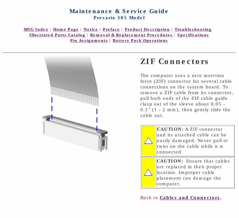
The computer uses a zero insertion force (ZIF) connector for several cable connections on the system board. To remove a ZIF cable from its connector, pull both ends of the ZIF cable guide clasp out of the sleeve about 0.05 - 0.1" (1 - 2 mm), then gently slide the cable out.
CAUTION: A ZIF connector and its attached cable can be easily damaged. Never pull or twist on the cable while it is connected.
CAUTION: Ensure that cables are replaced in their proper location. Improper cable placement can damage the computer.
Back to Cables and Connectors.
privacy and legal statement
http://h18000.www1.hp.com/athome/support/msgs/305/zif.html [12/9/2002 2:17:04 PM]
Compaq Presario Series Maintenance and Service Guide
United States December 9, 2002
Presario 305 Model
Before You Begin Specifications Parts Catalog
Removal Sequence Troubleshooting Battery Operations
Product Description Pin Assignments Index
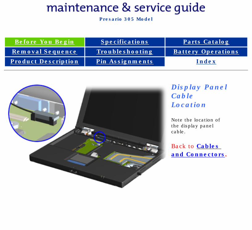
Display Panel Cable Location
Note the location of the display panel cable.
Back to Cables and Connectors.
privacy and legal statement
http://h18000.www1.hp.com/athome/support/msgs/305/cabdisp.html [12/9/2002 2:17:07 PM]
Compaq Presario Series Maintenance and Service Guide
United States December 9, 2002
Presario 305 Model
Before You Begin Specifications Parts Catalog
Removal Sequence Troubleshooting Battery Operations
Product Description Pin Assignments Index
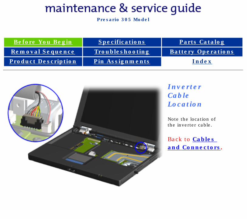
Inverter Cable Location
Note the location of the inverter cable.
Back to Cables and Connectors.
privacy and legal statement
http://h18000.www1.hp.com/athome/support/msgs/305/cabinv.html [12/9/2002 2:17:11 PM]
Compaq Presario Series Maintenance and Service Guide
United States December 9, 2002
Presario 305 Model
Before You Begin Specifications Parts Catalog
Removal Sequence Troubleshooting Battery Operations
Product Description Pin Assignments Index
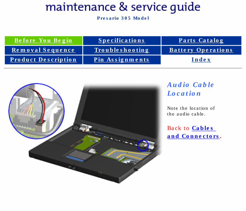
Audio Cable Location
Note the location of the audio cable.
Back to Cables and Connectors.
privacy and legal statement
http://h18000.www1.hp.com/athome/support/msgs/305/cabaud.html [12/9/2002 2:17:14 PM]
Compaq Presario Series Maintenance and Service Guide
United States December 9, 2002
Presario 305 Model
Before You Begin Specifications Parts Catalog
Removal Sequence Troubleshooting Battery Operations
Product Description Pin Assignments Index
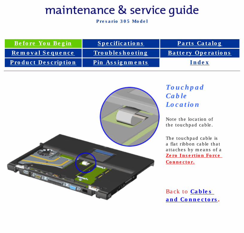
Touchpad Cable Location
Note the location of the touchpad cable.
The touchpad cable is a flat ribbon cable that attaches by means of a Zero Insertion Force Connector.
Back to Cables and Connectors.
privacy and legal statement
http://h18000.www1.hp.com/athome/support/msgs/305/cabtou.html [12/9/2002 2:17:18 PM]
Compaq Presario Series Maintenance and Service Guide
United States December 9, 2002
Presario 305 Model
Before You Begin Specifications Parts Catalog
Removal Sequence Troubleshooting Battery Operations
Product Description Pin Assignments Index
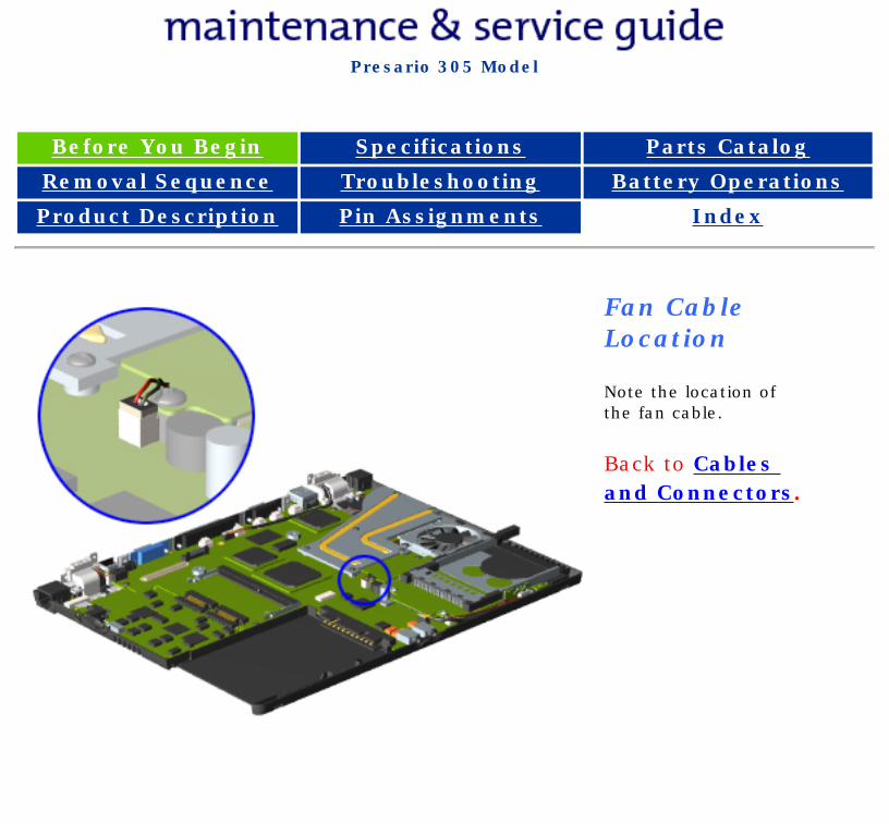
Fan Cable Location
Note the location of the fan cable.
Back to Cables and Connectors.
privacy and legal statement
http://h18000.www1.hp.com/athome/support/msgs/305/cabfan.html [12/9/2002 2:17:33 PM]
Compaq Presario Series Maintenance and Service Guide
United States December 9, 2002
Presario 305 Model
Before You Begin Specifications Parts Catalog
Removal Sequence Troubleshooting Battery Operations
Product Description Pin Assignments Index
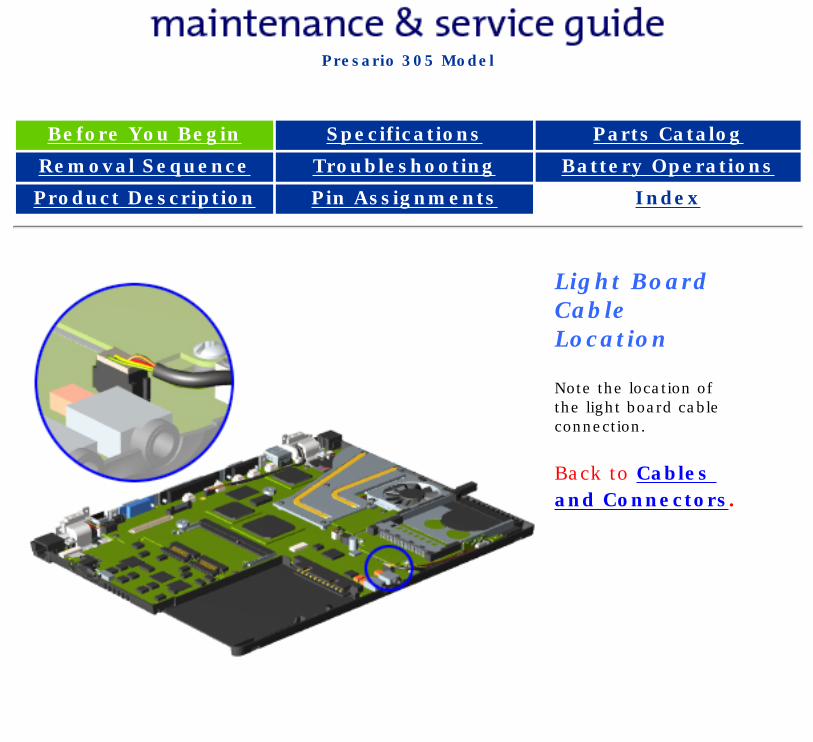
Light Board Cable Location
Note the location of the light board cable connection.
Back to Cables and Connectors.
privacy and legal statement
http://h18000.www1.hp.com/athome/support/msgs/305/cablit.html [12/9/2002 2:17:37 PM]
Compaq Presario Series Maintenance and Service Guide
United States December 9, 2002
Presario 305 Model
Before You Begin Specifications Parts Catalog
Removal Sequence Troubleshooting Battery Operations
Product Description Pin Assignments Index
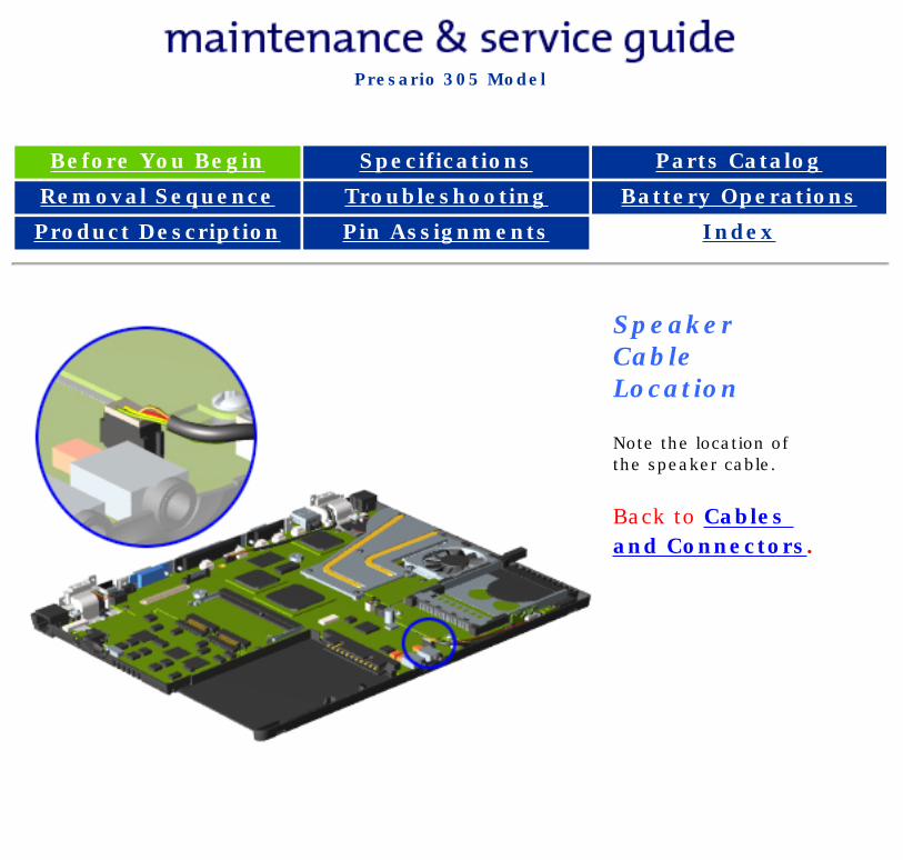
Speaker Cable Location
Note the location of the speaker cable.
Back to Cables and Connectors.
privacy and legal statement
http://h18000.www1.hp.com/athome/support/msgs/305/cabspk.html [12/9/2002 2:17:41 PM]
Compaq Presario Series Maintenance and Service Guide
United States December 9, 2002
Presario 305 Model
Before You Begin Specifications Parts Catalog
Removal Sequence Troubleshooting Battery Operations
Product Description Pin Assignments Index
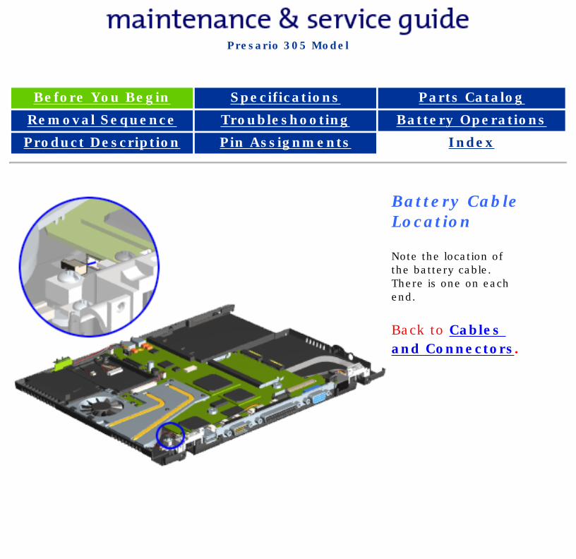
Battery Cable Location
Note the location of the battery cable. There is one on each end.
Back to Cables and Connectors.
privacy and legal statement
http://h18000.www1.hp.com/athome/support/msgs/305/cabbat.html [12/9/2002 2:17:48 PM]
Compaq Presario Series Maintenance and Service Guide
United States December 9, 2002
Presario 305 Model
Before You Begin Specifications Parts Catalog
Removal Sequence Troubleshooting Battery Operations
Product Description Pin Assignments Index
Removing the Hard Drive
Removal Sequence
Serial Number Location
Preparing for Disassembly
Electrostatic Discharge
Service Considerations
Cables and Connectors
Multi-media Expansion Unit
Battery Pack
Hard Drive
Modem Card
RTC Battery
Keyboard
Memory Board
Switch Cover
Display Panel
Deck
Voltage Converter Board
Modem Connector Board
PC Card
PC Card Assembly
System Board
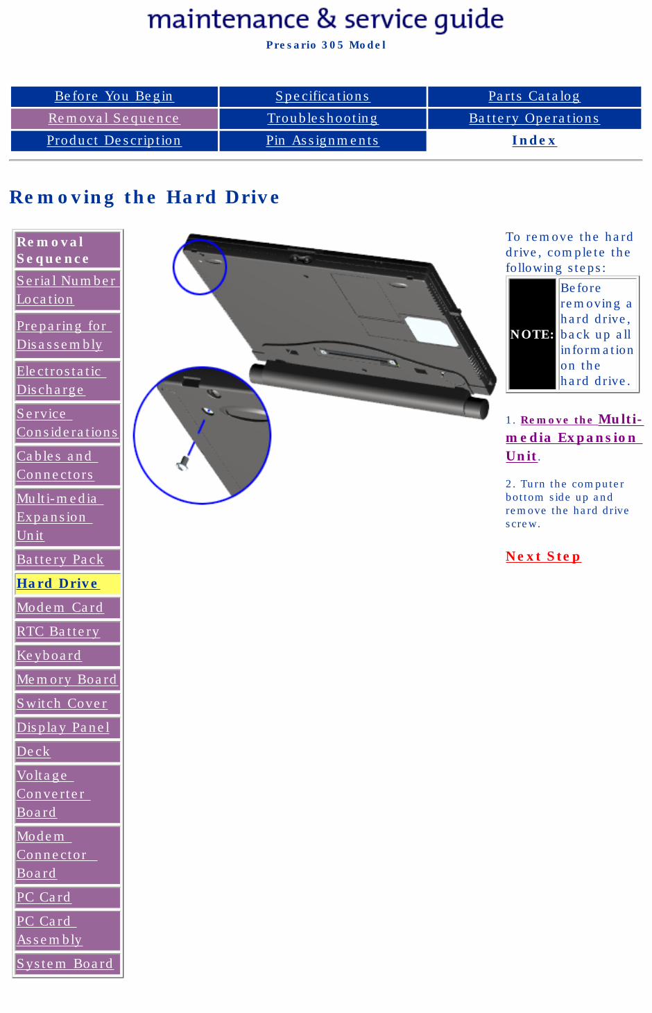
To remove the hard drive, complete the following steps:
NOTE:
Before removing a hard drive, back up all information on the hard drive.
1. Remove the Multi-media Expansion Unit.
2. Turn the computer bottom side up and remove the hard drive screw.
Next Step
privacy and legal statement
http://h18000.www1.hp.com/athome/support/msgs/305/hdrem1.html [12/9/2002 2:18:00 PM]
Compaq Presario Series Maintenance and Service Guide
United States December 9, 2002
Presario 305 Model
Before You Begin Specifications Parts Catalog
Removal Sequence Troubleshooting Battery Operations
Product Description Pin Assignments Index
Removing the Hard Drive (continued)
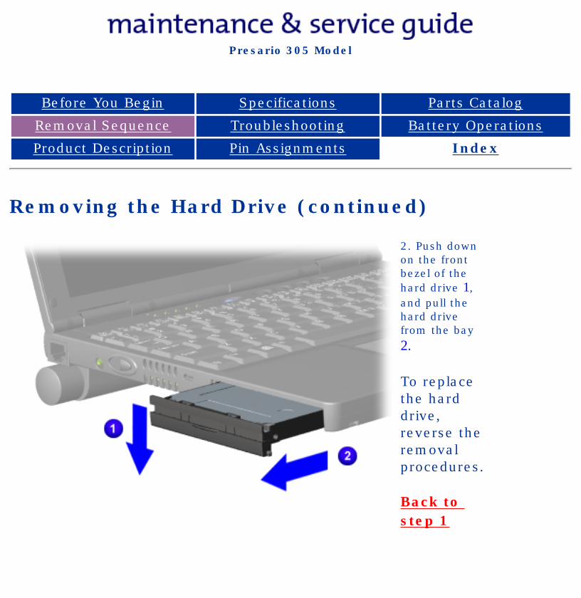
2. Push down on the front bezel of the hard drive 1, and pull the hard drive from the bay 2.
To replace the hard drive, reverse the removal procedures.
Back to step 1
privacy and legal statement
http://h18000.www1.hp.com/athome/support/msgs/305/hdrem2.html [12/9/2002 2:18:03 PM]
Compaq Presario Series Maintenance and Service Guide
United States December 9, 2002
Presario 305 Model
Before You Begin Specifications Parts Catalog
Removal Sequence Troubleshooting Battery Operations
Product Description Pin Assignments Index
Removing the Modem Card
Removal Sequence
Serial Number Location
Preparing for Disassembly
Electrostatic Discharge
Service Considerations
Cables and Connectors
Multi-media Expansion Unit
Battery Pack
Hard Drive
Modem Card
RTC Battery
Keyboard
Memory Board
Switch Cover
Display Panel
Deck
Voltage Converter Board
Modem Connector Board
PC Card
PC Card Assembly
System Board
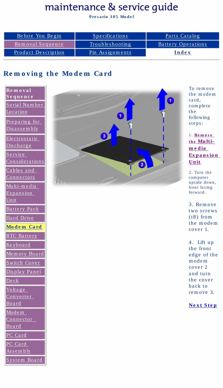
To remove the modem card, complete the following steps:
1. Remove
the Multi-media Expansion Unit.
2. Turn the computer upside down, front facing forward.
3. Remove two screws (t8) from the modem cover 1.
4. Lift up the front edge of the modem cover 2 and turn the cover back to remove 3.
Next Step
privacy and legal statement
http://h18000.www1.hp.com/athome/support/msgs/305/mcomcd1.html [12/9/2002 2:18:06 PM]
Compaq Presario Series Maintenance and Service Guide
United States December 9, 2002
Presario 305 Model
Before You Begin Specifications Parts Catalog
Removal Sequence Troubleshooting Battery Operations
Product Description Pin Assignments Index
Removing the Modem Card (continued)
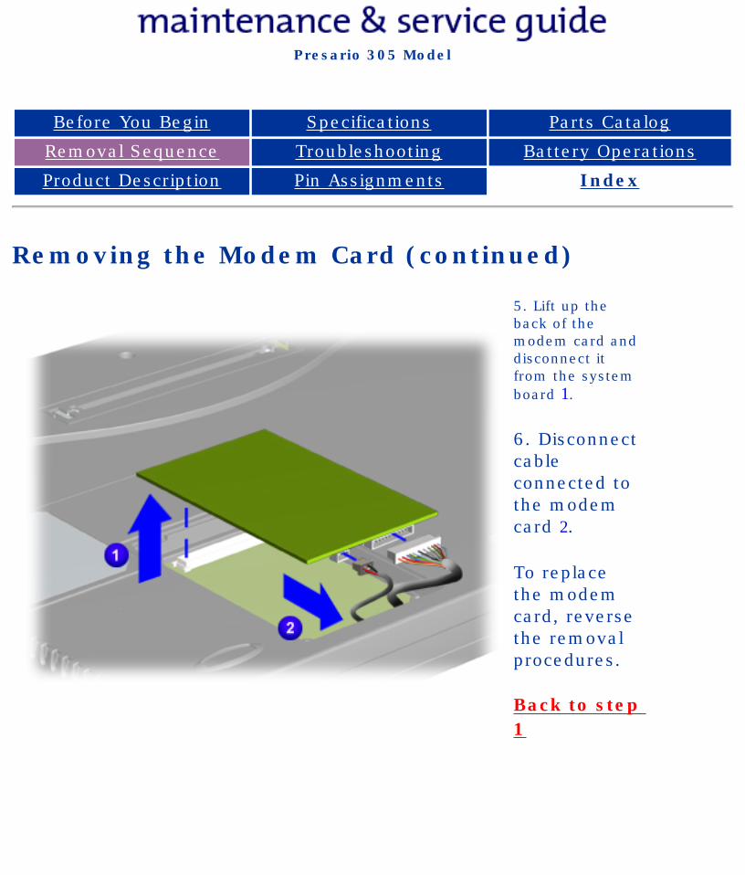
5. Lift up the back of the modem card and disconnect it from the system board 1.
6. Disconnect cable connected to the modem card 2.
To replace the modem card, reverse the removal procedures.
Back to step 1
privacy and legal statement
http://h18000.www1.hp.com/athome/support/msgs/305/mcomcd2.html [12/9/2002 2:18:09 PM]
Compaq Presario Series Maintenance and Service Guide
United States December 9, 2002
Presario 305 Model
Before You Begin Specifications Parts Catalog
Removal Sequence Troubleshooting Battery Operations
Product Description Pin Assignments Index
Removing the RTC Battery
Removal Sequence
Serial Number Location
Preparing for Disassembly
Electrostatic Discharge
Service Considerations
Cables and Connectors
Multi-media Expansion Unit
Battery Pack
Hard Drive
Modem Card
RTC Battery
Keyboard
Memory Board
Switch Cover
Display Panel
Deck
Voltage Converter Board
Modem Connector Board
PC Card
PC Card Assembly
System Board
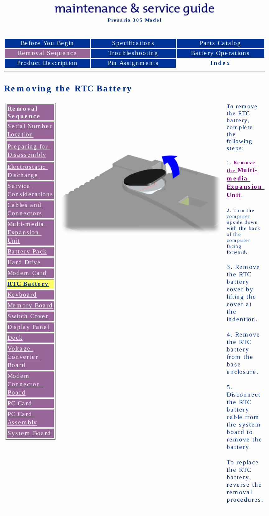
To remove the RTC battery, complete the following steps:
1. Remove
the Multi-media Expansion Unit.
2. Turn the computer upside down with the back of the computer facing forward.
3. Remove the RTC battery cover by lifting the cover at the indention.
4. Remove the RTC battery from the base enclosure.
5. Disconnect the RTC battery cable from the system board to remove the battery.
To replace the RTC battery, reverse the removal procedures.
privacy and legal statement
http://h18000.www1.hp.com/athome/support/msgs/305/rtcbatt.html [12/9/2002 2:18:13 PM]
Compaq Presario Series Maintenance and Service Guide
United States December 9, 2002
Presario 305 Model
Before You Begin Specifications Parts Catalog
Removal Sequence Troubleshooting Battery Operations
Product Description Pin Assignments Index
Removing the Keyboard
Removal Sequence
Serial Number Location
Preparing for Disassembly
Electrostatic Discharge
Service Considerations
Cables and Connectors
Multi-media Expansion Unit
Battery Pack
Hard Drive
Modem Card
RTC Battery
Keyboard
Memory Board
Switch Cover
Display Panel
Deck
Voltage Converter Board
Modem Connector Board
PC Card
PC Card Assembly
System Board
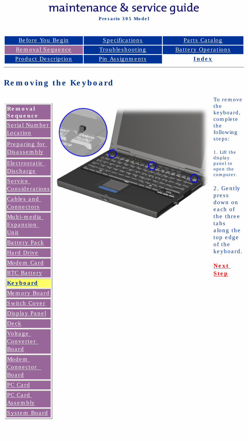
To remove the keyboard, complete the following steps:
1. Lift the display panel to open the computer.
2. Gently press down on each of the three tabs along the top edge of the keyboard.
Next Step
privacy and legal statement
http://h18000.www1.hp.com/athome/support/msgs/305/keybrm1.html [12/9/2002 2:18:18 PM]
Compaq Presario Series Maintenance and Service Guide
United States December 9, 2002
Presario 305 Model
Before You Begin Specifications Parts Catalog
Removal Sequence Troubleshooting Battery Operations
Product Description Pin Assignments Index
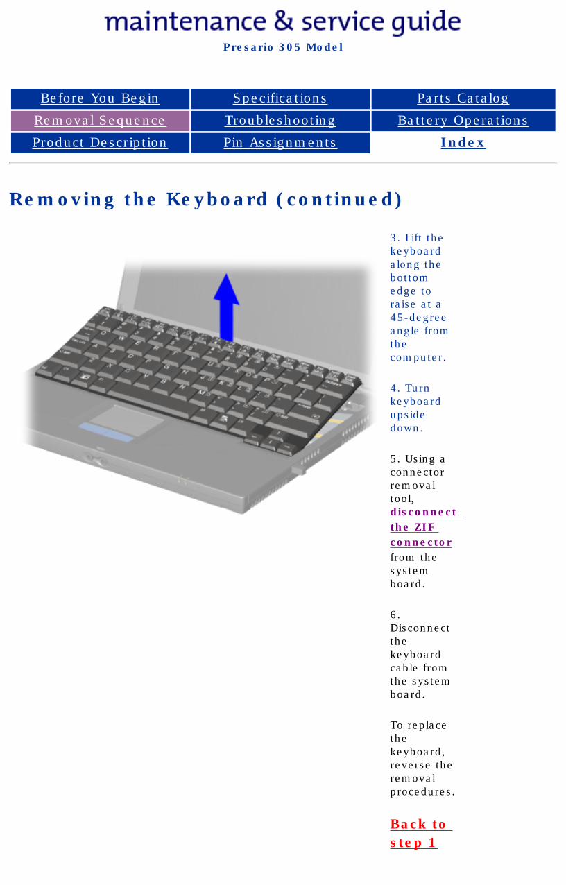
Removing the Keyboard (continued)
3. Lift the keyboard along the bottom edge to raise at a 45-degree angle from the computer.
4. Turn keyboard upside down.
5. Using a connector removal tool, disconnect the ZIF connector from the system board.
6. Disconnect the keyboard cable from the system board.
To replace the keyboard, reverse the removal procedures.
Back to step 1
privacy and legal statement
http://h18000.www1.hp.com/athome/support/msgs/305/keybrm2.html [12/9/2002 2:18:20 PM]

Compaq Presario Series Maintenance and Service Guide
United States December 9, 2002
Presario 305 Model
Before You Begin Specifications Parts Catalog
Removal Sequence Troubleshooting Battery Operations
Product Description Pin Assignments Index
Removing the Memory Board
Removal Sequence
Serial Number Location
Preparing for Disassembly
Electrostatic Discharge
Service Considerations
Cables and Connectors
Multi-media Expansion Unit
Battery Pack
Hard Drive
Modem Card
RTC Battery
Keyboard
Memory Board
Switch Cover
Display Panel
Deck
Voltage Converter Board
Modem Connector Board
PC Card
PC Card Assembly
System Board
To remove the Memory Board, complete the following steps:
WARNING: Failure to unplug the power cord and remove the battery pack before installing a memory expansion board can damage the equipment and expose you to the risk of electrical shock.
CAUTION: Electrostatic discharge (ESD) can damage electronic components. Before beginning this procedure, ensure that you are properly grounded. For more information, refer to Electrostatic discharge section.
NOTE:
There is only one memory expansion slot in the computer. Before upgrade memory, you must remove the memory board that came with the computer.
1. To remove the memory board, pull away the plastic retention clips on each side of the memory expansion board 1. The memory expansion board tilts upward.
2. Lift the edge of the memory expansion board and slide it gently out of the memory expansion slot at a 45-degree angle 2.
3. If applicable, turn back the memory insulator.
4. Place the removed memory expansion board in an electrostatic-safe container.
To replace the Memory Board, reverse the removal procedures.
privacy statementlegal notices
http://h18000.www1.hp.com/athome/support/msgs/305/memory.html [12/9/2002 2:18:25 PM]
Compaq Presario Series Maintenance and Service Guide
United States December 9, 2002
Presario 305 Model
Before You Begin Specifications Parts Catalog
Removal Sequence Troubleshooting Battery Operations
Product Description Pin Assignments Index
Removing the Switch Cover
Removal Sequence
Serial Number Location
Preparing for Disassembly
Electrostatic Discharge
Service Considerations
Cables and Connectors
Multi-media Expansion Unit
Battery Pack
Hard Drive
Modem Card
RTC Battery
Keyboard
Memory Board
Switch Cover
Display Panel
Deck
Voltage Converter Board
Modem Connector Board
PC Card
PC Card Assembly
System Board
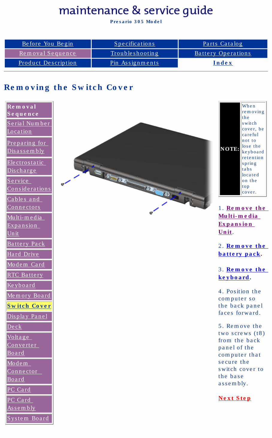
NOTE:
When removing the switch cover, be careful not to lose the keyboard retention spring tabs located on the top cover.
1. Remove the Multi-media Expansion Unit.
2. Remove the battery pack.
3. Remove the keyboard.
4. Position the computer so the back panel faces forward.
5. Remove the two screws (t8) from the back panel of the computer that secure the switch cover to the base assembly.
Next Step
privacy and legal statement
http://h18000.www1.hp.com/athome/support/msgs/305/swcorm1.html [12/9/2002 2:18:31 PM]

Compaq Presario Series Maintenance and Service Guide
United States December 9, 2002
Presario 305 Model
Before You Begin Specifications Parts Catalog
Removal Sequence Troubleshooting Battery Operations
Product Description Pin Assignments Index
Removing the Switch Cover (continued)
5. Position the computer so the front faces forward.
6. Open the display panel as far as possible.
7. Remove one screw from each end cap on the display panel.
8. Lift the front edge of the switch cover. When the switch cover disconnects from the top cover, turn the back edge of the switch cover up and forward.
To replace the switch cover, reverse the removal procedures.
Back to step 1
privacy and legal statement
http://h18000.www1.hp.com/athome/support/msgs/305/swcorm2.html [12/9/2002 2:18:35 PM]
Compaq Presario Series Maintenance and Service Guide
United States December 9, 2002
Presario 305 Model
Before You Begin Specifications Parts Catalog
Removal Sequence Troubleshooting Battery Operations
Product Description Pin Assignments Index
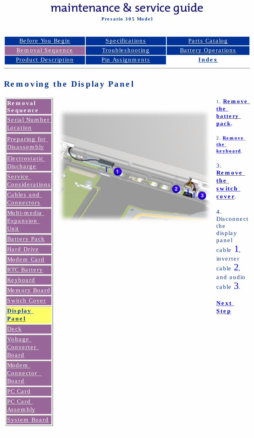
Removing the Display Panel
Removal Sequence
Serial Number Location
Preparing for Disassembly
Electrostatic Discharge
Service Considerations
Cables and Connectors
Multi-media Expansion Unit
Battery Pack
Hard Drive
Modem Card
RTC Battery
Keyboard
Memory Board
Switch Cover
Display Panel
Deck
Voltage Converter Board
Modem Connector Board
PC Card
PC Card Assembly
System Board
1. Remove the battery pack.
2. Remove the keyboard.
3. Remove the switch cover.
4. Disconnect the display panel
cable 1, inverter
cable 2, and audio
cable 3.
Next Step
privacy and legal statement
http://h18000.www1.hp.com/athome/support/msgs/305/disprm1.html [12/9/2002 2:18:47 PM]
Compaq Presario Series Maintenance and Service Guide
United States December 9, 2002
Presario 305 Model
Before You Begin Specifications Parts Catalog
Removal Sequence Troubleshooting Battery Operations
Product Description Pin Assignments Index
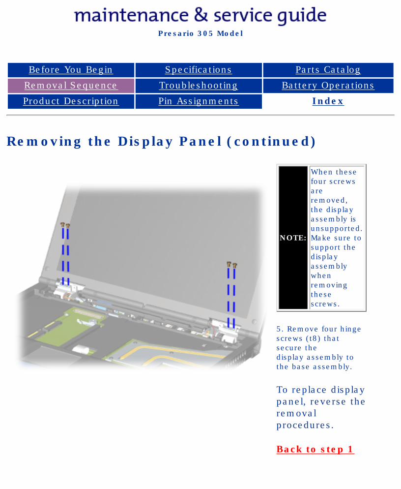
Removing the Display Panel (continued)
NOTE:
When these four screws are removed, the display assembly is unsupported. Make sure to support the display assembly when removing these screws.
5. Remove four hinge screws (t8) that secure the display assembly to the base assembly.
To replace display panel, reverse the removal procedures.
Back to step 1
privacy and legal statement
http://h18000.www1.hp.com/athome/support/msgs/305/disprm2.html [12/9/2002 2:18:51 PM]
Compaq Presario Series Maintenance and Service Guide
United States December 9, 2002
Presario 305 Model
Before You Begin Specifications Parts Catalog
Removal Sequence Troubleshooting Battery Operations
Product Description Pin Assignments Index
Removing the Deck
Removal Sequence
Serial Number Location
Preparing for Disassembly
Electrostatic Discharge
Service Considerations
Cables and Connectors
Multi-media Expansion Unit
Battery Pack
Hard Drive
Modem Card
RTC Battery
Keyboard
Memory Board
Switch Cover
Display Panel
Deck
Voltage Converter Board
Modem Connector Board
PC Card
PC Card Assembly
System Board
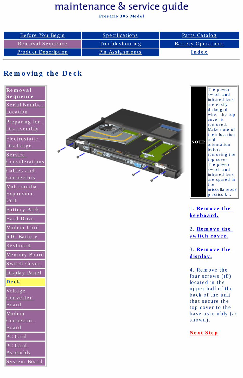
NOTE:
The power switch and infrared lens are easily dislodged when the top cover is removed. Make note of their location and orientation before removing the top cover. The power switch and infrared lens are spared in the miscellaneous plastics kit.
1. Remove the keyboard.
2. Remove the switch cover.
3. Remove the display.
4. Remove the four screws (t8) located in the upper half of the back of the unit that secure the top cover to the base assembly (as shown).
Next Step
privacy and legal statement
http://h18000.www1.hp.com/athome/support/msgs/305/deckre1.html [12/9/2002 2:19:00 PM]
Compaq Presario Series Maintenance and Service Guide
United States December 9, 2002
Presario 305 Model
Before You Begin Specifications Parts Catalog
Removal Sequence Troubleshooting Battery Operations
Product Description Pin Assignments Index
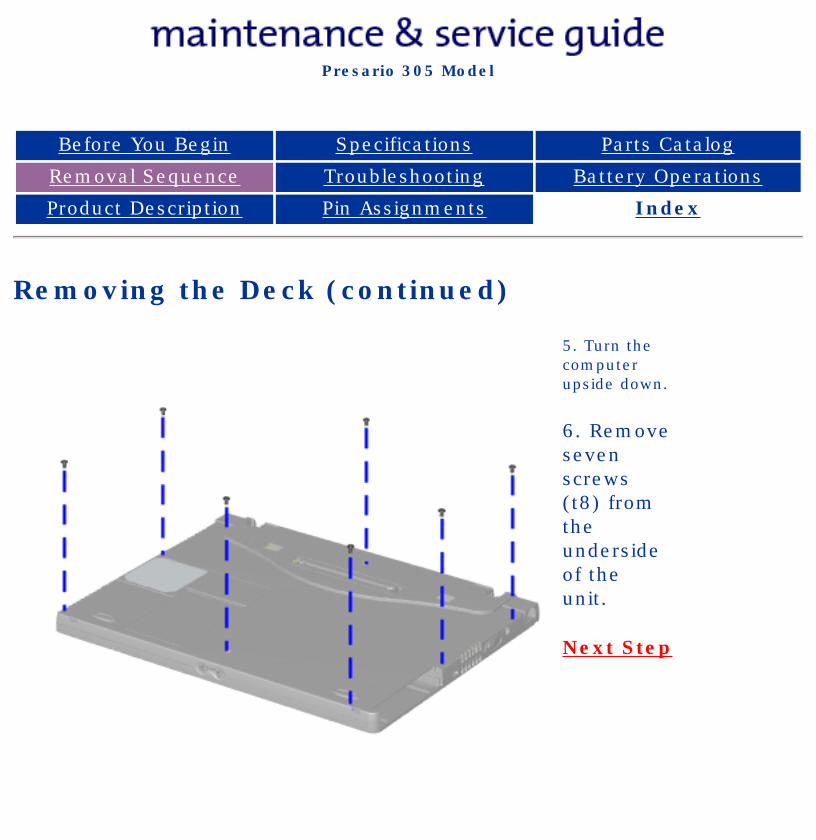
Removing the Deck (continued)
5. Turn the computer upside down.
6. Remove seven screws (t8) from the underside of the unit.
Next Step
privacy and legal statement
http://h18000.www1.hp.com/athome/support/msgs/305/deckre2.html [12/9/2002 2:19:03 PM]
Compaq Presario Series Maintenance and Service Guide
United States December 9, 2002
Presario 305 Model
Before You Begin Specifications Parts Catalog
Removal Sequence Troubleshooting Battery Operations
Product Description Pin Assignments Index
Removing the Deck (continued)
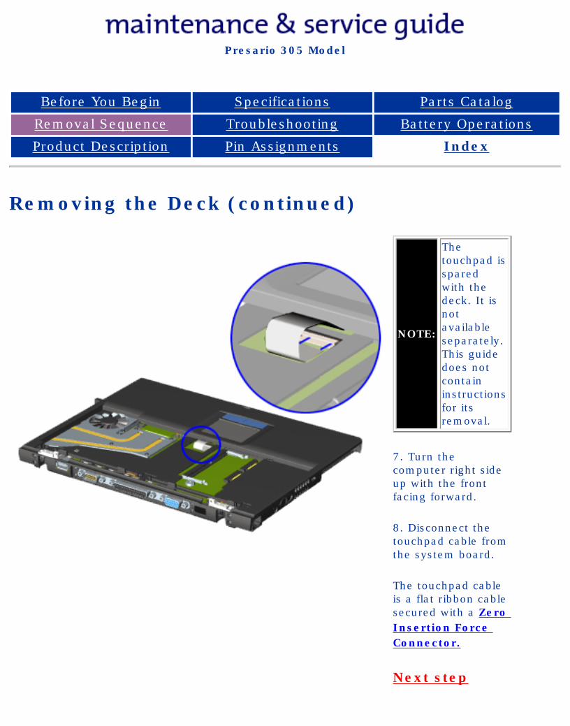
NOTE:
The touchpad is spared with the deck. It is not available separately. This guide does not contain instructions for its removal.
7. Turn the computer right side up with the front facing forward.
8. Disconnect the touchpad cable from the system board.
The touchpad cable is a flat ribbon cable secured with a Zero Insertion Force Connector.
Next step
privacy and legal statement
http://h18000.www1.hp.com/athome/support/msgs/305/deckre3.html [12/9/2002 2:19:05 PM]
Compaq Presario Series Maintenance and Service Guide
United States December 9, 2002
Presario 305 Model
Before You Begin Specifications Parts Catalog
Removal Sequence Troubleshooting Battery Operations
Product Description Pin Assignments Index
Removing the Deck (continued)
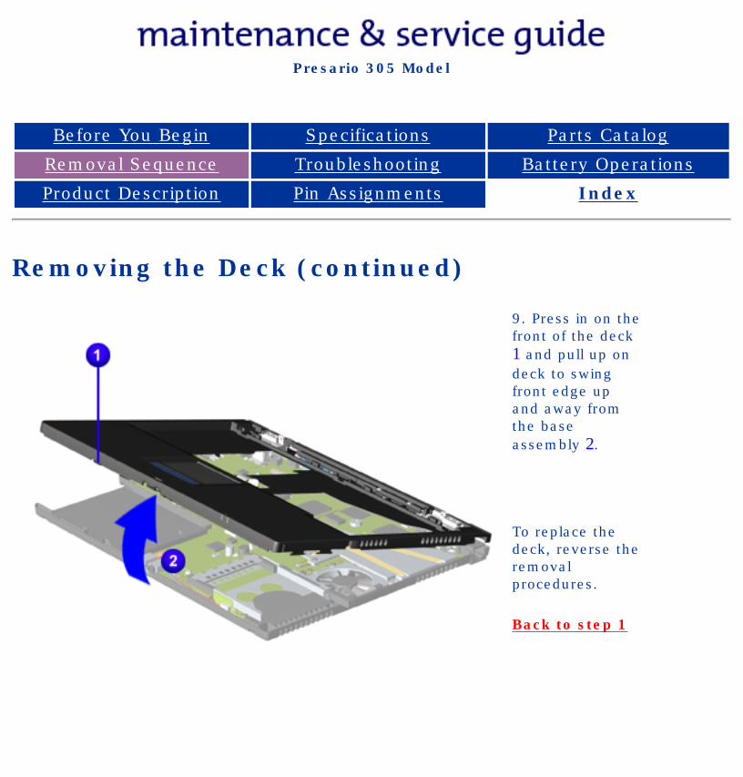
9. Press in on the front of the deck 1 and pull up on deck to swing front edge up and away from the base assembly 2.
To replace the deck, reverse the removal procedures.
Back to step 1
privacy and legal statement
http://h18000.www1.hp.com/athome/support/msgs/305/deckre4.html [12/9/2002 2:19:07 PM]
Compaq Presario Series Maintenance and Service Guide
United States December 9, 2002
Presario 305 Model
Before You Begin Specifications Parts Catalog
Removal Sequence Troubleshooting Battery Operations
Product Description Pin Assignments Index
Removing the Voltage Converter Board
Removal Sequence
Serial Number Location
Preparing for Disassembly
Electrostatic Discharge
Service Considerations
Cables and Connectors
Multi-media Expansion Unit
Battery Pack
Hard Drive
Modem Card
RTC Battery
Keyboard
Memory Board
Switch Cover
Display Panel
Deck
Voltage Converter Board
Modem Connector Board
PC Card
PC Card Assembly
System Board
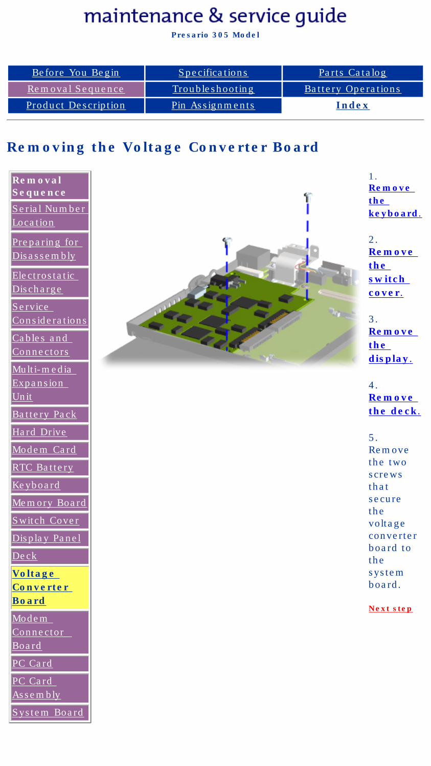
1. Remove the keyboard.
2. Remove the switch cover.
3. Remove the display.
4. Remove the deck.
5. Remove the two screws that secure the voltage converter board to the system board.
Next step
privacy and legal statement
http://h18000.www1.hp.com/athome/support/msgs/305/voltcon1.html [12/9/2002 2:19:12 PM]
Compaq Presario Series Maintenance and Service Guide
United States December 9, 2002
Presario 305 Model
Before You Begin Specifications Parts Catalog
Removal Sequence Troubleshooting Battery Operations
Product Description Pin Assignments Index
Removing the Voltage Converter Board (continued)
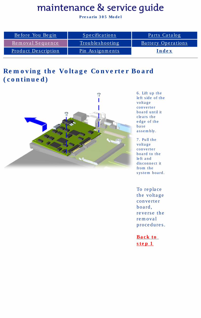
6. Lift up the left side of the voltage converter board until it clears the edge of the base assembly.
7. Pull the voltage converter board to the left and disconnect it from the system board.
To replace the voltage converter board, reverse the removal procedures.
Back to step 1
privacy and legal statement
http://h18000.www1.hp.com/athome/support/msgs/305/voltcon2.html [12/9/2002 2:19:20 PM]
Compaq Presario Series Maintenance and Service Guide
United States December 9, 2002
Presario 305 Model
Before You Begin Specifications Parts Catalog
Removal Sequence Troubleshooting Battery Operations
Product Description Pin Assignments Index
Removing the Modem Connector Board
Removal Sequence
Serial Number Location
Preparing for Disassembly
Electrostatic Discharge
Service Considerations
Cables and Connectors
Multi-media Expansion Unit
Battery Pack
Hard Drive
Modem Card
RTC Battery
Keyboard
Memory Board
Switch Cover
Display Panel
Deck
Voltage Converter Board
Modem Connector Board
PC Card
PC Card Assembly
System Board
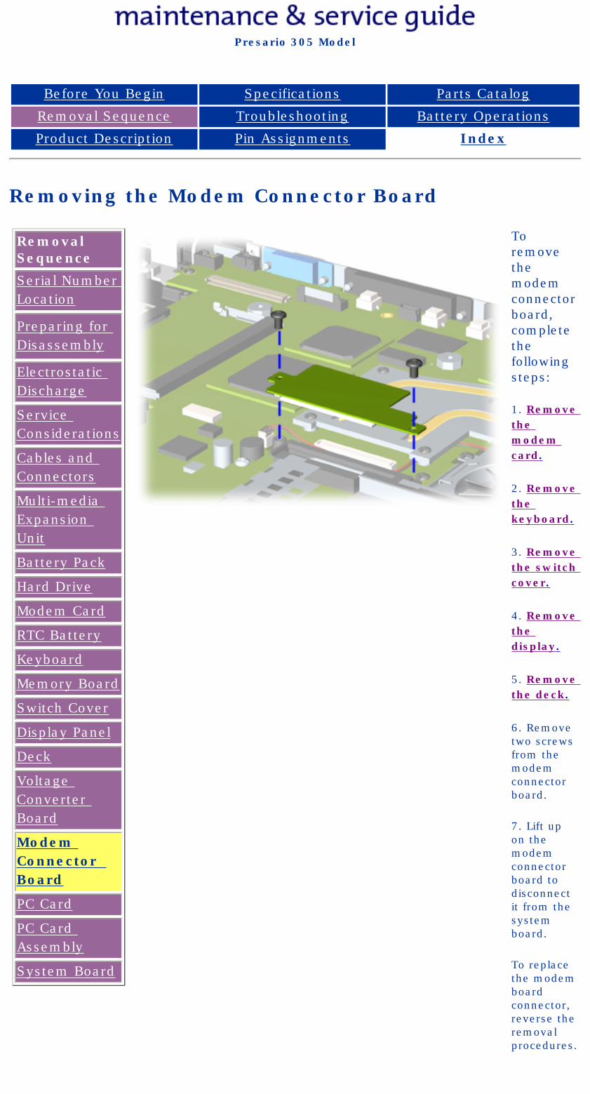
To remove the modem connector board, complete the following steps:
1. Remove the modem card.
2. Remove the keyboard.
3. Remove the switch cover.
4. Remove the display.
5. Remove the deck.
6. Remove two screws from the modem connector board.
7. Lift up on the modem connector board to disconnect it from the system board.
To replace the modem board connector, reverse the removal procedures.
privacy and legal statement
http://h18000.www1.hp.com/athome/support/msgs/305/modconb.html [12/9/2002 2:19:24 PM]
Compaq Presario Series Maintenance and Service Guide
United States December 9, 2002
Presario 305 Model
Before You Begin Specifications Parts Catalog
Removal Sequence Troubleshooting Battery Operations
Product Description Pin Assignments Index
Removing the PC Card
Removal Sequence
Serial Number Location
Preparing for Disassembly
Electrostatic Discharge
Service Considerations
Cables and Connectors
Multi-media Expansion Unit
Battery Pack
Hard Drive
Modem Card
RTC Battery
Keyboard
Memory Board
Switch Cover
Display Panel
Deck
Voltage Converter Board
Modem Connector Board
PC Card
PC Card Assembly
System Board
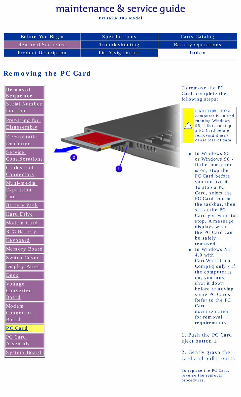
To remove the PC Card, complete the following steps:
CAUTION: If the computer is on and running Windows 95, failure to stop a PC Card before removing it may cause loss of data.
● In Windows 95 or Windows 98 - If the computer is on, stop the PC Card before you remove it. To stop a PC Card, select the PC Card icon in the taskbar, then select the PC Card you want to stop. A message displays when the PC Card can be safely removed.
● In Windows NT 4.0 with CardWare from Compaq only - If the computer is on, you must shut it down before removing some PC Cards. Refer to the PC Card documentation for removal requirements.
1. Push the PC Card eject button 1.
2. Gently grasp the card and pull it out 2.
To replace the PC Card, reverse the removal procedures.
privacy statementlegal notices
http://h18000.www1.hp.com/athome/support/msgs/305/pccard.html [12/9/2002 2:19:28 PM]
http://h18000.www1.hp.com/athome/support/msgs/305/pccardr.html
United States December 9, 2002
Presario 305 Model
Before You Begin Specifications Parts Catalog
Removal Sequence Troubleshooting Battery Operations
Product Description Pin Assignments Index
Removing the PC Card Assembly
Removal Sequence
Serial Number Location
Preparing for Disassembly
Electrostatic Discharge
Service Considerations
Cables and Connectors
Multi-media Expansion Unit
Battery Pack
Hard Drive
Modem Card
RTC Battery
Keyboard
Memory Board
Switch Cover
Display Panel
Deck
Voltage Converter Board
Modem Connector Board
PC Card
PC Card Assembly
System Board
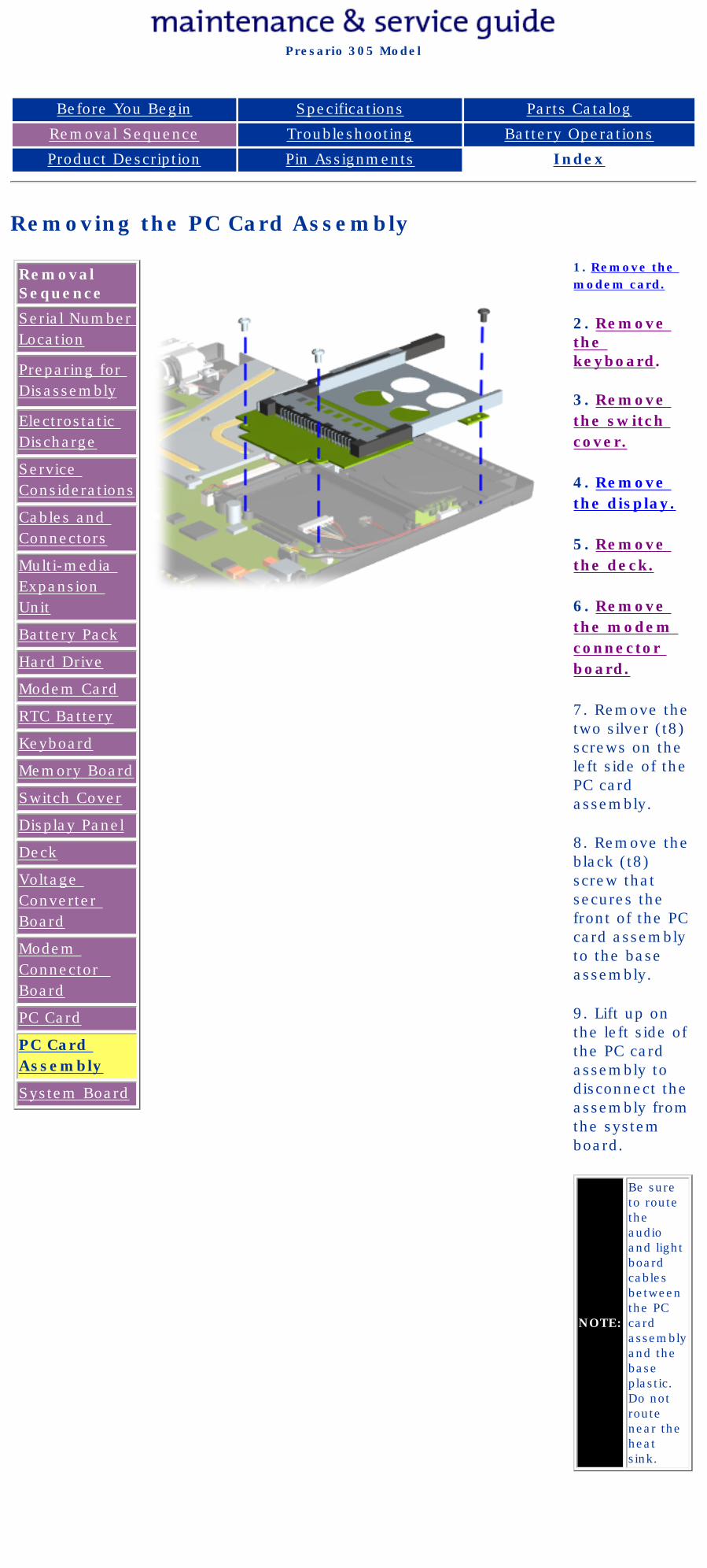
1. Remove the modem card.
2. Remove the keyboard.
3. Remove the switch cover.
4. Remove the display.
5. Remove the deck.
6. Remove the modem connector board.
7. Remove the two silver (t8) screws on the left side of the PC card assembly.
8. Remove the black (t8) screw that secures the front of the PC card assembly to the base assembly.
9. Lift up on the left side of the PC card assembly to disconnect the assembly from the system board.
NOTE:
Be sure to route the audio and light board cables between the PC card assembly and the base plastic. Do not route near the heat sink.
privacy and legal statement
http://h18000.www1.hp.com/athome/support/msgs/305/pccardr.html [12/9/2002 2:19:31 PM]
Compaq Presario Series Maintenance and Service Guide
United States December 9, 2002
Presario 305 Model
Before You Begin Specifications Parts Catalog
Removal Sequence Troubleshooting Battery Operations
Product Description Pin Assignments Index
Removing the System Board
Removal Sequence
Serial Number Location
Preparing for Disassembly
Electrostatic Discharge
Service Considerations
Cables and Connectors
Multi-media Expansion Unit
Battery Pack
Hard Drive
Modem Card
RTC Battery
Keyboard
Memory Board
Switch Cover
Display Panel
Deck
Voltage Converter Board
Modem Connector Board
PC Card
PC Card Assembly
System Board
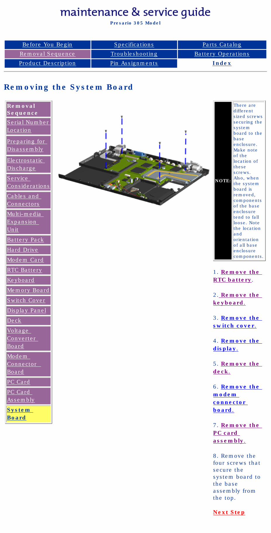
NOTE:
There are different sized screws securing the system board to the base enclosure. Make note of the location of these screws. Also, when the system board is removed, components of the base enclosure tend to fall loose. Note the location and orientation of all base enclosure components.
1. Remove the RTC battery.
2. Remove the keyboard.
3. Remove the switch cover.
4. Remove the display.
5. Remove the deck.
6. Remove the modem connector board.
7. Remove the PC card assembly.
8. Remove the four screws that secure the system board to the base assembly from the top.
Next Step
privacy and legal statement
http://h18000.www1.hp.com/athome/support/msgs/305/sysbrd1.html [12/9/2002 2:19:35 PM]
Compaq Presario Series Maintenance and Service Guide
United States December 9, 2002
Presario 305 Model
Before You Begin Specifications Parts Catalog
Removal Sequence Troubleshooting Battery Operations
Product Description Pin Assignments Index
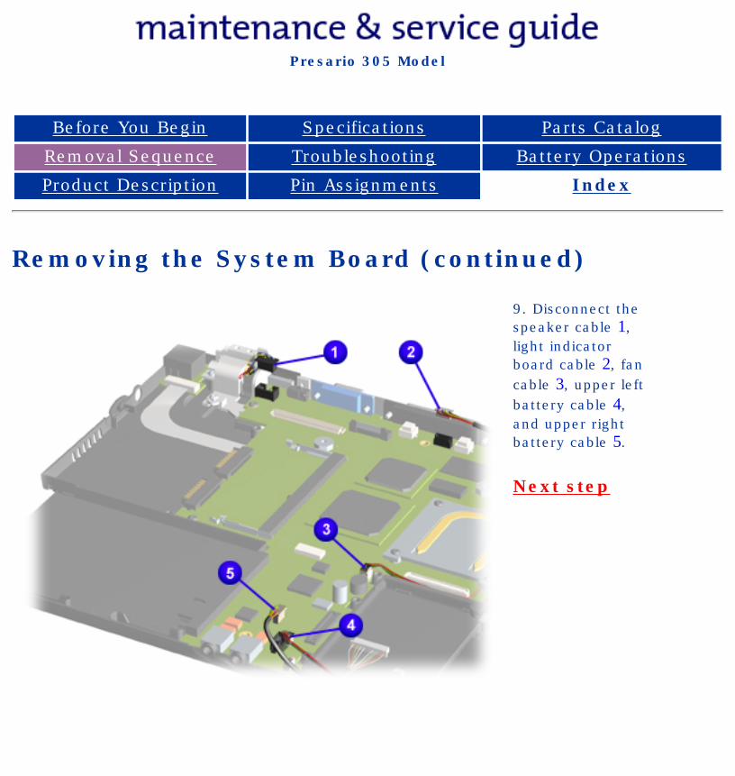
Removing the System Board (continued)
9. Disconnect the speaker cable 1, light indicator board cable 2, fan cable 3, upper left battery cable 4, and upper right battery cable 5.
Next step
privacy and legal statement
http://h18000.www1.hp.com/athome/support/msgs/305/sysbrd3.html [12/9/2002 2:19:39 PM]
Compaq Presario Series Maintenance and Service Guide
United States December 9, 2002
Presario 305 Model
Before You Begin Specifications Parts Catalog
Removal Sequence Troubleshooting Battery Operations
Product Description Pin Assignments Index
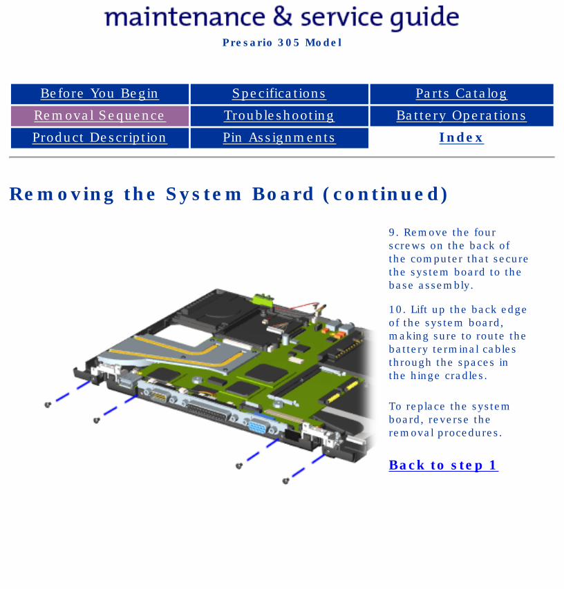
Removing the System Board (continued)
9. Remove the four screws on the back of the computer that secure the system board to the base assembly.
10. Lift up the back edge of the system board, making sure to route the battery terminal cables through the spaces in the hinge cradles.
To replace the system board, reverse the removal procedures.
Back to step 1
privacy and legal statement
http://h18000.www1.hp.com/athome/support/msgs/305/sysbrd2.html [12/9/2002 2:19:41 PM]
Compaq Presario Series Maintenance and Service Guide
United States December 9, 2002
Presario 305 Model
Before You Begin Specifications Parts Catalog
Removal Sequence Troubleshooting Battery Operations
Product Description Pin Assignments Index
Troubleshooting
Preliminary Steps
Clearing the Power-On Password
Power-On Self Test (POST)
Compaq Diagnostics
Diagnostic Error Codes
Troubleshooting Without Diagnostics
Solving Minor Problems
Contacting Compaq Support
This section covers troubleshooting information for the Compaq Presario 305 Model Portable Computer. The basic steps in troubleshooting include:
1. Follow the Preliminary Steps.
2. Run the Power-On Self Test (POST).
3. Follow the recommended actions described in the diagnostic tables, if you are unable to run POST or if POST displays an error message.
When following the recommended actions in the Sections on POST and Diagnostic Error Codes perform them in the order listed. Rerun POST after each recommended action until the problem is solved and no error message occurs. Once the problem is solved, do not complete the remaining recommended actions.
NOTE:If the problem is intermittent, check the computer several times to verify that the problem is solved.
privacy and legal statement
http://h18000.www1.hp.com/athome/support/msgs/305/trouble.html [12/9/2002 2:19:47 PM]
Compaq Presario Series Maintenance and Service Guide
United States December 9, 2002
Presario 305 Model
Before You Begin Specifications Parts Catalog
Removal Sequence Troubleshooting Battery Operations
Product Description Pin Assignments Index
Preliminary Steps
IMPORTANT:
Use AC power when running POST, Computer Setup, or Computer Checkup. A low battery condition could initiate Hibernation and interrupt the test.
Before running POST, complete the following steps:
1. If a power-on password has been established, type the password and press Enter. If the password is not known, clear the password.
2. Ensure the hard drive is installed in the computer.
3. Ensure that the battery pack is installed in the computer and the power cord is connected to the computer and plugged into an external AC power source.
4. Turn on the computer.
5. Run Computer Setup.
6. Turn off the computer and its external devices.
7. Disconnect any external devices that you do not want to test. If you want to use the printer to log error messages, leave it connected to the computer.
IMPORTANT:
If the problem only occurs when an external device is connected to the computer, the problem may be related to the external device or its cable. Verify this by running POST with and without the external device connected.
8. Use Compaq Utilities and loopback plugs in the serial and parallel connectors if you plan to test these ports.
When the preliminary steps are completed, you are ready to run POST.
privacy and legal statement
http://h18000.www1.hp.com/athome/support/msgs/305/trbprlm.html [12/9/2002 2:19:50 PM]
Compaq Presario Series Maintenance and Service Guide
United States December 9, 2002
Presario 305 Model
Before You Begin Specifications Parts Catalog
Removal Sequence Troubleshooting Battery Operations
Product Description Pin Assignments Index
Power-On Self Test (POST)
Running POST
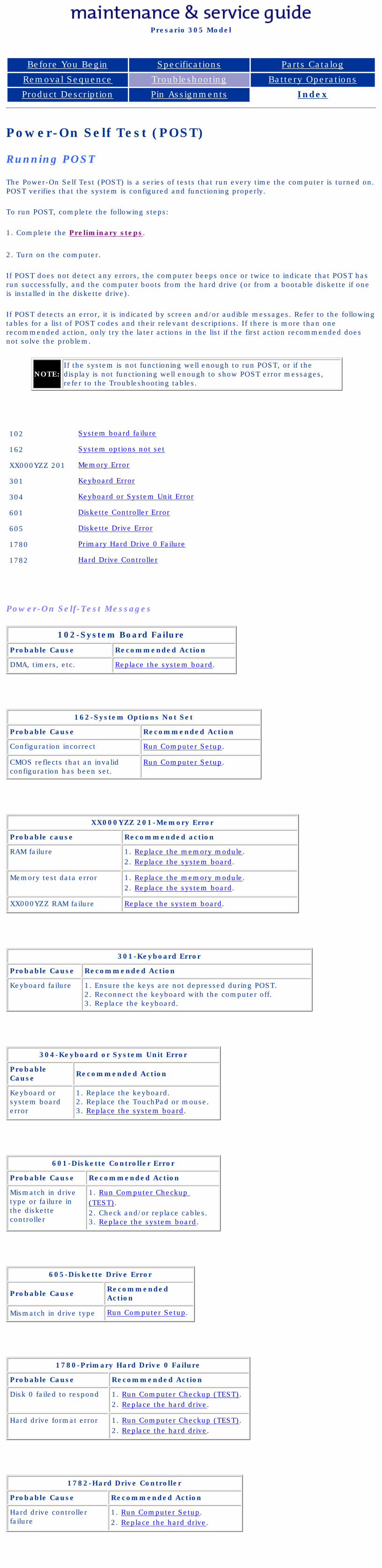
The Power-On Self Test (POST) is a series of tests that run every time the computer is turned on. POST verifies that the system is configured and functioning properly.
To run POST, complete the following steps:
1. Complete the Preliminary steps.
2. Turn on the computer.
If POST does not detect any errors, the computer beeps once or twice to indicate that POST has run successfully, and the computer boots from the hard drive (or from a bootable diskette if one is installed in the diskette drive).
If POST detects an error, it is indicated by screen and/or audible messages. Refer to the following tables for a list of POST codes and their relevant descriptions. If there is more than one recommended action, only try the later actions in the list if the first action recommended does not solve the problem.
NOTE:If the system is not functioning well enough to run POST, or if the display is not functioning well enough to show POST error messages, refer to the Troubleshooting tables.
102 System board failure
162 System options not set
XX000YZZ 201 Memory Error
301 Keyboard Error
304 Keyboard or System Unit Error
601 Diskette Controller Error
605 Diskette Drive Error
1780 Primary Hard Drive 0 Failure
1782 Hard Drive Controller
Power-On Self-Test Messages
102-System Board Failure
Probable Cause Recommended Action
DMA, timers, etc. Replace the system board.
162-System Options Not Set
Probable Cause Recommended Action
Configuration incorrect Run Computer Setup.
CMOS reflects that an invalidconfiguration has been set.
Run Computer Setup.
XX000YZZ 201-Memory Error
Probable cause Recommended action
RAM failure 1. Replace the memory module.2. Replace the system board.
Memory test data error 1. Replace the memory module.2. Replace the system board.
XX000YZZ RAM failure Replace the system board.
301-Keyboard Error
Probable Cause Recommended Action
Keyboard failure 1. Ensure the keys are not depressed during POST.2. Reconnect the keyboard with the computer off.3. Replace the keyboard.
304-Keyboard or System Unit Error
Probable Cause Recommended Action
Keyboard or system board error
1. Replace the keyboard.2. Replace the TouchPad or mouse.3. Replace the system board.
601-Diskette Controller Error
Probable Cause Recommended Action
Mismatch in drive type or failure in the diskette controller
1. Run Computer Checkup (TEST).2. Check and/or replace cables.3. Replace the system board.
605-Diskette Drive Error
Probable Cause Recommended Action
Mismatch in drive type Run Computer Setup.
1780-Primary Hard Drive 0 Failure
Probable Cause Recommended Action
Disk 0 failed to respond 1. Run Computer Checkup (TEST).2. Replace the hard drive.
Hard drive format error 1. Run Computer Checkup (TEST).2. Replace the hard drive.
1782-Hard Drive Controller
Probable Cause Recommended Action
Hard drive controller failure
1. Run Computer Setup.2. Replace the hard drive.
privacy and legal statement
http://h18000.www1.hp.com/athome/support/msgs/305/post.html [12/9/2002 2:19:52 PM]
Compaq Presario Series Maintenance and Service Guide
United States December 9, 2002
Presario 305 Model
Before You Begin Specifications Parts Catalog
Removal Sequence Troubleshooting Battery Operations
Product Description Pin Assignments Index
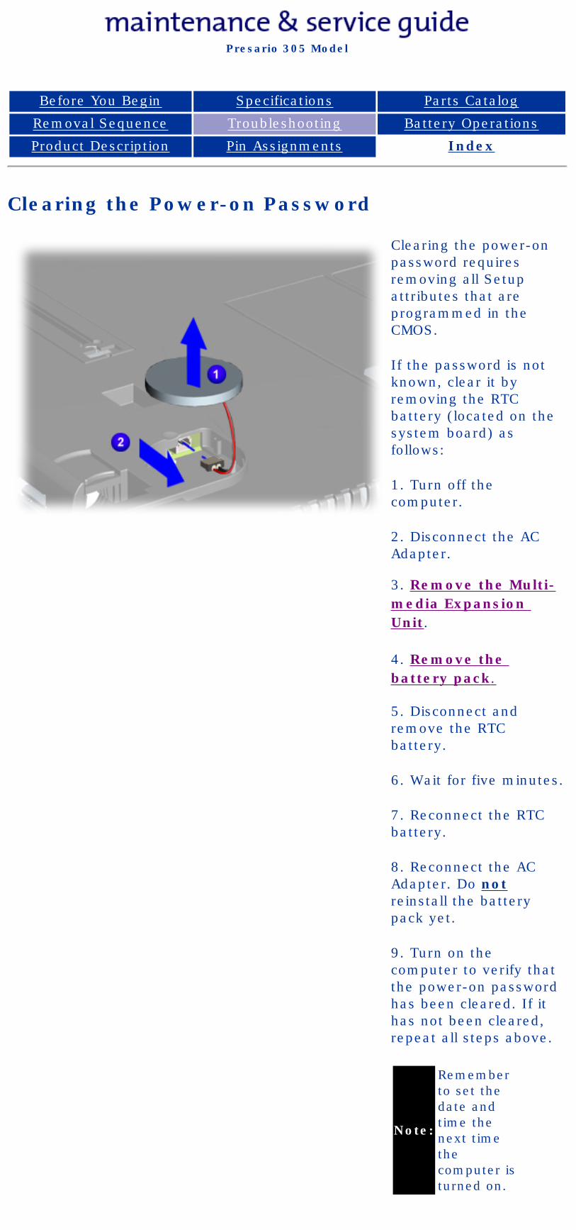
Clearing the Power-on Password
Clearing the power-on password requires removing all Setup attributes that are programmed in the CMOS.
If the password is not known, clear it by removing the RTC battery (located on the system board) as follows:
1. Turn off the computer.
2. Disconnect the AC Adapter.
3. Remove the Multi-media Expansion Unit.
4. Remove the battery pack.
5. Disconnect and remove the RTC battery.
6. Wait for five minutes.
7. Reconnect the RTC battery.
8. Reconnect the AC Adapter. Do not reinstall the battery pack yet.
9. Turn on the computer to verify that the power-on password has been cleared. If it has not been cleared, repeat all steps above.
Note:
Remember to set the date and time the next time the computer is turned on.
privacy and legal statement
http://h18000.www1.hp.com/athome/support/msgs/305/ponpass.html [12/9/2002 2:19:56 PM]
Compaq Presario Series Maintenance and Service Guide
United States December 9, 2002
Presario 305 Model
Before You Begin Specifications Parts Catalog
Removal Sequence Troubleshooting Battery Operations
Product Description Pin Assignments Index
Compaq Diagnostics
Compaq Diagnostics is installed on the hard drive of the computer. Run the Diagnostics utilities when you want to view or test system information and if you have installed or connected devices. If you run Compaq Diagnostics from a diskette, ensure that it is version 10.11 or later.
The Diagnostics menu includes the following utilities:
■ Computer Setup■ Computer Checkup (TEST)■ View System Information (INSPECT)
If you have a problem you cannot solve, run the Diagnostics utilities before you call for support (see also Preparing the Computer for a Compaq Service Call). Run Computer Checkup and select to save the device list to a file and to print or to save the log of errors. Run the View System Information (INSPECT) utility and select to print or to save that information. Have the files or the printed information available when you call for support.
Computer Setup
The Computer Setup utility resides in a hidden partition on the hard drive. It gives you a snapshot of the computer's hardware and configuration, aids in troubleshooting, and allows you to set custom features.
Access Computer Setup when you want to:
● Modify settings for audio, storage, communications, and input devices
● Get an overall picture of the computer's hardware configuration
● Verify configuration parameters in determining problems
● Configure options
● Update time, date, or password information
To run Computer Setup:
Go to the Compaq Utilities menu and select the Computer Setup option. Follow the on-screen instructions to complete your chosen task.
Computer Checkup (TEST)
Computer Checkup (TEST) determines whether the various computer components and devices are recognized by the system and are functioning properly. You can display, print, or save the information generated by Computer Checkup.
To run Computer Checkup, follow these steps:
1. Plug the computer into an external power source. A low battery condition can interrupt the program.
2. Connect the printer if you want to print a log of error messages.
3. Turn on the external devices that you want to test.
4. Insert the Compaq Diagnostics diskette in drive A.
5. Turn on or restart the computer. The computer starts from drive A, and the Diagnostics Welcome screen appears.
6. Press Enter to continue. The Diagnostics menu appears.
7. Select Computer Checkup from the Diagnostics menu. A Test Option menu appears.
8. Select View the Device List from the Test Option menu. A list of the installed Compaq devices appears.
9. If the list of installed devices is correct, select OK. The Test Option menu appears.
NOTE:If the list is incorrect, ensure that any new devices are installed properly.
10. Select one of the following from the Test Option menu:
■ Quick Check Diagnostics. Runs a quick, general test on each device with a minimal number of prompts. If errors occur, they display when the testing is complete. You cannot print or save the error messages.
■ Automatic Diagnostics. Runs unattended, maximum testing of each device with minimal prompts. You can choose how many times to run the tests, to stop on errors, or to print or save a log of errors.
■ Prompted Diagnostics. Allows maximum control over testing the devices. You can choose attended or unattended testing, decide to stop on errors, or choose to print or save a log of errors.
11. Follow the instructions on the screen as the devices are tested. When testing is complete, the Test Option menu appears.
12. Exit the Test Option menu.
13. Exit the Diagnostics menu.
View System Information (INSPECT)
The View System Information (INSPECT) utility provides information about the computer and installed or connected devices. You can display, print, or save the information.
Follow these steps to run View System Information (INSPECT) from the Compaq Diagnostics diskette:
1. Connect the printer if you want to print the INSPECT information.
2. Turn on the computer.
3. Access Compaq Utilities by pressing F10 when the cursor blinks in the upper-right corner of the display.
4. If prompted, select a language.
5. Click View System Information (INSPECT)
6. Click the item you want to view from the following list:
System Memory
ROM Audio
Keyboard Operating system
System ports System files
System storage Windows files
Graphics Miscellaneous
Network (applicable only if computer is docked in the expansion base or convenience base)
7. Follow the instructions on the screen to cycle through the screens, to return to the list and choose another item, or to print the information.
8. Select Exit Inspect.
privacy and legal statement
http://h18000.www1.hp.com/athome/support/msgs/305/cpqdiag.html [12/9/2002 2:20:07 PM]
Compaq Presario Series Maintenance and Service Guide
United States December 9, 2002
Presario 305 Model
Before You Begin Specifications Parts Catalog
Removal Sequence Troubleshooting Battery Operations
Product Description Pin Assignments Index
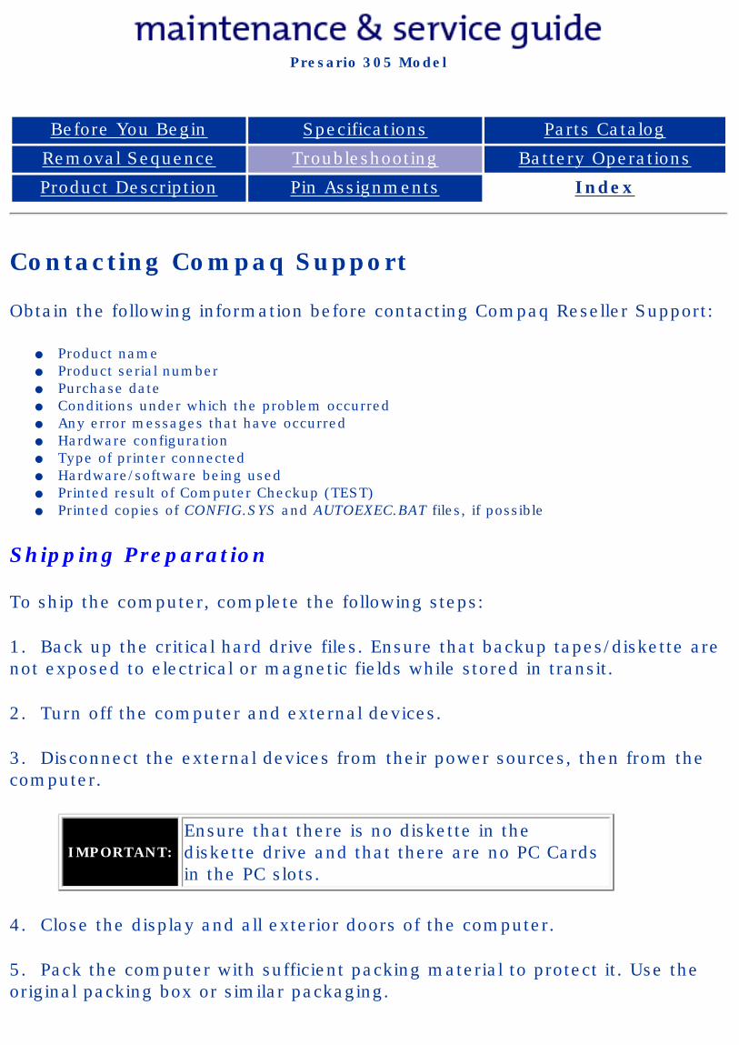
Contacting Compaq Support
Obtain the following information before contacting Compaq Reseller Support:
● Product name● Product serial number ● Purchase date● Conditions under which the problem occurred● Any error messages that have occurred● Hardware configuration● Type of printer connected● Hardware/software being used● Printed result of Computer Checkup (TEST)● Printed copies of CONFIG.SYS and AUTOEXEC.BAT files, if possible
Shipping Preparation
To ship the computer, complete the following steps:
1. Back up the critical hard drive files. Ensure that backup tapes/diskette are not exposed to electrical or magnetic fields while stored in transit.
2. Turn off the computer and external devices.
3. Disconnect the external devices from their power sources, then from the computer.
IMPORTANT:Ensure that there is no diskette in the diskette drive and that there are no PC Cards in the PC slots.
4. Close the display and all exterior doors of the computer.
5. Pack the computer with sufficient packing material to protect it. Use the original packing box or similar packaging.
privacy and legal statement
http://h18000.www1.hp.com/athome/support/msgs/305/cpqdgs2.html [12/9/2002 2:20:17 PM]
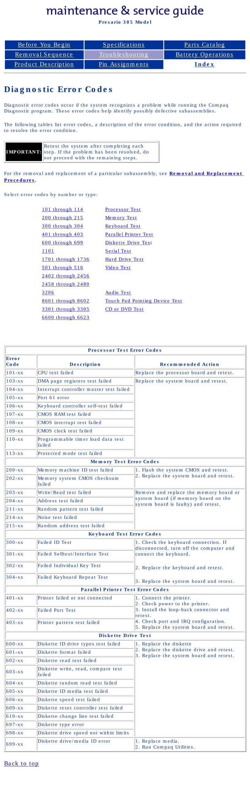
Compaq Presario Series Maintenance and Service Guide
United States December 9, 2002
Presario 305 Model
Before You Begin Specifications Parts Catalog
Removal Sequence Troubleshooting Battery Operations
Product Description Pin Assignments Index
Diagnostic Error Codes
Diagnostic error codes occur if the system recognizes a problem while running the Compaq Diagnostic program. These error codes help identify possibly defective subassemblies.
The following tables list error codes, a description of the error condition, and the action required to resolve the error condition.
IMPORTANT:Retest the system after completing each step. If the problem has been resolved, do not proceed with the remaining steps.
For the removal and replacement of a particular subassembly, see Removal and Replacement Procedures.
Select error codes by number or type:
101 through 114 Processor Test
200 through 215 Memory Test
300 through 304 Keyboard Test
401 through 403 Parallel Printer Test
600 through 699 Diskette Drive Test
1101 Serial Test
1701 through 1736 Hard Drive Test
501 through 516 Video Test
2402 through 2456
2458 through 2480
3206 Audio Test
8601 through 8602 Touch Pad Pointing Device Test
3301 through 3305 CD or DVD Test
6600 through 6623
Processor Test Error Codes
Error Code Description Recommended Action
101-xx CPU test failed Replace the processor board and retest.
103-xx DMA page registers test failed Replace the system board and retest.
104-xx Interrupt controller master test failed
105-xx Port 61 error
106-xx Keyboard controller self-test failed
107-xx CMOS RAM test failed
108-xx CMOS interrupt test failed
109-xx CMOS clock test failed
110-xx Programmable timer load data test failed
113-xx Protected mode test failed
Memory Test Error Codes
200-xx Memory machine ID test failed 1. Flash the system CMOS and retest.2. Replace the system board and retest.202-xx Memory system CMOS checksum
failed
203-xx Write/Read test failed Remove and replace the memory board or system board (if memory board on the system board is faulty) and retest.
204-xx Address test failed
211-xx Random pattern test failed
214-xx Noise test failed
215-xx Random address test failed
Keyboard Test Error Codes
300-xx Failed ID Test 1. Check the keyboard connection. If disconnected, turn off the computer and connect the keyboard.
2. Replace the keyboard and retest.
3. Replace the system board and retest.
301-xx Failed Selftest/Interface Test
302-xx Failed Individual Key Test
304-xx Failed Keyboard Repeat Test
Parallel Printer Test Error Codes
401-xx Printer failed or not connected 1. Connect the printer.2. Check power to the printer.3. Install the loop-back connector and retest.4. Check port and IRQ configuration.5. Replace the system board and retest.
402-xx Failed Port Test
403-xx Printer pattern test failed
Diskette Drive Test
600-xx Diskette ID drive types test failed 1. Replace the diskette 2. Replace the diskette drive and retest.3. Replace the system board and retest.
601-xx Diskette format failed
602-xx Diskette read test failed
603-xx Diskette write, read, compare test failed
604-xx Diskette random read test failed
605-xx Diskette ID media test failed
606-xx Diskette speed test failed
609-xx Diskette reset controller test failed
610-xx Diskette change line test failed
697-xx Diskette type error
698-xx Diskette drive speed not within limits
699-xx Diskette drive/media ID error 1. Replace media.2. Run Compaq Utilities.
Back to top
privacy and legal statement
http://h18000.www1.hp.com/athome/support/msgs/305/error.html [12/9/2002 2:20:36 PM]
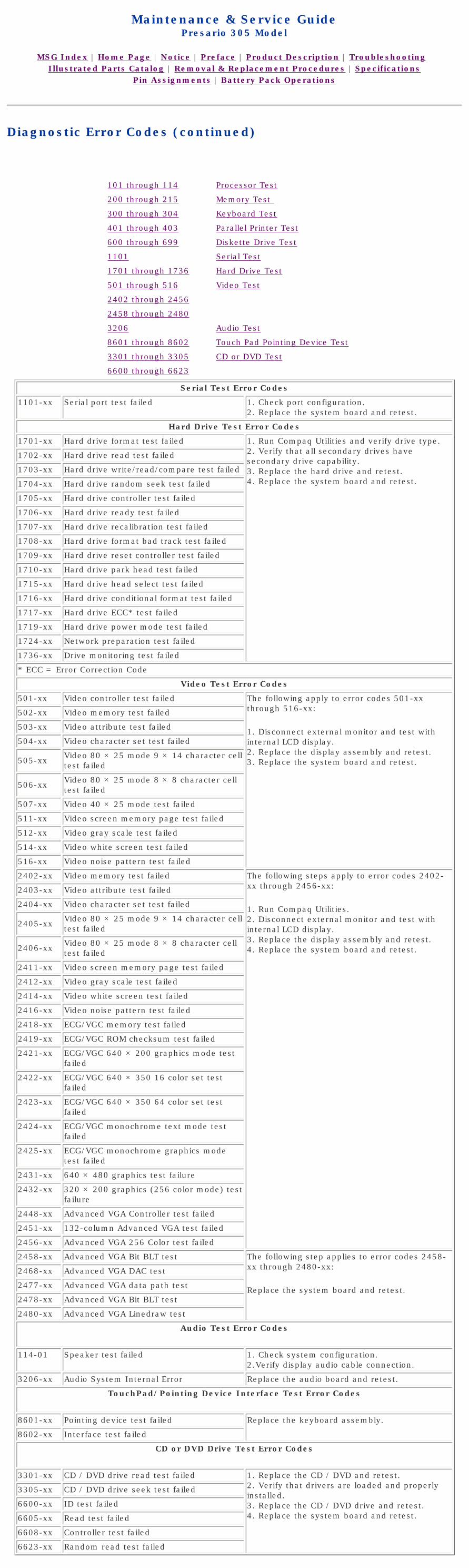
Compaq.com Compaq Presario Maintenance and Service Guide - 305
United States December 9, 2002
Maintenance & Service GuidePresario 305 Model
MSG Index | Home Page | Notice | Preface | Product Description | Troubleshooting Illustrated Parts Catalog | Removal & Replacement Procedures | Specifications
Pin Assignments | Battery Pack Operations
Diagnostic Error Codes (continued)
101 through 114 Processor Test
200 through 215 Memory Test
300 through 304 Keyboard Test
401 through 403 Parallel Printer Test
600 through 699 Diskette Drive Test
1101 Serial Test
1701 through 1736 Hard Drive Test
501 through 516 Video Test
2402 through 2456
2458 through 2480
3206 Audio Test
8601 through 8602 Touch Pad Pointing Device Test
3301 through 3305 CD or DVD Test
6600 through 6623
Serial Test Error Codes
1101-xx Serial port test failed 1. Check port configuration.2. Replace the system board and retest.
Hard Drive Test Error Codes
1701-xx Hard drive format test failed 1. Run Compaq Utilities and verify drive type.2. Verify that all secondary drives have secondary drive capability.3. Replace the hard drive and retest. 4. Replace the system board and retest.
1702-xx Hard drive read test failed
1703-xx Hard drive write/read/compare test failed
1704-xx Hard drive random seek test failed
1705-xx Hard drive controller test failed
1706-xx Hard drive ready test failed
1707-xx Hard drive recalibration test failed
1708-xx Hard drive format bad track test failed
1709-xx Hard drive reset controller test failed
1710-xx Hard drive park head test failed
1715-xx Hard drive head select test failed
1716-xx Hard drive conditional format test failed
1717-xx Hard drive ECC* test failed
1719-xx Hard drive power mode test failed
1724-xx Network preparation test failed
1736-xx Drive monitoring test failed
* ECC = Error Correction Code
Video Test Error Codes
501-xx Video controller test failed The following apply to error codes 501-xx through 516-xx:
1. Disconnect external monitor and test with internal LCD display.2. Replace the display assembly and retest.3. Replace the system board and retest.
502-xx Video memory test failed
503-xx Video attribute test failed
504-xx Video character set test failed
505-xx Video 80 × 25 mode 9 × 14 character cell test failed
506-xx Video 80 × 25 mode 8 × 8 character cell test failed
507-xx Video 40 × 25 mode test failed
511-xx Video screen memory page test failed
512-xx Video gray scale test failed
514-xx Video white screen test failed
516-xx Video noise pattern test failed
2402-xx Video memory test failed The following steps apply to error codes 2402-xx through 2456-xx:
1. Run Compaq Utilities.2. Disconnect external monitor and test with internal LCD display.3. Replace the display assembly and retest.4. Replace the system board and retest.
2403-xx Video attribute test failed
2404-xx Video character set test failed
2405-xx Video 80 × 25 mode 9 × 14 character cell test failed
2406-xx Video 80 × 25 mode 8 × 8 character cell test failed
2411-xx Video screen memory page test failed
2412-xx Video gray scale test failed
2414-xx Video white screen test failed
2416-xx Video noise pattern test failed
2418-xx ECG/VGC memory test failed
2419-xx ECG/VGC ROM checksum test failed
2421-xx ECG/VGC 640 × 200 graphics mode test failed
2422-xx ECG/VGC 640 × 350 16 color set test failed
2423-xx ECG/VGC 640 × 350 64 color set test failed
2424-xx ECG/VGC monochrome text mode test failed
2425-xx ECG/VGC monochrome graphics mode test failed
2431-xx 640 × 480 graphics test failure
2432-xx 320 × 200 graphics (256 color mode) test failure
2448-xx Advanced VGA Controller test failed
2451-xx 132-column Advanced VGA test failed
2456-xx Advanced VGA 256 Color test failed
2458-xx Advanced VGA Bit BLT test The following step applies to error codes 2458-xx through 2480-xx:
Replace the system board and retest.
2468-xx Advanced VGA DAC test
2477-xx Advanced VGA data path test
2478-xx Advanced VGA Bit BLT test
2480-xx Advanced VGA Linedraw test
Audio Test Error Codes
114-01 Speaker test failed 1. Check system configuration.2.Verify display audio cable connection.
3206-xx Audio System Internal Error Replace the audio board and retest.
TouchPad/Pointing Device Interface Test Error Codes
8601-xx Pointing device test failed Replace the keyboard assembly.
8602-xx Interface test failed
CD or DVD Drive Test Error Codes
3301-xx CD / DVD drive read test failed 1. Replace the CD / DVD and retest.2. Verify that drivers are loaded and properly installed.3. Replace the CD / DVD drive and retest.4. Replace the system board and retest.
3305-xx CD / DVD drive seek test failed
6600-xx ID test failed
6605-xx Read test failed
6608-xx Controller test failed
6623-xx Random read test failed
Revised: 15 January 1999
http://h18000.www1.hp.com/athome/support/msgs/305/errcod2.html [12/9/2002 2:20:41 PM]
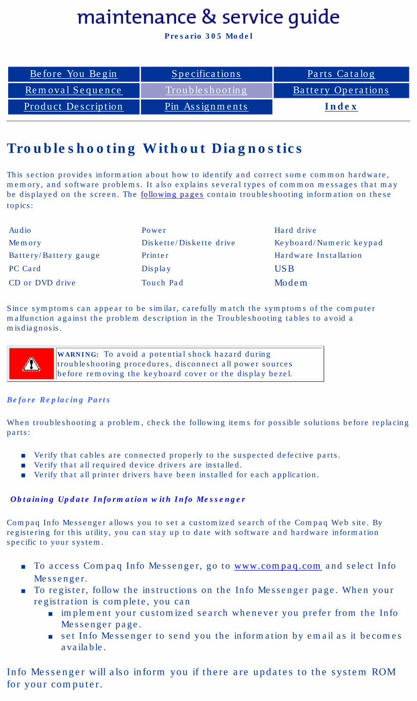
Compaq Presario Series Maintenance and Service Guide
United States December 9, 2002
Presario 305 Model
Before You Begin Specifications Parts Catalog
Removal Sequence Troubleshooting Battery Operations
Product Description Pin Assignments Index
Troubleshooting Without Diagnostics
This section provides information about how to identify and correct some common hardware, memory, and software problems. It also explains several types of common messages that may be displayed on the screen. The following pages contain troubleshooting information on these topics:
Audio Power Hard drive
Memory Diskette/Diskette drive Keyboard/Numeric keypad
Battery/Battery gauge Printer Hardware Installation
PC Card Display USBCD or DVD drive Touch Pad Modem
Since symptoms can appear to be similar, carefully match the symptoms of the computer malfunction against the problem description in the Troubleshooting tables to avoid a misdiagnosis.
WARNING: To avoid a potential shock hazard during troubleshooting procedures, disconnect all power sources before removing the keyboard cover or the display bezel.
Before Replacing Parts
When troubleshooting a problem, check the following items for possible solutions before replacing parts:
■ Verify that cables are connected properly to the suspected defective parts.■ Verify that all required device drivers are installed.■ Verify that all printer drivers have been installed for each application.
Obtaining Update Information with Info Messenger
Compaq Info Messenger allows you to set a customized search of the Compaq Web site. By registering for this utility, you can stay up to date with software and hardware information specific to your system.
■ To access Compaq Info Messenger, go to www.compaq.com and select Info Messenger.
■ To register, follow the instructions on the Info Messenger page. When your registration is complete, you can
■ implement your customized search whenever you prefer from the Info Messenger page.
■ set Info Messenger to send you the information by email as it becomes available.
Info Messenger will also inform you if there are updates to the system ROM for your computer.
privacy and legal statement
http://h18000.www1.hp.com/athome/support/msgs/305/tswo.html [12/9/2002 2:20:56 PM]
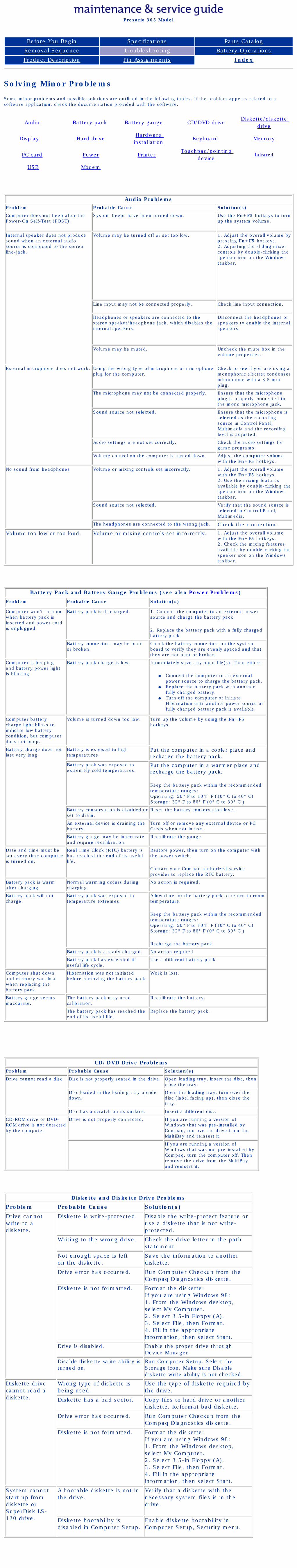
Compaq Presario Series Maintenance and Service Guide
United States December 9, 2002
Presario 305 Model
Before You Begin Specifications Parts Catalog
Removal Sequence Troubleshooting Battery Operations
Product Description Pin Assignments Index
Solving Minor Problems
Some minor problems and possible solutions are outlined in the following tables. If the problem appears related to a software application, check the documentation provided with the software.
Audio Battery pack Battery gauge CD/DVD driveDiskette/diskette
drive
Display Hard driveHardware installation
Keyboard Memory
PC card Power Printer Touchpad/pointing
deviceInfrared
USB Modem
Audio ProblemsProblem Probable Cause Solution(s)
Computer does not beep after the Power-On Self-Test (POST).
System beeps have been turned down. Use the Fn+F5 hotkeys to turn up the system volume.
Internal speaker does not produce sound when an external audio source is connected to the stereo line-jack.
Volume may be turned off or set too low. 1. Adjust the overall volume by pressing Fn+F5 hotkeys.2. Adjusting the sliding mixer controls by double-clicking the speaker icon on the Windows taskbar.
Line input may not be connected properly. Check line input connection.
Headphones or speakers are connected to the stereo speaker/headphone jack, which disables the internal speakers.
Disconnect the headphones or speakers to enable the internal speakers.
Volume may be muted. Uncheck the mute box in the volume properties.
External microphone does not work. Using the wrong type of microphone or microphone plug for the computer.
Check to see if you are using a monophonic electret condenser microphone with a 3.5 mm plug.
The microphone may not be connected properly. Ensure that the microphone plug is properly connected to the mono microphone jack.
Sound source not selected. Ensure that the microphone is selected as the recording source in Control Panel, Multimedia and the recording level is adjusted.
Audio settings are not set correctly. Check the audio settings for game programs.
Volume control on the computer is turned down. Adjust the computer volume with the Fn+F5 hotkeys.
No sound from headphones Volume or mixing controls set incorrectly. 1. Adjust the overall volume with the Fn+F5 hotkeys.2. Use the mixing features available by double-clicking the speaker icon on the Windows taskbar.
Sound source not selected. Verify that the sound source is selected in Control Panel, Multimedia.
The headphones are connected to the wrong jack. Check the connection.
Volume too low or too loud. Volume or mixing controls set incorrectly. 1. Adjust the overall volume with the Fn+F5 hotkeys.2. Check the mixing features available by double-clicking the speaker icon on the Windows taskbar.
Battery Pack and Battery Gauge Problems (see also Power Problems)
Problem Probable Cause Solution(s)
Computer won't turn on when battery pack is inserted and power cord is unplugged.
Battery pack is discharged. 1. Connect the computer to an external power source and charge the battery pack.
2. Replace the battery pack with a fully charged battery pack.
Battery connectors may be bent or broken.
Check the battery connectors on the system board to verify they are evenly spaced and that they are not bent or broken.
Computer is beeping and battery power light is blinking.
Battery pack charge is low. Immediately save any open file(s). Then either:
● Connect the computer to an external power source to charge the battery pack.
● Replace the battery pack with another fully charged battery.
● Turn off the computer or initiate Hibernation until another power source or fully charged battery pack is available.
Computer battery charge light blinks to indicate low battery condition, but computer does not beep.
Volume is turned down too low. Turn up the volume by using the Fn+F5 hotkeys.
Battery charge does not last very long.
Battery is exposed to high temperatures.
Put the computer in a cooler place and recharge the battery pack.
Battery pack was exposed to extremely cold temperatures.
Put the computer in a warmer place and recharge the battery pack.
Keep the battery pack within the recommended temperature ranges:Operating: 50° F to 104° F (10° C to 40° C) Storage: 32° F to 86° F (0° C to 30° C )
Battery conservation is disabled or set to drain.
Reset the battery conservation level.
An external device is draining the battery.
Turn off or remove any external device or PC Cards when not in use.
Battery gauge may be inaccurate and require recalibration.
Recalibrate the gauge.
Date and time must be set every time computer is turned on.
Real Time Clock (RTC) battery is has reached the end of its useful life.
Restore power, then turn on the computer with the power switch.
Contact your Compaq authorized service provider to replace the RTC battery.
Battery pack is warm after charging.
Normal warming occurs during charging.
No action is required.
Battery pack will not charge.
Battery pack was exposed to temperature extremes.
Allow time for the battery pack to return to room temperature.
Keep the battery pack within the recommended temperature ranges:Operating: 50° F to 104° F (10° C to 40° C) Storage: 32° F to 86° F (0° C to 30° C )
Recharge the battery pack.
Battery pack is already charged. No action required.
Battery pack has exceeded its useful life cycle.
Use a different battery pack.
Computer shut down and memory was lost when replacing the battery pack.
Hibernation was not initiated before removing the battery pack.
Work is lost.
Battery gauge seems inaccurate.
The battery pack may need calibration.
Recalibrate the battery.
The battery pack has reached the end of its useful life.
Replace the battery pack.
CD/DVD Drive ProblemsProblem Probable Cause Solution(s)
Drive cannot read a disc. Disc is not properly seated in the drive. Open loading tray, insert the disc, then close the tray.
Disc loaded in the loading tray upside down.
Open the loading tray, turn over the disc (label facing up), then close the tray.
Disc has a scratch on its surface. Insert a different disc.
CD-ROM drive or DVD-ROM drive is not detected by the computer.
Drive is not properly connected. If you are running a version of Windows that was pre-installed by Compaq, remove the drive from the MultiBay and reinsert it.
If you are running a version of Windows that was not pre-installed by Compaq, turn the computer off. Then remove the drive from the MultiBay and reinsert it.
Diskette and Diskette Drive Problems
Problem Probable Cause Solution(s)
Drive cannot write to a diskette.
Diskette is write-protected. Disable the write-protect feature or use a diskette that is not write-protected.
Writing to the wrong drive. Check the drive letter in the path statement.
Not enough space is left on the diskette.
Save the information to another diskette.
Drive error has occurred. Run Computer Checkup from the Compaq Diagnostics diskette.
Diskette is not formatted. Format the diskette:If you are using Windows 98:1. From the Windows desktop, select My Computer.2. Select 3.5-in Floppy (A).3. Select File, then Format.4. Fill in the appropriate information, then select Start.
Drive is disabled. Enable the proper drive through Device Manager.
Disable diskette write ability is turned on.
Run Computer Setup. Select the Storage icon. Make sure Disable diskette write ability is not checked.
Diskette drive cannot read a diskette.
Wrong type of diskette is being used.
Use the type of diskette required by the drive.
Diskette has a bad sector. Copy files to hard drive or another diskette. Reformat bad diskette.
Drive error has occurred. Run Computer Checkup from the Compaq Diagnostics diskette.
Diskette is not formatted. Format the diskette:If you are using Windows 98:1. From the Windows desktop, select My Computer.2. Select 3.5-in Floppy (A).3. Select File, then Format.4. Fill in the appropriate information, then select Start.
System cannot start up from diskette or SuperDisk LS-120 drive.
A bootable diskette is not in the drive.
Verify that a diskette with the necessary system files is in the drive.
Diskette bootability is disabled in Computer Setup.
Enable diskette bootability in Computer Setup, Security menu.
privacy and legal statement
http://h18000.www1.hp.com/athome/support/msgs/305/tblnodg2.html [12/9/2002 2:21:03 PM]
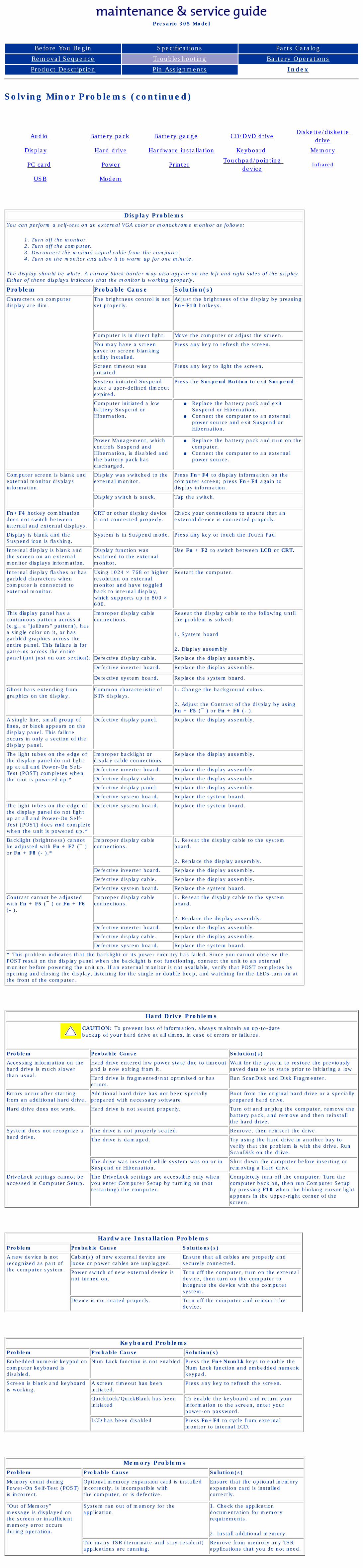
Compaq Presario Series Maintenance and Service Guide
United States December 9, 2002
Presario 305 Model
Before You Begin Specifications Parts Catalog
Removal Sequence Troubleshooting Battery Operations
Product Description Pin Assignments Index
Solving Minor Problems (continued)
Audio Battery pack Battery gauge CD/DVD driveDiskette/diskette
drive
Display Hard drive Hardware installation Keyboard Memory
PC card Power Printer Touchpad/pointing
deviceInfrared
USB Modem
Display ProblemsYou can perform a self-test on an external VGA color or monochrome monitor as follows:
1. Turn off the monitor.2. Turn off the computer.3. Disconnect the monitor signal cable from the computer.4. Turn on the monitor and allow it to warm up for one minute.
The display should be white. A narrow black border may also appear on the left and right sides of the display. Either of these displays indicates that the monitor is working properly.
Problem Probable Cause Solution(s)Characters on computer display are dim.
The brightness control is not set properly.
Adjust the brightness of the display by pressing Fn+F10 hotkeys.
Computer is in direct light. Move the computer or adjust the screen.
You may have a screen saver or screen blanking utility installed.
Press any key to refresh the screen.
Screen timeout was initiated.
Press any key to light the screen.
System initiated Suspend after a user-defined timeout expired.
Press the Suspend Button to exit Suspend.
Computer initiated a low battery Suspend or Hibernation.
● Replace the battery pack and exit Suspend or Hibernation.
● Connect the computer to an external power source and exit Suspend or Hibernation.
Power Management, which controls Suspend and Hibernation, is disabled and the battery pack has discharged.
● Replace the battery pack and turn on the computer.
● Connect the computer to an external power source.
Computer screen is blank and external monitor displays information.
Display was switched to the external monitor.
Press Fn+F4 to display information on the computer screen; press Fn+F4 again to display information.
Display switch is stuck. Tap the switch.
Fn+F4 hotkey combination does not switch between internal and external displays.
CRT or other display device is not connected properly.
Check your connections to ensure that an external device is connected properly.
Display is blank and the Suspend icon is flashing.
System is in Suspend mode. Press any key or touch the Touch Pad.
Internal display is blank and the screen on an external monitor displays information.
Display function was switched to the external monitor.
Use Fn + F2 to switch between LCD or CRT.
Internal display flashes or has garbled characters when computer is connected to external monitor.
Using 1024 × 768 or higher resolution on external monitor and have toggled back to internal display, which supports up to 800 × 600.
Restart the computer.
This display panel has a continuous pattern across it (e.g., a "jailbars" pattern), has a single color on it, or has garbled graphics across the entire panel. This failure is for patterns across the entire panel (not just on one section).
Improper display cable connections.
Reseat the display cable to the following until the problem is solved:
1. System board
2. Display assembly
Defective display cable. Replace the display assembly.
Defective inverter board. Replace the display assembly.
Defective system board. Replace the system board.
Ghost bars extending from graphics on the display.
Common characteristic of STN displays.
1. Change the background colors.
2. Adjust the Contrast of the display by using Fn + F5 (¯ ) or Fn + F6 ( ).
A single line, small group of lines, or block appears on the display panel. This failure occurs in only a section of the display panel.
Defective display panel. Replace the display assembly.
The light tubes on the edge of the display panel do not light up at all and Power-On Self-Test (POST) completes when the unit is powered up.*
Improper backlight or display cable connections
Replace the display assembly.
Defective inverter board. Replace the display assembly.
Defective display cable. Replace the display assembly.
Defective display panel. Replace the display assembly.
Defective system board. Replace the system board.
The light tubes on the edge of the display panel do not light up at all and Power-On Self-Test (POST) does not complete when the unit is powered up.*
Defective system board. Replace the system board.
Backlight (brightness) cannot be adjusted with Fn + F7 (¯ ) or Fn + F8 ( ).*
Improper display cable connections.
1. Reseat the display cable to the system board.
2. Replace the display assembly.
Defective inverter board. Replace the display assembly.
Defective display cable. Replace the display assembly.
Defective system board. Replace the system board.
Contrast cannot be adjusted with Fn + F5 (¯ ) or Fn + F6 ( ).
Improper display cable connections.
1. Reseat the display cable to the system board.
2. Replace the display assembly.
Defective inverter board. Replace the display assembly.
Defective display cable. Replace the display assembly.
Defective system board. Replace the system board.
* This problem indicates that the backlight or its power circuitry has failed. Since you cannot observe the POST result on the display panel when the backlight is not functioning, connect the unit to an external monitor before powering the unit up. If an external monitor is not available, verify that POST completes by opening and closing the display, listening for the single or double beep, and watching for the LEDs turn on at the front of the computer.
Hard Drive Problems
CAUTION: To prevent loss of information, always maintain an up-to-date backup of your hard drive at all times, in case of errors or failures.
Problem Probable Cause Solution(s)
Accessing information on the hard drive is much slower than usual.
Hard drive entered low power state due to timeout and is now exiting from it.
Wait for the system to restore the previously saved data to its state prior to initiating a low
Hard drive is fragmented/not optimized or has errors.
Run ScanDisk and Disk Fragmenter.
Errors occur after starting from an additional hard drive.
Additional hard drive has not been specially prepared with necessary software.
Boot from the original hard drive or a specially prepared hard drive.
Hard drive does not work. Hard drive is not seated properly. Turn off and unplug the computer, remove the battery pack, and remove and then reinstall the hard drive.
System does not recognize a hard drive.
The drive is not properly seated. Remove, then reinsert the drive.
The drive is damaged. Try using the hard drive in another bay to verify that the problem is with the drive. Run ScanDisk on the drive.
The drive was inserted while system was on or in Suspend or Hibernation.
Shut down the computer before inserting or removing a hard drive.
DriveLock settings cannot be accessed in Computer Setup.
The DriveLock settings are accessible only when you enter Computer Setup by turning on (not restarting) the computer.
Completely turn off the computer. Turn the computer back on, then run Computer Setup by pressing F10 when the blinking cursor light appears in the upper-right corner of the screen.
Hardware Installation ProblemsProblem Probable Cause Solutions(s)
A new device is not recognized as part of the computer system.
Cable(s) of new external device are loose or power cables are unplugged.
Ensure that all cables are properly and securely connected.
Power switch of new external device is not turned on.
Turn off the computer, turn on the external device, then turn on the computer to integrate the device with the computer system.
Device is not seated properly. Turn off the computer and reinsert the device.
Keyboard ProblemsProblem Probable Cause Solution(s)
Embedded numeric keypad on computer keyboard is disabled.
Num Lock function is not enabled. Press the Fn+NumLk keys to enable the Num Lock function and embedded numeric keypad.
Screen is blank and keyboard is working.
A screen timeout has been initiated.
Press any key to refresh the screen.
QuickLock/QuickBlank has been initiated
To enable the keyboard and return your information to the screen, enter your power-on password.
LCD has been disabled Press Fn+F4 to cycle from external monitor to internal LCD.
Memory ProblemsProblem Probable Cause Solution(s)
Memory count during Power-On Self-Test (POST) is incorrect.
Optional memory expansion card is installed incorrectly, is incompatible with the computer, or is defective.
Ensure that the optional memory expansion card is installed correctly.
"Out of Memory" message is displayed on the screen or insufficient memory error occurs during operation.
System ran out of memory for the application.
1. Check the application documentation for memory requirements.
2. Install additional memory.
Too many TSR (terminate-and stay-resident) applications are running.
Remove from memory any TSR applications that you do not need.
Revised: 15 January 1999
http://h18000.www1.hp.com/athome/support/msgs/305/tblnodg4.html [12/9/2002 2:21:08 PM]
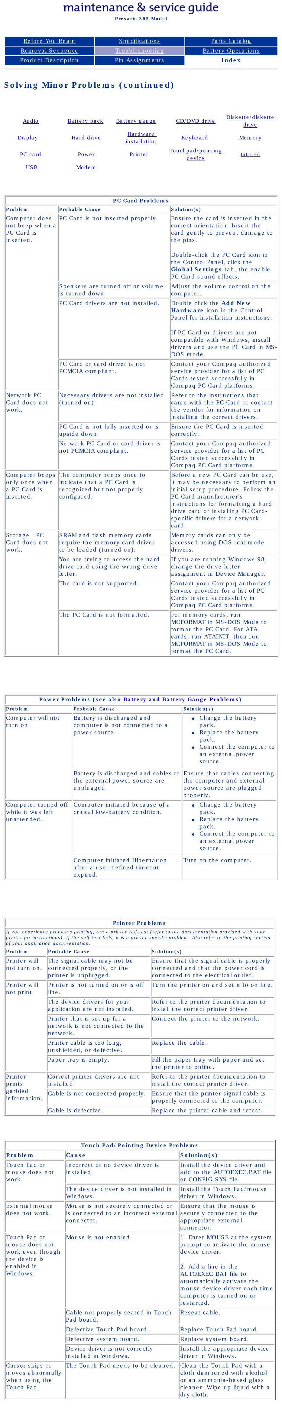
Compaq Presario Series Maintenance and Service Guide
United States December 9, 2002
Presario 305 Model
Before You Begin Specifications Parts Catalog
Removal Sequence Troubleshooting Battery Operations
Product Description Pin Assignments Index
Solving Minor Problems (continued)
Audio Battery pack Battery gauge CD/DVD driveDiskette/diskette
drive
Display Hard driveHardware installation
Keyboard Memory
PC card Power Printer Touchpad/pointing
deviceInfrared
USB Modem
PC Card ProblemsProblem Probable Cause Solution(s)
Computer does not beep when a PC Card is inserted.
PC Card is not inserted properly. Ensure the card is inserted in the correct orientation. Insert the card gently to prevent damage to the pins.
Double-click the PC Card icon in the Control Panel, click the Global Settings tab, the enable PC Card sound effects.
Speakers are turned off or volume is turned down.
Adjust the volume control on the computer.
PC Card drivers are not installed. Double click the Add New Hardware icon in the Control Panel for installation instructions.
If PC Card or drivers are not compatible with Windows, install drivers and use the PC Card in MS-DOS mode.
PC Card or card driver is not PCMCIA compliant.
Contact your Compaq authorized service provider for a list of PC Cards tested successfully in Compaq PC Card platforms.
Network PC Card does not work.
Necessary drivers are not installed (turned on).
Refer to the instructions that came with the PC Card or contact the vendor for information on installing the correct drivers.
PC Card is not fully inserted or is upside down.
Ensure the PC Card is inserted correctly.
Network PC Card or card driver is not PCMCIA compliant.
Contact your Compaq authorized service provider for a list of PC Cards tested successfully in Compaq PC Card platforms
Computer beeps only once when a PC Card is inserted.
The computer beeps once to indicate that a PC Card is recognized but not properly configured.
Before a new PC Card can be use, it may be necessary to perform an initial setup procedure. Follow the PC Card manufacturer's instructions for formatting a hard drive card or installing PC Card-specific drivers for a network card.
Storage PC Card does not work.
SRAM and flash memory cards require the memory card driver to be loaded (turned on).
Memory cards can only be accessed using DOS real mode drivers.
You are trying to access the hard drive card using the wrong drive letter.
If you are running Windows 98, change the drive letter assignment in Device Manager.
The card is not supported. Contact your Compaq authorized service provider for a list of PC Cards tested successfully in Compaq PC Card platforms.
The PC Card is not formatted. For memory cards, run MCFORMAT in MS-DOS Mode to format the PC Card. For ATA cards, run ATAINIT, then run MCFORMAT in MS-DOS Mode to format the PC Card.
Power Problems (see also Battery and Battery Gauge Problems)
Problem Probable Cause Solution(s)
Computer will not turn on.
Battery is discharged and computer is not connected to a power source.
● Charge the battery pack.
● Replace the battery pack.
● Connect the computer to an external power source.
Battery is discharged and cables to the external power source are unplugged.
Ensure that cables connecting the computer and external power source are plugged properly.
Computer turned off while it was left unattended.
Computer initiated because of a critical low-battery condition.
● Charge the battery pack.
● Replace the battery pack.
● Connect the computer to an external power source.
Computer initiated Hibernation after a user-defined timeout expired.
Turn on the computer.
Printer ProblemsIf you experience problems printing, run a printer self-test (refer to the documentation provided with your printer for instructions). If the self-test fails, it is a printer-specific problem. Also refer to the printing section of your application documentation.
Problem Probable Cause Solution(s)
Printer will not turn on.
The signal cable may not be connected properly, or the printer is unplugged.
Ensure that the signal cable is properly connected and that the power cord is connected to the electrical outlet.
Printer will not print.
Printer is not turned on or is off line.
Turn the printer on and set it to on line.
The device drivers for your application are not installed.
Refer to the printer documentation to install the correct printer driver.
Printer that is set up for a network is not connected to the network.
Connect the printer to the network.
Printer cable is too long, unshielded, or defective.
Replace the cable.
Paper tray is empty. Fill the paper tray with paper and set the printer to online.
Printer prints garbled information.
Correct printer drivers are not installed.
Refer to the printer documentation to install the correct printer driver.
Cable is not connected properly. Ensure that the printer signal cable is properly connected to the computer.
Cable is defective. Replace the printer cable and retest.
Touch Pad/Pointing Device Problems
Problem Cause Solution(s)
Touch Pad or mouse does not work.
Incorrect or no device driver is installed.
Install the device driver and add to the AUTOEXEC.BAT file or CONFIG.SYS file.
The device driver is not installed in Windows.
Install the Touch Pad/mouse driver in Windows.
External mouse does not work.
Mouse is not securely connected or is connected to an incorrect external connector.
Ensure that the mouse is securely connected to the appropriate external connector.
Touch Pad or mouse does not work even though the device is enabled in Windows.
Mouse is not enabled.
1. Enter MOUSE at the system prompt to activate the mouse device driver.
2. Add a line in the AUTOEXEC.BAT file to automatically activate the mouse device driver each time computer is turned on or restarted.
Cable not properly seated in Touch Pad board.
Reseat cable.
Defective Touch Pad board. Replace Touch Pad board.
Defective system board. Replace system board.
Device driver is not correctly installed in Windows.
Install the appropriate device driver in Windows.
Cursor skips or moves abnormally when using the Touch Pad.
The Touch Pad needs to be cleaned. Clean the Touch Pad with a cloth dampened with alcohol or an ammonia-based glass cleaner. Wipe up liquid with a dry cloth.
privacy and legal statement
http://h18000.www1.hp.com/athome/support/msgs/305/tblnodg3.html [12/9/2002 2:21:18 PM]
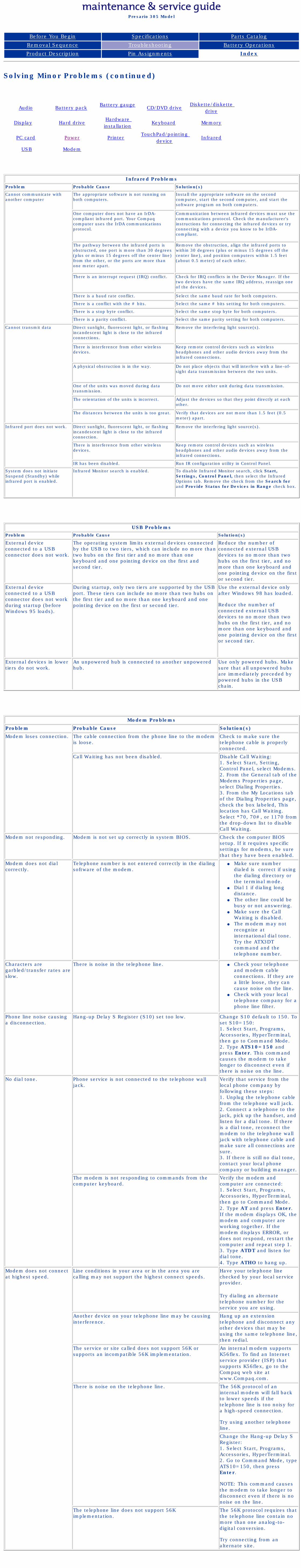
Compaq Presario Series Maintenance and Service Guide
United States December 9, 2002
Presario 305 Model
Before You Begin Specifications Parts Catalog
Removal Sequence Troubleshooting Battery Operations
Product Description Pin Assignments Index
Solving Minor Problems (continued)
Audio Battery pack Battery gauge
CD/DVD driveDiskette/diskette
drive
Display Hard driveHardware installation
Keyboard Memory
PC card Power Printer TouchPad/pointing
deviceInfrared
USB Modem
Infrared Problems
Problem Probable Cause Solution(s)
Cannot communicate with another computer
The appropriate software is not running on both computers.
Install the appropriate software on the second computer, start the second computer, and start the software program on both computers.
One computer does not have an IrDA-compliant infrared port. Your Compaq computer uses the IrDA communications protocol.
Communication between infrared devices must use the communications protocol. Check the manufacturer's instructions for connecting the infrared devices or try connecting with a device you know to be IrDA-compliant.
The pathway between the infrared ports is obstructed, one port is more than 30 degrees (plus or minus 15 degrees off the center line) from the other, or the ports are more than one meter apart.
Remove the obstruction, align the infrared ports to within 30 degrees (plus or minus 15 degrees off the center line), and position computers within 1.5 feet (about 0.5 meter) of each other.
There is an interrupt request (IRQ) conflict. Check for IRQ conflicts in the Device Manager. If the two devices have the same IRQ address, reassign one of the devices.
There is a baud rate conflict. Select the same baud rate for both computers.
There is a conflict with the # bits. Select the same # bits setting for both computers.
There is a stop byte conflict. Select the same stop byte for both computers.
There is a parity conflict. Select the same parity setting for both computers.
Cannot transmit data Direct sunlight, fluorescent light, or flashing incandescent light is close to the infrared connections.
Remove the interfering light source(s).
There is interference from other wireless devices.
Keep remote control devices such as wireless headphones and other audio devices away from the infrared connections.
A physical obstruction is in the way. Do not place objects that will interfere with a line-of-sight data transmission between the two units.
One of the units was moved during data transmission.
Do not move either unit during data transmission.
The orientation of the units is incorrect. Adjust the devices so that they point directly at each other.
The distances between the units is too great. Verify that devices are not more than 1.5 feet (0.5 meter) apart.
Infrared port does not work. Direct sunlight, fluorescent light, or flashing incandescent light is close to the infrared connection.
Remove the interfering light source(s).
There is interference from other wireless devices.
Keep remote control devices such as wireless headphones and other audio devices away from the infrared connections.
IR has been disabled. Run IR configuration utility in Control Panel.
System does not initiate Suspend (Standby) while infrared port is enabled.
Infrared Monitor search is enabled. To disable Infrared Monitor search, click Start, Settings, Control Panel, then select the Infrared Options tab. Remove the check from the Search for and Provide Status for Devices in Range check box.
USB ProblemsProblem Probable Cause Solution(s)
External device connected to a USB connector does not work.
The operating system limits external devices connected by the USB to two tiers, which can include no more than two hubs on the first tier and no more than one keyboard and one pointing device on the first and second tier.
Reduce the number of connected external USB devices to no more than two hubs on the first tier, and no more than one keyboard and one pointing device on the first or second tier.
External device connected to a USB connector does not work during startup (before Windows 95 loads).
During startup, only two tiers are supported by the USB port. These tiers can include no more than two hubs on the first tier and no more than one keyboard and one pointing device on the first or second tier.
Use the external device only after Windows 98 has loaded.
Reduce the number of connected external USB devices to no more than two hubs on the first tier, and no more than one keyboard and one pointing device on the first or second tier.
External devices in lower tiers do not work.
An unpowered hub is connected to another unpowered hub.
Use only powered hubs. Make sure that all unpowered hubs are immediately preceded by powered hubs in the USB chain.
Modem Problems
Problem Probable Cause Solution(s)
Modem loses connection. The cable connection from the phone line to the modem is loose.
Check to make sure the telephone cable is properly connected.
Call Waiting has not been disabled. Disable Call Waiting:1. Select Start, Setting, Control Panel, select Modems.2. From the General tab of the Modems Properties page, select Dialing Properties.3. From the My Locations tab of the Dialing Properties page, check the box labeled, This location has Call Waiting. Select *70, 70#, or 1170 from the drop-down list to disable Call Waiting.
Modem not responding. Modem is not set up correctly in system BIOS. Check the computer BIOS setup. If it requires specific settings for modems, be sure that they have been enabled.
Modem does not dial correctly.
Telephone number is not entered correctly in the dialing software of the modem.
● Make sure number dialed is correct if using the dialing directory or the terminal mode.
● Dial 1 if dialing long distance.
● The other line could be busy or not answering.
● Make sure the Call Waiting is disabled.
● The modem may not recognize at international dial tone. Try the ATX3DT command and the telephone number.
Characters are garbled/transfer rates are slow.
There is noise in the telephone line. ● Check your telephone and modem cable connections. If they are a little loose, they can cause noise on the line.
● Check with your local telephone company for a phone line filter.
Phone line noise causing a disconnection.
Hang-up Delay S Register (S10) set too low. Change S10 default to 150. To set S10=150:1. Select Start, Programs, Accessories, HyperTerminal, then go to Command Mode.2. Type ATS10=150 and press Enter. This command causes the modem to take longer to disconnect even if there is noise on the line.
No dial tone. Phone service is not connected to the telephone wall jack.
Verify that service from the local phone company by following these steps:1. Unplug the telephone cable from the telephone wall jack.2. Connect a telephone to the jack, pick up the handset, and listen for a dial tone. If there is a dial tone, reconnect the modem to the telephone wall jack with telephone cable and make sure all connections are sure.3. If there is still no dial tone, contact your local phone company or building manager.
The modem is not responding to commands from the computer keyboard.
Verify the modem and computer are connected:1. Select Start, Programs, Accessories, HyperTerminal, then go to Command Mode.2. Type AT and press Enter. If the modem displays OK, the modem and computer are working together. If the modem displays ERROR, or does not respond, restart the computer and repeat step 1.3. Type ATDT and listen for dial tone.4. Type ATHO to hang up.
Modem does not connect at highest speed.
Line conditions in your area or in the area you are calling may not support the highest connect speeds.
Have your telephone line checked by your local service provider.
Try dialing an alternate telephone number for the service you are using.
Another device on your telephone line may be causing interference.
Hang up an extension telephone and disconnect any other devices that may be using the same telephone line, then redial.
The service or site called does not support 56K or supports an incompatible 56K implementation.
An internal modem supports K56flex. To find an Internet service provider (ISP) that supports K56flex, go to the Compaq web site at www.Compaq.com.
There is noise on the telephone line. The 56K protocol of an internal modem will fall back to lower speeds if the telephone line is too noisy for a high-speed connection.
Try using another telephone line.
Change the Hang-up Delay S Register:1. Select Start, Programs, Accessories, HyperTerminal.2. Go to Command Mode, type ATS10=150, then press Enter.
NOTE: This command causes the modem to take longer to disconnect even if there is no noise on the line.
The telephone line does not support 56K implementation.
The 56K protocol requires that the telephone line contain no more than one analog-to-digital conversion.
Try connecting from an alternate site.
privacy and legal statement
http://h18000.www1.hp.com/athome/support/msgs/305/tblnodg5.html [12/9/2002 2:21:34 PM]
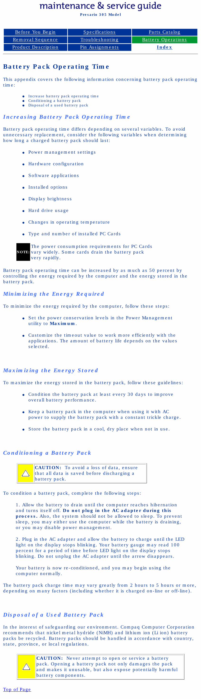
Compaq Presario Series Maintenance and Service Guide
United States December 9, 2002
Presario 305 Model
Before You Begin Specifications Parts Catalog
Removal Sequence Troubleshooting Battery Operations
Product Description Pin Assignments Index
Battery Pack Operating Time
This appendix covers the following information concerning battery pack operating time:
● Increase battery pack operating time● Conditioning a battery pack● Disposal of a used battery pack
Increasing Battery Pack Operating Time
Battery pack operating time differs depending on several variables. To avoid unnecessary replacement, consider the following variables when determining how long a charged battery pack should last:
● Power management settings
● Hardware configuration
● Software applications
● Installed options
● Display brightness
● Hard drive usage
● Changes in operating temperature
● Type and number of installed PC Cards
NOTE:The power consumption requirements for PC Cards vary widely. Some cards drain the battery pack very rapidly.
Battery pack operating time can be increased by as much as 50 percent by controlling the energy required by the computer and the energy stored in the battery pack.
Minimizing the Energy Required
To minimize the energy required by the computer, follow these steps:
● Set the power conservation levels in the Power Management utility to Maximum.
● Customize the timeout value to work more efficiently with the applications. The amount of battery life depends on the values selected.
Maximizing the Energy Stored
To maximize the energy stored in the battery pack, follow these guidelines:
● Condition the battery pack at least every 30 days to improve overall battery performance.
● Keep a battery pack in the computer when using it with AC power to supply the battery pack with a constant trickle charge.
● Store the battery pack in a cool, dry place when not in use.
Conditioning a Battery Pack
CAUTION: To avoid a loss of data, ensure that all data is saved before discharging a battery pack.
To condition a battery pack, complete the following steps:
1. Allow the battery to drain until the computer reaches hibernation and turns itself off. Do not plug in the AC adapter during this process. Also, the system should not be allowed to sleep. To prevent sleep, you may either use the computer while the battery is draining, or you may disable power management.
2. Plug in the AC adapter and allow the battery to charge until the LED light on the display stops blinking. Your battery gauge may read 100 percent for a period of time before LED light on the display stops blinking. Do not unplug the AC adapter until the arrow disappears.
Your battery is now re-conditioned, and you may begin using the computer normally.
The battery pack charge time may vary greatly from 2 hours to 5 hours or more, depending on many factors (including whether it is charged on-line or off-line).
Disposal of a Used Battery Pack
In the interest of safeguarding our environment. Compaq Computer Corporation recommends that nickel metal hydride (NiMH) and lithium ion (Li ion) battery packs be recycled. Battery packs should be handled in accordance with country, state, province, or local regulations.
CAUTION: Never attempt to open or service a battery pack. Opening a battery pack not only damages the pack and makes it unusable, but also expose potentially harmful battery components.
Top of Page
privacy and legal statement
http://h18000.www1.hp.com/athome/support/msgs/305/batpkop.html [12/9/2002 2:22:13 PM]
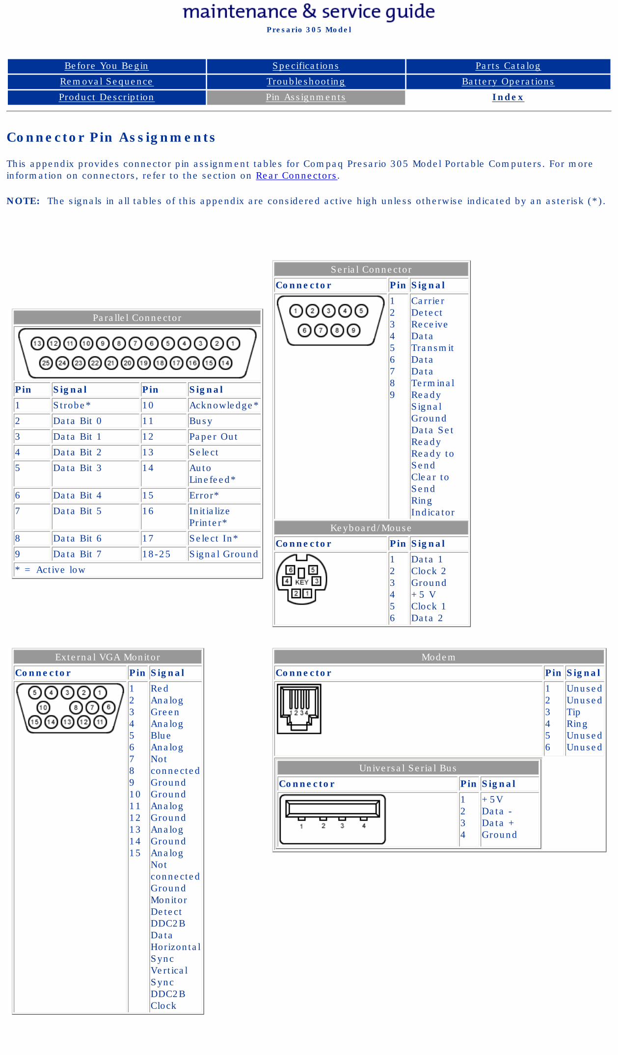
Compaq Presario Series Maintenance and Service Guide
United States December 9, 2002
Presario 305 Model
Before You Begin Specifications Parts Catalog
Removal Sequence Troubleshooting Battery Operations
Product Description Pin Assignments Index
Connector Pin Assignments
This appendix provides connector pin assignment tables for Compaq Presario 305 Model Portable Computers. For more information on connectors, refer to the section on Rear Connectors.
NOTE: The signals in all tables of this appendix are considered active high unless otherwise indicated by an asterisk (*).
Parallel Connector
Pin Signal Pin Signal
1 Strobe* 10 Acknowledge*
2 Data Bit 0 11 Busy
3 Data Bit 1 12 Paper Out
4 Data Bit 2 13 Select
5 Data Bit 3 14 Auto Linefeed*
6 Data Bit 4 15 Error*
7 Data Bit 5 16 Initialize Printer*
8 Data Bit 6 17 Select In*
9 Data Bit 7 18-25 Signal Ground
* = Active low
Serial Connector
Connector Pin Signal
123456789
Carrier DetectReceive DataTransmit DataData Terminal ReadySignal GroundData Set ReadyReady to SendClear to SendRing Indicator
Keyboard/Mouse
Connector Pin Signal
123456
Data 1Clock 2Ground+5 VClock 1Data 2
External VGA Monitor
Connector Pin Signal
123456789101112131415
Red AnalogGreen AnalogBlue AnalogNot connectedGroundGround AnalogGround AnalogGround AnalogNot connectedGroundMonitor DetectDDC2B DataHorizontal SyncVertical SyncDDC2B Clock
Modem
Connector Pin Signal
123456
UnusedUnusedTipRingUnusedUnused
Universal Serial Bus
Connector Pin Signal
1234
+5VData -Data +Ground
privacy and legal statement
http://h18000.www1.hp.com/athome/support/msgs/305/conPA.html [12/9/2002 2:22:24 PM]
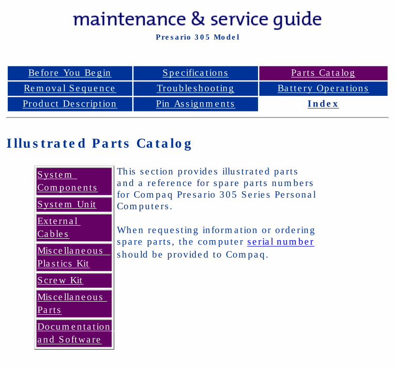
Compaq Presario Series Maintenance and Service Guide
United States December 9, 2002
Presario 305 Model
Before You Begin Specifications Parts Catalog
Removal Sequence Troubleshooting Battery Operations
Product Description Pin Assignments Index
Illustrated Parts Catalog
System Components
System Unit
External Cables
Miscellaneous Plastics Kit
Screw Kit
Miscellaneous Parts
Documentation and Software
This section provides illustrated parts and a reference for spare parts numbers for Compaq Presario 305 Series Personal Computers.
When requesting information or ordering spare parts, the computer serial number should be provided to Compaq.
privacy and legal statement
http://h18000.www1.hp.com/athome/support/msgs/305/illust.html [12/9/2002 2:22:34 PM]
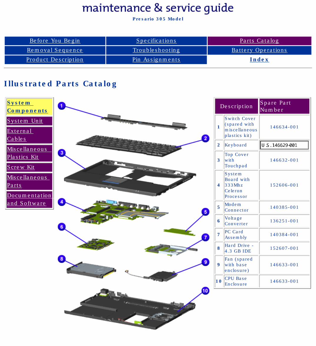
Compaq Presario Series Maintenance and Service Guide
United States December 9, 2002
Presario 305 Model
Before You Begin Specifications Parts Catalog
Removal Sequence Troubleshooting Battery Operations
Product Description Pin Assignments Index
Illustrated Parts Catalog
System Components
System Unit
External Cables
Miscellaneous Plastics Kit
Screw Kit
Miscellaneous Parts
Documentation and Software
Description Spare Part Number
1
Switch Cover (spared with miscellaneous plastics kit)
146634-001
2 Keyboard
3 Top Cover with Touchpad
146632-001
4
System Board with 333Mhz Celeron Processor
152606-001
5 Modem Connector 140385-001
6 Voltage Converter 136251-001
7 PC Card Assembly 140384-001
8 Hard Drive - 4.3 GB IDE 152607-001
9 Fan (spared with base enclosure)
146633-001
10 CPU Base Enclosure 146633-001
privacy and legal statement
http://h18000.www1.hp.com/athome/support/msgs/305/boards.html [12/9/2002 2:22:38 PM]
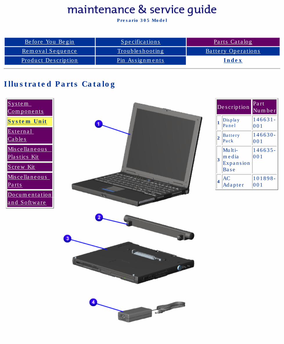
Compaq Presario Series Maintenance and Service Guide
United States December 9, 2002
Presario 305 Model
Before You Begin Specifications Parts Catalog
Removal Sequence Troubleshooting Battery Operations
Product Description Pin Assignments Index
Illustrated Parts Catalog
System Components
System Unit
External Cables
Miscellaneous Plastics Kit
Screw Kit
Miscellaneous Parts
Documentation and Software
Description Part Number
1 Display Panel
146631-001
2 Battery Pack
146630-001
3
Multi-media Expansion Base
146635-001
4AC Adapter
101898-001
privacy and legal statement
http://h18000.www1.hp.com/athome/support/msgs/305/mass.html [12/9/2002 2:22:42 PM]
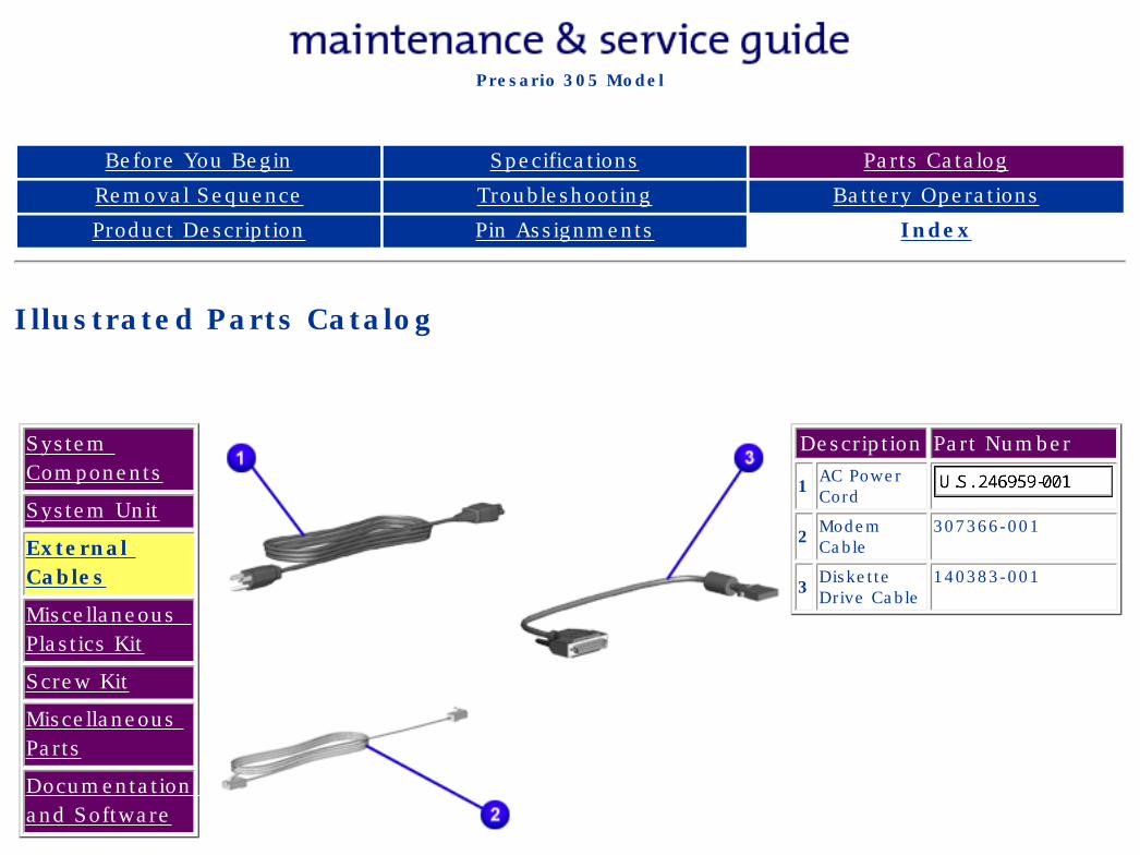
Compaq Presario Series Maintenance and Service Guide
United States December 9, 2002
Presario 305 Model
Before You Begin Specifications Parts Catalog
Removal Sequence Troubleshooting Battery Operations
Product Description Pin Assignments Index
Illustrated Parts Catalog
System Components
System Unit
External Cables
Miscellaneous Plastics Kit
Screw Kit
Miscellaneous Parts
Documentation and Software
Description Part Number
1 AC Power Cord
2 Modem Cable
307366-001
3 Diskette Drive Cable
140383-001
privacy and legal statement
http://h18000.www1.hp.com/athome/support/msgs/305/xtrcbl.html [12/9/2002 2:22:44 PM]
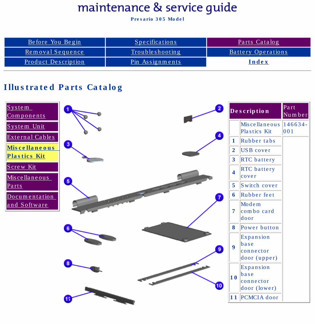
Compaq Presario Series Maintenance and Service Guide
United States December 9, 2002
Presario 305 Model
Before You Begin Specifications Parts Catalog
Removal Sequence Troubleshooting Battery Operations
Product Description Pin Assignments Index
Illustrated Parts Catalog
System Components
System Unit
External Cables
Miscellaneous Plastics Kit
Screw Kit
Miscellaneous Parts
Documentation and Software
Description Part Number
Miscellaneous Plastics Kit
146634-001
1 Rubber tabs
2 USB cover
3 RTC battery
4 RTC battery cover
5 Switch cover
6 Rubber feet
7Modem combo card door
8 Power button
9
Expansion base connector door (upper)
10
Expansion base connector door (lower)
11 PCMCIA door
privacy and legal statement
http://h18000.www1.hp.com/athome/support/msgs/305/miscpl.html [12/9/2002 2:22:47 PM]
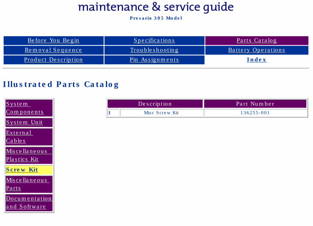
Compaq Presario Series Maintenance and Service Guide
United States December 9, 2002
Presario 305 Model
Before You Begin Specifications Parts Catalog
Removal Sequence Troubleshooting Battery Operations
Product Description Pin Assignments Index
Illustrated Parts Catalog
System Components
System Unit
External Cables
Miscellaneous Plastics Kit
Screw Kit
Miscellaneous Parts
Documentation and Software
Description Part Number1 Misc Screw Kit 136255-001
privacy and legal statement
http://h18000.www1.hp.com/athome/support/msgs/305/screw.html [12/9/2002 2:22:49 PM]
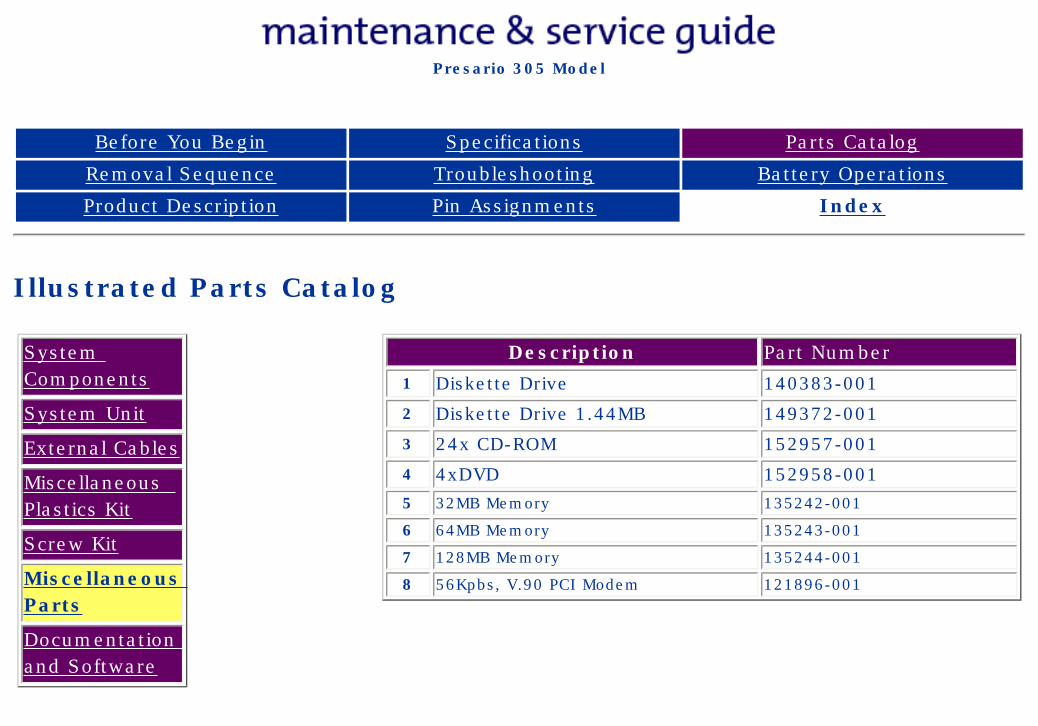
Compaq Presario Series Maintenance and Service Guide
United States December 9, 2002
Presario 305 Model
Before You Begin Specifications Parts Catalog
Removal Sequence Troubleshooting Battery Operations
Product Description Pin Assignments Index
Illustrated Parts Catalog
System Components
System Unit
External Cables
Miscellaneous Plastics Kit
Screw Kit
Miscellaneous Parts
Documentation and Software
Description Part Number1 Diskette Drive 140383-001
2 Diskette Drive 1.44MB 149372-001
3 24x CD-ROM 152957-001
4 4xDVD 152958-0015 32MB Memory 135242-001
6 64MB Memory 135243-001
7 128MB Memory 135244-001
8 56Kpbs, V.90 PCI Modem 121896-001
privacy and legal statement
http://h18000.www1.hp.com/athome/support/msgs/305/miscpts.html [12/9/2002 2:22:53 PM]
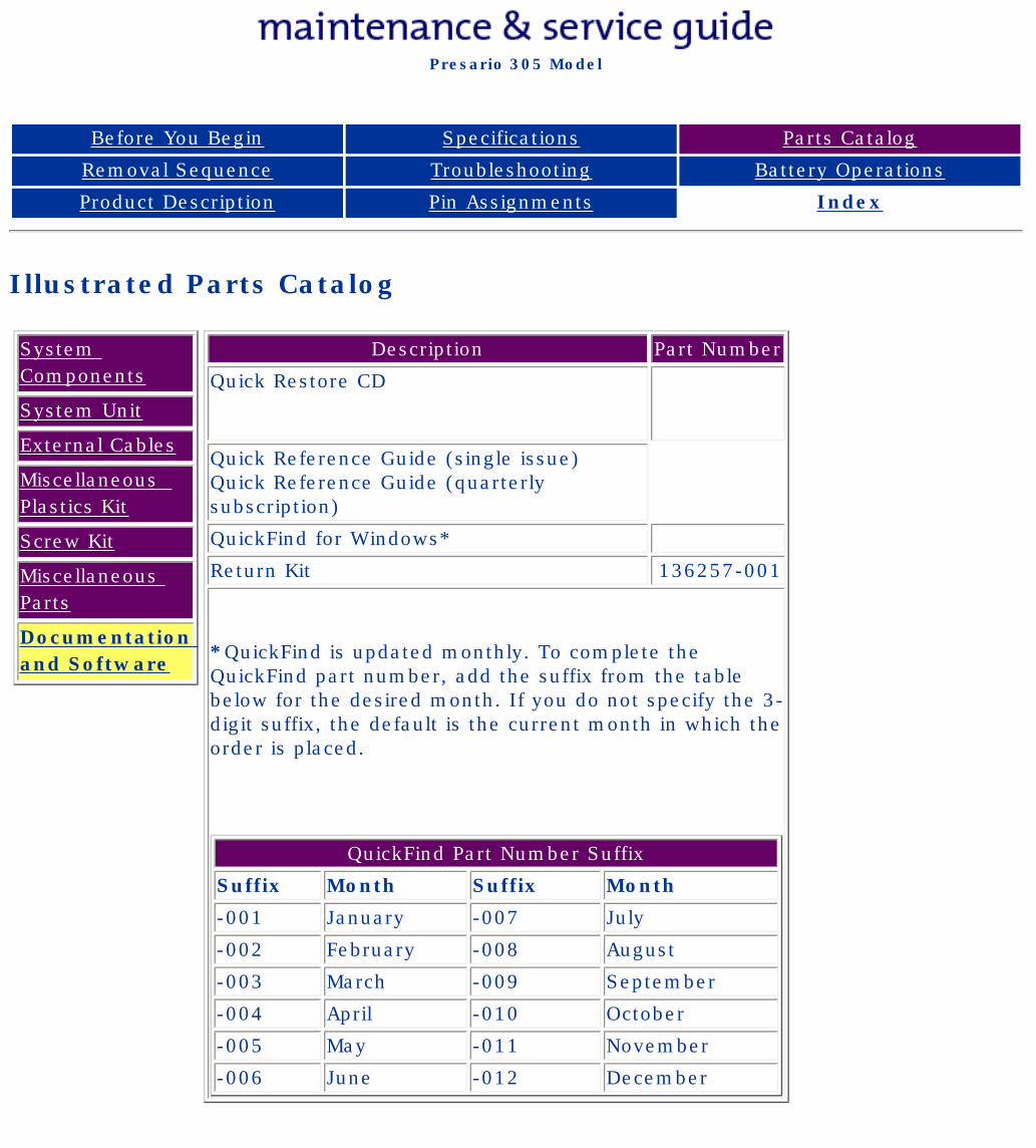
Compaq Presario Series Maintenance and Service Guide
United States December 9, 2002
Presario 305 Model
Before You Begin Specifications Parts Catalog
Removal Sequence Troubleshooting Battery Operations
Product Description Pin Assignments Index
Illustrated Parts Catalog
System Components
System Unit
External Cables
Miscellaneous Plastics Kit
Screw Kit
Miscellaneous Parts
Documentation and Software
Description Part Number
Quick Restore CD
Quick Reference Guide (single issue)Quick Reference Guide (quarterly subscription)
QuickFind for Windows*
Return Kit 136257-001
*QuickFind is updated monthly. To complete the QuickFind part number, add the suffix from the table below for the desired month. If you do not specify the 3-digit suffix, the default is the current month in which the order is placed.
QuickFind Part Number Suffix
Suffix Month Suffix Month
-001 January -007 July
-002 February -008 August
-003 March -009 September
-004 April -010 October
-005 May -011 November
-006 June -012 December
privacy and legal statement
http://h18000.www1.hp.com/athome/support/msgs/305/docume.html [12/9/2002 2:22:56 PM]
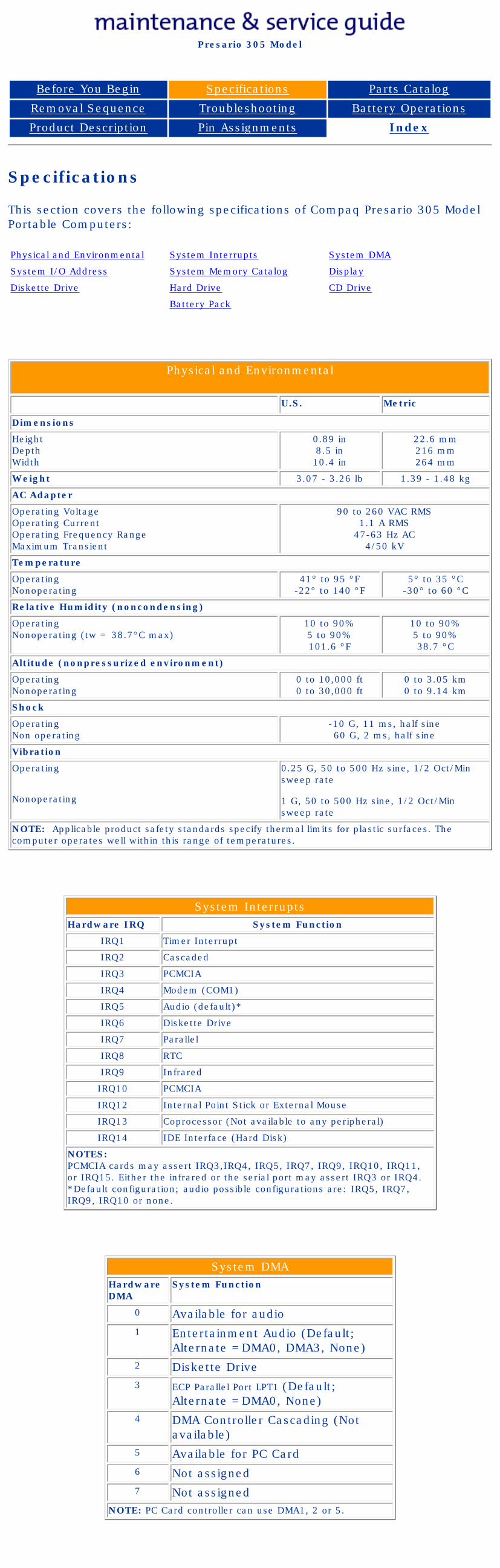
United States January 2, 2003
Presario 305 Model
Before You Begin Specifications Parts Catalog
Removal Sequence Troubleshooting Battery Operations
Product Description Pin Assignments Index
Specifications
This section covers the following specifications of Compaq Presario 305 Model Portable Computers:
Physical and Environmental System Interrupts System DMA
System I/O Address System Memory Catalog Display
Diskette Drive Hard Drive CD Drive
Battery Pack
Physical and Environmental
U.S. Metric
Dimensions
HeightDepthWidth
0.89 in8.5 in10.4 in
22.6 mm216 mm264 mm
Weight 3.07 - 3.26 lb 1.39 - 1.48 kg
AC Adapter
Operating VoltageOperating CurrentOperating Frequency RangeMaximum Transient
90 to 260 VAC RMS1.1 A RMS
47-63 Hz AC4/50 kV
Temperature
OperatingNonoperating
41° to 95 °F-22° to 140 °F
5° to 35 °C-30° to 60 °C
Relative Humidity (noncondensing)
OperatingNonoperating (tw = 38.7°C max)
10 to 90%5 to 90%101.6 °F
10 to 90%5 to 90% 38.7 °C
Altitude (nonpressurized environment)
OperatingNonoperating
0 to 10,000 ft0 to 30,000 ft
0 to 3.05 km0 to 9.14 km
Shock
OperatingNon operating
-10 G, 11 ms, half sine60 G, 2 ms, half sine
Vibration
Operating
Nonoperating
0.25 G, 50 to 500 Hz sine, 1/2 Oct/Min sweep rate
1 G, 50 to 500 Hz sine, 1/2 Oct/Min sweep rate
NOTE: Applicable product safety standards specify thermal limits for plastic surfaces. The computer operates well within this range of temperatures.
System InterruptsHardware IRQ System Function
IRQ1 Timer Interrupt
IRQ2 Cascaded
IRQ3 PCMCIA
IRQ4 Modem (COM1)
IRQ5 Audio (default)*
IRQ6 Diskette Drive
IRQ7 Parallel
IRQ8 RTC
IRQ9 Infrared
IRQ10 PCMCIA
IRQ12 Internal Point Stick or External Mouse
IRQ13 Coprocessor (Not available to any peripheral)
IRQ14 IDE Interface (Hard Disk)
NOTES:PCMCIA cards may assert IRQ3,IRQ4, IRQ5, IRQ7, IRQ9, IRQ10, IRQ11, or IRQ15. Either the infrared or the serial port may assert IRQ3 or IRQ4.*Default configuration; audio possible configurations are: IRQ5, IRQ7, IRQ9, IRQ10 or none.
System DMAHardware DMA
System Function
0 Available for audio1 Entertainment Audio (Default;
Alternate =DMA0, DMA3, None)2 Diskette Drive3 ECP Parallel Port LPT1 (Default;
Alternate =DMA0, None)4 DMA Controller Cascading (Not
available)5 Available for PC Card6 Not assigned7 Not assigned
NOTE: PC Card controller can use DMA1, 2 or 5.
privacy and legal statement
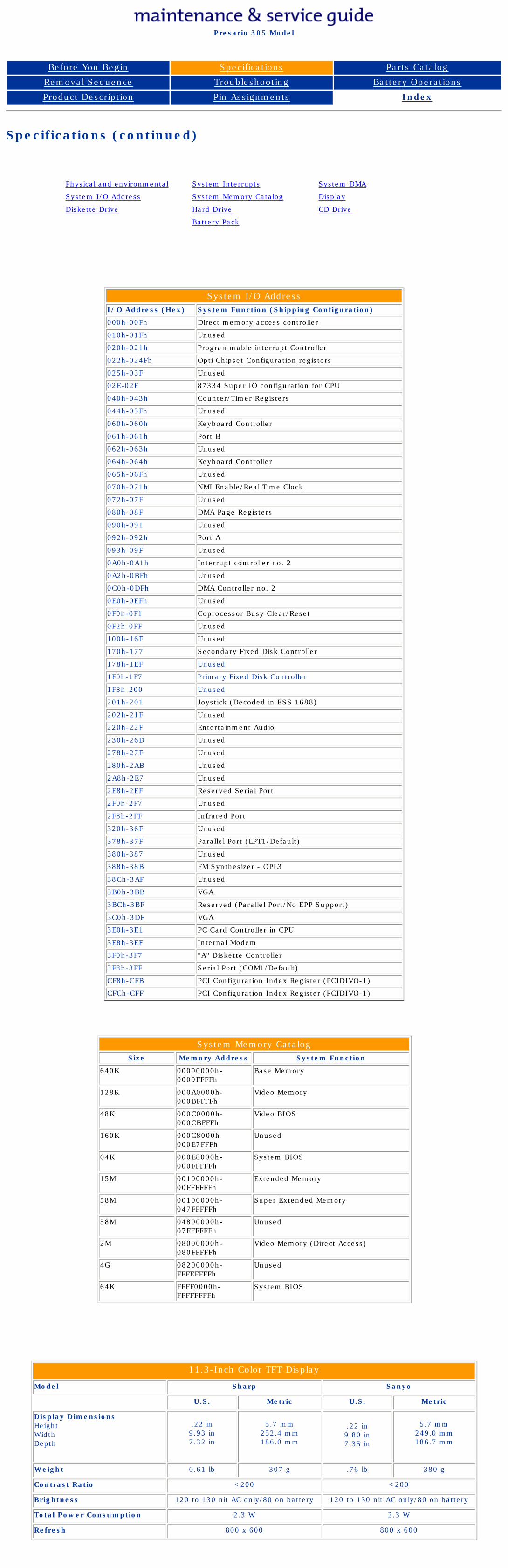
United States January 2, 2003
Presario 305 Model
Before You Begin Specifications Parts Catalog
Removal Sequence Troubleshooting Battery Operations
Product Description Pin Assignments Index
Specifications (continued)
Physical and environmental System Interrupts System DMA
System I/O Address System Memory Catalog Display
Diskette Drive Hard Drive CD Drive
Battery Pack
System I/O AddressI/O Address (Hex) System Function (Shipping Configuration)
000h-00Fh Direct memory access controller
010h-01Fh Unused
020h-021h Programmable interrupt Controller
022h-024Fh Opti Chipset Configuration registers
025h-03F Unused
02E-02F 87334 Super IO configuration for CPU
040h-043h Counter/Timer Registers
044h-05Fh Unused
060h-060h Keyboard Controller
061h-061h Port B
062h-063h Unused
064h-064h Keyboard Controller
065h-06Fh Unused
070h-071h NMI Enable/Real Time Clock
072h-07F Unused
080h-08F DMA Page Registers
090h-091 Unused
092h-092h Port A
093h-09F Unused
0A0h-0A1h Interrupt controller no. 2
0A2h-0BFh Unused
0C0h-0DFh DMA Controller no. 2
0E0h-0EFh Unused
0F0h-0F1 Coprocessor Busy Clear/Reset
0F2h-0FF Unused
100h-16F Unused
170h-177 Secondary Fixed Disk Controller
178h-1EF Unused
1F0h-1F7 Primary Fixed Disk Controller
1F8h-200 Unused
201h-201 Joystick (Decoded in ESS 1688)
202h-21F Unused
220h-22F Entertainment Audio
230h-26D Unused
278h-27F Unused
280h-2AB Unused
2A8h-2E7 Unused
2E8h-2EF Reserved Serial Port
2F0h-2F7 Unused
2F8h-2FF Infrared Port
320h-36F Unused
378h-37F Parallel Port (LPT1/Default)
380h-387 Unused
388h-38B FM Synthesizer - OPL3
38Ch-3AF Unused
3B0h-3BB VGA
3BCh-3BF Reserved (Parallel Port/No EPP Support)
3C0h-3DF VGA
3E0h-3E1 PC Card Controller in CPU
3E8h-3EF Internal Modem
3F0h-3F7 "A" Diskette Controller
3F8h-3FF Serial Port (COM1/Default)
CF8h-CFB PCI Configuration Index Register (PCIDIVO-1)
CFCh-CFF PCI Configuration Index Register (PCIDIVO-1)
System Memory CatalogSize Memory Address System Function
640K 00000000h-0009FFFFh
Base Memory
128K 000A0000h-000BFFFFh
Video Memory
48K 000C0000h-000CBFFFh
Video BIOS
160K 000C8000h-000E7FFFh
Unused
64K 000E8000h-000FFFFFh
System BIOS
15M 00100000h-00FFFFFFh
Extended Memory
58M 00100000h-047FFFFFh
Super Extended Memory
58M 04800000h-07FFFFFFh
Unused
2M 08000000h-080FFFFFh
Video Memory (Direct Access)
4G 08200000h-FFFEFFFFh
Unused
64K FFFF0000h-FFFFFFFFh
System BIOS
11.3-Inch Color TFT Display
Model Sharp Sanyo
U.S. Metric U.S. Metric
Display DimensionsHeight Width Depth
.22 in9.93 in7.32 in
5.7 mm252.4 mm186.0 mm
.22 in9.80 in7.35 in
5.7 mm249.0 mm186.7 mm
Weight 0.61 lb 307 g .76 lb 380 g
Contrast Ratio <200 <200
Brightness 120 to 130 nit AC only/80 on battery 120 to 130 nit AC only/80 on battery
Total Power Consumption 2.3 W 2.3 W
Refresh 800 x 600 800 x 600
privacy and legal statement
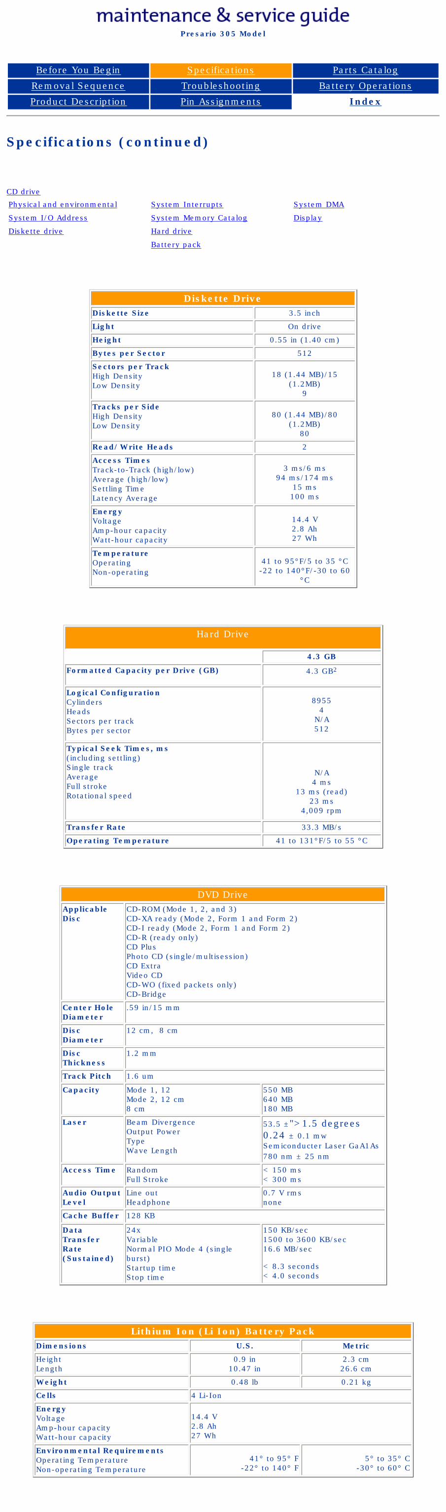
United States January 2, 2003
Presario 305 Model
Before You Begin Specifications Parts Catalog
Removal Sequence Troubleshooting Battery Operations
Product Description Pin Assignments Index
Specifications (continued)
CD drive
Physical and environmental System Interrupts System DMA
System I/O Address System Memory Catalog Display
Diskette drive Hard drive
Battery pack
Diskette DriveDiskette Size 3.5 inch
Light On drive
Height 0.55 in (1.40 cm)
Bytes per Sector 512
Sectors per TrackHigh DensityLow Density
18 (1.44 MB)/15 (1.2MB)
9
Tracks per SideHigh DensityLow Density
80 (1.44 MB)/80 (1.2MB)
80
Read/Write Heads 2
Access TimesTrack-to-Track (high/low)Average (high/low)Settling TimeLatency Average
3 ms/6 ms94 ms/174 ms
15 ms100 ms
EnergyVoltageAmp-hour capacityWatt-hour capacity
14.4 V2.8 Ah27 Wh
Temperature OperatingNon-operating
41 to 95°F/5 to 35 °C-22 to 140°F/-30 to 60
°C
Hard Drive
4.3 GB
Formatted Capacity per Drive (GB) 4.3 GB2
Logical ConfigurationCylindersHeadsSectors per trackBytes per sector
89554
N/A512
Typical Seek Times, ms (including settling)Single trackAverageFull strokeRotational speed
N/A4 ms
13 ms (read)23 ms
4,009 rpm
Transfer Rate 33.3 MB/s
Operating Temperature 41 to 131°F/5 to 55 °C
DVD DriveApplicable Disc
CD-ROM (Mode 1, 2, and 3)CD-XA ready (Mode 2, Form 1 and Form 2)CD-I ready (Mode 2, Form 1 and Form 2)CD-R (ready only)CD PlusPhoto CD (single/multisession)CD ExtraVideo CDCD-WO (fixed packets only)CD-Bridge
Center Hole Diameter
.59 in/15 mm
Disc Diameter
12 cm, 8 cm
Disc Thickness
1.2 mm
Track Pitch 1.6 um
Capacity Mode 1, 12Mode 2, 12 cm8 cm
550 MB640 MB180 MB
Laser Beam DivergenceOutput PowerTypeWave Length
53.5 ±">1.5 degrees0.24 ± 0.1 mwSemiconducter Laser GaA1As780 nm ± 25 nm
Access Time RandomFull Stroke
< 150 ms< 300 ms
Audio Output Level
Line outHeadphone
0.7 V rmsnone
Cache Buffer 128 KB
Data Transfer Rate(Sustained)
24xVariableNormal PIO Mode 4 (single burst)Startup timeStop time
150 KB/sec1500 to 3600 KB/sec16.6 MB/sec
< 8.3 seconds< 4.0 seconds
Lithium Ion (Li Ion) Battery PackDimensions U.S. Metric
HeightLength
0.9 in10.47 in
2.3 cm26.6 cm
Weight 0.48 lb 0.21 kg
Cells 4 Li-Ion
EnergyVoltageAmp-hour capacity Watt-hour capacity
14.4 V2.8 Ah27 Wh
Environmental RequirementsOperating TemperatureNon-operating Temperature
41° to 95° F-22° to 140° F
5° to 35° C-30° to 60° C
privacy and legal statement