Embed Size (px)
Citation preview
CCHHAAPPTTEERR 22

PROPRIETARY MATERIAL. Copyright © 2015 McGraw-Hill Education. This is proprietary material solely for authorized instructor use.
Not authorized for sale or distribution in any manner. This document may not be copied, scanned, duplicated, forwarded, distributed, or posted
on a website, in whole or part.
93
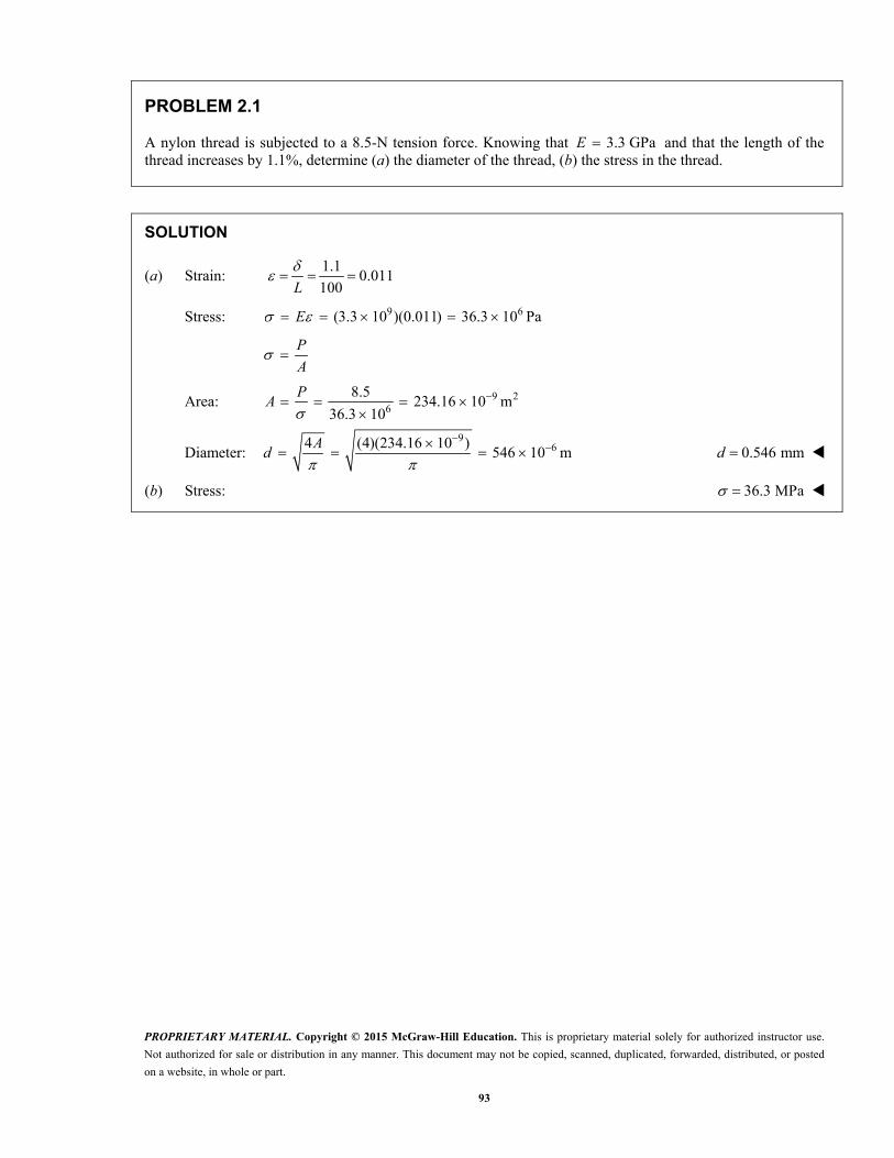
PROBLEM 2.1
A nylon thread is subjected to a 8.5-N tension force. Knowing that 3.3 GPaE and that the length of the thread increases by 1.1%, determine (a) the diameter of the thread, (b) the stress in the thread.
SOLUTION
(a) Strain: 1.1
0.011100L
Stress: 9 6(3.3 10 )(0.011) 36.3 10 Pa E
P
A
Area: 9 26
8.5234.16 10 m
36.3 10
P
A
Diameter: 9
64 (4)(234.16 10 )546 10 m
A
d 0.546 mmd
(b) Stress: 36.3 MPa
PROPRIETARY MATERIAL. Copyright © 2015 McGraw-Hill Education. This is proprietary material solely for authorized instructor use.
Not authorized for sale or distribution in any manner. This document may not be copied, scanned, duplicated, forwarded, distributed, or posted
on a website, in whole or part.
94
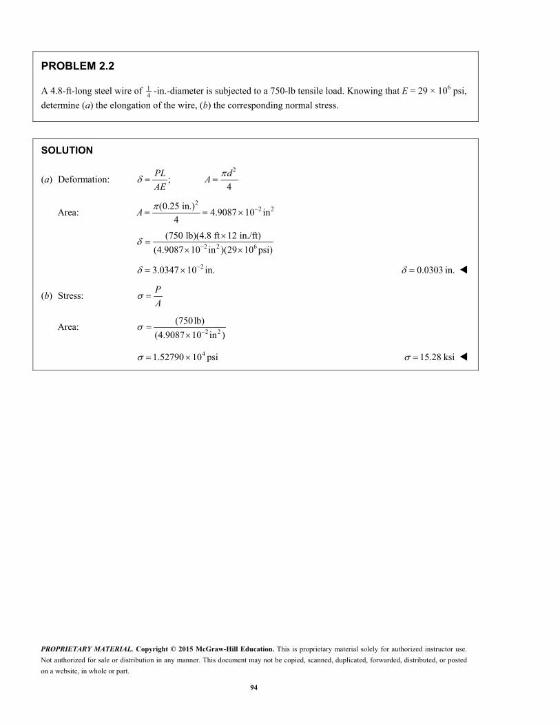
PROBLEM 2.2
A 4.8-ft-long steel wire of 14 -in.-diameter is subjected to a 750-lb tensile load. Knowing that E = 29 × 106 psi,
determine (a) the elongation of the wire, (b) the corresponding normal stress.
SOLUTION
(a) Deformation: 2
;4
PL dA
AE
Area: 2
2 2(0.25 in.)4.9087 10 in
4A
2 2 6
(750 lb)(4.8 ft 12 in./ft)
(4.9087 10 in )(29 10 psi)
23.0347 10 in. 0.0303 in.
(b) Stress: P
A
Area: 2 2
(750lb)
(4.9087 10 in )
41.52790 10 psi 15.28 ksi
PROPRIETARY MATERIAL. Copyright © 2015 McGraw-Hill Education. This is proprietary material solely for authorized instructor use.
Not authorized for sale or distribution in any manner. This document may not be copied, scanned, duplicated, forwarded, distributed, or posted
on a website, in whole or part.
95
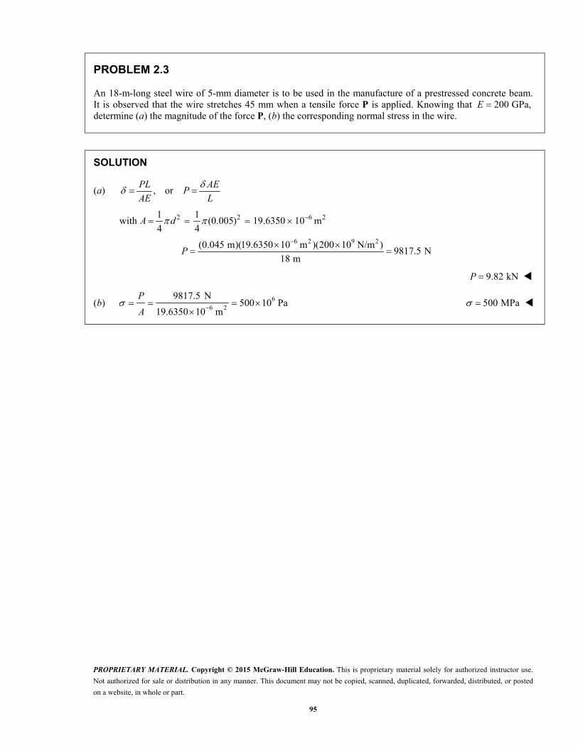
PROBLEM 2.3
An 18-m-long steel wire of 5-mm diameter is to be used in the manufacture of a prestressed concrete beam. It is observed that the wire stretches 45 mm when a tensile force P is applied. Knowing that 200 GPa,E determine (a) the magnitude of the force P, (b) the corresponding normal stress in the wire.
SOLUTION
(a) , orPL AE
PAE L
with 2 2 6 21 1(0.005) 19.6350 10 m
4 4 A d
6 2 9 2(0.045 m)(19.6350 10 m )(200 10 N/m )
9817.5 N18 m
P
9.82 kNP
(b) 66 2
9817.5 N500 10 Pa
19.6350 10 m
P
A 500 MPa
PROPRIETARY MATERIAL. Copyright © 2015 McGraw-Hill Education. This is proprietary material solely for authorized instructor use.
Not authorized for sale or distribution in any manner. This document may not be copied, scanned, duplicated, forwarded, distributed, or posted
on a website, in whole or part.
96
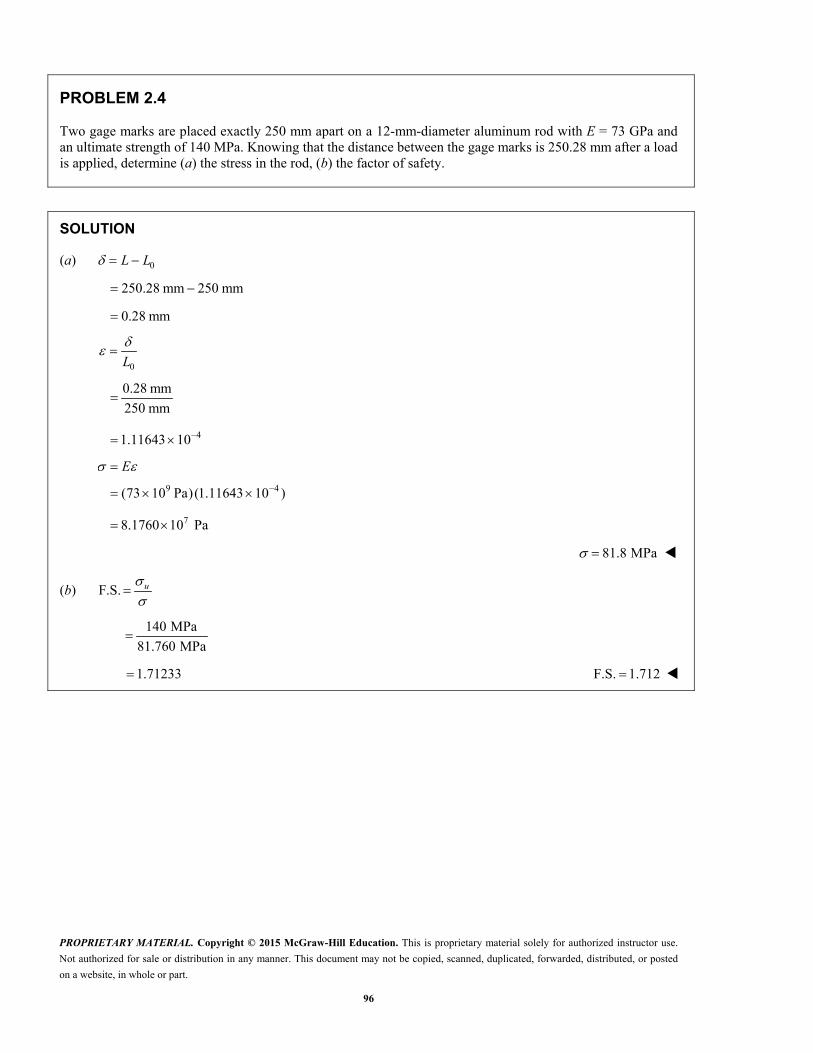
PROBLEM 2.4
Two gage marks are placed exactly 250 mm apart on a 12-mm-diameter aluminum rod with E = 73 GPa and an ultimate strength of 140 MPa. Knowing that the distance between the gage marks is 250.28 mm after a load is applied, determine (a) the stress in the rod, (b) the factor of safety.
SOLUTION
(a) 0L L
250.28 mm 250 mm
0.28 mm
0
L
0.28 mm
250 mm
41.11643 10
E
9 4(73 10 Pa)(1.11643 10 )
78.1760 10 Pa
81.8 MPa
(b) F.S. u
140 MPa
81.760 MPa
1.71233 F.S. 1.712

PROPRIETARY MATERIAL. Copyright © 2015 McGraw-Hill Education. This is proprietary material solely for authorized instructor use.
Not authorized for sale or distribution in any manner. This document may not be copied, scanned, duplicated, forwarded, distributed, or posted
on a website, in whole or part.
97
PROBLEM 2.5
An aluminum pipe must not stretch more than 0.05 in. when it is subjected to a tensile load. Knowing that 610.1 10E psi and that the maximum allowable normal stress is 14 ksi, determine (a) the maximum
allowable length of the pipe, (b) the required area of the pipe if the tensile load is 127.5 kips.
SOLUTION
(a) PL
AE
Thus, 6
3
(10.1 10 ) (0.05)
14 10
EA EL
P
36.1 in.L
(b) P
A
Thus, 3
3
127.5 10
14 10
PA
29.11 inA
PROPRIETARY MATERIAL. Copyright © 2015 McGraw-Hill Education. This is proprietary material solely for authorized instructor use.
Not authorized for sale or distribution in any manner. This document may not be copied, scanned, duplicated, forwarded, distributed, or posted
on a website, in whole or part.
98
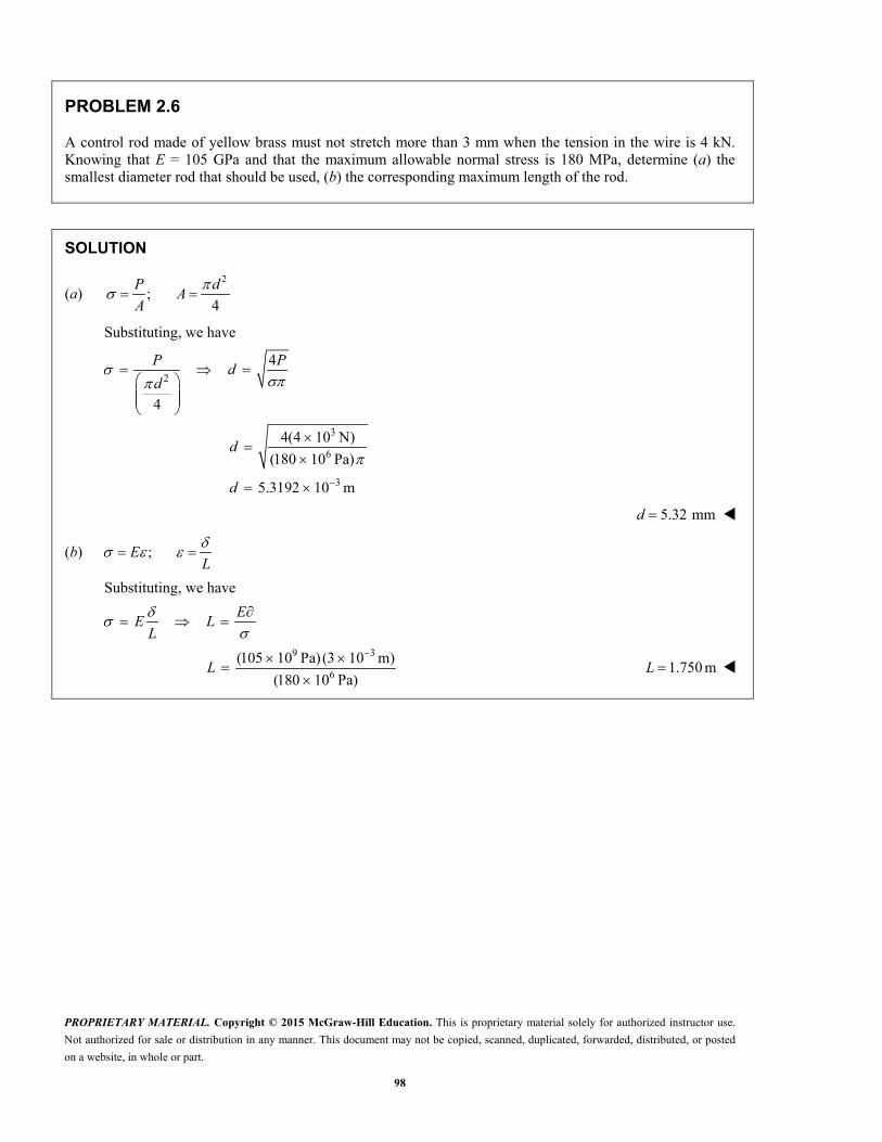
PROBLEM 2.6
A control rod made of yellow brass must not stretch more than 3 mm when the tension in the wire is 4 kN. Knowing that E = 105 GPa and that the maximum allowable normal stress is 180 MPa, determine (a) the smallest diameter rod that should be used, (b) the corresponding maximum length of the rod.
SOLUTION
(a) 2
;4
P d
AA
Substituting, we have
2
3
6
3
4
4
4(4 10 N)
(180 10 Pa)
5.3192 10 m
P Pd
d
d
d
5.32 mmd
(b) ; EL
Substituting, we have
E
E LL
9 3
6
(105 10 Pa) (3 10 m)
(180 10 Pa)
L 1.750 mL

PROPRIETARY MATERIAL. Copyright © 2015 McGraw-Hill Education. This is proprietary material solely for authorized instructor use.
Not authorized for sale or distribution in any manner. This document may not be copied, scanned, duplicated, forwarded, distributed, or posted
on a website, in whole or part.
99
PROBLEM 2.7
A steel control rod is 5.5 ft long and must not stretch more than 0.04 in. when a 2-kip tensile load is applied to it. Knowing that 629 10 psi,E determine (a) the smallest diameter rod that should be used, (b) the corresponding normal stress caused by the load.
SOLUTION
(a) 6
(2000 lb) (5.5 12 in.)0.04 in.
(29 10 psi):
PL
AE A
2 210.113793 in
4A d
0.38063 in.d 0.381 in.d
(b) 2
2000 lb17575.8 psi
0.113793 in
P
A 17.58 ksi

PROPRIETARY MATERIAL. Copyright © 2015 McGraw-Hill Education. This is proprietary material solely for authorized instructor use.
Not authorized for sale or distribution in any manner. This document may not be copied, scanned, duplicated, forwarded, distributed, or posted
on a website, in whole or part.
100
PROBLEM 2.8
A cast-iron tube is used to support a compressive load. Knowing that 610 10 E psi and that the maximum allowable change in length is 0.025%, determine (a) the maximum normal stress in the tube, (b) the minimum wall thickness for a load of 1600 lb if the outside diameter of the tube is 2.0 in.
SOLUTION
(a) 0.00025100L
; EL
EL
6(10 10 psi)(0.00025)
32.50 10 psi
2.50 ksi
(b) 23
1600 lb; 0.64 in
2.50 10 psi
P P
AA
2 2
4
o iA d d
2 2 4
i o
Ad d
2
2 2 24(0.64 in )(2.0 in.) 3.1851 in
id
1.78469 in.id
1 1
( ) (2.0 in. 1.78469 in.)2 2
o it d d
0.107655 in.t
0.1077t
PROPRIETARY MATERIAL. Copyright © 2015 McGraw-Hill Education. This is proprietary material solely for authorized instructor use.
Not authorized for sale or distribution in any manner. This document may not be copied, scanned, duplicated, forwarded, distributed, or posted
on a website, in whole or part.
101
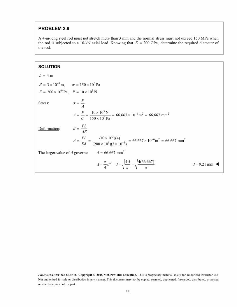
PROBLEM 2.9
A 4-m-long steel rod must not stretch more than 3 mm and the normal stress must not exceed 150 MPa when the rod is subjected to a 10-kN axial load. Knowing that 200 GPa,E determine the required diameter of the rod.
SOLUTION
4 mL
3 6
9 3
3 10 m, 150 10 Pa
200 10 Pa, 10 10 NE P
Stress:
36 2 2
6
10 10 N66.667 10 m 66.667 mm
150 10 Pa
P
A
PA
Deformation:
36 2 2
9 3
(10 10 )(4)66.667 10 m 66.667 mm
(200 10 )(3 10 )
PL
AE
PLA
E
The larger value of A governs: 266.667 mmA
2 4 4(66.667)
4
AA d d
9.21 mmd

PROPRIETARY MATERIAL. Copyright © 2015 McGraw-Hill Education. This is proprietary material solely for authorized instructor use.
Not authorized for sale or distribution in any manner. This document may not be copied, scanned, duplicated, forwarded, distributed, or posted
on a website, in whole or part.
102
PROBLEM 2.10
A nylon thread is to be subjected to a 10-N tension. Knowing that 3.2E GPa, that the maximum allowable normal stress is 40 MPa, and that the length of the thread must not increase by more than 1%, determine the required diameter of the thread.
SOLUTION
Stress criterion:
6
9 26
92 6
40 MPa 40 10 Pa 10 N
10 N: 250 10 m
40 10 Pa
250 10: 2 2 564.19 10 m
4
P
P PA
A
AA d d
0.564 mmd
Elongation criterion:
1% 0.01
:
LPL
AE
99 2
96 2
/ 10 N/3.2 10 Pa312.5 10 m
/ 0.01
312.5 102 2 630.78 10 m
P EA
L
Ad
0.631 mmd
The required diameter is the larger value: 0.631 mmd

PROPRIETARY MATERIAL. Copyright © 2015 McGraw-Hill Education. This is proprietary material solely for authorized instructor use.
Not authorized for sale or distribution in any manner. This document may not be copied, scanned, duplicated, forwarded, distributed, or posted
on a website, in whole or part.
103
PROBLEM 2.11
A block of 10-in. length and 1.8 × 1.6-in. cross section is to support a centric compressive load P. The material to be used is a bronze for which E 14 × 106 psi. Determine the largest load that can be applied, knowing that the normal stress must not exceed 18 ksi and that the decrease in length of the block should be at most 0.12% of its original length.
SOLUTION
Considering allowable stress, 318 ksi or 18 10 psi
Cross-sectional area: 2(1.8 in.)(1.6 in.) 2.880 in A
3 2
4
(18 10 psi)(2.880 in )
5.1840 10 lb
or 51.840 kips
PP A
A
Considering allowable deformation, 0.12% or 0.0012 in.L
2 6
4
(2.880 in )(14 10 psi)(0.0012 in.)
4.8384 10 lb
or 48.384 kips
PLP AE
AE L
P
The smaller value for P resulting from the required deformation criteria governs.
48.4 kips

PROPRIETARY MATERIAL. Copyright © 2015 McGraw-Hill Education. This is proprietary material solely for authorized instructor use.
Not authorized for sale or distribution in any manner. This document may not be copied, scanned, duplicated, forwarded, distributed, or posted
on a website, in whole or part.
104
PROBLEM 2.12
A square yellow-brass bar must not stretch more than 2.5 mm when it is subjected to a tensile load. Knowing that 105E GPa and that the allowable tensile strength is 180 MPa, determine (a) the maximum allowable length of the bar, (b) the required dimensions of the cross section if the tensile load is 40 kN.
SOLUTION
6 3
9 3
180 10 Pa 40 10 N
105 10 Pa 2.5 10 m
P
E
(a)
9 3
6
(105 10 )(2.5 10 )1.45833 m
180 10
PL L
AE E
EL
1.458 mL
(b)
36 2 2
6
40 10222.22 10 m 222.22 mm
180 10
P
A
PA
2 222.22A a a A 14.91 mma

PROPRIETARY MATERIAL. Copyright © 2015 McGraw-Hill Education. This is proprietary material solely for authorized instructor use.
Not authorized for sale or distribution in any manner. This document may not be copied, scanned, duplicated, forwarded, distributed, or posted
on a website, in whole or part.
105
72 in.
54 in.
72 in.
B
A
C
D
P � 130 kips
PROBLEM 2.13
Rod BD is made of steel 6( 29 10 psi)E and is used to brace the axially compressed member ABC. The maximum force that can be developed in member BD is 0.02P. If the stress must not exceed 18 ksi and the maximum change in length of BD must not exceed 0.001 times the length of ABC, determine the smallest-diameter rod that can be used for member BD.
SOLUTION
30.02 (0.02)(130) 2.6 kips 2.6 10 lb BDF P
Considering stress, 318 ksi 18 10 psi
22.60.14444 in
18 BD BDF F
AA
Considering deformation, (0.001)(144) 0.144 in.
3
26
(2.6 10 )(54)0.03362 in
(29 10 )(0.144)
BD BD BD BDF L F LA
AE E
Larger area governs. 20.14444 inA
2 4 (4)(0.14444)
4
A
A d d 0.429 in.d
PROPRIETARY MATERIAL. Copyright © 2015 McGraw-Hill Education. This is proprietary material solely for authorized instructor use.
Not authorized for sale or distribution in any manner. This document may not be copied, scanned, duplicated, forwarded, distributed, or posted
on a website, in whole or part.
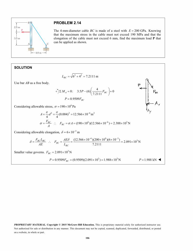
106
3.5 m
4.0 m
2.5 m
B
A C
P
PROBLEM 2.14
The 4-mm-diameter cable BC is made of a steel with 200 GPa.E Knowing that the maximum stress in the cable must not exceed 190 MPa and that the elongation of the cable must not exceed 6 mm, find the maximum load P that can be applied as shown.
SOLUTION
2 26 4 7.2111 m BCL
Use bar AB as a free body.
4
0: 3.5 (6) 07.2111
0.9509
A BC
BC
M P F
P F
Considering allowable stress, 6190 10 Pa
2 2 6 2
6 6 3
(0.004) 12.566 10 m4 4
(190 10 )(12.566 10 ) 2.388 10 N
BCBC
A d
FF A
A
Considering allowable elongation, 36 10 m
6 9 3
3(12.566 10 )(200 10 )(6 10 )2.091 10 N
7.2111BC BC
BCBC
F L AEF
AE L
Smaller value governs. 32.091 10 NBCF
3 30.9509 (0.9509)(2.091 10 ) 1.988 10 NBCP F 1.988 kNP

PROPRIETARY MATERIAL. Copyright © 2015 McGraw-Hill Education. This is proprietary material solely for authorized instructor use.
Not authorized for sale or distribution in any manner. This document may not be copied, scanned, duplicated, forwarded, distributed, or posted
on a website, in whole or part.
107
P
1.25-in. diameter
4 ft3 ft
d
A
BC
PROBLEM 2.15
A single axial load of magnitude P = 15 kips is applied at end C of the steel rod ABC. Knowing that E = 30 × 106 psi, determine the diameter d of portion BC for which the deflection of point C will be 0.05 in.
SOLUTION
iC
i i AB BC
PL PL PL
A E AE AE
4 ft 48 in.; 3 ft 36 in.AB BCL L
2 2
2(1.25 in.)1.22718 in
4 4 AB
dA
Substituting, we have
3
6 2
15 10 lb 48 in. 36 in.0.05 in.
30 10 psi 1.22718 in
BCA
20.59127 inBCA
2
4BCd
A
4
BCAor d
24(0.59127 in )
d
0.86766 in.d
0.868 in.d
PROPRIETARY MATERIAL. Copyright © 2015 McGraw-Hill Education. This is proprietary material solely for authorized instructor use.
Not authorized for sale or distribution in any manner. This document may not be copied, scanned, duplicated, forwarded, distributed, or posted
on a website, in whole or part.
108
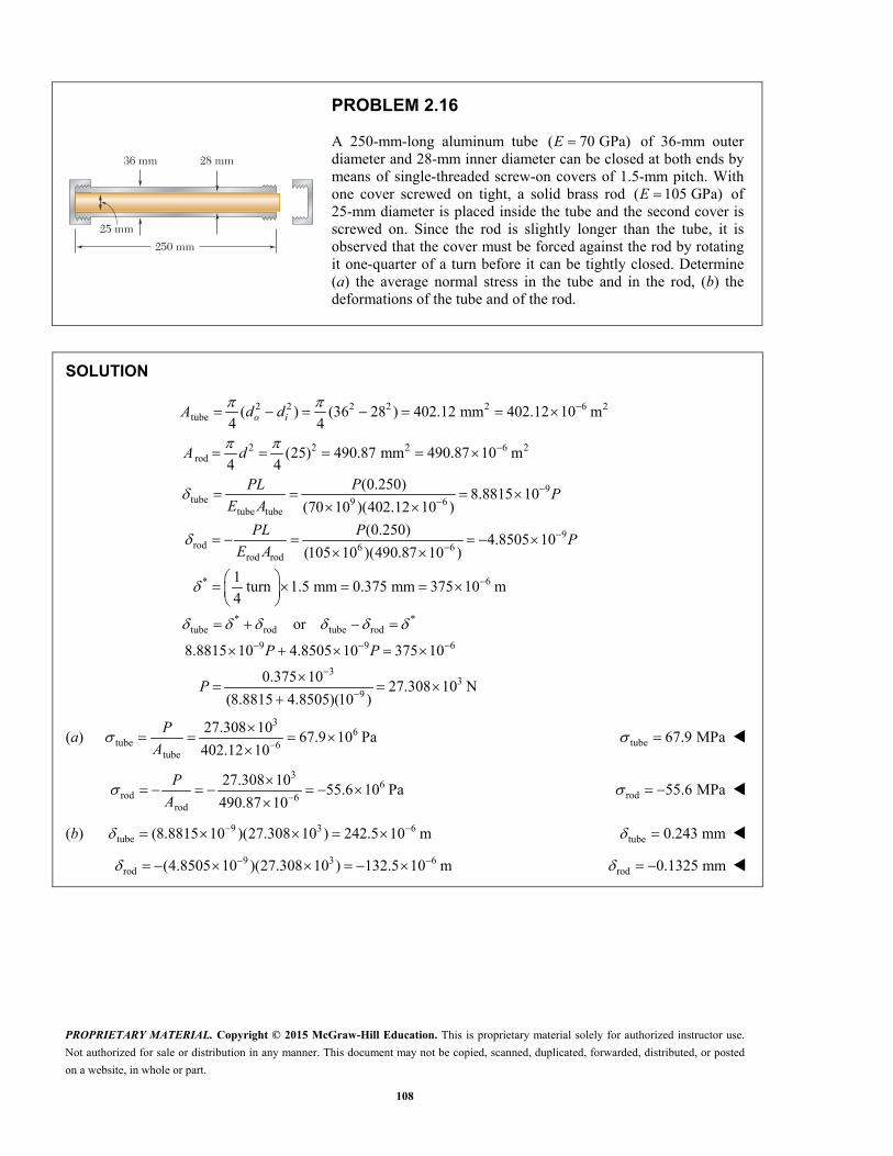
36 mm 28 mm
25 mm
250 mm
PROBLEM 2.16
A 250-mm-long aluminum tube ( 70 GPa)E of 36-mm outer diameter and 28-mm inner diameter can be closed at both ends by means of single-threaded screw-on covers of 1.5-mm pitch. With one cover screwed on tight, a solid brass rod ( 105 GPa)E of 25-mm diameter is placed inside the tube and the second cover is screwed on. Since the rod is slightly longer than the tube, it is observed that the cover must be forced against the rod by rotating it one-quarter of a turn before it can be tightly closed. Determine (a) the average normal stress in the tube and in the rod, (b) the deformations of the tube and of the rod.
SOLUTION
2 2 2 2 2 6 2tube
2 2 2 6 2rod
9tube 9 6
tube tube
rod 6rod rod
( ) (36 28 ) 402.12 mm 402.12 10 m4 4
(25) 490.87 mm 490.87 10 m4 4
(0.250)8.8815 10
(70 10 )(402.12 10 )
(0.250)
(105 10 )(490.87 1
o iA d d
A d
PL PP
E A
PL P
E A9
6
* 6
* *tube rod tube rod
9 9 6
33
9
4.8505 100 )
1turn 1.5 mm 0.375 mm 375 10 m
4
or
8.8815 10 4.8505 10 375 10
0.375 1027.308 10 N
(8.8815 4.8505)(10 )
P
P P
P
(a) 3
6tube 6
tube
27.308 1067.9 10 Pa
402.12 10
P
A tube 67.9 MPa
3
6rod 6
rod
27.308 1055.6 10 Pa
490.87 10
P
A rod 55.6 MPa
(b) 9 3 6tube (8.8815 10 )(27.308 10 ) 242.5 10 m tube 0.243 mm
9 3 6rod (4.8505 10 )(27.308 10 ) 132.5 10 m rod 0.1325 mm

PROPRIETARY MATERIAL. Copyright © 2015 McGraw-Hill Education. This is proprietary material solely for authorized instructor use.
Not authorized for sale or distribution in any manner. This document may not be copied, scanned, duplicated, forwarded, distributed, or posted
on a website, in whole or part.
109
P 5 350 lbA B C D
1 in. 1 in.
1.6 in. 2 in.
0.4 in.
1.6 in.
P 5 350 lb
PROBLEM 2.17
The specimen shown has been cut from a 14 -in.-thick sheet
of vinyl (E = 0.45 × 10⁶ psi) and is subjected to a 350-lb tensile load. Determine (a) the total deformation of the specimen, (b) the deformation of its central portion BC.
SOLUTION
36
(350 lb)(1.6 in.)4.9778 10 in.
(0.45 10 psi)(1 in.)(0.25 in.)
AB
ABAB
PL
EA
36
(350 lb)(2 in.)15.5556 10 in.
(0.45 10 psi)(0.4 in.)(0.25 in.)
BC
BCBC
PL
EA
34.9778 10 in. CD AB
(a) Total deformation:
AB BC CD
325.511 10 in.
325.5 10 in.
(b) Deformation of portion BC :
315.56 10 in.BC

PROPRIETARY MATERIAL. Copyright © 2015 McGraw-Hill Education. This is proprietary material solely for authorized instructor use.
Not authorized for sale or distribution in any manner. This document may not be copied, scanned, duplicated, forwarded, distributed, or posted
on a website, in whole or part.
110
375 mm
1 mm
C
D A
B
P
PROBLEM 2.18
The brass tube ( 105 GPa)AB E has a cross-sectional area of 140 mm2 and is fitted with a plug at A. The tube is attached at B to a rigid plate that is itself attached at C to the bottom of an aluminum cylinder ( 72 GPa)E with a cross-sectional area of 250 mm2. The cylinder is then hung from a support at D. In order to close the cylinder, the plug must move down through 1 mm. Determine the force P that must be applied to the cylinder.
SOLUTION
Shortening of brass tube AB:
2 6 2
9
99 6
375 1 376 mm 0.376 m 140 mm 140 10 m
105 10 Pa
(0.376)25.578 10
(105 10 )(140 10 )
AB AB
AB
ABAB
AB AB
L A
E
PL PP
E A
Lengthening of aluminum cylinder CD:
2 6 2 9
99 6
0.375 m 250 mm 250 10 m 72 10 Pa
(0.375)20.833 10
(72 10 )(250 10 )
CD CD CD
CDCD
CD CD
L A E
PL PP
E A
Total deflection: A AB CD where 0.001 mA
9 90.001 (25.578 10 20.833 10 ) P
321.547 10 NP 21.5 kNP

PROPRIETARY MATERIAL. Copyright © 2015 McGraw-Hill Education. This is proprietary material solely for authorized instructor use.
Not authorized for sale or distribution in any manner. This document may not be copied, scanned, duplicated, forwarded, distributed, or posted
on a website, in whole or part.
111
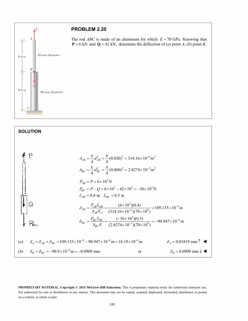
0.4 m
0.5 m
P
Q
20-mm diameter
60-mm diameter
A
B
C
PROBLEM 2.19
Both portions of the rod ABC are made of an aluminum for which 70 GPa.E Knowing that the magnitude of P is 4 kN, determine (a) the value of Q so that the deflection at A is zero, (b) the corresponding deflection of B.
SOLUTION
(a) 2 2 6 2(0.020) 314.16 10 m4 4AB ABA d
2 2 3 2(0.060) 2.8274 10 m4 4BC BCA d
Force in member AB is P tension.
Elongation:
3
69 6
(4 10 )(0.4)72.756 10 m
(70 10 )(314.16 10 )
AB
ABAB
PL
EA
Force in member BC is Q P compression.
Shortening:
99 3
( ) ( )(0.5)2.5263 10 ( )
(70 10 )(2.8274 10 )
BC
BCBC
Q P L Q PQ P
EA
For zero deflection at A, BC AB
9 6 32.5263 10 ( ) 72.756 10 28.8 10 N Q P Q P
3 3 328.3 10 4 10 32.8 10 NQ 32.8 kNQ
(b) 672.756 10 mAB BC B 0.0728 mm AB
PROPRIETARY MATERIAL. Copyright © 2015 McGraw-Hill Education. This is proprietary material solely for authorized instructor use.
Not authorized for sale or distribution in any manner. This document may not be copied, scanned, duplicated, forwarded, distributed, or posted
on a website, in whole or part.
112
0.4 m
0.5 m
P
Q
20-mm diameter
60-mm diameter
A
B
C
PROBLEM 2.20
The rod ABC is made of an aluminum for which 70 GPa.E Knowing that 6 kNP and 42 kN,Q determine the deflection of (a) point A, (b) point B.
SOLUTION
2 2 6 2
2 2 3 2
(0.020) 314.16 10 m4 4
(0.060) 2.8274 10 m4 4
AB AB
BC BC
A d
A d
3
3 3 3
6 10 N
6 10 42 10 36 10 N
0.4 m 0.5 m
AB
BC
AB BC
P P
P P Q
L L
36
6 9
36
3 9
(6 10 )(0.4)109.135 10 m
(314.16 10 )(70 10 )
( 36 10 )(0.5)90.947 10 m
(2.8274 10 )(70 10 )
AB ABAB
AB A
BC BCBC
BC
P L
A E
P L
A E
(a) 6 6 6109.135 10 90.947 10 m 18.19 10 mA AB BC 0.01819 mmA
(b) 690.9 10 m 0.0909 mmB BC or 0.0909 mm B
PROPRIETARY MATERIAL. Copyright © 2015 McGraw-Hill Education. This is proprietary material solely for authorized instructor use.
Not authorized for sale or distribution in any manner. This document may not be copied, scanned, duplicated, forwarded, distributed, or posted
on a website, in whole or part.
113
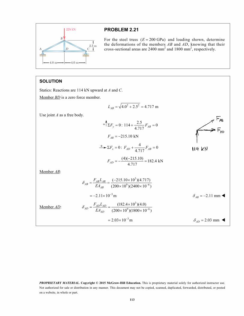
4.0 m 4.0 m
2.5 mD CA
B
228 kN
PROBLEM 2.21
For the steel truss ( 200 GPa)E and loading shown, determine the deformations of the members AB and AD, knowing that their cross-sectional areas are 2400 mm2 and 1800 mm2, respectively.
SOLUTION
Statics: Reactions are 114 kN upward at A and C.
Member BD is a zero force member.
2 24.0 2.5 4.717 m ABL
Use joint A as a free body.
2.5
0 : 114 04.717y ABF F
215.10 kNABF
4
0 : 04.717x AD ABF F F
(4)( 215.10)
182.4 kN4.717ADF
Member AB:
3
9 6
( 215.10 10 )(4.717)
(200 10 )(2400 10 )AB AB
ABAB
F L
EA
32.11 10 m 2.11 mm AB
Member AD: 3
9 6
(182.4 10 )(4.0)
(200 10 )(1800 10 )AD AD
ADAD
F L
EA
32.03 10 m 2.03 mm AD
PROPRIETARY MATERIAL. Copyright © 2015 McGraw-Hill Education. This is proprietary material solely for authorized instructor use.
Not authorized for sale or distribution in any manner. This document may not be copied, scanned, duplicated, forwarded, distributed, or posted
on a website, in whole or part.
114
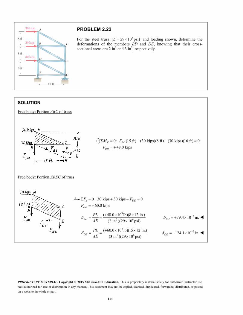
15 ft
8 ft
8 ft
8 ft
D
C
F
E
G
A
B
30 kips
30 kips
30 kips
PROBLEM 2.22
For the steel truss 6( 29 10 psi)E and loading shown, determine the deformations of the members BD and DE, knowing that their cross-sectional areas are 2 in2 and 3 in2, respectively.
SOLUTION
Free body: Portion ABC of truss
0 : (15 ft) (30 kips)(8 ft) (30 kips)(16 ft) 0
48.0 kipsE BD
BD
M F
F
Free body: Portion ABEC of truss
0 : 30 kips 30 kips 0
60.0 kips
x DE
DE
F F
F
3
2 6
( 48.0 10 lb)(8 12 in.)
(2 in )(29 10 psi)
BD
PL
AE 379.4 10 in. BD
3
2 6
( 60.0 10 lb)(15 12 in.)
(3 in )(29 10 psi)
DE
PL
AE 3124.1 10 in. DE

PROPRIETARY MATERIAL. Copyright © 2015 McGraw-Hill Education. This is proprietary material solely for authorized instructor use.
Not authorized for sale or distribution in any manner. This document may not be copied, scanned, duplicated, forwarded, distributed, or posted
on a website, in whole or part.
115
6 ft 6 ft
5 ft
C
D EA
B
28 kips 54 kips
PROBLEM 2.23
Members AB and BC are made of steel 6( 29 10 psi)E with cross-sectional areas of 0.80 in2 and 0.64 in2, respectively. For the loading shown, determine the elongation of (a) member AB, (b) member BC.
SOLUTION
(a) 2 26 5 7.810 ft 93.72 in. ABL
Use joint A as a free body.
3
50: 28 0
7.810
43.74 kip 43.74 10 lb
y AB
AB
F F
F
3
6
(43.74 10 )(93.72)
(29 10 )(0.80)
AB ABAB
AB
F L
EA 0.1767 in. AB
(b) Use joint B as a free body.
3
60: 0
7.810(6)(43.74)
33.60 kip 33.60 10 lb7.810
x BC AB
BC
F F F
F
3
6
(33.60 10 )(72)
(29 10 )(0.64)
BC BCBC
BC
F L
EA 0.1304 in.BC
PROPRIETARY MATERIAL. Copyright © 2015 McGraw-Hill Education. This is proprietary material solely for authorized instructor use.
Not authorized for sale or distribution in any manner. This document may not be copied, scanned, duplicated, forwarded, distributed, or posted
on a website, in whole or part.
116
6 m
5 m
C
DA
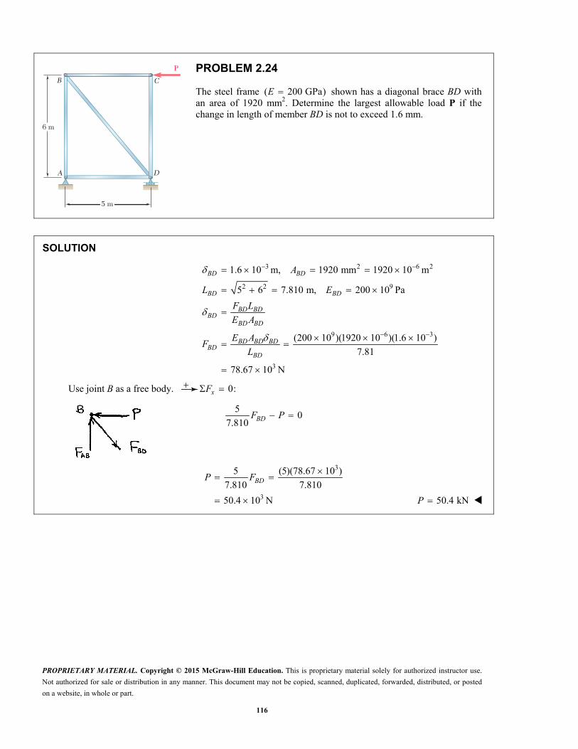
B
P
PROBLEM 2.24
The steel frame ( 200 GPa)E shown has a diagonal brace BD with an area of 1920 mm2. Determine the largest allowable load P if the change in length of member BD is not to exceed 1.6 mm.
SOLUTION
3 2 6 2
2 2 9
9 6 3
3
1.6 10 m, 1920 mm 1920 10 m
5 6 7.810 m, 200 10 Pa
(200 10 )(1920 10 )(1.6 10 )
7.81
78.67 10 N
BD BD
BD BD
BD BDBD
BD BD
BD BD BDBD
BD
A
L E
F L
E A
E AF
L
Use joint B as a free body. 0:xF
50
7.810 BDF P
3
3
5 (5)(78.67 10 )
7.810 7.810
50.4 10 N
BDP F
50.4 kNP
PROPRIETARY MATERIAL. Copyright © 2015 McGraw-Hill Education. This is proprietary material solely for authorized instructor use.
Not authorized for sale or distribution in any manner. This document may not be copied, scanned, duplicated, forwarded, distributed, or posted
on a website, in whole or part.
117
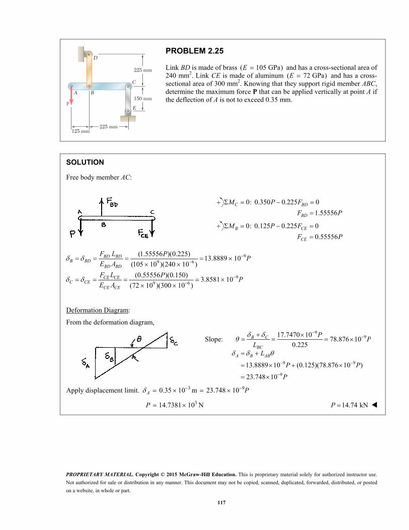
P
125 mm225 mm
225 mm
150 mm
E
D
A B
C
PROBLEM 2.25
Link BD is made of brass ( 105 GPa)E and has a cross-sectional area of 240 mm2. Link CE is made of aluminum ( 72 GPa)E and has a cross-sectional area of 300 mm2. Knowing that they support rigid member ABC, determine the maximum force P that can be applied vertically at point A if the deflection of A is not to exceed 0.35 mm.
SOLUTION
Free body member AC:
0: 0.350 0.225 0
1.55556
C BD
BD
M P F
F P
0: 0.125 0.225 0
0.55556
B CE
CE
M P F
F P
99 6
99 6
(1.55556 )(0.225)13.8889 10
(105 10 )(240 10 )
(0.55556 )(0.150)3.8581 10
(72 10 )(300 10 )
BD BDB BD
BD BD
CE CEC CE
CE CE
F L PP
E A
F L PP
E A
Deformation Diagram:
From the deformation diagram,
Slope: 9
917.7470 1078.876 10
0.225
B C
BC
PP
L
9 9
9
13.8889 10 (0.125)(78.876 10 )
23.748 10
A B ABL
P P
P
Apply displacement limit. 3 90.35 10 m 23.748 10 A P
314.7381 10 NP 14.74 kNP

PROPRIETARY MATERIAL. Copyright © 2015 McGraw-Hill Education. This is proprietary material solely for authorized instructor use.
Not authorized for sale or distribution in any manner. This document may not be copied, scanned, duplicated, forwarded, distributed, or posted
on a website, in whole or part.
118
260 mm
18 kN 18 kN240 mm
180 mmC
D
E
F
A
B
PROBLEM 2.26
Members ABC and DEF are joined with steel links (E 200 GPa). Each of the links is made of a pair of 25 × 35-mm plates. Determine the change in length of (a) member BE, (b) member CF.
SOLUTION
Free body diagram of Member ABC:
0: BM
(0.26 m)(18 kN) (0.18 m) 0 CFF
26.0 kNCFF
0: xF
18 kN 26.0 kN 0 BEF
44.0 kN BEF
Area for link made of two plates:
3 22(0.025 m)(0.035 m) 1.750 10 m A
(a) 3
9 3 2
6
( 44.0 10 N)(0.240 m)
(200 10 Pa)(1.75 10 m )
30.171 10 m
BEBE
F L
EA
0.0302 mmBE
(b) 3
9 3 2
6
(26.0 10 N)(0.240 m)
(200 10 Pa)(1.75 10 m )
17.8286 10 m
BFCF
F L
EA
0.01783 mmCF
PROPRIETARY MATERIAL. Copyright © 2015 McGraw-Hill Education. This is proprietary material solely for authorized instructor use.
Not authorized for sale or distribution in any manner. This document may not be copied, scanned, duplicated, forwarded, distributed, or posted
on a website, in whole or part.
119
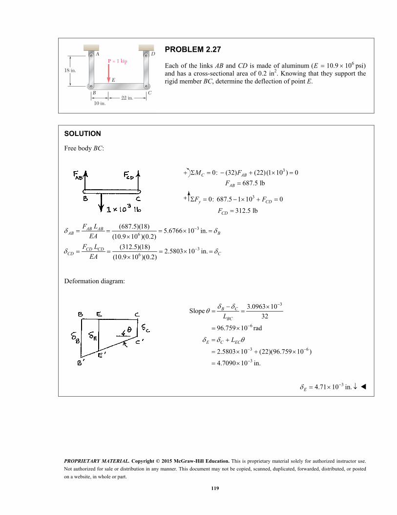
P = 1 kip
10 in.22 in.
18 in.
A
E
D
B C
PROBLEM 2.27
Each of the links AB and CD is made of aluminum 6( 10.9 10 psi) E and has a cross-sectional area of 0.2 in2. Knowing that they support the rigid member BC, determine the deflection of point E.
SOLUTION
Free body BC:
30: (32) (22) (1 10 ) 0
687.5 lb
C AB
AB
M F
F
30: 687.5 1 10 0
312.5 lb
y CD
CD
F F
F
36
36
(687.5)(18)5.6766 10 in.
(10.9 10 )(0.2)
(312.5)(18)2.5803 10 in.
(10.9 10 )(0.2)
AB ABAB B
CD CDCD C
F L
EA
F L
EA
Deformation diagram:
3
6
3.0963 10Slope
32
96.759 10 rad
B C
BCL
3 6
3
2.5803 10 (22)(96.759 10 )
4.7090 10 in.
E C ECL
34.71 10 in.E

PROPRIETARY MATERIAL. Copyright © 2015 McGraw-Hill Education. This is proprietary material solely for authorized instructor use.
Not authorized for sale or distribution in any manner. This document may not be copied, scanned, duplicated, forwarded, distributed, or posted
on a website, in whole or part.
120
12.5 in.
D
CA
x
B50 lb
16 in.4 in.
E116 in.
PROBLEM 2.28
The length of the 332
-in.-diameter steel wire CD has been adjusted so that with no load applied, a gap of 1
16in. exists between the end B of the rigid
beam ACB and a contact point E. Knowing that 629 10 psi,E determine where a 50-lb block should be placed on the beam in order to cause contact between B and E.
SOLUTION
Rigid beam ACB rotates through angle to close gap.
31/163.125 10 rad
20
Point C moves downward.
3 3
3
22 3 2
4 4(3.125 10 ) 12.5 10 in.
12.5 10 in.
36.9029 10 in
4 32
C
CD C
CD
CD CDCD
CD
A dd
F L
EA
6 3 3(29 10 )(6.9029 10 )(12.5 10 )
12.5
200.18 lb
CD CDCD
CD
EAF
L
Free body ACB:
0: 4 (50)(20 ) 0 A CDM F x
(4)(200.18)20 16.0144
503.9856 in.
x
x
For contact, 3.99 in.x

PROPRIETARY MATERIAL. Copyright © 2015 McGraw-Hill Education. This is proprietary material solely for authorized instructor use.
Not authorized for sale or distribution in any manner. This document may not be copied, scanned, duplicated, forwarded, distributed, or posted
on a website, in whole or part.
121
PROBLEM 2.29
A homogeneous cable of length L and uniform cross section is suspended from one end. (a) Denoting by the density (mass per unit volume) of the cable and by E its modulus of elasticity, determine the elongation of the cable due to its own weight. (b) Show that the same elongation would be obtained if the cable were horizontal and if a force equal to half of its weight were applied at each end.
SOLUTION
(a) For element at point identified by coordinate y,
2
00
weight of portion below the point
( )
( ) ( )
( ) 1
2
LL
P
gA L y
Pdy gA L y dy g L yd dy
EA EA E
g L y gdy Ly y
E E
2
2
2
g LL
E
21
2
gL
E
(b) Total weight: W gAL
21 1
2 2
EA EA gL
F gALL L E
1
2F W
PROPRIETARY MATERIAL. Copyright © 2015 McGraw-Hill Education. This is proprietary material solely for authorized instructor use.
Not authorized for sale or distribution in any manner. This document may not be copied, scanned, duplicated, forwarded, distributed, or posted
on a website, in whole or part.
122
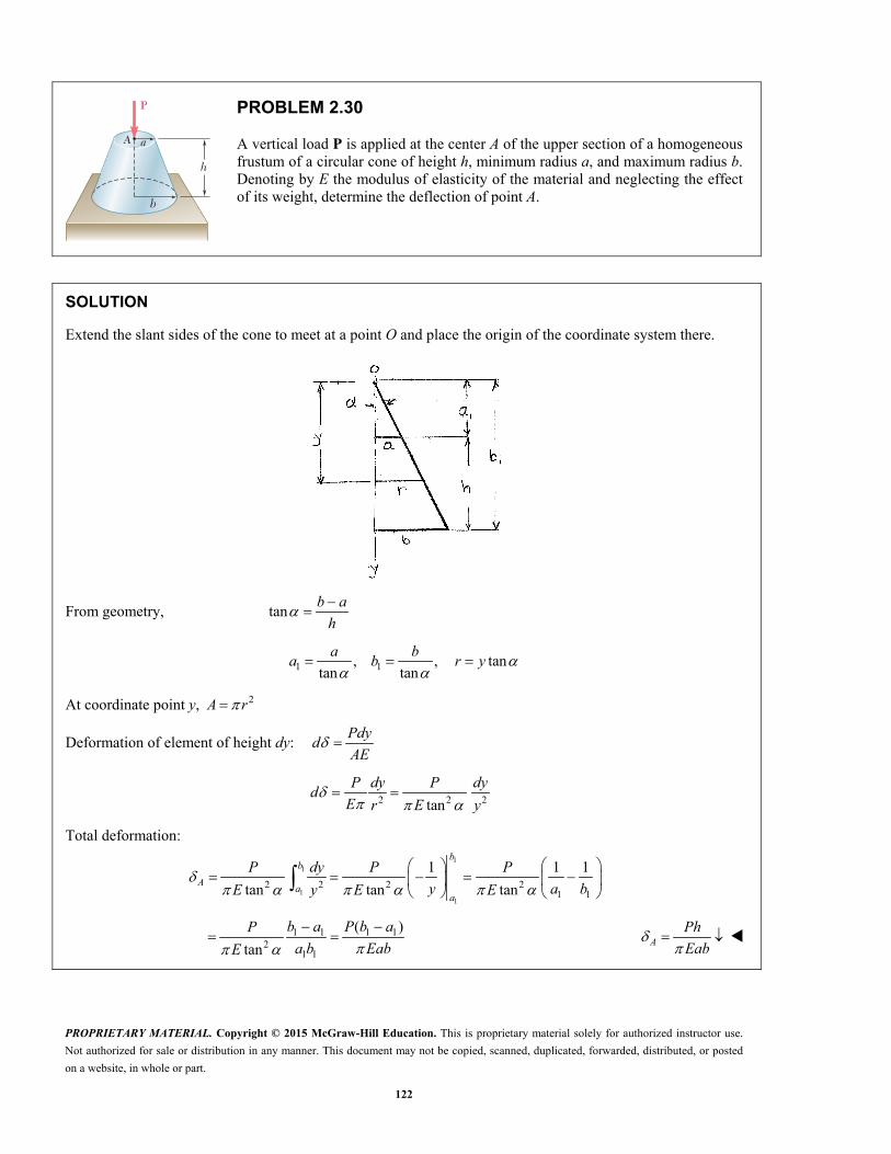
h
A a
b
P
PROBLEM 2.30
A vertical load P is applied at the center A of the upper section of a homogeneous frustum of a circular cone of height h, minimum radius a, and maximum radius b. Denoting by E the modulus of elasticity of the material and neglecting the effect of its weight, determine the deflection of point A.
SOLUTION
Extend the slant sides of the cone to meet at a point O and place the origin of the coordinate system there.
From geometry, tanb a
h
1 1, , tantan tan
a b
a b r y
At coordinate point y, 2A r
Deformation of element of height dy: Pdy
dAE
2 2 2tan
P dy P dy
dE r E y
Total deformation:
1
1
11
2 2 2 21 1
1 1 1
tan tan tan
bb
Aa
a
P dy P P
y a bE y E E
1 1 1 12
1 1
( )
tan
b a P b aP
a b EabE
APh
Eab

PROPRIETARY MATERIAL. Copyright © 2015 McGraw-Hill Education. This is proprietary material solely for authorized instructor use.
Not authorized for sale or distribution in any manner. This document may not be copied, scanned, duplicated, forwarded, distributed, or posted
on a website, in whole or part.
123
PROBLEM 2.31
Denoting by the “engineering strain” in a tensile specimen, show that the true strain is ln (1 ). t
SOLUTION
0
0 0 0
ln ln ln 1 ln (1 )
t
LL
L L L
Thus, ln (1 ) t
PROPRIETARY MATERIAL. Copyright © 2015 McGraw-Hill Education. This is proprietary material solely for authorized instructor use.
Not authorized for sale or distribution in any manner. This document may not be copied, scanned, duplicated, forwarded, distributed, or posted
on a website, in whole or part.
124
PROBLEM 2.32
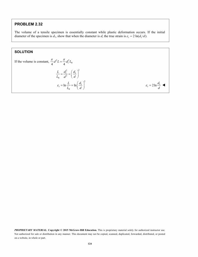
The volume of a tensile specimen is essentially constant while plastic deformation occurs. If the initial diameter of the specimen is d1, show that when the diameter is d, the true strain is 12 ln( / ). t d d
SOLUTION
If the volume is constant, 2 21 04 4
d L d L
221 12
0
21
0
ln ln
t
d dL
L dd
dL
L d 12ln t
d
d
PROPRIETARY MATERIAL. Copyright © 2015 McGraw-Hill Education. This is proprietary material solely for authorized instructor use.
Not authorized for sale or distribution in any manner. This document may not be copied, scanned, duplicated, forwarded, distributed, or posted
on a website, in whole or part.
125
40 mm
60 mm
Aluminum plates(E = 70 GPa)
300 mm
Brass core(E = 105 GPa) Rigid
end plateP
h
h
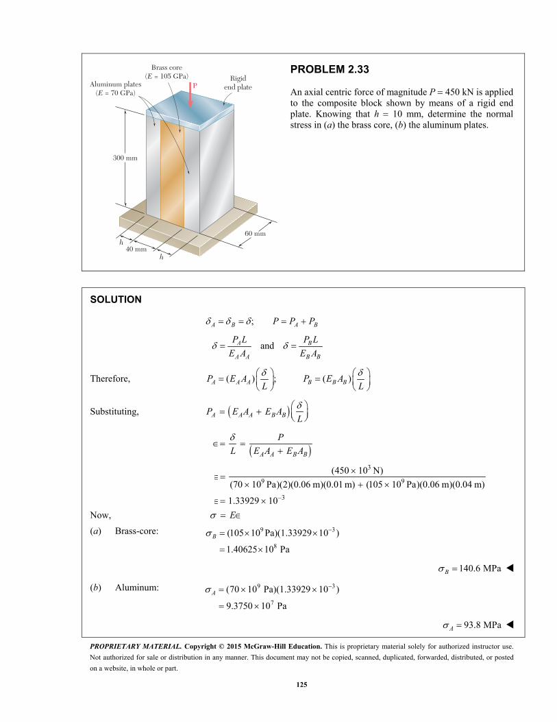
PROBLEM 2.33
An axial centric force of magnitude P 450 kN is applied to the composite block shown by means of a rigid end plate. Knowing that h 10 mm, determine the normal stress in (a) the brass core, (b) the aluminum plates.
SOLUTION
;A B A BP P P
and A B
A A B B
P L P L
E A E A
Therefore, ( ) ; ( )
A A A B B BP E A P E AL L
Substituting, A A A B BP E A E AL
A A B B
P
L E A E A
3
9 9
3
(450 10 N)
(70 10 Pa)(2)(0.06 m)(0.01 m) (105 10 Pa)(0.06 m)(0.04 m)
1.33929 10
Now, E
(a) Brass-core:
9 3
8
(105 10 Pa)(1.33929 10 )
1.40625 10 Pa
B
140.6 MPaB
(b) Aluminum:
9 3
7
(70 10 Pa)(1.33929 10 )
9.3750 10 Pa
A
93.8 MPaA

PROPRIETARY MATERIAL. Copyright © 2015 McGraw-Hill Education. This is proprietary material solely for authorized instructor use.
Not authorized for sale or distribution in any manner. This document may not be copied, scanned, duplicated, forwarded, distributed, or posted
on a website, in whole or part.
126
40 mm
60 mm
Aluminum plates(E = 70 GPa)
300 mm
Brass core(E = 105 GPa) Rigid
end plateP
h
h
PROBLEM 2.34
For the composite block shown in Prob. 2.33, determine (a) the value of h if the portion of the load carried by the aluminum plates is half the portion of the load carried by the brass core, (b) the total load if the stress in the brass is 80 MPa.
PROBLEM 2.33. An axial centric force of magnitude P 450 kN is applied to the composite block shown by means of a rigid end plate. Knowing that h 10 mm, determine the normal stress in (a) the brass core, (b) the aluminum plates.
SOLUTION
;a b a bP P P
anda b
a a b b
P L P L
E A E A
Therefore,
( ) ; ( )a a a b b bP E A P E AL L
(a) 1
2a bP P
1
( ) ( )2a a b bE A E A
L L
1
2b
a ba
EA A
E
1 105 GPa
(40 mm)(60 mm)2 70 GPa
aA
21800 mmaA
21800 mm 2(60 mm)( ) h
15.00 mmh
(b) 1
and2
bb b b b a b
b
PP A P P
A
a bP P P

PROPRIETARY MATERIAL. Copyright © 2015 McGraw-Hill Education. This is proprietary material solely for authorized instructor use.
Not authorized for sale or distribution in any manner. This document may not be copied, scanned, duplicated, forwarded, distributed, or posted
on a website, in whole or part.
127
PROBLEM 2.34 (Continued)
1
( )2 b b b bP A A
( )1.5b bP A
6(80 10 Pa)(0.04 m)(0.06 m)(1.5) P
52.880 10 N P
288 kNP
PROPRIETARY MATERIAL. Copyright © 2015 McGraw-Hill Education. This is proprietary material solely for authorized instructor use.
Not authorized for sale or distribution in any manner. This document may not be copied, scanned, duplicated, forwarded, distributed, or posted
on a website, in whole or part.
128
4.5 ft
18 in.
P
PROBLEM 2.35
The 4.5-ft concrete post is reinforced with six steel bars, each with a 181 -in. diameter.
Knowing that Es 29 × 106 psi and Ec = 4.2 × 10⁶ psi, determine the normal stresses in the steel and in the concrete when a 350-kip axial centric force P is applied to the post.
SOLUTION
Let portion of axial force carried by concrete.
portion carried by the six steel rods.
c
s
P
P
( )
c c cc
c c
s s ss
s s
c s c c s s
c c s s
P L E AP
E A L
P L E AP
E A L
P P P E A E AL
P
L E A E A
2 2 2
2 2 2
2
34
6 2 6 2
66 (1.125 in.) 5.9641 in
4 4
(18 in.) 5.9641 in4 4
248.51 in
4.5 ft 54 in.
350 10 lb2.8767 10
(4.2 10 psi)(248.51 in ) (29 10 psi)(5.9641 in )
s s
c c s
A d
A d A
L
6 4(29 10 psi)( 2.8767 10 ) 8.3424 10 psis sE s 8.34 ksi
6 4 3(4.2 10 psi)( 2.8767 10 ) 1.20821 10 psi c cE c 1.208 ksi
PROPRIETARY MATERIAL. Copyright © 2015 McGraw-Hill Education. This is proprietary material solely for authorized instructor use.
Not authorized for sale or distribution in any manner. This document may not be copied, scanned, duplicated, forwarded, distributed, or posted
on a website, in whole or part.
129
4.5 ft
18 in.
P
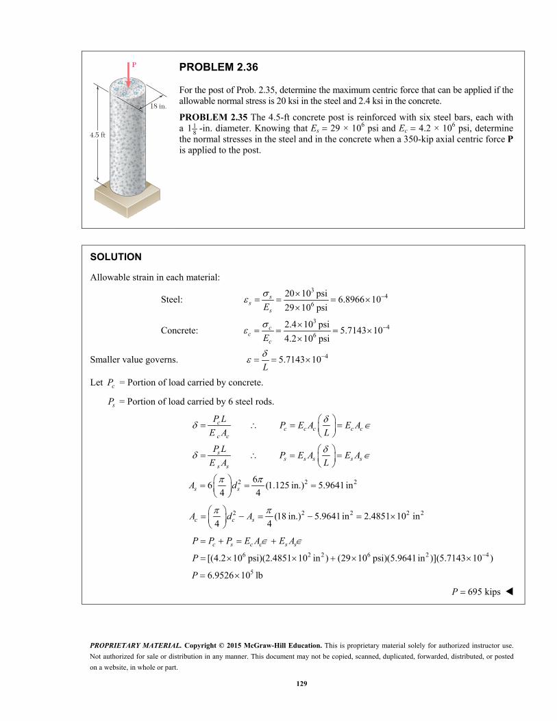
PROBLEM 2.36
For the post of Prob. 2.35, determine the maximum centric force that can be applied if the allowable normal stress is 20 ksi in the steel and 2.4 ksi in the concrete.
PROBLEM 2.35 The 4.5-ft concrete post is reinforced with six steel bars, each with a 1
81 -in. diameter. Knowing that Es 29 × 106 psi and Ec 4.2 × 10⁶ psi, determine the normal stresses in the steel and in the concrete when a 350-kip axial centric force P is applied to the post.
SOLUTION
Allowable strain in each material:
Steel: 3
46
20 10 psi6.8966 10
29 10 psi
ss
sE
Concrete: 3
46
2.4 10 psi5.7143 10
4.2 10 psi
cc
cE
Smaller value governs. 45.7143 10 L
Let cP = Portion of load carried by concrete.
sP = Portion of load carried by 6 steel rods.
c
c c c c cc c
P LP E A E A
E A L
s
s s s s ss s
P LP E A E A
E A L
2 2 266 (1.125 in.) 5.9641 in
4 4
s sA d
2 2 2 2 2(18 in.) 5.9641 in 2.4851 10 in4 4
c c sA d A
c s c c s sP P P E A E A
6 2 2 6 2 4[(4.2 10 psi)(2.4851 10 in ) (29 10 psi)(5.9641 in )](5.7143 10 ) P
56.9526 10 lb P
695 kipsP
PROPRIETARY MATERIAL. Copyright © 2015 McGraw-Hill Education. This is proprietary material solely for authorized instructor use.
Not authorized for sale or distribution in any manner. This document may not be copied, scanned, duplicated, forwarded, distributed, or posted
on a website, in whole or part.
130
300 mm
60 mm
Aluminium shellE � 70 GPa
Brass coreE � 105 GPa
25 mm
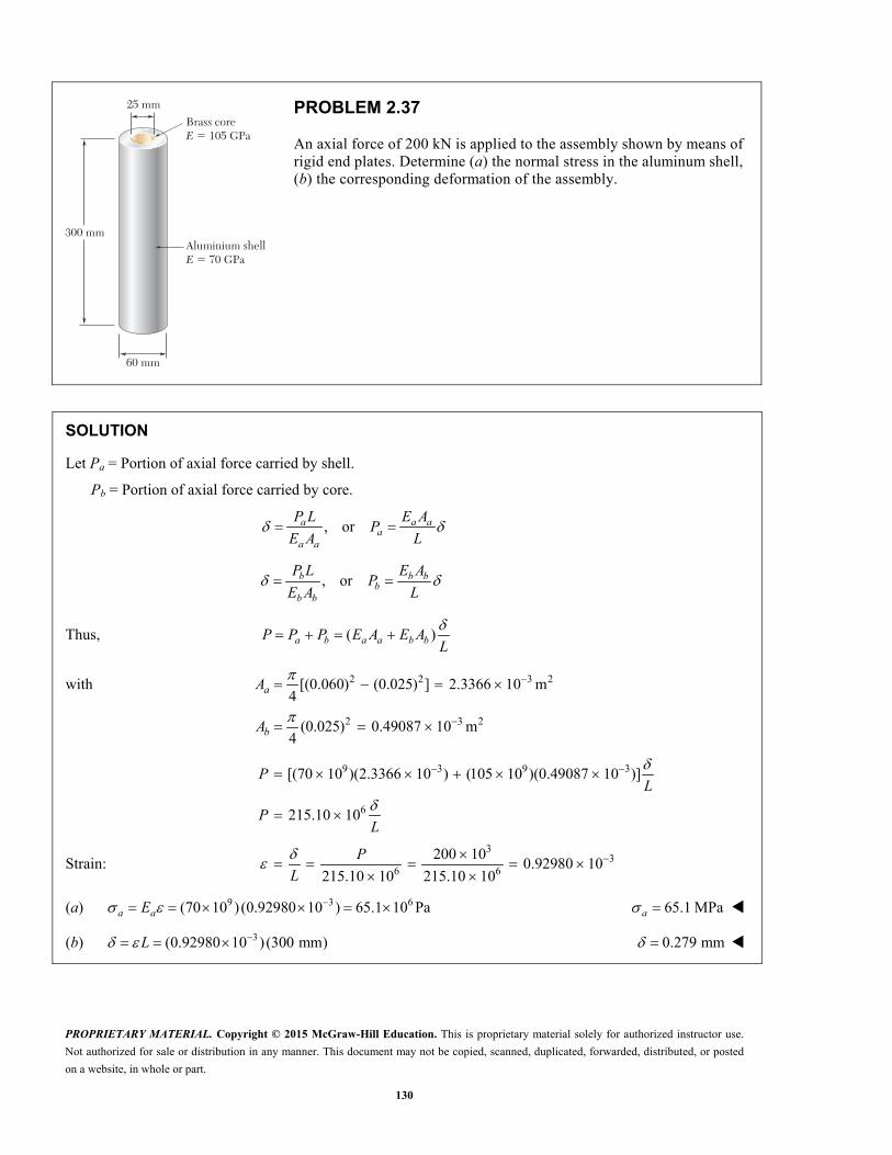
PROBLEM 2.37
An axial force of 200 kN is applied to the assembly shown by means of rigid end plates. Determine (a) the normal stress in the aluminum shell, (b) the corresponding deformation of the assembly.
SOLUTION
Let Pa = Portion of axial force carried by shell.
Pb = Portion of axial force carried by core.
, ora a aa
a a
P L E AP
E A L
, orb b bb
b b
P L E AP
E A L
Thus, ( )a b a a b bP P P E A E AL
with 2 2 3 2
2 3 2
[(0.060) (0.025) ] 2.3366 10 m4
(0.025) 0.49087 10 m4
a
b
A
A
9 3 9 3
6
[(70 10 )(2.3366 10 ) (105 10 )(0.49087 10 )]
215.10 10
PL
PL
Strain: 3
36 6
200 100.92980 10
215.10 10 215.10 10
P
L
(a) 9 3 6(70 10 ) (0.92980 10 ) 65.1 10 Pa a aE 65.1 MPaa
(b) 3(0.92980 10 )(300 mm)L 0.279 mm
PROPRIETARY MATERIAL. Copyright © 2015 McGraw-Hill Education. This is proprietary material solely for authorized instructor use.
Not authorized for sale or distribution in any manner. This document may not be copied, scanned, duplicated, forwarded, distributed, or posted
on a website, in whole or part.
131
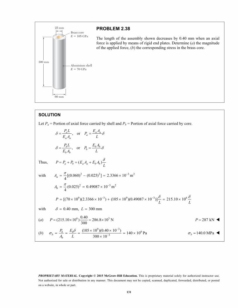
300 mm
60 mm
Aluminium shellE � 70 GPa
Brass coreE � 105 GPa
25 mm
PROBLEM 2.38
The length of the assembly shown decreases by 0.40 mm when an axial force is applied by means of rigid end plates. Determine (a) the magnitude of the applied force, (b) the corresponding stress in the brass core.
SOLUTION
Let Pa = Portion of axial force carried by shell and Pb = Portion of axial force carried by core.
, ora a aa
a a
P L E AP
E A L
, orb b bb
b b
P L E AP
E A L
Thus, ( )a b a a b bP P P E A E AL
with 2 2 3 2
2 3 2
[(0.060) (0.025) ] 2.3366 10 m4
(0.025) 0.49087 10 m4
a
b
A
A
9 3 9 3 6[(70 10 )(2.3366 10 ) (105 10 )(0.49087 10 )] 215.10 10 PL L
with 0.40 mm, 300 mmL
(a) 6 30.40(215.10 10 ) 286.8 10 N
300P 287 kNP
(b) 9 3
63
(105 10 )(0.40 10 )140 10 Pa
300 10
b bb
b
P E
A L 140.0 MPab

PROPRIETARY MATERIAL. Copyright © 2015 McGraw-Hill Education. This is proprietary material solely for authorized instructor use.
Not authorized for sale or distribution in any manner. This document may not be copied, scanned, duplicated, forwarded, distributed, or posted
on a website, in whole or part.
132
B
C
15 in.
25 in.1.25 in.
A
6 kips6 kips
2 in.
PROBLEM 2.39
A polystyrene rod consisting of two cylindrical portions AB and BC is restrained at both ends and supports two 6-kip loads as shown. Knowing that 60.45 10 psi, E determine (a) the reactions at A and C, (b) the normal stress in each portion of the rod.
SOLUTION
(a) We express that the elongation of the rod is zero.
2 2
4 4
0BC BCAB AB
AB BC
P LP L
d E d E
But AB A BC CP R P R
Substituting and simplifying,
2 20C BCA AB
AB BC
R LR L
d d
2 2
25 2
15 1.25
BCABC A A
BC AB
dLR R R
L d
4.2667C AR R (1)
From the free body diagram, 12 kipsA CR R (2)
Substituting (1) into (2), 5.2667 12AR
2.2785 kipsAR 2.28 kipsAR
From (1), 4.2667(2.2785) 9.7217 kipsCR
9.72 kipsCR
(b) 2
4
2.2785
(1.25)
AB A
ABAB AB
P R
A A 1.857 ksiAB
2
4
9.7217
(2)BC C
BCBC BC
P R
A A
3.09 ksiBC

PROPRIETARY MATERIAL. Copyright © 2015 McGraw-Hill Education. This is proprietary material solely for authorized instructor use.
Not authorized for sale or distribution in any manner. This document may not be copied, scanned, duplicated, forwarded, distributed, or posted
on a website, in whole or part.
133
A
B
C
D
E
F
20 in.
16 in.
P
PROBLEM 2.40
Three steel rods (E = 29 × 106 psi) support an 8.5-kip load P. Each of the rods AB and CD has a 0.32-in2 cross-sectional area and rod EF has a 1-in2 cross-sectional area. Neglecting the deformation of bar BED, determine (a) the change in length of rod EF, (b) the stress in each rod.
SOLUTION
Use member BED as a free body.
By symmetry, or by 0 : EM
CD ABP P
0: 0 y AB CD EFF P P P P
2 AB EFP P P
CD CDAB AB EF EFAB CD EF
AB CD EF
P LP L P L
EA EA EA
Since and ,AB CD AB CD AB CDL L A A
Since points A, C, and F are fixed, , ,B AB D CD E EF
Since member BED is rigid, E B C
0.32 16
0.2561 20
AB AB EF EF AB EFAB EF EF EF
AB EF EF AB
P L P L A LP P P P
EA EA A L
2 2(0.256 ) 1.512
8.55.6217 kips
1.512 1.5120.256(5.6217) 1.43916 kips
AB EF EF EF EF
EF
AB CD
P P P P P P
PP
P P
(a) 3
(5.6217)(16)0.0031016 in.
(29 10 )(1)
EF EF
EFEF
P L
EA 0.00310 in.EF
(b)1.43916
4.4974 ksi0.32
ABAB CD
AB
P
A 4.50 ksiAB CD
5.6217
5.6217 ksi1
EFEF
EF
P
A 5.62 ksiEF

PROPRIETARY MATERIAL. Copyright © 2015 McGraw-Hill Education. This is proprietary material solely for authorized instructor use.
Not authorized for sale or distribution in any manner. This document may not be copied, scanned, duplicated, forwarded, distributed, or posted
on a website, in whole or part.
134
180
40-mm diam. 30-mm diam.
120100
Dimensions in mm
100
A C D E
60 kN 40 kN
BrassSteel B
PROBLEM 2.41
Two cylindrical rods, one of steel and the other of brass, are joined at C and restrained by rigid supports at A and E. For the loading shown and knowing that 200 GPasE and 105 GPa,bE determine (a) the reactions at A and E, (b) the deflection of point C.
SOLUTION
A to C: 9
2 3 2 3 2
6
200 10 Pa
(40) 1.25664 10 mm 1.25664 10 m4
251.327 10 N
E
A
EA
C to E: 9
2 2 6 2
6
105 10 Pa
(30) 706.86 mm 706.86 10 m4
74.220 10 N
E
A
EA
A to B:
6
12
180 mm 0.180 m
(0.180)
251.327 10
716.20 10
A
AAB
A
P R
L
RPL
EA
R
B to C: 3
3
6
12 6
60 10
120 mm 0.120 m
( 60 10 )(0.120)
251.327 10
447.47 10 26.848 10
A
ABC
A
P R
L
RPL
EA
R
PROPRIETARY MATERIAL. Copyright © 2015 McGraw-Hill Education. This is proprietary material solely for authorized instructor use.
Not authorized for sale or distribution in any manner. This document may not be copied, scanned, duplicated, forwarded, distributed, or posted
on a website, in whole or part.
135
PROBLEM 2.41 (Continued)
C to D: 3
3
6
9 6
60 10
100 mm 0.100 m
( 60 10 )(0.100)
74.220 10
1.34735 10 80.841 10
A
ABC
A
P R
L
RPL
EA
R
D to E: 3
3
6
9 6
100 10
100 mm 0.100 m
( 100 10 )(0.100)
74.220 10
1.34735 10 134.735 10
A
ADE
A
P R
L
RPL
EA
R
A to E: 9 63.85837 10 242.424 10
AE AB BC CD DE
AR
Since point E cannot move relative to A, 0AE
(a) 9 6 33.85837 10 242.424 10 0 62.831 10 N A AR R 62.8 kN AR
3 3 3 3100 10 62.8 10 100 10 37.2 10 N E AR R 37.2 kN ER
(b) 9 61.16367 10 26.848 10 C AB BC AR
9 3 6
6
(1.16369 10 )(62.831 10 ) 26.848 10
46.3 10 m
46.3 mC

PROPRIETARY MATERIAL. Copyright © 2015 McGraw-Hill Education. This is proprietary material solely for authorized instructor use.
Not authorized for sale or distribution in any manner. This document may not be copied, scanned, duplicated, forwarded, distributed, or posted
on a website, in whole or part.
136
180
40-mm diam. 30-mm diam.
120100
Dimensions in mm
100
A C D E
60 kN 40 kN
BrassSteel B
PROBLEM 2.42
Solve Prob. 2.41, assuming that rod AC is made of brass and rod CE is made of steel.
PROBLEM 2.41 Two cylindrical rods, one of steel and the other of brass, are joined at C and restrained by rigid supports at A and E. For the loading shown and knowing that 200sE GPa and 105 GPa,bE determine (a) the reactions at A and E, (b) the deflection of point C.
SOLUTION
A to C: 9
2 3 2 3 2
6
105 10 Pa
(40) 1.25664 10 mm 1.25664 10 m4
131.947 10 N
E
A
EA
C to E: 9
2 2 6 2
6
200 10 Pa
(30) 706.86 mm 706.86 10 m4
141.372 10 N
E
A
EA
A to B:
6
9
180 mm 0.180 m
(0.180)
131.947 10
1.36418 10
A
AAB
A
P R
L
RPL
EA
R
B to C: 3
3
6
12 6
60 10
120 mm 0.120 m
( 60 10 )(0.120)
131.947 10
909.456 10 54.567 10
A
ABC
A
P R
L
RPL
EA
R
C to D: 3
3
6
12 6
60 10
100 mm 0.100 m
( 60 10 )(0.100)
141.372 10
707.354 10 42.441 10
A
ACD
A
P R
L
RPL
EA
R
PROPRIETARY MATERIAL. Copyright © 2015 McGraw-Hill Education. This is proprietary material solely for authorized instructor use.
Not authorized for sale or distribution in any manner. This document may not be copied, scanned, duplicated, forwarded, distributed, or posted
on a website, in whole or part.
137
PROBLEM 2.42 (Continued)
D to E: 3
3
6
12 6
100 10
100 mm 0.100 m
( 100 10 )(0.100)
141.372 10
707.354 10 70.735 10
A
ADE
A
P R
L
RPL
EA
R
A to E: 9 63.68834 10 167.743 10
AE AB BC CD DE
AR
Since point E cannot move relative to A, 0AE
(a) 9 6 33.68834 10 167.743 10 0 45.479 10 N A AR R 45.5 kN AR
3 3 3 3100 10 45.479 10 100 10 54.521 10E AR R 54.5 kN ER
(b) 9 62.27364 10 54.567 10 C AB BC AR
9 3 6
6
(2.27364 10 )(45.479 10 ) 54.567 10
48.8 10 m
48.8 mC

PROPRIETARY MATERIAL. Copyright © 2015 McGraw-Hill Education. This is proprietary material solely for authorized instructor use.
Not authorized for sale or distribution in any manner. This document may not be copied, scanned, duplicated, forwarded, distributed, or posted
on a website, in whole or part.
138
AB
D E
F
C
550 mm
75 mm 100 mm
225 mm2 kN
PROBLEM 2.43
Each of the rods BD and CE is made of brass (E 105 GPa) and has a cross-sectional area of 200 mm2. Determine the deflection of end A of the rigid member ABC caused by the 2-kN load.
SOLUTION
Let be the rotation of member ABC as shown.
Then 1 10.625 0.075 0.1 A B C
But BD BDB
P L
AE
9 6(105 10 )(200 10 )(0.075 )
0.225B
BDBD
EAP
L
67 10
Free body ABC:
CE CEC
P L
AE
9 6(105 10 )(200 10 )(0.1 )
0.225C
CECE
EAP
L
69.3333 10
From free body of member ABC:
0 : (0.625)(2000) 0.075 0.1 0 F BD CEP PM
or 6 6(0.625)(2000) 0.075(7 10 ) 0.1(9.3333 10 ) 0
30.85714 10 rad
and 3 30.625 0.625(0.85714 10 ) 0.53571 10 m A
0.536 mm A

PROPRIETARY MATERIAL. Copyright © 2015 McGraw-Hill Education. This is proprietary material solely for authorized instructor use.
Not authorized for sale or distribution in any manner. This document may not be copied, scanned, duplicated, forwarded, distributed, or posted
on a website, in whole or part.
139
P
F
C
D
BA
E
12 in.12 in.12 in.
8 in.
10 in.
PROBLEM 2.44
The rigid bar AD is supported by two steel wires of 116 -in. diameter
(E 29 × 106 psi) and a pin and bracket at A. Knowing that the wires were initially taut, determine (a) the additional tension in each wire when a 220-lb load P is applied at D, (b) the corresponding deflection of point D.
SOLUTION
Let be the notation of bar ABCD.
Then 12B
24C
BE BEB
P L
AE
26 1
(29 10 ) (12 )4 610
BE
BEBE
EAP
L
3106.765 10
CF CF
CP L
EA
26 1
(29 10 ) (24 )4 16
18
CE
CFCF
EAP
L
3118.628 10
Using free body ABCD,
0 : 12 24 36 0 A BE CFP P PM
3 6(12)(106.765 10 ) (24)(118.628 10 ) (36)(220) 0
6
3
4.1283 10 (36)(220)
1.91847 10 rad
(a) 3 3(106.765 10 )(1.91847 10 ) 204.83 lb BEP 205 lbBEP
3 3(118.628 10 )(1.91847 10 ) 227.58 lbCFP 228 lbCFP
(b) 3 336 (36)(1.91847 10 ) 69.1 10 in. D
0.0691 in.

PROPRIETARY MATERIAL. Copyright © 2015 McGraw-Hill Education. This is proprietary material solely for authorized instructor use.
Not authorized for sale or distribution in any manner. This document may not be copied, scanned, duplicated, forwarded, distributed, or posted
on a website, in whole or part.
140
P
AD B
L L
C
L34
PROBLEM 2.45
The rigid bar ABC is suspended from three wires of the same material. The cross-sectional area of the wire at B is equal to half of the cross-sectional area of the wires at A and C. Determine the tension in each wire caused by the load P shown.
SOLUTION
30: 2 0
4 A C BLP LP LPM
3 1
8 2C BP P P
50: 2 0
4 C A BLP LP LPM
5 1
8 2A BP P P
Let l be the length of the wires.
5 1
8 2
AA B
P l lP P
EA EA
2
( /2) B
B BP l l
PE A EA
3 1
8 2
CC B
P l lP P
EA EA
From the deformation diagram,
A B B C
or 1
( )2B A c
1 5 1 3 1
( / 2) 2 8 2 8 2B B Bl l
P P P P PE A EA
5 1 1
;2 2 5B BP P P P 0.200BP P
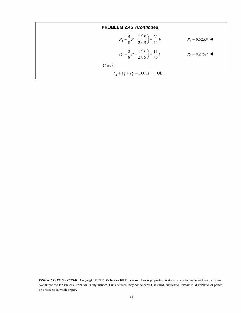
PROPRIETARY MATERIAL. Copyright © 2015 McGraw-Hill Education. This is proprietary material solely for authorized instructor use.
Not authorized for sale or distribution in any manner. This document may not be copied, scanned, duplicated, forwarded, distributed, or posted
on a website, in whole or part.
141
PROBLEM 2.45 (Continued)
5 1 21
8 2 5 40AP
P P P
0.525AP P
3 1 11
8 2 5 40CP
P P P
0.275CP P
Check:
1.000 Ok A B CP P P P
PROPRIETARY MATERIAL. Copyright © 2015 McGraw-Hill Education. This is proprietary material solely for authorized instructor use.
Not authorized for sale or distribution in any manner. This document may not be copied, scanned, duplicated, forwarded, distributed, or posted
on a website, in whole or part.
142
D
P
B C
E
15 in.
8 in.8 in.8 in.
F
A
8 in.
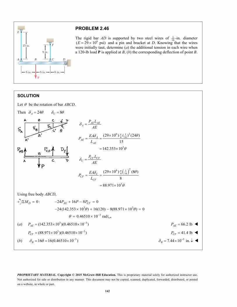
PROBLEM 2.46
The rigid bar AD is supported by two steel wires of 116 -in. diameter
6( 29 10 psi) E and a pin and bracket at D. Knowing that the wires were initially taut, determine (a) the additional tension in each wire when a 120-lb load P is applied at B, (b) the corresponding deflection of point B.
SOLUTION
Let be the rotation of bar ABCD.
Then 24 8A C
AE AEA
P L
AE
6 214 16
3
(29 10 ) ( ) (24 )
15
142.353 10
AAE
AE
EAP
L
CF CFC
P L
AE
26 14 16
3
(29 10 ) (8 )
8
88.971 10
CCF
CF
EAP
L
Using free body ABCD,
0 :DM 3 3
3
24 16 8 0
24(142.353 10 ) 16(120) 8(88.971 10 ) 0
0.46510 10 rad
AE CFP P P
�
(a) 3 3(142.353 10 )(0.46510 10 ) AEP 66.2 lbAEP
3 3(88.971 10 )(0.46510 10 ) CFP 41.4 lbCFP
(b) 316 16(0.46510 10 ) B 37.44 10 in.B

PROPRIETARY MATERIAL. Copyright © 2015 McGraw-Hill Education. This is proprietary material solely for authorized instructor use.
Not authorized for sale or distribution in any manner. This document may not be copied, scanned, duplicated, forwarded, distributed, or posted
on a website, in whole or part.
143
Brass core E � 105 GPa � 20.9 � 10–6/�C
Aluminum shell E � 70 GPa � 23.6 � 10–6/�C
25 mm
60 mm
�
�
PROBLEM 2.47
The aluminum shell is fully bonded to the brass core and the assembly is unstressed at a temperature of 15 C. Considering only axial deformations, determine the stress in the aluminum when the temperature reaches 195 C.
SOLUTION
Brass core:
6
105 GPa
20.9 10 / C
E
Aluminum shell:
6
70 GPa
23.6 10 / C
E
Let L be the length of the assembly.
Free thermal expansion:
195 15 180 CT
Brass core: ( ) ( )T b bL T
Aluminum shell: ( ) ( ) T a aL T
Net expansion of shell with respect to the core: ( )( )a bL T
Let P be the tensile force in the core and the compressive force in the shell.
Brass core: 9
2 2
6 2
105 10 Pa
(25) 490.87 mm4
490.87 10 m
( )
b
b
P bb b
E
A
PL
E A
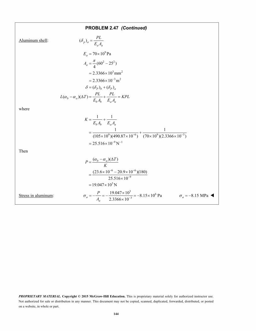
PROPRIETARY MATERIAL. Copyright © 2015 McGraw-Hill Education. This is proprietary material solely for authorized instructor use.
Not authorized for sale or distribution in any manner. This document may not be copied, scanned, duplicated, forwarded, distributed, or posted
on a website, in whole or part.
144
PROBLEM 2.47 (Continued)
Aluminum shell: ( )p aa a
PL
E A
9
2 2
3 2
3 2
70 10 Pa
(60 25 )4
2.3366 10 mm
2.3366 10 m
( ) ( )
( )( )
a
a
P b P a
b ab b a a
E
A
PL PLL T KPL
E A E A
where
9 6 9 3
9 1
1 1
1 1
(105 10 )(490.87 10 ) (70 10 )(2.3366 10 )
25.516 10 N
b b a a
KE A E A
Then
6 6
9
3
( )( )
(23.6 10 20.9 10 )(180)
25.516 10
19.047 10 N
b a TP
K
Stress in aluminum: 3
63
19.047 108.15 10 Pa
2.3366 10
aa
P
A 8.15 MPaa
PROPRIETARY MATERIAL. Copyright © 2015 McGraw-Hill Education. This is proprietary material solely for authorized instructor use.
Not authorized for sale or distribution in any manner. This document may not be copied, scanned, duplicated, forwarded, distributed, or posted
on a website, in whole or part.
145
Brass core E � 105 GPa � 20.9 � 10–6/�C
Aluminum shell E � 70 GPa � 23.6 � 10–6/�C
25 mm
60 mm
�
�
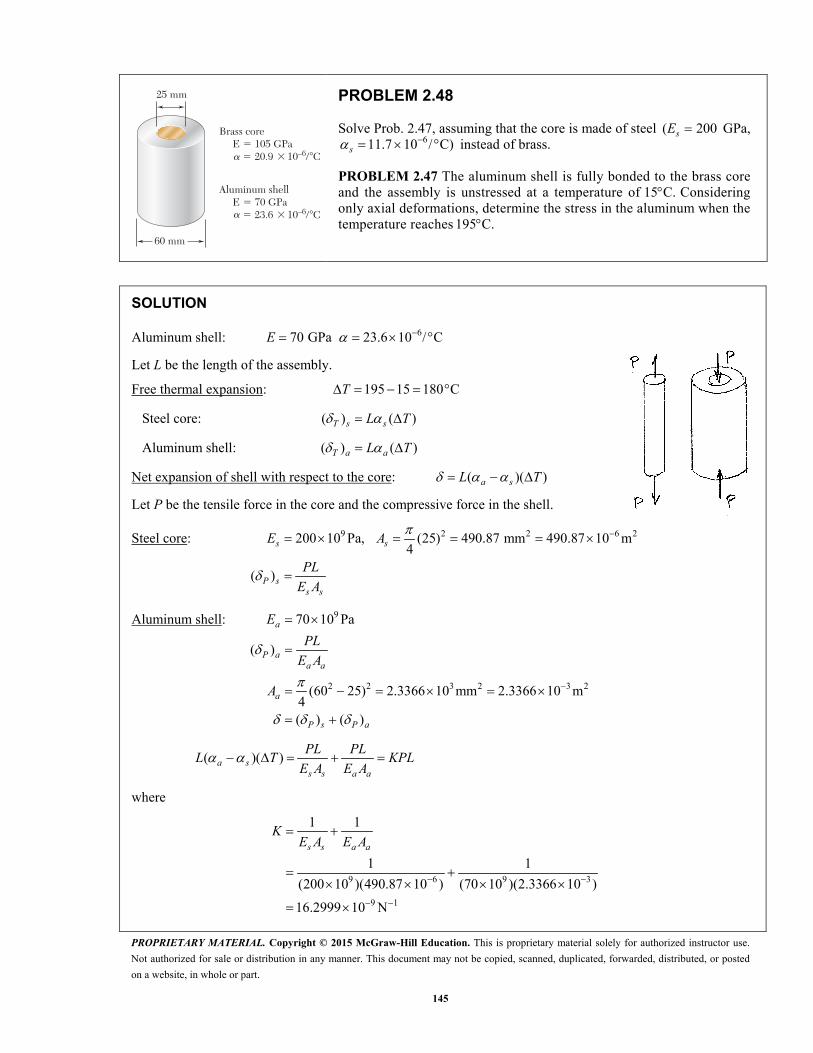
PROBLEM 2.48
Solve Prob. 2.47, assuming that the core is made of steel ( 200sE GPa, 611.7 10 / C)s instead of brass.
PROBLEM 2.47 The aluminum shell is fully bonded to the brass core and the assembly is unstressed at a temperature of 15 C. Considering only axial deformations, determine the stress in the aluminum when the temperature reaches 195 C.
SOLUTION
Aluminum shell: 670 GPa 23.6 10 / C E
Let L be the length of the assembly.
Free thermal expansion: 195 15 180 CT
Steel core: ( ) ( )T s sL T
Aluminum shell: ( ) ( )T a aL T
Net expansion of shell with respect to the core: ( )( )a sL T
Let P be the tensile force in the core and the compressive force in the shell.
Steel core: 9 2 2 6 2200 10 Pa, (25) 490.87 mm 490.87 10 m4
( )
s s
P ss s
E A
PL
E A
Aluminum shell: 9
2 2 3 2 3 2
70 10 Pa
( )
(60 25) 2.3366 10 mm 2.3366 10 m4( ) ( )
a
P aa a
a
P s P a
E
PL
E A
A
( )( ) a ss s a a
PL PLL T KPL
E A E A
where
9 6 9 3
9 1
1 1
1 1
(200 10 )(490.87 10 ) (70 10 )(2.3366 10 )
16.2999 10 N
s s a a
KE A E A

PROPRIETARY MATERIAL. Copyright © 2015 McGraw-Hill Education. This is proprietary material solely for authorized instructor use.
Not authorized for sale or distribution in any manner. This document may not be copied, scanned, duplicated, forwarded, distributed, or posted
on a website, in whole or part.
146
PROBLEM 2.48 (Continued)
Then
6 6
39
( )( ) (23.6 10 11.7 10 )(180)131.412 10 N
16.2999 10a s T
PK
Stress in aluminum: 3
63
131.412 1056.241 10 Pa
2.3366 10
a
a
P
A 56.2 MPaa

PROPRIETARY MATERIAL. Copyright © 2015 McGraw-Hill Education. This is proprietary material solely for authorized instructor use.
Not authorized for sale or distribution in any manner. This document may not be copied, scanned, duplicated, forwarded, distributed, or posted
on a website, in whole or part.
147
12 in.
1 in.1 in.
Steel coreE � 29 � 106 psi
Brass shellE � 15 � 106 psi
in.14
in.14
in.14
in.14
PROBLEM 2.49
The brass shell 6( 11.6 10 / F) b is fully bonded to the steel core 6( 6.5 10 / F). s Determine the largest allowable increase in
temperature if the stress in the steel core is not to exceed 8 ksi.
SOLUTION
Let axial force developed in the steel core.sP
For equilibrium with zero total force, the compressive force in the brass shell is .sP
Strains: ( )
( )
ss s
s s
sb b
b b
PT
E A
PT
E A
Matching: s b
( ) ( )s ss b
s s b b
P PT T
E A E A
1 1
( )( )s b ss s b b
P TE A E A
(1)
2
2
(1.5)(1.5) (1.0)(1.0) 1.25 in
(1.0)(1.0) 1.0 in
b
s
A
A
6
3 3
5.1 10 / F
(8 10 )(1.0) 8 10 lb
b s
s s sP A
9 16 6
1 1 1 187.816 10 lb
(29 10 )(1.0) (15 10 )(1.25)
s s b bE A E A
From (1), 9 3 6(87.816 10 )(8 10 ) (5.1 10 )( ) T
137.8 F T

PROPRIETARY MATERIAL. Copyright © 2015 McGraw-Hill Education. This is proprietary material solely for authorized instructor use.
Not authorized for sale or distribution in any manner. This document may not be copied, scanned, duplicated, forwarded, distributed, or posted
on a website, in whole or part.
148
6 ft
10 in.10 in.
PROBLEM 2.50
The concrete post 6( 3.6 10cE psi and 65.5 10 / F) c is reinforced with six steel bars, each of 7
8 -in. diameter 6( 29 10sE psi and 66.5 10 / F). s Determine the normal stresses induced in the steel and in the concrete by a temperature rise of 65°F.
SOLUTION
2
2 276 6 3.6079 in
4 4 8
sA d
2 2 210 10 3.6079 96.392 in c sA A
Let cP tensile force developed in the concrete.
For equilibrium with zero total force, the compressive force in the six steel rods equals .cP
Strains: ( ) ( )c cs s c c
s s c c
P PT T
E A E A
Matching: c s ( ) ( )c cc s
c c s s
P PT T
E A E A
66 6
3
1 1( )( )
1 1(1.0 10 )(65)
(3.6 10 )(96.392) (29 10 )(3.6079)
5.2254 10 lb
c s cc c s s
c
c
P TE A E A
P
P
35.2254 10
54.210 psi96.392
cc
c
P
A
54.2 psic
35.2254 10
1448.32 psi3.6079
cs
s
P
A
1.448 ksis
PROPRIETARY MATERIAL. Copyright © 2015 McGraw-Hill Education. This is proprietary material solely for authorized instructor use.
Not authorized for sale or distribution in any manner. This document may not be copied, scanned, duplicated, forwarded, distributed, or posted
on a website, in whole or part.
149
B
C
250 mm
300 mm
A
50-mm diameter
30-mm diameter
PROBLEM 2.51
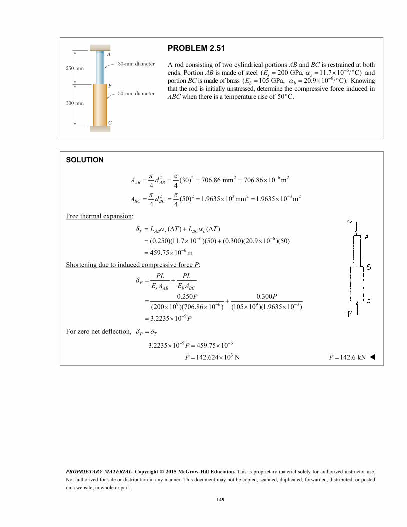
A rod consisting of two cylindrical portions AB and BC is restrained at both ends. Portion AB is made of steel ( 200 GPa,sE 611.7 10 / C)s
and portion BC is made of brass ( 105 GPa,bE 6 20.9 10 / C).b
Knowing that the rod is initially unstressed, determine the compressive force induced in ABC when there is a temperature rise of 50 C.
SOLUTION
2 2 2 6 2
2 2 3 2 3 2
(30) 706.86 mm 706.86 10 m4 4
(50) 1.9635 10 mm 1.9635 10 m4 4
AB AB
BC BC
A d
A d
Free thermal expansion:
6 6
6
( ) ( )
(0.250)(11.7 10 )(50) (0.300)(20.9 10 )(50)
459.75 10 m
T AB s BC bL T L T
Shortening due to induced compressive force P:
9 6 9 3
9
0.250 0.300
(200 10 )(706.86 10 ) (105 10 )(1.9635 10 )
3.2235 10
Ps AB b BC
PL PL
E A E A
P P
P
For zero net deflection, P T
9 6
3
3.2235 10 459.75 10
142.624 10 N
P
P 142.6 kNP

PROPRIETARY MATERIAL. Copyright © 2015 McGraw-Hill Education. This is proprietary material solely for authorized instructor use.
Not authorized for sale or distribution in any manner. This document may not be copied, scanned, duplicated, forwarded, distributed, or posted
on a website, in whole or part.
150
A B C
1 -in. diameter12
24 in. 32 in.
2 -in. diameter14
PROBLEM 2.52
A rod consisting of two cylindrical portions AB and BC is restrained at both ends. Portion AB is made of steel 6( 29 10 psi, sE 66.5 10 / F) s and portion BC is made of aluminum 6( 10.4 10 psi, aE 613.3 10 /°F). a Knowing that the rod is initially unstressed, determine (a) the normal stresses induced in portions AB and BC by a temperature rise of 70°F, (b) the corresponding deflection of point B.
SOLUTION
2 2 2 2(2.25) 3.9761 in (1.5) 1.76715 in4 4
AB BCA A
Free thermal expansion. 70 FT
Total:
6 3
6 3
3
( ) ( ) (24)(6.5 10 )(70) 10.92 10 in.
( ) ( ) (32)(13.3 10 )(70) 29.792 10 in.
( ) ( ) 40.712 10 in.
T AB AB s
T BC BC a
T T AB T BC
L T
L T
Shortening due to induced compressive force P.
96
96
24( ) 208.14 10
(29 10 )(3.9761)
32( ) 1741.18 10
(10.4 10 )(1.76715)
ABP AB
s AB
BCP BC
a BC
PL PP
E A
PL PP
E A
Total: 9( ) ( ) 1949.32 10 P P AB P BC P
For zero net deflection, P T 9 31949.32 10 40.712 10 P 320.885 10 lb P
(a) 3
320.885 105.25 10 psi
3.9761ABAB
P
A
5.25 ksiAB
3
320.885 1011.82 10 psi
1.76715BCBC
P
A
11.82 ksiBC
(b) 9 3 3( ) (208.14 10 )(20.885 10 ) 4.3470 10 in.P AB
3 3( ) ( ) 10.92 10 4.3470 10B T AB P AB 36.57 10 in.B
or
9 3 3( ) (1741.18 10 )(20.885 10 ) 36.365 10 in.P BC
3 3 3( ) ( ) 29.792 10 36.365 10 6.57 10 in.B T BC P BC (checks)

PROPRIETARY MATERIAL. Copyright © 2015 McGraw-Hill Education. This is proprietary material solely for authorized instructor use.
Not authorized for sale or distribution in any manner. This document may not be copied, scanned, duplicated, forwarded, distributed, or posted
on a website, in whole or part.
151
A B C
1 -in. diameter12
24 in. 32 in.
2 -in. diameter14
PROBLEM 2.53
Solve Prob. 2.52, assuming that portion AB of the composite rod is made of aluminum and portion BC is made of steel.
PROBLEM 2.52 A rod consisting of two cylindrical portions AB and BC is restrained at both ends. Portion AB is made of steel 6( 29 10 psi, sE
66.5 10 / F) s and portion BC is made of aluminum 6( 10.4 10 psi, aE 613.3 10 /°F). a Knowing that the rod is initially unstressed, determine
(a) the normal stresses induced in portions AB and BC by a temperature rise of 70°F, (b) the corresponding deflection of point B.
SOLUTION
2 2(2.25) 3.9761 in4
ABA 2 2(1.5) 1.76715 in
4
BCA
Free thermal expansion. 70 FT
6 3
6 3
( ) ( ) (24)(13.3 10 )(70) 22.344 10 in.
( ) ( ) (32)(6.5 10 )(70) 14.56 10 in.
T AB AB a
T BC BC s
L T
L T
Total: 3( ) ( ) 36.904 10 in.T T AB T BC
Shortening due to induced compressive force P.
96
96
24( ) 580.39 10
(10.4 10 )(3.9761)
32( ) 624.42 10
(29 10 )(1.76715)
ABP AB
a AB
BCP BC
s BC
PL PP
E A
PL PP
E A
Total: 9( ) ( ) 1204.81 10 P P AB P BC P
For zero net deflection, P T 9 31204.81 10 36.904 10 P 330.631 10 lbP
(a) 3
330.631 107.70 10 psi
3.9761ABAB
P
A
7.70 ksiAB
3
330.631 1017.33 10 psi
1.76715BCBC
P
A
17.33 ksiBC

PROPRIETARY MATERIAL. Copyright © 2015 McGraw-Hill Education. This is proprietary material solely for authorized instructor use.
Not authorized for sale or distribution in any manner. This document may not be copied, scanned, duplicated, forwarded, distributed, or posted
on a website, in whole or part.
152
PROBLEM 2.53 (Continued)
(b) 9 3 3( ) (580.39 10 )(30.631 10 ) 17.7779 10 in. P AB
3 3( ) ( ) 22.344 10 17.7779 10B T AB P AB 34.57 10 in. B
or 9 3 3( ) (624.42 10 )(30.631 10 ) 19.1266 10 in. P BC
3 3 3( ) ( ) 14.56 10 19.1266 10 4.57 10 in. (checks)B T BC P BC

PROPRIETARY MATERIAL. Copyright © 2015 McGraw-Hill Education. This is proprietary material solely for authorized instructor use.
Not authorized for sale or distribution in any manner. This document may not be copied, scanned, duplicated, forwarded, distributed, or posted
on a website, in whole or part.
153
PROBLEM 2.54
The steel rails of a railroad track (Es 200 GPa, αs 11.7 × 10²–6/C) were laid at a temperature of 6C. Determine the normal stress in the rails when the temperature reaches 48C, assuming that the rails (a) are welded to form a continuous track, (b) are 10 m long with 3-mm gaps between them.
SOLUTION
(a) 6 3( ) (11.7 10 )(48 6)(10) 4.914 10 mT T L
129
(10)50 10
200 10P
PL L
AE E
3 124.914 10 50 10 0T P
698.3 10 Pa 98.3 MPa
(b) 3 12 34.914 10 50 10 3 10T P
3 3
12
6
3 10 4.914 10
50 10
38.3 10 Pa
38.3 MPa

PROPRIETARY MATERIAL. Copyright © 2015 McGraw-Hill Education. This is proprietary material solely for authorized instructor use.
Not authorized for sale or distribution in any manner. This document may not be copied, scanned, duplicated, forwarded, distributed, or posted
on a website, in whole or part.
154
15 mm
40 mm
2 m
5 mmSteel
Brass
Steel
P�
P
PROBLEM 2.55
Two steel bars 6( 200 GPa and 11.7 10 / C) s sE are used to reinforce a brass bar 6( 105 GPa, 20.9 10 / C) b bE that is subjected to a load 25 kN.P When the steel bars were fabricated, the distance between the centers of the holes that were to fit on the pins was made 0.5 mm smaller than the 2 m needed. The steel bars were then placed in an oven to increase their length so that they would just fit on the pins. Following fabrication, the temperature in the steel bars dropped back to room temperature. Determine (a) the increase in temperature that was required to fit the steel bars on the pins, (b) the stress in the brass bar after the load is applied to it.
SOLUTION
(a) Required temperature change for fabrication:
30.5 mm 0.5 10 mT
Temperature change required to expand steel bar by this amount:
3 6
3 6
, 0.5 10 (2.00)(11.7 10 )( ),
0.5 10 (2)(11.7 10 )( )
21.368 C
T sL T T
T T
T
21.4 C
(b) Once assembled, a tensile force P* develops in the steel, and a compressive force P* develops in the brass, in order to elongate the steel and contract the brass.
Elongation of steel: 2 6 2(2)(5)(40) 400 mm 400 10 msA
* *
9 *6 9
(2.00)( ) 25 10
(400 10 )(200 10 )
P s
s s
F L PP
A E
Contraction of brass: 2 6 2(40)(15) 600 mm 600 10 mbA
* *
9 *6 9
(2.00)( ) 31.746 10
(600 10 )(105 10 )
P b
b b
P L PP
A E
But ( ) ( )P s P b is equal to the initial amount of misfit:
3 9 * 3
* 3
( ) ( ) 0.5 10 , 56.746 10 0.5 10
8.8112 10 N
P s P b P
P
Stresses due to fabrication:
Steel: * 3
* 66
8.8112 1022.028 10 Pa 22.028 MPa
400 10s
s
P
A

PROPRIETARY MATERIAL. Copyright © 2015 McGraw-Hill Education. This is proprietary material solely for authorized instructor use.
Not authorized for sale or distribution in any manner. This document may not be copied, scanned, duplicated, forwarded, distributed, or posted
on a website, in whole or part.
155
PROBLEM 2.55 (Continued)
Brass: * 3
* 66
8.8112 1014.6853 10 Pa 14.685 MPa
600 10b
b
P
A
To these stresses must be added the stresses due to the 25-kN load.
For the added load, the additional deformation is the same for both the steel and the brass. Let be the additional displacement. Also, let Ps and Pb be the additional forces developed in the steel and brass, respectively.
6 9
6
6 96
(400 10 )(200 10 )40 10
2.00
(600 10 )(105 10 )31.5 10
2.00
s b
s s b b
s ss
b bb
P L P L
A E A E
A EP
L
A EP
L
Total: 325 10 Ns bP P P
6 6 3 640 10 31.5 10 25 10 349.65 10 m
6 6 3
6 6 3
(40 10 )(349.65 10 ) 13.9860 10 N
(31.5 10 )(349.65 10 ) 11.0140 10 N
s
b
P
P
36
6
36
6
13.9860 1034.965 10 Pa
400 10
11.0140 1018.3566 10 Pa
600 10
ss
s
bb
b
P
A
P
A
Add stress due to fabrication.
Total stresses:
6 6 634.965 10 22.028 10 56.991 10 Pas 57.0 MPa s
6 6 618.3566 10 14.6853 10 3.6713 10 Pa b 3.67 MPab
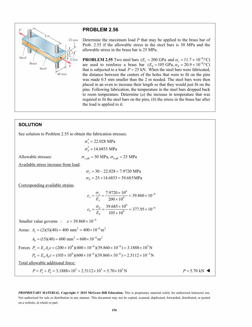
PROPRIETARY MATERIAL. Copyright © 2015 McGraw-Hill Education. This is proprietary material solely for authorized instructor use.
Not authorized for sale or distribution in any manner. This document may not be copied, scanned, duplicated, forwarded, distributed, or posted
on a website, in whole or part.
156
15 mm
40 mm
2 m
5 mmSteel
Brass
Steel
P�
P
PROBLEM 2.56
Determine the maximum load P that may be applied to the brass bar of Prob. 2.55 if the allowable stress in the steel bars is 30 MPa and the allowable stress in the brass bar is 25 MPa.
PROBLEM 2.55 Two steel bars ( 200 GPa and 11.7s sE 10–6/C) are used to reinforce a brass bar ( 105 GPa, 20.9b bE 10–6/C) that is subjected to a load 25 kN.P When the steel bars were fabricated, the distance between the centers of the holes that were to fit on the pins was made 0.5 mm smaller than the 2 m needed. The steel bars were then placed in an oven to increase their length so that they would just fit on the pins. Following fabrication, the temperature in the steel bars dropped back to room temperature. Determine (a) the increase in temperature that was required to fit the steel bars on the pins, (b) the stress in the brass bar after the load is applied to it.
SOLUTION
See solution to Problem 2.55 to obtain the fabrication stresses.
*
*
22.028 MPa
14.6853 MPa
s
b
Allowable stresses: ,all ,all30 MPa, 25 MPas b
Available stress increase from load.
30 22.028 7.9720 MPa
25 14.6853 39.685MPa
s
b
Corresponding available strains.
66
9
66
9
7.9720 1039.860 10
200 10
39.685 10377.95 10
105 10
ss
s
bb
b
E
E
6Smaller value governs 39.860 10
Areas: 2 6 2(2)(5)(40) 400 mm 400 10 msA
2 6 2(15)(40) 600 mm 600 10 mbA
Forces 9 6 6 3
9 6 6 3
(200 10 )(400 10 )(39.860 10 ) 3.1888 10 N
(105 10 )(600 10 )(39.860 10 ) 2.5112 10 N
s s s
b b b
P E A
P E A
Total allowable additional force:
3 3 33.1888 10 2.5112 10 5.70 10 N s bP P P 5.70 kNP
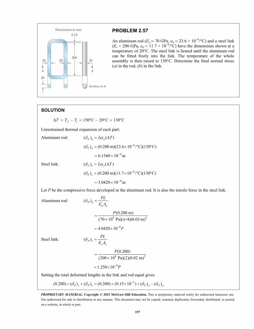
PROPRIETARY MATERIAL. Copyright © 2015 McGraw-Hill Education. This is proprietary material solely for authorized instructor use.
Not authorized for sale or distribution in any manner. This document may not be copied, scanned, duplicated, forwarded, distributed, or posted
on a website, in whole or part.
157
20
20 20200
0.15
Dimensions in mm
30
A A
Section A-A
PROBLEM 2.57
An aluminum rod (Ea 70 GPa, αa 23.6 × 10⁶/C) and a steel link (Es × 200 GPa, αa 11.7 × 10⁶/C) have the dimensions shown at a temperature of 20C. The steel link is heated until the aluminum rod can be fitted freely into the link. The temperature of the whole assembly is then raised to 150C. Determine the final normal stress (a) in the rod, (b) in the link.
SOLUTION
150 C 20 C 130 Cf iT T T
Unrestrained thermal expansion of each part:
Aluminum rod: ( ) ( )T a aL T
6( ) (0.200 m)(23.6 10 / C)(130 C) T a
46.1360 10 m
Steel link: ( ) ( )T s sL T
6( ) (0.200 m)(11.7 10 / C)(130 C) T s
43.0420 10 m
Let P be the compressive force developed in the aluminum rod. It is also the tensile force in the steel link.
Aluminum rod: ( )P aa a
PL
E A
9 2
(0.200 m)
(70 10 Pa)( /4)(0.03 m)
P
94.0420 10 P
Steel link: ( )P ss s
PL
E A
9 2
(0.200)
(200 10 Pa)(2)(0.02 m)
P
91.250 10 P
Setting the total deformed lengths in the link and rod equal gives
3(0.200) ( ) ( ) (0.200) (0.15 10 ) ( ) ( ) T s P s T a P a

PROPRIETARY MATERIAL. Copyright © 2015 McGraw-Hill Education. This is proprietary material solely for authorized instructor use.
Not authorized for sale or distribution in any manner. This document may not be copied, scanned, duplicated, forwarded, distributed, or posted
on a website, in whole or part.
158
PROBLEM 2.57 (Continued)
3( ) ( ) 0.15 10 ( ) ( )P s P a T a T s
9 9 3 4 41.25 10 4.0420 10 0.15 10 6.1360 10 3.0420 10 P P
48.6810 10 N P
(a) Stress in rod: P
A
4
82
8.6810 10 N1.22811 10 Pa
( /4)(0.030 m)
R
122.8 MPaR
(b) Stress in link:
4
82
8.6810 10 N1.08513 10 Pa
(2)(0.020 m)
L
108.5 MPa L
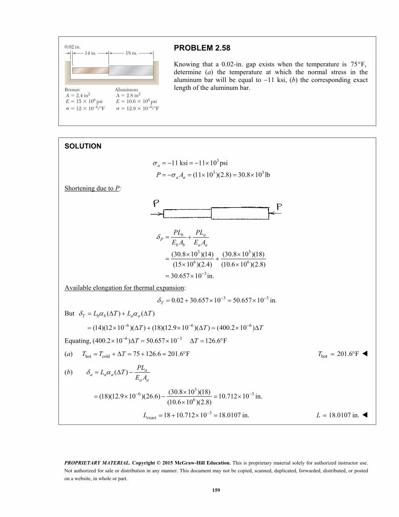
PROPRIETARY MATERIAL. Copyright © 2015 McGraw-Hill Education. This is proprietary material solely for authorized instructor use.
Not authorized for sale or distribution in any manner. This document may not be copied, scanned, duplicated, forwarded, distributed, or posted
on a website, in whole or part.
159
Bronze A � 2.4 in2
E � 15 � 106 psi � 12 � 10–6/�F
0.02 in.14 in. 18 in.
�
Aluminum A � 2.8 in2
E � 10.6 � 106 psi � 12.9 � 10–6/�F�
PROBLEM 2.58
Knowing that a 0.02-in. gap exists when the temperature is 75 F, determine (a) the temperature at which the normal stress in the aluminum bar will be equal to 11 ksi, (b) the corresponding exact length of the aluminum bar.
SOLUTION
3
3 3
11 ksi 11 10 psi
(11 10 )(2.8) 30.8 10 lb
a
a aP A
Shortening due to P:
3 3
6 6
3
(30.8 10 )(14) (30.8 10 )(18)
(15 10 )(2.4) (10.6 10 )(2.8)
30.657 10 in.
b aP
b b a a
PL PL
E A E A
Available elongation for thermal expansion:
3 30.02 30.657 10 50.657 10 in. T
But ( ) ( )T b b a aL T L T
6 6 6(14)(12 10 )( ) (18)(12.9 10 )( ) (400.2 10 ) T T T
Equating, 6 3(400.2 10 ) 50.657 10 126.6 F T T
(a) hot cold 75 126.6 201.6 F T T T hot 201.6 F T
(b) ( ) aa a a
a a
PLL T
E A
3
6 36
(30.8 10 )(18)(18)(12.9 10 )(26.6) 10.712 10 in.
(10.6 10 )(2.8)
3exact 18 10.712 10 18.0107 in. L 18.0107 in.L

PROPRIETARY MATERIAL. Copyright © 2015 McGraw-Hill Education. This is proprietary material solely for authorized instructor use.
Not authorized for sale or distribution in any manner. This document may not be copied, scanned, duplicated, forwarded, distributed, or posted
on a website, in whole or part.
160
Bronze A � 2.4 in2
E � 15 � 106 psi � 12 � 10–6/�F
0.02 in.14 in. 18 in.
�
Aluminum A � 2.8 in2
E � 10.6 � 106 psi � 12.9 � 10–6/�F�
PROBLEM 2.59
Determine (a) the compressive force in the bars shown after a temperature rise of 180 F, (b) the corresponding change in length of the bronze bar.
SOLUTION
Thermal expansion if free of constraint:
6 6
3
( ) ( )
(14)(12 10 )(180) (18)(12.9 10 )(180)
72.036 10 in.
T b b a aL T L T
Constrained expansion: 0.02 in.
Shortening due to induced compressive force P:
3 372.036 10 0.02 52.036 10 in.P
But b a b aP
b b a a b b a a
PL PL L LP
E A E A E A E A
96 6
14 18995.36 10
(15 10 )(2.4) (10.6 10 )(2.8)
P P
Equating, 9 3
3
995.36 10 52.036 10
52.279 10 lb
P
P
(a) 52.3 kipsP
(b) ( ) bb b b
b b
PLL T
E A
3
6 36
(52.279 10 )(14)(14)(12 10 )(180) 9.91 10 in.
(15 10 )(2.4)
39.91 10 in. b

PROPRIETARY MATERIAL. Copyright © 2015 McGraw-Hill Education. This is proprietary material solely for authorized instructor use.
Not authorized for sale or distribution in any manner. This document may not be copied, scanned, duplicated, forwarded, distributed, or posted
on a website, in whole or part.
161
Aluminum A 5 2000 mm2
E 5 75 GPa 5 23 3 10–6/8C
A B
300 mm 250 mm
0.5 mm
a
Stainless steel A 5 800 mm2
E 5 190 GPa 5 17.3 3 10–6/8Ca
PROBLEM 2.60
At room temperature (20 C) a 0.5-mm gap exists between the ends of the rods shown. At a later time when the temperature has reached 140C, determine (a) the normal stress in the aluminum rod, (b) the change in length of the aluminum rod.
SOLUTION
140 20 120 C T
Free thermal expansion:
6 6
3
( ) ( )
(0.300)(23 10 )(120) (0.250)(17.3 10 )(120)
1.347 10 m
T a a s sL T L T
Shortening due to P to meet constraint:
3 3 31.347 10 0.5 10 0.847 10 mP
9 6 9 6
9
0.300 0.250
(75 10 )(2000 10 ) (190 10 )(800 10 )
3.6447 10
a s a sP
a a s s a a s s
PL PL L LP
E A E A E A E A
P
P
Equating, 9 3
3
3.6447 10 0.847 10
232.39 10 N
P
P
(a) 3
66
232.39 10116.2 10 Pa
2000 10a
a
P
A
116.2 MPa a
(b) ( ) aa a a
a a
PLL T
E A
3
6 69 6
(232.39 10 )(0.300)(0.300)(23 10 )(120) 363 10 m
(75 10 )(2000 10 )
0.363 mm a
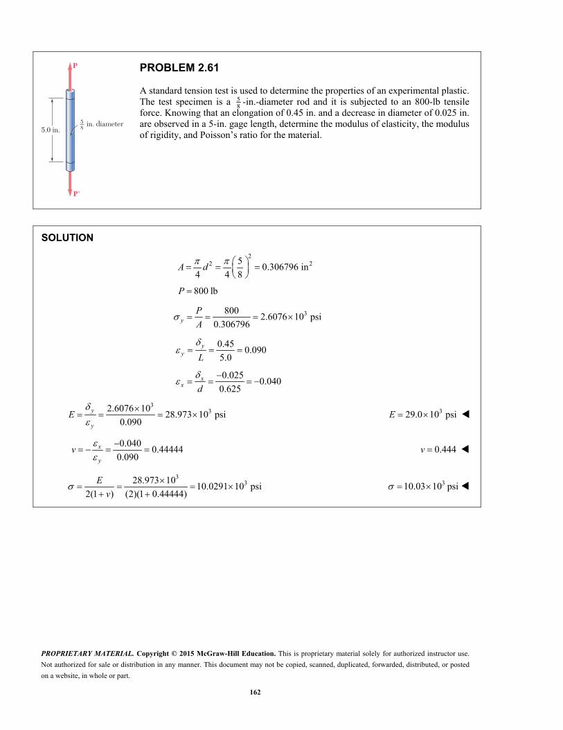
PROPRIETARY MATERIAL. Copyright © 2015 McGraw-Hill Education. This is proprietary material solely for authorized instructor use.
Not authorized for sale or distribution in any manner. This document may not be copied, scanned, duplicated, forwarded, distributed, or posted
on a website, in whole or part.
162
in. diameter5.0 in.
P'
P
58
PROBLEM 2.61
A standard tension test is used to determine the properties of an experimental plastic. The test specimen is a 5
8 -in.-diameter rod and it is subjected to an 800-lb tensile force. Knowing that an elongation of 0.45 in. and a decrease in diameter of 0.025 in. are observed in a 5-in. gage length, determine the modulus of elasticity, the modulus of rigidity, and Poisson’s ratio for the material.
SOLUTION
2
2 250.306796 in
4 4 8
A d
800 lbP
38002.6076 10 psi
0.306796yP
A
0.45
0.0905.0
yy L
0.025
0.0400.625
x
x d
3
32.6076 1028.973 10 psi
0.090
y
y
E
329.0 10 psiE
0.040
0.444440.090
x
y
v
0.444v
3
328.973 1010.0291 10 psi
2(1 ) (2)(1 0.44444)
E
v 310.03 10 psi
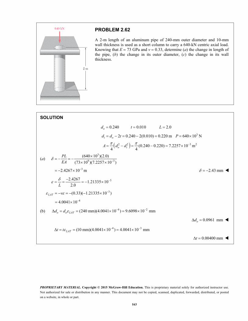
PROPRIETARY MATERIAL. Copyright © 2015 McGraw-Hill Education. This is proprietary material solely for authorized instructor use.
Not authorized for sale or distribution in any manner. This document may not be copied, scanned, duplicated, forwarded, distributed, or posted
on a website, in whole or part.
163
640 kN
2 m
PROBLEM 2.62
A 2-m length of an aluminum pipe of 240-mm outer diameter and 10-mm wall thickness is used as a short column to carry a 640-kN centric axial load. Knowing that E 73 GPa and v 0.33, determine (a) the change in length of the pipe, (b) the change in its outer diameter, (c) the change in its wall thickness.
SOLUTION
0.240 0.010 2.0 od t L
32 0.240 2(0.010) 0.220 m 640 10 N i od d t P
2 2 3 2(0.240 0.220) 7.2257 10 m4 4
o iA d d
(a) 3
9 3
(640 10 )(2.0)
(73 10 )(7.2257 10 )
PL
EA
32.4267 10 m 2.43 mm
32.42671.21335 10
2.0
L
3(0.33)( 1.21335 10 ) LAT v
44.0041 10
(b) 4 2(240 mm)(4.0041 10 ) 9.6098 10 mm o o LATd d
0.0961 mmod
4 3(10 mm)(4.0041 10 ) 4.0041 10 mm LATt t
0.00400 mmt

PROPRIETARY MATERIAL. Copyright © 2015 McGraw-Hill Education. This is proprietary material solely for authorized instructor use.
Not authorized for sale or distribution in any manner. This document may not be copied, scanned, duplicated, forwarded, distributed, or posted
on a website, in whole or part.
164
10
200 mm
150 mm4200 kN 200 kN
PROBLEM 2.63
A line of slope 4:10 has been scribed on a cold-rolled yellow-brass plate, 150 mm wide and 6 mm thick. Knowing that E 105 GPa and v 0.34, determine the slope of the line when the plate is subjected to a 200-kN centric axial load as shown.
SOLUTION
3 2(0.150)(0.006) 0.9 10 mA
3
63
200 10222.22 10 Pa
0.9 10x
P
A
6
39
222.22 102.1164 10
105 10x
x E
3(0.34)(2.1164 10 )y x
30.71958 10
3
3
4(1 )tan
10(1 )
4(1 0.71958 10 )
10(1 2.1164 10 )
0.39887
y
x
tan 0.399

PROPRIETARY MATERIAL. Copyright © 2015 McGraw-Hill Education. This is proprietary material solely for authorized instructor use.
Not authorized for sale or distribution in any manner. This document may not be copied, scanned, duplicated, forwarded, distributed, or posted
on a website, in whole or part.
165
2.75 kN2.75 kN
50 mm
A B
12 mm
PROBLEM 2.64
A 2.75-kN tensile load is applied to a test coupon made from 1.6-mm flat steel plate (E 200 GPa, v 0.30). Determine the resulting change (a) in the 50-mm gage length, (b) in the width of portion AB of the test coupon, (c) in the thickness of portion AB, (d) in the cross-sectional area of portion AB.
SOLUTION
2(1.6)(12) 19.20 mmA
6 219.20 10 m
32.75 10 N P
3
6
2.75 10
19.20 10x
P
A
6143.229 10 Pa
6
69
143.229 10716.15 10
200 10x
x E
6 6(0.30)(716.15 10 ) 214.84 10y z x
(a) 6 60.050 m (0.50)(716.15 10 ) 35.808 10 m x xL L
0.0358 mm
(b) 6 60.012 m (0.012)( 214.84 10 ) 2.5781 10 m y yw w
0.00258 mm
(c) 6 90.0016 m (0.0016)( 214.84 10 ) 343.74 10 m z zt t
0.000344 mm
(d) 0 0 0 0 0 0 0(1 ) (1 ) (1 ) y z y z y zA w t w t A w t
0 0 0 0 0( negligible term) 2 y z yA A A w t w t
6 9 2(2)(0.012)(0.0016)( 214.84 10 ) 8.25 10 m 20.00825 mm
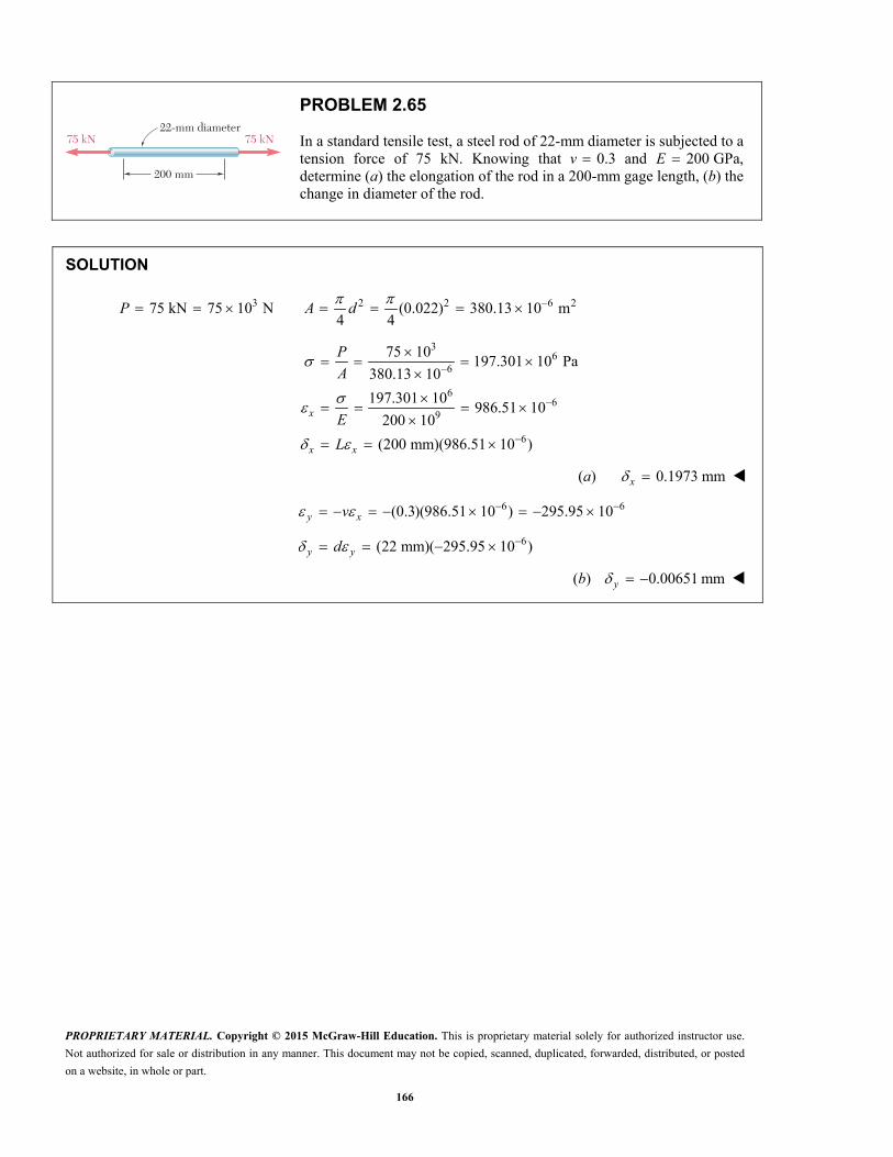
PROPRIETARY MATERIAL. Copyright © 2015 McGraw-Hill Education. This is proprietary material solely for authorized instructor use.
Not authorized for sale or distribution in any manner. This document may not be copied, scanned, duplicated, forwarded, distributed, or posted
on a website, in whole or part.
166
200 mm
22-mm diameter75 kN 75 kN
PROBLEM 2.65
In a standard tensile test, a steel rod of 22-mm diameter is subjected to a tension force of 75 kN. Knowing that 0.3v and 200 GPa,E determine (a) the elongation of the rod in a 200-mm gage length, (b) the change in diameter of the rod.
SOLUTION
3 2 2 6 275 kN 75 10 N (0.022) 380.13 10 m4 4
P A d
36
6
66
9
6
75 10197.301 10 Pa
380.13 10
197.301 10986.51 10
200 10
(200 mm)(986.51 10 )
x
x x
P
A
E
L
(a) 0.1973 mm x
6 6(0.3)(986.51 10 ) 295.95 10y xv
6(22 mm)( 295.95 10 ) y yd
(b) 0.00651 mm y
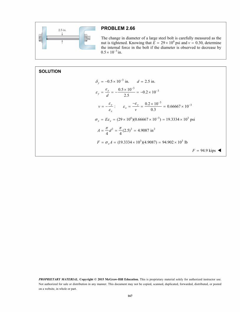
PROPRIETARY MATERIAL. Copyright © 2015 McGraw-Hill Education. This is proprietary material solely for authorized instructor use.
Not authorized for sale or distribution in any manner. This document may not be copied, scanned, duplicated, forwarded, distributed, or posted
on a website, in whole or part.
167
2.5 in.
PROBLEM 2.66
The change in diameter of a large steel bolt is carefully measured as the nut is tightened. Knowing that 629 10 psi E and 0.30,v determine the internal force in the bolt if the diameter is observed to decrease by
30.5 10 in.
SOLUTION
3
33
0.5 10 in. 2.5 in.
0.5 100.2 10
2.5
y
yy
d
d
3
30.2 10: 0.66667 10
0.3y y
xx
vv
6 3 3(29 10 )(0.66667 10 ) 19.3334 10 psix xE
2 2 2(2.5) 4.9087 in4 4
A d
3 3(19.3334 10 )(4.9087) 94.902 10 lbxF A
94.9 kipsF
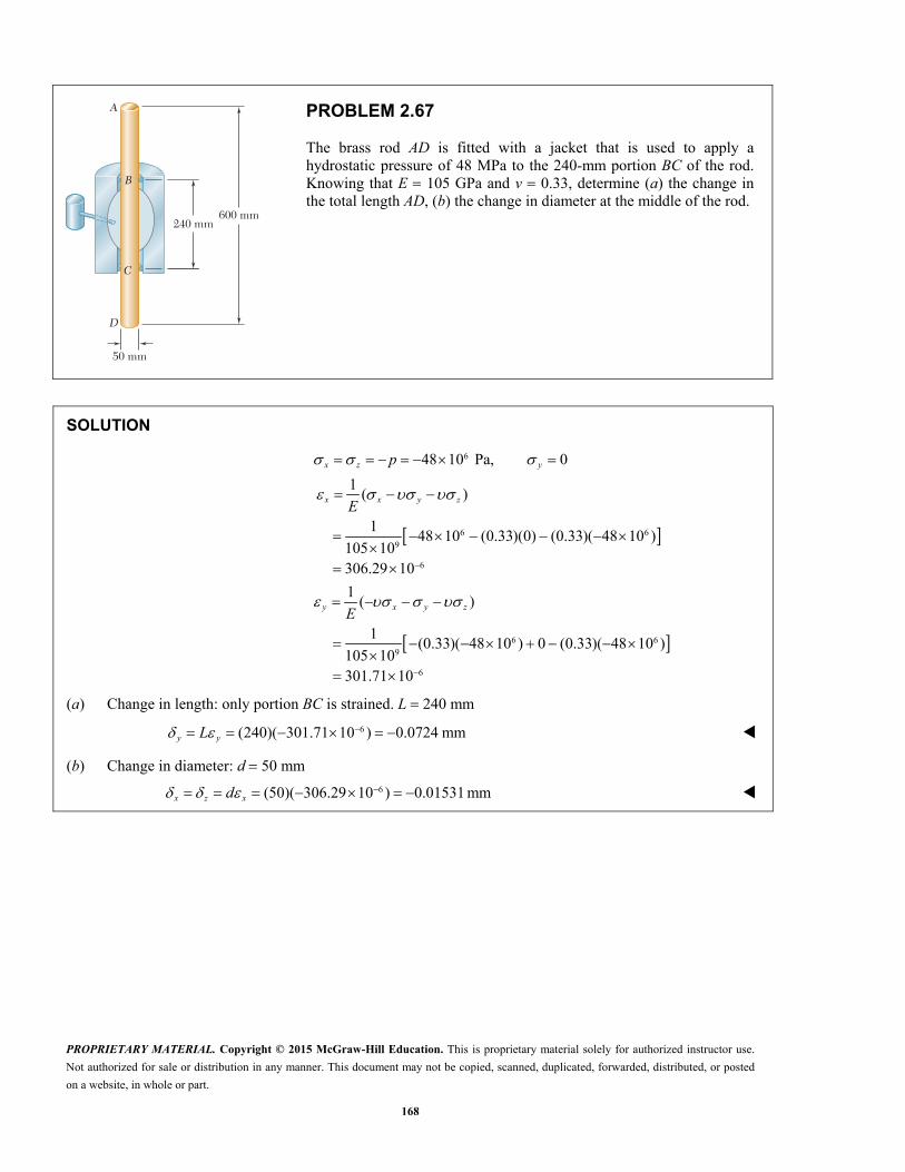
PROPRIETARY MATERIAL. Copyright © 2015 McGraw-Hill Education. This is proprietary material solely for authorized instructor use.
Not authorized for sale or distribution in any manner. This document may not be copied, scanned, duplicated, forwarded, distributed, or posted
on a website, in whole or part.
168
240 mm600 mm
C
D
A
B
50 mm
PROBLEM 2.67
The brass rod AD is fitted with a jacket that is used to apply a hydrostatic pressure of 48 MPa to the 240-mm portion BC of the rod. Knowing that E 105 GPa and v 0.33, determine (a) the change in the total length AD, (b) the change in diameter at the middle of the rod.
SOLUTION
6
6 69
6
6 69
6
48 10 Pa, 0
1( )
148 10 (0.33)(0) (0.33)( 48 10 )
105 10306.29 10
1( )
1(0.33)( 48 10 ) 0 (0.33)( 48 10 )
105 10301.71 10
x z y
x x y z
y x y z
p
E
E
(a) Change in length: only portion BC is strained. L 240 mm
6(240)( 301.71 10 ) 0.0724 mmy yL
(b) Change in diameter: d 50 mm
6(50)( 306.29 10 ) 0.01531 mm x z xd
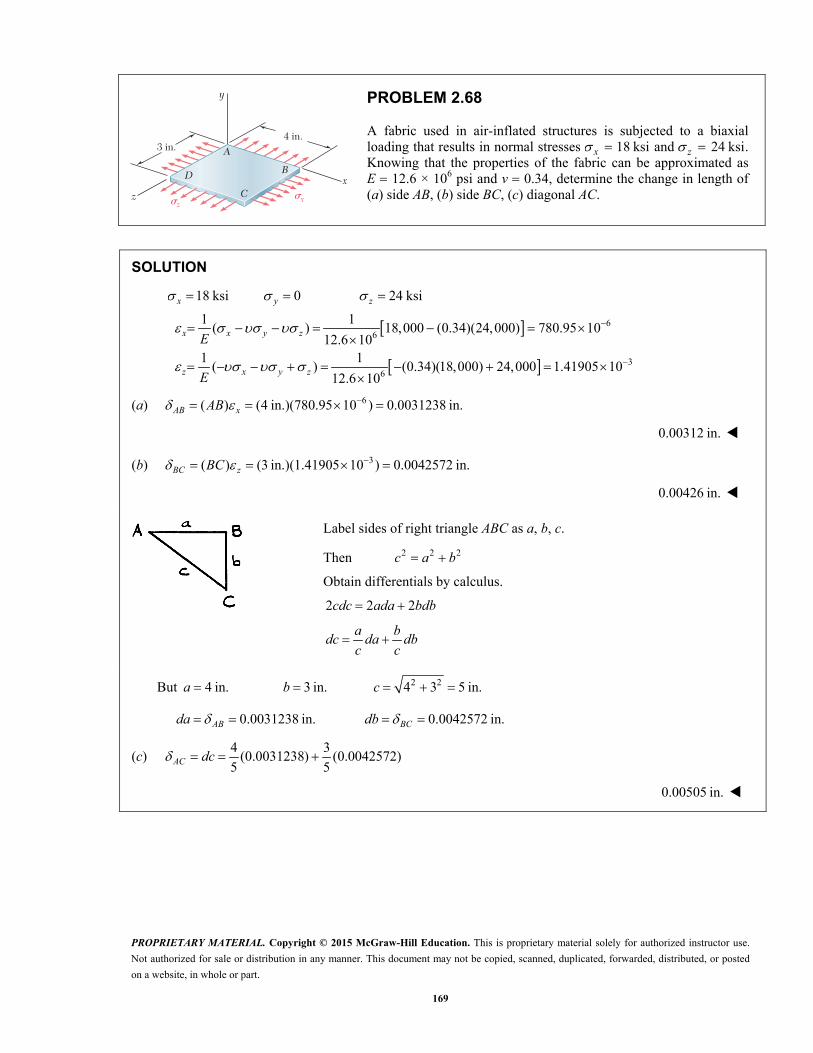
PROPRIETARY MATERIAL. Copyright © 2015 McGraw-Hill Education. This is proprietary material solely for authorized instructor use.
Not authorized for sale or distribution in any manner. This document may not be copied, scanned, duplicated, forwarded, distributed, or posted
on a website, in whole or part.
169
x�z�
3 in.4 in.
z
y
x
A
B
C
D
PROBLEM 2.68
A fabric used in air-inflated structures is subjected to a biaxial loading that results in normal stresses 18 ksi x and 24 ksi z . Knowing that the properties of the fabric can be approximated as E 12.6 × 10⁶ psi and v 0.34, determine the change in length of (a) side AB, (b) side BC, (c) diagonal AC.
SOLUTION
66
36
18 ksi 0 24 ksi
1 1( ) 18,000 (0.34)(24,000) 780.95 10
12.6 101 1
( ) (0.34)(18,000) 24,000 1.41905 1012.6 10
x y z
x x y z
z x y z
E
E
(a) 6( ) (4 in.)(780.95 10 ) 0.0031238 in.AB xAB
0.00312 in.
(b) 3( ) (3 in.)(1.41905 10 ) 0.0042572 in. BC zBC
0.00426 in.
Label sides of right triangle ABC as a, b, c.
Then 2 2 2c a b
Obtain differentials by calculus.
2 2 2cdc ada bdb
a bdc da db
c c
But 2 24 in. 3 in. 4 3 5 in. a b c
0.0031238 in. 0.0042572 in. AB BCda db
(c) 4 3
(0.0031238) (0.0042572)5 5AC dc
0.00505 in.
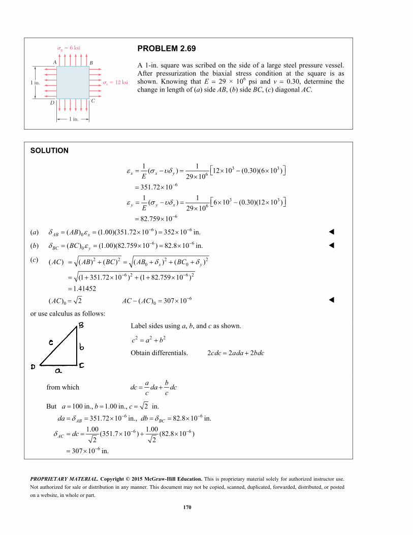
PROPRIETARY MATERIAL. Copyright © 2015 McGraw-Hill Education. This is proprietary material solely for authorized instructor use.
Not authorized for sale or distribution in any manner. This document may not be copied, scanned, duplicated, forwarded, distributed, or posted
on a website, in whole or part.
170
y � 6 ksi�
x � 12 ksi�1 in.
A B
CD
1 in.
PROBLEM 2.69
A 1-in. square was scribed on the side of a large steel pressure vessel. After pressurization the biaxial stress condition at the square is as shown. Knowing that E 29 × 106 psi and v 0.30, determine the change in length of (a) side AB, (b) side BC, (c) diagonal AC.
SOLUTION
3 36
6
3 36
6
1 1( ) 12 10 (0.30)(6 10 )
29 10
351.72 10
1 1( ) 6 10 (0.30)(12 10 )
29 10
82.759 10
x x y
y y x
E
E
(a) 6 60( ) (1.00)(351.72 10 ) 352 10 in. AB xAB
(b) 6 60( ) (1.00)(82.759 10 ) 82.8 10 in. BC yBC
(c)
2 2 2 20 0
6 2 6 2
60 0
( ) ( ) ( ) ( ) ( )
(1 351.72 10 ) (1 82.759 10 )
1.41452
( ) 2 ( ) 307 10
x yAC AB BC AB BC
AC AC AC
or use calculus as follows:
Label sides using a, b, and c as shown.
2 2 2c a b
Obtain differentials. 2 2 2 cdc ada bdc
from which a b
dc da dcc c
6 6
6 6
6
But 100 in., 1.00 in., 2 in.
351.72 10 in., 82.8 10 in.
1.00 1.00(351.7 10 ) (82.8 10 )
2 2
307 10 in.
AB BC
AC
a b c
da db
dc

PROPRIETARY MATERIAL. Copyright © 2015 McGraw-Hill Education. This is proprietary material solely for authorized instructor use.
Not authorized for sale or distribution in any manner. This document may not be copied, scanned, duplicated, forwarded, distributed, or posted
on a website, in whole or part.
171
PROBLEM 2.70
The block shown is made of a magnesium alloy, for which 45E GPa and 0.35.v Knowing that 180x MPa,
determine (a) the magnitude of y for which the change in the height of the block will be zero, (b) the corresponding change in the area of the face ABCD, (c) the corresponding change in the volume of the block.
SOLUTION
(a)
6
0 0 0
1( )
(0.35)( 180 10 )
y y z
y x y z
y x
v vE
v
663 10 Pa 63.0 MPay
63
9
63
9
1 (0.35)( 243 10 )( ) ( ) 1.890 10
45 10
1 157.95 10( ) 3.510 10
45 10
z z x y x y
x yx x y Z
vv v
E Ev
v vE E
(b) 0
0
(1 ) (1 ) (1 )
( ) ( )
x z
x x z z x z x z x z
x z x z x z x z x z
A L L
A L L L L
A A A L L L L
3 3(100 mm)(25 mm)( 3.510 10 1.890 10 ) A 24.05 mm A
(c) 0
0
(1 ) (1 ) (1 )
(1 )
( small terms)
x y z
x x y y z z
x y z x y z x y y z z x x y z
x y z x y z
V L L L
V L L L
L L L
V V V L L L
3 3(100)(40)(25)( 3.510 10 0 1.890 10 ) V 3162.0 mm V

PROPRIETARY MATERIAL. Copyright © 2015 McGraw-Hill Education. This is proprietary material solely for authorized instructor use.
Not authorized for sale or distribution in any manner. This document may not be copied, scanned, duplicated, forwarded, distributed, or posted
on a website, in whole or part.
172
x�z�z
y
x
A
B
C
D
PROBLEM 2.71
The homogeneous plate ABCD is subjected to a biaxial loading as shown. It is known that 0z and that the change in length of the plate in the x direction must be zero, that is, 0.x Denoting by E the modulus of elasticity and by v Poisson’s ratio, determine (a) the required magnitude of ,x (b) the ratio 0 / .z
SOLUTION
0
0
, 0, 0
1 1( ) ( )
z y x
x x y z xv v vE E
(a) 0x v
(b) 2
20 0 0
1 1 1( ) ( 0 )z x y z
vv v v
E E E
021z
E
v
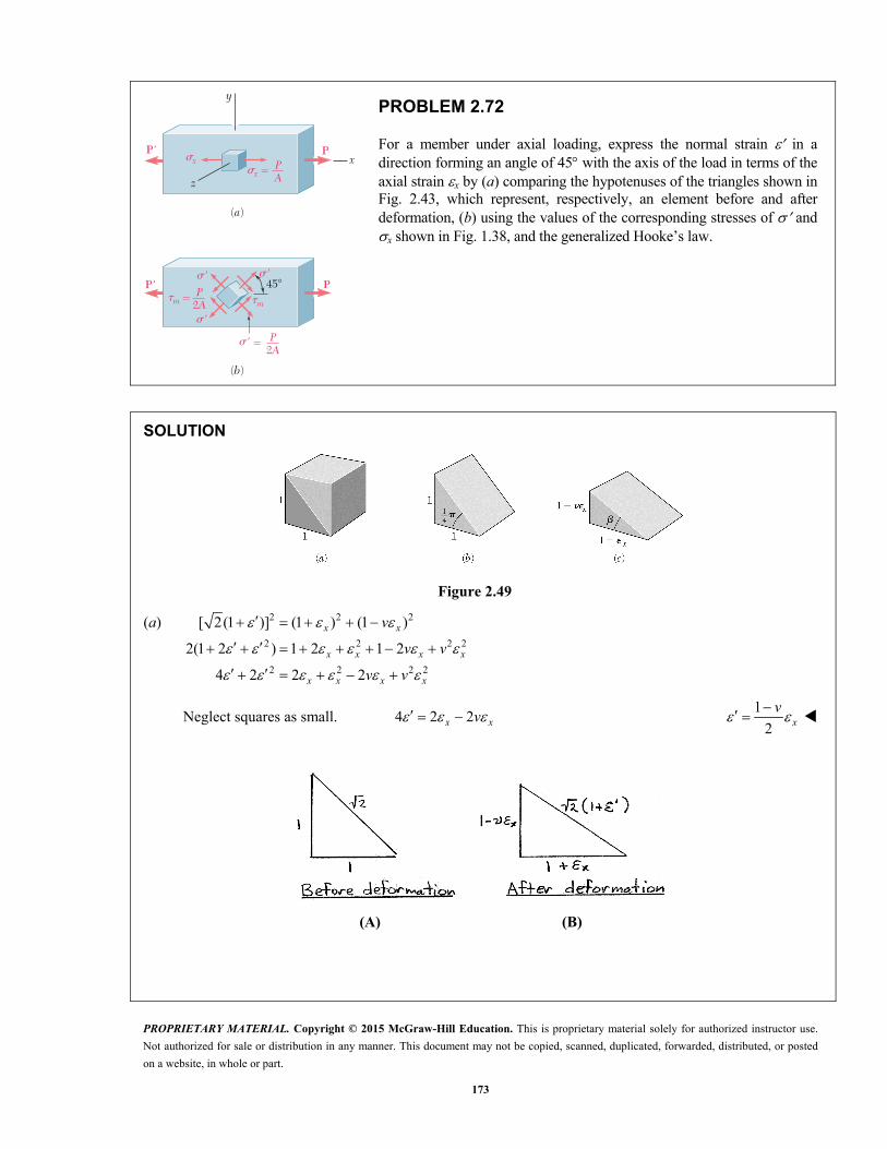
PROPRIETARY MATERIAL. Copyright © 2015 McGraw-Hill Education. This is proprietary material solely for authorized instructor use.
Not authorized for sale or distribution in any manner. This document may not be copied, scanned, duplicated, forwarded, distributed, or posted
on a website, in whole or part.
173
(b)
(a)
�m �mP
P'
P'
P
P
2A
z
x
y
'45�
�x
�x PA
P2A
� '�
'�
'� �
�
�
PROBLEM 2.72
For a member under axial loading, express the normal strain in a direction forming an angle of 45 with the axis of the load in terms of the axial strain x by (a) comparing the hypotenuses of the triangles shown in Fig. 2.43, which represent, respectively, an element before and after deformation, (b) using the values of the corresponding stresses of and x shown in Fig. 1.38, and the generalized Hooke’s law.
SOLUTION
Figure 2.49
(a) 2 2 2
2 2 2 2
2 2 2 2
[ 2(1 )] (1 ) (1 )
2(1 2 ) 1 2 1 2
4 2 2 2
x x
x x x x
x x x x
v
v v
v v
Neglect squares as small. 4 2 2x xv 1
2 xv
(A) (B)
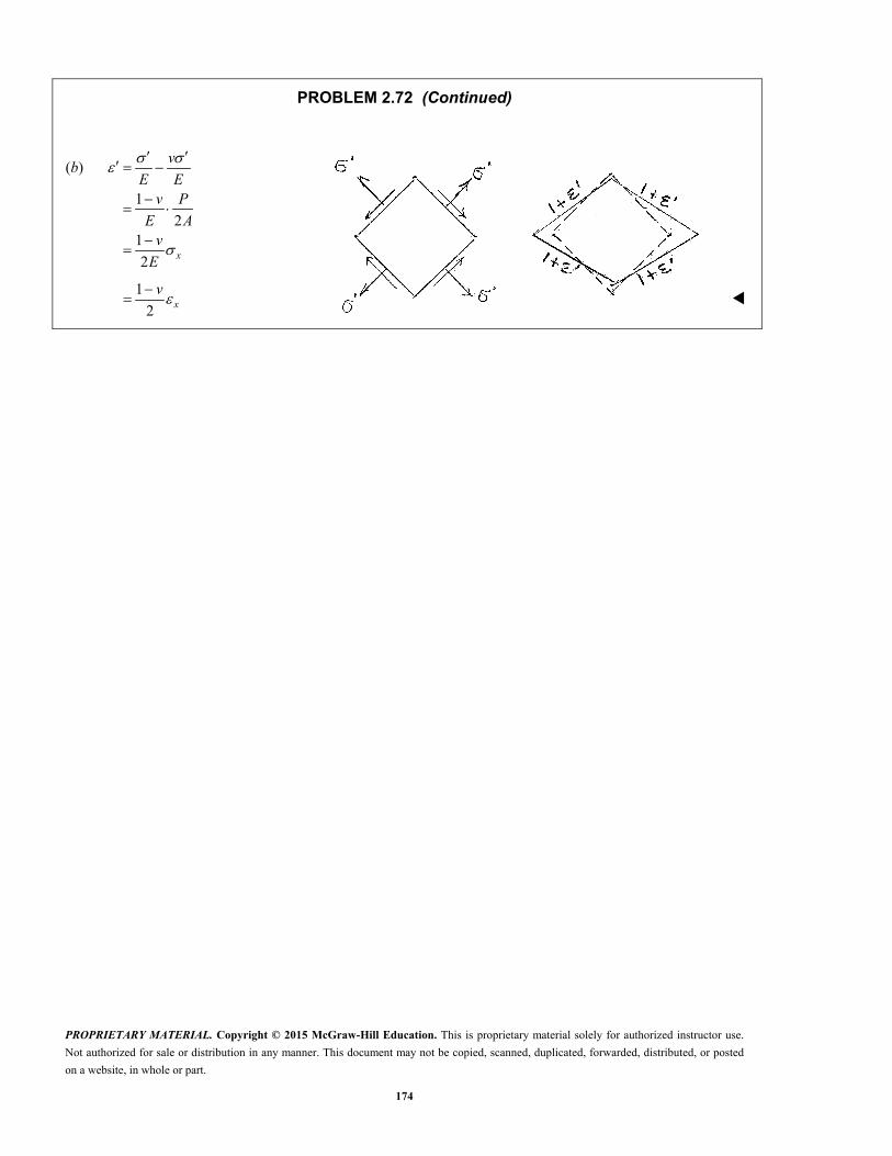
PROPRIETARY MATERIAL. Copyright © 2015 McGraw-Hill Education. This is proprietary material solely for authorized instructor use.
Not authorized for sale or distribution in any manner. This document may not be copied, scanned, duplicated, forwarded, distributed, or posted
on a website, in whole or part.
174
PROBLEM 2.72 (Continued)
(b)
1
21
2 x
v
E Ev P
E Av
E
1
2 xv

PROPRIETARY MATERIAL. Copyright © 2015 McGraw-Hill Education. This is proprietary material solely for authorized instructor use.
Not authorized for sale or distribution in any manner. This document may not be copied, scanned, duplicated, forwarded, distributed, or posted
on a website, in whole or part.
175
x�
y�
PROBLEM 2.73
In many situations, it is known that the normal stress in a given direction is zero. For example, 0z in the case of the thin plate shown. For this case, which is known as plane stress, show that if the strains x and y have been determined experimentally, we can express , , x y and z as follows:
2 2( )
11 1
x y y xx y z x y
v v vE E
vv v
SOLUTION
0
1( )
z
x x yvE
(1)
1
( )y x yvE
(2)
Multiplying (2) by v and adding to (1),
2
2
1or ( )
1x y x x x y
v Ev v
E v
Multiplying (1) by v and adding to (2),
2
2
1or ( )
1y x y y y x
v Ev v
E v
1( )z x y
vv v
E E
E
2
2
( )1
(1 )( ) ( )
11
x y y x
x y x y
v vv
v v v
vv

PROPRIETARY MATERIAL. Copyright © 2015 McGraw-Hill Education. This is proprietary material solely for authorized instructor use.
Not authorized for sale or distribution in any manner. This document may not be copied, scanned, duplicated, forwarded, distributed, or posted
on a website, in whole or part.
176
xx�
zz�
yy�y
x
z (a) (b)
�
PROBLEM 2.74
In many situations, physical constraints prevent strain from occurring in a given direction. For example, 0z in the case shown, where longitudinal movement of the long prism is prevented at every point. Plane sections perpendicular to the longitudinal axis remain plane and the same distance apart. Show that for this situation, which is known as plane strain, we can express , z , x and y as follows:
2
2
( )
1[(1 ) (1 ) ]
1[(1 ) (1 ) ]
z x y
x x y
y y x
v
v v vE
v v vE
SOLUTION
1
0 ( ) or ( )z x y z z x yv v vE
2
2
1( )
1[ ( )]
1[(1 ) (1 ) ]
x x y z
x y x y
x y
v vE
v vE
v v vE
2
2
1( )
1[ ( )]
1[(1 ) (1 ) ]
y x y z
x y x y
y x
v vE
v vE
v v vE

PROPRIETARY MATERIAL. Copyright © 2015 McGraw-Hill Education. This is proprietary material solely for authorized instructor use.
Not authorized for sale or distribution in any manner. This document may not be copied, scanned, duplicated, forwarded, distributed, or posted
on a website, in whole or part.
177
4.8 in.
3.2 in.
2 in. P
PROBLEM 2.75
The plastic block shown is bonded to a rigid support and to a vertical plate to which a 55-kip load P is applied. Knowing that for the plastic used 150G ksi, determine the deflection of the plate.
SOLUTION
2
3
3
3
33
(3.2)(4.8) 15.36 in
55 10 lb
55 103580.7 psi
15.36
150 10 psi
3580.723.871 10
150 102 in.
A
P
P
A
G
G
h
3
3
(2)(23.871 10 )
47.7 10 in.
h
0.0477 in.

PROPRIETARY MATERIAL. Copyright © 2015 McGraw-Hill Education. This is proprietary material solely for authorized instructor use.
Not authorized for sale or distribution in any manner. This document may not be copied, scanned, duplicated, forwarded, distributed, or posted
on a website, in whole or part.
178
4.8 in.
3.2 in.
2 in. P
PROBLEM 2.76
What load P should be applied to the plate of Prob. 2.75 to produce a 116
-in. deflection?
PROBLEM 2.75 The plastic block shown is bonded to a rigid support and to a vertical plate to which a 55-kip load P is applied. Knowing that for the plastic used 150G ksi, determine the deflection of the plate.
SOLUTION
3
3
1in. 0.0625 in.
162 in.
0.06250.03125
2
150 10 psi
(150 10 )(0.03125)
4687.5 psi
h
h
G
G
2
3
(3.2)(4.8) 15.36 in
(4687.5)(15.36)
72.0 10 lb
A
P A
72.0 kips
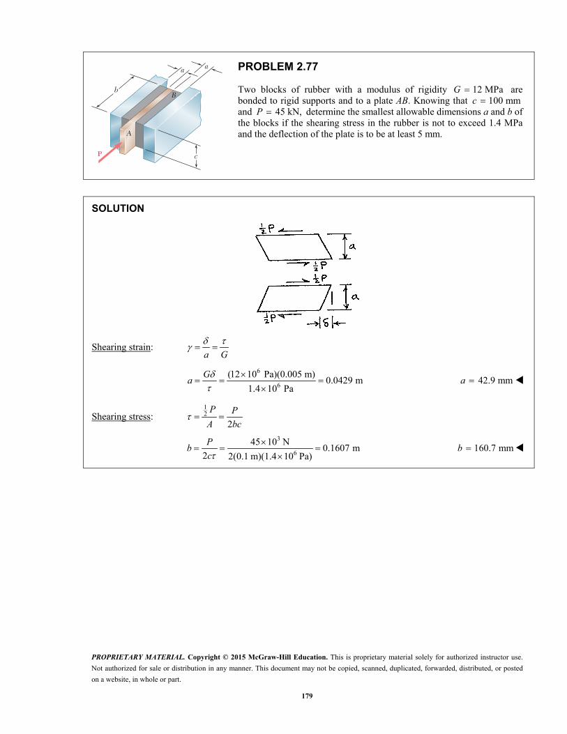
PROPRIETARY MATERIAL. Copyright © 2015 McGraw-Hill Education. This is proprietary material solely for authorized instructor use.
Not authorized for sale or distribution in any manner. This document may not be copied, scanned, duplicated, forwarded, distributed, or posted
on a website, in whole or part.
179
a a
c
b
A
B
P
PROBLEM 2.77
Two blocks of rubber with a modulus of rigidity 12 MPaG are bonded to rigid supports and to a plate AB. Knowing that 100 mmc and 45 kN,P determine the smallest allowable dimensions a and b of the blocks if the shearing stress in the rubber is not to exceed 1.4 MPa and the deflection of the plate is to be at least 5 mm.
SOLUTION
Shearing strain: a G
6
6
(12 10 Pa)(0.005 m)0.0429 m
1.4 10 Pa
Ga
42.9 mma
Shearing stress: 12
2
P P
A bc
3
6
45 10 N0.1607 m
2 2(0.1 m)(1.4 10 Pa)
Pb
c 160.7 mmb

PROPRIETARY MATERIAL. Copyright © 2015 McGraw-Hill Education. This is proprietary material solely for authorized instructor use.
Not authorized for sale or distribution in any manner. This document may not be copied, scanned, duplicated, forwarded, distributed, or posted
on a website, in whole or part.
180
a a
c
b
A
B
P
PROBLEM 2.78
Two blocks of rubber with a modulus of rigidity 10G MPa are bonded to rigid supports and to a plate AB. Knowing that 200b mm and
125c mm, determine the largest allowable load P and the smallest allowable thickness a of the blocks if the shearing stress in the rubber is not to exceed 1.5 MPa and the deflection of the plate is to be at least 6 mm.
SOLUTION
Shearing stress: 12
2
P P
A bc
32 2(0.2 m)(0.125 m)(1.5 10 kPa)P bc 75.0 kNP
Shearing strain: a G
6
6
(10 10 Pa)(0.006 m)0.04 m
1.5 10 Pa
Ga
40.0 mma

PROPRIETARY MATERIAL. Copyright © 2015 McGraw-Hill Education. This is proprietary material solely for authorized instructor use.
Not authorized for sale or distribution in any manner. This document may not be copied, scanned, duplicated, forwarded, distributed, or posted
on a website, in whole or part.
181
8 in.
b
a
P
PROBLEM 2.79
An elastomeric bearing (G 130 psi) is used to support a bridge girder as shown to provide flexibility during earthquakes. The beam must not displace more than 3
8 in. when a 5-kip lateral load is applied as shown. Knowing that the maximum allowable shearing stress is 60 psi, determine (a) the smallest allowable dimension b, (b) the smallest required thickness a.
SOLUTION
Shearing force: 5 kips 5000 lbP
Shearing stress: 60 psi
25000, or 83.333 in
60
P PA
A
and (8 in.)( )A b
(a) 83.333
10.4166 in.8 8
Ab 10.42 in.b
360461.54 10 rad
130
(b) 3
0.375 in.But , or
461.54 10
a
a 0.813 in.a
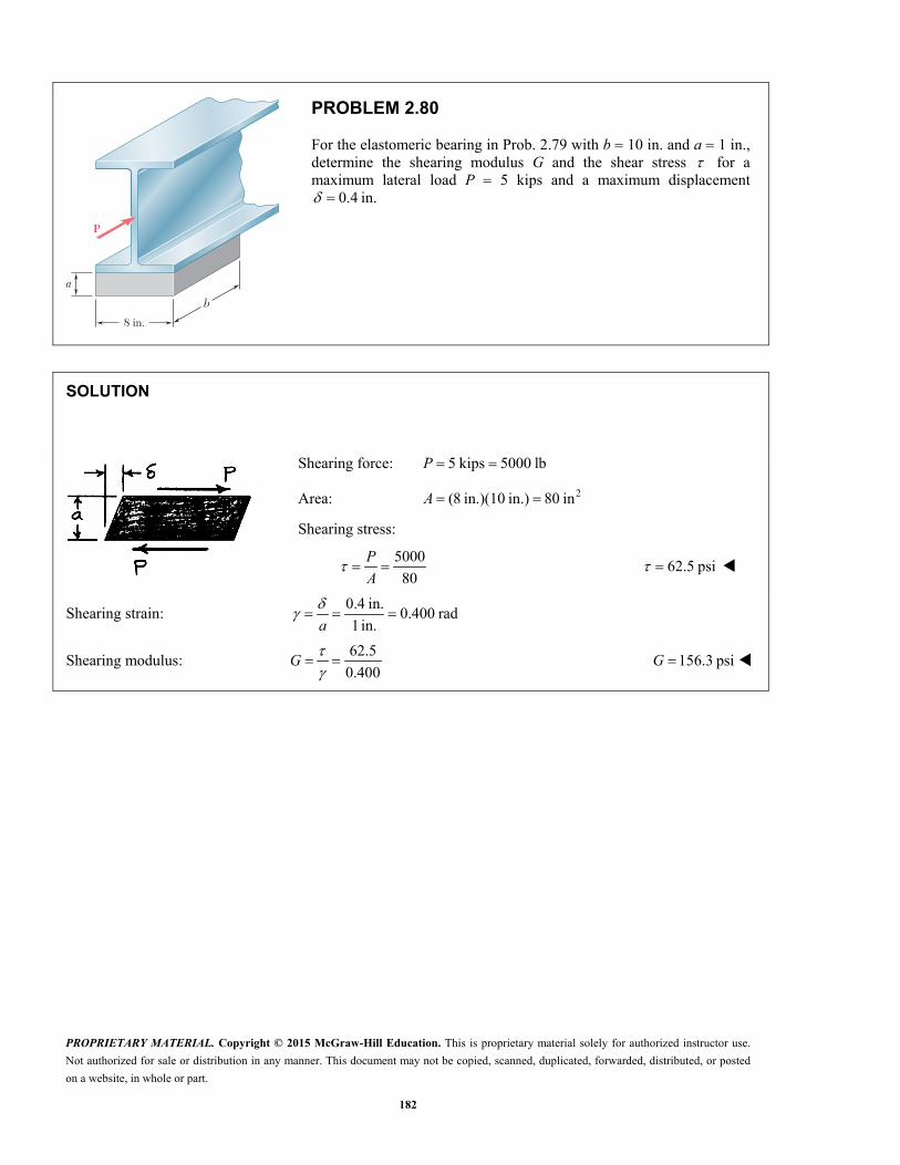
PROPRIETARY MATERIAL. Copyright © 2015 McGraw-Hill Education. This is proprietary material solely for authorized instructor use.
Not authorized for sale or distribution in any manner. This document may not be copied, scanned, duplicated, forwarded, distributed, or posted
on a website, in whole or part.
182
8 in.
b
a
P
PROBLEM 2.80
For the elastomeric bearing in Prob. 2.79 with b 10 in. and a 1 in., determine the shearing modulus G and the shear stress for a maximum lateral load P 5 kips and a maximum displacement
0.4 in.
SOLUTION
Shearing force: 5 kips 5000 lbP
Area: 2(8 in.)(10 in.) 80 inA
Shearing stress:
5000
80
P
A 62.5 psi
Shearing strain: 0.4 in.
0.400 rad1 in.
a
Shearing modulus: 62.5
0.400
G 156.3 psiG

PROPRIETARY MATERIAL. Copyright © 2015 McGraw-Hill Education. This is proprietary material solely for authorized instructor use.
Not authorized for sale or distribution in any manner. This document may not be copied, scanned, duplicated, forwarded, distributed, or posted
on a website, in whole or part.
183
150 mm100 mm
30 mm
B
A
30 mm
P
PROBLEM 2.81
A vibration isolation unit consists of two blocks of hard rubber bonded to a plate AB and to rigid supports as shown. Knowing that a force of magnitude 25 kNP causes a deflection 1.5 mm of plate AB, determine the modulus of rigidity of the rubber used.
SOLUTION
3 3
33
1 1(25 10 N) 12.5 10 N
2 2
(12.5 10 N)833.33 10 Pa
(0.15 m)(0.1 m)
F P
F
A
3
3
1.5 10 m 0.03 m
1.5 100.05
0.03
h
h
36833.33 10
16.67 10 Pa0.05
G
16.67 MPaG

PROPRIETARY MATERIAL. Copyright © 2015 McGraw-Hill Education. This is proprietary material solely for authorized instructor use.
Not authorized for sale or distribution in any manner. This document may not be copied, scanned, duplicated, forwarded, distributed, or posted
on a website, in whole or part.
184
150 mm100 mm
30 mm
B
A
30 mm
P
PROBLEM 2.82
A vibration isolation unit consists of two blocks of hard rubber with a modulus of rigidity 19 MPaG bonded to a plate AB and to rigid supports as shown. Denoting by P the magnitude of the force applied to the plate and by the corresponding deflection, determine the effective spring constant, / ,k P of the system.
SOLUTION
Shearing strain: h
Shearing stress: G
Gh
Force: 1 2
or2
GA GAP A P
h h
Effective spring constant: 2P GA
kh
with 2(0.15)(0.1) 0.015 m 0.03 mA h
6 262(19 10 Pa)(0.015 m )
19.00 10 N/m0.03 m
k
319.00 10 kN/mk

PROPRIETARY MATERIAL. Copyright © 2015 McGraw-Hill Education. This is proprietary material solely for authorized instructor use.
Not authorized for sale or distribution in any manner. This document may not be copied, scanned, duplicated, forwarded, distributed, or posted
on a website, in whole or part.
185
PROBLEM 2.83
A 6-in.-diameter solid steel sphere is lowered into the ocean to a point where the pressure is 7.1 ksi (about 3 miles below the surface). Knowing that 629 10E psi and 0.30,v determine (a) the decrease in diameter of the sphere, (b) the decrease in volume of the sphere, (c) the percent increase in the density of the sphere.
SOLUTION
For a solid sphere, 30 0
3
3
6
(6.00)6
113.097 in
x y z
V d
p
3
3
6
6
7.1 10 psi
1( )
(1 2 ) (0.4)(7.1 10 )
29 10
97.93 10
x x y zv vE
v p
E
Likewise, 697.93 10y z
6293.79 10x y ze
(a) 6 60 (6.00)( 97.93 10 ) 588 10 in. xd d 6588 10 in. d
(b) 6 3 30 (113.097)( 293.79 10 ) 33.2 10 in V V e 3 333.2 10 in V
(c) Let mass of sphere. constant.m m
0 0 0 (1 )m V V V e
0 0
0 0 0
2 3 2 3
6
60
0
11 1 1
(1 ) 1
(1 ) 1
293.79 10
100% (293.79 10 )(100%)
Vm
V e m e
e e e e e e
e
0.0294%

PROPRIETARY MATERIAL. Copyright © 2015 McGraw-Hill Education. This is proprietary material solely for authorized instructor use.
Not authorized for sale or distribution in any manner. This document may not be copied, scanned, duplicated, forwarded, distributed, or posted
on a website, in whole or part.
186
s
E 5 105 GPa
y 5 258 MPa
n 5 0.33
135 mm
85 mm
PROBLEM 2.84
(a) For the axial loading shown, determine the change in height and the change in volume of the brass cylinder shown. (b) Solve part a, assuming that the loading is hydrostatic with 70x y z MPa.
SOLUTION
0
2 2 3 2 3 20 0
3 3 6 30 0 0
135 mm 0.135 m
(85) 5.6745 10 mm 5.6745 10 m4 4
766.06 10 mm 766.06 10 m
h
A d
V A h
(a) 6
66
9
0, 58 10 Pa, 0
1 58 10( ) 552.38 10
105 10
x y z
yy x y zv v
E E
60 (135 mm)( 552.38 10 ) yh h 0.0746 mm h
6
69
(1 2 )1 2 (0.34)( 58 10 )( ) 187.81 10
105 10
yx y z
vve
E E
3 3 60 (766.06 10 mm )( 187.81 10 ) V V e 3143.9 mm V
(b) 6 6
66
9
70 10 Pa 210 10 Pa
1 1 2 (0.34)( 70 10 )( ) 226.67 10
105 10
x y z x y z
y x y z yv
v vE E
60 (135 mm)( 226.67 10 ) yh h 0.0306 mm h
6
69
1 2 (0.34)( 210 10 )( ) 680 10
105 10
x y z
ve
E
3 3 60 (766.06 10 mm )( 680 10 ) V V e 3521 mm V

PROPRIETARY MATERIAL. Copyright © 2015 McGraw-Hill Education. This is proprietary material solely for authorized instructor use.
Not authorized for sale or distribution in any manner. This document may not be copied, scanned, duplicated, forwarded, distributed, or posted
on a website, in whole or part.
187
11 kips11 kips
8 in.
1 in. diameter
PROBLEM 2.85*
Determine the dilatation e and the change in volume of the 8-in. length of the rod shown if (a) the rod is made of steel with E 29 × 106 psi and v 0.30, (b) the rod is made of aluminum with E 10.6 × 10⁶ psi and v 0.35.
SOLUTION
2 2 2
3
(1) 0.78540 in4 4
11 10 lb
A d
P
Stresses : 3311 10
14.0056 10 psi0.785400
x
y z
P
A
(a) Steel. 629 10 psi 0.30 E v
3
66
1 14.0056 10( ) 482.95 10
29 10
xx x y zv v
E E
6
6
1( ) (0.30)(482.95 10 )
144.885 10
xy x y z x
vv v v
E E
61( ) 144.885 10 x
z x y z yv
v vE E
6193.2 10 x y ze
6 3 3(0.78540)(8)(193.2 10 ) 1.214 10 in v ve Le
(b) Aluminum. 610.6 10 psi 0.35 E v
3
36
14.0056 101.32128 10
10.6 10x
x E
3 6(0.35)(1.32128 10 ) 462.45 10 y xv
6462.45 10z y
6396 10x y ze
6 3 3(0.78540)(8)(396 10 ) 2.49 10 in v ve Le

PROPRIETARY MATERIAL. Copyright © 2015 McGraw-Hill Education. This is proprietary material solely for authorized instructor use.
Not authorized for sale or distribution in any manner. This document may not be copied, scanned, duplicated, forwarded, distributed, or posted
on a website, in whole or part.
188
PROBLEM 2.86
Determine the change in volume of the 50-mm gage length segment AB in Prob. 2.64 (a) by computing the dilatation of the material, (b) by subtracting the original volume of portion AB from its final volume.
PROBLEM 2.64 A 2.75-kN tensile load is applied to a test coupon made from 1.6-mm flat steel plate (E 200 GPa, v 0.30). Determine the resulting change (a) in the 50-mm gage length, (b) in the width of portion AB of the test coupon, (c) in the thickness of portion AB, (d) in the cross-sectional area of portion AB.
2.75 kN2.75 kN
50 mm
A B
12 mm
SOLUTION
(a) 2 6 20 (12)(1.6) 19.2 mm 19.2 10 m A
30 0 0Volume (50)(19.2) 960 mm V L A
3
66
0
2.75 10143.229 10 Pa 0
19.2 10
x y zP
A
6
69
1 143.229 10( ) 716.15 10
200 10x
x x y zE E
3 6(0.30)(716.15 10 ) 214.84 10 y z x
6286.46 10 x y ze
6 30 (960)(286.46 10 ) 0.275 mm v v e
(b) From the solution to problem 2.64,
0.035808 mm 0.0025781 0.00034374 mm x y z
The dimensions when under the 2.75-kN load are
Length: 0 50 0.035808 50.035808 mm xL L
Width: 0 12 0.0025781 11.997422 mm yw w
Thickness: 0 1.6 0.00034374 1.599656 mm zt t
Volume: 3(50.03581)(11.997422)(1.599656) 960.275 mm V Lwt
30 960.275 960 0.275 mm V V V
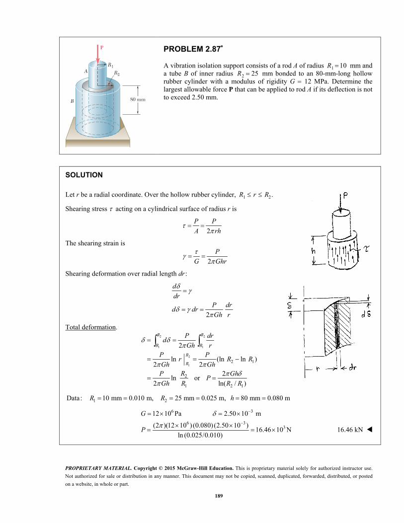
PROPRIETARY MATERIAL. Copyright © 2015 McGraw-Hill Education. This is proprietary material solely for authorized instructor use.
Not authorized for sale or distribution in any manner. This document may not be copied, scanned, duplicated, forwarded, distributed, or posted
on a website, in whole or part.
189
A
B
R1
80 mm
R2
P
PROBLEM 2.87
A vibration isolation support consists of a rod A of radius 1 10R mm and a tube B of inner radius 2 25R mm bonded to an 80-mm-long hollow rubber cylinder with a modulus of rigidity G 12 MPa. Determine the largest allowable force P that can be applied to rod A if its deflection is not to exceed 2.50 mm.
SOLUTION
Let r be a radial coordinate. Over the hollow rubber cylinder, 1 2.R r R
Shearing stress acting on a cylindrical surface of radius r is
2
P P
A rh
The shearing strain is
2
P
G Ghr
Shearing deformation over radial length dr :
2
d
drP dr
d drGh r
Total deformation.
2 2
1 1
2
12 1
2
1 2 1
2
ln (ln ln )2 2
2ln or
2 ln( / )
R R
R R
R
R
P drd
Gh rP P
r R RGh Gh
RP GhP
Gh R R R
1 2Data: 10 mm 0.010 m, 25 mm 0.025 m, 80 mm 0.080 mR R h
6 3
6 33
12 10 Pa 2.50 10 m
(2 )(12 10 ) (0.080) (2.50 10 )16.46 10 N
ln (0.025/0.010)
G
P
16.46 kN
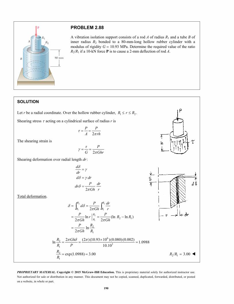
PROPRIETARY MATERIAL. Copyright © 2015 McGraw-Hill Education. This is proprietary material solely for authorized instructor use.
Not authorized for sale or distribution in any manner. This document may not be copied, scanned, duplicated, forwarded, distributed, or posted
on a website, in whole or part.
190
A
B
R1
80 mm
R2
P
PROBLEM 2.88
A vibration isolation support consists of a rod A of radius R1 and a tube B of inner radius R2 bonded to a 80-mm-long hollow rubber cylinder with a modulus of rigidity G 10.93 MPa. Determine the required value of the ratio R2/R1 if a 10-kN force P is to cause a 2-mm deflection of rod A.
SOLUTION
Let r be a radial coordinate. Over the hollow rubber cylinder, 1 2.R r R
Shearing stress acting on a cylindrical surface of radius r is
2
P P
A rh
The shearing strain is
2
P
G Ghr
Shearing deformation over radial length dr :
2
d
drd dr
P drdr
Gh r
Total deformation.
2 2
1 1
2
12 1
2
1
2
ln (ln ln )2 2
ln2
R R
R R
R
R
P drd
Gh rP P
r R RGh Gh
RP
Gh R
62
31
2
1
2 (2 ) (10.93 10 ) (0.080) (0.002)ln 1.0988
10.10
exp(1.0988) 3.00
R Gh
R P
R
R
2 1/ 3.00R R
PROPRIETARY MATERIAL. Copyright © 2015 McGraw-Hill Education. This is proprietary material solely for authorized instructor use.
Not authorized for sale or distribution in any manner. This document may not be copied, scanned, duplicated, forwarded, distributed, or posted
on a website, in whole or part.
191
PROBLEM 2.89
The material constants E, G, k, and v are related by Eqs. (2.33) and (2.43). Show that any one of these constants may be expressed in terms of any other two constants. For example, show that (a) k GE/(9G 3E) and (b) v (3k 2G)/(6k 2G).
SOLUTION
and3(1 2 ) 2(1 )
E Ek G
v v
(a) 1 or 12 2
E Ev v
G G
2 2
3[2 2 4 ] 18 63 1 2 1
2
E EG EGk
G E G G EEG
9 6
EGk
G E
(b) 2(1 )
3(1 2 )
k v
G v
3 6 2 2
3 2 2 6
k kv G Gv
k G G k 3 2
6 2
k G
vk G
PROPRIETARY MATERIAL. Copyright © 2015 McGraw-Hill Education. This is proprietary material solely for authorized instructor use.
Not authorized for sale or distribution in any manner. This document may not be copied, scanned, duplicated, forwarded, distributed, or posted
on a website, in whole or part.
192
PROBLEM 2.90
Show that for any given material, the ratio G/E of the modulus of rigidity over the modulus of elasticity is always less than 1
2 but more than 13 . [Hint: Refer to Eq. (2.43) and to Sec. 2.13.]
SOLUTION
or 2(1 )2(1 )
E EG v
v G
Assume 0v for almost all materials, and 12<v for a positive bulk modulus.
Applying the bounds, 1
2 < 2 1 32
E
G
Taking the reciprocals, 1 1
2 3
G
E
or 1 1
3 2
G
E
PROPRIETARY MATERIAL. Copyright © 2015 McGraw-Hill Education. This is proprietary material solely for authorized instructor use.
Not authorized for sale or distribution in any manner. This document may not be copied, scanned, duplicated, forwarded, distributed, or posted
on a website, in whole or part.
193
Ex � 50 GPa Ey � 15.2 GPa Ez � 15.2 GPa
�xz � 0.254�xy � 0.254 �zy � 0.428
y
zx
PROBLEM 2.91
A composite cube with 40-mm sides and the properties shown is made with glass polymer fibers aligned in the x direction. The cube is constrained against deformations in the y and z directions and is subjected to a tensile load of 65 kN in the x direction. Determine (a) the change in the length of the cube in the x direction, (b) the stresses , ,x y and .z
50 GPa 0.254
15.2 GPa 0.254
15.2 GPa 0.428
x xz
y xy
z zy
E v
E v
E v
SOLUTION
Stress-to-strain equations are
yx yx zx zx
x y z
v v
E E E
(1)
xy x y zy zy
x y z
v v
E E E
(2)
yz yxz x zz
x y z
vv
E E E
(3)
xy yx
x y
v v
E E (4)
yz zy
y z
v v
E E (5)
zx xz
z x
v v
E E (6)
The constraint conditions are 0 and 0.y z
Using (2) and (3) with the constraint conditions gives
1 zy xy
y z xy z x
v v
E E E (7)
1yz xz
y z xy z x
v V
E E E (8)
1 0.428 0.254or 0.428 0.077216
15.2 15.2 500.428 1 0.254
or 0.428 0.07721615.2 15.2 50
y z x y z x
y z x y z x

PROPRIETARY MATERIAL. Copyright © 2015 McGraw-Hill Education. This is proprietary material solely for authorized instructor use.
Not authorized for sale or distribution in any manner. This document may not be copied, scanned, duplicated, forwarded, distributed, or posted
on a website, in whole or part.
194
PROBLEM 2.91 (Continued)
Solving simultaneously, 0.134993 y z x
Using (4) and (5) in (1), 1 xy xz
x x y zx x
v v
E E E
2 6 2
36
6
36
9
1[1 (0.254)(0.134993) (0.254)(0.134993)]
0.93142
(40)(40) 1600 mm 1600 10 m
65 1040.625 10 Pa
1600 10
(0.93142)(40.625 10 )756.78 10
50 10
x xx
x
x
x
x
EE
E
A
P
A
(a) 6(40 mm)(756.78 10 ) x x xL 0.0303 mm x
(b) 640.625 10 Pa x 40.6 MPa x
6 6(0.134993)(40.625 10 ) 5.48 10 Pa y z 5.48 MPa y z
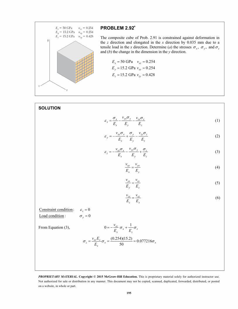
PROPRIETARY MATERIAL. Copyright © 2015 McGraw-Hill Education. This is proprietary material solely for authorized instructor use.
Not authorized for sale or distribution in any manner. This document may not be copied, scanned, duplicated, forwarded, distributed, or posted
on a website, in whole or part.
195
Ex � 50 GPa Ey � 15.2 GPa Ez � 15.2 GPa
�xz � 0.254�xy � 0.254 �zy � 0.428
y
zx
PROBLEM 2.92
The composite cube of Prob. 2.91 is constrained against deformation in the z direction and elongated in the x direction by 0.035 mm due to a tensile load in the x direction. Determine (a) the stresses , ,x y and z and (b) the change in the dimension in the y direction.
50 GPa 0.254
15.2 GPa 0.254
15.2 GPa 0.428
x xz
y xy
z zy
E v
E v
E v
SOLUTION
yx yx zx zx
x y z
v v
E E E
(1)
xy x y zy zy
x y z
v v
E E E
(2)
yz yxz x zz
x y z
vv
E E E
(3)
xy yx
x y
v v
E E (4)
yz zy
y z
v v
E E (5)
zx xz
z x
v v
E E (6)
Constraint condition: 0
Load condition : 0
z
y
From Equation (3), 1
0 xzx z
x z
v
E E
(0.254)(15.2)
0.07721650
xz zz x x
x
v E
E

PROPRIETARY MATERIAL. Copyright © 2015 McGraw-Hill Education. This is proprietary material solely for authorized instructor use.
Not authorized for sale or distribution in any manner. This document may not be copied, scanned, duplicated, forwarded, distributed, or posted
on a website, in whole or part.
196
PROBLEM 2.92 (Continued)
From Equation (1) with 0,y
1 1
1 1[ 0.254 ] [1 (0.254)(0.077216)]
0.98039
0.98039
zx xzx x z x z
x z x x
x z xx x
xx
x xx
v v
E E E E
E E
E
E
But 60.035 mm875 10
40 mmx
xxL
(a) 9 6
3(50 10 )(875 10 )44.625 10 Pa
0.98039
x 44.6 MPa x
0y
6 6(0.077216)(44.625 10 ) 3.446 10 Pa z 3.45 MPa z
From (2),
6 6
9 9
6
1
(0.254)(44.625 10 ) (0.428)(3.446 10 )0
50 10 15.2 10
323.73 10
xy zyy x y z
x y z
v v
E E E
(b) 6(40 mm)( 323.73 10 ) y y yL 0.0129 mm y
PROPRIETARY MATERIAL. Copyright © 2015 McGraw-Hill Education. This is proprietary material solely for authorized instructor use.
Not authorized for sale or distribution in any manner. This document may not be copied, scanned, duplicated, forwarded, distributed, or posted
on a website, in whole or part.
197
120 mm
60 mm r
P
15 mm
PROBLEM 2.93
Knowing that, for the plate shown, the allowable stress is 125 MPa, determine the maximum allowable value of P when (a) r 12 mm, (b) r 18 mm.
SOLUTION
2 6 2(60)(15) 900 mm 900 10 m
120 mm2.00
60 mm
A
D
d
(a) 12 mm
12 mm 0.260 mm
r
rd
maxFrom Fig. 2.60b, 1.92 P
K KA
6 6
3max (900 10 )(125 10 )58.6 10 N
1.92
AP
K
58.3 kN
(b) 18 mm
18 mm, 0.30 From Fig 2.60b, 1.7560 mm
r
r Kd
6 6
3max (900 10 )(125 10 )64.3 10 N
1.75
AP
K 64.3 kN
PROPRIETARY MATERIAL. Copyright © 2015 McGraw-Hill Education. This is proprietary material solely for authorized instructor use.
Not authorized for sale or distribution in any manner. This document may not be copied, scanned, duplicated, forwarded, distributed, or posted
on a website, in whole or part.
198
120 mm
60 mm r
P
15 mm
PROBLEM 2.94
Knowing that P 38 kN, determine the maximum stress when (a) r 10 mm, (b) r 16 mm, (c) r 18 mm.
SOLUTION
2 6 2(60)(15) 900 mm 900 10 m
10 mm2.00
60 mm
A
D
d
(a) 10 mm
10 mm 0.166760 mm
r
rd
maxFrom Fig. 2.60b, 2.06 KP
KA
3
6max 6
(2.06)(38 10 )87.0 10 Pa
900 10
87.0 MPa
(b) 16 mm
16 mm 0.266760 mm
r
rd
From Fig. 2.60b, 1.78K
3
6max 6
(1.78)(38 10 )75.2 10 Pa
900 10
75.2 MPa
(c) 18 mm
18 mm, 0.3060 mm
From Fig 2.60b, 1.75
rr
d
K
3
6max 6
(1.75)(38 10 )73.9 10 Pa
900 10
73.9 MPa
PROPRIETARY MATERIAL. Copyright © 2015 McGraw-Hill Education. This is proprietary material solely for authorized instructor use.
Not authorized for sale or distribution in any manner. This document may not be copied, scanned, duplicated, forwarded, distributed, or posted
on a website, in whole or part.
199
A
d rf �
P
12 in.
183 in.
38 in.11
164 in.PROBLEM 2.95
A hole is to be drilled in the plate at A. The diameters of the bits available to drill the hole range from 1
2 to 11/2 in. in
14
-in. increments. If the allowable stress in the plate is 21 ksi, determine (a) the diameter d of the largest bit that can be used if the allowable load P at the hole is to exceed that at the fillets, (b) the corresponding allowable load P.
SOLUTION
At the fillets: 4.6875 0.375
1.5 0.123.125 3.125
D r
d d
From Fig. 2.60b, 2.10K
2min
allmax all
min
min allall
(3.125)(0.5) 1.5625 in
(1.5625)(21)15.625 kips
2.10
A
PK
A
AP
K
At the hole: net ( 2 ) , from Fig. 2.60a A D r t K
net allmax all all
net
P A
K PA K
with all4.6875 in. 0.5 in. 21 ksiD t
Hole diam. r 2d D r 2 /r D K netA allP
0.5 in. 0.25 in. 4.1875 in. 0.107 2.68 2.0938 in2 16.41 kips
0.75 in. 0.375 in. 3.9375 in. 0.16 2.58 1.96875 in2 16.02 kips
1 in. 0.5 in. 3.6875 in. 0.213 2.49 1.84375 in2 15.55 kips
1.25 in. 0.625 in. 3.4375 in. 0.267 2.41 1.71875 in2 14.98 kips
1.5 in. 0.75 in. 3.1875 in. 0.32 2.34 1.59375 in2 14.30 kips
(a) Largest hole with all 15.625 kipsP is the 34
-in.-diameter hole.
(b) Allowable load all 15.63 kipsP

PROPRIETARY MATERIAL. Copyright © 2015 McGraw-Hill Education. This is proprietary material solely for authorized instructor use.
Not authorized for sale or distribution in any manner. This document may not be copied, scanned, duplicated, forwarded, distributed, or posted
on a website, in whole or part.
200
A
d rf �
P
12 in.
183 in.
38 in.11
164 in.
PROBLEM 2.96
(a) For 13 kipsP and 12
in.,d determine the maximum stress in the plate shown. (b) Solve part a, assuming that the hole at A is not drilled.
SOLUTION
Maximum stress at hole:
Use Fig. 2.60a for values of K.
2net
maxnet
2 0.50.017, 2.68
4.6875
(0.5)(4.6875 0.5) 2.0938 in
(2.68)(13)16.64 ksi
2.0938
rK
D
A
PK
A
Maximum stress at fillets:
Use Fig. 2.60b for values of K.
0.375 4.6875
0.12 1.53.125 3.125
r D
d d 2.10K
2min
maxmin
(0.5)(3.125) 1.5625 in
(2.10)(13)17.47 ksi
1.5625
A
PK
A
(a) With hole and fillets: 17.47 ksi
(b) Without hole: 17.47 ksi
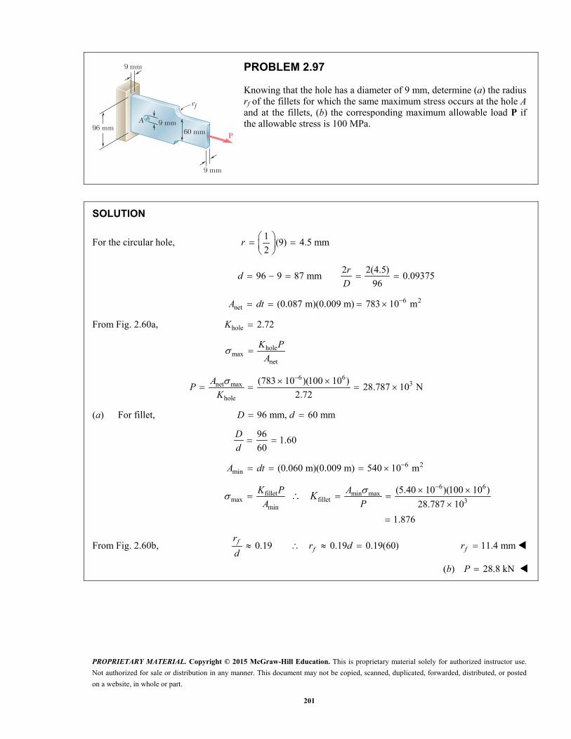
PROPRIETARY MATERIAL. Copyright © 2015 McGraw-Hill Education. This is proprietary material solely for authorized instructor use.
Not authorized for sale or distribution in any manner. This document may not be copied, scanned, duplicated, forwarded, distributed, or posted
on a website, in whole or part.
201
P
9 mm
9 mm
9 mm
96 mm 60 mm
A
rf
PROBLEM 2.97
Knowing that the hole has a diameter of 9 mm, determine (a) the radius rf of the fillets for which the same maximum stress occurs at the hole A and at the fillets, (b) the corresponding maximum allowable load P if the allowable stress is 100 MPa.
SOLUTION
For the circular hole, 1
(9) 4.5 mm2
r
2 2(4.5)
96 9 87 mm 0.0937596
rd
D
6 2net (0.087 m)(0.009 m) 783 10 mA dt
From Fig. 2.60a, hole 2.72K
holemax
net
K P
A
6 6
3net max
hole
(783 10 )(100 10 )28.787 10 N
2.72
AP
K
(a) For fillet, 96 mm, 60 mmD d
96
1.6060
D
d
6 2min (0.060 m)(0.009 m) 540 10 mA dt
6 6fillet min max
max fillet 3min
(5.40 10 )(100 10 )
28.787 10
1.876
K P A
A PK
From Fig. 2.60b, 0.19 0.19 0.19(60) ff
rr d
d 11.4 mmfr
(b) 28.8 kNP
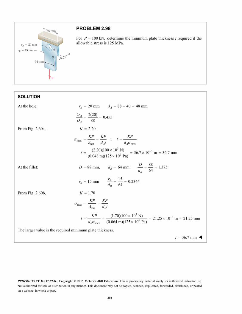
PROPRIETARY MATERIAL. Copyright © 2015 McGraw-Hill Education. This is proprietary material solely for authorized instructor use.
Not authorized for sale or distribution in any manner. This document may not be copied, scanned, duplicated, forwarded, distributed, or posted
on a website, in whole or part.
202
rA 5 20 mm
rB 5 15 mm
B
A
64 mm
88 mm
P
t
PROBLEM 2.98
For 100 kN,P determine the minimum plate thickness t required if the allowable stress is 125 MPa.
SOLUTION
At the hole: 20 mm 88 40 48 mmA Ar d
2 2(20)
0.45588
A
A
r
D
From Fig. 2.60a, 2.20K
maxnet max
33
6
(2.20)(100 10 N)36.7 10 m 36.7 mm
(0.048 m)(125 10 Pa)
A A
KP KP KPt
A d t d
t
At the fillet: 88
88 mm, 64 mm 1.37564B
B
DD d
d
15
15 mm 0.234464
BB
B
rr
d
From Fig. 2.60b, 1.70K
maxmin B
KP KP
A d t
3
36
max
(1.70)(100 10 N)21.25 10 m 21.25 mm
(0.064 m)(125 10 Pa)B
KPt
d
The larger value is the required minimum plate thickness.
36.7 mmt
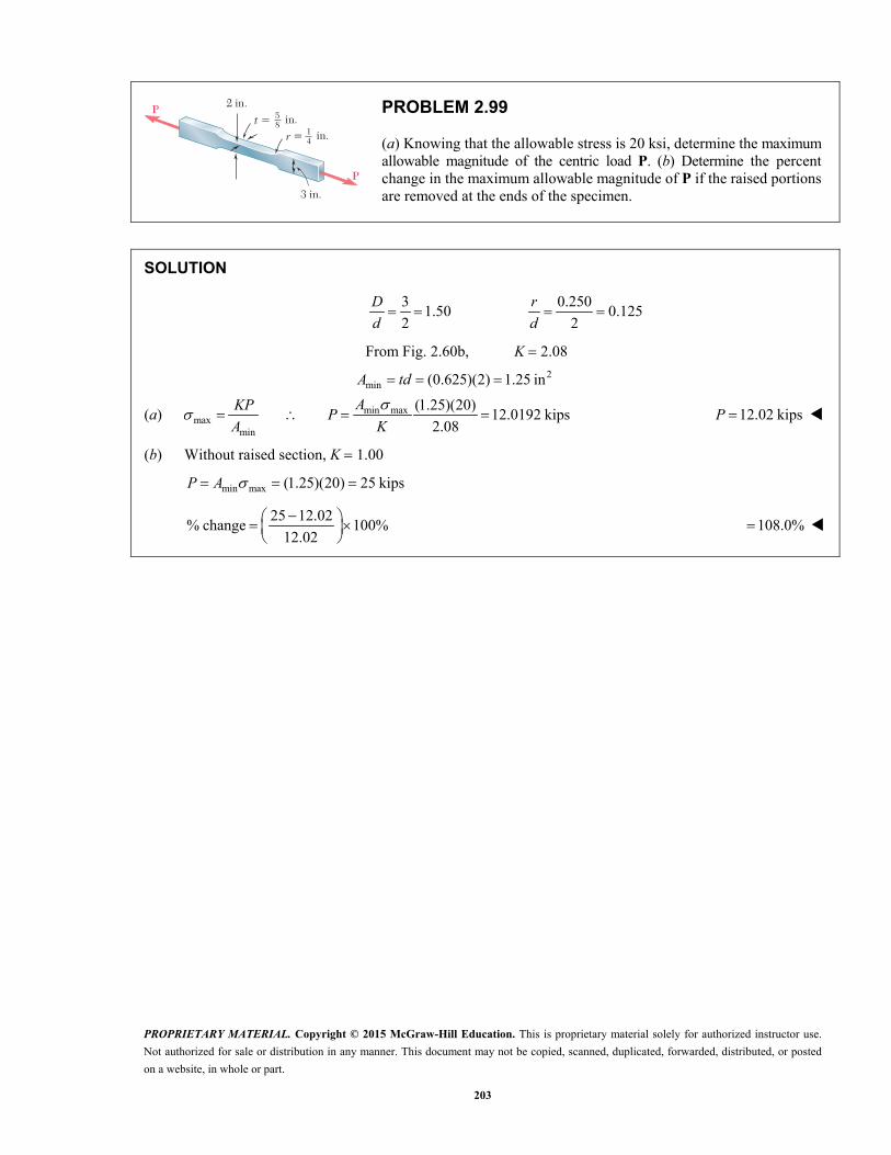
PROPRIETARY MATERIAL. Copyright © 2015 McGraw-Hill Education. This is proprietary material solely for authorized instructor use.
Not authorized for sale or distribution in any manner. This document may not be copied, scanned, duplicated, forwarded, distributed, or posted
on a website, in whole or part.
203
P
P
t 5
2 in.
3 in.
58 in.
r 5 14 in.
PROBLEM 2.99
(a) Knowing that the allowable stress is 20 ksi, determine the maximum allowable magnitude of the centric load P. (b) Determine the percent change in the maximum allowable magnitude of P if the raised portions are removed at the ends of the specimen.
SOLUTION
3 0.250
1.50 0.1252 2
D r
d d
From Fig. 2.60b, K 2.08
2min (0.625)(2) 1.25 in A td
(a) min maxmax
min
(1.25)(20)12.0192 kips
2.08
AKPP
A K 12.02 kipsP
(b) Without raised section, K 1.00
min max (1.25)(20) 25 kipsP A
25 12.02
% change 100%12.02
108.0%
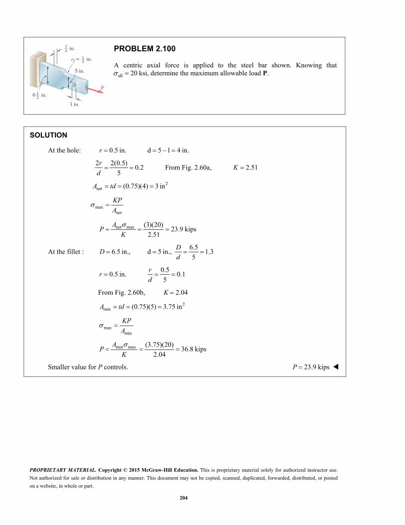
PROPRIETARY MATERIAL. Copyright © 2015 McGraw-Hill Education. This is proprietary material solely for authorized instructor use.
Not authorized for sale or distribution in any manner. This document may not be copied, scanned, duplicated, forwarded, distributed, or posted
on a website, in whole or part.
204
34 in.
12 in.
12 in.
5 in.
1 in.
6
rf 5
P
PROBLEM 2.100
A centric axial force is applied to the steel bar shown. Knowing that
all 20 ksi , determine the maximum allowable load P.
SOLUTION
At the hole: 0.5 in. d 5 1 4 in. r
2 2(0.5)
0.2 From Fig. 2.60a, 2.515
r
Kd
2net (0.75)(4) 3 in A td
maxnet
KP
A
net max (3)(20)23.9 kips
2.51
AP
K
At the fillet : 6.5
6.5 in., d 5 in., 1.35
DD
d
0.5
0.5 in. 0.15
rr
d
From Fig. 2.60b, K 2.04
2min (0.75)(5) 3.75 in A td
maxmin
KP
A
min max (3.75)(20)36.8 kips
2.04
AP
K
Smaller value for P controls. 23.9 kipsP

PROPRIETARY MATERIAL. Copyright © 2015 McGraw-Hill Education. This is proprietary material solely for authorized instructor use.
Not authorized for sale or distribution in any manner. This document may not be copied, scanned, duplicated, forwarded, distributed, or posted
on a website, in whole or part.
205
L
B
A
P
PROBLEM 2.101
The cylindrical rod AB has a length L 5 ft and a 0.75-in. diameter; it is made of a mild steel that is assumed to be elastoplastic with E 29 × 106 psi and 36 ksiY . A force P is applied to the bar and then removed to give it a permanent set .P Determine the maximum value of the force P and the maximum amount m by which the bar should be stretched if the desired value of P is (a) 0.1 in., (b) 0.2 in.
SOLUTION
2 2 2(0.75) 0.44179 in 5 ft 60 in.4 4
A d L
3
3
(60)(36 10 )0.074483 in.
29 10
Yy Y
LL
E
When m exceeds ,Y thus causing permanent stretch , p the maximum force is
3 3(0.44179)(36 10 ) 15.9043 10 lb m YP A
15.90 kipsP
' so that p m m Y m p Y
(a) 0.1 in. 0.1 0.074483 0.1745 in. p m
(b) 0.2 in. 0.2 0.074483 0.274 in. p m

PROPRIETARY MATERIAL. Copyright © 2015 McGraw-Hill Education. This is proprietary material solely for authorized instructor use.
Not authorized for sale or distribution in any manner. This document may not be copied, scanned, duplicated, forwarded, distributed, or posted
on a website, in whole or part.
206
L
B
A
P
PROBLEM 2.102
The cylindrical rod AB has a length L 6 ft and a 1.25-in. diameter; it is made of a mild steel that is assumed to be elastoplastic with E 29 × 106 psi and 36 ksiY . A force P is applied to the bar until end A has moved down by an amount m . Determine the maximum value of the force P and the permanent set of the bar after the force has been removed, knowing (a) 0.125 in.,m (b) 0.250 in.m
SOLUTION
2 2 2(1.25) 1.22718 in 6 ft 72 in.4 4
A d L
3
3
(72)(36 10 )0.089379 in.
29 10
YY Y
LL
E
If 3, (1.22718)(36 10 ) m Y m YP A
344.179 10 lb 44.2 kips
(a) 0.125 in. > so that 44.2 kips m Y mP
0.089379
m YY
P L L
AE E
0.125 0.089379 0.356 in. p m
(b) 0.250 in. > so that 44.2 kips m Y mP
Y
0.250 0.089379 0.1606 in. p m
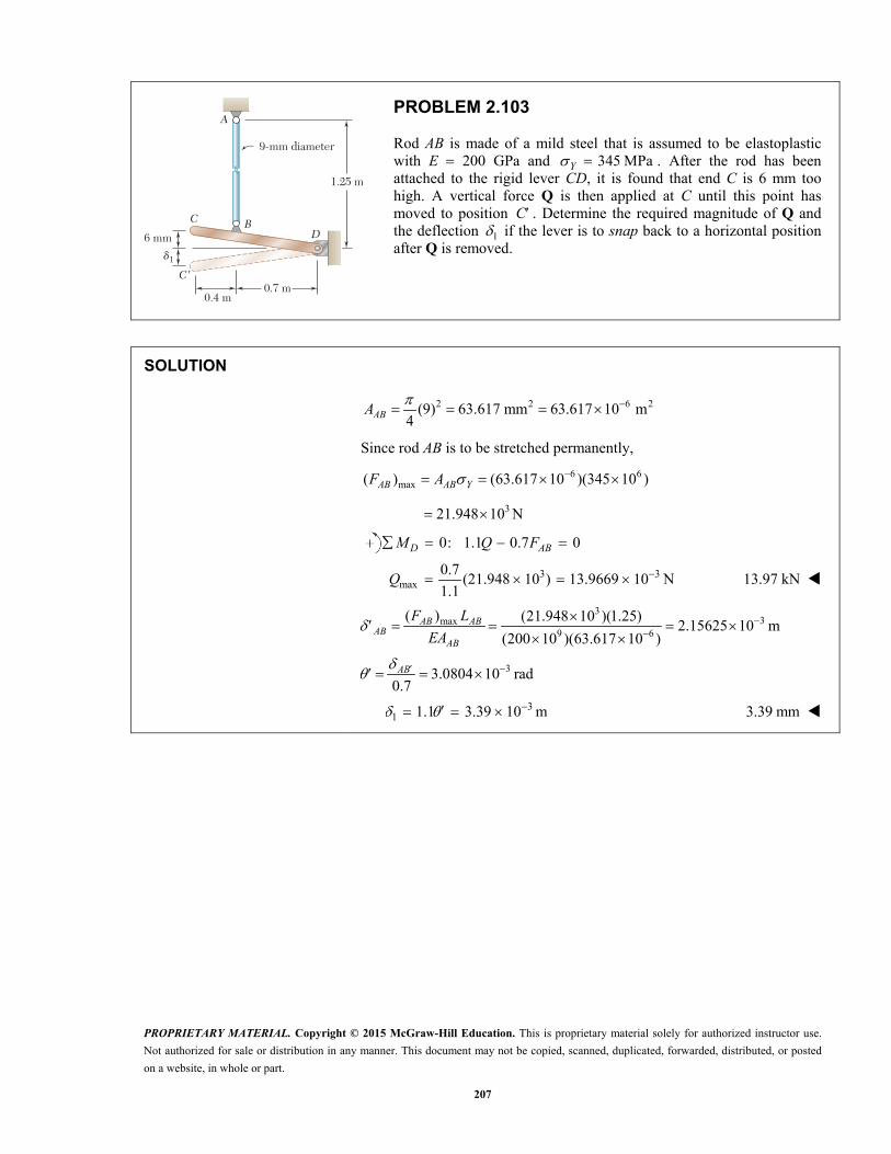
PROPRIETARY MATERIAL. Copyright © 2015 McGraw-Hill Education. This is proprietary material solely for authorized instructor use.
Not authorized for sale or distribution in any manner. This document may not be copied, scanned, duplicated, forwarded, distributed, or posted
on a website, in whole or part.
207
6 mm
9-mm diameter
0.4 m0.7 m
1.25 m
C BD
A
C�
1d
PROBLEM 2.103
Rod AB is made of a mild steel that is assumed to be elastoplastic with E 200 GPa and 345 MPaY . After the rod has been attached to the rigid lever CD, it is found that end C is 6 mm too high. A vertical force Q is then applied at C until this point has moved to position C . Determine the required magnitude of Q and the deflection 1 if the lever is to snap back to a horizontal position after Q is removed.
SOLUTION
2 2 6 2(9) 63.617 mm 63.617 10 m4ABA
Since rod AB is to be stretched permanently,
6 6max( ) (63.617 10 )(345 10 )AB AB YF A
321.948 10 N
0: 1.1 0.7 0 D ABM Q F
3 3max
0.7(21.948 10 ) 13.9669 10 N
1.1 Q 13.97 kN
33max
9 6
( ) (21.948 10 )(1.25)2.15625 10 m
(200 10 )(63.617 10 )
AB AB
ABAB
F L
EA
33.0804 10 rad0.7
AB
31 1.1 3.39 10 m 3.39 mm
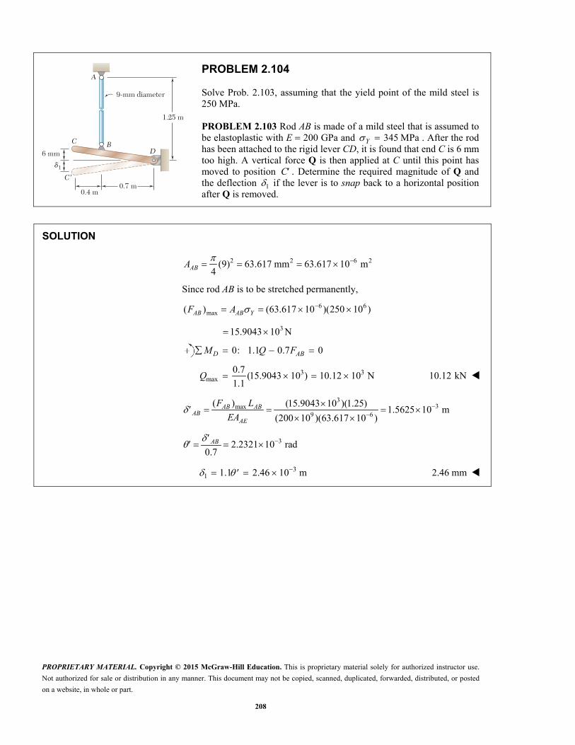
PROPRIETARY MATERIAL. Copyright © 2015 McGraw-Hill Education. This is proprietary material solely for authorized instructor use.
Not authorized for sale or distribution in any manner. This document may not be copied, scanned, duplicated, forwarded, distributed, or posted
on a website, in whole or part.
208
6 mm
9-mm diameter
0.4 m0.7 m
1.25 m
C BD
A
C�
1d
PROBLEM 2.104
Solve Prob. 2.103, assuming that the yield point of the mild steel is 250 MPa.
PROBLEM 2.103 Rod AB is made of a mild steel that is assumed to be elastoplastic with E 200 GPa and 345 MPaY . After the rod has been attached to the rigid lever CD, it is found that end C is 6 mm too high. A vertical force Q is then applied at C until this point has moved to position C . Determine the required magnitude of Q and the deflection 1 if the lever is to snap back to a horizontal position after Q is removed.
SOLUTION
2 2 6 2(9) 63.617 mm 63.617 10 m4ABA
Since rod AB is to be stretched permanently,
6 6max( ) (63.617 10 )(250 10 )AB AB YF A
315.9043 10 N
0: 1.1 0.7 0 D ABM Q F
3 3max
0.7(15.9043 10 ) 10.12 10 N
1.1 Q 10.12 kN
33max
9 6
( ) (15.9043 10 )(1.25)1.5625 10 m
(200 10 )(63.617 10 )
AB AB
ABAE
F L
EA
32.2321 10 rad0.7
AB
31 1.1 2.46 10 m 2.46 mm
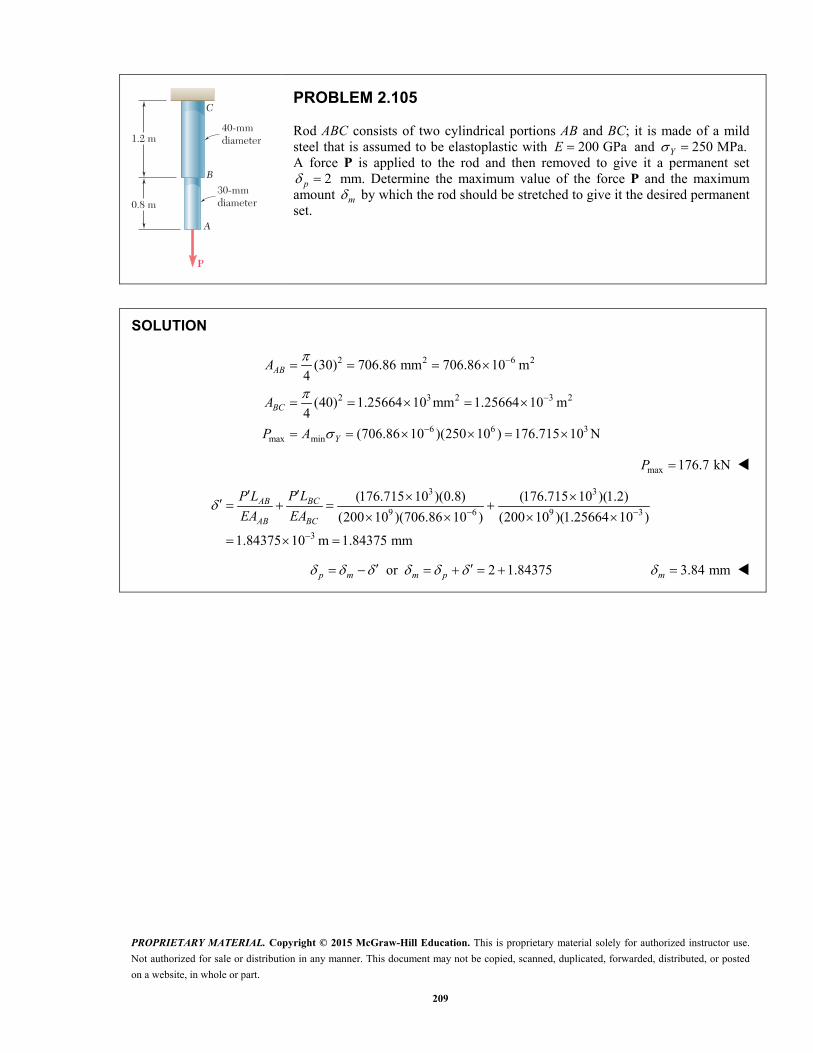
PROPRIETARY MATERIAL. Copyright © 2015 McGraw-Hill Education. This is proprietary material solely for authorized instructor use.
Not authorized for sale or distribution in any manner. This document may not be copied, scanned, duplicated, forwarded, distributed, or posted
on a website, in whole or part.
209
P
40-mmdiameter
30-mmdiameter
1.2 m
0.8 m
C
B
A
PROBLEM 2.105
Rod ABC consists of two cylindrical portions AB and BC; it is made of a mild steel that is assumed to be elastoplastic with 200 GPaE and 250 MPa.Y A force P is applied to the rod and then removed to give it a permanent set
2p mm. Determine the maximum value of the force P and the maximum amount m by which the rod should be stretched to give it the desired permanent set.
SOLUTION
2 2 6 2
2 3 2 3 2
6 6 3max min
(30) 706.86 mm 706.86 10 m4
(40) 1.25664 10 mm 1.25664 10 m4
(706.86 10 )(250 10 ) 176.715 10 N
AB
BC
Y
A
A
P A
max 176.7 kNP
3 3
9 6 9 3
3
(176.715 10 )(0.8) (176.715 10 )(1.2)
(200 10 )(706.86 10 ) (200 10 )(1.25664 10 )
1.84375 10 m 1.84375 mm
BCAB
AB BC
P LP L
EA EA
or 2 1.84375p m m p 3.84 mmm
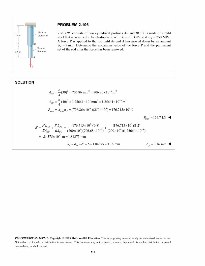
PROPRIETARY MATERIAL. Copyright © 2015 McGraw-Hill Education. This is proprietary material solely for authorized instructor use.
Not authorized for sale or distribution in any manner. This document may not be copied, scanned, duplicated, forwarded, distributed, or posted
on a website, in whole or part.
210
P
40-mmdiameter
30-mmdiameter
1.2 m
0.8 m
C
B
A
PROBLEM 2.106
Rod ABC consists of two cylindrical portions AB and BC; it is made of a mild steel that is assumed to be elastoplastic with 200 GPaE and 250 MPa.Y A force P is applied to the rod until its end A has moved down by an amount
5 mm.m Determine the maximum value of the force P and the permanent set of the rod after the force has been removed.
SOLUTION
2 2 6 2
2 3 2 3 2
6 6 3max min
(30) 706.86 mm 706.86 10 m4
(40) 1.25664 10 mm 1.25644 10 m4
(706.86 10 )(250 10 ) 176.715 10 N
AB
BC
Y
A
A
P A
max 176.7 kNP
3 3
9 6 9 3
3
(176.715 10 )(0.8) (176.715 10 )(1.2)
(200 10 )(706.68 10 ) (200 10 )(1.25664 10 )
1.84375 10 m 1.84375 mm
BCAB
AB BC
P LP L
EA EA
5 1.84375 3.16 mmp m 3.16 mmp

PROPRIETARY MATERIAL. Copyright © 2015 McGraw-Hill Education. This is proprietary material solely for authorized instructor use.
Not authorized for sale or distribution in any manner. This document may not be copied, scanned, duplicated, forwarded, distributed, or posted
on a website, in whole or part.
211
190 mm
190 mm
C
B
A
P
PROBLEM 2.107
Rod AB consists of two cylindrical portions AC and BC, each with a cross-sectional area of 1750 mm2. Portion AC is made of a mild steel with 200 GPaE and
250 MPa,Y and portion CB is made of a high-strength steel with 200 GPaE and 345 MPa.Y A load P is applied at C as shown. Assuming both steels to be elastoplastic, determine (a) the maximum deflection of C if P is gradually increased from zero to 975 kN and then reduced back to zero, (b) the maximum stress in each portion of the rod, (c) the permanent deflection of C.
SOLUTION
Displacement at C to cause yielding of AC.
6
, 3, , 9
(0.190)(250 10 )0.2375 10 m
200 10
AC Y ACC Y AC Y AC
LL
E
Corresponding force. 6 6 3, (1750 10 )(250 10 ) 437.5 10 N AC Y ACF A
9 6 3
3(200 10 )(1750 10 )(0.2375 10 )437.5 10 N
0.190C
CBCB
EAF
L
For equilibrium of element at C,
3( ) 0 875 10 NAC CB Y Y AC CBF F P P F F
Since applied load 3 3975 10 N 875 10 N,P portion AC yields.
3 3 3437.5 10 975 10 N 537.5 10 NCB ACF F P
(a) 3
39 6
(537.5 10 )(0.190)0.29179 10 m
(200 10 )(1750 10 )CB CD
CF L
EA
0.292 mm
(b) Maximum stresses: , 250 MPa AC Y AC 250 MPa
3
66
537.5 10307.14 10 Pa 307 MPa
1750 10
BC
BCF
A 307 MPa
(c) Deflection and forces for unloading.
3 3
33
9 6
975 10 2 487.5 10 N
(487.5 10 )(0.190)0.26464 10 m
(200 10 )(1750 10 )
AC AC CB CB ACCB AC AC
AB
AC CB AC AC
P L P L LP P P
EA EA L
P P P P P
3 3
3
0.29179 10 0.26464 10
0.02715 10 m
p m
0.0272 mm
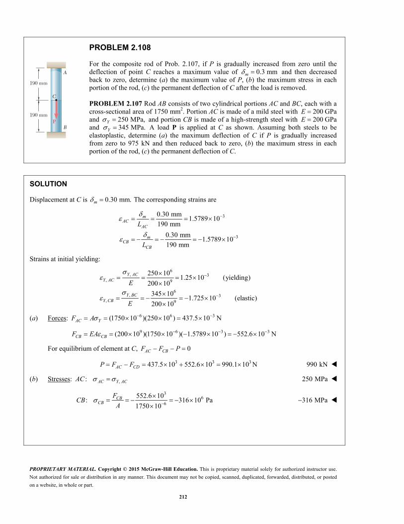
PROPRIETARY MATERIAL. Copyright © 2015 McGraw-Hill Education. This is proprietary material solely for authorized instructor use.
Not authorized for sale or distribution in any manner. This document may not be copied, scanned, duplicated, forwarded, distributed, or posted
on a website, in whole or part.
212
190 mm
190 mm
C
B
A
P
PROBLEM 2.108
For the composite rod of Prob. 2.107, if P is gradually increased from zero until the deflection of point C reaches a maximum value of 0.3 mmm and then decreased back to zero, determine (a) the maximum value of P, (b) the maximum stress in each portion of the rod, (c) the permanent deflection of C after the load is removed.
PROBLEM 2.107 Rod AB consists of two cylindrical portions AC and BC, each with a cross-sectional area of 1750 mm2. Portion AC is made of a mild steel with 200E GPa and 250 MPa,Y and portion CB is made of a high-strength steel with 200E GPa and 345 MPa.Y A load P is applied at C as shown. Assuming both steels to be elastoplastic, determine (a) the maximum deflection of C if P is gradually increased from zero to 975 kN and then reduced back to zero, (b) the maximum stress in each portion of the rod, (c) the permanent deflection of C.
SOLUTION
Displacement at C is 0.30 mm.m The corresponding strains are
3
3
0.30 mm1.5789 10
190 mm
0.30 mm1.5789 10
190 mm
mAC
AC
mCB
CB
L
L
Strains at initial yielding:
6, 3
, 9
6, 3
, 9
250 101.25 10 (yielding)
200 10
345 101.725 10 (elastic)
200 10
Y ACY AC
Y BCY CB
E
E
(a) Forces: 6 6 3(1750 10 )(250 10 ) 437.5 10 NAC YF A
9 6 3 3(200 10 )(1750 10 )( 1.5789 10 ) 552.6 10 NCB CBF EA
For equilibrium of element at C, 0AC CBF F P
3 3 3437.5 10 552.6 10 990.1 10 N AC CDP F F 990 kN
(b) Stresses: ,: AC Y ACAC 250 MPa
3
66
552.6 10: 316 10 Pa
1750 10
CB
CBF
CBA
316 MPa

PROPRIETARY MATERIAL. Copyright © 2015 McGraw-Hill Education. This is proprietary material solely for authorized instructor use.
Not authorized for sale or distribution in any manner. This document may not be copied, scanned, duplicated, forwarded, distributed, or posted
on a website, in whole or part.
213
PROBLEM 2.108 (Continued)
(c) Deflection and forces for unloading.
3 3
33
9 6
2 990.1 10 N 495.05 10 N
(495.05 10 )(0.190)0.26874 10 m 0.26874 mm
(200 10 )(1750 10 )
AC AC CB CB ACCB AC AC
AB
AC CB AC AC
P L P L LP P P
EA EA L
P P P P P
0.30 mm 0.26874 mm p m 0.0313mm

PROPRIETARY MATERIAL. Copyright © 2015 McGraw-Hill Education. This is proprietary material solely for authorized instructor use.
Not authorized for sale or distribution in any manner. This document may not be copied, scanned, duplicated, forwarded, distributed, or posted
on a website, in whole or part.
214
1 m
AB C
Q
D E
1 m
2 m
PROBLEM 2.109
Each cable has a cross-sectional area of 100 mm2 and is made of an elastoplastic material for which 345 MPaY and 200 GPa.E A force Q is applied at C to the rigid bar ABC and is gradually increased from 0 to 50 kN and then reduced to zero. Knowing that the cables were initially taut, determine (a) the maximum stress that occurs in cable BD, (b) the maximum deflection of point C, (c) the final displacement of point C. (Hint: In part c, cable CE is not taut.)
SOLUTION
Elongation constraints for taut cables.
Let rotation angle of rigid bar . ABC
CEBD
AB ACL L
1
2 AB
BD CE CEAC
L
L (1)
Equilibrium of bar ABC.
0 : 0A AB BD AC CE ACM L F L F L Q
1
2AB
CE BD CE BDAC
LQ F F F F
L (2)
Assume cable CE is yielded. 6 6 3(100 10 )(345 10 ) 34.5 10 NCE YF A
From (2), 3 3 32( ) (2)(50 10 34.5 10 ) 31.0 10 NBD CEF Q F
Since 3 < 34.5 10 N,BD YF A cable BD is elastic when 50 kN.Q
PROPRIETARY MATERIAL. Copyright © 2015 McGraw-Hill Education. This is proprietary material solely for authorized instructor use.
Not authorized for sale or distribution in any manner. This document may not be copied, scanned, duplicated, forwarded, distributed, or posted
on a website, in whole or part.
215
PROBLEM 2.109 (Continued)
(a) Maximum stresses. 345 MPaCE Y
3
66
31.0 10310 10 Pa
100 10BD
BDF
A
310 MPaBD
(b) Maximum of deflection of point C.
3
39 6
(31.0 10 )(2)3.1 10 m
(200 10 )(100 10 )BD BD
BDF L
EA
From (1), 32 6.2 10 mC CE BD 6.20 mm
Permanent elongation of cable CE: ( ) ( )
Y CECE p CE
L
E
max
63 3
9
( ) ( )
(345 10 )(2)6.20 10 2.75 10 m
200 10
Y CECE P CE
L
E
(c) Unloading. Cable CE is slack ( 0)CEF at 0.Q
From (2), 2( ) 2(0 0) 0BD CEF Q F
Since cable BD remained elastic, 0.BD BDBD
F L
EA 0

PROPRIETARY MATERIAL. Copyright © 2015 McGraw-Hill Education. This is proprietary material solely for authorized instructor use.
Not authorized for sale or distribution in any manner. This document may not be copied, scanned, duplicated, forwarded, distributed, or posted
on a website, in whole or part.
216
1 m
AB C
Q
D E
1 m
2 m
PROBLEM 2.110
Solve Prob. 2.109, assuming that the cables are replaced by rods of the same cross-sectional area and material. Further assume that the rods are braced so that they can carry compressive forces.
PROBLEM 2.109 Each cable has a cross-sectional area of 100 mm2 and is made of an elastoplastic material for which 345 MPaY and
200 GPa.E A force Q is applied at C to the rigid bar ABC and is gradually increased from 0 to 50 kN and then reduced to zero. Knowing that the cables were initially taut, determine (a) the maximum stress that occurs in cable BD, (b) the maximum deflection of point C, (c) the final displacement of point C. (Hint: In part c, cable CE is not taut.)
SOLUTION
Elongation constraints.
Let rotation angle of rigid bar .ABC
BC CE
AB ACL L
1
2 AB
BD CE CEAC
L
L (1)
Equilibrium of bar ABC.
0: 0 A AB BD AC CE ACM L F L F L Q
1
2AB
CE BD CE BDAC
LQ F F F F
L (2)
Assume cable CE is yielded. 6 6 3(100 10 )(345 10 ) 34.5 10 N CE YF A
From (2), 3 3 32( ) (2)(50 10 34.5 10 ) 31.0 10 N BD CEF Q F
Since 334.5 10 N, BD YF A cable BD is elastic when 50 kN.Q

PROPRIETARY MATERIAL. Copyright © 2015 McGraw-Hill Education. This is proprietary material solely for authorized instructor use.
Not authorized for sale or distribution in any manner. This document may not be copied, scanned, duplicated, forwarded, distributed, or posted
on a website, in whole or part.
217
PROBLEM 2.110 (Continued)
(a) Maximum stresses. 345 MPaCE Y
3
66
31.0 10310 10 Pa
100 10BD
BDF
A
310 MPaBD
(b) Maximum of deflection of point C.
3
39 6
(31.0 10 )(2)3.1 10 m
(200 10 )(100 10 )BD BD
BDF L
EA
From (1), 32 6.2 10 mC CE BD 6.20 mm
Unloading. 350 10 N, CE CQ
From (1), 12BD C
Elastic 9 6 1
62(200 10 )(100 10 )( )5 10
2
CBD
BD CBD
EAF
L
9 6
6(200 10 )(100 10 )( )10 10
2
CE CCE C
CE
EAF
L
From (2), 612 12.5 10 CE BD CQ F F
Equating expressions for ,Q 6 312.5 10 50 10 C
34 10 mC
(c) Final displacement. 3 3 3( ) 6.2 10 4 10 2.2 10 mC C m C 2.20 mm
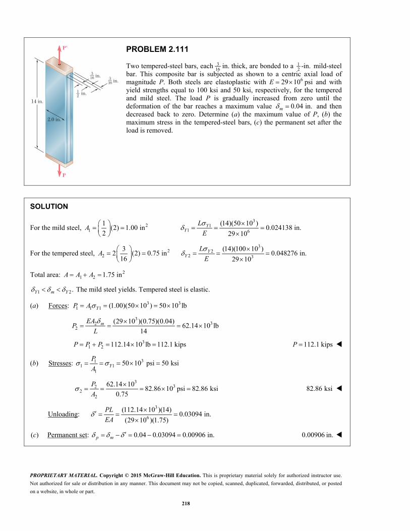
PROPRIETARY MATERIAL. Copyright © 2015 McGraw-Hill Education. This is proprietary material solely for authorized instructor use.
Not authorized for sale or distribution in any manner. This document may not be copied, scanned, duplicated, forwarded, distributed, or posted
on a website, in whole or part.
218
P
14 in.
2.0 in.
P'
in.
12 in.
316 3
16
in.
PROBLEM 2.111
Two tempered-steel bars, each 316 in. thick, are bonded to a 1
2 -in. mild-steel bar. This composite bar is subjected as shown to a centric axial load of magnitude P. Both steels are elastoplastic with 629 10 psi E and with yield strengths equal to 100 ksi and 50 ksi, respectively, for the tempered and mild steel. The load P is gradually increased from zero until the deformation of the bar reaches a maximum value 0.04 in.m and then decreased back to zero. Determine (a) the maximum value of P, (b) the maximum stress in the tempered-steel bars, (c) the permanent set after the load is removed.
SOLUTION
For the mild steel, 21
1(2) 1.00 in
2
A 3
11 6
(14)(50 10 )0.024138 in.
29 10
YY
L
E
For the tempered steel, 22
32 (2) 0.75 in
16
A 3
22 3
(14)(100 10 )0.048276 in.
29 10
YY
L
E
Total area: 21 2 1.75 in A A A
1 2.Y m Y The mild steel yields. Tempered steel is elastic.
(a) Forces: 3 31 1 1 (1.00)(50 10 ) 50 10 lb YP A
3
322
(29 10 )(0.75)(0.04)62.14 10 lb
14
mEA
PL
31 2 112.14 10 lb 112.1 kips P P P 112.1 kipsP
(b) Stresses: 311 1
1
50 10 psi 50 ksiYP
A
3
322
2
62.14 1082.86 10 psi 82.86 ksi
0.75
P
A 82.86 ksi
Unloading: 3
6
(112.14 10 )(14)0.03094 in.
(29 10 )(1.75)
PL
EA
(c) Permanent set: 0.04 0.03094 0.00906 in.p m 0.00906 in.

PROPRIETARY MATERIAL. Copyright © 2015 McGraw-Hill Education. This is proprietary material solely for authorized instructor use.
Not authorized for sale or distribution in any manner. This document may not be copied, scanned, duplicated, forwarded, distributed, or posted
on a website, in whole or part.
219
P
14 in.
2.0 in.
P'
in.
12 in.
316 3
16
in.
PROBLEM 2.112
For the composite bar of Prob. 2.111, if P is gradually increased from zero to 98 kips and then decreased back to zero, determine (a) the maximum deformation of the bar, (b) the maximum stress in the tempered-steel bars, (c) the permanent set after the load is removed.
PROBLEM 2.111 Two tempered-steel bars, each 316 in. thick, are bonded to
a 12 -in. mild-steel bar. This composite bar is subjected as shown to a centric
axial load of magnitude P. Both steels are elastoplastic with 629 10E psi and with yield strengths equal to 100 ksi and 50 ksi, respectively, for the tempered and mild steel. The load P is gradually increased from zero until the deformation of the bar reaches a maximum value 0.04 in.m and then decreased back to zero. Determine (a) the maximum value of P, (b) the maximum stress in the tempered-steel bars, (c) the permanent set after the load is removed.
SOLUTION
Areas: Mild steel: 21
1(2) 1.00 in
2
A
Tempered steel: 22
32 (2) 0.75 in
16
A
Total: 21 2 1.75 in A A A
Total force to yield the mild steel:
3 31 1 (1.75)(50 10 ) 87.50 10 lbY
Y Y YP
P AA
,YP P therefore, mild steel yields.
Let 1 force carried by mild steel.P
2 force carried by tempered steel.P
3 31 1 1 (1.00)(50 10 ) 50 10 lb P A
3 3 31 2 2 1, 98 10 50 10 48 10 lbP P P P P P
(a) 3
26
2
(48 10 )(14)
(29 10 )(0.75)
m
P L
EA 0.0309 in.
(b) 3
322
2
48 1064 10 psi
0.75
P
A 64.0 ksi
Unloading: 3
6
(98 10 )(14)0.02703 in.
(29 10 )(1.75)
PL
EA
(c) 0.03090 0.02703 0.003870 in.P m 0.00387 in.

PROPRIETARY MATERIAL. Copyright © 2015 McGraw-Hill Education. This is proprietary material solely for authorized instructor use.
Not authorized for sale or distribution in any manner. This document may not be copied, scanned, duplicated, forwarded, distributed, or posted
on a website, in whole or part.
220
1.7 m
1 m
2.64 m
C
B
E
D
A
Qa
PROBLEM 2.113
The rigid bar ABC is supported by two links, AD and BE, of uniform 37.5 6-mm rectangular cross section and made of a mild steel that is assumed to be elastoplastic with 200 GPaE and 250 MPa.Y The magnitude of the force Q applied at B is gradually increased from zero to 260 kN. Knowing that 0.640 m,a determine (a) the value of the normal stress in each link, (b) the maximum deflection of point B.
SOLUTION
Statics: 0 : 0.640( ) 2.64 0C BE ADM Q P P
Deformation: 2.64 , 0.640 A B a
Elastic analysis:
2 6 2
9 66
6 6
9
9 66
6 6
(37.5)(6) 225 mm 225 10 m
(200 10 )(225 10 )26.47 10
1.7
(26.47 10 )(2.64 ) 69.88 10
310.6 10
(200 10 )(225 10 )45 10
1.0
(45 10 )(0.640 ) 28.80 10
AD A A AAD
ADAD
BE B B BBE
A
EAP
L
P
A
EAP
L
9128 10 BEBE
P
A
From statics, 2.644.125
0.640BE AD BE ADQ P P P P
6 6 6[28.80 10 (4.125)(69.88 10 )] 317.06 10
Y at yielding of link AD: 6 9250 10 310.6 10 AD Y
6
6 6 3
804.89 10
(317.06 10 )(804.89 10 ) 255.2 10 N
Y
YQ
PROPRIETARY MATERIAL. Copyright © 2015 McGraw-Hill Education. This is proprietary material solely for authorized instructor use.
Not authorized for sale or distribution in any manner. This document may not be copied, scanned, duplicated, forwarded, distributed, or posted
on a website, in whole or part.
221
PROBLEM 2.113 (Continued)
(a) Since 3260 10 ,YQ Q link AD yields. 250 MPaAD
6 6 3(225 10 )(250 10 ) 56.25 10 N AD YP A
From statics, 3 34.125 260 10 (4.125)(56.25 10 )BE ADP Q P
3
36
6
27.97 10 N
27.97 10124.3 10 Pa
225 10
BE
BEBE
P
P
A 124.3 MPa BE
(b) 3
69 6
(27.97 10 )(1.0)621.53 10 m
(200 10 )(225 10 )BE BE
BP L
EA
0.622 mmB
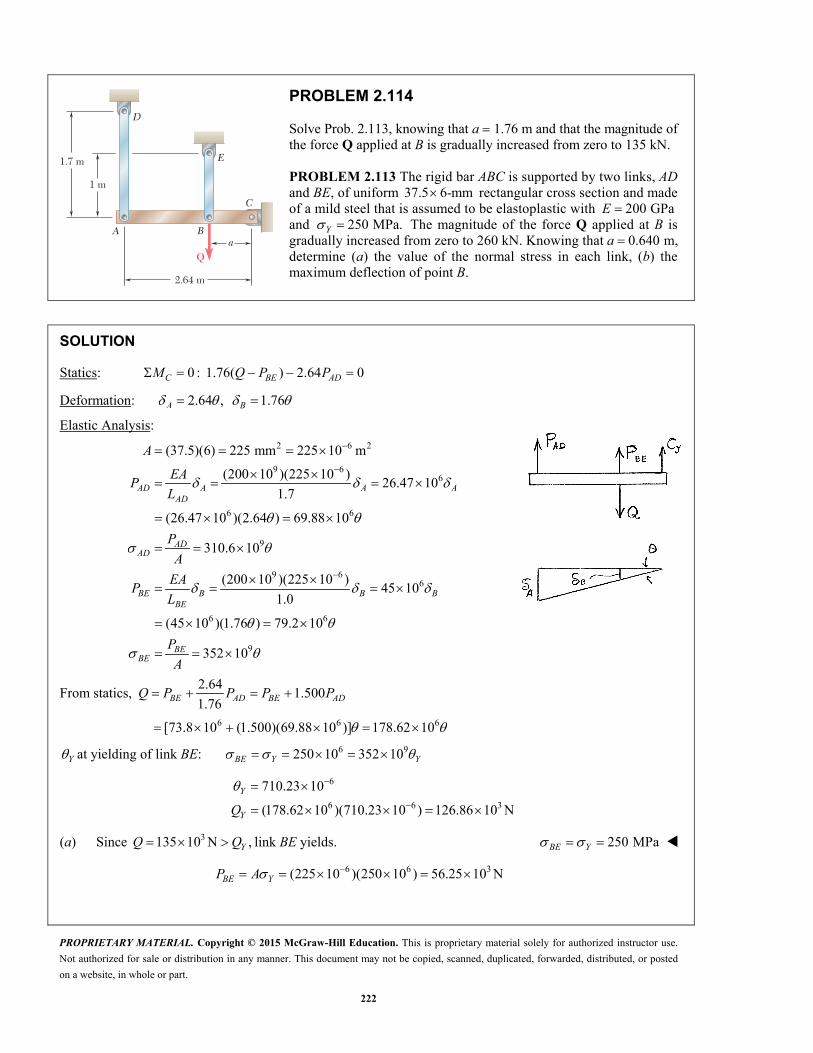
PROPRIETARY MATERIAL. Copyright © 2015 McGraw-Hill Education. This is proprietary material solely for authorized instructor use.
Not authorized for sale or distribution in any manner. This document may not be copied, scanned, duplicated, forwarded, distributed, or posted
on a website, in whole or part.
222
1.7 m
1 m
2.64 m
C
B
E
D
A
Qa
PROBLEM 2.114
Solve Prob. 2.113, knowing that a 1.76 m and that the magnitude of the force Q applied at B is gradually increased from zero to 135 kN.
PROBLEM 2.113 The rigid bar ABC is supported by two links, AD and BE, of uniform 37.5 6-mm rectangular cross section and made of a mild steel that is assumed to be elastoplastic with 200 GPaE and 250 MPa.Y The magnitude of the force Q applied at B is gradually increased from zero to 260 kN. Knowing that 0.640 m,a determine (a) the value of the normal stress in each link, (b) the maximum deflection of point B.
SOLUTION
Statics: 0 : 1.76( ) 2.64 0C BE ADM Q P P
Deformation: 2.64 , 1.76 A B
Elastic Analysis:
2 6 2
9 66
6 6
9
9 66
6 6
(37.5)(6) 225 mm 225 10 m
(200 10 )(225 10 )26.47 10
1.7
(26.47 10 )(2.64 ) 69.88 10
310.6 10
(200 10 )(225 10 )45 10
1.0
(45 10 )(1.76 ) 79.2 10
AD A A AAD
ADAD
BE B B BBE
BE
A
EAP
L
P
A
EAP
L
9352 10 BEP
A
From statics, 2.64
1.5001.76
BE AD BE ADQ P P P P
6 6 6[73.8 10 (1.500)(69.88 10 )] 178.62 10
Y at yielding of link BE: 6 9250 10 352 10 BE Y Y
6
6 6 3
710.23 10
(178.62 10 )(710.23 10 ) 126.86 10 N
Y
YQ
(a) Since 3135 10 N ,YQ Q link BE yields. 250 MPaBE Y
6 6 3(225 10 )(250 10 ) 56.25 10 N BE YP A

PROPRIETARY MATERIAL. Copyright © 2015 McGraw-Hill Education. This is proprietary material solely for authorized instructor use.
Not authorized for sale or distribution in any manner. This document may not be copied, scanned, duplicated, forwarded, distributed, or posted
on a website, in whole or part.
223
PROBLEM 2.114 (Continued)
From statics, 31( ) 52.5 10 N
1.500 AD BEP Q P
3
66
52.5 10233.3 10
225 10
AD
ADP
A 233 MPa AD
From elastic analysis of AD, 36
751.29 10 rad69.88 10
ADP
(b) 31.76 1.322 10 mB 1.322 mmB

PROPRIETARY MATERIAL. Copyright © 2015 McGraw-Hill Education. This is proprietary material solely for authorized instructor use.
Not authorized for sale or distribution in any manner. This document may not be copied, scanned, duplicated, forwarded, distributed, or posted
on a website, in whole or part.
224
1.7 m
1 m
2.64 m
C
B
E
D
A
Qa
PROBLEM 2.115
Solve Prob. 2.113, assuming that the magnitude of the force Q applied at B is gradually increased from zero to 260 kN and then decreased back to zero. Knowing that 0.640 m,a determine (a) the residual stress in each link, (b) the final deflection of point B. Assume that the links are braced so that they can carry compressive forces without buckling.
PROBLEM 2.113 The rigid bar ABC is supported by two links, AD and BE, of uniform 37.5 6-mm rectangular cross section and made of a mild steel that is assumed to be elastoplastic with 200 GPaE and 250 MPa.Y The magnitude of the force Q applied at B is gradually increased from zero to 260 kN. Knowing that
0.640 m,a determine (a) the value of the normal stress in each link, (b) the maximum deflection of point B.
SOLUTION
See solution to Problem 2.113 for the normal stresses in each link and the deflection of Point B after loading.
6
6
6
250 10 Pa
124.3 10 Pa
621.53 10 m
AD
BE
B
The elastic analysis given in the solution to Problem 2.113 applies to the unloading.
6
36
6 6
317.06 10
260 10820.03 10
317.06 10 317.06 10
Q
9 9 6 6
9 9 6 6
6
310.6 10 (310.6 10 )(820.03 10 ) 254.70 10 Pa
128 10 (128 10 )(820.03 10 ) 104.96 10 Pa
0.640 524.82 10 m
AD
BE
B
(a) Residual stresses.
6 6 6, res 250 10 254.70 10 4.70 10 Pa AD AD AD 4.70MPa
6 6 6, res 124.3 10 104.96 10 19.34 10 Pa BE BE BE 19.34 MPa
(b) 6 6 6, 621.53 10 524.82 10 96.71 10 m B P B B 0.0967 mm

PROPRIETARY MATERIAL. Copyright © 2015 McGraw-Hill Education. This is proprietary material solely for authorized instructor use.
Not authorized for sale or distribution in any manner. This document may not be copied, scanned, duplicated, forwarded, distributed, or posted
on a website, in whole or part.
225
L
BA
PROBLEM 2.116
A uniform steel rod of cross-sectional area A is attached to rigid supports and is unstressed at a temperature of 45 F. The steel is assumed to be elastoplastic with 36Y ksi and 629 10 psi.E Knowing that 66.5 10 / F, determine the stress in the bar (a) when the temperature is raised to 320 F, (b) after the temperature has returned to 45 F .
SOLUTION
Let P be the compressive force in the rod.
Determine temperature change to cause yielding.
3
6 6
( ) ( ) 0
36 10( ) 190.98 F
(29 10 )(6.5 10 )
YY
YY
LPLL T L T
AE E
TE
But 320 45 275 F ( ) YT T
(a) Yielding occurs. 36.0 ksiY
Cooling:
6 6 3
( T) 275 F
( ) 0
( )
(29 10 )(6.5 10 )(275) 51.8375 10 psi
P TP L
L TAE
PE T
A
(b) Residual stress:
3 3res 36 10 51.8375 10 15.84 10 psi Y 15.84 ksi
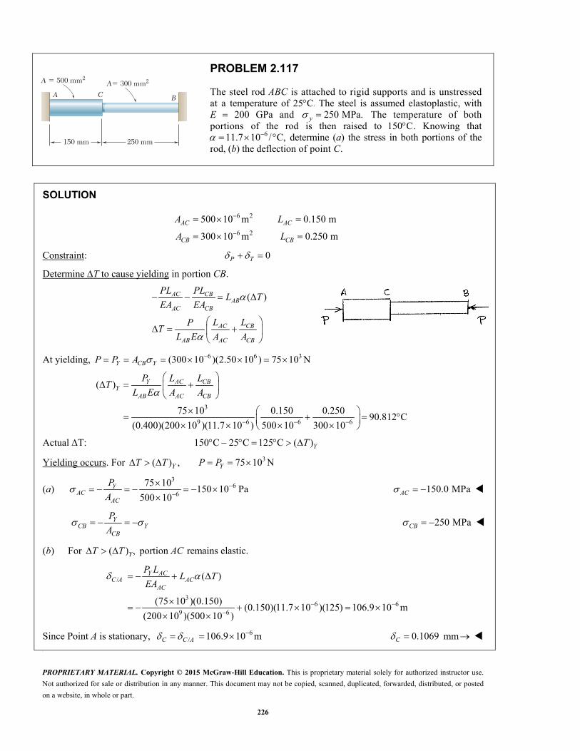
PROPRIETARY MATERIAL. Copyright © 2015 McGraw-Hill Education. This is proprietary material solely for authorized instructor use.
Not authorized for sale or distribution in any manner. This document may not be copied, scanned, duplicated, forwarded, distributed, or posted
on a website, in whole or part.
226
BA C
A � 500 mm2A� 300 mm2
150 mm 250 mm
PROBLEM 2.117
The steel rod ABC is attached to rigid supports and is unstressed at a temperature of 25 C. The steel is assumed elastoplastic, with E 200 GPa and 250 MPa.y The temperature of both portions of the rod is then raised to 150 C . Knowing that
611.7 10 / C, determine (a) the stress in both portions of the rod, (b) the deflection of point C.
SOLUTION
6 2
6 2
500 10 m 0.150 m
300 10 m 0.250 m
AC AC
CB CB
A L
A L
Constraint: 0P T
Determine T to cause yielding in portion CB.
( )AC CBAB
AC CB
AC CB
AB AC CB
PL PLL T
EA EA
L LPT
L E A A
At yielding, 6 6 3(300 10 )(2.50 10 ) 75 10 NY CB YP P A
3
9 6 6 6
( )
75 10 0.150 0.25090.812 C
(0.400)(200 10 )(11.7 10 ) 500 10 300 10
AC CBYY
AB AC CB
L LPT
L E A A
Actual T: 150 C 25 C 125 C ( ) YT
Yielding occurs. For 3( ) , 75 10 NY YT T P P
(a) 3
66
75 10150 10 Pa
500 10Y
ACAC
P
A
150.0 MPaAC
YCB Y
CB
P
A 250 MPaCB
(b) For ( ) , portion remains elastic.YT T AC
/
36 6
9 6
( )
(75 10 )(0.150)(0.150)(11.7 10 )(125) 106.9 10 m
(200 10 )(500 10 )
Y ACC A AC
AC
P LL T
EA
Since Point A is stationary, 6/ 106.9 10 mC C A 0.1069 mmC
\
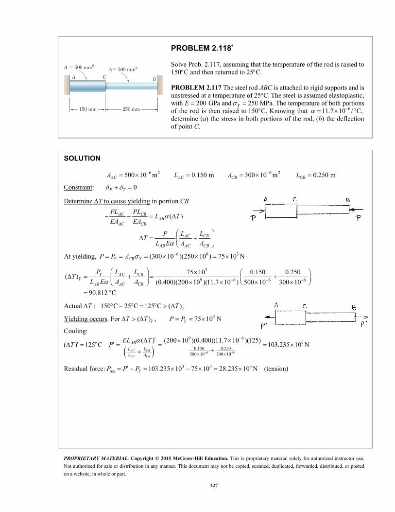
PROPRIETARY MATERIAL. Copyright © 2015 McGraw-Hill Education. This is proprietary material solely for authorized instructor use.
Not authorized for sale or distribution in any manner. This document may not be copied, scanned, duplicated, forwarded, distributed, or posted
on a website, in whole or part.
227
BA C
A � 500 mm2A� 300 mm2
150 mm 250 mm
PROBLEM 2.118
Solve Prob. 2.117, assuming that the temperature of the rod is raised to 150C and then returned to 25 C.
PROBLEM 2.117 The steel rod ABC is attached to rigid supports and is unstressed at a temperature of 25 C. The steel is assumed elastoplastic, with 200E GPa and 250 Y MPa. The temperature of both portions of the rod is then raised to 150 C. Knowing that 611.7 10 / C, determine (a) the stress in both portions of the rod, (b) the deflection of point C.
SOLUTION
6 2 6 2500 10 m 0.150 m 300 10 m 0.250 m AC AC CB CBA L A L
Constraint: 0P T
Determine T to cause yielding in portion CB.
( )
AC CBAB
AC CB
AC CB
AB AC CB
PL PLL T
EA EA
L LPT
L E A A
At yielding, 6 6 3(300 10 )(250 10 ) 75 10 NY CB YP P A
3
9 6 6 6
75 10 0.150 0.250( )
(0.400)(200 10 )(11.7 10 ) 500 10 300 10
90.812 C
AC CBYY
AB AC CB
L LPT
L E A A
Actual : 150 C 25 C 125 C ( ) YT T
Yielding occurs. For 3( ) , 75 10 N Y YT T P P
Cooling:
( )
( ) 125 C AC CB
AC CB
ABL LA A
EL TT P
6 6
9 63
0.150 0.250500 10 300 10
(200 10 )(0.400)(11.7 10 )(125)103.235 10 N
Residual force: 3 3 3res 103.235 10 75 10 28.235 10 N (tension) YP P P

PROPRIETARY MATERIAL. Copyright © 2015 McGraw-Hill Education. This is proprietary material solely for authorized instructor use.
Not authorized for sale or distribution in any manner. This document may not be copied, scanned, duplicated, forwarded, distributed, or posted
on a website, in whole or part.
228
PROBLEM 2.118 (Continued)
(a) Residual stresses. 3
res6
28.235 10
500 10AC
AC
P
A
56.5 MPaAC
3
res6
28.235 10
300 10CB
CB
P
A
9.41 MPa CB
(b) Permanent deflection of point C. res ACC
AC
P L
EA 0.0424 mmC
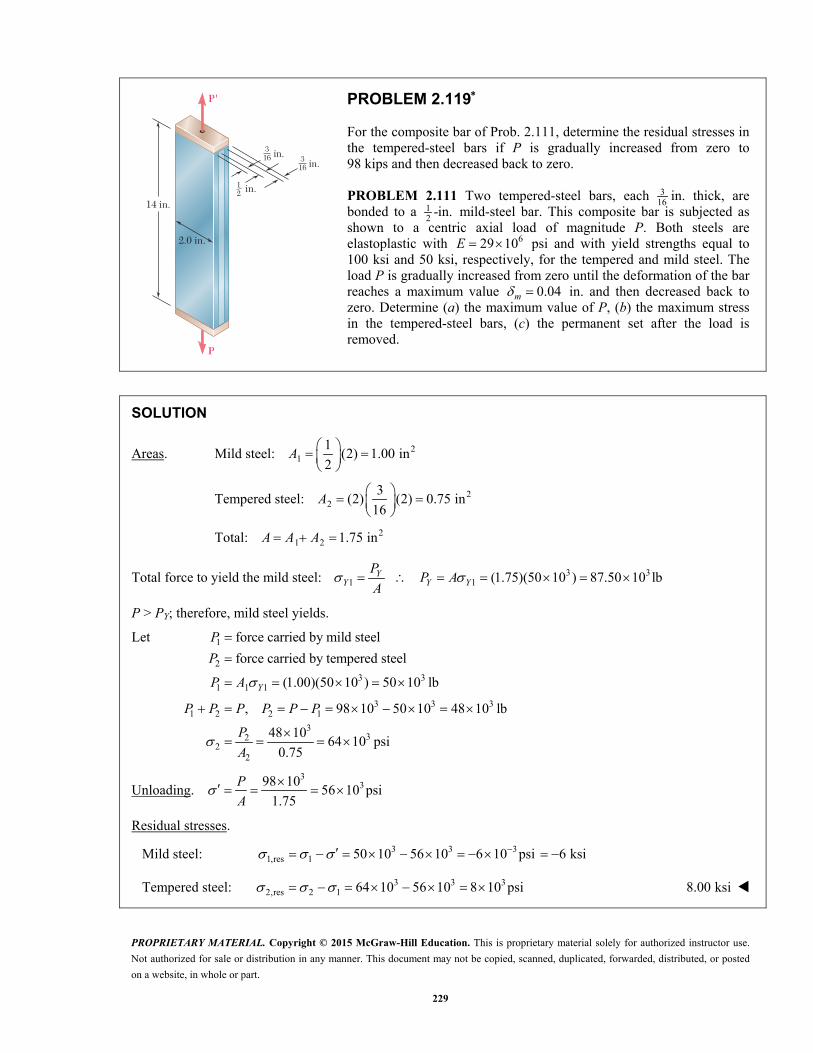
PROPRIETARY MATERIAL. Copyright © 2015 McGraw-Hill Education. This is proprietary material solely for authorized instructor use.
Not authorized for sale or distribution in any manner. This document may not be copied, scanned, duplicated, forwarded, distributed, or posted
on a website, in whole or part.
229
P
14 in.
2.0 in.
P'
in.
12 in.
316 3
16
in.
PROBLEM 2.119
For the composite bar of Prob. 2.111, determine the residual stresses in the tempered-steel bars if P is gradually increased from zero to 98 kips and then decreased back to zero.
PROBLEM 2.111 Two tempered-steel bars, each 316 in. thick, are
bonded to a 12 -in. mild-steel bar. This composite bar is subjected as
shown to a centric axial load of magnitude P. Both steels are elastoplastic with 629 10E psi and with yield strengths equal to 100 ksi and 50 ksi, respectively, for the tempered and mild steel. The load P is gradually increased from zero until the deformation of the bar reaches a maximum value 0.04m in. and then decreased back to zero. Determine (a) the maximum value of P, (b) the maximum stress in the tempered-steel bars, (c) the permanent set after the load is removed.
SOLUTION
Areas. Mild steel: 21
1(2) 1.00 in
2
A
Tempered steel: 22
3(2) (2) 0.75 in
16
A
Total: 21 2 1.75 in A A A
Total force to yield the mild steel: 3 31 1 (1.75)(50 10 ) 87.50 10 lb Y
Y Y YP
P AA
P > PY; therefore, mild steel yields.
Let 1
2
3 31 1 1
3 3 31 2 2 1
332
22
force carried by mild steel
force carried by tempered steel
(1.00)(50 10 ) 50 10 lb
, 98 10 50 10 48 10 lb
48 1064 10 psi
0.75
Y
P
P
P A
P P P P P P
P
A
Unloading. 3
398 1056 10 psi
1.75
P
A
Residual stresses.
Mild steel: 3 3 31,res 1 50 10 56 10 6 10 psi 6 ksi
Tempered steel: 3 3 32,res 2 1 64 10 56 10 8 10 psi 8.00 ksi

PROPRIETARY MATERIAL. Copyright © 2015 McGraw-Hill Education. This is proprietary material solely for authorized instructor use.
Not authorized for sale or distribution in any manner. This document may not be copied, scanned, duplicated, forwarded, distributed, or posted
on a website, in whole or part.
230
P
14 in.
2.0 in.
P'
in.
12 in.
316 3
16
in.
PROBLEM 2.120
For the composite bar in Prob. 2.111, determine the residual stresses in the tempered-steel bars if P is gradually increased from zero until the deformation of the bar reaches a maximum value 0.04m in. and is then decreased back to zero.
PROBLEM 2.111 Two tempered-steel bars, each 316 in. thick, are bonded
to a 12 -in. mild-steel bar. This composite bar is subjected as shown to a
centric axial load of magnitude P. Both steels are elastoplastic with 629 10E psi and with yield strengths equal to 100 ksi and 50 ksi, respectively, for the tempered and mild steel. The load P is gradually increased from zero until the deformation of the bar reaches a maximum value 0.04m in. and then decreased back to zero. Determine (a) the maximum value of P, (b) the maximum stress in the tempered-steel bars, (c) the permanent set after the load is removed.
SOLUTION
For the mild steel, 3
2 11 1 6
1 (14)(50 10 )(2) 1.00 in 0.024138 in.
2 29 10
YY
LA
E
For the tempered steel, 3
2 22 2 6
3 (14)(100 10 )2 (2) 0.75 in 0.048276 in.
16 29 10
YY
LA
E
Total area: 21 2 1.75 in A A A
1 2 Y m Y
The mild steel yields. Tempered steel is elastic.
Forces: 3 31 1 1
632
2
(1.00)(50 10 ) 50 10 lb
(29 10 )(0.75)(0.04)62.14 10 lb
14
Y
m
P A
EAP
L
Stresses: 3
3 31 21 1 2
1 2
62.14 1050 10 psi 82.86 10 psi
0.75
YP P
A A
Unloading: 3112.1464.08 10 psi
1.75
P
A
Residual stresses. 3 3 31,res 1 50 10 64.08 10 14.08 10 psi 14.08 ksi
3 3 32,res 2 82.86 10 64.08 10 18.78 10 psi 18.78 ksi

PROPRIETARY MATERIAL. Copyright © 2015 McGraw-Hill Education. This is proprietary material solely for authorized instructor use.
Not authorized for sale or distribution in any manner. This document may not be copied, scanned, duplicated, forwarded, distributed, or posted
on a website, in whole or part.
231
PROBLEM 2.121
Narrow bars of aluminum are bonded to the two sides of a thick steel plate as shown. Initially, at 1 70 F,T all stresses are zero. Knowing that the temperature will be slowly raised to T2 and then reduced to T1, determine (a) the highest temperature T2 that does not result in residual stresses, (b) the temperature T2 that will result in a residual stress in the aluminum equal to 58 ksi. Assume 612.8 10 / F a for the aluminum and 66.5 10 / F s for the steel. Further assume that the aluminum is elastoplastic, with E 610.9 10 psi and 58Y ksi. (Hint: Neglect the small stresses in the plate.)
SOLUTION
Determine temperature change to cause yielding.
3
6 6
( ) ( )
( )( )
58 10( ) 844.62 F
( ) (10.9 10 )(12.8 6.5)(10 )
a Y s Y
a s Y Y
YY
a s
PLL T L T
EAP
E TA
TE
(a) 2 1 ( ) 70 844.62 915 F Y YT T T 915 F
After yielding,
( ) ( )Ya s
LL T L T
E
Cooling:
( ) ( )
a sP L
L T L TAE
The residual stress is
res ( )( )Y Y a sP
E TA
Set res
( )( )Y
Y Y a sE T
3
6 6
2 (2)(58 10 )1689 F
( ) (10.9 10 )(12.8 6.5)(10 )
Y
a s
TE
(b) 2 1 70 1689 1759 F T T T 1759 F
If 2 1759 F, T the aluminum bar will most likely yield in compression.

PROPRIETARY MATERIAL. Copyright © 2015 McGraw-Hill Education. This is proprietary material solely for authorized instructor use.
Not authorized for sale or distribution in any manner. This document may not be copied, scanned, duplicated, forwarded, distributed, or posted
on a website, in whole or part.
232
440 mm
a � 120 mm
F
C BA
PROBLEM 2.122
Bar AB has a cross-sectional area of 1200 mm2 and is made of a steel that is assumed to be elastoplastic with 200 GPaE and 250 MPa.Y Knowing that the force F increases from 0 to 520 kN and then decreases to zero, determine (a) the permanent deflection of point C, (b) the residual stress in the bar.
SOLUTION
2 6 21200 mm 1200 10 mA
Force to yield portion AC: 6 6
3
(1200 10 )(250 10 )
300 10 N
AC YP A
For equilibrium, 0. CB ACF P P
3 3
3
300 10 520 10
220 10 N
CB ACP P F
3
9 6
3
3
6
6
(220 10 )(0.440 0.120)
(200 10 )(1200 10 )
0.29333 10 m
220 10
1200 10
183.333 10 Pa
CB CBC
CBCB
P L
EA
P
A

PROPRIETARY MATERIAL. Copyright © 2015 McGraw-Hill Education. This is proprietary material solely for authorized instructor use.
Not authorized for sale or distribution in any manner. This document may not be copied, scanned, duplicated, forwarded, distributed, or posted
on a website, in whole or part.
233
PROBLEM 2.122 (Continued)
Unloading:
( )
AC AC CB CB AC CBC
AC BC CBAC
P L P L F P L
EA EA EAL L FL
PEA EA EA
33
3 3 3
36
6
36
6
(520 10 )(0.440 0.120)378.18 10 N
0.440
378.18 10 520 10 141.820 10 N
378.18 10315.150 10 Pa
1200 10
141.820 10118.183 10 Pa
1200 10
(378.
CBAC
AC CB
CB AC
ACAC
BCBC
C
FLP
L L
P P F
P
A
P
A
3
39 6
18 10 )(0.120)0.189090 10 m
(200 10 )(1200 10 )
(a) 3 3 3, 0.29333 10 0.189090 10 0.104240 10 mC p C C 0.1042 mm
(b) 6 6 6, res 250 10 315.150 10 65.150 10 PaAC Y AC 65.2 MPa
6 6 6, res 183.333 10 118.183 10 65.150 10 PaCB CB CB 65.2 MPa

PROPRIETARY MATERIAL. Copyright © 2015 McGraw-Hill Education. This is proprietary material solely for authorized instructor use.
Not authorized for sale or distribution in any manner. This document may not be copied, scanned, duplicated, forwarded, distributed, or posted
on a website, in whole or part.
234
440 mm
a � 120 mm
F
C BA
PROBLEM 2.123
Solve Prob. 2.122, assuming that 180a mm.
PROBLEM 2.122 Bar AB has a cross-sectional area of 1200 mm2 and is made of a steel that is assumed to be elastoplastic with 200E GPa and 250Y MPa. Knowing that the force F increases from 0 to 520 kN and then decreases to zero, determine (a) the permanent deflection of point C, (b) the residual stress in the bar.
SOLUTION
2 6 21200 mm 1200 10 mA
Force to yield portion AC: 6 6
3
(1200 10 )(250 10 )
300 10 N
AC YP A
For equilibrium, 0. CB ACF P P
3 3
3
300 10 520 10
220 10 N
CB ACP P F
3
9 6
3
3
6
6
(220 10 )(0.440 0.180)
(200 10 )(1200 10 )
0.23833 10 m
220 10
1200 10
183.333 10 Pa
CB CBC
CBCB
P L
EA
P
A
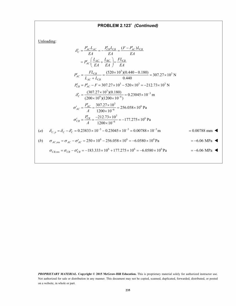
PROPRIETARY MATERIAL. Copyright © 2015 McGraw-Hill Education. This is proprietary material solely for authorized instructor use.
Not authorized for sale or distribution in any manner. This document may not be copied, scanned, duplicated, forwarded, distributed, or posted
on a website, in whole or part.
235
PROBLEM 2.123 (Continued)
Unloading:
( )AC AC CB CB AC CBC
AC BC CBAC
P L P L F P L
EA EA EAL L FL
PEA EA EA
33
3 3 3
33
9 6
36
6
(520 10 )(0.440 0.180)307.27 10 N
0.440
307.27 10 520 10 212.73 10 N
(307.27 10 )(0.180)0.23045 10 m
(200 10 )(1200 10 )
307.27 10256.058 10 Pa
1200 10
CBAC
AC CB
CB AC
C
ACAC
FLP
L L
P P F
P
A3
66
212.73 10177.275 10 Pa
1200 10
CBCB
P
A
(a) 3 3 3, 0.23833 10 0.23045 10 0.00788 10 mC p C C 0.00788 mm
(b) 6 6 6,res 250 10 256.058 10 6.0580 10 PaAC AC AC 6.06 MPa
6 6 6,res 183.333 10 177.275 10 6.0580 10 PaCB CB CB 6.06 MPa

PROPRIETARY MATERIAL. Copyright © 2015 McGraw-Hill Education. This is proprietary material solely for authorized instructor use.
Not authorized for sale or distribution in any manner. This document may not be copied, scanned, duplicated, forwarded, distributed, or posted
on a website, in whole or part.
236
P
l l
CB
A�
PROBLEM 2.124
The uniform wire ABC, of unstretched length 2l, is attached to the supports shown and a vertical load P is applied at the midpoint B. Denoting by A the cross-sectional area of the wire and by E the modulus of elasticity, show that, for ,l the deflection at the midpoint B is
3 P
lAE
SOLUTION
Use approximation.
sin tanl
Statics: 0 : 2 sin 0 Y ABF P P
2sin 2
ABP Pl
P
Elongation: 2
2AB
ABP l Pl
AE AE
Deflection:
From the right triangle,
2 2 2
2 2
( )
ABl l
l 2 22 AB ABl l
3
12 1 2
2
ABAB ABl l
l
Pl
AE
3
3 3Pl P
lAE AE

PROPRIETARY MATERIAL. Copyright © 2015 McGraw-Hill Education. This is proprietary material solely for authorized instructor use.
Not authorized for sale or distribution in any manner. This document may not be copied, scanned, duplicated, forwarded, distributed, or posted
on a website, in whole or part.
237
B
d
C
A
12 in.
18 in.
1.5 in.
2.25 in.
28 kips
E
D
28 kips
PROBLEM 2.125
The aluminum rod ABC ( 610.1 10 psi),E which consists of two cylindrical portions AB and BC, is to be replaced with a cylindrical steel rod DE ( 629 10 psi)E of the same overall length. Determine the minimum required diameter d of the steel rod if its vertical deformation is not to exceed the deformation of the aluminum rod under the same load and if the allowable stress in the steel rod is not to exceed 24 ksi.
SOLUTION
Deformation of aluminum rod.
3
6 2 24 4
28 10 12 18
10.1 10 (1.5) (2.25)
0.031376 in.
BCABA
AB BC
BCAB
AB BC
PLPL
A E A E
LLP
E A A
Steel rod. 0.031376 in.
32
6
32
3
(28 10 )(30)0.92317 in
(29 10 )(0.031376)
28 101.16667 in
24 10
PL PLA
EA E
P PA
A
Required area is the larger value. 21.16667 inA
Diameter: 4 (4)(1.16667)A
d
1.219 in.d

PROPRIETARY MATERIAL. Copyright © 2015 McGraw-Hill Education. This is proprietary material solely for authorized instructor use.
Not authorized for sale or distribution in any manner. This document may not be copied, scanned, duplicated, forwarded, distributed, or posted
on a website, in whole or part.
238
C
B
A
3 in.
2 in.30 kips 30 kips
P � 40 kips
40 in.
30 in.
PROBLEM 2.126
Two solid cylindrical rods are joined at B and loaded as shown. Rod AB is made of steel 6( 29 10 E psi), and rod BC of brass 6( 15 10 psi).E Determine (a) the total deformation of the composite rod ABC, (b) the deflection of point B.
SOLUTION
Portion AB: 3
2 2 2
6
33
6
40 10 lb
40 in.
2 in.
(2) 3.1416 in4 4
29 10 psi
(40 10 )(40)17.5619 10 in.
(29 10 )(3.1416)
AB
AB
AB
AB
AB ABAB
AB AB
P
L
d
A d
E
P L
E A
Portion BC: 3
2 2 2
6
33
6
20 10 lb
30 in.
3 in.
(3) 7.0686 in4 4
15 10 psi
( 20 10 )(30)5.6588 10 in.
(15 10 )(7.0686)
BC
BC
BC
BC
BC BCBC
BC BC
P
L
d
A d
E
P L
E A
(a) 6 617.5619 10 5.6588 10AB BC 311.90 10 in.
(b) B BC 35.66 10 in.B
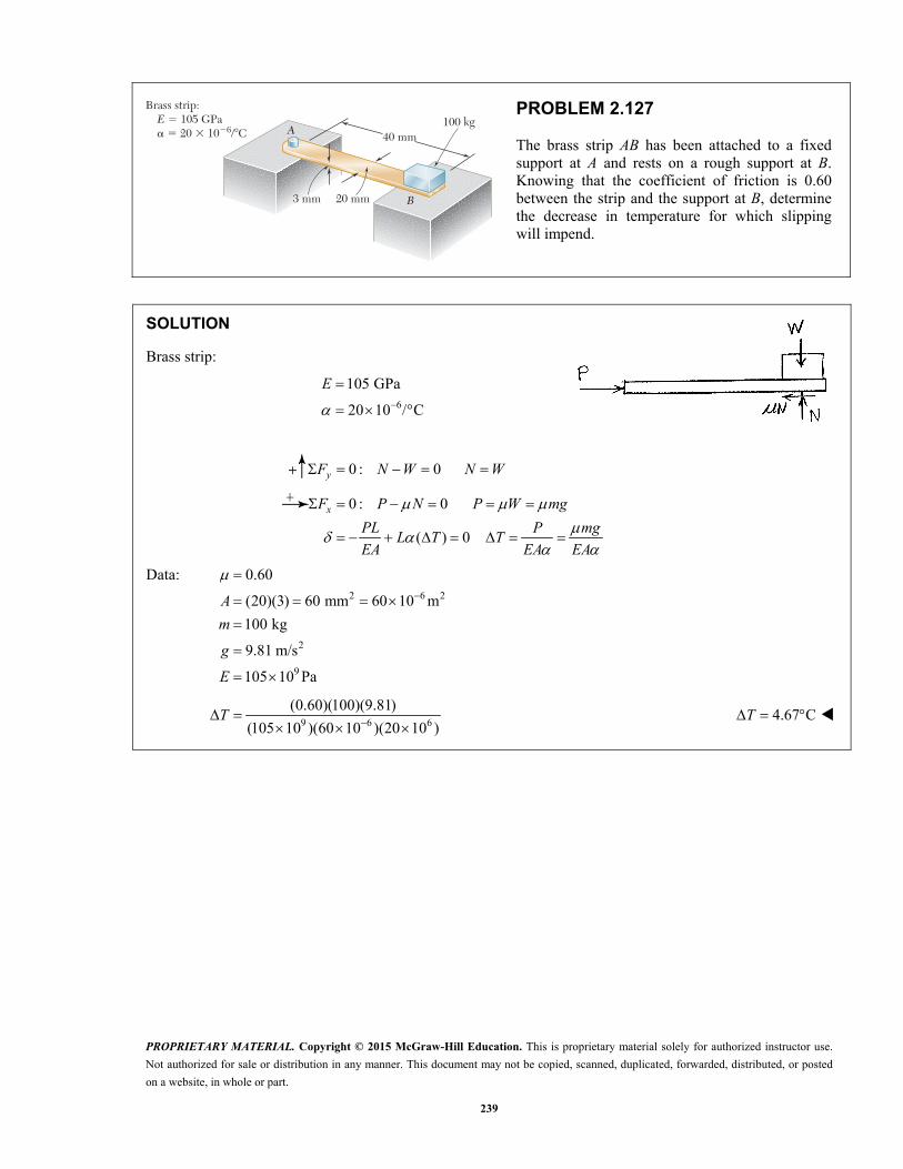
PROPRIETARY MATERIAL. Copyright © 2015 McGraw-Hill Education. This is proprietary material solely for authorized instructor use.
Not authorized for sale or distribution in any manner. This document may not be copied, scanned, duplicated, forwarded, distributed, or posted
on a website, in whole or part.
239
3 mm
A
B
40 mm100 kg
20 mm
Brass strip: E 5 105 GPa a 5 20 3 1026/8C
PROBLEM 2.127
The brass strip AB has been attached to a fixed support at A and rests on a rough support at B. Knowing that the coefficient of friction is 0.60 between the strip and the support at B, determine the decrease in temperature for which slipping will impend.
SOLUTION
Brass strip:
6
105 GPa
20 10 / C
E
0 : 0 yF N W N W
0 : 0
( ) 0
xF P N P W mg
PL P mgL T T
EA EA EA
Data: 2 6 2
2
9
0.60
(20)(3) 60 mm 60 10 m
100 kg
9.81 m/s
105 10 Pa
A
m
g
E
9 6 6
(0.60)(100)(9.81)
(105 10 )(60 10 )(20 10 )T
4.67 C T
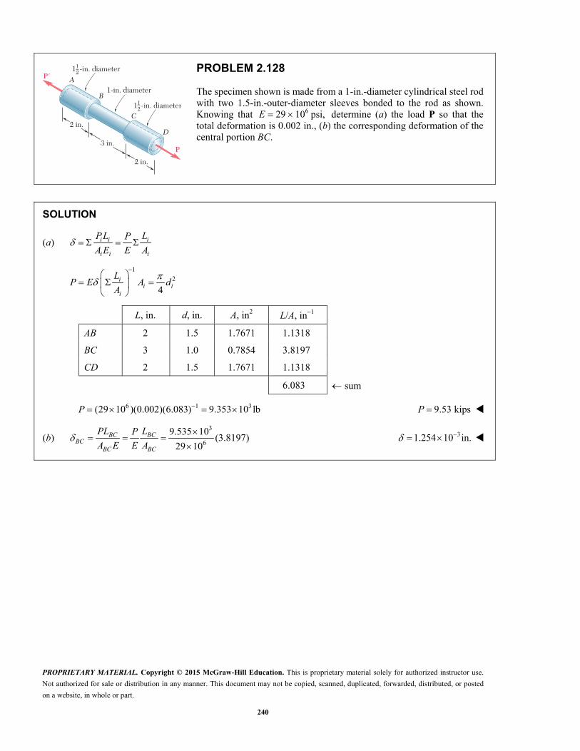
PROPRIETARY MATERIAL. Copyright © 2015 McGraw-Hill Education. This is proprietary material solely for authorized instructor use.
Not authorized for sale or distribution in any manner. This document may not be copied, scanned, duplicated, forwarded, distributed, or posted
on a website, in whole or part.
240
2 in.
2 in.
3 in.
C
D
A
B
P'
P
1 -in. diameter
1-in. diameter
12
1 -in. diameter12
PROBLEM 2.128
The specimen shown is made from a 1-in.-diameter cylindrical steel rod with two 1.5-in.-outer-diameter sleeves bonded to the rod as shown. Knowing that 629 10 psi, E determine (a) the load P so that the total deformation is 0.002 in., (b) the corresponding deformation of the central portion BC.
SOLUTION
(a) i i i
i i i
PL LP
A E E A
1
2
4i
i ii
LP E A d
A
L, in. d, in. A, in2 L/A, in1
AB 2 1.5 1.7671 1.1318
BC 3 1.0 0.7854 3.8197
CD 2 1.5 1.7671 1.1318
6.083 sum
6 1 3(29 10 )(0.002)(6.083) 9.353 10 lbP 9.53 kipsP
(b) 3
6
9.535 10(3.8197)
29 10BC BC
BCBC BC
PL LP
A E E A
31.254 10 in.
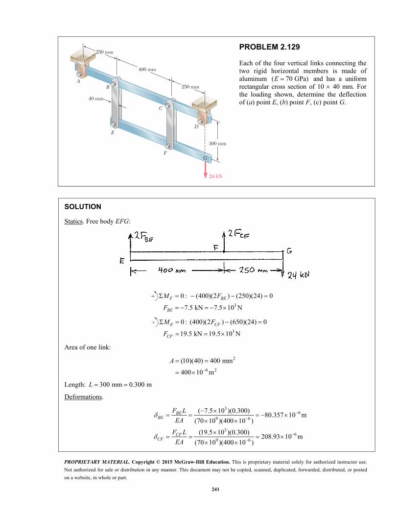
PROPRIETARY MATERIAL. Copyright © 2015 McGraw-Hill Education. This is proprietary material solely for authorized instructor use.
Not authorized for sale or distribution in any manner. This document may not be copied, scanned, duplicated, forwarded, distributed, or posted
on a website, in whole or part.
241
24 kN
F
E
AB
C
D
300 mm
250 mm
400 mm
250 mm
40 mm
G
PROBLEM 2.129
Each of the four vertical links connecting the two rigid horizontal members is made of aluminum ( 70 GPa)E and has a uniform rectangular cross section of 10 40 mm. For the loading shown, determine the deflection of (a) point E, (b) point F, (c) point G.
SOLUTION
Statics. Free body EFG:
3
0 : (400)(2 ) (250)(24) 0
7.5 kN 7.5 10 N
F BE
BE
M F
F
3
0 : (400)(2 ) (650)(24) 0
19.5 kN 19.5 10 N
E CF
CF
M F
F
Area of one link:
2
6 2
(10)(40) 400 mm
400 10 m
A
Length: 300 mm 0.300 m L
Deformations.
36
9 6
36
9 6
( 7.5 10 )(0.300)80.357 10 m
(70 10 )(400 10 )
(19.5 10 )(0.300)208.93 10 m
(70 10 )(400 10 )
BEBE
CFCF
F L
EA
F L
EA

PROPRIETARY MATERIAL. Copyright © 2015 McGraw-Hill Education. This is proprietary material solely for authorized instructor use.
Not authorized for sale or distribution in any manner. This document may not be copied, scanned, duplicated, forwarded, distributed, or posted
on a website, in whole or part.
242
PROBLEM 2.129 (Continued)
(a) Deflection of Point E. | | E BF 80.4 m E
(b) Deflection of Point F. F CF 209 mF
Geometry change.
Let be the small change in slope angle.
6 6
680.357 10 208.93 10723.22 10 radians
0.400
E F
EFL
(c) Deflection of Point G. G F FGL
6 6
6
208.93 10 (0.250)(723.22 10 )
389.73 10 m
G F FGL
390 m G

PROPRIETARY MATERIAL. Copyright © 2015 McGraw-Hill Education. This is proprietary material solely for authorized instructor use.
Not authorized for sale or distribution in any manner. This document may not be copied, scanned, duplicated, forwarded, distributed, or posted
on a website, in whole or part.
243
4 ft
8 in.8 in.
P
PROBLEM 2.130
A 4-ft concrete post is reinforced with four steel bars, each with a 34 -in. diameter.
Knowing that 629 10sE psi and 63.6 10cE psi, determine the normal stresses in the steel and in the concrete when a 150-kip axial centric force P is applied to the post.
SOLUTION
2
234 1.76715 in
4 4
sA
2 28 62.233 in c sA A
66
(48)0.93663 10
(1.76715)(29 10 )
s s
s ss s
P L PP
A E
66
(48)0.21425 10
(62.233)(3.6 10 )
c c
c cc c
P L PP
A E
But :s c 6 60.93663 10 0.21425 10 s cP P
0.22875s cP P (1)
Also, 150 kipss cP P P (2)
Substituting (1) into (2), 1.22875 150 kipscP
122.075 kipscP
From (1), 0.22875(122.075) 27.925 kipssP
27.925
1.76715s
ss
P
A 15.80 ksis
122.075
62.233c
cc
P
A 1.962 ksic

PROPRIETARY MATERIAL. Copyright © 2015 McGraw-Hill Education. This is proprietary material solely for authorized instructor use.
Not authorized for sale or distribution in any manner. This document may not be copied, scanned, duplicated, forwarded, distributed, or posted
on a website, in whole or part.
244
100 mm
2 m
A
CD
B E
3 m
150 mm
PROBLEM 2.131
The steel rods BE and CD each have a 16-mm diameter ( 200 GPa);E the ends of the rods are single-threaded with a pitch of 2.5 mm. Knowing that after being snugly fitted, the nut at C is tightened one full turn, determine (a) the tension in rod CD, (b) the deflection of point C of the rigid member ABC.
SOLUTION
Let be the rotation of bar ABC as shown.
Then 0.15 0.25B C
But turnCD CD
CCD CD
P L
E A
turn
9 24
3 6
( )
(200 10 Pa) (0.016 m)(0.0025m 0.25 )
2m
50.265 10 5.0265 10
CD CDCD C
CD
E AP
L
orBE BE BE BEB BE B
BE BE BE
P L E AP
E A L
9 24
6
(200 10 Pa) (0.016 m)(0.15 )
3 m
2.0106 10
BEP
From free body of member ABC:
0 : 0.15 0.25 0A BE CDM P P
6 3 60.15(2.0106 10 ) 0.25(50.265 10 5.0265 10 ) 0
38.0645 10 rad
(a) 3 6 350.265 10 5.0265 10 (8.0645 10 )CDP
39.7288 10 N 9.73 kNCDP
(b) 30.25 0.25(8.0645 10 )C
32.0161 10 m 2.02 mmC
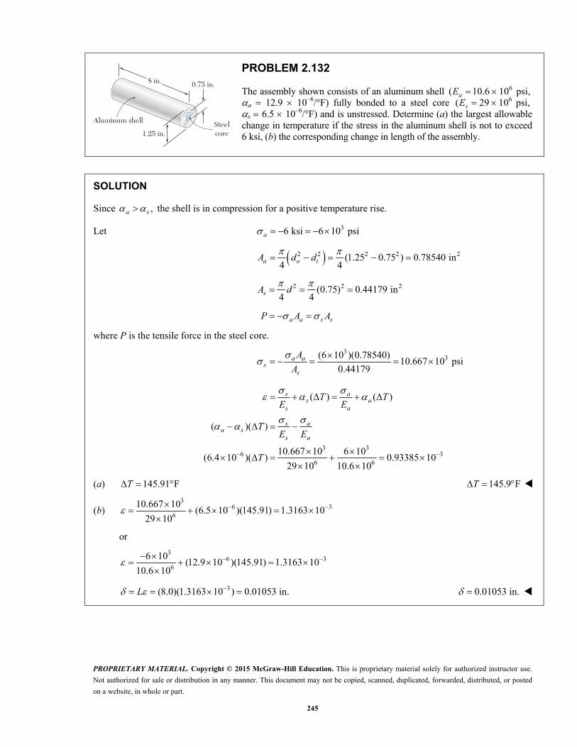
PROPRIETARY MATERIAL. Copyright © 2015 McGraw-Hill Education. This is proprietary material solely for authorized instructor use.
Not authorized for sale or distribution in any manner. This document may not be copied, scanned, duplicated, forwarded, distributed, or posted
on a website, in whole or part.
245
8 in.
Aluminum shell
1.25 in.Steelcore
0.75 in.
PROBLEM 2.132
The assembly shown consists of an aluminum shell 6( 10.6 10 psi, aE a 12.9 106/°F) fully bonded to a steel core 6( 29 10 psi, sE s 6.5 106/°F) and is unstressed. Determine (a) the largest allowable change in temperature if the stress in the aluminum shell is not to exceed 6 ksi, (b) the corresponding change in length of the assembly.
SOLUTION
Since ,a s the shell is in compression for a positive temperature rise.
Let 36 ksi 6 10 psia
2 2 2 2 2(1.25 0.75 ) 0.78540 in4 4
a o iA d d
2 2 2(0.75) 0.44179 in4 4
sA d
a a s sP A A
where P is the tensile force in the steel core.
3
3(6 10 )(0.78540)10.667 10 psi
0.44179a a
ss
A
A
3 36 3
6 6
( ) ( )
( )( )
10.667 10 6 10(6.4 10 )( ) 0.93385 10
29 10 10.6 10
s as a
s a
s aa s
s a
T TE E
TE E
T
(a) 145.91 FT 145.9 F T
(b) 3
6 36
10.667 10(6.5 10 )(145.91) 1.3163 10
29 10
or
3
6 36
6 10(12.9 10 )(145.91) 1.3163 10
10.6 10
3(8.0)(1.3163 10 ) 0.01053 in. L 0.01053 in.
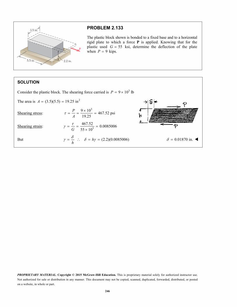
PROPRIETARY MATERIAL. Copyright © 2015 McGraw-Hill Education. This is proprietary material solely for authorized instructor use.
Not authorized for sale or distribution in any manner. This document may not be copied, scanned, duplicated, forwarded, distributed, or posted
on a website, in whole or part.
246
3.5 in.
5.5 in. 2.2 in.
P
PROBLEM 2.133
The plastic block shown is bonded to a fixed base and to a horizontal rigid plate to which a force P is applied. Knowing that for the plastic used 55G ksi, determine the deflection of the plate when 9P kips.
SOLUTION
Consider the plastic block. The shearing force carried is 39 10 lb P
The area is 2(3.5)(5.5) 19.25 in A
Shearing stress: 39 10
467.52 psi19.25
P
A
Shearing strain: 3
467.520.0085006
55 10
G
But (2.2)(0.0085006) hh
0.01870 in.
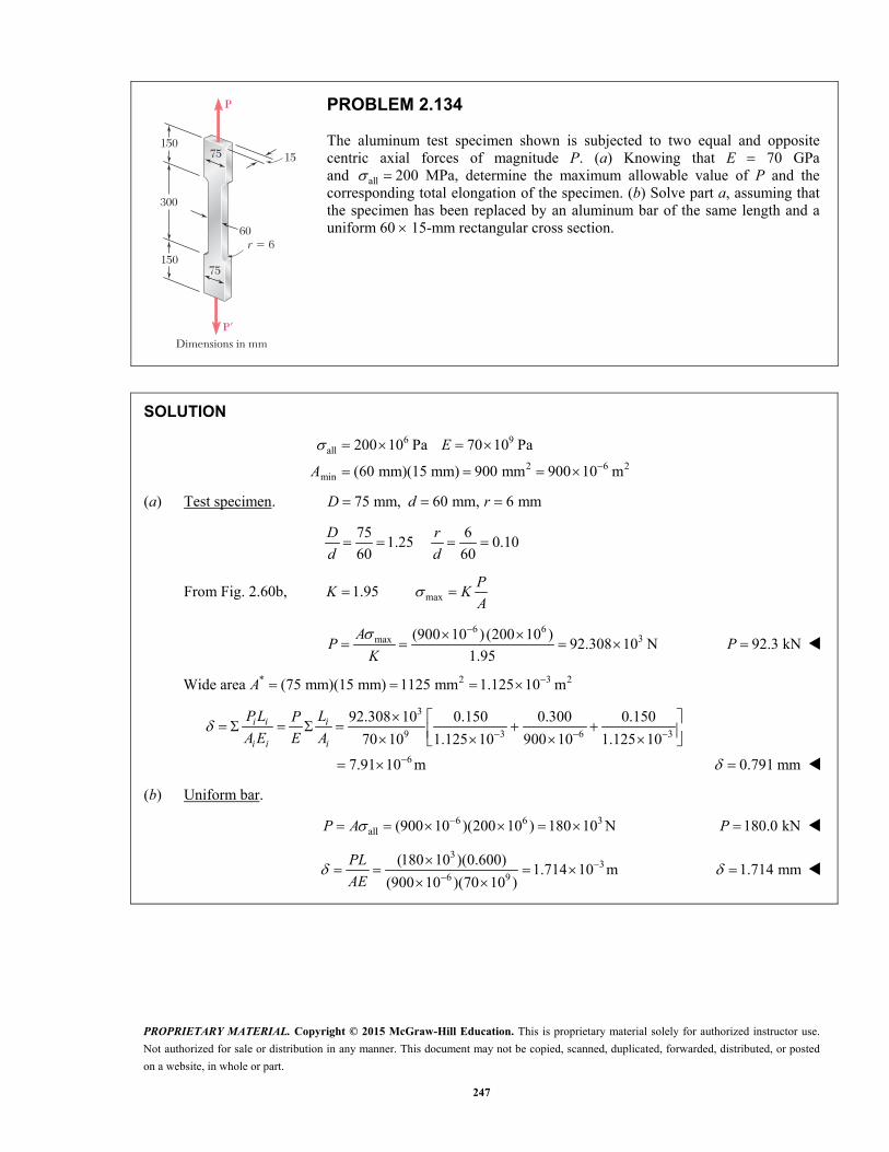
PROPRIETARY MATERIAL. Copyright © 2015 McGraw-Hill Education. This is proprietary material solely for authorized instructor use.
Not authorized for sale or distribution in any manner. This document may not be copied, scanned, duplicated, forwarded, distributed, or posted
on a website, in whole or part.
247
150
300
75
150
P�
75
Dimensions in mm
P
15
r 5 660
PROBLEM 2.134
The aluminum test specimen shown is subjected to two equal and opposite centric axial forces of magnitude P. (a) Knowing that E 70 GPa and all 200 MPa, determine the maximum allowable value of P and the corresponding total elongation of the specimen. (b) Solve part a, assuming that the specimen has been replaced by an aluminum bar of the same length and a uniform 60 15-mm rectangular cross section.
SOLUTION
6 9
all
2 6 2min
200 10 Pa 70 10 Pa
(60 mm)(15 mm) 900 mm 900 10 m
E
A
(a) Test specimen. 75 mm, 60 mm, 6 mmD d r
75 6
1.25 0.1060 60
D r
d d
From Fig. 2.60b, max1.95P
K KA
6 6
3max (900 10 ) (200 10 )92.308 10 N
1.95
AP
K
92.3 kNP
Wide area * 2 3 2(75 mm)(15 mm) 1125 mm 1.125 10 m A
3
9 3 6 3
6
92.308 10 0.150 0.300 0.150
70 10 1.125 10 900 10 1.125 10
7.91 10 m
i i i
i i i
PL LP
A E E A
0.791 mm
(b) Uniform bar.
6 6 3all (900 10 )(200 10 ) 180 10 NP A 180.0 kNP
3
36 9
(180 10 )(0.600)1.714 10 m
(900 10 )(70 10 )
PL
AE
1.714 mm
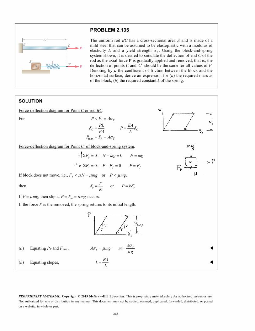
PROPRIETARY MATERIAL. Copyright © 2015 McGraw-Hill Education. This is proprietary material solely for authorized instructor use.
Not authorized for sale or distribution in any manner. This document may not be copied, scanned, duplicated, forwarded, distributed, or posted
on a website, in whole or part.
248
L
CP
Pk
m
B
B'C'
PROBLEM 2.135
The uniform rod BC has a cross-sectional area A and is made of a mild steel that can be assumed to be elastoplastic with a modulus of elasticity E and a yield strength .Y Using the block-and-spring system shown, it is desired to simulate the deflection of end C of the rod as the axial force P is gradually applied and removed, that is, the deflection of points C and C should be the same for all values of P. Denoting by the coefficient of friction between the block and the horizontal surface, derive an expression for (a) the required mass m of the block, (b) the required constant k of the spring.
SOLUTION
Force-deflection diagram for Point C or rod BC.
For
max
Y Y
C C
Y Y
P P A
PL EAP
EA LP P A
Force-deflection diagram for Point C of block-and-spring system.
0 : 0 yF N mg N mg
0 : 0 x f fF P F P F
If block does not move, i.e., or , fF N mg P mg
then orc cP
P kK
If P mg, then slip at occurs. mP F mg
If the force P is the removed, the spring returns to its initial length.
(a) Equating PY and Fmax,
YY
AA mg m
g
(b) Equating slopes, EA
kL

PROPRIETARY MATERIAL. Copyright © 2015 McGraw-Hill Education. This is proprietary material solely for authorized instructor use.
Not authorized for sale or distribution in any manner. This document may not be copied, scanned, duplicated, forwarded, distributed, or posted
on a website, in whole or part.
249
Element n Element 1
Pn P1
PROBLEM 2.C1
A rod consisting of n elements, each of which is homogeneous and of uniform cross section, is subjected to the loading shown. The length of element i is denoted by ,iL its cross-sectional area by ,iA modulus of elasticity by ,iE and the load applied to its right end by iP , the magnitude Pi of this load being assumed to be positive if iP is directed to the right and negative otherwise. (a) Write a computer program that can be used to determine the average normal stress in each element, the deformation of each element, and the total deformation of the rod. (b) Use this program to solve Probs. 2.20 and 2.126.
SOLUTION
For each element, enter
, ,i i iL A E
Compute deformation
Update axial load iP P P
Compute for each element
/
/i i
i i i i
P A
PL A E
Total deformation:
Update through n elements
i
Program Outputs
Problem 2.20
Element Stress (MPa) Deformation (mm)
1 19.0986 0.1091
2 12.7324 0.0909
Total Deformation 0.0182 mm
Problem 2.126
Element Stress (ksi) Deformation (in.)
1 12.7324 0.0176
2 2.8294 0.0057
Total Deformation 0.01190 in.
PROPRIETARY MATERIAL. Copyright © 2015 McGraw-Hill Education. This is proprietary material solely for authorized instructor use.
Not authorized for sale or distribution in any manner. This document may not be copied, scanned, duplicated, forwarded, distributed, or posted
on a website, in whole or part.
250
Element n Element 1
Pn
P2
AB
PROBLEM 2.C2
Rod AB is horizontal with both ends fixed; it consists of n elements, each of which is homogeneous and of uniform cross section, and is subjected to the loading shown. The length of element i is denoted by ,iL its cross-sectional area by ,iA its modulus of elasticity by ,iE and the load applied to its right end by ,iP the magnitude iP of this load being assumed to be positive if iP is directed to the right and negative otherwise. (Note that P1 0.) (a) Write a computer program which can be used to determine the reactions at A and B, the average normal stress in each element, and the deformation of each element. (b) Use this program to solve Probs. 2.41 and 2.42.
SOLUTION
We Consider the reaction at B redundant and release the rod at B
Compute with 0B BR
For each element, enter
, ,i i iL A E
Update axial load
iP P P
Compute for each element
/
/i i
i i i i
P A
PL A E
Update total deformation
B B i
Compute due to unit load at B B
Unit 1/
Unit /i i
i i i i
A
L A E
Update total unit deformation
Unit Unit Unit B B i
Superposition
For total displacement at 0B
Unit 0B B BR
Solving:
/Unit B B BR
Then: A i BR P R
PROPRIETARY MATERIAL. Copyright © 2015 McGraw-Hill Education. This is proprietary material solely for authorized instructor use.
Not authorized for sale or distribution in any manner. This document may not be copied, scanned, duplicated, forwarded, distributed, or posted
on a website, in whole or part.
251
PROBLEM 2.C2 (Continued)
For each element
Unit
Unit i B i
i B i
R
R
Program Outputs
Problem 2.41
RA 62.809 kN
RB 37.191 kN
Element Stress (MPa) Deformation (mm)
1 52.615 0.05011
2 3.974 0.00378
3 2.235 0.00134
4 49.982 0.04498
Problem 2.42
RA 45.479 kN
RB 54.521 kN
Element Stress (MPa) Deformation (mm)
1 77.131 0.03857
2 20.542 0.01027
3 11.555 0.01321
4 36.191 0.06204
PROPRIETARY MATERIAL. Copyright © 2015 McGraw-Hill Education. This is proprietary material solely for authorized instructor use.
Not authorized for sale or distribution in any manner. This document may not be copied, scanned, duplicated, forwarded, distributed, or posted
on a website, in whole or part.
252
Element n Element 1
AB
0�
PROBLEM 2.C3
Rod AB consists of n elements, each of which is homogeneous and of uniform cross section. End A is fixed, while initially there is a gap 0 between end B and the fixed vertical surface on the right. The length of element i is denoted by ,iL its cross-sectional area by ,iA its modulus of elasticity by ,iE and its coefficient of thermal expansion by .i After the temperature of the rod has been increased by ,T the gap at B is closed and the vertical surfaces exert equal and opposite forces on the rod. (a) Write a computer program which can be used to determine the magnitude of the reactions at A and B, the normal stress in each element, and the deformation of each element. (b) Use this program to solve Probs. 2.59 and 2.60.
SOLUTION
We compute the displacements at B.
Assuming there is no support at B,
enter , , ,i i i iL A E
Enter temperature change T. Compute for each element.
i i iL T
Update total deformation.
B B i
Compute due to unit load at .B B
Unit / i i i iL A E
Update total unit deformation.
Unit Unit Unit B B i
Compute reactions.
From superposition,
0( )/Unit B B BR
Then
A BR R
For each element,
/
/
i B i
i i i B i i i
R A
L T R L A E

PROPRIETARY MATERIAL. Copyright © 2015 McGraw-Hill Education. This is proprietary material solely for authorized instructor use.
Not authorized for sale or distribution in any manner. This document may not be copied, scanned, duplicated, forwarded, distributed, or posted
on a website, in whole or part.
253
PROBLEM 2.C3 (Continued)
Program Outputs
Problem 2.59.
52.279 kipsR
Element Stress (ksi) Deformation (10* 3 in.)
1 21.783 9.909
2 18.671 10.091
Problem 2.60.
232.390 kNR
Element Stress (MPa) Deformation (microm)
1 116.195 363.220
2 290.487 136.780

PROPRIETARY MATERIAL. Copyright © 2015 McGraw-Hill Education. This is proprietary material solely for authorized instructor use.
Not authorized for sale or distribution in any manner. This document may not be copied, scanned, duplicated, forwarded, distributed, or posted
on a website, in whole or part.
254
Plate
�A1, E1, ( Y)1
L
�A2, E2, ( Y)2
P
PROBLEM 2.C4
Bar AB has a length L and is made of two different materials of given cross-sectional area, modulus of elasticity, and yield strength. The bar is subjected as shown to a load P that is gradually increased from zero until the deformation of the bar has reached a maximum value m and then decreased back to zero. (a) Write a computer program that, for each of 25 values of m equally spaced over a range extending from 0 to a value equal to 120% of the deformation causing both materials to yield, can be used to determine the maximum value mP of the load, the maximum normal stress in each material, the permanent deformation p of the bar, and the residual stress in each material. (b) Use this program to solve Probs. 2.111 and 2.112.
SOLUTION
Note: The following assumes 1 2( ) < ( )Y Y
Displacement increment
2 20.05( ) /m Y L E
Displacements at yielding
1 1 2 2( ) / ( ) /A Y B YL E L E
For each displacement If
1 1
2 2
1 1 2 2
< :
/
/
( / ) ( )
m A
m
m
m m
E L
E L
P L A E A E
If
1 1
2 2
1 1 2 2
< < :
( )
/
( / )
A m B
Y
m
m m
E L
P A L A E
If
1 1
2 2
1 1 2 2
> :
( )
( )
m B
Y
Y
mP A A

PROPRIETARY MATERIAL. Copyright © 2015 McGraw-Hill Education. This is proprietary material solely for authorized instructor use.
Not authorized for sale or distribution in any manner. This document may not be copied, scanned, duplicated, forwarded, distributed, or posted
on a website, in whole or part.
255
PROBLEM 2.C4 (Continued)
Permanent deformations, residual stresses
Slope of first (elastic) segment
1 1 2 2Slope ( )/
( /Slope)P m m
A E A E L
P
1 res 1 1
2 res 2 2
( ) ( /( Slope))
( ) ( /( Slope))m
m
E P L
E P L
Program Outputs
Problems 2.111 and 2.112
DM 10** 3 in.
PM kips
SIGM (1) ksi
SIGM (2) ksi
DP 10** 3 in.
SIGR (1) ksi
SIG (2)ksi
0.000 0.000 0.000 0.000 0.000 0.000 0.000
2.414 8.750 5.000 5.000 0.000 0.000 0.000
4.828 17.500 10.000 10.000 0.000 0.000 0.000
7.241 26.250 15.000 15.000 0.000 0.000 0.000
9.655 35.000 20.000 20.000 0.000 0.000 0.000
12.069 43.750 25.000 25.000 0.000 0.000 0.000
14.483 52.500 30.000 30.000 0.000 0.000 0.000
16.897 61.250 35.000 35.000 0.000 0.000 0.000
19.310 70.000 40.000 40.000 0.000 0.000 0.000
21.724 78.750 45.000 45.000 0.000 0.000 0.000
24.138 87.500 50.000 50.000 0.000 0.000 0.000
26.552 91.250 50.000 55.000 1.379 2.143 2.857
28.966 95.000 50.000 60.000 2.759 4.286 5.714
31.379 98.750 50.000 65.000 4.138 6.429 8.571
2.112
33.793 102.500 50.000 70.000 5.517 8.571 11.429
36.207 106.250 50.000 75.000 6.897 10.714 14.286
38.621 110.000 50.000 80.000 8.276 12.857 17.143
41.034 113.750 50.000 85.000 9.655 15.000 20.000
2.111
43.448 117.500 50.000 90.000 11.034 17.143 22.857
45.862 121.250 50.000 95.000 12.414 19.286 25.714
48.276 125.000 50.000 100.000 13.793 21.429 28.571
50.690 125.000 50.000 100.000 16.207 21.429 28.571
53.103 125.000 50.000 100.000 18.621 21.429 28.571
55.517 125.000 50.000 100.000 21.034 21.429 28.571
57.931 125.000 50.000 100.000 23.448 21.429 28.571
PROPRIETARY MATERIAL. Copyright © 2015 McGraw-Hill Education. This is proprietary material solely for authorized instructor use.
Not authorized for sale or distribution in any manner. This document may not be copied, scanned, duplicated, forwarded, distributed, or posted
on a website, in whole or part.
256
12 d
12 d
Dr PP9
PROBLEM 2.C5
The plate has a hole centered across the width. The stress concentration factor for a flat bar under axial loading with a centric hole is
2 32 2 2
3.00 3.13 3.66 1.53r r r
KD D D
where r is the radius of the hole and D is the width of the bar. Write a computer program to determine the allowable load P for the given values of r, D, the thickness t of the bar, and the allowable stress all of the material. Knowing that t 1
4 in., 3.0 in.,D and 16 ksi, all determine the allowable load P for values of r from 0.125 in. to 0.75 in., using 0.125 in. increments.
SOLUTION
Enter
all, , ,r D t
Compute K
2.0 /RD r D
2 33.00 3.13 3.66 1.53K RD RD RD
Compute average stress
ave all/K
Allowable load
all ave ( 2.0 )P D r t
Program Output
Radius (in.)
Allowable Load(kips)
0.1250 3.9802
0.2500 3.8866
0.3750 3.7154
0.5000 3.4682
0.6250 3.1523
0.7500 2.7794

PROPRIETARY MATERIAL. Copyright © 2015 McGraw-Hill Education. This is proprietary material solely for authorized instructor use.
Not authorized for sale or distribution in any manner. This document may not be copied, scanned, duplicated, forwarded, distributed, or posted
on a website, in whole or part.
257
L
A
B
c
P2c
PROBLEM 2.C6
A solid truncated cone is subjected to an axial force P as shown. The exact elongation is 2( ) /(2 ).PL c E By replacing the cone by n circular cylinders of equal thickness, write a computer program that can be used to calculate the elongation of the truncated cone. What is the percentage error in the answer obtained from the program using (a) 6,n (b) 12,n (c) 60?n
SOLUTION
For 1 to :
( 0.5)( / )
2 ( / )i
i i
i n
L i L n
r c c L L
Area:
2iA r
Displacement:
( / )/( )P L n AE
Exact displacement:
2exact /(2.0 )PL c E
Percentage error:
exact exactPercent = 100( )/
Program Output
n Approximate Exact Percent
6 0.15852 0.15915 0.40083
12 0.15899 0.15915 0.10100
60 0.15915 0.15915 0.00405


![Tutorial1A - [yamakita-lab.ctrl.titech]Home Page · H8/36064 マニュアルを開き、ctrl+F でP64 をpdf 内検索をかけると、P64 はポート6 に所属していることが分](https://img.dokumen.tips/doc/110x75/5ee1f3e8ad6a402d666ca32b/tutorial1a-yamakita-labctrltitechhome-h836064-ffffectrlf.jpg)


