Embed Size (px)
Citation preview

679
075
Einbau und Inbetriebnahmenur von autorisiertem Fachpersonal,gemäß Bedienungsanleitung.
Fitting and commissioning to becarried out by qualified personnelonly in accordance with the operatinginstructions.
Es bedeuten/Symbols:
WarnungWarning, Caution
HinweisNote
RecyclingRecycling
ZubehörAccessories
Bedienungsanleitung
Pneumatische KlemmpatroneTyp KP, Klemmeinheit Typ KPE,Klemmzylinder Typen DN..-...-KP,DS..-...-KP
Operating instructions
Pneumatic clamping cartridgetype KP, clamping unit type KPE,clamping cylinder types DN..-...-KP,DS..-...-KP
0401c D/GB 1
1 Operating parts andconnections
� Clamping cartridge KP
� Thread for compressed airconnection P or for screw formanual operation
� Clamping unit KPE housing forsupporting the KP
� Through holes and threadedholes for fastening the clampingunit
� Clamping cylinder DS...-...-KP
� Clamping cylinder DN...-...-KP
� Compressed air connection forcylinder (if necessary withadjusting screw for end positioncushioning)
� Thread for fastening the clampingcylinder (DN...-...-KP)
Piston rod
Through holes and threadedholes for fastening clampingcylinder (DS...-...-KP)
Bedienteile und Anschlüsse
� Klemmpatrone KP
� Gewinde für Druckluftanschluss Poder für Schraube zur manuellenBetätigung
� Klemmeinheit KPE Gehäuse zurAufnahme der KP
� Durchgangs- und Gewindebohru-ngen zur Befestigung der Klemm-einheit
� Klemmzylinder DS...-...-KP
� Klemmzylinder DN...-...-KP
� Druckluftanschluss Zylinder (ggf.mit Einstellschraube für Endla-gendämpfung)
� Gewinde zur Befestigung desKlemmzylinders (DN...-...-KP)
Kolbenstange
Durchgangs- und Gewindebohru-ngen zur Befestigung des Klemm-zylinders (DS...-...-KP)
�
� �
�
�
�
� �
Bild 1 / Fig. 1
KP / KPE / DN...-...-KP / DS...-...-KP
0401c D/GB 2
2
Bild 2 / Fig. 2
Bild 3 / Fig. 3
Ohne Druckbeaufschlagung:Kraftschluss
Without pressure applied:friction lock
Mit Druckbeaufschlagung:freie Kolbenstange
With pressure applied:piston rod free
Bild 4 / Fig. 4
Funktion und Anwendung
Die Klemmpatrone in der Klemmeinheitoder im Klemmzylinder, hält Rundmate-rial oder die Kolbenstange in jeder be-liebigen Position fest.
Durch Entlüften der Klemmpatronedrückt eine Feder die Klemmbackenauseinander (Bild 2). Infolge der Sprei-zung der Klemmbacken werden dieseauf der Kolbenstange schräg gestellt.Das Rundmaterial bzw. die Kolbenstan-ge wird geklemmt.
Durch Belüften der Klemmpatrone (An-schluss P) drückt ein Kolben dieKlemmbacken zusammen, bis dieseparallel zueinander stehen (Bild 3). So-mit liegen die Bohrungen der Klemm-backen in einer Achse mit der Kolben-stange. Die Klemmung ist gelöst, dasRundmaterial bzw. die Kolbenstange istfrei beweglich.
Die Klemmung kann manuell gelöst wer-den (Bild 4). Die mitgelieferte Schraube(M5 DIN 912 bzw. 1/8 Zoll) wird in denLuftanschluss P der Klemmpatrone ge-dreht. Diese drückt über den Kolben dieKlemmbacken zusammen, bis die Klem-mung gelöst ist.
Function and application
The clamping cartridge in a clampingunit or a clamping cylinder holds roundmaterial or the piston rod in any desiredposition.
When the clamping cartridge is exhau-sted, a spring presses the clampingjaws apart (Fig. 2). When the clampingjaws have open, they are placed diago-nally on the piston rod. The round mate-rial or the piston rod is clamped.
When the clamping cartridge is pressuri-zed (port P), a piston presses the clam-ping jaws together until these are paral-lel to each other (Fig. 3). The bores ofthe clamping jaws then lie on the sameaxis as the piston rod. The clamp is re-leased, the round material or the pistonrod can move freely.
The clamp can be released manually(Fig. 4). The screw supplied (M5 DIN912 or 1/8 inch) must be screwed intoair connection P of the clamping cartrid-ge. This presses the clamping jaws to-gether over the piston until the clamp isreleased.
Manuelles Lösen:freie Kolbenstange
Release manually:piston rod free
P
0401c D/GB 3
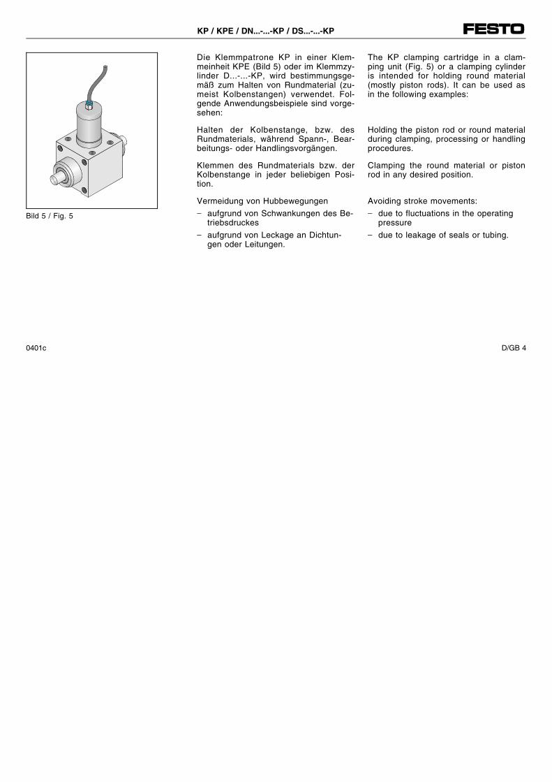
The KP clamping cartridge in a clam-ping unit (Fig. 5) or a clamping cylinderis intended for holding round material(mostly piston rods). It can be used asin the following examples:
Holding the piston rod or round materialduring clamping, processing or handlingprocedures.
Clamping the round material or pistonrod in any desired position.
Avoiding stroke movements:− due to fluctuations in the operating
pressure− due to leakage of seals or tubing.
Die Klemmpatrone KP in einer Klem-meinheit KPE (Bild 5) oder im Klemmzy-linder D...-...-KP, wird bestimmungsge-mäß zum Halten von Rundmaterial (zu-meist Kolbenstangen) verwendet. Fol-gende Anwendungsbeispiele sind vorge-sehen:
Halten der Kolbenstange, bzw. desRundmaterials, während Spann-, Bear-beitungs- oder Handlingsvorgängen.
Klemmen des Rundmaterials bzw. derKolbenstange in jeder beliebigen Posi-tion.
Vermeidung von Hubbewegungen− aufgrund von Schwankungen des Be-
triebsdruckes− aufgrund von Leckage an Dichtun-
gen oder Leitungen.
Bild 5 / Fig. 5
KP / KPE / DN...-...-KP / DS...-...-KP
0401c D/GB 4
C % mbar
Bild 6 / Fig. 6
LF-... LR-...
Bild 7 / Fig. 7
Bild 8 / Fig. 8
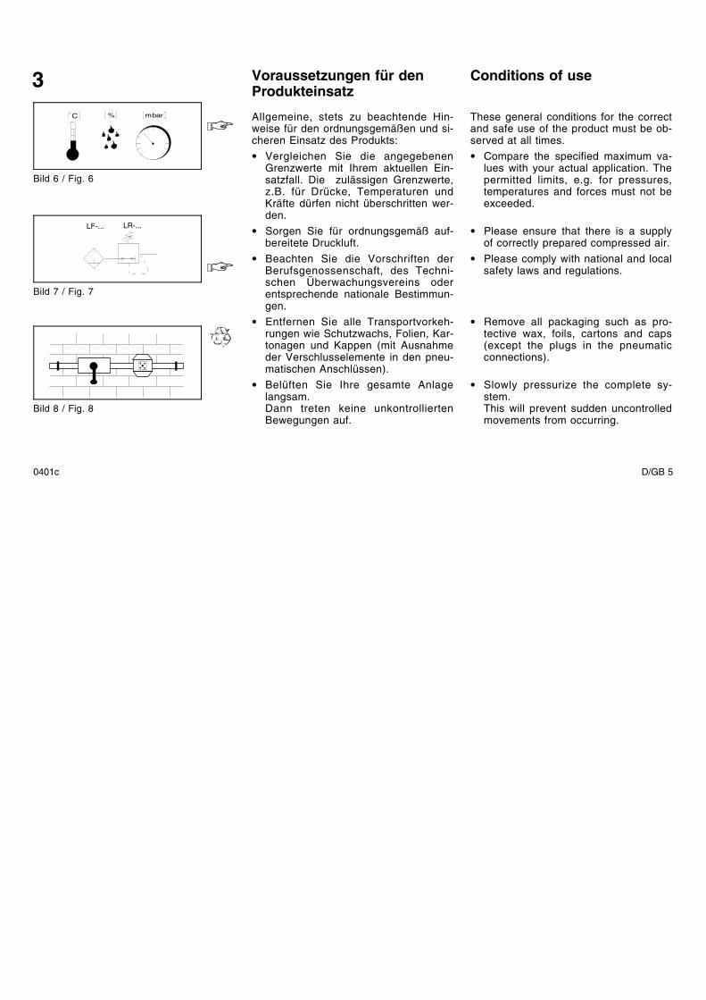
Voraussetzungen für denProdukteinsatz
Allgemeine, stets zu beachtende Hin-weise für den ordnungsgemäßen und si-cheren Einsatz des Produkts:• Vergleichen Sie die angegebenen
Grenzwerte mit Ihrem aktuellen Ein-satzfall. Die zulässigen Grenzwerte,z.B. für Drücke, Temperaturen undKräfte dürfen nicht überschritten wer-den.
• Sorgen Sie für ordnungsgemäß auf-bereitete Druckluft.
• Beachten Sie die Vorschriften derBerufsgenossenschaft, des Techni-schen Überwachungsvereins oderentsprechende nationale Bestimmun-gen.
• Entfernen Sie alle Transportvorkeh-rungen wie Schutzwachs, Folien, Kar-tonagen und Kappen (mit Ausnahmeder Verschlusselemente in den pneu-matischen Anschlüssen).
• Belüften Sie Ihre gesamte Anlagelangsam.Dann treten keine unkontrolliertenBewegungen auf.
Conditions of use
These general conditions for the correctand safe use of the product must be ob-served at all times.• Compare the specified maximum va-
lues with your actual application. Thepermitted limits, e.g. for pressures,temperatures and forces must not beexceeded.
• Please ensure that there is a supplyof correctly prepared compressed air.
• Please comply with national and localsafety laws and regulations.
• Remove all packaging such as pro-tective wax, foils, cartons and caps(except the plugs in the pneumaticconnections).
• Slowly pressurize the complete sy-stem.This will prevent sudden uncontrolledmovements from occurring.
3
0401c D/GB 5
• Verwenden Sie das Produkt ohnejegliche eigenmächtige Veränderun-gen.
• Berücksichtigen Sie die Warnungenund Hinweise- am Produkt- in der Bedienungsanleitung
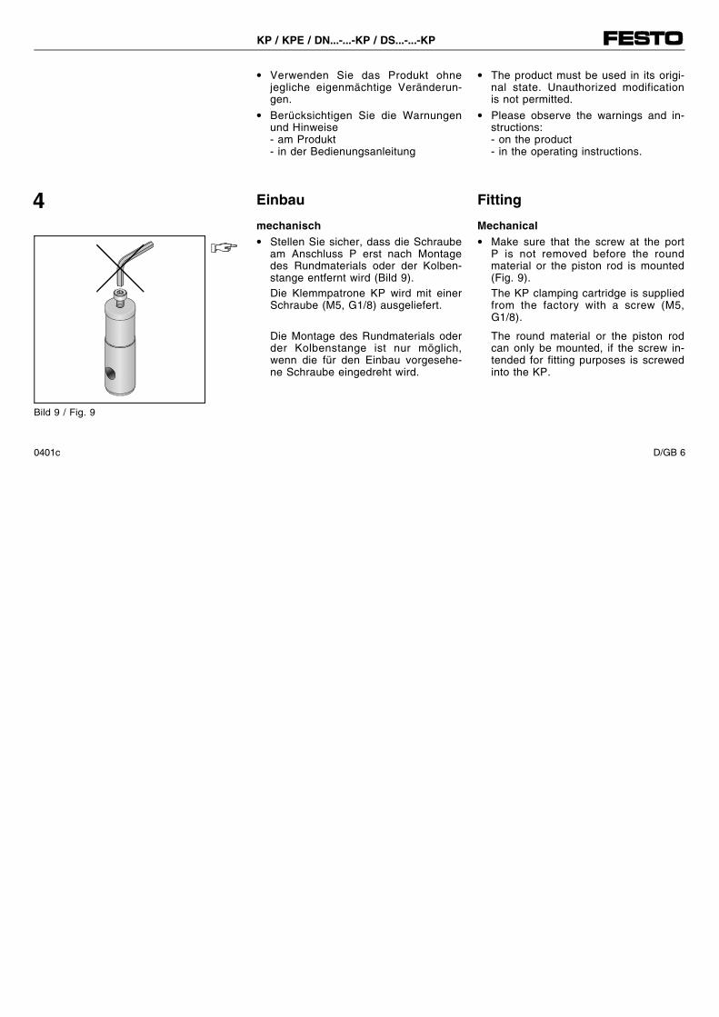
Einbau
mechanisch• Stellen Sie sicher, dass die Schraube
am Anschluss P erst nach Montagedes Rundmaterials oder der Kolben-stange entfernt wird (Bild 9).Die Klemmpatrone KP wird mit einerSchraube (M5, G1/8) ausgeliefert.
Die Montage des Rundmaterials oderder Kolbenstange ist nur möglich,wenn die für den Einbau vorgesehe-ne Schraube eingedreht wird.
• The product must be used in its origi-nal state. Unauthorized modificationis not permitted.
• Please observe the warnings and in-structions:- on the product- in the operating instructions.
Fitting
Mechanical• Make sure that the screw at the port
P is not removed before the roundmaterial or the piston rod is mounted(Fig. 9).The KP clamping cartridge is suppliedfrom the factory with a screw (M5,G1/8).
The round material or the piston rodcan only be mounted, if the screw in-tended for fitting purposes is screwedinto the KP.
4
Bild 9 / Fig. 9
KP / KPE / DN...-...-KP / DS...-...-KP
0401c D/GB 6

• Achten Sie auf genügend Platz fürpneumatische Anschlüsse.
Zum Einbau der Klemmpatrone:1. Schieben Sie die Klemmpatrone von
oben in die Aufnahmebohrung desGehäuses (Bild 10).
2. Schieben Sie die zu klemmende Stan-ge in das Gehäuse durch die Klemm-patrone.
• Stellen Sie sicher, dass die Stangen-qualität h8 gewährleistet ist.
Bei Verwendung eines eigenen Gehäu-ses (Bild 11):• Stellen Sie folgende Punkte sicher:
- das Toleranzfeld der Bohrung zurAufnahme der KlemmpatroneKP der Passung D9 entspricht(DIN ISO 286).
- am eigenen Gehäuse werden2 Gleitlager mit einer maximalenFluchtungsabweichung derBohrungen von 0,05 mm verwendet(siehe Bild 11).
• Make sure that there is sufficientroom for the pneumatic connections.
Fitting the clamping cartridge:1. Push the clamping cartridge from
above into the bore in the housing(Fig. 10).
2. Push the rod to be clamped intothe housing through the clampingcartridge.
• Make sure that rod quality h8 is gua-ranteed.
If you are using your own housing(Fig. 11):• Make sure that the following points
are observed:- the tolerance field of the hole for
the KP clamping cartridge is of sizeD9 (DIN ISO 286).
- 2 friction bearings with a maximumalignment deviation of the holes of0.05 mm must be used if you haveyour own housing (see Fig. 11).
Bild 10 / Fig. 10
KEø D9
Bild 11 / Fig. 11
0401c D/GB 7
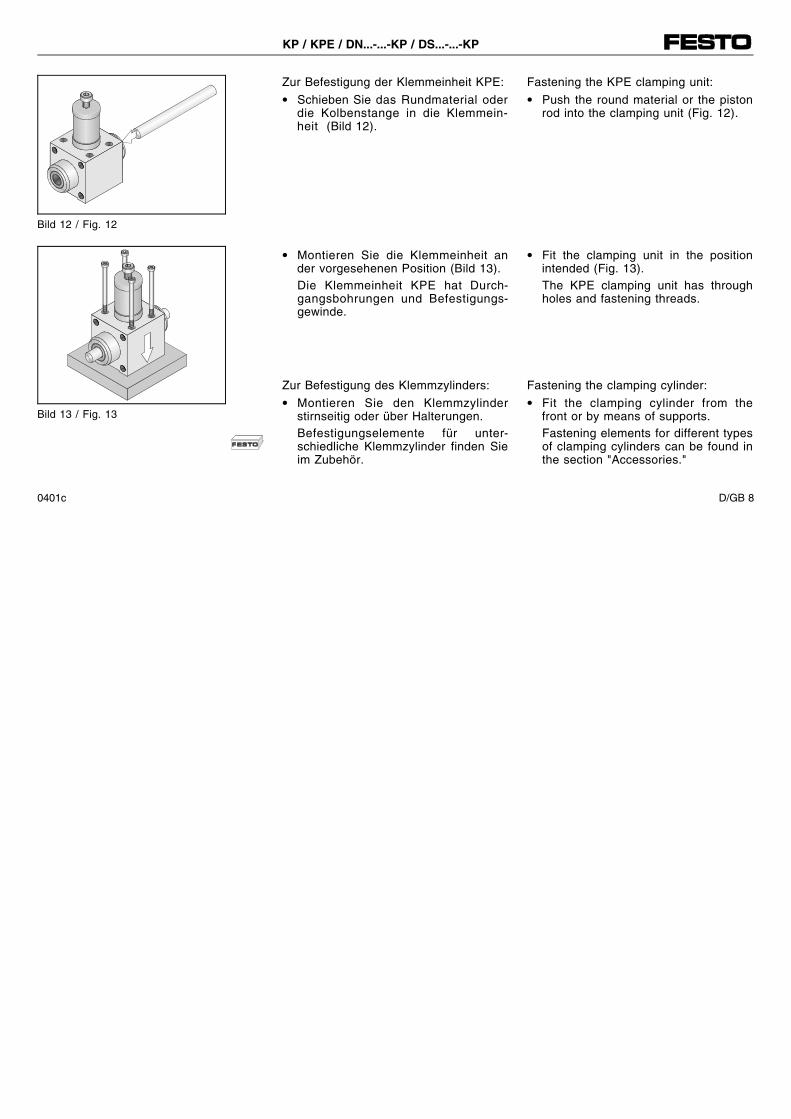
Zur Befestigung der Klemmeinheit KPE:• Schieben Sie das Rundmaterial oder
die Kolbenstange in die Klemmein-heit (Bild 12).
• Montieren Sie die Klemmeinheit ander vorgesehenen Position (Bild 13).Die Klemmeinheit KPE hat Durch-gangsbohrungen und Befestigungs-gewinde.
Zur Befestigung des Klemmzylinders:• Montieren Sie den Klemmzylinder
stirnseitig oder über Halterungen.Befestigungselemente für unter-schiedliche Klemmzylinder finden Sieim Zubehör.
Fastening the KPE clamping unit:• Push the round material or the piston
rod into the clamping unit (Fig. 12).
• Fit the clamping unit in the positionintended (Fig. 13).The KPE clamping unit has throughholes and fastening threads.
Fastening the clamping cylinder:• Fit the clamping cylinder from the
front or by means of supports.Fastening elements for different typesof clamping cylinders can be found inthe section "Accessories."
Bild 12 / Fig. 12
Bild 13 / Fig. 13
KP / KPE / DN...-...-KP / DS...-...-KP
0401c D/GB 8
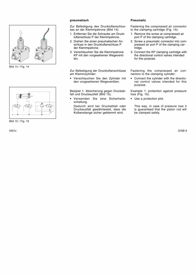
Pneumatic
Fastening the compressed air connectorto the clamping cartridge (Fig. 14):1. Remove the screw at compressed air
port P of the clamping cartridge.2. Screw a pneumatic connector into com-
pressed air port P of the clamping car-tridge.
3. Connect the KP clamping cartridge withthe directional control valves intendedfor this purpose.
Fastening the compressed air con-nectors to the clamping cylinder:• Connect the cylinder with the directio-
nal control valves intended for thispurpose.
Example 1: protection against pressureloss (Fig. 15).• Use a protection plot.
This way, in case of pressure loss itis guaranteed that the piston rod willbe clamped safely.
pneumatisch
Zur Befestigung des Druckluftanschlus-ses an der Klemmpatrone (Bild 14):1. Entfernen Sie die Schraube am Druck-
luftanschluss P der Klemmpatrone.2. Drehen Sie einen pneumatischen An-
schluss in den Druckluftanschluss Pder Klemmpatrone.
3. Verschlauchen Sie die KlemmpatroneKP mit den vorgesehenen Wegeventi-len.
Zur Befestigung der Druckluftanschlüsseam Klemmzylinder:• Verschlauchen Sie den Zylinder mit
den vorgesehenen Wegeventilen.
Beispiel 1: Absicherung gegen Druckab-fall und Druckausfall (Bild 15).• Verwenden Sie eine Sicherheits-
schaltung.Dadurch wird bei Druckabfall oderDruckausfall gewährleistet, dass dieKolbenstange sicher geklemmt wird.
Bild 14 / Fig. 14
Bild 15 / Fig. 15
0401c D/GB 9
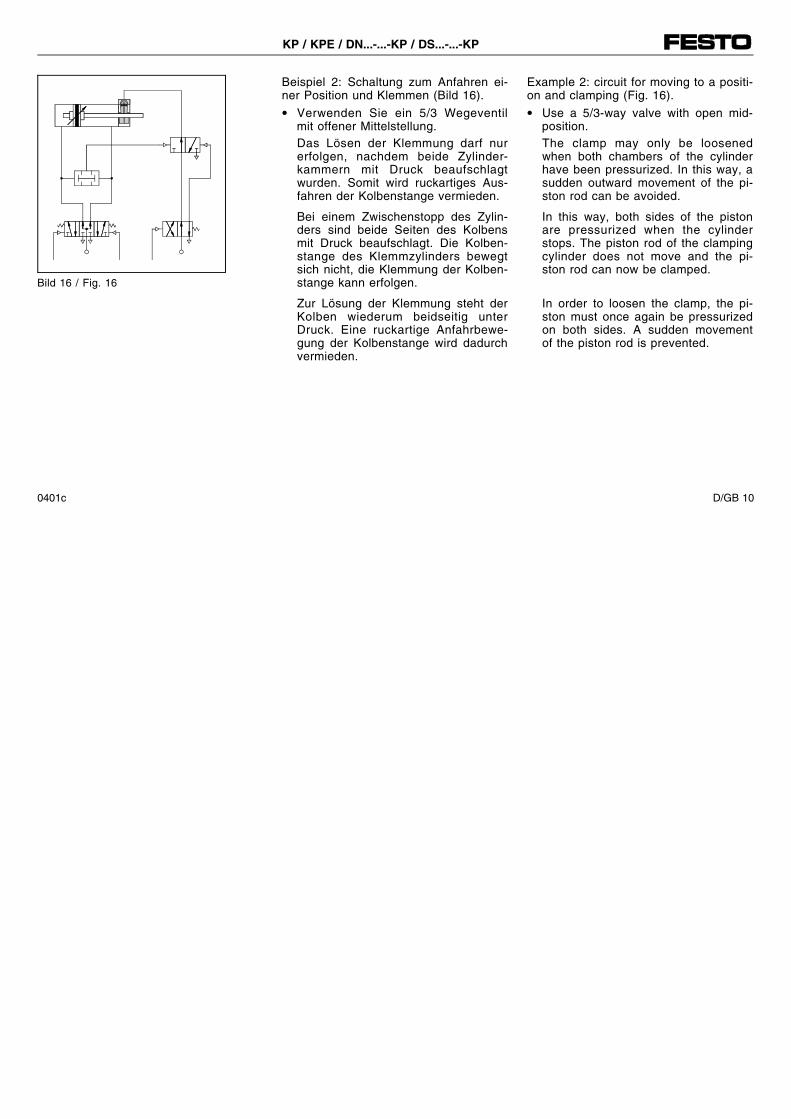
Beispiel 2: Schaltung zum Anfahren ei-ner Position und Klemmen (Bild 16).• Verwenden Sie ein 5/3 Wegeventil
mit offener Mittelstellung.Das Lösen der Klemmung darf nurerfolgen, nachdem beide Zylinder-kammern mit Druck beaufschlagtwurden. Somit wird ruckartiges Aus-fahren der Kolbenstange vermieden.
Bei einem Zwischenstopp des Zylin-ders sind beide Seiten des Kolbensmit Druck beaufschlagt. Die Kolben-stange des Klemmzylinders bewegtsich nicht, die Klemmung der Kolben-stange kann erfolgen.
Zur Lösung der Klemmung steht derKolben wiederum beidseitig unterDruck. Eine ruckartige Anfahrbewe-gung der Kolbenstange wird dadurchvermieden.
Example 2: circuit for moving to a positi-on and clamping (Fig. 16).• Use a 5/3-way valve with open mid-
position.The clamp may only be loosenedwhen both chambers of the cylinderhave been pressurized. In this way, asudden outward movement of the pi-ston rod can be avoided.
In this way, both sides of the pistonare pressurized when the cylinderstops. The piston rod of the clampingcylinder does not move and the pi-ston rod can now be clamped.
In order to loosen the clamp, the pi-ston must once again be pressurizedon both sides. A sudden movementof the piston rod is prevented.
Bild 16 / Fig. 16
KP / KPE / DN...-...-KP / DS...-...-KP
0401c D/GB 10
Inbetriebnahme
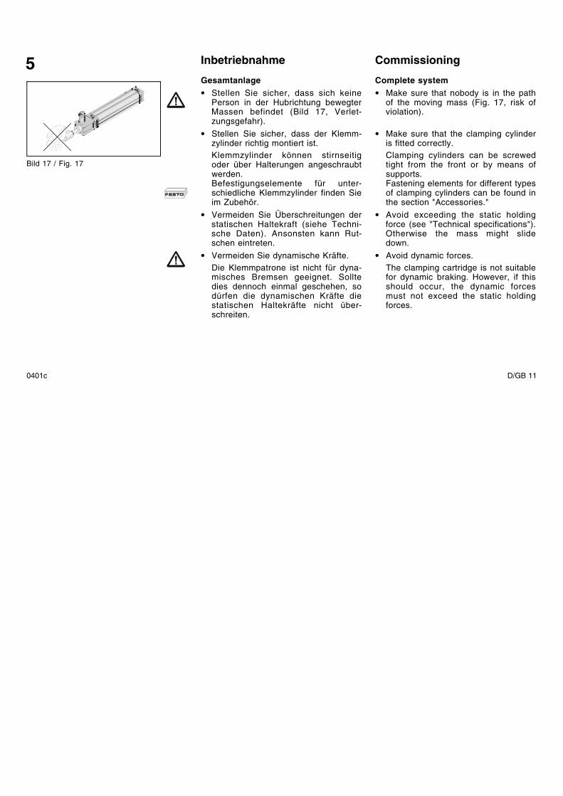
Gesamtanlage• Stellen Sie sicher, dass sich keine
Person in der Hubrichtung bewegterMassen befindet (Bild 17, Verlet-zungsgefahr).
• Stellen Sie sicher, dass der Klemm-zylinder richtig montiert ist.Klemmzylinder können stirnseitigoder über Halterungen angeschraubtwerden.Befestigungselemente für unter-schiedliche Klemmzylinder finden Sieim Zubehör.
• Vermeiden Sie Überschreitungen derstatischen Haltekraft (siehe Techni-sche Daten). Ansonsten kann Rut-schen eintreten.
• Vermeiden Sie dynamische Kräfte.Die Klemmpatrone ist nicht für dyna-misches Bremsen geeignet. Solltedies dennoch einmal geschehen, sodürfen die dynamischen Kräfte diestatischen Haltekräfte nicht über-schreiten.
Commissioning
Complete system• Make sure that nobody is in the path
of the moving mass (Fig. 17, risk ofviolation).
• Make sure that the clamping cylinderis fitted correctly.Clamping cylinders can be screwedtight from the front or by means ofsupports.Fastening elements for different typesof clamping cylinders can be found inthe section "Accessories."
• Avoid exceeding the static holdingforce (see "Technical specifications").Otherwise the mass might slidedown.
• Avoid dynamic forces.The clamping cartridge is not suitablefor dynamic braking. However, if thisshould occur, the dynamic forcesmust not exceed the static holdingforces.
5
Bild 17 / Fig. 17
0401c D/GB 11
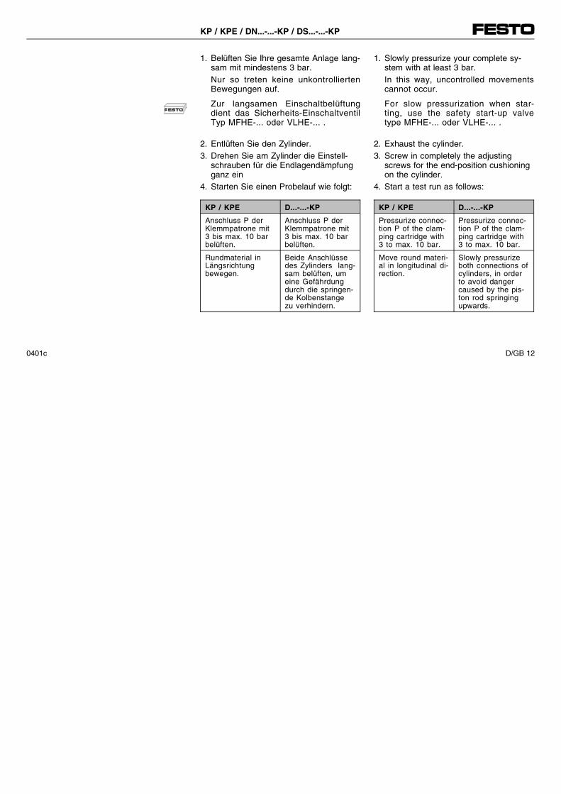
1. Belüften Sie Ihre gesamte Anlage lang-sam mit mindestens 3 bar.Nur so treten keine unkontrolliertenBewegungen auf.
Zur langsamen Einschaltbelüftungdient das Sicherheits-EinschaltventilTyp MFHE-... oder VLHE-... .
2. Entlüften Sie den Zylinder.3. Drehen Sie am Zylinder die Einstell-
schrauben für die Endlagendämpfungganz ein
4. Starten Sie einen Probelauf wie folgt:
KP / KPE D...-...-KP
Anschluss P derKlemmpatrone mit3 bis max. 10 barbelüften.
Anschluss P derKlemmpatrone mit3 bis max. 10 barbelüften.
Rundmaterial inLängsrichtungbewegen.
Beide Anschlüssedes Zylinders lang-sam belüften, umeine Gefährdungdurch die springen-de Kolbenstangezu verhindern.
1. Slowly pressurize your complete sy-stem with at least 3 bar.In this way, uncontrolled movementscannot occur.
For slow pressurization when star-ting, use the safety start-up valvetype MFHE-... oder VLHE-... .
2. Exhaust the cylinder.3. Screw in completely the adjusting
screws for the end-position cushioningon the cylinder.
4. Start a test run as follows:
KP / KPE D...-...-KP
Pressurize connec-tion P of the clam-ping cartridge with3 to max. 10 bar.
Pressurize connec-tion P of the clam-ping cartridge with3 to max. 10 bar.
Move round materi-al in longitudinal di-rection.
Slowly pressurizeboth connections ofcylinders, in orderto avoid dangercaused by the pis-ton rod springingupwards.
KP / KPE / DN...-...-KP / DS...-...-KP
0401c D/GB 12
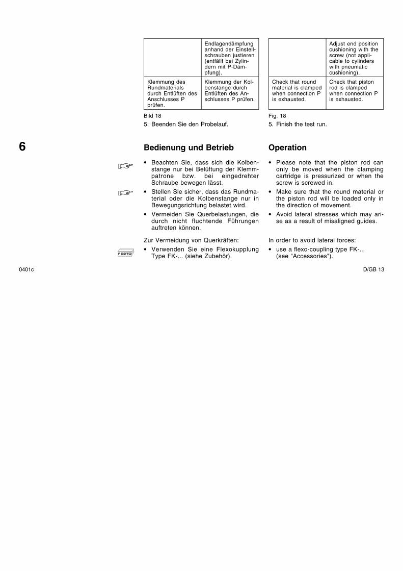
Endlagendämpfunganhand der Einstell-schrauben justieren(entfällt bei Zylin-dern mit P-Däm-pfung).
Klemmung desRundmaterialsdurch Entlüften desAnschlusses Pprüfen.
Klemmung der Kol-benstange durchEntlüften des An-schlusses P prüfen.
Bild 18
5. Beenden Sie den Probelauf.
Bedienung und Betrieb
• Beachten Sie, dass sich die Kolben-stange nur bei Belüftung der Klemm-patrone bzw. bei eingedrehterSchraube bewegen lässt.
• Stellen Sie sicher, dass das Rundma-terial oder die Kolbenstange nur inBewegungsrichtung belastet wird.
• Vermeiden Sie Querbelastungen, diedurch nicht fluchtende Führungenauftreten können.
Zur Vermeidung von Querkräften:• Verwenden Sie eine Flexokupplung
Type FK-... (siehe Zubehör).
Adjust end positioncushioning with thescrew (not appli-cable to cylinderswith pneumaticcushioning).
Check that roundmaterial is clampedwhen connection Pis exhausted.
Check that pistonrod is clampedwhen connection Pis exhausted.
Fig. 18
5. Finish the test run.
Operation
• Please note that the piston rod canonly be moved when the clampingcartridge is pressurized or when thescrew is screwed in.
• Make sure that the round material orthe piston rod will be loaded only inthe direction of movement.
• Avoid lateral stresses which may ari-se as a result of misaligned guides.
In order to avoid lateral forces:• use a flexo-coupling type FK-...
(see "Accessories").
6
0401c D/GB 13
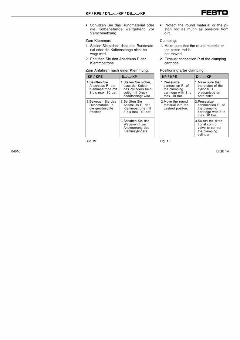
• Schützen Sie das Rundmaterial oderdie Kolbenstange weitgehend vorVerschmutzung.
Zum Klemmen:1. Stellen Sie sicher, dass das Rundmate-
rial oder die Kolbenstange nicht be-wegt wird.
2. Entlüften Sie den Anschluss P derKlemmpatrone.
Zum Anfahren nach einer Klemmung:
KP / KPE D...-...-KP
1.Belüften SieAnschluss P derKlemmpatrone mit3 bis max. 10 bar.
1.Stellen Sie sicher,dass der Kolbendes Zylinders beid-seitig mit Druckbeaufschlagt wird.
2.Bewegen Sie dasRundmaterial indie gewünschtePosition
2.Belüften SieAnschluss P derKlemmpatrone mit3 bis max. 10 bar.
3.Schalten Sie dasWegeventil zurAnsteuerung desKlemmzylinders.
Bild 19
• Protect the round material or the pi-ston rod as much as possible fromdirt.
Clamping:1. Make sure that the round material or
the piston rod isnot moved.
2. Exhaust connection P of the clampingcartridge.
Positioning after clamping:
KP / KPE D...-...-KP
1.Pressurizeconnection P ofthe clampingcartridge with 3 tomax. 10 bar.
1.Make sure thatthe piston of thecylinder ispressurized onboth sides.
2.Move the roundmaterial into thedesired positon.
2.Pressurizeconnnection P ofthe clampingcartridge with 3 tomax. 10 bar.
3.Switch the direc-tional controlvalve to controlthe clampingcylinder.
Fig. 19
KP / KPE / DN...-...-KP / DS...-...-KP
0401c D/GB 14
Wartung und Pflege
Zur Reinigung:• Entlüften Sie die Klemmpatrone bzw.
den Klemmzylinder.• Reinigen Sie KP / KPE / D...-...-KP
ausschließlich mit Wasser (max.+60°C).
• Trocknen Sie alle Bauteile sorgfältig.Nach der Reinigung ist am Klemmzy-linder die Kolbenstange leicht mitKlüberplex 222 einzufetten.
Ausbau und Reparatur
• Entlüften Sie die gesamte Anlage unddas Gerät.
• Lösen Sie die Befestigungselementeder KPE / D...-...-KP.
• Nutzen Sie die Möglichkeit der Über-holung Ihrer Klemmzylinder D......KPdurch unseren Reparaturservice.
Care and maintenance
Cleaning:• Exhaust the clamping cartridge or the
clamping cylinder.• Clean the KP / KPE / D...-...-KP only
with water (max. +60°C).
• Carefully dry all components.After cleaning, the piston rod on theclamping cylinder must be lightly lu-bricated with Klüberplex 222.
Dismantling and repairs
• Exhaust the complete system and theclamping cartridge.
• Loosen the fastening elements of theKPE / D...-...-KP.
• Make use of our repair service forhaving your D...-...-KP clamping cylin-der overhauled.
7
8
0401c D/GB 15
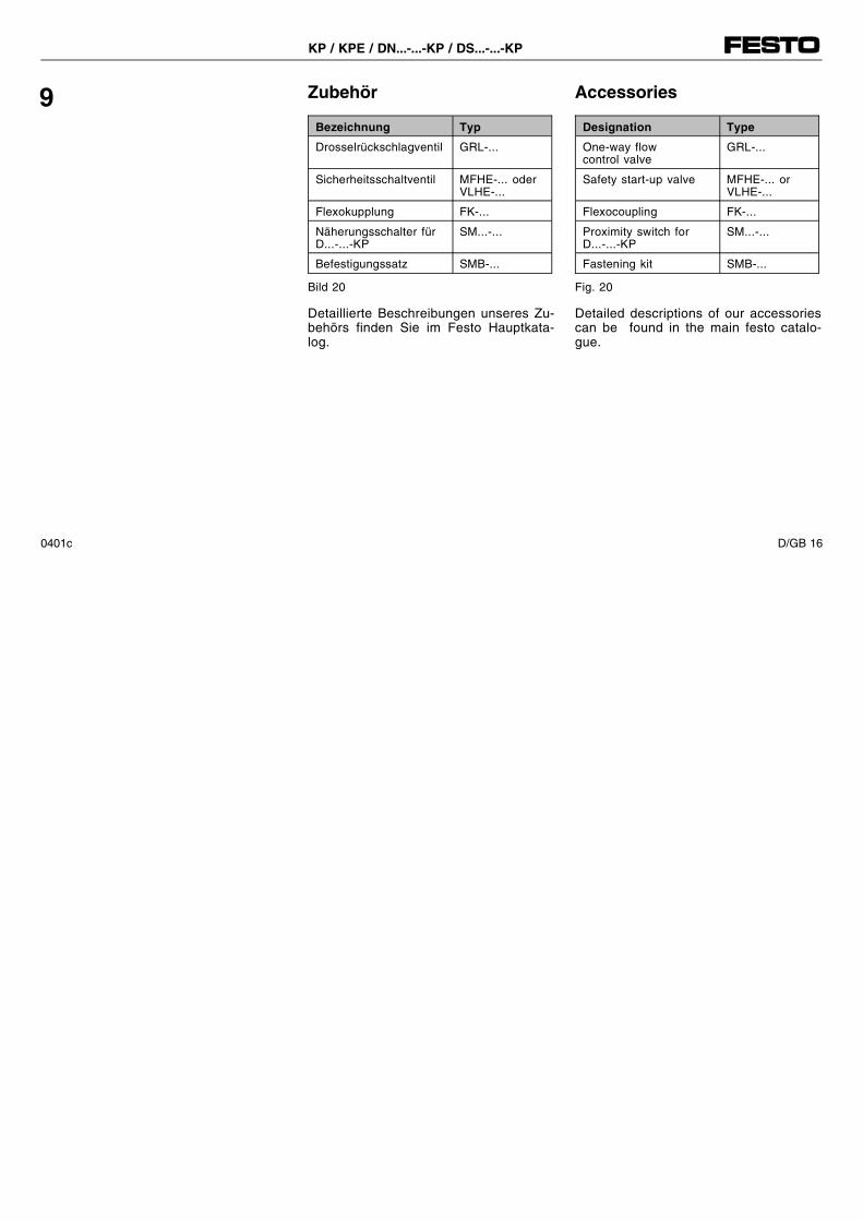
Zubehör
Bezeichnung Typ
Drosselrückschlagventil GRL-...
Sicherheitsschaltventil MFHE-... oderVLHE-...
Flexokupplung FK-...
Näherungsschalter fürD...-...-KP
SM...-...
Befestigungssatz SMB-...
Bild 20
Detaillierte Beschreibungen unseres Zu-behörs finden Sie im Festo Hauptkata-log.
9 Accessories
Designation Type
One-way flowcontrol valve
GRL-...
Safety start-up valve MFHE-... orVLHE-...
Flexocoupling FK-...
Proximity switch forD...-...-KP
SM...-...
Fastening kit SMB-...
Fig. 20
Detailed descriptions of our accessoriescan be found in the main festo catalo-gue.
KP / KPE / DN...-...-KP / DS...-...-KP
0401c D/GB 16
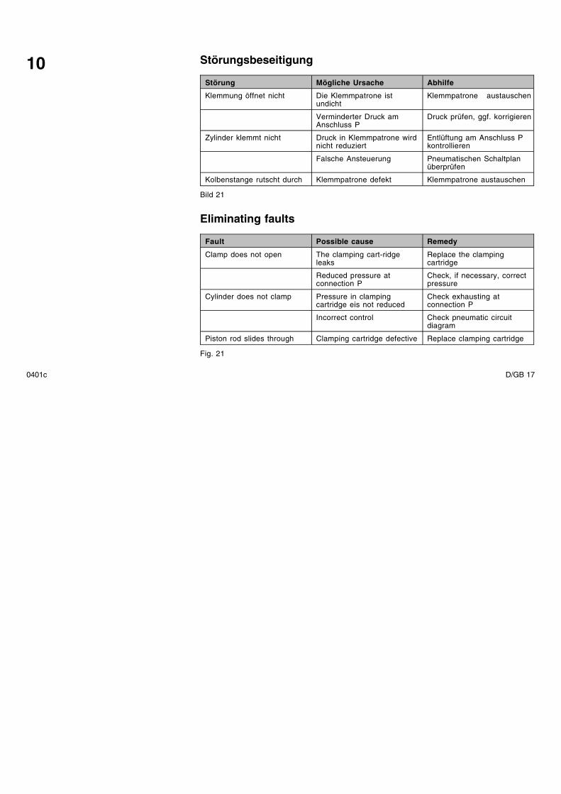
Störungsbeseitigung
Störung Mögliche Ursache Abhilfe
Klemmung öffnet nicht Die Klemmpatrone istundicht
Klemmpatrone austauschen
Verminderter Druck amAnschluss P
Druck prüfen, ggf. korrigieren
Zylinder klemmt nicht Druck in Klemmpatrone wirdnicht reduziert
Entlüftung am Anschluss Pkontrollieren
Falsche Ansteuerung Pneumatischen Schaltplanüberprüfen
Kolbenstange rutscht durch Klemmpatrone defekt Klemmpatrone austauschen
Bild 21
Eliminating faults
Fault Possible cause Remedy
Clamp does not open The clamping cart-ridgeleaks
Replace the clampingcartridge
Reduced pressure atconnection P
Check, if necessary, correctpressure
Cylinder does not clamp Pressure in clampingcartridge eis not reduced
Check exhausting atconnection P
Incorrect control Check pneumatic circuitdiagram
Piston rod slides through Clamping cartridge defective Replace clamping cartridge
Fig. 21
10
0401c D/GB 17
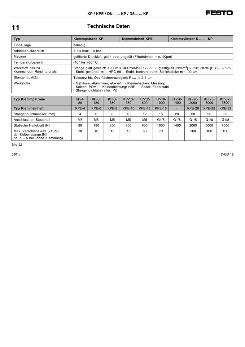
Technische Daten11Typ Klemmpatrone KP Klemmeinheit KPE Klemmzylinder D...-...- KP
Einbaulage beliebig
Arbeitsdruckbereich 3 bis max. 10 bar
Medium gefilterte Druckluft, geölt oder ungeölt (Filterfeinheit min. 40µm)
Temperaturbereich -10° bis +80° C
Werkstoff des zuklemmenden Rundmaterials
Stange glatt gewalzt: X20Cr13, X6CrNiMoTi 17222; Zugfestigkeit [N/mm2] > 650; Härte [HB30] > 175- Stahl, gehärtet: min. HRC 60 - Stahl, hartverchromt: Schichtdicke min. 20 µm
Stangenqualität Toleranz h8, Oberflächenrauhigkeit Rmax. = 2,5 µm
Werkstoffe - Gehäuse: Aluminium, eloxiert; - Klemmbacken: Messing;- Kolben: POM; - Kolbendichtung: NBR; - Feder: Federstahl- Stangendichtabstreifer: PU
Typ Klemmpatrone KP-4-80
KP-6-180
KP-8-350
KP-10-350
KP-12-600
KP-16-1000
KP-20-1400
KP-20-2000
KP-25-5000
KP-32-7500
Typ Klemmeinheit KPE-4 KPE-6 KPE-8 KPE-10 KPE-12 KPE-16 - KPE-20 KPE-25 KPE-32
Stangendurchmesser [mm] 4 6 8 10 12 16 20 20 25 32
Anschluss an Steuerluft M5 M5 M5 M5 M5 G1/8 G1/8 G1/8 G1/8 G1/8
Statische Haltekraft [N] 80 180 350 350 600 1000 1400 2000 5000 7500
Max. Verschiebekraft (+15%)der Kolbenstange [N]bei p = 6 bar (ohne Klemmung)
10 10 15 15 50 70 - 100 100 100
Bild 22
KP / KPE / DN...-...-KP / DS...-...-KP
0401c D/GB 18
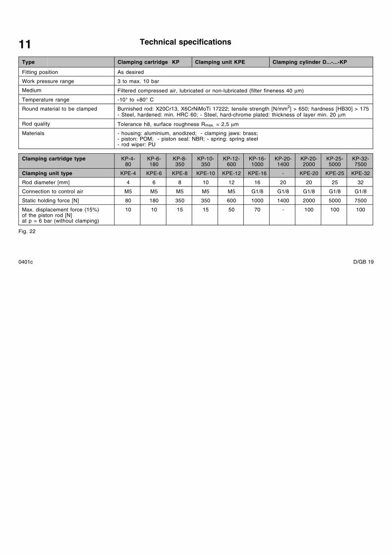
Technical specifications11Type Clamping cartridge KP Clamping unit KPE Clamping cylinder D...-...-KP
Fitting position As desired
Work pressure range 3 to max. 10 bar
Medium Filtered compressed air, lubricated or non-lubricated (filter fineness 40 µm)
Temperature range -10° to +80° C
Round material to be clamped Burnished rod: X20Cr13, X6CrNiMoTi 17222; tensile strength [N/mm2] > 650; hardness [HB30] > 175- Steel, hardened: min. HRC 60; - Steel, hard-chrome plated: thickness of layer min. 20 µm
Rod quality Tolerance h8, surface roughness Rmax. = 2,5 µm
Materials - housing: aluminium, anodized; - clamping jaws: brass;- piston: POM; - piston seal: NBR; - spring: spring steel- rod wiper: PU
Clamping cartridge type KP-4-80
KP-6-180
KP-8-350
KP-10-350
KP-12-600
KP-16-1000
KP-20-1400
KP-20-2000
KP-25-5000
KP-32-7500
Clamping unit type KPE-4 KPE-6 KPE-8 KPE-10 KPE-12 KPE-16 - KPE-20 KPE-25 KPE-32
Rod diameter [mm] 4 6 8 10 12 16 20 20 25 32
Connection to control air M5 M5 M5 M5 M5 G1/8 G1/8 G1/8 G1/8 G1/8
Static holding force [N] 80 180 350 350 600 1000 1400 2000 5000 7500
Max. displacement force (15%)of the piston rod [N]at p = 6 bar (without clamping)
10 10 15 15 50 70 - 100 100 100
Fig. 22
0401c D/GB 19
PostfachD-73726 EsslingenPhone +49/711/347-0
Quelltext: deutschVersion: 0401c
Weitergabe sowie Vervielfätigung diesesDokuments, Verwertung und Mitteilungseines Inhalts verboten, soweit nichtausdrücklich gestattet. Zuwiderhandlun-gen verpflichten zu Schadenersatz. AlleRechte vorbehalten, insbesondere dasRecht, Patent-, Gebrauchsmuster- oderGeschmacksmusteranmeldungen durch-zuführen.
The copying, distribution and utilizationof this document as well as the commu-nication of its contents to others withoutexpressed authorization is prohibited.Offenders will be held liable for thepayment of damages. All rights reser-ved, in particular the right to carry outpatent, utility model or ornamental de-sign registrations.
0401c D/GB 20


![Rohrleitungen an Kaltvergasern gemäß EN 13458 und EN · PDF fileQualitätsanforderungen gemäß Bewertungsgruppe C gemäß EN ISO 5817 [9] und ZfP - Verfahrensübertrag gemäß EN](https://img.dokumen.tips/doc/110x75/5a7a0a6d7f8b9ae5058c78c3/rohrleitungen-an-kaltvergasern-gem-en-13458-und-en-gem-bewertungsgruppe-c-gem.jpg)

![-SERIE BEDIENUNGSANLEITUNG - ADAM Audio · 2018. 3. 21. · gemäß funktioniert oder fallen gelassen wurde. 5 S-SERIE BEDIENUNGSANLEITUNG [DEUTSCH] 2. ... wie der Weiterentwicklung](https://img.dokumen.tips/doc/110x75/60c0859613bab2141b1f6809/serie-bedienungsanleitung-adam-audio-2018-3-21-gem-funktioniert-oder.jpg)