Embed Size (px)
Citation preview
Frank Rüdiger 1
Beam Loss Position Monitoring with Optical Fibres at DELTA
Frank Rüdiger
M. Körfer (DESY)W. Göttmann (HMI Berlin)
G. Schmidt (DELTA)K. Wille (DELTA)
24. June 2008
Frank Rüdiger 2
Table of Content1. Introduction and Motivation2. Optical Time Domain Reflectometry3. Transmission Measurement with Optical Fibres4. Detection of Cerenkov-Radiation5. Summary
Frank Rüdiger 3
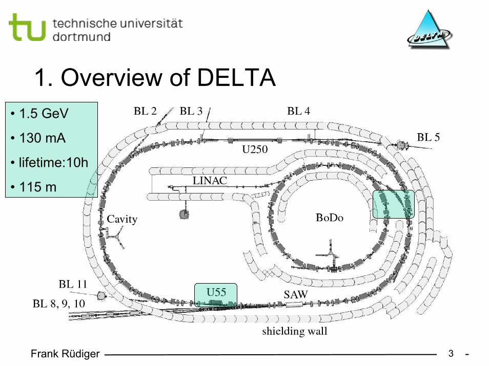
1. Overview of DELTA• 1.5 GeV
• 130 mA
• lifetime:10h
• 115 m
Frank Rüdiger 4
• The DELTA vacuum chamber is made up of 3 mm V4A steel
• The synchrotron radiation is almost completely absorbed inside the chamber wall
• Beam loss electrons colliding with the chamber generate electro-magnetic cascades. Even at small incident angles a significant amount of the shower particles can leave the vacuum chamber
• 1.5 GeV beam loss electrons are the main source of ionising radiation at DELTA
1. Radiation Sources at DELTA
Frank Rüdiger 5
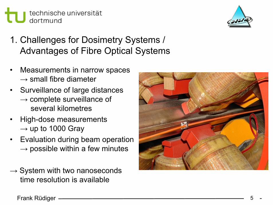
• Measurements in narrow spaces→ small fibre diameter
• Surveillance of large distances→ complete surveillance of
several kilometres • High-dose measurements
→ up to 1000 Gray• Evaluation during beam operation
→ possible within a few minutes
→ System with two nanoseconds time resolution is available
1. Challenges for Dosimetry Systems /Advantages of Fibre Optical Systems
Frank Rüdiger 6
• Chemical bonds are split up in the fibre by exposure to radiation (radiolysis)Example: ≡Si-OH → ≡Si-O· + H0
• The generated defects are called “colour-centres”
• Transitions between the generated states→ attenuation of injected light intensity
1. Radiation Induced Attenuation of Optical Fibres
Frank Rüdiger 7
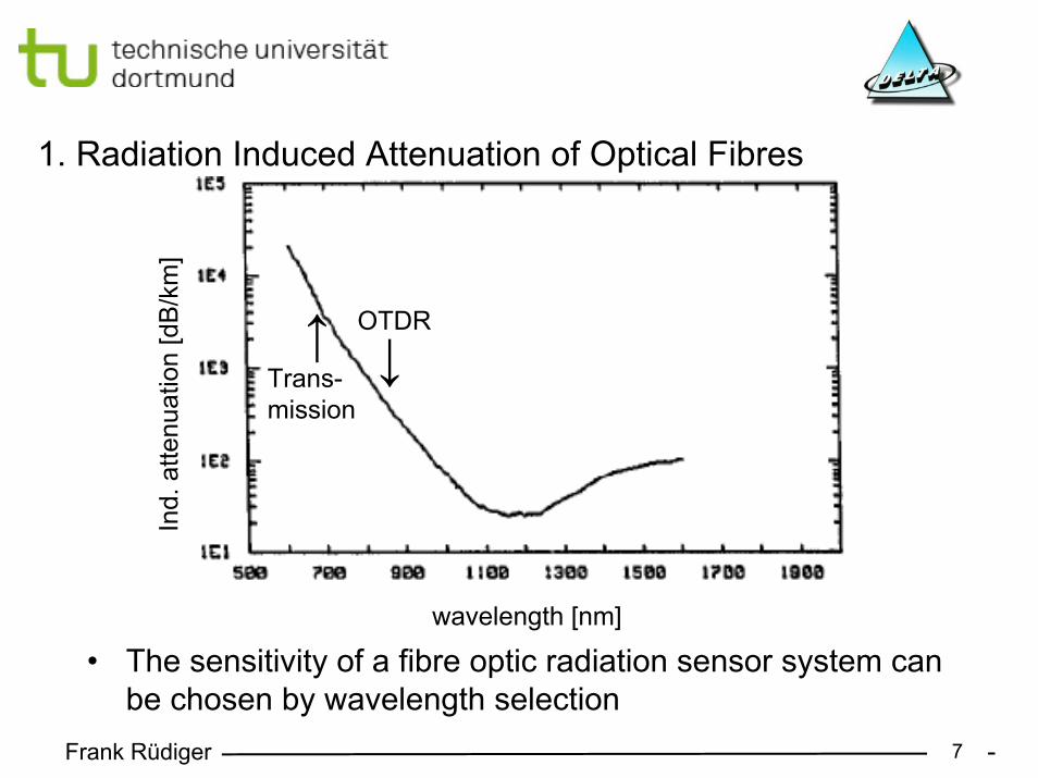
• The sensitivity of a fibre optic radiation sensor system can be chosen by wavelength selection
1. Radiation Induced Attenuation of Optical Fibres
wavelength [nm]
Ind.
atte
nuat
ion
[dB
/km
]
→← OTDR
Trans-mission
Frank Rüdiger 8
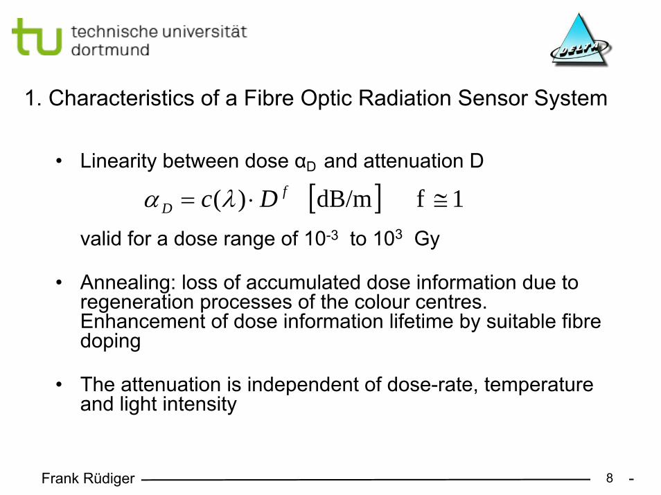
• Linearity between dose αD and attenuation D
valid for a dose range of 10-3 to 103 Gy
• Annealing: loss of accumulated dose information due to regeneration processes of the colour centres.Enhancement of dose information lifetime by suitable fibre doping
• The attenuation is independent of dose-rate, temperature and light intensity
1. Characteristics of a Fibre Optic Radiation Sensor System
[ ] 1f dB/m )( ≅⋅= fD Dc λα
Frank Rüdiger 9
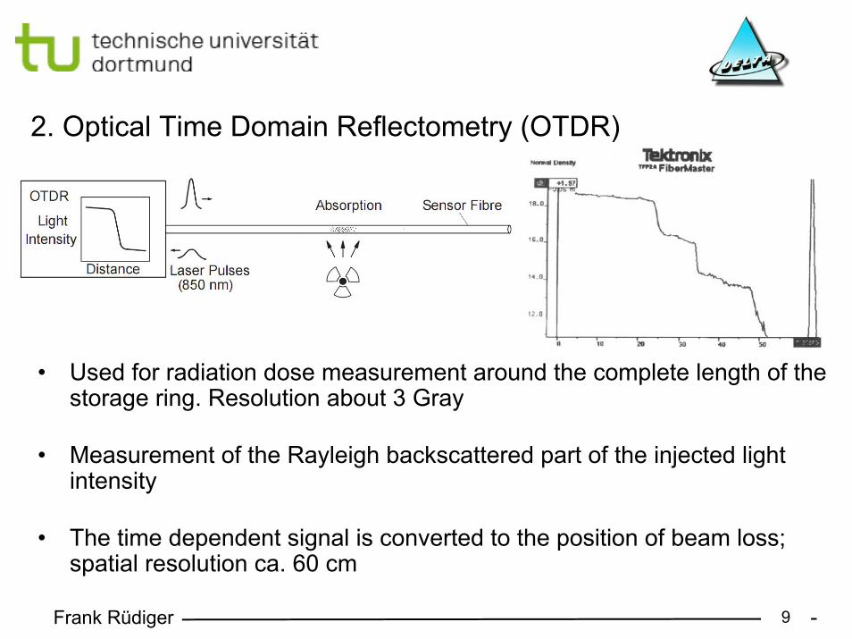
• Used for radiation dose measurement around the complete length of the storage ring. Resolution about 3 Gray
• Measurement of the Rayleigh backscattered part of the injected light intensity
• The time dependent signal is converted to the position of beam loss; spatial resolution ca. 60 cm
2. Optical Time Domain Reflectometry (OTDR)
Frank Rüdiger 10
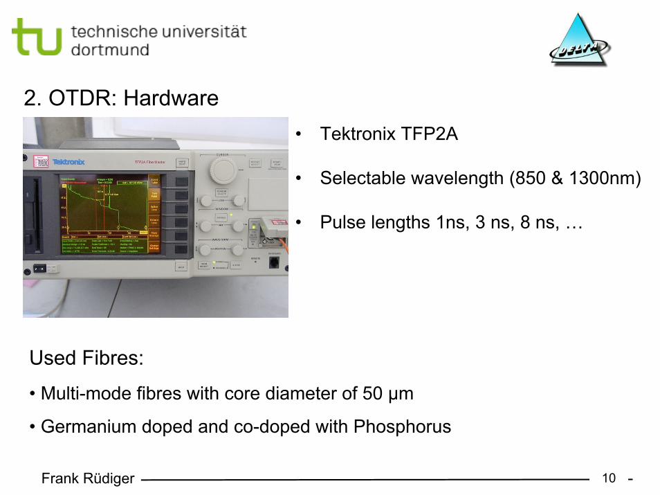
• Tektronix TFP2A
• Selectable wavelength (850 & 1300nm)
• Pulse lengths 1ns, 3 ns, 8 ns, …
2. OTDR: Hardware
• Multi-mode fibres with core diameter of 50 µm
• Germanium doped and co-doped with Phosphorus
Used Fibres:
Frank Rüdiger 11
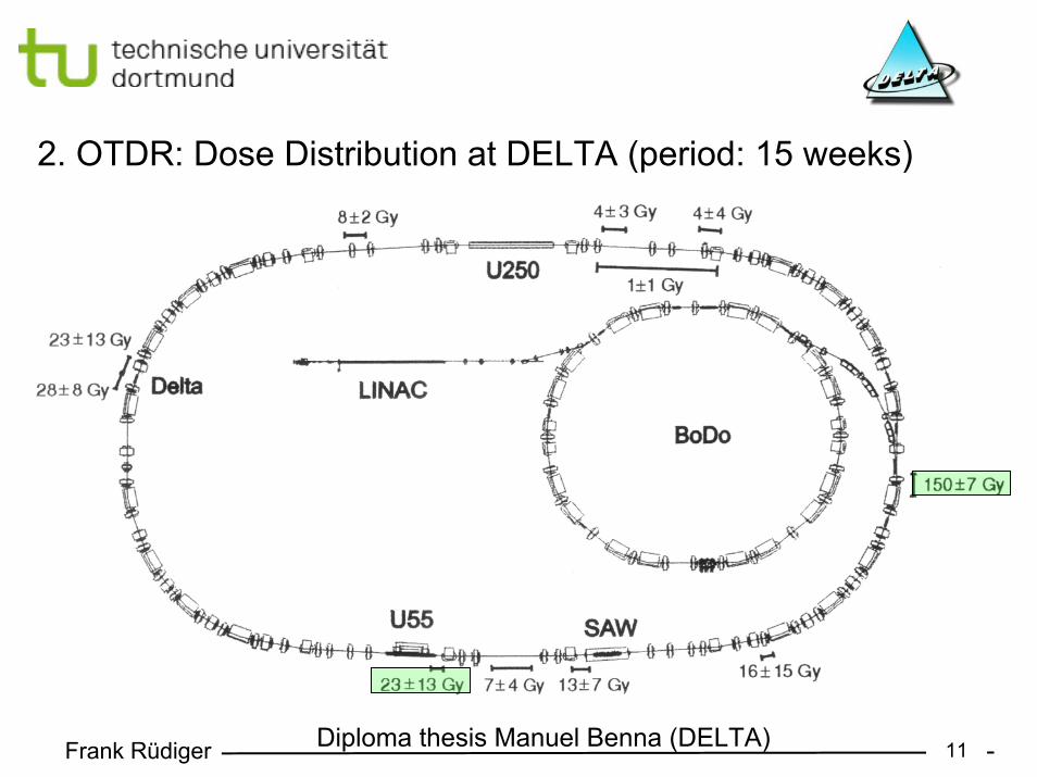
2. OTDR: Dose Distribution at DELTA (period: 15 weeks)
Diploma thesis Manuel Benna (DELTA)
Frank Rüdiger 12
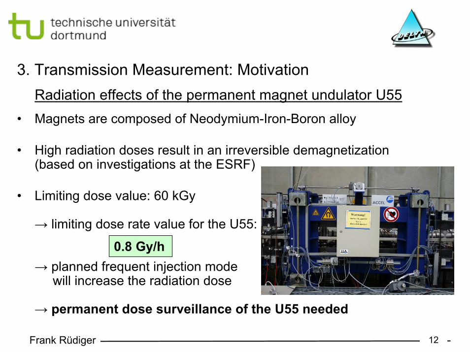
• Magnets are composed of Neodymium-Iron-Boron alloy
• High radiation doses result in an irreversible demagnetization(based on investigations at the ESRF)
• Limiting dose value: 60 kGy
→ limiting dose rate value for the U55:
→ planned frequent injection modewill increase the radiation dose
→ permanent dose surveillance of the U55 needed
3. Transmission Measurement: MotivationRadiation effects of the permanent magnet undulator U55
0.8 Gy/h
Frank Rüdiger 13
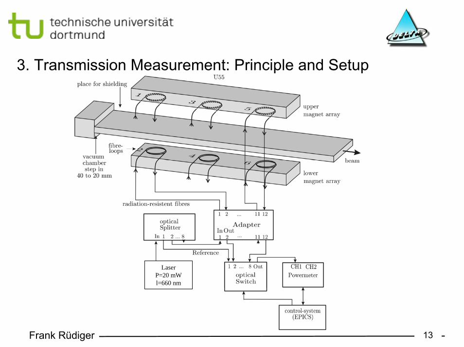
3. Transmission Measurement: Principle and Setup
LaserP=20 mWl=660 nm
Frank Rüdiger 14
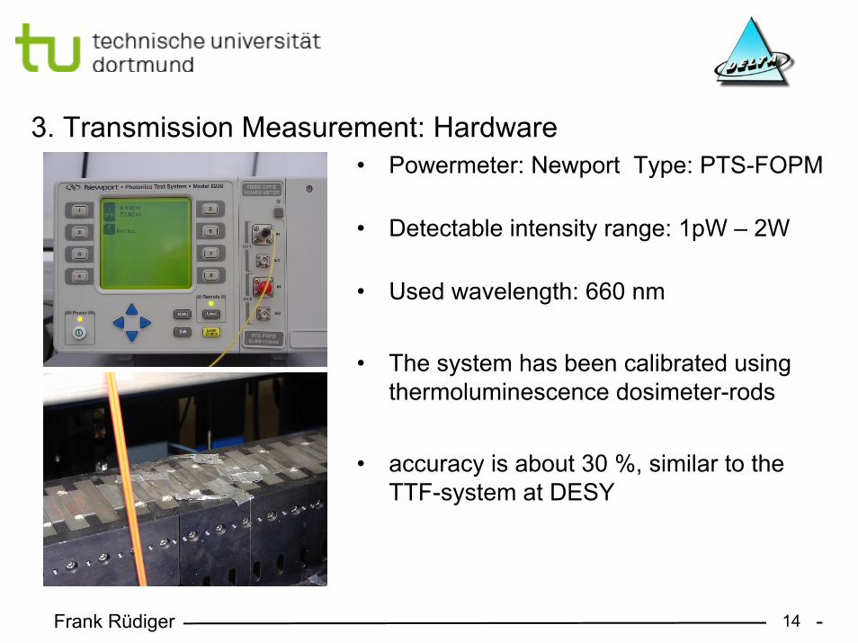
• Powermeter: Newport Type: PTS-FOPM
• Detectable intensity range: 1pW – 2W
• Used wavelength: 660 nm
• The system has been calibrated using thermoluminescence dosimeter-rods
• accuracy is about 30 %, similar to the TTF-system at DESY
3. Transmission Measurement: Hardware
Frank Rüdiger 15
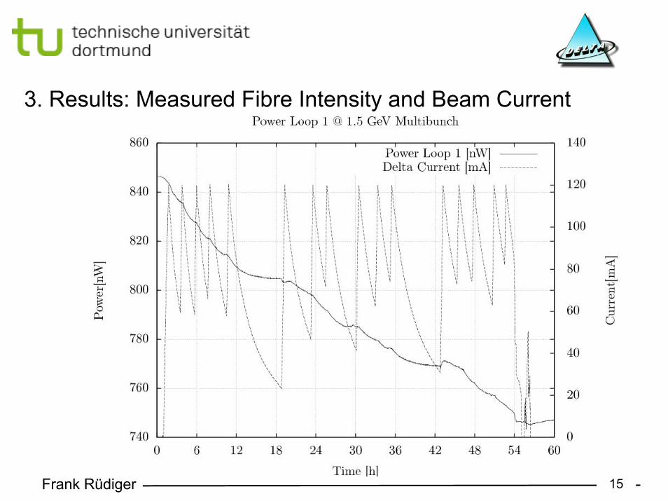
3. Results: Measured Fibre Intensity and Beam Current
Frank Rüdiger 16
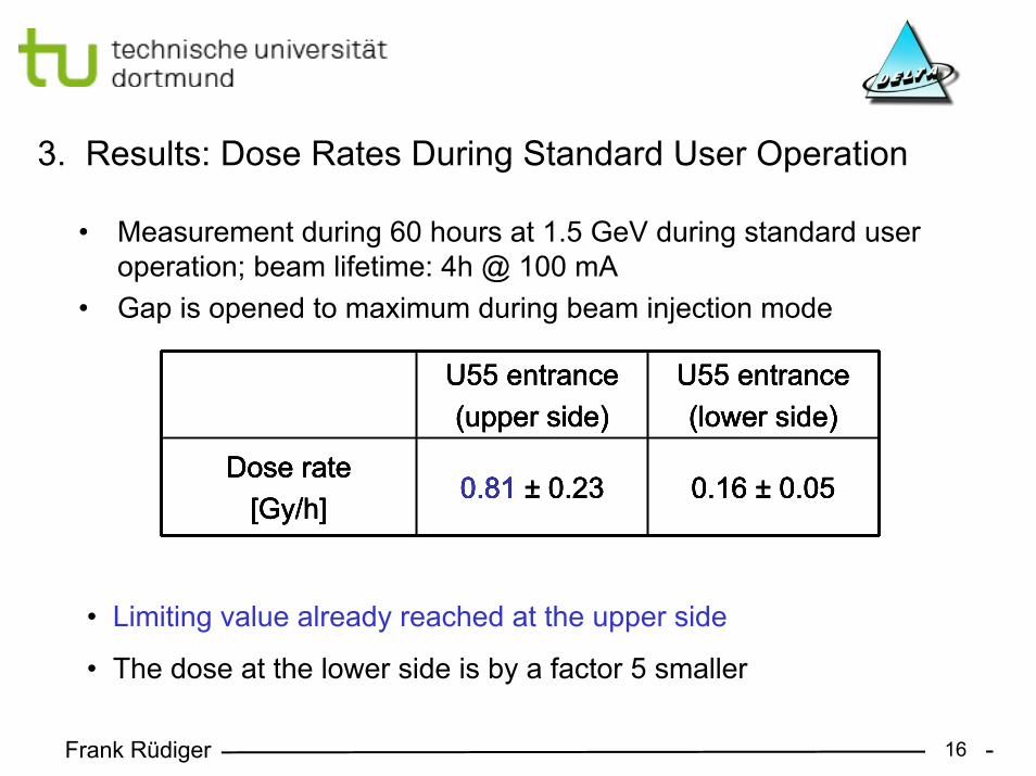
• Measurement during 60 hours at 1.5 GeV during standard user operation; beam lifetime: 4h @ 100 mA
• Gap is opened to maximum during beam injection mode
3. Results: Dose Rates During Standard User Operation
U55 entrance(upper side)
U55 entrance(lower side)
Dose rate[Gy/h]
0.81 ± 0.23 0.16 ± 0.05
• Limiting value already reached at the upper side
• The dose at the lower side is by a factor 5 smaller
U55 entrance(upper side)
U55 entrance(lower side)
Dose rate[Gy/h]
0.81 ± 0.23 0.16 ± 0.05
U55 entrance(upper side)
U55 entrance(lower side)
Dose rate[Gy/h]
0.81 ± 0.23 0.16 ± 0.05
U55 entrance(upper side)
U55 entrance(lower side)
Dose rate[Gy/h]
0.81 ± 0.23 0.16 ± 0.05
Frank Rüdiger 17
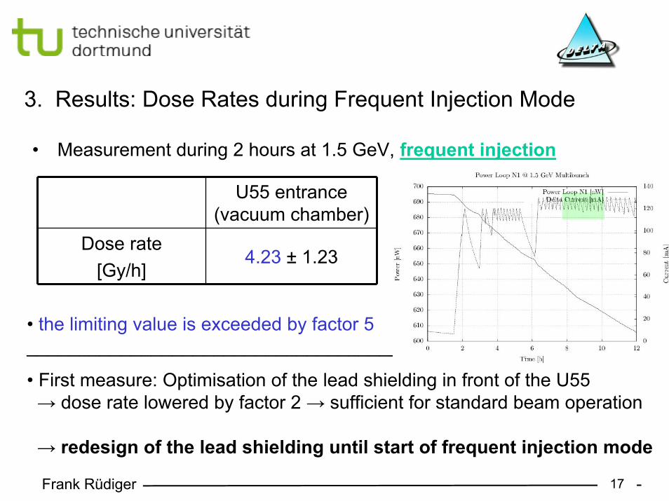
• Measurement during 2 hours at 1.5 GeV, frequent injection
3. Results: Dose Rates during Frequent Injection Mode
U55 entrance(vacuum chamber)
Dose rate[Gy/h]
4.23 ± 1.23
• the limiting value is exceeded by factor 5____________________________________
• First measure: Optimisation of the lead shielding in front of the U55→ dose rate lowered by factor 2 → sufficient for standard beam operation
→ redesign of the lead shielding until start of frequent injection mode
Frank Rüdiger 18
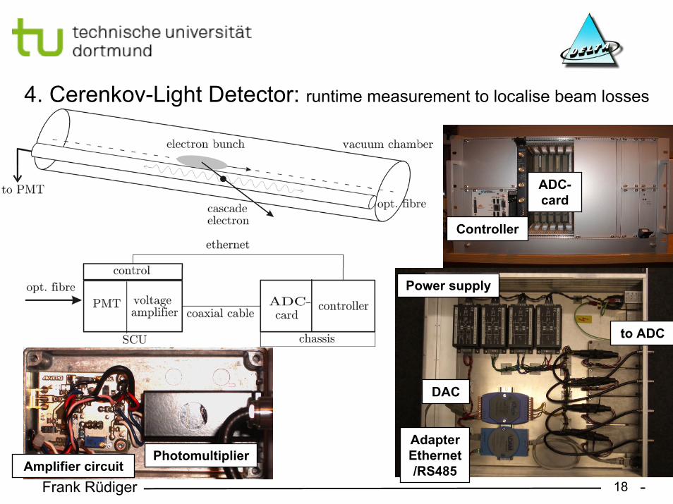
4. Cerenkov-Light Detector: runtime measurement to localise beam losses
Amplifier circuitPhotomultiplier
Power supply
AdapterEthernet/RS485
to ADC
DAC
ADC-card
Controller

Frank Rüdiger 19
• Runtime-measurement to localise beam losses → detector is connected to the upstream-side
• Time resolution: 2 ns given by sampling rate of the ADC (1 GS/s)
• Spatial resolution: 0.24 m in longitudinal direction
• Used wavelength range: 500 nm – 650 nm (maximum at 550 nm)
• Multi-mode-step-index fibres (core diameter: 300 µm) consisting of undoped silicon dioxide with high content of OH- ions
4. Cerenkov-Light Detector: Principle of Measurement
Frank Rüdiger 20
• Fibre optic radiation sensor systems are well suited for accelerators:- usable in narrow spaces- dose range is up to 1000 Gy- evaluation during beam operation
• OTDR: - used for dose surveillance of the complete Delta vacuum chamber- dose resolution: 3 Gy
• Transmission measurement: - used for dose surveillance of the U55 permanent magnet undulator- dose resolution: 60 mGy
• Cerenkov-light detector:- system has been installed and functionality has been proven- will be used for increase of injection efficiency- real-time beam loss position monitoring with single bunch resolution of 2 ns
5. Summary:
Frank Rüdiger 21
Acknowledgement• Dr. Markus Körfer (DESY)• Walter Göttmann (HMI Berlin)• Prof. Dr. Wille (DELTA)• Prof. Dr. Weis (DELTA)• Dr. Gerald Schmidt (DELTA)• Holger Huck (DELTA)
Frank Rüdiger 22
References:• Frank Rüdiger, diploma thesis, Aufbau und Einsatz von Glasfaser-Dosimetriesystemen an der
Speicherringanlage DELTA, 2008• Manuel Benna, diploma thesis, Strahlverlustmessung und Dosimetrie am DELTA, 2006• S. Girard, A. Boukenter, et al., Properties of phosphourus-related defects induced by γ-rays and
pulsed X-ray irradiation in germanosilicate optical fibres, 2003• D. Griscom, E. Friebele, Fundamental radiation-induced defect centers in synthetic fused
silicas: Atomic chlorine, delocalized E' centers and a triplet state, 1986• H. Henschel, M. Körfer, J. Kuhnhenn, U. Weiland, F.Wulf, Fibre optic radiation sensor systems
for particle accelerator, Nuclear Instruments and Methods in Physics Research A 526, 2004• H. Henschel, O. Köhn, H.U. Schmidt, Optical Fibres as radiation dosimeters, Nuclear
Instruments and Methods in Physics Research B 69, 1992• G. Schmidt et al., Optical Fibre Beam Loss Monitors for Storage Rings at DELTA, Proceedings
of EPAC, 2002• W.V.Hassenzahl, T.M. Jenkins et al., An Assessment ot the Radiation on Permanent-Magnet
Material in the ALS Insertion Devices, Nuclear Instruments and Methods in Physics Research A291, 1990
• G. Schmidt et al., Proposal for a Frequent Injection Mode at DELTA, Proceedings of EPAC, 2004
• H. Henschel et al, Optical Fibre Dosimeter For SASE FEL Undulators, DIPAC, 2003• W. Göttmann, M. Körfer, J. Kuhnhenn, Beam Loss Position Monitoring using Cerenkov
Radiation on Optical Fibers, Proceedings of DIPAC, 2005