Embed Size (px)
Citation preview

BDS5USER’S MANUAL
Old Number M93102 - ISSUE 3
New number MB5001H
BDS5 TECHNICAL MANUAL CONFIGURATION
TECHNICAL MANUAL CONFIGURATION
( USER’S MANUAL M93102 )
PAGE NO. DESCRIPTION # CHANGE NO.*
-- ...............................Title Page..................................................................................................................... 0
-- ...............................Technical Manual Configuration ................................................................................. 0
-- ...............................Configuration Table..................................................................................................... 0
-- ...............................Customer Response...................................................................................................... 0
-- ...............................Copyright Page ............................................................................................................ 0
-- ............................... Foreword...................................................................................................................... 0
-- ...............................How to Use This Manual ............................................................................................. 0
i - iv.............................Table of Contents......................................................................................................... 0
v ..................................List of Figures.............................................................................................................. 0
vi .................................List of Tables ............................................................................................................... 0
1-1 -- 1-16 ...................Chapter 1 System Description..................................................................................... 0
2-1 -- 2-14 ...................Chapter 2 Getting Started ........................................................................................... 0
3-1 -- 3-42 ...................Chapter 3 Programming Language ............................................................................. 0
4-1 -- 4-44 ...................Chapter 4 User Programs............................................................................................ 0
5-1 -- 5-10 ...................Chapter 5 Debugging .................................................................................................. 0
6-1 -- 6-8 .....................Chapter 6 Compensation............................................................................................. 0
A-1 -- A-2 ...................Appendix A Warranty Information............................................................................. 0
B-1 -- B-4....................Appendix B ASCII Table ........................................................................................... 0
C-1 -- C-16..................Appendix C Software Commands............................................................................... 0
D-1 -- D-14 .................Appendix D Error Codes ............................................................................................ 0
E-1 -- E-6 ....................Appendix E Variable Quick Reference....................................................................... 0
F-1 -- F-2.....................Appendix F Command Timings.................................................................................. 0
Glossary-i -- xiv ..........Glossary ....................................................................................................................... 0
Index-i -- viii .............. Index ............................................................................................................................ 0
-- ...............................BDS5 Upgrade Notices................................................................................................ 0
* Zero in this column indicates an original page
CONFIGURATION TABLE BDS5
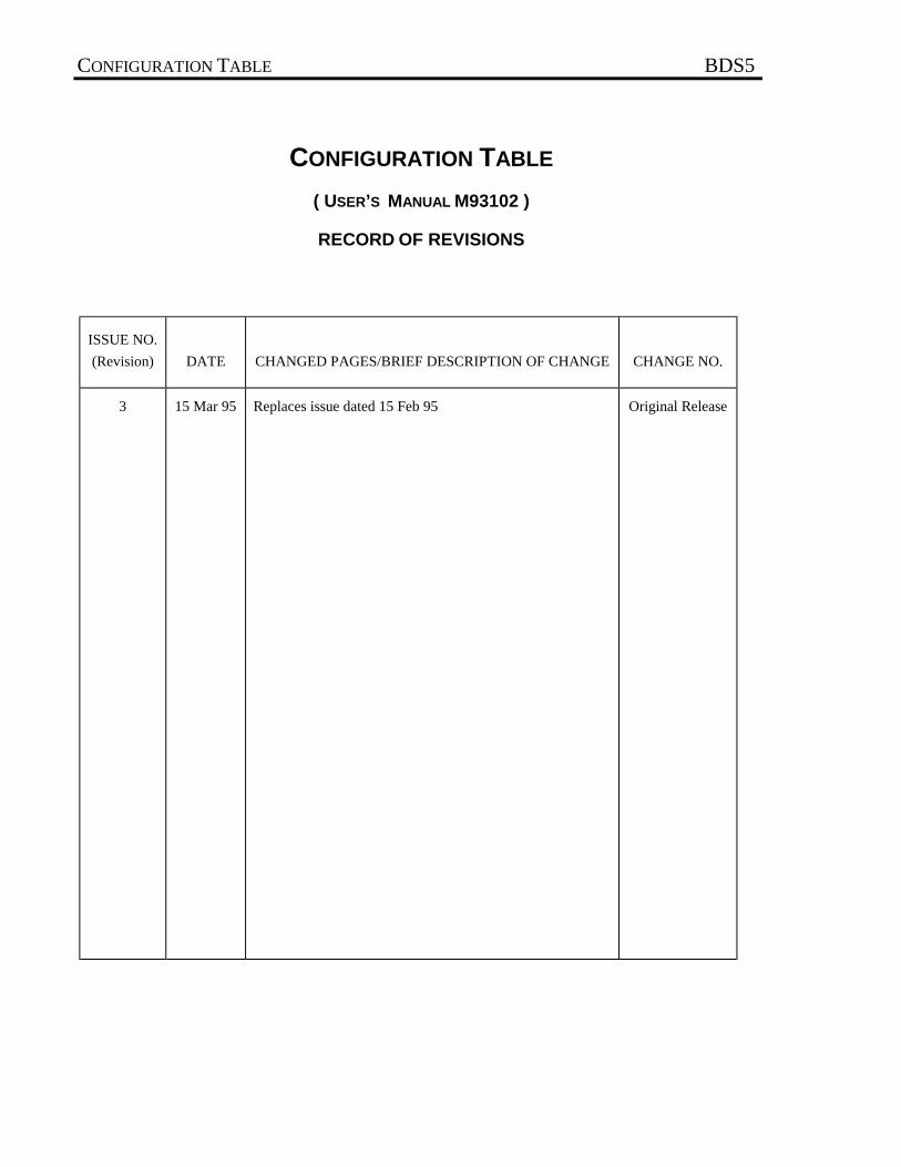
CONFIGURATION TABLE
( USER’S MANUAL M93102 )
RECORD OF REVISIONS
ISSUE NO.
(Revision) DATE CHANGED PAGES/BRIEF DESCRIPTION OF CHANGE CHANGE NO.
3 15 Mar 95 Replaces issue dated 15 Feb 95 Original Release

THANK YOU!
Thank you and congratulations for choosing Industrial Drives' servo products for your motion controlrequirements. We seek to provide our customers with quality products, excellent support and outstandingvalue. In an effort to provide you with dependable and useful documentation, we offer you an opportunityto critique this manual with your comments and suggestions. Your feedback on this reader commentsform is very important to us. Please answer the questions below and return the form to:
INDUSTRIAL DRIVES - Technical Manual Department
201 Rock RoadRadford, VA 24141U.S.A.FAX: 703/731/0847
Name: Title:
Company:
Street Address:
City: State: Zip:
Telephone: Fax:
Product:
Manual Part Number:
Please check the rating that best represents your opinion on each topic.
Excellent Good Fair Poor 1. Overall clarity and readability. ! ! ! !2. Organization of the manual. ! ! ! !3. Information completeness. ! ! ! !4. Information accuracy. ! ! ! !5. Installation procedures. ! ! ! !6. Ability to quickly find information you need. ! ! ! !7. Graphics. ! ! ! !8. Figures (usefulness). ! ! ! !9. Tables (usefulness). ! ! ! !10. Overall rating of this manual. ! ! ! !
Please list any errors.
What did you like least about this manual?
What did you like most about this manual?
How would you improve this manual?
Signature: Date:
© Copyright 1993, Danaher Motion Kollmorgen. All rights reserved Printed in the United States of America NOTICE Not for use or disclosure outside of Danaher Motion Kollmorgen except under written agreement.
All rights reserved. No part of this book shall be reproduced, stored in a retrieval system, or transmitted by any means (electronic, mechanical, photocopying, recording, or otherwise) without the written permission from the publisher. While every precaution has been taken in the preparation of this book, the publisher assumes no responsibility for errors or omissions. Neither is any liability assumed for damager resulting from the use of the information contained herein.
This document is proprietary information of Danaher Motion Kollmorgen, furnished for customer use ONLY. No other uses are authorized without written permission from Danaher Motion Kollmorgen.
Information in this document is subject to change without notice and does not represent a commitment on the part of Danaher Motion Kollmorgen. Therefore, information contained in this manual may be updated without notice due to product improvements, etc., and may not conform in every respect to former issues.
This product is covered by U. S. Patents:
4,447,771 4,479,078 4,490,661 Other (foreign patents pending)
U. L. is a trademark of Underwriter's Laboratories. N. E. C. is a trademark of the National Electric Code. Kollmorgen GOLDLine, BDS4, BDS5, and PSR4/5 are trademarks of Danaher Motion Kollmorgen.
Dangerous voltages, currents, temperatures, and energy levels exist in this product and in the associated servomotor(s). Extreme caution should be exercised in the application of this equipment. Only qualified individuals should attempt to install, setup, and operate this equipment. Ensure that the motor, drive, and the end-user assembly are all properly grounded per NEC requirements.
Danaher Motion Kollmorgen
Phone: 1-800-777-3786 or (815) 226-3100 Technical Support Fax: (540) 731-5679
BDS5 FOREWORD
FOREWORD
The commitment to quality at Industrial Drives is ourfirst priority. In all aspects of our business: research,development, product design and customer service,we strive to guarantee total quality. This pledge isfounded on a solid history of innovative technologicalachievements dating back to 1948. One of the finesttributes to that achievement can now be seen at theSmithsonian which has on display the first stellarinertial navigation system developed by Dr. CharlesStark Draper. This system contains the first modelsof torque motors built by the founding organization ofIndustrial Drives. During the period of 1948 to 1960,our "firsts" in the industry numbered more than adozen; they ranged from the simple but invaluable(such as the direct-drive DC torque motor and movietheater projection motors) to the exotic: submarineperiscope drive motors for the U.S. Navy, electricdrives, Curtis Wright electric brake coils, andnumerous other innovations.
For more than a decade, Industrial Drives (known inthe early days as part of Inland Motor Division ofKollmorgen) has continued to enhance itssophisticated engineering solutions to pioneer newproduct development.
The results of these and other efforts has encouragedsome of the most significant innovations in the servoindustry. We developed the application of servomotors and drives in the Machine Tool market. Wewere the first with water-cooled servos, the integralbrake, the flux forcing concept and the brushlessmotor. We developed the electronically commutatedelectric car motor. Industrial Drives pioneered rare
earth magnet development for the servo motorindustry.
Between 1974 and 1980, Industrial Drives continuedto lead the industry in servo application innovations.Our commitment to engineering excellence neverwaivered. In fact, that commitment grew strongerwith the development of brushless submarine andsubmersible motors (visiting the Titanic graveyard),multi-axis electronic drives and antenna pedestaldrives (delivering unprecedented accuracy andrevolutionizing the entire industrial automationprocess).
The decade of the 1980's brought continuedadvancements in technology and penetration of newmarkets requiring precise motion control. Already inthe fifth generation of brushless products, IndustrialDrives continues to lead the way with digital servopositioning capability and our newest motor offering,the GOLDLINE Series, incorporating the very latesthigh-energy, rare earth magnets (neodymium ironboron). Once again, we are setting the standards thatothers only hope to duplicate. Recentlyacknowledged by the Frost and Sullivan Foundation,a leading market specialist in the motion controlindustry, Industrial Drives and its parent, KollmorgenCorporation, continue to rank first in servotechnology.
Other achievements? Yes, too many in fact tomention. Each achievement stands as a testimony tothe committed quality and excellence in designtechnology. This constancy of purpose is unyieldingin an era of rapidly changing technology.
BDS5 HOW TO USE THIS MANUAL
HOW TO USE THIS MANUAL
INTRODUCTION
This User’s Manual is designed to help you properlyoperate a BDS5 Servo System. You do not have tobe an expert in motion control to utilize the systemhowever this manual does assume you have thefundamental understanding of basic electronics andmotion control concepts. Many of these areexplained in the glossary of this manual.
The BDS5 is a programmable motion control device.An understanding of computer programmingtechniques will be beneficial to all users. Forapplications that require complex programs, aprofessional programmer should be consulted.
RECOMMENDATIONS
It is recommended that you read this entire manualbefore you attempt to operate the BDS5 so you canpromptly find any information you need. This willalso familiarize you with system components, andtheir relationship to one another.
After installation and before you apply your ownapplication check all system functions and features toinsure you have installed your BDS5 properly.
These instructions are intended to aid you toadminister the BDS5 to your own applications. Yoursafety and satisfaction are important to IndustrialDrives. Be sure to follow all instructions carefullyand pay special attention to safety.
CONVENTIONS
To assist you in understanding the material in thismanual, conventions have been established toenhance reader comprehension. Explanations ofthese conventions are as follows:
• Safety warnings, cautions, and notes presentmaterial that is important to user safety. Be sureto read any safety notices you see as they couldprevent equipment damage, personal injury, oreven death to you or a co-worker.
• Bold text highlights other important informationthat is critical to system operations.
• CAPITALIZED text stresses attention to thedetails of the procedure.
• Underlined text emphasizes crucial words insentences that could be misunderstood if theword is not recognized.
• DOUBLE BLOCKED text defines words
that are to be typed into the computer by theuser to interface with the BDS5.
• SINGLE BLOCKED text defines words
that are displayed by the BDS5 on the computerterminal to inform the user of system operationsor problems.
HOW TO USE THIS MANUAL BDS5
ABBREVIATIONS
CCW Counter ClockwiseCW ClockwiseD/L Direction LimitGC Goldline CableGCS Goldline Cable SetLED Light Emitting DiodeNEC National Electrical CodeP/N Part NumberR/D Resolver-to-DigitalRegen RegenerationTL Test LimitsUL Underwriters Laboratories
NOTICE:
This manual is the second of a two part manualstructure. The Installation and Setup Manual isintended to instruct the user on the installationprocedures and practices to be used with the BDS5.
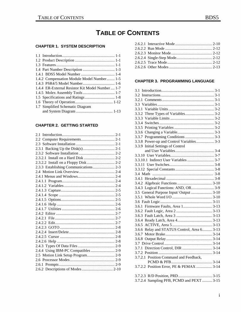
TABLE OF CONTENTS BDS5
i
TABLE OF CONTENTS
CHAPTER 1. SYSTEM DESCRIPTION
1.1 Introduction..................................................... 1-11.2 Product Description ........................................ 1-11.3 Features........................................................... 1-11.4 Part Number Description ................................ 1-31.4.1 BDS5 Model Number .................................. 1-41.4.2 Compensation Module Model Number........ 1-51.4.3 PSR4/5 Model Number................................ 1-61.4.4 ER-External Resistor Kit Model Number .... 1-71.4.5 Molex Assembly Tools ................................ 1-71.5 Specifications and Ratings .............................. 1-81.6 Theory of Operation...................................... 1-121.7 Simplified Schematic Diagram and System Diagram ..................................... 1-13
CHAPTER 2. GETTING STARTED
2.1 Introduction..................................................... 2-12.2 Computer Requirements.................................. 2-12.3 Software Installation ....................................... 2-12.3.1 Backing Up the Disk(s)................................ 2-12.3.2 Software Installation .................................... 2-22.3.2.1 Install on a Hard Disk ............................... 2-22.3.2.2 Install on a Floppy Disk ............................ 2-22.3.3 Establishing Communications...................... 2-32.4 Motion Link Overview.................................... 2-42.4.1 Menus and Windows..................................... 2-42.4.1.1 Program..................................................... 2-42.4.1.2 Variables ................................................... 2-42.4.1.3 Capture...................................................... 2-52.4.1.4 Scope ........................................................ 2-52.4.1.5 Options...................................................... 2-52.4.1.6 Help .......................................................... 2-62.4.1.7 Utilities ..................................................... 2-62.4.2 Editor ........................................................... 2-72.4.2.1 File ............................................................ 2-72.4.2.2 Edit............................................................ 2-72.4.2.3 GOTO ....................................................... 2-82.4.2.4 Insert/Delete.............................................. 2-82.4.2.5 Cursor ....................................................... 2-82.4.2.6 Help .......................................................... 2-82.4.3 Types Of Data Files ..................................... 2-92.4.4 Using IBM-PC Compatibles ........................ 2-92.5 Motion Link Setup Program............................ 2-92.6 Processor Modes............................................. 2-92.6.1 Prompts ........................................................ 2-92.6.2 Descriptions of Modes ............................... 2-10
2.6.2.1 Interactive Mode ..................................... 2-102.6.2.2 Run Mode ............................................... 2-122.6.2.3 Monitor Mode......................................... 2-122.6.2.4 Single-Step Mode.................................... 2-122.6.2.5 Trace Mode............................................. 2-122.6.2.6 Other Modes ........................................... 2-13
CHAPTER 3. PROGRAMMING LANGUAGE
3.1 Introduction..................................................... 3-13.2 Instructions...................................................... 3-13.2.1 Comments .................................................... 3-13.3 Variables ......................................................... 3-13.3.1 Variable Units .............................................. 3-23.3.2 Three Types of Variables............................. 3-23.3.3 Variable Limits ............................................ 3-23.3.4 Switches ....................................................... 3-23.3.5 Printing Variables ........................................ 3-23.3.6 Changing a Variable..................................... 3-33.3.7 Programming Conditions ............................. 3-33.3.8 Power-up and Control Variables.................. 3-33.3.9 Initial Settings of Control and User Variables....................................... 3-43.3.10 User Variables............................................ 3-73.3.10.1 Indirect User Variables ........................... 3-73.3.11 User Switches............................................. 3-83.3.12 Special Constants ....................................... 3-83.4 Math ............................................................. 3-83.4.1 Hexadecimal ................................................ 3-83.4.2 Algebraic Functions ................................... 3-103.4.3 Logical Functions: AND, OR....................... 3-93.5 General Purpose Input/ Output ..................... 3-103.5.1 Whole Word I/O ........................................ 3-103.6 Fault Logic.................................................... 3-113.6.1 Firmware Faults, Area 1............................. 3-133.6.2 Fault Logic, Area 2 .................................... 3-133.6.3 Fault Latch, Area 3 .................................... 3-133.6.4 Ready Latch, Area 4................................... 3-133.6.5 ACTIVE, Area 5 ........................................ 3-133.6.6 Relay and STATUS Control, Area 6.......... 3-133.6.7 Motor Brake............................................... 3-143.6.8 Output Relay .............................................. 3-143.7 Drive Control ................................................ 3-143.7.1 Direction Control, DIR .............................. 3-143.7.2 Position ...................................................... 3-143.7.2.1 Position Command and Feedback, PCMD & PFB......................................... 3-143.7.2.2 Position Error, PE & PEMAX ................ 3-14
3.7.2.3 R/D Position, PRD.................................. 3-153.7.2.4 Sampling PFB, PCMD and PEXT .......... 3-15
BDS5 TABLE OF CONTENTS
ii
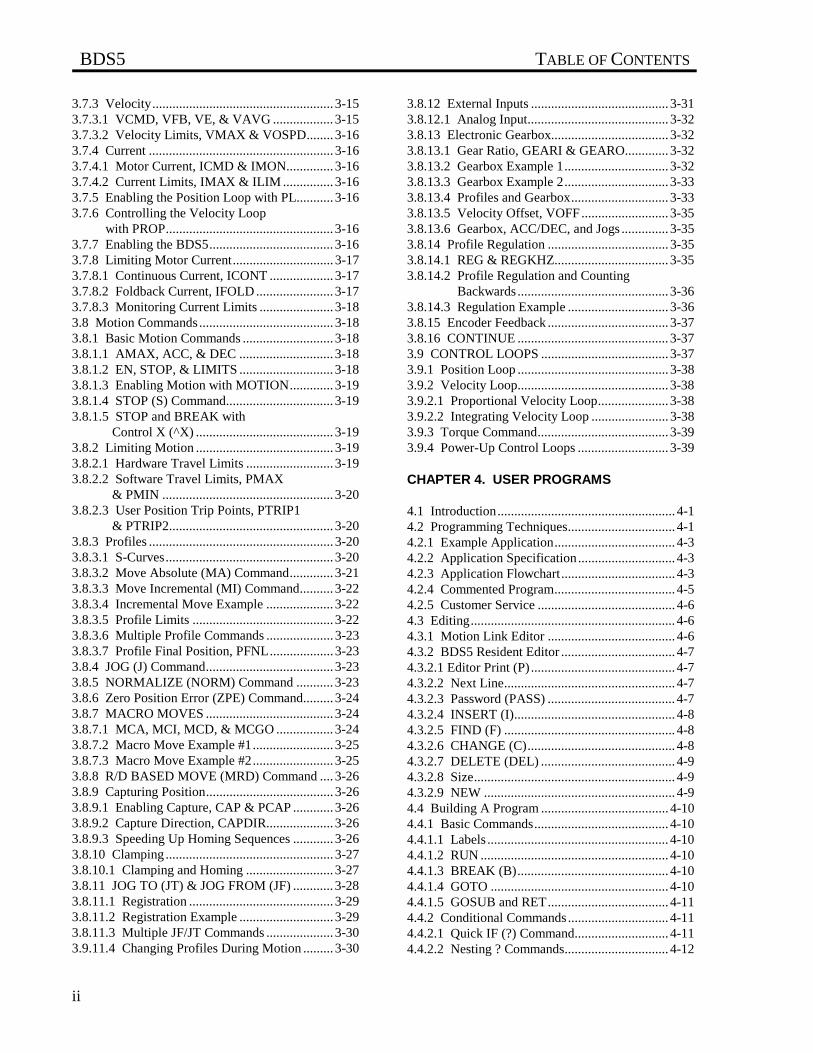
3.7.3 Velocity...................................................... 3-153.7.3.1 VCMD, VFB, VE, & VAVG .................. 3-153.7.3.2 Velocity Limits, VMAX & VOSPD........ 3-163.7.4 Current ....................................................... 3-163.7.4.1 Motor Current, ICMD & IMON.............. 3-163.7.4.2 Current Limits, IMAX & ILIM ............... 3-163.7.5 Enabling the Position Loop with PL........... 3-163.7.6 Controlling the Velocity Loop with PROP.................................................. 3-163.7.7 Enabling the BDS5..................................... 3-163.7.8 Limiting Motor Current.............................. 3-173.7.8.1 Continuous Current, ICONT ................... 3-173.7.8.2 Foldback Current, IFOLD ....................... 3-173.7.8.3 Monitoring Current Limits ...................... 3-183.8 Motion Commands........................................ 3-183.8.1 Basic Motion Commands ........................... 3-183.8.1.1 AMAX, ACC, & DEC ............................ 3-183.8.1.2 EN, STOP, & LIMITS ............................ 3-183.8.1.3 Enabling Motion with MOTION............. 3-193.8.1.4 STOP (S) Command................................ 3-193.8.1.5 STOP and BREAK with Control X (^X) ......................................... 3-193.8.2 Limiting Motion ......................................... 3-193.8.2.1 Hardware Travel Limits .......................... 3-193.8.2.2 Software Travel Limits, PMAX & PMIN ................................................... 3-203.8.2.3 User Position Trip Points, PTRIP1 & PTRIP2................................................. 3-203.8.3 Profiles ....................................................... 3-203.8.3.1 S-Curves.................................................. 3-203.8.3.2 Move Absolute (MA) Command............. 3-213.8.3.3 Move Incremental (MI) Command.......... 3-223.8.3.4 Incremental Move Example .................... 3-223.8.3.5 Profile Limits .......................................... 3-223.8.3.6 Multiple Profile Commands .................... 3-233.8.3.7 Profile Final Position, PFNL................... 3-233.8.4 JOG (J) Command...................................... 3-233.8.5 NORMALIZE (NORM) Command ........... 3-233.8.6 Zero Position Error (ZPE) Command......... 3-243.8.7 MACRO MOVES ...................................... 3-243.8.7.1 MCA, MCI, MCD, & MCGO ................. 3-243.8.7.2 Macro Move Example #1........................ 3-253.8.7.3 Macro Move Example #2........................ 3-253.8.8 R/D BASED MOVE (MRD) Command .... 3-263.8.9 Capturing Position...................................... 3-263.8.9.1 Enabling Capture, CAP & PCAP ............ 3-263.8.9.2 Capture Direction, CAPDIR.................... 3-263.8.9.3 Speeding Up Homing Sequences ............ 3-263.8.10 Clamping .................................................. 3-273.8.10.1 Clamping and Homing .......................... 3-273.8.11 JOG TO (JT) & JOG FROM (JF) ............ 3-283.8.11.1 Registration ........................................... 3-293.8.11.2 Registration Example ............................ 3-293.8.11.3 Multiple JF/JT Commands .................... 3-303.9.11.4 Changing Profiles During Motion ......... 3-30
3.8.12 External Inputs ......................................... 3-313.8.12.1 Analog Input.......................................... 3-323.8.13 Electronic Gearbox................................... 3-323.8.13.1 Gear Ratio, GEARI & GEARO............. 3-323.8.13.2 Gearbox Example 1............................... 3-323.8.13.3 Gearbox Example 2............................... 3-333.8.13.4 Profiles and Gearbox............................. 3-333.8.13.5 Velocity Offset, VOFF.......................... 3-353.8.13.6 Gearbox, ACC/DEC, and Jogs .............. 3-353.8.14 Profile Regulation .................................... 3-353.8.14.1 REG & REGKHZ.................................. 3-353.8.14.2 Profile Regulation and Counting Backwards ............................................. 3-363.8.14.3 Regulation Example .............................. 3-363.8.15 Encoder Feedback .................................... 3-373.8.16 CONTINUE ............................................. 3-373.9 CONTROL LOOPS ...................................... 3-373.9.1 Position Loop ............................................. 3-383.9.2 Velocity Loop............................................. 3-383.9.2.1 Proportional Velocity Loop..................... 3-383.9.2.2 Integrating Velocity Loop ....................... 3-383.9.3 Torque Command....................................... 3-393.9.4 Power-Up Control Loops ........................... 3-39
CHAPTER 4. USER PROGRAMS
4.1 Introduction..................................................... 4-14.2 Programming Techniques................................ 4-14.2.1 Example Application.................................... 4-34.2.2 Application Specification............................. 4-34.2.3 Application Flowchart.................................. 4-34.2.4 Commented Program.................................... 4-54.2.5 Customer Service ......................................... 4-64.3 Editing............................................................. 4-64.3.1 Motion Link Editor ...................................... 4-64.3.2 BDS5 Resident Editor .................................. 4-74.3.2.1 Editor Print (P) ........................................... 4-74.3.2.2 Next Line................................................... 4-74.3.2.3 Password (PASS) ...................................... 4-74.3.2.4 INSERT (I)................................................ 4-84.3.2.5 FIND (F) ................................................... 4-84.3.2.6 CHANGE (C)............................................ 4-84.3.2.7 DELETE (DEL) ........................................ 4-94.3.2.8 Size............................................................ 4-94.3.2.9 NEW ......................................................... 4-94.4 Building A Program ...................................... 4-104.4.1 Basic Commands........................................ 4-104.4.1.1 Labels ...................................................... 4-104.4.1.2 RUN ........................................................ 4-104.4.1.3 BREAK (B)............................................. 4-104.4.1.4 GOTO ..................................................... 4-104.4.1.5 GOSUB and RET.................................... 4-114.4.2 Conditional Commands.............................. 4-114.4.2.1 Quick IF (?) Command............................ 4-114.4.2.2 Nesting ? Commands............................... 4-12
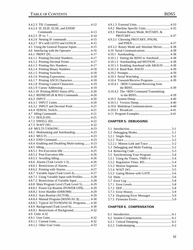
TABLE OF CONTENTS BDS5
iii
4.4.2.3 TIL Command......................................... 4-124.4.2.4 IF, ELIF, ELSE, and ENDIF Commands ............................................... 4-134.4.2.5 IF vs. ? .................................................... 4-144.4.2.6 Nesting IF commands ............................. 4-154.4.2.7 IF's with GOTO and GOSUB ................. 4-154.5 Using the General Purpose Inputs................. 4-154.6 Interfacing with the Operator ........................ 4-164.6.1 PRINT (P).................................................. 4-174.6.1.1 Printing Decimal Numbers...................... 4-174.6.1.2 Printing Decimal Points .......................... 4-174.6.1.3 Printing Hex Numbers ............................ 4-174.6.1.4 Printing Binary Numbers ........................ 4-184.6.1.5 Printing Switches .................................... 4-184.6.1.6 Printing Expressions ............................... 4-184.6.1.7 Printing ASCII Characters ...................... 4-184.6.1.8 Printing Control Characters .................... 4-194.6.1.9 Cursor Addressing .................................. 4-194.6.1.10 Printing BDS5 Status (PS) .................... 4-204.6.2 REFRESH (R & RS) Commands............... 4-204.6.3 INPUT ....................................................... 4-204.6.3.1 INPUT Limits ......................................... 4-204.6.3.2 INPUT and Decimal Point ...................... 4-214.6.4 SERIAL Switch.......................................... 4-214.7 Idling Commands.......................................... 4-214.7.1 HOLD (H).................................................. 4-214.7.2 DWELL (D)............................................... 4-224.7.3 WAIT (W) ................................................. 4-224.8 MULTI-TASKING....................................... 4-234.8.1 Multitasking and Autobauding................... 4-234.8.2 MULTI....................................................... 4-234.8.3 END Command.......................................... 4-234.8.4 Enabling and Disabling Multi-tasking........ 4-234.8.5 Idling.......................................................... 4-254.8.5.1 Pre-Execution Idle .................................. 4-254.8.5.2 Post-Execution Idle................................. 4-264.8.5.3 Avoiding Idling....................................... 4-264.8.6 Alarms (Task Levels 1-3)........................... 4-264.8.6.1 Restrictions of Alarms............................. 4-274.8.6.2 Printing with Alarms ............................... 4-274.8.7 Variable Input (Task Level 4).................... 4-274.8.7.1 Using Variable Input with Profiles.......... 4-284.8.7.2 Restrictions of Variable Input ................. 4-284.8.8 Main Program Level (Task Level 5) .......... 4-294.8.8.1 Power-Up Routine (POWER-UP$)......... 4-294.8.8.2 Error Handler (ERROR$) ....................... 4-294.8.8.3 Auto Routine (AUTO$) .......................... 4-294.8.8.4 Manual Program (MANUAL $).............. 4-304.8.8.5 Typical AUTO/MANUAL Programs...... 4-304.8.9 Background (Task Level 6)........................ 4-304.8.9.1 Restrictions of Background..................... 4-324.9 Units 4-324.9.1 User Units .................................................. 4-324.9.1.1 Current Units........................................... 4-324.9.1.2 Other User Units ..................................... 4-33
4.9.1.3 External Units ......................................... 4-334.9.2 Machine Specific Units .............................. 4-354.9.3 Position Rotary Mode, ROTARY, & PROTARY................................................. 4-374.9.3.1 Choosing PROTARY, PNUM, and PDEN ............................................... 4-374.9.3.2 Rotary Mode and Absolute Moves ......... 4-384.10 Serial Communications ............................... 4-384.10.1 Autobauding............................................. 4-384.10.1.1 Setting the BDS5 to Autobaud.............. 4-384.10.1.2 Autobauding and MOTION.................. 4-384.10.1.3 Enabling Autobaud with ABAUD ........ 4-384.10.1.4 Baud Rate, BAUD ................................ 4-394.10.2 Prompts .................................................... 4-394.10.3 Serial Watchdog....................................... 4-394.10.4 Transmit/Receive Programs ..................... 4-394.10.4.1 <BDS Command Receiving from the BDS5............................................... 4-394.10.4.2 The >BDS Command Transmitting to the BDS5.......................................... 4-394.10.5 System Dump........................................... 4-404.10.5.1 Version Dump....................................... 4-404.10.6 Multidrop Communications ..................... 4-404.10.6.1 Broadcast .............................................. 4-414.11 Program Examples ...................................... 4-41
CHAPTER 5. DEBUGGING
5.1 Introduction..................................................... 5-15.2 Debugging Modes........................................... 5-15.2.1 Single-Step................................................... 5-15.2.2 Trace ............................................................ 5-25.2.2.1 Motion Link and Trace ............................. 5-25.3 Debugging and Multi-Tasking ........................ 5-25.4 Removing Code .............................................. 5-35.5 Synchronizing Your Program.......................... 5-45.5.1 Using the Timers, TMR1-4.......................... 5-45.5.2 Regulation Timer, RD.................................. 5-45.5.3 Motion Segments ......................................... 5-45.5.4 WAIT (W) ................................................... 5-55.5.5 Gating Motion with GATE .......................... 5-65.6 Hints .............................................................. 5-65.7 Error Log ........................................................ 5-85.7.1 Error Levels ................................................. 5-85.7.2 DEP.............................................................. 5-85.7.3 Error History................................................ 5-95.7.4 Displaying Error Messages .......................... 5-95.7.5 Firmware Errors ........................................... 5-9
CHAPTER 6. COMPENSATION
6.1 Introduction..................................................... 6-16.2 System Compensation..................................... 6-16.2.1 Critical Damping.......................................... 6-26.2.2 Underdamping.............................................. 6-2
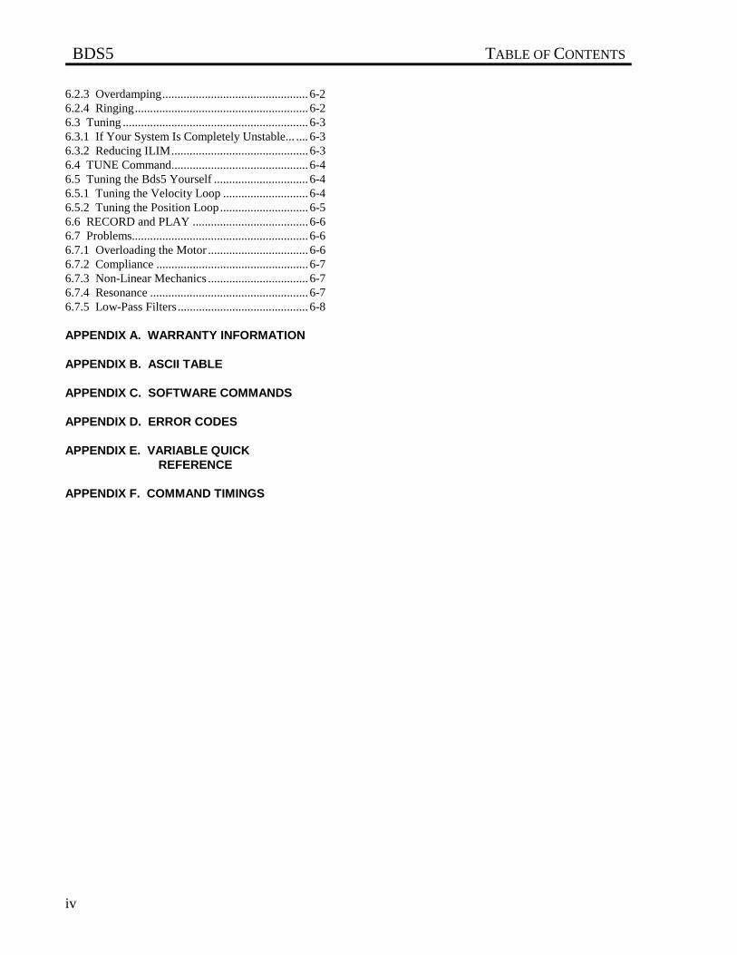
BDS5 TABLE OF CONTENTS
iv
6.2.3 Overdamping................................................ 6-26.2.4 Ringing......................................................... 6-26.3 Tuning ............................................................. 6-36.3.1 If Your System Is Completely Unstable... .... 6-36.3.2 Reducing ILIM............................................. 6-36.4 TUNE Command............................................. 6-46.5 Tuning the Bds5 Yourself ............................... 6-46.5.1 Tuning the Velocity Loop ............................ 6-46.5.2 Tuning the Position Loop............................. 6-56.6 RECORD and PLAY ...................................... 6-66.7 Problems.......................................................... 6-66.7.1 Overloading the Motor ................................. 6-66.7.2 Compliance .................................................. 6-76.7.3 Non-Linear Mechanics ................................. 6-76.7.4 Resonance .................................................... 6-76.7.5 Low-Pass Filters........................................... 6-8
APPENDIX A. WARRANTY INFORMATION
APPENDIX B. ASCII TABLE
APPENDIX C. SOFTWARE COMMANDS
APPENDIX D. ERROR CODES
APPENDIX E. VARIABLE QUICK REFERENCE
APPENDIX F. COMMAND TIMINGS
LIST OF FIGURES BDS5
v
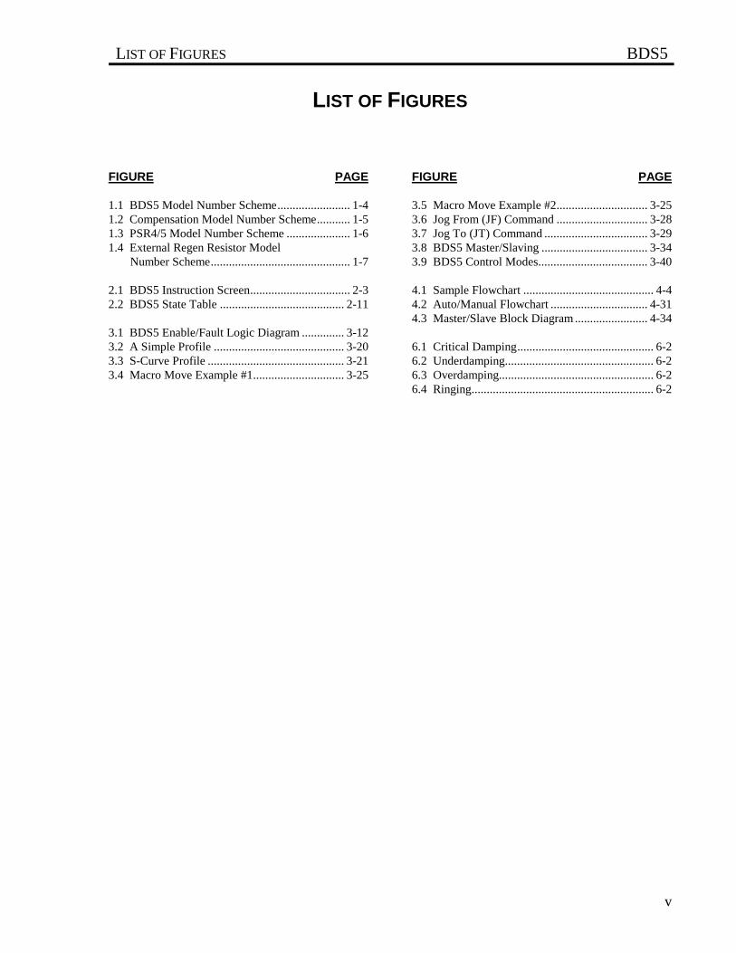
LIST OF FIGURES
FIGURE PAGE FIGURE PAGE
1.1 BDS5 Model Number Scheme........................ 1-41.2 Compensation Model Number Scheme........... 1-51.3 PSR4/5 Model Number Scheme ..................... 1-61.4 External Regen Resistor Model
Number Scheme.............................................. 1-7
2.1 BDS5 Instruction Screen................................. 2-32.2 BDS5 State Table ......................................... 2-11
3.1 BDS5 Enable/Fault Logic Diagram .............. 3-123.2 A Simple Profile ........................................... 3-203.3 S-Curve Profile ............................................. 3-213.4 Macro Move Example #1.............................. 3-25
3.5 Macro Move Example #2.............................. 3-253.6 Jog From (JF) Command .............................. 3-283.7 Jog To (JT) Command .................................. 3-293.8 BDS5 Master/Slaving ................................... 3-343.9 BDS5 Control Modes.................................... 3-40
4.1 Sample Flowchart ........................................... 4-44.2 Auto/Manual Flowchart ................................ 4-314.3 Master/Slave Block Diagram ........................ 4-34
6.1 Critical Damping............................................. 6-26.2 Underdamping................................................. 6-26.3 Overdamping................................................... 6-26.4 Ringing............................................................ 6-2
LIST OF TABLES BDS5
vi
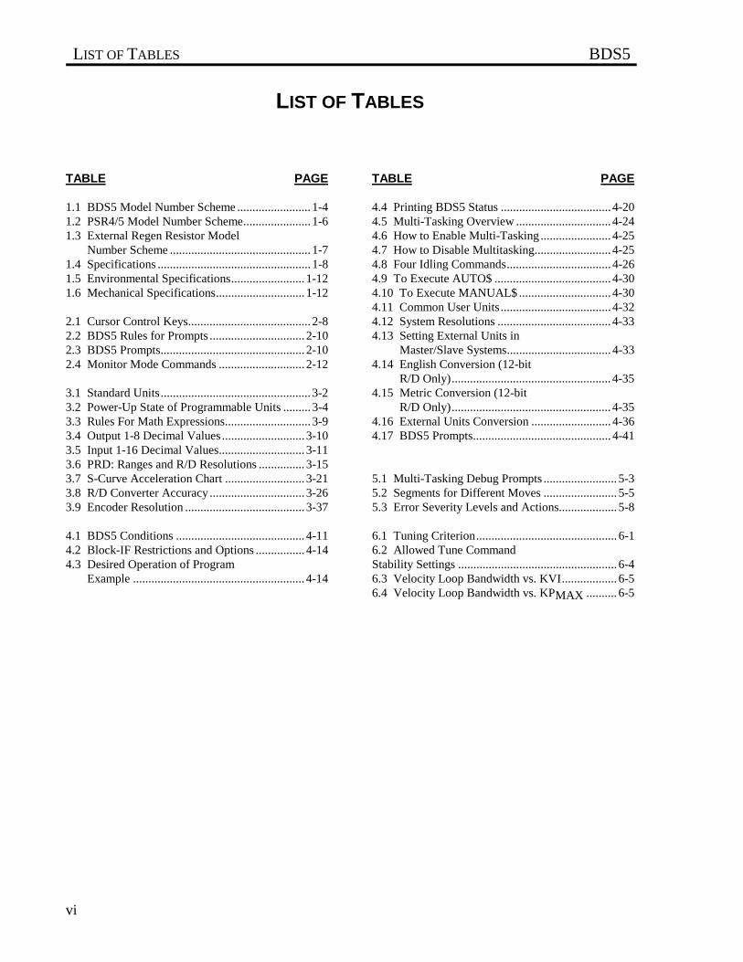
LIST OF TABLES
TABLE PAGE TABLE PAGE
1.1 BDS5 Model Number Scheme ........................ 1-41.2 PSR4/5 Model Number Scheme...................... 1-61.3 External Regen Resistor Model Number Scheme .............................................. 1-71.4 Specifications .................................................. 1-81.5 Environmental Specifications........................ 1-121.6 Mechanical Specifications............................. 1-12
2.1 Cursor Control Keys........................................ 2-82.2 BDS5 Rules for Prompts ............................... 2-102.3 BDS5 Prompts............................................... 2-102.4 Monitor Mode Commands ............................ 2-12
3.1 Standard Units................................................. 3-23.2 Power-Up State of Programmable Units ......... 3-43.3 Rules For Math Expressions............................ 3-93.4 Output 1-8 Decimal Values ........................... 3-103.5 Input 1-16 Decimal Values............................ 3-113.6 PRD: Ranges and R/D Resolutions ............... 3-153.7 S-Curve Acceleration Chart .......................... 3-213.8 R/D Converter Accuracy ............................... 3-263.9 Encoder Resolution ....................................... 3-37
4.1 BDS5 Conditions .......................................... 4-114.2 Block-IF Restrictions and Options ................ 4-144.3 Desired Operation of Program Example ........................................................ 4-14
4.4 Printing BDS5 Status .................................... 4-204.5 Multi-Tasking Overview ............................... 4-244.6 How to Enable Multi-Tasking ....................... 4-254.7 How to Disable Multitasking......................... 4-254.8 Four Idling Commands.................................. 4-264.9 To Execute AUTO$ ...................................... 4-304.10 To Execute MANUAL$ .............................. 4-304.11 Common User Units .................................... 4-324.12 System Resolutions ..................................... 4-334.13 Setting External Units in Master/Slave Systems.................................. 4-334.14 English Conversion (12-bit R/D Only).................................................... 4-354.15 Metric Conversion (12-bit R/D Only).................................................... 4-354.16 External Units Conversion .......................... 4-364.17 BDS5 Prompts............................................. 4-41
5.1 Multi-Tasking Debug Prompts ........................ 5-35.2 Segments for Different Moves ........................ 5-55.3 Error Severity Levels and Actions................... 5-8
6.1 Tuning Criterion.............................................. 6-16.2 Allowed Tune CommandStability Settings .................................................... 6-46.3 Velocity Loop Bandwidth vs. KVI.................. 6-56.4 Velocity Loop Bandwidth vs. KPMAX .......... 6-5
BDS5 CHAPTER 1 - SYSTEM DESCRIPTION
1-1
CHAPTER 1
SYSTEM DESCRIPTION
1.1 INTRODUCTION
The information in this chapter will enable you tounderstand the BDS5's basic functions and features.These concepts will allow you to apply them to yourown unique applications.
1.2 PRODUCT DESCRIPTION
The BDS5 is a full-featured, high-performance,brushless positioning servo in one compact enclosure it is the smallest, totally-integrated packageavailable to motion control users. The BDS5combines a positioner, a servo amplifier, and an I/Ointerface into one unit. The BDS5 sets new standardsfor motion control with its simple BASIC-likecommand structure and sophisticated decision-makingcapability. The BDS5 provides the outstanding servoperformance that you have come to expect fromIndustrial Drives. Using a high-performancemicroprocessor, the BDS5 does not have tocompromise on either positioner software or servoperformance. This single microprocessor closes allservo loops, resulting in a truly integrated positioningsystem. The BDS5 has the features and performanceyou need in your next positioning application.
1.3 FEATURES
The BDS5 offers a wide feature set to accommodatereal world positioning requirements:
• LOW COST
The BDS5 is very affordable--even though it is full ofadvanced features. Use all or only a portion of thesefeatures to accomplish your application.
• EASY TO INSTALL
The BDS5 is easy to install because the servoamplifier and the positioner are integrated into onepackage. Many interconnects, including thetachometer and encoder, are eliminated.
• SIMPLE PROGRAMMING LANGUAGE
The BDS5 uses simple BASIC-like commands such asRUN, GOTO (for branching), and GOSUB /RETURN (for subroutines). In addition to a simplecomparison statement, advanced IF / ELIF / ELSE /END IF statements result in more readable and lesserror-prone programs. You can comment every line inyour program.

CHAPTER 1 - SYSTEM DESCRIPTION BDS5
1-2
• ADVANCED MOTION CONTROL MOVES
The simple language does not prevent you fromsolving complex problems. The BDS5 has separateacceleration and deceleration rates, as well as linear,half S-curve, and full S-curve acceleration profiles.The BDS5 has Macro Moves for applications wheresimple indexes cannot do the job. A Macro Move is acombination of up to 30 accelerations, traverses, anddecelerations, which are fully precalculated for fasterexecution. You can program teach modes whereposition end points can be changed by a factoryoperator
• MASTER/SLAVE - ELECTRONIC GEARBOX
The electronic gearbox is used to link two motorstogether so that the velocity of the slave isproportional to the velocity of the master. The ratiocan be from 32767:1 to 1:32767 and can be negativeto allow the slave to move in the opposite direction.Also, the "index-on-gearing" feature permits phaseadjustments.
• MASTER/ SLAVE - PROFILE REGULATION
With profile regulation you can control the slave'smotion profile according to an external master motoror frequency. Profile regulation modifies the velocityand acceleration of the slave axis without affecting thefinal position of the move. You can use profileregulation to implement "feed rate override."
• MOTION GATING AND REGISTRATION
The BDS5 can precalculate moves to begin motionwithin one millisecond after a transition on the GATEinput. This provides rapid and repeatable motioninitiation. The BDS5 has the ability to capture thecurrent position within 25 microseconds after atransition of the HOME input. This results in fasthoming and accurate registration sequences.
• MATHEMATICS Algebraic math is provided forcommands such as:
X X X1 2 2 3= × +( )
The BDS5 has 100 program labels, 50 user-definablevariables, and 50 user-definable switches. It also has15 mathematical/logical operations and over 150system variables.
• USER UNITS
Quantities such as position, velocity, and accelerationare automatically scaled into user-defined units. Thisfeature lets you program the BDS5 in convenient units,such as feet, inches, miles, RPM, and degrees.
• SUPERIOR SERVO LOOP CONTROL
The BDS5 offers smooth, high-resolution control.Standard BDS5 position repeatability is better thanone arc-minute, bidirectional. The BDS5 has a 32-bitposition word. The BDS5 position loop completelyeliminates the digital dither normally associated withpositioning systems. Long-term speed stability is0.01%. The standard system converter (12-bit)provides a resolution of 0.0005 RPM and a maximumspeed of 8000 RPM.
• SELF-TUNING
The BDS5 can tune itself. You do not have to be aservo expert to set up a system quickly. Just specifythe desired bandwidth, and let the BDS5 do the rest.
• POWERFUL MICROPROCESSOR
The heart of the BDS5 is the 16-bit processor thatdelivers high performance. The result: the BDS5 cancontrol a motor and execute its motion program fasterthan a standard positioner can.
• DIGITAL SERVO LOOPS
Both the position and velocity loops are totally digital.The digital loops give the BDS5 features not availablein standard velocity drives, such as self-tuning, verylow velocity offset, and digitally-adjustable servotuning parameters. The optional analog input permitsyou to use the BDS5 as an analog velocity drive.
• FEED-FORWARD GAIN
The digital feed-forward gain reduces following errorand motion initiation delay, thereby increasingmachine throughput.
• DIAGNOSTICS
The BDS5 offers a complete set of error diagnostics.When an error occurs, the BDS5 displays an English
BDS5 CHAPTER 1 - SYSTEM DESCRIPTION
1-3
language error message. The BDS5 remembers thelast 20 errors even through power loss. In addition,the BDS5 lets you write your own error handler.During a fault condition, you can use the error handlerto set outputs, alert an operator, and shut down yourprocess smoothly. The BDS5 offers trace and single-step modes so that you can debug your program. TheBDS5 has complete fault monitoring, including travellimit switches, feedback loss, and software positionlimits, as well as hardware safety circuits (watchdogs)and checksums for more reliable and safer operation.
• I/O
The BDS5 has up to 32 I/O sections that you connectvia ribbon cable to standard OPTO-22 compatible I/Oboards or to INDUSTRIAL DRIVES I/O-32. TheI/O-32 provides either fixed 24-volt or removable,industry standard, optically-isolated I/O in aGOLDLINE style package.
• SERIAL COMMUNICATIONS
The BDS5's serial communications provide a powerfullink to other popular factory automation devices suchas PLC's, process control computers, and smartterminals. The BDS5 offers RS-232 for mostterminals and RS-422/RS-485 for multidropcommunications. With multidrop you can put up to 26axes on one serial line. The BDS5 can autobaud from300 baud to 19.2k baud, eliminating the need to setdip switches to start communicating.
• MOTION LINK
Industrial Drives also offers MOTION LINK, apowerful, menu-driven communications package for
your IBM-PC (c) compatible computer. With thispackage, the BDS5's programs and variables can beretrieved from or saved to a disk drive. Also, on-linehelp and a full screen editor are built into MOTIONLINK.
• MENU-DRIVEN SOFTWARE
The BDS5's programming language allows you towrite operator-friendly, menu-driven software. Byincorporating an INDUSTRIAL DRIVES Data EntryPanel, or any other serial communications device, theoperator can be prompted for specific process data.
• MONITOR MODE
The BDS5 provides interactive communications andpermits all system variables and parameters to beexamined and modified at any time--even duringactual program execution or while the motor isrunning.
1.4 PART NUMBER DESCRIPTION
A model number is printed on a gold and black tag onthe front of your BDS5, PSR4/5, Compensation Cardand External Regen Resistor modules. The modelnumber identifies how the equipment is configured.Each component is described to explain what themodel configurations are. You should verify that themodel numbers represent the equipment desired foryour application. Also verify the compatibilitybetween components of the servo system. The modelnumbers are as follows:
CHAPTER 1 - SYSTEM DESCRIPTION BDS5
1-4
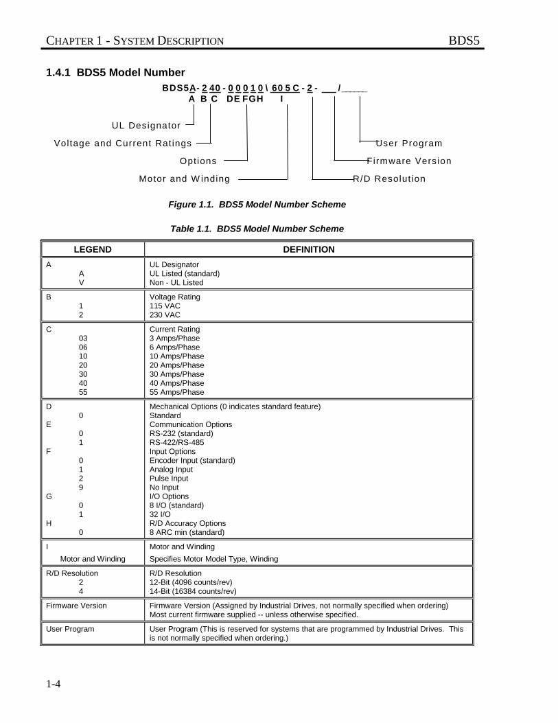
1.4.1 BDS5 Model Number
Figure 1.1. BDS5 Model Number Scheme
Table 1.1. BDS5 Model Number Scheme
LEGEND DEFINITION
AAV
UL DesignatorUL Listed (standard)Non - UL Listed
B12
Voltage Rating115 VAC230 VAC
C03061020304055
Current Rating3 Amps/Phase6 Amps/Phase10 Amps/Phase20 Amps/Phase30 Amps/Phase40 Amps/Phase55 Amps/Phase
D0
E01
F0129
G01
H0
Mechanical Options (0 indicates standard feature)StandardCommunication OptionsRS-232 (standard)RS-422/RS-485Input OptionsEncoder Input (standard)Analog InputPulse InputNo InputI/O Options8 I/O (standard)32 I/OR/D Accuracy Options8 ARC min (standard)
I
Motor and Winding
Motor and Winding
Specifies Motor Model Type, Winding
R/D Resolution24
R/D Resolution12-Bit (4096 counts/rev)14-Bit (16384 counts/rev)
Firmware Version Firmware Version (Assigned by Industrial Drives, not normally specified when ordering)Most current firmware supplied -- unless otherwise specified.
User Program User Program (This is reserved for systems that are programmed by Industrial Drives. Thisis not normally specified when ordering.)
UL Designator
Voltage and Current Rat ings User Program
Opt ions Firmware Version
Motor and W inding R/D Resolut ion
B D S 5 A - 2 4 0 - 0 0 0 1 0 \ 6 0 5 C - 2 - / ______ A B C D E F G H I
BDS5 CHAPTER 1 - SYSTEM DESCRIPTION
1-5
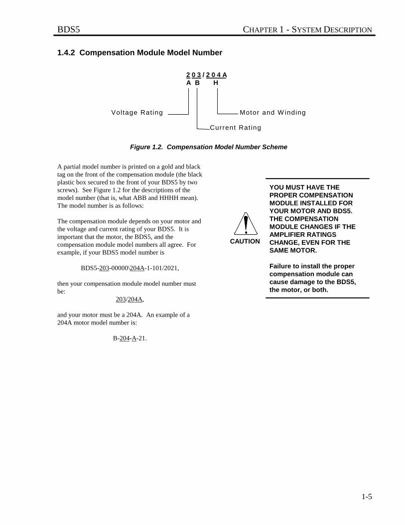
1.4.2 Compensation Module Model Number
Figure 1.2. Compensation Model Number Scheme
A partial model number is printed on a gold and blacktag on the front of the compensation module (the blackplastic box secured to the front of your BDS5 by twoscrews). See Figure 1.2 for the descriptions of themodel number (that is, what ABB and HHHH mean).The model number is as follows:
The compensation module depends on your motor andthe voltage and current rating of your BDS5. It isimportant that the motor, the BDS5, and thecompensation module model numbers all agree. Forexample, if your BDS5 model number is
BDS5-203-00000\204A-1-101/2021,
then your compensation module model number mustbe:
203/204A,
and your motor must be a 204A. An example of a204A motor model number is:
B-204-A-21.
YOU MUST HAVE THEPROPER COMPENSATIONMODULE INSTALLED FORYOUR MOTOR AND BDS5.THE COMPENSATIONMODULE CHANGES IF THEAMPLIFIER RATINGSCHANGE, EVEN FOR THESAME MOTOR.
Failure to install the propercompensation module cancause damage to the BDS5,the motor, or both.
Voltage Rating Motor and W inding
Current Rat ing
2 0 3 / 2 0 4 AA B H
CAUTION
CHAPTER 1 - SYSTEM DESCRIPTION BDS5
1-6
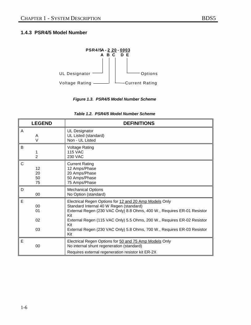
1.4.3 PSR4/5 Model Number
Figure 1.3. PSR4/5 Model Number Scheme
Table 1.2. PSR4/5 Model Number Scheme
LEGEND DEFINITIONS
AAV
UL DesignatorUL Listed (standard)Non - UL Listed
B12
Voltage Rating115 VAC230 VAC
C12205075
Current Rating12 Amps/Phase20 Amps/Phase50 Amps/Phase75 Amps/Phase
D00
Mechanical OptionsNo Option (standard)
E0001
02
03
Electrical Regen Options for 12 and 20 Amp Models OnlyStandard Internal 40 W Regen (standard)External Regen (230 VAC Only) 8.8 Ohms, 400 W., Requires ER-01 ResistorKitExternal Regen (115 VAC Only) 5.5 Ohms, 200 W., Requires ER-02 ResistorKitExternal Regen (230 VAC Only) 5.8 Ohms, 700 W., Requires ER-03 ResistorKit
E00
Electrical Regen Options for 50 and 75 Amp Models OnlyNo internal shunt regeneration (standard)
Requires external regeneration resistor kit ER-2X
UL Designator Opt ions
Voltage Rating Current Rat ing
P S R 4 / 5A - 2 2 0 - 0 0 0 3 A B C D E
BDS5 CHAPTER 1 - SYSTEM DESCRIPTION
1-7
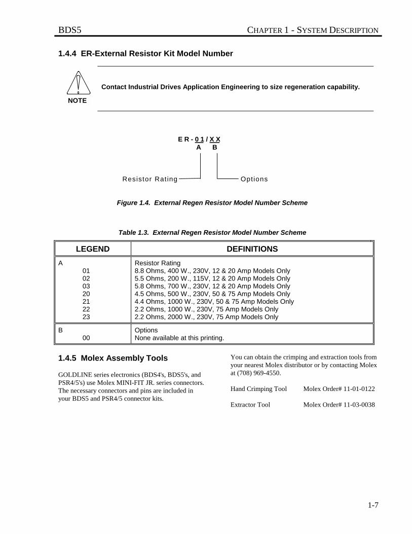
1.4.4 ER-External Resistor Kit Model Number
Contact Industrial Drives Application Engineering to size regeneration capability.
Figure 1.4. External Regen Resistor Model Number Scheme
Table 1.3. External Regen Resistor Model Number Scheme
LEGEND DEFINITIONS
A01020320212223
Resistor Rating8.8 Ohms, 400 W., 230V, 12 & 20 Amp Models Only5.5 Ohms, 200 W., 115V, 12 & 20 Amp Models Only5.8 Ohms, 700 W., 230V, 12 & 20 Amp Models Only4.5 Ohms, 500 W., 230V, 50 & 75 Amp Models Only4.4 Ohms, 1000 W., 230V, 50 & 75 Amp Models Only2.2 Ohms, 1000 W., 230V, 75 Amp Models Only2.2 Ohms, 2000 W., 230V, 75 Amp Models Only
B00
OptionsNone available at this printing.
1.4.5 Molex Assembly Tools
GOLDLINE series electronics (BDS4's, BDS5's, andPSR4/5's) use Molex MINI-FIT JR. series connectors.The necessary connectors and pins are included inyour BDS5 and PSR4/5 connector kits.
You can obtain the crimping and extraction tools fromyour nearest Molex distributor or by contacting Molexat (708) 969-4550.
Hand Crimping Tool Molex Order# 11-01-0122
Extractor Tool Molex Order# 11-03-0038
Resistor Rat ing Opt ions
E R - 0 1 / X X A B
NOTE
CHAPTER 1 - SYSTEM DESCRIPTION BDS5
1-8
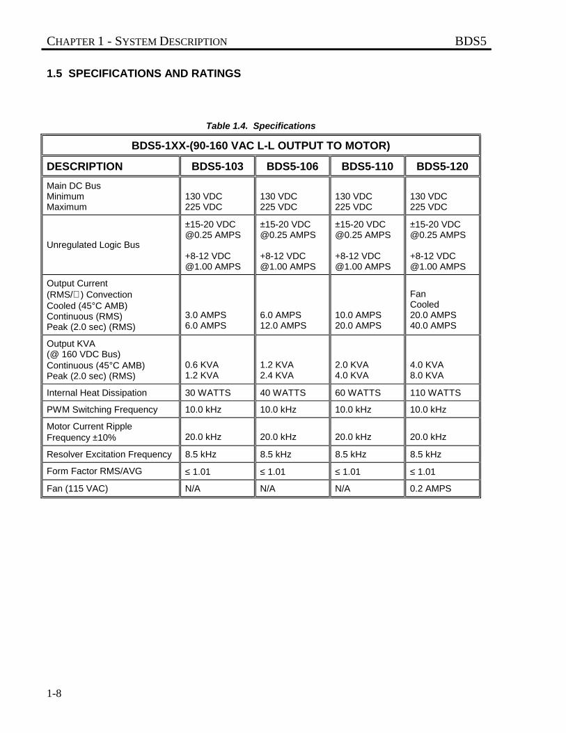
1.5 SPECIFICATIONS AND RATINGS
Table 1.4. Specifications
BDS5-1XX-(90-160 VAC L-L OUTPUT TO MOTOR)
DESCRIPTION BDS5-103 BDS5-106 BDS5-110 BDS5-120
Main DC BusMinimumMaximum
130 VDC225 VDC
130 VDC225 VDC
130 VDC225 VDC
130 VDC225 VDC
Unregulated Logic Bus
±15-20 [email protected] AMPS
+8-12 [email protected] AMPS
±15-20 [email protected] AMPS
+8-12 [email protected] AMPS
±15-20 [email protected] AMPS
+8-12 [email protected] AMPS
±15-20 [email protected] AMPS
+8-12 [email protected] AMPS
Output Current(RMS/∅ ) ConvectionCooled (45°C AMB)Continuous (RMS)Peak (2.0 sec) (RMS)
3.0 AMPS6.0 AMPS
6.0 AMPS12.0 AMPS
10.0 AMPS20.0 AMPS
FanCooled20.0 AMPS40.0 AMPS
Output KVA(@ 160 VDC Bus)Continuous (45°C AMB)Peak (2.0 sec) (RMS)
0.6 KVA1.2 KVA
1.2 KVA2.4 KVA
2.0 KVA4.0 KVA
4.0 KVA8.0 KVA
Internal Heat Dissipation 30 WATTS 40 WATTS 60 WATTS 110 WATTS
PWM Switching Frequency 10.0 kHz 10.0 kHz 10.0 kHz 10.0 kHz
Motor Current RippleFrequency ±10% 20.0 kHz 20.0 kHz 20.0 kHz 20.0 kHz
Resolver Excitation Frequency 8.5 kHz 8.5 kHz 8.5 kHz 8.5 kHz
Form Factor RMS/AVG ≤ 1.01 ≤ 1.01 ≤ 1.01 ≤ 1.01
Fan (115 VAC) N/A N/A N/A 0.2 AMPS
BDS5 CHAPTER 1 - SYSTEM DESCRIPTION
1-9
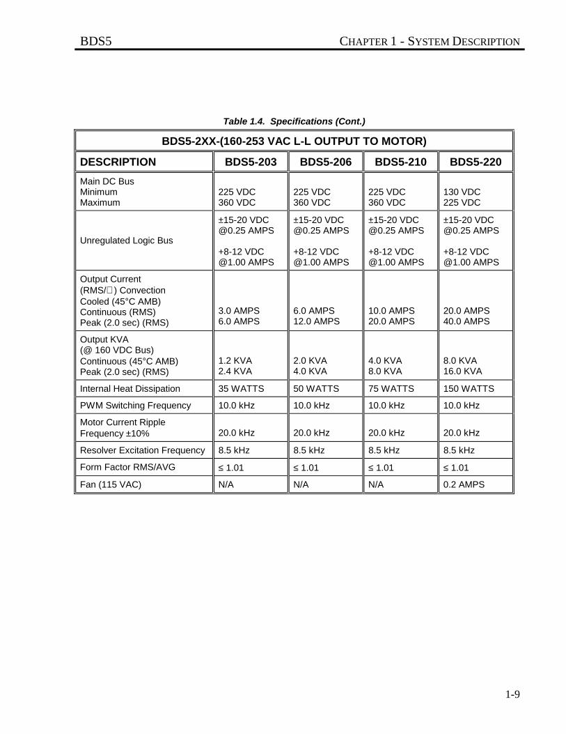
Table 1.4. Specifications (Cont.)
BDS5-2XX-(160-253 VAC L-L OUTPUT TO MOTOR)
DESCRIPTION BDS5-203 BDS5-206 BDS5-210 BDS5-220
Main DC BusMinimumMaximum
225 VDC360 VDC
225 VDC360 VDC
225 VDC360 VDC
130 VDC225 VDC
Unregulated Logic Bus
±15-20 [email protected] AMPS
+8-12 [email protected] AMPS
±15-20 [email protected] AMPS
+8-12 [email protected] AMPS
±15-20 [email protected] AMPS
+8-12 [email protected] AMPS
±15-20 [email protected] AMPS
+8-12 [email protected] AMPS
Output Current(RMS/∅ ) ConvectionCooled (45°C AMB)Continuous (RMS)Peak (2.0 sec) (RMS)
3.0 AMPS6.0 AMPS
6.0 AMPS12.0 AMPS
10.0 AMPS20.0 AMPS
20.0 AMPS40.0 AMPS
Output KVA(@ 160 VDC Bus)Continuous (45°C AMB)Peak (2.0 sec) (RMS)
1.2 KVA2.4 KVA
2.0 KVA4.0 KVA
4.0 KVA8.0 KVA
8.0 KVA16.0 KVA
Internal Heat Dissipation 35 WATTS 50 WATTS 75 WATTS 150 WATTS
PWM Switching Frequency 10.0 kHz 10.0 kHz 10.0 kHz 10.0 kHz
Motor Current RippleFrequency ±10% 20.0 kHz 20.0 kHz 20.0 kHz 20.0 kHz
Resolver Excitation Frequency 8.5 kHz 8.5 kHz 8.5 kHz 8.5 kHz
Form Factor RMS/AVG ≤ 1.01 ≤ 1.01 ≤ 1.01 ≤ 1.01
Fan (115 VAC) N/A N/A N/A 0.2 AMPS
CHAPTER 1 - SYSTEM DESCRIPTION BDS5
1-10
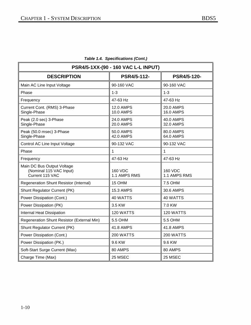
Table 1.4. Specifications (Cont.)
PSR4/5-1XX-(90 - 160 VAC L-L INPUT)
DESCRIPTION PSR4/5-112- PSR4/5-120-
Main AC Line Input Voltage 90-160 VAC 90-160 VAC
Phase 1-3 1-3
Frequency 47-63 Hz 47-63 Hz
Current Cont. (RMS) 3-PhaseSingle-Phase
12.0 AMPS10.0 AMPS
20.0 AMPS16.0 AMPS
Peak (2.0 sec) 3-PhaseSingle-Phase
24.0 AMPS20.0 AMPS
40.0 AMPS32.0 AMPS
Peak (50.0 msec) 3-PhaseSingle-Phase
50.0 AMPS42.0 AMPS
80.0 AMPS64.0 AMPS
Control AC Line Input Voltage 90-132 VAC 90-132 VAC
Phase 1 1
Frequency 47-63 Hz 47-63 Hz
Main DC Bus Output Voltage(Nominal 115 VAC Input)Current 115 VAC
160 VDC1.1 AMPS RMS
160 VDC1.1 AMPS RMS
Regeneration Shunt Resistor (Internal) 15 OHM 7.5 OHM
Shunt Regulator Current (PK) 15.3 AMPS 30.6 AMPS
Power Dissipation (Cont.) 40 WATTS 40 WATTS
Power Dissipation (PK) 3.5 KW 7.0 KW
Internal Heat Dissipation 120 WATTS 120 WATTS
Regeneration Shunt Resistor (External Min) 5.5 OHM 5.5 OHM
Shunt Regulator Current (PK) 41.8 AMPS 41.8 AMPS
Power Dissipation (Cont.) 200 WATTS 200 WATTS
Power Dissipation (PK.) 9.6 KW 9.6 KW
Soft-Start Surge Current (Max) 80 AMPS 80 AMPS
Charge Time (Max) 25 MSEC 25 MSEC
BDS5 CHAPTER 1 - SYSTEM DESCRIPTION
1-11
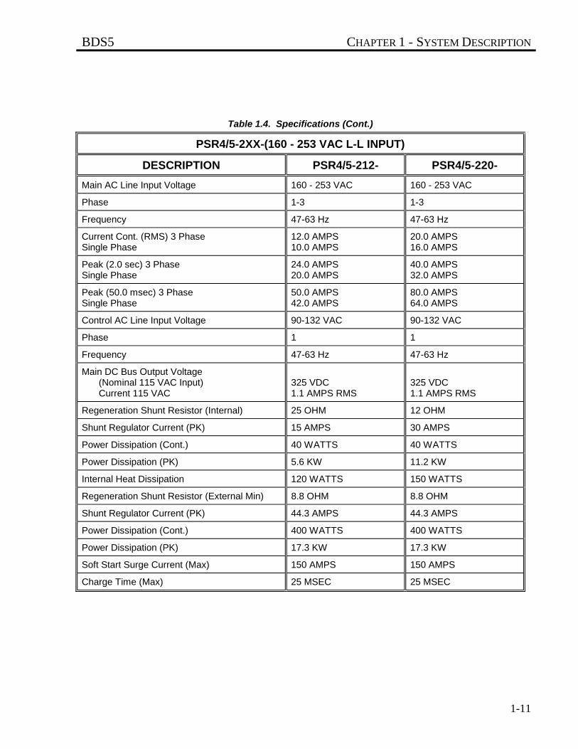
Table 1.4. Specifications (Cont.)
PSR4/5-2XX-(160 - 253 VAC L-L INPUT)
DESCRIPTION PSR4/5-212- PSR4/5-220-
Main AC Line Input Voltage 160 - 253 VAC 160 - 253 VAC
Phase 1-3 1-3
Frequency 47-63 Hz 47-63 Hz
Current Cont. (RMS) 3 PhaseSingle Phase
12.0 AMPS10.0 AMPS
20.0 AMPS16.0 AMPS
Peak (2.0 sec) 3 PhaseSingle Phase
24.0 AMPS20.0 AMPS
40.0 AMPS32.0 AMPS
Peak (50.0 msec) 3 PhaseSingle Phase
50.0 AMPS42.0 AMPS
80.0 AMPS64.0 AMPS
Control AC Line Input Voltage 90-132 VAC 90-132 VAC
Phase 1 1
Frequency 47-63 Hz 47-63 Hz
Main DC Bus Output Voltage(Nominal 115 VAC Input)Current 115 VAC
325 VDC1.1 AMPS RMS
325 VDC1.1 AMPS RMS
Regeneration Shunt Resistor (Internal) 25 OHM 12 OHM
Shunt Regulator Current (PK) 15 AMPS 30 AMPS
Power Dissipation (Cont.) 40 WATTS 40 WATTS
Power Dissipation (PK) 5.6 KW 11.2 KW
Internal Heat Dissipation 120 WATTS 150 WATTS
Regeneration Shunt Resistor (External Min) 8.8 OHM 8.8 OHM
Shunt Regulator Current (PK) 44.3 AMPS 44.3 AMPS
Power Dissipation (Cont.) 400 WATTS 400 WATTS
Power Dissipation (PK) 17.3 KW 17.3 KW
Soft Start Surge Current (Max) 150 AMPS 150 AMPS
Charge Time (Max) 25 MSEC 25 MSEC
CHAPTER 1 - SYSTEM DESCRIPTION BDS5
1-12
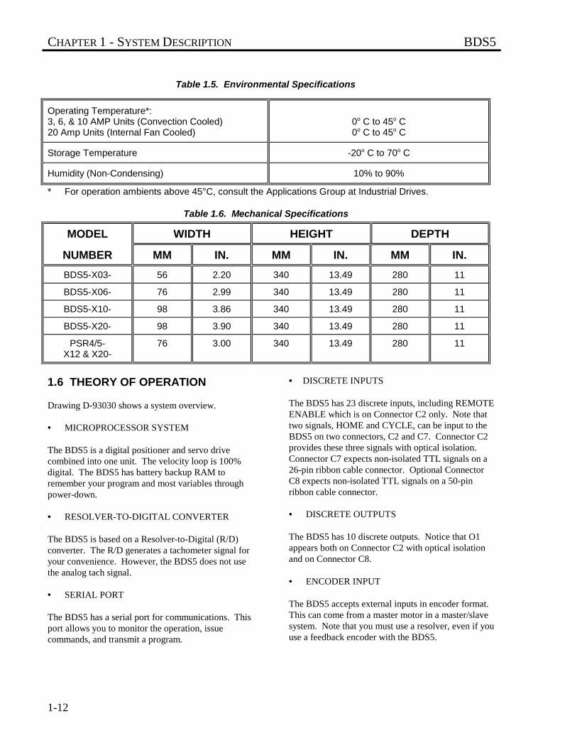
Table 1.5. Environmental Specifications
Operating Temperature*:3, 6, & 10 AMP Units (Convection Cooled)20 Amp Units (Internal Fan Cooled)
0o C to 45o C0o C to 45o C
Storage Temperature -20o C to 70o C
Humidity (Non-Condensing) 10% to 90%
* For operation ambients above 45°C, consult the Applications Group at Industrial Drives.
Table 1.6. Mechanical Specifications
MODEL WIDTH HEIGHT DEPTH
NUMBER MM IN. MM IN. MM IN.
BDS5-X03- 56 2.20 340 13.49 280 11
BDS5-X06- 76 2.99 340 13.49 280 11
BDS5-X10- 98 3.86 340 13.49 280 11
BDS5-X20- 98 3.90 340 13.49 280 11
PSR4/5-X12 & X20-
76 3.00 340 13.49 280 11
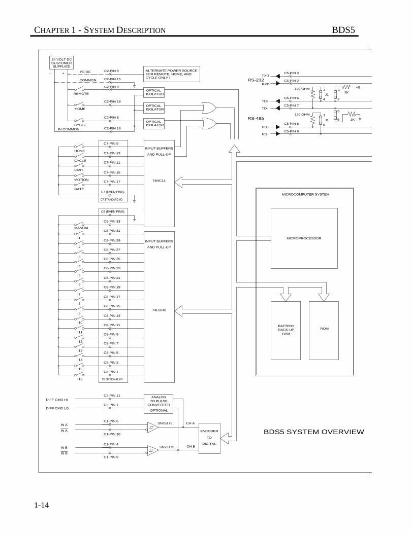
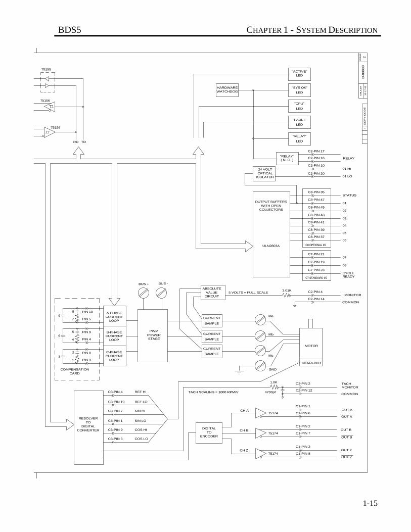
1.6 THEORY OF OPERATION
Drawing D-93030 shows a system overview.
• MICROPROCESSOR SYSTEM
The BDS5 is a digital positioner and servo drivecombined into one unit. The velocity loop is 100%digital. The BDS5 has battery backup RAM toremember your program and most variables throughpower-down.
• RESOLVER-TO-DIGITAL CONVERTER
The BDS5 is based on a Resolver-to-Digital (R/D)converter. The R/D generates a tachometer signal foryour convenience. However, the BDS5 does not usethe analog tach signal.
• SERIAL PORT
The BDS5 has a serial port for communications. Thisport allows you to monitor the operation, issuecommands, and transmit a program.
• DISCRETE INPUTS
The BDS5 has 23 discrete inputs, including REMOTEENABLE which is on Connector C2 only. Note thattwo signals, HOME and CYCLE, can be input to theBDS5 on two connectors, C2 and C7. Connector C2provides these three signals with optical isolation.Connector C7 expects non-isolated TTL signals on a26-pin ribbon cable connector. Optional ConnectorC8 expects non-isolated TTL signals on a 50-pinribbon cable connector.
• DISCRETE OUTPUTS
The BDS5 has 10 discrete outputs. Notice that O1appears both on Connector C2 with optical isolationand on Connector C8.
• ENCODER INPUT
The BDS5 accepts external inputs in encoder format.This can come from a master motor in a master/slavesystem. Note that you must use a resolver, even if youuse a feedback encoder with the BDS5.
BDS5 CHAPTER 1 - SYSTEM DESCRIPTION
1-13
• ENCODER EQUIVALENT OUTPUT
The BDS5 provides encoder format output derivedfrom the R/D converter.
• ANALOG INPUT (OPT1 CARD)
As an option, the BDS5 can accept a ±10 volt analoginput. This input is converted to digital format by theBDS5. Gain and offset adjustments are made digitallyinside the BDS5, not with potentiometers.
• PULSE INPUT (OPT2 CARD)
The BDS5 can accept special pulse inputs. Thestandard BDS5 can accept signals directly fromencoders or encoder-like devices. As an option, theBDS5 can accept other pulse formats, such ascount/direction or up/down.
• LED'S
The BDS5 provides LED's for diagnostics. TheseLED's are on the front panel of the BDS5. The LED'sare listed below:
ACTIVESYS OKCPUFAULTRELAY
• CURRENT LOOP COMPENSATION
The BDS5 has analog current loops. The current loopcompensation components are all contained in thecompensation module located on the front of theBDS5. The current loop compensation changes whenyou change the motor model. You must install thecorrect compensation module when changing motormodels.
YOU MUST HAVE THEPROPER COMPENSATIONMODULE INSTALLED FORYOUR MOTOR
Failure to install the propercompensation module cancause damage to the BDS5,the motor, or both.
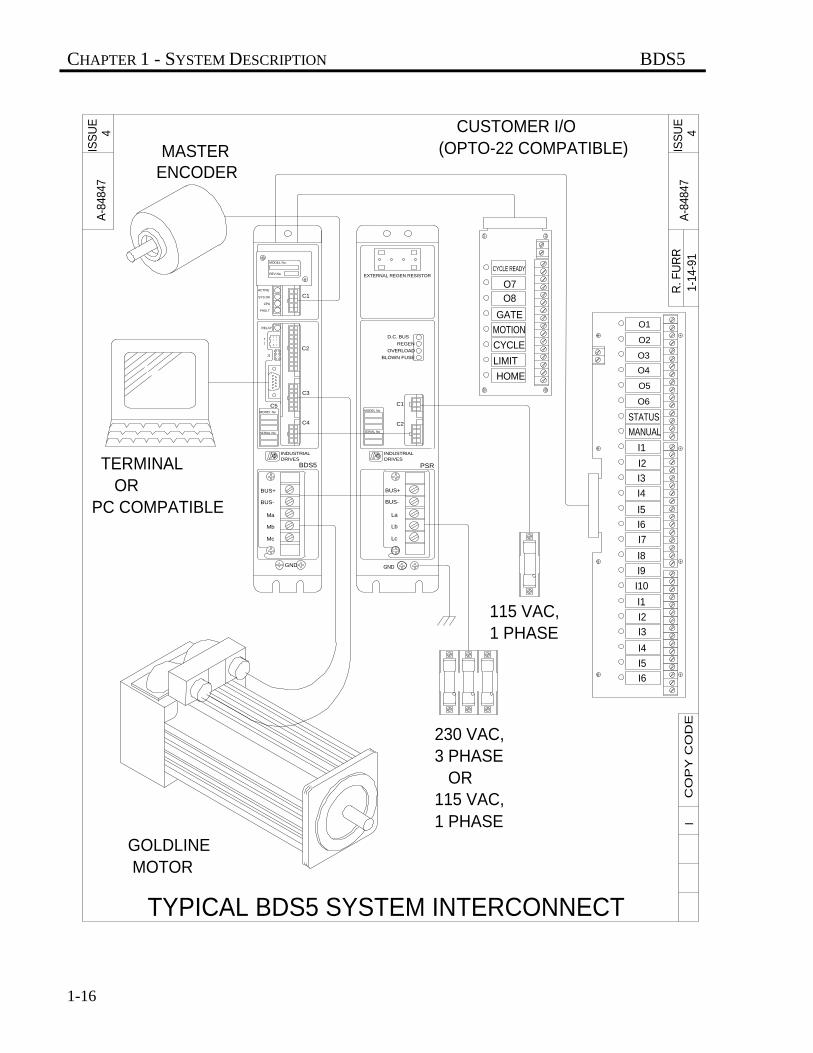
1.7 SIMPLIFIED SCHEMATICDIAGRAM AND SYSTEM DIAGRAM
Drawings D-93030 and A-84847 illustrate a BDS5servo system with all of the major components.
CAUTION
CHAPTER 1 - SYSTEM DESCRIPTION BDS5
1-14
IN B
IN B
IN A
IN A
C1-PIN 9
C1-PIN 4
C1-PIN 10
C1-PIN 5
DIFF CMD LO
DIFF CMD HI
I16
I14
I15
I12
I13
C2-PIN 1
C2-PIN 11
C8 OPTIONAL I/O
C8-PIN 7
C8-PIN 5
C8-PIN 3
C8-PIN 1
I10
I11
I9
I8
I6
I7
I5
I4
C8-PIN 9
C8-PIN 15
C8-PIN 13
C8-PIN 11
C8-PIN 17
C8-PIN 23
C8-PIN 21
C8-PIN 19
OPTIONAL
ENCODER
SN75175
SN75175
CH B
CH A
DIGITAL
TO
BDS5 SYSTEM OVERVIEW
CONVERTERTO PULSEANALOG
74LS540
RAMBACK-UPBATTERY
ROM
INPUT BUFFERS
INPUT BUFFERS
OPTICALISOLATOR
OPTICALISOLATOR
ISOLATOROPTICAL
CYCLE ONLY !FOR REMOTE, HOME, ANDALTERNATE POWER SOURCE
C2-PIN 8
C7 (EVEN PINS)
MANUAL
I2
I3
I1
C8-PIN 25
C8-PIN 29
C8-PIN 31
C8-PIN 27
C8-PIN 33
C8 (EVEN PINS)
C7 STANDARD I/O
GATE
MOTION
LIMIT
CYCLE
IN COMMON
HOME
CYCLE
C7-PIN 13
C7-PIN 17
C7-PIN 15
C7-PIN 11
C7-PIN 9
C2-PIN 18
I/O DC
COMMON
HOME
REMOTE
SUPPLIEDCUSTOMER24 VOLT DC
- +
C2-PIN 15
C2-PIN 19
C2-PIN 9
C2-PIN 5
7RS-485
AND PULL-UP
AND PULL-UP
74HC14
MICROPROCESSOR
MICROCOMPUTER SYSTEM
C5-PIN 8
C5-PIN 9RD-
RD+
J1
8
6 1K
RS-232 C5-PIN 2
C5-PIN 6
C5-PIN 7TD-
TD+
RXD
120 OHM
120 OHM
C5-PIN 3TXD
4
5
2
J1
3 11K
+5
BDS5 CHAPTER 1 - SYSTEM DESCRIPTION
1-15
08
5 VOLTS = FULL SCALE
CH ASIN HIC3-PIN 7
COS LO
COS HI
SIN LO
CONVERTERDIGITAL
TORESOLVER
C3-PIN 3
C3-PIN 1
C3-PIN 9
CH Z
ENCODERTO
DIGITALCH B
BUS +
REF LO
REF HI
4 PIN 4
PIN 8
PIN 3
COMPENSATION
3
CARD
1
2
C3-PIN 4
C3-PIN 10
C-PHASE
LOOP
LOOPCURRENT
PIN 10
PIN 5
PIN 96
97
5
8
CURRENTA-PHASE
B-PHASECURRENT
LOOP
SAMPLESTAGE
TACH SCALING = 1000 RPM/V
CURRENT
SAMPLE
POWERPWM
BUS -
CURRENT
SAMPLE
CURRENT
ABSOLUTEVALUE
CIRCUIT
C1-PIN 6
C1-PIN 8
C1-PIN 3
C1-PIN 7
C1-PIN 2
75174
75174
75174
OUT Z
OUT Z
OUT B
OUT B
OUT A
MOTOR
RESOLVER
C1-PIN 1
C2-PIN 12
C2-PIN 2
4700pf
1.0K
GND
Mc
COMMON
OUT A
MONITORTACH
C7-PIN 23
C7 STANDARD I/O
C2-PIN 14
C2-PIN 4
Mb
Ma
3.01K
COMMON
I MONITOR
READYCYCLE
75156
RD TD
75156
75155
HARDWAREWATCHDOG
"FAULT"
CO
PY
CO
DE
I
C8-PIN 35
C8-PIN 47
C8-PIN 45
C8-PIN 43
C8-PIN 41
C8-PIN 39
C8-PIN 37
C7-PIN 19
C7-PIN 21
C8 OPTIONAL I/OULN2803A
OUTPUT BUFFERS
COLLECTORSWITH OPEN
07
06
05
02
03
04
STATUS
01
C2-PIN 20
C2-PIN 10
C2-PIN 16
C2-PIN 17
"RELAY"( N. O. )
OPTICALISOLATOR
24 VOLT
"RELAY"
LED
LED
01 LO
RELAY
01 HI
2
"CPU"
LED
"SYS OK"
LED
"ACTIVE"LED
SH
ULE
RD
-93030
ISS
UE
12-1
7-9
2
CHAPTER 1 - SYSTEM DESCRIPTION BDS5
1-16
TYPICAL BDS5 SYSTEM INTERCONNECT
(OPTO-22 COMPATIBLE) CUSTOMER I/O
1 PHASE115 VAC,
GND
MOTORGOLDLINE
Mc Lc
GND
115 VAC,1 PHASE
OR3 PHASE230 VAC,
DRIVESINDUSTRIAL
PC COMPATIBLE
TERMINAL
ENCODERMASTER
OR
4IS
SU
EA
-848
47
Mb
Ma
BUS-
BUS+
SERIAL No
MODEL No
REV No.
ACTIVE
SYS OK
CPU
FAULT
RELAY
1T
J1
C5
MODEL No.
EXTERNAL REGEN RESISTOR
C1
C2
C3
C4
BDS5DRIVESINDUSTRIAL
MODEL No
SERIAL No
D.C. BUS
BUS+
BUS-
La
Lb
C2
REGEN
OVERLOAD
BLOWN FUSE
C1
CYCLE READY
PSR
HOME
LIMIT
CYCLE
MOTION
GATE
O8O7
I6
I5
I4
I3
I2
I1
I10
I9
I8
I7
CO
PY
CO
DE
I
I6
I5
I4
I3
I2
I1
MANUAL
STATUS
O6
O5
O4
O3
O2
O1
1-1
4-91
R. F
UR
RA
-848
47IS
SU
E4
BDS5 CHAPTER 2 - GETTING STARTED
2-1
CHAPTER 2
GETTING STARTED
2.1 INTRODUCTION
The information in this chapter will enable you to getstarted with programming the BDS5. Computerrequirements and software installation prepare youfor Motion Link, the Industrial Drives' softwarepackage specially designed for the BDS5. Thischapter also contains an overview of Motion Link andits basic functions and features. The Motion Linksetup program is introduced to enable the user to haveeasy access to the more common Motion Linkprocedures.
2.2 COMPUTER REQUIREMENTS
The BDS5 requires an IBM-PC or compatiblecomputer with the following features:
• IBM-PC, XT, AT, PS/2, or compatibleworkstation.
• 512 K RAM.
• PC-DOS or MS-DOS Version 2.5 or later.
• Either 5-1/4" or 3-1/2" Floppy Drive.
• Standard Video Adapter (CGA, MDA, EGA,MCGA, and VGA).
• Serial Port (for communication link with BDS5).The serial communications port may be COM1or COM2. The chart below shows the way yourPC should configure COM1 and COM2. This isthe normal configuration:
COM1:(PC Address 3F8h, Interrupt Request #4)
COM2:(PC Address 2F8h, Interrupt Request #3)
2.3 SOFTWARE INSTALLATION
The following section will show you how to back upand copy the files from the Motion Link disk to yourcomputer's hard disk or floppy disk.
2.3.1 Backing Up the Disk(s)
Before starting Motion Link, you should back up theMotion Link disk(s) that came with the BDS5. Thisway if something happens to the master disk(s), you'llalways have a copy. Remember, disks can bedamaged by heat, magnets, pressure, and dirt allextensively found in a manufacturing environment.Follow the procedure below to back up your disk(s).
1. From DOS, find either the DOS disk or directorywhere DISKCOPY.COM is located
and type:
CHAPTER 2 - GETTING STARTED BDS5
2-2
DISKCOPY A: A:
Press enter and follow the DOS prompts onscreen concerning source (Motion Link) anddestination (blank disk) disks.
2. After DOS finishes copying the disk(s), place theMotion Link original disk(s) in a safe place forstorage. Use it only to make extra copies. Neveruse the original disk(s) in day-to-day operation.
2.3.2 Software Installation
Motion Link can be installed on either a hard disk, 5-1/4 floppy disks, or 3-1/2 floppy disks. Follow thecorresponding instructions below for the installationthat your system requires.
2.3.2.1 Install on a Hard DiskUse this procedure to install Motion Link on a harddisk.
1. Type:
C:
2. Make a subdirectory named ML5 on your harddisk. Type:
MD \ML5
3. Change to subdirectory ML5. Type:
CD \ML5
4. Insert the Motion Link disk into the A-drive.This disk should be in the disk holder in thefront of this manual.
5. Copy all the files from the Motion Link diskonto the hard disk by typing:
COPY A:*.*
6. Store the original Motion Link disk in a safeplace. Do not use this disk, except to makeother copies.
2.3.2.2 Install on a Floppy DiskUse this procedure to install Motion Link on a floppydisk. Use the procedure for both Motion Link disks ifyou are using a 5-1/4 floppy.
1. Insert your DOS disk into the A-drive. TheDOS Disk must have the DOS file,FORMAT.COM.
2. Insert a blank disk into the B-drive.
3. Type:
A:
4. Type:
FORMAT B:/S
5. The Format program will ask you to hit a keyto continue.
6. After the format is completed, your computerwill prompt you to format more disks; answer"N" to exit the Format command.
7. Remove the DOS disk from the your computer.Leave the formatted disk in the B-drive.
8. Insert the Motion Link disk into the A-drive.This disk should be in the disk holder in thefront of this manual.
9. Copy all the files from the original MotionLink disk onto your disk by typing:
"COPY A:*.* B:".
10. Label your disk as Motion Link. Includetoday's date on the label.
11. Store the original Motion Link disk in a safeplace. Do not use this disk, except to makeother copies.
2.3.3 Establishing Communications
This procedure will get you started using MotionLink after you have installed it:
1. Connect and turn on your BDS5 as described inthe Installation and Setup Manual.
BDS5 CHAPTER 2 - GETTING STARTED
2-3
2. If you have Motion Link installed on a harddisk, type:
CD\ML5ML
Skip to Step 4.
3. If you have Motion Link installed on a floppydisk. Insert the copy of Motion Link in the A-drive, type:
A:ML
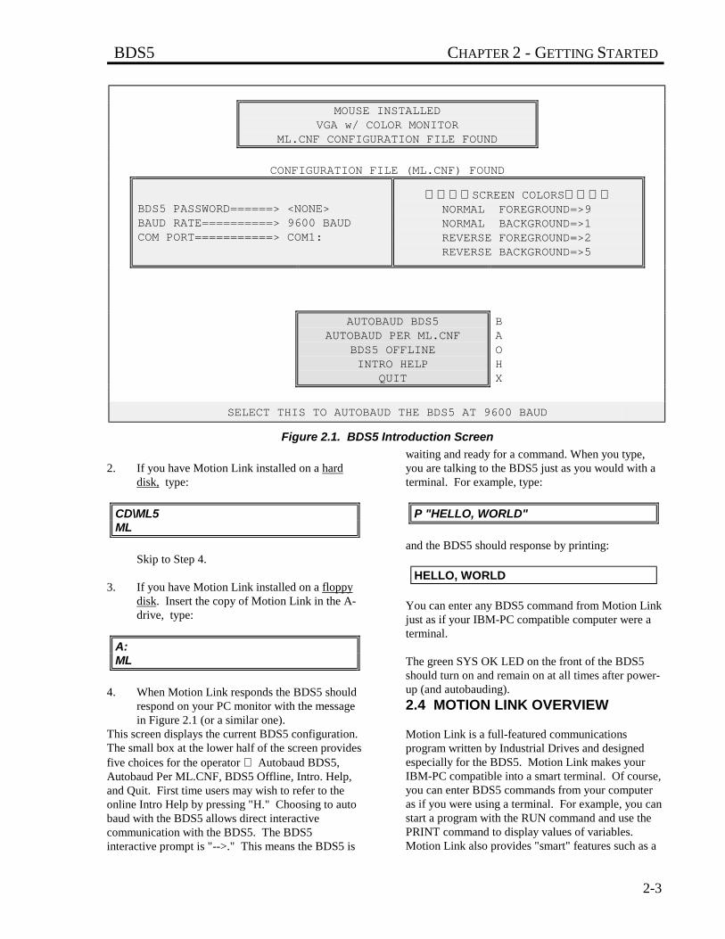
4. When Motion Link responds the BDS5 shouldrespond on your PC monitor with the messagein Figure 2.1 (or a similar one).
This screen displays the current BDS5 configuration.The small box at the lower half of the screen providesfive choices for the operator Autobaud BDS5,Autobaud Per ML.CNF, BDS5 Offline, Intro. Help,and Quit. First time users may wish to refer to theonline Intro Help by pressing "H." Choosing to autobaud with the BDS5 allows direct interactivecommunication with the BDS5. The BDS5interactive prompt is "-->." This means the BDS5 is
waiting and ready for a command. When you type,you are talking to the BDS5 just as you would with aterminal. For example, type:
P "HELLO, WORLD"
and the BDS5 should response by printing:
HELLO, WORLD
You can enter any BDS5 command from Motion Linkjust as if your IBM-PC compatible computer were aterminal.
The green SYS OK LED on the front of the BDS5should turn on and remain on at all times after power-up (and autobauding).
2.4 MOTION LINK OVERVIEW
Motion Link is a full-featured communicationsprogram written by Industrial Drives and designedespecially for the BDS5. Motion Link makes yourIBM-PC compatible into a smart terminal. Of course,you can enter BDS5 commands from your computeras if you were using a terminal. For example, you canstart a program with the RUN command and use thePRINT command to display values of variables.Motion Link also provides "smart" features such as a
MOUSE INSTALLEDVGA w/ COLOR MONITOR
ML.CNF CONFIGURATION FILE FOUND
CONFIGURATION FILE (ML.CNF) FOUND
BDS5 PASSWORD======> <NONE>BAUD RATE==========> 9600 BAUDCOM PORT===========> COM1:
SCREEN COLORSNORMAL FOREGROUND=>9NORMAL BACKGROUND=>1REVERSE FOREGROUND=>2REVERSE BACKGROUND=>5
AUTOBAUD BDS5AUTOBAUD PER ML.CNF
BDS5 OFFLINEINTRO HELP
QUIT
BAOHX
SELECT THIS TO AUTOBAUD THE BDS5 AT 9600 BAUD
Figure 2.1. BDS5 Introduction Screen
CHAPTER 2 - GETTING STARTED BDS5
2-4
full-screen editor, disk storage and retrieval, and thecommunications "capture" for debugging.
2.4.1 Menus and Windows
Motion Link's special features are accessed through amenu bar printed at the top of your PC screen. Whenyou select an entry from the menu bar, a pull-downwindow appears, allowing you to select an item.Press the F10 key, the right arrow key, or the leftarrow key, to display the menu bar. You can leave awindow or the menu bar by pressing the escape key.There are six choices on the menu bar:
• PROGRAM - Edit new or old BDS5 programs;retrieve a program from disk or from theBDS5.
• VARIABLE - Edit new or old BDS5 variablefiles; retrieve variable files from disk or fromthe BDS5. Variable files contain staticassignments. A static assignment is aninstruction that sets the value of a variable thatdoes not change throughout the program. Ofcourse, static assignments can be included inyour BDS5 power-up routine. However,moving a static assignment from your programto the variable file saves space in yourprogram.
• CAPTURE - Start or stop capturingcommunications from the BDS5; retrieveprevious capture files from disk; examine (edit)capture files.
• SCOPE - Retrieve, plot, print, and storePC-scope.
• OPTIONS - Set up communications, screencolors, computer configuration.
• HELP - Provide on-screen help for MotionLink and for the BDS5.
• UTILITIES - Exit Motion Link, enter a DOScommand from within Motion Link, use aDEP01 Simulator or run Motion Link Setupprogram.
2.4.1.1 ProgramThe PROGRAM pull-down window allows you toretrieve, edit, transmit, and save BDS5 programs.
• EDIT - This selection calls the Motion LinkEditor and assumes that you want to "re-edit"the last program that you edited. It is a short-cut, allowing you to edit without first loading aprogram from the BDS5 or from the disk. Ifyou exit the Motion Link Editor, Motion Linkremembers the program you were last editing.Note that if you have selected an item fromeither the VARIABLES or CAPTURE menusince you last edited a program, this selection isinvalid.
• FROM DISK - This selection retrieves aprogram from your computer disk. MotionLink will display all of the files currently onyour disk and allow you to choose the file youwant. After you choose a program, the MotionLink Editor is called, allowing you to examineand change the program.
• FROM BDS5 - This selection retrieves theprogram currently stored in the BDS5. Afterthe program is returned, the Motion LinkEditor is called, allowing you to examine andchange the program.
• NEW PROGRAM - This selection calls theMotion Link Editor, allowing you to enter anew program.
Upon exiting the Motion Link Editor, you can storethe program to your computer disk and/or transmit itto the BDS5.
2.4.1.2 VariablesThe VARIABLES pull-down window allows you toretrieve, edit, transmit, and save BDS5 variable files.A BDS5 variable file contains a list of some or all ofthe BDS5 variables with initial values. This includesuser variables and control variables. Together, thesevariables configure a BDS5 for an application.
• EDIT - This selection calls the Motion LinkEditor and assumes that you want to "re-edit"the last variable file that you edited. It is ashort-cut, allowing you to edit without firstloading a variable file from the BDS5 or fromthe disk. If you exit the Motion Link Editor,Motion Link remembers the variables you were
BDS5 CHAPTER 2 - GETTING STARTED
2-5
last editing. Note that if you have selected anitem from either the PROGRAM or CAPTUREmenu since you last edited a variable file, thisselection is invalid.
• FROM DISK - This selection retrieves avariable file from your computer disk. MotionLink will display all of the variable filescurrently on your disk and allow you to choosethe file you want. After you choose a variablefile, the Motion Link Editor is called, allowingyou to examine and change the variable file.
• FROM BDS5 - This selection retrieves all ofthe variables currently stored in the BDS5.After the variables are retrieved, the MotionLink Editor is called, allowing you to examineand change the variable file.
• NEW VARIABLES - This selection calls theMotion Link Editor, allowing you to enter anew set of variables.
Upon exiting the Motion Link Editor, you can storethe variable settings to your computer disk and/ortransmit them to the BDS5.
2.4.1.3 Capture
This is a communicationscapture and is unrelated tothe BDS5 variables CAP andCAPDIR which are for positioncapture.
• EDIT - This selection allows you to examinethe communications that have been captured.Upon exiting the Motion Link Editor, youcan store the captured data on your computerdisk. Note that if you selected an item fromeither the PROGRAM or VARIABLESmenu since you last capturedcommunications or loaded acommunications capture file, this selection isinvalid.
• FROM DISK - This selection allows you toretrieve a capture file from disk and examineit with the Motion Link Editor.
• START CAPTURE - This selection starts(or re-starts) capturing communications fromthe BDS5. This selection always clears the
capture storage area before beginning tocapture new communications.
• STOP CAPTURE - This selectionterminates the communications capture. Ifyou want to examine the communicationsthat were captured, select "EDIT" in thismenu.
2.4.1.4 Scope• VIEW AGAIN - This selection lets you view
playback data that was previously retrievedfrom the BDS5.
• FROM DISK - This selection retrievesrecorded data from your computer disk.Motion Link will display all of the playbackfiles currently on your disk and allow you tochoose the file you want. Playback fileshave the file type .CSV for "commaseparated variables." This format iscompatible with most spreadsheets.
• FROM BDS5 - This selection retrievesplayback data stored in the BDS5. After theplayback data is retrieved, the data is plottedand stored on disk.
• VIEW DATA - View the data in numerical(rather than graphical) format.
• PRINT PLOT - Print the plot on a lineprinter.
2.4.1.5 Options• SELECT AXIS - This selection allows you
to select options that are available to systemsusing RS-485 communications.
• BDS5 PASSWORD - This selection allowsyou to enter the password that you set in theBDS5 editor. If you set such a password in
the BDS5, Motion Link needs the passwordto transmit new programs to the BDS5. Ifyou use this selection to change thepassword, then you should use the UPDATECONFIGURATION function below to writea new configuration file.
• COMMUNICATIONS - This selectionallows you to set up your communicationsport. After you have set up this port, MotionLink will initiate an autobaud sequence to
NOTE
CHAPTER 2 - GETTING STARTED BDS5
2-6
re-establish communications. Remember topower-down the BDS5 so that it willautobaud. If you want Motion Link to usethe new communications setup in the future,you must use the UPDATECONFIGURATION function below to writea new configuration file on your computerdisk.
• SCREEN COLORS - This selection allowsyou to change the colors displayed on yourcomputer monitor. If you want Motion Linkto use the new colors in the future, you mustuse the UPDATE CONFIGURATIONfunction below to write a new configurationfile.
• CABLE DISCONNECT - This selectionprovides a safe method of disconnecting thecommunication cable from a BDS5 that ispowered up. After you have reconnected thecable, press the space bar and Motion Linkwill restart communications. Disconnectingthis cable can generate random characters.Do not disconnect your communicationscable without using this function.
Always use this selection tosecure data beforedisconnecting thecommunications cable.
• UPDATE CONFIGURATION - Thisselection allows you to examine and writethe Motion Link configuration file. This filecontains information about your computer,such as what communications port you areusing, the baud rate at which your computeris transmitting, and what your screen colorsare. All of the settings displayed in thisselection can be changed by the SETUP-BDS5 PASSWORD, SETUP-COMMUNICATIONS, and SETUP-SCREEN COLORS and selections.
After you make these changes, you shouldupdate the configuration file (ML.CNF) withthis selection. This file is read by MotionLink when you type "ML" from DOS.
• TL FROM DISK - This selection is aninternal function.
• TL FROM BDS5 - This selection is aninternal function.
2.4.1.6 Help• BDS5 HELP <F1> - This selection displays
several pages of help for the BDS5. It listsBDS5 commands and variables with briefdescriptions. You can also press F1 for thishelp.
• INTRO HELP - This selection displaysintroductory information about Motion Link.
• LAST COMMAND <F3> - This selectionrecalls your last command. You can also usethe function key F3 to recall your lastcommand.
• VARIABLE INPUT ^V - If you haveincluded a variable input routine in yourBDS5 program (that is, used VARIABLE$)and your program is running, this selectionwill initiate that routine. You can also press^V (hold the control key down and press V)for this function.
• STOP MOTION ^X - This selection breaksyour BDS5 program and stops motion. Itworks even if your program is not in theInteractive or Monitor mode. You can alsopress ^X for this function.
2.4.1.7 Utilities• RUN DEP01 SIMULATOR - This selection
allows the computer to simulate IndustrialDrives DEP (Data Entry Panel).
• RUN BDS5 SETUP PROGRAM - Thisselection provides utilities to test I/O, drivefeedback, communication, and dedicatedswitches. Refer to Section 2.6 for moreinformation.
• EXIT TO DOS Alt-X - This selectionterminates Motion Link and returns to DOS.You can also press Alt-X (hold the alternatekey down and press X) for this function.
• SHELL TO DOS - This selection allows youto temporarily exit (or "shell") to DOS sothat you can execute a DOS command.Type "EXIT" to return to Motion Link.
NOTE
BDS5 CHAPTER 2 - GETTING STARTED
2-7
2.4.2 Editor
The Motion Link Editor is a full-featured screeneditor. Use this editor to examine or edit programsand variable files, or to capture data. All of the editorcommands can be accessed from a menu bar and pull-down windows. Press the F10 key to display themenu bar. Then use the left and right arrow keys toselect a pull-down window. Each editor command canbe accessed with a "control key" or "hot-key"sequence. You can use the control key as a shortcutin place of selecting from the window. The control-key sequence is listed beside each command here, andin Motion Link. For example, the FILE-PRINTselection can be accessed with ^P (hold the controlkey down and press P). Many selections require twocontrol keys, such as FILE-FILE MERGE ^K^R. Inthis case, hold down the control key and press andrelease K, then press R. The rest of this section willdiscuss each of the editor pull-down windows.
2.4.2.1 File• SAVE FILE ^K^S - Copy the file in the
editor to the disk.
• MERGE FILE ^K^R - Copy a file into theeditor starting at the cursor. You must placethe editor cursor in the proper locationbefore you make this selection.
• PRINT... ^P - Print the contents of theeditor.
• EXIT <Esc> - This selection exits theMotion Link Editor. If you modify yourprogram, Motion Link will prompt you tosave your program to your computer's diskwhen you exit. If you are editing a programor a variable set, Motion Link will normallyprompt you to transmit the program orvariable settings to the BDS5. You can alsouse the escape key for this function.
2.4.2.2 Edit• MARK START OF BLOCK ^K^B - This
selection marks the beginning of a block. Ifyou want to move or eliminate a block oftext, use this selection to mark the top andthe bottom of the block you want tomanipulate.
• COPY MARKED BLOCK ^K^C - Use thisselection after you have marked a block.This selection copies the marked block intothe Motion Link cut/paste memory. If youwant to copy the block into the cut/pastememory and delete it from the editor, seeCUT MARKED BLOCK below.
• CUT MARKED BLOCK ^K^V - Use thisselection after you have marked a block.This selection copies the marked block intothe Motion Link cut/paste memory anddeletes it from the editor. If you want tocopy the block into the cut/paste memorywithout deleting it from the editor, seeCOPY MARKED BLOCK above.
• PASTE CUT/COPIED BLOCK ^K^P - Usethis selection after you have either copied orcut a block to the cut/paste memory. Thisselection copies the cut/paste memory intothe editor starting at the cursor. You mustposition the cursor to the proper place beforeyou make this selection.
• SAVE MARKED BLOCK ^K^W - Use thisselection after you have marked a block.This selection saves the marked block to afile on your disk. Motion Link will ask youfor the file name after you make thisselection.
2.4.2.3 GOTO• FIND A STRING ^Q^F - This selection
finds a string in the editor. Motion Link willprompt you to enter the string.
• REPEAT LAST FIND ^L - This selectionrepeats the last FIND A STRING.
• GOTO A LINE NUMBER ^Q^I - Thisselection moves the cursor to the specifiedline. Note that you can transmit yourprogram to the BDS5 without comments.Since comment lines can be ignored byMotion Link when your program istransmitted, the line numbers of yourprogram in the editor may not agree with theline numbers of your program in the BDS5.Because of this, Motion Link will ask you ifyou want to count comments. If you aretrying to find a line number from a BDS5error message, and you transmitted your
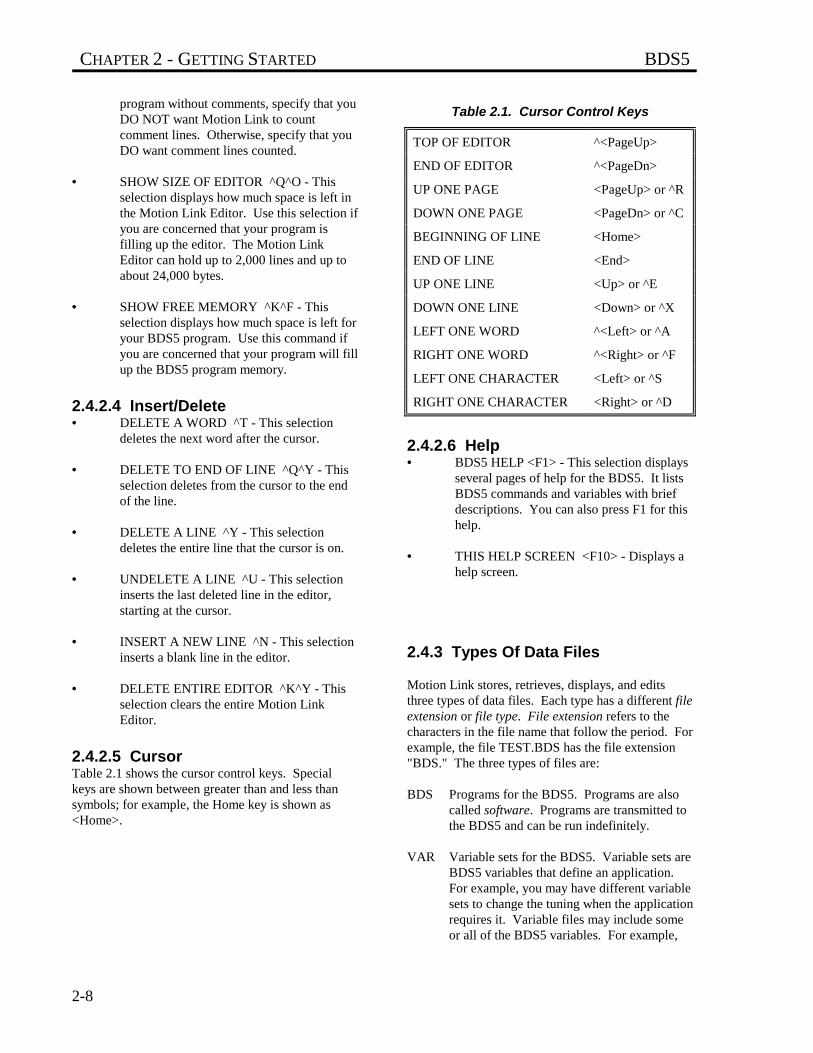
CHAPTER 2 - GETTING STARTED BDS5
2-8
program without comments, specify that youDO NOT want Motion Link to countcomment lines. Otherwise, specify that youDO want comment lines counted.
• SHOW SIZE OF EDITOR ^Q^O - Thisselection displays how much space is left inthe Motion Link Editor. Use this selection ifyou are concerned that your program isfilling up the editor. The Motion LinkEditor can hold up to 2,000 lines and up toabout 24,000 bytes.
• SHOW FREE MEMORY ^K^F - Thisselection displays how much space is left foryour BDS5 program. Use this command ifyou are concerned that your program will fillup the BDS5 program memory.
2.4.2.4 Insert/Delete• DELETE A WORD ^T - This selection
deletes the next word after the cursor.
• DELETE TO END OF LINE ^Q^Y - Thisselection deletes from the cursor to the endof the line.
• DELETE A LINE ^Y - This selectiondeletes the entire line that the cursor is on.
• UNDELETE A LINE ^U - This selectioninserts the last deleted line in the editor,starting at the cursor.
• INSERT A NEW LINE ^N - This selectioninserts a blank line in the editor.
• DELETE ENTIRE EDITOR ^K^Y - Thisselection clears the entire Motion LinkEditor.
2.4.2.5 CursorTable 2.1 shows the cursor control keys. Specialkeys are shown between greater than and less thansymbols; for example, the Home key is shown as<Home>.
Table 2.1. Cursor Control Keys
TOP OF EDITOR ^<PageUp>
END OF EDITOR ^<PageDn>
UP ONE PAGE <PageUp> or ^R
DOWN ONE PAGE <PageDn> or ^C
BEGINNING OF LINE <Home>
END OF LINE <End>
UP ONE LINE <Up> or ^E
DOWN ONE LINE <Down> or ^X
LEFT ONE WORD ^<Left> or ^A
RIGHT ONE WORD ^<Right> or ^F
LEFT ONE CHARACTER <Left> or ^S
RIGHT ONE CHARACTER <Right> or ^D
2.4.2.6 Help• BDS5 HELP <F1> - This selection displays
several pages of help for the BDS5. It listsBDS5 commands and variables with briefdescriptions. You can also press F1 for thishelp.
• THIS HELP SCREEN <F10> - Displays ahelp screen.
2.4.3 Types Of Data Files
Motion Link stores, retrieves, displays, and editsthree types of data files. Each type has a different fileextension or file type. File extension refers to thecharacters in the file name that follow the period. Forexample, the file TEST.BDS has the file extension"BDS." The three types of files are:
BDS Programs for the BDS5. Programs are alsocalled software. Programs are transmitted tothe BDS5 and can be run indefinitely.
VAR Variable sets for the BDS5. Variable sets areBDS5 variables that define an application.For example, you may have different variablesets to change the tuning when the applicationrequires it. Variable files may include someor all of the BDS5 variables. For example,
BDS5 CHAPTER 2 - GETTING STARTED
2-9
your Motion Link disk has the file"STANDARD.VAR." This variable fileincludes all of the "standard" or "default"variable settings. Variable files aretransmitted to the BDS5 to initialize variablesbefore programs are run.
CAP Capture files contain capturedcommunications from the BDS5. The capturefeatures of the BDS5 allow you to collect andstore up to 16,000 bytes of transmissionsfrom the BDS5. Capture is provided to helpyou debug your program.
Any time you store your programs, variable sets, orcaptured communication onto your computer disk,Motion Link will automatically determine the properfile extension.
2.4.4 Using IBM-PC Compatibles
If you are using an IBM-PC Compatible, make sure ithas been booted with the optional serial/paralleladapter plugged in. Also make sure it has beenconfigured to allow the operation of the serial/paralleladapter on batteries. This configuration may beaccomplished through the IBM-supplied programSYSPROF.COM. To run this program, type"SYSPROF"<cr>.
This program may also be reached through theAPP/SELECTOR DISK, but this is a remain-residentprogram that will not leave enough memory to loadMotion Link after running. So a three-key computerreboot (Ctrl, Alt, Del) must be done to remove thisprogram from memory before loading Motion Link.Because of this, it is easier to simply run "SYSPROF"in order to configure the IBM CONVERTIBLE.
2.5 MOTION LINK SETUP PROGRAM
The Motion Link Setup Program is accessed throughthe Utilities Menu. Setup provides the following testcapabilities:
• Communicate with the BDS5• Resolver Zeroing Test• Tune Drive• Drive Test• Drive Feedback
• Input Test• Output Test• Machine Setup - Units• Machine Setup - Limits• Motor Setup• BDS5 Modes• Communications• Other• Send Variables• Reset Variables
This test program provides the operator with userfriendly methods for testing most BDS5 functions.
2.6 PROCESSOR MODES
2.6.1 Prompts
The BDS5 provides several modes of operation.Each mode is distinguished by a unique prompt. Aprompt is the short series of characters that the BDS5writes to the screen asking you for input. Forexample, the interactive prompt is "-->." This promptis unique and tells you that the BDS5 is in theInteractive mode.
The BDS5 is designed to receive commands from aterminal or a computer through a serial port. In orderto support computer communications, the BDS5observes the following conventions:
Table 2.2. BDS5 Rules For Prompts
1. Prompts are 3 characters long (except single-step and trace).
2. Prompts end with a greater than (“>”).
3. Each mode has a unique prompt.
4. Once the BDS5 displays a prompt, it stopstransmitting until a new instruction and/or acarriage return is received.
These conventions are designed to allow efficientcommunications between the BDS5 and a computer.The last rule ensures that there is never a questionabout which device is transmitting. If a ">" has beenissued from the BDS5, then the BDS5 will nottransmit anything until a carriage return or escape has
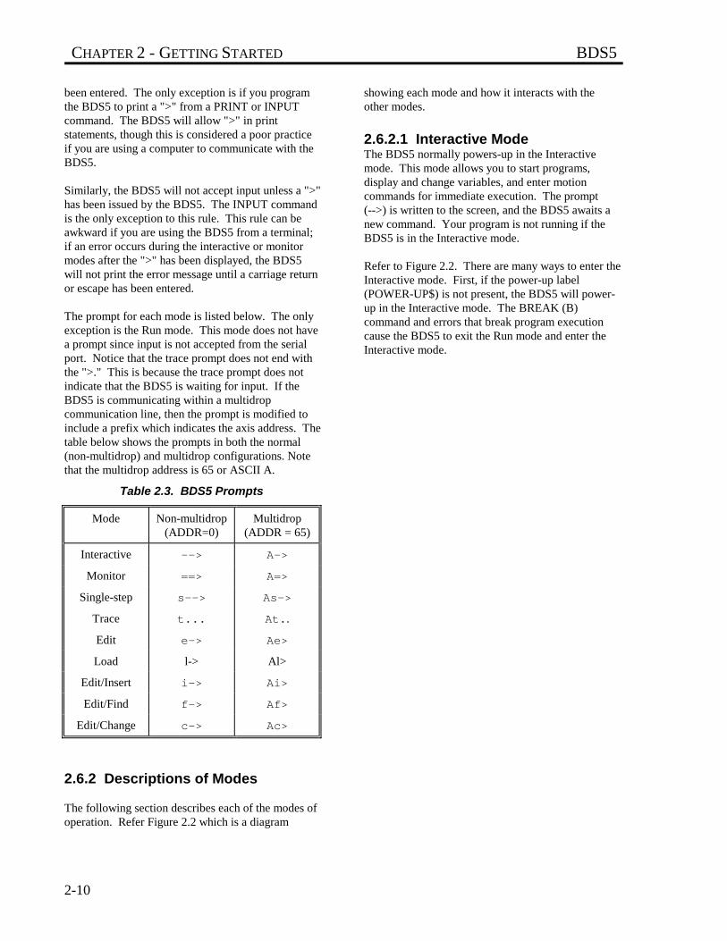
CHAPTER 2 - GETTING STARTED BDS5
2-10
been entered. The only exception is if you programthe BDS5 to print a ">" from a PRINT or INPUTcommand. The BDS5 will allow ">" in printstatements, though this is considered a poor practiceif you are using a computer to communicate with theBDS5.
Similarly, the BDS5 will not accept input unless a ">"has been issued by the BDS5. The INPUT commandis the only exception to this rule. This rule can beawkward if you are using the BDS5 from a terminal;if an error occurs during the interactive or monitormodes after the ">" has been displayed, the BDS5will not print the error message until a carriage returnor escape has been entered.
The prompt for each mode is listed below. The onlyexception is the Run mode. This mode does not havea prompt since input is not accepted from the serialport. Notice that the trace prompt does not end withthe ">." This is because the trace prompt does notindicate that the BDS5 is waiting for input. If theBDS5 is communicating within a multidropcommunication line, then the prompt is modified toinclude a prefix which indicates the axis address. Thetable below shows the prompts in both the normal(non-multidrop) and multidrop configurations. Notethat the multidrop address is 65 or ASCII A.
Table 2.3. BDS5 Prompts
Mode Non-multidrop(ADDR=0)
Multidrop(ADDR = 65)
Interactive --> A->
Monitor ==> A=>
Single-step s--> As->
Trace t... At..
Edit e-> Ae>
Load l-> Al>
Edit/Insert i-> Ai>
Edit/Find f-> Af>
Edit/Change c-> Ac>
2.6.2 Descriptions of Modes
The following section describes each of the modes ofoperation. Refer Figure 2.2 which is a diagram
showing each mode and how it interacts with theother modes.
2.6.2.1 Interactive ModeThe BDS5 normally powers-up in the Interactivemode. This mode allows you to start programs,display and change variables, and enter motioncommands for immediate execution. The prompt(-->) is written to the screen, and the BDS5 awaits anew command. Your program is not running if theBDS5 is in the Interactive mode.
Refer to Figure 2.2. There are many ways to enter theInteractive mode. First, if the power-up label(POWER-UP$) is not present, the BDS5 will power-up in the Interactive mode. The BREAK (B)command and errors that break program executioncause the BDS5 to exit the Run mode and enter theInteractive mode.
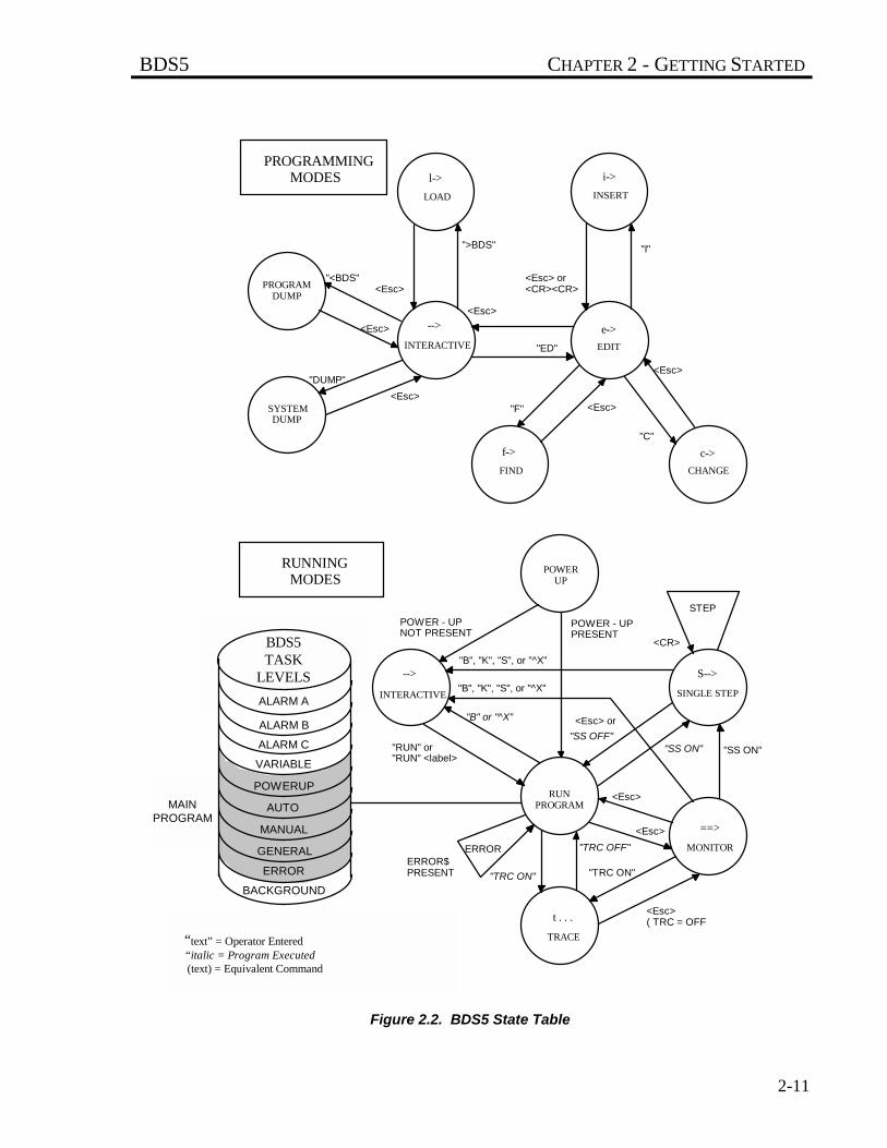
BDS5 CHAPTER 2 - GETTING STARTED
2-11
LOAD INSERT
PROGRAMDUMP
SYSTEMDUMP
INTERACTIVE EDIT
FIND
">BDS"
CHANGE
PROGRAMMINGMODES
"<BDS"
<Esc>
<Esc>
<Esc>
"ED"
"F" <Esc>
<Esc> or<CR><CR>
<Esc>
<Esc>
"C"
"I"
RUNNINGMODES
"DUMP"
l-> i->
e->
c->f->
-->
INTERACTIVE
-->
POWERUP
SINGLE STEP
S-->
RUNPROGRAM
MONITOR
==>
TRACE
t . . .
STEPPOWER - UPNOT PRESENT
POWER - UPPRESENT
"B", "K", "S", or "^X"
"B", "K", "S", or "^X"
<CR>
"B" or "^X"
"RUN" or"RUN" <label>
<Esc> or
"SS OFF""SS ON" "SS ON"
<Esc>
<Esc>
"TRC ON"
"TRC OFF"
"TRC ON"
ERRORERROR$PRESENT
<Esc>( TRC = OFF
BDS5TASK
LEVELS
MAINPROGRAM
ALARM A
ALARM B
ALARM C
VARIABLE
POWERUP
AUTO
MANUAL
GENERAL
ERROR
BACKGROUND
“text” = Operator Entered“italic = Program Executed (text) = Equivalent Command
Figure 2.2. BDS5 State Table
CHAPTER 2 - GETTING STARTED BDS5
2-12
2.6.2.2 Run ModeThe BDS5 is normally in the Run mode when aprogram is executing. There is no prompt becauseinput is not accepted from the terminal. The programis running; it can display errors and print to theterminal.
Refer to Figure 2.2. After autobauding, the Runmode is normally entered from either the Interactivemode, the RUN command, or from multi-tasking. Ifthe power-up label (POWER-UP$) is present, theBDS5 will start running your program at that label onpower-up. Also, the BDS5 will exit the Run mode tothe Monitor mode if the escape key is pressed.
Errors can also cause the BDS5 to change modes.Some errors are serious enough to cause the BDS5 tobreak program execution. Usually, this has theidentical effect of issuing a BREAK (B) command.
As an option, you can write an error handling routinebeginning at label ERROR$. This routine should beshort and should end with a BREAK (B) command.The error handler is intended for graceful errorrecovery. For example, you can set outputs or print amessage. It is not intended to continue the programas if the error never occurred.
2.6.2.3 Monitor ModeThe BDS5 Monitor mode is a unique mode forpositioners. In this mode, the user program isrunning, but commands are accepted from theterminal for immediate execution. The Monitor modeallows you to display and change variables duringprogram execution, including tuning variables.
You can print any variable and change anyprogrammable variable from the Monitor mode. Thecommands that are allowed from the Monitor modeare a subset of the commands allowed from the userprogram and Interactive modes, and include thefollowing commands:
Table 2.4. Monitor Mode Commands
? ; B DIS EN
ERR K MOTOR P PS
R RS S ZPE
In the Monitor mode, all print commands from theuser program are suppressed, and the monitor prompt
(==>) is displayed. Print commands typed in fromthe Monitor mode are executed immediately.
To enter the Monitor mode, press the escape keywhile a program is running. Pressing the escape keyagain will change modes back to the Run mode.STOP, BREAK, and KILL all return the BDS5 to theInteractive mode.
2.6.2.4 Single-Step ModeThe Single-Step mode is provided for debugging, andit allows you to execute a program one step at a time.The single-step prompt (s->) is printed out, followedby the line that is about to be executed (the nextcommand). Any command allowed from the terminalin the Monitor mode is also allowed from the terminalin the Single-Step mode. These commands allow youto probe the BDS5 variables while debugging yourprogram. If you press the enter key without acommand entered, then the next command in the userprogram is executed. To stop the program, enter theS, B, or K command. To turn off the Single-Stepmode and allow the program to execute normally,press the escape key twice (once to get into theMonitor mode and again to get into the Run mode),or type SS OFF.
Single-Step mode is enabled by turning SS on, eitherfrom the program, from the Interactive mode beforerunning the program, or from the Monitor mode.After SS is on, the BDS5 will enter the Single-Stepmode when the user program is executed. SS canalso be turned on and off from the program. This isuseful if there are certain sections that you want tosingle step through. Turning SS off from the programreturns the BDS5 to the Run mode.
2.6.2.5 Trace ModeThe Trace mode is provided for debugging. When intrace, the BDS5 prints statements before they areexecuted. The trace prompt (t...) is printed out,followed by the line that is about to be executed, andthe line is then executed. This process is repeated foreach command. The trace prompt is not a trueprompt in that you are not allowed to enter acommand after the prompt is issued. This is why itdoes not have the ">" that the other prompts use toindicate that the BDS5 is waiting for a command.
The trace is enabled by turning TRC on. When TRCis on, the BDS5 will enter the Trace mode when theuser program is executed. TRC can be turned on andoff from the Interactive mode before executing theprogram or from the program itself. It can be turned

BDS5 CHAPTER 2 - GETTING STARTED
2-13
on from the Monitor mode. Pressing the escape keyfrom the Trace mode will exit to the Monitor modeand turn TRC off. If TRC is turned off from theprogram, the BDS5 will exit to the Run mode. If bothTRC and SS are on, then the BDS5 will be in Single-Step mode.
2.6.2.6 Other ModesThe other modes shown in Figure 2.2 include the Editmodes (Edit, Insert, Change, and Find) and thecommunication modes (Program Load, ProgramDump, and System Dump). These modes are coveredin later chapters.
BDS5 CHAPTER 3 - PROGRAMMING LANGUAGE
3-1
CHAPTER 3
PROGRAMMING LANGUAGE
3.1 INTRODUCTION
This chapter discusses the basics of the BDS5 and itsprogramming language.
Your BDS5 system should be mounted and wired asdescribed in the Installation and Setup Manual. TheAC Line voltage to your PSR4/5 should not be turnedon for examples in this chapter. Turn on ControlPower only, and establish communications. If theproper connections are not made, or the terminal isnot communicating, then see the Installation andSetup Manual.
AC LINE SHOULD NOT BETURNED ON!
3.2 INSTRUCTIONS
The BDS5 can respond to instructions entered fromthe terminal. The format of the instructions is usuallya command followed by one or more parameters. Forexample, the jog instruction is a "J" followed by oneparameter: the desired speed.
J 10
would cause the motor to jog at 10 RPM.
The command and parameter must be separated by atleast one space.
3.2.1 Comments
Instructions can be followed by comments on thesame line. A semicolon marks the beginning of acomment. The BDS5 ignores everything on the lineafter the semicolon. For example:
J 10 ;THIS IS A GOOD COMMENT
is a valid instruction. The BDS5 ignores everythingthat follows the semicolon. Note that a space mustseparate the semicolon from the last parameter:
J 10;BAD COMMENT-";" MUST BE;PRECEDED BY A SPACE
;GOOD LINE. SPACE NOT REQUIRED-;WHOLE LINE IS A COMMENT
3.3 VARIABLES
The BDS5 uses variables to monitor and controlvirtually all of its processes.
WARNING
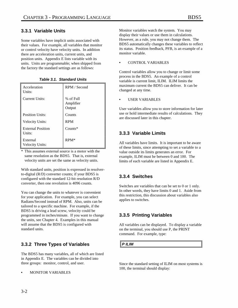
CHAPTER 3 - PROGRAMMING LANGUAGE BDS5
3-2
3.3.1 Variable Units
Some variables have implicit units associated withtheir values. For example, all variables that monitoror control velocity have velocity units. In additionthere are acceleration units, current units, andposition units. Appendix E lists variable with itsunits. Units are programmable; when shipped fromthe factory the standard settings are as follows:
Table 3.1. Standard Units
AccelerationUnits:
RPM / Second
Current Units: % of FullAmplifierOutput
Position Units: Counts
Velocity Units: RPM
External PositionUnits:
Counts*
ExternalVelocity Units:
RPM*
* This assumes external source is a motor with thesame resolution as the BDS5. That is, externalvelocity units are set the same as velocity units.
With standard units, position is expressed in resolver-to-digital (R/D) converter counts; if your BDS5 isconfigured with the standard 12-bit resolution R/Dconverter, then one revolution is 4096 counts.
You can change the units to whatever is convenientfor your application. For example, you can selectRadians/Second instead of RPM. Also, units can betailored to a specific machine. For example, if theBDS5 is driving a lead screw, velocity could beprogrammed in inches/minute. If you want to changethe units, see Chapter 4. Examples in this manualwill assume that the BDS5 is configured withstandard units.
3.3.2 Three Types of Variables
The BDS5 has many variables, all of which are listedin Appendix E. The variables can be divided intothree groups: monitor, control, and user.
• MONITOR VARIABLES
Monitor variables watch the system. You maydisplay their values or use them in calculations.However, as a rule, you may not change them. TheBDS5 automatically changes these variables to reflectits status. Position feedback, PFB, is an example of amonitor variable.
• CONTROL VARIABLES
Control variables allow you to change or limit someprocess in the BDS5. An example of a controlvariable is current limit, ILIM. ILIM limits themaximum current the BDS5 can deliver. It can bechanged at any time.
• USER VARIABLES
User variables allow you to store information for lateruse or hold intermediate results of calculations. Theyare discussed later in this chapter.
3.3.3 Variable Limits
All variables have limits. It is important to be awareof these limits, since attempting to set a variable to avalue outside its limits generates an error. Forexample, ILIM must be between 0 and 100. Thelimits of each variable are listed in Appendix E.
3.3.4 Switches
Switches are variables that can be set to 0 or 1 only.In other words, they have limits 0 and 1. Aside fromthis restriction, this discussion about variables alsoapplies to switches.
3.3.5 Printing Variables
All variables can be displayed. To display a variableon the terminal, you should use P, the PRINTcommand. For example, type:
P ILIM
Since the standard setting of ILIM on most systems is100, the terminal should display:
BDS5 CHAPTER 3 - PROGRAMMING LANGUAGE
3-3
100
Suppose you want to display PFB, the positionfeedback. Type:
P PFB
The position feedback should now be displayed.Assuming the motor and resolver are connected to theBDS5, rotate the motor shaft about half a revolution.Now, print PFB as above and notice that it haschanged to reflect the new position.
3.3.6 Changing a Variable
Variables are changed with assignment instructions.An assignment instruction begins with the name ofthe particular variable, followed by "=" and endingwith the new value. One or more spaces can besubstituted for the "=". The following examplesassign (or at least attempt to assign) ILIM a newvalue:
ILIM=10 ;CORRECT--ASSIGN A NEW ;VALUE TO ILIM
ILIM 10 ;CORRECT--THE '=' IS ;OPTIONAL
ILIM10 ;INCORRECT--THERE MUST ;BE A SPACE OR '='
A few systems are set up withILIM less than 100. If yourterminal displays a numberless than 100, write it downfor reference later in thischapter. The followingexamples will change ILIM,and it must be reset to itsoriginal value.
Type the following line on the terminal:
ILIM=10
Next, print the new value of ILIM with the Pinstruction:
P ILIM
ILIM should now be 10. Return ILIM to its originalvalue (normally 100) and type:
ILIM=100
Print ILIM to make sure the change was carried outproperly.
3.3.7 Programming Conditions
Most variables can be changed, but some can bechanged only under certain conditions. For example,the maximum acceleration level, AMAX, can bechanged only when the BDS5 is disabled.Attempting to change AMAX with the BDS5 enabledwill generate an error. The conditions under which avariable can be changed are called programmingconditions. Some variables should never need to bechanged after the BDS5 has left the factory; thesevariables are called "factory settable." Attempting tochange a factory settable variable will generate anerror. The programming conditions of all variablesare listed in Appendix E.
Limits and programmingconditions for all variables areshown in Appendix E.
3.3.8 Power-up and ControlVariables
Most control variables and all user variables arestored in non-volatile RAM; their values are not lostwhen the BDS5 is powered-down. In general, controlvariables are remembered, except the switches. Table3.2 shows the condition of all BDS5 programmableswitches on power-up.
NOTE
NOTE
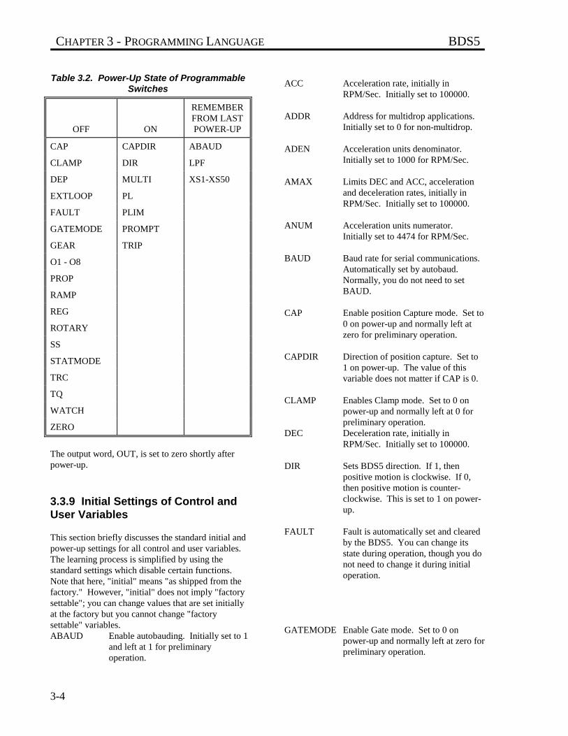
CHAPTER 3 - PROGRAMMING LANGUAGE BDS5
3-4
Table 3.2. Power-Up State of ProgrammableSwitches
OFF ON
REMEMBERFROM LASTPOWER-UP
CAP CAPDIR ABAUD
CLAMP DIR LPF
DEP MULTI XS1-XS50
EXTLOOP PL
FAULT PLIM
GATEMODE PROMPT
GEAR TRIP
O1 - O8
PROP
RAMP
REG
ROTARY
SS
STATMODE
TRC
TQ
WATCH
ZERO
The output word, OUT, is set to zero shortly afterpower-up.
3.3.9 Initial Settings of Control andUser Variables
This section briefly discusses the standard initial andpower-up settings for all control and user variables.The learning process is simplified by using thestandard settings which disable certain functions.Note that here, "initial" means "as shipped from thefactory." However, "initial" does not imply "factorysettable"; you can change values that are set initiallyat the factory but you cannot change "factorysettable" variables.ABAUD Enable autobauding. Initially set to 1
and left at 1 for preliminaryoperation.
ACC Acceleration rate, initially inRPM/Sec. Initially set to 100000.
ADDR Address for multidrop applications.Initially set to 0 for non-multidrop.
ADEN Acceleration units denominator.Initially set to 1000 for RPM/Sec.
AMAX Limits DEC and ACC, accelerationand deceleration rates, initially inRPM/Sec. Initially set to 100000.
ANUM Acceleration units numerator.Initially set to 4474 for RPM/Sec.
BAUD Baud rate for serial communications.Automatically set by autobaud.Normally, you do not need to setBAUD.
CAP Enable position Capture mode. Set to0 on power-up and normally left atzero for preliminary operation.
CAPDIR Direction of position capture. Set to1 on power-up. The value of thisvariable does not matter if CAP is 0.
CLAMP Enables Clamp mode. Set to 0 onpower-up and normally left at 0 forpreliminary operation.
DEC Deceleration rate, initially inRPM/Sec. Initially set to 100000.
DIR Sets BDS5 direction. If 1, thenpositive motion is clockwise. If 0,then positive motion is counter-clockwise. This is set to 1 on power-up.
FAULT Fault is automatically set and clearedby the BDS5. You can change itsstate during operation, though you donot need to change it during initialoperation.
GATEMODE Enable Gate mode. Set to 0 onpower-up and normally left at zero forpreliminary operation.
BDS5 CHAPTER 3 - PROGRAMMING LANGUAGE
3-5
GEAR Enable electronic gearbox. Set to 0on power-up and normally left at 0 forpreliminary operation.
GEARI Number of teeth on the input "gear"for electronic gearbox. Initially set to1. Value of this variable does notmatter if GEAR is 0.
GEARO Number of teeth on the output "gear"for electronic gearbox. Initially set to3. Value of this variable does notmatter if GEAR is 0.
IDEN Current units denominator. Initiallyset to 100 for percent.
ILIM Peak current limit. The initial valueis listed on the Test and Limits (TL)sheet which should be enclosed withyour system. Normally set to IMAX.However, you may want to reduce itfor protection. The motor cannormally run under no-load with 15-25% current, so you can set ILIM aslow as 15 or 25 during preliminaryoperation.
INUM Current units numerator. Initially setto 4095 for percent.
KC Low speed "graininess"compensation. Almost always set to200. See discussion in theInstallation and Setup Manual wherea procedure for fine-tuning thisvariable is given.
KF Tuning gain for velocity feed-forward. Set to 0 for preliminaryoperation.
KP Tuning gain for position loop. Leaveat initial setting for preliminaryoperation. The initial value is listedon the Test and Limits (TL) sheet,which should be enclosed with yoursystem. Use TUNE command tochange if necessary.
KPROP Tuning gain for proportional velocityloop. Leave at initial setting forpreliminary operation. The initialvalue is listed on the Test and Limits(TL) sheet, which should be enclosed
with your system. Use TUNEcommand to change if necessary.
KV Tuning gain #1 for integratingvelocity loop. Leave at initial settingfor preliminary operation. The initialvalue is listed on the Test and Limits(TL) sheet, which should be enclosedwith your system. Use TUNEcommand to change if necessary.
KVI Tuning gain #2 for integratingvelocity loop. Leave at initial settingfor preliminary operation. The initialvalue is listed on the Test and Limits(TL) sheet, which should be enclosedwith your system. Use TUNEcommand to change if necessary.
LPF Enables low pass filter. The low passfilter is often required to reduce noiseor torsional resonance. Leave atinitial setting for preliminaryoperation. Set to 1 if system is toonoisy. The initial value is listed onthe Test and Limits (TL) sheet, whichshould be enclosed with your system.
LPFHZ Low pass filter break frequency. Thelow pass filter is often required toreduce noise or torsional resonance.Leave at initial setting for preliminaryoperation. Reduce value if system istoo noisy. The initial value is listedon the Test and Limits (TL) sheet,which should be enclosed with yoursystem.
MULTI Enable multi-tasking.
O1-8 General purpose outputs. Reset to 0on power-up. These variables arediscussed later in this chapter.
PDEN Position units denominator. Initiallyset to 1.
PECLAMP Position error limit for clamping.Initially set to 100. Value of thisvariable does not matter if CLAMP is0 during preliminary operation.
PEMAX Position error limit for system. Thisvariable is initially set to 32767 (itsupper limit) for preliminary operationand can be reduced later.
CHAPTER 3 - PROGRAMMING LANGUAGE BDS5
3-6
PEXT PEXT monitors the position of theexternal (master) axis. Initially thisvariable is undefined. Value of thisvariable does not matter during initialoperation.
PL Enable position loop. This variable isset to 1 on power-up and left at 1 forpreliminary operation.
PLIM Enable software travel limits. Thisvariable is set to 1 on power-up. Thisvariable is normally set to 0 duringpreliminary operation.
PMAX Positive software travel limit.Initially set to 100. If PLIM is 0, thevalue of this variable does not matter.
PMIN Negative software travel limit.Initially set to -100. If PLIM is 0, thevalue of this variable does not matter.
PROMPT Set to 1 on power-up and almostalways left at 1. When set to 0, allprompts (such as "-->") which arenormally sent to the screen are notprinted. This allows you to printcustomized messages.
PNUM Position units numerator. Initially setto 1.
PROP Enable proportional velocity loop.This variable is set to 0 on power-upand usually left at 0 for preliminaryoperation.
PXDEN External position units denominator.Initially set to 1. Value of thisvariable does not matter during initialoperation.
PXNUM External position units numerator.Initially set to 1. Value of thisvariable does not matter during initialoperation.
REG Enable Profile Regulation mode. Setto 0 on power-up and normally left atzero for preliminary operation.
REGKHZ Profile regulation frequency. Initiallyset to 1000. Value of this variabledoes not matter if REG is 0.
SCRV Set S-curve level. Initially set to 2.
SS Enable Single-Step mode. Set to 0 onpower-up and normally left at 0 forpreliminary operation.
STATMODE Set mode of STATUS output. Set to0 on power-up and normally left at 0for preliminary operation.
TMR1 Software timer. Set to 0 on power-up.Value of this variable does not matterduring preliminary operation.
TMR2 Software timer. Set to 0 on power-up.Value of this variable does not matterduring preliminary operation.
TMR3 Software timer. Set to 0 on power-up.Value of this variable does not matterduring preliminary operation.
TMR4 Software timer. Set to 0 on power-up.Value of this variable does not matterduring preliminary operation.
TRC Enable Trace mode for debugging.Set to 0 on power-up and normallyleft at 0 for preliminary operation.
TRIP Enable position trip points.
TQ Enable torque loop, which disablesvelocity loop. This variable is set to0 on power-up and left at 0 forpreliminary operation.
VDEN Velocity units denominator. Initiallyset to 10 for RPM.
VDEFAULT Default velocity for MI and MAcommands. Initially set to 1 RPM.
VNUM Velocity units numerator. Initially setto 44739 for RPM.
BDS5 CHAPTER 3 - PROGRAMMING LANGUAGE
3-7
VOFF Offset velocity for electronic gearbox.Reset to 0 whenever GEAR is turnedon. This variable should be left at 0for preliminary operation.
VOSPD Overspeed setting. Initially set toVMAX_1.2. This variable should beleft at this value for preliminaryoperation, but it can be reduced forprotection.
VXDEN External velocity units denominator.Initially set to VDEN. Value of thisvariable does not matter duringpreliminary operation.
VXNUM External velocity units numerator.Initially set to VNUM. Value of thisvariable does not matter duringpreliminary operation.
WATCH Enable the serial watchdog timer.This function disables the BDS5 if acommand is not received from theserial port every WTIMEmilliseconds. Set to 0 on power-up.
WTIME See WATCH above. Initially set to1000.
X1..X250 User variables. Initially set to 0.
XS1..XS50 User switches. Initially set to 0.
ZERO Puts the BDS5 in Resolver Zeroingmode. This is set to 0 on power-up.Zeroing mode is used only duringinstallation. If 1, BDS5 rotates themotor to the zero position. If 0, theBDS5 controls the motor normally.
3.3.10 User Variables
User variables are like memory on a hand-heldcalculator. They can be used as application-specificvariables or for storing intermediate results ofcomplex calculations. There are 250 user variables:X1, X2, . . . X250. ( Extended to 750 with VaraableEXTDX=1. PC Scope is not available withEXTDX=1 ). They can be displayed and assignednew values like other variables. They can store
numbers that range from -231 (-2,147,473,648) to231 -1 (2,147,473,647). For example, if you want tostore PFB, the position feedback, at a particular timeand use it later in a calculation, you can assign PFB toa user variable. Type the following line on theterminal:
X1=PFB
Now, without moving the motor, print X1 and PFBby typing:
P X1 PFB
This print statement prints both X1 and PFB on oneline and should show them to have approximately thesame value. Note that when the motor is disabled, theposition feedback can change slightly, so there maybe a small difference in the values. Turn the motorabout one-half of a revolution and repeat the printstatement from above. Notice that X1 hasremembered the old position feedback while PFB haschanged. X1 will not change unless you assign it anew value.
3.3.10.1 Indirect User VariablesAn advanced method of accessing the values stored inuser variables is called indirect. With indirect uservariables, the specified user variable "points" atanother user variable. Indirect references to variableshave the format: X(Xn) where n is between 1 and250. The value stored in the variable Xn specifies thevariable that X(Xn) refers to. This is best illustratedwith an example.
Suppose you want to look at either X1 or X2 whenX10 is either 1 or 2. Type this example:
X1=100X2=1000X10=1 ;USE X10 TO POINTTO X1P X(X10) ;PRINT WHAT X10 POINTS
;AT
The BDS5 responds:

CHAPTER 3 - PROGRAMMING LANGUAGE BDS5
3-8
100
since X(X10) = X1 = 100.
Now type:
X10=2 ;USE X10 TO POINTTO X2P X(X10) ;PRINT WHAT X10 POINTS
;AT
The BDS5 responds:
1000
since X(X10) is now X2, which equals 1000. Soprinting X10 indirect, X(X10), prints the uservariable to which X10 points, not X10 itself.
Indirect user variables are often used to look up datain tables. For example, they are often used in teachprograms--programs that remember a large number ofpositions taught by the operator. In this case, manyuser variables are used to remember positions, andone variable is used to point at the group. Useindirect references with caution since it is easy tomake mistakes with them.
3.3.11 User Switches
User switches are similar to user variables, exceptthat they can only take on values of 0 or 1. A userswitch can be used in place of a user variable if youonly need to store 0 or 1. An example of a goodplace for a user switch would be to store informationfor go/no-go decisions. This saves user variables forother places.
There are 50 user switches ranging from XS1 toXS50. For example, type:
XS33=1P XS33
and the BDS5 should respond by printing 1.
3.3.12 Special Constants
The examples above have used decimal numbers inmost of the assignments. There are four specialconstants that make the BDS5 easier to use: ON,
OFF, Y, and N. ON is the same as 1 and OFF is thesame as 0. Similarly, Y is 1 and N is 0. Theseconstants are normally used for switches. Comparethe two statements:
O1=1O1 ON
Although both statements have the same effect, thesecond is easier to read (that is, more intuitive).When you write programs, the use of ON and OFF,and Y and N can make the program easier tounderstand. Note, however, that the P commandnormally prints numbers, not ON, OFF, Y, or N. Forexample:
O1=ONP OUT
will result in "1" being printed, not "ON." Anotherpoint to recognize is that the equal sign ("=") isoptional. The two statements
O1=ONO1 ON
produce identical results. The program can be morereadable if the "=" is not used with Y, N, ON, andOFF.
3.4 MATH
3.4.1 Hexadecimal
The BDS5 allows constants to be entered inhexadecimal, or hex. Hex is base 16 representation
which is often used when programming computers.BDS5 hex constants begin with a number and arefollowed by an "h." For example: 16h, 0Fh and0FFh are all hex numbers. Appendix H shows thehex conversion of 0 through 255. From the appendix,you can see that hex 25 is equal to decimal 37. Thetwo instructions:
X9=37X9=25H
have identical effects because 25 hex equals 37decimal. Sometimes, the first digit of a hex number
BDS5 CHAPTER 3 - PROGRAMMING LANGUAGE
3-9
can be a letter. In this case, the number must bepreceded with a zero. For example:
X9=FFH ;ERROR-HEX NUMBER ;MUST BEGIN WITH A
;NUMBERX9=0FFH ;VALID STATEMENT
Hex is useful when trying to use general purposeinputs to control the user program. See later in thischapter for more information about applying theseinputs.
3.4.2 Algebraic Functions
The BDS5 provides four standard algebraicfunctions: multiplication, division, addition, andsubtraction. The usual algebraic operators (*, /, +, -)are used. Standard algebraic hierarchy is observed:all multiplications and divisions are done before anyadditions or subtractions. Parentheses are provided tooverride this precedence. Type in the followingexamples:
P 1+2*3 ;THIS PRINTS 7, NOT 9--* IS ;DONE BEFORE +
P (1+2)*3 ;THIS PRINTS 9
Math expressions must obey the rules listed in Table3.3.
Table 3.3. Rules for Math Expressions
1. No spaces are allowed.
2. Any valid variables can be used.
3. Any valid constants can be used.
4. Indirect user variables can be used.
5. Any math operator can be used.
6. Parentheses can be nested to 2 levels.
7. Integer math is used for all operations.
8. Expressions are evaluated left to right.
Valid math expressions can be substituted fornumbers in most instructions. A few examples ofmath expressions in assignment instructions follow:
X1=500X1=5*100
X1=5000/10X1=(7+3)*(28+22)
All set X1 to 500. Furthermore, variables can beused in the expression:
X1=20X2=30X3=X1*X2
fills X3 with 600.
All operations are done with integer math. Fractionalresults from division are rounded to the nearestinteger. Also, expressions are evaluated from left toright. These two conditions can cause unexpectedresults. Consider the following expressions:
P 53/100*280 ;THIS PRINTS 280P 280/100*53 ;THIS PRINTS 159P 280*53/100 ;THIS PRINTS 148
Mathematically, these three expressions areequivalent; they calculate 53% of 280, which isexactly 148.4. However, with integer math, the firstexpression is evaluated as 280. This is because53/100 is evaluated first. The result, 0.53, is roundedto the nearest integer, 1, which is multiplied by 280.Likewise, in the second expression, the 280/100 isevaluated as 3, which is multiplied by 53 to get theresult 159. Only the third expression gives theexpected result, 148. In this example, round-off erroris minimized by performing the multiplication first.
3.4.3 Logical Functions: AND, OR
Two logical math functions, AND and OR, can alsobe used in math expressions. ANDing is indicated by"&" operator and ORing is indicated by "!" operator.When evaluating an expression, AND has the samelevel of precedence as multiplication, and OR has thesame level as addition.
Like hex, logical math is often used whenprogramming computers. With logical functions, twonumbers are converted to binary representation andcompared bit by bit. When the numbers are ORed, ifeither bit is set, the result bit is set. With ANDing,both bits must be set for the result to be set. Type inthe following examples:
P 1!2 ;THIS IS 3
CHAPTER 3 - PROGRAMMING LANGUAGE BDS5
3-10
The BDS5 responds: 3,
since00000001 (Binary 1)
OR 00000010 (Binary 2)
00000011 (Binary 3)
P 1&2 ;THIS IS 0
The BDS5 responds: 0,
since00000001 (Binary 1)
AND 00000010 (Binary 2)
00000000 (Binary 0)Logical math is generally used with hex constants.
Logical math is also useful when trying to use generalpurpose inputs to control the user program.
3.5 GENERAL PURPOSE INPUT/OUTPUT
The BDS5 provides 16 general purpose inputs and 8general purpose outputs. On power-up, all outputsare turned off. Inputs and outputs can both bereferred to individually or collectively: I1, I2, . . . I16represent the individual inputs, and O1, O2, . . . O8represent the outputs. You can turn the third outputon and the sixth off by typing:
O3 ON ;TURN ON THE THIRD ;OUTPUT BIT
O6 OFF ;TURN OFF THE SIXTH ;OUTPUT BIT
To display the fifth input, type:
P I5
and either 1 or 0 will be displayed.
3.5.1 Whole Word I/O
Inputs and outputs can also be referred tocollectively. In order to do this, the individual inputsor outputs are referenced as the bits of a digital word,hence the term Whole Word I/O. Whole Wordreferences are especially useful when you are tryingto set or clear many output bits at once. If you areunfamiliar with logical/binary math or you plan to useI/O one bit at a time, you may not be interested inWhole Word I/O. However, it can save space andexecution time when properly used.
Whole Word I/O is done using the variables OUTand IN. OUT is an 8-bit digital word representing allof the outputs, with O1 as the least significant bit(LSB), and IN is a 16-bit digital word representing allof the inputs, with I1 as the LSB. Each bit has avalue which depends on its position within the word.The value in OUT or IN is the sum of the values foreach bit that is turned on. The value for each bit islisted in Table 3.4.
Table 3.4. Output 1-8 Decimal Values
Out Bits O8 O7 O6 O5 04 03 02 01
Value 128 64 32 16 8 4 2 1
For example, if O8 and O4 are on and all otheroutputs are off, then:
OUT = 128 (value of O8) + 8 (value of O4)= 136.
Many bits can be set or cleared with one instruction.For example,
OUT=7
turns on O1, O2, and O3 while turning all otheroutputs off. One logical math statement can be usedto set some bits without affecting others. Forexample:
O1 ONO2 ONO3 ON
can be replaced with:
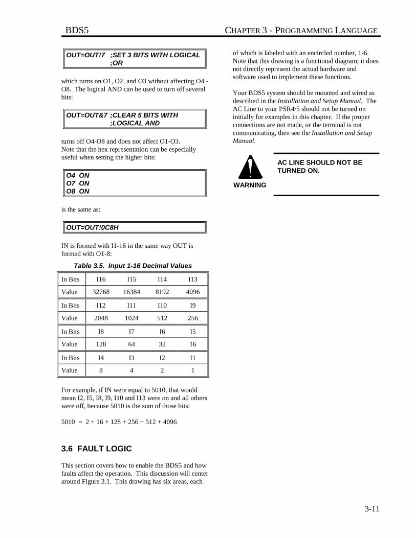
BDS5 CHAPTER 3 - PROGRAMMING LANGUAGE
3-11
OUT=OUT!7 ;SET 3 BITS WITH LOGICAL ;OR
which turns on O1, O2, and O3 without affecting O4 -O8. The logical AND can be used to turn off severalbits:
OUT=OUT&7 ;CLEAR 5 BITS WITH ;LOGICAL AND
turns off O4-O8 and does not affect O1-O3.Note that the hex representation can be especiallyuseful when setting the higher bits:
O4 ONO7 ONO8 ON
is the same as:
OUT=OUT!0C8H
IN is formed with I1-16 in the same way OUT isformed with O1-8:
Table 3.5. Input 1-16 Decimal Values
In Bits I16 I15 I14 I13
Value 32768 16384 8192 4096
In Bits I12 I11 I10 I9
Value 2048 1024 512 256
In Bits I8 I7 I6 I5
Value 128 64 32 16
In Bits I4 I3 I2 I1
Value 8 4 2 1
For example, if IN were equal to 5010, that wouldmean I2, I5, I8, I9, I10 and I13 were on and all otherswere off, because 5010 is the sum of those bits:
5010 = 2 + 16 + 128 + 256 + 512 + 4096
3.6 FAULT LOGIC
This section covers how to enable the BDS5 and howfaults affect the operation. This discussion will centeraround Figure 3.1. This drawing has six areas, each
of which is labeled with an encircled number, 1-6.Note that this drawing is a functional diagram; it doesnot directly represent the actual hardware andsoftware used to implement these functions.
Your BDS5 system should be mounted and wired asdescribed in the Installation and Setup Manual. TheAC Line to your PSR4/5 should not be turned oninitially for examples in this chapter. If the properconnections are not made, or the terminal is notcommunicating, then see the Installation and SetupManual.
AC LINE SHOULD NOT BETURNED ON.
WARNING
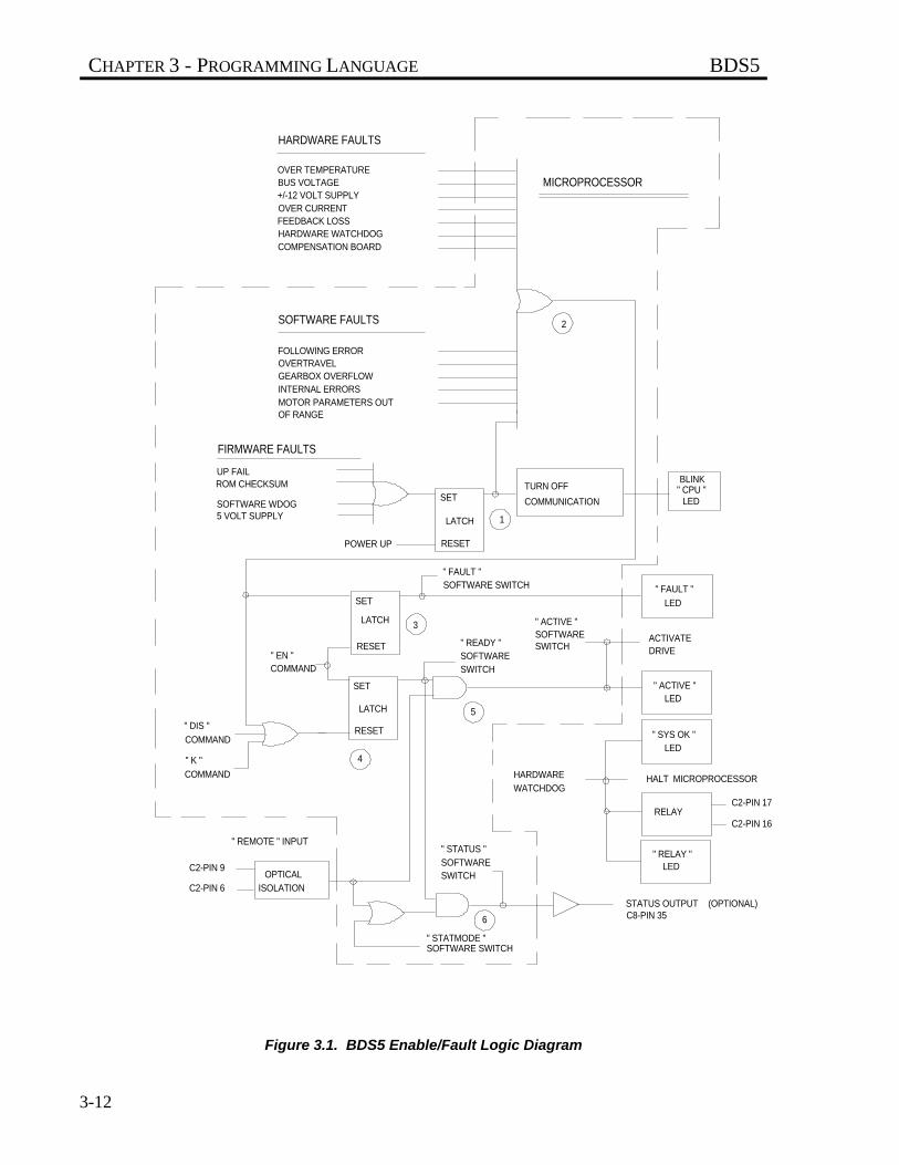
CHAPTER 3 - PROGRAMMING LANGUAGE BDS5
3-12
Figure 3.1. BDS5 Enable/Fault Logic Diagram
UP FAIL
OF RANGE
6
5
4
3
2
1
" REMOTE " INPUT
C2-PIN 6
C2-PIN 9
ISOLATIONOPTICAL
SOFTWARE SWITCH" STATMODE "
SWITCHSOFTWARE" STATUS "
C8-PIN 35(OPTIONAL)STATUS OUTPUT
LED" RELAY "
C2-PIN 16
C2-PIN 17RELAY
WATCHDOGHARDWARE HALT MICROPROCESSOR
LED" SYS OK "
LED" ACTIVE "
DRIVEACTIVATE
SWITCHSOFTWARE" ACTIVE "
SWITCHSOFTWARE" READY "
COMMAND" EN "
COMMAND
" K "
COMMAND
" DIS " RESET
SET
LATCH
LED
" FAULT "SOFTWARE SWITCH" FAULT "
RESET
SET
LATCH
RESET
SET
LATCH
LED" CPU "BLINK
COMMUNICATION
TURN OFF
5 VOLT SUPPLYSOFTWARE WDOG
ROM CHECKSUM
POWER UP
MICROPROCESSOR
FIRMWARE FAULTS
SOFTWARE FAULTS
MOTOR PARAMETERS OUTINTERNAL ERRORSGEARBOX OVERFLOWOVERTRAVELFOLLOWING ERROR
HARDWARE FAULTS
COMPENSATION BOARDHARDWARE WATCHDOGFEEDBACK LOSSOVER CURRENT+/-12 VOLT SUPPLYBUS VOLTAGEOVER TEMPERATURE
BDS5 CHAPTER 3 - PROGRAMMING LANGUAGE
3-13
3.6.1 Firmware Faults, Area 1
Area 1 shows how firmware faults are combined.Firmware faults are the most serious errors. Theyinclude checksums (to help verify computer memory),watchdogs (to help verify that the computer isrunning properly), and the 5-volt logic power supplymonitor.
These circuits are designed to watch the basicoperation of the microprocessor. They do notgenerate error messages because the detected faultaffects the microprocessor directly. Instead, they justblink the Central Processing Unit (CPU) LED.
As shown in Figure 3.1, firmware faults set a latch toturn off communications and blink the CPU LED.The CPU LED blinks in cycles consisting of 2 to 8blinks and a pause. The number of blinkscorresponds to the error number, which you can lookup in Appendix D. The only way to reset these faultsis to power-down the BDS5. These faults are seriousand you should consult the factory if they occur. Donot confuse these faults with autobauding on power-up. When autobauding, the CPU LED blinks at aconstant rate, about three times per second.
3.6.2 Fault Logic, Area 2
The large OR gate in Area 2 combines three types offaults: hardware, software, and firmware. Thecircuits that generate these faults are typical of motorcontrollers and are listed on the drawing. Thesefaults are errors that are serious enough to disable theBDS5, as described in Appendix D.
3.6.3 Fault Latch, Area 3
The latch in Area 3 turns on the FAULT LED, theFAULT software switch, and the FAULT output onConnector C8. Any fault sets this latch; you can alsowrite your program to turn it on if you detect a faultcondition. The fault latch can be reset by:
1. Turning FAULT off,2. Typing the enable command (EN), or3. Powering down the BDS5.
3.6.4 Ready Latch, Area 4
Area 4 shows the logic required to make the driveready. If there are no faults, the EN command setsthe ready latch. This turns the READY softwareswitch on. This latch is reset with the KILL (K)command, the DISABLE (DIS) command, or a fault.These turn READY off.
3.6.5 ACTIVE, Area 5
Area 5 shows that ACTIVE will be on if bothREADY and REMOTE are on. This turns on theACTIVE LED. It also allows the BDS5 to activelycontrol the motor.
REMOTE (Remote Enable) is an isolated input that isaccessed from Connector C2 on the front of the drive.You can print REMOTE with the P command. Itmust be 1 to activate the BDS5. If you cannot turnREMOTE on, see the Installation and Setup Manual.Note that some faults "hide" the value of theREMOTE input from the BDS5 microprocessor.This does not normally matter because all faults mustbe cleared before the drive will enable. If thiscondition exists, the BDS5 will print REMOTE as "-1."
3.6.6 Relay and STATUS Control,Area 6
Area 6 shows how software switch STATUS and therelay work. You can configure STATUS to indicateeither drive READY (but not necessarily ACTIVE)or drive ACTIVE. The difference is in how you wantto use STATUS. STATUS can be used for aninterlock. In this case, you want STATUS to indicatedrive ACTIVE. If the BDS5 becomes inactive forany reason (including the REMOTE input turningoff), then STATUS will turn off. As an alternative,you can use STATUS to indicate that the BDS5 isready for the REMOTE input to turn on. That is, ifREMOTE turns on, the BDS5 will be ACTIVE. Inthis case, you want STATUS to indicate driveREADY.
The software switch STATMODE controls whichstate STATUS will indicate. If STATMODE is on,then STATUS will indicate drive READY. If
CHAPTER 3 - PROGRAMMING LANGUAGE BDS5
3-14
STATMODE is off, then STATUS will indicate driveACTIVE.
The operation of STATUS is shown by the AND-gateand OR-gate in Area 6. If STATMODE is on, thenREADY will turn on STATUS through the AND-gate. If STATMODE is off, then only ACTIVE(from Area 5) will turn on STATUS through the otherleg of the OR-gate. The STATUS output on optionalConnector C8, Pin 35, is always the same as theSTATUS software switch. Note, however, that thestate of the STATUS output is undefined for 25milliseconds after power-up.
STATUS may turn on for up to25 milliseconds during power-up.
3.6.7 Motor Brake
Industrial Drives motors can be purchased with anoptional brake. The brake is fail-safe in that if nocurrent is applied, the brake is active. If you setSTATMODE to 0, you can use STATUS to controlthe brake. Then, when the BDS5 is disabled orpowered down, the brake will be active.
3.6.8 Output Relay
The relay (Connector C2, Pins 16 and 17) representsthe state of the hardware watchdog. The hardwarewatchdog makes a system more reliable because thewatchdog is independent of the microprocessor. Ifthe processor is not working, the watchdog willusually detect it (though this is not guaranteed).
On power-up, the contacts are open until the BDS5passes its power-up self tests. Then the contacts closeand the BDS5 begins normal operation. Note that ifthe BDS5 is set to autobaud on power-up, thecontacts will not close until after autobauding andestablishing communications.
One way to use the relay is to interconnect it with themain power contactor. In this case, a hardwarewatchdog fault will disconnect all power to thesystem.The SYS OK LED indicates that there is not ahardware watchdog fault. If this LED goes out, you
should remove the BDS5 from operation and contactthe factory.
3.7 DRIVE CONTROL
This section discusses several variables that you mustbe familiar with before you can control the BDS5.
3.7.1 Direction Control, DIR
DIR is a switch that controls the algebraic sign ofcommand and feedback variables. When DIR is on,clockwise position, velocity, and torque are allpositive. If DIR is off, then clockwise position,velocity, and torque are negative. DIR is turned on atpower-up.
3.7.2 Position
3.7.2.1 Position Command andFeedback, PCMD & PFBPCMD is the commanded position. It is generatedinternally from motion commands like the JOGcommand. PCMD is in position units. The standardposition units are R/D converter counts as specified inTable 3.6. PCMD is set to PFB when the BDS5 isdisabled.
PFB, the position feedback, is the actual position ofthe motor. It is updated every millisecond. PFB is inposition units. Section 3.3.5 explained how to look atPFB and watch it as the motor turns. PFB is alwaysactive, even when the BDS5 is disabled. PFB is resetto zero when the BDS5 is powered-up.
3.7.2.2 Position Error, PE & PEMAXPE is position error, sometimes referred to asfollowing error. It is the difference between PCMDand PFB. PE is zero when the BDS5 is disabled. PEis in position units.
When the magnitude of the position error exceeds thevalue stored in PEMAX, a Position Error Overflowerror is generated. This is a serious error,disabling the BDS5 immediately. Note that settingPEMAX to some value will not limit the positionerror. The position error depends on the control loopparameters and the application. Normally, you wantto set PEMAX to as low a level as will allow the
WARNING
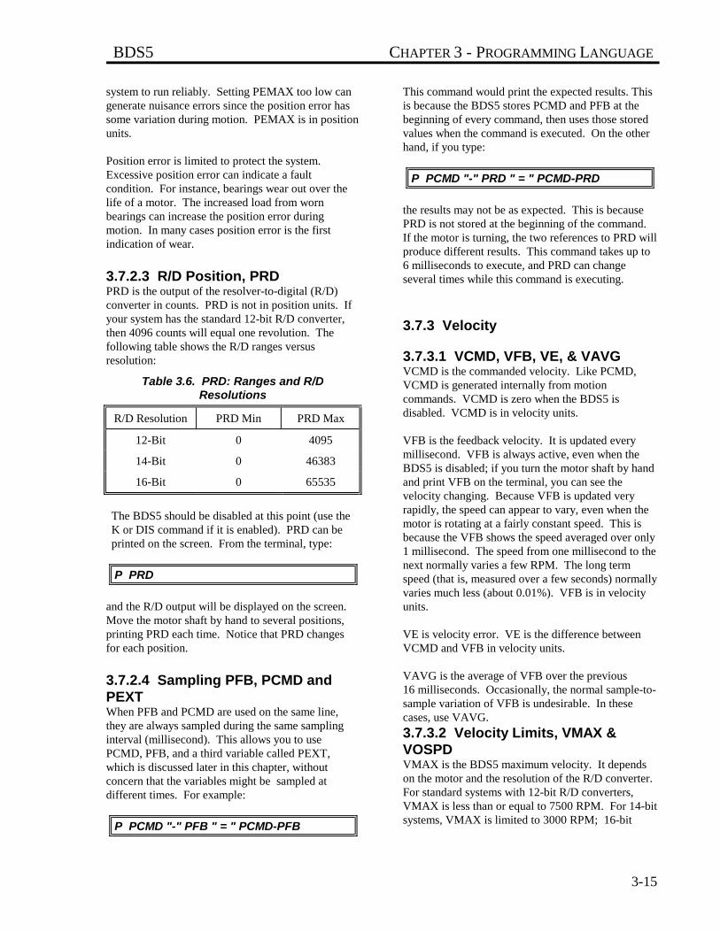
BDS5 CHAPTER 3 - PROGRAMMING LANGUAGE
3-15
system to run reliably. Setting PEMAX too low cangenerate nuisance errors since the position error hassome variation during motion. PEMAX is in positionunits.
Position error is limited to protect the system.Excessive position error can indicate a faultcondition. For instance, bearings wear out over thelife of a motor. The increased load from wornbearings can increase the position error duringmotion. In many cases position error is the firstindication of wear.
3.7.2.3 R/D Position, PRDPRD is the output of the resolver-to-digital (R/D)converter in counts. PRD is not in position units. Ifyour system has the standard 12-bit R/D converter,then 4096 counts will equal one revolution. Thefollowing table shows the R/D ranges versusresolution:
Table 3.6. PRD: Ranges and R/DResolutions
R/D Resolution PRD Min PRD Max
12-Bit 0 4095
14-Bit 0 46383
16-Bit 0 65535
The BDS5 should be disabled at this point (use theK or DIS command if it is enabled). PRD can beprinted on the screen. From the terminal, type:
P PRD
and the R/D output will be displayed on the screen.Move the motor shaft by hand to several positions,printing PRD each time. Notice that PRD changesfor each position.
3.7.2.4 Sampling PFB, PCMD andPEXTWhen PFB and PCMD are used on the same line,they are always sampled during the same samplinginterval (millisecond). This allows you to usePCMD, PFB, and a third variable called PEXT,which is discussed later in this chapter, withoutconcern that the variables might be sampled atdifferent times. For example:
P PCMD "-" PFB " = " PCMD-PFB
This command would print the expected results. Thisis because the BDS5 stores PCMD and PFB at thebeginning of every command, then uses those storedvalues when the command is executed. On the otherhand, if you type:
P PCMD "-" PRD " = " PCMD-PRD
the results may not be as expected. This is becausePRD is not stored at the beginning of the command.If the motor is turning, the two references to PRD willproduce different results. This command takes up to6 milliseconds to execute, and PRD can changeseveral times while this command is executing.
3.7.3 Velocity
3.7.3.1 VCMD, VFB, VE, & VAVGVCMD is the commanded velocity. Like PCMD,VCMD is generated internally from motioncommands. VCMD is zero when the BDS5 isdisabled. VCMD is in velocity units.
VFB is the feedback velocity. It is updated everymillisecond. VFB is always active, even when theBDS5 is disabled; if you turn the motor shaft by handand print VFB on the terminal, you can see thevelocity changing. Because VFB is updated veryrapidly, the speed can appear to vary, even when themotor is rotating at a fairly constant speed. This isbecause the VFB shows the speed averaged over only1 millisecond. The speed from one millisecond to thenext normally varies a few RPM. The long termspeed (that is, measured over a few seconds) normallyvaries much less (about 0.01%). VFB is in velocityunits.
VE is velocity error. VE is the difference betweenVCMD and VFB in velocity units.
VAVG is the average of VFB over the previous16 milliseconds. Occasionally, the normal sample-to-sample variation of VFB is undesirable. In thesecases, use VAVG.
3.7.3.2 Velocity Limits, VMAX &VOSPDVMAX is the BDS5 maximum velocity. It dependson the motor and the resolution of the R/D converter.For standard systems with 12-bit R/D converters,VMAX is less than or equal to 7500 RPM. For 14-bitsystems, VMAX is limited to 3000 RPM; 16-bit
CHAPTER 3 - PROGRAMMING LANGUAGE BDS5
3-16
systems are limited to 750 RPM. VMAX is set at thefactory. VMAX is in velocity units.
VOSPD is the maximum velocity for your system.The BDS5 generates an overspeed fault if VFB isever greater than VOSPD. You can set VOSPD toany level below 1.2_VMAX. This allows you to limitthe speed of your system to any level below VMAX.When an overspeed occurs, the BDS5 is disabledimmediately.
You should set VOSPD to at least 10% or 15% aboveyour system's maximum speed to avoid nuisanceoverspeed faults. You can change VOSPD only whenthe BDS5 is disabled. VOSPD is in velocity units.
3.7.4 Current
3.7.4.1 Motor Current, ICMD & IMONICMD is commanded motor current. ICMD, likePCMD and VCMD, is generated internally frommotion commands. ICMD is in current units.IMON is the output of the current monitor circuit, andit represents the magnitude of the motor current.IMON is always positive, and it is in current units.IMON is the digital conversion of the analog signalI_Monitor on Connector C2.
3.7.4.2 Current Limits, IMAX & ILIMIMAX is the maximum level of current that the BDS5can output. It is set at the factory; its value dependson both the BDS5 rating and on the motor. IMAX isin current units.ILIM limits the peak of ICMD, the commandedcurrent. You can set ILIM to any level below IMAX.This allows you to limit the current below themaximum level that the BDS5 can output. You canset ILIM at any time, even during profile moves.ILIM is in current units.
3.7.5 Enabling the Position Loopwith PL
PL is a switch that controls the position loop. If PL ison, then the position loop is enabled. If PL is off,then it is disabled, and the BDS5 is running as avelocity loop. Most positioning applications run withPL on. See later in this chapter for more informationabout the position loops. PL turns on at power-up.You can change PL at any time.
3.7.6 Controlling the Velocity Loopwith PROP
PROP is a switch that controls the integration sectionof the velocity loop. If PROP is on, then the velocityloop is proportional and the integral is disabled. IfPROP is off, then the velocity loop is fullyintegrating. PROP is turned off at power-up. Youcan change PROP at any time. Most applications runwith PROP off. Sometimes proportional velocityloops are used during set-up. See later in this chapterfor more information.
3.7.7 Enabling the BDS5
THE BDS5 WILL BE ENABLEDAND THE MOTOR WILLTURN. SECURE THE MOTOR.
At this point you should turn REMOTE on asdescribed in the Installation and Setup Manual.Type the following command to print the state of theREMOTE input:
P REMOTE ;REMOTE SHOULD BE 1
SHOCK HAZARD!
Large voltages from the ACLine and the DC Bus cancause injury. Ensure that thewiring is correct. See theInstallation and Setup Manual.
WARNING
WARNING
BDS5 CHAPTER 3 - PROGRAMMING LANGUAGE
3-17
THE MOTOR MAY MOVEUNEXPECTEDLY!
BE PREPARED TO DISABLETHE BDS5!
You should have completed"Initial Check-Out" in theInstallation and Setup Manual.If not, return to the Installationand Setup Manual andcomplete that section.
This section will enable theBDS5. The system may beunstable. The motor maybegin oscillating or run away.Be prepared to disable theBDS5 quickly. You candisable the BDS5 by turningoff (opening the contacts of)LIMIT or REMOTE.
To enable the BDS5, turn on the AC Line and enterthe enable command:
EN
The BDS5 should turn on. To verify that it did turnon, print ACTIVE. If ACTIVE is 1, then the BDS5 isenabled; otherwise, it is disabled.
To disable the BDS5, enter the disable command:
DIS
As an alternative, you can disable the BDS5 with theone-letter kill command by typing:
K
ENABLE, DISABLE, and KILL are examples ofBDS5 commands. All of the BDS5 commands arelisted, with their formats and syntax, in Appendix C.
Appendix C is a quickreference for all BDS5commands.
3.7.8 Limiting Motor Current
The following section discusses how the BDS5 limitsmotor current.
3.7.8.1 Continuous Current, ICONTThe BDS5 limits current in two ways: peak current islimited according to the variable ILIM, which wasdiscussed earlier in this chapter; continuous (that is,average) current is limited according to the variableICONT. The software that limits the time that motorcurrent is allowed to be above ICONT is calledfoldback, since the current is gradually folded back toICONT. ICONT is dependent on the BDS5 ratingand on the motor; ICONT is set at the factory, and itis in current units.
Most BDS5 systems have about 2:1 peak tocontinuous rating. Generally, ILIM is 100% of themaximum current and ICONT is about 50%. Thepurpose of the foldback software is to allow theoutput current to go above ICONT for a short time(generally 2-3 seconds) while still protecting theBDS5 from overheating.
3.7.8.2 Foldback Current, IFOLDThere are two current limits: ILIM and IFOLD.ICMD (the commanded current) is limited by eitherILIM or IFOLD, whichever is less. You can set ILIMbut you cannot set IFOLD; IFOLD is controlled bythe foldback software. IFOLD depends on threethings: ICONT (the continuous current rating of theBDS5), IMON (the current monitor), and time.
When the BDS5 is disabled, IFOLD is set to somevalue well above maximum current (IMAX), andthus, well above ILIM. Since current is limited by thelesser of ILIM and IFOLD, IFOLD has no effectunder this condition. If IMON, the output current,stays below ICONT, then IFOLD remains at itsoriginal, high value. If IMON is greater than ICONT,IFOLD gradually decreases. The greater IMON is,the faster IFOLD decreases. Since IFOLD starts outwell above ILIM, initially this has no effect.However, when IFOLD is less than ILIM, IFOLDwill limit the current. This is called "being infoldback." If IMON remains (on average) aboveICONT long enough, IFOLD will decrease all theway to ICONT, forcing IMON eventually to becomeless than or equal to ICONT. Typically, it takes atleast 2 to 3 seconds for IFOLD to decrease from itsoriginal high value to IMAX. At this point, the BDS5is in foldback. It takes an additional 10 seconds toreduce IFOLD from IMAX to ICONT.
WARNING
NOTE
CHAPTER 3 - PROGRAMMING LANGUAGE BDS5
3-18
If IMON is reduced below ICONT, then IFOLD willincrease; the smaller IMON is, the faster IFOLD willincrease. If IMON remains below ICONT longenough, IFOLD will return to its original high value.
3.7.8.3 Monitoring Current LimitsThere are two switches that provide information oncurrent limiting. SAT is a switch that is on if thecurrent is limited by either ILIM or IFOLD. FOLD isa switch that is on if the current is limited by IFOLDonly.
The operation of the foldback software is as follows:
If... IMON > ICONT then... IFOLD decreasesIf... IMON < ICONT then... IFOLD increases
If... IFOLD < ILIM then... FOLD is onIf... IFOLD > ILIM then... FOLD is off
If... ICMD = ILIM or IFOLD then... SAT is onIf... ICMD < ILIM and IFOLD then... SAT is off
ICMD is never > ILIMICMD is never > IFOLD
In some cases, it may be desirable to know whenfoldback is just about to limit current below ILIM.You can use IFOLD for this; if IFOLD is less thanILIM, the foldback software is limiting current. IfIFOLD is larger than ILIM, but only by 5% or 10%,then foldback software is about to limit current.
3.8 MOTION COMMANDS
This section discusses how to control motion usingthe BDS5. Basic motion commands are describedfirst. Later sections discuss advanced motion controlincluding BDS5 Macro Moves, electronic gearbox,and synchronizing motion.
3.8.1 Basic Motion Commands
3.8.1.1 AMAX, ACC, & DECThe BDS5 controls acceleration with three variables:AMAX, ACC, and DEC.
AMAX is the maximum acceleration allowed foralmost all motion commands. The only exception iselectronic gearbox. AMAX is the upper limit for thenormal acceleration rates, ACC and DEC. AMAXshould always be set below the acceleration level thatcan damage your machine. Errors which stop motionwill decelerate the motor at AMAX; therefore, yourmachine is subject to deceleration rates of AMAX atany time. AMAX is in acceleration units, which areRPM/second as a default. AMAX can be changedonly when the BDS5 is disabled.
Set AMAX below themaximum acceleration ratethat your machine canexperience without damage.
ACC is the acceleration rate for most moves. ACC isin acceleration units. ACC can be changed at anytime, although it must be less than AMAX.Attempting to set ACC to a value greater than AMAXwill generate an error.
DEC is the deceleration rate for most moves. DEC isalso in acceleration units. DEC can be changed atany time. Attempting to set DEC to a value greaterthan AMAX will generate an error.
3.8.1.2 EN, STOP, & LIMITSBefore any motion can take place, the BDS5 must beenabled. Type:
EN
WARNING
BDS5 CHAPTER 3 - PROGRAMMING LANGUAGE
3-19
3.8.1.3 Enabling Motion with MOTIONMOTION is a hardware input that enables or inhibitsmotion. If MOTION is on, motion is enabled; ifMOTION is off, motion is inhibited. You can enablethe BDS5 if MOTION is off, but commanding motionwill generate an error. If you do not need to connectMOTION for your application, you must hardwireMOTION on. See the Installation and Setup Manualfor instructions on how to hardwire MOTION.Before continuing, make sure that MOTION is on.Type the following command to print the state of theMOTION input:
P MOTION ;MOTION SHOULD BE 1
Many times, the MOTION input is controlled by thenormally-closed contacts of a push button. This pushbutton is often called "STOP," since pressing thebutton opens the MOTION input and forces themotor to stop. Emergency Stop should not beimplemented with the MOTION input. EmergencyStop should be connected to a contactor that removespower from the system. This is because anemergency stop, which is for safety, should notdepend on BDS5 functions to operate properly.
Do not use MOTION or anyother BDS5 input forEmergency Stop. WhenEmergency Stop is activated,it should directly removepower from the system.
3.8.1.4 STOP (S) CommandAny motion can be stopped using S, the STOPcommand. S has no parameters. S decelerates themotor at AMAX and terminates all motioncommands. The S command does not disable theBDS5.
Normally, the STOP command should only be givenfrom the terminal or from the program in response toan error condition. A better method for stoppingmotion from the program under normal circumstancesis:
J 0 ;JOG TO 0 SPEED--STOP MOTION ;AT DEC, NOT AMAX
The J 0 command also stops motion from any mode,much like the STOP command. Unlike S, J 0decelerates at the rate specified by DEC.
The S command should notbe used as a part of normalprogram operation. Use J 0.
At any time, when motion is commanded, if theMOTION input turns off, an error is generated, andall motion is stopped, as if the STOP command weregiven. Also, any errors with a severity of 2 or 3 willstop motion in a straight line deceleration at a rate ofAMAX. Appendix D lists all errors and theirseverity.
3.8.1.5 STOP and BREAK withControl X (^X)You can execute a stop and break command with thecontrol-X (^X) character. Control-X or ^X meansthat you hold down the control key (Ctrl) on yourterminal (or IBM-PC) and press the X key. This hasthe same effect as typing B, then S from yourterminal.
3.8.2 Limiting Motion
The BDS5 allows you to limit motion with bothSoftware and Hardware Travel Limits.
3.8.2.1 Hardware Travel LimitsHardware Travel Limits limit the range of motion. Ifyou have an application with boundaries whichshould never be crossed, you are encouraged to usethe Hardware Travel Limits with limit switches.
Exceeding Hardware Travel Limits is a more severeerror than exceeding Software Travel Limits. TheBDS5 assumes that Software Travel Limits shouldcatch normal overtravel conditions and that aHardware Travel Limit indicates a serious problem.Hardware Travel Limits disable the BDS5 rather thanjust stopping motion, as the software limits do. Thismeans that the motor must be backed away from thelimit by hand.
The Installation and Setup Manual discusses how towire LIMIT. Usually, two limit switches are wired
WARNING
NOTE
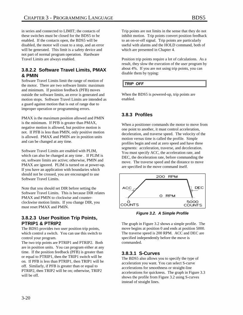
CHAPTER 3 - PROGRAMMING LANGUAGE BDS5
3-20
in series and connected to LIMIT; the contacts ofthese switches must be closed for the BDS5 to beenabled. If the contacts open, the BDS5 will bedisabled, the motor will coast to a stop, and an errorwill be generated. This limit is a safety device andnot part of normal program operation. HardwareTravel Limits are always enabled.
3.8.2.2 Software Travel Limits, PMAX& PMINSoftware Travel Limits limit the range of motion ofthe motor. There are two software limits: maximumand minimum. If position feedback (PFB) movesoutside the software limits, an error is generated andmotion stops. Software Travel Limits are intended asa guard against motion that is out of range due toimproper operation or programming errors.
PMAX is the maximum position allowed and PMINis the minimum. If PFB is greater than PMAX,negative motion is allowed, but positive motion isnot. If PFB is less than PMIN, only positive motionis allowed. PMAX and PMIN are in position unitsand can be changed at any time.
Software Travel Limits are enabled with PLIM,which can also be changed at any time . If PLIM ison, software limits are active; otherwise, PMIN andPMAX are ignored. PLIM is turned on at power-up.If you have an application with boundaries whichshould not be crossed, you are encouraged to useSoftware Travel Limits.
Note that you should set DIR before setting theSoftware Travel Limits. This is because DIR relatesPMAX and PMIN to clockwise and counter-clockwise motion limits. If you change DIR, youmust reset PMAX and PMIN.
3.8.2.3 User Position Trip Points,PTRIP1 & PTRIP2The BDS5 provides two user position trip points,which control a switch. You can use this switch tocontrol your program.The two trip points are PTRIP1 and PTRIP2. Bothare in position units. You can program either at anytime. If the position feedback (PFB) is greater thanor equal to PTRIP1, then the TRIP1 switch will beon. If PFB is less than PTRIP1, then TRIP1 will beoff. Similarly, if PFB is greater than or equal toPTRIP2, then TRIP2 will be on; otherwise, TRIP2will be off.
Trip points are not limits in the sense that they do notinhibit motion. Trip points convert position feedbackto an on-or-off signal. Trip points are particularlyuseful with alarms and the HOLD command, both ofwhich are presented in Chapter 4.
Position trip points require a lot of calculations. As aresult, they slow the execution of the user program byabout 4%. If you are not using trip points, you candisable them by typing:
TRIP OFF
When the BDS5 is powered-up, trip points areenabled.
3.8.3 Profiles
When a positioner commands the motor to move fromone point to another, it must control acceleration,deceleration, and traverse speed. The velocity of themotion versus time is called the profile. Simpleprofiles begin and end at zero speed and have threesegments: acceleration, traverse, and deceleration.You must specify ACC, the acceleration rate, andDEC, the deceleration rate, before commanding themove. The traverse speed and the distance to moveare specified in the move command itself.
Figure 3.2. A Simple Profile
The graph in Figure 3.2 shows a simple profile. Themove begins at position 0 and ends at position 5000.The traverse speed is 200 RPM. ACC and DEC arespecified independently before the move iscommanded.
3.8.3.1 S-CurvesThe BDS5 also allows you to specify the type ofacceleration you want. You can select S-curveaccelerations for smoothness or straight-lineaccelerations for quickness. The graph in Figure 3.3shows the profile from Figure 3.2 using S-curvesinstead of straight lines.

BDS5 CHAPTER 3 - PROGRAMMING LANGUAGE
3-21
Figure 3.3. S-Curve Profile
Notice that ACC and DEC are still independent.Notice also that they specify the average acceleration,not the peak. Since S-curves reduce the accelerationrate at the endpoints of the acceleration, theacceleration rate in the middle must increase.Typically, when you switch to S-curves, you mustreduce ACC and DEC to stay within the ratings of themotor. However, since S-curves reduce overshoot,you may find that you increase the overallacceleration rate when you use them.
You may need to reduce ACCand DEC when usingS-curves.
For some applications, S-curves can reduce theaverage acceleration too much; in others, straight lineacceleration produces motion that jerks the motorexcessively. The BDS5 provides different levels ofS-curves allowing you to make the trade-off. Thereare five levels that are selected by setting the variableSCRV to either 1, 2, 3, 4, or 5. For more informationon S-curves, see Industrial Drives application noteB101, "Acceleration Profiles."
Table 3.7. S-Curve Acceleration Chart
For this acceleration... Set SCRV to...
Straight-Line 1
Modified Polynomial 2
Polynomial 3
Modified Sinusoid 4
Sinusoid 5
3.8.3.2 Move Absolute (MA)CommandThere are two kinds of simple moves: absolute andincremental. With absolute moves, you specify theend position; with incremental moves, you specify thetotal distance of the move.
The MA command allows you to command absolutemoves by specifying the end position. ACC, DEC,and SCRV are all in effect for MA moves. As anoption, you can specify the traverse speed.For example:
MA 50000 1000
moves to position 50000 at a peak speed of 1000RPM.
The variable VDEFAULT is the default velocity forMA and MI commands. If you enter an MAcommand without specifying a speed, the traversespeed will be VDEFAULT. For example,
MA 100000
would move the motor so that PFB is equal to100000; it would assume a traverse speed ofVDEFAULT. If you do not specify the speed in MAcommands, it reduces the execution time. Thisnormally means less delay between when thecommand is entered and when the motor beginsturning. Appendix F lists the execution times of afew simple moves.
Not specifying the speed inMA commands reducesexecution time.
NOTE
NOTE
CHAPTER 3 - PROGRAMMING LANGUAGE BDS5
3-22
3.8.3.3 Move Incremental (MI)CommandThe MI command allows you to commandincremental moves by specifying the total distance ofthe move. ACC, DEC, and SCRV are all in effect forMI moves. Like MA, if you enter an MI commandwithout specifying a speed, the traverse speed will beVDEFAULT.
For example:
MI 5000 200
causes the motor to move 5000 counts at a peakspeed of 200 RPM. The profiles that were shownearlier as "A SIMPLE PROFILE" or "S-CURVEPROFILE" could have been generated from thisexample.
As with the MA command,
MI 25000
causes the motor to move 25000 counts, with thepeak speed at the speed VDEFAULT.For both the MI and MA commands, not specifyingspeed reduces execution time and program size.
Not specifying the speed in MIcommands reduces executiontime.
3.8.3.4 Incremental Move Example
SHOCK HAZARD!
Large voltages from the ACline and the DC bus can causeinjury. Wire the BDS5 asdescribed in the Installationand Setup Manual.
THE MOTOR MAY MOVEUNEXPECTEDLY!
BE PREPARED TO DISABLETHE BDS5!
You should have completed"Initial Check-Out" in theInstallation and Setup Manual.If not, return to the Installationand Setup Manual andcomplete that section.
This section will enable theBDS5. The system may beunstable. The motor maybegin oscillating or run away.Be prepared to disable theBDS5 quickly. You candisable the BDS5 by turningoff (opening the contacts of)LIMIT or REMOTE.
Turn on the AC line voltage. Type in the followingexample:
ENACC 1000DEC 1000MI 4000 100
This should cause the motor to rotate 4000 countswith a traverse speed of 100 RPM. With the nextexample the motor will repeat the move. Type:
VDEFAULT = 100MI 4000
Notice that the motor again moves 4000 counts.Now, to bring the motor back to the original position,type:
MI -8000
3.8.3.5 Profile LimitsWith both the MA and MI commands, if the traversespeed cannot be reached because ACC or DEC is toosmall for the specified move, then the BDS5 reducesthe maximum speed so that the move, for all practicalpurposes, is triangular. Actually, there is a very short
WARNING
WARNING
NOTE
BDS5 CHAPTER 3 - PROGRAMMING LANGUAGE
3-23
(less than 5 milliseconds) traverse segment so that themove still has three segments.
The maximum time for an entire move is not limited.However, the time for each acceleration ordeceleration is limited to 30 seconds. If theacceleration rate is so low that this limit is exceeded,then the BDS5 generates an error explaining thateither ACC or DEC is too low. This error is issuedbefore the motion command begins. In this case ACCor DEC must be increased, or the peak speed of themove must be decreased.
3.8.3.6 Multiple Profile CommandsThe BDS5 allows one succeeding move to becalculated while the present move is being executed.This reduces inter-index delay, the delay betweensuccessive moves, almost to zero. When you arecommanding motion from the Interactive mode (-->),be careful not to type in two move commands whileanother is executing (motion from the originalcommand is not complete). This generates an error.If you are commanding motion from your program,the BDS5 automatically pauses before calculating athird motion profile, thus stopping this error fromoccurring.
3.8.3.7 Profile Final Position, PFNLIf you want to keep track of the end position of thepresent move, the variable PFNL (Position Final) isprovided. This variable contains the final position ofa move. The variable can be used to compute thedistance remaining by combining it with PFB(Position Feedback):
P "DISTANCE TO GO " PFNL-PFB;PRINT THE AMOUNT OF;POSITION TO GO TO;FINISH THE MOVE
3.8.4 JOG (J) Command
This section describes J, the JOG command. Joggingis useful when you want to command motion withoutposition endpoints. For example,
J 500
causes the motor to rotate at 500 RPM indefinitely.Jogs are useful for machine set up and testing.ACC and DEC are in effect with Jogs, as is SCRV.Software and Hardware Travel Limits are also ineffect. Jog is the only move command that can cause
motion to change direction without stopping first.However, since changing directions involves bothacceleration and deceleration, Jog commands thatchange direction of rotation use ACC or DEC,whichever is lower. Jog commands should be usedwith caution, since motion continues indefinitely.
3.8.5 NORMALIZE (NORM) Command
NORM, the NORMALIZE command, is required ifyou want to reset the BDS5 position feedback, PFB.Often, you may want to set the position feedback tosome known value. For example, on power-up theposition feedback is set to zero. After a homingsequence, you may need to reset the position register.This is done using NORM, the NORMALIZEcommand. For example,
NORM 10000
sets PFB (position feedback) as well as PCMD(POSITION command) to 10000 in position units.As an alternative, you can enter:
PFB=10000
Setting PFB has the same effect as the NORMcommand. Use whichever you think makes yourprogram easier to understand.
Now, type in:
P PFB
Now, normalize the position to 1000 with:
NORM 1000
Again, print PFB:
P PFB
and see that it is now 1000. The NORMALIZEcommand cannot be used when either GEAR is on, orwhen motion is commanded from MA, MI, or anyother motion command.
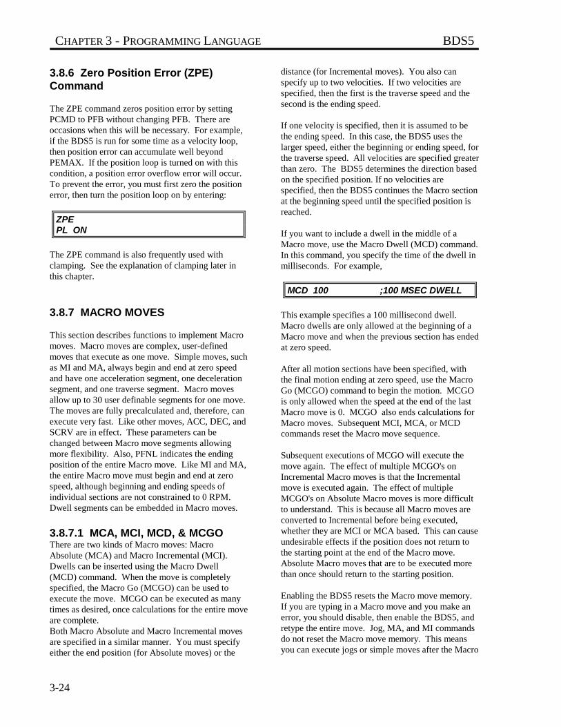
CHAPTER 3 - PROGRAMMING LANGUAGE BDS5
3-24
3.8.6 Zero Position Error (ZPE)Command
The ZPE command zeros position error by settingPCMD to PFB without changing PFB. There areoccasions when this will be necessary. For example,if the BDS5 is run for some time as a velocity loop,then position error can accumulate well beyondPEMAX. If the position loop is turned on with thiscondition, a position error overflow error will occur.To prevent the error, you must first zero the positionerror, then turn the position loop on by entering:
ZPEPL ON
The ZPE command is also frequently used withclamping. See the explanation of clamping later inthis chapter.
3.8.7 MACRO MOVES
This section describes functions to implement Macromoves. Macro moves are complex, user-definedmoves that execute as one move. Simple moves, suchas MI and MA, always begin and end at zero speedand have one acceleration segment, one decelerationsegment, and one traverse segment. Macro movesallow up to 30 user definable segments for one move.The moves are fully precalculated and, therefore, canexecute very fast. Like other moves, ACC, DEC, andSCRV are in effect. These parameters can bechanged between Macro move segments allowingmore flexibility. Also, PFNL indicates the endingposition of the entire Macro move. Like MI and MA,the entire Macro move must begin and end at zerospeed, although beginning and ending speeds ofindividual sections are not constrained to 0 RPM.Dwell segments can be embedded in Macro moves.
3.8.7.1 MCA, MCI, MCD, & MCGOThere are two kinds of Macro moves: MacroAbsolute (MCA) and Macro Incremental (MCI).Dwells can be inserted using the Macro Dwell(MCD) command. When the move is completelyspecified, the Macro Go (MCGO) can be used toexecute the move. MCGO can be executed as manytimes as desired, once calculations for the entire moveare complete.Both Macro Absolute and Macro Incremental movesare specified in a similar manner. You must specifyeither the end position (for Absolute moves) or the
distance (for Incremental moves). You also canspecify up to two velocities. If two velocities arespecified, then the first is the traverse speed and thesecond is the ending speed.
If one velocity is specified, then it is assumed to bethe ending speed. In this case, the BDS5 uses thelarger speed, either the beginning or ending speed, forthe traverse speed. All velocities are specified greaterthan zero. The BDS5 determines the direction basedon the specified position. If no velocities arespecified, then the BDS5 continues the Macro sectionat the beginning speed until the specified position isreached.
If you want to include a dwell in the middle of aMacro move, use the Macro Dwell (MCD) command.In this command, you specify the time of the dwell inmilliseconds. For example,
MCD 100 ;100 MSEC DWELL
This example specifies a 100 millisecond dwell.Macro dwells are only allowed at the beginning of aMacro move and when the previous section has endedat zero speed.
After all motion sections have been specified, withthe final motion ending at zero speed, use the MacroGo (MCGO) command to begin the motion. MCGOis only allowed when the speed at the end of the lastMacro move is 0. MCGO also ends calculations forMacro moves. Subsequent MCI, MCA, or MCDcommands reset the Macro move sequence.
Subsequent executions of MCGO will execute themove again. The effect of multiple MCGO's onIncremental Macro moves is that the Incrementalmove is executed again. The effect of multipleMCGO's on Absolute Macro moves is more difficultto understand. This is because all Macro moves areconverted to Incremental before being executed,whether they are MCI or MCA based. This can causeundesirable effects if the position does not return tothe starting point at the end of the Macro move.Absolute Macro moves that are to be executed morethan once should return to the starting position.
Enabling the BDS5 resets the Macro move memory.If you are typing in a Macro move and you make anerror, you should disable, then enable the BDS5, andretype the entire move. Jog, MA, and MI commandsdo not reset the Macro move memory. This meansyou can execute jogs or simple moves after the Macro
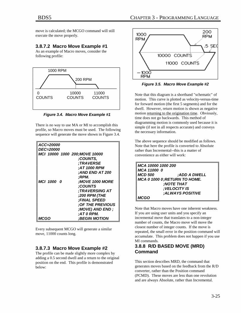
BDS5 CHAPTER 3 - PROGRAMMING LANGUAGE
3-25
move is calculated; the MCGO command will stillexecute the move properly.
3.8.7.2 Macro Move Example #1As an example of Macro moves, consider thefollowing profile:
Figure 3.4. Macro Move Example #1
There is no way to use MA or MI to accomplish thisprofile, so Macro moves must be used. The followingsequence will generate the move shown in Figure 3.4.
ACC=20000DEC=20000MCI 10000 1000 200;MOVE 10000
;COUNTS, ;TRAVERSE;AT 1000 RPM;AND END AT 200 ;RPM.
MCI 1000 0 ;MOVE 1000 MORE ;COUNTS;TRAVERSING AT ;200 RPM (THE ;FINAL SPEED ;OF THE PREVIOUS ;MOVE) AND END ;;AT 0 RPM.
MCGO ;BEGIN MOTION
Every subsequent MCGO will generate a similarmove, 11000 counts long.
3.8.7.3 Macro Move Example #2The profile can be made slightly more complex byadding a 0.5 second dwell and a return to the originalposition on the end. This profile is demonstratedbelow:
Figure 3.5. Macro Move Example #2
Note that this diagram is a shorthand "schematic" ofmotion. This curve is plotted as velocity-versus-timefor forward motion (the first 5 segments) and for thedwell. However, return motion is shown as negativemotion returning to the origination time. Obviously,time does not go backwards. This method ofdiagramming motion is commonly used because it issimple (if not in all respects accurate) and conveysthe necessary information.
The above sequence should be modified as follows.Note that here the profile is converted to Absoluterather than Incremental--this is a matter ofconvenience as either will work:
MCA 10000 1000 200MCA 11000 0MCD 500 ;ADD A DWELLMCA 0 1000 0;RETURN TO HOME.
;NOTE THAT;VELOCITY IS;ALWAYS POSITIVE
MCGO
Note that Macro moves have one inherent weakness.If you are using user units and you specify anincremental move that translates to a non-integernumber of counts, the Macro move will move theclosest number of integer counts. If the move isrepeated, the small error in the position command willaccumulate. This problem does not happen if you useMI commands.
3.8.8 R/D BASED MOVE (MRD)Command
This section describes MRD, the command thatgenerates moves based on the feedback from the R/Dconverter, rather than the Position command(PCMD). These moves are less than one revolutionand are always Absolute, rather than Incremental.
1000 RPM
200 RPM
0 10000 11000 COUNTS COUNTS COUNTS
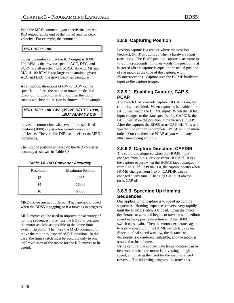
CHAPTER 3 - PROGRAMMING LANGUAGE BDS5
3-26
With the MRD command, you specify the desiredR/D output (at the end of the move) and the peakvelocity. For example, the command:
MRD 1000 100
moves the motor so that the R/D output is 1000.100 RPM is the traverse speed. ACC, DEC, andSCRV are all in effect with MRD. As with MI andMA, if 100 RPM is too large to be attained givenACC and DEC, the move becomes triangular.
As an option, directions of CW or CCW can bespecified to force the motor to rotate the desireddirection. If direction is left out, then the motorrotates whichever direction is shortest. For example:
MRD 1000 100 CW ;MOVE R/D TO 1000, ;BUT ALWAYS CW
moves the motor clockwise, even if the specifiedposition (1000) is just a few counts counter-clockwise. The variable DIR has no effect on MRDcommands.
The limit of position is based on the R/D converteraccuracy as shown in Table 3.8.
Table 3.8 R/D Converter Accuracy
Resolution Maximum Position
12 4095
14 16383
16 65535
MRD moves are not buffered. They are not allowedwhen the BDS5 is jogging or if a move is in progress.
MRD moves can be used to improve the accuracy ofhoming sequences. First, use the BDS5 to positionthe motor as close as possible to the home limitswitch trip point. Then, use the MRD command tomove the motor to a specified R/D position. In thiscase, the limit switch must be accurate only to one-half revolution of the motor for the R/D moves to beuseful.
3.8.9 Capturing Position
Position capture is a feature where the positionfeedback (PFB) is captured when a hardware inputtransitions. The BDS5 position capture is accurate to+/-25 microseconds. In other words, the position thatis stored after a capture is equal to the actual positionof the motor at the time of the capture, within25 microseconds. Capture uses the HOME hardwareinput as the capture trigger.
3.8.9.1 Enabling Capture, CAP &PCAPThe switch CAP controls capture. If CAP is on, thencapturing is enabled. When capturing is enabled, theBDS5 will watch the HOME input. When the HOMEinput changes to the state specified by CAPDIR, theBDS5 will store the position in the variable PCAP.After the capture, the BDS5 turns CAP off. This tellsyou that the capture is complete. PCAP is in positionunits. You can then use PCAP as you would anyother monitoring variable.
3.8.9.2 Capture Direction, CAPDIRThe capture is triggered when the HOME inputchanges from 0 to 1, or vice versa. If CAPDIR is 1,the capture occurs when the HOME input changesfrom 0 to 1. If CAPDIR is 0, the capture occurs whenHOME changes from 1 to 0. CAPDIR can bechanged at any time. Changing CAPDIR alwaysturns CAP off.
3.8.9.3 Speeding Up HomingSequencesOne application of capture is to speed up homingsequences. Homing sequences traverse very rapidlyuntil the HOME switch is tripped. Then the motordecelerates to zero and begins to traverse at a mediumspeed in the opposite direction until the HOMEswitch trips again. Then the motor decelerates againto a slow speed until the HOME switch trips again.Since the final speed was low, the distance todecelerate is considered negligible, and the motor isassumed to be at home.Using capture, the approximate home location can bedetermined when the motor is traversing at highspeed, eliminating the need for the medium speedtraverse. The following program illustrates this.
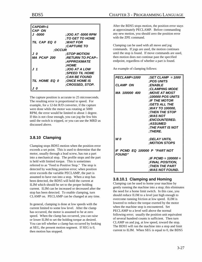
BDS5 CHAPTER 3 - PROGRAMMING LANGUAGE
3-27
CAPDIR=1CAP ONJ -5000 ;JOG AT -5000 RPM
;TO GET TO HOMETIL CAP EQ 0 ;WAIT FOR
;CAPTURE TO ;OCCUR
J 0 ;STOP MOTIONMA PCAP 200 ;RETURN TO PCAP--
;APPROXIMATE ;HOME
J 1 ;JOG AT A LOW;SPEED TIL HOME ;CAN BE FOUND
TIL HOME EQ 0 ;ONCE HOME IS ;CROSSED, STOP.
J 0
The capture position is accurate to 25 microseconds.The resulting error is proportional to speed. Forexample, for a 12-bit R/D converter, if the capturewere done while the motor was rotating at 5000RPM, the error would be limited to about 1 degree.If this is not close enough, you can jog the few bitsuntil the switch is tripped, or you can use the MRD asdiscussed above.
3.8.10 Clamping
Clamping stops BDS5 motion when the position errorexceeds a set point. This is used to determine that themotor, usually through a lead screw, has run a partinto a mechanical stop. The profile stops and the partis held with limited torque. This is sometimesreferred to as "Feed to Positive Stop." The stop isdetected by watching position error; when positionerror exceeds the variable PECLAMP, the part isassumed to have run into a stop. When a stop hasbeen detected, the BDS5 will hold the current atILIM which should be set to the proper holdingcurrent. ILIM can be increased or decreased after thestop has been detected. To enable clamping, turnCLAMP on. PECLAMP can be changed at any time.
In general, clamping is done at low speeds with thecurrent limited to some low level. After the clamphas occurred, the motor is assumed to be at zerospeed. When the clamp has occurred, you can raiseor lower ILIM to set the holding torque as desired.You can tell whether a clamp has occurred by lookingat SEG, the present motion segment. If SEG is 0,then motion has stopped.
After the BDS5 stops motion, the position error staysat approximately PECLAMP. Before commandingany new motion, you should zero the position errorwith the ZPE command.
Clamping can be used with all move and jogcommands. If jogs are used, the motion continuesuntil the stop is found. If move commands are used,then motion does not continue past the specifiedendpoint, regardless of whether a part is found.
An example of clamping follows:
PECLAMP=1000 ;SET CLAMP = 1000 ;POS UNITS
CLAMP ON ;ENABLE ;CLAMPING MODE
MA 100000 400 ;MOVE AT MOST ;100000 POS UNITS;IF THE MOTOR ;GETS ALL THE ;WAY TO 100000, ;THEN THE STOP ;WAS NOT ;ENCOUNTERED. ;ASSUMED;THE PART IS NOT ;THERE.
W 0 ;DELAY UNTIL ;MOTION STOPS
IF PCMD EQ 100000 P "PART NOTFOUND"
;IF PCMD = 100000 = ;FINAL POSITION,;THEN THE PART ;WAS NOT FOUND.
3.8.10.1 Clamping and HomingClamping can be used to home your machine bygently running the machine into a stop; this eliminatesthe need for a home limit switch. In this case, youshould reduce ILIM to a level just high enough toovercome running friction at low speed. ILIM islowered to reduce the torque exerted by the motorwhen the machine stop is encountered. SetPECLAMP to a level well above the normalfollowing error; usually the position unit equivalentof several hundred counts is sufficient. Then turnCLAMP on and jog, at low speed, toward the stop.The BDS5 will run the machine into a stop and limitcurrent to ILIM. When SEG is equal to 0, the BDS5
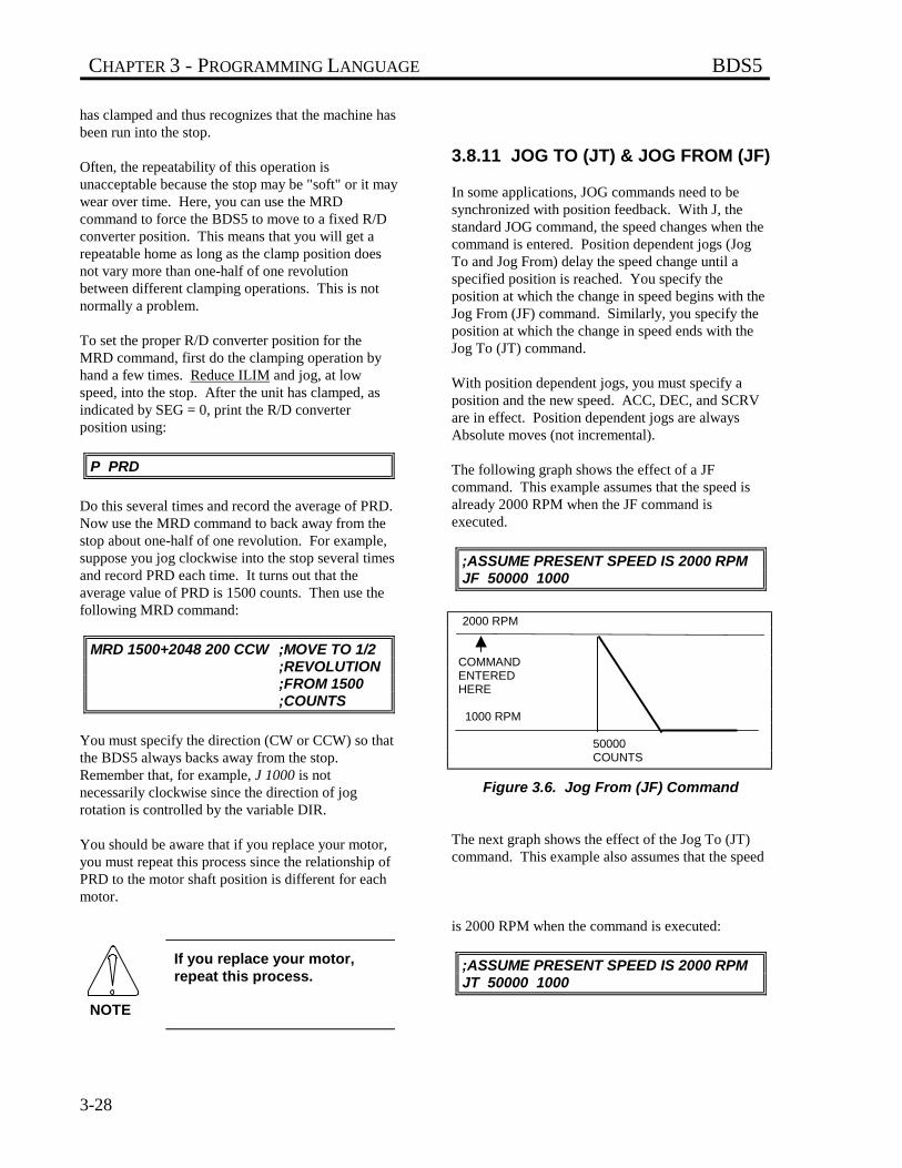
CHAPTER 3 - PROGRAMMING LANGUAGE BDS5
3-28
has clamped and thus recognizes that the machine hasbeen run into the stop.
Often, the repeatability of this operation isunacceptable because the stop may be "soft" or it maywear over time. Here, you can use the MRDcommand to force the BDS5 to move to a fixed R/Dconverter position. This means that you will get arepeatable home as long as the clamp position doesnot vary more than one-half of one revolutionbetween different clamping operations. This is notnormally a problem.
To set the proper R/D converter position for theMRD command, first do the clamping operation byhand a few times. Reduce ILIM and jog, at lowspeed, into the stop. After the unit has clamped, asindicated by SEG = 0, print the R/D converterposition using:
P PRD
Do this several times and record the average of PRD.Now use the MRD command to back away from thestop about one-half of one revolution. For example,suppose you jog clockwise into the stop several timesand record PRD each time. It turns out that theaverage value of PRD is 1500 counts. Then use thefollowing MRD command:
MRD 1500+2048 200 CCW ;MOVE TO 1/2 ;REVOLUTION;FROM 1500 ;COUNTS
You must specify the direction (CW or CCW) so thatthe BDS5 always backs away from the stop.Remember that, for example, J 1000 is notnecessarily clockwise since the direction of jogrotation is controlled by the variable DIR.
You should be aware that if you replace your motor,you must repeat this process since the relationship ofPRD to the motor shaft position is different for eachmotor.
If you replace your motor,repeat this process.
3.8.11 JOG TO (JT) & JOG FROM (JF)
In some applications, JOG commands need to besynchronized with position feedback. With J, thestandard JOG command, the speed changes when thecommand is entered. Position dependent jogs (JogTo and Jog From) delay the speed change until aspecified position is reached. You specify theposition at which the change in speed begins with theJog From (JF) command. Similarly, you specify theposition at which the change in speed ends with theJog To (JT) command.
With position dependent jogs, you must specify aposition and the new speed. ACC, DEC, and SCRVare in effect. Position dependent jogs are alwaysAbsolute moves (not incremental).
The following graph shows the effect of a JFcommand. This example assumes that the speed isalready 2000 RPM when the JF command isexecuted.
;ASSUME PRESENT SPEED IS 2000 RPMJF 50000 1000
Figure 3.6. Jog From (JF) Command
The next graph shows the effect of the Jog To (JT)command. This example also assumes that the speed
is 2000 RPM when the command is executed:
;ASSUME PRESENT SPEED IS 2000 RPMJT 50000 1000
2000 RPM
COMMAND ENTERED HERE
1000 RPM
50000 COUNTS
NOTE
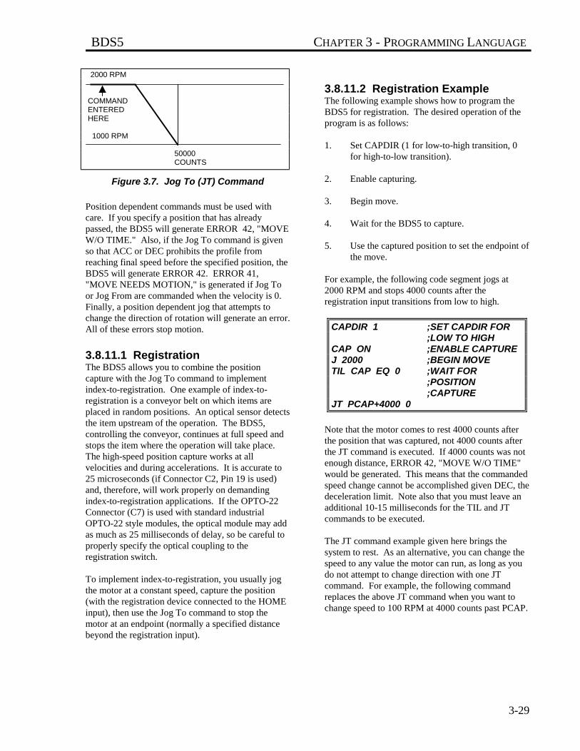
BDS5 CHAPTER 3 - PROGRAMMING LANGUAGE
3-29
Figure 3.7. Jog To (JT) Command
Position dependent commands must be used withcare. If you specify a position that has alreadypassed, the BDS5 will generate ERROR 42, "MOVEW/O TIME." Also, if the Jog To command is givenso that ACC or DEC prohibits the profile fromreaching final speed before the specified position, theBDS5 will generate ERROR 42. ERROR 41,"MOVE NEEDS MOTION," is generated if Jog Toor Jog From are commanded when the velocity is 0.Finally, a position dependent jog that attempts tochange the direction of rotation will generate an error.All of these errors stop motion.
3.8.11.1 RegistrationThe BDS5 allows you to combine the positioncapture with the Jog To command to implementindex-to-registration. One example of index-to-registration is a conveyor belt on which items areplaced in random positions. An optical sensor detectsthe item upstream of the operation. The BDS5,controlling the conveyor, continues at full speed andstops the item where the operation will take place.The high-speed position capture works at allvelocities and during accelerations. It is accurate to25 microseconds (if Connector C2, Pin 19 is used)and, therefore, will work properly on demandingindex-to-registration applications. If the OPTO-22Connector (C7) is used with standard industrialOPTO-22 style modules, the optical module may addas much as 25 milliseconds of delay, so be careful toproperly specify the optical coupling to theregistration switch.
To implement index-to-registration, you usually jogthe motor at a constant speed, capture the position(with the registration device connected to the HOMEinput), then use the Jog To command to stop themotor at an endpoint (normally a specified distancebeyond the registration input).
3.8.11.2 Registration ExampleThe following example shows how to program theBDS5 for registration. The desired operation of theprogram is as follows:
1. Set CAPDIR (1 for low-to-high transition, 0for high-to-low transition).
2. Enable capturing.
3. Begin move.
4. Wait for the BDS5 to capture.
5. Use the captured position to set the endpoint ofthe move.
For example, the following code segment jogs at2000 RPM and stops 4000 counts after theregistration input transitions from low to high.
CAPDIR 1 ;SET CAPDIR FOR ;LOW TO HIGH
CAP ON ;ENABLE CAPTUREJ 2000 ;BEGIN MOVETIL CAP EQ 0 ;WAIT FOR
;POSITION ;CAPTURE
JT PCAP+4000 0
Note that the motor comes to rest 4000 counts afterthe position that was captured, not 4000 counts afterthe JT command is executed. If 4000 counts was notenough distance, ERROR 42, "MOVE W/O TIME"would be generated. This means that the commandedspeed change cannot be accomplished given DEC, thedeceleration limit. Note also that you must leave anadditional 10-15 milliseconds for the TIL and JTcommands to be executed.
The JT command example given here brings thesystem to rest. As an alternative, you can change thespeed to any value the motor can run, as long as youdo not attempt to change direction with one JTcommand. For example, the following commandreplaces the above JT command when you want tochange speed to 100 RPM at 4000 counts past PCAP.
2000 RPM
COMMAND ENTERED HERE
1000 RPM
50000 COUNTS
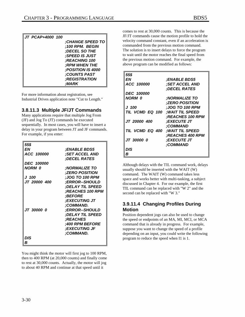
CHAPTER 3 - PROGRAMMING LANGUAGE BDS5
3-30
JT PCAP+4000 100;CHANGE SPEED TO;100 RPM. BEGIN;DECEL SO THE ;SPEED IS JUST;REACHING 100 ;RPM WHEN THE ;POSITION IS 4000;COUNTS PAST ;REGISTRATION ;MARK
For more information about registration, seeIndustrial Drives application note "Cut to Length."
3.8.11.3 Multiple JF/JT CommandsMany applications require that multiple Jog From(JF) and Jog To (JT) commands be executedsequentially. In most cases, you will have to insert adelay in your program between JT and JF commands.For example, if you enter:
55$EN ;ENABLE BDS5ACC 100000 ;SET ACCEL AND
;DECEL RATESDEC 100000NORM 0 ;NORMALIZE TO
;ZERO POSITIONJ 100 ;JOG TO 100 RPMJT 20000 400 ;ERROR--SHOULD
;DELAY TIL SPEED ;REACHES 100 RPM ;BEFORE ;EXECUTING JT ;COMMAND.
JT 30000 0 ;ERROR--SHOULD ;DELAY TIL SPEED ;REACHES;400 RPM BEFORE ;EXECUTING JF ;COMMAND.
DISB
You might think the motor will first jog to 100 RPM,then to 400 RPM (at 20,000 counts) and finally cometo rest at 30,000 counts. Actually, the motor will jogto about 40 RPM and continue at that speed until it
comes to rest at 30,000 counts. This is because theJF/JT commands cause the motion profile to hold thevelocity command constant, even if an acceleration iscommanded from the previous motion command.The solution is to insert delays to force the programto wait until the motor reaches the final speed fromthe previous motion command. For example, theabove program can be modified as follows:
55$EN ;ENABLE BDS5ACC 100000 ;SET ACCEL AND
;DECEL RATESDEC 100000NORM 0 ;NORMALIZE TO
;ZERO POSITIONJ 100 ;JOG TO 100 RPMTIL VCMD EQ 100 ;WAIT TIL SPEED
;REACHES 100 RPMJT 20000 400 ;EXECUTE JT
;COMMANDTIL VCMD EQ 400 ;WAIT TIL SPEED
;REACHES 400 RPMJT 30000 0 ;EXECUTE JT
;COMMANDDISB
Although delays with the TIL command work, delaysusually should be inserted with the WAIT (W)command. The WAIT (W) command takes lessspace and works better with multi-tasking, a subjectdiscussed in Chapter 4. For our example, the firstTIL command can be replaced with "W 2" and thesecond can be replaced with "W 3."
3.9.11.4 Changing Profiles DuringMotionPosition dependent jogs can also be used to changethe speed or endpoints of an MA, MI, MCI, or MCAcommand that is already in progress. For example,suppose you want to change the speed of a profiledepending on an input, you could write the followingprogram to reduce the speed when I1 is 1.
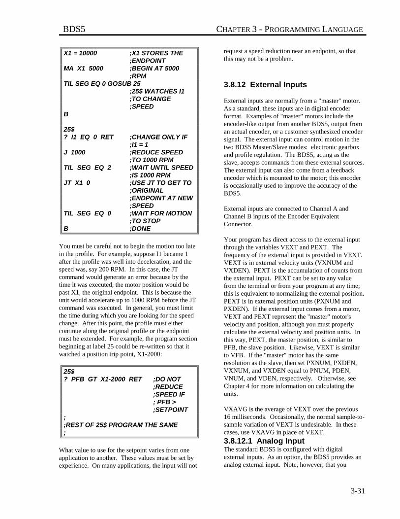
BDS5 CHAPTER 3 - PROGRAMMING LANGUAGE
3-31
X1 = 10000 ;X1 STORES THE ;ENDPOINT
MA X1 5000 ;BEGIN AT 5000 ;RPM
TIL SEG EQ 0 GOSUB 25;25$ WATCHES I1 ;TO CHANGE;SPEED
B
25$? I1 EQ 0 RET ;CHANGE ONLY IF
;I1 = 1J 1000 ;REDUCE SPEED
;TO 1000 RPMTIL SEG EQ 2 ;WAIT UNTIL SPEED
;IS 1000 RPMJT X1 0 ;USE JT TO GET TO
;ORIGINAL;ENDPOINT AT NEW ;SPEED
TIL SEG EQ 0 ;WAIT FOR MOTION ;TO STOP
B ;DONE
You must be careful not to begin the motion too latein the profile. For example, suppose I1 became 1after the profile was well into deceleration, and thespeed was, say 200 RPM. In this case, the JTcommand would generate an error because by thetime it was executed, the motor position would bepast X1, the original endpoint. This is because theunit would accelerate up to 1000 RPM before the JTcommand was executed. In general, you must limitthe time during which you are looking for the speedchange. After this point, the profile must eithercontinue along the original profile or the endpointmust be extended. For example, the program sectionbeginning at label 25 could be re-written so that itwatched a position trip point, X1-2000:
25$? PFB GT X1-2000 RET ;DO NOT
;REDUCE ;SPEED IF; PFB > ;SETPOINT
;;REST OF 25$ PROGRAM THE SAME;
What value to use for the setpoint varies from oneapplication to another. These values must be set byexperience. On many applications, the input will not
request a speed reduction near an endpoint, so thatthis may not be a problem.
3.8.12 External Inputs
External inputs are normally from a "master" motor.As a standard, these inputs are in digital encoderformat. Examples of "master" motors include theencoder-like output from another BDS5, output froman actual encoder, or a customer synthesized encodersignal. The external input can control motion in thetwo BDS5 Master/Slave modes: electronic gearboxand profile regulation. The BDS5, acting as theslave, accepts commands from these external sources.The external input can also come from a feedbackencoder which is mounted to the motor; this encoderis occasionally used to improve the accuracy of theBDS5.
External inputs are connected to Channel A andChannel B inputs of the Encoder EquivalentConnector.
Your program has direct access to the external inputthrough the variables VEXT and PEXT. Thefrequency of the external input is provided in VEXT.VEXT is in external velocity units (VXNUM andVXDEN). PEXT is the accumulation of counts fromthe external input. PEXT can be set to any valuefrom the terminal or from your program at any time;this is equivalent to normalizing the external position.PEXT is in external position units (PXNUM andPXDEN). If the external input comes from a motor,VEXT and PEXT represent the "master" motor'svelocity and position, although you must properlycalculate the external velocity and position units. Inthis way, PEXT, the master position, is similar toPFB, the slave position. Likewise, VEXT is similarto VFB. If the "master" motor has the sameresolution as the slave, then set PXNUM, PXDEN,VXNUM, and VXDEN equal to PNUM, PDEN,VNUM, and VDEN, respectively. Otherwise, seeChapter 4 for more information on calculating theunits.
VXAVG is the average of VEXT over the previous16 milliseconds. Occasionally, the normal sample-to-sample variation of VEXT is undesirable. In thesecases, use VXAVG in place of VEXT.
3.8.12.1 Analog InputThe standard BDS5 is configured with digitalexternal inputs. As an option, the BDS5 provides ananalog external input. Note, however, that you
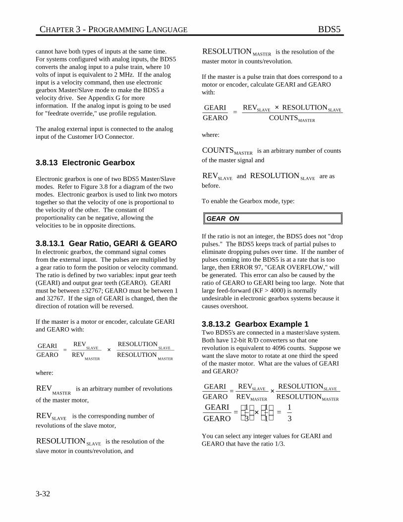
CHAPTER 3 - PROGRAMMING LANGUAGE BDS5
3-32
cannot have both types of inputs at the same time.For systems configured with analog inputs, the BDS5converts the analog input to a pulse train, where 10volts of input is equivalent to 2 MHz. If the analoginput is a velocity command, then use electronicgearbox Master/Slave mode to make the BDS5 avelocity drive. See Appendix G for moreinformation. If the analog input is going to be usedfor "feedrate override," use profile regulation.
The analog external input is connected to the analoginput of the Customer I/O Connector.
3.8.13 Electronic Gearbox
Electronic gearbox is one of two BDS5 Master/Slavemodes. Refer to Figure 3.8 for a diagram of the twomodes. Electronic gearbox is used to link two motorstogether so that the velocity of one is proportional tothe velocity of the other. The constant ofproportionality can be negative, allowing thevelocities to be in opposite directions.
3.8.13.1 Gear Ratio, GEARI & GEAROIn electronic gearbox, the command signal comesfrom the external input. The pulses are multiplied bya gear ratio to form the position or velocity command.The ratio is defined by two variables: input gear teeth(GEARI) and output gear teeth (GEARO). GEARImust be between ±32767; GEARO must be between 1and 32767. If the sign of GEARI is changed, then thedirection of rotation will be reversed.
If the master is a motor or encoder, calculate GEARIand GEARO with:
GEARI
GEARO =
REV
REV
RESOLUTION
RESOLUTION SLAVE
MASTER
SLAVE
MASTER
×
where:
REVMASTER
is an arbitrary number of revolutions
of the master motor,
REV SLAVE is the corresponding number of
revolutions of the slave motor,
RESOLUTION SLAVE is the resolution of the
slave motor in counts/revolution, and
RESOLUTION MASTER is the resolution of the
master motor in counts/revolution.
If the master is a pulse train that does correspond to amotor or encoder, calculate GEARI and GEAROwith:
GEARI
GEARO =
REV RESOLUTION
COUNTSSLAVE SLAVE
MASTER
×
where:
COUNTSMASTER is an arbitrary number of counts
of the master signal and
REVSLAVE and RESOLUTION SLAVE are as
before.
To enable the Gearbox mode, type:
GEAR ON
If the ratio is not an integer, the BDS5 does not "droppulses." The BDS5 keeps track of partial pulses toeliminate dropping pulses over time. If the number ofpulses coming into the BDS5 is at a rate that is toolarge, then ERROR 97, "GEAR OVERFLOW," willbe generated. This error can also be caused by theratio of GEARO to GEARI being too large. Note thatlarge feed-forward (KF > 4000) is normallyundesirable in electronic gearbox systems because itcauses overshoot.
3.8.13.2 Gearbox Example 1Two BDS5's are connected in a master/slave system.Both have 12-bit R/D converters so that onerevolution is equivalent to 4096 counts. Suppose wewant the slave motor to rotate at one third the speedof the master motor. What are the values of GEARIand GEARO?
GEARI
GEARO=
REV
REV
RESOLUTION
RESOLUTION SLAVE
MASTER
SLAVE
MASTER
×
GEARI
GEARO=
1
3
1
1 =
1
3
×
You can select any integer values for GEARI andGEARO that have the ratio 1/3.
BDS5 CHAPTER 3 - PROGRAMMING LANGUAGE
3-33
3.8.13.3 Gearbox Example 2Suppose the master signal in Example 1 came from a500-line encoder. With quadrature encoding, a 500-line encoder will generate 2000 counts per revolution.If you still wanted 1:3 gearing, then:
GEARI
GEARO=
REV
REV
RESOLUTION
RESOLUTION SLAVE
MASTER
SLAVE
MASTER
×
GEARI
GEARO=
1
3
4096
2000 =
4096
6000
×
So, GEARI would be 4096 and GEARO would be6000.
3.8.13.4 Profiles and GearboxGearboxing can be done in conjunction withincremental moves and jogs. MI and Macro movesbased on MCI are summed with the gearboxcommand to form the profile. This can be used for"phase adjustment," a common function used withelectronic gearbox. Phase adjustment means that theslave will be locked to the master through theelectronic gearbox, but occasionally the slave BDS5adds a short profile on top of the gearbox command.For example, you may want to increase the slaveposition (phase) by 90° while remaining in gear. Inthis case, enter the following commands:
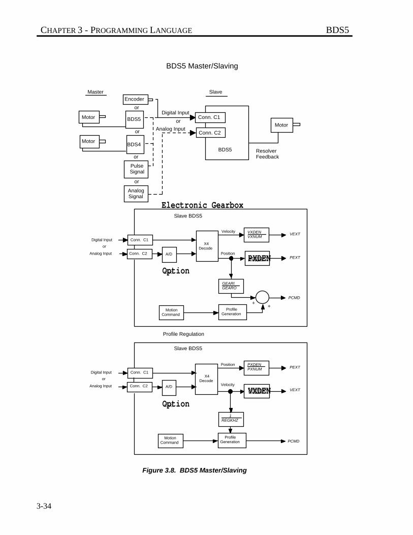
CHAPTER 3 - PROGRAMMING LANGUAGE BDS5
3-34
Figure 3.8. BDS5 Master/Slaving
Conn. C1
Conn. C2 A/D
X4Decode
Velocity
Position
VXDENVXNUM
PXDENPXNUM
GEARIGEARO
VEXT
PEXT
PCMD
MotionCommand
ProfileGeneration
Digital Input
or
Analog Input
OptionCard
++
Slave BDS5
Conn. C1
Conn. C2 A/D
X4Decode
Velocity
Position PXDENPXNUM
VXDENVXNUM
PEXT
VEXT
PCMDMotion
CommandProfile
Generation
Digital Input
or
Analog Input
OptionCard
Slave BDS5
1REGKHZ
Electronic Gearbox
Profile Regulation
Motor
Motor
Motor
BDS5 Resolver Feedback
or
or
or
or
BDS4
BDS5
Encoder
PulseSignal
AnalogSignal
Digital Input
Analog Input
or
Master Slave
BDS5 Master/Slaving
Conn. C1
Conn. C2
BDS5 CHAPTER 3 - PROGRAMMING LANGUAGE
3-35
GEAR ON ;ENABLE ELECTRONIC ;GEARBOX
;; ...NORMALLY, SOME TIME WOULD;PASS BETWEEN THESE COMMANDS...;MI 1028 10 ;PHASE ADJUST 90
;DEGREES AT 10 RPM.;SYSTEM REMAINS IN
;GEARBOX THROUGH THE ;PHASE ADJUSTMENT.
You cannot use MA or MCA commands when GEARis on. Also, you cannot use position-dependent jogs(JT or JF) when GEAR is on.
3.8.13.5 Velocity Offset, VOFFVOFF, velocity offset, is added to the Velocitycommand when the gearbox is enabled. VOFF is invelocity units. It is normally used with the analoginput to correct voltage offset in the optional analogvelocity input. VOFF can be changed at any time.Note that VOFF is set to zero when GEAR isenabled. This is done because if VOFF is large (say,2000 RPM), enabling the gearbox would immediatelycommand motion.
VOFF is set to zero whenGEAR is turned on.
3.8.13.6 Gearbox, ACC/DEC, andJogsWhen the BDS5 is run as a velocity loop (PL off),acceleration and deceleration rates can be limited bythe variables ACC and DEC. This allows you to limitthe acceleration from external velocity commandsthat are otherwise unlimited. If you want theacceleration and deceleration to be limited by ACCand DEC, type:
RAMP ON ;LIMIT ACC AND ;DEC WHEN PL IS OFF
3.8.14 Profile Regulation
This section describes profile regulation, one of theBDS5 Master/Slave modes. Profile regulation allowsyou to synchronize the rate of profile executionaccording to the external input. This modifies the
velocity and acceleration of move commands withoutaffecting the final position of the move. The rate ofthe move is dependent on the frequency of an externalclock, which is connected to the external input, inaddition to the normal limits of the move (ACC,DEC, and the velocity are set in the move commanditself). The external input may be a master motor towhich all moves must be synchronized (such as aconveyor belt motor), or it may be a signal that yougenerate electronically. As an option, an analogsignal can be fed directly to the BDS5, where it isconverted to a pulse train and can be used as theexternal input. Profile regulation works with MA andMI, as well as Macro moves.
All profile regulation is based on an accumulation ofcounts from the external input during the move. Ifthe external frequency changes during a move, thevelocity of that move will be proportional to thechanging clock frequency. In fact, if the externalinput frequency goes to zero, then motion will stop.Note that if the external input changes rapidly, theprofile is not limited to ACC or DEC. For example,if the external frequency stopped suddenly, the BDS5would command motion to stop just as suddenly.Note also that large feed-forward (KF > 4000) isnormally undesirable during regulation because itcauses overshoot.
3.8.14.1 REG & REGKHZREG enables the Profile Regulate mode. If REG ison, then profile regulation is enabled. REG andGEAR cannot be on at the same time.
To use profile regulation, you must determine:
1. The maximum frequency of the external input.Set REGKHZ to this value.
2. The desired speed of the move when theexternal input frequency is REGKHZ. Use thisvalue as the commanded velocity of the profile.
The maximum frequency of the external input isstored in the variable REGKHZ in kHz. The profilewill execute normally (that is, at the specified velocityand acceleration) when the external input frequency isequal to REGKHZ. If the input frequency is less thanREGKHZ, then the profile will move the specifieddistance, but the acceleration and velocity will be lessthan, and in proportion to, the
input frequency. The move will never go faster thanspecified in the original move command, even if the
NOTE
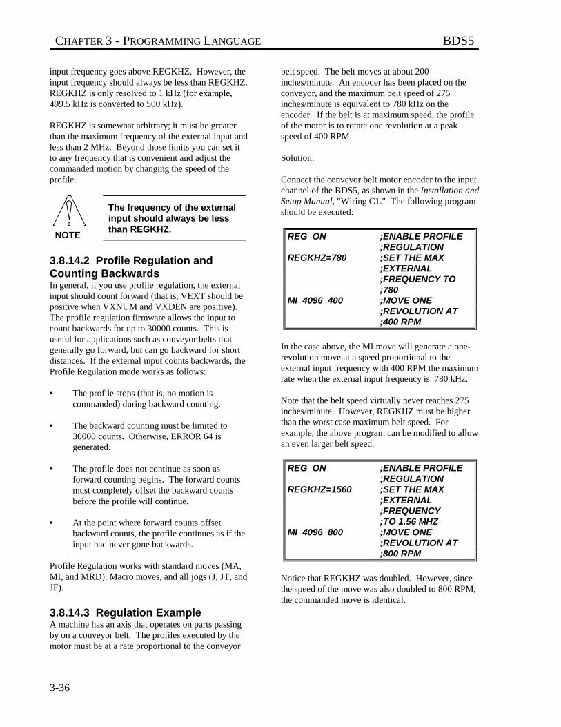
CHAPTER 3 - PROGRAMMING LANGUAGE BDS5
3-36
input frequency goes above REGKHZ. However, theinput frequency should always be less than REGKHZ.REGKHZ is only resolved to 1 kHz (for example,499.5 kHz is converted to 500 kHz).
REGKHZ is somewhat arbitrary; it must be greaterthan the maximum frequency of the external input andless than 2 MHz. Beyond those limits you can set itto any frequency that is convenient and adjust thecommanded motion by changing the speed of theprofile.
The frequency of the externalinput should always be lessthan REGKHZ.
3.8.14.2 Profile Regulation andCounting BackwardsIn general, if you use profile regulation, the externalinput should count forward (that is, VEXT should bepositive when VXNUM and VXDEN are positive).The profile regulation firmware allows the input tocount backwards for up to 30000 counts. This isuseful for applications such as conveyor belts thatgenerally go forward, but can go backward for shortdistances. If the external input counts backwards, theProfile Regulation mode works as follows:
• The profile stops (that is, no motion iscommanded) during backward counting.
• The backward counting must be limited to30000 counts. Otherwise, ERROR 64 isgenerated.
• The profile does not continue as soon asforward counting begins. The forward countsmust completely offset the backward countsbefore the profile will continue.
• At the point where forward counts offsetbackward counts, the profile continues as if theinput had never gone backwards.
Profile Regulation works with standard moves (MA,MI, and MRD), Macro moves, and all jogs (J, JT, andJF).
3.8.14.3 Regulation ExampleA machine has an axis that operates on parts passingby on a conveyor belt. The profiles executed by themotor must be at a rate proportional to the conveyor
belt speed. The belt moves at about 200inches/minute. An encoder has been placed on theconveyor, and the maximum belt speed of 275inches/minute is equivalent to 780 kHz on theencoder. If the belt is at maximum speed, the profileof the motor is to rotate one revolution at a peakspeed of 400 RPM.
Solution:
Connect the conveyor belt motor encoder to the inputchannel of the BDS5, as shown in the Installation andSetup Manual, "Wiring C1." The following programshould be executed:
REG ON ;ENABLE PROFILE ;REGULATION
REGKHZ=780 ;SET THE MAX ;EXTERNAL ;FREQUENCY TO ;780
MI 4096 400 ;MOVE ONE ;REVOLUTION AT ;400 RPM
In the case above, the MI move will generate a one-revolution move at a speed proportional to theexternal input frequency with 400 RPM the maximumrate when the external input frequency is 780 kHz.
Note that the belt speed virtually never reaches 275inches/minute. However, REGKHZ must be higherthan the worst case maximum belt speed. Forexample, the above program can be modified to allowan even larger belt speed.
REG ON ;ENABLE PROFILE ;REGULATION
REGKHZ=1560 ;SET THE MAX ;EXTERNAL ;FREQUENCY;TO 1.56 MHZ
MI 4096 800 ;MOVE ONE ;REVOLUTION AT ;800 RPM
Notice that REGKHZ was doubled. However, sincethe speed of the move was also doubled to 800 RPM,the commanded move is identical.
NOTE
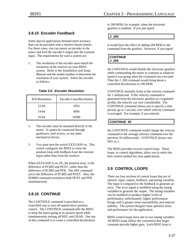
BDS5 CHAPTER 3 - PROGRAMMING LANGUAGE
3-37
3.8.15 Encoder Feedback
Some special applications demand more accuracythan can be provided with a resolver based system.For these cases, you can mount an encoder to themotor and feed the encoder's output into the externalinput. The requirements for such a system are:
1. The resolution of the encoder must match theresolution of the resolver on your BDS5system. Refer to the Installation and SetupManual and the model number to determine theresolution of your system. Select the encoderas follows:
Table 3.9. Encoder Resolution
R/D Resolution Encoder Lines/Revolution
12-bit 1024
14-bit 4096
16-bit 16384
2. The encoder must be mounted directly to themotor. It cannot be connected throughgearboxes, lead screws, or any othermechanical device.
3. You must turn the switch EXTLOOP on. Thisswitch configures the BDS5 to close theposition loop with feedback from the externalinput rather than from the resolver.
When EXTLOOP is on, PE, the position error, is thedifference of PCMD and PEXT, rather than thedifference of PCMD and PFB. The ZPE commandzero's the difference of PCMD and PEXT. Also, theNORM command normalizes both PEXT and PFBsimultaneously.
3.8.16 CONTINUE
The CONTINUE command is provided as acontrolled way to turn off master/slave positioncontrol. The CONTINUE command tells the BDS5to keep the motor going at its present speed whilesimultaneously turning off REG and GEAR. One useof this command is to cause a controlled deceleration
to 200 RPM, for example, when the electronicgearbox is enabled. If you just typed:
J 200
it would have the effect of adding 200 RPM to thecommand from the gearbox. However, if you typed:
CONTINUEJ 200
the CONTINUE would disable the electronic gearboxwhile commanding the motor to continue at whateverspeed it was going when the command was executed.Then the J 200 command would bring about acontrolled deceleration to 200 RPM.
CONTINUE normally looks at the velocity commandfor 1 millisecond. If the velocity command isgenerated from the electronic gearbox or a regulatedprofile, the velocity can vary considerable. TheCONTINUE command allows you to specify a timeperiod, up to 1 second, over which velocity commandis averaged. For example, if you entered:
CONTINUE 50
the CONTINUE command would change the velocitycommand to the average velocity command over theprevious 50 milliseconds. CONTINUE always setsSEG to 1.
The BDS5 provides several control loops. Theseloops, or control algorithms, allow you to select thebest control method for your applications.
3.9 CONTROL LOOPS
There are four sections of control loops that are ofinterest: input, output, feedback, and tuning variables.The input is compared to the feedback to generate anerror. The error signal is modified using the tuningvariables to generate the output. The tuning variablescan be modified to produce higher levels ofperformance; unfortunately, higher performancebrings with it greater noise susceptibility and reducedstability. The system designer must optimize noiseand performance for the application.
BDS5 control loops have one or two tuning variables.All BDS5 loops follow the convention that largerconstants provide higher gain. Each BDS5 loop is
CHAPTER 3 - PROGRAMMING LANGUAGE BDS5
3-38
described below and shown on the drawing at the endof this chapter.
3.9.1 Position Loop
The Position Loop input is the variable PCMD, thePosition command. The feedback is PFB, theposition feedback. The output is VCMD, Velocitycommand, and its two tuning variables are KP, theposition loop gain, and KF, the position loop feed-forward gain.
The position loop calculates the position error (PE) asthe difference of PCMD and PFB. As a secondarycommand source, PCMD is differentiated(d/dt)PCMD. The position loop then performs thefollowing calculations:
VCMD=KP_PE+KF_(d/dt)PCMD.
The position loop is optional. If the switch PL is on,then the position loop is enabled; if it is off, then theposition loop is bypassed. PL is turned on at power-up.
The feed-forward gain reduces position error at highspeed. Without feed-forward, the velocity commandis generated only from position error; a large positionerror is required to command a high speed. If KF is large enough, then a high velocitycommand can be generated with little or no positionerror. The BDS5 scales KF so that unity feed-forward occurs when KF equals 16384. In otherwords, if KF is 16384, no position error is required togenerate the velocity command in steady-staterunning conditions. KF should never be larger than16384. In addition, larger KF makes the system moreresponsive to commands.
Unfortunately, large values of KF cause overshoot.KP must be reduced to reduce overshoot. If you needto minimize position error when the motor is turning,you will need to optimize KF and KP. Typically, KFranges from 2000 to 10000.
TQ should be off when PL is turned on. The systembecomes unstable when PL and TQ are both on. Ifyou do not turn TQ off before turning PL on, theBDS5 will force TQ off.
When PL is turned on, TQ isturned off automatically.
3.9.2 Velocity Loop
The velocity loop takes its input from the positionloop if PL is on. If PL is off, motion commandsdirectly control the velocity command (VCMD). Thefeedback is VFB, velocity feedback, and thedifference of these two signals is VE, velocity error.Velocity error can be used in two control loops:proportional and integrating.
3.9.2.1 Proportional Velocity LoopIf a proportional velocity loop is selected, then thevelocity error is multiplied by KPROP, theproportional constant, to generate ICMD, the currentcommand. Proportional velocity loop is selectedwhen the PROP switch is on. PROP is turned off onpower-up.
Proportional velocity loops are much easier tostabilize than integrating loops, so they are often usedduring machine setup. However, they also allowsteady-state velocity error and therefore, they aregenerally replaced with integrating loops when themachine is fully operational.
3.9.2.2 Integrating Velocity LoopIf an integrating velocity loop is selected, then thevelocity error is integrated and multiplied by KVI, thevelocity integration constant. Velocity feedback issubtracted from this signal, then the signal ismultiplied by KV, the velocity loop gain, to formICMD. This velocity loop is selected when PROP isoff.
3.9.3 Torque Command
In a few applications, the BDS5 is given a "torque"command. Actually, this is a current command, butat lower speeds, motor torque is approximatelyproportional to current. In this case, VCMD is
NOTE
BDS5 CHAPTER 3 - PROGRAMMING LANGUAGE
3-39
multiplied by KPROP to form ICMD. Note that thisdiffers from the proportional velocity loop only inthat VFB is not subtracted from VCMD. The switchTQ must be on to select the torque mode and off forall other modes. The position loop should be off (PLoff) when the BDS5 is running in Torque commandmode. The BDS5 will turn PL off when TQ is turnedon.
When TQ is turned on, PL isforced off
3.9.4 Power-Up Control Loops
The BDS5 has, at power-up, the following settings:
• Position loop enabled (PL on).
• No feed-forward (KF=0)
• Integrating Velocity Loop (PROP off, TQ off)
These settings meet the requirements of a largenumber of applications. Figure 3.9 shows each of thefive BDS5 controller modes.
NOTE
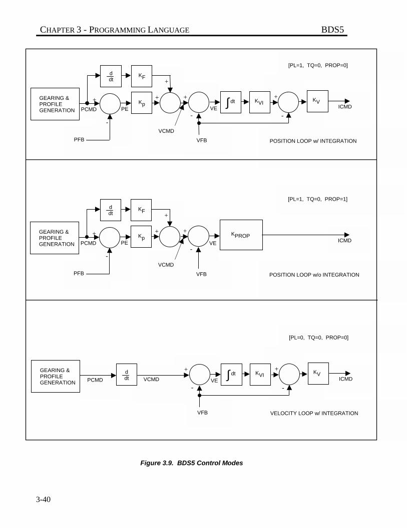
CHAPTER 3 - PROGRAMMING LANGUAGE BDS5
3-40
Figure 3.9. BDS5 Control Modes
VFB
-
++
-
+
+
PFB
-
+ICMD
KpPCMD
GEARING &PROFILEGENERATION
KVIdt∫
KF
KVPE
ddt
VE
[PL=1, TQ=0, PROP=0]
VCMD
POSITION LOOP w/ INTEGRATION
KPROP
VFB
+
-
+
+
PFB
-
+ICMD
KpPCMD
GEARING &PROFILEGENERATION
KF
PE
ddt
VE
[PL=1, TQ=0, PROP=1]
VCMD
POSITION LOOP w/o INTEGRATION
VCMDPCMD
VFB
-
++
-ICMD
GEARING &PROFILEGENERATION
KVIdt∫ KVddt VE
[PL=0, TQ=0, PROP=0]
VELOCITY LOOP w/ INTEGRATION
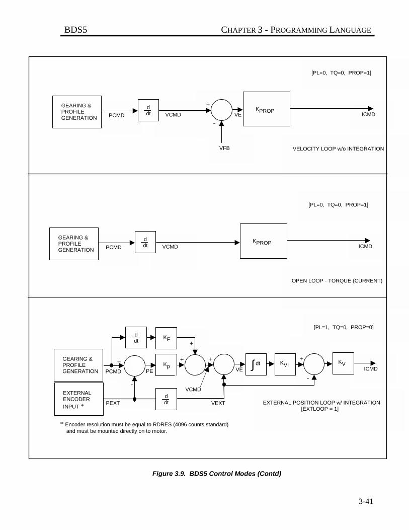
BDS5 CHAPTER 3 - PROGRAMMING LANGUAGE
3-41
* Encoder resolution must be equal to RDRES (4096 counts standard) and must be mounted directly on to motor.
Figure 3.9. BDS5 Control Modes (Contd)
VCMDPCMD
VFB
+
-ICMD
GEARING &PROFILEGENERATION
ddt VE
[PL=0, TQ=0, PROP=1]
VELOCITY LOOP w/o INTEGRATION
KPROP
VCMDPCMD ICMD
GEARING &PROFILEGENERATION
ddt
[PL=0, TQ=0, PROP=1]
OPEN LOOP - TORQUE (CURRENT)
KPROP
-
++
-
+
+
-
+ICMD
KpPCMD
GEARING &PROFILEGENERATION
KVIdt∫
KF
KVPE
ddt
VE
[PL=1, TQ=0, PROP=0]
VCMD
EXTERNAL POSITION LOOP w/ INTEGRATION [EXTLOOP = 1]
EXTERNALENCODER
INPUT *
ddtPEXT VEXT
BDS5 CHAPTER 4 - USER PROGRAMS
4-1
CHAPTER 4
USER PROGRAMS
4.1 INTRODUCTION
The information in this chapter will enable you tounderstand the capabilities of the system. You willalso explore important consideraions that must beaddressed before you implement your ownapplication. Examples of programming techniqueswill aid you to develop your own applications.
4.2 PROGRAMMING TECHNIQUES
User programs are combinations of BDS5 commandswhich are stored in the BDS5 memory. Theseprograms are stored in non-volatile RAM; they arenot lost when the BDS5 is powered down. Userprograms are composed mostly of the commands thathave been described in earlier chapters. In addition,there are commands necessary for controlling the waythe program executes; these commands are covered inthis chapter. The first section describes the BDS5Editor, which allows you to enter and modifyprograms from the terminal. If you have not alreadydone so, read Chapter 3 before proceeding. Thismanual is written to be read sequentially. Do notattempt to save time by skipping ahead to thischapter.
READ THIS ENTIRE SECTION CAREFULLY.
This section discusses programming practices. TheBDS5 has a flexible language. You must followproper programming principles to insure that the
flexibility does not lead to overly-complex programs.If you follow good programming practices you will:
• be able to modify programs when theapplication changes;
• have fewer programming errors;
• have an easier time fixing the programmingerrors that do occur; and
• be able to get help with errors you cannot fix.
People who are new to programming often disregardgood programming practices because they have notexperienced the problems that result from poorprogramming practices. Save yourself the misery ofhaving to re-write your entire program. Follow thesesteps:
1. DO NOT PROGRAM SAFETYFUNCTIONS.
Always hardwire personalsafety functions. Neverprogram these functions.
Always hardwire safety functions. Thisincludes EMERGENCY STOP or ESTOP.You should not depend on your program forsafety functions because of three potentialproblems: 1) You can easily make
WARNING
CHAPTER 4 - USER PROGRAMS BDS5
4-2
programming errors (software problem); 2) Afunction on the BDS5 may not work in exactlythe way you expect it to in every condition(firmware problem); and 3) A criticalcomponent in your system may fail andprevent the function from working (hardwareproblem). Remember, safety functions arerarely exercised so that if one of theseproblems does occur, it can go undetectedindefinitely. If personal safety is involved,always hardwire the function.
2. USE CAUTION WHEN PROGRAMMINGEQUIPMENT PROTECTION FUNCTIONS.
Use caution whenprogramming equipment-protection functions.Programming errors candamage your equipment.
Sometimes you can hardwire equipmentprotection functions, but other times this isimpractical and you must program thefunctions. If this is the case, be very careful.Remember, if your program has an error, it canresult in damage to your equipment. Forexample, suppose you want to wire your motorthermostat so that when a fault occurs, thepresent machine cycle continues untilcomplete. In this case, you must program thefunction (hardwiring the thermostat wouldresult in motion stopping the moment athermostat fault is encountered). Carefully testthese functions.
3. WRITE A SIMPLE SPECIFICATION FORYOUR APPLICATION.
Write an outline of all the functions yourapplication will require before you startprogramming. This will serve as aspecification. Everyone who is involved withyour system (customers, supervisors, co-workers, operators) should agree on thespecification. While last-minute requests forprogram changes will still occur, this is areasonable step towards reducing the incidenceof such requests.
4. WRITE A FLOWCHART OF YOURPROGRAM.
People who are new to programming oftenhave a natural distaste for writing flowcharts.Many view flowcharts as something between acrutch and unnecessary work. Mostexperienced programmers have a differentview. The most important point aboutflowcharts is that they are virtually required ifyou need help over the telephone. Alwayswrite flowcharts for programs that are longerthan 20 to 30 lines.
5. COMMENT YOUR PROGRAM.
Always comment your programs. Commentshelp explain your program to other people.Keep in mind that others may need to modifyyour program in the future. Comments alsohelp you remember why you chose certainways to do things.
6. AVOID SPAGHETTI CODE.
A program with too much branching is oftencalled spaghetti code because of the look of theflowcharts. Avoid a lot of branching,especially branching up (that is, towards thetop of your program); logic in programs thatbranch down is more intuitive and thus, lessprone to errors. If you do branch up, branch tothe top of a major section. In most programsthere should only be one or two places that youbranch up to. Feel free to use small loops (2 or3 lines) which, of course, repeatedly branch tothe top of the loop. Avoid branching betweensections.
7. AVOID USER SWITCHES THAT MODIFYBLOCKS OF CODE.
Switches that modify functions can be difficultto understand. This is commonly done whenprogrammers attempt to use one block of codefor two similar functions. If possible, writetwo different blocks of code rather than tryingto use one block for two functions.
4.2.1 Example Application
Suppose you are working on a project that is definedby someone besides yourself. It may be a co-worker,a supervisor, a customer, or an operator. For this
CAUTION
BDS5 CHAPTER 4 - USER PROGRAMS
4-3
example, we will use a customer. Suppose you havethis conversation:
Customer: "My machine feeds plastic from a rollonto a conveyor then cuts it into sheets.The length of the sheet varies. There isa registration mark on each plastic sheetwhich is detected while the plastic ismoving. After this mark is detected, themotor must move the plastic a variabledistance and stop. There is a stop inputthat should stop and disable the BDS5after it completes the cycle."
You: "Are there other parameters that shouldbe variable such as speed, acceleration,and deceleration?"
Customer: "Now that you mention it, all thoseparameters should be variable. I alsoneed an output at the end of the move tostart the saw blade rotating."
You: "How often do these variables change?"
Customer: "About once or twice a year."
You: "Do you mind typing them in from akeyboard?"
Customer: "No. That would be fine."
You: "What controls the start of the move?"
Customer: "My PLC activates an input. CanESTOP be programmed so that it can beoverridden when the cycle is almostcomplete?"
You: "No. Since ESTOP is a safety function,it is always hardwired to removepower."
Customer: "Okay. About how long do you think itwill take?"
You: "I'll be in touch."
4.2.2 Application Specification
1. Allow a variable cut length, acceleration,deceleration, and speed. Use user variables X1-X4 as follows:
X1 AccelerationX2 DecelerationX3 SpeedX4 Cut Length (added to registration mark)
2. Turn on an output at the end of the move. Thisoutput will be connected to start the saw. Useoutput O1.
3. Allow contacts that stop the process after thepresent cycle is complete. Use input I1.
4. Wait for a start signal to begin each cycle. Useinput I2.
4.2.3 Application Flowchart
When you write flowcharts use three symbols: acircle, a square, and a diamond. A circle indicates thestart or end of a program. It also indicates the start orend of a subroutine. A square is an execution block.That is, the BDS5 should do something: turn on anoutput, print a message, or command motion. Adiamond is a decision block. There are two exitsfrom a diamond: one if the condition is true and theother if it is false. "Sample Flowchart" is a flowchartfor this application.
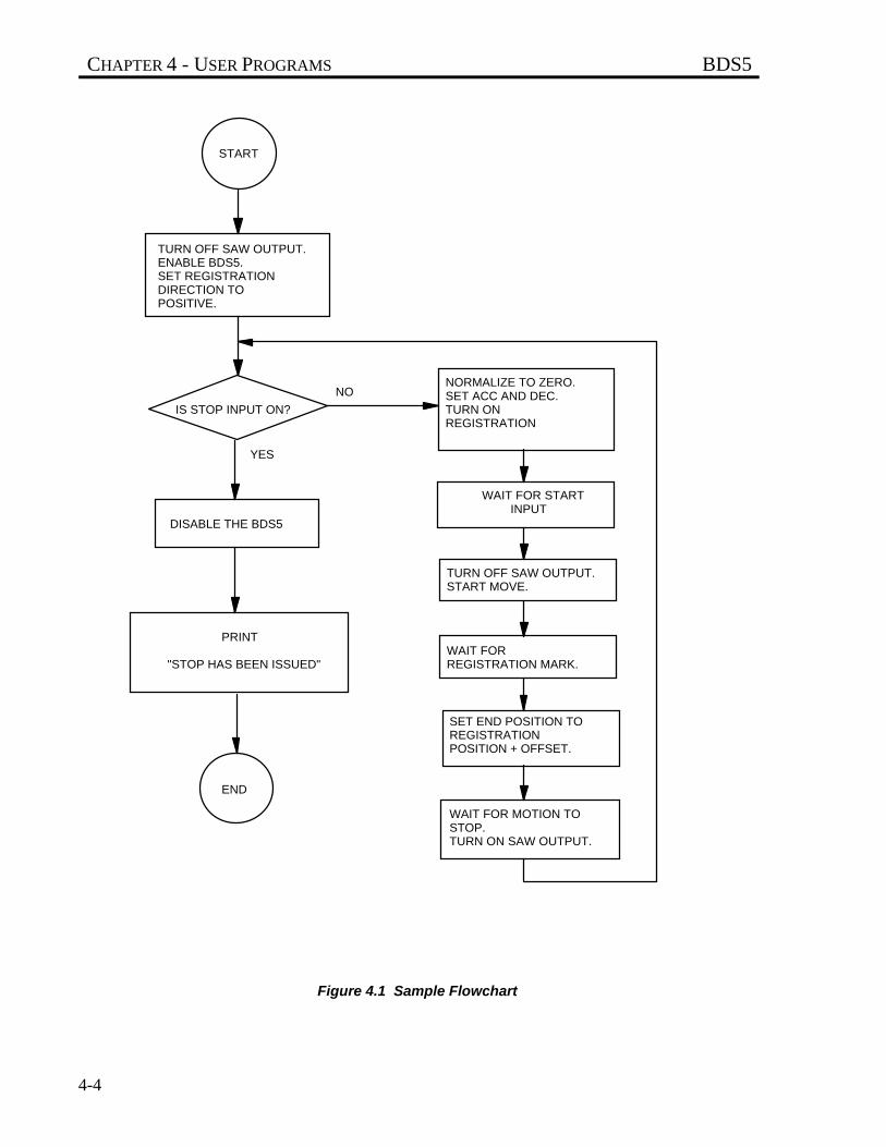
CHAPTER 4 - USER PROGRAMS BDS5
4-4
Figure 4.1 Sample Flowchart
START
TURN OFF SAW OUTPUT.ENABLE BDS5.SET REGISTRATIONDIRECTION TO POSITIVE.
IS STOP INPUT ON?
DISABLE THE BDS5
"STOP HAS BEEN ISSUED"
END
NORMALIZE TO ZERO.SET ACC AND DEC.TURN ONREGISTRATION
WAIT FOR STARTINPUT
TURN OFF SAW OUTPUT.START MOVE.
WAIT FORREGISTRATION MARK.
SET END POSITION TOREGISTRATIONPOSITION + OFFSET.
WAIT FOR MOTION TOSTOP.TURN ON SAW OUTPUT.
YES
NO
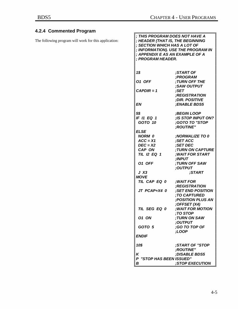
BDS5 CHAPTER 4 - USER PROGRAMS
4-5
4.2.4 Commented Program
The following program will work for this application:; THIS PROGRAM DOES NOT HAVE A; HEADER (THAT IS, THE BEGINNING; SECTION WHICH HAS A LOT OF; INFORMATION). USE THE PROGRAM IN; APPENDIX E AS AN EXAMPLE OF A; PROGRAM HEADER.
1$ ;START OF ;PROGRAM
O1 OFF ;TURN OFF THE ;SAW OUTPUT
CAPDIR = 1 ;SET ;REGISTRATION ;DIR. POSITIVE
EN ;ENABLE BDS5
5$ ;BEGIN LOOPIF I1 EQ 1 ;IS STOP INPUT ON? GOTO 10 ;GOTO TO "STOP
;ROUTINE"ELSE NORM 0 ;NORMALIZE TO 0 ACC = X1 ;SET ACC DEC = X2 ;SET DEC CAP ON ;TURN ON CAPTURE TIL I2 EQ 1 ;WAIT FOR START
;INPUT O1 OFF ;TURN OFF SAW
;OUTPUT J X3 ;STARTMOVE TIL CAP EQ 0 ;WAIT FOR
;REGISTRATION JT PCAP+X4 0 ;SET END POSITION
;TO CAPTURED;POSITION PLUS AN;OFFSET (X4)
TIL SEG EQ 0 ;WAIT FOR MOTION ;TO STOP
O1 ON ;TURN ON SAW ;OUTPUT
GOTO 5 ;GO TO TOP OF ;LOOP
ENDIF
10$ ;START OF "STOP ;ROUTINE"
K ;DISABLE BDS5P "STOP HAS BEEN ISSUED"B ;STOP EXECUTION
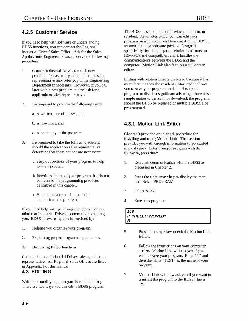
CHAPTER 4 - USER PROGRAMS BDS5
4-6
4.2.5 Customer Service
If you need help with software or understandingBDS5 functions, you can contact the RegionalIndustrial Drives' Sales Office. Ask for the SalesApplications Engineer. Please observe the followingprocedure:
1. Contact Industrial Drives for each newproblem. Occasionally, an applications salesrepresentative may refer you to the EngineeringDepartment if necessary. However, if you calllater with a new problem, please ask for aapplications sales representative.
2. Be prepared to provide the following items:
a. A written spec of the system;
b. A flowchart; and
c. A hard copy of the program.
3. Be prepared to take the following actions,should the application sales representativedetermine that these actions are necessary:
a. Strip out sections of your program to helplocate a problem.
b. Rewrite sections of your program that do notconform to the programming practicesdescribed in this chapter.
c. Video tape your machine to helpdemonstrate the problem.
If you need help with your program, please bear inmind that Industrial Drives is committed to helpingyou. BDS5 software support is provided by:
1. Helping you organize your program.
2. Explaining proper programming practices.
3. Discussing BDS5 functions.
Contact the local Industrial Drives sales applicationrepresentative. All Regional Sales Offices are listedin Appendix I of this manual.
4.3 EDITING
Writing or modifying a program is called editing.There are two ways you can edit a BDS5 program.
The BDS5 has a simple editor which is built in, orresident. As an alternative, you can edit yourprogram on a computer and transmit it to the BDS5.Motion Link is a software package designedspecifically for this purpose. Motion Link runs onIBM-PC's and compatibles, and it handles thecommunications between the BDS5 and thecomputer. Motion Link also features a full-screeneditor.
Editing with Motion Link is preferred because it hasmore features than the resident editor, and it allowsyou to save your program on disk. Having theprogram on disk is a significant advantage since it is asimple matter to transmit, or download, the program,should the BDS5 be replaced or multiple BDS5's beprogrammed.
4.3.1 Motion Link Editor
Chapter 3 provided an in-depth procedure forinstalling and using Motion Link. This sectionprovides you with enough information to get startedin most cases. Enter a simple program with thefollowing procedure:
1. Establish communication with the BDS5 asdiscussed in Chapter 2.
2. Press the right arrow key to display the menubar. Select PROGRAM.
3. Select NEW.
4. Enter this program:
10$P "HELLO WORLD"B
5. Press the escape key to exit the Motion LinkEditor.
6. Follow the instructions on your computerscreen. Motion Link will ask you if youwant to save your program. Enter "Y" andgive the name "TEST" as the name of yourprogram.
7. Motion Link will now ask you if you want totransmit the program to the BDS5. Enter"Y."
BDS5 CHAPTER 4 - USER PROGRAMS
4-7
8. After the transmission is complete, youshould receive the interactive prompt (-->).Type:
RUN 10
Your program should print:
HELLO WORLD-->
This should provide you with enough information toenter the examples from this chapter. Read Chapter 3for a complete description of Motion Link.
4.3.2 BDS5 Resident Editor
If you are not using the BDS5 Editor, skip ahead tothe next section, "Building a Program." The BDS5resident editor allows you to enter small programsand make changes without Motion Link. Note thatyou can use this editor from Motion Link just as youwould use it from a terminal.
To enter the BDS5 Editor, type:
ED
When you are in the Editor, the BDS5 will respondwith the editor prompt:
E->
To exit the Editor, press the escape key.
4.3.2.1 Editor Print (P)The Print (P) command prints a program line (orlines) then goes to that line. Each line in the programmemory has a number. Many editor instructions,such as Print, expect you to specify the line number(or numbers) that applies to the instruction.Type in the following example from the BDS5Editor:
P BEG END
The BDS5 will print the entire program and go to theend of the program. When you specify a range, thecommand works for all the lines in the range. Youcan specify one line. For example, type:
P 1
and the BDS5 will print and go to line 1. If you wantto print the current line, then do not specify a line.For example:
P
prints the current line. If you attempt to print a linethat is not in the program, such as, line 100 of a 10-line program, the Editor will issue an error like:
BAD ENTRY
4.3.2.2 Next LineIf you enter an empty line, then the BDS5 goes downone line in the program and prints that line. Theempty line is entered by pressing only the enter key.This makes it easy to move down through theprogram.
4.3.2.3 Password (PASS)The BDS5 Editor has password protection. Thepassword allows you to prevent the user programfrom being changed. If the password is set, theprogram cannot be changed, but it can still bedisplayed. The password can be up to six characterslong. The default setting of the password is null (i.e.empty), which means there is no password protection.From the Editor, type:
PASS
and the BDS5 will ask you for the new password.
If you do not want password protection, enter anempty line. Note that the NEW command, discussedlater, also clears the password.
4.3.2.4 Insert (I)Entering the Insert (I) command causes the Editor toenter the Insert mode. When you are in the Insertmode, everything you type is put directly into theprogram memory. You exit the Insert mode bypressing the escape key or entering an empty line.For example, type in a line as follows. Type:
P BEG ;GO TO THE BEGINNING OFTHE PROGRAMI ;ENTER THE INSERT MODE
CHAPTER 4 - USER PROGRAMS BDS5
4-8
and the BDS5 will respond with:
I->
indicating that you are in the Insert mode. Now type:
;TEST LINE FOR LEARNING ABOUT THE;EDITOR
Press the escape key to exit the insert mode. Type:
P 1
and the BDS5 should respond with:
1 ;TEST LINE FOR LEARNING ABOUTTHE EDITOR
You can specify the line you want to insert directly.For example:
I 5
enters the Insert mode. The next line you type isentered directly into the program as the new line 5.Subsequent lines, 6, 7, and so on, follow line 5.
4.3.2.5 Find (F)The Find (F) command will search down through theprogram memory for a particular word, letter, orstring of characters. For example, the Find commandcan be used to find the word "EDITOR" from theInsert command above. From the Editor, type:
P BEG ;USE P TO GO TO ;TOP AND SEARCH
F
The BDS5 should respond with:
FIND WHAT?F->
then type:
EDITOR
and the Find command will find line 1 since the wordEDITOR occurs in that line. Now F can be used tofind the next line with "EDITOR." Type:
F
and the BDS5 should respond with:
FIND WHAT? EDITOR?F->
In this example, the Find command has a default"FIND WHAT" string. The default is the find stringfrom the last Find command. If you enter an emptyline, the next line with "EDITOR" will be found. Ifyou do not want to use the default string from the lastFind command, type in the word or words you wantto find this time. Pressing the escape key will abortthe F command.
If the Editor cannot find the specified word, it willrespond with "NOT FOUND" and return to the editmode:
NOT FOUNDE->
4.3.2.6 Change (C)The Change (C) command is similar to the Findcommand. However, Change allows you to changethe string you found. Also, Change only searches thecurrent line. Use the P command to go to line 1 andprint the line you typed from the previous discussionof the Insert command. Type:
P 1
and the BDS5 should respond:
1 ;TEST LINE FOR LEARNING ABOUT;THE EDITOR
Now use the C command to change "EDITOR" to"BDS5 EDITOR." Type:
C
and the BDS5 will respond with:
CHANGE WHAT? "EDITOR"?C->
Again, "EDITOR" from the Find command is thedefault input. Press the return key to accept thedefault and the BDS5 will respond with:
BDS5 CHAPTER 4 - USER PROGRAMS
4-9
CHANGE TO WHAT?C->
Now type:
BDS5 EDITOR
The BDS5 will change the line to read:
1 ;TEST LINE FOR LEARNING ABOUT;THE BDS5 EDITOR
C has defaults for both the "CHANGE WHAT" andthe "CHANGE TO WHAT." This allows you to stepthrough memory, changing each occurrence of onestring to another string with minimal keystrokes.Like F, pressing the escape key will abort the processand return to the Edit mode.
4.3.2.7 Delete (DEL)The Delete (DEL) command can be used to deleteone line or a whole range of lines.
DO NOT TYPE THESE EXAMPLES!
For example:
DEL 5 10 ;DELETE LINES ;5,6,7,8,9, AND 10
DEL 12 ;DELETE LINE 12DEL ;DELETE CURRENT
;LINE
All of these delete instructions are valid.
For an example that you can type in, if you enteredline 1 "TEST LINE FOR LEARNING ABOUT THEEDITOR," then type in the following command todelete that line:
P 1 ;POINT AT THE FIRST LINE ;"TEST LINE..."
DEL 1 ;DELETE THAT LINE
Line 1 should be deleted.
4.3.2.8 SizeThe BDS5 program memory has space for about16000 characters. If you want to see how muchmemory is left, type:
SIZE
The BDS5 will respond with:
65 % LEFT
which means the available space is about 65%. If youtry to enter a program larger than the BDS5 can store,an error will be generated.
4.3.2.9 NEWThe NEW command resets the password and clearsthe program. The user program is stored in batterybacked-up RAM. Normally, the program isremembered indefinitely. However, if power to theBDS5 is lost when it is executing an Editor command,there is a small chance that the program will becorrupted. This can happen, for example, if power islost during the Change or Delete command. In thiscase, the BDS5 will generate a "USER PROGRAMCORRUPT" error and the program cannot bemodified or run. If this happens, use the NEWcommand to clear the user program and reset thecorrupt error.
DO NOT TYPE IN THIS EXAMPLE!
NEW
The NEW command also clears the editor password.
The >BDS command, which is discussed later in thisChapter, will also reset the program so that it is nolonger corrupt, although it will not clear thepassword.
4.4 BUILDING A PROGRAM
Programs are sequences of commands, most of whichcan also be executed directly from the keyboard. Aprogram stores the sequences of these normalcommands. Examples of these commands are MI,MA, and P (Print). However, in order for a programto run properly, other commands, called programcontrol commands, are required. Examples of thesecommands are GOTO and GOSUB.
CHAPTER 4 - USER PROGRAMS BDS5
4-10
4.4.1 Basic Commands
4.4.1.1 LabelsLabels are used to mark places in the program whereexecution begins or continues. There are two kindsof labels: general purpose labels and dedicatedlabels.
General purpose labels are numbers from 0 to 500followed by a dollar sign ($). You can execute aprogram that begins at a general purpose label withthe RUN command. You can jump to a label fromwithin your program with the GOTO and GOSUBcommands. RUN, GOTO, and GOSUB are describedlater in this chapter.
Dedicated labels each have specific functions.Dedicated labels include alarms, auto programs, andthe user error handler. These labels are letters orwords followed by a dollar sign. For example, A$ isthe A-Alarm label. Dedicated labels cannot be usedby the RUN, GOTO, or GOSUB commands. Theselabels are discussed with multi-tasking later in thischapter.
4.4.1.2 RUNThe RUN command is used to start the program fromthe Interactive mode. For example, type:
RUN 3
If there are no errors, and if label 3 is in the userprogram, then program execution begins at label 3.The RUN command can execute all valid generalpurpose labels. If the label is not in the program, anerror is generated and no part of the program isexecuted. You cannot use the RUN command fordedicated labels.
Before the program is run, the BDS5 searches theentire program for some types of errors. If, after youenter a RUN command, an error is detected, theBDS5 will display the appropriate error messagetogether with the offending line. Also, RUN verifiesthat the program has not changed since the last edit.If the program has changed, a "PROGRAMCORRUPT" error is generated. The program corrupterror can be cleared, though this requires that theentire program be erased with the Editor NEWcommand or the >BDS command. If a "ProgramCorrupt" error occurs, and it was not caused by losing
power while you were editing, this may indicate aserious condition. Contact the factory.
4.4.1.3 Break (B)The Break (B) command is the opposite of RUN; itstops program execution and normally returns to theinteractive state. The Break command does not stopmotion. Profile commands are allowed to continueuntil they are complete. If you want to break theprogram and stop motion, precede the Breakcommand with the Stop (S) command.
4.4.1.4 GOTOThe GOTO command is used within the program tojump to a label. Before the following example ofGOTO can be done, another function of the Print (P)command should be explained. From the terminal,type:
P "THIS PRINTS TEXT JUST LIKE ITYPED IT IN"
and the result will be:
THIS PRINTS TEXT JUST LIKE I TYPED IT IN
When using the Print command, characters betweendouble quotes are printed back without modification.
Returning to the GOTO command, use the EditorInsert command to enter the short program below:
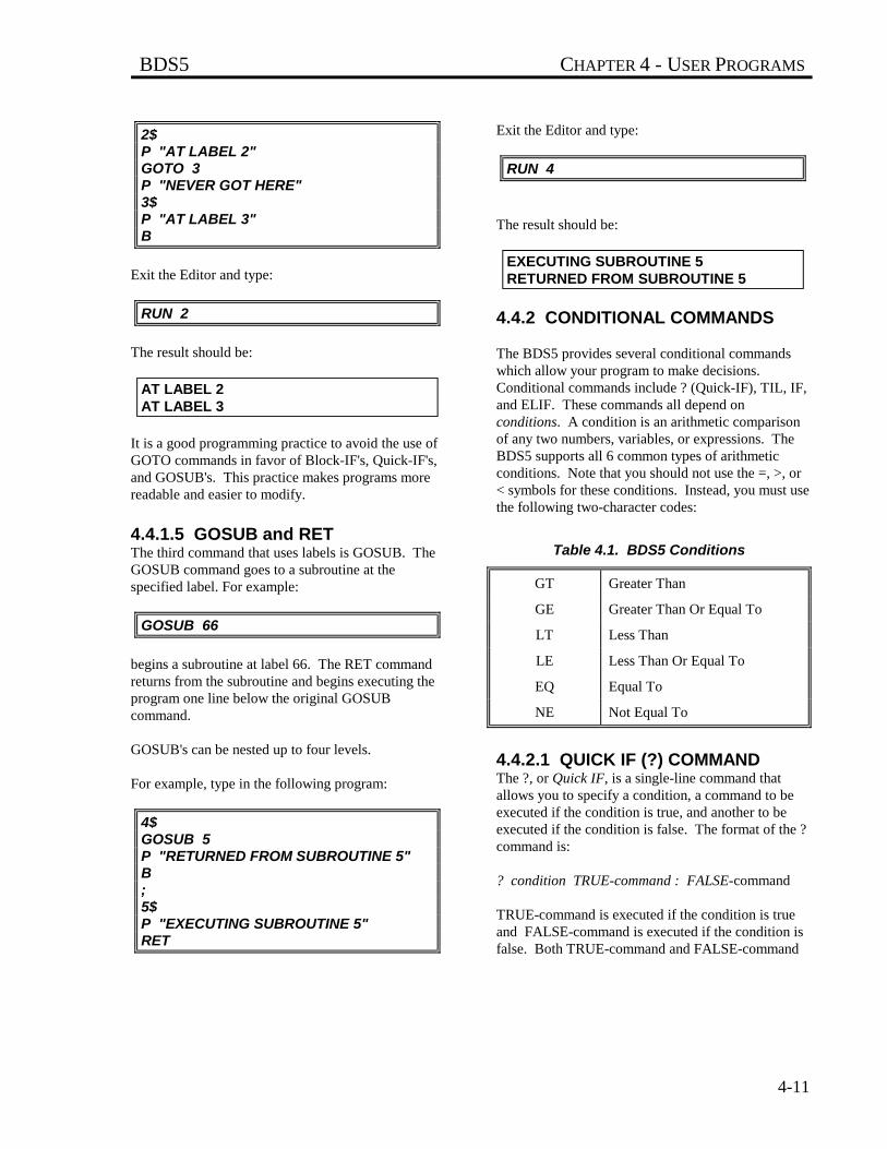
BDS5 CHAPTER 4 - USER PROGRAMS
4-11
2$P "AT LABEL 2"GOTO 3P "NEVER GOT HERE"3$P "AT LABEL 3"B
Exit the Editor and type:
RUN 2
The result should be:
AT LABEL 2AT LABEL 3
It is a good programming practice to avoid the use ofGOTO commands in favor of Block-IF's, Quick-IF's,and GOSUB's. This practice makes programs morereadable and easier to modify.
4.4.1.5 GOSUB and RETThe third command that uses labels is GOSUB. TheGOSUB command goes to a subroutine at thespecified label. For example:
GOSUB 66
begins a subroutine at label 66. The RET commandreturns from the subroutine and begins executing theprogram one line below the original GOSUBcommand.
GOSUB's can be nested up to four levels.
For example, type in the following program:
4$GOSUB 5P "RETURNED FROM SUBROUTINE 5"B;5$P "EXECUTING SUBROUTINE 5"RET
Exit the Editor and type:
RUN 4
The result should be:
EXECUTING SUBROUTINE 5RETURNED FROM SUBROUTINE 5
4.4.2 CONDITIONAL COMMANDS
The BDS5 provides several conditional commandswhich allow your program to make decisions.Conditional commands include ? (Quick-IF), TIL, IF,and ELIF. These commands all depend onconditions. A condition is an arithmetic comparisonof any two numbers, variables, or expressions. TheBDS5 supports all 6 common types of arithmeticconditions. Note that you should not use the =, >, or< symbols for these conditions. Instead, you must usethe following two-character codes:
Table 4.1. BDS5 Conditions
GT Greater Than
GE Greater Than Or Equal To
LT Less Than
LE Less Than Or Equal To
EQ Equal To
NE Not Equal To
4.4.2.1 QUICK IF (?) COMMANDThe ?, or Quick IF, is a single-line command thatallows you to specify a condition, a command to beexecuted if the condition is true, and another to beexecuted if the condition is false. The format of the ?command is:
? condition TRUE-command : FALSE-command
TRUE-command is executed if the condition is trueand FALSE-command is executed if the condition isfalse. Both TRUE-command and FALSE-command
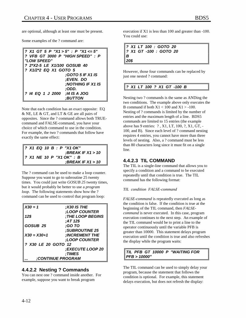
CHAPTER 4 - USER PROGRAMS BDS5
4-12
are optional, although at least one must be present.
Some examples of the ? command are:
? X1 GT 5 P "X1 > 5" : P "X1 <= 5"? VFB GT 3000 P "HIGH SPEED" : P"LOW SPEED"? 2*X2-5 LE X1/100 GOSUB 40? X1/2*2 EQ X1 GOTO 5
;GOTO 5 IF X1 IS ;EVEN. DO;NOTHING IF X1 IS;ODD.
? I4 EQ 1 J 2000 ;I4 IS A JOG ;BUTTON
Note that each condition has an exact opposite: EQ& NE, LE & GT, and LT & GE are all pairs ofopposites. Since the ? command allows both TRUE-command and FALSE-command, you have yourchoice of which command to use in the condition.For example, the two ? commands that follow haveexactly the same effect:
? X1 EQ 10 B : P "X1 OK";BREAK IF X1 > 10
? X1 NE 10 P "X1 OK" : B;BREAK IF X1 > 10
The ? command can be used to make a loop counter.Suppose you want to go to subroutine 25 twentytimes. You could just write GOSUB 25 twenty times,but it would probably be better to use a programloop. The following statements show how the ?command can be used to control that program loop:
X30 = 1 ;X30 IS THE ;LOOP COUNTER
12$ ;THE LOOP BEGINS ;AT 12$
GOSUB 25 ;GO TO ;SUBROUTINE 25
X30 = X30+1 ;INCREMENT THE ;LOOP COUNTER
? X30 LE 20 GOTO 12;EXECUTE LOOP 20 ;TIMES
... ;CONTINUE PROGRAM
4.4.2.2 Nesting ? CommandsYou can nest one ? command inside another. Forexample, suppose you want to break program
execution if X1 is less than 100 and greater than -100.You could use:
? X1 LT 100 : GOTO 20? X1 GT -100 : GOTO 20B20$
However, those four commands can be replaced byjust one nested ? command:
? X1 LT 100 ? X1 GT -100 B
Nesting two ? commands is the same as ANDing thetwo conditions. The example above only executes theB command if both X1 < 100 and X1 > -100.Nesting of ? commands is limited by the number ofentries and the maximum length of a line. BDS5commands are limited to 15 entries (the exampleabove has 9 entries: ? , X1, LT, 100, ?, X1, GT, -100, and B). Since each level of ? command nestingrequires 4 entries, you cannot have more than threelevels of nesting. Also, a ? command must be lessthan 80 characters long since it must fit on a singleline.
4.4.2.3 TIL COMMANDThe TIL is a single-line command that allows you tospecify a condition and a command to be executedrepeatedly until that condition is true. The TILcommand has the following format:
TIL condition FALSE-command
FALSE-command is repeatedly executed as long asthe condition is false. If the condition is true at thebeginning of the TIL command, then FALSE-command is never executed. In this case, programexecution continues to the next step. An example ofthe TIL command would be to print a line to theoperator continuously until the variable PFB isgreater than 10000. This statement delays programexecution until the condition is true and also refreshesthe display while the program waits:
TIL PFB GT 10000 P "WAITING FORPFB > 10000"
The TIL command can be used to simply delay yourprogram, because the statement that follows thecondition is optional. For example, this statementdelays execution, but does not refresh the display:
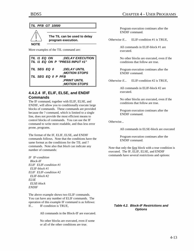
BDS5 CHAPTER 4 - USER PROGRAMS
4-13
TIL PFB GT 10000
The TIL can be used to delayprogram execution.
More examples of the TIL command are:
TIL I1 EQ ON ;DELAY EXECUTIONTIL I1 EQ ON P "PRESS INPUT #1"
TIL SEG EQ 0 ;DELAY UNTIL ;MOTION STOPS
TIL SEG EQ 0 P PFB;PRINT UNTIL ;MOTION STOPS
4.4.2.4 IF, ELIF, ELSE, and ENDIFCommandsThe IF command, together with ELIF, ELSE, andENDIF, will allow you to conditionally execute largeblocks of commands. These commands are providedbecause the ? command, which is limited to a singleline, does not provide the most efficient means tocontrol blocks of commands. You can use the IFcommand to write more readable, and thus less errorprone, programs.
The format of the IF, ELIF, ELSE, and ENDIFcommands follows. Note that the conditions have thesame format as the conditions for the TIL and ?commands. Note also that block can indicate anynumber of commands:
IF IF-condition Block-IFELIF ELIF-condition #1 ELIF-block #1ELIF ELIF-condition #2 ELIF-block #2ELSE ELSE-blockENDIF
The above example shows two ELIF commands.You can have any number of ELIF commands. Theoperation of this example IF command is as follows:If... IF-condition is TRUE,
All commands in the Block-IF are executed.
No other blocks are executed, even if someor all of the other conditions are true.
Program execution continues after theENDIF command.
Otherwise if... ELIF-condition #1 is TRUE,
All commands in ELIF-block #1 areexecuted.
No other blocks are executed, even if theconditions that follow are true.
Program execution continues after theENDIF command.
Otherwise if... ELIF-condition #2 is TRUE,
All commands in ELIF-block #2 areexecuted.
No other blocks are executed, even if theconditions that follow are true.
Program execution continues after theENDIF command.
Otherwise...
All commands in ELSE-block are executed
Program execution continues after theENDIF command.
Note that only the first block with a true condition isexecuted. The IF, ELIF, ELSE, and ENDIFcommands have several restrictions and options:
Table 4.2. Block-IF Restrictions andOptions
NOTE
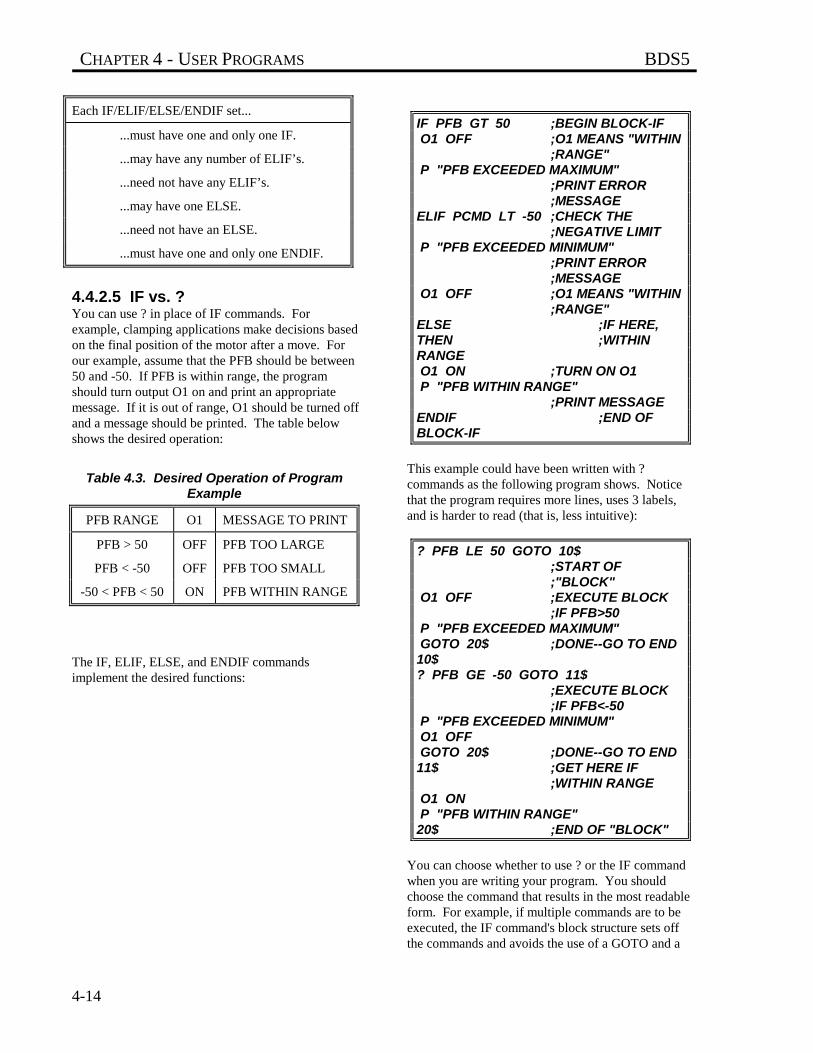
CHAPTER 4 - USER PROGRAMS BDS5
4-14
Each IF/ELIF/ELSE/ENDIF set...
...must have one and only one IF.
...may have any number of ELIF’s.
...need not have any ELIF’s.
...may have one ELSE.
...need not have an ELSE.
...must have one and only one ENDIF.
4.4.2.5 IF vs. ?You can use ? in place of IF commands. Forexample, clamping applications make decisions basedon the final position of the motor after a move. Forour example, assume that the PFB should be between50 and -50. If PFB is within range, the programshould turn output O1 on and print an appropriatemessage. If it is out of range, O1 should be turned offand a message should be printed. The table belowshows the desired operation:
Table 4.3. Desired Operation of ProgramExample
PFB RANGE O1 MESSAGE TO PRINT
PFB > 50 OFF PFB TOO LARGE
PFB < -50 OFF PFB TOO SMALL
-50 < PFB < 50 ON PFB WITHIN RANGE
The IF, ELIF, ELSE, and ENDIF commandsimplement the desired functions:
IF PFB GT 50 ;BEGIN BLOCK-IF O1 OFF ;O1 MEANS "WITHIN
;RANGE" P "PFB EXCEEDED MAXIMUM"
;PRINT ERROR ;MESSAGE
ELIF PCMD LT -50 ;CHECK THE ;NEGATIVE LIMIT
P "PFB EXCEEDED MINIMUM";PRINT ERROR ;MESSAGE
O1 OFF ;O1 MEANS "WITHIN ;RANGE"
ELSE ;IF HERE,THEN ;WITHINRANGE O1 ON ;TURN ON O1 P "PFB WITHIN RANGE"
;PRINT MESSAGEENDIF ;END OFBLOCK-IF
This example could have been written with ?commands as the following program shows. Noticethat the program requires more lines, uses 3 labels,and is harder to read (that is, less intuitive):
? PFB LE 50 GOTO 10$;START OF ;"BLOCK"
O1 OFF ;EXECUTE BLOCK ;IF PFB>50
P "PFB EXCEEDED MAXIMUM" GOTO 20$ ;DONE--GO TO END10$? PFB GE -50 GOTO 11$
;EXECUTE BLOCK ;IF PFB<-50
P "PFB EXCEEDED MINIMUM" O1 OFF GOTO 20$ ;DONE--GO TO END11$ ;GET HERE IF
;WITHIN RANGE O1 ON P "PFB WITHIN RANGE"20$ ;END OF "BLOCK"
You can choose whether to use ? or the IF commandwhen you are writing your program. You shouldchoose the command that results in the most readableform. For example, if multiple commands are to beexecuted, the IF command's block structure sets offthe commands and avoids the use of a GOTO and a

BDS5 CHAPTER 4 - USER PROGRAMS
4-15
label. On the other hand, if a single instruction is tobe executed, the ? may be more readable. Usually,one form results in less program space or fasterexecution, and this may dictate which to use.However, if space or timing are not critical, use themost readable form.
4.4.2.6 Nesting IF commandsYou can nest IF commands. For example, thefollowing program shows two levels of nesting:
55$IF X1 GT 0 IF X2 GT 0 P "BOTH X1 AND X2 > 0" ELSE P "ONLY X1 GT 0" ENDIFELSE IF X2 GT 0 P "ONLY X2 GT 0" ELSE P "NEITHER X1 NOR X2 > 0" ENDIFENDIFB
You can nest IF commands indefinitely. You shouldbe careful to include all of the ENDIF's to close eachlevel of nested IF. All of the restrictions and optionsthat were listed earlier as applying to IF commandsalso apply to nested IF's. The indentation shownabove is not required, but is present to make theprogram more readable. The BDS5 ignores theindentation.
4.4.2.7 IF's with GOTO and GOSUBYou can use the GOSUB command from within aBlock-IF, even if you have another Block-IF in thatsubroutine. In this case, the IF in the subroutine islike a nested IF. However, be careful to return fromthe subroutine after you have executed the ENDIF.You should never return from a subroutine frombetween IF and ENDIF. Finally, you may use aGOTO to jump completely out of an IF-THEN-ELSEcontrol structure. When a GOTO is executed after anIF has been executed, but before an ENDIF has
been executed, all ENDIF's are automaticallyexecuted. This means that you cannot jump to a labelwithin any IF-THEN-ELSE structure. Note thatjumping out of a control structure in such a manner isa poor programming practice and should be avoided.Also, you may not jump to a label within an IF-THEN-ELSE from outside the structure.
You cannot GOTO the middleof an IF/ENDIF set. Youshould never execute a RETfrom between an IF andENDIF.
4.5 USING THE GENERAL PURPOSEINPUTS
General purpose inputs can be used to control theprogram. From Chapter 3 you may recall that theseinputs can be referred to one at a time using variablesI1-I16, or collectively IN. If the program must waitfor a particular input to be on or off beforecontinuing execution, the TIL command can be used:
TIL I5 EQ 0
If this statement is executed from the program, theprogram will delay execution until I5 is 0.
If the program must wait for many inputs to be on oroff, then the TIL command can be expanded. Forexample, if inputs 1, 4, 5, and 6 must all be on, eitherof the following TIL instructions can be used:
TIL I1+I4+I5+I6 EQ 4;THIS USES ;ALGEBRAIC MATH
TIL I1&I4&I5&I6 EQ 1;THIS USES ;LOGICAL MATH
; BOTH WORK
It is slightly more complicated if the program mustwait for some inputs to be on and others off. Forexample, if inputs 1, 4, and 5 must be on, and input 6must be off, the following TIL instructions can beused:
TIL I1+I4+I5+(1-I6) EQ 4 ;ALGEBRAIC MATH
NOTE
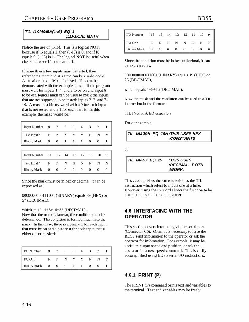
CHAPTER 4 - USER PROGRAMS BDS5
4-16
TIL I1&I4&I5&(1-I6) EQ 1 ;LOGICAL MATH
Notice the use of (1-I6). This is a logical NOT,because if I6 equals 1, then (1-I6) is 0, and if I6equals 0, (1-I6) is 1. The logical NOT is useful whenchecking to see if inputs are off.
If more than a few inputs must be tested, thenreferencing them one at a time can be cumbersome.As an alternative, IN can be used. This can bedemonstrated with the example above. If the programmust wait for inputs 1, 4, and 5 to be on and input 6to be off, logical math can be used to mask the inputsthat are not supposed to be tested: inputs 2, 3, and 7-16. A mask is a binary word with a 0 for each inputthat is not tested and a 1 for each that is. In thisexample, the mask would be:
Input Number 8 7 6 5 4 3 2 1
Test Input? N N Y Y Y N N Y
Binary Mask 0 0 1 1 1 0 0 1
Input Number 16 15 14 13 12 11 10 9
Test Input? N N N N N N N N
Binary Mask 0 0 0 0 0 0 0 0
Since the mask must be in hex or decimal, it can beexpressed as:
0000000000111001 (BINARY) equals 39 (HEX) or57 (DECIMAL),
which equals 1+8+16+32 (DECIMAL).Now that the mask is known, the condition must bedetermined. The condition is formed much like themask. In this case, there is a binary 1 for each inputthat must be on and a binary 0 for each input that iseither off or masked:
I/O Number 8 7 6 5 4 3 2 1
I/O On? N N N Y Y N N Y
Binary Mask 0 0 0 1 1 0 0 1
I/O Number 16 15 14 13 12 11 10 9
I/O On? N N N N N N N N
Binary Mask 0 0 0 0 0 0 0 0
Since the condition must be in hex or decimal, it canbe expressed as:
0000000000011001 (BINARY) equals 19 (HEX) or25 (DECIMAL),
which equals 1+8+16 (DECIMAL).
Now the mask and the condition can be used in a TILinstruction in the format:
TIL IN&mask EQ condition
For our example,
TIL IN&39H EQ 19H;THIS USES HEX ;CONSTANTS
or
TIL IN&57 EQ 25 ;THIS USES ;DECIMAL. BOTH ;WORK.
This accomplishes the same function as the TILinstruction which refers to inputs one at a time.However, using the IN word allows the function to bedone in a less cumbersome manner.
4.6 INTERFACING WITH THEOPERATOR
This section covers interfacing via the serial port(Connector C5). Often, it is necessary to have theBDS5 send information to the operator or ask theoperator for information. For example, it may beuseful to output speed and position, or ask theoperator for a new speed command. This is easilyaccomplished using BDS5 serial I/O instructions.
4.6.1 PRINT (P)
The PRINT (P) command prints text and variables tothe terminal. Text and variables may be freely
BDS5 CHAPTER 4 - USER PROGRAMS
4-17
intermixed, limited only by the 80-charactermaximum instruction length. The followingcommand prints the speed on the terminal:
P "SPEED = " VFB " RPM"
Assuming VFB is 1962, the BDS5 will respond with:
SPEED = 1962 RPM
Note that the text must be enclosed by double quotes,and that text and/or variables must be separated by atleast one blank space.
4.6.1.1 Printing Decimal NumbersVariables are normally printed as decimal integers ina field which is 12 characters wide. Formatting canbe used to adjust the field width or to print decimalpoints.
To change the width of the field, follow the variablename with the width enclosed in square brackets ([ ]).Referring to the above example,
P "SPEED = " VFB[5] " RPM"
will cause the BDS5 to print:
SPEED = 1962 RPM
If you try to print a number and do not have enoughspace in the format for the number, then the BDS5will fill the format width with X's. For example,
P "SPEED = " VFB[3] " RPM"
will result in:
SPEED = XXX RPM
(again, assuming the speed is 1962 RPM).
4.6.1.2 Printing Decimal PointsYou can also use the BDS5 to print a decimal point.The BDS5 performs calculations with integersbecause it is much faster than floating point math.However, it is often desirable to convert integers tofloating point numbers, especially when printing outinformation for the operator. This allows you tomake the integer math of the BDS5 transparent to theoperator. For our example, suppose you would preferto print out the speed in KRPM (thousands of RPM).
You can use print formatting to convert the programunits (RPM) to KRPM with the following printcommand:
P "SPEED = " VFB[5.3] " KRPM"
Assuming VFB was 1962, this command wouldproduce:
SPEED = 1.962 KRPM.
The ".3" which follows the "5" in the format causesthe BDS5 to insert a decimal point three places fromthe right of the number. To the operator, this is moreconvenient, though the programmer still must work ininteger units.
You also have the option of printing fewer than allthe digits which follow the decimal point. This alsocan be specified in the format. For example, supposeyou only wanted to print one digit after the decimalpoint. The print command from above would bechanged to limit the number of digits to be printed:
P "SPEED = " VFB[5.3.1] " KRPM"
This command would produce:
SPEED = 1.9 KRPM.So the general format for decimal format is:
[OVERALL WIDTH.DECIMAL POSITION.PRINTABLE DIGITS]
For the example above ([5.3.1], the overall width was5, the decimal position was 3, and the number ofprintable digits after the decimal was 1. You canleave off any of these three specifications. Theoverall width defaults to 12, the decimal position tozero, and the printable digits to the value of thedecimal position.
4.6.1.3 Printing Hex NumbersTo print a variable in hexadecimal, follow thevariable name with an H enclosed in square brackets([H]). The variable will be printed in a field 9characters wide, including an appended "H,"indicating hex. The default field width of 9 can bechanged by following the "H" with the desired fieldwidth. For example:
CHAPTER 4 - USER PROGRAMS BDS5
4-18
X1 = 255P "X1 = " X1[H]P "X1 = " X1[H3]
will cause the BDS5 to print:
X1 = FFHX1 = FFH
Two's-complement notation is used when printing inhex. This means that printing negative hex valuesrequires the full field width of 9 characters. Whenprinting in hex format, the field must be wide enoughto include the appended "H."
4.6.1.4 Printing Binary NumbersTo print a variable in binary format, follow thevariable name with a B enclosed in square brackets([B]). The variable will be printed in a field 33characters wide, including an appended "B,"indicating binary. All of the leading zeros will beprinted. The default field width of 33 can be reducedby following the "B" with the desired field width.For example:
X2 = 127P "X2 = " X2[B]P "X2 = " X2[B10]
will cause the BDS5 to print:
X2 =0000000000000000000000001111111BX2 = 001111111B
4.6.1.5 Printing SwitchesFormatted printing can also be used to displayswitches (any variable with a value of 0 or 1) either asY or N or as on or off. This allows you tocommunicate with the operator better than justprinting 0 or 1. The switch format (on or off) isprinted with a bracketed S ([S]) following thevariable:
XS1 = 1P "USER SWITCH #1 IS " XS1[S]
These commands would result in:
USER SWITCH #1 IS ON
Similarly,
XS1 = 0P "USER SWITCH #1 IS " XS1[S]
results in:
USER SWITCH #1 IS OFF
In addition, you can print a switch as Y or N if youfollow the switch with a bracketed Y ([Y]). Forexample,
P XS1[Y]
will print either Y or N depending on whether XS1 is1 or 0, respectively. This format is useful with theinput command which we will discuss later. Theinput command allows the operator to respond with Yor N and stores 1 or 0 in a BDS5 variable. This printformat allows you to print the previous answer on thescreen the way it was entered.
4.6.1.6 Printing ExpressionsThe P instruction is not restricted to printing onlyvariables. In general, any numeric expression can beformatted and printed. All the following examplesare valid:
P "MINUS 1 IN HEX IS " -1[H]P X1+X3 " IS THE RESULT OF ADDINGX1 AND X3"P "SENSE OF DIRECTION IS " DIR*2-1[2]P "DISTANCE TO GO IS " PFNL-PFB[.3]"INCHES"P "HIGH BYTE OF IN IS "(IN&0F0H)/10H[H3]
4.6.1.7 Printing ASCII CharactersThe BDS5 will also convert numbers to ASCII formatbefore printing. You can do this by following thevariable or expression with a bracketed C ([C]). Thiswill cause the BDS5 to print out the character
BDS5 CHAPTER 4 - USER PROGRAMS
4-19
for which the number is an ASCII code. Forexample,
X6 = 65P "THE NUMBER " X6[2] " IS THE ASCIICODE FOR " X6[C]
will result in:
THE NUMBER 65 IS THE ASCII CODE FOR A
If the number is greater than 127 (that is, the eighthbit is set), the BDS5 removes the eighth bit beforetransmitting the character. For example:
P 65[C] " IS THE SAME AS " 128+65[C]
since the BDS5 removes the eighth bit of theexpression on the right, which has the end effect ofreducing the number by 128. If the number is largerthan 255, the BDS5 divides the variable or expressioninto four bytes and prints them out separately. Forexample:
X2 =256*256*256*65+256*256*65+256*65+65P X2[C]
prints:
AAAA
since the number stored in X2 is equivalent to 4 bytesof 65.
The default field width of the character format is 4,and you can change the field width by following the Cwith the desired format.
4.6.1.8 Printing Control CharactersThe BDS5 uses the standard ASCII character set asshown in Appendix B. There are unprintablecharacters, such as the bell (ASCII 7) and carriagereturn (ASCII 0DH). These characters have an effecton the terminal but do not print anything on thescreen. Unprintable characters range from ASCII 1to 1FH. The BDS5 cannot print ASCII 0.
As Appendix B shows, each unprintable character canbe produced with a control sequence. For example,most terminals will sound a bell when you press<Control>G (hold down the control key while
pressing the G key). As Appendix B shows,<Control>G produces 07 or the ASCII bell. You canuse the BDS5 to produce unprintable characters bypreceding the appropriate character with the carat (^)to signify an unprintable character. For example, thefollowing BDS5 command will sound the bell onyour terminal:
P "^G"
You can also use the character format to print controlcharacters. For example:
P 07[C]
also sounds the bell. The character format allows youto print variables as ASCII codes. However, theeasiest way to print control characters is normallywith the carat (^). One reason for this is that controlcharacters can be within text strings. For example:
P "BELL = <CONTROL>G. ^G SOUNDS ABELL"
If you use the carat to specify an invalid controlcharacter, such as ^1, the BDS5 will print the caratand the 1 ("^1"). Only ^A to ^Z, ^[, ^/, ^], ^^ and ^_are allowed.
4.6.1.9 Cursor AddressingMany displays allow you to address the cursor. Forexample, the DEP-01 from Industrial Drives is an 80character display that allows you to address anylocation from 0 (leftmost top line) to 79 (rightmostbottom line). First, send ASCII 27 ("^[") followed bythe address of ASCII 0 ("^@") through ASCII 79("O"). For example, you can address the rightmostspace of line one (space #39) with the controlcharacter sequence ^['. The ^[ specifies cursoraddressing and "'" (ASCII 39) specifies space #40.
One problem with cursor addressing is that the BDS5cannot transmit ASCII 0 (^@). This is a commonlimitation for terminals. If you want to address space#0, you must first address space #1, then transmit abackspace (ASCII 8 or "^H"). For example, if thefollowing line is executed from the user programwhile the BDS5 serial port is connected to the DEP-01, "X" will be printed on space #0.
P "^[^A^HX MARKS THE FIRST SPACE"
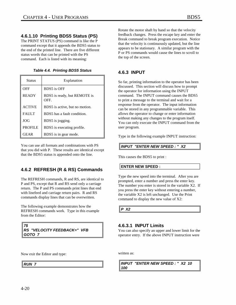
CHAPTER 4 - USER PROGRAMS BDS5
4-20
4.6.1.10 Printing BDS5 Status (PS)The PRINT STATUS (PS) command is like the Pcommand except that it appends the BDS5 status tothe end of the printed line. There are five differentstatus words that can be printed with the PScommand. Each is listed with its meaning:
Table 4.4. Printing BDS5 Status
Status Explanation
OFF BDS5 is OFF
READY BDS5 is ready, but REMOTE isOFF.
ACTIVE BDS5 is active, but no motion.
FAULT BDS5 has a fault condition.
JOG BDS5 is jogging.
PROFILE BDS5 is executing profile.
GEAR BDS5 is in gear mode.
You can use all formats and combinations with PSthat you did with P. These results are identical exceptthat the BDS5 status is appended onto the line.
4.6.2 REFRESH (R & RS) Commands
The REFRESH commands, R and RS, are identical toP and PS, except that R and RS send only a carriagereturn. The P and PS commands print lines that endwith linefeed and carriage return pairs. R and RScommands display lines that can be overwritten.
The following example demonstrates how theREFRESH commands work. Type in this examplefrom the Editor:
7$RS "VELOCITY FEEDBACK=" VFBGOTO 7
Now exit the Editor and type:
RUN 7
Rotate the motor shaft by hand so that the velocityfeedback changes. Press the escape key and enter theBreak command to break program execution. Noticethat the velocity is continuously updated, but the lineappears to be stationary. A similar program with theP or PS commands would cause the lines to scroll tothe top of the screen.
4.6.3 INPUT
So far, printing information to the operator has beendiscussed. This section will discuss how to promptthe operator for information using the INPUTcommand. The INPUT command causes the BDS5to print a message to the terminal and wait for aresponse from the operator. The input informationcan be stored in any programmable variable. Thisallows the operator to change or enter informationwithout making any changes to the program itself.You can only execute the INPUT command from theuser program.
Type in the following example INPUT instruction:
INPUT "ENTER NEW SPEED : " X2
This causes the BDS5 to print :
ENTER NEW SPEED :
Type the new speed into the terminal. After you areprompted, enter a number and press the enter key.The number you enter is stored in the variable X2. Ifyou press the enter key without entering a number,the variable X2 is left unchanged. Use the Printcommand to display the new value of X2:
P X2
4.6.3.1 INPUT LimitsYou can also specify an upper and lower limit for theoperator entry. If the above INPUT instruction were
written as:
INPUT "ENTER NEW SPEED : " X2 10100
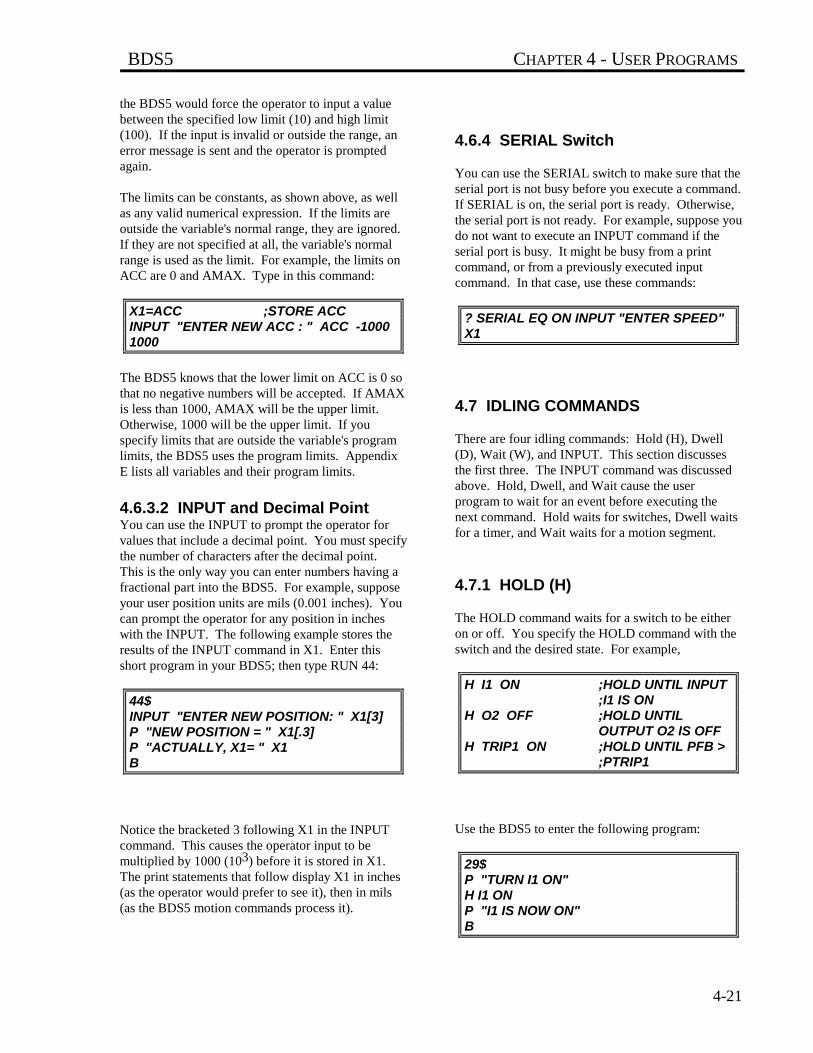
BDS5 CHAPTER 4 - USER PROGRAMS
4-21
the BDS5 would force the operator to input a valuebetween the specified low limit (10) and high limit(100). If the input is invalid or outside the range, anerror message is sent and the operator is promptedagain.
The limits can be constants, as shown above, as wellas any valid numerical expression. If the limits areoutside the variable's normal range, they are ignored.If they are not specified at all, the variable's normalrange is used as the limit. For example, the limits onACC are 0 and AMAX. Type in this command:
X1=ACC ;STORE ACCINPUT "ENTER NEW ACC : " ACC -10001000
The BDS5 knows that the lower limit on ACC is 0 sothat no negative numbers will be accepted. If AMAXis less than 1000, AMAX will be the upper limit.Otherwise, 1000 will be the upper limit. If youspecify limits that are outside the variable's programlimits, the BDS5 uses the program limits. AppendixE lists all variables and their program limits.
4.6.3.2 INPUT and Decimal PointYou can use the INPUT to prompt the operator forvalues that include a decimal point. You must specifythe number of characters after the decimal point.This is the only way you can enter numbers having afractional part into the BDS5. For example, supposeyour user position units are mils (0.001 inches). Youcan prompt the operator for any position in incheswith the INPUT. The following example stores theresults of the INPUT command in X1. Enter thisshort program in your BDS5; then type RUN 44:
44$INPUT "ENTER NEW POSITION: " X1[3]P "NEW POSITION = " X1[.3]P "ACTUALLY, X1= " X1B
Notice the bracketed 3 following X1 in the INPUTcommand. This causes the operator input to bemultiplied by 1000 (103) before it is stored in X1.The print statements that follow display X1 in inches(as the operator would prefer to see it), then in mils(as the BDS5 motion commands process it).
4.6.4 SERIAL Switch
You can use the SERIAL switch to make sure that theserial port is not busy before you execute a command.If SERIAL is on, the serial port is ready. Otherwise,the serial port is not ready. For example, suppose youdo not want to execute an INPUT command if theserial port is busy. It might be busy from a printcommand, or from a previously executed inputcommand. In that case, use these commands:
? SERIAL EQ ON INPUT "ENTER SPEED"X1
4.7 IDLING COMMANDS
There are four idling commands: Hold (H), Dwell(D), Wait (W), and INPUT. This section discussesthe first three. The INPUT command was discussedabove. Hold, Dwell, and Wait cause the userprogram to wait for an event before executing thenext command. Hold waits for switches, Dwell waitsfor a timer, and Wait waits for a motion segment.
4.7.1 HOLD (H)
The HOLD command waits for a switch to be eitheron or off. You specify the HOLD command with theswitch and the desired state. For example,
H I1 ON ;HOLD UNTIL INPUT ;I1 IS ON
H O2 OFF ;HOLD UNTIL OUTPUT O2 IS OFF
H TRIP1 ON ;HOLD UNTIL PFB > ;PTRIP1
Use the BDS5 to enter the following program:
29$P "TURN I1 ON"H I1 ONP "I1 IS NOW ON"B
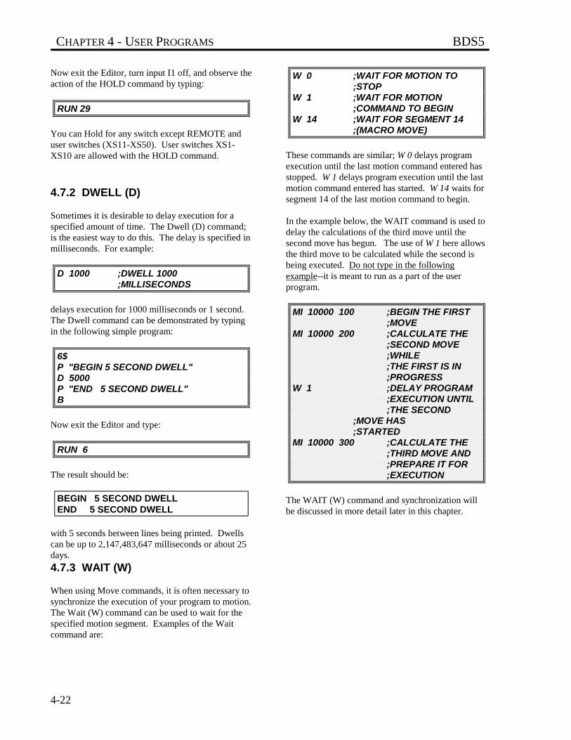
CHAPTER 4 - USER PROGRAMS BDS5
4-22
Now exit the Editor, turn input I1 off, and observe theaction of the HOLD command by typing:
RUN 29
You can Hold for any switch except REMOTE anduser switches (XS11-XS50). User switches XS1-XS10 are allowed with the HOLD command.
4.7.2 DWELL (D)
Sometimes it is desirable to delay execution for aspecified amount of time. The Dwell (D) command;is the easiest way to do this. The delay is specified inmilliseconds. For example:
D 1000 ;DWELL 1000 ;MILLISECONDS
delays execution for 1000 milliseconds or 1 second.The Dwell command can be demonstrated by typingin the following simple program:
6$P "BEGIN 5 SECOND DWELL"D 5000P "END 5 SECOND DWELL"B
Now exit the Editor and type:
RUN 6
The result should be:
BEGIN 5 SECOND DWELLEND 5 SECOND DWELL
with 5 seconds between lines being printed. Dwellscan be up to 2,147,483,647 milliseconds or about 25days.
4.7.3 WAIT (W)
When using Move commands, it is often necessary tosynchronize the execution of your program to motion.The Wait (W) command can be used to wait for thespecified motion segment. Examples of the Waitcommand are:
W 0 ;WAIT FOR MOTION TO ;STOP
W 1 ;WAIT FOR MOTION ;COMMAND TO BEGIN
W 14 ;WAIT FOR SEGMENT 14 ;(MACRO MOVE)
These commands are similar; W 0 delays programexecution until the last motion command entered hasstopped. W 1 delays program execution until the lastmotion command entered has started. W 14 waits forsegment 14 of the last motion command to begin.
In the example below, the WAIT command is used todelay the calculations of the third move until thesecond move has begun. The use of W 1 here allowsthe third move to be calculated while the second isbeing executed. Do not type in the followingexample--it is meant to run as a part of the userprogram.
MI 10000 100 ;BEGIN THE FIRST ;MOVE
MI 10000 200 ;CALCULATE THE ;SECOND MOVE ;WHILE;THE FIRST IS IN ;PROGRESS
W 1 ;DELAY PROGRAM ;EXECUTION UNTIL;THE SECOND
;MOVE HAS ;STARTED
MI 10000 300 ;CALCULATE THE ;THIRD MOVE AND;PREPARE IT FOR ;EXECUTION
The WAIT (W) command and synchronization willbe discussed in more detail later in this chapter.
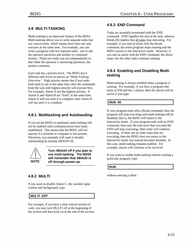
BDS5 CHAPTER 4 - USER PROGRAMS
4-23
4.8 MULTI-TASKING
Multi-tasking is an important feature of the BDS5.Multi-tasking allows you to write separate tasks thatrun concurrently, which means more than one taskexecutes at the same time. For example, you canwrite a program with two separate tasks: one to askthe operator questions and another to commandmotion. These two tasks can run independently sothat while the operator is answering questions, themotion continues.
Each task has a priority level. The BDS5 has 6different task levels as shown on "Multi-TaskingOverview." High priority means that if two tasksboth need to run at the same time, then the commandsfrom the task with highest priority will execute first.For example, Alarm A has the highest priority. IfAlarm A and Alarm B are "fired" at the same time,Alarm A will run until it is complete; then Alarm Bwill run until it is complete.
4.8.1 Multitasking and Autobauding
If you set the BDS5 to autobaud, multi-tasking willnot be enabled until communications have beenestablished. This means that the BDS5 will notoperate if a terminal or computer is not present.Therefore, you normally will want to disableautobauding by turning ABAUD off.
Turn ABAUD off if you plan touse multi-tasking. The BDS5will remember that ABAUD isoff through power-up.
4.8.2 MULTI
If you want to disable Alarm C, the variable inputroutine and background, type:
MULTI OFF
For example, if you have a time critical section ofcode, you may turn MULTI off at the beginning ofthe section and then back on at the end of the section.
4.8.3 END Command
Tasks are normally terminated with the ENDcommand. END signifies the end of the task, whereasBreak (B) implies that all tasks stop executing. Forexample, if you end an alarm with the Breakcommand, the entire program stops running and theBDS5 returns to the Interactive mode. However, ifyou end an alarm with the END command, the alarmstops, but the other tasks continue running.
4.8.4 Enabling and Disabling Multi-tasking
Multi-tasking is always enabled when a program isrunning. For example, if you have a program thatstarts at 55$ and has 2 alarms, then the alarms will beactive if you type:
RUN 55
If your program ends with a Break command, then theprogram will stop executing and multi-tasking will bedisabled; that is, the BDS5 will return to theInteractive mode. If your program ends with an ENDcommand, then only the task level that executed theEND will stop executing; other tasks will continueexecuting. If there are no other tasks that areexecuting, then the BDS5 does not return to theInteractive mode, but instead becomes dormant. Inthis case, multi-tasking remains enabled. Forexample, alarms will continue to be serviced.
If you want to enable multi-tasking without running aparticular program, type:
RUN
without entering a label.
NOTE
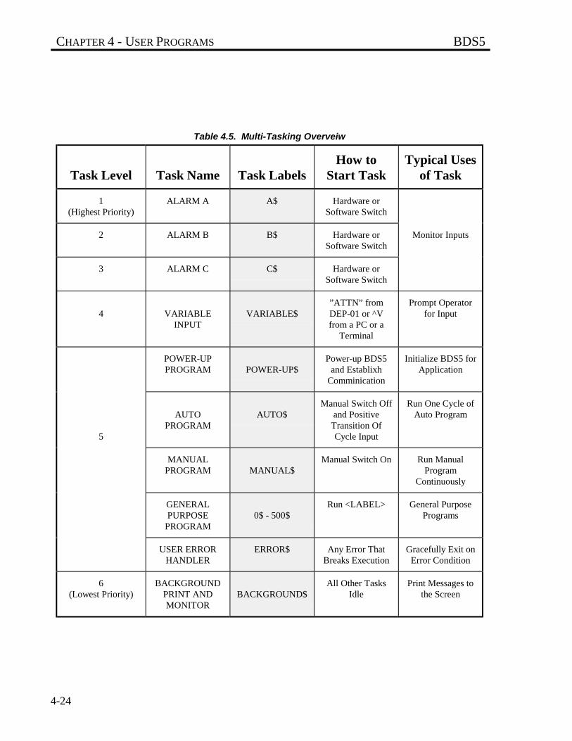
CHAPTER 4 - USER PROGRAMS BDS5
4-24
Table 4.5. Multi-Tasking Overveiw
Task Level Task Name Task LabelsHow to
Start TaskTypical Uses
of Task
1(Highest Priority)
ALARM A A$ Hardware orSoftware Switch
2 ALARM B B$ Hardware orSoftware Switch
Monitor Inputs
3 ALARM C C$ Hardware orSoftware Switch
4 VARIABLEINPUT
VARIABLE$”ATTN” fromDEP-01 or ^Vfrom a PC or a
Terminal
Prompt Operatorfor Input
POWER-UPPROGRAM POWER-UP$
Power-up BDS5and Establixh
Comminication
Initialize BDS5 forApplication
5
AUTOPROGRAM
AUTO$Manual Switch Off
and PositiveTransition OfCycle Input
Run One Cycle ofAuto Program
MANUALPROGRAM MANUAL$
Manual Switch On Run ManualProgram
Continuously
GENERALPURPOSE
PROGRAM0$ - 500$
Run <LABEL> General PurposePrograms
USER ERRORHANDLER
ERROR$ Any Error ThatBreaks Execution
Gracefully Exit onError Condition
6(Lowest Priority)
BACKGROUNDPRINT ANDMONITOR
BACKGROUND$All Other Tasks
IdlePrint Messages to
the Screen
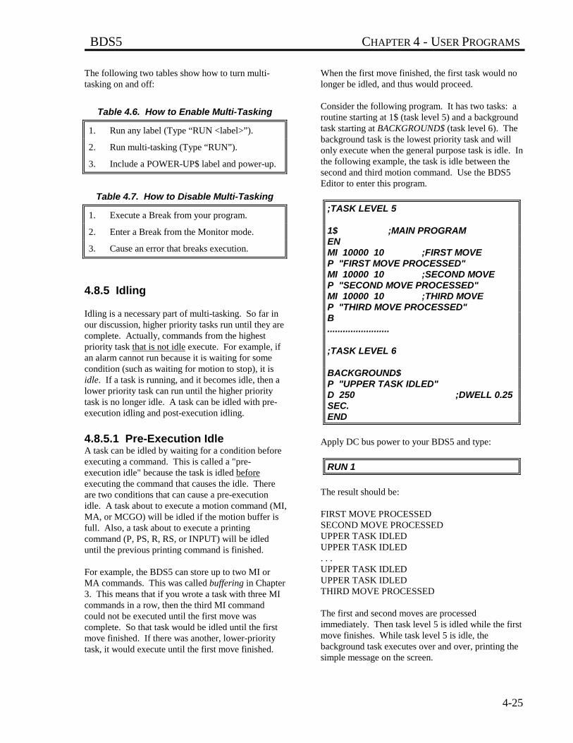
BDS5 CHAPTER 4 - USER PROGRAMS
4-25
The following two tables show how to turn multi-tasking on and off:
Table 4.6. How to Enable Multi-Tasking
1. Run any label (Type “RUN <label>”).
2. Run multi-tasking (Type “RUN”).
3. Include a POWER-UP$ label and power-up.
Table 4.7. How to Disable Multi-Tasking
1. Execute a Break from your program.
2. Enter a Break from the Monitor mode.
3. Cause an error that breaks execution.
4.8.5 Idling
Idling is a necessary part of multi-tasking. So far inour discussion, higher priority tasks run until they arecomplete. Actually, commands from the highestpriority task that is not idle execute. For example, ifan alarm cannot run because it is waiting for somecondition (such as waiting for motion to stop), it isidle. If a task is running, and it becomes idle, then alower priority task can run until the higher prioritytask is no longer idle. A task can be idled with pre-execution idling and post-execution idling.
4.8.5.1 Pre-Execution IdleA task can be idled by waiting for a condition beforeexecuting a command. This is called a "pre-execution idle" because the task is idled beforeexecuting the command that causes the idle. Thereare two conditions that can cause a pre-executionidle. A task about to execute a motion command (MI,MA, or MCGO) will be idled if the motion buffer isfull. Also, a task about to execute a printingcommand (P, PS, R, RS, or INPUT) will be idleduntil the previous printing command is finished.
For example, the BDS5 can store up to two MI orMA commands. This was called buffering in Chapter3. This means that if you wrote a task with three MIcommands in a row, then the third MI commandcould not be executed until the first move wascomplete. So that task would be idled until the firstmove finished. If there was another, lower-prioritytask, it would execute until the first move finished.
When the first move finished, the first task would nolonger be idled, and thus would proceed.
Consider the following program. It has two tasks: aroutine starting at 1$ (task level 5) and a backgroundtask starting at BACKGROUND$ (task level 6). Thebackground task is the lowest priority task and willonly execute when the general purpose task is idle. Inthe following example, the task is idle between thesecond and third motion command. Use the BDS5Editor to enter this program.
;TASK LEVEL 5
1$ ;MAIN PROGRAMENMI 10000 10 ;FIRST MOVEP "FIRST MOVE PROCESSED"MI 10000 10 ;SECOND MOVEP "SECOND MOVE PROCESSED"MI 10000 10 ;THIRD MOVEP "THIRD MOVE PROCESSED"B........................
;TASK LEVEL 6
BACKGROUND$P "UPPER TASK IDLED"D 250 ;DWELL 0.25SEC.END
Apply DC bus power to your BDS5 and type:
RUN 1
The result should be:
FIRST MOVE PROCESSEDSECOND MOVE PROCESSEDUPPER TASK IDLEDUPPER TASK IDLED. . .UPPER TASK IDLEDUPPER TASK IDLEDTHIRD MOVE PROCESSED
The first and second moves are processedimmediately. Then task level 5 is idled while the firstmove finishes. While task level 5 is idle, thebackground task executes over and over, printing thesimple message on the screen.
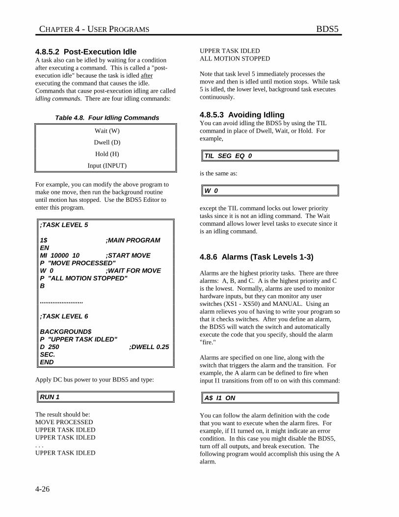
CHAPTER 4 - USER PROGRAMS BDS5
4-26
4.8.5.2 Post-Execution IdleA task also can be idled by waiting for a conditionafter executing a command. This is called a "post-execution idle" because the task is idled afterexecuting the command that causes the idle.Commands that cause post-execution idling are calledidling commands. There are four idling commands:
Table 4.8. Four Idling Commands
Wait (W)
Dwell (D)
Hold (H)
Input (INPUT)
For example, you can modify the above program tomake one move, then run the background routineuntil motion has stopped. Use the BDS5 Editor toenter this program.
;TASK LEVEL 5
1$ ;MAIN PROGRAMENMI 10000 10 ;START MOVEP "MOVE PROCESSED"W 0 ;WAIT FOR MOVEP "ALL MOTION STOPPED"B
........................
;TASK LEVEL 6
BACKGROUND$P "UPPER TASK IDLED"D 250 ;DWELL 0.25SEC.END
Apply DC bus power to your BDS5 and type:
RUN 1
The result should be:MOVE PROCESSEDUPPER TASK IDLEDUPPER TASK IDLED. . .UPPER TASK IDLED
UPPER TASK IDLEDALL MOTION STOPPED
Note that task level 5 immediately processes themove and then is idled until motion stops. While task5 is idled, the lower level, background task executescontinuously.
4.8.5.3 Avoiding IdlingYou can avoid idling the BDS5 by using the TILcommand in place of Dwell, Wait, or Hold. Forexample,
TIL SEG EQ 0
is the same as:
W 0
except the TIL command locks out lower prioritytasks since it is not an idling command. The Waitcommand allows lower level tasks to execute since itis an idling command.
4.8.6 Alarms (Task Levels 1-3)
Alarms are the highest priority tasks. There are threealarms: A, B, and C. A is the highest priority and Cis the lowest. Normally, alarms are used to monitorhardware inputs, but they can monitor any userswitches (XS1 - XS50) and MANUAL. Using analarm relieves you of having to write your program sothat it checks switches. After you define an alarm,the BDS5 will watch the switch and automaticallyexecute the code that you specify, should the alarm"fire."
Alarms are specified on one line, along with theswitch that triggers the alarm and the transition. Forexample, the A alarm can be defined to fire wheninput I1 transitions from off to on with this command:
A$ I1 ON
You can follow the alarm definition with the codethat you want to execute when the alarm fires. Forexample, if I1 turned on, it might indicate an errorcondition. In this case you might disable the BDS5,turn off all outputs, and break execution. Thefollowing program would accomplish this using the Aalarm.
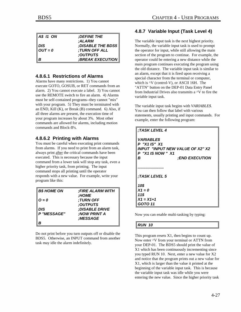
BDS5 CHAPTER 4 - USER PROGRAMS
4-27
A$ I1 ON ;DEFINE THE ;ALARM
DIS ;DISABLE THE BDS5OUT = 0 ;TURN OFF ALL
;OUTPUTSB ;BREAK EXECUTION
4.8.6.1 Restrictions of AlarmsAlarms have many restrictions. 1) You cannotexecute GOTO, GOSUB, or RET commands from analarm. 2) You cannot execute a label. 3) You cannotuse the REMOTE switch to fire an alarm. 4) Alarmsmust be self-contained programs--they cannot "mix"with your program. 5) They must be terminated withan END, Kill (K), or Break (B) command. 6) Also, ifall three alarms are present, the execution time ofyour program increases by about 3%. Most othercommands are allowed for alarms, including motioncommands and Block-IFs.
4.8.6.2 Printing with AlarmsYou must be careful when executing print commandsfrom alarms. If you need to print from an alarm task,always print after the critical commands have beenexecuted. This is necessary because the inputcommand from a lower task will stop any task, even ahigher priority task, from printing. The inputcommand stops all printing until the operatorresponds with a new value. For example, write yourprogram like this:
B$ HOME ON ;FIRE ALARM WITH ;HOME
O = 0 ;TURN OFF ;OUTPUTS
DIS ;DISABLE DRIVEP "MESSAGE" ;NOW PRINT A
;MESSAGEB
Do not print before you turn outputs off or disable theBDS5. Otherwise, an INPUT command from anothertask may idle the alarm indefinitely.
4.8.7 Variable Input (Task Level 4)
The variable input task is the next highest priority.Normally, the variable input task is used to promptthe operator for input, while still allowing the mainsection of the program to continue. For example, theoperator could be entering a new distance while themain program continues executing the program usingthe old distance. The variable input task is similar toan alarm, except that it is fired upon receiving aspecial character from the terminal or computer,which is ^V (control-V), or ASCII 16H. The"ATTN" button on the DEP-01 Data Entry Panelfrom Industrial Drives also transmits a ^V to fire thevariable input task.
The variable input task begins with VARIABLE$.You can then follow that label with variousstatements, usually printing and input commands. Forexample, enter the following program:
;TASK LEVEL 4
VARIABLE$P "X1 IS" X1INPUT "INPUT NEW VALUE OF X2" X2P "X1 IS NOW " X1B ;END EXECUTION
........................
;TASK LEVEL 5
10$X1 = 011$X1 = X1+1GOTO 11
Now you can enable multi-tasking by typing:
RUN 10
This program resets X1, then begins to count up.Now enter ^V from your terminal or ATTN fromyour DEP-01. The BDS5 should print the value ofX1 which has been continuously incrementing sinceyou typed RUN 10. Next, enter a new value for X2and notice that the program prints out a new value forX1, which is larger than the value it printed at thebeginning of the variable input task. This is becausethe variable input task was idle while you wereentering the new value. Since the higher priority task
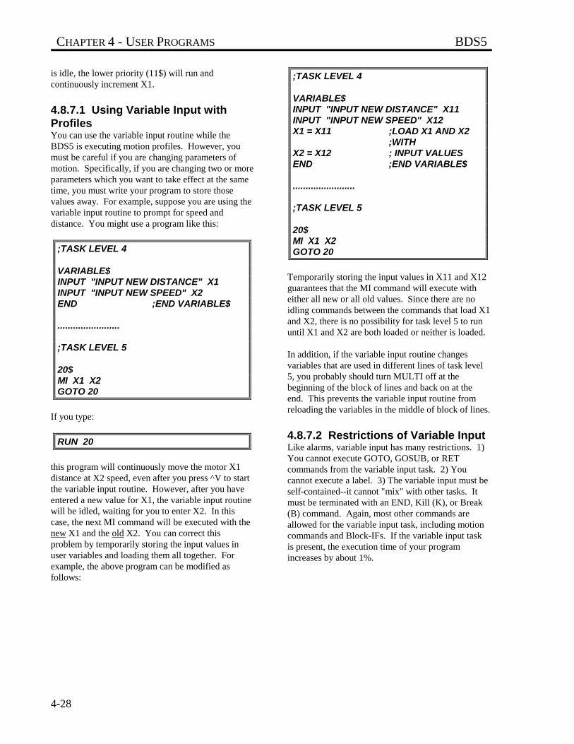
CHAPTER 4 - USER PROGRAMS BDS5
4-28
is idle, the lower priority (11$) will run andcontinuously increment X1.
4.8.7.1 Using Variable Input withProfilesYou can use the variable input routine while theBDS5 is executing motion profiles. However, youmust be careful if you are changing parameters ofmotion. Specifically, if you are changing two or moreparameters which you want to take effect at the sametime, you must write your program to store thosevalues away. For example, suppose you are using thevariable input routine to prompt for speed anddistance. You might use a program like this:
;TASK LEVEL 4
VARIABLE$INPUT "INPUT NEW DISTANCE" X1INPUT "INPUT NEW SPEED" X2END ;END VARIABLE$
........................
;TASK LEVEL 5
20$MI X1 X2GOTO 20
If you type:
RUN 20
this program will continuously move the motor X1distance at X2 speed, even after you press ^V to startthe variable input routine. However, after you haveentered a new value for X1, the variable input routinewill be idled, waiting for you to enter X2. In thiscase, the next MI command will be executed with thenew X1 and the old X2. You can correct thisproblem by temporarily storing the input values inuser variables and loading them all together. Forexample, the above program can be modified asfollows:
;TASK LEVEL 4
VARIABLE$INPUT "INPUT NEW DISTANCE" X11INPUT "INPUT NEW SPEED" X12X1 = X11 ;LOAD X1 AND X2
;WITHX2 = X12 ; INPUT VALUESEND ;END VARIABLE$
........................
;TASK LEVEL 5
20$MI X1 X2GOTO 20
Temporarily storing the input values in X11 and X12guarantees that the MI command will execute witheither all new or all old values. Since there are noidling commands between the commands that load X1and X2, there is no possibility for task level 5 to rununtil X1 and X2 are both loaded or neither is loaded.
In addition, if the variable input routine changesvariables that are used in different lines of task level5, you probably should turn MULTI off at thebeginning of the block of lines and back on at theend. This prevents the variable input routine fromreloading the variables in the middle of block of lines.
4.8.7.2 Restrictions of Variable InputLike alarms, variable input has many restrictions. 1)You cannot execute GOTO, GOSUB, or RETcommands from the variable input task. 2) Youcannot execute a label. 3) The variable input must beself-contained--it cannot "mix" with other tasks. Itmust be terminated with an END, Kill (K), or Break(B) command. Again, most other commands areallowed for the variable input task, including motioncommands and Block-IFs. If the variable input taskis present, the execution time of your programincreases by about 1%.
BDS5 CHAPTER 4 - USER PROGRAMS
4-29
4.8.8 Main Program Level (TaskLevel 5)
Most of the time, your program will run at task level5. All the program examples given earlier in thischapter executed at task level 5. Notice from "Multi-Tasking Overview" that all general purpose labels (0$- 500$) and many dedicated labels (POWER-UP$,AUTO$, MANUAL$, and ERROR$) share task level5. The routines that follow these labels share onetask level and cannot run concurrently. For example,you cannot run AUTO$ and MANUAL$concurrently. In other words, only one task-level-5routine can run at a time.
Alarms and the variable input task are higher prioritythan task level 5. For example, if an alarm fires whileyour program is running a task that begins at ageneral purpose label (task level 5), task level 5 willbe suspended until the alarm is complete. Thebackground program (BACKGROUND$) runs at thelowest level. Generally, alarms respond to conditionsthat are more urgent than most other sections of theprogram. Similarly, background is for tasks that arenot critical, such as printing. Multi-tasking controlswhich task runs by executing commands from thehighest priority task that is not idle.
The rest of this section will discuss the dedicatedlabels in task level 5: POWER-UP$, ERROR$,AUTO$, and MANUAL$.
4.8.8.1 Power-Up Routine (POWER-UP$)On power-up, the BDS5 checks your program to seeif you entered POWER-UP$. If you did, the power-up routine is executed. For example, enter thefollowing program:
POWER-UP$X1 = X1+1 ;SAMPLE COMMANDB
Now power-down your BDS5 for a few seconds andpower-up again. After establishing communications,the BDS5 should display the sign-on messagefollowed by:
EXECUTING POWER-UP LABEL-->
indicating that the power-up routine was executed.
The power-up label is runafter the autobaud.
If you want your program to start automatically onpower-up, begin it with POWER-UP$. If POWER-UP$ is not found in the program, then the BDS5powers-up in the Interactive mode. If the BDS5 is setto autobaud, then it will not execute the power-uplabel until communications have been established.
If you want to leave multi-tasking active after yourpower-up routine is done, end the power-up routinewith the END command instead of the Breakcommand. If your routine ends with the ENDcommand, then multi-tasking will be enabled, and theAlarms, Background, and other multi-taskingfunctions will be working. If you want to return tothe Interactive mode after power-up, then end thepower-up routine with the Break command.
4.8.8.2 Error Handler (ERROR$)When a serious error occurs, the BDS5 breaksexecution of your program and checks your programto see if you entered ERROR$. If you did, the errorhandler (that is, the routine that follows the ERROR$)is executed. All multi-tasking is suspended, includingalarms, when the error handler is being executed.
4.8.8.3 Auto Routine (AUTO$)If you want to start a program from an externalswitch, you should use the auto routine. You can usethe auto routine to interface to simple operator panelsor to programmable logic controllers (PLCs).
CYCLE (Connector C7, Pin 13) is a hardware inputthat, under the proper conditions, will cause theBDS5 to begin executing one cycle of the autoprogram. The AUTO program begins at AUTO$.CYCLE READY is a hardware output that indicatesthe BDS5 is ready to run another cycle of the AUTOprogram.
The following conditions must be met for the BDS5to execute the AUTO program. When theseconditions are met, the CYCLE READY output(Connector C7, Pin 23) will turn on. Otherwise, itwill be off.
NOTE
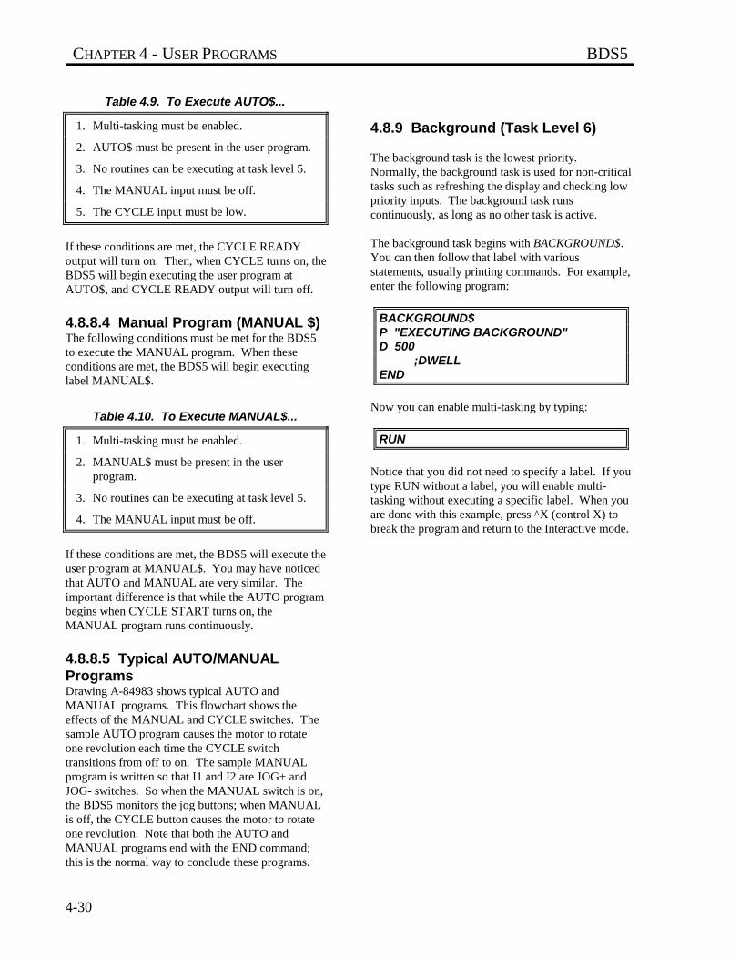
CHAPTER 4 - USER PROGRAMS BDS5
4-30
Table 4.9. To Execute AUTO$...
1. Multi-tasking must be enabled.
2. AUTO$ must be present in the user program.
3. No routines can be executing at task level 5.
4. The MANUAL input must be off.
5. The CYCLE input must be low.
If these conditions are met, the CYCLE READYoutput will turn on. Then, when CYCLE turns on, theBDS5 will begin executing the user program atAUTO$, and CYCLE READY output will turn off.
4.8.8.4 Manual Program (MANUAL $)The following conditions must be met for the BDS5to execute the MANUAL program. When theseconditions are met, the BDS5 will begin executinglabel MANUAL$.
Table 4.10. To Execute MANUAL$...
1. Multi-tasking must be enabled.
2. MANUAL$ must be present in the userprogram.
3. No routines can be executing at task level 5.
4. The MANUAL input must be off.
If these conditions are met, the BDS5 will execute theuser program at MANUAL$. You may have noticedthat AUTO and MANUAL are very similar. Theimportant difference is that while the AUTO programbegins when CYCLE START turns on, theMANUAL program runs continuously.
4.8.8.5 Typical AUTO/MANUALProgramsDrawing A-84983 shows typical AUTO andMANUAL programs. This flowchart shows theeffects of the MANUAL and CYCLE switches. Thesample AUTO program causes the motor to rotateone revolution each time the CYCLE switchtransitions from off to on. The sample MANUALprogram is written so that I1 and I2 are JOG+ andJOG- switches. So when the MANUAL switch is on,the BDS5 monitors the jog buttons; when MANUALis off, the CYCLE button causes the motor to rotateone revolution. Note that both the AUTO andMANUAL programs end with the END command;this is the normal way to conclude these programs.
4.8.9 Background (Task Level 6)
The background task is the lowest priority.Normally, the background task is used for non-criticaltasks such as refreshing the display and checking lowpriority inputs. The background task runscontinuously, as long as no other task is active.
The background task begins with BACKGROUND$.You can then follow that label with variousstatements, usually printing commands. For example,enter the following program:
BACKGROUND$P "EXECUTING BACKGROUND"D 500
;DWELLEND
Now you can enable multi-tasking by typing:
RUN
Notice that you did not need to specify a label. If youtype RUN without a label, you will enable multi-tasking without executing a specific label. When youare done with this example, press ^X (control X) tobreak the program and return to the Interactive mode.
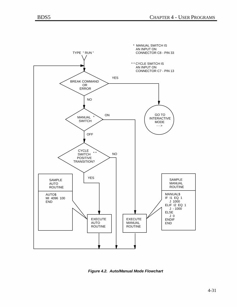
BDS5 CHAPTER 4 - USER PROGRAMS
4-31
Figure 4.2. Auto/Manual Mode Flowchart
BREAK COMMANDOR
ERROR
CYCLESWITCH
POSITIVE TRANSITION?
* *
GO TOINTERACTIVE
MODE- - >
MANUALSWITCH
*
EXECUTEMANUALROUTINE
SAMPLE AUTO ROUTINE
AUTO$MI 4096 100END
EXECUTEAUTOROUTINE
* MANUAL SWITCH IS AN INPUT ON CONNECTOR C8 - PIN 33
* * CYCLE SWITCH IS AN INPUT ON CONNECTOR C7 - PIN 13
TYPE " RUN "
YES
YES
NO
NO
ON
OFF
SAMPLE MANUAL ROUTINE
MANUAL$ IF I1 EQ 1 J 1000 ELIF I2 EQ 1 J - 1000 ELSE J 0 ENDIF END
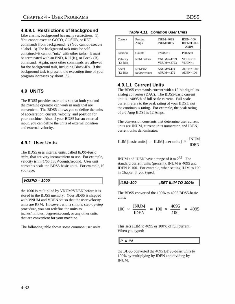
CHAPTER 4 - USER PROGRAMS BDS5
4-32
4.8.9.1 Restrictions of BackgroundLike alarms, background has many restrictions. 1)You cannot execute GOTO, GOSUB, or RETcommands from background. 2) You cannot executea label. 3) The background task must be self-contained--it cannot "mix" with other tasks. It mustbe terminated with an END, Kill (K), or Break (B)command. Again, most other commands are allowedfor the background task, including Block-IFs. If thebackground task is present, the execution time of yourprogram increases by about 1%.
4.9 UNITS
The BDS5 provides user units so that both you andthe machine operator can work in units that areconvenient. The BDS5 allows you to define the unitsof acceleration, current, velocity, and position foryour machine. Also, if your BDS5 has an externalinput, you can define the units of external positionand external velocity.
4.9.1 User Units
The BDS5 uses internal units, called BDS5-basicunits, that are very inconvenient to use. For example,velocity is in (1/65.536)*counts/second. User unitconstants scale the BDS5-basic units. For example, ifyou type:
VOSPD = 1000
the 1000 is multiplied by VNUM/VDEN before it isstored in the BDS5 memory. Your BDS5 is shippedwith VNUM and VDEN set so that the user velocityunits are RPM. However, with a simple, step-by-stepprocedure, you can redefine the units asinches/minutes, degrees/second, or any other unitsthat are convenient for your machine.
The following table shows some common user units.
Table 4.11. Common User Units
Current PercentAmps
INUM=4095INUM=4095
IDEN=100IDEN=FULL AMPS
Position Counts PNUM=1 PDEN=1
Velocity(12-Bit)
RPM rad/sec VNUM=44739VNUM=42723
VDEN=10VDEN=1
Accel(12-Bit)
RPM/secrad/(sec×sec)
ANUM=4474ANUM=4272
ADEN=1000ADEN=100
4.9.1.1 Current UnitsThe BDS5 commands current with a 12-bit digital-to-analog converter (DAC). The BDS5-basic currentunit is 1/4095th of full-scale current. Full-scalecurrent refers to the peak rating of your BDS5, notthe continuous rating. For example, the peak ratingof a 6 Amp BDS5 is 12 Amps.
The conversion constants that determine user currentunits are INUM, current units numerator, and IDEN,current units denominator:
ILIM[basic units] = ILIM[user units] INUM
IDEN×
INUM and IDEN have a range of 0 to 231. Forstandard current units (percent), INUM is 4095 andIDEN is 100. For example, when setting ILIM to 100in Chapter 3, you typed:
ILIM=100 ;SET ILIM TO 100%
The BDS5 converted the 100% to 4095 BDS5-basicunits:
100 INUM
IDEN = 100
4095
100 = 4095× ×
This sets ILIM to 4095 or 100% of full current.When you typed:
P ILIM
the BDS5 converted the 4095 BDS5-basic units to100% by multiplying by IDEN and dividing byINUM.

BDS5 CHAPTER 4 - USER PROGRAMS
4-33
4.9.1.2 Other User UnitsBDS5-basic units for position, velocity, andacceleration vary with the system resolution. Theresolution is determined by the R/D converter, whichconverts the position of the motor into a 12-, 14- or16-bit number. The system resolution is indicated bythe model number.
Table 4.12. System Resolutions
R/D Resolution Counts in One Revolution
12-Bit 4096
14-Bit 16384
16-Bit 65536
When shipped from the factory, the standard BDS5user units are velocity in RPM, acceleration inRPM/second, current in percent of full-scale, andposition in counts.
The velocity and acceleration units shown on"COMMON USER UNITS" above are for thestandard 12-bit R/D converter. For 14-bit resolution,multiply VNUM and ANUM by 4. For 16-bitresolution, multiply by 16. Do not change VDEN orADEN.
All variables that have units associated with themshould be set after you have specified the user units.This is because the values actually stored in thevariables are in BDS5-basic units, not user units.Changing the user units will not affect the basic valuestored in the variables. For example, if you wantVOSPD to be 100 inches/minute, and you type:
VOSPD = 100
when velocity units are in RPM, VOSPD would be100 RPM. Then, if you change the velocity units toinches/minute, VOSPD would remain 100 RPM--itwould just be converted to the equivalent of100 RPM in inches/minute. If you change any userunits, you should reset all programmable variablesthat depend on those units. Refer to Appendix E,which lists all variables and the units associated withthem.
4.9.1.3 External UnitsExternal units are for the external inputs, VEXT andPEXT. The user units are set by VXNUM and
VXDEN for external velocity (VEXT) and byPXNUM and PXDEN for external position (PEXT).Drawing A-84866 shows how external position andvelocity come into a slave BDS5 and are displayed asPEXT and VEXT.
If the external input is a system with the sameresolution as your BDS5, set external units asfollows:
Table 4.13. Setting External Units inMaster/Slave Systems
VXNUM = VNUM
VXDEN = VDEN
PXNUM = PNUM
PXDEN = PDEN
If the command is something other than a motor ofsimilar resolution, see "Machine Specific Units" inthe next section.
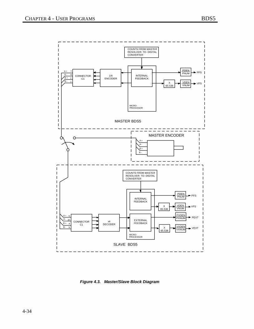
CHAPTER 4 - USER PROGRAMS BDS5
4-34
Figure 4.3. Master/Slave Block Diagram
COUNTS FROM MASTERRESOLVER- TO- DIGITALCONVERTER
COUNTS FROM MASTERRESOLVER- TO- DIGITALCONVERTER
CONNECTORC1
CONNECTORC1
1/4ENCODER
INTERNALFEEDBACK
INTERNALFEEDBACK
EXTERNALFEEDBACK
x4DECODER
X65.536
X65.536
X65.536
PDENPNUM
PDENPNUM
VDENVNUM
VDENVNUM
VXDENVXNUM
PXDENPXNUM PEXT
VEXT
PFS
VFS
VFS
PFS
MICRO-PROCESSOR
A -
A +
B +
B -
1
6
2
7
MASTER BDS5
MICRO-PROCESSOR
A -
B +
B -
SLAVE BDS5
A + 5
10
4
9
A -
B +
B -
A +
MASTER ENCODER
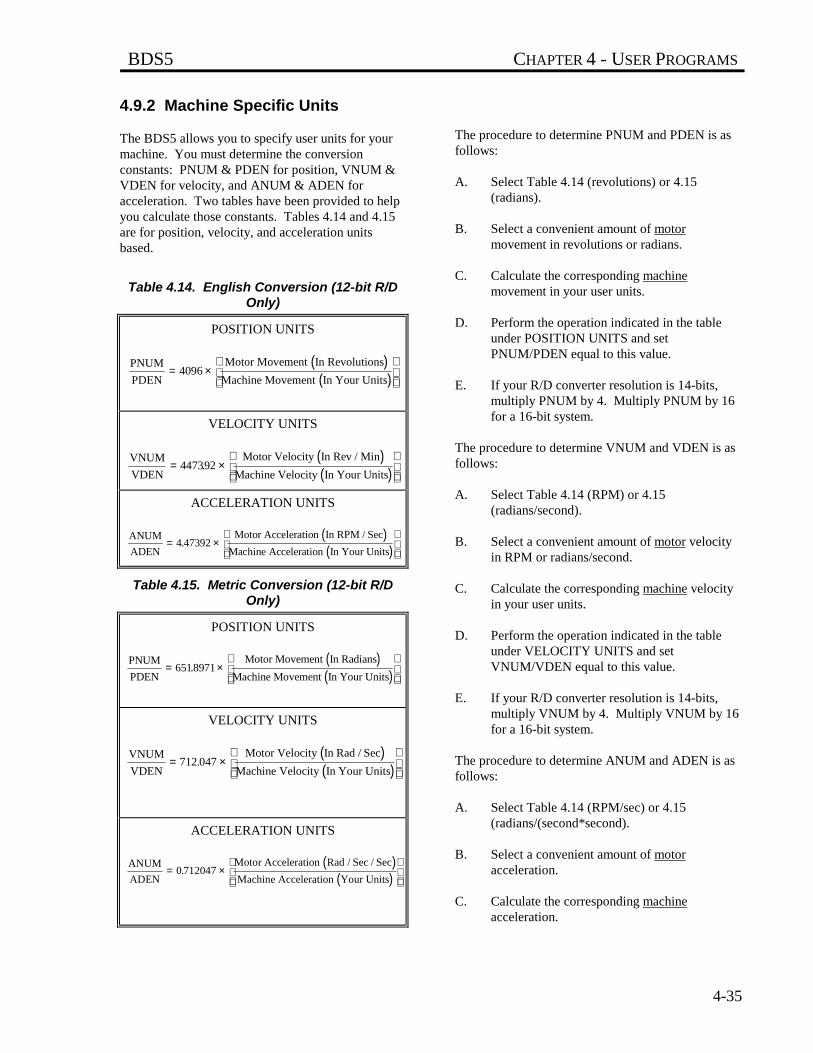
BDS5 CHAPTER 4 - USER PROGRAMS
4-35
4.9.2 Machine Specific Units
The BDS5 allows you to specify user units for yourmachine. You must determine the conversionconstants: PNUM & PDEN for position, VNUM &VDEN for velocity, and ANUM & ADEN foracceleration. Two tables have been provided to helpyou calculate those constants. Tables 4.14 and 4.15are for position, velocity, and acceleration unitsbased.
Table 4.14. English Conversion (12-bit R/DOnly)
POSITION UNITS
( )( )
PNUM
PDEN
Motor Movement In Revolutions
Machine Movement In Your Units= ×
4096
VELOCITY UNITS
( )( )
VNUM
VDEN
Motor Velocity In Rev / Min
Machine Velocity In Your Units= ×
447392.
ACCELERATION UNITS
( )( )
ANUM
ADEN
Motor Acceleration In RPM / Sec
Machine Acceleration In Your Units= ×
4 47392.
Table 4.15. Metric Conversion (12-bit R/DOnly)
POSITION UNITS
( )( )
PNUM
PDEN
Motor Movement In Radians
Machine Movement In Your Units= ×
6518971.
VELOCITY UNITS
( )( )
VNUM
VDEN
Motor Velocity In Rad / Sec
Machine Velocity In Your Units= ×
712 047.
ACCELERATION UNITS
( )( )
ANUM
ADEN
Motor Acceleration Rad / Sec / Sec
Machine Acceleration Your Units= ×
0 712047.
The procedure to determine PNUM and PDEN is asfollows:
A. Select Table 4.14 (revolutions) or 4.15(radians).
B. Select a convenient amount of motormovement in revolutions or radians.
C. Calculate the corresponding machinemovement in your user units.
D. Perform the operation indicated in the tableunder POSITION UNITS and setPNUM/PDEN equal to this value.
E. If your R/D converter resolution is 14-bits,multiply PNUM by 4. Multiply PNUM by 16for a 16-bit system.
The procedure to determine VNUM and VDEN is asfollows:
A. Select Table 4.14 (RPM) or 4.15(radians/second).
B. Select a convenient amount of motor velocityin RPM or radians/second.
C. Calculate the corresponding machine velocityin your user units.
D. Perform the operation indicated in the tableunder VELOCITY UNITS and setVNUM/VDEN equal to this value.
E. If your R/D converter resolution is 14-bits,multiply VNUM by 4. Multiply VNUM by 16for a 16-bit system.
The procedure to determine ANUM and ADEN is asfollows:
A. Select Table 4.14 (RPM/sec) or 4.15(radians/(second*second).
B. Select a convenient amount of motoracceleration.
C. Calculate the corresponding machineacceleration.
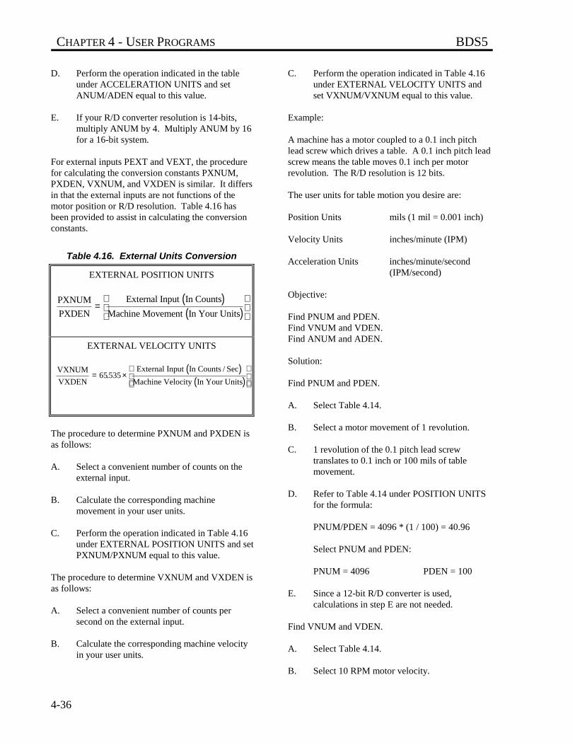
CHAPTER 4 - USER PROGRAMS BDS5
4-36
D. Perform the operation indicated in the tableunder ACCELERATION UNITS and setANUM/ADEN equal to this value.
E. If your R/D converter resolution is 14-bits,multiply ANUM by 4. Multiply ANUM by 16for a 16-bit system.
For external inputs PEXT and VEXT, the procedurefor calculating the conversion constants PXNUM,PXDEN, VXNUM, and VXDEN is similar. It differsin that the external inputs are not functions of themotor position or R/D resolution. Table 4.16 hasbeen provided to assist in calculating the conversionconstants.
Table 4.16. External Units Conversion
EXTERNAL POSITION UNITS
( )( )
PXNUM
PXDEN
External Input In Counts
Machine Movement In Your Units=
EXTERNAL VELOCITY UNITS
( )( )
VXNUM
VXDEN
External Input In Counts / Sec
Machine Velocity In Your Units= ×
65 535.
The procedure to determine PXNUM and PXDEN isas follows:
A. Select a convenient number of counts on theexternal input.
B. Calculate the corresponding machinemovement in your user units.
C. Perform the operation indicated in Table 4.16under EXTERNAL POSITION UNITS and setPXNUM/PXNUM equal to this value.
The procedure to determine VXNUM and VXDEN isas follows:
A. Select a convenient number of counts persecond on the external input.
B. Calculate the corresponding machine velocityin your user units.
C. Perform the operation indicated in Table 4.16under EXTERNAL VELOCITY UNITS andset VXNUM/VXNUM equal to this value.
Example:
A machine has a motor coupled to a 0.1 inch pitchlead screw which drives a table. A 0.1 inch pitch leadscrew means the table moves 0.1 inch per motorrevolution. The R/D resolution is 12 bits.
The user units for table motion you desire are:
Position Units mils (1 mil = 0.001 inch)
Velocity Units inches/minute (IPM)
Acceleration Units inches/minute/second(IPM/second)
Objective:
Find PNUM and PDEN.Find VNUM and VDEN.Find ANUM and ADEN.
Solution:
Find PNUM and PDEN.
A. Select Table 4.14.
B. Select a motor movement of 1 revolution.
C. 1 revolution of the 0.1 pitch lead screwtranslates to 0.1 inch or 100 mils of tablemovement.
D. Refer to Table 4.14 under POSITION UNITSfor the formula:
PNUM/PDEN = 4096 * (1 / 100) = 40.96
Select PNUM and PDEN:
PNUM = 4096 PDEN = 100
E. Since a 12-bit R/D converter is used,calculations in step E are not needed.
Find VNUM and VDEN.
A. Select Table 4.14.
B. Select 10 RPM motor velocity.
BDS5 CHAPTER 4 - USER PROGRAMS
4-37
C. 10 RPM of the 0.1 pitch lead screw translatesto 1 IPM of table velocity.
D. Refer to Table 4.14 under VELOCITY UNITSfor the formula:
VNUM/VDEN = 4473.92 * (10 / 1) = 44739.2
Select VNUM and VDEN:
VNUM = 447392 VDEN = 10
Find ANUM and ADEN.
A. Refer to Table 4.14.
B. Select 10 RPM/second motor acceleration.
C. A 10 RPM/second acceleration of the 0.1 pitchlead screw translates to 1 IPM/second of tableacceleration.
D. Refer to Table 4.14 under ACCELERATIONUNITS for the formula:
ANUM/ADEN = 4.47392 * (10 / 1) = 44.7392
Select ANUM and ADEN:
ANUM = 447392 ADEN = 10000
The BDS5 does not support floating point operations.You must use fractional units to make the resolutionfiner. For example, if the units for velocity need to befiner than IPM, 0.1 IPM could be chosen. In this caseVDEN would be 100 instead of 10. Then to jog at 1IPM the command J 10 would be required.
4.9.3 Position Rotary Mode,ROTARY, & PROTARY
The BDS5 stores position in a 32-bit number. Thisnumber is large enough to count many revolutions.For example, the 32-bit number will store the countsfrom a 12-bit R/D converter for about 10 millionrevolutions before the 32-bit limit is exceeded.Normally, this is sufficient. However, someapplications require the motor to rotate in onedirection indefinitely. Eventually, the 32-bit limitwill be exceeded, resulting in an error. The Rotarymode allows the BDS5 to support these unidirectionalapplications.
The Rotary mode forces all position-related variablesto "roll-over" after position feedback (PFB) exceeds aspecified limit. The variables that are rolled over arePFB, PCMD, and PFNL. The rotary distance (thespecified limit before roll-over) is stored inPROTARY. PROTARY is in position units.
When ROTARY is on, the Rotary mode is enabled.If PFB is greater than PROTARY, then PFB, PCMD,and PFNL are decremented by PROTARY. If PFB isless than zero, then PFB, PCMD, and PFNL areincremented by PROTARY. Note that DIR=0 doesnot work well with the Rotary mode as PCMD , PFB,and PFNL are always less than zero.
You cannot change PNUM, PDEN, or PROTARYwhen ROTARY is ON. In addition, you mustnormalize PFB so that 0 < PFB < PROTARY beforeturning ROTARY ON. Enable the Rotary mode bytyping:
ROTARY ON
4.9.3.1 Choosing PROTARY, PNUM,and PDENIf you have a rotary application such as a printingdrum, set PROTARY in position user units to be theexact equivalent of one revolution of the drum.PROTARY must be exact or position error willaccumulate over many revolutions. For example,suppose the motor of an application is connectedthrough a 5:3 gearbox. For convenience, assume theuser units are in degrees of the table. PROTARYwould be one revolution of the table or 360 degrees.How do you select PNUM, PDEN, and PROTARY?
The key is selecting PNUM and PDEN so thatPROTARY can be represented exactly as an integer.This does not mean that PROTARY must be aninteger number of counts. In fact, it normally will notbe. Returning to the example, a motor movement of 5revolutions would cause 3 revolutions of machine(table) rotation, or 1080 user units (degrees).Returning to Table 4.14,
PNUM = 4096 * 5 PDEN = 360 * 3
thus, PROTARY would be 360. Notice thatPROTARY is not exact in counts; it is 5/3 of arevolution or 6826 and 2/3 counts. However, it is
CHAPTER 4 - USER PROGRAMS BDS5
4-38
exact in user units. Therefore, error will notaccumulate as the table rotates.
The incorrect way to choose PNUM, PDEN, andPROTARY would be to select PNUM and PDEN sothat PROTARY could not be represented as aninteger. For example, we could have stated that 5/3revolution of the motor would cause one revolution ofthe machine. Then:
PNUM = 4096 * 5/3 or about 6827
PDEN = 360
In this case, PROTARY would not be exactly 360degrees (actually, it would be 359.98 degrees), so thaterror would accumulate as the table turned.Remember, PROTARY must be an integer in userunits, though it can have fractional counts.
4.9.3.2 Rotary Mode and AbsoluteMovesWhen the BDS5 is in the Rotary mode, you must limitthe final position of all absolute moves to between 0and PROTARY. If you want to move more thanPROTARY, you can use incremental moves. Forexample,
MI 50*PROTARY
is a legal command.
4.10 SERIAL COMMUNICATIONS
This section discusses details of BDS5 serialcommunications. This includes autobauding,multidrop connections, and transferring your programto and from the BDS5. If you are using Motion Link,the Industrial Drives software package for the BDS5,you do not need to read the sections on transmittingand receiving your program, or on system dump.Motion Link provides facilities for these functions.
4.10.1 Autobauding
It is not necessary to set the baud rate on the BDS5directly. Once the BDS5 is properly connected, it candetermine the terminal's baud rate, then set its ownbaud rate accordingly. This is called autobauding.After the BDS5 determines the correct baud rate, itwill store this rate away in BAUD. The BDS5 willflash the CPU light to indicate that it is autobauding.In order for the BDS5 to determine the baud ratesetting on your terminal, you must press the enter keyseveral times. Press only the enter key; otherwise theBDS5 will not autobaud correctly. The system willonly autobaud during power-up.
4.10.1.1 Setting the BDS5 toAutobaudThere are three ways to set the BDS5 to autobaud atpower-up:
1. Powering-up with the MOTION input off.
2. Turning the switch ABAUD on before the nextpower-up.
3. Setting the value of the variable BAUD to aninvalid value (say, 1000).
4.10.1.2 Autobauding and MOTIONIf the MOTION input is off during power-up, theBDS5 will autobaud. (Note that this also sets ADDRto zero.) This allows you to command autobaudwithout being able to communicate with the BDS5.The other ways to start autobauding require thatcommunications be set up first. See the section onADDR and multidrop communication later in thischapter for more information.
4.10.1.3 Enabling Autobaud withABAUDThe autobaud software switch (ABAUD) is the usualway to tell the BDS5 to autobaud on power-up. IfABAUD is on, then the system will autobaud when itis powered-up or reset, provided that the multidropaddress, ADDR, is 0. After a successful autobaud,the baud rate will be stored in BAUD.
BDS5 CHAPTER 4 - USER PROGRAMS
4-39
If you do not want your BDS5 to autobaud when theunit is powered-up, then turn ABAUD off. This isimportant if you want the BDS5 to run the Power-UpLabel (POWER-UP$), because if ABAUD is on, theBDS5 will not execute the program untilcommunications have been established.
4.10.1.4 Baud Rate, BAUDIf the MOTION input is on, ADDR is zero, andABAUD is off, then the system will check thevariable BAUD for the desired baud rate. If it is not avalid baud rate, the BDS5 will autobaud. After asuccessful autobaud, an error is generated indicatingthat the baud rate was out-of-range on power-up.
4.10.2 Prompts
The BDS5 issues a prompt when it is ready to receivea new command. Prompts are discussed in Chapter 3.The BDS5 allows you to suppress the promptcharacters by typing:
PROMPT OFF
PROMPT is turned on at power-up. Prompts areparticularly important when communicating withcomputers, since the computer that is transmitting tothe BDS5 must wait for a prompt before beginning anew line. After the prompt is received, the computercan transmit at the full baud rate, without insertingdelays.
4.10.3 Serial Watchdog
The BDS5 provides a serial watchdog timer forapplications where a command should be receivedfrom a computer on a regular basis. If a completecommand is not received from the serial port in thespecified time, an error will be generated that willdisable the BDS5 and break the user program.
The serial watchdog is a safety feature that disablesthe BDS5 if the communications line breaks. Theserial watchdog waits for a carriage return to signify acompleted command. It does not test the validity ofthe command. For example, if your computer failsand begins sending random carriage returns, the serialwatchdog will not generate an error.
The BDS5 serial watchdog isintended to detect a brokenserial communications line. Itdoes not test the validity ofdata received from yourcomputer.
Set WTIME in milliseconds to the time that you wantthe serial watchdog to timeout. To enable the serialwatchdog, type:
WATCH ON
4.10.4 Transmit/Receive Programs
The BDS5 provides commands that allow programsto be transmitted and received without using theEditor. These commands are intended forapplications which require that a computer directlytransmit and receive programs. This does not includeMotion Link, the software communications packagethat is run from an IBM-PC or compatible. Refer tothe Installation and Setup Manual forcommunications format.
4.10.4.1 <BDS Command Receivingfrom the BDS5The <BDS command is used to send the BDS5 userprogram through the serial port to the terminal orcomputer. The transmission can be stopped bysending an escape character. You should not rely onthe BDS5 to store all your programs. Keep back-upcopies elsewhere. The <BDS command will causethe BDS5 to transmit the entire user program to yourcomputer. It cannot be issued in the Program mode.For example, from the terminal type:
<BDS
and the BDS5 will respond by printing out the entireuser program.
4.10.4.2 The >BDS CommandTransmitting to the BDS5The >BDS command is used to send a new userprogram through the serial port to the BDS5. Thetransmission is ended by sending an escape character.Note that this command writes over the contents of
WARNING
CHAPTER 4 - USER PROGRAMS BDS5
4-40
the user program stored in the BDS5. This commandallows the program to be directly entered, presumablyby a computer, to the BDS5. It cannot be issued inthe program mode.
The >BDS command writesover the entire user program.
The BDS5 issues the "l->" prompt to indicate that itis ready to load a new program line. If you areloading from a computer, you must wait for theprompt before beginning to transmit a new line.
The >BDS command is password protected. If apassword was set in the BDS5 Editor, then it must begiven in the >BDS command.
Typing in these examples willerase the user program in theBDS5. Do not type them inunless your program isbacked up.
For example, if a password was not set in the Editor:
>BDS
will begin transmitting the new program. If you pressthe escape key before typing anything else, theprocess will be aborted without changing the programin the BDS5.
If a password was set in the Editor, then the passwordmust follow the command. For example, if thepassword was set as SECRET, type:
>BDS SECRET
and the BDS5 will accept programs directly from theterminal.
The user program is stored in battery backed-upmemory. If the program changes because of ahardware problem, the BDS5 issues a "USERPROGRAM CORRUPT" error. The >BDScommand resets the user program memory, whicheliminates this condition.
4.10.5 System Dump
The BDS5 can transmit all variables in addition to theuser program. This is called a system dump, and yourequest it with the DUMP command. For example,type:
DUMP
and the BDS5 will provide pages of informationincluding the program, all BDS5 variables, uservariables, and user switches. This also includes allprotected variables.
The system dump is provided so that the informationfrom the dump can be directly re-transmitted to anyBDS5. This changes all NON-PROTECTEDvariables. The DUMP command precedes protectedvariables with a semicolon (";"). This makes the linea comment so that when the line is re-transmitted, ithas no effect. If the ";" were not there, re-transmitting the dump information would generate anerror when a protected variable was changed. Everyline of the user program is preceded with a semicolonfor the same reason.
4.10.5.1 Version DumpYour BDS5 will print out its firmware version at anytime with the DUMP VERSION command:
DUMP VERSION
4.10.6 Multidrop Communications
This function is not availablefor the RS-232 option.
Multidrop communication allows you to have many(up to 32) axes on one serial line. This is onlysupported with RS-485. When the BDS5 is inMultidrop mode, each axis must have a uniqueaddress. This address is a prefix on allcommunications to and from the BDS5. The addressis stored in variable ADDR. ADDR is set to 0 forstandard (single-drop) communications. Validaddresses are 48 (ASCII '0') through 57 (ASCII '9')and 65 (ASCII 'A') through 90 (ASCII 'Z') (see
NOTE
NOTE
NOTE
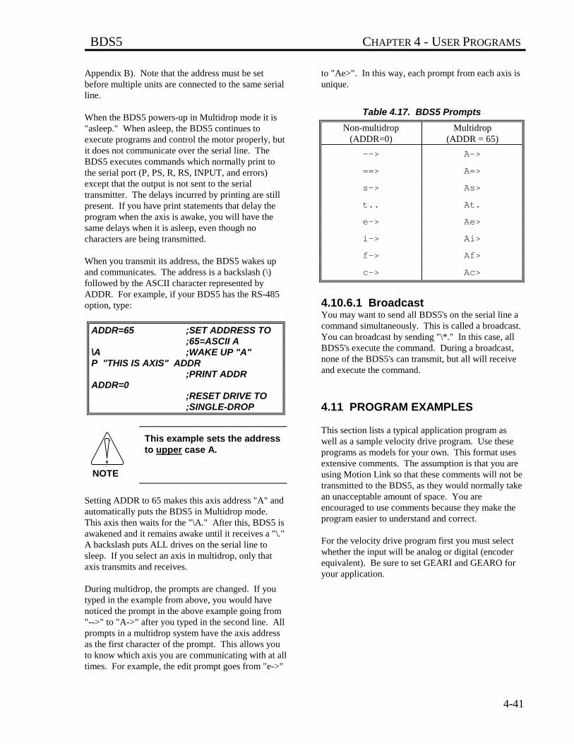
BDS5 CHAPTER 4 - USER PROGRAMS
4-41
Appendix B). Note that the address must be setbefore multiple units are connected to the same serialline.
When the BDS5 powers-up in Multidrop mode it is"asleep." When asleep, the BDS5 continues toexecute programs and control the motor properly, butit does not communicate over the serial line. TheBDS5 executes commands which normally print tothe serial port (P, PS, R, RS, INPUT, and errors)except that the output is not sent to the serialtransmitter. The delays incurred by printing are stillpresent. If you have print statements that delay theprogram when the axis is awake, you will have thesame delays when it is asleep, even though nocharacters are being transmitted.
When you transmit its address, the BDS5 wakes upand communicates. The address is a backslash (\)followed by the ASCII character represented byADDR. For example, if your BDS5 has the RS-485option, type:
ADDR=65 ;SET ADDRESS TO ;65=ASCII A
\A ;WAKE UP "A"P "THIS IS AXIS" ADDR
;PRINT ADDRADDR=0
;RESET DRIVE TO ;SINGLE-DROP
This example sets the addressto upper case A.
Setting ADDR to 65 makes this axis address "A" andautomatically puts the BDS5 in Multidrop mode.This axis then waits for the "\A." After this, BDS5 isawakened and it remains awake until it receives a "\."A backslash puts ALL drives on the serial line tosleep. If you select an axis in multidrop, only thataxis transmits and receives.
During multidrop, the prompts are changed. If youtyped in the example from above, you would havenoticed the prompt in the above example going from"-->" to "A->" after you typed in the second line. Allprompts in a multidrop system have the axis addressas the first character of the prompt. This allows youto know which axis you are communicating with at alltimes. For example, the edit prompt goes from "e->"
to "Ae>". In this way, each prompt from each axis isunique.
Table 4.17. BDS5 Prompts
Non-multidrop(ADDR=0)
Multidrop(ADDR = 65)
--> A->
==> A=>
s-> As>
t.. At.
e-> Ae>
i-> Ai>
f-> Af>
c-> Ac>
4.10.6.1 BroadcastYou may want to send all BDS5's on the serial line acommand simultaneously. This is called a broadcast.You can broadcast by sending "\*." In this case, allBDS5's execute the command. During a broadcast,none of the BDS5's can transmit, but all will receiveand execute the command.
4.11 PROGRAM EXAMPLES
This section lists a typical application program aswell as a sample velocity drive program. Use theseprograms as models for your own. This format usesextensive comments. The assumption is that you areusing Motion Link so that these comments will not betransmitted to the BDS5, as they would normally takean unacceptable amount of space. You areencouraged to use comments because they make theprogram easier to understand and correct.
For the velocity drive program first you must selectwhether the input will be analog or digital (encoderequivalent). Be sure to set GEARI and GEARO foryour application.
NOTE
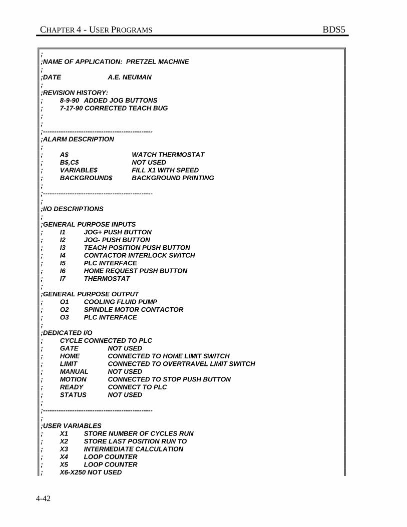
CHAPTER 4 - USER PROGRAMS BDS5
4-42
;;NAME OF APPLICATION: PRETZEL MACHINE;;DATE A.E. NEUMAN;;REVISION HISTORY:; 8-9-90 ADDED JOG BUTTONS; 7-17-90 CORRECTED TEACH BUG;;;-------------------------------------------------;ALARM DESCRIPTION;; A$ WATCH THERMOSTAT; B$,C$ NOT USED; VARIABLE$ FILL X1 WITH SPEED; BACKGROUND$ BACKGROUND PRINTING;;-------------------------------------------------;;I/O DESCRIPTIONS;;GENERAL PURPOSE INPUTS; I1 JOG+ PUSH BUTTON; I2 JOG- PUSH BUTTON; I3 TEACH POSITION PUSH BUTTON; I4 CONTACTOR INTERLOCK SWITCH; I5 PLC INTERFACE; I6 HOME REQUEST PUSH BUTTON; I7 THERMOSTAT;;GENERAL PURPOSE OUTPUT; O1 COOLING FLUID PUMP; O2 SPINDLE MOTOR CONTACTOR; O3 PLC INTERFACE;;DEDICATED I/O; CYCLE CONNECTED TO PLC; GATE NOT USED; HOME CONNECTED TO HOME LIMIT SWITCH; LIMIT CONNECTED TO OVERTRAVEL LIMIT SWITCH; MANUAL NOT USED; MOTION CONNECTED TO STOP PUSH BUTTON; READY CONNECT TO PLC; STATUS NOT USED;;-------------------------------------------------;;USER VARIABLES; X1 STORE NUMBER OF CYCLES RUN; X2 STORE LAST POSITION RUN TO; X3 INTERMEDIATE CALCULATION; X4 LOOP COUNTER; X5 LOOP COUNTER; X6-X250 NOT USED
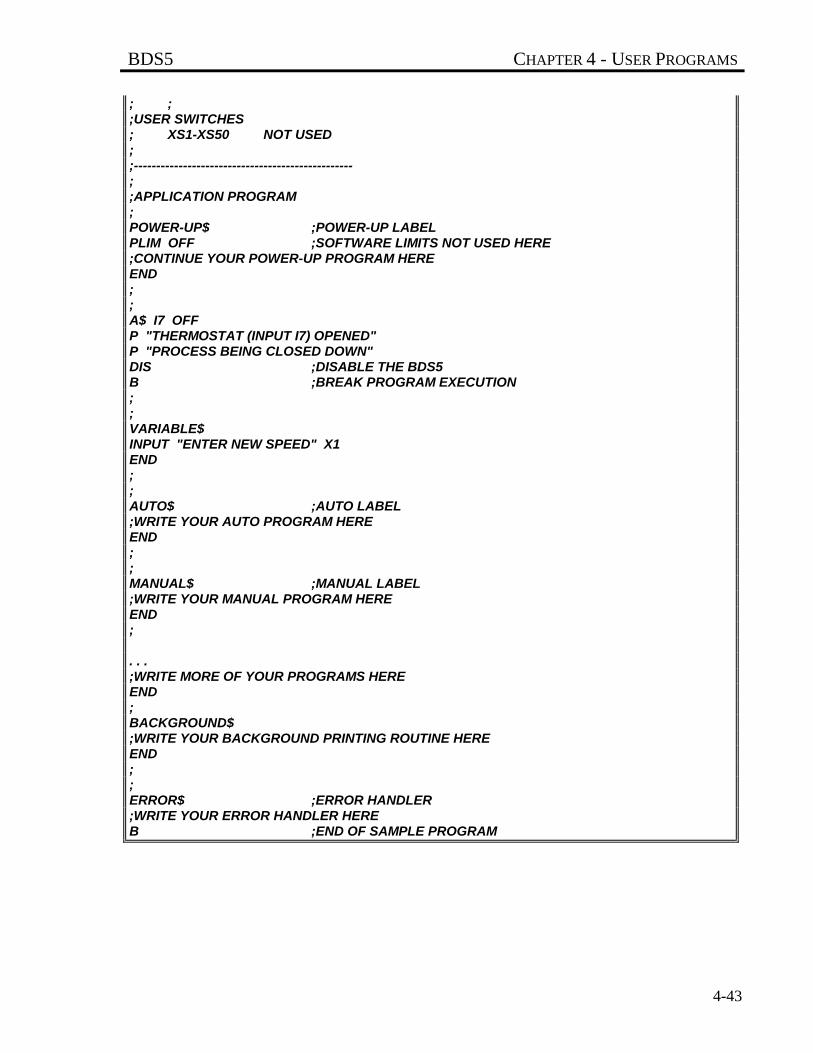
BDS5 CHAPTER 4 - USER PROGRAMS
4-43
; ;;USER SWITCHES; XS1-XS50 NOT USED;;-------------------------------------------------;;APPLICATION PROGRAM;POWER-UP$ ;POWER-UP LABELPLIM OFF ;SOFTWARE LIMITS NOT USED HERE;CONTINUE YOUR POWER-UP PROGRAM HEREEND;;A$ I7 OFFP "THERMOSTAT (INPUT I7) OPENED"P "PROCESS BEING CLOSED DOWN"DIS ;DISABLE THE BDS5B ;BREAK PROGRAM EXECUTION;;VARIABLE$INPUT "ENTER NEW SPEED" X1END;;AUTO$ ;AUTO LABEL;WRITE YOUR AUTO PROGRAM HEREEND;;MANUAL$ ;MANUAL LABEL;WRITE YOUR MANUAL PROGRAM HEREEND;
. . .;WRITE MORE OF YOUR PROGRAMS HEREEND;BACKGROUND$;WRITE YOUR BACKGROUND PRINTING ROUTINE HEREEND;;ERROR$ ;ERROR HANDLER;WRITE YOUR ERROR HANDLER HEREB ;END OF SAMPLE PROGRAM
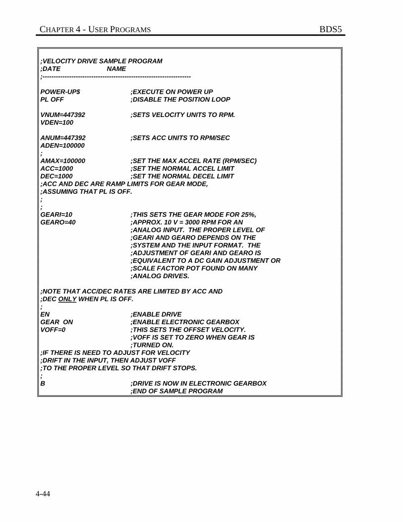
CHAPTER 4 - USER PROGRAMS BDS5
4-44
;VELOCITY DRIVE SAMPLE PROGRAM;DATE NAME;-------------------------------------------------------------------
POWER-UP$ ;EXECUTE ON POWER UPPL OFF ;DISABLE THE POSITION LOOP
VNUM=447392 ;SETS VELOCITY UNITS TO RPM.VDEN=100
ANUM=447392 ;SETS ACC UNITS TO RPM/SECADEN=100000;AMAX=100000 ;SET THE MAX ACCEL RATE (RPM/SEC)ACC=1000 ;SET THE NORMAL ACCEL LIMITDEC=1000 ;SET THE NORMAL DECEL LIMIT;ACC AND DEC ARE RAMP LIMITS FOR GEAR MODE,;ASSUMING THAT PL IS OFF.;;GEARI=10 ;THIS SETS THE GEAR MODE FOR 25%,GEARO=40 ;APPROX. 10 V = 3000 RPM FOR AN
;ANALOG INPUT. THE PROPER LEVEL OF;GEARI AND GEARO DEPENDS ON THE;SYSTEM AND THE INPUT FORMAT. THE;ADJUSTMENT OF GEARI AND GEARO IS;EQUIVALENT TO A DC GAIN ADJUSTMENT OR;SCALE FACTOR POT FOUND ON MANY;ANALOG DRIVES.
;NOTE THAT ACC/DEC RATES ARE LIMITED BY ACC AND;DEC ONLY WHEN PL IS OFF.;EN ;ENABLE DRIVEGEAR ON ;ENABLE ELECTRONIC GEARBOXVOFF=0 ;THIS SETS THE OFFSET VELOCITY.
;VOFF IS SET TO ZERO WHEN GEAR IS;TURNED ON.
;IF THERE IS NEED TO ADJUST FOR VELOCITY;DRIFT IN THE INPUT, THEN ADJUST VOFF;TO THE PROPER LEVEL SO THAT DRIFT STOPS.;B ;DRIVE IS NOW IN ELECTRONIC GEARBOX
;END OF SAMPLE PROGRAM
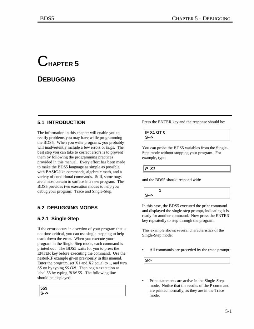
BDS5 CHAPTER 5 - DEBUGGING
5-1
CHAPTER 5
DEBUGGING
5.1 INTRODUCTION
The information in this chapter will enable you torectify problems you may have while programmingthe BDS5. When you write programs, you probablywill inadvertently include a few errors or bugs. Thebest step you can take to correct errors is to preventthem by following the programming practicesprovided in this manual. Every effort has been madeto make the BDS5 language as simple as possiblewith BASIC-like commands, algebraic math, and avariety of conditional commands. Still, some bugsare almost certain to surface in a new program. TheBDS5 provides two execution modes to help youdebug your program: Trace and Single-Step.
5.2 DEBUGGING MODES
5.2.1 Single-Step
If the error occurs in a section of your program that isnot time-critical, you can use single-stepping to helptrack down the error. When you execute yourprogram in the Single-Step mode, each command isprinted out. The BDS5 waits for you to press theENTER key before executing the command. Use thenested-IF example given previously in this manual.Enter the program, set X1 and X2 equal to 1, and turnSS on by typing SS ON. Then begin execution atlabel 55 by typing RUN 55. The following lineshould be displayed:
55$S-->
Press the ENTER key and the response should be:
IF X1 GT 0S-->
You can probe the BDS5 variables from the Single-Step mode without stopping your program. Forexample, type:
P X1
and the BDS5 should respond with:
1S-->
In this case, the BDS5 executed the print commandand displayed the single-step prompt, indicating it isready for another command. Now press the ENTERkey repeatedly to step through the program.
This example shows several characteristics of theSingle-Step mode:
• All commands are preceded by the trace prompt:
S->
• Print statements are active in the Single-Stepmode. Notice that the results of the P commandare printed normally, as they are in the Tracemode.
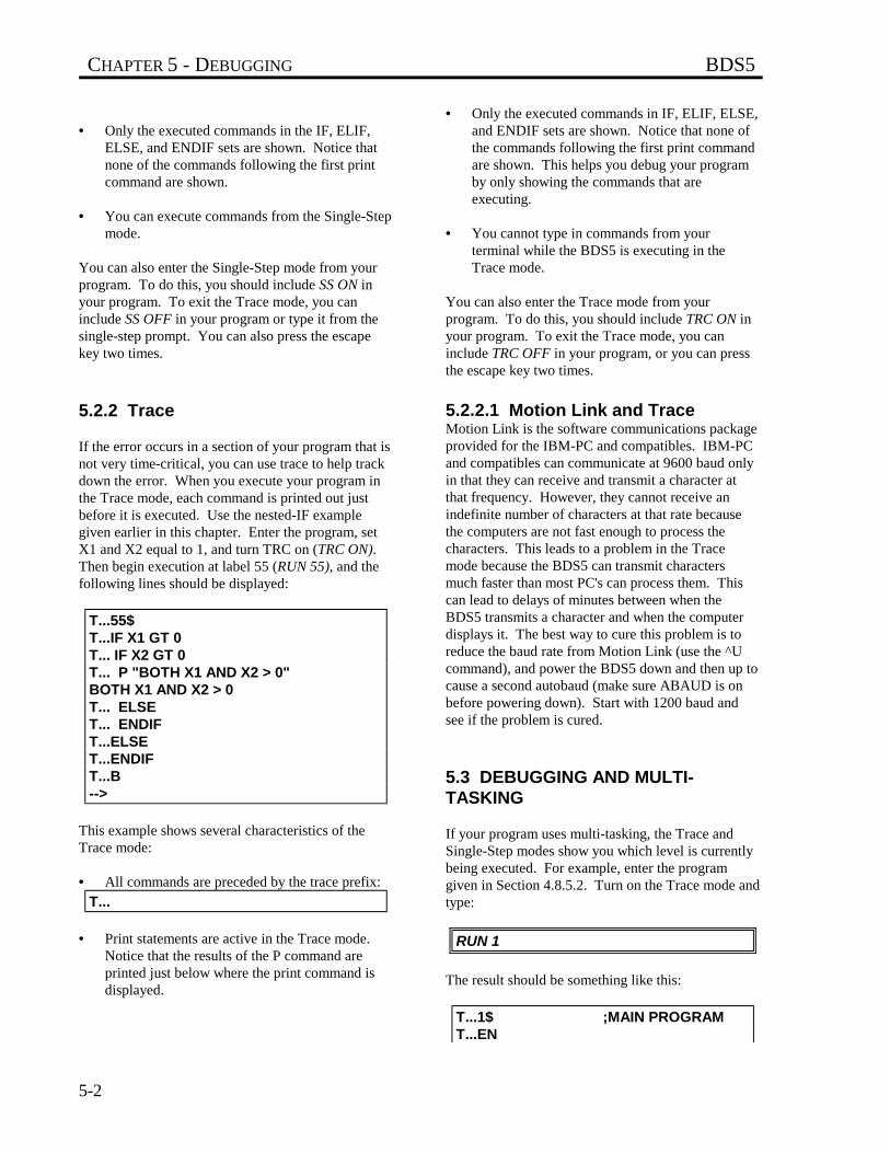
CHAPTER 5 - DEBUGGING BDS5
5-2
• Only the executed commands in the IF, ELIF,ELSE, and ENDIF sets are shown. Notice thatnone of the commands following the first printcommand are shown.
• You can execute commands from the Single-Stepmode.
You can also enter the Single-Step mode from yourprogram. To do this, you should include SS ON inyour program. To exit the Trace mode, you caninclude SS OFF in your program or type it from thesingle-step prompt. You can also press the escapekey two times.
5.2.2 Trace
If the error occurs in a section of your program that isnot very time-critical, you can use trace to help trackdown the error. When you execute your program inthe Trace mode, each command is printed out justbefore it is executed. Use the nested-IF examplegiven earlier in this chapter. Enter the program, setX1 and X2 equal to 1, and turn TRC on (TRC ON).Then begin execution at label 55 (RUN 55), and thefollowing lines should be displayed:
T...55$T...IF X1 GT 0T... IF X2 GT 0T... P "BOTH X1 AND X2 > 0"BOTH X1 AND X2 > 0T... ELSET... ENDIFT...ELSET...ENDIFT...B-->
This example shows several characteristics of theTrace mode:
• All commands are preceded by the trace prefix:
T...
• Print statements are active in the Trace mode.Notice that the results of the P command areprinted just below where the print command isdisplayed.
• Only the executed commands in IF, ELIF, ELSE,and ENDIF sets are shown. Notice that none ofthe commands following the first print commandare shown. This helps you debug your programby only showing the commands that areexecuting.
• You cannot type in commands from yourterminal while the BDS5 is executing in theTrace mode.
You can also enter the Trace mode from yourprogram. To do this, you should include TRC ON inyour program. To exit the Trace mode, you caninclude TRC OFF in your program, or you can pressthe escape key two times.
5.2.2.1 Motion Link and TraceMotion Link is the software communications packageprovided for the IBM-PC and compatibles. IBM-PCand compatibles can communicate at 9600 baud onlyin that they can receive and transmit a character atthat frequency. However, they cannot receive anindefinite number of characters at that rate becausethe computers are not fast enough to process thecharacters. This leads to a problem in the Tracemode because the BDS5 can transmit charactersmuch faster than most PC's can process them. Thiscan lead to delays of minutes between when theBDS5 transmits a character and when the computerdisplays it. The best way to cure this problem is toreduce the baud rate from Motion Link (use the ^Ucommand), and power the BDS5 down and then up tocause a second autobaud (make sure ABAUD is onbefore powering down). Start with 1200 baud andsee if the problem is cured.
5.3 DEBUGGING AND MULTI-TASKING
If your program uses multi-tasking, the Trace andSingle-Step modes show you which level is currentlybeing executed. For example, enter the programgiven in Section 4.8.5.2. Turn on the Trace mode andtype:
RUN 1
The result should be something like this:
T...1$ ;MAIN PROGRAMT...EN
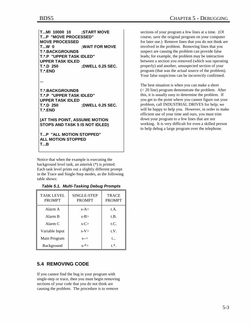
BDS5 CHAPTER 5 - DEBUGGING
5-3
T...MI 10000 10 ;START MOVET...P "MOVE PROCESSED"MOVE PROCESSEDT...W 0 ;WAIT FOR MOVET.*.BACKGROUND$T.*.P "UPPER TASK IDLED"UPPER TASK IDLEDT.*.D 250 ;DWELL 0.25 SEC.T.*.END
...
T.*.BACKGROUND$T.*.P "UPPER TASK IDLED"UPPER TASK IDLEDT.*.D 250 ;DWELL 0.25 SEC.T.*.END
(AT THIS POINT, ASSUME MOTIONSTOPS AND TASK 5 IS NOT IDLED)
T...P "ALL MOTION STOPPED"ALL MOTION STOPPEDT...B
Notice that when the example is executing thebackground level task, an asterisk (*) is printed.Each task level prints out a slightly different promptin the Trace and Single-Step modes, as the followingtable shows:
Table 5.1. Multi-Tasking Debug Prompts
TASK LEVELPROMPT
SINGLE-STEPPROMPT
TRACEPROMPT
Alarm A s-A> t.A.
Alarm B s-B> t.B.
Alarm C s-C> t.C.
Variable Input s-V> t.V.
Main Program s--> t...
Background s-*> t.*.
5.4 REMOVING CODE
If you cannot find the bug in your program withsingle-step or trace, then you must begin removingsections of your code that you do not think arecausing the problem. The procedure is to remove
sections of your program a few lines at a time. (Ofcourse, save the original program on your computerfor later use.) Remove lines that you do not think areinvolved in the problem. Removing lines that yoususpect are causing the problem can provide falseleads; for example, the problem may be interactionbetween a section you removed (which was operatingproperly) and another, unsuspected section of yourprogram (that was the actual source of the problem).Your false suspicions can be incorrectly confirmed.
The best situation is when you can make a short(< 20 line) program demonstrate the problem. Afterthis, it is usually easy to determine the problem. Ifyou get to the point where you cannot figure out yourproblem, call INDUSTRIAL DRIVES for help; wewill be happy to help you. However, in order to makeefficient use of your time and ours, you must trimdown your program to a few lines that are notworking. It is very difficult for even a skilled personto help debug a large program over the telephone.
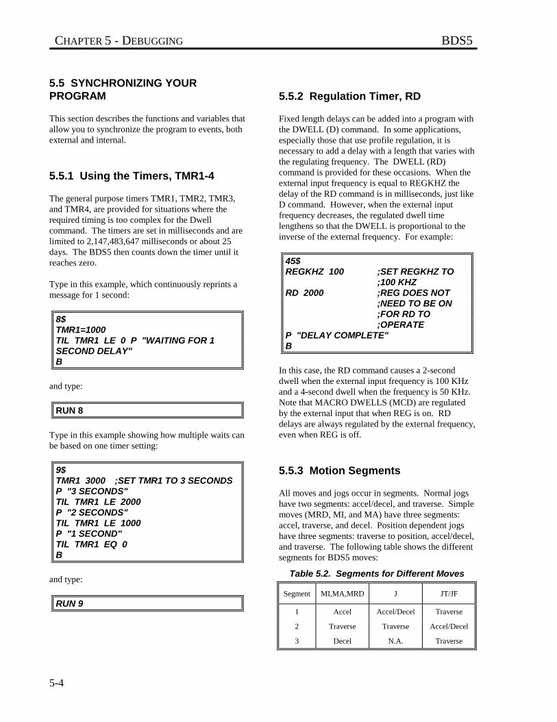
CHAPTER 5 - DEBUGGING BDS5
5-4
5.5 SYNCHRONIZING YOURPROGRAM
This section describes the functions and variables thatallow you to synchronize the program to events, bothexternal and internal.
5.5.1 Using the Timers, TMR1-4
The general purpose timers TMR1, TMR2, TMR3,and TMR4, are provided for situations where therequired timing is too complex for the Dwellcommand. The timers are set in milliseconds and arelimited to 2,147,483,647 milliseconds or about 25days. The BDS5 then counts down the timer until itreaches zero.
Type in this example, which continuously reprints amessage for 1 second:
8$TMR1=1000TIL TMR1 LE 0 P "WAITING FOR 1SECOND DELAY"B
and type:
RUN 8
Type in this example showing how multiple waits canbe based on one timer setting:
9$TMR1 3000 ;SET TMR1 TO 3 SECONDSP "3 SECONDS"TIL TMR1 LE 2000P "2 SECONDS"TIL TMR1 LE 1000P "1 SECOND"TIL TMR1 EQ 0B
and type:
RUN 9
5.5.2 Regulation Timer, RD
Fixed length delays can be added into a program withthe DWELL (D) command. In some applications,especially those that use profile regulation, it isnecessary to add a delay with a length that varies withthe regulating frequency. The DWELL (RD)command is provided for these occasions. When theexternal input frequency is equal to REGKHZ thedelay of the RD command is in milliseconds, just likeD command. However, when the external inputfrequency decreases, the regulated dwell timelengthens so that the DWELL is proportional to theinverse of the external frequency. For example:
45$REGKHZ 100 ;SET REGKHZ TO
;100 KHZRD 2000 ;REG DOES NOT
;NEED TO BE ON ;FOR RD TO ;OPERATE
P "DELAY COMPLETE"B
In this case, the RD command causes a 2-seconddwell when the external input frequency is 100 KHzand a 4-second dwell when the frequency is 50 KHz.Note that MACRO DWELLS (MCD) are regulatedby the external input that when REG is on. RDdelays are always regulated by the external frequency,even when REG is off.
5.5.3 Motion Segments
All moves and jogs occur in segments. Normal jogshave two segments: accel/decel, and traverse. Simplemoves (MRD, MI, and MA) have three segments:accel, traverse, and decel. Position dependent jogshave three segments: traverse to position, accel/decel,and traverse. The following table shows the differentsegments for BDS5 moves:
Table 5.2. Segments for Different Moves
Segment MI,MA,MRD J JT/JF
1 Accel Accel/Decel Traverse
2 Traverse Traverse Accel/Decel
3 Decel N.A. Traverse
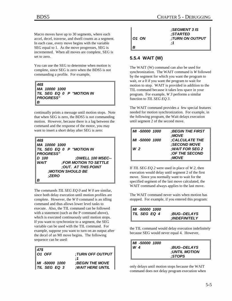
BDS5 CHAPTER 5 - DEBUGGING
5-5
Macro moves have up to 30 segments, where eachaccel, decel, traverse, and dwell counts as a segment.In each case, every move begins with the variableSEG equal to 1. As the move progresses, SEG isincremented. When all moves are complete, SEG isset to zero.
You can use the SEG to determine when motion iscomplete, since SEG is zero when the BDS5 is notcommanding a profile. For example,
46$MA 10000 1000TIL SEG EQ 0 P "MOTION INPROGRESS"B
continually prints a message until motion stops. Notethat when SEG is zero, the BDS5 is not commandingmotion. However, because there is a lag between thecommand and the response of the motor, you maywant to insert a short delay after SEG is zero:
46$MA 10000 1000TIL SEG EQ 0 P "MOTION INPROGRESS"D 100 ;DWELL 100 MSEC--WAIT ;FOR MOTION TO SETTLE
;OUT. AT THIS POINT ;MOTION SHOULD BE ;ZERO
B
The commands TIL SEG EQ 0 and W 0 are similar,since both delay execution until motion profiles arecomplete. However, the W 0 command is an idlingcommand and thus allows lower level tasks toexecute. Also, the TIL command can be followedwith a statement (such as the P command above),which is executed continuously until motion stops.If you want to synchronize to a segment, the SEGvariable can be used with the TIL command. Forexample, suppose you want to turn on an output afterthe decel of an MI move begins. The followingsequence can be used:
47$O1 OFF ;TURN OFF OUTPUT
;1MI -50000 1000 ;BEGIN THE MOVETIL SEG EQ 3 ;WAIT HERE UNTIL
;SEGMENT 3 IS;STARTED
O1 ON ;TURN ON OUTPUT ;1
B
5.5.4 WAIT (W)
The WAIT (W) command can also be used forsynchronization. The WAIT command is W followedby the segment for which you want the program towait, or a 0 if you want the program to wait formotion to stop. WAIT is provided in addition to theTIL command because it takes less space in yourprogram. For example, W 3 performs a similarfunction to TIL SEG EQ 3.
The WAIT command provides a few special featuresneeded for motion synchronization. For example, inthe following program, the Wait delays executionuntil segment 2 of the second move.
MI -50000 1000 ;BEGIN THE FIRST ;MOVE
MI -50000 1000 ;CALCULATE THE ;SECOND MOVE
W 2 ;WAIT FOR SEG 2 ;OF THE SECOND ;MOVE
If TIL SEG EQ 2 were used in place of W 2, thenexecution would delay until segment 2 of the firstmove. Since you normally want to wait for thespecified segment of the last move calculated, theWAIT command always applies to the last move.
The WAIT command never waits when motion hasstopped. For example, if you entered this program:
MI -50000 1000TIL SEG EQ 4 ;BUG--DELAYS
;INDEFINITELY
the TIL command would delay execution indefinitelybecause SEG would never equal 4. However,
MI -50000 1000W 4 ;BUG--DELAYS
;UNTIL MOTION ;STOPS
only delays until motion stops because the WAITcommand does not delay program execution when
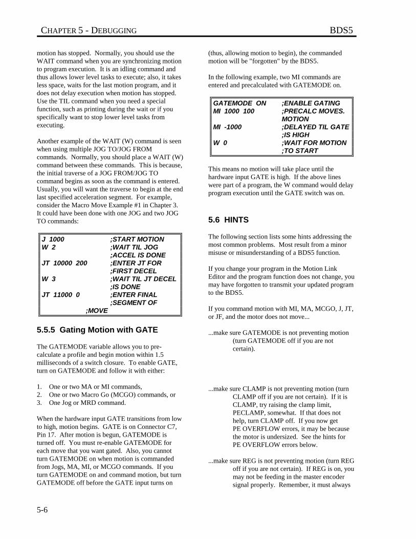
CHAPTER 5 - DEBUGGING BDS5
5-6
motion has stopped. Normally, you should use theWAIT command when you are synchronizing motionto program execution. It is an idling command andthus allows lower level tasks to execute; also, it takesless space, waits for the last motion program, and itdoes not delay execution when motion has stopped.Use the TIL command when you need a specialfunction, such as printing during the wait or if youspecifically want to stop lower level tasks fromexecuting.
Another example of the WAIT (W) command is seenwhen using multiple JOG TO/JOG FROMcommands. Normally, you should place a WAIT (W)command between these commands. This is because,the initial traverse of a JOG FROM/JOG TOcommand begins as soon as the command is entered.Usually, you will want the traverse to begin at the endlast specified acceleration segment. For example,consider the Macro Move Example #1 in Chapter 3.It could have been done with one JOG and two JOGTO commands:
J 1000 ;START MOTIONW 2 ;WAIT TIL JOG
;ACCEL IS DONEJT 10000 200 ;ENTER JT FOR
;FIRST DECELW 3 ;WAIT TIL JT DECEL
;IS DONEJT 11000 0 ;ENTER FINAL
;SEGMENT OF ;MOVE
5.5.5 Gating Motion with GATE
The GATEMODE variable allows you to pre-calculate a profile and begin motion within 1.5milliseconds of a switch closure. To enable GATE,turn on GATEMODE and follow it with either:
1. One or two MA or MI commands,2. One or two Macro Go (MCGO) commands, or3. One Jog or MRD command.
When the hardware input GATE transitions from lowto high, motion begins. GATE is on Connector C7,Pin 17. After motion is begun, GATEMODE isturned off. You must re-enable GATEMODE foreach move that you want gated. Also, you cannotturn GATEMODE on when motion is commandedfrom Jogs, MA, MI, or MCGO commands. If youturn GATEMODE on and command motion, but turnGATEMODE off before the GATE input turns on
(thus, allowing motion to begin), the commandedmotion will be "forgotten" by the BDS5.
In the following example, two MI commands areentered and precalculated with GATEMODE on.
GATEMODE ON ;ENABLE GATINGMI 1000 100 ;PRECALC MOVES.
MOTIONMI -1000 ;DELAYED TIL GATE
;IS HIGHW 0 ;WAIT FOR MOTION
;TO START
This means no motion will take place until thehardware input GATE is high. If the above lineswere part of a program, the W command would delayprogram execution until the GATE switch was on.
5.6 HINTS
The following section lists some hints addressing themost common problems. Most result from a minormisuse or misunderstanding of a BDS5 function.
If you change your program in the Motion LinkEditor and the program function does not change, youmay have forgotten to transmit your updated programto the BDS5.
If you command motion with MI, MA, MCGO, J, JT,or JF, and the motor does not move...
...make sure GATEMODE is not preventing motion(turn GATEMODE off if you are notcertain).
...make sure CLAMP is not preventing motion (turnCLAMP off if you are not certain). If it isCLAMP, try raising the clamp limit,PECLAMP, somewhat. If that does nothelp, turn CLAMP off. If you now getPE OVERFLOW errors, it may be becausethe motor is undersized. See the hints forPE OVERFLOW errors below.
...make sure REG is not preventing motion (turn REGoff if you are not certain). If REG is on, youmay not be feeding in the master encodersignal properly. Remember, it must always
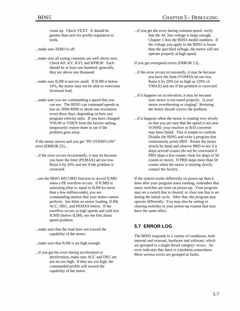
BDS5 CHAPTER 5 - DEBUGGING
5-7
count up. Check VEXT. It should begreater than zero for profile regulation towork.
...make sure ZERO is off.
...make sure all tuning constants are well above zero.Check KP, KV, KVI, and KPROP. Eachshould be at least one hundred; generally,they are above one thousand.
...make sure ILIM is not too small. If ILIM is below10%, the motor may not be able to overcomefrictional load.
...make sure you are commanding a speed that youcan see. The BDS5 can command speeds aslow as .0004 RPM or about one revolutionevery three days, depending on how youprogram velocity units. If you have changedVNUM or VDEN from the factory setting,temporarily restore them to see if theproblem goes away.
If the motor moves and you get "PE OVERFLOW"error (ERROR 25)...
...if the error occurs occasionally, it may be becauseyou have the limit (PEMAX) set too low.Raise it by 20% and see if the problem iscorrected.
...use the BDS5 RECORD function to record ICMDwhen a PE overflow occurs. If ICMD issaturating (that is, equal to ILIM for morethan a few milliseconds), you arecommanding motion that your motor cannotperform. See hints on motor loading, ILIM,ACC, DEC, and PEMAX below. If theoverflow occurs at high speeds and with lowICMD (below ILIM), see the hint aboutspeed problem.
...make sure that the load does not exceed thecapability of the motor.
...make sure that ILIM is set high enough.
...if you get the error during acceleration ordeceleration, make sure ACC and DEC arenot set too high. If they are too high, thecommanded profile will exceed thecapability of the motor.
...if you get the error during constant speed, verifythat the AC line voltage is large enough.Chapter 1 lists the BDS5 model numbers. Ifthe voltage you apply to the BDS5 is lowerthan the specified voltage, the motor will notoperate properly at high speed.
If you get overspeed errors (ERROR 13)...
...if the error occurs occasionally, it may be becauseyou have the limit (VOSPD) set too low.Raise it by 20% (or as high as 120% ofVMAX) and see if the problem is corrected.
...if it happens on acceleration, it may be becauseyour motor is not tuned properly. Is yourmotor overshooting or ringing? Retuningthe motor should correct the problem.
...if it happens when the motor is rotating very slowlyso that you are sure that the speed is not nearVOSPD, your resolver or R/D convertermay have failed. This is simple to confirm.Disable the BDS5 and write a program thatcontinuously prints PRD. Rotate the motorslowly by hand and observe PRD to see if itskips several counts (do not be concerned ifPRD skips a few counts--look for skips of 50counts or more). If PRD skips more than 50counts when the motor is rotating slowly,contact the factory.
If the system works differently on power-up than itdoes after your program starts running, remember thatmany switches are reset on power-up. Your programmay set a switch that is cleared, or clear one that is setduring the initial cycle. After that, the program mayoperate differently. You may also be setting orclearing switches in your power-up routine that mayhave the same effect.
5.7 ERROR LOG
The BDS5 responds to a variety of conditions, bothinternal and external, hardware and software, whichare grouped in a single broad category: errors. Anerror indicates that there is a problem somewhere.More serious errors are grouped as faults.
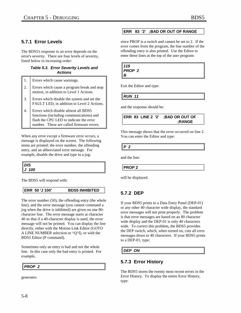
CHAPTER 5 - DEBUGGING BDS5
5-8
5.7.1 Error Levels
The BDS5's response to an error depends on theerror's severity. There are four levels of severity,listed below in increasing order:
Table 5.3. Error Severity Levels andActions
1.
2.
3.
4.
Errors which cause warnings.
Errors which cause a program break and stopmotion, in addition to Level 1 Actions.
Errors which disable the system and set theFAULT LED, in addition to Level 2 Actions.
Errors which disable almost all BDS5functions (including communications) andflash the CPU LED to indicate the errornumber. These are called firmware errors.
When any error except a firmware error occurs, amessage is displayed on the screen. The followingitems are printed: the error number, the offendingentry, and an abbreviated error message. Forexample, disable the drive and type in a jog:
DISJ 100
The BDS5 will respond with:
ERR 50 'J 100' BDS5 INHIBITED
The error number (50), the offending entry (the wholeline), and the error message (you cannot command ajog when the drive is inhibited) are given on one 80-character line. The error message starts at character40 so that if a 40-character display is used, the errormessage will not be printed. You can display the linedirectly, either with the Motion Link Editor (GOTOA LINE NUMBER selection or ^Q^I), or with theBDS5 Editor (P command).
Sometimes only an entry is bad and not the wholeline. In this case only the bad entry is printed. Forexample,
PROP 2
generates:
ERR 83 '2' ;BAD OR OUT OF RANGE
since PROP is a switch and cannot be set to 2. If theerror comes from the program, the line number of theoffending entry is also printed. Use the Editor toenter these lines at the top of the user program:
11$PROP 2B
Exit the Editor and type:
RUN 11
and the response should be:
ERR 83 LINE 2 '2' ;BAD OR OUT OF ;RANGE
This message shows that the error occurred on line 2.You can enter the Editor and type:
P 2
and the line:
PROP 2
will be displayed.
5.7.2 DEP
If your BDS5 prints to a Data Entry Panel (DEP-01)or any other 40 character wide display, the standarderror messages will not print properly. The problemis that error messages are based on an 80 characterwide display and the DEP-01 is only 40 characterswide. To correct this problem, the BDS5 providesthe DEP switch, which, when turned on, cuts all errormessages down to 40 characters. If your BDS5 printsto a DEP-01, type:
DEP ON
5.7.3 Error History
The BDS5 stores the twenty most recent errors in theError History. To display the entire Error History,type:
BDS5 CHAPTER 5 - DEBUGGING
5-9
ERR HIST
This causes the Error History to be sent to theterminal, with the most recent error sent first. Whenthe BDS5 is powered-up, a "DRIVE POWERED UP"message is inserted into Error History even thoughthis is not an actual error.To clear the Error History, type:
ERR CLR
Error History remains intact even through power-down.
5.7.4 Displaying Error Messages
The ERR command can also be used to display anabbreviated description of the error. For example,type:
ERR 50
The BDS5 responds with:
ERR 50 BDS5 INHIBITED
You may display messages for errors from 1 through999. If you type in an error number that the BDS5does not recognize, it will respond with:
ERROR NOT FOUND
A description of all errors is given in Appendix D.
5.7.5 Firmware Errors
Firmware errors are an indication of a seriousproblem with the BDS5. These errors stopcommunications, disable the drive, and flash the CPULED. The CPU LED flashes several times, then turnsoff and pauses. The number of flashes represents theerror number. These error numbers range from 2 to9. See Appendix D for information on these errors.Contact the factory should one of these errors occur.
BDS5 CHAPTER 6 - COMPENSATION
6-1
CHAPTER 6
COMPENSATION
6.1 INTRODUCTION
The information in this chapter will enable you tocompensate your motor for load conditions. Tuningis an important step in setting up and maintainingyour BDS5 servo system. This chapter defines andexplains tuning in detail. A flowchart is alsoprovided for easy step-by-step instructions to tune theservo system.
6.2 SYSTEM COMPENSATION
Feedback systems (like a motor controller) requiretuning to attain high performance. Tuning is theprocess whereby the position and velocity loop gainsare set, attempting to optimize the performance of asystem (a BDS5 and a motor connected to a load) to athree-part criterion:
Table 6.1. Tuning Criterion
Noise SusceptibilityResponseStability
Tuning is normally a laborious procedure requiringan experienced person. However, the BDS5 providesmany tools to aid tuning, making it a much simplerprocess than it has been in the past.
In a broad sense, the performance of a system ischaracterized by its noise susceptibility, response, andstability. These quantities tend to be mutuallyexclusive. The system designer must decide whatnoise susceptibility (in the form of a "busy" motor) isacceptable.
"Busyness" is random activity in the motor and canoften be felt on the motor shaft. Busyness in a motorshould not be confused with PWM noise. PWMnoise is high-pitched, relatively constant noise andcannot be felt on the motor shaft.
Response is a measure of the system's quickness.Response can also be characterized by bandwidth andby rise time in response to a step command.Normally, designers want high bandwidth, thoughsometimes the response is purposely degraded toreduce stress on mechanical components. This iscalled detuning. Typical velocity loop bandwidthsrange from 20 to 60 Hz. Typical position loopbandwidths range from 0.1 to 0.2 times the velocityloop bandwidth.
Stability measures how controlled the system is.Stability can be measured with damping ratio or withovershoot in response to a step command. Adiscussion of different levels of stability follows.
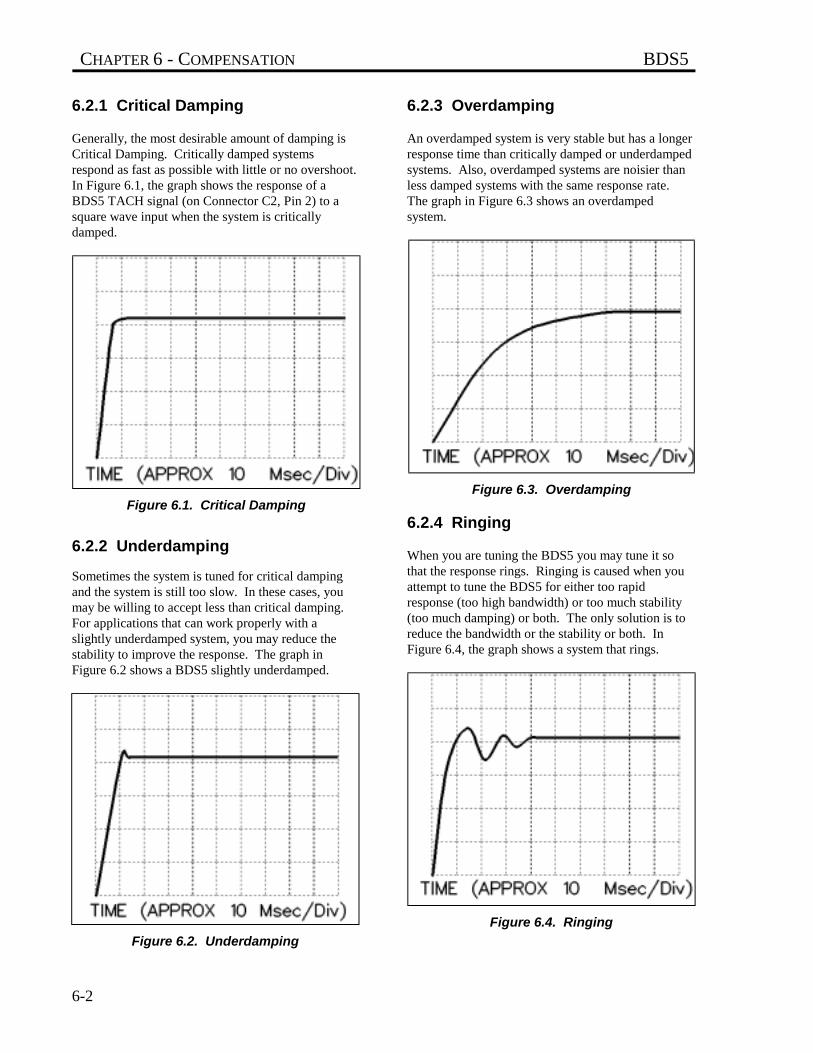
CHAPTER 6 - COMPENSATION BDS5
6-2
6.2.1 Critical Damping
Generally, the most desirable amount of damping isCritical Damping. Critically damped systemsrespond as fast as possible with little or no overshoot.In Figure 6.1, the graph shows the response of aBDS5 TACH signal (on Connector C2, Pin 2) to asquare wave input when the system is criticallydamped.
Figure 6.1. Critical Damping
6.2.2 Underdamping
Sometimes the system is tuned for critical dampingand the system is still too slow. In these cases, youmay be willing to accept less than critical damping.For applications that can work properly with aslightly underdamped system, you may reduce thestability to improve the response. The graph inFigure 6.2 shows a BDS5 slightly underdamped.
Figure 6.2. Underdamping
6.2.3 Overdamping
An overdamped system is very stable but has a longerresponse time than critically damped or underdampedsystems. Also, overdamped systems are noisier thanless damped systems with the same response rate.The graph in Figure 6.3 shows an overdampedsystem.
Figure 6.3. Overdamping
6.2.4 Ringing
When you are tuning the BDS5 you may tune it sothat the response rings. Ringing is caused when youattempt to tune the BDS5 for either too rapidresponse (too high bandwidth) or too much stability(too much damping) or both. The only solution is toreduce the bandwidth or the stability or both. InFigure 6.4, the graph shows a system that rings.
Figure 6.4. Ringing
BDS5 CHAPTER 6 - COMPENSATION
6-3
6.3 TUNING
The TUNE command shakesthe motor vigorously. Securethe motor before tuning.
The BDS5 is usually shipped with a tuning that willwork reasonably well with the load inertia between 0to 4 times the rotor inertia. Many applications haveapproximately matching inertia. If your system does,you may not have to adjust the tuning of your BDS5.The following section describes how you can re-tuneyour system.
When tuning a system, it maybe desirable to disable theBDS5 quickly. You can use K,the KILL command, to disablewith a one-letter command.
The BDS5 provides self-tuning. This is a feature thatsenses the inertial load of your system and thenattempts to set tuning parameters accordingly. Notethat self-tuning is not fool-proof. You may need toadjust one or two of the tuning parameters to getexactly the response you need.
THE MOTOR MAYOSCILLATE!
Unloaded motors tuned for alarge inertia load may becomeunstable when the system isactivated. If the systembecomes unstable, removethe power immediately.
6.3.1 If Your System Is CompletelyUnstable...
If your system is completely unstable when youenable it, remove power immediately. After restoringpower, but before enabling the BDS5, turn off theswitch PL, reduce KV to 100, and reduce KVI to 0.This should make the system stable.
;TYPE THESE LINES ONLY IF YOUR;BDS5 IS UNSTABLE WHEN YOU
;ENABLE IT. DON'T FORGET TO;RESTORE PL WHEN YOU HAVE;FINISHED TUNING.PL OFFKVI = 0KV = 100
If the BDS5 is still unstable, remove power andcontact the factory. If it is stable, continue on withtuning. Do not forget to turn PL back on when youhave finished tuning. Also, PL is always turned onduring the BDS5 power-up.
6.3.2 Reducing ILIM
You may need to reduce ILIM before executing theTUNE command since the TUNE command causesthe motor to "shake" at about 15 Hz and at fulltorque. This may damage some machines. Also,lightly loaded motors can overspeed if ILIM is toohigh. You should raise ILIM to the highest level thatdoes not cause problems, because the tuning may notbe acceptable if ILIM is too low. The effect can bethat the torque the BDS5 produces is "swamped out"by friction. If you are not sure how much ILIM isnecessary, reduce ILIM to a low value (say 5 or 10%)and gradually raise it. If the tuning is acceptable (thatis, it does not ring or overshoot excessively, and itdoes respond fast enough), then you are done. Do notforget to restore ILIM to its original value.
The TUNE command shakesthe motor vigorously. Youmay need to reduce ILIMbefore executing the TUNEcommand to protect yourmachine. Do not forget torestore ILIM when tuning iscomplete.
The TUNE command cancause the motor to overspeed.You may need to reduce ILIMto prevent overspeed errors.Do not forget to restore ILIMwhen tuning is complete.
CAUTION
WARNING
WARNING
NOTE
NOTE
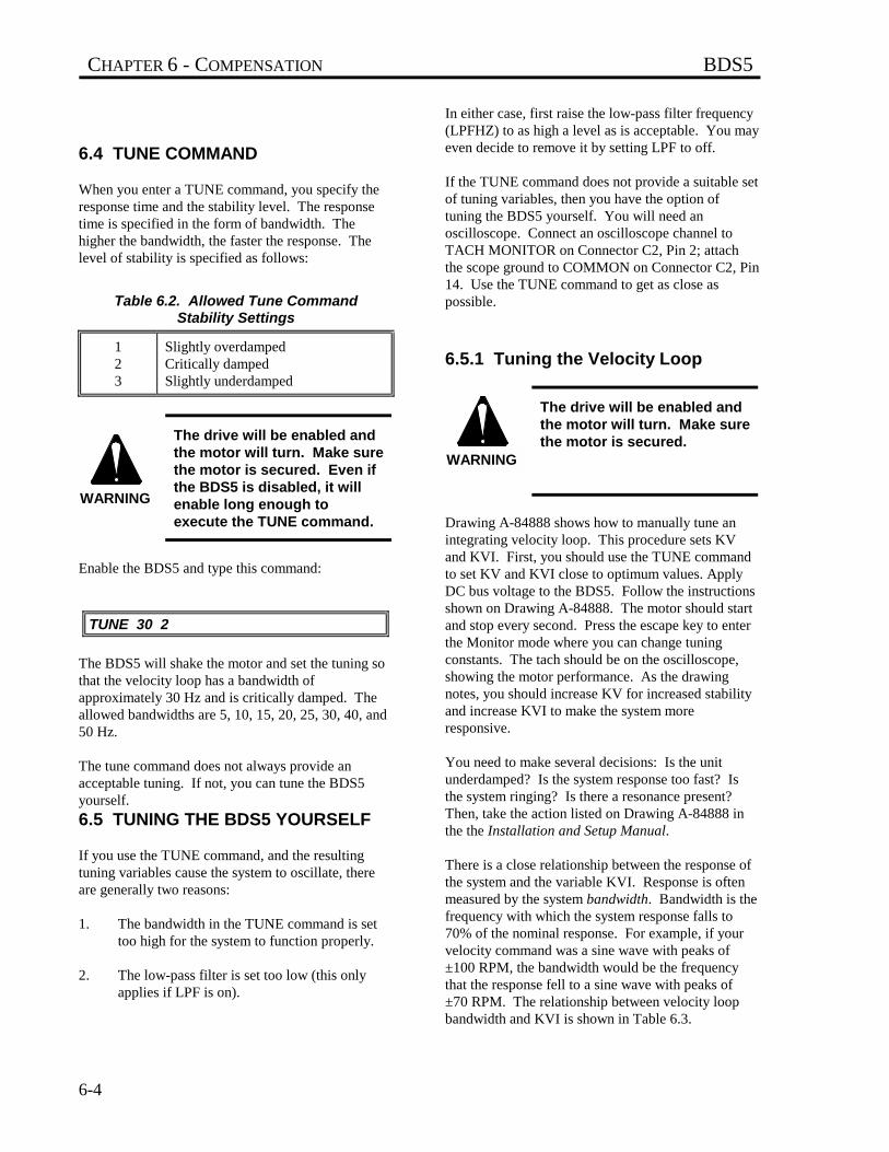
CHAPTER 6 - COMPENSATION BDS5
6-4
6.4 TUNE COMMAND
When you enter a TUNE command, you specify theresponse time and the stability level. The responsetime is specified in the form of bandwidth. Thehigher the bandwidth, the faster the response. Thelevel of stability is specified as follows:
Table 6.2. Allowed Tune CommandStability Settings
123
Slightly overdampedCritically dampedSlightly underdamped
The drive will be enabled andthe motor will turn. Make surethe motor is secured. Even ifthe BDS5 is disabled, it willenable long enough toexecute the TUNE command.
Enable the BDS5 and type this command:
TUNE 30 2
The BDS5 will shake the motor and set the tuning sothat the velocity loop has a bandwidth ofapproximately 30 Hz and is critically damped. Theallowed bandwidths are 5, 10, 15, 20, 25, 30, 40, and50 Hz.
The tune command does not always provide anacceptable tuning. If not, you can tune the BDS5yourself.
6.5 TUNING THE BDS5 YOURSELF
If you use the TUNE command, and the resultingtuning variables cause the system to oscillate, thereare generally two reasons:
1. The bandwidth in the TUNE command is settoo high for the system to function properly.
2. The low-pass filter is set too low (this onlyapplies if LPF is on).
In either case, first raise the low-pass filter frequency(LPFHZ) to as high a level as is acceptable. You mayeven decide to remove it by setting LPF to off.
If the TUNE command does not provide a suitable setof tuning variables, then you have the option oftuning the BDS5 yourself. You will need anoscilloscope. Connect an oscilloscope channel toTACH MONITOR on Connector C2, Pin 2; attachthe scope ground to COMMON on Connector C2, Pin14. Use the TUNE command to get as close aspossible.
6.5.1 Tuning the Velocity Loop
The drive will be enabled andthe motor will turn. Make surethe motor is secured.
Drawing A-84888 shows how to manually tune anintegrating velocity loop. This procedure sets KVand KVI. First, you should use the TUNE commandto set KV and KVI close to optimum values. ApplyDC bus voltage to the BDS5. Follow the instructionsshown on Drawing A-84888. The motor should startand stop every second. Press the escape key to enterthe Monitor mode where you can change tuningconstants. The tach should be on the oscilloscope,showing the motor performance. As the drawingnotes, you should increase KV for increased stabilityand increase KVI to make the system moreresponsive.
You need to make several decisions: Is the unitunderdamped? Is the system response too fast? Isthe system ringing? Is there a resonance present?Then, take the action listed on Drawing A-84888 inthe the Installation and Setup Manual.
There is a close relationship between the response ofthe system and the variable KVI. Response is oftenmeasured by the system bandwidth. Bandwidth is thefrequency with which the system response falls to70% of the nominal response. For example, if yourvelocity command was a sine wave with peaks of±100 RPM, the bandwidth would be the frequencythat the response fell to a sine wave with peaks of±70 RPM. The relationship between velocity loopbandwidth and KVI is shown in Table 6.3.
WARNING
WARNING
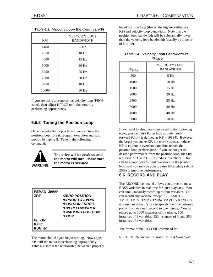
BDS5 CHAPTER 6 - COMPENSATION
6-5
Table 6.3. Velocity Loop Bandwith vs. KVI
KVIVELOCITY LOOP
BANDWIDTH
1400 5 Hz
2650 10 Hz
4000 15 Hz
5000 20 Hz
6250 25 Hz
7500 30 Hz
8750 40 Hz
10000 50 Hz
If you are using a proportional velocity loop (PROPis on), then adjust KPROP until the motor isperforming appropriately.
6.5.2 Tuning the Position Loop
Once the velocity loop is tuned, you can tune theposition loop. Break program execution and stopmotion by typing S. Type in the followingcommands:
The drive will be enabled andthe motor will turn. Make surethe motor is secured.
PEMAX 30000ZPE ;ZERO POSITION
;ERROR TO AVOID;POSITION ERROR ;OVERFLOW WHEN;ENABLING POSITION ;LOOP
PL ONKF=0RUN 80
The motor should again begin turning. Now adjustKP until the motor is performing appropriately.Table 6.4 shows the relationship between a properly
tuned position loop (that is, the highest setting forKP) and velocity loop bandwidth. Note that theposition loop bandwidth will be substantially lowerthan the velocity loop bandwidth (usually by a factorof 5 to 10).
Table 6.4. Velocity Loop Bandwidth vs.KPMAX
KPMAX
VELOCITY LOOPBANDWIDTH
500 5 Hz
1000 10 Hz
1500 15 Hz
2000 20 Hz
2500 25 Hz
3000 30 Hz
4000 40 Hz
5000 50 Hz
If you want to eliminate some or all of the followingerror, you can raise KF as high as unity feed-forward (Unity is defined as KF = 16384). However,the larger you make KF, the more you must reduceKP to eliminate overshoot and thus reduce theposition loop performance. If you cannot get thedesired performance from the position loop, then tryreducing ACC and DEC to reduce overshoot. Thiscan be a good way to limit overshoot in the positionloop, and you may be able to raise KP slightly (about20%) to improve performance.
6.6 RECORD AND PLAY
The RECORD command allows you to record mostBDS5 variables in real time for later playback. Youcan simultaneously record up to four variables. Youcan record any variable except PE, REMOTE,TMR1, TMR2, TMR3, TMR4, VAVG, VXAVG, orany user switches. You can specify the time betweenpoints from one millisecond to one minute. You canrecord up to 1000 instances of 1 variable, 500instances of 2 variables, 333 instances of 3, and 250instances of 4 variables.
The format of the RECORD command is:
RECORD <Number> <Time> <1 to 4 Variables>
WARNING
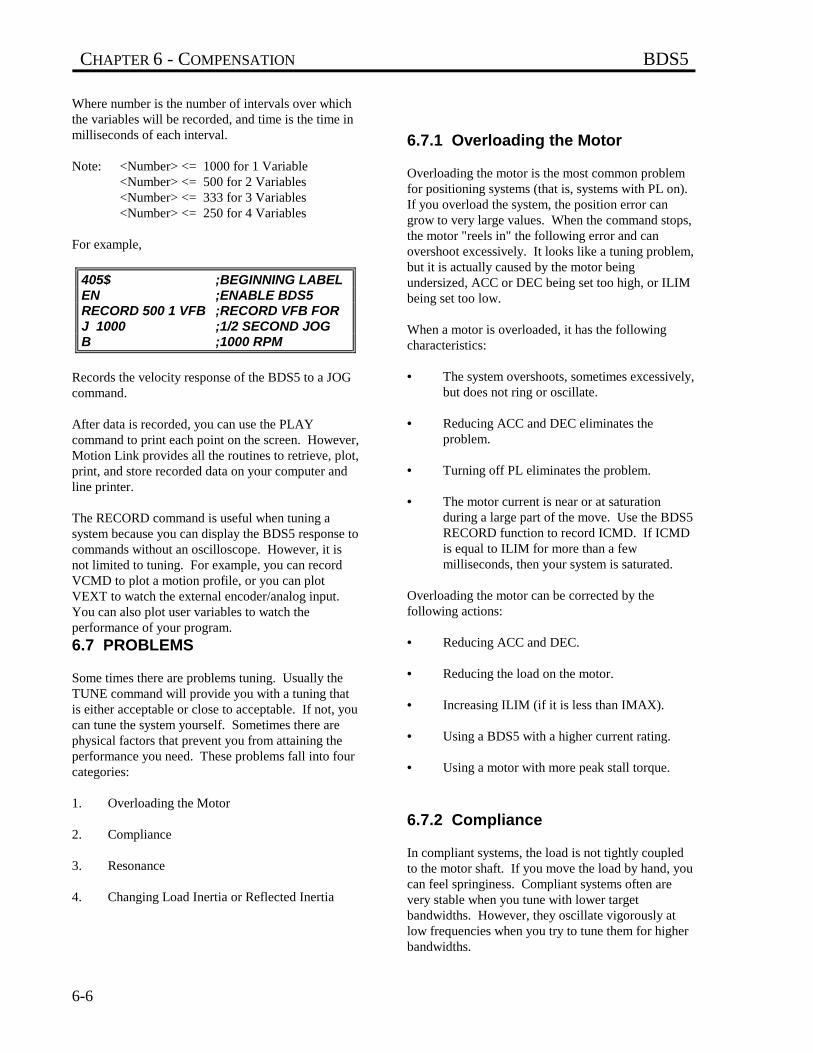
CHAPTER 6 - COMPENSATION BDS5
6-6
Where number is the number of intervals over whichthe variables will be recorded, and time is the time inmilliseconds of each interval.
Note: <Number> <= 1000 for 1 Variable<Number> <= 500 for 2 Variables<Number> <= 333 for 3 Variables<Number> <= 250 for 4 Variables
For example,
405$ ;BEGINNING LABELEN ;ENABLE BDS5RECORD 500 1 VFB ;RECORD VFB FORJ 1000 ;1/2 SECOND JOGB ;1000 RPM
Records the velocity response of the BDS5 to a JOGcommand.
After data is recorded, you can use the PLAYcommand to print each point on the screen. However,Motion Link provides all the routines to retrieve, plot,print, and store recorded data on your computer andline printer.
The RECORD command is useful when tuning asystem because you can display the BDS5 response tocommands without an oscilloscope. However, it isnot limited to tuning. For example, you can recordVCMD to plot a motion profile, or you can plotVEXT to watch the external encoder/analog input.You can also plot user variables to watch theperformance of your program.
6.7 PROBLEMS
Some times there are problems tuning. Usually theTUNE command will provide you with a tuning thatis either acceptable or close to acceptable. If not, youcan tune the system yourself. Sometimes there arephysical factors that prevent you from attaining theperformance you need. These problems fall into fourcategories:
1. Overloading the Motor
2. Compliance
3. Resonance
4. Changing Load Inertia or Reflected Inertia
6.7.1 Overloading the Motor
Overloading the motor is the most common problemfor positioning systems (that is, systems with PL on).If you overload the system, the position error cangrow to very large values. When the command stops,the motor "reels in" the following error and canovershoot excessively. It looks like a tuning problem,but it is actually caused by the motor beingundersized, ACC or DEC being set too high, or ILIMbeing set too low.
When a motor is overloaded, it has the followingcharacteristics:
• The system overshoots, sometimes excessively,but does not ring or oscillate.
• Reducing ACC and DEC eliminates theproblem.
• Turning off PL eliminates the problem.
• The motor current is near or at saturationduring a large part of the move. Use the BDS5RECORD function to record ICMD. If ICMDis equal to ILIM for more than a fewmilliseconds, then your system is saturated.
Overloading the motor can be corrected by thefollowing actions:
• Reducing ACC and DEC.
• Reducing the load on the motor.
• Increasing ILIM (if it is less than IMAX).
• Using a BDS5 with a higher current rating.
• Using a motor with more peak stall torque.
6.7.2 Compliance
In compliant systems, the load is not tightly coupledto the motor shaft. If you move the load by hand, youcan feel springiness. Compliant systems often arevery stable when you tune with lower targetbandwidths. However, they oscillate vigorously atlow frequencies when you try to tune them for higherbandwidths.
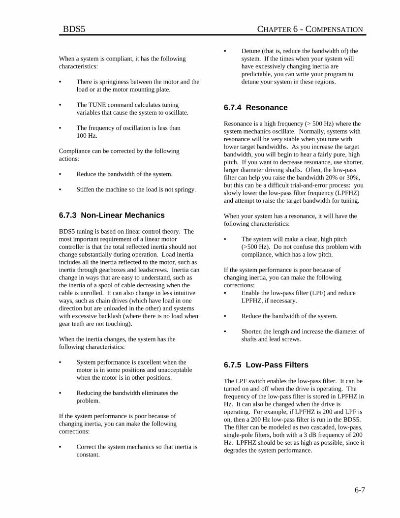
BDS5 CHAPTER 6 - COMPENSATION
6-7
When a system is compliant, it has the followingcharacteristics:
• There is springiness between the motor and theload or at the motor mounting plate.
• The TUNE command calculates tuningvariables that cause the system to oscillate.
• The frequency of oscillation is less than100 Hz.
Compliance can be corrected by the followingactions:
• Reduce the bandwidth of the system.
• Stiffen the machine so the load is not springy.
6.7.3 Non-Linear Mechanics
BDS5 tuning is based on linear control theory. Themost important requirement of a linear motorcontroller is that the total reflected inertia should notchange substantially during operation. Load inertiaincludes all the inertia reflected to the motor, such asinertia through gearboxes and leadscrews. Inertia canchange in ways that are easy to understand, such asthe inertia of a spool of cable decreasing when thecable is unrolled. It can also change in less intuitiveways, such as chain drives (which have load in onedirection but are unloaded in the other) and systemswith excessive backlash (where there is no load whengear teeth are not touching).
When the inertia changes, the system has thefollowing characteristics:
• System performance is excellent when themotor is in some positions and unacceptablewhen the motor is in other positions.
• Reducing the bandwidth eliminates theproblem.
If the system performance is poor because ofchanging inertia, you can make the followingcorrections:
• Correct the system mechanics so that inertia isconstant.
• Detune (that is, reduce the bandwidth of) thesystem. If the times when your system willhave excessively changing inertia arepredictable, you can write your program todetune your system in these regions.
6.7.4 Resonance
Resonance is a high frequency (> 500 Hz) where thesystem mechanics oscillate. Normally, systems withresonance will be very stable when you tune withlower target bandwidths. As you increase the targetbandwidth, you will begin to hear a fairly pure, highpitch. If you want to decrease resonance, use shorter,larger diameter driving shafts. Often, the low-passfilter can help you raise the bandwidth 20% or 30%,but this can be a difficult trial-and-error process: youslowly lower the low-pass filter frequency (LPFHZ)and attempt to raise the target bandwidth for tuning.
When your system has a resonance, it will have thefollowing characteristics:
• The system will make a clear, high pitch(>500 Hz). Do not confuse this problem withcompliance, which has a low pitch.
If the system performance is poor because ofchanging inertia, you can make the followingcorrections:• Enable the low-pass filter (LPF) and reduce
LPFHZ, if necessary.
• Reduce the bandwidth of the system.
• Shorten the length and increase the diameter ofshafts and lead screws.
6.7.5 Low-Pass Filters
The LPF switch enables the low-pass filter. It can beturned on and off when the drive is operating. Thefrequency of the low-pass filter is stored in LPFHZ inHz. It can also be changed when the drive isoperating. For example, if LPFHZ is 200 and LPF ison, then a 200 Hz low-pass filter is run in the BDS5.The filter can be modeled as two cascaded, low-pass,single-pole filters, both with a 3 dB frequency of 200Hz. LPFHZ should be set as high as possible, since itdegrades the system performance.

CHAPTER 6 - COMPENSATION BDS5
6-8
For example, the following sequence sets the low-pass filter to 250 Hz and enables the drive.
LPF ON ;ENABLE LOW-PASS FILTERLPFHZ 250 ;SET BREAK FREQ. TO 250
;HZ
If the low-pass filter is on, theTUNE command may not workwell.
NOTE

BDS5 APPENDIX A - WARRANTY INFORMATION
A-1
APPENDIX A
WARRANTY INFORMATION
Industrial Drives, a Kollmorgen Division, warrantsthat equipment, delivered by it to the Purchaser, willbe of the kind and quality described in the salesagreement and/or catalog and that the equipment willbe free of defects in design, workmanship, andmaterial.
The terms and conditions of this Warranty areprovided with the product at the time of shipping orin advance upon request.
The items described in this manual are offered forsale at prices to be established by Industrial Drivesand its authorized dealers.

BDS5 APPENDIX B- ASCII TABLE
B-1
APPENDIX B
ASCII TABLE
The chart on the following pages is an ASCII Codeand Hexadecimal conversion chart. The BDS5doesnot support extended ASCII (128-255).
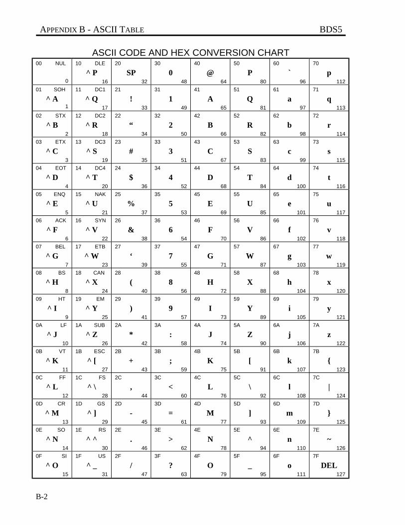
APPENDIX B - ASCII TABLE BDS5
B-2
ASCII CODE AND HEX CONVERSION CHART00 NUL
0
10 DLE
^ P16
20
SP32
30
048
40
@64
50
P80
60
`96
70
p112
01 SOH
^ A1
11 DC1
^ Q17
21
!33
31
149
41
A65
51
Q81
61
a97
71
q113
02 STX
^ B2
12 DC2
^ R18
22
“34
32
250
42
B66
52
R82
62
b98
72
r114
03 ETX
^ C3
13 DC3
^ S19
23
#35
33
351
43
C67
53
S83
63
c99
73
s115
04 EOT
^ D4
14 DC4
^ T20
24
$36
34
452
44
D68
54
T84
64
d100
74
t116
05 ENQ
^ E5
15 NAK
^ U21
25
%37
35
553
45
E69
55
U85
65
e101
75
u117
06 ACK
^ F6
16 SYN
^ V22
26
&38
36
654
46
F70
56
V86
66
f102
76
v118
07 BEL
^ G7
17 ETB
^ W23
27
‘39
37
755
47
G71
57
W87
67
g103
77
w119
08 BS
^ H8
18 CAN
^ X24
28
(40
38
856
48
H72
58
X88
68
h104
78
x120
09 HT
^ I9
19 EM
^ Y25
29
)41
39
957
49
I73
59
Y89
69
i105
79
y121
0A LF
^ J10
1A SUB
^ Z26
2A
*42
3A
:58
4A
J74
5A
Z90
6A
j106
7A
z122
0B VT
^ K11
1B ESC
^ [27
2B
+43
3B
;59
4B
K75
5B
[91
6B
k107
7B
{123
0C FF
^ L12
1C FS
^ \28
2C
,44
3C
<60
4C
L76
5C
\92
6C
l108
7C
|124
0D CR
^ M13
1D GS
^ ]29
2D
-45
3D
=61
4D
M77
5D
]93
6D
m109
7D
}125
0E SO
^ N14
1E RS
^ ^30
2E
.46
3E
>62
4E
N78
5E
^94
6E
n110
7E
~126
0F SI
^ O15
1F US
^ _31
2F
/47
3F
?63
4F
O79
5F
_95
6F
o111
7F
DEL127
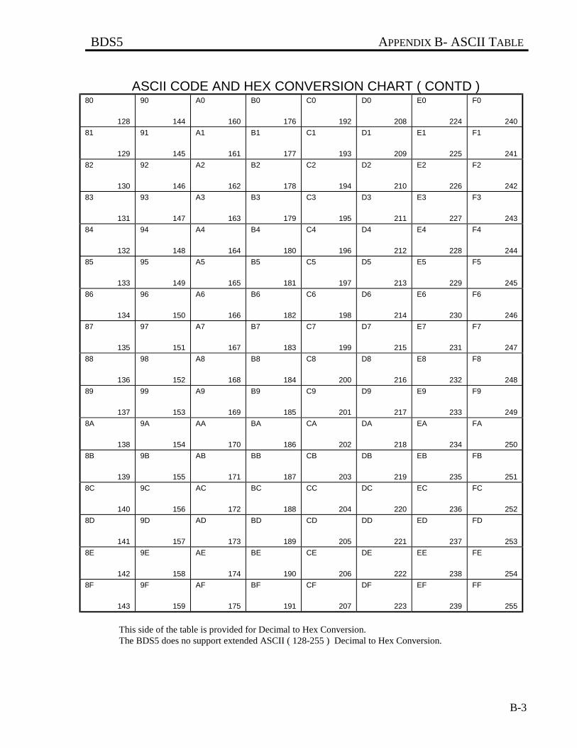
BDS5 APPENDIX B- ASCII TABLE
B-3
ASCII CODE AND HEX CONVERSION CHART ( CONTD )80
128
90
144
A0
160
B0
176
C0
192
D0
208
E0
224
F0
240
81
129
91
145
A1
161
B1
177
C1
193
D1
209
E1
225
F1
241
82
130
92
146
A2
162
B2
178
C2
194
D2
210
E2
226
F2
242
83
131
93
147
A3
163
B3
179
C3
195
D3
211
E3
227
F3
243
84
132
94
148
A4
164
B4
180
C4
196
D4
212
E4
228
F4
244
85
133
95
149
A5
165
B5
181
C5
197
D5
213
E5
229
F5
245
86
134
96
150
A6
166
B6
182
C6
198
D6
214
E6
230
F6
246
87
135
97
151
A7
167
B7
183
C7
199
D7
215
E7
231
F7
247
88
136
98
152
A8
168
B8
184
C8
200
D8
216
E8
232
F8
248
89
137
99
153
A9
169
B9
185
C9
201
D9
217
E9
233
F9
249
8A
138
9A
154
AA
170
BA
186
CA
202
DA
218
EA
234
FA
250
8B
139
9B
155
AB
171
BB
187
CB
203
DB
219
EB
235
FB
251
8C
140
9C
156
AC
172
BC
188
CC
204
DC
220
EC
236
FC
252
8D
141
9D
157
AD
173
BD
189
CD
205
DD
221
ED
237
FD
253
8E
142
9E
158
AE
174
BE
190
CE
206
DE
222
EE
238
FE
254
8F
143
9F
159
AF
175
BF
191
CF
207
DF
223
EF
239
FF
255
This side of the table is provided for Decimal to Hex Conversion.The BDS5 does no support extended ASCII ( 128-255 ) Decimal to Hex Conversion.
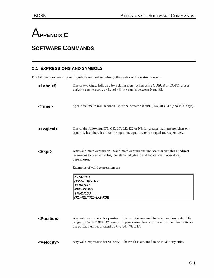
BDS5 APPENDIX C - SOFTWARE COMMANDS
C-1
APPENDIX C
SOFTWARE COMMANDS
C.1 EXPRESSIONS AND SYMBOLS
The following expressions and symbols are used in defining the syntax of the instruction set:
<Label>$ One or two digits followed by a dollar sign. When using GOSUB or GOTO, a uservariable can be used as <Label> if its value is between 0 and 99.
<Time> Specifies time in milliseconds. Must be between 0 and 2,147,483,647 (about 25 days).
<Logical> One of the following: GT, GE, LT, LE, EQ or NE for greater-than, greater-than-or-equal-to, less-than, less-than-or-equal-to, equal-to, or not-equal-to, respectively.
<Expr> Any valid math expression. Valid math expressions include user variables, indirectreferences to user variables, constants, algebraic and logical math operators,parentheses.
Examples of valid expressions are:
X1*X2*X3(X2-VFB)/VOFFX1&07FHPFB-PCMDTMR1/100(X1+X2)*(X1+(X2-X3))
<Position> Any valid expression for position. The result is assumed to be in position units. Therange is +/-2,147,483,647 counts. If your system has position units, then the limits arethe position unit equivalent of +/-2,147,483,647.
<Velocity> Any valid expression for velocity. The result is assumed to be in velocity units.
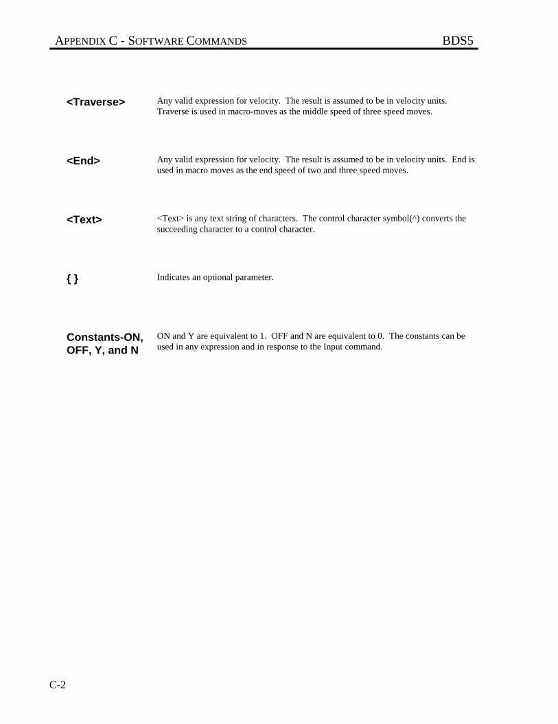
APPENDIX C - SOFTWARE COMMANDS BDS5
C-2
<Traverse> Any valid expression for velocity. The result is assumed to be in velocity units.Traverse is used in macro-moves as the middle speed of three speed moves.
<End> Any valid expression for velocity. The result is assumed to be in velocity units. End isused in macro moves as the end speed of two and three speed moves.
<Text> <Text> is any text string of characters. The control character symbol(^) converts thesucceeding character to a control character.
{ } Indicates an optional parameter.
Constants-ON,OFF, Y, and N
ON and Y are equivalent to 1. OFF and N are equivalent to 0. The constants can beused in any expression and in response to the Input command.
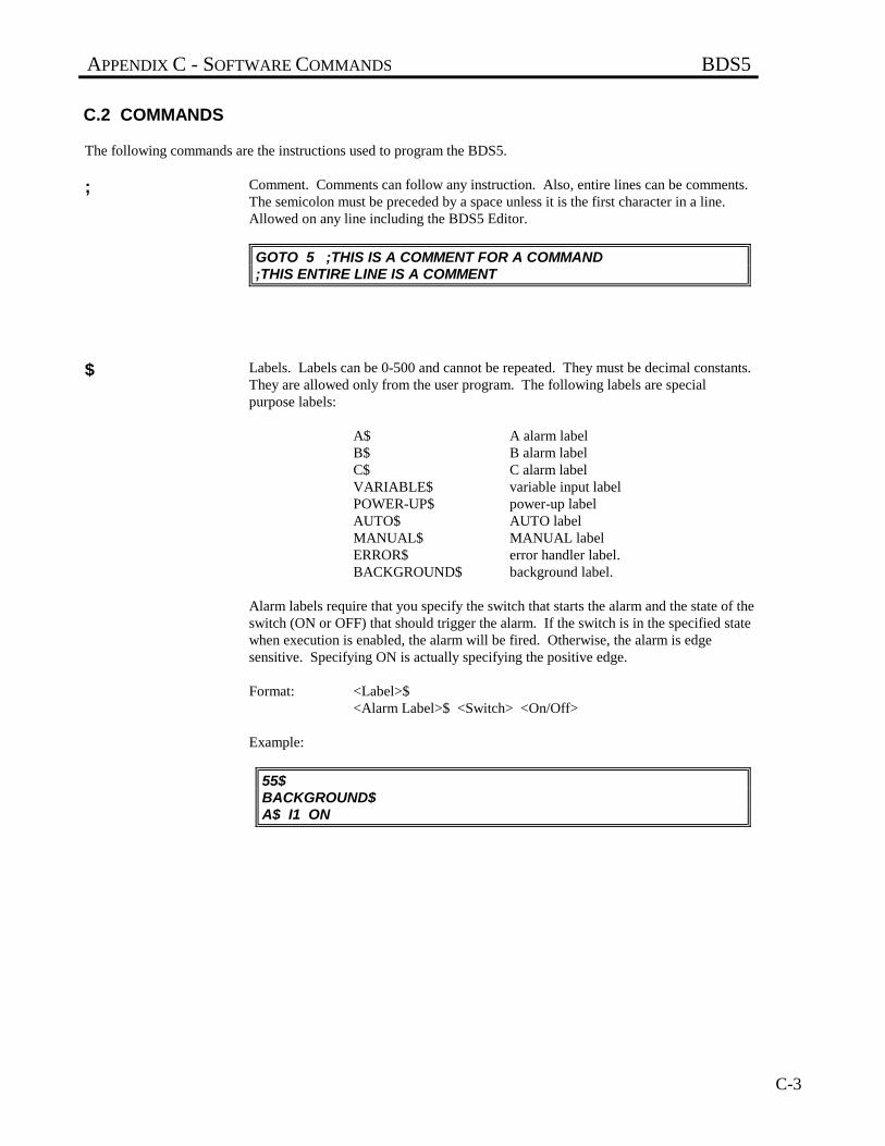
APPENDIX C - SOFTWARE COMMANDS BDS5
C-3
C.2 COMMANDS
The following commands are the instructions used to program the BDS5.
; Comment. Comments can follow any instruction. Also, entire lines can be comments.The semicolon must be preceded by a space unless it is the first character in a line.Allowed on any line including the BDS5 Editor.
GOTO 5 ;THIS IS A COMMENT FOR A COMMAND;THIS ENTIRE LINE IS A COMMENT
$ Labels. Labels can be 0-500 and cannot be repeated. They must be decimal constants.They are allowed only from the user program. The following labels are specialpurpose labels:
A$ A alarm labelB$ B alarm labelC$ C alarm labelVARIABLE$ variable input labelPOWER-UP$ power-up labelAUTO$ AUTO labelMANUAL$ MANUAL labelERROR$ error handler label.BACKGROUND$ background label.
Alarm labels require that you specify the switch that starts the alarm and the state of theswitch (ON or OFF) that should trigger the alarm. If the switch is in the specified statewhen execution is enabled, the alarm will be fired. Otherwise, the alarm is edgesensitive. Specifying ON is actually specifying the positive edge.
Format: <Label>$<Alarm Label>$ <Switch> <On/Off>
Example:
55$BACKGROUND$A$ I1 ON
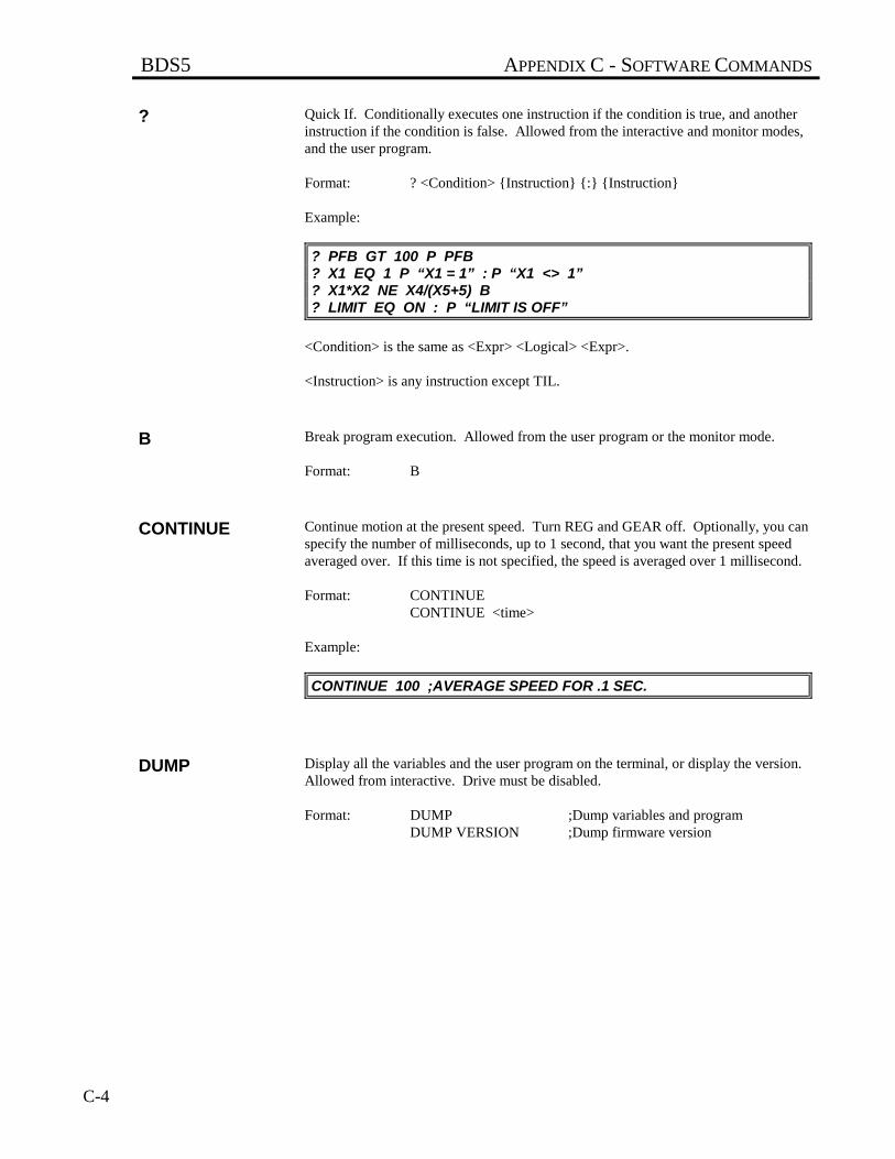
BDS5 APPENDIX C - SOFTWARE COMMANDS
C-4
? Quick If. Conditionally executes one instruction if the condition is true, and anotherinstruction if the condition is false. Allowed from the interactive and monitor modes,and the user program.
Format: ? <Condition> {Instruction} {:} {Instruction}
Example:
? PFB GT 100 P PFB? X1 EQ 1 P “X1 = 1” : P “X1 <> 1”? X1*X2 NE X4/(X5+5) B? LIMIT EQ ON : P “LIMIT IS OFF”
<Condition> is the same as <Expr> <Logical> <Expr>.
<Instruction> is any instruction except TIL.
B Break program execution. Allowed from the user program or the monitor mode.
Format: B
CONTINUE Continue motion at the present speed. Turn REG and GEAR off. Optionally, you canspecify the number of milliseconds, up to 1 second, that you want the present speedaveraged over. If this time is not specified, the speed is averaged over 1 millisecond.
Format: CONTINUECONTINUE <time>
Example:
CONTINUE 100 ;AVERAGE SPEED FOR .1 SEC.
DUMP Display all the variables and the user program on the terminal, or display the version.Allowed from interactive. Drive must be disabled.
Format: DUMP ;Dump variables and programDUMP VERSION ;Dump firmware version
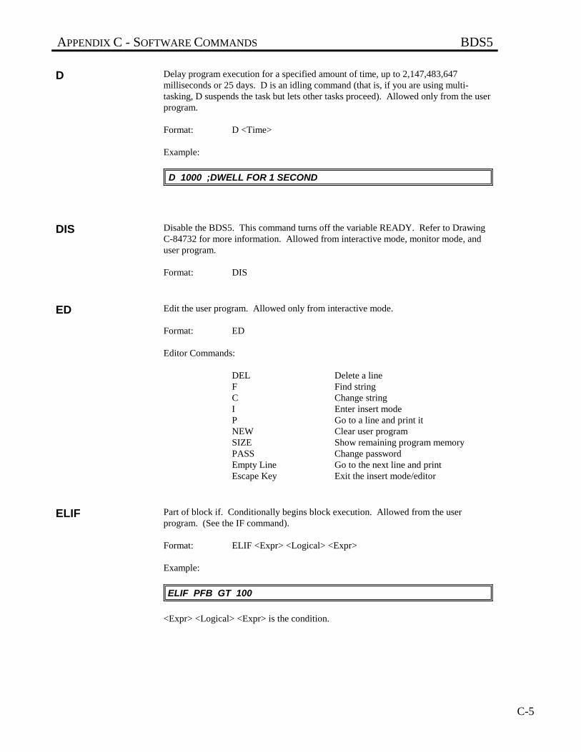
APPENDIX C - SOFTWARE COMMANDS BDS5
C-5
D Delay program execution for a specified amount of time, up to 2,147,483,647milliseconds or 25 days. D is an idling command (that is, if you are using multi-tasking, D suspends the task but lets other tasks proceed). Allowed only from the userprogram.
Format: D <Time>
Example:
D 1000 ;DWELL FOR 1 SECOND
DIS Disable the BDS5. This command turns off the variable READY. Refer to DrawingC-84732 for more information. Allowed from interactive mode, monitor mode, anduser program.
Format: DIS
ED Edit the user program. Allowed only from interactive mode.
Format: ED
Editor Commands:
DEL Delete a lineF Find stringC Change stringI Enter insert modeP Go to a line and print itNEW Clear user programSIZE Show remaining program memoryPASS Change passwordEmpty Line Go to the next line and printEscape Key Exit the insert mode/editor
ELIF Part of block if. Conditionally begins block execution. Allowed from the userprogram. (See the IF command).
Format: ELIF <Expr> <Logical> <Expr>
Example:
ELIF PFB GT 100
<Expr> <Logical> <Expr> is the condition.
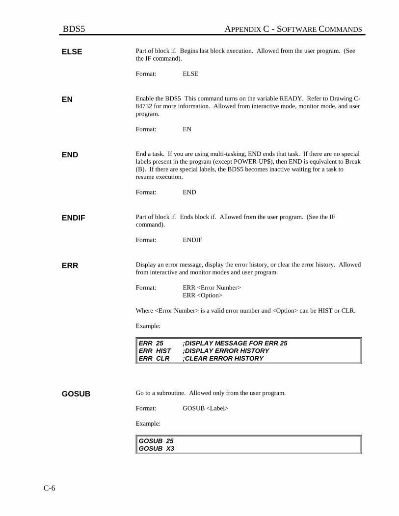
BDS5 APPENDIX C - SOFTWARE COMMANDS
C-6
ELSE Part of block if. Begins last block execution. Allowed from the user program. (Seethe IF command).
Format: ELSE
EN Enable the BDS5 This command turns on the variable READY. Refer to Drawing C-84732 for more information. Allowed from interactive mode, monitor mode, and userprogram.
Format: EN
END End a task. If you are using multi-tasking, END ends that task. If there are no speciallabels present in the program (except POWER-UP$), then END is equivalent to Break(B). If there are special labels, the BDS5 becomes inactive waiting for a task toresume execution.
Format: END
ENDIF Part of block if. Ends block if. Allowed from the user program. (See the IFcommand).
Format: ENDIF
ERR Display an error message, display the error history, or clear the error history. Allowedfrom interactive and monitor modes and user program.
Format: ERR <Error Number>ERR <Option>
Where <Error Number> is a valid error number and <Option> can be HIST or CLR.
Example:
ERR 25 ;DISPLAY MESSAGE FOR ERR 25ERR HIST ;DISPLAY ERROR HISTORYERR CLR ;CLEAR ERROR HISTORY
GOSUB Go to a subroutine. Allowed only from the user program.
Format: GOSUB <Label>
Example:
GOSUB 25GOSUB X3
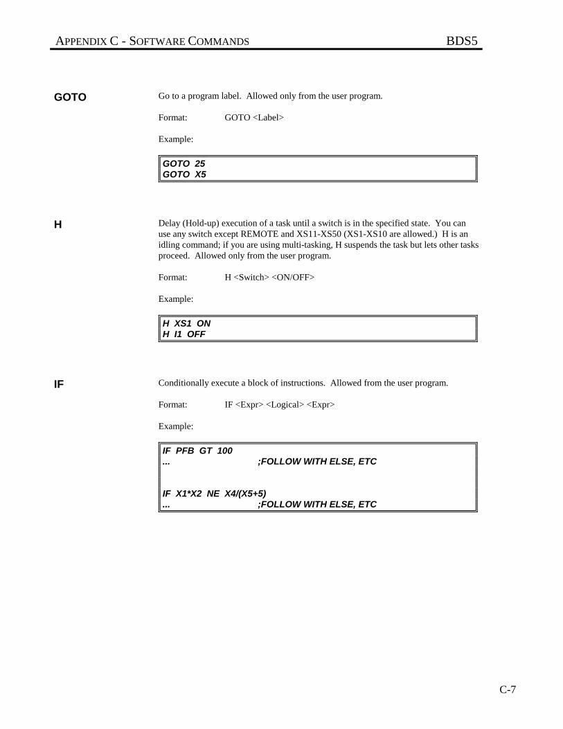
APPENDIX C - SOFTWARE COMMANDS BDS5
C-7
GOTO Go to a program label. Allowed only from the user program.
Format: GOTO <Label>
Example:
GOTO 25GOTO X5
H Delay (Hold-up) execution of a task until a switch is in the specified state. You canuse any switch except REMOTE and XS11-XS50 (XS1-XS10 are allowed.) H is anidling command; if you are using multi-tasking, H suspends the task but lets other tasksproceed. Allowed only from the user program.
Format: H <Switch> <ON/OFF>
Example:
H XS1 ONH I1 OFF
IF Conditionally execute a block of instructions. Allowed from the user program.
Format: IF <Expr> <Logical> <Expr>
Example:
IF PFB GT 100... ;FOLLOW WITH ELSE, ETC
IF X1*X2 NE X4/(X5+5)... ;FOLLOW WITH ELSE, ETC
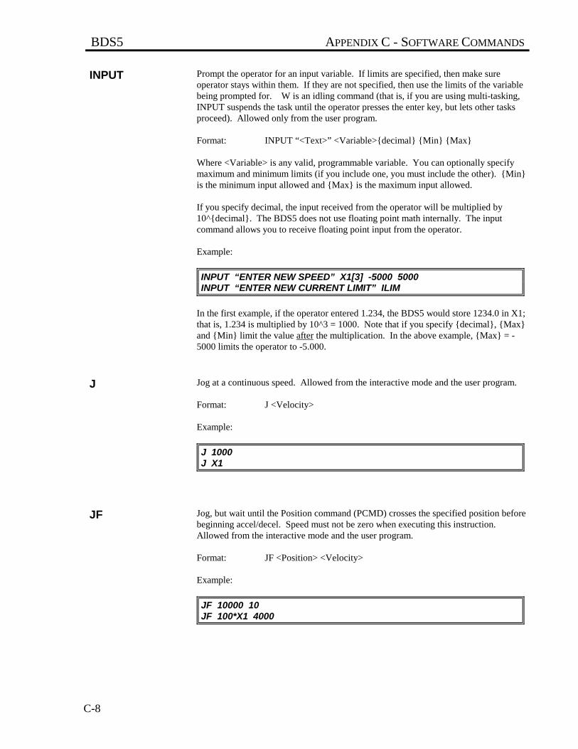
BDS5 APPENDIX C - SOFTWARE COMMANDS
C-8
INPUT Prompt the operator for an input variable. If limits are specified, then make sureoperator stays within them. If they are not specified, then use the limits of the variablebeing prompted for. W is an idling command (that is, if you are using multi-tasking,INPUT suspends the task until the operator presses the enter key, but lets other tasksproceed). Allowed only from the user program.
Format: INPUT “<Text>” <Variable>{decimal} {Min} {Max}
Where <Variable> is any valid, programmable variable. You can optionally specifymaximum and minimum limits (if you include one, you must include the other). {Min}is the minimum input allowed and {Max} is the maximum input allowed.
If you specify decimal, the input received from the operator will be multiplied by10^{decimal}. The BDS5 does not use floating point math internally. The inputcommand allows you to receive floating point input from the operator.
Example:
INPUT “ENTER NEW SPEED” X1[3] -5000 5000INPUT “ENTER NEW CURRENT LIMIT” ILIM
In the first example, if the operator entered 1.234, the BDS5 would store 1234.0 in X1;that is, 1.234 is multiplied by 10^3 = 1000. Note that if you specify {decimal}, {Max}and {Min} limit the value after the multiplication. In the above example, {Max} = -5000 limits the operator to -5.000.
J Jog at a continuous speed. Allowed from the interactive mode and the user program.
Format: J <Velocity>
Example:
J 1000J X1
JF Jog, but wait until the Position command (PCMD) crosses the specified position beforebeginning accel/decel. Speed must not be zero when executing this instruction.Allowed from the interactive mode and the user program.
Format: JF <Position> <Velocity>
Example:
JF 10000 10JF 100*X1 4000
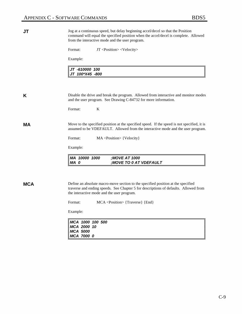
APPENDIX C - SOFTWARE COMMANDS BDS5
C-9
JT Jog at a continuous speed, but delay beginning accel/decel so that the Positioncommand will equal the specified position when the accel/decel is complete. Allowedfrom the interactive mode and the user program.
Format: JT <Position> <Velocity>
Example:
JT -610000 100JT 100*X45 -800
K Disable the drive and break the program. Allowed from interactive and monitor modesand the user program. See Drawing C-84732 for more information.
Format: K
MA Move to the specified position at the specified speed. If the speed is not specified, it isassumed to be VDEFAULT. Allowed from the interactive mode and the user program.
Format: MA <Position> {Velocity}
Example:
MA 10000 1000 ;MOVE AT 1000MA 0 ;MOVE TO 0 AT VDEFAULT
MCA Define an absolute macro-move section to the specified position at the specifiedtraverse and ending speeds. See Chapter 5 for descriptions of defaults. Allowed fromthe interactive mode and the user program.
Format: MCA <Position> {Traverse} {End}
Example:
MCA 1000 100 500MCA 2000 10MCA 5000MCA 7000 0

BDS5 APPENDIX C - SOFTWARE COMMANDS
C-10
MCD Define a macro-move dwell section for the specified time. This is only valid when theprevious macro-move section ended at zero speed. When used with the profileregulation mode, time is inversely proportional to external input frequency. Allowedfrom the interactive mode and the user program.
Format: MCD <Time>
Example:
MCD 500 ;DWELL 0.5 SECONDS
MCGO Execute a macro move. This is only valid when the last macro-move section ended atzero speed. Allowed from the interactive mode and the user program.
Format: MCGO
MCI Define an incremental macro-move section for the specified distance at the specifiedtraverse and ending speed. See Chapter 5 for descriptions of defaults. Allowed fromthe interactive mode and the user program.
Format: MCI <Position> {Traverse} {End}
Example:
MCI 100000 500 5000MCI 3000 10MCI -56000MCI 8000 0 ;LAST SECTION
MI Incrementally move the specified distance at the specified speed. If the speed is notspecified, it is assumed to be VDEFAULT. Allowed from the interactive mode and theuser program.
Format: MI <Position> {Velocity}
Example:
MI 10000 1000 ;MOVE AT 1000MI -1000 ;MOVE BACK 1000
MOTOR Display the present motor drive combination. This command is used to determine themotor for which your BDS5 was configured when it was shipped. This command isnot normally used by the customer.
Format: MOTOR
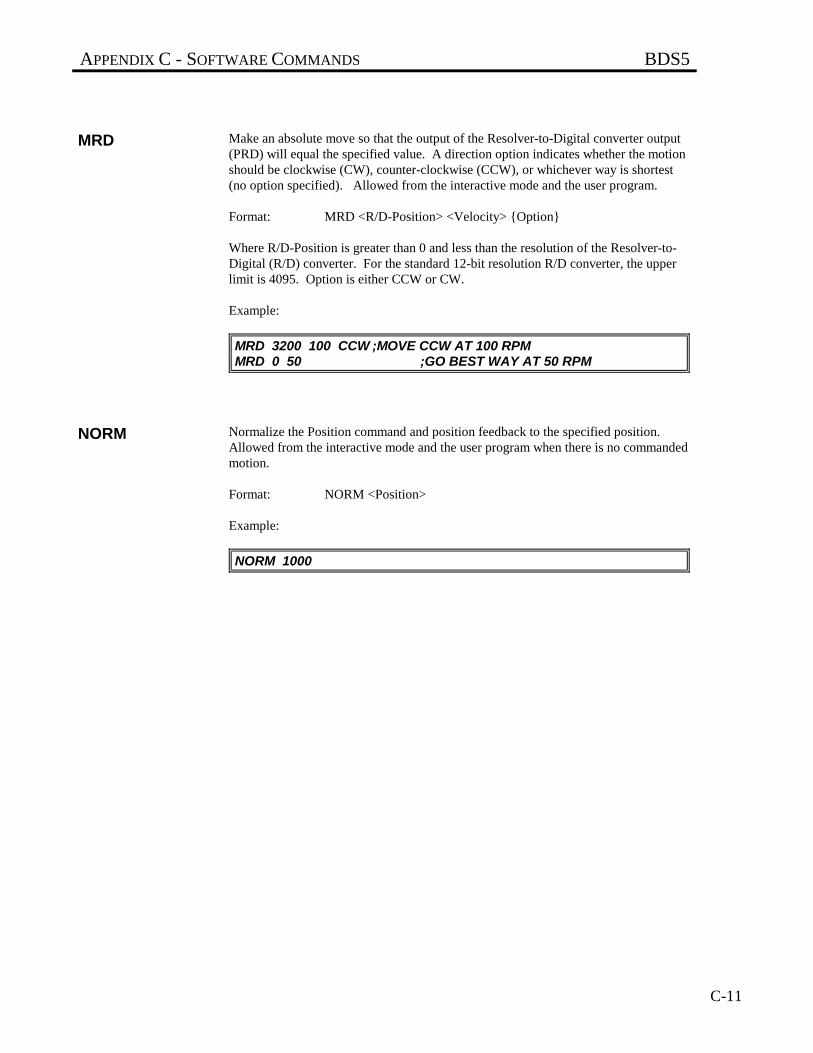
APPENDIX C - SOFTWARE COMMANDS BDS5
C-11
MRD Make an absolute move so that the output of the Resolver-to-Digital converter output(PRD) will equal the specified value. A direction option indicates whether the motionshould be clockwise (CW), counter-clockwise (CCW), or whichever way is shortest(no option specified). Allowed from the interactive mode and the user program.
Format: MRD <R/D-Position> <Velocity> {Option}
Where R/D-Position is greater than 0 and less than the resolution of the Resolver-to-Digital (R/D) converter. For the standard 12-bit resolution R/D converter, the upperlimit is 4095. Option is either CCW or CW.
Example:
MRD 3200 100 CCW ;MOVE CCW AT 100 RPMMRD 0 50 ;GO BEST WAY AT 50 RPM
NORM Normalize the Position command and position feedback to the specified position.Allowed from the interactive mode and the user program when there is no commandedmotion.
Format: NORM <Position>
Example:
NORM 1000
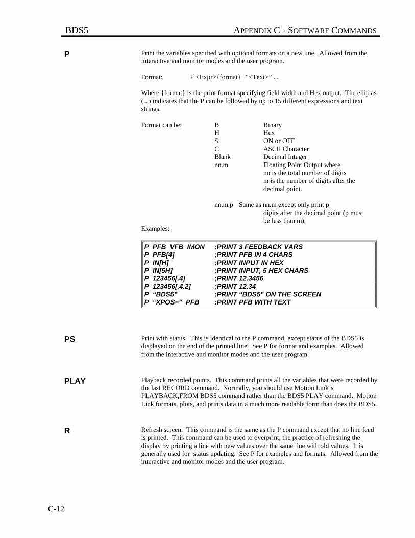
BDS5 APPENDIX C - SOFTWARE COMMANDS
C-12
P Print the variables specified with optional formats on a new line. Allowed from theinteractive and monitor modes and the user program.
Format: P <Expr>{format} | “<Text>” ...
Where {format} is the print format specifying field width and Hex output. The ellipsis(...) indicates that the P can be followed by up to 15 different expressions and textstrings.
Format can be: B BinaryH HexS ON or OFFC ASCII CharacterBlank Decimal Integernn.m Floating Point Output where
nn is the total number of digitsm is the number of digits after thedecimal point.
nn.m.p Same as nn.m except only print pdigits after the decimal point (p mustbe less than m).
Examples:
P PFB VFB IMON ;PRINT 3 FEEDBACK VARSP PFB[4] ;PRINT PFB IN 4 CHARSP IN[H] ;PRINT INPUT IN HEXP IN[5H] ;PRINT INPUT, 5 HEX CHARSP 123456[.4] ;PRINT 12.3456P 123456[.4.2] ;PRINT 12.34P “BDS5” ;PRINT “BDS5” ON THE SCREENP “XPOS=” PFB ;PRINT PFB WITH TEXT
PS Print with status. This is identical to the P command, except status of the BDS5 isdisplayed on the end of the printed line. See P for format and examples. Allowedfrom the interactive and monitor modes and the user program.
PLAY Playback recorded points. This command prints all the variables that were recorded bythe last RECORD command. Normally, you should use Motion Link’sPLAYBACK,FROM BDS5 command rather than the BDS5 PLAY command. MotionLink formats, plots, and prints data in a much more readable form than does the BDS5.
R Refresh screen. This command is the same as the P command except that no line feedis printed. This command can be used to overprint, the practice of refreshing thedisplay by printing a line with new values over the same line with old values. It isgenerally used for status updating. See P for examples and formats. Allowed from theinteractive and monitor modes and the user program.
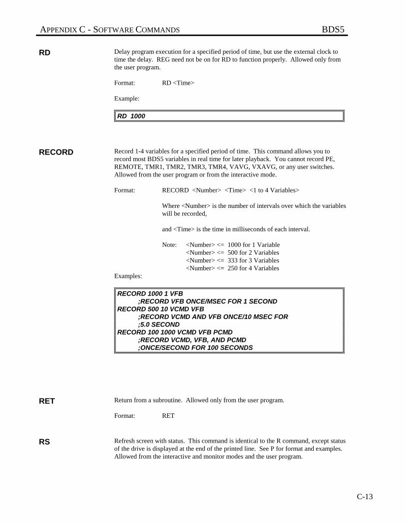
APPENDIX C - SOFTWARE COMMANDS BDS5
C-13
RD Delay program execution for a specified period of time, but use the external clock totime the delay. REG need not be on for RD to function properly. Allowed only fromthe user program.
Format: RD <Time>
Example:
RD 1000
RECORD Record 1-4 variables for a specified period of time. This command allows you torecord most BDS5 variables in real time for later playback. You cannot record PE,REMOTE, TMR1, TMR2, TMR3, TMR4, VAVG, VXAVG, or any user switches.Allowed from the user program or from the interactive mode.
Format: RECORD <Number> <Time> <1 to 4 Variables>
Where <Number> is the number of intervals over which the variableswill be recorded,
and <Time> is the time in milliseconds of each interval.
Note: <Number> <= 1000 for 1 Variable<Number> <= 500 for 2 Variables<Number> <= 333 for 3 Variables<Number> <= 250 for 4 Variables
Examples:
RECORD 1000 1 VFB ;RECORD VFB ONCE/MSEC FOR 1 SECOND
RECORD 500 10 VCMD VFB;RECORD VCMD AND VFB ONCE/10 MSEC FOR;5.0 SECOND
RECORD 100 1000 VCMD VFB PCMD;RECORD VCMD, VFB, AND PCMD;ONCE/SECOND FOR 100 SECONDS
RET Return from a subroutine. Allowed only from the user program.
Format: RET
RS Refresh screen with status. This command is identical to the R command, except statusof the drive is displayed at the end of the printed line. See P for format and examples.Allowed from the interactive and monitor modes and the user program.
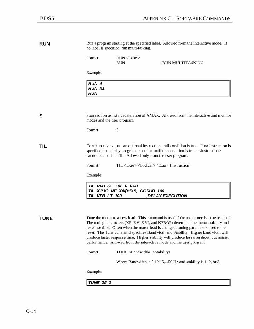
BDS5 APPENDIX C - SOFTWARE COMMANDS
C-14
RUN Run a program starting at the specified label. Allowed from the interactive mode. Ifno label is specified, run multi-tasking.
Format: RUN <Label>RUN ;RUN MULTITASKING
Example:
RUN 4RUN X1RUN
S Stop motion using a deceleration of AMAX. Allowed from the interactive and monitormodes and the user program.
Format: S
TIL Continuously execute an optional instruction until condition is true. If no instruction isspecified, then delay program execution until the condition is true. <Instruction>cannot be another TIL. Allowed only from the user program.
Format: TIL <Expr> <Logical> <Expr> [Instruction]
Example:
TIL PFB GT 100 P PFBTIL X1*X2 NE X4/(X5+5) GOSUB 100TIL VFB LT 100 ;DELAY EXECUTION
TUNE Tune the motor to a new load. This command is used if the motor needs to be re-tuned.The tuning parameters (KP, KV, KVI, and KPROP) determine the motor stability andresponse time. Often when the motor load is changed, tuning parameters need to bereset. The Tune command specifies Bandwidth and Stability. Higher bandwidth willproduce faster response time. Higher stability will produce less overshoot, but noisierperformance. Allowed from the interactive mode and the user program.
Format: TUNE <Bandwidth> <Stability>
Where Bandwidth is 5,10,15,...50 Hz and stability is 1, 2, or 3.
Example:
TUNE 25 2
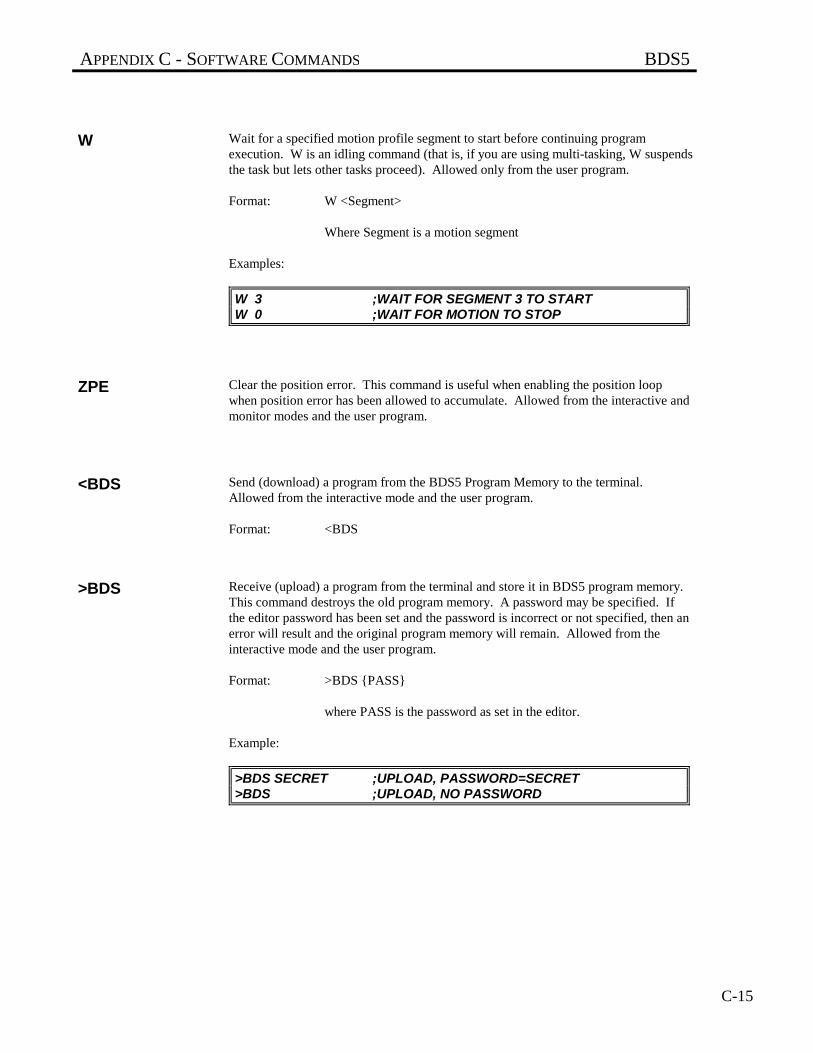
APPENDIX C - SOFTWARE COMMANDS BDS5
C-15
W Wait for a specified motion profile segment to start before continuing programexecution. W is an idling command (that is, if you are using multi-tasking, W suspendsthe task but lets other tasks proceed). Allowed only from the user program.
Format: W <Segment>
Where Segment is a motion segment
Examples:
W 3 ;WAIT FOR SEGMENT 3 TO STARTW 0 ;WAIT FOR MOTION TO STOP
ZPE Clear the position error. This command is useful when enabling the position loopwhen position error has been allowed to accumulate. Allowed from the interactive andmonitor modes and the user program.
<BDS Send (download) a program from the BDS5 Program Memory to the terminal.Allowed from the interactive mode and the user program.
Format: <BDS
>BDS Receive (upload) a program from the terminal and store it in BDS5 program memory.This command destroys the old program memory. A password may be specified. Ifthe editor password has been set and the password is incorrect or not specified, then anerror will result and the original program memory will remain. Allowed from theinteractive mode and the user program.
Format: >BDS {PASS}
where PASS is the password as set in the editor.
Example:
>BDS SECRET ;UPLOAD, PASSWORD=SECRET>BDS ;UPLOAD, NO PASSWORD
BDS5 APPENDIX D - ERROR CODES
D-1
APPENDIX D
ERROR CODES
D.1 INTRODUCTION
The BDS5's response to an error depends on the error's severity. There are four levels of severity, listed below inincreasing order:
Table D.1. Error Severity Levels and Actions
1. Errors which cause warnings.
2. Errors which cause a program break and stop motion, in addition to Level 1 Actions.
3. Errors which cause the system to disable and set the FAULT Hardware Output, in addition to Level 2Actions.
4. Errors which disable almost all BDS5 functions (including communications) and flash the CPU LED toindicate the error number. These are called firmware errors.
See Chapter 5 for more information about error severity. The following is a complete list of errors generated by theBDS5.
D.2 HARDWARE FAULTS
D.2.1 Firmware Faults
ERROR 2 ”HARDWARE- U-P FAIL” SEVERITY 4
The microprocessor cannot pass self-test. This fault causes themicroprocessor to blink the CPU light twice and then pause. The BDS5 willnot communicate or run the user program. Contact the factory.
ERROR 3 ”HARDWARE-CHECKSUM” SEVERITY 4
The microprocessor cannot pass the checksum self-test. This fault causes themicroprocessor to blink the CPU light three times and then pause. The BDS5will not communicate or run the user program. Contact the factory.
ERROR 4 ”SOFTWARE WATCHDOG” SEVERITY 4
The microprocessor has failed the software watchdog self-test. This faultcauses the microprocessor to blink the CPU light four times and then pause.The BDS5 will not communicate or run the user program. Contact thefactory.
APPENDIX D - ERROR CODES BDS5
D-2
ERROR 5 ”+5 VOLTS” SEVERITY 4
The +5 volts is too low. This fault causes the microprocessor to blink theCPU light five times and then pause. The BDS5 will not communicate or runthe user program. Check the +10 VDC input into the BDS5 (Connector C4,pin 4 or 8). If it is below 6.5 Volts for even a short time, this error will occur.This happens when the logic supply is loaded too heavily, or when the linevoltage (PSR4/5 Connector C1, pins 2 and 3) is below 98 VAC (115 VACless 15%).
D.2.2 BDS5 Faults
ERROR 10 ”REMOTE OFF” SEVERITY 2
You attempted to execute an instruction that requires the hardware inputREMOTE on the signal connector to be active. This error breaks programexecution.
ERROR 11 ”OVER-TEMP” SEVERITY 3
The thermostat on the BDS5 heatsink opened, indicating overheating.Overheating may be caused by excessive ambient temperature, obstructedairflow, broken fan, etc. Correct any such condition before resumingoperation. REMOVE ALL POWER BEFORE CHECKING THIS. Ifeverything is functioning properly, a drive with a higher current rating may berequired. This error breaks program execution and disables the BDS5.
ERROR 12 ”OVER-CURRENT” SEVERITY 3
The BDS5 detected an overcurrent. This can be caused by a shorted motorwinding, a shorted power transistor or a short circuit in the wiring. Be sure tocheck all wiring before resuming operation. This error breaks programexecution and disables the BDS5.
ERROR 13 ”OVER-SPEED” SEVERITY 3
The BDS5 determined that the speed of the motor was greater than thevariable VOSPD. If this occurs occasionally, it may be a nuisance fault thatshould be corrected by raising VOSPD by 5% or 10%. This error breaksprogram execution and disables the BDS5.
ERROR 14 ”POWER BUS” SEVERITY 3
The power supply high voltage bus has either an overvoltage fault or anundervoltage fault. This error breaks program execution and disables theBDS5.
ERROR 15 ”COMP BOARD” SEVERITY 3
You attempted to enable the BDS5 with the compensation board removed.Replace the compensation board. This error breaks program execution.
BDS5 APPENDIX D - ERROR CODES
D-3
ERROR 17 ”FEEDBACK LOSS” SEVERITY 3
The BDS5 has detected that one or more wires to the resolver have beenbroken, or the resolver connector has been removed. This error breaksprogram execution.
ERROR 18 ”BAD TL” SEVERITY 3
The BDS5 has two boards: a small MC board and a larger IBD board. Bothboards have the current and voltage rating encoded and they must match. Ifthis error occurs because you exchanged the MC card, then you shouldreplace the original card. If it occurs for some other reason, contact thefactory. This error breaks program execution.
ERROR 19 ”MOTION (HDWR LINE)” SEVERITY 2
The MOTION input was off at the beginning of a motion instruction, or itturned off during a motion instruction. This signal comes from the optionalI/O card. This error breaks program execution.
ERROR 20 ”TUNE FAILED” SEVERITY 3
The Tune command failed. Either the inertia on the motor is too large for thedesired bandwidth, the motor is not functioning properly, the bus voltage istoo low, or the BDS5 is not functioning properly. Try reducing the desiredbandwidth to correct this problem. Make sure REMOTE is on. If this doesnot work, attempt to tune the system by hand.
ERROR 22 ”+/- 12 VOLTS” SEVERITY 3
The ±12 volts is out of tolerance. Contact the factory. This error breaksprogram execution.
D.2.3 Positioner Faults
ERROR 23 ”SOFTWARE OVERTRAVEL” SEVERITY 2
Software travel limits are enabled and either PMAX or PMIN, the softwarelimits, have been exceeded. If your application does not need software travellimits, or if you want to disable software travel limits temporarily, type:
PLIM OFF
This error breaks program execution.
APPENDIX D - ERROR CODES BDS5
D-4
ERROR 24 ”HARDWARE OVERTRAVEL” SEVERITY 3
The BDS5 detected an overtravel condition while it was enabled. You canprint the state of the overtravel limit switch by typing:
P LIMIT
If LIMIT is 0, then an overtravel condition exists. LIMIT should be connectedto a limit switch that has contacts that are normally closed but which openwhere an overtravel condition occurs. Hardware overtravel limits cannot bedisabled. This error breaks program execution and disables the BDS5.
ERROR 25 ”PE OVERFLOW” SEVERITY 3
The variable PE, the position error, exceeded the variable PEMAX. This isalso called a following error overflow. This error breaks program executionand disables the BDS5.
ERROR 26 ”PFB ROLLOVER” SEVERITY 3
The variable PFB, the position feedback, exceeded +/-2,147,483,647 counts.If you are using position units, then PFB exceeded the position unit equivalentof +/-2,147,483,647 counts. This can occur if the motor rotates indefinitely inone direction. If your application requires this, consider using the rotarymode.
ERROR 27 ”R/D JUMPERS” SEVERITY 3
Either the jumpers on your BDS5 MC2 card are incorrectly set or the wrongTL has been loaded. Contact the factory.
D.3 MOTION ERRORS
D.3.1 Position Calculation Errors
ERROR 30 ”TOO MANY MOVES” SEVERITY 2
You typed in too many move commands (MA, MI, MCGO) from theinteractive mode. You can have one move executing and the other pending.The error does not occur when move commands are executed from the userprogram, because the BDS5 sees that the motion buffer is full and delaysexecution to prevent the error. This error breaks program execution.
ERROR 31 ”TOO MANY MRD MOVES” SEVERITY 2
You attempted to execute a motion instruction that required the profile bufferto be empty. This occurs when two MRD instructions are active at once. Youshould use a synchronizer to delay the execution of the instruction that causedthe error. This error breaks program execution.
ERROR 32 ”ACC/DEC TOO LOW” SEVERITY 2
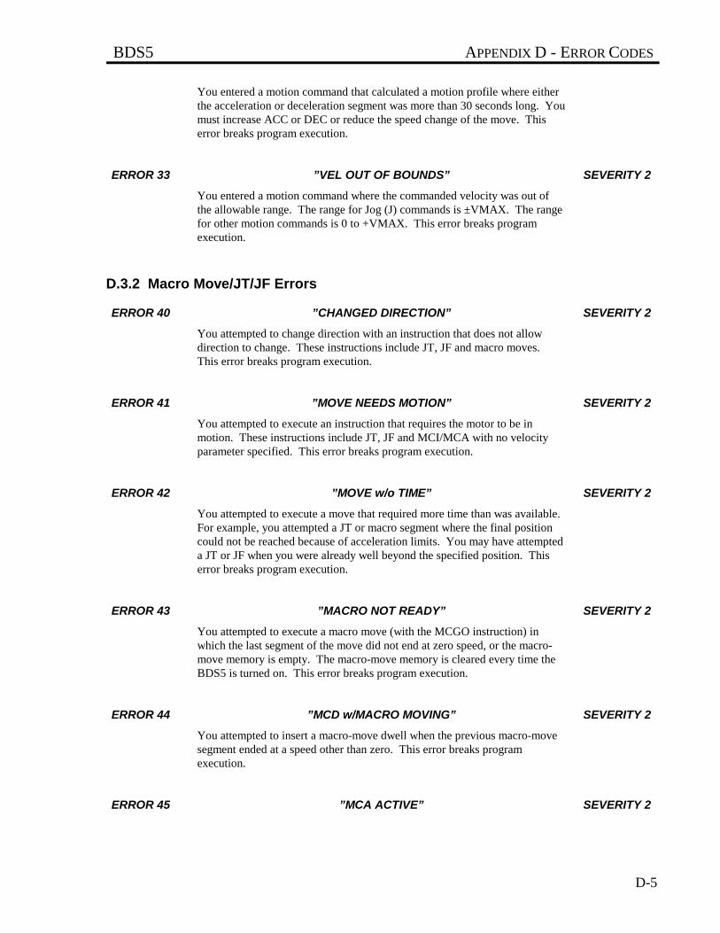
BDS5 APPENDIX D - ERROR CODES
D-5
You entered a motion command that calculated a motion profile where eitherthe acceleration or deceleration segment was more than 30 seconds long. Youmust increase ACC or DEC or reduce the speed change of the move. Thiserror breaks program execution.
ERROR 33 ”VEL OUT OF BOUNDS” SEVERITY 2
You entered a motion command where the commanded velocity was out ofthe allowable range. The range for Jog (J) commands is ±VMAX. The rangefor other motion commands is 0 to +VMAX. This error breaks programexecution.
D.3.2 Macro Move/JT/JF Errors
ERROR 40 ”CHANGED DIRECTION” SEVERITY 2
You attempted to change direction with an instruction that does not allowdirection to change. These instructions include JT, JF and macro moves.This error breaks program execution.
ERROR 41 ”MOVE NEEDS MOTION” SEVERITY 2
You attempted to execute an instruction that requires the motor to be inmotion. These instructions include JT, JF and MCI/MCA with no velocityparameter specified. This error breaks program execution.
ERROR 42 ”MOVE w/o TIME” SEVERITY 2
You attempted to execute a move that required more time than was available.For example, you attempted a JT or macro segment where the final positioncould not be reached because of acceleration limits. You may have attempteda JT or JF when you were already well beyond the specified position. Thiserror breaks program execution.
ERROR 43 ”MACRO NOT READY” SEVERITY 2
You attempted to execute a macro move (with the MCGO instruction) inwhich the last segment of the move did not end at zero speed, or the macro-move memory is empty. The macro-move memory is cleared every time theBDS5 is turned on. This error breaks program execution.
ERROR 44 ”MCD w/MACRO MOVING” SEVERITY 2
You attempted to insert a macro-move dwell when the previous macro-movesegment ended at a speed other than zero. This error breaks programexecution.
ERROR 45 ”MCA ACTIVE” SEVERITY 2
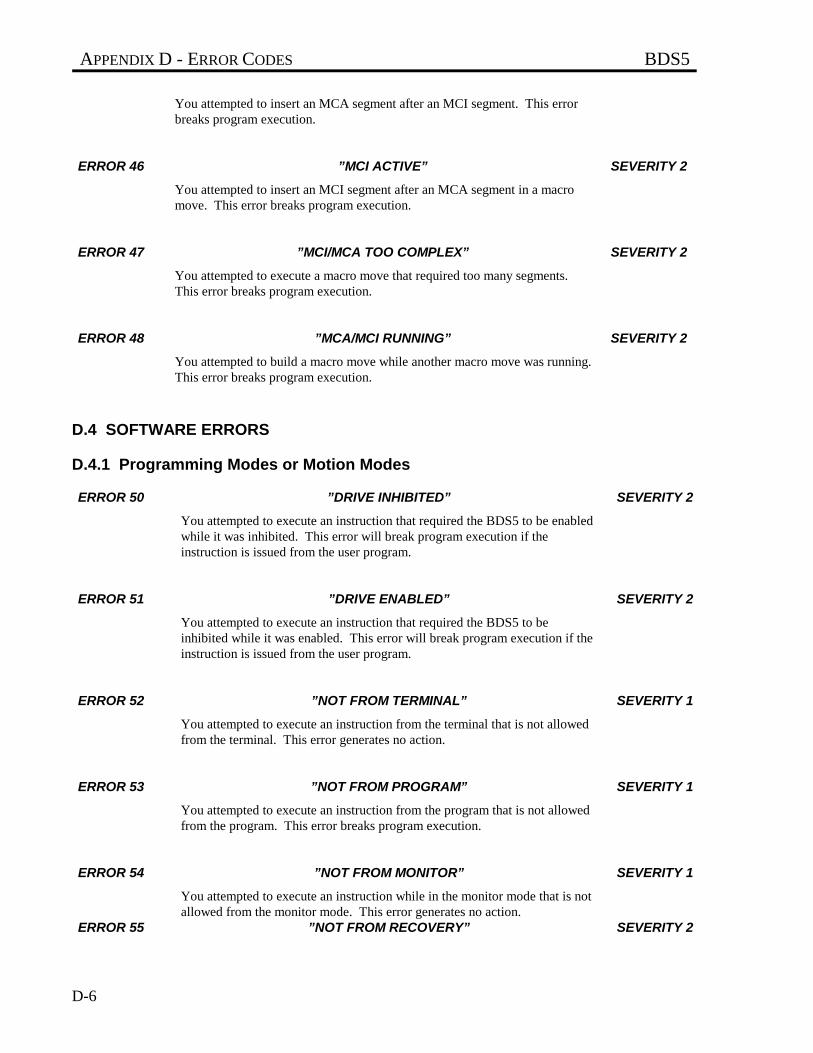
APPENDIX D - ERROR CODES BDS5
D-6
You attempted to insert an MCA segment after an MCI segment. This errorbreaks program execution.
ERROR 46 ”MCI ACTIVE” SEVERITY 2
You attempted to insert an MCI segment after an MCA segment in a macromove. This error breaks program execution.
ERROR 47 ”MCI/MCA TOO COMPLEX” SEVERITY 2
You attempted to execute a macro move that required too many segments.This error breaks program execution.
ERROR 48 ”MCA/MCI RUNNING” SEVERITY 2
You attempted to build a macro move while another macro move was running.This error breaks program execution.
D.4 SOFTWARE ERRORS
D.4.1 Programming Modes or Motion Modes
ERROR 50 ”DRIVE INHIBITED” SEVERITY 2
You attempted to execute an instruction that required the BDS5 to be enabledwhile it was inhibited. This error will break program execution if theinstruction is issued from the user program.
ERROR 51 ”DRIVE ENABLED” SEVERITY 2
You attempted to execute an instruction that required the BDS5 to beinhibited while it was enabled. This error will break program execution if theinstruction is issued from the user program.
ERROR 52 ”NOT FROM TERMINAL” SEVERITY 1
You attempted to execute an instruction from the terminal that is not allowedfrom the terminal. This error generates no action.
ERROR 53 ”NOT FROM PROGRAM” SEVERITY 1
You attempted to execute an instruction from the program that is not allowedfrom the program. This error breaks program execution.
ERROR 54 ”NOT FROM MONITOR” SEVERITY 1
You attempted to execute an instruction while in the monitor mode that is notallowed from the monitor mode. This error generates no action.
ERROR 55 ”NOT FROM RECOVERY” SEVERITY 2
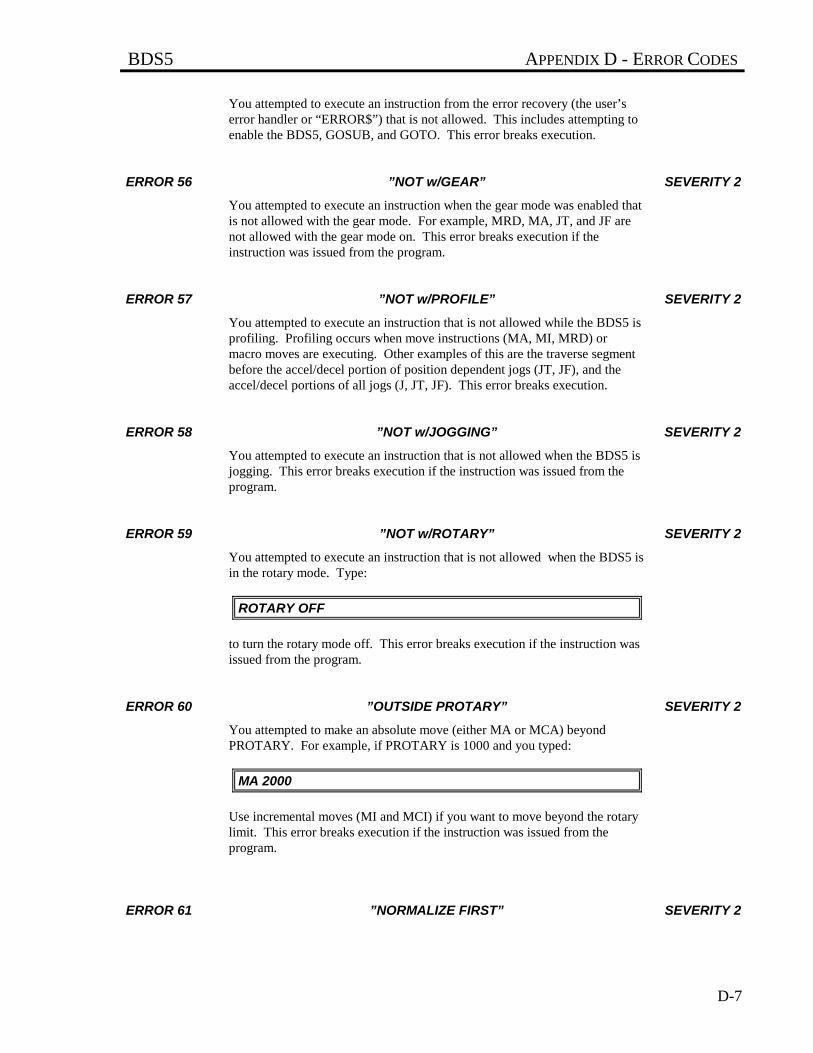
BDS5 APPENDIX D - ERROR CODES
D-7
You attempted to execute an instruction from the error recovery (the user’serror handler or “ERROR$”) that is not allowed. This includes attempting toenable the BDS5, GOSUB, and GOTO. This error breaks execution.
ERROR 56 ”NOT w/GEAR” SEVERITY 2
You attempted to execute an instruction when the gear mode was enabled thatis not allowed with the gear mode. For example, MRD, MA, JT, and JF arenot allowed with the gear mode on. This error breaks execution if theinstruction was issued from the program.
ERROR 57 ”NOT w/PROFILE” SEVERITY 2
You attempted to execute an instruction that is not allowed while the BDS5 isprofiling. Profiling occurs when move instructions (MA, MI, MRD) ormacro moves are executing. Other examples of this are the traverse segmentbefore the accel/decel portion of position dependent jogs (JT, JF), and theaccel/decel portions of all jogs (J, JT, JF). This error breaks execution.
ERROR 58 ”NOT w/JOGGING” SEVERITY 2
You attempted to execute an instruction that is not allowed when the BDS5 isjogging. This error breaks execution if the instruction was issued from theprogram.
ERROR 59 ”NOT w/ROTARY” SEVERITY 2
You attempted to execute an instruction that is not allowed when the BDS5 isin the rotary mode. Type:
ROTARY OFF
to turn the rotary mode off. This error breaks execution if the instruction wasissued from the program.
ERROR 60 ”OUTSIDE PROTARY” SEVERITY 2
You attempted to make an absolute move (either MA or MCA) beyondPROTARY. For example, if PROTARY is 1000 and you typed:
MA 2000
Use incremental moves (MI and MCI) if you want to move beyond the rotarylimit. This error breaks execution if the instruction was issued from theprogram.
ERROR 61 ”NORMALIZE FIRST” SEVERITY 2
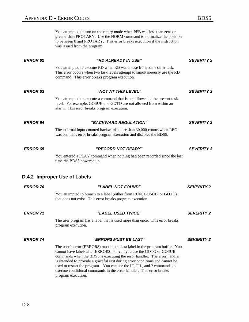
APPENDIX D - ERROR CODES BDS5
D-8
You attempted to turn on the rotary mode when PFB was less than zero orgreater than PROTARY. Use the NORM command to normalize the positionto between 0 and PROTARY. This error breaks execution if the instructionwas issued from the program.
ERROR 62 ”RD ALREADY IN USE” SEVERITY 2
You attempted to execute RD when RD was in use from some other task.This error occurs when two task levels attempt to simultaneously use the RDcommand. This error breaks program execution.
ERROR 63 ”NOT AT THIS LEVEL” SEVERITY 2
You attempted to execute a command that is not allowed at the present tasklevel. For example, GOSUB and GOTO are not allowed from within analarm. This error breaks program execution.
ERROR 64 ”BACKWARD REGULATION” SEVERITY 3
The external input counted backwards more than 30,000 counts when REGwas on. This error breaks program execution and disables the BDS5.
ERROR 65 ”RECORD NOT READY” SEVERITY 3
You entered a PLAY command when nothing had been recorded since the lasttime the BDS5 powered up.
D.4.2 Improper Use of Labels
ERROR 70 ”LABEL NOT FOUND” SEVERITY 2
You attempted to branch to a label (either from RUN, GOSUB, or GOTO)that does not exist. This error breaks program execution.
ERROR 71 ”LABEL USED TWICE” SEVERITY 2
The user program has a label that is used more than once. This error breaksprogram execution.
ERROR 74 ”ERROR$ MUST BE LAST” SEVERITY 2
The user’s error (ERROR$) must be the last label in the program buffer. Youcannot have labels after ERROR$, nor can you use the GOTO or GOSUBcommands when the BDS5 is executing the error handler. The error handleris intended to provide a graceful exit during error conditions and cannot beused to restart the program. You can use the IF, TIL, and ? commands toexecute conditional commands in the error handler. This error breaksprogram execution.
BDS5 APPENDIX D - ERROR CODES
D-9
D.4.3 Invalid Instructions or Entries
ERROR 79 ”BAD FORMAT” SEVERITY 2
You entered a format that the BDS5 does not recognize. For example, youmay have entered:
INPUT “INPUT X1” X1[.3]
In this case, the decimal point (following the “[”) is incorrect. Pay carefulattention to the rules for formats in Chapter 4. This error breaks programexecution if the instruction is issued from the user program.
ERROR 80 ”INVALID INSTRUCTION” SEVERITY 2
You attempted to execute an instruction or change a variable that the BDS5does not recognize. This error breaks program execution if the instruction isissued from the user program.
ERROR 81 ”NOT PROGRAMMABLE” SEVERITY 2
You attempted to change a variable that is not programmable. This error willbreak program execution if the instruction is issued from the user program.
ERROR 82 ”BAD NUMBER ENTRIES” SEVERITY 2
The instruction that is executing has too many or too few parameters. Lookup the instruction in Appendix B to determine the correct number of entries.This error breaks program execution if the instruction is issued from the userprogram.
ERROR 83 ”BAD OR OUT OF RANGE” SEVERITY 2
You entered a parameter to an instruction that was too large or too small.Check Appendix C for limits on variables. This error can also occur when aparameter is in the wrong format, such as a character string where a number isexpected. This error breaks program execution if the instruction is issuedfrom the user program.
ERROR 84 ”OUT OF BOUNDS” SEVERITY 2
The variable listed is out of bounds. If the variable is protected (that is, set bythe factory as defined in Appendix C), contact the factory. If the variable isnot protected, set it within its bounds. This error breaks execution.
ERROR 85 ”BAD INDIRECTION” SEVERITY 2
APPENDIX D - ERROR CODES BDS5
D-10
You attempted an indirect reference to a user variable that does not exist.For example:
X1 10000P X(X1)
X(X1) refers to user variable X10000, which does not exist. The “P X(X1)”will generate this error. This error breaks program execution if the instructionis issued from the user program.
ERROR 86 ”USER PROGRAM FULL” SEVERITY 2
You attempted to load a program larger than the BDS5 can hold. This occurswith the >BDS instruction and from the Motion Link communicationssoftware “Program Transmit (^T)”. This error breaks program execution.
ERROR 87 ”EMBEDDED QUOTE” SEVERITY 2
You entered a command with an embedded quote. A space must precede anopening quote and follow a closing quote. For example:
P”BAD COMMAND”
has an embedded quote after the “P”. This error breaks program execution ifthe instruction is issued from the user program.
ERROR 88 ”NO CLOSING QUOTE” SEVERITY 2
You entered a command with an odd (as opposed to even) number of quotes.This error breaks program execution if the instruction is issued from the userprogram.
ERROR 89 ”NOT FOR ALARM/HOLD/RECORD” SEVERITY 2
You have specified a switch that is not an allowable switch for an alarm or ahold or record command. For example:
A$ REMOTE ON ;ERROR—REMOTE NOT ALLOWED FORALARMS
This line causes Error 89 since REMOTE is not allowed to fire an alarm.
ERROR 90 ”TOO MANY POINTS” SEVERITY 2
BDS5 APPENDIX D - ERROR CODES
D-11
You specified too many points in a RECORD command. Only 1000 pointstotal can be recorded. For example, if you are recording four variables, theycan be recorded no more than 250 times, since 4*250 = 1000.
D.4.4 Math Errors
ERROR 92 ”ZERO DIVIDE” SEVERITY 2
You attempted to divide a number by 0. This error breaks program executionif the instruction is issued from the user program.
ERROR 93 ”MATH OVERFLOW” SEVERITY 2
The final result of a calculation or an intermediate result during thecalculation of an expression was greater than 231 or less than -231. This errorbreaks program execution.
ERROR 94 ”>2 PARENTHESES” SEVERITY 2
The BDS5 evaluated an expression with more levels of parentheses than theBDS5 supports. Up to two levels of parentheses are allowed. This errorbreaks program execution.
ERROR 95 ”UNEVEN PARENTHESES” SEVERITY 2
The BDS5 encountered an expression in which the number of closingparentheses was not equal to the number of opening parentheses. This errorbreaks program execution.
ERROR 96 ”SCALING OVERFLOW” SEVERITY 2
During a conversion to or from user units, the result was greater than 231 orless than -231. This error breaks program execution if the instruction isissued from the user program.
ERROR 97 ”GEAR OVERFLOW” SEVERITY 3
The BDS5 encountered an overflow when calculating the velocity from theexternal pulse input. This can be caused when the variable GEARI is toosmall or GEARO is too large. That is, the input times the ratio ofGEARO/GEARI was greater than the highest allowable input frequency, 2MHz. This error breaks program execution and disables the BDS5.
D.4.5 Communication Errors
ERROR 103 ”BAUD RATE” SEVERITY 1
APPENDIX D - ERROR CODES BDS5
D-12
The variable BAUD contains a value that is not supported by the BDS5. Thiserror occurs during the autobaud sequence and so is never printed to theterminal. You will only see it in the error history buffer. This error has noaction.
ERROR 104 ”ABAUD & MULTIDROP” SEVERITY 1
This error is caused by attempting to autobaud while in multidropcommunications, which is not allowed. The variable ABAUD is on,indicating request for autobaud, and the variable ADDR is not zero, indicatingmultidrop communications. This error occurs during the autobaud sequenceand so is never printed to the terminal. You will only see it in the errorhistory buffer. This error has no action.
ERROR 105 ”SERIAL WDOG” SEVERITY 3
The serial port did not receive a valid command for WTIME millisecondswhen the serial watchdog was enabled (that is, WATCH = 1). This errorbreaks program execution and disables the BDS5.
D.4.6 Password Errors
ERROR 110 ”EDIT PASSWORD” SEVERITY 1
You attempted to execute an instruction that requires the Editor password.This occurs with the >BDS command. In this case, you must follow thecommand with the password.
ERROR 111 ”FACTORY SETTABLE” SEVERITY 2
You attempted to change a variable that is protected. These variables are setat the factory. This error breaks program execution if the instruction is issuedfrom the user program.
D.4.7 Errors From IF, TIL and GOSUB Commands
ERROR 115 ”IF w/o ENDIF” SEVERITY 2
The program executed an IF command to begin an IF BLOCK, but could notfind the corresponding ENDIF to end the IF block. This error breaks programexecution.
ERROR 116 ”IF NOT STARTED” SEVERITY 2
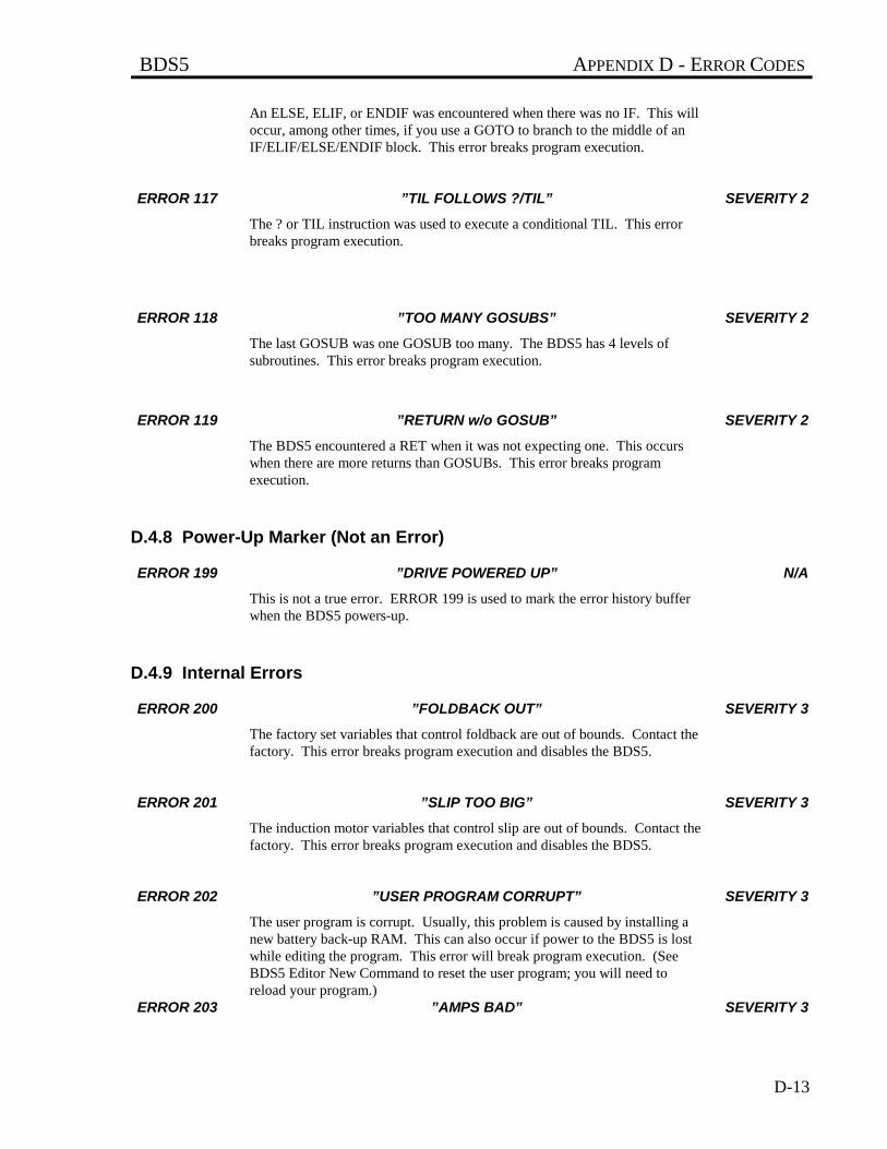
BDS5 APPENDIX D - ERROR CODES
D-13
An ELSE, ELIF, or ENDIF was encountered when there was no IF. This willoccur, among other times, if you use a GOTO to branch to the middle of anIF/ELIF/ELSE/ENDIF block. This error breaks program execution.
ERROR 117 ”TIL FOLLOWS ?/TIL” SEVERITY 2
The ? or TIL instruction was used to execute a conditional TIL. This errorbreaks program execution.
ERROR 118 ”TOO MANY GOSUBS” SEVERITY 2
The last GOSUB was one GOSUB too many. The BDS5 has 4 levels ofsubroutines. This error breaks program execution.
ERROR 119 ”RETURN w/o GOSUB” SEVERITY 2
The BDS5 encountered a RET when it was not expecting one. This occurswhen there are more returns than GOSUBs. This error breaks programexecution.
D.4.8 Power-Up Marker (Not an Error)
ERROR 199 ”DRIVE POWERED UP” N/A
This is not a true error. ERROR 199 is used to mark the error history bufferwhen the BDS5 powers-up.
D.4.9 Internal Errors
ERROR 200 ”FOLDBACK OUT” SEVERITY 3
The factory set variables that control foldback are out of bounds. Contact thefactory. This error breaks program execution and disables the BDS5.
ERROR 201 ”SLIP TOO BIG” SEVERITY 3
The induction motor variables that control slip are out of bounds. Contact thefactory. This error breaks program execution and disables the BDS5.
ERROR 202 ”USER PROGRAM CORRUPT” SEVERITY 3
The user program is corrupt. Usually, this problem is caused by installing anew battery back-up RAM. This can also occur if power to the BDS5 is lostwhile editing the program. This error will break program execution. (SeeBDS5 Editor New Command to reset the user program; you will need toreload your program.)
ERROR 203 ”AMPS BAD” SEVERITY 3
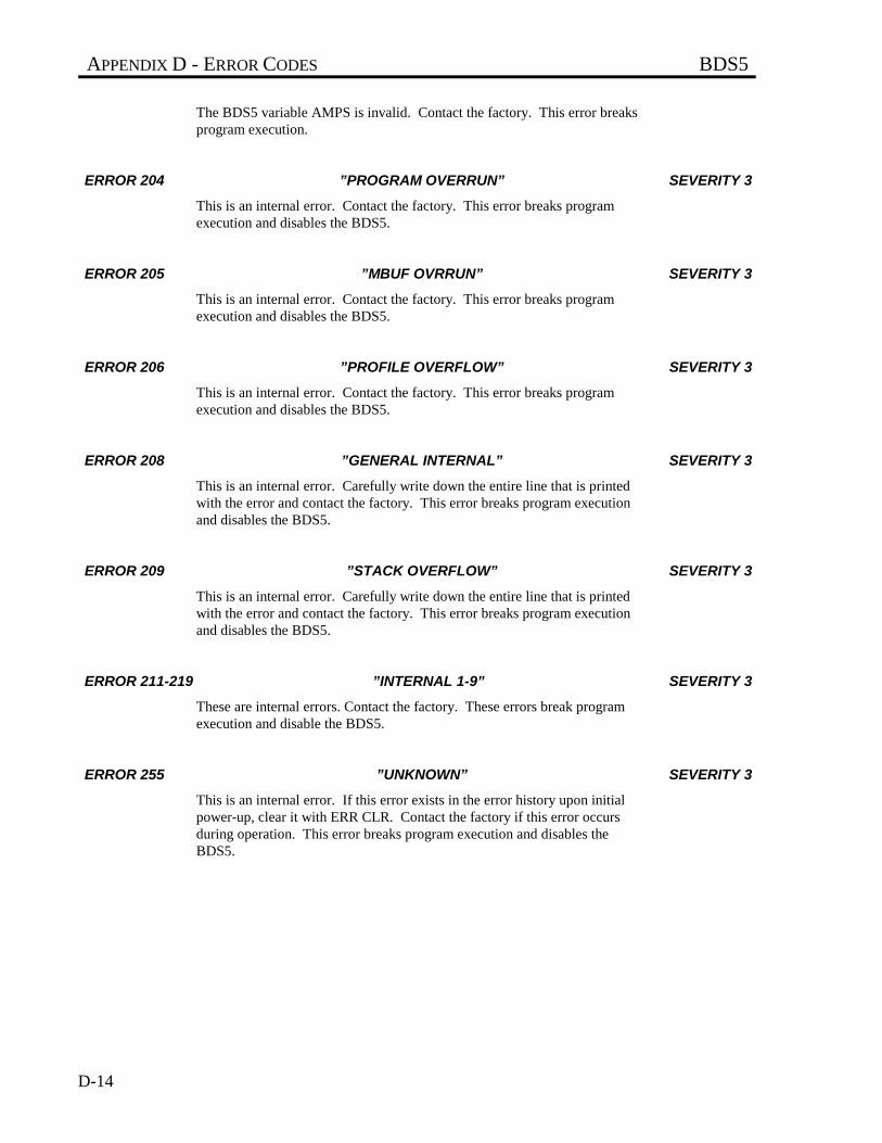
APPENDIX D - ERROR CODES BDS5
D-14
The BDS5 variable AMPS is invalid. Contact the factory. This error breaksprogram execution.
ERROR 204 ”PROGRAM OVERRUN” SEVERITY 3
This is an internal error. Contact the factory. This error breaks programexecution and disables the BDS5.
ERROR 205 ”MBUF OVRRUN” SEVERITY 3
This is an internal error. Contact the factory. This error breaks programexecution and disables the BDS5.
ERROR 206 ”PROFILE OVERFLOW” SEVERITY 3
This is an internal error. Contact the factory. This error breaks programexecution and disables the BDS5.
ERROR 208 ”GENERAL INTERNAL” SEVERITY 3
This is an internal error. Carefully write down the entire line that is printedwith the error and contact the factory. This error breaks program executionand disables the BDS5.
ERROR 209 ”STACK OVERFLOW” SEVERITY 3
This is an internal error. Carefully write down the entire line that is printedwith the error and contact the factory. This error breaks program executionand disables the BDS5.
ERROR 211-219 ”INTERNAL 1-9” SEVERITY 3
These are internal errors. Contact the factory. These errors break programexecution and disable the BDS5.
ERROR 255 ”UNKNOWN” SEVERITY 3
This is an internal error. If this error exists in the error history upon initialpower-up, clear it with ERR CLR. Contact the factory if this error occursduring operation. This error breaks program execution and disables theBDS5.
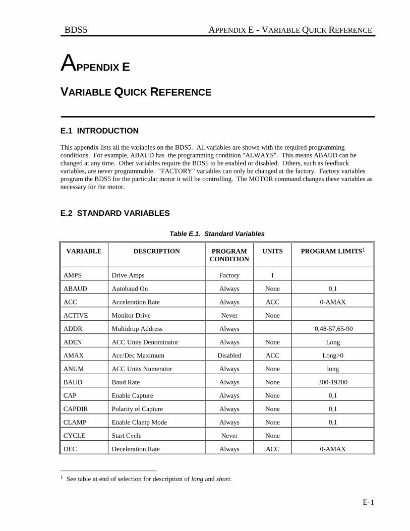
BDS5 APPENDIX E - VARIABLE QUICK REFERENCE
E-1
APPENDIX E
VARIABLE QUICK REFERENCE
E.1 INTRODUCTION
This appendix lists all the variables on the BDS5. All variables are shown with the required programmingconditions. For example, ABAUD has the programming condition "ALWAYS". This means ABAUD can bechanged at any time. Other variables require the BDS5 to be enabled or disabled. Others, such as feedbackvariables, are never programmable. "FACTORY" variables can only be changed at the factory. Factory variablesprogram the BDS5 for the particular motor it will be controlling. The MOTOR command changes these variables asnecessary for the motor.
E.2 STANDARD VARIABLES
Table E.1. Standard Variables
VARIABLE DESCRIPTION PROGRAMCONDITION
UNITS PROGRAM LIMITS1
AMPS Drive Amps Factory I
ABAUD Autobaud On Always None 0,1
ACC Acceleration Rate Always ACC 0-AMAX
ACTIVE Monitor Drive Never None
ADDR Multidrop Address Always 0,48-57,65-90
ADEN ACC Units Denominator Always None Long
AMAX Acc/Dec Maximum Disabled ACC Long>0
ANUM ACC Units Numerator Always None long
BAUD Baud Rate Always None 300-19200
CAP Enable Capture Always None 0,1
CAPDIR Polarity of Capture Always None 0,1
CLAMP Enable Clamp Mode Always None 0,1
CYCLE Start Cycle Never None
DEC Deceleration Rate Always ACC 0-AMAX
1 See table at end of selection for description of long and short.
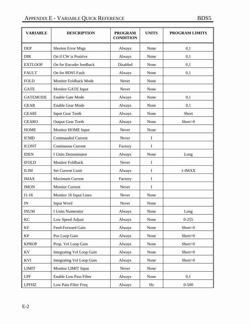
APPENDIX E - VARIABLE QUICK REFERENCE BDS5
VARIABLE DESCRIPTION PROGRAMCONDITION
UNITS PROGRAM LIMITS
E-2
DEP Shorten Error Msgs Always None 0,1
DIR On if CW is Positive Always None 0,1
EXTLOOP On for Encoder feedback Disabled None 0,1
FAULT On for BDS5 Fault Always None 0,1
FOLD Monitor Foldback Mode Never None
GATE Monitor GATE Input Never None
GATEMODE Enable Gate Mode Always None 0,1
GEAR Enable Gear Mode Always None 0,1
GEARI Input Gear Teeth Always None Short
GEARO Output Gear Teeth Always None Short>0
HOME Monitor HOME Input Never None
ICMD Commanded Current Never I
ICONT Continuous Current Factory I
IDEN I Units Denominator Always None Long
IFOLD Monitor Foldback Never I
ILIM Set Current Limit Always I 1-IMAX
IMAX Maximum Current Factory I
IMON Monitor Current Never I
I1-16 Monitor 16 Input Lines Never None
IN Input Word Never None
INUM I Units Numerator Always None Long
KC Low Speed Adjust Always None 0-255
KF Feed-Forward Gain Always None Short>0
KP Pos Loop Gain Always None Short>0
KPROP Prop. Vel Loop Gain Always None Short>0
KV Integrating Vel Loop Gain Always None Short>0
KVI Integrating Vel Loop Gain Always None Short>0
LIMIT Monitor LIMIT Input Never None
LPF Enable Low Pass Filter Always None 0,1
LPFHZ Low Pass Filter Freq Always Hz 0-500
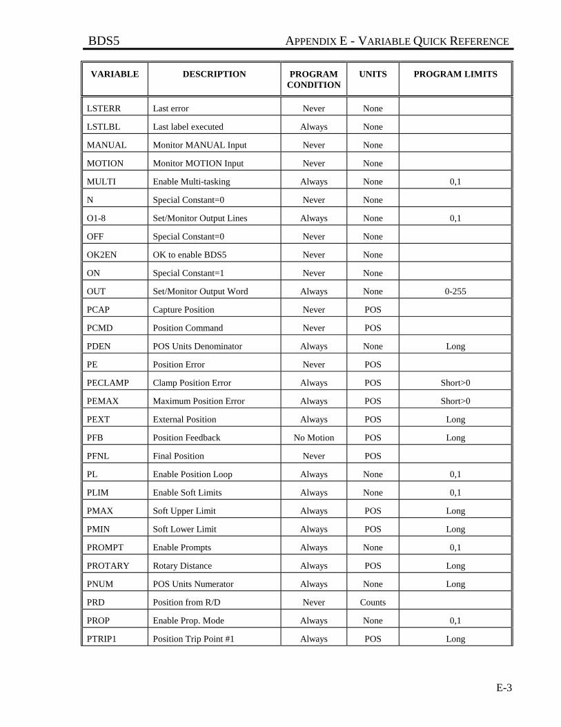
BDS5 APPENDIX E - VARIABLE QUICK REFERENCE
VARIABLE DESCRIPTION PROGRAMCONDITION
UNITS PROGRAM LIMITS
E-3
LSTERR Last error Never None
LSTLBL Last label executed Always None
MANUAL Monitor MANUAL Input Never None
MOTION Monitor MOTION Input Never None
MULTI Enable Multi-tasking Always None 0,1
N Special Constant=0 Never None
O1-8 Set/Monitor Output Lines Always None 0,1
OFF Special Constant=0 Never None
OK2EN OK to enable BDS5 Never None
ON Special Constant=1 Never None
OUT Set/Monitor Output Word Always None 0-255
PCAP Capture Position Never POS
PCMD Position Command Never POS
PDEN POS Units Denominator Always None Long
PE Position Error Never POS
PECLAMP Clamp Position Error Always POS Short>0
PEMAX Maximum Position Error Always POS Short>0
PEXT External Position Always POS Long
PFB Position Feedback No Motion POS Long
PFNL Final Position Never POS
PL Enable Position Loop Always None 0,1
PLIM Enable Soft Limits Always None 0,1
PMAX Soft Upper Limit Always POS Long
PMIN Soft Lower Limit Always POS Long
PROMPT Enable Prompts Always None 0,1
PROTARY Rotary Distance Always POS Long
PNUM POS Units Numerator Always None Long
PRD Position from R/D Never Counts
PROP Enable Prop. Mode Always None 0,1
PTRIP1 Position Trip Point #1 Always POS Long
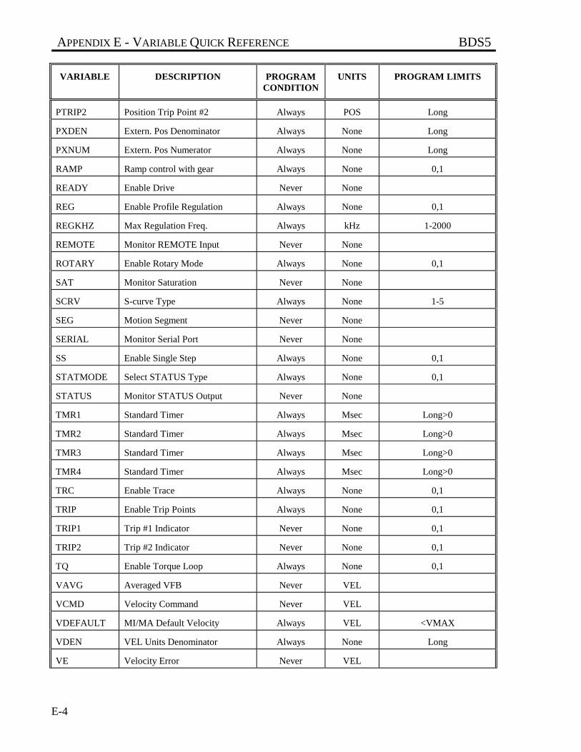
APPENDIX E - VARIABLE QUICK REFERENCE BDS5
VARIABLE DESCRIPTION PROGRAMCONDITION
UNITS PROGRAM LIMITS
E-4
PTRIP2 Position Trip Point #2 Always POS Long
PXDEN Extern. Pos Denominator Always None Long
PXNUM Extern. Pos Numerator Always None Long
RAMP Ramp control with gear Always None 0,1
READY Enable Drive Never None
REG Enable Profile Regulation Always None 0,1
REGKHZ Max Regulation Freq. Always kHz 1-2000
REMOTE Monitor REMOTE Input Never None
ROTARY Enable Rotary Mode Always None 0,1
SAT Monitor Saturation Never None
SCRV S-curve Type Always None 1-5
SEG Motion Segment Never None
SERIAL Monitor Serial Port Never None
SS Enable Single Step Always None 0,1
STATMODE Select STATUS Type Always None 0,1
STATUS Monitor STATUS Output Never None
TMR1 Standard Timer Always Msec Long>0
TMR2 Standard Timer Always Msec Long>0
TMR3 Standard Timer Always Msec Long>0
TMR4 Standard Timer Always Msec Long>0
TRC Enable Trace Always None 0,1
TRIP Enable Trip Points Always None 0,1
TRIP1 Trip #1 Indicator Never None 0,1
TRIP2 Trip #2 Indicator Never None 0,1
TQ Enable Torque Loop Always None 0,1
VAVG Averaged VFB Never VEL
VCMD Velocity Command Never VEL
VDEFAULT MI/MA Default Velocity Always VEL <VMAX
VDEN VEL Units Denominator Always None Long
VE Velocity Error Never VEL
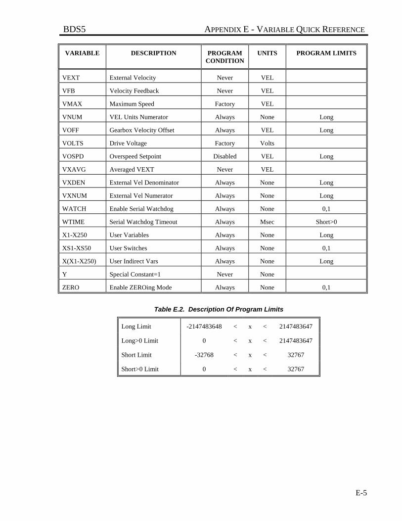
BDS5 APPENDIX E - VARIABLE QUICK REFERENCE
VARIABLE DESCRIPTION PROGRAMCONDITION
UNITS PROGRAM LIMITS
E-5
VEXT External Velocity Never VEL
VFB Velocity Feedback Never VEL
VMAX Maximum Speed Factory VEL
VNUM VEL Units Numerator Always None Long
VOFF Gearbox Velocity Offset Always VEL Long
VOLTS Drive Voltage Factory Volts
VOSPD Overspeed Setpoint Disabled VEL Long
VXAVG Averaged VEXT Never VEL
VXDEN External Vel Denominator Always None Long
VXNUM External Vel Numerator Always None Long
WATCH Enable Serial Watchdog Always None 0,1
WTIME Serial Watchdog Timeout Always Msec Short>0
X1-X250 User Variables Always None Long
XS1-XS50 User Switches Always None 0,1
X(X1-X250) User Indirect Vars Always None Long
Y Special Constant=1 Never None
ZERO Enable ZEROing Mode Always None 0,1
Table E.2. Description Of Program Limits
Long Limit -2147483648 < x < 2147483647
Long>0 Limit 0 < x < 2147483647
Short Limit -32768 < x < 32767
Short>0 Limit 0 < x < 32767
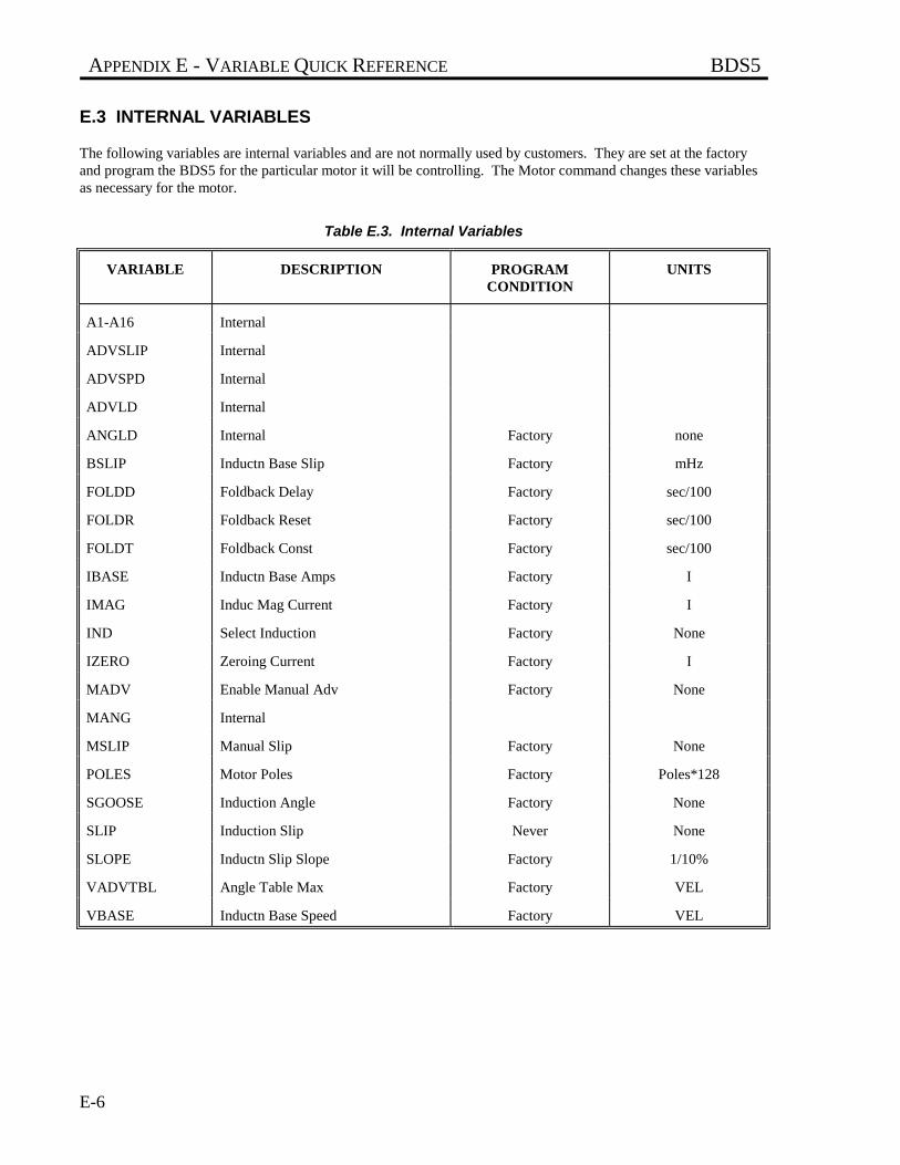
APPENDIX E - VARIABLE QUICK REFERENCE BDS5
E-6
E.3 INTERNAL VARIABLES
The following variables are internal variables and are not normally used by customers. They are set at the factoryand program the BDS5 for the particular motor it will be controlling. The Motor command changes these variablesas necessary for the motor.
Table E.3. Internal Variables
VARIABLE DESCRIPTION PROGRAMCONDITION
UNITS
A1-A16 Internal
ADVSLIP Internal
ADVSPD Internal
ADVLD Internal
ANGLD Internal Factory none
BSLIP Inductn Base Slip Factory mHz
FOLDD Foldback Delay Factory sec/100
FOLDR Foldback Reset Factory sec/100
FOLDT Foldback Const Factory sec/100
IBASE Inductn Base Amps Factory I
IMAG Induc Mag Current Factory I
IND Select Induction Factory None
IZERO Zeroing Current Factory I
MADV Enable Manual Adv Factory None
MANG Internal
MSLIP Manual Slip Factory None
POLES Motor Poles Factory Poles*128
SGOOSE Induction Angle Factory None
SLIP Induction Slip Never None
SLOPE Inductn Slip Slope Factory 1/10%
VADVTBL Angle Table Max Factory VEL
VBASE Inductn Base Speed Factory VEL
BDS5 APPENDIX F - COMMAND TIMINGS
F-1
APPENDIX F
COMMAND TIMINGS
This appendix gives approximate timings of representative commands. Command times are difficult to predictbecause they depend on many factors, including whether the BDS5 is enabled, whether profile motion has beencommanded, whether electronic gearbox or profile regulation have been enabled and so on. The times listed here arebased on these conditions:
1. The BDS5 is enabled.
2. PLIM, PL, and LPF are on.
3. TQ, and PROP are off.
4. No profiles are being calculated. That is, the BDS5 is enabled, but not in motion.
5. GEAR and REG are off.
Acceleration profiles increase the execution time by 40%-50%. If the GEAR mode is enabled, increase executiontime by 10% to 20%. Profile regulation increases execution time by as much as 20%. As you can see, if either gearor profile regulation is enabled, and the BDS5 is executing the acceleration or deceleration portion of a motionprofile, then the times can be 60% greater than those shown here. These commands are not meant to represent theworst case, but are only provided as an estimate of the execution times1.
1These times are based on tests run at Industrial Drives Electronic Lab. Reference Test 67 of May 21, 1990.
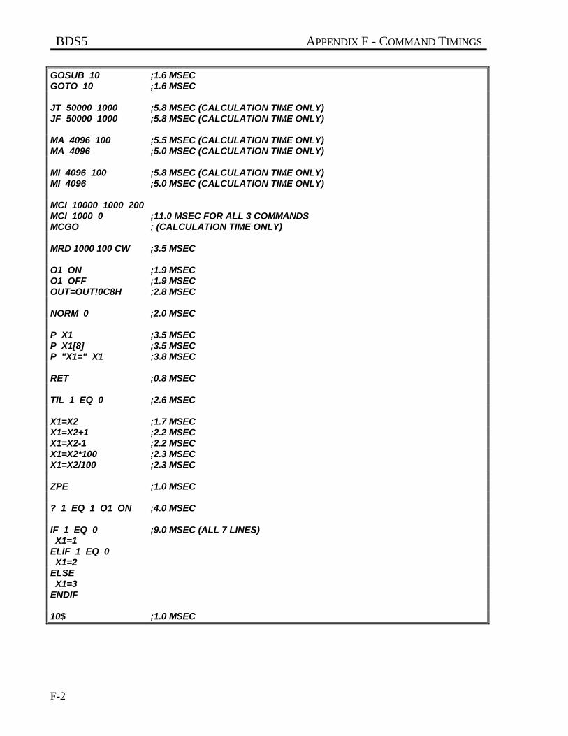
BDS5 APPENDIX F - COMMAND TIMINGS
F-2
GOSUB 10 ;1.6 MSECGOTO 10 ;1.6 MSEC
JT 50000 1000 ;5.8 MSEC (CALCULATION TIME ONLY)JF 50000 1000 ;5.8 MSEC (CALCULATION TIME ONLY)
MA 4096 100 ;5.5 MSEC (CALCULATION TIME ONLY)MA 4096 ;5.0 MSEC (CALCULATION TIME ONLY)
MI 4096 100 ;5.8 MSEC (CALCULATION TIME ONLY)MI 4096 ;5.0 MSEC (CALCULATION TIME ONLY)
MCI 10000 1000 200MCI 1000 0 ;11.0 MSEC FOR ALL 3 COMMANDSMCGO ; (CALCULATION TIME ONLY)
MRD 1000 100 CW ;3.5 MSEC
O1 ON ;1.9 MSECO1 OFF ;1.9 MSECOUT=OUT!0C8H ;2.8 MSEC
NORM 0 ;2.0 MSEC
P X1 ;3.5 MSECP X1[8] ;3.5 MSECP "X1=" X1 ;3.8 MSEC
RET ;0.8 MSEC
TIL 1 EQ 0 ;2.6 MSEC
X1=X2 ;1.7 MSECX1=X2+1 ;2.2 MSECX1=X2-1 ;2.2 MSECX1=X2*100 ;2.3 MSECX1=X2/100 ;2.3 MSEC
ZPE ;1.0 MSEC
? 1 EQ 1 O1 ON ;4.0 MSEC
IF 1 EQ 0 ;9.0 MSEC (ALL 7 LINES) X1=1ELIF 1 EQ 0 X1=2ELSE X1=3ENDIF
10$ ;1.0 MSEC
BDS5 GLOSSARY
Glossary-i
GLOSSARY
Absolute Position
Position referenced to a fixed zero position.
Absolute Positioning
Refers to a motion control system employing positionfeedback devices (absolute encoders) to maintain agiven mechanical location.
Absolute Programming
A positioning coordinate reference wherein allpositions are specified relative to some reference, or"home" position. This is different from incrementalprogramming, where distances are specified relativeto the current position.
AC Adjustable-Speed Drive
All equipment required to adjust the speed or torqueof AC electric motor(s) by controlling both frequencyand voltage applied to the motor(s).
AC Servo Drive
A servo drive used to control either or bothsynchronous or induction AC motors.
Acceleration
The change in velocity as a function of time.Acceleration usually refers to increasing velocity anddeceleration describes decreasing velocity.
Accuracy
A measure of the difference between expectedposition and actual position of a motor or mechanicalsystem. Motor accuracy is usually specified as anangle representing the maximum deviation fromexpected position.
Actuator
A device which creates mechanical motion byconverting various forms of energy to mechanicalenergy.
Adaptive Control
A technique to allow the control to automaticallycompensate for changes in system parameters such asload variations.
Ambient Temperature
The temperature of the cooling medium, usually air,immediately surrounding the motor or another device.
Amplifier
Electronics which convert low level command signalsto high power voltages and currents to operate aservomotor.
ASCII
(American Standard Code for InformationInterchange) This code assigns a number to eachnumeral letter of the alphabet. In this manner,information can be transmitted between machines as aseries of binary numbers.
Back EMF
The voltage generated when a permanent magnetmotor is rotated. This voltage is proportional tomotor speed and is present regardless of whether themotor winding(s) are energized or un-energized.
Bandwidth
The frequency range in which the magnitude of thesystem gain expressed in dB is greater than -3 dB.
Baud Rate
The number of binary bits transmitted per second ona serial communications link (such as RS-232).
GLOSSARY BDS5
Glossary-ii
Bit (Binary Digit)
A unit of information equal to 1 binary decision orhaving only a value 0 or 1.
Block Diagram
A simplified schematic representing components andsignal flow through a system.
Bode Plot
A plot of the magnitude of system gain in dB and thephase of system gain in degrees versus the sinusoidalinput signal frequency in logarithmic scale.
Brownout
Low-line voltage at which the device no longerfunctions properly.
Brush
Conducting material which passes current from theDC motor terminals to the rotating commutator.
Brushless Servo Drive
A servo drive used to control a permanent magnetsynchronous AC motor. May also be referred to as anAC Servo Drive.
Bus
A group of parallel connections carrying pre-assigneddigital signals. Buses usually consist of address anddata information and miscellaneous control signalsfor the interconnection of microprocessors, memories,and other computing elements.
Byte
A group of 8 bits treated as a whole with 256possible combinations of ones and zeros, eachcombination representing a unique piece of
information.
CAM Profile
A technique used to perform nonlinear motionelectronically similar to that achieved withmechanical cams.
Characteristic Equation
1+GH = 0, where G is the transfer function of theforward signal path and H is the transfer function ofthe feedback signal path.
Circular Coordinated Move
A coordinated move where the path betweenendpoints is the arc of a circle.
Class B Insulation
A NEMA insulation specification. Class B insulationis rated to an operating temperature of 130 degreescentigrade.
Class H Insulation
A NEMA insulation specification. Class H insulationis rated to an operating temperature of 180 degreescentigrade.
Closed Loop
A broadly applied term relating to any system wherethe output is measured and compared to the input.The output is then adjusted to reach the desiredcondition. In motion control, the term is used todescribe a system wherein a velocity or position (orboth) transducer is used to generate correction signalsby comparison to desired parameters.
Cogging
A term used to describe non-uniform angularvelocity. Cogging appears as a jerkiness especially atlow speeds.
Command Position
The desired angular or linear position of an actuator.
BDS5 GLOSSARY
Glossary-iii
Commutation
A term which refers to the action of steering currentsor voltage to the proper motor phases so as toproduce optimum motor torque. In brush typemotors, commutation is done electromechanically viathe brushes and commutator. In brushless motors,commutation is done by the switching electronicsusing rotor position information typically obtained byhall sensors, a tachsyn, a resolver or an encoder.
Commutator
A mechanical cylinder consisting of alternatingsegments of conductive and insulating material. Thiscylinder used in DC motors passes currents from thebrushes into the rotor windings and performs motorcommutation as the motor rotates.
Compensation
The corrective or control action in a feedback loopsystem which is used to improve system performancecharacteristics such as accuracy and response time.
Compensation, Feedforward
A control action which depends on the command onlyand not the error to improve system response time.
Compensation, Integral
A control action which is proportional to the integralor accumulative time error value product of thefeedback loop error signal. It is usually used toreduce static error.
Compensation, Lag
A control action which causes the lag at lowfrequencies and tends to increase the delay betweenthe input and output of a system while decreasingstatic error.
Compensation, Lead
A control action which causes the phase to lead athigh frequencies and tends to decrease the delaybetween the input and output of a system.
Compensation, Lead Lag
A control action which combines the characteristicsof lead and lag compensations.
Compensation, Proportional
A control action which is directly proportional to theerror signal of a feedback loop. It is used to improvesystem accuracy and response time.
Compliance
The amount of displacement per unit of applied force.
Computer Numerical Control
A computer-based motion control deviceprogrammable in a numerical word address format.A computer numerical control (CNC) producttypically includes a CPU section, operator interfacedevices, input/output signal and data devices,software and related peripheral apparatus.
Control Systems or Automatic ControlSystems
An engineering or scientific field that deals withcontrolling or determining the performance ofdynamic systems such as servo systems.
Coordinated Motion
Multi-axis motion where the position of each axis isdependent on the other axis such that the path andvelocity of a move can be accurately controlled.(Requires coordination between axes.)
Coupling Ratio
The ratio of motor velocity to load velocity for a loadcoupled to motor through a gear or similarmechanical device.
Critical Damping
A system is critically damped when the response to astep change in desired velocity or position is achievedin the minimum possible time with little or noovershoot.
Daisy Chain
GLOSSARY BDS5
Glossary-iv
A term used to describe the linking of severalRS232C devices in sequence such that a single datastream flows through one device and on to the next.Daisy-chained devices usually are distinguished bydevice addresses which serve to indicate the desireddestination for data in the stream.
Damping
An indication of the rate of decay of a signal to itssteady state value. Related to setting time.
Damping Ratio
Ratio of actual damping to critical damping. Lessthan one is an underdamped system and greater thanone is an overdamped system.
DC Adjustable-Speed Drive
All equipment required to adjust the speed or torqueof DC motor(s) by controlling the voltages applied tothe armature and/or field of the motors.
DC Drive
An electronic control unit for running DC motors.The DC drive converts AC line current to a variableDC current to control a DC motor. The DC drive hasa signal input that controls the torque and speed of themotor.
Dead Band
A range of input signals for which there is no systemresponse.
Decibel (dB)
A logarithmic measurement of gain. If G is a systemsgain (ratio of output to input) then 20 log G = gain indecibels (dB).
Demag Current
The current level at which the motor magnets will bedemagnetized. This is an irreversible effect whichwill alter the motor characteristics and degradeperformance.
Detent Torque
The maximum torque that can be applied to an un-energized stepping motor without causing continuousrotating motion.
Dielectric Test
A high voltage breakdown test of insulation's abilityto withstand an AC voltage. Test criterion limits theleakage current to a specified magnitude andfrequency, applied between the specified test points.
Differential
An electrical input or output signal which uses twolines of opposite polarity referenced to the localsignal ground.
Distributed Processing
A technique to gain increased performance andmodularity in control systems utilizing multiplecomputers or processors.
DNC, Direct Numerical Control
Technique of transferring part program data to anumerical control system via direct electricalconnection in place of paper tapes.
Drive
This is the electronics portion of the system thatcontrols power to the motor.
Drive, Analog
Usually referring to any type of motor drive in whichthe input is an analog signal.
Drive, Digital
Usually referring to any type of motor drive in whichthe tuning or compensation is done digitally. Inputmay be an analog or digital signal.
Drive, Linear
BDS5 GLOSSARY
Glossary-v
A motor drive in which the output is directlyproportional to either a voltage or current input.Normally both inputs and outputs are analog signals.This is a relatively inefficient drive type.
Drive, PWM
A motor drive utilizing Pulse-Width Modulationtechniques to control power to the motor. Typically ahigh efficiency drive that can be used for highresponse application.
Drive, SCR
A DC motor drive which utilizes internal siliconcontrolled rectifiers as the power control elements.Usually used for low bandwidths, high powerapplications.
Drive, Servo
A motor drive which utilizes internal feedback loopsfor accurate control of motor current and/or velocity.
Drive, Stepper
Electronics which convert step and direction inputs tohigh power currents and voltages to drive a steppingmotor. The stepping motor driver is analogous to theservo motor amplifier.
Duty Cycle
For a repetitive cycle, the ratio of an on time to totalcycle time.
( )( )Duty Cycle =
On Time
On Time + Off Time
×100%
Dynamic Braking
A passive technique for stopping a permanent magnetbrush or brushless motor. The motor windings areshorted together through a resistor which results inmotor braking with an exponential decrease in speed.
Efficiency
The ratio of power output to power input.
Electrical Time Constant
The ratio of armature inductance to armatureresistance.
Electronic Gearing
A technique used to electrically simulate mechanicalgearing. Causes one closed loop axis to be slaved toanother open or closed loop axis with a variable ratio.
EMI: Electro-Magnetic Interference
EMI is noise which, when coupled into sensitiveelectronic circuits, may cause problems.
Encoder
A type of feedback device which converts mechanicalmotion into electrical signals to indicate actuatorposition. Typical encoders are designed with aprinted disc and a light source. As the disc turns withthe actuator shaft, the light source shines through theprinted pattern onto a sensor. The light transmissionis interrupted by the patterns on the disc. Theseinterruptions are sensed and converted to electricalpulses. By counting these pulses, actuator shaftposition is determined.
Encoder, Absolute
A digital position transducer in which the output isrepresentative of the absolute position of the inputshaft within one (or more) revolutions. Output isusually a parallel digital word.
Encoder, Incremental
A position encoding device in which the outputrepresents incremental changes in position.
Encoder, Linear
A digital position transducer which directly measureslinear position.
GLOSSARY BDS5
Glossary-vi
Encoder Marker
A ounce-per-revolution signal provided by someincremental encoders to specify a reference pointwithin that revolution. Also known as ZeroReference signal or index pulse.
Encoder Resolution
A measure of the smallest positional change whichcan be detected by the encoder.
Explosion-proof
A motor classification that indicates a motor iscapable of withstanding internal explosions withoutbursting or allowing ignition to reach beyond theconfines of the motor frame.
Fall Time
The time for the amplitude of system response todecay to 37% of its steady-state value after theremoval of a steady-state step input signal.
Feed Forward
A technique used to pre-compensate control a loopfor known errors due to motor, drive, or leadcharacteristics. Provides improved response.
Feedback
A signal which is transferred from the output back tothe input for use in a closed loop system.
Field Weakening
A method of increasing the speed of a wound fieldDC motor; reducing stator magnetic field instantly byreducing magnet winding current.
Filter (Control Systems)
A transfer function used to modify the frequency ortime response of a control system.
Flutter
Flutter is an error of the basic cycle of an encoder perone revolution.
Following Error
The positional error during motion resulting from useof a position control loop with proportional gain only.
Form Factor
The ratio of RMS current to average current. Thisnumber is a measure of the current ripple in a PWMor other switch mode type of controller. Since motorheating is a function of RMS current while motortorque is a function of average current, a form factorgreater than 1.00 means some fraction of motorcurrent is producing heat but not torque.
Four Quadrant
Refers to a motion system which can operate in allfour quadrants i.e. velocity in either direction andtorque in either direction. This means that the motorcan accelerate, run, and decelerate in either direction.
Friction
A resistance to motion caused by surfaces rubbingtogether. Friction can be constant with varying speed(coulomb friction) or proportional to speed (viscousfriction) or present at rest (static friction).
Full Load Current
The armature current of a motor operated at its fullload torque and speed with rated voltage applied.
Full Load Speed
The speed of a motor operated with rated voltage andfull load torque.
Gain
The ratio of system output signal to system inputsignal.
Hall Sensors
BDS5 GLOSSARY
Glossary-vii
A feedback device which is used in a brushless servosystem to provide information for the amplifier toelectronically commutate the motor. The device usesa magnetized wheel and hall-effect sensors togenerate the commutation signals.
Holding Torque
Sometimes called torque, it specifies the maximumexternal force or torque that can be applied to astopped, energized motor without causing the rotor torotate continuously.
Home Position
A reference position for all absolute positioningmovements. Usually defined by a home limit switchand/or encoder marker. Normally set at power up andretained for as long as the control system isoperational.
Host Computer
An auxiliary computer system which is connected to acontroller or controllers. The host computer indistributed control systems is frequently involvedwith controlling many remote and distributed motioncontrol devices. It may also be used for off-line taskssuch as program preparation, storage, and supervisorycontrol and evaluation.
HP: Horsepower
One horsepower is equal to 746 watts. Since Power =Torque x Speed, horsepower is a measure of amotor's torque and speed capability (e.g. a 1 HPmotor will produce 35 lb.-in. at 1800 rpm).
Hunting
The oscillation of the system response about atheoretical steady-state value.
Hybrid Stepping Motor
A motor designed to move in discrete increments orsteps. The motor has a permanent magnet rotor andwound stator. These motors are brushless and phasecurrents are commutated as a function of time toproduce motion.
Hysteresis
The difference in response of a system to anincreasing or a decreasing input signal.
I/O: Input/Output
The reception and transmission of informationbetween control devices. In modern control systems,I/O has two distinct forms: switches, relays, etc.,which are in either an on or off state, or analogsignals that are continuous in nature such as speed,temperature, flow, etc.
Idle Current Reduction
A stepping motor driver feature that reduces thephase current to the motor when no motor motion(idle) is commanded for a specified period of time.This reduces motor heating and allows high machinethroughput to be obtained from a given motor.
Incremental Motion
A motion control term that is used to describe adevice that produces one step of motion for each stepcommand (usually a pulse) received.
Indexer
Electronics which convert high level motioncommands from a host computer, programmablecontroller, or operator panel into step direction pulsestreams for use by the stepping motor driver.
Inertia
The property of an object to resist changes in velocityunless acted upon by an outside force. Higher inertiaobjects require larger torques to accelerate anddecelerate. Inertia is dependent upon the mass andshape of the object.
Inertial Match
An inertial match between motor and load is obtainedby selecting the coupling ratio such that the loadmoment of inertia referred to the motor shaft is equalto the motor moment of inertia.
GLOSSARY BDS5
Glossary-viii
Inrush Current
The current surge generated when a piece ofequipment such as a servoamplifier is connected to anAC line. This surge is typically due to the impulsecharging of a large capacitor located in theequipment.
Instability
Undesirable motion of an actuator that is differentfrom the command motion. Instability can take theform of irregular speed or hunting of the final restposition.
Lead Ball Screw
A lead screw which has its threads formed as a ballbearing race; the carriage contains a circulatingsupply of balls for increased efficiency.
Lead Screw
A device for translating rotary motion into linearmotion, consisting of an externally threaded screwand an internally threaded carriage (nut).
Least Significant Bit
The bit in a binary number that is the least important,or having the least weight.
Limits
Properly designed motion control systems havesensors called limits that alert the control electronicsthat the physical end of travel is being approachedand that motion should stop.
Linear Coordinated Move
A coordinated move where the path betweenendpoints is a line.
Linearity
For a speed control system it is the maximumdeviation between actual and set speed expressed as apercentage of set speed.
Logic Ground
An electrical potential to which all control signals in aparticular system are referenced.
Loop, Feedback Control
A control method that compares the input from ameasurement device, such as an encoder ortachometer, to a desired parameter, such as a positionor velocity and causes action to correct any detectederror. Several types of loops can be used incombination (i.e. velocity and position together) forhigh performance requirements.
Loop Gain, Open
The product of the forward path and feedback pathgains.
Loop, PID: Proportional, Integral, andDerivative Loop
Specialized very high performance control loopwhich gives superior response.
Loop, Position
A feedback control loop in which the controlledparameter is motor position.
Loop, Velocity
A feedback control loop in which the controlledparameter is mechanical velocity.
Master Slave Motion Control
A type of coordinated motion control where themaster axis position is used to generate one or moreslave axis position commands.
Mechanical Time Constant
BDS5 GLOSSARY
Glossary-ix
The time for an unloaded motor to reach 63.2% of itsfinal velocity after the application of a DC armaturevoltage.
Microstepping
An electronic control technique that proportions thecurrent in a step motor's windings to provideadditional intermediate positions between poles.Produces smooth rotation over a wide speed rangeand high positional resolution.
Mid-Range Instability
A phenomenon in which a stepping motor can fall outof synchronism due to loss of torque at mid-rangespeeds. The loss of torque is due to interactionbetween the motor's electrical characteristics and thedriver electronics. Some drivers have circuitry toeliminate or reduce this phenomenon.
Most Significant Bit
The bit in a binary number that is the most importantor that has the most weight.
Motor, AC
A device that converts electrical alternating currentinto mechanical energy. Requires no commutationdevices such as brushes. Normally operated offcommercial AC power. Can be single- or multiple-phase.
Motor, AC Asynchronous or Induction
An AC motor in which speed is proportional to thefrequency of the applied AC. Requires no magnets orfield coil. Usually used for non-precise constantspeed applications.
Motor, AC Synchronous
Another term for brushless DC motor.
Motor Constant
The ratio of the motor torque to motor input power.
Motor, DC
A device that converts electrical direct current intomechanical energy. It requires a commutating device,either brushes or electronic. Usually requires asource of DC power.
Motor, DC Brushless
A type of direct current motor that utilizes electroniccommutation rather than brushes to transfer current.
Motor, DC Permanent Magnet
A motor utilizing permanent magnets to produce amagnetic field. Has linear torque speedcharacteristics.
Motor, DC Wound Field
A direct current utilizing a coil to produce a magneticfield. Usually used in high power applications whereconstant horsepower operation is desired.
Motor, Stepping
A specialized AC motor that allows discretepositioning without feedback. Normally used fornon-critical, low power applications, since positionalinformation is easily lost if acceleration or velocitylimits are exceeded. Load variations can also causeloss of position. If encoders are used, theselimitations can be overcome.
NC, Numerical Control
Usually refers to any type of automated equipment orprocess used for contouring or positioning.
Negative Feedback
The type of feedbacks used in a closed loop systemwhere the output value is inverted and combined withthe input to be used to stabilize or improve systemcharacteristics.
No Load Speed
Motor speed with no external load.
GLOSSARY BDS5
Glossary-x
Open Collector
A term used to describe a signal output that isperformed with a transistor. An open collector outputacts like a switch closure with one end of the switchat ground potential and the other end of the switchaccessible.
Open-Loop System
A system where the command signal results inactuator movement but, because the movement is notsensed, there is no way to correct for error. Openloop means no feedback.
Operator Interface
A device that allows the operator to communicatewith a machine. This device typically has a keyboardor thumbwheel to enter instructions into the machine.It also has a display device that allows the machine todisplay messages.
Optically Isolated
A system or circuit that transmits signals with nodirect electrical connection. Used to protectivelyisolate electrically noisy machine signals from lowlevel control logic.
Oscillation
An effect that varies periodically between two values.
Overshoot
The amount of the parameter being controlledexceeds the desired value for a step input.
Phase-Locked Servo System
A hybrid control system in which the output of anoptical tachometer is compared to a reference squarewave signal to generate a system error signalproportional to both shaft velocity and positionerrors.
Phase Margin
The difference between 180 degrees and the phaseangle of a system at the frequency where the openloop gain is unity.
PID
Proportional-Integral-Derivative. An acronym thatdescribes the compensation structure that can be usedin a closed-loop system.
PLC
Programmable Logic Controller. An industrialcontrol device that turns on and off outputs basedupon responses to inputs.
PMDC Motor
A motor consisting of a permanent magnet stator anda wound iron-core rotor. These are brush type motorsand are operated by application of DC current.
Point to Point Move
A multi-axis move from one point to another whereeach axis is controlled independently. (Nocoordination between axes is required.)
Pole
A frequency at which the transfer function of a systemgoes to infinity.
Pole Pair, Electromechanical
The number of cycles of magnetic flux distribution inthe air gap of a rotary electromechanical device.
Position Error
The difference between the present actuator(feedback) value and the desired position commandfor a position loop.
Position Feedback
Present actuator position as measured by a positiontransducer.
BDS5 GLOSSARY
Glossary-xi
Power
The rate at which work is done. In motion control,Power = Torque x Speed.
Process Control
A term used to describe the control of machine ormanufacturing processes, especially in continuousproduction environments.
Pull-In Torque
The maximum torque at which an energized steppingmotor or synchronous motor will start and run insynchronism.
Pull-Out Torque
The maximum torque that can be applied to astepping motor or synchronous motor running atconstant speed without causing a loss of synchronism.
Pulse Rate
The frequency of the step pulses applied to a steppermotor driver. The pulse rate divided by theresolution of the motor/drive combination (in stepsper revolution) yields the rotational speed inrevolutions per second.
PWM
Pulse Width Modulation. An acronym whichdescribes a switch-mode control technique used inamplifiers and drivers to control motor voltage andcurrent. This control technique is used in contrast tolinear control and offers the advantages of greatlyimproved efficiency.
Quadrature
Refers to signal characteristics of interfaces topositioning devices such as encoders or resolvers.Specifically, that property of position
Ramping
The acceleration and deceleration of a motor. Mayalso refer to the change in frequency of the appliedstep pulse train.
Rated Torque
The torque producing capacity of a motor at a givenspeed. This is the maximum continuous torque themotor can deliver to a load and is usually specifiedwith a torque/speed curve.
Regeneration
The action during motor braking, in which the motoracts as a generator and takes kinetic energy from theload, converts it to electrical energy, and returns it tothe amplifier.
Repeatability
The degree to which the positioning accuracy for agiven move performed repetitively can be duplicated.
Resolution
The smallest positioning increment that can beachieved. Frequently defined as the number of stepsor feedback units required for a motor's shaft to rotateone complete revolution.
Resolver
A position transducer utilizing magnetic coupling tomeasure absolute shaft position over one revolution.
Resonance
The effect of a periodic driving force that causeslarge amplitude increases at a particular frequency.(Resonance frequency.)
RFI
Radio Frequency Interference.
Ringing
Oscillation of a system following sudden change instate.
GLOSSARY BDS5
Glossary-xii
Rise Time
The time required for a signal to rise from 10% of itsfinal value to 90% of its final value.
RMS Current
Root mean square current. In an intermittent dutycycle application, the RMS current is equal to thevalue of steady state current which would produce theequivalent resistive heating over a long period oftime.
RMS Torque
Root Mean Square Torque. For an intermittent dutycycle application, the RMS torque is equal to thesteady state torque which would produce the sameamount of motor heating over long periods of time.
Robot
A reprogrammable multifunctional manipulatordesigned to move material, parts, tools, or specializeddevices through variable programmed motions for theperformance of a variety of tasks.
Robot Control
A computer-based motion control device to controlthe servo-axis motion of a robot.
Rotor
The rotating part of a magnetic structure. In a motor,the rotor is connected to the motor shaft.
Serial Port
A digital data communications port configured with aminimum number of signal lines. This is achieved bypassing binary information signals as a time series of"1"s and "0"s on a single line.
Servo Amplifier/Servo Drive
An electronic device which produces the windingcurrent for a servo motor. The amplifier converts a
low level control signal into high voltage and currentlevels top produce torque in the motor.
Servo System
An automatic feedback control system for mechanicalmotion in which the controlled or output quantity isposition, velocity, or acceleration. Servo systems areclosed loop systems.
Settling Time
The time required for a step response of a systemparameter to stop oscillating or ringing and reach itsfinal value.
Shunt Resistor
A device located in a servoamplifier for controllingregenerative energy generated when braking a motor.This device dissipates or "dumps" the kinetic energyas heat.
Single Point Ground
The common connection point for signal grounds in acontrol wiring environment.
Slew
In motion control the portion of a move made at aconstant non-zero velocity.
Slew Speed
The maximum velocity at which an encoder will berequired to perform.
Speed
In motion control, the concept used to describe thelinear or rotational velocity of a motor or other objectin motion.
Speed Regulation
For a speed control system, speed regulation is thevariation in actual speed expressed as a percentage ofset speed.
BDS5 GLOSSARY
Glossary-xiii
SPS
Steps-Per-Second. A measure of velocity used withstepping motors.
Stall Torque
The torque available from a motor at stall or zerorpm.
Static Torque
The angle the shaft rotates upon receipt of a singlestep command.
Stator
The non-rotating part of a magnetic structure. In amotor the stator usually contains the mountingsurface, bearings, and non-rotating windings orpermanent magnets.
Stiffness
The ability to resist movement induced by an appliedtorque. It is often specified as a displacement curve,indicating the amount a motor shaft will rotate uponapplication of a known external force when stopped.
Synchronism
A motor rotating at a speed correctly correspondingto the applied step pulse frequency is said to be insynchronism. Load torques in excess of the motor'scapacity (rated torque) will cause a loss ofsynchronism.
Tachometer
An electromagnetic feedback transducer whichproduces an analog voltage signal proportional torotational velocity. Tachometers can be either brushor brushless.
Tachsyn
A brushless, electromagnetic feedback transducerwhich produces an analog velocity feedback signaland commutation signals for a brushless servo motor.The tachsyn is functionally equivalent to hall sensorsand a tachometer.
Torque
The rotary equivalent to force. Equal to the productof the force perpendicular to the radius of motion anddistance from the center of rotation to the point wherethe force is applied.
Torque Constant
A number representing the relationship betweenmotor input current and motor output torque.Typically expressed in units of torque/amp.
Torque Ripple
The cyclical variation of generated torque given bythe product of motor angular velocity and number ofcommutator segments.
Torque-to-Inertia Ratio
Defined as a motor's torque divided by the inertia ofits rotor, the higher the ratio the higher theacceleration will be.
Transducer
Any device that translates a physical parameter intoan electrical parameter. Tachometers and encodersare examples of transducers.
Transfer Function
The ratio of the Laplace transforms of system outputsignal and system input signal.
Trapezoidal Profile
A motion profile in which the velocity vs. time profileresembles a trapezoid. Characterized by constantacceleration, constant velocity, and constantdeceleration.
GLOSSARY BDS5
Glossary-xiv
TTL
Transistor-Transistor Logic.
Variable Frequency Drive
An electronic device used to control the speed of astandard AC induction motor. The device controlsthe speed by varying the frequency of the windingcurrent used to drive the motor.
Vector Control
A method of obtaining servo type performance froman AC motor by controlling two components of motorcurrent.
Velocity
The change in position as a function of time.Velocity has both a magnitude and a direction.
Voltage Constant (or Back EMF Constant)
A number representing the relationship between BackEMF voltage and angular velocity. Typicallyexpressed as V/Krpm.
Zero
A frequency at which the transfer function of a systemgoes to zero.
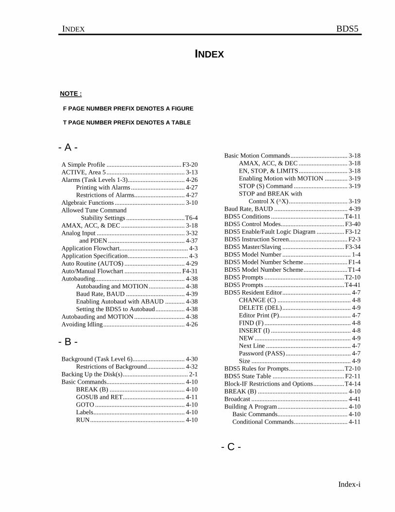
INDEX BDS5
Index-i
INDEX
NOTE :
F PAGE NUMBER PREFIX DENOTES A FIGURE
T PAGE NUMBER PREFIX DENOTES A TABLE
- A -
A Simple Profile .............................................. F3-20 ACTIVE, Area 5 ................................................ 3-13 Alarms (Task Levels 1-3)................................... 4-26 Printing with Alarms ................................. 4-27 Restrictions of Alarms............................... 4-27 Algebraic Functions ........................................... 3-10 Allowed Tune Command Stability Settings ....................................T6-4 AMAX, ACC, & DEC ....................................... 3-18 Analog Input ...................................................... 3-32 and PDEN ............................................... 4-37 Application Flowchart.......................................... 4-3 Application Specification..................................... 4-3 Auto Routine (AUTO$) ..................................... 4-29 Auto/Manual Flowchart ................................... F4-31 Autobauding....................................................... 4-38 Autobauding and MOTION...................... 4-38 Baud Rate, BAUD .................................... 4-39 Enabling Autobaud with ABAUD ............ 4-38 Setting the BDS5 to Autobaud.................. 4-38 Autobauding and MOTION............................... 4-38 Avoiding Idling.................................................. 4-26
- B -
Background (Task Level 6)................................ 4-30 Restrictions of Background....................... 4-32 Backing Up the Disk(s)........................................ 2-1 Basic Commands................................................ 4-10 BREAK (B) .............................................. 4-10 GOSUB and RET...................................... 4-11 GOTO ....................................................... 4-10 Labels........................................................ 4-10 RUN.......................................................... 4-10
Basic Motion Commands................................... 3-18 AMAX, ACC, & DEC .............................. 3-18 EN, STOP, & LIMITS.............................. 3-18 Enabling Motion with MOTION .............. 3-19 STOP (S) Command ................................. 3-19 STOP and BREAK with Control X (^X).................................... 3-19 Baud Rate, BAUD ............................................. 4-39 BDS5 Conditions .............................................T4-11 BDS5 Control Modes....................................... F3-40 BDS5 Enable/Fault Logic Diagram ................. F3-12 BDS5 Instruction Screen.................................... F2-3 BDS5 Master/Slaving ...................................... F3-34 BDS5 Model Number .......................................... 1-4 BDS5 Model Number Scheme........................... F1-4 BDS5 Model Number Scheme...........................T1-4 BDS5 Prompts .................................................T2-10 BDS5 Prompts .................................................T4-41 BDS5 Resident Editor.......................................... 4-7 CHANGE (C) ............................................. 4-8 DELETE (DEL).......................................... 4-9 Editor Print (P)............................................ 4-7 FIND (F) ..................................................... 4-8 INSERT (I) ................................................. 4-8 NEW ........................................................... 4-9 Next Line .................................................... 4-7 Password (PASS) ........................................ 4-7 Size ............................................................. 4-9 BDS5 Rules for Prompts..................................T2-10 BDS5 State Table ............................................ F2-11 Block-IF Restrictions and Options...................T4-14 BREAK (B) ....................................................... 4-10 Broadcast ........................................................... 4-41 Building A Program........................................... 4-10 Basic Commands........................................... 4-10 Conditional Commands................................. 4-11
- C -
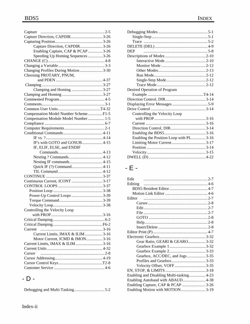
BDS5 INDEX
Index-ii
Capture .............................................................. 2-5 Capture Direction, CAPDIR............................... 3-26 Capturing Position.............................................. 3-26 Capture Direction, CAPDIR...................... 3-26 Enabling Capture, CAP & PCAP .............. 3-26 Speeding Up Homing Sequences .............. 3-26 CHANGE (C)....................................................... 4-8 Changing a Variable............................................. 3-3 Changing Profiles During Motion ...................... 3-30 Choosing PROTARY, PNUM, and PDEN ............................................. 4-37 Clamping ........................................................... 3-27 Clamping and Homing .............................. 3-27 Clamping and Homing ....................................... 3-27 Commented Program............................................ 4-5 Comments............................................................. 3-1 Common User Units .........................................T4-32 Compensation Model Number Scheme ..............F1-5 Compensation Module Model Number ................ 1-5 Compliance .......................................................... 6-7 Computer Requirements....................................... 2-1 Conditional Commands...................................... 4-11 IF vs. ?....................................................... 4-14 IF's with GOTO and GOSUB.................... 4-15 IF, ELIF, ELSE, and ENDIF Commands........................................... 4-13 Nesting ? Commands................................. 4-12 Nesting IF commands................................ 4-15 Quick IF (?) Command.............................. 4-11 TIL Command........................................... 4-12 CONTINUE ....................................................... 3-37 Continuous Current, ICONT .............................. 3-17 CONTROL LOOPS ........................................... 3-37 Position Loop ................................................ 3-38 Power-Up Control Loops .............................. 3-39 Torque Command.......................................... 3-39 Velocity Loop................................................ 3-38 Controlling the Velocity Loop with PROP.................................................. 3-16 Critical Damping .................................................. 6-2 Critical Damping ................................................F6-2 Current ............................................................ 3-16 Current Limits, IMAX & ILIM ................. 3-16 Motor Current, ICMD & IMON................ 3-16 Current Limits, IMAX & ILIM .......................... 3-16 Current Units ...................................................... 4-32 Cursor .............................................................. 2-8 Cursor Addressing.............................................. 4-19 Cursor Control Keys...........................................T2-8 Customer Service ................................................. 4-6
- D -
Debugging and Multi-Tasking.............................. 5-2
Debugging Modes ................................................ 5-1 Single-Step ...................................................... 5-1 Trace .............................................................. 5-2 DELETE (DEL) ................................................... 4-9 DEP .............................................................. 5-8 Descriptions of Modes ....................................... 2-10 Interactive Mode ....................................... 2-10 Monitor Mode ........................................... 2-12 Other Modes.............................................. 2-13 Run Mode.................................................. 2-12 Single-Step Mode...................................... 2-12 Trace Mode ............................................... 2-12 Desired Operation of Program Example ......................................................T4-14 Direction Control, DIR....................................... 3-14 Displaying Error Messages .................................. 5-9 Drive Control ..................................................... 3-14 Controlling the Velocity Loop with PROP.................................................. 3-16 Current .......................................................... 3-16 Direction Control, DIR.................................. 3-14 Enabling the BDS5........................................ 3-16 Enabling the Position Loop with PL.............. 3-16 Limiting Motor Current................................. 3-17 Position ......................................................... 3-14 Velocity......................................................... 3-15 DWELL (D) ....................................................... 4-22
- E -
Edit .............................................................. 2-7 Editing .............................................................. 4-6 BDS5 Resident Editor ..................................... 4-7 Motion Link Editor ......................................... 4-6 Editor .............................................................. 2-7 Cursor.......................................................... 2-8 Edit.............................................................. 2-7 File .............................................................. 2-7 GOTO ......................................................... 2-8 Help............................................................. 2-8 Insert/Delete ................................................ 2-8 Editor Print (P) ..................................................... 4-7 Electronic Gearbox............................................. 3-32 Gear Ratio, GEARI & GEARO................. 3-32 Gearbox Example 1................................... 3-32 Gearbox Example 2................................... 3-33 Gearbox, ACC/DEC, and Jogs .................. 3-35 Profiles and Gearbox................................. 3-33 Velocity Offset, VOFF.............................. 3-35 EN, STOP, & LIMITS ....................................... 3-18 Enabling and Disabling Multi-tasking................ 4-23 Enabling Autobaud with ABAUD...................... 4-38 Enabling Capture, CAP & PCAP ....................... 3-26 Enabling Motion with MOTION........................ 3-19
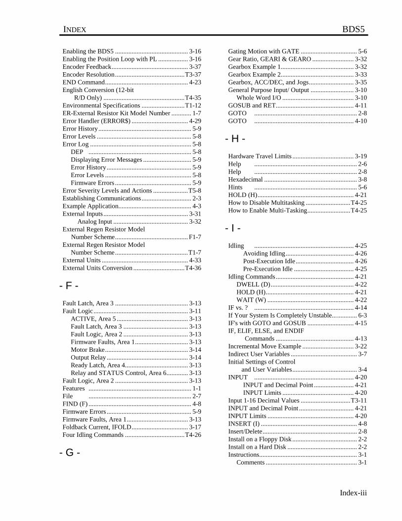
INDEX BDS5
Index-iii
Enabling the BDS5 ............................................ 3-16 Enabling the Position Loop with PL .................. 3-16 Encoder Feedback.............................................. 3-37 Encoder Resolution..........................................T3-37 END Command.................................................. 4-23 English Conversion (12-bit R/D Only) .................................................T4-35 Environmental Specifications ..........................T1-12 ER-External Resistor Kit Model Number ............ 1-7 Error Handler (ERROR$) .................................. 4-29 Error History........................................................ 5-9 Error Levels ......................................................... 5-8 Error Log ............................................................. 5-8 DEP .............................................................. 5-8 Displaying Error Messages ............................. 5-9 Error History................................................... 5-9 Error Levels .................................................... 5-8 Firmware Errors .............................................. 5-9 Error Severity Levels and Actions .....................T5-8 Establishing Communications.............................. 2-3 Example Application............................................ 4-3 External Inputs ................................................... 3-31 Analog Input ............................................. 3-32 External Regen Resistor Model
Number Scheme............................................ F1-7 External Regen Resistor Model Number Scheme............................................T1-7 External Units .................................................... 4-33 External Units Conversion ...............................T4-36
- F -
Fault Latch, Area 3 ............................................ 3-13 Fault Logic......................................................... 3-11 ACTIVE, Area 5 ........................................... 3-13 Fault Latch, Area 3 ....................................... 3-13 Fault Logic, Area 2 ....................................... 3-13 Firmware Faults, Area 1................................ 3-13 Motor Brake.................................................. 3-14 Output Relay ................................................. 3-14 Ready Latch, Area 4...................................... 3-13 Relay and STATUS Control, Area 6............. 3-13 Fault Logic, Area 2 ............................................ 3-13 Features .............................................................. 1-1 File .............................................................. 2-7 FIND (F) .............................................................. 4-8 Firmware Errors ................................................... 5-9 Firmware Faults, Area 1..................................... 3-13 Foldback Current, IFOLD.................................. 3-17 Four Idling Commands ....................................T4-26
- G -
Gating Motion with GATE .................................. 5-6 Gear Ratio, GEARI & GEARO ......................... 3-32 Gearbox Example 1............................................ 3-32 Gearbox Example 2............................................ 3-33 Gearbox, ACC/DEC, and Jogs........................... 3-35 General Purpose Input/ Output .......................... 3-10 Whole Word I/O ........................................... 3-10 GOSUB and RET............................................... 4-11 GOTO .............................................................. 2-8 GOTO ............................................................ 4-10
- H -
Hardware Travel Limits ..................................... 3-19 Help .............................................................. 2-6 Help .............................................................. 2-8 Hexadecimal ........................................................ 3-8 Hints .............................................................. 5-6 HOLD (H).......................................................... 4-21 How to Disable Multitasking ...........................T4-25 How to Enable Multi-Tasking..........................T4-25
- I -
Idling ............................................................ 4-25 Avoiding Idling......................................... 4-26 Post-Execution Idle................................... 4-26 Pre-Execution Idle .................................... 4-25 Idling Commands............................................... 4-21 DWELL (D).................................................. 4-22 HOLD (H)..................................................... 4-21 WAIT (W) .................................................... 4-22 IF vs. ? ............................................................ 4-14 If Your System Is Completely Unstable............... 6-3 IF's with GOTO and GOSUB ............................ 4-15 IF, ELIF, ELSE, and ENDIF Commands ............................................... 4-13 Incremental Move Example ............................... 3-22 Indirect User Variables ........................................ 3-7 Initial Settings of Control and User Variables....................................... 3-4 INPUT ............................................................ 4-20 INPUT and Decimal Point ........................ 4-21 INPUT Limits ........................................... 4-20 Input 1-16 Decimal Values ..............................T3-11 INPUT and Decimal Point ................................. 4-21 INPUT Limits .................................................... 4-20 INSERT (I) .......................................................... 4-8 Insert/Delete......................................................... 2-8 Install on a Floppy Disk ....................................... 2-2 Install on a Hard Disk .......................................... 2-2 Instructions........................................................... 3-1 Comments ....................................................... 3-1
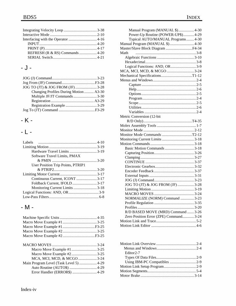
BDS5 INDEX
Index-iv
Integrating Velocity Loop .................................. 3-38 Interactive Mode ................................................ 2-10 Interfacing with the Operator ............................. 4-16 INPUT........................................................... 4-20 PRINT (P) ..................................................... 4-17 REFRESH (R & RS) Commands .................. 4-20 SERIAL Switch............................................. 4-21
- J -
JOG (J) Command.............................................. 3-23 Jog From (JF) Command..................................F3-28 JOG TO (JT) & JOG FROM (JF) ...................... 3-28 Changing Profiles During Motion .......... A3-30 Multiple JF/JT Commands ........................ 3-30 Registration ............................................ A3-29 Registration Example ................................ 3-29 Jog To (JT) Command .....................................F3-29
- K -
- L -
Labels ............................................................ 4-10 Limiting Motion ................................................. 3-19 Hardware Travel Limits ............................ 3-19 Software Travel Limits, PMAX & PMIN .............................................. 3-20 User Position Trip Points, PTRIP1 & PTRIP2............................................ 3-20 Limiting Motor Current...................................... 3-17 Continuous Current, ICONT ..................... 3-17 Foldback Current, IFOLD ......................... 3-17 Monitoring Current Limits ........................ 3-18 Logical Functions: AND, OR............................... 3-9 Low-Pass Filters................................................... 6-8
- M -
Machine Specific Units ...................................... 4-35 Macro Move Example #1................................... 3-25 Macro Move Example #1.................................F3-25 Macro Move Example #2................................... 3-25 Macro Move Example #2.................................F3-25
MACRO MOVES .............................................. 3-24 Macro Move Example #1.......................... 3-25 Macro Move Example #2.......................... 3-25 MCA, MCI, MCD, & MCGO ................... 3-24 Main Program Level (Task Level 5) .................. 4-29 Auto Routine (AUTO$) ............................ 4-29 Error Handler (ERROR$) ......................... 4-29
Manual Program (MANUAL $) ................ 4-30 Power-Up Routine (POWER-UP$)........... 4-29 Typical AUTO/MANUAL Programs........ 4-30 Manual Program (MANUAL $) ......................... 4-30 Master/Slave Block Diagram ...........................F4-34 Math .............................................................. 3-8 Algebraic Functions ...................................... 3-10 Hexadecimal.................................................... 3-8 Logical Functions: AND, OR.......................... 3-9 MCA, MCI, MCD, & MCGO ............................ 3-24 Mechanical Specifications................................T1-12 Menus and Windows............................................ 2-4 Capture ........................................................ 2-5 Help............................................................. 2-6 Options ........................................................ 2-5 Program....................................................... 2-4 Scope........................................................... 2-5 Utilities........................................................ 2-6 Variables ..................................................... 2-4 Metric Conversion (12-bit R/D Only)..................................................T4-35 Molex Assembly Tools ........................................ 1-7 Monitor Mode .................................................... 2-12 Monitor Mode Commands ...............................T2-12 Monitoring Current Limits ................................. 3-18 Motion Commands............................................. 3-18 Basic Motion Commands .............................. 3-18 Capturing Position......................................... 3-26 Clamping ....................................................... 3-27 CONTINUE .................................................. 3-37 Electronic Gearbox........................................ 3-32 Encoder Feedback ......................................... 3-37 External Inputs .............................................. 3-31 JOG (J) Command......................................... 3-23 JOG TO (JT) & JOG FROM (JF) ................. 3-28 Limiting Motion ............................................ 3-19 MACRO MOVES ......................................... 3-24 NORMALIZE (NORM) Command .............. 3-23 Profile Regulation ......................................... 3-35 Profiles .......................................................... 3-20 R/D BASED MOVE (MRD) Command ....... 3-26 Zero Position Error (ZPE) Command............ 3-24 Motion Link and Trace......................................... 5-2 Motion Link Editor .............................................. 4-6
Motion Link Overview......................................... 2-4 Menus and Windows........................................ 2-4 Editor2-7 Types Of Data Files......................................... 2-9 Using IBM-PC Compatibles ........................... 2-9 Motion Link Setup Program................................. 2-9 Motion Segments.................................................. 5-4 Motor Brake ....................................................... 3-14
INDEX BDS5
Index-v
Motor Current, ICMD & IMON ........................ 3-16 Move Absolute (MA) Command ....................... 3-21 Move Incremental (MI) Command .................... 3-22 MULTI ............................................................ 4-23 MULTI-TASKING............................................ 4-23 Alarms (Task Levels 1-3).............................. 4-26 Background (Task Level 6)........................... 4-30 Enabling and Disabling Multi-tasking........... 4-23 END Command............................................. 4-23 Idling 4-25 Main Program Level (Task Level 5) ............. 4-29 MULTI.......................................................... 4-23 Multitasking and Autobauding...................... 4-23 Variable Input (Task Level 4)....................... 4-27 Multi-Tasking Debug Prompts...........................T5-3 Multi-Tasking Overview..................................T4-24 Multidrop Communications ............................... 4-40 Broadcast .................................................. 4-41 Multiple JF/JT Commands................................. 3-30 Multiple Profile Commands............................... 3-23 Multitasking and Autobauding........................... 4-23
- N -
Nesting ? Commands ......................................... 4-12 Nesting IF commands ........................................ 4-15 NEW .............................................................. 4-9 Next Line ............................................................. 4-7 Non-Linear Mechanics......................................... 6-7 NORMALIZE (NORM) Command ................... 3-23
- O -
Options .............................................................. 2-5 Other Modes ...................................................... 2-13 Other User Units ................................................ 4-33 Output 1-8 Decimal Values..............................T3-10 Output Relay ...................................................... 3-14 Overdamping........................................................ 6-2 Overdamping...................................................... F6-2 Overloading the Motor......................................... 6-6
- P -
Part Number Description ..................................... 1-3 BDS5 Model Number ..................................... 1-4 Compensation Module Model Number........... 1-5 ER-External Resistor Kit Model Number ....... 1-7 Molex Assembly Tools ................................... 1-7 PSR4/5 Model Number................................... 1-6 Password (PASS) ................................................. 4-7
Position ............................................................ 3-14 Position Command and Feedback, PCMD & PFB.................................... 3-14 Position Error, PE & PEMAX .................. 3-14 R/D Position, PRD.................................... 3-15 Sampling PFB, PCMD and PEXT ............ 3-15 Position Command and Feedback, PCMD & PFB......................................... 3-14 Position Error, PE & PEMAX ........................... 3-14 Position Loop..................................................... 3-38 Position Rotary Mode, ROTARY, & PROTARY................................................. 4-37 Choosing PROTARY, PNUM, and PDEN ............................................. 4-37 Rotary Mode and Absolute Moves ......... 4-38 Post-Execution Idle............................................ 4-26 Power-up and Control Variables.......................... 3-3 Power-Up Control Loops ................................... 3-39 Power-Up Routine (POWER-UP$).................... 4-29 Power-Up State of Programmable Units ............T3-4 PRD: Ranges and R/D Resolutions..................T3-15 Pre-Execution Idle ............................................. 4-25 PRINT (P).......................................................... 4-17 Cursor Addressing .................................... 4-19 Printing ASCII Characters ........................ 4-18 Printing BDS5 Status (PS) ........................ 4-20 Printing Binary Numbers .......................... 4-18 Printing Control Characters ...................... 4-19 Printing Decimal Numbers........................ 4-17 Printing Decimal Points ............................ 4-17 Printing Expressions ................................. 4-18 Printing Hex Numbers .............................. 4-17 Printing Switches ...................................... 4-18 Printing ASCII Characters ................................. 4-18 Printing BDS5 Status .......................................T4-20 Printing BDS5 Status (PS) ................................. 4-20 Printing Binary Numbers ................................... 4-18 Printing Control Characters ............................... 4-19 Printing Decimal Numbers................................. 4-17 Printing Decimal Points ..................................... 4-17
Printing Expressions .......................................... 4-18 Printing Hex Numbers ....................................... 4-17 Printing Switches ............................................... 4-18 Printing Variables ................................................ 3-2 Printing with Alarms .......................................... 4-27 Problems6-6 Compliance ..................................................... 6-7 Low Pass Filters.............................................. 6-7 Non-Linear Mechanics.................................... 6-7 Overloading the Motor.................................... 6-6 Resonance ....................................................... 6-7
BDS5 INDEX
Index-vi
Processor Modes .................................................. 2-9 Descriptions of Modes .................................. 2-10 Prompts ........................................................... 2-9 Product Description.............................................. 1-1 Profile Final Position, PFNL.............................. 3-23 Profile Limits ..................................................... 3-22 Profile Regulation .............................................. 3-35 Profile Regulation and Counting Backwards ........................................... 3-36 REG & REGKHZ...................................... 3-35 Regulation Example .................................. 3-36 Profile Regulation and Counting Backwards ........................................... 3-36 Profiles ............................................................ 3-20 Incremental Move Example ...................... 3-22 Move Absolute (MA) Command............... 3-21 Move Incremental (MI) Command............ 3-22 Multiple Profile Commands ...................... 3-23 Profile Final Position, PFNL..................... 3-23 Profile Limits ............................................ 3-22 S-Curves.................................................... 3-20 Profiles and Gearbox.......................................... 3-33 Program .............................................................. 2-4 Program Examples ............................................. 4-41 Programming Conditions...................................... 3-3 Programming Techniques..................................... 4-1 Application Flowchart..................................... 4-3 Application Specification................................ 4-3 Commented Program....................................... 4-5 Customer Service ............................................ 4-6 Example Application....................................... 4-3 Prompts .............................................................. 2-9 Prompts 4-39 Proportional Velocity Loop................................ 3-38 PROTARY................................................. 4-37 PSR4/5 Model Number ........................................ 1-6 PSR4/5 Model Number Scheme.........................F1-6 PSR4/5 Model Number Scheme.........................T1-6
- Q -
Quick IF (?) Command....................................... 4-11
- R -
R/D BASED MOVE (MRD) Command ............ 3-26 R/D Converter Accuracy ..................................T3-26 R/D Position, PRD ............................................. 3-15 Ready Latch, Area 4........................................... 3-13 RECORD and PLAY ........................................... 6-6 Reducing ILIM..................................................... 6-3 REFRESH (R & RS) Commands ....................... 4-20 REG & REGKHZ............................................... 3-35 Registration ........................................................ 3-29
Registration Example ......................................... 3-29 Regulation Example ........................................... 3-36 Regulation Timer, RD .......................................... 5-4 Relay and STATUS Control, Area 6.................. 3-13 Removing Code.................................................... 5-3 Resonance ............................................................ 6-7 Restrictions of Alarms........................................ 4-27 Restrictions of Background ................................ 4-32 Restrictions of Variable Input ............................ 4-28 Ringing .............................................................. 6-2 Ringing ............................................................F6-2 Rotary Mode and Absolute Moves..................... 4-38 Rules For Math Expressions...............................T3-9 RUN ............................................................ 4-10 Run Mode........................................................... 2-12
- S -
S-Curve Acceleration Chart .............................T3-21 S-Curve Profile.................................................F3-21 S-Curves ............................................................ 3-20 Sample Flowchart...............................................F4-4 Sampling PFB, PCMD and PEXT ..................... 3-15 Scope .............................................................. 2-5 Segments for Different Moves ...........................T5-5 Serial Communications ...................................... 4-38 Autobauding.................................................. 4-38 Multidrop Communications........................... 4-40 Prompts ......................................................... 4-39 Serial Watchdog............................................ 4-39 System Dump ................................................ 4-40 Transmit/Receive Programs .......................... 4-39 SERIAL Switch.................................................. 4-21 Serial Watchdog................................................. 4-39 Setting External Units in Master/Slave Systems................................T4-33 Setting the BDS5 to Autobaud ........................... 4-38 Simplified Schematic Diagram and System Diagram...................................... 1-13 Single-Step ........................................................... 5-1 Single-Step Mode............................................... 2-12 Size .............................................................. 4-9 Software Installation............................................. 2-1 Software Installation............................................. 2-1 Backing Up the Disk(s) ................................... 2-1 Establishing Communications ......................... 2-3 Software Installation........................................ 2-2 Software Installation............................................. 2-2 Install on a Floppy Disk .............................. 2-2 Install on a Hard Disk.................................. 2-2 Software Travel Limits, PMAX & PMIN ................................................... 3-20 Special Constants ................................................. 3-8 Specifications .....................................................T1-8
INDEX BDS5
Index-vii
Specifications and Ratings ................................... 1-8 Speeding Up Homing Sequences ....................... 3-26 Standard Units....................................................T3-2 STOP (S) Command .......................................... 3-19 STOP and BREAK with Control X (^X)......................................... 3-19 Switche s............................................................. 3-2 Synchronizing Your Program............................... 5-4 Gating Motion with GATE ............................. 5-6 Motion Segments ............................................ 5-4 Regulation Timer, RD..................................... 5-4 Using the Timers, TMR1-4............................. 5-4 WAIT (W) ...................................................... 5-5 System Compensation.......................................... 6-1 Critical Damping............................................. 6-2 Overdamping................................................... 6-2 Ringing............................................................ 6-2 Underdamping................................................. 6-2 System Dump..................................................... 4-40 Version Dump........................................... 4-40 System Resolutions ..........................................T4-33
- T -
The >BDS Command Transmitting to the BDS5.......................................... 4-39 Theory of Operation........................................... 1-12 Three Types of Variables..................................... 3-2 TIL Command.................................................... 4-12 To Execute AUTO$ .........................................T4-30 To Execute MANUAL$...................................T4-30 Torque Command .............................................. 3-39 Trace .............................................................. 5-2 Motion Link and Trace ................................ 5-2 Trace Mode........................................................ 2-12 Transmit/Receive Programs ............................... 4-39 <BDS Command Receiving from the BDS5............................................... 4-39 The >BDS Command Transmitting to the BDS5.......................................... 4-39 TUNE Command ................................................. 6-4 Tuning .............................................................. 6-3 If Your System Is Completely Unstable.......... 6-3 Reducing ILIM................................................ 6-3 Tuning Criterion.................................................T6-1 Tuning the BDS5 Yourself .................................. 6-4 Tuning the Position Loop................................ 6-5 Tuning the Velocity Loop ................................ 6-4 Tuning the Position Loop..................................... 6-5 Tuning the Velocity Loop .................................... 6-4 Types Of Data Files ............................................. 2-9 Typical AUTO/MANUAL Programs................. 4-30
- U -
Underdamping...................................................... 6-2 Underdamping.................................................... F6-2 Units ............................................................ 4-32 Machine Specific Units ................................. 4-35 Position Rotary Mode, ROTARY, & PROTARY................................................. 4-37 User Position Trip Points, PTRIP1 & PTRIP2 ................................................ 3-20 User Switches....................................................... 3-8 User Units .......................................................... 4-32 Current Units............................................. 4-32 External Units ........................................... 4-33 Other User Units ....................................... 4-33 User Variables...................................................... 3-7 Indirect User Variables ............................... 3-7 Using IBM-PC Compatibles ................................ 2-9 Using the General Purpose Inputs...................... 4-15 Using the Timers, TMR1-4.................................. 5-4 Using Variable Input with Profiles..................... 4-28 Utilities .............................................................. 2-6
- V -
Variable Input (Task Level 4)............................ 4-27 Restrictions of Variable Input ................... 4-28 Using Variable Input with Profiles............ 4-28 Variable Limits .................................................... 3-2 Variable Units ...................................................... 3-2 Variables .............................................................. 2-4 Variables .............................................................. 3-1 Changing a Variable........................................ 3-3 Initial Settings of Control and User Variables....................................... 3-4 Power-up and Control Variables..................... 3-3 Printing Variables ........................................... 3-2 Programming Conditions ................................ 3-3 Special Constants ............................................ 3-8 Switches .......................................................... 3-2 Three Types of Variables................................ 3-2 User Switches.................................................. 3-8 User Variables................................................. 3-7 Variable Limits ............................................... 3-2 Variable Units ................................................. 3-2 VCMD, VFB, VE, & VAVG............................. 3-15 Velocity ............................................................ 3-15 VCMD, VFB, VE, & VAVG.................... 3-15 Velocity Limits, VMAX & VOSPD ......... 3-16 Velocity Limits, VMAX & VOSPD .................. 3-16 Velocity Loop .................................................... 3-38 Integrating Velocity Loop ......................... 3-38 Proportional Velocity Loop ...................... 3-38
BDS5 INDEX
Index-viii
Velocity Loop Bandwidth vs. KPMAX .............T6-5 Velocity Loop Bandwidth vs. KVI.....................T6-5 Velocity Offset, VOFF....................................... 3-35 Version Dump .................................................... 4-40
- W -
WAIT (W).......................................................... 4-22 WAIT (W)............................................................ 5-5 Whole Word I/O................................................. 3-10
- X -
- Y -
- Z -
Zero Position Error (ZPE) Command................. 3-24
- - -
<BDS Command Receiving from the BDS5............................................... 4-39

BDS5 UPGRADE NOTICES
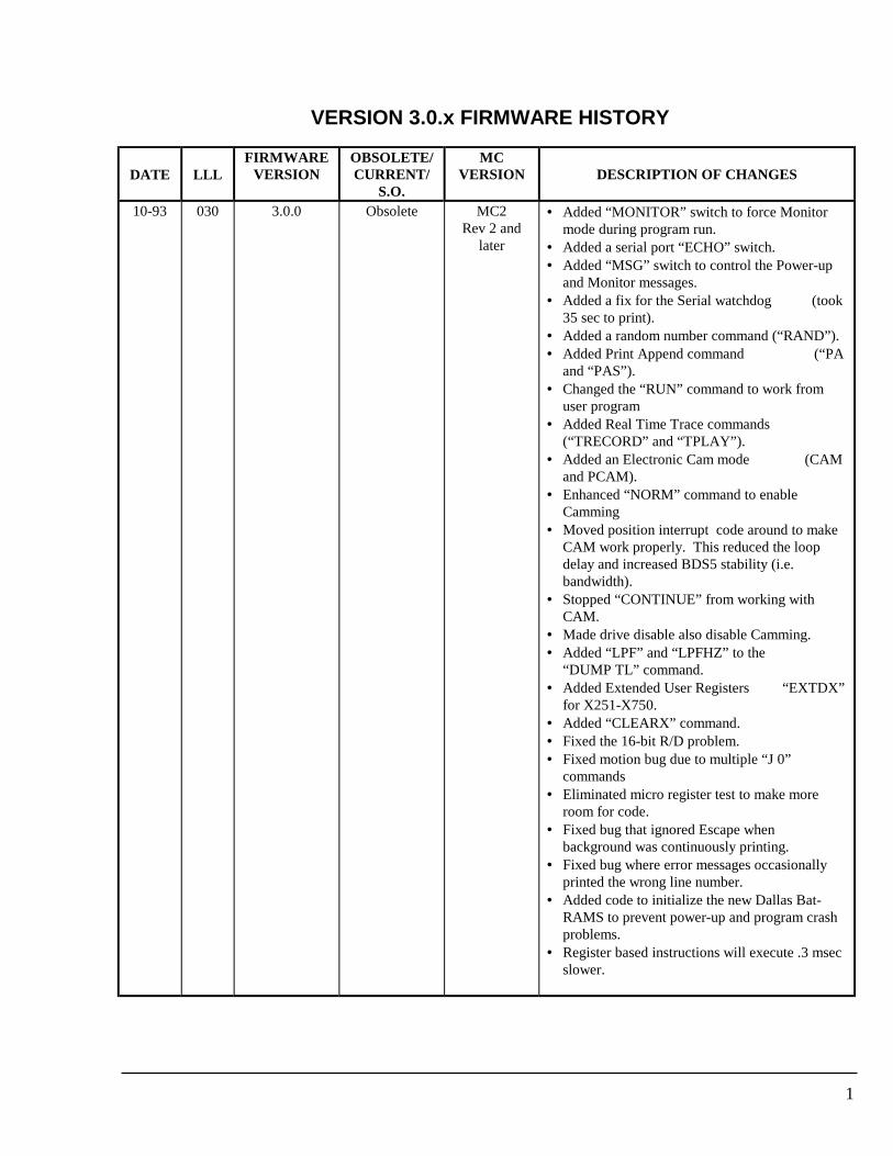
1
VERSION 3.0.x FIRMWARE HISTORY
DATE LLLFIRMWARE
VERSIONOBSOLETE/CURRENT/
S.O.
MCVERSION DESCRIPTION OF CHANGES
10-93 030 3.0.0 Obsolete MC2Rev 2 and
later
• Added “MONITOR” switch to force Monitormode during program run.
• Added a serial port “ECHO” switch.• Added “MSG” switch to control the Power-up
and Monitor messages.• Added a fix for the Serial watchdog (took
35 sec to print).• Added a random number command (“RAND”).• Added Print Append command (“PA
and “PAS”).• Changed the “RUN” command to work from
user program• Added Real Time Trace commands
(“TRECORD” and “TPLAY”).• Added an Electronic Cam mode (CAM
and PCAM).• Enhanced “NORM” command to enable
Camming• Moved position interrupt code around to make
CAM work properly. This reduced the loopdelay and increased BDS5 stability (i.e.bandwidth).
• Stopped “CONTINUE” from working withCAM.
• Made drive disable also disable Camming.• Added “LPF” and “LPFHZ” to the
“DUMP TL” command.• Added Extended User Registers “EXTDX”
for X251-X750.• Added “CLEARX” command.• Fixed the 16-bit R/D problem.• Fixed motion bug due to multiple “J 0”
commands• Eliminated micro register test to make more
room for code.• Fixed bug that ignored Escape when
background was continuously printing.• Fixed bug where error messages occasionally
printed the wrong line number.• Added code to initialize the new Dallas Bat-
RAMS to prevent power-up and program crashproblems.
• Register based instructions will execute .3 msecslower.
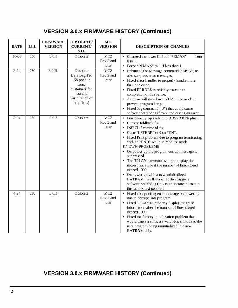
2
VERSION 3.0.x FIRMWARE HISTORY (Continued)
DATE LLLFIRMWARE
VERSIONOBSOLETE/CURRENT/
S.O.
MCVERSION DESCRIPTION OF CHANGES
10-93 030 3.0.1 Obsolete MC2Rev 2 and
later
• Changed the lower limit of “PEMAX” from0 to 1.
• Force “PEMAX” to 1 if less than 1.2-94 030 3.0.2b Obsolete
Beta Bug Fix(Shipped to
somecustomers for
test andverification of
bug fixes)
MC2Rev 2 and
later
• Enhanced the Message command (“MSG”) toalso suppress error messages.
• Fixed error handler to properly handle morethan one error.
• Fixed ERROR$ to reliably execute tocompletion on first error.
• An error will now force off Monitor mode toprevent program hang.
• Fixed Jog command (“J”) that could causesoftware watchdog if executed during an error.
2-94 030 3.0.2 Obsolete MC2Rev 2 and
later
• Functionally equivalent to BDS5 3.0.2b plus. . .• Current foldback fix• INPUT”” command fix• Clear “LSTERR” to 0 on “EN”.• Fixed Print problem due to program terminating
with an “END” while in Monitor mode.KNOWN PROBLEMS• On power-up the program corrupt message is
suppressed.• The TPLAY command will not display the
newest trace line if the number of lines storedexceed 1000.
• On power-up with a new uninitializedBATRAM the BDS5 will often trigger asoftware watchdog (this is an inconvenience tothe factory test people).
4-94 030 3.0.3 Obsolete MC2Rev 2 and
later
• Fixed non-printing error message on power-updue to corrupt user program.
• Fixed TPLAY to properly display the traceinformation after the number of lines storedexceed 1000.
• Fixed the factory initialization problem thatwould cause a software watchdog trip due to theuser program being uninitialized in a newBATRAM chip.
VERSION 3.0.x FIRMWARE HISTORY (Continued)

3
DATE LLLFIRMWARE
VERSIONOBSOLETE/CURRENT/
S.O.
MCVERSION DESCRIPTION OF CHANGES
5-94 030 3.0.4 Obsolete MC2Rev 2 and
later
• Enhanced the CLEARX command to allowseparate clearing of all User Registers or UserFlags or both.
• Fixed LSTERR to work even if MSG=0.• Fixed another factory initialization problem that
would cause a software watchdog trip on entryto the User Program Editor due to the userprogram being uninitialized in a new BATRAMchip.
• Enhanced the Break (B) command to allow theoptional breaking of a user INPUT command (BI).
• Enhanced the Error Recovery Task to cancel theuser INPUT command if it is active.
• Enhanced the Error Recovery Task to cancel aTask idling command such as “H”.
11-94 030 3.0.5 Current MC2Rev 2 and
later
• Added MONITOR=OFF support from the userprogram.
• Fixed a problem with EXTLOOP.• Added PCMD=PEXT when EXTLOOP=1 and
drive disabled.• Fixed front panel LED initialization on power-
up.• Syntax error in ERROR$ will break the
program.• An invalid command will not allow any program
execution.• An error occurring while in Monitor mode will
print the error message and return to Monitormode.
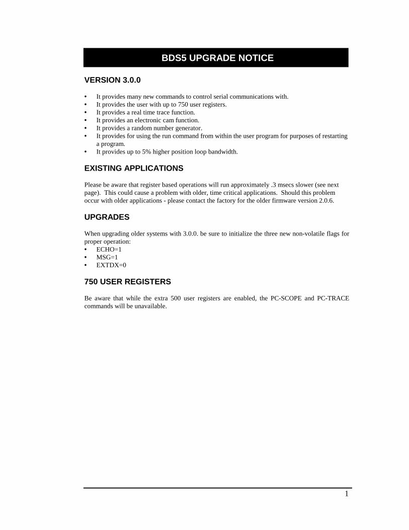
1
BDS5 UPGRADE NOTICE
VERSION 3.0.0
• It provides many new commands to control serial communications with.• It provides the user with up to 750 user registers.• It provides a real time trace function.• It provides an electronic cam function.• It provides a random number generator.• It provides for using the run command from within the user program for purposes of restarting
a program.• It provides up to 5% higher position loop bandwidth.
EXISTING APPLICATIONS
Please be aware that register based operations will run approximately .3 msecs slower (see nextpage). This could cause a problem with older, time critical applications. Should this problemoccur with older applications - please contact the factory for the older firmware version 2.0.6.
UPGRADES
When upgrading older systems with 3.0.0. be sure to initialize the three new non-volatile flags forproper operation:• ECHO=1• MSG=1• EXTDX=0
750 USER REGISTERS
Be aware that while the extra 500 user registers are enabled, the PC-SCOPE and PC-TRACEcommands will be unavailable.
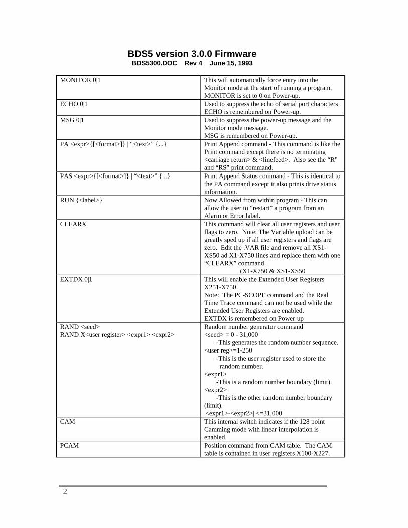
2
BDS5 version 3.0.0 FirmwareBDS5300.DOC Rev 4 June 15, 1993
MONITOR 0|1 This will automatically force entry into theMonitor mode at the start of running a program.MONITOR is set to 0 on Power-up.
ECHO 0|1 Used to suppress the echo of serial port charactersECHO is remembered on Power-up.
MSG 0|1 Used to suppress the power-up message and theMonitor mode message.MSG is remembered on Power-up.
PA <expr>{[<format>]} | “<text>” {...} Print Append command - This command is like thePrint command except there is no terminating<carriage return> & <linefeed>. Also see the “R”and “RS” print command.
PAS <expr>{[<format>]} | “<text>” {...} Print Append Status command - This is identical tothe PA command except it also prints drive statusinformation.
RUN {<label>} Now Allowed from within program - This canallow the user to “restart” a program from anAlarm or Error label.
CLEARX This command will clear all user registers and userflags to zero. Note: The Variable upload can begreatly sped up if all user registers and flags arezero. Edit the .VAR file and remove all XS1-XS50 ad X1-X750 lines and replace them with one“CLEARX” command.
(X1-X750 & XS1-XS50EXTDX 0|1 This will enable the Extended User Registers
X251-X750.Note: The PC-SCOPE command and the RealTime Trace command can not be used while theExtended User Registers are enabled.EXTDX is remembered on Power-up
RAND <seed>RAND X<user register> <expr1> <expr2>
Random number generator command<seed> = 0 - 31,000
-This generates the random number sequence.<user reg>=1-250
-This is the user register used to store the random number.
<expr1>-This is a random number boundary (limit).
<expr2>-This is the other random number boundary
(limit).|<expr1>-<expr2>| <=31,000
CAM This internal switch indicates if the 128 pointCamming mode with linear interpolation isenabled.
PCAM Position command from CAM table. The CAMtable is contained in user registers X100-X227.

3
NORM <pos> {CAM} Used to enable the Cam at the Normalize position -GEAR mode must be turned off before enablingCAM, after which GEAR must be turned on tostart Camming.
DUMP {TL | VERSION} Added LPF and LPFHZ to DUMP TL
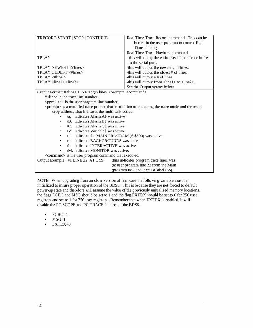
4
TRECORD START | STOP | CONTINUE Real Time Trace Record command. This can beburied in the user program to control RealTime Tracing.
TPLAY
TPLAY NEWEST <#lines>TPLAY OLDEST <#lines>TPLAY <#lines>TPLAY <line1> <line2>
Real Time Trace Playback command.- this will dump the entire Real Time Trace buffer to the serial port.-this will output the newest # of lines.-this will output the oldest # of lines.-this will output a # of lines.-this will output from <line1> to <line2>.See the Output syntax below
Output Format: #<line> LINE <pgm line> <prompt> <command>#<line> is the trace line number.<pgm line> is the user program line number.<prompt> is a modified trace prompt that in addition to indicating the trace mode and the multi-
drop address, also indicates the multi-task active.• ta. indicates Alarm A$ was active• tB. indicates Alarm B$ was active• tC. indicates Alarm C$ was active• tV. indicates Variable$ was active• t.. indicates the MAIN PROGRAM ($-$500) was active• t*. indicates BACKGROUND$ was active• tI. indicates INTERACTIVE was active• tM. indicates MONITOR was active.
<command> is the user program command that executed.Output Example: #1 LINE 22 AT .. 5$ ;this indicates program trace line1 was
;at user program line 22 from the Main;program task and it was a label (5$).
NOTE: When upgrading from an older version of firmware the following variable must beinitialized to insure proper operation of the BDS5. This is because they are not forced to defaultpower-up state and therefore will assume the value of the previously unitialized memory locations.the flags ECHO and MSG should be set to 1 and the flag EXTDX should be set to 0 for 250 userregisters and set to 1 for 750 user registers. Remember that when EXTDX is enabled, it willdisable the PC-SCOPE and PC-TRACE features of the BDS5.
• ECHO=1• MSG=1• EXTDX=0
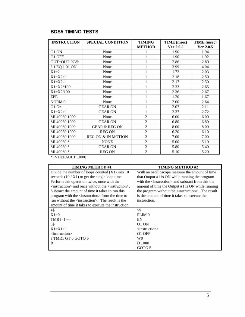
5
BDS5 TIMING TESTS
INSTRUCTION SPECIAL CONDITION TIMINGMETHOD
TIME (msec)Ver 2.0.5
TIME (msec)Ver 2.0.5
O1 ON None 1 1.90 1.94O1 OFF None 1 1.90 1.92OUT=OUT!0C8h None 1 2.86 2.89? 1 EQ 1 01 ON None 1 3.99 4.04X1=2 None 1 1.72 2.03X1=X2+1 None 1 2.18 2.50X1=X2-1 None 1 2.17 2.50X1=X2*100 None 1 2.33 2.65X1=X2/100 None 1 2.36 2.67ZPE None 1 1.20 1.67NORM 0 None 1 2.00 2.64O1 On GEAR ON 1 2.07 2.11X1=X2+1 GEAR ON 1 2.37 2.72MI 40960 1000 None 2 6.00 6.00MI 40960 1000 GEAR ON 2 6.80 6.80MI 40960 1000 GEAR & REG ON 2 8.00 8.00MI 40960 1000 REG ON 2 6.20 6.10MI 40960 1000 REG ON & IN MOTION 2 7.00 7.00MI 40960 * NONE 2 5.00 5.10MI 40960 * GEAR ON 2 5.80 5.40MI 40960 * REG ON 2 5.10 5.20* (VDEFAULT 1000)
TIMING METHOD #1 TIMING METHOD #2Divide the number of loops counted (X1) into 10seconds (10 / X1) to get the single loop time.Perform this operation twice, once with the<instruction> and once without the <instruction>.Subtract the amount of time it takes to run thisprogram with the <instruction> from the time torun without the <instruction>. The result is theamount of time it takes to execute the instruction.
With an oscilloscope measure the amount of timethat Output #1 is ON while running the programwith the <instruction> and subtract from this theamount of time the Output #1 is ON while runningthe program without the <instruction>. The resultis the amount of time it takes to execute theinstruction.
4$X1=0TMR1=1----5$X1=X1+1<instruction>? TMR1 GT 0 GOTO 5B
5$PLIM 0ENO1 ON<instruction>O1 OFFW0D 1000GOTO 5
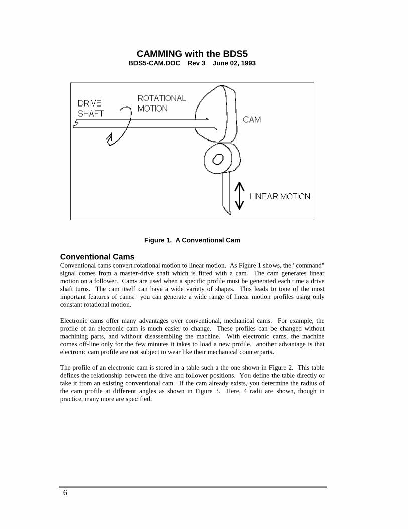
6
CAMMING with the BDS5BDS5-CAM.DOC Rev 3 June 02, 1993
Figure 1. A Conventional Cam
Conventional CamsConventional cams convert rotational motion to linear motion. As Figure 1 shows, the "command"signal comes from a master-drive shaft which is fitted with a cam. The cam generates linearmotion on a follower. Cams are used when a specific profile must be generated each time a driveshaft turns. The cam itself can have a wide variety of shapes. This leads to tone of the mostimportant features of cams: you can generate a wide range of linear motion profiles using onlyconstant rotational motion.
Electronic cams offer many advantages over conventional, mechanical cams. For example, theprofile of an electronic cam is much easier to change. These profiles can be changed withoutmachining parts, and without disassembling the machine. With electronic cams, the machinecomes off-line only for the few minutes it takes to load a new profile. another advantage is thatelectronic cam profile are not subject to wear like their mechanical counterparts.
The profile of an electronic cam is stored in a table such a the one shown in Figure 2. This tabledefines the relationship between the drive and follower positions. You define the table directly ortake it from an existing conventional cam. If the cam already exists, you determine the radius ofthe cam profile at different angles as shown in Figure 3. Here, 4 radii are shown, though inpractice, many more are specified.
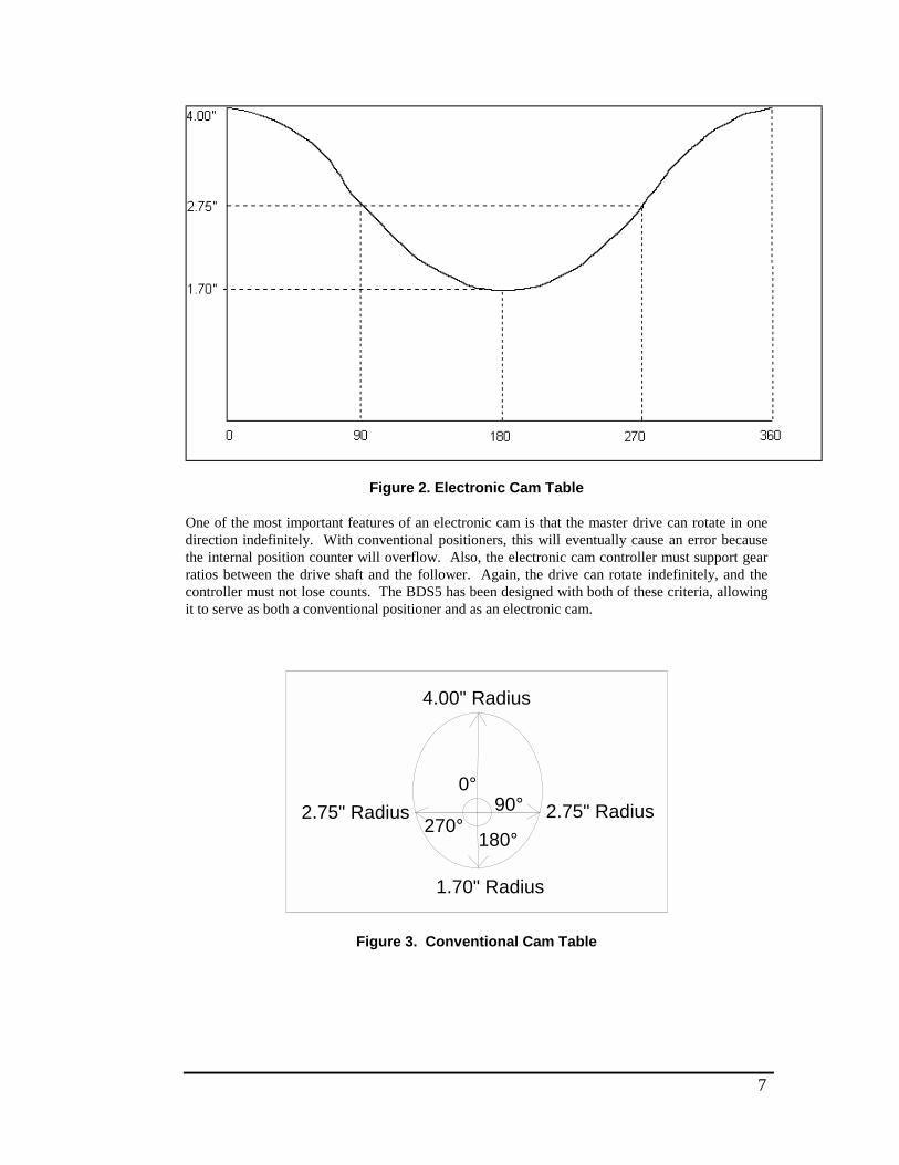
7
Figure 2. Electronic Cam Table
One of the most important features of an electronic cam is that the master drive can rotate in onedirection indefinitely. With conventional positioners, this will eventually cause an error becausethe internal position counter will overflow. Also, the electronic cam controller must support gearratios between the drive shaft and the follower. Again, the drive can rotate indefinitely, and thecontroller must not lose counts. The BDS5 has been designed with both of these criteria, allowingit to serve as both a conventional positioner and as an electronic cam.
4.00" Radius
2.75" Radius
1.70" Radius
2.75" Radius
0°90°
180° 270°
Figure 3. Conventional Cam Table
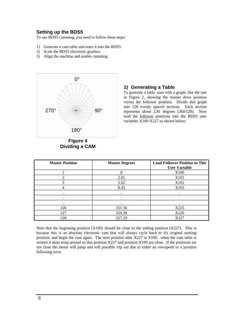
8
Setting up the BDS5To use BDS5 camming, you need to follow these steps:
1) Generate a cam table and enter it into the BDS5.2) Scale the BDS5 electronic gearbox.3) Align the machine and enable camming.
0°
90°
180°
270°
Figure 4Dividing a CAM
1) Generating a TableTo generate a table, start with a graph, like the onein Figure 2, showing the master drive positionversus the follower position. Divide this graphinto 128 evenly spaced sections. Each sectionrepresents about 2.81 degrees (360/128). Nowload the follower positions into the BDS5 uservariables X100-X227 as shown below:
Master Position Master Degrees Load Follower Position in ThisUser Variable
1 0 X1002 2.81 X10¹³ 5.62 X1024 8.43 X10³. . .. . .. . .
126 351.56 X225127 354.38 X226128 357.19 X227
Note that the beginning position (X100) should be close to the ending position (X227). This isbecause this is an absolute electronic cam that will always cycle back to it's original startingposition. and begin the cam again. The next position after X227 is X100. when the cam table iswritten it must wrap around so that position X227 and position X100 are close. If the positions arenot close the motor will jump and will possible trip out due to either an overspeed or a positionfollowing error.
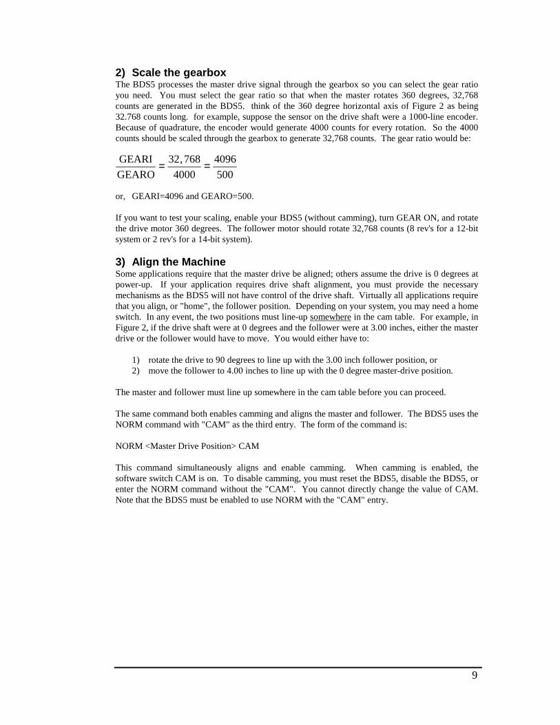
9
2) Scale the gearboxThe BDS5 processes the master drive signal through the gearbox so you can select the gear ratioyou need. You must select the gear ratio so that when the master rotates 360 degrees, 32,768counts are generated in the BDS5. think of the 360 degree horizontal axis of Figure 2 as being32.768 counts long. for example, suppose the sensor on the drive shaft were a 1000-line encoder.Because of quadrature, the encoder would generate 4000 counts for every rotation. So the 4000counts should be scaled through the gearbox to generate 32,768 counts. The gear ratio would be:
GEARI
GEARO= =32 768
4000
4096
500
,
or, GEARI=4096 and GEARO=500.
If you want to test your scaling, enable your BDS5 (without camming), turn GEAR ON, and rotatethe drive motor 360 degrees. The follower motor should rotate 32,768 counts (8 rev's for a 12-bitsystem or 2 rev's for a 14-bit system).
3) Align the MachineSome applications require that the master drive be aligned; others assume the drive is 0 degrees atpower-up. If your application requires drive shaft alignment, you must provide the necessarymechanisms as the BDS5 will not have control of the drive shaft. Virtually all applications requirethat you align, or "home", the follower position. Depending on your system, you may need a homeswitch. In any event, the two positions must line-up somewhere in the cam table. For example, inFigure 2, if the drive shaft were at 0 degrees and the follower were at 3.00 inches, either the masterdrive or the follower would have to move. You would either have to:
1) rotate the drive to 90 degrees to line up with the 3.00 inch follower position, or2) move the follower to 4.00 inches to line up with the 0 degree master-drive position.
The master and follower must line up somewhere in the cam table before you can proceed.
The same command both enables camming and aligns the master and follower. The BDS5 uses theNORM command with "CAM" as the third entry. The form of the command is:
NORM <Master Drive Position> CAM
This command simultaneously aligns and enable camming. When camming is enabled, thesoftware switch CAM is on. To disable camming, you must reset the BDS5, disable the BDS5, orenter the NORM command without the "CAM". You cannot directly change the value of CAM.Note that the BDS5 must be enabled to use NORM with the "CAM" entry.
10
When the "NORM <Master Drive Position> CAM" command is executed, PCMD is determinedby the cam table and is set to the corresponding value for PCMD. PFB is set to the same value asPCAM and therefore there is no PE (position error).
Returning to Figure 2, assume you know the follower to bed 4.00 inches. The master drive shouldbe at 0 degrees. You would normalize the position as follows:
ENNORM 0 CAM
If you are using position units, the most convenient place to normalize for camming is when themaster drive is at zero. This is because the master drive position (PCMD) uses position units(PNUM and PDEN) which are normally scaled for the follower. When you normalize to zero, theunits do not have any effect. However, if you want to normalize the master to a non-zero position,you must
A) Determine the position of the drive master to which you will normalize;
B) Convert the position to counts where 360 degrees equals 32.768 counts;
C) Temporarily set position units to 1:1 (PNUM = PDEN = 1);
D) Normalize to the position in counts:ENNORM <Master Drive Position in Counts> CAM
E) Restore the position units to their original values.
For example, if you knew the follower to be 3.00 inches and you knew the drive to be at 90degrees:
A) Drive position = 90 degrees.
B) Drive position = 8192 counts.
C) PNUM=1PDEN=1
D) ENNORM 8192 CAM
E) Restore PNUM and PDEN
11
Finally, you must turn GEAR on. This connects the drive to the follower. If you want tot test yoursystem before you connect the master-drive, you can use VOFF. VOFF is the offset speed for theelectronic gearbox. For example, if the master drive is not moving and you turn GEAR ON and setVOFF to 100 RPM, the position command will increase at a rate of 100 RPM. This has the sameeffect as the encoder option input running at 100 RPM. For a 12-bit system, this is equivalent totthe master drive rotating at 409,600 counts per minute; as 360 degrees is 32.768 counts, this isequivalent to 12.5 (409,600/32,768) cycles through the cam table every minute.
PCAM and PCMDThe BDS5 uses a special variable for camming, PCAM. PCAM is the position command from thecam table. This is usually the role for PCMD (position command). However, when camming isenabled, PCM represents the position from the electronic gearbox; that is, the position that goesinto the table. PC�M is the output from the table.
PCMD is automatically in a "ROTARY" mode where the distance of one rotation is fixed at32.768 counts. PCAM can be printed or recorded with PC-Scope. In fact, if you want to see yourcam profile, you can record PCAM and PCMD simultaneously. For example, the following linerecords both positions for 0.5 seconds.
RECORD 500 1 PCMD PCAM
You can then use PC-Scope to verify your profile. Also, the PS and RS commands display"CAMMING" if GEAR and CAM are both ON.
LimitationsThere are several limitations for camming applications. These limitations reflect that manyfunctions of the BDS5 are not useful when caming. For example, profile commands (MI, MA, J,JT, JF, MCGO) are not allowed. ROTARY must be OFF. Any error that disables the drive alsodisables camming; you must re-normalize after such errors. Error 23, SOFTWAREOVERTRAVEL, disables the BDS5 and breaks the user program; when camming is off, this erroronly breaks the user program.
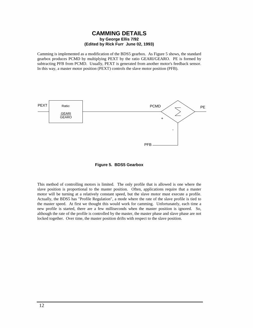
12
CAMMING DETAILSby George Ellis 7/92
(Edited by Rick Furr June 02, 1993)
Camming is implemented as a modification of the BDS5 gearbox. As Figure 5 shows, the standardgearbox produces PCMD by multiplying PEXT by the ratio GEARI/GEARO. PE is formed bysubtracting PFB from PCMD. Usually, PEXT is generated from another motor's feedback sensor.In this way, a master motor position (PEXT) controls the slave motor position (PFB).
Ratio:
GEARIGEARO
PCMD
PFB
PEXT
+
PE
-
Figure 5. BDS5 Gearbox
This method of controlling motors is limited. The only profile that is allowed is one where theslave position is proportional to the master position. Often, applications require that a mastermotor will be turning at a relatively constant speed, but the slave motor must execute a profile.Actually, the BDS5 has "Profile Regulation", a mode where the rate of the slave profile is tied tothe master speed. At first we thought this would work for camming. Unfortunately, each time anew profile is started, there are a few milliseconds when the master position is ignored. So,although the rate of the profile is controlled by the master, the master phase and slave phase are notlocked together. Over time, the master position drifts with respect to the slave position.
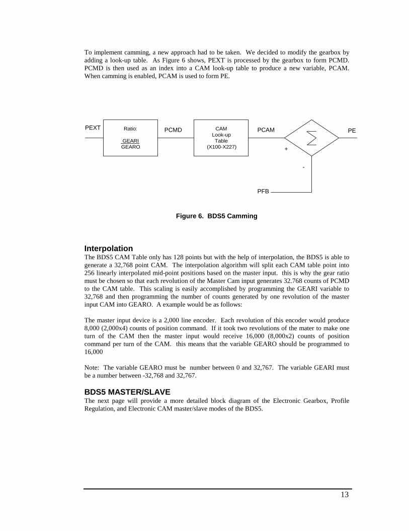
13
To implement camming, a new approach had to be taken. We decided to modify the gearbox byadding a look-up table. As Figure 6 shows, PEXT is processed by the gearbox to form PCMD.PCMD is then used as an index into a CAM look-up table to produce a new variable, PCAM.When camming is enabled, PCAM is used to form PE.
Ratio:
GEARIGEARO
CAMLook-upTable
(X100-X227)
PCMD PCAM
PFB
PEXT PE
+
-
Figure 6. BDS5 Camming
InterpolationThe BDS5 CAM Table only has 128 points but with the help of interpolation, the BDS5 is able togenerate a 32,768 point CAM. The interpolation algorithm will split each CAM table point into256 linearly interpolated mid-point positions based on the master input. this is why the gear ratiomust be chosen so that each revolution of the Master Cam input generates 32.768 counts of PCMDto the CAM table. This scaling is easily accomplished by programming the GEARI variable to32,768 and then programming the number of counts generated by one revolution of the masterinput CAM into GEARO. A example would be as follows:
The master input device is a 2,000 line encoder. Each revolution of this encoder would produce8,000 (2,000x4) counts of position command. If it took two revolutions of the mater to make oneturn of the CAM then the master input would receive 16,000 (8,000x2) counts of positioncommand per turn of the CAM. this means that the variable GEARO should be programmed to16,000
Note: The variable GEARO must be number between 0 and 32,767. The variable GEARI mustbe a number between -32,768 and 32,767.
BDS5 MASTER/SLAVEThe next page will provide a more detailed block diagram of the Electronic Gearbox, ProfileRegulation, and Electronic CAM master/slave modes of the BDS5.
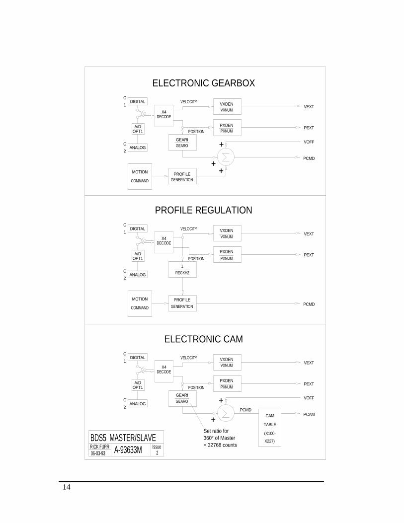
14
PROFILE REGULATION
ELECTRONIC GEARBOX
PCMD
PXDEN
RICK FURR06-03-93
BDS5 MASTER/SLAVE
GEARI
A-93633M
ANALOG2
C
Issue2
= 32768 counts360° of MasterSet ratio for
GEARO
+
+
ELECTRONIC CAM
DIGITAL1
C
OPT1A/D
DECODEX4
MOTION
COMMAND
ANALOGC
2
OPT1A/D
VELOCITY
POSITION
VXDEN
PXDEN
PXNUM
VXNUM
GENERATION
PROFILE
POSITION
REGKHZ
1
PXNUM
VXNUM
COMMAND
DIGITAL1
C
DECODEX4
MOTION
ANALOGC
2
A/DOPT1
DECODEX4
GENERATION
VELOCITY VXDEN
VXNUM
GEARO
PROFILE
POSITION
GEARI+
++
PXDEN PXNUM
DIGITALC
1VELOCITY VXDEN
X227)
(X100-
TABLE
CAM PCAM
VOFF
PEXT
VEXT
PCMD
PEXT
VEXT
VEXT
PCMD
VOFF
PEXT

15
TESTINGA simple test program was written. This test performs the following task:
1. Loads X100-X227 with a triangle wave where x100 = 0, x101 = 100, x102 =200, ... . Themid point of the triangle wave is X164 so that X163 = 6300, X164 = 6400, X165, 6300,X166 = 6200, ... [Lines 14-24]
2. Enable the BDS5 and enable camming [Lines 28-32].
3. Use VOFF to move PCMD through the cam cycle. VOFF is usually used with thegearbox to add an offset speed. It was designed for use with analog input where a customermay need to add an offset speed to adjust out error from a D/A converter. Here, we use it tosimplify the test (without VOFF, testing would require a second motor be connected to thegearbox).
4) Loop control [Lines 35-37, 58-61]
5) Calculate which segment this iteration is in (it repeats from segment 0 to segment 127every 128 iterations) and store it in X2. [Line 38]
6) Determine PCMD at the end of the segment. [Line 40]
7) Wait until PCMD reaches the boundary. Store the commanded position (PCAM) [Lines45-53]
8) Calculate error between what the command is (X4) and what is should be (X(X2)).
9) Subroutines to print whether iteration tested good or bad [Lines 63-70].

16
CAM TEST PROGRAM FOR THE BDS5
1 ;CAM TEST ghe 7/16/922 ;3 ;use voff set to keep vcmd moving at a constant speed. Selected that4 ;speed to be 20 RPM which is about 1365 counts/second. The entire5 'cam cycle is 32768 counts. Each of the 128 segments is 256 counts.6 ;So. 20 RPM cycles through the cam cycle at one cycle per 32768/13657 ;seconds or 24 seconds. Each of the 128 cycles requires 24/128 or8 '187 msecs.910 ;1$11 ;This section loads cam variables with a triangular profile where12 ;each segment is different from the last by 100 counts13 ;First, load variables x100-x16414 ;xi = 100 ;starting variable15 ;2$ ;loop beginning16 X(X1) = = (X1-100)*100 ;load the "up side" of the triangle17 X1 = X1+1 ;increment the loop counter18 ? x1 1e 164 goto 2 'test loop--keep going until X16419 ;20 ;Now, load variables X165-X227 with the "down side" of the counter21 3$ ;loop beginning22 X(X1) = X164-(X1-164)*10023 X1 = X1+1 ;increment the loop counter24 ? X1 LE 227 GOTO 3;test loop--keep going until X22725 ;26 ;Now, it's time to start the CAM27 4$28 PLIM OFF ;Standard line to enable29 GEAR OFF ;Disable GEAR so we can enable CAM30 EN31 NORM 0 CAM ;Normalize and enable CAM32 GEAR ON ;Now, we can enable GEAR33 VOFF 20 ;Use offset speed of 20 RPM to go through34 ; cam cycle35 B ;Break back to Immediate mode
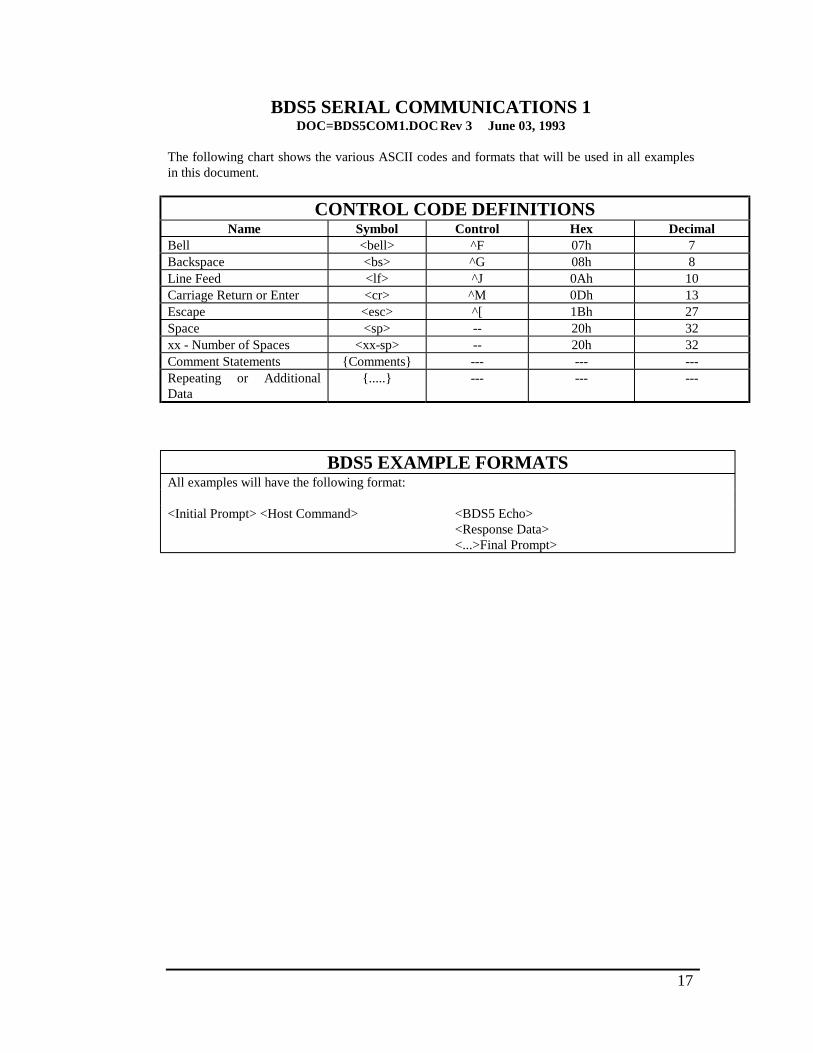
17
BDS5 SERIAL COMMUNICATIONS 1DOC=BDS5COM1.DOC Rev 3 June 03, 1993
The following chart shows the various ASCII codes and formats that will be used in all examplesin this document.
CONTROL CODE DEFINITIONSName Symbol Control Hex Decimal
Bell <bell> ^F 07h 7Backspace <bs> ^G 08h 8Line Feed <lf> ^J 0Ah 10Carriage Return or Enter <cr> ^M 0Dh 13Escape <esc> ^[ 1Bh 27Space <sp> -- 20h 32xx - Number of Spaces <xx-sp> -- 20h 32Comment Statements {Comments} --- --- ---Repeating or AdditionalData
{.....} --- --- ---
BDS5 EXAMPLE FORMATSAll examples will have the following format:
<Initial Prompt> <Host Command> <BDS5 Echo><Response Data><...>Final Prompt>
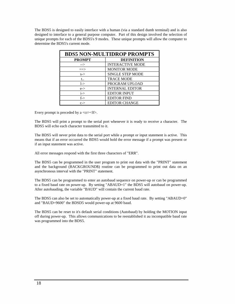
18
The BDS5 is designed to easily interface with a human (via a standard dumb terminal) and is alsodesigned to interface to a general purpose computer. Part of this design involved the selection ofunique prompts for each of the BDS5's 9 modes. These unique prompts will allow the computer todetermine the BDS5's current mode.
BDS5 NON-MULTIDROP PROMPTSPROMPT DEFINITION
--> INTERACTIVE MODE==> MONITOR MODEs-> SINGLE STEP MODEt.. TRACE MODEl-> PROGRAM UPLOADe-> INTERNAL EDITORi-> EDITOR INPUTf-> EDITOR FINDc-> EDITOR CHANGE
Every prompt is preceded by a <cr><lf>.
The BDS5 will print a prompt to the serial port whenever it is ready to receive a character. TheBDS5 will echo each character transmitted to it.
The BDS5 will never print data to the serial port while a prompt or input statement is active. Thismeans that if an error occurred the BDS5 would hold the error message if a prompt was present orif an input statement was active.
All error messages respond with the first three characters of "ERR".
The BDS5 can be programmed in the user program to print out data with the "PRINT" statementand the background (BACKGROUND$) routine can be programmed to print out data on anasynchronous interval with the "PRINT" statement.
The BDS5 can be programmed to enter an autobaud sequence on power-up or can be programmedto a fixed baud rate on power-up. By setting "ABAUD=1" the BDS5 will autobaud on power-up.After autobauding, the variable "BAUD" will contain the current baud rate.
The BDS5 can also be set to automatically power-up at a fixed baud rate. By setting "ABAUD=0"and "BAUD=9600" the BDSD5 would power-up at 9600 baud.
The BDS5 can be reset to it's default serial conditions (Autobaud) by holding the MOTION inputoff during power-up. This allows communications to be reestablished it au incompatible baud ratewas programmed into the BDS5.
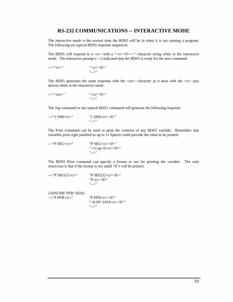
19
RS-232 COMMUNICATIONS -- INTERACTIVE MODE
The interactive mode is the normal state the BDS5 will be in when it is not running a program.The following are typical BDS5 response sequences.
The BDS5 will respond to a <cr> with a "<cr><lf>-->" character string while in the interactivemode. The interactive prompt (-->) indicated that the BDS5 is ready for the next command.
-->"<cr>" "<cr><lf>""-->"
The BDS5 generates the same response with the <esc> character as it does with the <cr> (seeabove) while in the interactive mode.
-->"<esc>" "<cr><lf>""-->"
The Jog command or any typical BDS5 command will generate the following response:
-->"J 1000<cr>" "J 1000<cr><lf>""-->"
The Print command can be used to print the contents of any BDS5 variable. Remember thatvariables print right justified so up to 11 Spaces could precede the value to be printed.
-->"P SEG<cr>" "P SEG<cr><lf>""<11-sp>0<cr><lf>""-->"
The BDS5 Print command can specify a format to use for printing the variable. The onlyrestriction is that if the format is too small "X"s will be printed.
-->"P SEG[1]<cr>" "P SEG[1]<cr><lf>""0<cr><lf>""-->"
{ASSUME PFB=1024}-->"P PFB<cr>" "P PFB<cr><lf>"
"<8-SP>1024<cr><lf>""-->"
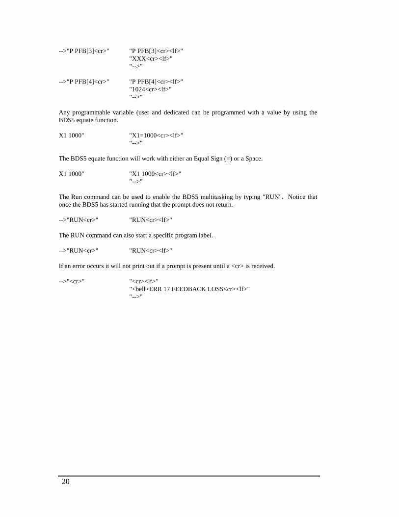
20
-->"P PFB[3]<cr>" "P PFB[3]<cr><lf>""XXX<cr><lf>""-->"
-->"P PFB[4]<cr>" "P PFB[4]<cr><lf>""1024<cr><lf>""-->"
Any programmable variable (user and dedicated can be programmed with a value by using theBDS5 equate function.
X1 1000" "X1=1000<cr><lf>""-->"
The BDS5 equate function will work with either an Equal Sign (=) or a Space.
X1 1000" "X1 1000<cr><lf>""-->"
The Run command can be used to enable the BDS5 multitasking by typing "RUN". Notice thatonce the BDS5 has started running that the prompt does not return.
-->"RUN<cr>" "RUN<cr><lf>"
The RUN command can also start a specific program label.
-->"RUN<cr>" "RUN<cr><lf>"
If an error occurs it will not print out if a prompt is present until a <cr> is received.
-->"<cr>" "<cr><lf>""<bell>ERR 17 FEEDBACK LOSS<cr><lf>""-->"
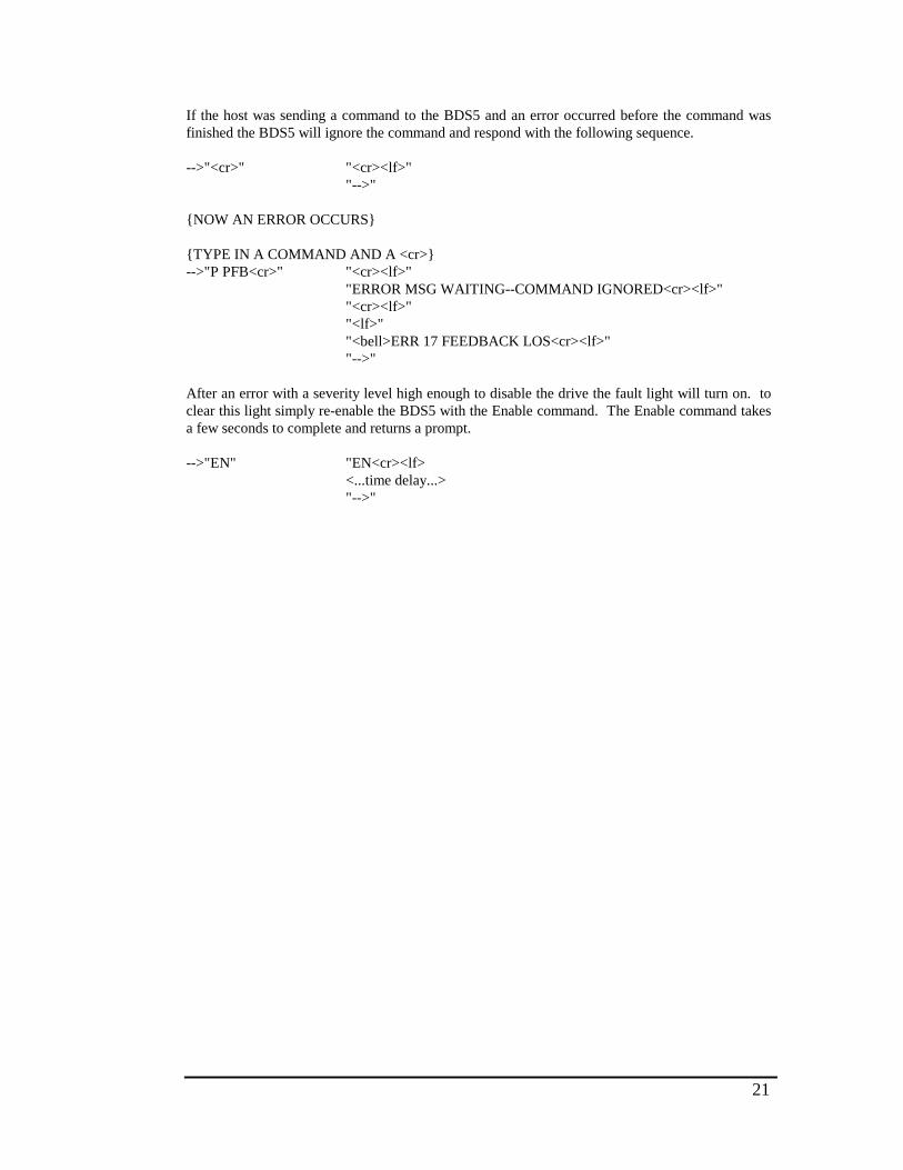
21
If the host was sending a command to the BDS5 and an error occurred before the command wasfinished the BDS5 will ignore the command and respond with the following sequence.
-->"<cr>" "<cr><lf>""-->"
{NOW AN ERROR OCCURS}
{TYPE IN A COMMAND AND A <cr>}-->"P PFB<cr>" "<cr><lf>"
"ERROR MSG WAITING--COMMAND IGNORED<cr><lf>""<cr><lf>""<lf>""<bell>ERR 17 FEEDBACK LOS<cr><lf>""-->"
After an error with a severity level high enough to disable the drive the fault light will turn on. toclear this light simply re-enable the BDS5 with the Enable command. The Enable command takesa few seconds to complete and returns a prompt.
-->"EN" "EN<cr><lf><...time delay...>"-->"
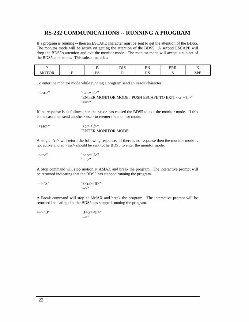
22
RS-232 COMMUNICATIONS -- RUNNING A PROGRAM
If a program is running -- then an ESCAPE character must be sent to get the attention of the BDS5.The monitor mode will be active on getting the attention of the BDS5. A second ESCAPE willdrop the BDS5's attention and exit the monitor mode. The monitor mode will accept a sub-set ofthe BDS5 commands. This subset includes:
? ; B DIS EN ERR KMOTOR P PS R RS S ZPE
To enter the monitor mode while running a program send an <esc> character.
"<esc>" "<cr><lf>""ENTER MONITOR MODE. PUSH ESCAPE TO EXIT <cr><lf>""==>"
If the response is as follows then the <esc> has caused the BDS5 to exit the monitor mode. If thisis the case then send another <esc> to reenter the monitor mode.
"<esc>" "<cr><lf>""ENTER MONITOR MODE.
A single <cr> will return the following response. If there is no response then the monitor mode isnot active and an <esc> should be sent tot he BDS5 to enter the monitor mode.
"<cr>" "<cr><lf>""==>"
A Stop command will stop motion at AMAX and break the program. The interactive prompt willbe returned indicating that the BDS5 has stopped running the program.
==>"S" "S<cr><lf>""-->"
A Break command will stop at AMAX and break the program. The interactive prompt will bereturned indicating that the BDS5 has stopped running the program.
==>"B" "B<cr><lf>""-->"

23
A Kill command will disable the motor and break the program. The interactive prompt will bereturned indicating that the BDS5 has stopped running the program.
==>"K" "K<cr><lf>""-->"
Sending a command not allowed in the monitor mode will return the following response.
==>"J 1000 <cr> "J 1000<cr><lf>""<cr><lf>""<lf>""<bell>ERR 63 'J 1000'<22-sp>NOT AT THIS LEVEL<cr><lf>""==>"
==>"P SEG[1]"<cr> "P SEG[1]<cr><lf>""0<cr><lf>""==>"
{ASSUME PFB=1024}==>"P PFB<cr>" "P PFB<cr><lf>"
"<8-sp>1024<cr><lf>""==>"
==>"P PFB[4]<cr>" "P PFB[4]<cr><lf>""1024<cr><lf>""==>"
==>"P PFB[5]" "P PFB[5]<cr><lf>""<sp>1024<cr><lf>""==>"
==>"P PFB[3]" "P PFB[3]<cr><lf>""XXX<cr><lf>""==>"
{THE XXX MEANS THAT PFB WAS TOO BIG TO FIT INTO 3 SPACES}
==>"X1=1000" "X1=1000<cr><lf>"==>
{THIS SETS VARIABLE X1 TO 1000}
==>"X1.1000" "X1.1000<cr><lf>"==>
{THIS SETS VARIABLE X1 TO 1000}
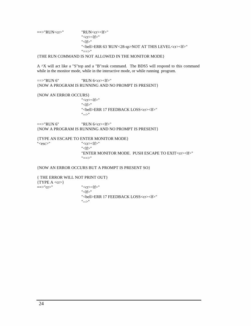
24
==>"RUN<cr>" "RUN<cr><lf>""<cr><lf>""<lf>""<bell>ERR 63 'RUN'<28-sp>NOT AT THIS LEVEL<cr><lf>""==>"
{THE RUN COMMAND IS NOT ALLOWED IN THE MONITOR MODE}
A ^X will act like a "S"top and a "B"reak command. The BDS5 will respond to this commandwhile in the monitor mode, while in the interactive mode, or while running program.
==>"RUN 6" "RUN 6<cr><lf>"{NOW A PROGRAM IS RUNNING AND NO PROMPT IS PRESENT}
{NOW AN ERROR OCCURS}"<cr><lf>""<lf>""<bell>ERR 17 FEEDBACK LOSS<cr><lf>""-->"
==>"RUN 6" "RUN 6<cr><lf>"{NOW A PROGRAM IS RUNNING AND NO PROMPT IS PRESENT}
{TYPE AN ESCAPE TO ENTER MONITOR MODE}"<esc>" "<cr><lf>"
"<lf>""ENTER MONITOR MODE. PUSH ESCAPE TO EXIT<cr><lf>""==>"
{NOW AN ERROR OCCURS BUT A PROMPT IS PRESENT SO}
{ THE ERROR WILL NOT PRINT OUT}{TYPE A <cr>}==>"cr>" "<cr><lf>"
"<lf>""<bell>ERR 17 FEEDBACK LOSS<cr><lf>""-->"

25
==>"RUN 6" "RUN 6<cr><lf>"{NOW A PROGRAM IS RUNNING AND NO PROMPT IS PRESENT}
{TYPE AN ESCAPE TO ENTER MONITOR MODE}"<esc>" "<cr><lf>"
"<lf>""ENTER MONITOR MODE. PUSH ESCAPE TO EXIT<cr><lf>""==>"
{NOW AN ERROR OCCURS BUT A PROMPT IS PRESENT}{SO THE ERROR WILL NOT PRINT OUT}
{TYPE IN A COMMAND AND A <cr>}==>"P PFB<cr>" "<cr><lf>"
"ERROR MSG WAITING--COMMAND IGNORED<cr><lf>""<cr><lf>""<lf>""<bell>ERR 17 FEEDBACK LOSS<cr><lf>""-->"
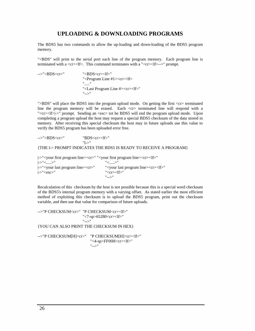
26
UPLOADING & DOWNLOADING PROGRAMS
The BDS5 has two commands to allow the up-loading and down-loading of the BDS5 programmemory.
"<BDS" will print to the serial port each line of the program memory. Each program line isterminated with a <cr><lf>. This command terminates with a "<cr><lf>-->" prompt.
-->"<BDS<cr>" "<BDS<cr><lf>""<Program Line #1><cr><lf>".....""<Last Program Line #><cr><lf>""-->"
">BDS" will place the BDS5 into the program upload mode. On getting the first <cr> terminatedline the program memory will be erased. Each <cr> terminated line will respond with a"<cr><lf>|->" prompt. Sending an <esc> tot he BDS5 will end the program upload mode. Uponcompleting a program upload the host may request a special BDS5 checksum of the data stored inmemory. After receiving this special checksum the host may in future uploads use this value toverify the BDS5 program has been uploaded error free.
-->">BDS<cr>" "BDS<cr><lf>""l->"
{THE l-> PROMPT INDICATES THE BDS5 IS READY TO RECEIVE A PROGRAM}
|->"<your first program line><cr>" "<your first program line><cr><lf>"|->"<.....>" "<.....>"|->"<your last program line><cr>" "<your last program line><cr><lf>"|->"<esc>" "<cr><lf>"
"-->"
Recalculation of this checksum by the host is not possible because this is a special word checksumof the BDS5's internal program memory with a varying offset. As stated earlier the most efficientmethod of exploiting this checksum is to upload the BDS5 program, print out the checksumvariable, and then use that value for comparison of future uploads.
-->"P CHECKSUM<cr>" "P CHECKSUM<cr><lf>""<7-sp>65280<cr><lf>""-->"
{YOU CAN ALSO PRINT THE CHECKSUM IN HEX}
-->"P CHECKSUM[H]<cr>" "P CHECKSUM[H]<cr><lf>""<4-sp>FF00H<cr><lf>""-->"
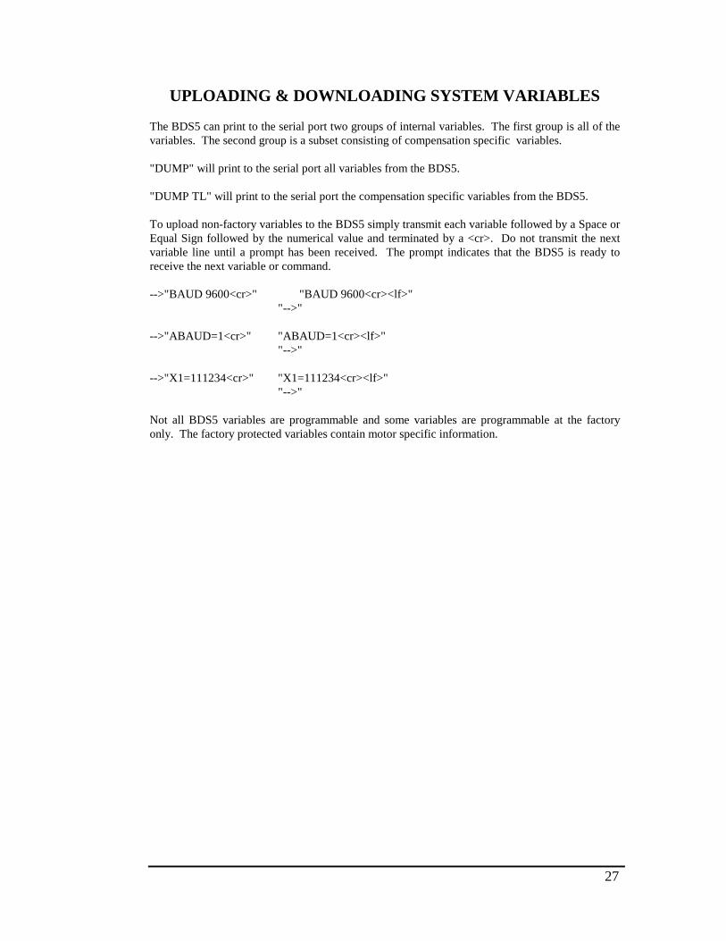
27
UPLOADING & DOWNLOADING SYSTEM VARIABLES
The BDS5 can print to the serial port two groups of internal variables. The first group is all of thevariables. The second group is a subset consisting of compensation specific variables.
"DUMP" will print to the serial port all variables from the BDS5.
"DUMP TL" will print to the serial port the compensation specific variables from the BDS5.
To upload non-factory variables to the BDS5 simply transmit each variable followed by a Space orEqual Sign followed by the numerical value and terminated by a <cr>. Do not transmit the nextvariable line until a prompt has been received. The prompt indicates that the BDS5 is ready toreceive the next variable or command.
-->"BAUD 9600<cr>" "BAUD 9600<cr><lf>""-->"
-->"ABAUD=1<cr>" "ABAUD=1<cr><lf>""-->"
-->"X1=111234<cr>" "X1=111234<cr><lf>""-->"
Not all BDS5 variables are programmable and some variables are programmable at the factoryonly. The factory protected variables contain motor specific information.

28
MULTIDROP COMMUNICATIONS
Multidrop communications will allow you to have up to 32 axes on serial communications line.Each axis must have an unique address. The valid addresses are "0"-"9" and "A"-"Z". The AxisAttention Character is a Backslash "\". The Backslash when followed by a valid Axis ID will wakeup the addressed axis. "\*" is a special Axis Broadcast All command that will wake-up all the axesto respond to any transmitter command but no axis may transmit. The BDS5 prompts are slightlydifferent from the standard RS-232 prompts. The Multidrop prompts always print the Axis ID astheir first character. The normal first character is then slid over to the second position in theprompt. The prompt terminates with a ">".
BDS5 MULTIDROP PROMPTSASSUME: ADDR=65 AXIS I.D.=”A”
PROMPT DEFINITIONA-> INTERACTIVE MODEA=> MONITOR MODEAs> SINGLE STEP MODEAt. TRACE MODEAl> PROGRAM UPLOADAe> INTERNAL EDITORAi> EDITOR INPUTAf> EDITOR FINDAc> EDITOR CHANGE
All handshaking will be identical to the above examples except the prompts will change as shownin the above chart.
{WAKE UP AN AXIS "A" (ADDR=65)}
"\A<cr>" "<cr><lf>""A->"
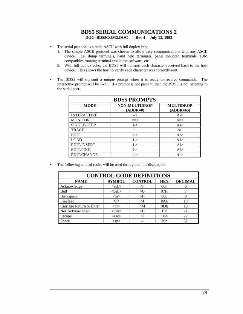
29
BDS5 SERIAL COMMUNICATIONS 2DOC=BDS5COM2.DOC Rev 4 July 13, 1993
• The serial protocol is simple ASCII with full duplex echo.1. The simple ASCII protocol was chosen to allow easy communications with any ASCII
device. I.e. dump terminals, hand held terminals, panel mounted terminals, IBMcompatibles running terminal emulation software, etc.
2. With full duplex echo, the BDS5 will transmit each character received back to the hostdevice. This allows the host to verify each character was correctly sent.
• The BDS5 will transmit a unique prompt when it is ready to receive commands. Theinteractive prompt will be "-->". If a prompt is not present, then the BDS5 is not listening tothe serial port.
BDS5 PROMPTSMODE NON-MULTIDROP
(ADDR=0)MULTIDROP
(ADDR=65)INTERACTIVE --> A->MONITOR ==> A=>SINGLE-STEP s-> As>TRACE t.. At.EDIT e-> Ae>LOAD 1-> A1>EDIT/INSERT i-> Ai>EDIT/FIND f-> Af>EDIT/CHANGE c-> Ac>
• The following control codes will be used throughout this discussion:
CONTROL CODE DEFINITIONSNAME SYMBOL CONTROL HEX DECIMAL
Acknowledge <ack> ^F 06h 6Bell <bell> ^G 07H 7Backspace <bs> ^H 08h 8Linefeed <lf> ^J 0Ah 10Carriage Return or Enter <cr> ^M 0Dh 13Not Acknowledge <nak> ^U 15h 21Escape <esc> ^[ 1Bh 27Space <sp> -- 20h 32
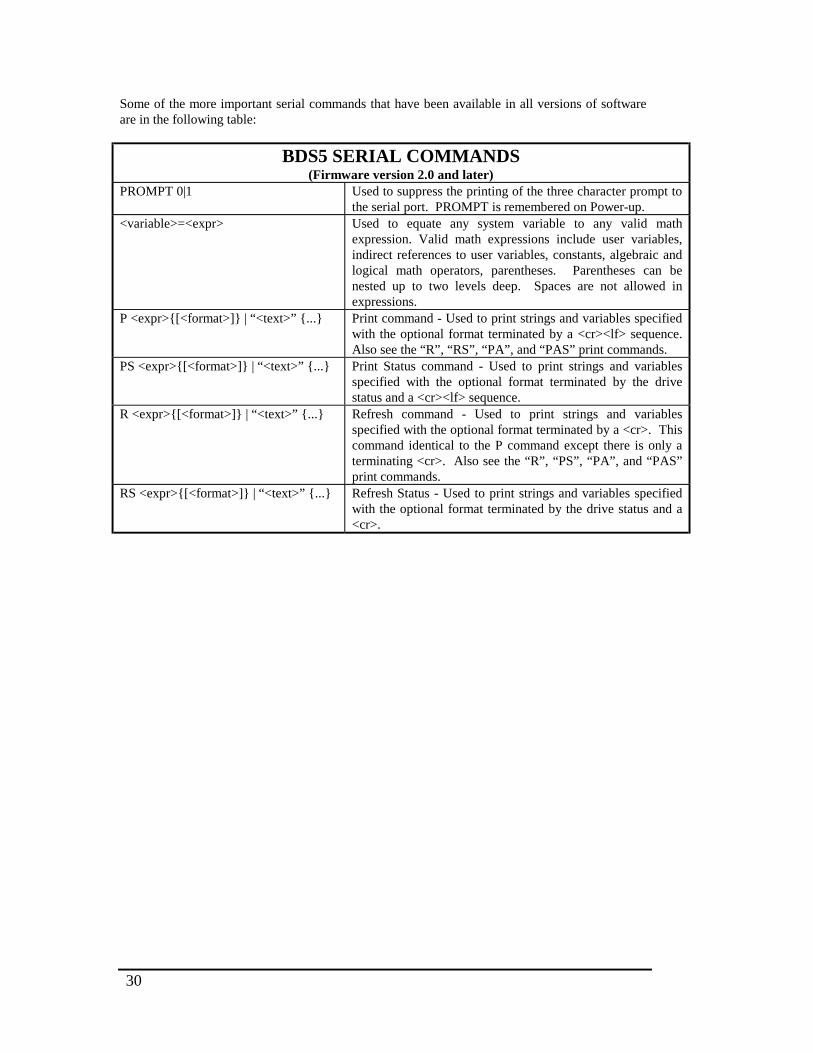
30
Some of the more important serial commands that have been available in all versions of softwareare in the following table:
BDS5 SERIAL COMMANDS(Firmware version 2.0 and later)
PROMPT 0|1 Used to suppress the printing of the three character prompt tothe serial port. PROMPT is remembered on Power-up.
<variable>=<expr> Used to equate any system variable to any valid mathexpression. Valid math expressions include user variables,indirect references to user variables, constants, algebraic andlogical math operators, parentheses. Parentheses can benested up to two levels deep. Spaces are not allowed inexpressions.
P <expr>{[<format>]} | “<text>” {...} Print command - Used to print strings and variables specifiedwith the optional format terminated by a <cr><lf> sequence.Also see the “R”, “RS”, “PA”, and “PAS” print commands.
PS <expr>{[<format>]} | “<text>” {...} Print Status command - Used to print strings and variablesspecified with the optional format terminated by the drivestatus and a <cr><lf> sequence.
R <expr>{[<format>]} | “<text>” {...} Refresh command - Used to print strings and variablesspecified with the optional format terminated by a <cr>. Thiscommand identical to the P command except there is only aterminating <cr>. Also see the “R”, “PS”, “PA”, and “PAS”print commands.
RS <expr>{[<format>]} | “<text>” {...} Refresh Status - Used to print strings and variables specifiedwith the optional format terminated by the drive status and a<cr>.
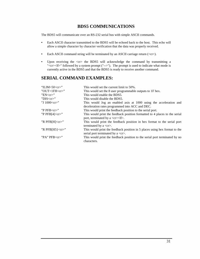
31
BDS5 COMMUNICATIONS
The BDS5 will communicate over an RS-232 serial bus with simple ASCII commands.
• Each ASCII character transmitted to the BDS5 will be echoed back to the host. This echo willallow a simple character by character verification that the data was properly received.
• Each ASCII command string will be terminated by an ASCII carriage return (<cr>).
• Upon receiving the <cr> the BDS5 will acknowledge the command by transmitting a"<cr><lf>" followed by a system prompt ("-->"). The prompt is used to indicate what mode iscurrently active in the BDS5 and that the BDS5 is ready to receive another command.
SERIAL COMMAND EXAMPLES:
“ILIM=50<cr>” This would set the current limit to 50%.”OUT=1FH<cr>” This would set the 8 user programmable outputs to 1F hex.”EN<cr>” This would enable the BDS5.”DIS<cr>” This would disable the BDS5.”J 1000<cr>” This would Jog an enabled axis at 1000 using the acceleration and
deceleration rates programmed into ACC and DEC.”P PFB<cr>” This would print the feedback position to the serial port.”P PFB[4]<cr>” This would print the feedback position formatted to 4 places to the serial
port, terminated by a <cr><lf>.”R PFB[H]<cr>” This would print the feedback position in hex format to the serial port
terminated by a <cr>.”R PFB[H5}<cr>” This would print the feedback position in 5 places using hex format to the
serial port terminated by a <cr>.”PA” PFB<cr>” This would print the feedback position to the serial port terminated by no
characters.
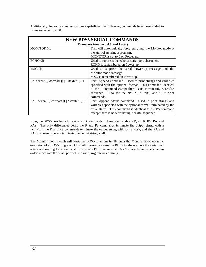
32
Additionally, for more communications capabilities, the following commands have been added tofirmware version 3.0.0:
NEW BDS5 SERIAL COMMANDS(Firmware Version 3.0.0 and Later)
MONITOR 0|1 This will automatically force entry into the Monitor mode atthe start of running a program.MONITOR is set to 0 on Power-up.
ECHO 0|1 Used to suppress the echo of serial port characters.ECHO is remembered on Power-up.
MSG 0|1 Used to suppress the serial Power-up message and theMonitor mode message.MSG is remembered on Power-up.
PA <expr>{[<format>]} | “<text>” {...} Print Append command - Used to print strings and variablesspecified with the optional format. This command identicalto the P command except there is no terminating <cr><lf>sequence. Also see the “P”, “PS”, “R”, and “RS” printcommands.
PAS <expr>{[<format>]} | “<text>” {...} Print Append Status command - Used to print strings andvariables specified with the optional format terminated by thedrive status. This command is identical to the PS commandexcept there is no terminating <cr<lf> sequence.
Note, the BDS5 now has a full set of Print commands. These commands are P, PS, R, RS, PA, andPAS. The only differences being the P and PS commands terminate the output string with a<cr><lf>, the R and RS commands terminate the output string with just a <cr>, and the PA andPAS commands do not terminate the output string at all.
The Monitor mode switch will cause the BDS5 to automatically enter the Monitor mode upon theexecution of a BDS5 program. This will in essence cause the BDS5 to always have the serial portactive and waiting for a command. Previously BDS5 required an <esc> character to be received inorder to activate the serial port while a user program was running.
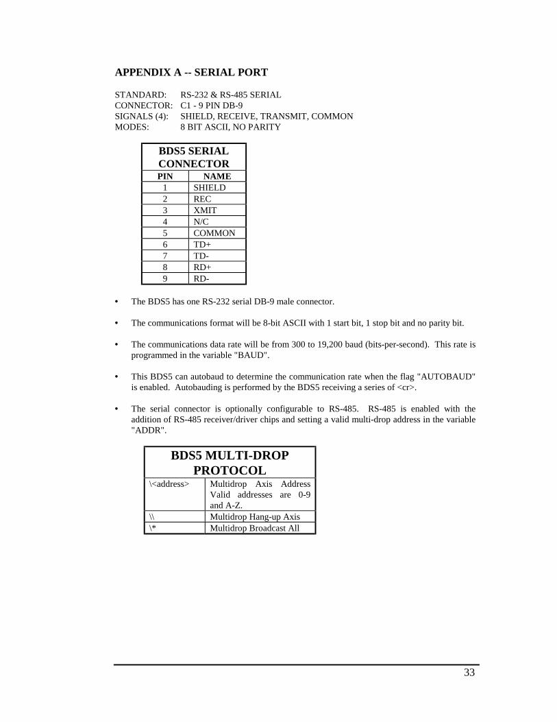
33
APPENDIX A -- SERIAL PORT
STANDARD: RS-232 & RS-485 SERIALCONNECTOR: C1 - 9 PIN DB-9SIGNALS (4): SHIELD, RECEIVE, TRANSMIT, COMMONMODES: 8 BIT ASCII, NO PARITY
BDS5 SERIALCONNECTORPIN NAME
1 SHIELD2 REC3 XMIT4 N/C5 COMMON6 TD+7 TD-8 RD+9 RD-
• The BDS5 has one RS-232 serial DB-9 male connector.
• The communications format will be 8-bit ASCII with 1 start bit, 1 stop bit and no parity bit.
• The communications data rate will be from 300 to 19,200 baud (bits-per-second). This rate isprogrammed in the variable "BAUD".
• This BDS5 can autobaud to determine the communication rate when the flag "AUTOBAUD"is enabled. Autobauding is performed by the BDS5 receiving a series of <cr>.
• The serial connector is optionally configurable to RS-485. RS-485 is enabled with theaddition of RS-485 receiver/driver chips and setting a valid multi-drop address in the variable"ADDR".
BDS5 MULTI-DROPPROTOCOL
\<address> Multidrop Axis AddressValid addresses are 0-9and A-Z.
\\ Multidrop Hang-up Axis\* Multidrop Broadcast All
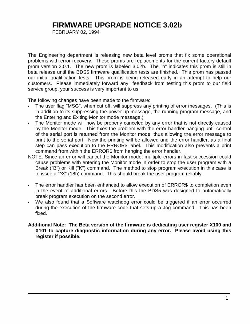
1
FIRMWARE UPGRADE NOTICE 3.02bFEBRUARY 02, 1994
The Engineering department is releasing new beta level proms that fix some operationalproblems with error recovery. These proms are replacements for the current factory defaultprom version 3.0.1. The new prom is labeled 3.02b. The "b" indicates this prom is still inbeta release until the BDS5 firmware qualification tests are finished. This prom has passedour initial qualification tests. This prom is being released early in an attempt to help ourcustomers. Please immediately forward any feedback from testing this prom to our fieldservice group, your success is very important to us.
The following changes have been made to the firmware:• The user flag "MSG", when cut off, will suppress any printing of error messages. (This is
in addition to its suppressing the power-up message, the running program message, andthe Entering and Exiting Monitor mode message.)
• The Monitor mode will now be properly canceled by any error that is not directly causedby the Monitor mode. This fixes the problem with the error handler hanging until controlof the serial port is returned from the Monitor mode, thus allowing the error message toprint to the serial port. Now the printing will be allowed and the error handler, as a finalstep can pass execution to the ERROR$ label. This modification also prevents a printcommand from within the ERROR$ from hanging the error handler.
NOTE: Since an error will cancel the Monitor mode, multiple errors in fast succession couldcause problems with entering the Monitor mode in order to stop the user program with aBreak ("B") or Kill ("K") command. The method to stop program execution in this case isto issue a "^X" (18h) command. This should break the user program reliably.
• The error handler has been enhanced to allow execution of ERROR$ to completion evenin the event of additional errors. Before this the BDS5 was designed to automaticallybreak program execution on the second error.
• We also found that a Software watchdog error could be triggered if an error occurredduring the execution of the firmware code that sets up a Jog command. This has beenfixed.
Additional Note: The Beta version of the firmware is dedicating user register X100 andX101 to capture diagnostic information during any error. Please avoid using thisregister if possible.
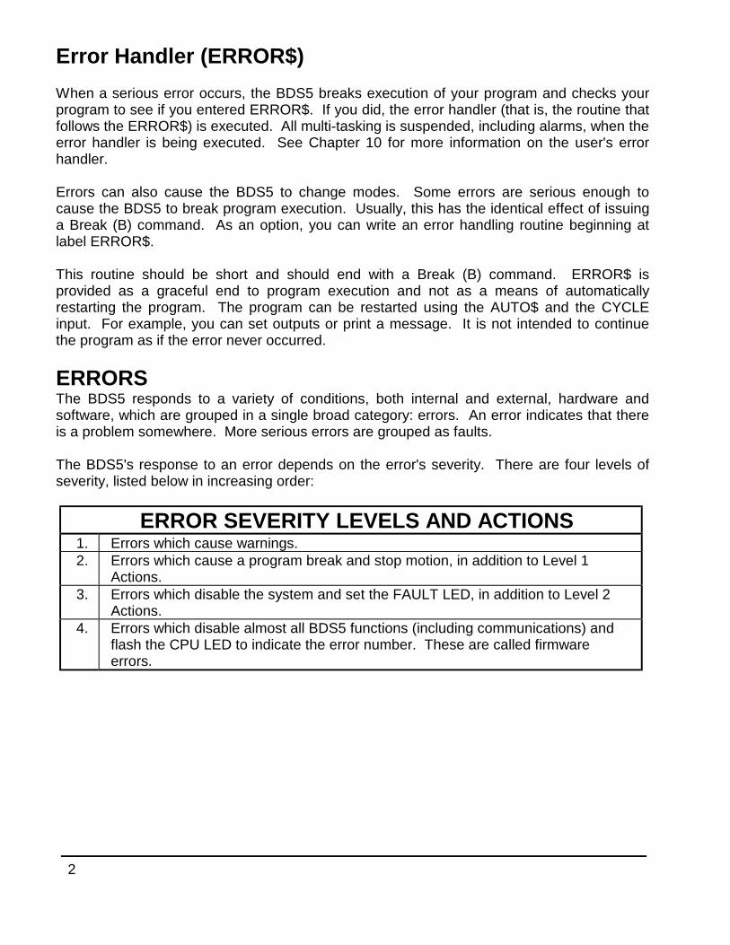
2
Error Handler (ERROR$)
When a serious error occurs, the BDS5 breaks execution of your program and checks yourprogram to see if you entered ERROR$. If you did, the error handler (that is, the routine thatfollows the ERROR$) is executed. All multi-tasking is suspended, including alarms, when theerror handler is being executed. See Chapter 10 for more information on the user's errorhandler.
Errors can also cause the BDS5 to change modes. Some errors are serious enough tocause the BDS5 to break program execution. Usually, this has the identical effect of issuinga Break (B) command. As an option, you can write an error handling routine beginning atlabel ERROR$.
This routine should be short and should end with a Break (B) command. ERROR$ isprovided as a graceful end to program execution and not as a means of automaticallyrestarting the program. The program can be restarted using the AUTO$ and the CYCLEinput. For example, you can set outputs or print a message. It is not intended to continuethe program as if the error never occurred.
ERRORSThe BDS5 responds to a variety of conditions, both internal and external, hardware andsoftware, which are grouped in a single broad category: errors. An error indicates that thereis a problem somewhere. More serious errors are grouped as faults.
The BDS5's response to an error depends on the error's severity. There are four levels ofseverity, listed below in increasing order:
ERROR SEVERITY LEVELS AND ACTIONS1. Errors which cause warnings.2. Errors which cause a program break and stop motion, in addition to Level 1
Actions.3. Errors which disable the system and set the FAULT LED, in addition to Level 2
Actions.4. Errors which disable almost all BDS5 functions (including communications) and
flash the CPU LED to indicate the error number. These are called firmwareerrors.
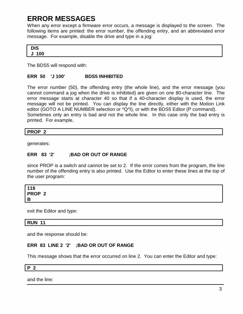
3
ERROR MESSAGESWhen any error except a firmware error occurs, a message is displayed to the screen. Thefollowing items are printed: the error number, the offending entry, and an abbreviated errormessage. For example, disable the drive and type in a jog:
DISJ 100
The BDS5 will respond with:
ERR 50 'J 100' BDS5 INHIBITED
The error number (50), the offending entry (the whole line), and the error message (youcannot command a jog when the drive is inhibited) are given on one 80-character line. Theerror message starts at character 40 so that if a 40-character display is used, the errormessage will not be printed. You can display the line directly, either with the Motion Linkeditor (GOTO A LINE NUMBER selection or ^Q^I), or with the BDS5 Editor (P command).Sometimes only an entry is bad and not the whole line. In this case only the bad entry isprinted. For example,
PROP 2
generates:
ERR 83 '2' ;BAD OR OUT OF RANGE
since PROP is a switch and cannot be set to 2. If the error comes from the program, the linenumber of the offending entry is also printed. Use the Editor to enter these lines at the top ofthe user program:
11$PROP 2B
exit the Editor and type:
RUN 11
and the response should be:
ERR 83 LINE 2 '2' ;BAD OR OUT OF RANGE
This message shows that the error occurred on line 2. You can enter the Editor and type:
P 2
and the line:
4
PROP 2
will be displayed.
DEP01If your BDS5 prints to a Data Entry Panel (DEP-01) or any other 40 character wide display,the standard error messages will not print properly. The problem is that error messages arebased on an 80 character wide display and the DEP-01 is only 40 characters wide. Tocorrect this problem, the BDS5 provides the DEP switch, which, when turned on, cuts allerror messages down to 40 characters. If your BDS5 prints to a DEP-01, type "DEP ON"
ERROR HISTORYThe BDS5 stores the twenty most recent errors in the Error History. To displaythe entire Error History, type:
ERR HIST
This causes the Error History to be sent to the terminal, with the most recent error sent first.When the BDS5 is powered up, a "DRIVE POWERED UP" message is inserted into ErrorHistory even though this is not an actual error.
To clear the Error History, type:
ERR CLR
Error History remains intact even through power-down.
DISPLAYING ERROR MESSAGESThe ERR command can also be used to display an abbreviated description of the error. Forexample, type:
ERR 50
The BDS5 responds with:
ERR 50 BDS5 INHIBITED
You may display messages for errors from 1 through 999. If you type in an error number thatthe BDS5 does not recognize, it will respond with:
ERROR NOT FOUND.A description of all errors is given in the BDS5 manual in Appendix D.
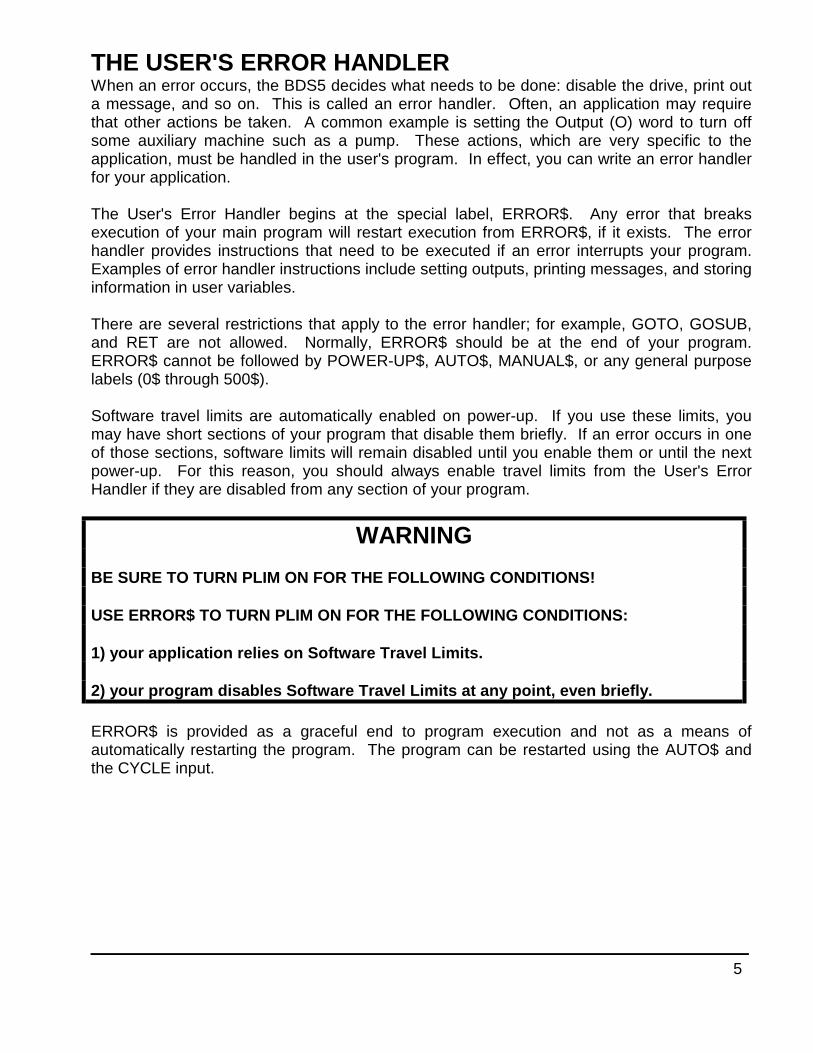
5
THE USER'S ERROR HANDLERWhen an error occurs, the BDS5 decides what needs to be done: disable the drive, print outa message, and so on. This is called an error handler. Often, an application may requirethat other actions be taken. A common example is setting the Output (O) word to turn offsome auxiliary machine such as a pump. These actions, which are very specific to theapplication, must be handled in the user's program. In effect, you can write an error handlerfor your application.
The User's Error Handler begins at the special label, ERROR$. Any error that breaksexecution of your main program will restart execution from ERROR$, if it exists. The errorhandler provides instructions that need to be executed if an error interrupts your program.Examples of error handler instructions include setting outputs, printing messages, and storinginformation in user variables.
There are several restrictions that apply to the error handler; for example, GOTO, GOSUB,and RET are not allowed. Normally, ERROR$ should be at the end of your program.ERROR$ cannot be followed by POWER-UP$, AUTO$, MANUAL$, or any general purposelabels (0$ through 500$).
Software travel limits are automatically enabled on power-up. If you use these limits, youmay have short sections of your program that disable them briefly. If an error occurs in oneof those sections, software limits will remain disabled until you enable them or until the nextpower-up. For this reason, you should always enable travel limits from the User's ErrorHandler if they are disabled from any section of your program.
WARNING
BE SURE TO TURN PLIM ON FOR THE FOLLOWING CONDITIONS!
USE ERROR$ TO TURN PLIM ON FOR THE FOLLOWING CONDITIONS:
1) your application relies on Software Travel Limits.
2) your program disables Software Travel Limits at any point, even briefly.
ERROR$ is provided as a graceful end to program execution and not as a means ofautomatically restarting the program. The program can be restarted using the AUTO$ andthe CYCLE input.
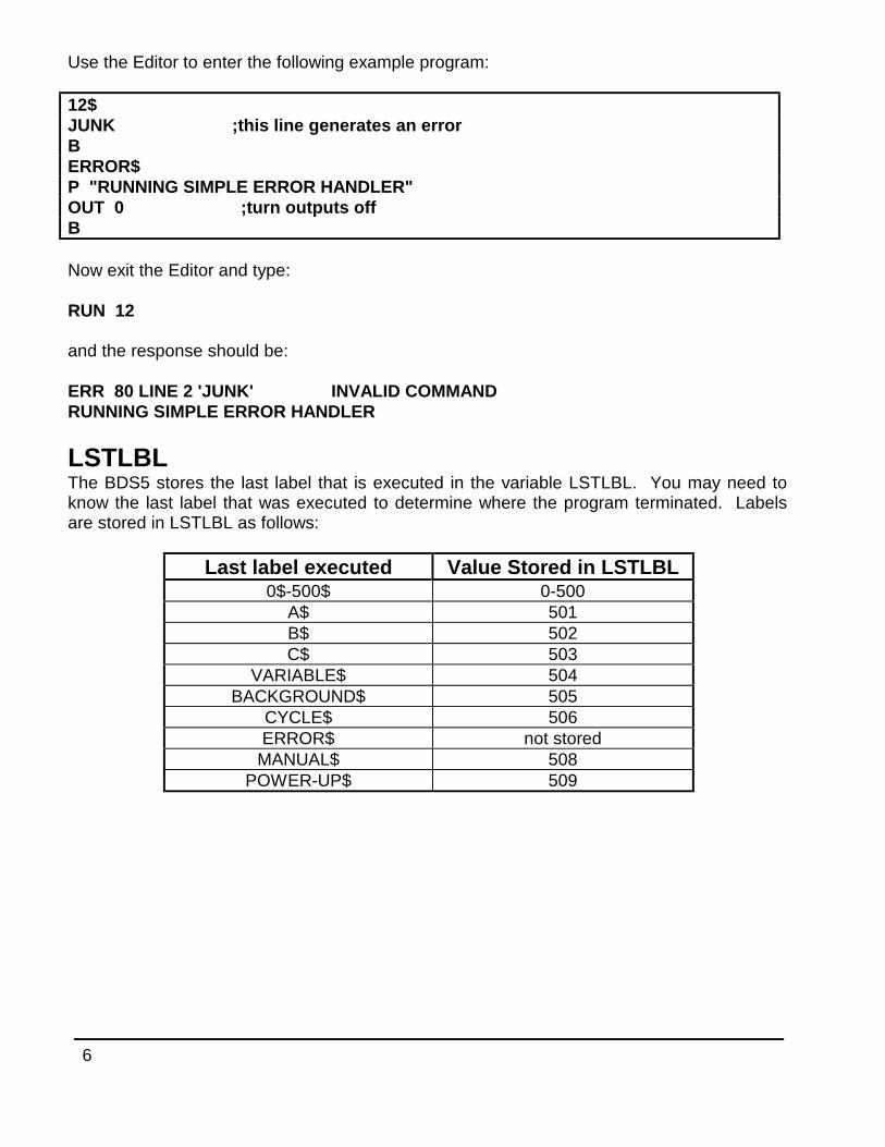
6
Use the Editor to enter the following example program:
12$JUNK ;this line generates an errorBERROR$P "RUNNING SIMPLE ERROR HANDLER"OUT 0 ;turn outputs offB
Now exit the Editor and type:
RUN 12
and the response should be:
ERR 80 LINE 2 'JUNK' INVALID COMMANDRUNNING SIMPLE ERROR HANDLER
LSTLBLThe BDS5 stores the last label that is executed in the variable LSTLBL. You may need toknow the last label that was executed to determine where the program terminated. Labelsare stored in LSTLBL as follows:
Last label executed Value Stored in LSTLBL0$-500$ 0-500
A$ 501B$ 502C$ 503
VARIABLE$ 504BACKGROUND$ 505
CYCLE$ 506ERROR$ not stored
MANUAL$ 508POWER-UP$ 509
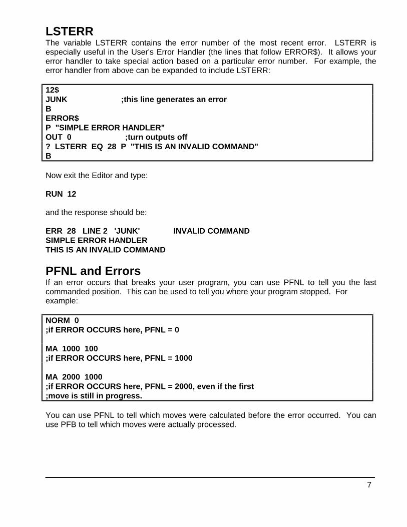
7
LSTERRThe variable LSTERR contains the error number of the most recent error. LSTERR isespecially useful in the User's Error Handler (the lines that follow ERROR$). It allows yourerror handler to take special action based on a particular error number. For example, theerror handler from above can be expanded to include LSTERR:
12$JUNK ;this line generates an errorBERROR$P "SIMPLE ERROR HANDLER"OUT 0 ;turn outputs off? LSTERR EQ 28 P "THIS IS AN INVALID COMMAND"B
Now exit the Editor and type:
RUN 12
and the response should be:
ERR 28 LINE 2 'JUNK' INVALID COMMANDSIMPLE ERROR HANDLERTHIS IS AN INVALID COMMAND
PFNL and ErrorsIf an error occurs that breaks your user program, you can use PFNL to tell you the lastcommanded position. This can be used to tell you where your program stopped. Forexample:
NORM 0;if ERROR OCCURS here, PFNL = 0
MA 1000 100;if ERROR OCCURS here, PFNL = 1000
MA 2000 1000;if ERROR OCCURS here, PFNL = 2000, even if the first;move is still in progress.
You can use PFNL to tell which moves were calculated before the error occurred. You canuse PFB to tell which moves were actually processed.

8
FIRMWARE ERRORSFirmware errors are an indication of a serious problem with the BDS5. These errors stopcommunications, disable the drive, and flash the CPU LED. The CPU LED flashes severaltimes, then turns off and pauses. The number of flashes represents the error number.These error numbers range from 2 to 5. Contact the factory should one of these errorsoccur.
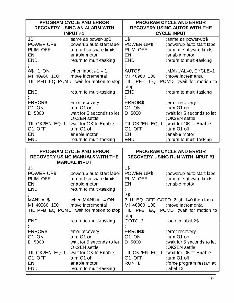
9
PROGRAM CYCLE AND ERRORRECOVERY USING AN ALARM WITH
INPUT #1
PROGRAM CYCLE AND ERRORRECOVERY USING AUTO$ WITH THE
CYCLE INPUT1$ ;same as power-up$ 1$ ;same as power-up$POWER-UP$ ;powerup auto start label POWER-UP$ ;powerup auto start labelPLIM OFF ;turn off software limits PLIM OFF ;turn off software limitsEN ;enable motor EN ;enable motorEND ;return to multi-tasking END ;return to multi-tasking; ;A$ I1 ON ;when input #1 = 1 AUTO$ ;MANUAL=0, CYCLE=1MI 40960 100 ;move incremental MI 40960 100 ;move incrementalTIL PFB EQ PCMD ;wait for motion to stop TIL PFB EQ PCMD ;wait for motion to
stopEND ;return to multi-tasking END ;return to multi-tasking; ;ERROR$ ;error recovery ERROR$ ;error recoveryO1 ON ;turn O1 on O1 ON ;turn O1 onD 5000 ;wait for 5 seconds to let
;OK2EN settleD 5000 ;wait for 5 seconds to let
;OK2EN settleTIL OK2EN EQ 1 ;wait for OK to Enable TIL OK2EN EQ 1 ;wait for OK to EnableO1 OFF ;turn O1 off O1 OFF ;turn O1 offEN ;enable motor EN ;enable motorEND ;return to multi-tasking END ;return to multi-tasking
PROGRAM CYCLE AND ERRORRECOVERY USING MANUAL$ WITH THE
MANUAL INPUT
PROGRAM CYCLE AND ERRORRECOVERY USING RUN WITH INPUT #1
1$ 1$POWER-UP$ ;powerup auto start label POWER-UP$ ;powerup auto start labelPLIM OFF ;turn off software limits PLIM OFF ;turn off software limitsEN ;enable motor EN ;enable motorEND ;return to multi-tasking ;; 2$MANUAL$ ;when MANUAL = ON ? I1 EQ OFF GOTO 2 ;if I1=0 then loopMI 40960 100 ;move incremental MI 40960 100 ;move incrementalTIL PFB EQ PCMD ;wait for motion to stop TIL PFB EQ PCMD ;wait for motion to
stopEND ;return to multi-tasking GOTO 2 ;loop to label 2$; ;ERROR$ ;error recovery ERROR$ ;error recoveryO1 ON ;turn O1 on O1 ON ;turn O1 onD 5000 ;wait for 5 seconds to let ;OK2EN settle
D 5000 ;wait for 5 seconds to let;OK2EN settle
TIL OK2EN EQ 1 ;wait for OK to Enable TIL OK2EN EQ 1 ;wait for OK to EnableO1 OFF ;turn O1 off O1 OFF ;turn O1 offEN ;enable motor RUN 1 ;force program restart atEND ;return to multi-tasking ;label 1$
1
BDS5 FIRMWARE UPGRADE NOTICEDOC=BDS5-304.DOC.R5 / FIRM-UP.DOC June 17, 1994
VERSION 3.0.4
UPGRADES
When upgrading older systems (pre version 3.0.0) with 3.0.4. Be sure to initialize the three newnon-volatile flags for proper operation:1. ECHO=12. MSG=13. EXTDX=0
CHANGES (from 3.0.3)
• Enhanced the CLEARX command to allow separate clearing of all User Registers or UserFlags or both.
Syntax: CLEARX {1|2}
Example: CLEARX - Clear both User Registers and User Flags CLEARX 1 - Clear only the User Registers CLEARX 2 - Clear only the User Flags
• Enhanced the Break (B) command to allow separate the optional breakink of a user INPUTcommand:
Syntax: B {I}
Example: B - Break the user program B I - Break a user INPUT command (if active).
The “B I” command was designed to allow the user to break any active Input command becausePrinting from all tasks are suppressed until completion of the Input command. Aditionally, anyPrint while the Input command is active will HOLD the task at the Print command until the Inputhas finished. This means that if, for example, a user needed to Print a message to the machineoperator during an Alarm condition, this would not work if an Input command was active. Now,with the “B I” command, the user can imbed the “B I” command in the program prior to any criticalPrint messages and thus cancel any active Input command.
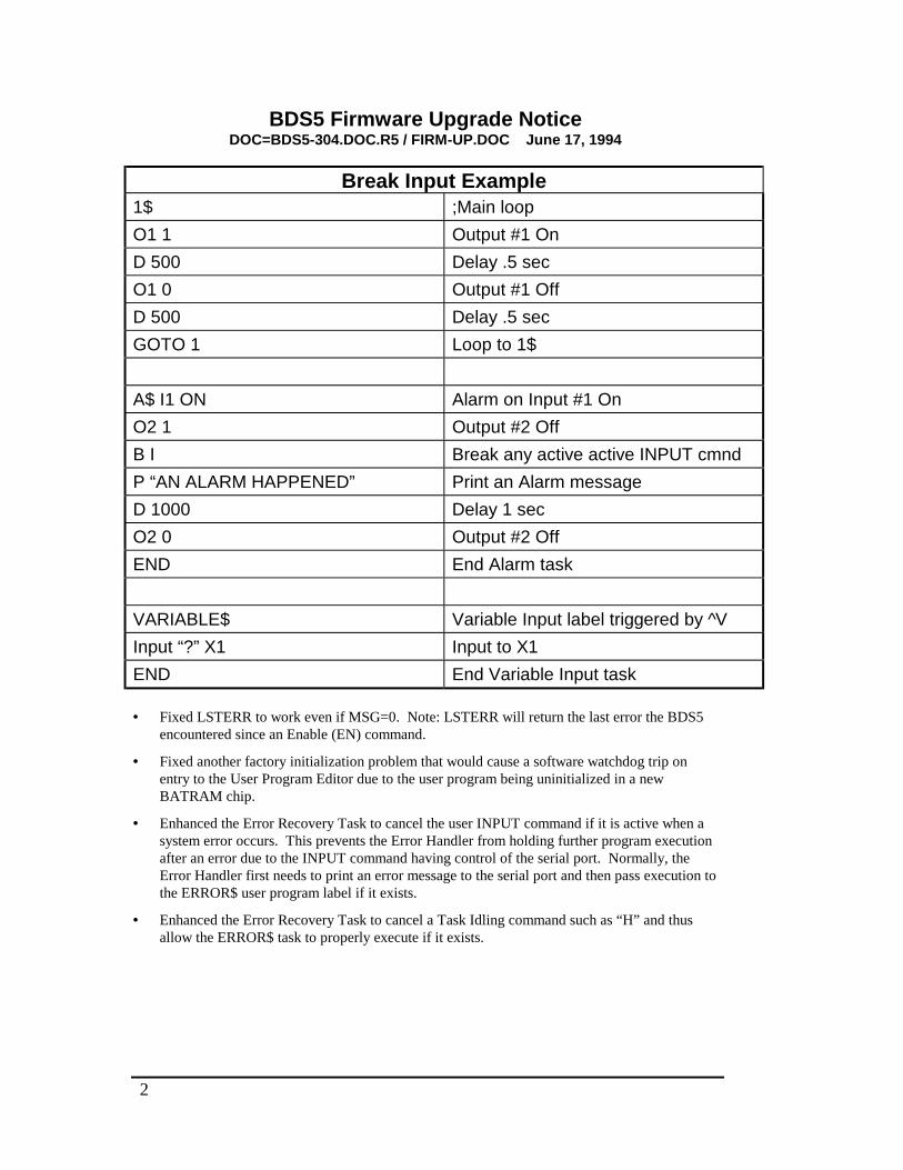
2
BDS5 Firmware Upgrade NoticeDOC=BDS5-304.DOC.R5 / FIRM-UP.DOC June 17, 1994
Break Input Example1$ ;Main loop
O1 1 Output #1 On
D 500 Delay .5 sec
O1 0 Output #1 Off
D 500 Delay .5 sec
GOTO 1 Loop to 1$
A$ I1 ON Alarm on Input #1 On
O2 1 Output #2 Off
B I Break any active active INPUT cmnd
P “AN ALARM HAPPENED” Print an Alarm message
D 1000 Delay 1 sec
O2 0 Output #2 Off
END End Alarm task
VARIABLE$ Variable Input label triggered by ^V
Input “?” X1 Input to X1
END End Variable Input task
• Fixed LSTERR to work even if MSG=0. Note: LSTERR will return the last error the BDS5encountered since an Enable (EN) command.
• Fixed another factory initialization problem that would cause a software watchdog trip onentry to the User Program Editor due to the user program being uninitialized in a newBATRAM chip.
• Enhanced the Error Recovery Task to cancel the user INPUT command if it is active when asystem error occurs. This prevents the Error Handler from holding further program executionafter an error due to the INPUT command having control of the serial port. Normally, theError Handler first needs to print an error message to the serial port and then pass execution tothe ERROR$ user program label if it exists.
• Enhanced the Error Recovery Task to cancel a Task Idling command such as “H” and thusallow the ERROR$ task to properly execute if it exists.
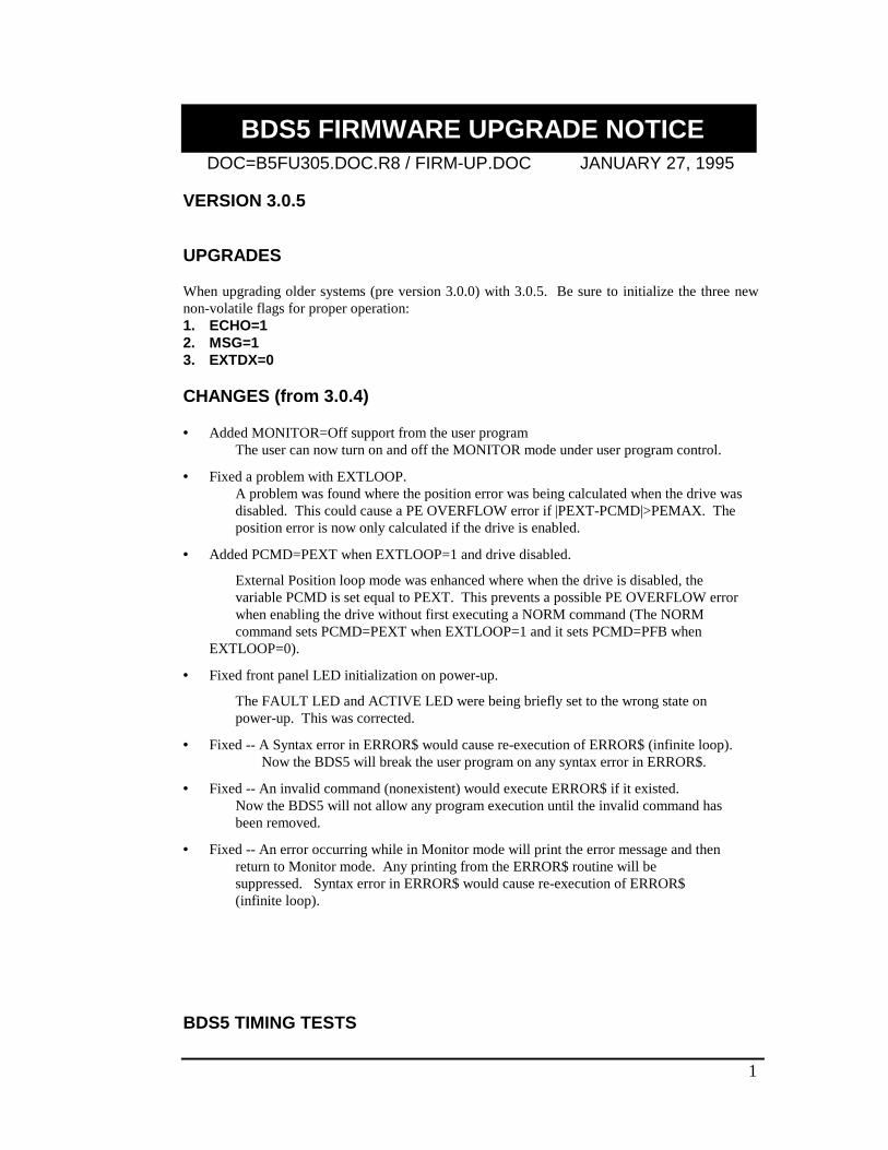
1
BDS5 FIRMWARE UPGRADE NOTICEDOC=B5FU305.DOC.R8 / FIRM-UP.DOC JANUARY 27, 1995
VERSION 3.0.5
UPGRADES
When upgrading older systems (pre version 3.0.0) with 3.0.5. Be sure to initialize the three newnon-volatile flags for proper operation:1. ECHO=12. MSG=13. EXTDX=0
CHANGES (from 3.0.4)
• Added MONITOR=Off support from the user programThe user can now turn on and off the MONITOR mode under user program control.
• Fixed a problem with EXTLOOP.A problem was found where the position error was being calculated when the drive was disabled. This could cause a PE OVERFLOW error if |PEXT-PCMD|>PEMAX. The position error is now only calculated if the drive is enabled.
• Added PCMD=PEXT when EXTLOOP=1 and drive disabled.
External Position loop mode was enhanced where when the drive is disabled, the variable PCMD is set equal to PEXT. This prevents a possible PE OVERFLOW error when enabling the drive without first executing a NORM command (The NORM command sets PCMD=PEXT when EXTLOOP=1 and it sets PCMD=PFB when
EXTLOOP=0).
• Fixed front panel LED initialization on power-up.
The FAULT LED and ACTIVE LED were being briefly set to the wrong state on power-up. This was corrected.
• Fixed -- A Syntax error in ERROR$ would cause re-execution of ERROR$ (infinite loop). Now the BDS5 will break the user program on any syntax error in ERROR$.
• Fixed -- An invalid command (nonexistent) would execute ERROR$ if it existed.Now the BDS5 will not allow any program execution until the invalid command has been removed.
• Fixed -- An error occurring while in Monitor mode will print the error message and then return to Monitor mode. Any printing from the ERROR$ routine will be suppressed. Syntax error in ERROR$ would cause re-execution of ERROR$ (infinite loop).
BDS5 TIMING TESTS
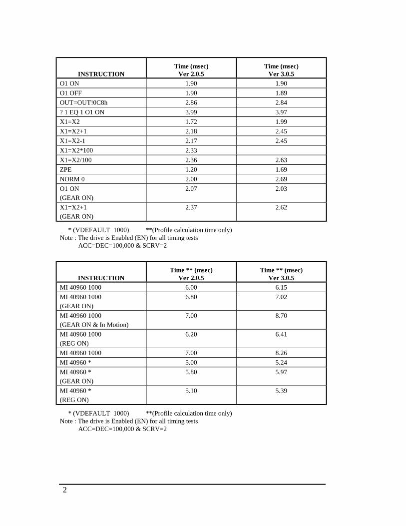
2
INSTRUCTIONTime (msec)
Ver 2.0.5Time (msec)
Ver 3.0.5
O1 ON 1.90 1.90
O1 OFF 1.90 1.89
OUT=OUT!0C8h 2.86 2.84
? 1 EQ 1 O1 ON 3.99 3.97
X1=X2 1.72 1.99
X1=X2+1 2.18 2.45
X1=X2-1 2.17 2.45
X1=X2*100 2.33
X1=X2/100 2.36 2.63
ZPE 1.20 1.69
NORM 0 2.00 2.69
O1 ON
(GEAR ON)
2.07 2.03
X1=X2+1
(GEAR ON)
2.37 2.62
* (VDEFAULT 1000) **(Profile calculation time only)Note : The drive is Enabled (EN) for all timing tests ACC=DEC=100,000 & SCRV=2
INSTRUCTIONTime ** (msec)
Ver 2.0.5Time ** (msec)
Ver 3.0.5
MI 40960 1000 6.00 6.15
MI 40960 1000
(GEAR ON)
6.80 7.02
MI 40960 1000
(GEAR ON & In Motion)
7.00 8.70
MI 40960 1000
(REG ON)
6.20 6.41
MI 40960 1000 7.00 8.26
MI 40960 * 5.00 5.24
MI 40960 *
(GEAR ON)
5.80 5.97
MI 40960 *
(REG ON)
5.10 5.39
* (VDEFAULT 1000) **(Profile calculation time only)Note : The drive is Enabled (EN) for all timing tests ACC=DEC=100,000 & SCRV=2
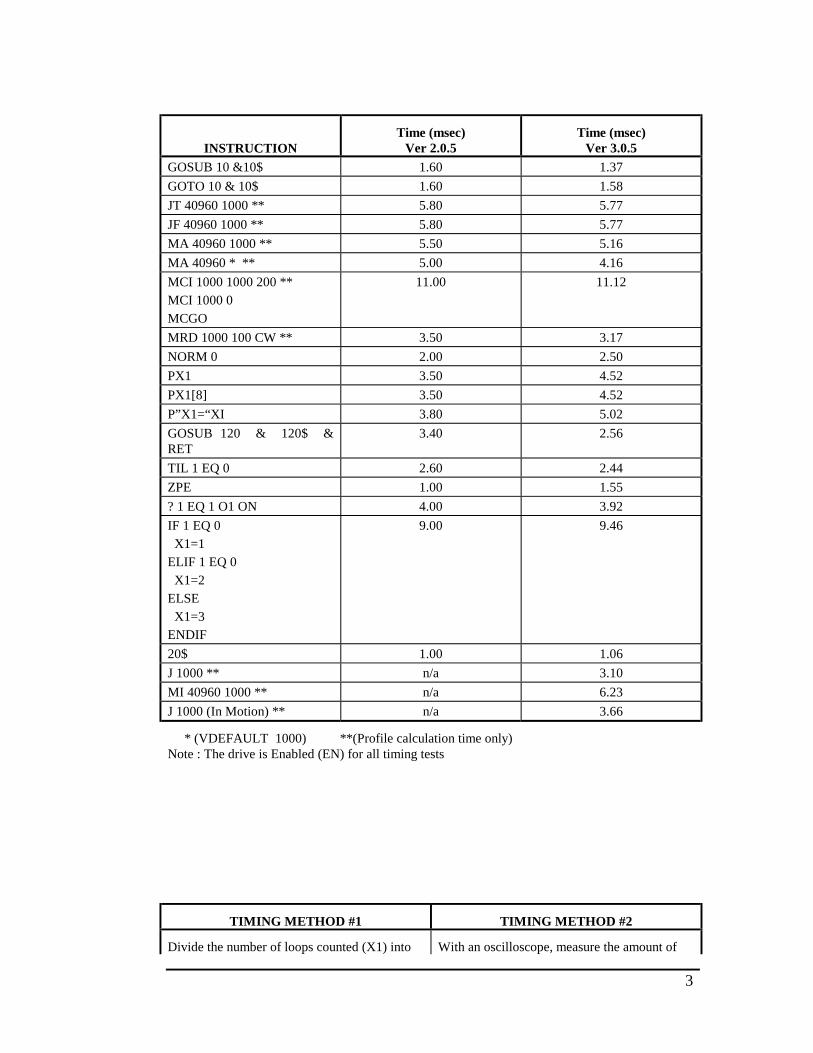
3
INSTRUCTIONTime (msec)
Ver 2.0.5Time (msec)
Ver 3.0.5
GOSUB 10 &10$ 1.60 1.37
GOTO 10 & 10$ 1.60 1.58
JT 40960 1000 ** 5.80 5.77
JF 40960 1000 ** 5.80 5.77
MA 40960 1000 ** 5.50 5.16
MA 40960 * ** 5.00 4.16
MCI 1000 1000 200 **
MCI 1000 0
MCGO
11.00 11.12
MRD 1000 100 CW ** 3.50 3.17
NORM 0 2.00 2.50
PX1 3.50 4.52
PX1[8] 3.50 4.52
P”X1=“XI 3.80 5.02
GOSUB 120 & 120$ &RET
3.40 2.56
TIL 1 EQ 0 2.60 2.44
ZPE 1.00 1.55
? 1 EQ 1 O1 ON 4.00 3.92
IF 1 EQ 0
X1=1
ELIF 1 EQ 0
X1=2
ELSE
X1=3
ENDIF
9.00 9.46
20$ 1.00 1.06
J 1000 ** n/a 3.10
MI 40960 1000 ** n/a 6.23
J 1000 (In Motion) ** n/a 3.66
* (VDEFAULT 1000) **(Profile calculation time only)Note : The drive is Enabled (EN) for all timing tests
TIMING METHOD #1 TIMING METHOD #2
Divide the number of loops counted (X1) into With an oscilloscope, measure the amount of

4
10 seconds (10 / X1) to get the single loop time.Perform this operation twice, once with the<instruction> and once without the<instruction>. Subtract the amount of time ittakes to run this program with the <instruction>from the time to run without the <instruction>.The result is the amount of time it takes toexecute the instruction.
time that Output #1 is ON while running theprogram with the <instruction> and subtractfrom this amount of time the Output #1 is ONwhile running the program without the<instruction>. The result is the amount of timeit takes to execute the instruction.
4$X1=0TMR1=100005$X1=X1+1<instruction>? TMR1 GT 0 GOTO 5B
5$PLIM 0ENO1 ON<instruction>O1 OFFW0D 1000GOTO 5
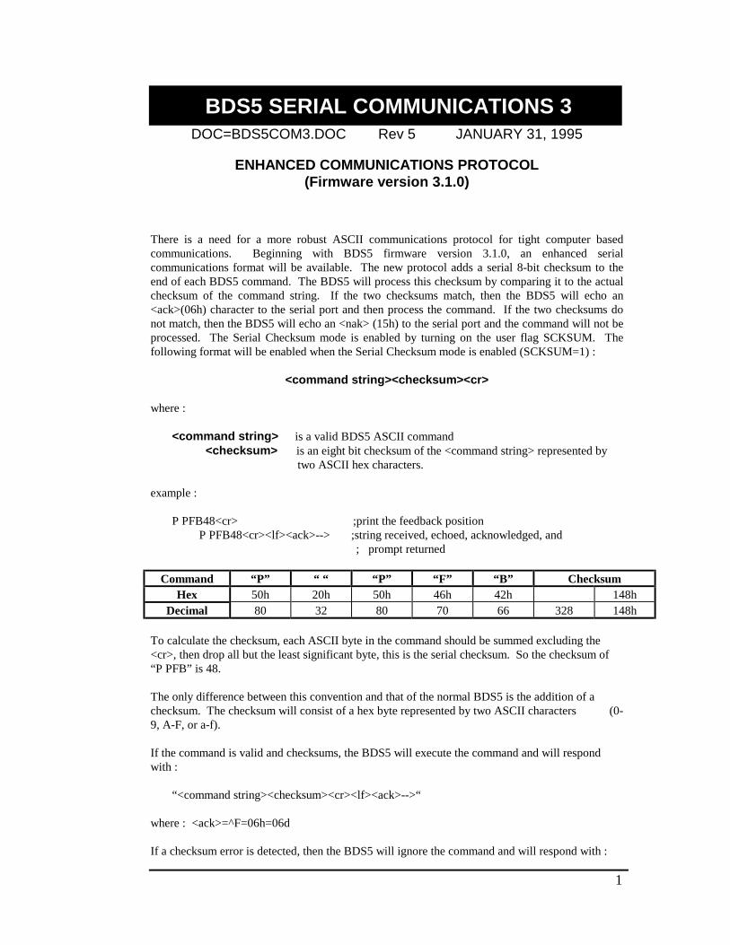
1
BDS5 SERIAL COMMUNICATIONS 3DOC=BDS5COM3.DOC Rev 5 JANUARY 31, 1995
ENHANCED COMMUNICATIONS PROTOCOL(Firmware version 3.1.0)
There is a need for a more robust ASCII communications protocol for tight computer basedcommunications. Beginning with BDS5 firmware version 3.1.0, an enhanced serialcommunications format will be available. The new protocol adds a serial 8-bit checksum to theend of each BDS5 command. The BDS5 will process this checksum by comparing it to the actualchecksum of the command string. If the two checksums match, then the BDS5 will echo an<ack>(06h) character to the serial port and then process the command. If the two checksums donot match, then the BDS5 will echo an <nak> (15h) to the serial port and the command will not beprocessed. The Serial Checksum mode is enabled by turning on the user flag SCKSUM. Thefollowing format will be enabled when the Serial Checksum mode is enabled (SCKSUM=1) :
<command string><checksum><cr>
where :
<command string> is a valid BDS5 ASCII command <checksum> is an eight bit checksum of the <command string> represented by
two ASCII hex characters.
example :
P PFB48<cr> ;print the feedback position P PFB48<cr><lf><ack>--> ;string received, echoed, acknowledged, and
; prompt returned
Command “P” “ “ “P” “F” “B” ChecksumHex 50h 20h 50h 46h 42h 148h
Decimal 80 32 80 70 66 328 148h
To calculate the checksum, each ASCII byte in the command should be summed excluding the<cr>, then drop all but the least significant byte, this is the serial checksum. So the checksum of“P PFB” is 48.
The only difference between this convention and that of the normal BDS5 is the addition of achecksum. The checksum will consist of a hex byte represented by two ASCII characters (0-9, A-F, or a-f).
If the command is valid and checksums, the BDS5 will execute the command and will respondwith :
“<command string><checksum><cr><lf><ack>-->“
where : <ack>=^F=06h=06d
If a checksum error is detected, then the BDS5 will ignore the command and will respond with :
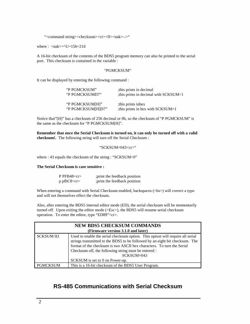
2
“<command string><checksum><cr><lf><nak>-->“
where : <nak>=^U=15h=21d
A 16-bit checksum of the contents of the BDS5 program memory can also be printed to the serialport. This checksum is contained in the variable :
“PGMCKSUM”
It can be displayed by entering the following command :
“P PGMCKSUM” ;this prints in decimal“P PGMCKSUMD7” ;this prints in decimal with SCKSUM=1
“P PGMCKSUM[H]” ;this prints inhex“P PGMCKSUM[H]D7” ;this prints in hex with SCKSUM=1
Notice that”[H]” has a checksum of 256 decimal or 0h, so the checksum of “P PGMCKSUM” isthe same as the checksum for “P PGMCKSUM[H]”.
Remember that once the Serial Checksum is turned on, it can only be turned off with a validchecksum!. The following string will turn off the Serial Checksum :
“SCKSUM=043<cr>“
where : 43 equals the checksum of the string : “SCKSUM=0”
The Serial Checksum is case sensitive :
P PFB48<cr> ;print the feedback positionp pfbC8<cr> ;print the feedback position
When entering a command with Serial Checksum enabled, backspaces (<bs>) will correct a typoand will not themselves effect the checksum.
Also, after entering the BDS5 internal editor mode (ED), the serial checksum will be momentarilyturned off. Upon exiting the editor mode (<Esc>), the BDS5 will resume serial checksumoperation. To enter the editor, type “ED89”<cr>.
NEW BDS5 CHECKSUM COMMANDS(Firmware version 3.1.0 and later)
SCKSUM 0|1 Used to enable the serial checksum option. This option will require all serialstrings transmitted to the BDS5 to be followed by an eight bit checksum. Theformat of the checksum is two ASCII hex characters. To turn the SerialChecksum off, the following string must be entered :
SCKSUM=043SCKSUM is set to 0 on Power-up.
PGMCKSUM This is a 16-bit checksum of the BDS5 User Program.
RS-485 Communications with Serial Checksum
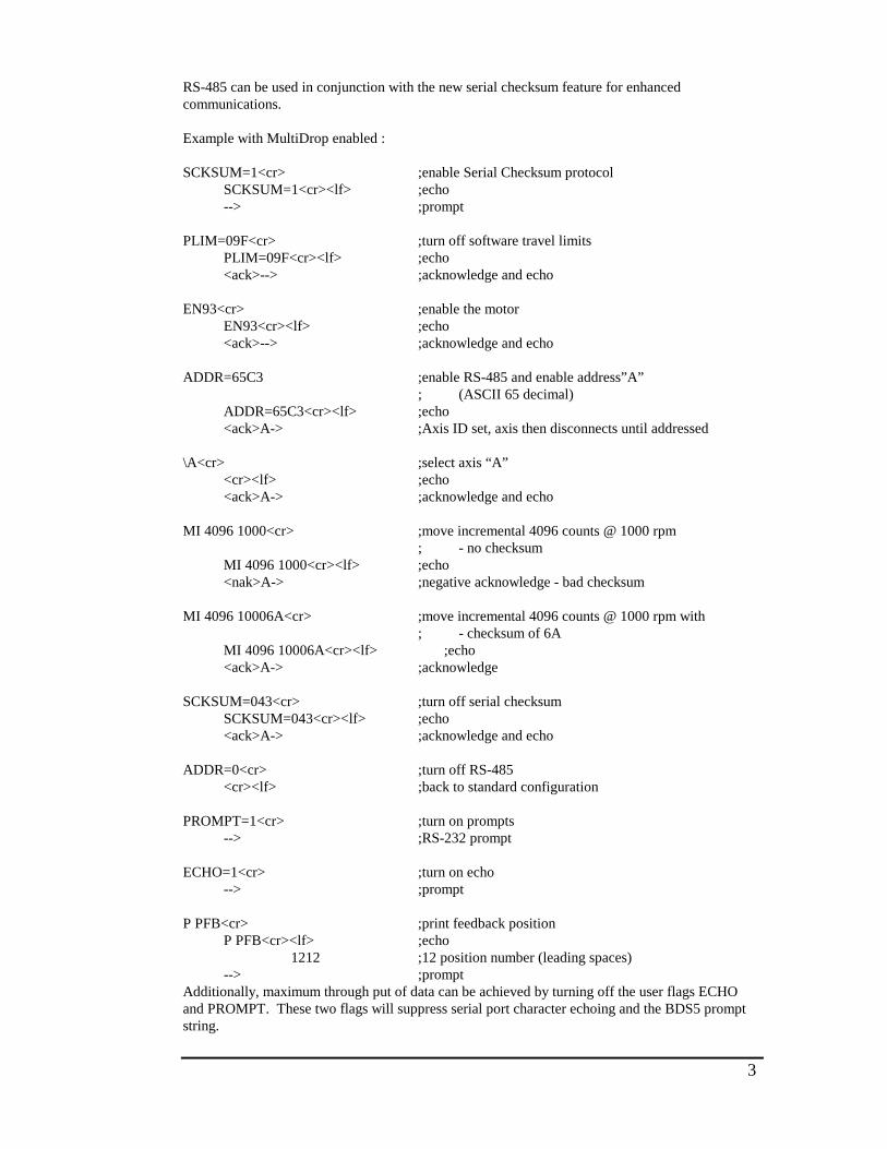
3
RS-485 can be used in conjunction with the new serial checksum feature for enhancedcommunications.
Example with MultiDrop enabled :
SCKSUM=1<cr> ;enable Serial Checksum protocol SCKSUM=1<cr><lf> ;echo --> ;prompt
PLIM=09F<cr> ;turn off software travel limits PLIM=09F<cr><lf> ;echo <ack>--> ;acknowledge and echo
EN93<cr> ;enable the motor EN93<cr><lf> ;echo <ack>--> ;acknowledge and echo
ADDR=65C3 ;enable RS-485 and enable address”A”; (ASCII 65 decimal)
ADDR=65C3<cr><lf> ;echo <ack>A-> ;Axis ID set, axis then disconnects until addressed
\A<cr> ;select axis “A” <cr><lf> ;echo <ack>A-> ;acknowledge and echo
MI 4096 1000<cr> ;move incremental 4096 counts @ 1000 rpm; - no checksum
MI 4096 1000<cr><lf> ;echo <nak>A-> ;negative acknowledge - bad checksum
MI 4096 10006A<cr> ;move incremental 4096 counts @ 1000 rpm with; - checksum of 6A
MI 4096 10006A<cr><lf> ;echo <ack>A-> ;acknowledge
SCKSUM=043<cr> ;turn off serial checksum SCKSUM=043<cr><lf> ;echo <ack>A-> ;acknowledge and echo
ADDR=0<cr> ;turn off RS-485 <cr><lf> ;back to standard configuration
PROMPT=1<cr> ;turn on prompts --> ;RS-232 prompt
ECHO=1<cr> ;turn on echo --> ;prompt
P PFB<cr> ;print feedback position P PFB<cr><lf> ;echo
1212 ;12 position number (leading spaces) --> ;prompt
Additionally, maximum through put of data can be achieved by turning off the user flags ECHOand PROMPT. These two flags will suppress serial port character echoing and the BDS5 promptstring.
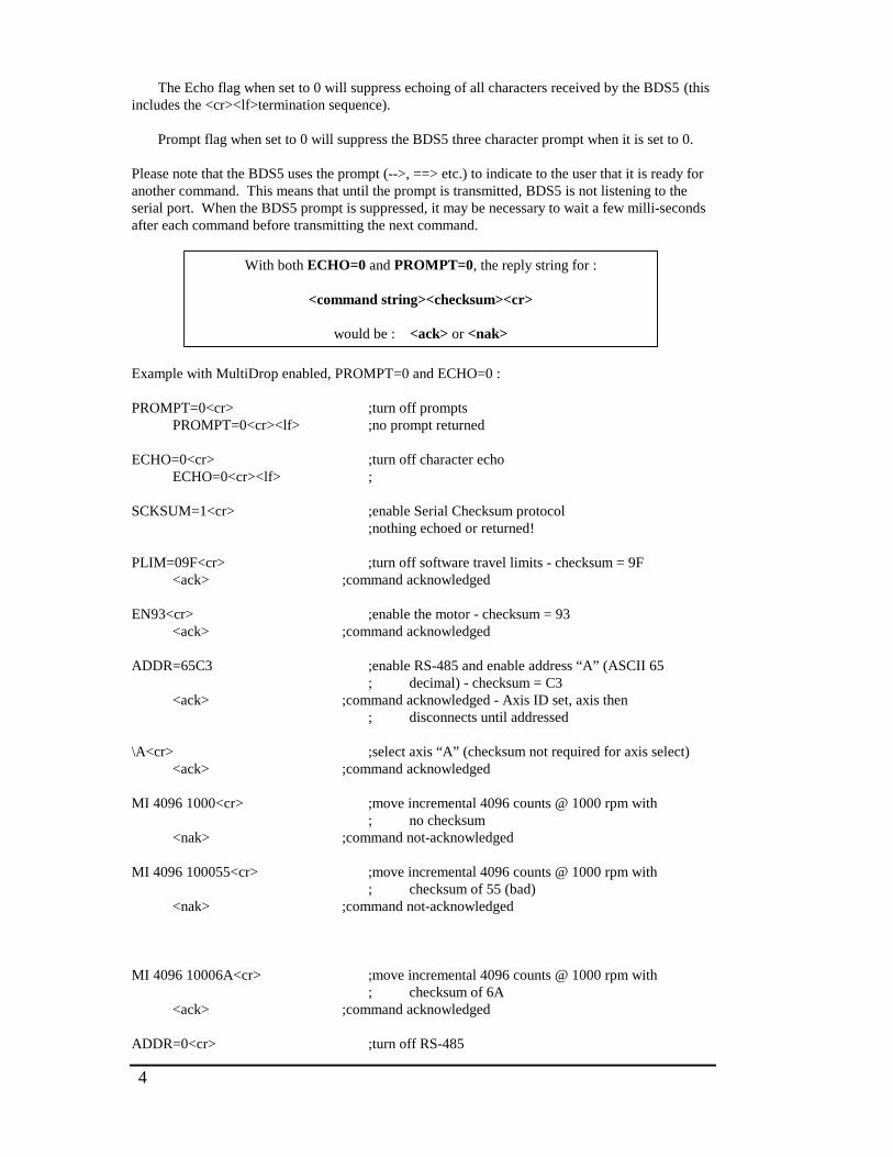
4
The Echo flag when set to 0 will suppress echoing of all characters received by the BDS5 (thisincludes the <cr><lf>termination sequence).
Prompt flag when set to 0 will suppress the BDS5 three character prompt when it is set to 0.
Please note that the BDS5 uses the prompt (-->, ==> etc.) to indicate to the user that it is ready foranother command. This means that until the prompt is transmitted, BDS5 is not listening to theserial port. When the BDS5 prompt is suppressed, it may be necessary to wait a few milli-secondsafter each command before transmitting the next command.
With both ECHO=0 and PROMPT=0, the reply string for :
<command string><checksum><cr>
would be : <ack> or <nak>
Example with MultiDrop enabled, PROMPT=0 and ECHO=0 :
PROMPT=0<cr> ;turn off prompts PROMPT=0<cr><lf> ;no prompt returned
ECHO=0<cr> ;turn off character echo ECHO=0<cr><lf> ;
SCKSUM=1<cr> ;enable Serial Checksum protocol;nothing echoed or returned!
PLIM=09F<cr> ;turn off software travel limits - checksum = 9F <ack> ;command acknowledged
EN93<cr> ;enable the motor - checksum = 93 <ack> ;command acknowledged
ADDR=65C3 ;enable RS-485 and enable address “A” (ASCII 65; decimal) - checksum = C3
<ack> ;command acknowledged - Axis ID set, axis then; disconnects until addressed
\A<cr> ;select axis “A” (checksum not required for axis select) <ack> ;command acknowledged
MI 4096 1000<cr> ;move incremental 4096 counts @ 1000 rpm with; no checksum
<nak> ;command not-acknowledged
MI 4096 100055<cr> ;move incremental 4096 counts @ 1000 rpm with; checksum of 55 (bad)
<nak> ;command not-acknowledged
MI 4096 10006A<cr> ;move incremental 4096 counts @ 1000 rpm with; checksum of 6A
<ack> ;command acknowledged
ADDR=0<cr> ;turn off RS-485

5
PROMPT=1<cr> ;turn on prompts --> ;RS-232 prompt
ECHO=1<cr> ;turn on echo --. ;prompt
P PFB<cr> ;print feedback position P PFB<cr><lf> ;echo
1212 ;12 position number (leading spaces) --> ;prompt
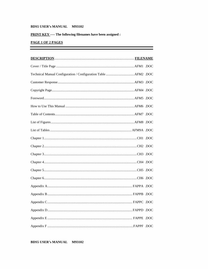
BDS5 USER’s MANUAL M93102
PRINT KEY ---- The following filenames have been assigned :
PAGE 1 OF 2 PAGES
DESCRIPTION............................................................................................. FILENAME
Cover / Title Page ...........................................................................................AFM1 .DOC
Technical Manual Configuration / Configuration Table .................................AFM2 .DOC
Customer Response.........................................................................................AFM3 .DOC
Copyright Page................................................................................................AFM4 .DOC
Foreword.........................................................................................................AFM5 .DOC
How to Use This Manual ................................................................................AFM6 .DOC
Table of Contents............................................................................................AFM7 .DOC
List of Figures .................................................................................................AFM8 .DOC
List of Tables ............................................................................................... AFM9A .DOC
Chapter 1............................................................................................................CH1 .DOC
Chapter 2............................................................................................................CH2 .DOC
Chapter 3............................................................................................................CH3 .DOC
Chapter 4............................................................................................................CH4 .DOC
Chapter 5............................................................................................................CH5 .DOC
Chapter 6............................................................................................................CH6 .DOC
Appendix A................................................................................................... FAPPA .DOC
Appendix B ................................................................................................... FAPPB .DOC
Appendix C ................................................................................................... FAPPC .DOC
Appendix D................................................................................................... FAPPD .DOC
Appendix E ................................................................................................... FAPPE .DOC
Appendix F ....................................................................................................FAPPF .DOC
BDS5 USER’s MANUAL M93102
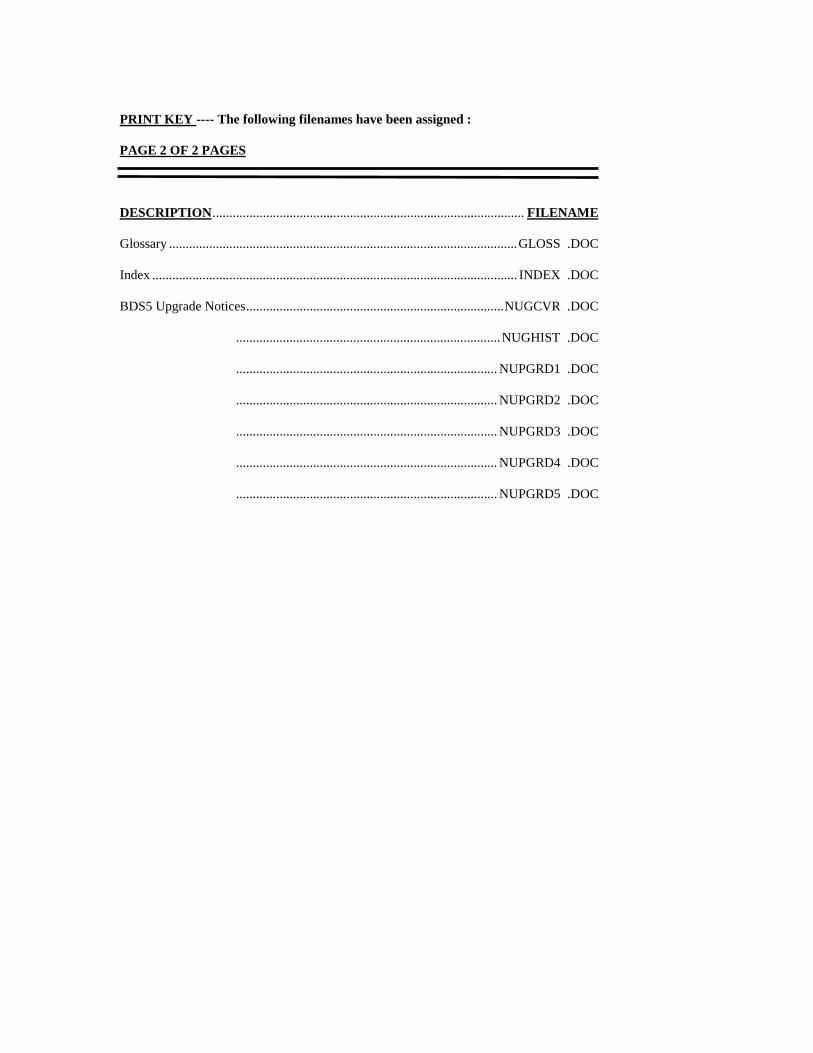
PRINT KEY ---- The following filenames have been assigned :
PAGE 2 OF 2 PAGES
DESCRIPTION............................................................................................. FILENAME
Glossary ........................................................................................................GLOSS .DOC
Index ............................................................................................................. INDEX .DOC
BDS5 Upgrade Notices.............................................................................NUGCVR .DOC
...............................................................................NUGHIST .DOC
.............................................................................. NUPGRD1 .DOC
.............................................................................. NUPGRD2 .DOC
.............................................................................. NUPGRD3 .DOC
.............................................................................. NUPGRD4 .DOC
.............................................................................. NUPGRD5 .DOC