Embed Size (px)
Citation preview
bdbiosciences.comPart No. 642224 Rev. AApril 2007
BD Biosciences2350 Qume DriveSan Jose, CA 95131-1807USATel (877) 232-8995Fax (408) 954-2347
bdbiosciences.comPart No. 642224 Rev. AJune 2007
BD Biosciences2350 Qume DriveSan Jose, CA 95131-1807USATel (877) 232-8995Fax (800) [email protected]
BD High Throughput Sampler User’s Guide
for the
BD LSR IIBD FACSCanto
BD FACSCanto II
Brazil Tel (55) 11-5185-9995Fax (55) 11-5185-9895
Europe Tel (32) 2 400 98 95Fax (32) 2 401 70 94
MexicoToll Free 01-800-236-2543Tel (52) 55 5999 8296
JapanNippon Becton Dickinson Company, Ltd.Toll Free 0120-8555-90
Asia Pacific
Fax (65) 6-860-1590
CanadaToll Free (888) 259-0187
Fax (888) 229-9918
Tel (65) 6-861-0633Tel (905) 542-8028
[email protected] Fax (52) 55 5999 8288Tel 81-24-593-5405Fax 81-24-593-5761
Brazil Tel (55) 11-5185-9995Fax (55) 11-5185-9895
Europe Tel (32) 2 400 98 95Fax (32) 2 401 70 94
MexicoToll Free 01-800-236-2543Tel (52) 55 5999 8296
JapanNippon Becton Dickinson Company, Ltd.Toll Free 0120-8555-90
Asia Pacific
Fax (65) 6-860-1590
CanadaToll Free (888) 259-0187
Fax (888) 229-9918
Tel (65) 6-861-0633Tel (905) 542-8028
[email protected] Tel 81-24-593-5405Fax 81-24-593-5761
Fax (52) 55 5999 8288
© 2007, Becton, Dickinson and Company. All rights reserved. No part of this publication may be reproduced, transmitted, transcribed, stored in retrieval systems, or translated into any language or computer language, in any form or by any means: electronic, mechanical, magnetic, optical, chemical, manual, or otherwise, without prior written permission from BD Biosciences.
The information in this guide is subject to change without notice. BD Biosciences reserves the right to change its products and services at any time to incorporate the latest technological developments. Although this guide has been prepared with every precaution to ensure accuracy, BD Biosciences assumes no liability for any errors or omissions, nor for any damages resulting from the application or use of this information. BD Biosciences welcomes customer input on corrections and suggestions for improvement.
BD FACSDiva software © 2007, Becton, Dickinson and Company. This software is the property of Becton, Dickinson and Company. Each sale of a stored unit of this software grants the purchaser a nontransferable, nonexclusive, personal license. This software may not be duplicated, reproduced, or copied in any form or by any means whatsoever, except as otherwise permitted by law.
This product includes software developed by the Apache Software Foundation (apache.org).
BD, BD logo, and all other trademarks are property of Becton, Dickinson and Company.
Adobe and Acrobat are registered trademarks of Adobe Systems Incorporated.
Diskeeper is a registered trademark of Executive Software International.
Microsoft and Windows are registered trademarks of Microsoft Corporation.
Sybase, Adaptive Server Anywhere, and SQL Anywhere are trademarks of Sybase, Inc or its subsidiaries.
Cy™ is a trademark of Amersham Biosciences Corp.
Cy™ dyes are subject to proprietary rights of Amersham Biosciences Corp. and Carnegie Mellon University and are made and sold under license from Amersham Biosciences Corp. only for research and in vitro diagnostic use. Any other use requires a commercial sublicense from Amersham Biosciences Corp., 800 Centennial Avenue, Piscataway, NJ 08855-1327, USA.
All other company and product names might be trademarks of the respective companies with which they are associated.
Patents
PerCP: US 4,876,190
APC-Cy7: US 5,714,386
FCC Information
WARNING: Changes or modifications to this unit not expressly approved by the party responsible for compliance could void the user’s authority to operate the equipment.
NOTICE: This equipment has been tested and found to comply with the limits for a Class A digital device, pursuant to Part 15 of the FCC Rules. These limits are designed to provide reasonable protection against harmful interference when the equipment is operated in a commercial environment. This equipment generates, uses, and can radiate radio frequency energy and, if not installed and used in accordance with the instruction manual, may cause harmful interference to radio communications. Operation of this equipment in a residential area is likely to cause harmful interference in which case the user will be required to correct the interference at his or her own expense.
Shielded cables must be used with this unit to ensure compliance with the Class A FCC limits.
This Class A digital apparatus meets all requirements of the Canadian Interference-Causing Equipment Regulations.
Cet appareil numérique de la classe A respecte toutes les exigences du Réglement sur the matériel brouilleur du Canada.
Notice
BD Biosciences delivers software and workstations that are intended for running the cytometers supplied by BD Biosciences. It is the responsibility of the buyer/user to ensure that all added electronic files including software and transport media are virus free. If the workstation is used for Internet access or purposes other than those specified by BD Biosciences, it is the buyer/user’s responsibility to install and maintain up-to-date virus protection software. BD Biosciences does not make any warranty with respect to the workstation remaining virus free after installation. BD Biosciences is not liable for any claims related to or resulting from buyer/user's failure to install and maintain virus protection.
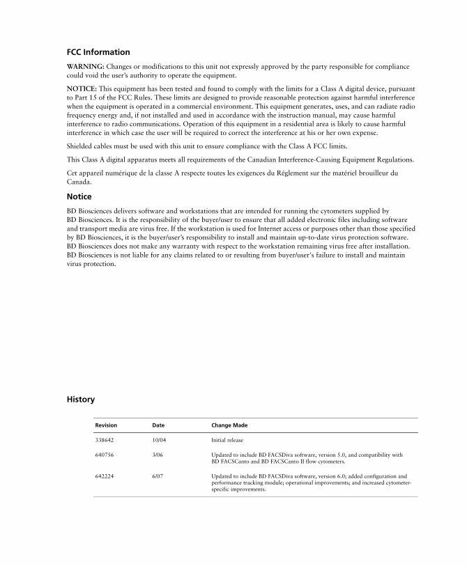
History
Revision Date Change Made
338642 10/04 Initial release
640756 3/06 Updated to include BD FACSDiva software, version 5.0, and compatibility with BD FACSCanto and BD FACSCanto II flow cytometers.
642224 6/07 Updated to include BD FACSDiva software, version 6.0; added configuration and performance tracking module; operational improvements; and increased cytometer-specific improvements.

Contents
About This Guide ix
Conventions . . . . . . . . . . . . . . . . . . . . . . . . . . . . . . . . . . . . . . . . . . . . . . . . . x
Technical Assistance . . . . . . . . . . . . . . . . . . . . . . . . . . . . . . . . . . . . . . . . . . . xi
Chapter 1: Introduction 13
HTS Hardware Overview . . . . . . . . . . . . . . . . . . . . . . . . . . . . . . . . . . . . . . . 14
Components . . . . . . . . . . . . . . . . . . . . . . . . . . . . . . . . . . . . . . . . . . . . . . . . . 16
Cytometer Connections . . . . . . . . . . . . . . . . . . . . . . . . . . . . . . . . . . . . . . . . 19
Cytometer Interface Panel . . . . . . . . . . . . . . . . . . . . . . . . . . . . . . . . . . . 19
Sample Coupler . . . . . . . . . . . . . . . . . . . . . . . . . . . . . . . . . . . . . . . . . . . 21
Sample Processing . . . . . . . . . . . . . . . . . . . . . . . . . . . . . . . . . . . . . . . . . . . . . 23
Chapter 2: BD FACSDiva Software Overview 27
Workspace Components . . . . . . . . . . . . . . . . . . . . . . . . . . . . . . . . . . . . . . . . 28
Plate Window . . . . . . . . . . . . . . . . . . . . . . . . . . . . . . . . . . . . . . . . . . . . . . . . 32
Setup View Components . . . . . . . . . . . . . . . . . . . . . . . . . . . . . . . . . . . . 33
Setup View Functions . . . . . . . . . . . . . . . . . . . . . . . . . . . . . . . . . . . . . . . 43
Analysis View Components . . . . . . . . . . . . . . . . . . . . . . . . . . . . . . . . . . 48
Analysis View Functions . . . . . . . . . . . . . . . . . . . . . . . . . . . . . . . . . . . . 51
Chapter 3: Running Samples 55
Starting Up . . . . . . . . . . . . . . . . . . . . . . . . . . . . . . . . . . . . . . . . . . . . . . . . . . 56
Setting Up for Plate-Based Acquisition . . . . . . . . . . . . . . . . . . . . . . . . . . 59
v
Creating Experiments . . . . . . . . . . . . . . . . . . . . . . . . . . . . . . . . . . . . . . . . . . 64
Creating a Folder and an Experiment . . . . . . . . . . . . . . . . . . . . . . . . . . . 64
Setting Up the Plate . . . . . . . . . . . . . . . . . . . . . . . . . . . . . . . . . . . . . . . . . 67
Setting Up the Worksheet . . . . . . . . . . . . . . . . . . . . . . . . . . . . . . . . . . . . 74
Exporting a Plate as a Template . . . . . . . . . . . . . . . . . . . . . . . . . . . . . . . 76
Assigning Keywords . . . . . . . . . . . . . . . . . . . . . . . . . . . . . . . . . . . . . . . . 77
Preparing for Acquisition . . . . . . . . . . . . . . . . . . . . . . . . . . . . . . . . . . . . . . . 78
Optimizing Cytometer and HTS Settings . . . . . . . . . . . . . . . . . . . . . . . . 78
Performing Compensation . . . . . . . . . . . . . . . . . . . . . . . . . . . . . . . . . . . 81
Acquiring Data . . . . . . . . . . . . . . . . . . . . . . . . . . . . . . . . . . . . . . . . . . . . . . . 82
Pausing the BD High Throughput Sampler . . . . . . . . . . . . . . . . . . . . . . . 83
Stopping the BD High Throughput Sampler . . . . . . . . . . . . . . . . . . . . . . 84
Exporting an Experiment as a Template . . . . . . . . . . . . . . . . . . . . . . . . . 84
Analyzing Data . . . . . . . . . . . . . . . . . . . . . . . . . . . . . . . . . . . . . . . . . . . . . . . 86
Displaying Keywords . . . . . . . . . . . . . . . . . . . . . . . . . . . . . . . . . . . . . . . 86
Performing Data Analysis . . . . . . . . . . . . . . . . . . . . . . . . . . . . . . . . . . . . 90
Maintaining Data . . . . . . . . . . . . . . . . . . . . . . . . . . . . . . . . . . . . . . . . . . 93
Returning to Tube-Based Acquisition . . . . . . . . . . . . . . . . . . . . . . . . . . . . . . 94
Returning to Tube-Based Acquisition on the BD LSR II . . . . . . . . . . . . . 94
Returning to Tube-Based Acquisition on the BD FACSCanto and BD FACSCanto II . . . . . . . . . . . . . . . . . . . . . . . . . . . . . . . . . . . . . . . . . . 97
Shutting Down . . . . . . . . . . . . . . . . . . . . . . . . . . . . . . . . . . . . . . . . . . . . . . . 100
Quitting the Software . . . . . . . . . . . . . . . . . . . . . . . . . . . . . . . . . . . . . . . 101
Chapter 4: Maintenance 103
Daily Maintenance . . . . . . . . . . . . . . . . . . . . . . . . . . . . . . . . . . . . . . . . . . . . 104
Daily Cleaning . . . . . . . . . . . . . . . . . . . . . . . . . . . . . . . . . . . . . . . . . . . . 104
Cytometer Inspection and Servicing . . . . . . . . . . . . . . . . . . . . . . . . . . . . 109
Monthly Maintenance . . . . . . . . . . . . . . . . . . . . . . . . . . . . . . . . . . . . . . . . . . 111
Monthly Cleaning . . . . . . . . . . . . . . . . . . . . . . . . . . . . . . . . . . . . . . . . . . 111
Surface Inspection and Cleaning . . . . . . . . . . . . . . . . . . . . . . . . . . . . . . 114
vi BD High Throughput Sampler User’s Guide
Periodic Maintenance . . . . . . . . . . . . . . . . . . . . . . . . . . . . . . . . . . . . . . . . . . 114
Replacing the Sample Injection Tubing . . . . . . . . . . . . . . . . . . . . . . . . . 116
Replacing the HTS Sheath Filter . . . . . . . . . . . . . . . . . . . . . . . . . . . . . . . 119
Cleaning the Air Filter . . . . . . . . . . . . . . . . . . . . . . . . . . . . . . . . . . . . . . 121
Replacing the Sample Coupler and Tubing . . . . . . . . . . . . . . . . . . . . . . . 123
Replacing a Pump Syringe . . . . . . . . . . . . . . . . . . . . . . . . . . . . . . . . . . . 125
Replacing the Probe . . . . . . . . . . . . . . . . . . . . . . . . . . . . . . . . . . . . . . . . 129
Replacing Quick-Connector O-Rings . . . . . . . . . . . . . . . . . . . . . . . . . . . 130
Replacing SIT Protector and O-Ring (BD LSR II Only) . . . . . . . . . . . . . 130
Placing HTS Unit into Long-Term Storage . . . . . . . . . . . . . . . . . . . . . . . 132
Unscheduled Maintenance . . . . . . . . . . . . . . . . . . . . . . . . . . . . . . . . . . . . . . 136
Homing the Sample Probe . . . . . . . . . . . . . . . . . . . . . . . . . . . . . . . . . . . 136
Priming the HTS . . . . . . . . . . . . . . . . . . . . . . . . . . . . . . . . . . . . . . . . . . 138
Performing a Motion Test . . . . . . . . . . . . . . . . . . . . . . . . . . . . . . . . . . . 138
Verifying the Sample Probe Position . . . . . . . . . . . . . . . . . . . . . . . . . . . . 140
Reinitializing the HTS . . . . . . . . . . . . . . . . . . . . . . . . . . . . . . . . . . . . . . 142
Inspecting Thumbscrew Fittings . . . . . . . . . . . . . . . . . . . . . . . . . . . . . . . 142
Inspecting Hexagonal Fittings . . . . . . . . . . . . . . . . . . . . . . . . . . . . . . . . 143
Declogging the SIT . . . . . . . . . . . . . . . . . . . . . . . . . . . . . . . . . . . . . . . . . 143
Chapter 5: Troubleshooting 145
HTS Troubleshooting . . . . . . . . . . . . . . . . . . . . . . . . . . . . . . . . . . . . . . . . . . 146
Acquisition Troubleshooting . . . . . . . . . . . . . . . . . . . . . . . . . . . . . . . . . . . . . 147
BD FACSDiva Troubleshooting . . . . . . . . . . . . . . . . . . . . . . . . . . . . . . . . . . 149
Appendix A: Consumables and Replacement Parts 151
Cytometer Supplies . . . . . . . . . . . . . . . . . . . . . . . . . . . . . . . . . . . . . . . . . . . . 152
Maintenance Log . . . . . . . . . . . . . . . . . . . . . . . . . . . . . . . . . . . . . . . . . . . . . 154
Contents vii
Appendix B: Depot Repair Procedures 157
Depot Repair Overview . . . . . . . . . . . . . . . . . . . . . . . . . . . . . . . . . . . . . . . . . 158
Removing the HTS Unit . . . . . . . . . . . . . . . . . . . . . . . . . . . . . . . . . . . . . . . . 159
Cleaning the HTS Unit . . . . . . . . . . . . . . . . . . . . . . . . . . . . . . . . . . . . . . . . . 162
Decontaminating the Fluidics Manually . . . . . . . . . . . . . . . . . . . . . . . . . 163
Decontaminating External Surfaces . . . . . . . . . . . . . . . . . . . . . . . . . . . . 167
Unpacking the Replacement Unit . . . . . . . . . . . . . . . . . . . . . . . . . . . . . . . . . 169
Lifting Heavy Objects . . . . . . . . . . . . . . . . . . . . . . . . . . . . . . . . . . . . . . 169
Unpacking the HTS Unit . . . . . . . . . . . . . . . . . . . . . . . . . . . . . . . . . . . . . 170
Installing the HTS Unit . . . . . . . . . . . . . . . . . . . . . . . . . . . . . . . . . . . . . . . . . 170
Packing the Unit for Shipping . . . . . . . . . . . . . . . . . . . . . . . . . . . . . . . . . . . . 175
Placing the HTS into Its Shipping Container . . . . . . . . . . . . . . . . . . . . . . 175
Index 177
viii BD High Throughput Sampler User’s Guide
About This Guide
This guide describes how to set up and operate the BD™ High Throughput Sampler (HTS) option with the BD™ LSR II, BD FACSCanto™, and BD FACSCanto™ II flow cytometers. You should know how to operate your flow cytometer before using the HTS option. For important safety information, refer to the safety booklet provided with the HTS option.
Cytometer function is controlled by BD FACSDiva™ software. In this guide, you will find a description of BD FACSDiva software features specific to the HTS option.
BD LSR II, BD FACSCanto, and BD FACSCanto II flow cytometers modified with the HTS can acquire samples from plates or tubes. Even when acquiring samples using the HTS, consult the appropriate cytometer user’s guide for information about flow cytometer operation, daily shutdown, maintenance, and troubleshooting.
The BD High Throughput Sampler User’s Guide assumes you have a working knowledge of basic Microsoft® Windows® operation. If you are not familiar with the Windows operating system, refer to the documentation provided with your computer.
ix
Conventions
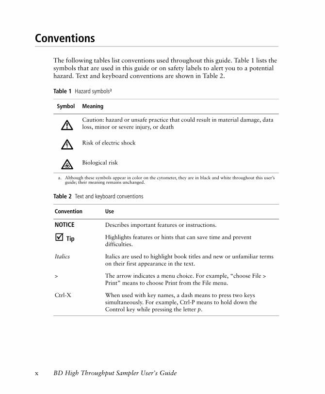
The following tables list conventions used throughout this guide. Table 1 lists the symbols that are used in this guide or on safety labels to alert you to a potential hazard. Text and keyboard conventions are shown in Table 2.
Table 1 Hazard symbolsa
a. Although these symbols appear in color on the cytometer, they are in black and white throughout this user’s guide; their meaning remains unchanged.
Symbol Meaning
Caution: hazard or unsafe practice that could result in material damage, data loss, minor or severe injury, or death
Risk of electric shock
Biological risk
Table 2 Text and keyboard conventions
Convention Use
NOTICE Describes important features or instructions.
! Tip Highlights features or hints that can save time and prevent difficulties.
Italics Italics are used to highlight book titles and new or unfamiliar terms on their first appearance in the text.
> The arrow indicates a menu choice. For example, “choose File > Print” means to choose Print from the File menu.
Ctrl-X When used with key names, a dash means to press two keys simultaneously. For example, Ctrl-P means to hold down the Control key while pressing the letter p.
x BD High Throughput Sampler User’s Guide
Technical Assistance
For technical questions or assistance in solving a problem:
• Read the section of the user’s guide specific to the operation you are performing.
• See Chapter 5, Troubleshooting.
If additional assistance is required, contact your local BD Biosciences technical support representative or supplier.
When contacting BD Biosciences, have the following information available:
• product name and serial number
• any error messages
• details of recent system performance
For cytometer support from within the US, call (877) 232-8995.
For support from within Canada, call (888) 259-0187.
Customers outside the US and Canada, contact your local BD representative or distributor.
If you need to send your HTS unit back to BD Biosciences for repair, see Appendix B on page 157 for instructions. Note that depot repair procedures might be different outside of the United States. Contact your local BD Biosciences service representative for information for your region.
About This Guide xi

xii BD High Throughput Sampler User’s Guide
1
Introduction
The BD High Throughput Sampler (HTS) is a compact, high-speed sample loading device for use with the BD LSR II, BD FACSCanto, and BD FACSCanto II flow cytometers. BD FACSDiva software controls the sample loader, providing automated acquisition of samples from a multiwell plate. Automate analysis using the BD FACSDiva batch analysis feature, for an efficient, high-throughput system.
The following topics are covered in this chapter:
• HTS Hardware Overview on page 14
• Components on page 16
• Cytometer Connections on page 19
• Sample Processing on page 23
13
HTS Hardware Overview
Easy to use and maintain, and highly reliable, the HTS provides the following basic functionality:
• Acquires samples from 96- and 384-well plates (standard depth)
• Includes two throughput modes: standard and high throughput
• Minimizes carryover
• Provides user-definable mixing and sample introduction protocols
• Is user-installable (software and sampler unit only; initial installation excluded)
• Supports immunophenotyping assays
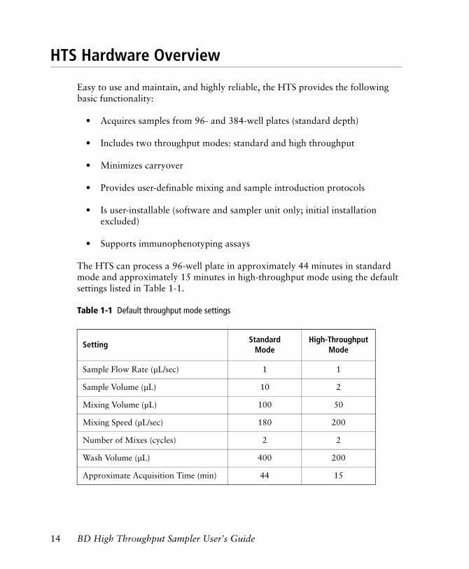
The HTS can process a 96-well plate in approximately 44 minutes in standard mode and approximately 15 minutes in high-throughput mode using the default settings listed in Table 1-1.
Table 1-1 Default throughput mode settings
SettingStandard
ModeHigh-Throughput
Mode
Sample Flow Rate (µL/sec) 1 1
Sample Volume (µL) 10 2
Mixing Volume (µL) 100 50
Mixing Speed (µL/sec) 180 200
Number of Mixes (cycles) 2 2
Wash Volume (µL) 400 200
Approximate Acquisition Time (min) 44 15
14 BD High Throughput Sampler User’s Guide
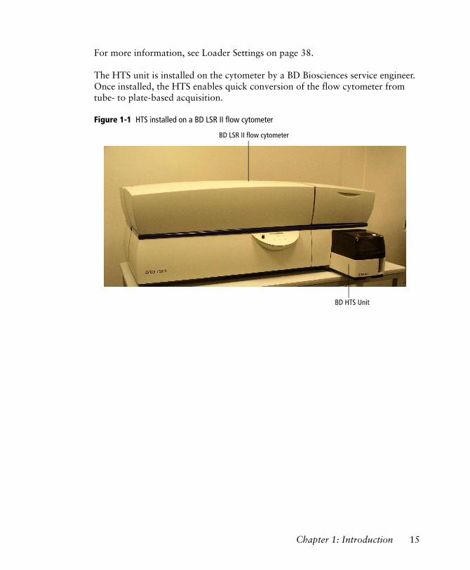
For more information, see Loader Settings on page 38.
The HTS unit is installed on the cytometer by a BD Biosciences service engineer. Once installed, the HTS enables quick conversion of the flow cytometer from tube- to plate-based acquisition.
Figure 1-1 HTS installed on a BD LSR II flow cytometer
BD LSR II flow cytometer
BD HTS Unit
Chapter 1: Introduction 15
Components
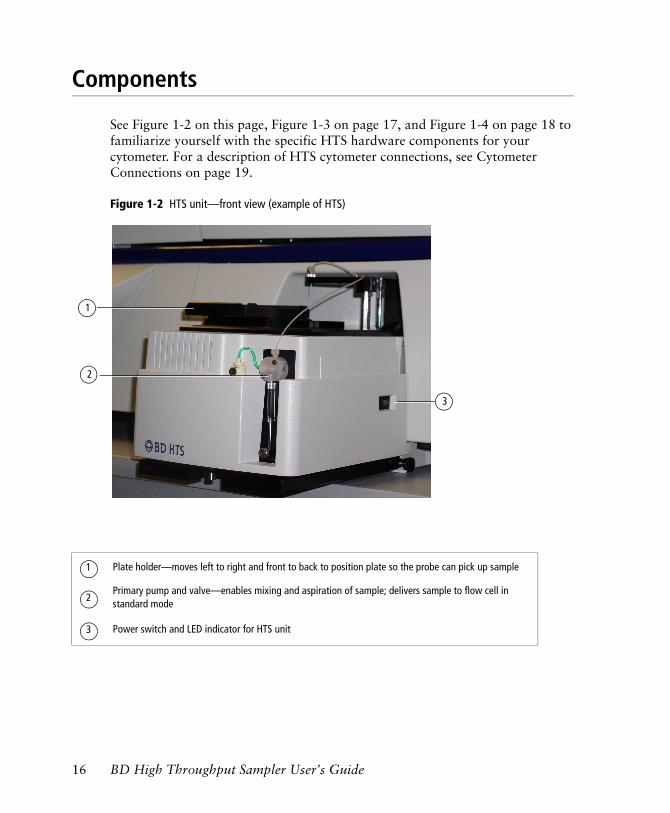
See Figure 1-2 on this page, Figure 1-3 on page 17, and Figure 1-4 on page 18 to familiarize yourself with the specific HTS hardware components for your cytometer. For a description of HTS cytometer connections, see Cytometer Connections on page 19.
Figure 1-2 HTS unit—front view (example of HTS)
Plate holder—moves left to right and front to back to position plate so the probe can pick up sample
Primary pump and valve—enables mixing and aspiration of sample; delivers sample to flow cell in standard mode
Power switch and LED indicator for HTS unit
2
3
1
1
2
3
16 BD High Throughput Sampler User’s Guide
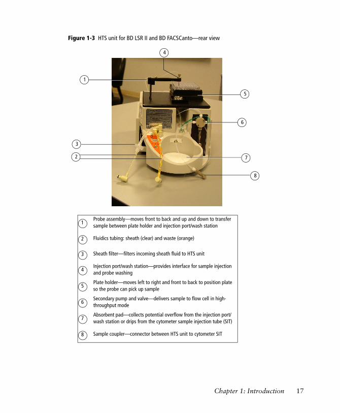
Figure 1-3 HTS unit for BD LSR II and BD FACSCanto—rear view
1
Probe assembly—moves front to back and up and down to transfer sample between plate holder and injection port/wash station
Fluidics tubing: sheath (clear) and waste (orange)
Sheath filter—filters incoming sheath fluid to HTS unit
Injection port/wash station—provides interface for sample injection and probe washing
Plate holder—moves left to right and front to back to position plate so the probe can pick up sample
Secondary pump and valve—delivers sample to flow cell in high-throughput mode
Absorbent pad—collects potential overflow from the injection port/wash station or drips from the cytometer sample injection tube (SIT)
Sample coupler—connector between HTS unit to cytometer SIT
1
2
3
4
5
6
7
8
5
6
72
8
3
4
Chapter 1: Introduction 17
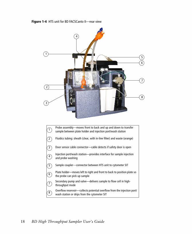
Figure 1-4 HTS unit for BD FACSCanto II—rear view
1
4
Probe assembly—moves front to back and up and down to transfer sample between plate holder and injection port/wash station
Fluidics tubing: sheath (clear, with in-line filter) and waste (orange)
Door sensor cable connector—cable detects if safety door is open
Injection port/wash station—provides interface for sample injection and probe washing
Sample coupler—connector between HTS unit to cytometer SIT
Plate holder—moves left to right and front to back to position plate so the probe can pick up sample
Secondary pump and valve—delivers sample to flow cell in high-throughput mode
Overflow reservoir—collects potential overflow from the injection port/wash station or drips from the cytometer SIT
1
2
3
4
5
6
7
8
5
7
2
8
3
6
18 BD High Throughput Sampler User’s Guide
Cytometer Connections
Cytometer Interface Panel
Sheath and waste travel between the cytometer and the HTS unit via connectors in the cytometer interface panel (see Figure 1-5, Figure 1-6, and Figure 1-7).
The BD LSR II interface panel also includes an acquisition mode switch, which controls pressure at the cytometer sample injection tube (SIT).
• In Tube mode ( ), the droplet containment module (DCM) vacuum functions normally—the vacuum is on when the arm is positioned to the side and off when the arm is centered. Backdripping from the sample injection tube is contained when the DCM sleeve is installed.
• In Plate mode ( ), the DCM vacuum on the cytometer does not function. Drip containment is provided by the absorbent pad in back of the HTS unit (Figure 1-3 on page 17).
[BD LSR II] To keep your cytometer free of drips from potentially biohazardous samples, always switch the cytometer to Tube mode and install the DCM sleeve when you are not acquiring samples using the HTS option. Note that if backdripping does occur, drips are contained by the absorbent pad in back of the HTS unit.
Chapter 1: Introduction 19
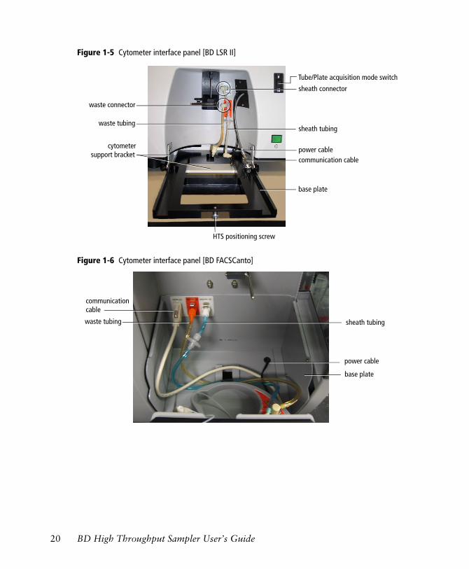
Figure 1-5 Cytometer interface panel [BD LSR II]
Figure 1-6 Cytometer interface panel [BD FACSCanto]
Tube/Plate acquisition mode switch
sheath connector
communication cablepower cable
HTS positioning screw
waste tubingsheath tubing
waste connector
cytometer
base plate
support bracket
communication cable
base plate
sheath tubingwaste tubing
power cable
20 BD High Throughput Sampler User’s Guide
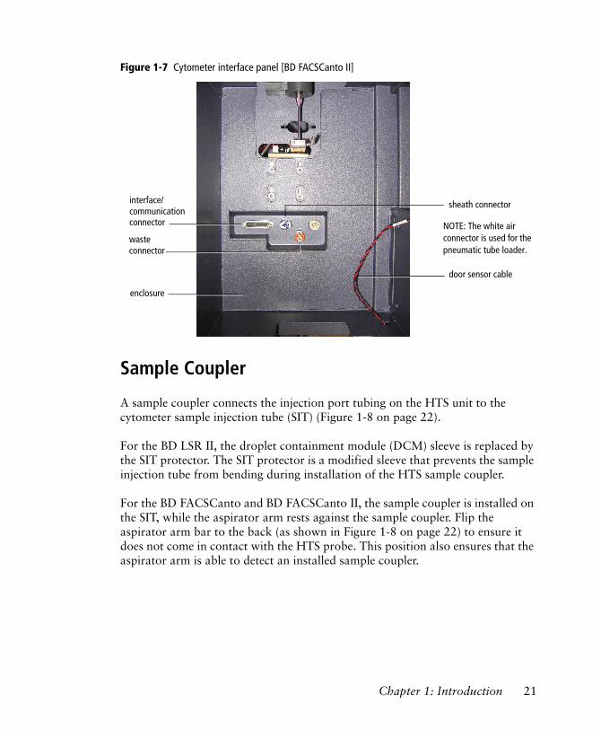
Figure 1-7 Cytometer interface panel [BD FACSCanto II]
Sample Coupler
A sample coupler connects the injection port tubing on the HTS unit to the cytometer sample injection tube (SIT) (Figure 1-8 on page 22).
For the BD LSR II, the droplet containment module (DCM) sleeve is replaced by the SIT protector. The SIT protector is a modified sleeve that prevents the sample injection tube from bending during installation of the HTS sample coupler.
For the BD FACSCanto and BD FACSCanto II, the sample coupler is installed on the SIT, while the aspirator arm rests against the sample coupler. Flip the aspirator arm bar to the back (as shown in Figure 1-8 on page 22) to ensure it does not come in contact with the HTS probe. This position also ensures that the aspirator arm is able to detect an installed sample coupler.
interface/
connector
enclosure
sheath connector
waste
door sensor cable
communication
connector
NOTE: The white air connector is used for the pneumatic tube loader.
Chapter 1: Introduction 21
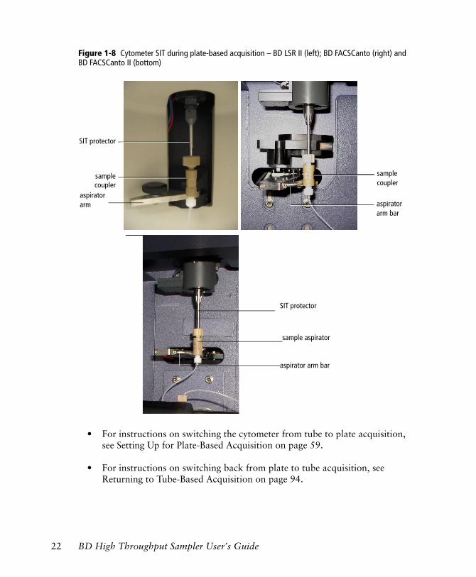
Figure 1-8 Cytometer SIT during plate-based acquisition – BD LSR II (left); BD FACSCanto (right) and BD FACSCanto II (bottom)
• For instructions on switching the cytometer from tube to plate acquisition, see Setting Up for Plate-Based Acquisition on page 59.
• For instructions on switching back from plate to tube acquisition, see Returning to Tube-Based Acquisition on page 94.
SIT protector
samplecoupler
sample coupler
aspirator arm bar
aspiratorarm
SIT protector
sample aspirator
aspirator arm bar
22 BD High Throughput Sampler User’s Guide
NOTICE [BD LSR II] Soft standby mode is not available when you are acquiring samples in Plate mode. Refer to your BD LSR II User’s Guide for information about soft standby mode.
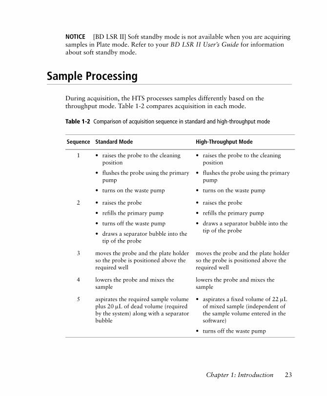
Sample Processing
During acquisition, the HTS processes samples differently based on the throughput mode. Table 1-2 compares acquisition in each mode.
Table 1-2 Comparison of acquisition sequence in standard and high-throughput mode
Sequence Standard Mode High-Throughput Mode
1 • raises the probe to the cleaning position
• flushes the probe using the primary pump
• turns on the waste pump
• raises the probe to the cleaning position
• flushes the probe using the primary pump
• turns on the waste pump
2 • raises the probe
• refills the primary pump
• turns off the waste pump
• draws a separator bubble into the tip of the probe
• raises the probe
• refills the primary pump
• draws a separator bubble into the tip of the probe
3 moves the probe and the plate holder so the probe is positioned above the required well
moves the probe and the plate holder so the probe is positioned above the required well
4 lowers the probe and mixes the sample
lowers the probe and mixes the sample
5 aspirates the required sample volume plus 20 µL of dead volume (required by the system) along with a separator bubble
• aspirates a fixed volume of 22 µL of mixed sample (independent of the sample volume entered in the software)
• turns off the waste pump
Chapter 1: Introduction 23
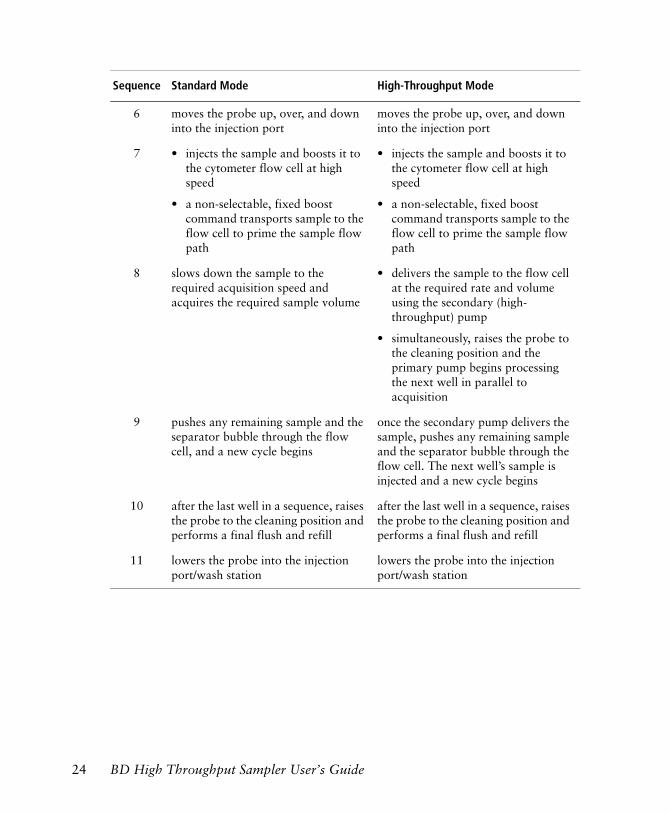
6 moves the probe up, over, and down into the injection port
moves the probe up, over, and down into the injection port
7 • injects the sample and boosts it to the cytometer flow cell at high speed
• a non-selectable, fixed boost command transports sample to the flow cell to prime the sample flow path
• injects the sample and boosts it to the cytometer flow cell at high speed
• a non-selectable, fixed boost command transports sample to the flow cell to prime the sample flow path
8 slows down the sample to the required acquisition speed and acquires the required sample volume
• delivers the sample to the flow cell at the required rate and volume using the secondary (high-throughput) pump
• simultaneously, raises the probe to the cleaning position and the primary pump begins processing the next well in parallel to acquisition
9 pushes any remaining sample and the separator bubble through the flow cell, and a new cycle begins
once the secondary pump delivers the sample, pushes any remaining sample and the separator bubble through the flow cell. The next well’s sample is injected and a new cycle begins
10 after the last well in a sequence, raises the probe to the cleaning position and performs a final flush and refill
after the last well in a sequence, raises the probe to the cleaning position and performs a final flush and refill
11 lowers the probe into the injection port/wash station
lowers the probe into the injection port/wash station
Sequence Standard Mode High-Throughput Mode
24 BD High Throughput Sampler User’s Guide
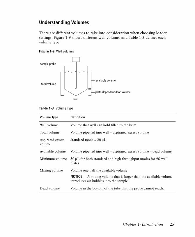
Understanding Volumes
There are different volumes to take into consideration when choosing loader settings. Figure 1-9 shows different well volumes and Table 1-3 defines each volume type.
Figure 1-9 Well volumes
Table 1-3 Volume Type
Volume Type Definition
Well volume Volume that well can hold filled to the brim
Total volume Volume pipetted into well – aspirated excess volume
Aspirated excess volume
Standard mode = 20 µL
Available volume Volume pipetted into well – aspirated excess volume – dead volume
Minimum volume 50 µL for both standard and high-throughput modes for 96-well plates
Mixing volume Volume one-half the available volume
NOTICE A mixing volume that is larger than the available volume introduces air bubbles into the sample.
Dead volume Volume in the bottom of the tube that the probe cannot reach.
available volume
plate-dependent dead volume
total volume
well
sample probe
Chapter 1: Introduction 25
Mixing
HTS mixing efficiency is impacted by the viscosity of the sample in the well. Adjust the mixing volume, speed, and the number of mixes to obtain the most homogeneous population for acquisition.
A greater number of mixes might allow you to decrease the mixing volume and speed, but this could impact sample throughput. Increasing the mixing speed and volume might improve throughput and mixing efficiency, but it could also introduce air bubbles in the sample well. In addition, increased mixing speed could compromise the separator bubble between the sample and sheath, resulting in sporadic event rates and possibly higher carryover.
Use default values as a starting point (see Table 2-4 on page 40) with a mixing volume of one-half the total sample volume. Note that samples are mixed less effectively in flat-bottom wells than U- or V-bottom wells. When using flat-bottom wells, you might want to mix the sample well before pipetting it into the plate, and acquire the sample before it has a chance to settle.
Carryover
You can vary the amount of wash volume to minimize carryover. In general, a greater wash volume results in less carryover, but the greater the volume, the slower the system throughput.
The minimum volume is determined by the sample and mixing volume. To start with, try a 400-µL wash for 10 µL of sample volume. As the sample and mixing volumes decrease, the wash volume can also be reduced.
Throughput
The speed at which the HTS completes a plate depends on the acquisition time (sample volume/sample rate), acquisition mode (high throughput or standard), mixing volume and speed, number of mixes, and wash volume. To achieve optimal throughput, BD recommends that you concentrate the sample, reduce the sample volume (10 µL or less), increase the sample rate (1 µL/sec or greater), minimize the number of mixes (2 or less), and decrease the wash volume (400 µL or less).
NOTICE The BD FACSCanto II maximum event rate is 10,000 events/second.
26 BD High Throughput Sampler User’s Guide
2
BD FACSDiva Software Overview
This chapter describes the BD FACSDiva software features necessary to operate the BD High Throughput Sampler with the BD LSR II, BD FACSCanto, and BD FACSCanto II flow cytometers. For an in-depth description of software components not described in this chapter, refer to the BD FACSDiva Software Reference Manual.
The following topics are covered in this chapter:
• Workspace Components on page 28
• Plate Window on page 32
27
Workspace Components
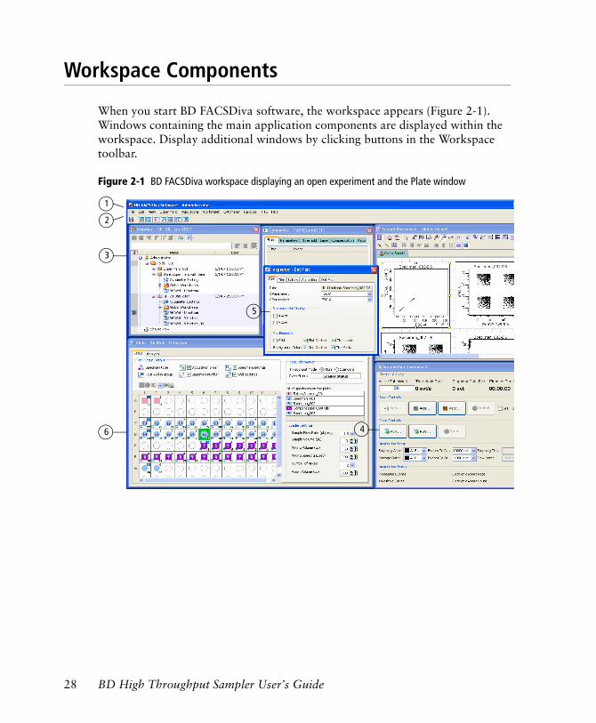
When you start BD FACSDiva software, the workspace appears (Figure 2-1). Windows containing the main application components are displayed within the workspace. Display additional windows by clicking buttons in the Workspace toolbar.
Figure 2-1 BD FACSDiva workspace displaying an open experiment and the Plate window
1
2
4
3
5
6
28 BD High Throughput Sampler User’s Guide
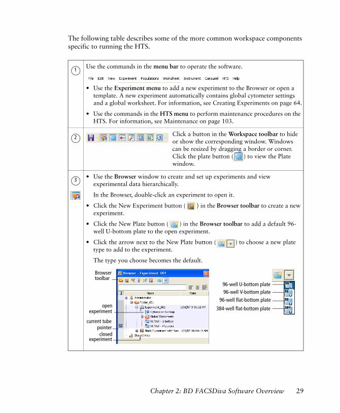
The following table describes some of the more common workspace components specific to running the HTS.
Use the commands in the menu bar to operate the software.
• Use the Experiment menu to add a new experiment to the Browser or open a template. A new experiment automatically contains global cytometer settings and a global worksheet. For information, see Creating Experiments on page 64.
• Use the commands in the HTS menu to perform maintenance procedures on the HTS. For information, see Maintenance on page 103.
Click a button in the Workspace toolbar to hide or show the corresponding window. Windows can be resized by dragging a border or corner. Click the plate button ( ) to view the Plate window.
• Use the Browser window to create and set up experiments and view experimental data hierarchically.
In the Browser, double-click an experiment to open it.
• Click the New Experiment button ( ) in the Browser toolbar to create a new experiment.
• Click the New Plate button ( ) in the Browser toolbar to add a default 96-well U-bottom plate to the open experiment.
• Click the arrow next to the New Plate button ( ) to choose a new plate type to add to the experiment.
The type you choose becomes the default.
1
2
3
closed
open
experiment
experiment
current tubepointer
Browsertoolbar
96-well flat-bottom plate96-well V-bottom plate96-well U-bottom plate
384-well flat-bottom plate
Chapter 2: BD FACSDiva Software Overview 29
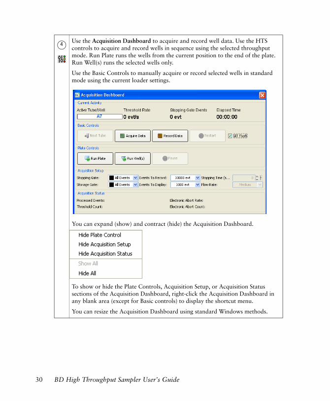
Use the Acquisition Dashboard to acquire and record well data. Use the HTS controls to acquire and record wells in sequence using the selected throughput mode. Run Plate runs the wells from the current position to the end of the plate. Run Well(s) runs the selected wells only.
Use the Basic Controls to manually acquire or record selected wells in standard mode using the current loader settings.
You can expand (show) and contract (hide) the Acquisition Dashboard.
To show or hide the Plate Controls, Acquisition Setup, or Acquisition Status sections of the Acquisition Dashboard, right-click the Acquisition Dashboard in any blank area (except for Basic controls) to display the shortcut menu.
You can resize the Acquisition Dashboard using standard Windows methods.
4
30 BD High Throughput Sampler User’s Guide
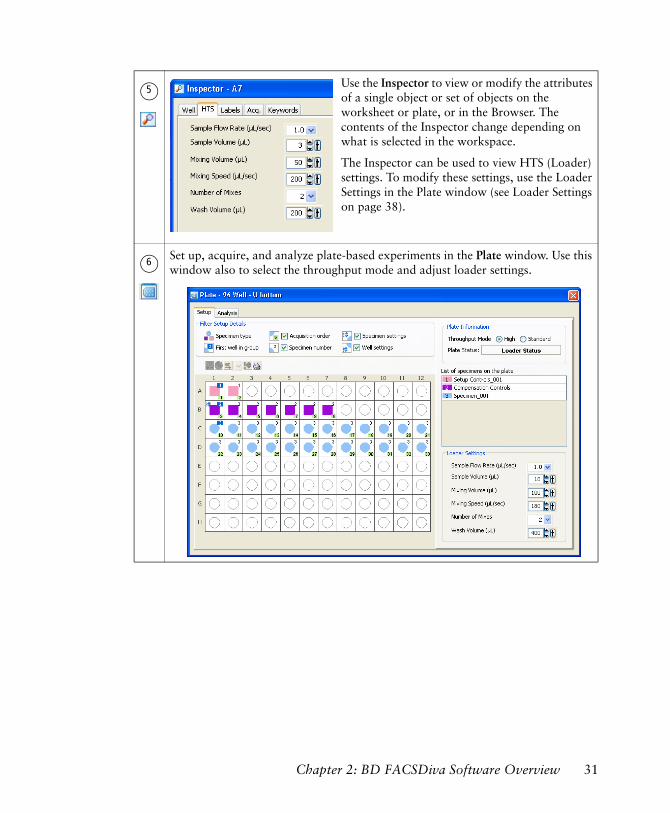
Use the Inspector to view or modify the attributes of a single object or set of objects on the worksheet or plate, or in the Browser. The contents of the Inspector change depending on what is selected in the workspace.
The Inspector can be used to view HTS (Loader) settings. To modify these settings, use the Loader Settings in the Plate window (see Loader Settings on page 38).
Set up, acquire, and analyze plate-based experiments in the Plate window. Use this window also to select the throughput mode and adjust loader settings.
5
6
Chapter 2: BD FACSDiva Software Overview 31
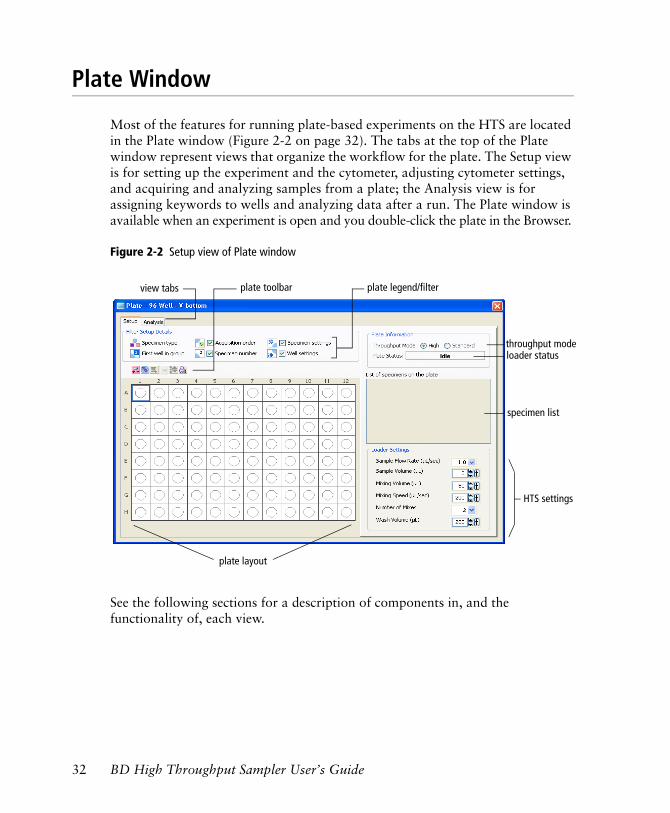
Plate Window
Most of the features for running plate-based experiments on the HTS are located in the Plate window (Figure 2-2 on page 32). The tabs at the top of the Plate window represent views that organize the workflow for the plate. The Setup view is for setting up the experiment and the cytometer, adjusting cytometer settings, and acquiring and analyzing samples from a plate; the Analysis view is for assigning keywords to wells and analyzing data after a run. The Plate window is available when an experiment is open and you double-click the plate in the Browser.
Figure 2-2 Setup view of Plate window
See the following sections for a description of components in, and the functionality of, each view.
loader status
plate legend/filter plate toolbarview tabs
plate layout
throughput mode
HTS settings
specimen list
32 BD High Throughput Sampler User’s Guide
Setup View Components
The Setup view contains controls for designing experiments, running plate-based acquisition, and monitoring acquisition status. For instructions on setting up an experiment, see Creating Experiments on page 64. All entries made in the Setup view can be saved as a template, either for general projects or as a default experiment for a user-defined project.
The following components are available in the Setup view.
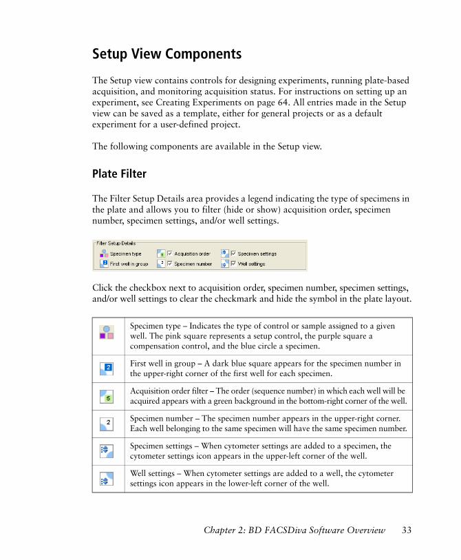
Plate Filter
The Filter Setup Details area provides a legend indicating the type of specimens in the plate and allows you to filter (hide or show) acquisition order, specimen number, specimen settings, and/or well settings.
Click the checkbox next to acquisition order, specimen number, specimen settings, and/or well settings to clear the checkmark and hide the symbol in the plate layout.
Specimen type – Indicates the type of control or sample assigned to a given well. The pink square represents a setup control, the purple square a compensation control, and the blue circle a specimen.
First well in group – A dark blue square appears for the specimen number in the upper-right corner of the first well for each specimen.
Acquisition order filter – The order (sequence number) in which each well will be acquired appears with a green background in the bottom-right corner of the well.
Specimen number – The specimen number appears in the upper-right corner. Each well belonging to the same specimen will have the same specimen number.
Specimen settings – When cytometer settings are added to a specimen, the cytometer settings icon appears in the upper-left corner of the well.
Well settings – When cytometer settings are added to a well, the cytometer settings icon appears in the lower-left corner of the well.
Chapter 2: BD FACSDiva Software Overview 33
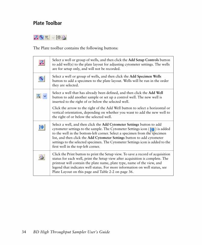
Plate Toolbar
The Plate toolbar contains the following buttons:
Select a well or group of wells, and then click the Add Setup Controls button to add well(s) to the plate layout for adjusting cytometer settings. The wells are for setup only, and will not be recorded.
Select a well or group of wells, and then click the Add Specimen Wells button to add a specimen to the plate layout. Wells will be run in the order they are selected.
Select a well that has already been defined, and then click the Add Well button to add another sample or set up a control well. The new well is inserted to the right of or below the selected well.
Click the arrow to the right of the Add Well button to select a horizontal or vertical orientation, depending on whether you want to add the new well to the right of or below the selected well.
Select a well, and then click the Add Cytometer Settings button to add cytometer settings to the sample. The Cytometer Settings icon ( ) is added to the well in the bottom-left corner. Select a specimen from the specimen list, and then click the Add Cytometer Settings button to add cytometer settings to the selected specimen. The Cytometer Settings icon is added to the first well in the top-left corner.
Click the Print button to print the Setup view. To save a record of acquisition status for each well, print the Setup view after acquisition is complete. The printout will contain the plate name, plate type, name of the view, and legend that indicates well status. For more information on well status, see Plate Layout on this page and Table 2-2 on page 36.
34 BD High Throughput Sampler User’s Guide
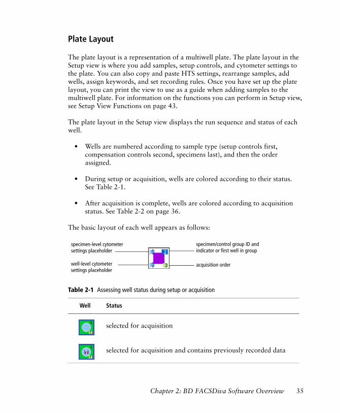
Plate Layout
The plate layout is a representation of a multiwell plate. The plate layout in the Setup view is where you add samples, setup controls, and cytometer settings to the plate. You can also copy and paste HTS settings, rearrange samples, add wells, assign keywords, and set recording rules. Once you have set up the plate layout, you can print the view to use as a guide when adding samples to the multiwell plate. For information on the functions you can perform in Setup view, see Setup View Functions on page 43.
The plate layout in the Setup view displays the run sequence and status of each well.
• Wells are numbered according to sample type (setup controls first, compensation controls second, specimens last), and then the order assigned.
• During setup or acquisition, wells are colored according to their status. See Table 2-1.
• After acquisition is complete, wells are colored according to acquisition status. See Table 2-2 on page 36.
The basic layout of each well appears as follows:
Table 2-1 Assessing well status during setup or acquisition
Well Status
selected for acquisition
selected for acquisition and contains previously recorded data
acquisition order
specimen/control group ID andindicator or first well in group
specimen-level cytometersettings placeholder
well-level cytometersettings placeholder
Chapter 2: BD FACSDiva Software Overview 35
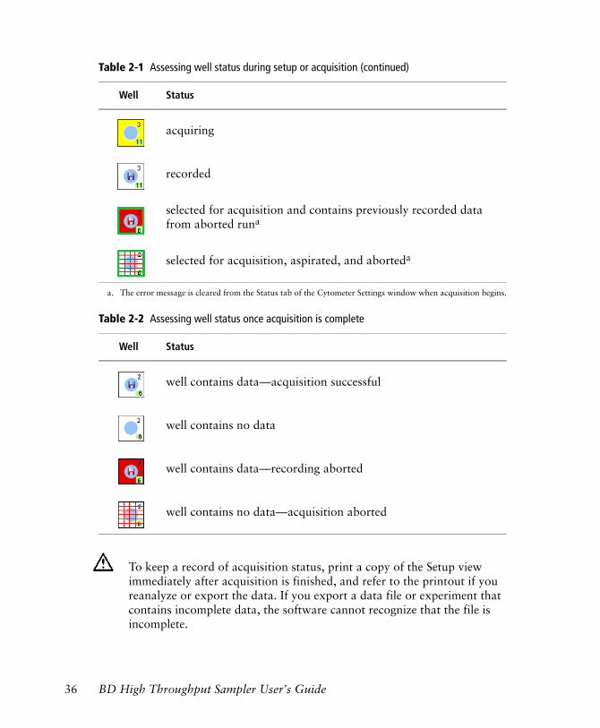
acquiring
recorded
selected for acquisition and contains previously recorded data from aborted runa
selected for acquisition, aspirated, and aborteda
a. The error message is cleared from the Status tab of the Cytometer Settings window when acquisition begins.
Table 2-2 Assessing well status once acquisition is complete
Well Status
well contains data—acquisition successful
well contains no data
well contains data—recording aborted
well contains no data—acquisition aborted
To keep a record of acquisition status, print a copy of the Setup view immediately after acquisition is finished, and refer to the printout if you reanalyze or export the data. If you export a data file or experiment that contains incomplete data, the software cannot recognize that the file is incomplete.
Table 2-1 Assessing well status during setup or acquisition (continued)
Well Status
36 BD High Throughput Sampler User’s Guide
Compensation Controls
You can create label-specific compensation controls. Refer to the BD FACSDiva Software Reference Manual for information.
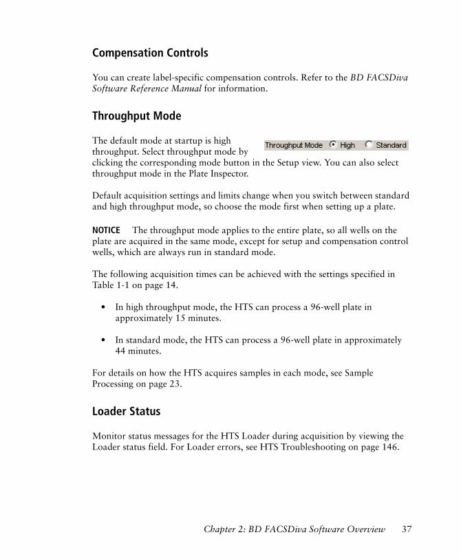
Throughput Mode
The default mode at startup is high throughput. Select throughput mode by clicking the corresponding mode button in the Setup view. You can also select throughput mode in the Plate Inspector.
Default acquisition settings and limits change when you switch between standard and high throughput mode, so choose the mode first when setting up a plate.
NOTICE The throughput mode applies to the entire plate, so all wells on the plate are acquired in the same mode, except for setup and compensation control wells, which are always run in standard mode.
The following acquisition times can be achieved with the settings specified in Table 1-1 on page 14.
• In high throughput mode, the HTS can process a 96-well plate in approximately 15 minutes.
• In standard mode, the HTS can process a 96-well plate in approximately 44 minutes.
For details on how the HTS acquires samples in each mode, see Sample Processing on page 23.
Loader Status
Monitor status messages for the HTS Loader during acquisition by viewing the Loader status field. For Loader errors, see HTS Troubleshooting on page 146.
Chapter 2: BD FACSDiva Software Overview 37
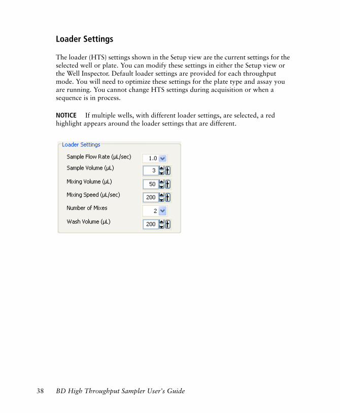
Loader Settings
The loader (HTS) settings shown in the Setup view are the current settings for the selected well or plate. You can modify these settings in either the Setup view or the Well Inspector. Default loader settings are provided for each throughput mode. You will need to optimize these settings for the plate type and assay you are running. You cannot change HTS settings during acquisition or when a sequence is in process.
NOTICE If multiple wells, with different loader settings, are selected, a red highlight appears around the loader settings that are different.
38 BD High Throughput Sampler User’s Guide
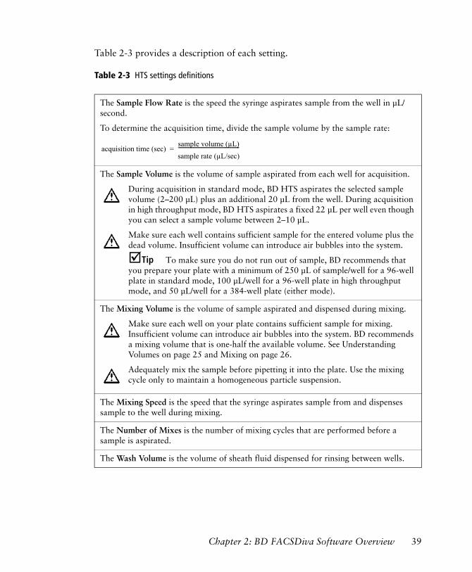
Table 2-3 provides a description of each setting.
Table 2-3 HTS settings definitions
The Sample Flow Rate is the speed the syringe aspirates sample from the well in µL/second.
To determine the acquisition time, divide the sample volume by the sample rate:
The Sample Volume is the volume of sample aspirated from each well for acquisition.
During acquisition in standard mode, BD HTS aspirates the selected sample volume (2–200 µL) plus an additional 20 µL from the well. During acquisition in high throughput mode, BD HTS aspirates a fixed 22 µL per well even though you can select a sample volume between 2–10 µL.
Make sure each well contains sufficient sample for the entered volume plus the dead volume. Insufficient volume can introduce air bubbles into the system.
!Tip To make sure you do not run out of sample, BD recommends that you prepare your plate with a minimum of 250 µL of sample/well for a 96-well plate in standard mode, 100 µL/well for a 96-well plate in high throughput mode, and 50 µL/well for a 384-well plate (either mode).
The Mixing Volume is the volume of sample aspirated and dispensed during mixing.
Make sure each well on your plate contains sufficient sample for mixing. Insufficient volume can introduce air bubbles into the system. BD recommends a mixing volume that is one-half the available volume. See Understanding Volumes on page 25 and Mixing on page 26.
Adequately mix the sample before pipetting it into the plate. Use the mixing cycle only to maintain a homogeneous particle suspension.
The Mixing Speed is the speed that the syringe aspirates sample from and dispenses sample to the well during mixing.
The Number of Mixes is the number of mixing cycles that are performed before a sample is aspirated.
The Wash Volume is the volume of sheath fluid dispensed for rinsing between wells.
acquisition time (sec)sample volume (µL)sample rate (µL/sec)-------------------------------------------------=
Chapter 2: BD FACSDiva Software Overview 39
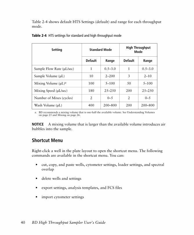
Table 2-4 shows default HTS Settings (default) and range for each throughput mode.
Table 2-4 HTS settings for standard and high throughput mode
NOTICE A mixing volume that is larger than the available volume introduces air bubbles into the sample.
Shortcut Menu
Right-click a well in the plate layout to open the shortcut menu. The following commands are available in the shortcut menu. You can:
• cut, copy, and paste wells, cytometer settings, loader settings, and spectral overlap
• delete wells and settings
• export settings, analysis templates, and FCS files
• import cytometer settings
Setting Standard ModeHigh Throughput
Mode
Default Range Default Range
Sample Flow Rate (µL/sec) 1 0.5–3.0 1 0.5–3.0
Sample Volume (µL) 10 2–200 3 2–10
Mixing Volume (µL)a
a. BD recommends a mixing volume that is one-half the available volume. See Understanding Volumes on page 25 and Mixing on page 26.
100 5–100 50 5–100
Mixing Speed (µL/sec) 180 25–250 200 25–250
Number of Mixes (cycles) 2 0–5 2 0–5
Wash Volume (µL) 400 200–800 200 200–800
40 BD High Throughput Sampler User’s Guide
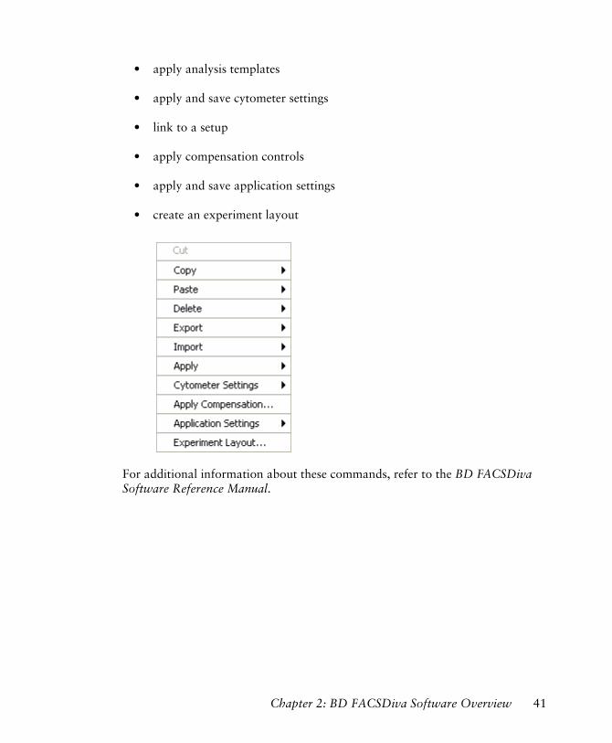
• apply analysis templates
• apply and save cytometer settings
• link to a setup
• apply compensation controls
• apply and save application settings
• create an experiment layout
For additional information about these commands, refer to the BD FACSDiva Software Reference Manual.
Chapter 2: BD FACSDiva Software Overview 41
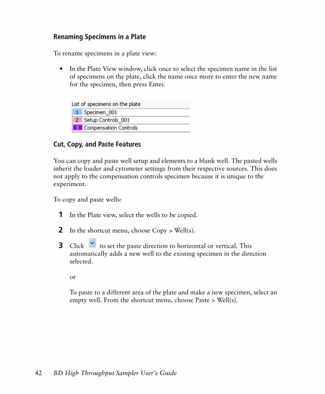
Renaming Specimens in a Plate
To rename specimens in a plate view:
• In the Plate View window, click once to select the specimen name in the list of specimens on the plate, click the name once more to enter the new name for the specimen, then press Enter.
Cut, Copy, and Paste Features
You can copy and paste well setup and elements to a blank well. The pasted wells inherit the loader and cytometer settings from their respective sources. This does not apply to the compensation controls specimen because it is unique to the experiment.
To copy and paste wells:
1 In the Plate view, select the wells to be copied.
2 In the shortcut menu, choose Copy > Well(s).
3 Click to set the paste direction to horizontal or vertical. This automatically adds a new well to the existing specimen in the direction selected.
or
To paste to a different area of the plate and make a new specimen, select an empty well. From the shortcut menu, choose Paste > Well(s).
42 BD High Throughput Sampler User’s Guide
To copy and paste a specimen:
1 Click the specimen in the List of specimens on the plate. Right-click a well in that specimen, then select Copy.
2 Select an empty well, then right-click it and select Paste.
The specimen will be pasted, if there is room on the plate.
Setup View Functions
Use the Setup view to set up new plate-based experiments. Once you have added setup controls, samples, and cytometer settings to the plate layout, you can assign keywords, set recording rules, apply a selected assay (Analysis template), and copy and paste HTS (loader) settings to selected wells or to the entire plate.
Use the Setup view to perform the following functions:
• Define loader settings
• Optimize cytometer settings while running setup controls
• Monitor well status during acquisition
• Acquire and record wells manually or automatically
• Analyze plate data
Chapter 2: BD FACSDiva Software Overview 43
Rearranging Samples on the Plate
Rearrange samples and wells in the plate layout by using the Cut, Copy, and Paste functions. Note that specimens and wells cannot be overwritten.
• You can move specimens to different locations in the plate layout as long as there is room to accommodate the entire specimen.
• You can move wells within a specimen to change the acquisition order or move wells from one specimen to another. Wells are pasted either below or to the right of the selected well, depending on the orientation of the Add Well button.
Assigning Keywords
You can create and assign keywords at the experiment or well level. For information on creating experiment keywords, refer to the BD FACSDiva Software Reference Manual. For instructions on creating and assigning keywords at the well level, see Assigning Keywords on page 77.
Setting Recording Rules
You can alter the acquisition stopping criteria for a selected well by:
• changing the Sample Flow Rate and Sample Volume in the HTS tab of the Well Inspector
• changing the Events to Record in the Experiment Layout or Acq tab of the Well Inspector
For information on acquisition stopping criteria, see Running Samples Automatically in Sequence on page 46 and Running Wells Manually on page 47.
44 BD High Throughput Sampler User’s Guide
Applying an Analysis Template
You can apply an Analysis template to selected samples or wells. First select the well, then:
• choose Edit > Apply Analysis Template in the menu bar
or
• right-click to select Apply > Analysis Template in the shortcut menu.
For instructions on how to save an Analysis template, see Exporting an Experiment as a Template on page 84.
Applying HTS Settings
Apply specific HTS settings to a well or group of wells by using the Copy/Paste Loader Settings commands in the shortcut menu.
Copying and Pasting Cytometer Settings
You can copy and paste cytometer settings from one specimen or well to another as long as the specimen or well that you are copying from has cytometer settings. You can copy and paste cytometer settings to and from unrecorded wells only.
To copy settings from one specimen to another, click to select the specimen in the specimen list (see Figure 2-2 on page 32), then right-click the selected specimen on the plate and choose Copy Cytometer Settings. Select the specimen you wish to copy to in the specimen list, then right-click the selected specimen on the plate and choose Paste Cytometer Settings.
To copy settings from one well to another, click to select the well, then right-click it and choose Copy Cytometer Settings. Select the well you wish to copy to, then right-click it and choose Paste Cytometer Settings.
Chapter 2: BD FACSDiva Software Overview 45
Acquisition Mode
There are two ways to run plate-based acquisition on the HTS: automatically in sequence or manually one well at a time. See Running Samples Automatically in Sequence in the following section and Running Wells Manually on page 47 for a description of each mode.
Running Samples Automatically in Sequence
When running samples in sequence, use the HTS Controls in the Acquisition Dashboard. Data collection proceeds automatically according to sequence number.
Select noncontiguous samples by holding down the Ctrl-key while clicking individual specimens, or select a range of samples using the mouse. Wells are run in the following order:
• setup controls
• compensation controls
• specimen wells
NOTICE When a sequence is in progress, the ability to select a well in the plate layout is disabled.
During a sequence, the acquisition buttons have the following function:
• Run Plate/Stop Plate toggle button—starts recording data for all wells in the plate; terminates the sequence after recording data for the current well. The system flushes any remaining sample that was aspirated.
• Run Well(s)/Stop Well(s) toggle button—starts recording for all wells selected in the sequence; terminates the sequence after recording data for the current well. The system flushes any remaining sample that was aspirated.
46 BD High Throughput Sampler User’s Guide
• Pause/Resume toggle button—pauses the sequence after finishing collection of the current well; resumes a paused sequence with the next well in the sequence
During an uninterrupted sequence, BD FACSDiva software calculates the acquisition time of each well based on sample volume. This acquisition time is referred to as the stopping time, and is calculated as follows:
The software will stop acquisition or recording of a well and proceed to the next well when any of the following stopping rules have been met:
• the specified number of events were collected
• the stopping time was reached
• the file exceeded memory specifications
NOTICE If an HTS error occurs during a run, the run will abort and an error message will display. Once the sequence run is complete, a dialog will be displayed with the status of the run and whether any errors occurred. An alert will sound until the dialog is dismissed.
Running Wells Manually
When running samples in manual mode, use the Basic Controls in the Acquisition Dashboard. You can acquire, record, and restart acquisition on a single selected well as long as a sequence is not currently running. For detailed information on the Basic acquisition controls, refer to the BD FACSDiva Software Reference Manual.
To start manual mode, do one of the following:
• Click on a well and then click Acquire Data under Basic Controls to start acquisition
stop time (msec) = sample volume (µL)flow rate (µL/sec) x 1 sec/1000 msec
Chapter 2: BD FACSDiva Software Overview 47
• Click on a well and then click Record Data under Basic Controls to start recording data
NOTICE While running plate-based acquisition, the Start Acquisition on pointer change preference in the User Preferences window is ignored and the software proceeds as if the preference were set to Off.
NOTICE During manual acquisition, high throughput mode is not applicable.
Stopping time in manual acquisition mode is calculated the same as in automatic sequence mode. The software will stop acquisition or recording of a well when any of the following stopping rules have been met:
• the specified number of events were collected
• the stopping time was reached
• the file exceeded memory specifications
• acquisition was stopped by clicking the Stop Acquiring button under Basic Controls
Once acquisition of the well is complete, any remaining sample is flushed from the system. The controls in the Acquisition Dashboard are briefly disabled while the loader is reset.
Analysis View Components
The Analysis view provides an interface for
• displaying keyword results in the plate layout
• reviewing and analyzing data collected from a plate
• starting a batch analysis
For information on performing these functions, see Analysis View Functions on page 51.
48 BD High Throughput Sampler User’s Guide
The following components are available in the Analysis view.
Plate Layout
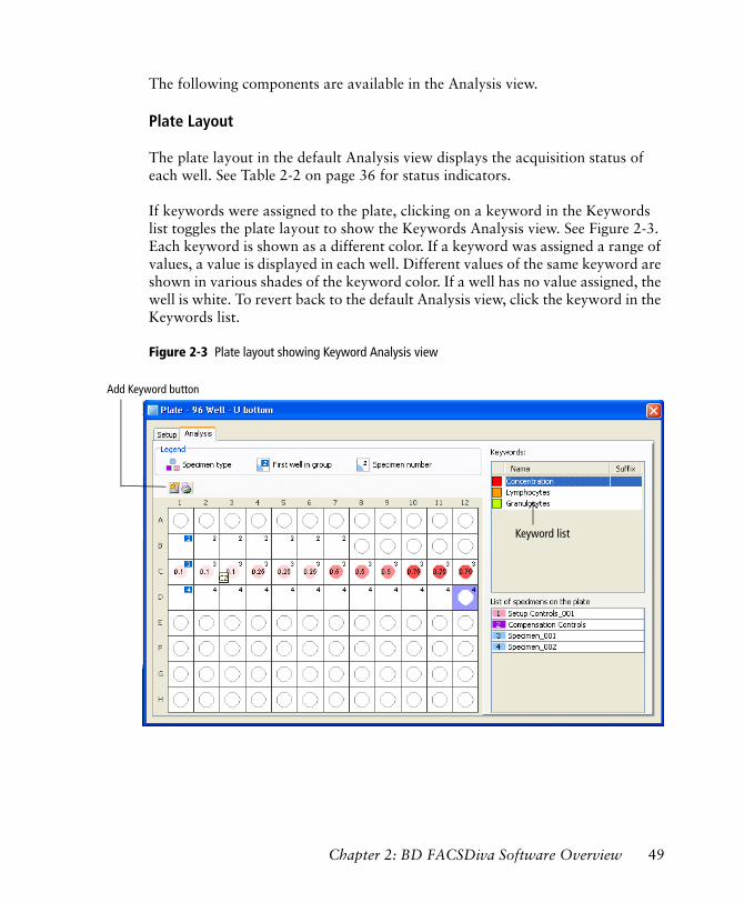
The plate layout in the default Analysis view displays the acquisition status of each well. See Table 2-2 on page 36 for status indicators.
If keywords were assigned to the plate, clicking on a keyword in the Keywords list toggles the plate layout to show the Keywords Analysis view. See Figure 2-3. Each keyword is shown as a different color. If a keyword was assigned a range of values, a value is displayed in each well. Different values of the same keyword are shown in various shades of the keyword color. If a well has no value assigned, the well is white. To revert back to the default Analysis view, click the keyword in the Keywords list.
Figure 2-3 Plate layout showing Keyword Analysis view
Keyword list
Add Keyword button
Chapter 2: BD FACSDiva Software Overview 49
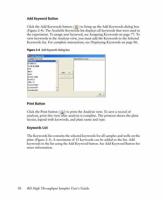
Add Keyword Button
Click the Add Keywords button ( ) to bring up the Add Keywords dialog box (Figure 2-4). The Available Keywords list displays all keywords that were used in the experiment. To assign new keyword, see Assigning Keywords on page 77. To view keywords in the Analysis view, you must add the Keywords to the Selected Keywords list. For complete instructions, see Displaying Keywords on page 86.
Figure 2-4 Add Keywords dialog box
Print Button
Click the Print button ( ) to print the Analysis view. To save a record of analysis, print this view after analysis is complete. The printout shows the plate layout, legend with keywords, and plate name and type.
Keywords List
The Keywords list contains the selected keywords for all samples and wells on the plate (Figure 2-3). A maximum of 15 keywords can be added to the list. Add keywords to the list using the Add Keyword button. See Add Keyword Button for more information.
50 BD High Throughput Sampler User’s Guide
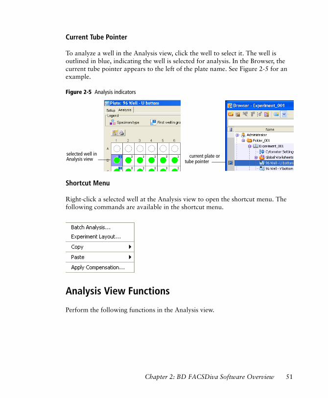
Current Tube Pointer
To analyze a well in the Analysis view, click the well to select it. The well is outlined in blue, indicating the well is selected for analysis. In the Browser, the current tube pointer appears to the left of the plate name. See Figure 2-5 for an example.
Figure 2-5 Analysis indicators
Shortcut Menu
Right-click a selected well at the Analysis view to open the shortcut menu. The following commands are available in the shortcut menu.
Analysis View Functions
Perform the following functions in the Analysis view.
current plate orselected well inAnalysis view tube pointer
Chapter 2: BD FACSDiva Software Overview 51
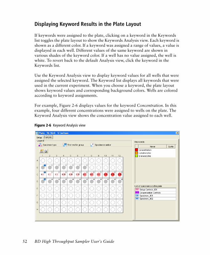
Displaying Keyword Results in the Plate Layout
If keywords were assigned to the plate, clicking on a keyword in the Keywords list toggles the plate layout to show the Keywords Analysis view. Each keyword is shown as a different color. If a keyword was assigned a range of values, a value is displayed in each well. Different values of the same keyword are shown in various shades of the keyword color. If a well has no value assigned, the well is white. To revert back to the default Analysis view, click the keyword in the Keywords list.
Use the Keyword Analysis view to display keyword values for all wells that were assigned the selected keyword. The Keyword list displays all keywords that were used in the current experiment. When you choose a keyword, the plate layout shows keyword values and corresponding background colors. Wells are colored according to keyword assignments.
For example, Figure 2-6 displays values for the keyword Concentration. In this example, four different concentrations were assigned to wells on the plate. The Keyword Analysis view shows the concentration value assigned to each well.
Figure 2-6 Keyword Analysis view
52 BD High Throughput Sampler User’s Guide
Analyzing Plate Data
Analyze plate data the same way you would analyze tube data. For detailed information, refer to the BD FACSDiva Software Reference Manual.
Performing Batch Analysis
Use the batch analysis feature to automatically advance a selected set of data for multiple wells through an analysis template on a global worksheet. You can also assign a preferred global worksheet to a specimen or individual wells using the Inspector. You can set up batch analysis to pause between each data file and to print a copy of the analysis before proceeding with the next well.
NOTICE To perform batch analysis, you must view data using a global worksheet.
For an example of setting up and performing batch analysis, see Performing Batch Analysis on page 90.
Chapter 2: BD FACSDiva Software Overview 53

54 BD High Throughput Sampler User’s Guide
3
Running Samples
This chapter describes how to set up for plate-based acquisition and acquire samples using the BD High Throughput Sampler. For general information about the software, see Chapter 2.
! Tip If you are running the system for the first time, BD Biosciences recommends that you practice running a sample plate using BD Calibrite™ beads or a similar control sample.
The following topics are covered in this chapter:
• Starting Up on page 56
• Creating Experiments on page 64
• Preparing for Acquisition on page 78
• Performing Compensation on page 81
• Acquiring Data on page 82
• Analyzing Data on page 86
• Maintaining Data on page 93
• Returning to Tube-Based Acquisition on page 94
55
Starting Up
This section describes how to start up the cytometer and software. Notice that some steps apply only to a specific cytometer(s).
1 Start up the flow cytometer as described in the appropriate cytometer manual.
Make sure to refill the sheath container and empty the waste container. If a full waste container is detected at the start of or during a run, the run will be stopped. If necessary, perform a sheath fluid exchange to use the appropriate sheath solution. See Exchanging the Sheath Fluid on a BD LSR II on page 96 or Exchanging the Sheath Fluid on a BD FACSCanto and BD FACSCanto II on page 98.
2 Turn on the HTS.
NOTICE The HTS turns on automatically for the BD FACSCanto II.
3 Ensure the sample coupler is installed. See details under Setting Up for Plate-Based Acquisition on page 59.
To prevent bubble formation in the flow cell, use only BD FACS sheath solution with surfactant (BD Catalog No. 336524 [US] or 336911 [Europe]) when acquiring samples with the HTS. This sheath solution is intended for research use only, and should be used only with the HTS option. It should not be used for sorting or in vitro diagnostic (IVD) applications. Refer to the product insert for more information.
Add 500 µL of Sigma® Antifoam A Concentrate to the waste tank to prevent foaming of potentially biohazardous waste up around the cap. Mix the Antifoam Concentrate in distilled water to force it into solution before adding it to the waste tank. Add the Antifoam Concentrate in addition to bleach.
Do not allow the system to run dry, as this could damage the HTS pumps.
56 BD High Throughput Sampler User’s Guide
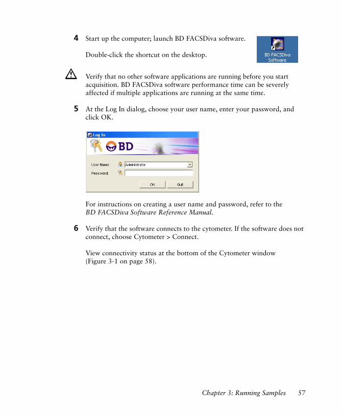
4 Start up the computer; launch BD FACSDiva software.
Double-click the shortcut on the desktop.
5 At the Log In dialog, choose your user name, enter your password, and click OK.
For instructions on creating a user name and password, refer to the BD FACSDiva Software Reference Manual.
6 Verify that the software connects to the cytometer. If the software does not connect, choose Cytometer > Connect.
View connectivity status at the bottom of the Cytometer window (Figure 3-1 on page 58).
Verify that no other software applications are running before you start acquisition. BD FACSDiva software performance time can be severely affected if multiple applications are running at the same time.
Chapter 3: Running Samples 57
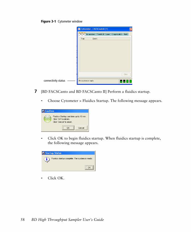
Figure 3-1 Cytometer window
7 [BD FACSCanto and BD FACSCanto II] Perform a fluidics startup.
- Choose Cytometer > Fluidics Startup. The following message appears.
- Click OK to begin fluidics startup. When fluidics startup is complete, the following message appears.
- Click OK.
connectivity status
58 BD High Throughput Sampler User’s Guide
8 [BD LSR II] Place the cytometer in Run mode, then choose HTS > Prime to prime the HTS unit. When the priming is complete, click OK in the dialog.
NOTICE To prime the cytometer, press the Prime button on the fluid control panel on the cytometer itself.
Setting Up for Plate-Based Acquisition
This section describes how to set up the cytometer for plate-based acquisition.
Setting Up for Plate-Based Acquisition on the BD FACSCanto and BD FACSCanto II
When switching from tube to plate mode, perform a sheath fluid exchange, then attach the sample coupler to the SIT.
1 Turn on the cytometer and the HTS.
For the BD FACSCanto, turn on the cytometer, followed by the HTS. For the BD FACSCanto II, the HTS turns on automatically when the cytometer is powered on.
2 Remove/open the HTS safety cover.
[BD FACSCanto] Tilt the front of the cover up, then slide the cover forward to remove it.
[BD FACSCanto II] Slide open the covers. Slide the front cover to the left; slide the side cover to the back.
3 Perform a sheath fluid exchange.
Refer to Exchanging the Sheath Fluid on a BD FACSCanto and BD FACSCanto II on page 98.
Any cytometer surface that comes in contact with biological specimens can transmit potentially fatal disease. Use universal precautions when handling cytometer hardware. Wear suitable protective clothing and gloves.
Chapter 3: Running Samples 59
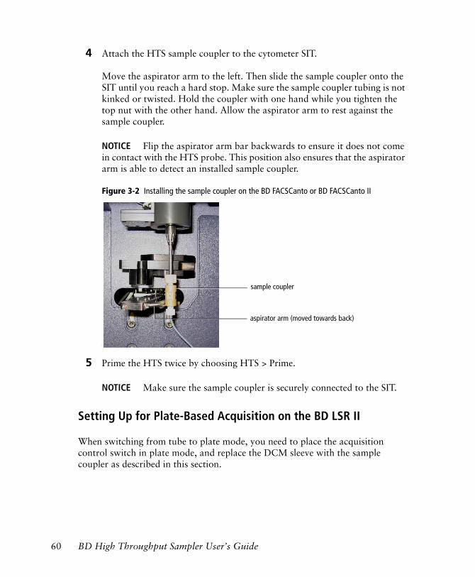
4 Attach the HTS sample coupler to the cytometer SIT.
Move the aspirator arm to the left. Then slide the sample coupler onto the SIT until you reach a hard stop. Make sure the sample coupler tubing is not kinked or twisted. Hold the coupler with one hand while you tighten the top nut with the other hand. Allow the aspirator arm to rest against the sample coupler.
NOTICE Flip the aspirator arm bar backwards to ensure it does not come in contact with the HTS probe. This position also ensures that the aspirator arm is able to detect an installed sample coupler.
Figure 3-2 Installing the sample coupler on the BD FACSCanto or BD FACSCanto II
‘
5 Prime the HTS twice by choosing HTS > Prime.
NOTICE Make sure the sample coupler is securely connected to the SIT.
Setting Up for Plate-Based Acquisition on the BD LSR II
When switching from tube to plate mode, you need to place the acquisition control switch in plate mode, and replace the DCM sleeve with the sample coupler as described in this section.
sample coupler
aspirator arm (moved towards back)
60 BD High Throughput Sampler User’s Guide
1 If necessary, install the HTS unit.
For instructions, see Installing the HTS Unit on page 170.
2 Switch the acquisition control switch to plate mode ( ).
3 Remove the tube of DI water from the SIT.
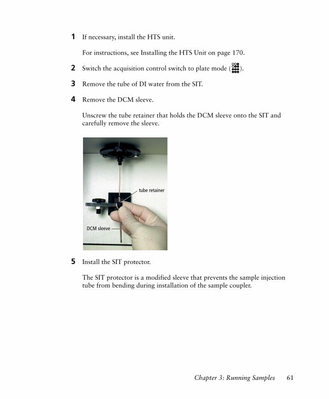
4 Remove the DCM sleeve.
Unscrew the tube retainer that holds the DCM sleeve onto the SIT and carefully remove the sleeve.
5 Install the SIT protector.
The SIT protector is a modified sleeve that prevents the sample injection tube from bending during installation of the sample coupler.
DCM sleeve
tube retainer
Chapter 3: Running Samples 61
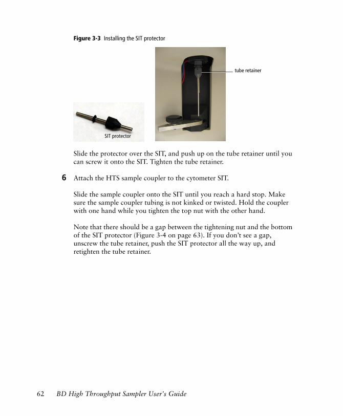
Figure 3-3 Installing the SIT protector
Slide the protector over the SIT, and push up on the tube retainer until you can screw it onto the SIT. Tighten the tube retainer.
6 Attach the HTS sample coupler to the cytometer SIT.
Slide the sample coupler onto the SIT until you reach a hard stop. Make sure the sample coupler tubing is not kinked or twisted. Hold the coupler with one hand while you tighten the top nut with the other hand.
Note that there should be a gap between the tightening nut and the bottom of the SIT protector (Figure 3-4 on page 63). If you don’t see a gap, unscrew the tube retainer, push the SIT protector all the way up, and retighten the tube retainer.
SIT protector
tube retainer
62 BD High Throughput Sampler User’s Guide
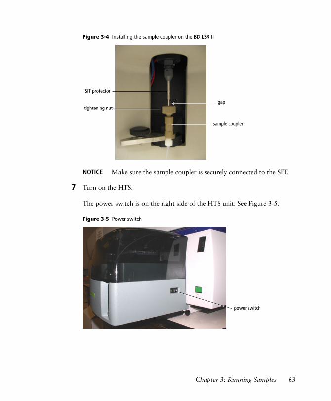
Figure 3-4 Installing the sample coupler on the BD LSR II
NOTICE Make sure the sample coupler is securely connected to the SIT.
7 Turn on the HTS.
The power switch is on the right side of the HTS unit. See Figure 3-5.
Figure 3-5 Power switch
sample coupler
tightening nutgap
SIT protector
power switch
power switch
Chapter 3: Running Samples 63
Creating Experiments
An experiment is a group of elements used to acquire and analyze data from the BD High Throughput Sampler. The Browser is where you create experiments and access stored data.
Here are two ways to add experiments to the Browser.
• Use the New Experiment button ( ) in the Browser toolbar to create a new, empty experiment with default experiment elements and default cytometer settings.
• Use the Experiment > New Experiment command to create a new experiment based on a saved template with customized elements such as plots, gates, statistics view, and cytometer settings.
The following tutorials describe how to set up an experiment specifically for plate-based acquisition and how to use each of the above commands to create additional experiments.
Creating a Folder and an Experiment
This section describes how to create a folder and an experiment containing basic analysis options.
1 Click the corresponding buttons in the Workspace toolbar to display the Browser ( ), Cytometer ( ), Inspector ( ), Worksheet ( ), and Acquisition Dashboard ( ) windows, as needed.
! Tip As you work in the software, windows can become hidden. Bring a window to the forefront by double-clicking the corresponding button in the Workspace toolbar.
2 Choose Edit > User Preferences and verify that the options (in Figure 3-6 on page 65) in the General tab are selected.
64 BD High Throughput Sampler User’s Guide
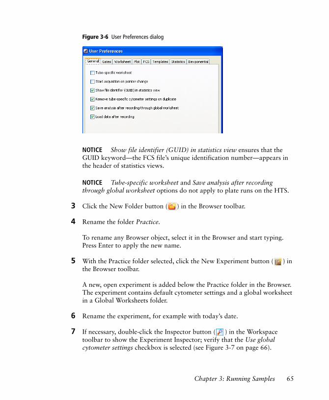
Figure 3-6 User Preferences dialog
NOTICE Show file identifier (GUID) in statistics view ensures that the GUID keyword—the FCS file’s unique identification number—appears in the header of statistics views.
NOTICE Tube-specific worksheet and Save analysis after recording through global worksheet options do not apply to plate runs on the HTS.
3 Click the New Folder button ( ) in the Browser toolbar.
4 Rename the folder Practice.
To rename any Browser object, select it in the Browser and start typing. Press Enter to apply the new name.
5 With the Practice folder selected, click the New Experiment button ( ) in the Browser toolbar.
A new, open experiment is added below the Practice folder in the Browser. The experiment contains default cytometer settings and a global worksheet in a Global Worksheets folder.
6 Rename the experiment, for example with today’s date.
7 If necessary, double-click the Inspector button ( ) in the Workspace toolbar to show the Experiment Inspector; verify that the Use global cytometer settings checkbox is selected (see Figure 3-7 on page 66).
Chapter 3: Running Samples 65
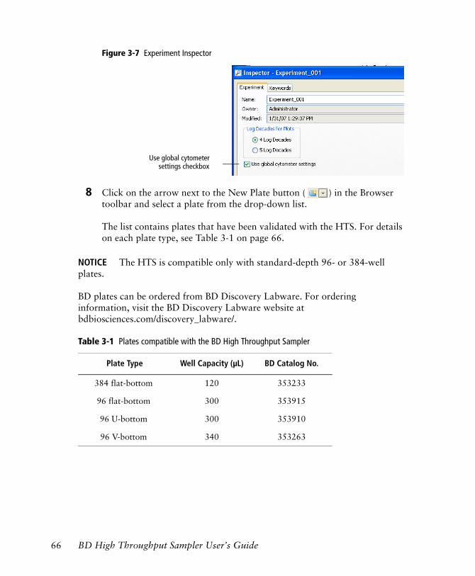
Figure 3-7 Experiment Inspector
8 Click on the arrow next to the New Plate button ( ) in the Browser toolbar and select a plate from the drop-down list.
The list contains plates that have been validated with the HTS. For details on each plate type, see Table 3-1 on page 66.
NOTICE The HTS is compatible only with standard-depth 96- or 384-well plates.
BD plates can be ordered from BD Discovery Labware. For ordering information, visit the BD Discovery Labware website at bdbiosciences.com/discovery_labware/.
Table 3-1 Plates compatible with the BD High Throughput Sampler
Plate Type Well Capacity (µL) BD Catalog No.
384 flat-bottom 120 353233
96 flat-bottom 300 353915
96 U-bottom 300 353910
96 V-bottom 340 353263
Use global cytometersettings checkbox
66 BD High Throughput Sampler User’s Guide
The selected plate type is added to the experiment.
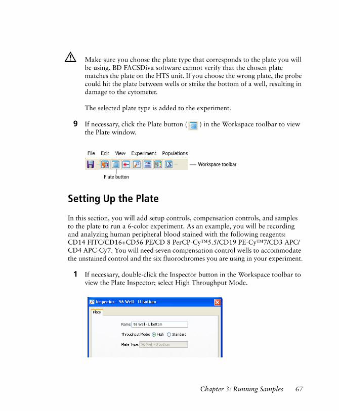
9 If necessary, click the Plate button ( ) in the Workspace toolbar to view the Plate window.
Setting Up the Plate
In this section, you will add setup controls, compensation controls, and samples to the plate to run a 6-color experiment. As an example, you will be recording and analyzing human peripheral blood stained with the following reagents: CD14 FITC/CD16+CD56 PE/CD 8 PerCP-Cy™5.5/CD19 PE-Cy™7/CD3 APC/CD4 APC-Cy7. You will need seven compensation control wells to accommodate the unstained control and the six fluorochromes you are using in your experiment.
1 If necessary, double-click the Inspector button in the Workspace toolbar to view the Plate Inspector; select High Throughput Mode.
Make sure you choose the plate type that corresponds to the plate you will be using. BD FACSDiva software cannot verify that the chosen plate matches the plate on the HTS unit. If you choose the wrong plate, the probe could hit the plate between wells or strike the bottom of a well, resulting in damage to the cytometer.
Plate button
Workspace toolbar
Chapter 3: Running Samples 67
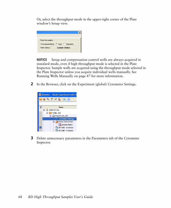
Or, select the throughput mode in the upper-right corner of the Plate window’s Setup view.
NOTICE Setup and compensation control wells are always acquired in standard mode, even if high throughput mode is selected in the Plate Inspector. Sample wells are acquired using the throughput mode selected in the Plate Inspector unless you acquire individual wells manually. See Running Wells Manually on page 47 for more information.
2 In the Browser, click on the Experiment (global) Cytometer Settings.
3 Delete unnecessary parameters in the Parameters tab of the Cytometer Inspector.
68 BD High Throughput Sampler User’s Guide
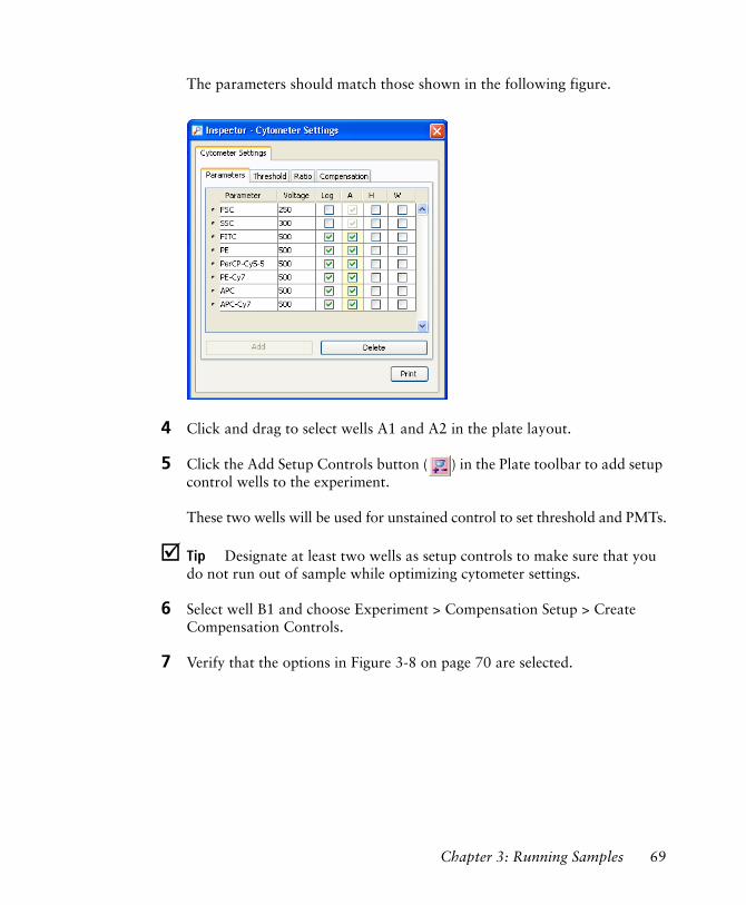
The parameters should match those shown in the following figure.
4 Click and drag to select wells A1 and A2 in the plate layout.
5 Click the Add Setup Controls button ( ) in the Plate toolbar to add setup control wells to the experiment.
These two wells will be used for unstained control to set threshold and PMTs.
! Tip Designate at least two wells as setup controls to make sure that you do not run out of sample while optimizing cytometer settings.
6 Select well B1 and choose Experiment > Compensation Setup > Create Compensation Controls.
7 Verify that the options in Figure 3-8 on page 70 are selected.
Chapter 3: Running Samples 69
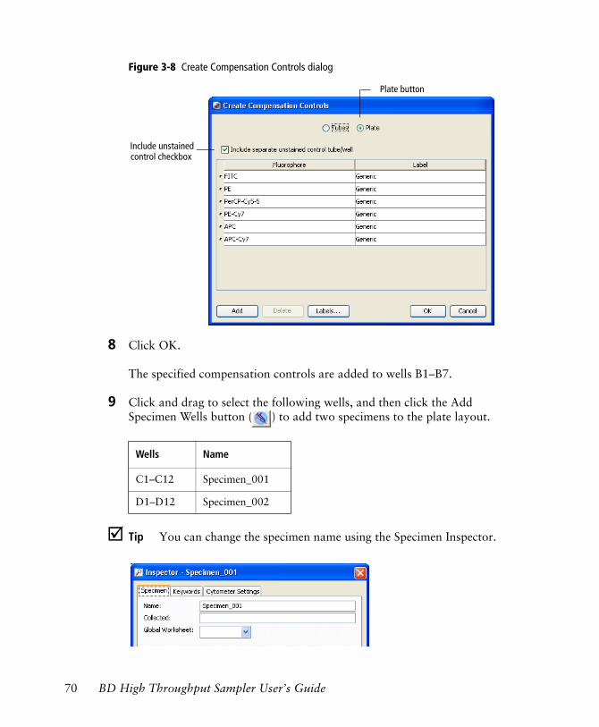
Figure 3-8 Create Compensation Controls dialog
8 Click OK.
The specified compensation controls are added to wells B1–B7.
9 Click and drag to select the following wells, and then click the Add Specimen Wells button ( ) to add two specimens to the plate layout.
! Tip You can change the specimen name using the Specimen Inspector.
Wells Name
C1–C12 Specimen_001
D1–D12 Specimen_002
Plate button
Include unstained control checkbox
70 BD High Throughput Sampler User’s Guide
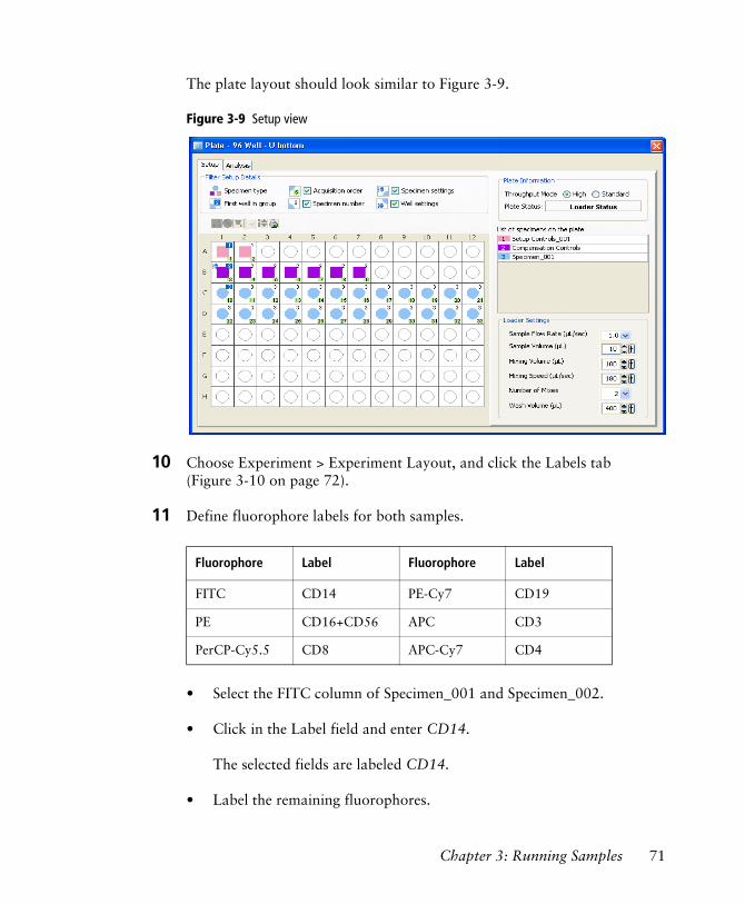
The plate layout should look similar to Figure 3-9.
Figure 3-9 Setup view
10 Choose Experiment > Experiment Layout, and click the Labels tab (Figure 3-10 on page 72).
11 Define fluorophore labels for both samples.
• Select the FITC column of Specimen_001 and Specimen_002.
• Click in the Label field and enter CD14.
The selected fields are labeled CD14.
• Label the remaining fluorophores.
Fluorophore Label Fluorophore Label
FITC CD14 PE-Cy7 CD19
PE CD16+CD56 APC CD3
PerCP-Cy5.5 CD8 APC-Cy7 CD4
Chapter 3: Running Samples 71
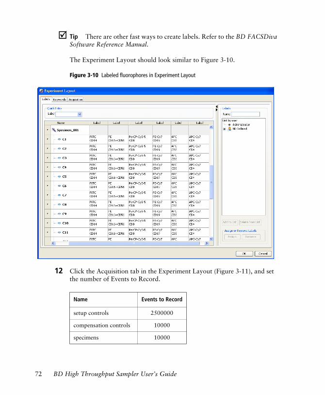
! Tip There are other fast ways to create labels. Refer to the BD FACSDiva Software Reference Manual.
The Experiment Layout should look similar to Figure 3-10.
Figure 3-10 Labeled fluorophores in Experiment Layout
12 Click the Acquisition tab in the Experiment Layout (Figure 3-11), and set the number of Events to Record.
Name Events to Record
setup controls 2500000
compensation controls 10000
specimens 10000
72 BD High Throughput Sampler User’s Guide
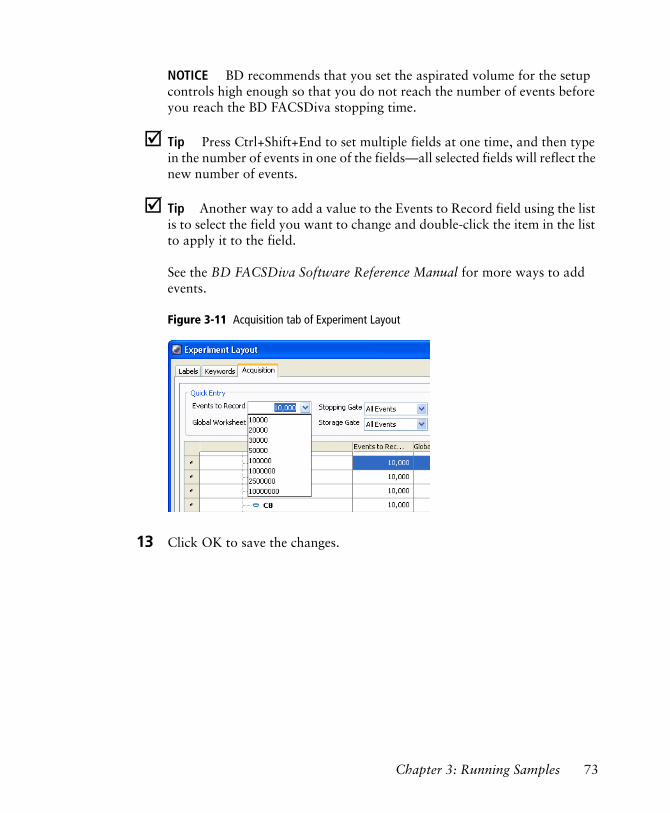
NOTICE BD recommends that you set the aspirated volume for the setup controls high enough so that you do not reach the number of events before you reach the BD FACSDiva stopping time.
! Tip Press Ctrl+Shift+End to set multiple fields at one time, and then type in the number of events in one of the fields—all selected fields will reflect the new number of events.
! Tip Another way to add a value to the Events to Record field using the list is to select the field you want to change and double-click the item in the list to apply it to the field.
See the BD FACSDiva Software Reference Manual for more ways to add events.
Figure 3-11 Acquisition tab of Experiment Layout
13 Click OK to save the changes.
Chapter 3: Running Samples 73

Setting Up the Worksheet
This section describes how to set up plots in a global worksheet.
1 Create an FSC vs SSC plot on the global worksheet.
The plot parameters should be FSC-A and SSC-A.
2 Create a PE histogram next to the FSC vs SSC dot plot; change the plot parameter to PE-A.
3 Create the following dot plots choosing the appropriate parameters.
• FITC vs PE
• PerCP-Cy5.5 vs PE-Cy7
• APC vs APC-Cy7
4 Show a population hierarchy.
The worksheet should look similar to Figure 3-12 on page 75.
74 BD High Throughput Sampler User’s Guide
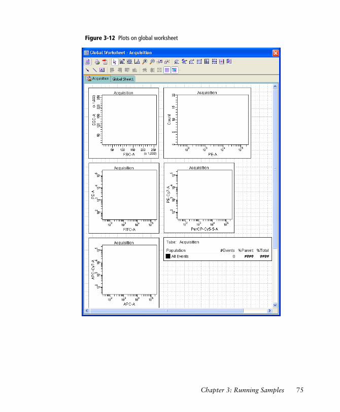
Figure 3-12 Plots on global worksheet
Chapter 3: Running Samples 75
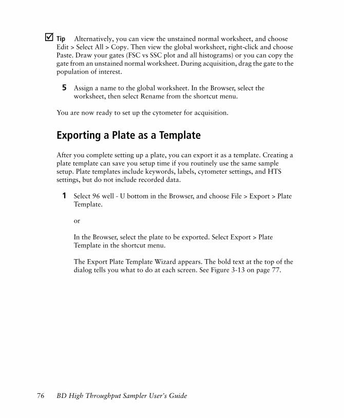
! Tip Alternatively, you can view the unstained normal worksheet, and choose Edit > Select All > Copy. Then view the global worksheet, right-click and choose Paste. Draw your gates (FSC vs SSC plot and all histograms) or you can copy the gate from an unstained normal worksheet. During acquisition, drag the gate to the population of interest.
5 Assign a name to the global worksheet. In the Browser, select the worksheet, then select Rename from the shortcut menu.
You are now ready to set up the cytometer for acquisition.
Exporting a Plate as a Template
After you complete setting up a plate, you can export it as a template. Creating a plate template can save you setup time if you routinely use the same sample setup. Plate templates include keywords, labels, cytometer settings, and HTS settings, but do not include recorded data.
1 Select 96 well - U bottom in the Browser, and choose File > Export > Plate Template.
or
In the Browser, select the plate to be exported. Select Export > Plate Template in the shortcut menu.
The Export Plate Template Wizard appears. The bold text at the top of the dialog tells you what to do at each screen. See Figure 3-13 on page 77.
76 BD High Throughput Sampler User’s Guide
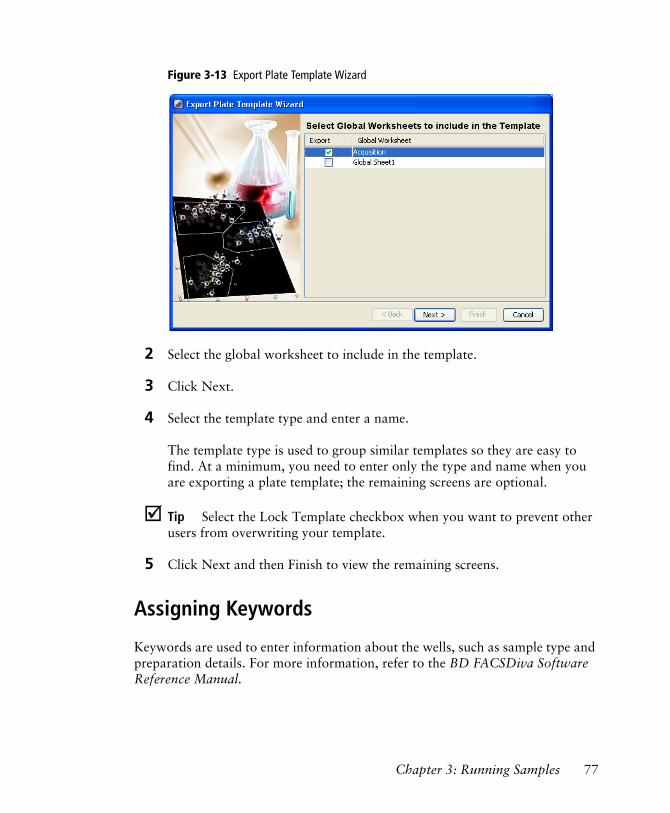
Figure 3-13 Export Plate Template Wizard
2 Select the global worksheet to include in the template.
3 Click Next.
4 Select the template type and enter a name.
The template type is used to group similar templates so they are easy to find. At a minimum, you need to enter only the type and name when you are exporting a plate template; the remaining screens are optional.
! Tip Select the Lock Template checkbox when you want to prevent other users from overwriting your template.
5 Click Next and then Finish to view the remaining screens.
Assigning Keywords
Keywords are used to enter information about the wells, such as sample type and preparation details. For more information, refer to the BD FACSDiva Software Reference Manual.
Chapter 3: Running Samples 77
Preparing for Acquisition
Optimizing Cytometer and HTS Settings
The default settings provide good starting points to achieve optimal throughput in either mode, but the settings should be optimized for your plate type and sample volume.
1 Click the Setup tab of the Plate window.
2 Click each setup control well, view the Cytometer Settings, and verify that they are the same as defined in step 1 in Setting Up the Plate on page 67.
3 Remove the safety cover on the HTS unit and place the prepared plate on the plate holder.
Make sure the plate corresponds to the type selected in the software. Orient the plate with well A1 at the back-right corner of the stage. See Figure 3-14 on page 79.
To prevent damage to the HTS probe, always remove the multiwell plate cover before you put the plate on the holder.
78 BD High Throughput Sampler User’s Guide
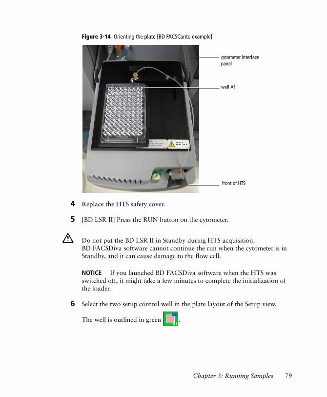
Figure 3-14 Orienting the plate [BD FACSCanto example]
4 Replace the HTS safety cover.
5 [BD LSR II] Press the RUN button on the cytometer.
NOTICE If you launched BD FACSDiva software when the HTS was switched off, it might take a few minutes to complete the initialization of the loader.
6 Select the two setup control well in the plate layout of the Setup view.
The well is outlined in green .
Do not put the BD LSR II in Standby during HTS acquisition. BD FACSDiva software cannot continue the run when the cytometer is in Standby, and it can cause damage to the flow cell.
cytometer interface panel
front of HTS
well A1
Chapter 3: Running Samples 79
7 Click in the Acquisition Dashboard.
If necessary, choose View > Acquisition Dashboard.
The HTS homes and primes the probe, and then aspirates the unstained control from the first setup control well.
NOTICE Setup and compensation wells are always acquired in standard mode, even if high throughput mode is selected in the Plate window.
8 Adjust FSC, SSC, threshold, and PMTs using the unstained control.
For more information on optimizing cytometer settings, refer to the appropriate cytometer user’s guide.
NOTICE Acquisition stopping time is determined by BD FACSDiva software, according to sample volume/sample rate. BD recommends you set the target number of events high enough so that you do not run out of events before you reach the software-based acquisition stopping time. For more information on stopping time, see Running Samples Automatically in Sequence on page 46 and Running Wells Manually on page 47.
! Tip If you run out of sample before you finish optimizing settings, allow the HTS to move to the next setup control well and continue optimization from there.
9 Click Stop Well(s) once you have optimized settings.
The HTS goes through a purge cycle.
If the stopping time is met or the specified number of events are collected, acquisition of the current well will stop, the HTS will be purged, and the software will automatically proceed to the next well.
NOTICE No data file is saved for setup control wells.
80 BD High Throughput Sampler User’s Guide
Performing Compensation
Once you have optimized cytometer settings, you are ready to run your compensation controls and calculate compensation.
NOTICE You can run compensation controls only once during an experiment. If you need to re-run compensation controls, you must create a new experiment.
1 Select wells B1 through B7 in the plate layout.
2 Click Run Well(s) in the Acquisition Dashboard.
The compensation wells will be run in the order they were created.
NOTICE You must select a well(s) in the Setup view as well as a global worksheet to enable the Run Wells button.
After the last compensation control has been recorded, the Sequence Done dialog appears.
3 Click OK.
4 Toggle to the normal worksheet for the compensation control wells.
5 Select the FITC Stained Control worksheet in the Worksheet window.
6 Verify that the P1 gate encompasses the singlet bead population.
7 Verify that the Autointerval gate encompasses the positive peak in each of the plots on all worksheets.
8 Choose Cytometer > Cytometer Setup > Calculate Compensation.
If the calculation is successful, a dialog appears.
Chapter 3: Running Samples 81
9 Name the compensation setup after the experiment, and click OK.
For information on performing compensation, refer to the BD FACSDiva Software Reference Manual.
! Tip Compensation controls can be run individually through their normal worksheets using Basic Controls in the Acquisition Dashboard.
Acquiring Data
Once you calculate compensation, you are ready to record your samples.
1 Click the Worksheets View button to return to the global worksheet.
2 Select well C1 in the plate layout.
3 Click Run Plate in the Acquisition Dashboard.
Wells will be acquired in the order they were created.
As each well is injected into the cytometer SIT, events appear in plots on the global worksheet. If an error occurs, an error message will appear, and the well in the plate layout will be colored according to its status. Well status is indicated by the color outlining each well, as described in Plate Layout on page 35.
At the end of the run, a dialog appears indicating the run is complete.
4 Click OK to dismiss the completion message.
The HTS is equipped with a safety interlock that prevents the cytometer from running when the safety cover is removed or opened. Do not remove or open the safety cover while samples are being processed. To pause or stop acquisition, click the corresponding buttons in the Acquisition Dashboard before you remove or open the safety cover.
82 BD High Throughput Sampler User’s Guide
5 Open the safety cover and remove the plate.
NOTICE Access the plate only after sample processing is complete and the probe is no longer moving.
6 Click the Print button in the Plate toolbar to print a record of the Setup view and legend.
7 Select the appropriate settings and printer, and then click OK.
Use the printout to
• view acquisition run order according to well numbering.
• determine well status post-acquisition. (See Plate Layout on page 35.)
8 At the end of each day or shift, clean and service the cytometer as described in Daily Maintenance on page 104.
Pausing the BD High Throughput Sampler
To pause during a run, click Pause in the Acquisition Dashboard. The HTS unit finishes processing the current well (or wells in high throughput mode), and then remains in a suspended state until you choose to continue.
• To continue the run, click Resume .
• To stop the run, click Stop Well(s) or Stop Plate .
This sequence allows you to stop the run early to minimize additional sample loss.
Keep a record of acquisition status by printing a copy of the Setup view immediately after acquisition is complete. Refer to the printout if you reanalyze or export the data. If you export a data file or an experiment that contains incomplete data, the software cannot recognize that the file is incomplete.
Chapter 3: Running Samples 83
Stopping the BD High Throughput Sampler
The HTS stops automatically when plate acquisition is finished. Do the following if you need to stop the HTS in the middle of a run.
1 Click Stop Plate or Stop Well(s) in the Acquisition Dashboard.
The BD High Throughput Sampler finishes the sequence in progress, stops, and then the following message appears:
NOTICE If you are using the Basic Controls to acquire, simply click Stop Acquiring .
2 Click OK to close the dialog.
Exporting an Experiment as a Template
Now that you have completed an experiment with cytometer and HTS settings, you can export it as a template. Creating Analysis templates for assays that you typically run saves setup time. Experiment templates include plates, keywords, labels, worksheet elements and worksheets (including all settings such as page breaks), cytometer settings, and HTS settings, but do not include recorded data.
1 Select Experiment_001 (or whatever you named it) in the Browser.
If you stop the HTS during a run in standard mode, the current well will be lost. If you stop the HTS in high throughput mode, the current and next well will be lost. Do not stop acquisition if your sample volume is limited.
84 BD High Throughput Sampler User’s Guide
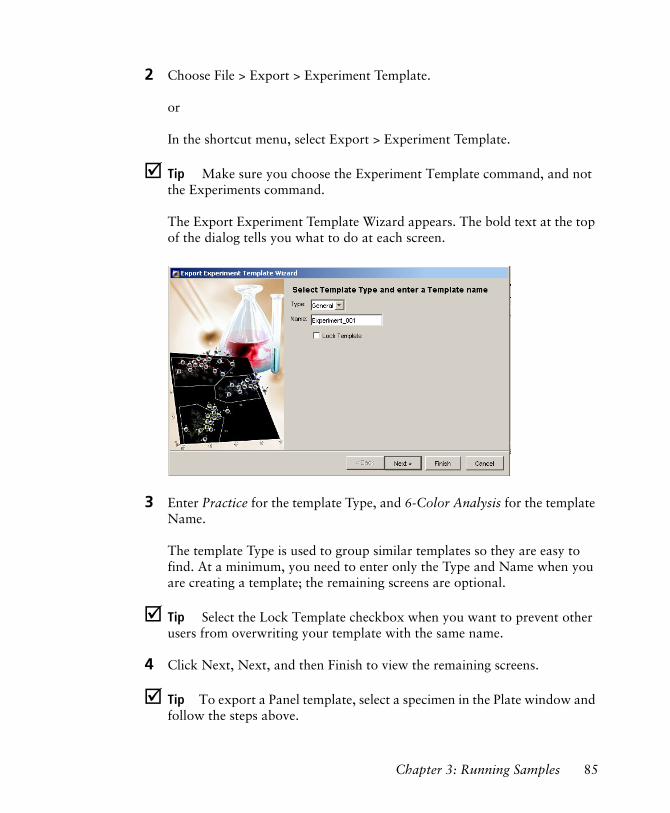
2 Choose File > Export > Experiment Template.
or
In the shortcut menu, select Export > Experiment Template.
! Tip Make sure you choose the Experiment Template command, and not the Experiments command.
The Export Experiment Template Wizard appears. The bold text at the top of the dialog tells you what to do at each screen.
3 Enter Practice for the template Type, and 6-Color Analysis for the template Name.
The template Type is used to group similar templates so they are easy to find. At a minimum, you need to enter only the Type and Name when you are creating a template; the remaining screens are optional.
! Tip Select the Lock Template checkbox when you want to prevent other users from overwriting your template with the same name.
4 Click Next, Next, and then Finish to view the remaining screens.
! Tip To export a Panel template, select a specimen in the Plate window and follow the steps above.
Chapter 3: Running Samples 85
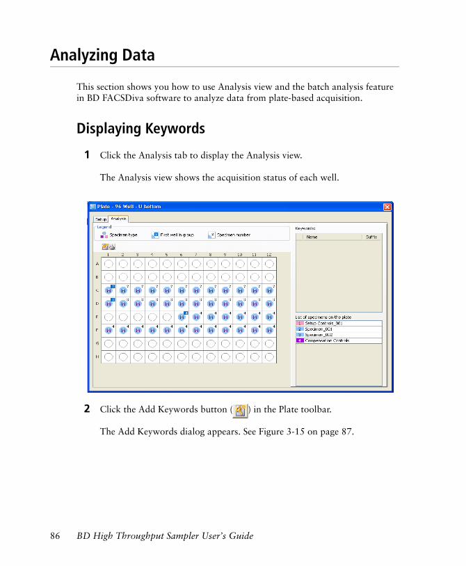
Analyzing Data
This section shows you how to use Analysis view and the batch analysis feature in BD FACSDiva software to analyze data from plate-based acquisition.
Displaying Keywords
1 Click the Analysis tab to display the Analysis view.
The Analysis view shows the acquisition status of each well.
2 Click the Add Keywords button ( ) in the Plate toolbar.
The Add Keywords dialog appears. See Figure 3-15 on page 87.
86 BD High Throughput Sampler User’s Guide
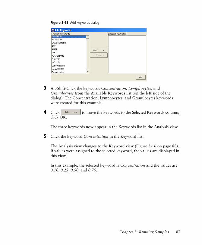
Figure 3-15 Add Keywords dialog
3 Alt-Shift-Click the keywords Concentration, Lymphocytes, and Granulocytes from the Available Keywords list (on the left side of the dialog). The Concentration, Lymphocytes, and Granulocytes keywords were created for this example.
4 Click to move the keywords to the Selected Keywords column; click OK.
The three keywords now appear in the Keywords list in the Analysis view.
5 Click the keyword Concentration in the Keyword list.
The Analysis view changes to the Keyword view (Figure 3-16 on page 88). If values were assigned to the selected keyword, the values are displayed in this view.
In this example, the selected keyword is Concentration and the values are 0.10, 0.25, 0.50, and 0.75.
Chapter 3: Running Samples 87
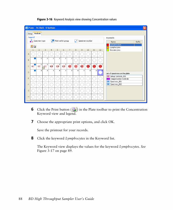
Figure 3-16 Keyword Analysis view showing Concentration values
6 Click the Print button ( ) in the Plate toolbar to print the Concentration Keyword view and legend.
7 Choose the appropriate print options, and click OK.
Save the printout for your records.
8 Click the keyword Lymphocytes in the Keyword list.
The Keyword view displays the values for the keyword Lymphocytes. See Figure 3-17 on page 89.
88 BD High Throughput Sampler User’s Guide
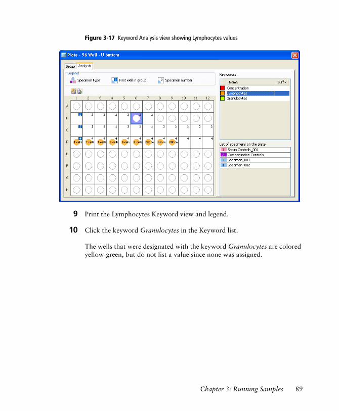
Figure 3-17 Keyword Analysis view showing Lymphocytes values
9 Print the Lymphocytes Keyword view and legend.
10 Click the keyword Granulocytes in the Keyword list.
The wells that were designated with the keyword Granulocytes are colored yellow-green, but do not list a value since none was assigned.
Chapter 3: Running Samples 89
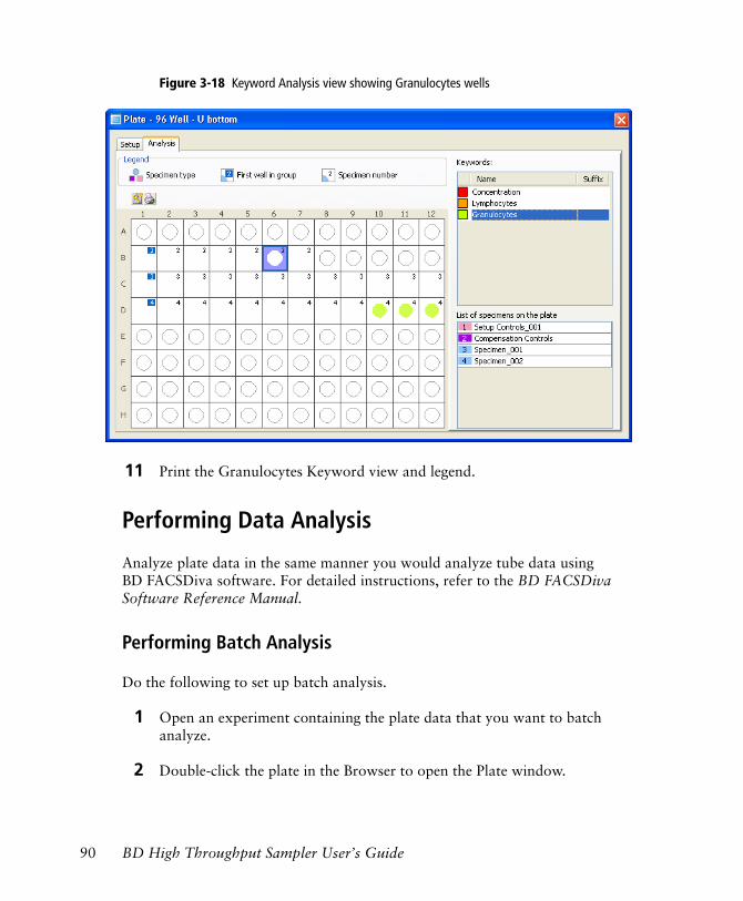
Figure 3-18 Keyword Analysis view showing Granulocytes wells
11 Print the Granulocytes Keyword view and legend.
Performing Data Analysis
Analyze plate data in the same manner you would analyze tube data using BD FACSDiva software. For detailed instructions, refer to the BD FACSDiva Software Reference Manual.
Performing Batch Analysis
Do the following to set up batch analysis.
1 Open an experiment containing the plate data that you want to batch analyze.
2 Double-click the plate in the Browser to open the Plate window.
90 BD High Throughput Sampler User’s Guide
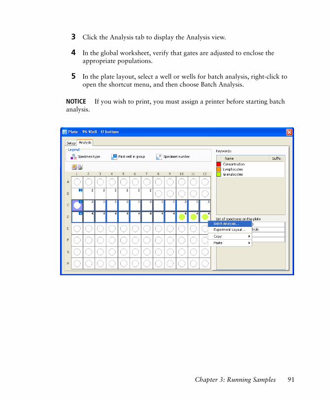
3 Click the Analysis tab to display the Analysis view.
4 In the global worksheet, verify that gates are adjusted to enclose the appropriate populations.
5 In the plate layout, select a well or wells for batch analysis, right-click to open the shortcut menu, and then choose Batch Analysis.
NOTICE If you wish to print, you must assign a printer before starting batch analysis.
Chapter 3: Running Samples 91
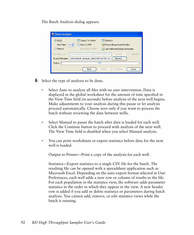
The Batch Analysis dialog appears.
6 Select the type of analysis to be done.
- Select Auto to analyze all files with no user intervention. Data is displayed in the global worksheet for the amount of time specified in the View Time field (in seconds) before analysis of the next well begins. Make adjustments to your analysis during this pause or let analysis proceed automatically. Choose zero only if you want to process the batch without reviewing the data between wells.
- Select Manual to pause the batch after data is loaded for each well. Click the Continue button to proceed with analysis of the next well. The View Time field is disabled when you select Manual analysis.
- You can print worksheets or export statistics before data for the next well is loaded.
Output to Printer—Print a copy of the analysis for each well.
Statistics—Export statistics to a single CSV file for the batch. The resulting file can be opened with a spreadsheet application such as Microsoft Excel. Depending on the auto export format selected in User Preferences, each well adds a new row or column of results to the file. For each population in the statistics view, the software adds parameter statistics in the order in which they appear in the view. A new header row is added if you add or delete statistics or parameters during batch analysis. You cannot add, remove, or edit statistics views while the batch is running.
92 BD High Throughput Sampler User’s Guide
- Save as PDF—the Add Report to PDF and View PDF checkboxes become active. If you keep Add Report to PDF selected, the Batch Analysis Report is added at the top of the worksheet’s PDF file. If you keep View PDF selected, the PDF is automatically displayed at the completion of the batch analysis.
- Specify whether to let biexponential scales fluctuate, if applicable. When the Freeze Biexponential Scales checkbox is selected, biexponential scaling does not change during batch analysis. All data is processed using scales from the tube where the current tube pointer is set. For information on biexponential scales, refer to the BD FACSDiva Software Reference Guide.
Preferred global worksheets can be used with wells and specimens. For information on using preferred global worksheets, refer to the BD FACSDiva Software Reference Manual.
NOTICE Choose zero only if you want to process the batch without reviewing data between wells.
7 Click Start to begin batch analysis.
A message informs you when batch analysis is complete.
NOTICE A plate GUID (globally unique identifier) appears in the statistics view. This number is unique for each plate.
Maintaining Data
Maintain the database by keeping the size below recommended limits, backing up data on a regular basis, and deleting experiments and plates that you no longer need. Follow the precautions and instructions for database management given in the BD FACSDiva Software Reference Manual.
Chapter 3: Running Samples 93
Returning to Tube-Based Acquisition
Returning to Tube-Based Acquisition on the BD LSR II
To return to tube mode, you need to remove the sample coupler and the SIT protector, reinstall the DCM sleeve, place the acquisition control switch in tube mode, and remove the HTS as described in this section.
1 Place the cytometer in Standby.
2 Switch off the HTS power.
3 Detach the sample coupler from the cytometer SIT by unscrewing the top thumbscrew.
Once the coupler feels free, gently pull it straight down from the SIT.
4 Remove the SIT protector.
Unscrew the tube retainer and slide the SIT protector straight down.
5 Reinstall the standard DCM sleeve (Figure 3-19 on page 95).
Slide the sleeve straight up over the SIT, and screw the tube retainer on to secure it.
Any cytometer surface that comes in contact with biological specimens can transmit potentially fatal disease. Use universal precautions when handling cytometer hardware. Wear suitable protective clothing and gloves.
To avoid bending the SIT, pull straight down on the coupler. Do not pull the coupler at an angle.
To avoid bending the SIT, do not slide the SIT protector at an angle.
94 BD High Throughput Sampler User’s Guide
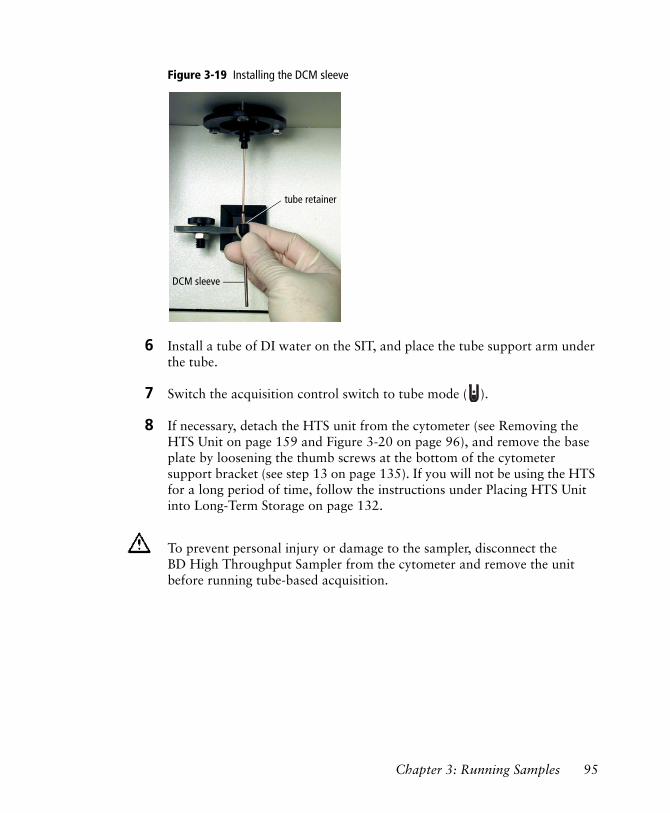
Figure 3-19 Installing the DCM sleeve
6 Install a tube of DI water on the SIT, and place the tube support arm under the tube.
7 Switch the acquisition control switch to tube mode ( ).
8 If necessary, detach the HTS unit from the cytometer (see Removing the HTS Unit on page 159 and Figure 3-20 on page 96), and remove the base plate by loosening the thumb screws at the bottom of the cytometer support bracket (see step 13 on page 135). If you will not be using the HTS for a long period of time, follow the instructions under Placing HTS Unit into Long-Term Storage on page 132.
To prevent personal injury or damage to the sampler, disconnect the BD High Throughput Sampler from the cytometer and remove the unit before running tube-based acquisition.
DCM sleeve
tube retainer
Chapter 3: Running Samples 95
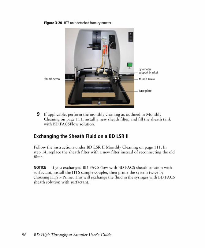
Figure 3-20 HTS unit detached from cytometer
9 If applicable, perform the monthly cleaning as outlined in Monthly Cleaning on page 111, install a new sheath filter, and fill the sheath tank with BD FACSFlow solution.
Exchanging the Sheath Fluid on a BD LSR II
Follow the instructions under BD LSR II Monthly Cleaning on page 111. In step 14, replace the sheath filter with a new filter instead of reconnecting the old filter.
NOTICE If you exchanged BD FACSFlow with BD FACS sheath solution with surfactant, install the HTS sample coupler, then prime the system twice by choosing HTS > Prime. This will exchange the fluid in the syringes with BD FACS sheath solution with surfactant.
cytometer
thumb screw thumb screw
support bracket
base plate
96 BD High Throughput Sampler User’s Guide
Returning to Tube-Based Acquisition on the BD FACSCanto and BD FACSCanto II
Before running BD FACSCanto clinical software, you must exchange BD FACS sheath solution with surfactant with BD FACSFlow. Version 2.1 of the clinical software will not connect in acquisition mode if the sheath type is set to BD FACS sheath solution with surfactant.
1 Perform a sheath exchange to replace BD FACS sheath solution with surfactant with BD FACSFlow. See Exchanging the Sheath Fluid on a BD FACSCanto and BD FACSCanto II on page 98.
2 Detach the sample coupler from the cytometer SIT by unscrewing the top thumbscrew.
Once the coupler feels free, gently pull it straight down from the SIT.
NOTICE For the BD FACSCanto, place the sample coupler in the clamp on the catch tray when the coupler is not in use (see Figure B-11 on page 173).
To avoid bending the SIT, pull straight down on the coupler. Do not pull the coupler at an angle.
Chapter 3: Running Samples 97
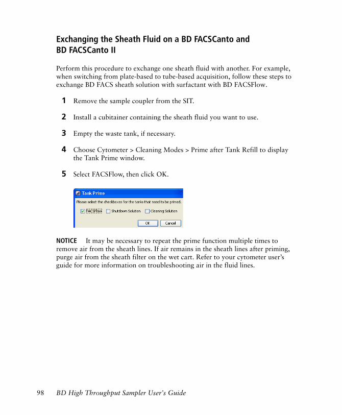
Exchanging the Sheath Fluid on a BD FACSCanto and BD FACSCanto II
Perform this procedure to exchange one sheath fluid with another. For example, when switching from plate-based to tube-based acquisition, follow these steps to exchange BD FACS sheath solution with surfactant with BD FACSFlow.
1 Remove the sample coupler from the SIT.
2 Install a cubitainer containing the sheath fluid you want to use.
3 Empty the waste tank, if necessary.
4 Choose Cytometer > Cleaning Modes > Prime after Tank Refill to display the Tank Prime window.
5 Select FACSFlow, then click OK.
NOTICE It may be necessary to repeat the prime function multiple times to remove air from the sheath lines. If air remains in the sheath lines after priming, purge air from the sheath filter on the wet cart. Refer to your cytometer user’s guide for more information on troubleshooting air in the fluid lines.
98 BD High Throughput Sampler User’s Guide
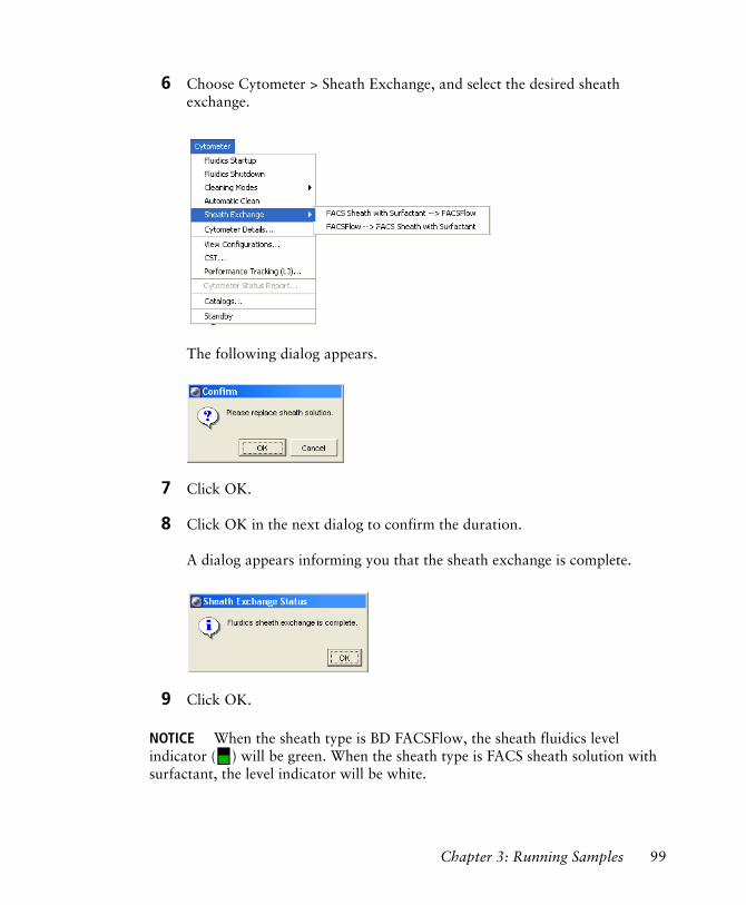
6 Choose Cytometer > Sheath Exchange, and select the desired sheath exchange.
The following dialog appears.
7 Click OK.
8 Click OK in the next dialog to confirm the duration.
A dialog appears informing you that the sheath exchange is complete.
9 Click OK.
NOTICE When the sheath type is BD FACSFlow, the sheath fluidics level indicator ( ) will be green. When the sheath type is FACS sheath solution with surfactant, the level indicator will be white.
Chapter 3: Running Samples 99
NOTICE If you exchanged BD FACSFlow with BD FACS sheath solution with surfactant, install the HTS sample coupler, then prime the HTS twice by choosing HTS > Prime. This will exchange the fluid in the syringes with BD FACS sheath solution with surfactant.
Shutting Down
Perform a daily cleaning procedure before shutting down the system.
1 Run a daily cleaning procedure (see Daily Cleaning on page 104).
2 [BD FACSCanto and BD FACSCanto II] Perform a fluidics shutdown. Refer to Fluidics Shutdown in the following section.
3 [BD LSR II] Prime the HTS unit.
- Place the cytometer in Run mode.
- Choose HTS > Prime.
- When priming is complete, click OK in the dialog, then place the cytometer in Standby mode.
NOTICE To prime the cytometer, press the Prime button on the fluid control panel on the cytometer itself.
4 [BD FACSCanto and BD LSR II] Turn off the power to the HTS.
5 Turn off the power to the cytometer.
6 Quit the software (see Quitting the Software on page 101).
Fluidics Shutdown
[BD FACSCanto and BD FACSCanto II] Perform a fluidics shutdown before quitting the software.
100 BD High Throughput Sampler User’s Guide
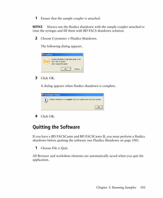
1 Ensure that the sample coupler is attached.
NOTICE Always run the fluidics shutdown with the sample coupler attached to rinse the syringes and fill them with BD FACS shutdown solution.
2 Choose Cytometer > Fluidics Shutdown.
The following dialog appears.
3 Click OK.
A dialog appears when fluidics shutdown is complete.
4 Click OK.
Quitting the Software
If you have a BD FACSCanto and BD FACSCanto II, you must perform a fluidics shutdown before quitting the software (see Fluidics Shutdown on page 100).
1 Choose File > Quit.
All Browser and worksheet elements are automatically saved when you quit the application.
Chapter 3: Running Samples 101

102 BD High Throughput Sampler User’s Guide
4
Maintenance
This chapter provides maintenance procedures to keep your HTS in good working order.
The following maintenance procedures are covered in this chapter.
• Daily Maintenance on page 104
• Monthly Maintenance on page 111
• Periodic Maintenance on page 114
• Unscheduled Maintenance on page 136
103
Daily Maintenance
When running the HTS daily, perform the following at the end of every day (or shift):
• Daily Cleaning—see the following section
• Cytometer Inspection and Servicing—see page 109
NOTICE [BD LSR II] When running samples containing acridine orange or propidium iodide, run Daily Clean twice. First, run 70% isopropyl alcohol in wells A1–A4 and BD™ FACSClean or a 10% bleach solution in wells B1–B4. Second, run BD™ FACSRinse solution in wells A1–A4, followed by DI water in wells B1–B4.
Daily Cleaning
During the daily clean procedure, the cytometer samples cleaning solution and then DI water from predefined wells and performs a sequence of mixing, aspiration, and rinsing. Software prompts guide you through the cleaning sequence. Perform the cleaning procedure at the end of every day or shift while the cytometer is in plate-based mode. Allow 15 minutes to complete this procedure.
Materials Needed
• BD FACSClean or a fresh 10% bleach solution (1 part bleach in 9 parts DI water)
• BD FACSRinse solution
• DI water
104 BD High Throughput Sampler User’s Guide
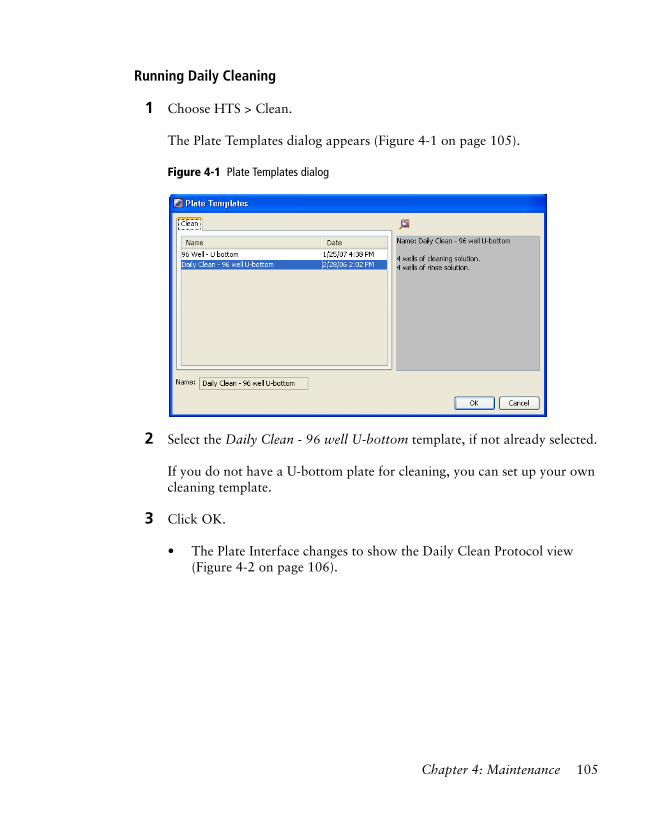
Running Daily Cleaning
1 Choose HTS > Clean.
The Plate Templates dialog appears (Figure 4-1 on page 105).
Figure 4-1 Plate Templates dialog
2 Select the Daily Clean - 96 well U-bottom template, if not already selected.
If you do not have a U-bottom plate for cleaning, you can set up your own cleaning template.
3 Click OK.
• The Plate Interface changes to show the Daily Clean Protocol view (Figure 4-2 on page 106).
Chapter 4: Maintenance 105
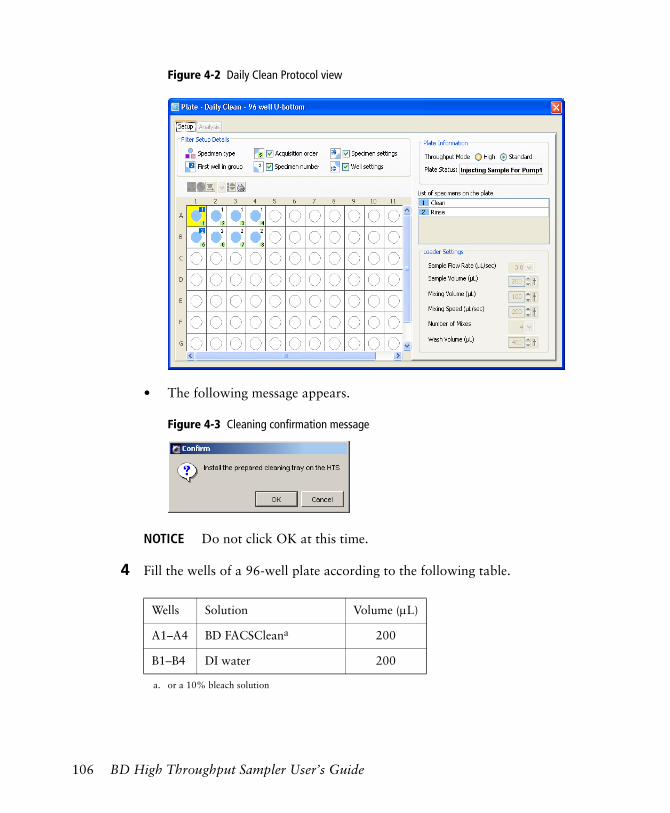
Figure 4-2 Daily Clean Protocol view
• The following message appears.
Figure 4-3 Cleaning confirmation message
NOTICE Do not click OK at this time.
4 Fill the wells of a 96-well plate according to the following table.
Wells Solution Volume (µL)
A1–A4 BD FACSCleana
a. or a 10% bleach solution
200
B1–B4 DI water 200
106 BD High Throughput Sampler User’s Guide
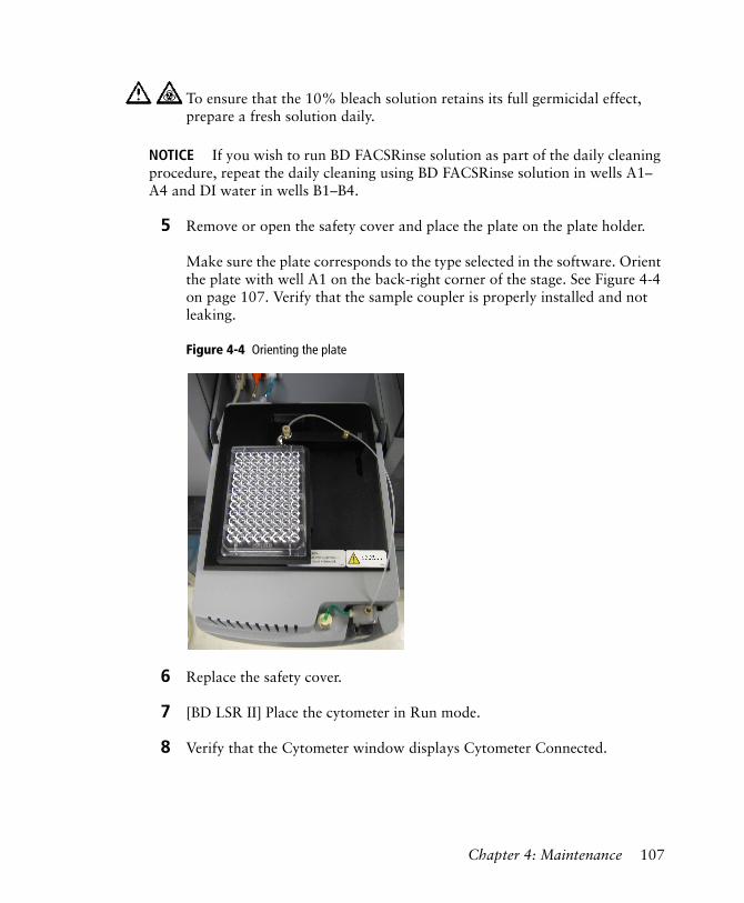
NOTICE If you wish to run BD FACSRinse solution as part of the daily cleaning procedure, repeat the daily cleaning using BD FACSRinse solution in wells A1–A4 and DI water in wells B1–B4.
5 Remove or open the safety cover and place the plate on the plate holder.
Make sure the plate corresponds to the type selected in the software. Orient the plate with well A1 on the back-right corner of the stage. See Figure 4-4 on page 107. Verify that the sample coupler is properly installed and not leaking.
Figure 4-4 Orienting the plate
6 Replace the safety cover.
7 [BD LSR II] Place the cytometer in Run mode.
8 Verify that the Cytometer window displays Cytometer Connected.
To ensure that the 10% bleach solution retains its full germicidal effect, prepare a fresh solution daily.
Chapter 4: Maintenance 107
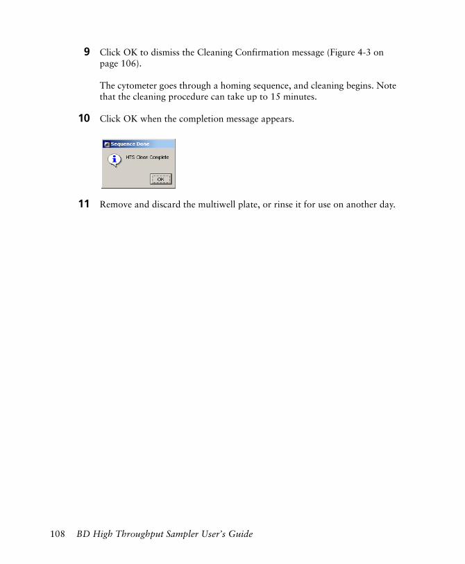
9 Click OK to dismiss the Cleaning Confirmation message (Figure 4-3 on page 106).
The cytometer goes through a homing sequence, and cleaning begins. Note that the cleaning procedure can take up to 15 minutes.
10 Click OK when the completion message appears.
11 Remove and discard the multiwell plate, or rinse it for use on another day.
108 BD High Throughput Sampler User’s Guide
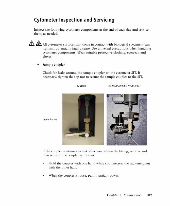
Cytometer Inspection and Servicing
Inspect the following cytometer components at the end of each day and service them, as needed.
• Sample coupler
Check for leaks around the sample coupler on the cytometer SIT. If necessary, tighten the top nut to secure the sample coupler to the SIT.
If the coupler continues to leak after you tighten the fitting, remove and then reinstall the coupler as follows.
- Hold the coupler with one hand while you unscrew the tightening nut with the other hand.
- When the coupler is loose, pull it straight down.
All cytometer surfaces that come in contact with biological specimens can transmit potentially fatal disease. Use universal precautions when handling cytometer components. Wear suitable protective clothing, eyewear, and gloves.
tightening nut
BD LSR II BD FACSCanto/BD FACSCanto II
Chapter 4: Maintenance 109
- Slide the coupler back up until you reach a hard stop. Make sure the sample coupler tubing is not kinked or twisted.
- Hold the coupler with one hand while you tighten the tightening nut with the other hand.
If the coupler is still leaking, replace it. See Replacing the Sample Coupler and Tubing on page 123.
• Injection port/wash station
Check this area for residual liquid. Liquid appearing around the injection port/wash station may indicate a clog. If you suspect a clog, refer to HTS Troubleshooting on page 146.
• Base plate, probe arm assembly, and plate holder
Dampen a clean, lint-free cloth with distilled or DI water and wipe down only the black surfaces of these components, as needed.
• Sample probe
Make sure the probe is straight. If it is bent or shows signs of wear, replace the probe. See Replacing the Probe on page 129.
• Pumps
- Wipe up any spills on or around the pumps.
- Inspect the fittings to make sure they are tight. See Inspecting Thumbscrew Fittings on page 142 and Inspecting Hexagonal Fittings on page 143.
- Inspect the pump syringes for leakage. If your system has been used extensively and the syringes appear worn, replace them. See Replacing a Pump Syringe on page 125.
• [BD LSR II and BD FACSCanto] Absorbent pad
Inspect the absorbent pad at the back of the HTS unit to make sure it is not saturated. Replace the pad, if needed.
110 BD High Throughput Sampler User’s Guide
Monthly Maintenance
When running the HTS daily, perform the following cleaning procedures at the end of every month. If you are using the HTS less frequently, adjust the monthly maintenance schedule accordingly.
• Monthly Cleaning—see the following section
• Surface Inspection and Cleaning—see page 114
Monthly Cleaning
BD LSR II Monthly Cleaning
To perform a monthly cleaning procedure, choose HTS > Monthly Clean. The software prompts you to install a tank containing BD FACSClean (or a 10% bleach solution) in place of the cytometer sheath tank, and then pumps cleaning solution through the lines for 30 minutes. When cleaning is complete, the software prompts you to install a rinse tank, and then pumps DI water through the lines for 30 minutes. Allow 60 minutes to complete the monthly cleaning procedure.
To perform the monthly cleaning you will need DI water and BD FACSClean or a fresh 10% bleach solution (1 part bleach in 9 parts DI water).
1 Bypass the cytometer sheath filter:
• Press the quick-disconnectors on both sides of the filter assembly.
• Remove the filter assembly.
• Reconnect the two fluidic lines.
2 Remove the sheath tank and replace the sheath fluid with BD FACSClean or a freshly prepared 10% bleach solution. Replace the tank.
To ensure that the 10% bleach solution retains its full germicidal effect, prepare a fresh solution daily.
Chapter 4: Maintenance 111
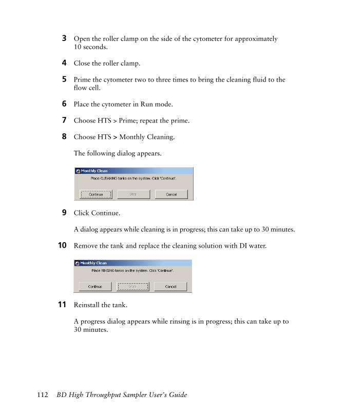
3 Open the roller clamp on the side of the cytometer for approximately 10 seconds.
4 Close the roller clamp.
5 Prime the cytometer two to three times to bring the cleaning fluid to the flow cell.
6 Place the cytometer in Run mode.
7 Choose HTS > Prime; repeat the prime.
8 Choose HTS > Monthly Cleaning.
The following dialog appears.
9 Click Continue.
A dialog appears while cleaning is in progress; this can take up to 30 minutes.
10 Remove the tank and replace the cleaning solution with DI water.
11 Reinstall the tank.
A progress dialog appears while rinsing is in progress; this can take up to 30 minutes.
112 BD High Throughput Sampler User’s Guide
12 Click OK when monthly cleaning is complete.
NOTICE If you have been running BD FACSRinse solution as part of a biweekly cleaning procedure, you can repeat the monthly cleaning using BD FACSRinse solution followed by DI water.
13 Disconnect the tank, fill it with sheath solution, and reconnect it.
14 Reconnect the BD LSR II sheath filter.
NOTICE If you are performing a sheath fluid exchange, install a new filter.
15 Check for bubbles and prime, if necessary.
BD FACSCanto and BD FACSCanto II Monthly Cleaning
1 Ensure the sample coupler is properly installed and the HTS is powered on.
2 Empty the waste tank, if necessary.
3 Ensure the BD FACSClean and BD FACS shutdown solution cubitainers are full and connected.
4 Choose Cytometer > Long Clean.
5 Click OK when the Long Clean is complete.
Chapter 4: Maintenance 113
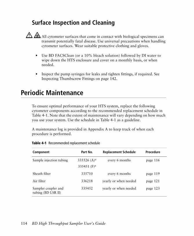
Surface Inspection and Cleaning
• Use BD FACSClean (or a 10% bleach solution) followed by DI water to wipe down the HTS enclosure and cover on a monthly basis, or when needed.
• Inspect the pump syringes for leaks and tighten fittings, if required. See Inspecting Thumbscrew Fittings on page 142.
Periodic Maintenance
To ensure optimal performance of your HTS system, replace the following cytometer components according to the recommended replacement schedule in Table 4-1. Note that the extent of maintenance will vary depending on how much you use your system. Use the schedule in Table 4-1 as a guideline.
A maintenance log is provided in Appendix A to keep track of when each procedure is performed.
All cytometer surfaces that come in contact with biological specimens can transmit potentially fatal disease. Use universal precautions when handling cytometer surfaces. Wear suitable protective clothing and gloves.
Table 4-1 Recommended replacement schedule
Component Part No. Replacement Schedule Procedure
Sample injection tubing 335526 (A)a
335451 (F)a
every 6 months page 116
Sheath filter 335710 every 6 months page 119
Air filter 336218 yearly or when needed page 121
Sampler coupler and tubing (BD LSR II)
335452 yearly or when needed page 123
114 BD High Throughput Sampler User’s Guide
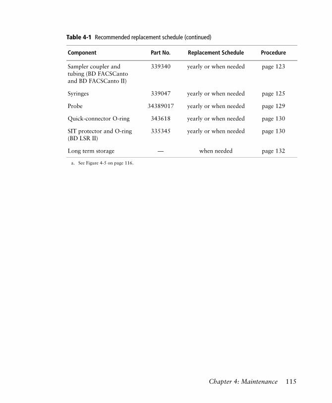
Sampler coupler and tubing (BD FACSCanto and BD FACSCanto II)
339340 yearly or when needed page 123
Syringes 339047 yearly or when needed page 125
Probe 34389017 yearly or when needed page 129
Quick-connector O-ring 343618 yearly or when needed page 130
SIT protector and O-ring (BD LSR II)
335345 yearly or when needed page 130
Long term storage — when needed page 132
a. See Figure 4-5 on page 116.
Table 4-1 Recommended replacement schedule (continued)
Component Part No. Replacement Schedule Procedure
Chapter 4: Maintenance 115
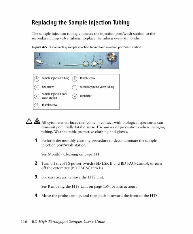
Replacing the Sample Injection Tubing
The sample injection tubing connects the injection port/wash station to the secondary pump valve tubing. Replace the tubing every 6 months.
Figure 4-5 Disconnecting sample injection tubing from injection port/wash station
1 Perform the monthly cleaning procedure to decontaminate the sample injection port/wash station.
See Monthly Cleaning on page 111.
2 Turn off the HTS power switch (BD LSR II and BD FACSCanto), or turn off the cytometer (BD FACSCanto II).
3 For easy access, remove the HTS unit.
See Removing the HTS Unit on page 159 for instructions.
4 Move the probe arm up, and then push it toward the front of the HTS.
All cytometer surfaces that come in contact with biological specimens can transmit potentially fatal disease. Use universal precautions when changing tubing. Wear suitable protective clothing and gloves.
A
B E D
sample injection tubing thumb screw
hex screw secondary pump valve tubing
sample injection port/wash station
connector
thumb screw
A E
B F
C G
D
CF
G
116 BD High Throughput Sampler User’s Guide
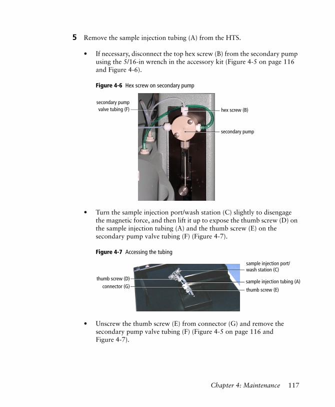
5 Remove the sample injection tubing (A) from the HTS.
• If necessary, disconnect the top hex screw (B) from the secondary pump using the 5/16-in wrench in the accessory kit (Figure 4-5 on page 116 and Figure 4-6).
Figure 4-6 Hex screw on secondary pump
• Turn the sample injection port/wash station (C) slightly to disengage the magnetic force, and then lift it up to expose the thumb screw (D) on the sample injection tubing (A) and the thumb screw (E) on the secondary pump valve tubing (F) (Figure 4-7).
Figure 4-7 Accessing the tubing
• Unscrew the thumb screw (E) from connector (G) and remove the secondary pump valve tubing (F) (Figure 4-5 on page 116 and Figure 4-7).
hex screw (B)secondary pumpvalve tubing (F)
secondary pump
thumb screw (D)
thumb screw (E)connector (G)
sample injection port/wash station (C)
sample injection tubing (A)
Chapter 4: Maintenance 117
• Disconnect the sample injection tubing (A) from the sample injection port/wash station (C) by unscrewing the thumb screw (D) (Figure 4-7) and remove the sample injection tubing (A).
6 Discard the sample injection tubing (A) and the secondary pump valve tubing (F) as biohazardous waste.
7 Install new sample injection tubing.
Replacement tubing is included in the accessory kit.
• Screw the thumb screw (D) onto the sample injection port/wash station (C).
• Screw the thumb screw (E) from the secondary pump valve tubing into connector (G).
NOTICE Take care to screw the thumb screws on straight. If you attach them at an angle, you could strip the threads.
8 Insert the secondary pump valve tubing (F) into the opening of the cytometer base and route the tubing to the secondary pump. Then, lower the sample injection port/wash station (C) onto the cytometer base plate.
The magnetic force will secure the sample injection port/wash station in place.
9 Reconnect the secondary pump valve tubing (F) to the secondary pump by tightening the hex screw (B).
10 Reinstall the HTS unit.
Follow the instructions for Installing the HTS Unit on page 170.
118 BD High Throughput Sampler User’s Guide
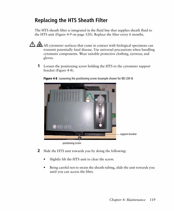
Replacing the HTS Sheath Filter
The HTS sheath filter is integrated in the fluid line that supplies sheath fluid to the HTS unit (Figure 4-9 on page 120). Replace the filter every 6 months.
1 Loosen the positioning screw holding the HTS to the cytometer support bracket (Figure 4-8).
Figure 4-8 Loosening the positioning screw (example shown for BD LSR II)
2 Slide the HTS unit towards you by doing the following:
• Slightly lift the HTS unit to clear the screw.
• Being careful not to strain the sheath tubing, slide the unit towards you until you can access the filter.
All cytometer surfaces that come in contact with biological specimens can transmit potentially fatal disease. Use universal precautions when handling cytometer components. Wear suitable protective clothing, eyewear, and gloves.
support bracket
positioning screw
Chapter 4: Maintenance 119
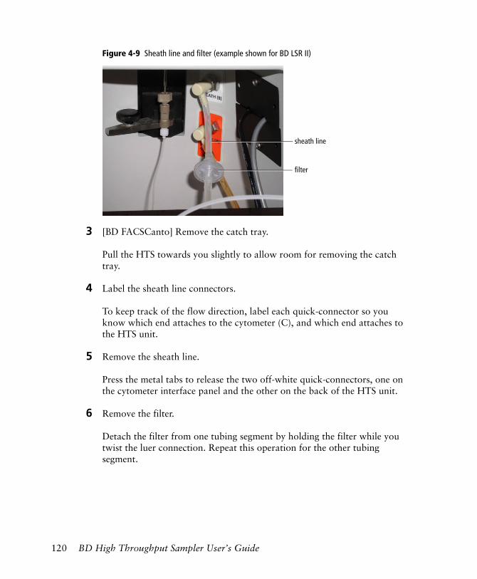
Figure 4-9 Sheath line and filter (example shown for BD LSR II)
3 [BD FACSCanto] Remove the catch tray.
Pull the HTS towards you slightly to allow room for removing the catch tray.
4 Label the sheath line connectors.
To keep track of the flow direction, label each quick-connector so you know which end attaches to the cytometer (C), and which end attaches to the HTS unit.
5 Remove the sheath line.
Press the metal tabs to release the two off-white quick-connectors, one on the cytometer interface panel and the other on the back of the HTS unit.
6 Remove the filter.
Detach the filter from one tubing segment by holding the filter while you twist the luer connection. Repeat this operation for the other tubing segment.
filter
sheath line
120 BD High Throughput Sampler User’s Guide
7 Install the new filter.
• Attach the tubing segment with the male connector to the female filter connection. Hold the filter while you twist the luer lock ring.
• Attach the tubing segment with the female connector to the male filter connection. Hold the filter while you twist the luer female connector.
8 Reinstall the sheath line between the cytometer interface panel and the HTS.
Attach the quick-connectors at each end.
NOTICE Although the sheath filter is a screen filter that provides identical performance regardless of the flow direction, BD recommends that you always install the sheath line with the lock-ring end toward the cytometer panel (connector labeled C). This will prevent any foreign material accumulated on one side of the filter from flushing into the HTS if the filter is reversed.
9 Reinstall the HTS unit.
- [BD FACSCanto] Install the rear catch tray by routing the sample coupler underneath the catch tray tongue and sample coupler slot. Push the tray in, making sure the coupler line is not crimped or kinked.
- Push in the unit and tighten the positioning screw holding the HTS to the cytometer support bracket.
Cleaning the Air Filter
The air filter element is located within a filter retainer and fan guard attached to the base plate of the HTS unit. To clean or replace the air filter, follow these steps.
1 Remove the HTS unit from the cytometer.
For detailed instructions, see Removing the HTS Unit on page 159.
Chapter 4: Maintenance 121
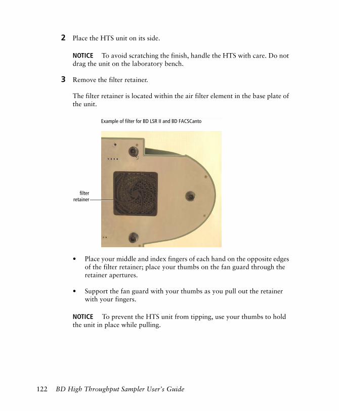
2 Place the HTS unit on its side.
NOTICE To avoid scratching the finish, handle the HTS with care. Do not drag the unit on the laboratory bench.
3 Remove the filter retainer.
The filter retainer is located within the air filter element in the base plate of the unit.
• Place your middle and index fingers of each hand on the opposite edges of the filter retainer; place your thumbs on the fan guard through the retainer apertures.
• Support the fan guard with your thumbs as you pull out the retainer with your fingers.
NOTICE To prevent the HTS unit from tipping, use your thumbs to hold the unit in place while pulling.
filterretainer
Example of filter for BD LSR II and BD FACSCanto
122 BD High Throughput Sampler User’s Guide
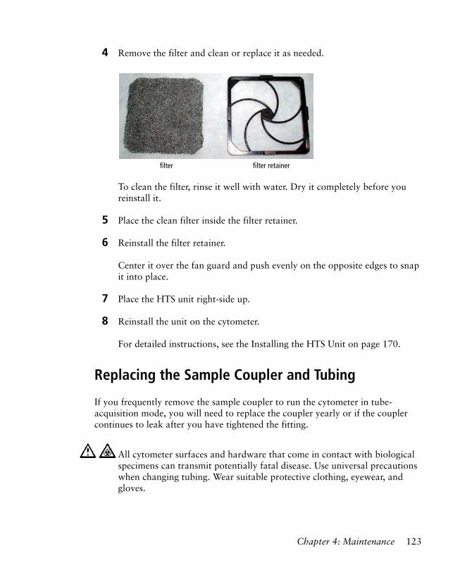
4 Remove the filter and clean or replace it as needed.
To clean the filter, rinse it well with water. Dry it completely before you reinstall it.
5 Place the clean filter inside the filter retainer.
6 Reinstall the filter retainer.
Center it over the fan guard and push evenly on the opposite edges to snap it into place.
7 Place the HTS unit right-side up.
8 Reinstall the unit on the cytometer.
For detailed instructions, see the Installing the HTS Unit on page 170.
Replacing the Sample Coupler and Tubing
If you frequently remove the sample coupler to run the cytometer in tube-acquisition mode, you will need to replace the coupler yearly or if the coupler continues to leak after you have tightened the fitting.
All cytometer surfaces and hardware that come in contact with biological specimens can transmit potentially fatal disease. Use universal precautions when changing tubing. Wear suitable protective clothing, eyewear, and gloves.
filter filter retainer
Chapter 4: Maintenance 123
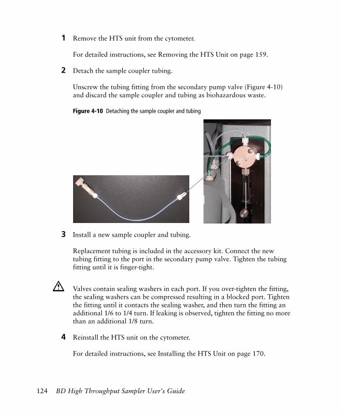
1 Remove the HTS unit from the cytometer.
For detailed instructions, see Removing the HTS Unit on page 159.
2 Detach the sample coupler tubing.
Unscrew the tubing fitting from the secondary pump valve (Figure 4-10) and discard the sample coupler and tubing as biohazardous waste.
Figure 4-10 Detaching the sample coupler and tubing
3 Install a new sample coupler and tubing.
Replacement tubing is included in the accessory kit. Connect the new tubing fitting to the port in the secondary pump valve. Tighten the tubing fitting until it is finger-tight.
4 Reinstall the HTS unit on the cytometer.
For detailed instructions, see Installing the HTS Unit on page 170.
Valves contain sealing washers in each port. If you over-tighten the fitting, the sealing washers can be compressed resulting in a blocked port. Tighten the fitting until it contacts the sealing washer, and then turn the fitting an additional 1/6 to 1/4 turn. If leaking is observed, tighten the fitting no more than an additional 1/8 turn.
124 BD High Throughput Sampler User’s Guide
Replacing a Pump Syringe
Glass syringes are used in the primary and secondary pumps in the HTS unit. Replace a syringe once a year or whenever leaks occur or pumping accuracy is suspect. To begin this procedure, the cytometer and software must be running.
1 Before replacing the pump syringe, perform monthly cleaning.
See Monthly Cleaning on page 111.
2 [BD LSR II] Place the cytometer in Run mode.
3 Remove the liquid from the syringe by performing steps 2 through 11 in Placing HTS Unit into Long-Term Storage on page 132.
4 Turn off the HTS power switch (BD LSR II and BD FACSCanto), or turn off the cytometer (BD FACSCanto II). Keep the software running on the workstation.
5 If you are replacing:
• the primary pump syringe, located at the front of the HTS, skip to step 7.
• the secondary pump syringe, located at the back of the HTS, remove the HTS by following steps 1 through 13 in Removing the HTS Unit on page 159.
All cytometer surfaces and hardware that come in contact with biological specimens can transmit potentially fatal disease. Use universal precautions when changing the syringe. Wear suitable protective clothing, eyewear, and gloves.
Chapter 4: Maintenance 125
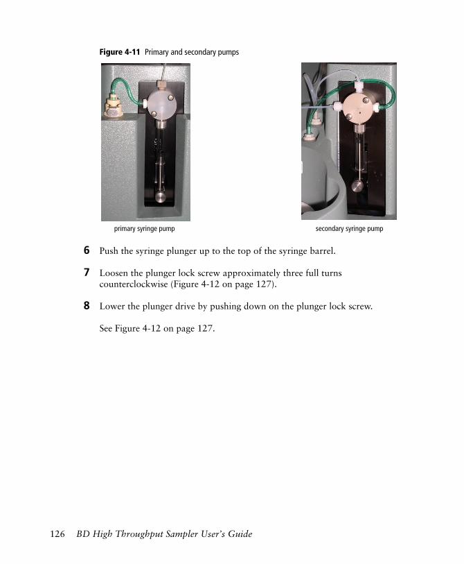
Figure 4-11 Primary and secondary pumps
6 Push the syringe plunger up to the top of the syringe barrel.
7 Loosen the plunger lock screw approximately three full turns counterclockwise (Figure 4-12 on page 127).
8 Lower the plunger drive by pushing down on the plunger lock screw.
See Figure 4-12 on page 127.
primary syringe pump secondary syringe pump
126 BD High Throughput Sampler User’s Guide
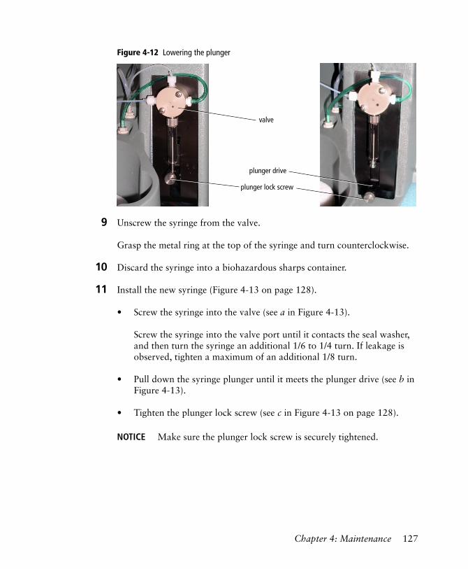
Figure 4-12 Lowering the plunger
9 Unscrew the syringe from the valve.
Grasp the metal ring at the top of the syringe and turn counterclockwise.
10 Discard the syringe into a biohazardous sharps container.
11 Install the new syringe (Figure 4-13 on page 128).
• Screw the syringe into the valve (see a in Figure 4-13).
Screw the syringe into the valve port until it contacts the seal washer, and then turn the syringe an additional 1/6 to 1/4 turn. If leakage is observed, tighten a maximum of an additional 1/8 turn.
• Pull down the syringe plunger until it meets the plunger drive (see b in Figure 4-13).
• Tighten the plunger lock screw (see c in Figure 4-13 on page 128).
NOTICE Make sure the plunger lock screw is securely tightened.
plunger lock screw
plunger drive
valve
Chapter 4: Maintenance 127
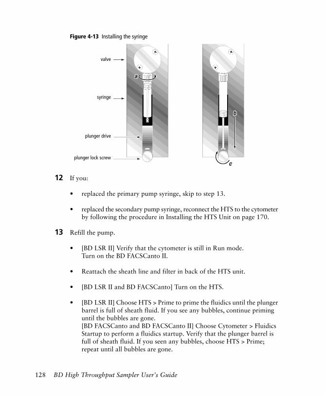
Figure 4-13 Installing the syringe
12 If you:
• replaced the primary pump syringe, skip to step 13.
• replaced the secondary pump syringe, reconnect the HTS to the cytometer by following the procedure in Installing the HTS Unit on page 170.
13 Refill the pump.
• [BD LSR II] Verify that the cytometer is still in Run mode. Turn on the BD FACSCanto II.
• Reattach the sheath line and filter in back of the HTS unit.
• [BD LSR II and BD FACSCanto] Turn on the HTS.
• [BD LSR II] Choose HTS > Prime to prime the fluidics until the plunger barrel is full of sheath fluid. If you see any bubbles, continue priming until the bubbles are gone.[BD FACSCanto and BD FACSCanto II] Choose Cytometer > Fluidics Startup to perform a fluidics startup. Verify that the plunger barrel is full of sheath fluid. If you seen any bubbles, choose HTS > Prime; repeat until all bubbles are gone.
plunger drive
syringe
valve
plunger lock screw
128 BD High Throughput Sampler User’s Guide
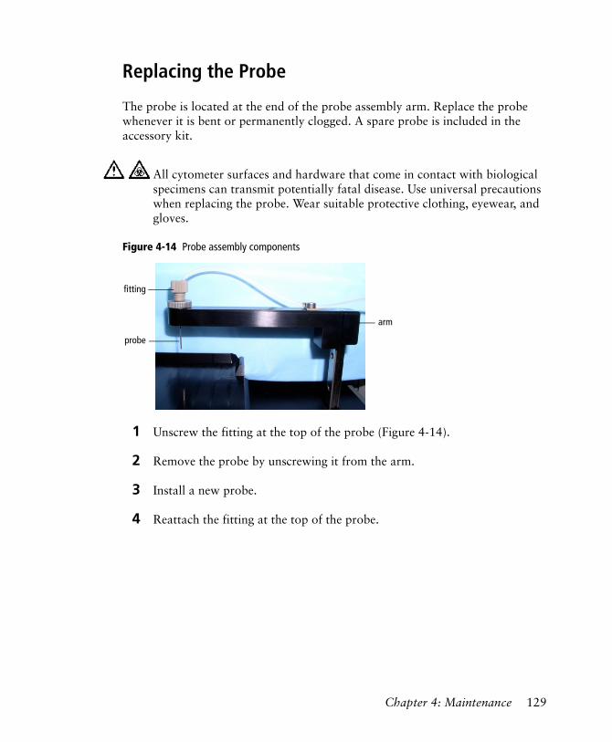
Replacing the Probe
The probe is located at the end of the probe assembly arm. Replace the probe whenever it is bent or permanently clogged. A spare probe is included in the accessory kit.
Figure 4-14 Probe assembly components
1 Unscrew the fitting at the top of the probe (Figure 4-14).
2 Remove the probe by unscrewing it from the arm.
3 Install a new probe.
4 Reattach the fitting at the top of the probe.
All cytometer surfaces and hardware that come in contact with biological specimens can transmit potentially fatal disease. Use universal precautions when replacing the probe. Wear suitable protective clothing, eyewear, and gloves.
probe
fitting
arm
Chapter 4: Maintenance 129
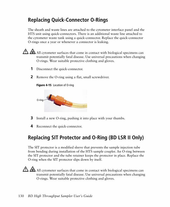
Replacing Quick-Connector O-Rings
The sheath and waste lines are attached to the cytometer interface panel and the HTS unit using quick-connectors. There is an additional waste line attached to the cytometer waste tank using a quick-connector. Replace the quick-connector O-rings once a year or whenever a connector is leaking.
1 Disconnect the quick-connector.
2 Remove the O-ring using a flat, small screwdriver.
Figure 4-15 Location of O-ring
3 Install a new O-ring, pushing it into place with your thumbs.
4 Reconnect the quick-connector.
Replacing SIT Protector and O-Ring (BD LSR II Only)
The SIT protector is a modified sleeve that prevents the sample injection tube from bending during installation of the HTS sample coupler. An O-ring between the SIT protector and the tube retainer keeps the protector in place. Replace the O-ring when the SIT protector slips down by itself.
All cytometer surfaces that come in contact with biological specimens can transmit potentially fatal disease. Use universal precautions when changing O-rings. Wear suitable protective clothing and gloves.
All cytometer surfaces that come in contact with biological specimens can transmit potentially fatal disease. Use universal precautions when changing O-rings. Wear suitable protective clothing and gloves.
O-ring
130 BD High Throughput Sampler User’s Guide
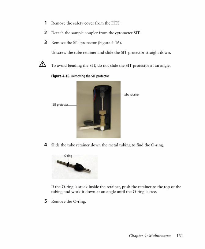
1 Remove the safety cover from the HTS.
2 Detach the sample coupler from the cytometer SIT.
3 Remove the SIT protector (Figure 4-16).
Unscrew the tube retainer and slide the SIT protector straight down.
Figure 4-16 Removing the SIT protector
4 Slide the tube retainer down the metal tubing to find the O-ring.
If the O-ring is stuck inside the retainer, push the retainer to the top of the tubing and work it down at an angle until the O-ring is free.
5 Remove the O-ring.
To avoid bending the SIT, do not slide the SIT protector at an angle.
tube retainer
SIT protector
O-ring
Chapter 4: Maintenance 131
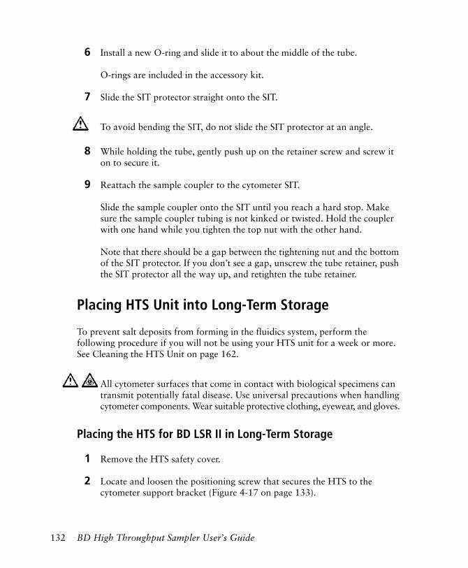
6 Install a new O-ring and slide it to about the middle of the tube.
O-rings are included in the accessory kit.
7 Slide the SIT protector straight onto the SIT.
8 While holding the tube, gently push up on the retainer screw and screw it on to secure it.
9 Reattach the sample coupler to the cytometer SIT.
Slide the sample coupler onto the SIT until you reach a hard stop. Make sure the sample coupler tubing is not kinked or twisted. Hold the coupler with one hand while you tighten the top nut with the other hand.
Note that there should be a gap between the tightening nut and the bottom of the SIT protector. If you don’t see a gap, unscrew the tube retainer, push the SIT protector all the way up, and retighten the tube retainer.
Placing HTS Unit into Long-Term Storage
To prevent salt deposits from forming in the fluidics system, perform the following procedure if you will not be using your HTS unit for a week or more. See Cleaning the HTS Unit on page 162.
Placing the HTS for BD LSR II in Long-Term Storage
1 Remove the HTS safety cover.
2 Locate and loosen the positioning screw that secures the HTS to the cytometer support bracket (Figure 4-17 on page 133).
To avoid bending the SIT, do not slide the SIT protector at an angle.
All cytometer surfaces that come in contact with biological specimens can transmit potentially fatal disease. Use universal precautions when handling cytometer components. Wear suitable protective clothing, eyewear, and gloves.
132 BD High Throughput Sampler User’s Guide
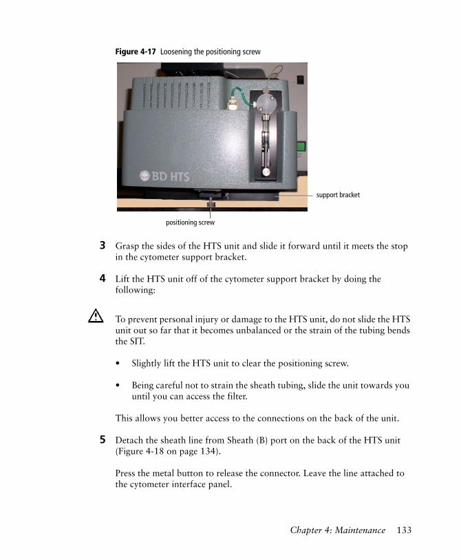
Figure 4-17 Loosening the positioning screw
3 Grasp the sides of the HTS unit and slide it forward until it meets the stop in the cytometer support bracket.
4 Lift the HTS unit off of the cytometer support bracket by doing the following:
• Slightly lift the HTS unit to clear the positioning screw.
• Being careful not to strain the sheath tubing, slide the unit towards you until you can access the filter.
This allows you better access to the connections on the back of the unit.
5 Detach the sheath line from Sheath (B) port on the back of the HTS unit (Figure 4-18 on page 134).
Press the metal button to release the connector. Leave the line attached to the cytometer interface panel.
To prevent personal injury or damage to the HTS unit, do not slide the HTS unit out so far that it becomes unbalanced or the strain of the tubing bends the SIT.
support bracket
positioning screw
Chapter 4: Maintenance 133
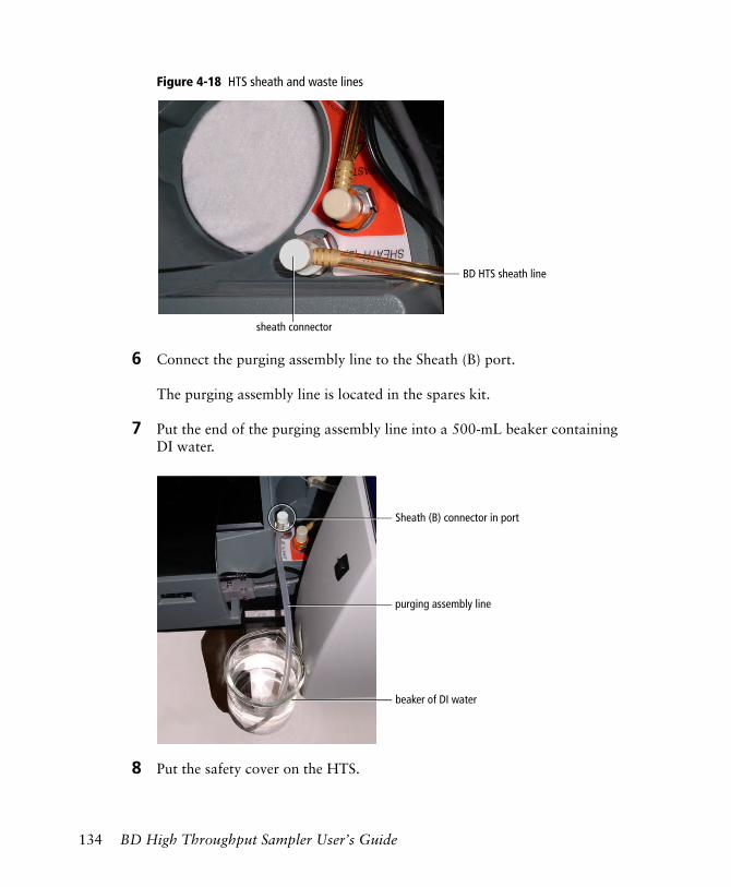
Figure 4-18 HTS sheath and waste lines
6 Connect the purging assembly line to the Sheath (B) port.
The purging assembly line is located in the spares kit.
7 Put the end of the purging assembly line into a 500-mL beaker containing DI water.
8 Put the safety cover on the HTS.
filter
BD HTS sheath line
sheath connector
purging assembly line
beaker of DI water
Sheath (B) connector in port
134 BD High Throughput Sampler User’s Guide
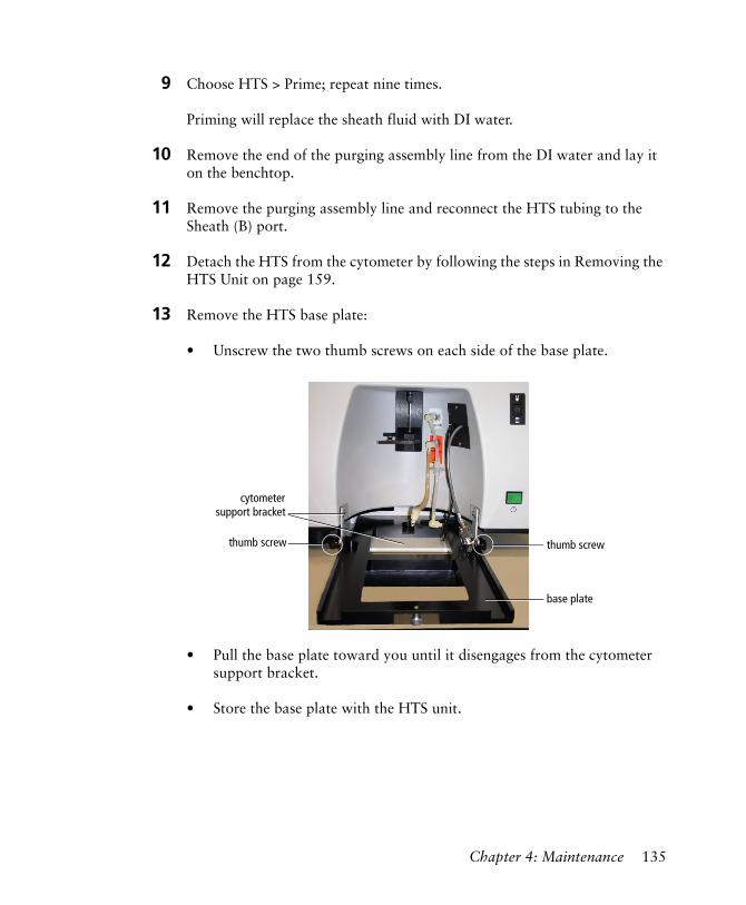
9 Choose HTS > Prime; repeat nine times.
Priming will replace the sheath fluid with DI water.
10 Remove the end of the purging assembly line from the DI water and lay it on the benchtop.
11 Remove the purging assembly line and reconnect the HTS tubing to the Sheath (B) port.
12 Detach the HTS from the cytometer by following the steps in Removing the HTS Unit on page 159.
13 Remove the HTS base plate:
• Unscrew the two thumb screws on each side of the base plate.
• Pull the base plate toward you until it disengages from the cytometer support bracket.
• Store the base plate with the HTS unit.
thumb screw
base plate
thumb screw
cytometersupport bracket
Chapter 4: Maintenance 135
Placing the HTS for BD FACSCanto or BD FACSCanto II in Long-Term Storage
1 Ensure the sample coupler is installed and the HTS is turned on.
2 Perform a fluidic shutdown. See Fluidics Shutdown on page 100 for details.
3 If required, remove the HTS from the cytometer. See Removing the HTS Unit on page 159.
Unscheduled Maintenance
Perform the following procedures when necessary or when you are directed to do so by a BD Biosciences service representative.
• Homing the Sample Probe on this page
• Priming the HTS on page 138
• Performing a Motion Test on page 138
• Verifying the Sample Probe Position on page 140
• Inspecting Thumbscrew Fittings on page 142
• Inspecting Hexagonal Fittings on page 143
• Declogging the SIT on page 143
Homing the Sample Probe
During normal operation, the sample probe goes through a homing sequence during initialization. Perform the following procedure to manually send the probe to the home position, or when directed by a BD Biosciences service representative during troubleshooting.
136 BD High Throughput Sampler User’s Guide
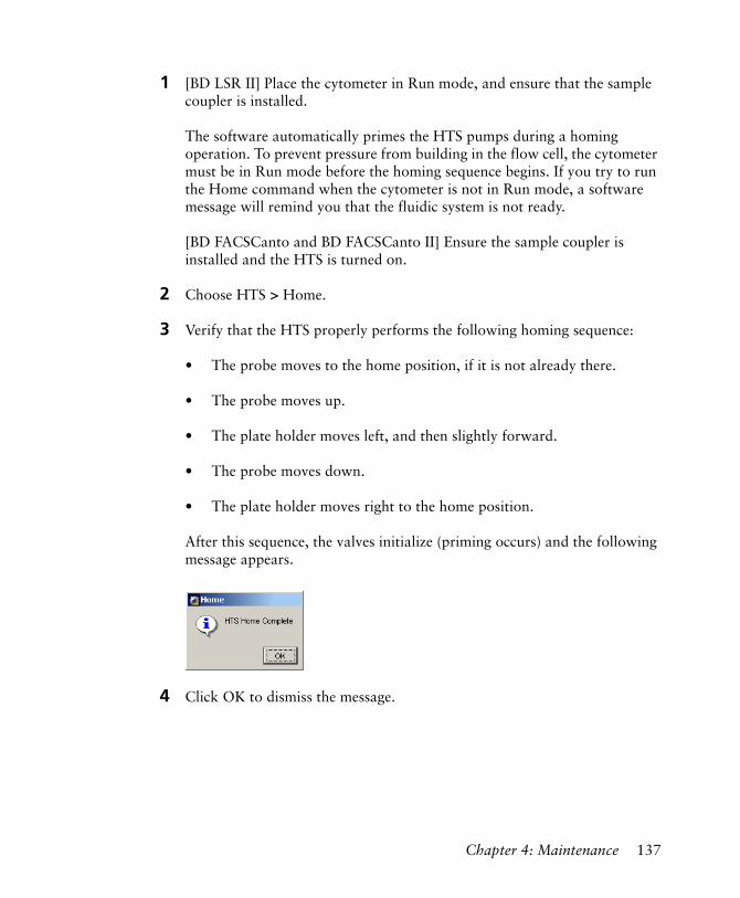
1 [BD LSR II] Place the cytometer in Run mode, and ensure that the sample coupler is installed.
The software automatically primes the HTS pumps during a homing operation. To prevent pressure from building in the flow cell, the cytometer must be in Run mode before the homing sequence begins. If you try to run the Home command when the cytometer is not in Run mode, a software message will remind you that the fluidic system is not ready.
[BD FACSCanto and BD FACSCanto II] Ensure the sample coupler is installed and the HTS is turned on.
2 Choose HTS > Home.
3 Verify that the HTS properly performs the following homing sequence:
• The probe moves to the home position, if it is not already there.
• The probe moves up.
• The plate holder moves left, and then slightly forward.
• The probe moves down.
• The plate holder moves right to the home position.
After this sequence, the valves initialize (priming occurs) and the following message appears.
4 Click OK to dismiss the message.
Chapter 4: Maintenance 137
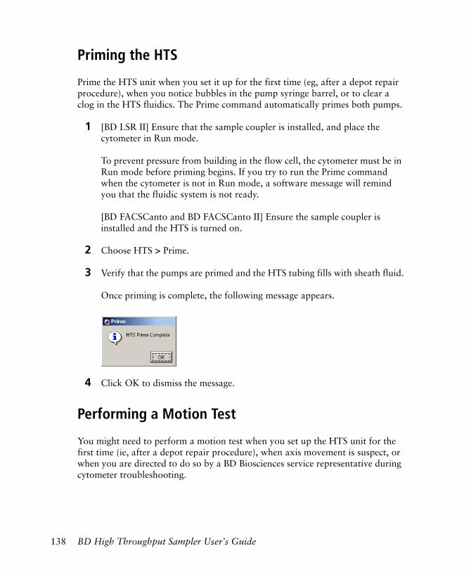
Priming the HTS
Prime the HTS unit when you set it up for the first time (eg, after a depot repair procedure), when you notice bubbles in the pump syringe barrel, or to clear a clog in the HTS fluidics. The Prime command automatically primes both pumps.
1 [BD LSR II] Ensure that the sample coupler is installed, and place the cytometer in Run mode.
To prevent pressure from building in the flow cell, the cytometer must be in Run mode before priming begins. If you try to run the Prime command when the cytometer is not in Run mode, a software message will remind you that the fluidic system is not ready.
[BD FACSCanto and BD FACSCanto II] Ensure the sample coupler is installed and the HTS is turned on.
2 Choose HTS > Prime.
3 Verify that the pumps are primed and the HTS tubing fills with sheath fluid.
Once priming is complete, the following message appears.
4 Click OK to dismiss the message.
Performing a Motion Test
You might need to perform a motion test when you set up the HTS unit for the first time (ie, after a depot repair procedure), when axis movement is suspect, or when you are directed to do so by a BD Biosciences service representative during cytometer troubleshooting.
138 BD High Throughput Sampler User’s Guide
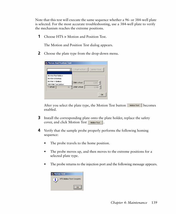
Note that this test will execute the same sequence whether a 96- or 384-well plate is selected. For the most accurate troubleshooting, use a 384-well plate to verify the mechanism reaches the extreme positions.
1 Choose HTS > Motion and Position Test.
The Motion and Position Test dialog appears.
2 Choose the plate type from the drop-down menu.
After you select the plate type, the Motion Test button becomes enabled.
3 Install the corresponding plate onto the plate holder, replace the safety cover, and click Motion Test .
4 Verify that the sample probe properly performs the following homing sequence:
• The probe travels to the home position.
• The probe moves up, and then moves to the extreme positions for a selected plate type.
• The probe returns to the injection port and the following message appears.
Chapter 4: Maintenance 139

5 Click OK to dismiss the message.
If the motion test fails, contact your local BD Biosciences service representative.
Verifying the Sample Probe Position
This test will position the probe at the center of the nearest and farthest wells on a plate so you can visually verify the mechanical positioning of the probe.
To run this test, you must select a plate type in BD FACSDiva software and install the corresponding plate on the plate holder. The test can be run with a 96- or 384-well plate.
1 Choose HTS > Motion and Position Test.
The Motion and Position Test dialog appears.
2 Choose the plate type from the drop-down menu.
After you select the plate type, the Position Test button becomes enabled.
3 Install the corresponding plate onto the plate holder, replace the safety cover, and click Position Test .
140 BD High Throughput Sampler User’s Guide

4 Verify that the sample probe properly performs the following sequence:
• The probe travels to the home position.
• The probe moves up, and then moves to well A1.
The following message appears.
5 Remove or open the safety cover and verify that the probe is in the center of the nearest well (position A1).
6 Replace or close the safety cover and click OK.
The probe moves to well H12 and the following message appears.
7 Remove or open the safety cover and verify that the probe is in the center of the farthest well (position H12).
8 Replace or close the safety cover and click OK.
The probe returns to the injection port and the following message appears.
9 Click OK to dismiss the message.
Chapter 4: Maintenance 141
Reinitializing the HTS
If you switch off the HTS, and then switch it back on again while the software is running, you must reinitialize the HTS.
1 Choose HTS > Reinitialize.
The following message appears when reinitialization is complete.
2 Click OK to dismiss the message.
Inspecting Thumbscrew Fittings
Thumbscrew fittings are installed in the following tubing locations. Check and tighten these thumbscrews periodically, and replace them when needed.
• Primary pump valve to probe—There are male thumbscrew fittings at both ends of the tubing.
• Sample injection tubing—There is a male thumbscrew fitting at the sample injection port/wash station and a female thumbscrew fitting at the extension tubing to the secondary pump valve.
• Extension tubing to the secondary pump valve—There is a male thumbscrew fitting at the sample injection tubing end.
All cytometer surfaces that come in contact with biological specimens can transmit potentially fatal disease. Use universal precautions when handling cytometer components. Wear suitable protective clothing, eyewear, and gloves.
142 BD High Throughput Sampler User’s Guide
Inspecting Hexagonal Fittings
Hexagonal male fittings are located at the following locations. Check and tighten these fittings periodically, and replace them when needed.
• Left port of primary pump
• Top, left, and right ports of secondary pump
NOTICE Valves contain sealing washers in each port. Over-tightening fittings can compress the seal washers resulting in a blocked port. Insert a fitting or syringe into a port until it contacts the seal washer, then turn the fitting or syringe an additional 1/6 to 1/4 turn. If leakage is observed, tighten a maximum of an additional 1/8 turn.
Declogging the SIT
Perform this procedure to dislodge a clog in the SIT only when instructed to do so by BD Biosciences.
Materials
cleaning stylus
All cytometer surfaces that come in contact with biological specimens can transmit potentially fatal disease. Use universal precautions when handling cytometer components. Wear suitable protective clothing, eyewear, and gloves.
All cytometer surfaces that come in contact with biological specimens can transmit potentially fatal disease. Use universal precautions when handling cytometer components. Wear suitable protective clothing, eyewear, and gloves.
To avoid a service call, do not insert the cleaning stylus all the way into the SIT; allow at least an inch of the stylus to protrude from the end of the SIT while declogging.
Chapter 4: Maintenance 143
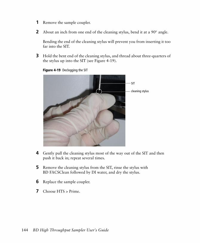
1 Remove the sample coupler.
2 About an inch from one end of the cleaning stylus, bend it at a 90° angle.
Bending the end of the cleaning stylus will prevent you from inserting it too far into the SIT.
3 Hold the bent end of the cleaning stylus, and thread about three-quarters of the stylus up into the SIT (see Figure 4-19).
Figure 4-19 Declogging the SIT
4 Gently pull the cleaning stylus most of the way out of the SIT and then push it back in; repeat several times.
5 Remove the cleaning stylus from the SIT, rinse the stylus with BD FACSClean followed by DI water, and dry the stylus.
6 Replace the sample coupler.
7 Choose HTS > Prime.
cleaning stylus
SIT
144 BD High Throughput Sampler User’s Guide
5
Troubleshooting
The tips in this section are provided to help you troubleshoot issues that might arise when using the BD High Throughput Sampler. For additional troubleshooting assistance, refer to the appropriate cytometer user’s guide.
If additional assistance is required, contact your local BD Biosciences service representative. See Technical Assistance on page xi.
Troubleshooting suggestions in this chapter are grouped under the following headings:
• HTS Troubleshooting on page 146
• Acquisition Troubleshooting on page 147
• BD FACSDiva Troubleshooting on page 149
145
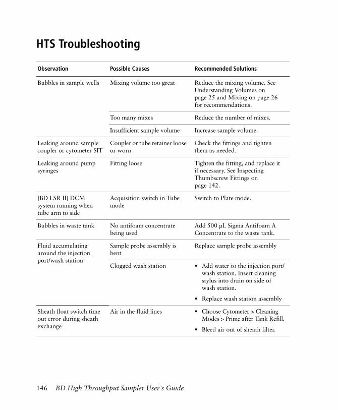
HTS Troubleshooting
Observation Possible Causes Recommended Solutions
Bubbles in sample wells Mixing volume too great Reduce the mixing volume. See Understanding Volumes on page 25 and Mixing on page 26 for recommendations.
Too many mixes Reduce the number of mixes.
Insufficient sample volume Increase sample volume.
Leaking around sample coupler or cytometer SIT
Coupler or tube retainer loose or worn
Check the fittings and tighten them as needed.
Leaking around pump syringes
Fitting loose Tighten the fitting, and replace it if necessary. See Inspecting Thumbscrew Fittings on page 142.
[BD LSR II] DCM system running when tube arm to side
Acquisition switch in Tube mode
Switch to Plate mode.
Bubbles in waste tank No antifoam concentrate being used
Add 500 µL Sigma Antifoam A Concentrate to the waste tank.
Fluid accumulating around the injection port/wash station
Sample probe assembly is bent
Replace sample probe assembly
Clogged wash station • Add water to the injection port/wash station. Insert cleaning stylus into drain on side of wash station.
• Replace wash station assembly
Sheath float switch time out error during sheath exchange
Air in the fluid lines • Choose Cytometer > Cleaning Modes > Prime after Tank Refill.
• Bleed air out of sheath filter.
146 BD High Throughput Sampler User’s Guide
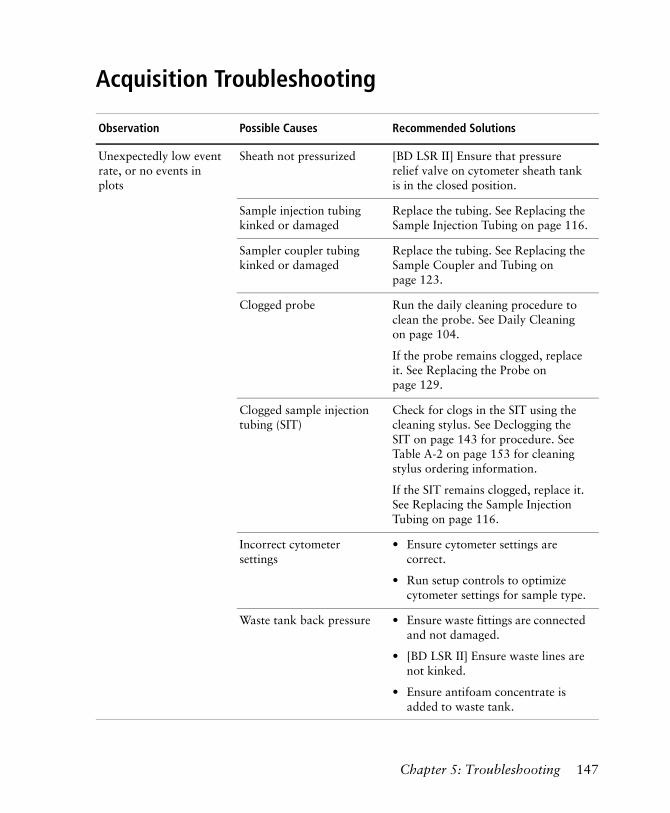
Acquisition Troubleshooting
Observation Possible Causes Recommended Solutions
Unexpectedly low event rate, or no events in plots
Sheath not pressurized [BD LSR II] Ensure that pressure relief valve on cytometer sheath tank is in the closed position.
Sample injection tubing kinked or damaged
Replace the tubing. See Replacing the Sample Injection Tubing on page 116.
Sampler coupler tubing kinked or damaged
Replace the tubing. See Replacing the Sample Coupler and Tubing on page 123.
Clogged probe Run the daily cleaning procedure to clean the probe. See Daily Cleaning on page 104.
If the probe remains clogged, replace it. See Replacing the Probe on page 129.
Clogged sample injection tubing (SIT)
Check for clogs in the SIT using the cleaning stylus. See Declogging the SIT on page 143 for procedure. See Table A-2 on page 153 for cleaning stylus ordering information.
If the SIT remains clogged, replace it. See Replacing the Sample Injection Tubing on page 116.
Incorrect cytometer settings
• Ensure cytometer settings are correct.
• Run setup controls to optimize cytometer settings for sample type.
Waste tank back pressure • Ensure waste fittings are connected and not damaged.
• [BD LSR II] Ensure waste lines are not kinked.
• Ensure antifoam concentrate is added to waste tank.
Chapter 5: Troubleshooting 147
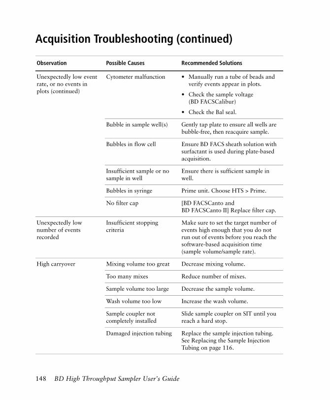
Unexpectedly low event rate, or no events in plots (continued)
Cytometer malfunction • Manually run a tube of beads and verify events appear in plots.
• Check the sample voltage (BD FACSCalibur)
• Check the Bal seal.
Bubble in sample well(s) Gently tap plate to ensure all wells are bubble-free, then reacquire sample.
Bubbles in flow cell Ensure BD FACS sheath solution with surfactant is used during plate-based acquisition.
Insufficient sample or no sample in well
Ensure there is sufficient sample in well.
Bubbles in syringe Prime unit. Choose HTS > Prime.
No filter cap [BD FACSCanto and BD FACSCanto II] Replace filter cap.
Unexpectedly low number of events recorded
Insufficient stopping criteria
Make sure to set the target number of events high enough that you do not run out of events before you reach the software-based acquisition time (sample volume/sample rate).
High carryover Mixing volume too great Decrease mixing volume.
Too many mixes Reduce number of mixes.
Sample volume too large Decrease the sample volume.
Wash volume too low Increase the wash volume.
Sample coupler not completely installed
Slide sample coupler on SIT until you reach a hard stop.
Damaged injection tubing Replace the sample injection tubing. See Replacing the Sample Injection Tubing on page 116.
Acquisition Troubleshooting (continued)
Observation Possible Causes Recommended Solutions
148 BD High Throughput Sampler User’s Guide
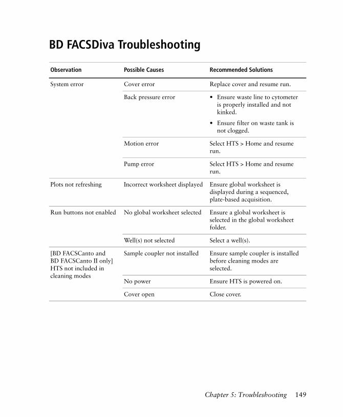
BD FACSDiva Troubleshooting
Observation Possible Causes Recommended Solutions
System error Cover error Replace cover and resume run.
Back pressure error • Ensure waste line to cytometer is properly installed and not kinked.
• Ensure filter on waste tank is not clogged.
Motion error Select HTS > Home and resume run.
Pump error Select HTS > Home and resume run.
Plots not refreshing Incorrect worksheet displayed Ensure global worksheet is displayed during a sequenced, plate-based acquisition.
Run buttons not enabled No global worksheet selected Ensure a global worksheet is selected in the global worksheet folder.
Well(s) not selected Select a well(s).
[BD FACSCanto and BD FACSCanto II only] HTS not included in cleaning modes
Sample coupler not installed Ensure sample coupler is installed before cleaning modes are selected.
No power Ensure HTS is powered on.
Cover open Close cover.
Chapter 5: Troubleshooting 149

150 BD High Throughput Sampler User’s Guide
Appendix A
Consumables andReplacement Parts
This appendix provides a list of supplies and replacement parts for your HTS unit. To order spare parts and consumables from within the US, call (877) 232-8995 or go to bdbiosciences.com. In other countries, contact your local BD Biosciences representative.
This information is correct at the time of publication. For up-to-date information, refer to our website (bdbiosciences.com).
You will find the following in this appendix:
• Cytometer Supplies on page 152
• Maintenance Log on page 154
151
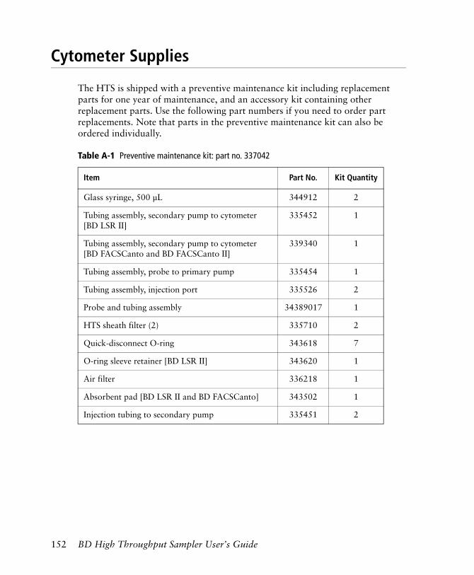
Cytometer Supplies
The HTS is shipped with a preventive maintenance kit including replacement parts for one year of maintenance, and an accessory kit containing other replacement parts. Use the following part numbers if you need to order part replacements. Note that parts in the preventive maintenance kit can also be ordered individually.
Table A-1 Preventive maintenance kit: part no. 337042
Item Part No. Kit Quantity
Glass syringe, 500 µL 344912 2
Tubing assembly, secondary pump to cytometer [BD LSR II]
335452 1
Tubing assembly, secondary pump to cytometer [BD FACSCanto and BD FACSCanto II]
339340 1
Tubing assembly, probe to primary pump 335454 1
Tubing assembly, injection port 335526 2
Probe and tubing assembly 34389017 1
HTS sheath filter (2) 335710 2
Quick-disconnect O-ring 343618 7
O-ring sleeve retainer [BD LSR II] 343620 1
Air filter 336218 1
Absorbent pad [BD LSR II and BD FACSCanto] 343502 1
Injection tubing to secondary pump 335451 2
152 BD High Throughput Sampler User’s Guide
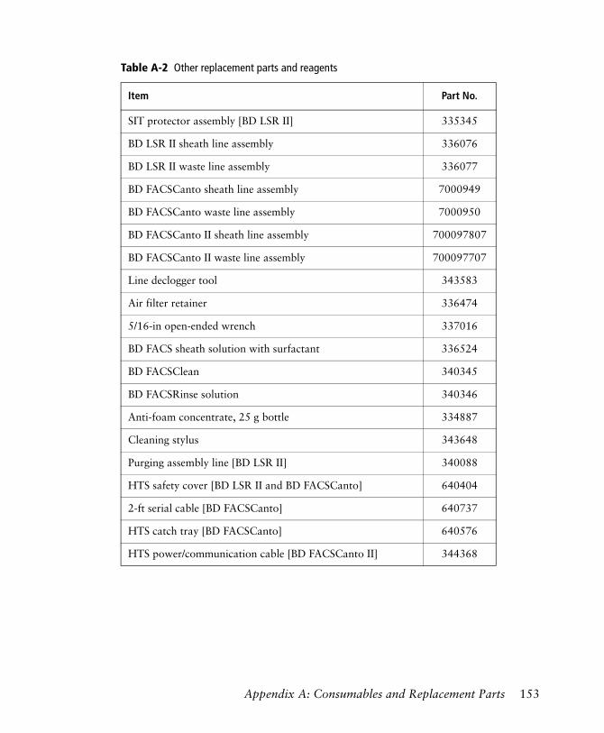
Table A-2 Other replacement parts and reagents
Item Part No.
SIT protector assembly [BD LSR II] 335345
BD LSR II sheath line assembly 336076
BD LSR II waste line assembly 336077
BD FACSCanto sheath line assembly 7000949
BD FACSCanto waste line assembly 7000950
BD FACSCanto II sheath line assembly 700097807
BD FACSCanto II waste line assembly 700097707
Line declogger tool 343583
Air filter retainer 336474
5/16-in open-ended wrench 337016
BD FACS sheath solution with surfactant 336524
BD FACSClean 340345
BD FACSRinse solution 340346
Anti-foam concentrate, 25 g bottle 334887
Cleaning stylus 343648
Purging assembly line [BD LSR II] 340088
HTS safety cover [BD LSR II and BD FACSCanto] 640404
2-ft serial cable [BD FACSCanto] 640737
HTS catch tray [BD FACSCanto] 640576
HTS power/communication cable [BD FACSCanto II] 344368
Appendix A: Consumables and Replacement Parts 153
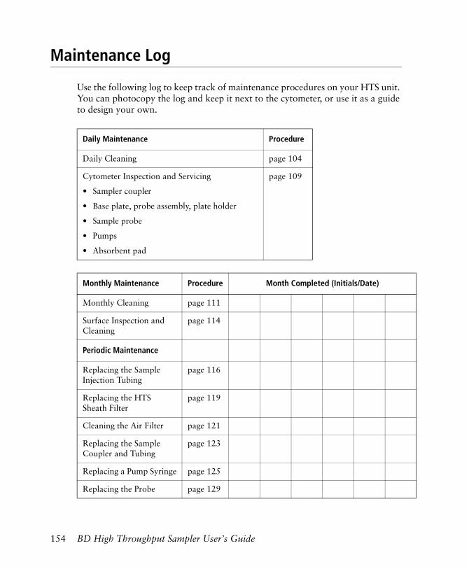
Maintenance Log
Use the following log to keep track of maintenance procedures on your HTS unit. You can photocopy the log and keep it next to the cytometer, or use it as a guide to design your own.
Daily Maintenance Procedure
Daily Cleaning page 104
Cytometer Inspection and Servicing
• Sampler coupler
• Base plate, probe assembly, plate holder
• Sample probe
• Pumps
• Absorbent pad
page 109
Monthly Maintenance Procedure Month Completed (Initials/Date)
Monthly Cleaning page 111
Surface Inspection and Cleaning
page 114
Periodic Maintenance
Replacing the Sample Injection Tubing
page 116
Replacing the HTS Sheath Filter
page 119
Cleaning the Air Filter page 121
Replacing the Sample Coupler and Tubing
page 123
Replacing a Pump Syringe page 125
Replacing the Probe page 129
154 BD High Throughput Sampler User’s Guide
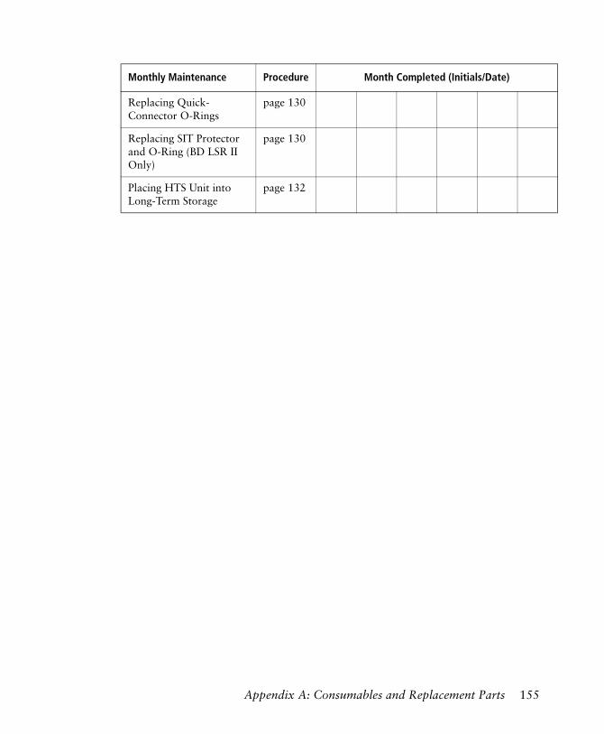
Replacing Quick-Connector O-Rings
page 130
Replacing SIT Protector and O-Ring (BD LSR II Only)
page 130
Placing HTS Unit into Long-Term Storage
page 132
Monthly Maintenance Procedure Month Completed (Initials/Date)
Appendix A: Consumables and Replacement Parts 155

156 BD High Throughput Sampler User’s Guide
Appendix B
Depot Repair Procedures
This appendix contains procedures to perform if your BD High Throughput Sampler (HTS) needs repair and depot repair service is available in your region. For a summary of how the depot repair process works, see Depot Repair Overview on page 158.
NOTICE Depot repair procedures might be different outside the United States. Contact your local BD Biosciences service representative for information for your region.
The following procedures are covered in this chapter.
• Depot Repair Overview on page 158
• Removing the HTS Unit on page 159
• Cleaning the HTS Unit on page 162
• Unpacking the Replacement Unit on page 169
• Installing the HTS Unit on page 170
• Packing the Unit for Shipping on page 175
157
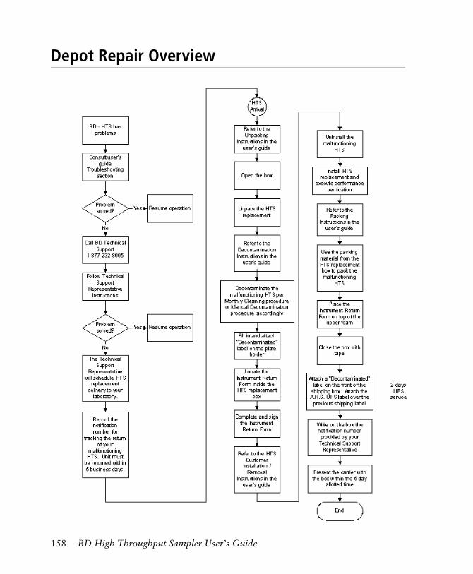
Depot Repair Overview
158 BD High Throughput Sampler User’s Guide
Removing the HTS Unit
Follow this procedure to detach your HTS unit from the cytometer to perform maintenance specified in this user’s guide, or before sending it in to BD Biosciences for depot repair.
NOTICE If you are able to run the system, decontaminate the HTS before you remove it by performing a monthly cleaning procedure. See Monthly Maintenance on page 111. If you cannot run the system, decontaminate it after removal as described in Cleaning the HTS Unit on page 162.
1 [BD LSR II and BD FACSCanto] Switch off the HTS power.
2 Shut down the cytometer.
3 Remove or open the HTS safety cover.
4 Detach the sample coupler from the cytometer SIT.
• Unscrew the top nut.
• Pull the sample coupler down and away from the SIT, leaving the nut attached to the sample coupler.
5 Locate and loosen the positioning screw that secures the HTS unit to the base plate.
See Figure B-1 on page 160.
All cytometer surfaces that come in contact with biological specimens can transmit potentially fatal disease. Use universal precautions when handling cytometer parts. Wear suitable protective clothing, eyewear, and gloves.
Appendix B: Depot Repair Procedures 159
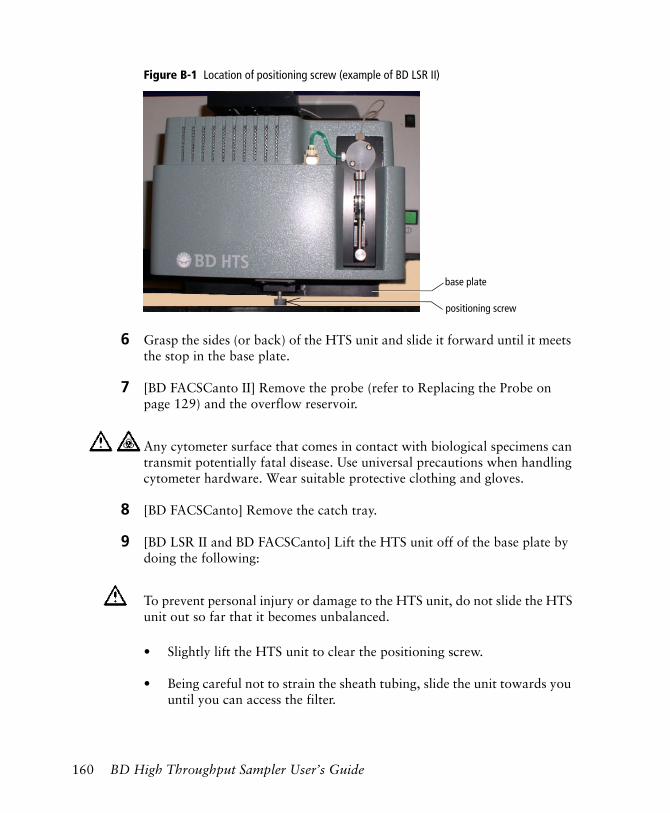
Figure B-1 Location of positioning screw (example of BD LSR II)
6 Grasp the sides (or back) of the HTS unit and slide it forward until it meets the stop in the base plate.
7 [BD FACSCanto II] Remove the probe (refer to Replacing the Probe on page 129) and the overflow reservoir.
8 [BD FACSCanto] Remove the catch tray.
9 [BD LSR II and BD FACSCanto] Lift the HTS unit off of the base plate by doing the following:
• Slightly lift the HTS unit to clear the positioning screw.
• Being careful not to strain the sheath tubing, slide the unit towards you until you can access the filter.
Any cytometer surface that comes in contact with biological specimens can transmit potentially fatal disease. Use universal precautions when handling cytometer hardware. Wear suitable protective clothing and gloves.
To prevent personal injury or damage to the HTS unit, do not slide the HTS unit out so far that it becomes unbalanced.
positioning screw
base plate
160 BD High Throughput Sampler User’s Guide
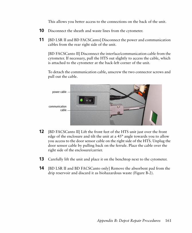
This allows you better access to the connections on the back of the unit.
10 Disconnect the sheath and waste lines from the cytometer.
11 [BD LSR II and BD FACSCanto] Disconnect the power and communication cables from the rear right side of the unit.
[BD FACSCanto II] Disconnect the interface/communication cable from the cytometer. If necessary, pull the HTS out slightly to access the cable, which is attached to the cytometer at the back-left corner of the unit.
To detach the communication cable, unscrew the two connector screws and pull out the cable.
12 [BD FACSCanto II] Lift the front feet of the HTS unit just over the front edge of the enclosure and tilt the unit at a 45° angle towards you to allow you access to the door sensor cable on the right side of the HTS. Unplug the door sensor cable by pulling back on the ferrule. Place the cable over the right side of the enclosure/carrier.
13 Carefully lift the unit and place it on the benchtop next to the cytometer.
14 [BD LSR II and BD FACSCanto only] Remove the absorbent pad from the drip reservoir and discard it as biohazardous waste (Figure B-2).
power cable
communicationcable
Appendix B: Depot Repair Procedures 161
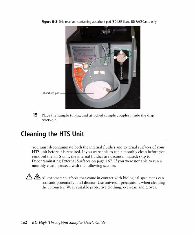
Figure B-2 Drip reservoir containing absorbent pad [BD LSR II and BD FACSCanto only]
15 Place the sample tubing and attached sample coupler inside the drip reservoir.
Cleaning the HTS Unit
You must decontaminate both the internal fluidics and external surfaces of your HTS unit before it is repaired. If you were able to run a monthly clean before you removed the HTS unit, the internal fluidics are decontaminated; skip to Decontaminating External Surfaces on page 167. If you were not able to run a monthly clean, proceed with the following section.
All cytometer surfaces that come in contact with biological specimens can transmit potentially fatal disease. Use universal precautions when cleaning the cytometer. Wear suitable protective clothing, eyewear, and gloves.
absorbent pad
162 BD High Throughput Sampler User’s Guide
Use a 10% bleach solution to decontaminate the internal fluidics and external surfaces of the HTS unit.
1 Pour 45 mL of DI water into a 100-mL beaker.
2 Carefully add 5 mL of undiluted bleach to the same beaker.
3 Gently swirl the solution to mix.
Decontaminating the Fluidics Manually
Materials Needed
• household bleach
• DI water
• disposable plastic pipettes
• line declogger, PN 343583 from the accessories kit (for manual fluidics decontamination only)
Cleaning the Fluidics
Perform this procedure to decontaminate the internal fluidics of a non-functional HTS unit.
1 Remove the sample probe and tubing that connects the probe to the primary pump; discard the probe and tubing (Figure B-3 on page 164).
To prevent shock, verify that the cytometer is turned off and the power cable is detached before you start cleaning.
To ensure that the 10% bleach solution retains its full germicidal effect, prepare a fresh solution daily.
Appendix B: Depot Repair Procedures 163
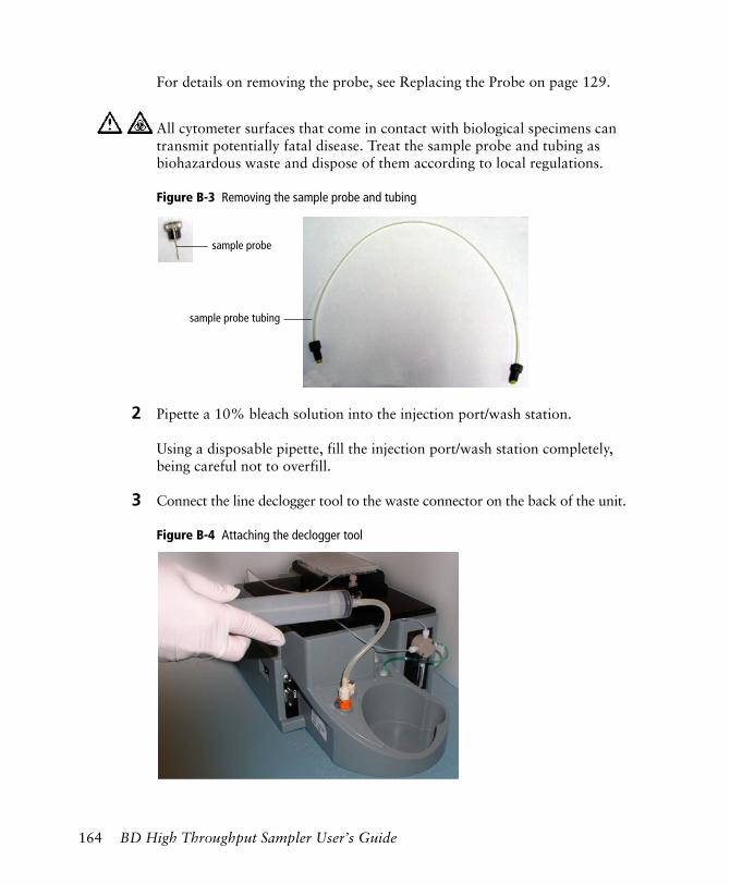
For details on removing the probe, see Replacing the Probe on page 129.
Figure B-3 Removing the sample probe and tubing
2 Pipette a 10% bleach solution into the injection port/wash station.
Using a disposable pipette, fill the injection port/wash station completely, being careful not to overfill.
3 Connect the line declogger tool to the waste connector on the back of the unit.
Figure B-4 Attaching the declogger tool
All cytometer surfaces that come in contact with biological specimens can transmit potentially fatal disease. Treat the sample probe and tubing as biohazardous waste and dispose of them according to local regulations.
sample probe
sample probe tubing
164 BD High Throughput Sampler User’s Guide
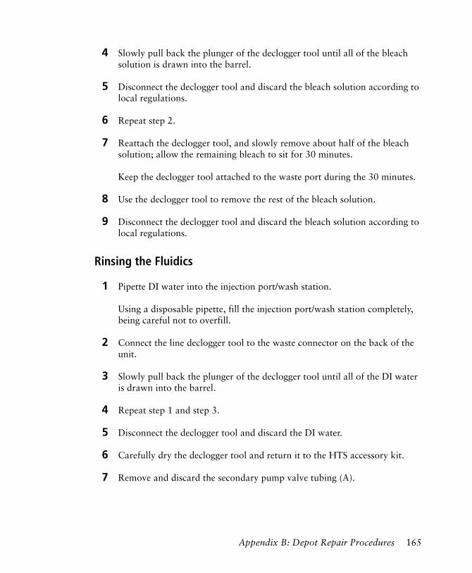
4 Slowly pull back the plunger of the declogger tool until all of the bleach solution is drawn into the barrel.
5 Disconnect the declogger tool and discard the bleach solution according to local regulations.
6 Repeat step 2.
7 Reattach the declogger tool, and slowly remove about half of the bleach solution; allow the remaining bleach to sit for 30 minutes.
Keep the declogger tool attached to the waste port during the 30 minutes.
8 Use the declogger tool to remove the rest of the bleach solution.
9 Disconnect the declogger tool and discard the bleach solution according to local regulations.
Rinsing the Fluidics
1 Pipette DI water into the injection port/wash station.
Using a disposable pipette, fill the injection port/wash station completely, being careful not to overfill.
2 Connect the line declogger tool to the waste connector on the back of the unit.
3 Slowly pull back the plunger of the declogger tool until all of the DI water is drawn into the barrel.
4 Repeat step 1 and step 3.
5 Disconnect the declogger tool and discard the DI water.
6 Carefully dry the declogger tool and return it to the HTS accessory kit.
7 Remove and discard the secondary pump valve tubing (A).
Appendix B: Depot Repair Procedures 165
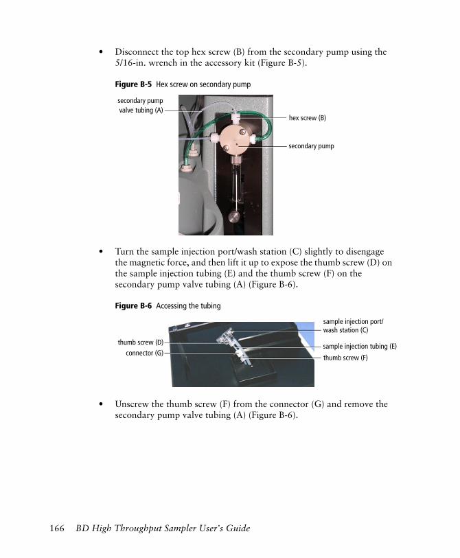
• Disconnect the top hex screw (B) from the secondary pump using the 5/16-in. wrench in the accessory kit (Figure B-5).
Figure B-5 Hex screw on secondary pump
• Turn the sample injection port/wash station (C) slightly to disengage the magnetic force, and then lift it up to expose the thumb screw (D) on the sample injection tubing (E) and the thumb screw (F) on the secondary pump valve tubing (A) (Figure B-6).
Figure B-6 Accessing the tubing
• Unscrew the thumb screw (F) from the connector (G) and remove the secondary pump valve tubing (A) (Figure B-6).
hex screw (B)
secondary pumpvalve tubing (A)
secondary pump
thumb screw (D)
thumb screw (F)connector (G)
sample injection port/wash station (C)
sample injection tubing (E)
166 BD High Throughput Sampler User’s Guide
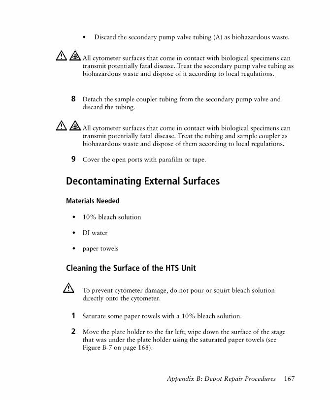
• Discard the secondary pump valve tubing (A) as biohazardous waste.
8 Detach the sample coupler tubing from the secondary pump valve and discard the tubing.
9 Cover the open ports with parafilm or tape.
Decontaminating External Surfaces
Materials Needed
• 10% bleach solution
• DI water
• paper towels
Cleaning the Surface of the HTS Unit
1 Saturate some paper towels with a 10% bleach solution.
2 Move the plate holder to the far left; wipe down the surface of the stage that was under the plate holder using the saturated paper towels (see Figure B-7 on page 168).
All cytometer surfaces that come in contact with biological specimens can transmit potentially fatal disease. Treat the secondary pump valve tubing as biohazardous waste and dispose of it according to local regulations.
All cytometer surfaces that come in contact with biological specimens can transmit potentially fatal disease. Treat the tubing and sample coupler as biohazardous waste and dispose of them according to local regulations.
To prevent cytometer damage, do not pour or squirt bleach solution directly onto the cytometer.
Appendix B: Depot Repair Procedures 167
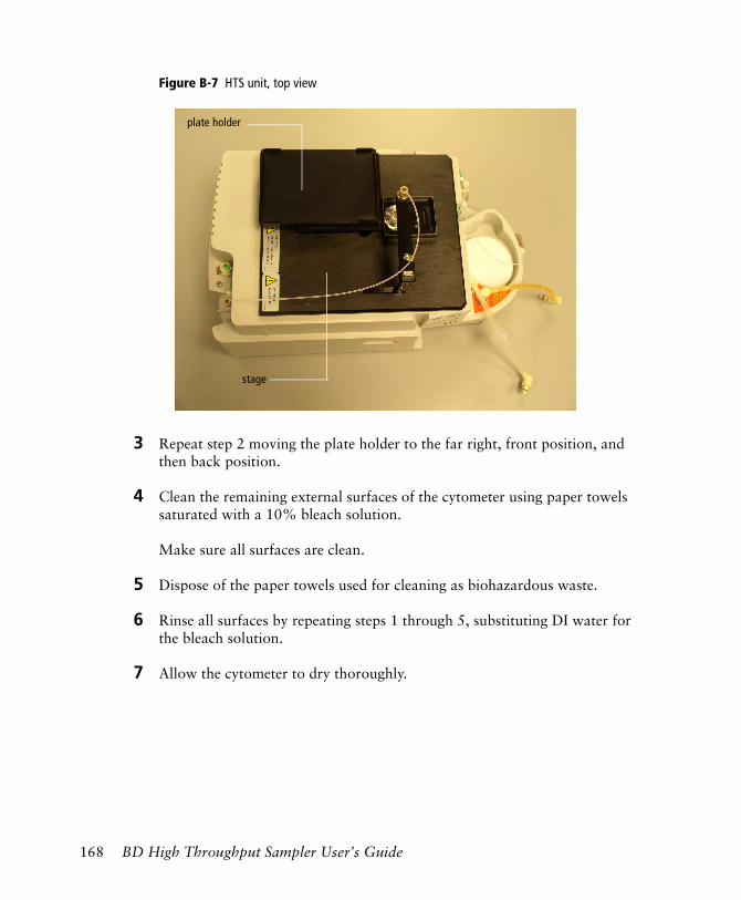
Figure B-7 HTS unit, top view
3 Repeat step 2 moving the plate holder to the far right, front position, and then back position.
4 Clean the remaining external surfaces of the cytometer using paper towels saturated with a 10% bleach solution.
Make sure all surfaces are clean.
5 Dispose of the paper towels used for cleaning as biohazardous waste.
6 Rinse all surfaces by repeating steps 1 through 5, substituting DI water for the bleach solution.
7 Allow the cytometer to dry thoroughly.
plate holder
stage
168 BD High Throughput Sampler User’s Guide
Unpacking the Replacement Unit
NOTICE If you are sending back an existing HTS for depot repair, save all shipping materials and ship the existing unit in this new container. It contains paperwork for shipping and two labels verifying that the cytometer you are returning was decontaminated.
Before you proceed with unpacking:
• Make sure you have adequate space
- on the floor near the cytometer to place the shipping container.
- on the table or bench near the cytometer to place the new HTS unit.
• Make sure you
- read through these instructions before attempting to unpack the new cytometer.
- are ready to install the new cytometer. See Installing the HTS Unit on page 170.
Lifting Heavy Objects
1 Stand in front of the object, and then sit on your heels (squat).
2 Place your hands under the base of the object, ensure the load is balanced, and bring the object as close to your lap as possible.
A HTS unit without a cover weighs approximately 22 lb. To prevent personal injury or damage to the cytometer, follow the guidelines on page 169 to remove the replacement HTS unit from its shipping container.
To avoid personal injury or damage to the cytometer, follow these guidelines for lifting heavy objects from the floor.
Appendix B: Depot Repair Procedures 169
3 While keeping your spine in a natural position and your head up, lift the object using the force of your legs.
Do not twist your back when lifting; pivot on your heels.
Unpacking the HTS Unit
1 With the arrows on the box pointing up, open the shipping container.
Remember to save all paperwork and shipping materials to repack the unit to be returned.
2 Remove the top piece of foam and set it aside.
3 Using proper lifting techniques, carefully lift the unit out of the container and place it on a table near the cytometer.
4 Remove the HTS unit from the plastic bag.
5 Remove the small I-shaped piece of foam that secures the HTS probe assembly and plate holder and set it aside.
Installing the HTS Unit
Follow this procedure to install your replacement HTS unit.
1 To avoid damaging the HTS probe:
The unit is encased in plastic to protect it during shipment. The plastic can make the cytometer slippery and difficult to grasp. To prevent personal injury or damage to the cytometer, use caution when lifting the cytometer out of the container.
Any cytometer surface that comes in contact with biological specimens can transmit potentially fatal disease. Use universal precautions when handling cytometer hardware. Wear suitable protective clothing and gloves.
170 BD High Throughput Sampler User’s Guide
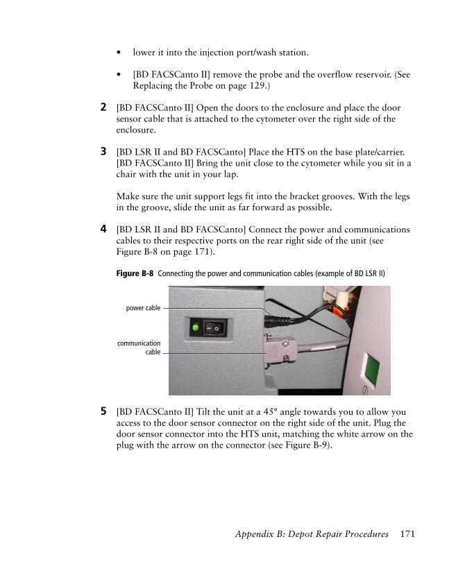
• lower it into the injection port/wash station.
• [BD FACSCanto II] remove the probe and the overflow reservoir. (See Replacing the Probe on page 129.)
2 [BD FACSCanto II] Open the doors to the enclosure and place the door sensor cable that is attached to the cytometer over the right side of the enclosure.
3 [BD LSR II and BD FACSCanto] Place the HTS on the base plate/carrier. [BD FACSCanto II] Bring the unit close to the cytometer while you sit in a chair with the unit in your lap.
Make sure the unit support legs fit into the bracket grooves. With the legs in the groove, slide the unit as far forward as possible.
4 [BD LSR II and BD FACSCanto] Connect the power and communications cables to their respective ports on the rear right side of the unit (see Figure B-8 on page 171).
Figure B-8 Connecting the power and communication cables (example of BD LSR II)
5 [BD FACSCanto II] Tilt the unit at a 45° angle towards you to allow you access to the door sensor connector on the right side of the unit. Plug the door sensor connector into the HTS unit, matching the white arrow on the plug with the arrow on the connector (see Figure B-9).
power cable
communicationcable
Appendix B: Depot Repair Procedures 171
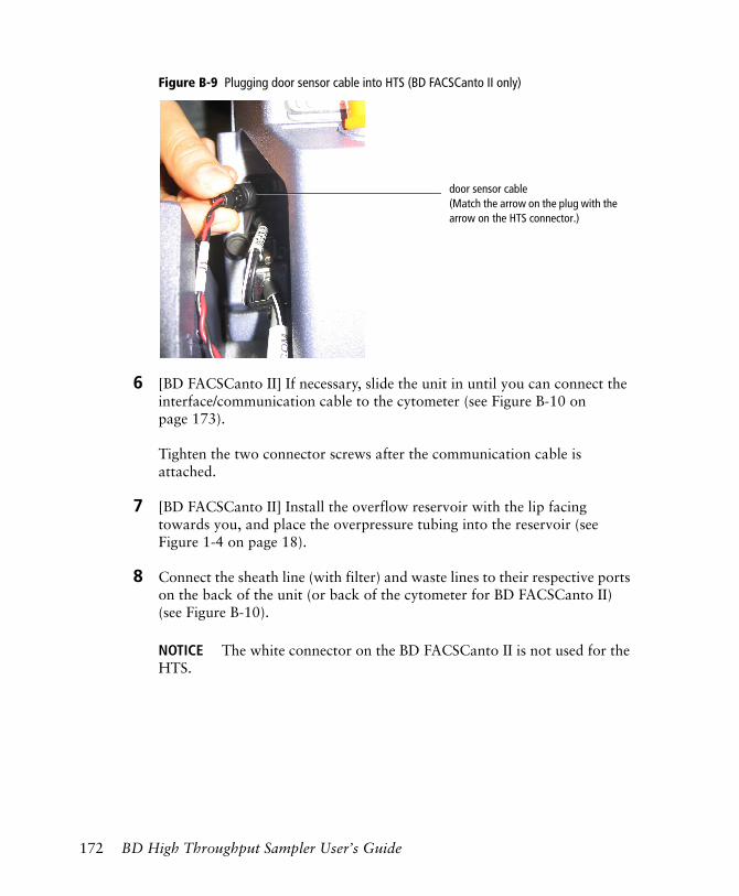
Figure B-9 Plugging door sensor cable into HTS (BD FACSCanto II only)
6 [BD FACSCanto II] If necessary, slide the unit in until you can connect the interface/communication cable to the cytometer (see Figure B-10 on page 173).
Tighten the two connector screws after the communication cable is attached.
7 [BD FACSCanto II] Install the overflow reservoir with the lip facing towards you, and place the overpressure tubing into the reservoir (see Figure 1-4 on page 18).
8 Connect the sheath line (with filter) and waste lines to their respective ports on the back of the unit (or back of the cytometer for BD FACSCanto II) (see Figure B-10).
NOTICE The white connector on the BD FACSCanto II is not used for the HTS.
door sensor cable(Match the arrow on the plug with the arrow on the HTS connector.)
172 BD High Throughput Sampler User’s Guide
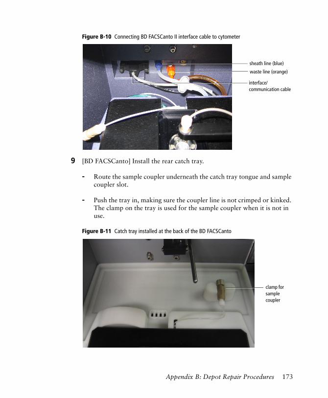
Figure B-10 Connecting BD FACSCanto II interface cable to cytometer
9 [BD FACSCanto] Install the rear catch tray.
- Route the sample coupler underneath the catch tray tongue and sample coupler slot.
- Push the tray in, making sure the coupler line is not crimped or kinked. The clamp on the tray is used for the sample coupler when it is not in use.
Figure B-11 Catch tray installed at the back of the BD FACSCanto
interface/communication cable
waste line (orange)
sheath line (blue)
clamp for sample coupler
Appendix B: Depot Repair Procedures 173
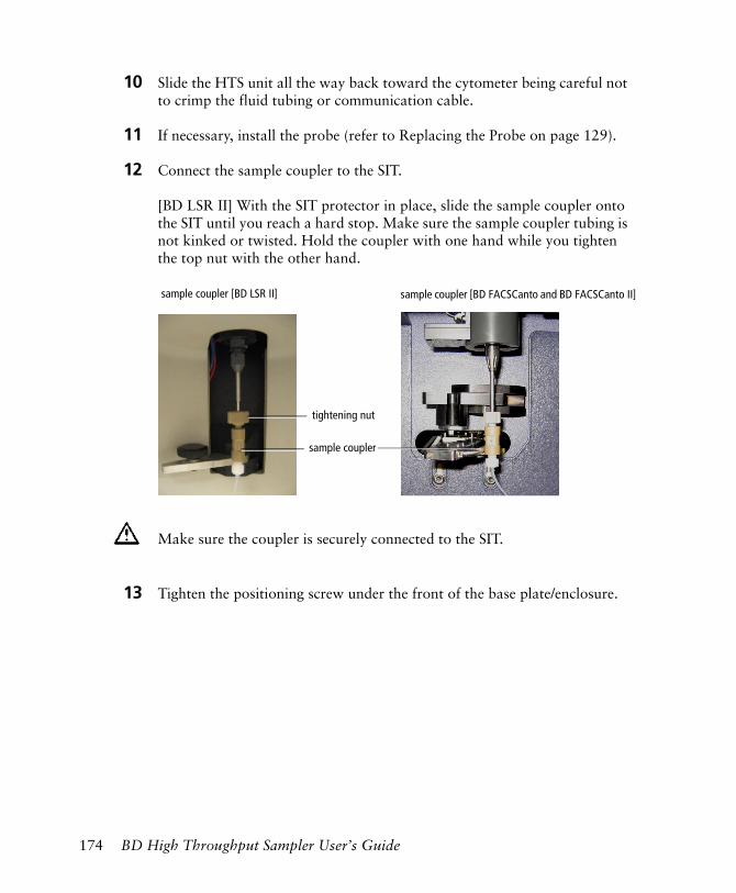
10 Slide the HTS unit all the way back toward the cytometer being careful not to crimp the fluid tubing or communication cable.
11 If necessary, install the probe (refer to Replacing the Probe on page 129).
12 Connect the sample coupler to the SIT.
[BD LSR II] With the SIT protector in place, slide the sample coupler onto the SIT until you reach a hard stop. Make sure the sample coupler tubing is not kinked or twisted. Hold the coupler with one hand while you tighten the top nut with the other hand.
13 Tighten the positioning screw under the front of the base plate/enclosure.
Make sure the coupler is securely connected to the SIT.
sample coupler
tightening nut
sample coupler [BD LSR II] sample coupler [BD FACSCanto and BD FACSCanto II]
174 BD High Throughput Sampler User’s Guide
Packing the Unit for Shipping
Use the following procedure to pack the inoperable HTS unit prior to shipping.
NOTICE Pack the unit in the shipping container that contained the HTS replacement unit. It should contain the following:
• shipping paperwork
• decontamination label
• small I-shaped piece of foam
• plastic bag
• top piece of foam
• bottom piece of foam
Placing the HTS into Its Shipping Container
1 Make sure the unit was decontaminated according to the procedures in Cleaning the HTS Unit on page 162.
2 Disconnect the sheath and waste lines from the HTS.
3 [BD FACSCanto II] Disconnect the interface/communication cable from the HTS.
4 Initial and date the decontamination labels; stick one on the plate holder and the other on the outside of the shipping carton.
Enter the initials of the person who decontaminated the cytometer.
5 Fill out the Cytometer Return form.
6 Place the small I-shaped piece of foam between the probe assembly arm and plate holder to secure them.
Appendix B: Depot Repair Procedures 175
7 Slide the HTS unit into the plastic bag.
8 Using proper lifting techniques, place the bagged unit in the shipping container, making sure the arrows on the box are pointing up.
For proper lifting techniques, see Lifting Heavy Objects on page 169. Place the cytometer on top of the bottom piece of foam.
9 Place the top piece of foam over the cytometer.
10 Lay the Cytometer Return form on top of the foam, and close and seal the flaps of the shipping container.
The plastic might make the cytometer slippery and hard to grasp. To prevent personal injury or damage to the cytometer, use caution when placing the cytometer in the shipping container.
176 BD High Throughput Sampler User’s Guide
Index
A
acquisitionautomatic 46Dashboard 30data 82–83defaults 37, 40high-throughput mode 23, 37manual 47modes 23optimizing settings for 78plate-based See plate-based
acquisition.standard mode 23, 37status 35status record 83switching modes 94time equation 39troubleshooting 147tube-based 22, 94
acquisition status record 36air filter, cleaning 121Analysis view
components 48functionality 51
analysis, automating 13, 90application window components 28apply analysis template to wells 40apply application settings 40apply cytometer settings to wells 40assistance, technical xiavailable well volume 25
B
backdripping 19base plate
inspection and service 110removing 135
batch analysis 90, 92BD High Throughput Sampler See HTS.Browser, shown 29
C
carryover, minimizing 26cleaning
air filter 121daily 104–108fluidics 163HTS unit 162–168Long Clean 113monthly, BD FACSCanto 113monthly, BD LSR II 111–113surfaces 114template 105
color indicatorssheath fluid 99well status 35
compensation 81compensation controls 37components
application window, shown 28HTS, shown 16, 17, 18
consumable part numbers 152
177
controls, acquisition 30conventions, user’s guide xcopy and paste
instrument settings 45wells and specimens 42
coupler, sampleinspection and service 109replacing 123shown 17, 18
creating compensation controls 37customer support xicytometer
connectors 19–21interface panel 19–21sample injection tube (SIT) 21setting up 59support bracket, shown 20
cytometer settingsoptimizing 78–80
D
daily cleaning 104–108daily maintenance 104–110data
acquiring 82–83analyzing 86–93
dead volume 25decontaminating
external surfaces 167fluidics
automatically 111manually 163
defaultsacquisition settings 14, 37HTS settings 40
deleting wells and settings 40depot repair See repair procedures.door sensor cable, BD FACSCanto II 18
E
error messagesacquisition 147hardware 146software 149
experimentcreating 64exporting 84templates 84
Experiment Layout 71–73accessing from shortcut menu 40events to record 72
shortcut keys 73labels 71
exportingexperiment templates 84panel template 85plate template 76well settings and files 40
external surfaces, decontaminating 167
F
fittingshexagonal, inspecting 143thumbscrew, inspecting 142tightening 124, 133, 143, 160
fluidic modesfluidics shutdown 101fluidics startup 58sheath exchange 99
fluidicscleaning 163manually decontaminating 163modes 14rinsing 165shutdown, BD FACSCanto 100startup, BD FACSCanto 58tubing, shown 17, 18
fluorophore labels 37
178 BD High Throughput Sampler User’s Guide
G
GUID 65, 93
H
hardwarebasic functionality 14components 16installation 15part replacement 114plate sizes 14
hazard symbols xhexagonal fittings, inspecting 143High Throughput Sampler See HTS.high-throughput mode 23, 37HTS
decontaminating for repair 162hardware See hardware.installing replacement unit 170introduction 13long-term storage 132pausing 83priming 138reinitializing 142settings 39stopping 84unpacking replacement unit 169
I
import well settings 40injection
port interface 17, 18tubing, replacing 116
inspectioncytometer 109fittings
hexagonal 143thumbscrew 142
surface 114Inspector window 31
instrument settingscopying and pasting 45
interface panel, cytometer 19–21
K
Keyword Analysis view feature 52, 86keywords
assigning 44, 77viewing assignments 52, 86
L
labels 72labels for fluorophores 37loader settings, choosing 25long-term storage of unit 132
M
maintenancedaily 104–110log 154monthly 111–114part replacement schedule 114procedures 103–144unscheduled 136–144
menus, software 29mixing
number of cycles 40optimizing 26speed 39volume 25, 39
Index 179
modes 14, 23default HTS settings 40default settings 37fluidic 14high-throughput 23, 37plate 19, 60soft standby 23standard 23, 37tube 19, 94
monthlycleaning
BD FACSCanto 113BD LSR II 111–113
maintenance 111–114motion test 138
N
number of mixes 40
O
optimizing cytometer settings 78–80ordering information
how to 151plates 66replacement parts 151–153
O-rings, replacingquick-connector 130SIT protector 130
overflow reservoir 18
P
packaging for shipping 175panel template 85part replacement
air filter 121hexagonal fittings 143injection tubing 116instrument supplies 152ordering information 151–153O-rings 130part numbers 152plates 66probe 129pump syringes 125reagents 153sample coupler and tubing 123schedule 114sheath filter 119SIT protector 130thumbscrew fittings 142
perform compensation setup 40perform panel analysis 40phone numbers
ordering parts 151technical support xi
plateSee also plates.filter 33holder
inspection and service 110shown 17, 18, 79
icons 35layout view 35legend 33mode 19, 60rearranging samples on 44template 76toolbar 34
Plate Interface, shown 31
180 BD High Throughput Sampler User’s Guide
plate-based acquisitionpreparing for 59running samples 55–85setting up 60–63vs tube-based 22
platescompatibility 66list of tested 66ordering information 66orienting 79printing records 83, 88sizes supported 14working with 35
position test 140probe
assembly 17, 18homing 136inspection and service 110preventing damage 78replacing 129verifying position 140wash volume 39
pumpsinspection and service 110replacing syringes 125secondary, shown 17, 18
Q
quitting software 101
R
rate, sample flow 39records
acquisition status 36, 83printing 86
renaming specimen in a plate 42
repair proceduresabout 158cleaning the HTS unit 162–168decontaminating exterior 167decontaminating fluidics 163installing replacement unit 170packing unit for shipping 175removing the HTS unit 159rinsing fluidics 165unpacking replacement unit 169
replacement unit, unpacking 169returns, packaging 175run sequence
automatic 46manual 47
S
safetybiological 59, 160drip containment module (DCM) 19interlock feature 82lifting heavy objects 169maintenance procedures 103–144tube-based acquisition 95unpacking replacement unit 169
sample coupler 21–23BD FACS Canto II 18BD LSR II 17inspection and service 109
sample volume 39samples
aspirated volume 39flow rate 39minimum volume 39processing, overview 23running 55–85sample injection tube (SIT) 21setting volume 25, 40
servicing cytometer 109
Index 181

settingscarryover 26HTS 38mixing 26optimizing for acquisition 78throughput 26
Setup viewcomponents 33functionality 43
sheathfilter
replacing 119shown 17, 18
fluidexchanging 96, 98for use on HTS 56
shipping, packaging 175soft standby mode 23software
application window, shown 28batch analysis 13, 90main features 27menus 29quitting 101troubleshooting 149
specimenrenaming 42
specimen, copying and pasting 42speed, mixing 39standard mode 23, 37status indicators, well colors 35stopping
HTS 84software 101
syringes, replacing 125
T
technical assistance xitemplates
cleaning 105experiment 84panel 85plate 76
test, motion 138throughput
mode 37optimizing 26
thumbscrew fittings, inspecting 142time, acquisition 39total volume 25troubleshooting
acquisition 147hardware 146homing the sample probe 136leaking valves 124, 133, 143, 160software 149suggestions 145–149
tube mode 19, 94tube-based acquisition
returning to 94safety 95vs plate-based 22
tubingreplacing 116, 123thumbscrew fittings 142
U
unscheduled maintenance 136–144user preferences 65
182 BD High Throughput Sampler User’s Guide
V
viewsAcquisition Dashboard 30Analysis 48Browser 29Inspector 31plate layout 35Plate window 31Setup 33
volumeminimum sample 39mixing 39sample 39
volumeschoosing loader settings 25types 25well 25
W
wash station, shown 17, 18wash volume, probe 39wells
apply analysis template 40apply application settings 40apply cytometer settings 40border colors and status 35compensation setup 40copying and pasting 42create Experiment Layout 40cytometer settings in 40deleting 40displaying keywords 86exporting settings and files 40loader settings in 40perform panel analysis 40spectral overlap 40volume 25
windowsAcquisition Dashboard 30Browser 29Inspector 31Plate 31
worksheetglobal 65normal 76setting up 74
Index 183

184 BD High Throughput Sampler User’s Guide


![l>lf·· E ·B; -I,:,C-·-1·1V · cat. no.i bd lj.657 bd lj.6]5 bd 4630 bd 4·627 bd 4628 bd 4886 bd 4546 bd 4·545 bd 4544 bd 4542 bd lj,588 bd lj.593 bd 0102 bd 4636 bd 4632 bd](https://img.dokumen.tips/doc/110x75/5f7c69bb7d840d18665ab1e6/llf-e-b-ic-11v-cat-noi-bd-lj657-bd-lj65-bd-4630-bd-4627-bd-4628-bd.jpg)