Embed Size (px)
DESCRIPTION
j
Citation preview

Implementing Spanning Tree
Describing the STP
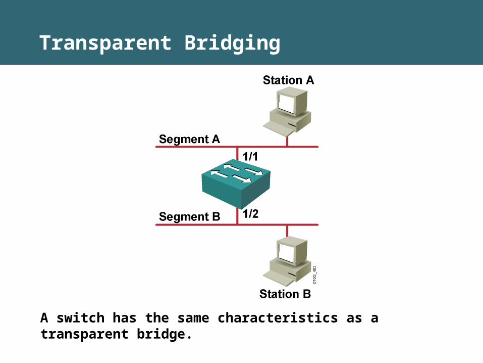
Transparent Bridging
A switch has the same characteristics as a transparent bridge.
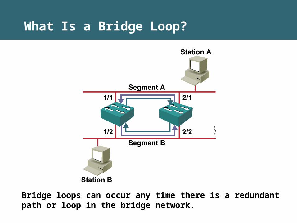
Bridge loops can occur any time there is a redundant path or loop in the bridge network.
What Is a Bridge Loop?
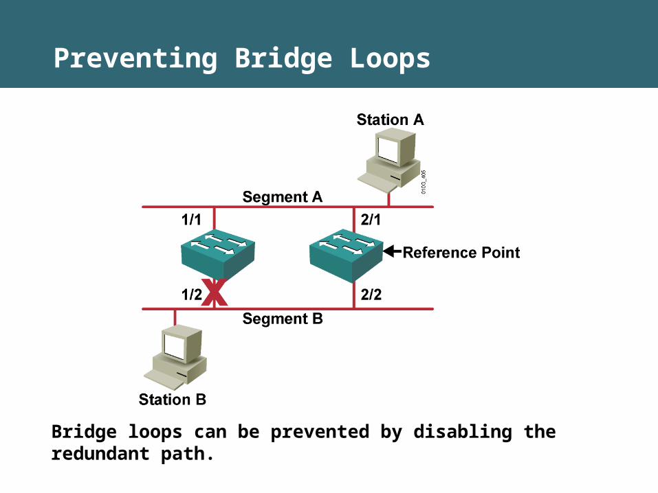
Bridge loops can be prevented by disabling the redundant path.
Preventing Bridge Loops

802.1D STP
• Configured root switch
• Redundant switch links
• Optimal path selection
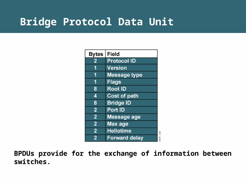
Bridge Protocol Data Unit
BPDUs provide for the exchange of information between switches.
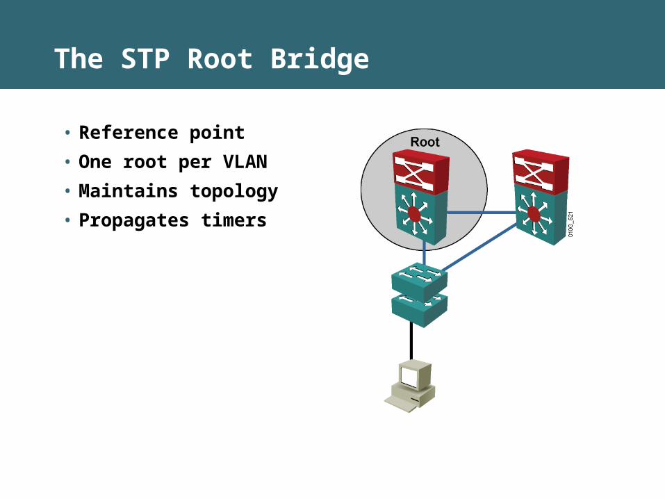
The STP Root Bridge
• Reference point
• One root per VLAN
• Maintains topology
• Propagates timers
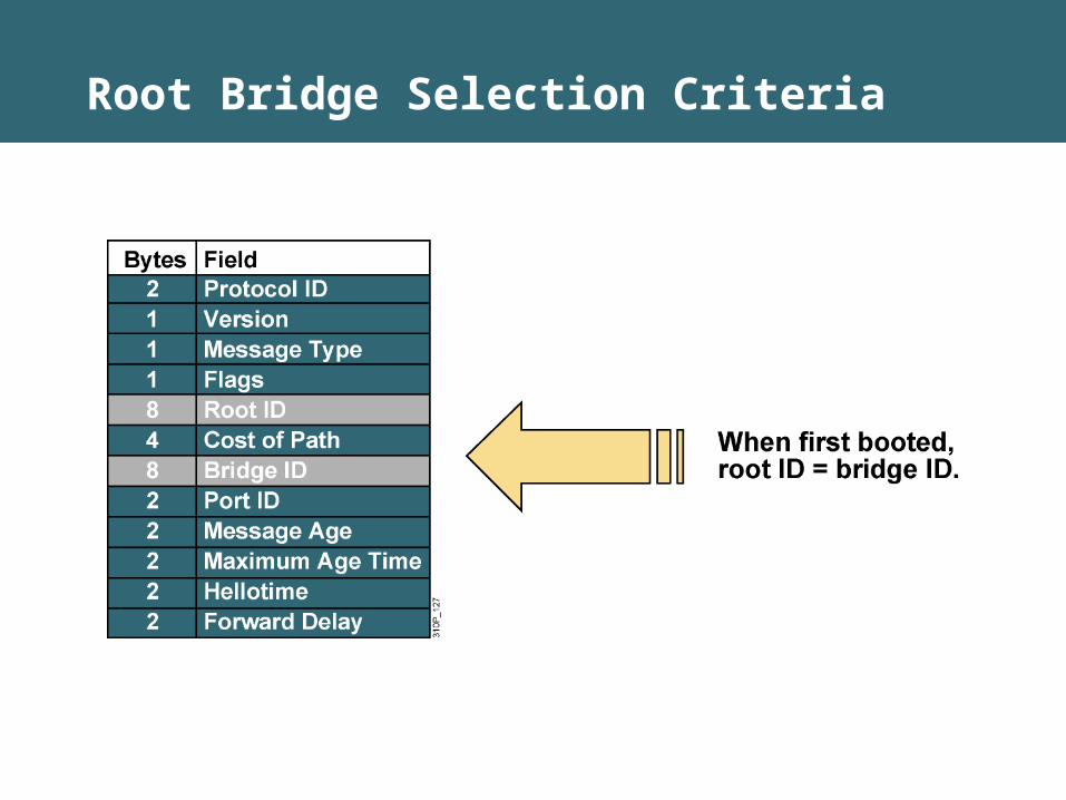
Root Bridge Selection Criteria
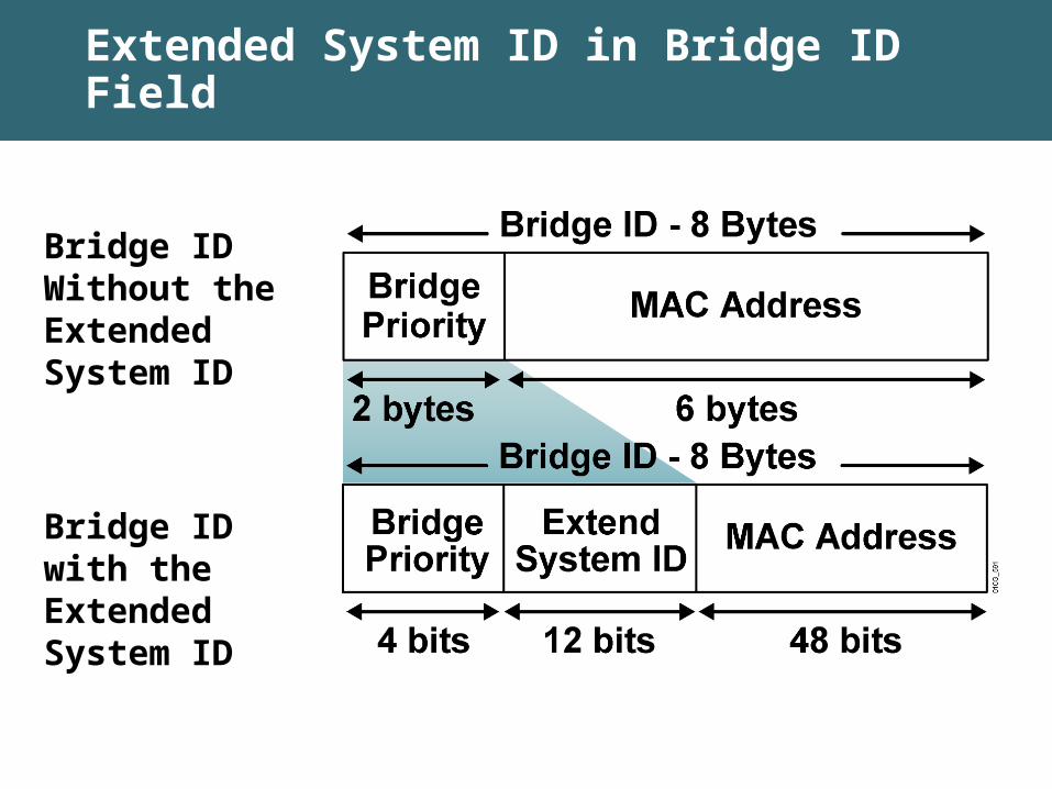
Extended System ID in Bridge ID Field
Bridge ID Without the Extended System ID
Bridge ID with the Extended System ID

802.1D 16-bit Bridge Priority Field Using the Extended System ID
• Only four high-order bits of the 16-bit Bridge Priority field carry actual priority.
• Therefore, priority can be incremented only in steps of 4096, onto which will be added the VLAN number.
• Example: For VLAN 11: If the priority is left at default, the 16-bit Priority field will hold 32768 + 11 = 32779.
Priority Values (Hex) Priority Values (Dec) 0 01 40962 8192. .. .8 (default) 32768. . . .F 61440
4 bits
12 bits
Priority VLAN Number
20215

Configuring the Root Bridge
Switch(config)#spanning-tree vlan 1 root primary
• This command forces this switch to be the root.
Switch(config)#spanning-tree vlan 1 root secondary
• This command configures this switch to be the secondary root.
Or
Switch(config)#spanning-tree vlan 1 priority priority
• This command statically configures the priority (in increments of 4096).
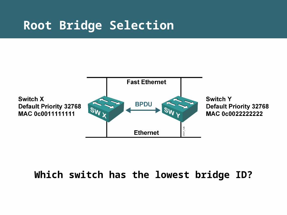
Root Bridge Selection
Which switch has the lowest bridge ID?
Spanning Tree Operation
• One root bridge per network
• One root port per nonroot bridge
• One designated port per segment
• Nondesignated ports are blocking

Spanning Tree Port States
Spanning tree transitions each port through several different states.
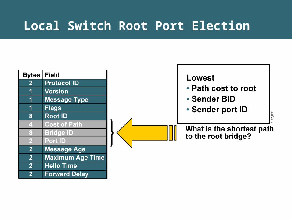
Local Switch Root Port Election
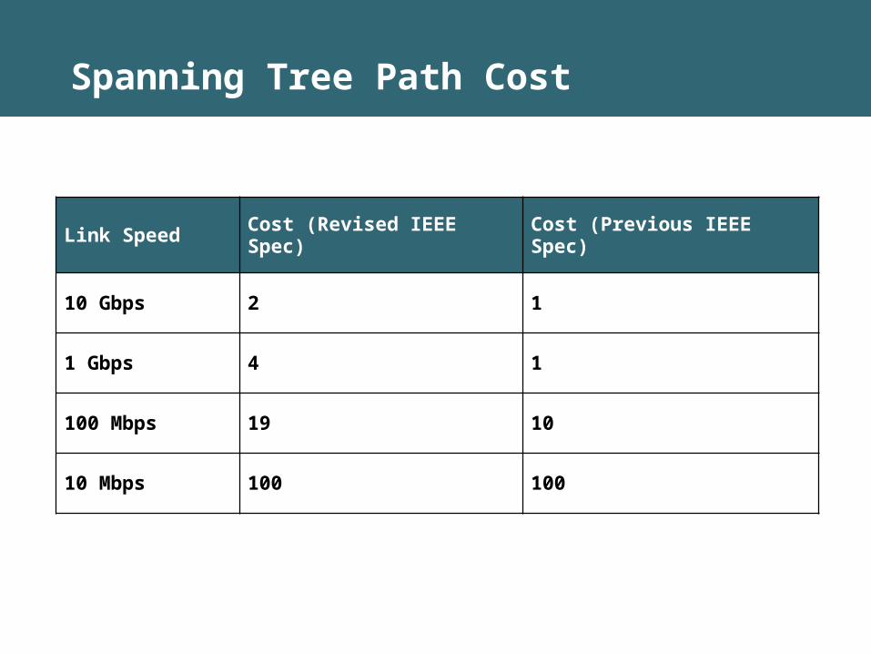
Spanning Tree Path Cost
Link Speed Cost (Revised IEEE Spec) Cost (Previous IEEE Spec)
10 Gbps 2 1
1 Gbps 4 1
100 Mbps 19 10
10 Mbps 100 100

• SW X is the root bridge.
• SW Y needs to elect a root port.
• Which port is the root port on SW Y?
• Fast Ethernet total cost = 0 + 19.
• Ethernet total cost = 0 + 100.
Spanning Tree Protocol Root Port Selection

STP Designated Port Selection
• Switch X is the root bridge.
• All ports on the root bridge are designated ports because they have a path cost of 0.
• Because the Ethernet segment has a path cost of 100, switch Y will block on that port.
• Do all segments have a designated port?
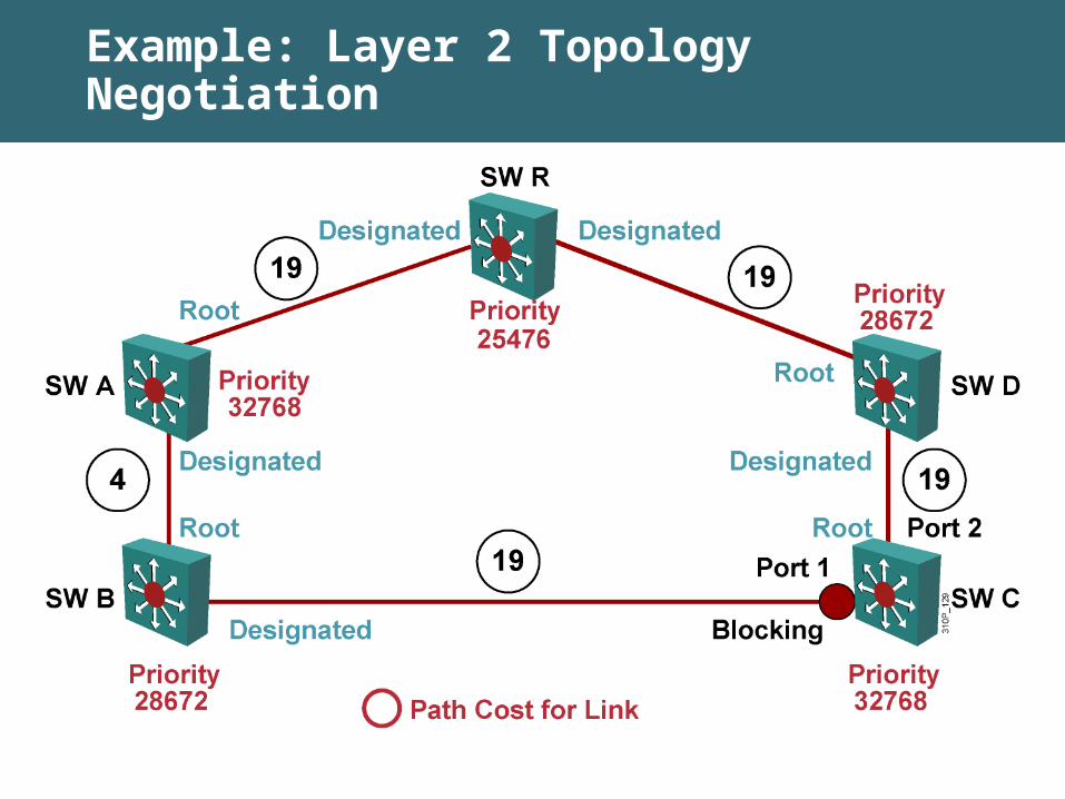
Example: Layer 2 Topology Negotiation

Enhancements to STP
• PortFast
• Per VLAN Spanning Tree+ (PVST+)
• Rapid Spanning Tree Protocol (RSTP)
• Multiple Spanning Tree Protocol (MSTP)
– MSTP is also known as Multi-Instance Spanning Tree Protocol (MISTP) on Cisco Catalyst 6500 switches and above
• Per VLAN Rapid Spanning Tree (PVRST)
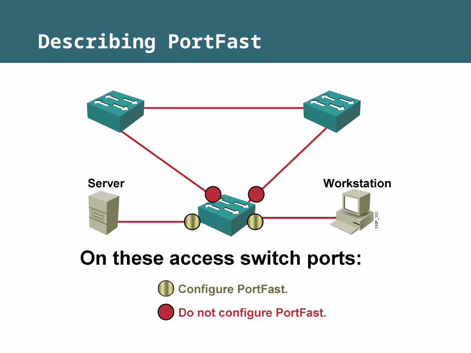
Describing PortFast
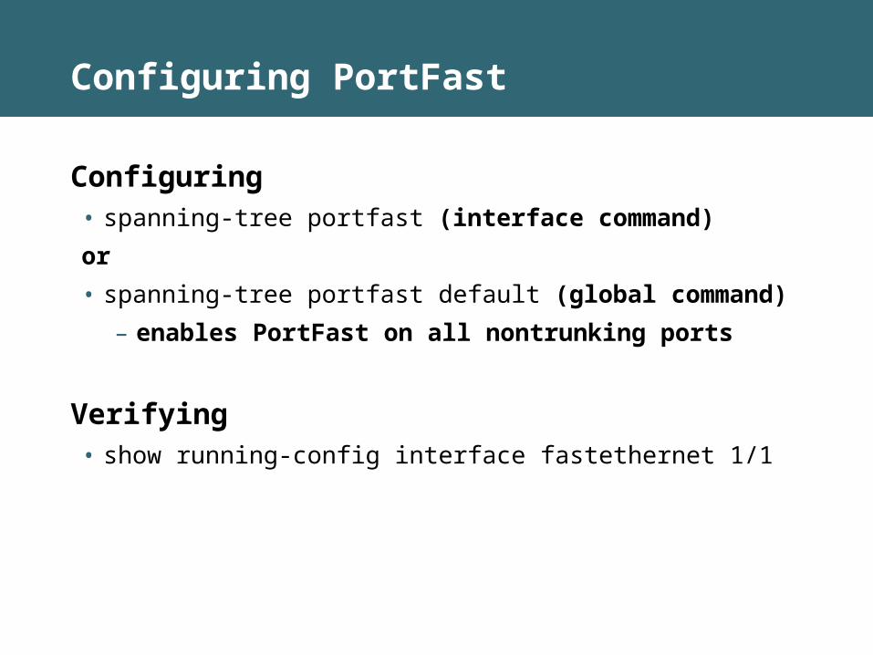
Configuring PortFast
Configuring• spanning-tree portfast (interface command)
or
• spanning-tree portfast default (global command)
– enables PortFast on all nontrunking ports
Verifying• show running-config interface fastethernet 1/1
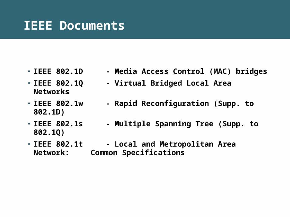
IEEE Documents
• IEEE 802.1D - Media Access Control (MAC) bridges
• IEEE 802.1Q - Virtual Bridged Local Area Networks
• IEEE 802.1w - Rapid Reconfiguration (Supp. to 802.1D)
• IEEE 802.1s - Multiple Spanning Tree (Supp. to 802.1Q)
• IEEE 802.1t - Local and Metropolitan Area Network: Common Specifications
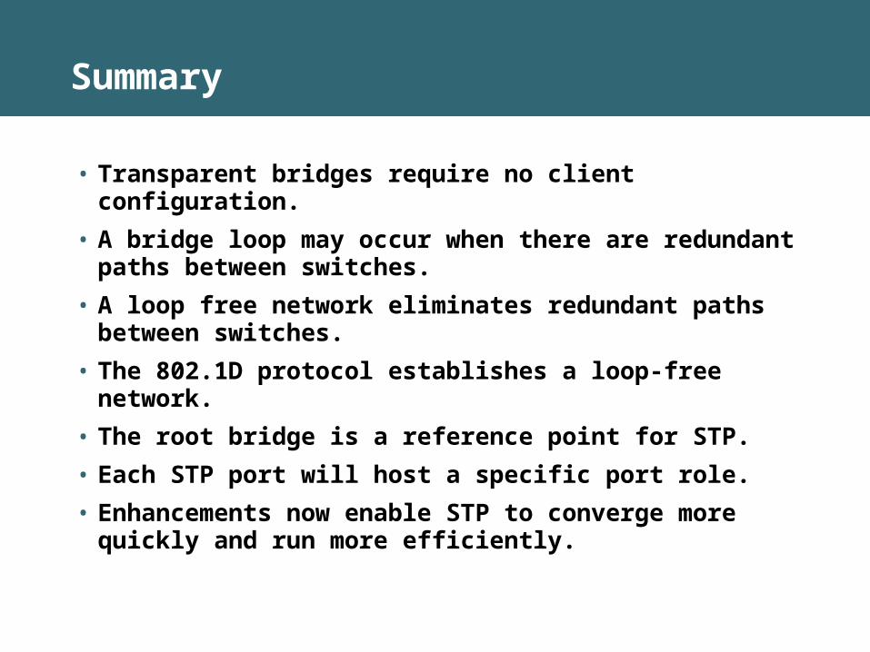
Summary
• Transparent bridges require no client configuration.
• A bridge loop may occur when there are redundant paths between switches.
• A loop free network eliminates redundant paths between switches.
• The 802.1D protocol establishes a loop-free network.
• The root bridge is a reference point for STP.
• Each STP port will host a specific port role.
• Enhancements now enable STP to converge more quickly and run more efficiently.

Implementing Spanning Tree
Implementing RSTP
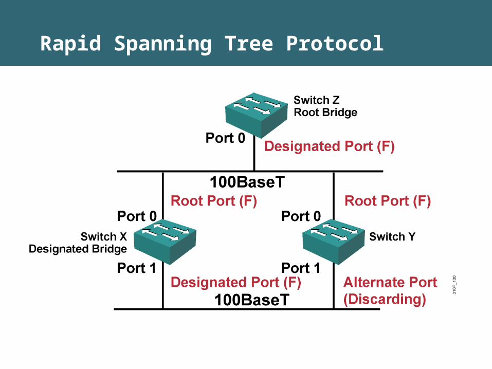
Rapid Spanning Tree Protocol
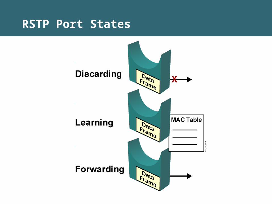
RSTP Port States

RSTP Port Roles
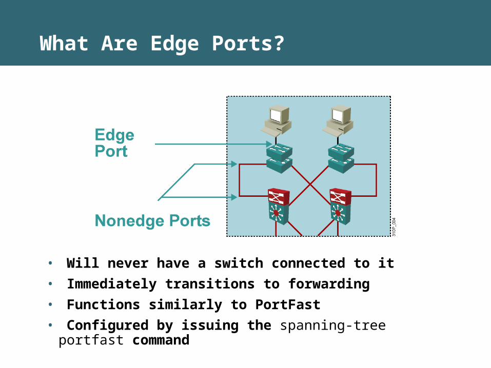
What Are Edge Ports?
• Will never have a switch connected to it
• Immediately transitions to forwarding
• Functions similarly to PortFast
• Configured by issuing the spanning-tree portfast command
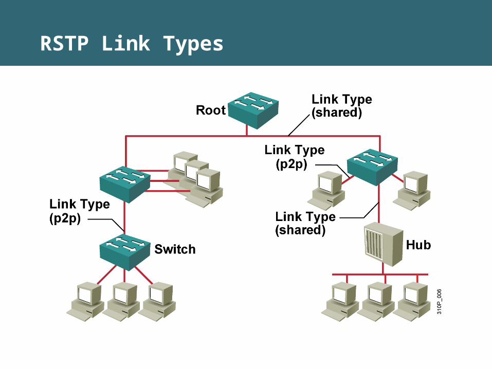
RSTP Link Types
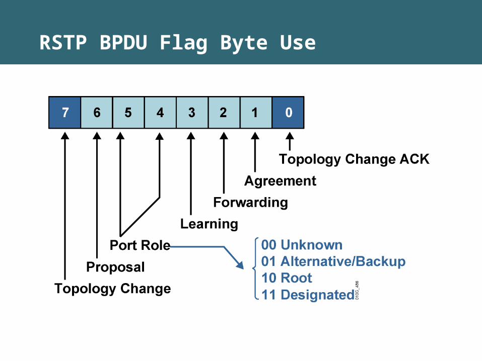
RSTP BPDU Flag Byte Use
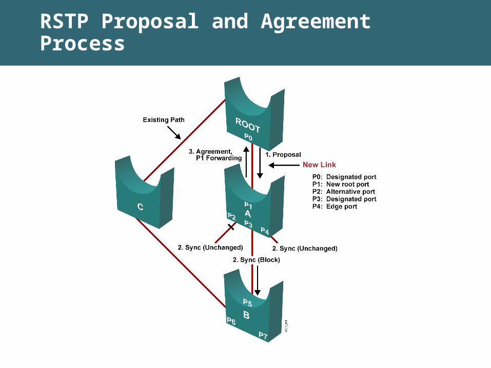
RSTP Proposal and Agreement Process
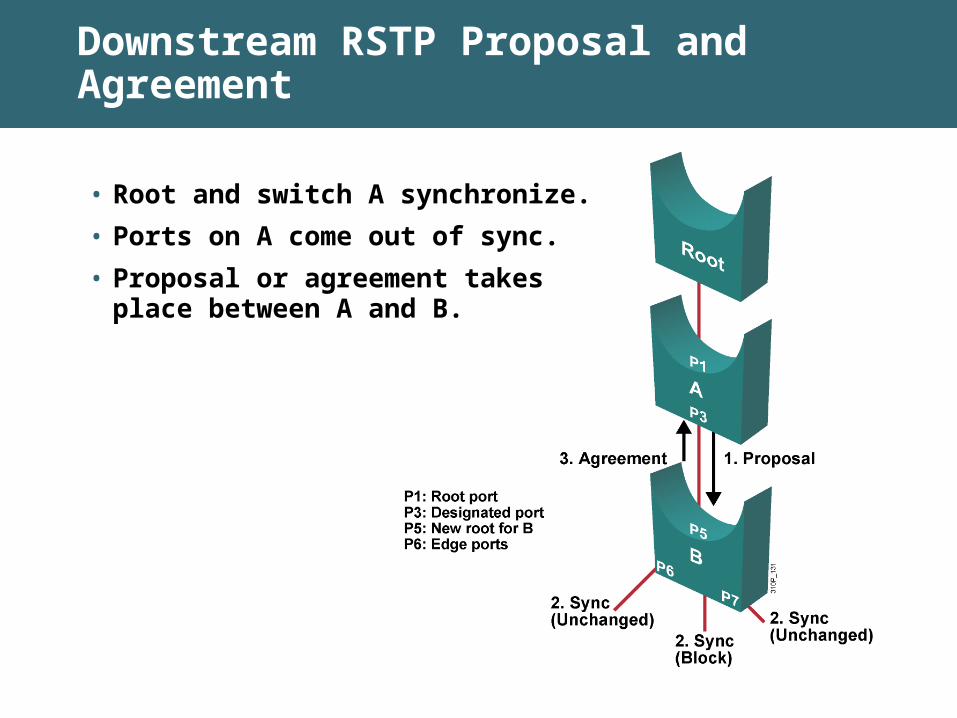
• Root and switch A synchronize.
• Ports on A come out of sync.
• Proposal or agreement takesplace between A and B.
Downstream RSTP Proposal and Agreement
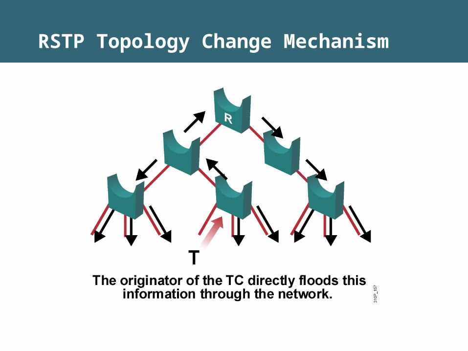
RSTP Topology Change Mechanism
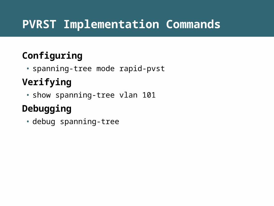
PVRST Implementation Commands
Configuring• spanning-tree mode rapid-pvst
Verifying • show spanning-tree vlan 101
Debugging• debug spanning-tree
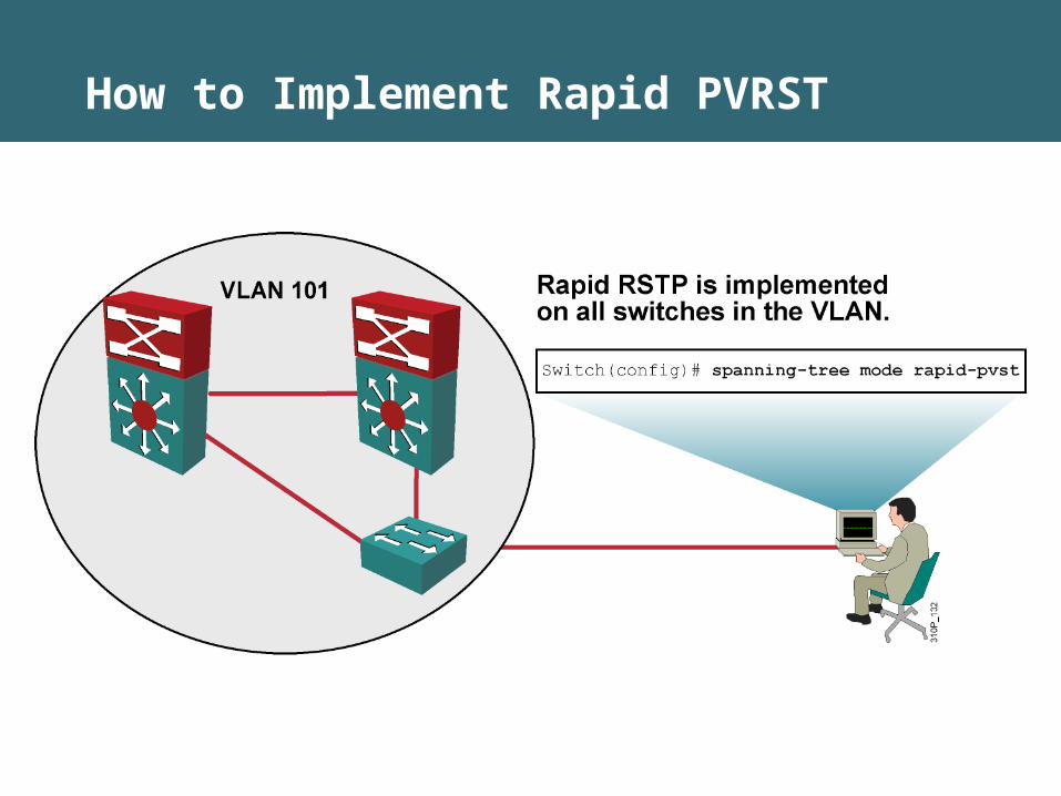
How to Implement Rapid PVRST
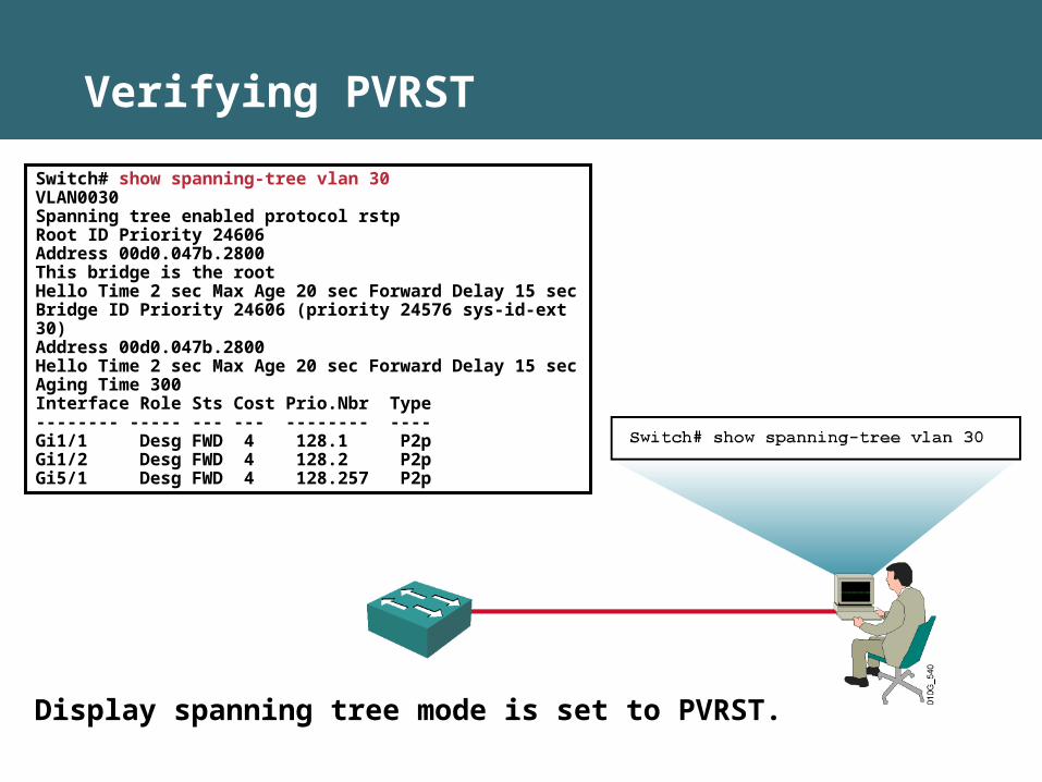
Verifying PVRST
Display spanning tree mode is set to PVRST.
Switch# show spanning-tree vlan 30 VLAN0030Spanning tree enabled protocol rstpRoot ID Priority 24606Address 00d0.047b.2800This bridge is the rootHello Time 2 sec Max Age 20 sec Forward Delay 15 secBridge ID Priority 24606 (priority 24576 sys-id-ext 30) Address 00d0.047b.2800Hello Time 2 sec Max Age 20 sec Forward Delay 15 secAging Time 300Interface Role Sts Cost Prio.Nbr Type-------- ----- --- --- -------- ----Gi1/1 Desg FWD 4 128.1 P2pGi1/2 Desg FWD 4 128.2 P2pGi5/1 Desg FWD 4 128.257 P2p
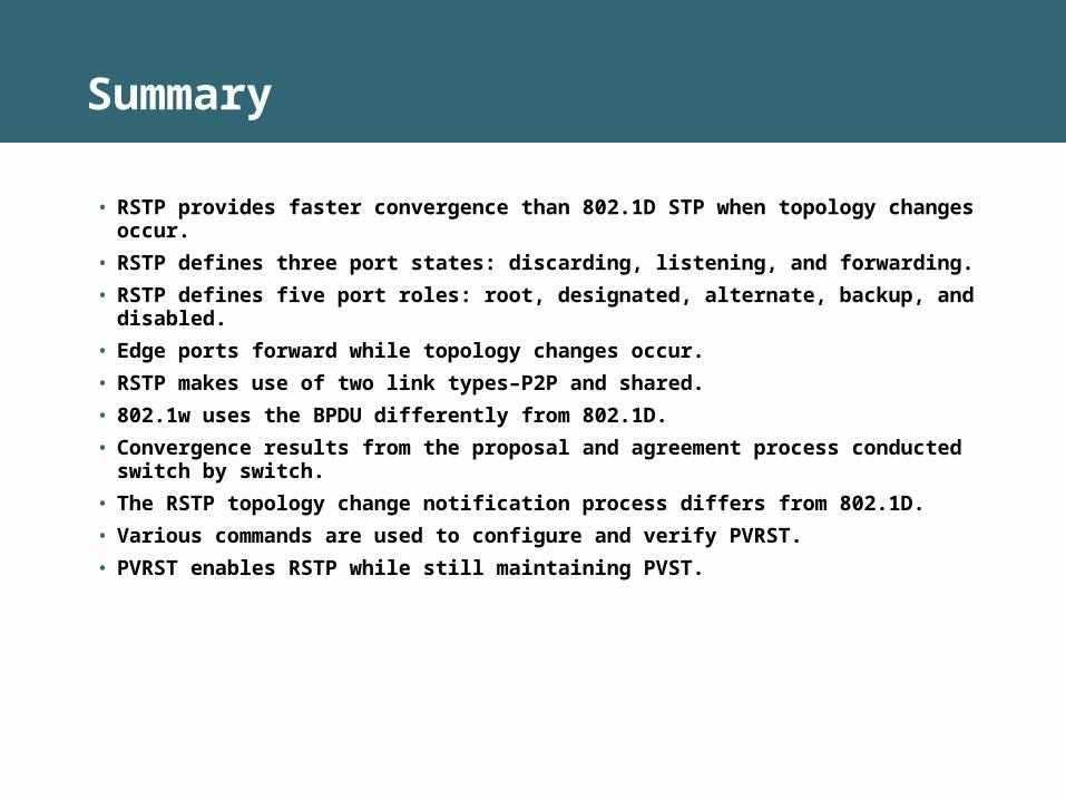
Summary
• RSTP provides faster convergence than 802.1D STP when topology changes occur.
• RSTP defines three port states: discarding, listening, and forwarding.
• RSTP defines five port roles: root, designated, alternate, backup, and disabled.
• Edge ports forward while topology changes occur.
• RSTP makes use of two link types–P2P and shared.
• 802.1w uses the BPDU differently from 802.1D.
• Convergence results from the proposal and agreement process conducted switch by switch.
• The RSTP topology change notification process differs from 802.1D.
• Various commands are used to configure and verify PVRST.
• PVRST enables RSTP while still maintaining PVST.
Implementing Spanning Tree
Implementing MSTP
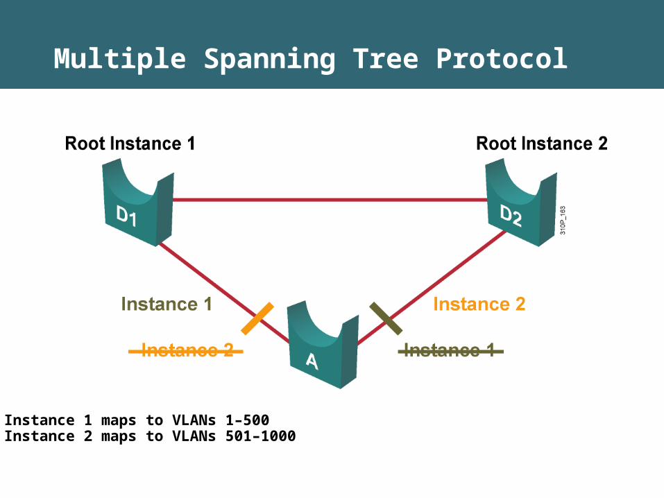
Multiple Spanning Tree Protocol
Instance 1 maps to VLANs 1–500Instance 2 maps to VLANs 501–1000
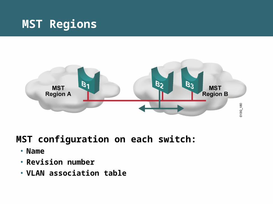
MST Regions
MST configuration on each switch:• Name
• Revision number
• VLAN association table
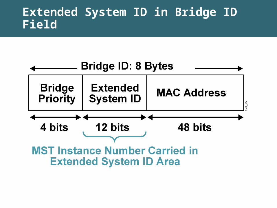
Extended System ID in Bridge ID Field

Interacting Between MST Regions and 802.1D
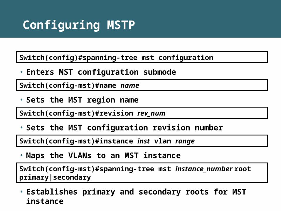
Configuring MSTP
Switch(config)#spanning-tree mst configuration
• Enters MST configuration submode
Switch(config-mst)#name name
• Sets the MST region name
Switch(config-mst)#revision rev_num
• Sets the MST configuration revision number
Switch(config-mst)#instance inst vlan range
• Maps the VLANs to an MST instance
Switch(config-mst)#spanning-tree mst instance_number root primary|secondary
• Establishes primary and secondary roots for MST instance
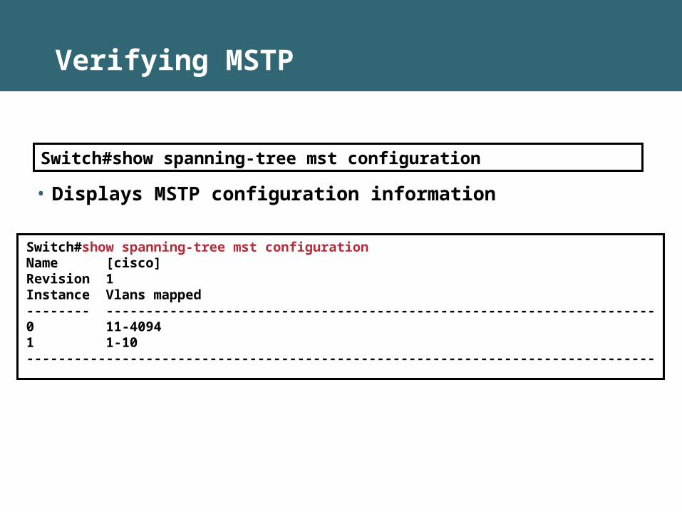
Verifying MSTP
Switch#show spanning-tree mst configuration Name [cisco]Revision 1Instance Vlans mapped-------- ---------------------------------------------------------------------0 11-40941 1-10-------------------------------------------------------------------------------
Switch#show spanning-tree mst configuration
• Displays MSTP configuration information
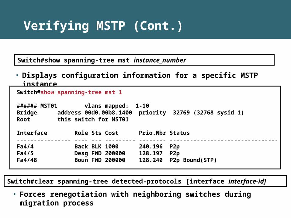
Verifying MSTP (Cont.)
Switch#show spanning-tree mst 1 ###### MST01 vlans mapped: 1-10Bridge address 00d0.00b8.1400 priority 32769 (32768 sysid 1)Root this switch for MST01 Interface Role Sts Cost Prio.Nbr Status---------------- ---- --- --------- -------- --------------------------------Fa4/4 Back BLK 1000 240.196 P2p Fa4/5 Desg FWD 200000 128.197 P2p Fa4/48 Boun FWD 200000 128.240 P2p Bound(STP)
Switch#show spanning-tree mst instance_number
• Displays configuration information for a specific MSTP instance
Switch#clear spanning-tree detected-protocols [interface interface-id]
• Forces renegotiation with neighboring switches during migration process
Summary
• MSTP reduces the encumbrance of PVST by allowing a single instance of spanning tree to run for multiple VLANs.
• An MST region is a group of MSTP switches that appears as a single virtual bridge to adjacent CST and MSTP regions.
• Extended system ID ensures that VLAN ID or MSTP instance can be carried in the Bridge ID field of a BPDU.
• An MSTP region requires an IST and an arbitrary number of MSTP instances as it connects to an 802.1Q network at the MST region border.
• MSTP is configured with a unique set of commands.
• MSTP implementation requires configuration and verification using specific configuration and show commands.

Implementing Spanning Tree
Configuring Link Aggregation with EtherChannel
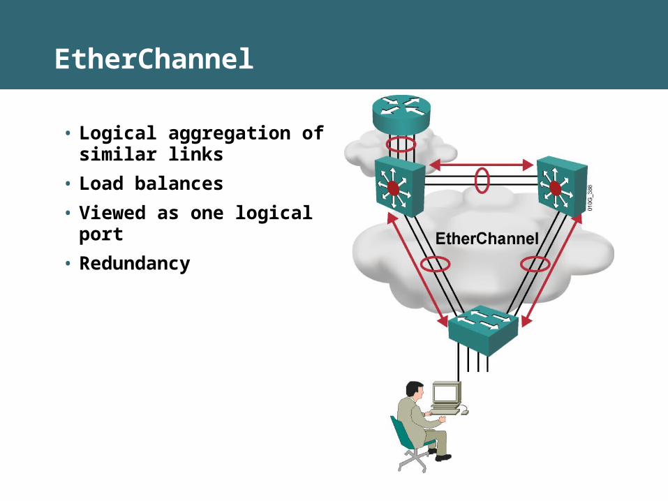
EtherChannel
• Logical aggregation of similar links
• Load balances
• Viewed as one logical port
• Redundancy
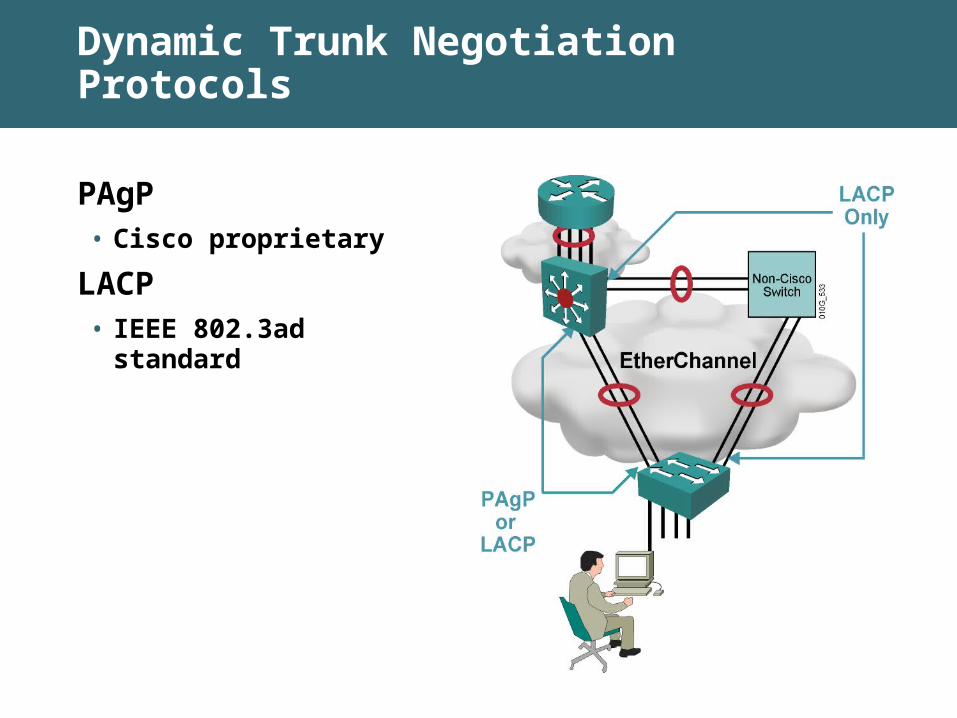
Dynamic Trunk Negotiation Protocols
PAgP• Cisco proprietary
LACP
• IEEE 802.3ad standard

About EtherChannel Configuration Commands
Configure PAgP• interface port-channel {channel-group-number}
• channel-protocol pagp
• channel-group 1 mode {mode}
Verify• show interfaces fastethernet 0/1 etherchannel
• show etherchannel 1 port-channel
• show etherchannel 1 summary
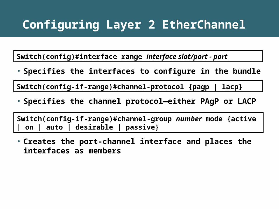
Configuring Layer 2 EtherChannel
Switch(config-if-range)#channel-protocol {pagp | lacp}
• Creates the port-channel interface and places the interfaces as members
Switch(config)#interface range interface slot/port - port
• Specifies the interfaces to configure in the bundle
Switch(config-if-range)#channel-group number mode {active | on | auto | desirable | passive}
• Specifies the channel protocol—either PAgP or LACP
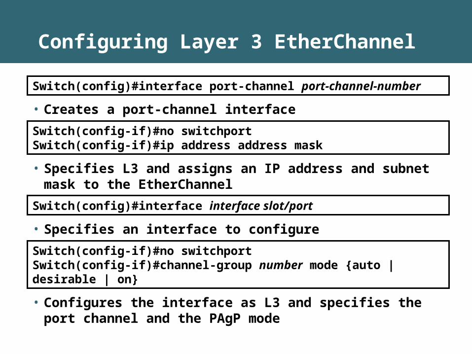
Configuring Layer 3 EtherChannel
Switch(config)#interface port-channel port-channel-number
• Creates a port-channel interface
Switch(config-if)#no switchportSwitch(config-if)#ip address address mask
• Specifies L3 and assigns an IP address and subnet mask to the EtherChannel
Switch(config-if)#no switchportSwitch(config-if)#channel-group number mode {auto | desirable | on}
• Configures the interface as L3 and specifies the port channel and the PAgP mode
Switch(config)#interface interface slot/port
• Specifies an interface to configure
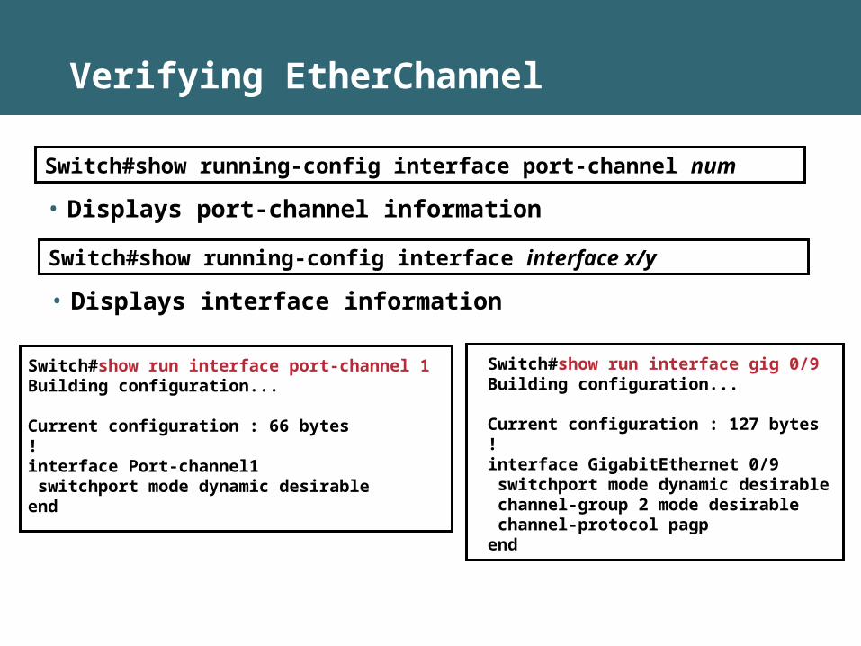
Verifying EtherChannel
Switch#show running-config interface port-channel num
• Displays port-channel information
Switch#show run interface port-channel 1 Building configuration...
Current configuration : 66 bytes!interface Port-channel1 switchport mode dynamic desirableend
Switch#show running-config interface interface x/y
• Displays interface information
Switch#show run interface gig 0/9Building configuration...
Current configuration : 127 bytes!interface GigabitEthernet 0/9 switchport mode dynamic desirable channel-group 2 mode desirable channel-protocol pagpend
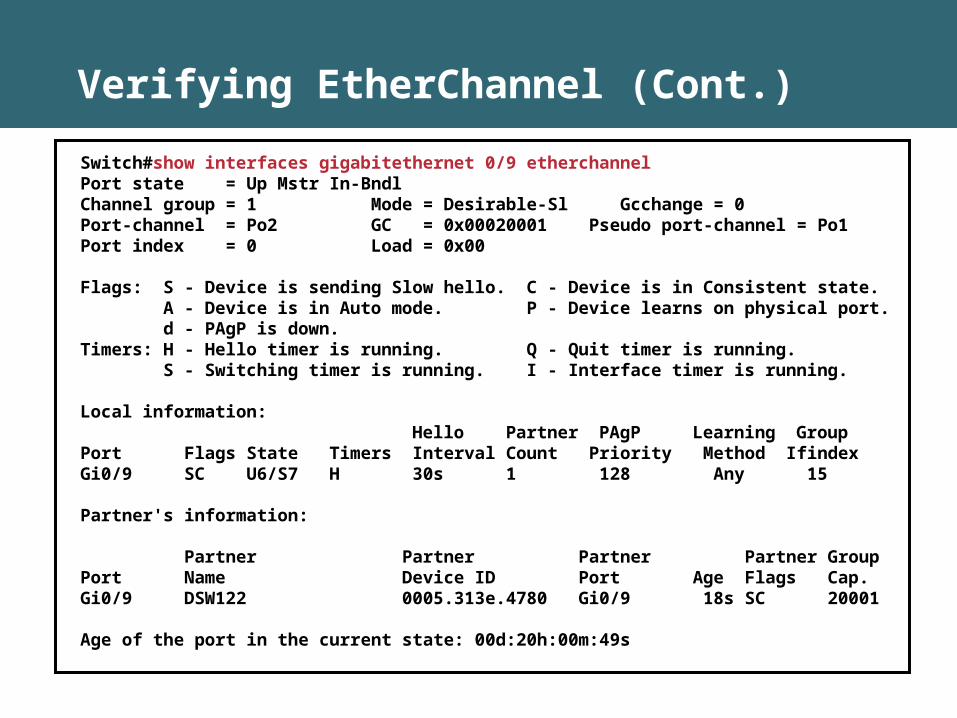
Verifying EtherChannel (Cont.)
Switch#show interfaces gigabitethernet 0/9 etherchannelPort state = Up Mstr In-BndlChannel group = 1 Mode = Desirable-Sl Gcchange = 0Port-channel = Po2 GC = 0x00020001 Pseudo port-channel = Po1Port index = 0 Load = 0x00
Flags: S - Device is sending Slow hello. C - Device is in Consistent state. A - Device is in Auto mode. P - Device learns on physical port. d - PAgP is down.Timers: H - Hello timer is running. Q - Quit timer is running. S - Switching timer is running. I - Interface timer is running.
Local information: Hello Partner PAgP Learning GroupPort Flags State Timers Interval Count Priority Method IfindexGi0/9 SC U6/S7 H 30s 1 128 Any 15
Partner's information:
Partner Partner Partner Partner GroupPort Name Device ID Port Age Flags Cap.Gi0/9 DSW122 0005.313e.4780 Gi0/9 18s SC 20001
Age of the port in the current state: 00d:20h:00m:49s
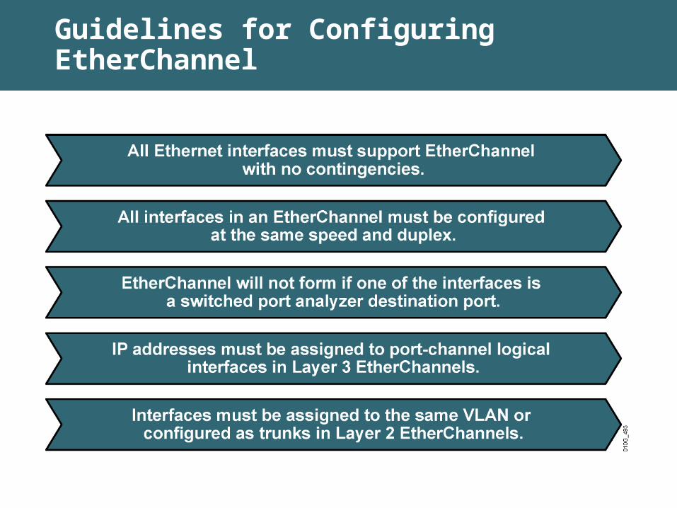
Guidelines for Configuring EtherChannel
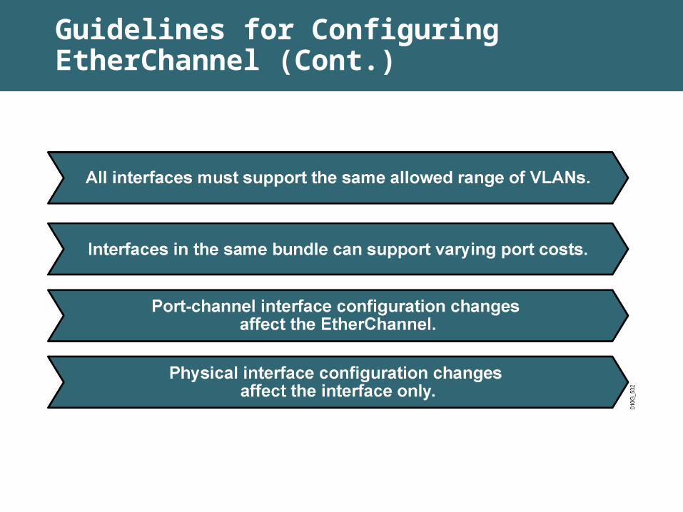
Guidelines for Configuring EtherChannel (Cont.)
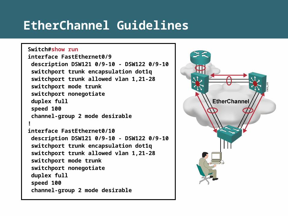
EtherChannel Guidelines
Switch#show runinterface FastEthernet0/9 description DSW121 0/9-10 - DSW122 0/9-10 switchport trunk encapsulation dot1q switchport trunk allowed vlan 1,21-28 switchport mode trunk switchport nonegotiate duplex full speed 100 channel-group 2 mode desirable!interface FastEthernet0/10 description DSW121 0/9-10 - DSW122 0/9-10 switchport trunk encapsulation dot1q switchport trunk allowed vlan 1,21-28 switchport mode trunk switchport nonegotiate duplex full speed 100 channel-group 2 mode desirable
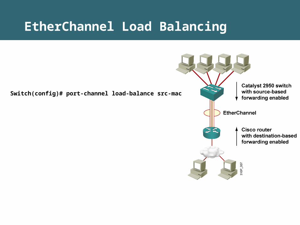
EtherChannel Load Balancing
Switch(config)# port-channel load-balance src-mac
Configuring EtherChannel Load Balancing
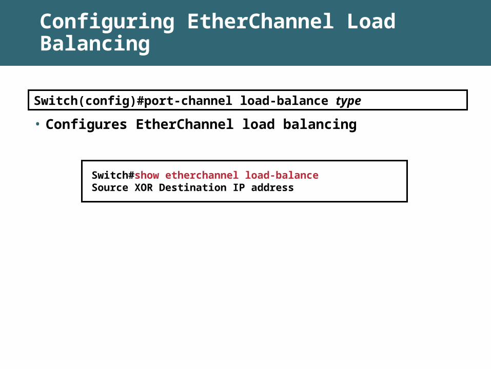
Switch#show etherchannel load-balance Source XOR Destination IP address
Switch(config)#port-channel load-balance type
• Configures EtherChannel load balancing
Summary
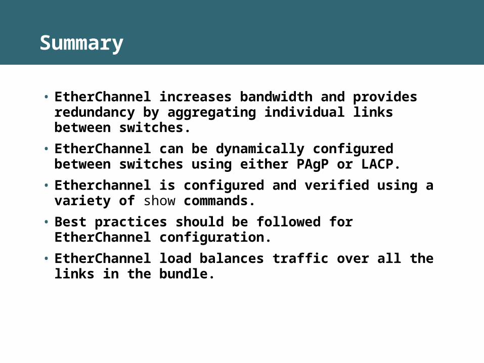
• EtherChannel increases bandwidth and provides redundancy by aggregating individual links between switches.
• EtherChannel can be dynamically configured between switches using either PAgP or LACP.
• Etherchannel is configured and verified using a variety of show commands.
• Best practices should be followed for EtherChannel configuration.
• EtherChannel load balances traffic over all the links in the bundle.
Module Summary
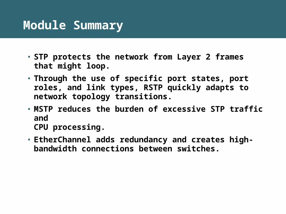
• STP protects the network from Layer 2 frames that might loop.
• Through the use of specific port states, port roles, and link types, RSTP quickly adapts to network topology transitions.
• MSTP reduces the burden of excessive STP traffic and CPU processing.
• EtherChannel adds redundancy and creates high-bandwidth connections between switches.