Embed Size (px)
Citation preview

BAY ENGINEERING, INC
Naval Architects & Marine Engineers
Sturgeon Bay, WI 54235
Report No: 3930-00 R2
Date: Jun 6, 2012
Title: S.S. BADGER Conversion from Coal to CNG/LNG
Fired Boiler Engineering Feasibility Analysis
To: Great Lakes Maritime Research Institute
Duluth, MN 55812
Prepared By: Ziyan Zhang, P.E,
&
Joseph P. Fischer, P.E,
Checked By: Ronald C. Olander, P.E.
Approved By: Joseph P. Fischer, P.E.
File: BEI Job # 3930-00

BEI Job # 3930-00
Table of Contents
I. Abstract ................................................................................................................................................. 1
II. Purpose ................................................................................................................................................. 1
III. Merits of Natural Gas against Coal ....................................................................................................... 1
IV. Natural Gas Storage Options: CNG vs LNG ........................................................................................ 2
V. Source of CNG/LNG: ........................................................................................................................... 4
VI. Gas Consumption Estimation ............................................................................................................... 5
VII. Conceptual Design ................................................................................................................................ 9
VIII. Off Season Gas Discharge .................................................................................................................. 20
IX. Cost Estimate ...................................................................................................................................... 21
X. Manning and Crew Training Implications .......................................................................................... 22
XI. Value as a Pilot Program for the Great Lakes Vessels ....................................................................... 22
XII. Recommendation ................................................................................................................................ 22
XIII. Summary ............................................................................................................................................. 23
XIV. Bibliography ....................................................................................................................................... 24
Appendix A Natural Gas Consumption Calculations
Appendix B Natural Gas Tanks Layout
Appendix C Samples of LNG Tanks for Ship & Road Transportation
i
BEI Job # 3930-00
I. ABSTRACT The report presents an analysis of the feasibility of using natural gas to fuel Great Lakes ships. This report highlights the merits of natural gas as a ship fueling option against coal. Additionally, an analysis of the conversion of the car ferry S. S BADGER from a coal powered steam plant to a natural gas powered steam plant is presented. The two principal methods of storing natural gas onboard, Liquefied Natural Gas (LNG) and Compressed Natural Gas (CNG), are described. The possible source for obtaining natural gas near the current S. S. BADGER ferry route is discussed. The gas consumption is estimated for the current ferry route. Design details and safety regulation compliance are demonstrated. The off season gas discharge problem is introduced. The cost of the conversion is estimated, and manning and crew training are considered.
II. PURPOSE The purpose of the report is to show the feasibility of using natural gas as a fuel option. The advantage of natural gas is presented. The feasibility of economically and safely converting the car ferry S.S. BADGER to a natural gas powered vessel is discussed. In Section VII - Conceptual Design, the inherent safety of the two principal fuel storage options, Liquefied Natural Gas (LNG) and Compressed Natural Gas (CNG) is discussed for a passenger vessel, by following the published rules. The main guideline used to demonstrate inherent safety is ABS Guide for Propulsion and Auxiliary Systems for Gas, 2011 [1]. The safety measures such as double wall, double piping with inert gas, forced ventilation, insulation of steel structure, etc. are discussed. See Section VII - Conceptual Design for details. The possible fuel availability and options for the current route is presented. This report also explains the necessary shore side support and infrastructure. The cost is estimated for the conversion. The report suggests areas where additional manning and crew training will be required. The value of the S. S. BADGER as a pilot for future conversions of U.S. Flag Great Lakes vessels is discussed.
III. MERITS OF NATURAL GAS AGAINST COAL Natural gas is a “greener" fuel that complies more easily with ever stricter government regulations.
The current fuel used by the S. S. BADGER is bituminous coal. Bituminous coal normally consists of not less than 70% of carbon, not over 1% sulfur, not over 7% ash and not over 12% moisture [2]. The combustion product of coal consists of nitrogen oxide (NOx), carbon monoxide (CO), hydro carbon (HC), particulate matter (PM) and sulfur oxide (SOx).
Natural gas predominantly consists of methane, CH4 (85-95%), with smaller amounts of ethane, propane, butane and nitrogen. The exhaust emission from the natural gas engines or boilers mainly consists of nitrogen, carbon dioxide (CO2) and water vapor. The exhaust emission contains relatively lower nitrogen oxide (NOx), lower carbon monoxide (CO) and lower hydro carbon (HC) contents as well as no particulate matter (PM) and no sulfur oxide (SOx), which makes natural gas a good alternative to coal for protection of the environment.
1

BEI Job # 3930-00
CO2 emissions from natural gas are 53.06 kg CO2/mmBTU, where as bituminous coal CO2 emissions are 93.28 kg CO2/mmBTU. Using natural gas instead of coal as an energy resource greatly helps reduce green house gases. [3]
Liquefied natural gas (LNG) and compressed natural gas (CNG) contain more energy in unit mass of fuel. Bituminous coal has a specific energy of 24 MJ/kg and energy density of 20 MJ/L. LNG (NG at -160°C) has a specific energy of 53.6 MJ/kg and an energy density of 22.2 MJ/L. CNG (NG compressed to 250 bar/~3,600 psi) has a specific energy of 53.6 MJ/kg and an energy density of 9 MJ/L. From this we can see that LNG and CNG have a higher energy per mass of fuel than bituminous coal. LNG also has a higher energy per unit volume of fuel than bituminous coal [4].
Natural gas has a price advantage. As of January 25, 2012, the Henry Hub natural gas spot price was $2.61 per million British Thermal Units (mmBTU) [5]. With overhead costs such as transportation and storage factored in, the destination user price is estimated below $4 per mmBTU. At this same date, coal was selling for 125 dollars per short ton. The coal heat density is about 25 mmBTU/ST, which is equivalent to $5.00 per mmBTU. By comparison, natural gas has a better price per unit energy than coal.
IV. NATURAL GAS STORAGE OPTIONS: CNG VS LNG Natural gas occupies a large amount of space, which makes it economically and structurally impossible to carry natural gas in its original status at ambient temperature and standard atmosphere pressure. In order to reduce the volume, the natural gas is either liquefied or pressurized. There are currently three storage options of natural gas.
Liquefied Natural Gas (LNG) Natural gas is liquefied when it’s cooled down to approximately -162 °C (-260 °F) with a working pressure at about 5 to 7 bars [6]. LNG achieves a higher reduction in volume than compressed natural gas (CNG) so that the energy density of LNG is 2.4 times that of CNG or 1.1 times that of bituminous coal [6].
LNG storage tanks onboard the ships are normally IMO ‘Type C’ tanks. They consist of an inner cryogenic cylindrical vessel with an outer jacket. This design creates a double barrier required by ABS safety regulations. The inner vessel is made of stainless steel and outer jacket is made of mild steel. The space in between the inner vessel and outer jack is filled with perlite insulation and vacuumed. The method maintains LNG’s temperature and prevents the stress cracks forming from the high temperature differential. The cryogenic tanks typically come with a cold box attached to one end, containing control equipment, connection fittings and vaporizer(s).The vaporizer can vaporize the LNG from liquid status at -162°C storage temperature to gas status at 15°C, which is suitable to be used by the ships gas engines or boilers. [7] See Appendix C for a sample of a LNG onboard storage tank. These tanks and vaporization system can be expensive to construct and install onboard a ship.
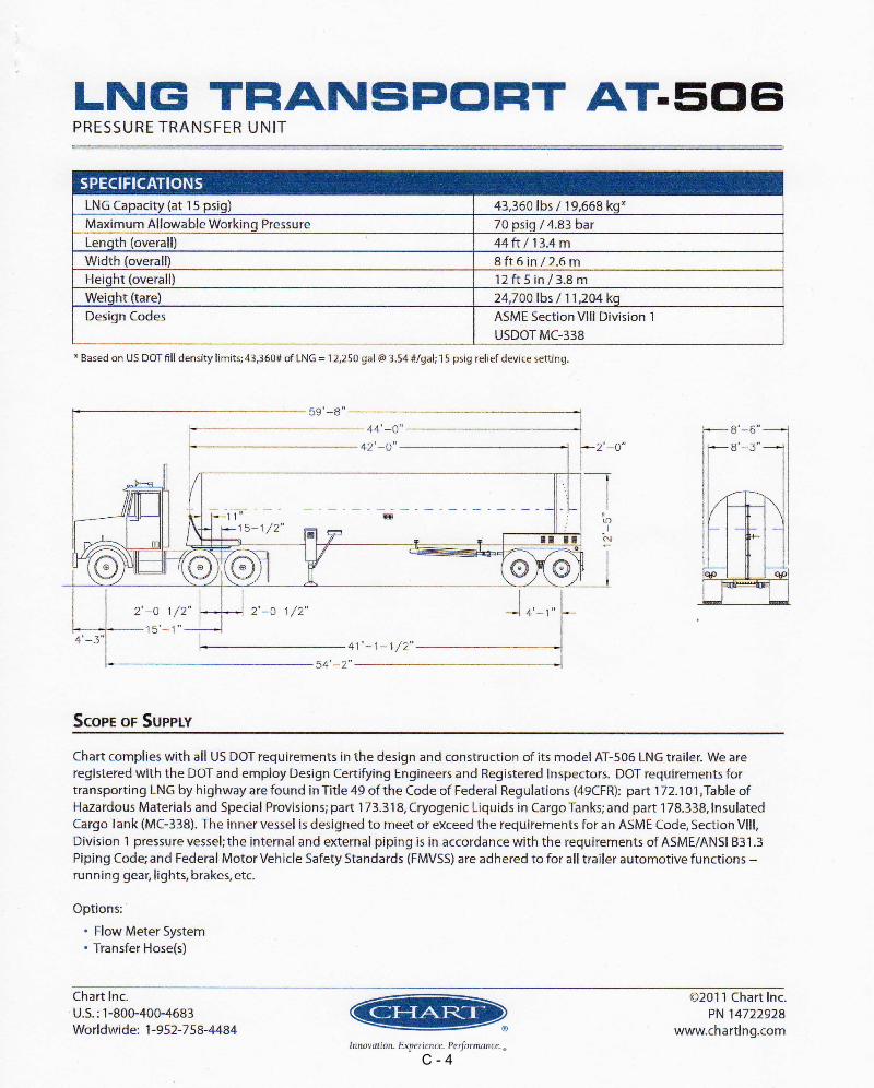
LNG can be transported from distribution point to the ship by cryogenic tanker trucks. The tanks on the truck are similar to the tanks onboard the ship. A typical truck can carry about 12,250 gallons of LNG and unload at a rate up to 300 GPM. See Appendix C for a sample of a road transportation tank.
2

BEI Job # 3930-00
Compressed Natural Gas (CNG) LNG needs to be stored in expensive cryogenic tanks and has a relatively high cost of production. In comparison, the CNG becomes an attractive option with relatively low cost and structurally simpler tanks. CNG is made by compressing natural gas to a pressure of 200-248 bar (2900-3600 psi). The CNG volume is less than 1% of its volume at standard atmospheric pressure [8].
The tanks for storing CNG are much simpler than those for LNG. The CNG will be stored in high pressure cylinders that can be stacked vertically or horizontally. The cylinders are strapped to steel framed grids supporting each cylinder. See Figure 1 for a general layout of tanks.
The transportation of CNG can be undertaken by CNG containers / tube trailers. An existing sample trailer is shown in Figure 2, which has been used to transport CNG to CNG fuel station.
Pressurized Liquefied Natural Gas (PLNG) While this option is not very common today it is worth mentioning. When natural gas is stored at a temperature of minus 40 degrees Celsius and under high pressure up to 240 bar, the natural gas will exist primarily as a liquid called PLNG. The PLNG is able to use the specially made storage tank such as the Trans Ocean Gas Pressure Vessel (Figure 1) which is also used for storing CNG [9]. Under these conditions, the gas container will carry about 39375 scf of equivalent CNG per cylinder tank.
Due to the novelty of this storage system and the current state of the regulatory process, this system is not considered as an option in this report.
Figure 1 - Image from Trans Ocean Gas Inc. website: http://www.transoceangas.com/Development_Plan.htm
3

BEI Job # 3930-00
Figure 2 - Image from D&D Methane Inc. website: http://www.methane-did.com/en/products/cng-tube-trailers
V. Source of CNG/LNG: The figure from Damien Gaul’s article “U.S. LNG Markets and Uses” [10] shows the fuel availability and options on the US map. For the current Ludington-Manitowoc route, the most convenient fuel source is the SE Wisconsin LNG peak shaving plant in Milwaukee. The ideal transportation method would be a truck with tank trailer from the shaving plant to Manitowoc.
Since the last revision of this report, several natural gas suppliers have been contacted. CNG can be transported to the dock using tanker trucks from a Manitowoc pipeline gas station owned by one of the CNG suppliers. LNG can be supplied by one LNG supplier from several plants within 500 miles via tanker truck. The specific locations of the LNG resources have not been revealed by the supplier.
The natural gas quantity needed for S. S. BADGER will be discussed in the next chapter.
4

BEI Job # 3930-00
Figure 3 - U.S. Liquefied Natural Gas Facilities as of June 2004, Damien Gaul, U.S. LNG Markets and Uses
VI. GAS CONSUMPTION ESTIMATION The daily gas consumption for LNG and CNG is summarized in the table below. The detailed calculations are attached in Appendix A.
Table 1 - Daily Gas Usage Summary LNG LNG Vol. Req'd
per Day Vol of Tks
Onbd # of Days
per Fill m3 m3 Days One Round Trip Per Day 50.28 210.45 4.19 Two Round Trip Per Day 62.85 210.45 3.35
CNG CNG Vol. Req'd per Day
Vol of Tks Onbd
# of Days per Fill
m3 m3 Days One Round Trip Per Day 140.67 216.00 1.54 Two Round Trip Per Day 175.84 216.00 1.23
5
BEI Job # 3930-00
Liquefied Natural Gas (LNG): The LNG fuel system would be located under the car deck in four separate compartments containing one LNG tank and evaporator in each compartment. The LNG tanks are sized according to the geometric restriction of the compartments that they are located in. The sizes of the LNG tanks are 46 m3 for the forward two tanks and 59 m3 for the aft two tanks, see Figure 4. The S. S. BADGER shall be fuelled by LNG tanker truck. The LNG tank truck has a volume of 46 m3. Each LNG tank onboard has enough capacity to take a full truck load. The ferry is bunkering every 3 or 4 days with the LNG option. The refueling takes place when the ferry is docked and when boarding the passengers, if regulation permits. If passengers and cars are not allow onboard while bunkering, then bunkering will occur after unloading the passengers and cars from the previous trip and before loading the passengers and cars for the next trip. Refueling time is about 41 minutes for a truckload of 46 m3 of LNG. The total bunkering procedure will take about 3 hours. Two trucks can be connected to the bunker station and refuel the ferry at the same time, which reduces the bunkering time down to 1.5 hours. The trucks connect to the filling station through a connection in the recessed area on either side of the ship. When the ferry is working on the summer schedule which only allows 2 hr docking time, two trucks refuelling the ferry at the same time are needed. Besides, two separate bunkering processes in the same day may happen. A storage bunker at the ferry berth is not necessary, which reduces the initial investment cost and makes it possible to relocate the ferry to serve other routes. [11]
Since the ship has on average 2 hour docking periods scheduled and it would be inefficient to require half a truck load, the LNG refueling plan should be rationalized to the ship operation schedule so that it can use integer truck loads and fit within the operating schedule. Below is a tentative schedule assuming two BADGER round trips per day which limits each fueling time at no more than one hour using integer truck loads with the assumption of two trucks fueling at a time. When the S. S. BADGER is running on the schedule of two round trips per day and needs 4 truckloads of LNG that day, it can be fueled with 2 trucks at the first dockside and then fueled with 2 more trucks the second time the S. S. BADGER is at the same dockside. According to the tentative schedule for spring and fall, the S. S. BADGER needs to be fueled every three days, 3 to 4 trucks at a time. During the summer schedule, 4 trucks of LNG are needed every three days, with 2 trucks a day for two days.
6

BEI Job # 3930-00
One Round Trip Per Day
Suggested Fueling
Schedule truck #
Fueling Time (hr)
Added Vol (m3)
Vol After
Fueling (m3) % Full
Consumed
(m3)
Vol Remain
(m3) % Full day 1 4 1.4 185 185 88% 50 135 64% day 2 - - 0 135 64% 50 85 40% day 3 - - 0 85 40% 50 35 16% day 4 3 1.4 139 174 83% 50 123 59% day 5 - - 0 123 59% 50 73 35% day 6 - - 0 73 35% 50 23 11% day 7 3 1.4 139 162 77% 50 112 53% day 8 - - 0 112 53% 50 61 29% day 9 - - 0 61 29% 50 11 5% day 10 4 1.4 185 197 93% 50 146 70% day 11 - - 0 146 70% 50 96 46% day 12 - - 0 96 46% 50 46 22% day 13 3 1.4 139 185 88% 50 135 64% day 14 - - 0 135 64% 50 84 40% day 15 - - 0 84 40% 50 34 16%
… … … … … … … … …
Two Round Trip Per Day
Suggested Fueling
Schedule truck #
Fueling Time (hr)
Added Vol (m3)
Vol After
Fueling (m3) % Full
Consumed
(m3)
Vol Remain
(m3) % Full day 1 4 1.4 185 185 88% 63 123 58% day 2 - - 0 123 58% 63 60 28% day 3 2 0.7 93 153 72% 63 90 43% day 4 2 0.7 93 182 87% 63 120 57% day 5 - - 0 120 57% 63 57 27% day 6 2 0.7 93 149 71% 63 87 41% day 7 2 0.7 93 179 85% 63 117 55% day 8 - - 0 117 55% 63 54 25% day 9 2 0.7 93 146 70% 63 84 40% day 10 2 0.7 93 176 84% 63 113 54% day 11 - - 0 113 54% 63 51 24% day 12 2 0.7 93 143 68% 63 80 38% day 13 2 0.7 93 173 82% 63 110 52% day 14 - - 0 110 52% 63 48 23% day 15 2 0.7 93 140 67% 63 77 37%
… … … … … … … … …
7

BEI Job # 3930-00
Compressed Natural Gas (CNG): Three scenarios have been investigated for the use of CNG.
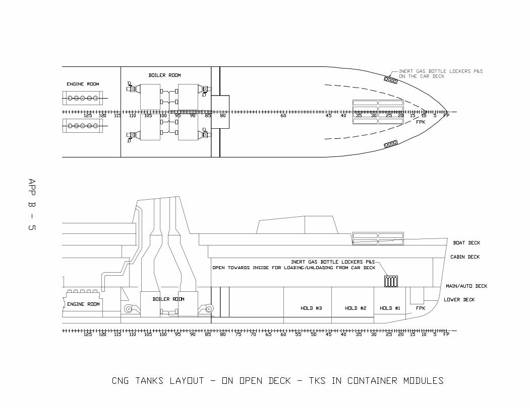
Option 1 would locate the CNG storage tanks under the car deck in six separate compartments. The layout is shown in Appendix B. The sizes of the CNG tanks can vary to suit the size of the compartment, but, we have used the 3000 liter (3 m3) CNG tanks as shown in Figure 1. There will be a total of seventy-two (72) CNG tanks under the car deck. The S.S. BADGER would be fuelled by the suppliers CNG tank truck. The refueling takes place when the ferry is docked and when boarding the passengers, if regulation permits. If passengers and cars are not allow onboard while bunkering, then bunkering will occur after unloading the passengers and cars from the previous trip and before loading the passengers and cars for the next trip. Each CNG tank truck can carry about 24 m3 CNG. This would require the ferry to bunker every day for this option. The truck connects to the filling station through a connection in the recessed area at either side of the ship. The refueling rate of CNG depends on the specific pump on the supplier’s truck or by the owner’s facility. The shortcoming of this option is the CNG bunkering rate is too slow to finish filling the CNG storage tanks within the current 2 hour docking time, according to a natural gas supplier’s estimate.
Option 2 follows the USCG preference that the tanks be located on the open deck and not located under passenger accommodation areas. The greatest obstacle in placing the CNG tanks on the open deck is the lack of available space. Using the same 3 m3 CNG tank as option 1, and the calculations in Appendix A, we need about 59 CNG tanks (or 72 CNG tanks if count in surplus) per day in the peak season. With the tank lying flat, the open deck can hold 20 CNG tanks. With the tank standing vertically, the open deck can hold 56 CNG tanks. Both CNG tanks layouts are shown in Appendix B. Neither plan can hold enough tanks for one day’s fuel needs at peak season. In addition, the bridge house’s view is obstructed heavily and the strength of the deck would need to be verified to support 300 LT of tanks. This also has the transfer rate limitation as described for scenario 1.
Option 3 utilizes removable CNG storage units and the ship will only carry enough fuel for a one-way trip on board. This concept is similar to replacing the propane tank used for a gas grill. The CNG tanks are mounted in standard 40’ shipping containers, every container consists of 8 CNG tanks as shown in Figure 1. The storage unit would be located on the forward deck similar to option 2. This option is limited by the space available in the open deck. The ship will only carry two (2) containers on the foreword open deck, which is enough fuel need for a one-way trip. (See Appendix A for calculations and Appendix B for container layout.) When the ship is at dockside, the fuel needed is supplied by on shore containers. The storage unit would be loaded / unloaded onto the ferry via a container truck. The container will be left onboard and the truck drives away. Otherwise, a new crane can be installed on the vessel or on shore for this purpose. If a truck would be used, a new ramp will need to be built, since there is no ramp access to the forward deck from within the ship. If an on-shore crane is used to load / unload, this would result in a large crane due to the required load requirement (more than 21 LT capacity) and long reach needed (150 ft boom). If a shipboard crane was used it could be located on the open deck in space that cannot be utilized by the containers. An example of a suitable crane would be an EBI crane with 55 ft boom and 30 LT capacity. The cost of purchasing and maintain a crane, whether ship mounted or truck, would have to consider in the cost analysis of this option. The method alleviates the transfer rate problem of the two previous methods since the unit is full when loading and would only require the pipe connection to be made.
8

BEI Job # 3930-00
VII. CONCEPTUAL DESIGN
1. General
Objectives and Scope The design objective is to apply ABS criteria for the arrangements and construction of machinery, equipment and systems for vessels operating with natural gas as fuel, in order to minimize risks to the vessel, crew and environment. Detailed requirements are provided in the following sections with key requirements quoted from the chapters of ABS rules to show compliance.
This section is aimed at providing a general guidance for the design and construction of the subject vessel, S. S BADGER, to convert to utilize gas as a fuel. The system configuration is to use natural gas to power the existing boilers with new burners which work with natural gas instead of coal. The boilers in turn will provide steam energy to power propulsion and auxiliary systems. The gas will be stored in the original coal bunker space as well as cargo hold #3 spaces. The tank type will be double-wall Type C cryogenic tanks for Liquefied Natural Gas (LNG) or high pressure gas tanks for Compressed Natural Gas (CNG).
Safety Related Rules & Regulations The design will follow ABS Guide for Propulsion and Auxiliary Systems for Gas Fueled Ships 2011 [1]. Other rules may apply including Part 5C Chapter 8 Vessels Intended to Carry Liquefied Gases in Bulk of the ABS RULES For Building And Classing Steel Vessels 2012, and the Interim Guidelines on Safety for Natural Gas-Fuelled Engine Installations in Ships, which were adopted by International Maritime Organization (IMO) Resolution MSC.285(86) on 1 June 2009.
USCG has no public rules for gas powered ships. Every design is individually checked. USCG’s current process for approval of natural gas fueled vessels is to first conduct a concept design review, and this will result in a Design Basis Agreement. Next, the Marine Safety Center will conduct plan review of the detailed design. Past successful submissions have aligned their designs with the IMO's Interim Guidelines on Safety for Natural Gas-Fuelled Engine Installations in Ships MSC.285(86). [12]
Materials in general are to comply with the requirements of the ABS Rules for Materials and Welding (Part 2). The construction materials used in gas tanks, gas piping, process pressure vessels and other components in contact with cryogenic liquids or gases are to be in compliance with Section 5C-8-6 of the Steel Vessel Rules.
For further guidance on CNG tanks, see ABS Guide for Vessels Intended to Carry Compressed Natural Gases in Bulk (CNG Guide)
2. Key Design Elements a) Distance from side shell: The lesser of 1/5 of the beam or 11.5 m (37.73 feet). For the S. S.
BADGER, the least distance from the side shell is 3.627 m (11.9 ft). b) Distance from bottom shell: The lesser of 1/15 the beam or 2 m (6.562 ft). For the S. S.
BADGER, the least distance from bottom shell is 1.209 m (3.967 ft). c) Tank type: Ideally are independent IMO ‘Type C’ tanks for liquid gas storage. The configuration
of a Type C tank is described in item (f) below. CNG tanks are designed according to the CNG Guide.
9
BEI Job # 3930-00
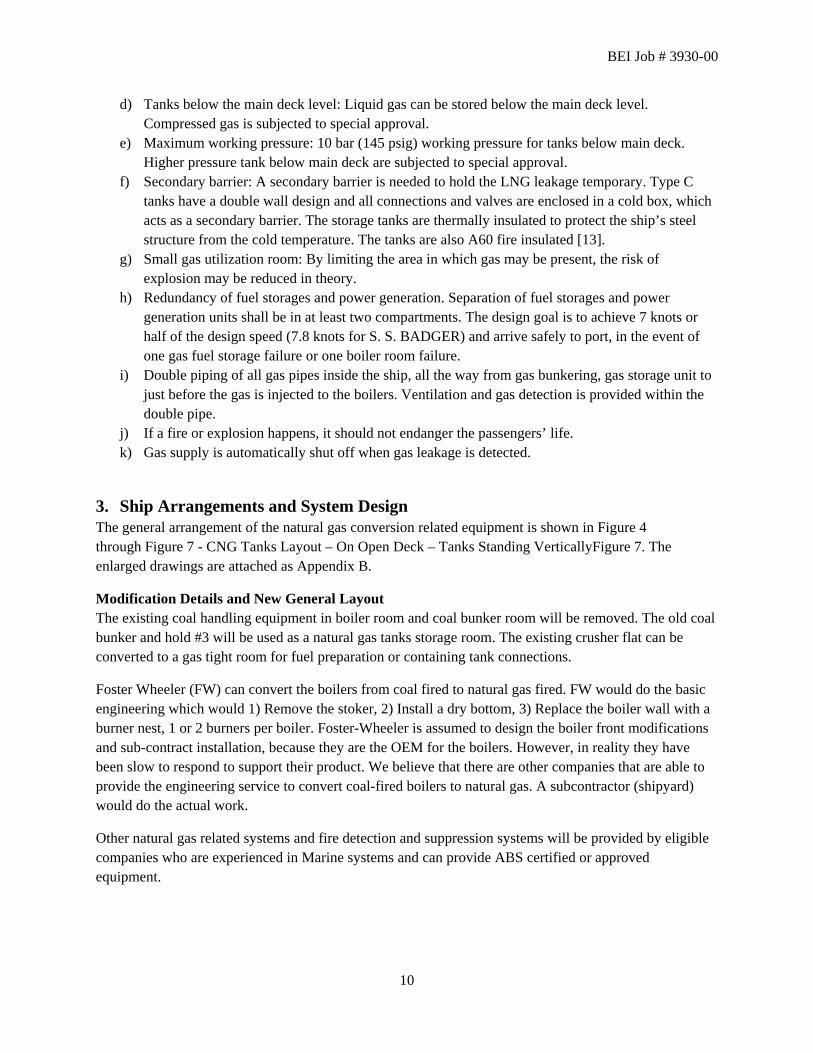
d) Tanks below the main deck level: Liquid gas can be stored below the main deck level. Compressed gas is subjected to special approval.
e) Maximum working pressure: 10 bar (145 psig) working pressure for tanks below main deck. Higher pressure tank below main deck are subjected to special approval.
f) Secondary barrier: A secondary barrier is needed to hold the LNG leakage temporary. Type C tanks have a double wall design and all connections and valves are enclosed in a cold box, which acts as a secondary barrier. The storage tanks are thermally insulated to protect the ship’s steel structure from the cold temperature. The tanks are also A60 fire insulated [13].
g) Small gas utilization room: By limiting the area in which gas may be present, the risk of explosion may be reduced in theory.
h) Redundancy of fuel storages and power generation. Separation of fuel storages and power generation units shall be in at least two compartments. The design goal is to achieve 7 knots or half of the design speed (7.8 knots for S. S. BADGER) and arrive safely to port, in the event of one gas fuel storage failure or one boiler room failure.
i) Double piping of all gas pipes inside the ship, all the way from gas bunkering, gas storage unit to just before the gas is injected to the boilers. Ventilation and gas detection is provided within the double pipe.
j) If a fire or explosion happens, it should not endanger the passengers’ life. k) Gas supply is automatically shut off when gas leakage is detected.
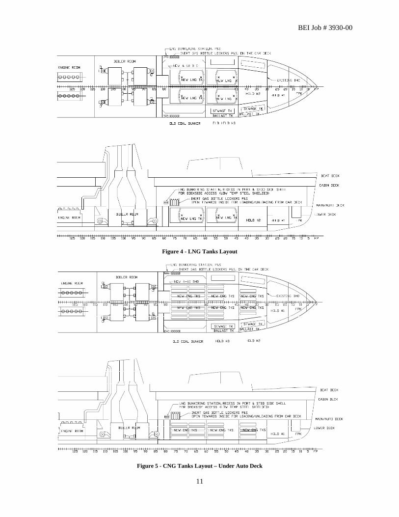
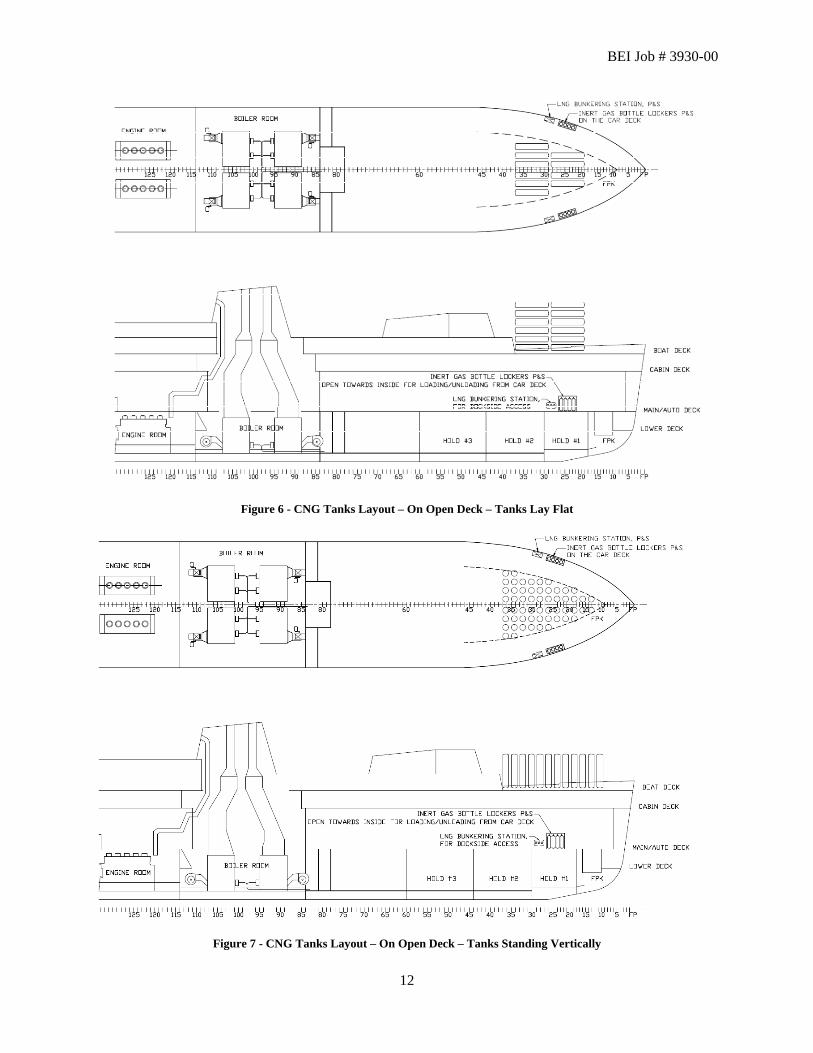
3. Ship Arrangements and System Design The general arrangement of the natural gas conversion related equipment is shown in Figure 4 through Figure 7 - CNG Tanks Layout – On Open Deck – Tanks Standing VerticallyFigure 7. The enlarged drawings are attached as Appendix B.
Modification Details and New General Layout The existing coal handling equipment in boiler room and coal bunker room will be removed. The old coal bunker and hold #3 will be used as a natural gas tanks storage room. The existing crusher flat can be converted to a gas tight room for fuel preparation or containing tank connections.
Foster Wheeler (FW) can convert the boilers from coal fired to natural gas fired. FW would do the basic engineering which would 1) Remove the stoker, 2) Install a dry bottom, 3) Replace the boiler wall with a burner nest, 1 or 2 burners per boiler. Foster-Wheeler is assumed to design the boiler front modifications and sub-contract installation, because they are the OEM for the boilers. However, in reality they have been slow to respond to support their product. We believe that there are other companies that are able to provide the engineering service to convert coal-fired boilers to natural gas. A subcontractor (shipyard) would do the actual work.
Other natural gas related systems and fire detection and suppression systems will be provided by eligible companies who are experienced in Marine systems and can provide ABS certified or approved equipment.
10
BEI Job # 3930-00
Figure 4 - LNG Tanks Layout
Figure 5 - CNG Tanks Layout – Under Auto Deck
11
BEI Job # 3930-00
Figure 6 - CNG Tanks Layout – On Open Deck – Tanks Lay Flat
Figure 7 - CNG Tanks Layout – On Open Deck – Tanks Standing Vertically
12

BEI Job # 3930-00
Figure 8 CNG Tanks Layout - On Open Deck - Tanks in Container Modules
Location and Separation of Spaces In order to prevent an explosion in gas storage tank rooms and gas utilization rooms (boiler rooms), those room stated above are divided into two or more compartments. Those compartments are divided with bulkheads which can withstand an explosion and will not to affect the normal operation of the equipment in other compartments.
Gas Storage Tanks Both CNG and LNG gas storage tanks are located under car decks. According to ABS rule for gas fueled ships, LNG fuel may be stored in enclosed spaces, with a maximum allowable working pressure of 10 bars. Storage of compressed gas in enclosed spaces is to be in accordance with the CNG Guide.
The location of compressed gas storage tanks with a design pressure greater than 10 bars in enclosed spaces would be acceptable, provided: (1) capability to depressurize in case of fire, (2) suitable thermal protection against gas leakage, (3) fixed fire extinguishing system installed and, (4) ability to relieve pressure if failure occurs.
Gas storage tanks are to be located as close as possible to the ship centerline and:
a) Minimum, the lesser of B/5 (11.9 ft or 3.627 m for S. S. BADGER) and 11.5 m (37.730 ft) from the ship side measured inboard from the ship’s side at right angles to the centerline at the level of the summer load line; and
13

BEI Job # 3930-00
b) Minimum, the lesser of B/15 (3.967 ft or 1.209 m for S. S. BADGER) and 2 m (6.562 ft) from the bottom plating; and nowhere to be less than 800 mm (2.625 ft) from the shell plating.
Gas Storage Tank Location Limitations for S. S BADGER
Metric Units Beam B = 18.136 m
From the ship side Minimum, the lesser of B/5 and 11.5 m 3.627 m From the bottom plating Minimum, the lesser of B/15 and 2 m 1.209 m From the shell plating Nowhere to be less than 800 mm 0.800 m
English Units Beam B = 59.5 ft
From the ship side Minimum, the lesser of B/5 and 37.730 ft 11.900 ft From the bottom plating Minimum, the lesser of B/15 and 6.562 ft 3.967 ft From the shell plating Nowhere to be less than 2.625 ft 2.625 ft
Type C tank doesn’t require a secondary barrier. The connections of Type C independent tanks will be located in a gas tight space. A double hull space is not needed for Type C tanks.
Normally, fuel containment systems are not to be located adjacent to boiler room spaces. Separation is to be by means of a cofferdam, and the separation is to be at least 900 mm (2.953 ft). However, a hold space containing a Type C fuel storage tank with no connections to the tank inside the hold space may be separated from a category A boiler room space by a single gas tight class A-60 bulkhead.
Tank connection spaces and ventilation trunks to such spaces below the bulkhead deck are to be constructed to class A-60.
Stainless steel drip trays are to be fitted below LNG storage tanks connections. And there should be enough separation or isolation so that the surrounding structure will not be cooled below the design temperature in the event of leakage.
Access in way of Gas Storage Tanks i) Where access is required for inspection between the gas storage tank surface (flat or curved), and structural elements (such as deck beams, stiffeners, frames, girders, etc.), the distance between that surface and the free edge of the structural elements is to be at least 380 mm (1.247 ft). The distance between the surface to be inspected and the surface to which the above structural elements are fitted (e.g., deck, bulkhead or shell) is to be at least 450 mm (1.476 ft) for a curved tank surface or 600 mm (1.968ft) and for a flat tank surface. See also 5C-8-3/5.2.1, 5C-8-3/5.2.3 and 5C-8-3/5.2.4 of the Steel Vessel Rules.
14

BEI Job # 3930-00
Figure 9 - Fig 1 from 5C-8-3/5.2.1 of the Steel Vessel Rules (Dimensions in mm)
ii) Where access is not practical between the surface to be inspected and any structural elements, the distance between the free edge of the structural element and the surface to be inspected is to be at least 50 mm (0.164 ft) or half the breadth of the structure's face plate, whichever is the larger. See also 5C-8-3/5.2.2 of the Steel Vessel Rules.
Figure 10 – Fig 2 from 5C-8-3/5.2.2 of the Steel Vessel Rules (Dimensions in mm)
iii) Steel Vessel Rules also covers the distance between two tank surfaces. If, for inspection of a curved surface, the surveyor requires to pass between that surface and another surface, flat or curved, to which no structural elements are fitted, the distance between both surfaces should be at least 380 mm (1.247 ft). (See 5C-8-3/Figure 3) Where the surveyor does not require to pass between that curved surface and another surface, a smaller distance than 380 mm (1.247 ft) may be accepted, taking into account the shape of the curved surface.
Figure 11 – Fig 3 from 5C-8-3/5.2.3 of the Steel Vessel Rules (Dimensions in mm)
15

BEI Job # 3930-00
Fuel Bunkering Station The bunkering stations and manifolds are to be located at a recess area on both side of the hull with provision for effective mechanical ventilation. The bunkering stations are to be physically separated and structurally shielded from adjacent normally manned areas such as passenger accommodation, auto/working deck and control stations. A quick disconnect valve, installed on both vehicle hose and vessel’s gas bunkering connections, with automatic shut down in the event of gas hose damage to prevent uncontrolled gas discharge of the vessel’s gas storage tank.
In order to protect hull structure from leakage of LNG, Stainless steel drip trays are to be fitted below liquid gas bunkering connections and where leakage may occur.
For compressed gas bunkering stations, low temperature steel shielding is to be provided as necessary to prevent possible cold jet impingement on the hull structure.
Bunkering stations are to be shielded with class A-0 insulation towards spaces of little or no fire risk.
Gas Compressor and Fuel Preparation Rooms Compressor and fuel preparation equipments are to be fitted in the cold box integrated with the Type C tanks. Generally, the cold box contains all controls and instrumentation needed for the tank operation as well as the vaporizers. [7]
Boiler Room Spaces Containing Gas Utilization Units Two boiler room spaces are required for gas fueled boilers and these spaces are separated by a single bulkhead. The bulkhead is to be class A-60. In order to maintain continuity of power, the bulkheads are to be such that the effects of a gas explosion in either space can be contained or vented without affecting the integrity of the adjacent boiler space and equipment within that space.
Boiler room spaces in which gas fuel are used are to be fitted with a mechanical ventilation system without the formation of dead spaces. The ventilation system is to be independent of all other ventilation systems.
The ventilation fans will be sized to vent not less than 100% of the total ventilation required with one fan failure.
Permanently fitted gas detectors are installed in these spaces.
System Configuration The propulsion and auxiliary arrangements and fuel supply systems are to be arranged so that in the case of emergency shutdown of the fuel gas supply the propulsion and maneuvering capability, together with power for essential services, can be maintained. Under such a condition the remaining power is to be sufficient to provide for a speed of at least 7 knots or half of the design speed (7.8 knots for S. S. BADGER), whichever is the lesser.
Automatic means are to be provided to stop the supply of natural gas into an area or space where a gas release has been detected.
Means are to be provided to control the pressure and temperature of the fuel gas delivered to each gas utilization unit.
16

BEI Job # 3930-00
The double wall fuel gas piping concept is used in the new system configurations:
Double Wall Fuel Gas Piping Concept is that arrangements in boiler room spaces are such that the spaces are considered non-hazardous under all conditions, normal as well as abnormal conditions.
In order to maintain propulsion capability in case an engine compartment is shut down, propulsion engines utilizing natural gas and necessary equipment are to be located in at least two separate compartments. Since the propulsion engines utilize steam and not natural gas, the propulsion engines do not have to be in separate compartments. However, since the boilers are necessary equipment that utilizes natural gas, they are to be located in at least two separate compartments. These compartments are to have double-wall boundaries or single explosion proof wall. The boiler compartments are to contain only the boiler(s) and their necessary equipment.
Boil-off Gas Utilization The entire bunker tank system is designed to withstand the full gauge vapor pressure of the gas under conditions of the upper ambient design temperatures, as specified in 5C-8-7/1.2 of the Steel Vessel Rules (which is 32 deg centigrade for sea and 45 deg centigrade for air). Another option is that tank pressure is maintained by boil off the natural LNG boil-off in the steam boiler. The rate of boil- off LNG in the steam boiler will be bigger than the normal boil-off rate (NBOR).
Gas fuel storage tank pressure accumulates whereby the bunker tank fuel is allowed to warm up and increase in pressure. The tank insulation or tank design pressure is to be sufficient to maintain tank pressure below the Max Allowable Relief Valve Setting (MARVS) and for the tank not to become liquid full for a period of 15 days under all tank fill conditions. [1]
Hazardous Area Zones ABS guide for Gas Fueled Ships defines the hazardous area zones.
Zone 0 is an area in which an explosive gas atmosphere is present continuously or for long periods or frequently. It includes: The interiors of gas tanks, any pipework of pressure relief or other venting systems for gas tanks, pipes and equipment containing gas.
Zone 1 is an area in which an explosive gas atmosphere is likely to occur in normal operation occasionally. It includes: Fuel containment system spaces, Gas compressor or fuel preparation room, gas or vapor outlets and inlets.
Zone 2 is an area in which an explosive gas atmosphere is not likely to occur in normal operation but, if it does occur, will persist for a short period only. It includes areas within 1.5 m surrounding open or semi-enclosed spaces of zone 1.
A special note is given to Type C tanks. Spaces containing Type C fuel storage tanks with no connections to the tank in the space are considered zone 2.
17

BEI Job # 3930-00
4. Gas Fuel Storage The subject vessel is to be powered by gas fuel only, which is classified as “single fuel installations”. The ABS rules require the fuel storage to be divided into two or more tanks of approximately equal size. On the S. S. BADGER, the gas storage tanks are to be located in separate existing compartments.
LNG Storage Tanks The storage tank used for liquefied gas is to be an independent tank Type C designed in accordance with Section 5C-8-4 of the Steel Vessel Rules. For Type C tank, no secondary barrier is required. Pipe connections for Type C independent tanks can be mounted below the highest liquid level and located in a gas tight space, which in this case, is a cold box attached to the end of each tank. Pressure relief valves are fitted. Inspection openings are to be provided for Type C gas fuel storage tanks. The cold box should have circular access openings of 600 mm (1.968 ft) diameter or bigger.
Storage tanks for liquid gas are not to be filled to more than 98% full at the reference temperature.
The packaging of LNG as a fuel by comparison to conventional liquid fuels is a challenge for most vessels and particularly with respect to retrofit conversions. The direct volume ratio for equivalent energy content indicates a ratio of approximately 1.8:1. The additional space requirements required as a result of using (typically) Type C tanks and associated fuel processing spaces. The ship is estimated to need 3 to 4 times the space for tankage compared to diesel fuel.
The propulsion and auxiliary arrangements and fuel supply systems are to be arranged so that in the case of emergency shutdown of the fuel gas supply the propulsion and maneuvering capability, together with power for essential services, can be maintained. Under such a condition the remaining power is to be sufficient to provide for a speed of at least 7 knots or half of the design speed, whichever is lesser. [1]
CNG Storage Tanks The storage tanks used for compressed gas are to be designed in accordance with the CNG Guide. Tanks for compressed gas are to be fitted with pressure relief valves vented up above the open deck (fwd boat deck, for example) with a set point below the design pressure of the tank.
Gas storage tanks are monitored and equipped with equipment to prevent overfilling and detect leakage.
Ventilation of Tank Connection Space A ventilation system of the under pressure type is required in the tank connection space that will provide a ventilation of not less than 30 air changes per hour. Permanent gas detection and fire detection equipment are required. Another option is fill the hold or void spaces around gas storage tanks with inert gas or dry air, thus creating a non combustible environment. This is not recommended for S. S. BADGER.
5. Fuel Bunkering System Fuel bunkering operations for LNG/CNG powered S. S. BADGER will be made by trucks transporting the gas to the vessel gas storage system.
The on-board bunkering system will be comprised of bunkering stations located on both sides of the vessel. Each station will have provision for two bunkering lines and two return lines (LNG vapor return
18
BEI Job # 3930-00
lines) together with nitrogen purging facility, associated relief/safety valves and control station. The LNG or CNG is led by double wall piping from the bunker station to the gas storage tanks.
Gas pipes are not to be located less than 800 mm (2.625 ft) from the ship’s side. Low temperature piping is to be thermally isolated from the adjacent hull structure to prevent the temperature of the hull from falling below the design temperature of the steel hull.
Where liquid piping is dismantled regularly, or where liquid leakage may be anticipated, such as at shore connections or pump seals, protection for the hull beneath is to be provided, such as drip pans and insulation.
Both manually operated stop valves and remote operated shutdown valves shall be installed in series on each bunkering line, close to the bunker supplier connecting point.
An arrangement for purging gas bunkering lines and supply lines with nitrogen is to be provided. The liquid in the bunkering pipes will be drained and inerted after bunkering is completed. During vessel operation, the bunkering pipes will remain gas free.
The return line is typically used to return evaporated gas to the bunker supplier and may, subject to transfer arrangements, be used to balance delivering and receiving tank pressures.
Emergency shutdown system shall be installed to shut down the bunker flow in the event of an emergency.
Control of bunkering is to be possible from a safe location, such as a gas free area or on the bridge. At this location the tank pressure and tank level are to be monitored. Overfill alarm and automatic shutdowns are also to be indicated at this location.
Gas bunkering lines leading from bunkering stations to gas storage tanks will adopt double piping design with ventilation in the space between gas fuel piping and the outer pipe wall. The mechanical under pressure ventilation will be no less than 30 air changes per hour.
The semi enclosed bunker stations are to be fitted with permanently installed gas detectors.
Permanent gas detectors and a fixed fire detection system shall be installed in the bunker stations.
6. Fuel Gas Supply System This section will cover the fuel gas supply arrangements and systems installed on board to deliver natural gas from the gas fuel storage tank to the gas utilization units (boilers). The arrangements and systems will include cryogenic fuel preparation rooms.
Gas Supply Systems in Boiler Room Spaces (Double Wall Fuel Gas Piping Concept) Gas supply lines from the gas fuel storage tank to the boilers will be double wall pipes. The gas fuel flows through the inner pipe. The space between inner pipe and outer pipe is to be pressurized with inert gas at a pressure greater than the gas fuel pressure. Alarms will monitor the pressure loss of the inert gas. Another option is to ventilate the space between inner pipe and outer pipe. The mechanical under pressure ventilation will be no less than 30 air change per hour.
19
BEI Job # 3930-00
The recommendation for the S. S. BADGER is to pressurize the space between the piping double walls with inert gas. The inert gas generator and storage system is considered to be safer. Besides, inert gas will be required on the ferry for other purposes such as purging the bunker pipes before and after bunking, and purging the storage tank before filling with natural gas and to purge the tank being emptied. The same system can be used to inert the double wall piping, or even an additional small inert gas generator could be added for the small quantity required.
Ducting for high pressure piping is to be pressure tested to at least 10 bars.
Gas Distribution Outside of Boiler Room Spaces Gas fuel piping is not to be led through accommodation spaces, service spaces or control stations.
Where gas pipes pass through enclosed spaces in the ship, they are to be enclosed in a duct. This duct is to be mechanically under pressure ventilated with 30 air changes per hour, and gas detection is to be provided. This is a general guideline on gas pipes. Details will be specified when detail design is worked on.
Gas pipes that run through ro-ro spaces on open deck need fire and mechanical protection to prevent vehicle collision damage.
Fuel Gas Preparation Equipment (Cold Box) Other fuel gas preparation equipment includes vaporizers/heaters, LNG pump and other ancillary systems. All of them will be located in the fuel preparation rooms, which is the cold boxes attached to the end of each tank. Evaporated gas is fed in double piping to the boiler room at about 4 bars [11].
Heat exchangers are used for heating or vaporizing fuel gas.
Ventilation System Fuel preparation rooms (cold boxes) are to be fitted with an effective mechanical ventilation system of the under pressure type, providing a ventilation capacity of at least 30 air changes per hour. The ventilation pipe will vent up above the open deck (fwd boat deck, for example). The space right above the tank rooms is the car deck, which has natural ventilation. The car deck is open on the stern (the sea gate is open at the top) and mechanical exhaust fans are fitted although they are small and intended for CO and exhaust removal. The mechanical venting system on the car deck will be redesigned to better prevent gas accumulation.
Permanent gas detectors, fire protection and fire extinguishing system are to be installed in fuel preparation rooms.
VIII. OFF SEASON GAS DISCHARGE From mid October to mid May each year, the S. S. BADGER will return to port for layup, maintenance and repairs. The ferry will stay docked and the boilers will be shut down. The steam generator used to supply power onboard will also be shut down. Instead, the shore power supply system can provide electricity via power plug located in the ship side recessed areas. The natural gas tanks will be gas freed for inspection and maintenance.
20

BEI Job # 3930-00
Any remaining CNG can be emptied by directly pumping the CNG in the compressed gas format from the vessel tank to the same type of tanker truck as used to deliver the CNG to the vessel.
The discharge of LNG is a multi-step procedure. First, the remaining LNG will be emptied by directly pumping the LNG in the cryogenic liquid format from the vessel tank to the same type of tanker truck as used to deliver the LNG to the vessel. Residual liquids in the LNG tanks can be allowed to warm up to ambient temperature. This can be accelerated by warming up the remaining gas using the gas heater in the evaporator in the cold box and circulate the gas back into LNG tanks. Once the LNG tanks are warmed up to ambient temperature, an inert gas (carbon dioxide CO2) is pumped into the tanks to push the warmed-up gas status natural gas from the LNG tanks to a tanker truck which is used to contain gas status natural gas. After the tanks are methane free, then dry air can be pumped in to make the tanks a safe working atmosphere. [14]
Before resuming operation at the beginning of the transportation season, the tanks need to be prepared for storing natural gas again. CNG tanks have to be filled with inert gas (carbon dioxide CO2) until the oxygen content drops below 4% to avoid explosion. Then, CNG can be pumped in using the regular method of connecting CNG tank truck with ship bunker station. LNG tanks need an extra “cool down” step after they are filled with the inert gas. The LNG is sprayed into the tanks via spray heads inside the tank. The LNG is vaporized from liquid status to gas status and absorbs the heat inside the tank. The vaporized LNG is then pumped out of the tank and burned off. This process is repeated until the tanks are cooled down to -140°C, then the normal LNG loading procedure can be used.
IX. COST ESTIMATE The cost estimate for the conversion is listed in Table 2. The annual fuel cost is also listed in Table 2. Although the fuel cost savings may not be enough to recoup the conversion cost in a timely manner, the project still has significant merit. The conversion would allow the S. S. BADGER to pass the EPA regulations and alleviate environmental problems.
Table 2 – Cost Estimate Annual Fuel Cost Annual Fuel Cost
Coal: $847,000 LNG: $ 794,000
Conversion Cost Boiler $ 4,000,000 LNG Fuel Tanks $ 3,253,960 Auxiliaries $ 2,902,000
Subtotal $10,155,960 Shipyard $ 2,539,000 Eng. & ABS $ 1,016,000 Total $13,710,960
21
BEI Job # 3930-00
X. MANNING AND CREW TRAINING IMPLICATIONS The S. S. BADGER will staff with enough crew numbers according to the LNG related equipment suppliers’ requirement to maintain and operate the LNG / CNG equipment. The crew involved with the LNG / CNG will have to be trained in the proper handling and maintenance of the equipment. This would include safety drills on proper emergency shutdown procedures and passenger evacuations. The crew will need the proper state and federal certifications to operate the equipment. The copies of operation manuals will be stored on board for reference. Safety notes and warning signs will be posted at the required zones.
XI. VALUE AS A PILOT PROGRAM FOR THE GREAT LAKES VESSELS The S. S. BADGER is a good example to demonstrate the feasibility of natural gas powered conversion and acts as a pilot for future conversions of U.S. flag Great Lakes vessels.
First it’s a relatively simple conversion. The original propulsion system (reciprocating steam engines and fixed pitch propellers) shall remain untouched. The boiler is simply converted from coal to LNG powered. The old coal bunkers are converted to LNG or CNG tank storage spaces. No significant structural modifications are needed.
Second, it’s a convenient, small scale, experimental subject. The S. S. BADGER is running on a short fixed route with one or two round trips per day. This helps gathering operation data needed for future research and reference in a short time. Quick diagnostics helps decide if further adjustment is needed. The short routes also make it possible to test different scenarios and get comparison data in a relatively short period of time.
Third, the conversion cost is relatively low for the S. S. BADGER compared to other Great Lake vessels. As stated above, only the boiler equipment needs be modified and replaced. There are no major structure changes.
XII. RECOMMENDATION The choice of whether to use LNG or CNG fuel in the S. S. BADGER ferry is not straightforward. They have different safety, storage requirements and economics. The option of using CNG may be less expensive. But LNG is a feasible fuel in a lot more ship types because the storage tanks occupy less space [13]. Using LNG as fuel will make the S. S. BADGER conversion a more representative case and serve as a better pilot project applicable to Great Lakes vessels. When making this decision, it should be recognized that the fuel choice involves trade-offs between the two options. The table below summarizes the relative advantages of the fuels with respect to different criteria considered in this qualitative assessment. [15]
22
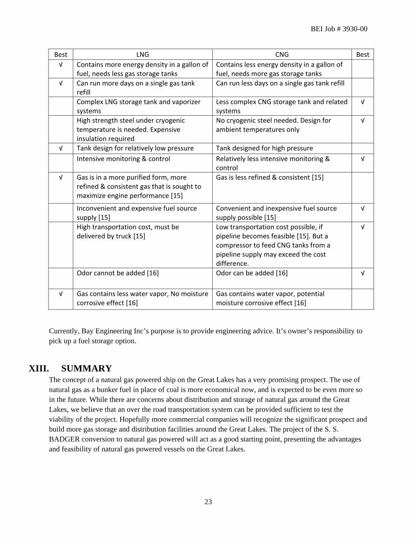
BEI Job # 3930-00
Best LNG CNG Best √ Contains more energy density in a gallon of
fuel, needs less gas storage tanks Contains less energy density in a gallon of fuel, needs more gas storage tanks
√ Can run more days on a single gas tank refill
Can run less days on a single gas tank refill
Complex LNG storage tank and vaporizer systems
Less complex CNG storage tank and related systems
√
High strength steel under cryogenic temperature is needed. Expensive insulation required
No cryogenic steel needed. Design for ambient temperatures only
√
√ Tank design for relatively low pressure Tank designed for high pressure Intensive monitoring & control Relatively less intensive monitoring &
control √
√ Gas is in a more purified form, more refined & consistent gas that is sought to maximize engine performance [15]
Gas is less refined & consistent [15]
Inconvenient and expensive fuel source supply [15]
Convenient and inexpensive fuel source supply possible [15]
√
High transportation cost, must be delivered by truck [15]
Low transportation cost possible, if pipeline becomes feasible [15]. But a compressor to feed CNG tanks from a pipeline supply may exceed the cost difference.
√
Odor cannot be added [16] Odor can be added [16] √
√ Gas contains less water vapor, No moisture corrosive effect [16]
Gas contains water vapor, potential moisture corrosive effect [16]
Currently, Bay Engineering Inc’s purpose is to provide engineering advice. It’s owner’s responsibility to pick up a fuel storage option.
XIII. SUMMARY The concept of a natural gas powered ship on the Great Lakes has a very promising prospect. The use of natural gas as a bunker fuel in place of coal is more economical now, and is expected to be even more so in the future. While there are concerns about distribution and storage of natural gas around the Great Lakes, we believe that an over the road transportation system can be provided sufficient to test the viability of the project. Hopefully more commercial companies will recognize the significant prospect and build more gas storage and distribution facilities around the Great Lakes. The project of the S. S. BADGER conversion to natural gas powered will act as a good starting point, presenting the advantages and feasibility of natural gas powered vessels on the Great Lakes.
23
BEI Job # 3930-00
XIV. BIBLIOGRAPHY
[1] ABS Guide For Propulsion And Auxiliary Systems For Gas Fueled Ships, American Bureau of Shipping, 2011.
[2] "Bituminous Coal, Wikipedia," [Online]. Available: http://en.wikipedia.org/wiki/Bituminous_coal.
[3] "Voluntary Reporting of Greenhouse Gases Program," Energy Information Administration, Retrieved 21 August 2009. [Online]. Available: http://www.eia.gov/oiaf/1605/coefficients.html.
[4] "Energy Density, Wikipedia," [Online]. Available: http://en.wikipedia.org/wiki/Energy_density.
[5] "Henry Hub Natural Gas Spot Prices 2012," [Online]. Available: http://www.neo.ne.gov/statshtml/124.htm.
[6] "Liquefied Natural Gas, Wikipedia," [Online]. Available: http://en.wikipedia.org/wiki/Liquefied_natural_gas.
[7] "LNG Fuel Tank For Ship - General Specification," Chart Industries Inc, [Online]. Available: www.chart-ferox.com / www.chart-ind.com.
[8] "Compressed Natural Gas, Wikipedia," [Online]. Available: http://en.wikipedia.org/w/index.php?title=Compressed_natural_gas&oldid=460391772.
[9] "Trans Ocean Gas Pressure Vessel," Trans Ocean Gas Inc, [Online]. Available: http://www.transoceangas.com/Development_Plan.htm.
[10] D. Gaul, "U.S. LNG Markets and Uses," Energy Information Administration, 2004.
[11] P. Einag and K. Haavik, "The Norwegian LNG ferry," Paper A-095, Natural gas vessels 2000, Yokohama, Japan.
[12] "Resolution MSC.285(86) Interim Guidelines on Safety for Natural Gas-fuelled Engine Installations in Ships," The Maritime Safety Committee, June 2009.
[13] T. G. Osberg, "Gas fuelled engine applications in ships," 2008.
[14] "LNG carrier," [Online]. Available: http://en.wikipedia.org/wiki/LNG_carrier.
[15] E. Toy, "Fueling Heavy Duty Trucks Diesel or Natural Gas," Risk in Perspective, vol. 8, no. 1, Jan 2000.
[16] "Ch. 3.3.4 Liquefied Natural Gas," in Clean Air Program from the Federal Transit Administration Summary Assesment of the Safety, Health, Environmental and System Risks of Alternative Fuel.
24

Appendix A Natural Gas Consumption Calculations
S S BADGERLudington-Manitowoc
3930-00
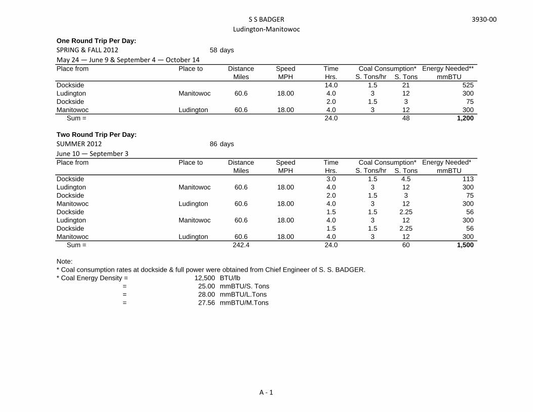
One Round Trip Per Day:SPRING & FALL 2012 58 daysMay 24 — June 9 & September 4 — October 14Place from Place to Distance Speed Time Energy Needed**
Miles MPH Hrs. S. Tons/hr S. Tons mmBTUDockside 14.0 1.5 21 525Ludington Manitowoc 60.6 18.00 4.0 3 12 300Dockside 2.0 1.5 3 75Manitowoc Ludington 60.6 18.00 4.0 3 12 300
Sum = 24.0 48 1,200
Two Round Trip Per Day:SUMMER 2012 86 daysJune 10 — September 3 Place from Place to Distance Speed Time Energy Needed*
Miles MPH Hrs. S. Tons/hr S. Tons mmBTUDockside 3.0 1.5 4.5 113Ludington Manitowoc 60.6 18.00 4.0 3 12 300Dockside 2.0 1.5 3 75Manitowoc Ludington 60.6 18.00 4.0 3 12 300Dockside 1.5 1.5 2.25 56Ludington Manitowoc 60.6 18.00 4.0 3 12 300Dockside 1.5 1.5 2.25 56Manitowoc Ludington 60.6 18.00 4.0 3 12 300
Sum = 242.4 24.0 60 1,500
Note:* Coal consumption rates at dockside & full power were obtained from Chief Engineer of S. S. BADGER.* Coal Energy Density = 12,500 BTU/lb
= 25.00 mmBTU/S. Tons= 28.00 mmBTU/L.Tons= 27.56 mmBTU/M.Tons
Coal Consumption*
Coal Consumption*
A - 1

S S BADGERLudington-Manitowoc
3930-00
LNG One Round Trip Per Day
Two Round Trip Per Day
Energy Needed per Day mmBTU 1,200 1,500 Energy Density of LNG mmBTU/m3 23.87 23.87LNG Vol. Required per Day m3 50.28 62.85Total Maximum Possible Storage Tank Vol m3 210.45 210.45# of Days per Fill Days 4.19 3.35
Truck Tank Size * m3 46.37 46.37 # of Trucks needed per Fill 4.5 4.5Time Needed per Fill (Two Hoses to Two Trucks at a time) **
hr 1.5 1.5
Note:* LNG Truck Tank Size = 12,250 Gal
= 46.37 m3
** Truck LNG Transfer Rate = 300 GPM= 1.14 m3/M
Ref: CHART LNG transport tank AT-506
CNG One Round Trip Per Day
Two Round Trip Per Day
Energy Needed per Day mmBTU 1,200 1,500 Energy Density of CNG mmBTU/m3 8.53 8.53CNG Vol. Required per Day m3 140.67 175.84Total Maximum Possible Tank Vol m3 216.00 216.00# of Days per Fill Days 1.54 1.23
Truck Tank Size *** m3 24.00 24.00 # of Trucks needed per Fill 9.0 9.0
Note:*** CNG Truck Tank Size = 24,000 L
= 24 m3
Ref: The TOG Inc Multi-Element Gas Container (MEGC)
CNG for One Way Trip One Way TripEnergy Needed per One Way Trip + 36% Surplus mmBTU 409 Energy Density of CNG mmBTU/m3 8.53CNG Vol. Required per One Way Trip m3 48.00Vol. of One Shipping Container Module(Contains 8 CNG Tanks) m3 24.00# of Shipping Container Modules 2.00
Note:*** CNG Truck Tank Size = 24,000 L
= 24 m3
Ref: The TOG Inc Multi-Element Gas Container (MEGC)
A - 2

S S BADGERLudington-Manitowoc
3930-00
LNG Tank Size Calculations:Horizontal, Long'l Tanks Ref: ABS Guide for Propulsion and Auxiliary Systems for Gas Fueled Ships 2011 Section 2 - 2.2.2 iii) c)
Space Length LOA L, Eff ID Vol OD 2t t Vol Vol No. Tanks Vol,Ft Ft Ft Ft Ft3, Gross Ft Ft Ft Ft3, Net m3, Net m3, Net
Original No. 3 Hold 32 21.05 14.72744 12.90 1,925 14.60 1.7 0.85 1,636 46.32 2 92.65 Original Coal Bunker 36 25.05 18.72744 12.90 2,447 14.60 1.7 0.85 2,080 58.90 2 117.81
210.45
A - 3

Appendix B Natural Gas Tanks Layout


Appendix C Samples of LNG Tanks for Ship & Road Transportation

LNG
Pac
typi
cal d
imen
sion
s
L 1 L 2
Prel
imin
ary:
Info
rmat
ion
in th
is d
raw
ing
is s
ubje
ct to
cha
nge
with
out n
otic
e
Type
LNGP
ac 1
05LN
GPac
145
LNGP
ac 1
94LN
GPac
239
LNGP
ac 2
84LN
GPac
280
LNGP
ac 3
08LN
GPac
339
LNGP
ac 4
02
Geo
met
ric v
olum
e[m
3 ]10
514
519
423
928
428
030
833
940
2
Net v
olum
e 90
%[m
3 ]10
013
017
521
525
625
227
730
536
2Di
amet
er[m
]3,
54,
04,
34,
34,
34,
84,
85,
05,
0Ta
nk le
nght
[m]
16,7
16,9
19,1
23,1
27,1
21,3
23,4
23,5
27,5
Cold
box
[m]
2,5
2,5
2,7
2,7
3,0
3,0
3,0
3,0
3,0
Tota
l len
ght
[m]
19,2
19,4
21,8
25,8
30,1
24,3
26,4
26,5
30,5
Empt
y w
eigh
t[to
n]46
,662
76,6
9010
3,6
105,
111
2,9
118,
813
5,2
Tank
full
wei
ght
[ton]
9212
516
119
522
822
924
837
544
0M
ax o
pera
ting
wei
gh[to
n]94
127
163,
519
7,5
231
232,
525
1,5
379
444
16©
Wär
tsilä
C - 1

Chart Europe Chart Industries, Inc.
Chart Ferox, a.s. Ústecká 30 405 30 Dĕčín V, Czech Republic Phone: +420 (0) 412 507 343 Fax: +420 (0) 412 510 200 www.chart-ferox.com / www.chart-ind.com
LNG Fuel Tank for ship - General Specification In general, the fuel tank comprises: - tank for storing liquefied natural gas (gas) under cryogenic temperature and elevated pressure (this is
also referred to as a “bare” tank) - vaporizer(s) for converting LNG into gaseous fuel of approximately ambient temperature - cold-box containing all controls and instrumentation needed for the tank operation as well as the
vaporizer(s) - bunkering station for filling the tank with LNG from outside source - vacuum insulated pipeline connecting the bunkering station with the cold-box Excluded from the systems are: - engine fuel conditioning (gas panel) - ducts for shielding the gas pipelines - ventilation - supply system of heating fluid for vaporizers - instrument air system - purging nitrogen system - control system for controlling the tank operation The LNG storage tank is a pressure vessel (or an inner vessel) encased within an outer jacket (or an outer vessel). The annular space is filled with insulation perlite and evacuated. The resulting product enables a storage of LNG a very low temperatures, at elevated pressures, and still ensures long holding times (period of time in which there is no gas loss due to a relief valve opening). The tank could have either horizontal or vertical arrangement. More tanks could be used in parallel. The dimensions will be as required by a particular project within the manufacturing capability limits. Parameter Description IMO IGC Type Independent tank Type „C“ Design norm EN 13458-2 – Cryogenic vessels. Design pressure max. 10 bar Construction material – inner vessel Stainless steel 304L Construction material – outer jacket Carbon steel
Stainless steel 304L Stainless steel 316L
Insulation Perlite + vacuum
C - 2

C - 3
C - 4