Embed Size (px)
Citation preview

MPS1000MARINE POWERED SUBWOOFEROWNER’S MANUAL
www.jbl.com
The Official Brand of Live Music.
INSTALLATION
2
THANK YOUfor choosing the JBL® MPS1000. In order that we may better serve you should you require warranty service for your new subwoofer, please retain your original purchase receipt and register your newJBL marine subwoofer online at www.jbl.com.
WARNINGPlaying loud music in a boat can hinder your ability to hear other boats,passengers and nearby swimmers and can permanently damage yourhearing. We recommend listening at low or moderate levels while oper-ating your boat. JBL accepts no liability for hearing loss, bodily injury orproperty damage resulting from the use or misuse of this product.
IMPORTANTThe MPS1000 has been designed to provide the kind of high-performancelow-frequency reproduction that used to require big, clumsy enclosures,large amplifiers and complex installation. To ensure maximum performance, we strongly recommend that installation be entrusted to a qualified professional. Although these instructions explain how toinstall the MPS1000 in a general sense, they do not show the specificinstallation methods for your particular boat. If you feel you do nothave the necessary tools or experience, do not attempt the installationyourself; rather, ask your authorized JBL car audio or marine audiodealer about professional installation options. Remember to keep thismanual and your sales receipt in a safe place for future reference.
NOTE: This marine product is not intended for automotive applications.
INSTALLATION WARNINGS AND TIPS• Always wear protective eyewear when using tools.• Turn off the audio system and other electrical devices before you
start. Disconnect the (–) negative lead from your boat’s battery.• At the installation sites, locate and make a note of all fuel lines,
hydraulic lines, vacuum lines and electrical wiring. Use extremecaution when cutting or drilling in and around these areas.
• Check clearances on both sides of a planned mounting surfacebefore drilling any holes or installing any screws. Remember thatthe screws can extend behind the surface. Do not use screws longenough to penetrate the boat’s hull.
• Before drilling or cutting holes, use a utility knife to remove unwantedfabric or vinyl to keep material from snagging in a drill bit.
• When routing cables, keep input-signal cables away from powercables and speaker wires.
• When making connections, make certain they are secure and properly insulated.
• If the amplifier’s fuse must be replaced, use only the same type andrating as that of the original. Do not substitute another kind.
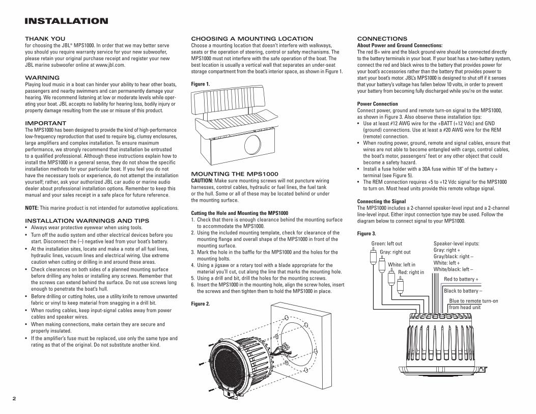
CHOOSING A MOUNTING LOCATIONChoose a mounting location that doesn’t interfere with walkways, seats or the operation of steering, control or safety mechanisms. TheMPS1000 must not interfere with the safe operation of the boat. Thebest location is usually a vertical wall that separates an under-seatstorage compartment from the boat’s interior space, as shown in Figure 1.
Figure 1.
MOUNTING THE MPS1000CAUTION: Make sure mounting screws will not puncture wiring harnesses, control cables, hydraulic or fuel lines, the fuel tank or the hull. Some or all of these may be located behind or under the mounting surface.
Cutting the Hole and Mounting the MPS10001. Check that there is enough clearance behind the mounting surface
to accommodate the MPS1000. 2. Using the included mounting template, check for clearance of the
mounting flange and overall shape of the MPS1000 in front of themounting surface.
3. Mark the hole in the baffle for the MPS1000 and the holes for themounting bolts.
4. Using a jigsaw or a rotary tool with a blade appropriate for thematerial you’ll cut, cut along the line that marks the mounting hole.
5. Using a drill and bit, drill the holes for the mounting screws.6. Insert the MPS1000 in the mounting hole, align the screw holes, insert
the screws and then tighten them to hold the MPS1000 in place.
Figure 2.
CONNECTIONSAbout Power and Ground Connections:The red B+ wire and the black ground wire should be connected directlyto the battery terminals in your boat. If your boat has a two-battery system,connect the red and black wires to the battery that provides power foryour boat’s accessories rather than the battery that provides power tostart your boat’s motor. JBL’s MPS1000 is designed to shut off if it sensesthat your battery’s voltage has fallen below 10 volts, in order to preventyour battery from becoming fully discharged while you’re on the water.
Power ConnectionConnect power, ground and remote turn-on signal to the MPS1000, as shown in Figure 3. Also observe these installation tips:• Use at least #12 AWG wire for the +BATT (+12 Vdc) and GND
(ground) connections. Use at least a #20 AWG wire for the REM(remote) connection.
• When routing power, ground, remote and signal cables, ensure thatwires are not able to become entangled with cargo, control cables,the boat’s motor, passengers’ feet or any other object that couldbecome a safety hazard.
• Install a fuse holder with a 30A fuse within 18" of the battery + terminal (see Figure 5).
• The REM connection requires +5 to +12 Vdc signal for the MPS1000to turn on. Most head units provide this remote voltage signal.
Connecting the SignalThe MPS1000 includes a 2-channel speaker-level input and a 2-channelline-level input. Either input connection type may be used. Follow thediagram below to connect signal to your MPS1000.
Figure 3.
Red to battery +
Black to battery –
Blue to remote turn-onfrom head unit
Speaker-level inputs:Gray: right +Gray/black: right – White: left +White/black: left –Red: right in
White: left in
Gray: right out
Green: left out
3
CONTROLS AND FUNCTIONS
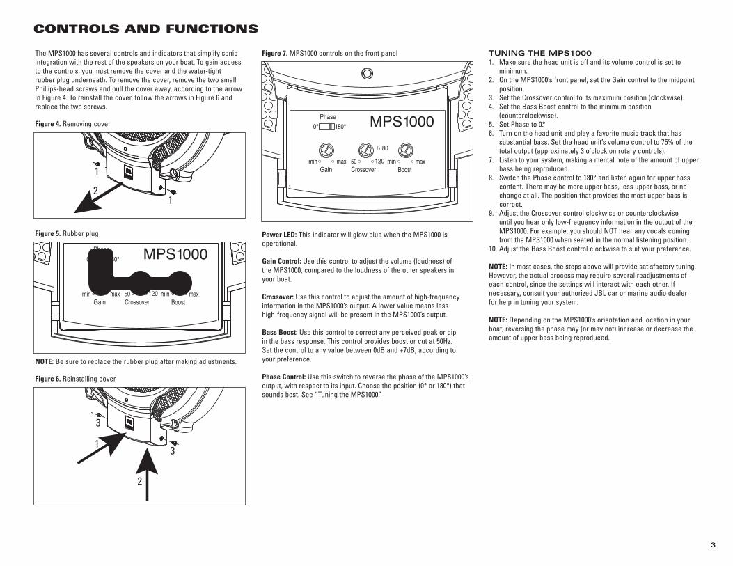
The MPS1000 has several controls and indicators that simplify sonicintegration with the rest of the speakers on your boat. To gain accessto the controls, you must remove the cover and the water-tight rubber plug underneath. To remove the cover, remove the two smallPhillips-head screws and pull the cover away, according to the arrowin Figure 4. To reinstall the cover, follow the arrows in Figure 6 andreplace the two screws.
Figure 4. Removing cover
Figure 5. Rubber plug
NOTE: Be sure to replace the rubber plug after making adjustments.
Figure 6. Reinstalling cover
Figure 7. MPS1000 controls on the front panel
Power LED: This indicator will glow blue when the MPS1000 is operational.
Gain Control: Use this control to adjust the volume (loudness) of the MPS1000, compared to the loudness of the other speakers in your boat.
Crossover: Use this control to adjust the amount of high-frequencyinformation in the MPS1000’s output. A lower value means less high-frequency signal will be present in the MPS1000’s output.
Bass Boost: Use this control to correct any perceived peak or dip in the bass response. This control provides boost or cut at 50Hz. Set the control to any value between 0dB and +7dB, according to your preference.
Phase Control: Use this switch to reverse the phase of the MPS1000’soutput, with respect to its input. Choose the position (0° or 180°) thatsounds best. See “Tuning the MPS1000.”
TUNING THE MPS10001. Make sure the head unit is off and its volume control is set to
minimum.2. On the MPS1000’s front panel, set the Gain control to the midpoint
position.3. Set the Crossover control to its maximum position (clockwise).4. Set the Bass Boost control to the minimum position
(counterclockwise).5. Set Phase to 0.°6. Turn on the head unit and play a favorite music track that has
substantial bass. Set the head unit’s volume control to 75% of thetotal output (approximately 3 o’clock on rotary controls).
7. Listen to your system, making a mental note of the amount of upperbass being reproduced.
8. Switch the Phase control to 180° and listen again for upper basscontent. There may be more upper bass, less upper bass, or nochange at all. The position that provides the most upper bass iscorrect.
9. Adjust the Crossover control clockwise or counterclockwise until you hear only low-frequency information in the output of theMPS1000. For example, you should NOT hear any vocals comingfrom the MPS1000 when seated in the normal listening position.
10. Adjust the Bass Boost control clockwise to suit your preference.
NOTE: In most cases, the steps above will provide satisfactory tuning.However, the actual process may require several readjustments ofeach control, since the settings will interact with each other. If necessary, consult your authorized JBL car or marine audio dealer for help in tuning your system.
NOTE: Depending on the MPS1000’s orientation and location in yourboat, reversing the phase may (or may not) increase or decrease theamount of upper bass being reproduced.
1
1
2
Phase
max80
max120 min50minBoostCrossoverGain
0° 180° MPS1000
Phase
max80
max120 min50minBoostCrossoverGain
MPS10000° 180°
3
3
1
2
Declaration of Conformity
We, Harman Consumer Group, Inc.2, route de Tours72500 Château du LoirFrance
declare in own responsibility that the productdescribed in this manual is in compliance withtechnical standards:
EN 55013:2001EN 55020:2002
Klaus LebherzHarman Consumer Group, Inc.Château du Loir, France 5/07
Harman Consumer Group, Inc. 250 Crossways Park Drive Woodbury, NY 11797 USA
www.jbl.com
© 2007 Harman International Industries, Incorporated. All rights reserved.
JBL is a trademark of Harman InternationalIndustries, Incorporated, registered in the United States and/or other countries.
Part No. MPS1000OM5/07
www.jbl.com
SYMPTOM LIKELY CAUSE SOLUTION
Power LED is not lit. Fuse is blown. Fuse should be replaced.
Head unit is not Check remote voltage, and power,functioning properly. ground or remote connections. The
MPS1000 is designed to shut off if the battery voltage falls below 10V. This is to ensure that your battery isn’t completely drained. Charge the boat’s battery.
Power LED is lit Inputs are not connected. Check connections.but there is no bass.
Head-unit fader control Adjust head-unit fader control to is not set properly. feed audio signals to the MPS1000.
MPS1000 sounds Gain control is set too high. Readjust Gain control (see “Tuningmuddy or distorted. the MPS1000” on the previous page).
Bass Boost is set too high. Readjust Bass Boost control (see “Tuning the MPS1000” on the previous page).
Head-unit output is distorted or blown.
A valid serial number is required for warranty coverage.Features, specifications and appearance are subject to change without notice.
TROUBLESHOOTING
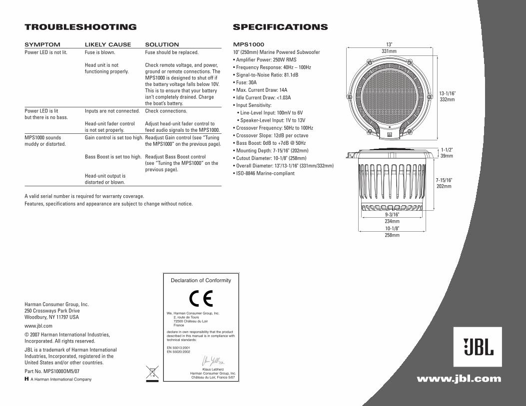
MPS1000
10" (250mm) Marine Powered Subwoofer• Amplifier Power: 250W RMS• Frequency Response: 40Hz – 100Hz• Signal-to-Noise Ratio: 81.1dB• Fuse: 30A • Max. Current Draw: 14A• Idle Current Draw: <1.03A• Input Sensitivity:
• Line-Level Input: 100mV to 6V• Speaker-Level Input: 1V to 13V
• Crossover Frequency: 50Hz to 100Hz• Crossover Slope: 12dB per octave• Bass Boost: 0dB to +7dB @ 50Hz• Mounting Depth: 7-15/16" (202mm)• Cutout Diameter: 10-1/8" (258mm)• Overall Diameter: 13"/13-1/16" (331mm/332mm)• ISO-8846 Marine-compliant
SPECIFICATIONS
13"331mm
9-3/16"234mm10-1/8"258mm
13-1/16"332mm
1-1/2"39mm
7-15/16"202mm


![TR00970 JBL BassPro QSG B v2 LD · appearance are subject to change without notice. fr merci k h]vpy jovpzp s 1)3 )hzz7yv 3l )hzz7yv h t[t jvus\ wv\y wyvk\pyl ... [plz oh\[ whysl\y](https://img.dokumen.tips/doc/110x75/5fe380d21ff8f850440c1a3e/tr00970-jbl-basspro-qsg-b-v2-ld-appearance-are-subject-to-change-without-notice.jpg)