Embed Size (px)
Citation preview
Basic principles and
operation of a transformer Seminar paper for course Distribution and industrial
networks
Andrea Ljubljanac
Mentor: professor Grega Bizjak
Ljubljana, March 2018
Basic principles and operation of transformer
TABLE OF CONTENTS
1 INTRODUCTION ...................................................................................... 1
2 STANDARDS AND PRINCIPLES ................................................................... 2
2.1 Basic transformer action ....................................................................... 2
2.2 Transformer equivalent circuit ............................................................ 3
2.3 Voltage and current distribution and transformer impedance
representation ................................................................................. 4
2.4 Tap changers .................................................................................. 6
3 VOLTAGE, IMPEDANCE AND POWER RATING ............................................. 9
3.1 Voltage drop and impedance .............................................................. 9
3.2 Voltage ratio and tappings ................................................................. 9
3.3 Vector groups and neutral earthing ................................................... 10
4 THERMAL DESIGN ............................................................................... 12
4.1 Temperature rise ........................................................................... 12
4.2 Loss of life expectancy with temperature ........................................... 12
4.3 Ambient temperature ..................................................................... 13
4.4 Solar heating ................................................................................. 13
4.5 Transformer cooling classifications .................................................... 13
4.6 Selection of cooling classification ...................................................... 16
4.7 Capitalization of losses .................................................................... 16
5 CONSTRUCTIONAL ASPECTS ................................................................. 17
5.1 Cores ........................................................................................... 17
5.2 Windings ...................................................................................... 17
5.3 Tanks and enclosures ..................................................................... 18
5.4 Low fire risk types .......................................................................... 19
5.5 Underground transformers .............................................................. 19
6 ACCESSORIES .................................................................................... 20
6.1 Buchholz relay ............................................................................... 20
6.2 Sudden pressure relay and gas analyzer relay .................................... 20
6.3 Pressure relief devices .................................................................... 20
6.4 Temperature monitoring ................................................................. 21
6.5 Breathers ...................................................................................... 21
7 CONCLUSION ........................................................................................ 22
8 QUESTIONS ......................................................................................... 23

Basic principles and operation of transformer
9 HOMEWORK ........................................................................................ 24
10 LITERATURE ........................................................................................ 25
Basic principles and operation of transformer
1
1 INTRODUCTION
A power transformer is a passive electromagnetic device that transfers energy from one circuit
to another circuit by means of inductive coupling. Power transformers differ from other
transformer types in that they are designed to comply with regulatory requirements for mains
power interfacing, working at mains voltages and relatively high currents. The most important
specification of a power transformer is its primary to secondary transformer galvanic isolation,
which is usually specified in kV. This is a fundamental safety aspect in protecting humans from
potentially lethal earth fault conditions.
Power transformers typically have a single primary (mains side) winding and one or more
secondary windings. The secondary winding may be tapped at different points to generate
multiple voltage outputs. A power transformer operates according to Faradays Law of Induction.
Transformers are extremely efficient when operating within their design specifications.
Core type is an important consideration. Typical power transformer supplies include laminated
core. Laminations can be important as they help prevent eddy currents flowing in the core that
cause loss of efficiency. The maximum output current is specified at the point where the core is
saturated, or the windings current rating is exceeded. Power transformers are found in any
application that requires mains power.
Power transformers play an important and significant role in the power system to connecting
the subsystems and delivering the electricity to the consumers. They are one of the most
expensive elements in the power system, which is why focusing on their status of parameters is
the primary task. This seminar paper will focus on highlighting certain important aspects of
voltage selection and thermal aspects.
Voltage selection goes for determining and calculating transformer voltage ratio, the
specification of insulation levels, examples of voltage regulation, rating, tap ranges and
impedance calculations.
Thermal aspects go for specification of temperature rise and ambient conditions. Also,
constructional features of different types of a transformer in common use together with the
purpose and selection of accessories.
Basic principles and operation of transformer
2
2 STANDARDS AND PRINCIPLES
2.1 Basic transformer action
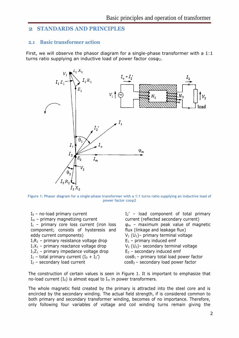
First, we will observe the phasor diagram for a single-phase transformer with a 1:1
turns ratio supplying an inductive load of power factor cosφ2.
Figure 1: Phasor diagram for a single-phase transformer with a 1:1 turns ratio supplying an inductive load of
power factor cosφ2
I0 – no-load primary current
Im – primary magnetizing current Ic – primary core loss current (iron loss
component; consists of hysteresis and
eddy current components)
I1R1 – primary resistance voltage drop
I1X1 – primary reactance voltage drop I1Z1 – primary impedance voltage drop
I1 – total primary current (I0 + I2’)
I2 – secondary load current
I2’ – load component of total primary
current (reflected secondary current) φm – maximum peak value of magnetic
flux (linkage and leakage flux)
V1 (U1)– primary terminal voltage
E1 – primary induced emf
V2 (U2)– secondary terminal voltage E2 – secondary induced emf
cosθ1 – primary total load power factor
cosθ2 – secondary load power factor
The construction of certain values is seen in Figure 1. It is important to emphasize that
no-load current (I0) is almost equal to Im in power transformers.
The whole magnetic field created by the primary is attracted into the steel core and is
encircled by the secondary winding. The actual field strength, if is considered common to both primary and secondary transformer winding, becomes of no importance. Therefore,
only following four variables of voltage and coil winding turns remain giving the
Basic principles and operation of transformer
3
fundamental transformer expression:
U1/U2 ~ N1/N2
When a transformer is loaded, the voltage induced in the secondary winding coil drives a
current into the load. Also, the secondary current produces its own magnetic field which is
reducing (opposing) the existing field, which is why the field in the primary is reduced.
More current flows until a turns balance is reached. The final outcome is that the magnetic
field is left unchanged, comparing to the state before adding load to the secondary coil (I1
and I2 produce equal and opposite magnetic fields). This is why we get the second equation:
𝑁1 ∙ 𝐼1 = 𝑁2 ∙ 𝐼2
The magnetic flux levels in the core do not rise in proportion to the load current. Combining
previous two equations we get:
𝑈1 ∙ 𝐼1 = 𝑈2 ∙ 𝐼2
2.2 Transformer equivalent circuit
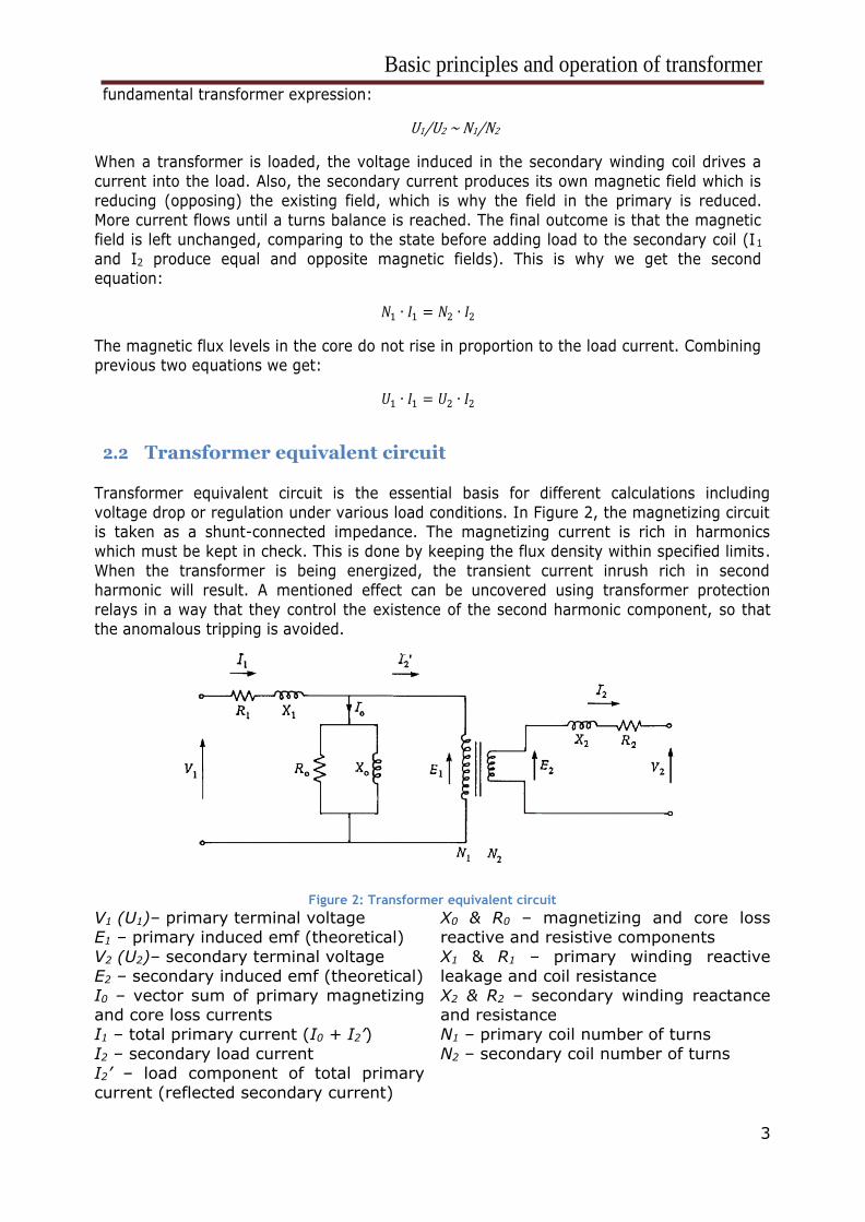
Transformer equivalent circuit is the essential basis for different calculations including
voltage drop or regulation under various load conditions. In Figure 2, the magnetizing circuit is taken as a shunt-connected impedance. The magnetizing current is rich in harmonics
which must be kept in check. This is done by keeping the flux density within specified limits.
When the transformer is being energized, the transient current inrush rich in second
harmonic will result. A mentioned effect can be uncovered using transformer protection
relays in a way that they control the existence of the second harmonic component, so that
the anomalous tripping is avoided.
Figure 2: Transformer equivalent circuit
V1 (U1)– primary terminal voltage
E1 – primary induced emf (theoretical)
V2 (U2)– secondary terminal voltage
E2 – secondary induced emf (theoretical)
I0 – vector sum of primary magnetizing and core loss currents
I1 – total primary current (I0 + I2’)
I2 – secondary load current
I2’ – load component of total primary
current (reflected secondary current)
X0 & R0 – magnetizing and core loss
reactive and resistive components
X1 & R1 – primary winding reactive
leakage and coil resistance
X2 & R2 – secondary winding reactance and resistance
N1 – primary coil number of turns
N2 – secondary coil number of turns
Basic principles and operation of transformer
4
2.3 Voltage and current distribution and transformer impedance representation
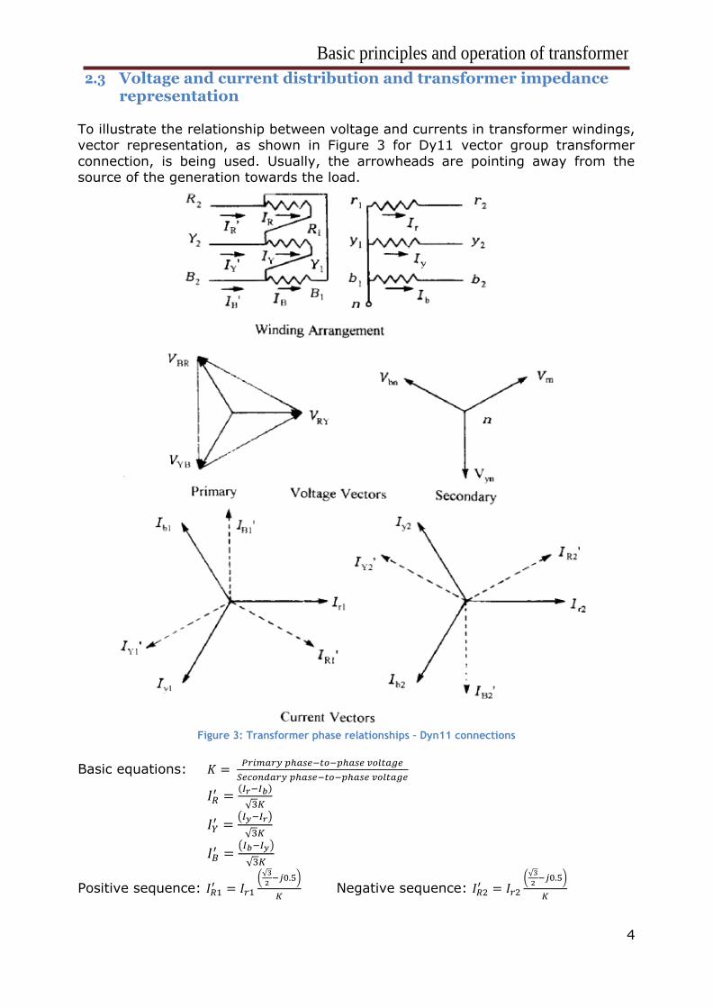
To illustrate the relationship between voltage and currents in transformer windings,
vector representation, as shown in Figure 3 for Dy11 vector group transformer
connection, is being used. Usually, the arrowheads are pointing away from the
source of the generation towards the load.
Figure 3: Transformer phase relationships – Dyn11 connections
Basic equations: 𝐾 = 𝑃𝑟𝑖𝑚𝑎𝑟𝑦 𝑝ℎ𝑎𝑠𝑒−𝑡𝑜−𝑝ℎ𝑎𝑠𝑒 𝑣𝑜𝑙𝑡𝑎𝑔𝑒
𝑆𝑒𝑐𝑜𝑛𝑑𝑎𝑟𝑦 𝑝ℎ𝑎𝑠𝑒−𝑡𝑜−𝑝ℎ𝑎𝑠𝑒 𝑣𝑜𝑙𝑡𝑎𝑔𝑒
𝐼𝑅′ =
(𝐼𝑟−𝐼𝑏)
√3𝐾
𝐼𝑌′ =
(𝐼𝑦−𝐼𝑟)
√3𝐾
𝐼𝐵′ =
(𝐼𝑏−𝐼𝑦)
√3𝐾
Positive sequence: 𝐼𝑅1′ = 𝐼𝑟1
(√3
2−𝑗0.5)
𝐾 Negative sequence: 𝐼𝑅2
′ = 𝐼𝑟2
(√3
2−𝑗0.5)
𝐾
Basic principles and operation of transformer
5
In load flow and fault studies, transformers are represented in the network
diagrams by their equivalent impedances. For two winding power transformers,
these impedances are usually represented as percentage reactance on the base of
the transformer rating. Three winding transformers can be represented in an impedance network by three impedances, rather than a single. Both two winding
and three winding transformers have equivalent positive and negative sequence
impedances.
Transformer zero sequence impedances depend on winding vector grouping and
neutral point earthing of both transformers and/or source generators within the system. Turns balance is normally produced within the transformer windings.
Nevertheless, under fault conditions, the zero sequence impedance results in the
extent to which the configuration allows the zero sequence current in one winding
to be balanced by equivalent ampere-turns in another winding.
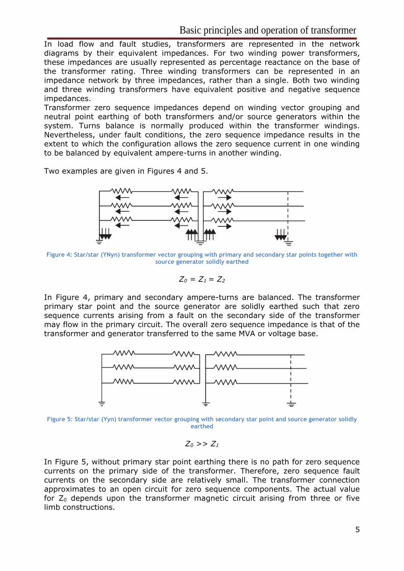
Two examples are given in Figures 4 and 5.
Figure 4: Star/star (YNyn) transformer vector grouping with primary and secondary star points together with source generator solidly earthed
Z0 = Z1 = Z2
In Figure 4, primary and secondary ampere-turns are balanced. The transformer primary star point and the source generator are solidly earthed such that zero
sequence currents arising from a fault on the secondary side of the transformer
may flow in the primary circuit. The overall zero sequence impedance is that of the
transformer and generator transferred to the same MVA or voltage base.
Figure 5: Star/star (Yyn) transformer vector grouping with secondary star point and source generator solidly earthed
Z0 >> Z1
In Figure 5, without primary star point earthing there is no path for zero sequence
currents on the primary side of the transformer. Therefore, zero sequence fault
currents on the secondary side are relatively small. The transformer connection
approximates to an open circuit for zero sequence components. The actual value
for Z0 depends upon the transformer magnetic circuit arising from three or five limb constructions.
Basic principles and operation of transformer
6
2.4 Tap changers
A tap changer is a mechanism in transformers which allows for variable turn ratios
to be selected in discrete steps. Transformers with this mechanism obtain this
variable turn ratio by connecting to several access points known as taps along
either the primary or secondary winding. Tap changers switches may be mounted separately on the side of the tank with
their own separate oil insulation, or in the main transformer tank in order to reduce
costs and result in a compact transformer design. Tap changers may be motor
driven or manually operated by a switch.
Types of tap changers:
1. Off-circuit – The condition for this type of tap change is that the transformer
is not energized. Off-circuit tap changers are usually switches which are
located close to the winding tapings and they are operated by a handle or a
wheel. 2. Off-load – The condition is that the circuit may be energized, but the
operation is not happening when the circuit is drawing load current.
3. On-load – The tap changer may be operated under load conditions, which
means they can change tapping position with transformer load current
flowing. Some of the manufacturer’s requirements for this type of tap
changer are: reliability, lowest cost, minimal maintenance, dielectric strength, electrical and mechanical life expectancy, overload and fault
current capability.
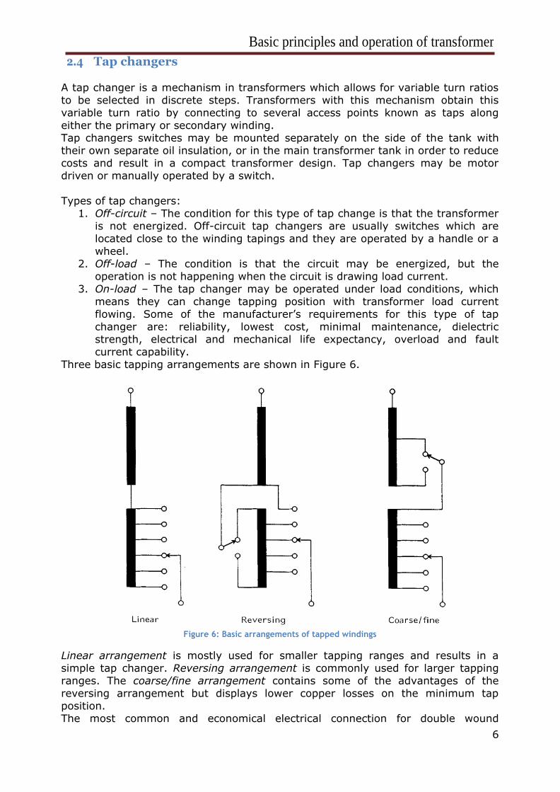
Three basic tapping arrangements are shown in Figure 6.
Figure 6: Basic arrangements of tapped windings
Linear arrangement is mostly used for smaller tapping ranges and results in a
simple tap changer. Reversing arrangement is commonly used for larger tapping
ranges. The coarse/fine arrangement contains some of the advantages of the
reversing arrangement but displays lower copper losses on the minimum tap
position. The most common and economical electrical connection for double wound
Basic principles and operation of transformer
7
transformers to the main winding is at the neutral end of star connected HV
windings, though it is also possible to connect it to the delta-connected windings.
For auto-transformers, the ideal position for the tapping is at the neutral end. As
with double wound transformers, this has the advantage of a smaller, lower cost tap changer. However, it is also possible for auto-transformers to be positioned at
the line-end taps. The line-end connection has the advantage to constant flux
density and therefore constant tertiary voltage over the tapping range.
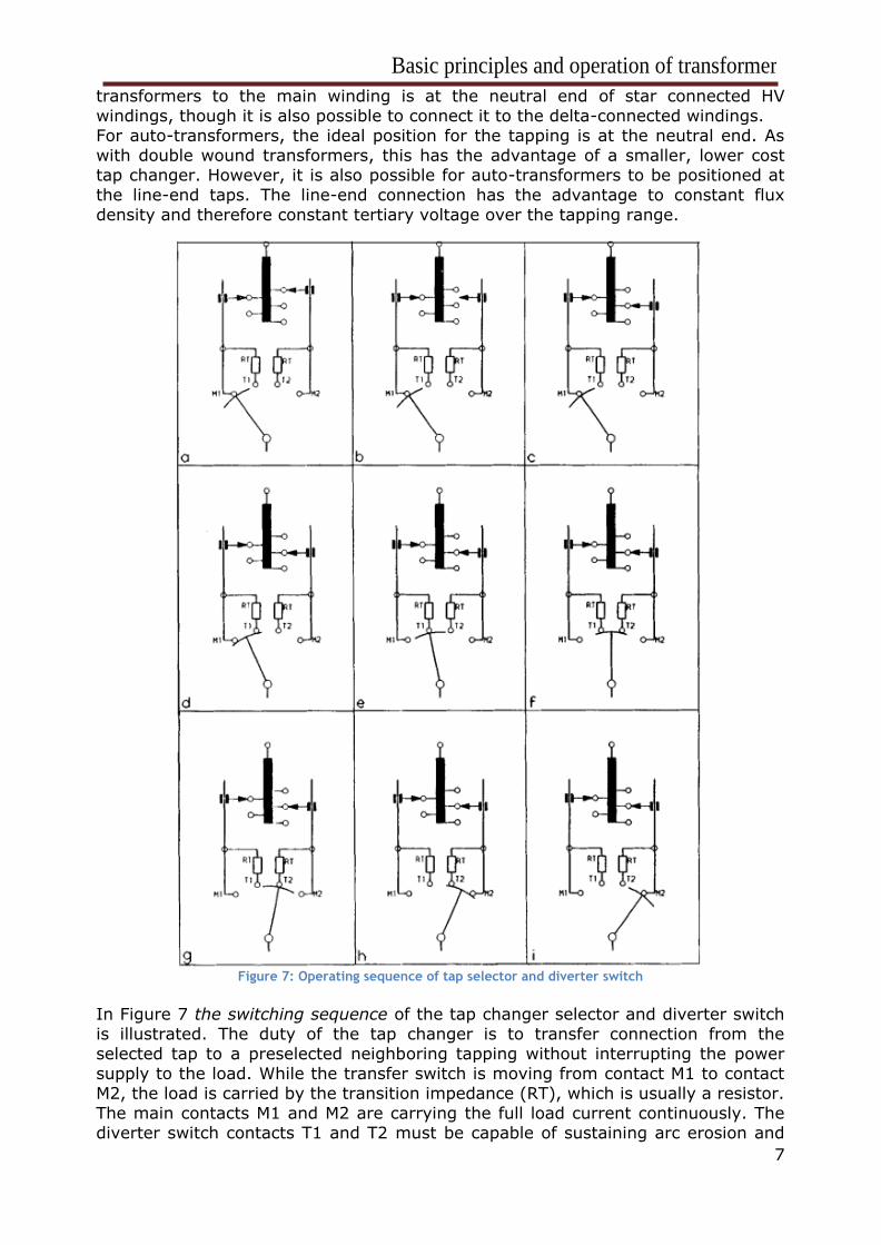
Figure 7: Operating sequence of tap selector and diverter switch
In Figure 7 the switching sequence of the tap changer selector and diverter switch
is illustrated. The duty of the tap changer is to transfer connection from the
selected tap to a preselected neighboring tapping without interrupting the power
supply to the load. While the transfer switch is moving from contact M1 to contact
M2, the load is carried by the transition impedance (RT), which is usually a resistor.
The main contacts M1 and M2 are carrying the full load current continuously. The diverter switch contacts T1 and T2 must be capable of sustaining arc erosion and
Basic principles and operation of transformer
8
mechanical duty resulting from making and breaking full load current. The arcing of
these contacts produces gases which saturate the neighboring oil and a barrier
must be provided to separate this oil from the main transformer oil.
In-tank tap changers have tapping winding peaks connected to the selector contacts (maintenance free) within the main transformer oil, while diverter
switches (maintained) are enclosed in an oil-filled insulating cylinder which is piped
to its own conservator.
Bolt-on tap changers are divided into two main types:
1. Double-compartment type has a construction of separated selector contacts from the diverter switch, in which way two main compartments are formed.
Now, they can be operated separately. Larger transformers build in the UK
prefer this type.
2. Single-compartment type is used for the lower ratings. This type of tap
changer uses selector switches which combine the function of selection and transfer in one mechanical device.
It is notable to mention the main standard reference for power transformers, which
is IEC 60076.
Basic principles and operation of transformer
9
3 VOLTAGE, IMPEDANCE AND POWER RATING
3.1 Voltage drop and impedance
Voltage drop happens in a transformer under secondary load conditions, due to the
leakage reactance and the winding resistance. It is most commonly expressed as a
percentage value referred to the kVA (or MVA) rating of the transformer.
Regulation of the transformer is the change in transformer terminal voltage from no load to full load. This change matches with the volt drop appearing at the full
load. Most commonly used formula is following:
∆𝑈 = √(𝑅 ∙ 𝑝)2 + (𝑋 ∙ 𝑞)2
100%
X - leakage reactance (%)
R – winding resistance (%)
p – power factor, cosφ (%) q – sinφ (%)
ΔU - % volt drop at full load
The main parameter for a transformer is the short circuit (internal) impedance. The
lowest value is limited by the minimum physical distance between windings, while the highest is limited by the effects of the associated high leakage flux. This means
that extreme values are limited by design factor.
Three phase systems consider zero sequence impedance as well, as it determines
the magnitude of fault currents flowing between the neutral of a star-connected
winding and earth during phase-to-earth faults. This impedance depends on the core configuration (whether it is 3 or 5 limb core) and whether or not a delta-
connected auxiliary winding is fitted.
3.2 Voltage ratio and tappings
It is always advisable to think twice before deciding on the voltage ratio for the
transformer. For example, if there is a transformer with values 132kV connecting
to the 20kV system, this does not mean that the voltage ratio is 132/20kV since we need to take into account:
1. The 132kv voltage is not constant and may vary as much as ±10% from
the nominal value
2. Volt drop on load will lower the voltage at the 20kV terminals.
Every practical transformer will need tappings to allow selection of different voltage
ratios to suit different circumstances.
Off-circuit (off-load) tappings are used in situations when the transformer regulation and the primary voltage variations are small, which means that change
from one tapping to another will be very rare in the transformer life. These are
usually used in domestic and industrial distribution systems. The voltage ratio is
usually chosen to give approximately nominal secondary voltage at full load.
Therefore, a ratio of 11 kV to 433 V is usually chosen to feed a 415 V system. Distribution transformer off-circuit tappings giving -5.0%, -2.5%, 0%, +2.5% and
+5.0% variation in ratio are conventionally specified and will be adequate for the
Basic principles and operation of transformer
10
majority of situations. The middle tap of a transformer is referred to as the
‘principal tap’.
On-load tappings are used for frequent changes in tapping without removing the
transformer from service. They are used in most of transmission system applications. However, the procedure for defining voltage ratio and tapping range
often causes problems. In the standard IEC 60076-1 are defined categories of
voltage variation for transformers with tappings.
3.3 Vector groups and neutral earthing
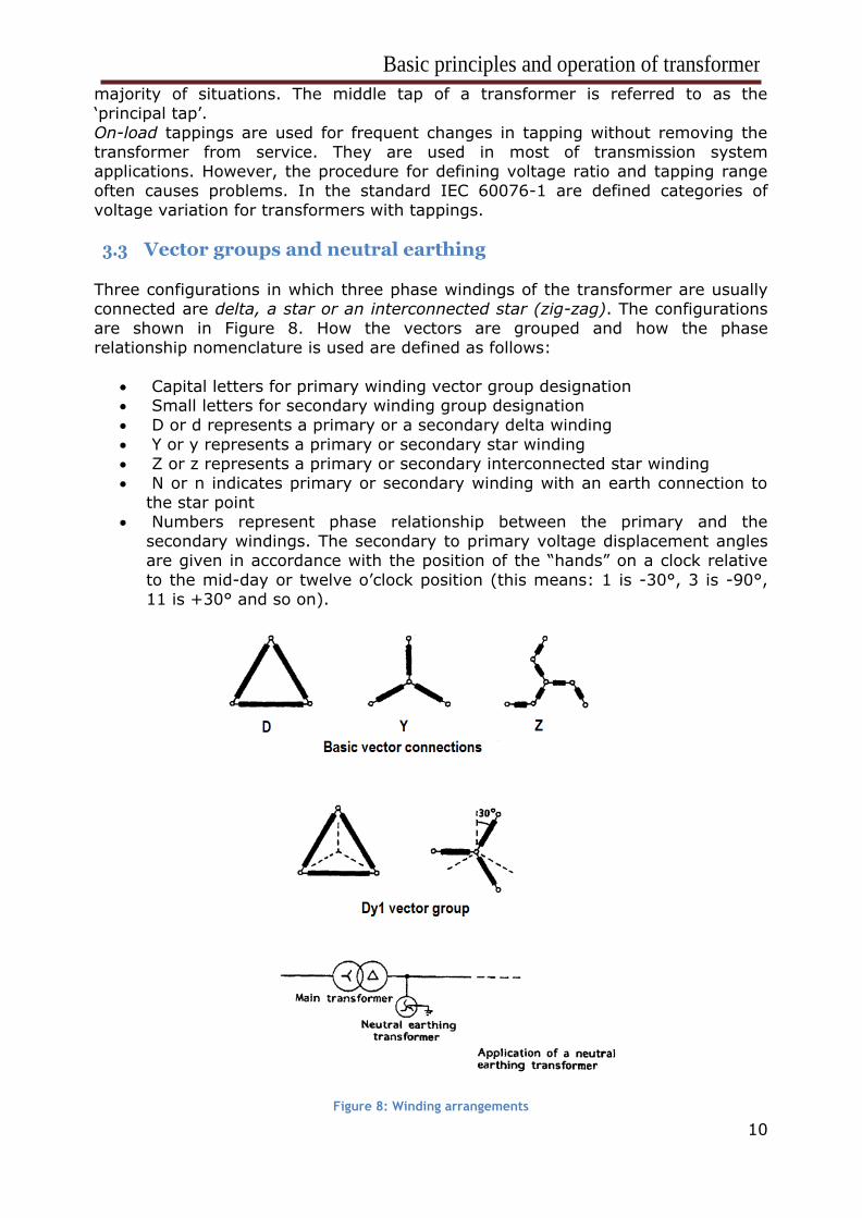
Three configurations in which three phase windings of the transformer are usually connected are delta, a star or an interconnected star (zig-zag). The configurations
are shown in Figure 8. How the vectors are grouped and how the phase
relationship nomenclature is used are defined as follows:
• Capital letters for primary winding vector group designation • Small letters for secondary winding group designation
• D or d represents a primary or a secondary delta winding
• Y or y represents a primary or secondary star winding
• Z or z represents a primary or secondary interconnected star winding
• N or n indicates primary or secondary winding with an earth connection to
the star point • Numbers represent phase relationship between the primary and the
secondary windings. The secondary to primary voltage displacement angles
are given in accordance with the position of the “hands” on a clock relative
to the mid-day or twelve o’clock position (this means: 1 is -30°, 3 is -90°,
11 is +30° and so on).
Figure 8: Winding arrangements
Basic principles and operation of transformer
11
Example on defining Dy1 vector grouping is given in Figure 8. In this case, it is
noticeable that the secondary star voltage is at the one o’clock position, meaning
that it is lagging the primary delta voltage vector by 30°.
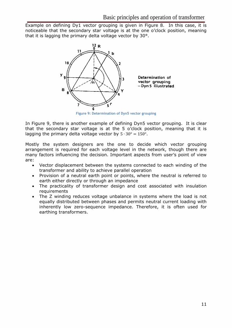
Figure 9: Determination of Dyn5 vector grouping
In Figure 9, there is another example of defining Dyn5 vector grouping. It is clear
that the secondary star voltage is at the 5 o’clock position, meaning that it is lagging the primary delta voltage vector by 5 ∙ 30° = 150°.
Mostly the system designers are the one to decide which vector grouping
arrangement is required for each voltage level in the network, though there are
many factors influencing the decision. Important aspects from user’s point of view
are:
• Vector displacement between the systems connected to each winding of the transformer and ability to achieve parallel operation
• Provision of a neutral earth point or points, where the neutral is referred to
earth either directly or through an impedance
• The practicality of transformer design and cost associated with insulation
requirements • The Z winding reduces voltage unbalance in systems where the load is not
equally distributed between phases and permits neutral current loading with
inherently low zero-sequence impedance. Therefore, it is often used for
earthing transformers.
Basic principles and operation of transformer
12
4 THERMAL DESIGN
There are several ways of producing heat in a transformer. Most significant ones
are the heat produced in a transformer due to the flow of load current through the
resistance of the winding conductor, where load loss exists, and due to the heat
production in the magnetic core, where there is no load loss. Some other sources of heat include dielectric heating of insulating materials, eddy current heating in
conductors and support steel structures. Thermal design of a transformer aims to
remove this heat economically and effectively, in a way to avoid any unwanted
deterioration of components.
4.1 Temperature rise The heat is produced in the windings of the conductor. Windings are insulated with
a paper type wound around them. It is saturated with oil, since the winding is
located in the oil inside of the transformer tank, so this insulation is good for
protecting (insulating) from the earthed parts and other windings.
Heat from the conductor moves through the paper type insulation, then in the bulk of oil and it is finally conducted away from the winding, which results in dissipation
of the heat into the air. To prevent damage of the conductor, the maximum
temperature is determined, which is on average 98°C.
Generally, not all the parts of a winding are the same temperature. The warmest
part is called the “hot spot”, which location is not always known, but it can be determined with the infrared imaging technique. Besides hot spot, also “average
winding temperature” is determined. From the researches, it is known that the “hot
spot” temperature is about 13°C above the average winding temperature.
However, when the transformer is unloaded the conductor temperature is
practically the same as the ambient temperature. From these conclusions, follows
the formula for the temperature of the hot spot:
hot spot temperature = ambient temperature + average winding temperature rise
+ hot spot differential
Based on the IEC specification and conclusions written above, following can be said:
98°C ≥ 20°C + average winding temperature rise + 13°C
Which means that the average winding temperature rise should be ≤65°C, which is
a basis of the IEC specification.
4.2 Loss of life expectancy with temperature
In the previous segment, it was mentioned that the insulating materials are
determined by the maximum temperature, which does not mean that immediate
insulation failure would happen, but that the insulation would have shortened
lifespan. The estimated lifespan is determined by the law due to Arrhenius:
Loss of life expectancy = A + B/T
A and B are empirical constants for a given material
T is the absolute temperature in °C
The Arrhenius effect equalizes the periods of operation with the insulation above
Basic principles and operation of transformer
13
the “normal life” temperature with the periods of the lower temperature, where the
life is above normal. The good example is the ambient temperature of insulator
during winter and summer, which significantly changes, but after all the lifespan is
equalized.
4.3 Ambient temperature
Ambient temperature is not the same everywhere around the world. That means
that the average winding temperature rise would drop (or rise) if the ambient
temperature is higher (lower).
Nevertheless, the IEC reference ambient temperature is given in four components
as follows:
• Maximum: 40°C
• Maximum average over a 24-hour period: 30°C
• Annual average: 20°C • Minimum -25°C
The correct annual average temperature to use when specifying transformers is a
“weighted” value given as follows:
𝑇𝑎1 = 20𝑙𝑜𝑔10
1
𝑁[∑ 10𝑇𝑎/20
𝑁
1
]
Ta1 – weighted annual ambient temperature
Ta – monthly average temperature
N – month number
The weighted value is designed to take proper account of the Arrhenius law.
4.4 Solar heating
In tropical climates, it is important to include solar heating of transformers into
account. In these cases, the additional typical rise of the oil in the transformer is
small, about 2°C to 3°C. However, the transformers which has a large surface
compared to the volume (like pole-mounted units) can get higher temperature rise,
between 5°C and 10°C. This means that much should be subtracted from the permitted winding temperature rise at full load.
4.5 Transformer cooling classifications
Previously, one method of cooling the transformer has been mentioned, where the
heat is conducted to the oil from the windings and core, after which is transmitted
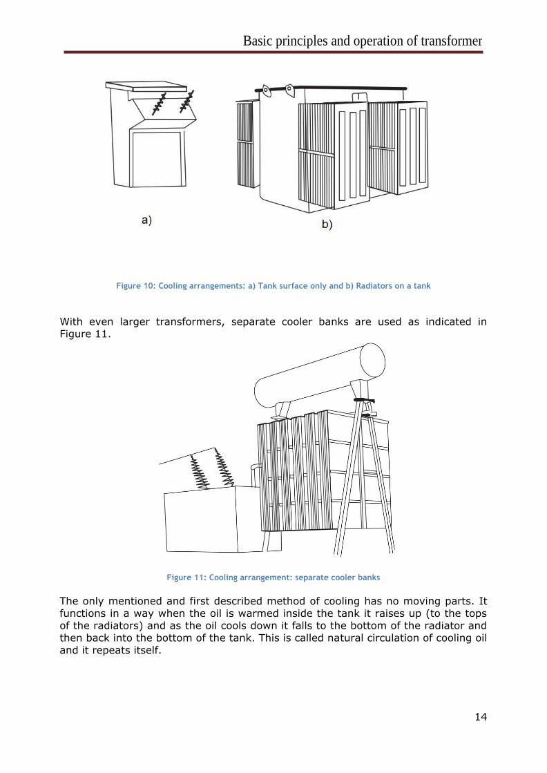
to the surrounding air at the tank surface. Practically, only the smallest pole-mounted distribution transformers have enough tank surface to dissipate the
internal heat effectively (Figure 10.a). With larger transformers, the surface area
for heat dissipation is deliberately increased by attaching radiators to the tank. A
1000kVA hermetically sealed transformer with radiators is shown in Figure 10.b.
Basic principles and operation of transformer
14
Figure 10: Cooling arrangements: a) Tank surface only and b) Radiators on a tank
With even larger transformers, separate cooler banks are used as indicated in Figure 11.
Figure 11: Cooling arrangement: separate cooler banks
The only mentioned and first described method of cooling has no moving parts. It
functions in a way when the oil is warmed inside the tank it raises up (to the tops of the radiators) and as the oil cools down it falls to the bottom of the radiator and
then back into the bottom of the tank. This is called natural circulation of cooling oil
and it repeats itself.
Basic principles and operation of transformer
15
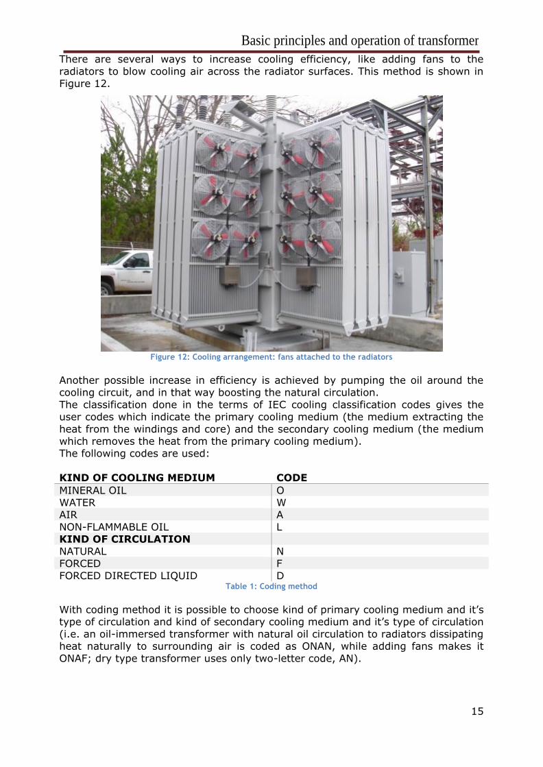
There are several ways to increase cooling efficiency, like adding fans to the
radiators to blow cooling air across the radiator surfaces. This method is shown in
Figure 12.
Figure 12: Cooling arrangement: fans attached to the radiators
Another possible increase in efficiency is achieved by pumping the oil around the
cooling circuit, and in that way boosting the natural circulation.
The classification done in the terms of IEC cooling classification codes gives the
user codes which indicate the primary cooling medium (the medium extracting the
heat from the windings and core) and the secondary cooling medium (the medium
which removes the heat from the primary cooling medium). The following codes are used:
KIND OF COOLING MEDIUM CODE
MINERAL OIL O
WATER W
AIR A
NON-FLAMMABLE OIL L KIND OF CIRCULATION
NATURAL N
FORCED F
FORCED DIRECTED LIQUID D Table 1: Coding method
With coding method it is possible to choose kind of primary cooling medium and it’s type of circulation and kind of secondary cooling medium and it’s type of circulation
(i.e. an oil-immersed transformer with natural oil circulation to radiators dissipating
heat naturally to surrounding air is coded as ONAN, while adding fans makes it
ONAF; dry type transformer uses only two-letter code, AN).
Basic principles and operation of transformer
16
4.6 Selection of cooling classification
It is hard to choose the most appropriate method of cooling for a particular
application, but the following guidance for mineral oil-immersed transformers may
help. The basic questions to consider are related to capital cost, maintenance
procedure, use of the transformer (on its own or parallel), how critical is physical size.
ONAN
This type of cooling requires zero to minimum maintenance, as it has no
mechanical moving parts. Numerous developing countries prefer this type of cooling because of the reliability, but there is an increasing cost penalty as sizes
increase.
ONAF
This type has fans fitted to the radiators, and it has the rating between 15% and 33% greater than with the fans not in operation. Therefore, the transformer has an
effective dual rating under ONAN and ONAF conditions. It can be specified as
20/25MVA ONAN/ONAF. However, it is not always desirable to use ONAN/ONAF
transformers, as in the example of transformers working in parallel. In this case,
fans would run very rarely and will produce a loud noise, which can be a problem in
environmentally sensitive areas.
OFAF
Generator transformers and power station interbus transformers often use OFAF
cooling. This cooling method is forcing the oil circulation and blowing air over the
radiators. The maintenance burden is increased owing to the oil pumps, motors and radiator fans required. Good maintenance procedures are recommended.
ODAF/ODWF
These are special cooling categories where the oil is directed by pumps into the
closest proximity possible to the winding conductors. The external cooling medium can be air or water. Because of the design, the operation of the oil pumps, cooling
fans, or water pumps is crucial to the rating obtainable and such transformers may
have rather poor naturally cooled (ONAN) ratings. Such directed and forced cooling
results in a compact and economical design suitable for use in well-maintained
environments.
4.7 Capitalization of losses Lower investment in materials will result in initial lower costs, but a shorter life of
transformer, when on the other side, investing a bit more initially in the
transformer can pay off in a way of a longer lifetime of the transformer.
The total cost of the transformer is called the capital cost. In most cases, the
consultant or electrical supply utility will specify separate capitalizing factors for the load and no-load losses and typical figures for UK transmission transformers are:
no-load loss capitalization rate £4000/kW; load loss capitalization rate £650/kW.
The transformer manufacturer can then easily calculate the capitalized price
following the formula:
Capitalized cost = selling cost + 4000 x no-load losses (kW) + 650 x load loss (kW)
Basic principles and operation of transformer
17
5 CONSTRUCTIONAL ASPECTS
5.1 Cores
In order to enhance core’s magnetic properties, it is constructed from an iron and
silicon mixture (alloy). The magnetic core consists of a few thin sheets (0.3 mm to
0.23 mm thick) of the core metal. Each of these sheets has a thin layer of
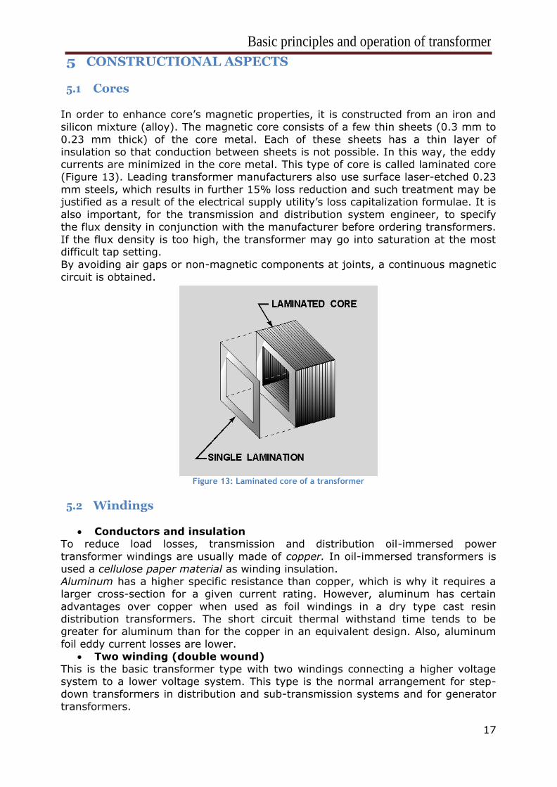
insulation so that conduction between sheets is not possible. In this way, the eddy currents are minimized in the core metal. This type of core is called laminated core
(Figure 13). Leading transformer manufacturers also use surface laser-etched 0.23
mm steels, which results in further 15% loss reduction and such treatment may be
justified as a result of the electrical supply utility’s loss capitalization formulae. It is
also important, for the transmission and distribution system engineer, to specify the flux density in conjunction with the manufacturer before ordering transformers.
If the flux density is too high, the transformer may go into saturation at the most
difficult tap setting.
By avoiding air gaps or non-magnetic components at joints, a continuous magnetic
circuit is obtained.
Figure 13: Laminated core of a transformer
5.2 Windings
• Conductors and insulation
To reduce load losses, transmission and distribution oil-immersed power
transformer windings are usually made of copper. In oil-immersed transformers is used a cellulose paper material as winding insulation.
Aluminum has a higher specific resistance than copper, which is why it requires a
larger cross-section for a given current rating. However, aluminum has certain
advantages over copper when used as foil windings in a dry type cast resin
distribution transformers. The short circuit thermal withstand time tends to be greater for aluminum than for the copper in an equivalent design. Also, aluminum
foil eddy current losses are lower.
• Two winding (double wound)
This is the basic transformer type with two windings connecting a higher voltage
system to a lower voltage system. This type is the normal arrangement for step-down transformers in distribution and sub-transmission systems and for generator
transformers.
Basic principles and operation of transformer
18
• Three winding
Third winding is added because a third voltage level is involved or for design
reasons. A star/star transformer is often combined with third (delta-connected)
winding. This can be for numerous of reasons: - In order to reduce the transformer impedance to zero sequence currents, so
that earth fault currents of sufficient magnitude can flow to operate the
protection
- In order to suppress the third harmonics due to the no-load current in the
earth connection when the neutral is earthed - In order to stabilize the phase-to-phase voltages under unbalanced load
conditions
- In order to enable overpotential testing of large high voltage transformers to
be carried out by excitation at a relatively low voltage
- In order to provide an intermediate voltage level for supply to an auxiliary load where a tertiary winding offers a more economical solution than a
separate transformer
Besides these advantages, there are still some disadvantages concerning three
winding cores, as it increases costs of a transformer by 6% to 8% which follows
also additional losses of 5%.
• Auto-transformers
This type of transformer has only one winding. Prefix auto refers to the single coil
acting alone (not to any kind of automatic mechanism). Portions of the same
winding act as both the primary and the secondary sides of the transformer (if a tap is made part way down the winding). Since having just one winding, auto-
transformers have advantages of often being smaller lighter and cheaper than
typical two winding transformers. A disadvantage is not providing electrical
insulation between primary and secondary circuits. Auto-transformers are usually
star connected, which means that both high and low voltage systems have the same neutral. This is only desirable in transmission systems where solid earthing of
neutrals is common at all voltage levels.
5.3 Tanks and enclosures
• Oil preservation
The oil inside transformer tank acts as heat transfer medium and an insulation. The
oil must be dry and free from contaminants, to keep good insulating properties. This is done by sealing the oil inside the tank so that there is no contact with the
atmosphere. Also, there has to be left some free area to allow expansion in volume
of oil because of temperature changes. Some of the methods to be used depending
on the rating of the transformer, its location and the particular policy of the
manufacturer are: - Sealed rigid tank – The tank is not fully filled with oil. The free space above
oil is filled with a dry gas, which has no chemical reaction with the oil. The
tank should be strong because of the large pressure changes inside of it.
- Sealed expandable tank – Not all the transformers can use this technique.
The tank is fully filled with oil, but the surfaces of the tank are flexible to allow the expansion of oil due to temperature changes.
- Positive pressure nitrogen – It is applied to the large transformers. It is
similar to the sealed rigid tanks, just that it has venting for minimizing
pressure changes.
- Conservator (with breather) – Applied to any size of transformers. The tank
Basic principles and operation of transformer
19
is filled with oil and changes in volume are allowed by an expansion tank
(conservator) mounted above the main tank. A conservator has a vent to the
atmosphere, in which an air-drying device is located.
- Conservator (with diaphragm seal) – The expansion tank contains a flexible synthetic rubber diaphragm which allows for oil expansion, but seals the oil
from the atmosphere.
It is crucial that the quality of tank welding, gasketing, and painting is carefully
specified and inspected prior to release from the manufacturer’s works, in order to
avoid oil leakage.
• Dry type transformer enclosures
These types of transformers have physical protection around them to protect the
core and windings form dust, water entry, condensation and to keep personnel
away from live parts. Open steel mesh surround may be specified for indoor applications depending on the classification required.
5.4 Low fire risk types
The possible situations where a transformer may be involved in a fire fall in three
categories:
- There has been an internal fault that leads to ignition and subsequent burning of the materials within the transformer. However, arcing faults
should be cleared by overcurrent devices in short time.
- The transformer is located in the enclosed space involving materials such as
wood, which could ignite the transformer.
- The transformer is located in an enclosure in which a fire involving hydrocarbon fuels or plastic materials occur taking the transformer in
flames.
When comparing the dry type and non-flammable liquid-immersed types to the
mineral oil-immersed units, the difference in cost is noticeable (latter are the cheapest).
The fire protection of transformers is usually done by controlling the oil spillage
from a tank. For outdoor installations, additional protection exists, represented by
a temperature sensor located above the transformer, which initiates water spray or
foam system to extinguish the fire.
5.5 Underground transformers
Distribution transformers may be buried or installed in underground chambers. This
is usually done in dense urban areas where substation sites are difficult to obtain.
In Europe are typically directly buried small units up to 1 MVA, which are ON/AF
types and in the USA, which are AN/AF types, both with air ducts leading to a radiator on the surface. Problem with these types of transformers is tank corrosion
of directly buried units. Special care should include minimizing the effect of soil
drying, which can be done by using the thermal backfill. Another type of
underground transformers includes those of size 100 MVA, which are in
underground substations and in fully accessible rooms.
Basic principles and operation of transformer
20
6 ACCESSORIES
Beside elementary assembly of transformers, there are also additional accessories
which may or may not be obligatory for a transformer. Those are accessories for
protection, safety purposes, and monitoring.
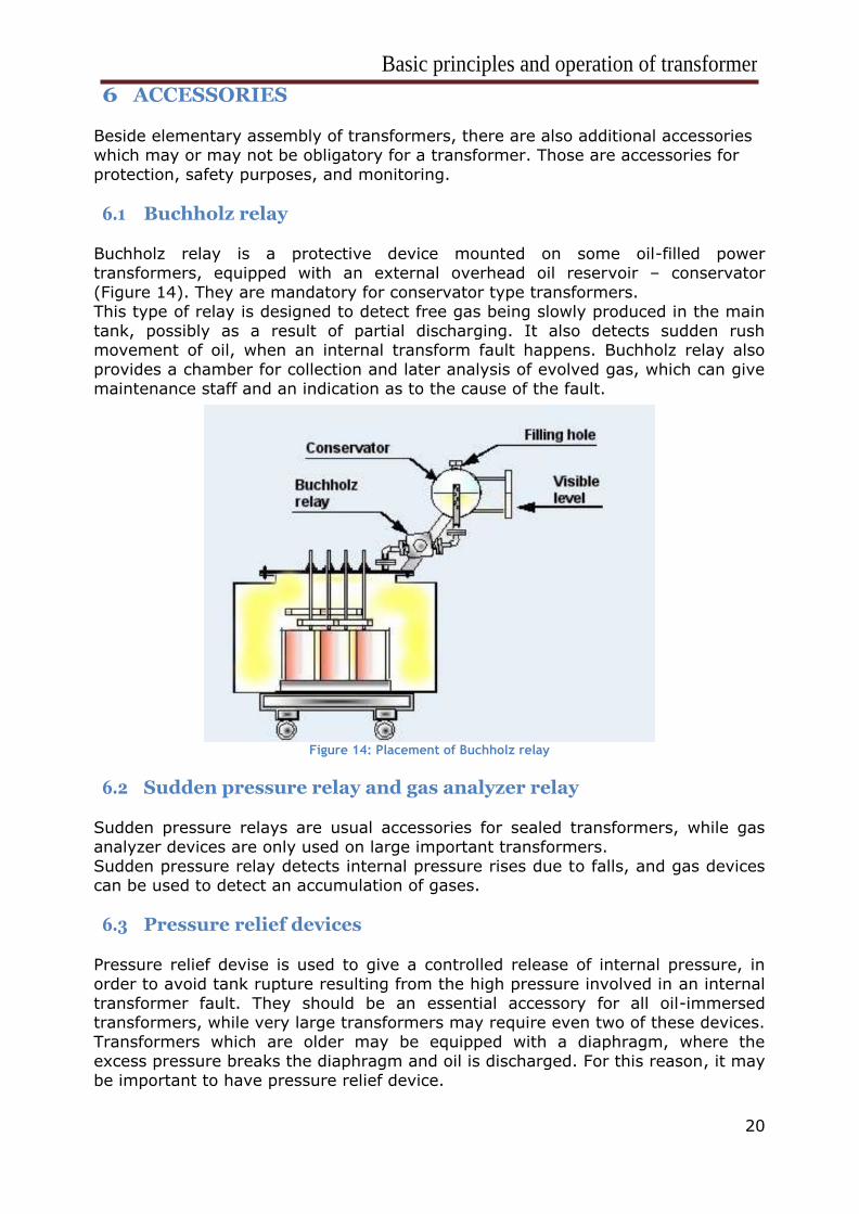
6.1 Buchholz relay Buchholz relay is a protective device mounted on some oil-filled power
transformers, equipped with an external overhead oil reservoir – conservator
(Figure 14). They are mandatory for conservator type transformers.
This type of relay is designed to detect free gas being slowly produced in the main
tank, possibly as a result of partial discharging. It also detects sudden rush movement of oil, when an internal transform fault happens. Buchholz relay also
provides a chamber for collection and later analysis of evolved gas, which can give
maintenance staff and an indication as to the cause of the fault.
Figure 14: Placement of Buchholz relay
6.2 Sudden pressure relay and gas analyzer relay
Sudden pressure relays are usual accessories for sealed transformers, while gas
analyzer devices are only used on large important transformers.
Sudden pressure relay detects internal pressure rises due to falls, and gas devices can be used to detect an accumulation of gases.
6.3 Pressure relief devices
Pressure relief devise is used to give a controlled release of internal pressure, in
order to avoid tank rupture resulting from the high pressure involved in an internal
transformer fault. They should be an essential accessory for all oil-immersed transformers, while very large transformers may require even two of these devices.
Transformers which are older may be equipped with a diaphragm, where the
excess pressure breaks the diaphragm and oil is discharged. For this reason, it may
be important to have pressure relief device.
Basic principles and operation of transformer
21
6.4 Temperature monitoring
Oil and winding temperature is monitored in all but small (less than 200 kVA)
distribution transformers. If a transformer is correctly loaded and specified, it
should not produce excessive temperatures.
Winding temperature indicator usually has a feature to initiate automatic switch-on and switch-off of cooling fans and oil circulation pumps. This is how ONAN/ONAF
will automatically switch from ONAN to ONAF (and vice versa), according to the
transformer loading conditions. Temperature monitoring can also help in detecting
“hot spot” winding temperature. Oil temperature monitor is usually a capillary type
thermometer with the sensor located near the hottest oil in the tank (i.e. at the top of the tank, before hot oil enters the radiators). Both oil and winding temperature
monitors are fitted with contacts which can be set to operate at the desired
temperature. These contacts are used for alarm and trip purposes.
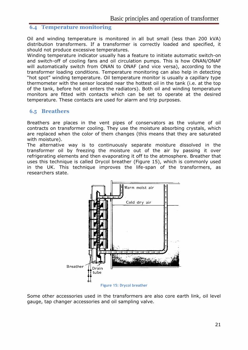
6.5 Breathers
Breathers are places in the vent pipes of conservators as the volume of oil contracts on transformer cooling. They use the moisture absorbing crystals, which
are replaced when the color of them changes (this means that they are saturated
with moisture).
The alternative way is to continuously separate moisture dissolved in the
transformer oil by freezing the moisture out of the air by passing it over
refrigerating elements and then evaporating it off to the atmosphere. Breather that uses this technique is called Drycol breather (Figure 15), which is commonly used
in the UK. This technique improves the life-span of the transformers, as
researchers state.
Figure 15: Drycol breather
Some other accessories used in the transformers are also core earth link, oil level
gauge, tap changer accessories and oil sampling valve.
Basic principles and operation of transformer
22
7 CONCLUSION
In this seminar, basic components, standards, and principles of a transformer have been
described. When applying power transformer to the wanted part in the power network, it is
important to follow requirements and specifications given, together with the use of essential
monitoring, safety, and reliability accessories. Otherwise, significant damages may occur.
When choosing the transformer for one’s application, the geographical location should be taken
into consideration too, as the thermal design is dependent on the average ambient temperature,
which varies around the world. Accordingly, should the cooling systems be chosen and used.
Power transformers are a crucial part of the power systems. Considering this fact, continuous
monitoring and diagnostics of transformers increase stability, reliability, and safety as well as their
life-span. Also, non-obligatory, but desirable accessories may be used, such as Buchholz relay,
sudden pressure relay, pressure relief devices, breathers.
Basic principles and operation of transformer
23
8 QUESTIONS
1) What is the use of tap changer and how do we divide them?
The purpose of a tap changer is to regulate the output voltage of a
transformer. It does this by altering the number of turns in one winding and
thereby changing the turns ratio of the transformer.
Types of tap changers:
o Off-circuit
o Off-load
o On-load
2) When does a voltage drop in a transformer happen?
Voltage drop happens in a transformer under secondary load conditions, due to
the leakage reactance and the winding resistance. It is most commonly
expressed as a percentage value referred to the kVA (or MVA) rating of the
transformer.
3) What is the “hot spot” and how do we calculate its temperature?
The warmest part of the winding is called the “hot spot”.
The formula for the temperature of the hot spot is:
hot spot temperature = ambient temperature +
average winding temperature rise +
hot spot differential
4) How are transformers divided based on the number of windings?
They are divided into following types:
- two winding (double wound)
- three winding
- auto-transformers (one winding)
Basic principles and operation of transformer
24
9 HOMEWORK
a) Find the volt drop of the three-phase transformer with a leakage reactance
of 6.6%, and resistance of 2.4%. The transformer has manufacturer rating
given as follows:
U1/U2 = 12,7kV/0,23kV
S = 150 kVA
P = 120 kW
R = 2.4% X = 6.6%
Solution:
We will use the following formula:
∆𝑈 = √(𝑅 ∙ 𝑝)2 + (𝑋 ∙ 𝑞)2
100%
Observing the formula, we realize that we need to calculate power factor (cosφ = p).
𝑝 = 𝑐𝑜𝑠𝜑 = 𝑃
𝑆=
120
150= 0.8
Therefore, we can also get sinφ (q):
𝑞 = 𝑠𝑖𝑛φ = √1 − 𝑐𝑜𝑠2φ = √1 − 0.8 = 0.6
Finally, we have:
∆𝑈 = √(𝑅 ∙ 𝑝)2 + (𝑋 ∙ 𝑞)2
100%=
√(2.4 ∙ 80)2 + (6.6 ∙ 60)2
100%= 4.4%
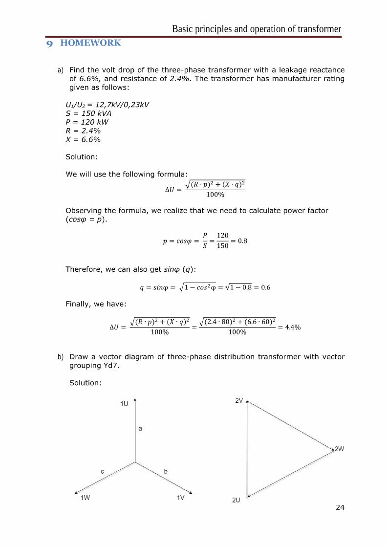
b) Draw a vector diagram of three-phase distribution transformer with vector
grouping Yd7.
Solution:
Basic principles and operation of transformer
25
10 LITERATURE
1) C. Bayliss, B. Hardy: Transmission and Distribution Electric Engineering
2) Vezir Rexhepi: An Analysis of Power Transformer Outages and Reliability
Monitoring
3) https://en.wikipedia.org/wiki/ (date of use 06.03.2018)
4) Andrea Ljubljanac, notes from lectures and exercises from course Generators and Transformers
5) Tom A. Short, Electric Power Distribution Handbook, CRC Press, 2004


![RAZPRŠENI VIRI ELEKTRIČNE ENERGIJE IN - Domovlrf.fe.uni-lj.si/e_rio/Seminarji1516/... · E energija [J] I tok [A] RIO 2015/16 JERIHA JAN 4 1. Uvod ... Geotermalna energija [7],](https://img.dokumen.tips/doc/110x75/5a7934417f8b9ae93a8bc815/razprseni-viri-elektricne-energije-in-energija-j-i-tok-a-rio-201516-jeriha.jpg)