Embed Size (px)
Citation preview

Basic Electricity & Basic Electricity & ElectronicsElectronics
Let’s go on a Let’s go on a Learning JourneyLearning Journey

Conductors and Insulators
Metals Metals are good conductors because are good conductors because current flows through them easily.current flows through them easily.
Wood and most plasticsWood and most plastics do not allow do not allow current to flow and are electrical current to flow and are electrical insulators.insulators.
Some materials, such as Some materials, such as silicon and silicon and germaniumgermanium, are called semi-conductors , are called semi-conductors because current flows through them, but because current flows through them, but not as freely as through metals.not as freely as through metals.

• A switch with two connections is A switch with two connections is called a single-pole, single-throw called a single-pole, single-throw (SPST) switch.(SPST) switch.
• A switch with three connections is A switch with three connections is called a single-pole, double-throw called a single-pole, double-throw (SPDT) switch.(SPDT) switch.
SWITCHESSWITCHES
SPDT

• A double-pole, double-throw A double-pole, double-throw (DPDT) switch has six contacts. (DPDT) switch has six contacts. DPDT can operate two independent DPDT can operate two independent circuits at the same time.circuits at the same time.
SWITCHESSWITCHES
DPDT
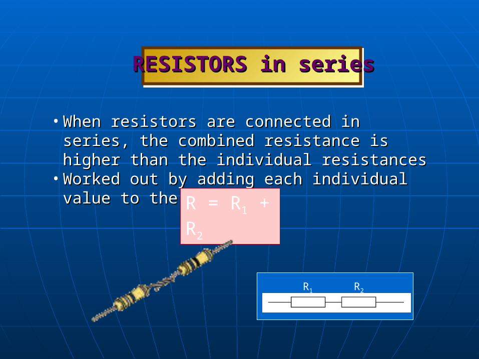
• When resistors are connected in series, the combined When resistors are connected in series, the combined resistance is higher than the individual resistances resistance is higher than the individual resistances
• Worked out by adding each individual value to the next.Worked out by adding each individual value to the next.
RESISTORS in seriesRESISTORS in series
R = R1 + R2
R1 R2
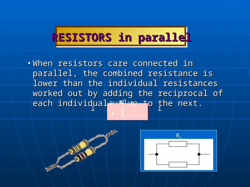
• When resistors care connected in parallel, the combined When resistors care connected in parallel, the combined resistance is lower than the individual resistances resistance is lower than the individual resistances worked out by adding the reciprocal of each individual worked out by adding the reciprocal of each individual value to the next.value to the next.
RESISTORS in parallelRESISTORS in parallel
R = R1 + R2
1 1 1
R1
R2

• Resistors reduce the amount of Resistors reduce the amount of current flowing in a circuit and current flowing in a circuit and are used for protecting are used for protecting components from being components from being damaged by too much current.damaged by too much current.
• They are made in a range of They are made in a range of values, with higher values values, with higher values providing a greater resistance.providing a greater resistance.
• Resistors can be connected Resistors can be connected either way round in a circuit.either way round in a circuit.
Use of RESISTORSUse of RESISTORS

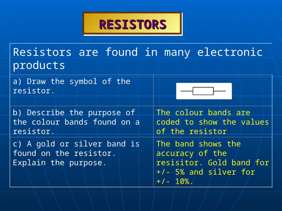
RESISTORSRESISTORS
Resistors are found in many electronic productsa) Draw the symbol of the resistor.
b) Describe the purpose of the colour bands found on a resistor.
The colour bands are coded to show the values of the resistor
c) A gold or silver band is found on the resistor. Explain the purpose.
The band shows the accuracy of the resisitor. Gold band for +/- 5% and silver for +/- 10%.

• A transistor is an automatic switch.A transistor is an automatic switch.• Instead of pushing a button or sliding a lever to turn it on Instead of pushing a button or sliding a lever to turn it on
or off, it has a contact, called the base, which is used to or off, it has a contact, called the base, which is used to activate it.activate it.
BIPOLAR TRANSISTORBIPOLAR TRANSISTOR

Types of SWITCHESTypes of SWITCHES
Slide switch
Tilt switch
Reed switchMicroswitch
Push switch
Rotary switchRocker switch
Key switchMembrane panel switch

• The filament bulb lights up when The filament bulb lights up when current passes through.current passes through.
• The current causes the filament to The current causes the filament to become so hot that it glows.become so hot that it glows.
OUTPUT COMPONENTSOUTPUT COMPONENTS

• Buzzers make a noise when Buzzers make a noise when connected to a battery and are connected to a battery and are often used as warning devices.often used as warning devices.
• The wires are sometimes The wires are sometimes coloured coded: red to connect to coloured coded: red to connect to the positive terminal and black to the positive terminal and black to connect to the negative terminal.connect to the negative terminal.
OUTPUT COMPONENTSOUTPUT COMPONENTS

• Motors are used for turning wheels, Motors are used for turning wheels, pulleys, gears or cams.pulleys, gears or cams.
• D.C. brush motors having contacts for D.C. brush motors having contacts for the battery connection are the most the battery connection are the most common type.common type.
• The direction of the spindle rotation The direction of the spindle rotation can be reversed by swapping the can be reversed by swapping the connections at the contacts.connections at the contacts.
• The larger the motor, the more current The larger the motor, the more current it requires.it requires.
OUTPUT COMPONENTSOUTPUT COMPONENTS
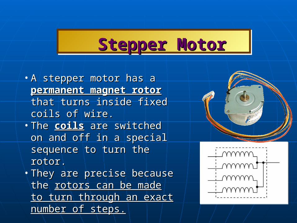
• A stepper motor has a A stepper motor has a permanent permanent magnet rotormagnet rotor that turns inside that turns inside fixed coils of wire.fixed coils of wire.
• The The coilscoils are switched on and off in are switched on and off in a special sequence to turn the rotor.a special sequence to turn the rotor.
• They are precise because the They are precise because the rotors rotors can be made to turn through an can be made to turn through an exact number of steps.exact number of steps.
Stepper MotorStepper Motor

• A solenoid also produces a linear A solenoid also produces a linear movement.movement.
• It consists of a It consists of a coil of wirecoil of wire with a with a plungerplunger in the centre. When the in the centre. When the current flows through the coil, it current flows through the coil, it creates a magnetic field, causing creates a magnetic field, causing the plunger to move through the the plunger to move through the coil.coil.
SolenoidSolenoid

• A relay is a switch which is A relay is a switch which is operated by a small solenoid. operated by a small solenoid.
• The relay allows a The relay allows a low voltage low voltage circuit called the primary circuit circuit called the primary circuit to control a high voltage circuit to control a high voltage circuit called the secondary circuit.called the secondary circuit.
• It also allows high current devices It also allows high current devices to be switched on and off by a to be switched on and off by a circuit which uses a much smaller circuit which uses a much smaller current.current.
RelayRelay
NC
NO
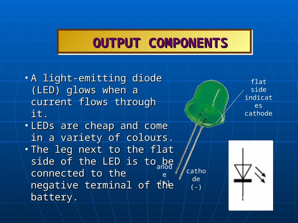
• A light-emitting diode (LED) glows A light-emitting diode (LED) glows when a current flows through it.when a current flows through it.
• LEDs are cheap and come in a LEDs are cheap and come in a variety of colours. variety of colours.
• The leg next to the flat side of the The leg next to the flat side of the LED is to be connected to the LED is to be connected to the negative terminal of the battery.negative terminal of the battery.
OUTPUT COMPONENTSOUTPUT COMPONENTS
anode
cathode
anode (+) cathode
(-)
flat side indicates cathode

• Diodes allow an electric current Diodes allow an electric current to flow through in one direction to flow through in one direction only.only.
• They are used in circuits for They are used in circuits for controlling the flow of the controlling the flow of the current.current.
• A standard semiconductor diode A standard semiconductor diode does not light up when current does not light up when current flows through it.flows through it.
OUTPUT COMPONENTSOUTPUT COMPONENTS
anode
cathode
anode (+)
cathode (-)

Components and UsesComponents and Uses
Components Application and Uses
Motor Produces low cost rotary motion that does not required speed control. Used in children’s toys
Buzzer For producing sound. Has built-in signal generator and a pre-designed tone. Used in door bells.
Bulb This lights up to give bright light. It is used in torches
Components and UsesComponents and Uses
Components Application/ Uses
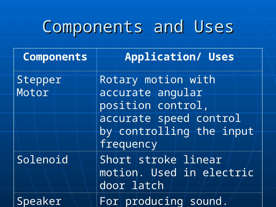
Stepper Motor Rotary motion with accurate angular position control, accurate speed control by controlling the input frequency
Solenoid Short stroke linear motion. Used in electric door latch
Speaker For producing sound. Requires signal source

Components and UsesComponents and UsesComponents Application and Uses
Cell/ Battery Source of electricity (Direct Current - DC). Used in toys
Filament light bulb
Lighting.Used in torch light
Variable resisitor
Provides variable voltage in a voltage divider circuit. Adjust the gain of an amplified circuit
Resistor Controls or limits the current flowing in a circuit

Components and UsesComponents and UsesComponents Application and Uses
Light- dependent resistor
High resistance in the dark, low resistance when exposed to light. Used in automatic light switch circuit.
Thermistor High resistance when cold, low resistance when hot. Used in temperature heater/ oven control circuit
Microphone For picking up sound wave

Components and UsesComponents and UsesComponents Application and Uses
Capacitor Smoothens fluctuating voltage from a rectifier and delay or timing circuit. Used with for electronic differentiation and integration
Light-emitting diode (LED)
Indicator lights for instrument panel and home appliances. Used Exit sign and in traffic lights.
Components and UsesComponents and UsesComponents Application and Uses
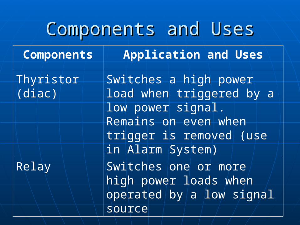
Thyristor (diac)
Switches a high power load when triggered by a low power signal. Remains on even when trigger is removed (use in Alarm System)
Relay Switches one or more high power loads when operated by a low signal source

Draw a simple electrical (light) circuit to Draw a simple electrical (light) circuit to show: (a) its components and (b) its symbols show: (a) its components and (b) its symbols
at its switch-off positionat its switch-off position
Include energy source Battery, light bulb and a switch
(a) (b)

How are components temporary How are components temporary connected in a circuitconnected in a circuit
• Components can be temporarily connected using terminal blocks.
• The plastics covering of the wires must be removed from the ends before they are inserted in the terminal blocks.
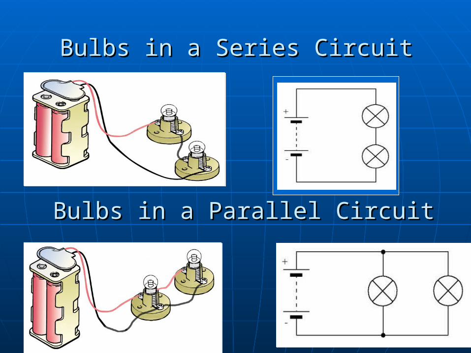
Bulbs in a Parallel CircuitBulbs in a Parallel Circuit
Bulbs in a Series CircuitBulbs in a Series Circuit
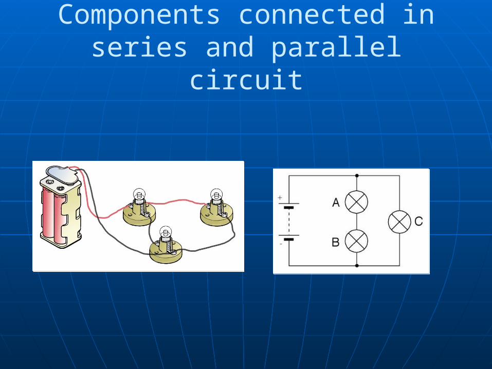
Components connected in series and parallel circuit
A
B
C

What is a transistor?What is a transistor?
•The transistor is an automatic switch that can be operated by a sensor and has three legs called the base, collector and emitter.
•Sensor is connected to the base; positive terminal of the battery towards the collector; negative terminal towards the emitter.

Draw the transistors and its symbolDraw the transistors and its symbol
Transistors Symbol
Positive
negative
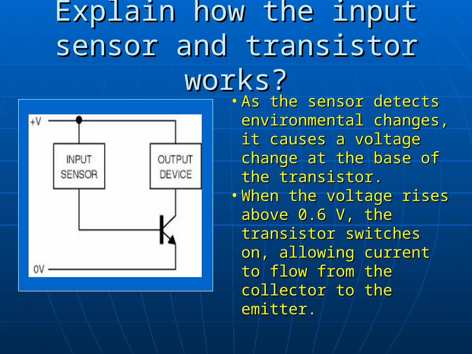
Explain how the input sensor Explain how the input sensor and transistor works?and transistor works?
• As the sensor detects As the sensor detects environmental changes, it environmental changes, it causes a voltage change causes a voltage change at the base of the at the base of the transistor.transistor.
• When the voltage rises When the voltage rises above 0.6 V, the above 0.6 V, the transistor switches on, transistor switches on, allowing current to flow allowing current to flow from the collector to the from the collector to the emitter.emitter.

What is an open loop system?What is an open loop system?
• In an automatic cooling system, when a thermistor (input) senses a rise in the temperature, a propellor blade (output) connected to a motor is turned on by the transistor. When the temperature falls, the transistor switches off.
• This is an open loop control system because the fan does not actually cool the air.
INPUT PROCESS OUTPUT
thermistor transistor fan
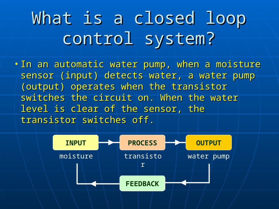
What is a closed loop control What is a closed loop control system?system?
INPUT PROCESS OUTPUT
moisture transistor water pump
FEEDBACK
• In an automatic water pump, when a moisture In an automatic water pump, when a moisture sensor (input) detects water, a water pump (output) sensor (input) detects water, a water pump (output) operates when the transistor switches the circuit operates when the transistor switches the circuit on. When the water level is clear of the sensor, the on. When the water level is clear of the sensor, the transistor switches off.transistor switches off.
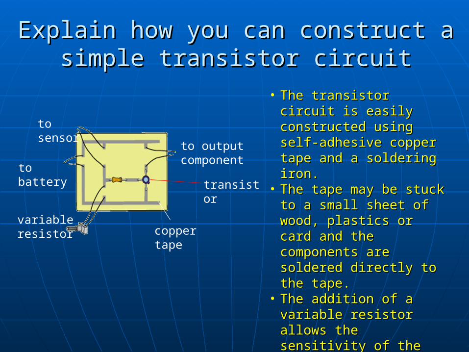
Explain how you can construct a simple Explain how you can construct a simple transistor circuittransistor circuit
to output component
to battery transistor
copper tape
variable resistor
to sensor
• The transistor circuit is The transistor circuit is easily constructed using easily constructed using self-adhesive copper self-adhesive copper tape and a soldering tape and a soldering iron.iron.
• The tape may be stuck The tape may be stuck to a small sheet of wood, to a small sheet of wood, plastics or card and the plastics or card and the components are components are soldered directly to the soldered directly to the tape.tape.
• The addition of a The addition of a variable resistor allows variable resistor allows the sensitivity of the the sensitivity of the circuit to be adjustedcircuit to be adjusted

• A very small current at the base will switch on the transistor, A very small current at the base will switch on the transistor, allowing a much larger current to flow between the collector allowing a much larger current to flow between the collector and emitter.and emitter.
BIPOLAR TRANSISTORBIPOLAR TRANSISTOR

• The base of a transistor is usually connected to a sensor, The base of a transistor is usually connected to a sensor, such as a light or temperature sensor, which determines the such as a light or temperature sensor, which determines the amount of current flowing into the base.amount of current flowing into the base.
• When the sensor allows enough current to flow, the When the sensor allows enough current to flow, the transistor switches on.transistor switches on.
BIPOLAR TRANSISTORBIPOLAR TRANSISTOR
• A resistor is normally A resistor is normally connected to the base of a connected to the base of a transistor to prevent it from transistor to prevent it from being damaged by too much being damaged by too much current.current.

• In a P-N-P transistor, current is allowed to flow from the In a P-N-P transistor, current is allowed to flow from the emitter to the base and from the emitter to the collector.emitter to the base and from the emitter to the collector.
BIPOLAR TRANSISTORBIPOLAR TRANSISTOR
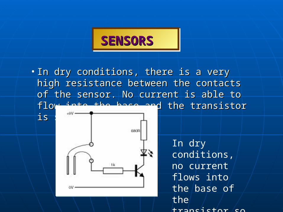
• In dry conditions, there is a very high resistance In dry conditions, there is a very high resistance between the contacts of the sensor. No current is able to between the contacts of the sensor. No current is able to flow into the base and the transistor is switched off.flow into the base and the transistor is switched off.
SENSORSSENSORS
In dry conditions, no current flows into the base of the transistor so the LED is off.
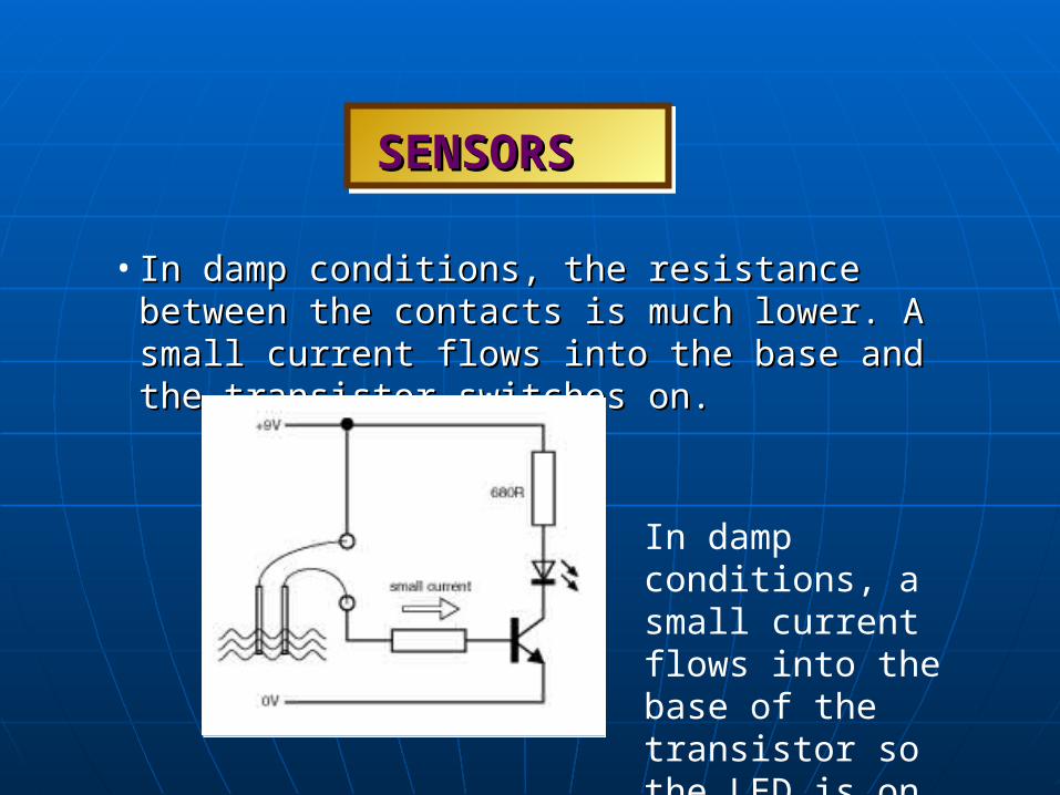
• In damp conditions, the resistance between the contacts is In damp conditions, the resistance between the contacts is much lower. A small current flows into the base and the much lower. A small current flows into the base and the transistor switches on.transistor switches on.
SENSORSSENSORS
In damp conditions, a small current flows into the base of the transistor so the LED is on.

• INPUT-PROCESS-OUTPUT diagram for a moisture- INPUT-PROCESS-OUTPUT diagram for a moisture- sensing circuit.sensing circuit.
SENSORSSENSORS
INPUT PROCESS OUTPUT
probes transistor LED/buzzer
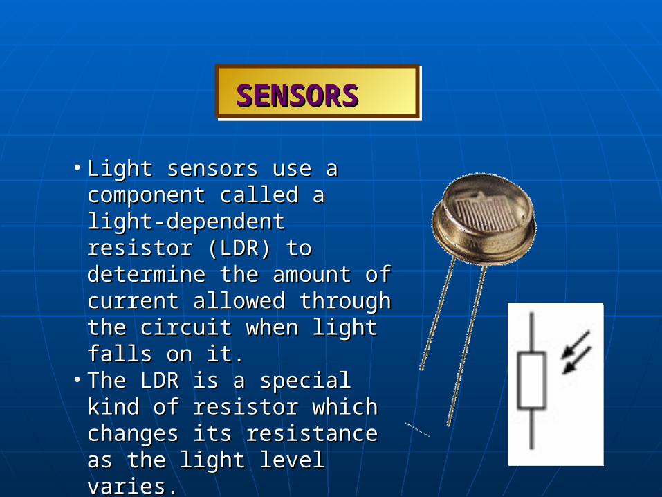
• Light sensors use a component Light sensors use a component called a light-dependent resistor called a light-dependent resistor (LDR) to determine the amount of (LDR) to determine the amount of current allowed through the current allowed through the circuit when light falls on it.circuit when light falls on it.
• The LDR is a special kind of The LDR is a special kind of resistor which changes its resistor which changes its resistance as the light level varies.resistance as the light level varies.
• The LDR is connected to the base The LDR is connected to the base of the transistor.of the transistor.
SENSORSSENSORS
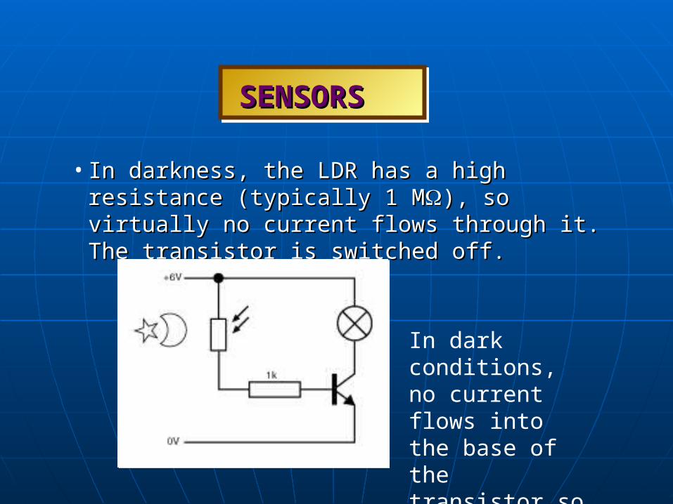
• In darkness, the LDR has a high resistance (typically 1 In darkness, the LDR has a high resistance (typically 1 MM), so virtually no current flows through it. The ), so virtually no current flows through it. The transistor is switched off.transistor is switched off.
SENSORSSENSORS
In dark conditions, no current flows into the base of the transistor so the filament bulb is off.

• In bright light, the LDR has a low resistance (typically In bright light, the LDR has a low resistance (typically 270 270 ), allowing a larger current to flow. As the light ), allowing a larger current to flow. As the light level increases, the flow of current through the LDR level increases, the flow of current through the LDR increases, switching on the transistor.increases, switching on the transistor.
SENSORSSENSORS
In light conditions, current flows into the base of the transistor so the filament bulb is on.

• INPUT-PROCESS-OUTPUT diagram for a light-sensing INPUT-PROCESS-OUTPUT diagram for a light-sensing circuit.circuit.
SENSORSSENSORS
INPUT PROCESS OUTPUT
light-dependent
resistor
transistor bulb/LED/buzzer

• The amount of light needed to The amount of light needed to switch on the transistor in the switch on the transistor in the light-sensing circuit can be light-sensing circuit can be adjusted by adding a resistor adjusted by adding a resistor between the base and negative between the base and negative side of the circuit.side of the circuit.
• The lower the resistor value, the The lower the resistor value, the greater the amount of light greater the amount of light needed to switch on the transistor.needed to switch on the transistor.
• This arrangement of the LDR and This arrangement of the LDR and resistor is called a potential resistor is called a potential divider.divider.
SENSORSSENSORS

• To switch on the transistor in To switch on the transistor in dark conditions and off in dark conditions and off in light conditions, the LDR and light conditions, the LDR and the resistor in the potential the resistor in the potential divider can be reversed by divider can be reversed by swapping positions.swapping positions.
SENSORSSENSORS

• For extra sensitivity, two transistors may be used.For extra sensitivity, two transistors may be used.
SENSORSSENSORS
Darlington Pair for extra sensitivity (very small current can pass through

• Temperature sensors use a Temperature sensors use a component called a thermistor to component called a thermistor to determine the amount of current determine the amount of current allowed through the circuit when allowed through the circuit when temperature changes.temperature changes.
• The thermistor is a special kind of The thermistor is a special kind of resistor that changes its resistance resistor that changes its resistance as the temperature varies.as the temperature varies.
• It is connected between the base It is connected between the base of the transistor and the positive of the transistor and the positive side of the circuit.side of the circuit.
SENSORSSENSORS
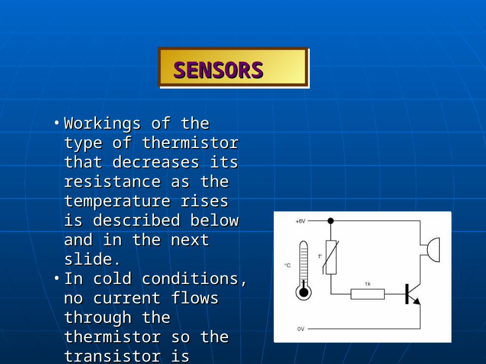
• Workings of the type of Workings of the type of thermistor that decreases its thermistor that decreases its resistance as the temperature resistance as the temperature rises is described below and rises is described below and in the next slide.in the next slide.
• In cold conditions, no current In cold conditions, no current flows through the thermistor flows through the thermistor so the transistor is switched so the transistor is switched off.off.
SENSORSSENSORS

• As the temperature rises, the As the temperature rises, the flow of current through the flow of current through the thermistor increases, switching thermistor increases, switching on the transistor. on the transistor.
SENSORSSENSORS
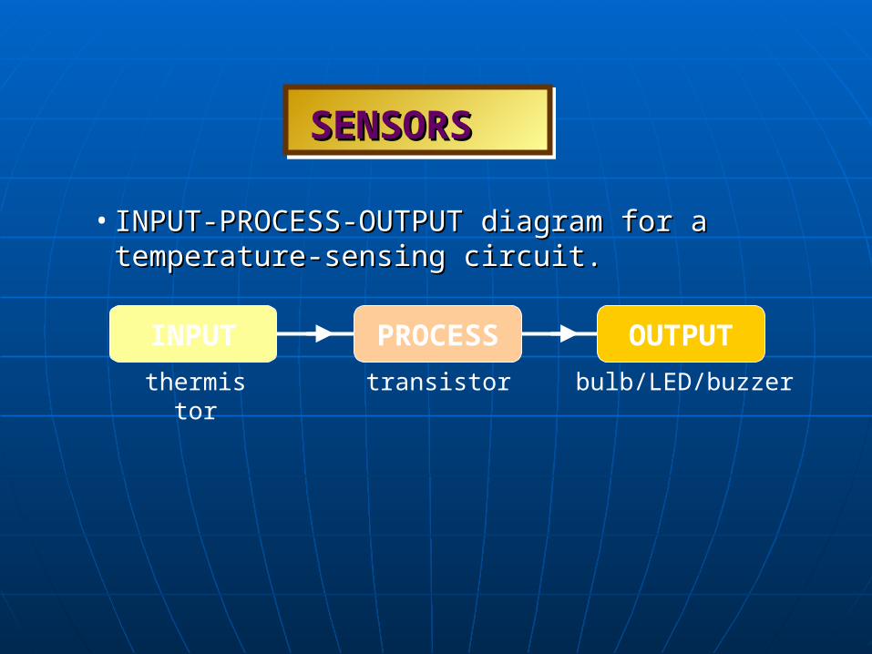
• INPUT-PROCESS-OUTPUT diagram for a temperature-INPUT-PROCESS-OUTPUT diagram for a temperature-sensing circuit.sensing circuit.
SENSORSSENSORS
INPUT PROCESS OUTPUT
thermistor transistor bulb/LED/buzzer

• To adjust the sensitivity, a To adjust the sensitivity, a potentiometer may be connected potentiometer may be connected between the base and the negative between the base and the negative track.track.
• The value printed on a potentiometer The value printed on a potentiometer states its resistance value between the states its resistance value between the two outer contacts. By rotating the two outer contacts. By rotating the shaft, the resistance between the shaft, the resistance between the middle contact and either of the outer middle contact and either of the outer contacts is adjusted.contacts is adjusted.
SENSORSSENSORS

• For extra sensitivity, two transistors may be used.For extra sensitivity, two transistors may be used.
SENSORSSENSORS
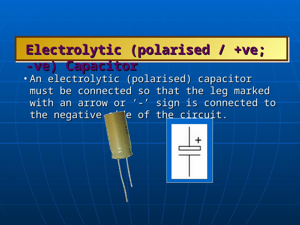
• An electrolytic (polarised) capacitor must be connected so An electrolytic (polarised) capacitor must be connected so that the leg marked with an arrow or ‘-’ sign is connected to that the leg marked with an arrow or ‘-’ sign is connected to the negative side of the circuit.the negative side of the circuit.
Electrolytic (polarised / +ve; -ve) CapacitorElectrolytic (polarised / +ve; -ve) Capacitor

non-electrolytic (non-polarised) capacitornon-electrolytic (non-polarised) capacitornon-electrolytic (non-polarised) capacitornon-electrolytic (non-polarised) capacitor
• A non-electrolytic capacitor (non-polarised) can be A non-electrolytic capacitor (non-polarised) can be connected either way around.connected either way around.