Embed Size (px)
Citation preview

Basic ConstructionSurveying
Georgia Department of TransportationCopyright 2000

2
Reproduction of any or all portions of this Manual is prohibited without the written consent of the Georgia Department ofTransportation, Office of Personnel.

TABLE OF CONTENTS
Chapter 1: Survey Stakes
Chapter 2: Measurement of Distances
Chapter 3: Slope Measurements
Chapter 4: Common Mistakes in Reading and Recording LinearMeasurements
Chapter 5: Leveling
Chapter 6: Notekeeping
3

4
1-1. a. Survey stakes
1-2. c. Hubs
1-3. d. 50 foot

5
CHAPTER 1: SURVEY STAKES
Survey stakes are the survey party's means of communication. The survey stakes most frequently used by theDepartment of Transportation are the wooden 1" x 2" x 18" stakes, although other sizes are available. Surveystakes are normally set by a survey party to establish and designate a work point or reference point on the ground.Appropriate information is written on the stake with keel, felt-tip markers, or other devices, instructingconstruction personnel as to the work to be performed. Since these stakes are the actual physical basis forconstruction, it is essential that they be set at the correct location with the data written on them in a legible andunderstandable manner.
2" x 2" wooden stakes, called "hubs," are available to mark important survey points, work points, or referencepoints, which are to remain in place for future use. These hubs are normally driven flush with the ground afterwhich a survey tack is set in the top of the hub to mark the exact survey point. The hub is driven flush to make itless susceptible to damage and its location is usually marked by a "guard" or "witness" stake. The guard stake willusually have sufficient information written on it to identify the point.
F 8
66
36
2.1
This figure represents the amount of fill materialthat must be put in place beginning at the stake.
This figure represents the distance from theconstruction stake to the construction centerline.
This figure represents the slope of the fill material(for every 2� you go horizontally, you go 1�vertically).
33+50
This figure represents a station, the distancethat this particular stake is from thebeginning of the project (EX: 3350� frombeginning of project).
FRONT OF STAKE BACK OF STAKE
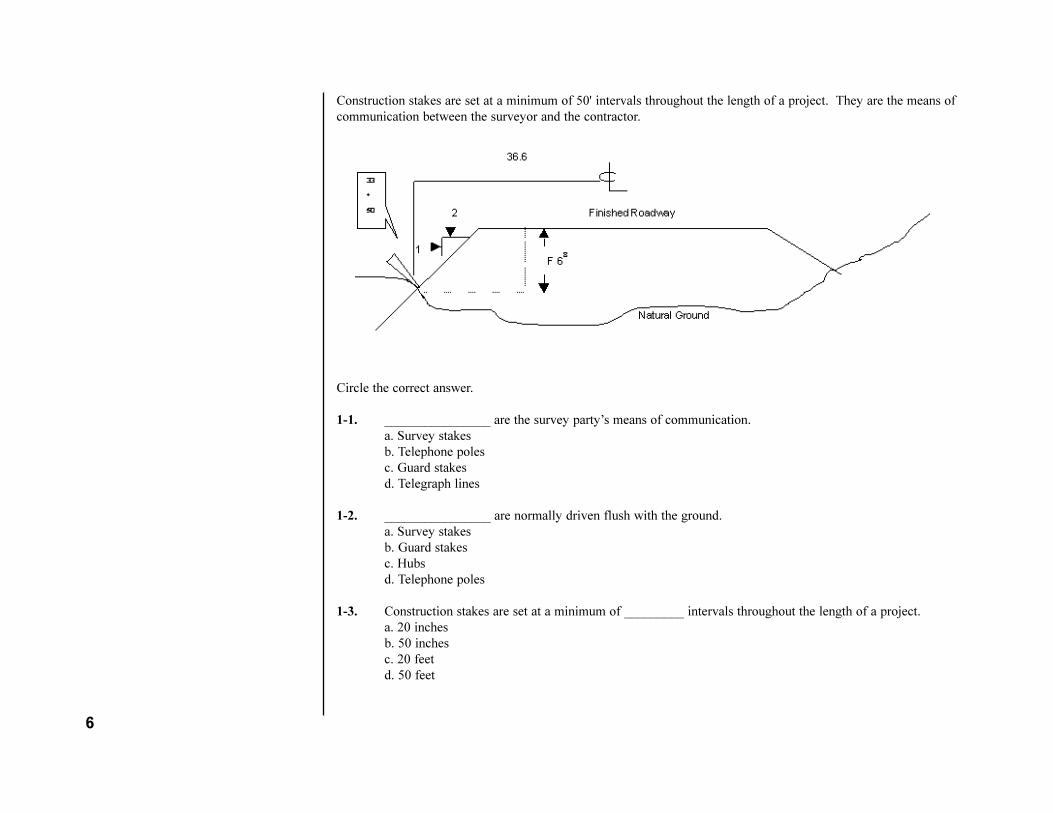
Construction stakes are set at a minimum of 50' intervals throughout the length of a project. They are the means ofcommunication between the surveyor and the contractor.
Circle the correct answer.
1-1. ________________ are the survey party�s means of communication.a. Survey stakesb. Telephone polesc. Guard stakesd. Telegraph lines
1-2. ________________ are normally driven flush with the ground.a. Survey stakesb. Guard stakesc. Hubsd. Telephone poles
1-3. Construction stakes are set at a minimum of _________ intervals throughout the length of a project.a. 20 inchesb. 50 inchesc. 20 feetd. 50 feet
6

CHAPTER 2: MEASUREMENT OF DISTANCES
Measurements are usually made with a steel tape called a chain; however, a cloth tape may be used at times formeasuring distances when accuracy is not critical. The steel chains used in construction surveying are normally100' long, graduated in 1-foot increments, except for the first and last foot, which is graduated in tenths andhundredths of a foot.
TYPICAL GRADUATIONS ON A STEEL CHAIN
The steel chains used in construction surveying are commonly called "cut chains." This terminology is usedbecause in order to obtain a partial distance other than a whole foot, the front chain person must "cut" someportion of the first foot in order to read a true distance. One can readily see that the distance from the zero (0) onthe chain to the 64-foot mark is 64 feet. Now assume that the back chain person held the 64-foot mark on a pointand the front chain person read 4 marks to the right of the one-tenth mark, or 0.14 feet. This would mean that themeasured distance is 64 feet minus 0.14 feet (64.00' - 0.14') or 63.86 feet. By the same token, if the back chainperson held 64 feet on a point and the front chain person cut 0.94 feet on another point, the distance between thetwo points would be 63.06 feet (64.00' - 0.94'= 63.06'). Normally, the back chain person would call out thedistance he is holding ("Holding 64 feet") and the front chain person would call out the distance he is cutting("Cutting 94 hundredths"). Both chainmen would mentally compute the distance, one would call it out (63.06feet") and the other would acknowledge its correctness. Both chainmen should always be mindful of the distancesbeing measured, particularly long distances where lack of attention could result in a measurement being recordedone or more chain lengths in error.
MEASUREMENT OF HORIZONTAL DISTANCES
In surveying, the distance between two points means the horizontal, or level, distance. Construction plans areprepared showing distances as horizontal. Two methods are commonly used to measure the horizontal distancebetween two points.
7

The first method is to measure the distance by holding the tape in a horizontal position. This method provides adirect determination of the distance.
The second method, slope chaining, will be discussed later in the text. Unless the two chaining points are at thesame elevation, this method also involves the use of plumb bobs to transfer the distance to the ground, or chainingpoints.
A plumb bob is a device usually made of brass with replaceable steel tip and attached to a special cord, which maybe used to transfer a point vertically. It is commonly used in measuring distances and in alignment operations.The customary way to hold the plumb bob when providing a vertical line of sight is to let the string drape acrossthe forefinger and then clamp the string with the thumb.
8

The importance of having both ends of the chain at the same elevation when measuring a horizontal distancecannot be over emphasized. One of the most common errors in chaining is failure to hold both ends of the chain atthe same level.
Holding a chain level requires practice. A good chain person will use guides such as finish lines on buildings andwater surfaces in leveling the chain. Also, he will readily use a hand level if other reliable guides are not available.The drawing below shows how errors in determining horizontal distances can occur as a result of failure to keepboth ends of the chain level.
9

When chaining by the usual method of holding the chain horizontally, and steep or irregular terrain is encountered,it may be necessary to measure a distance by series of individual horizontal measurements, each less than a chainlength.
The length of each horizontal increment would be controlled by the slope of the terrain; steeper terrain wouldnaturally result in shorter chaining increments. One method of measuring steep terrain would be to lay the chainout for its entire length along the line to be measured, then the back chain person would hold the 100-foot markover the beginning point, Point "a", at a convenient elevation using a plumb bob. The front chain person wouldthen take position at a point, Point "b", along the line so that the chain could be held horizontally and mark thedistance on the ground at some full foot mark (for instance, at the 65-foot mark).
The process would then be repeated by having the back chain person come ahead to Point "b" and hold the same65-foot mark on the chain over Point 'b" at some convenient elevation. The front chain person would thenprogress ahead to a point where the chain could be held horizontally near the ground, Point "c", and again mark thedistance on the ground at some full foot mark (for instance, at the 33-foot mark).
The process would be repeated as necessary until the front chain person can mark a point at the zero (0) end of thechain, Point "D". At this point one chain length (100.00 feet) would have been measured. The entire processwould then be repeated for as many chain lengths as necessary to measure the entire distance. Measurement ofdistances in the above manner is called "breaking the chain" or "breaking tape".
10

You will note that the distance to be measured was over two full chain lengths. In that particular example, the twofull lengths were measured by "breaking the chain" as necessary to traverse the terrain. Then with the back chainperson on Point "f" holding 25 feet, the front chain person read, or cut, 0.35' to complete the measurement.
You will recall from previous discussions in this text that in this example, the back chain person would call out"holding 25 feet," the front chain person would call out "cutting 35 hundredths," and both would mentally computethe distance (25.00' - 0.35' = 24.65'), with one chain person calling out "24.65 feet," and the other chain personverifying this figure. Then the two chain lengths (200.00 feet) could readily be added to the partial chin length of24.65 feet for the total measured distance of 224.65 feet. The big advantage of "breaking the chain" is that it iseasy to keep account of the number of full chain lengths, 100.00 feet, measured.
One can readily see that the distances could have been measured individually (a to b = 35 feet, b to c = 32 feet, cto d = 33 feet, etc) and then totaled for the overall horizontal distance; however, this would require additionalcomputations whereas "breaking the chain" lets you utilize the chain itself to sum the partial distances necessary tomake up a chain length. As previously noted, "breaking the chain" has the advantage of working in even chainlengths (100 feet) in lieu of odd distances.
The above text discussed in detail horizontal measurements on uphill terrain; however, the same principles applyfor horizontal measurements of a downslope. The only variation would be that the back chain person would beworking at or near ground elevation and the front chain person would be doing the plumbing.
Horizontal measurement with the chain and plumb bobs is a process which requires skill and care. It takesconsiderable practice and experience to chain accurately and efficiently. It is easier to chain downhill than uphill.
When chaining downhill, the back chain person can hold the tape steady at the ground level point, while the frontchain person applies the required tension or pull to the chain, and then plumbs exactly over the pint to bemeasured.
The front chain person is applying the tension and doing the plumbing, thus it is easier for him to maintain hisbalance. The back chain person has no balance or plumbing problem since he is working at ground level and canposition himself solidly while holding the chain over the point. When chaining uphill, the back chain person mustkeep himself in balance and hold his plumb bob exactly and steadily over the pint while the front chain personapplies the required tension. This tends to pull the back chain person off balance.
SUGGESTED CHAINING PROCEDURES
When chaining, both chainmen should position themselves so that they can gradually apply the required tension onthe chain without losing their balance. One should never apply a sudden or irregular pull on the chain whileattempting to make a measurement; to do so, could cause the other chain person to lose his balance. The chain
11

person should always stand so that he can look squarely across the graduations on the chain when reading ameasurement.
When using a plumb bob, the chain person should get a firm grip on the chain with one hand, and manipulate theplumb bob with the other. Normally one should not use the hand controlling the plumb bob to apply tension to thechain. The leather throngs on the chain ends can be wrapped around the chain person's hand to provide a steadygrip to apply tension in most instances.
However, when "breaking the chain" or measuring distances less than a chain length, it will be necessary to gripthe chain itself.
Care should be exercised so as not to permanently bend or "kink" the chain when gripping it. Generally the backchain person can drape the plumb bob string across the chain on the appropriate foot mark, and clamp the stringposition with the thumb and forefinger of one hand while applying tension to the chain with the other. Care should
12
2-6. should not
2-7.This terminology is used becausepartial measurements, i.e. less thana whole foot, must often be made.The front chain person must "cut"some portion of the first foot inorder to read a true distance.
2-8. to transfer a point vertically

be given to ensure that the plumb bob string remains in the correct position on the chain during the measurementprocess. When using the plumb bob to make a measurement, the plumb bob tip should be held approximately 1/8of an inch above the chaining point; if held much higher, it is difficult to position the tip directly over the chainingpoint.
In general, the chain person should not try to plumb higher than his chest because it is very difficult to maintainbalance and provide a steady pull on the chain above chest level. The chain person should be careful to stand farenough off line to allow line of sight for the transit person.
When checking measured distances, the front and back chain person should exchange positions, or if possible, twoother chain person should be used. Also, when checking measurements greater than one chain length, differentintermediate chaining points should be used.
Answer the questions.
2-1. A cloth tape may be used in surveying when ___________________.a. accuracy is not importantb. accuracy is importantc. when it�s full length onlyd. when it�s half length only
2-2. Steel chains are commonly called _________________ in construction.a. steel rivetsb. cut stakesc. cut chainsd. measuring chains
2-3. If the front chain person reads three marks to the right of the two-tenths mark and the back chain person has his point marked at 75, what is the distance?
2-4. If the back chain person calls �Holding 52 feet,.� and the front chain person calls �cutting 37-hundreths (.37),� what is the distance they both should acknowledge?
2-5. A plumb is used to:a. transfer grades to a hubb. transfer grades to a stakec. transfer a point horizontallyd. transfer a point vertically
13

2-6. The chain person (should/should not) plumb higher than his chest.
2-7. Why are the chains commonly used in highway construction surveying called �cut chains?�
2-8. Why are plumb bob�s used when chaining?
14

CHAPTER 3: SLOPE MEASUREMENTS
In some instances it may be easier and more accurate to make a slope measurement rather than a horizontalmeasurement. The cases are usually confined to distances of a chain length or less and on steep terrain.
There are two common methods of computing the horizontal distance from a slope measurement.
The first method is by measuring a slope distance directly between two points when the difference in elevation ofthe two points is known.
You can see that the horizontal distance can be readily computed based on the right triangle rule, that the square ofthe hypotenuse is equal to the sum of the squares of the other two sides. It is assumed that the reader is familiarwith this rule from the Basic Highway Mathematics Course, or from some other source, and development of thisrule will not be discussed.
Suppose one needs to determine the horizontal distance between Points A and B, and it is determined that thedifference in elevation between Point A and Point B is 8.26 feet. Then using a chain the distance between Point Aand Point B is measured to be 73.84 feet. This is the slope distance of Line AB. Remember the measurement is adirect measurement; it is not a horizontal measurement. You can see that a right triangle has been constructed withLine AB as the hypotenuse. Recalling the rule mentioned above, it can be seen that AB2= AC2 + BC2 or solvingthis equation for the horizontal distance AC2 = AB2-BC2. Substituting in the above numbers, AC2 = (73.84)2 -(8.26)2 = 5452.35 - 68.23 = 5384.12. Therefore Line AC = 5384.12, AC = 73.38 feet.-The most frequently used method of slope measurement in construction surveying involves the use of the transit to
15
2-1. a-accuracy is not important
2-2. c-cut chains
2-3. 75 feet - .23 feet = 74.77 feet
2-4. 52 feet - .37 = 51.63 feet
2-5. c-transfer a point horizontally

determine the angle between a horizontal line of sight at the transit axis, and a slope line from the transit axis tothe point in question.
This angle is referred to as the "vertical angle." The transit will be discussed later on in this text, but for purposesof this article, it will be sufficient to say that the transit is an engineering instrument capable of measuring bothhorizontal and vertical angles.
The transit is set up over one point, and the vertical angle is measured to the other point. It should be noted thatthis method will work equally well with the transit located on the lower point. The distance is then measureddirectly from the transit telescope axis to the point in question.
One can see that a right triangle has been constructed with the measured slope distance, Line DB, as thehypotenuse. Recalling a basic trigonometric function, one can see that by knowing the vertical angle and thelength of the hypotenuse, the horizontal distance can be computed by use of the Cosine function of a right triangle;Cosine of the angle equals the adjacent side divided by the hypotenuse.
In the right triangle BCD formed, the cosine of the vertical angle equals Line DC/Line BD. As an example,assume that the transit was set up over Point A, the vertical angle was measured to be 7° - 00', and the slopedistance DB was measured to be 81.84 feet. Then the horizontal distance DC could be computed as follows:Cosine 7° - 00' = DC DC= 81.84 X Cosine 7° - 00' = 81.84 X .99255 = 81.23
When using the transit in conjunction with slope measurements, the chain person should exercise care not to16
3-1.1-Determine the elevation ofvarious points2-determine distances betweenpoints
3-2. may
3-3. can

disturb the instrument when chaining from the telescope axis. The chain person should also remember to base hismeasurement from the telescope axis, not the point of the ground, since the vertical angle is measured about thetelescope axis.
One variation of the above text covering slope measurements should be mentioned here. On occasion it may bedesirable to determine a horizontal distance by using the vertical angle and slope measurement when anobstruction blocks the instrument person's direct line of sight to the other point.
By use of a plumb bob, the front chain person can transfer the point on the ground (Point B) vertically to someconvenient elevation (Point E) so that the instrument person has an unobstructed view. Then a new vertical angleand slope distance (Line DE) can be measured. Using the principles discussed earlier in this article, one couldreadily compute the horizontal distance (Line DC). For example, assume the vertical angle to be 4° - 15' and themeasured slope distance DB to be 81.45 feet. The horizontal distance DC is equal to the cosine of 4° -15'multiplied by 81.45 feet, or 81.23 feet.
Care should be taken to ensure that the front chain person holds the chain and plumb bob at the exact line of sightas determined by the vertical angle. This is extremely critical. For as one can see from the above examples, themeasured slope distances for the same horizontal line vary significantly as the slope angle changes. The amount oferror in computing a horizontal distance which results from failure to hold the chain at the exact line determined bythe vertical angle drastically increases as the size of the vertical angle increases
17

Answer the questions.
3-1. What are two common methods of measuring slopes, other than by "breaking chain?"1.________________________________________________2.________________________________________________
3-2. It (may/may not) be easier and more accurate to make a slope measurement rather than a horizontalmeasurement.
3-3. Horizontal distance (can/cannot) be readily computed based on the right triangle rule.
18

CHAPTER 4:COMMON MISTAKES IN READING AND RECORDING LINEARMEASUREMENTS
Reading the Wrong Foot Mark
This is a careless mistake, which can usually be avoided by alertness and concentration by the chain person.
Transposing Figures
Sometimes a chain person may mentally transpose figures before calling them out, or the notekeeper maytranspose them when recording them. For example, he may call out, or record 42.63 when he should have calledout 42.36. Alertness and concentration will usually eliminate this type of mistake.
Reading the Chain Upside Down
When reading a chain upside down, certain numbers can easily be misread for others. For example, a 6 may bemisread as a 9, 86 may be misread for 98, etc. One way to avoid this mistake is to note the adjacent footmarks onboth sides of the footmark being used to see that the number is in sequence. However, the best solution is to avoidreading the chain in an upside down position.
Subtracting incorrectly when the front chain person cuts a partial foot.
This mistake can be minimized by both chainmen making the subtraction mentally in order to check each other. Inorder to do this, both chainmen must call out their readings for the measurement.
Principal Sources of Error in Linear Measurements
An error may be defined as the difference between an observed value and the true; or, as the variation inobservations, measurements, or calculations, of a quantity. This section will discuss some of the principal errorsmade in chaining and their effect on the measurements. In general, these errors tend to result in the recorded, ormeasured, distances being greater than the actual distance.
Tape Not Stretched Straight
Chainmen should always be sure that the chain is free to be stretched directly between the two chaining points.The chain should not be allowed to bend around trees, bushes, boulders, etc., since this would result in the
19

measured distance being too great.
One can readily see the effect of this error on the measured distance as compared to the actual distance.
The wind can blow the chain off line, particularly when plumbing, resulting in the same type error as an obstaclewhich prevents the chain from being stretched straight between two points. The magnitude of this type error canbe reduced by supporting the chain on line at one or more intermediate points.
Incorrect Alignment
When measuring distances greater than a chain length, or when breaking the chain, the intermediate chainingpoints must be lined by eye or by an instrument. Usually, the back chain person can stand on line and line thefront chain person to within 0.2 feet to 0.3 feet of true line.
20

One can see that if the chain is lined within 0.5 foot of true line, the error is insignificant when measuring a fullchain length. This error may be computed by utilizing the right triangle rule as previously discussed. One can alsosee that for shorter distances, the alignment becomes more critical. Since this type error is cumulative, it becomesmore significant when multiple chaining points are used in measuring a distance. This type error results in themeasured distance being greater than the actual distance.
Careless Plumbing
This error relates to failure to hold the plumb bob tip directly over the chaining point. This type error is acompensating error in that the measured distance may be greater, or it may be less than the actual distance.Proficient use of the plumb bob requires practice and care. The chainmen should exercise care to ensure that theplumb bob is positioned directly over the chaining point when making a measurement.
Incorrect Length of Chain
Obviously, if a chain is incorrectly marked, it cannot be used to accurately measure distances, unless it isrecalibrated. For purposes of this course, the reader can assume that the chains used in construction surveying aremanufactured to acceptable tolerances and therefore not be concerned with this type error. However, the readershould be aware that this error can exist.
Temperature
The reader should be aware that since chains are manufactured from steel, they are subject to expand and contractwith variations in temperature. Chains are manufactured to be a standard length at 68° F. A good rule of thumb isthat for each 15° F change in temperature, the corresponding change in length of a 100 foot chain will beapproximately 0.01 foot.
Tension and Sag
Chains of 100 feet or less are manufactured to be of standard length when supported throughout the entire lengthon a level surface with 10 pounds of tension applied to its ends. However, this ideal condition is not frequentlyencountered in actual construction. Normally measurements will be made over irregular surfaces, and in mostinstances, the chain will be supported at its ends only. Obviously when the chain is supported at its ends only, itwill sag.
21

Assume Line AB, represents a distance of 100.00 feet as measured with the chain fully supported throughout itslength, and with 10 pounds of tension applied to the chain. If the intermediate support were removed and the same10 pounds of tension applies at the ends, the chain would sag in a fashion similar to the dashed line. If Point Awere held stationary, and the intermediate support removed, the Point B would shift slightly to Point B'. Therefore,with the chain supported at the ends only and Point A held stationary, the only way to move Point B' back to PointB is to apply more tension.
Naturally this tension will have to be more than 10 pounds. A mathematical formula has been developed whichshows that, for the chains normally used in construction surveying and supported at the ends only, a tension of 25-27 pounds must be applied to allow for sag. This text will not discuss development of that formula. It will besufficient for the reader to remember that 25-27 pounds of tension should be applied to the chain when supportedat the ends only.
22
4-2. a-25-27 pounds
4-3. a-63 degrees Fahrenheit
4-4. a-0.01 foot
4-5. should
4-6. c-chain
4-7. c-10

Most construction offices have a tension handle available for the more precise measurements. The tension handleis a spring balance device used to measure the tension applied to a chain. One end connects to the end of thechain, the other end is a handle for gripping and applying tension, and the center section is a spring-loaded slidegraduated in pounds for registering the applied tension directly. The tension handle is not normally used in the dayto day operations of a survey party, but the chain person should use the tension handle enough to keep a feel forthe tension normally required when chaining. Even though the chain is constructed from steel, it has some elasticproperties, and stretches when tension is applied. If the tension is greater or less than the standardized pull, thechain will be correspondingly too long or too short.
Care of the Steel Chain
The chain should be cleaned as necessary at the end of each day's operations to prevent rust. Damp or muddychains should be cleaned, dried, and wiped with an oiled cloth before storing. An occasional wiping with a slightlyoiled cloth is usually sufficient to prevent rust on chains that are only dusty. If some rust spots do accumulate,they can usually be removed by rubbing dry cement on the affected areas.
Care should be taken to prevent bending or kinking the chain. Never bend the chain sharply because this normallyleaves a permanent kink in the chain. Never loop the chain around a survey stake or small sapling when draggingthe chain around a sharp bend. It is best to let the other chain person stand at the point and feed the chain throughhis hands to prevent a sharp bend in the chain.
The front chain person should always look back to see that the chain is clear before pulling ahead for the nextmeasurement; sometimes, when the chain is carelessly laid down, it will form a loop which if pulled tight willcause a kink or possibly a break. Any time a kink is created, it makes the chain more susceptible to breakage atthat point. Vehicles should not be allowed to run over the chain. Rubber tired vehicles can bend the chain, and, obviously,track type vehicles will severely damage a chain.
Answer the questions.
4-1. Name four of the principal sources of error in linear measurements? 1. ___________________________________2. ___________________________________3. ___________________________________4. ___________________________________
23

4-2. The standardized tension, which must be applied to a steel chain when only supported by the ends isa. 25-27 poundsb. 10-12 poundsc. enough to hold up a 200 lb. persond. 100 pond weights
4-3. The temperature standard at which chains are manufactured isa. 63 degrees Fahrenheitb. 32 degrees Fahrenheitc. 15 degrees Fahrenheitd. 63 degrees Celsius
4-4. For each 15 degrees F. change in temperature, the chain change in length, approximatelya. 0.01 footb. 0.001 footc. 1.0 footd. 10.0 foot
4-5. A chain (should/should not) be cleaned at the end of the day's operation.
4-6. A tension handle is used to measure tension applied to a ___________________.a. levelb. transitc. chaind. stake
4-7. The tension to be applied to the chains normally used in construction surveying when the chain issupported throughout the entire length is
a. 150b. 15c. 10d. 100
24

CHAPTER 5: LEVELING
Leveling may be defined as the process of determining the elevations of various points, or determining the verticaldistances between points. An elevation may be defined as the vertical distance above a reference plane, or datum.Mean sea level is the datum most commonly used in leveling; however, in some cases, it may be advantageous toassume, or set, a datum. Various organizations such as the National Geodetic Survey, the U. S. Geological Survey,and the DOT's Office of Location/ Control Surveys Party have conveniently established a network of monuments,called "benchmarks," which are referenced to mean sea level. These benchmarks are the references normally usedto establish the vertical control on highway construction projects.
In the process of accumulating data for the development of a set of roadway plans, the Photogrammetry Unitand/or the Location Unit will establish benchmarks along the project at frequent intervals for use duringconstruction of the project. These benchmarks are usually nails and spikes driven in tree trunks, or X-marks etchedinto some hard and permanent surface such as concrete. The benchmarks are appropriately described on theconstruction plans with the elevations designated.
The Engineer's Level
The engineer's level is an instrument designed to project a level line of sight. Basically, the engineer's levelconsists of a telescope tube designed to impose a set of cross-hairs on the image viewed through the telescope. Aspirit level vial is attached or incorporated into the instrument to allow the tube to be accurately leveled bymanipulating adjusting screws on a foot plate.
25
4-1.tape not stretched straight
incorrect alignment
careless plumbing
incorrect length of chain
temperature
tension and sag

There are three types of levels used in construction surveying: The Wye Level, the Dumpy Level, and the Self-Leveling Level. All are designed to project a level line of sight when used properly.
The Wye LevelThe Wye Level is basically a telescope which is attached to a horizontal bar by two vertical supports. A sensitivespirit level is attached parallel to the telescope for use in leveling the instrument. The horizontal bar is parallel tothe telescope and is mounted on a vertical tapered spindle, which fits down into a conical socket in the levelinghead. 'The leveling head is attached to the foot plate by a ball and socket type connection to allow for movementwhen the leveling screws are turned. The foot plate is threaded to screw onto the tripod head. The characteristic,which distinguishes the Wye level, is the manner in which the telescope is secured to the horizontal bar. Thetelescope is clamped in two Y shaped supports, which are easily opened, so that the telescope may be reversedend-for-end when the instrument is being adjusted. The Y supports are attached to the horizontal bar with capstannuts and at least one Y is adjustable vertically.
The Dumpy LevelThe Dumpy Level is constructed similar to the Wye type level. The basic difference between the, two types ofinstruments is that the telescope is rigidly attached to the horizontal bar on the Dumpy Level, and thus this type ofinstrument cannot be adjusted in the same manner as a Wye Level. However, the cross hair ring and the spirit leveltube may be adjusted on the Dumpy Level.
The Self-Leveling LevelThe Self Leveling type uses an optical system to establish a level line of sight, instead of the spirit level bubbleused in the Wye and Dumpy levels. The optical system consists of three prisms within the telescope, which reflectthe line of sight. The two end prisms are stationary, while the center prism is suspended from the top of thetelescope by wires and is free to swing under the force of gravity. The optical system is designed so that a levelline of sight is maintained as long as the center prism hangs freely, even though the telescope tube may not be trulylevel.
26

The Hand Level The Hand Level is a device commonly used in construction when a great degree of accuracy is not required. TheHand Level is often referred to as a "Locke" Level. An experienced observer can get satisfactory results with theHand Level when the distances involved are approximately 50 feet or less. At distances greater than 50 feet,readings with the Hand Level may be questionable.
The Hand Level is a metal tube with a spirit level tube attached to its top. The metal tube is slotted under the spiritlevel and a cross-wire is positioned across the slot. There is a prism inside the metal tube, which reflects the cross-wire and level bubble when the observer looks into the tube. By tilting the farther end of the instrument up ordown the bubble can be made to appear bisected by the cross-wire. When this occurs, the cross-wire, represents alevel line of sight.
The field of view through a Hand Level is split. The left half shows the level bubble and cross-wire, while the righthalf provides the user an open view of the landscape, level rod, or other objects. The user should remember thatthe level bubble must be on the top side of the tube for proper operation. The cross-wire which, defines the levelline can usually be adjusted by means of two opposing screws.
Leveling RodsLevel rods are normally constructed from strips of wood and graduated in hundredths of feet. The rod mostcommonly used in construction surveying is called the "Philadelphia" rod. The student should be aware that other-types of level rods are made, but they will not be discussed in this text. Level rods are available in several lengths;
27

however, the one commonly used in construction surveying is a three-piece device, which is twelve feet long-whenfully extended. The three sections of the rod are assembled to slide one over the other, and when fully extended,the sections are locked in place by screw clamps.
The above photo shows several views of the Philadelphia level rod. The target shown on the two right hand viewsis not normally used in construction surveying. The face of the rod is painted white with the graduations painted inblack and spaced 0.01 ft. apart. The top of the black graduations are the even hundredths, and thus the top of thewhite graduations are the odd hundredths. The smaller numbers painted black represent tenths of a foot; the largenumbers painted red indicate foot-marks.
Setting Up The LevelWhen setting up the level to take a reading, the tripod legs should be positioned at such an angle as to providestability and a convenient working height. The tripod legs should also be in a position, which leaves the tripod
28

head in a nearly horizontal position; this will facilitate the leveling of the instrument with its leveling screws. Thestudent should practice setting up a tripod without the instrument attached until he gets a fell for the procedure.
An accepted method of setting up the level is to place one tripod leg on the ground while holding the other two asshown in the above photo, and by using a fashion as to make the tripod head nearly horizontal. The tripod legsshould be pressed firmly into the ground for added stability, remembering that the more nearly leveled the tripodhead is kept the less the leveling screws on the instrument will have to be turned
The tripods used for the Wye and Dumpy Levels have threaded heads upon which the instruments are mounted.Tripods used for the Self-Leveling Levels are slightly different. Most have a threaded post, or rod, extendingthrough the tripod head which is used as a means of attaching the instrument.
Care should be taken when attaching the instrument so as not to cross thread or otherwise damage the threads oneither the instrument or the tripod head. The instrument should be attached to the tripod head firmly to prevent anymovement during use, but it should not be attached so tightly to cause the-threads to bind. A tripod cap, which is adevice to cover and protect the threads on the tripod head, should always be attached to the tripod during storageor transportation to prevent damage to the threaded areas.
After the tripod is set, the instrument is leveled by leveling screws. The Wye and Dumpy Levels have four levelingscrews, and they are leveled by centering the bubble in the bubble tube, which is under, and parallel to thetelescope.
Graduations are etched on the bubble tube for ease in exact centering of the bubble. To center the bubble, turn thetelescope until it is aligned with a pair of opposite level screws and turn this pair of screws either both in or both
29

out until the bubble is approximately centered.
The screws should be gripped between the thumbs and forefingers as shown above, and uniformly turned so thatthe thumbs move either toward or away from each other. By turning the screws uniformly in this fashion, onescrew is tightened by the same amount the other is loosened. This tilts the telescope and at the same time supportsthe instrument by maintaining tension on both screws. The level screws should bear firmly on the plate at all times,but should never be so tight as to bind. The inexperienced instrument person has a tendency to apply too muchtension to the leveling screws.
After the telescope has been approximately leveled in the direction of one pair of level screws, the telescopeshould be turned at a right angle to align with the other pair of level screws, and leveled by manipulating that pairof screws as previously described. The telescope is then turned back to align with the first pair of level screws andthe level bubble centered exactly; this procedure is then repeated for the second pair of screws.
Two levelings over each pair of screws should have the bubble centered exactly; however; three or more levelingsmay be necessary for the inexperienced instrumentman. When leveling the instrument, it is not necessary to centerthe bubble exactly on the first leveling. Usually to within one-half to one division is sufficient; then the bubble iscentered exactly on the second leveling. If the instrument is in perfect adjustment, the bubble will remain centeredas the telescope is rotated about its axis.
Bubble movement from a centered position when the telescope is aligned in a direction not parallel to a pair ofscrews indicates the instrument is out of adjustment. Adjustment of the level will not be covered in this text. Slightmovement of the bubble, up one or two divisions, can be tolerated if the bubble is centered prior to taking thereading. In these cases, the bubble can be centered by slightly turning only one of the screws.
In setting up the Self-Leveling Level, the tripod is positioned as previously described in this section. However, the
30

procedure for leveling the instrument is different. Since this type of instrument relies on an optical system using asuspended prism to reflect a level line of sight, it is not necessary that the level tube be truly level when taking areading. The Self-Leveling Level is equipped with a circular bubble vial instead of a bubble tube for use inleveling the instrument.
A right angle prism, or mirror, is usually mounted over the circular bubble vial to allow the instrument person toobserve the bubble from his normal operating position, The bubble need only be inside the circle etched in thecenter of the circular vial for the instrument to operate satisfactorily. Thus the instrument person does not have togo through the time consuming procedure of precisely leveling the telescope tube as required for the Wye andDumpy Levels.
The Self-Leveling Level is equipped with only three leveling screws, each one of which can be adjustedindependently of the other two. When the instrument person has completed his observations and is ready to pick upthe instrument he should always adjust the level screws to make the telescope approximately parallel to the footplate of the instrument. This is easily done by adjusting the level screws until they are all exposed approximatelythe same amount below the level head.
Remember that the level screws should be operated as opposite pairs and be uniformly turned with the thumbsmoving either toward or away from each other on the Wye and Dumpy Levels. By adjusting the level screws tomake the level head parallel to the foot plate, the instrument person will make an equal range of adjustment, up ordown, on the next set up. Also, it is easier to set the instrument up close to horizontal when the telescope is parallelto the tripod head and foot plate. If the foot plate and level head are not close to parallel, some instruments will notfit properly into their cases or boxes.
31

Reading the Rod After the instrument is set up and leveled, the instrument person should check to make sure the cross-hairs in thetelescope are focused before taking a reading. The cross-hairs are focused by moving the eyepiece in or out untilthe most distinct position of the cross-hairs is found. On some instruments the eyepiece may be manually moved inor out, but on most instruments the eyepiece is moved in or out by turning a knurled ring on the end of thetelescope tube nearest the eyepiece.
It is best to use a light background such as the sky or light colored building when focusing the cross-hairs, and theeyepiece should be moved slowly when focusing. After this, turn the telescope toward the level rod and focus onthe rod by turning the knob mounted on the top or side of the telescope tube. You will note that focusing on the roddoes not affect the focus of the cross-hairs.
Once focused on the rod, the instrument person should check for parallax by slowly moving his eye up or downand observing whether the horizontal cross-hair appears to move on the rod. If apparent movement is observed,parallax exists, and further focusing of the cross-hairs is necessary. When apparent movement of the cross-hairs isnot evident, parallax does not exist, and the cross-hairs are properly focused. Once they are properly focused, nofurther adjustment of the cross-hairs will be necessary as long as the same instrument person makes the readingbecause the eyepiece will remain in the correct position for all observations, regardless of their distance from theinstrument. However, it may be necessary to re-focus the cross-hairs when another individual makes a reading. After focusing on the rod, the instrument person should check to see if the bubble is still centered.
On a self-leveling level, the bubble should be within the circle etched on the circular level vial; on either a Wye orDumpy level the bubble should be centered in the tube. If the bubble is off by only one or two divisions, it can becentered by tightening one of the pair of opposite screws, which are more closely aligned with the telescope. If thebubble is off by more than two divisions, it would be advisable to relevel the instrument as described in thepreceding section.
The rod reading is taken directly from the face of the rod, where the horizontal cross-hair appears to intersect theface of the rod. The typical level has one long horizontal cross-hair which appears to be centered in the telescopetube. This is the cross-hair used when leveling. The two shorter horizontal lines are used for stadia readings, whichwill not be covered in this text. The readings are normally made to the nearest one hundredth (.01); however, onoccasion it may be desirable to estimate readings to the nearest five thousandths (.005). After making a reading onthe Wye or Dumpy level, the instrument person should again check the bubble to be sure that it was centeredduring the reading.
Holding the RodThe level rod must be held vertically for the reading to be correct; when the rod is not held plumb, the rod readingwill be a greater number than the correct rod reading.
32

One can readily see that the amount of error increases significantly as the rod is tilted more, and as the reading istaken from nearer the top of the rod. The instrument person can tell whether the rod is vertical in the plane of theline of sight by noting if the rod is being held parallel to the vertical cross-hair, and he can instruct the rodmanaccordingly. However, the instrument person can not determine whether the rod is being held vertical to thedirection of his line of sight.
An excellent means of keeping the rod vertical is for the rodman to balance the rod between his fingers; however,this works only when the wind is not blowing. The rodman can compare the rod to building lines, utility poles,trees, etc., to determine if it is being held plumb.
Also, rod levels are available for use as an aid in holding the rod plumb. A rod level is a device consisting of acircular level vial, or two tubular level vials mounted at right angles to each other, which may be fastened to orheld on the edge of the level rod. When the bubbles are centered, the rod is plumb.
Another means of ensuring that the correct rod reading is observed is called "waving the rod". Waving the rod iswaving or swinging the rod slowly back and forth toward the instrument, using the base of the rod as a pivot point.The instrument person can observe the lowest reading, which is the true vertical reading.
Determining Elevations - LevelingAn elevation has been previously defined in this text as the vertical distance above a reference or datum plane.Governmental agencies have established a network of permanent monuments with known elevations across thecountry. These monuments are called benchmarks.
33

In construction surveying any point with a known elevation can be termed a benchmark. As noted earlier in thistext, the Photogrammetry Unit and Location Unit normally establish a network of benchmarks along constructionprojects when they accumulate data for development of the plans. Definition of several common terms normallyused in leveling will probably be beneficial at this point:
Benchmark (B.M.) - Monument or point with known elevation.
Elevation - Vertical distance above a reference or datum plane.
Backsight (B.S.) - Rod reading taken on a point of known elevation, sometimes called a plus (+) sight.
Foresight (F.S.) - Rod reading taken on a point to determine the elevation on that point, sometimes called aminus (-) sight.
Turning Point (T.P.) - An intermediate reference point used when it is necessary to move the instrumentahead while running a line of levels.
Height of Instrument (H.I.) - The elevation of the level line sight projected by the instrument, when properlyset up.
The photo above illustrates a simple example of determining the elevation of a point. First, note that datum line orreference is shown. For purposes of this example, the datum is set at 0.00 elevation. The benchmark (B.M.) is
34
5-1. c-the vertical distance betweenpoints
5-2. b-vertical distance
5-3.WyeDumpySelf Leveling
5-4. vertical
5-5. 4, 3, 2, 1
5-6. 786.27 + 7.30 = 793.57

shown 92.26. Remember that the elevation of a point is its vertical distance above a datum. You will also recallthat a benchmark is a point with known elevation. So in reality, the elevation of the benchmark would be knownprior to commencing any field work.
The level should be set up at some convenient distance from the benchmark. A good rule of thumb to follow inleveling is to keep all observations to within 300'. Observations in excess of 300' may introduce errors. Theinstrument person should be careful to set up the instrument at a point that is neither too high, nor too low, to readthe level rod when held on the benchmark. Usually a quick check with a hand level before setting up the level willverify whether the rod can be seen from a particular point.
Once the instrument is set up, the instrument is ready to take a rod reading on the benchmark. This reading iscalled a backsight (B.S.) or a plus (+) shot. From the photo above, assume the rod reading on the B.S. is 8.24, onecan readily see that by adding (+) the B.S. (8.24) to the B.M. elevation (92.26), the height of instrument (H.I.) iscalculated to be 92.26 + 8.24 or 100.50. Remember B.S., or plus shots, are always added.
Once the height of instrument is known, the elevation of other points can be determined from that set up as long asa rod reading is visible on the point. If the instrument person is unable to observe a rod reading on the point due todifference in elevation, distance limitations, physical obstructions, etc., it will be necessary to establish one ormore turning points (T.P.) in order to progress to the required points.
A turning point should be a solid, clearly defined point, such as a stake or embedded rock, which is not likely tochange in elevation during the leveling process. It should also be of such configuration that the elevation of thebottom of the rod will not change when the rod is faced in different directions.
To determine the elevation of a point a rod reading is taken on that point. This reading is called a frontshot (F.S.)or minus (-) shot. The elevation of the point is then determined by subtracting the F.S. from the H.I. As in thephoto, the F.S. (2.25) is subtracted from the H.I. (100.50) to determine the elevation of T.P.1 (100.50- 2.25) =98.25. Remember frontshots are rod readings taken to determine the elevations of points; frontshots are alwayssubtracted from the H.I. to calculate elevations.
Using the principles above, one can readily calculate the elevation of T.P. 2 in the above photo. Once the elevationof T.P.1 is determined, the level is then moved ahead and set up. Since the elevation of T.P.1 is known, theinstrument person can take a B.S. on T.P.1, calculate the H.I. for the set up, take an F.S. on T.P.2, and calculate theelevation of T.P.2. Elevation of T.P.1 (98.25') + B.S. (7.35') = H.I. (105.60'). Then the H.I. (105.60') - F.S. (1.42')= the elevation of T.P.2 (104.18'). Using this technique one can progress through as many turning points asnecessary to reach a particular point.
Whenever a line of levels is run involving two or more set ups, the field work should always be checked byrunning a line of levels back to the original B.M. or to another B.M. which has been previously established from
35

the same datum. This will detect significant errors in the observations.
Answer the questions.
5-1. Leveling may be defined as the process of determining ________________________.a. the horizontal distance between pointsb. the distance the spreader and rollerc. the vertical distance between pointsd. the distance between the stake and hub
5-2. An elevation is the _________________ above a reference plane, or datum.a. horizontal distanceb. vertical distancec. corrected pointd. staking party
5-3. Name three types of levels used in construction surveying.1. __________________________________2. __________________________________3. __________________________________
5-4. A benchmark is the reference normally used to establish (horizontal/vertical) control on highwayconstruction projects.
5-5. Match the following columns:
Column A Column B_____a. Backsight 1. The elevation of the level line sight projected by the instrument, when
properly set up.
_____b. Foresight 2. An intermediate reference point used when it is necessary to move the instrument ahead while running a line of levels.
_____c. Turning Point 3. Rod reading taken on a point to determine the elevation on that point, sometimes called a minus (-) sight.
_____d. H.I. 4.Rod reading taken on a point of known elevation, sometimes called a plus (+)sight.
5-6. If the B.M. is at 786.27 above sea level and the Backsight is 7.30, what is the H. I.?36
5-7. If the F.S. reads 1.98, what is the elevation of the First Turning Point (T.P.1 )? Use the H.I. in the above example.
5-8. What is the elevation of T.P.2, if the B.S. is 4.56 and the F.S. is 2.44?
5-9. The rodperson must hold the level rod _____________ when it is being read.a. diagonallyb. as best they canc. verticallyd. horizontally
37

CHAPTER 6: NOTEKEEPINGObviously level notes cannot be kept on sketches such as the photo above. In construction surveying, level notesare kept in bound level books furnished by the Department. As with all field notes, level notes should be writtenwith a 3H pencil or harder, and with no erasures. Erroneous entries should be lined through and initialed, noterased. Also, for each day's operation, the date, party members and their respective duties, and the weather shouldbe recorded. Level notes are normally kept in a fashion as shown below:
Some survey parties may use slight variations of the above example; however, the format used for the first fourcolumn headings is almost universal. The right hand page is normally used exclusively for descriptive notes andcomments. B.M.'s should always be described in the notes. A description of the T.P.'s is optional; however, ifsome permanent feature is used as a T.P., it may be helpful to record a description since it could possibly be ofvalue later.
Level notes are generally recorded starting at the top of the page and running down the page. Field data (rodreadings, elevations, etc.) is usually recorded on the left-hand sheet. The rod readings (both F.S. and B.S.) arerecorded on the same horizontal line for a particular point. However, the F.S. is subtracted from the previous H.I.to calculate the elevation of that particular point. The B.S. is then added to the elevation to calculate the H.I., andthe process is then repeated as necessary to reach a given point.
38
6-1. a-in bound level books
6-2. c-lined through and initialed

It may be helpful to refer to the elevation photo when reviewing the data recorded in the photo above. Note thatelevation computed for B.M.2 is 0.02' off the given B.M.2 elevation. This amount of error may or may not beacceptable; the degree of accuracy required is dependent upon the type of work involved.
Referring back to the elevation photo, it can be seen that the difference in elevation between any two points isequal to the difference in the sum of the backshots and the sum of the frontshots between those two points. Forexample, between B.M. and T.P.2, the sum of B.S. is 15.59' and the sum of F.S. is 3.67'. Since backshots are plus(+) and frontshots are minus (-), the difference in the sums is +11.92'. By adding this figure algebraically to theB.M. elevation a figure of 104.18' is computed. This figure is the same as the elevation calculated for T.P.2, thus amathematical check of the computed notes is provided.
Now apply this same check to the notes. Between B.M. and B.M.2 the sum of backshots is +26.62' and the sum ofthe frontshots is -22.54'; the difference in the two sums is 4.08'. This figure added algebraically to the elevation ofB.M. is 92.26' + 4.08' or 96.34', the computed elevation of B.M.2. Thus the calculated notes are mathematicallycorrect. This method provides a quick check of mathematics, which can be easily done in the field, and it isrecommended that some type of check be made on field notes.
When running profile levels, normally several observations are made from the same H. I. Consequently, the noteswill have to be recorded slightly different. Rod readings are usually read and recorded to the nearest tenth of afoot (0.1') on earth material, and to the nearest one hundredth (0.01') on pavements, turning points, benchmarks, orother permanent features. As previously stated, the degree of accuracy is dependent upon the type of workinvolved. For profile levels, notes are usually recorded in a manner similar to the following photo.
39
5-7.793.57 - 1.98 = 791.59 = T.P. 1
5-8.791.59 + 4.56 = 796.15 = H.I.796.15 - 2.44 = 793.71 = T.P. 2
5-9. c-vertically

Up to this point the text has discussed leveling procedures using the Philadelphia type level rod only.
Answer the questions.
6-1. Level notes are kept ___________________.a. in bound level booksb. in the refrigeratorc. in stenographer padsd. in the project manager's diary
6-2. Erroneous entries in level notes should bea. crossed out and covered with correction fluidb. erased and rewrittenc. lined through and initialedd. washed down and dried out
40

CHAPTER 7:COMMON SOURCES OF ERRORS AND MISTAKES INLEVELING
The main requirement of any level is for the line of sight to be projected parallel to the level tube (excluding self-leveling types) and for the line of sight to be projected perpendicular to the vertical axis. The amount of errorresulting from an improper adjustment increases in direct proportion to the distance from the rod to the instrument
Instrument out of AdjustmentIf an instrument is out of adjustment, and the line of sight is not truly level, then the error can be eliminated orminimized by taking backsights and frontsights at approximately equal distances from the instrument. Thedistances may be obtained by pacing; or, in the case of a line of levels, the sum of the distances to the backsightsshould approximately equal the sum of the distances to the frontsights. This is a very important principle toobserve in leveling, and it should always be adhered to where practical. The distances to backsights should equalthe distances to frontsights.
Bubble Not Centered When Taking Rod ReadingThis applies to Wye and Dumpy type levels. The instrument person should always check the bubble when makinga rod reading.
Rod Not Held PlumbThe rodman can "balance" the rod between his fingers if the wind is not blowing. Rod levels may be used; therodman can use the horizon, building lines, trees, or other references to hold the rod plumb; and the instrumentperson can use the vertical hairline to assure that the rod is plumb in one direction. "Waving the rod," as discussedearlier in the text, is an effective means of eliminating this type of error, particularly when reading high on the rod.
Turning PointsTurning points should be some solid, well defined point that is not apt to change in elevation while the instrumentperson moves ahead. A marked spot on pavement, a stake firmly set, an embedded rock are some examples ofitems which can be used as turning points. It is very important that the frontsight and backsight be taken onexactly the same spot on a T.P.
Erroneous Rod LengthNew rods should be checked with a steel tape to verify that the face is properly graduated. However, the mostcommon error relating to rod length is failure to clamp the top sections of the rod at the proper place when using
41
the "high rod." The rodman should always extend the rod fully before clamping it, and he should periodicallycheck to see that the rod does not slip from its fully extended position when using the high rod.
Parallax - Improper FocusingThe check for parallax was discussed earlier in the text, as was the procedure for eliminating parallax. Whenparallax exists, incorrect rod readings are likely to occur. The instrument person should check for parallax eachday, and each time it is necessary to focus the cross-hairs.
Other Careless Mistakes and ErrorsSome others of the more frequent careless mistakes include: reading the wrong foot-mark; reading the wrongtenth-mark; entering the F.S. in the B.S. column of the field book, or vice versa; adding the F.S. or subtracting theB.S. when computing the notes. Concentration on individual job tasks is probably the most effective means ofreducing careless mistakes.
Care of EquipmentAs with any other precision measuring equipment, the level should be carefully handled. When being transportedin a vehicle, the instrument should be in its box or case. Level boxes or carrying cases are fitted to accept theinstrument and afford protection while it is being transported.
The instrument should be handled by the base plate, not the telescope, when transferring it from the tripod to thebox or vice versa. In the field, the instrument is normally carried over the shoulder with the tripod legs pointingforward; however, in close quarters, thickly wooded areas, entering doorways, etc., the instrument head should beheld forward to avoid striking it on objects. Special care should be exercised to avoid striking or jolting theinstrument, as this can result in the instrument being out of adjustment.
The instrument should not be allowed to get wet, but in case of a quick rain shower, all metal parts should bewiped dry before storing the instrument. When cleaning the telescope lens, care should be exercised to avoidscratching the glass. The glass should be first brushed with a camel's hair brush, then gently wiped with an oldsoft piece of linen moistened with alcohol to dissolve any grease on the lens, and finally brushed again with acamel's hair brush. Special lens paper is also available for cleaning the lens.
The level rod should always be stored with the clamps loose. These rods are made of wood and are affected bymoisture; and if stored with the clamps tight, swelling may occur making it difficult to release the clamps. Thelevel should be used and stored in such a manner as to prevent damage to the graduated face.
42
Summary
a. 6.25"
b. H.I. = Elevation at Point A + BS= 10/00" + 6.25"
c. 2.52'
d. Elev. at Pt. B = H.I. - F.S.
= 106.25 - 2.52Elevation at Point B = 103.73

7-1. Name five (5) common sources of errors and mistakes in leveling.__________________________________________________________________________________________________________________________________
7-2. A rod can be ________________________ between his fingers if the wind is not blowing to hold it plumb.
a. twirledb. balancedc. flippedd. laid flat
43

SUMMARYAfter studying this text, the student should have a basic understanding of the measurement of horizontal distances(chaining), and the measurement of vertical distances (leveling). The only way to become proficient in makingthese measurements is through experience, and hopefully by observing the principles set forth in this text, thestudent will become proficient at a quicker pace.
The serious student would do well to secure a textbook on surveying for more detailed study. Surveying, byCharles B. Breed, is a excellent book which is available at most college bookstores.
Answer the questions.
From the above sketch:
A. What is the reading observed for the backsight?
B. What is the elevation of the height of instrument?
C. What is the reading observed for the frontsight?
D. What is the elevation of Point B?
44

45
7-1.� instrument out of adjustment� bubble not centered when takingrod reading�rod not held plumb� turning point not solid� erroneous rod length� parallax - improper focus� reading rod wrong� entering data in the wrong column� adding or subtracting the wrongnumber
7-2. b-balanced

46