Embed Size (px)
Citation preview

VOL. 4, NO. 8, OCTOBER 2009 ISSN 1819-6608
ARPN Journal of Engineering and Applied Sciences
©2006-2009 Asian Research Publishing Network (ARPN). All rights reserved.
www.arpnjournals.com
BANDWIDTH ENHANCEMENT OF INNER SHORTED ANNULAR MICROSTRIP ANTENNAS
Abdulkareem Abd Ali Mohammed1 and Ali Hussain Ali Yawer2
1Space Observatory and Simulation Research Center, Aeronautics and Space Directorate, Baghdad, Iraq 2Electronic and Communications Department, College of Engineering, Al-Nahrain University, Baghdad, Iraq
E-Mail: [email protected] ABSTRACT
An inner shorted annular micro-strip antenna was designed using Bessel function relations and then two techniques of bandwidth enhancement has been suggested and designed and the current distribution and the radiation field with the frequency and the feed point location has been studied. Keywords: inner shorted annular microstrip antennas, bandwidth, stacked patches, Bessel function. INTRODUCTION
Among the various shapes of microstrip antennas, the rectangular and circular patches are the ones that have been more extensively studied. The annular patch antennas have been chosen as an alternative to the standard shape. These anular antennas are geometrically and electrically an intermediate step between printed loops and patches [1].
Annular antennas have many interesting features, first, for a given frequency, the size of annular antennas is substantially smaller than that of the circular patch when both operated in the lowest mode. Second, it can be easily designed for dual band operation by using a concentric ring structure, or by employing another circular patch [2].
One of the many types of annular antennas is the inner shorted annular microstrip antennas (ISAMA), the inner boundary of this patch is shorted to the ground plane, the presence of the cylindrical conductor in the central zone of the antenna reduces the energy stored under the patch resulting in a lower antenna quality factor and in a bandwidth wider than circular disk. This will lead to a greater gain [3].
The inner shorted annular is shown in Figure-1 it has an inner shorted (a) and an outer radius (b) and printed on a substrate matreial of thickness (t) with a dielectric constant (εr) , The lower order modes in circular patch antenna is while in inner shorted patch it is
which is the fundamental mode and it is sometimes called mode 0 ,the patch has been modeled as a cavity where the bounded by an electric wall from top and bottom and a magnetic wall from the outer periphery so the frequency can be calculated by,
= (1)
Where c is the velocity of light and ( ) is the root of the characteristic equation
. - = 0 (2)
and is the dielectric constant
The input impedance of inner shorted is calculated from transmitted power and energy stored and the losses in the patch as [4]:
= (3)
Where V is the voltage in the patch, is the transmitted power where:
= + + (4)
And is the electric energy stored and is the magnetic energy stored and the bandwidth is dependent on the Q-factor and the VSWR of the patch and it is:
B.W = ( (5) And the Quality factor is computed as follows:
Q = (6) The far field radiation with the two components of and components are shown below:
= + ( [ cos
n *[ b (7)
= + ( [ cos
n *[b (8)
Where = ANTENNA DESIGN
An inner shorted annular microstrip antennas has been designed according to the characteristic equation:
. - = 0 (9)
Where =
51

VOL. 4, NO. 8, OCTOBER 2009 ISSN 1819-6608
ARPN Journal of Engineering and Applied Sciences
©2006-2009 Asian Research Publishing Network (ARPN). All rights reserved.
www.arpnjournals.com
So the characteristic equation can be written as
. - = 0
The antenna was designed to work at mode which is the lower mode in the inner shorted
annular microstrip antennas, it is designed at a resonance frequency of 800 MHz with an inner radius of 0.73 cm and outer radius of 6.68 cm printed on a substrate of a thickness of 0.159 cm and a dielectric constant of 2.62 ,the top layer was set to have the properties of air with dielectric constant of 1 and thickness of 1 cm in order to increase the bandwidth of the patch ,a capacitor has been added ,this is done by printing the patch on a capacitor strip printed on the ground plane, the thickness between the patch and the capacitor strip and between the capacitor strip and the ground plane was 0.02 cm and 0.96cm respectively. The third technique used to improve bandwidth combines the two techniques of stacked configuration and adding a capacitive element to the patch forming a structure shown in Figure-1 this technique will provide bandwidth by removing the reactance effect of the long probe. it consists of two inner shorted patches the printed one on the other ,the lower one is the radiating patch which has an inner radius a = 0.73 cm and an outer radius b = 6.68 cm is printed on a capacitor –strip on the top of a ground plane, the dielectric constant of the capacitor–strip ( = 2.62 have the same dielectric constant of the radiating patch ( = 2.62 and thickness of 1 cm, the other one is the parasitic patch has the dimensions of a = 1.47 cm, b = 7.15 cm printed on a substrate of dielectric constant of ( = 2.62 and thickness of 1 cm, the thickness of the layers between of the capacitor strip and the ground plane and the radiating patch and the capacitor-strip are 0.02 cm and 1 cm, respectively. RESULTS
An inner shorted annular antenna designed according to equation (1) , Figure-2 shows the return loss of the single inner shorted patch, Figure-3 represent the real and imaginary parts of the input impedance and Figure-4 a and b represents the E-plane and the H-plane respectively, the return loss shows that the bandwidth is 12 MHz and resonance frequency of 790 MHz
The technique of capacitive-fed patch is shown in Figures (5, 6, and 7), this technique improves the bandwidth to 75 MHz (about 10.08 % of the resonance frequency) with shifting of the resonance frequency to 744 MHz
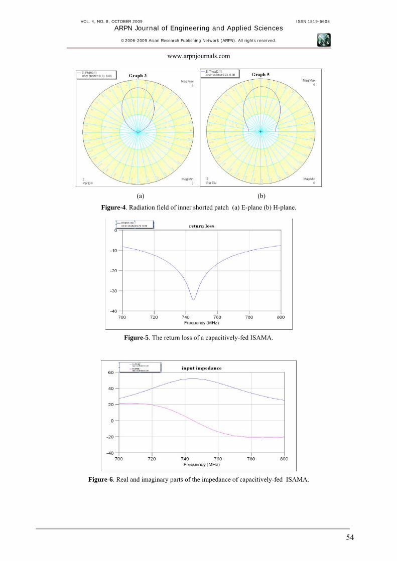
The second technique is shown in Figures (8, 9, and 10); this configuration gives a bandwidth of 174 MHz
(about 22.715 % of the resonance frequency which is 766 MHz).
The above results show that the radiation field has not been affected by the different methods of enhancement and the matching between the probe feed and the antenna is about 50 ohm which is a good matching with the effect of shifting the resonance frequency from its original location.
The effect of feed location was studied for the three designs in which for every case the feed point was taken at the resonance point and the edge and the center of the patch , the radiation field for each design with three cases is shown in Figures (11,12,13), as it is seen from the figures that the radiation field is not affected too much when changing the feed point from resonance point to the edge of the patch ,on the other hand the radiation field is affected when the feed is putted at the center of the circle ,this implies for the three designs.
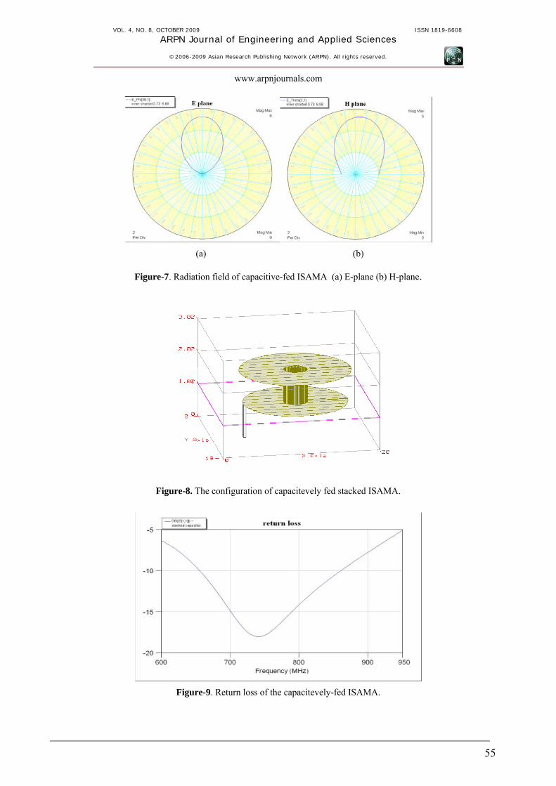
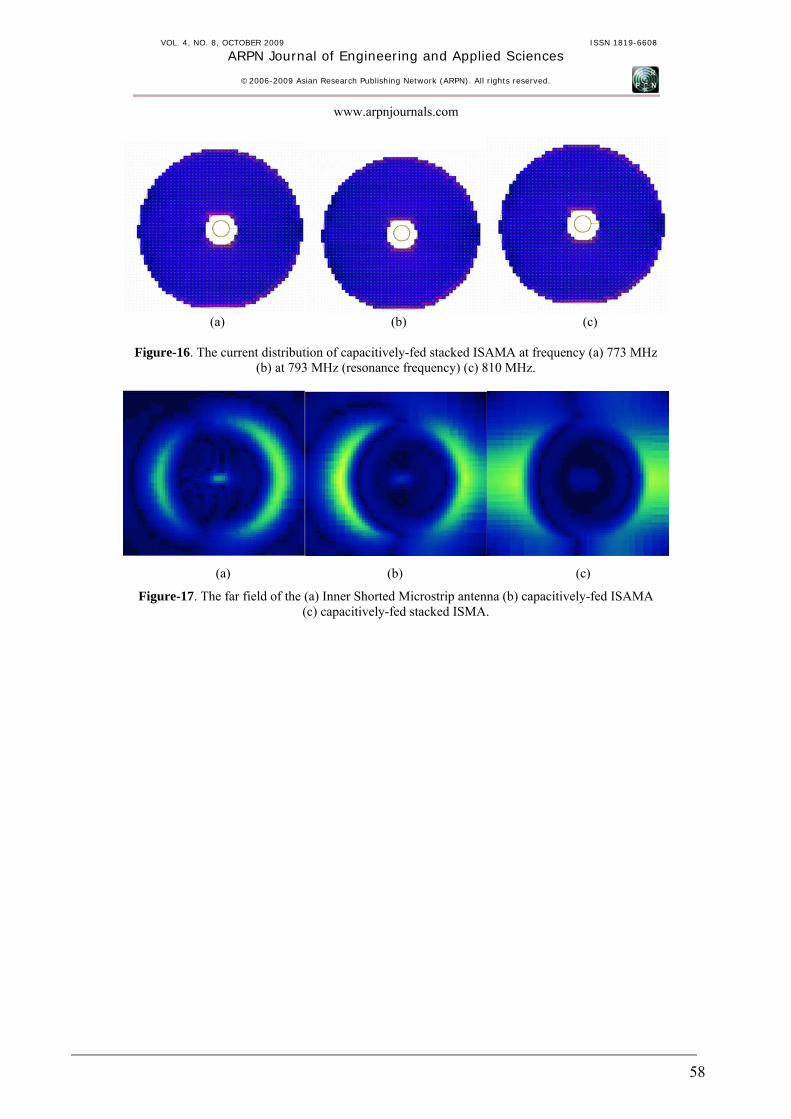
Figures (14, 15, and 16) represent the current distribution on the patch of the three designs for three frequencies, the resonance frequency, a frequency less than the resonance, a frequency greater than the resonance, the figures indicates the current at the resonance frequency has a maximum current indicated as the red distribution of the color, for the capacitively-fed ISAMA and capacitively-fed stacked ISAMA the current distribution is not affected by the frequency change. Figure-17 represents the radiation field at the resonance for the three designs. REFRENCES [1] Vicente Gonzalez P., Daniel Segovia V., Eva Rajo I.,
José Luis Vazquez R., Carlos Martin P. 2005. Analysis of Short Circuited Ring Patch operated at
Mode. Rev. Fac. Ing. - Univ. Tarapaca. 13(2): 21-30.
[2] H. Liu and X.-F. Hu. Input Impedance Analysis of a
Microstrip Annular-Ring Antenna with a Thick Substrate.
[3] L. Boccia, G. Amendola, G. Di Massa, L. Giulicchi-
Shorted Annular Patches as Flexible Antennas for Space Applications Dipartimento di Elettronica, Informatica e Sistemistica Università Della Calabria, 87036 Arcavacata di Rende (CS), Italy.
[4] Y. LIN, L. Shafai. 1990. Characteristics of
concentrically shorted circular patch microstrip antennas. IEE Proc. Vol. 137, Pt. H, No.1. February.
52

VOL. 4, NO. 8, OCTOBER 2009 ISSN 1819-6608
ARPN Journal of Engineering and Applied Sciences
©2006-2009 Asian Research Publishing Network (ARPN). All rights reserved.
www.arpnjournals.com
Figure-1. The structure of inner shorted annular microstrip antennas.
Figure-2. The return loss of an inner shorted annular patch.
Figure-3. The input impedance of the inner shorted annular patch.
53
VOL. 4, NO. 8, OCTOBER 2009 ISSN 1819-6608
ARPN Journal of Engineering and Applied Sciences
©2006-2009 Asian Research Publishing Network (ARPN). All rights reserved.
www.arpnjournals.com
(a) (b)
Figure-4. Radiation field of inner shorted patch (a) E-plane (b) H-plane.
Figure-5. The return loss of a capacitively-fed ISAMA.
Figure-6. Real and imaginary parts of the impedance of capacitively-fed ISAMA.
54
VOL. 4, NO. 8, OCTOBER 2009 ISSN 1819-6608
ARPN Journal of Engineering and Applied Sciences
©2006-2009 Asian Research Publishing Network (ARPN). All rights reserved.
www.arpnjournals.com
(a) (b)
Figure-7. Radiation field of capacitive-fed ISAMA (a) E-plane (b) H-plane.
Figure-8. The configuration of capacitevely fed stacked ISAMA.
Figure-9. Return loss of the capacitevely-fed ISAMA.
55

VOL. 4, NO. 8, OCTOBER 2009 ISSN 1819-6608
ARPN Journal of Engineering and Applied Sciences
©2006-2009 Asian Research Publishing Network (ARPN). All rights reserved.
www.arpnjournals.com
(a) (b)
Figure-10. The Radiation pattern of capacitively-fed stacked ISMA (a) E-plane (b) H-plane.
(a) (b) (c)
Figure-11. The far field of a single ISAMA when the feed is at resonance point (b) the edge (c) the center.
(a) (b) (c)
Figure-12. The far field of capacitively-fed Inner shorted annular patch (ISAMA) when the feed is at (a) resonance point (b) the edge (c) the center.
56

VOL. 4, NO. 8, OCTOBER 2009 ISSN 1819-6608
ARPN Journal of Engineering and Applied Sciences
©2006-2009 Asian Research Publishing Network (ARPN). All rights reserved.
www.arpnjournals.com
(a) (b) (c)
Figure-13. The far field of a capacitively-fed stacked Inner shorted annular patch (ISAMA) when the feed is at (a) resonance point (b) the edge (c) the center.
(a) (b) (c)
Figure-14. The current distribution for single ISAMA at frequency (a) 770 MHz (b) 790 MHz (resonance frequency) (c) 810 MHz.
(a) (b) (c)
Figure-15. The current distribution of capacitively-fed ISAMA at frequency (a) 725 MHz (b) 745 MHz (resonance frequency) (c) 765 MHz.
57
VOL. 4, NO. 8, OCTOBER 2009 ISSN 1819-6608
ARPN Journal of Engineering and Applied Sciences
©2006-2009 Asian Research Publishing Network (ARPN). All rights reserved.
www.arpnjournals.com
(a) (b) (c)
Figure-16. The current distribution of capacitively-fed stacked ISAMA at frequency (a) 773 MHz (b) at 793 MHz (resonance frequency) (c) 810 MHz.
(a) (b) (c)
Figure-17. The far field of the (a) Inner Shorted Microstrip antenna (b) capacitively-fed ISAMA (c) capacitively-fed stacked ISMA.
58