Embed Size (px)
Citation preview

www.bajasaeindia.org 1 | Page
2014 BAJA SAEINDIA®
Raise the bar!!
BAJA SAEINDIA® RULES
Revision 0/2014
10th April, 2014
www.bajasaeindia.org 2 | Page
CONTENTS
Section 1 General Information 3
Section 2 Vehicle Requirements and Restrictions 6
Section 3 Roll Cage, Systems and Driver’s Equipment Requirements 15
Section 4 Competition Procedures and Regulations 40
Section 5 Technical Inspection 43
Section 6 BAJA SAEINDIA Events 48
Section 7 Appendices 57
Appendix 01- Roll Cage Specification Sheet 57
Appendix 02- Local Technical Inspection Rules 58
Appendix 03- Code of Conduct 60
Appendix 04- Virtual BAJA SAEINDIA 61
Appendix 05- Design Report Format 64
Appendix 06- Cost Report Format 66
Appendix 07- Index Sheet for Process Cost Reference 69
Appendix 08- Static Event Participation Sheet 70
Appendix 09- BAJA SAEINDIA 2014 Scoring 71
Appendix 10- BAJA SAEINDIA 2014 Awards 72
Appendix 11- BAJA SAEINDIA 2014 Penalty Structure 73
Appendix 12- BAJA SAEINDIA 2014 Contacts 74
_____________________________________________________________________________________
www.bajasaeindia.org 3 | Page
Section 1 – General Information
1.1 INDIVIDUAL PARTICIPATION REQUIREMENTS
1.1.1 Eligibility Limits
Eligibility is limited to undergraduate students to ensure this is an engineering competition rather
than a race. Individual members of teams participating in this competition must satisfy the
following requirements:
1.1.2 Student Status
Team members must be enrolled as degree seeking undergraduate student in a college or
university. Team members who have already graduated prior to the competition (Feb. 2014) are
NOT eligible to participate.
1.1.3 Society Membership
Team members must be members of SAE (Society of Automotive Engineers) or an SAE affiliate
society. Proof of membership, such as a membership card, is required at the event.
1.1.4 Age
Team members must be 18 (eighteen) years of age at the time of the competition.
1.1.5 Driver’s License
Team members who will drive a competition vehicle at any time during a competition must hold
a valid, government issued driver’s license. This will be required onsite for proof.
1.1.6 Liability Waiver
All on-site participants and faculty are required to sign a liability waiver upon
registering on-site.
1.1.7 Insurance
Individual medical and accident insurance coverage is required and is sole responsibility of the
participant.
1.2 FACULTY ADVISOR
1.2.1 Faculty Advisor Status
Each team is expected to have a Faculty Advisor appointed by the university. The faculty advisor
is expected to accompany the team to the competition and will be considered by competition
officials to be the official university representative.
www.bajasaeindia.org 4 | Page
1.2.2 Responsibilities
Faculty Advisors are expected to advise their teams on general engineering and engineering
project management theory.
1.2.3 Limitations
Faculty advisors may not design any part of the vehicle nor directly participate in the
development of any documentation or presentation.
Faculty Advisors may neither fabricate nor assemble any components nor assist in the
preparation, maintenance, testing or operation of the vehicle.
Faculty Advisors are not allowed to participate during technical inspection, cost audit or design
presentations. The team captain or other designated members of the team must do all the
presenting although Faculty Advisors may silently observe.
In brief – Faculty Advisors may not design, build or repair any part of the vehicle.
1.3 ELIGIBILTY – VEHICLES
1.3.1 Student Created
Undergraduate Engineering Student in India can participate in SAE BAJA 2014 event. The
College / Institute needs to have at least 1 year of SAE India Collegiate membership before
official registration for BAJA SAEINDIA 2014 for becoming eligible to participate.
The vehicle and associated documentation must be conceived, designed and fabricated by the
team members without direct /indirect involvement from professional engineers, faculty or
professionals in the off-road and racing . Proof of manufacturing location will be essentially
required to be furnished by the teams on-site upon being so asked for by the officials.
1.3.2 Professional Fabrication Limits
1. Only those teams, whose management gives an undertaking to allow them to use the workshop
facilities, would be allowed to participate without exception. Also teams need to submit a list of
facilities / equipments in operating condition with the college facilities which will be used to
fabricate & assemble the vehicle as per design presented in virtual BAJA event.
2. During the actual manufacturing and fabrication process, the video clips that covers students
working in college facility need to be furnished in CD-Format during the College Level Technical
Inspection.
3. Extensive use of readymade subassemblies may invoke penalties. Vehicles, which have been
professionally fabricated, may be penalized up to 400 points or even disqualified from the
competition. The decision of the organizers committee in this regard will be final. The
registration fee would NOT be returned in such case.
www.bajasaeindia.org 5 | Page
1.3.3 Prefabricated Subassemblies
These rules do not exclude the use of prefabricated or modified sub-assemblies. Extensive use of
readymade subassemblies may invoke penalties. List of pre-fabricated parts allowed are – Shock
Absorber, spring, Brake drum, Brake disc, Brake calipers and brake holding assembly, Master
cylinder, Steering gear box, Steering column, Steering wheel, Wheel rims & Tires, Seat frame,
Tie rod ends.
Engine, Fuel tank & Exhaust system - complete assembly supplied from B&S to be used. All
other parts need to be fabricated in house & not allowed to outsource from professional
manufactures/ designers.
1.4 Top 10 Teams – Design Comparison Requirement
Teams with vehicles that finished in a top ten position in any of the previous year’s Baja SAE
INDIA competitions are classified as having created a “successful design”. Such teams are
required to provide a comparison of their current design with their previous year’s design even if
the current design is entirely new. As part of the design event, judges will evaluate the
comparison documentation of the top ten teams. If the judges find that the design changes are (A)
not significant, (B) not supported by a detailed analysis or (C) have not been sufficiently
documented, then a penalty of up to one hundred (100) points may be assessed against the design
score. Modifications are defined as, but not limited to: New frame and/or roll cage design, new
drive train design or arrangement (gear ratio changes are NOT considered as drive train
modifications), new suspension design, driver ergonomics and controls. The redesign/design
document may be in the form of either, or both, (A) posters or (B) report.
www.bajasaeindia.org 6 | Page
Section 2 - Vehicle Requirements and Restrictions
2.1 Vehicle Configuration
The vehicle must have four (4) or more wheels not in a straight line. Three (3) wheeled vehicles
are prohibited from the competition. The vehicle must be capable of carrying one (1) person
190.3 cm (6’3”) tall weighing 113.4 kg (250 lb).
2.1.2 Maximum Vehicle Dimensions
Width : 162.56 cm (64 in) at its widest point: Mandatory
Length : 274.32 cm (108 in) end to end: Recommended
Vehicles exceeding the width will not be allowed to run in any event. “GO-NO-GO” device is
made available by the organizers at the Technical Inspection area during the On-Site Technical
Inspection to check the width (Section 5).
2.2 Required Engine
2.2.1 Briggs and Stratton Engine: 10 hp OHV Intake
Since last year, the Briggs & Stratton Corporation USA has generously provided engines to the
BAJA SAEINDIA teams with charges. Team pays for subsidized price and the shipping &
handling charges. The teams may be asked to collect their engines from specified locations. Also,
the teams are needed to arrange all the transit requirements as required by the Transportation &
Insurance Authorities, at their own. All such notifications would be made available on the BAJA
website, www.bajasaeindia.org.
2.2.2 Engine Eligibility
Colleges/Institutes will be eligible to receive and use a new Briggs & Stratton engine in their
THIRD participation only. Engines are allocated on the basis of one engine per vehicle per two
seasons of participation.
Example: A college/institute that receives a new Briggs & Stratton engine in year 2012 for
competition season of 2013 can participate in a BAJA SAEINDIA event in 2013 & 2014 with the
same engine. It becomes eligible to receive a new engine only for the 2015 competition season if
registered & qualified.
Example: A college/institute that receives an engine in 2012, but does not compete in a BAJA
SAEINDIA event in 2013, is not eligible to receive an engine in 2015. It means the same engine
can be used for 2014 & 2015 provided its team qualifies the criteria of selection and is registered.
Similarly if the college has participated in 2013 event but not in 2014 event; then it can use the
same engine for 2015 event provided its team qualifies the criteria of selection and is registered.
2.2.3 Eligible Teams - Receiving New Engines
Teams that are eligible to receive a new engine must order online upon completion of registering
the team for a competition. Please contact Briggs &Stratton and SAE INDIA if any team has
www.bajasaeindia.org 7 | Page
trouble placing the engine order. Eligible teams will have to pay the cost of engine & shipping as
per SAE approved rate.
Neither Briggs & Stratton nor SAE assume any responsibility for the delivery of engines. Transit
Insurance can be separately born by team.
2.2.4 Purchasing of Additional Briggs & Stratton Engines
Teams may purchase additional Briggs & Stratton engines directly through their local Briggs &
Stratton dealer. There is no special discount or purchase price for additional engines.
2.3 Engine Requirement and Restrictions
To provide a uniform basis for the performance events, all vehicles must use the same engine: a
stock of four cycles, air cooled, Briggs & Stratton OHV Intake Model. The Briggs & Stratton
engine bearing the following part no. is the only engine allowed for the BAJA SAEINDIA 2014
competition:
20S332 0036 - New Engine having 3800 as the maximum rpm.
NOTE: Blueprinting (reworking an engine to a manufacturer’s exact specifications) is
considered to be modification.
2.3.1 Replacement Parts
Only original equipment Briggs & Stratton replacement parts may be used.
2.3.2 Piston Rings
Only standard size original Briggs & Stratton piston rings may be used.
2.3.3 Intake Ports
No cleaning or removing of aluminum flashing from intake or exhaust ports may be done.
2.3.4 Valves – Clearance & Lapping
Any valve clearance setting between tappet and valve stem – intake and exhaust may be set.
Valves may be lapped to ensure proper sealing. Intake angle must remain at 45 degrees; exhaust
angle must remain at 45 degrees.
2.3.5 Shafts and Rods
Camshaft, crankshaft, connecting rod and flywheel must not be altered or modified.
2.3.6 Spark Plugs
Only RC12YC spark plugs must be used.
Before carrying any welding activity, it is recommended that the spark plug cable is removed and
battery terminal cables are disconnected. This will prevent burning of wiring harness and HT
Coil.
www.bajasaeindia.org 8 | Page
2.3.7 Armature
Any armature air gap setting is allowed. No slotting or elongating of armature mounting holes to
increase or retard ignition timing.
2.3.8 Flywheel Rotation
No flywheel rotation to advance or retard timing is permissible.
2.3.9 Carburetor
Carburetor - This is a fixed carburetor, re-jetting of the carburetor is prohibited.
Idle Speed – Any idle speed adjustment: NOT ALLOWED. B&S recommends 1750 ± 100 rpm.
Carburetor Float - Carburetor float is non-adjustable and may not be re-adjusted.
Carburetor Venturi - Modification of carburetor venturi is prohibited.
2.3.10 Air Cleaner
The air intake system should use a Filter from Briggs and Stratton recommended source. The
teams may be required to submit proof of purchase.
The filter should be located as close as possible to the engine. The air intake may be relocated,
but Briggs & Stratton parts must be used to relocate the air filter: remote kits, 695329 – choke
shaft and 699960 – air cleaner base (metal). The supplied air hose may be shortened to a
minimum of 152 mm (6.0 in). No other type of hose will be allowed. A team may also add
additional pre-filters (part number: 491435S) to the top of the air intake. These parts must be
included on the cost report. Any changes made to the air filter will have to pass Briggs & Stratton
inspection.
NOTE: Relocation of the air cleaner may decrease engine performance. Any damage on account
of failure to comply with the instructions would have to be borne by the team. The complete air
intake system shall be located so that its extremities lie at least 100 mm within the perimeter of
the vehicle. The decision of the Head of the Technical Committee of BAJA SAEINDIA / Briggs
and Stratton personnel in this regard will be final and binding to all. This is in the interest of
safety.
A fresh air cleaner element & paper filter are required during On-site Technical
Inspection-Engine at BAJA SAEINDIA 2014.
2.3.11 Exhaust System
A. Muffler & Exhaust system
Since B&S Engine is supplied with pre mounted exhaust system, there is no need to change the
mounting. Regarding GO GREEN Award, concept model & system need to be separately worked
out for presentation during the event. Details for GO GREEN Award will be separately put on the
official BAJA SAEINDIA 2014 website.
www.bajasaeindia.org 9 | Page
B. Exhaust System – Durability Required
The exhaust pipe and muffler must be completely intact and operational throughout the event, and
shall be grounds for penalty or disqualification if not intact at the end of any event, including
endurance event. The decision of the representatives of the engine manufacturer and/or the Head
of the Technical Committee of BAJA SAEINDIA in this regard will be final and binding to all.
C. Exhaust system complete
The complete exhaust system exhaust system shall be located such that its extremities lie at least
100 mm within the perimeter of the vehicle. The decision of the Head of the Technical
Committee of BAJA SAEINDIA in this regard will be final and binding to all. This is in the
interest of safety.
D. Exhaust system painting
This is recommended but not compulsory.
2.3.12 Starter
The Recoil Starter Rope may be extended to accommodate the driver starting the engine while
being seated. Electric start is not acceptable in any case even if it is from B&S standard parts.
2.3.13 Alternator
The engine is not configured for fitment with an external alternator to generate electrical energy.
Hence it is not permitted.
2.3.14 Engine Governor
Each engine is equipped with a governor. Each governor will be set at the competition to a 3800
rpm or maximum speed. Random inspection of the governor may be conducted at any time. Any
attempt to defeat the engine governor so as to increase the engine speed grounds for immediate
disqualification.
GOVERNOR SETTING: NOT TO EXCEED 3800 RPM.
The governor operation must remain free of obstructions at all times. Governor area must be
shielded from debris. The stock configuration of fuel tank mounted to the engine is acceptable for
debris management. However, if the fuel tank is to be remote mounted, a debris shield covering
the exposed governor area is required. Briggs & Stratton part number 697326 Control Cover may
be used or some other part with equivalent features.
NOTE: The governor spring must be placed in hole # 6.
The top 10 vehicles in the Endurance Event will be checked for the same.
2.3.15 Hybrid Electric Power Systems
Hybrid electric power systems are specifically prohibited.
www.bajasaeindia.org 10 | Page
2.3.16 Energy Storage Devices Used for Propulsion
Hydraulic accumulators are the only type of stored energy device that may be incorporated into
the vehicle for propulsion purposes. If employed, hydraulic accumulators must be at zero energy
at the start of each event. Hydraulic power systems must be properly shielded and documentation
of the shielding made available for review.
2.4 Engine Use Restriction
Briggs & Stratton generously provides engines to the teams for the exclusive purpose of use on
their BAJA SAEINDIA vehicle. If, for any reason, a team receives an engine and at a later date
decides not to participate, it must, at its own expense, return the engine to SAE or Briggs &
Stratton.
2.5 Battery Requirements
The battery/batteries can only provide power to accessories on the vehicle (horn, brake light,
reverse light & beeper, data acquisitions, safety items and other instrumentation). It is expressly
prohibited to operate the vehicle by using power from an on-board battery.
The mounting of battery must prevent the battery from coming loose during a roll over & must be
enclosed from the exhaust and the fuel system. There should not be any positive contact with
the exhaust unit of the fuel system. The battery must be safely placed & concealed. Failing
this, the technical inspectors may debar the team from the dynamic events.
Recommended Battery: 12 V, 44 Ah
2.5.1 Electronic Controls
Electronic control of suspension and transmission systems is allowed. The power can be from the
approved battery.
2.6 Component Failure
In the event of a major component failure during the course of the event, any modifications must
be approved by the Technical Inspectors prior to the vehicle returning to the competition. Teams
without the approval may be penalized as per the decision of the Head of Baja Technical
Committee.
2.7 Engine Use Restriction
The B&S staff on-site is empowered to make final decisions regarding the condition and set-up of
all engines.
NOTE from B&S: B&S will Provide support, however, if it is observed that the damages to
the engine are caused due to team’s negligence in handling/ installing/ running the engine as
per the specified directions given by B&S. or as specified in the manual supplied by
B&S, the teams may be charged for the repairs or for procuring a new engine in place of the
damaged engine. No components/spares shall be installed without consulting B&S authorities or
the organizer committee member. Queries regarding the engine and related peripherals may be
addressed to [email protected].
www.bajasaeindia.org 11 | Page
2.8 Transmission
Teams are free to use any transmission, such that maximum speed of the vehicle on a
plain terrain is recommended to be no more than 60 km/hr in top gear. Continuously Variable
Transmission (CVT) is also permitted with appropriate shielding as in Sec 3.19.1.Teams can plan
to install reverse gear for reverse drive of vehicle.
Teams need to safely install gear shifting cables; lever and shifting mechanism are installed at
such locations which will not be hindrance for driver and his safety.
The adapter for Engine & Transmission is to be designed and installed by students as per the type
of transmission used. Engine drive / output shaft side details are available on BAJA SAEINDIA
official website.
The decision of the Head of the Technical Committee of BAJA SAEINDIA in this regard will be
final and binding to all.
2.9 Reverse Light and Alarm
It is mandatory that each vehicle should be equipped with a reverse light (Amber color,
visible at a minimum distance of 10 meters from vehicle). Reverse alarm is not mandatory
however it is recommended to be installed for safety reason which shall operate when the reverse
gear is engaged.
2.10 Front Bumper
A tubular front bumper is MANDATORY for the safety requirement of the vehicle.
2.11 TOWING HITCH POINT
Each vehicle must have towing hitch points at the front and rear, along its longitudinal centerline.
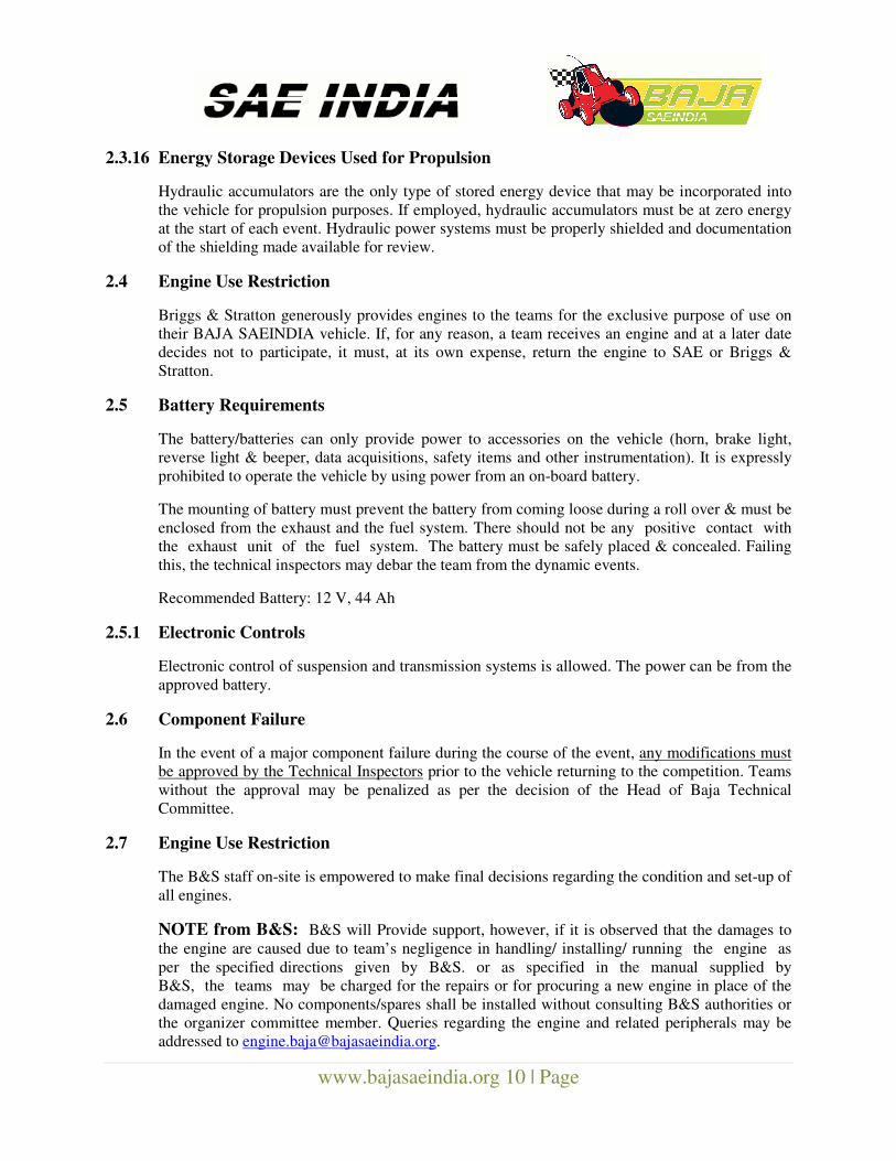
2.11.1 Front Hitch Point
The front hitch point may be either:
(a) A tubular front bumper strong enough to lift the weight of the car with no permanent
deformation and having a maximum outside diameter of 25.4 mm (1 in) to which a clevis
can be centrally attached, or
(b) A hitch plate complying with the requirements of Section 2.11.2, which is designed to fold or
pivot, into a position where it will not affect anything during a front-end collision.
Figure 1- EXAMPLES OF ACCEPTABLE FRONT HITCH POINT
www.bajasaeindia.org 12 | Page
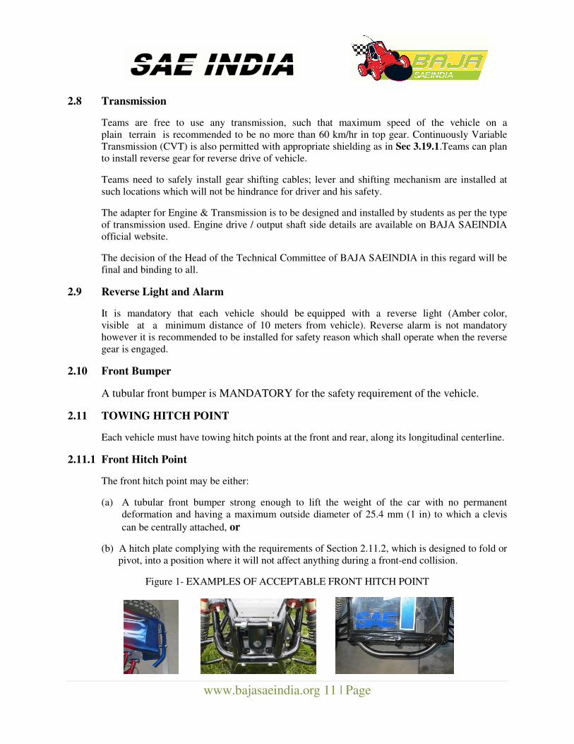
Figure 2 - EXAMPLES OF UNACCEPTABLE FRONT HITCH POINT (CUT-OUTS / PIVOTS)
2.11.2 Rear Hitch Plate Requirements –
Towing plate Maximum thickness - 9.5 mm (0.375 in)
Hole diameter Minimum - 25.4 mm (1 in)
Radial clearance Maximum from hole - 25.4 mm (1 in)
Hole to tube Minimum clearance – 19.0 mm (0.75 in)
Figure 3 - Hitch Plate Specs
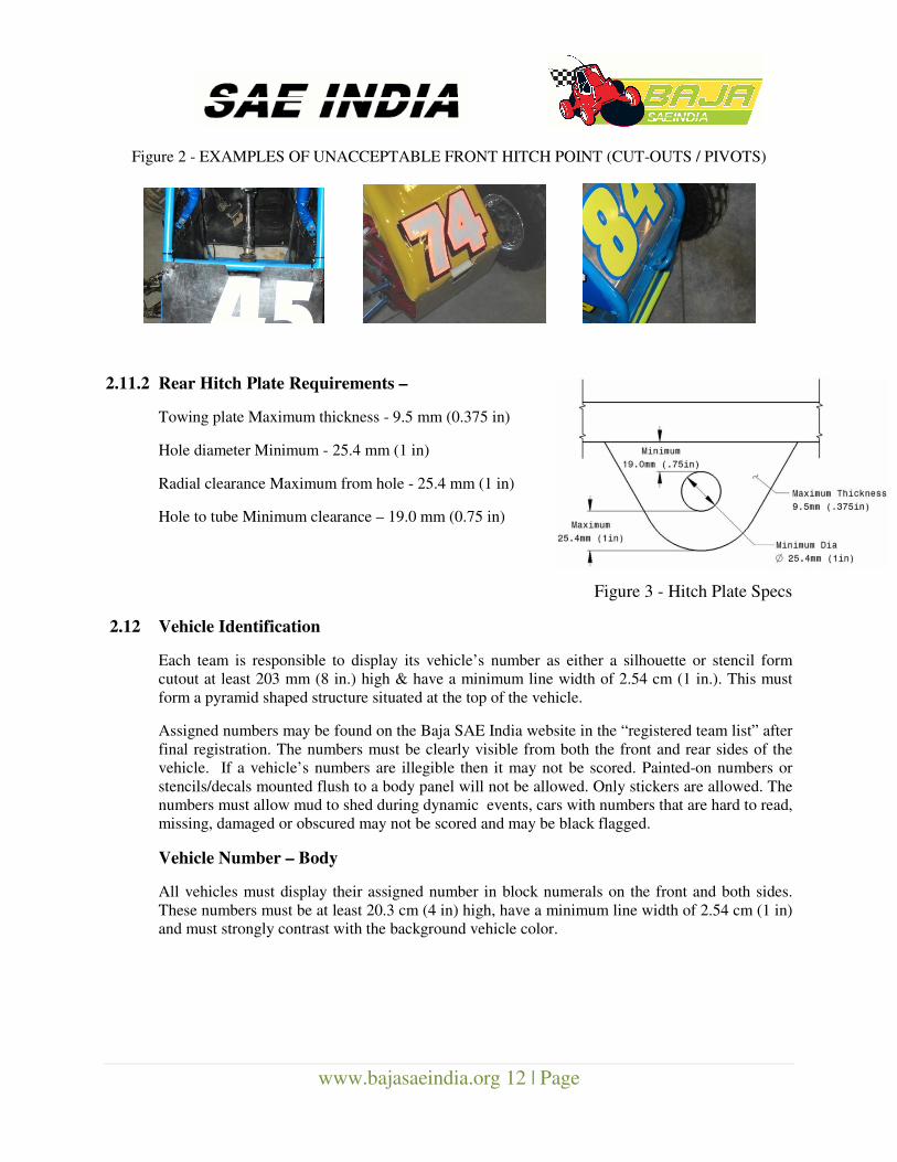
2.12 Vehicle Identification
Each team is responsible to display its vehicle’s number as either a silhouette or stencil form
cutout at least 203 mm (8 in.) high & have a minimum line width of 2.54 cm (1 in.). This must
form a pyramid shaped structure situated at the top of the vehicle.
Assigned numbers may be found on the Baja SAE India website in the “registered team list” after
final registration. The numbers must be clearly visible from both the front and rear sides of the
vehicle. If a vehicle’s numbers are illegible then it may not be scored. Painted-on numbers or
stencils/decals mounted flush to a body panel will not be allowed. Only stickers are allowed. The
numbers must allow mud to shed during dynamic events, cars with numbers that are hard to read,
missing, damaged or obscured may not be scored and may be black flagged.
Vehicle Number – Body
All vehicles must display their assigned number in block numerals on the front and both sides.
These numbers must be at least 20.3 cm (4 in) high, have a minimum line width of 2.54 cm (1 in)
and must strongly contrast with the background vehicle color.
www.bajasaeindia.org 13 | Page
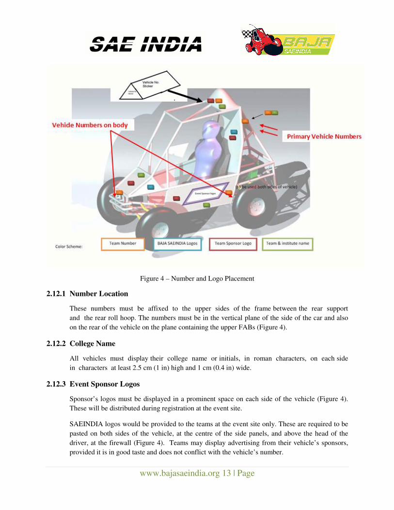
Figure 4 – Number and Logo Placement
2.12.1 Number Location
These numbers must be affixed to the upper sides of the frame between the rear support
and the rear roll hoop. The numbers must be in the vertical plane of the side of the car and also
on the rear of the vehicle on the plane containing the upper FABs (Figure 4).
2.12.2 College Name
All vehicles must display their college name or initials, in roman characters, on each side
in characters at least 2.5 cm (1 in) high and 1 cm (0.4 in) wide.
2.12.3 Event Sponsor Logos
Sponsor’s logos must be displayed in a prominent space on each side of the vehicle (Figure 4).
These will be distributed during registration at the event site.
SAEINDIA logos would be provided to the teams at the event site only. These are required to be
pasted on both sides of the vehicle, at the centre of the side panels, and above the head of the
driver, at the firewall (Figure 4). Teams may display advertising from their vehicle’s sponsors,
provided it is in good taste and does not conflict with the vehicle’s number.
www.bajasaeindia.org 14 | Page
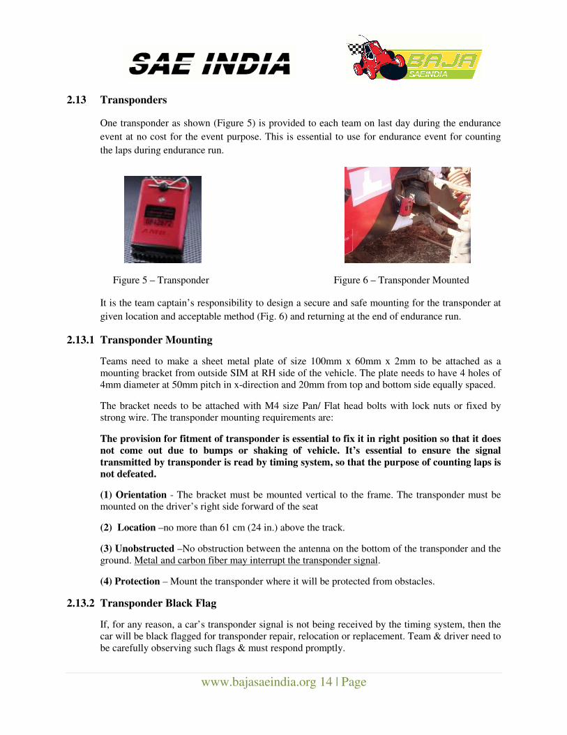
2.13 Transponders
One transponder as shown (Figure 5) is provided to each team on last day during the endurance
event at no cost for the event purpose. This is essential to use for endurance event for counting
the laps during endurance run.
Figure 5 – Transponder Figure 6 – Transponder Mounted
It is the team captain’s responsibility to design a secure and safe mounting for the transponder at
given location and acceptable method (Fig. 6) and returning at the end of endurance run.
2.13.1 Transponder Mounting
Teams need to make a sheet metal plate of size 100mm x 60mm x 2mm to be attached as a
mounting bracket from outside SIM at RH side of the vehicle. The plate needs to have 4 holes of
4mm diameter at 50mm pitch in x-direction and 20mm from top and bottom side equally spaced.
The bracket needs to be attached with M4 size Pan/ Flat head bolts with lock nuts or fixed by
strong wire. The transponder mounting requirements are:
The provision for fitment of transponder is essential to fix it in right position so that it does
not come out due to bumps or shaking of vehicle. It’s essential to ensure the signal
transmitted by transponder is read by timing system, so that the purpose of counting laps is
not defeated.
(1) Orientation - The bracket must be mounted vertical to the frame. The transponder must be
mounted on the driver’s right side forward of the seat
(2) Location –no more than 61 cm (24 in.) above the track.
(3) Unobstructed –No obstruction between the antenna on the bottom of the transponder and the
ground. Metal and carbon fiber may interrupt the transponder signal.
(4) Protection – Mount the transponder where it will be protected from obstacles.
2.13.2 Transponder Black Flag
If, for any reason, a car’s transponder signal is not being received by the timing system, then the
car will be black flagged for transponder repair, relocation or replacement. Team & driver need to
be carefully observing such flags & must respond promptly.
www.bajasaeindia.org 15 | Page
Section 3 - Roll Cage, Systems & Driver’s Equipment
Requirements
3.1 Modifications at Last Minute
Once the Technical Inspection check is approved and stickers are issued for the vehicle indicating
cleared for Static & Dynamic event, teams need to participate with the vehicle without any
modifications/ improvements. In case of any teams found doing changes/ modification in system
will be disqualified/ penalized for such last minute changes in vehicle.
All installations and construction are required to be intact as in approved condition by technical
inspector. No modifications in the design would be allowed after the conclusion of static
events. Teams may be penalized with a minimum deduction of 50 to the maximum of 200
points subject to the modifications done on vehicle.
3.2 Unstable Vehicle
Any vehicle exhibiting handling or other vehicle dynamics that are deemed unstable by the
technical inspectors will not be permitted to participate in the dynamic events. The decision of the
Head of the Technical Committee of BAJA SAEINDIA in this regard will be final and binding to
all. This is in the interest of safety of all teams.
3.3 ROLL CAGE
3.3.1 Objective
The purpose of the roll cage is to provide a minimal space surrounding the driver and to support
all subsystems. The cage must be designed and fabricated to prevent any failure of the cage’s
integrity. It should be large enough for accommodating hefty & tallest member participating in a
team in driving position.
3.3.2 Lateral Space
The minimum space is based on clearance between the driver and straight edge applied to any
two points on the roll cage.
1. The driver’s helmet to be 152 mm (6 in) clearance to the top of roll cage.
2. The driver’s shoulders, torso, hips, thighs, knees, arms elbows, and hands, shall have a
minimum of 76 mm (3 in) of clearance from the envelope created by the structure of the car.
NOTE : When minimal dimensions are given that is to the centerline of the members,
and when a clearance for the driver is given, it is defined by the outside edges of the roll
cage members less the padding installed.
DRIVER DEFINITION- For the purposes of this section "driver" refers to the team's largest
driver and the 95-percentile male properly suited and wearing a helmet.
www.bajasaeindia.org 16 | Page
3.3.3 Roll Cage Structure
3.3.3.1 Elements of Roll Cage
Roll cage must be space frame of tubular steel. The required members of roll cage are –
A. Primary members –
NOTE: The primary members must conform to Section 3.6.1. [Circular steel tubing with
an outside diameter of 25mm (1 in) and a wall thickness of 3 mm (0.120 in) and a carbon content
of at least 0.18%.]
Rear Roll Hoop (RRH)
Rear Hoop Overhead Members (RHO)
Front Bracing Member (FBM)
Lateral Cross Member (LC)
Front Lateral Cross Member (FLC)
B. Secondary Members –
NOTE: Secondary members must be steel tube having minimum wall thickness of 0.89 mm
(0.035 in) and min outside diameter 25.4mm (1 in).
Lateral Diagonal Bracing (LBD)
Lower Frame side (LFS)
Side Impact Member (SIM)
Fore / Aft Bracing (FAB)
Under seat Member (USM)
All other required cross members.
Any tube used to mount safety belts.
Roll cage members which are not straight must not extend longer than 711 mm (28 in) between
supports. Small bend radii (<152 mm/ 6 in) at a supported end of a member are expected, and are
not considered to make a member not-straight. The minor angle between the two ends of a not-
straight tube must not exceed 30°.
NOTE: Required dimensions between roll cage members are defined by measurements between
member centerlines, except where noted. All Roll cage members having a bend radius > 15.2 cm
(6 in) may NOT be longer than 71.1cm (28 in) unsupported.
No holes are allowed to be drilled on the roll cage tubing. Also, no tube should show any
cracks or deformation. Final judgment rests with the Head BAJA Technical Committee.
www.bajasaeindia.org 17 | Page
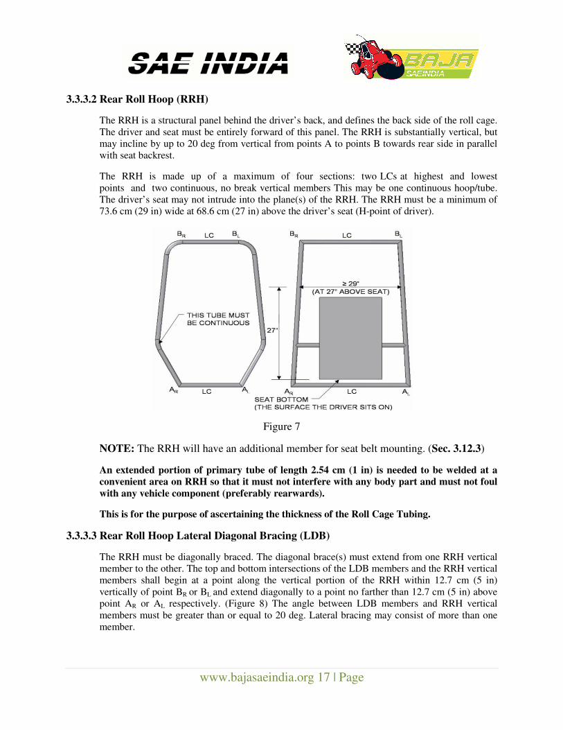
3.3.3.2 Rear Roll Hoop (RRH)
The RRH is a structural panel behind the driver’s back, and defines the back side of the roll cage.
The driver and seat must be entirely forward of this panel. The RRH is substantially vertical, but
may incline by up to 20 deg from vertical from points A to points B towards rear side in parallel
with seat backrest.
The RRH is made up of a maximum of four sections: two LCs at highest and lowest
points and two continuous, no break vertical members This may be one continuous hoop/tube.
The driver’s seat may not intrude into the plane(s) of the RRH. The RRH must be a minimum of
73.6 cm (29 in) wide at 68.6 cm (27 in) above the driver’s seat (H-point of driver).
Figure 7
NOTE: The RRH will have an additional member for seat belt mounting. (Sec. 3.12.3)
An extended portion of primary tube of length 2.54 cm (1 in) is needed to be welded at a
convenient area on RRH so that it must not interfere with any body part and must not foul
with any vehicle component (preferably rearwards).
This is for the purpose of ascertaining the thickness of the Roll Cage Tubing.
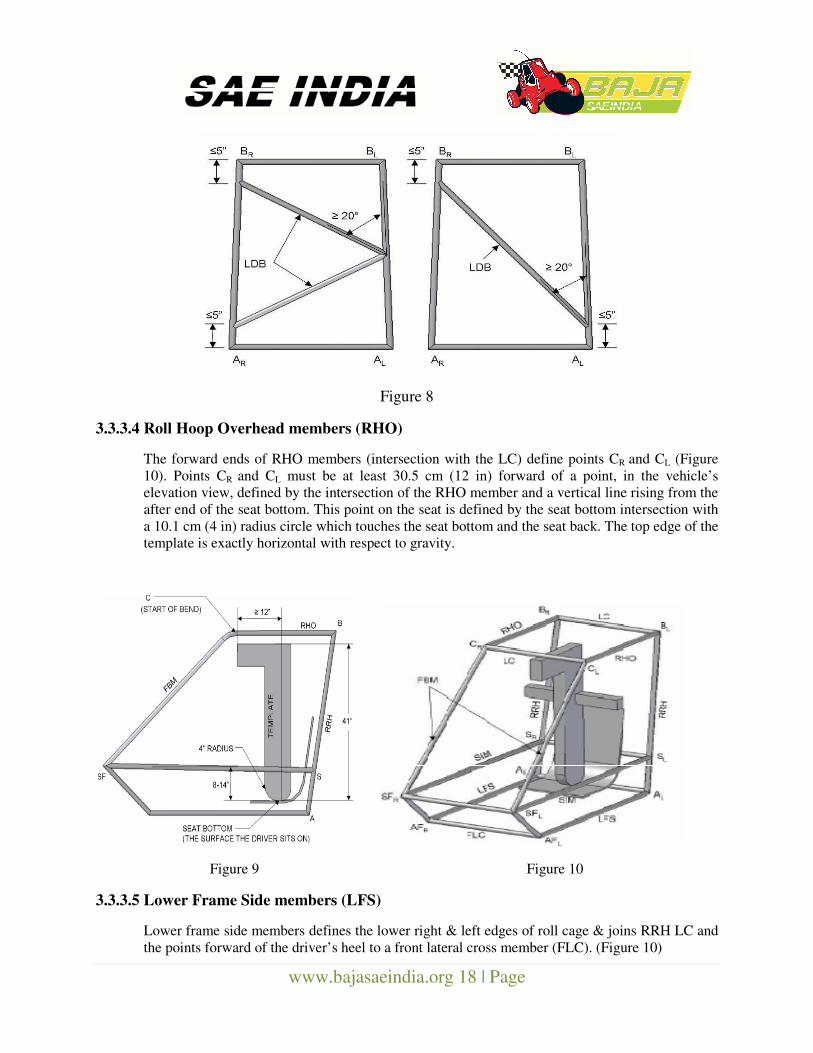
3.3.3.3 Rear Roll Hoop Lateral Diagonal Bracing (LDB)
The RRH must be diagonally braced. The diagonal brace(s) must extend from one RRH vertical
member to the other. The top and bottom intersections of the LDB members and the RRH vertical
members shall begin at a point along the vertical portion of the RRH within 12.7 cm (5 in)
vertically of point BR or BL and extend diagonally to a point no farther than 12.7 cm (5 in) above
point AR or AL respectively. (Figure 8) The angle between LDB members and RRH vertical
members must be greater than or equal to 20 deg. Lateral bracing may consist of more than one
member.
www.bajasaeindia.org 18 | Page
Figure 8
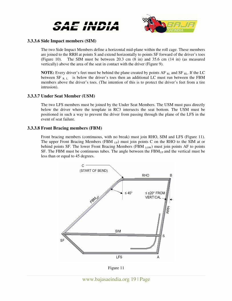
3.3.3.4 Roll Hoop Overhead members (RHO)
The forward ends of RHO members (intersection with the LC) define points CR and CL (Figure
10). Points CR and CL must be at least 30.5 cm (12 in) forward of a point, in the vehicle’s
elevation view, defined by the intersection of the RHO member and a vertical line rising from the
after end of the seat bottom. This point on the seat is defined by the seat bottom intersection with
a 10.1 cm (4 in) radius circle which touches the seat bottom and the seat back. The top edge of the
template is exactly horizontal with respect to gravity.
Figure 9 Figure 10
3.3.3.5 Lower Frame Side members (LFS)
Lower frame side members defines the lower right & left edges of roll cage & joins RRH LC and
the points forward of the driver’s heel to a front lateral cross member (FLC). (Figure 10)
www.bajasaeindia.org 19 | Page
3.3.3.6 Side Impact members (SIM)
The two Side Impact Members define a horizontal mid-plane within the roll cage. These members
are joined to the RRH at points S and extend horizontally to points SF forward of the driver’s toes
(Figure 10). The SIM must be between 20.3 cm (8 in) and 35.6 cm (14 in) (as measured
vertically) above the area of the seat in contact with the driver (Figure 9).
NOTE: Every driver’s feet must be behind the plane created by points AF RL and SF RL. If the LC
between SF R, L is below the driver’s toes then an additional LC must run between the FBM
members above the driver’s toes. (The intention of this is to protect the driver’s feet from a tire
intrusion).
3.3.3.7 Under Seat Member (USM)
The two LFS members must be joined by the Under Seat Members. The USM must pass directly
below the driver where the template in RC3 intersects the seat bottom. The USM must be
positioned in such a way to prevent the driver from passing through the plane of the LFS in the
event of seat failure.
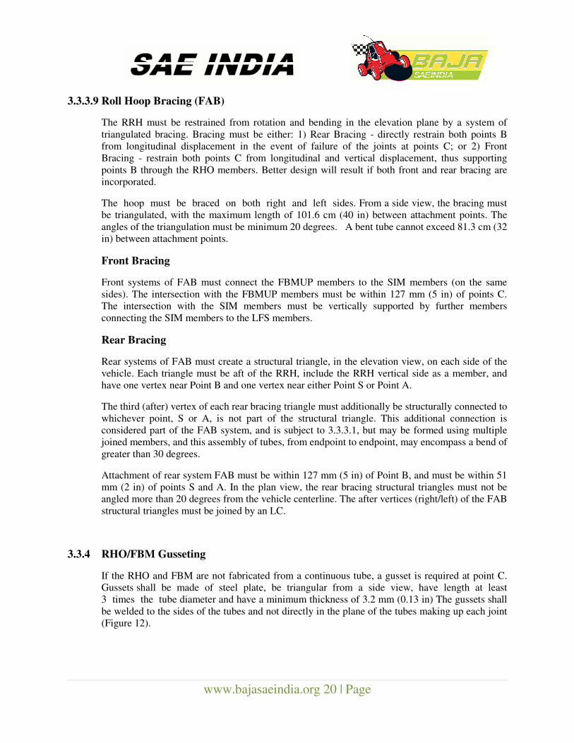
3.3.3.8 Front Bracing members (FBM)
Front bracing members (continuous, with no break) must join RHO, SIM and LFS (Figure 11).
The upper Front Bracing Members (FBM UP) must join points C on the RHO to the SIM at or
behind points SF. The lower Front Bracing Members (FBM LOW) must join points AF to points
SF. The FBM must be continuous tubes. The angle between the FBMUP and the vertical must be
less than or equal to 45 degrees.
Figure 11
www.bajasaeindia.org 20 | Page
3.3.3.9 Roll Hoop Bracing (FAB)
The RRH must be restrained from rotation and bending in the elevation plane by a system of
triangulated bracing. Bracing must be either: 1) Rear Bracing - directly restrain both points B
from longitudinal displacement in the event of failure of the joints at points C; or 2) Front
Bracing - restrain both points C from longitudinal and vertical displacement, thus supporting
points B through the RHO members. Better design will result if both front and rear bracing are
incorporated.
The hoop must be braced on both right and left sides. From a side view, the bracing must
be triangulated, with the maximum length of 101.6 cm (40 in) between attachment points. The
angles of the triangulation must be minimum 20 degrees. A bent tube cannot exceed 81.3 cm (32
in) between attachment points.
Front Bracing
Front systems of FAB must connect the FBMUP members to the SIM members (on the same
sides). The intersection with the FBMUP members must be within 127 mm (5 in) of points C.
The intersection with the SIM members must be vertically supported by further members
connecting the SIM members to the LFS members.
Rear Bracing
Rear systems of FAB must create a structural triangle, in the elevation view, on each side of the
vehicle. Each triangle must be aft of the RRH, include the RRH vertical side as a member, and
have one vertex near Point B and one vertex near either Point S or Point A.
The third (after) vertex of each rear bracing triangle must additionally be structurally connected to
whichever point, S or A, is not part of the structural triangle. This additional connection is
considered part of the FAB system, and is subject to 3.3.3.1, but may be formed using multiple
joined members, and this assembly of tubes, from endpoint to endpoint, may encompass a bend of
greater than 30 degrees.
Attachment of rear system FAB must be within 127 mm (5 in) of Point B, and must be within 51
mm (2 in) of points S and A. In the plan view, the rear bracing structural triangles must not be
angled more than 20 degrees from the vehicle centerline. The after vertices (right/left) of the FAB
structural triangles must be joined by an LC.
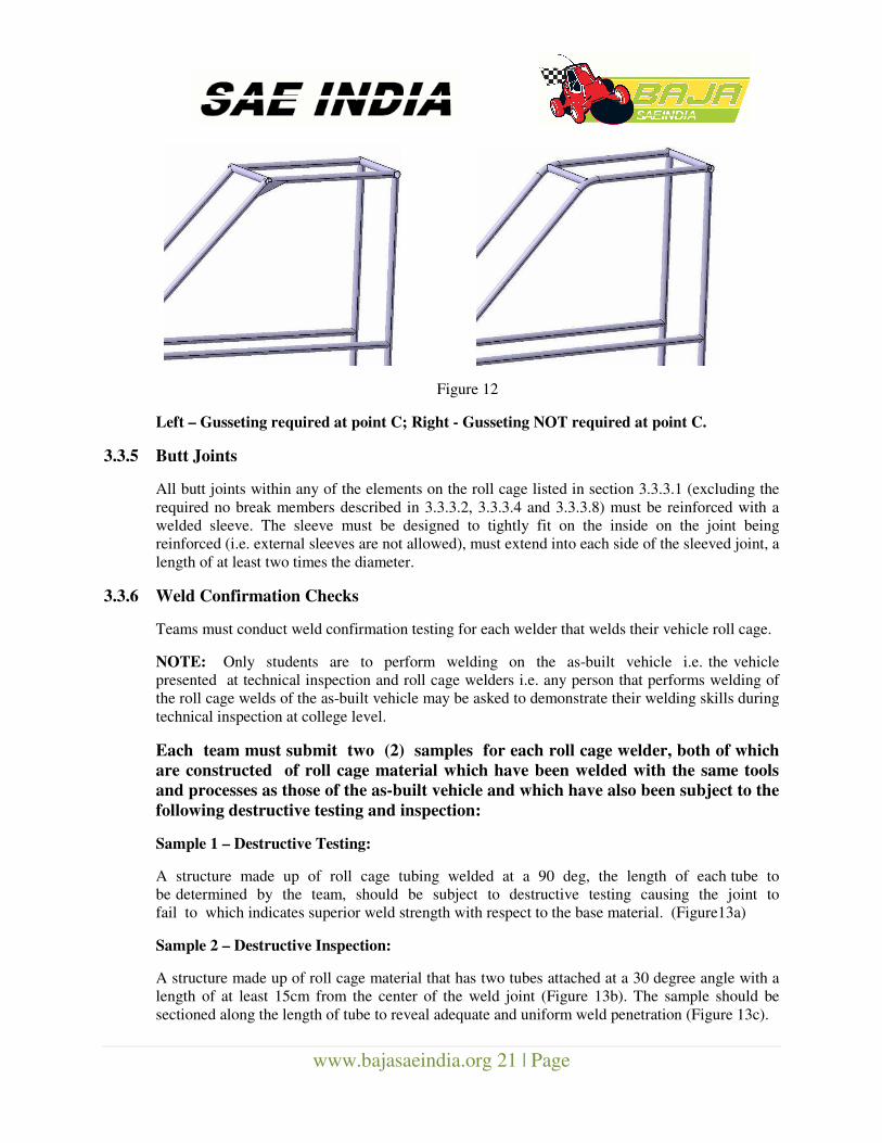
3.3.4 RHO/FBM Gusseting
If the RHO and FBM are not fabricated from a continuous tube, a gusset is required at point C.
Gussets shall be made of steel plate, be triangular from a side view, have length at least
3 times the tube diameter and have a minimum thickness of 3.2 mm (0.13 in) The gussets shall
be welded to the sides of the tubes and not directly in the plane of the tubes making up each joint
(Figure 12).
www.bajasaeindia.org 21 | Page
Figure 12
Left – Gusseting required at point C; Right - Gusseting NOT required at point C.
3.3.5 Butt Joints
All butt joints within any of the elements on the roll cage listed in section 3.3.3.1 (excluding the
required no break members described in 3.3.3.2, 3.3.3.4 and 3.3.3.8) must be reinforced with a
welded sleeve. The sleeve must be designed to tightly fit on the inside on the joint being
reinforced (i.e. external sleeves are not allowed), must extend into each side of the sleeved joint, a
length of at least two times the diameter.
3.3.6 Weld Confirmation Checks
Teams must conduct weld confirmation testing for each welder that welds their vehicle roll cage.
NOTE: Only students are to perform welding on the as-built vehicle i.e. the vehicle
presented at technical inspection and roll cage welders i.e. any person that performs welding of
the roll cage welds of the as-built vehicle may be asked to demonstrate their welding skills during
technical inspection at college level.
Each team must submit two (2) samples for each roll cage welder, both of which
are constructed of roll cage material which have been welded with the same tools
and processes as those of the as-built vehicle and which have also been subject to the
following destructive testing and inspection:
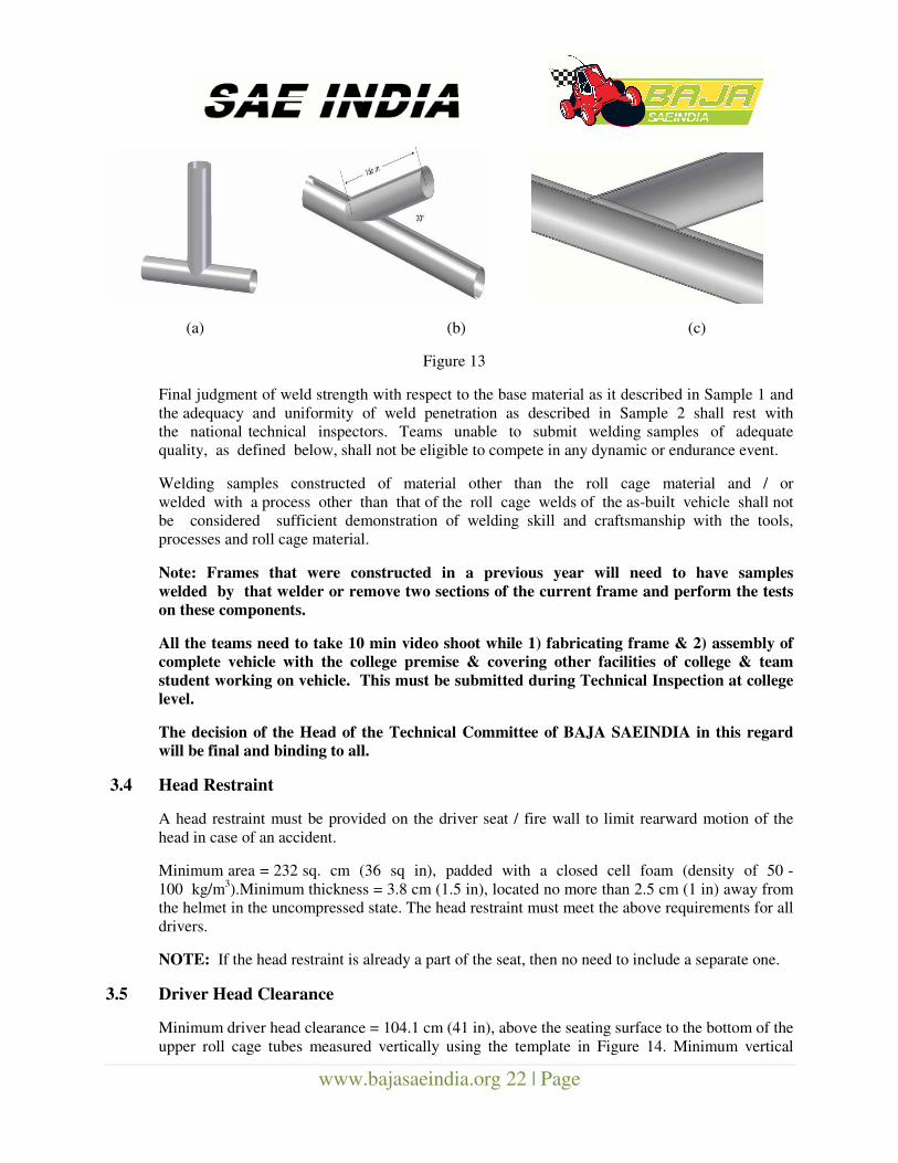
Sample 1 – Destructive Testing:
A structure made up of roll cage tubing welded at a 90 deg, the length of each tube to
be determined by the team, should be subject to destructive testing causing the joint to
fail to which indicates superior weld strength with respect to the base material. (Figure13a)
Sample 2 – Destructive Inspection:
A structure made up of roll cage material that has two tubes attached at a 30 degree angle with a
length of at least 15cm from the center of the weld joint (Figure 13b). The sample should be
sectioned along the length of tube to reveal adequate and uniform weld penetration (Figure 13c).
www.bajasaeindia.org 22 | Page
(a) (b) (c)
Figure 13
Final judgment of weld strength with respect to the base material as it described in Sample 1 and
the adequacy and uniformity of weld penetration as described in Sample 2 shall rest with
the national technical inspectors. Teams unable to submit welding samples of adequate
quality, as defined below, shall not be eligible to compete in any dynamic or endurance event.
Welding samples constructed of material other than the roll cage material and / or
welded with a process other than that of the roll cage welds of the as-built vehicle shall not
be considered sufficient demonstration of welding skill and craftsmanship with the tools,
processes and roll cage material.
Note: Frames that were constructed in a previous year will need to have samples
welded by that welder or remove two sections of the current frame and perform the tests
on these components.
All the teams need to take 10 min video shoot while 1) fabricating frame & 2) assembly of
complete vehicle with the college premise & covering other facilities of college & team
student working on vehicle. This must be submitted during Technical Inspection at college
level.
The decision of the Head of the Technical Committee of BAJA SAEINDIA in this regard
will be final and binding to all.
3.4 Head Restraint
A head restraint must be provided on the driver seat / fire wall to limit rearward motion of the
head in case of an accident.
Minimum area = 232 sq. cm (36 sq in), padded with a closed cell foam (density of 50 -
100 kg/m3).Minimum thickness = 3.8 cm (1.5 in), located no more than 2.5 cm (1 in) away from
the helmet in the uncompressed state. The head restraint must meet the above requirements for all
drivers.
NOTE: If the head restraint is already a part of the seat, then no need to include a separate one.
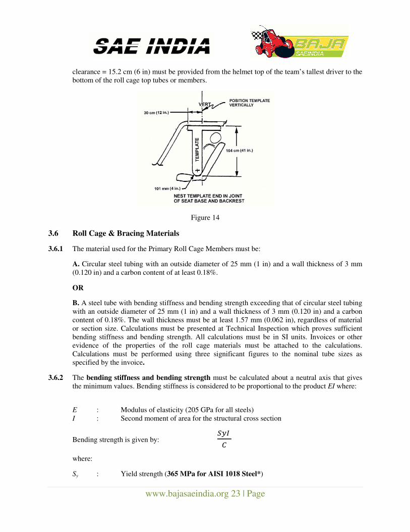
3.5 Driver Head Clearance
Minimum driver head clearance = 104.1 cm (41 in), above the seating surface to the bottom of the
upper roll cage tubes measured vertically using the template in Figure 14. Minimum vertical
www.bajasaeindia.org 23 | Page
clearance = 15.2 cm (6 in) must be provided from the helmet top of the team’s tallest driver to the
bottom of the roll cage top tubes or members.
Figure 14
3.6 Roll Cage & Bracing Materials
3.6.1 The material used for the Primary Roll Cage Members must be:
A. Circular steel tubing with an outside diameter of 25 mm (1 in) and a wall thickness of 3 mm
(0.120 in) and a carbon content of at least 0.18%.
OR
B. A steel tube with bending stiffness and bending strength exceeding that of circular steel tubing
with an outside diameter of 25 mm (1 in) and a wall thickness of 3 mm (0.120 in) and a carbon
content of 0.18%. The wall thickness must be at least 1.57 mm (0.062 in), regardless of material
or section size. Calculations must be presented at Technical Inspection which proves sufficient
bending stiffness and bending strength. All calculations must be in SI units. Invoices or other
evidence of the properties of the roll cage materials must be attached to the calculations.
Calculations must be performed using three significant figures to the nominal tube sizes as
specified by the invoice.
3.6.2 The bending stiffness and bending strength must be calculated about a neutral axis that gives
the minimum values. Bending stiffness is considered to be proportional to the product EI where:
E : Modulus of elasticity (205 GPa for all steels)
I : Second moment of area for the structural cross section
Bending strength is given by: ���
�
where:
Sy : Yield strength (365 MPa for AISI 1018 Steel*)
www.bajasaeindia.org 24 | Page
C : Distance from neutral axis to extreme fiber
*Bending Strength of AISI 1018 Steel (for tube dimension of Sec. 3.6.1 A) = 387.38 Nm
3.7 Roll Cage Specification Sheet:
Each team must present a completed BAJA SAEINDIA Roll Cage Specification Sheet (Sec 7,
Appendix 1) at Technical Inspection. While procuring tube one should get copy of tube
specification and also ensure this is certified from local laboratory. Both copies must be presented
during Tech Inspection at College level and Final Check at event site.
NOTE: Latest Material Specification Check Report is essential for used material.
3.8 Roll Cage Padding
Any portion of the roll cage, which would be contacted by the driver, must be covered by a
resilient foam material such as Polyethylene® (pipe insulation) with a minimum thickness of 1.2
cm (0.5 in).
Any vehicle not meeting this requirement shall not be allowed to take part in any events.
Inspectors shall measure this dimension as per the Technical Inspection Sheet. All sharp edges
which might endanger the driver, crew, officials and safety staff must be eliminated by
shielding and/or padding. This includes brackets, gussets, sheet stock, fastener ends,
clamps, zip ties or other features accessible during servicing, judging or competition impact
or roll over.
3.9 Bolted Roll Cages
Bolted Roll cages are acceptable only if the following requirements are met:
(A) Flanges or tabs must be twice (2X) the thickness of the tube structures, made of the same
material type. They must be properly welded to each tubing part to be joined.
(B) Flange mounts must be twice (2X) the diameter of the attached tubing, flush mated, and with
no gap between the faces greater than 0.07 mm (0.003 in).
(C) Tab mounts must be dual, parallel and on each side of the tubing to which they are
welded, having a welded length of at least twice (2X) the diameter of the adjoined. Tubing held
by bolts must be reinforced such that the area through which the bolt passes cannot be
compressed from tightening or impact.
3.10 COCKPIT
3.10.1 Driver’s Seat
The use of a driver seat is mandatory; cushioning or padding attached to the frame and/or firewall
will not be accepted as a seat. The seat shall be fastened to the frame and shall support the entire
body of the driver (full torso and head). The load shall not be transferred to the firewall or
any other member except those supporting the seat clearance of 75 mm (3in) between the
firewall, Side Impact Members and the seat must be maintained. The use of commercially
available rally seats is highly recommended. Recliner Seats are not allowed.
www.bajasaeindia.org 25 | Page
Driver Exit Time
All drivers must be able to exit on either side of the vehicle within five (5) seconds. Exit time
begins with the driver in the fully seated position, hands in driving position on the connected
steering wheel, and wearing the required driver equipment. Exit time will stop when the driver
has both feet on the ground.
3.10.2 Firewall
A firewall between the cockpit and the engine and fuel tank compartment is mandatory.
The firewall is recommended to be behind the RRH. It must cover the area between the lower and
upper lateral cross member. This firewall must be metal, at least 0.508 mm (0.020 in) thick.
Cutouts in the firewall are allowed, but they need to have grommets or boots that prevent large
amounts of fuel from getting into the cockpit.
Front or Mid-engine Cars
If the engine is not placed in the rear of the vehicle, then a firewall is not required to cover the
area between the RRH lateral cross members. Instead, the firewall must meet the following
standards:
(A) Fuel tank must be in a sealed container that prevents fuel from leaking in the event of fuel
tank failure.
(B) Splash shields/ Drip Pan must prevent fuel from being poured anywhere in the cockpit area
during fuelling. (See rule 3.16.3 “Spill Prevention”)
(C) Engine must be completely enclosed and protect the driver in the event of an engine failure.
Shielding must meet guarding requirements. This shielding must be made of metal. . (See rule
3.19.1 “Power train Guards”).
(D) All engine compartment venting must be directed away from driver area.
(E) Driver must be able to still egress from either side of the vehicle.
(F) The exhaust must not exit towards the driver and must be shielded.
(G) There must be a place to mount the Technical Inspection sticker (30cm x 30cm or 12 in x 12
in) on the RRH. It must be located on the driver’s right side above the shoulders in easy view of
track workers.
NOTE: Engine enclosures must prevent fuel from spilling onto driver area during any
vehicle upset.
Body Panels
The cockpit must be fitted with body panels that cover the area between the lower frame side
member and the side impact member. No gaps can exist that are larger than 6.35 mm (0.25 in).
These panels must be made of plastic, fiberglass, metal or similar material.
They must be designed to prevent debris and foreign object intrusion into the driver compartment.
www.bajasaeindia.org 26 | Page
The panels must be mounted securely to the frame using sound engineering practices
NOTE: Zip ties and Velcro are not acceptable.
3.10.3 Belly Pan and Leg/ Foot Shielding
The cockpit should be fitted with a belly pan (minimum length being the cockpit), so the
driver cannot contact the ground and is protected from debris while seated normally. All
steering or suspension links exposed in the cockpit must be shielded with metal. The shielding
must prevent the driver’s legs and feet (completely within the roll cage), from coming in
contact, or becoming entangled during operation or a failure. No gaps can exist that are
larger than 6.35 mm (0.25 in).
3.10.4 Kill Switches
Each vehicle must be equipped with two (2) easily accessible kill switches to push off the ignition
and the entire electrical system of the car. However Brake light, Reverse light and Reverse Alarm
should not be switched off by use of Kill switch.
Kill switch which operates by “Push-to-Off” is only allowed to use on Baja Vehicle. Rotary
switches or Pull-to-Off type switches are not allowed.
A. Kill Switch – Type
The kill switch must be one of the following types:
a) 01-171 Ski-Doo kill switch available at
http://www.mfgsupply.com/m/c/01-171.html?id=UxSI4Vzn
b) AfterMarketWPS#27-0152 or 27-0124
http://www.parkeryamaha.com/index.asp?PageAction=PRODSEARCH&txtSearch=27-
0152&Page=1
c) A Stock Polaris # 4110106
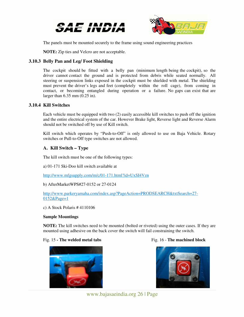
Sample Mountings
NOTE: The kill switches need to be mounted (bolted or riveted) using the outer cases. If they are
mounted using adhesive on the back cover the switch will fail constraining the switch.
Fig. 15 - The welded metal tabs Fig. 16 - The machined block
www.bajasaeindia.org 27 | Page
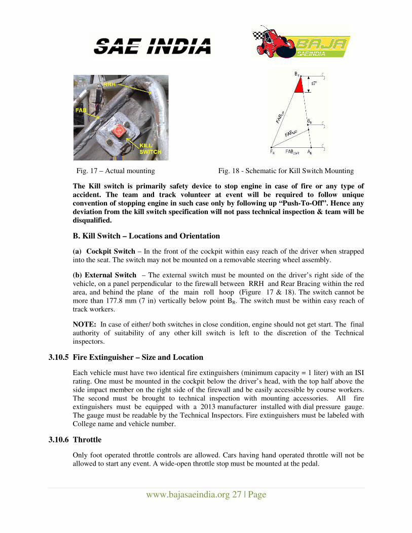
Fig. 17 – Actual mounting Fig. 18 - Schematic for Kill Switch Mounting
The Kill switch is primarily safety device to stop engine in case of fire or any type of
accident. The team and track volunteer at event will be required to follow unique
convention of stopping engine in such case only by following up “Push-To-Off”. Hence any
deviation from the kill switch specification will not pass technical inspection & team will be
disqualified.
B. Kill Switch – Locations and Orientation
(a) Cockpit Switch – In the front of the cockpit within easy reach of the driver when strapped
into the seat. The switch may not be mounted on a removable steering wheel assembly.
(b) External Switch – The external switch must be mounted on the driver’s right side of the
vehicle, on a panel perpendicular to the firewall between RRH and Rear Bracing within the red
area, and behind the plane of the main roll hoop (Figure 17 & 18). The switch cannot be
more than 177.8 mm (7 in) vertically below point BR. The switch must be within easy reach of
track workers.
NOTE: In case of either/ both switches in close condition, engine should not get start. The final
authority of suitability of any other kill switch is left to the discretion of the Technical
inspectors.
3.10.5 Fire Extinguisher – Size and Location
Each vehicle must have two identical fire extinguishers (minimum capacity = 1 liter) with an ISI
rating. One must be mounted in the cockpit below the driver’s head, with the top half above the
side impact member on the right side of the firewall and be easily accessible by course workers.
The second must be brought to technical inspection with mounting accessories. All fire
extinguishers must be equipped with a 2013 manufacturer installed with dial pressure gauge.
The gauge must be readable by the Technical Inspectors. Fire extinguishers must be labeled with
College name and vehicle number.
3.10.6 Throttle
Only foot operated throttle controls are allowed. Cars having hand operated throttle will not be
allowed to start any event. A wide-open throttle stop must be mounted at the pedal.
www.bajasaeindia.org 28 | Page
Throttle Extensions
Teams may not add any type of extension (e.g. blocks of wood) to either the control surfaces
or to the driver in order to operate the vehicle.
3.11 DRIVER RESTRAINT
3.11.1 Minimum Four Strap System Required
All drivers must use a minimum of a four (4) strap restraint harness. However, it is strongly
recommended to use a 5 point restraint harness meeting the following specifications. A five-point
system consists of a 76 mm (3 in) wide lap belt and approximately 76 mm (3 in) wide shoulder
harness straps, along with a fifth (anti-submarine) belt must be worn between the legs,
preventing the lap belt from riding up along the driver’s torso. The restraint system installation
is subject to approval of the Technical Inspector. No more than a finger width gap between the
belts and the driver will be allowed when the belt is pulled.
3.11.2 Release Mechanism
All belts must join with a single metal-to-metal quick release lever type buckle. No cam-lock
systems are allowed.
3.11.3 Safety Harness Expiration
The material of all straps must be Nylon or Dacron polyester and in new or perfect condition. All
driver restraint systems must meet either SFI Specification 16.5/16.1 or FIA specification
8853/98 or ISI marks. The belts must bear the appropriate dated labels, and on 1st Jan of the
competition year be no more than three years old. The team should show the SFI rating during
inspection, if required along with the bill.
3.12 Shoulder Harness
The shoulder harness must be the over-the-shoulder type. Only separate shoulder straps are
permitted (i.e. “Y”-type shoulder straps are not allowed).
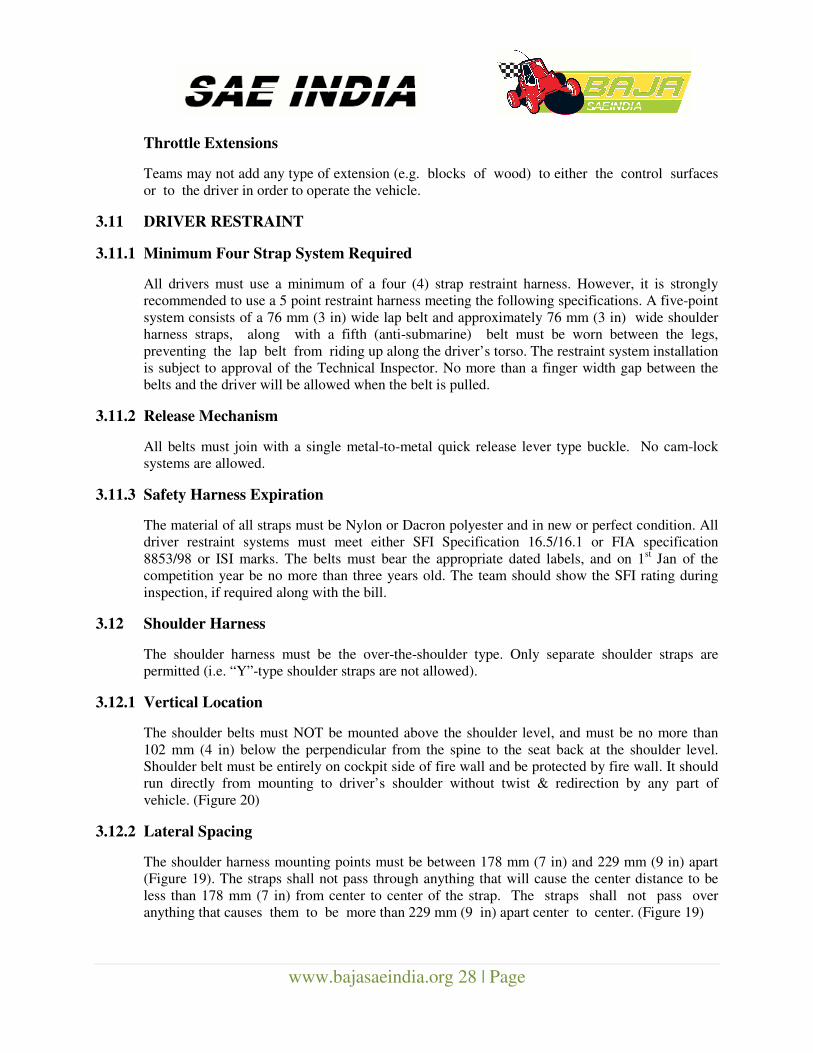
3.12.1 Vertical Location
The shoulder belts must NOT be mounted above the shoulder level, and must be no more than
102 mm (4 in) below the perpendicular from the spine to the seat back at the shoulder level.
Shoulder belt must be entirely on cockpit side of fire wall and be protected by fire wall. It should
run directly from mounting to driver’s shoulder without twist & redirection by any part of
vehicle. (Figure 20)
3.12.2 Lateral Spacing
The shoulder harness mounting points must be between 178 mm (7 in) and 229 mm (9 in) apart
(Figure 19). The straps shall not pass through anything that will cause the center distance to be
less than 178 mm (7 in) from center to center of the strap. The straps shall not pass over
anything that causes them to be more than 229 mm (9 in) apart center to center. (Figure 19)
www.bajasaeindia.org 29 | Page
Fig. 19 - Distance of shoulder point Fig. 20 - Vertical Location
Fig. 21 - Lap belt specification Fig. 22 – Lap Belt Anchoring Method
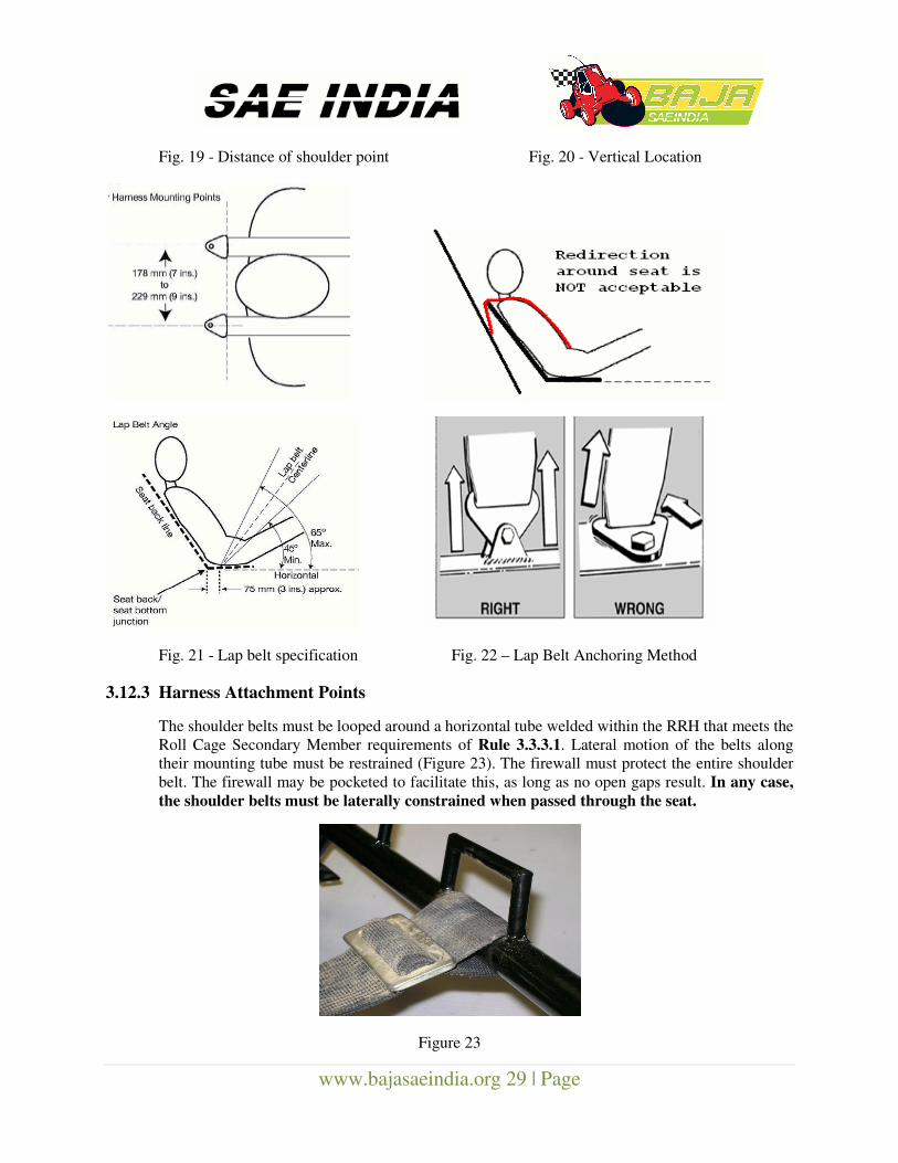
3.12.3 Harness Attachment Points
The shoulder belts must be looped around a horizontal tube welded within the RRH that meets the
Roll Cage Secondary Member requirements of Rule 3.3.3.1. Lateral motion of the belts along
their mounting tube must be restrained (Figure 23). The firewall must protect the entire shoulder
belt. The firewall may be pocketed to facilitate this, as long as no open gaps result. In any case,
the shoulder belts must be laterally constrained when passed through the seat.
Figure 23
www.bajasaeindia.org 30 | Page
3.13 Lap & Anti-Submarine Belts
The lap belt must pass around the pelvic area below the Anterior Superior Iliac Spines (hip bones)
(Fig. 21). Under no condition may the lap belt be worn over the area of the intestines or abdomen.
The lap belts should come through the seat at the bottom of the sides of the seat to
maximize the wrap of the pelvic surface and continue in a straight line to the anchorage point.
In side view, the lap belt must be at an angle of between 45 degrees and 65 degrees to the
horizontal. This means that the centerline of the lap belt at the seat bottom should be
approximately 76 mm (3 in) forward of the seat back to seat bottom junction (see Figure 21).
To fit drivers of differing statures correctly, in side view, the lap / anti-submarine belts must be
capable of pivoting freely by using either a shouldered bolt or an eye bolt attachment (Figure 22).
Mounting lap belts by wrapping them around frame tubes is no longer acceptable unlike the case
of Shoulder Harness. The lap belts should not be routed over the sides of the seat.
3.13.1 Specified Lap & Anti-Submarine Belts Mounting
The frame tabs which accept the lap belt mounting tabs must meet the following requirements:
1) The lap belt tabs must be mounted in double-shear. (See Figure 22)
2) The frame tabs that accept the lap belt tabs shall be no less than 2.3 mm thick (0.90 in)
3) The tabs mounted to the frame to accept the lap belt tabs shall have no less than 38
mm (1.5 in) of weld length where mounted to the frame
4) These tabs shall have no less than 6.4 mm (0.25 in) of material in the radial direction from the
edge of the mounting bolt hole to the closest outside edge of the mounting tab.
5) Where the harness tab mounts to the frame tabs, the lap belt must be capable of pivoting
freely about the axis of the mounting bolt such that the webbing and tab can align with
the direction of the load. The height of the tab is free, but ultimately subject to the judgment of
the Technical Inspectors. The mount should not exhibit noticeable deformation when pulled on
during technical inspection.
NOTE: If the belts do not have enough adjustment capacity or improperly fitted, the vehicle will
not be cleared for Technical Inspection. The final decision in this regard rests with the technical
committee head.
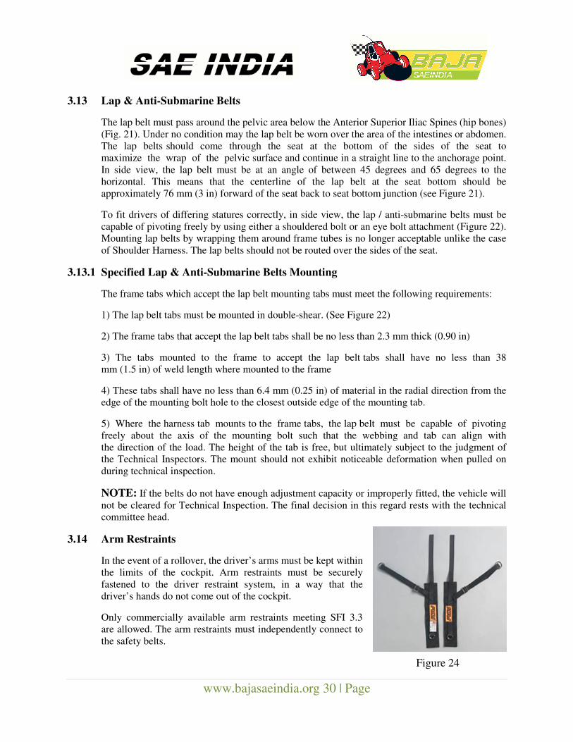
3.14 Arm Restraints
In the event of a rollover, the driver’s arms must be kept within
the limits of the cockpit. Arm restraints must be securely
fastened to the driver restraint system, in a way that the
driver’s hands do not come out of the cockpit.
Only commercially available arm restraints meeting SFI 3.3
are allowed. The arm restraints must independently connect to
the safety belts.
Figure 24
www.bajasaeindia.org 31 | Page
3.14.1 Arm Restraint – Expiration
The belts must bear the appropriate dated labels, and on 1st Jan of the competition
year be no more than three years old.
3.15 BRAKING SYSTEM
3.15.1 Foot Brake
The vehicle must have at least two (2) independent hydraulic braking systems that act on all
wheels and is operated by a single foot. The pedal must directly actuate the master cylinder (no
cables are allowed). Each hydraulic system shall have its own fluid reserve either through
separate reservoirs or by the use of a dammed, OEM-style reservoir. The brake system must be
capable of locking ALL FOUR wheels in a static condition and dynamically on pavement AND
an unpaved surface. Both the independent brake-systems may be actuated by a tandem master
cylinder and safely stop the vehicle at max speed of 45kmph or above.
All rigid brake pipes must be mounted securely along the roll cage / other members as required.
Loosely hanging / pipes located by using ties / tapes etc shall not be permitted. Wheel ends
should be connected with flexible pipe only. The bleed point location must lie on top of the
caliper cylinders, without exception. Vehicles not meeting this requirement will not clear
technical Inspection. This is in the interest of safety of vehicle & team. The brake(s) on the driven
axle must operate through the final drive. Inboard braking through universal joints is permitted.
Braking on a jackshaft or through an intermediate reduction stage is prohibited.
NOTE: Plastic brake lines are not allowed. Use of OEM Brake lines is recommended.
3.15.2 Brake Light
The vehicle must be equipped with a red brake light whose lens must be marked with an SAE “S”
or “U” rating (i.e.: SAE IPRSTM) or if it is not rated as per SAE J759, it must be equal to or
exceed these standards (e.g.: OEM brake light assemblies)/ AIS and ISI rated brake lights are
also permitted. The determination of whether or not a brake light meets the required standards.
The brake light must be mounted at a minimum of 1 meter (40 in.) above the ground.
Light must be mounted such that it shines parallel to the ground, not at an angle, till a
distance of 10 meters.
3.16 FUEL SYSTEM
3.16.1 System Location
The entire fuel system must be located within the roll cage envelope such that it is protected from
impact. The tank mountings are done along with B&S engine and need not to be changed.
3.16.2 Fuel Tank
A single fuel tank (maximum capacity = 4.5 liter) is permitted on the vehicle which is supplied &
mounted along with B&S Engine. Quality, cleanliness of fuel tanks is important from both safety
& engine working point of view.
www.bajasaeindia.org 32 | Page
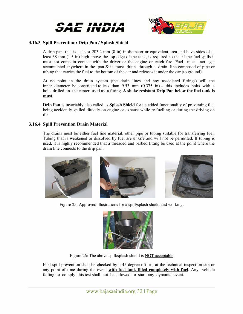
3.16.3 Spill Prevention: Drip Pan / Splash Shield
A drip pan, that is at least 203.2 mm (8 in) in diameter or equivalent area and have sides of at
least 38 mm (1.5 in) high above the top edge of the tank, is required so that if the fuel spills it
must not come in contact with the driver or the engine or catch fire. Fuel must not get
accumulated anywhere in the pan & it must drain through a drain line composed of pipe or
tubing that carries the fuel to the bottom of the car and releases it under the car (to ground).
At no point in the drain system (the drain lines and any associated fittings) will the
inner diameter be constricted to less than 9.53 mm (0.375 in) – this includes bolts with a
hole drilled in the center used as a fitting. A shake resistant Drip Pan below the fuel tank is
must.
Drip Pan is invariably also called as Splash Shield for its added functionality of preventing fuel
being accidently spilled directly on engine or exhaust while re-fuelling or during the driving on
tilt.
3.16.4 Spill Prevention Drain Material
The drains must be either fuel line material, other pipe or tubing suitable for transferring fuel.
Tubing that is weakened or dissolved by fuel are unsafe and will not be permitted. If tubing is
used, it is highly recommended that a threaded and barbed fitting be used at the point where the
drain line connects to the drip pan.
Figure 25: Approved illustrations for a spill/splash shield and working.
Figure 26: The above spill/splash shield is NOT acceptable
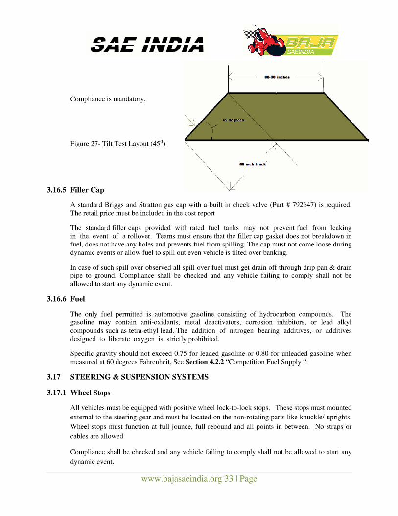
Fuel spill prevention shall be checked by a 45 degree tilt test at the technical inspection site or
any point of time during the event with fuel tank filled completely with fuel. Any vehicle
failing to comply this test shall not be allowed to start any dynamic event.
www.bajasaeindia.org 33 | Page
Compliance is mandatory.
Figure 27- Tilt Test Layout (45⁰)
3.16.5 Filler Cap
A standard Briggs and Stratton gas cap with a built in check valve (Part # 792647) is required.
The retail price must be included in the cost report
The standard filler caps provided with rated fuel tanks may not prevent fuel from leaking
in the event of a rollover. Teams must ensure that the filler cap gasket does not breakdown in
fuel, does not have any holes and prevents fuel from spilling. The cap must not come loose during
dynamic events or allow fuel to spill out even vehicle is tilted over banking.
In case of such spill over observed all spill over fuel must get drain off through drip pan & drain
pipe to ground. Compliance shall be checked and any vehicle failing to comply shall not be
allowed to start any dynamic event.
3.16.6 Fuel
The only fuel permitted is automotive gasoline consisting of hydrocarbon compounds. The
gasoline may contain anti-oxidants, metal deactivators, corrosion inhibitors, or lead alkyl
compounds such as tetra-ethyl lead. The addition of nitrogen bearing additives, or additives
designed to liberate oxygen is strictly prohibited.
Specific gravity should not exceed 0.75 for leaded gasoline or 0.80 for unleaded gasoline when
measured at 60 degrees Fahrenheit, See Section 4.2.2 “Competition Fuel Supply “.
3.17 STEERING & SUSPENSION SYSTEMS
3.17.1 Wheel Stops
All vehicles must be equipped with positive wheel lock-to-lock stops. These stops must mounted
external to the steering gear and must be located on the non-rotating parts like knuckle/ uprights.
Wheel stops must function at full jounce, full rebound and all points in between. No straps or
cables are allowed.
Compliance shall be checked and any vehicle failing to comply shall not be allowed to start any
dynamic event.
www.bajasaeindia.org 34 | Page
3.17.2 Tie Rod Protection
The tie rods of all vehicles must be protected from frontal impact. A bumper may be required, at
the technical inspector’s discretion, depending on the design and installation. Adjustable tie rod
ends must be constrained with a jam nut to prevent loosening.
3.17.3 Handlebar steering
Handlebar operated steering system is specifically prohibited.
3.18 FASTENERS
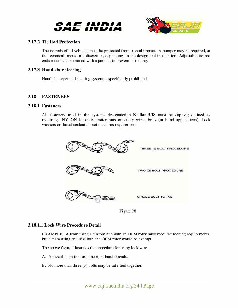
3.18.1 Fasteners
All fasteners used in the systems designated in Section 3.18 must be captive; defined as
requiring NYLON locknuts, cotter nuts or safety wired bolts (in blind applications). Lock
washers or thread sealant do not meet this requirement.
Figure 28
3.18.1.1 Lock Wire Procedure Detail
EXAMPLE: A team using a custom hub with an OEM rotor must meet the locking requirements,
but a team using an OEM hub and OEM rotor would be exempt.
The above figure illustrates the procedure for using lock wire:
A. Above illustrations assume right hand threads.
B. No more than three (3) bolts may be safe-tied together.
www.bajasaeindia.org 35 | Page
C. Bolt heads may be safe-tied as shown only when the female thread receiver is captive,
or the nuts meet previous lock nut requirements.
D. Nuts (pre-drilled) may be safe-tied in similar fashion to the illustrations with the following
conditions:
1. Nuts are heat-treated.
2. Nuts are “factory drilled” for use with lock wire.
E. Lock wire MUST fill a minimum of 75% of the drilled hole provided for the use of lock wire.
F. Lock wire must be aircraft quality stainless steel of 0.508 mm, 0.813mm, or 1.067mm
diameter (0.020 in., 0.032 in., or 0.042 in. diameter). Diameter of lock wire is determined by the
thread size of the fastener to be satisfied:
1. Thread sizes of ¼” and smaller use 0 020” wire
2. Thread sized of ¼” to ½” use 0 032” wire
3. Thread sizes > ½” use 0 042” wire
4. The larger wire may be used in smaller bolts in cases of convenience, but smaller wire must
not be used in larger fastener sizes.
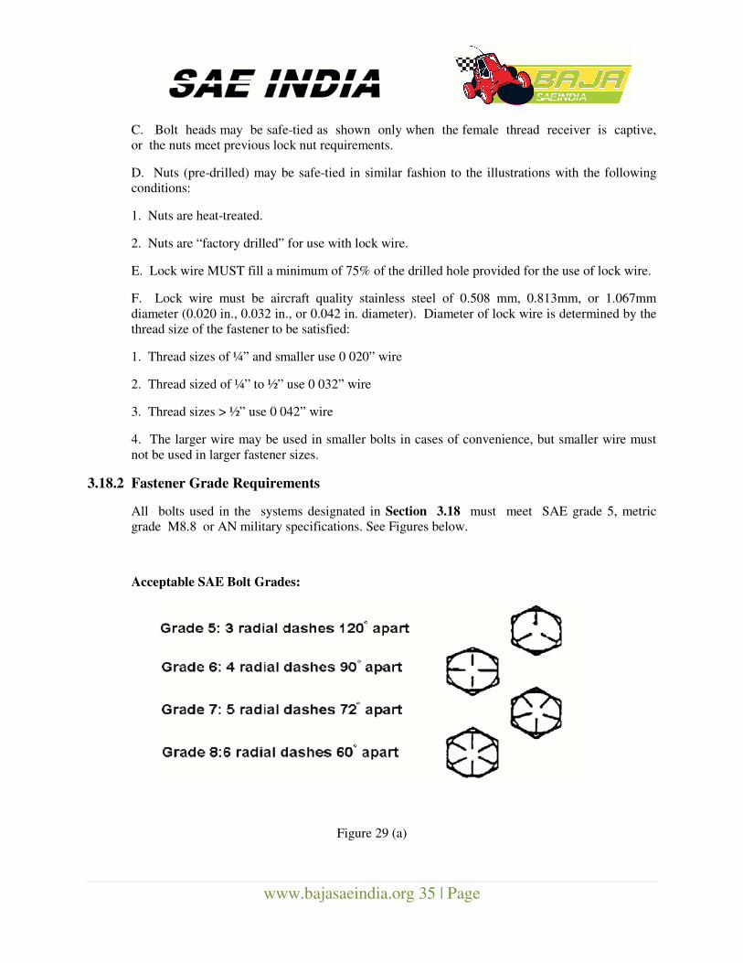
3.18.2 Fastener Grade Requirements
All bolts used in the systems designated in Section 3.18 must meet SAE grade 5, metric
grade M8.8 or AN military specifications. See Figures below.
Acceptable SAE Bolt Grades:
Figure 29 (a)
www.bajasaeindia.org 36 | Page
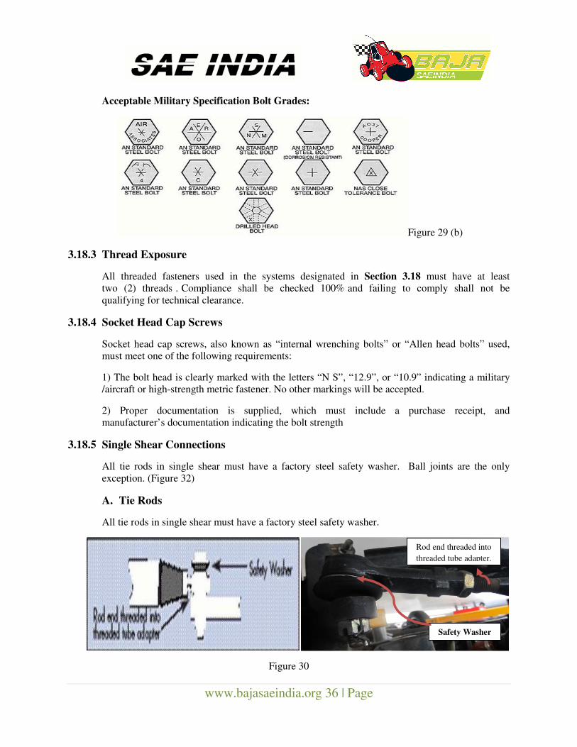
Acceptable Military Specification Bolt Grades:
Figure 29 (b)
3.18.3 Thread Exposure
All threaded fasteners used in the systems designated in Section 3.18 must have at least
two (2) threads . Compliance shall be checked 100% and failing to comply shall not be
qualifying for technical clearance.
3.18.4 Socket Head Cap Screws
Socket head cap screws, also known as “internal wrenching bolts” or “Allen head bolts” used,
must meet one of the following requirements:
1) The bolt head is clearly marked with the letters “N S”, “12.9”, or “10.9” indicating a military
/aircraft or high-strength metric fastener. No other markings will be accepted.
2) Proper documentation is supplied, which must include a purchase receipt, and
manufacturer’s documentation indicating the bolt strength
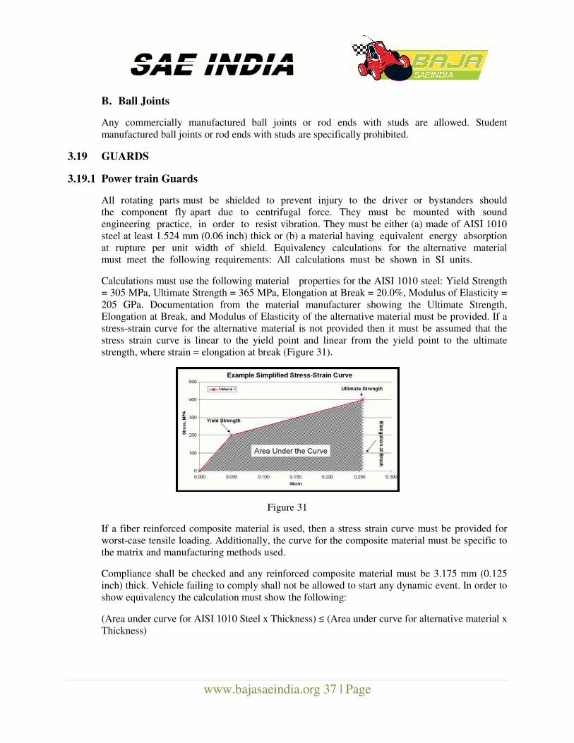
3.18.5 Single Shear Connections
All tie rods in single shear must have a factory steel safety washer. Ball joints are the only
exception. (Figure 32)
A. Tie Rods
All tie rods in single shear must have a factory steel safety washer.
Figure 30
Safety Washer
Rod end threaded into
threaded tube adapter.
www.bajasaeindia.org 37 | Page
B. Ball Joints
Any commercially manufactured ball joints or rod ends with studs are allowed. Student
manufactured ball joints or rod ends with studs are specifically prohibited.
3.19 GUARDS
3.19.1 Power train Guards
All rotating parts must be shielded to prevent injury to the driver or bystanders should
the component fly apart due to centrifugal force. They must be mounted with sound
engineering practice, in order to resist vibration. They must be either (a) made of AISI 1010
steel at least 1.524 mm (0.06 inch) thick or (b) a material having equivalent energy absorption
at rupture per unit width of shield. Equivalency calculations for the alternative material
must meet the following requirements: All calculations must be shown in SI units.
Calculations must use the following material properties for the AISI 1010 steel: Yield Strength
= 305 MPa, Ultimate Strength = 365 MPa, Elongation at Break = 20.0%, Modulus of Elasticity =
205 GPa. Documentation from the material manufacturer showing the Ultimate Strength,
Elongation at Break, and Modulus of Elasticity of the alternative material must be provided. If a
stress-strain curve for the alternative material is not provided then it must be assumed that the
stress strain curve is linear to the yield point and linear from the yield point to the ultimate
strength, where strain = elongation at break (Figure 31).
Figure 31
If a fiber reinforced composite material is used, then a stress strain curve must be provided for
worst-case tensile loading. Additionally, the curve for the composite material must be specific to
the matrix and manufacturing methods used.
Compliance shall be checked and any reinforced composite material must be 3.175 mm (0.125
inch) thick. Vehicle failing to comply shall not be allowed to start any dynamic event. In order to
show equivalency the calculation must show the following:
(Area under curve for AISI 1010 Steel x Thickness) ≤ (Area under curve for alternative material x
Thickness)
www.bajasaeindia.org 38 | Page
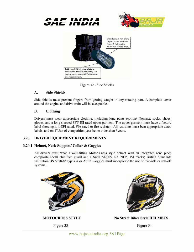
Figure 32 - Side Shields
A. Side Shields
Side shields must prevent fingers from getting caught in any rotating part. A complete cover
around the engine and drive-train will be acceptable.
B. Clothing
Drivers must wear appropriate clothing, including long pants (cotton/ Nomex), socks, shoes,
gloves, and a long sleeved SFI/ ISI rated upper garment. The upper garment must have a factory
label showing it is SFI rated, FIA rated or fire resistant. All restraints must bear appropriate dated
labels, and on 1st Jan of competition year be no older than 3years.
3.20 DRIVER EQUIPMENT REQUIREMENTS
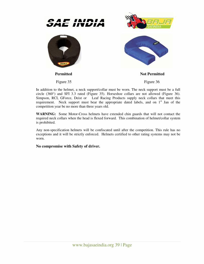
3.20.1 Helmet, Neck Support/ Collar & Goggles
All drivers must wear a well-fitting Motor-Cross style helmet with an integrated (one piece
composite shell) chin/face guard and a Snell M2005, SA 2005, ISI marks; British Standards
Institution BS 6658-85 types A or A/FR. Goggles must incorporate the use of tear-offs or roll-off
systems.
MOTOCROSS STYLE No Street Bikes Style HELMETS
Figure 33 Figure 34
www.bajasaeindia.org 39 | Page
Permitted Not Permitted
Figure 35 Figure 36
In addition to the helmet, a neck support/collar must be worn. The neck support must be a full
circle (360°) and SFI 3.3 rated (Figure 35). Horseshoe collars are not allowed (Figure 36).
Simpson, RCI, GForce, Deist or Leaf Racing Products supply neck collars that meet this
requirement. Neck support must bear the appropriate dated labels, and on 1st Jan of the
competition year be no more than three years old.
WARNING: Some Motor-Cross helmets have extended chin guards that will not contact the
required neck collars when the head is flexed forward. This combination of helmet/collar system
is prohibited.
Any non-specification helmets will be confiscated until after the competition. This rule has no
exceptions and it will be strictly enforced. Helmets certified to other rating systems may not be
worn.
No compromise with Safety of driver.
www.bajasaeindia.org 40 | Page
Section 4 - Competition Procedures and Regulations
4.1 RULES CLARIFICATION AND PROTESTS
4.1.1 Technical Questions
Questions about the rules requirements and restrictions must be submitted by e-mail to
the Technical Inspectors of the Baja SAE India at: [email protected] . Questions and
answers will be posted on the Baja SAE India website at: www.bajasaeindia.org .
NOTE: Please keep in mind that final operating approval of a BAJA SAEINDIA vehicle can
only be given at the competition venue by the National Technical Inspectors.
4.1.2 Protests
Any objection/matter must be brought to the notice of the organizers or SAE INDIA staff’s
attention for an informal preliminary review before a protest can be filed.
Teams may not protest rule interpretations or actions that have not caused them any
substantive damage.
All protests must be filed in writing and presented to the organizer or SAE staff by the
faculty advisor or team captain within one hour (60 minutes) of the end of the event to
which the protest relates. In order to have a protest considered, a team must post a twenty-five
(25) point protest bond which will be forfeited if their protest is rejected.
The decision of the competition protest committee or National Technical Inspectors regarding any
protest is final.
4.2 COMPETITION PROCEDURES AND REGULATION (GENERAL)
4.2.1 Drivers Meetings
All team members identified as drivers and their support personnel MUST attend all
drivers meetings. Failure to attend drivers meetings can result in disqualification of members or
the entire team.
4.2.2 Competition Fuel Supply
Fuel at the competition will either (1) be provided by the organizers or (2) the organizers
will specify acceptable fuel providers.
4.2.2.1 Re-fuelling
All refueling of the cars done in the pit area or on the course must be done with (1) the engine
shut-off and (2) the driver out of the car. Any violations of this rule will be subjected to severe
penalties. A fire extinguisher must be in hand whenever a vehicle is being refueled.
www.bajasaeindia.org 41 | Page
4.2.3 Engine and Drive-train Inspection
The Technical Inspectors reserve the right to impound and inspect any vehicle during/ after the
dynamic or endurance events. Any vehicle found to have: (1) a drive-train configuration not
matching the Drive-train Certification Form submitted during technical inspection or (2) an
engine in violation of rules Sections 2.2 through 2.2, 1.2, 2.3, 2.4 shall receive zero points (0) for
all dynamic competition events completed during the day on which the inspection was performed.
4.2.4 Engine Recall Option
The organizers and SAE India may, at their sole option, recall the engine from any vehicle in the
competition in exchange for a new B&S engine. Recalled engines will not be returned and will
be inspected at B&S’s facilities to confirm compliance with the rules.
4.2.5 Driving Restrictions
When a vehicle is driven anywhere except the practice area or competition events, it must move
at walking speed with a team member walking along side at a normal walking pace. The walking
speed rule will be strictly enforced and point penalties will be assessed for violations, including
impounding the vehicle for a specific period of time, at the discretion of the Technical Inspectors.
Under no circumstances may anyone other than the driver ride on a vehicle.
Drivers must wear all of the equipment specified such as seatbelts, helmets, goggles, wrist
restraints, required clothing and a properly fastened restraint system at all times when the vehicle
is running in any event or on the test track.
Drivers not wearing the proper equipment will not be permitted to drive, and may have their
competition driver’s privileges revoked
Practicing outside of the designated practice area will result in a minimum fifty (50) point penalty
and/or the revocation of driving privileges depending on the extent of the infraction.
DRIVING OFF-SITE IS ABSOLUTELY PROHIBITED. TEAMS FOUND TO HAVE
DRIVEN THEIR VEHICLE AT AN OFF- SITE LOCATION MAY BE EXPELLED FROM
THE COMPETITION.
4.2.6 Penalties
Organizers have the right to modify the penalties listed in the various dynamic event descriptions
to better reflect the design of their event courses, the course lengths or any special conditions
unique to the site.
4.3 Rules of Conduct
4.3.1 Sportsmanship
Good conduct and compliance with the rules are requirements for every team member. Owing to
any unsportsmanlike conduct which can include arguments with officials, disobedience of official
instructions and the use of abusive or threatening language to any official or other
participant, the organizer is authorized to impose an appropriate penalty.
www.bajasaeindia.org 42 | Page
4.3.2 Alcohol and Illegal Material
Alcoholic beverages, firearms, weapons of any type and illegal materials are prohibited at
the Baja SAE India site during the competition. The penalty for violation of this rule is the
immediate expulsion of the entire team, not just the individual(s) involved. This rule applies to
team members, advisors and any individuals working with the team on-site. Disruptive
parties either on or off-site should be prevented by the faculty advisor.
4.3.3 Site Condition
Please help the organizers keep the site clean. Failure to clean the premises will result in an
unsportsmanlike conduct penalty. Competitors and spectators are encouraged to police their
areas after meals.
4.4 Safety – Team Responsibility
Safety is the primary consideration in the design of BAJA SAEINDIA vehicles and the
conduct of the competitions. Teams need to include safety considerations in all parts of their
program. At all performance events, it is the responsibility of the team to ensure both the
vehicle and driver meet and follow all the requirements and restrictions of the rules.
The teams are required to maintain the code of conduct throughout the event, failing which they
may have to face point penalties or even disqualification.
4.5 Spectator Rules
The competitors, faculty and volunteers are expected to help inform the spectators of the safety
rules and help restrict spectators to the spectator areas. Spectators may not drink alcoholic
beverages at any event location. Spectators must keep well back from the event and
practice tracks and from any area where vehicles are operating under power. Spectators
who fail to strictly control their children will be asked to leave the site. The course officials
and organizers have the absolute right to restrict spectator access to any parts of the site and to
eject anyone who violates safety rules or ignores the instructions of officials.
Note: All teams, spectators and faculty members are responsible for the safety of their own, their
vehicles and belongings. No claims regarding these shall be entertained by the organizers.
www.bajasaeindia.org 43 | Page
Section 5 – Technical Inspection
5.1 Self-Certification
Participating teams are required to carry-out a self-certification check at their end by the
due date of 30th
Nov. 2013 and complete the check sheet. The list of documents/
certificates/ video clips etc. and the check sheet completed in all respect with the actual
measurement values are to be submitted to the technical inspectors.
5.2 Technical Inspection at College level
1. The college level technical inspection is scheduled in Dec’13. The inspection will be carried
out by the trained technical inspectors at respective colleges.
2. The teams are required to demonstrate – weld check, workshop facilities, brake-test, figure of
8-test, tilt test, vehicle validation procedures/ facilities etc. during the technical inspection.
3. The completed Self-Certification Check Sheet duly signed by the faculty advisor and team
captain should be sent to BAJA Technical Committee. Teams should download the most
current version of the Self-Certification Check Sheet and thoroughly inspect their vehicle in
accordance with the sheet.
4. Only on the confirmation from the technical inspectors, the teams will be allowed to participate
in BAJA SAEINDIA 2014. Teams are liable to be DISQUALIFIED from participation in
BAJA SAEINDIA 2014 on NON-COMPLIANCE with the rulebook. The decision of
technical inspector will be final and non-challengeable.
5.3 On-site Safety Scrutiny
The objectives of On-Site safety scrutiny are to -
(1) Ensure engine is in proper operating condition & does not over speed 3800 rpm.
(2) Ensure compliance with the safety parameters for the vehicle & driver.
(3) Compliance of basic requirements mentioned in the rulebook.
(4) Validate the vehicle performance by conducting preliminary tests.
On the zeroth day at the BAJA site, the team need to report with SCCs duly signed by technical
inspector at college level and on its confirmation following sequence of Safety Scrutiny follows -
1) Fuel Filling
2) Stage 1- Engine Inspection (Engine OK Sticker Issue)
3) Stage 2- Safety Scrutiny & Figure of 8 (Safety Scrutiny & Fig 8 OK Sticker Issue)
a. 64-Inch (GO-NO-GO) Gauge
b. 45 Degree Tilt Test
c. Overall Safety Scrutiny
d. Fig of 8 - Test for turning & maneuverability (30 - 40 kmph)
4) Stage 3- Panic Brake test at 45 kmph (Brake OK Sticker Issue)
www.bajasaeindia.org 44 | Page
5.3.1 Zero Tolerance Policy
All BAJA SAEINDIA vehicles must pass Safety Scrutiny in two attempts only. During the safety
scrutiny, vehicle has to be in running condition, full tank fuel topped-up condition and should be
capable of undergoing for all the test sequence mentioned above.
The inspectors at site will give two attempts to all for each test and team need to comply for the
same within the stipulated time. Hence, it is mandatory to get certified with the same Technical
Inspector who has examined the vehicle at the first attempt (every test of the sequence bears
dedicated inspectors).
No special request for 3rd
test will be entertained.
The time will be logged for the complete Technical Inspection for each vehicle to evaluate the
best. The parameters - college level perfection & the shortest possible time in clearing the
technical inspection.
To satisfy the requirements and restrictions of the BAJA SAEINDIA rules, teams need to take the
best efforts at college level manufacturing and ensure the vehicles are complete in all aspects. The
Self-Certification is vital for the commitment towards ensuring the basic quality standards aimed
at completing the Technical Inspection on the 1st day of the event.
If vehicles are not ready on the day of technical inspection, teams are liable to be rewarded with
point-deduction. Teams not carrying Self Certification Check Sheet verified and approved by
technical inspectors, will be debarred from further participation.
Faculty advisors are not allowed to participate during technical inspection.
The team captains or other designated members (maximum 5) of the team must be present during
Inspection.
Vehicles that do not pass the technical inspection will be disqualified for all other events and
can’t participate in Dynamic and Endurance Tests.
The decision of the Head of the Technical Committee of BAJA SAEINDIA in this regard
will be final and binding to all.
5.4 Inspection Stickers
Technical inspection comprises of three stages. A three-parts inspection sticker (see Section 5.3
– Engine OK/ Safety Scrutiny & Fig 8 OK/ Brake OK Stickers) will be issued in sections
to the team as each of the three stages of technical inspection is completed. The inspection
sticker must remain on the vehicle throughout the competition.
Technical inspectors and officials may remove any or all parts of the inspection sticker from any
vehicle that has been damaged or which they reasonably believe may not comply with the rules.
Stage 1 – Engine Inspection OK
Briggs and Stratton staff is responsible for the Engine Inspection of each vehicle. To expedite the
process, each team needs to arrive with side cover removed and loosened bolts of fuel tank
www.bajasaeindia.org 45 | Page
mounting with spare air filter kit. Engine inspection will consist of - the engine rpm setting with
governor position verification, after-installation of new air-filter element and working of kill
switch. The inspection ensures-
(1) Setting of the governor at 3800 rpm & spring at 6th notch position, and
(2) Engine compliance for normal performance.
On successful completion of Stage 1, the First sticker will be put on the firewall.
Stage 1 must be passed before a team may apply for Stage 2 inspection.
Stage 2 – Safety Scrutiny & Figure of “8”
Each vehicle will be inspected to determine its compliance with the rules and restrictions. This
inspection will include an examination of the driver’s equipment including helmet and arm
restraints and a test of driver exit time.
ALL THE REGISTERED DRIVERS ARE MANDATORILY REQUIRED DURING SAFETY
SCRUTINY.
Each team must bring the following items to inspection; if they do not have the items at the time
of inspection they will receive a 10 point deduction for each item missing or not completely
filled:
a) Self-Certification Check sheet: With self checks carried out by team and verified by Technical
Inspector (Format is due to be posted on www.bajasaeindia.org by 10th November 2012. Team is
needed to download and ensure the compliance).
b) Tube Specification Certificate: Obtained from supplier with latest testing certificate from local
laboratory (Section 3.7).
c) Roll Cage Specification Sheet: Completed Roll Cage Specification Sheet. (See Section 7 –
Appendix 1)
d) Safety equipment and driver’s kit
The following tests will be carried out in the sequential manner during this stage-
(a) 64 inch GO-NO-GO gauge
(b) 45 deg tilt test for fuel spillage and drain
(c) Wheel lock stoppers
(d) Accelerator pedal return ability
(e) Free operation of gear shift and hand brake
(f) Reverse lamp functionality
(g) Specified hardware and nylon lock nuts
(h) Safety belt and restraints as per specification
(i) Egress test of all drivers
(j) Figure of 8 test and maneuverability
On successful completion of Stage 2, the Second sticker will be put on the firewall.
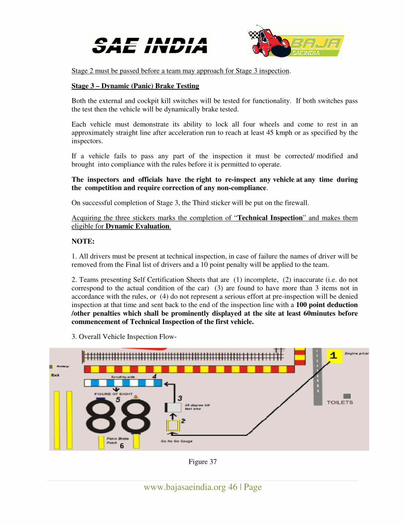
www.bajasaeindia.org 46 | Page
Stage 2 must be passed before a team may approach for Stage 3 inspection.
Stage 3 – Dynamic (Panic) Brake Testing
Both the external and cockpit kill switches will be tested for functionality. If both switches pass
the test then the vehicle will be dynamically brake tested.
Each vehicle must demonstrate its ability to lock all four wheels and come to rest in an
approximately straight line after acceleration run to reach at least 45 kmph or as specified by the
inspectors.
If a vehicle fails to pass any part of the inspection it must be corrected/ modified and
brought into compliance with the rules before it is permitted to operate.
The inspectors and officials have the right to re-inspect any vehicle at any time during the competition and require correction of any non-compliance.
On successful completion of Stage 3, the Third sticker will be put on the firewall.
Acquiring the three stickers marks the completion of “Technical Inspection” and makes them
eligible for Dynamic Evaluation.
NOTE:
1. All drivers must be present at technical inspection, in case of failure the names of driver will be
removed from the Final list of drivers and a 10 point penalty will be applied to the team.
2. Teams presenting Self Certification Sheets that are (1) incomplete, (2) inaccurate (i.e. do not
correspond to the actual condition of the car) (3) are found to have more than 3 items not in
accordance with the rules, or (4) do not represent a serious effort at pre-inspection will be denied
inspection at that time and sent back to the end of the inspection line with a 100 point deduction
/other penalties which shall be prominently displayed at the site at least 60minutes before
commencement of Technical Inspection of the first vehicle.
3. Overall Vehicle Inspection Flow-
Figure 37
6
www.bajasaeindia.org 47 | Page
INDEX (Figure 37):
1. Engine Check
2. 64-Inch (GO-NO-GO) Gauge
3. 45 Degree Tilt Test
4. Overall Safety Scrutiny
5. Figure of 8 Test
6. Panic Brake Test
5.5 “As-Approved” Conditions
Once a vehicle has passed technical inspection its configuration may not be modified. Approved
vehicles must remain in “as-approved” condition throughout the competition Necessary repairs
that do not significantly change the configuration of the vehicle are permitted. Minor adjustments
permitted by the rules and normal vehicle maintenance and tuning are not considered
modifications.
NOTE: It is important for every team to get their vehicle approved by the technical scrutiny
during which the safety, integrity of vehicle structure, fabrication processes adopted, etc will
be judged. The team shall provide documented proof of fabrication process of every
component and the design analysis, failing which they may have to face point penalties or
disqualification.
THE BAJA SAEINDIA TECHNICAL COMMITTEE RESERVES THE RIGHT TO
DISALLOW ANY VEHICLE FAILING TO COMPLY WITH THE REQUIREMENT OF
THESE RULES TO TAKE PART IN ANY DYNAMIC EVENT TILL THE VEHICLE IN
QUESTION IS RECTIFIED, REPRESENTED AND PASSES THE TECHNICAL
INSPECTION. FOR THIS COMPLIANCE, MAXIMUM NUMBER OF RE-
INSPECTIONS PER VEHICLE (BESIDES THE NORMAL INSPECTION AT SITE)
SHALL BE 2 (TWO) ONLY. THIS REQUIREMENT SHALL BE ENSURED WITHOUT
EXCEPTION. THEREFORE, IT IS REQUIRED THAT TEAMS COME WITH THEIR
VEHICLES WELL PREPARED FOR THE EVENT, TO AVOID DISAPPOINTMENT.
The decision of the Head of the Technical Committee of BAJA SAEINDIA in this regard
will be final and binding to all. This is in the interest of safety.
www.bajasaeindia.org 48 | Page
Section 6 – BAJA SAEINDIA Events
6.1 Static Events
The static events comprise of Design Evaluation, Cost Evaluation and Marketing
Presentation.
Teams are required to clear the Static Event at different panels assigned for specific evaluation.
Important instructions for Static Event-
1. BAJA SAEINDIA 2014 participating vehicle MUST be available for Design and Cost
Evaluation.
2. Design Report and Cost Report are mandatory during Design and Cost Evaluations
respectively.
3. During Marketing Evaluation business case needs to be explicitly presented dealing with
manufacturing and marketing strategies/plans.
4. There are 3-4 rows (with panel of judges) for each Static Event namely Design Evaluation,
Cost Evaluation and Marketing Presentation.
5. Teams are required to choose any one of the available rows and clear the same before
proceeding to next static event.
6. In case of failure at the first attempt in Design Evaluation, teams are allowed for ONLY 1
more attempt (2nd
attempt) at the same judges’ panel.
STUDENTS CAN INDEPENDENTLY APPROACH TO STATIC EVALUATION EVEN IF
FAILED IN TECHNICAL INSPECTION.
6.2 Dynamic Events
The dynamic events are intended to determine how the BAJA SAEINDIA vehicles perform under
a variety of conditions. Please note that the organizers have the right to modify the dynamic
events to address local conditions, weather or resources.
6.2.1 Speed Events
6.2.1.1 Acceleration
A. Objective
Acceleration determines the time it takes the vehicle to accelerate along 100 ft (30.48 m)
or 150 ft (45.72 m) flat course. The choice of course length is at the organizer’s discretion.
B. Acceleration – Procedure
Each team may make two (2) attempts. Scoring will be based on the better of the two
www.bajasaeindia.org 49 | Page
attempts. Timing may be done using either electronic systems or stop watches.
C. Acceleration – Penalties
The organizer has the right to modify the penalties imposed for different violations to
account for differences in the length or design of specific event courses.
False Start or Stall at Start : First False Start - Rerun at end
Second False Start - Disqualification
Leaving Course : Disqualification
D. Acceleration - Scoring
If the time taken for acceleration by a team is more than twice that of the fastest car, it will
not receive a score for this event. Teams attempting the event, but exceeding the time limit
will be classified as “Excess Time”. The following equation will be used for the
acceleration score:
Acceleration score = 100 x [(T Longest–T yours)/ (T Longest–T Shortest)]
Where:
“T Shortest” is the fastest time by any team.
“T Longest” is either
a. The slowest time by any team or
b. 2 times the fastest time,
whichever is the shorter interval.
“T yours” is the best time of your team.
6.2.2 Traction Event
The traction events are designed to demonstrate the vehicle’s ability to use its traction to accomplish
various tasks. At the organizer’s discretion, the traction event will be either the hill climb or a
pulling event.
6.2.2.1 Hill Climb
A. Objective
Hill climb assesses each vehicle’s ability to ascend a steep grade from a standing start.
B. Hill Climb – Procedure
Each vehicle may make two (2) climbing attempts with the best distance or the fastest completion
time counting for score. Once the vehicle stops moving forward the attempt is over and the attempt
www.bajasaeindia.org 50 | Page
is scored for distance at that point. Vehicles may not continue the attempt after they have stopped
on the course. If a vehicle stalls before reaching the top of the hill, or if its wheels are spinning
without moving the vehicle forward, the attempt is scored for distance at that point.
C. Hill Climb Event – Penalties
The organizer has the right to modify the penalties imposed for different violations to account for
differences in the length or design of specific event courses.
Leaving Course : Score equals distance covered before course violation.
False Start : First False Start - Rerun at end
Second False Start - Disqualification
D. Hill Climb – Scoring
Method A: Everyone Climbs the Hill
If all of the teams succeed in completing a full climb, then the score will be based on the time of the
climb and calculated by the following formula:
Hill Climb Score = 100 x [(T Longest–T yours)/ (T Longest–T Shortest)]
Where:
“T Longest” is the longest time by any team.
“T Shortest” is the shortest time by any team.
“T yours” is the best time of your team.
Method B: No One Climbs the Hill
If none of the vehicles succeeds in climbing the hill, then the score will be based on the distance
each team climbs as determined by the following formula:
Hill Climb Score = 100 x [(D yours –D Shortest)/ (D Longest–D Shortest)]
Where:
“D Shortest” is the shortest distance climbed by any team.
“D Longest” is the longest distance climbed by any team.
“D yours” is the best climb of your team.
Method C: Some Teams Make the Climb
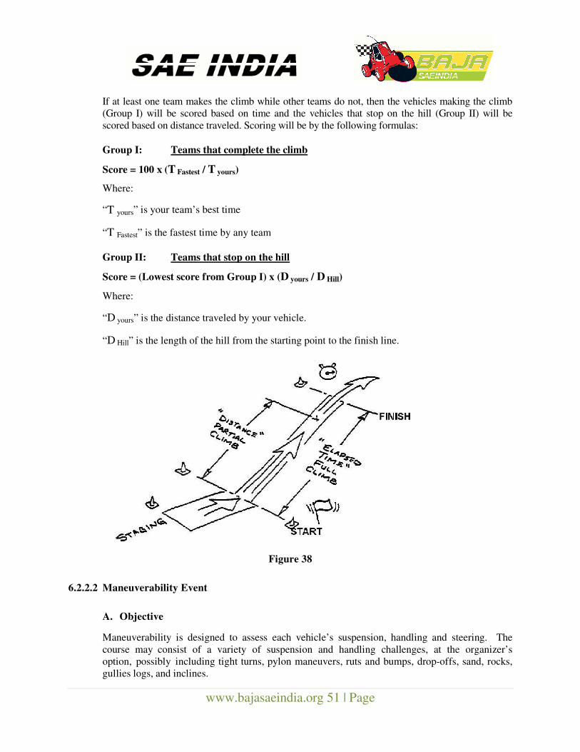
www.bajasaeindia.org 51 | Page
If at least one team makes the climb while other teams do not, then the vehicles making the climb
(Group I) will be scored based on time and the vehicles that stop on the hill (Group II) will be
scored based on distance traveled. Scoring will be by the following formulas:
Group I: Teams that complete the climb Score = 100 x (T Fastest / T yours) Where: “T yours” is your team’s best time
“T Fastest” is the fastest time by any team
Group II: Teams that stop on the hill Score = (Lowest score from Group I) x (D yours / D Hill) Where:
“D yours” is the distance traveled by your vehicle.
“D Hill” is the length of the hill from the starting point to the finish line.
Figure 38 6.2.2.2 Maneuverability Event
A. Objective
Maneuverability is designed to assess each vehicle’s suspension, handling and steering. The
course may consist of a variety of suspension and handling challenges, at the organizer’s
option, possibly including tight turns, pylon maneuvers, ruts and bumps, drop-offs, sand, rocks,
gullies logs, and inclines.
www.bajasaeindia.org 52 | Page
B. Maneuverability Procedure Each vehicle may make two (2) runs with the best time, including penalties, counting for score.
C. Maneuverability – Penalty Default Values
The organizer has the right to modify the penalties imposed for different violations to account
for differences in the length or design of specific event courses.
Obstacle/Pylon moved : 2 seconds
Missed gate* : 10 seconds
Deliberate course violation : Run disqualification
False Start : First False Start - Rerun at end
Second False Start - Disqualification
*Missed gate is when 2 or more wheels are outside the gate
D. Maneuverability – Time Limit
Only vehicles that complete the maneuverability course within a time not exceeding two and half
times (2.5X) that of the fastest vehicle will receive a score. If a vehicle is on the course for a
time that exceeds twice the fastest time recorded to that point then the Event Captain may
declare the attempt over, remove the car from the course and score the attempt as “Excess
Time”.
E. Maneuverability – Scoring
Maneuverability scoring is based on the vehicle’s time through the course including any penalties.
Maneuverability Score = 100 x [(T Longest–T yours)/ (T Longest–T Shortest)]
Where:
“T Longest” is either
(a) The longest time through the course by any team or
(b) 2.5 x “T Shortest” whichever is the shorter time
“T Shortest” is the shortest time through the course by any team
“T yours” is your team’s time through the course
6.3 PRACTICE ROUND
One hour time will be dedicated to practice on endurance track those who have successfully
completed Technical Inspection and Dynamic Event.
www.bajasaeindia.org 53 | Page
6.4 Endurance Event
6.4.1 Endurance – Objective
The endurance event assesses each vehicle’s ability to operate continuously and at speed over
rough terrain containing obstacles in any weather conditions.
6.4.2 Endurance - General Description
Endurance run may be based upon either total time taken or total distance covered. Endurance
events for time usually run for four (4) hours. Endurance events for distance continue until at
least one car has gone the specified distance.
Endurance will be run as one of the following-
(A) A single four (4) hour race,
(B) A predetermined and published distance, or
(C) Elimination heats followed by a final in which the total time of one elimination heat
plus the final is 4 hours.
The organizer will announce the structure of the event prior to the start.
Determining the winner of the endurance race:
• The team, which completes the distance of the competition first, or the greatest
distance in the time set for the competition will be declared the winner.
• In competitions of a given distance, the checkered flag will be given first to the leading
car, then to the other finishers as they cross the finish line.
• In competitions of a timed length, the checkered flag will be given first to the
leading car as it crosses the finish line at or after the expiration of the specified
duration, then to the other finishers as they cross the finish line. If the leading car is not
running at the expiration of the time limit, the checkered flag will be given to the next
highest running car in the same manner.
6.4.3 Endurance - Starting
The starting grid for endurance will be based on each team’s performance in a previous
dynamic competition, or set of dynamic events, to be determined by the organizer. All vehicles
will be considered to have begun the race simultaneously at the time when the starter releases
the first vehicle onto the course regardless of their actual position in the grid.
6.4.4 Endurance – Command Flags
Command flags are just those flags which must be immediately followed by participants without
any dissent.
www.bajasaeindia.org 54 | Page
Green Flag –
(1) At a starting line or when re-entering the course: Your run, or session, has started; enter the
course under the direction of the starter. (NOTE: If you stall the vehicle then restart and wait
for another green flag as the opening in traffic may have closed.)
(2) While running on the course: Course is clear, proceed.
Yellow Flag, Steady – Danger, SLOW DOWN, be prepared to take evasive action, something has
happened beyond the flag station. NO PASSING, unless directed by the course workers.
Yellow Flag, Waved – Great danger, SLOW DOWN, evasive action is likely to be required, BE
PREPARED TO STOP, something has happened beyond the flag station. NO PASSING,
unless directed by the course workers. Red Flag – Come to an immediate safe and controlled stop on the course. Pull to the side of the
course as much as possible to keep the course open. Follow course worker directions. NO
PASSING.
Black Flag, Furled and Pointed – Warning, the officials are watching your driving – obey the
event rules. Black Flag, Displayed –
( 1) Pull into the penalty box for a discussion with the Director of Operations or other official
concerning an incident. A time penalty may be assessed for the incident.
(2) Pull into the penalty box for a mechanical inspection of your car; something has been
observed that needs closer inspection.
Checkered Flag – Your run, or session, has been completed, exit the course at the first
opportunity.
6.4.5 Endurance – Stalled or Disabled Vehicles
Disabled or stalled vehicles must be immediately removed from the roadway. It is
the driver’s responsibility to assist and cooperate with the course marshals in removing the
vehicle.
Cars may only be started with the driver seated with all belts properly fastened. The driver may
not exit the vehicle to execute a restart. Course marshals, volunteers or team members may
assist drivers in restarting their vehicles.
Officials and course marshals may stop any vehicle, at any time, if they believe it no longer
complies with the requirements and restrictions of the rules. If a vehicle is stopped by officials
for a mechanical fault, the fault must be corrected / repaired before it may reenter the event.
6.4.6 Endurance – Repairs
The organizer will announce the rules governing repairs that are permitted to be made during
the endurance event. If repairs along the course are permitted then vehicles under repair must be
www.bajasaeindia.org 55 | Page
removed well off the course, away from the outside of turns and away from any natural run-off
areas.
6.4.7 Endurance Event – Penalty Default Values
The organizer has the right to modify the penalties imposed for different violations to account
for differences in the length or design of the course
Failure to stop for Black Flag 10 minutes or 1 lap per flag*
Passing under a Yellow Flag 1 lap penalty
Deliberate Ramming First time = 10 minutes
Second time = Disqualification
Deliberate Forcing another First time = 10 minutes
Vehicle off the course Second time = 20 minutes
Third time = Disqualification
Leaving Course and Advancing : 5 minutes
Driving in an Unauthorized Area : 10 minutes
Failure to Yield to Traffic on Entering Track : 5 minutes
Speeding in Pit Area : 5 minutes
Fueling : 30 minutes
Fueling will not be allowed until the engine is turned off, the driver is out of the car,
and a fire extinguisher is ready. No work will be done on the car when fueling.
* whichever the official determines is the greater penalty.
6.4.8 Endurance – Scoring
A. General: The endurance event score is determined by (a) the number of laps each team completes during
the endurance final and (b) the finish order of teams at the end of the event.
“Scored laps” are the number of full laps actually completed during the endurance event final. Only
full the laps count, partial laps do not count for score. A vehicle must cross the counting/timing line
under its own power for a lap to be counted.
www.bajasaeindia.org 56 | Page
“Finish order” is the sequence in which vehicles cross the finish line after the lap scoring period has
ended. Finish order determines the ranking of teams completing the same number of laps. For
example, if the top four teams finish with the same number of laps, then they will be ranked 1st to
4th based on their finish order.
“Bonus points” are additional points awarded to the first ten (10) vehicles on the leading (winning)
lap, as separated by finish order as required, in part to differentiate teams finishing with the same
number of scored laps. Up to 10 bonus points will be awarded in the inverse order of finish. Thus,
the first vehicle to cross the finish line in the highest lap group will receive bonus points equal to the
number of cars on the lead lap (max of 10); the second vehicle will receive one less bonus point etc.
Endurance scoring is based on number of laps the vehicle completes in the allowed time:
Endurance Score = [400 x (L Yours–L Lowest)/ (L Highest–L Lowest)] + bonus points
Where:
“L Highest” is the highest number of laps completed by any team.
“L Lowest” is the lowest number of laps completed by any team.
“L Yours” is the number of laps completed by your team.
B. Endurance Heats plus a Final – Point Distribution:
When endurance is run as heats plus a final, the points for the event will be distributed
between the heats and the final in proportion to the time/distance of each stage. Thus, if
endurance is run as one (1) hour eliminations plus a three (3) hour final, the four hundred (400)
total points will be allocated as one hundred (100) points to each elimination heat plus three
hundred (300) points to the final.
6.4.9 Tie-breakers
There will be no tiebreakers for static events. Tiebreakers for dynamic events will be the second
best run time or score for the given tied event. If both scores for tied teams in the event are
equal then the tie remains. Ties in the endurance race will be judged by the endurance event
judge and may remain a tie.
Ties for overall winner will be broken by the following criteria:
Endurance score
Total dynamic events score
Total static events score
If a tie remains after all the above tiebreakers then the tie remains for the overall winner(s).
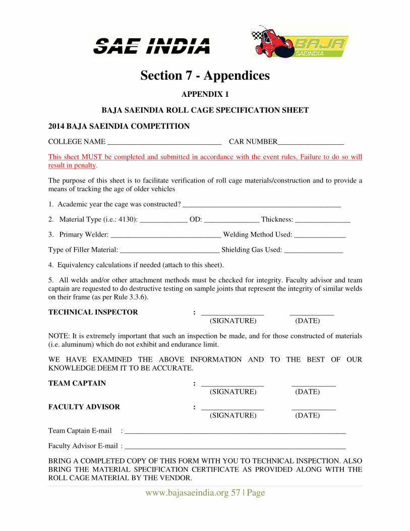
www.bajasaeindia.org 57 | Page
Section 7 - Appendices
APPENDIX 1
BAJA SAEINDIA ROLL CAGE SPECIFICATION SHEET
2014 BAJA SAEINDIA COMPETITION
COLLEGE NAME _______________________________ CAR NUMBER__________________
This sheet MUST be completed and submitted in accordance with the event rules. Failure to do so will
result in penalty.
The purpose of this sheet is to facilitate verification of roll cage materials/construction and to provide a
means of tracking the age of older vehicles
1. Academic year the cage was constructed? ___________________________________________
2. Material Type (i.e.: 4130): _____________ OD: _______________ Thickness: _______________
3. Primary Welder: ______________________________ Welding Method Used: ______________
Type of Filler Material: ___________________________ Shielding Gas Used: ________________
4. Equivalency calculations if needed (attach to this sheet).
5. All welds and/or other attachment methods must be checked for integrity. Faculty advisor and team
captain are requested to do destructive testing on sample joints that represent the integrity of similar welds
on their frame (as per Rule 3.3.6).
TECHNICAL INSPECTOR : _________________ ____________
(SIGNATURE) (DATE)
NOTE: It is extremely important that such an inspection be made, and for those constructed of materials
(i.e. aluminum) which do not exhibit and endurance limit.
WE HAVE EXAMINED THE ABOVE INFORMATION AND TO THE BEST OF OUR
KNOWLEDGE DEEM IT TO BE ACCURATE.
TEAM CAPTAIN : _________________ ____________
(SIGNATURE) (DATE)
FACULTY ADVISOR : _________________ ____________
(SIGNATURE) (DATE)
Team Captain E-mail : ____________________________________________________________
Faculty Advisor E-mail : ____________________________________________________________
BRING A COMPLETED COPY OF THIS FORM WITH YOU TO TECHNICAL INSPECTION. ALSO
BRING THE MATERIAL SPECIFICATION CERTIFICATE AS PROVIDED ALONG WITH THE
ROLL CAGE MATERIAL BY THE VENDOR.
www.bajasaeindia.org 58 | Page
APPENDIX 2
Local Technical Inspection Rules / Violation Penalties for 2014
• Names & contact details of Technical inspectors and their allotted colleges will be mailed/ put on the
official BAJA 2014 website in December 2013.
• Allotted teams will directly contact the Technical Inspectors for mutually fixing Technical Inspection
dates for the local level Technical Inspection.
• At least an early intimation of 20 days should be made by the teams so as the technical inspector can
make necessary arrangement for visiting college campus for local inspection.
• At local level inspection, vehicle should conform to 100 percent Self Certification Check Sheet
criteria; it also includes a “Figure of 8” test and a panic brake test at the local level inspection.
• Any team, if found to have fabricated their vehicle using professional assistance or from a Standard
kit would be liable for a penalty of 400 points or may be ineligible to compete.
• Failing the 100 % acceptance criteria at local level and confirmed by the Technical Inspector, the
vehicle will not be allowed at the main event.
• Last date of technical inspection at college level will be 31 Dec ’2013 and all the teams will adhere to
the deadlines for inspection.
• The teams failing to above timelines automatically gets eliminated out of the BAJA 2014 event.
• Teams must retain the Original Technical Sheet /all the Documents of proof along with them only
Teams will then submit these documents at the Main technical Inspection site at Indore only, failing
which teams may be disqualified from the main event also.
• Only one re-inspection will be conducted during the main event, failing which the teams will be
disqualified for the dynamic events.
• BAJA main Technical inspection will start one day prior to the Starting day of the Main event at the
Pithampur site and no Technical inspection will be conducted on a later date.
• Teams shall be penalized with a minimum deduction of 50 points subject to the any Design
modifications done after the conclusion of Static event.
• Teams unable to submit welding samples of adequate quality shall not be eligible to complete in any
dynamic or endurance event.
• Any vehicle exhibiting handling or other vehicle dynamics that are deemed unstable by the technical
inspectors will not be permitted to participate in the dynamic events.
• The Baja SAEINDIA Technical Committee reserve the right to impound any on-site registered
vehicle at any time during a competition for failure to comply to the discipline of the event at all
times. This impound time shall be 180 minutes per incident.
• Extensive use of readymade subassemblies may invoke penalties.
www.bajasaeindia.org 59 | Page
• Team representatives must be present during the comparison to discuss the design changes. If the
judges find that the design changes are (A) not significant, (B) not supported by a detailed analysis or
(C) have not been sufficiently documented, then a penalty of up to three hundred (300) points may be
assessed against the design score
• Any vehicles found unsafe at any given time of the event will not be allowed to run .The decision of
the Head of the Technical Committee of Baja SAEINDIA in this regard will be final and binding to
all. This is in the interest of safety.
www.bajasaeindia.org 60 | Page
APPENDIX 3
RECOMMENDATIONS OF CODE OF CONDUCT DURING BAJA SAEINDIA 2014
If a technical inspector at site finds the vehicle incomplete during his/her final technical level
vehicle inspection, the team is likely to attract penalty / rejection as deemed fit by the
organizers.
Any team performing any welding operation at site should do it in a defined area preferably with
empty fuel tanks.
Teams which do not pass inspection at the 1 inspection may be penalized as deemed fit by the organizers.
No one else will be permitted other than team members to work on vehicle if found so, the
complete team may be penalized as deemed fit by the organizers, which may include
disqualification.
Team members without authentic ID Cards will be liable for penalty as deemed fit by the
organizers.
Event timings shall be strictly adhered to, including that the organizers reserving the right to
refuse re-inspection.
Team may file a protest against professionally made vehicles with supporting evidence. The
decision of the organizers in this regard will be final and binding on all parties.
www.bajasaeindia.org 61 | Page
APPENDIX 4
Virtual BAJA SAEINDIA
A. Objective
The Virtual BAJA SAEINDIA is a pre-qualifier to participation in the BAJA SAEINDIA event. The
objectives of the Virtual BAJA Event are as follows:
1. To acquaint the teams completely with the objectives of the BAJA SAEINDIA event.
2. The teams are required to acquaint themselves with the technical guidelines and limits for the design
of BAJA vehicle.
3. To design the complete CAD Model of the BAJA Vehicle. The design should be complete in all
respects to the extent of being considered ready-for-manufacture.
4. The teams would be judged on the following basis:
4.1 Knowledge of rulebook
4.2 Project Plan
4.3 Design
4.3.1 Extent of completion of vehicle design
4.3.2 Design Methodology
4.3.3 Roll Cage Design
4.3.3.1.1 Materials Used
4.3.3.1.2 Compliance with rulebook
4.3.3.1.3 Finite Element Analysis
A. Pre-Processing (framing the parameters, constraints, loads etc.)
B. Post-Processing (result analysis, changes in design, etc.)
C. Human Ergonomics
4.3.4 Suspension, Steering & Brakes
1. Chosen configuration (disc, drum brakes, type of suspension, steering geometry, etc.)
2. Specifications (stopping distance, suspension travel, tie-rod length, turning radius, caster,
www.bajasaeindia.org 62 | Page
camber, toe-in, toe-out, braking effort, pedal force etc.)
3. Suspension Design (wishbone, A-arm, trailing arm design, wheel hub, knuckle design, shock
absorber, damper mounting, travel, etc.)
4. Brake Design (braking effort, braking circuit, brake mounting, etc.)
5. Steering Design (geometry, turning radius, power assistance etc.)
4.3.5 Power train
1. Engine (engine specifications, mounting, emission control, intake, exhaust design, fuel system,
fuel lines, transmission coupling etc.)
2. Transmission (chosen configuration, engine coupling, max speed, traction, power, acceleration,
final drive to wheels, wheel size, joints, etc.)
3. Wheel Size (wheel mounting, joint with final drive, etc)
4.3.6 Body & Electricals
1. Weight (target)
2. Electrical System (safety, battery placement, kill switch, routing etc.)
3. Ergonomics
4. Aesthetics
4.3.7 Safety
4.3.8 DFMEA
4.3.9 Innovation
4.3.10 Design Validation Plan
4.3.11 Vehicle Completion Date & Technical Inspection Date
B. Selection
1. Based on the performance in the Virtual BAJA, the teams would be selected for participation in
the main event.
2. The selection would be purely on the basis of merit.
3. ONLY ONE TEAM PER COLLEGE shall be allowed on the basis of comparative merit.
www.bajasaeindia.org 63 | Page
C. Scoring
• Knowledge of rulebook 50
• Project Plan 50
• Roll Cage Design 50
• Over all Vehicle Technical Specification & Target 50
• Suspension, 25
• Steering 25
• Brakes 25
• Power train 25
• Safety 50
• Design Validation Plan 50
Total 400
The qualified teams would be required to submit the design report soon after the Virtual BAJA
event.
The design presented during the event shall be considered as final and the team shall be considered to
proceed towards fabrication activity using the same design. Failing this, the teams shall be penalized /
disqualified if the fabricated vehicle does not exhibit correlation with the design report or if the teams fail
to fabricate within the stipulated timeframe.
NOTE: The Virtual BAJA is a pre-qualifier, thus, no ranks or awards would be issued for the Virtual
BAJA event.
www.bajasaeindia.org 64 | Page
APPENDIX 5
Design Report Format
(A) Format – Design reports must follow the
format for SAE Technical Papers.
(Please use bullets wherever possible & max 10
pages + 4 pages for illustration)
(B) Electronic version – The design report must
be submitted electronically in Adobe Acrobat
Format (PDF) The document must be a single
file (text, drawings and optional content are all
inclusive). The design report file must be named
as follows: Team reg. ID, Institute abbreviated
name
(C) File Size – The maximum size for the file is
5 megabytes.
Introduction
The author should describe the introduction of
the project, the expected performance, design
methodology & outcome.
Generally Applicable: Methodology of design as
to why the particular configuration has been
selected over other options, the design
iterations done to get the desired configuration,
etc.
Technical Specification- Vehicle Performance
Target and 3D Views (10 Marks) Engine Drive
Suspension
Wheels Brake
Steering Dimensions
Weights The expected target vehicle performance (speed,
acceleration, stopping distance, deceleration,
grade ability, turning circle diameter, ground
clearance, emissions, fuel consumption).
3D View of the Complete Vehicle
The CAD view and the isometric view of
actual vehicle
Roll Cage Design & Driver Ergonomics
(15 marks)
Design Considerations
Material Used
Static & Dynamic FEA Results
Weight
Material Properties Selection Criteria
Driver Ergonomics
Ergonomic considerations for driver comfort
Design for driver ergonomics.
Front & Rear Suspension Design (10 Marks)
Design considerations, target specifications,
calculations, innovation, picture, design
selection, criterions, design data, sprung and un-
sprung mass, spring design considerations,
travels and safety factor. Roll/ pitch suspension
layout- camber / caster / toe in, bump steer
calculations, any other features etc.
Steering Design (5 marks)
Design selection criterions, lay-out, steering
geometry, turning angles/ diameter, steering
effort etc.
Brake System Design (5 marks)
Design considerations, weight transfer, brake
system details and calculations, lay-out, pedal
force versus deceleration.
www.bajasaeindia.org 65 | Page
Powertrain Design (10 marks)
Power unit mountings, NVH considerations if
any, over all transmission ratios and
maximum speed/ grade ability in each gear, inlet
air filter/ exhaust system, fuel tank, drive line lay
out, output shaft angularities for the full
suspension travel, total weight of drive line parts.
Body Panels and Safety Equipment
(10 marks)
Weight considerations and the design of body
panels. The safety features used in the vehicle.
Engineering Bill of Materials (5 marks)
Innovations – (Separate Evaluation)
Any innovation if used in the vehicle
References & Acknowledgment / General
Presentation (5 marks)

www.bajasaeindia.org 66 | Page
APPENDIX 6
BAJA SAEINDIA Cost Report Format
ILLUSTRATION: BOM of a Cost Report
Block Part
Name Part No. Level Qty
Cost (Procurement)
Manufacturing Operation
No. of Operations
Cost of Operation
Total Cost
PTE Engine PTEENGIN00
1 1 1 28,000 L - - 28,000
PTT Chain PTTCHAIN00
1 1 2 15,00 SW 10 150 1,800
10 GW 1 12 120
5 GR 2 10 50
1 NA 0 0
Guideline for Cost Report for Baja SAEINDIA 2014
The cost report is based on Bill of Materials. It’s based on indentifying unique components required to build
the vehicle assembly / sub-assemblies. The parts may be classified as Parent (Level1) or Child (Level 2)
depending on whether it’s being assembled to vehicle directly. If it is in the form of another unit or sub-
assembly which is assembled on vehicle subsequently. Example: Gears in gearbox are Level 2 parts while
gearbox is Level 1 part.
The BAJA SAEINDIA COST Sheet comprise of three sheets: Sheet 1: It indicates the overall cost of the vehicle, manufacturing cost, procurement cost, total no. of
parts used, etc. It gives a brief overview about the cost and Bill of Materials for the BAJA Vehicle.
Sheet 2: It is the Bill of Materials Sheet. Herein, the students are required to fill in the following details: i. Block: If the vehicle is considered as an assembly of the following major aggregates: Engine,
Suspension, Transmission, Roll Cage, Electricals & Instrumentation (E&I), each one is regarded as
a building block of the BAJA Vehicle. The teams are required to classify all the parts used in
building the vehicle into either of the blocks as mentioned in the Index Sheet.
ii. Part Name: Every unique part is to be identified with a unique name. The part should be named in a
manner that it reflects the level of usage in the vehicle (e.g.: Gearbox Assembly – indicates the
gearbox is an assembly part).
iii. Part Number: Every unique part is to be identified with a unique part number. The part number
should be a 10 digit number with the first three digits indicating the block, the next five digits
classify the part number and the next two digits represent the level of hierarchy. The codes for block
are mentioned in the sheet, the teams are required to judicially choose the part number and revision
number.
www.bajasaeindia.org 67 | Page
iv. Level: Indicates whether the part is the parent part (Level 1) or whether it is a child part (used as an
entity in a parent assembly) (Level 2). The teams are required to fill either 1 or 2.
v. Quantity: The number of such parts to be used. For ex.: if the team plans to use the same wheel at
all four locations in the vehicle, the cost is to be determined for a single wheel with Quantity as ‘4’.
vi. Procurement Cost: The teams are required to mention the procurement cost of the finished product/
raw material required to build the vehicle. The teams are required to fill the MRP (without taxes),
irrespective of whether the part is a fresh sale or resale based procurement or even if it is sponsored.
The MRP must be mentioned for all the parts and must be supported through Original bills / invoice/
quotes etc.
vii. Manufacturing Operation: The teams must mention the manufacturing operation for each part, to
be required to bring it to the final shape for assembly in the vehicle. The codes for each operation are
mentioned in the index sheet. The teams are required to fill the exact code as mentioned in the index
sheet. For multiple operations it is required to fill the manufacturing details in subsequent rows
(only manufacturing operation is to be filled with the number of operations). Please note that
the manufacturing cost includes the raw material required for the operation, for example: filler
material for weld. The teams DO NOT have to add the cost of filler material. It is already taken into
account in the standardized cost. The standard tables also define the specification of the operation.
For example: the cost of welding is based on a 10 mm weld length. The students need to identify the
no. of such welds required for the completion of the job. For example: to weld the roll cage, the
outer diameter of the roll cage pipes is to be considered, divided by 10 (mm) would give the no. of
operations required for completion. This would be the cost of a single joint. The total joints and total
no. of operations are to be considered for determining the cost of the roll cage. In such a case, roll
cage is also to be considered as an assembly of various pipes (RRH, SIM etc. which constitute the
child parts of the roll cage). Thus the cost of child parts may be established for a better and clear
estimation. In case the cost of the parent is determined completely by its child parts, the costing
fields of the parent may be left blank as the cost would be indicated by the child parts. Wherever
there is no manufacturing operation applicable, please mention ‘NA’.
viii. Cost of Operation: The cost of operation is standardized as in the index sheet. The teams are
ONLY required to fill the codes as specified in the index in the ‘Manufacturing Operation’ column.
Cost would be indicated automatically.
ix. Total Cost: It is the sum of procurement cost and manufacturing cost.
www.bajasaeindia.org 68 | Page
Sheet 3: It is the index sheet. This sheet is to be referred for cost, operations, etc.
Please note that the BAJA SAEINDIA Cost Event is meant for the teams to determine the vehicle
cost precisely and accurately and NOT to the minimum. It is not necessary that the vehicle with the
LOWEST COST would be awarded the maximum score. Instead in such case, there would be an
adjustment cost added to the cost as indicated by the team. This would be multiplied by an adjustment
factor (penalty point) and the final adjusted cost may come out to be higher than the incurred cost.
It is thus suggested for the teams, to accurately determine the cost of the vehicle and not minimize the
cost intentionally.
The objective is to find out the cost of the vehicle if a fictitious firm manufactures the BAJA vehicle at
a rate of 4000 vehicles per annum.
IT IS ENTIRELY THE RESPONSIBILITY OF THE TEAM TO UNDERSTAND THE GUIDELINES
AND FORMULATE THE COST OF THE VEHICLE AS PER THEIR UNDERSTANDING. THE
COST ADJUSTMENT WOULD BE DONE AT THE JUDGE’S DISCRETION. ANY DISCREPANCY
IN DATA / FOULING WITH THE FORMULAE WOULD LEAD TO DISQUALIFICATION /
PENALTY IN THE COST EVENT.
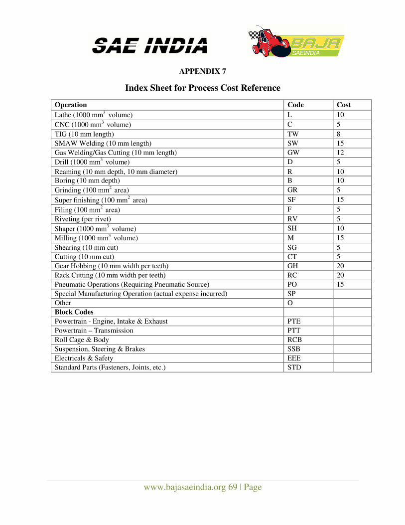
www.bajasaeindia.org 69 | Page
APPENDIX 7
Index Sheet for Process Cost Reference
Operation Code Cost
Lathe (1000 mm3
volume) L 10
CNC (1000 mm3
volume) C 5
TIG (10 mm length) TW 8 SMAW Welding (10 mm length) SW 15 Gas Welding/Gas Cutting (10 mm length) GW 12
Drill (1000 mm3
volume) D 5
Reaming (10 mm depth, 10 mm diameter) R 10 Boring (10 mm depth) B 10
Grinding (100 mm2
area) GR 5
Super finishing (100 mm2
area) SF 15
Filing (100 mm2
area) F 5
Riveting (per rivet) RV 5
Shaper (1000 mm3
volume) SH 10
Milling (1000 mm3
volume) M 15
Shearing (10 mm cut) SG 5 Cutting (10 mm cut) CT 5 Gear Hobbing (10 mm width per teeth) GH 20 Rack Cutting (10 mm width per teeth) RC 20 Pneumatic Operations (Requiring Pneumatic Source) PO 15 Special Manufacturing Operation (actual expense incurred) SP Other O Block Codes Powertrain - Engine, Intake & Exhaust PTE Powertrain – Transmission PTT Roll Cage & Body RCB Suspension, Steering & Brakes SSB Electricals & Safety EEE Standard Parts (Fasteners, Joints, etc.) STD
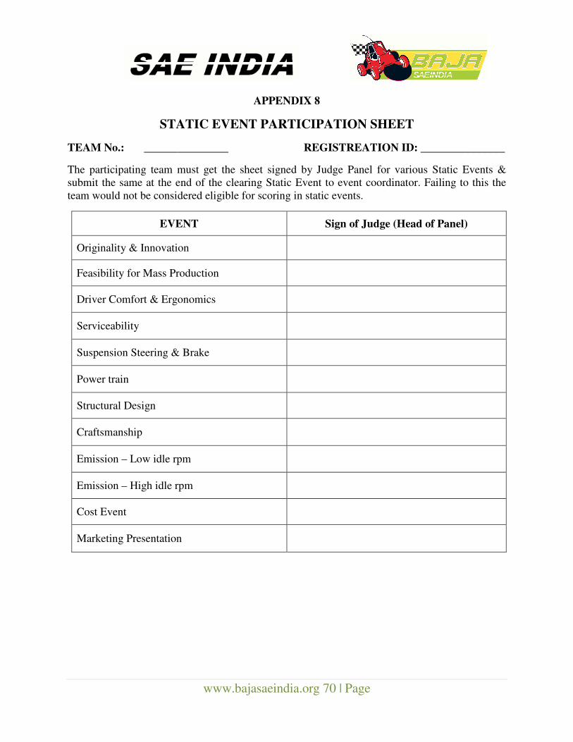
www.bajasaeindia.org 70 | Page
APPENDIX 8
STATIC EVENT PARTICIPATION SHEET
TEAM No.: _______________ REGISTREATION ID: _______________
The participating team must get the sheet signed by Judge Panel for various Static Events &
submit the same at the end of the clearing Static Event to event coordinator. Failing to this the
team would not be considered eligible for scoring in static events.
EVENT Sign of Judge (Head of Panel)
Originality & Innovation
Feasibility for Mass Production
Driver Comfort & Ergonomics
Serviceability
Suspension Steering & Brake
Power train
Structural Design
Craftsmanship
Emission – Low idle rpm
Emission – High idle rpm
Cost Event
Marketing Presentation
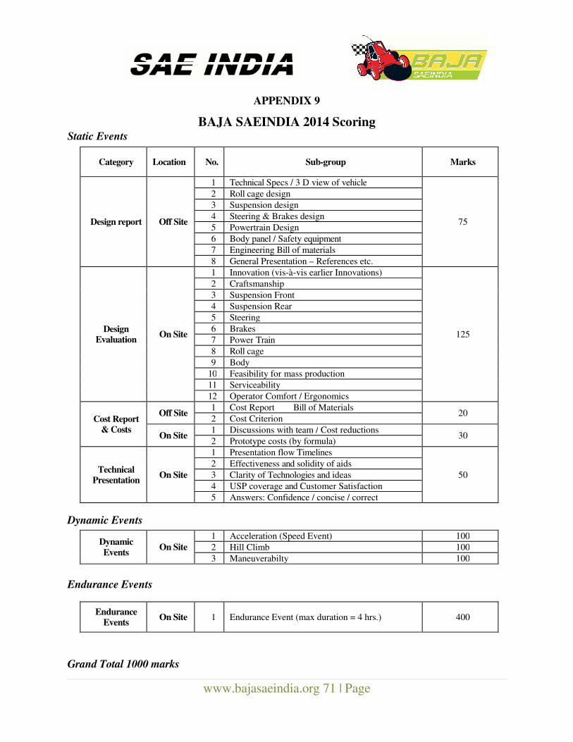
www.bajasaeindia.org 71 | Page
APPENDIX 9
BAJA SAEINDIA 2014 Scoring Static Events
Dynamic Events
Endurance Events
Grand Total 1000 marks
Category Location No. Sub-group Marks
Design report Off Site
1 Technical Specs / 3 D view of vehicle
75
2 Roll cage design 3 Suspension design 4 Steering & Brakes design 5 Powertrain Design 6 Body panel / Safety equipment 7 Engineering Bill of materials 8 General Presentation – References etc.
Design Evaluation
On Site
1 Innovation (vis-à-vis earlier Innovations)
125
2 Craftsmanship 3 Suspension Front 4 Suspension Rear 5 Steering 6 Brakes 7 Power Train 8 Roll cage 9 Body
10 Feasibility for mass production 11 Serviceability 12 Operator Comfort / Ergonomics
Cost Report & Costs
Off Site 1 Cost Report Bill of Materials
20 2 Cost Criterion
On Site 1 Discussions with team / Cost reductions
30 2 Prototype costs (by formula)
Technical Presentation
On Site
1 Presentation flow Timelines
50
2 Effectiveness and solidity of aids 3 Clarity of Technologies and ideas 4 USP coverage and Customer Satisfaction 5 Answers: Confidence / concise / correct
Dynamic
Events On Site
1 Acceleration (Speed Event) 100
2 Hill Climb 100
3 Maneuverabilty 100
Endurance
Events On Site 1 Endurance Event (max duration = 4 hrs.) 400
www.bajasaeindia.org 72 | Page
APPENDIX 10
BAJA SAEINDIA 2014 Awards
Details of Various Awards Given in Event will be hosted on BAJA SAEINDIA official website.
Safe Vehicle Award Criteria:
“ZERO TOLERANCE” is the theme for BAJA SAEINDIA 2014.
This is, chiefly, considered on the basis of the total compliance of BAJA SAEINDIA vehicle
with the official RULEBOOK during the college-level and the main event-level Technical
Inspection and on clearing of the On-Site (main event) Safety Scrutiny (Section 5.3) in
“First Attempt & Shortest Time”.
The number of attempts for the On-Site Safety Scrutiny is important and the time taken, to clear
it, will be recorded for each team. Hence, it is very important for a team to ensure 100%
compliance for Self Certification as well as the high quality of build so that there is no re-work
during the main event.
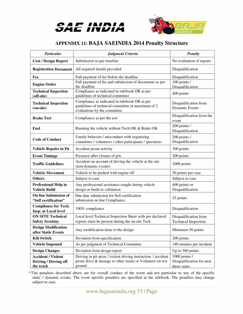
www.bajasaeindia.org 73 | Page
APPENDIX 11: BAJA SAEINDIA 2014 Penalty Structure
Particular Judgment Criteria Penalty
Cost / Design Report Submission as per timeline No evaluation of reports
Registration Document All required details provided Disqualification
Fee Full payment of fee before the deadline Disqualification
Engine Order Full payment of fee and submission of documents as per
the deadline
100 points /
Disqualification Technical Inspection
(off-site)
Compliance as indicated in rulebook OR as per
guidelines of technical committee 400 points
Technical Inspection
(on-site)
Compliance as indicated in rulebook OR as per
guidelines of technical committee in maximum of 2
evaluations by the committee
Disqualification from
Dynamic Events
Brake Test Compliance as per the test Disqualification from the
event
Fuel Running the vehicle without Tech OK & Brake OK 200 points /
Disqualification
Code of Conduct Unruly behavior / misconduct with organizing
committee / volunteers / other participants / spectators
200 points /
Disqualification
Vehicle Repairs in Pit Accident prone activity 300 points
Event Timings Presence after closure of pits 200 points
Traffic Guidelines Accident on account of driving the vehicle at the site
(non-dynamic events) 1000 points
Vehicle Movement Vehicle to be pushed with engine off 50 points per case
Others Subject to case Subject to case
Professional Help in
Vehicle Build
Any professional assistance sought during vehicle
design or build or validation
400 points or
Disqualification
On line Submission of
“Self certification”
Due date submission for Self certification
submission on line Compliance. 25 points
Compliance for Tech.
Insp. at Local level 100% compliance Disqualification
ON SITE Technical
Safety Scrutiny
Inspection Sheet
Local level Technical Inspection Sheet with pre declared
reports must be present during the on-site Tech
Inspection
Disqualification from
Technical Inspection
Design Modification
after Static Events Any modification done to the design Minimum 50 points
Kill Switch Deviation from specification 200 points
Vehicle Impound As per judgment of Technical Committee 180 minutes per incident
Design Changes Deviation from design report Up to 300 points
Accident / Violent
Driving / Driving off
the track
Driving in pit areas / violent driving instruction / accident
prone drive & damage to other teams or Volunteer on test
ground
1000 points /
Disqualification for next
three years
*T he penalties described above are for overall conduct of the event and not particular to any of the specific
static / dynamic events. The event specific penalties are specified in the rulebook. The penalties may change
subject to case.
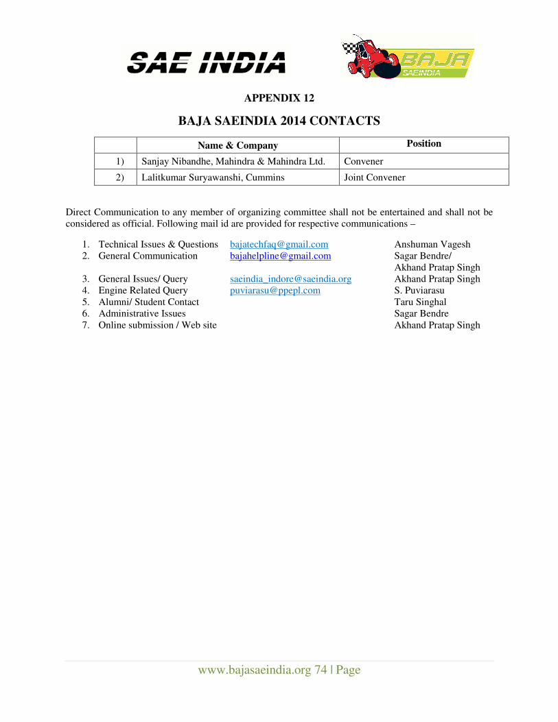
www.bajasaeindia.org 74 | Page
APPENDIX 12
BAJA SAEINDIA 2014 CONTACTS
Name & Company Position
1) Sanjay Nibandhe, Mahindra & Mahindra Ltd. Convener
2) Lalitkumar Suryawanshi, Cummins Joint Convener
Direct Communication to any member of organizing committee shall not be entertained and shall not be
considered as official. Following mail id are provided for respective communications –
1. Technical Issues & Questions [email protected] Anshuman Vagesh
2. General Communication [email protected] Sagar Bendre/
Akhand Pratap Singh
3. General Issues/ Query [email protected] Akhand Pratap Singh
4. Engine Related Query [email protected] S. Puviarasu
5. Alumni/ Student Contact Taru Singhal
6. Administrative Issues Sagar Bendre
7. Online submission / Web site Akhand Pratap Singh