Embed Size (px)
Citation preview
Find us at www.keysight.com Page 1
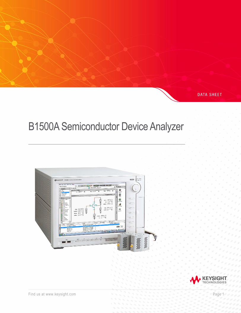
B1500A Semiconductor Device Analyzer
Find us at www.keysight.com Page 2
Introduction Keysight B1500A Semiconductor Device Analyzer of Precision Current-Voltage Analyzer Series is an all in one analyzer supporting IV, CV, pulse/dynamic IV and more, which is designed for all-round characterization from basic to cutting-edge applications. It provides a wide range of measurement capabilities to cover the electrical characterization and evaluation of devices, materials, semiconductors, active/passive components, or virtually any other type of electronic device with uncompromised measurement reliability and efficiency. In addition, the B1500A’s modular architecture with ten available slots allows you to add or upgrade measurement modules if your measurement needs change over time.
Keysight EasyEXPERT group+ GUI based characterization software is available either on the B1500A’s embedded Windows 10 platform with 15-inch touch screen or on your PC to accelerate the characterization tasks. It supports efficient and repeatable device characterization in the entire characterization process from measurement setup and execution to analysis and data management either interactive manual operation or automation across a wafer in conjunction with a semiautomatic wafer prober. EasyEXPERT group+ makes it easy to perform complex device characterization immediately with hundreds of ready-to-use measurements (application tests) furnished, and allows you the option of storing test condition and measurement data automatically after each measurement in a unique built-in database (workspace), ensuring that valuable information is not lost and that measurements can be repeated at a later date. Keysight B1500A provides the complete solution for device characterization with these versatile capabilities.
Find us at www.keysight.com Page 3
Table of Contents
Introduction ...................................................................................................................................................................... 2
Basic Features ................................................................................................................................................................. 4
B1500A Mainframe Specifications .................................................................................................................................... 6
MPSMU and HRSMU Module Specifications .................................................................................................................... 9
HPSMU Module Specifications ........................................................................................................................................13
MCSMU Module Specifications .......................................................................................................................................16
Supplemental Characteristics ..........................................................................................................................................19
MFCMU (multi frequency capacitance measurement unit) Module Specifications ............................................................22
Atto-sense and switch unit (ASU) Specifications ..............................................................................................................26
SMU CMU unify unit (SCUU) and Guard Switch Unit (GSWU) Specifications ..................................................................26
HV-SPGU (high voltage semiconductor pulse generator unit) Module Specification .........................................................29
WGFMU (waveform generator/fast measurement unit) Module Specification ...................................................................34
General specifications .....................................................................................................................................................40
Keysight EasyEXPERT group+ Software .........................................................................................................................41
EasyEXPERT group+ supported instruments and prerequisites .......................................................................................49
Prerequisites ...................................................................................................................................................................50
Recommended GPIB I/F .................................................................................................................................................51
Order information ............................................................................................................................................................51
Package Option Contents ...............................................................................................................................................53
Find us at www.keysight.com Page 4
Basic Features
Measurement capabilities
Current versus voltage (IV) measurement • Accurate and precise measurement ranges of 0.1 fA - 1 A and 0.5 μV - 200 V • Spot and sweep measurement • Time sampling measurements (100 μs minimum sampling rate) • Pulsed measurement with minimum pulse widths of 50 μs using the MCSMU or 500 μs using the
HPSMU, MPSMU, or HRSMU • The ASU (atto-sense and switch unit) can be used with the MPSMU, or HRSMU to provide 0.1 fA
measurement resolution and SMU/AUX path switching • Two analog-to-digital converter choices (high-resolution ADC or high-speed ADC) available for each
SMU type (HPSMU, MPSMU and HRSMU)
Capacitance measurement • Multi-frequency AC impedance measurement supports CV (capacitance versus voltage), C-t
(capacitance versus time) and C-f (capacitance versus frequency) measurement • Capacitance measurement frequency range of 1 kHz to 5 MHz • Quasi-Static Capacitance-Voltage (QS-CV) measurement with leakage current compensation • Automated switching between IV and CV measurements using either the optional SCUU (SMU CMU
unify unit) and GSWU (guard switch unit) or a pair of ASUs
Pulsed IV/Fast IV/Transient IV measurement • Provides high speed and high sensitivity measurement capability for ultra-fast IV (current-voltage),
pulsed IV and transient IV measurements, including NBTI/PBTI and RTN (Random Telegraph Signal Noise) measurements
• Arbitrary waveform generation with 10 ns programmable resolution • Simultaneous high-speed voltage/current measurement (200 MSa/s, 5 ns sampling rate) • SMU technology supports pulsed IV measurement without load line effects
Pulse Generation • Up to ±40 V voltage pulsing and arbitrary waveform generation for non-volatile memory evaluation • Single channel two-level and three level pulsing capability
B1500A platform: • 15-inch touch screen supports all capabilities of the intuitive GUI for convenient device
characterization • Configurable and upgradable measurement modules with 10 slots per mainframe • GPIB, USB, LAN interfaces, and VGA video output port
Find us at www.keysight.com Page 5
EasyEXPERT group+ software: • Characterization environment is available either on mainframe (embedded Windows 10) or on user’s
PC • Intuitive GUI based operation with keyboard, mouse operation and touch screen. • Application Test mode provides the furnished hundreds of ready-to-use application tests for quick
measurement execution • Classic test mode provides easy access to the full capability of instrument features. • Graphical display and analysis capabilities facilitate front-end data analysis without additional utilities
and support report generation as image data or Excel data. • Individualized built-in database (workspace) records test data automatically, and simplifies the data
management without annoying numerous data files. • Tracer test mode enables a curve tracer like knob control of measurement parameters to support
interactive real-time device characterization and automatic data recording feature • Oscilloscope view (available for the MCSMU) supports pulsed voltage and current waveform viewing
for quick and easy timing verification • Quick test mode supports test sequencing without programming • GUI-based control of the Keysight B2200A, B2201A and E5250A switching matrices • GUI-based self-test, self-calibration and diagnostics menu for hardware maintenance • EasyEXPERT remote control function supports the remote measurement execution of application
tests that are created on GUI interactively, via the LAN interface • Data back capability and various data protection feature for shared usage by multiple users • EasyEXPERT group+ can be installed on as many PCs as you need without additional charge to take
advantage of offline personal analyzer environment among users in your department.
Specification conditions The measurement and output accuracy are specified at the rear panel connector terminals when referenced to the Zero Check terminal. The B1530A WGFMU measurement and output accuracy are specified at the output terminal of the RSU. Accuracy is specified under the following conditions:
1. Temperature: 23°C ±5°C
2. Humidity: 20% to 60%
3. After 40 minutes warm-up followed by self-calibration
4. Ambient temperature changes less than ±1°C after self-calibration execution, not applicable for MFCMU and WGFMU
5. Measurement made within one hour after self-calibration execution, not applicable for MFCMU and WGFMU
6. Calibration period: 1 year
Find us at www.keysight.com Page 6
7. SMU integration time setting: 1 PLC (1 nA to 1A range, voltage range) 20 PLC (100 pA range) 50 PLC (1 pA to 10 pA range) Averaging of high-speed ADC: 128 samples per 1 PLC
8. SMU filter: ON (for HPSMU, MPSMU and HRSMU)
9. SMU measurement terminal connection: Kelvin connection
10. WGFMU load capacitance: 25 pF or less
Note: This document lists specif ications and supplemental characteris tics for the B1500A and its associated modules. The specif ications are the standards against which the B1500A and its associated modules are tested. When the B1500A and any of its associated modules are shipped from the factory, they meet the specif ications. The “supplemental” characterist ics described in the following specif ications are not warranted,but provide useful information about the functions and performance of the instrument. Note: Keysight is responsible for removing, install ing, and replac ing the B1500A modules. Contact your nearest Keysight to install and calibrate the B1500A modules.
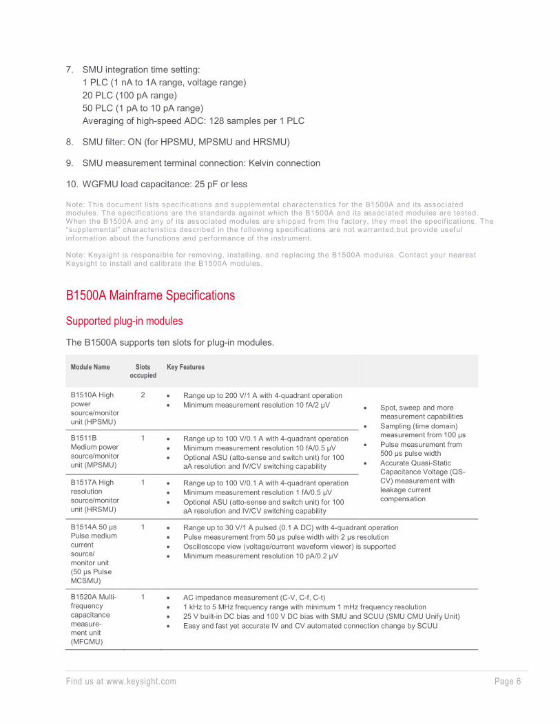
B1500A Mainframe Specifications
Supported plug-in modules The B1500A supports ten slots for plug-in modules.
Module Name Slots occupied
Key Features
B1510A High power source/monitor unit (HPSMU)
2 • Range up to 200 V/1 A with 4-quadrant operation • Minimum measurement resolution 10 fA/2 µV • Spot, sweep and more
measurement capabilities • Sampling (time domain)
measurement from 100 μs • Pulse measurement from
500 μs pulse width • Accurate Quasi-Static
Capacitance Voltage (QS-CV) measurement with leakage current compensation
B1511B Medium power source/monitor unit (MPSMU)
1 • Range up to 100 V/0.1 A with 4-quadrant operation • Minimum measurement resolution 10 fA/0.5 μV • Optional ASU (atto-sense and switch unit) for 100
aA resolution and IV/CV switching capability
B1517A High resolution source/monitor unit (HRSMU)
1 • Range up to 100 V/0.1 A with 4-quadrant operation • Minimum measurement resolution 1 fA/0.5 μV • Optional ASU (atto-sense and switch unit) for 100
aA resolution and IV/CV switching capability
B1514A 50 μs Pulse medium current source/ monitor unit (50 μs Pulse MCSMU)
1 • Range up to 30 V/1 A pulsed (0.1 A DC) with 4-quadrant operation • Pulse measurement from 50 μs pulse width with 2 μs resolution • Oscilloscope view (voltage/current waveform viewer) is supported • Minimum measurement resolution 10 pA/0.2 μV
B1520A Multi-frequency capacitance measure- ment unit (MFCMU)
1 • AC impedance measurement (C-V, C-f, C-t) • 1 kHz to 5 MHz frequency range with minimum 1 mHz frequency resolution • 25 V built-in DC bias and 100 V DC bias with SMU and SCUU (SMU CMU Unify Unit) • Easy and fast yet accurate IV and CV automated connection change by SCUU
Find us at www.keysight.com Page 7
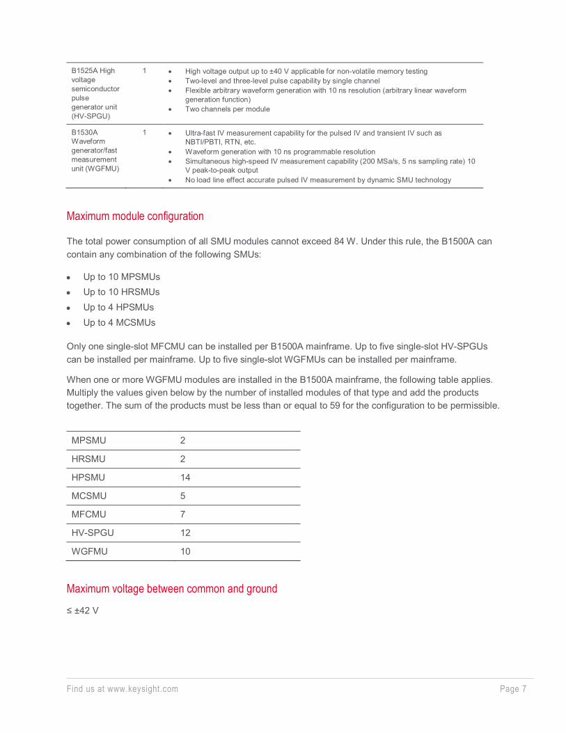
B1525A High voltage semiconductor pulse generator unit (HV-SPGU)
1 • High voltage output up to ±40 V applicable for non-volatile memory testing • Two-level and three-level pulse capability by single channel • Flexible arbitrary waveform generation with 10 ns resolution (arbitrary linear waveform
generation function) • Two channels per module
B1530A Waveform generator/fast measurement unit (WGFMU)
1 • Ultra-fast IV measurement capability for the pulsed IV and transient IV such as NBTI/PBTI, RTN, etc.
• Waveform generation with 10 ns programmable resolution • Simultaneous high-speed IV measurement capability (200 MSa/s, 5 ns sampling rate) 10
V peak-to-peak output • No load line effect accurate pulsed IV measurement by dynamic SMU technology
Maximum module configuration
The total power consumption of all SMU modules cannot exceed 84 W. Under this rule, the B1500A can contain any combination of the following SMUs:
• Up to 10 MPSMUs • Up to 10 HRSMUs • Up to 4 HPSMUs • Up to 4 MCSMUs
Only one single-slot MFCMU can be installed per B1500A mainframe. Up to five single-slot HV-SPGUs can be installed per mainframe. Up to five single-slot WGFMUs can be installed per mainframe.
When one or more WGFMU modules are installed in the B1500A mainframe, the following table applies. Multiply the values given below by the number of installed modules of that type and add the products together. The sum of the products must be less than or equal to 59 for the configuration to be permissible.
MPSMU 2
HRSMU 2
HPSMU 14
MCSMU 5
MFCMU 7
HV-SPGU 12
WGFMU 10
Maximum voltage between common and ground
≤ ±42 V
Find us at www.keysight.com Page 8
Ground unit (GNDU) specification
The GNDU is furnished standard with the B1500A mainframe.
Output voltage: 0 V ±100 µV Maximum sink current: ±4.2 A Output terminal/connection: Triaxial connector, Kelvin (remote sensing)
GNDU supplemental characteristics Load capacitance: 1 µF Cable resistance:
• For IS ≤ 1.6 A: force line R < 1 Ω • For 1.6 A < IS ≤ 2.0 A: force line R < 0.7 Ω • For 2.0 A < IS ≤ 4.2 A: force line R < 0.35 Ω • For all cases: sense line R ≤ 10 Ω • Where IS is the current being sunk by the GNDU.
Peripherals and interface
Data storage SSD, DVD-R drive
Interfaces GPIB, interlock, USB (USB 2.0, front 2, rear 2), LAN (1000BASE-T/100BASE-TX/10BASE-T), trigger in/out, digital I/O, VGA video output
Remote control capabilities • FLEX commands (GPIB) • EasyEXPERT remote control function (LAN)
Trigger I/O • Only available using GPIB FLEX commands. • Trigger in/out synchronization pulses before and after setting and measuring DC voltage and current.
Arbitrary trigger events can be masked or activated independently.
Find us at www.keysight.com Page 9
Furnished accessories • Keyboard • Mouse • Stylus pen • Power cable • Software entitlement document for EasyEXPERT
Furnished software • EasyEXPERT group+ • MDM file converter
This tool can convert the EasyEXPERT file (XTR/ZTR) to Keysight IC-CAP MDM file format. The EasyEXPERT file of the following measurements performed in the classic mode is only supported:
• IV Sweep • Multi channel IV Sweep • CV Sweep
• 4155/56 setup file converter tool This tool can convert 4155 and 4156 measurement setup files (file extensions MES or DAT) into equivalent EasyEXPERT classic test mode setup files.
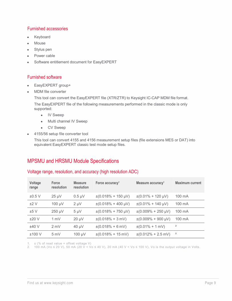
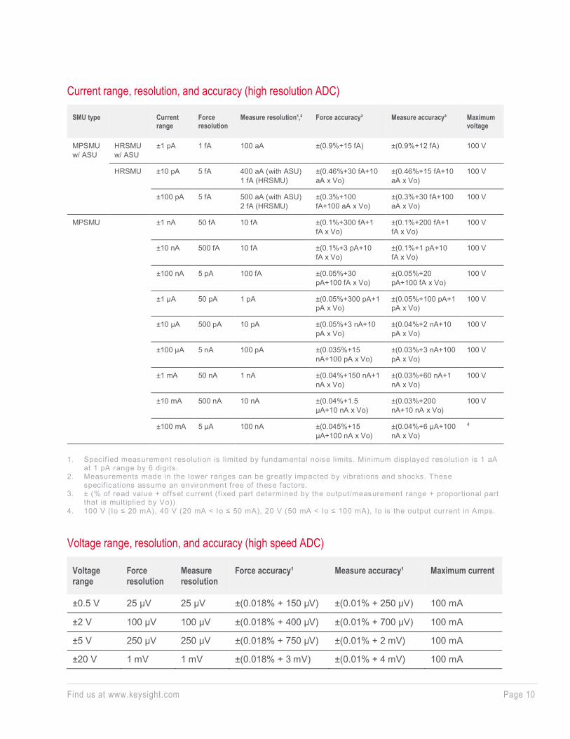
MPSMU and HRSMU Module Specifications
Voltage range, resolution, and accuracy (high resolution ADC)
Voltage range
Force resolution
Measure resolution
Force accuracy¹ Measure accuracy¹ Maximum current
±0.5 V 25 µV 0.5 µV ±(0.018% + 150 µV) ±(0.01% + 120 µV) 100 mA
±2 V 100 µV 2 µV ±(0.018% + 400 µV) ±(0.01% + 140 µV) 100 mA
±5 V 250 µV 5 µV ±(0.018% + 750 µV) ±(0.009% + 250 µV) 100 mA
±20 V 1 mV 20 µV ±(0.018% + 3 mV) ±(0.009% + 900 µV) 100 mA
±40 V 2 mV 40 µV ±(0.018% + 6 mV) ±(0.01% + 1 mV) ²
±100 V 5 mV 100 µV ±(0.018% + 15 mV) ±(0.012% + 2.5 mV) ²
1. ± (% of read value + offset voltage V) 2. 100 mA (Vo ≤ 20 V), 50 mA (20 V < Vo ≤ 40 V), 20 mA (40 V < Vo ≤ 100 V), Vo is the output voltage in Volts .
Find us at www.keysight.com Page 10
Current range, resolution, and accuracy (high resolution ADC)
SMU type Current range
Force resolution
Measure resolution¹,² Force accuracy³ Measure accuracy³ Maximum voltage
MPSMU w/ ASU
HRSMU w/ ASU
±1 pA 1 fA 100 aA ±(0.9%+15 fA) ±(0.9%+12 fA) 100 V
HRSMU ±10 pA 5 fA 400 aA (with ASU) 1 fA (HRSMU)
±(0.46%+30 fA+10 aA x Vo)
±(0.46%+15 fA+10 aA x Vo)
100 V
±100 pA 5 fA 500 aA (with ASU) 2 fA (HRSMU)
±(0.3%+100 fA+100 aA x Vo)
±(0.3%+30 fA+100 aA x Vo)
100 V
MPSMU ±1 nA 50 fA 10 fA ±(0.1%+300 fA+1 fA x Vo)
±(0.1%+200 fA+1 fA x Vo)
100 V
±10 nA 500 fA 10 fA ±(0.1%+3 pA+10 fA x Vo)
±(0.1%+1 pA+10 fA x Vo)
100 V
±100 nA 5 pA 100 fA ±(0.05%+30 pA+100 fA x Vo)
±(0.05%+20 pA+100 fA x Vo)
100 V
±1 µA 50 pA 1 pA ±(0.05%+300 pA+1 pA x Vo)
±(0.05%+100 pA+1 pA x Vo)
100 V
±10 µA 500 pA 10 pA ±(0.05%+3 nA+10 pA x Vo)
±(0.04%+2 nA+10 pA x Vo)
100 V
±100 µA 5 nA 100 pA ±(0.035%+15 nA+100 pA x Vo)
±(0.03%+3 nA+100 pA x Vo)
100 V
±1 mA 50 nA 1 nA ±(0.04%+150 nA+1 nA x Vo)
±(0.03%+60 nA+1 nA x Vo)
100 V
±10 mA 500 nA 10 nA ±(0.04%+1.5 µA+10 nA x Vo)
±(0.03%+200 nA+10 nA x Vo)
100 V
±100 mA 5 µA 100 nA ±(0.045%+15 µA+100 nA x Vo)
±(0.04%+6 µA+100 nA x Vo)
4
1. Specif ied measurement resolution is limited by fundamental noise limits. Minimum displayed resolution is 1 aA
at 1 pA range by 6 digits. 2. Measurements made in the lower ranges can be greatly impacted by vibrations and shocks. These
specif ications assume an environment free of these factors. 3. ± (% of read value + offset current (f ixed part determined by the output/measurement range + proportional part
that is mult iplied by Vo)) 4. 100 V (Io ≤ 20 mA), 40 V (20 mA < Io ≤ 50 mA), 20 V (50 mA < Io ≤ 100 mA), Io is the output current in Amps.
Voltage range, resolution, and accuracy (high speed ADC)
Voltage range
Force resolution
Measure resolution
Force accuracy¹ Measure accuracy¹ Maximum current
±0.5 V 25 µV 25 µV ±(0.018% + 150 µV) ±(0.01% + 250 µV) 100 mA
±2 V 100 µV 100 µV ±(0.018% + 400 µV) ±(0.01% + 700 µV) 100 mA
±5 V 250 µV 250 µV ±(0.018% + 750 µV) ±(0.01% + 2 mV) 100 mA
±20 V 1 mV 1 mV ±(0.018% + 3 mV) ±(0.01% + 4 mV) 100 mA
Find us at www.keysight.com Page 11
±40 V 2 mV 2 mV ±(0.018% + 6 mV) ±(0.015% + 8 mV) ²
±100 V 5 mV 5 mV ±(0.018% + 15 mV) ±(0.02% + 20 mV) ² 1. ± (% of read value + offset voltage V) 2. 100 mA (Vo ≤ 20 V), 50 mA (20 V < Vo ≤ 40 V), 20 mA (40 V < Vo ≤ 100 V), Vo is the output voltage in Volts .
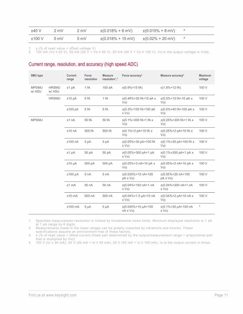
Current range, resolution, and accuracy (high speed ADC)
SMU type Current range
Force resolution
Measure resolution¹,²
Force accuracy³ Measure accuracy³ Maximum voltage
MPSMU w/ ASU
HRSMU w/ ASU
±1 pA 1 fA 100 aA ±(0.9%+15 fA) ±(1.8%+12 fA) 100 V
HRSMU ±10 pA 5 fA 1 fA ±(0.46%+30 fA+10 aA x Vo)
±(0.5%+15 fA+10 aA x Vo)
100 V
±100 pA 5 fA 5 fA ±(0.3%+100 fA+100 aA x Vo)
±(0.5%+40 fA+100 aA x Vo)
100 V
MPSMU ±1 nA 50 fA 50 fA ±(0.1%+300 fA+1 fA x Vo)
±(0.25%+300 fA+1 fA x Vo)
100 V
±10 nA 500 fA 500 fA ±(0.1%+3 pA+10 fA x Vo)
±(0.25%+2 pA+10 fA x Vo)
100 V
±100 nA 5 pA 5 pA ±(0.05%+30 pA+100 fA x Vo)
±(0.1%+20 pA+100 fA x Vo)
100 V
±1 µA 50 pA 50 pA ±(0.05%+300 pA+1 pA x Vo)
±(0.1%+200 pA+1 pA x Vo)
100 V
±10 µA 500 pA 500 pA ±(0.05%+3 nA+10 pA x Vo)
±(0.05%+2 nA+10 pA x Vo)
100 V
±100 µA 5 nA 5 nA ±(0.035%+15 nA+100 pA x Vo)
±(0.05%+20 nA+100 pA x Vo)
100 V
±1 mA 50 nA 50 nA ±(0.04%+150 nA+1 nA x Vo)
±(0.04%+200 nA+1 nA x Vo)
100 V
±10 mA 500 nA 500 nA ±(0.04%+1.5 µA+10 nA x Vo)
±(0.04%+2 µA+10 nA x Vo)
100 V
±100 mA 5 µA 5 µA ±(0.045%+15 µA+100 nA x Vo)
±(0.1%+20 µA+100 nA x Vo)
4
1. Specif ied measurement resolution is limited by fundamental noise limits. Minimum displayed resolution is 1 aA
at 1 pA range by 6 digits. 2. Measurements made in the lower ranges can be greatly impacted by vibrations and shocks. These
specif ications assume an environment free of these factors. 3. ± (% of read value + offset current (f ixed part determined by the output/measurement range + proportional part
that is mult iplied by Vo)) 4. 100 V (Io ≤ 20 mA), 40 V (20 mA < Io ≤ 50 mA), 20 V (50 mA < Io ≤ 100 mA), Io is the output current in Amps.
Find us at www.keysight.com Page 12
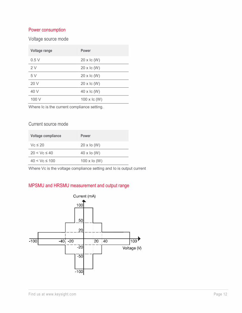
Power consumption
Voltage source mode
Voltage range Power
0.5 V 20 x Ic (W)
2 V 20 x Ic (W)
5 V 20 x Ic (W)
20 V 20 x Ic (W)
40 V 40 x Ic (W)
100 V 100 x Ic (W)
Where Ic is the current compliance setting.
Current source mode
Voltage compliance Power
Vc ≤ 20 20 x Io (W)
20 < Vc ≤ 40 40 x Io (W)
40 < Vc ≤ 100 100 x Io (W)
Where Vc is the voltage compliance setting and Io is output current
MPSMU and HRSMU measurement and output range

Find us at www.keysight.com Page 13
HPSMU Module Specifications
Voltage range, resolution, and accuracy (high resolution ADC)
Voltage range
Force resolution
Measure resolution
Force accuracy¹ Measure accuracy¹ Maximum current
±2 V 100 µV 2 µV ±(0.018% + 400 µV) ±(0.01% + 140 µV) 1 A
±20 V 1 mV 20 µV ±(0.018% + 3 mV) ±(0.009% + 900 µV) 1 A
±40 V 2 mV 40 µV ±(0.018% + 6 mV) ±(0.01% + 1 mV) 500 mA
±100 V 5 mV 100 µV ±(0.018% + 15 mV) ±(0.012% + 2.5 mV) 125 mA
±200 V 10 mV 200 µV ±(0.018% + 30 mV) ±(0.014% + 2.8 mV) 50 mA
1. ± (% of read value + offset voltage V)
Current range, resolution, and accuracy (high resolution ADC)
Current range Force resolution
Measure resolution¹
Force accuracy² Measure accuracy² Maximum voltage
±1 nA 50 fA 10 fA ±(0.1%+300 fA+1 fA x Vo) ±(0.1%+200 fA+1 fA x Vo) 200 V
±10 nA 500 fA 10 fA ±(0.1%+3 pA+10 fA x Vo) ±(0.1%+1 pA+10 fA x Vo) 200 V
±100 nA 5 pA 100 fA ±(0.05%+30 pA+100 fA x Vo) ±(0.05%+20 pA+100 fA x Vo) 200 V
±1 µA 50 pA 1 pA ±(0.05%+300 pA+1 pA x Vo) ±(0.05%+100 pA+1 pA x Vo) 200 V
±10 µA 500 pA 10 pA ±(0.05%+3 nA+10 pA x Vo) ±(0.04%+2 nA+10 pA x Vo) 200 V
±100 µA 5 nA 100 pA ±(0.035%+15 nA+100 pA x Vo) ±(0.03%+3 nA+100 pA x Vo) 200 V
±1 mA 50 nA 1 nA ±(0.04%+150 nA+1 nA x Vo) ±(0.03%+60 nA+1 nA x Vo) 200 V
±10 mA 500 nA 10 nA ±(0.04%+1.5 µA+10 nA x Vo) ±(0.03%+200 nA+10 nA x Vo) 200 V
±100 mA 5 µA 100 nA ±(0.045%+15 µA+100 nA x Vo) ±(0.04%+6 µA+100 nA x Vo) ³
±1 A 50 µA 1 µA ±(0.4%+300 µA+1 µA x Vo) ±(0.4%+150 µA+1 µA x Vo) ³
1. Specif ied measurement resolution is limited by fundamental noise limits. 2. ± (% of read value + offset current (f ixed part determined by the output/measurement range + proportional part
that is mult iplied by Vo)) 3. 200 V (Io ≤ 50 mA), 100 V (50 mA < Io ≤ 125 mA), 40 V (125 mA < Io ≤ 500 mA), 20 V (500 mA < Io ≤ 1 A), Io is
the output current in Amps.

Find us at www.keysight.com Page 14
Voltage range, resolution, and accuracy (high speed ADC)
Voltage range
Force resolution
Measure resolution
Force accuracy¹ Measure accuracy¹ Maximum current
±2 V 100 µV 100 µV ±(0.018% + 400 µV) ±(0.01% + 700 µV) 1 A
±20 V 1 mV 1 mV ±(0.018% + 3 mV) ±(0.01% + 4 mV) 1 A
±40 V 2 mV 2 mV ±(0.018% + 6 mV) ±(0.015% + 8 mV) 500 mA
±100 V 5 mV 5 mV ±(0.018% + 15 mV) ±(0.02% + 20 mV) 125 mA
±200 V 10 mV 10 mV ±(0.018% + 30 mV) ±(0.035% + 40 mV) 50 mA
1. ± (% of read value + offset voltage V)
Current range, resolution, and accuracy (high speed ADC)
Current range Force resolution
Measure resolution¹
Force accuracy² Measure accuracy² Maximum voltage
±1 nA 50 fA 50 fA ±(0.1%+300 fA+1 fA x Vo) ±(0.25%+300 fA+1 fA x Vo) 200 V
±10 nA 500 fA 500 fA ±(0.1%+3 pA+10 fA x Vo) ±(0.25%+2 pA+10 fA x Vo) 200 V
±100 nA 5 pA 5 pA ±(0.05%+30 pA+100 fA x Vo) ±(0.1%+20 pA+100 fA x Vo) 200 V
±1 µA 50 pA 50 pA ±(0.05%+300 pA+1 pA x Vo) ±(0.1%+200 pA+1 pA x Vo) 200 V
±10 µA 500 pA 500 pA ±(0.05%+3 nA+10 pA x Vo) ±(0.05%+2 nA+10 pA x Vo) 200 V
±100 µA 5 nA 5 nA ±(0.035%+15 nA+100 pA x Vo) ±(0.05%+20 nA+100 pA x Vo) 200 V
±1 mA 50 nA 50 nA ±(0.04%+150 nA+1 nA x Vo) ±(0.04%+200 nA+1 nA x Vo) 200 V
±10 mA 500 nA 500 nA ±(0.04%+1.5 µA+10 nA x Vo) ±(0.04%+2 µA+10 nA x Vo) 200 V
±100 mA 5 µA 5 µA ±(0.045%+15 µA+100 nA x Vo) ±(0.1%+20 µA+100 nA x Vo) ³
±1 A 50 µA 50 µA ±(0.4%+300 µA+1 µA x Vo) ±(0.5%+300 µA+1 µA x Vo) ³
1. Specif ied measurement resolution is limited by fundamental noise limits. 2. ± (% of read value + offset current (f ixed part determined by the output/measurement range + proportional part
that is mult iplied by Vo)) 3. 200 V (Io ≤ 50 mA), 100 V (50 mA < Io ≤ 125 mA), 40 V (125 mA < Io ≤ 500 mA), 20 V (500 mA < Io ≤ 1 A), Io is
the output current in Amps.
Power consumption
Voltage source mode
Voltage range Power
2 V 20 x Ic (W)
20 V 20 x Ic (W)
40 V 40 x Ic (W)
Find us at www.keysight.com Page 15
100 V 100 x Ic (W)
200 V 200 x Ic (W)
Where Ic is the current compliance setting.
Current source mode
Voltage compliance Power
Vc ≤ 20 20 x Io (W)
20 < Vc ≤ 40 40 x Io (W)
40 < Vc ≤ 100 100 x Io (W)
100 < Vc ≤ 200 200 x Io (W)
Where Vc is the voltage compliance setting and Io is output current
HPSMU measurement and output range
Find us at www.keysight.com Page 16
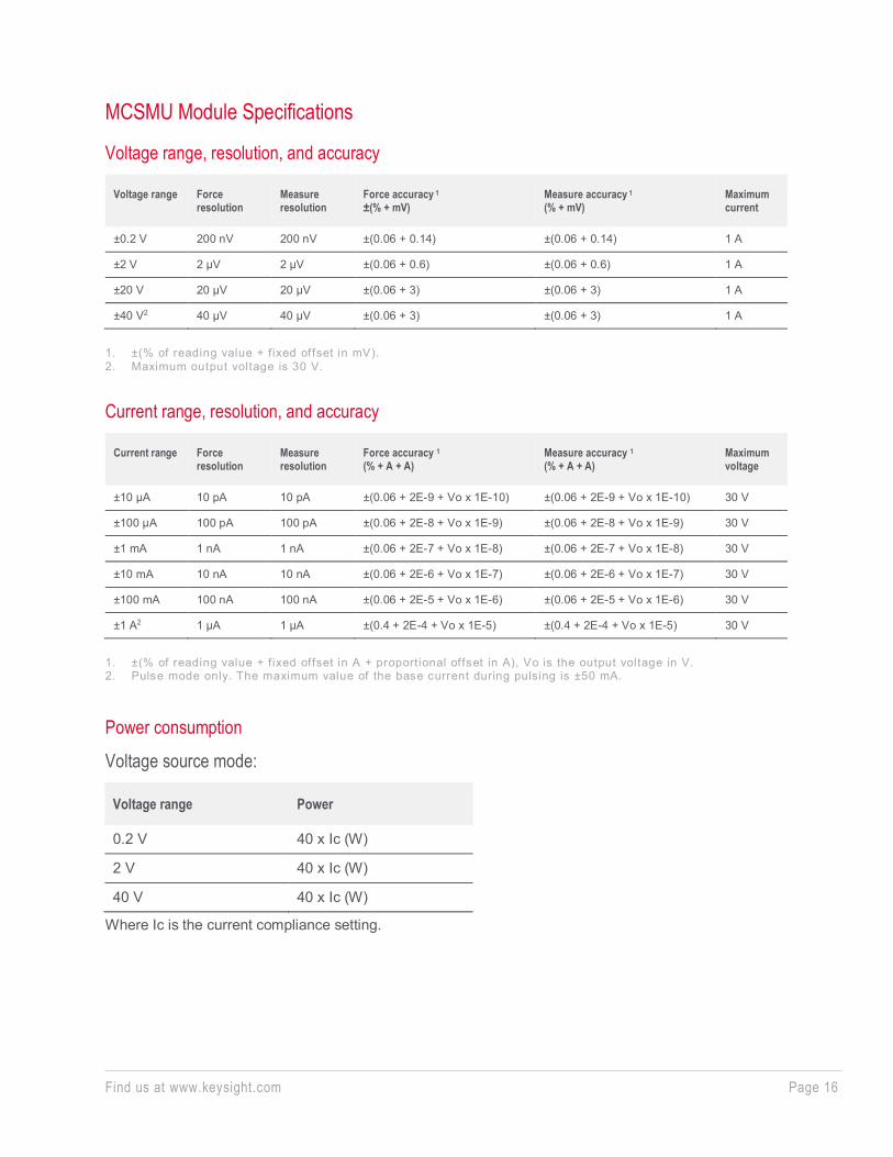
MCSMU Module Specifications
Voltage range, resolution, and accuracy
Voltage range Force resolution
Measure resolution
Force accuracy 1 ±(% + mV)
Measure accuracy 1 (% + mV)
Maximum current
±0.2 V 200 nV 200 nV ±(0.06 + 0.14) ±(0.06 + 0.14) 1 A
±2 V 2 µV 2 µV ±(0.06 + 0.6) ±(0.06 + 0.6) 1 A
±20 V 20 µV 20 µV ±(0.06 + 3) ±(0.06 + 3) 1 A
±40 V2 40 µV 40 µV ±(0.06 + 3) ±(0.06 + 3) 1 A
1. ±(% of reading value + f ixed offset in mV). 2. Maximum output voltage is 30 V.
Current range, resolution, and accuracy
Current range Force resolution
Measure resolution
Force accuracy 1 (% + A + A)
Measure accuracy 1 (% + A + A)
Maximum voltage
±10 µA 10 pA 10 pA ±(0.06 + 2E-9 + Vo x 1E-10) ±(0.06 + 2E-9 + Vo x 1E-10) 30 V
±100 µA 100 pA 100 pA ±(0.06 + 2E-8 + Vo x 1E-9) ±(0.06 + 2E-8 + Vo x 1E-9) 30 V
±1 mA 1 nA 1 nA ±(0.06 + 2E-7 + Vo x 1E-8) ±(0.06 + 2E-7 + Vo x 1E-8) 30 V
±10 mA 10 nA 10 nA ±(0.06 + 2E-6 + Vo x 1E-7) ±(0.06 + 2E-6 + Vo x 1E-7) 30 V
±100 mA 100 nA 100 nA ±(0.06 + 2E-5 + Vo x 1E-6) ±(0.06 + 2E-5 + Vo x 1E-6) 30 V
±1 A2 1 µA 1 µA ±(0.4 + 2E-4 + Vo x 1E-5) ±(0.4 + 2E-4 + Vo x 1E-5) 30 V
1. ±(% of reading value + f ixed offset in A + proportional offset in A), Vo is the output voltage in V. 2. Pulse mode only. The maximum value of the base current during pulsing is ±50 mA.
Power consumption
Voltage source mode:
Voltage range Power
0.2 V 40 x Ic (W)
2 V 40 x Ic (W)
40 V 40 x Ic (W)
Where Ic is the current compliance setting.
Find us at www.keysight.com Page 17
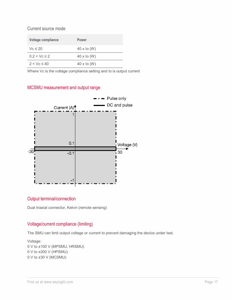
Current source mode
Voltage compliance Power
Vc ≤ 20 40 x Io (W)
0.2 < Vc ≤ 2 40 x Io (W)
2 < Vc ≤ 40 40 x Io (W)
Where Vc is the voltage compliance setting and Io is output current
MCSMU measurement and output range
Output terminal/connection Dual triaxial connector, Kelvin (remote sensing)
Voltage/current compliance (limiting)
The SMU can limit output voltage or current to prevent damaging the device under test.
Voltage: 0 V to ±100 V (MPSMU, HRSMU) 0 V to ±200 V (HPSMU) 0 V to ±30 V (MCSMU)
Find us at www.keysight.com Page 18
Current: ±10 fA to ±100 mA (HRSMU/MPSMU with ASU) ±100 fA to ±100 mA (HRSMU) ±1 pA to ±100 mA (MPSMU) ±1 pA to ±1 A (HPSMU) ±10 nA to ±1 A (MCSMU)
Compliance accuracy: Same as the current or voltage set accuracy.
About measurement accuracy RF electromagnetic field and SMU measurement accuracy: SMU voltage and current measurement accuracy can be affected by RF electro-magnetic field strengths greater than 3 V/m in the frequency range of 80 MHz to 1 GHz. The extent of this effect depends upon how the instrument is positioned and shielded.
Induced RF field noise and SMU measurement accuracy: SMU voltage and current measurement accuracy can be affected by induced RF field noise strengths greater than 3 Vrms in the frequency range of 150 kHz to 80 MHz. The extent of this effect depends upon how the instrument is positioned and shielded.
Pulse measurement Programmable pulse width, period and delay:
For HPSMU, MPSMU, and HRSMU Pulse width: 500 μs to 2 s Pulse period: 5 ms to 5 s Period ≥ width + 2 ms (when width ≤ 100 ms) Period ≥ width + 10 ms (when width > 100 ms) Pulse resolution: 100 μs Pulse delay: 0 s
For MCSMU Pulse width: 10 μs* to 100 ms (1 A range) 10 μs* to 2 s (10 μA to 100 mA range) Pulse width resolution: 2 μs Pulse period: 5 ms to 5 s Pulse period resolution: 100 μs Pulse duty: For 1 A range: ≤ 5% For 10 μA to 100m A range Period ≥ delay + width + 2 ms (when delay + width ≤ 100 ms) Period ≥ delay + width + 10 ms (when delay + width > 100 ms)
Find us at www.keysight.com Page 19
Pulse delay: 0 s to (Period–width)
* Recommended pulse width ≥50 µs Time to reach within 1% of the final value at resistive load >50 Ω , 10 V step voltage, 1 A compliance (supplemental characteristics)
Supplemental Characteristics
Current compliance setting accuracy (for opposite polarity): For HPSMU, MPSMU, and HRSMU: For 1 pA to 10 nA ranges: ± (setting accuracy + 12% of range) For 100 nA to 1 A ranges: ± (setting accuracy + 2.5% of range) For MCSMU: ± (setting accuracy + 2.5% of range)
SMU pulse setting accuracy (fixed measurement range): For HPSMU, MPSMU, and HRSMU: Width: ±0.5% ± 50 μs Period: ±0.5% ± 100 μs
For MCSMU: Width: ±0.1% ± 2 μs Period: ±0.1% ± 100 μs
Minimum pulse measurement time: 16 μs (HPSMU, MPSMU, and HRSMU) 2 μs (MCSMU)
Voltage source output resistance: (Force line, non-Kelvin connection) 0.2 Ω (HPSMU) 0.3 Ω (MPSMU, HRSMU)
Voltage measurement input resistance: ≥ 1013 Ω (HPSMU, MPSMU, and HRSMU) ≥ 109 Ω (MCSMU, ≤ 1 A)
Find us at www.keysight.com Page 20
Current source output resistance: ≥ 1013 Ω (HPSMU, MPSMU, and HRSMU) ≥ 109 Ω (MCSMU, ≤ 1 A)
Maximum allowable cable resistance: (Kelvin connection) For HPSMU, MPSMU, and HRSMU: Sense: 10 Ω Force: 10 Ω (≤ 100 mA),1.5 Ω (>100 mA)
For MCSMU Sense: 10 Ω Force : 1 Ω between High and Low
Maximum allowable inductance: Force 3 µH with Low Force as shield (MCSMU)
Maximum load capacitance: For HPSMU, MPSMU, and HRSMU: 1 pA to 10 nA ranges: 1000 pF 100 nA to 10 mA ranges: 10 nF 100 mA and 1 A ranges: 100 μF
For MCSMU: 10 μA to 10 mA range : 12 nF 100 mA to 1 A range : 100 μF
Maximum guard capacitance:
900 pF (HPSMU, MPSMU, and HRSMU) 660 pF (HRSMU/MPSMU with ASU)
Maximum shield capacitance: 5000 pF (HPSMU, MPSMU, and HRSMU) 3500 pF (HRSMU/MPSMU with ASU)
Find us at www.keysight.com Page 21
Noise characteristics: For HPSMU, MPSMU, and HRSMU (filter ON) Voltage source: 0.01% of V range (rms.) Current source: 0.1% of I range (rms.)
For MCSMU Voltage/Current source: 200 mV (0 to peak) max
Overshoot (filter ON): For HPSMU MPSMU, and HRSMU Voltage source: 0.03% of V range Current source: 1% of I range
For MCSMU Voltage/Current source: 10% of range
Range switching transient noise: For HPSMU, MPSMU, and HRSMU (filter ON): Voltage ranging: 250 mV Current ranging: 70 mV
For MCSMU: Voltage ranging: 250 mV Current ranging: 70 mV
Maximum guard offset voltage: ±1 mV (HPSMU) ±3 mV (MPSMU, HRSMU) ±4.2 mV (HRSMU/MPSMU with ASU, Iout≤100 μA)
Maximum slew rate: 0.2 V/μs (HPSMU, MPSMU, and HRSMU) 1 V/μs (MCSMU)
Maximum DC floating voltage: ±200 V DC between low force and common (MCSMU)
Find us at www.keysight.com Page 22
MFCMU (multi frequency capacitance measurement unit) Module Specifications
Measurement functions Measurement parameters: Cp-G, Cp-D, Cp-Q, Cp-Rp, Cs-Rs, Cs-D, Cs-Q, Lp-G, Lp-D, Lp-Q, Lp-Rp, Ls-Rs, Ls-D, Ls-Q, R-X, G-B, Z-q, Y-q
Ranging: Auto and fixed
Measurement terminal: Four-terminal pair configuration, four BNC (female) connectors
Cable length: 1.5 m or 3 m, automatic identification of accessories
Test signal Frequency: Range: 1 kHz to 5 MHz Resolution: 1 mHz (minimum) Accuracy: ±0.008%
Output signal level: Range: 10 mVrms to 250 mVrms Resolution: 1 mVrms
Accuracy: ±(10.0% + 1 mVrms) at the measurement port of the MFCMU ±(15.0% + 1 mVrms) at the measurement port of the MFCMU cable (1.5 m or 3.0 m)
Output impedance: 50 Ω, typical
Signal level monitor: Range: 10 mVrms to 250 mVrms
Accuracy (open load): ±(10.0% of reading + 1 mVrms) at the measurement port of the MFCMU ±(15.0% of reading + 1 mVrms) at the measurement port of the MFCMU cable (1.5 m or 3 m)
DC bias function DC bias: Range: 0 to ±25 V Resolution: 1 mV Accuracy: ±(0.5% + 5.0 mV) at the measurement port of the MFCMU or the MFCMU cable (1.5 m or 3.0 m)
Find us at www.keysight.com Page 23
Maximum DC bias current (supplemental characteristics)
Impedance range Maximum DC bias current
50 Ω 10 mA
100 Ω 10 mA
300 Ω 10 mA
1 kΩ 1 mA
3 kΩ 1 mA
10 kΩ 100 µA
30 kΩ 100 µA
100 kΩ 10 µA
300 kΩ 10 µA
Output impedance: 50 Ω, typical
DC bias monitor: Range: 0 to ±25 V
Accuracy (open load): ±(0.2% of reading + 10.0 mV) at the measurement port of the MFCMU or the MFCMU cable (1.5 m or 3.0 m)
Sweep characteristics Available sweep parameters: Oscillator level, DC bias voltage, frequency Sweep type: linear, log Sweep mode: single, double Sweep direction: up, down Number of measurement points: Maximum 1001 points
Measurement accuracy The following parameters are used to express the impedance measurement accuracy at the measurement port of the MFCMU or the MFCMU cable (1.5 m or 3.0 m).
Zx: Impedance measurement value (Ω) Dx: Measurement value of D E = EP’ + (ZS’/|Zx| + YO’|Zx|) x 100 (%) EP’ = EPL + EPOSC + EP (%)
Find us at www.keysight.com Page 24
YO’ = YOL + YOSC + YO (S) ZS’ = ZSL + ZOSC + ZS (Ω)
|Z| accuracy ±E (%)
θ accuracy ±E/100 (rad)
C accuracy at DX ≤ 0.1 ±E (%)
at Dx > 0.1 ±E x (√1+DX 2 )(%)
D accuracy at DX ≤ 0.1 ±E/100
at Dx > 0.1 ±E x (1 + DX)/100
G accuracy at Dx ≤ 0.1 ±E/ Dx (%)
at DX > 0.1 ±E x (√1+Dx 2 ) / Dx(%)
Note: measurement accuracy is specif ied under the following conditions: Temperature: 23°C ±5°C Integration t ime: 1 PLC or 16 PLC
Parameters Eposc Zosc
Oscillator level EPOSC (%) ZOSC (mΩ)
125 mV < VOSC ≤ 250 mV 0.03 x (250/ VOSC - 1) 5 x (250/ VOSC - 1)
64 mV < VOSC ≤ 125 mV 0.03 x (125/ VOSC - 1) 5 x (125/ VOSC - 1)
32 mV < VOSC ≤ 64 mV 0.03 x (64/ VOSC - 1) 5 x (64/ VOSC - 1)
VOSC ≤ 32 mV 0.03 x (32/ VOSC - 1) 5 x (64/ VOSC - 1)
VOSC is oscillator level in mV.
________
________
Find us at www.keysight.com Page 25
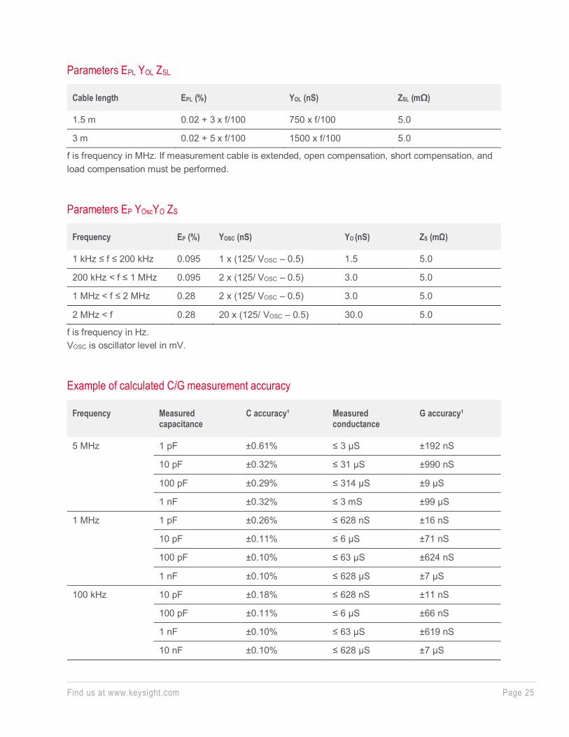
Parameters EPL YOL ZSL
Cable length EPL (%) YOL (nS) ZSL (mΩ)
1.5 m 0.02 + 3 x f/100 750 x f/100 5.0
3 m 0.02 + 5 x f/100 1500 x f/100 5.0
f is frequency in MHz. If measurement cable is extended, open compensation, short compensation, and load compensation must be performed.
Parameters EP YOscYO ZS
Frequency EP (%) YOSC (nS) YO (nS) ZS (mΩ)
1 kHz ≤ f ≤ 200 kHz 0.095 1 x (125/ VOSC – 0.5) 1.5 5.0
200 kHz < f ≤ 1 MHz 0.095 2 x (125/ VOSC – 0.5) 3.0 5.0
1 MHz < f ≤ 2 MHz 0.28 2 x (125/ VOSC – 0.5) 3.0 5.0
2 MHz < f 0.28 20 x (125/ VOSC – 0.5) 30.0 5.0
f is frequency in Hz. VOSC is oscillator level in mV.
Example of calculated C/G measurement accuracy
Frequency Measured capacitance
C accuracy¹ Measured conductance
G accuracy¹
5 MHz 1 pF ±0.61% ≤ 3 µS ±192 nS
10 pF ±0.32% ≤ 31 µS ±990 nS
100 pF ±0.29% ≤ 314 µS ±9 µS
1 nF ±0.32% ≤ 3 mS ±99 µS
1 MHz 1 pF ±0.26% ≤ 628 nS ±16 nS
10 pF ±0.11% ≤ 6 µS ±71 nS
100 pF ±0.10% ≤ 63 µS ±624 nS
1 nF ±0.10% ≤ 628 µS ±7 µS
100 kHz 10 pF ±0.18% ≤ 628 nS ±11 nS
100 pF ±0.11% ≤ 6 µS ±66 nS
1 nF ±0.10% ≤ 63 µS ±619 nS
10 nF ±0.10% ≤ 628 µS ±7 µS
Find us at www.keysight.com Page 26
10 kHz 100 pF ±0.18% ≤ 628 nS ±11 nS
1 nF ±0.11% ≤ 6 µS ±66 nS
10 nF ±0.10% ≤ 63 µS ±619 nS
100 nF ±0.10% ≤ 628 µS ±7 µS
1 kHz 100 pF ±0.92% ≤ 63 nS ±6 nS
1 nF ±0.18% ≤ 628 nS ±11 nS
10 nF ±0.11% ≤ 6 µS ±66 nS
100 nF ±0.10% ≤ 63 µS ±619 nS 1. The capacitance and conductance measurement accuracy is specif ied under the following conditions:
Dx = 0.1 Integration t ime: 1 PLC Test s ignal level: 30 mVr ms At four-terminal pair port of MFCMU
Atto-sense and switch unit (ASU) Specifications
AUX path specification Maximum voltage 100 V (AUX input to AUX common) 100 V (AUX input to circuit common) 42 V (AUX common to circuit common)
Maximum current 0.5 A (AUX input to force output)
ASU supplemental characteristics Band width (at -3 dB) 30 MHz (AUX port)
SMU CMU unify unit (SCUU) and Guard Switch Unit (GSWU) Specifications
The SCUU multiplexes the outputs from two SMUs (MPSMUs and/or HRSMUs) and the CMU. The SCUU outputs are two sets of Kelvin triaxial ports (Force and Sense). The SCUU also allows the SMUs to act as DC bias sources in conjunction with the CMU. Special cables are available to connect the SMUs and CMU with the SCUU, and an auto-detect feature automatically compensates for the cable length going to the SCUU.
The GSWU contains a relay that automatically opens for IV measurements and closes for CV measurements, forming a guard return path to improve CV measurement accuracy.
Find us at www.keysight.com Page 27
Supported SMU
MPSMU and HRSMU
For SCUU Inputs: Triaxial ports: Force1, Sense1, Force2, and Sense2 BNC ports: for MFCMU Control port: for MFCMU
Outputs: Triaxial ports: Force1/CMUH, Sense1, Force2/CMUL, and Sense2 Control port: for GSWU LEDs: SMU/CMU output status indicator
Docking mode: Direct and indirect mode
For GSWU Input: Control port: for SCUU Mini pin plug ports: Guard1, Guard2
Output: LED: Connection status indicator
SCUU supplemental characteristics SMU path: Offset current: < ± (20 fA + 0.004% of SMU current range) (1 pA to 1 µA range) Offset current is negligible for other current ranges Offset voltage: < 100 µV at 300 sec Closed channel residual resistance: < 200 mΩ Channel isolation resistance: > 1015 Ω
CMU path:
Test signal Signal output level additional errors (CMU bias, open load): ±2% (direct docking) ±7% (indirect docking)
Find us at www.keysight.com Page 28
Signal output level additional errors (SMU bias, open load): ±5% (direct docking, ≥ 10 kHz) ±10% (indirect docking, ≥ 10 kHz)
Output impedance: 50 Ω, typical
Signal level monitor additional errors (open load): ±2% (CMU bias), direct docking ±5% (SMU bias), direct docking ±7% (CMU bias), indirect docking ±10% (SMU bias), indirect docking
DC bias function DC voltage bias (CMU bias): Range: 0 to ±25 V Resolution: 1 mV Additional errors (for CMU bias): ±100 µV (open load)
DC voltage bias (SMU bias): Range: 0 to ±100 V Resolution: 5 mV Additional errors (for SMU voltage output accuracy): ±100 µV (open load)
DC bias monitor additional errors (open load): ±20 mV, direct docking ±30 mV, indirect docking
Output impedance: 50 Ω, typical DC output resistance: 50 Ω (CMU bias), 130 Ω (SMU bias)
Measurement accuracy Impedance measurement error is given by adding the following additional error Ee to the MFCMU measurement error.
Ee = ±(A + ZS/|ZX| + YO|ZX|) x 100 (%) ZX: Impedance measurement value (Ω) A: 0.05% (direct docking) or 0.1% (indirect docking) ZS: 500 + 500 x f (mΩ) YO: 1 + 1000 x f/100 (nS) (direct docking, x2 for indirect docking)
Note: f is frequency in MHz
Find us at www.keysight.com Page 29
When the measurement terminals are extended by using the measurement cable, the measurement accuracy is applied to the data measured after performing the open/short/load correction at the DUT side cable end.
Note: The error is specified under the following conditions: Temperature: 23°C ±5°C Integration time: 1 PLC or 16 PLC
HV-SPGU (high voltage semiconductor pulse generator unit) Module Specification
Specifications Number of output channels: 2 channels per module
Modes: pulse, constant, and freerun
Standard pulse mode:
• Two level pulse • Three level pulse per one channel • Pulse period: 20 ns to 10 s
Delay range: 0 s to 9.99 s Delay resolution: 2.5 ns (minimum) Output count: 1 to 1,000,000 Voltage monitor minimum sampling period: 5 μs
Trigger output: Level: TTL Timing: Synchronized with pulse period Trigger width: Pulse period x 1/2 (pulse period ≤ 10 µs) Maximum 5 µs (pulse period > 10 µs)
Pulse/DC output voltage and accuracy
Output voltage (Vout) 50 Ω load –20 V to +20 V
Open load –40 V to +40 V
Accuracy¹ Open load ±(0.5% + 50 mV)
Amplitude resolution 50 Ω load 0.2 mV (|Vout|≤5V) 0.8 mV (5V<|Vout|≤20V)
Open load 0.4 mV (|Vout|≤10V) 1.6 mV (10V<|Vout|≤40V)
Find us at www.keysight.com Page 30
Output connectors SMA
Source impedance 50 Ω²
Short circuit current 800 mA peak (400 mA average³)
Overshoot/pre-shoot/ringing4 50 Ω load ±(5% + 20 mV) 1. At 1 µs af ter completing transit ion. 2. Supplemental characterist ics (±1%) 3. This value is specif ied under the following condit ion: [(Number of installed HV-SPGUs) x 0.2 A] + [DC current
output by all modules ( inc luding HV-SPGUs)] < 3.0 A 4. Follow the specif ied condit ion of the transient time.
Pulse range and pulse parameter¹
Frequency range 0.1 Hz to 33 MHz
Pulse period Programmable range 20 ns to 10 s
Resolution 10 ns
Minimum4 100 ns³
Accuracy ±1% (±0.01% + 200 ps)2
Width Programmable range 10 ns to (period – 10 ns)
Resolution 2.5 ns (Tr and Tf ≤ 8 µs) 10 ns (Tr or Tf > 8 µs)
Minimum4 50 ns (25 ns typical)³
Accuracy ±(3% + 2 ns)
Transition time5 (Tr and Tf)
Programmable range 8 ns to 400 ms
Resolution 2 ns (Tr and Tf ≤ 8 µs) 8 ns (Tr or Tf > 8 µs)
Minimum4 15 ns2 (Vamp ≤ 10 V) 20 ns (Vamp ≤ 10 V) 30 ns (Vamp ≤ 20 V) 60 ns (Vamp > 20 V)
Accuracy –5% to 5% + 10 ns (Vamp ≤ 10 V) –5% to 5% + 20 ns (Vamp ≤ 20 V)
Output relay switching time6
Open/close 100 µs 2
1. Unless otherwise stated, all specif ications assume a 50 Ω termination. 2. Supplemental characterist ics. 3. This is specif ied at Vamp ≤ 10 V. 4. Minimum value in which t iming accuracy can be applied. 5. The t ime from 10% to 90% of Vamp which is the amplitude of output pulse. 6. Solid state relay for frequent switching applications.
Find us at www.keysight.com Page 31
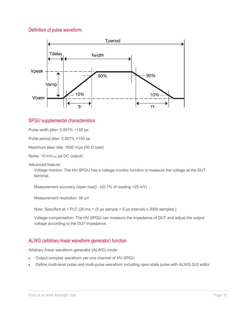
Definition of pulse waveform
SPGU supplemental characteristics Pulse width jitter: 0.001% +150 ps
Pulse period jitter: 0.001% +150 ps
Maximum slew rate: 1000 V/µs (50 Ω load)
Noise: 10 mVrms (at DC output)
Advanced feature: Voltage monitor: The HV-SPGU has a voltage monitor function to measure the voltage at the DUT terminal. Measurement accuracy (open load): ±(0.1% of reading +25 mV) Measurement resolution: 50 μV Note: Specified at 1 PLC (20 ms = (5 μs sample + 5 μs interval) x 2000 samples.)
Voltage compensation: The HV-SPGU can measure the impedance of DUT and adjust the output voltage according to the DUT impedance.
ALWG (arbitrary linear waveform generator) function Arbitrary linear waveform generator (ALWG) mode:
• Output complex waveform per one channel of HV-SPGU • Define multi-level pulse and multi-pulse waveform including open state pulse with ALWG GUI editor
Find us at www.keysight.com Page 32
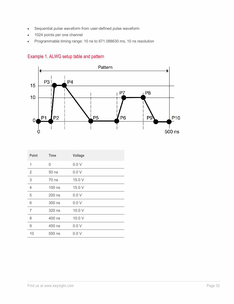
• Sequential pulse waveform from user-defined pulse waveform • 1024 points per one channel • Programmable timing range: 10 ns to 671.088630 ms, 10 ns resolution
Example 1. ALWG setup table and pattern
Point Time Voltage
1 0 0.0 V
2 50 ns 0.0 V
3 70 ns 15.0 V
4 100 ns 15.0 V
5 200 ns 0.0 V
6 300 ns 0.0 V
7 320 ns 10.0 V
8 400 ns 10.0 V
9 450 ns 0.0 V
10 500 ns 0.0 V
Find us at www.keysight.com Page 33
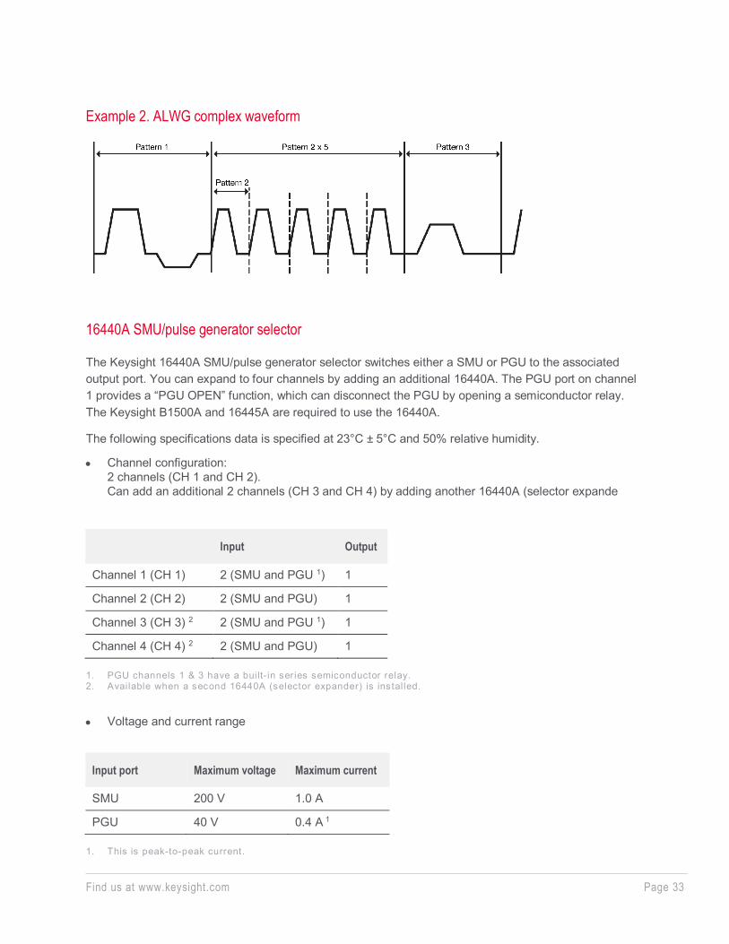
Example 2. ALWG complex waveform
16440A SMU/pulse generator selector
The Keysight 16440A SMU/pulse generator selector switches either a SMU or PGU to the associated output port. You can expand to four channels by adding an additional 16440A. The PGU port on channel 1 provides a “PGU OPEN” function, which can disconnect the PGU by opening a semiconductor relay. The Keysight B1500A and 16445A are required to use the 16440A.
The following specifications data is specified at 23°C ± 5°C and 50% relative humidity.
• Channel configuration: 2 channels (CH 1 and CH 2). Can add an additional 2 channels (CH 3 and CH 4) by adding another 16440A (selector expande
Input Output
Channel 1 (CH 1) 2 (SMU and PGU 1) 1
Channel 2 (CH 2) 2 (SMU and PGU) 1
Channel 3 (CH 3) 2 2 (SMU and PGU 1) 1
Channel 4 (CH 4) 2 2 (SMU and PGU) 1 1. PGU channels 1 & 3 have a built- in series semiconductor relay. 2. Available when a second 16440A (selector expander) is installed.
• Voltage and current range
Input port Maximum voltage Maximum current
SMU 200 V 1.0 A
PGU 40 V 0.4 A 1
1. This is peak-to-peak current.
Find us at www.keysight.com Page 34
16445A SMU/PGU selector connection adaptor
The Keysight 16445A selector adapter is required to control and to supply DC power to the Keysight 16440A SMU/pulse generator selector.
Power requirement: 100 to 240 V, 50/60 Hz
Maximum volt-amps (VA): 20 VA
WGFMU (waveform generator/fast measurement unit) Module Specification
Overview
The WGFMU is a self-contained module offering the combination of arbitrary linear waveform generation (ALWG) with synchronized fast current or voltage (IV) measurement. The ALWG function allows you to generate not only DC, but also various types of AC waveforms. In addition to this versatile sourcing capability, the WGFMU can also perform measurement in synchronization with the applied waveform, which enables accurate high-speed IV characterization.
Measurement mode, function and range
WGFMU Mode
WGFMU function Voltage force ranges
Voltage measurement ranges
Current measurement ranges
Source Impedance
Maximum output
VF VM IM
Fast IV mode/ DC mode
Y Y Y -3 V to +3 V -5 V to +5 V -10 V to 0 V 0 V to +10 V
5 V 10 V
1 μA, 10 μA, 100 μA, 1mA, 10 mA
0 Ω1 +10 V, -10 V, ±5 V
PG mode
Y Y – -3 V to +3 V -5 V to +5 V
5 V – 50 Ω2 ±5 V (open load) ±2.5 V (50 Ω load)
SMU pass- through
Measurement is performed by an SMU
– – – – ±25 V ±100 mA
VF: Voltage Force VM: Voltage Measurement IM: Current Measurement 1. Fast IV mode supports active analog feedback loop to keep its output as specif ied voltage and the output
impedance negligible. It can reduce the influence of load l ine effect by the source impedance and DUT impedance.
2. 50 Ω (nominal) at DC in PG mode
Find us at www.keysight.com Page 35
Waveform generation and measurement capabilities
Pulse and any waveform can be generated by using ALWG (Arbitrary Linear Waveform Generation vector data. Measurements can be performed by measurement events embedded on the vectors.
Voltage waveform output
Waveform programming Any waveform (including pulse shape) pattern can be programmed by using ALWG vector data within maximum number of vectors.
Minimum timing resolution 10 ns
Vector length 10 ns to 10,000 s with 10 ns resolution/vector
Maximum number of vectors 2048
Maximum number of sequences 512
Maximum number of loop counts 1012
Measurement capabilities
Measurement (event) Measurement can be performed at any specified points/timing in the waveform by using the measurement event feature. This provides the flexibility to perform the measurement only specific area to reduce the data size and utilize the memory efficiently. Measurement events can be embedded on any ALWG vectors in the waveform with number of measurement points, measurement interval and averaging parameters settings.
Sampling rate 200MSa/s
Maximum number of measurement points
About 4 M data points/channel (typical)
Interval between measurement points
5 ns, or 10 ns to 1 s with 10 ns resolution
Averaging per a measurement point
10 ns to 20 ms with 10 ns resolution
Range change (Event) Current measurement range can be changed at any specified points/timing in the waveform by using the range change event feature. It enables to use the user specified ranges in a measurement sequence according to the device impedance.
Trigger capability
Trigger out (Event) Output trigger event can be set at any specified points/timing in the waveform by using the trigger out event feature.
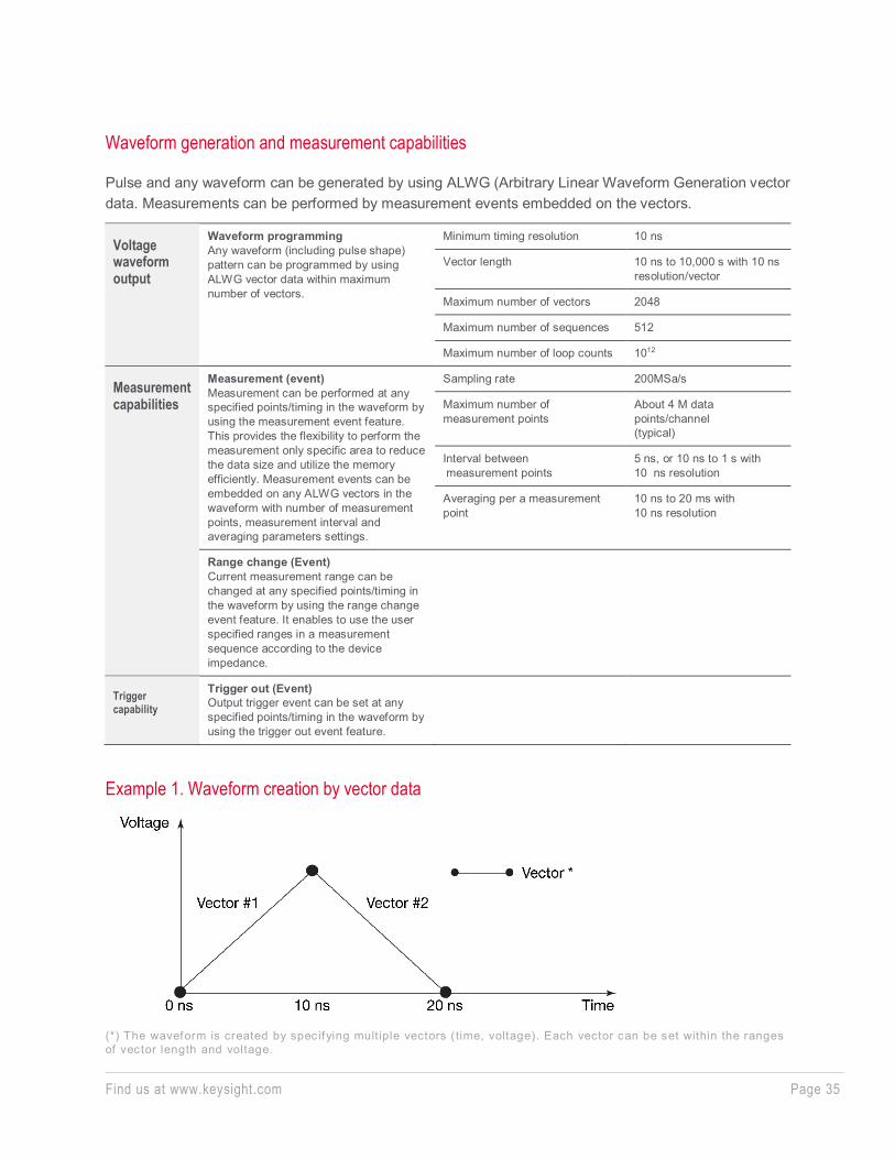
Example 1. Waveform creation by vector data
(*) The waveform is created by specifying mult iple vectors (time, voltage). Each vector can be set within the ranges of vector length and voltage.
Find us at www.keysight.com Page 36
Example 2. Measurement event on a created waveform
(*) As well as the measurement event, the range change and trigger event can be specif ied in the vector.
To perform accurate measurement, it is necessary to take the voltage/current settling time into account from the analog performance viewpoint. Refer to the Minimum timing parameters tables as supplemental characteristics of analog performance.
Force, measurement and timing specifications
Voltage force Accuracy ± (0.1% of setting +0.1% of range) 1
Resolution2 96 μV (-3 to 3 V range) 160 μV (all ranges except for -3 V to 3 V range)
Overshoot/undershoot ±(5%+20 mV)3
Noise Maximum 0.1 mVrms 4
Voltage measurement Accuracy ±(0.1% of reading ±0.1% of range) 8
Resolution 9 680 μV (-5 V to +5 V range) 1.4 mV (-10 V to +10 V range)
Noise 10 Maximum 4 mVrms (-5 V to +5 V range)
Current measurement Accuracy ±(0.1% of reading ±0.2% of range) 8
Resolution 9 0.014% of range
Noise (Effective resolution) Maximum 0.2% of range 11
Timing accuracy Rise time Trise (10 to 90%)/ Fall time Tfall (90 to 10%)
-5% to (+5% +10 ns) of setting 5
Pulse period ±1% of setting 6
Pulse width ±(3% +2 ns) 7
1. Independent of the range or the mode. DC constant voltage output. Load impedance must be ≥ 1 MΩ (1 μA range) or ≥ 200 kΩ (all other current ranges) for Fast IV mode, or ≥ 1 MΩ for PG mode.
2. Can vary at most 5% based on the result of calibration. 3. PG mode, 50 Ω load, Trise and Tfall >16 ns with the 1.5 m cable, >32 ns with 3 m cable, or >56 ns with 5 m
cable.
Find us at www.keysight.com Page 37
4. Theoretical value for observed t ime 100 ns to 1 ms, supplemental characterist ics.
5. PG mode, 50 Ω load, T r ise and Tfall ≥ 24 ns. 6. PG mode, 50 Ω load, pulse period ≥ 100 ns. 7. PG mode, 50 Ω load, pulse width ≥ 50 ns. 8. Independent of the range or the mode. DC constant voltage output. Applicable condit ion: 10,000 averaging
samples for 10 μA range and above; 100,000 averaging samples for the 1 μA range. 9. Display resolution. Can vary at most 5% based on the result of calibration. 10. 0 V output, open load, no averaging. Maximum 1.5 mVr ms as supplemental characteristics. 11. Effective value at 0 V output, open load, and no averaging. Supplemental characterist ics.
Other Specifications
Number of output channels: 2 channels per module
RSU: Output Connector: SMA
V monitor terminal:
• Connector: BNC • Source Impedance: 50 Ω (nominal) at DC • The terminal outputs a buffered signal equal to 1/10 of Vout (into a 50 Ω load)
RSU SMU path:
• Leak current: <100 pA (supplemental characteristics) • Residual resistance: <300 mΩ (supplemental characteristics)
WGFMU to RSU cable length: The WGFMU and RSU are connected by a special composite cable. The following configurations are available:
• 3 m • 5 m • 1.5 m • 2.4 m + connector adapter + 0.6 m • 4.4 m + connector adapter + 0.6 m
Note: The connector adapter is used when routing the cable through the prober’s connector panel.
Trigger output Level: TTL Trigger width: 10 ns Trigger output skew: <3 ns (supplemental characteristics)
Find us at www.keysight.com Page 38
Jitter:
<1 ns (supplemental characteristics)
Skew between channels: <3 ns, under no electrostatic discharge condition (supplemental characteristics).
Current range change time: <150 μs* * The time until the measured current settles within ± 0.3% of the final result value after the range change (supplemental characteristics).
Minimum timing parameters for current measurement (Supplemental Characteristics)1
Voltage applied to DUT
10 V
Current applied to DUT
100 nA 1 μA 10 μA 100 μA 1 mA 10 mA
Applied voltage condition
Recommended minimum pulse width2
47 μs 38.7 μs 6.8 μs 950 ns 240 ns 145 ns
Current measurement condition
Measurement Range 1 μA 1 μA 10 μA 100 μA 1 mA 10 mA
Recommended minimum measurement window
10 μs 1.64 μs 1 μs 130 ns 40 ns 20 ns
Settling time3 37 μs 37 μs 5.8 μs 820 ns 200 ns 125 ns
Noise (rms)4 160 pA 425 pA 2.5 nA 47 nA 280 nA 1.9 μA
1. Measurement condit ions: The DUT is a resistive load chosen to adjust the f lowing current to the specif ied current in the table above. The capacitance of the cable between the RSU and the DUT is 20 pF. Voltage is applied to the DUT by a channel of W GFMU/RSU in Fast IV mode and in the 10 mA range, and current measurement is performed by another channel at 0 V in Fast IV mode.
2. Recommended minimum pulse width = sett ling t ime + recommended minimum measurement window. 3. The t ime until the measured value sett les to within ± 0.6% of the f inal result value after the output voltage is
changed from the initial value (0 V). Minimum rise/fall time of 70 ns is recommended for minimizing overshoot. 4. RMS noise measured over the recommended minimum measurement window.
Find us at www.keysight.com Page 39
Minimum timing parameters for voltage measurement (Supplemental Characteristics)1
Voltage applied to DUT 5V 10 V
Applied voltage condition Recommended minimum pulse width2 105 ns 130 ns
Voltage measurement condition
Measurement Range 5 V 10 V
Recommended minimum measurement window
20 ns 20 ns
Settling time3 85 ns 110 ns
Noise (rms)4 1.4 mV 1.4 mV
1. Measurement condit ions: The DUT is a resistive load between 1 kΩ and 10 MΩ. The capacitance of the cable between the RSU and the DUT is 20 pF. Voltage is applied to the DUT by a channel of W GFMU/RSU, and voltage measurement is performed by the same channel. (PG mode for 5 V, Fast IV mode for 10 V)
2. Recommended minimum pulse width = sett ling t ime + recommended minimum measurement window. 3. The t ime until the measured value sett les to within ± 0.6% of the f inal result value after the output voltage is
changed from the initial value (0 V). Minimum rise/fall time of 70 ns for 10 V, or 30ns for 5 V is recommended for minimizing overshoot.
4. RMS noise measured over the recommended minimum measurement window.
WGFMU Software
Application Programming Interface (API): Instrument Library (.DLL/.Lib for .NET) Note: Instrument library is available for the following programming environments. Microsoft Visual C++ .NET, Visual C# .NET, Visual Basic .NET, Visual Basic 6.0, VBA, or TransEra HTBasic for Windows (release 8.3 or later)
Application Tests • BTI (NBTI/PBTI) • Sweep/pulsed sweep measurement (using 2ch of WGFMU in fast IV mode) • Pattern Editor for general purpose
Sample application programs
Following application programs are available on external Windows PC. The Source code is available for customization.
• BTI (NBTI/PBTI) • Fast IV Sweep • Pulsed IV measurement • Transient I/V measurement • Sampling measurement and RNT data analysis tool
Find us at www.keysight.com Page 40
WGFMU supported prober vendors • Cascade Microtech (Suss MicroTec included.) • Vector Semiconductor
General specifications
Temperature range Operating: +5°C to +40°C Storage: -20°C to +60°C
Humidity range Operating: 20% to 70% RH, non-condensing Storage: 10% to 90% RH, non-condensing
Altitude Operating: 0 m to 2,000 m (6,561 ft) Storage: 0 m to 4,600 m (15,092 ft)
Power requirement AC voltage: 100-240 V (±10%) Line frequency: 50/60 Hz
Maximum volt-amps (VA) B1500A: 900 VA
Regulatory compliance EMC: IEC61326-1/EN61326-1 AS/NZS CISPR 11 KC: RRA Notification amending Radio Waves Act Article 58-2
Safety: IEC61010-1/EN61010-1 CAN/CSA-C22.2 No. 61010-1-04, C/US
Find us at www.keysight.com Page 41
Certification
CE, cCSAus, C-Tick, KC
Dimensions B1500A: 420 mm W x 330 mm H x 575 mm D N1301A-100 SMU CMU unify unit (SCUU): 148 mm W x 75 mm H x 70 mm D N1301A-200 guard switch unit (GSWU): 33.2 mm W x 41.5 mm H x 32.8 mm D E5288A Atto-sense and switch unit (ASU): 132 mm W × 88.5 mm H × 50 mm D B1531A RSU: 45.2 mm W x 70 mm H x 82 mm D N1255A 2 channel connection box for MCSMU: 184.4 mm W x 61.6 mm H x 169.6 mm D 16440A SMU/PGU selector: 250 mm W × 50 mm H × 275 mm D 16445A Selector adaptor: 250 mm W × 50 mm H × 260 mm D
Weight B1500A mainframe: 20 kg B1510A HPSMU: 2.0 kg B1511B MPSMU: 1.0 kg B1514A MCSMU: 1.3 kg B1517A HRSMU: 1.2 kg B1520A MFCMU: 1.5 kg B1525A HV-SPGU: 1.3 kg B1530A WGFMU: 1.3 kg B1531A RSU: 0.13 kg E5288A ASU: 0.5 kg N1301A-100 SCUU: 0.8 kg N1301A-200 GSWU: 0.1 kg N1255A 2 channel connection box for MCSMU: 0.7 kg 16440A SMU/PGU selector: 1.1 kg 16445A Selector adapter: 1.0 kg
Keysight EasyEXPERT group+ Software
Keysight EasyEXPERT group+ GUI based characterization software is available either on the B1500A’s embedded Windows 10 platform with 15-inch touch screen or on your PC to accelerate the characterization tasks. It supports efficient and repeatable device characterization in the entire characterization process from measurement setup and execution to analysis and data management either interactive manual operation or automation across a wafer in conjunction with a semiautomatic wafer prober. EasyEXPERT group+ makes it easy to perform complex device characterization immediately with the hundreds of ready-to-use measurements (application tests) furnished, and allows you the option of storing test condition and measurement data automatically after each measurement in a
Find us at www.keysight.com Page 42
unique built-in database (workspace), ensuring that valuable information is not lost and that measurements can be repeated at a later date. Finally, EasyEXPERT has built-in analysis capabilities and a graphical programming environment that facilitate the development of complex testing algorithms.
Key features • Multiple measurement modes for quick setup and measurement execution (application test, classic
test, tracer test, quick test and oscilloscope view) • Graphical display, automated analysis capabilities and data generation to Excel and image for
analysis and reporting • Built-in database (workspace) records test data automatically and simplifies the data management
without numerous data files • GUI-based control of the Keysight B2200A, B2201A and E5250A switching matrices • GUI-based self-test, self-calibration and diagnostics menu for hardware maintenance • EasyEXPERT remote control function supports the remote measurement execution of application
tests that are created on GUI interactively, via the LAN interface • Data back capability and various data protection feature for shared usage by multiple users • Characterization environment is available either on mainframe (embedded Windows 10) or on user’s
PC as a personal and portable analyzer environment. EasyEXPERT group+ can be installed on any PC as many as needed without additional charge.
Application library EasyEXPERT comes with over 300 application tests conveniently organized by device type, application, and technology. You can easily edit and customize the furnished application tests to fit your specific needs. Application tests are provided for the following categories; they are subject to change without notice.
Device Type Application Tests
CMOS Transistor Id-Vg, Id-Vd, Vth, breakdown, capacitance, QSCV, etc.
Bipolar Transistor Ic-Vc, diode, Gummel plot, breakdown, hfe, capacitance, etc.
Discrete device Id-Vg, Id-Vd, Ic-Vc, diode, etc.
Memory Vth, capacitance, endurance test, etc.
Power device Pulsed Id-Vg, pulsed Id-Vd, breakdown, etc.
Nano Device Resistance, Id-Vg, Id-Vd, Ic-Vc, etc.
Reliability test NBTI/PBTI, charge pumping, electro migration, hot carrier injection, J-Ramp, TDDB, etc.
And more And more
Find us at www.keysight.com Page 43
Measurement modes and functions
Operation Mode Application test mode The application test mode provides application oriented point-and-click test setup and execution. An application test can be selected from the library by device type and desired measurement, and then executed after modifying the default input parameters as needed.
Classic test mode The classic test mode provides function oriented test setup and execution with the same look, feel, and terminology of the 4155/4156 user interface. In addition, it improves the 4155/4156 user interface by taking full advantage of EasyEXPERT’s GUI features.
Tracer test mode The tracer test mode offers intuitive and interactive sweep control using a rotary knob similar to a curve tracer. Just like an analog curve tracer, you can sweep in only one direction (useful for R&D device analysis) or in both directions (useful in failure analysis applications). Test set ups created in tracer test mode can be seamlessly and instantaneously transferred to classic test mode for further detailed measurement and analysis.
Oscilloscope view (available for MCSMU) The oscilloscope view (available in tracer test mode) displays measured MCSMU module current or voltage data versus time. The pulsed measurement waveforms appear in a separate window for easy verification of the measurement timings. This function is useful for verifying waveform timings and debugging pulsed measurements. It is available when a tracer test has one or more MCSMU channels being used in pulsed mode. The oscilloscope view can display the pulsed waveform timings at any (user specified) sweep step of the sweep output.
Sampling interval: 2 μs Sampling points: 2000 Sa Sampling duration: 22 μs to 24 ms Marker function: Read-out for each data channel Resolution: 2μs Data saving: Numeric: Text/CSV/XMLSS Image: EMF/BMP/JPG/PNG
Find us at www.keysight.com Page 44
Quick test mode A GUI-based Quick Test mode enables you to perform test sequencing without programming. You can select, copy, rearrange and cut-and-paste any application tests with a few simple mouse clicks. Once you have selected and arranged your tests, simply click on the measurement button to begin running an automated test sequence.
Measurement modes The Keysight B1500A supports the following measurement modes:
IV measurement
• Spot • Staircase sweep • Pulsed spot • Pulsed sweep • Staircase sweep with pulsed bias • Sampling • Multi-channel sweep • Multi-channel pulsed sweep • List sweep • Linear search1 • Binary search1
C measurement
• Spot C • CV (DC bias) sweep • Pulsed spot C • Pulsed sweep CV • C-t sampling • C-f sweep • CV (AC level) sweep • Quasi-Static CV (QSCV)
1. They are supported by FLEX command only.
Sweep measurement Number of steps: 1 to 10001 (SMU), 1 to 1001 (CMU) Sweep mode: Linear or logarithmic (log) Sweep direction: Single or double sweep Hold time: 0 to 655.35 s, 10 ms resolution Delay time: 0 to 65.535 s, 100 μs resolution
Find us at www.keysight.com Page 45
0 to 655.35 s, 100 μs resolution (CV (AC level) sweep, C-f sweep) Step delay time: 0 to 1 s, 100 μs resolution Step output trigger delay time: 0 to (delay time) s, 100 μs resolution Step measurement trigger delay time: 0 to 65.535 s, 100 μs resolution
Sampling (time domain) measurement Displays the time sampled voltage/current data (by SMU) versus time. Sampling channels: Up to 10 Sampling mode: Linear, logarithmic (log) Sampling points: For linear sampling: 1 to 100,001/(number of channels) For log sampling: 1 to 1+ (number of data for 11 decades) Sampling interval range: 100 μs +20 μs x (num. of channels – 1) to 2 ms, 10 μs resolution 2 ms to 65.535 s, 1 ms resolution
* Sampling interval less than 2ms is only supported in linear mode. Hold time, bias hold time: -90 ms to -100 μs, 100 μs resolution 0 to 655.35 s, 10 ms resolution Measurement time resolution: 100 μs
Other measurement characteristics Measurement control Single, repeat, append, and stop
SMU setting capabilities Limited auto ranging, voltage/current compliance, power compliance, automatic sweep abort functions, self-test, and self-calibration
Standby mode SMUs in “Standby” remain programmed to their specified output value even as other units are reset for the next measurement.
Bias hold function This function allows you to keep a source active between measurements. The source module will apply the specified bias between measurements when running classic tests inside an application test, in quick test mode, or during a repeated measurement. The function ceases as soon as these conditions end or when a measurement that does not use this function is started.
Find us at www.keysight.com Page 46
Current offset cancel This function subtracts the offset current from the current measurement raw data, and returns the result as the measurement data. This function is used to compensate the error factor (offset current) caused by the measurement path such as the measurement cables, manipulators, or probe card.
Time stamp The B1500A supports a time stamp function utilizing an internal quartz clock. Resolution: 100 μs
Data display, analysis and arithmetic functions
Data Display X-Y graph plot X-axis and up to eight Y-axes, linear and log scale, real time graph plotting. Scale: Auto scale and zoom Marker: Marker to min/max, interpolation, direct marker, and marker skip Cursor: Direct cursor Line: Two lines, normal mode, grad mode, tangent mode, and regression mode Overlay graph comparison: Graphical plots can be overlaid.
List display Measurement data and calculated user function data are listed in conjunction with sweep step number or time domain sampling step number. Up to 20 data sets can be displayed.
Data variable display Up to 20 user-defined parameters can be displayed on the graphics screen.
Automatic analysis function On a graphics plot, the markers and lines can be automatically located using the auto analysis setup. Parameters can be automatically determined using automatic analysis, user function, and read out functions.
Analysis functions Up to 20 user-defined analysis functions can be defined using arithmetic expressions. Measured data, pre-defined variables, and read out functions can be used in the computation, and the result can be displayed.
Find us at www.keysight.com Page 47
Read out functions The read out functions are built-in functions for reading various values related to the marker, cursor, or line.
Data export X-Y graph plot can be printed or stored as image data to clipboard or mass storage device. (File type: bmp, gif, png, emf). Graph and list data can be exported to Excel.
Arithmetic functions User functions Up to 20 user-defined functions can be defined using arithmetic expressions. Measured data and pre-defined variables can be used in the computation. The results can be displayed on the LCD.
Arithmetic operators +, -, *, /, ^, abs (absolute value), at (arc tangent), avg (averaging), cond (conditional evaluation), delta, diff (differential), exp (expo- nent), integ (integration), lgt (logarithm, base 10), log (logarithm, base e), mavg (moving average), max,min, sqrt, trigonometric function, inverse trigonometric function, and so on.
Physical constants Keyboard constants are stored in memory as follows: q: Electron charge, 1.602177E-19 C k: Boltzman’s constant, 1.380658E-23 e (e): Dielectric constant of vacuum, 8.854188E-12
Engineering units The following unit symbols are also available on the keyboard: a (10-18), f (10-15), p (10-12), n (10-9), u or μ (10-6), m (10-3), k (103), M (106), G (109), T (1012) , P (1015)
Find us at www.keysight.com Page 48
Data management
Workspace (Built-in database) • EasyEXPERT group+ supports the built-in database called “workspace”. Workspaces are created on
a SSD, and they enable to manage and access all the measurement related data without handling numerous files. Every workspace supports the following features:
• Access to measurement capabilities and data stored in the workspace. • Save/Import/Export measurement settings and data (application library, measurement settings, my
favorite setup, and measurement data) • Recall the setup for measurement reproduction and data for analysis
Data auto record/auto export EasyEXPERT group+ has the ability to automatically store the measurement setup and data within a workspace. It can also export measurement data in real time, in a variety of formats such as Excel (xlsx).
Import/export files File type: Keysight EasyEXPERT format, XML-SS format, CSV format
Data Protection
EasyEXPERT group+ has various options to protect important data as follows.
• Password protection (workspace, test definition and my favorite) • User level access control (engineer mode/operator mode)
Workspace back-up and portability
EasyEXPERT group+ has the ability to import/export a workspace for back-up and portability.
Find us at www.keysight.com Page 49
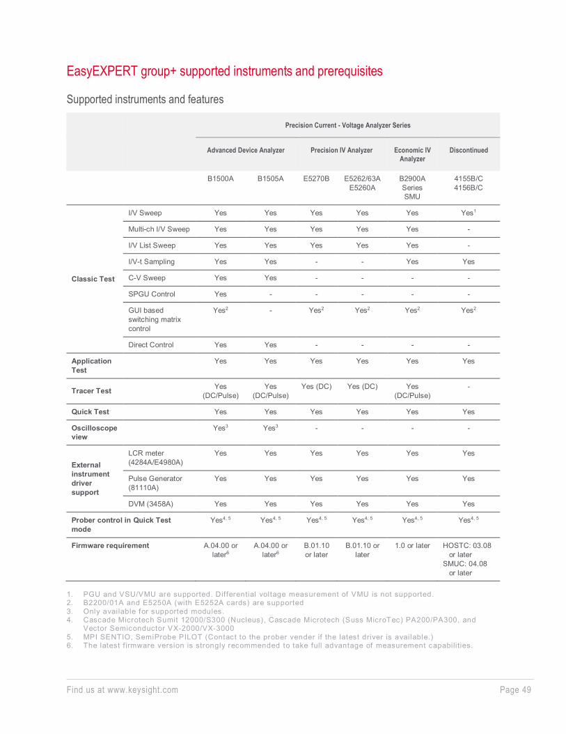
EasyEXPERT group+ supported instruments and prerequisites
Supported instruments and features
Precision Current - Voltage Analyzer Series
Advanced Device Analyzer Precision IV Analyzer Economic IV Analyzer
Discontinued
B1500A B1505A E5270B E5262/63A E5260A
B2900A Series SMU
4155B/C 4156B/C
Classic Test
I/V Sweep Yes Yes Yes Yes Yes Yes1
Multi-ch I/V Sweep Yes Yes Yes Yes Yes -
I/V List Sweep Yes Yes Yes Yes Yes -
I/V-t Sampling Yes Yes - - Yes Yes
C-V Sweep Yes Yes - - - -
SPGU Control Yes - - - - -
GUI based switching matrix control
Yes2 - Yes2 Yes2 Yes2 Yes2
Direct Control Yes Yes - - - -
Application Test
Yes Yes Yes Yes Yes Yes
Tracer Test Yes (DC/Pulse)
Yes (DC/Pulse)
Yes (DC) Yes (DC) Yes (DC/Pulse)
-
Quick Test Yes Yes Yes Yes Yes Yes
Oscilloscope view
Yes3 Yes3 - - - -
External instrument driver support
LCR meter (4284A/E4980A)
Yes Yes Yes Yes Yes Yes
Pulse Generator (81110A)
Yes Yes Yes Yes Yes Yes
DVM (3458A) Yes Yes Yes Yes Yes Yes
Prober control in Quick Test mode
Yes4, 5 Yes4, 5 Yes4, 5 Yes4, 5 Yes4, 5 Yes4, 5
Firmware requirement A.04.00 or later6
A.04.00 or later6
B.01.10 or later
B.01.10 or later
1.0 or later HOSTC: 03.08 or later SMUC: 04.08 or later
1. PGU and VSU/VMU are supported. Differential voltage measurement of VMU is not supported. 2. B2200/01A and E5250A (with E5252A cards) are supported 3. Only available for supported modules. 4. Cascade Microtech Sumit 12000/S300 (Nucleus), Cascade Microtech (Suss MicroTec) PA200/PA300, and
Vector Semiconductor VX-2000/VX-3000 5. MPI SENTIO, SemiProbe PILOT (Contact to the prober vender if the latest driver is available.) 6. The latest f irmware version is strongly recommended to take full advantage of measurement capabilities.
Find us at www.keysight.com Page 50
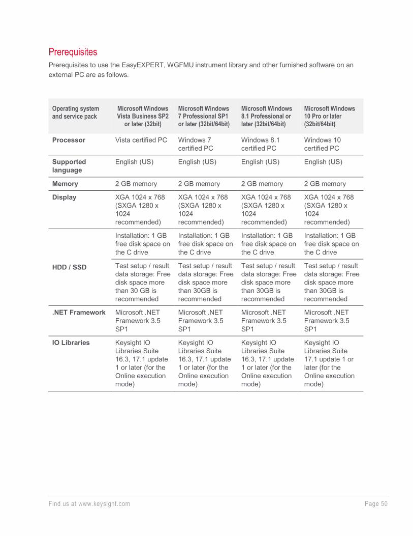
Prerequisites Prerequisites to use the EasyEXPERT, WGFMU instrument library and other furnished software on an external PC are as follows.
Operating system and service pack
Microsoft Windows Vista Business SP2
or later (32bit)
Microsoft Windows 7 Professional SP1 or later (32bit/64bit)
Microsoft Windows 8.1 Professional or later (32bit/64bit)
Microsoft Windows 10 Pro or later (32bit/64bit)
Processor Vista certified PC Windows 7 certified PC
Windows 8.1 certified PC
Windows 10 certified PC
Supported language
English (US) English (US) English (US) English (US)
Memory 2 GB memory 2 GB memory 2 GB memory 2 GB memory
Display XGA 1024 x 768 (SXGA 1280 x 1024 recommended)
XGA 1024 x 768 (SXGA 1280 x 1024 recommended)
XGA 1024 x 768 (SXGA 1280 x 1024 recommended)
XGA 1024 x 768 (SXGA 1280 x 1024 recommended)
HDD / SSD
Installation: 1 GB free disk space on the C drive
Installation: 1 GB free disk space on the C drive
Installation: 1 GB free disk space on the C drive
Installation: 1 GB free disk space on the C drive
Test setup / result data storage: Free disk space more than 30 GB is recommended
Test setup / result data storage: Free disk space more than 30GB is recommended
Test setup / result data storage: Free disk space more than 30GB is recommended
Test setup / result data storage: Free disk space more than 30GB is recommended
.NET Framework Microsoft .NET Framework 3.5 SP1
Microsoft .NET Framework 3.5 SP1
Microsoft .NET Framework 3.5 SP1
Microsoft .NET Framework 3.5 SP1
IO Libraries Keysight IO Libraries Suite 16.3, 17.1 update 1 or later (for the Online execution mode)
Keysight IO Libraries Suite 16.3, 17.1 update 1 or later (for the Online execution mode)
Keysight IO Libraries Suite 16.3, 17.1 update 1 or later (for the Online execution mode)
Keysight IO Libraries Suite 17.1 update 1 or later (for the Online execution mode)
Find us at www.keysight.com Page 51
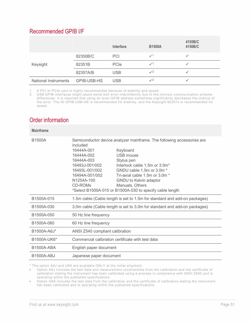
Recommended GPIB I/F
Interface B1500A 4155B/C 4156B/C
Keysight
82350B/C PCI 1
82351B PCIe 1
82357A/B USB 2
National Instruments GPIB-USB-HS USB 2
1. A PCI or PCIe card is highly recommended because of stabil ity and speed. 2. USB GPIB interfaces might cause serial poll error intermittently due to the intrinsic communication scheme
differences. It is reported that using an even GPIB address sometimes s ignif icantly decreases the chance of the error. The NI GPIB-USB-HS is recommended for stabili ty, and the Keysight 82357x is recommended for speed.
Order information Mainframe
B1500A Semiconductor device analyzer mainframe. The following accessories are included 16444A-001 Keyboard 16444A-002 USB mouse 16444A-003 Stylus pen 16493J-001/002 Interlock cable 1.5m or 3.0m* 16493L-001/002 GNDU cable 1.5m or 3.0m * 16494A-001/002 Tri-axial cable 1.5m or 3.0m * N1254A-100 GNDU to Kelvin adaptor CD-ROMs Manuals, Others *Select B1500A-015 or B1500A-030 to specify cable length
B1500A-015 1.5m cable (Cable length is set to 1.5m for standard and add-on packages)
B1500A-030 3.0m cable (Cable length is set to 3.0m for standard and add-on packages)
B1500A-050 50 Hz line frequency
B1500A-060 60 Hz line frequency
B1500A-A6J* ANSI Z540 compliant calibration
B1500A-UK6* Commercial calibration certificate with test data
B1500A-ABA English paper document
B1500A-ABJ Japanese paper document * The option A6J and UK6 are available ONLY at the initial shipment. • Option A6J includes the test data and measurement uncertainties from the calibration and the certif icate of
calibration stating the instrument has been calibrated using a process in compliance with ANSI Z540 and is operating within the published specif ications.
• Option UK6 includes the test data from the calibration and the certif icate of calibration stating the instrument has been calibrated and is operating within the published specif ications.
Find us at www.keysight.com Page 52
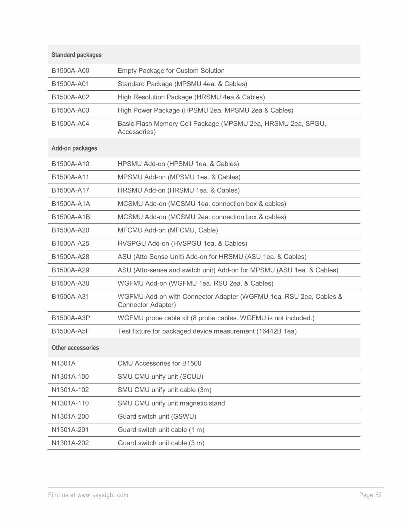
Standard packages
B1500A-A00 Empty Package for Custom Solution
B1500A-A01 Standard Package (MPSMU 4ea. & Cables)
B1500A-A02 High Resolution Package (HRSMU 4ea & Cables)
B1500A-A03 High Power Package (HPSMU 2ea, MPSMU 2ea & Cables)
B1500A-A04 Basic Flash Memory Cell Package (MPSMU 2ea, HRSMU 2ea, SPGU, Accessories)
Add-on packages
B1500A-A10 HPSMU Add-on (HPSMU 1ea. & Cables)
B1500A-A11 MPSMU Add-on (MPSMU 1ea. & Cables)
B1500A-A17 HRSMU Add-on (HRSMU 1ea. & Cables)
B1500A-A1A MCSMU Add-on (MCSMU 1ea. connection box & cables)
B1500A-A1B MCSMU Add-on (MCSMU 2ea. connection box & cables)
B1500A-A20 MFCMU Add-on (MFCMU, Cable)
B1500A-A25 HVSPGU Add-on (HVSPGU 1ea. & Cables)
B1500A-A28 ASU (Atto Sense Unit) Add-on for HRSMU (ASU 1ea. & Cables)
B1500A-A29 ASU (Atto-sense and switch unit) Add-on for MPSMU (ASU 1ea. & Cables)
B1500A-A30 WGFMU Add-on (WGFMU 1ea. RSU 2ea. & Cables)
B1500A-A31 WGFMU Add-on with Connector Adapter (WGFMU 1ea, RSU 2ea, Cables & Connector Adapter)
B1500A-A3P WGFMU probe cable kit (8 probe cables. WGFMU is not included.)
B1500A-A5F Test fixture for packaged device measurement (16442B 1ea)
Other accessories
N1301A CMU Accessories for B1500
N1301A-100 SMU CMU unify unit (SCUU)
N1301A-102 SMU CMU unify unit cable (3m)
N1301A-110 SMU CMU unify unit magnetic stand
N1301A-200 Guard switch unit (GSWU)
N1301A-201 Guard switch unit cable (1 m)
N1301A-202 Guard switch unit cable (3 m)
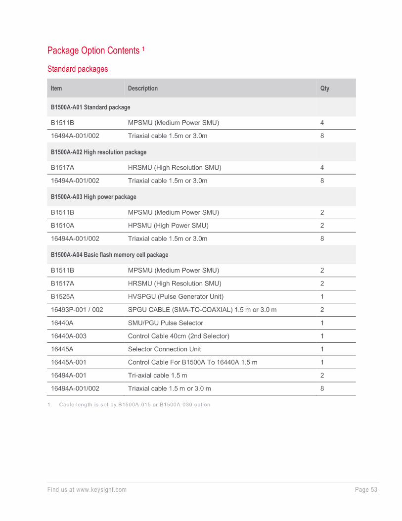
Find us at www.keysight.com Page 53
Package Option Contents 1
Standard packages
Item Description Qty
B1500A-A01 Standard package
B1511B MPSMU (Medium Power SMU) 4
16494A-001/002 Triaxial cable 1.5m or 3.0m 8
B1500A-A02 High resolution package
B1517A HRSMU (High Resolution SMU) 4
16494A-001/002 Triaxial cable 1.5m or 3.0m 8
B1500A-A03 High power package
B1511B MPSMU (Medium Power SMU) 2
B1510A HPSMU (High Power SMU) 2
16494A-001/002 Triaxial cable 1.5m or 3.0m 8
B1500A-A04 Basic flash memory cell package
B1511B MPSMU (Medium Power SMU) 2
B1517A HRSMU (High Resolution SMU) 2
B1525A HVSPGU (Pulse Generator Unit) 1
16493P-001 / 002 SPGU CABLE (SMA-TO-COAXIAL) 1.5 m or 3.0 m 2
16440A SMU/PGU Pulse Selector 1
16440A-003 Control Cable 40cm (2nd Selector) 1
16445A Selector Connection Unit 1
16445A-001 Control Cable For B1500A To 16440A 1.5 m 1
16494A-001 Tri-axial cable 1.5 m 2
16494A-001/002 Triaxial cable 1.5 m or 3.0 m 8
1. Cable length is set by B1500A-015 or B1500A-030 option
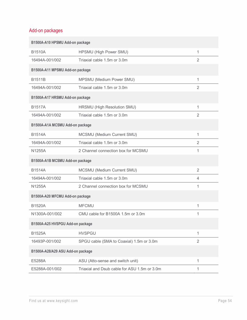
Find us at www.keysight.com Page 54
Add-on packages
B1500A-A10 HPSMU Add-on package
B1510A HPSMU (High Power SMU) 1
16494A-001/002 Triaxial cable 1.5m or 3.0m 2
B1500A-A11 MPSMU Add-on package
B1511B MPSMU (Medium Power SMU) 1
16494A-001/002 Triaxial cable 1.5m or 3.0m 2
B1500A-A17 HRSMU Add-on package
B1517A HRSMU (High Resolution SMU) 1
16494A-001/002 Triaxial cable 1.5m or 3.0m 2
B1500A-A1A MCSMU Add-on package
B1514A MCSMU (Medium Current SMU) 1
16494A-001/002 Triaxial cable 1.5m or 3.0m 2
N1255A 2 Channel connection box for MCSMU 1
B1500A-A1B MCSMU Add-on package
B1514A MCSMU (Medium Current SMU) 2
16494A-001/002 Triaxial cable 1.5m or 3.0m 4
N1255A 2 Channel connection box for MCSMU 1
B1500A-A20 MFCMU Add-on package
B1520A MFCMU 1
N1300A-001/002 CMU cable for B1500A 1.5m or 3.0m 1
B1500A-A25 HVSPGU Add-on package
B1525A HVSPGU 1
16493P-001/002 SPGU cable (SMA to Coaxial) 1.5m or 3.0m 2
B1500A-A28/A29 ASU Add-on package
E5288A ASU (Atto-sense and switch unit) 1
E5288A-001/002 Triaxial and Dsub cable for ASU 1.5m or 3.0m 1
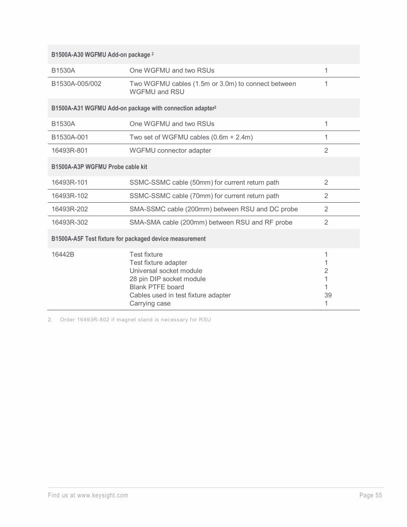
Find us at www.keysight.com Page 55
B1500A-A30 WGFMU Add-on package 2
B1530A One WGFMU and two RSUs 1
B1530A-005/002 Two WGFMU cables (1.5m or 3.0m) to connect between WGFMU and RSU
1
B1500A-A31 WGFMU Add-on package with connection adapter2
B1530A One WGFMU and two RSUs 1
B1530A-001 Two set of WGFMU cables (0.6m + 2.4m) 1
16493R-801 WGFMU connector adapter 2
B1500A-A3P WGFMU Probe cable kit
16493R-101 SSMC-SSMC cable (50mm) for current return path 2
16493R-102 SSMC-SSMC cable (70mm) for current return path 2
16493R-202 SMA-SSMC cable (200mm) between RSU and DC probe 2
16493R-302 SMA-SMA cable (200mm) between RSU and RF probe 2
B1500A-A5F Test fixture for packaged device measurement
16442B Test fixture Test fixture adapter Universal socket module 28 pin DIP socket module Blank PTFE board Cables used in test fixture adapter Carrying case
1 1 2 1 1 39 1
2. Order 16493R-802 if magnet stand is necessary for RSU
Find us at www.keysight.com Page 56
Learn more at: www.keysight.com For more information on Keysight Technologies’ products, applications or services, please contact your local Keysight office. The complete list is available at: www.keysight.com/find/contactus
This informat ion is subject to change without notice. © Keysight Technologies, 2019, Published in USA, December 26, 2019, 5989-2785EN
Keysight Precision Current-Voltage Analyzer Series and Power Device Analyzer Series
www.keysight.com/find/analyzer