Embed Size (px)
Citation preview
ROADS AND MARITIME SERVICES (RMS)
QA SPECIFICATION B113
POST-TENSIONING OF CONCRETE
NOTICE
This document is a Roads and Maritime Services QA Specification. It has been developed for use with roadworks and bridgeworks contracts let by Roads and Maritime Services or by local councils in NSW. It is not suitable for any other purpose and must not be used for any other purpose or in any other context.
Copyright in this document belongs to Roads and Maritime Services.
REVISION REGISTER
Ed/Rev Number
Clause Number Description of Revision Authorised
By Date
Ed 1/Rev 0 First Issued GM,CMS 03.05.91
Ed 2/Rev 0 Changes throughout GM,RNIC 24.04.98
Ed 2/Rev 1 1.2 Components to be supplied by system supplier.
GM, RNIC 31.07.98
1.4 Definitions of Supervisor and Supplier changed.
Ed 2/Rev 2 Annexure B113/1
Schedule of Identified Records added GM, RNIC (J Woodward)
14.04.00
Ed 3/Rev 0 Extensive changes to format and technical content
GM, RNIC 18.03.05
Ed 3/Rev 1 1.2.5, 2.3, 10.3, 10.5.1
RTA title changed GM, IC 07.04.08
4.2.1 Materials for tendons amended in line with AS/NZS 4672
4.3.1 Testing of tendons amended in line with AS/NZS 4672
Annex B113/F
New systems added and one removed
Annex B113/M
AS 1310, AS 1311 and AS 1313 replaced by AS/NZS 4672
Ed 3/Rev 2 1.3 Definitions of “you” and “your” added. GM, IC 11.08.09
2.1, 5.2, 8.4 Certification changed to by Chartered Professional Engineer with Membership of Engrs Aust.
Ed 3/Rev 3 2.1, 5.2, 8.4 Added: NPER registration as equivalent to CPEng, Engrs Aust, for certification purposes.
GM, IC 14.12.09
Edition 3 / Revision 5 ROADS AND MARITIME SERVICES May 2011
Ed/Rev Number
Clause Number Description of Revision Authorised
By Date
Ed 3/Rev 4 2.1 Approved Proprietary Post-Tensioning Systems changed from listing in Annex F to RTA Internet website.
GM, IC 26.11.10
10.2 Approved Proprietary Grouting Systems changed from listing in Annex F to RTA Internet website.
Annex F Deleted.
Ed 3/Rev 5 8.1 Requirements for gauges for stressing jacks clarified.
GM, IC 30.05.11
ii

QA SPECIFICATION B113
POST-TENSIONING OF CONCRETE Copyright – Roads and Maritime Services
IC-QA-B113
VERSION FOR: DATE:
Edition 3 / Revision 5 ROADS AND MARITIME SERVICES May 2011

Post-Tensioning of Concrete B113
CONTENTS
CLAUSE PAGE
FOREWORD .............................................................................................................................................. III RMS Copyright and Use of this Document ................................................................................. iii Revisions to Previous Version ..................................................................................................... iii Project Specific Changes ............................................................................................................. iii
1 GENERAL ........................................................................................................................................ 1 1.1 Scope .............................................................................................................................. 1 1.2 Structure of the Specification ......................................................................................... 1 1.3 Definitions ...................................................................................................................... 2
2 POST-TENSIONING SYSTEMS .......................................................................................................... 3 2.1 General ........................................................................................................................... 3 2.2 Provisions for External Prestressing .............................................................................. 3 2.3 Post-Tensioning Supervisor ........................................................................................... 6
3 SUPPLY OF DUCTS .......................................................................................................................... 7
4 MANUFACTURE AND SUPPLY OF TENDONS, ANCHORAGES AND OTHER COMPONENTS ............... 7 4.1 Suppliers of Materials .................................................................................................... 7 4.2 Material Requirements ................................................................................................... 7 4.3 Testing ............................................................................................................................ 8 4.4 Inspection ....................................................................................................................... 9 4.5 Assembly of Tendons ................................................................................................... 10 4.6 Condition of Tendons ................................................................................................... 10 4.7 Storage of Tendons ....................................................................................................... 10
5 INSTALLATION OF INTERNAL DUCTS AND ANCHORAGES ............................................................ 10 5.1 Placing .......................................................................................................................... 10 5.2 Restrictions on Welding ............................................................................................... 11 5.3 Minimum Cover ........................................................................................................... 11 5.4 Grout Vents and Caps .................................................................................................. 12
6 INSTALLATION OF TENDONS ........................................................................................................ 12 6.1 Pulling of Tendons and Pushing of Strands ................................................................. 12 6.2 Special Provision for High Tensile Bars ...................................................................... 12
7 CONCRETE WORK ........................................................................................................................ 13 7.1 General ......................................................................................................................... 13 7.2 Precautions During Concreting .................................................................................... 13 7.3 Precautions After Concreting ....................................................................................... 13
8 PREPARATION FOR STRESSING ..................................................................................................... 14 8.1 Stressing Equipment ..................................................................................................... 14 8.2 Clearing Ducts and Cleaning Tendons and Anchorages .............................................. 14 8.3 Concrete Strength Testing and Age of Concrete Before Stressing .............................. 14 8.4 Stressing Calculations .................................................................................................. 15
9 STRESSING OPERATIONS .............................................................................................................. 16 9.1 General ......................................................................................................................... 16 9.2 Acceptance of Stressing ............................................................................................... 18
Ed 3 / Rev 5 i
B113 Post-Tensioning of Concrete
10 GROUTING .................................................................................................................................... 19 10.1 Air Testing of Ducts Before Grouting .......................................................................... 19 10.2 Operations ..................................................................................................................... 19 10.3 Materials and Mix Design ............................................................................................ 20 10.4 Performance Requirements ........................................................................................... 21 10.5 Tests .............................................................................................................................. 21 10.6 Mixing and Pumping Equipment .................................................................................. 22 10.7 Mixing .......................................................................................................................... 23 10.8 Grouting of Ducts ......................................................................................................... 23
11 PROTECTION OF ANCHORAGES ..................................................................................................... 25
ANNEXURE B113/A – (NOT USED) ......................................................................................................... 26
ANNEXURE B113/B – PAYMENT ............................................................................................................ 26
ANNEXURE B113/C – SCHEDULES OF HOLD POINTS AND IDENTIFIED RECORDS .................................. 27 C1 Schedule of Hold Points ............................................................................................... 27 C2 Schedule of Identified Records..................................................................................... 27
ANNEXURE B113/D – PLANNING DOCUMENTS ...................................................................................... 28
ANNEXURE B113/E – MINIMUM FREQUENCY OF TESTING .................................................................... 28
ANNEXURES B113/F TO B113/L – (NOT USED) ..................................................................................... 29
ANNEXURE B113/M – REFERENCED DOCUMENTS AND ABBREVIATIONS ............................................. 29 M1 Referenced Documents ................................................................................................. 29 M2 Abbreviations ................................................................................................................ 30
LAST PAGE OF THIS DOCUMENT IS .......................................................................................................... 30
ii Ed 3 / Rev 5
Post-Tensioning of Concrete B113
FOREWORD
RMS COPYRIGHT AND USE OF THIS DOCUMENT
Copyright in this document belongs to Roads and Maritime Services.
When this document forms part of a contract
This document should be read with all the documents forming the Contract.
When this document does not form part of a contract
This copy is not a controlled document. Observe the Notice that appears on the first page of the copy controlled by RMS. A full copy of the latest version of the document is available on the RMS Internet website: http://www.rms.nsw.gov.au/business-industry/partners-suppliers/specifications/index.html
REVISIONS TO PREVIOUS VERSION
This document has been revised from Specification RMS B113 Edition 3 Revision 4.
All revisions to the previous version (other than minor editorial and project specific changes) are indicated by a vertical line in the margin as shown here, except when it is a new edition and the text has been extensively rewritten.
PROJECT SPECIFIC CHANGES
Any project specific changes are indicated in the following manner:
(a) Text which is additional to the base document and which is included in the Specification is shown in bold italics e.g. Additional Text.
(b) Text which has been deleted from the base document and which is not included in the Specification is shown struck out e.g. Deleted Text.
Ed 3 / Rev 5 iii

(RTA COPYRIGHT AND USE OF THIS DOCUMENT - Refer to the Foreword after the Table of Contents)
RMS QA SPECIFICATION B113
POST-TENSIONING OF CONCRETE
1 GENERAL
1.1 SCOPE
This Specification sets out the requirements for the supply, installation, stressing, grouting and corrosion protection of post-tensioned internal and external prestressing tendons and their anchorages and other components for post-tensioned concrete bridge elements.
This Specification does not fully specify post-tensioning systems comprising ungrouted internal tendons or stay cables, the requirements for which must be obtained from the Principal.
1.2 STRUCTURE OF THE SPECIFICATION
This Specification includes a series of annexures that detail additional requirements.
1.2.1 Payment
The method of measurement and payment must comply with Annexure B113/B.
Work and materials must be rejected unless they conform to the requirements of this Specification.
1.2.2 Schedules of HOLD POINTS and Identified Records
The schedules in Annexure B113/C list the HOLD POINTS that must be observed. Refer to Specification RMS Q for the definition of HOLD POINTS.
The records listed in Annexure B113/C are Identified Records for the purposes of RMS Q Annexure Q/E.
1.2.3 Planning Documents
The PROJECT QUALITY PLAN must include each of the documents and requirements listed in Annexure B113/D and must be implemented.
1.2.4 Minimum Frequency of Testing
The Inspection and Test Plan must nominate the proposed testing frequency to verify conformity of the item and it must not be less than that specified in Annexure B113/E. Where a minimum frequency is not specified, nominate an appropriate frequency.
The Principal may conditionally agree to your proposal to reduce the specified minimum frequency of testing. The proposal must be supported by a statistical analysis verifying consistent process capability and product characteristics. The Principal may vary or restore the specified minimum frequency of testing, either selectively or permanently, at any time.
Ed 3 / Rev 5 1
(RTA COPYRIGHT AND USE OF THIS DOCUMENT - Refer to the Foreword after the Table of Contents)
B113 Post-Tensioning of Concrete
1.2.5 Approved Post-Tensioning and Grouting Systems
Approval of post-tensioning systems and grouting systems have been delegated by the Principal to the Bridge Engineer (Policy & Specifications), RMS Bridge and Structural Engineering (telephone 02 8837 0875 facsimile 02 8837 0054).
Approval of post-tensioning systems is carried out in accordance with Specification RMS B119.
Details of approval of grouting systems can be forwarded on request.
The approved post-tensioning systems and grouting systems are listed in RMS Internet website (refer Clauses 2.1 and 10.2).
1.2.6 Referenced Documents and Abbreviations
Unless specified otherwise or is specifically supplied by the Principal, the applicable issue of a referenced document is the issue current at the date one week before the closing date for tenders, or where no issue is current at that date, the most recent issue.
Codes, standards, specifications and test methods are referred to in abbreviated form (eg AS 1234). For convenience, the full titles are given in Annexure B113/M. Whenever a part of a standard is referenced, the common title of the standard is mentioned in Annexure B113/M as a separate entry with that part of the standard referred to only by its particular title.
1.3 DEFINITIONS
The terms “you” and “your” mean “the Contractor” and “the Contractor’s” respectively.
The following definitions apply to this Specification:-
(a) Critical Post-Tensioning Activity: Construction activities, including concrete vibration at anchorages and vents, air testing, stressing and grouting, that must be supervised by the Post-Tensioning Supervisor.
(b) Design Elongation: Tendon elongation at the jack stated on the Drawings.
(c) Design Jacking Force: Tendon force at the jack stated on the Drawings, based on the design parameters stated thereon
(d) Measured Elongation: Tendon elongation at the jack measured at the nominated jacking force.
(e) Nominated Draw-In: Inward movement of the tendon due to anchorage slip and draw-in when the post-tensioning force is transferred from the jack, assessed by lift off testing during approval of the post-tensioning system.
(f) Nominated Elongation: Tendon elongation at the jack nominated by the Contractor corresponding to the nominated jacking force.
(g) Nominated Gauge Pressure: Gauge pressure at the jack nominated by the Contractor corresponding to the nominated jacking force.
(h) Nominated Jacking Force: Tendon force at the jack nominated by the Contractor, based on the design jacking force adjusted for actual tendon and post-tensioning system properties and
2 Ed 3 / Rev 5
(RTA COPYRIGHT AND USE OF THIS DOCUMENT - Refer to the Foreword after the Table of Contents)
Post-Tensioning of Concrete B113
parameters, including allowances for losses in addition to and where different to those stated on the Drawings.
(i) Post-Tensioning Supervisor: Employee of, and nominated by, the Post-Tensioning System Supplier and approved by the Principal.
(j) Post-Tensioning System Supplier: The owner, or the agent of the owner, that is responsible for the supply and installation in the Works of a post-tensioning system approved by RMS, in accordance with the conditions of approval.
2 POST-TENSIONING SYSTEMS
2.1 GENERAL
The post-tensioning system must be one of the approved Proprietary Post-Tensioning Systems listed in RMS Internet website: http://www.rms.nsw.gov.au/business-industry/partners-suppliers/documents/tenders-contracts/listofapprovedbridgecomponentssystems.pdf
The post-tensioning system components must be supplied by a Post-Tensioning System Supplier.
Changes may be introduced to auxiliary hardware components as defined in RMS B119 of an approved system on individual projects only if approved by the Principal. Any other changes to an approved system may only be introduced after being submitted for approval in accordance with Clause 1.2.5.
Where any modifications are necessary to the reinforcement and/or concrete dimensions to suit an approved post-tensioning system for the type, size and arrangement of tendons shown on the Drawings, submit to the Principal working drawings to the same scale as the Drawings of all necessary modifications together with supporting design calculations carried out and certified by a Chartered Professional Engineer with Membership of Engineers Australia (or equivalent) practising in the field of structural engineering and experienced in this work.
An equivalent to membership of Engineers Australia would be an Engineer registered on the National Engineering Register (NER) in the general area of practice of Structural Engineering.
All necessary modifications, calculations and drawings must be carried out at no cost to the Principal.
2.2 PROVISIONS FOR EXTERNAL PRESTRESSING
2.2.1 General
External tendons must be replaceable.
Encapsulate external tendons in smooth polyethylene plastic ducts with minimum wall thickness 1/17 of the outside diameter.
The duct design must account for creep rupture effects from the sustained circumferential stresses induced by pressure grouting, if applicable.
Ed 3 / Rev 5 3
(RTA COPYRIGHT AND USE OF THIS DOCUMENT - Refer to the Foreword after the Table of Contents)
B113 Post-Tensioning of Concrete
Where duct couplers are used, provide drip rings on the high side above the coupler to prevent water running along the duct into the coupled joint.
Fit external tendons with suitable connections at fixing points to allow easy replacement. Install with sufficient access and clearances to allow replacement and stressing.
Adopt one of the following forms of construction where external tendons pass through deviators, anchorage diaphragms and/or blisters:
(a) At deviators, one of the following:
(i) Diabolo
Pass the plastic duct through a formed double conical hole (diabolo) in the deviator. Form diabolos so that the plastic duct is not damaged by localised bearing stresses.
(ii) Steel pipe
Pass the tendon through a rigid steel pipe located in the deviator to which the plastic duct is coupled on both sides. Curve the steel pipe to a constant radius between tangent points located approximately 75 mm inside the concrete faces. Extend the steel pipe at least 150 mm but not more than 300 mm beyond the concrete faces, following the tangential direction of the tendon. Where the steel pipe exits from the concrete, set a rubber O-ring 50 mm wide and 10 mm thick into the concrete to prevent spalling of the concrete cover if the steel pipe is misaligned.
Acceptable coupling systems include, but are not limited to:
(A) Reinforced neoprene sleeves with stainless steel power seated band clamps;
(B) Compression coupling with O-rings.
(b) At anchorage diaphragms and blisters, one of the following:
(i) Concrete bell mouth
Insert and seal the plastic duct into a straight rigid plastic or steel pipe extending from the cast-in anchorage to approximately 200 mm inside the exit face of the diaphragm or blister. Provide a conical concrete bell mouth at the exit face of the diaphragm or blister, ensuring that the distance from the face of the concrete to where the plastic duct contacts the concrete of the bell mouth is at least 20 mm.
(ii) Tube
Pass the tendon through a rigid steel or smooth plastic tube located in the anchorage diaphragm or blister to which the plastic duct is coupled on the exit side. Extend the tube at least 150 mm but not more than 300 mm beyond the concrete faces, following the tangential direction of the tendon. Where the tube exits from the concrete, set a rubber O-ring 50 mm wide and 10 mm thick into the concrete to prevent spalling of the concrete cover if the tube is misaligned. The smooth plastic tube must have a minimum wall thickness 1/17 of the outside diameter.
Positively connect ducts to the steel or plastic sleeves at the diaphragms and deviators using connections strong enough to withstand site construction loads and conditions without damage.
Positively seal all connections between steel pipes and plastic ducts, between length of plastic ducts, and between steel pipes and anchorages/couplers with an air and water tight coupling system capable of sustaining testing and grouting pressures, to ensure continuity of the ducts for corrosion protection.
4 Ed 3 / Rev 5
(RTA COPYRIGHT AND USE OF THIS DOCUMENT - Refer to the Foreword after the Table of Contents)
Post-Tensioning of Concrete B113
Do not use duct tape for sealing these connections.
Hot-dip galvanise steel pipes to AS 4680.
Provide, before construction, detailed shop drawings of the external tendons.
2.2.2 Protection of ungrouted external tendons and anchorages
The protection against deterioration of the post-tensioning system components must remain effective for the design life of the structure.
Where ducts are ungrouted, the tendons must be galvanized or epoxy coated, or encapsulated in individual grease or wax filled polyethylene plastic sheathing. For galvanized or epoxy coated tendons comprising wire stands, the individual wires must have the same type of protective treatment. Tendon protection systems must be approved by the Principal.
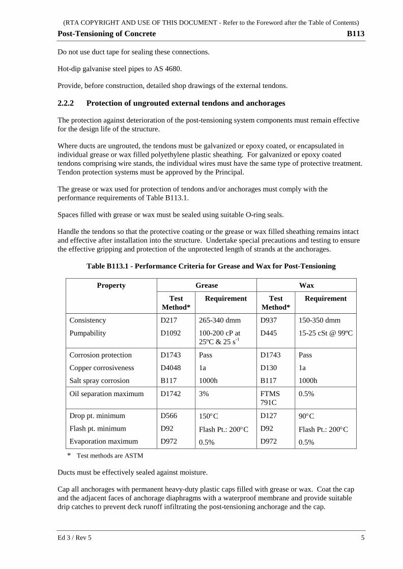
The grease or wax used for protection of tendons and/or anchorages must comply with the performance requirements of Table B113.1.
Spaces filled with grease or wax must be sealed using suitable O-ring seals.
Handle the tendons so that the protective coating or the grease or wax filled sheathing remains intact and effective after installation into the structure. Undertake special precautions and testing to ensure the effective gripping and protection of the unprotected length of strands at the anchorages.
Table B113.1 - Performance Criteria for Grease and Wax for Post-Tensioning
Property Grease Wax
Test Method*
Requirement Test Method*
Requirement
Consistency
Pumpability
D217
D1092
265-340 dmm
100-200 cP at 25ºC & 25 s-1
D937
D445
150-350 dmm
15-25 cSt @ 99ºC
Corrosion protection
Copper corrosiveness
Salt spray corrosion
D1743
D4048
B117
Pass
1a
1000h
D1743
D130
B117
Pass
1a
1000h
Oil separation maximum D1742 3% FTMS 791C
0.5%
Drop pt. minimum
Flash pt. minimum
Evaporation maximum
D566
D92
D972
150°C
Flash Pt.: 200°C
0.5%
D127
D92
D972
90°C
Flash Pt.: 200°C
0.5%
* Test methods are ASTM
Ducts must be effectively sealed against moisture.
Cap all anchorages with permanent heavy-duty plastic caps filled with grease or wax. Coat the cap and the adjacent faces of anchorage diaphragms with a waterproof membrane and provide suitable drip catches to prevent deck runoff infiltrating the post-tensioning anchorage and the cap.
Ed 3 / Rev 5 5
(RTA COPYRIGHT AND USE OF THIS DOCUMENT - Refer to the Foreword after the Table of Contents)
B113 Post-Tensioning of Concrete
2.2.3 Provisions for full tendon replacement
For full tendon replacement:
(i) the structure must be able to withstand the removal/loss of a tendon under reduced live load;
(ii) provide access to the stressing anchors for all operations without the need to close traffic lanes for more than 48 hours for each tendon, or to require the removal of any structural elements of the superstructure, abutments or piers;
(iii) the tendon must be fully destressable and replaceable with sufficient access and clearances to allow the installation and stressing of the replacement tendon in existing deviators and anchorages; and
(iv) the Works-As-Executed Drawings must contain the design criteria for the post-tensioning system used in the bridge, as well as full construction details and procedures for destressing and replacing tendons, including any limitations on structure loading during tendon replacement operations.
2.3 POST-TENSIONING SUPERVISOR
Carry out Critical Post-Tensioning Activities under the supervision of a Post-Tensioning Supervisor.
Critical Post-Tensioning Activities include:
(a) vibration during placement of concrete around all anchorages and grout vents (refer to Clause 7.1).
(b) stressing (refer to Clause 9.1);
(c) air testing (refer to Clause 10.1); and
(d) grouting (refer to Clause 10.2).
The Post-Tensioning Supervisor must certify that the following work conforms to the requirements of this Specification:
(i) information listed to be supplied (refer to Clause 4);
(ii) placing and fixing ducts and anchorages (refer to Clause 5);
(iii) installation of tendons (refer to Clause 6);
(iv) precautions during and after concreting (refer to clause 7);
(v) clearing of ducts and cleaning of tendons and anchorages (refer to Clauses 7.3 and 8.2);
(vi) preparing for stressing (refer to Clause 8);
(vii) conformity of concrete to strength (refer to Clause 8.3);
(viii) stressing (refer to Clause 9);
(ix) air testing and grouting (refer to Clause 10); and
(x) protection of anchorages (refer to Clause 11).
The list of nominated Post-Tensioning Supervisors acceptable to the Principal is held by the Bridge Engineer (Policy & Specifications), RMS Bridge and Structural Engineering (telephone 02 8837 0875 facsimile 02 8837 0025).
6 Ed 3 / Rev 5
(RTA COPYRIGHT AND USE OF THIS DOCUMENT - Refer to the Foreword after the Table of Contents)
Post-Tensioning of Concrete B113
3 SUPPLY OF DUCTS Sheaths and removable formers used to form ducts must maintain their original cross section and profile during construction. The friction coefficient between the duct and the tendon must not be higher than 0.20 unless otherwise shown on the Drawings.
Where plastic ducts are specified on the Drawings, they must comply with the following:
(a) External ducts must be smooth walled and conform to either:
(i) ASTM D1248 for HDPE with designation IIIC5-P34; or
(ii) Classification PE 80 B to AS 4131.
(b) Internal plastic ducts must have a corrugated profile, an allowance in the wall thickness to account for abrasion during stressing of the tendon, and conform to either:
(i) ASTM D3350 for HDPE with cell classification 335533C; or
(ii) ASTM D1784 for rigid PVC with classification 13464B.
4 MANUFACTURE AND SUPPLY OF TENDONS, ANCHORAGES AND OTHER COMPONENTS
4.1 SUPPLIERS OF MATERIALS
Obtain tendon, anchorages and other system components only from suppliers who have implemented quality management systems meeting the requirements of AS/NZS/ISO 9001.
Provide evidence demonstrating that each supplier has the specified quality management systems in place, and that supplied materials will comply with this Specification.
Plastic ducts must comply with the requirements of this Specification.
4.2 MATERIAL REQUIREMENTS
4.2.1 Tendons
Obtain prestressing materials only from suppliers that have implemented quality management systems to AS/NZS ISO 9001, with third-party certification accredited or accepted by JAS-ANZ. Australian Certification Authority for Reinforcing Steels Ltd's (ACRS) certification of product compliance to AS/NZS 4672 will be accepted as conforming to this requirement.
Provide evidence demonstrating that each supplier of prestressing materials has the specified quality management systems in place, and provide proof of conformity of the supplied materials with the requirements of this Specification.
Tendons must conform to AS/NZS 4672.1 and the RMS approved post tensioning system. If tendons conform to other standards, provide to the Principal evidence that the tendons are of equivalent quality.
Strand must be Relaxation Class 2 unless specified otherwise.
Ed 3 / Rev 5 7

(RTA COPYRIGHT AND USE OF THIS DOCUMENT - Refer to the Foreword after the Table of Contents)
B113 Post-Tensioning of Concrete
4.2.2 Anchorages
Anchorages must comply with AS 1314 and this Specification.
Size and shape anchorages or bearing plates to transfer anchor loads to the concrete without overstress, irrespective of whether the load is applied by the anchorage or the stressing jack.
Provide a centring device or spigot for the anchor head so that the tendon force is applied uniformly on the anchor head and the bearing plate contact surface.
The combined anchorage must be capable of being loaded in stages so that accurate elongation measurements can be taken without indeterminate losses between stages.
The loss of prestress during stressing must be uniform and correspond to a pre-established plot of inward tendon movement versus load.
Unless approved otherwise, the steel for anchorage bearing plates must be Grade 250 to AS 3678. The bearing stress at the contact surface between the anchor head and the bearing plate must not exceed 400 MPa.
Anchorage castings or bearing plates manufactured from higher strength materials than Grade 250 steel may be used where higher stresses occur provided supporting calculations and experimental evidence are supplied demonstrating that an adequate factor of safety exists.
4.2.3 Couplers
Tendons may be joined only by approved couplers designed to develop 100% of the specified minimum breaking load of the tendon. Carry out efficiency testing to AS 1314 to prove that the couplers develop greater than 95% of the specified minimum breaking load of the tendon for strand tendons, and greater than 100% for bar tendons.
Provide couplers where shown on the Drawings or where approved otherwise.
4.2.4 Swaging and button-heading
Swages and button-heads must develop not less than 95% of the specified minimum breaking load of the strand or wire.
4.3 TESTING
4.3.1 Tendons
Provide, with each delivery, documentation listing the Lot numbers from which each coil or bar is taken and NATA endorsed test certificates in accordance with RMS Q as evidence of conformity with AS/NZS 4672.
Testing must conform to AS 4672.2.
Test at least one sample from each coil of wire and strand.
Test at least 3 bars from each Lot and each delivery.
Submit the following test reports:
8 Ed 3 / Rev 5

(RTA COPYRIGHT AND USE OF THIS DOCUMENT - Refer to the Foreword after the Table of Contents)
Post-Tensioning of Concrete B113
(a) Breaking force;
(b) Yield strength and elongation;
(c) Load-elongation curve;
(d) Cast analysis of the steel;
(e) Cross-sectional area of tendon; and
(f) 1000 hour isothermal relaxation, with evidence that the tendon tested represents the tendons supplied.
4.3.2 Anchorage components
Submit certificates of compliance to the post-tensioning system approval for all anchorage components delivered.
Gripping efficiency of the combined anchorage must be maintained by achieving the required manufacturing tolerances for each component.
4.3.2 Swaging and button-heading
Make and test at least one swaged sample during the swaging of each tendon. Cut off non-conforming swages and install a new die prior to continuing swaging.
Test three sample button headed ends at the commencement of the fabrication of the tendons.
Test further samples throughout the job in accordance with the Inspection and Test Plan.
4.4 INSPECTION
All tendons and anchorage components, including bearing plates and cast-in anchorages, must at all times be identifiable and traceable to the relevant Lots and test reports, which must be available on Site. Include tendon and component identification and traceability in the Inspection and Test Plan.
Where tendons are from more than one coil, maintain the identification process until stressing is completed.
Tendons must not be damaged, kinked or bent and must be free of rust, oil, grease, tar, paint, mud or any other deleterious substance.
Individually inspect high tensile steel bars for superficial tears, nicks, roller marks or any other form of surface imperfection. A bar with surface imperfections that range up to 0.40 mm deep may be accepted provided that imperfections ranging from 0.15 mm to 0.40 mm in depth are filed smooth with a fine cut half round file. A bar with surface imperfections that exceed 0.40 mm in depth must be treated as nonconforming.
Ed 3 / Rev 5 9
(RTA COPYRIGHT AND USE OF THIS DOCUMENT - Refer to the Foreword after the Table of Contents)
B113 Post-Tensioning of Concrete
4.5 ASSEMBLY OF TENDONS
HOLD POINT
Process Held: Assembly of tendons.
Submission Details: Full conformity records for all tendon materials.
Release of Hold Point: The Principal will consider the submitted documents prior to authorising the release of the Hold Point.
Pull strand out from the coil in such a way that any twisting force which the strand might acquire during the uncoiling will not loosen the lay of the strand.
Cut strand only with high speed carborundum disc cutters or hydraulic guillotines. Do not use flame cutting under any circumstances.
Use appropriate methods and equipment to assemble tendons so that individual wires or strands are not kinked, and maintain approximately the same relative position to the other wires and strands in the tendon. Bind the wires and strands of the assembled tendon at regular intervals, so that twisting of the tendon is minimised and no damage will be done to the tendon when it is installed.
4.6 CONDITION OF TENDONS
Keep tendons free from rust, oil, grease, tar, paint, mud or any other deleterious substance. Do not bring tendons to a smooth polished condition. A slight film of rust will not be regarded as harmful. The steel must not be visibly pitted.
Do not use tendons that are damaged, kinked, bent or have been subjected to fire.
4.7 STORAGE OF TENDONS
Store post-tensioning system components whether made up or not, including tendons, ducts and anchorage fittings, under a waterproof shelter supported above the surface of the ground protected from damage and from deterioration due to exposure.
Each tendon must be effectively identified.
5 INSTALLATION OF INTERNAL DUCTS AND ANCHORAGES
5.1 PLACING
Place ducts within a tolerance of ± 6 mm in any direction of the position shown on the Drawings. Position anchorages within tolerances of ± 6 mm across and vertically and ± 15 mm along the tendon. The face of the anchorage must be square to within 0.5o to the line of the tendon.
Where unavoidable conflict occurs between post-tensioning ducts and bar reinforcement, displace the reinforcement slightly.
Before placement of the ducts, inspect the profile of the duct supports for conformity.
10 Ed 3 / Rev 5
(RTA COPYRIGHT AND USE OF THIS DOCUMENT - Refer to the Foreword after the Table of Contents)
Post-Tensioning of Concrete B113
Tie and support ducts so that they do not move during concreting. The ducts must be fixed to the reinforcement at intervals sufficient to prevent the duct floating and causing reverse curvatures and increases to the wobble friction factor. Space duct supports at no more than 600 mm in flanges and 1200 mm in webs.
At high points in the tendon profile, space duct supports sufficiently close to prevent crushing of the ducts and penetration of the duct supports into the duct due to the weight of the tendon. A duct saddle may be required at such locations.
Set all cast-in anchorages square to the line of action of the tendon with the grout inlet on the bottom and the outlet on the top. Attach the anchorage securely to the formwork, which must be adequately designed and constructed to prevent movement of the anchorage during concreting. Remove any mortar or slurry adhering to bearing or wedging surfaces.
Internal plastic ducts must be mechanically attached to the anchorages.
Seal all joints in ducts to prevent entry of slurry during concreting.
Provide slurry-tight joints at holes or gaps between the ducts and cast-in anchorages or precast end blocks. Seal cast-in anchorages and ends of ducts at all times to prevent entry of debris, water, concrete, mortar, slurry or foreign matter.
Prevent ingress of water into ducts, particularly those with tendons installed, before stressing by covering exposed strands and blocking anchorages with plastic or similar.
Allow in the Inspection and Test Plan for staging of inspections of any ducts, anchorages, and/or supporting reinforcement that may be inaccessible after the reinforcement placement has reached a certain stage, particularly where void formers are incorporated into the reinforcement cage.
5.2 RESTRICTIONS ON WELDING
Do not weld in the vicinity of tendons unless it can be demonstrated to be absolutely necessary.
The Principal must approve the proposed welding procedures before welding operations commence. The Principal may disallow the proposals if they do not eliminate the risk of welding leads being earthed to tendons during welding operations.
Welding procedures must be certified by a Chartered Professional Engineer with Membership of Engineers Australia (or equivalent) practising in the field of Structural Engineering and experienced in this work. Welding procedures, together with reasons why welding in the vicinity of tendons cannot be avoided, must be submitted at least seven days before the proposed date of welding. ]
An equivalent to membership of Engineers Australia would be an Engineer registered on the National Engineering Register (NER) in the general area of practice of Structural Engineering.
Where welding is approved adjacent to a tendon, erect a shield to protect the tendon from damage. Do not cause any damage to tendons either directly by heat or weld spatter, or indirectly by stray electric currents.
5.3 MINIMUM COVER
Unless specified otherwise, the concrete cover to any duct, sheathing or former must not be less than 50 mm.
Ed 3 / Rev 5 11
(RTA COPYRIGHT AND USE OF THIS DOCUMENT - Refer to the Foreword after the Table of Contents)
B113 Post-Tensioning of Concrete
5.4 GROUT VENTS AND CAPS
Provide grout inlets and outlets at each anchorage. Provide grout vents at each high point.
Grout vents must be at least 0.5 m higher than the grout inlet, to ensure effective head of grout.
Fit all grout inlets with a pressure gauge for measuring pressures independent of pressures observed at the grout pump or air compressor. Unless specified otherwise, measure at the grout inlet all pressures specified for testing and grouting of ducts.
Fit anchorages with grout caps and seal for grouting and venting operations.
Equip all grout inlets, outlets and vents with a metal valve which can be closed and opened several times, or another approved method provided for maintaining pressure during air testing, and for controlling the grout flow during grouting. Exposed grout vents must be in the shut position.
The pressure rating for inlets, outlets and vents must not be less than 1.0 MPa. All tubing must be of plastic or other non-metallic materials with 20 mm minimum inside diameter, with sufficient strength to withstand the applied pressures without distortion or damage. Protect tubing from accidental damage during construction operations. Securely fasten the tubing to the duct and make all joints airtight.
6 INSTALLATION OF TENDONS
6.1 PULLING OF TENDONS AND PUSHING OF STRANDS
Pull the pre-assembled tendons or individual strands through the ducts using a pulling sock or cable leader or similar device so that no damage is done to the sheathing.
Strands or wires may be pushed individually through the ducts provided that before and throughout the pushing process each strand is fitted with a temporary head sized and shaped e.g. bullet, to prevent damage to the ducts and to prevent interlocking or crossover of strands, and to prevent damage to the tendon from the pushing rollers.
6.2 SPECIAL PROVISION FOR HIGH TENSILE BARS
Fully protect exposed threads of all bars, nuts and couplers on site at all times until stressing is completed.
Carry out a trial assembly of each set of bars, nuts and couplers before installation.
Mark the bars and/or provide a system of reference marks in the adjacent concrete to confirm by visual inspection that each end of each bar is fully engaged in its corresponding nut or coupler.
Submit details of the proposed procedures for ensuring that all bars will be fully engaged during installation, including the method of visual inspection to confirm this before stressing.
12 Ed 3 / Rev 5

(RTA COPYRIGHT AND USE OF THIS DOCUMENT - Refer to the Foreword after the Table of Contents)
Post-Tensioning of Concrete B113
7 CONCRETE WORK
7.1 GENERAL
Concrete, reinforcement and embedments must comply with Specification RMS B80.
Vibration of concrete around all anchorage zones and grout vents is a Critical Post-Tensioning Activity that must be carried out under the supervision of a Post-Tensioning Supervisor.
Where required by the design, or where it is essential for construction reasons, that the tendon be installed in the duct before concreting, provide procedures for preventing the duct being damaged either by the installation of the tendon or by subsequent concreting operations.
Where a tendon has a dead-end anchorage or is coupled to a previously stressed anchorage, provide a procedure for preventing ingress of concrete or cement slurry into the duct.
7.2 PRECAUTIONS DURING CONCRETING
When the tendons are not installed in the duct before concreting, support the ducts internally during concreting operations by inserting into it a continuous tube of diameter and stiffness adequate to prevent the duct from being dented or opened up allowing the entry of slurry because of direct hammering by the vibrators. The tube must be sufficiently flexible and have sufficient clearance to allow it to be drawn through the duct without damaging or distorting it. A number of smaller diameter tubes may be used instead of a single tube.
Tubular inserts need not be provided where it has been demonstrated by testing of a concreted prototype that the duct will not be damaged by:
(a) opening of seams;
(b) separation of joints;
(c) becoming excessively oval;
(d) leakage of mortar or grout.
Other proven precautions may be proposed for consideration.
7.3 PRECAUTIONS AFTER CONCRETING
Immediately after all the concrete has been placed in the element, pull any installed tendons or continuous tubing back and forth about 0.25 m to ensure that they are perfectly free inside the duct.
Any tendon installed in the ducts before stressing for more than:
(a) two weeks under severe corrosivity level;
(b) four weeks under moderate corrosivity level;
(c) eight weeks under low corrosivity level;
as defined in AS/NZS 2312 must be withdrawn and examined, except that where a set of similar tendons have been in place for a similar period, one representative tendon only need be withdrawn for examination.
Ed 3 / Rev 5 13
(RTA COPYRIGHT AND USE OF THIS DOCUMENT - Refer to the Foreword after the Table of Contents)
B113 Post-Tensioning of Concrete
There must be no additional cost to the Principal in these circumstances for withdrawing tendons for examination and reinstalling the tendons or new tendons if the ones examined do not conform to Clause 4.6.
8 PREPARATION FOR STRESSING
8.1 STRESSING EQUIPMENT
Pressure gauges must conform to the requirements of AS 1349. The diameter of the gauge must not be less than 150 mm and must be of such a type which will allow visual reading to the nearest 0.5 MPa or 5 bar.
The maximum jacking force must correspond to a gauge pressure between 50 % and 90 % of the gauge capacity.
Fit a device to the gauge to protect it against a sudden loss of pressure.
8.2 CLEARING DUCTS AND CLEANING TENDONS AND ANCHORAGES
Clear out the tendon ducts by blowing oil-free compressed air through both ends and each grout vent before fitting anchor blocks and gripping components. Protect and clean anchorages thoroughly before commencement of tensioning. Clean the protruding ends of the tendons of any coating, rust, mortar, oil, or mud that would hinder the gripping action of the jacking wedges or other gripping components.
Where the bearing plate has been previously cast in concrete, compensate for any misalignment before stressing.
8.3 CONCRETE STRENGTH TESTING AND AGE OF CONCRETE BEFORE STRESSING
In addition to testing any compressive strength cylinders required by RMS B80, take and test additional cylinders as specified below before stressing the tendon.
Take an additional pair of test cylinders from each batch or load of concrete placed around or close to anchorages.
Take an additional pair of test cylinders from every 30 cubic metres or part thereof of the remaining concrete in the element.
Do not stress the tendons until testing of cylinders representing all the concrete in the element confirms the specified transfer strength has been achieved and, unless otherwise shown on the Drawings, the concrete has reached the age of seven (7) days, if moist cured, or two (2) days if steam cured, and the concrete has cooled to ambient temperature.
If the specified transfer strength is not achieved, the tendons must not be stressed until the concrete represented by the cylinder is estimated to have attained 105% of the transfer strength.
14 Ed 3 / Rev 5
(RTA COPYRIGHT AND USE OF THIS DOCUMENT - Refer to the Foreword after the Table of Contents)
Post-Tensioning of Concrete B113
8.4 STRESSING CALCULATIONS
Calculations to determine the nominated jacking force, the corresponding nominated gauge pressure, and the nominated elongation, all as defined in Clause 1.3, must be carried out and certified by a Chartered Professional Engineer with Membership of Engineers Australia (or equivalent) practising in the field of structural engineering and experienced in this work.
An equivalent to membership of Engineers Australia would be an Engineer registered on the National Engineering Register (NER) in the general area of practice of Structural Engineering.
The calibration test report for the jack and gauge combination must be accurate, not more than 6 months old, and be used to calculate nominated jacking force so that the design jacking force on the Drawings is achieved. The Post-Tensioning System Supplier must nominate the anchorage friction allowance and other jacking losses to be used when calculating the nominated jacking force.
Calculations of elongation must account for, amongst other factors, the actual length of the stressed tendon and the composite Youngs modulus for the tendon derived using the measured Youngs modulus of all Lots within the tendons of the duct.
HOLD POINT
Process Held: Commencement of stressing operations.
Submission Details: Calculations and Engineer's certification as detailed in Clause 8.4 at least five (5) working days before the commencement of stressing.
Release of Hold Point: The Principal will consider the submitted documents, before authorising the release of the Hold Point.
Prepare and make available before commencement of stressing forms to record at least the following information for each tendon:
(a) Identification Number(s) of coil(s);
(b) Applicable test Identification Number;
(c) Stressing length of tendon (including jacking length);
(d) Nominated jacking force, including allowance for losses;
(e) Nominated draw-in;
(f) Nominated elongation at nominated jacking force and corresponding nominated gauge pressure;
(g) Anticipated elongation versus load plot from gauge readings which must be in a form suitable for comparison with the measured elongation versus load plot recorded during the stressing operation.
Ed 3 / Rev 5 15
(RTA COPYRIGHT AND USE OF THIS DOCUMENT - Refer to the Foreword after the Table of Contents)
B113 Post-Tensioning of Concrete
9 STRESSING OPERATIONS
9.1 GENERAL
9.1.1 Control of Stressing Operations
Stressing is a Critical Post-Tensioning Activity that must be carried out under the supervision of a Post-Tensioning Supervisor.
HOLD POINT
Process Held: Each phase of stressing operations.
Submission Details: Full conformity records for the relevant tendons, stressing equipment and the concrete to be stressed at least two (2) working days before the commencement of each phase of stressing operations.
Release of Hold Point: The Principal will consider the submitted documents prior to authorising the release of the Hold Point.
Stress the tendons according to the stages and in the order indicated on the Drawings.
Set the jack accurately to the line of action of the post-tensioning tendon at each anchorage.
Stress all strands in each multistrand tendon simultaneously. Strands for flat (slab) ducts with 5 or less strands may be stressed individually.
Apply the tensioning force smoothly at an even rate during stressing.
Release the jacking force gradually.
Complete the stressing operation without interruption in as short a time as possible.
9.1.2 Take Up of Slack
The initial force applied to the tendon to take up the slack must seat the jack firmly but must not exceed 5% of the minimum breaking load of the tendon.
9.1.3 Measurement of Elongation
Where tendons consist of a number of individual strands, mark each strand after taking up the slack by spray painting the strand, at the back of the anchor block, so that any anchorage slip may be observed and measured accurately.
Measure with an accurate steel ruler the elongation from these markings.
Take readings of force and elongation at stages during the stressing and plot them on the previously prepared anticipated elongation versus load plots and compare them.
Take sufficient readings before resetting the jack, to accurately determine the zero error for the stressing graph plots.
16 Ed 3 / Rev 5

(RTA COPYRIGHT AND USE OF THIS DOCUMENT - Refer to the Foreword after the Table of Contents)
Post-Tensioning of Concrete B113
Take sufficient readings between one reset and the next, including ones just before and just after, to detect and compensate for any discontinuity due to the resetting operation.
Once a regular pattern has been established during stressing of the first tendons of each type, the number of readings may be reduced, provided sufficient readings are taken to detect any significant irregularities during the stressing of any remaining tendons.
9.1.4 Allowance for Slippage/Breakages
In the case of the slippage of one or more strands, or of tendons of a group tensioned together, a compensating increase in the elongation of the remaining strands may be permitted provided the measured jacking force does not exceed 85% of the minimum breaking load of the remaining strands.
Alternatively, use a mono jack to stress the slipped strand until the paint marks line up. If the slipped strand slips again, replace the wedges and re-stress it to line up the paint marks.
Failures of individual wires in strands may be accepted provided that not more than one wire per strand is broken and the total area of the broken wires does not exceed 2.0% of the tendon area.
9.1.5 Tolerances
For an individual tendon, a ±5% tolerance applies to the nominated jacking force as measured by the nominated gauge pressure.
For the element, a ±2% tolerance applies to the total nominated jacking force, except to overcome friction losses as provided below.
Check the actual jacking force by measuring the tendon elongation and correlate it with the nominated elongation. The measured elongation in each tendon must be within 5% of the nominated elongation.
9.1.6 Non-correlation between Jacking Force and Elongation
Where the measured elongation at the nominated jacking force, is not within 5% of the nominated elongation the reason for the non-correlation must be established before any further stressing.
HOLD POINT (Where there is non-correlation between jacking force and elongation)
Process Held: Further stressing.
Submission Details: Reasons for the non correlation, revised stressing method and/or revised stressing calculations in accordance with Clause 8.4.
Release of Hold Point: The Principal will consider the submitted documents, before authorising the release of the Hold Point.
Where the reason for the non-correlation is due to excessive friction, Clause 9.1.7 must apply, otherwise Clause 9.1.8 must apply.
9.1.7 Contingencies for Excessive Friction
If the nominated jacking force is attained before the measured elongation reaches 95% of the nominated elongation, then continue stressing to reach the nominated elongation provided the measured jacking force does not exceed 105% of the nominated jacking force.
Ed 3 / Rev 5 17
(RTA COPYRIGHT AND USE OF THIS DOCUMENT - Refer to the Foreword after the Table of Contents)
B113 Post-Tensioning of Concrete
Where the nominated elongation is still not reached, then adopt one or more of the following methods to obtain the calculated value:
(a) Tendons may be detensioned and re-stressed (secant modulus applicable to second stressing must be used);
(b) Water-soluble oil may be used as a tendon lubricant and washed out before grouting;
(c) Where only one jack was used, stress tendons from both ends (i.e. use two jacks), applying a greater force first at one end, then the other, to break up minor duct blockages.
The maximum measured jacking force must not under any circumstances exceed 85% of the minimum breaking load of the tendon, or the rated capacity of the jacking equipment used, whichever is the lesser.
9.1.8 Contingencies for Excessive Elongation
If the nominated elongation is obtained at a measured jacking force less than 95% of the nominated jacking force then continue stressing to the nominated jacking force provided the measured elongation does not exceed 105% of the nominated elongation. Ascertain the reasons for the excessive elongation and take appropriate measures before re-commencing stressing.
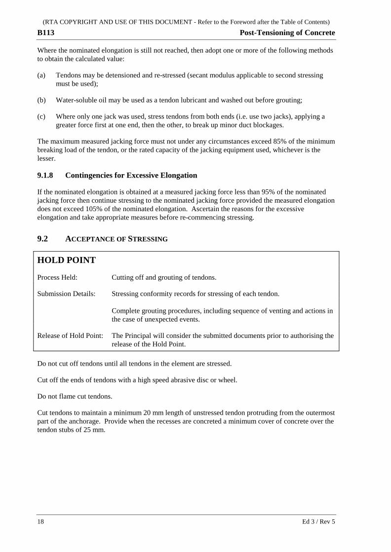
9.2 ACCEPTANCE OF STRESSING
HOLD POINT
Process Held: Cutting off and grouting of tendons.
Submission Details: Stressing conformity records for stressing of each tendon. Complete grouting procedures, including sequence of venting and actions in the case of unexpected events.
Release of Hold Point: The Principal will consider the submitted documents prior to authorising the release of the Hold Point.
Do not cut off tendons until all tendons in the element are stressed.
Cut off the ends of tendons with a high speed abrasive disc or wheel.
Do not flame cut tendons.
Cut tendons to maintain a minimum 20 mm length of unstressed tendon protruding from the outermost part of the anchorage. Provide when the recesses are concreted a minimum cover of concrete over the tendon stubs of 25 mm.
18 Ed 3 / Rev 5
(RTA COPYRIGHT AND USE OF THIS DOCUMENT - Refer to the Foreword after the Table of Contents)
Post-Tensioning of Concrete B113
10 GROUTING
10.1 AIR TESTING OF DUCTS BEFORE GROUTING
Air testing of ducts before grouting is a Critical Post-Tensioning Activity that must be carried out under the supervision of a Post-Tensioning Supervisor.
Before air testing, determine the volume of air in the duct taking into account the internal dimensions of the duct and the space taken up by the tendon.
Before the testing, blow out any water in the duct with compressed oil-free air.
The applied air pressure must not exceed 400 kPa.
After sealing the anchorage ends, test each duct as follows:
(i) With all valves closed, at the grout inlet pressurise the duct with oil-free air to 250 kPa to confirm that the installed system has sufficient integrity for grouting;
(ii) Hold the pressure at 250 kPa for 30 seconds. A sudden drop in pressure of more than 100 kPa, or a need to continuously inject compressed air to maintain pressure indicates that the system is not sufficiently sealed for grouting. Locate and repair any leaks and repeat the test;
(iii) Reduce the pressure to 100 kPa;
(iv) Lock off the air source;
(v) Record the air pressure loss over time; a pressure loss greater than 40% must not occur within a duration of:
D = (1.1V + 5)/60
Where: D = duration in minutes;
V = the volume of the duct minus the strand volume in litres.
If the pressure loss over time is greater than 40%, make a thorough inspection for any evidence of leakage from, or between, ducts. Rectify leakages and retest the duct before grouting.
The Post-Tensioning Supervisor must make an assessment of the entire tendon to determine whether grouting can proceed if the air loss criterion cannot be achieved after rectifying detected leakages.
Where air testing detects leakage between two adjacent ducts that cannot be practically rectified, air test both as a single system and then grout the two ducts simultaneously with two lines controlled by individual lock off valves.
10.2 OPERATIONS
Grouting is a Critical Post-Tensioning Activity that must be carried out under the supervision of a Post-Tensioning Supervisor.
All personnel involved in grouting must be appropriately trained and experienced, and must be acceptable to the Post-Tensioning Supervisor.
Ed 3 / Rev 5 19
(RTA COPYRIGHT AND USE OF THIS DOCUMENT - Refer to the Foreword after the Table of Contents)
B113 Post-Tensioning of Concrete
A standby grout pump must be available for use on site at all times. The grouting system comprising procedure, equipment, material and personnel must be one of the approved Proprietary Grouting Systems listed in RMS Internet website: http://www.rms.nsw.gov.au/business-industry/partners-suppliers/documents/tenders-contracts/listofapprovedbridgecomponentssystems.pdf
Non-approved grouting systems may still be used subject to compliance with the requirements of this Specification. Refer to Clause 10.5.
Grout tendons as soon as practicable after stressing and in any case no later than:
(a) one week under severe corrosivity level;
(b) two weeks under moderate corrosivity level;
(c) three weeks under low corrosivity level,
as defined in AS/NZS 2312.
Take safety precautions to prevent injury to operators and other workmen in the vicinity during grouting operations.
Carry out grouting so that the ducts are completely filled with a dense and uniform grout.
10.3 MATERIALS AND MIX DESIGN
Materials for grout must comply with the requirements of RMS B80. Where fine aggregate is used in the grout it must have a maximum nominal aggregate size of 1.0 mm.
Grout mixes may be pre-packaged when only water and admixtures are added to the dry grout mix on site, or may be designed to meet specific project requirements where different grout mix ingredients are batched on Site.
Use the same make and type of mixing equipment used for approval of the grouting system for grout production. Equipment different to that used for approval may be used subject to the Principal’s approval.
Where a grout mix is commercially confidential, forward a full submission of such mixes to the Bridge Engineer (Policy & Specifications), RMS Bridge and Structural Engineering (telephone 02 8837 0875 facsimile 02 8837 0054), in confidence.
The water/cement ratio must not be greater than 0.40 by mass.
Expansive admixtures where used must:
(a) be of the pre-hardening type; and
(b) not contain iron or aluminium powder; and
(c) not generate gases from chemical reaction between grout mix constituents or other materials in contact with the grout.
Use only fresh cement or fresh packaged grout mixes less than 1 month old.
Hold adequate stocks of cement or pre-packaged grout mixes at the grout mixer to ensure no interruptions to the continuity of grouting operations.
20 Ed 3 / Rev 5
(RTA COPYRIGHT AND USE OF THIS DOCUMENT - Refer to the Foreword after the Table of Contents)
Post-Tensioning of Concrete B113
Use only clean water free from oil, acid, alkali, organic or vegetable matter and from any ingredients harmful to steel or the grout in the mix. The water must not contain more than 500 mg/l of chloride ions.
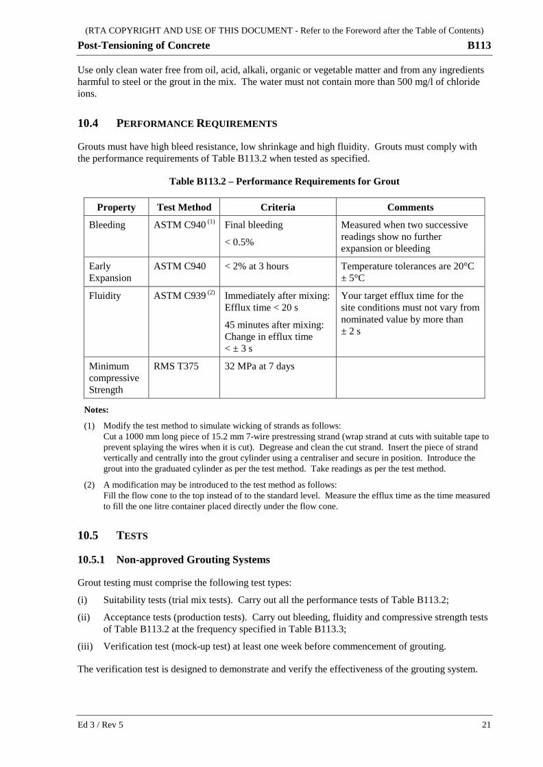
10.4 PERFORMANCE REQUIREMENTS
Grouts must have high bleed resistance, low shrinkage and high fluidity. Grouts must comply with the performance requirements of Table B113.2 when tested as specified.
Table B113.2 – Performance Requirements for Grout
Property Test Method Criteria Comments
Bleeding ASTM C940 (1) Final bleeding
< 0.5%
Measured when two successive readings show no further expansion or bleeding
Early Expansion
ASTM C940 < 2% at 3 hours Temperature tolerances are 20°C ± 5°C
Fluidity ASTM C939 (2) Immediately after mixing: Efflux time < 20 s
45 minutes after mixing: Change in efflux time < ± 3 s
Your target efflux time for the site conditions must not vary from nominated value by more than ± 2 s
Minimum compressive Strength
RMS T375 32 MPa at 7 days
Notes:
(1) Modify the test method to simulate wicking of strands as follows: Cut a 1000 mm long piece of 15.2 mm 7-wire prestressing strand (wrap strand at cuts with suitable tape to prevent splaying the wires when it is cut). Degrease and clean the cut strand. Insert the piece of strand vertically and centrally into the grout cylinder using a centraliser and secure in position. Introduce the grout into the graduated cylinder as per the test method. Take readings as per the test method.
(2) A modification may be introduced to the test method as follows: Fill the flow cone to the top instead of to the standard level. Measure the efflux time as the time measured to fill the one litre container placed directly under the flow cone.
10.5 TESTS
10.5.1 Non-approved Grouting Systems
Grout testing must comprise the following test types:
(i) Suitability tests (trial mix tests). Carry out all the performance tests of Table B113.2;
(ii) Acceptance tests (production tests). Carry out bleeding, fluidity and compressive strength tests of Table B113.2 at the frequency specified in Table B113.3;
(iii) Verification test (mock-up test) at least one week before commencement of grouting.
The verification test is designed to demonstrate and verify the effectiveness of the grouting system.
Ed 3 / Rev 5 21
(RTA COPYRIGHT AND USE OF THIS DOCUMENT - Refer to the Foreword after the Table of Contents)
B113 Post-Tensioning of Concrete
The verification test comprises making up a fully assembled mock-up tendon comprising one peak and two valleys with two end anchorages located 12 m apart fitted with grout inlets and outlets. Secure the tendon to a supporting frame capable of taking the stressing force required to take up the slack. Grout the mock-up tendon and protect from shock and vibration for 48 hours. Strip the tendon and slice it at specified locations and determine the extent of air/bleed voids in the duct and the integrity of the grout.
Prepare additional test specimens for all the performance tests of Table B113.2 during the grouting of the mock-up tendon.
Full details of the procedures for verification testing and/or grouting system approval are available on request from the Bridge Engineer (Policy & Specifications), RMS Bridge and Structural Engineering (telephone 02 8837 0875, facsimile 02 8837 0054).
10.5.2 Approved Grouting Systems
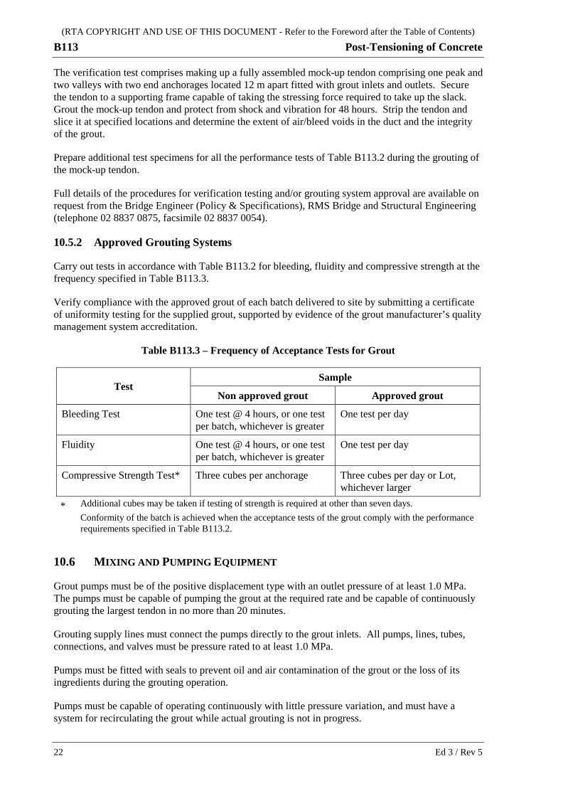
Carry out tests in accordance with Table B113.2 for bleeding, fluidity and compressive strength at the frequency specified in Table B113.3.
Verify compliance with the approved grout of each batch delivered to site by submitting a certificate of uniformity testing for the supplied grout, supported by evidence of the grout manufacturer’s quality management system accreditation.
Table B113.3 – Frequency of Acceptance Tests for Grout
Test Sample
Non approved grout Approved grout
Bleeding Test One test @ 4 hours, or one test per batch, whichever is greater
One test per day
Fluidity One test @ 4 hours, or one test per batch, whichever is greater
One test per day
Compressive Strength Test* Three cubes per anchorage Three cubes per day or Lot, whichever larger
* Additional cubes may be taken if testing of strength is required at other than seven days. Conformity of the batch is achieved when the acceptance tests of the grout comply with the performance
requirements specified in Table B113.2.
10.6 MIXING AND PUMPING EQUIPMENT
Grout pumps must be of the positive displacement type with an outlet pressure of at least 1.0 MPa. The pumps must be capable of pumping the grout at the required rate and be capable of continuously grouting the largest tendon in no more than 20 minutes.
Grouting supply lines must connect the pumps directly to the grout inlets. All pumps, lines, tubes, connections, and valves must be pressure rated to at least 1.0 MPa.
Pumps must be fitted with seals to prevent oil and air contamination of the grout or the loss of its ingredients during the grouting operation.
Pumps must be capable of operating continuously with little pressure variation, and must have a system for recirculating the grout while actual grouting is not in progress.
22 Ed 3 / Rev 5

(RTA COPYRIGHT AND USE OF THIS DOCUMENT - Refer to the Foreword after the Table of Contents)
Post-Tensioning of Concrete B113
Pumps and grout inlets must be fitted with pressure gauges capable of reading grout pressures up to 1.0 MPa. Pressure gauges must have a full scale reading less than 1.5 MPa and must be maintained in calibration.
Flowmeters and pressure gauges used during air testing or grouting must have NATA accredited calibration certificates issued within the last 100 operations for which the device was used or within the last six months, whichever is less.
Replace immediately with another gauge any gauge that has sustained hydraulic or other shock.
10.7 MIXING
Carry out batching of grout into mixers by mass for all mix constituents except liquids which may be measured by volume.
Use whole bags of cement or pre-packaged grout mix.
Weigh bags of cement or grout before batching.
Provide accurate control of the water/cement ratio and additives for each batch of grout. Supply admixtures for the grout mix in single dose containers made up to suit each grout batch size.
Place the water with premixed additive in the agitator tank first, and then disperse the cement uniformly within it. Heat or cool the mixing water if necessary to keep the grout temperature between 5 °C and 30 °C during mixing and grouting.
Mix the grout at a minimum 1000 rpm in a high-speed mixer capable of imparting a high shear to the grout components so that a colloidal grout of uniform consistency is produced in a mixing time of less than five minutes.
10.8 GROUTING OF DUCTS
Unless approved otherwise, do not carry out grouting when the temperature of the concrete is below 10°C or above 30°C.
Before grouting, determine the volume of grout required for each duct and use it as a basis for control of volumes and rates of grout injection.
Before commencing grouting, carry out sampling for acceptance (production) testing in accordance with Clause 10.5 and Table B113.3. Where fluidity testing is required determine the efflux time before proceeding with grouting. This time must not vary from the target efflux time by more than ± 2 seconds.
Feed the mixed grout to the pump by gravity from a hopper attached to and directly over the pump. Keep the hopper at least partially full of grout during grouting operations.
Pass the mixed grout through a screen with 2.36 mm nominal apertures between the hopper and the pump before injecting it into the grout inlet. Use the grout as soon as possible after mixing and in any case within 45 minutes of adding cement to mixing water.
Inject the grout from a low point or the low end of a tendon. Maintain an even, slow, continuous flow of grout until the duct is completely filled with pure grout and all entrapped water and air has been expelled.
Ed 3 / Rev 5 23

(RTA COPYRIGHT AND USE OF THIS DOCUMENT - Refer to the Foreword after the Table of Contents)
B113 Post-Tensioning of Concrete
Grout to fill the duct at a rate of between 10 m and 15 m of duct per minute. Filling rates for vertical ducts must not be more than 5 m/minute.
Close off vents and drains progressively once pure grout issues from them except for vents located downstream (< 1.0 m) of a high point. The downstream vent must be closed off before the high point vent.
In an unexpected event requiring the use of a high point grout vent as an inlet, implement procedures to vent the grout from that vent to ensure that no air is entrapped in the duct.
Do not exceed a maximum grouting pressure of 400 kPa. Where the maximum grouting pressure is not sufficient to grout the duct, then move the grout injection point to the next downstream vent which is closed off or ready to be closed off, to reduce injection pressures whilst maintaining one way flow.
10.8.1 Grouting Procedure
Follow this grouting procedure.
Use either single metal valves or a single use plastic valve before a reusable metal valve on all grout lines, inlets, outlets, vents and drains. If only single metal valves are used, leave these in place undisturbed until removed the following day:
(a) With all vents and valves open, start injecting the grout at a rate of 10-15 m/min through the inlet in the anchorage casting or at the tendon low point using a suitable grouting pressure dependent on grout properties and tendon geometry. This pressure is termed the operational grouting pressure (OGP).
(b) Progressively close off vents using the metal control valves when consistent grout flows from each vent. The quality of the grout may be checked visually. Carry out a fluidity test if there is any doubt as to the quality of the grout issuing from the vent. The fluidity must not be less than 3 seconds than that measured during the acceptance testing.
(c) After initial grouting is completed and all the vents have been closed off under OGP:
(i) Check for any grout leaks while maintaining the minimum OGP for 1 minute;
(ii) Reduce the pressure to 100 kPa, and maintain this pressure for 5 minutes. This may require opening of a high point vent metal control valve to reduce the pressure, closing that vent’s metal control valve, then reinjecting a very small quantity of grout at 100 kPa;
(iii) Using the minimum possible OGP pressure, maintain grout injection whilst slowly discharging any water, air and any diluted grout from each vent by opening and subsequently closing the vent’s metal control valve, successively working in the direction of grout injection starting with the inlet vent in the grout cap or the closest vent to the grout injection point;
(iv) Reduce the OGP pressure and close off the grout inlet at 100 kPa pressure if necessary utilising the pressure reducing procedure set out in (ii) above.
(d) Close off any plastic valves and remove their associated metal valves for cleaning and re-use to complete the grouting.
Unless approved otherwise, do not subject grouted ducts to shock, vibration, construction traffic or similar loads, until 24 hours after completion of grouting.
Remove grout inlets, outlets and vents the following day and inspect the completed grouting.
24 Ed 3 / Rev 5
(RTA COPYRIGHT AND USE OF THIS DOCUMENT - Refer to the Foreword after the Table of Contents)
Post-Tensioning of Concrete B113
Fill any voids within anchorages with epoxy. Fill any voids within the ducts at anchorages using vacuum injected grouting or refer the matter to the Principal if the void is large. Determine the reasons for the formation of any voids and take steps to stop it being repeated in other tendons.
If, due to blockages, equipment breakdowns, or for other reasons a duct is not filled with grout, locate all voids, and inform the Principal, together with a disposition for filling the voids.
Do not lift precast elements within three days of grouting, or transport them within seven days of grouting.
11 PROTECTION OF ANCHORAGES Where the ends of the tendons are not covered with concrete, apply a protective coating of epoxy in an approved manner to the exposed parts of the anchorage and then conceal the anchorage within positively sealed caps.
Use concrete of the same mix as for the element for concreting the anchorage recess where shown on the Drawings.
Ed 3 / Rev 5 25
(RTA COPYRIGHT AND USE OF THIS DOCUMENT - Refer to the Foreword after the Table of Contents)
B113 Post-Tensioning of Concrete
ANNEXURE B113/A – (NOT USED)
ANNEXURE B113/B – PAYMENT Refer to Clause 1.2.1.
In the Schedule of Rates or the Schedule of Prices forming part of the Contract, the cost for the post-tensioning of concrete must include the cost of supply, installation, post-tensioning and grouting of post-tensioning tendons and associated components.
The unit of measurement is per metre.
26 Ed 3 / Rev 5

(RTA COPYRIGHT AND USE OF THIS DOCUMENT - Refer to the Foreword after the Table of Contents)
Post-Tensioning of Concrete B113
ANNEXURE B113/C – SCHEDULES OF HOLD POINTS AND IDENTIFIED RECORDS
Refer to Clause 1.2.2.
C1 SCHEDULE OF HOLD POINTS
Clause Description
4.5 Conformity records for tendon materials
8.4 Stressing calculations
9.1.1 Conformity records for tendons, stressing equipment and concrete
9.1.6 Further stressing (where there is a non-correlation between jacking force and elongation)
9.2 Stressing conformity records and complete grouting procedures
C2 SCHEDULE OF IDENTIFIED RECORDS
The records listed below are Identified Records for the purposes of RMS Q Annexure Q/E.
Clause Description of Identified Record
1.2 Working drawings and Engineer's certificate for modifications to design to suit approved system
2.2.3 Works as Executed Drawings for external tendons
4.5 Full conformity records for all tendon materials and system components
8.4 Calculations to determine nominated jacking force
9.1.1 Full conformity records for each tendon, the stressing equipment used and the concrete element stressed
9.1.6 Reasons for any non-correlation between jacking force and extension, revised stressing method and/or revised stressing calculations
9.2 Stressing conformity records for each tendon
10.1 Results of air testing of each duct
10.5 Details of grouting system and results of each grout test
Ed 3 / Rev 5 27
(RTA COPYRIGHT AND USE OF THIS DOCUMENT - Refer to the Foreword after the Table of Contents)
B113 Post-Tensioning of Concrete
ANNEXURE B113/D – PLANNING DOCUMENTS Refer to Clause 1.2.3.
The following documents are a summary of documents that must be included in the PROJECT QUALITY PLAN. Review the requirements of this Specification and others included in the Contract to determine additional documentation requirements.
The information to be submitted as part of the PROJECT QUALITY PLAN must include the following:-
(a) Inspection of components (refer to Clause 4.4);
(b) Placement of internal ducts and anchorages (refer to Clause 5.1);
(c) Precautions during welding (refer to Clause 5.2);
(d) Installation of tendons (refer to Clause 6);
(e) Procedure for securing full engagement of high tensile bars (refer to Clause 6.2);
(f) Provision of internal support for ducts during concreting (refer to Clause 7.1);
(g) Inspection and clearing of ducts after concreting and before stressing (refer to Clauses 7.3 and 8.2);
(h) Technical Procedures in accordance with RMS Q for the stressing operations in Clause 9. Details of the personnel required to carry out the operations together with proof of any relevant training and experience must be included;
(i) Technical Procedures in accordance with RMS Q for the grouting operations in Clause 10. Details of the personnel required to carry out the operations together with proof of any relevant training and experience must be included.
For each of the above construction operations or activities, sample record sheets which show full conformity of the structure after final stressing and grouting must be provided.
ANNEXURE B113/E – MINIMUM FREQUENCY OF TESTING Refer to Clauses 1.2.4 and 10.5.
28 Ed 3 / Rev 5

(RTA COPYRIGHT AND USE OF THIS DOCUMENT - Refer to the Foreword after the Table of Contents)
Post-Tensioning of Concrete B113
ANNEXURES B113/F TO B113/L – (NOT USED)
ANNEXURE B113/M – REFERENCED DOCUMENTS AND ABBREVIATIONS
Refer to Clause 1.2.5.
M1 REFERENCED DOCUMENTS
RMS Specifications
RMS Q Quality Management System
RMS B80 Concrete Work for Bridges
RMS B119 Approval of Post-Tensioning Systems
RMS Test Methods
RMS T375 Sampling and Testing of Grout
Australian Standards
AS 1314 Prestressing anchorages
AS 1349 Bourdon tube pressure and vacuum gauges
AS/NZS 2312 Guide to the protection of structural steel against atmospheric corrosion by the use of protective coatings
AS 3678 Structural steel - Hot-rolled plates, floorplates and slabs
AS 4131 Polyethylene (PE) compounds for pressure pipes and fittings
AS/NZS 4672 Steel prestressing materials
AS/NZS 4672.1 General requirements
AS/NZS 4672.2 Testing requirements
AS 4680 Hot-dip galvanized (zinc) coatings on fabricated ferrous articles
AS/NZS ISO 9001 Quality management systems - Requirements
ASTM Standards
ASTM B117 Standard Practice for Operating Salt Spray (Fog) Apparatus
ASTM C939 Standard Test Method for Flow of Grout for Preplaced-Aggregate Concrete (Flow Cone Method)
ASTM C940 Standard Test Method for Expansion and Bleeding of Freshly Mixed Grouts for Preplaced-Aggregate Concrete in the Laboratory
ASTM D92 Standard Test Method for Flash and Fire Points by Cleveland Open Cup Tester
Ed 3 / Rev 5 29
(RTA COPYRIGHT AND USE OF THIS DOCUMENT - Refer to the Foreword after the Table of Contents)
B113 Post-Tensioning of Concrete
ASTM D127-05 Standard Test Method for Drop Meting Point of petroleum Wax, including Petrolatum)
ASTM D217 Standard Test Methods for Cone Penetration of Lubricating Grease
ASTM D445-06 Standard Test Method for Kinematic Viscosity of Transparent and Opaque Liquids (and Calculation of Dynamic viscosity)
ASTM D566 Standard Test Method for Dropping Point of Lubricating Grease
ASTM D972 Standard Test Method for Evaporation Loss of Lubricating Greases and Oils
ASTM D937-07 Standard Test Method for Cone Penetration of Petrolatum
ASTM D1092 Standard Test Method for Measuring Apparent Viscosity of Lubricating Greases
ASTM D1248 Standard Specification for Polyethylene Plastics Extrusion Materials For Wire and Cable
ASTM D1742 Standard Test Method for Oil Separation from Lubricating Grease During Storage
ASTM D1743 Standard Test Method for Determining Corrosion Preventive Properties of Lubricating Greases
ASTM D1784 Standard Specification for Rigid Poly(Vinyl Chloride) (PVC) Compounds and Chlorinated Poly(Vinyl Chloride) (CPVC) Compounds
ASTM D3350 Standard Specification for Polyethylene Plastics Pipe and Fittings Materials
ASTM D4048 Standard Test Method for Detection of Copper Corrosion from Lubricating Grease
M2 ABBREVIATIONS ASTM American Society for Testing and Materials
RMS Roads and Maritime Services
30 Ed 3 / Rev 5