Embed Size (px)
DESCRIPTION
exelent
Citation preview

®© 2010 CaterpillarAll Rights Reserved
®
SAFETYOperation and Maintenance Manual Excerpt

SEBU8407-03November 2009
Operation andMaintenanceManual279C, 289C and 299C Compact TrackLoadersMBT1-Up (279C)JMP1-Up (289C)JSP1-Up (299C)
SAFETY.CAT.COM

i03684547
Important Safety InformationMost accidents that involve product operation, maintenance and repair are caused by failure to observebasic safety rules or precautions. An accident can often be avoided by recognizing potentially hazardoussituations before an accident occurs. A person must be alert to potential hazards. This person should alsohave the necessary training, skills and tools to perform these functions properly.
Improper operation, lubrication, maintenance or repair of this product can be dangerous andcould result in injury or death.Do not operate or perform any lubrication, maintenance or repair on this product, until you haveread and understood the operation, lubrication, maintenance and repair information.Safety precautions and warnings are provided in this manual and on the product. If these hazard warningsare not heeded, bodily injury or death could occur to you or to other persons.
The hazards are identified by the “Safety Alert Symbol” and followed by a “Signal Word” such as“DANGER”, “WARNING” or “CAUTION”. The Safety Alert “WARNING” label is shown below.
The meaning of this safety alert symbol is as follows:
Attention! Become Alert! Your Safety is Involved.The message that appears under the warning explains the hazard and can be either written or pictoriallypresented.
A non-exhaustive list of operations that may cause product damage are identified by “NOTICE” labelson the product and in this publication.
Caterpillar cannot anticipate every possible circumstance that might involve a potential hazard.The warnings in this publication and on the product are, therefore, not all inclusive. You mustnot use this product in any manner different from that considered by this manual without firstsatisfying yourself that you have considered all safety rules and precautions applicable to theoperation of the product in the location of use, including site-specific rules and precautionsapplicable to the worksite. If a tool, procedure, work method or operating technique that is notspecifically recommended by Caterpillar is used, you must satisfy yourself that it is safe for youand for others. You should also ensure that the product will not be damaged or become unsafe bythe operation, lubrication, maintenance or repair procedures that you intend to use.The information, specifications, and illustrations in this publication are on the basis of information thatwas available at the time that the publication was written. The specifications, torques, pressures,measurements, adjustments, illustrations, and other items can change at any time. These changes canaffect the service that is given to the product. Obtain the complete and most current information before youstart any job. Caterpillar dealers have the most current information available.
When replacement parts are required for thisproduct Caterpillar recommends using Caterpil-lar replacement parts or parts with equivalentspecifications including, but not limited to, phys-ical dimensions, type, strength and material.
Failure to heed this warning can lead to prema-ture failures, product damage, personal injury ordeath.
In the United States, the maintenance, replacement, or repair of the emission control devices andsystems may be performed by any repair establishment or individual of the owner's choosing.

6 SEBU8407-03Safety SectionSafety Messages
Safety Sectioni02919553
Safety MessagesSMCS Code: 7000; 7405
There are several specific safety messages on thismachine. The exact location of the hazards andthe description of the hazards are reviewed in thissection. Please become familiarized with all safetymessages.
Make sure that all of the safety messages are legible.Clean the safety messages or replace the safetymessages if you cannot read the words. Replacethe illustrations if the illustrations are not legible.When you clean the safety messages, use a cloth,water and soap. Do not use solvent, gasoline, orother harsh chemicals to clean the safety messages.Solvents, gasoline, or harsh chemicals could loosenthe adhesive that secures the safety message. Looseadhesive will allow the safety message to fall.
Replace any safety message that is damaged, ormissing. If a safety message is attached to a partthat is replaced, install a safety message on thereplacement part. Any Caterpillar dealer can providenew safety messages.

SEBU8407-03 7Safety Section
Safety Messages
g01451237Illustration 2(1) Do Not Operate.(2) Rollover Protective Structure/Falling
Object Protective Structure
(3) Jump Starting(4) Crushing Hazard(5) Stay Inside Operator Station
(6) Never Permit Riders.(7) Seat Belt

8 SEBU8407-03Safety SectionSafety Messages
g01451239Illustration 3(8) Pressurized System(9) Work Tool Coupler(10) Cab Support(11) Brace for the Loader Lift Arms
(12) Crushing Hazard(13) Accumulator(14) Aerosol Starting Aid(15) Armrests
(16) Product Link(17) High Pressure Oil

SEBU8407-03 9Safety Section
Safety Messages
Do Not Operate (1)This warning message is located on the front panelby the rear view mirror.
g01379128
Read and understand the instructions and warn-ings in the operation and maintenance manuals.Contact any Caterpillar dealer for replacementmanuals. Proper care is your responsibility.
Be alert! Knowwork conditions. Note and avoid allhazards and obstructions. Keep by-standers awaywhen operating.
Fasten seat belt and lower armrest.
Make certain all controls are in neutral positionand start engine.
Disengage parking brake.
Machine controls are active.
Failure to follow the instructions or heed the warn-ings could result injury or death.
Rollover Protective Structure/Falling Object Protective Structure(2)This warning film and the certification film are locatedinside the cab on the rear left side.
g01212168
Structural damage, an overturn, modification, al-teration, or improper repair can impair this struc-ture's protection capability thereby voiding thiscertification. Do not weld on or drill holes in thestructure. Consult a Caterpillar dealer to deter-mine this structure's limitations without voidingits certification.
This machine has been certified to the standards thatare listed on the certification plate. The maximummass of the machine, which includes the operatorand the attachments without a payload, should notexceed the mass on the certification film.

10 SEBU8407-03Safety SectionSafety Messages
Batteries (3)This warning message is located on the rear door onthe left side of the machine near the positive cableterminal.
g01409730
Improper jumper cable connections can cause ex-plosion resulting in personal injury. Batteries maybe located in separate compartments, always con-nect positive (+) cable to positive (+) terminal ofbattery connected to starter solenoid and negative(−) cable from external source to engine block orframe.
Crush Hazard (4) & (12)This warning is located on the loader arms of themachines that are equipped with vertical lift.
g01378775
No clearance for person in this area during oper-ation. Severe injury or death from crushing couldoccur. Stay away from the work tool while it is inoperation.
SEBU8407-03 11Safety Section
Safety Messages
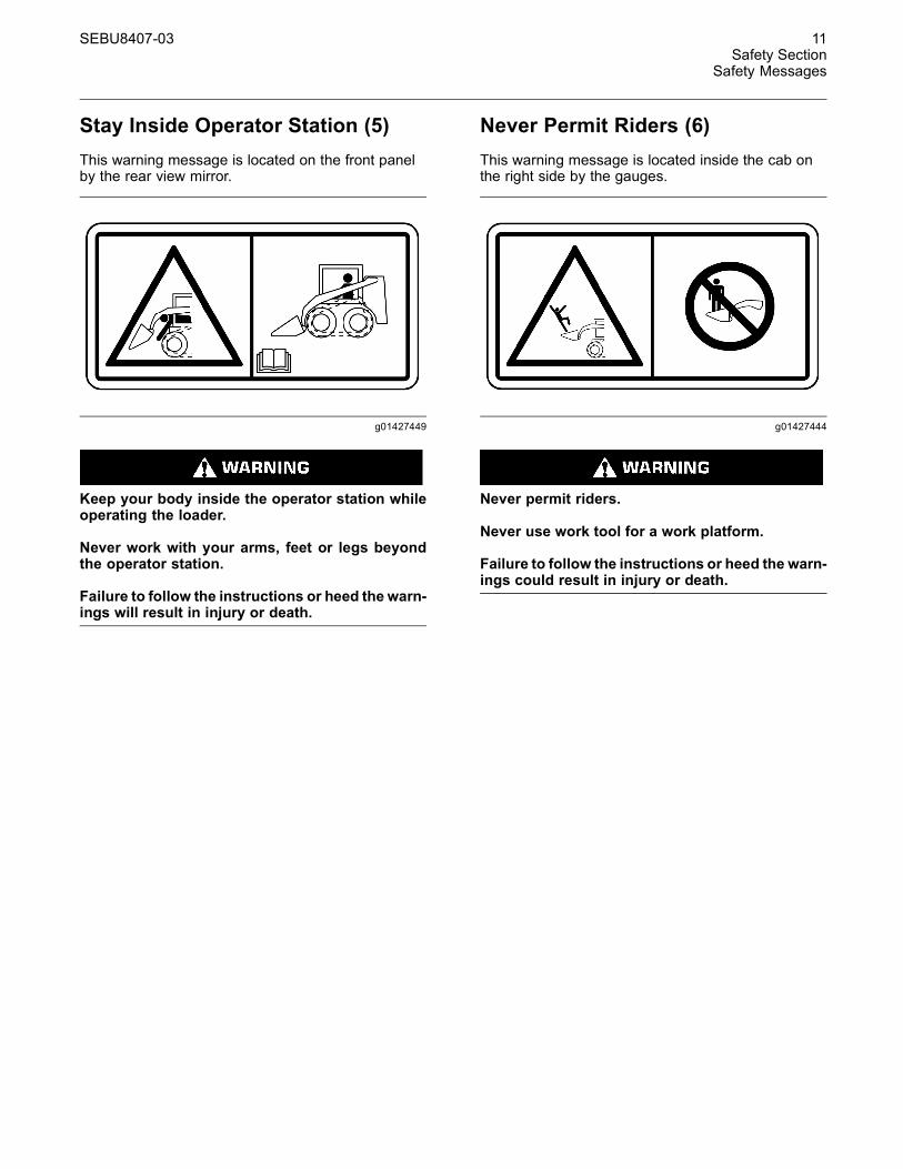
Stay Inside Operator Station (5)This warning message is located on the front panelby the rear view mirror.
g01427449
Keep your body inside the operator station whileoperating the loader.
Never work with your arms, feet or legs beyondthe operator station.
Failure to follow the instructions or heed the warn-ings will result in injury or death.
Never Permit Riders (6)This warning message is located inside the cab onthe right side by the gauges.
g01427444
Never permit riders.
Never use work tool for a work platform.
Failure to follow the instructions or heed the warn-ings could result in injury or death.

12 SEBU8407-03Safety SectionSafety Messages
Seat Belt (7)This warning message is located on the ROPS poston the right side .
g01371636
A seat belt should be worn at all times during ma-chine operation to prevent serious injury or deathin the event of an accident or machine overturn.Failure to wear a seat belt during machine opera-tion may result in serious injury or death.
Refer to Operation and Maintenance Manual, “SeatBelt” for more information.
Pressurized System (8)This warning message is located on the right side ofthe radiator by the radiator cap.
g01378799
Pressurized system: Hot coolant can cause seri-ous burn. To open cap, stop engine, wait until ra-diator is cool. Then loosen cap slowly to relievethe pressure.

SEBU8407-03 13Safety Section
Safety Messages
Work Tool Coupler (9)This warning message is located inside the cab onthe left side by the gauges.
g01427447
Improper Attachment of theWork Tool could resultin injury or death.
Do not operate the machine without confirmationthat the coupler pins are fully engaged. Follow theoperating procedures in the Operation and Main-tenance Manual.
Refer to Operation and Maintenance Manual, “WorkTool Coupler Operation” for the proper procedure forthe work tool coupler.
Cab Support (10)This warning message is located on the right side ofthe machine near the cab support lever.
g01427441
Do not go beneath cab unless cab is empty andsupport lever is engaged.
Failure to follow the instructions or heed the warn-ings could result in injury or death.
Brace for the Loader Lift Arms (11)This warning message is located on the right handside on the brace for the loader lift arms.
g01427443
Loader lift arm brace must be in place when work-ing under raised lift arms.
Failure to follow the instructions or heed the warn-ings could result in injury or death.
Refer to Operation and Maintenance Manual, “LoaderLift Arm Brace Operation” for operating information.

14 SEBU8407-03Safety SectionSafety Messages
Accumulator (13)This warning message is located near theaccumulator underneath the cab. If your machine isequipped with ride control, there will be an additionalaccumulator in this location.
g01372252
Accumulator may contain high pressure oil. Donot service the accumulator or any hydraulic linesuntil all of the pressure has been relieved. See theService Manual for proper procedures. Failure toheed this warning could result in injury or death.
Aerosol Starting Aid (14)This warning message is located on the side of theair cleaner housing.
g01372254
Do not use ether. This machine is equipped withglow plugs. Using ether can create explosions orfires that can cause personal injury or death. Readand follow the engine starting procedure in theOperation and Maintenance Manual.
Armrests (15)This warning message is located inside the cab onthe right side by the gauges.
g01427454
Crush/Ejection Hazard! Could cause serious in-jury or death.
Always wear seatbelt and lower both armrestswhile operating machine. Read the Operation andMaintenance Manual.
SEBU8407-03 15Safety Section
Safety Messages
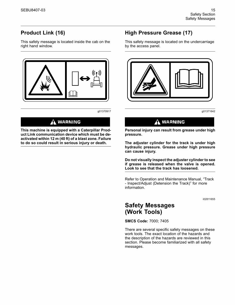
Product Link (16)This safety message is located inside the cab on theright hand window.
g01370917
This machine is equipped with a Caterpillar Prod-uct Link communication device which must be de-activated within 12 m (40 ft) of a blast zone. Failureto do so could result in serious injury or death.
High Pressure Grease (17)This safety message is located on the undercarriageby the access panel.
g01371642
Personal injury can result from grease under highpressure.
The adjuster cylinder for the track is under highhydraulic pressure. Grease under high pressurecan cause injury.
Do not visually inspect the adjuster cylinder to seeif grease is released when the valve is opened.Look to see that the track has loosened.
Refer to Operation and Maintenance Manual, “Track- Inspect/Adjust (Detension the Track)” for moreinformation.
i02811655
Safety Messages(Work Tools)SMCS Code: 7000; 7405
There are several specific safety messages on thesework tools. The exact location of the hazards andthe description of the hazards are reviewed in thissection. Please become familiarized with all safetymessages.

16 SEBU8407-03Safety SectionSafety Messages
Make sure that all of the safety messages are legible.Clean the safety messages or replace the safetymessages if you cannot read the words. Replacethe illustrations if the illustrations are not legible.When you clean the safety messages, use a cloth,water and soap. Do not use solvent, gasoline, orother harsh chemicals to clean the safety messages.Solvents, gasoline, or harsh chemicals could loosenthe adhesive that secures the safety message. Looseadhesive will allow the safety message to fall.
Replace any safety message that is damaged, ormissing. If a safety message is attached to a partthat is replaced, install a safety message on thereplacement part. Any Caterpillar dealer can providenew safety messages.
SEBU8407-03 17Safety Section
Safety Messages
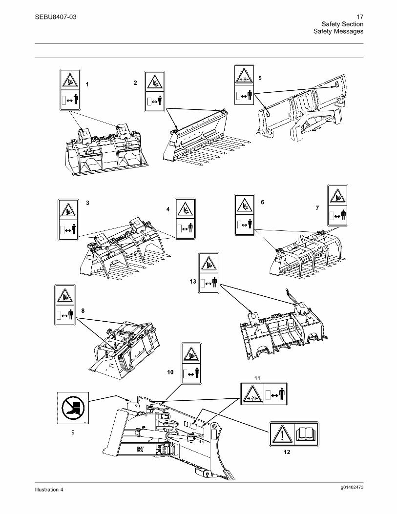
g01402473Illustration 4

18 SEBU8407-03Safety SectionSafety Messages
Industrial Grapple Bucket (1)These warning messages are located on top of theguards for the grapple cylinders.
g01378775
No clearance for person in this area during oper-ation. Severe injury or death from crushing couldoccur. Stay away from the work tool while it is inoperation.
Utility Fork (2)These warning messages are located on top of thefork carriage.
g01389170
No clearance for person in this area during op-eration. Severe injury or death from impalementcould occur. Stay away from the work tool while itis in operation.
SEBU8407-03 19Safety Section
Safety Messages
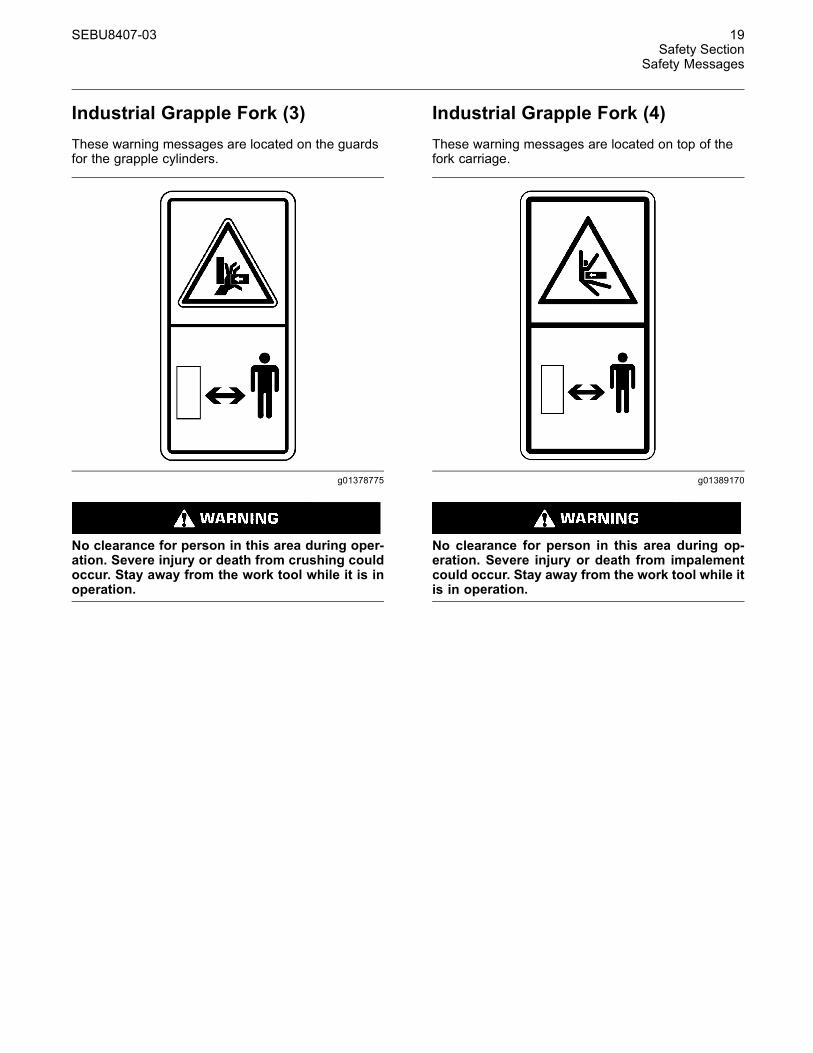
Industrial Grapple Fork (3)These warning messages are located on the guardsfor the grapple cylinders.
g01378775
No clearance for person in this area during oper-ation. Severe injury or death from crushing couldoccur. Stay away from the work tool while it is inoperation.
Industrial Grapple Fork (4)These warning messages are located on top of thefork carriage.
g01389170
No clearance for person in this area during op-eration. Severe injury or death from impalementcould occur. Stay away from the work tool while itis in operation.

20 SEBU8407-03Safety SectionSafety Messages
Angle Blade (5)These warning messages are located on the backside of the blade.
g01377717
No clearance for person in this area during oper-ation. Severe injury or death from crushing couldoccur. Stay away from the work tool while it is inoperation.
Utility Grapple Fork (6)These warning messages are located on top of thefork carriage.
g01389170
No clearance for person in this area during op-eration. Severe injury or death from impalementcould occur. Stay away from the work tool while itis in operation.

SEBU8407-03 21Safety Section
Safety Messages
Utility Grapple Fork (7)These warning messages are located on top of thegrapple frame.
g01378775
No clearance for person in this area during oper-ation. Severe injury or death from crushing couldoccur. Stay away from the work tool while it is inoperation.
Utility Grapple Bucket (8)These warning messages are located on top of thegrapple frame.
g01378775
No clearance for person in this area during oper-ation. Severe injury or death from crushing couldoccur. Stay away from the work tool while it is inoperation.
Dozer Blade (9)This warning message is located on top of the dozerblade.
g00946617
Falling Hazard - Area may be oily and slippery.Do not step on cylinders. Serious injury or deathcould occur from a fall.
22 SEBU8407-03Safety SectionSafety Messages
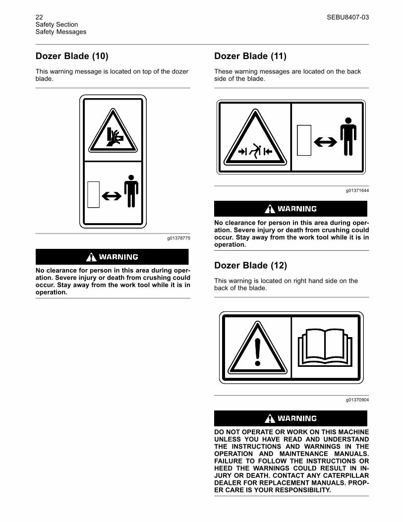
Dozer Blade (10)This warning message is located on top of the dozerblade.
g01378775
No clearance for person in this area during oper-ation. Severe injury or death from crushing couldoccur. Stay away from the work tool while it is inoperation.
Dozer Blade (11)These warning messages are located on the backside of the blade.
g01371644
No clearance for person in this area during oper-ation. Severe injury or death from crushing couldoccur. Stay away from the work tool while it is inoperation.
Dozer Blade (12)This warning is located on right hand side on theback of the blade.
g01370904
DO NOT OPERATE OR WORK ON THIS MACHINEUNLESS YOU HAVE READ AND UNDERSTANDTHE INSTRUCTIONS AND WARNINGS IN THEOPERATION AND MAINTENANCE MANUALS.FAILURE TO FOLLOW THE INSTRUCTIONS ORHEED THE WARNINGS COULD RESULT IN IN-JURY OR DEATH. CONTACT ANY CATERPILLARDEALER FOR REPLACEMENT MANUALS. PROP-ER CARE IS YOUR RESPONSIBILITY.

SEBU8407-03 23Safety Section
Additional Messages
Grapple Rake (13)These warning messages are located on top of thegrapple frame.
g01378775
No clearance for person in this area during oper-ation. Severe injury or death from crushing couldoccur. Stay away from the work tool while it is inoperation.
i02900018
Additional MessagesSMCS Code: 7000; 7405
There are several specific messages on this machine.Please become familiarized with all messages.
Make sure that all of the messages are legible. Cleanthe messages or replace the messages if you cannotread the words.
When you clean the messages, use a cloth, waterand soap. Do not use solvent, gasoline, or otherharsh chemicals to clean the messages. Solvents,gasoline, or harsh chemicals could loosen theadhesive that secures the messages. Loose adhesivewill allow the messages to fall.
Replace the illustrations if the illustrations are notlegible. Replace any message that is damaged, ormissing. If a message is attached to a part that isreplaced, install a message on the replacement part.
Consult your Caterpillar dealer for replacement ofmessages.
Product Link (If Equipped)
g01418953Illustration 5
If your machine is equipped with the Product LinkSystem, this film will be located in the cab. TheProduct Link System is a satellite communicationdevice that transmits information regarding themachine back to Caterpillar and Caterpillar dealersand customers. All logged events and diagnosticcodes that are available to the Caterpillar ElectronicTechnician (ET) on the CAT data link can be sentto the satellite. Information can also be sent to theProduct Link System. The information is used toimprove Caterpillar products and Caterpillar services.
Refer to Operation and Maintenance Manual,“Product Link” for more information.
i03559343
General Hazard InformationSMCS Code: 7000
g00104545Illustration 6

24 SEBU8407-03Safety SectionGeneral Hazard Information
Attach a “Do Not Operate” warning tag or a similarwarning tag to the start switch or to the controlsbefore you service the equipment or before yourepair the equipment. These warning tags (SpecialInstruction, SEHS7332) are available from yourCaterpillar dealer.
Know the width of your equipment in order to maintainproper clearance when you operate the equipmentnear fences or near boundary obstacles.
Be aware of high voltage power lines and powercables that are buried. If the machine comes incontact with these hazards, serious injury or deathmay occur from electrocution.
g00702020Illustration 7
Wear a hard hat, protective glasses, and otherprotective equipment, as required.
Do not wear loose clothing or jewelry that can snagon controls or on other parts of the equipment.
Make sure that all protective guards and all coversare secured in place on the equipment.
Keep the equipment free from foreign material.Remove debris, oil, tools, and other items from thedeck, from walkways, and from steps.
Secure all loose items such as lunch boxes, tools,and other items that are not a part of the equipment.
Know the appropriate work site hand signals andthe personnel that are authorized to give the handsignals. Accept hand signals from one person only.
Do not smoke when you service an air conditioner.Also, do not smoke if refrigerant gas may be present.Inhaling the fumes that are released from a flame thatcontacts air conditioner refrigerant can cause bodilyharm or death. Inhaling gas from air conditionerrefrigerant through a lighted cigarette can causebodily harm or death.
Never put maintenance fluids into glass containers.Drain all liquids into a suitable container.
Obey all local regulations for the disposal of liquids.
Use all cleaning solutions with care. Report allnecessary repairs.
Do not allow unauthorized personnel on theequipment.
Unless you are instructed otherwise, performmaintenance with the equipment in the servicingposition. Refer to Operation and Maintenance Manualfor the procedure for placing the equipment in theservicing position.
When you perform maintenance above ground leveluse appropriate devices such as ladders or man liftmachines. If equipped, use the machine anchoragepoints and use approved fall arrest harnesses andlanyards.
Pressurized Air and WaterPressurized air and/or water can cause debrisand/or hot water to be blown out. This could result inpersonal injury.
When pressurized air and/or pressurized water isused for cleaning, wear protective clothing, protectiveshoes, and eye protection. Eye protection includesgoggles or a protective face shield.
The maximum air pressure for cleaning purposesmust be reduced to 205 kPa (30 psi) when thenozzle is deadheaded and the nozzle is used withan effective chip deflector and personal protectiveequipment. The maximum water pressure forcleaning purposes must be below 275 kPa (40 psi).
Trapped PressurePressure can be trapped in a hydraulic system.Releasing trapped pressure can cause suddenmachine movement or attachment movement. Usecaution if you disconnect hydraulic lines or fittings.High pressure oil that is released can cause a hose towhip. High pressure oil that is released can cause oilto spray. Fluid penetration can cause serious injuryand possible death.
Fluid PenetrationPressure can be trapped in the hydraulic circuit longafter the engine has been stopped. The pressure cancause hydraulic fluid or items such as pipe plugs toescape rapidly if the pressure is not relieved correctly.
SEBU8407-03 25Safety Section
General Hazard Information
Do not remove any hydraulic components or partsuntil pressure has been relieved or personal injurymay occur. Do not disassemble any hydrauliccomponents or parts until pressure has been relievedor personal injury may occur. Refer to the ServiceManual for any procedures that are required torelieve the hydraulic pressure.
g00687600Illustration 8
Always use a board or cardboard when you checkfor a leak. Leaking fluid that is under pressure canpenetrate body tissue. Fluid penetration can causeserious injury and possible death. A pin hole leak cancause severe injury. If fluid is injected into your skin,you must get treatment immediately. Seek treatmentfrom a doctor that is familiar with this type of injury.
Containing Fluid SpillageCare must be taken in order to ensure that fluidsare contained during performance of inspection,maintenance, testing, adjusting and repair of theequipment. Prepare to collect the fluid with suitablecontainers before opening any compartment ordisassembling any component that contains fluids.
Refer to Special Publication, NENG2500, “CaterpillarDealer Service Tool Catalog” for the following items:
• Tools that are suitable for collecting fluids andequipment that is suitable for collecting fluids
• Tools that are suitable for containing fluids andequipment that is suitable for containing fluids
Obey all local regulations for the disposal of liquids.
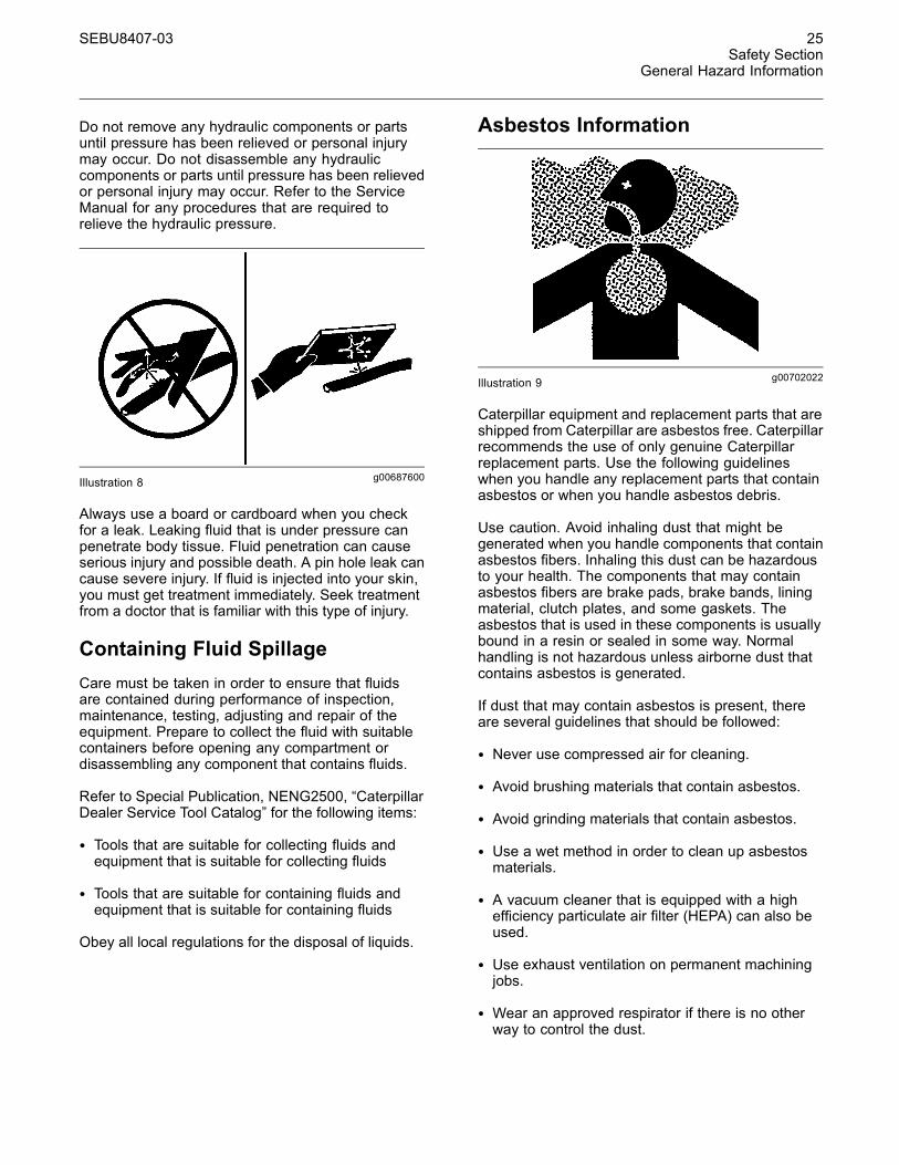
Asbestos Information
g00702022Illustration 9
Caterpillar equipment and replacement parts that areshipped from Caterpillar are asbestos free. Caterpillarrecommends the use of only genuine Caterpillarreplacement parts. Use the following guidelineswhen you handle any replacement parts that containasbestos or when you handle asbestos debris.
Use caution. Avoid inhaling dust that might begenerated when you handle components that containasbestos fibers. Inhaling this dust can be hazardousto your health. The components that may containasbestos fibers are brake pads, brake bands, liningmaterial, clutch plates, and some gaskets. Theasbestos that is used in these components is usuallybound in a resin or sealed in some way. Normalhandling is not hazardous unless airborne dust thatcontains asbestos is generated.
If dust that may contain asbestos is present, thereare several guidelines that should be followed:
• Never use compressed air for cleaning.
• Avoid brushing materials that contain asbestos.
• Avoid grinding materials that contain asbestos.
• Use a wet method in order to clean up asbestosmaterials.
• A vacuum cleaner that is equipped with a highefficiency particulate air filter (HEPA) can also beused.
• Use exhaust ventilation on permanent machiningjobs.
• Wear an approved respirator if there is no otherway to control the dust.

26 SEBU8407-03Safety SectionCrushing Prevention and Cutting Prevention
• Comply with applicable rules and regulationsfor the work place. In the United States, useOccupational Safety and Health Administration(OSHA) requirements. These OSHA requirementscan be found in “29 CFR 1910.1001”.
• Obey environmental regulations for the disposalof asbestos.
• Stay away from areas that might have asbestosparticles in the air.
Dispose of Waste Properly
g00706404Illustration 10
Improperly disposing of waste can threaten theenvironment. Potentially harmful fluids should bedisposed of according to local regulations.
Always use leakproof containers when you drainfluids. Do not pour waste onto the ground, down adrain, or into any source of water.
i01359664
Crushing Prevention andCutting PreventionSMCS Code: 7000
Support the equipment properly before you performany work or maintenance beneath that equipment.Do not depend on the hydraulic cylinders to holdup the equipment. Equipment can fall if a control ismoved, or if a hydraulic line breaks.
Do not work beneath the cab of the machine unlessthe cab is properly supported.
Unless you are instructed otherwise, never attemptadjustments while the machine is moving or whilethe engine is running.
Never jump across the starter solenoid terminalsin order to start the engine. Unexpected machinemovement could result.
Whenever there are equipment control linkages theclearance in the linkage area will change with themovement of the equipment or the machine. Stayclear of areas that may have a sudden change inclearance with machine movement or equipmentmovement.
Stay clear of all rotating and moving parts.
If it is necessary to remove guards in order to performmaintenance, always install the guards after themaintenance is performed.
Keep objects away from moving fan blades. The fanblade will throw objects or cut objects.
Do not use a kinked wire cable or a frayed wire cable.Wear gloves when you handle wire cable.
When you strike a retainer pin with force, the retainerpin can fly out. The loose retainer pin can injurepersonnel. Make sure that the area is clear of peoplewhen you strike a retainer pin. To avoid injury toyour eyes, wear protective glasses when you strikea retainer pin.
Chips or other debris can fly off an object when youstrike the object. Make sure that no one can beinjured by flying debris before striking any object.
i01329099
Burn PreventionSMCS Code: 7000
Do not touch any part of an operating engine.Allow the engine to cool before any maintenance isperformed on the engine. Relieve all pressure in theair system, in the oil system, in the lubrication system,in the fuel system, or in the cooling system beforeany lines, fittings or related items are disconnected.
CoolantWhen the engine is at operating temperature, theengine coolant is hot. The coolant is also underpressure. The radiator and all lines to the heaters orto the engine contain hot coolant.
Any contact with hot coolant or with steam can causesevere burns. Allow cooling system components tocool before the cooling system is drained.
Check the coolant level only after the engine hasbeen stopped.

SEBU8407-03 27Safety Section
Fire Prevention and Explosion Prevention
Ensure that the filler cap is cool before removing thefiller cap. The filler cap must be cool enough to touchwith a bare hand. Remove the filler cap slowly inorder to relieve pressure.
Cooling system conditioner contains alkali. Alkali cancause personal injury. Do not allow alkali to contactthe skin, the eyes, or the mouth.
OilsHot oil and hot components can cause personalinjury. Do not allow hot oil to contact the skin. Also,do not allow hot components to contact the skin.
Remove the hydraulic tank filler cap only after theengine has been stopped. The filler cap must becool enough to touch with a bare hand. Follow thestandard procedure in this manual in order to removethe hydraulic tank filler cap.
BatteriesElectrolyte is an acid. Electrolyte can cause personalinjury. Do not allow electrolyte to contact the skin orthe eyes. Always wear protective glasses for servicingbatteries. Wash hands after touching the batteriesand connectors. Use of gloves is recommended.
i03659986
Fire Prevention and ExplosionPreventionSMCS Code: 7000
g00704000Illustration 11
GeneralAll fuels, most lubricants, and some coolant mixturesare flammable.
To minimize the risk of fire or explosion, Caterpillarrecommends the following actions.
Always perform a Walk-Around Inspection, whichmay help you identify a fire hazard. Do not operatea machine when a fire hazard exists. Contact yourCaterpillar dealer for service.
Understand the use of the primary exit and alternativeexit on the machine. Refer to Operation andMaintenance Manual, “Alternative Exit”.
Do not operate a machine with a fluid leak. Repairleaks and clean up fluids before resuming machineoperation. Fluids that are leaking or spilled onto hotsurfaces or onto electrical components can cause afire. A fire may cause personal injury or death.
Remove flammable material such as leaves, twigs,papers, trash, etc. These items may accumulate inthe engine compartment or around other hot areasand hot parts on the machine.
Keep the access doors to major machinecompartments closed and access doors in workingcondition in order to permit the use of fire suppressionequipment, in case a fire should occur.
Clean all accumulations of flammable materials suchas fuel, oil and debris from the machine.
Do not operate the machine near any flame.
Keep shields in place. Exhaust shields (if equipped)protect hot exhaust components from oil spray or fuelspray in case of a break in a line, in a hose, or in aseal. Exhaust shields must be installed correctly.
Do not weld or flame cut on tanks or lines that containflammable fluids or flammable material. Empty andpurge the lines and tanks. Then clean the lines andtanks with a nonflammable solvent prior to weldingor flame cutting. Ensure that the components areproperly grounded in order to avoid unwanted arcs.
Dust that is generated from repairing nonmetallichoods or fenders may be flammable and/or explosive.Repair such components in a well ventilated areaaway from open flames or sparks. Use suitablePersonal Protection Equipment (PPE).
Inspect all lines and hoses for wear or deterioration.Replace damaged lines and hoses. The lines andthe hoses should have adequate support and secureclamps. Tighten all connections to the recommendedtorque. Damage to the protective cover or insulationmay provide fuel for fires.
Store fuels and lubricants in properly markedcontainers away from unauthorized personnel. Storeoily rags and flammable materials in protectivecontainers. Do not smoke in areas that are used forstoring flammable materials.

28 SEBU8407-03Safety SectionFire Prevention and Explosion Prevention
g00704059Illustration 12
Use caution when you are fueling a machine. Do notsmoke while you are fueling a machine. Do not fuela machine near open flames or sparks. Always stopthe engine before fueling. Fill the fuel tank outdoors.Properly clean areas of spillage.
Follow practices for safe fueling that are describedin the “Operation” section of the Operation andMaintenance Manual section and follow localregulations. Never store flammable fluids in theoperator compartment of the machine.
Battery and Battery Cables
g00704135Illustration 13
Caterpillar recommends the following in order tominimize the risk of fire or an explosion related tothe battery.
Do not operate a machine if battery cables or relatedparts show signs of wear or damage. Contact yourCaterpillar dealer for service.
Follow safe procedures for engine starting with jumpstart cables. Improper jumper cable connections cancause an explosion that may result in injury. Refer toOperation and Maintenance Manual, “Engine Startingwith Jump Start Cables” for specific instructions.
Do not charge a frozen battery. This may cause anexplosion.
Gases from a battery can explode. Keep any openflames or sparks away from the top of a battery. Donot smoke in battery charging areas.
Never check the battery charge by placing a metalobject across the terminal posts. Use a voltmeter inorder to check the battery charge.
Daily inspect battery cables that are in areas thatare visible. Inspect cables, clips, straps, and otherrestraints for damage. Replace any damaged parts.Check for signs of the following, which can occurover time due to use and environmental factors:
• Fraying
• Abrasion
• Cracking
• Discoloration
• Cuts on the insulation of the cable
• Fouling
• Corroded terminals, damaged terminals, and looseterminals
Replace damaged battery cable(s) and replaceany related parts. Eliminate any fouling, which mayhave caused insulation failure or related componentdamage or wear. Ensure that all components arereinstalled correctly.
An exposed wire on the battery cable may causea short to ground if the exposed area comes intocontact with a grounded surface. A battery cableshort produces heat from the battery current, whichmay be a fire hazard.

SEBU8407-03 29Safety Section
Fire Prevention and Explosion Prevention
An exposed wire on the ground cable between thebattery and the disconnect switch may cause thedisconnect switch to be bypassed if the exposed areacomes into contact with a grounded surface. Thismay result in an unsafe condition for servicing themachine. Repair components or replace componentsbefore servicing the machine.
Fire on a machine can result in personal injuryor death. Exposed battery cables that come intocontact with a grounded connection can result infires. Replace cables and related parts that showsigns of wear or damage. Contact your Caterpillardealer.
WiringCheck electrical wires daily. If any of the followingconditions exist, replace parts before you operatethe machine.
• Fraying
• Signs of abrasion or wear
• Cracking
• Discoloration
• Cuts on insulation
• Other damage
Make sure that all clamps, guards, clips, and strapsare reinstalled correctly. This will help to preventvibration, rubbing against other parts, and excessiveheat during machine operation.
Attaching electrical wiring to hoses and tubes thatcontain flammable fluids or combustible fluids shouldbe avoided.
Consult your Caterpillar dealer for repair or forreplacement parts.
Keep wiring and electrical connections free of debris.
Lines, Tubes and HosesDo not bend high pressure lines. Do not strike highpressure lines. Do not install any lines that are bent ordamaged. Use the appropriate backup wrenches inorder to tighten all connections to the recommendedtorque.
g00687600Illustration 14
Check lines, tubes and hoses carefully. WearPersonal Protection Equipment (PPE) in order tocheck for leaks. Always use a board or cardboardwhen you check for a leak. Leaking fluid that is underpressure can penetrate body tissue. Fluid penetrationcan cause serious injury and possible death. A pinhole leak can cause severe injury. If fluid is injectedinto your skin, you must get treatment immediately.Seek treatment from a doctor that is familiar with thistype of injury.
Replace the affected parts if any of the followingconditions are present:
• End fittings are damaged or leaking.
• Outer coverings are chafed or cut.
• Wires are exposed.
• Outer coverings are swelling or ballooning.
• Flexible parts of the hoses are kinked.
• Outer covers have exposed embedded armoring.
• End fittings are displaced.
Make sure that all clamps, guards, and heat shieldsare installed correctly. During machine operation, thiswill help to prevent vibration, rubbing against otherparts, excessive heat, and failure of lines, tubes andhoses.
Do not operate a machine when a fire hazardexists. Repair any lines that are corroded, looseor damaged. Leaks may provide fuel for fires.Consult your Caterpillar dealer for repair or forreplacement parts. Use genuine Caterpillar parts orthe equivalent, for capabilities of both the pressurelimit and temperature limit.
30 SEBU8407-03Safety SectionFire Extinguisher Location
EtherEther (if equipped) is commonly used in cold weatherapplications. Ether is flammable and poisonous.
Follow the correct cold engine starting procedures.Refer to the section in the Operation and MaintenanceManual with the label “Engine Starting”.
Do not spray ether manually into an engine if themachine is equipped with a thermal starting aid forcold weather starting.
Use ether in well ventilated areas. Do not smokewhile you are replacing an ether cylinder or while youare using an ether spray.
Do not store ether cylinders in living areas or in theoperator compartment of a machine. Do not storeether cylinders in direct sunlight or in temperaturesabove 49° C (120.2° F). Keep ether cylinders awayfrom open flames or sparks.
Dispose of used ether cylinders properly. Do notpuncture an ether cylinder. Keep ether cylindersaway from unauthorized personnel.
Fire ExtinguisherAs an additional safety measure, keep a fireextinguisher on the machine.
Be familiar with the operation of the fire extinguisher.Inspect the fire extinguisher and service the fireextinguisher regularly. Follow the recommendationson the instruction plate.
Consider installation of an aftermarket FireSuppression System, if the application and workingconditions warrant the installation.
i02574390
Fire Extinguisher LocationSMCS Code: 7000; 7419
Make sure that a fire extinguisher is on themachine. Make sure that you are familiar with theoperation of the fire extinguisher. Inspect the fireextinguisher and service the fire extinguisher. Obeythe recommendations on the instruction plate.
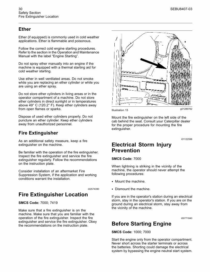
g01289762Illustration 15
Mount the fire extinguisher on the left side of thecab behind the seat. Consult your Caterpillar dealerfor the proper procedure for mounting the fireextinguisher.
i01122596
Electrical Storm InjuryPreventionSMCS Code: 7000
When lightning is striking in the vicinity of themachine, the operator should never attempt thefollowing procedures:
• Mount the machine.
• Dismount the machine.
If you are in the operator's station during an electricalstorm, stay in the operator's station. If you are on theground during an electrical storm, stay away fromthe vicinity of the machine.
i00771840
Before Starting EngineSMCS Code: 1000; 7000
Start the engine only from the operator compartment.Never short across the starter terminals or acrossthe batteries. Shorting could damage the electricalsystem by bypassing the engine neutral start system.

SEBU8407-03 31Safety Section
Visibility Information
Inspect the condition of the seat belt and of themounting hardware. Replace any parts that are wornor damaged. Regardless of appearance, replace theseat belt after three years of use. Do not use a seatbelt extension on a retractable seat belt.
Adjust the seat so that full pedal travel can beachieved with the operator's back against the backof the seat.
Make sure that the machine is equipped with alighting system that is adequate for the job conditions.Make sure that all machine lights are workingproperly.
Before you start the engine and before you move themachine, make sure that no one is underneath themachine, around the machine, or on the machine.Make sure that the area is free of personnel.
i03162317
Visibility InformationSMCS Code: 7000
Before you start the machine, perform a walk-aroundinspection in order to ensure that there are nohazards around the machine.
While the machine is in operation, constantly surveythe area around the machine in order to identifypotential hazards as hazards become visible aroundthe machine.
Your machine may be equipped with visual aids.Some examples of visual aids are Closed CircuitTelevision (CCTV) and mirrors. Before operating themachine, ensure that the visual aids are in properworking condition and that the visual aids are clean.Adjust the visual aids using the procedures that arelocated in this Operation and Maintenance Manual.If equipped, the Work Area Vision System shall beadjusted according to Operation and MaintenanceManual, SEBU8157, “Work Area Vision System”.
It may not be possible to provide direct visibility onlarge machines to all areas around the machine.Appropriate job site organization is required in orderto minimize hazards that are caused by restrictedvisibility. Job site organization is a collection of rulesand procedures that coordinates machines andpeople that work together in the same area. Examplesof job site organization include the following:
• Safety instructions
• Controlled patterns of machine movement andvehicle movement
• Workers that direct traffic to move when it is safe
• Restricted areas
• Operator training
• Warning symbols or warning signs on machinesor on vehicles
• A system of communication
• Communication between workers and operatorsprior to approaching the machine
Modifications of the machine configuration by theuser that result in a restriction of visibility shall beevaluated.
i02578915
Engine StartingSMCS Code: 1000; 7000
If a warning tag is attached to the start switch or tothe controls, do not start the engine. Also, do notmove any controls.
Move all hydraulic controls to the NEUTRAL positionbefore you start the engine.
Diesel engine exhaust contains products ofcombustion which can be harmful to your health.Always start the engine in a well ventilated area.Always operate the engine in a well ventilated area.If you are in an enclosed area, vent the exhaust tothe outside.
i02680030
Before OperationSMCS Code: 7000
Video tapes and safety information are availablein English for the machine. A list of some ofthe material is available in the Operation andMaintenance Manual, “Reference Material”. Consultyour Caterpillar dealer in order to obtain copies ofthe material. The information should be reviewed byevery person that operates the machine.
Clear all personnel from the machine and from thearea.
Clear all obstacles from the path of the machine.Beware of hazards such as wires, ditches, etc.
Make sure that all windows are clean. Secure alldoors in the closed position. Secure the windows inthe open position or in the shut position.

32 SEBU8407-03Safety SectionOperation
Make sure that the machine horn, the backup alarmand all other warning devices are working properly.
Fasten the seat belt securely. Lower the armrests.
i03713960
OperationSMCS Code: 7000
Only operate the machine while you are in the seat.The seat belt must be fastened while you operate themachine. Only operate the controls while the engineis running.
Before you move the machine, you must be certainthat no one will be endangered.
While you operate the machine and the work toolslowly in an open area, check for proper operation ofall controls and all protective devices.
Do not allow riders on the machine. Never use thework tool for a work platform.
Note any needed repairs during machine operation.Report any needed repairs.
Use Caterpillar Approved Work Tools on thismachine. Obey all the lift restrictions. Refer toOperation and Maintenance Manual, “CaterpillarApproved Work Tools” for the approved work toolsand the lift restriction information.
Carry work tools low. Lower the lift arms fully. Tiltback the work tool in order to keep the work tool offof the ground. Do not go close to the edge of a cliff,an excavation, or an overhang.
If the machine begins to sideslip downward on agrade, immediately remove the load and turn themachine downhill.
Avoid any conditions that can lead to tipping themachine. The machine can tip when you work onhills, on banks and on slopes. Also, the machinecan tip when you cross ditches, ridges or otherunexpected obstacles.
Avoid operating the machine across the slope. Whenpossible, operate the machine up the slopes anddown the slopes.
Maintain control of the machine. Do not overload themachine beyond the machine capacity.
Never straddle a wire cable. Never allow personnelto straddle a wire cable.
Know the maximum dimensions of your machine.
Always keep the Rollover Protective Structure(ROPS) installed during machine operation.
This machine is designed to operate in the ambienttemperature range of −32 °C (−25 °F) to 43 °C(109.4 °F).
Observe all applicable local government regulationswhen you use the Skid Steer Loader to lift heavyobjects.
i01115299
Work ToolsSMCS Code: 6700
Only use work tools that are approved by Caterpillarfor use on Caterpillar machines. Refer to theOperation and Maintenance Manual, “CaterpillarApproved Work Tools”.
If you are in doubt about the compatibility of aparticular work tool with your machine, consult yourCaterpillar dealer.
Make sure that all necessary guarding is in place onthe host machine and on the work tool.
Keep all windows and doors closed on the hostmachine. Always wear protective glasses. Alwayswear the protective equipment that is recommendedin the work tool's operation manual. Wear any otherprotective equipment that is required for the operatingenvironment.
To prevent personnel from being struck by flyingobjects, ensure that all personnel are out of the workarea.
While you are performing any maintenance, anytesting, or any adjustments to the work tool stayclear of the following areas: cutting edges, pinchingsurfaces, and crushing surfaces.
i02518481
ParkingSMCS Code: 7000
Park on a level surface. If you must park on a grade,chock the machine.
1. Move the joystick control slowly to the NEUTRALposition in order to stop the machine.
2. Move the governor control lever to the LOW IDLEposition.

SEBU8407-03 33Safety Section
Slope Operation
3. Lower the loader arms and tilt the linkage so thatthe work tool rests firmly on the ground.
4. Move the hydraulic controls to the NEUTRALposition.
5. Turn the engine start switch key to OFF positionand remove the key.
6. Raise the armrests and exit the machine.
i03745198
Slope OperationSMCS Code: 7000
Machines that are operating safely in variousapplications depend on these criteria: the machinemodel, configuration, machine maintenance,operating speed of the machine, conditions of theterrain, fluid levels, and tire inflation pressures. Themost important criteria are the skill and judgment ofthe operator.
A well trained operator that follows the instructionsin the Operation and Maintenance Manual hasthe greatest impact on stability. Operator trainingprovides a person with the following abilities:observation of working and environmental conditions,feel for the machine, identification of potentialhazards, and operating the machine safely by makingappropriate decisions.
When you work on side hills and when you work onslopes, consider the following important points:
Speed of travel – At higher speeds, forces of inertiatend to make the machine less stable.
Roughness of terrain or surface – The machinemay be less stable with uneven terrain.
Direction of travel – Avoid operating the machineacross the slope. When possible, operate themachine up the slopes and operate the machinedown the slopes. Place the heaviest end of themachine uphill when you are working on an incline.
Mounted equipment – Balance of the machinemay be impeded by the following components:equipment that is mounted on the machine, machineconfiguration, weights, and counterweights.
Nature of surface – Ground that has been newlyfilled with earth may collapse from the weight of themachine.
Surface material – Rocks and moisture of thesurface material may drastically affect the machine'straction and machine's stability. Rocky surfaces maypromote side slipping of the machine.
Slippage due to excessive loads – This may causedownhill tracks or downhill tires to dig into the ground,which will increase the angle of the machine.
Width of tracks or tires – Narrower tracks ornarrower tires further increase the digging into theground which causes the machine to be less stable.
Implements attached to the drawbar – This maydecrease the weight on the uphill tracks. This mayalso decrease the weight on the uphill tires. Thedecreased weight will cause the machine to be lessstable.
Height of the working load of the machine –When the working loads are in higher positions, thestability of the machine is reduced.
Operated equipment – Be aware of performancefeatures of the equipment in operation and the effectson machine stability.
Operating techniques – Keep all attachments orpulled loads low to the ground for optimum stability.
Machine systems have limitations on slopes –Slopes can affect the proper function and operationof the various machine systems. These machinesystems are needed for machine control.
Note: Safe operation on steep slopes may requirespecial machine maintenance. Excellent skill ofthe operator and proper equipment for specificapplications are also required. Consult the Operationand Maintenance Manual sections for the proper fluidlevel requirements and intended machine use.

34 SEBU8407-03Safety SectionEquipment Lowering with Engine Stopped
i01329161
Equipment Lowering withEngine StoppedSMCS Code: 7000
Before lowering any equipment with the enginestopped, clear the area around the equipment ofall personnel. The procedure to use will vary withthe type of equipment to be lowered. Keep in mindmost systems use a high pressure fluid or air toraise or lower equipment. The procedure will causehigh pressure air, hydraulic, or some other mediato be released in order to lower the equipment.Wear appropriate personal protective equipment andfollow the established procedure in the Operationand Maintenance Manual, “Equipment Lowering withEngine Stopped” in the Operation Section of themanual.
i03064142
Sound Information andVibration InformationSMCS Code: 7000
Sound Level InformationThe operator Equivalent Sound Pressure Level(Leq) is 87 dB(A) when “ANSI/SAE J1166 OCT 98”is used to measure the value for an enclosed cab.This is a work cycle sound exposure level. The cabwas properly installed and maintained. The test wasconducted with the cab doors and the cab windowsclosed.
Hearing protection may be needed when themachine is operated with an open operator station forextended periods or in a noisy environment. Hearingprotection may be needed when the machine isoperated with a cab that is not properly maintained orwhen the doors and windows are open for extendedperiods or in a noisy environment.
The average exterior sound pressure level is 75dB(A) when the “SAE J88Apr95 - Constant SpeedMoving Test” procedure is used to measure the valuefor the standard machine. The measurement wasconducted under the following conditions: distance of15 m (49.2 ft) and “the machine moving forward in anintermediate gear ratio”.
Sound Level Information forMachines in European UnionCountries and in Countries thatAdopt the “EU Directives”The dynamic operator sound pressure level is 85dB(A) when “ISO 6396:1992” is used to measure thevalue for an enclosed cab. The cab was properlyinstalled and maintained. The test was conductedwith the cab doors and the cab windows closed.
“European Physical AgentsDirective (Vibration) 2002/44/EC”
Vibration Data for Multi Terrain Loaders
Information concerning hand/arm vibration level
When the machine is operated according to theintended use, the hand/arm vibration of this machineis below 2.5 meter per second squared.
Information concerning whole body vibrationlevel
This section provides vibration data and a method forestimating the vibration level for multi terrain loaders.
Note: Vibration levels are influenced by manydifferent parameters. Many items are listed below.
• Operator training, behavior, mode, and stress
• Job site organization, preparation, environment,weather, and material
• Machine type, quality of the seat, quality of thesuspension system, attachments, and condition ofthe equipment
It is not possible to get precise vibration levels forthis machine. The expected vibration levels can beestimated with the information in Table 1 in orderto calculate the daily vibration exposure. A simpleevaluation of the machine application can be used.
Estimate the vibration levels for the three vibrationdirections. For typical operating conditions, use theaverage vibration levels as the estimated level. Withan experienced operator and smooth terrain, subtractthe Scenario Factors from the average vibration levelin order to obtain the estimated vibration level. Foraggressive operations and severe terrain, add theScenario Factors to the average vibration level inorder to obtain the estimated vibration level.
Note: All vibration levels are in meter per secondsquared.
SEBU8407-03 35Safety Section
Sound Information and Vibration Information
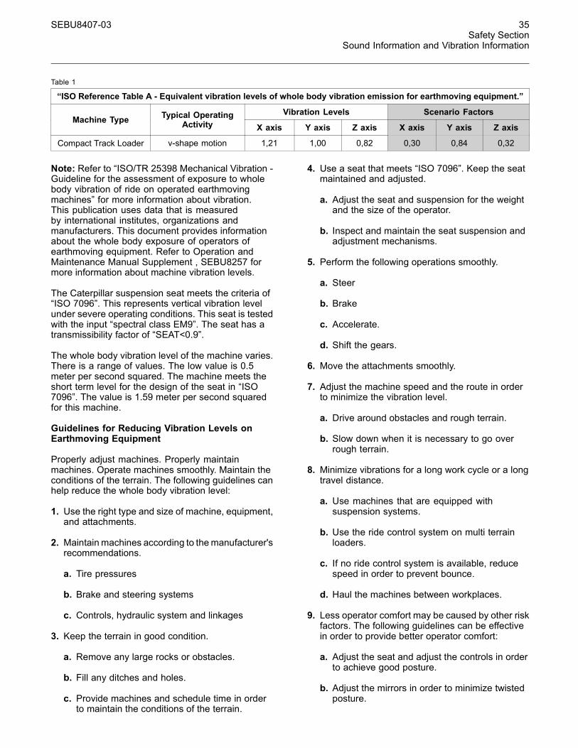
Table 1
“ISO Reference Table A - Equivalent vibration levels of whole body vibration emission for earthmoving equipment.”
Vibration Levels Scenario FactorsMachine Type Typical Operating
Activity X axis Y axis Z axis X axis Y axis Z axis
Compact Track Loader v-shape motion 1,21 1,00 0,82 0,30 0,84 0,32
Note: Refer to “ISO/TR 25398 Mechanical Vibration -Guideline for the assessment of exposure to wholebody vibration of ride on operated earthmovingmachines” for more information about vibration.This publication uses data that is measuredby international institutes, organizations andmanufacturers. This document provides informationabout the whole body exposure of operators ofearthmoving equipment. Refer to Operation andMaintenance Manual Supplement , SEBU8257 formore information about machine vibration levels.
The Caterpillar suspension seat meets the criteria of“ISO 7096”. This represents vertical vibration levelunder severe operating conditions. This seat is testedwith the input “spectral class EM9”. The seat has atransmissibility factor of “SEAT<0.9”.
The whole body vibration level of the machine varies.There is a range of values. The low value is 0.5meter per second squared. The machine meets theshort term level for the design of the seat in “ISO7096”. The value is 1.59 meter per second squaredfor this machine.
Guidelines for Reducing Vibration Levels onEarthmoving Equipment
Properly adjust machines. Properly maintainmachines. Operate machines smoothly. Maintain theconditions of the terrain. The following guidelines canhelp reduce the whole body vibration level:
1. Use the right type and size of machine, equipment,and attachments.
2. Maintainmachines according to themanufacturer'srecommendations.
a. Tire pressures
b. Brake and steering systems
c. Controls, hydraulic system and linkages
3. Keep the terrain in good condition.
a. Remove any large rocks or obstacles.
b. Fill any ditches and holes.
c. Provide machines and schedule time in orderto maintain the conditions of the terrain.
4. Use a seat that meets “ISO 7096”. Keep the seatmaintained and adjusted.
a. Adjust the seat and suspension for the weightand the size of the operator.
b. Inspect and maintain the seat suspension andadjustment mechanisms.
5. Perform the following operations smoothly.
a. Steer
b. Brake
c. Accelerate.
d. Shift the gears.
6. Move the attachments smoothly.
7. Adjust the machine speed and the route in orderto minimize the vibration level.
a. Drive around obstacles and rough terrain.
b. Slow down when it is necessary to go overrough terrain.
8. Minimize vibrations for a long work cycle or a longtravel distance.
a. Use machines that are equipped withsuspension systems.
b. Use the ride control system on multi terrainloaders.
c. If no ride control system is available, reducespeed in order to prevent bounce.
d. Haul the machines between workplaces.
9. Less operator comfort may be caused by other riskfactors. The following guidelines can be effectivein order to provide better operator comfort:
a. Adjust the seat and adjust the controls in orderto achieve good posture.
b. Adjust the mirrors in order to minimize twistedposture.

36 SEBU8407-03Safety SectionGuards
c. Provide breaks in order to reduce long periodsof sitting.
d. Avoid jumping from the cab.
e. Minimize repeated handling of loads and liftingof loads.
f. Minimize any shocks and impacts during sportsand leisure activities.
SourcesThe vibration information and calculation procedureis based on “ISO/TR 25398 Mechanical Vibration- Guideline for the assessment of exposureto whole body vibration of ride on operatedearthmoving machines”. harmonized data ismeasured by international institutes, organizationsand manufacturers.
This literature provides information about assessingthe whole body vibration exposure of operators ofearthmoving equipment. The method is based onmeasured vibration emission under real workingconditions for all machines.
You should check the original directive. Thisdocument summarizes part of the content of theapplicable law. This document is not meant tosubstitute the original sources. Other parts of thesedocuments are based on information from the UnitedKingdom Health and Safety Executive.
Refer to Operation and Maintenance ManualSupplement , SEBU8257 for more information aboutvibration.
Consult your local Caterpillar dealer for moreinformation about machine features that minimizevibration levels. Consult your local Caterpillar dealerabout safe machine operation.
Use the web site in order to find your local dealer.
Caterpillar, Inc.www.cat.com
i03656846
Guards(Operator Protection)SMCS Code: 7150-MCH; 7325
There are different types of guards that are used toprotect the operator. The machine and the machineapplication determines the type of guard that shouldbe used.
A daily inspection of the guards is required in order tocheck for structures that are bent, cracked or loose.Never operate a machine with a damaged structure.
The operator becomes exposed to a hazardoussituation if the machine is used improperly or if pooroperating techniques are used. This situation canoccur even though a machine is equipped with anappropriate protective guard. Follow the establishedoperating procedures that are recommended for yourmachine.
Rollover Protective Structure(ROPS), Falling Object ProtectiveStructure (FOPS) or Tip OverProtection Structure (TOPS)The ROPS/FOPS Structure (if equipped) on yourmachine is specifically designed, tested andcertified for that machine. Any alteration or anymodification to the ROPS/FOPS Structure couldweaken the structure. This places the operatorinto an unprotected environment. Modifications orattachments that cause the machine to exceed theweight that is stamped on the certification plate alsoplace the operator into an unprotected environment.Excessive weight may inhibit the brake performance,the steering performance and the ROPS. Theprotection that is offered by the ROPS/FOPSStructure will be impaired if the ROPS/FOPSStructure has structural damage. Damage to thestructure can be caused by an overturn, a fallingobject, a collision, etc.
Do not mount items (fire extinguishers, first aidkits, work lights, etc) by welding brackets to theROPS/FOPS Structure or by drilling holes in theROPS/FOPS Structure. Welding brackets or drillingholes in the ROPS/FOPS Structures can weakenthe structures. Consult your Caterpillar dealer formounting guidelines.
The Tip Over Protection Structure (TOPS) isanother type of guard that is used on mini hydraulicexcavators. This structure protects the operator inthe event of a tipover. The same guidelines for theinspection, the maintenance and the modification ofthe ROPS/FOPS Structure are required for the TipOver Protection Structure.
Other Guards (If Equipped)Protection from flying objects and/or falling objects isrequired for special applications. Logging applicationsand demolition applications are two examples thatrequire special protection.
SEBU8407-03 37Safety Section
Guards
A front guard needs to be installed when a work toolthat creates flying objects is used. Mesh front guardsthat are approved by Caterpillar or polycarbonatefront guards that are approved by Caterpillar areavailable for machines with a cab or an open canopy.On machines that are equipped with cabs, thewindows should also be closed. Safety glasses arerecommended when flying hazards exist for machineswith cabs and machines with open canopies.
If the work material extends above the cab, topguards and front guards should be used. Typicalexamples of this type of application are listed below:
• Demolition applications
• Rock quarries
• Forestry products
Additional guards may be required for specificapplications or work tools. The Operation andMaintenance Manual for your machine or yourwork tool will provide specific requirements for theguards. Consult your Caterpillar dealer for additionalinformation.