Embed Size (px)
Citation preview
AxSOS 3®
Titanium Proximal Lateral TibiaLocking Plate System
Operative techniqueTargeting instrumentation
AxSOS 3 Titanium | Operative technique
2
This publication sets forth detailed recommended procedures for using Stryker devices and instruments. It offers guidance that you should heed, but, as with any such technical guide, each surgeon must consider the particular needs of each patient and make appropriate adjustments when and as required. A workshop training is recommended prior to first surgery. All non-sterile devices must be cleaned and sterilized before use. Follow the instructions provided in our reprocessing guide (OT-RG-1). Multi-component instruments must be disassembled for cleaning.
AxSOS 3 TitaniumProximal Lateral Tibia Locking Plate System with targeting instrumentationContents
Introduction . . . . . . . . . . . . . . . . . . . . . . . . . . . . . . 3
Indications, precautions and contraindications . . 4
Operative technique . . . . . . . . . . . . . . . . . . . . . . . . 6
General guidelines . . . . . . . . . . . . . . . . . . . . . . . . . 6
Step 1 – pre-operative planning . . . . . . . . . . . . . . 8
Step 2 – plate insertion handle assembly . . . . . . . 9
Step 3 – submuscular plate application . . . . . . . 10
Step 4 – primary plate fixation . . . . . . . . . . . . . . 11
Step 5 – metaphyseal plate fixation . . . . . . . . . . 14
Step 6 – shaft fixation . . . . . . . . . . . . . . . . . . . . . 17
Step 7 – lower rafter and kick-stand
screw placement . . . . . . . . . . . . . . . . . . . . . . . . . 19
Additional tips . . . . . . . . . . . . . . . . . . . . . . . . . . . 20
SPS Titanium − AxSOS 3 Titanium
compatibility chart . . . . . . . . . . . . . . . . . . . . . . . 21
Please refer to the corresponding assembly / disassembly instructions.
Please remember that the compatibility of different product systems has not been tested unless specified otherwise in the product labeling.
See package insert (instruction for use) V15011, V15020, V15246 and V15013 for a complete list of potential adverse effects, contraindications, warnings and precautions.
The surgeon must discuss all relevant risks, including the finite lifetime of the device with the patient.

AxSOS 3 Titanium | Operative technique
3
The AxSOS 3 Titanium Locking Plate System is intended for long bone fracture fixation. The system allows for the use of locking and non-locking screws in the metaphysis and the shaft. This operative technique contains a step-by-step procedure for the implantation of tibial plates using the targeting instrumentation.
Plates and screws used in this operative technique guide:
AxSOS 3 Titanium Proximal Lateral Tibia plate:
Introduction
All of the above AxSOS 3 Titanium screws have a T15 screw head interface. Please refer to the compatibility table on page 21 showing SPS and AxSOS 3 Titanium compatibility.
All of the above SPS Titanium Small Fragment ISO screws have a Hex 2.5 screw head interface. Please refer to the compatibility table on page 21 showing SPS and AxSOS 3 Titanium compatibility.
4.0mm cancellous partial thread
4.0mm cancellous partial thread
3.5mm cortex shaft
3.5mm cortex screw
3.5mm cortex screw
4.0mm locking screw
4.0mm cancellous full thread
4.0mm cancellous full thread
4.0mm blind screw
SPS Titanium Small Fragment screws used with the AxSOS 3 Titanium Proximal Lateral Tibia plate:
AxSOS 3 Titanium screws used with the AxSOS 3 Titanium Proximal Lateral Tibia plate:
AxSOS 3 Titanium | Operative technique
4
Indications
AxSOS 3 Titanium is intended for long bone fracture fixation. Indications include:
• Diaphyseal, metaphyseal, epiphyseal,extra- and intra-articular fractures
• Non-unions and malunions
• Normal and osteopenic bone
• Osteotomies
• Periprosthetic fractures ofthe femur and proximal tibia
The AxSOS 3 Titanium Waisted Compression plates are also indicated for fracture fixation of:
• Periprosthetic fractures
• Diaphyseal and metaphyseal areasof long bones in pediatric patients
The 4mm waisted compression plate indications also include fixation of the scapula and the pelvis.
Precautions
MRI Safety Information
AxSOS 3 Titanium System (no periprosthetic indication)
Non-clinical testing has demonstrated the Stryker AxSOS 3 Titanium System is MR Conditional. A patient with these devices can be safely scanned in an MR system meeting the following conditions:
• Static magnetic field of 1.5T and 3.0T
• Maximum spatial field gradientof 3000 gauss / cm (30T / m)
• Maximum MR system reported, wholebody averaged specific absorption rate(SAR) of 2 W/kg (Normal Operating Mode)
Under the scan conditions defined above, the Stryker AxSOS 3 Titanium System is expected to produce a maximum temperature rise of less than 7.1°C after 15 minutes of continuous scanning.
In non-clinical testing, the image artifact caused by the device extends approximately 32mm from the Stryker AxSOS 3 Titanium System when imaged with a gradient echo pulse sequence and a 3.0T MRI system.
AxSOS 3 Titanium System (periprosthetic indication of the femur)
Non-clinical testing has demonstrated the Stryker AxSOS 3 Titanium System is MR conditional. A patient with these devices can be safely scanned in an MR system meeting the following conditions:
• Static magnetic field of 1.5T and 3.0T
• Maximum spatial field gradientof 2000 gauss / cm (20T / m)
• Maximum MR system reported, wholebody averaged specific absorption rate(SAR) of 2 W/kg (Normal Operating Mode)
• Scan time restriction: maximum 6 minutesof continuous scanning
• Only in combination with MR conditionalStryker hip implants
Under the scan conditions defined above, the Stryker AxSOS 3 Titanium System is expected to produce a maximum temperature rise of less than 8.9°C after 6 minutes of continuous scanning.
In non-clinical testing, the image artifact caused by the device extends approximately 45 mm from the Stryker AxSOS 3 Titanium System when imaged with a gradient echo pulse sequence and a 3.0T MRI system.
Indications, precautions and contraindications
The MRI safety information provided is based on testing which did not include supplementary devices. If there are supplementary devices (i.e. plates, screws, wires, prosthesis etc.) present in proximity to the System, this could result in additional MRI effects and the information provided above may not apply.

AxSOS 3 Titanium | Operative technique
5
The AxSOS 3 Titanium 4.0mm and 5.0mm Waisted Compression plates should not cross the growth plates of pediatric patients.
• Any mental or neuromuscular disorder whichwould create an unacceptable risk of fixationfailure or complications in postoperative care
• Other medical or surgical conditions whichwould preclude the potential benefit of surgery
Detailed information is included in the instructions for use attached to every implant.
See package insert for a complete list of potential adverse effects and contraindications. The surgeon must discuss all relevant risks, including the finite lifetime of the device, with the patient.
Several Titanium SPS Screws are also compatible with the AxSOS 3 Titanium plates. Please refer to the compatibility table on page 21 showing SPS and AxSOS 3 Titanium compatibility. Please note that AxSOS 3 is made out of anodized type II titanium alloy (Ti6Al4V) and is not compatible with any stainless steel plates or screws.
Intended use
AxSOS 3 Titanium is intended for long bone fracture fixation.
Contraindications
The physician’s education, training and professional judgement must be relied upon to choose the most appropriate device and treatment.
Conditions presenting an increased risk of failure include:
• Any active or suspected latent infection or markedlocal inflammation in or about the affected area
• Compromised vascularity that would inhibit adequateblood supply to the fracture or the operative site
• Bone stock compromised by disease, infection orprior implantation that can not provide adequatesupport and / or fixation of the devices
• Material sensitivity, documented or suspected
• Obesity. An overweight or obese patient can produceloads on the implant that can lead to failure of thefixation of the device or to failure of the device itself
• Patients having inadequate tissue coverageover the operative site
• Implant utilization that would interferewith anatomical structures or physiologicalperformance
The only plates indicated for pediatricuse are the 4.0mm and 5.0mm waistedcompression plates.
6
AxSOS 3 Titanium | Operative technique
Operative technique
Reduction
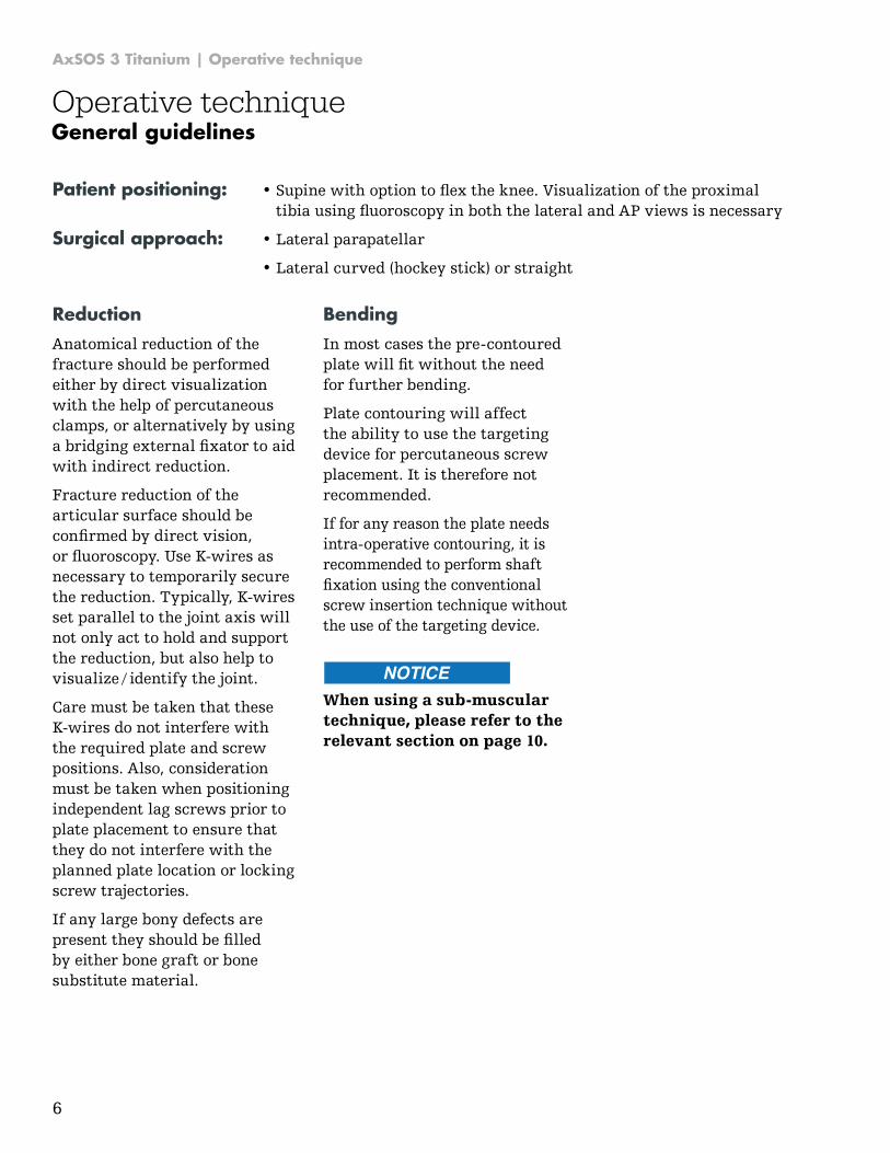
Anatomical reduction of the fracture should be performed either by direct visualization with the help of percutaneous clamps, or alternatively by using a bridging external fixator to aid with indirect reduction.
Fracture reduction of the articular surface should be confirmed by direct vision, or fluoroscopy. Use K-wires as necessary to temporarily secure the reduction. Typically, K-wires set parallel to the joint axis will not only act to hold and support the reduction, but also help to visualize / identify the joint.
Care must be taken that these K-wires do not interfere with the required plate and screw positions. Also, consideration must be taken when positioning independent lag screws prior to plate placement to ensure that they do not interfere with the planned plate location or locking screw trajectories.
If any large bony defects are present they should be filled by either bone graft or bone substitute material.
Bending
In most cases the pre-contoured plate will fit without the need for further bending.
Plate contouring will affect the ability to use the targeting device for percutaneous screw placement. It is therefore not recommended.
If for any reason the plate needs intra-operative contouring, it is recommended to perform shaft fixation using the conventional screw insertion technique without the use of the targeting device.
General guidelines
Patient positioning: • Supine with option to flex the knee. Visualization of the proximaltibia using fluoroscopy in both the lateral and AP views is necessary
Surgical approach: • Lateral parapatellar
• Lateral curved (hockey stick) or straight
When using a sub-muscular technique, please refer to the relevant section on page 10.
7
AxSOS 3 Titanium | Operative technique
Operative technique
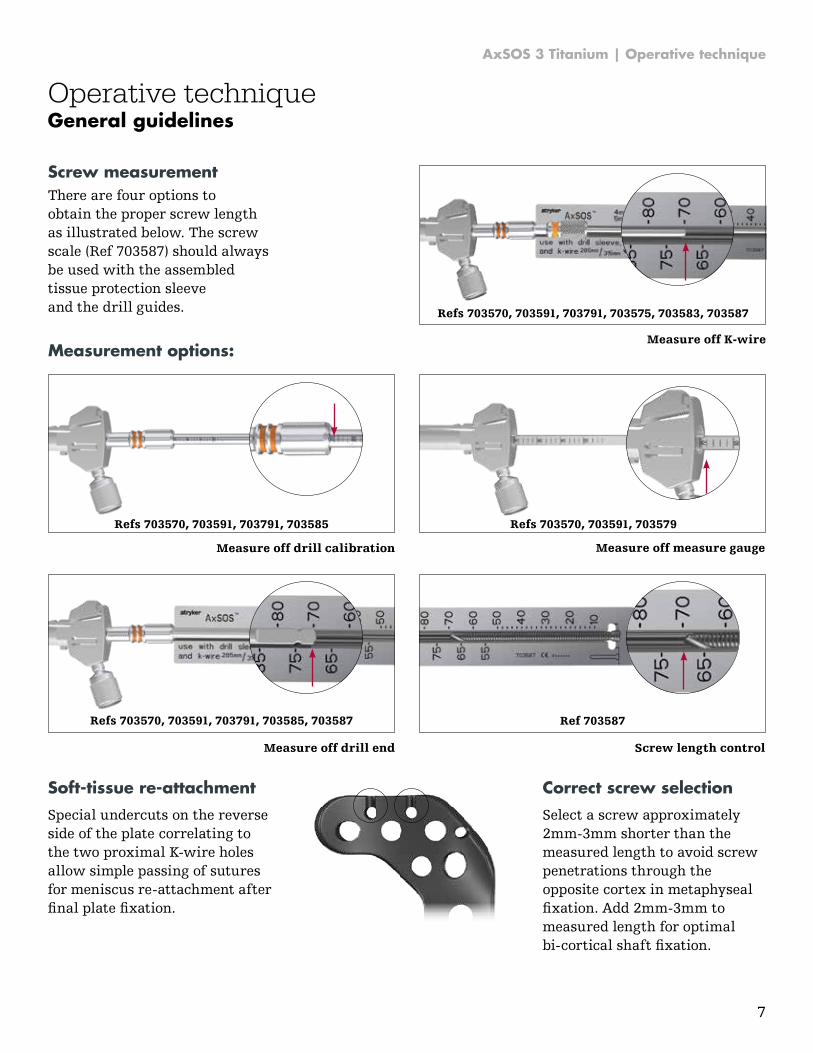
Screw measurementThere are four options to obtain the proper screw length as illustrated below. The screw scale (Ref 703587) should always be used with the assembled tissue protection sleeve and the drill guides.
Measurement options:Measure off K-wire
Measure off drill calibration
Measure off drill end
Measure off measure gauge
Screw length control
Soft-tissue re-attachment
Special undercuts on the reverse side of the plate correlating to the two proximal K-wire holes allow simple passing of sutures for meniscus re-attachment after final plate fixation.
Refs 703570, 703591, 703791, 703575, 703583, 703587
Refs 703570, 703591, 703579Refs 703570, 703591, 703791, 703585
Ref 703587Refs 703570, 703591, 703791, 703585, 703587
General guidelines
Correct screw selection
Select a screw approximately 2mm-3mm shorter than the measured length to avoid screw penetrations through the opposite cortex in metaphyseal fixation. Add 2mm-3mm to measured length for optimal bi-cortical shaft fixation.
8
AxSOS 3 Titanium | Operative technique
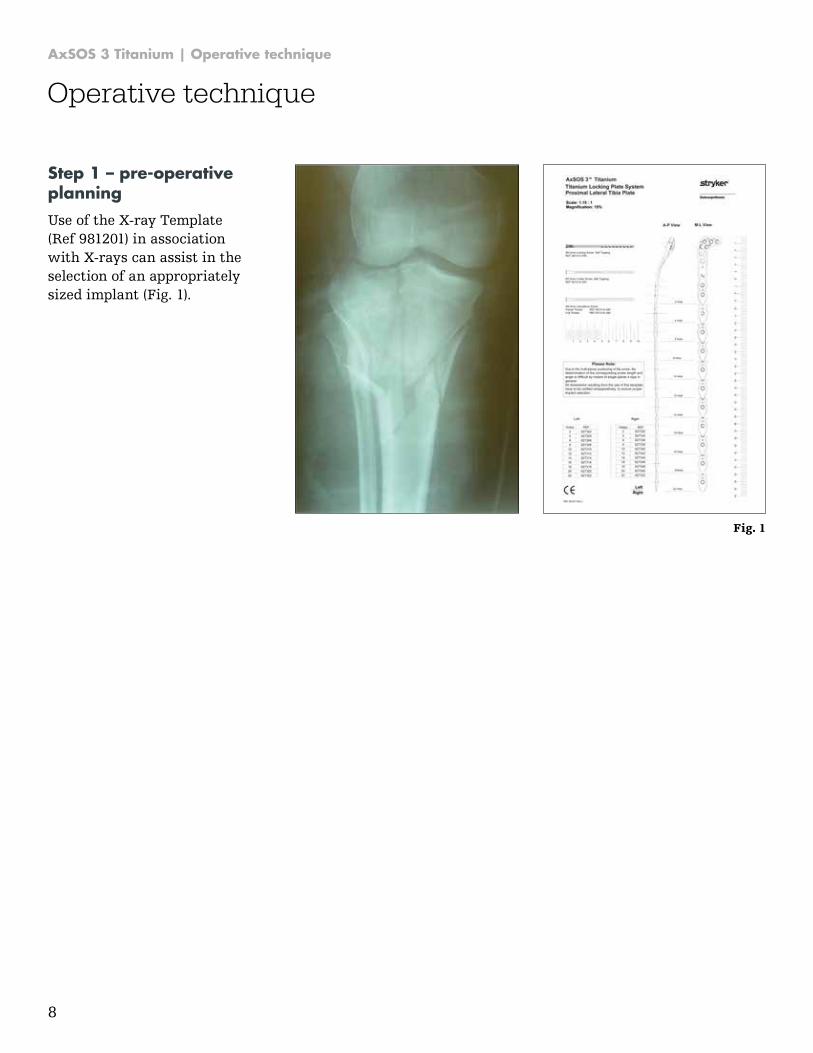
Step 1 – pre-operative planning
Use of the X-ray Template (Ref 981201) in association with X-rays can assist in the selection of an appropriately sized implant (Fig. 1).
Fig. 1
Operative technique
9
AxSOS 3 Titanium | Operative technique
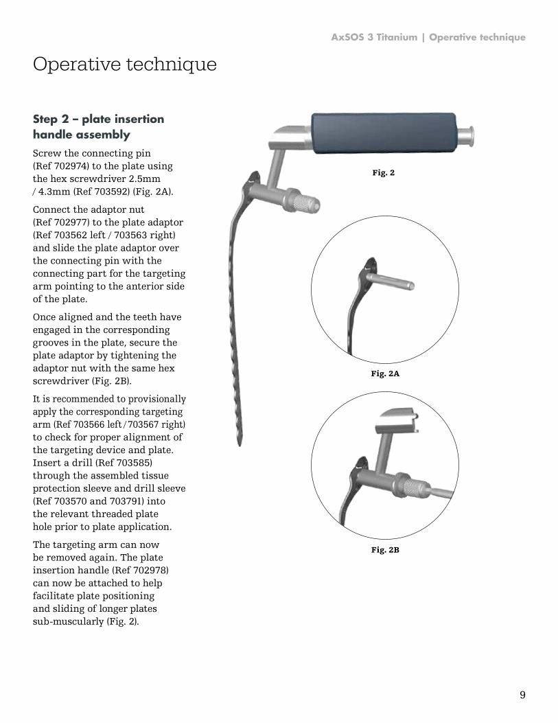
Step 2 – plate insertion handle assembly
Screw the connecting pin (Ref 702974) to the plate using the hex screwdriver 2.5mm / 4.3mm (Ref 703592) (Fig. 2A).
Connect the adaptor nut (Ref 702977) to the plate adaptor (Ref 703562 left / 703563 right) and slide the plate adaptor over the connecting pin with the connecting part for the targeting arm pointing to the anterior side of the plate.
Once aligned and the teeth have engaged in the corresponding grooves in the plate, secure the plate adaptor by tightening the adaptor nut with the same hex screwdriver (Fig. 2B).
It is recommended to provisionally apply the corresponding targeting arm (Ref 703566 left / 703567 right) to check for proper alignment of the targeting device and plate. Insert a drill (Ref 703585) through the assembled tissue protection sleeve and drill sleeve (Ref 703570 and 703791) into the relevant threaded plate hole prior to plate application.
The targeting arm can now be removed again. The plate insertion handle (Ref 702978) can now be attached to help facilitate plate positioning and sliding of longer plates sub-muscularly (Fig. 2).
Fig. 2
Fig. 2A
Fig. 2B
Operative technique

10
AxSOS 3 Titanium | Operative technique
Fig. 3
Step 3 – submuscular plate application
Patient position
Place the patient supine on a radiolucent bed that will allow fluoroscopic imaging in both the AP and lateral views.Position a bump under the ipsilateral hip to correct natural external rotation of the extremity. Use a ramp or leg elevator to position the operative leg above the contralateral leg for lateral X-rays. Prep the leg circumferentially to the mid-thigh to allow for proximal extension of the incision, allowing adequate exposure if an arthrotomy is required.
Surgical approach
The anterolateral incision is curvilinear centered on Gerdy’s tubercle, extending proximally to a direct lateral position at the knee. Incise the iliotibial band in the same manner and perform a submeniscal arthrotomy if needed to confirm articular surface reduction. Elevate the muscles off the proximal tibia towards the fibular head. (Every surgical procedure posterior to the fibular head bears a high risk of peroneal nerve injury). After reduction is obtained, apply the plate to the anterolateral surface of the tibia. The soft tissue elevator (Ref 702782) has been designed to create a pathway for the plate (Fig 3). The plate implant has a special rounded and tapered end, which further allows for smooth insertion under the soft tissue. Prior to inserting any wires or
screw fixation, confirm that the plate is under the iliotibial and that the iliotibial band in not trapped under the plate, which would hinder future closure of this tissue layer. (Surgical treatment of orthopaedic trauma, Stannard et al.) (Masters techniques in orthopaedic surgery, 2nd ed.).
The plate is applied so that the lateral tibial plateau is supported, with the proximal end of the plate approximately 5mm-10mm below the articular surface (Fig. 4). Essentially, ensuring that the most proximal locking screws are directly supporting the joint surface.
Fig. 4
Fig. 5
Operative technique
In addition, plate end markers (Ref 703568) may be inserted into the appropriate holes of the targeting arm to assist in locating the plate end and holes designated for locked fixation during the entire procedure (Fig. 5).
A slightly extended distal shaft incision is recommended to visualize the superficial peroneal nerve. In certain cases this nerve crosses the tibia in the proximity of the distal part of a 12-14 hole plate.

11
AxSOS 3 Titanium | Operative technique
Operative technique
Step 4 – primary plate fixation
A K-wire Ø2.0mm x 285mm (Ref 703583) can now be inserted through the cannulation of the adaptor nut and the plate adaptor to help secure the plate to the bone (Fig. 6). Precise alignment of the K-wire can be achieved using a K-wire sleeve (Ref 703575) through the cannulation of the plate adaptor. Also, other independently placed K-wires can help to support depressed articular surface fragments. Insertion of a K-wire should be checked by fluoroscopy to avoid penetration into the articulating surface.
To remove the insertion handle, press the metal button at the top of the handle. At this point, alignment of the plate to the shaft of the tibia should be checked by fluoroscopy in both the AP and lateral planes, both proximally and distally.
Attach the correct aiming block (Ref 703564 left / 703565 right) to the plate adaptor. Ensure that the aiming block is properly seated on the adaptor shaft and secured with the aiming block screw (Ref 703597).
Using the tissue protection sleeve (Ref 703578) together with the drill sleeve (Ref 703791) and the trocar (Ref 703577), the drill sleeve can be inserted into the most posterior hole of the metaphyseal portion of the plate.
Ensure that the drill sleeve is properly seated in the thread of the plate hole.
Remove the trocar, replace it with the K-wire sleeve (Ref 703575) and then insert a Ø2.0mm x 285mm K-wire (Ref 703583).
The above step shows the position of a posterior screw and its relation to the joint surface.
Also, this will confirm that the screw will not be placed intra-articularly or too posterior exiting the cortex into the popliteal space (Fig. 7).
Using fluoroscopy, the K-wire position can be checked until the optimal position is achieved, and the plate is positioned correctly.
Fig. 6
Fig. 7
12
AxSOS 3 Titanium | Operative technique
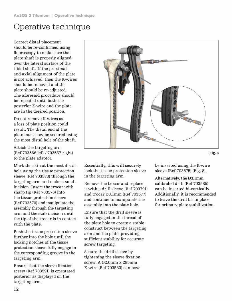
Correct distal placement should be re-confirmed using fluoroscopy to make sure the plate shaft is properly aligned over the lateral surface of the tibial shaft. If the proximal and axial alignment of the plate is not achieved, then the K-wires should be removed and the plate should be re-adjusted. The aforesaid procedure should be repeated until both the posterior K-wire and the plate are in the desired position.
Do not remove K-wires as a loss of plate position could result. The distal end of the plate must now be secured using the most distal hole of the shaft.
Attach the targeting arm (Ref 703566 left / 703567 right) to the plate adaptor.
Mark the skin at the most distal hole using the tissue protection sleeve (Ref 703570) through the targeting arm and make a small incision. Insert the trocar with sharp tip (Ref 703576) into the tissue protection sleeve (Ref 703570) and manipulate the assembly through the targeting arm and the stab incision until the tip of the trocar is in contact with the plate.
Push the tissue protection sleeve further into the hole until the locking notches of the tissue protection sleeve fully engage in the corresponding groove in the targeting arm.
Ensure that the sleeve fixation screw (Ref 703591) is orientated posterior as displayed on the targeting arm.
Essentially, this will securely lock the tissue protection sleeve in the targeting arm.
Remove the trocar and replace it with a drill sleeve (Ref 703791) and trocar Ø3.1mm (Ref 703577) and continue to manipulate the assembly into the plate hole.
Ensure that the drill sleeve is fully engaged in the thread of the plate hole to create a stable construct between the targeting arm and the plate, providing sufficient stability for accurate screw targeting.
Secure the drill sleeve by tightening the sleeve fixation screw. A Ø2.0mm x 285mm K-wire (Ref 703583) can now
be inserted using the K-wire sleeve (Ref 703575) (Fig. 8).
Alternatively, the Ø3.1mm calibrated drill (Ref 703585) can be inserted bi-cortically. Additionally, it is recommended to leave the drill bit in place for primary plate stabilization.
Operative technique
Fig. 8
13
AxSOS 3 Titanium | Operative technique
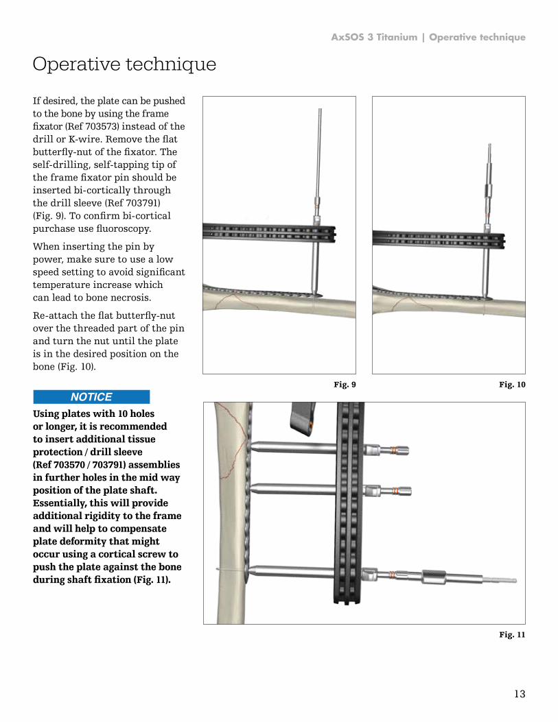
If desired, the plate can be pushed to the bone by using the frame fixator (Ref 703573) instead of the drill or K-wire. Remove the flat butterfly-nut of the fixator. The self-drilling, self-tapping tip of the frame fixator pin should be inserted bi-cortically through the drill sleeve (Ref 703791) (Fig. 9). To confirm bi-cortical purchase use fluoroscopy.
When inserting the pin by power, make sure to use a low speed setting to avoid significant temperature increase which can lead to bone necrosis.
Re-attach the flat butterfly-nut over the threaded part of the pin and turn the nut until the plate is in the desired position on the bone (Fig. 10).
Operative technique
Fig. 9 Fig. 10
Fig. 11
Using plates with 10 holes or longer, it is recommended to insert additional tissue protection / drill sleeve (Ref 703570 / 703791) assemblies in further holes in the mid way position of the plate shaft. Essentially, this will provide additional rigidity to the frame and will help to compensate plate deformity that might occur using a cortical screw to push the plate against the bone during shaft fixation (Fig. 11).
14
AxSOS 3 Titanium | Operative technique
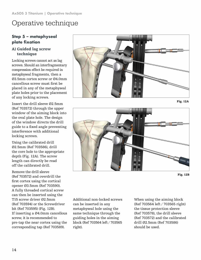
Step 5 – metaphyseal plate fixation A) Guided lag screw
technique
Locking screws cannot act as lag screws. Should an interfragmentary compression effect be required in metaphyseal fragments, then a Ø3.5mm cortex screw or Ø4.0mm cancellous screw must first be placed in any of the metaphyseal plate holes prior to the placement of any locking screws.
Insert the drill sleeve Ø2.5mm (Ref 703572) through the upper window of the aiming block into the oval plate hole. The design of the window directs the drill guide to a fixed angle preventing interference with additional locking screws.
Using the calibrated drill Ø2.5mm (Ref 703586), drill the core hole to the appropriate depth (Fig. 12A). The screw length can directly be read off the calibrated drill.
Remove the drill sleeve (Ref 703572) and overdrill the first cortex using the cortical opener Ø3.5mm (Ref 703590). A fully threaded cortical screw can then be inserted using the T15 screw driver Ø2.5mm (Ref 703594) or the Screwdriver bit (Ref 703595) (Fig. 12B). If inserting a Ø4.0mm cancellous screw, it is recommended to pre-tap the near cortex using the corresponding tap (Ref 703589).
Additional non-locked screws can be inserted in any metaphyseal hole using the same technique through the guiding holes in the aiming block (Ref 703564 left / 703565 right).
When using the aiming block (Ref 703564 left / 703565 right) the tissue protection sleeve (Ref 703578), the drill sleeve (Ref 703572) and the calibrated drill Ø2.5mm (Ref 703586) should be used.
Operative technique
Fig. 12A
Fig. 12B

15
AxSOS 3 Titanium | Operative technique
Step 5 – metaphyseal plate fixation
B) Optional lag technique
Remove the sleeve assembly and the K-wire in the posterior metaphyseal hole. Disconnect and remove the aiming block. Freehand placement of a lag screw can now be performed using the freehand tissue protection sleeve (Ref 702920) together with the drill sleeve Ø2.5mm (Ref 703572) and the sleeve fixation screw (Ref 703591). Using the calibrated drill Ø2.5mm (Ref 703586), drill the core hole to the appropriate depth (Fig. 13). The screw length can directly be read off the calibrated drill or using the screw scale (Ref 703587) as described under the measurement options on page 5. Over-drill the first cortex using the cortical opener Ø3.5mm (Ref 703590) through the tissue protection sleeve. A fully threaded cortical screw can then be inserted through the tissue protection sleeve. If inserting a Ø4.0mm cancellous screw, the near cortex should be pre-tapped using the cancellous tap (Ref 703589). Care must be taken that these screws do not interfere with the locking screw trajectories. This is done by using locking drill sleeves (Ref 703791) with K-wire sleeves (Ref 703575) and K-wires (Ref 703583).
C) Locking screw fixation
Locking fixation of the metaphyseal portion of the plate can now begin. Remove the K-wire and K-wire sleeve in the most posterior hole.
Drill the core hole for the locking screw using a calibrated Ø3.1mm drill (Ref 703585).
Using fluoroscopy, check the correct depth of the drill. The screw length can be obtained with any measurement option as described on page 5.
Operative technique
Fig. 13
Fig. 14
The drill and the drill sleeve should now be removed and the correct 4.0mm locking screw is inserted using the screwdriver T15 (Ref 703594) or screwdriver bit T15 (Ref 703595) if power insertion is selected (Fig. 14).
16
AxSOS 3 Titanium | Operative technique
Operative technique
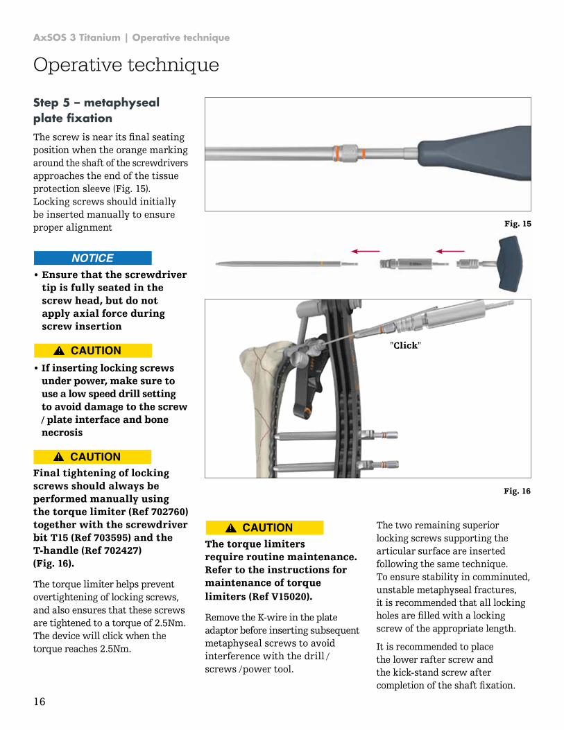
Step 5 – metaphyseal plate fixation The screw is near its final seating position when the orange marking around the shaft of the screwdrivers approaches the end of the tissue protection sleeve (Fig. 15). Locking screws should initially be inserted manually to ensure proper alignment Fig. 15
"Click"
Fig. 16
The two remaining superior locking screws supporting the articular surface are inserted following the same technique. To ensure stability in comminuted, unstable metaphyseal fractures, it is recommended that all locking holes are filled with a locking screw of the appropriate length.
It is recommended to place the lower rafter screw and the kick-stand screw after completion of the shaft fixation.
The torque limiters require routine maintenance. Refer to the instructions for maintenance of torque limiters (Ref V15020).
Remove the K-wire in the plate adaptor before inserting subsequent metaphyseal screws to avoid interference with the drill / screws / power tool.
Final tightening of locking screws should always be performed manually using the torque limiter (Ref 702760) together with the screwdriver bit T15 (Ref 703595) and the T-handle (Ref 702427) (Fig. 16).
The torque limiter helps prevent overtightening of locking screws, and also ensures that these screws are tightened to a torque of 2.5Nm. The device will click when the torque reaches 2.5Nm.
• If inserting locking screwsunder power, make sure touse a low speed drill settingto avoid damage to the screw/ plate interface and bonenecrosis
• Ensure that the screwdrivertip is fully seated in thescrew head, but do notapply axial force duringscrew insertion
17
AxSOS 3 Titanium | Operative technique
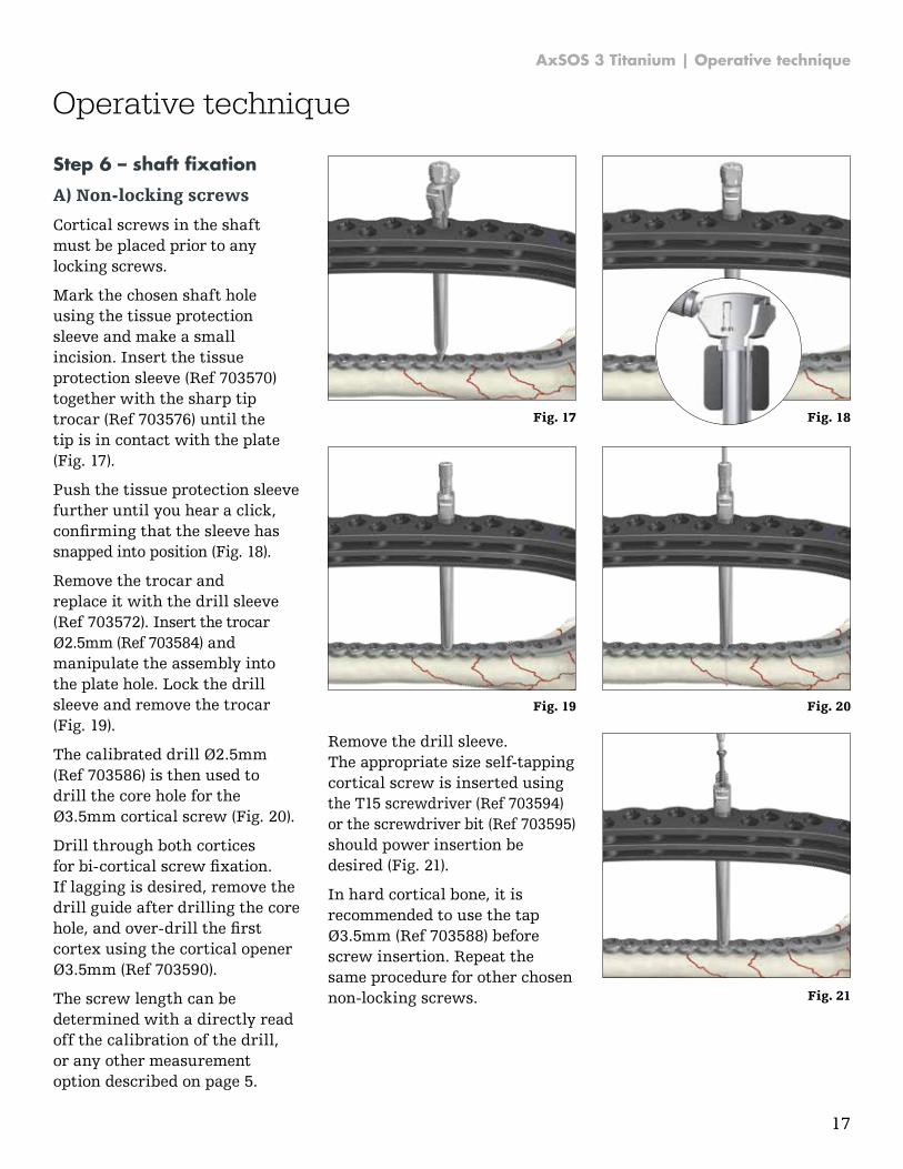
Step 6 – shaft fixation
A) Non-locking screws
Cortical screws in the shaft must be placed prior to any locking screws.
Mark the chosen shaft hole using the tissue protection sleeve and make a small incision. Insert the tissue protection sleeve (Ref 703570) together with the sharp tip trocar (Ref 703576) until the tip is in contact with the plate (Fig. 17).
Push the tissue protection sleeve further until you hear a click, confirming that the sleeve has snapped into position (Fig. 18).
Remove the trocar and replace it with the drill sleeve (Ref 703572). Insert the trocar Ø2.5mm (Ref 703584) and manipulate the assembly into the plate hole. Lock the drill sleeve and remove the trocar (Fig. 19).
The calibrated drill Ø2.5mm (Ref 703586) is then used to drill the core hole for the Ø3.5mm cortical screw (Fig. 20).
Drill through both cortices for bi-cortical screw fixation. If lagging is desired, remove the drill guide after drilling the core hole, and over-drill the first cortex using the cortical opener Ø3.5mm (Ref 703590).
The screw length can be determined with a directly read off the calibration of the drill, or any other measurement option described on page 5.
Remove the drill sleeve. The appropriate size self-tapping cortical screw is inserted using the T15 screwdriver (Ref 703594) or the screwdriver bit (Ref 703595) should power insertion be desired (Fig. 21).
In hard cortical bone, it is recommended to use the tap Ø3.5mm (Ref 703588) before screw insertion. Repeat the same procedure for other chosen non-locking screws.
Operative technique
Fig. 17 Fig. 18
Fig. 19 Fig. 20
Fig. 21
18
AxSOS 3 Titanium | Operative technique
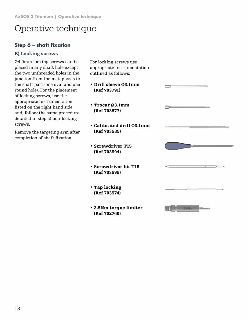
Step 6 – shaft fixation
B) Locking screws
Ø4.0mm locking screws can be placed in any shaft hole except the two unthreaded holes in the junction from the metaphysis to the shaft part (one oval and one round hole). For the placement of locking screws, use the appropriate instrumentation listed on the right hand side and, follow the same procedure detailed in step a) non-locking screws.
Remove the targeting arm after completion of shaft fixation.
For locking screws use appropriate instrumentation outlined as follows:
• Drill sleeve Ø3.1mm(Ref 703791)
• Trocar Ø3.1mm(Ref 703577)
• Calibrated drill Ø3.1mm(Ref 703585)
• Screwdriver T15(Ref 703594)
• Screwdriver bit T15(Ref 703595)
• Tap locking(Ref 703574)
• 2.5Nm torque limiter(Ref 702760)
Operative technique
19
AxSOS 3 Titanium | Operative technique
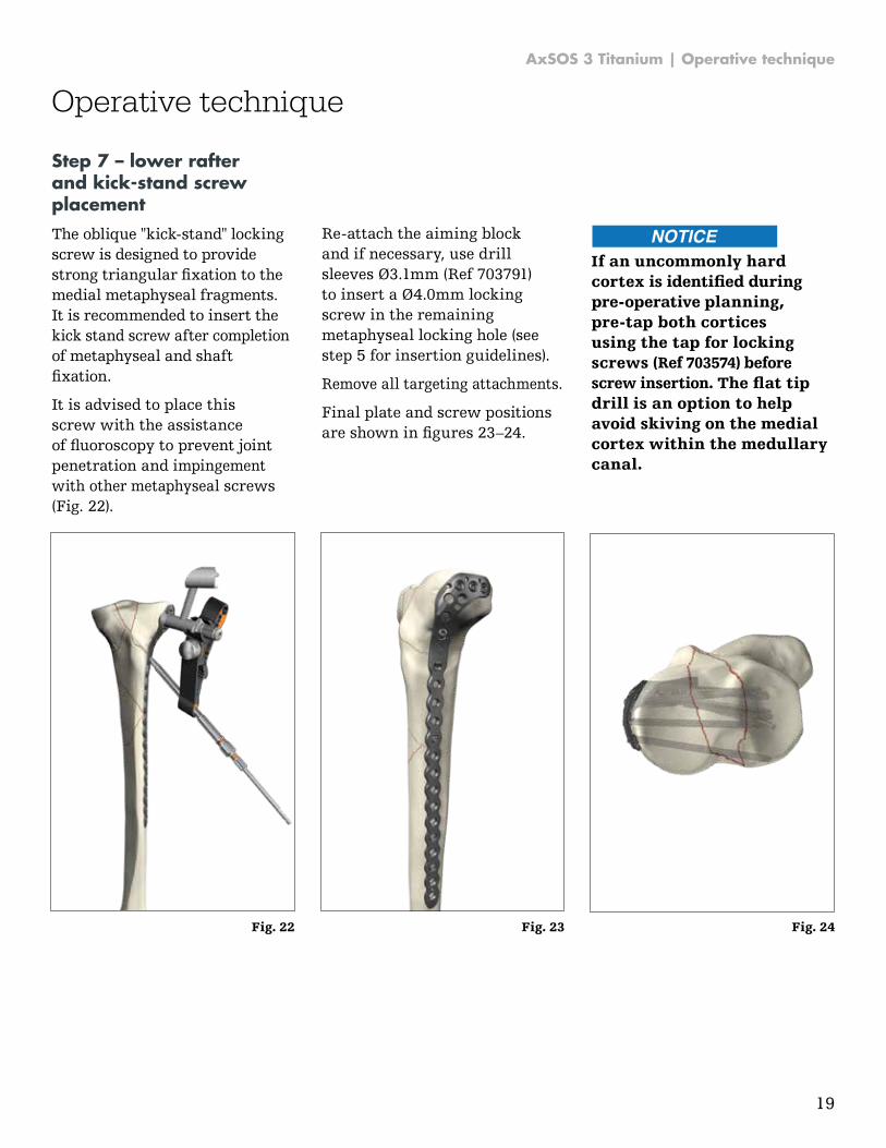
Step 7 – lower rafter and kick-stand screw placement
The oblique "kick-stand" locking screw is designed to provide strong triangular fixation to the medial metaphyseal fragments. It is recommended to insert the kick stand screw after completion of metaphyseal and shaft fixation.
It is advised to place this screw with the assistance of fluoroscopy to prevent joint penetration and impingement with other metaphyseal screws (Fig. 22).
Re-attach the aiming block and if necessary, use drill sleeves Ø3.1mm (Ref 703791) to insert a Ø4.0mm locking screw in the remaining metaphyseal locking hole (see step 5 for insertion guidelines).
Remove all targeting attachments.
Final plate and screw positions are shown in figures 23–24.
If an uncommonly hard cortex is identified during pre-operative planning, pre-tap both cortices using the tap for locking screws (Ref 703574) before screw insertion. The flat tip drill is an option to help avoid skiving on the medial cortex within the medullary canal.
Operative technique
Fig. 24Fig. 23Fig. 22
20
AxSOS 3 Titanium | Operative technique
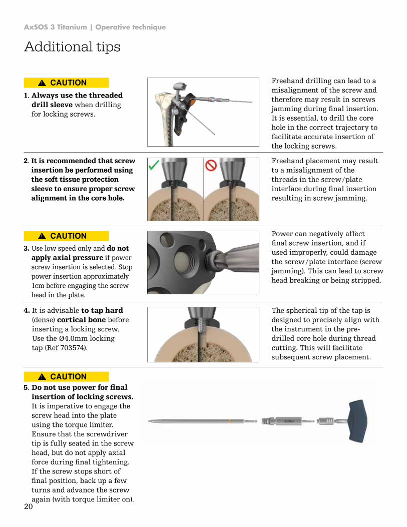
2. It is recommended that screwinsertion be performed usingthe soft tissue protectionsleeve to ensure proper screwalignment in the core hole.
Freehand placement may result to a misalignment of the threads in the screw / plate interface during final insertion resulting in screw jamming.
1. Always use the threadeddrill sleeve when drillingfor locking screws.
Freehand drilling can lead to a misalignment of the screw and therefore may result in screws jamming during final insertion. It is essential, to drill the core hole in the correct trajectory to facilitate accurate insertion of the locking screws.
3. Use low speed only and do notapply axial pressure if powerscrew insertion is selected. Stoppower insertion approximately1cm before engaging the screwhead in the plate.
Power can negatively affect final screw insertion, and if used improperly, could damage the screw / plate interface (screw jamming). This can lead to screw head breaking or being stripped.
4. It is advisable to tap hard(dense) cortical bone beforeinserting a locking screw.Use the Ø4.0mm lockingtap (Ref 703574).
The spherical tip of the tap is designed to precisely align with the instrument in the pre-drilled core hole during thread cutting. This will facilitate subsequent screw placement.
5. Do not use power for finalinsertion of locking screws.It is imperative to engage thescrew head into the plateusing the torque limiter.Ensure that the screwdrivertip is fully seated in the screwhead, but do not apply axialforce during final tightening.If the screw stops short offinal position, back up a fewturns and advance the screwagain (with torque limiter on).
Additional tips

AxSOS 3 Titanium | Operative technique
28
AxSOS 3 Ti 4.0mm AxSOS 3 Ti 5.0mm SPS 3.5mm SPS 4.5mm SPS 2.7mm
66
10
14
/-0
95
66
14
10
/-5
20
60
73
10
/-4
00
60
74
10
/-5
00
66
16
12
/-6
40
66
10
04
66
11
14
/-1
95
66
17
14
/-8
50
60
82
30
/-3
50
60
80
20
/-1
50
60
84
45
/-5
50
66
19
22
/-9
75
66
13
08
/-3
20
66
10
05
99
10
88
S
66
10
02
S
60
30
10
/-0
90
60
40
10
/-0
60
60
42
10
/-2
60
60
10
14
/-1
50
60
20
30
/-1
50
60
22
45
/-4
00
60
24
20
/-5
50
60
50
08
/-0
60
4.0
mm
lo
ck
ing
Ti
scre
w
3.5
mm
co
rtex
Ti
scre
w
4.0
mm
ca
ncell
ou
s T
i scre
w -
fu
ll t
hre
ad
4.0
mm
ca
ncell
ou
s T
i scre
w -
pa
rtia
l th
rea
d
3.5
mm
co
rtex
sh
aft
Ti
scre
w
4.0
mm
bli
nd
scre
w
5.0
mm
lo
ck
ing
scre
w
4.5
mm
co
rtex
Ti
scre
w
6.0
mm
ca
ncell
ou
s T
i scre
w -
TL
-16
6.0
mm
ca
ncell
ou
s T
i scre
w -
fu
ll t
hre
ad
6.0
mm
ca
ncell
ou
s T
i scre
w -
TL
-32
4.5
mm
co
rtex
sh
aft
Ti
scre
w
5.0
mm
peri
pro
sth
eti
c l
ock
ing
scre
w
5.0
mm
bli
nd
scre
w
5.0m
m v
aria
ble
angl
e ex
tens
ion*
arm
with
4.0
mm
blin
d sc
rew
5.0
mm
ca
ble
plu
g
SP
S 3
.5m
m T
i co
rtic
al
scre
w
SP
S 4
.0m
m T
i ca
ncell
ou
s f
ull
SP
S 4
.0m
m T
i ca
ncell
ou
s p
art
ial
SP
S 4
.5m
m T
i co
rtic
al
scre
w
SP
S 6
.5m
m T
i ca
ncell
ou
s 1
6.0
mm
SP
S 6
.5m
m T
i ca
ncell
ou
s 3
2.0
mm
SP
S 6
.5m
m T
i ca
ncell
ou
s f
ull
th
rea
d
SP
S 2
.7m
m T
i co
rtic
al
scre
w
Ax
SO
S 3
Ti
4m
m
627302/-352 Proximal lateral tibia plate X X X X X X X X X
627404/-452 Distal medial tibia plate X X X X X X X X X
627454/-500 Distal anterolateral tibia plate X X X X X X X X X X
627704/-752 Proximal medial tibia plate X X X X X X X X X
627203/-250 Proximal lateral humerus plate X X X X X X X X X
627502/-520 4mm compression plate X X X X X X X X X
Ax
SO
S 3
Ti
5m
m
627604/-650 Distal lateral femur plate X X X X X X X X X X X
627532/-552 5mm compression plate narrow X X X X X X X X X X X
627566/-582 5mm compression plate broad X X X X X X X X X X X
SP
S S
ma
ll
Fra
gm
en
t
621423/-436 T-plate X X X X X X X
621463/-468 Oblique T-plate X X X X X X X
621443/-450 Cloverleaf plate X X X X X X X
621122/-134 One third tubular plate X X X X X X X
SP
S B
asic
Fra
gm
en
t
620413/-413 T-plate X X X X
620454/-458 T-buttress plate X X X X
620704/-706 L-buttress plate, left X X X X
620754/-758 L-buttress plate, right X X X X
SPS Titanium – AxSOS 3 Titanium
compatibility chart
Screws
Plates
The chart shows the compatibility
of SPS Small and Basic Fragment
Titanium Plates and vice-versa.
* This product is not CE marked in accordance with applicable EU regulations anddirectives. Stryker is not marketing ordistributing this product in the EU. Any reference to this product is for presentation purposes only.

AxSOS 3 Titanium | Operative technique
22
Notes

AxSOS 3 Titanium | Operative technique
23
Notes

This document is intended solely for the use of healthcare professionals. A surgeon must always rely on his or her own professional clinical judgment when deciding whether to use a particular product when treating a particular patient. Stryker does not dispense medical advice and recommends that surgeons be trained in the use of any particular product before using it in surgery.
The information presented is intended to demonstrate a Stryker product. A surgeon must always refer to the package insert, product label and / or instructions for use, including the instructions for Cleaning and Sterilization (if applicable), before using any Stryker product. Products may not be available in all markets because product availability is subject to the regulatory and / or medical practices in individual markets. Please contact your Stryker representative if you have questions about the availability of Stryker products in your area.
Stryker Corporation or its divisions or other corporate affiliated entities own, use or have applied for the following trademarks or service marks: AxSOS 3, Stryker. All other trademarks are trademarks of their respective owners or holders.
Content ID: AxSOS-ST-50 Rev-5, 04-2018
Copyright © 2018 Stryker
Manufacturer:
Stryker GmbH Bohnackerweg 1 2545 Selzach Switzerland
stryker.com
Unless otherwise indicated, products above are CE marked. Refer to the main product label for CE mark information.