Embed Size (px)
Citation preview

Volume 1, Number 2 (June, 2008) p. 158 - 170 ISSN • ISSN 1983-4195
Axial compression behavior of concrete masonry wallettes strengthened with cement mortar overlays
Comportamento à compressão axial de pequenas paredes de blocos de concreto reforçadas com revestimentos de argamassa
F. L. DE OLIVEIRA a
J. B. DE HANAI b
© 2008 IBRACON
a Escola Politécnica, Departamento de Construção Civil e Estruturas, Universidade Federal da Bahia, [email protected], Rua Aristides Novis, n. 2, CEP 40210-910, Salvador-BA, Brasil.b Escola de Engenharia de São Carlos, Departamento de Engenharia de Estruturas, Universidade de São Paulo, [email protected], Av. do Trabalhador São-Carlense, n. 400, CEP 13566-590, São Carlos-SP, Brasil.
Abstract
Resumo
This paper presents the results of a series of axial compression tests on concrete block wallettes coated with cement mortar overlays. Different types of mortars and combinations with steel welded meshes and fibers were tested. The experimental results were discussed based on different theoretical approaches: analytical and Finite Element Method models. The main conclusions are: a) the application of mortar overlays increases the wall strength, but not in a uniform manner; b) the strengthening efficiency of wallettes loaded in axial compression is not proportional to the overlay mortar strength because it can be affected by the failure mechanisms of the wall; c) steel mesh reinforced overlays in combination with high strength mortar show better efficiency, because the steel mesh mitigates the damage effects in the block wall and in the overlays themselves; d) simplified theoretical methods of analysis as described in this paper can give satisfactory predictions of masonry wall behavior up to a certain level.
Keywords: masonry wall, concrete block, cement mortar overlay, composite behavior, strengthening.
Este artigo apresenta os resultados de uma série de ensaios de compressão axial sobre pequenas paredes de blocos vazados de concreto, as quais foram revestidas com argamassa de cimento e areia. Diferentes tipos de argamassa e combinações com telas de aço soldadas e fibras curtas foram testados. Os resultados experimentais são discutidos com base em duas abordagens teóricas: por expressões analíticas e modelo simples de análise pelo Método dos Elementos Finitos. As principais conclusões são: a) a aplicação de revestimentos de argamassa aumenta a resistência da parede, porém nem sempre do mesmo modo; b) a eficiência do reforço das paredes sujeitas à compressão axial não é proporcional à resistência da argamassa do revestimento, porque ela é influenciada pelo mecanismo de ruína da parede; c) a combinação de argamassa de maior resistência com telas de aço soldadas mostrou melhor eficiência no reforço, porque as telas de aço controlam melhor o processo de danificação da parede e do próprio revestimento; d) métodos simplificados de análise, como os descritos neste artigo, podem dar uma previsão razoável do comportamento da alvenaria, até um certo nível de solicitação.
Palavras-chave: alvenaria estrutural, bloco de concreto, revestimento de argamassa, estrutura mista, reforço.
159IBRACON Structures and Materials Journal • 2008 • vol. 1 • nº 2
1. Introduction
Recent advances in masonry technology brought new materials, building techniques and rational methods of structural analysis. However, the structural behavior of masonry walls is still a complex matter. A concrete masonry wall is made of at least two different materials that are assembled under diverse conditions of execution and quality control. For walls subjected to axial compression, the internal stress distribution and deformation characteristics depend on a large set of parameters related to its components.If the masonry wall is coated on both sides with cement mortar overlays, these overlays become part of the composite element. In this case, the wall can be seen as a sandwich panel where the overlays are the covering sheets and the concrete masonry wall is the core.The application of resistant overlays on masonry walls is useful in two situations:• rehabilitation of existing masonry walls;• masonry walls with special performance requirements, such as seismic resistant walls, water tanks, shear resistant panels, etc.Reinforced mortar and ferrocement overlays have been studied as a potential retrofitting material for masonry structures. A brief literature review is presented. Reinhorn and Prawell [1] tested seven panels of solid clay bricks under diagonal compression according to ASTM E 519-93. Five panels were coated with a ferrocement overlay on each side and two panels were uncoated. Significant increase of the ultimate load capacity and ductility was observed in the coated panels.Irimies and Crainic [2] tested masonry walls to evaluate the efficiency of two rehabilitation procedures. The first one involved the injection of cement paste into the cracks and the second consisted of the appli-cation of 30 mm thickness reinforced mortar overlays. The walls were
submitted to combinations of vertical and horizontal loads up to failure.Jabarov et al. [3] tested similar masonry walls but with 2 rectangu-lar openings each. Previously damaged walls were coated with 25 mm reinforced mortar overlays. Additional steel bars in diagonal directions were placed in some parts of the walls to test the ef-ficiency of different reinforcement arrangements.Among other conclusions, the mentioned authors observed that the strength and stiffness of the rehabilitated walls depended on the overlay thickness, the mortar strength and the reinforcement ratio.Oliveira [4] carried out an extensive study on the rehabilitation of masonry walls with reinforced mortar overlays. The experimental program involved axial compression, shear and bending tests on hollow concrete block panels with different types of mortar overlays. The general conclusion was that the application of mortar overlays is a powerful rehabilitation technique for masonry constructions.This paper presents the results of a series of axial compression tests on concrete block wallettes with cement mortar overlays. Different types of mortars and combinations with steel welded meshes and polypropylene and steel fibers were used. The experimental results were discussed based on two different theoretical approaches: alge-braic formulas and Finite Element Method models.
2. Materials and experimental program
The experimental program consisted of testing 8 concrete block wallette prototypes with and without cement mortar overlays under axial compression. Different mortar overlays were used, namely: unreinforced, reinforced with steel welded meshes, reinforced with steel fibers and reinforced with polypropylene fibers. Two distinct steel wire connectors were also tested to enhance the bonding properties between overlays and concrete blocks. Two samples of each model were tested in a total of 16 wallettes.
F. L. DE OLIVEIRA | J. B. DE HANAI

160 IBRACON Structures and Materials Journal • 2008 • vol. 1 • nº 2
Axial compression behavior of concrete masonry wallettes strengthened with cement mortar overlays
2.1 Dimensions of the wallettes
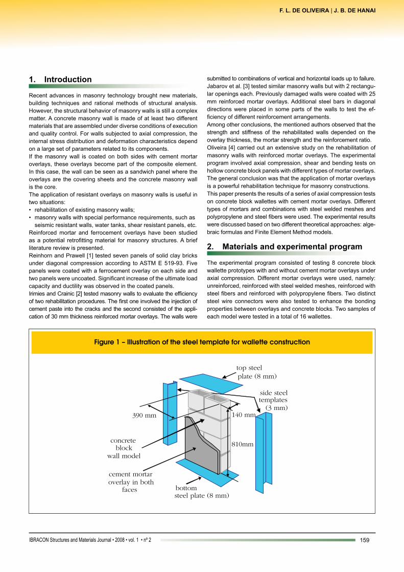
The wallettes were 390 mm wide and 810 mm high and were built with 390 mm x 190 mm x 140 mm and 190 mm x 190 mm x 140 mm concrete blocks, as shown in Figure 1. The thickness of all bed mortar joints was about 10 mm, including the top and bot-tom layers. The thickness of the mortar overlays was 20 mm in all samples.
2.2 Construction procedures and material properties
All wallettes were built using steel templates, as illustrated in Fig-ure 1. The templates were used to obtain better uniformity in con-struction, to allow a safe handling of the wallette, and to provide the same conditions of load distribution at the top and bottom.Six concrete blocks were tested under compression according to ASTM E447 [5]. The average strength referred to the gross area was 9.44 MPa. A series of two-block prisms were also tested and the average prism strength was 8.0 MPa (gross area).A mixture proportion of 1:0.5:4.5 (cement:lime:sand, by volume) was used for the bed joint mortar. Its average 28-day compressive strength was about 11 MPa, obtained from tests on 50 mm x 100 mm cylindrical samples.a) two types of cement mortar were used for the overlays: low compressive strength mortar (“weak” mortar), with a mixture proportion of 1:3.5:10 (cement; lime; sand, by volume). The average compressive strength was about 3 MPa and the average secant elastic modulus at 40% of the strength was about 4.3 GPa. According to its characteristics, the “weak” mortar could be classified between the O and K classes of ASTM C270 [6].b) high compressive strength mortar (“strong” mortar), with a mixture proportion of 1:3. The average compressive strength was about 23 MPa and the average secant elastic modulus at 40% of the strength was about 21.7 GPa.These two types of mortar were used to observe the effect of more or less rigid overlays on the wallette stiffness.The steel welded square mesh had 2.77 mm diameter wires with

161IBRACON Structures and Materials Journal • 2008 • vol. 1 • nº 2
F. L. DE OLIVEIRA | J. B. DE HANAI
nominal yield strength of 600 MPa, spaced every 50 mm. The steel meshes were positioned at each wallette face and tied with mild steel wires crossing the blocks.
Type 1 connectors consisted of 160 mm wide strips of welded meshes, placed in the bed joints (Figure 2) during the wall construction.

162 IBRACON Structures and Materials Journal • 2008 • vol. 1 • nº 2
Axial compression behavior of concrete masonry wallettes strengthened with cement mortar overlays
Type 2 connectors consisted of 5 mm steel wires passing through cylindrical holes in the wallettes. Two holes were drilled in each block layer (total of 8 holes in each wallette) in which 50 mm PVC tubes were introduced. The steel wires were positioned across the wallette and then the tube was grouted (Figure 2).Fibrillated 25 mm polypropylene fibers were added to the overlay mortar at a 0.25% volume fraction. Steel fibers were of 0.45 mm diameter, 30 mm long and hooked at the ends. They were added to the mortar at a 0.50% volume fraction.The concrete block wallettes were built using steel templates, start-ing with a mortar layer applied directly to the bottom steel plate and finishing with the top steel plate set on the last mortar layer. Two days after the construction of each pair of wallettes, the overlays were applied.All the wallettes were air cured inside the laboratory (approximately 25°C temperature and 70% relative humidity) for 28 days.
2.3 Moving and testing the wallettes
On the testing day, each whole set of wallette and steel templates was moved and placed on the Instron Universal Testing Machine Model 8506/Custom (Figure 3). The side steel templates were then removed and the wallette was carefully positioned. Top and bottom steel plates were maintained in place.Each wallette test began with the application of two pre-loading cycles of 20 kN load increments. The first cycle reached a load of 40 kN and, the second one, 80 kN. During these pre-loading cycles, the wallette position was checked to avoid large load ec-centricities.The test continued up to failure of the wallette, under displacement-
controlled mode. The hydraulic actuator speed was 0.005 mm/sec. Some quick interruptions were made for crack observation. Spe-cial events such as first crack load, failure mode and post-peak behavior were observed.
3. Test results
Table 1 shows the main characteristics of the wallettes and their ultimate load capacity under axial compression.Figure 4 shows selected load-displacement curves which repre-sent the behavior of the wallettes during the tests. Individual curves referring to each test are presented later on. Illustrations of the wal-lette condition after the test are in Figure 5 (post-failure scene of P02) and Figure 6 (post-failure scene of P07).Table 1 shows that the application of plain mortar overlays provid-ed around 20% strength increase for both mortar strengths. How-ever, in case of “strong” mortar reinforced by steel welded meshes, the load capacity was increased nearly 43% (for wallettes P07, P08, P09 and P10). Wallette P15 resulted in a decreased strength (30%), however, in this wallette and also P16, some flaws in the construction technique have been detected, hence they were dis-carded.Wallettes P11 and P12 showed a decrease in ultimate load, as opposed to wallettes P1 and P2. One possible explanation is that bonding conditions were poor due to the presence of polypropyl-ene fibers and the debonding of the overlays was premature.Wallettes P13 and P14 (“strong” mortar with steel fibers) also did not show a good performance, probably due to early debonding of the overlays.In all tests, the wallettes showed a typical failure under axial com-

163IBRACON Structures and Materials Journal • 2008 • vol. 1 • nº 2
F. L. DE OLIVEIRA | J. B. DE HANAI
pression, starting with vertical cracks followed by splitting of the block webs. This behavior is initially explained by the larger de-formability of the bed joint mortar with respect to the concrete block. This induces splitting stresses that cause the separation of the wal-lette in two parts and further instability of the whole structure.
4. Theoretical models and analysis of the results
Although significant advances have occurred on the theoretical analysis of masonry structures, the evaluation of the load bearing capacity of a simple block wall is still based on empirical methods. Many factors contribute to the load bearing capacity such as:a) masonry blocks are typically made of non-linear behavior materials, such as concrete and clay that are subjected to microcracking and time-dependent effects;b) blocks are separated units that are assembled by mortar (by using bed and head joints), and the mortar properties also impacts the wall behavior;c) the behavior of mortar inside the bed joint in a masonry wall
is different from the one observed in isolated samples due to differences in size, confinement conditions and field moisture absorption;d) head joints may introduce stress concentrations and they may induce preferential paths for crack formation;e) hollow blocks are composed of thin-walled parts and the contact conditions, stress distribution and transversal cracking may affect its structural behavior;f) the load-bearing capacity of masonry block walls is determined by a large set of factors that are not independent. Damage process can start and develop by different ways and failure may occur before the strength of the weakest material is reached.
4.1 Strength analysis of coated walls by asimplifiedmethod
A simplified procedure developed by Oliveira [4] for determining the strength and load-deformation behavior of the tested wallettes is presented in this section.The simplified method is based on the sum of the resistant forces

164 IBRACON Structures and Materials Journal • 2008 • vol. 1 • nº 2
Axial compression behavior of concrete masonry wallettes strengthened with cement mortar overlays
developed by the block wallette and the mortar overlays. This sum is made step by step, at each deformation stage, therefore this procedure is referred here as “additive formulation”.
The coated wallette can be seen as a sandwich panel where the concrete block wall is the core and the mortar overlays are the panel external faces. If this structural system is tested under axial

165IBRACON Structures and Materials Journal • 2008 • vol. 1 • nº 2
F. L. DE OLIVEIRA | J. B. DE HANAI
loads and equal deformation conditions at top and base are main-tained, the faces work in parallel to the core. Hence, theoretically, the resistant forces can be summed to give a first estimate of the total load capacity (theoretically).Neglecting the interaction of core and overlays:a) the contribution of the core strength can be extracted from the load-displacement curve obtained from the non-coated wallette test (in the absence of wallette tests, prism tests can also be utilized, if prisms of at least 3-course height are employed);b) the contribution of the overlay strength is given by the force- displacement curve derived from the stress-strain curve of the mortar, which can be obtained from cylindrical sample tests;c) the sum of each contribution must be done at each displacement value in the force-displacement curves of core and overlays, as illustrated in Figure 7.In Figure 7 the experimental load-displacement curve of wallette P01 was taken as representative of core behavior. Similar curves for the mortar were derived from experimental stress-strain curves that were obtained from tests on cylindrical samples. Force-dis-placement curves at each deformation step was obtained by mul-tiplying the strain by the height of the wallette and the correspond-ing stress was multiplied by the cross sectional area of the mortar overlays.Figure 8 and Figure 9 show the force-displacement curves of “strong” and “weak” mortars.Figure 8 shows that the additive formulation for “strong” mortar in-dicates an ultimate load value around 770 kN. However, this value
was not reached because some internal instability occurred in the wallettes at the loading stage of 300 kN. During the test, vertical and horizontal cracks were observed in the external faces of wal-lettes P05 and P06, and also in the internal blocks, in the same location. Apparently, some internal accommodation or cracking of the block inside the wallette caused damages to the overlays.These hypotheses justify a sudden loss in stiffness in the load-displacement curve. Before this internal instability the additive for-mulation curve represented almost perfectly the coated wallettes P05 and P06. After this point, the tested wallettes became less stiff and displayed a moderate increase in strength with increasing displacement.Nevertheless, this internal instability was not observed during the test on wallette P03 (see Figure 9). A possible explanation is the use of more flexible overlays in this wallette, which caused a pro-gressive accommodation, due to plastic deformations. A synergy is also suggested, since wallette P03 presented a higher capacity than the one estimated by the additive formulation.Figure 10 shows the load-displacement curves obtained using the additive formulation, for wallettes with steel welded overlays and strong mortar. An abrupt loss in stiffness is observed, as op-posed to what was observed for “strong” mortar only (Figure 7). The explanation of such difference is that the steel welded meshes avoided major damages in the overlays, especially cracking prog-ress. Due to the positive effect provided by the steel meshes, the ultimate load capacity was increased about 43%.Although the ultimate load estimate obtained by the additive formu-lation was not reached, it can be said that the approximate method

166 IBRACON Structures and Materials Journal • 2008 • vol. 1 • nº 2
Axial compression behavior of concrete masonry wallettes strengthened with cement mortar overlays

167IBRACON Structures and Materials Journal • 2008 • vol. 1 • nº 2
F. L. DE OLIVEIRA | J. B. DE HANAI
gave a reasonable prediction of the force-displacement behavior before any internal instability took place.Figures 11 and 12 show the load-displacement curves related to the other types of tested wallettes and overlays. Similar comments about the general behavior of the strengthened wallettes can be drawn:l mesh reinforced overlays with additional type 1 connectors worked as well as those without connectors (Figure 11). Connectors are lightly stressed, at least in these tests. Strengthening efficiency was obtained and the additive formulation gave a reasonable estimate of the wallette composite behavior;l results from tests on the 2 walls strengthened by a combination of “weak”mortar and polypropilene fibers (Figure 12) were similar and showed a reasonable agreement with the additive formulation estimate. The strengthening technique for these walls was not so efficient, since a reduction in strength was observed. However an increase in ductility was attained, as expected for this combination;l walls coated with a combination of “strong”mortar and steel fibers did not show any significant increase in strength. The load capacity increase was less than that obtained with plain “weak” mortar (Figure 12);l the use of type 2 connectors did not show to be effective. Stress concentration around the grouted tubes caused premature cracking of blocks and overlays. The ultimate load was smaller than the one obtained when other steel mesh combinations were used (Figure 11).Some conclusions of this analysis are:l the simplified method named “additive formulation” can give
a good prediction on the behavior of concrete block wallettes strengthened by weak mortar overlays, but for other kind of coating it only gives a reasonable prediction up to a certain load level (at service);l in the case of stiff overlays, the additive formulation could not estimate the wall behavior observed experimentally beyond a certain load level, up to failure, because the composite action is lost. Damages such as cracking of blocks and overlays and local debonding may cause sudden loss in the wall stiffness as well as in its load capacity;l continuous fiber reinforcements, like steel welded meshes in the overlays, can mitigate the loss in the wall stiffness and therefore increase its strengthening efficiency;l results from tests on walls coated with a combination of mortar and steel or polypropylene fibers are not conclusive and further tests are necessary, especially to check bonding conditions.
4.2 Deformation parameters
The deformation parameters needed for the finite element analysis were determined taking as basis mechanical models, as developed by Oliveira [4]. In these models the strengthened wall components are connected either in series or in parallel (named here as “series” or “parallel association”).Previous tests were conducted to estimate the elastic modulus of the bed mortar joint, the overlay mortar, and the concrete block. In the case of concrete blocks, the estimated elastic modulus corresponds to a ficti-tious material that occupies the same volume as the hollow blocks.

168 IBRACON Structures and Materials Journal • 2008 • vol. 1 • nº 2
Axial compression behavior of concrete masonry wallettes strengthened with cement mortar overlays
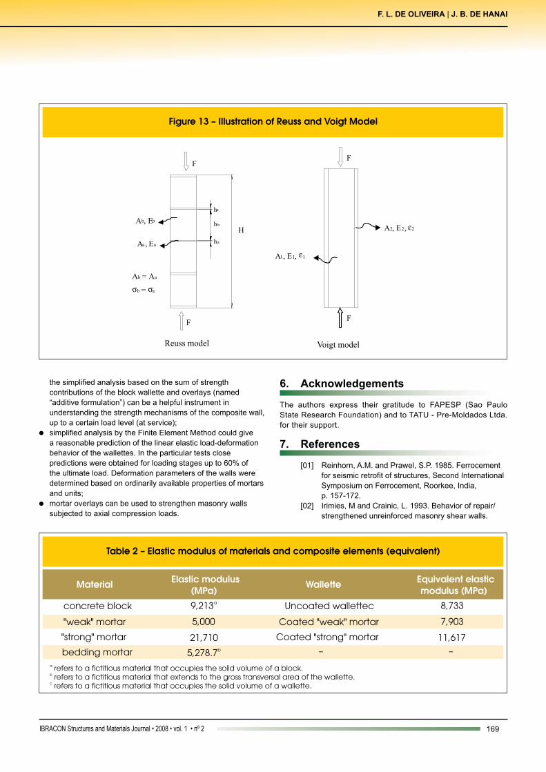
Referring to a concrete block wall without overlays under axial com-pression, the equivalent elastic modulus of the whole wall can be obtained by considering the series association of blocks and mortar layers, i.e. two different materials in the same loading line. Equation 1 expresses the condition of the series association and Figure 13 repre-sents the Reuss model, as described by Mehta and Monteiro [7]:
WhereVw,unc = volume of the uncoated wallVb = volume of the blocksVemb = volume of the bed mortar jointEw,unc = equivalent elastic modulus (of a fictitious material) of the uncoated wallEb = equivalent elastic modulus of the blocksEemb = elastic modulus of the bedding mortarIn the case of concrete block walls with overlays under axial com-pression, the equivalent elastic modulus of the wall can be obtained by considering the parallel association (Voigt model) of block wall and the mortar overlays. Equation 2 expresses the condition of the parallel association and Figure 13 represents the Voigt model, as described by Mehta and Monteiro [7]:
Where:Ew,coat = equivalent elastic modulus (of a fictitious material) of the coated wallEw,unc = equivalent elastic modulus (of a fictitious material) of the uncoated wallEover = elastic modulus of the overlay mortarAw,unc = section area of the uncoated wallAover = section area of the mortar overlayThe elastic modulus obtained experimentally for all the wall com-ponents and the calculated equivalent modulus for the walls are presented in Table 2.Some of the variables are not perfectly under control and they are not independent as described below:a) the bed mortar influences the block cracking conditions, therefore it modifies the block deformability;b) the blocks introduce confinement stresses in the bed mortar. This fact modifies the mortar deformability when compared to uniaxial test results of cylindrical samples;c) the overlays are not uniformly bonded to the wall (because of the joints) and this alters the composite behavior;d) the strength and the deformability of the plastered mortar in the overlays are not the same as the ones obtained from the mortar molded in cylindrical samples;e) concrete blocks are porous, so they tend to absorb water from the overlay mortar and this modifies its properties;f) the curing conditions are different for wallettes and mortar samples.
4.3 Finite Element analysis
The Finite Element Method (FEM) was applied to analyze the stress distribution in the wallettes and their deformation character-istics. A simplified linear analysis was performed.The wallettes were modeled with the same dimensions as the pro-totypes and the following hypotheses were assumed, according to Oliveira [4]:l the concrete hollow block wallette was represented by a solid wall formed by a fictitious material with equivalent elastic modulus determined by the “series association”, as shown in Table 2 (uncoated wallette);l similarly, the wallette strengthened with mortar overlays was simulated by a solid wall with the same external dimensions. The equivalent elastic modulus is presented in Table 2, both for “strong” and “weak” mortar;l Poisson’s ratio was assumed as 0.20 for both mortar and concrete;l the maximum applied load was about the same observed in the tests;ANSYS® software [8] was utilized and the SOLID 65 three-dimen-sional element was selected. Bottom nodes were restrained in all directions while top nodes were restrained only in the horizontal plane. Top and bottom plates were supposed to be perfectly rigid.Results from the stress analysis gave some indications about the critical regions and crack formation, but only force versus total dis-placement curves are discussed in this paper.Figure 14 shows load-displacement curves to illustrate the comparison between experimental and numerical results from the FE analysis.An overall look at the curves in Figure 14 shows that the linear FE analysis yields a reasonable estimate for the load-displacement curve obtained from the wallette tests, up to around 60% of the ultimate load.
5. Conclusions
In this work, plain and strengthened concrete block wallettes were tested under axial compression loads. The experimental results were analyzed and discussed based on theoretical simulations.Concluding remarks are given below:l uncoated concrete hollow block wallettes displayed a typical structural behavior. Near failure, longitudinal cracks appeared in the faces and in the webs of the blocks. The ultimate load estimation based on prism test results was close to the experimental value measured in the wallette tests;l application of mortar overlays increased the wallette strength, but not in a uniform manner. The strengthening efficiency in axial compression was not proportional to the overlay mortar strength and it was affected by failure mechanisms of the wallette;l among the different techniques, the one provided by the steel mesh reinforced overlays showed the best efficiency.. A possible explanation is that the steel meshes could mitigate the effects of damages in the block wallette and in the overlays themselves. Therefore, sudden loss of rigidity was avoided and the composite element could attain a higher load capacity;l fiber reinforced overlays did not show good efficiency, at least in the particular tested cases. It is possible that lack of bonding, moulding defects and even inappropriate mix proportion had caused unsatisfactory results;
169IBRACON Structures and Materials Journal • 2008 • vol. 1 • nº 2
F. L. DE OLIVEIRA | J. B. DE HANAI
the simplified analysis based on the sum of strength contributions of the block wallette and overlays (named “additive formulation”) can be a helpful instrument in understanding the strength mechanisms of the composite wall, up to a certain load level (at service);l simplified analysis by the Finite Element Method could give a reasonable prediction of the linear elastic load-deformation behavior of the wallettes. In the particular tests close predictions were obtained for loading stages up to 60% of the ultimate load. Deformation parameters of the walls were determined based on ordinarily available properties of mortars and units;l mortar overlays can be used to strengthen masonry walls subjected to axial compression loads.
6. Acknowledgements
The authors express their gratitude to FAPESP (Sao Paulo State Research Foundation) and to TATU - Pre-Moldados Ltda. for their support.
7. References
[01] Reinhorn, A.M. and Prawel, S.P. 1985. Ferrocement for seismic retrofit of structures, Second International Symposium on Ferrocement, Roorkee, India, p. 157-172. [02] Irimies, M and Crainic, L. 1993. Behavior of repair/ strengthened unreinforced masonry shear walls.

170 IBRACON Structures and Materials Journal • 2008 • vol. 1 • nº 2
Axial compression behavior of concrete masonry wallettes strengthened with cement mortar overlays
Proceedings of the Sixth North American Masonry Conference, Drexel University, p.555-563. [03] Jabarov, M. et al. 1985. Strengthening of damaged masonry by reinforced mortar layers. Proceedings of the Seventh World Conference on Earthquake Engineering, vol. 15, n. 3, p. 73-80. [04] Oliveira, F. L. 2001. Rehabilitation of masonry walls by application of ferrocement overlays. PhD Thesis University of Sao Paulo. Sao Carlos, SP. In Portuguese.
[05] American Society for Testing and Materials (1976). Standard methods for compressive strength of masonry prisms. ASTM E447. [06] American Society for Testing and Materials (1987). Standard specification for mortar for unit masonry. ASTM C270. [07] Mehta, P.K.; Monteiro, P.J.M. 1993. Concrete: structure, properties, and materials. Englewood Cliffs, NJ, Prentice Hall, 548p. [08] ANSYS Inc. 1998. Ansys Structural Analysis Manual.