Embed Size (px)
Citation preview

Avidyne Traffic Advisory Systems TAS 600, TAS 605, TAS 610, TAS 615,
TAS 620 and
Avidyne/Ryan 9900BX INSTALLATION MANUAL
Part Number 600-00282-000 (32-2351) Revision 00 Date 27 April 2011
AVIDYNE SAFETY SYSTEMS GROUP
RYAN INTERNATIONAL CORPORATION 770 Brooksedge Plaza
Westerville, Ohio 43081 Copyright 2005-2011


Avidyne TAS Installation Manual, 600-00282-000 Rev 00 – 27 April 2011 i
Special Notes to Installers: The following important issues regarding the Avidyne TAS6XX and Ryan 9900BX TCAD TAS (collectively identified as TAS in this manual) installation should be noted during the planning stages.
1. There are several references to Avidyne and Ryan, reflecting a merger of the two companies. The data labels on the equipment show Ryan TSO labels as Ryan International Corporation remains the manufacturer.
2. Installation of the TAS 600 and 610 systems are limited to aircraft with a service ceiling of 18,500 feet and 25,000 feet respectively. The TAS605, TAS 610, TAS615, TAS620 and 9900BX accept ARINC 429 heading input. See Limitations in Section I.
3. Make each antenna cable the same length (within two inches or 5 cm) for proper bearing performance. The antenna cables should meet the 3dB (±0.5dB) requirement. See Section 1.8.
4. The location of the antenna is important. The antenna "view" ahead of the aircraft must not be obstructed. Proper bonding of the antennas to the ground plane is critical to reliable bearing data. Use precautions to minimize the possibility of cross talk between antenna cables. There are special considerations for composite airframes. See Section VI for more information.
5. Suppression between the transponder, the TAS and DME (if installed) is required. See Table 7 for Availability of Suppression for Popular Transponder Models.
6. Connecting the TAS audio to an audio panel without internal amplification or into a shared audio port can affect the maximum audio level. See Section VI for more information.
7. A personal computer is required for checkout of the TAS.
8. The Suppression I/O is sensitive to short circuits and can be damaged. Be certain there are no shorts before applying power, and only apply power when the connector containing the suppression pin is fully inserted.
9. Individual RS-232 input and output connections should go to each display. There is no master display. Each RS-232 display can control the TAS. Unused RS-232 ports should be grounded as shown in the wiring diagrams.
10. The Annunciator circuit supplies a ground. Applying battery voltage directly to this input will damage the TAS Processor.
11. Connect the antennas to the Processor and check all connections before applying power.
12. The TAS is approved under TSO-C147. Section I lists the components that make up the equipment system complying with the standards prescribed in the TSO. TAS ½ 3ATI Traffic Display is not part of the TAS TSO Authorization, and was awarded a separate Parts Manufacturing Approval by the FAA.
13. Upgrade of the Model 9900B installation to the TAS requires checkout in accordance with this Manual. Installation requirements for the 9900B and TAS differ by the addition of an inductor on the power return line, and some recommended connections. Upgrade instructions are available. Contact Avidyne Corporation, Ryan International Division for more information.
14. Documentation regarding certification and installation may be found on the Internet at www.avidyne.com. The TAS meets the requirements of TSO-C147, Traffic Advisory System (TAS) Airborne Equipment, and is authorized to mark the system with this TSO marking. It is appropriate, if desired, to identify the product as a TAS.
15. Power Switch. Pin 16 of P1 must be grounded for operation (Reference Page 48). It can be routed through a switch on the panel, or permanently grounded to permit turning the system on through the avionics master (the system can then be isolated by the circuit breaker).
16. Altitude data can be accepted via ARINC 429 in lieu of gray code. Processor part number suffix of -5 (i.e. 70-2420-5) or subsequent may use ARINC 429 for altitude data input. See Paragraph 1.13 for detailed information.
17. Section VI contains useful tips that will assist in planning an installation.
18. This installation manual provides guidance for installing the Processor, Transponder Coupler, and Antennas in a structurally sound manner in compliance with the certification basis for the aircraft listed on the Approved Model List STC. Any Installation Deviations from the instructions listed in this manual requires additional Structural
Avidyne TAS Installation Manual, 600-00282-000 Rev 00 – 27 April 2011 ii
Approval.
19. Mounting the antenna on composite and pressurized aircraft requires engineering guidance beyond the scope of this manual. With respect to the Approved Model List STC, the physical mounting of the antenna is specifically excluded from the approval in the case of installation on the pressure vessel of a pressurized aircraft, composite aircraft, and aircraft with a certification basis of Amendment 23-45 or later, unless approved installation data is listed in the Master Document List of the STC. All early amendment, metal construction, non-pressurized aircraft antenna installations must be installed consistent with accepted industry practice. The installation must be structurally sound and in accordance with FAA Advisory Circular 43.13-( ).
20. Separate structural installation-specific approval is required for the airframes listed in the STC Approved Model List if the components listed in this manual are attached to FAA defined Principle Structural Elements (PSE’s). These PSE’s may carry life limits or special inspection requirements. The appropriate airframe Instructions for Continued Airworthiness must address any alterations or modifications conducted to PSE’s if the equipment noted within this manual is attached to these elements.
21. Except for the Avidyne ½ 3ATI, a separate installation approval is required for installing a Traffic System Display. The ½ 3ATI Controller/Display must be installed in accordance with this manual and FAA AC43.13-( ).
22. The TAS6XX Audio Outputs must be suppressed by all higher priority messages (e.g. EGPWS, Windshear, etc.)
23. Installation location of the TAS System components must not violate the environmental qualifications of the equipment. Reference Section 1.11 for equipment qualifications.

Avidyne TAS Installation Manual, 600-00282-000 Rev 00 – 27 April 2011 iii
Table of Contents Special Notes to Installers: ................................................................................................ i REVISION INDEX ............................................................................................................. vii SECTION I GENERAL INFORMATION ............................................................................. 1
1.1. INTRODUCTION .................................................................................................................. 1 1.2. PRODUCT DESCRIPTION ................................................................................................... 1 1.3. EQUIPMENT SPECIFICATIONS ......................................................................................... 2 1.4. FACTORY SETTINGS .......................................................................................................... 3 1.5. UNITS AND ACCESSORIES SUPPLIED ............................................................................ 3 1.6. UNITS & ACCESSORIES REQUIRED BUT NOT SUPPLIED .......................................... 4 1.7. EQUIPMENT REQUIRED FOR SETUP AND CHECKOUT .............................................. 5 1.8. ANTENNA CABLE REQUIREMENTS ............................................................................... 5 1.9. INSTALLATION APPROVAL BASIS ................................................................................. 6 1.10. INSTRUCTIONS FOR PERIODIC MAINTENANCE AND CALIBRATION WHICH
ARE NECESSARY FOR CONTINUED AIRWORTHINESS ONCE THE EQUIPMENT IS INSTALLED ...................................................................................................................... 8
1.11. LOCATION OF DATA REQUIRED BY TSO-C147 ............................................................ 8 ENVIRONMENTAL QUALIFICATIONS TAS PROCESSOR ..................................................... 9 ENVIRONMENTAL QUALIFICATIONS TRANSPONDER COUPLER .................................. 10 ENVIRONMENTAL QUALIFICATIONS TAS ½ 3ATI TRAFFIC CONTROLLER/DISPLAY
11 ENVIRONMENTAL QUALIFICATIONS TAS Antennas ........................................................... 13 1.12. LIMITATIONS ..................................................................................................................... 14 1.13. ARINC 429 INFORMATION .............................................................................................. 16 1.14. NO AVIDYNE DISPLAY CONFIGURATION .................................................................. 17
SECTION II INSTALLATION ............................................................................................ 21 2.1. GENERAL ............................................................................................................................ 21 2.2. TRANSPONDER AND ENCODER REQUIREMENTS .................................................... 21 2.3. SUPPRESSION .................................................................................................................... 24 2.4. ANNUNCIATOR OUTPUT AND MUTE/UPDATE FUNCTION .................................... 25 2.5. PRIORITIZATION WITH WINDSHEAR AND EGPWS/TAWS ...................................... 25 2.6. RS-232 COMMUNICATIONS ............................................................................................ 25 2.7. ARINC 429 COMMUNICATIONS ..................................................................................... 25 2.8. GEAR POSITION AND WEIGHT-ON-WHEELS ............................................................. 26 2.9. COOLING ............................................................................................................................. 26 2.10. ANTENNA PLACEMENT CONSIDERATIONS ............................................................... 26 2.11. TRANSPONDER COUPLER .............................................................................................. 27 2.12. CHECKOUT PRECAUTIONS ............................................................................................ 27 2.13. MECHANICAL INSTALLATION OF THE OPTIONAL ½ 3ATI TRAFFIC
CONTROLLER/DISPLAY .................................................................................................. 27 2.14. MECHANICAL INSTALLATION OF PROCESSOR ........................................................ 30 2.15. MECHANICAL INSTALLATION OF TRANSPONDER COUPLER .............................. 33 2.16. MECHANICAL INSTALLATION OF ANTENNAS ......................................................... 34 2.17. OVERVIEW OF ELECTRICAL INSTALLATION ............................................................ 35 2.18. INSTALLATION WITHOUT A DISPLAY ........................................................................ 36 2.19. INSTALLATION WITH A MULTI-FUNCTION DISPLAY ............................................. 36
Avidyne TAS Installation Manual, 600-00282-000 Rev 00 – 27 April 2011 iv
2.20. INSTALLATION WITHOUT AN AVIDYNE DISPLAY .................................................. 36 2.21. ELECTRICAL WIRING OF ½ 3ATI Traffic DISPLAY AND PROCESSOR ................... 38 2.22. ELECTRICAL WIRING OF SUPPRESSION ..................................................................... 38 2.23. ELECTRICAL WIRING OF TRANSPONDER COUPLER ............................................... 39 2.24. ANTENNA CABLE INSTALLATION ............................................................................... 40 2.25. ELECTRICAL WIRING OF ALTITUDE ENCODER........................................................ 41
SECTION III OPERATION ................................................................................................ 52 3.1. GENERAL ............................................................................................................................ 52 3.2. AUDIO & VISUAL ALERT ................................................................................................ 52 3.3. OPTIONAL ½ 3ATI TRAFFIC DISPLAY OPERATOR CONTROLS ............................. 53 3.4. SYMBOLS ............................................................................................................................ 54 3.5. BASIC DISPLAYS ............................................................................................................... 55 3.6. PROGRAMMING ................................................................................................................ 57 3.7. SETTING THE PROXIMITY AIRSPACE SIZE ................................................................ 57 3.8. SETTING DENSITY ALTITUDE ....................................................................................... 57 3.9. SETTING AUDIO VOLUME .............................................................................................. 57 3.10. SETTING THE ALTITUDE ALERT .................................................................................. 58 3.11. BUILT-IN TEST & FAULT INDICATIONS ...................................................................... 58 3.12. DISCLAIMER ...................................................................................................................... 61
SECTION IV PERFORMANCE TESTING ......................................................................... 62 4.1. GENERAL ............................................................................................................................ 62 4.2. EQUIPMENT REQUIRED .................................................................................................. 62 4.3. RAMP TEST ......................................................................................................................... 63 4.3.1. INITIAL TRANSPONDER TEST ....................................................................................... 63 4.3.2. PERSONAL COMPUTER SETUP ...................................................................................... 63 4.3.3. CALIBRATION AND VERIFICATION INTERFACE ...................................................... 66 4.3.4. RAMP TEST, ANTENNAS ................................................................................................. 74 4.3.5. RAMP TEST, OPTIONAL ½ 3ATI TRAFFIC CONTROLLER/DISPLAY ...................... 75 4.3.6. RAMP TEST, SELF TEST FEATURES AND FAILURE MODE DISPLAYS ................. 76 4.4. INTERFERENCE CHECK .................................................................................................. 76 4.4.1. INTERFERENCE CHECK, TRANSPONDER ................................................................... 76 4.4.2. INTERFERENCE CHECK, OTHER EQUIPMENT ........................................................... 77 4.4.3. TAS AUDIO ALERTS ......................................................................................................... 77 4.4.4. ELECTRICAL SYSTEM ..................................................................................................... 77 4.5. FLIGHT TEST ...................................................................................................................... 77 4.6. CUSTOMER CARE CHECKLIST ...................................................................................... 78
SECTION V WARRANTY SERVICE AND PRODUCT SUPPORT ................................... 79 5.1. DOCUMENTATION ........................................................................................................... 79 5.2. RETURN AUTHORIZATION ............................................................................................. 79 5.3. WARRANTY SERVICE ...................................................................................................... 79
SECTION VI INSTALLATION PLANNING AND TROUBLESHOOTING GUIDE ............. 80 6.1. GENERAL ............................................................................................................................ 80 6.2. EXTERNAL CONNECTIONS ............................................................................................ 80 6.2.1. ANTENNA BONDING ........................................................................................................ 80 6.2.2. TOP AND BOTTOM ANTENNA SELECTION ................................................................ 82 6.2.2.1. ANTENNA CABLING ..................................................................................................... 82 6.2.2.2. PROCESSOR ANTENNA CONNECTIONS ................................................................... 82 6.2.3. POWER INPUT LINE AND GROUND RETURN ............................................................. 82
Avidyne TAS Installation Manual, 600-00282-000 Rev 00 – 27 April 2011 v
6.2.4. ANNUNCIATOR LIGHT .................................................................................................... 82 6.2.5. AUDIO .................................................................................................................................. 82 6.2.6. ENCODER LINES ............................................................................................................... 83 6.2.7. ON-THE-GROUND INDICATIONS AND GEAR POSITION .......................................... 83 6.2.8. TRANSPONDER SUPPRESSION ...................................................................................... 83 6.2.9. TRANSPONDER COUPLER .............................................................................................. 84 6.2.10. AVIDYNE ½ 3ATI TRAFFIC DISPLAY, MFD AND PROCESSOR INTERCONNECT
PRECAUTIONS ................................................................................................................... 84 6.2.11. MUTE/UPDATE INPUT .................................................................................................. 86 6.2.12. EMI INTERFERENCE FROM OTHER ONBOARD ELECTRONICS .......................... 87 6.3. CHECKOUT ......................................................................................................................... 87 6.4. INSTALLATION IN A SEVERE EMI ENVIRONMENT .................................................. 88 6.5. COMPASS HEADING INPUT ............................................................................................ 89 6.6. MALFUNCTION INDICATIONS ....................................................................................... 89
SECTION VII STC Permission ......................................................................................... 91
Avidyne TAS Installation Manual, 600-00282-000 Rev 00 – 27 April 2011 vi
LIST OF TABLES Table 1 Part Number Matrix ............................................................................................................................................... 3 Table 2 Antenna Cable Requirements ................................................................................................................................ 5 Table 3 Environmental Statements ................................................................................................................................... 14 Table 4 Compatible Displays ........................................................................................................................................... 14 Table 5 TAS6XX Limitations .......................................................................................................................................... 15 Table 6 Connector Pin Assignments................................................................................................................................. 20 Table 7 Availability of Suppression for Popular Transponders ........................................................................................ 24 Table 8 Proximity Airspace Limits for the ½ 3ATI Traffic Display ................................................................................ 57 Table 9 Test Function with the ½ 3ATI Traffic Controller/display .................................................................................. 58 Table 10 Null Modem Cable Pin Assignments ................................................................................................................ 62 Table 11 Antenna connections when the Twin Blade Antenna is top-mounted ............................................................... 82 Table 12 J1-15 Configuration Options ............................................................................................................................. 86
LIST OF FIGURES Figure 1 Sample Description of Work Accomplished ........................................................................................................ 7 Figure 2 Pin J1-15 Jumper Configuration Table .............................................................................................................. 18 Figure 3 TAS Components including optional ½ 3ATI Traffic Controller/display (Antennas not shown) ..................... 22 Figure 4 The Avidyne Multi-Hazard Display (MHD) ...................................................................................................... 23 Figure 5 Avidyne ½ 3ATI Traffic Controller/Display Mounting and Dimensions .......................................................... 28 Figure 6 Panel Cutout for optional ½ 3ATI Traffic Controller/Display ........................................................................... 29 Figure 7 Processor Mounting Tray ................................................................................................................................... 31 Figure 8 Processor with Mounting Tray ........................................................................................................................... 32 Figure 9 Transponder Coupler .......................................................................................................................................... 33 Figure 10 Recommended Antenna Locations ................................................................................................................... 34 Figure 11 Block Diagram of Electrical Wiring ................................................................................................................ 37 Figure 12 Processor Front Panel View ............................................................................................................................. 38 Figure 13 Suppression Configuration for Unidirectional King Transponders and DME ................................................. 39 Figure 14 Installing Cables to the Transponder Coupler .................................................................................................. 40 Figure 15 Internal Diode Isolation of Altitude Encoder Lines and Discrete Functions .................................................... 42 Figure 16 15-Pin Cable-End Plug for Mating with J1 ...................................................................................................... 43 Figure 17 TAS Single-blade Antenna Illustration ............................................................................................................ 44 Figure 18 TAS Twin-blade Antenna Illustration .............................................................................................................. 45 Figure 19 Cable-End Receptacle for Mating with P1. ...................................................................................................... 46 Figure 20 9-Pin Cable-End Receptacle for the Optional ½ 3ATI Traffic Display (not COM1) ....................................... 47 Figure 21 Wiring Diagram for the TAS Processor, P1 ..................................................................................................... 48 Figure 22 Wiring Diagram for Connection of an Avidyne TAS ½ 3ATI Traffic Controller/display ............................... 49 Figure 23 Wiring diagram for TAS Processor J1, COM 1 and Antenna Connections ..................................................... 50 Figure 24 Coupler and Suppression Bus Wiring Diagram ............................................................................................... 51 Figure 25 ½ 3ATI Traffic Controller/display ................................................................................................................... 53 Figure 26 ½ 3ATI Traffic Controller/display Symbols .................................................................................................... 54 Figure 27 Controls and Display, Monitoring for Traffic .................................................................................................. 55 Figure 28 Controls and Display, Traffic Acquired ........................................................................................................... 56 Figure 29 Paint Removal Beneath the Antennas to Assure Proper Antenna Bonding ..................................................... 81 Figure 30 Ramp Test Geometry Considerations............................................................................................................... 88

Avidyne TAS Installation Manual, 600-00282-000 Rev 00 – 27 April 2011 vii
REVISION INDEX
Revision Date Remarks 00 27 April 2011 Initial Release


Avidyne TAS Installation Manual, 600-00282-000 Rev 00 – 27 April 2011 1
SECTION I GENERAL INFORMATION
1.1. INTRODUCTION This manual contains information regarding the physical, mechanical and electrical characteristics, as well as installation information pertaining to the Avidyne Traffic Advisory Systems (TAS). For maintenance and repair information, contact Avidyne Corporation, Ryan International Division. Installation Planning tips are found in Section VI.
1.2. PRODUCT DESCRIPTION The Avidyne TAS600, TAS605, TAS610, TAS615, TAS620 and Ryan Model 9900BX Traffic Advisory Systems (collectively known as TASs) are actively interrogating on-board air traffic detection systems used to identify potential collision threats. Each model offers similar features, but are limited in the types of aircraft the equipment can be installed in. See Limitations in this Section.
The TAS computes relative altitude and range of threats from nearby transponder-equipped aircraft. Aircraft with non-Mode C transponders can provide range information. The TAS does not detect aircraft without operating transponders.
The TASs are available in four configurations:
• The TAS without display
• The TAS with Avidyne Multi-Hazard Display (MHD)
• The TAS with ½ 3ATI Traffic Controller/display
• The TAS integrated with a Multi-Function Display
NOTE: Refer to the Avidyne Multi-Hazard Display Installation Manual for more information about the MHD (Reference Avidyne Installation Manual, P/N 32-2401).
Up to four RS-232-compatible displays may be connected with one TAS. The TAS will respond to control inputs from any of the displays. The system will also connect to many displays that support ARINC 429 TCAS protocol. See paragraph 1.13 for label information.
The TAS is advisory only, and is a back up to the See and Avoid Concept, and the ATC radar environment.
Avidyne TAS Installation Manual, 600-00282-000 Rev 00 – 27 April 2011 2
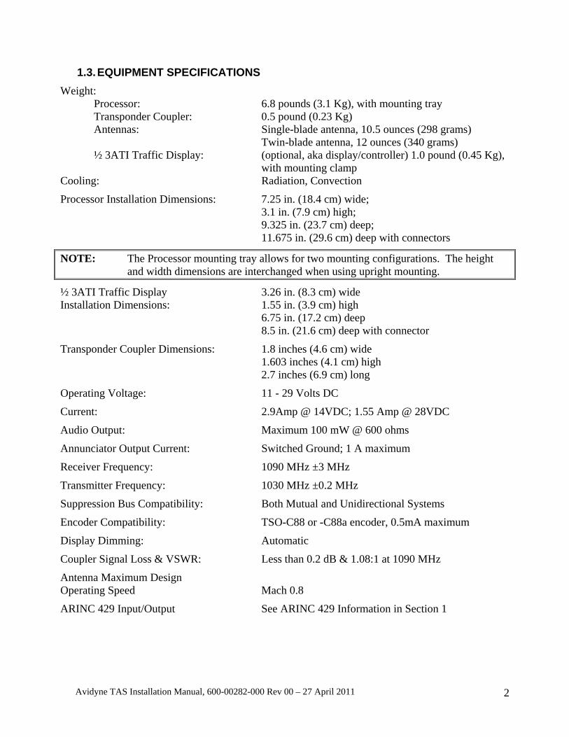
1.3. EQUIPMENT SPECIFICATIONS Weight: Processor: 6.8 pounds (3.1 Kg), with mounting tray
Transponder Coupler: 0.5 pound (0.23 Kg) Antennas: Single-blade antenna, 10.5 ounces (298 grams) Twin-blade antenna, 12 ounces (340 grams) ½ 3ATI Traffic Display: (optional, aka display/controller) 1.0 pound (0.45 Kg), with mounting clamp Cooling: Radiation, Convection
Processor Installation Dimensions: 7.25 in. (18.4 cm) wide; 3.1 in. (7.9 cm) high; 9.325 in. (23.7 cm) deep; 11.675 in. (29.6 cm) deep with connectors
NOTE: The Processor mounting tray allows for two mounting configurations. The height and width dimensions are interchanged when using upright mounting.
½ 3ATI Traffic Display 3.26 in. (8.3 cm) wide Installation Dimensions: 1.55 in. (3.9 cm) high 6.75 in. (17.2 cm) deep 8.5 in. (21.6 cm) deep with connector
Transponder Coupler Dimensions: 1.8 inches (4.6 cm) wide 1.603 inches (4.1 cm) high 2.7 inches (6.9 cm) long
Operating Voltage: 11 - 29 Volts DC
Current: 2.9Amp @ 14VDC; 1.55 Amp @ 28VDC
Audio Output: Maximum 100 mW @ 600 ohms
Annunciator Output Current: Switched Ground; 1 A maximum
Receiver Frequency: 1090 MHz ±3 MHz
Transmitter Frequency: 1030 MHz ±0.2 MHz
Suppression Bus Compatibility: Both Mutual and Unidirectional Systems
Encoder Compatibility: TSO-C88 or -C88a encoder, 0.5mA maximum
Display Dimming: Automatic
Coupler Signal Loss & VSWR: Less than 0.2 dB & 1.08:1 at 1090 MHz
Antenna Maximum Design Operating Speed Mach 0.8
ARINC 429 Input/Output See ARINC 429 Information in Section 1
Avidyne TAS Installation Manual, 600-00282-000 Rev 00 – 27 April 2011 3
1.4. FACTORY SETTINGS The TAS is delivered with the following setting:
Audio Volume: Mid Range
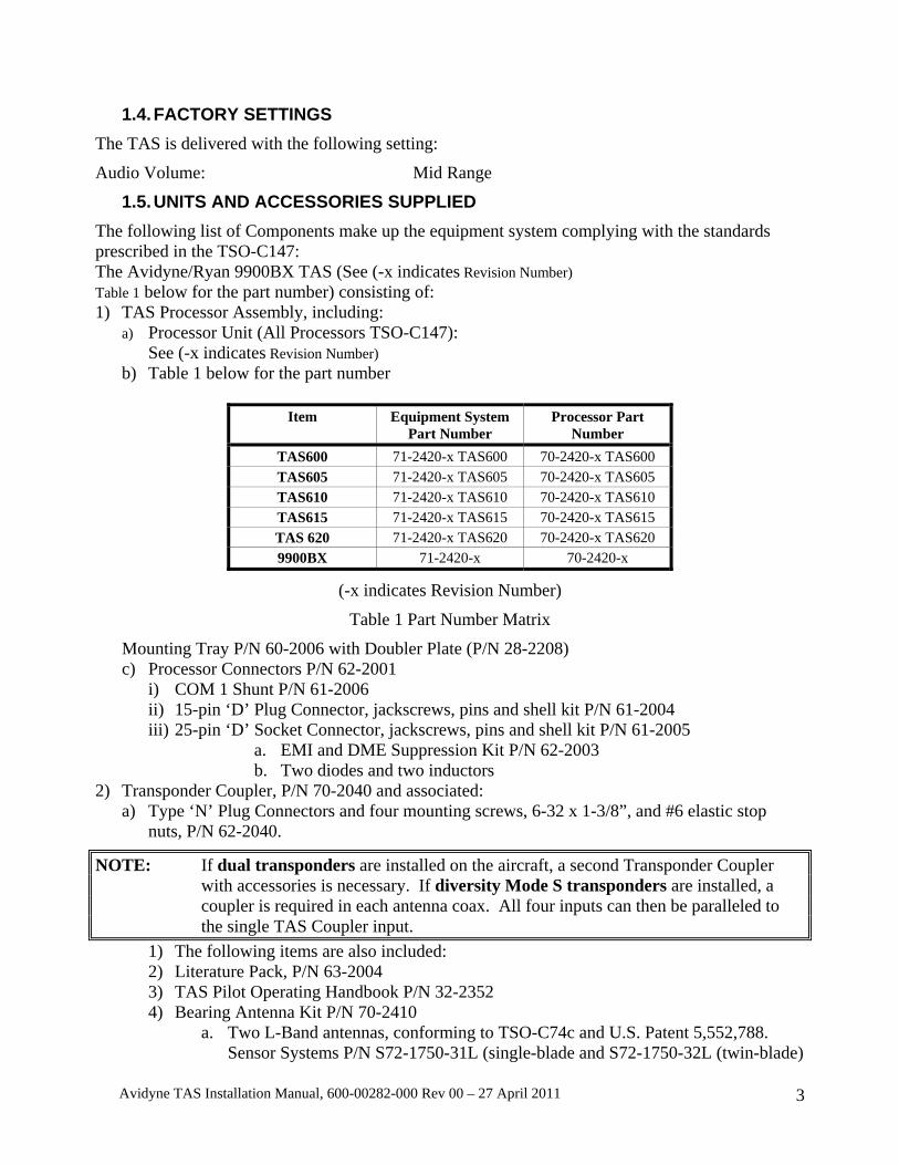
1.5. UNITS AND ACCESSORIES SUPPLIED The following list of Components make up the equipment system complying with the standards prescribed in the TSO-C147: The Avidyne/Ryan 9900BX TAS (See (-x indicates Revision Number) Table 1 below for the part number) consisting of: 1) TAS Processor Assembly, including:
a) Processor Unit (All Processors TSO-C147): See (-x indicates Revision Number)
b) Table 1 below for the part number
Item Equipment System Part Number
Processor Part Number
TAS600 71-2420-x TAS600 70-2420-x TAS600 TAS605 71-2420-x TAS605 70-2420-x TAS605 TAS610 71-2420-x TAS610 70-2420-x TAS610 TAS615 71-2420-x TAS615 70-2420-x TAS615 TAS 620 71-2420-x TAS620 70-2420-x TAS620 9900BX 71-2420-x 70-2420-x
(-x indicates Revision Number)
Table 1 Part Number Matrix
Mounting Tray P/N 60-2006 with Doubler Plate (P/N 28-2208) c) Processor Connectors P/N 62-2001
i) COM 1 Shunt P/N 61-2006 ii) 15-pin ‘D’ Plug Connector, jackscrews, pins and shell kit P/N 61-2004 iii) 25-pin ‘D’ Socket Connector, jackscrews, pins and shell kit P/N 61-2005
a. EMI and DME Suppression Kit P/N 62-2003 b. Two diodes and two inductors
2) Transponder Coupler, P/N 70-2040 and associated: a) Type ‘N’ Plug Connectors and four mounting screws, 6-32 x 1-3/8”, and #6 elastic stop
nuts, P/N 62-2040.
NOTE: If dual transponders are installed on the aircraft, a second Transponder Coupler with accessories is necessary. If diversity Mode S transponders are installed, a coupler is required in each antenna coax. All four inputs can then be paralleled to the single TAS Coupler input.
1) The following items are also included: 2) Literature Pack, P/N 63-2004 3) TAS Pilot Operating Handbook P/N 32-2352 4) Bearing Antenna Kit P/N 70-2410
a. Two L-Band antennas, conforming to TSO-C74c and U.S. Patent 5,552,788. Sensor Systems P/N S72-1750-31L (single-blade and S72-1750-32L (twin-blade)
Avidyne TAS Installation Manual, 600-00282-000 Rev 00 – 27 April 2011 4
b. Two Doubler Plates, Sensor Systems P/N S72-17500-1 5) The optional TAS ½ 3ATI Traffic Controller/display is not required under the conditions
of TSO-C147. If included, the top assembly part number is 71-2420. In addition to the above, the assembly includes:
a. ½ 3ATI Traffic Display Unit P/N 70-2520 i. ½ 3ATI Traffic Controller/display Clamp Assembly P/N 28-3110
ii. ½ 3ATI Traffic Controller/display Connector kit P/N 61-2003, including iii. 9 pin ‘D’ Connector - Socket iv. 9-pin ‘D’ Shell, Jack Screw Kit and Socket Pins
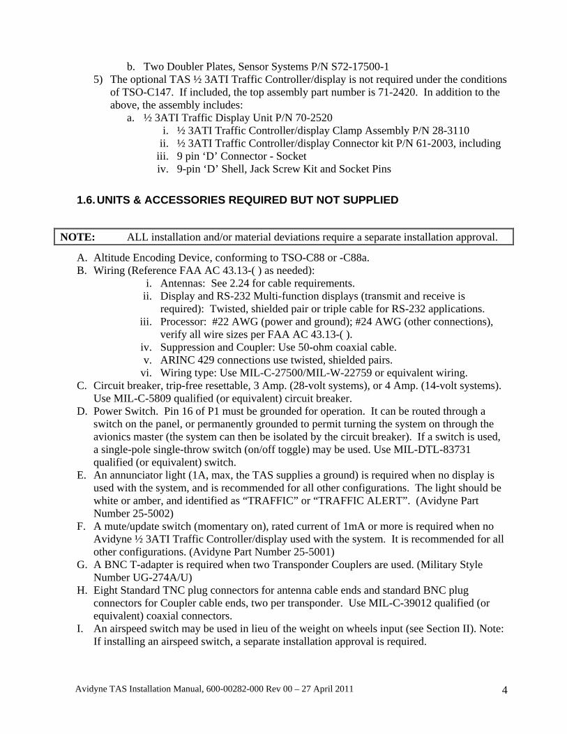
1.6. UNITS & ACCESSORIES REQUIRED BUT NOT SUPPLIED
NOTE: ALL installation and/or material deviations require a separate installation approval.
A. Altitude Encoding Device, conforming to TSO-C88 or -C88a. B. Wiring (Reference FAA AC 43.13-( ) as needed):
i. Antennas: See 2.24 for cable requirements. ii. Display and RS-232 Multi-function displays (transmit and receive is
required): Twisted, shielded pair or triple cable for RS-232 applications. iii. Processor: #22 AWG (power and ground); #24 AWG (other connections),
verify all wire sizes per FAA AC 43.13-( ). iv. Suppression and Coupler: Use 50-ohm coaxial cable. v. ARINC 429 connections use twisted, shielded pairs.
vi. Wiring type: Use MIL-C-27500/MIL-W-22759 or equivalent wiring. C. Circuit breaker, trip-free resettable, 3 Amp. (28-volt systems), or 4 Amp. (14-volt systems).
Use MIL-C-5809 qualified (or equivalent) circuit breaker. D. Power Switch. Pin 16 of P1 must be grounded for operation. It can be routed through a
switch on the panel, or permanently grounded to permit turning the system on through the avionics master (the system can then be isolated by the circuit breaker). If a switch is used, a single-pole single-throw switch (on/off toggle) may be used. Use MIL-DTL-83731 qualified (or equivalent) switch.
E. An annunciator light (1A, max, the TAS supplies a ground) is required when no display is used with the system, and is recommended for all other configurations. The light should be white or amber, and identified as “TRAFFIC” or “TRAFFIC ALERT”. (Avidyne Part Number 25-5002)
F. A mute/update switch (momentary on), rated current of 1mA or more is required when no Avidyne ½ 3ATI Traffic Controller/display used with the system. It is recommended for all other configurations. (Avidyne Part Number 25-5001)
G. A BNC T-adapter is required when two Transponder Couplers are used. (Military Style Number UG-274A/U)
H. Eight Standard TNC plug connectors for antenna cable ends and standard BNC plug connectors for Coupler cable ends, two per transponder. Use MIL-C-39012 qualified (or equivalent) coaxial connectors.
I. An airspeed switch may be used in lieu of the weight on wheels input (see Section II). Note: If installing an airspeed switch, a separate installation approval is required.
Avidyne TAS Installation Manual, 600-00282-000 Rev 00 – 27 April 2011 5
1.7. EQUIPMENT REQUIRED FOR SETUP AND CHECKOUT A computer with serial communications capability (such as a PC with Microsoft Windows HyperTerminal∗) is required. In addition, the following devices are required:
A. A null modem cable (often called a file transfer cable) B. A Transponder tester, such as the IFR ATC-601 or equivalent
A TCAS tester such as the IFR TCAS-201 is recommended for easier checkout, but is not required.
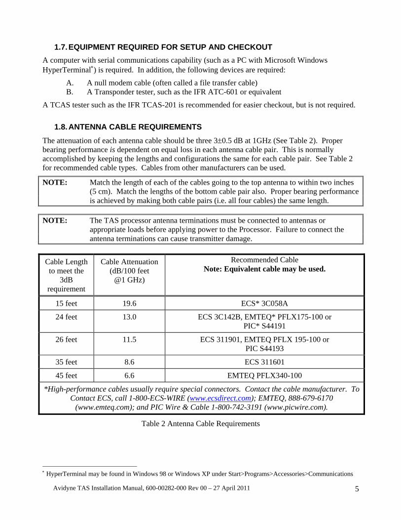
1.8. ANTENNA CABLE REQUIREMENTS The attenuation of each antenna cable should be three 3±0.5 dB at 1GHz (See Table 2). Proper bearing performance is dependent on equal loss in each antenna cable pair. This is normally accomplished by keeping the lengths and configurations the same for each cable pair. See Table 2 for recommended cable types. Cables from other manufacturers can be used.
NOTE: Match the length of each of the cables going to the top antenna to within two inches (5 cm). Match the lengths of the bottom cable pair also. Proper bearing performance is achieved by making both cable pairs (i.e. all four cables) the same length.
NOTE: The TAS processor antenna terminations must be connected to antennas or
appropriate loads before applying power to the Processor. Failure to connect the antenna terminations can cause transmitter damage.
Cable Length to meet the
3dB requirement
Cable Attenuation (dB/100 feet
@1 GHz)
Recommended Cable Note: Equivalent cable may be used.
15 feet 19.6 ECS* 3C058A
24 feet 13.0 ECS 3C142B, EMTEQ* PFLX175-100 or PIC* S44191
26 feet 11.5 ECS 311901, EMTEQ PFLX 195-100 or PIC S44193
35 feet 8.6 ECS 311601
45 feet 6.6 EMTEQ PFLX340-100
*High-performance cables usually require special connectors. Contact the cable manufacturer. To Contact ECS, call 1-800-ECS-WIRE (www.ecsdirect.com); EMTEQ, 888-679-6170
(www.emteq.com); and PIC Wire & Cable 1-800-742-3191 (www.picwire.com).
Table 2 Antenna Cable Requirements
∗ HyperTerminal may be found in Windows 98 or Windows XP under Start>Programs>Accessories>Communications

Avidyne TAS Installation Manual, 600-00282-000 Rev 00 – 27 April 2011 6
1.9. INSTALLATION APPROVAL BASIS
The FAA has awarded Avidyne Corporation an Approved Model List (AML) Supplemental Type Certificate (STC) for the Avidyne TAS System. Aircraft listed on the Approved Model List for the STC may use the installation data listed in the Master Document List to install the TAS System.
Aircraft not listed on the AML may use the STC data for a follow-on installation (FAA Form 337 approval). Data that can be used as a basis for approval for return to service are:
A. STC Documents (Supplied in the Literature Pack).
B. AC 43.13-1( ) and -2( ); Acceptable Methods, Techniques, and Practices. C. TSO Markings and PMA markings. D. Manufacturer's installation instructions.
Installation of a Traffic Advisory System (TAS) may or may not be eligible for approval by means other than an STC. TAS will not automatically qualify for a field approval; TAS requires evaluation of the scope and complexity of the alteration and review of guidance by the FSDO to determine if the field approval process may be used.
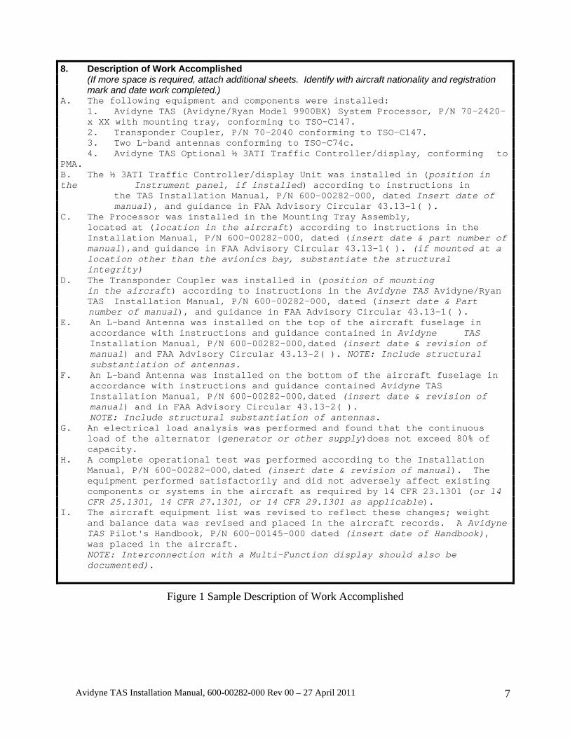
The Avidyne TAS is an isolated self-contained system operating as a supplement to “see and avoid” procedures. The installation and operation of the TAS does not materially affect aircraft operation or performance. Equipment installation procedures do not differ significantly among various aircraft. The Sample Description of Work Accomplished is suggested language provided as a convenience to the installing agency. A person who performs or supervises the installation of the TAS may be required to prepare FAA Form 337 for installation approval. See the Sample Description of Work Accomplished in Section I. The information and wording should be modified to correctly describe the particular installation. Avidyne Corporation, Ryan International Division assumes no responsibility for alterations to the airframe. The TAS complies with the requirements of TSO-C147.
Avidyne TAS Installation Manual, 600-00282-000 Rev 00 – 27 April 2011 7
8. Description of Work Accomplished (If more space is required, attach additional sheets. Identify with aircraft nationality and registration mark and date work completed.) A. The following equipment and components were installed: 1. Avidyne TAS (Avidyne/Ryan Model 9900BX) System Processor, P/N 70-2420- x XX with mounting tray, conforming to TSO-C147. 2. Transponder Coupler, P/N 70-2040 conforming to TSO-C147. 3. Two L-band antennas conforming to TSO-C74c. 4. Avidyne TAS Optional ½ 3ATI Traffic Controller/display, conforming to PMA. B. The ½ 3ATI Traffic Controller/display Unit was installed in (position in the Instrument panel, if installed) according to instructions in the TAS Installation Manual, P/N 600-00282-000, dated Insert date of manual), and guidance in FAA Advisory Circular 43.13-1( ). C. The Processor was installed in the Mounting Tray Assembly, located at (location in the aircraft) according to instructions in the Installation Manual, P/N 600-00282-000, dated (insert date & part number of manual),and guidance in FAA Advisory Circular 43.13-1( ). (if mounted at a location other than the avionics bay, substantiate the structural integrity) D. The Transponder Coupler was installed in (position of mounting in the aircraft) according to instructions in the Avidyne TAS Avidyne/Ryan TAS Installation Manual, P/N 600-00282-000, dated (insert date & Part number of manual), and guidance in FAA Advisory Circular 43.13-1( ). E. An L-band Antenna was installed on the top of the aircraft fuselage in
accordance with instructions and guidance contained in Avidyne TAS Installation Manual, P/N 600-00282-000,dated (insert date & revision of manual) and FAA Advisory Circular 43.13-2( ). NOTE: Include structural substantiation of antennas.
F. An L-band Antenna was installed on the bottom of the aircraft fuselage in accordance with instructions and guidance contained Avidyne TAS Installation Manual, P/N 600-00282-000,dated (insert date & revision of manual) and in FAA Advisory Circular 43.13-2( ). NOTE: Include structural substantiation of antennas.
G. An electrical load analysis was performed and found that the continuous load of the alternator (generator or other supply)does not exceed 80% of capacity. H. A complete operational test was performed according to the Installation
Manual, P/N 600-00282-000,dated (insert date & revision of manual). The equipment performed satisfactorily and did not adversely affect existing components or systems in the aircraft as required by 14 CFR 23.1301 (or 14 CFR 25.1301, 14 CFR 27.1301, or 14 CFR 29.1301 as applicable).
I. The aircraft equipment list was revised to reflect these changes; weight and balance data was revised and placed in the aircraft records. A Avidyne TAS Pilot's Handbook, P/N 600-00145-000 dated (insert date of Handbook), was placed in the aircraft. NOTE: Interconnection with a Multi-Function display should also be documented).
Figure 1 Sample Description of Work Accomplished
Avidyne TAS Installation Manual, 600-00282-000 Rev 00 – 27 April 2011 8
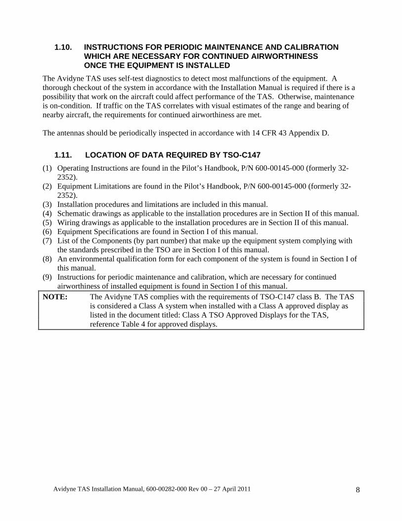
1.10. INSTRUCTIONS FOR PERIODIC MAINTENANCE AND CALIBRATION WHICH ARE NECESSARY FOR CONTINUED AIRWORTHINESS ONCE THE EQUIPMENT IS INSTALLED
The Avidyne TAS uses self-test diagnostics to detect most malfunctions of the equipment. A thorough checkout of the system in accordance with the Installation Manual is required if there is a possibility that work on the aircraft could affect performance of the TAS. Otherwise, maintenance is on-condition. If traffic on the TAS correlates with visual estimates of the range and bearing of nearby aircraft, the requirements for continued airworthiness are met. The antennas should be periodically inspected in accordance with 14 CFR 43 Appendix D.
1.11. LOCATION OF DATA REQUIRED BY TSO-C147 (1) Operating Instructions are found in the Pilot’s Handbook, P/N 600-00145-000 (formerly 32-
2352). (2) Equipment Limitations are found in the Pilot’s Handbook, P/N 600-00145-000 (formerly 32-
2352). (3) Installation procedures and limitations are included in this manual. (4) Schematic drawings as applicable to the installation procedures are in Section II of this manual. (5) Wiring drawings as applicable to the installation procedures are in Section II of this manual. (6) Equipment Specifications are found in Section I of this manual. (7) List of the Components (by part number) that make up the equipment system complying with
the standards prescribed in the TSO are in Section I of this manual. (8) An environmental qualification form for each component of the system is found in Section I of
this manual. (9) Instructions for periodic maintenance and calibration, which are necessary for continued
airworthiness of installed equipment is found in Section I of this manual. NOTE: The Avidyne TAS complies with the requirements of TSO-C147 class B. The TAS
is considered a Class A system when installed with a Class A approved display as listed in the document titled: Class A TSO Approved Displays for the TAS, reference Table 4 for approved displays.

Avidyne TAS Installation Manual, 600-00282-000 Rev 00 – 27 April 2011 9
ENVIRONMENTAL QUALIFICATIONS TAS PROCESSOR NOMENCLATURE: Processor PART NUMBERS: 70-2420 MANUFACTURER'S SPECIFICATION: TSO-C147 MANUFACTURER: Avidyne Corporation 770 Brooksedge Plaza Westerville, Ohio 43081
CONDITIONS DO-160DSECTION
DESCRIPTION OF TESTS CONDUCTED
TEMPERATURE AND ALTITUDE
4.0 EQUIPMENT TESTED TO CATEGORY F2
TEMP. VARIATION 5.0 EQUIPMENT IDENTIFIED AS CATEGORY ‘X’, NO TEST REQUIRED
HUMIDITY 6.0 EQUIPMENT TESTED TO CATEGORY A
OPERATIONAL SHOCK AND CRASH SAFETY
7.0 EQUIPMENT TESTED TO CATEGORY B
VIBRATION 8.0 EQUIPMENT TESTED TO CATEGORY S, AIRCRAFT ZONE 2 FOR FIXED WING AIRCRAFT USING VIBRATION TEST CURVE B & M (Table 8-1). EQUIPMENT TESTED TO DO-160C CURVE N FOR HELICOPTERS
EXPLOSION 9.0 EQUIPMENT TESTED TO ENVIRONMENT II, CATEGORY H
WATERPROOFNESS 10.0 EQUIPMENT IDENTIFIED AS CATEGORY ‘X’, NO TEST REQUIRED
FLUIDS SUSCEPTIBILITY 11.0 EQUIPMENT IDENTIFIED AS CATEGORY ‘X’, NO TEST REQUIRED
SAND AND DUST 12.0 EQUIPMENT IDENTIFIED AS CATEGORY ‘X’, NO TEST REQUIRED
FUNGUS 13.0 EQUIPMENT IDENTIFIED AS CATEGORY ‘X’, NO TEST REQUIRED
SALT SPRAY 14.0 EQUIPMENT IDENTIFIED AS CATEGORY ‘X’, NO TEST REQUIRED
MAGNETIC EFFECT 15.0 EQUIPMENT TESTED TO CATEGORY Z
POWER INPUT 16.0 EQUIPMENT TESTED TO CATEGORY B
VOLTAGE SPIKE CONDUCTED
17.0 EQUIPMENT TESTED TO CATEGORY B
AUDIO FREQUENCY CONDUCTED SUSCEPTIBILITY
18.0 EQUIPMENT TESTED TO CATEGORY B
Avidyne TAS Installation Manual, 600-00282-000 Rev 00 – 27 April 2011 10
INDUCED SIGNAL SUSCEPTIBILITY
19.0 EQUIPMENT TESTED TO CATEGORY A
RADIO FREQUENCY SUSCEPTIBILITY
20.0 EQUIPMENT TESTED TO CATEGORY U (CONDUCTED) AND CATEGORY U (RADIATED)
RADIO FREQUENCY EMISSION
21.0 EQUIPMENT TESTED TO CATEGORY M (CONDUCTED AND RADIATED)
LIGHTNING INDUCED TRANSIENT SUSCPT
22.0 EQUIPMENT IDENTIFIED AS CATEGORY ‘X’, NO TEST REQUIRED
LIGHTNING DIRECT EFFECTS
23.0 EQUIPMENT IDENTIFIED AS CATEGORY ‘X’, NO TEST REQUIRED
ICING 24.0 EQUIPMENT IDENTIFIED AS CATEGORY ‘X’, NO TEST REQUIRED
ELECTROSTATIC DISCHARGE
25.0 EQUIPMENT IDENTIFIED AS CATEGORY ‘X’, NO TEST REQUIRED
FIRE FLAMMABILITY 26.0 EQUIPMENT NOT TESTED
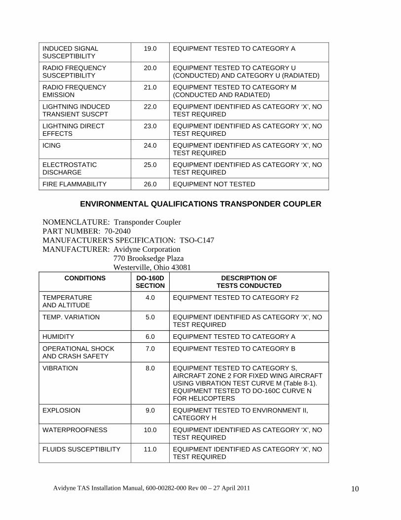
ENVIRONMENTAL QUALIFICATIONS TRANSPONDER COUPLER
NOMENCLATURE: Transponder Coupler PART NUMBER: 70-2040 MANUFACTURER'S SPECIFICATION: TSO-C147 MANUFACTURER: Avidyne Corporation 770 Brooksedge Plaza Westerville, Ohio 43081
CONDITIONS DO-160DSECTION
DESCRIPTION OF TESTS CONDUCTED
TEMPERATURE AND ALTITUDE
4.0 EQUIPMENT TESTED TO CATEGORY F2
TEMP. VARIATION 5.0 EQUIPMENT IDENTIFIED AS CATEGORY ‘X’, NO TEST REQUIRED
HUMIDITY 6.0 EQUIPMENT TESTED TO CATEGORY A
OPERATIONAL SHOCK AND CRASH SAFETY
7.0 EQUIPMENT TESTED TO CATEGORY B
VIBRATION 8.0 EQUIPMENT TESTED TO CATEGORY S, AIRCRAFT ZONE 2 FOR FIXED WING AIRCRAFT USING VIBRATION TEST CURVE M (Table 8-1). EQUIPMENT TESTED TO DO-160C CURVE N FOR HELICOPTERS
EXPLOSION 9.0 EQUIPMENT TESTED TO ENVIRONMENT II, CATEGORY H
WATERPROOFNESS 10.0 EQUIPMENT IDENTIFIED AS CATEGORY ‘X’, NO TEST REQUIRED
FLUIDS SUSCEPTIBILITY 11.0 EQUIPMENT IDENTIFIED AS CATEGORY ‘X’, NO TEST REQUIRED
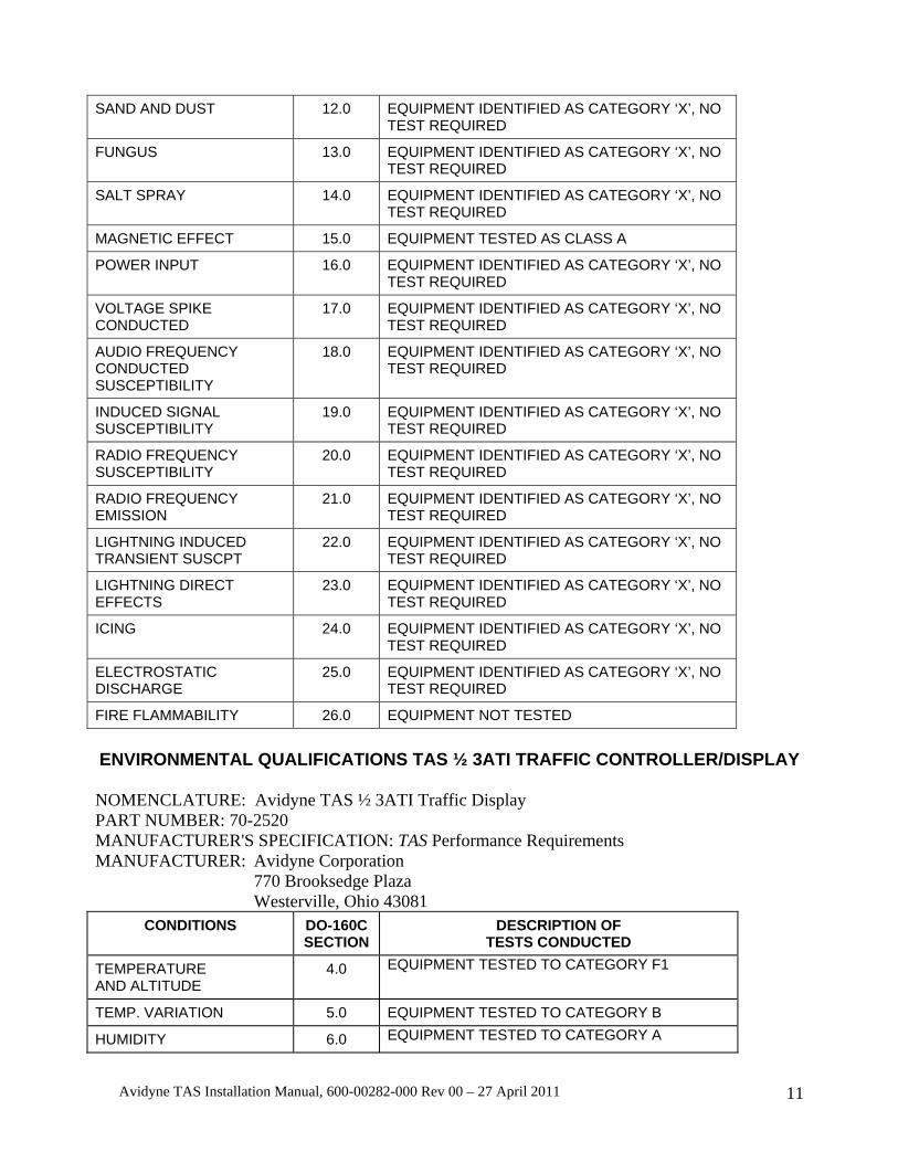
Avidyne TAS Installation Manual, 600-00282-000 Rev 00 – 27 April 2011 11
SAND AND DUST 12.0 EQUIPMENT IDENTIFIED AS CATEGORY ‘X’, NO TEST REQUIRED
FUNGUS 13.0 EQUIPMENT IDENTIFIED AS CATEGORY ‘X’, NO TEST REQUIRED
SALT SPRAY 14.0 EQUIPMENT IDENTIFIED AS CATEGORY ‘X’, NO TEST REQUIRED
MAGNETIC EFFECT 15.0 EQUIPMENT TESTED AS CLASS A
POWER INPUT 16.0 EQUIPMENT IDENTIFIED AS CATEGORY ‘X’, NO TEST REQUIRED
VOLTAGE SPIKE CONDUCTED
17.0 EQUIPMENT IDENTIFIED AS CATEGORY ‘X’, NO TEST REQUIRED
AUDIO FREQUENCY CONDUCTED SUSCEPTIBILITY
18.0 EQUIPMENT IDENTIFIED AS CATEGORY ‘X’, NO TEST REQUIRED
INDUCED SIGNAL SUSCEPTIBILITY
19.0 EQUIPMENT IDENTIFIED AS CATEGORY ‘X’, NO TEST REQUIRED
RADIO FREQUENCY SUSCEPTIBILITY
20.0 EQUIPMENT IDENTIFIED AS CATEGORY ‘X’, NO TEST REQUIRED
RADIO FREQUENCY EMISSION
21.0 EQUIPMENT IDENTIFIED AS CATEGORY ‘X’, NO TEST REQUIRED
LIGHTNING INDUCED TRANSIENT SUSCPT
22.0 EQUIPMENT IDENTIFIED AS CATEGORY ‘X’, NO TEST REQUIRED
LIGHTNING DIRECT EFFECTS
23.0 EQUIPMENT IDENTIFIED AS CATEGORY ‘X’, NO TEST REQUIRED
ICING 24.0 EQUIPMENT IDENTIFIED AS CATEGORY ‘X’, NO TEST REQUIRED
ELECTROSTATIC DISCHARGE
25.0 EQUIPMENT IDENTIFIED AS CATEGORY ‘X’, NO TEST REQUIRED
FIRE FLAMMABILITY 26.0 EQUIPMENT NOT TESTED
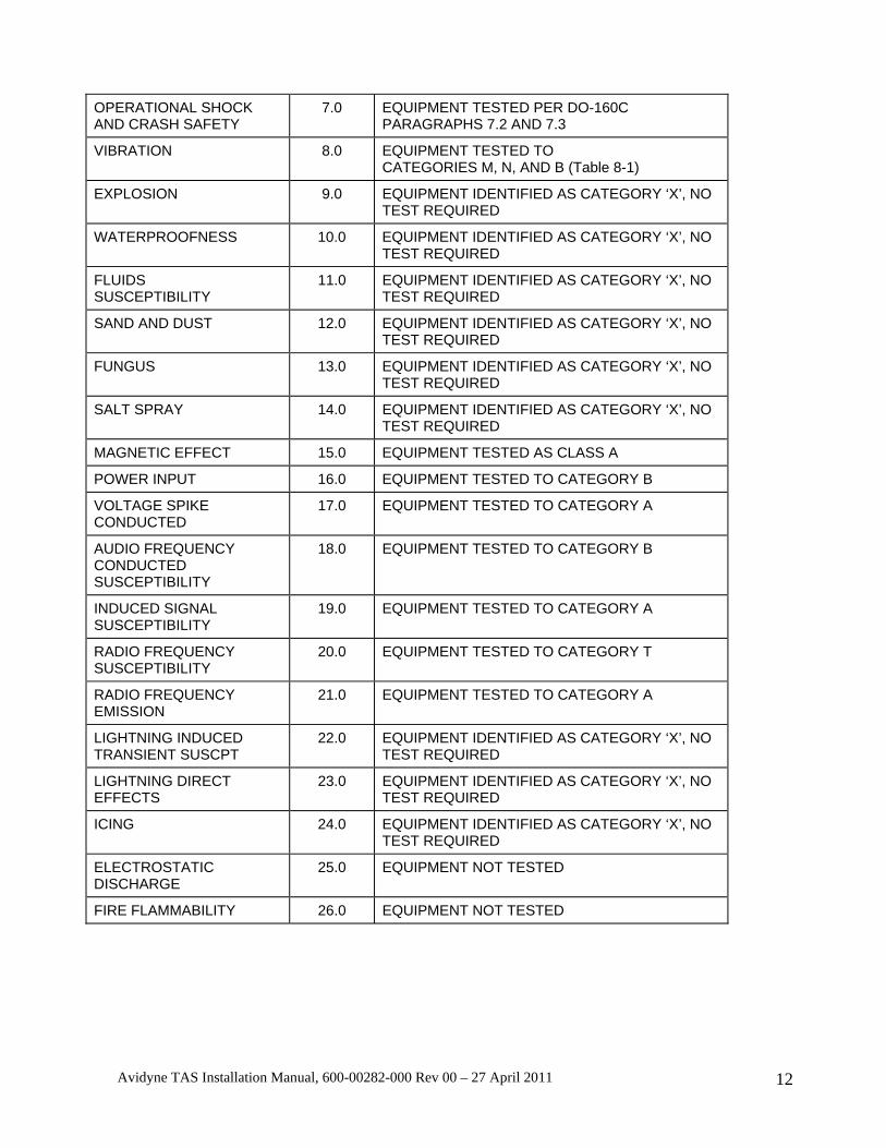
ENVIRONMENTAL QUALIFICATIONS TAS ½ 3ATI TRAFFIC CONTROLLER/DISPLAY NOMENCLATURE: Avidyne TAS ½ 3ATI Traffic Display PART NUMBER: 70-2520 MANUFACTURER'S SPECIFICATION: TAS Performance Requirements MANUFACTURER: Avidyne Corporation 770 Brooksedge Plaza Westerville, Ohio 43081
CONDITIONS DO-160CSECTION
DESCRIPTION OF TESTS CONDUCTED
TEMPERATURE AND ALTITUDE
4.0 EQUIPMENT TESTED TO CATEGORY F1
TEMP. VARIATION 5.0 EQUIPMENT TESTED TO CATEGORY B
HUMIDITY 6.0 EQUIPMENT TESTED TO CATEGORY A
Avidyne TAS Installation Manual, 600-00282-000 Rev 00 – 27 April 2011 12
OPERATIONAL SHOCK AND CRASH SAFETY
7.0 EQUIPMENT TESTED PER DO-160C PARAGRAPHS 7.2 AND 7.3
VIBRATION 8.0 EQUIPMENT TESTED TO CATEGORIES M, N, AND B (Table 8-1)
EXPLOSION 9.0 EQUIPMENT IDENTIFIED AS CATEGORY ‘X’, NO TEST REQUIRED
WATERPROOFNESS 10.0 EQUIPMENT IDENTIFIED AS CATEGORY ‘X’, NO TEST REQUIRED
FLUIDS SUSCEPTIBILITY
11.0 EQUIPMENT IDENTIFIED AS CATEGORY ‘X’, NO TEST REQUIRED
SAND AND DUST 12.0 EQUIPMENT IDENTIFIED AS CATEGORY ‘X’, NO TEST REQUIRED
FUNGUS 13.0 EQUIPMENT IDENTIFIED AS CATEGORY ‘X’, NO TEST REQUIRED
SALT SPRAY 14.0 EQUIPMENT IDENTIFIED AS CATEGORY ‘X’, NO TEST REQUIRED
MAGNETIC EFFECT 15.0 EQUIPMENT TESTED AS CLASS A
POWER INPUT 16.0 EQUIPMENT TESTED TO CATEGORY B
VOLTAGE SPIKE CONDUCTED
17.0 EQUIPMENT TESTED TO CATEGORY A
AUDIO FREQUENCY CONDUCTED SUSCEPTIBILITY
18.0 EQUIPMENT TESTED TO CATEGORY B
INDUCED SIGNAL SUSCEPTIBILITY
19.0 EQUIPMENT TESTED TO CATEGORY A
RADIO FREQUENCY SUSCEPTIBILITY
20.0 EQUIPMENT TESTED TO CATEGORY T
RADIO FREQUENCY EMISSION
21.0 EQUIPMENT TESTED TO CATEGORY A
LIGHTNING INDUCED TRANSIENT SUSCPT
22.0 EQUIPMENT IDENTIFIED AS CATEGORY ‘X’, NO TEST REQUIRED
LIGHTNING DIRECT EFFECTS
23.0 EQUIPMENT IDENTIFIED AS CATEGORY ‘X’, NO TEST REQUIRED
ICING 24.0 EQUIPMENT IDENTIFIED AS CATEGORY ‘X’, NO TEST REQUIRED
ELECTROSTATIC DISCHARGE
25.0 EQUIPMENT NOT TESTED
FIRE FLAMMABILITY 26.0 EQUIPMENT NOT TESTED
Avidyne TAS Installation Manual, 600-00282-000 Rev 00 – 27 April 2011 13
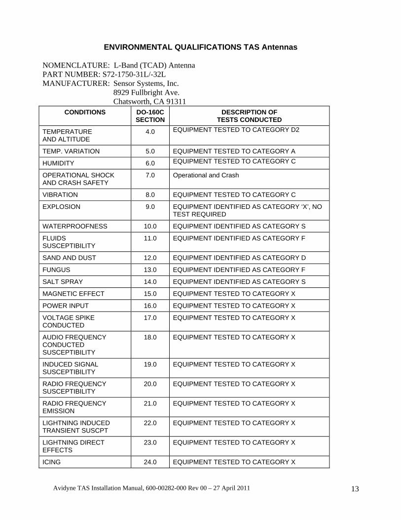
ENVIRONMENTAL QUALIFICATIONS TAS Antennas NOMENCLATURE: L-Band (TCAD) Antenna PART NUMBER: S72-1750-31L/-32L MANUFACTURER: Sensor Systems, Inc. 8929 Fullbright Ave. Chatsworth, CA 91311
CONDITIONS DO-160CSECTION
DESCRIPTION OF TESTS CONDUCTED
TEMPERATURE AND ALTITUDE
4.0 EQUIPMENT TESTED TO CATEGORY D2
TEMP. VARIATION 5.0 EQUIPMENT TESTED TO CATEGORY A
HUMIDITY 6.0 EQUIPMENT TESTED TO CATEGORY C
OPERATIONAL SHOCK AND CRASH SAFETY
7.0 Operational and Crash
VIBRATION 8.0 EQUIPMENT TESTED TO CATEGORY C
EXPLOSION 9.0 EQUIPMENT IDENTIFIED AS CATEGORY ‘X’, NO TEST REQUIRED
WATERPROOFNESS 10.0 EQUIPMENT IDENTIFIED AS CATEGORY S
FLUIDS SUSCEPTIBILITY
11.0 EQUIPMENT IDENTIFIED AS CATEGORY F
SAND AND DUST 12.0 EQUIPMENT IDENTIFIED AS CATEGORY D
FUNGUS 13.0 EQUIPMENT IDENTIFIED AS CATEGORY F
SALT SPRAY 14.0 EQUIPMENT IDENTIFIED AS CATEGORY S
MAGNETIC EFFECT 15.0 EQUIPMENT TESTED TO CATEGORY X
POWER INPUT 16.0 EQUIPMENT TESTED TO CATEGORY X
VOLTAGE SPIKE CONDUCTED
17.0 EQUIPMENT TESTED TO CATEGORY X
AUDIO FREQUENCY CONDUCTED SUSCEPTIBILITY
18.0 EQUIPMENT TESTED TO CATEGORY X
INDUCED SIGNAL SUSCEPTIBILITY
19.0 EQUIPMENT TESTED TO CATEGORY X
RADIO FREQUENCY SUSCEPTIBILITY
20.0 EQUIPMENT TESTED TO CATEGORY X
RADIO FREQUENCY EMISSION
21.0 EQUIPMENT TESTED TO CATEGORY X
LIGHTNING INDUCED TRANSIENT SUSCPT
22.0 EQUIPMENT TESTED TO CATEGORY X
LIGHTNING DIRECT EFFECTS
23.0 EQUIPMENT TESTED TO CATEGORY X
ICING 24.0 EQUIPMENT TESTED TO CATEGORY X
Avidyne TAS Installation Manual, 600-00282-000 Rev 00 – 27 April 2011 14
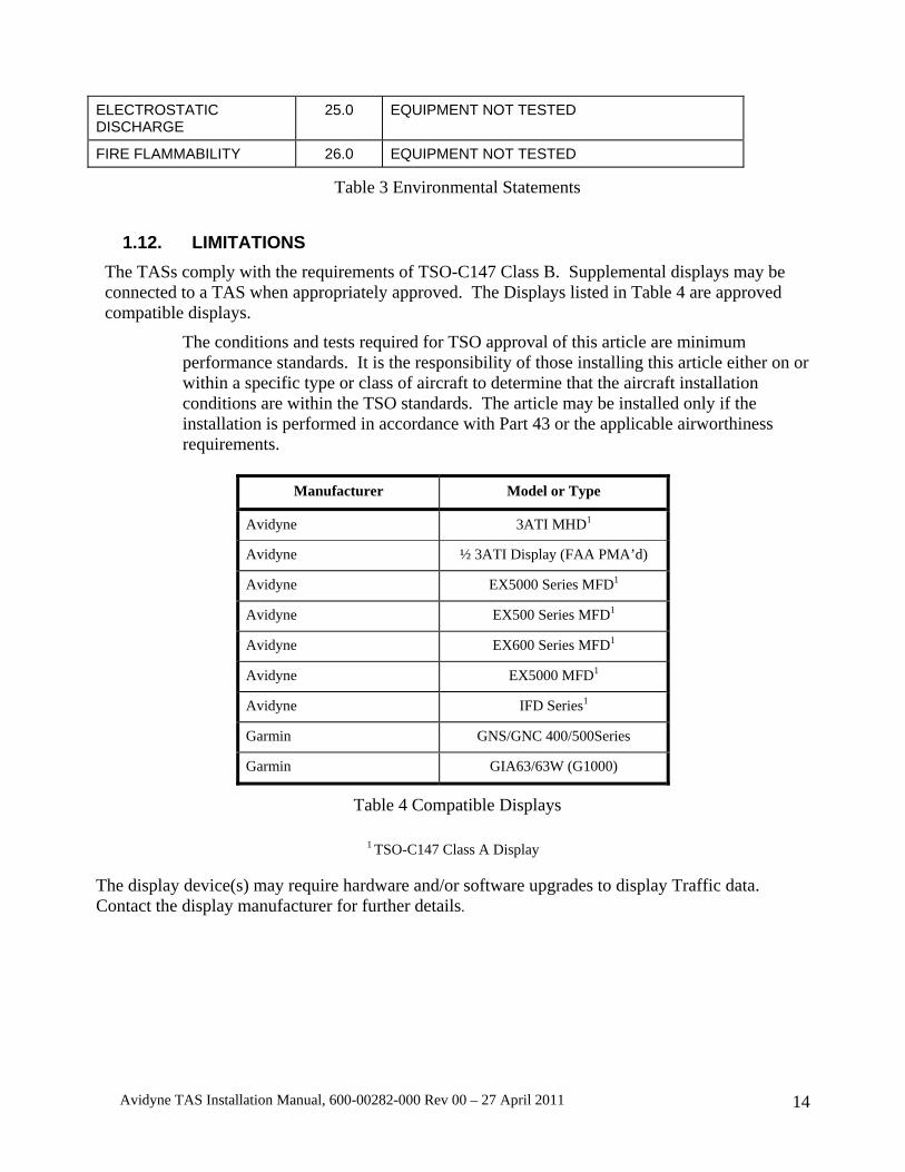
ELECTROSTATIC DISCHARGE
25.0 EQUIPMENT NOT TESTED
FIRE FLAMMABILITY 26.0 EQUIPMENT NOT TESTED
Table 3 Environmental Statements
1.12. LIMITATIONS The TASs comply with the requirements of TSO-C147 Class B. Supplemental displays may be connected to a TAS when appropriately approved. The Displays listed in Table 4 are approved compatible displays.
The conditions and tests required for TSO approval of this article are minimum performance standards. It is the responsibility of those installing this article either on or within a specific type or class of aircraft to determine that the aircraft installation conditions are within the TSO standards. The article may be installed only if the installation is performed in accordance with Part 43 or the applicable airworthiness requirements.
Manufacturer Model or Type
Avidyne 3ATI MHD1
Avidyne ½ 3ATI Display (FAA PMA’d)
Avidyne EX5000 Series MFD1
Avidyne EX500 Series MFD1
Avidyne EX600 Series MFD1
Avidyne EX5000 MFD1
Avidyne IFD Series1
Garmin GNS/GNC 400/500Series
Garmin GIA63/63W (G1000)
Table 4 Compatible Displays
1 TSO-C147 Class A Display
The display device(s) may require hardware and/or software upgrades to display Traffic data. Contact the display manufacturer for further details.

Avidyne TAS Installation Manual, 600-00282-000 Rev 00 – 27 April 2011 15
Verify the Windshear, GPWS and TAS (TAS) voice alerts are compatible. For TAS units with Processor part number suffix of -6 or subsequent, the mute input to the TAS may be used to momentarily override the TAS audio to prioritize TAWS or EGPWS audio. See Section II for more information.
The TASs are limited in the following ways: TAS600 TAS605 TAS610 TAS615 9900BX/
TAS620 What the limit
means Display Range 7nm 13nm 12nm 17nm 21nm This is the
maximum range that non-TA traffic will be displayed
Vertical Filter of Displayed
Traffic
±3500 ft. ±5500 ft. ±3500 ft. ±10,000 ft. ±10,000 ft. This is the maximum altitude
separation that non-TA traffic will be
displayed Maximum Operating Altitude
18,500 ft. 55,000 ft. 25,000 ft. 55,000 ft. 55,000 ft. The TAS has full functionality to the
altitude limit identified.
TSO Certification
TSO-C147 TSO-C147 TSO-C147 TSO-C147 TSO-C147 Each System has full TSO
certification Traffic Alert
Limits The TSO-
C147 Specified warning
times – Not limited in range or altitude
The TSO-C147
Specified warning
times – Not limited in range or altitude
The TSO-C147
Specified warning
times – Not limited in range or altitude
The TSO-C147
Specified warning
times – Not limited in range or altitude
The TSO-C147
Specified warning
times – Not limited in range or altitude
All Traffic alerts are displayed on all
models
ARINC 429 Heading Input
Not included Included Included Included Included Heading input permits rapid
repositioning of targets during high-
rate turns All other features
Included Included Included Included Included Available on all the systems
Table 5 TAS6XX Limitations

Avidyne TAS Installation Manual, 600-00282-000 Rev 00 – 27 April 2011 16
1.13. ARINC 429 INFORMATION The two ARINC-429 receive ports on the Avidyne TAS are identical. Both ports can receive either high-speed or low-speed data. The ports must be the same speed. Both can receive any of the following labels:
164 - Host radio altitude (binary) This input provides for automatic Approach Mode as the aircraft descends. Generally, this application is for aircraft that are operated at airports with a control tower. It is normally not used. 165 - Host radio altitude (BCD) This input is an alternative to label 164. 203 - Pressure altitude (uncorrected, Processor part number suffix of -5 and subsequent). This input can be used instead of the encoder gray code. 204 - MSL altitude (corrected) This input is not currently used 234 - Barometric pressure (mb) This input can be used to permit barometric pressure adjustment from another ARINC 429 communicator on the aircraft. 235 - Barometric pressure (inches Hg). Identical to label 234 except it uses inches of mercury for adjustment. 320 – Magnetic heading (Processor part number suffix of -4 and subsequent) This input is used to improve display performance during turns (TAS605, TAS610, TAS615, TAS620 and 9900BX).
NOTE: Both receive ports must be the same speed. Both ports can receive either high-speed or low-speed data. If this is not followed, the TAS will fail to receive data from one of the ports. The same label should not be transmitted to the TAS on both ports as this can create an unsatisfactory mixed signal condition. Dual Air Data Computers (ADC) operating simultaneously and transmitting on the 429 data bus will permit the TAS to operate properly, however failure of one ADC will generate failure indications on the TAS.
The Avidyne TASs transmit ARINC-429 data at the high-speed data rate. A data file is sent twice per second. Our data is ARINC-735 compliant. For a complete description of the label formats, refer to the ARINC-735A and ARINC-429 Part 1-16 documents. Up to 30 targets are supported, sent in priority order as required by ARINC-735.
Each data set contains the following sequence of ARINC-429 labels: 377 - Equipment ID 035 371 - General Aviation Equipment ID 350 - Maintenance data / TCAS Fault Summary Word 274 - Selected Sensitivity Level 016 - TCAS Mode/Sense 270 - TCAS vertical RA data output word (SSM=Test (demo) or NCD) 015 - Altitude Select Limits Word 203 - Own Aircraft Altitude (uncorrected) 320 - Magnetic Heading (Processor part number suffix of -4 and subsequent) 357 - RTS (Start of the traffic data file) 130 - Intruder Range 131 - Intruder Altitude 132 - Intruder Bearing

Avidyne TAS Installation Manual, 600-00282-000 Rev 00 – 27 April 2011 17
Labels 130, 131 and 132 are repeated for each intruder 357 - ETX (End of the traffic data file)
Label 371 is formatted as follows: Company code: 27 (011011) EQ Code: 0x35 (0011 0101) Company Private: 0 (00000)
1.14. NO AVIDYNE DISPLAY CONFIGURATION When a display other than an Avidyne display is used, it is not always possible to take the TAS out of Ground Mode. The pilot should always have the ability to take the TAS out of Ground Mode. If the installation includes the Avidyne/Ryan ½ 3ATI controller/display or the Avidyne/Ryan MHD (using RS-232 connection), then this requirement is fulfilled. Other displays may or may not provide the ability to take the TAS out of the Ground Mode. Displays that use ARINC 429 input from the TAS do not have the ability to take the TAS out of Ground Mode.
NOTE: If at least one of the display systems operating with the TAS has a control to take the TAS out of Ground mode, then the “No Avidyne Display” jumper (Pin 15 of J1) need not be grounded. When Pin 15 is jumpered to ground, use Weight on Wheels (or equivalent) for customer convenience.
Pin 15 of J1 prevents the TAS from entering the Ground mode upon startup unless the Weight on Wheels input shows the aircraft is on the ground. The following table illustrates the configuration of Pin 15 of J1
Several displays can be connected to the TAS. If any of the displays can be used to exit the Ground Mode, then Pin 15 need not be jumpered.
Configuration Pin 15 of J1 Condition
Avidyne ½ 3ATI Traffic Controller/display (Allows access to deselect the Ground Mode)
Not jumpered
Automatic, encoder-based Ground mode on startup is available.
Avidyne/Ryan Multi-Hazard Display (MHD) with RS-232 connection (Allows access to deselect the Ground Mode)
Not jumpered
Automatic, encoder-based Ground mode on startup is available.
RS-232 Display that allows access to deselect the Ground Mode
Not jumpered
Automatic, encoder-based Ground mode on startup is available.
Any ARINC 429 display connection
Jumpered Automatic, encoder-based Ground mode on startup is disabled.
No Display at all Jumpered Automatic, encoder-based Ground mode on startup is disabled.
RS-232 Display that does not allow Jumpered Automatic, encoder-based Ground mode
Avidyne TAS Installation Manual, 600-00282-000 Rev 00 – 27 April 2011 18
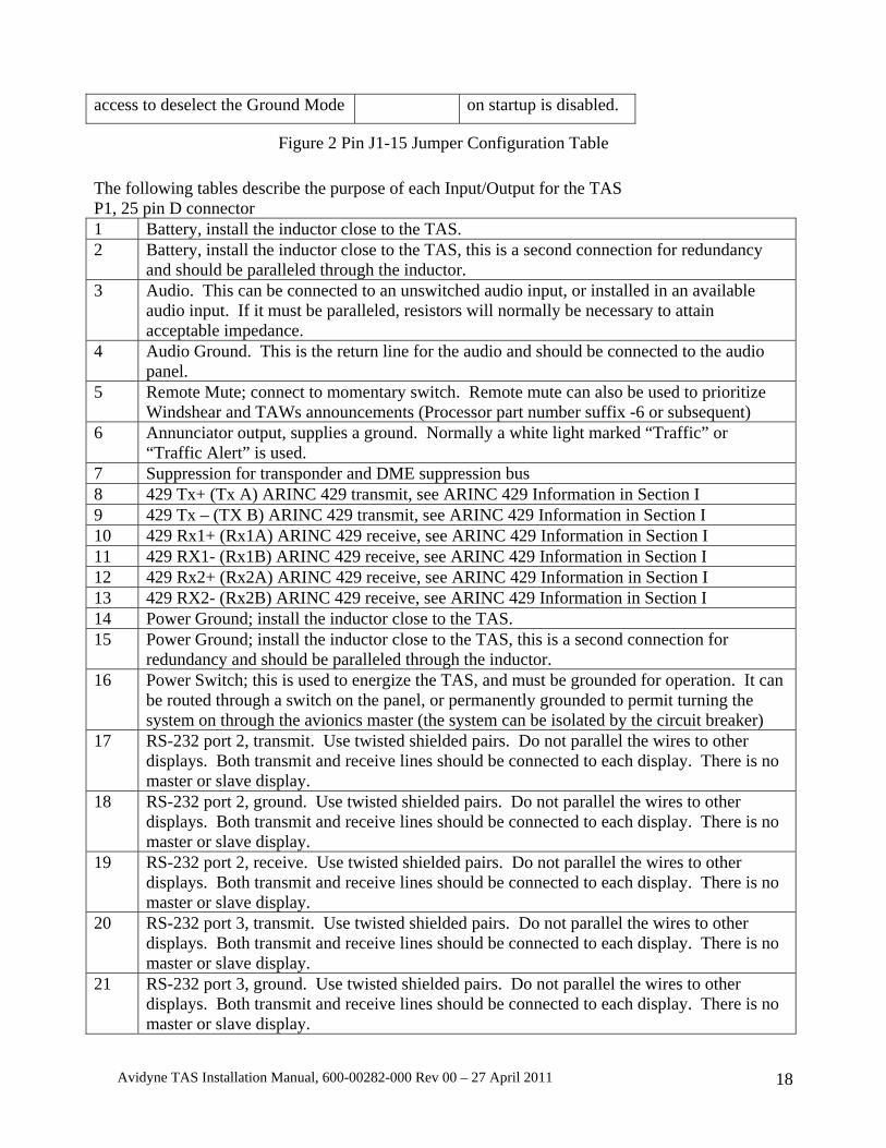
access to deselect the Ground Mode on startup is disabled.
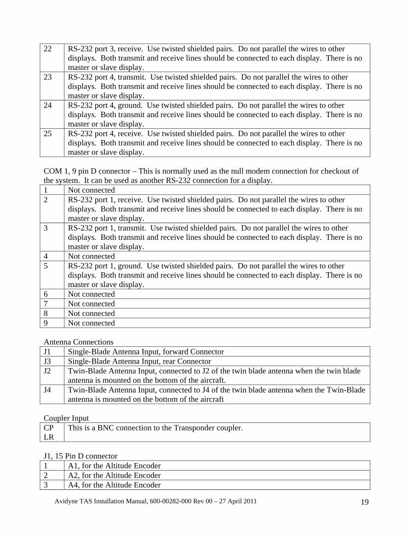
Figure 2 Pin J1-15 Jumper Configuration Table The following tables describe the purpose of each Input/Output for the TAS P1, 25 pin D connector 1 Battery, install the inductor close to the TAS. 2 Battery, install the inductor close to the TAS, this is a second connection for redundancy
and should be paralleled through the inductor. 3 Audio. This can be connected to an unswitched audio input, or installed in an available
audio input. If it must be paralleled, resistors will normally be necessary to attain acceptable impedance.
4 Audio Ground. This is the return line for the audio and should be connected to the audio panel.
5 Remote Mute; connect to momentary switch. Remote mute can also be used to prioritize Windshear and TAWs announcements (Processor part number suffix -6 or subsequent)
6 Annunciator output, supplies a ground. Normally a white light marked “Traffic” or “Traffic Alert” is used.
7 Suppression for transponder and DME suppression bus 8 429 Tx+ (Tx A) ARINC 429 transmit, see ARINC 429 Information in Section I 9 429 Tx – (TX B) ARINC 429 transmit, see ARINC 429 Information in Section I 10 429 Rx1+ (Rx1A) ARINC 429 receive, see ARINC 429 Information in Section I 11 429 RX1- (Rx1B) ARINC 429 receive, see ARINC 429 Information in Section I 12 429 Rx2+ (Rx2A) ARINC 429 receive, see ARINC 429 Information in Section I 13 429 RX2- (Rx2B) ARINC 429 receive, see ARINC 429 Information in Section I 14 Power Ground; install the inductor close to the TAS. 15 Power Ground; install the inductor close to the TAS, this is a second connection for
redundancy and should be paralleled through the inductor. 16 Power Switch; this is used to energize the TAS, and must be grounded for operation. It can
be routed through a switch on the panel, or permanently grounded to permit turning the system on through the avionics master (the system can be isolated by the circuit breaker)
17 RS-232 port 2, transmit. Use twisted shielded pairs. Do not parallel the wires to other displays. Both transmit and receive lines should be connected to each display. There is no master or slave display.
18 RS-232 port 2, ground. Use twisted shielded pairs. Do not parallel the wires to other displays. Both transmit and receive lines should be connected to each display. There is no master or slave display.
19 RS-232 port 2, receive. Use twisted shielded pairs. Do not parallel the wires to other displays. Both transmit and receive lines should be connected to each display. There is no master or slave display.
20 RS-232 port 3, transmit. Use twisted shielded pairs. Do not parallel the wires to other displays. Both transmit and receive lines should be connected to each display. There is no master or slave display.
21 RS-232 port 3, ground. Use twisted shielded pairs. Do not parallel the wires to other displays. Both transmit and receive lines should be connected to each display. There is no master or slave display.
Avidyne TAS Installation Manual, 600-00282-000 Rev 00 – 27 April 2011 19
22 RS-232 port 3, receive. Use twisted shielded pairs. Do not parallel the wires to other displays. Both transmit and receive lines should be connected to each display. There is no master or slave display.
23 RS-232 port 4, transmit. Use twisted shielded pairs. Do not parallel the wires to other displays. Both transmit and receive lines should be connected to each display. There is no master or slave display.
24 RS-232 port 4, ground. Use twisted shielded pairs. Do not parallel the wires to other displays. Both transmit and receive lines should be connected to each display. There is no master or slave display.
25 RS-232 port 4, receive. Use twisted shielded pairs. Do not parallel the wires to other displays. Both transmit and receive lines should be connected to each display. There is no master or slave display.
COM 1, 9 pin D connector – This is normally used as the null modem connection for checkout of the system. It can be used as another RS-232 connection for a display. 1 Not connected 2 RS-232 port 1, receive. Use twisted shielded pairs. Do not parallel the wires to other
displays. Both transmit and receive lines should be connected to each display. There is no master or slave display.
3 RS-232 port 1, transmit. Use twisted shielded pairs. Do not parallel the wires to other displays. Both transmit and receive lines should be connected to each display. There is no master or slave display.
4 Not connected 5 RS-232 port 1, ground. Use twisted shielded pairs. Do not parallel the wires to other
displays. Both transmit and receive lines should be connected to each display. There is no master or slave display.
6 Not connected 7 Not connected 8 Not connected 9 Not connected Antenna Connections J1 Single-Blade Antenna Input, forward Connector J3 Single-Blade Antenna Input, rear Connector J2 Twin-Blade Antenna Input, connected to J2 of the twin blade antenna when the twin blade
antenna is mounted on the bottom of the aircraft. J4 Twin-Blade Antenna Input, connected to J4 of the twin blade antenna when the Twin-Blade
antenna is mounted on the bottom of the aircraft Coupler Input CP LR
This is a BNC connection to the Transponder coupler.
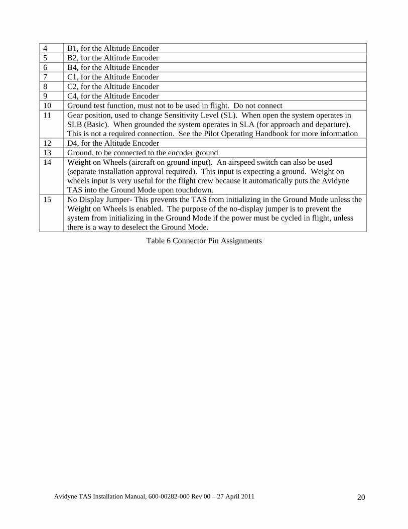
J1, 15 Pin D connector 1 A1, for the Altitude Encoder 2 A2, for the Altitude Encoder 3 A4, for the Altitude Encoder
Avidyne TAS Installation Manual, 600-00282-000 Rev 00 – 27 April 2011 20
4 B1, for the Altitude Encoder 5 B2, for the Altitude Encoder 6 B4, for the Altitude Encoder 7 C1, for the Altitude Encoder 8 C2, for the Altitude Encoder 9 C4, for the Altitude Encoder 10 Ground test function, must not to be used in flight. Do not connect 11 Gear position, used to change Sensitivity Level (SL). When open the system operates in
SLB (Basic). When grounded the system operates in SLA (for approach and departure). This is not a required connection. See the Pilot Operating Handbook for more information
12 D4, for the Altitude Encoder 13 Ground, to be connected to the encoder ground 14 Weight on Wheels (aircraft on ground input). An airspeed switch can also be used
(separate installation approval required). This input is expecting a ground. Weight on wheels input is very useful for the flight crew because it automatically puts the Avidyne TAS into the Ground Mode upon touchdown.
15 No Display Jumper- This prevents the TAS from initializing in the Ground Mode unless the Weight on Wheels is enabled. The purpose of the no-display jumper is to prevent the system from initializing in the Ground Mode if the power must be cycled in flight, unless there is a way to deselect the Ground Mode.
Table 6 Connector Pin Assignments
Avidyne TAS Installation Manual, 600-00282-000 Rev 00 – 27 April 2011 21
SECTION II INSTALLATION
2.1. GENERAL The Avidyne TAS should be installed according to this manual and AC 43.13-1( ) and AC 43.13-2( ). This Section contains interconnect diagrams, mounting dimensions, antenna placement and other information pertaining to installation. See Section VI for installation tips.
The Avidyne TAS consists of two major components, plus antennas: • Processor with Mounting Tray • Transponder Coupler
Two special L-band directional antennas are required. The single blade antenna is normally top mounted on the aircraft fuselage, and the dual blade is normally bottom mounted. For more information see paragraph 6.2.2. A ½ 3ATI Traffic Controller/display is optional, and is not part of the TSO’d system. Figure 3 illustrates the two major components and the display.
Refer to Section IV for checkout and Customer Care checklist.
Interference from DME and the transponder can affect the TAS performance. Inspect the transponder (s) and DME(s) to assure performance is within specification. Also check for frayed or loose coaxial connections or excessive bends in the antenna cables that could emit Electromagnetic Interference (EMI), especially L-Band interference such as the transponder or DME.
Exercise care when unpacking the equipment. Make a visual inspection of the unit for evidence of damage incurred during shipment. If a claim for damage is to be made, save the shipping container to substantiate the claim. The claim should be filed with the transportation company. Retain the container and packaging material after the equipment has been removed should equipment storage or reshipment become necessary.
2.2. TRANSPONDER AND ENCODER REQUIREMENTS The on-board transponder(s) must accept suppression input (often called DME or mutual suppression). An altitude data source is required. Encoders that conform to TSO-C88 or-C88A can be used. The TAS can normally be paralleled on the output of an encoder without degrading the encoder performance. The installing agency must make this determination. TAS altitude input lines are diode isolated internally. The altimetry source used for the TAS must meet the accuracy requirements of CFR Part 43, Appendix E or equivalent.
Ordinarily, TAS should be connected to the encoder that is connected to the transponder. Altitude data can be received via ARINC 429 protocol in lieu of gray code. Processor part number suffix of -5 or subsequent can use altitude data from a source using ARINC 429 communications protocol. See paragraph 1.13, ARINC 429 Information.

Avidyne TAS Installation Manual, 600-00282-000 Rev 00 – 27 April 2011 22
Figure 3 TAS Components including optional ½ 3ATI Traffic Controller/display (Antennas not shown)

Avidyne TAS Installation Manual, 600-00282-000 Rev 00 – 27 April 2011 23
Figure 4 The Avidyne Multi-Hazard Display (MHD)
See the MHD Installation Manual or STC 02061CH for installation data.

Avidyne TAS Installation Manual, 600-00282-000 Rev 00 – 27 April 2011 24
2.3. SUPPRESSION Transponder and DME suppression are required for TAS operation. The TAS sends and receives positive-going suppression signals. The outgoing suppression amplitude is approximately battery voltage.
DME suppression is used to ensure the DME does not interfere with the transponder or the TAS. Interference that causes transponder squitter (unsolicited replies) from any source reduces data available to the TAS. See Transponder Suppression Section VI.
The TAS is compatible with both mutual and unidirectional suppression systems. Table 7 below lists the availability of suppression for popular transponders.
The TAS suppression can be connected directly to any ARINC-standard mutual suppression bus. Not all suppression busses conform to ARINC standards. See the Note below.
NOTE: Not all transponder suppression configurations conform to ARINC standards. See Electrical Wiring of Suppression in this Section for conformance information.
NOTE: A momentary short to ground on the Suppression line will cause internal damage to the Processor, requiring repair at the factory
Manufacturer Model Suppression Remarks
ARC 359 459 859 1060
Yes Yes Yes Yes
Must be modified to accept suppression. Contact Sigma Tek, Inc.
Collins TDR-950 All Others
Yes Yes
Some must be modified to accept suppression. See Collins Manual.
King KT 76 KT 78
KT 76A KT 78A
All Others
None None Yes Yes Yes
Not compatible Not compatible See Figure 13 See Figure 13
Narco AT-50 AT-50A
All Others
Yes Yes Yes
Garmin All Yes Terra Radair 250
TRT 250 N/A N/A
These transponders are not compatible with the TAS
Table 7 Availability of Suppression for Popular Transponders
Avidyne TAS Installation Manual, 600-00282-000 Rev 00 – 27 April 2011 25
2.4. ANNUNCIATOR OUTPUT AND MUTE/UPDATE FUNCTION The Mute/Update function is required. The function is available in the ½ 3ATI controller/display. For all other display options (including no display) a remote Mute/Update button must be used. The switch provides audible updates and muting of Traffic Alerts. For TAS processors with a part number suffix of -6 or subsequent, the Remote Mute input can also be used to prioritize the TAS with EGPWS/TAWS systems.
An annunciator light is required when no display is used. The annunciator light is recommended for all other applications because it places the TA indication in the pilot’s line of sight, and when the light extinguishes the pilot is thus informed that the TA is no longer valid.
A switched ground is available from the Processor Unit for illuminating the annunciator light. The output is grounded when traffic is displayed, and the circuit opens when traffic is no longer displayed. The light should be white or amber, and marked “Traffic” or “Traffic Alert”. The light should be dimmable, and clearly visible to the pilot.
NOTE: The annunciator circuit supplies a ground. Applying a voltage to this input will damage the TAS Processor.
The maximum current through the annunciator output must be limited to 100mA.
2.5. PRIORITIZATION WITH WINDSHEAR AND EGPWS/TAWS For TAS processors with a part number suffix of -6 or subsequent, the Remote Mute input can also be used to prioritize the TAS with Windshear and EGPWS/TAWS systems.
2.6. RS-232 COMMUNICATIONS The TAS communicates information to certain displays using a proprietary RS-232 protocol. Many popular displays use this protocol. The communication is bi-directional, meaning the display information can be transmitted and requests can be sent from the display to the TAS. Features such as N-number display, altitude alerter, and Approach mode can only be communicated by RS-232. Not all displays utilize all features. RS-232, if available, is the preferred communications protocol. The display manufacturers have information regarding the interface capability of their equipment with the TAS. The Avidyne ½ 3ATI indicator uses RS-232 communications. The MHD is capable of ARINC 429 communication, but RS-232 is preferred.
NOTE: RS-232 transmit and receive must be connected for all RS-232 connections. Each port must be connected to only one display. Do not parallel connections.
2.7. ARINC 429 COMMUNICATIONS
The TAS transmits information to certain displays using standard ARINC 429 protocol. Many popular displays use this protocol. The communication is one way, meaning the display information is only transmitted. Features such as N-number display, altitude alerter, and Approach mode are not available.
Avidyne TAS Installation Manual, 600-00282-000 Rev 00 – 27 April 2011 26
NOTE: The Avidyne Multi-Hazard Display is capable of either RS-232 or ARINC 429 communication. RS-232 provides all the features described in the Avidyne MHD Traffic Application manual. ARINC 429 communication does not.
See Section 1.13, ARINC 429 Information.
2.8. GEAR POSITION AND WEIGHT-ON-WHEELS
Discrete inputs are provided for gear position and weight-on-wheels (aircraft on ground). The gear position input changes the Sensitivity Level (SL) of the TAS from SL B (gear up) to SL A when the gear is down. The TAS expects a ground when the landing gear is down. If gear position is impractical or unavailable, leave the input unconnected.
The weight-on-wheels input adds convenience for the flight crew by allowing automatic enabling of the Ground mode upon landing. The TAS expects a ground when the aircraft is on the ground. If an aircraft on-ground input is impractical or unavailable, leave the input unconnected.
Both of these inputs are internally diode isolated as shown in the Internal Diode Isolation diagram, see Figure 15.
2.9. COOLING
Elevated operating temperatures reduce reliability. Allow sufficient space around the Processor and the ½ 3ATI Traffic Display to allow adequate convective cooling.
2.10. ANTENNA PLACEMENT CONSIDERATIONS
The top antenna should be mounted as high up and as far forward as practical, normally directly above the cockpit. Mounting the antenna aft of this location will usually result in unsatisfactory performance. The antenna should be a minimum of twelve inches aft of the windshield, with a minimum of 12 inches of undisturbed ground plane around the antenna (See Section VI).
The bottom antenna should be toward the front of the aircraft and at least 36 inches from other L-band transmitting antennas. Twelve inches of undisturbed ground plane with no large obstructions beyond is needed for best bearing performance. See the Mechanical Installation of Antennas paragraph in this Section. Section VI contains additional information on antenna placement.
Avidyne TAS Installation Manual, 600-00282-000 Rev 00 – 27 April 2011 27
NOTE: The following statement from Sensor Systems, the manufacturer of the TAS antennas, constitutes the antenna considerations with respect to icing:
“The S72-1750-31L/-32L L-Band (TAS) antennas have not been tested for icing per RTCA/DO-160C, Section 24.0. The design and shape of these antennas with the slanted 40° leading edge, the thin airfoil section, less than 13%, and low profile 2.75 inches, preclude ice from accumulating. Typically, ice has very little, if any, effect on the electrical performance of this type of antenna.
Because of the small size of this antenna, there could not be enough ice accumulation to degrade the aerodynamic performance of the aircraft.
The TAS antennas are designed for speeds up to Mach 0.8.”
The two top antenna coax cables should be the same length. The bottom antenna cables should also be the same length. See Table 2.
2.11. TRANSPONDER COUPLER The Transponder Coupler supplies the Processor with a signal indicating the transponder is transmitting a reply.
The Transponder Coupler is required for each transponder to provide a blanking pulse to prevent display of the host transponder. The Transponder Coupler is normally installed near the transponder, behind the instrument panel or in the equipment rack.
When routing the Coupler Cable, make the run as short as practical, and avoid routing with any cable that may emit excessive EMI, such as DME, transponder cables, suppression lines from other equipment or high-current power cables.
When mounting the Transponder Coupler, use the type-N connectors provided. Use of BNC to Type-N adapters can increase the VSWR in the transponder cabling. Check the output frequency of the transponder at its antenna after installing the Coupler to ensure that a standing wave has not been introduced.
NOTE: Ensure that the mounting location for the coupler is accessible and at a location that provides a good ground. Normally, the mounting tray or avionics rack is not a good ground.
2.12. CHECKOUT PRECAUTIONS The TAS antenna outputs require connection to antennas or to 50-ohm loads whenever power is applied. Failure to do so could result in damage to the TAS transmitter. Before applying power, double check power, ground, suppression and annunciator lines for proper connection. Improper connections can result in severe damage to the TAS.
2.13. MECHANICAL INSTALLATION OF THE OPTIONAL ½ 3ATI TRAFFIC CONTROLLER/DISPLAY
The optional ½ 3ATI Traffic Display is rigidly mounted in the instrument panel, and is secured using the clamp provided. The instrument panel should be a minimum thickness of .050”, 2024-T3 QQ-A-250/5 Aluminum. If the instrument panel is less than .050” or is not made of 2024-T3 QQ-A-250/5 Aluminum, additional engineering approval will be required. Allow adequate space for

Avidyne TAS Installation Manual, 600-00282-000 Rev 00 – 27 April 2011 28
installation of cables and connectors.
The ½ 3ATI Controller/Display should be installed in a location that will not produce objectionable glare or reflections that may affect the Pilot’s vision. Also, install the display in a location where controls are readily accessible and the display is readable without undue effort when seated in the pilot position. Replacing or relocating instruments or controls is not covered by this installation manual, separate approval is required.
NOTE: Any deviations from this Installation Manual will require additional engineering approval.
CAUTION: When removing the Display, do not pull the ON/OFF switch. Pull from behind the trim ring of the bezel.
(Dimensions in inches)
Figure 5 Avidyne ½ 3ATI Traffic Controller/Display Mounting and Dimensions

Avidyne TAS Installation Manual, 600-00282-000 Rev 00 – 27 April 2011 29
(Dimensions in inches)
Figure 6 Panel Cutout for optional ½ 3ATI Traffic Controller/Display

Avidyne TAS Installation Manual, 600-00282-000 Rev 00 – 27 April 2011 30
2.14. MECHANICAL INSTALLATION OF PROCESSOR Listed below are factors and suggestions to consider before installing the TAS Processor and Mounting Tray. Close adherence to these suggestions will assure optimum performance. Also refer to FAA Advisory Circular 43.13-( ) as needed.
A. Allow adequate space for installation of cables and connectors.
B. Install the Processor in the avionics bay. The avionics shelf must be a minimum .050” 2024-T3 QQ-A-250/5 Aluminum (Note: Sheet metal doublers may be installed to achieve an Avionics Shelf base thickness of .050”). If the avionics bay shelf is less than .050” or is not made of 2024-T3 QQ-A-250/5 Aluminum, additional engineering approval will be required. If installed at a location other than the avionics bay, the location should be structurally substantiated.
(Dimensions in inches)

Avidyne TAS Installation Manual, 600-00282-000 Rev 00 – 27 April 2011 31
Figure 7 Processor Mounting Tray
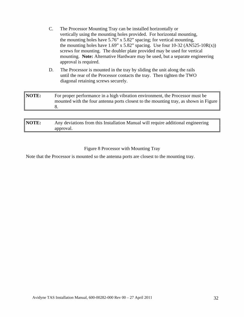
Avidyne TAS Installation Manual, 600-00282-000 Rev 00 – 27 April 2011 32
C. The Processor Mounting Tray can be installed horizontally or vertically using the mounting holes provided. For horizontal mounting, the mounting holes have 5.76” x 5.82” spacing; for vertical mounting, the mounting holes have 1.69” x 5.82” spacing. Use four 10-32 (AN525-10R(x)) screws for mounting. The doubler plate provided may be used for vertical mounting. Note: Alternative Hardware may be used, but a separate engineering approval is required.
D. The Processor is mounted in the tray by sliding the unit along the rails until the rear of the Processor contacts the tray. Then tighten the TWO diagonal retaining screws securely.
NOTE: For proper performance in a high vibration environment, the Processor must be mounted with the four antenna ports closest to the mounting tray, as shown in Figure 8.
NOTE: Any deviations from this Installation Manual will require additional engineering approval.
Figure 8 Processor with Mounting Tray
Note that the Processor is mounted so the antenna ports are closest to the mounting tray.
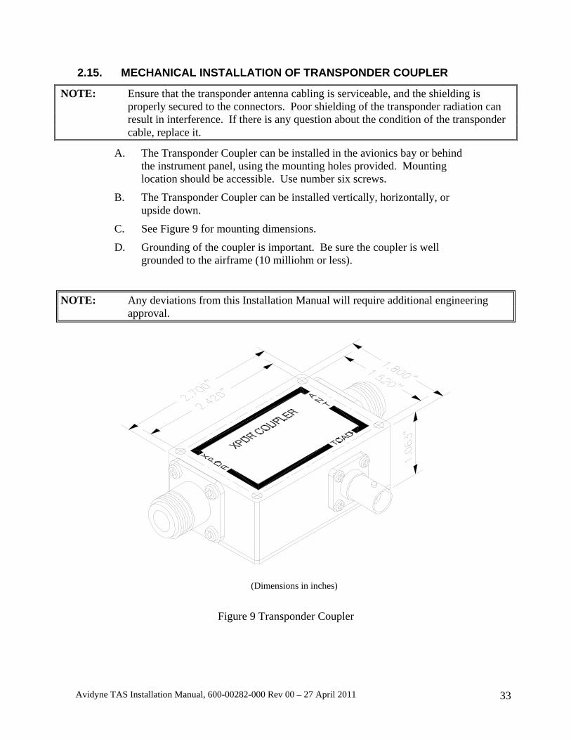
Avidyne TAS Installation Manual, 600-00282-000 Rev 00 – 27 April 2011 33
2.15. MECHANICAL INSTALLATION OF TRANSPONDER COUPLER
NOTE: Ensure that the transponder antenna cabling is serviceable, and the shielding is properly secured to the connectors. Poor shielding of the transponder radiation can result in interference. If there is any question about the condition of the transponder cable, replace it.
A. The Transponder Coupler can be installed in the avionics bay or behind the instrument panel, using the mounting holes provided. Mounting location should be accessible. Use number six screws.
B. The Transponder Coupler can be installed vertically, horizontally, or upside down.
C. See Figure 9 for mounting dimensions.
D. Grounding of the coupler is important. Be sure the coupler is well grounded to the airframe (10 milliohm or less).
NOTE: Any deviations from this Installation Manual will require additional engineering approval.
(Dimensions in inches)
Figure 9 Transponder Coupler

Avidyne TAS Installation Manual, 600-00282-000 Rev 00 – 27 April 2011 34
2.16. MECHANICAL INSTALLATION OF ANTENNAS Refer to FAA Advisory Circular 43.13-2( ) and other approved guidance for instructions on proper antenna and doubler plate installation and sealing. Any deviations from FAA Advisory Circular 43.13-2( ) requires separate structural approval.
NOTE: The Installing agency is responsible for structural substantiation of the antenna locations. See Section VI for more information.
The TAS normally uses the single blade antenna as the top antenna, and the twin blade antenna the bottom antenna. This is not always the optimum configuration, and the positions may be switched if circumstances warrant it. See Section VI.
CAUTION: Proper antenna location is important. It is best for one of the two antennas to have line-of-sight to threat aircraft. This is not always possible for every direction from the host aircraft. The antenna should be toward the forward part of the host aircraft. See Section VI for additional information.
Figure 10 Recommended Antenna Locations
A. Locate the L-band antenna on the top surface of the aircraft as high on the airframe and as far forward as practical. Mount close to the aircraft centerline and in normal (the base of the antenna is horizontal) position when the aircraft is in level flight. Generally, the antenna mounts above the cockpit.
NOTE: Customer satisfaction is directly related to the proper location of the top antenna.
B. The antennas should be mounted on a conductive surface, at least 18-inches from access panels, doors, or other openings to provide a good ground plane. To the extent practicable, mount the antenna so the base is horizontal when the aircraft is in cruise attitude. The antenna base must be electrically bonded to the airframe and ground plane. Remove nonconductive material from the aircraft skin where the antenna will be mounted to assure sufficient electrical bonding. AC 43.13-2( ) describes acceptable techniques for antenna mounting and corrosion protection.

Avidyne TAS Installation Manual, 600-00282-000 Rev 00 – 27 April 2011 35
NOTE: A satisfactory ground plane is necessary for optimum performance. An adequate ground plane and satisfactory bonding of the antenna to the ground plane is important for reliable bearing data. Completely remove the paint from under the antenna to within 0.1 inch of the edge of the antenna for proper ground plane RF connection. The antenna must be mounted so the bare metal of the aircraft skin touches the entire metal base plate of the antenna. Electrical bonding resistance of the installed antenna to the aircraft skin should be .01 ohm or less. Composite airframes are especially challenging. See Section VI for more information about installation on metal and non-metal fuselages.
C. Avoid mounting either antenna within two feet of other antennas, or physical obstructions (three feet for DME or transponder antennas).
NOTE: Some DME and transponder designs permit high-energy Continuous Wave (CW) emissions at the TAS reception frequency, which can affect TAS performance. In order to reduce the possibility of interference, the DME and transponder antenna cables and terminations must be effectively shielded. The three-foot antenna separation requirement is essential to minimize interference from DMEs and transponders with high CW levels. Failure to heed these requirements can result in reduced reception range of the TAS.
D. The cable lengths must be matched and not exceed the 3dB requirement. See Section I.
E. Avoid mounting the bottom antenna where exhaust or oil will contaminate the surface of the antenna.
2.17. OVERVIEW OF ELECTRICAL INSTALLATION The block diagram of electrical wiring in this section provides an overview of TAS wiring. This simplified illustration depicts the basic elements of the electrical wiring, and allows the installer to better comprehend the total installation before proceeding with detailed steps.
The 9-pin connector on the Processor marked “COM 1” is for an external computer interface with the TAS, and is used for setup when the optional ½ 3ATI Traffic Display is not used. COM 1 is another RS-232 port, and may be used to interface with an additional display. The provided COM 1 shunt contains a jumper that must be installed when the COM1 port is not being used.
Compass heading may be connected via ARINC 429 (Label 320). Compass heading is optional and assists in rapid traffic orientation during turns.
All wiring should be secured to prevent chafing and faulty connections. Ensure all wiring is installed clear of all flight controls and flight control cables. Refer to Advisory Circular 43.13-1( ).
Refer to FAA Advisory Circular 43.13-1 ( ) for selecting the appropriate wire size and type.
NOTE: The TAS processor antenna terminations must be connected to antennas or 50 ohm
loads before applying power the Processor. Failure to connect the antenna terminations can cause transmitter damage.
Avidyne TAS Installation Manual, 600-00282-000 Rev 00 – 27 April 2011 36
2.18. INSTALLATION WITHOUT A DISPLAY Pin 16 on P1 of the Processor is used to energize the TAS. The pin must be grounded, either through a switch on the instrument panel or by permanently grounding pin 16 to permit energizing the system through the avionics master switch. The system can then be isolated with the circuit breaker.
A momentary-on remote mute switch, labeled “Mute/Update”, and an annunciator light, labeled “Traffic” or “Traffic Alert” must be installed. Install in a location accessible to the flight crewmembers.
The “No display” jumper, pin 15 of J1 must be installed. See Table 7 and Section VI.
2.19. INSTALLATION WITH A MULTI-FUNCTION DISPLAY Any RS-232 port (RX/TX/GND 2, RX/TX/GND 3, or RX/TX/GND 4) on the TAS Processor may be used to connect to a compatible Multi-Function display (see the wiring diagrams in this section). The transmit line (TX) must be connected to the display receive line, and the receive line (RX) must be connected to the transmit line. Use twisted, shielded pairs or triples, as described in Section 1.
Any combination of displays may be installed using the RS-232 ports and the ARINC 429 ports. Only one device can be connected to an RS-232 port. More than one display can be connected to the ARINC 429 port. See Section VI for more information.
NOTE: If display systems operating with the TAS have a control to take the TAS out of Ground mode, then the “No Avidyne Display” jumper (Pin 15 of J1) need not be grounded. When Pin 15 is jumpered to ground, use Weight on Wheels (or equivalent) for customer convenience.
NOTE: The RS-232 transmit and receive lines from each device must be connected to the
TAS to meet bi-directional communication requirements. Each display should be connected to its own RS-232 Processor port. There is no distinction of a master or slave display. Do not parallel RS-232 display connections.
NOTE: If the Avidyne TAS Ground Mode cannot be manually exited on at least one display,
pin 15 of J1 must be connected to ground. ARINC 429 interfaces do not permit manual exit of the Ground Mode. Some RS-232 interfaces, the Avidyne MHD and the ½ 3ATI Traffic Display permit manual exit of the Ground Mode. See Figure 2 Pin J1-15 Jumper Configuration Table.
2.20. INSTALLATION WITHOUT AN AVIDYNE DISPLAY A special “no Avidyne display” jumper from pin 15 of J1 to ground is required when a Avidyne Display is not used. See the wiring diagram titled “Wiring Diagram for TAS installation without any display” for more details. See Section VI for more information.
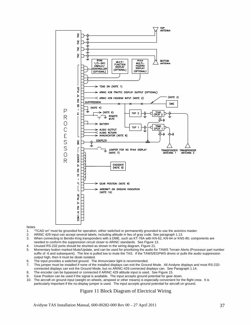
Avidyne TAS Installation Manual, 600-00282-000 Rev 00 – 27 April 2011 37
Notes 1. “TCAD on” must be grounded for operation, either switched or permanently grounded to use the avionics master. 2. ARINC 429 input can accept several labels, including altitude in lieu of gray code. See paragraph 1.13. 3. When connecting to Bendix-King transponders with a DME, such as KT-76A with KN-62, KN-64 or KNS-80, components are
needed to conform the suppression circuit closer to ARINC standards. See Figure 13. 4. Unused RS-232 ports should be shunted as shown in the wiring diagram, Figure 21. 5. Momentary button marked Mute/Update, and can be used for prioritizing the audio for TAWS Terrain Alerts (Processor part number
suffix of -6 and subsequent). The line is pulled low to mute the TAS. If the TAWS/EGPWS drives or pulls the audio suppression output high, then it must be diode isolated.
6. The input provides a switched ground. The Annunciator light is recommended. 7. This jumper must be installed if none of the installed displays can exit the Ground Mode. All Avidyne displays and most RS-232-
connected displays can exit the Ground Mode, but no ARINC-429 connected displays can. See Paragraph 1.14. 8. The encoder can be bypassed or connected if ARINC 429 altitude input is used. See Figure 15. 9. Gear Position can be used if the signal is available. The input accepts ground potential for gear down. 10. The aircraft on ground input (weight on wheels, airspeed or other means) is especially convenient for the flight crew. It is
particularly important if the no-display jumper is used. The input accepts ground potential for aircraft on ground.
Figure 11 Block Diagram of Electrical Wiring
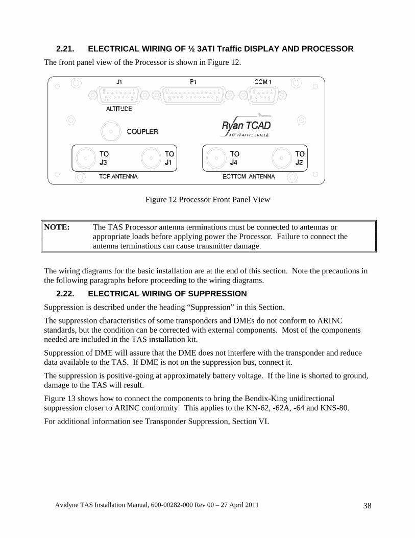
Avidyne TAS Installation Manual, 600-00282-000 Rev 00 – 27 April 2011 38
2.21. ELECTRICAL WIRING OF ½ 3ATI Traffic DISPLAY AND PROCESSOR The front panel view of the Processor is shown in Figure 12.
Figure 12 Processor Front Panel View
NOTE: The TAS Processor antenna terminations must be connected to antennas or appropriate loads before applying power the Processor. Failure to connect the antenna terminations can cause transmitter damage.
The wiring diagrams for the basic installation are at the end of this section. Note the precautions in the following paragraphs before proceeding to the wiring diagrams.
2.22. ELECTRICAL WIRING OF SUPPRESSION Suppression is described under the heading “Suppression” in this Section.
The suppression characteristics of some transponders and DMEs do not conform to ARINC standards, but the condition can be corrected with external components. Most of the components needed are included in the TAS installation kit.
Suppression of DME will assure that the DME does not interfere with the transponder and reduce data available to the TAS. If DME is not on the suppression bus, connect it.
The suppression is positive-going at approximately battery voltage. If the line is shorted to ground, damage to the TAS will result.
Figure 13 shows how to connect the components to bring the Bendix-King unidirectional suppression closer to ARINC conformity. This applies to the KN-62, -62A, -64 and KNS-80.
For additional information see Transponder Suppression, Section VI.
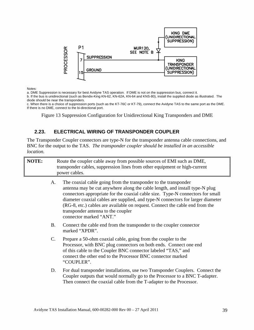
Avidyne TAS Installation Manual, 600-00282-000 Rev 00 – 27 April 2011 39
Notes: a. DME Suppression is necessary for best Avidyne TAS operation. If DME is not on the suppression bus, connect it. b. If the bus is unidirectional (such as Bendix-King KN-62, KN-62A, KN-64 and KNS-80), install the supplied diode as illustrated. The diode should be near the transponders. c. When there is a choice of suppression ports (such as the KT-76C or KT-79), connect the Avidyne TAS to the same port as the DME. If there is no DME, connect to the bi-directional port.
Figure 13 Suppression Configuration for Unidirectional King Transponders and DME
2.23. ELECTRICAL WIRING OF TRANSPONDER COUPLER The Transponder Coupler connectors are type-N for the transponder antenna cable connections, and BNC for the output to the TAS. The transponder coupler should be installed in an accessible location.
NOTE: Route the coupler cable away from possible sources of EMI such as DME, transponder cables, suppression lines from other equipment or high-current power cables.
A. The coaxial cable going from the transponder to the transponder antenna may be cut anywhere along the cable length, and install type-N plug connectors appropriate for the coaxial cable size. Type-N connectors for small diameter coaxial cables are supplied, and type-N connectors for larger diameter (RG-8, etc.) cables are available on request. Connect the cable end from the transponder antenna to the coupler connector marked “ANT.”
B. Connect the cable end from the transponder to the coupler connector marked “XPDR”.
C. Prepare a 50-ohm coaxial cable, going from the coupler to the Processor, with BNC plug connectors on both ends. Connect one end of this cable to the Coupler BNC connector labeled “TAS,” and connect the other end to the Processor BNC connector marked “COUPLER”.
D. For dual transponder installations, use two Transponder Couplers. Connect the Coupler outputs that would normally go to the Processor to a BNC T-adapter. Then connect the coaxial cable from the T-adapter to the Processor.
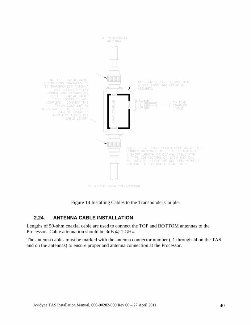
Avidyne TAS Installation Manual, 600-00282-000 Rev 00 – 27 April 2011 40
Figure 14 Installing Cables to the Transponder Coupler
2.24. ANTENNA CABLE INSTALLATION Lengths of 50-ohm coaxial cable are used to connect the TOP and BOTTOM antennas to the Processor. Cable attenuation should be 3dB @ 1 GHz.
The antenna cables must be marked with the antenna connector number (J1 through J4 on the TAS and on the antennas) to ensure proper and antenna connection at the Processor.
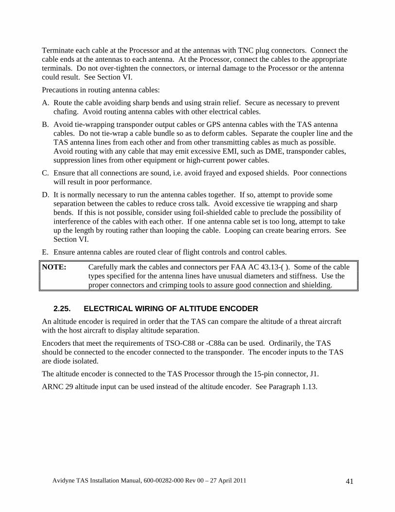
Avidyne TAS Installation Manual, 600-00282-000 Rev 00 – 27 April 2011 41
Terminate each cable at the Processor and at the antennas with TNC plug connectors. Connect the cable ends at the antennas to each antenna. At the Processor, connect the cables to the appropriate terminals. Do not over-tighten the connectors, or internal damage to the Processor or the antenna could result. See Section VI.
Precautions in routing antenna cables:
A. Route the cable avoiding sharp bends and using strain relief. Secure as necessary to prevent chafing. Avoid routing antenna cables with other electrical cables.
B. Avoid tie-wrapping transponder output cables or GPS antenna cables with the TAS antenna cables. Do not tie-wrap a cable bundle so as to deform cables. Separate the coupler line and the TAS antenna lines from each other and from other transmitting cables as much as possible. Avoid routing with any cable that may emit excessive EMI, such as DME, transponder cables, suppression lines from other equipment or high-current power cables.
C. Ensure that all connections are sound, i.e. avoid frayed and exposed shields. Poor connections will result in poor performance.
D. It is normally necessary to run the antenna cables together. If so, attempt to provide some separation between the cables to reduce cross talk. Avoid excessive tie wrapping and sharp bends. If this is not possible, consider using foil-shielded cable to preclude the possibility of interference of the cables with each other. If one antenna cable set is too long, attempt to take up the length by routing rather than looping the cable. Looping can create bearing errors. See Section VI.
E. Ensure antenna cables are routed clear of flight controls and control cables.
NOTE: Carefully mark the cables and connectors per FAA AC 43.13-( ). Some of the cable types specified for the antenna lines have unusual diameters and stiffness. Use the proper connectors and crimping tools to assure good connection and shielding.
2.25. ELECTRICAL WIRING OF ALTITUDE ENCODER
An altitude encoder is required in order that the TAS can compare the altitude of a threat aircraft with the host aircraft to display altitude separation.
Encoders that meet the requirements of TSO-C88 or -C88a can be used. Ordinarily, the TAS should be connected to the encoder connected to the transponder. The encoder inputs to the TAS are diode isolated.
The altitude encoder is connected to the TAS Processor through the 15-pin connector, J1.
ARNC 29 altitude input can be used instead of the altitude encoder. See Paragraph 1.13.
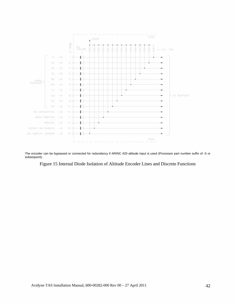
Avidyne TAS Installation Manual, 600-00282-000 Rev 00 – 27 April 2011 42
The encoder can be bypassed or connected for redundancy if ARINC 429 altitude input is used (Processor part number suffix of -5 or subsequent).
Figure 15 Internal Diode Isolation of Altitude Encoder Lines and Discrete Functions
Avidyne TAS Installation Manual, 600-00282-000 Rev 00 – 27 April 2011 43
Figure 16 15-Pin Cable-End Plug for Mating with J1
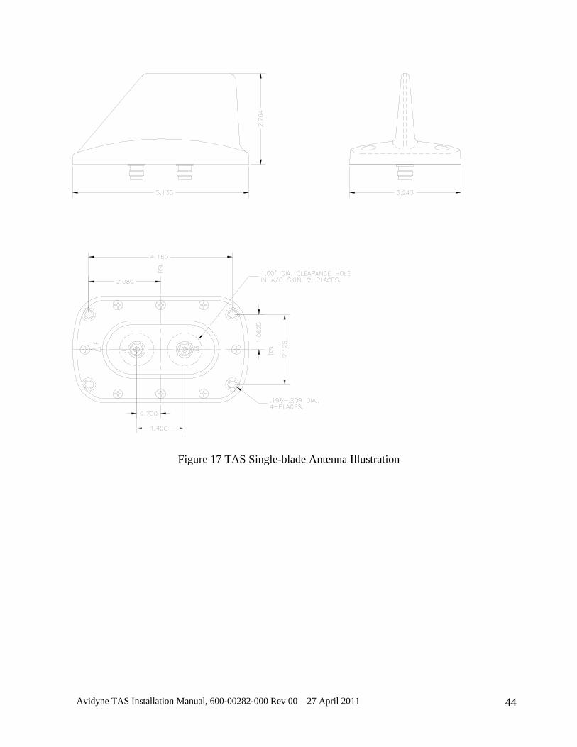
Avidyne TAS Installation Manual, 600-00282-000 Rev 00 – 27 April 2011 44
Figure 17 TAS Single-blade Antenna Illustration

Avidyne TAS Installation Manual, 600-00282-000 Rev 00 – 27 April 2011 45
Figure 18 TAS Twin-blade Antenna Illustration
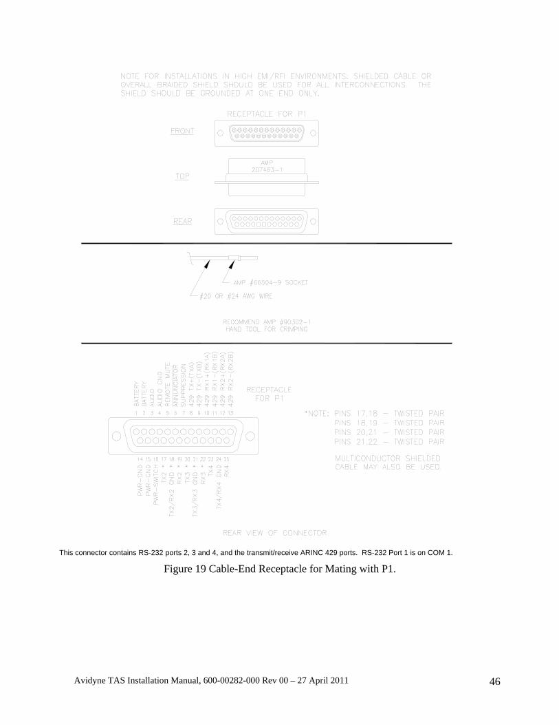
Avidyne TAS Installation Manual, 600-00282-000 Rev 00 – 27 April 2011 46
This connector contains RS-232 ports 2, 3 and 4, and the transmit/receive ARINC 429 ports. RS-232 Port 1 is on COM 1.
Figure 19 Cable-End Receptacle for Mating with P1.
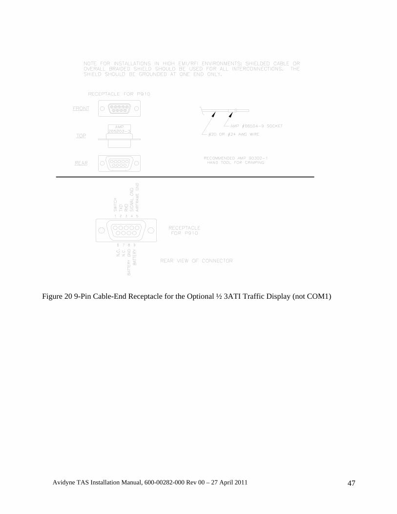
Avidyne TAS Installation Manual, 600-00282-000 Rev 00 – 27 April 2011 47
Figure 20 9-Pin Cable-End Receptacle for the Optional ½ 3ATI Traffic Display (not COM1)
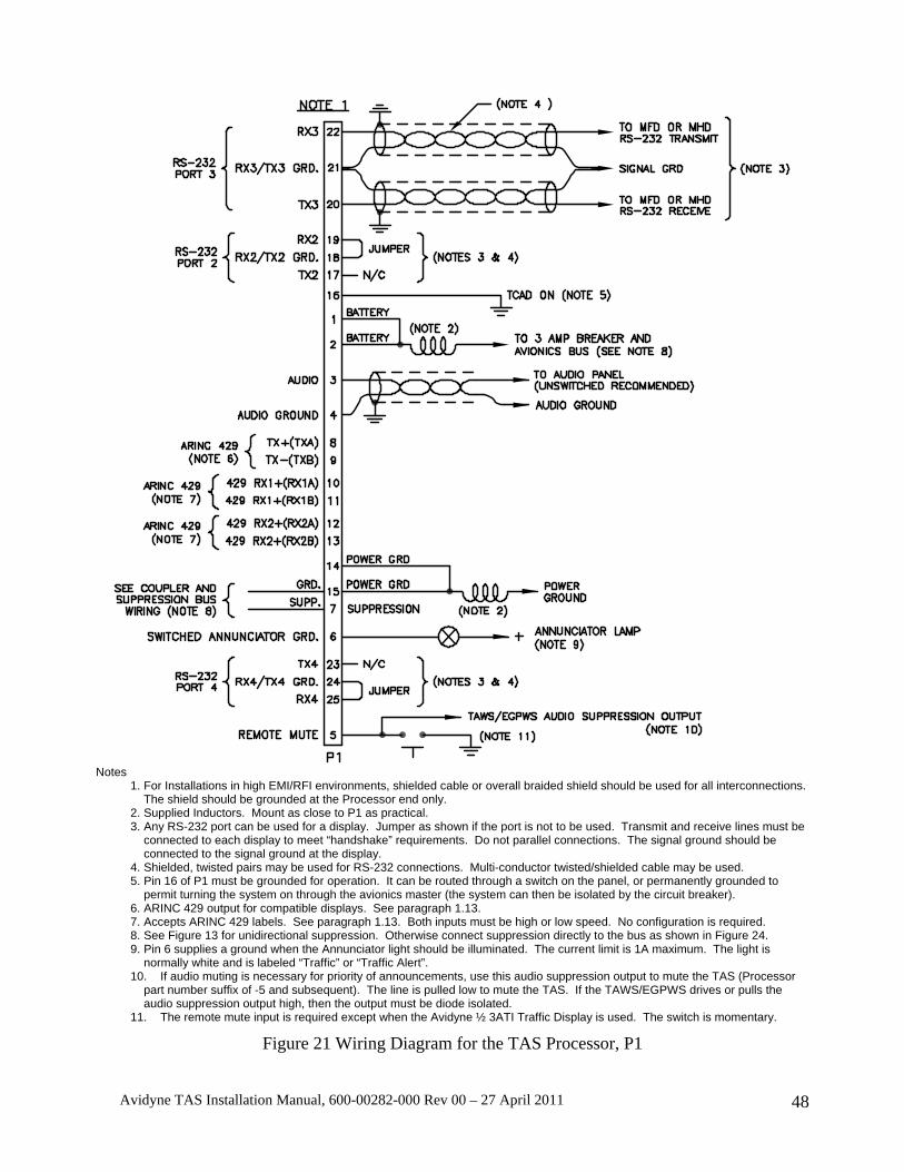
Avidyne TAS Installation Manual, 600-00282-000 Rev 00 – 27 April 2011 48
Notes
1. For Installations in high EMI/RFI environments, shielded cable or overall braided shield should be used for all interconnections. The shield should be grounded at the Processor end only.
2. Supplied Inductors. Mount as close to P1 as practical. 3. Any RS-232 port can be used for a display. Jumper as shown if the port is not to be used. Transmit and receive lines must be
connected to each display to meet “handshake” requirements. Do not parallel connections. The signal ground should be connected to the signal ground at the display.
4. Shielded, twisted pairs may be used for RS-232 connections. Multi-conductor twisted/shielded cable may be used. 5. Pin 16 of P1 must be grounded for operation. It can be routed through a switch on the panel, or permanently grounded to
permit turning the system on through the avionics master (the system can then be isolated by the circuit breaker). 6. ARINC 429 output for compatible displays. See paragraph 1.13. 7. Accepts ARINC 429 labels. See paragraph 1.13. Both inputs must be high or low speed. No configuration is required. 8. See Figure 13 for unidirectional suppression. Otherwise connect suppression directly to the bus as shown in Figure 24. 9. Pin 6 supplies a ground when the Annunciator light should be illuminated. The current limit is 1A maximum. The light is
normally white and is labeled “Traffic” or “Traffic Alert”. 10. If audio muting is necessary for priority of announcements, use this audio suppression output to mute the TAS (Processor
part number suffix of -5 and subsequent). The line is pulled low to mute the TAS. If the TAWS/EGPWS drives or pulls the audio suppression output high, then the output must be diode isolated.
11. The remote mute input is required except when the Avidyne ½ 3ATI Traffic Display is used. The switch is momentary.
Figure 21 Wiring Diagram for the TAS Processor, P1
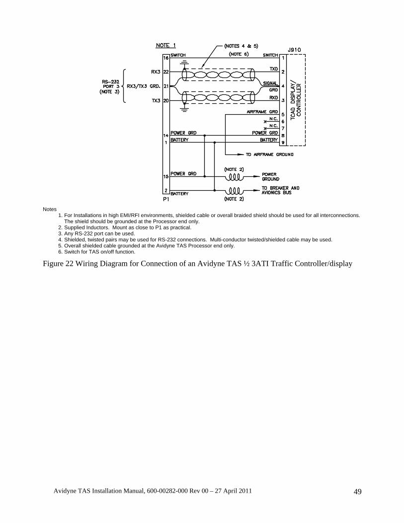
Avidyne TAS Installation Manual, 600-00282-000 Rev 00 – 27 April 2011 49
Notes
1. For Installations in high EMI/RFI environments, shielded cable or overall braided shield should be used for all interconnections. The shield should be grounded at the Processor end only.
2. Supplied Inductors. Mount as close to P1 as practical. 3. Any RS-232 port can be used. 4. Shielded, twisted pairs may be used for RS-232 connections. Multi-conductor twisted/shielded cable may be used. 5. Overall shielded cable grounded at the Avidyne TAS Processor end only. 6. Switch for TAS on/off function.
Figure 22 Wiring Diagram for Connection of an Avidyne TAS ½ 3ATI Traffic Controller/display
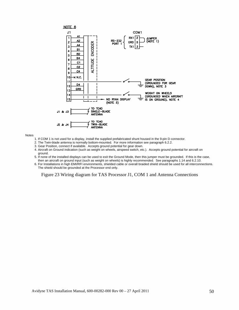
Avidyne TAS Installation Manual, 600-00282-000 Rev 00 – 27 April 2011 50
Notes 1. If COM 1 is not used for a display, install the supplied prefabricated shunt housed in the 9-pin D connector. 2. The Twin-blade antenna is normally bottom-mounted. For more information see paragraph 6.2.2. 3. Gear Position, connect if available. Accepts ground potential for gear down. 4. Aircraft on Ground indication (such as weight on wheels, airspeed switch, etc.). Accepts ground potential for aircraft on
ground. 5. If none of the installed displays can be used to exit the Ground Mode, then this jumper must be grounded. If this is the case,
then an aircraft on ground input (such as weight on wheels) is highly recommended. See paragraphs 1.14 and 6.2.10. 6. For Installations in high EMI/RFI environments, shielded cable or overall braided shield should be used for all interconnections.
The shield should be grounded at the Processor end only.
Figure 23 Wiring diagram for TAS Processor J1, COM 1 and Antenna Connections
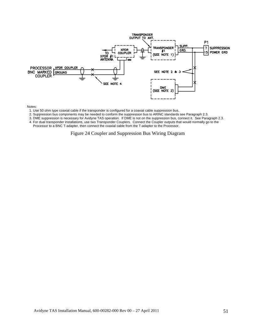
Avidyne TAS Installation Manual, 600-00282-000 Rev 00 – 27 April 2011 51
Notes: 1. Use 50 ohm type coaxial cable if the transponder is configured for a coaxial cable suppression bus. 2. Suppression bus components may be needed to conform the suppression bus to ARINC standards see Paragraph 2.3. 3. DME suppression is necessary for Avidyne TAS operation. If DME is not on the suppression bus, connect it. See Paragraph 2.3. 4. For dual transponder installations, use two Transponder Couplers. Connect the Coupler outputs that would normally go to the
Processor to a BNC T-adapter, then connect the coaxial cable from the T-adapter to the Processor.
Figure 24 Coupler and Suppression Bus Wiring Diagram
Avidyne TAS Installation Manual, 600-00282-000 Rev 00 – 27 April 2011 52
SECTION III OPERATION
3.1. GENERAL The TAS uses transponder replies to compute bearing, relative altitude and range from nearby Mode C- or Mode S-equipped aircraft. Non-Mode C aircraft provide range and bearing information only.
Relative altitude information is derived from decoding the altitude replies from nearby aircraft, and comparing the data with the encoded altitude information from the host aircraft. Range information is determined by active interrogations, using time of arrival and whisper-shout techniques.
The TAS declares Traffic Advisories using audible announcements and an annunciator light output. Additionally, when the Altitude Alert is activated, a distinctive short tone and voice alert is generated to call attention to arrival at a target altitude, or an altitude deviation.
The optional TAS ½ 3ATI Traffic Controller/display and/or Multi-Hazard Display (MHD) are available to communicate traffic information. See Figure 26 for special symbols used, and Figure 27 and Figure 28 for basic ½ 3ATI Traffic Display information. Multi-Function Displays can also be connected using other RS-232 ports.
Information regarding operation of the ½ 3ATI display is found in this Section. Information about other displays can be found in their respective Operating Manuals.
3.2. AUDIO & VISUAL ALERT One visual and four audible alerts are used by the TAS:
TRAFFIC ALERT A voice alert for Traffic Alerts, indicating the presence, direction and relative height above or below the host aircraft. See the Pilot's Handbook.
ALTITUDE ALERT A voice and tone for the Altitude Alert function (available when the optional TAS ½ 3ATI Traffic Display or MHD is used).
PERFORMANCE MONITOR An announcement indicating a detected TAS malfunction.
VISUAL ALERT An auxiliary output connected to an annunciator lamp, providing a visual alert to displayed traffic.

Avidyne TAS Installation Manual, 600-00282-000 Rev 00 – 27 April 2011 53
3.3. OPTIONAL ½ 3ATI TRAFFIC DISPLAY OPERATOR CONTROLS Operator controls are illustrated and described as follows:
Figure 25 ½ 3ATI Traffic Controller/display
PWR/MUTE: A push-on, pull-off button for supplying power to the unit. When the threat warning tone sounds, a momentary push of this button stops a current annunciation. See the Pilot Operating Handbook.
DATA: Used to identify the MSL altitude of the primary threat and the N-number if available. Double-pressing the DATA button repeats a TA announcement.
TRML: Terminal Mode, sets the range and altitude Proximity Airspace size to Terminal.
STD: Standard Mode, sets the range and altitude Proximity Airspace size to Standard.
ENRT: Enroute Mode, sets the range and altitude Proximity Airspace size to Enroute.
UP ARROW : For data entry and user programming.
DOWN ARROW : For data entry and user programming.
Pressing two buttons simultaneously accesses six functions:
UP & DOWN ARROW : To engage or disengage the Altitude Alert function.
DATA & TRML: To engage or disengage the Density Altitude function.
TRML & STD: By pressing these two buttons, the Ground Mode can be engaged.
STD & ENRT: These buttons engage the Unrestricted Mode of operation.
DATA & ENRT: These buttons engage the Pilot Initiated Test function.
TRML & MUTE: These buttons engage the Approach Mode set-up.

Avidyne TAS Installation Manual, 600-00282-000 Rev 00 – 27 April 2011 54
3.4. SYMBOLS Figure 26 is an illustration and brief description of the special symbols used on the TAS:
Figure 26 ½ 3ATI Traffic Controller/display Symbols
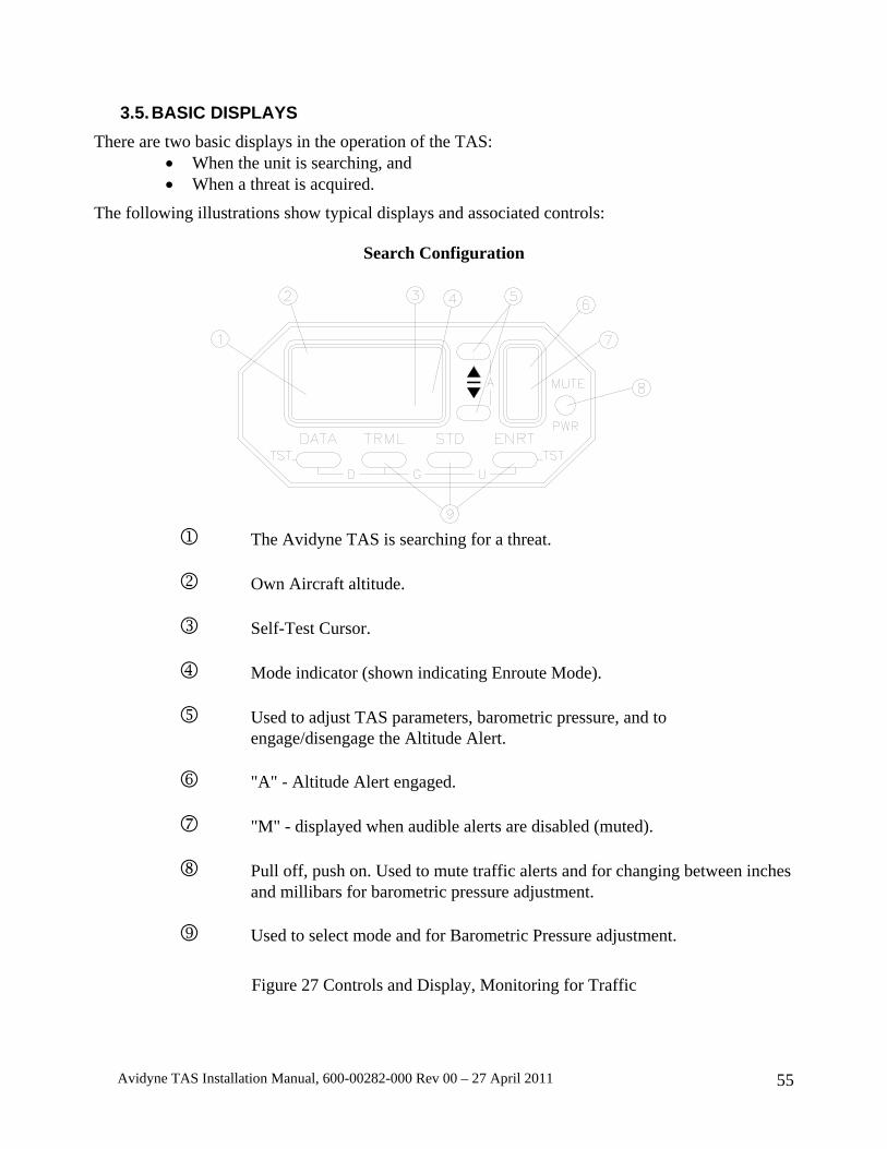
Avidyne TAS Installation Manual, 600-00282-000 Rev 00 – 27 April 2011 55
3.5. BASIC DISPLAYS There are two basic displays in the operation of the TAS:
• When the unit is searching, and • When a threat is acquired.
The following illustrations show typical displays and associated controls:
Search Configuration
1 The Avidyne TAS is searching for a threat. 2 Own Aircraft altitude. 3 Self-Test Cursor. 4 Mode indicator (shown indicating Enroute Mode). 5 Used to adjust TAS parameters, barometric pressure, and to
engage/disengage the Altitude Alert. 6 "A" - Altitude Alert engaged. 7 "M" - displayed when audible alerts are disabled (muted). 8 Pull off, push on. Used to mute traffic alerts and for changing between inches
and millibars for barometric pressure adjustment. 9 Used to select mode and for Barometric Pressure adjustment.
Figure 27 Controls and Display, Monitoring for Traffic

Avidyne TAS Installation Manual, 600-00282-000 Rev 00 – 27 April 2011 56
Threat Acquisition
1 Traffic range is 2.1 Nautical Miles, approximately 1:30. 2 Threat is a Traffic Alert (TA), 300 feet above and converging in altitude. 3 Mode indicator (shown in Terminal Mode). 4 Up button is used to display secondary threat. Down button is used to display third level threat. 5 Second and third level threats have been detected. Flashing indicates nearby in altitude (See the Pilot's Handbook). 6 Pull off, push on. Also used to mute current audible alerts. 7 Used to select mode, and for initiating Barometric Pressure
adjustment prior to using the up and down buttons. 8 Shows additional data about displayed traffic.
Figure 28 Controls and Display, Traffic Acquired

Avidyne TAS Installation Manual, 600-00282-000 Rev 00 – 27 April 2011 57
3.6. PROGRAMMING When completing an installation, the factory settings should be checked, and the programming functions should be used to adjust the settings as necessary. The following paragraphs describe the programming functions.
To engage a programming function, the appropriate button is pressed twice. When this is done, the current setting is displayed. The up and down buttons can be used to adjust the displayed parameter. To select the next parameter, the appropriate button is pressed again. When each parameter has been considered, the Avidyne TAS returns to collision alert operation. In all cases, if no button is pressed for about 8 seconds when in a programming mode, the Avidyne TAS will return to collision alert operation.
Proximity Airspace Limits when the optional ½ 3ATI Traffic Controller/display is used are as follows:
Terminal Mode Standard Mode En route Mode Unrestricted Mode
200 to 1000 FT 0.5 to 1.5 NM
500 to 1500 FT 1.0 to 3.0 NM
1000 to 2000 FT 2.0 to 10.0 NM
10,000 FT 21.0 NM
Table 8 Proximity Airspace Limits for the ½ 3ATI Traffic Display
3.7. SETTING THE PROXIMITY AIRSPACE SIZE Depress the selected button (TRML, STD, or ENRT) twice. The Proximity Airspace height in hundreds of feet will be displayed. To change the height, press the up or down buttons. Depress the selected button again for Proximity Airspace radius adjustment. Depress the mode button once more to return the Avidyne TAS to normal operation.
The factory-set airspace limits and other settings for the ½ 3ATI Traffic controller/display are as follows: ENRT Proximity Airspace Size: ±2000 FT, 3.0 NM STD Proximity Airspace Size: ±1000 FT, 2.0 NM TRML Proximity Airspace Size: ±500 FT, 1.0 NM Barometric Pressure Setting: 29.92 inches (1013mb) Density Altitude Temperature: +59°F (+15°C) Altitude Alert: 5,000 FT
3.8. SETTING DENSITY ALTITUDE Press the TRML and DATA buttons simultaneously. The previously programmed temperature will be displayed on the right. Use the up and down buttons to set the actual outside air temperature and read the Density Altitude on the left.
3.9. SETTING AUDIO VOLUME Depress the MUTE button twice. The Audio Volume can be adjusted using the up or down buttons.

Avidyne TAS Installation Manual, 600-00282-000 Rev 00 – 27 April 2011 58
If no button is pressed for 8 seconds, the Avidyne TAS will automatically return to collision alert operation. The sequence for tone related set up is as follows:
Press MUTE twice: Adjust tone volume; Press MUTE again: Return to operation
The TAS aural alert should be discernable at Vne (Vmo) and with full power applied, whether or not the crew is wearing headphones.
3.10. SETTING THE ALTITUDE ALERT Press the up and down buttons simultaneously. The previously programmed altitude will be displayed. Use the up and down buttons to set the selected altitude. Pressing the up and down buttons again will engage the Altitude Alert. See the Pilot's Handbook for more information.
3.11. BUILT-IN TEST & FAULT INDICATIONS An extensive battery of self-test functions is run at startup of the TAS. In addition, the TAS may be tested using the mute/update button. If a TAS ½ 3ATI Traffic Controller/display is used another self-test routine is available.
Self test without the TAS ½ 3ATI Traffic Display
Action Positive Result Negative Result
Double press the mute/update button (or the DATA button on the TAS ½ 3ATI Traffic Display)
Either a TA or “No advisories’ is announced.
No audible announcement, or a “TAS Code” announcement. Discontinue use of the TAS until identified and corrected.
Table 9 Test Function with the ½ 3ATI Traffic Controller/display
To initiate a self-test, press the DATA and ENRT buttons simultaneously. The following is displayed:
1. Testing Remote. 2. The Annunciator light illuminates (if installed) and the word “testing” is generated in the audio
system. 3. SYS CHK: OK 4. XMT CHK: OK 5. Testing Display. The ½ 3ATI Traffic Controller/display then displays the software versions.
If there is a fault indication, do not use the TAS data.
CAUTION: The TAS does not monitor for TAs or display intruder information during the Test function.
Avidyne TAS Installation Manual, 600-00282-000 Rev 00 – 27 April 2011 59
A cursor on the ½ 3ATI Traffic Controller/display confirms continued operation of the equipment. Two dots in the cell immediately to the left of the mode cell alternately illuminate, indicating continued operation. If the dots do not alternate, the equipment is not operating. “Link Failure" indicates a disrupted communications link between the Processor and ½ 3ATI Traffic Controller/display.
“Ground Mode” is annunciated upon startup when the TAS is in the Ground Mode. If the TAS is in the Ground Mode while flying, the system will not properly warn of traffic. The “Ground Mode” annunciation is normal on the ground. If the Ground Mode is announced when flying, discontinue operation of the TAS.
The TAS is designed to revert to a passive operation in the event of transmitter failure. If this occurs, the Annunciator light will remain illuminated, a voice alert of “TAS Interrogator Failure” will be announced and a ‘W’ will be displayed in place of the Mode indicator on the TAS ½ 3ATI Traffic Controller/display. Traffic will be announced with bearing and relative height, but not range. This is not a normal mode and the equipment should be repaired as soon as possible.
Some faults can be detected. If “TAS Code” followed by a number is announced, then a malfunction has been detected. Discontinue use of the TAS and contact the factory or your dealer for more information.
Electronic detection of faults is limited. An observant flight crew is the best and most effective monitor of the equipment.
If there is a fault indication or a “TAS Code” announcement, do not use the TAS data.
The TAS must receive valid altitude data in order to compute separation information. If the data is invalid or incorrect, the information the TAS provides will be incorrect. The TAS cannot always detect incorrect altitude input. The installing agency must ensure the altitude inputs are correct at installation.
If invalid host altitude information is detected and the Avidyne ½ 3ATI Traffic Controller/display is installed, stars are shown in place of altitude information. Multifunction displays also provide an invalid altitude message. When invalid altitude data is detected and the TAS is not in the Ground Mode, an unsolicited audible announcement is generated stating, “TCAD Altitude Data Invalid”. When the TAS is in the Ground Mode, double-pressing the Mute/Update button will generate the Altitude Data Invalid message.
A warming-up encoder can transmit invalid data. Therefore, invalid altitude input can be normal if it only happens a few minutes after startup. Otherwise, it should never happen. Even a momentary indication of a problem, such as during a climb, indicates the TAS is receiving invalid altitude data. The TAS should not be used until the problem is corrected.
If the host aircraft operates above the altitude limit identified for the particular model TAS, the message “TCAD Altitude Data Invalid” will sound. Double pressing the mute button will cause the Altitude Data Invalid message followed by “TCAD code three”.
The TAS should not be in the Ground Mode when in flight. There are indicators to advise the flight crew that the TAS is operating in the Ground Mode. The TAS ½ 3ATI Traffic Controller/display indicates operation in the Ground Mode by showing a “G” in the mode cell. The phrase “Ground Mode” is announced upon initialization. The phrase “Ground Mode” is also included in the annunciation when the mute/update button is double-pressed. If the TAS is inexplicably operating in “Ground Mode” in flight, discontinue operation until a qualified technician can evaluate it. If,

Avidyne TAS Installation Manual, 600-00282-000 Rev 00 – 27 April 2011 60
after a power reset in the air, the TAS enters the Ground Mode, select another mode to exit the Ground Mode. Operators without a display will not normally enter the Ground Mode after a reset.
The TAS operates in SL A when the landing gear is down (retractable gear aircraft).
Avidyne TAS Installation Manual, 600-00282-000 Rev 00 – 27 April 2011 61
3.12. DISCLAIMER The TAS has been meticulously designed to provide warning of nearby intruders. As with any device, there are significant limitations. The TAS can only detect signals if they are received. There are many impediments that can prevent the signal from being received, including the lack of transponder replies and the relative signal patterns of the transmitting and receiving antennas. We must declare in the strongest of terms that the TAS is not foolproof, and will not warn of nearby traffic in every instance, nor will it in itself prevent collisions. We make no claim in this regard. The pilot must make the avoidance decisions. We do claim the TAS is a very helpful device that can and has on many occasions helped to save the aircraft and occupants from disaster. Further, it aids in traffic awareness and traffic avoidance. The TAS is an aid to the see-and-avoid process and does not replace the common sense and good judgment of the pilot.
As a pilot, you must be relied upon for a certain level of competence and a high standard of knowledge about the airspace, aerodynamics, regulations, and the TAS. This includes knowledge of the limitations as well as the capabilities of the TAS.
This equipment is designed to increase the pilot's awareness of nearby traffic. It will not detect every aircraft. It is not designed to replace the see and avoid responsibility of the pilot or the ATC responsibility in the IFR environment.
The information provided by the TAS is not intended to lessen in any manner the pilot's obligation to see and avoid traffic.
The pilot in command of an aircraft is directly responsible for, and is the final authority as to, the operation of that aircraft.

Avidyne TAS Installation Manual, 600-00282-000 Rev 00 – 27 April 2011 62
SECTION IV PERFORMANCE TESTING Proper testing of the TAS in the host (TAS Equipped) aircraft is essential. Proper operation of critical functions can only be checked during the Performance Test. Failures of these tests mean improper or marginal performance of the TAS. Performance testing is the most important part of the installation.
CAUTION: Before applying power verify that all cables are properly terminated. The antennas must be connected before power is applied. Verify the suppression bus is correctly connected. A short circuit in the suppression line, excessive current on the annunciator line or reversed-polarity power lines will damage the TAS.
4.1. GENERAL Performance testing of the TAS is conducted using standard test equipment and a personal computer.
4.2. EQUIPMENT REQUIRED A. Transponder Test Set, IFR Model ATC-600A or equivalent.
B. A personal computer with serial communications capability (such as a PC with Microsoft Windows HyperTerminal∗).
C. A null modem cable (often called a file transfer cable).
D. A short coaxial cable with BNC connectors on both ends. The following information may be used to prepare a Null Modem Cable required for checkout of the TAS
9-pin female 9-pin female FG (Frame Ground) - - FG (Frame Ground) TD (Transmit Data) 3 2 TD (Transmit Data) RD (Receive Data) 2 3 RD (Receive Data)
RTS (Request To Send) 7 8 RTS (Request To Send) CTS (Clear To Send) 8 7 CTS (Clear To Send) SG (Signal Ground) 5 5 SG (Signal Ground)
DSR (Data Set Ready) 6 4 DSR (Data Set Ready) DTR (Data Terminal
Ready) 4 6 DTR (Data Terminal Ready)
Table 10 Null Modem Cable Pin Assignments
Alternatively, a manufactured cable may be purchased at office supply or computer supply stores. The cable is called a Direct Cable Connection for File Transfer, or a Data Transfer Cable, often made by Belkin. The cable usually has both a 9-pin and 25-pin connectors on both ends. ∗ HyperTerminal may be found in Windows 98 or Windows XP under Start>Programs>Accessories>Communications
Avidyne TAS Installation Manual, 600-00282-000 Rev 00 – 27 April 2011 63
4.3. RAMP TEST This test checks the function of the TAS, and confirms proper operation of the host transponder and altitude encoder with the TAS on. The following tests are shown as sequential steps. Each test must be completed, but the order is not important. If, for example, the altitude test is not planned until later, then it is not necessary to connect the altitude encoding test device until it is required by a test. All the testing may be done in a hangar except the Ramp Test, Bearing. This must be accomplished away from reflective objects. See the Ramp Test Geometry Considerations diagram in Section VI.
4.3.1. INITIAL TRANSPONDER TEST A. Place the transponder test set in position to interrogate the transponder of the aircraft
under test. The TAS should be off.
B. Set the transponder test set for Mode A/C and interrogate the transponder.
C. Verify proper operation of the host transponder with the TAS turned off, including altitude encoding, frequency and output power.
D. Turn the Avidyne TAS on. Once the system initializes, verify the % reply meter on the transponder test set shows a reduced % reply and is fluctuating. If this test is satisfactory, disregard Paragraph O in the CVI test.
E. Turn off the avionics and the test set until the computer setup is complete.
4.3.2. PERSONAL COMPUTER SETUP
The following instructions describe how to configure HyperTerminal for use with the TAS. HyperTerminal is a terminal emulator available with Microsoft Windows. Any terminal emulator (Kermit, Z-Term, etc.) may be used as long as it supports ANSI escape sequences; the emulator should be configured to communicate at 9600 bits per second with no parity and one start bit. Steps A through L will establish the required parameters. If the computer is already set up, proceed to step M.
A. With the TAS and the Portable Computer (PC) turned off, connect a null-modem cable (sometimes called data transfer cable) to the plug marked COM 11 on the TAS Processor and to the 9-pin serial connector on the PC.
B. Turn on the PC. Locate the HyperTerminal application (on Windows 98, HyperTerminal is available in the HyperTerminal folder under the Start->Programs->Accessories menu).
C. Start the HyperTerminal application by double-clicking on HyperTrm.exe.
D. When the "new connection" dialog box appears asking for a connection name, type 1 COM1 is normally a 9-pin serial connection (sometimes marked IOIOIO). Make sure COM1 is available on the computer (the computer will let you know). If not, COM2 may be used.
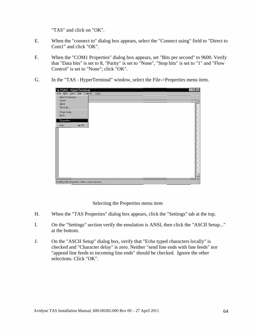
Avidyne
E.
F.
G.
H.
I.
J.
e TAS Installat
"TAS" and
When the Com1" an
When the that "DataControl" i
In the "TA
When the
On the "Seat the bott
On the "Achecked an"append liselections
tion Manual, 60
d click on "O
"connect to"nd click "OK
"COM1 Proa bits" is set ts set to "Non
AS - HyperT
S
"TAS Prope
ettings" sectom.
ASCII Setup"nd "Characteine feeds to i. Click "OK"
00-00282-000
OK".
" dialog boxK".
operties" dialto 8, "Parityne"; click "O
erminal" win
electing the
erties" dialog
tion verify th
" dialog box,er delay" is zincoming lin".
Rev 00 – 27 A
x appears, sel
log box appe" is set to "N
OK".
ndow, select
Properties m
g box appear
he emulation
, verify that zero. Neithene ends" sho
April 2011
lect the "Con
ears, set "BitNone", "Stop
t the File->P
menu item
rs, click the
n is ANSI, th
"Echo typeder "send line uld be check
nnect using"
ts per secondp bits" is set t
Properties me
"Settings" ta
hen click the
d characters lends with li
ked. Ignore
" field to "Di
d" to 9600. Vto "1" and "F
enu item.
ab at the top
"ASCII Set
locally" is ine feeds" nothe other
64
irect to
Verify Flow
.
tup..."
or
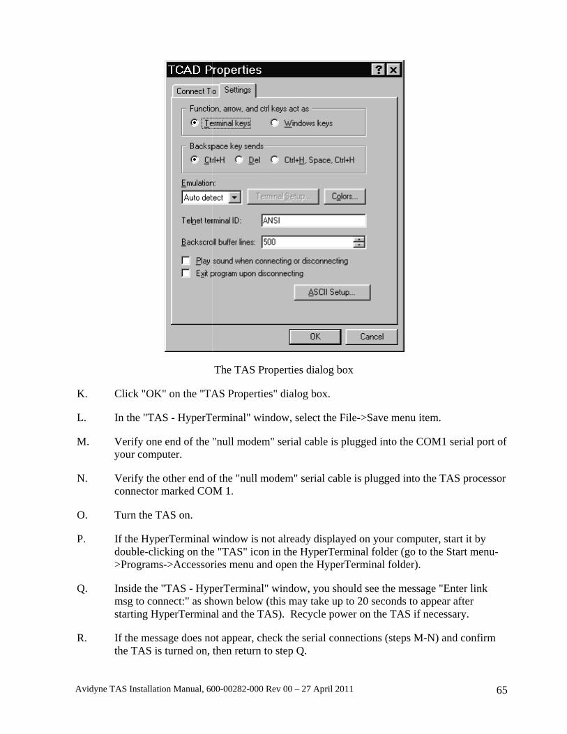
Avidyne
K.
L.
M.
N.
O.
P.
Q.
R.
e TAS Installat
Click "OK
In the "TA
Verify oneyour comp
Verify theconnector
Turn the T
If the Hypdouble-cli>Program
Inside the msg to constarting Hy
If the mesthe TAS is
tion Manual, 60
K" on the "TA
AS - HyperT
e end of the puter.
e other end omarked CO
TAS on.
perTerminal icking on thes->Accessor
"TAS - Hypnnect:" as shyperTermina
sage does nos turned on,
00-00282-000
The TAS Pr
AS Propertie
erminal" win
"null modem
of the "null mOM 1.
window is ne "TAS" iconries menu an
perTerminal"hown below al and the TA
ot appear, chthen return t
Rev 00 – 27 A
roperties dia
es" dialog bo
ndow, select
m" serial cab
modem" seria
not already dn in the Hypnd open the H
" window, y(this may taAS). Recyc
heck the serito step Q.
April 2011
alog box
ox.
t the File->S
ble is plugge
al cable is pl
displayed on perTerminal HyperTermi
you should seake up to 20 le power on
al connectio
Save menu it
d into the CO
lugged into t
your compufolder (go tonal folder).
ee the messaseconds to athe TAS if n
ons (steps M-
tem.
OM1 serial p
the TAS pro
uter, start it bo the Start m
age "Enter linappear after necessary.
-N) and conf
65
port of
ocessor
by menu-
nk
firm
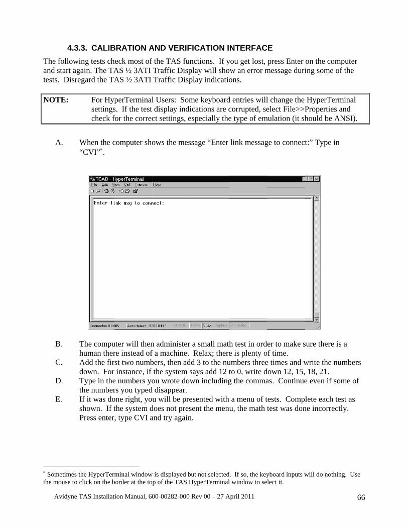
Avidyne
4.3The followand start atests. Disr NOTE:
A.
B.
C.
D.
E.
∗ Sometimesthe mouse to
e TAS Installat
3.3. CALIBwing tests chgain. The TAregard the TA
For Hypsettingscheck f
When the c“CVI”∗.
The compuhuman therAdd the firdown. For Type in thethe numberIf it was doshown. If tPress enter
s the HyperTermo click on the b
tion Manual, 60
BRATION Aheck most of AS ½ 3ATI AS ½ 3ATI
perTerminals. If the test for the correc
computer sho
uter will thenre instead of st two numbinstance, if
e numbers yors you typed one right, youthe system d, type CVI a
minal window
border at the top
00-00282-000
AND VERIFf the TAS funTraffic DispTraffic Disp
l Users: Somdisplay indi
ct settings, e
ows the mes
n administer f a machine. bers, then adthe system s
ou wrote dowdisappear.
u will be predoes not presand try again
is displayed bp of the TAS H
Rev 00 – 27 A
FICATION Inctions. If yplay will shoplay indicatio
me keyboardications are cespecially the
ssage “Enter
a small mat Relax; thered 3 to the nusays add 12 twn including
esented withsent the menn.
ut not selectedHyperTerminal
April 2011
NTERFACyou get lost, ow an error mons.
d entries willcorrupted, see type of em
link messag
h test in orde is plenty oumbers threeto 0, write dg the comma
h a menu of tnu, the math t
d. If so, the keyl window to se
E press Enter
message duri
l change the elect File>>P
mulation (it sh
ge to connect
er to make sof time. e times and wdown 12, 15, as. Continue
tests. Compltest was don
yboard inputs wlect it.
on the comping some of
HyperTermProperties anhould be AN
t:” Type in
sure there is
write the num18, 21.
e even if som
lete each tesne incorrectly
will do nothing
66
puter the
minal nd
NSI).
a
mbers
me of
st as y.
g. Use
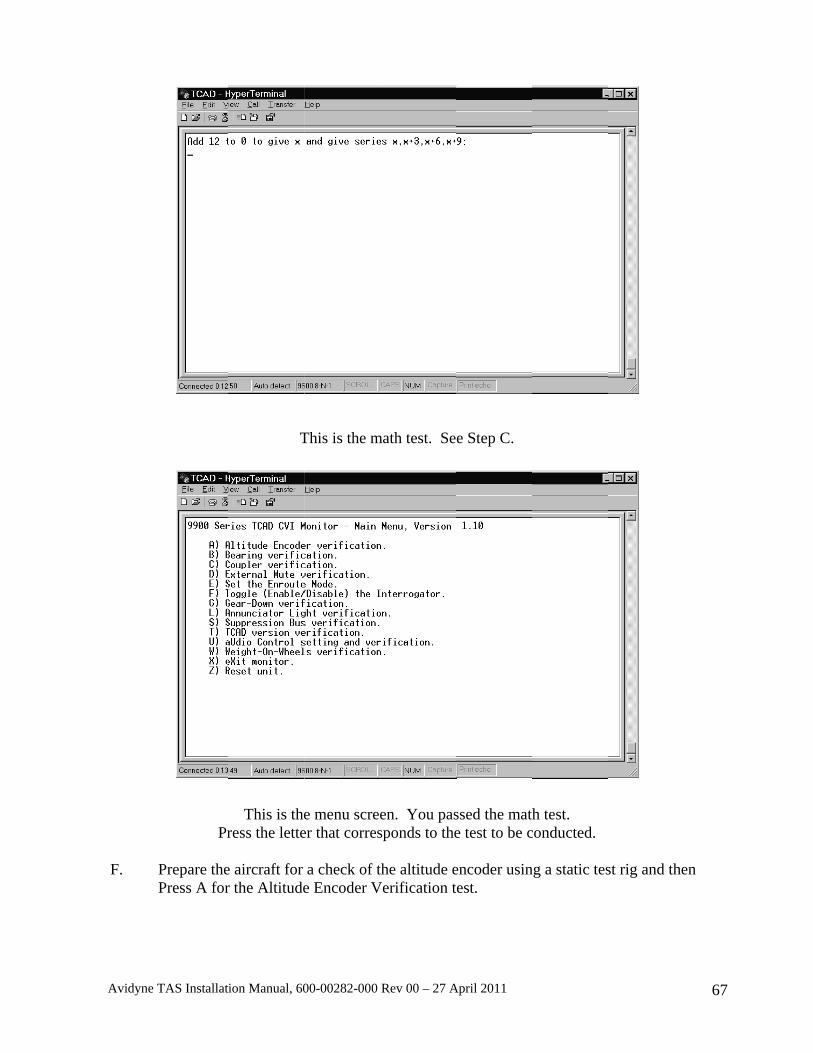
Avidyne
F.
e TAS Installat
Pr
Prepare thePress A for
tion Manual, 60
T
This is theress the lette
e aircraft for r the Altitude
00-00282-000
This is the m
e menu screeer that corres
a check of te Encoder V
Rev 00 – 27 A
math test. Se
en. You passponds to the
the altitude e
Verification t
April 2011
e Step C.
ssed the mathe test to be c
encoder usinest.
h test. conducted.
ng a static tes
st rig and the
67
en

Avidyne
G.
H.
e TAS Installat
Using a StaTAS altitudidentified oconnectionD2. Press X
Bearing Vetests. Presstransponde
tion Manual, 60
This is th
atic test rig, rde data. Theon the compus. Proper alX to return t
erification iss C for Coupr tester is ne
00-00282-000
he Altitude E
raise the altie data on theuter monitortitude decodto the main m
more involvpler Verificaecessary to in
Coupler V
Rev 00 – 27 A
Encoder Ver
itude of the ee static test syr. Each bit liding is essenmenu.
ved and willation. If the tnterrogate th
erification T
April 2011
rification Scr
encoder to vystem shouline must be tial for corre
l be accompltransponder
he host transp
Test Screen
reen.
verify proper d match the checked for ect operation
lished after tis not being
ponder.
r operation oPressure Alshorted or o
n. Ignore D1
the other CVg interrogated
68
f the titude
open 1 and
VI d, a

Avidyne
I.
J.
K.
e TAS Installat
Follow the confirms coIf the test pthe transpo“PASSED”
Coupler tesTest.
External Menable othe
tion Manual, 60
instructionsoupler operapasses, [PASSnder is oper
” alternate. T
st, passed. P
Mute test. Preer mute inpu
00-00282-000
s on the screeation when thSED] is showating prior toThis is norm
Press X to re
ess E to Enauts (such as T
Rev 00 – 27 A
en for the Cohe host transwn at the Armo enabling th
mal. If the te
turn to the m
able the test. TAWS) to ac
April 2011
oupler Verifsponder replim Coupler The test, the wst shows [PA
main menu an
Then press ccomplish th
fication Testies. Press E
Test line, as swords “ARMASSED], the
nd select the
the remote mhe test. The
. This test E to enable th
shown belowMED” and e test has pas
e External M
mute button Mute/Updat
69
he test. w. If
ssed.
Mute
or te
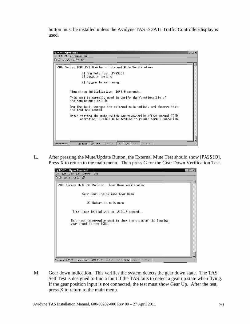
Avidyne
L.
M.
e TAS Installat
button musused.
After pressPress X to r
Gear downSelf Test isIf the gear ppress X to r
tion Manual, 60
st be installed
ing the Mutereturn to the
n indication. s designed toposition inpureturn to the
00-00282-000
d unless the
e/Update Bue main menu
This verifieo find a faultut is not con
e main menu
Rev 00 – 27 A
Avidyne TA
utton, the Exu. Then pres
es the systemt if the TAS nnected, the t.
April 2011
AS ½ 3ATI T
xternal Mute s G for the G
m detects the fails to detectest must sho
Traffic Cont
Test shouldGear Down V
gear down sct a gear up ow Gear Up
troller/displa
d show [PASSVerification
state. The Tstate when f. After the t
70
ay is
SED]. Test.
TAS flying. test,
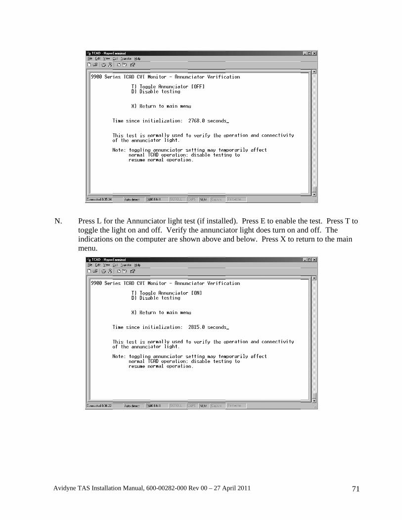
Avidyne
N.
e TAS Installat
Press L for toggle the lindicationsmenu.
tion Manual, 60
the Annunclight on and on the comp
00-00282-000
ciator light teoff. Verify puter are sho
Rev 00 – 27 A
est (if installthe annunci
own above a
April 2011
led). Press Eator light do
and below. P
E to enable thoes turn on anPress X to re
he test. Presnd off. The eturn to the m
71
ss T to
main
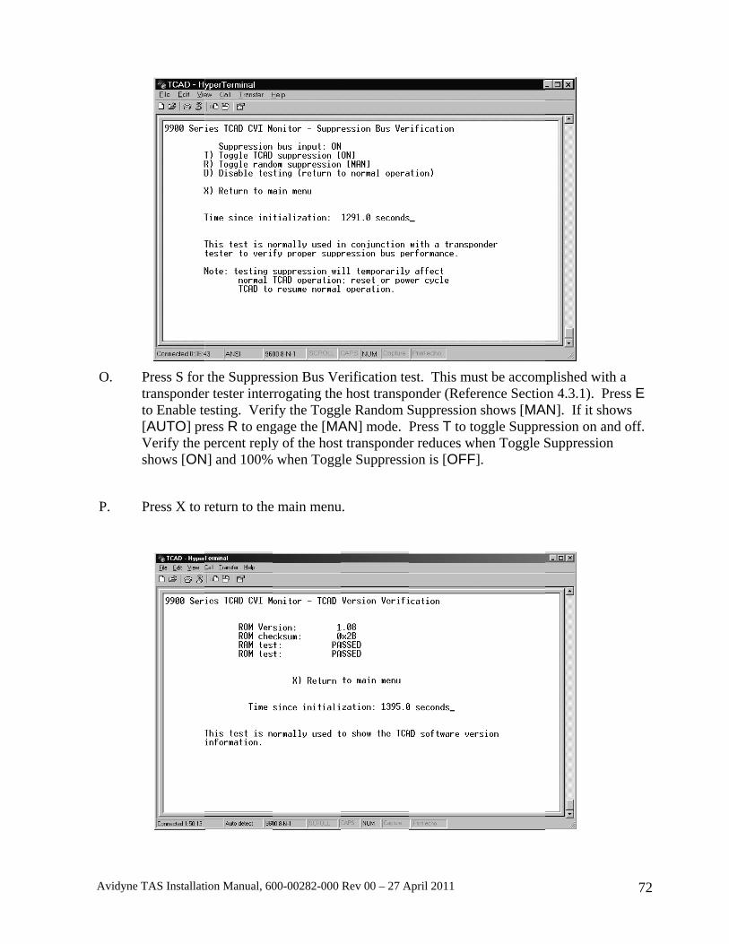
Avidyne
O.
P.
e TAS Installat
Press S for transpondeto Enable te[AUTO] prVerify the pshows [ON
Press X to r
tion Manual, 60
the Suppresr tester interesting. Veriress R to engpercent reply
N] and 100%
return to the
00-00282-000
ssion Bus Verrogating theify the Togggage the [MAy of the host when Togg
e main menu
Rev 00 – 27 A
erification tee host transpole Random SAN] mode. Pt transponde
gle Suppressi
u.
April 2011
est. This muonder (ReferSuppression Press T to tor reduces whion is [OFF]
ust be accomrence Sectioshows [MA
oggle Supprehen Toggle S].
mplished withon 4.3.1). PrAN]. If it shoession on anSuppression
72
h a ress E ows nd off.
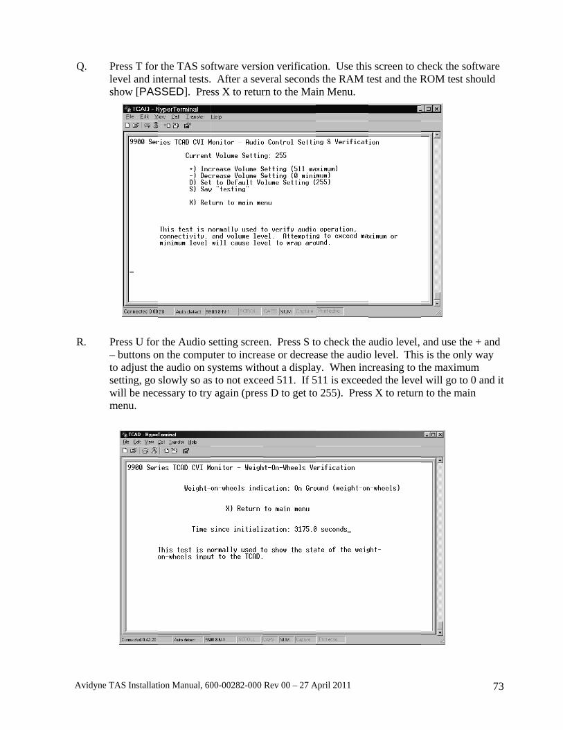
Avidyne
Q.
R.
e TAS Installat
Press T for level and inshow [PAS
Press U for– buttons oto adjust thsetting, go will be necmenu.
tion Manual, 60
the TAS sonternal tests.SSED]. Pre
r the Audio son the compuhe audio on sslowly so asessary to try
00-00282-000
ftware versio After a sevss X to retur
setting screeuter to increasystems withs to not excey again (pres
Rev 00 – 27 A
on verificativeral secondsrn to the Ma
n. Press S toase or decreahout a displayed 511. If 5s D to get to
April 2011
ion. Use thiss the RAM tin Menu.
o check the ase the audioy. When inc
511 is exceedo 255). Press
s screen to ctest and the R
audio level, o level. Thiscreasing to tded the levels X to return
check the sofROM test sh
and use the s is the only he maximuml will go to 0n to the main
73
ftware hould
+ and way
m 0 and it n
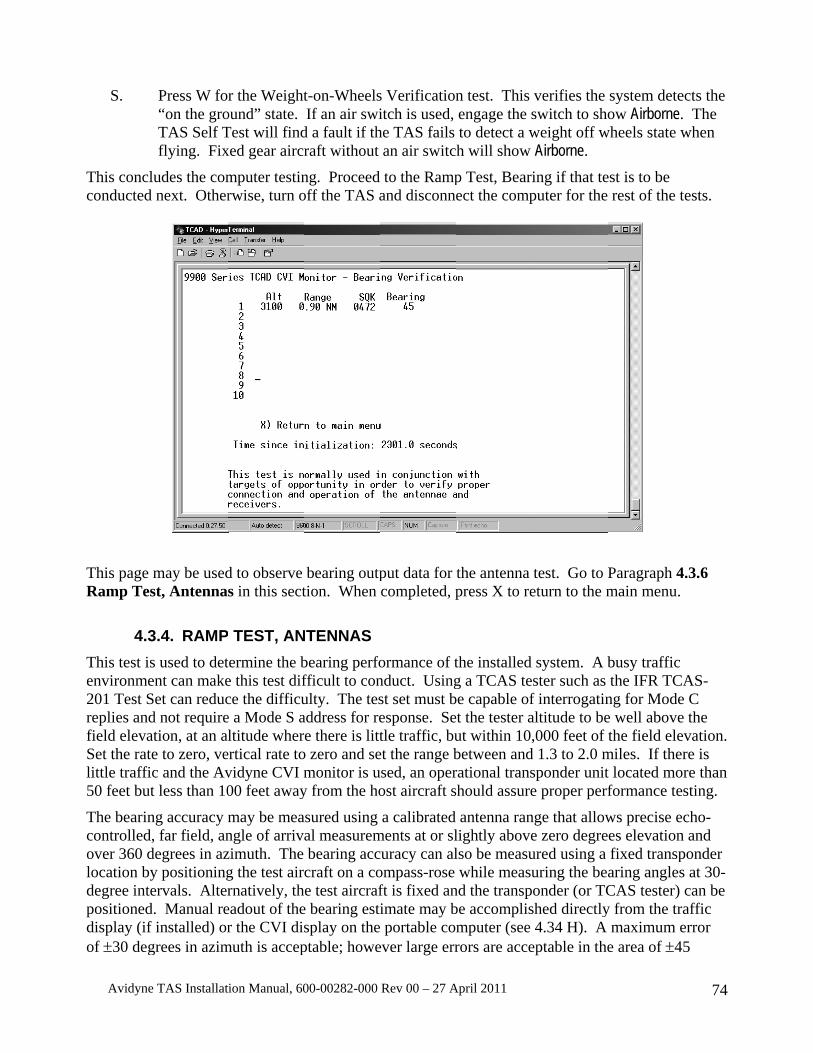
Avidyne
S.
This conclconducted
This page Ramp Tes
4.3This test isenvironme201 Test Sreplies andfield elevaSet the ratelittle traffic50 feet but
The bearincontrolled,over 360 dlocation bydegree intepositioneddisplay (if of ±30 deg
e TAS Installat
Press W fo“on the groTAS Self Tflying. Fix
ludes the comnext. Other
may be usedst, Antenna
3.4. RAMPs used to detent can makeSet can reducd not requireation, at an ale to zero, vec and the Avt less than 10
ng accuracy m, far field, an
degrees in azy positioningervals. Alter
d. Manual ref installed) orgrees in azim
tion Manual, 60
r the Weightound” state. Test will findxed gear aircr
mputer testinrwise, turn o
d to observe s in this sect
TEST, ANtermine the be this test difce the difficue a Mode S altitude wher
ertical rate tovidyne CVI m00 feet away
may be meangle of arrivzimuth. The g the test airrnatively, th
eadout of ther the CVI dis
muth is accep
00-00282-000
t-on-WheelsIf an air swi
d a fault if thraft without
ng. Proceed off the TAS a
bearing outption. When
NTENNASbearing perfofficult to conulty. The tesaddress for rere there is litto zero and semonitor is u
y from the ho
asured using al measurembearing acccraft on a coe test aircraf
e bearing estisplay on theptable; howe
Rev 00 – 27 A
s Verificationitch is used,
he TAS fails an air switc
to the Rampand disconne
put data for completed, p
ormance of tnduct. Usingst set must besponse. Setle traffic, bu
et the range bused, an operost aircraft s
a calibrated ments at or slcuracy can alompass-rose ft is fixed animate may b portable com
ever large err
April 2011
n test. This engage the sto detect a wh will show
p Test, Beariect the comp
the antenna press X to re
the installed g a TCAS te
be capable oft the tester aut within 10,between andrational transhould assure
antenna ranlightly abovelso be measuwhile measu
nd the transpbe accomplismputer (see rors are acce
verifies the switch to showeight off wAirborne.
ing if that teputer for the
test. Go to Peturn to the m
system. A bster such as f interrogatinaltitude to be,000 feet of t
d 1.3 to 2.0 msponder unite proper perf
nge that allowe zero degreured using a uring the beaonder (or TC
shed directly4.34 H). A
eptable in the
system deteow Airborne.
wheels state w
est is to be rest of the t
Paragraph 4main menu.
busy traffic the IFR TCA
ng for Modee well above the field elev
miles. If thert located morformance tes
ws precise eces elevation fixed transparing anglesCAS tester) y from the tra
maximum ee area of ±45
74
cts the The
when
ests.
.3.6
AS- C the
vation. re is re than sting.
cho-and
ponder at 30-can be affic error 5
Avidyne TAS Installation Manual, 600-00282-000 Rev 00 – 27 April 2011 75
degrees behind the tail and the area not visible from the cockpit. In these cases, aircraft structures may interfere with the signal path.
It is important to conduct the test in an area where signal reflections are minimal. Outside and away from hangars and other buildings is usually best. Specular reflections from moving aircraft or, ground vehicles or nearby operating transponders can contaminate the test results. If another aircraft with an operating transponder is used for testing, the signal path must not be occluded. If range or bearing indications from the test aircraft are unstable, then reflections from nearby structures or other interfering sources are likely disrupting the signals and a better location is necessary. See Section VI for more information.
NOTE: For aircraft with weather radar, check the TAS performance at 130° and 210° with the radar on to verify no interference from the radar. Use caution to operate the radar in accordance with recommended procedures and avoid RF exposure to personnel.
A. This test does not require interrogation of the host transponder.
B. Place the aircraft so the test transponder is positioned directly forward of the host aircraft.
CAUTION: Notification of ATC may be necessary to avoid false airborne TCAS resolution advisories.
C. Verify the TAS shows the target directly forward, at 0° (±30°) relative to the nose of the aircraft. If no display is used, verify using the CVI Interface. Paragraph 4.34.
D. Place the aircraft so the test transponder is oriented at 30° increments around the aircraft.
E. Verify the TAS shows the target at the correct bearing at each of the 30° points, ±30°.
NOTE: The vertical stabilizer or other appurtenances on the aircraft may affect the bearing performance. A maximum error of ±30° in azimuth is acceptable; however large errors are acceptable in the area of ±45° from the tail and the area not visible from the cockpit. In these cases, aircraft structures may interfere with the signal path.
4.3.5. RAMP TEST, OPTIONAL ½ 3ATI TRAFFIC CONTROLLER/DISPLAY
A. Press the test buttons (DATA & ENRT). B. When the ½ 3ATI Traffic Controller/display shows "Testing Display", press the UP
arrow and MUTE. C. The TAS will then perform a 90-second CRC test of the Display. A horizontally
oriented number will count down as the test is conducted. The test will conclude with the software version levels indicated.
D. Verify the Display can be seen under all probable lighting conditions and does not interfere with the Pilot’s vision.
E. Verify the Display is located in a position easily viewed and accessible to the Pilot. F. Verify the location and position of the Display does not have any reflections or glare that
would interfere with the Pilot’s vision.
Avidyne TAS Installation Manual, 600-00282-000 Rev 00 – 27 April 2011 76
4.3.6. RAMP TEST, SELF TEST FEATURES AND FAILURE MODE DISPLAYS
This test calls for removal of two connectors to verify proper operation of failure modes. The connectors must be reinstalled in order to restore proper operation of the TAS. Disregard any additional failure indications generated as a result of removing the connectors.
A. Remove the null-modem connection from the TAS Processor and recycle power to the TAS.
B. With the TAS operating, verify no audible or (if a display is installed) visual indications of a TAS failure. If installed, double-press the Mute/update button and verify the voice indication of “No advisories” if there are no computed Traffic Advisories (TA), or a traffic indication if there is a TA. Ground Mode may also be indicated.
C. Remove the connector from J1 on the Processor. “TAS altitude invalid” should sound. The warning sounds only once. Double-press the remote mute button or the DATA button to repeat the message.
D. Replace the connector. The warning stops. E. Remove the BNC connector marked Coupler. Connect a short coaxial cable with BNC
connectors on both ends to the Coupler input at the Processor. Short the center conductor of the open BNC connector to the shell. “TAS Code 1” will sound after about one minute or less. Double-press the remote mute button or the DATA button to repeat the message. Disregard any other failure indications.
F. Replace the Coupler connector. G. Turn the TAS off for a few seconds. H. Turn the TAS on again. Verify no audible or (if a display is installed) visual indications
of a TAS failure. If installed, double-press the Mute/update button and verify the voice indication of “No advisories” if there are no computed Traffic Advisories (TA), or a traffic indication if there is a TA. Ground Mode may also be indicated
4.4. INTERFERENCE CHECK These checks are designed to ensure interference-free operation of the TAS, to ensure the TAS causes no interference, and the equipment onboard the aircraft does not cause interference with the TAS.
4.4.1. INTERFERENCE CHECK, TRANSPONDER
This check is designed to ensure the TAS has adequate data to acquire and track aircraft. It is critical that the transponder does not ‘squitter’ as a result of on-board interference. If it does, the data available to the TAS for traffic avoidance is reduced.
A. With the transponder tester turned off, verify the rate of reply light flashes is reasonable for the location. If not, then proceed with the following to determine the source of interference.
B. Turn off all avionics except the transponder.
C. Turn on all the avionics, one at a time. Observe if the reply light flash rate changes.
Avidyne TAS Installation Manual, 600-00282-000 Rev 00 – 27 April 2011 77
Pay special attention to the DME and select different frequencies to verify there is no interference. The frequencies from 109.2 to 115.2 are especially important and should be specifically checked.
D. Verify there are no other sources of interference (i.e. engines or accessories).
4.4.2. INTERFERENCE CHECK, OTHER EQUIPMENT This check is to ensure the TAS does not interfere with other equipment in the aircraft.
The TAS employs a microprocessor that relies on a clock oscillator, which may generate interfering emissions at frequencies required for navigation and communication equipment. To substantiate the immunity of the VHF navigation and communications equipment, perform the following tests:
A. Apply power to the avionics bus and to both communications and navigation radios.
B. Open the squelch on the primary communications radio and apply power to the TAS.
C. Select various frequencies for a general test of the communications radio receiver. Then select 120.000 MHz, 122.000 MHz, 124.000 MHz, and 132.000 MHz and attempt to discern RF interference caused by the Model 9900. If such interference is experienced, confirm by removing power to the systems by pulling the respective circuit breakers.
D. Repeat the exercise for the secondary communications radio receiver. Note any unacceptable interference.
E. Tune each of the navigation receivers to the frequency of 109.2 and 115.2 MHz and listen for any discernible interference and, if practical, observe interruption of DME on those corresponding frequencies. Note any unacceptable interference.
F. Observe any other anomaly in other radios such as the ADF, the Marker Beacon, the Transponder, GPS navigation equipment, weather detection, weather radar, autopilot and the DME when operating the TAS.
G. Any unacceptable interference should be addressed prior to delivery to the customer.
4.4.3. TAS AUDIO ALERTS A. Verify the windshear, GPWS and TAS (TAS) voice alerts are compatible. Beginning
with part number suffix -5, the TAS warnings can be prioritized with windshear or GPWS warnings.
B. Verify all higher priority aural alerts can be heard over the TAS aural alerts.
4.4.4. ELECTRICAL SYSTEM A. Perform Electrical Load Analysis to verify the installation of the TAS System does not
adversely affect the electrical system.
4.5. FLIGHT TEST A. Verify the TAS Aural Alerts can be heard in all possible cockpit noise condition.
B. Verify all higher priority aircraft aural alerts (e.g. stall horn, landing gear horn, etc) is heard with and without headsets.
C. If installed, verify the ½ 3ATI Controller/display is located in a position free of glare
Avidyne TAS Installation Manual, 600-00282-000 Rev 00 – 27 April 2011 78
and reflections that could interfere with the Pilot’s vision.
4.6. CUSTOMER CARE CHECKLIST After installation, attention to the following items will help to make our mutual customer pleased with the TAS purchase.
A. Clean: The ½ 3ATI Traffic Controller/display can be cleaned with a damp cloth.
B. Checkout: Complete and satisfactory.
C. Preset Settings: The factory-preset settings should be enabled (see Section I).
D. Complete the TAS Instructions for Continued Airworthiness, Avidyne Document AVTAS-021, and install in the aircraft’s maintenance records.

Avidyne TAS Installation Manual, 600-00282-000 Rev 00 – 27 April 2011 79
SECTION V WARRANTY SERVICE AND PRODUCT SUPPORT
5.1. DOCUMENTATION After delivery to the customer, fill out and return the warranty document to Avidyne Corporation, Ryan International Division. The Warranty form may be found and filled out online at http://www.avidyne.com/support/registration.asp.
5.2. RETURN AUTHORIZATION In order to expedite repair of units, call the factory for a return authorization number before returning equipment for service.
5.3. WARRANTY SERVICE Avidyne warrants products in accordance with the warranty statement in effect at the time of equipment registration. All repairs are performed at the factory. Contact Avidyne Corporation, Ryan International Division for a warranty/return authorization.
All requests for warranty payment must be submitted on a standard AEA warranty claim form, accompanied by the dealer invoice. Authorized warranty work performed by the dealer will be limited to removal and re-installation of units on an exchange basis. Avidyne will bear the cost of warranty returns both ways via UPS surface delivery only. Avidyne reserves the right to use reconditioned parts in repairing the product or to use reconditioned units as warranty replacements.
For technical information and service, call 1-888-723-7592 or visit our website at http://www.avidyne.com/support/index.asp. For AOG support, call 1-877-900-4AOG (4264).

Avidyne TAS Installation Manual, 600-00282-000 Rev 00 – 27 April 2011 80
SECTION VI INSTALLATION PLANNING AND TROUBLESHOOTING GUIDE
6.1. GENERAL The following information is designed to give the technician guidance in planning installations and efficiently troubleshooting problems with the TAS. If there are any problems or difficulties experienced in installing or maintaining the TAS, please contact the factory.
6.2. EXTERNAL CONNECTIONS 6.2.1. ANTENNA BONDING
The antenna should have, at minimum, a ground plane equal to one wavelength (one wavelength is about twelve inches) all around the antenna. The location of the antenna is important. The ideal antenna "view" is ahead of the aircraft must not be obstructed.
An adequate ground plane and satisfactory bonding of the antenna to the ground plane is important for reliable bearing data. Completely remove the paint from under the antenna to within 0.1 inch of the edge of the antenna for proper ground plane RF connection. The antenna must be mounted so the bare metal of the aircraft skin touches the entire metal base plate of the antenna. Electrical bonding resistance of the installed antenna to the aircraft skin should be less than .01 ohm (0.005 ohms will provide best performance). The top antenna should be mounted as far forward as practical, above the cockpit, with no obstructions between the antenna and the nose of the aircraft.
Since the transponder signal from the threat aircraft is essentially line of sight, traffic ahead of the aircraft will be blocked if the antenna is mounted well aft of the cockpit. If the antenna is blocked by the airframe, other antennas, or large metal mass such as an engine, a less than optimum antenna reception pattern will occur. A perfect location does not exist on an airplane, and some compromise is normally necessary. Nonetheless, the TAS top antenna should be at the highest, forward-most part of the aircraft when the aircraft is in level flight, and the lower antenna should also be as far forward as practical. The forward view from the TAS antenna should be better than the view from the cockpit. Since the TAS monitors for traffic all around the aircraft, if possible ensure that the antenna is clear to the rear also. The distance from L-band antennas is especially important. See Operation in a Severe EMI Environment in this Section.
Even small obstructions within 11 inches of the antennas can seriously distort the signal path and significantly affect bearing performance.
Each antenna should normally be mounted so the antenna base is level (± 10º) when the aircraft is in level flight. Significant deviation from this orientation can affect the signal reception and bearing performance. The twin blade antenna is less susceptible to errors from a pitch angle, and the single blade antenna is less susceptible to errors in the roll axis.
The antenna must be well grounded to the airframe. The base of the antenna should be bonded to the airframe, in accordance with AC 43.13-2( ).
A ground plane is necessary for proper operation. Using the supplied screws, mount the antenna to the fuselage skin so contact is made to an inner ground plane. Then bond to an airframe structural
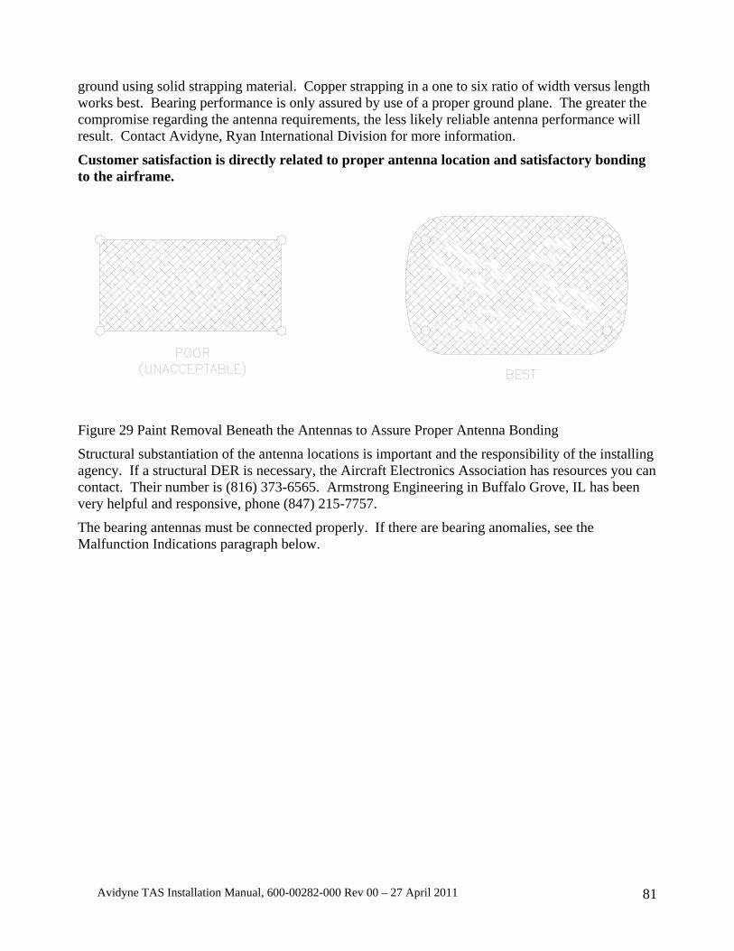
Avidyne TAS Installation Manual, 600-00282-000 Rev 00 – 27 April 2011 81
ground using solid strapping material. Copper strapping in a one to six ratio of width versus length works best. Bearing performance is only assured by use of a proper ground plane. The greater the compromise regarding the antenna requirements, the less likely reliable antenna performance will result. Contact Avidyne, Ryan International Division for more information.
Customer satisfaction is directly related to proper antenna location and satisfactory bonding to the airframe.
Figure 29 Paint Removal Beneath the Antennas to Assure Proper Antenna Bonding
Structural substantiation of the antenna locations is important and the responsibility of the installing agency. If a structural DER is necessary, the Aircraft Electronics Association has resources you can contact. Their number is (816) 373-6565. Armstrong Engineering in Buffalo Grove, IL has been very helpful and responsive, phone (847) 215-7757.
The bearing antennas must be connected properly. If there are bearing anomalies, see the Malfunction Indications paragraph below.

Avidyne TAS Installation Manual, 600-00282-000 Rev 00 – 27 April 2011 82
6.2.2. TOP AND BOTTOM ANTENNA SELECTION The TAS normally uses the single blade antenna as the top antenna, and the twin blade antenna the bottom antenna. This is not always the optimum configuration, and the positions may be switched if circumstances warrant it. Circumstances might include the inability to place the twin-blade antenna in an area that provides a clear area ahead of the antenna. In this case the single blade antenna could be used on the bottom to permit mounting the twin blade on the top, in an area that is clear ahead. If the twin blade antenna is mounted on the top, the antenna cabling changes see the table below:
Antenna Antenna end Processor end Single Blade antenna J1 J1 Single Blade Antenna J3 J3 Twin Blade antenna J2 J4 Twin Blade Antenna J4 J2
Table 11 Antenna connections when the Twin Blade Antenna is top-mounted
6.2.2.1. ANTENNA CABLING The antenna cabling is susceptible to interference. Most shielding is only partially effective. Make sure the cabling is properly terminated and the bearing antenna coaxes are not tightly tie-wrapped together. Looping the coaxes and tie-wrapping them can induce currents that can cause bearing interference.
6.2.2.2. PROCESSOR ANTENNA CONNECTIONS Do not over-tighten the connectors or internal damage to the Processor or the antenna could result. The connectors on the Processor and antenna are hard mounted. If a connector turns in its mounting, it needs to be repaired.
6.2.3. POWER INPUT LINE AND GROUND RETURN Ensure that the TAS is well grounded to an effective airframe ground. Poor grounds or ground loops can cause intermittent operation or alternator noise in the headphones. The supplied inductors should be mounted close to the TAS.
6.2.4. ANNUNCIATOR LIGHT The annunciator light uses a switched ground. Installation of an annunciator light is necessary for operation of the TAS without a display, and is recommended for use in display configurations. The light should be white or amber, and identified as “TRAFFIC” or “TRAFFIC ALERT”. The maximum current through the annunciator output must be limited to 1 Amp.
6.2.5. AUDIO The TAS audio is designed to operate into a 600-ohm load. If an audio port must be shared with another audio input, series resistors must be used in both lines to allow sufficiently high audio for both audio inputs. Usually 220- to 470-ohm resistors are satisfactory.
Avidyne TAS Installation Manual, 600-00282-000 Rev 00 – 27 April 2011 83
Connection to an audio panel without internal amplification normally requires a supplemental amplifier.
Low audio is usually caused by a greater than normal load on the line due to multiple inputs to one audio port.
A dedicated audio ground return line is provided to eliminate possible audio whine. Connect the return to the ground for the audio port the TAS is connected to. If no return ground is provided, ground to the case of the audio panel.
The audio line from the TAS to the audio panel should be shielded, with the shield grounded at one end.
6.2.6. ENCODER LINES The encoder lines are diode isolated inside the TAS. A diagram of this portion of the circuitry is in Section I of the Installation Manual. The common line should not be diode isolated, and should be the same potential as the encoder.
If any lines are shorted or open, several (but not all) altitudes on the TAS will be in error. Using the static tester and raising the altitude of the encoder while monitoring the TAS bit lines with a personal computer can quickly show a malfunction.
Stars (∗∗∗∗∗∗) on the altitude display of the Avidyne TAS ½ 3ATI Traffic Controller/display indicate the TAS is not receiving valid altitude data. Voice annunciation of “Altitude Data Invalid” also warns of this condition.
The common line from the TAS to the encoder should never be diode isolated. If it is, improper and unpredictable altitude errors will result. The encoder lines should be shielded, with the shield grounded at one end.
6.2.7. ON-THE-GROUND INDICATIONS AND GEAR POSITION The Aircraft On-the-Ground indication (typically Weight-on-Wheels or an airspeed switch) is used to automatically put the TAS in the Ground mode upon landing. This is convenient for the pilot because it eliminates audible advisories when on the ground. The landing gear position changes Sensitivity levels on the TAS. When the landing gear is down, the TAS operates in Sensitivity Level A. See the TAS Pilot’s Operating Handbook for more information.
The Aircraft On-the-Ground inputs (Weight-on-Wheels or an airspeed switch) and gear position are diode-isolated inside the TAS processor.
6.2.8. TRANSPONDER SUPPRESSION The TAS sends and receives suppression signals. Transponder and DME (if installed) suppression are required. Verification that suppression is operating is essential during checkout of the TAS.
The TAS is compatible with both mutual and unidirectional suppression systems.
Table 7 lists the availability of suppression for popular transponders.
The TAS suppression can be connected directly to any ARINC-standard mutual suppression bus. Several older Bendix-King transponder and DME suppression configurations do not conform to ARINC standards, so components must be added to bring those suppression circuits closer to conformity when DME is also installed. These transponders include the KT-76A, KT-78A, and KN-62, LN 62A, KN-64 and KNS-80 DME.
Avidyne TAS Installation Manual, 600-00282-000 Rev 00 – 27 April 2011 84
If a diode is called out in the Installation Manual, it should be installed at the transponder to avoid any capacitive charge build-up. The following items can cause an unsatisfactory suppression signal:
1) Suppression not connected.
REMEDY: Connect it.
2) The diode used to block the TAS suppression from sinking into the DME is installed backwards.
REMEDY: Install the diode correctly.
Best performance of the TAS is obtained when the DME and transponder are operating properly. Many aircraft have interference between the DME and transponder and DME interference cannot always be detected. If the DME causes the transponder to transmit often, there is much less time available for the TAS to acquire data.
To preclude possible interference from the DME, connect DME suppression.
The TAS suppression output is intentionally intermittent. This causes the reply meter on analog transponder testers to vary between 80% and 100%. It also causes some automatic testers to frequently indicate failure of the transponder test due to reply rate. This is normal and due to the tester’s design expectation of a regular suppression interval.
6.2.9. TRANSPONDER COUPLER The Coupler consists of a 50-ohm track on the transponder line and a diode detector to provide a signal to the TAS indicating the host transponder has transmitted. No maintenance is required for the coupler beyond the requirements in the periodic maintenance paragraph in Section I.
The most important item regarding the Coupler is the proper mounting and installation of the connectors on the transponder antenna cable. The RF cable must be intact and it should have no bends that exceed the natural radius of the cable. Do not bundle the Coupler output line with any pulse transmission lines.
The type N connectors used with the coupler are designed for RG-58 cable. If the connectors are used on cable that is smaller than RG-58, the cable jacket may not provide sufficient mechanical support for the connector. In this case the shield and the center conductor mechanically support the connector, resulting in an unreliable connection. The coax can easily pull out, creating transponder or TAS problems (where the TAS sees the onboard transponder). Be sure the coax jacket is sufficiently snug in the connector in order to provide mechanical support and a more reliable connection.
The Coupler should be well-grounded to the airframe. Grounding to the side of the Processor or transponder rack is usually not sufficient.
Addition of the Coupler to the Antenna cable increases the cable length, and can cause the transponder frequency at the antenna to shift. Adjust the transponder as necessary.
6.2.10. AVIDYNE ½ 3ATI TRAFFIC DISPLAY, MFD AND PROCESSOR INTERCONNECT PRECAUTIONS
Twisted shielded pairs should be used. Excessive EMI from other aircraft equipment penetrating these lines can cause a Link Failure indication on the TAS Display or a loss of signal to the MFDs.
Avidyne TAS Installation Manual, 600-00282-000 Rev 00 – 27 April 2011 85
The Avidyne TAS normally energizes in the Ground Mode, based on the altitude when power is applied. The Ground Mode allows Avidyne TAS to function, but all tones are muted and traffic below 200 feet above the aircraft is not displayed. When the system energizes in the Ground Mode, “Ground Mode” is announced. If the Avidyne TAS momentarily resets in the air, it will not enter the Ground Mode. If the system is intentionally reset in the air, then it can and likely will enter the Ground Mode, which is an abnormal and undesirable condition in flight. Although the System announces “Ground Mode”, there must be a way to deselect the Ground Mode. If not, then the automatic Ground Mode function must be disabled. The Avidyne TAS ½ 3ATI Traffic Controller/display, the Avidyne MHD and most RS-232-connected multi-function displays allow deselection of Ground Mode. Call the factory for more details if necessary. There are no ARINC 429 systems that allow the deselection of ground mode.
Pin 15 of J1 must be jumpered when there is no access to deselection of Ground Mode through any display. When Pin 15 of J1 is jumpered, then the Avidyne TAS will energize in a flight mode and will bypass the automatic, encoder-based Ground Mode on startup. In this case, the system will automatically enter the Ground Mode only when the Aircraft on Ground (such as Weight-on-Wheels) function is installed and operating.
One display may be connected to each RS-232 port. The Transmit and Receive lines must be connected for each display. Several displays can be connected to the ARINC 429 port. If the Ground Mode cannot be deselected on at least one (RS-232-connected) display, pin 15 of J1 must be jumpered to ground as shown in the wiring diagram. ARINC 429 interfaces do not permit Ground Mode deselection. Most RS-232 interfaces, the Avidyne MHD and the Avidyne ½ 3ATI Traffic Display allow Ground Mode deselection.

Avidyne TAS Installation Manual, 600-00282-000 Rev 00 – 27 April 2011 86
Explanatory Table: Several displays can be connected to the TAS. If any of the displays can deselect the Ground Mode, then Pin 15 need not be jumpered.
Configuration Pin 15 of J1 Condition
Avidyne ½ 3ATI Traffic Display (Allows access to deselect the Ground Mode)
Not jumpered
Automatic, encoder-based Ground mode on startup is available.
Avidyne Multi-Hazard Display (MHD) with RS-232 connection (Allows access to deselect the Ground Mode)
Not jumpered
Automatic, encoder-based Ground mode on startup is available.
RS-232 Display that allows access to deselect the Ground Mode
Not jumpered
Automatic, encoder-based Ground mode on startup is available.
Any ARINC 429 display connection
Jumpered Automatic, encoder-based Ground mode on startup is disabled.
No Display at all Jumpered Automatic, encoder-based Ground mode on startup is disabled.
RS-232 Display that does not allow access to deselect the Ground Mode
Jumpered Automatic, encoder-based Ground mode on startup is disabled.
Table 12 J1-15 Configuration Options
6.2.11. MUTE/UPDATE INPUT The Mute/Update button is used to give the pilot a momentary muting of the audible warnings, or (by double pressing the button) an update of the Traffic Alert.
TAs are announced through the audio system. If there is more than one TA, they are prioritized and delivered in sequence. Traffic Alert announcements can be repeated using the mute/update button.
The Mute/Update button mutes a current advisory or elicits a TA update. A single press of the Mute/Update button mutes an audible advisory in progress. A double press of the Mute/Update button repeats any TA announcements (with updated information and the range of the intruder). If no TAs are in effect when the button is double-pressed, the TAS announces “No Advisories”.
NOTE: The mute function only stops advisories scheduled to be reported at the time the mute button is pressed. Advisories that are scheduled after the mute button is pressed are not muted.
Avidyne TAS Installation Manual, 600-00282-000 Rev 00 – 27 April 2011 87
The update includes range information as well as the clock position and vertical reference of above or below the aircraft.
The mute input can be used to suppress the TAS audio for prioritization with TAWS and Windshear. This is only available for Processors with a part number with the -5 suffix and subsequent. The Remote Mute line is pulled low to mute the TAS. If the TAWS/EGPWS drives or pulls the audio suppression output high, then the output must be diode isolated.
6.2.12. EMI INTERFERENCE FROM OTHER ONBOARD ELECTRONICS EMI effects from other devices is rare due to the frequency of the receivers. EMI problems are typically manifested by inability to acquire distant targets, lack of bearing from distant targets, or poor bearing performance of distant targets.
Some DMEs and transponders emit continuous wave (CW) at the designed pulse frequency. Though this is several dB down from the pulse signal, the CW can swamp out the low level signals needed to detect distant targets. Actual measurements indicate the levels can be as high as –30dBm, much higher than the TAS receiver sensitivity.
If the offending CW overloads the bottom receivers, the TAS will fail to show bearing for all but the closest of targets. If all four receivers were affected, then the TAS would fail to show distant traffic. If the antenna cables are receiving interference from other high-level cables (or from each other), then the bearing will be unreliable. The signal used to check the system may be too strong to show the problem. Reduce the test signal levels or observe distant traffic to verify proper performance.
The solution to CW is to verify the integrity of the coaxial cables and connectors from the transmitting device, and keeping the antennas far apart. Some transponders have been shown to be incompatible. See Section I.
6.3. CHECKOUT Final checkout of the TAS should be done away from reflective areas. Non-reflective areas can be found a few hundred feet from aluminum structures such as hangars, or opposite the corner of the hangar where reflected signals will reflect away from the aircraft, not toward it. The following diagram from RTCA Document DO-185A “Minimum Operational Performance Standards for Traffic Alert and Collision Avoidance System II (TCAS II) Airborne Equipment” may be helpful in locating non-reflective areas of the ramp.
The vertical stabilizer or other appurtenances such as propellers may affect the bearing performance at very close range. By moving to the left or right the correct bearing measurements can be obtained. Reflections always play a role in bearing measurement. Testing with assurance that no reflections are affecting the results is not practical for most checkouts. Precise, echo-controlled far field angle of arrival measurements may not be possible due to ground and multipath reflections from buildings and other aircraft. If unacceptable errors are encountered, move the test location to change the multipath environment.
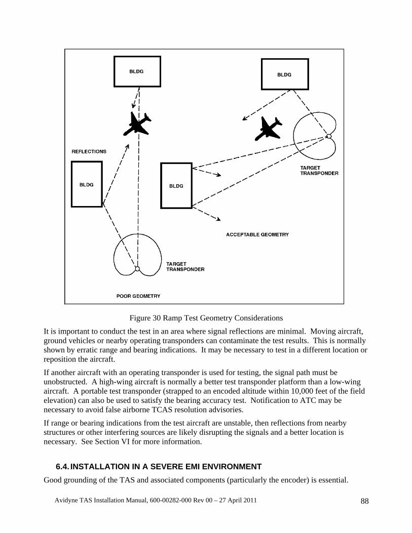
Avidyne TAS Installation Manual, 600-00282-000 Rev 00 – 27 April 2011 88
Figure 30 Ramp Test Geometry Considerations
It is important to conduct the test in an area where signal reflections are minimal. Moving aircraft, ground vehicles or nearby operating transponders can contaminate the test results. This is normally shown by erratic range and bearing indications. It may be necessary to test in a different location or reposition the aircraft.
If another aircraft with an operating transponder is used for testing, the signal path must be unobstructed. A high-wing aircraft is normally a better test transponder platform than a low-wing aircraft. A portable test transponder (strapped to an encoded altitude within 10,000 feet of the field elevation) can also be used to satisfy the bearing accuracy test. Notification to ATC may be necessary to avoid false airborne TCAS resolution advisories.
If range or bearing indications from the test aircraft are unstable, then reflections from nearby structures or other interfering sources are likely disrupting the signals and a better location is necessary. See Section VI for more information.
6.4. INSTALLATION IN A SEVERE EMI ENVIRONMENT Good grounding of the TAS and associated components (particularly the encoder) is essential.
Avidyne TAS Installation Manual, 600-00282-000 Rev 00 – 27 April 2011 89
Many precautions have been taken and tests have been conducted to ensure trouble-free operation of the Processor in high EMI environments. Nonetheless, common sense should be used when deciding on the mounting location of the Receiver/Processor. Clearly, mounting it close to L-band transmitters like DME or transponders should be avoided. If the Receiver/Processor must be mounted near an L-band transmitter, make sure the transmitter antenna cables are well shielded, and the L-band transmitter units are not emitting high levels of EMI. In addition, shield the TAS cables per the notes on the wiring diagrams.
Some DME designs permit a relatively high level of Continuous Wave (CW) emissions, which can affect the TAS performance. Interference from the onboard transponders can also affect performance. In order to reduce the possibility of interference, the DME and transponder antenna cables and terminations must be effectively shielded. Frayed cables at the RF connectors or lousy antenna cabling can introduce a high EMI level. The three-foot antenna separation requirement is essential to minimize interference from DMEs and transponders.
6.5. COMPASS HEADING INPUT Compass heading may be connected via ARINC 429 (Label 320). Compass heading assists in rapid traffic orientation during turns. Compass heading input is optional.
6.6. MALFUNCTION INDICATIONS PROBLEM: The TAS displays its own transponder. The suppression circuit is disabled. There are normally four possible reasons:
a. Internal Suppression fuse is blown. This can be checked by verifying continuity between the suppression pin and case ground. If the circuit is open, the suppression line is open. The Processor must be returned to Avidyne for repair. Verify the circuit is not shorted before reinstalling the Processor.
b. The DME diode is installed backwards, or it is installed unnecessarily. c. DME diode is not installed when it should be. d. Open suppression line.
PROBLEM: Erroneous host aircraft altitudes, asterisks instead of an altitude display, or voice annunciation of “Altitude Data Invalid”:
Check the altitude lines for shorted or open connections, and make sure the altitude encoder ground on J1 is properly connected to the altitude encoder.
PROBLEM: Annunciator light is on all the time:
Check for other failure conditions, such as altitude data invalid (double press the mute button to check this while in Ground Mode). The annunciator light will remain illuminated when other failure conditions are present.
PROBLEM: Whine in the audio caused by the TAS:
The TAS audio return line should be connected to the TAS audio port at the Audio Panel.
Check the primary source of the audio noise. Reduce the noise from this source as required. If the problem persists, shield the encoder lines and the audio line. Normally the shield is grounded at one end for optimum effectiveness. Sometimes grounding at both ends is the most effective arrangement. If audio interference is still a problem, contact the factory.
Avidyne TAS Installation Manual, 600-00282-000 Rev 00 – 27 April 2011 90
PROBLEM: The TAS bearing shows opposite to the traffic forward and aft, and it shows correctly left and right:
The antenna coaxes for the single-blade antenna are backwards. Recheck the antenna connections; J1 on the antenna connects to J1 on the TAS processor.
PROBLEM: The TAS bearing shows opposite to the traffic left and right, and it shows correctly forward and aft:
The antenna coaxes for the twin-blade antenna are backwards. Recheck the antenna connections.
PROBLEM: The TAS bearing shows opposite to the traffic sometimes, but not always:
If the traffic shows incorrect bearing sometimes, then one coax is shorted or open. If the problem is left or right, check the twin-blade antenna coax connectors. If the problem is front or aft, check the single-blade coax connectors.
NOTE: The TAS processor antenna terminations must be connected to antennas or a 50-ohm load before applying power to the Processor. Failure to connect the antenna terminations can cause transmitter damage.
PROBLEM: The TAS bearing is unreliable and traffic on the display moves all around. Multiple targets appear on the display, and then disappear.
Unreliable bearing causes the TAS to erroneously initiate new tracks on known targets, creating the appearance of multiple targets. Lack of a ground plane, poor bonding of the antennas to the ground plane, or poor ground connections from the antennas to the airframe can cause this. Looped and tie-wrapped antenna coax cables can induce interference and affect bearing, especially for distant traffic. Check the antennas for proper bonding and separate the antenna cables as much as possible to avoid cross talk.
PROBLEM: The TAS bearing is frequently not available, especially for distant traffic.
This and the next problem have the same cause and solution.
PROBLEM: The TAS never shows distant traffic beyond ten miles away.
The TAS receivers are capable of receiving signals lower than –73dBm. Continuous Wave (CW) EMI at or near 1090 MHz at levels greater than –73dBm can interfere with the ability of the TAS to detect distant traffic. The interference must be reduced below –73dBm for best TAS performance. Determine if the transponder or DME causes the problem. Select 112.3MHz (1094MHz is the collocated DME frequency) to check the DME since this is the most likely frequency to cause interference. If distant traffic cannot be detected with the interfering device on and can be detected with the device off, then steps should be taken to reduce or eliminate the interference. Check for proper and secure coaxial cables and connectors and verify the antennas are at least the minimum distance identified in the TAS Installation Manual. Verify the device in question can be installed with the TAS equipment. Consider moving the antenna of the offending equipment farther away from the TAS antenna. See Installation in a Severe EMI Environment above or contact the factory for more information.
PROBLEM: The TAS displays the onboard transponder.
Check the suppression connection.
Avidyne TAS Installation Manual, 600-00282-000 Rev 00 – 27 April 2011 91
SECTION VII STC Permission
Avidyne Corporation hereby grants to all National Aviation Authority (FAA, CAA, JAA) approved installers the use of data from STC SA02013CH to install the Avidyne Traffic System. Copies of the STC data are available on the Avidyne website Technical Publications page or upon request. The latest data revisions are listed in Avidyne TAS6XX Series Traffic System Master Document List, AVTAS-020.
Installers must abide by the conditions and limitations stated in both the STC and this manual in order to maintain compliance. The use of this data by itself does not constitute installation approval.
-End-


![Staphylococcus cohnii subsp. cohnii...TAS [20] Phylum . Firmicutes. TAS [21-23] Class . Bacilli. TAS [24,25] Current classification Order . Bacillales. TAS [26,27] Family . Staphylococcaceae](https://img.dokumen.tips/doc/110x75/60a52ad9c3f72c10995ebd7d/staphylococcus-cohnii-subsp-cohnii-tas-20-phylum-firmicutes-tas-21-23.jpg)