Embed Size (px)
Citation preview

8/13/2019 Av Iptel Imp Gd Cm21 0804
http://slidepdf.com/reader/full/av-iptel-imp-gd-cm21-0804 1/73
Avaya IP Telephony Implementation Guide
ABSTRACT
This application note gives implementation guidelines for the Avaya MultiVantage™ CommunicationsApplications. Configurations and recommendations are given for various Avaya Media Servers andGateways, as well as Avaya 4600 Series IP Telephones. This document also provides information on
virtual local area networks (VLANs), and guidelines for configuring Avaya and Cisco networkingequipment in VoIP applications.
The intent of this document is to provide training on IP telephony, and to give guidelines forimplementing Avaya solutions. It is intended to supplement the product documentation, not replace it.
This document covers the Avaya Communication Manager 2.0 and 2.1, and the Avaya 4600 Series IP
Telephone 1.8 and 2.0, with limited information regarding previous and future versions.
External posting: www1.avaya.com/enterprise/resourcelibrary/applicationnotes/eclips_general.html.
Application Note
August 2004
COMPAS ID 95180
Avaya IP Telephony Implementation Guide Communication Manager 2.1 Avaya Labs
8/13/2019 Av Iptel Imp Gd Cm21 0804
http://slidepdf.com/reader/full/av-iptel-imp-gd-cm21-0804 2/73
SM Avaya IP Telephony Implementation Guide 2
All information in this document is subject to change without notice. Although the information is believed to be accurate, it is provided without guarantee of complete accuracy and without warranty of
any kind. It is the user’s responsibility to verify and test all information in this document. Avaya shallnot be liable for any adverse outcomes resulting from the application of this document; the user accepts
full responsibility.
The instructions and tests in this document regarding Cisco products and features are best-effort attemptsat summarizing and testing the information and advertised features that are openly available atwww.cisco.com. Although all reasonable efforts have been made to provide accurate information
regarding Cisco products and features, Avaya makes no claim of complete accuracy and shall not beliable for adverse outcomes resulting from discrepancies. It is the user’s responsibility to verify and testall information in this document related to Cisco products, and the user accepts full responsibility for all
resulting outcomes.
© 2004 Avaya Inc. All Rights Reserved.
Avaya and the Avaya Logo are trademarks of Avaya Inc. or Avaya ECS Ltd., a wholly owned subsidiary
of Avaya Inc. and may be registered in the US and other jurisdictions. All trademarks identified by ® and™ are registered trademarks or trademarks, respectively, of Avaya Inc. All other registered trademarks ortrademarks are property of their respective owners.

8/13/2019 Av Iptel Imp Gd Cm21 0804
http://slidepdf.com/reader/full/av-iptel-imp-gd-cm21-0804 3/73
SM Avaya IP Telephony Implementation Guide 3
Foreword
Several benefits are motivating companies to transmit voice communications over packet networksoriginally designed for data.
Cost saving is one factor. By eliminating a separate circuit-switched voice network, businesses avoid theexpenses of buying, maintaining and administering two networks. They may also reduce toll charges by
sending long distance voice traffic over the enterprise network, rather than the public switched telephonenetwork.
Another benefit is the potential to more tightly integrate data and voice applications. Because they useopen programming standards, Avaya ECLIPS products make it easier for developers to create, and forcompanies to implement, applications that combine the power of voice and data in such areas as customerrelationship management (CRM) and unified communications. A converged multi-service network canmake such applications available to every employee.
These benefits do not come free, however. Voice and data communications place distinctly differentdemands on the network. Voice and video are real-time communications that require immediate
transmission. Data does not. Performance characteristics that work fine for data can produce entirelyunsatisfactory results for voice or video. So networks that transmit all three must be managed to meet the
disparate requirements of data and voice/video.
Network managers are implementing a range of techniques to help ensure their converged networks meet performance standards for all three payloads: voice, video and data. These techniques include the
strategic placement of VLANs, and the use of Class of Service (CoS) packet marking and Quality ofService (QoS) network mechanisms.
For an overview of IP telephony issues and networking requirements, see the “Avaya IP Voice Quality Network Requirements” white paper at www1.avaya.com/enterprise/resourcelibrary/applicationnotes.
Professional consulting services are available through The Avaya Business Communication Solutions andIntegration group. One essential function of this professional services group is to provide pre-deploymentnetwork assessments to Avaya customers. This assessment helps to prepare a customer’s network for IPtelephony, and also gives critical network information to Avaya support groups that will later assist with
implementation and troubleshooting. Arrange for this essential service through an Avaya account team.

8/13/2019 Av Iptel Imp Gd Cm21 0804
http://slidepdf.com/reader/full/av-iptel-imp-gd-cm21-0804 4/73
SM Avaya IP Telephony Implementation Guide 4
Avaya IP Telephony Implementation Guide
Table of Contents
1 Introduction to VoIP and Avaya Products.............................................................................................7
1.1 Servers, Gateways, Stations, and Trunks Defined......................................................................7
Servers ........................................................................................................................................7Gateways..................................................................................................................................... 7Stations........................................................................................................................................ 7Trunks .........................................................................................................................................8
1.2 Avaya Server-Gateway and Trunk Architectures .......................................................................8
Traditional DEFINITY! System ...............................................................................................8IP-enabled DEFINITY System...................................................................................................9
S8700 Multi-Connect ................................................................................................................ 10
S8500 Media Server.................................................................................................................. 10S8700 IP-Connect .....................................................................................................................11S8300/G700/G350 ....................................................................................................................11S8700 Multi-Connect with remote G700/350 gateways...........................................................12
S8700 IP-Connect with remote G700/350 gateways ................................................................13S8100/G600 ..............................................................................................................................13Trunks .......................................................................................................................................14
1.3 VoIP Protocols and Ports..........................................................................................................15
2 IP Network Guidelines ........................................................................................................................ 16
2.1 General Guidelines.................................................................................................................... 16
Ethernet Switches...................................................................................................................... 16
Speed/Duplex ............................................................................................................................ 17
2.2 Bandwidth Considerations........................................................................................................18
Calculation ................................................................................................................................ 18Ethernet Overhead ....................................................................................................................19WAN Overhead ........................................................................................................................19L3 Fragmentation (MTU) .........................................................................................................19L2 Fragmentation...................................................................................................................... 20
2.3 CoS and QoS............................................................................................................................. 20
General ...................................................................................................................................... 20CoS............................................................................................................................................ 20
802.1p/Q ...................................................................................................................................21Rules for 802.1p/Q Tagging ..................................................................................................... 21DSCP ........................................................................................................................................ 23QoS on an Ethernet Switch.......................................................................................................24QoS on a Router........................................................................................................................ 24
QoS Guidelines.........................................................................................................................25Traffic Shaping on Frame Relay Links..................................................................................... 26

8/13/2019 Av Iptel Imp Gd Cm21 0804
http://slidepdf.com/reader/full/av-iptel-imp-gd-cm21-0804 5/73
SM Avaya IP Telephony Implementation Guide 5
3 Guidelines for Avaya Servers and Gateways ......................................................................................27
3.1 S8700/8500 Servers ..................................................................................................................27
S8700/8500 Speed/Duplex........................................................................................................ 27S8700/8500 802.1p/Q and DSCP Tagging ...............................................................................28
3.2 S8300 Server............................................................................................................................. 28
3.3 S8100 Server (IP600)................................................................................................................ 29
S8100 Speed/Duplex................................................................................................................. 29
S8100 802.1p/Q and DSCP Tagging ........................................................................................29
3.4 G700 Media Gateway...............................................................................................................29
P330 L2 Switch......................................................................................................................... 30Media Gateway Processor (MGP) ............................................................................................30SAT Media-Gateway Form....................................................................................................... 31
G700 802.1p/Q and DSCP Tagging.......................................................................................... 31G700 in Octaplane Stack vs. Standalone ..................................................................................32
3.5 G350 Media Gateway...............................................................................................................32
3.6 G600/650, MCC1, and SCC1 Gateways................................................................................... 33
C-LAN Capacity and Recommendations.................................................................................. 33C-LAN and MedPro Protocols and Ports.................................................................................. 34C-LAN and MedPro Network Placement .................................................................................34
C-LAN and MedPro Speed/Duplex..........................................................................................34C-LAN and MedPro 802.1p/Q and DSCP Tagging..................................................................35
Extreme Measures for MedPro and Other IP Boards on Cisco Switches.................................35IP Server Interface (IPSI) Board...............................................................................................35
3.7 General IP-Telephony-Related Configurations (SAT Forms) ..................................................36ethernet-options......................................................................................................................... 36node-names ip ...........................................................................................................................36
ip-interface................................................................................................................................36data-module............................................................................................................................... 37ip-codec-set ............................................................................................................................... 37
ip-network-region .....................................................................................................................37ip-network-map......................................................................................................................... 39
station........................................................................................................................................ 40trunk-group and signaling-group .............................................................................................. 40system-parameters ip-options ...................................................................................................41
SAT Troubleshooting Commands ............................................................................................ 42
4 Guidelines for Avaya 4600 Series IP Telephones...............................................................................43
4.1 Basics ........................................................................................................................................ 43
4606/12/24 Speed/Duplex......................................................................................................... 4330A Base Switch....................................................................................................................... 43Legacy Models vs. Current Models..........................................................................................44DHCP Option 176..................................................................................................................... 44
DHCP Lease Duration ..............................................................................................................45

8/13/2019 Av Iptel Imp Gd Cm21 0804
http://slidepdf.com/reader/full/av-iptel-imp-gd-cm21-0804 6/73
SM Avaya IP Telephony Implementation Guide 6
Boot-up Sequence.....................................................................................................................46Call Sequence............................................................................................................................ 47
Keepalive Mechanisms .............................................................................................................47
4.2 Connecting a PC to the Phone ..................................................................................................48
IP Phone and Attached PC on Same VLAN .............................................................................49
IP Phone and Attached PC on Different VLANs...................................................................... 50
4.3 Gatekeeper Lists and DHCP Option 176 .................................................................................. 51
Main Site................................................................................................................................... 52Branch Site................................................................................................................................ 52
Two Methods of Receiving the Gatekeeper List ......................................................................53Verifying the Gatekeeper Lists .................................................................................................54
Appendix A: VLAN Primer........................................................................................................................ 55
Appendix B: Cisco Auto-Discovery ...........................................................................................................60
Appendix C: RTP Header Compression..................................................................................................... 62
Appendix D: Access List Guidelines..........................................................................................................64
Appendix E: Common IP Commands......................................................................................................... 66
Appendix F: Sample QoS Configurations ..................................................................................................68
Appendix G: IP Trunk Bypass – TDM Fallback Q&A............................................................................... 70
References................................................................................................................................................... 73

8/13/2019 Av Iptel Imp Gd Cm21 0804
http://slidepdf.com/reader/full/av-iptel-imp-gd-cm21-0804 7/73
SM Avaya IP Telephony Implementation Guide 7
1 Introduction to VoIP and Avaya Products
This section provides a foundation to build upon for the rest of this document. Voice over IP (VoIP)
terminology and Avaya products and architectures are introduced here.
1.1 Servers, Gateways, Stations, and Trunks Defined
Servers
Most of the intelligence in a voice system is in the call server. From servicing a simple call to makingcomplex decisions associated with large contact centers, the call server is the primary component of an IPtelephony system. Avaya Communication Manager is the call processing software that runs on Avayaserver platforms.
The following are some common terms for a call server. Some are generic and some are specified by a protocol, but all are generally used throughout the industry.
- Call Server – generic term
- Call Controller – generic term- Gatekeeper – H.323 term- Media Gateway Controller – H.248 term
Gateways
A gateway terminates and converts various media types, such as analog, TDM, and IP. A gateway isrequired so that, for example, an IP phone can communicate with an analog phone on the same telephonysystem, as well as with an external caller across a TDM trunk.
The following are some common terms for a gateway, and they are generally used throughout theindustry.
- Gateway – generic and H.323 term- Media Gateway – H.248 term- Port Network – Avaya term
A gateway requires a call server to function, and some common Avaya server-gateway architectures are
illustrated later.
Stations
There are several technical terms for what most would call a phone, and some that are generally usedthroughout the industry are listed below.
- Endpoint – H.323 general term that includes IP phones and other endpoints- Terminal – H.323 specific term to mean primarily IP phones (also an Avaya term)
- Station – Avaya term, and possibly a generic term- Set – Avaya term, and possibly a generic term
Avaya gateways have port boards or media modules that terminate various types of stations.

8/13/2019 Av Iptel Imp Gd Cm21 0804
http://slidepdf.com/reader/full/av-iptel-imp-gd-cm21-0804 8/73
SM Avaya IP Telephony Implementation Guide 8
Trunks
Trunks connect independent telephony systems together, such as PBX to PBX, or PBX to public switch,
or public switch to public switch. In traditional telephony there are various types of circuit-switchedtrunks, using various protocols to signal across these trunks. IP telephony introduces another trunk type –the IP trunk. Like circuit-switched trunks IP trunks connect independent telephony systems together, but
the medium is an IP network and the upper-layer protocol suite is H.323.
Avaya gateways have port boards or media modules that terminate various types of trunks, including IPtrunks.
1.2 Avaya Server-Gateway and Trunk Architectures
The following figures illustrate some common Avaya server-gateway architectures in succession, fromestablished to most recent technologies. Also included in the diagrams are the protocols used to
communicate between the various devices.
Traditional DEFINITY System
Medium/Large Enterprise - Main Location
CCMS from processor
to port boards across
backplane
Adjunct Location
PPN
MCC
P r o c r
P r o c r
EPN
MCC
EPN
MCC
EPN
SCCDCP
Analog t o
P S T N
DCP
AnalogCCMS and bearer over TDM or ATM t o
P S T N
Center Stageor ATM PNC
TDM busTDM bus
Figure 1: Traditional DEFINITY System architecture
- The single- (SCC1) and multi-carrier cabinets (MCC1) are called port networks (Avaya term) ormedia gateways (VoIP term). They house port boards, which, among other things, terminate stations
and trunks. (These port boards are not the focus of this document.)- The DEFINITY® call servers are the processor boards inserted into the processor port network
(PPN).- The other cabinets, without processors, are called expansion port networks (EPN) and are controlled
by the DEFINITY servers in the PPN.
- The port networks are connected together via a port network connectivity (PNC) solution, which can be TDM-based (Center Stage PNC) or ATM-based (ATM PNC). Both bearer (audio) and portnetwork control are carried across the PNC solutions.
- Control Channel Message Set (CCMS) is the Avaya proprietary protocol used by the DEFINITYservers to control the port networks (cabinets and port boards).

8/13/2019 Av Iptel Imp Gd Cm21 0804
http://slidepdf.com/reader/full/av-iptel-imp-gd-cm21-0804 9/73
SM Avaya IP Telephony Implementation Guide 9
IP-enabled DEFINITY System
H.225 - RAS &
Q.931 signalingIP
Adjunct Location Medium/Large Enterprise - Main Location
EPN
MCC
EPN
MCC
EPN
SCC
Center Stage
or ATM PNC
CCMS and bearer
over TDM or ATM
DCP
Analog t o
P S T N
t o P
S T N
DCP
Analog
MedPro
C-LANMedPro
C-LAN
IP IP
Enterprise
IP Network
IP Net
IP
RTP
audio
H.225
RTP
TDM busTDM bus
CCMS from processor
to port boards across
backplane
PPN
MCC
P r o c r
P r o c r
Figure 2: IP-enabled DEFINITY System
- IP-enabled DEFINITY System is the same architecture as before, but with IP port boards added.- The Control-LAN (C-LAN) board is the call servers’ interface into the IP network for call signaling.
H.225, which is a component of H.323, is the protocol used for call signaling. H.225 itself has twocomponents: RAS for endpoint registration, and Q.931 for call signaling.
- The IP Media Processor (MedPro) board is the IP termination point for audio. It performs theconversion between TDM and IP. The audio payload is encapsulated in RTP, then UDP, then IP.

8/13/2019 Av Iptel Imp Gd Cm21 0804
http://slidepdf.com/reader/full/av-iptel-imp-gd-cm21-0804 10/73
SM Avaya IP Telephony Implementation Guide 10
S8700 Multi-Connect
H.225 - RAS &
Q.931 signaling
IP
Adjunct Location Medium/Large Enterprise - Main Location
PN
MCC
PN
MCC
PN
MCC
PN
SCC
Center Stageor ATM PNC
CCMS and bearer over TDM or ATM
L2 switch L2 switch
I P S I
I P S I
I P S I
I P S I
I P S I
I P S I
DCP
Analog
CCMS over
TCP/IP
t o P S
T N
t o P S
T N
DCP
Analog
MedPro
C-LANMedPro
C-LAN
ControlIP Network
IP IP
Enterprise
IP Network
IP Net
IP
RTP
audio
H.225
RTP
TDM busTDM bus
s8700 s8700
Figure 3: S8700 Multi-Connect
- S8700 Multi-Connect is the same underlying DEFINITY architecture, except that the processor boards are replaced with much more powerful Avaya S8700 Media Servers.
- Port networks get IP Server Interface (IPSI) boards to communicate with the S8700 call servers.- CCMS exchanges between the call servers and port networks now take place over the control IP
network.- Not all port networks require IPSI boards, because Center Stage PNC and ATM PNC are still present
to connect the port networks.
S8500 Media Server
Figure 4: Avaya S8500 Media Server
The Avaya S8500 Media Server is the simplex equivalent of the S8700 server pair. The S8500 gives the
same call processing capability without the redundancy and added reliability of duplicated servers. TheS8500 can be substituted in any configuration in this section where the S8700 servers are shown. Such asubstitution would necessitates the removal of a duplicated IPSI board, where applicable.

8/13/2019 Av Iptel Imp Gd Cm21 0804
http://slidepdf.com/reader/full/av-iptel-imp-gd-cm21-0804 11/73
SM Avaya IP Telephony Implementation Guide 11
S8700 IP-Connect
Medium/Large Enterprise
DCP Analog t o P S T
N
IP
IP
EnterpriseIP Network
s8700 s8700
IP
IP
CCMS over
TCP/IP
H.225
RTP
audio
G650
IPSI
MedProC-LAN
G650
IPSI
MedProC-LAN
G650
IPSI
MedProC-LAN
Figure 5: S8700 IP-Connect
- With S8700 IP-Connect the
traditional port networks –MCC1 and SCC1 – arereplaced with new, 19-inch
rack-mountable Avaya G600or G650 Media Gateways.
- All G600/650s require IPSI boards; no more Center Stageor ATM PNC.
- Everything is done on theenterprise IP network; no morecontrol IP network.
- G600/650 media gateways still
use C-LAN and MedPro boards, as well as the othertraditional port boards used inthe MCC1 and SCC1.
S8300/G700/G350
- The Avaya G700 and G350 Media Gateways are based on theH.248 protocol.
- The G700 is tailored for medium size offices, and the G350 istailored for small offices. (Refer to current product offerings
for exact specifications.)- Both gateways have built-in Ethernet switches. The G700
supports IP routing and IP WAN connectivity with anexpansion module, and the G350 supports them natively.
- The G700 is built on the Avaya P330 Stackable Switching
System, with similar CLI. The G350 is built on a new IP platform, also with similar CLI.
- Both gateways use compact media modules instead oftraditional port boards.
- The VoIP media module serves the same function as the
MedPro board.- There are other media modules equivalent to traditional port
boards (analog, DCP, DS1).- The Avaya S8300 Media Server in internal call controller (ICC)
mode is the call server.
- The S8300 is a Linux platform, similar to the S8700, but in acompact form factor that fits into either gateway.
- The S8300 is not front-ended by C-LANs; it terminates the callsignaling natively.
Small/Medium Enterprise
g700 with
s8300 ICCVoIP mod
g700 with
VoIP mod
g700 with
VoIP mod
DCP mod
T1/E1 mod
IP IPRTP
Analog mod
H.248 media
gateway control
IP IP
H.225
DCP Analog
Ent IP Net
t o P S T N
g350 with
VoIP mod
Figure 6: S8300/G700/G350
architecture

8/13/2019 Av Iptel Imp Gd Cm21 0804
http://slidepdf.com/reader/full/av-iptel-imp-gd-cm21-0804 12/73
SM Avaya IP Telephony Implementation Guide 12
S8700 Multi-Connect with remote G700/350 gateways
CCMS and bearer
over TDM or ATM
backup
H.248
H.225 - RAS &
Q.931 signaling
PN
MCC
PN
MCC
PN
SCC
Center Stageor ATM PNC
L2 switch L2 switch
I P S I
I P S I
I P S I
I P S I
I P S I
I P S I
CCMS
t o P S
T N
MedPro
C-LAN
ControlIP Network
IP IP
RTP
audio
s8700 s8700
Remote Office
g700 with
VoIP mod
DCP mod
T1/E1 mod
IP IPRTP
Analog mod
IP IP
C-LAN
Medium/Large Enterprise
DCP Analog
t o P S T N
W A N
H. 2 4 8 m e
d i a g a t e w
a y c o n t r o
l
H.225
g700 with
s8300 LSPVoIP mod
g700 with
VoIP mod
backup H.225
IP Net
Enterprise
IP Network
g350 with
VoIP mod
Figure 7: S8700 Multi-Connect with remote G700/350s
- Remote gateways and stations are controlled by the S8700 servers via the C-LAN boards.- The remote S8300 is in local survivable processor (LSP) mode to take over as call server if
connectivity to the S8700s is lost.

8/13/2019 Av Iptel Imp Gd Cm21 0804
http://slidepdf.com/reader/full/av-iptel-imp-gd-cm21-0804 13/73
SM Avaya IP Telephony Implementation Guide 13
S8700 IP-Connect with remote G700/350 gateways
Medium/Large Enterprise
DCP Analog t o P
S T N
IP
IP
Enterprise
IP Network
s8700 s8700
IP
IP
CCMS over
TCP/IP
H.225
RTP
audio
backup
H.248
Remote Office
g700 with
VoIP mod
DCP mod
T1/E1 mod
IP IPRTP
Analog mod
IP IP
DCP Analog
t o P S T N
W AN
H. 2 4
8 m e d i a
g a t e w
a y c o
n t r o l
H.225
g700 with
s8300 LSPVoIP mod
g700 with
VoIP mod
backup H.225
IP Net
G650
IPSI
MedProC-LAN
G650
IPSI
MedProC-LAN
G650
IPSI
MedProC-LAN
g350 with
VoIP mod
Figure 8: S8700 IP-Connect with remote G700/350s
- Remote gateways and stations are controlled by the S8700 servers via the C-LAN boards.- The remote S8300 is in local survivable processor (LSP) mode to take over as call server if
connectivity to the S8700s is lost.
S8100/G600
Small/Medium Enterprise
DCP Analog t o P S T N
IP
IP
Enterprise
IP Network
G600
S8100
MedProC-LAN
IP
IP
H.225
RTP
audio
CCMS from S8100
to port boards
across backplane
AdminS8100 can control
multiple G600s
connected together
Figure 9: S8100/G600
- The Avaya S8100 MediaServer is a PC board that fits
into the G600 gateway.
- Multiple G600s can beconnected together andcontrolled by the same S8100
server.
- The S8100 server is aWindows 2000 Server
platform.
- The upgrade path for the
S8100/G600 is S8500 IP-Connect using G650 gateways.There is no S8100/G650combination.

8/13/2019 Av Iptel Imp Gd Cm21 0804
http://slidepdf.com/reader/full/av-iptel-imp-gd-cm21-0804 14/73
SM Avaya IP Telephony Implementation Guide 14
Trunks
PSTN
Public Switch
Vendor X PBX Analog
S8300 / G700
S8700
DEFINITY System
DCP
I P
Public Switch
Public Switch
SS7
I P
Q.931
PRI
Q.931
PRI
Inband
T1
OR
QSIG
Q.931
PRI
QSIG or DCS
Q.931
PRI
Inband
T1OR
QSIG or DCS
H.323 (Q.931)
I P
Call
Manager
QSIG
H.225
H.225
DCP
Loop Start
I P
H.323 (Q.931)
G650
Figure 10: Trunks
This figure illustrates a broad picture to put trunks into context.- PSTN trunks use the Signaling System 7 (SS7) signaling protocol. This protocol is not relevant to
private, enterprise telephony systems.- Private systems, such as the S8700 IP-Connect and DEFINITY servers in this illustration, commonly
connect to public switches using ISDN PRI trunks with Q.931 signaling.
- Two private systems commonly connect to one another using T1 trunks with inband signaling, orISDN PRI trunks with Q.931 signaling. This is illustrated in the trunks connecting the DEFINITY
server to the S8700 IP-Connect, and to the Vendor X PBX.- QSIG is a standard, feature-rich signaling protocol for private systems, and it “rides on top of” Q.931
as illustrated between the DEFINITY server and Vendor X PBX. DCS is The Avaya proprietary
equivalent to QSIG, which also rides on top of Q.931 as illustrated between the S8700 IP-Connectand DEFINITY server.
- Gatekeepers, such as the S8700, S8300, and Cisco Call Manager in this illustration, can connect toone another using IP trunks. The medium is IP and the signaling protocol is H.323, but Q.931 is still
the fundamental component of H.323 that does the call signaling. And, as with ISDN PRI trunks,QSIG or DCS can be overlaid on top of Q.931.
QSIG is the standard signaling protocol that provides the feature-richness expected in enterprises.Generally speaking, traditional telephony systems support a broad range of QSIG features, while pure IPtelephony systems support a very limited range. Due to the history and leadership of Avaya in traditional
telephony, all Avaya call servers – whether traditional, IP-enabled, or pure IP – support virtually the same broad range of QSIG features.

8/13/2019 Av Iptel Imp Gd Cm21 0804
http://slidepdf.com/reader/full/av-iptel-imp-gd-cm21-0804 15/73
SM Avaya IP Telephony Implementation Guide 15
1.3 VoIP Protocols and Ports
The following figure illustrates the protocol stacks relevant to VoIP. The contents of the upper-layer
protocol messages are important to those who develop VoIP applications. However, those who
implement these applications are typically not concerned with decoding the upper-layer messages.Instead, they are concerned primarily with the transport mechanism – TCP and UDP ports – so that theycan verify and filter these message exchanges.
L2 - Ethernet, PPP, frame relay, ATM, .. .
L3 - IP
TCP 1720 (gatekeeper)UDP 1719
(gatekeeper)
UDP pseudo-
random port
H.323
RTP
RTCP
H.245
CODEC
negotiation
H.225
Q.931 SignalingRAS
Registration
Audio CODEC
G.711, G.729
L2
L3
TCP 2945
(MG controller)
H.248
Media Gateway
Control
L2
L3
TCP 5010
(port network)
CCMS
Port Network
Control
Figure 11: VoIP protocol stacks
- H.323 is the prevalent VoIP protocol suite. It is used for signaling from gatekeeper to terminals(stations), and gatekeeper to gatekeeper (trunks).
- H.225 is the endpoint registration (RAS) and call signaling (Q.931) component of H.323.- H.225 call signaling messages are transported via TCP with port 1720 on the gatekeeper side.- H.225 registration messages (commonly referred to simply as RAS message) are sent via
UDP with port 1719 on the gatekeeper side.- H.245 is the multimedia control component of H.323.
- Audio is digitally encoded prior to transmission and decoded after transmission using a coder/decoder(codec).- G.711 is the fundamental codec based on traditional pulse-code modulation (PCM), and it is
generally recommended for LAN transport.- G.729 is a compressed codec, and it is generally recommended for transport over limited-
bandwidth WAN links.- Encoded audio is encapsulated in RTP (real-time protocol), then UDP, then IP.
- RTP has fields such as Sequence Number and Timestamp that are designed for the transport andmanagement of real-time applications.
- On Avaya solutions the UDP ports used to transport RTP streams are configured on the call
server.- Most protocol analyzers can identify RTP packets, making it easy to verify that audio streams are
being sent between endpoints.- H.248 is a protocol for media gateway control. It is transported via TCP with port 2945 on the media
gateway controller side.
- CCMS is an Avaya proprietary protocol for port network control (same as media gateway control). Itis transported via TCP with port 5010 on the port network (IPSI board) side.

8/13/2019 Av Iptel Imp Gd Cm21 0804
http://slidepdf.com/reader/full/av-iptel-imp-gd-cm21-0804 16/73
SM Avaya IP Telephony Implementation Guide 16
2 IP Network Guidelines
This section gives general guidelines and addresses several issues related to IP networks (LAN/WAN)
and device configurations.
2.1 General Guidelines
Because of the time-sensitive nature of VoIP applications, VoIP should be implemented on an entirelyswitched network. Ethernet collisions – a major contributor to delay and jitter – are virtually eliminatedon switched networks. Additionally, VoIP endpoints should be placed on separate subnets or VLANs
(separated from other non-VoIP hosts), with preferably no more than 500 hosts per VLAN. This providesfor a cleaner design where VoIP hosts are not subjected to broadcasts from other hosts, and where
troubleshooting is simplified. This also provides a routed boundary between the VoIP segments and therest of the enterprise network, where restrictions can be placed to prevent unwanted traffic from crossingthe boundary. When a PC is attached to an IP telephone, even if they are on separate VLANs, all traffic
(including broadcasts) to/from the PC and to/from the phone traverse the same uplink to the Ethernetswitch. In such a case the uplink should be a 100M link, and the recommended subnet/VLAN size is no
larger than 250 hosts.
Sometimes customers are unable to follow these guidelines, and Avaya solutions can be made to work in
some less-than-ideal circumstances. If IP telephones share a subnet with other non-VoIP hosts, theyshould be placed on a subnet of manageable size (24-bit subnet mask or larger; 254 hosts or less) with as
low a broadcast rate as possible. If the broadcast level is high, keep in mind that 100M links are lesslikely to be overwhelmed by broadcast traffic than 10M links.
On the subject of broadcasts, Avaya media servers and gateways and IP telephones utilize very lowamounts of broadcast traffic to operate. Therefore, a subnet/VLAN with only these Avaya hosts has a
very low level of broadcasts. There are two cases where Avaya hosts can be subjected to high levels of broadcasts: 1) Avaya hosts and other broadcast-intensive hosts share a subnet/VLAN; and 2) broadcast-
intensive PCs are attached to Avaya IP phones. Case 1 is one of the reasons for the recommendation touse separate voice subnets/VLANs. Case 2 is unavoidable, and the result is that broadcasts used by thePC must pass through the phone, even if the phone and PC are on different VLANs. For this reason
Avaya IP phones are designed to be very resilient against broadcasts, with lab tests showing the phonesoperating satisfactorily even with 1000+ broadcasts per second. Nevertheless, high-broadcastenvironments are very strongly discouraged for IP telephony.
Ethernet Switches
The following recommendations apply to Ethernet switches to optimize operation with Avaya IPtelephones and other Avaya VoIP endpoints, such as IP boards. They are meant to provide the simplest
configuration by removing unnecessary features.- Enable spanning tree fast start feature or disable spanning tree at the port level – The spanning tree
protocol is a layer 2 (L2) protocol used to prevent loops when multiple L2 network devices areconnected together. When a device is first connected (or re-connected) to a port running spanningtree, the port takes approximately 50 seconds to cycle through the Listening, Learning, and
Forwarding states. This 50-second delay is not necessary and not desired on ports connected to IPhosts. Enable a fast start feature on these ports to put them into the Forwarding state almostimmediately. Avaya P550 calls this fast-start and Cisco calls it portfast. If this feature is not
available, disabling spanning tree on the port is an option that should be considered. Do not disable spanning tree on an entire switch or VLAN.

8/13/2019 Av Iptel Imp Gd Cm21 0804
http://slidepdf.com/reader/full/av-iptel-imp-gd-cm21-0804 17/73
SM Avaya IP Telephony Implementation Guide 17
- Disable Cisco features – Cisco features that are not required by Avaya endpoints are auxiliaryvlan (except for IP phones in a dual-VLAN setting as described in appendices A and B), channeling, cdp,inlinepower, and any Cisco proprietary feature in general. Explicitly disable these features on portsconnected to Avaya devices, as they are non-standard mechanisms relevant only to Cisco devices and
can sometimes interfere with Avaya devices. The CatOS command set port host <mod/port> automatically disables channeling and trunking, and enables portfast. Execute this command first,
and then manually disablec cdp, inlinepower, and auxiliaryvlan. For dual-VLAN implementations see Appendices A and B for more information and updates regarding trunking and auxiliaryvlan.
- Properly configure 802.1Q trunking on Cisco switches – When trunking is required on a Cisco CatOS
switch connected to an Avaya IP telephone, enable it for 802.1Q encapsulation in the nonegotiate mode (set trunk <mod/port> nonegotiate dot1q). This causes the port to become a plain 802.1Qtrunk port with no Cisco auto-negotiation features. When trunking is not required, explicitly disable
it, as the default is to auto-negotiate trunking.
Speed/Duplex
One major issue with Ethernet connectivity is proper configuration of speed and duplex. There is a
significant amount of misunderstanding in the industry as a whole regarding the auto-negotiationstandard. The following table is provided as a quick reference for how speed and duplex settings aredetermined and typically configured. It is imperative that the speed and duplex settings be configured
properly.
Device1
Configuration
Device2
Configuration
Result
auto-negotiate auto-negotiate
100/full expected and often achieved, but not always stable. Suitable
for user PC connections, but not suitable for server connections or
uplinks between network devices. Suitable for a single VoIP call,
such as with a softphone or single IP telephone. Not suitable for
multiple VoIP calls, such as through a MedPro board.
auto-negotiate 100/half
100/half stable. Device1 senses the speed and matches accordingly.
Device1 senses no duplex negotiation, so it goes to half duplex.
auto-negotiate 10/half 10/half stable. Device1 senses the speed and matches accordingly.Device1 senses no duplex negotiation, so it goes to half duplex.
auto-negotiate 100/full
Device1 goes to 100/half, resulting in a duplex mismatch –
undesirable. Device1 senses the speed and matches accordingly.
Device1 senses no duplex negotiation, so it goes to half duplex.
100/full 100/full 100/full stable. Typical configuration for server connections and
uplinks between network devices.
10/half
100/half
10/half
100/half
Stable at respective speed and duplex. Some enterprises do this on
user ports as a matter of policy for various reasons.
Table 1: Speed/duplex matrix
Layer 1 (L1) errors such as runts, CRC errors, FCS errors, and alignment errors often accompany aduplex mismatch. If these errors exist and continue to increment, there is probably a duplex mismatch or
cabling problem or some other physical layer problem. The show port <mod/port> command onCatalyst switches gives this information. The Avaya P550 commands are show port status <mod/port>,show port counters <mod/port>, and show ethernet counters <mod/port>. The Avaya P330 switchcommand is show rmon statistics <mod/port>.

8/13/2019 Av Iptel Imp Gd Cm21 0804
http://slidepdf.com/reader/full/av-iptel-imp-gd-cm21-0804 18/73
SM Avaya IP Telephony Implementation Guide 18
2.2 Bandwidth Considerations
Calculation
Many VoIP bandwidth calculation tools are available, as well as pre-calculated tables. Rather than presenting a table, the following information is provided to help the administrator make an informed
bandwidth calculation. The per-call rates for G.711 and G.729 are provided under the “EthernetOverhead” and “WAN Overhead” headings below, and all calculations are for the recommended voice
packet size of 20ms.
- Voice payload and codec selection – The G.711 codec payload rate is 64000bps. Since the audio is
encapsulated in 10-ms frames, and there are 100 of these frames in a second (100 * 10ms = 1s), eachframe contains 640 bits (64000 / 100) or 80 bytes of voice payload. The G.729 codec payload rate is8000bps, which equates to 80 bits or 10 bytes per 10-ms frame.
Voice Payload 1 frame – 10ms 2 frames – 20ms 3 frames – 30ms 4 frames – 40ms
G.711 80 B 160 B 240 B 320 B
G.729 10 B 20 B 30 B 40 B
Table 2: Voice payload vs. number of frames
- Packet size and packet rate – Because the voice payload rate must remain constant, the number ofvoice frames per packet (packet size) determines the packet rate. As the number of frames per packetincreases, the number of packets per second decreases to maintain a steady rate of 100 voice frames
per second (64000bps or 8000bps).
Packet Rate 1 frame/packet
10ms
2 frames/packet
20ms
3 frames/packet
30ms
4 frames/packet
40ms
G.711 100pps 50pps 33pps 25pps
G.729 100pps 50pps 33pps 25pps
Table 3: Packet rate vs. packet size
- IP, UDP, RTP overhead – Each voice packet inherits a fixed overhead of 40 bytes.
IP
20 B
UDP
8 B
RTP
12 B
Voice Payload
Variable
Figure 12: IP/UDP/RTP overhead
To this point the calculation is simple. Add up the voice payload and overhead per packet, and multiply by the number of packets per second. Here are the calculations for a G.711 and a G.729 call, both using20-ms packets. (Remember that there are 8 bits per byte.)
G.711: (160 voice payload + 40 overhead)B/packet * 8 b/B * 50 packets/s = 80kbps
G.729: (20 voice payload + 40 overhead)B/packet * 8 b/B * 50 packets/s = 24kbps
The calculations above do not include the L2 encapsulation overhead. L2 overhead must be added to the
bandwidth calculation, and this varies with the protocol being used (Ethernet, PPP, HDLC, ATM, FrameRelay, etc).

8/13/2019 Av Iptel Imp Gd Cm21 0804
http://slidepdf.com/reader/full/av-iptel-imp-gd-cm21-0804 19/73
SM Avaya IP Telephony Implementation Guide 19
G.711 20-ms call over Ethernet = 90.4kbps
G.711 30-ms call over Ethernet = 81.6kbps
G.729 20-ms call over Ethernet = 34.4kbps
G.729 30-ms call over Ethernet = 25.6kbps
G.729 20-ms call over PPP = 26.8kbps
G.729 30-ms call over PPP = 20.5kbps
G.729 20-ms call over 14-B L2 = 29.6kbps
G.729 30-ms call over 14-B L2 = 22.4kbps
L2
header
IP
20 B
UDP
8 B
RTP
12 B
Voice Payload
Variable
L2
trailer
Figure 13: L2 overhead
Ethernet Overhead
Ethernet has a header of 14 bytes and a trailer of 4 bytes. It also has a 7-byte preamble and a 1-bytestart of frame delimiter (SFD), which some
bandwidth calculation tools do not take intoconsideration. Nevertheless, the preamble and SFDconsume bandwidth on the LAN, so the total Ethernet overhead is 26 bytes. When transmitting 20-msvoice packets, the Ethernet overhead equates to 10.4kbps (26 * 8 * 50), which must be added to the80kbps for G.711 or 24kbps for G.729. For full-duplex operation the totals are 90.4kbps for G.711 and
34.4kbps for G.729. For half-duplex operation these figures are at least doubled, but effectively the loadis higher due to the added overhead of collisions.
WAN Overhead
The WAN overhead is calculated just like the Ethernet overhead, by determining the size of the L2
encapsulation and figuring it into the calculation. L2 headers and trailers vary in size with the protocol being used, but they are typically much smaller than the Ethernet header and trailer. For example, the
PPP overhead is only 7 bytes. However, to allow for a high margin of error, assume a 14-byte total L2encapsulation size, which would add an overhead of 5.6kbps (14 * 8 * 50), assuming 20-ms voice
packets. This would result in approximately 86kbps for G.711 and 30kbps for G.729 over a WAN link.Significant bandwidth savings are realized by using a
compressed codec (G.729 recommended) across aWAN link. Note that in today’s data networks most, if
not all, WAN links are full duplex.
L3 Fragmentation (MTU)
Related to bandwidth, there are two other factors that must be considered for operation across WAN links,and they both involve fragmentation. The first factor, maximum transmission unit (MTU), involves
fragmenting the layer 3 (L3) payload. The MTU is the total size of the L3 packet (IP header + IP payload), which is 200 bytes for G.711 and 60 bytes for G.729 (assuming 20-ms voice packets). If theMTU on an interface is set below these values the IP payload (UDP + RTP + voice payload) must be
fragmented into multiple IP packets, each packet incurring the 20-byte IP overhead. For example,suppose the MTU on an interface is set to 100 bytes, which is an extremely low value. The 20-ms G.711
IP packet is 200 bytes, consisting of a 20-byte IP header and a 180-byte IP payload. The 180-byte payload must be divided into three fragments of 80 bytes, 80 bytes, and 20 bytes. Each fragment incurs a20-byte IP header to make the packets 100 bytes, 100 bytes, and 40 bytes. A single 200-byte IP packet
must be fragmented into three separate IP packets to meet the 100-byte MTU. In addition, the L2overhead also increases because each L3 packet requires L2 encapsulation.
MTU should not be an issue for VoIP because most interfaces have a default MTU of 1500 bytes.However, it is possible to intentionally set the MTU to low levels. Even if the MTU is not set to a level
that would fragment VoIP packets, the principle of fragmenting the L3 payload and incurring additionalL3 and L2 overhead applies universally. Changing the MTU requires a thorough understanding of the

8/13/2019 Av Iptel Imp Gd Cm21 0804
http://slidepdf.com/reader/full/av-iptel-imp-gd-cm21-0804 20/73
SM Avaya IP Telephony Implementation Guide 20
traffic traversing the network. A low MTU value, relative to any given IP packet size, always increasesL3 and L2 overhead as illustrated with the VoIP example. Because of this inefficiency, it is generally not
advisable to lower the MTU.
L2 Fragmentation
The second factor involves fragmenting the L2 payload, or the entire IP packet. This process offragmenting a single IP packet into multiple L2 frames incurs additional L2 overhead, but no additional
IP overhead. For example, the fixed cell size for ATM is 53 octets (bytes), with 5 octets for ATMoverhead and 48 octets for payload. Without header compression there is no way to get a voice packet tofit inside one ATM cell. Therefore, the L3 packet (not just the IP payload, but the entire IP packet) isfragmented and carried inside multiple ATM cells. A 200-byte G.711 IP packet would require five ATMcells (25 octets of ATM overhead), whereas a 60-byte G.729 IP packet would only require two ATM cells
(10 octets of ATM overhead). Refer to Appendix C for information regarding RTP header compression. Keep in mind, however, that the same precautions apply to RTP header compression as to QoS (see thenext section on CoS and QoS). The router could pay a significant processor penalty if the compression isdone in software.
Inter-LATA (typically interstate) Frame Relay is also affected by this ATM phenomenon. This is becausemost carriers (ATT, Worldcom, Sprint) convert Frame Relay to ATM for the long haul, between the localcentral offices. This is done through a process called frame-relay-to-ATM network interworking andservice interworking (FRF.5 and FRF.8). In this process the Frame Relay header is translated to an ATM
header, and the Frame Relay payload is transferred to an ATM cell. Since the Frame Relay payload can be a variable size but the ATM payload is a fixed size, a single Frame Relay frame can be converted tomultiple ATM cells for the long haul. Therefore, it is beneficial to limit the size of the voice packet evenwhen the WAN link is Frame Relay.
2.3 CoS and QoS
General
The term “Class of Service” refers to mechanisms that tag traffic in such a way that the traffic can bedifferentiated and segregated into various classes. The term “Quality of Service” refers to what the
network does to the tagged traffic to give higher priority to specific classes. If an endpoint tags its trafficwith L2 802.1p priority 6 and L3 DSCP 46, for example, the Ethernet switch must be configured to give
priority to value 6, and the router must be configured to give priority to DSCP 46. The fact that certaintraffic is tagged with the intent to give it higher priority does not necessarily mean it receives higher
priority. CoS tagging does no good without the supporting QoS mechanisms in the network devices.
CoS
802.1p/Q at the Ethernet layer (L2) and DSCP at the IP layer (L3) are two CoS mechanisms that Avaya products employ. These mechanisms are supported by the IP telephones and most IP port boards. In
addition, the call server can flexibly assign the UDP port range for audio traffic transmitted from theMedPro board or VoIP module. Although TCP/UDP source and destination ports are not CoSmechanisms, they are inherently used to identify specific traffic and can be used much like CoS tags.
Other non-CoS methods to identify specific traffic are to key in on source and destination IP addressesand specific protocols (ie, RTP).

8/13/2019 Av Iptel Imp Gd Cm21 0804
http://slidepdf.com/reader/full/av-iptel-imp-gd-cm21-0804 21/73
SM Avaya IP Telephony Implementation Guide 21
802.1p/Q
The figure below shows the IEEE 802.1Q tag and its insertion point in the Ethernet and 802.3 frames.
Note that in both cases the 802.1Q tag changes the size and format of the comprehensive Ethernet and802.3 frames. Because of this, many intelligent switches (ones that examine the L2 header and performsome kind of check against the L2 frame) must be explicitly configured to accept 802.1Q tagged frames.
Otherwise, these switches may reject the tagged frames. The Tag Protocol Identifier (TPID) field has hexvalue x8100 (802.1QTagType). This value alerts the switch or host that this is a tagged frame. If the
switch or host does not understand 802.1Q tagging, the TPID field is mistaken for the Type or Lengthfield, which results in an erroneous condition.
Figure 14: 802.1Q tag
The two other fields of importance are the Priority and Vlan ID (VID) fields. The Priority field is the “p”in 802.1p/Q and ranges in value from 0 to 7. (“802.1p/Q” is a common term used to indicate that thePriority field in the 802.1Q tag has significance. Prior to real-time applications 802.1Q was used
primarily for VLAN trunking, and the Priority field was not important.) The VID field is used as italways has been – to indicate the VLAN to which the Ethernet frame belongs.
Rules for 802.1p/Q TaggingThere are two questions that determine when and how to tag:
1. Is tagging required to place the frame on a specific VLAN (VLAN tagging)?2. Is tagging required to give the frame a priority level greater than 0 (priority tagging)?
Based on the answers to these questions, tagging should be enabled following these two rules.
1. Single-VLAN Ethernet switch port (default scenario).

8/13/2019 Av Iptel Imp Gd Cm21 0804
http://slidepdf.com/reader/full/av-iptel-imp-gd-cm21-0804 22/73
SM Avaya IP Telephony Implementation Guide 22
- On a single-VLAN port there is no need to tag to specify a VLAN, because there is only oneVLAN.
- For priority tagging only, the IEEE 802.1Q standard specifies the use of VID 0. VID 0 meansthat the frame belongs on the port’s primary VLAN, which IEEE calls the “port VLAN,” and
Cisco calls the “native VLAN.” Some Ethernet switches do not properly interpret VID 0, inwhich case the port/native VID may need to be used, but this is not the standard method.
- For single devices, such as a call server or port board, a simpler alternative is to not tag at all, butto configure the Ethernet switch port as a high-priority port instead. This treats all incomingtraffic on that port as high-priority traffic, based on the configured level.
- For multiple devices on the same VLAN, such as an IP telephone with a PC attached, the high- priority device (IP telephone) should tag with VID 0 and the desired priority. The low-prioritydevice (PC) would not tag at all. No tag at all is the same as priority 0 (default).
2. Multi-VLAN Ethernet switch port.- A multi-VLAN port has a single port/native VLAN and one or more additional tagged VLANs,
with each VLAN pertaining to a different IP subnet.- In general, do not configure multiple VLANs on a port with only one device attached to it (unless
that device is another Ethernet switch across a trunk link).- For the attached device that belongs on the port/native VLAN, follow the points given for rule 1
above. Clear frames (untagged frames) are forwarded on the port/native VLAN by default.- An attached device that belongs on any of the tagged VLANs must tag with that VID and the
desired priority.
- The most common VoIP scenario for a multi-VLAN port is an IP telephone with a PC attached,where the phone and PC are on different VLANs. In this case the PC would send clear frames,and the IP telephone should tag with the designated VID and desired priority.
As stated previously, an Ethernet switch must be capable of interpreting the 802.1Q tag, and many must
be explicitly configured to receive it. The use of VID 0 is a special case, because it only specifies a priority and not a VLAN. Avaya switches accept VID 0 without any special configuration. However,some Ethernet switches do not properly interpret VID 0. And some switches require trunking to beenabled to accept VID 0, while others do not. The following table shows the results of some testing
performed by Avaya Labs on Cisco switches.
Catalyst 6509 w/
CatOS 6.1(2)
Accepted VID 0 for the native VLAN when 802.1Q trunking was enabled
on the port.
Catalyst 4000 w/
CatOS 6.3(3)
Would not accept VID 0 for the native VLAN. Opened a case with Cisco
TAC, and TAC engineer said it was a hardware problem in the 4000. Bug
ID is CSCdr06231. Workaround is to enable 802.1Q trunking and tag with
native VID instead of 0.
Catalyst 3500XL w/
IOS 12.0(5)WC2
Accepted VID 0 for the native VLAN when 802.1Q trunking was disabled
on the port.
Conclusion Note the hardware platform and OS version and consult Cisco’s
documentation, or call TAC.
Table 4: Sample VID 0 behaviors for Cisco switches
See Appendix A for more information on VLANs and tagging.

8/13/2019 Av Iptel Imp Gd Cm21 0804
http://slidepdf.com/reader/full/av-iptel-imp-gd-cm21-0804 23/73
SM Avaya IP Telephony Implementation Guide 23
DSCP
Figure 15: IP header
The figure above shows the IP header with its 8-bit Type of Service (ToS) field. The ToS field containsthree IP Precedence bits and four Type of Service bits as follows.
Bits 0-2
IP Precedence
000
001010
011
100
101
110
111
Routine
PriorityImmediate
Flash
Flash Override
CRITIC/ECP
Internetwork Control
Network Control
Bit 3
Delay
0
1
Normal
Low
Bit 4
Throughput
0
1
Normal
High
Bit 5
Reliability
0
1
Normal
High
Bit 6Monetary Cost 01 NormalLow
Bit 7
Reserved
Always set to 0
Figure 16: Original scheme for IP ToS field
This original scheme was not widely used, and the IETF came up with a new CoS tagging method for IP
called Differentiated Services Code Points (DSCP, RFC 2474/2475). DSCP utilizes the first six bits of

8/13/2019 Av Iptel Imp Gd Cm21 0804
http://slidepdf.com/reader/full/av-iptel-imp-gd-cm21-0804 24/73
SM Avaya IP Telephony Implementation Guide 24
the ToS field and ranges in value from 0 to 63. The following figure shows the original ToS scheme andDSCP in relation to the eight bits of the ToS field.
8-bit Type of Service field
IP Precedence bits Type of Service bits 0
0 1 2 3 4 5 6 7
DSCP bits 0 0Figure 17: Compare DSCP w/ original ToS
Ideally any DSCP value would map directly to a Precedence/ToS combination of the original scheme.This is not always the case, however, and it can cause problems on some legacy devices, as explained inthe following paragraph.
On any device, new or old, having a non-zero value in the ToS field cannot hurt if the device is notconfigured to examine the ToS field. The problems arise on some legacy devices when the ToS field isexamined, either by default or by enabling QoS. These legacy devices (network and endpoint) maycontain code that only implemented the IP Precedence portion of the original ToS scheme, with the
remaining bits defaulted to zeros. This means that only DSCP values divisible by 8 (XXX000) can map
to the original ToS scheme. For example, if an endpoint is tagging with DSCP 40, a legacy networkdevice can be configured to look for IP Precedence 5, because both values show up as 10100000 in theToS field. However, a DSCP of 46 (101110) cannot be mapped to any IP Precedence value alone.Another hurdle is if the legacy code implemented IP Precedence with only one ToS bit permitted to be set
high. In this case a DSCP of 46 still would not work, because it would require two ToS bits to be sethigh. When these mismatches occur, the legacy device may reject the DSCP-tagged IP packet or exhibit
some other abnormal behavior. Most newer devices support both DSCP and the original ToS scheme.
QoS on an Ethernet Switch
On Avaya and Cisco Catalyst switches, VoIP traffic can be assigned to higher priority queues. Thenumber and sizes of queues and how they function are device-dependent and beyond the scope of this
document. However, generally speaking, there is a fixed number of queues and they are typically notconfigurable. If they are configurable, it is typically not recommended. Older or lower end switchescommonly have only two queues or none at all. Newer or higher end switches commonly have four oreight queues – eight being the maximum because there are only eight L2 priority levels. An Ethernetswitch can identify the high priority traffic by the 802.1p/Q tag and assign that traffic to a high priority
queue, but only if this is a default feature or it is explicitly configured. On many switches a specific portcan be designated as a high priority port, causing all incoming traffic on that port to be assigned to a high
priority queue. This frees the endpoint from having to tag its traffic with L2 priority.
QoS on a Router
It is generally more complicated to implement QoS on a router than on an Ethernet switch. UnlikeEthernet switches, routers typically do not have a fixed number of queues. Instead, routers have various
queuing mechanisms. For example, Cisco routers have standard first-in first-out queuing (FIFO),weighted fair queuing (WFQ), custom queuing (CQ), priority queuing (PQ), and low latency queuing(LLQ). LLQ is a combination of priority queuing and class-based weighted fair queuing (CBWFQ), and
it is Cisco’s recommended queuing mechanism for real-time applications such as VoIP. Each queuingmechanism behaves differently and is configured differently and has its own set of queues. First the
desired traffic must be identified using DSCP, IP address, TCP/UDP port, or protocol. Then the trafficmust be assigned to a queue in one of the queuing mechanisms. Then the queuing mechanism must beapplied to an interface. [2 p.1-7, 3-4, 3-5, 5-2]

8/13/2019 Av Iptel Imp Gd Cm21 0804
http://slidepdf.com/reader/full/av-iptel-imp-gd-cm21-0804 25/73
SM Avaya IP Telephony Implementation Guide 25
The interface itself may also require additional modifications, independent of the queuing mechanism, tomake QoS work properly. For example, Cisco requires traffic shaping on Frame Relay and ATM links to
help ensure that voice traffic is allotted the committed or guaranteed bandwidth (see “Traffic Shaping onFrame Relay Links” below in this section). Cisco also recommends link fragmentation and interleaving
(LFI) on WAN links below 768kbps, to reduce serialization delay. Serialization delay is the delayincurred in encapsulating a L3 packet in a L2 frame and transmitting it out the serial interface. It
increases with packet size but decreases with WAN link size. The concern is that large, low priority packets induce additional delay and jitter, even with QoS enabled. This is overcome by fragmenting thelarge, low priority packets and interleaving them with the small, high priority packets, thus reducing the
wait time for the high priority packets. The following matrix is taken directly from the “Cisco IPTelephony QoS Design Guide” [2 p.1-3].
L3 Packet SizeWAN
Link Speed 64 bytes 128 bytes 256 bytes 512 bytes 1024 bytes 1500 bytes
56 kbps 9 ms 18 ms 36 ms 72 ms 144 ms 214 ms
64 kbps 8 ms 16 ms 32 ms 64 ms 128 ms 187 ms
128 kbps 4 ms 8 ms 16 ms 32 ms 64 ms 93 ms
256 kbps 2 ms 4 ms 8 ms 16 ms 32 ms 46 ms
512 kbps 1 ms 2 ms 4 ms 8 ms 16 ms 23 ms768 kbps 640 us 1.28 ms 2.56 ms 5.12 ms 10.24 ms 15 ms
Table 5: Cisco seralization delay matrix
Consult Cisco’s documentation for detailed information regarding traffic shaping and LFI, and be
especially careful with LFI. On one hand it reduces the serialization delay, but on the other it increasesthe amount of L2 overhead. This is because a single L3 packet that was once transported in a single L2frame, is now fragmented and transported in multiple L2 frames. Configure the fragment size to be as
high as possible while still allowing for acceptable voice quality.
Instead of implementing LFI, some choose to simply lower the MTU size to reduce serialization delay.Two possible reasons for this are that LFI may not be supported on a given interface, or that lowering the
MTU is easier to configure. As explained in section 2.2 under the heading “L3 Fragmentation (MTU),”lowering the MTU (L3 fragmentation) is much less efficient than LFI (L2 fragmentation) because itincurs additional L3 overhead as well as additional L2 overhead. Lowering the MTU is generally notadvisable and may not provide any added value, because it adds more traffic to the WAN link than LFI.The added congestion resulting from the increase in traffic may effectively negate any benefit gained
from reducing serialization delay. One should have a thorough understanding of the traffic traversing theWAN link before changing the MTU.
Because of all these configuration variables, properly implementing QoS on a router is no trivial task.However, it is on the router where QoS is needed most, because most WAN circuits terminate on routers.
Appendix F contains examples of implementing QoS on Cisco routers. This appendix does not containconfigurations for all the issues discussed in this document, but it gives the reader a place to start.
QoS Guidelines
There is no all-inclusive set of rules regarding the implementation of QoS, because all networks and their
traffic characteristics are unique. It is good practice to baseline the VoIP response (ie, voice quality) on anetwork without QoS, and then apply QoS as necessary. Conversely, it is very bad practice to enablemultiple QoS features simultaneously, not knowing what effects, if any, each feature is introducing. If
voice quality is acceptable without QoS, then the simplest design may be a wise choice. If voice qualityis not acceptable, or if QoS is desired for contingencies such as unexpected traffic storms, the best place

8/13/2019 Av Iptel Imp Gd Cm21 0804
http://slidepdf.com/reader/full/av-iptel-imp-gd-cm21-0804 26/73
SM Avaya IP Telephony Implementation Guide 26
to begin implementing QoS is on the WAN link(s). Then QoS can be implemented on the LAN segmentsas necessary.
One caution to keep in mind about QoS is regarding the processor load on network devices. Simple
routing and switching technologies have been around for many years and have advanced significantly.Packet forwarding at L2 and L3 is commonly done in hardware (Cisco calls this fast switching [2 p.5-
18], “switching” being used as a generic term here), without heavy processor intervention. Whenselection criteria such as QoS and other policies are added to the routing and switching function, itinherently requires more processing resources from the network device. Many of the newer devices can
handle this additional processing in hardware, resulting in maintained speed without a significant processor burden. However, to implement QoS, some devices must take a hardware function and move itto software (Cisco calls this process switching [2 p.5-18]). Process switching not only reduces the speed
of packet forwarding, but it also adds a processor penalty that can be significant. This can result in anoverall performance degradation from the network device, and even device failure.
Each network device must be examined individually to determine if enabling QoS will reduce its overall
effectiveness by moving a hardware function to software, or for any other reason. Since most QoS policies are implemented on WAN links, the following very general points for Cisco routers are offered to
increase the level of confidence that QoS remains in hardware. Consult Cisco to be sure. - Newer hardware platforms are required: 2600, 3600, 7200, and 7500.- Newer interface modules (WIC, VIP, etc.) are required: Consult Cisco to determine which hardware
revision is required for any given module.- Sufficient memory is required: Device dependent.- Newer IOS is required: 12.0 or later.
Several things should be examined whenever QoS is enabled on a network device. First, the processor
level on the device should be examined and compared to levels before QoS was enabled. It is likely thatthe level will have gone up, but the increase should not be significant. If it is significant, then it is likelythat the QoS process is being done by software. The processor load must remain at a manageable level(max 50% average, 80% peak). If the processor load is manageable, the VoIP response should be
examined to verify that it has improved under stressed conditions (ie, high congestion) compared to performance before QoS was implemented. There is no added value in leaving a particular QoSmechanism enabled if VoIP response has not improved under stressed conditions. If VoIP response hasimproved, then the other applications should be checked to verify that their performances have notdegraded to unacceptable levels.
Traffic Shaping on Frame Relay Links
Experience to date supports Cisco’s requirement to use traffic shaping on frame relay links [2 p.5-22].Simply stated, VoIP traffic must be sent within the committed information rate (CIR) and not in the burst
range. This means that everything traversing a specific interface or sub-interface must be sent withinCIR, because there is no mechanism to dictate that VoIP be sent within CIR while data is sent in the burst
range on the same interface. Under this constraint one solution for maximizing bandwidth is to make theCIR as large as possible, and this is dictated by the end of the PVC that has the smaller access circuit.
Consult each router vendor’s documentation to see if other methods are available.

8/13/2019 Av Iptel Imp Gd Cm21 0804
http://slidepdf.com/reader/full/av-iptel-imp-gd-cm21-0804 27/73
SM Avaya IP Telephony Implementation Guide 27
3 Guidelines for Avaya Servers and Gateways
This section gives guidelines for Avaya servers and gateways, and covers most of the IP-telephony-
related configurations. Refer back to section 1 for an overview of IP telephony components and Avayaarchitectures.
Avaya Communication Manager is the call processing software that runs on Avaya servers, and it isconfigured via the Switch Administration Terminal (SAT) interface. Although the server platforms
themselves may be configured in various ways, SAT is the universal interface for CommunicationManager.
The Avaya Site Administrator (SA) is a client software application used to access the SAT interface on allAvaya servers. Additionally, on all but the DEFINITY servers, SAT can also be accessed by telnet-ing to
the server.
3.1 S8700/8500 Servers
The S8700 and S8500 are 19-inch rack-mountable Red Hat Linux server platforms. S8700 serversoperate in a redundant pair, whereas the S8500 is a simplex server. Each server is configured andmanaged via a variety of web interfaces, with the Maintenance Web Interface being the most
comprehensive. The web interfaces are designed to facilitate all anticipated configuration andmanagement requirements, and there is little or no need for a customer to access the Linux shell.
In an S8700 pair one of the servers is active and the other is standby. SAT administration is performed onthe active server, and it is automatically carried over to the standby server. Either of the servers could be
active or standby at any given time, and there are different ways to determine which is active. If the twoservers are on the same subnet there is a virtual IP address, which is labeled the active server address in
the Configure Server – Configure Interfaces screen of the Maintenance Web Interface. Whicheverserver is active takes control of the active server address, and telnet-ing or browsing or pointing Avaya
SA to that address accesses the active server. If the two S8700 servers are not on the same subnet (serverseparation), there is no virtual active server address. The Status Summary web screen shows the statusof the servers.
The S8700 SAT interface may be accessed using Avaya SA or by telnet-ing to port 5023: telnet <active
server address> 5023. This could also be done by telnet-ing to the active server and typing sat from theLinux shell. The standby server does not permit access to SAT.
SAT access to the S8500 is similar to that of the S8700 server pair, except that there is only one server.
S8700/8500 Speed/Duplex
Speed and duplex for the various S8700/8500 Ethernet interfaces are configured using the Configure
Server – Configure Interfaces web admin screen. It is critical to configure the speed and duplexcorrectly on the server interfaces used to communicate with the gateway IPSI boards. A speed/duplexmismatch between these interfaces and the Ethernet switch causes severe call processing problems.
The web admin screen has a pull-down menu for the various speed/duplex settings. This pull-down menudoes not indicate the current configuration, but only the available options. A “current speed” description
next to this pull-down menu indicates the current speed and duplex, but it does not indicate whether thesesettings were manually configured or reached via auto-negotiation. Follow these steps to properly
configure the speed and duplex.

8/13/2019 Av Iptel Imp Gd Cm21 0804
http://slidepdf.com/reader/full/av-iptel-imp-gd-cm21-0804 28/73
SM Avaya IP Telephony Implementation Guide 28
- Start with the server and the Ethernet switch port set to auto-negotiate (default). The server shouldshow “(Current speed : 100 Megabit full duplex)” on the web admin screen, and the Ethernet switch
port should show that the negotiated speed/duplex is 100/full. When in doubt always return to this base state.
- On the server manually configure the interface to 100/full. With the Ethernet switch port still at auto-negotiate, it should now show that the negotiated speed/duplex is 100/half. This is expected.
- Manually configure the Ethernet switch port to 100/full. After a screen refresh the server should stillshow the “current speed” to be 100/full. Both sides are now optimally configured for 100/fulloperation.
- If either side reverts back to auto-negotiate for any reason, it will show the negotiated speed/duplex to be 100/half, which is a duplex mismatch and must be corrected.
- Following the instructions in section 2.1, heading “Speed/Duplex,” examine the error counters on the
Ethernet switch port and verify that the link is healthy (no errors).
S8700/8500 802.1p/Q and DSCP Tagging
On a Multi-Connect system, the port network control traffic between the S8700/8500 server(s) and IPSI
boards traverses a closed control IP network. On this network there is no need to configure QoS, becauseall traffic is port network control traffic and has equal priority. QoS is required when there is the potentialfor contention for resources such as bandwidth, queue space, and processing power between variousclasses of traffic. This does not apply on the control IP network.
On an IP-Connect system the port network control traffic traverses the enterprise IP network, whichservices various classes of traffic. If QoS is desired and properly configured on this network, it may benecessary to have the S8700/8500 server(s) tag the port network control traffic. This is only required onthe interfaces that communicate with IPSI boards, as they are the only ones that participate in real-time IPtelephony. Traffic is tagged from these interfaces on a per destination basis for each IPSI board, as
administered on the SAT ipserver-interface form (see section 3.6, heading “IP Server Interface Board”).For the 802.1p priority from the SAT form to be applied to the S8700/8500 server(s), L2 tagging must beenabled on the appropriate server interfaces via the Configure Server – Configure Interfaces web
admin screen. The interfaces that communicate with IPSI boards have this option, and the others do not.The VLAN ID is always 0 for the S8700/8500 servers (follow the instructions in section 2.3, heading
“Rules for 802.1p/Q Tagging”).
3.2 S8300 Server
The S8300 is a Red Hat Linux server platform, similar to the S8700, but on a compact media module that
fits into a G700/350 gateway (always in media module slot 1). The S8300 is similar to the S8700 inmany ways. It is configured and managed via the same web interfaces as the S8700, and, as with theS8700, there is little or no need for a customer to access the Linux shell.
In a G700 the S8300 must have an IP address on the same IP subnet as the MGP, with the same mask and
default gateway (see G700 section below). This is because all media module slots in a G700 inherit theVLAN of the MGP, and therefore all VoIP media modules and the S8300 must be on the same IP subnetas the MGP. In a G350 a VLAN must be designated as the ICC VLAN, and the S8300 must have an IPaddress on the IP subnet pertaining to that VLAN (see G350 section below).
An S8300 server can be in one of two modes: internal call controller (ICC) or local survivable processor(LSP). In ICC mode the S8300 is a standalone call server. In LSP mode it is a backup to the primary call

8/13/2019 Av Iptel Imp Gd Cm21 0804
http://slidepdf.com/reader/full/av-iptel-imp-gd-cm21-0804 29/73
SM Avaya IP Telephony Implementation Guide 29
server and must be activated. An LSP does not accept station registrations or assume call processingresponsibilities until it becomes active, which occurs when a gateway registers to it.
The S8300 SAT interface may be accessed using Avaya SA or by telnet-ing to port 5023: telnet <S8300
address> 5023. This could also be done by telnet-ing to the S8300 and typing sat from the Linux shell.S8300 ICC permits SAT configuration (changes and displays), but S8300 LSP does not (displays only)
because it receives its Avaya Communication Manager translations from the primary server.
The S8300 connects to the G700/350 via a backplane 100M Ethernet interface, for which early software
versions have a speed/duplex configuration parameter on the Configure Server – Configure Interfaces web admin screen. This parameter is a carryover from the S8700 and is not necessary, because there is noneed to configure the backplane Ethernet interface. Do not change the settings for this parameter; it must
be left at auto-negotiate. In later S8300 Avaya Communication Manager versions, this is a display onlyfield and is not configurable.
3.3 S8100 Server (IP600)
The S8100 is a Windows 2000 Server platform on a PC board that slides into the G600 Media Gateway.The S8100’s interface module, which is placed on the back of the G600 adjacent to the processor slot,
contains interfaces for a monitor, keyboard, mouse, and Ethernet. The Ethernet interface and associatednetworking parameters are configured just like any other Windows 2000 PC by right-clicking on My
Network Places and selecting Properties, or by accessing the Network and Dial-up Connections iconfrom the Control Panel.
The S8100 has a terminal server that allows one to web browse to the server and emulate the WindowsDesktop environment in the web browser. The S8100 also has DHCP and TFTP servers pre-installed.However, it is better to use the enterprise DHCP and TFTP servers for large-scale production use, andreserve the S8100 processing resources for Communication Manager.
The S8100 SAT interface may be accessed using Avaya SA or by telnet-ing to the S8100 and typingdefinity at the LAC> prompt.
S8100 Speed/Duplex
Speed and duplex configuration on the S8100 is not as critical as with other servers, because the S8100’snative interface is used primarily for administrative access and not real-time IP telephony. The S8100and its associated Ethernet switch port can be configured to auto-negotiate, but it is better to configure
both sides to 100/full.
S8100 802.1p/Q and DSCP Tagging
There is no need to enable either L2 or L3 tagging on the S8100 native interface, because it is used
primarily for administrative access and not real-time IP telephony.
3.4 G700 Media Gateway
The G700 is built on the Avaya P330 L2 switching platform, and has a form factor similar to the P330 L2
switch. Although the G700 is one physical unit, it is made up of several logical components.

8/13/2019 Av Iptel Imp Gd Cm21 0804
http://slidepdf.com/reader/full/av-iptel-imp-gd-cm21-0804 30/73
SM Avaya IP Telephony Implementation Guide 30
P330 L2 Switch
The P330 L2 switch is the base platform for the G700. All other logical components are connected to the
P330 L2 switch. The asynchronous port (9600/8/N/1) marked CONSOLE on the face of the G700connects the user to the P330 CLI. The IP expansion slot on the lower left corner of the chassis acceptsthe same X330 expansion modules used by the P330 switch. The most common ones are probably the
WAN router module and the 16-port Ethernet module. The two Ethernet ports marked EXT1 and EXT2 are L2 switch ports. There is also an Octaplane® slot on the back of the chassis, just like the P330. For
practical purposes the L2 switching portion of the G700 is equivalent to a 2-port P330 switch, which has aCLI similar to Cisco’s CatOS and is configured using various set commands.
Three components of the P330 should be configured: the inband management interface, the default
route, and the switch itself. The inband management interface is displayed and configured using the
commands show interface inband and set interface inband, respectively. The inband interface requiresa VLAN, an IP address, and a mask. The VLAN can be any of the VLANs active on the P330, and the IPaddress and mask must correspond to the IP subnet associated with that VLAN.
Once configured, the inband interface should be thought of as a host attached to the P330. This may seemnon-intuitive, because the inband interface is the P330 and the way to administer the P330 remotely.However, like most L2 switch management interfaces, the inband interface is associated with a specificVLAN. As such, it is accessed just like any other host attached to the switch on a given VLAN – eitherdirectly from another host on the same VLAN/subnet, or by routing to it from a host on a different
VLAN/subnet. Many mistakenly think that any host attached to the P330 should be able to access theinband interface directly, and this is not necessarily true. Hosts on different VLANs/subnets must routeto the inband management interface via a L3 router.
Like any other IP host, the inband interface needs a default route if it is to route off of its VLAN/subnet.
The default route for the inband interface is displayed and configured using the commands show ip route and set ip route, respectively. If there is more than one router on the inband VLAN/subnet, the inbandinterface may have additional routes based on destination subnets or hosts. These are displayed and
configured using the same commands.
Finally, the P330 L2 switch itself has various configuration parameters, such as spanning tree, VLANs,trunking, and speed/duplex. These are configured just like on the P330 switch (see appendix E). TheEXT1 and EXT2 ports are most likely going to be used as uplinks to other Ethernet switches, and both
ends of any uplink should be fixed at 100M/full-duplex (see section 2.1, heading “Speed/Duplex”).
Media Gateway Processor (MGP)
The media gateway processor (MGP) is the media gateway portion of the G700. The MGP manages thevarious media modules inserted into the G700. These media modules include analog port modules for
analog phones, DCP port modules for DCP phones, DS1 modules for TDM trunks, and others. Themedia module associated specifically with IP telephony is the VoIP module. Each VoIP module is
equivalent to a MedPro board and has 64 audio resources. A single VoIP module is built in to the MGP,and external VoIP modules can be added as necessary.
Like the P330 inband management interface, the MGP should be thought of as a host on the P330 L2switch. The command session mgp from the P330 CLI puts the user into the MGP CLI. The MGPrequires a VLAN, IP address, and mask. These are displayed and configured using the MGP CLIcommands show interface mgp and set interface mgp (type configure to enter configuration mode for
the set commands). The MGP may be on the same VLAN as the inband interface, or on a differentVLAN. If on a different VLAN, a L3 router is required to route between the two VLANs. Like the

8/13/2019 Av Iptel Imp Gd Cm21 0804
http://slidepdf.com/reader/full/av-iptel-imp-gd-cm21-0804 31/73
SM Avaya IP Telephony Implementation Guide 31
inband interface, the MGP also needs at least a default route to route off of its VLAN/subnet. The MGPCLI commands are show ip route mgp and set ip route to display and configure MGP routes.
Each VoIP media module also requires an IP address using the set interface voip v# command. The
VoIP modules inherit the VLAN, mask, and configured routes of the MGP, so there is no need toexplicitly configure them for each VoIP module. The internal VoIP module is voip v0. An external VoIP
module would be voip v1 or voip v2 or voip v3 or voip v4, depending on which slot it is in. show mm shows all the media modules and their slot numbers.
Finally, the MGP must know the IP address(es) of the media gateway controller(s) (MGC), so that theMGP can register with a call server. This is displayed and configured using the MGP CLI commandsshow mgc list and set mgc list. An MGC is either an S8300 server or a C-LAN, and multiple MGCs can
be listed.
See the “Avaya Communication Manager Network Region Configuration Guide” atwww1.avaya.com/enterprise/resourcelibrary/applicationnotes/eclips_general.html for detailed instructions
on configuring the MGC list with primary controllers and LSP. This guide also gives instructions onconfiguring the associated recovery mechanism to send the media gateway to the LSP.
SAT Media-Gateway Form
A G700 media gateway is administered on a call server via the SAT media-gateway form, which has
commands change media-gateway #, display media-gateway #, and list media-gateway. Number is anumeric identifier used to sort the list of gateways. Name is an arbitrary descriptor. Identifier is thegateway’s serial number, which is displayed by typing show system at the MGP CLI. A gateway must beadministered on the call server before it can register to that server, and the serial number is what uniquelyidentifies a valid gateway. Network Region assigns the gateway VoIP resources to a particular
Communication Manager network region. Site Data can be used to note the G700’s address (ie, if it islocated at a remote branch office). The IP and MAC addresses, as well as the module types areautomatically populated when the gateway registers with the call server.
G700 802.1p/Q and DSCP Tagging
The G700 can receive its audio and call signaling priority values from the call server’s ip-network-
region form or from local configuration. The MGP CLI command show qos-rtcp shows the locally setvalues and the values downloaded from the call server, along with which set of values is in effect. The
command set qos control determines which set of values is used. The simplest implementation is to usethe values from the call server. If configured locally, the set qos commands are used to administer thesettings. There is no need, and no parameter, to set the VLAN ID because the MGP is already assigned toa VLAN via the set interface mgp command, and all modules inherit that VLAN ID.
The L3 DSCP value in an IP packet is carried end to end from source to destination across the IP network.The L2 802.1p value in the Ethernet frame is only carried from switch to switch, and this only if a trunk
link is in place between switches. Therefore, the uplink from the G700 EXT port to the next Ethernetswitch must be a trunk link, with matching VLANs at both ends of the link, if the L2 tag is to be
forwarded. Subsequent links upstream must also be trunk links to forward the tag. For the link betweenthe G700 and the connected Ethernet switch, an alternative method is to use an access (non-trunk) link,and set the upstream Ethernet switch port as a high-priority port. Then all incoming traffic on that portreceives the configured priority.

8/13/2019 Av Iptel Imp Gd Cm21 0804
http://slidepdf.com/reader/full/av-iptel-imp-gd-cm21-0804 32/73
SM Avaya IP Telephony Implementation Guide 32
G700 in Octaplane Stack vs. Standalone
The G700 can be placed within an Avaya P330 Octaplane stack, which provides 4Gib/full-duplex uplinks
between the Avaya switches in the stack. There are pros and cons to this. The pros are that the entirestack can be managed as one unit via a single IP address, there is abundant bandwidth between theswitches in the stack, and the entire stack can be uplinked to other network equipment without uplinking
each individual switch in the stack. The cons are that the initial configuration can be a little morecomplex, and a problem associated with the stack can adversely affect the G700. Many factors can drive
the decision to use or not use the Octaplane.
Device and uplink management are key factors. If several G700 gateways are co-located in the samerack, it makes practical sense to use the Octaplane stacking feature. This allows the P330 components ofall the G700s to be managed via a single inband interface. But more importantly, it eliminates the need
for each G700 to be uplinked to the next network device individually.
When determining whether or not a single G700 should be added to an existing Octaplane stack of P330switches, the relative importance of the G700 to the other devices is another factor. A G700’s primary
role is that of IP telephony, specifically media conversion. A P330 switch’s primary role is that of L2switching – processing and forwarding Ethernet frames, managing broadcast domains (VLANs),
participating in spanning tree, etc. Depending on the implementation, especially if there are nodependencies between the G700 and the P330 stack, it may be prudent to keep the two roles separate sothat a problem with either the G700 or the P330 stack does not adversely affect the other. These points
are mentioned to provoke thought in design and implementation. Whatever the decision, a G700 can fully participate in Octaplane stacks, with other G700s or with P330 switches.
Bandwidth is another key factor for using or not using the Octaplane stack. The G700 components (P330inband, MGP, VoIP modules, S8300) require a certain amount of bandwidth to communicate off the
chassis. Each VoIP module consumes a maximum of approximately 6Mbps to service 64 G.711 callsusing 20-ms packets. With up to five VoIP modules on a single G700, the maximum bandwidthconsumption is approximately 30Mbps. Other than firmware and translation downloads the bandwidth
consumed by the other components is negligible. Therefore, a single 100M uplink from EXT1 or EXT2to another Ethernet switch is sufficient for the G700 itself.
The added bandwidth of the Octaplane stack might be required when the 16-port X330 Ethernetexpansion module is used in the G700, and the hosts attached to that module communicate mostly to
other hosts not on the G700. If the hosts on the expansion module are IP telephones, a 100M uplink issufficient. But if PCs are attached to the phones and the PCs frequently communicate off the G700, a
100M uplink may not be sufficient.
3.5 G350 Media Gateway
The G350 is similar to the G700 in many ways. Therefore, this section details the differences while
referring to the G700 explanations for similarities.
Two significant differences between the G350 and G700 are capacity and architecture. The G350supports much fewer users than the G700. As such, the G350’s internal VoIP module has only 32 audioresources, as opposed to 64 in the G700’s internal VoIP module, and in the external VoIP media module
and MedPro board. The G350 also cannot presently accept external VoIP modules.

8/13/2019 Av Iptel Imp Gd Cm21 0804
http://slidepdf.com/reader/full/av-iptel-imp-gd-cm21-0804 33/73
SM Avaya IP Telephony Implementation Guide 33
The primary architectural difference between the G350 and G700 is that the G350 is an integrated platform. The L2 switch, MGP, and internal VoIP module all share the same processing engine and same
IP address. In addition, a L3 router is integrated into the G350, whereas the G700 can accept a L3 routeras an expansion module. The resulting G350 CLI has two components. The L2 switch and MGP
commands are practically the same as on the G700, using set commands similar to the P330 switch andCisco’s CatOS. The L3 router commands are practically the same as on the X330WAN and P330R
routers, using commands similar to Cisco’s IOS. The G350 utilizes both command sets in a single CLI.
The G350 can have several physical and logical interfaces, and there is no inband interface as on the
G700’s P330 switch component. One of the G350’s IP interfaces must be designated the primarymanagement interface (PMI). There is a default designation, but it can be changed by inserting thecommand pmi under the desired interface. The PMI, among other things, is the interface used by the
MGP and internal VoIP module. This means that H.248 media gateway control signaling and RTP audioare sourced by and terminated on the PMI. When an S8300 media server is inserted into a G350, one of
the VLANs on the G350 must be designated the ICC VLAN. This is done by inserting the command icc-
vlan under the desired VLAN interface.
The remaining G350/G700 similarities and differences are as follows. Refer to the G700 section above
for more details on each subject.- Like the G700, the G350 needs at least a default route to route off of its connected VLANs/subnets.
But there is a single default route for the whole unit, as opposed to a route for the P330 component
and a route for the MGP component. This is configured using the ip route command.- The G350 and G700 L2 switch configurations (spanning tree, VLANs, trunking, speed/duplex) are
very similar.- The G350 and G700 MGC List configuration are very similar.- The G350 and G700 SAT administration are very similar.
- The G350 and G700 802.1p/Q and DSCP configurations are very similar.- The G350 does not have an Octaplane interface.
See the “Avaya Communication Manager Network Region Configuration Guide” at
www1.avaya.com/enterprise/resourcelibrary/applicationnotes/eclips_general.html for detailed instructionson configuring the MGC list with primary controllers and LSP. This guide also gives instructions onconfiguring the associated recovery mechanism to send the media gateway to the LSP.
3.6 G600/650, MCC1, and SCC1 Gateways
The G600/650, MCC1, and SCC1 media gateways share the same port boards. The two most significant boards related to IP telephony are the C-LAN (TN799DP) and MedPro (TN2302AP) boards. Boards with
these specific codes are required for Communication Manager; previous board revisions cannot be used.
C-LAN Capacity and Recommendations
The Control LAN (C-LAN) board is the IP interface for many functions, including H.225 call signalingfor IP stations and IP trunks, H.248 media gateway control signaling, connectivity to various adjuncts,and SAT administrative access via TCP/IP. Each connection for one of these functions requires at leastone TCP socket on the C-LAN board. The C-LAN board can support over 400 sockets under typicalusage conditions. However, the heavier the usage the greater the load on the CLAN and the worse the
performance. Furthermore, regardless of usage it is highly discouraged to operate the C-LAN nearmaximum capacity in a production environment. The following conservative recommendations areoffered for typical environments, and can vary based on usage levels.

8/13/2019 Av Iptel Imp Gd Cm21 0804
http://slidepdf.com/reader/full/av-iptel-imp-gd-cm21-0804 34/73
SM Avaya IP Telephony Implementation Guide 34
- Adjuncts such as CMS, CDR, AUDIX! Messaging System, and others should be placed on separateC-LAN boards that are not used for call signaling or media gateway control signaling. This is
common practice primarily due to business impact of the adjunct and the consequent need to isolatethe adjunct, as well as to quickly troubleshoot any problems related to the adjunct.
- In a typical call center environment, design for a normal operating load of 200-250 IP stations plus 6media gateways per C-LAN.
- In a typical non-call center business environment, design for a normal operating load of 250-300 IPstations plus 8 media gateways per C-LAN.
- The number of signaling groups (IP trunks) per CLAN depends greatly on the configuration andusage of each signaling group. Configuring the signaling group to have “calls share IP signalingconnection” – an option between Avaya systems – requires less C-LAN resources than if eachindividual call has its own connection. The greater the usage of the signaling group (frequency of
calls, features utilized during calls, number of simultaneous calls, etc.), the greater the C-LANresource consumption. As a very general rule, based on anecdotal evidence of typical IP trunk usageand assuming calls share IP signaling connection, substitute one signaling group for ten IP stations inthe two preceding bullet items.
C-LAN and MedPro Protocols and Ports
Call signaling and media conversion between analog, TDM, and IP are key IP telephony functions. The
S8700, S8500, S8100, and DEFINITY servers use distributed C-LAN boards to front-end the callsignaling, and distributed MedPro boards to perform the media conversion. The following table lists the
protocols and ports used by both boards. Section 3.7, heading “ip-network-region” gives instructions on
how to configure the MedPro UDP port range. See Appendix D for guidelines on configuring access lists.
UDP 1719 H.225 RAS – IP station registration
TCP 1720 H.225 Q.931 – call signalingC-LAN
TCP 2945 H.248 media gateway control signaling
MedPro UDP 2048 – 65535 (configurable) RTP-encapsulated audio
Table 6: C-LAN and MedPro protocols and ports
C-LAN and MedPro Network Placement
Place both the C-LAN and MedPro boards on highly reliable subnets as close as possible to the majority
of IP endpoints (ie, IP phones and softphones). Keep in mind that both call signaling and audio from allIP endpoints require these boards. Therefore, it may not be good practice to place these boards on a
subnet containing many enterprise resources – such as a server farm – where there is heavy traffic both onthe subnet and on the uplink(s) to the subnet. On the other hand, a server farm is typically where the mostreliable and redundant network resources are deployed. A thorough understanding of the network and
network traffic is required to ultimately determine the best placement of these critical boards.
C-LAN and MedPro Speed/Duplex
Use the SAT ip-interface form to configure the speed and duplex for the C-LAN and MedPro boards. It
should be standard procedure to properly set the speed and duplex on all C-LAN and MedPro boards, andto configure the associated Ethernet switch ports accordingly. This results in much better system stabilityand audio quality than if the boards and Ethernet switch ports are left to auto-negotiate. See section 2.1under the “Speed/Duplex” heading.
The default speed/duplex setting on the MedPro board is auto-negotiate. The default speed/duplex settingon the TN799DP C-LAN board is 10/half, to make it backwards compatible with the previous TN799C
board, which could only do 10/half. When a C-LAN or MedPro is inserted into one of the gateways, the

8/13/2019 Av Iptel Imp Gd Cm21 0804
http://slidepdf.com/reader/full/av-iptel-imp-gd-cm21-0804 35/73
SM Avaya IP Telephony Implementation Guide 35
The maximum MedPro throughput is
5.8Mbps for 64 G.711 20-ms calls.
board receives its speed/duplex programming from Communication Manager, per the appropriate form.If for any reason a board loses this programming, it reverts back to the board’s default.
The maximum throughput for a MedPro board is
5.8Mbps, which is what is required for 64 G.711 20-ms calls over Ethernet. The maximum throughput for
a C-LAN board is much less than this. Therefore, theminimum speed/duplex requirements are 100/half for the MedPro and 10/half for the C-LAN.
If there is poor audio quality on calls going through a particular MedPro board, follow these steps todetermine if a speed/duplex mismatch between the MedPro and the Ethernet switch is the cause.- Check both the MedPro (get ethernet-options <slot #>) and the Ethernet switch port and verify that
they are set to the same speed/duplex or have auto-negotiated to the same speed/duplex.- Check for L1 errors as instructed in section 2.1 under the “Speed/Duplex” heading.
- Send a continuous ping (ping -t) to the MedPro from a Windows machine. If the pings intermittentlyfail and the failures coincide with periods of poor audio quality, then there is probably a speed/duplex
problem between the MedPro and the Ethernet switch.
C-LAN and MedPro 802.1p/Q and DSCP Tagging
See section 3.7, headings “ip-interface” and “ip-network-region.” L2 and L3 tagging on the C-LANrequires the TN799DP board with firmware v5 or later.
Extreme Measures for MedPro and Other IP Boards on Cisco Switches
This information is intentionally placed here and not in section 1.1 “General Guidelines,” because it is a
last-resort measure. On rare occasions a MedPro board’s Cisco switch port may flap up and downcontinuously. This is manifested by bridge join/leave messages for CatOS-based switches, and interfaceup/down messages for IOS-based switches. Sometimes this problem is caused by the backplane I/O cablenot being Cat5 compliant, and Avaya Tier 3 support can determine whether or not this is the case.Sometimes this problem is a compatibility issue between the MedPro and the Cisco switch. After the
instructions in section 2.1, headings “Ethernet Switches” and “Speed/Duplex” have been followed, if theCisco switch port continues to flap up and down, consider the options described in the next paragraph.
The Cisco white paper “Troubleshooting Cisco Catalyst Switches to Network Interface Card (NIC)Compatibility Issues [4 p.6]” describes the flapping problem mentioned above and offers a suggestion to
adjust the jitter tolerance (not related to audio jitter) on Cisco switches. The CatOS global command(which is hidden) is set option debounce enable (disable to undo). This command increases the jittertolerance to 3.1 nsec from the 1.4-nsec default. The IOS interface command is carrier-delay 4 (no
carrier-delay to undo). This adjusts the carrier transition delay to 4 seconds. If these commands do notcorrect or improve the flapping condition, put the switch back to its original state and try operating at
10/half until the problem can be resolved.
IP Server Interface (IPSI) Board
The IP Server Interface (IPSI) board is installed in a G600/650, MCC1, or SCC1 gateway, and it is the
gateway’s interface to communicate with the S8700 servers. Most of the programming for an IPSI boardis done on the SAT ipserver-interface form, which has commands change ipserver-interface #, display
ipserver-interface #, and list ipserver-interface. Location is the board slot #. Host is the board’s static
IP address, or the hostname if DHCP is used. DHCP ID is the hostname. Socket Encryption, if the parameter is present, allows the control link between the IPSI and call server to be encrypted. When QoS

8/13/2019 Av Iptel Imp Gd Cm21 0804
http://slidepdf.com/reader/full/av-iptel-imp-gd-cm21-0804 36/73
SM Avaya IP Telephony Implementation Guide 36
is enabled the 802.1p and DiffServ parameters contain the values to be applied to the call server whencommunicating with this IPSI board (values are not applied to the IPSI board itself).
The IPSI’s speed/duplex and L2/L3 tagging parameters are configured on the board itself, instead of via
SAT forms. From the IPSI board type ipsilogin at the [IPSI]: prompt, and enter the login name and password to access the [IPADMIN]: prompt. The commands to display and configure the control port
speed and duplex are show port 1, set port negotiation 1, set port speed 1, and set port duplex 1. Thecommands to display and configure the L2 and L3 priority values are show qos, set vlan tag, set vlan
priority, and set diffserv. Be sure to understand what these values do before setting them (see all of
section 2.3, particularly the heading “Rules for 802.1p/Q Tagging”).
3.7 General IP-Telephony-Related Configurations (SAT Forms)
The SAT interface has various “forms” that are used to configure specific features. This section covers
the forms used to configure general IP telephony. Most of the forms have a display option to view thecurrent configurations, and a change option to change them. Some also have a list option to view, forexample, a broad list of stations without seeing in detail how each station is configured.
ethernet-options
As of Avaya Communication Manager 2.0 each IP board’s speed and duplex settings are configured using
the ip-interface form. The ethernet-options form now has the list and get options to verifyconfigurations and actual settings for all boards and individual boards respectively. With each newsystem or IP board installation, one standard procedure should be to apply matching speed/duplex settingsto each IP board and its corresponding Ethernet switch port. Then this form can be used to verify theconfigured settings.
node-names ip
Options are change and display. This form is used to define arbitrary names and associate an IP address
with each name. For example, the name “c-lan_80” could be defined to describe a C-LAN board on the80 subnet with address 192.168.80.10, and the name “medpro_80” could be defined to describe a MedPro
board on the 80 subnet with address 192.168.80.11.
ip-interface
Options are change, display, and list. This form is used to configure individual IP boards. The first stepis to associate a board type and slot # to a previously defined node name, and to give the board a subnetmask and default gateway and assign it to a network region. For example, the board type C-LAN in slot01A05 can be associated with the node name “c-lan_80” defined earlier. This assigns the IP address
192.168.80.10 to the C-LAN board in slot 01A05. Then the board can be given the mask 255.255.255.0with default gateway 192.168.80.254. The board can also be assigned to network region 1.
802.1p/Q tagging for an IP board is also enabled or disabled on this form. A number (including 0) in theVLAN field indicates the VID, and it means that tagging is enabled on the board with that VID.
Although most implementations should use VID 0, other VIDs are permitted as well. The letter ‘n’ in thiscolumn means that tagging is disabled on the board, and a blank means that tagging is not supported onthe board. To properly enable L2 tagging on the C-LAN and MedPro boards, follow the instructions insection 2.1 under the heading “Rules for 802.1p/Q Tagging.”
The speed and duplex settings for an IP board are configured on this form under the Ethernet Optionsheading.

8/13/2019 Av Iptel Imp Gd Cm21 0804
http://slidepdf.com/reader/full/av-iptel-imp-gd-cm21-0804 37/73
SM Avaya IP Telephony Implementation Guide 37
Larger packet size = less bandwidth
Smaller packet size = more bandwidth
Larger packet size ! low loss, high jitter
network
Smaller packet size! high loss, low jitter
network
20-ms packet size recommended
data-module
Options are change, display, and list. This form is used to assign an extension (required for call processing) to a C-LAN board, and to specify other parameters. The extension can be any valid extensionin the dial plan, and does not have to be a DID extension. The type is Ethernet. The port is the board slot
# appended with the number 17 (ie, 01A0517). The link number can be any available number from theoutput of the display communication-interface links command. The name is the previously defined
node name (ie, “c-lan_80”).
ip-codec-set
Options are change, display, and list. This form is used to define the codec sets that are referenced byother IP telephony forms. Up to 7 codec sets may be defined with 5 codecs, listed in order of preference,
in each set. G.711 (uncompressed) and G.729 (compressed) are the recommended codecs for LAN andWAN, respectively. No silence suppression and 20-ms voice packets are also recommended.
Note about silence suppression: Although silence suppression conserves bandwidth by not transmitting
audio packets during periods of silence, its use typically results in audio clipping, which most users
consider unacceptable. The G.729B codec may be a better alternative to silence suppression. Rather thannot transmitting during silence, this codec transmits silence in a condensed format that requires less
bandwidth.
Note about voice packet size: Audio is encoded inincrements called frames, with the typical frame size
being 10ms. The packet size, or number of frames per
packet, is a measure of how much audio is sent in eachIP packet. Experience has shown that a 20-ms packetis a good compromise between audio quality and
bandwidth consumption. Reducing to 10ms doublesthe number of packets put onto the network, but only
10ms of audio can be lost when a packet fails to reachits destination or arrives out of order. Going beyond
20ms reduces the number of packets put onto the network, but there is greater potential for poor audioquality when there is high packet loss.
Larger packets work better in low loss, high jitter networks. Smaller packets work better in high loss, low jitter networks. 20-ms packets are a good compromise.
The Media Encryption portion of this form is an ordered list of preferred media encryption options. Forexample, an ordered list of AES, AEA, and none means that AES encryption is preferred first, then AEA
encryption if AES is not possible, then no encryption if neither AES nor AEA is possible. This list maycontain one or more items.
ip-network-region
Options are change, display, and list. This form is used to define the characteristics of an AvayaCommunication Manager network region. While this section describes the configuration parameters ofthe ip-network-region form, the overall explanation of network regions and guidelines for network
region design are covered in detail in the “Avaya Communication Manager Network RegionConfiguration Guide” at
www1.avaya.com/enterprise/resourcelibrary/applicationnotes/eclips_general.html.

8/13/2019 Av Iptel Imp Gd Cm21 0804
http://slidepdf.com/reader/full/av-iptel-imp-gd-cm21-0804 38/73
SM Avaya IP Telephony Implementation Guide 38
The name is an arbitrary string to describe the network region.
The codec set is one of the seven codec sets defined using the ip-codec-set form, and it specifies which
codec(s) are used by the endpoints in this network region.
The UDP port range is the range used by MedPro boards in this network region for RTP audio. Use thefollowing points to configure a more narrow UDP port range (to set up security filters, for example).- 2048 is the beginning of the range by default.
- The MedPro supports 64 uncompressed audio streams (G.711 codec) or 32 compressed audio streams(G.729 codec) or any combination using the following formula: [uncompressed streams +2(compressed streams)] = 64.
- Per the RTP standard, each audio stream requires an even-numbered UDP port for the RTP audio, andthe subsequent odd-numbered UDP port for the RTCP control exchange.
- Therefore, to support 64 audio streams, the end of the UDP port range should be no less than 2175 forthe default beginning of 2048, or any other range containing 64 sequential even- and odd-numbered
ports (128 ports total).
The DiffServ (DSCP) and 802.1p/Q parameters are the L3 and L2 priority values for call signaling fromC-LANs in this network region, and audio from MedPros in this network region. The L2 values are onlyapplied to boards that have L2 tagging enabled via the ip-interface form. The reason for the two forms is
that tagging and VID can vary per board across a network region, but the priority values are typicallyuniform throughout the region.
Although two different sets of L3/L2 values can be specified for signaling and audio, it is common to usethe same set of values for both, and appendix F gives examples of how the L3 values are used in
conjunction with QoS on routers. L2 and L3 tagging on the C-LAN requires the TN799DP board withfirmware v5 or later.
The H.323 Link Bounce Recovery parameters, the LSP list on page 2 of this form, and the inter-region
connectivity matrix beginning on page 3 of this form are covered in detail in a separate document. Forthese configurations, see the “Avaya Communication Manager Network Region Configuration Guide” atwww1.avaya.com/enterprise/resourcelibrary/applicationnotes/eclips_general.html.
Direct IP-IP Audio (shuffling) and IP Audio Hairpinning within a network region and across differentnetwork regions are enabled and disabled on this form. Direct IP-IP audio permits calls between IP
endpoints to “shuffle” directly to each other, instead of speaking through the MedPro board or VoIPmodule. If a feature that requires the media gateway, such as conferencing, is activated during the call,the endpoints shuffle back to the MedPro board or VoIP module. If then the conference ends and onlytwo parties remain, the IP stations shuffle back to one another.
Hairpinning permits calls between IP endpoints to speak through the MedPro board or VoIP module, but
without any transcoding. This is essentially a relay feature for IP endpoints that are not capable ofredirecting their audio streams. None of the Avaya IP telephones have this limitation.
Direct IP-IP Audio and IP Audio Hairpinning are generally enabled, unless there is an Avaya R300 or
MultiVOIP gateway in this network region, in which case hairpinning should be disabled. Also, for directIP-IP audio to function across different network regions, an inter-region codec set must be specified and
the regions must be connected via the inter-region connectivity matrix beginning on page 3 of this form.

8/13/2019 Av Iptel Imp Gd Cm21 0804
http://slidepdf.com/reader/full/av-iptel-imp-gd-cm21-0804 39/73
SM Avaya IP Telephony Implementation Guide 39
NAT shuffling. Since Avaya Communication Manager 1.3, Avaya has permitted shuffling betweenendpoints that are separated by network address translation (NAT). NAT has been a hurdle for VoIP due
to the fact that the address in the IP header is translated, but embedded IP addresses in the H.323messages are not translated. This hurdle has been overcome to some extent with the “NAT shuffling”
feature in Communication Manager, without the need for H.323-aware NAT devices. See “NAT Tutorialand Avaya Communication Manager 1.3 NAT Shuffling Feature” at
www1.avaya.com/enterprise/resourcelibrary/applicationnotes/eclips_security.html.
Note: In addition to the ip-network-region form, shuffling and hairpinning must be enabled on two other
forms: the system-parameters features form, page 10; and the station form, page 2, for each station.Communication Manager has direct IP-IP audio enabled on all these forms by default.
The RTCP monitoring feature is used with the Avaya VoIP Monitoring Manager (VMM). Enabling thisfeature causes the audio endpoints in this region to send periodic RTCP reports to VMM. VMM uses
these reports to keep a history of audio quality for all reporting endpoints. The default server parametersare configured on the system-parameters ip-options form. If the default settings are not desired in any
given network region, specific settings can be applied on a per region basis.
The RSVP feature requires careful integration with the IP network and must not be enabled without thesupporting IP network configurations. These configurations can be cumbersome and require a significantamount of network overhead. A better call admission control (CAC) mechanism is native to
Communication Manager 2.0 and is explained in detail in the “Avaya Communication Manager NetworkRegion Configuration Guide” atwww1.avaya.com/enterprise/resourcelibrary/applicationnotes/eclips_general.html.
ip-network-map
Options are change and display. This form is used to assign stations to Communication Managernetwork regions by IP address range or subnet. If a station’s IP address does not fall into any of theranges configured on this form, the station is assigned to the same network region as the gatekeeper it
registers with. Whether by assignment on this form or by inheritance, it is very important to assign IPstations to the proper network region. To understand how these methods of network region assignment
affect the station, see the “Avaya Communication Manager Network Region Configuration Guide” atwww1.avaya.com/enterprise/resourcelibrary/applicationnotes/eclips_general.html.
The VLAN column is used to send a VID to IP phones. This field should only be used if DHCP option176 is not available. If such is the case, then two rows are required on this form: one row for the data
subnet/VLAN the phone passes through, and another row for the voice subnet/VLAN on which the phonefinally resides, with both rows containing the voice VID. The resulting functionality would be as follows.- IP phone boots and obtains address on data VLAN.
- IP phone registers with Communication Manager from data VLAN.- ip-network-map shows phone assigned to a specific network region on a specific voice VLAN.
- Communication Manager directs phone to that voice VLAN.- IP phone releases data VLAN address and obtains address on voice VLAN.
- IP phone registers with Communication Manager from voice VLAN.- ip-network-map shows phone assigned to a specific network region on a specific voice VLAN.- Communication Manager directs phone to that voice VLAN, but phone is already on it.
The Emergency Location Extension is part of the E911 features of Communication Manager and is not
within the scope of this document.

8/13/2019 Av Iptel Imp Gd Cm21 0804
http://slidepdf.com/reader/full/av-iptel-imp-gd-cm21-0804 40/73
SM Avaya IP Telephony Implementation Guide 40
station
Options are add, change, display, and list. This form is used to define stations. To specify an IP station
the type must be an IP model. The port is automatically set to X for an IP phone when the station is firstadded. This is changed to S##### – an automatically assigned internal port number – when the phoneregisters with the call server. The IP softphone inquiry is regarding whether or not a softphone is
permitted to take over the extension. This field applies to non-IP stations as well, as an IP softphone cantake over an analog or DCP extension and emulate that set type. Survivable GK Node Name provides an
option for the station to fail over to a MultiVOIP gateway when no other gatekeeper is available. DirectIP-IP Audio and IP Audio Hairpinning for the individual station is configured on page 2 of this form.
trunk-group and signaling-group
Options are add, change, display, and list. These forms are used to define trunks, including H.323 IP
trunks. This document is concerned only with the IP-specific configuration parameters.
In the trunk-group form, the group type should be isdn, the carrier medium should be IP, and eachmember’s port designation (beginning on page 6 of the form) should also be IP. Once the members are
used for active calls the call server automatically changes the port designations to T#####, which are
internal port numbers. The number of members determines the number of simultaneous calls.
The signaling-group parameters are as follows.- Group Type: h.323.- Remote Office: ‘n’ in most cases, ‘y’ if the far end is an R300 or MultiVOIP gateway.- Trunk Group for Channel Selection: Specify the trunk group configured as described above.- Near-end Node Name: The node name of the local gatekeeper (C-LAN or S8300) terminating the
H.323 signaling link, as defined in the local call server’s node-names ip and ip-interface forms.- Near-end Listen Port: 1720 by default. This is the default TCP port used by the gatekeeper for H.225
call signaling.- Far-end Node Name: The node name of the far-end gatekeeper terminating the H.323 signaling link,
as defined in the local call server’s node-names ip form.
- Far-end Listen Port: 1720 by default if far-end gatekeeper is an Avaya server or Cisco Call Manager.May vary from device to device if configured to listen on a different TCP port.
- Far-end Network Region: The numeric identifier of the locally defined network region with which thefar-end gatekeeper is associated. That is, the far-end gatekeeper is treated as if it were an endpoint inthe locally defined network region specified in this field.
- Calls Share IP Signaling Connection: ‘y’ if the far-end is an Avaya device, ‘n’ if it is another vendor’sdevice. ‘y’ means that a single H.225 signaling connection is used for all trunk members (all calls),and ‘n’ means that each trunk member (each call) uses a separate signaling connection. The R300and MultiVOIP gateways require this to be set to ‘y’.
- Bypass if IP Threshold Exceeded: Part of a feature commonly referred to as “TDM fallback” or “IP
trunk bypass.” This parameter has to do with whether or not a TDM fallback trunk is utilized whenthe IP network fails or performs poorly between the near-end and far-end gatekeepers. The
thresholds for this fail-over are configured in the system-parameters ip-options form, as describedin Appendix G. Appendix G is a Q&A discussion on the IP trunk bypass feature and associated
issues related to IP trunks.- Media Encryption: New to Avaya Communication Manager 2.1. This parameter permits media
encryption between the two systems joined by this IP trunk. Selecting ‘y’ invokes a passphrase, and both ends of the IP trunk must have the identical passphrase. This facilitates a key exchange betweenthe systems, which makes media encryption possible between endpoints on the two systems, as long
as the ip-codec-set forms on both systems are configured with matching encryption options. In otherwords, enabling encryption on the ip-codec-set form permits encryption within a system. Media

8/13/2019 Av Iptel Imp Gd Cm21 0804
http://slidepdf.com/reader/full/av-iptel-imp-gd-cm21-0804 41/73
SM Avaya IP Telephony Implementation Guide 41
encryption between two systems is possible when they have compatible codec sets and encryptionoptions, and are connected by an IP trunk with this feature enabled.
- DTMF over IP: See the section below for the system-parameters ip-options form.- Direct IP-IP Audio Connections: ‘y’ typically, same as with endpoints.
- IP Audio Hairpinning: ‘y’, unless R300s or MultiVOIP gateways can talk across the trunk.
The LRQ Required parameter allows IP trunk availability to be determined on a per call basis. When thisoption is enabled a RAS-Location Request (LRQ) message is sent to the far-end gatekeeper prior to eachcall over the IP trunk. The far-end gatekeeper responds with a RAS-Location Confirm (LCF) message
and the call proceeds. The absence of an LCF from the far-end gatekeeper indicates that the call cannot proceed. If this occurs and the near-end gatekeeper is configured with the necessary route pattern, thenext preferred trunk in the route pattern is used for that call as follows.
- send LRQ- wait 2 seconds for LCF
- send LRQ- wait 2 seconds for LCF
- go to next preferred trunk in route pattern (4 seconds total per call)
The LRQ feature affects individual calls, whereas the IP trunk bypass feature affects entire IP trunks. TheIP trunk bypass feature takes some time to detect a problem in the IP network and put the signaling-groupinto bypass state. When this happens, with the appropriate route pattern in place, it results in all calls
being routed onto the next preferred trunk. The LRQ feature speeds up per call re-routes until IP trunk bypass is established.
When LRQ is enabled the near-end listen port must be 1719. This means that the far-end gatekeeper musthave its far-end listen port set to 1719. If the far-end gatekeeper is an Avaya call server and also has LRQ
enabled (near-end listen port is 1719), then the near-end gatekeeper must have its far-end listen port set to1719. Also, when LRQ is enabled calls cannot share the IP signaling connection, so this parameter must
be set to ‘n’. Each call establishes signaling across the IP trunk after a successful LRQ/LCF exchange.
For information about IP trunking with the Cisco Call Manager, see “How to configure an IP Trunk between an Avaya IP600 Communication Server and Cisco Call Manager” atwww1.avaya.com/enterprise/resourcelibrary/applicationnotes/eclips_interop.html. Despite the title, thisdocument applies to more than just the S8100 (IP600).
system-parameters ip-options
Options are display and change. This form is used for miscellaneous IP settings.
IP Media Packet Performance Thresholds: These parameters, detailed in Appendix G, are for the IP trunk
bypass feature described in the section covering the signaling-group form.
RTCP Monitor Server: These are the VoIP Monitoring Manager server settings applied to all networkregions, unless specified otherwise in the ip-network-region form.
IP DTMF Transmission Mode: The intra-system parameter determines how DTMF tones are passedwithin a system between G600/650 gateways where the port network connectivity is IP (as opposed to
TDM between MCC1 and SCC1 gateways using Center Stage or ATM PNC). The inter-system parameter, configured on the signaling-group form, determines how DTMF tones are passed between
systems across IP trunks. Note that both ends of the IP trunk must be configured the same.

8/13/2019 Av Iptel Imp Gd Cm21 0804
http://slidepdf.com/reader/full/av-iptel-imp-gd-cm21-0804 42/73
SM Avaya IP Telephony Implementation Guide 42
The primary issue driving these parameters is the fact that DTMF tones are not accurately reproducedusing compressed codecs. This is particularly an issue for systems that rely on DTMF tones for
functionality. The options operate as follows.- in-band: If the configured codec is G.711 or G.729, the tones are passed in-band. Otherwise, the
tones are passed out-of-band via call signaling. G.711 accurately passes DTMF tones, while G.729can pass the tones but is susceptible to error.
- in-band-g711: If the configured codec is G.711, the tones are passed in-band. Otherwise, the tonesare passed out-of-band via call signaling. This option removes the uncertainty of G.729.
- out-of-band: The digits represented by the tones are always passed out-of-band. If H.245 messages
are exchanged, the H.245 UserInputIndication message is used to pass the digits. Otherwise, theKeypad Information Element of an H.225/Q.931 INFO message is used to pass the digits.
- rtp-payload: The digits represented by the tones are sent via the RTP payload format specified in RFC
2833. This is required by SIP but also applicable to H.323.
The last two options require the MedPro board and VoIP media module to detect the tones and removethem from the outgoing audio stream. Then a message is sent to the call server for each digit to be sent
out-of-band, or a separate RTP packet with the specified payload format is created for each digit.
H.248 Media Gateway and H.323 IP Endpoint: See the “Avaya Communication Manager NetworkRegion Configuration Guide” atwww1.avaya.com/enterprise/resourcelibrary/applicationnotes/eclips_general.html.
SAT Troubleshooting Commands
The following table lists some common SAT troubleshooting commands.
status station <ext>
list trace station <ext>
list trace ras ip-stations <ext>
status signaling-group
status trunk-group
status clan-port <slot #17> (ie, 01a0517)
status clan-usage
status media-processor <slot #>
status ip-network-region <#>
get ethernet-options <slot #>
ping and trace-route
Gives a static view of a station’s current status (multiple pages).
Gives a real-time view of a station’s activities – good for tracing calls.
Traces a station’s registration events (GRQ, GCF, RRQ, RCF).
Gives signaling-group’s current status.
Gives trunk-group’s current status.
Gives C-LAN board statistics (multiple pages).
Gives C-LAN socket usage.
Gives MedPro board’s current status.
Gives status of inter-region connectivity.
Gives administered vs. actual speed/duplex settings for a board.
Sends pings and trace-route from a board or from a station. If board,
specify board <slot #>. If station, specify source <port #>, where
port # is from status station form. Use Help feature.
Table 7: Common SAT troubleshooting commands

8/13/2019 Av Iptel Imp Gd Cm21 0804
http://slidepdf.com/reader/full/av-iptel-imp-gd-cm21-0804 43/73
SM Avaya IP Telephony Implementation Guide 43
4 Guidelines for Avaya 4600 Series IP Telephones
This section covers some general information regarding various Avaya 4600 Series IP Telephone models.
More specific information is available in the “4600 Series IP Telephone LAN Administrator's Guide” andother IP telephone guides at support.avaya.com. The current GA firmware releases can be obtained at the
same site. Be sure to read the “readme” files that accompany each firmware package.
The most widely deployed Avaya Communication Manager loads at the time of this writing are
Communication Manager 1.3 and 2.0. The minimum recommended IP telephone firmware loads forCommunication Manager 1.3 and 2.0 are those found in the April 2004 package at support.avaya.com,
which are listed below. While earlier firmware loads may be used, they are not recommended.- 2.01 for the 4610/20 models- 1.82 for the 4606/12/24 models
- 1.81 for the 4601/02 models
Note: For simplicity in many IP telephone applications a C-LAN is often called a gatekeeper, althoughthe call server is the gatekeeper and the C-LAN is only a front end to the gatekeeper.
4.1 Basics
4606/12/24 Speed/Duplex
The integrated hub in the 4606/12/24 models operates at 10M or 100M half duplex. There are generally
no speed/duplex issues with these models. When connected to an Ethernet switch port configured toauto-negotiate, the Ethernet switch port stabilizes at 100/half. The exception to this is if a PC is attachedto the phone that is capable of only 10M, in which case all three devices stabilize at 10/half. If no PC isto be attached to the phone, or if the attached PC will always be capable of 100M operation, then it isgood practice to lock down the Ethernet switch port to 100/half. If a PC may be attached to the phone,
and there is a chance that it may have a 10M NIC, leave the Ethernet switch port in auto-negotiate mode.
Note about Single-Speed Bus: Dual-speed hubs and switches must inherently buffer and discard traffic because of the inconsistent flows (one port receives at 100M but the other can only send at 10M). The4606/12/24 models are designed with a single-speed bus in the hub and do not perform these functions.
Instead, these functions are transferred to the enterprise Ethernet switch, where they really belong.Although the IP telephone can accommodate a second user device (the phone itself being the first), its
primary function is not that of an enterprise network device.
30A Base Switch
Figure 18: 30A base switch
The 30A base switch is a 3-port switch integrated into the base stand of 4612 and 4624 sets. The pigtailcable attaches to the IP phone’s uplink port. The other two ports are an uplink port to connect to the
enterprise Ethernet switch and a user port to connect to a PC, just like the IP telephone. Both ports are

8/13/2019 Av Iptel Imp Gd Cm21 0804
http://slidepdf.com/reader/full/av-iptel-imp-gd-cm21-0804 44/73
SM Avaya IP Telephony Implementation Guide 44
wired such that they require straight Ethernet cables, just like the IP telephone. Each port supports 10/100operation at full or half duplex. The ports are in auto-negotiate mode and cannot be configured.
Therefore, the attached devices must also be in auto-negotiate mode, or they must be fixed at 100/half or10/half. Experience has shown that the 30A functions adequately with the attached devices in auto-
negotiate mode. Because the 30A is not an enterprise-class switch, it is best to have the speed and duplexon both ports be the same. Otherwise the 30A will be required to buffer and discard frames, which it
cannot do as well as an enterprise Ethernet switch.
The 30A has built-in QoS and gives strict priority to the IP phone’s traffic on the uplink port. That is,
when the IP phone and PC are both transmitting, the phone’s traffic is given strict priority out the uplink port to the enterprise Ethernet switch. This is not at all an issue for the PC, because under normalconditions the IP phone transmits less than 100kbps of audio traffic. Prioritization of traffic downstream
from the enterprise Ethernet switch to the 30A must be handled by the enterprise Ethernet switch.
The 30A also does something interesting in terms of 802.1Q tagging. It strips the tag from the IPtelephone toward the PC. That is, tagged traffic from the phone is sent to the Ethernet switch (uplink
port) with the tag, but to the attached PC (user port) without the tag. This allows the attached PC tocommunicate with the IP telephone when they are on the same VLAN and the phone is tagging. This is
not the case when the PC is connected directly into the phone’s hub port, because the hub port does notstrip the tag, and most PCs do not interpret the tag correctly.
Legacy Models vs. Current Models
Legacy IP telephone models are the 4606, 4612, and 4624. The firmware for these models ends with1.8x, and they cannot load the newer 2.x firmware and beyond. The term “current models” in thisdocument refers to the 4620 and 4610. One primary difference between the legacy and current models isthat the current models have integrated switches instead of hubs. Another primary difference is that the
current models have an updated look and a larger screen that facilitates additional features andfunctionality.
The built-in switch of the 4620 and 4610 operates much like the 30A base switch in terms ofspeed/duplex, QoS, and treatment of tagged traffic from the phone. Additionally, the built-in switch
permits speed and duplex configuration if necessary. Other than the hub/switch difference between thelegacy and current models, they are practically the same with respect to implementation.
The additional features and functionality of the current models are covered in IP telephone specificdocumentation found at support.avaya.com.
DHCP Option 176
Just the basics of DHCP option 176 are covered here. See the “4600 Series IP Telephone LAN
Administrator's Guide” for more details.
The DHCP specification has what are called options, numbered from 0 through 255. Each option isassociated with a specific bit of information to be sent to the client. For example, option 1 is the subnet
mask option and is used to send the subnet mask to the client. Option 3 is the router option and is used tosend the default gateway address and other gateway addresses to the client. Some options are defined –such as options 1 and 3 – and others are not. The defined options are found in RFC 2132.
Options 128 through 254 are site-specific options. They are standard options that are not defined, and
vendors may use these options and define them to be whatever is necessary for a specific application.

8/13/2019 Av Iptel Imp Gd Cm21 0804
http://slidepdf.com/reader/full/av-iptel-imp-gd-cm21-0804 45/73
SM Avaya IP Telephony Implementation Guide 45
Avaya IP telephones use site-specific option 176 as one of the methods to receive certain parameters fromthe DHCP server.
For The Avaya application of option 176, it is defined as a string. The string contains parameters and
values separated by commas, as illustrated after the following table. The most prevalent parameters andvalues are as follows.
Parameter Value
MCIPADD Address(es) of gatekeeper(s) – at least one required
MCPORT The UDP port used for registration – 1719 default
TFTPSRVR Address(es) of TFTP server(s) – at least one required
L2QVLAN 802.1Q VLAN ID – 0 default
VLANTEST The number of seconds a phone will attempt to return to the previously known voice VLAN
Table 8: DHCP option 176 parameters and values
The typical option 176 string looks like this.
MCIPADD=addr1 ,addr2 ,addr3 , … ,MCPORT=1719,TFTPSRVR=addr
At least one gatekeeper (C-LAN or S8300) address must be present after MCIPADD to point the phonesto a call server. MCPORT specifies which UDP port to use for RAS registration. IP telephone firmware1.61 and later already have 1719 as the default value, but it is prudent to include it for phones that mighthave older code. A TFTP server address is necessary so that phones know where to go to download thenecessary script files and binary codes (see “Boot-up Sequence” heading below). L2QVLAN andVLANTEST would be included if 802.1Q tagging were required (see section 4.2).
Other parameters may be added to option 176, such as L2QAUD, L2QSIG, DSCPAUD, and DSCPSIG,which are used to specify the L2 and L3 priority values for audio and signaling. These values areconfigured on the call server (ip-network-region form) and are sent automatically to the phones, but they
can be included in option 176.
An administrator must create option 176 on the DHCP server and include this string with the appropriatevalues. Option 176 could be applied globally or on a per scope basis. The recommendation is toconfigure option 176 on a per scope basis, because the values themselves or the order of the values could
change on a per scope basis. As part of the DHCP process at boot-up, the IP telephone requests option176 from the DHCP server.
DHCP Lease Duration
A DHCP server gives out an IP address with a finite or infinite lease, and The Avaya recommended leaseduration for IP phones is 2 to 4 weeks. The DHCP specification calls for the client to renew the lease at
determined intervals, typically beginning at half-life of the lease. If the first renewal attempt fails, thereare allowances in the specification for further renewal attempts, dependent on the length of the lease. Tooshort a lease requires too many renewals, which not only taxes the DHCP server but can also disruptservice to the IP phones if renewals cannot be accomplished for whatever reason. On the other hand, toolong a lease can result in IP address exhaustion if hosts are unplugged from the network without properlyshutting them down to invoke a release of the IP address lease.
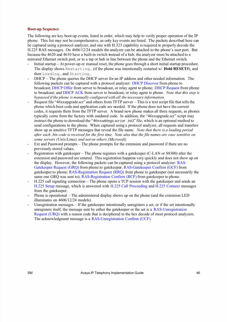
8/13/2019 Av Iptel Imp Gd Cm21 0804
http://slidepdf.com/reader/full/av-iptel-imp-gd-cm21-0804 46/73
SM Avaya IP Telephony Implementation Guide 46
Boot-up Sequence
The following are key boot-up events, listed in order, which may help to verify proper operation of the IP
phone. This list may not be comprehensive, as only key events are listed. The packets described here can be captured using a protocol analyzer, and one with H.323 capability is required to properly decode theH.225 RAS messages. On 4606/12/24 models the analyzer can be attached to the phone’s user port. But
because the 4620 and 4610 have a built-in switch instead of a hub, the analyzer must be attached to amirrored Ethernet switch port, or to a tap or hub in line between the phone and the Ethernet switch.
- Initial startup – At power-up or manual reset, the phone goes through a short initial startup procedure.
The display shows Restarting… (if the phone was intentionally restarted w/ Hold RESET#), and
then Loading… and Starting…
- DHCP – The phone queries the DHCP server for an IP address and other needed information. Thefollowing packets can be captured with a protocol analyzer: DHCP Discover from phone to
broadcast; DHCP Offer from server to broadcast, or relay agent to phone; DHCP Request from phone
to broadcast; and DHCP ACK from server to broadcast, or relay agent to phone. Note that this step isbypassed if the phone is manually configured with all the necessary information.
- Request file “46xxupgrade.scr” and others from TFTP server – This is a text script file that tells the phone which boot code and application code are needed. If the phone does not have the current
codes, it requests them from the TFTP server. A brand new phone makes all three requests, as phonestypically come from the factory with outdated code. In addition, the “46xxupgrade.scr” script mayinstruct the phone to download the “46xxsettings.scr (or .txt)” file, which is an optional method tosend configurations to the phone. When captured using a protocol analyzer, all requests and transfersshow up as intuitive TFTP messages that reveal the file name. Note that there is a loading periodafter each .bin code is received for the first time. Note also that the file names are case sensitive on
some servers (Unix/Linux) and not on others (Microsoft). - Ext and Password prompts – The phone prompts for the extension and password if there are no
previously stored values.- Registration with gatekeeper – The phone registers with a gatekeeper (C-LAN or S8300) after the
extension and password are entered. This registration happens very quickly and does not show up on
the display. However, the following packets can be captured using a protocol analyzer: RAS-
Gatekeeper Request (GRQ) from phone to gatekeeper; RAS-Gatekeeper Confirm (GCF) fromgatekeeper to phone; RAS-Registration Request (RRQ) from phone to gatekeeper (not necessarily thesame one GRQ was sent to); RAS-Registration Confirm (RCF) from gatekeeper to phone.
- H.225 call signaling connection – The phone opens a TCP session with the gatekeeper and sends an
H.225 Setup message, which is answered with H.225 Call Proceeding and H.225 Connect messagesfrom the gatekeeper.
- Phone is operational – The administered display shows up on the phone (and the extension LEDilluminates on 4606/12/24 models).
- Unregistration messages – If the gatekeeper intentionally unregisters a set, or if the set intentionally
unregisters itself, the message sent by either the gatekeeper or the set is a RAS-UnregistrationRequest (URQ) with a reason code that is deciphered in the hex decode of most protocol analyzers.
The acknowledgment message is a RAS-Unregistration Confirm (UCF).

8/13/2019 Av Iptel Imp Gd Cm21 0804
http://slidepdf.com/reader/full/av-iptel-imp-gd-cm21-0804 47/73
SM Avaya IP Telephony Implementation Guide 47
Call Sequence
It is not feasible to give a standard packet-by-packet call sequence, because of the many possible
variations on any given call. Instead, a higher level description of the process is offered here. Dependingon which features are enabled and executed during a call the packet-by-packet sequence may vary, but thefundamental functions described here apply overall. All call signaling functions go through the
gatekeeper, either via the C-LAN or natively (S8300), and the gatekeeper dictates what the IP stations doduring a call.
- Calling phone contacts gatekeeper on TCP 1720, the H.225 call signaling port. TCP 1720 is alwaysthe gatekeeper port. The phone's TCP port varies.
- There are some call signaling exchanges on this TCP session.- Calling phone establishes an audio stream with an audio resource (MedPro board or VoIP module), as
directed by the gatekeeper.
- Gatekeeper contacts called phone on TCP 1720.- There are some call signaling exchanges on this TCP session.- Called phone also establishes an audio stream with an audio resource, as directed by the gatekeeper,
but this stream is one-way until the call completes.
- Called phone answers, resulting in more call signaling activity on TCP 1720, and the call completes.The call could remain in this state, but…
- In most cases, unless configured otherwise, the gatekeeper contacts both phones on TCP 1720 andinstructs them to direct their audio streams to each other.
- Phones direct audio streams to each other, as instructed by the gatekeeper.
- One of the phones hangs up, resulting in more call signaling activity on TCP 1720.- Gatekeeper contacts both phones on TCP 1720 and instructs them to tear down audio streams.- Phones tear down audio streams.
Keepalive Mechanisms
There are two types of keepalive mechanisms: RAS and TCP.- RAS keepalive – The IP telephone sends RAS keepalive messages to the gatekeeper at a time-to-live
(TTL) interval specified by the gatekeeper. On a protocol analyzer a RAS keepalive message shows
up as a RAS-Registration Request (RRQ) with the keepalive bit set in the RAS decode. Each requestmessage is acknowledged by the gatekeeper with a RAS-Registration Confirm (RCF). This exchangetakes place over the RAS socket, which has UDP port 1719 on the gatekeeper side.
- TCP keepalive – The IP telephone sends TCP keepalive messages to the gatekeeper at a regularinterval determined by the phone, or as administered on the ip-network-region form. The keepalive
is an empty TCP datagrams with a sequence number that is 1 to 5 less than the sequence number ofthe previous real TCP message or ACK sent by the phone. The gatekeeper acknowledges eachkeepalive from the phone with a similar empty TCP datagram. This exchange takes place over thecall signaling socket, which has TCP port 1720 on the gatekeeper side.
- Regular and retry intervals – Each keepalive mechanism has a regular interval as described above.
If a regular interval keepalive is not acknowledged, more keepalives are sent at a faster retry
interval. If all the retry keepalives are unanswered, the phone effectively unregisters and moves on
to the next gatekeeper in its gatekeeper list (obtained via DHCP and/or the gatekeeper).- TTL – As stated above, the gatekeeper sends a TTL for the RAS keepalive mechanism. The TTL is
the greater of 60 seconds or a multiplier times the number of registered endpoints. The multiplier fora DEFINITY server is approximately 1.4 seconds, which means that anything above 42 registeredendpoints would exceed the minimum 60-sec TTL. The multiplier for the other servers described inthis document is .1 second, which means that more than 600 registered endpoints are required toexceed the minimum 60-sec TTL.
Independent of the mechanism (RAS or TCP), the keepalive flow follows this pattern.

8/13/2019 Av Iptel Imp Gd Cm21 0804
http://slidepdf.com/reader/full/av-iptel-imp-gd-cm21-0804 48/73
SM Avaya IP Telephony Implementation Guide 48
KA
ACK
KA
ACK
f ai l
ur e
KA
no ACK
retry KA
no ACK
retry KA
no ACK
retry KA
no ACK
retry KA
no ACK
retry KA
no ACK
d i s c
ov er i n g
regular interval regular interval retry int retry int retry int retry int retry int retry int
time to unregister
Figure 19: Keepalive pattern
The discovering at the end of the flow means that the phone has effectively unregistered and is searchingfor another gatekeeper. Effectively unregistered means that the phone has not sent an explicit RAS-
Unregistration Request (URQ) message, but it considers itself unregistered from that gatekeeper and ismoving on to the next. Even if the phone did send a URQ, chances are the gatekeeper would not receiveit because the failure condition could still exist.
The final retry interval prior to discovering would appear to give extra time for the failure to recover.
And indeed if the phone did receive a KA acknowledgment within that final retry interval it would stayregistered to the same gatekeeper. However, the reality is that if the phone doesn’t receive anacknowledgment within a second or two after the final retry KA, it won’t receive one. Therefore, thefinal retry interval really does not factor into the time to unregister. Time to unregister answers the
question, “How long must the failure (ie, network outage) last before the IP telephone unregisters?” If thefailure recovers just before the final retry KA is sent, the phone remains registered to the samegatekeeper. If the failure recovers a couple seconds after the final retry KA is sent, the phone most likelyunregisters and moves on to the next gatekeeper after the final retry interval.
The TCP and RAS keepalive algorithms are as follows.
IP telephone TCP KA
regular intrvl
TCP KA
retry intrvl
Time to
unregister
RAS KA
regular intrvl
RAS KA
retry intrvl
Time to
unregister4606/12/24/20
1.61 thru 1.72
60sec 5 * 30sec 150 to 210sec TTL – 5sec 2 * 45sec 90 to
TTL + 85sec
4620
1.73
60sec 5 * 30sec 150 to 210sec TTL – 5sec 2 * 45sec 90 to
TTL + 85sec
4606/12/24
1.73
15sec 5 * 2.5sec 12.5 to 27.5sec TTL – 5sec 2 * 45sec 90 to
TTL + 85sec
It was intended to make the TCP KA mechanism faster in the 4606/12/24 1.73 code. However, a bug in the code
made it much faster than intended.
4606/12/24/20
1.8 and later
30sec 5 * 10sec 50 to 80sec TTL – 5sec 2 * 45sec 90 to
TTL + 85sec
4620/10
2.x w/ CM 2.x
configurable configur-
able
varies obsolete obsolete n/a
Table 9: TCP and RAS keepalive matrix
4.2 Connecting a PC to the Phone
On the back of the phone, the port with the icon that looks like a terminal is the user port. (The port withthe icon that looks like a network jack is the uplink port, which connects to the Ethernet switch.) Usediscretion when connecting a PC to the phone, and remember that its primary function is not that of an
enterprise network device. For example, do not connect an enterprise server to the phone. Such high-

8/13/2019 Av Iptel Imp Gd Cm21 0804
http://slidepdf.com/reader/full/av-iptel-imp-gd-cm21-0804 49/73
SM Avaya IP Telephony Implementation Guide 49
traffic servers require their own separate connections to the enterprise Ethernet switch. Also, do notconnect a PC to the phone with a 10M uplink to the network, if that PC routinely runs high-volume
transactions. The phone itself operates well at 10M, and the PC itself may also operate adequately at10M. But the two combined can result in the PC overwhelming the 10M link at the expense of audio
quality. Connecting a user PC to the phone at 100M works very well.
IP Phone and Attached PC on Same VLAN
There are three variations of attaching a PC to the phone, and the first two involve having both the phoneand the PC on the same VLAN, which is the port/native VLAN (refer to Appendix A for a primer onVLANs). In the first scenario, traffic from both the phone and the PC have no CoS tagging. In this case,no special configurations are necessary. Simply attach the phone to an access port (one with only the
port/native VLAN configured) and attach the PC to the phone.
The second scenario is similar to the first, except that traffic from the phone is tagged with L2 and/or L3 priority while remaining on the port/native VLAN. See the instructions in section 2.3 under the heading“Rules for 802.1p/Q Tagging.” The phone must be configured to tag its Ethernet frames and/or IP
packets with the desired priority. The Hold ADDR# menu is used to manually enable or disable 802.1Qtagging and to set the VLAN ID. The other parameters are configured via the Hold QOS# menu. Themanual method is covered below, and an automated method is covered in the next paragraph.- 802.1Q – On/off for 802.1Q tagging. Turn this on if L2 priority tagging is desired; off otherwise.- VLAN ID – Should be zero (0) for this scenario, per the instructions in section 2.3, heading “Rules
for 802.1p/Q tagging.” The VID has no effect when 802.1Q tagging is disabled.- L2 audio – Layer 2 CoS tag for Ethernet frames containing audio packets. The phone automatically
receives this value from the call server, per the ip-network-region form. This value could also be setmanually on a per phone basis.
- L2 signaling – Layer 2 CoS tag for Ethernet frames containing signaling packets. The phone
automatically receives this value from the call server, per the ip-network-region form. This valuecould also be set manually on a per phone basis.
- L3 audio – Layer 3 DSCP for audio IP packets. The phone automatically receives this value from the
call server, per the ip-network-region form. This value could also be set manually on a per phone basis.
- L3 signaling – Layer 3 DSCP for signaling IP packets. The phone automatically receives this valuefrom the call server, per the ip-network-region form. This value could also be set manually on a per
phone basis.
The manual menus are covered here for explanatory purposes. However, a better alternative is to use
DHCP option 176 and the built-in capabilities of the call server and IP telephone to automaticallyconfigure the phones. As stated previously, the call server sends the L2 and L3 priority values to the
phones automatically, per the values configured in the ip-network-region form. The 802.1Q on/off
instruction and the VLAN ID can be configured automatically using the DHCP option 176 string asspecified in the “LAN Administrator’s Guide.” Here is what that string should look like for 1.8 and later
phones (see the appropriate “LAN Administrator’s Guide” for previous phone releases).
MCIPADD=addr1 ,addr2 ,addr3 , … ,MCPORT=1719,TFTPSRVR=addr ,L2QVLAN=0
The L2QVLAN=0 parameter instructs the phone to enable 802.1p/Q tagging with VLAN ID 0, which
means that the phone’s traffic belongs on the port/native VLAN. The Ethernet switch port to which the phone is connected must be configured to accept 802.1Q tagging for this to work, and the switch must
interpret VLAN ID 0 as the port/native VLAN ID, per the IEEE 802.1Q standard [6 p.69]. If the

8/13/2019 Av Iptel Imp Gd Cm21 0804
http://slidepdf.com/reader/full/av-iptel-imp-gd-cm21-0804 50/73
SM Avaya IP Telephony Implementation Guide 50
Ethernet switch does not understand VLAN ID 0, the phone may need to tag with the port/native VLANID, although this is not the standard method.
Remember that in order for the CoS tags to have any effect, the corresponding QoS configurations must
be implemented on the necessary network devices. Remember also that improperly enabling L2 and L3tagging may break processes that were working without tagging. Read section 2.3 of this document for
more information on CoS and QoS.
IP Phone and Attached PC on Different VLANs
The third scenario for attaching a PC to the phone (the first two were covered in the previous heading) isto have the phone and the PC on separate VLANs. This requires a multi-VLAN port on the Ethernetswitch as described in section 2.3, heading “Rules for 802.1p/Q Tagging.” One of the VLANs is the
port/native VLAN (the data VLAN), and the clear Ethernet frames (ones with no 802.1Q tag) from the PCare forwarded on this VLAN. The IP phone must tag its traffic with the proper VLAN ID to have itforwarded on the voice VLAN. The Hold ADDR# and Hold QOS# menu options are exactly the sameas described in the previous heading, except that the VID must not be zero. The automated method using
DHCP option 176 is also the same, except that L2QVLAN has a non-zero value and the VLANTEST parameter may be applied.
IP telephone 1.8 and forward has an auto-tagging feature and persistent memory. These allow the phoneto detect whether or not it can use tagged frames, and to preserve the voice VLAN ID through a reboot or
power cycle. The L2Q=0,1 parameter used in DHCP option 176 for earlier firmware is no longerrequired, although it may be restored in later releases. Instead a VLANTEST parameter dictates howlong the phone should try the previously known voice VLAN before reverting back to no tagging.
The following scenario with arbitrary VLAN IDs details the steps a phone (1.8 and later) would go
through in a typical dual-VLAN implementation. It also illustrates the recommended content of theoption 176 string.- Phone with no previously stored values boots up and obtains an address on the data VLAN.
- The data VLAN option 176 string directs the phone to go to voice VLAN 25.
MCIPADD=addr1 ,addr2 , … ,MCPORT=1719,TFTPSRVR=addr ,L2QVLAN=25,VLANTEST=600
- Phone releases the data VLAN address and obtains an address on the voice VLAN.- The voice VLAN option 176 string is identical to the data VLAN string but without the L2QVLAN
parameter, because a phone already on the voice VLAN doesn’t need to be directed to go there.
- Phone is operational on the voice VLAN.- Reboot or power cycle occurs.
- Phone immediately returns to voice VLAN 25 upon recovery, and one of the following occurs.- Phone obtains an address and option 176 string on the voice VLAN and all is well.- Phone cannot obtain an address on the voice VLAN, due to network or DHCP problems. In this
case the VLANTEST=600 parameter directs the phone to continue trying for 600sec (finite rangeis 1-999). If the phone does not succeed in obtaining an address within 600sec, it marks VLAN
25 as invalid and returns to no tagging (back to the data VLAN).
The idea behind going back to the data VLAN after some time is that the phone may have changed portsand be on one with a different voice VLAN. In such a case the phone would have to start over and bedirected to the proper voice VLAN. The idea behind marking VLAN 25 invalid in the previous scenario
is that if the phone hasn’t changed ports, it is preferable to operate on the data VLAN than to be sent to a bad voice VLAN in a continuous loop. For cases where it is not preferable to operate on the data VLAN,
the option VLANTEST=0 was added to legacy phone firmware 1.82 and current phone firmware 2.01.This instructs the phone to permanently remain on the previously known voice VLAN. Once the phone
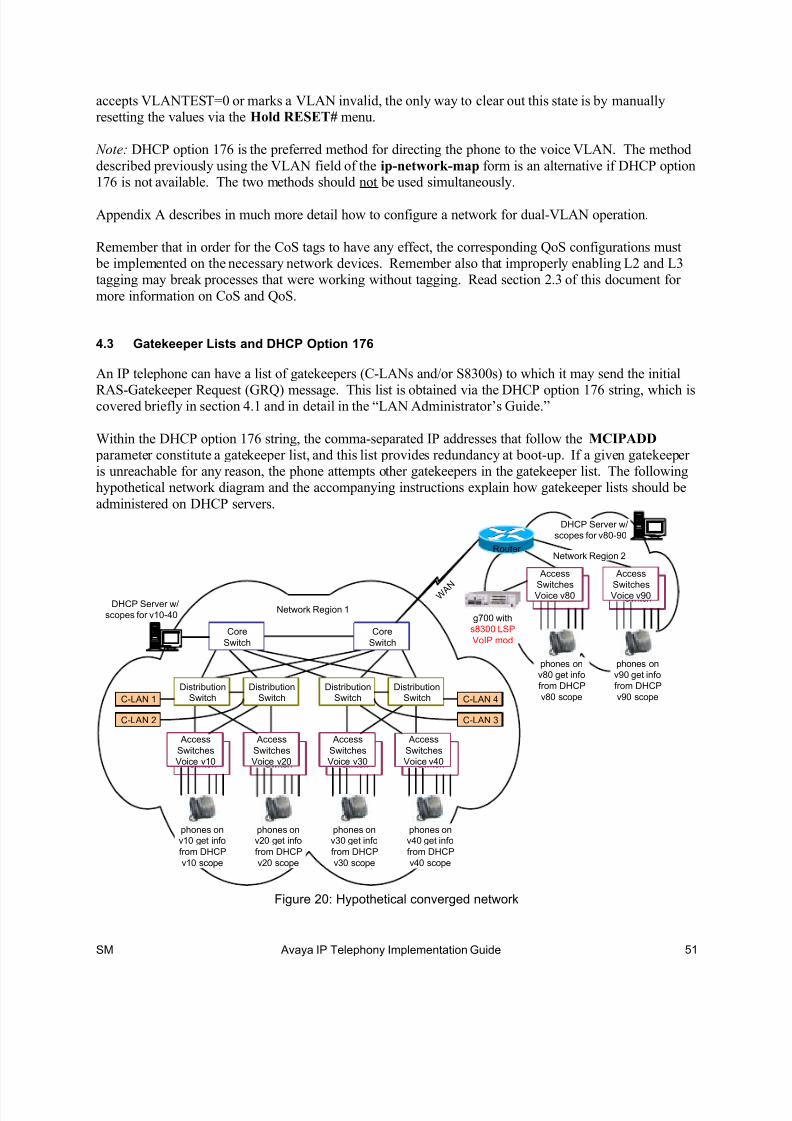
8/13/2019 Av Iptel Imp Gd Cm21 0804
http://slidepdf.com/reader/full/av-iptel-imp-gd-cm21-0804 51/73
SM Avaya IP Telephony Implementation Guide 51
accepts VLANTEST=0 or marks a VLAN invalid, the only way to clear out this state is by manuallyresetting the values via the Hold RESET# menu.
Note: DHCP option 176 is the preferred method for directing the phone to the voice VLAN. The method
described previously using the VLAN field of the ip-network-map form is an alternative if DHCP option176 is not available. The two methods should not be used simultaneously.
Appendix A describes in much more detail how to configure a network for dual-VLAN operation.
Remember that in order for the CoS tags to have any effect, the corresponding QoS configurations must be implemented on the necessary network devices. Remember also that improperly enabling L2 and L3tagging may break processes that were working without tagging. Read section 2.3 of this document for
more information on CoS and QoS.
4.3 Gatekeeper Lists and DHCP Option 176
An IP telephone can have a list of gatekeepers (C-LANs and/or S8300s) to which it may send the initial
RAS-Gatekeeper Request (GRQ) message. This list is obtained via the DHCP option 176 string, which iscovered briefly in section 4.1 and in detail in the “LAN Administrator’s Guide.”
Within the DHCP option 176 string, the comma-separated IP addresses that follow the MCIPADD parameter constitute a gatekeeper list, and this list provides redundancy at boot-up. If a given gatekeeperis unreachable for any reason, the phone attempts other gatekeepers in the gatekeeper list. The followinghypothetical network diagram and the accompanying instructions explain how gatekeeper lists should be
administered on DHCP servers.
DistributionSwitch
Core
Switch
Core
Switch
DistributionSwitch
DistributionSwitch
DistributionSwitch
Access
Switch
Access
Switches
Voice v10 Access
Switch
Access
Switches
Voice v20 Access
Switch
Access
Switches
Voice v30 Access
Switch
Access
Switches
Voice v40
phones onv10 get info
from DHCP
v10 scope
phones onv20 get info
from DHCP
v20 scope
phones onv30 get info
from DHCP
v30 scope
phones onv40 get info
from DHCP
v40 scope
C-LAN 1
C-LAN 2 C-LAN 3
C-LAN 4
Network Region 1DHCP Server w/
scopes for v10-40
AccessSwitch
Access
SwitchesVoice v80 AccessSwitch
Access
SwitchesVoice v90
phones on
v80 get info
from DHCP
v80 scope
phones on
v90 get info
from DHCP
v90 scope
Router
W A N
Network Region 2
DHCP Server w/
scopes for v80-90
g700 with
s8300 LSP
VoIP mod
Figure 20: Hypothetical converged network

8/13/2019 Av Iptel Imp Gd Cm21 0804
http://slidepdf.com/reader/full/av-iptel-imp-gd-cm21-0804 52/73
SM Avaya IP Telephony Implementation Guide 52
Main Site
The converged network depicted in the figure above could be an entire network, or a portion of a much
larger network. The main site is implemented in a core-distribution-access architecture common to manyenterprise networks. The IP phones are scattered across various voice VLANs, but the phones all belongto the same Communication Manager network region because they use the same codec set, share the same
audio characteristics, and use the same resources specified by a network region. Network region 1 hasfour C-LANs scattered across four distribution switches, but there could be more depending on the
number of IP telephones. The fact that there are four C-LANs and four voice VLANs is purelycoincidental.
Suppose, for whatever reason, that a large number of IP phones are rebooted at once. Whichgatekeeper(s) will they contact first? The correct answer is that they should contact all the gatekeepers in
a distributed fashion. All the phones should not bombard the same gatekeeper at once with GRQs. Thereare various ways to configure the gatekeeper lists, and the following is possibly the simplest.
- v10 scope: “MCIPADD=clan1 addr ,clan2 addr ,clan3 addr ,clan4 addr , …”
- v20 scope: “MCIPADD=clan2 addr ,clan3 addr ,clan4 addr ,clan1 addr , …”- v30 scope: “MCIPADD=clan3 addr ,clan4 addr ,clan1 addr ,clan2 addr , …”- v40 scope: “MCIPADD=clan4 addr ,clan1 addr ,clan2 addr ,clan3 addr , …”
Based on how this particular network is implemented, here is another alternative.
- v10 scope: “MCIPADD=clan1 addr ,clan2 addr ,clan3 addr ,clan4 addr , …”- v20 scope: “MCIPADD=clan2 addr ,clan1 addr ,clan4 addr ,clan3 addr , …”- v30 scope: “MCIPADD=clan3 addr ,clan4 addr ,clan1 addr ,clan2 addr , …”- v40 scope: “MCIPADD=clan4 addr ,clan3 addr ,clan2 addr ,clan1 addr , …”
Regardless of how the lists are administered, the principle is important. DHCP scopes should haverotating/varying gatekeeper lists, so as to produce a uniform distribution of GRQs at boot-up. Most
DHCP servers facilitate this by permitting the option 176 string to be created per scope. Even servers likeMicrosoft’s which allow the option 176 string to be created for the entire server, resulting in only one
gatekeeper list, also permit the option 176 string to be created per scope. Note that this principle may alsoapply to multiple TFTP servers.
Branch Site
The branch site is just slightly different in terms of the DHCP scopes, but very different in terms of thefailure scenario and other factors that affect the branch implementation.
The IP telephones at the branch site could access the same four C-LANs shown above, or there could be a
different set of C-LANs (not shown) for the branch IP phones. In either case the DHCP scopes for v80and v90 should have rotating lists, as at the main site. However, in addition to the list of C-LAN
addresses, the v80 and v90 scopes should also include the S8300 LSP address at the end of the list. Thisis because the LSP can take over as the call server for the branch if the WAN link fails. The LSP only
permits registrations when it is active, so having the LSP in the list does not result in inadvertentregistrations to the LSP.
Because an extended WAN link failure is possible, the branch site should ideally have its own DHCPserver. It makes sense that if there is a redundant call server at the branch, there should also be a
dedicated DHCP server, because the IP telephones require both services. For cost and administrativereasons, however, many will choose not to install a DHCP server at all branch locations. In such cases it

8/13/2019 Av Iptel Imp Gd Cm21 0804
http://slidepdf.com/reader/full/av-iptel-imp-gd-cm21-0804 53/73
SM Avaya IP Telephony Implementation Guide 53
is very important that the IP telephones not be rebooted during a WAN link failure, because they wouldnot be able to obtain IP addresses. The manual configuration option is available, but it is not always a
viable option for various reasons.
Two Methods of Receiving the Gatekeeper List
In addition to receiving the gatekeeper list via DHCP option 176, as described above, a gatekeeper list isalso received via the RCF message during registration. In other words, when an IP telephone registers
with the call server, the call server sends a gatekeeper list in the RCF message. The H.323 standard callsthis the Alternate Gatekeeper List. This means that a phone really only needs one gatekeeper address at
boot-up, because the phone receives the gatekeeper list when it registers. This feature is useful for phonesthat are manually administered, as the manual method only permits the entry of one gatekeeper address.However, it is still preferable to administer a gatekeeper list in DHCP option 176 for redundancy during
boot-up.
Here are some key points regarding the option 176 gatekeeper list and the RCF Alternate Gatekeeper List.- IP telephone versions prior to 2.0 use both lists simultaneously. GK addresses received from either
method are merged into one list.- IP telephone 2.0 and later maintains the two lists separately, with only one list active at any given
time. During boot-up the phone uses the list obtained from option 176. After registration the phoneuses the Alternate Gatekeeper List received in the RCF. When a phone is logged off but notrebooted, it reverts back to the list obtained from option 176.
- The option 176 GK list is recommended, as opposed to manual entry or a single GK address in option176, because the RCF list is received after boot-up. If the phone only knows of one GK at boot-upand that GK is out of service, the phone cannot register and hence cannot get an RCF.
- The Alternate Gatekeeper List sent in the RCF follows a specific algorithm. When an IP phoneregisters and its network region is specified in the ip-network-map form, the call server delivers a
list of all gatekeepers in that region, plus connected regions (specified in the ip-network-region form). If an IP phone’s network region is not administered in the ip-network-map form, it inheritsthe region of the gatekeeper that receives the registration, and the call server delivers a list of all
gatekeepers only in that region.- As of Avaya Communication Manager 1.3 the addresses of the LSPs in the same network region as
the IP phone are also sent in the RCF. As of Communication Manager 2.0, in addition to the LSPs,the address of the Survivable GK Node Name is also sent in the RCF, but only to phones that have aSurvivable GK administered on the station form.
- The combination of Communication Manager 2.x and IP telephone 2.x facilitates a distinction between primary and backup gatekeepers in the Alternate Gatekeeper List. During recovery after an
outage, the primary gatekeepers are attempted first for a period of time called the H.323 PrimarySearch Time, specified in the system-parameters ip-options form. After this search time expires,the backup gatekeepers – LSPs and the Survivable GK – are also included in the search. For a more
detailed discussion see the H.323 Link Bounce section of the “Avaya Communication Manager Network Region Configuration Guide” at
www1.avaya.com/enterprise/resourcelibrary/applicationnotes/eclips_general.html.
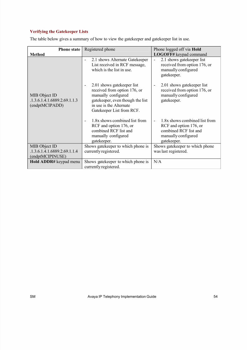
8/13/2019 Av Iptel Imp Gd Cm21 0804
http://slidepdf.com/reader/full/av-iptel-imp-gd-cm21-0804 54/73
SM Avaya IP Telephony Implementation Guide 54
Verifying the Gatekeeper Lists
The table below gives a summary of how to view the gatekeeper and gatekeeper list in use.
Phone state
Method
Registered phone Phone logged off via Hold
LOGOFF# keypad command
MIB Object ID.1.3.6.1.4.1.6889.2.69.1.1.3(endptMCIPADD)
- 2.1 shows Alternate GatekeeperList received in RCF message,which is the list in use.
- 2.01 shows gatekeeper list
received from option 176, ormanually configuredgatekeeper, even though the list
in use is the AlternateGatekeeper List from RCF.
- 1.8x shows combined list fromRCF and option 176, or
combined RCF list andmanually configured
gatekeeper.
- 2.1 shows gatekeeper listreceived from option 176, ormanually configuredgatekeeper.
- 2.01 shows gatekeeper list
received from option 176, ormanually configuredgatekeeper.
- 1.8x shows combined list fromRCF and option 176, or
combined RCF list andmanually configured
gatekeeper.
MIB Object ID.1.3.6.1.4.1.6889.2.69.1.1.4(endptMCIPINUSE)
Shows gatekeeper to which phone iscurrently registered.
Shows gatekeeper to which phonewas last registered.
Hold ADDR# keypad menu Shows gatekeeper to which phone iscurrently registered.
N/A

8/13/2019 Av Iptel Imp Gd Cm21 0804
http://slidepdf.com/reader/full/av-iptel-imp-gd-cm21-0804 55/73
SM Avaya IP Telephony Implementation Guide 55
Appendix A: VLAN Primer
This appendix is primarily concerned with configurations that require the Avaya IP Telephone to connect to
an Ethernet switch (Eth-switch) port configured with multiple VLANs – the IP phone on one VLAN and a PC
connected to the phone on a separate VLAN. Three sets of configurations are given: Avaya P330 v3.2.8 and later,
Cisco CatOS, and some Cisco IOS.
VLAN Defined
With simple Eth-switches, the entire switch is one L2 broadcast domain that typically contains one IP
subnet (L3 broadcast domain). Think of a single VLAN (on a VLAN-capable Eth-switch) as being equivalent to a
simple Eth-switch. A VLAN is a logical L2 broadcast domain that typically contains one IP subnet. Therefore,
multiple VLANs are logically separated subnets – analogous to multiple switches being physically separated
subnets. A L3 routing process is required to route between VLANs, just as one is required to route between
switches. This routing process can take place on a connected router or a router module within a L2/L3 Eth-switch.
If there is no routing process associated with a VLAN, devices on that VLAN can only communicate with other
devices on the same VLAN.
For a tutorial and more information on VLANs, see “LANs and VLANs: A Simplified Tutorial” at
www1.avaya.com/enterprise/resourcelibrary/applicationnotes/eclips_general.html.
The Port or Native VLAN
Port VLAN and native VLAN are synonymous terms. The IEEE standard and most Avaya switches use the
term port VLAN [6 p.11], but Cisco switches use the term native VLAN. Issue the command show trunk on P330s
and CatOS Catalysts to see which term is used in the display output.
Every port has a port/native VLAN. Unless otherwise configured, it is VLAN 1 by default. It can be
configured on a per port basis with the following commands.
Avaya P330 v3.2.8 and later Cisco CatOS
set port vlan <id> <mod/port> set vlan <id> <mod/port>
All clear Ethernet frames (ones with no 802.1Q tag, such as from a PC) are forwarded on the port/native
VLAN. This is true even if the Eth-switch port is configured as an 802.1Q trunk, or otherwise configured for
multiple VLANs (see VLAN binding heading below).
Configuring a Trunk
A trunk port on an Eth-switch is one that is capable of forwarding Ethernet frames on multiple VLANs via
the mechanism of VLAN tagging. IEEE 802.1Q specifies the standard method for VLAN tagging. Cisco also uses
a proprietary method called ISL. Avaya products do not interoperate with ISL.
A trunk link is a connection between two devices across trunk ports. This can be between a router and a
switch, between two switches, or between a switch and an IP phone. Some form of trunking or forwarding multiple
VLANs must be enabled to permit the IP phone and the attached PC to appear on separate VLANs. The followingcommands enable trunking.
Avaya P330 v3.2.8 and later Cisco CatOS
set trunk <mod/port> dot1q
By default only the port/native VLAN is enabled on
the trunk port. Another set of commands is required
to specify other allowed VLANs.
set trunk <mod/port> nonegotiate dot1q
By default all VLANs (1-1005) are enabled on the
trunk port. VLANs can be selectively removed with
the command clear trunk <mod/port> <vid>.

8/13/2019 Av Iptel Imp Gd Cm21 0804
http://slidepdf.com/reader/full/av-iptel-imp-gd-cm21-0804 56/73
SM Avaya IP Telephony Implementation Guide 56
Note that Avaya adds additional VLANs to a trunk port that has only one VLAN, while Cisco removes
excess VLANs from a trunk port that has all VLANs. Either method achieves the desired objective, which is to
have only two VLANs configured on a trunk port connected to an IP phone. That is, broadcasts from non-essential
VLANs are not permitted to bog down the link to the IP phone.
VLAN Binding Feature (P330 v3.2.8 and later)
On the Avaya P330, additional VLANs are added to a port using the VLAN binding feature. The port may
be a trunk port (802.1Q tagging enabled) or an access port (no 802.1Q tagging). The port does not need to be a
trunk to forward multiple VLANs, and for one application – connecting to an Avaya IP phone – it must not be a
trunk (ie, do not issue the set trunk command). The following steps enable VLAN binding.
1. Verify that the port is configured with the desired port/native VLAN.
2. Add additional VLANs with one of the following vlan-binding-mode options.
Static option:
set port vlan-binding-mode <mod/port> static Put the port in bind-to-static mode.
set port static-vlan <mod/port> <vid> Statically add another VLAN, in addition to the
port/native VLAN.
----- OR -----
Configured option:
set vlan <id> Add a VLAN to the configured VLAN list. Type show
vlan to see entire list.
set port vlan-binding-mode <mod/port> bind-to-
configured
Apply the configured VLANs to the port and permit
only those VLANs (bind-to-all permits all VLANs and
not just the configured).
3. If the port is connected to a router or to another switch, trunking must be enabled with the command set trunk
<mod/port> dot1q, which causes all egress frames to be tagged. However, if the port is connected to an Avaya
IP phone with an attached PC, trunking must not be enabled so that none of the egress frames are tagged. This
is necessary because most PCs do not understand tagged frames.
Setting the Priority without Trunking or VLAN binding (Single-VLAN Scenario)
With Avaya switches it is possible to set the L2 priority on the IP phone, even if the phone is not connected
to a trunk or multi-VLAN port. That is, the Avaya switch does not need to be explicitly configured to accept
priority-tagged Ethernet frames on a port with only the port/native VLAN configured. This is useful if the phone
and the attached PC are on the same VLAN (same IP subnet), but the phone traffic requires higher priority. Simply
enable 802.1Q tagging on the IP phone, set the priorities as desired, and set the VID to zero (0). Per the IEEE
standard, a VID of zero assigns the Ethernet frame to the port/native VLAN.
Cisco switches behave differently in this scenario, depending on the hardware platforms and OS versions.
Here are Avaya Labs test results with a sample of hardware platforms and OS versions.
Catalyst 6509 w/
CatOS 6.1(2)
Accepted VID zero for the native VLAN when 802.1Q trunking was
enabled on the port. In this case, all but the native VLAN should be cleared
off the trunk.
Catalyst 4000 w/
CatOS 6.3(3)
Would not accept VID zero for the native VLAN. Opened a case with
Cisco TAC, and TAC engineer said it was a hardware problem in the 4000.
Bug ID is CSCdr06231. Workaround is to enable 802.1Q trunking and tag
with native VID instead of zero. Again, clear all but the native VLAN off
the trunk.

8/13/2019 Av Iptel Imp Gd Cm21 0804
http://slidepdf.com/reader/full/av-iptel-imp-gd-cm21-0804 57/73
SM Avaya IP Telephony Implementation Guide 57
Catalyst 3500XL w/
IOS 12.0(5)WC2
Accepted VID zero for the native VLAN when 802.1Q trunking was
disabled on the port.
Conclusion Note the hardware platform and OS version and consult Cisco’s
documentation, or call TAC.
Note that setting a L2 priority is only useful if QoS is enabled on the Eth-switch. Otherwise, the priority-
tagged frames are treated no differently than clear frames.
Sample Multi-VLAN Scenario for Avaya P330 Code 3.2.8 and Cisco CatOS and IOS
Here is a sample multi-VLAN scenario. Suppose there is a Cisco router connected to a P330 switch that
contains two VLANs, one for the VoIP devices and one for the PCs. To conserve ports and cabling, the PCs are
connected to the phones and the phones are connected to the P330 switch.
PC
Cisco Router
f0/1
vlan 1
192.168.1.7
vlan 10192.168.10.7
1/1 1/5
DHCP Server
TFTP Server
vlan 1
192.168.1.100
1/12
S8100/G600
Avaya
Cajun P330
1/2 1/3
C-LAN
vlan 10
192.168.10.1
MedPro
vlan 10
192.168.10.2
192.168.1.254
192.168.10.254
Avaya
IP Phone
Cisco Router configuration
interface FastEthernet0/1
description 802.1Q trunk interface
!
interface FastEthernet0/1.1
encapsulation dot1q 1
ip address 192.168.1.254 255.255.255.0
!
interface FastEthernet0/1.10
encapsulation dot1q 10
ip address 192.168.10.254 255.255.255.0
ip helper-address 192.168.1.100 To forward DHCP requests to the DHCP server.
P330 configuration (bind-to-static option)
set port vlan-binding-mode 1/1 static
set port static-vlan 1/1 10
set trunk 1/1 dot1q
set port spantree disable 1/1
set port vlan 10 1/2
set port spantree disable 1/2
All ports have port/native VLAN 1 by default.
Port in static binding mode by default, but command shown.
In addition to v1, v10 statically bound to port.
Port connected to Cisco router is an 802.1Q trunk port.
Spanning Tree disabled at the port level.
Port/native VLAN changed to 10 on this port.
Spanning Tree disabled at the port level.

8/13/2019 Av Iptel Imp Gd Cm21 0804
http://slidepdf.com/reader/full/av-iptel-imp-gd-cm21-0804 58/73
SM Avaya IP Telephony Implementation Guide 58
set port level 1/2 6
set port vlan 10 1/3
set port spantree disable 1/3
set port level 1/3 6
set port vlan-binding-mode 1/5 static
set port static-vlan 1/5 10
set port spantree disable 1/5
set port spantree disable 1/12
Port L2 (802.1p) priority set to 6.
Port in static binding mode by default, but command shown.
In addition to v1, v10 statically bound to port, but not a trunk port.
Spanning Tree disabled at the port level.
Port 1/12 for the DHCP/TFTP server already has port/native VLAN 1.
Spanning Tree disabled at the port level.
P330 configuration (bind-to-configured option)
set vlan 1
set vlan 10
set port vlan-binding-mode 1/1 bind-to-
configured
set trunk 1/1 dot1q
set port spantree disable 1/1
set port vlan 10 1/2
set port spantree disable 1/2
set port level 1/2 6
set port vlan 10 1/3
set port spantree disable 1/3
set port level 1/3 6
set port vlan-binding-mode 1/5 bind-to-
configured
set port spantree disable 1/5
All ports have port/native VLAN 1 by default.
v1 configured
v10 configured
Port bound to configured VLANs 1 and 10.
Port connected to Cisco router is an 802.1Q trunk port.
Spanning Tree disabled at the port level.
Port/native VLAN changed to 10 on this port.
Spanning Tree disabled at the port level.
Port L2 (802.1p) priority set to 6.
Bound to configured VLANs but not a trunk port.
Spanning Tree disabled at the port level.
If the P330 switch were a Cisco CatOS switch instead
set port host
set vlan 1005 1/1
set trunk 1/1 on dot1q
clear trunk 1/1 2-9,11-1004
set vlan 10 1/2
set port qos 1/2 cos 6
set vlan 10 1/3
set port qos 1/3 cos 6
set trunk 1/5 nonegotiate dot1q
clear trunk 1/5 2-9, 11-1005
set port auxiliaryvlan 1/5 10
All ports have port/native VLAN 1 by default.
First invoke this command on all user ports.
Cisco switches do not tag the native VLAN, but the router expects a
tag on v1, so the native VLAN is changed to some unused VLAN.
Port connected to Cisco router is an 802.1Q trunk port.
Unnecessary VLANs removed; 1, 10, and 1005 remain.
Port/native VLAN changed to 10 on this port.
Port L2 (802.1p) priority set to 6.
Plain 802.1Q trunk port with no Cisco negotiation features.
Unnecessary VLANs removed; 1 and 10 remain.
Optional command using auxiliaryvlan on the phone port instead of
explicit trunking.
v10 is the auxiliaryvlan; only v1 and v10 on this port; port is an
802.1Q trunk port, though not explicitly configured.

8/13/2019 Av Iptel Imp Gd Cm21 0804
http://slidepdf.com/reader/full/av-iptel-imp-gd-cm21-0804 59/73
SM Avaya IP Telephony Implementation Guide 59
If the P330 switch were a Cisco IOS switch instead
interface FastEthernet0/1
switchport trunk encapsulation dot1q
switchport trunk native vlan 1005
switchport trunk allowed vlan 1,10,1005switchport mode trunk
spanning-tree portfast
interface FastEthernet0/2
switchport access vlan 10
spanning-tree portfast
switchport priority default 6
interface FastEthernet0/3
switchport access vlan 10
spanning-tree portfast
switchport priority default 6
interface FastEthernet0/5
switchport trunk encapsulation dot1q
switchport trunk native vlan 1
switchport trunk allowed vlan 1,10
switchport mode trunk
spanning-tree portfast
All ports have port/native VLAN 1 by default.
Port connected to Cisco router is an 802.1Q trunk port.
Cisco switches do not tag the native VLAN, but the router expects a
tag on v1, so the native VLAN is changed to some unused VLAN.
VLANs 1, 10, and 1005 allowed on trunk.Port is in trunk mode.
Spanning Tree fast start feature.
Port/native VLAN changed to 10 on this port.
Spanning Tree fast start feature.
Port native VLAN L2 (802.1p) priority set to 6.
802.1Q trunk port.
Since most PCs do not understand the tag, the PC’s VLAN must be
the native VLAN. v1 is already the native, but command shown.
VLANs 1 and 10 allowed on trunk.
Port is in trunk mode.
Spanning Tree fast start feature.
IP phone configuration
This procedure applies regardless of the Eth-switch being used. Initially placing the IP phone on VLAN 10
requires two DHCP scopes – one for VLAN 1 and another for VLAN 10. Both scopes should have identical DHCP
option 176 parameters, with one exception. The VLAN 1 scope must have the L2QVLAN parameter, and the
VLAN 10 scope should not. The following strings apply to phone firmware 1.8 and beyond.
v1: MCIPADD=addr1 ,addr2 ,addr3 , … ,MCPORT=1719,TFTPSRVR=addr ,L2QVLAN=10,VLANTEST=600
v10: MCIPADD=addr1 ,addr2 ,addr3 , … ,MCPORT=1719,TFTPSRVR=addr ,VLANTEST=600
Run the phone through its normal boot-up sequence. It obtains an IP address on VLAN 1 – the port/native
VLAN. When the phone receives the option 176 string above from the VLAN 1 scope, it releases the VLAN 1
address and enters a second DHCP sequence with tagging enabled to obtain a VLAN 10 address. After the phone is
operational on VLAN 10, subsequent reboots result in the phone returning to VLAN 10 directly, instead of passing
through VLAN 1. If an address is not obtained on VLAN 10 for 10min (VLANTEST=600), the phone reverts back
to no tagging (VLAN 1). With legacy phone firmware 1.82 and current phone firmware 2.01, VLANTEST=0 could
be used to make the phone stay on VLAN 10 indefinitely. See section 4.2, heading “IP Phone and Attached PC on
Different VLANs” for a full explanation of how the phone operates between the data and voice VLANs, including
the use of the VLANTEST parameter.
The L2QVLAN parameter should not be added to the VLAN 10 DHCP scope. This is so that in the event
a phone is connected to a port that has VLAN 10 as the port/native VLAN, it will not receive instructions from the
DHCP scope to enable tagging. In such a case the phone would not require tagging to function on VLAN 10, and
tagging could result in an incompatibility with the Eth-switch.
PC configuration: The PC can be statically addressed with a VLAN 1 address, or it can receive a VLAN 1 address
via DHCP. No special configurations are required.

8/13/2019 Av Iptel Imp Gd Cm21 0804
http://slidepdf.com/reader/full/av-iptel-imp-gd-cm21-0804 60/73
SM Avaya IP Telephony Implementation Guide 60
Appendix B: Cisco Auto-Discovery
This appendix describes Cisco’s proprietary auto-discovery feature using CDP and the auxiliaryvlan. Some
customers have requested that Avaya IP phones be put on the auxiliaryvlan. The previous position was that it was
believed to work but was not recommended. However, recent tests have shown successful interoperability with both
the auxiliaryvlan (CatOS) and the voice vlan (IOS). This testing was initiated because of the inability to enable
portfast on older Catalyst 6500 code (pre 5.5.14, 6.3.2, 7.2.2) when the port is in trunk mode. The resulting request
was to use the auxiliaryvlan instead of explicit trunking, because portfast can be enabled on auxiliaryvlan ports, even
on the older code releases. auxiliaryvlan and voice vlan were successfully tested on the following platforms, with
no known issues to date.
auxiliaryvlan on Catalyst 6509 w/ CatOS version 7.2.2
auxiliaryvlan on Catalyst 6509 w/ CatOS version 6.3.7
auxiliaryvlan on Catalyst 6509 w/ CatOS version 5.5.15
auxiliaryvlan on Catalyst 6509 w/ CatOS version 5.5.7a
auxiliaryvlan on Catalyst 6509 w/ CatOS version 5.5.3a
auxiliaryvlan on Catalyst 4000 w/ CatOS version 7.2.2
auxiliaryvlan on Catalyst 4000 w/ CatOS version 6.3.3
auxiliaryvlan on Catalyst 4000 w/ CatOS version 5.5.15
auxiliaryvlan on Catalyst 4000 w/ CatOS version 5.5.7a
voice vlan on Catalyst 3524 with IOS version 12.0.5
Therefore, the current Avaya position is that both the auxiliaryvlan (implicit 802.1Q trunking) and explicit
802.1Q trunking appear to be viable options when a dual-VLAN environment is required (see Appendix A). It is
left to the user to choose the method. The benefits of using the auxiliaryvlan are simpler configuration and no
known issues with the ability to enable portfast. However, auxiliaryvlan is a Cisco proprietary mechanism and is
not subject to constraint by a standards body or by Avaya. 802.1Q trunking is well tested, successfully deployed,
and defined by a standards body. But the inability to enable portfast on some CatOS versions is an obstacle that
merits the use of the auxiliaryvlan instead. For IOS-based Catalyst switches the voice vlan is roughly equivalent to
the auxiliaryvlan, but there appear to be no configuration or functionality benefits to using the voice vlan.
Note that Avaya IP phones still do not interoperate with CDP. Therefore, although the auxiliaryvlan can be
used, the mechanism of discovering the auxiliaryvlan via CDP is not supported. The Avaya IP phone can learn the
auxiliaryvlan designation via DHCP option 176, as explained below and in Appendix A.
How it Works
At the heart of this feature are Cisco-proprietary mechanisms. The first proprietary mechanism is CDP
(Cisco Discovery Protocol). This is a layer 2 protocol, which means that it works at the Ethernet level, without
requiring IP addresses. Cisco devices identify themselves to other Cisco devices using CDP packets that contain
device- and port-specific information. (CDP packets can be captured and decoded using protocol analyzers that
support CDP.) With certain devices the CDP packets contain information that is specific to VoIP and other real-
time applications. This VoIP information exchange requires CatOS (Catalyst Operating System) version 5.5 or
higher on Catalyst 4000, 5000, 6000, and 6500 series switches and 2948G and 2980G switches. The voice vlan is
supported on the Catalyst 2900XL and 3500XL series switches running IOS 12.0.5XU and higher. [1 p.2-22]
Using CDP, the Catalyst sends the Cisco IP phone an auxiliaryvlan ID, if auxiliaryvlan is enabled, and the phone tags its frames to be forwarded on that VLAN. The auxiliaryvlan is the second Cisco-proprietary mechanism,
and it must be enabled on the port that connects to the IP phone. It is VLAN 200 by default or can be arbitrarily
assigned as any number between 1 and 1000. According to Cisco’s documentation the auxiliaryvlan is just another
802.1Q VLAN. The only difference is the proprietary method of assigning it to a Cisco IP phone. The port with the
auxiliaryvlan also has a port/native VLAN (VLAN 1 by default or any arbitrarily assigned VLAN). This implies
that the port is an 802.1Q trunk port with two VLANs, and can accept 802.1p/Q tagged frames. This is similar to
the VLAN binding feature on the Avaya P330 v3.2.8 and later. [1 p.2-22, 2-23]

8/13/2019 Av Iptel Imp Gd Cm21 0804
http://slidepdf.com/reader/full/av-iptel-imp-gd-cm21-0804 61/73
SM Avaya IP Telephony Implementation Guide 61
The information passed from the Cisco phone to the Catalyst is not of concern. The phone communicates
its specific power requirements to the Catalyst, and the phone can also trigger the Catalyst to send its CDP packet
immediately instead of waiting for the transmit period (60 seconds by default) to recycle. [1 p.2-23]
Avaya IP Phones on Cisco Auxiliaryvlan
The auxiliaryvlan is a modified method of implementing 802.1Q trunking, and it may be nothing more than
this. Although testing to date has been positive, Avaya does not know what other mechanisms are or will be
incorporated with this feature, or if they could have any adverse effects on Avaya IP phones. Assuming that an
auxiliaryvlan-enabled port is truly a standard 802.1Q trunk port, the following steps allow Avaya IP phones to work
on Cisco’s auxiliaryvlan.
1) Verify that the auxiliaryvlan is enabled.
a) For example, the command set port auxiliaryvlan 2/4-8 500 would make ports 2/4 through 2/8
auxiliaryvlan-capable with auxiliaryvlan ID 500.
b) The command set port auxiliaryvlan 2/4-8 (w/o the 500) would make ports 2/4 through 2/8 auxiliaryvlan-
capable with the default auxiliaryvlan ID 200.
c) The command show port auxiliaryvlan reveals the ports that have been made auxiliaryvlan-capable, and
their respective auxiliaryvlan ID(s). The command show port reveals each port’s port/native VID.
2) Bring up the phones on the auxiliaryvlan using the same procedures that would be used on a regular trunk port.
a) Verify that a L3 router interface exists for both the port/native VLAN and the auxiliaryvlan, with anassociated subnet and gateway IP address. Both interfaces must be configured to forward DHCP requests
(ip helper-address <I P addr. of DHCP server >) to the DHCP server if the server is on a different subnet.
b) Follow the instructions at the end of appendix A to get the IP phone on the auxiliaryvlan (voice VLAN).
c) After the phone boots up, press Hold ADDR # to verify that the phone received an IP address and
associated information for the auxiliaryvlan.
3) For call servers, IP boards (ie, C-LAN and MedPro), and other VoIP resources, configure their ports on the Eth-
switch to be native to the auxiliaryvlan. That is, these ports do not require both a port/native VLAN and an
auxiliaryvlan. Just make the auxiliaryvlan the port/native VLAN on these ports (set vlan 200 <mod/port>,
assuming 200 is the auxiliaryvlan ID). Then disable the auxiliaryvlan feature on these ports (set port
auxiliaryvlan <mod/port> none).
4) Always verify network connectivity between devices using pings and trace-routes.

8/13/2019 Av Iptel Imp Gd Cm21 0804
http://slidepdf.com/reader/full/av-iptel-imp-gd-cm21-0804 62/73
SM Avaya IP Telephony Implementation Guide 62
Appendix C: RTP Header Compression
RTP header compression is a mechanism that reduces the protocol overhead associated with VoIP audio
packets. It is a function of the network and not a function of the VoIP application. Along with the benefits of using
RTP header compression there are also cautions, and this appendix discusses both.
Application Perspective
Here is the anatomy of a 20-ms G.729 audio packet, which is recommended for use across limited
bandwidth WAN links. Notice that two-thirds of the packet is consumed by overhead (IP, UDP, and RTP), and only
one-third is used by the actual audio.
IP Header
20 B
UDP Hdr
8 B
RTP Header
12 B
20ms of G.729 Audio
20B
It is important to understand that all 20-ms G.729 audio packets, regardless of the vendor, are constructed like this.
Not only is the structure of the packet the same, but the method of encoding and decoding the audio itself is also the
same. This sameness is what allows an Avaya IP phone to communicate directly with a Cisco IP phone, or any
other IP phone, when using matching codecs. The packets from the application perspective are identical.
Network Perspective
RTP header compression is a mechanism employed by routers to reduce the 40 bytes of protocol overhead
to approximately 2 to 4 bytes [7 p.1] [2 p.5-14]. Cisco routers employ this mechanism, as does the Avaya
X330WAN router, which is a module for the P330 chassis. RTP header compression can drastically reduce the
VoIP bandwidth consumption on a WAN link when using 20-ms G.729 audio. When the combined 40-byte header
is reduced to 4 bytes, the total IP packet size is reduced by 60% (from 60 bytes to 24 bytes). This equates to
reducing the total VoIP WAN bandwidth consumption by roughly half, and it applies to all 20-ms G.729 audio
packets, regardless of the vendor.
Customers who deploy routers capable of this feature may be able to benefit from it. However, Cisco
recommends caution in using RTP header compression because it can significantly tax the processor if the
compression is done in software. Depending on the processor load before compression, enabling RTP header
compression could significantly slow down or crash the router. For best results, use a hardware/IOS/interfacemodule combination that permits the compression to be done in hardware [3 QC-333] [5 “RTP Header
Compression and QoS”].
RTP header compression has to function with exactness or it will disrupt audio. If for any reason the
compression at one end of the WAN link and decompression at the other end do not function properly, the result
could be intermittent loss of audio or one-way audio. This has been very difficult to quantify, but there is some
anecdotal evidence. One production site in particular experienced intermittent one-way audio whose cause was very
difficult to troubleshoot and isolate. When RTP header compression was disabled, simply for experimentation
purposes, the audio problems went away.
The Test
This section details the results of a simple RTP header compression test conducted in a lab environment.Although this test was conducted using Cisco routers, the expected behavior is the same for any router that performs
this function as specified in RFC 2508 [7]. This test was performed in the following lab configuration.

8/13/2019 Av Iptel Imp Gd Cm21 0804
http://slidepdf.com/reader/full/av-iptel-imp-gd-cm21-0804 63/73
SM Avaya IP Telephony Implementation Guide 63
- NetIQ Chariot v4.0 was used to simulate VoIP calls between the two endpoints. Chariot v4.0 accurately
simulates the characteristics of various codecs and uses a 40-byte IP/UDP/RTP header.
- Sniffer Pro v3.50.02 was used to capture the sent and received packets.
- The Cisco 3600 had IOS v12.1(2)T and the Cisco 1600 had IOS v12.0(12).
- The Fredericks Engineering Parascope WAN probe was tapped into the V.35 serial link to take bandwidth
measurements.
- This test was performed using PPP encapsulation on the WAN link.
A single call was placed between the Chariot endpoints using various codecs, all sending 20-ms voice packets. Below are the results with and without RTP header compression. Note that these are rough measurements.
Avg WAN BW consumption (kbps)Codec Payload
bytes/packet
Packets/sec
w/o compression w/ compression
% reduction
G.711 (64 kbps) 160 50 84 68.5 ~18 %
G.729A (8 kbps) 20 50 27.5 13 ~53%
For each codec there was an attempt to verify that the audio packets were received in tact. This was done
by spot-checking the audio packets before and after compression, using two Sniffer protocol analyzers. For every
codec except G.711 the RTP header and payload were identical before and after compression. With G.711,
however, the received packets had the PADDING flag set in the RTP header, although the flag was not set when the
packets were transmitted. The PADDING flag indicates the presence of padding octets at the end of the RTP
payload, which cannot be true for G.711. Why this occurred is unknown, but it does not really matter because thereis no point in using the G.711 codec if bandwidth is scarce.
Configuration
To configure RTP header compression on a Cisco router,
1. Specify the number of RTP connections that can be compressed (cache allocation). In interface configuration
mode, the command is ip rtp compression-connections <number>. The default is 32, and each call requires
two connections. The configurable range is 3 to 256 for PPP and HDLC using IOS v11.3 and later; and 3 to
1000 for PPP and HDLC using IOS v12.0(7)T and later. For Frame Relay the value is fixed at 256.
2. The command to turn on compression is ip rtp header-compression in interface configuration mode. It must
be implemented at both ends of the WAN link. For this experiment, when the command was entered into the
router, ip tcp header-compression was also installed automatically. When either command was removed the
other was automatically removed.
Consult Cisco’s documentation for more specific configurations on other types of WAN links (ie, Frame Relay and
ATM) [2 p.5-14, 5-18, 5-26, 5-33] [3]. Configuration for the X330WAN router is very similar to Cisco and well
documented in the X330WAN User Guides.

8/13/2019 Av Iptel Imp Gd Cm21 0804
http://slidepdf.com/reader/full/av-iptel-imp-gd-cm21-0804 64/73
SM Avaya IP Telephony Implementation Guide 64
Appendix D: Access List Guidelines
This appendix gives guidelines for configuring access lists to facilitate basic Avaya IP telephony
functionality. The ports used by the Avaya call server are fairly fixed and known. The ports used by the endpoints
are more variable and random. As a result, it is simpler to tailor access lists based on call server ports.
Action From TCP/UDP port
or Protocol
To TCP/UDP port
or Protocol
The C-LAN uses UDP port 1719 for endpoint registration (RAS).
Permit Any C-LAN UDP 1719 Any endpoint UDP any
Permit Any endpoint UDP any Any C-LAN UDP 1719
The C-LAN uses TCP port 1720 for H.225 call signaling.
Permit Any C-LAN TCP 1720 Any endpoint TCP any
Permit Any endpoint TCP any Any C-LAN TCP 1720
This is to facilitate IP trunking between two Avaya call servers, and must be done for each IP trunk.
Permit Near-end C-LAN TCP 1720 Far-end C-LAN TCP 1720
Permit Far-end C-LAN TCP 1720 Near-end C-LAN TCP 1720
This is one way to facilitate audio streams between MedPros and endpoints.
Permit Any MedPro UDP port range
in ip-network-region form
Any endpoint UDP any
Permit Any endpoint UDP any Any MedPro UDP port range in
ip-network-region
form
This is another way to facilitate audio streams between MedPros and endpoints.
Permit Any MedPro RTP/RTCP Any endpoint --
Permit Any endpoint RTP/RTCP Any MedPro --
This is to facilitate audio streams between direct IP-IP (shuffled) endpoints.
Permit Any endpoint UDP any
RTP/RTCP
Any endpoint UDP any
--
The R300 uses this default UDP port range for audio. However, the range is configurable.
Permit Any R300 UDP 1900-2075
RTP/RTCP
Any MedPro or endpoint UDP varies
--Permit Any MedPro or endpoint UDP varies
RTP/RTCP
Any R300 UDP 1900-2075
--
Permit Any R300 UDP 1900-2075
RTP/RTCP
Any R300 UDP 1900-2075
--
These are all services used by the IP telephone. TFTP is tough to isolate to a port range. The GET and PUT
requests from the client go to the server’s UDP port 69, but all other messages go between random ports.
Permit Any IP telephone (hardphone) UDP any DNS server(s) UDP 53 (dns)
Permit DNS server(s) UDP 53 (dns) Any IP telephone (hardphone) UDP any
Permit Any IP telephone (hardphone) UDP 68 (bootpc) DHCP server(s) UDP 67 (bootps)
Permit DHCP server(s) UDP 67 (bootps) Any IP telephone (hardphone) UDP 68 (bootpc)
Permit Any IP telephone (hardphone) TFTP TFTP server(s) --
Permit TFTP server(s) TFTP Any IP telephone (hardphone) --
Permit SNMP management station(s) UDP any Any IP telephone (hardphone) UDP 161 (snmp)
Permit Any IP telephone (hardphone) UDP 161 (snmp) SNMP management station(s) UDP any
Avaya devices ping other devices for various reasons. For example, C-LANs ping endpoints for management
purposes; MedPros ping C-LANs to gauge network performance across an IP trunk; IP telephones ping TFTP
servers for verification purposes.
Permit Any Avaya device ICMP Echo Any --
Permit Any ICMP Echo
Reply
Any Avaya device --

8/13/2019 Av Iptel Imp Gd Cm21 0804
http://slidepdf.com/reader/full/av-iptel-imp-gd-cm21-0804 65/73
SM Avaya IP Telephony Implementation Guide 65
The following table contains access list guidelines for Avaya media servers and media gateways. The
S8700 enterprise interface, which is the one connected to the enterprise network (vs. the control network), is eth4 on
Multi-Connect systems and eth0 on IP-Connect systems.
Action From TCP/UDP port
or Protocol
To TCP/UDP port
or Protocol
This allows the S8500/8700 to synchronize translations with the S8300 LAN Spare Processor (LSP). A TCP sessionis initiated from the S8500/8700 to the S8300 TCP port 514. A second session is then initiated from the S8300 to
the S8500/8700 TCP port range 512-1023.
Permit S8700 enterprise interface TCP any S8300 LSP TCP 514
Permit S8300 LSP TCP 514 S8700 enterprise interface TCP any
Permit S8300 LSP TCP any S8700 enterprise interface TCP 512-1023
Permit S8700 enterprise interface TCP 512-1023 S8300 LSP TCP any
This allows an administrator to log in via Avaya SA to a call server (S8500/8700 and S8300).
Permit Avaya SA workstation TCP any S8700-ent-intf or S8300 TCP 5023
Permit S8700-ent-intf or S8300 TCP 5023 Avaya SA workstation TCP any
This allows secure and unsecure web access to a call server (S8500/8700 and S8300). The call server redirects
unsecure sessions to https.
Permit Web admin station TCP any S8700-ent-int or S8300 TCP 80
Permit S8700-ent-int or S8300 TCP 80 Web admin station(s) TCP anyPermit Web admin station TCP any S8700-ent-int or S8300 TCP 443
Permit S8700-ent-int or S8300 TCP 443 Web admin station(s) TCP any
Optional services used by S8500/8700 and S8300.
Permit S8700-ent-int or S8300 UDP any DNS server(s) UDP 53 (dns)
Permit DNS server(s) UDP 53 (dns) S8700-ent-int or S8300 UDP any
Permit S8700-ent-int or S8300 UDP any NTP server(s) UDP 123 (ntp)
Permit NTP server(s) UDP 123 (ntp) S8700-ent-int or S8300 UDP any
H.248 signaling between G700 Media Gateway and S8300 or CLAN. G700 initiates session.
Permit G700 TCP any S8300 or CLAN TCP 2945
Permit S8300 or CLAN TCP 2945 G700 TCP any
Control network traffic and other traffic between S8500/8700 and IPSI board.
Permit Call server IP any IPSI board IP any
Permit IPSI board IP any Call server IP any

8/13/2019 Av Iptel Imp Gd Cm21 0804
http://slidepdf.com/reader/full/av-iptel-imp-gd-cm21-0804 66/73
SM Avaya IP Telephony Implementation Guide 66
Appendix E: Common IP Commands
Cisco CatOS Switches (6500, 6000, 5000, 4000)
set port speed <mod/port> ?
set port duplex <mod/port> ?
show port
show port <mod/port>clear counters ?
set port host ?
clear port host ?
set spantree portfast <mod/port> ?
show spantree [<mod/port>]
set vlan <vlan id> <mod/port>
set port auxiliaryvlan <mod/port> <vid>
set port auxiliaryvlan <mod/port> none
show port auxiliaryvlan ?
set trunk all offset trunk <mod/port> ?
clear trunk <mod/port>
clear trunk <mod/port> <vid(s)>
show trunk ? OR show port trunk ?
show vlan ?
sets the speed for given port(s)
sets the duplex for given port(s)
displays settings and status for all ports
displays settings, statistics, and errors for given port
clears statistics and error counters on all ports or given port(s)
disables channeling/trunking; enables portfast on all or given port(s)
opposite of set port host
enables or disables spanning tree fast start feature on given port(s)
displays spanning tree and portfast info for all ports or given port(s)
sets the native vlan (default vlan) for given port(s)
sets the auxiliary vlan for given port(s)
removes auxiliary vlan from given port(s)
displays auxiliary vlan information
disables trunking on all portssets trunking mode for given port(s)
puts given port in auto trunk mode with negotiating encapsulation
removes specified vlans from given trunk port(s)
(all vlans are permitted on trunk by default)
displays trunking information for all ports or given port
displays vlan configuration information
Cisco IOS Switches (3500XL, 2900XL)
Global commands
show running-configshow startup-config
copy running-config startup-config
show interfaces status
show interfaces [fast|gig <mod/port>]
clear counters [fast|gig <mod/port>]
show controllers ethernet-controller ?
clear controllers ethernet-controllers ?
show vlan
Interface commands
speed ?
duplex ?
spanning-tree portfast
switchport access vlan <vid>
switchport mode trunk
switchport trunk encapsulation dot1q
switchport trunk allowed vlan ?
switchport trunk native vlan
displays all configurations currently running on switch
displays all configurations in NVRAM to be used at next boot-up
must be executed to save running configuration to NVRAM
(not necessary on CatOS switches, except on router module)
displays settings and status for all ports
displays port(s) status, statistics, and errors at the interface level
clears show interfaces counters
displays port(s) statistics and errors at the controller level
clears show controllers counters
displays vlan configuration information
These commands are executed on a port by port basis.
sets the port speed
sets the port duplex
enables spanning tree fast start feature (no to undo)
sets the native vlan (default vlan) when port is in access mode(default is access mode, where there is only one vlan on port)
puts port in trunk mode
makes trunk 802.1Q (instead of ISL)
specifies vlans permitted on trunk port (default is all vlans)
sets the native vlan (default vlan) when port is in trunk mode

8/13/2019 Av Iptel Imp Gd Cm21 0804
http://slidepdf.com/reader/full/av-iptel-imp-gd-cm21-0804 67/73
SM Avaya IP Telephony Implementation Guide 67
Avaya P550/580 and P880/882 Switches
show running-config
show startup-config
copy running-config startup-config
set port auto-negotiation <mod/port> ?
set port speed <mod/port> ?
set port duplex <mod/port> ?
show port status ?
show port counters ?
show ethernet counters ?
clear port counters ?
set port fast-start <mod/port> ?
show port [<mod/port>]
set port vlan <mod/port> <vid>
set port trunking-format <mod/port> ?
set port vlan-binding-method <md/pt> ?
show port [<mod/port>]
show vlan ?
displays all configurations currently running on switch
displays all configurations in NVRAM to be used at next boot-up
must be executed to save running configuration to NVRAM
(not necessary on P330 switches, except on router module)
enables or disables speed/duplex negotiation for given port(s)
sets the speed for given port(s)
sets the duplex for given port(s)
displays settings and status for all ports or given port(s)
displays high level TX and RX statistics for all ports or given port(s)
displays detailed statistics and errors for all ports or given port(s)
clears statistics and error counters on all ports or given port(s)
enables or disables spanning tree fast start feature on given port(s)
displays spanning tree and fast start info for all ports or given port(s)
sets the port vlan (default vlan) for given port(s)
sets trunking mode for given port(s)sets the vlan binding method for given port(s)
displays trunking and vlan-binding info for all ports or given port(s)
displays vlan configuration information
Avaya P330 Switches
set port negotiation <mod/port> ?
set port speed <mod/port> ?
set port duplex <mod/port> ?
show port [<mod/port>]
show rmon statistics <mod/port>
set port spantree ? <mod/port>show spantree [<mod/port>]
set port vlan <vid> <mod/port>
set trunk <mod/port> ?
set port vlan-binding-mode <mod/prt> ?
show trunk [<mod/port>]
show vlan ?
enables or disables speed/duplex negotiation for given port(s)
sets the speed for given port(s)
sets the duplex for given port(s)
displays settings and status for all ports or given ports(s)
displays statistics and errors for given port(s)
(must reset switch to clear these counters)
enables or disables spanning tree on given port (no fast start on P330)displays spanning tree information for all ports or given port
sets the port vlan (default vlan) for given port(s)
sets trunking mode for given port(s)
sets the vlan binding mode for given port(s)
displays trunking and vlan-binding info for all ports or given port(s)
displays vlan configuration information
Avaya SAT and IPSI Interfaces
change ethernet-options
display ethernet-optionsget ethernet-options <slot #>
IPSI commands
set port negotiation 1 enable|disable
set port speed 1 100MB|10MB
set port duplex 1 full|half
show port 1
show control stats
sets the speed and duplex for IP boards (board must be disabled
before change and enabled after change using ip-interface form)
displays administered speed and duplex for IP boardscompares administered vs. actual speed and duplex for given IP board
These commands are executed from the IPSI [IPADMIN] prompt.
enables or disables IPSI control port (port 1) speed/duplex negotiation
sets control port speed
sets control port duplex
displays control port status and configuration
displays control port statistics and errors

8/13/2019 Av Iptel Imp Gd Cm21 0804
http://slidepdf.com/reader/full/av-iptel-imp-gd-cm21-0804 68/73
SM Avaya IP Telephony Implementation Guide 68
Appendix F: Sample QoS Configurations
This appendix gives simple examples of configuring QoS on Cisco routers. It is only meant to give the
reader a starting point. Consult Cisco’s documentation for a full explanation of Cisco’s QoS implementation.
This rudimentary network configuration is used as a reference point. The objective is to assure high quality
of service to VoIP applications across the congested WAN link.
Example 1
Suppose all endpoints are capable of tagging with DSCP 46 or 34 (the defaults for audio and signaling). This would
be true in an Avaya Communication Manager system with TN799DP C-LAN boards running firmware v5 or later.
Previous firmware versions and the TN799C board cannot tag at L2 or L3. A matching set of configurations is
applied to both routers.
class-map match-any VoIP
match ip dscp 46
match ip dscp 34
policy-map voipQoS
class VoIP
priority 768
class class-default
fair-queue
random-detect dscp-based
interface Serial0
description T1
ip address 172.16.0.1
service-policy output voipQoS
create a class map called VoIP
any packet with DSCP 46 or 34 is in the class VoIP
create a policy map called voipQoS
give strict priority to packets in the class VoIP on up to 768k of this
WAN link
put everything else in the default class and transmit it out the default
queue in a fair queue fashion
if the default queue starts to get full, randomly discard packets in this
queue based on DSCP (lower values get discarded first)
apply the voipQoS policy outbound on this interface
In this example there is no distinction between DSCP 46 and 34, because they are treated the same by the routers.
This being the case, it would be equally effective to use just one code point throughout. If, however, the class VoIPonly included DSCP 46, the 34 packets would end up in the default queue, in which case the “dscp-based” discard
method would be very significant.

8/13/2019 Av Iptel Imp Gd Cm21 0804
http://slidepdf.com/reader/full/av-iptel-imp-gd-cm21-0804 69/73
SM Avaya IP Telephony Implementation Guide 69
Example 2
Suppose now that C-LANs 192.168.1.10 and .11 cannot tag their traffic (pre-Communication Manager system).
This set of configurations is applied only to the left router.
access-list 101 permit ip host 192.168.1.10 192.168.2.0 0.0.0.255
access-list 101 permit ip host 192.168.1.11 192.168.2.0 0.0.0.255
access list 101 permits any IP traffic from the two C-LANs to the 192.168.2.0/24 networkthere is an implicit deny any at the end of this access list
class-map match-any untaggedVoIP
match access-group 101
policy-map setDSCP
class untaggedVoIP
set ip dscp 46
interface Ethernet 0/0
service-policy input setDSCP
create a class map called untaggedVoIP
packets matching access list 101 are in the class untaggedVoIP
create a policy map called setDSCP
for all packets in the class untaggedVoIP set the DSCP to 46
apply the setDSCP policy inbound on this interface
Now the C-LAN traffic is also tagged with DSCP 46, as in example 1, and the example 1 configurations must be
applied to both routers.
Example 3
This is the same as example 1, but with more restrictions on the traffic. In this example DSCP 46 is used throughout
to simplify the access list. A somewhat matching set of configurations is applied to both routers.
access-list 101 permit ip 192.168.1.0 0.0.0.255 192.168.2.0 0.0.0.255 dscp 46 (left router)
access-list 101 permit ip 192.168.2.0 0.0.0.255 192.168.1.0 0.0.0.255 dscp 46 (right router)
access list 101 permits any IP traffic that is tagged with DSCP 46 between the two VoIP subnets
there is an implicit deny any at the end of this access list
class-map match-any VoIP
match access-group 101
policy-map voipQoS
class VoIP
priority 768
class class-default
fair-queue
random-detect dscp-based
interface Serial0
description T1
ip address 172.16.0.1
service-policy output voipQoS
create a class map called VoIP
only packets matching access list 101 are in the class VoIP; this is
more restrictive than matching any packet with DSCP 46 or 34
the remainder of the configurations is identical to example 1
create a policy map called voipQoS
give strict priority to packets in the class VoIP on up to 768k of this
WAN link
put everything else in the default class and transmit it out the default
queue in a fair queue fashion
if the default queue starts to get full, randomly discard packets in this
queue based on DSCP (lower values get discarded first)
apply the voipQoS policy outbound on this interface
If any of the endpoints were incapable of tagging, the “dscp 46” could be removed from access list 101. Then any
traffic between the two VoIP subnets, regardless of the tag, would be in the class VoIP.

8/13/2019 Av Iptel Imp Gd Cm21 0804
http://slidepdf.com/reader/full/av-iptel-imp-gd-cm21-0804 70/73
SM Avaya IP Telephony Implementation Guide 70
Appendix G: IP Trunk Bypass – TDM Fallback Q&A
Q1: How does the IP trunk bypass (aka TDM fallback) feature work, and how should the parameters be set on
the system-parameters ip-options form? How do these settings affect the IP trunk bypass feature?
The system-parameters ip-options form is used to define the thresholds that trigger a fallback to a TDM
trunk, thus bypassing the IP trunk. For this feature to work, the ‘Bypass if IP Threshold Exceeded’ parameter must
be set to ‘y’ in the signaling-group form for an IP trunk. The Avaya document, “How to Configure IP Trunk
Bypass to a PSTN Trunk…,” at
www1.avaya.com/enterprise/resourcelibrary/applicationnotes/eclips_configuration.html explains this feature and
configuration in more detail. Simply stated, a near-end MedPro monitors network performance by pinging the far-
end C-LAN to measure network response against the configured thresholds.
One thing to note about the IP trunk bypass feature is that it is not fully supported on the S8300/G700
platform. The VoIP module in the G700 does not behave exactly like the MedPro board, and it cannot perform the
ping functions that a MedPro performs. The issues with an S8300/G700 are discussed throughout this appendix.
When a high threshold is reached the signaling group goes into bypass state, and a fallback TDM trunk is
utilized. When the corresponding low threshold is re-established the signaling group comes back into service, and
the IP trunk is utilized. Because networks and user preferences vary, there is no single set of optimal thresholds.This is a feature that must be tested and fine-tuned with each implementation. The parameters are as follows.
- Roundtrip Propagation Delay (ms) High: 400-500ms is a good starting point for this threshold. Many users
begin to notice performance degradation at around 200-250ms one-way delay.
- Roundtrip Propagation Delay (ms) Low: 200-300ms is a good starting point for this threshold. 100-150ms or
less one-way delay typically results in very acceptable audio quality.
- Packet Loss (%) High: 7-10% is a good starting point for this threshold. Avaya Labs testing has shown that
audio quality is acceptable even with 5% packet loss.
- Packet Loss (%) Low: 0-3% is a good starting point for this threshold.
- Ping Test Interval (sec): This is the frequency at which pings are sent out. The lower the interval the better for
measuring network performance. In loads prior to Avaya Communication Manager 2.1 the low limit is 10sec,
which is sufficient for detecting a network outage but not for measuring network performance. With
Communication Manager 2.1 and MedPro firmware v70 the minimum ping test interval is 1sec, which is
granular enough to gauge network performance. 1-2 sec is a good starting point for this parameter.- Number of Pings per Measurement Interval: This is the number of pings sent out before delay and loss are
calculated. 10 should be used here for a minimum ping test interval of 10sec, which results in calculations
every 100sec to detect a network outage. With Communication Manager 2.1 and MedPro firmware v70, 20 to
30 pings at 1-second intervals results in calculations every 20 to 30 seconds, which provides the granularity
required to gauge network performance.
Because pings are used to determine network performance, the IP network should ideally give the pings
(ICMP Echoes and Echo Replies) between MedPros and C-LANs the same priority as audio traffic. To facilitate
this it is important to know that the call server can select any MedPro in the near-end system’s network region to
originate the pings. Depending on the network, it may be feasible to activate this feature without deploying any
network policies for the pings, especially if the primary concern is to compensate for network outages and not
necessarily for poor performance.
Q2: Besides the IP trunk bypass feature, what other mechanisms are in place to detect an outage or severe
congestion in the IP network, and how long does it take to detect it?
See section 3.7, heading “trunk-group and signaling-group” for details on the LRQ feature that applies to
individual calls placed over an IP trunk. For the IP trunk as a whole the best method is the IP trunk bypass feature.
In addition there is also a Maintenance Function. This function assesses the IP trunk every 15 minutes in a G3r or
Linux platform, and every hour in a G3i platform. Without going into detail, the Maintenance Function determines

8/13/2019 Av Iptel Imp Gd Cm21 0804
http://slidepdf.com/reader/full/av-iptel-imp-gd-cm21-0804 71/73
SM Avaya IP Telephony Implementation Guide 71
whether the signaling group is in service or out of service. It can detect a network outage, but it does not assess
network performance.
A third method was implemented as of Avaya Communication Manager 1.3. With this method a failure to
set up a signaling link triggers the Maintenance Function to assess the IP trunk immediately. Assuming the failure
to set up the signaling link is the result of a network outage, the Maintenance Function detects this and puts the
signaling group out of service within one minute. For example, suppose there is an IP trunk between an S8700
system and an S8300/G700. There is an outage in the IP network between the two systems and the S8700 discovers
this after a measurement interval (IP trunk bypass feature). The S8700 puts the signaling group in bypass state and
begins using the fallback TDM trunk. The S8300/G700 normally does not detect the outage until the next
Maintenance Function cycle. However, if the S8300 attempts to place a call over the IP trunk and cannot establish a
signaling link to the other end, this triggers the Maintenance Function immediately, which takes the signaling group
out of service, causing the fallback TDM trunk to be used. So the S8300 detects the outage less than one minute
after the first call attempt.
The scenario for severe congestion is different. In the case of severe congestion the S8700 detects the
congestion and puts the signaling group in bypass state, the same as with a network outage. It then sends a message
to the S8300 indicating this condition. (This message is also sent in the network outage case, but it doesn’t reach the
far end because of the outage.) The status signaling-group command at the S8700 shows the signaling group in
bypass state. The same command at the S8300 shows the signaling group in far-end bypass state. In this condition
both sides use the fallback TDM trunk until the S8700 puts the signaling group back into service.
Q3: As a follow-up to the previous question, what are the effects of the two sides not detecting the outage at
exactly the same time?
Both sides accept incoming calls on TDM trunks, regardless of the state of IP trunks. So if side A detects
an IP network outage and calls side B via the TDM trunk instead of the IP trunk, side B accepts the call. Side B
continues to attempt using the IP trunk until it detects the outage, at which time it utilizes the TDM trunk for its
outbound calls.
In the case of severe congestion, side A detects the congestion first, goes to bypass state, and starts using
the TDM trunk. This causes side B to go to far-end bypass state and also use the TDM trunk. Eventually side B
detects the congestion and goes to bypass state as well.
Q4: When the IP network recovers after an outage or severe congestion, do both sides discover this at the same
time and start sending calls over the IP trunk at the same time? If not, what are the effects?
No, as with detecting the failure, detecting the recovery is also independent. But this is usually not a
problem because both sides accept incoming calls on an IP trunk in bypass state. So if side A detects the IP network
recovery first and calls side B while B is still in bypass state, side B accepts the call. However, the same is not true
if side B is in out of service state.
The scenario for severe congestion is the same.
Q5: If the C-LAN or S8300 on one end of the IP trunk fails, does the IP trunk cover to a different C-LAN or
S8300?
No, the IP trunk has fixed termination points. If one of the points fails the IP trunk goes out of service
almost immediately at the local system where the failure occurred. This is especially true for an S8300 because it is
the call server and not just a call signaling board like the C-LAN. At the remote system (the other end of the IP
trunk) the IP trunk eventually goes out of service as follows. The IP trunk bypass feature puts the signaling group in
bypass state (unless the system is an S8300/G700). The Maintenance Function, either at the normal interval or

8/13/2019 Av Iptel Imp Gd Cm21 0804
http://slidepdf.com/reader/full/av-iptel-imp-gd-cm21-0804 72/73
SM Avaya IP Telephony Implementation Guide 72
triggered by a call attempt, puts the signaling group out of service. Depending on which of these occurs first the
signaling group may go into bypass and then out of service, or out of service directly. A way to compensate for this
type of outage is to administer multiple IP trunks (signaling groups and trunk groups) across multiple C-LANs
between the same systems.
Q6: What about a MedPro or VoIP module failure at either end of the IP trunk?
The IP trunk is not tied to any given MedPro or VoIP module. As long as there is at least one MedPro or
VoIP module at each end with available DSP resources, the IP trunk is unaffected by MedPro or VoIP module
failures. If all usable Medpros or VoIP modules fail, the IP trunk’s trunk group members go out of service, but the
signaling group stays in service and can be used to send messages between the two systems. This essentially results
in a bypass condition where the TDM trunk is utilized.
Q7: How is call processing affected in general by a C-LAN outage?
When configured properly the stations and media gateways have a list of alternate gatekeepers. They
discover if a C-LAN they are registered with has gone down, and re-home to a different C-LAN. If the C-LAN
failure occurs during an active call, the H.323 and H.248 link bounce recovery features preserve active calls on
stations and media gateways, respectively.
Q8: How is call processing affected in general by a MedPro or VoIP module outage?
The call server knows when a MedPro or VoIP module has gone out of service and stops directing calls to
that device. As long as there are sufficient MedPros or VoIP modules to compensate for the outage, there is no
adverse effect. If there is an outage during an active call, and that call is going through the affected MedPro or VoIP
module, that call loses audio. Avaya is studying the concept of redirecting an active call to a different MedPro or
VoIP module in this type of failure.
Q9: How is call processing affected in general by an IP trunk outage?
If the IP trunk outage is the result of a C-LAN/S8300 failure, direct IP-IP calls remain up until one of the IP
phone users goes on hook. If the IP trunk outage is the result of a MedPro/VoIP failure, existing calls are affected as
previously described. If the IP trunk outage is the result of the IP network going down, the audio is lost on active
calls, and new calls are routed over the fallback TDM trunk if one is administered.

8/13/2019 Av Iptel Imp Gd Cm21 0804
http://slidepdf.com/reader/full/av-iptel-imp-gd-cm21-0804 73/73
References
[1] Cisco Systems, Inc., “Cisco IP Telephony Network Design Guide,” www.cisco.com, Customer Order Number:
DOC-7811103=, Copyright 2001.
[2] Cisco Systems, Inc., “Cisco IP Telephony QoS Design Guide,” www.cisco.com, Customer Order Number:
DOC-7811549=, Copyright 2001.
[3] Cisco Systems, Inc., “Configuring Compressed Real-Time Protocol,” www.cisco.com, July 2002.
[4] Cisco Systems, Inc., “Troubleshooting Cisco Catalyst Switches to Network Interface Card (NIC) Compatibility
Issues,” www.cisco.com, July 2002.
[5] Cisco Systems, Inc., “Understanding Compression (Including cRTP) and Quality of Service,” www.cisco.com,
July 2002.
[6] IEEE, Inc., “802.1Q: IEEE Standard for Local and Metropolitan Area Networks: Virtual Bridged Local Area
Networks,” www.iee.org, December 8, 1998.
[7] IETF, “RFC 2508: Compressing IP/UDP/RTP Headers for Low-Speed Serial Links,” www.ietf.org,
February 1999.


![0804 EAV (CFA610)[1]](https://img.dokumen.tips/doc/110x75/577d39a41a28ab3a6b9a3fc6/0804-eav-cfa6101.jpg)