Embed Size (px)
Citation preview
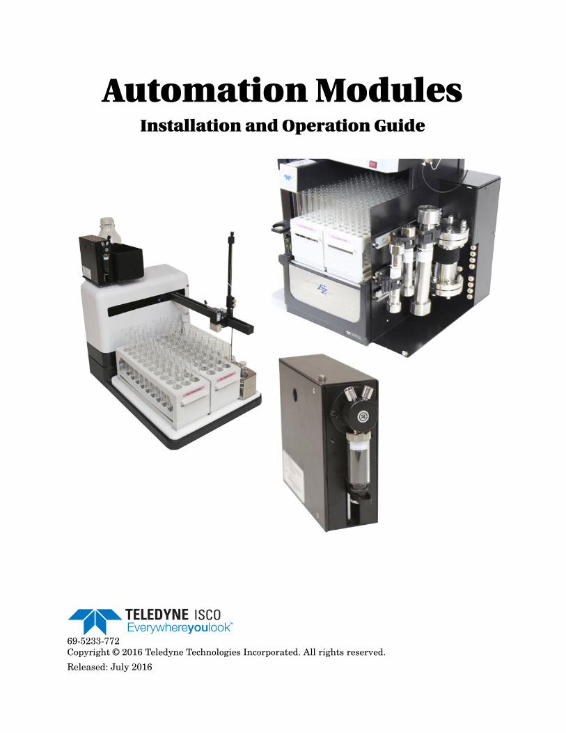
Automation ModulesInstallation and Operation Guide
69-5233-772Copyright © 2016 Teledyne Technologies Incorporated. All rights reserved.
Released: July 2016

Automation Modules Installation and Operation GuideSafety Warnings
3
Automation Modules Installation and Operation Guide
Safety Warnings
Safety Before installing, operating, or maintaining this equipment, it isimperative that all hazards and preventive measures are fullyunderstood. While specific hazards may vary according tolocation and application, take heed in the following generalwarnings:
WARNINGWARNINGLiquids associated with this instrument may be classified as carcinogenic, biohazard, flammable, or radioactive. Should these liquids be used, it is highly recommended that this application be accomplished in an isolated environment designed for these types of materials in accordance with federal, state, and local regulatory laws, and in compliance with your company’s chemical/hygiene plan in the event of a spill.
WARNINGWARNINGAvoid hazardous practices! If you use this instrument in any way not specified in this manual, the protection provided by the instrument may be impaired.
WARNINGWARNINGIf you are using flammable solvents or chemicals with this system, vapor concentration levels may exceed the maximum exposure levels as recommended by OSHA Guide 1910.1000. To reduce those levels to a safe exposure, Teledyne Isco recommends that you place the system in a laboratory hood designed for the purpose of ventilation. This hood should be constructed and operated in accordance with federal state and local regulations. In the event of a solvent or chemical spill, your organization should have a plan to deal with these mishaps. In all cases, use good laboratory practices and standard safety procedures.
Hazard Severity Levels This manual applies Hazard Severity Levels to the safety alerts.These three levels are described in the sample alerts below.
CAUTIONCautions identify a potential hazard, which if not avoided, mayresult in minor or moderate injury. This category can also warnyou of unsafe practices, or conditions that may cause propertydamage.
WARNINGWARNINGWarnings identify a potentially hazardous condition, which if not avoided, could result in death or serious injury.
Automation Modules Installation and Operation GuideSafety Warnings
4
DANGERDANGER – limited to the most extreme situations to identify an imminent hazard, which if not avoided, will result in death or serious injury.
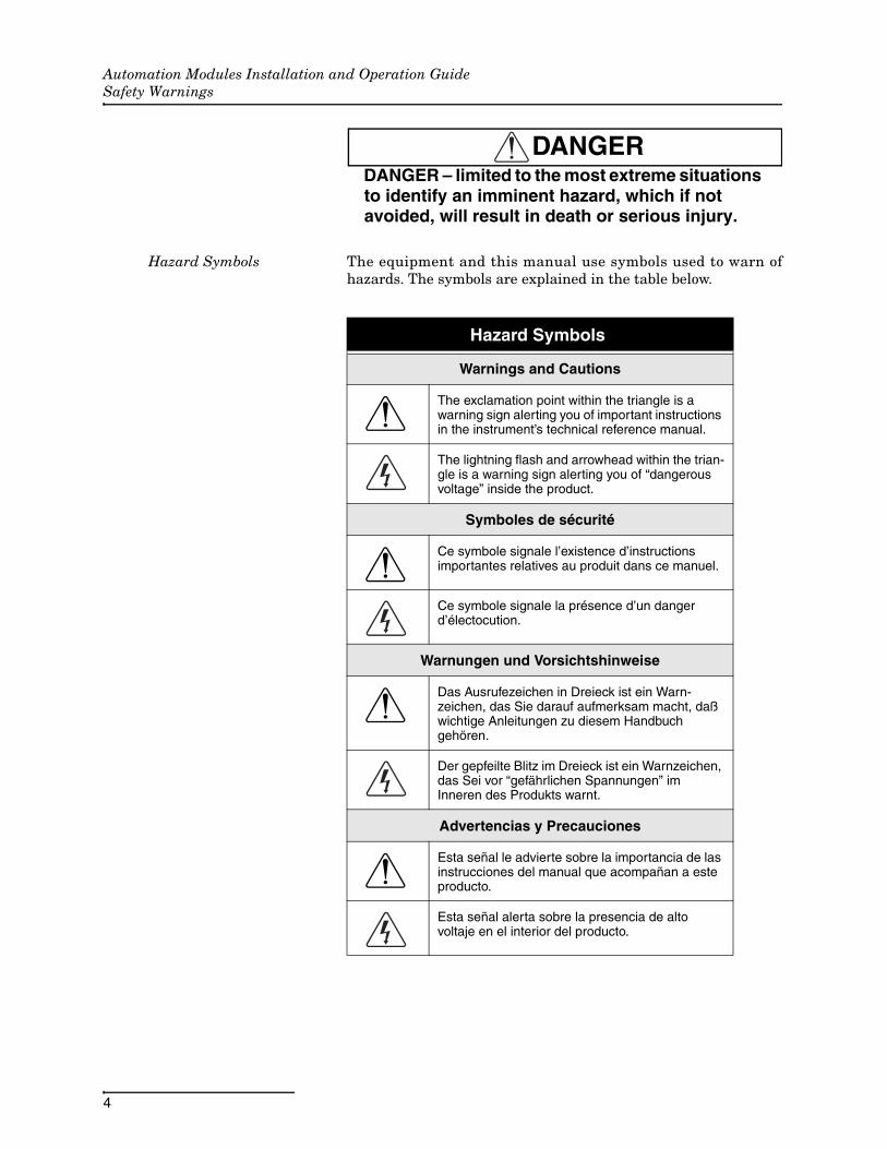
Hazard Symbols The equipment and this manual use symbols used to warn ofhazards. The symbols are explained in the table below.
Hazard Symbols
Warnings and Cautions
The exclamation point within the triangle is a warning sign alerting you of important instructions in the instrument’s technical reference manual.
The lightning flash and arrowhead within the trian-gle is a warning sign alerting you of “dangerous voltage” inside the product.
Symboles de sécurité
Ce symbole signale l’existence d’instructions importantes relatives au produit dans ce manuel.
Ce symbole signale la présence d’un danger d’électocution.
Warnungen und Vorsichtshinweise
Das Ausrufezeichen in Dreieck ist ein Warn-zeichen, das Sie darauf aufmerksam macht, daß wichtige Anleitungen zu diesem Handbuch gehören.
Der gepfeilte Blitz im Dreieck ist ein Warnzeichen, das Sei vor “gefährlichen Spannungen” im Inneren des Produkts warnt.
Advertencias y Precauciones
Esta señal le advierte sobre la importancia de las instrucciones del manual que acompañan a este producto.
Esta señal alerta sobre la presencia de alto voltaje en el interior del producto.

Automation Modules Installation and Operation GuideSafety Warnings
5
For Additional Information
Technical assistance for the Teledyne Isco Automation Modulescan be obtained from:
Teledyne Isco4700 Superior St.Lincoln NE 68504
Phone: (800) 775-2965 or (402) 464-0231Fax: (402) 465-3001E-mail: [email protected]

Automation Modules Installation and Operation GuideSafety Warnings
6
7
Automation Modules
Table of Contents
Section 1 Introduction
1.1 Overview . . . . . . . . . . . . . . . . . . . . . . . . . . . . . . . . . . . . . . . . . . . . . . . . . . . . . . . . . . 1-1
Section 2 The AutoInjector Module
2.1 AutoInjector Module Installation . . . . . . . . . . . . . . . . . . . . . . . . . . . . . . . . . . . . . . . 2-12.2 AutoInjector Module Operation . . . . . . . . . . . . . . . . . . . . . . . . . . . . . . . . . . . . . . . . 2-8
2.2.1 Setup . . . . . . . . . . . . . . . . . . . . . . . . . . . . . . . . . . . . . . . . . . . . . . . . . . . . . . . . 2-82.2.2 Operation . . . . . . . . . . . . . . . . . . . . . . . . . . . . . . . . . . . . . . . . . . . . . . . . . . . . 2-9
Section 3 The AutoSampler Module
3.1 AutoSampler Module Installation . . . . . . . . . . . . . . . . . . . . . . . . . . . . . . . . . . . . . . 3-13.1.1 Installing the AutoSampler Module . . . . . . . . . . . . . . . . . . . . . . . . . . . . . . . 3-13.1.2 Establishing Connections . . . . . . . . . . . . . . . . . . . . . . . . . . . . . . . . . . . . . . 3-11
3.2 Installing the AutoSampler Module with the Column Selector Module . . . . . . . 3-193.3 AutoSampler Module Operation. . . . . . . . . . . . . . . . . . . . . . . . . . . . . . . . . . . . . . . 3-20
3.3.1 Setup . . . . . . . . . . . . . . . . . . . . . . . . . . . . . . . . . . . . . . . . . . . . . . . . . . . . . . . 3-203.3.2 Operation . . . . . . . . . . . . . . . . . . . . . . . . . . . . . . . . . . . . . . . . . . . . . . . . . . . 3-21
Section 4 The Column Selector Module
4.1 Column Selector Module Installation . . . . . . . . . . . . . . . . . . . . . . . . . . . . . . . . . . . 4-14.1.1 Installing the Column Selector Module . . . . . . . . . . . . . . . . . . . . . . . . . . . . 4-14.1.2 Establishing Column Selector Module Connections . . . . . . . . . . . . . . . . . . 4-64.1.3 Mounting the AutoInjector Module to the Column Selector Module . . . . . 4-84.1.4 Establishing AutoInjector Module Connections . . . . . . . . . . . . . . . . . . . . . 4-16
4.2 Installing the Column Selector Module with the AutoSampler Module . . . . . . . 4-164.3 Column Selector Module Operation . . . . . . . . . . . . . . . . . . . . . . . . . . . . . . . . . . . . 4-16
4.3.1 Setup . . . . . . . . . . . . . . . . . . . . . . . . . . . . . . . . . . . . . . . . . . . . . . . . . . . . . . . 4-16
Appendix A Specifications
A.1 AutoInjector Module Specifications . . . . . . . . . . . . . . . . . . . . . . . . . . . . . . . . . . . . . A-1A.2 AutoSampler Module Specifications . . . . . . . . . . . . . . . . . . . . . . . . . . . . . . . . . . . . A-2A.3 Column Selector Module Specifications . . . . . . . . . . . . . . . . . . . . . . . . . . . . . . . . . A-3

Automation ModulesTable of Contents
8
1-1
Automation Modules
Section 1 Introduction
1.1 Overview The AutoInjector Module, AutoSampler Module, and ColumnSelector Module allow you to increase the productivity of theCombiFlash® EZ Prep by automating a number of tasks involvedwith high-performance liquid chromatography (HPLC). Thesemodules are controlled by Teledyne Isco's PeakTrak® software inorder to maintain the ease-of-use you are familiar with andpractically eliminate the need for training.
The three modules can be used separately or in conjunction withone another for even more automated operation.
AutoInjector Module The AutoInjector Module performs automated, repetitive com-pound injections completely unattended. This allows users toautomatically purify amounts of compound larger than what canbe done with a single separation run. As a result of having thistedious process automated, user productivity is increased.
More information regarding the AutoInjector Module includinginstallation, setup, and operation can be found in Section 2.
AutoSampler Module The AutoSampler Module performs automated purifications onmultiple samples. In addition, the module doubles the fractioncollection capacity of the EZ Prep by adding two collection racks.For more flexibility, samples can consist of multiple injections.You can even choose between maximizing rack capacity by fillingracks completely or optimizing work flow on a shared system byhaving each sample sent to the next rack. The racks utilize thesame RFID rack swapping technology of the EZ Prep, allowingusers to remove completed racks and replace them with newracks for practically unlimited fraction collection capacity.
More information regarding the AutoSampler Module includinginstallation, setup, and operation can be found in Section 3.
Column Selector Module The Column Selector Module allows the EZ Prep to automati-cally access up to four prep columns. This allows users easyaccess to a variety of column sizes and chemistries. It also allowsusers to dedicate columns to both high and low pH separations.When combined with the AutoSampler Module, each sample canbe separated on the column best suited for the job.
More information regarding the Column Selector Moduleincluding installation, setup, and operation can be found inSection 4.

Automation ModulesSection 1 Introduction
1-2
2-1
Automation
Section 2 The AutoInjector Module
2.1 AutoInjector Module Installation
NoteCombiFlash EZ Prep software must be version 3.1.0 or higherto support the automation capabilities.
NoteIf the AutoInjector Module is used in conjunction with the Col-umn Selector Module, the standard prep column mount canbe removed to keep the overall system width minimized. Inthis case, the AutoInjector Module can be mounted on top ofthe Column Selector Module instead of on top of the standardprep column mount.
Installation 1. Turn off the EZ Prep.
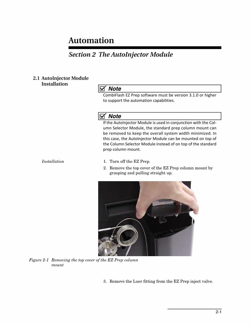
2. Remove the top cover of the EZ Prep column mount by grasping and pulling straight up.
Figure 2-1 Removing the top cover of the EZ Prep column mount
3. Remove the Luer fitting from the EZ Prep inject valve.
AutomationSection 2 The AutoInjector Module
2-2
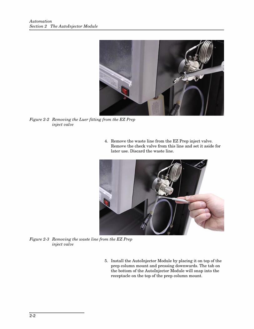
Figure 2-2 Removing the Luer fitting from the EZ Prep inject valve
4. Remove the waste line from the EZ Prep inject valve. Remove the check valve from this line and set it aside for later use. Discard the waste line.
Figure 2-3 Removing the waste line from the EZ Prep inject valve
5. Install the AutoInjector Module by placing it on top of the prep column mount and pressing downwards. The tab on the bottom of the AutoInjector Module will snap into the receptacle on the top of the prep column mount.

AutomationSection 2 The AutoInjector Module
2-3
Figure 2-4 AutoInjector Module attached to the EZ Prep column mount
6. Connect the USB cable from the AutoInjector Module to the USB port on the rear of the EZ Prep. If you have a CombiFlash Rf+ PurIonTM Mass Detector attached to the EZ Prep, you will need to obtain a USB hub to connect both modules.
7. Connect the included power supply from the AutoInjector Module to a suitable power connection. Use a power supply in a location that minimizes the possibility of a chemical spill damaging the power supply.
8. Locate the supplied waste tubing and fitting package (P/N 60-5234-653).
9. Unscrew the attached plastic ferrule in this fitting package until the plastic ferrule is almost completely detached from the steel fitting.
10. Attach the steel fitting in this package to the EZ Prep inject valve waste port. This steel fitting should be hand tight.

AutomationSection 2 The AutoInjector Module
2-4
Figure 2-5 Waste tubing fitting attached to the EZ Prep inject valve
11. Turn the plastic ferrule until it is attached hand tight to the valve.
12. Turn the steel fitting 1/2 turn tighter.
13. Remove the plastic ferrule while leaving the fitting attached.
Figure 2-6 Waste fitting with the plastic ferrule removed
14. Attach the supplied tubing from this package to the secured fitting. Tighten the ferrule finger tight with the supplied tool. Ensure the tubing and fitting are snug in the EZ Prep inject valve.

AutomationSection 2 The AutoInjector Module
2-5
Figure 2-7 Waste fitting with tubing attached
15. Connect the opposite end of this tubing to the left port of the AutoInjector Module.
Figure 2-8 Connection of the waste tubing from the EZ Prep inject valve to the left AutoInjector Module port
16. Connect the supplied waste line (P/N 60-5234-654) to the right port of the AutoInjector Module.

AutomationSection 2 The AutoInjector Module
2-6
Figure 2-9 Waste line connected to the right AutoInjector Module port
17. Connect the check valve removed in Step 4 to the waste line from the AutoInjector Module. Ensure that the arrow on the check valve points away from the AutoInjector Mod-ule as shown in Figure 2-10.
Figure 2-10 Check valve connected to the waste line of the AutoInjector Module
18. Locate the supplied sample probe tubing and fitting pack-age (P/N 60-5234-657).
19. Unscrew the attached plastic ferrule in this fitting package until the plastic ferrule is almost completely detached from the steel fitting.
20. Attach the steel fitting in this package to the EZ Prep inject valve waste port. This steel fitting should be hand tight.

AutomationSection 2 The AutoInjector Module
2-7
Figure 2-11 Sample tube fitting attached to the EZ Prep inject valve
21. Turn the plastic ferrule until it is attached hand tight to the valve.
22. Turn the steel fitting 1/2 turn tighter.
23. Remove the plastic ferrule while leaving the fitting attached.
Figure 2-12 Sample tube fitting with the plastic ferrule removed
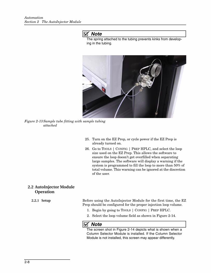
24. Attach the supplied tubing from this package to the secured fitting by screwing the new plastic ferrule into the fitting. Tighten the ferrule finger tight with the supplied tool.
AutomationSection 2 The AutoInjector Module
2-8
NoteThe spring attached to the tubing prevents kinks from develop-ing in the tubing.
Figure 2-13 Sample tube fitting with sample tubing attached
25. Turn on the EZ Prep, or cycle power if the EZ Prep is already turned on.
26. Go to TOOLS | CONFIG | PREP HPLC, and select the loop size used on the EZ Prep. This allows the software to ensure the loop doesn’t get overfilled when separating large samples. The software will display a warning if the system is programmed to fill the loop to more than 50% of total volume. This warning can be ignored at the discretion of the user.
2.2 AutoInjector Module Operation
2.2.1 Setup Before using the AutoInjector Module for the first time, the EZPrep should be configured for the proper injection loop volume.
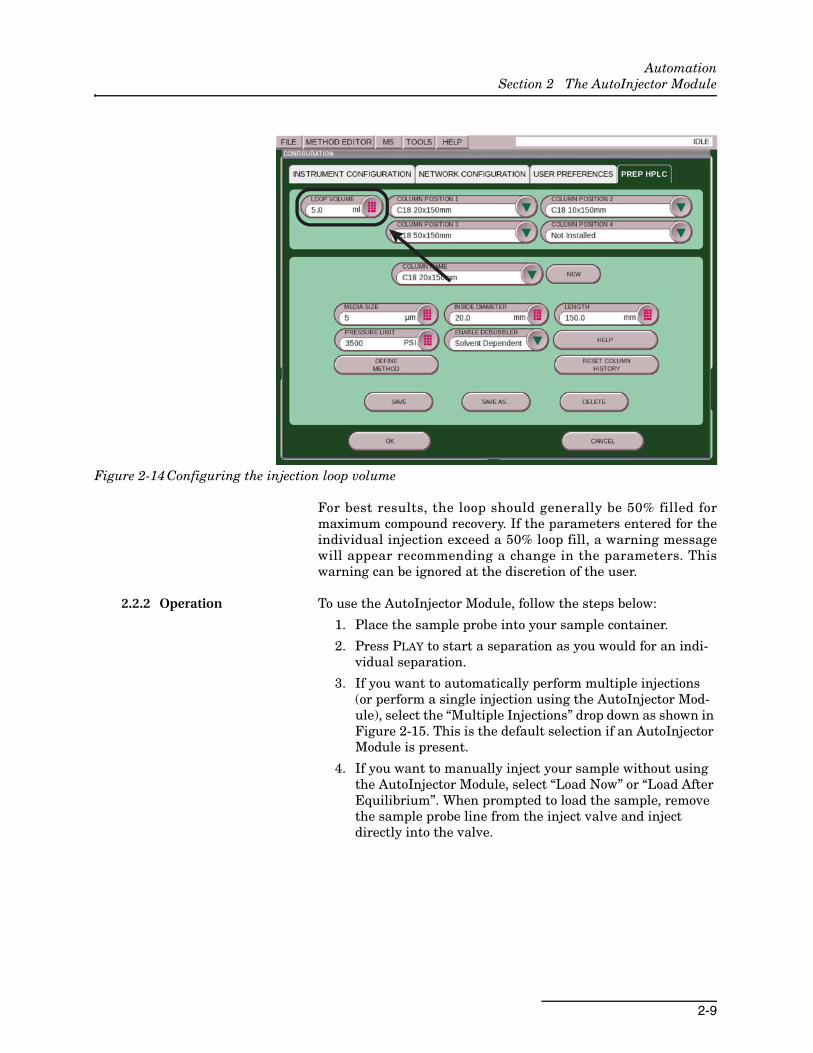
1. Begin by going to TOOLS | CONFIG | PREP HPLC.
2. Select the loop volume field as shown in Figure 2-14.
NoteThe screen shot in Figure 2-14 depicts what is shown when aColumn Selector Module is installed. If the Column SelectorModule is not installed, this screen may appear differently.
AutomationSection 2 The AutoInjector Module
2-9
Figure 2-14 Configuring the injection loop volume
For best results, the loop should generally be 50% filled formaximum compound recovery. If the parameters entered for theindividual injection exceed a 50% loop fill, a warning messagewill appear recommending a change in the parameters. Thiswarning can be ignored at the discretion of the user.
2.2.2 Operation To use the AutoInjector Module, follow the steps below:
1. Place the sample probe into your sample container.
2. Press PLAY to start a separation as you would for an indi-vidual separation.
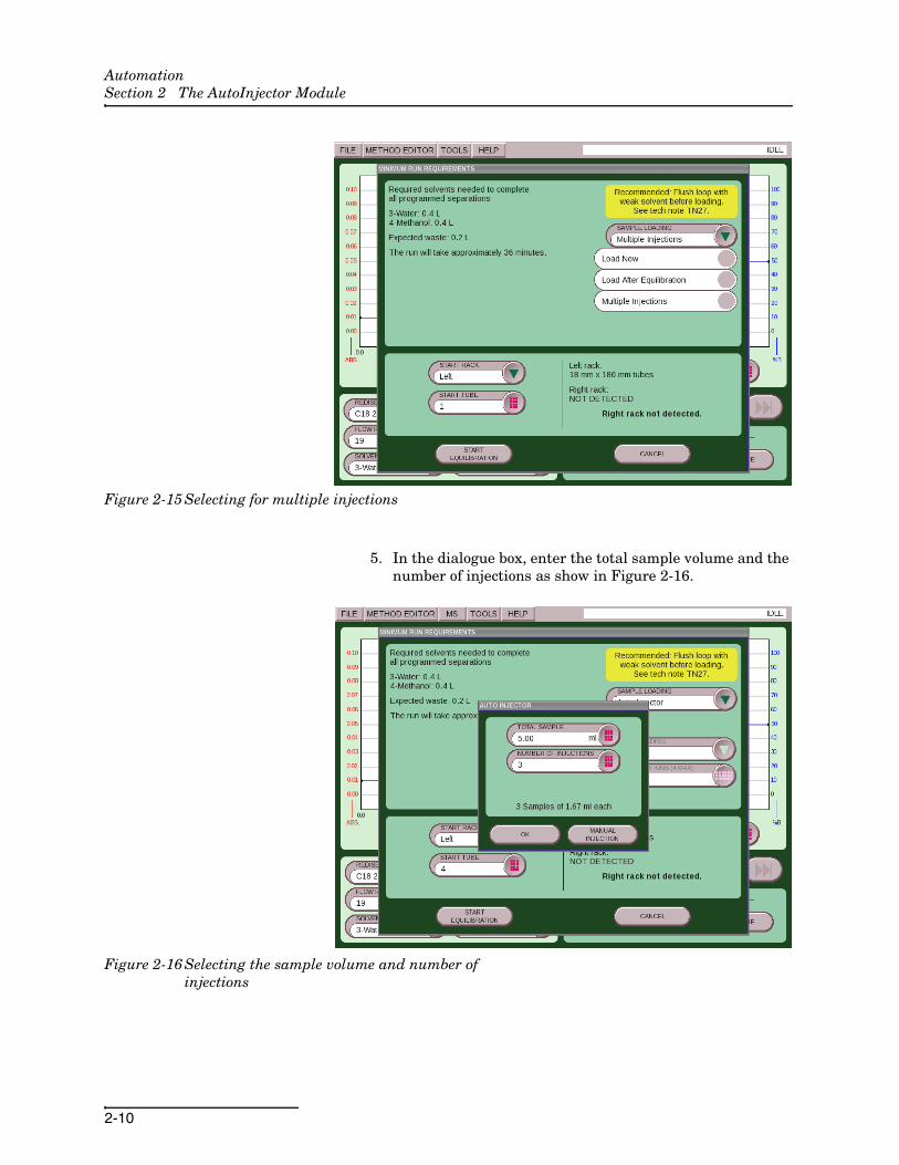
3. If you want to automatically perform multiple injections (or perform a single injection using the AutoInjector Mod-ule), select the “Multiple Injections” drop down as shown in Figure 2-15. This is the default selection if an AutoInjector Module is present.
4. If you want to manually inject your sample without using the AutoInjector Module, select “Load Now” or “Load After Equilibrium”. When prompted to load the sample, remove the sample probe line from the inject valve and inject directly into the valve.
AutomationSection 2 The AutoInjector Module
2-10
Figure 2-15 Selecting for multiple injections
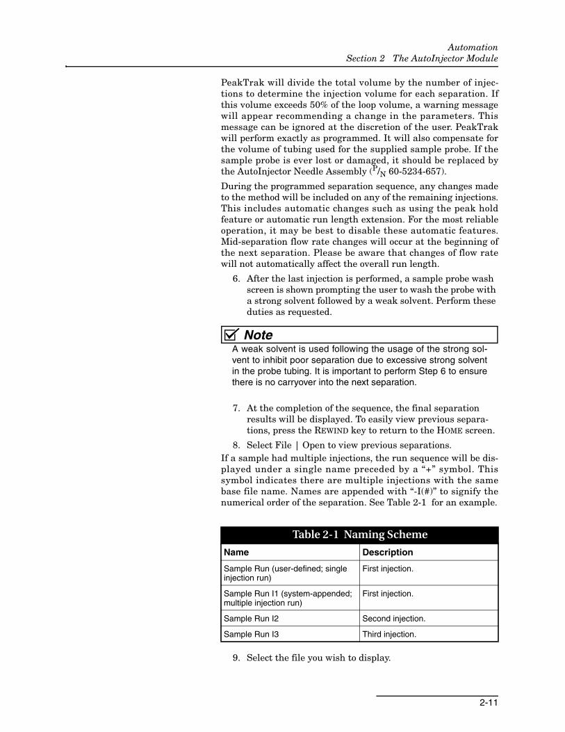
5. In the dialogue box, enter the total sample volume and the number of injections as show in Figure 2-16.
Figure 2-16 Selecting the sample volume and number of injections
AutomationSection 2 The AutoInjector Module
2-11
PeakTrak will divide the total volume by the number of injec-tions to determine the injection volume for each separation. Ifthis volume exceeds 50% of the loop volume, a warning messagewill appear recommending a change in the parameters. Thismessage can be ignored at the discretion of the user. PeakTrakwill perform exactly as programmed. It will also compensate forthe volume of tubing used for the supplied sample probe. If thesample probe is ever lost or damaged, it should be replaced bythe AutoInjector Needle Assembly (P/N 60-5234-657).
During the programmed separation sequence, any changes madeto the method will be included on any of the remaining injections.This includes automatic changes such as using the peak holdfeature or automatic run length extension. For the most reliableoperation, it may be best to disable these automatic features.Mid-separation flow rate changes will occur at the beginning ofthe next separation. Please be aware that changes of flow ratewill not automatically affect the overall run length.
6. After the last injection is performed, a sample probe wash screen is shown prompting the user to wash the probe with a strong solvent followed by a weak solvent. Perform these duties as requested.
NoteA weak solvent is used following the usage of the strong sol-vent to inhibit poor separation due to excessive strong solventin the probe tubing. It is important to perform Step 6 to ensurethere is no carryover into the next separation.
7. At the completion of the sequence, the final separation results will be displayed. To easily view previous separa-tions, press the REWIND key to return to the HOME screen.
8. Select File | Open to view previous separations. If a sample had multiple injections, the run sequence will be dis-played under a single name preceded by a “+” symbol. Thissymbol indicates there are multiple injections with the samebase file name. Names are appended with “-I(#)” to signify thenumerical order of the separation. See Table 2-1 for an example.
9. Select the file you wish to display.
Table 2-1 Naming Scheme
Name Description
Sample Run (user-defined; single injection run)
First injection.
Sample Run I1 (system-appended; multiple injection run)
First injection.
Sample Run I2 Second injection.
Sample Run I3 Third injection.
AutomationSection 2 The AutoInjector Module
2-12
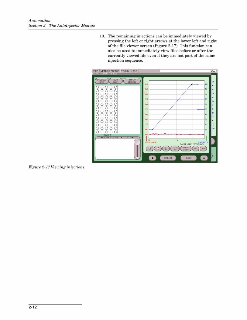
10. The remaining injections can be immediately viewed by pressing the left or right arrows at the lower left and right of the file viewer screen (Figure 2-17). This function can also be used to immediately view files before or after the currently viewed file even if they are not part of the same injection sequence.
Figure 2-17 Viewing injections

3-1
Automation
Section 3 The AutoSampler Module
3.1 AutoSampler Module Installation
NoteCombiFlash EZ Prep software must be version 3.1.0 or higherto support the automation capabilities.
NoteBegin your installation on a clean workspace separate fromthe EZ Prep. You will be prompted to place the AutoSam-pler Module on the right side of the EZ Prep in 3.1.2 Estab-lishing Connections.
The AutoSampler Module includes the AutoInjector Module toperform its automated functions. To install the AutoSamplerModule, follow the steps below:
3.1.1 Installing the AutoSampler Module
1. Mount the rinse station by placing it into the receptacle located on the right-rear portion of the AutoSampler Mod-ule bed.
Figure 3-1 AutoSampler Module rinse station
AutomationSection 3 The AutoSampler Module
3-2
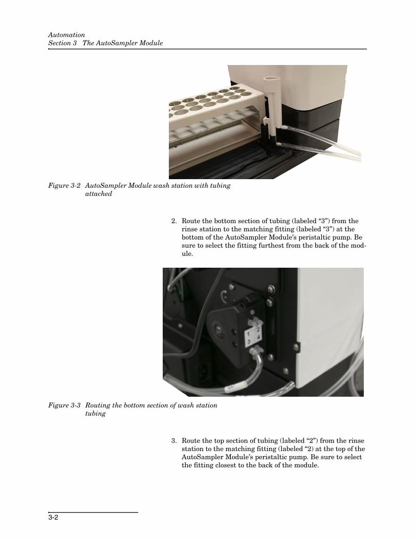
Figure 3-2 AutoSampler Module wash station with tubing attached
2. Route the bottom section of tubing (labeled “3”) from the rinse station to the matching fitting (labeled “3”) at the bottom of the AutoSampler Module’s peristaltic pump. Be sure to select the fitting furthest from the back of the mod-ule.
Figure 3-3 Routing the bottom section of wash station tubing
3. Route the top section of tubing (labeled “2”) from the rinse station to the matching fitting (labeled “2) at the top of the AutoSampler Module’s peristaltic pump. Be sure to select the fitting closest to the back of the module.
AutomationSection 3 The AutoSampler Module
3-3
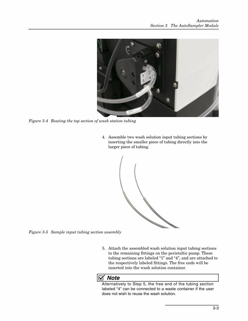
Figure 3-4 Routing the top section of wash station tubing
4. Assemble two wash solution input tubing sections by inserting the smaller piece of tubing directly into the larger piece of tubing.
Figure 3-5 Sample input tubing section assembly
5. Attach the assembled wash solution input tubing sections to the remaining fittings on the peristaltic pump. These tubing sections are labeled “1” and “4”, and are attached to the respectively labeled fittings. The free ends will be inserted into the wash solution container.
NoteAlternatively to Step 5, the free end of the tubing sectionlabeled “4” can be connected to a waste container if the userdoes not wish to reuse the wash solution.
AutomationSection 3 The AutoSampler Module
3-4
NoteThe smaller piece of tubing from Step 4 is resistant to chemicalcorrosion, but the larger piece is not. When inserting the tubinginto the wash solution, be sure only the smaller piece of tubingis resting inside the solution.
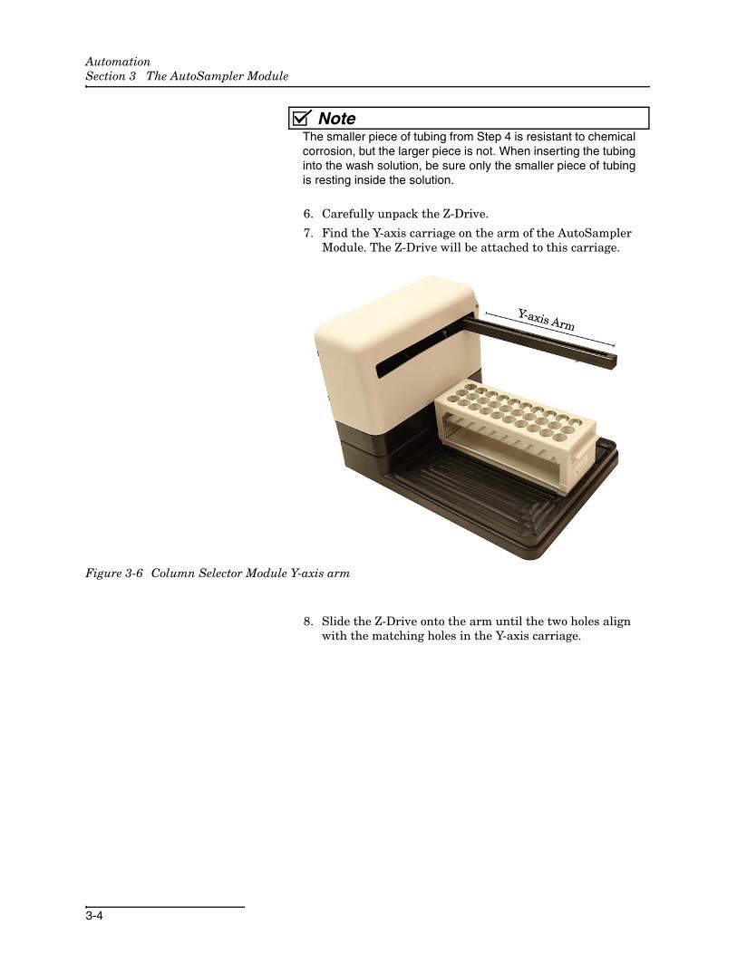
6. Carefully unpack the Z-Drive.
7. Find the Y-axis carriage on the arm of the AutoSampler Module. The Z-Drive will be attached to this carriage.
Figure 3-6 Column Selector Module Y-axis arm
8. Slide the Z-Drive onto the arm until the two holes align with the matching holes in the Y-axis carriage.
AutomationSection 3 The AutoSampler Module
3-5
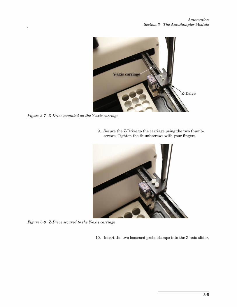
Figure 3-7 Z-Drive mounted on the Y-axis carriage
9. Secure the Z-Drive to the carriage using the two thumb-screws. Tighten the thumbscrews with your fingers.
Figure 3-8 Z-Drive secured to the Y-axis carriage
10. Insert the two loosened probe clamps into the Z-axis slider.
AutomationSection 3 The AutoSampler Module
3-6
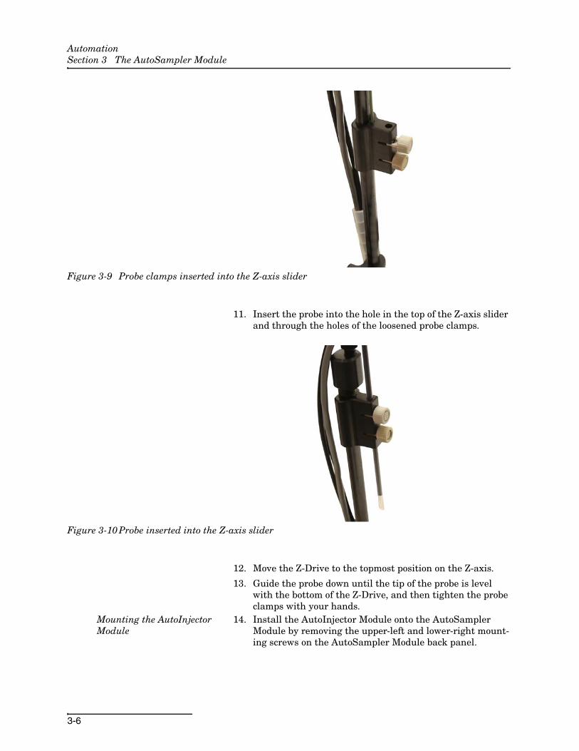
Figure 3-9 Probe clamps inserted into the Z-axis slider
11. Insert the probe into the hole in the top of the Z-axis slider and through the holes of the loosened probe clamps.
Figure 3-10 Probe inserted into the Z-axis slider
12. Move the Z-Drive to the topmost position on the Z-axis.
13. Guide the probe down until the tip of the probe is level with the bottom of the Z-Drive, and then tighten the probe clamps with your hands.
Mounting the AutoInjector Module
14. Install the AutoInjector Module onto the AutoSampler Module by removing the upper-left and lower-right mount-ing screws on the AutoSampler Module back panel.

AutomationSection 3 The AutoSampler Module
3-7
Figure 3-11 AutoSampler Module back panel with AutoInjector Module mounting screws removed
15. Place the AutoInjector Module on top of the AutoSampler Module and fasten them together with the mounting screws removed in Step 14.
Figure 3-12 AutoInjector Module fastened to the AutoSampler Module
16. Feed all cables (with the exception of the sample probe tub-ing) through the rear guide block of the AutoInjector Mod-ule.
AutomationSection 3 The AutoSampler Module
3-8
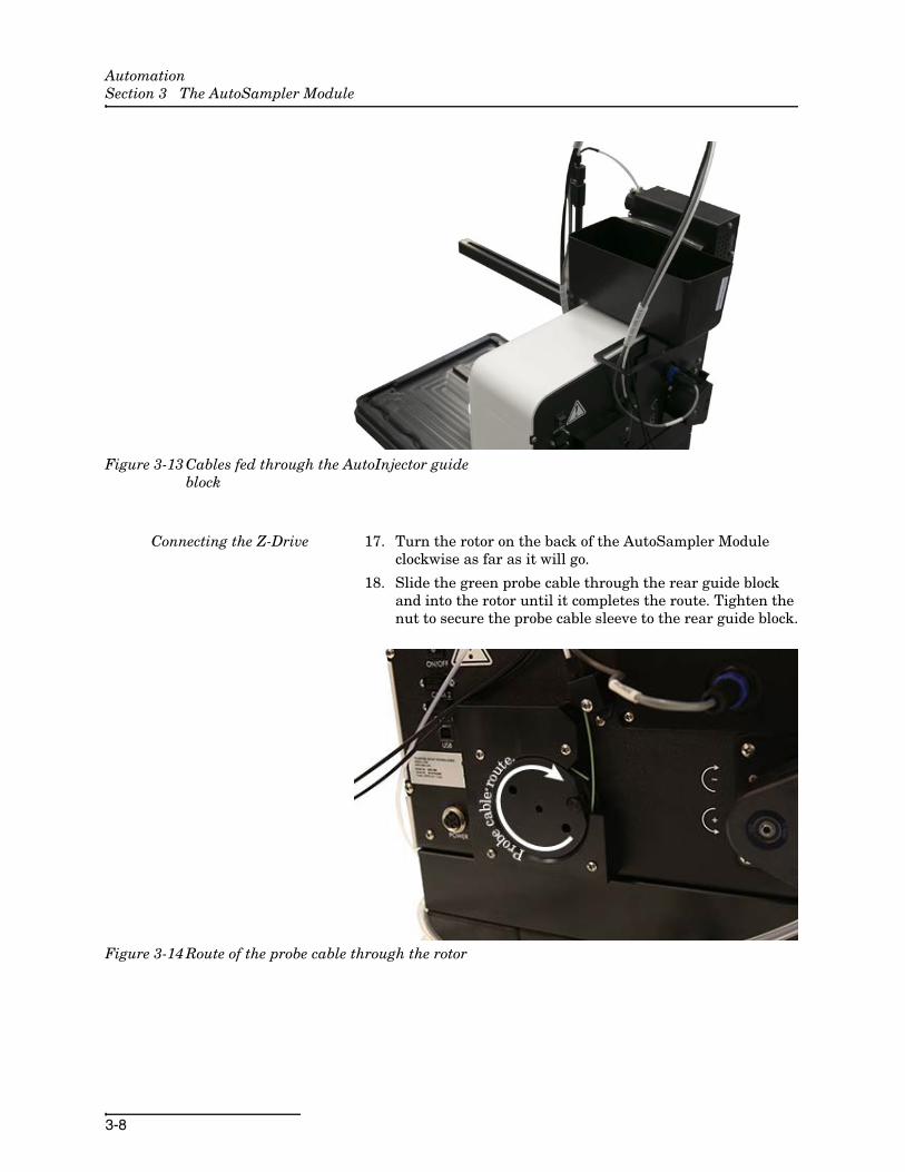
Figure 3-13 Cables fed through the AutoInjector guide block
Connecting the Z-Drive 17. Turn the rotor on the back of the AutoSampler Module clockwise as far as it will go.
18. Slide the green probe cable through the rear guide block and into the rotor until it completes the route. Tighten the nut to secure the probe cable sleeve to the rear guide block.
Figure 3-14 Route of the probe cable through the rotor
AutomationSection 3 The AutoSampler Module
3-9
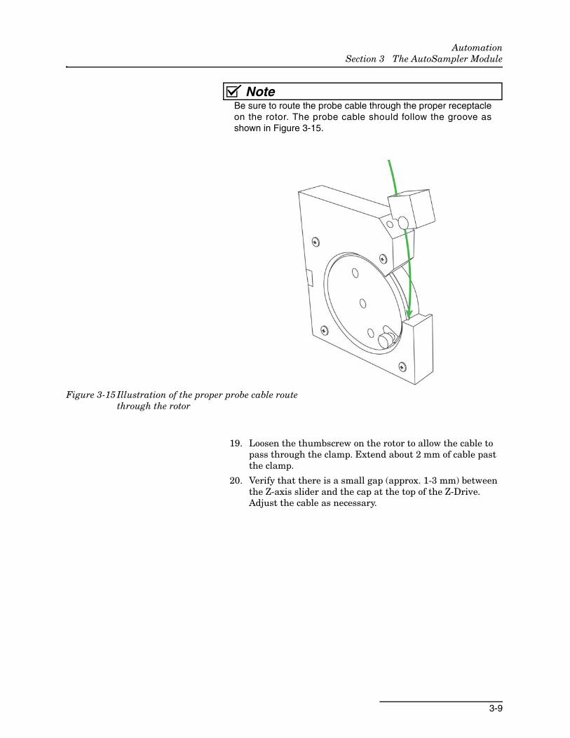
NoteBe sure to route the probe cable through the proper receptacleon the rotor. The probe cable should follow the groove asshown in Figure 3-15.
Figure 3-15 Illustration of the proper probe cable route through the rotor
19. Loosen the thumbscrew on the rotor to allow the cable to pass through the clamp. Extend about 2 mm of cable past the clamp.
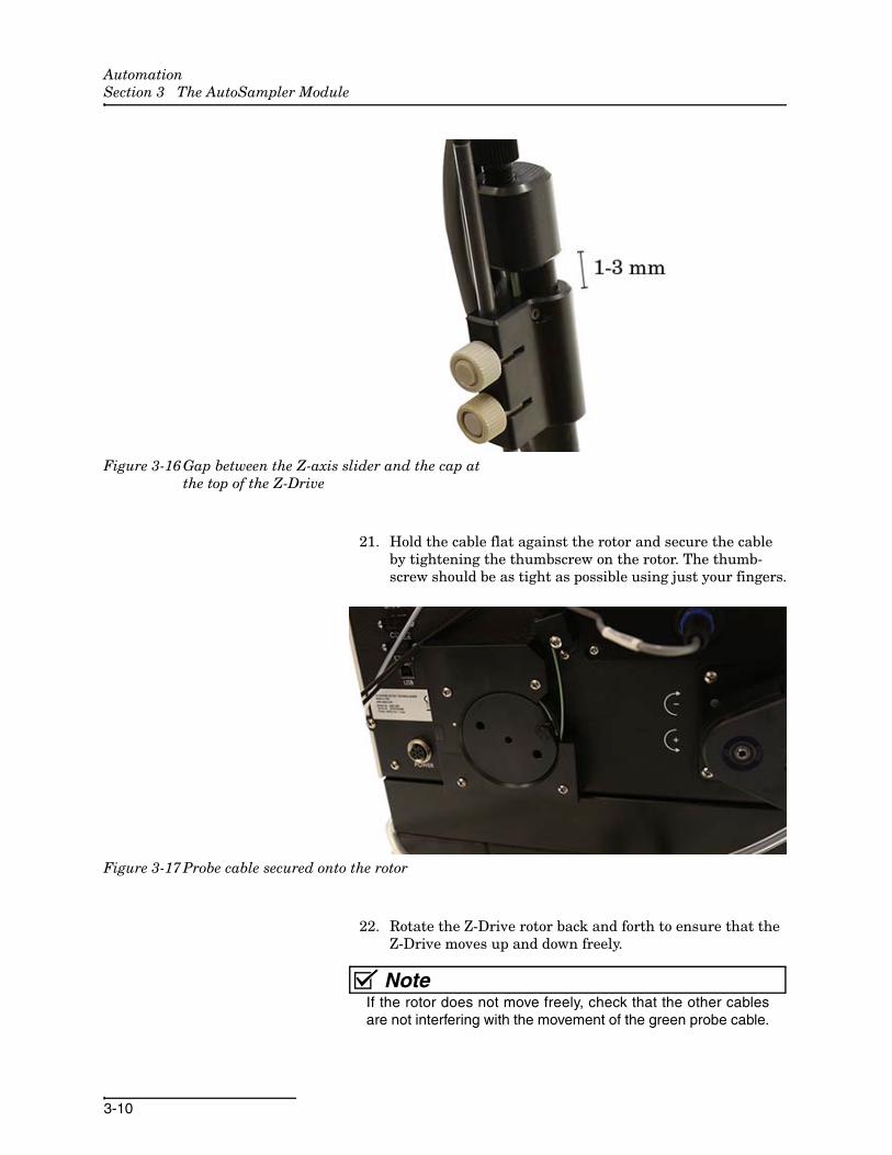
20. Verify that there is a small gap (approx. 1-3 mm) between the Z-axis slider and the cap at the top of the Z-Drive. Adjust the cable as necessary.
AutomationSection 3 The AutoSampler Module
3-10
Figure 3-16 Gap between the Z-axis slider and the cap at the top of the Z-Drive
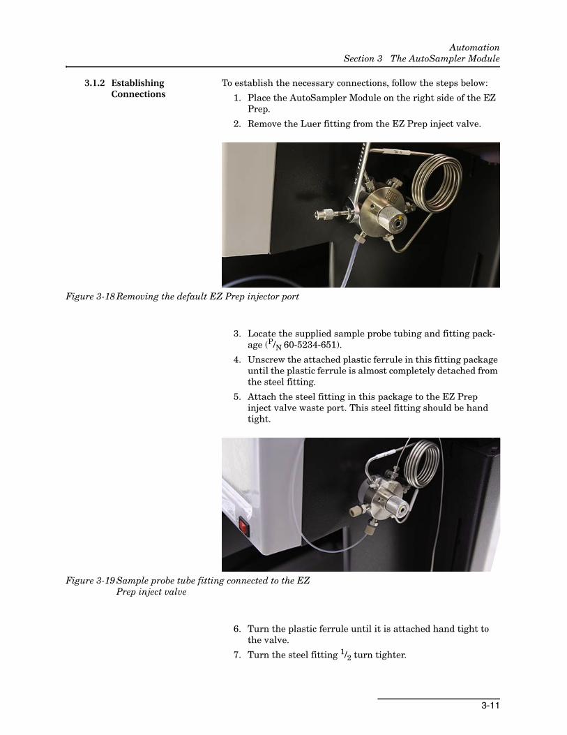
21. Hold the cable flat against the rotor and secure the cable by tightening the thumbscrew on the rotor. The thumb-screw should be as tight as possible using just your fingers.
Figure 3-17 Probe cable secured onto the rotor
22. Rotate the Z-Drive rotor back and forth to ensure that the Z-Drive moves up and down freely.
NoteIf the rotor does not move freely, check that the other cablesare not interfering with the movement of the green probe cable.
AutomationSection 3 The AutoSampler Module
3-11
3.1.2 Establishing Connections
To establish the necessary connections, follow the steps below:
1. Place the AutoSampler Module on the right side of the EZ Prep.
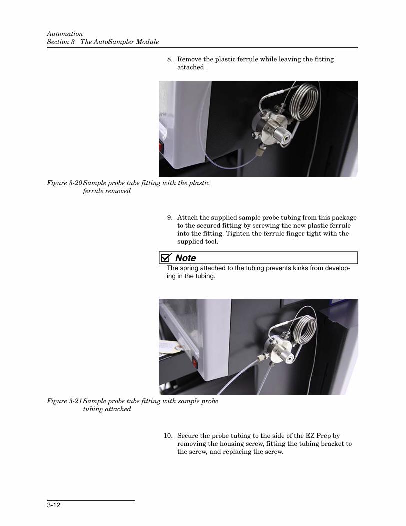
2. Remove the Luer fitting from the EZ Prep inject valve.
Figure 3-18 Removing the default EZ Prep injector port
3. Locate the supplied sample probe tubing and fitting pack-age (P/N 60-5234-651).
4. Unscrew the attached plastic ferrule in this fitting package until the plastic ferrule is almost completely detached from the steel fitting.
5. Attach the steel fitting in this package to the EZ Prep inject valve waste port. This steel fitting should be hand tight.
Figure 3-19 Sample probe tube fitting connected to the EZ Prep inject valve
6. Turn the plastic ferrule until it is attached hand tight to the valve.
7. Turn the steel fitting 1/2 turn tighter.
AutomationSection 3 The AutoSampler Module
3-12
8. Remove the plastic ferrule while leaving the fitting attached.
Figure 3-20 Sample probe tube fitting with the plastic ferrule removed
9. Attach the supplied sample probe tubing from this package to the secured fitting by screwing the new plastic ferrule into the fitting. Tighten the ferrule finger tight with the supplied tool.
NoteThe spring attached to the tubing prevents kinks from develop-ing in the tubing.
Figure 3-21 Sample probe tube fitting with sample probe tubing attached
10. Secure the probe tubing to the side of the EZ Prep by removing the housing screw, fitting the tubing bracket to the screw, and replacing the screw.

AutomationSection 3 The AutoSampler Module
3-13
Figure 3-22 Sample probe tubing secured to the EZ Prep
NoteThe tubing bracket should be affixed to the EZ Prep so that theprobe tubing threads vertically through the bracket. Thisensures that the probe tubing will not be obstructed by othertubing.
11. Disconnect the tubing at the back of the EZ Prep from the port labeled DIVERTER VALVE WASTE.
Figure 3-23 Diverter Valve Waste port with no connection
12. Connect the compatible tubing from the AutoSampler Module to the port labeled DIVERTER VALVE WASTE at the back of the EZ Prep.
AutomationSection 3 The AutoSampler Module
3-14
Figure 3-24 Diverter Valve Waste port with AutoSampler Module tubing connection
13. Connect the remaining tubing from the AutoSampler to the tubing removed in Step 11.
Figure 3-25 Connecting AutoSampler waste tubing to EZ Prep waste tubing
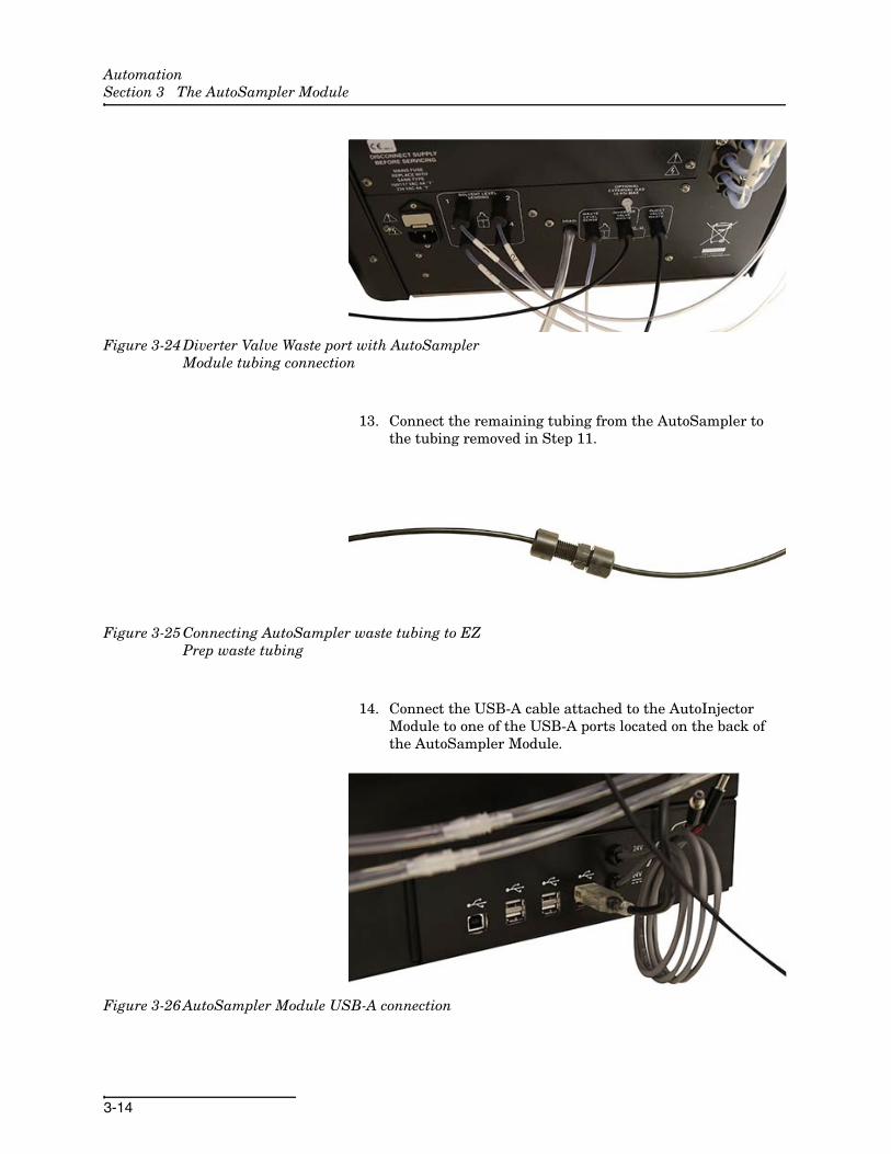
14. Connect the USB-A cable attached to the AutoInjector Module to one of the USB-A ports located on the back of the AutoSampler Module.
Figure 3-26 AutoSampler Module USB-A connection
AutomationSection 3 The AutoSampler Module
3-15
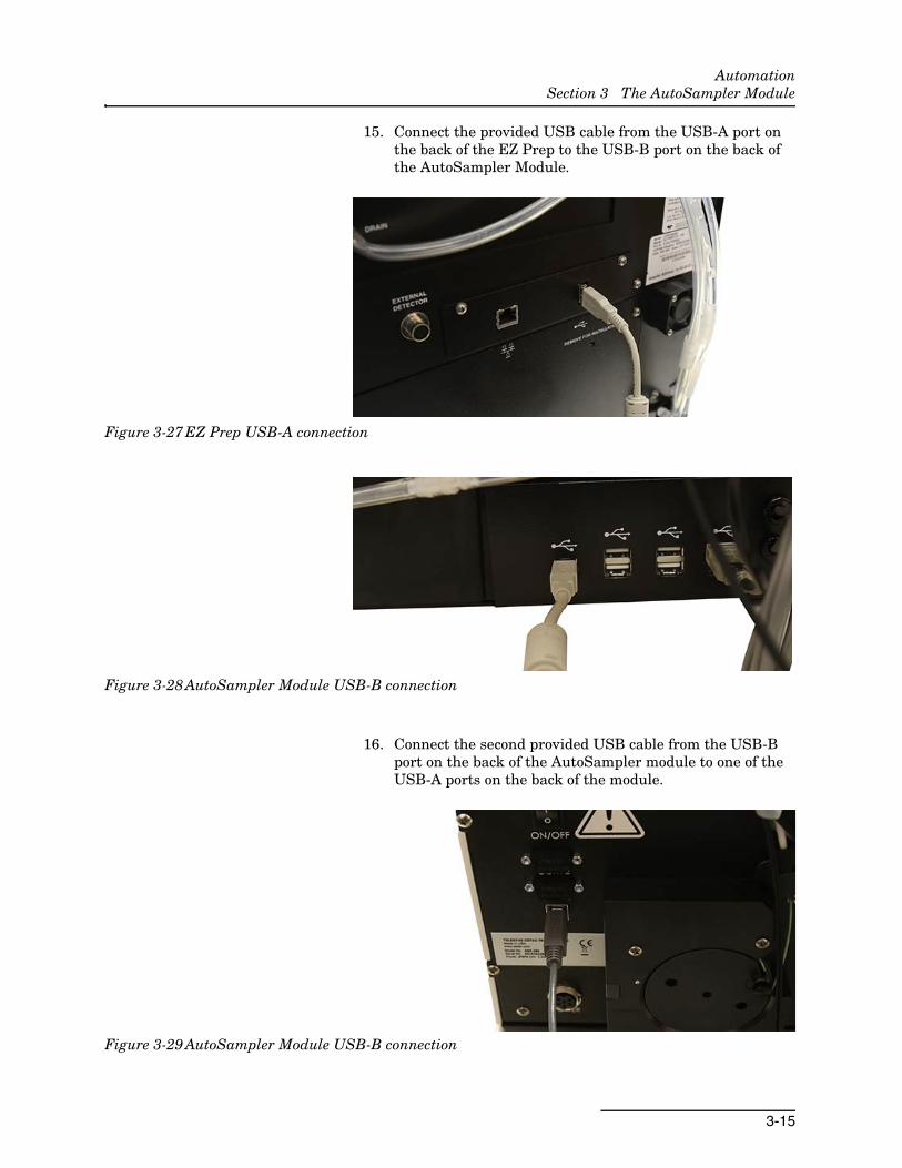
15. Connect the provided USB cable from the USB-A port on the back of the EZ Prep to the USB-B port on the back of the AutoSampler Module.
Figure 3-27 EZ Prep USB-A connection
Figure 3-28 AutoSampler Module USB-B connection
16. Connect the second provided USB cable from the USB-B port on the back of the AutoSampler module to one of the USB-A ports on the back of the module.
Figure 3-29 AutoSampler Module USB-B connection

AutomationSection 3 The AutoSampler Module
3-16
Figure 3-30 AutoSampler Module USB-A connection (center)
17. Connect the Z-Drive power cable to the port on the back of the AutoSampler Module.
Figure 3-31 Z-Drive power cable connected to the AutoSampler Module
18. Locate the AutoSampler Module’s power supply bracket as show in Figure 3-32.
AutomationSection 3 The AutoSampler Module
3-17
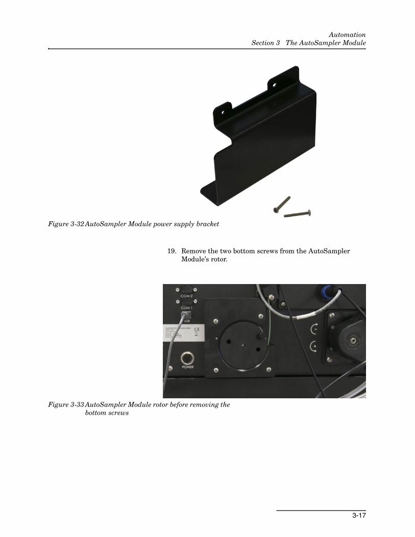
Figure 3-32 AutoSampler Module power supply bracket
19. Remove the two bottom screws from the AutoSampler Module’s rotor.
Figure 3-33 AutoSampler Module rotor before removing the bottom screws
AutomationSection 3 The AutoSampler Module
3-18
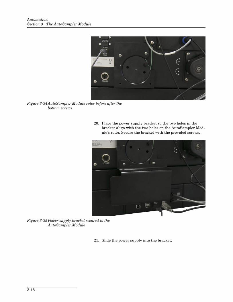
Figure 3-34 AutoSampler Module rotor before after the bottom screws
20. Place the power supply bracket so the two holes in the bracket align with the two holes on the AutoSampler Mod-ule’s rotor. Secure the bracket with the provided screws.
Figure 3-35 Power supply bracket secured to the AutoSampler Module
21. Slide the power supply into the bracket.
AutomationSection 3 The AutoSampler Module
3-19
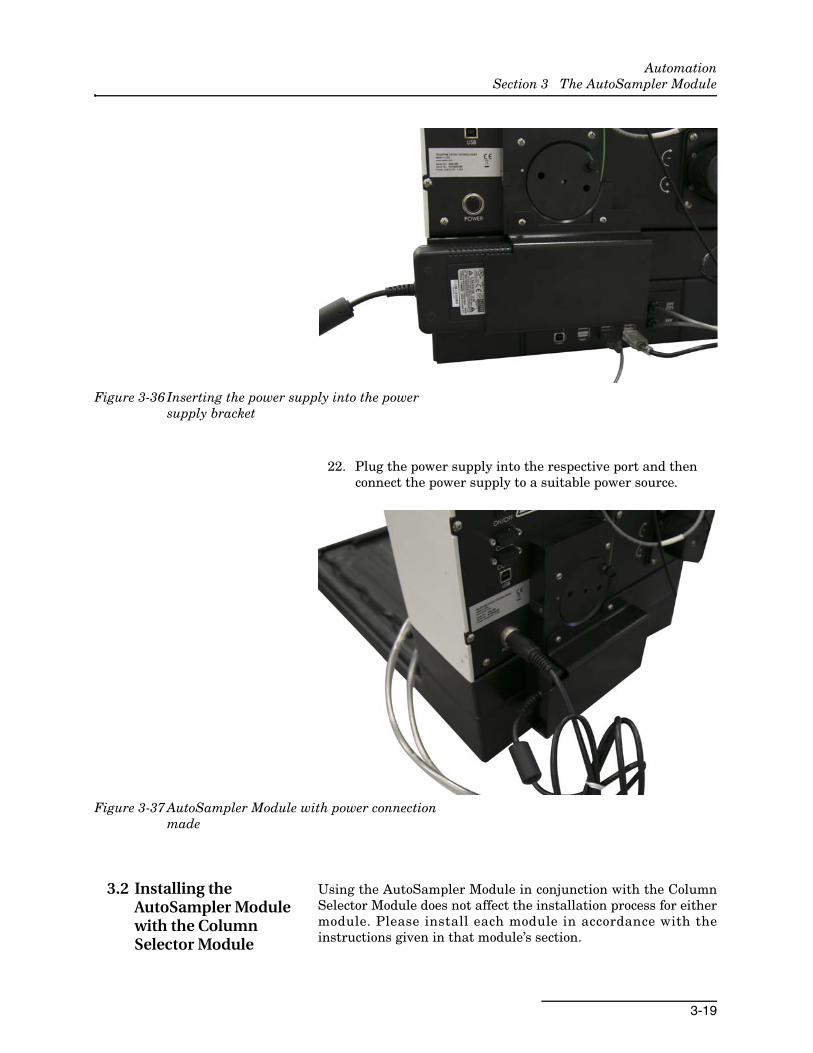
Figure 3-36 Inserting the power supply into the power supply bracket
22. Plug the power supply into the respective port and then connect the power supply to a suitable power source.
Figure 3-37 AutoSampler Module with power connection made
3.2 Installing the AutoSampler Module with the Column Selector Module
Using the AutoSampler Module in conjunction with the ColumnSelector Module does not affect the installation process for eithermodule. Please install each module in accordance with theinstructions given in that module’s section.
AutomationSection 3 The AutoSampler Module
3-20
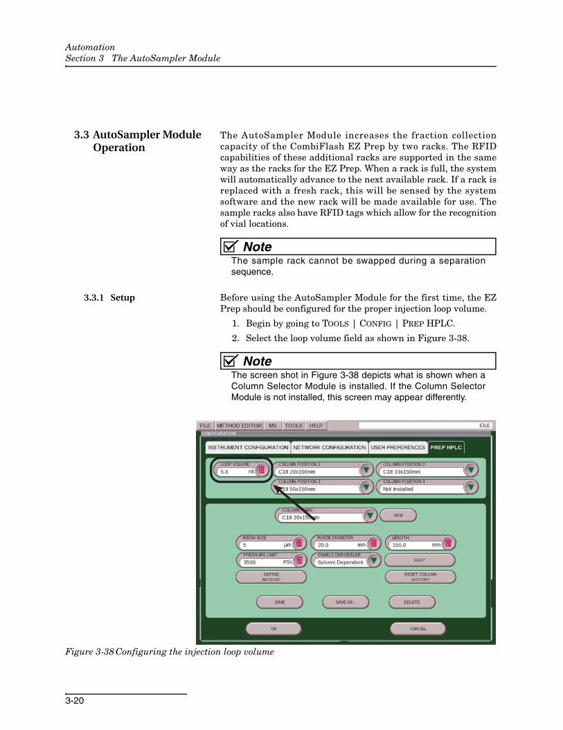
3.3 AutoSampler Module Operation
The AutoSampler Module increases the fraction collectioncapacity of the CombiFlash EZ Prep by two racks. The RFIDcapabilities of these additional racks are supported in the sameway as the racks for the EZ Prep. When a rack is full, the systemwill automatically advance to the next available rack. If a rack isreplaced with a fresh rack, this will be sensed by the systemsoftware and the new rack will be made available for use. Thesample racks also have RFID tags which allow for the recognitionof vial locations.
NoteThe sample rack cannot be swapped during a separationsequence.
3.3.1 Setup Before using the AutoSampler Module for the first time, the EZPrep should be configured for the proper injection loop volume.
1. Begin by going to TOOLS | CONFIG | PREP HPLC.
2. Select the loop volume field as shown in Figure 3-38.
NoteThe screen shot in Figure 3-38 depicts what is shown when aColumn Selector Module is installed. If the Column SelectorModule is not installed, this screen may appear differently.
Figure 3-38 Configuring the injection loop volume

AutomationSection 3 The AutoSampler Module
3-21
The system software assumes the loop should only be 50% filledfor maximum compound recovery. If the parameters entered forthe individual injection exceed a 50% loop fill, a warning messagewill appear recommending a change in the parameters. Thisadvice can be ignored at the discretion of the user.
The AutoSampler Module has an automatic probe wash built intoits operation. After each sample is complete, the probe goes to thewash station. This station rinses the inner and outer surface ofthe needle to minimize carryover. Air is then drawn into thesample probe to remove the strong wash fluid. Place a suitablewash fluid in a container, and place the lines from the washpump in this container.
NoteThe wash fluid will build up contaminants over time due to therinsing of the sample probe and therefore should be changedperiodically.
3.3.2 Operation To begin a separation sequence with the AutoSampler Module,you will need to create a sample queue. After the AutoSamplerModule has been installed and the EZ Prep is in the PREP HPLCmode, the software will display two tabs at the bottom of thescreen. Accessing the RUN tab will result in a screen and oper-ation much like the standard EZ Prep (without an installedAutoSampler Module). Pressing PLAY will display the RUNREQUIREMENTS screen. On this screen, you can perform a manualinjection by removing the Luer fitting from the inject loop, or youcan perform multiple injections on a single sample from theAutoSampler Module without creating a queue. Selecting theQUEUE screen will allow you to set up a separation sequence.
NoteIf you are performing a manual injection, the Luer fitting or aneedle port must be reinstalled on the injection valve.
Follow the instructions below for further information on oper-ating the AutoSampler Module:
1. Install a sample vial rack before opening the QUEUE tab. This will allow the software to limit sample programming to the positions available for sample vials.
2. Open the QUEUE tab.
For an explanation of the available columns on this screen, seeTable 3-1.
AutomationSection 3 The AutoSampler Module
3-22
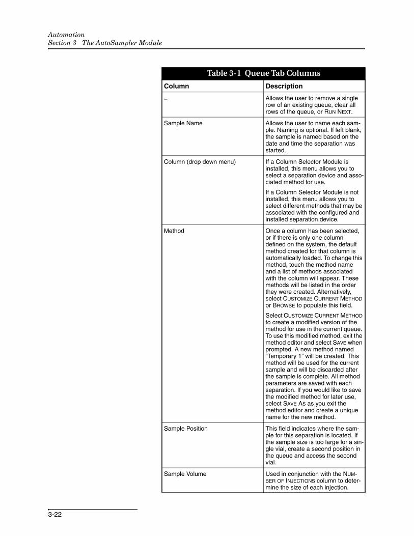
Table 3-1 Queue Tab Columns
Column Description
= Allows the user to remove a single row of an existing queue, clear all rows of the queue, or RUN NEXT.
Sample Name Allows the user to name each sam-ple. Naming is optional. If left blank, the sample is named based on the date and time the separation was started.
Column (drop down menu) If a Column Selector Module is installed, this menu allows you to select a separation device and asso-ciated method for use.
If a Column Selector Module is not installed, this menu allows you to select different methods that may be associated with the configured and installed separation device.
Method Once a column has been selected, or if there is only one column defined on the system, the default method created for that column is automatically loaded. To change this method, touch the method name and a list of methods associated with the column will appear. These methods will be listed in the order they were created. Alternatively, select CUSTOMIZE CURRENT METHOD or BROWSE to populate this field.
Select CUSTOMIZE CURRENT METHOD to create a modified version of the method for use in the current queue. To use this modified method, exit the method editor and select SAVE when prompted. A new method named “Temporary 1” will be created. This method will be used for the current sample and will be discarded after the sample is complete. All method parameters are saved with each separation. If you would like to save the modified method for later use, select SAVE AS as you exit the method editor and create a unique name for the new method.
Sample Position This field indicates where the sam-ple for this separation is located. If the sample size is too large for a sin-gle vial, create a second position in the queue and access the second vial.
Sample Volume Used in conjunction with the NUM-BER OF INJECTIONS column to deter-mine the size of each injection.
AutomationSection 3 The AutoSampler Module
3-23
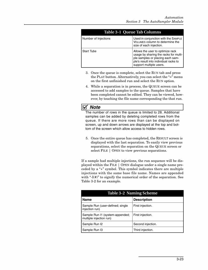
3. Once the queue is complete, select the RUN tab and press the PLAY button. Alternatively, you can select the “=” menu on the first unfinished run and select the RUN option.
4. While a separation is in process, the QUEUE screen can be accessed to add samples to the queue. Samples that have been completed cannot be edited. They can be viewed, how-ever, by touching the file name corresponding the that run.
NoteThe number of rows in the queue is limited to 28. Additionalsamples can be added by deleting completed rows from thequeue. If there are more rows than can be displayed onscreen, up and down arrows are displayed at the top and bot-tom of the screen which allow access to hidden rows.
5. Once the entire queue has completed, the RESULT screen is displayed with the last separation. To easily view previous separations, select the separation on the QUEUE screen or select FILE | OPEN to view previous separations.
If a sample had multiple injections, the run sequence will be dis-played within the FILE | OPEN dialogue under a single name pre-ceded by a “+” symbol. This symbol indicates there are multipleinjections with the same base file name. Names are appendedwith “-I(#)” to signify the numerical order of the separation. SeeTable 3-2 for an example.
Number of Injections Used in conjunction with the SAMPLE VOLUMES column to determine the size of each injection.
Start Tube Allows the user to optimize rack usage by sharing the racks for multi-ple samples or placing each sam-ple’s result into individual racks to support multiple users.
Table 3-2 Naming Scheme
Name Description
Sample Run (user-defined; single injection run)
First injection.
Sample Run I1 (system-appended; multiple injection run)
First injection.
Sample Run I2 Second injection.
Sample Run I3 Third injection.
Table 3-1 Queue Tab Columns

AutomationSection 3 The AutoSampler Module
3-24
4-1
Automation
Section 4 The Column Selector Module
4.1 Column Selector Module Installation
NoteCombiFlash EZ Prep software must be version 3.1.0 or higherto support the automation capabilities.
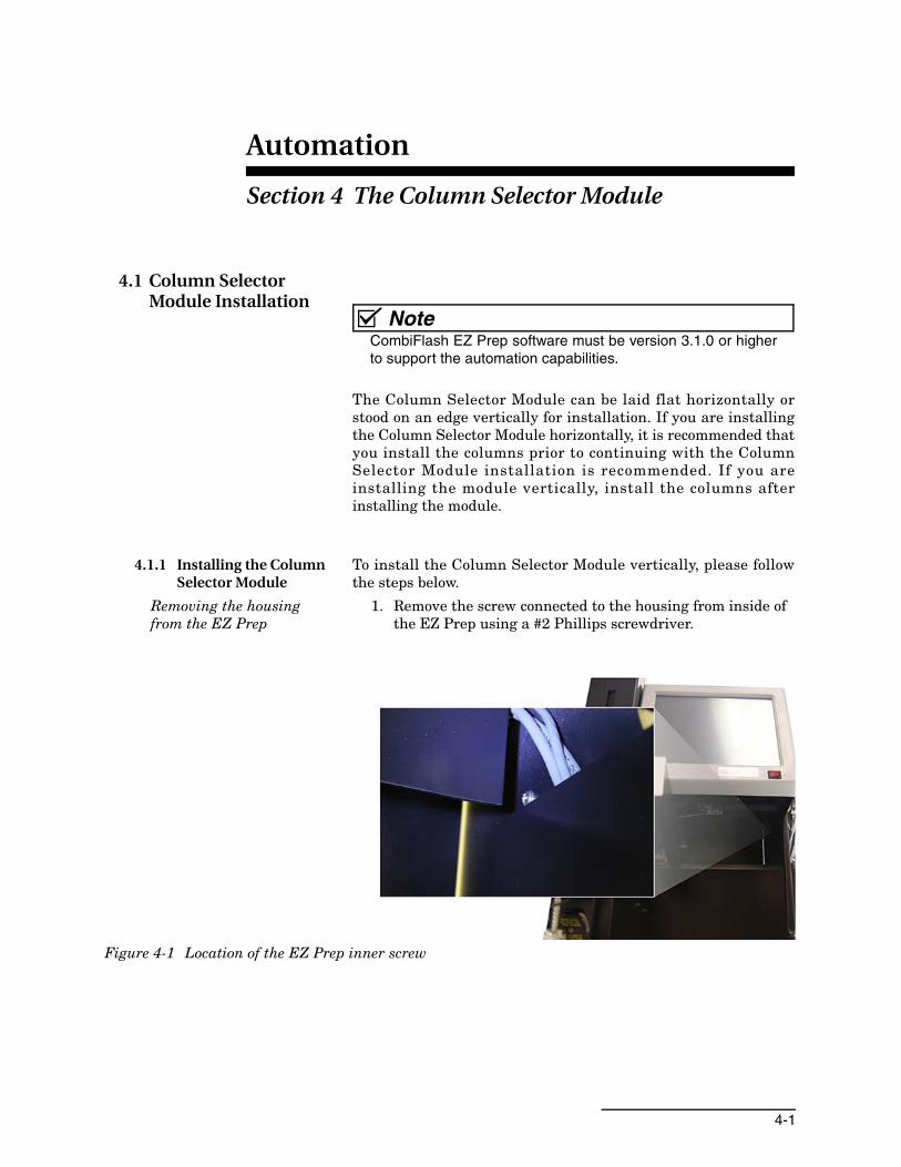
The Column Selector Module can be laid flat horizontally orstood on an edge vertically for installation. If you are installingthe Column Selector Module horizontally, it is recommended thatyou install the columns prior to continuing with the ColumnSelector Module installation is recommended. If you areinstalling the module vertically, install the columns afterinstalling the module.
4.1.1 Installing the Column Selector Module
To install the Column Selector Module vertically, please followthe steps below.
Removing the housing from the EZ Prep
1. Remove the screw connected to the housing from inside of the EZ Prep using a #2 Phillips screwdriver.
Figure 4-1 Location of the EZ Prep inner screw
AutomationSection 4 The Column Selector Module
4-2
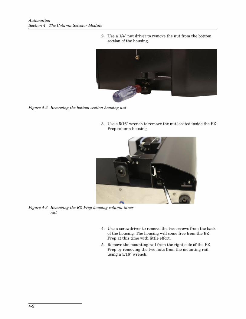
2. Use a 1/4” nut driver to remove the nut from the bottom section of the housing.
Figure 4-2 Removing the bottom section housing nut
3. Use a 5/16” wrench to remove the nut located inside the EZ Prep column housing.
Figure 4-3 Removing the EZ Prep housing column inner nut
4. Use a screwdriver to remove the two screws from the back of the housing. The housing will come free from the EZ Prep at this time with little effort.
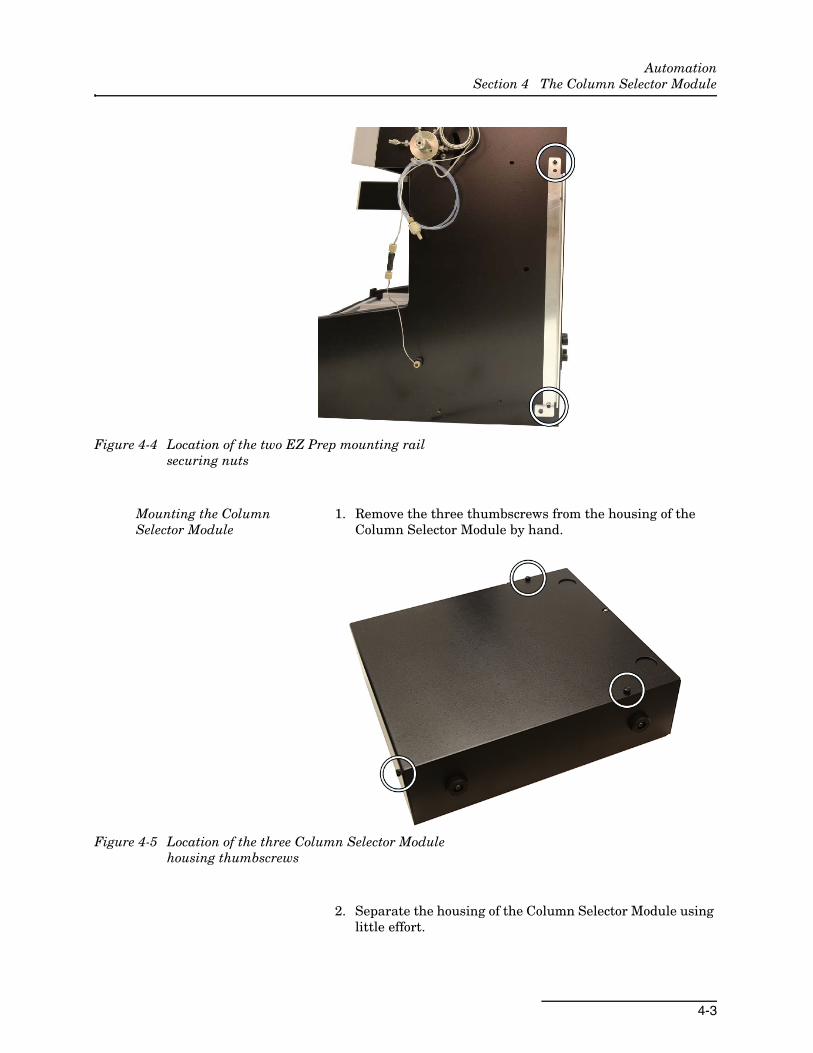
5. Remove the mounting rail from the right side of the EZ Prep by removing the two nuts from the mounting rail using a 5/16” wrench.
AutomationSection 4 The Column Selector Module
4-3
Figure 4-4 Location of the two EZ Prep mounting rail securing nuts
Mounting the Column Selector Module
1. Remove the three thumbscrews from the housing of the Column Selector Module by hand.
Figure 4-5 Location of the three Column Selector Module housing thumbscrews
2. Separate the housing of the Column Selector Module using little effort.
AutomationSection 4 The Column Selector Module
4-4
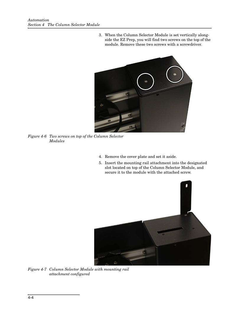
3. When the Column Selector Module is set vertically along-side the EZ Prep, you will find two screws on the top of the module. Remove these two screws with a screwdriver.
Figure 4-6 Two screws on top of the Column Selector Modules
4. Remove the cover plate and set it aside.
5. Insert the mounting rail attachment into the designated slot located on top of the Column Selector Module, and secure it to the module with the attached screw.
Figure 4-7 Column Selector Module with mounting rail attachment configured
AutomationSection 4 The Column Selector Module
4-5
6. Replace the cover plate and screw it into place.
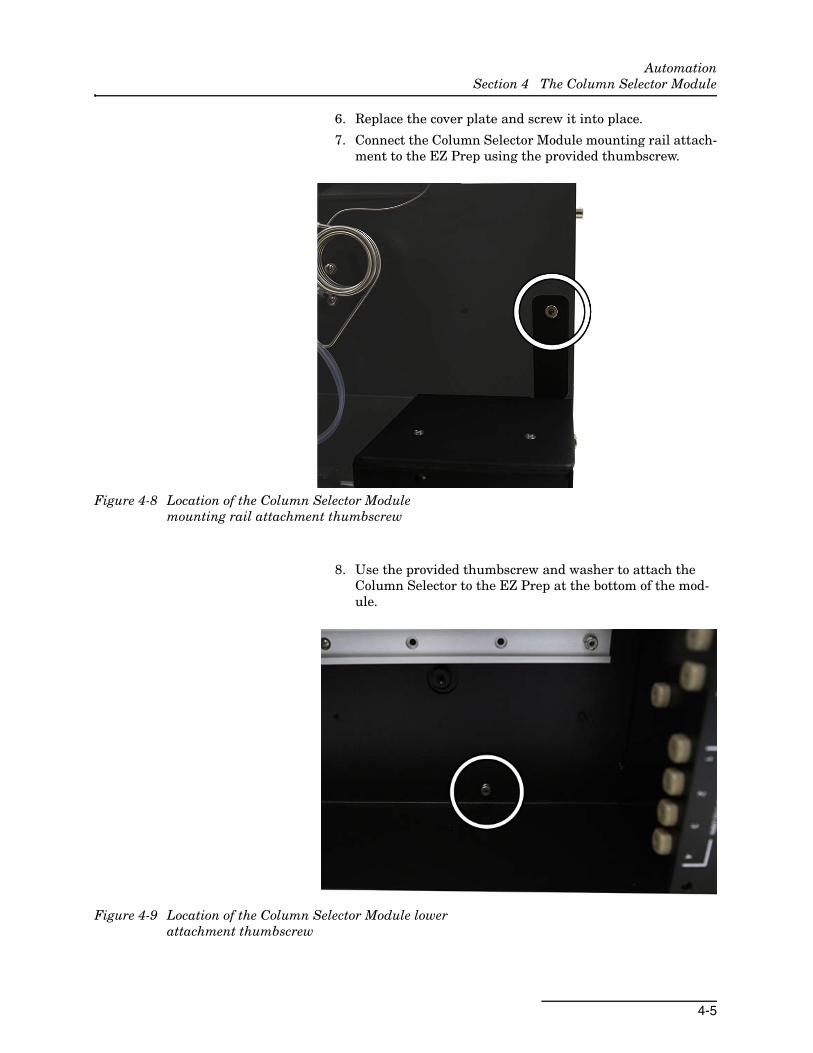
7. Connect the Column Selector Module mounting rail attach-ment to the EZ Prep using the provided thumbscrew.
Figure 4-8 Location of the Column Selector Module mounting rail attachment thumbscrew
8. Use the provided thumbscrew and washer to attach the Column Selector to the EZ Prep at the bottom of the mod-ule.
Figure 4-9 Location of the Column Selector Module lower attachment thumbscrew
AutomationSection 4 The Column Selector Module
4-6
4.1.2 Establishing Column Selector Module Connections
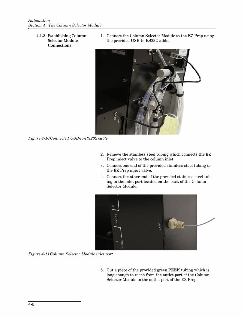
1. Connect the Column Selector Module to the EZ Prep using the provided USB-to-RS232 cable.
Figure 4-10 Connected USB-to-RS232 cable
2. Remove the stainless steel tubing which connects the EZ Prep inject valve to the column inlet.
3. Connect one end of the provided stainless steel tubing to the EZ Prep inject valve.
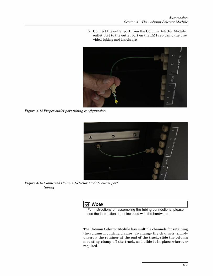
4. Connect the other end of the provided stainless steel tub-ing to the inlet port located on the back of the Column Selector Module.
Figure 4-11 Column Selector Module inlet port
5. Cut a piece of the provided green PEEK tubing which is long enough to reach from the outlet port of the Column Selector Module to the outlet port of the EZ Prep.
AutomationSection 4 The Column Selector Module
4-7
6. Connect the outlet port from the Column Selector Module outlet port to the outlet port on the EZ Prep using the pro-vided tubing and hardware.
Figure 4-12 Proper outlet port tubing configuration
Figure 4-13 Connected Column Selector Module outlet port tubing
NoteFor instructions on assembling the tubing connections, pleasesee the instruction sheet included with the hardware.
The Column Selector Module has multiple channels for retainingthe column mounting clamps. To change the channels, simplyunscrew the retainer at the end of the track, slide the columnmounting clamp off the track, and slide it in place whereverrequired.

AutomationSection 4 The Column Selector Module
4-8
7. Place the columns into a clamp suitable for the column size.
8. Using the provided tubing and a tubing cutter, connect the column input port to the “TO COLUMN” port on the Column Selector Module. If a guard column is used, it can be plumbed directly before the individual column.
9. Connect the column output port to the “FROM COLUMN” port on the Column Selector Module.
Figure 4-14 Proper column connections on the Column Selector Module
NoteRecord of the position of the columns as you will need thisinformation during your initial configuration. After the configu-ration is complete, the columns will be selected by name ratherthan by how they are connected.
10. If desired, secure the housing of the Column Selector Mod-ule back onto the module using the thumbscrews removed in Step 1 of Removing the housing from the EZ Prep.
11. Connect the power supply from the Column Selector Mod-ule to a power source.
4.1.3 Mounting the AutoInjector Module to the Column Selector Module
The Column Selector Module can be used in conjunction with theAutoInjector Module. Begin by installing the Column SelectorModule, and then install the AutoInjector Module using the stepsbelow:
1. Remove the cover plate from the top of the Column Selec-tor Module by removing the two screws.
AutomationSection 4 The Column Selector Module
4-9
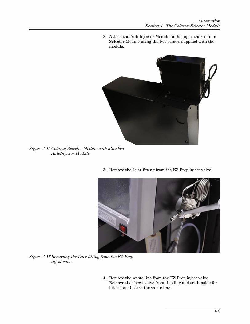
2. Attach the AutoInjector Module to the top of the Column Selector Module using the two screws supplied with the module.
Figure 4-15 Column Selector Module with attached AutoInjector Module
3. Remove the Luer fitting from the EZ Prep inject valve.
Figure 4-16 Removing the Luer fitting from the EZ Prep inject valve
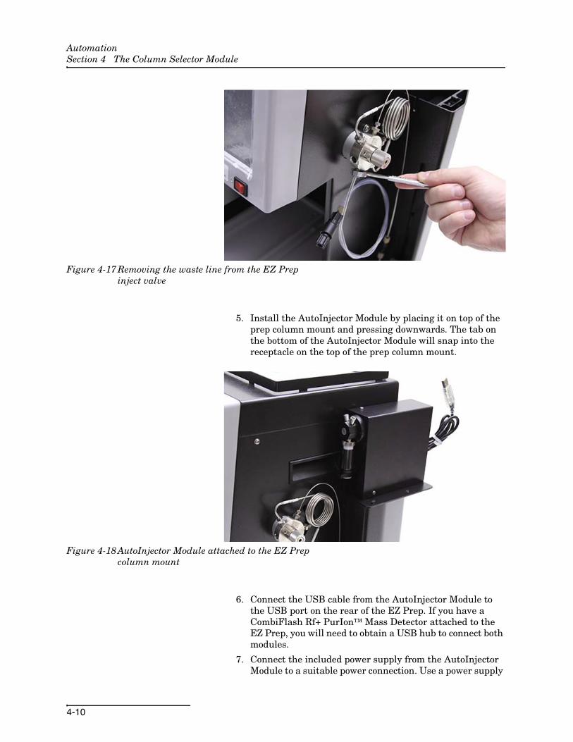
4. Remove the waste line from the EZ Prep inject valve. Remove the check valve from this line and set it aside for later use. Discard the waste line.
AutomationSection 4 The Column Selector Module
4-10
Figure 4-17 Removing the waste line from the EZ Prep inject valve
5. Install the AutoInjector Module by placing it on top of the prep column mount and pressing downwards. The tab on the bottom of the AutoInjector Module will snap into the receptacle on the top of the prep column mount.
Figure 4-18 AutoInjector Module attached to the EZ Prep column mount
6. Connect the USB cable from the AutoInjector Module to the USB port on the rear of the EZ Prep. If you have a CombiFlash Rf+ PurIonTM Mass Detector attached to the EZ Prep, you will need to obtain a USB hub to connect both modules.
7. Connect the included power supply from the AutoInjector Module to a suitable power connection. Use a power supply

AutomationSection 4 The Column Selector Module
4-11
in a location that minimizes the possibility of a chemical spill damaging the power supply.
8. Locate the supplied waste tubing and fitting package (P/N 60-5234-653).
9. Unscrew the attached plastic ferrule in this fitting package until the plastic ferrule is almost completely detached from the steel fitting.
10. Attach the steel fitting in this package to the EZ Prep inject valve waste port. This steel fitting should be hand tight.
Figure 4-19 Waste tubing fitting attached to the EZ Prep inject valve
11. Turn the plastic ferrule until it is attached hand tight to the valve.
12. Turn the steel fitting 1/2 turn tighter.
13. Remove the plastic ferrule while leaving the fitting attached.

AutomationSection 4 The Column Selector Module
4-12
Figure 4-20 Waste fitting with the plastic ferrule removed
14. Attach the supplied tubing from this package to the secured fitting. Tighten the ferrule finger tight with the supplied tool. Ensure the tubing and fitting are snug in the EZ Prep inject valve.
Figure 4-21 Waste fitting with tubing attached
15. Connect the opposite end of this tubing to the left port of the AutoInjector Module.
AutomationSection 4 The Column Selector Module
4-13
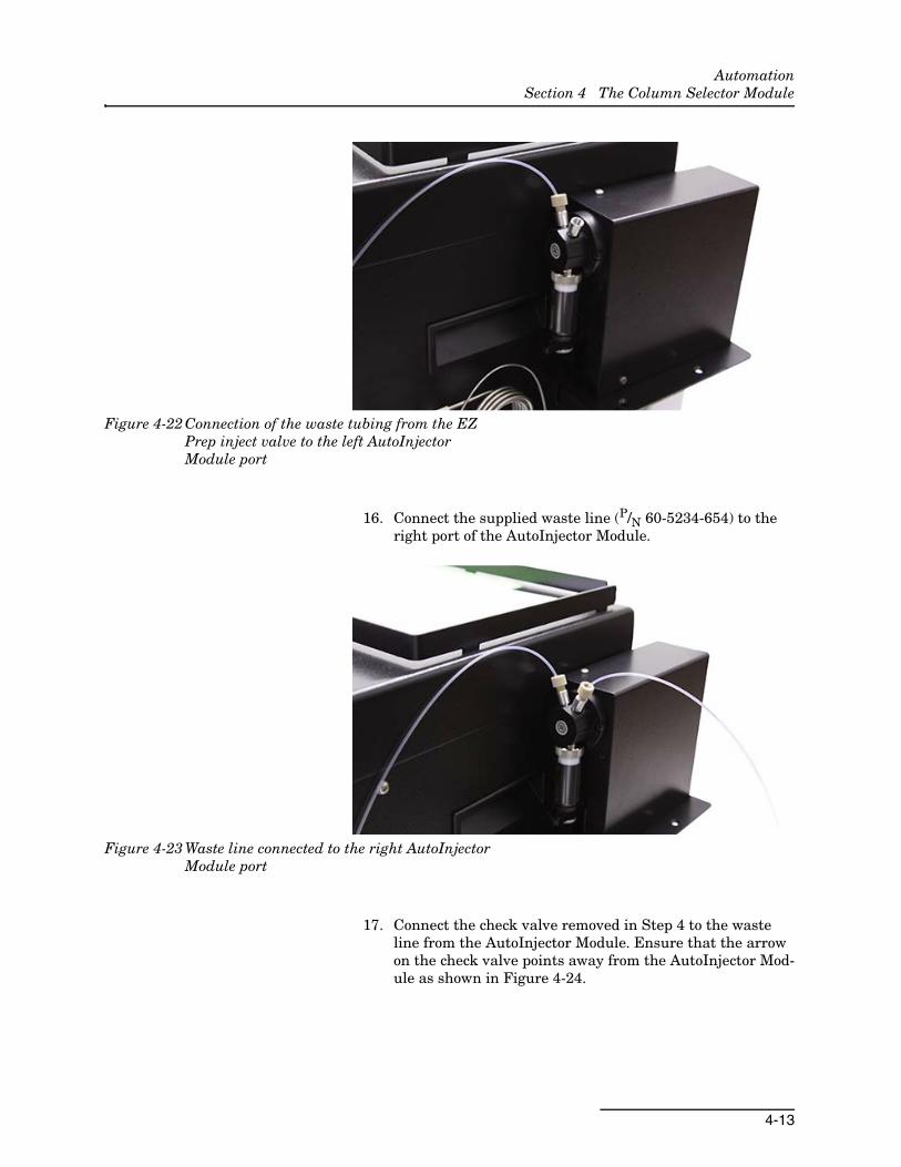
Figure 4-22 Connection of the waste tubing from the EZ Prep inject valve to the left AutoInjector Module port
16. Connect the supplied waste line (P/N 60-5234-654) to the right port of the AutoInjector Module.
Figure 4-23 Waste line connected to the right AutoInjector Module port
17. Connect the check valve removed in Step 4 to the waste line from the AutoInjector Module. Ensure that the arrow on the check valve points away from the AutoInjector Mod-ule as shown in Figure 4-24.

AutomationSection 4 The Column Selector Module
4-14
Figure 4-24 Check valve connected to the waste line of the AutoInjector Module
18. Locate the supplied sample probe tubing and fitting pack-age (P/N 60-5234-657).
19. Unscrew the attached plastic ferrule in this fitting package until the plastic ferrule is almost completely detached from the steel fitting.
20. Attach the steel fitting in this package to the EZ Prep inject valve waste port. This steel fitting should be hand tight.
Figure 4-25 Sample tube fitting attached to the EZ Prep inject valve
21. Turn the plastic ferrule until it is attached hand tight to the valve.
22. Turn the steel fitting 1/2 turn tighter.
23. Remove the plastic ferrule while leaving the fitting attached.
AutomationSection 4 The Column Selector Module
4-15
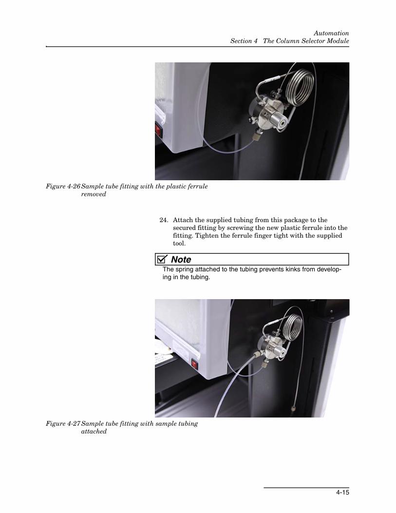
Figure 4-26 Sample tube fitting with the plastic ferrule removed
24. Attach the supplied tubing from this package to the secured fitting by screwing the new plastic ferrule into the fitting. Tighten the ferrule finger tight with the supplied tool.
NoteThe spring attached to the tubing prevents kinks from develop-ing in the tubing.
Figure 4-27 Sample tube fitting with sample tubing attached
AutomationSection 4 The Column Selector Module
4-16
4.1.4 Establishing AutoInjector Module Connections
The AutoInjector Module comes with an attached USB-A cable.Connect this cable to an open USB port on the back of the EZPrep.
NoteIt may be necessary to use a USB hub to accommodate USBconnections if there are not enough ports available.
Y-type Power Supply If you are using the Column Selector Module in conjunction withthe AutoInjector Module, you will be supplied with a Y-typepower supply. This power supply is used to power both of themodules from a single power source. Plug one end of the powercable into the Column Selector Module, and plug the other endinto the AutoInjector Module. Then, plug the power cord into asuitable power supply.
4.2 Installing the Column Selector Module with the AutoSampler Module
Using the Column Selector Module in conjunction with theAutoSampler Module does not affect the installation process foreither module. Please install each module in accordance with theinstructions given in that module’s section.
4.3 Column Selector Module Operation
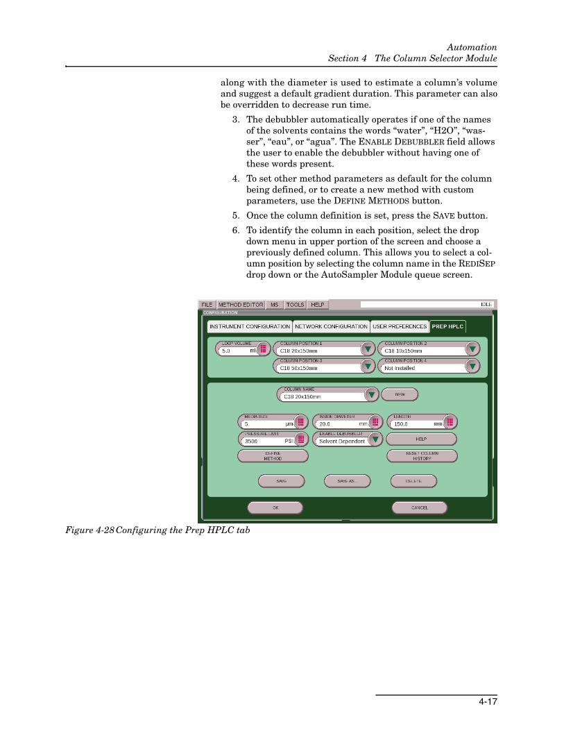
4.3.1 Setup Before using the Column Selector Module for the first time, theCombiFlash EZ Prep must be configured to identify the columnin each position. Once the columns have been installed in theColumn Selector Module, go to FILE | CONFIG | PREP HPLC.Then, define the parameters of each column so a default methodcan be created for the column. To create a new column definition,follow the steps below:
1. Select NEW and enter a name in the COLUMN NAME field.
2. Enter the media size, column inside diameter, and length. If the default pressure limit of 3,500 is excessive, enter a new pressure limit as well.
These parameters are automatically entered into the RUN NOTEfor each separation. The inside diameter is used to suggest a flowrate with a similar velocity to a 4.6 mm HPLC operating at1 mL/min. This flow rate may be overridden at this time todecrease the time required for a separation. The column length
AutomationSection 4 The Column Selector Module
4-17
along with the diameter is used to estimate a column’s volumeand suggest a default gradient duration. This parameter can alsobe overridden to decrease run time.
3. The debubbler automatically operates if one of the names of the solvents contains the words “water”, “H2O”, “was-ser”, “eau”, or “agua”. The ENABLE DEBUBBLER field allows the user to enable the debubbler without having one of these words present.
4. To set other method parameters as default for the column being defined, or to create a new method with custom parameters, use the DEFINE METHODS button.
5. Once the column definition is set, press the SAVE button.
6. To identify the column in each position, select the drop down menu in upper portion of the screen and choose a previously defined column. This allows you to select a col-umn position by selecting the column name in the REDISEP drop down or the AutoSampler Module queue screen.
Figure 4-28 Configuring the Prep HPLC tab

AutomationSection 4 The Column Selector Module
4-18
A-1
Automation
Appendix A Specifications
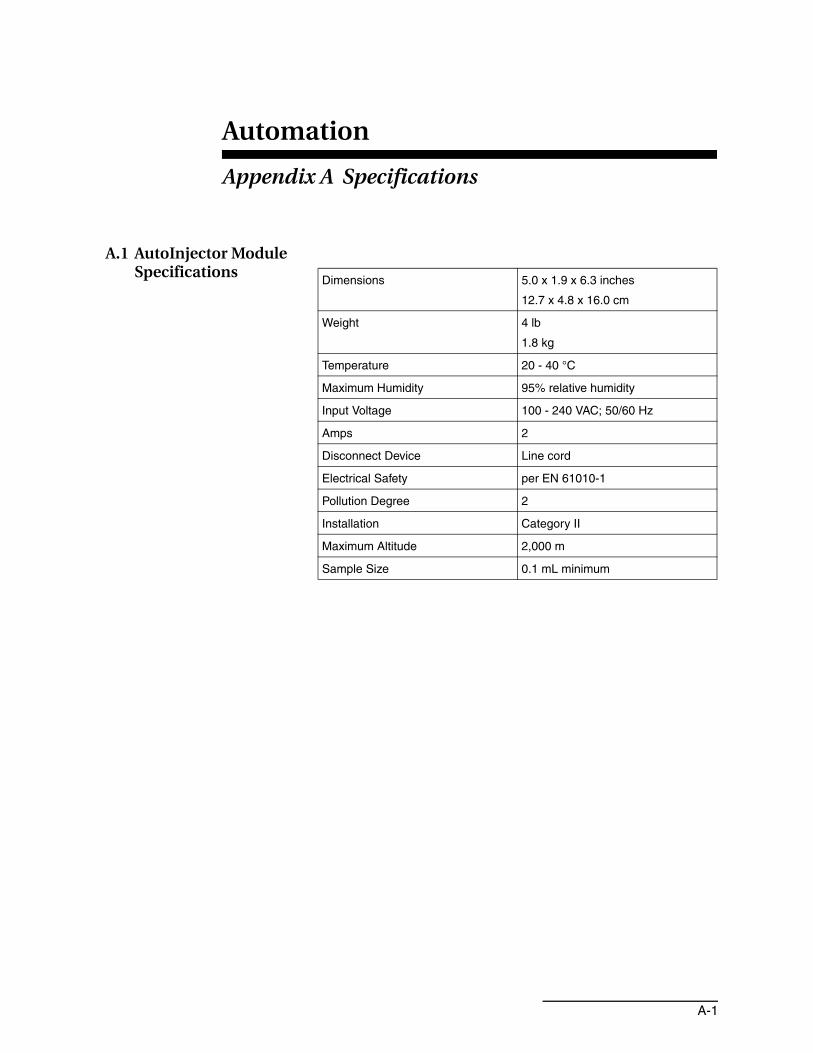
A.1 AutoInjector Module Specifications
Dimensions 5.0 x 1.9 x 6.3 inches
12.7 x 4.8 x 16.0 cm
Weight 4 lb
1.8 kg
Temperature 20 - 40 °C
Maximum Humidity 95% relative humidity
Input Voltage 100 - 240 VAC; 50/60 Hz
Amps 2
Disconnect Device Line cord
Electrical Safety per EN 61010-1
Pollution Degree 2
Installation Category II
Maximum Altitude 2,000 m
Sample Size 0.1 mL minimum

AutomationAppendix A Specifications
A-2
A.2 AutoSampler Module Specifications
Dimensions 18.9 x 14.0 x 19.3 inches
48.0 x 35.6 x 49.0 cm
Weight 31 lbs
14.1 kg
Temperature 20 - 40 °C
Maximum Humidity 95% relative humidity
Input Voltage 100 - 240 VAC; 50/60 Hz
Amps 2
Disconnect Device Line cord
Electrical Safety per EN 61010-1
Pollution Degree 2
Installation Category II
Maximum Altitude 2,000 m
Sample Size 0.1 mL minimum
AutomationAppendix A Specifications
A-3
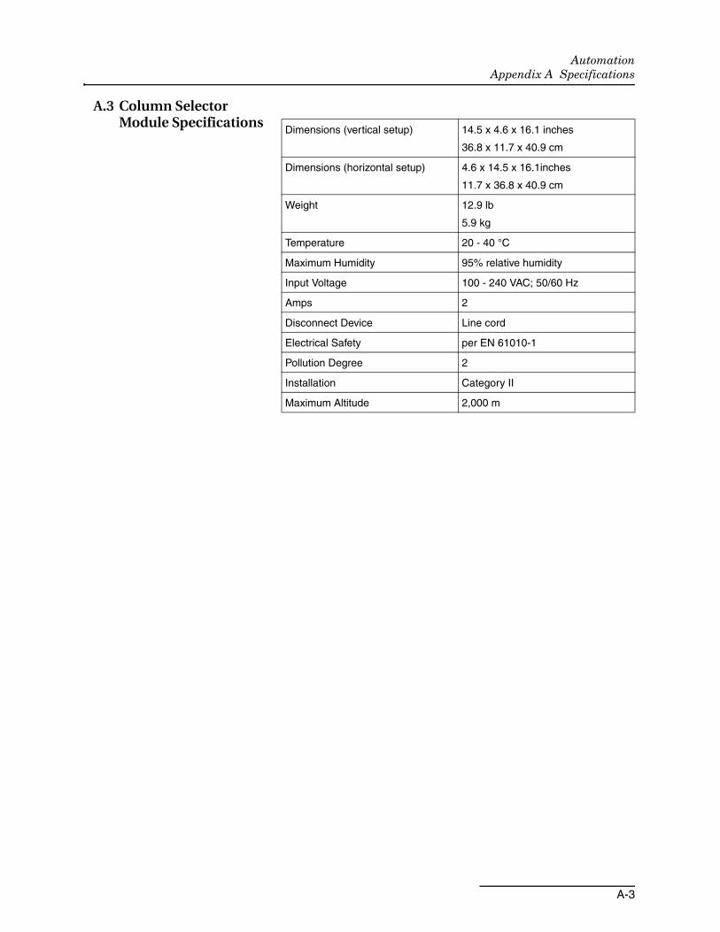
A.3 Column Selector Module Specifications
Dimensions (vertical setup) 14.5 x 4.6 x 16.1 inches
36.8 x 11.7 x 40.9 cm
Dimensions (horizontal setup) 4.6 x 14.5 x 16.1inches
11.7 x 36.8 x 40.9 cm
Weight 12.9 lb
5.9 kg
Temperature 20 - 40 °C
Maximum Humidity 95% relative humidity
Input Voltage 100 - 240 VAC; 50/60 Hz
Amps 2
Disconnect Device Line cord
Electrical Safety per EN 61010-1
Pollution Degree 2
Installation Category II
Maximum Altitude 2,000 m

AutomationAppendix A Specifications
A-4

Compliance Statements
CE Dec
larat
ion o
f Con
form
ity
Pendin
g...

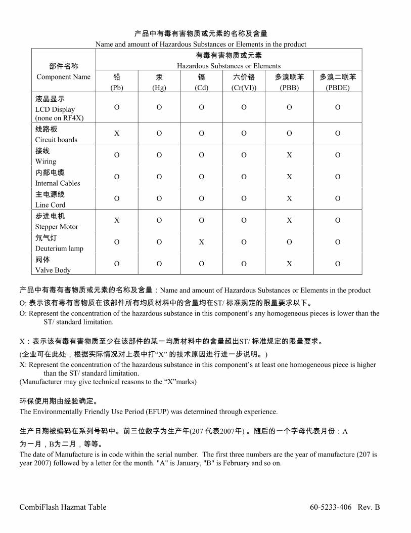
CombiFlash Hazmat Table 60-5233-406 Rev. B
Name and amount of Hazardous Substances or Elements in the product
Component Name
Hazardous Substances or Elements
(Pb)
(Hg)
(Cd)
(Cr(VI))
(PBB)
(PBDE)
LCD Display
(none on RF4X)
O O O O O O
Circuit boards X O O O O O
Wiring O O O O X O
Internal Cables O O O O X O
Line Cord O O O O X O
Stepper Motor X O O O X O
Deuterium lamp O O X O O O
Valve Body O O O O X O
Name and amount of Hazardous Substances or Elements in the product
O: ST/
O: Represent the concentration of the hazardous substance in this component’s any homogeneous pieces is lower than the ST/ standard limitation.
X ST/
( “X” )
X: Represent the concentration of the hazardous substance in this component’s at least one homogeneous piece is higher than the ST/ standard limitation.
(Manufacturer may give technical reasons to the “X”marks)
The Environmentally Friendly Use Period (EFUP) was determined through experience.
(207 2007 ) A
B
The date of Manufacture is in code within the serial number. The first three numbers are the year of manufacture (207 is
year 2007) followed by a letter for the month. "A" is January, "B" is February and so on.


Teledyne Isco One Year Limited Factory Service Warranty*This warranty exclusively covers Teledyne Isco
instruments, providing a one-year limited warranty
covering parts and labor.
Any instrument that fails during the warranty period due to
faulty parts or workmanship will be repaired at the factory
at no charge to the customer. Teledyne Isco’s exclusive
liability is limited to repair or replacement of defective
instruments. Teledyne Isco is not liable for consequential
damages.
Teledyne Isco will pay surface transportation charges both
ways within the 48 contiguous United States if the
instrument proves to be defective within 30 days of
shipment. Throughout the remainder of the warranty period,
the customer will pay to return the instrument to Teledyne
Isco and Teledyne Isco will pay surface transportation to
return the repaired instrument to the customer. Teledyne
Isco will not pay air freight or customer’s packing and
crating charges. This warranty does not cover loss, damage,
or defects resulting from transportation between the
customer’s facility and the repair facility.
The warranty for any instrument is the one in effect on date
of shipment. The warranty period begins on the shipping
date, unless Teledyne Isco agrees in writing to a different
date.
Excluded from this warranty are normal wear; expendable
items such as desiccant, pH sensors, charts, ribbon, lamps,
tubing, and glassware; fittings and wetted parts of valves;
check valves, pistons, piston seals, wash seals, cylinders,
pulse damper diaphragms, inlet lines and filter elements;
and damage due to corrosion, misuse, accident, or lack
of proper maintenance. This warranty does
not cover products not sold under the Teledyne
Isco trademark or for which any other warranty is
specifically stated.
No item may be returned for warranty service without a
return authorization number (RMA) issued by Teledyne
Isco.
This warranty is expressly in lieu of all other warranties
and obligations and Teledyne Isco specifically disclaims
any warranty of merchantability or fitness for a
particular purpose.
The warrantor is Teledyne Isco, 4700 Superior, Lincoln, NE
68504, U.S.A.
*This warranty applies to the USA and countries where Teledyne Isco does not have an authorized dealer.
Customers in countries outside the USA, where Teledyne Isco has an authorized dealer, should contact
their Teledyne Isco dealer for warranty service.
Problems can o f ten be diagnosed and corrected without returning the instrument to thefactory. Before returning any instrument for repair, please contact the Teledyne Isco Service Department for instructions and to obtain a return material authorization number (RMA). Instruments needing factory repair should be packed carefully and shipped to the attention ofthe service department. Small, non-fragile items can be sent by insured parcel post. PLEASE WRITE THE RMA NUMBER ON THE OUTSIDE OF THE SHIPPING CONTAINER and enclose a note explaining the problem.
Shipping Address: Teledyne Isco - Attention Repair Service4700 Superior StreetLincoln, NE 68504 USA
Mailing Address: Teledyne IscoPO Box 82531Lincoln, NE 68501 USA
Phone: Repair service: (800) 775-2965 (lab instruments)(866) 298-6174 (samplers & flow meters)
Sales & General Information: (800) 228-4373 (USA &Canada)Fax: (402) 465-3001Email: [email protected]
March 2, 2016 P/N 60-1002-040 Rev J