Embed Size (px)
Citation preview
1
Myat Kyaw
Control
2
Table of Contents
Abstract …………………………………………….……………………………………………. 3
Background…………………………………………………….…………..………………….. 3-4
Introduction …………………………………………………………………………… …….. 4
Bluetooth Switching Circuit Design…………………….………………………….. 5
Software Design ……………………………………….……….......................... 5-6
Test Setup ………………………………………………...................................6
Lessons Learned …………….…………………………………….………………………… 6
Conclusion ………………………………………………………….…………………………… 7
Appendix …………………………………………………………………….…………………. 8-14
3
Abstract
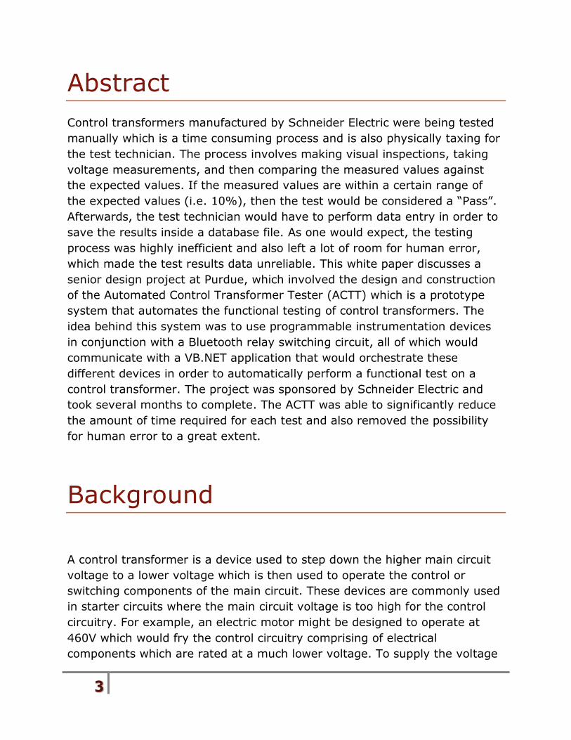
Control transformers manufactured by Schneider Electric were being tested
manually which is a time consuming process and is also physically taxing for
the test technician. The process involves making visual inspections, taking
voltage measurements, and then comparing the measured values against
the expected values. If the measured values are within a certain range of
the expected values (i.e. 10%), then the test would be considered a “Pass”.
Afterwards, the test technician would have to perform data entry in order to
save the results inside a database file. As one would expect, the testing
process was highly inefficient and also left a lot of room for human error,
which made the test results data unreliable. This white paper discusses a
senior design project at Purdue, which involved the design and construction
of the Automated Control Transformer Tester (ACTT) which is a prototype
system that automates the functional testing of control transformers. The
idea behind this system was to use programmable instrumentation devices
in conjunction with a Bluetooth relay switching circuit, all of which would
communicate with a VB.NET application that would orchestrate these
different devices in order to automatically perform a functional test on a
control transformer. The project was sponsored by Schneider Electric and
took several months to complete. The ACTT was able to significantly reduce
the amount of time required for each test and also removed the possibility
for human error to a great extent.
Background
A control transformer is a device used to step down the higher main circuit
voltage to a lower voltage which is then used to operate the control or
switching components of the main circuit. These devices are commonly used
in starter circuits where the main circuit voltage is too high for the control
circuitry. For example, an electric motor might be designed to operate at
460V which would fry the control circuitry comprising of electrical
components which are rated at a much lower voltage. To supply the voltage
4
to the control circuitry without a separate power source, power is tapped off
the main 460V line and passed through the disconnect transformer which
would then lower the voltage to a level that is usable by the control circuitry.
Introduction
The idea for the ACTT was proposed to Schneider Electric and they agreed to
provide sponsorship for the development of a prototype system. The
proposed solution was to use a Bluetooth switching circuit in conjunction
with programmable instrumentation devices, all communicating with a
VB.NET application which would orchestrate the testing. The proposed
system would be able to determine whether the test passed or failed and
display the results to the user. Additionally, if the test failed, the system will
also display to the user the conditions which caused the test to fail. Then the
system will automatically save the test results to a database file upon the
completion of each test.
After Schneider Electric agreed to sponsor the project, the next step was to
create a project charter which had to be approved by the senior design
project instructors. After the project charter was approved, a detailed
project plan was created and continuously updated as the project
progressed. After the project plan was created, an industry expert was
consulted to ensure the feasibility of the design. Once the design was
approved, Schneider Electric was asked to order the required
equipment/parts needed to construct the system. Then the development of
the VB.NET application began while waiting to receive the hardware parts.
5
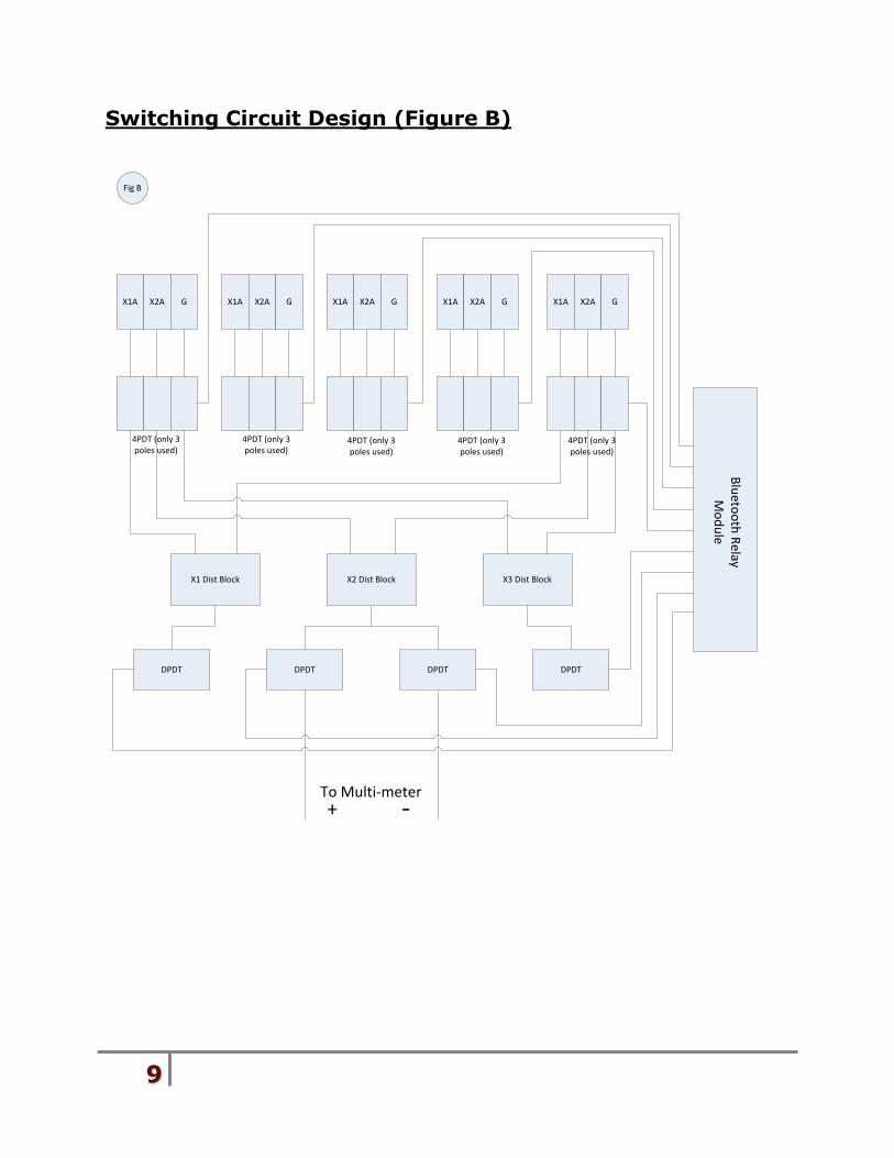
Bluetooth Switching Circuit Design
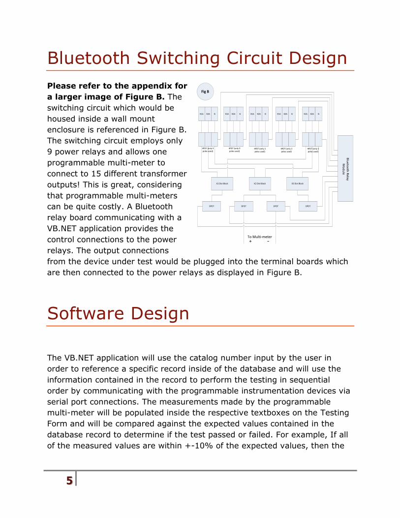
Please refer to the appendix for
a larger image of Figure B. The
switching circuit which would be
housed inside a wall mount
enclosure is referenced in Figure B.
The switching circuit employs only
9 power relays and allows one
programmable multi-meter to
connect to 15 different transformer
outputs! This is great, considering
that programmable multi-meters
can be quite costly. A Bluetooth
relay board communicating with a
VB.NET application provides the
control connections to the power
relays. The output connections
from the device under test would be plugged into the terminal boards which
are then connected to the power relays as displayed in Figure B.
Software Design
The VB.NET application will use the catalog number input by the user in
order to reference a specific record inside of the database and will use the
information contained in the record to perform the testing in sequential
order by communicating with the programmable instrumentation devices via
serial port connections. The measurements made by the programmable
multi-meter will be populated inside the respective textboxes on the Testing
Form and will be compared against the expected values contained in the
database record to determine if the test passed or failed. For example, If all
of the measured values are within +-10% of the expected values, then the
X1A X2A G X1A X2A G X1A X2A G X1A X2A G X1A X2A G
X1 Dist Block X2 Dist Block X3 Dist Block
4PDT (only 3 poles used)
4PDT (only 3 poles used)
4PDT (only 3 poles used)
4PDT (only 3 poles used)
4PDT (only 3 poles used)
DPDT DPDT DPDT DPDT
+ -
Fig B
Blu
eto
oth
Re
lay M
od
ule
To Multi-meter
6
test is considered a “Pass”, otherwise it’s considered a “Fail”. After each test
has been completed, the results will be saved automatically to the database.
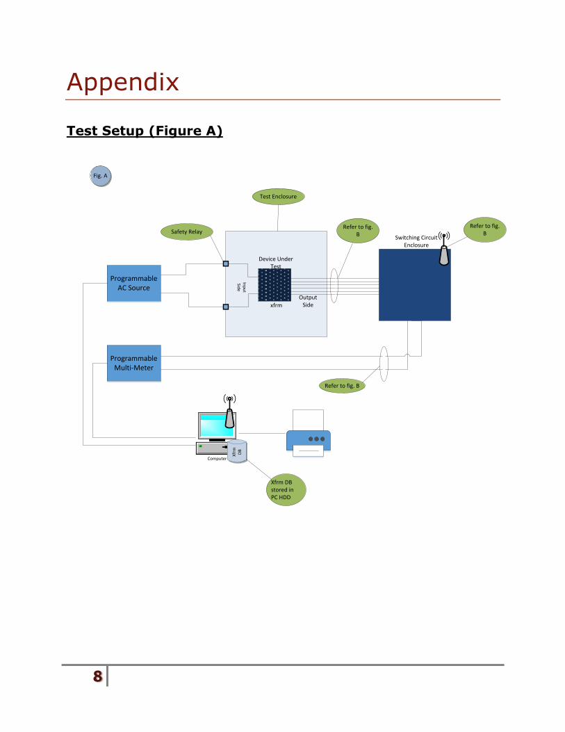
Test Setup
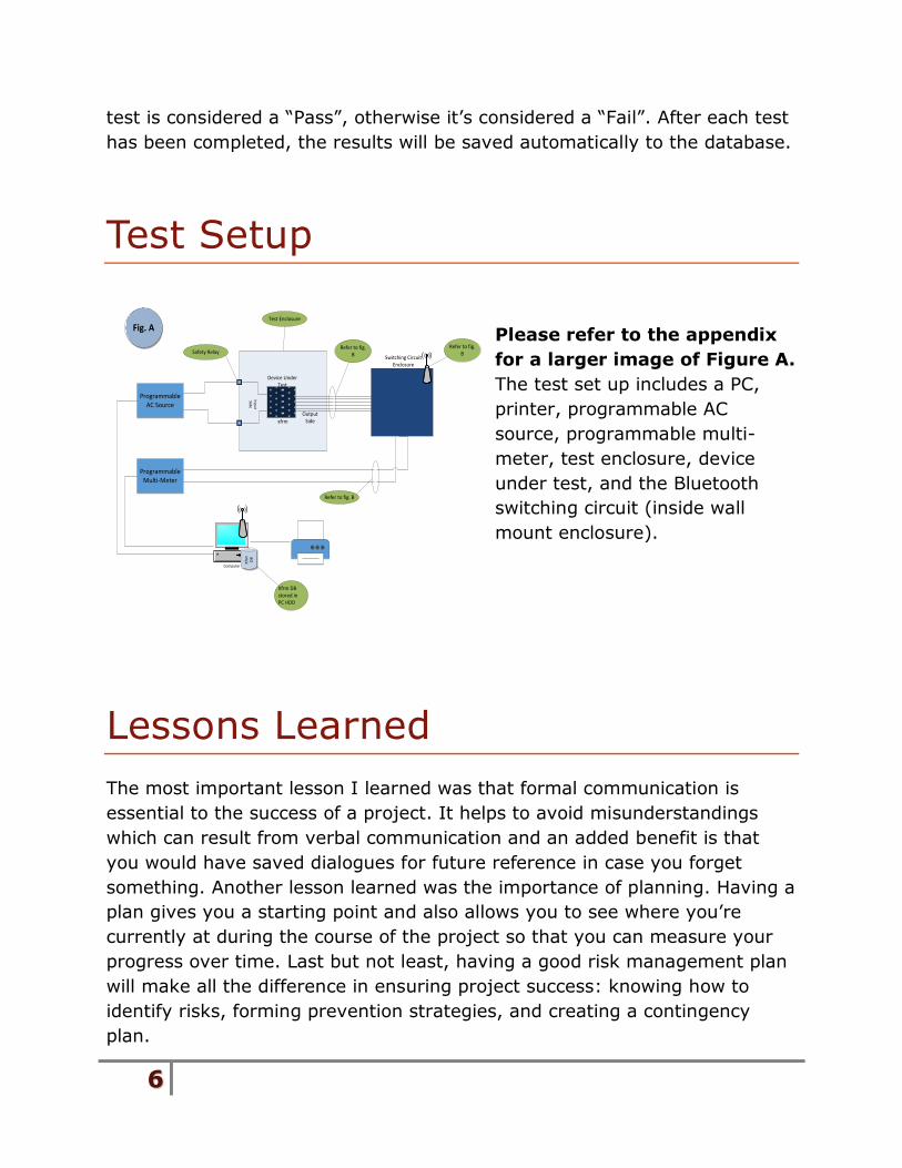
Please refer to the appendix
for a larger image of Figure A.
The test set up includes a PC,
printer, programmable AC
source, programmable multi-
meter, test enclosure, device
under test, and the Bluetooth
switching circuit (inside wall
mount enclosure).
Lessons Learned
The most important lesson I learned was that formal communication is
essential to the success of a project. It helps to avoid misunderstandings
which can result from verbal communication and an added benefit is that
you would have saved dialogues for future reference in case you forget
something. Another lesson learned was the importance of planning. Having a
plan gives you a starting point and also allows you to see where you’re
currently at during the course of the project so that you can measure your
progress over time. Last but not least, having a good risk management plan
will make all the difference in ensuring project success: knowing how to
identify risks, forming prevention strategies, and creating a contingency
plan.
Programmable AC Source
Programmable Multi-Meter
Device Under Test
Fig. A
Inp
ut
Sid
e
Output Sidexfrm
Switching Circuit Enclosure
Computer
Xfr
m
DB
Safety Relay
Test Enclosure
Refer to fig. B
Refer to fig. B
Refer to fig. B
Xfrm DB stored in PC HDD
7
Conclusion
The Automated Control Transformer Tester prototype system passed the
validation tests and also passed a safety inspection from ERS Automation.
Furthermore, the prototype system met all of the requirements.
Consequently, the system was able to drastically lower the amount of time
required to test an electrical control transformer and also greatly reduce the
chance of human error in the process. The prototype system not only met,
but exceeded the expectations of the project shareholders. In conclusion,
the project was completed successfully.
8
Appendix
Test Setup (Figure A)
Programmable AC Source
Programmable Multi-Meter
Device Under Test
Fig. A
Inp
ut
Side
Output Sidexfrm
Switching Circuit Enclosure
Computer
Xfr
m
DB
Safety Relay
Test Enclosure
Refer to fig. B
Refer to fig. B
Refer to fig. B
Xfrm DB stored in PC HDD
9
Switching Circuit Design (Figure B)
X1A X2A G X1A X2A G X1A X2A G X1A X2A G X1A X2A G
X1 Dist Block X2 Dist Block X3 Dist Block
4PDT (only 3 poles used)
4PDT (only 3 poles used)
4PDT (only 3 poles used)
4PDT (only 3 poles used)
4PDT (only 3 poles used)
DPDT DPDT DPDT DPDT
+ -
Fig B
Blu
etoo
th R
elay M
od
ule
To Multi-meter
10
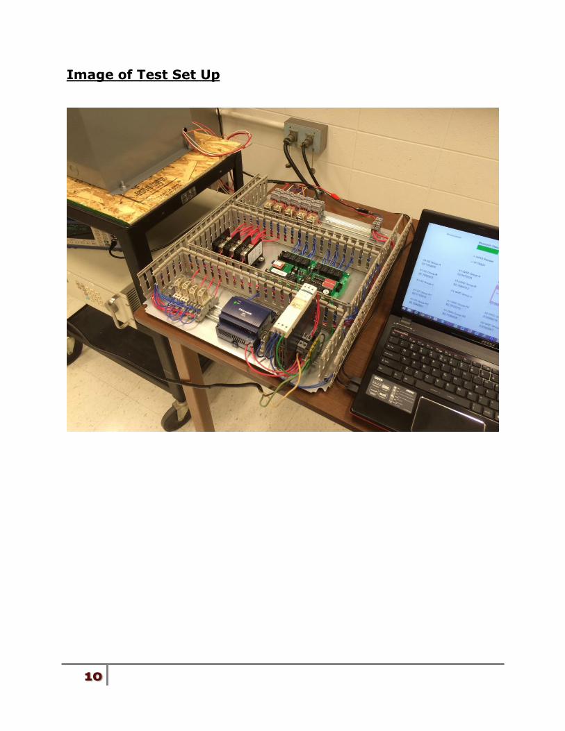
Image of Test Set Up
11
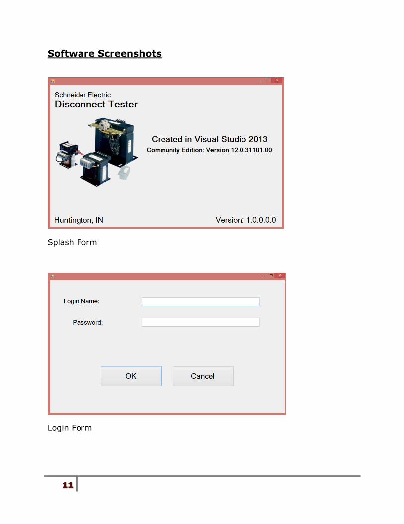
Software Screenshots
Splash Form
Login Form
12
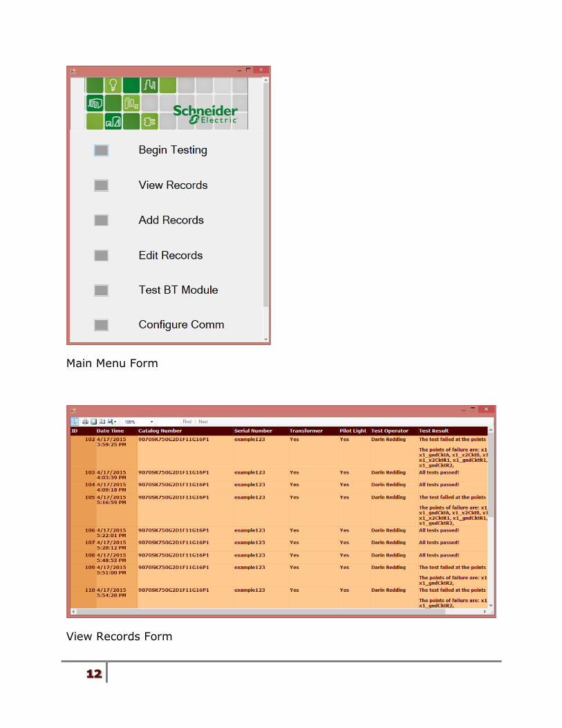
Main Menu Form
View Records Form
13
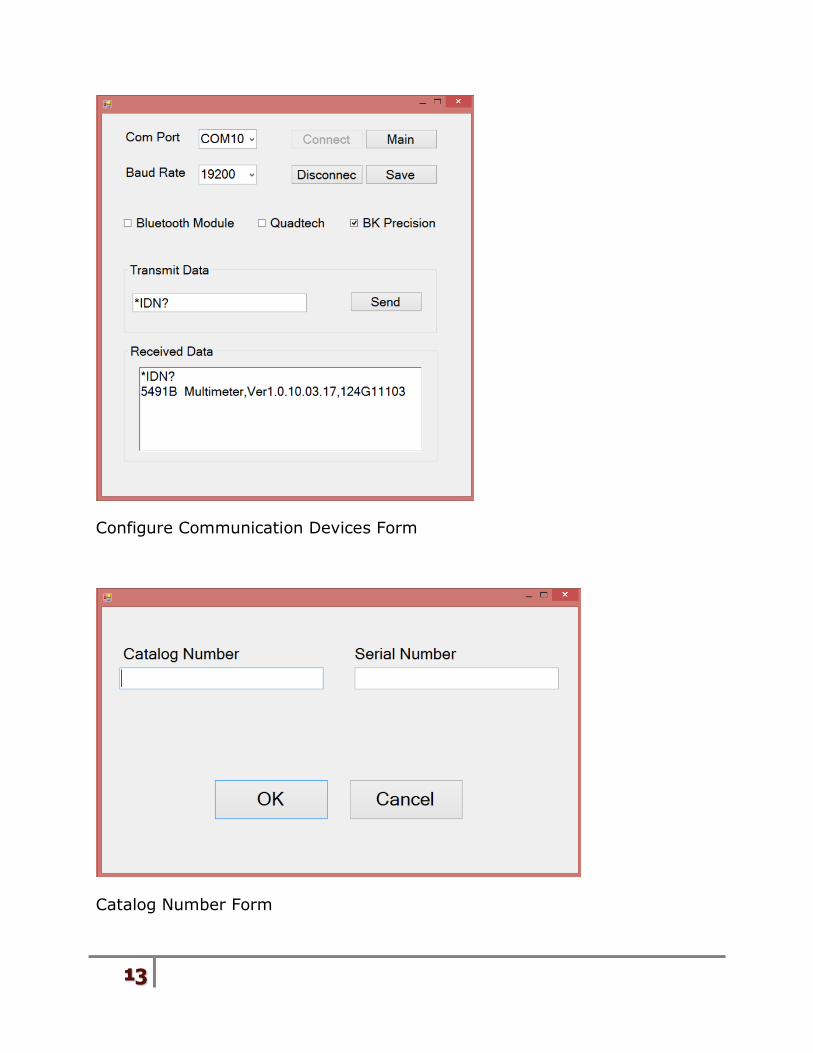
Configure Communication Devices Form
Catalog Number Form
14
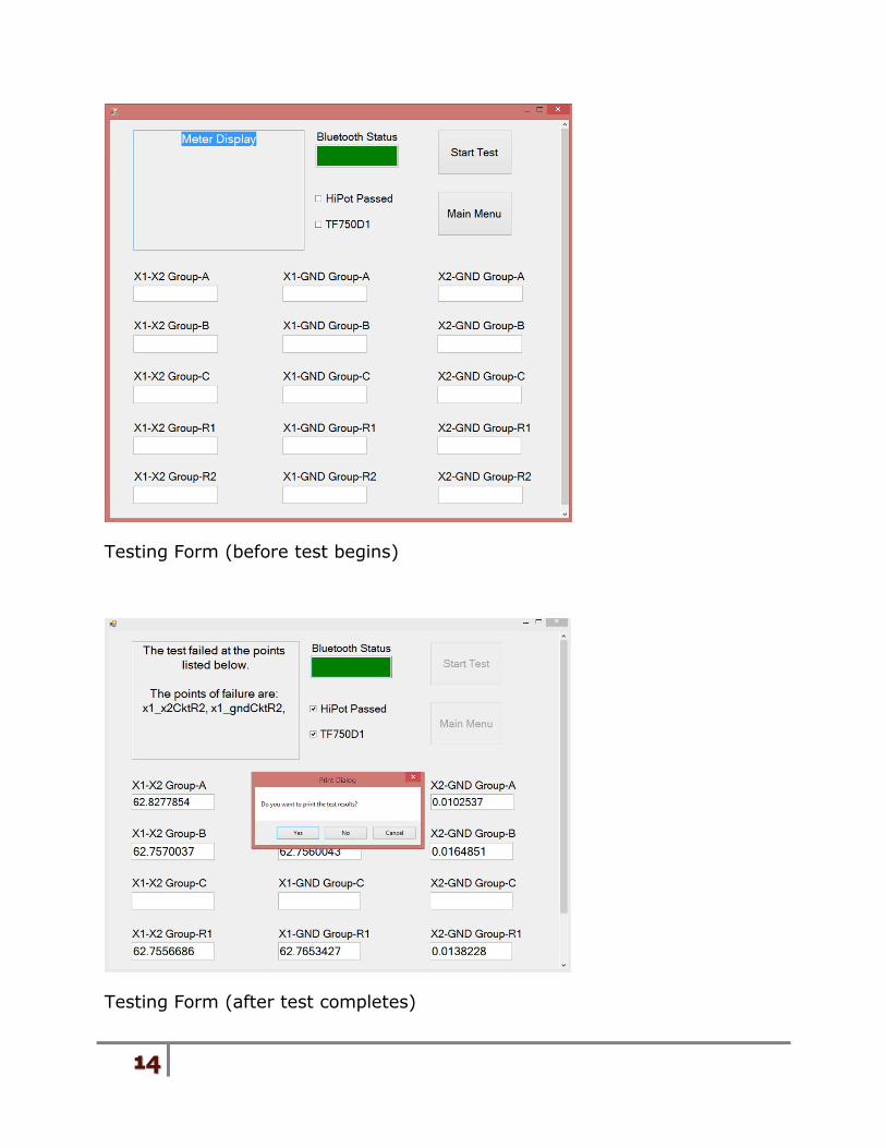
Testing Form (before test begins)
Testing Form (after test completes)