Embed Size (px)
Citation preview
October 2000 25ISSN 0895-0156/00/$10.00©2000 IEEE
As computers and other electronic equipmentbecome the mainstay of today’s businesses, cus-tomer awareness and intolerance for power sys-
tem outages continues to heighten. For these customers,it is important that utilities be able to offer completesolutions to meet their needs. Depending on the cus-tomer load requirements, standby generation, uninter-ruptible power supply, or automaticrestoration are possible solutions toimprove the system reliability. In addition,utilities are becoming increasingly automat-ed to keep up with the demands of the newbusiness environments. As newly reregulat-ed distribution companies emerge, it is like-ly that reliability indexes will be one of thekey factors for regulators to examine todetermine the overall performance of thedistribution company. Thus, drivers for dis-tribution automation include:
■ Remote control and restoration■ Targeted regions or customers for
improved reliability and operation■ Performance based rates (PBR)■ Safety issues for circuit isolation.Whatever the driver for feeder automa-
tion, several key issues must beaddressed:
■ What automation scheme isrequired?
■ How are communications imple-mented?
This article addresses these issues withexample solutions for overhead feederautomation.
What Automation Scheme is Required?Presently, utilities employ a variety of techniques toimprove the reliability of the delivery of electricpower. Traditional feeder practices include reclosers,sectionalizers, and load break switches. Reclosers,switches, and feeder restoration are key componentsto improving the operation of the distribution grid. For
* ABB
The 15 kV VR3S poletop recloser is an example of a new generation of automation-ready devices
To be able to calculate the exact performanceof an individual MV distribution networkrequires considerable engineering skill and sophisticated software analysis
David G. Hart,* David Uy,* James Northcote-Green,* Carl LaPlace,* Damir Novosel*
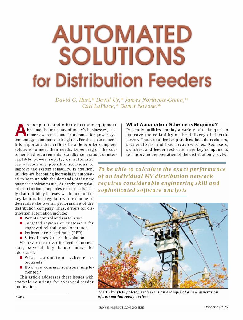
feeder automation, it is importantthat the equipment be able to oper-ate numerous times without main-tenance to minimize maintenancesupport. Other key factors includestandard communications proto-cols for SCADA integration, suffi-cient temperature operating range,and standby power to allow foroperation while the system is de-energized. By use of several exam-ples, different feeder automationsolutions are highlighted. Theexample system is illustrated in Fig-ure 1. For the examples, we willassume that it is important to mini-mize outages to customer 1 andcustomer 2.
For the examples, we willassume that faults occur evenly dis-tributed on the feeder. We will alsoassume that it takes 1 hour torestore the power following a per-manent fault and that the feederexperiences six permanent faultsper year. Using this information, wecan calculate the outage minutesdue to fault 1 and the total outageminutes (Table 1).
Reclosers and the Impact on Outage MinutesHistorically, reclosers have beenused as an economic method toimprove distribution feeder reliabil-ity. Reclosers provide fault-inter-rupting capability to isolate thefaulted line where needed.Reclosers are compact, easilyinstalled, and can be applied in sub-stations as well as on poletops.Reclosers must be coordinatedwith the upstream device such asthe substation circuit breaker andthe downstream devices such asline fuses. For line fuses, twoschemes are possible.
■ Fuse Saving: The fuse-savingscheme allows several opera-tions of the recloser and, thus,allows temporary faultscaused by animals or treelimbs to clear before the fuseoperates. A successful clear-ing of a temporary fault pre-vents a sustained outage and
Outage Minutes Total Outage due to Fault 1 Minutes
Customer 1 360 360
Customer 2 360 360
Figure 1. Example system with no feeder automation
Table 1. Feeder without Automation
CB
SubstationBreaker
Fuse
Fault 1
Customer 1 Customer 2
Outage Minutes Outage Minutes Total Outage due to Fault 1 due to Fault 2 Minutes
Customer 1 180 0 180 Customer 2 180 180 360
Table 2. Feeder with Recloser
Figure 2. Example system with recloser
CB
SubstationBreaker
Fuse
Fault 1
Customer 1 Customer 2
Fault 2
Recloser
R
Outage Minutes Outage Minutes Outage Minutes Total Outage due to Fault 1 due to Fault 2 due to Fault 3 Minutes
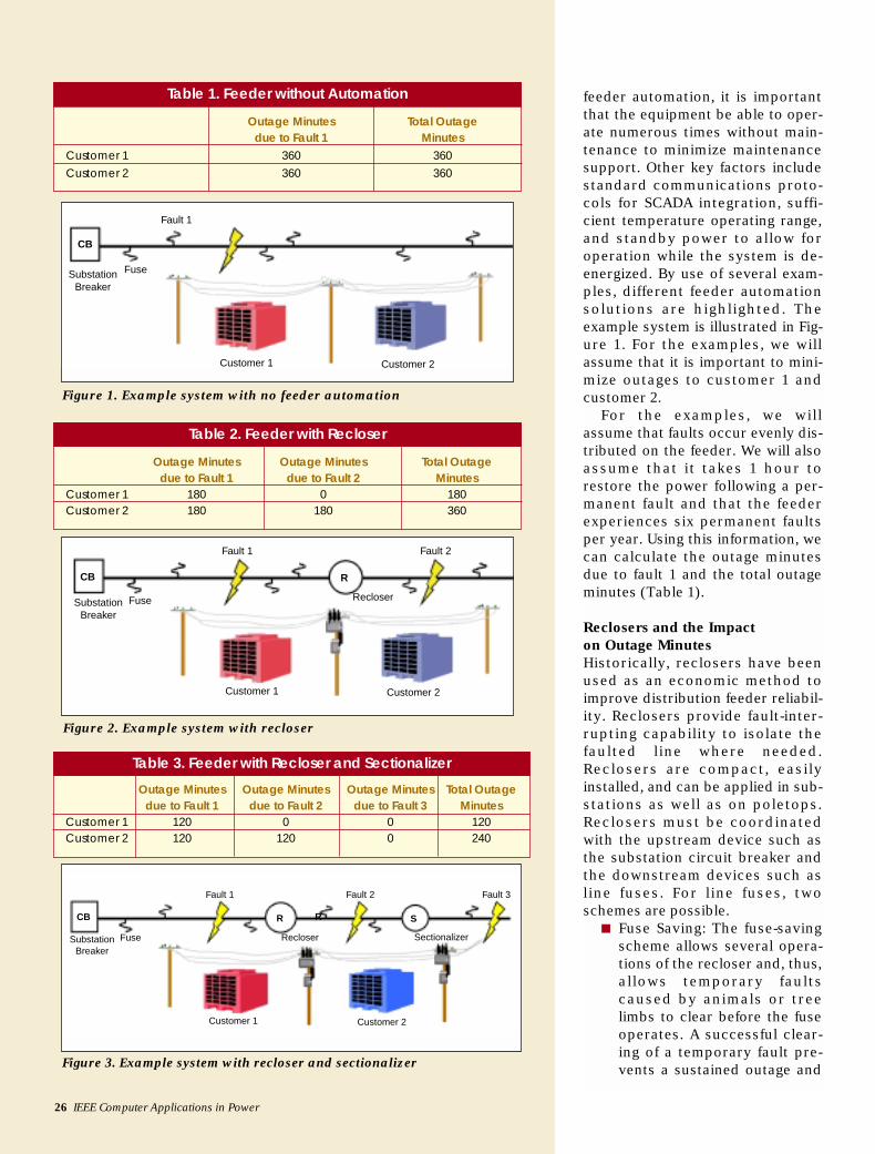
Customer 1 120 0 0 120 Customer 2 120 120 0 240
Figure 3. Example system with recloser and sectionalizer
Table 3. Feeder with Recloser and Sectionalizer
CB
SubstationBreaker
Fuse
Fault 1
Customer 1 Customer 2
Fault 2 Fault 3
Recloser
RR S
Sectionalizer
26 IEEE Computer Applications in Power
October 2000 27
saves money by avoiding unnecessary dispatchof line personnel to refuse the cutout. For perma-nent faults, the recloser operates more slowly,allowing the fuse to operate and isolate the per-manent fault.
■ Fuse Clearing: For some feeders, it is important toisolate the fault as quickly as possible, even if alateral fuse must clear the fault. This minimizesthe outage for all customers on the feeder. Forexample, the fuse-clearing scheme is used when amomentary outage is less desirable than dis-patching a line crew to refuse a cutout serving asmall branch line.
Both schemes are frequently deployed. In choosingwhich one to use, several economic and operationalfactors must be considered. For example, the costs ofdispatching line personnel vis-à-vis the power qualityof the affected customers.
In terms of improvements in system operation, con-sider the example above. A recloser is now installed onthe example distribution feeder, as shown in Figure 2.
Again, assuming six permanent faults evenly distrib-uted results in three faults at fault 1 and three faults atfault 2. Improvements by adding a recloser are illus-trated in Table 2.
Note that while permanent faults stillresult in customer 2 having the same out-age minutes, customer 1 sees a 50%reduction in outage minutes per year.
Sectionalizers and the Impact on Outage MinutesSectionalizers are used on distributionfeeders as a cost-effective means to fur-ther reduce the customer impact due topermanent faults. Typically, sectionaliz-ers are used on a line downstream from arecloser or a reclosing relay in the sub-station. Sectionalizers are not fault-inter-rupting devices, but operate in acoordinated manner with the reclosingoperation. For typical operation, consid-er Figure 3. In this example, the sectional-izer has a counter setting of 2. For a faultat fault 3 at the end of the feeder, a thesequence of events is:
■ Fault 3 is sensed by poletop recloser■ Poletop recloser trips■ Sectionalizer detects fault interrup-
tion and increments counter to 1■ Recloser recloses■ Since fault is permanent, recloser
trips again■ Sectionalizer increments counter to 2■ While recloser is open, sectionalizer
opens
■ Recloser recloses and power is restored to cus-tomer 2.
Note that, for a fault at fault 1, the sectionalizerwould not have detected the fault interruption andwould not have incremented the counter.
For the example system shown, the sectionalizer isadded to the circuit to further improve the circuit reli-ability. Again, for our discussion, we will assume thatthe faults are evenly distributed on the circuit and thatthe recloser and sectionalizer are equally spaced onthe feeder, resulting in two faults at each location.Again, we assume that it takes 1 hour to restore thepower following a permanent fault. Using this informa-tion, we can calculate the results in Table 3.
Thus, with a recloser and sectionalizer installed onthe line, there is a 66.6% improvement for the outagetime of customer 1 and a 33.3% improvement in theoutage time for customer 2, as compared to Table 1.(33.3% improvement in the outage times for customer1 and customer 2, as compared to Table 2).
Switches at Normal Open Points and the Impact on Outage MinutesWhen increased reliability is required and dual feedersare available, it is possible to place a switch at the nor-
Components are integrated into functionaldevices and assembled into a system tosolve the complete control or automationneeds of each distribution network
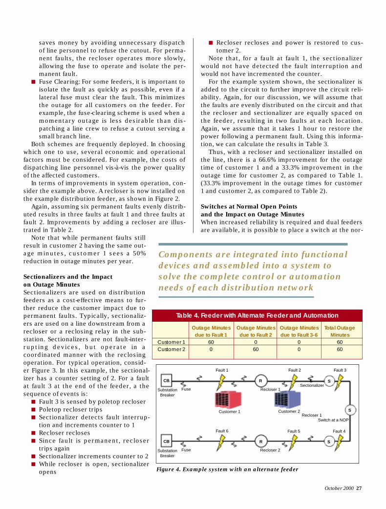
Outage Minutes Outage Minutes Outage Minutes Total Outage due to Fault 1 due to Fault 2 due to Fault 3-6 Minutes
Customer 1 60 0 0 60 Customer 2 0 60 0 60
Table 4. Feeder with Alternate Feeder and Automation
Figure 4. Example system with an alternate feeder
CB
SubstationBreaker
Fuse
Fault 1
CB
SubstationBreaker
Fuse
Fault 6
Customer 1 Customer 2
Fault 2 Fault 3
Recloser 1
R
R SSectionalizer
S
S
S
Switch at a NOP
Fault 5 Fault 4
Recloser 1
Recloser 2
mal open point (NOP) and restore power following apermanent fault. Typically, feeders serve customersfrom different substations such that a station outagedoes not eliminate the possibility of restoring power.Two typical implementations are:
■ Remote Transfer: Following a permanent fault,the SCADA/DMS system reports the outage andthe operator examines the recloser operation orsectionalizer fault indication to initiate the properequipment operation to isolate the fault andrestore power.
■ Local Automatic Transfer: Following a permanentfault, the line equipment clears the fault and iso-lates the faulted section. Following a time delay,the NOP switch will close, restoring power.
For typical operation, consider Figure 4. In thisexample, the switch is placed at the NOP as shown andis normally open. For a fault at fault 1, a sequence ofevents is:
■ Fault 1 is sensed and cleared by the station cir-cuit breaker
■ Either via system operator or local logic, recloser1 is opened
■ The switch at the NOP is closed, restoring powervia the alternate feeder.
Note that, for a fault at fault 1, customer 1 is withoutpower, since it is located on that segment.
For the example system shown, the addition of analternate distribution feeder and fault isolation equip-ment on the feeders will provide the highest reliability.Again, for our discussion, we will assume that thefaults are evenly distributed on the circuit, resulting inone fault at each location. Again, we assume that ittakes 1 hour to restore the power following a perma-nent fault. Using this information, we can calculate theresults in Table 4.
With a recloser and sectionalizer installed on theline, the customer is only impacted by faults on theconnected segment. Thus, there is a 83.3% improve-ment in the outage times for customer 1 and customer
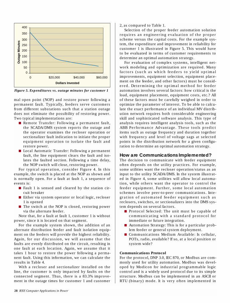
2, as compared to Table 1.Selection of the proper feeder automation solution
requires an engineering evaluation of the properscheme versus the capital costs. For the example sys-tem, the expenditure and improvement in reliability forcustomer 1 is illustrated in Figure 5. This would haveto be evaluated in terms of customer requirements todetermine an optimal automation strategy.
For evaluation of complex systems, intelligent net-work modeling and optimization are required. Manyfactors (such as which feeders to yield optimalimprovements, equipment selection, equipment place-ment on the feeder, and other factors) must be consid-ered. Determining the optimal method for feederautomation involves several factors: how critical is theload, equipment placement, equipment costs, etc.? Allof these factors must be carefully weighed in order tooptimize the parameter of interest. To be able to calcu-late the exact performance of an individual MV distrib-ution network requires both considerable engineeringskill and sophisticated software analysis. This type ofanalysis requires intelligent analysis tools, such as theABB Performance Advantage. These tools predictitems such as outage frequency and duration togetherwith frequency and level of voltage sags at selectedpoints in the distribution network for a given configu-ration to determine an optimal automation strategy.
How are Communications Implemented?The decision to communicate with feeder equipmentoften depends on the utility practices. For example,some utilities want the recloser operation/status as aninput to the utility SCADA/DMS. In the system illustrat-ed in Figure 4, some utilities will allow local automa-tion, while others want the operator to control thefeeder equipment. Further, some local automationschemes involve peer-to-peer communications. Inte-gration of automated feeder equipment such asreclosers, switches, or sectionalizers into the DMS sys-tem depends on several factors.
■ Protocol Selected: The unit must be capable ofcommunicating with a standard protocol forimmediate or future integration.
■ Automation Strategy: This is for a particular prob-lem feeder or general system deployment.
■ Communications Medium Available: Is cellular,POTs, radio, available? If so, at a local position orsystem wide?
Communications ProtocolFor the protocol, DNP 3.0, IEC 870, or Modbus are com-monly used for utility automation. Modbus was devel-oped by Modicon for industrial programmable logiccontrol and is a widely used protocol due to its simplestructure. Modbus can be implemented in an ASCII orRTU (binary) mode. It is very often implemented in
28 IEEE Computer Applications in Power
Figure 5. Expenditures vs. outage minutes for customer 1
400
350
300
250
200
150
100
50
0
Ou
tag
e M
inu
tes
Dollars Invested
0 $20,000 $40,000 $60,000
October 2000 29
RTU mode and interfaced to SCADARTUs in the field. DNP 3.0 is a morecomplex protocol but with somenice features, such as report byexception and allowing multiplemasters. This protocol was devel-oped by Harris and is now widelyused in the power industry. Certifi-cation of DNP is now available frommultiple sources. There is also agreat deal of interest in UCA 2.0,which promises to be a future stan-dard. IEC 870 is widely used inEurope and is similar to DNP 3.0.
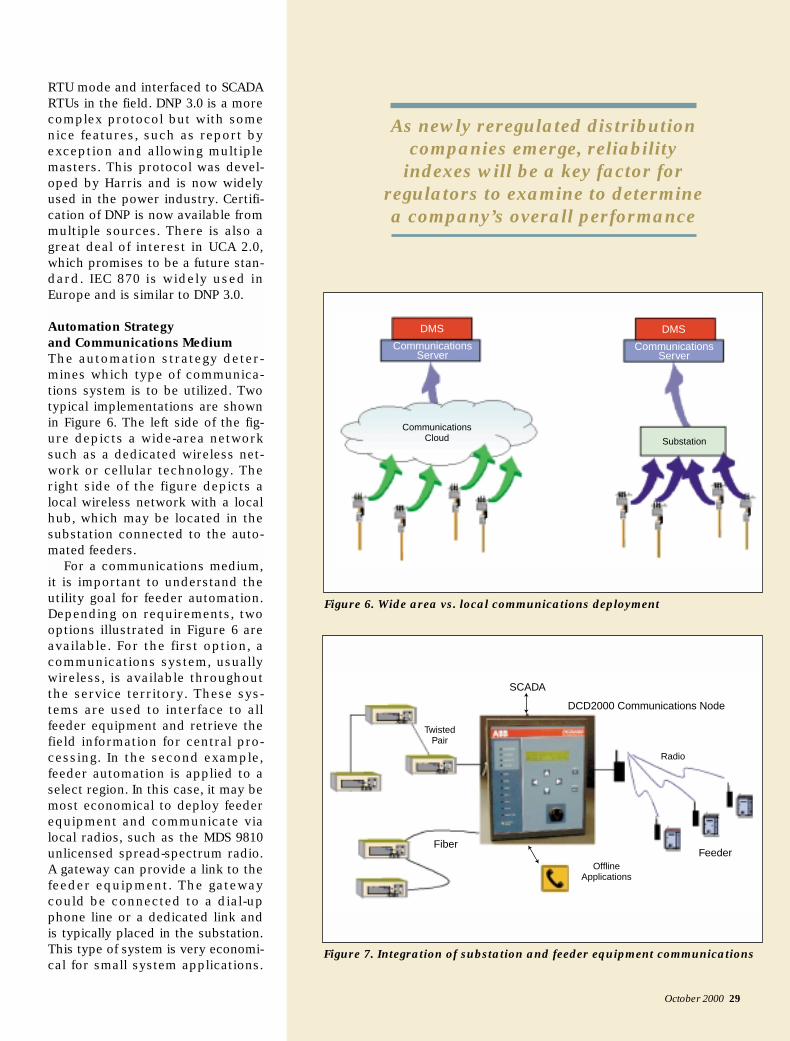
Automation Strategy and Communications MediumThe automation strategy deter-mines which type of communica-tions system is to be utilized. Twotypical implementations are shownin Figure 6. The left side of the fig-ure depicts a wide-area networksuch as a dedicated wireless net-work or cellular technology. Theright side of the figure depicts alocal wireless network with a localhub, which may be located in thesubstation connected to the auto-mated feeders.
For a communications medium,it is important to understand theutility goal for feeder automation.Depending on requirements, twooptions illustrated in Figure 6 areavailable. For the first option, acommunications system, usuallywireless, is available throughoutthe service territory. These sys-tems are used to interface to allfeeder equipment and retrieve thefield information for central pro-cessing. In the second example,feeder automation is applied to aselect region. In this case, it may bemost economical to deploy feederequipment and communicate vialocal radios, such as the MDS 9810unlicensed spread-spectrum radio.A gateway can provide a link to thefeeder equipment. The gatewaycould be connected to a dial-upphone line or a dedicated link andis typically placed in the substation.This type of system is very economi-cal for small system applications.
As newly reregulated distribution companies emerge, reliability
indexes will be a key factor for regulators to examine to determine a company’s overall performance
Figure 6. Wide area vs. local communications deployment
Substation
DMS
CommunicationsCloud
CommunicationsServer
DMS
CommunicationsServer
Figure 7. Integration of substation and feeder equipment communications
Feeder
Radio
DCD2000 Communications Node
Fiber
OfflineApplications
SCADA
TwistedPair
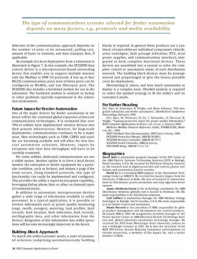
Selection of the communications approach depends onthe number of units to be automated, polling rate,amount of bytes to transmit, and data transport fees, ifapplicable.
An example of a local deployment from a substation isillustrated in Figure 7. In this example, the DCD2000 datacontrol device is a microprocessor-based networkingdevice that enables you to support multiple masterswith the Modbus or DNP 3.0 protocols. It has up to fourRS-232 communications ports (two of these ports can beconfigured as RS-485), and one fiberoptic port. TheDCD2000 also includes a hardened modem for use in thesubstation. The hardened modem is resistant to lockupor other problems typically experienced in the substa-tion environment.
Future Issues for Feeder AutomationOne of the major drivers for feeder automation in thefuture will be the continued global expansion of low-costcommunication technologies. It is estimated that over70% of utilities have implemented wireless devices intotheir present infrastructure. However, for large-scaledeployments, communications continues to be a majorissue. New technologies such as GSM, CDPD, and satel-lite are becoming available and will allow for new low-cost automation solutions. However, report byexception and slow data throughput will have to becarefully examined.
For some utilities, dedicated communications are nota viable option. Another option is to have a local devicemonitor the substation or feeder equipment for a partic-ular condition, such as lockout, and initiate a page if theevent occurs. Using standard protocols, this type offunctionality can easily be implemented and configured.This provides the utility a report-by-exception capability,leveraging dial-up phone lines or other on demand typesof communications.
In addition to automation, microprocessor devicesgather a wide range of information available to utilitypersonnel. In a typical application, it is possible toretrieve information such as power quality monitoring(sags, swells, outages), metering, load profiles, faultrecords, fault location, fault indication, fault records,oscillographic data, and other information from thedevices. Integration of this information into utility opera-tions will become increasingly important in the future.
Building-Block ApproachTo match the utility/customer needs, a suite of automat-ed solutions comprising automation-ready building
blocks is required. In general these products are a syn-thesis of state-of-the-art individual components (distrib-ution switchgear, fault passage indication, RTU, localpower supplies, and communications interface), inte-grated to form complete functional devices. Thesedevices are assembled into a system to solve the com-plete control or automation needs of each distributionnetwork. The building block devices must be preengi-neered and prepackaged to give the lowest possiblecosts for deployment.
Determining if, where, and how much automation todeploy is a complex issue. Detailed analysis is requiredto select the optimal strategy to fit the utility’s and itscustomer’s needs.
For Further ReadingD.G. Hart, B. Ackerman, R. Wright, and Brian Johnson, "DA: inte-grated substation and feeder automation," DistribuTech ConferenceProceedings, February 1999.
D.G. Hart, W. Peterson, D. Uy, J. Schneider, D. Novosel, R.Wright, “Tapping protective relays for power quality information,”IEEE Computer Applications in Power, vol. 13, no. 1, January 2000.
Modicon Modbus Protocol Reference Guide, PI-MBUS-300, Modi-con, Inc., 1994.
DNP 3.00 Basic Four Documentation, DNP User’s Group, 1993.DCD2000 Instruction Manual, ABB IB 38-300-1.PCD2000 Recloser Controller, ABB IB 38-737-1.SCD2000 Switch Controller, ABB (in press).DPU2000R Relay, ABB IB 7.11.1.7-4.
BiographiesDavid Hart is automation program manager of the EST Center atthe ABB Electric Systems Technology Institute (ETI) in Raleigh,North Carolina, U.S.A. He received his PhD from Clemson Universi-ty. His research area is digital protection and control, phasor esti-mation, and automation of power systems.
David Uy is a consulting R&D engineer in the Automation Tech-nology Center at ABB-ETI. He received his masters degree from theUniversity of Missouri at Rolla. His area of research is communica-tions for distribution system automation and relay algorithm devel-opment.
James Northcote-Green is the technology coordinator for ABBDistribution Solutions globally and is located in Farnham, UK. Hismain responsibility is for distribution solutions.
Carl LaPlace is automation manager for ABB Medium VoltageSwitchgear in Raleigh, North Carolina, U.S.A. His main responsibili-ty is for feeder control and automation.
Damir Novosel is vice president of ABB, responsible for glob-al product management and development for control products.He joined ABB in 1992. He assignments included: manager of thePower System Center at ABB Electrical System Technology Insti-tute and global substation automation technology manager. Hereceived his PhD from Mississippi State University (where hewas a Fulbright scholar) in 1991. He Is also the vice-chair of theIEEE PES Power System Relaying Committee subcommittee onsystem protection, a member of Eta Kappa Nu, and a seniormember of IEEE.
30 IEEE Computer Applications in Power
The type of communications systems selected for feeder automationdepends on many factors, e.g., protocols and media availability