Embed Size (px)
Citation preview

Autodesk®
Inventor®
2010
Autodesk Official Training Guide
Essentials
527B1-050000-CM00AApril 2009
Transitioning from Autodesk® Inventor® 2009Users moving to Autodesk® Inventor® 2010 software learn about the new interface and how to simulate a product before it is built.
Autodesk Certification Preparation

© 2009 Autodesk, Inc. All rights reserved.
Except as otherwise permitted by Autodesk, Inc., this publication, or parts thereof, may not be reproduced inany form, by any method, for any purpose.
Certain materials included in this publication are reprinted with the permission of the copyright holder.
Trademarks
The following are registered trademarks or trademarks of Autodesk, Inc., in the USA and other countries: 3DEC (design/logo), 3December, 3December.com, 3ds Max, ADI, Alias, Alias (swirl design/logo), AliasStudio, Alias|Wavefront (design/logo), ATC, AUGI, AutoCAD, AutoCAD Learning Assistance, AutoCAD LT, AutoCAD Simulator, AutoCAD SQL Extension,AutoCAD SQL Interface, Autodesk, Autodesk Envision, Autodesk Insight, Autodesk Intent, Autodesk Inventor, AutodeskMap, Autodesk MapGuide, Autodesk Streamline, AutoLISP, AutoSnap, AutoSketch, AutoTrack, Backdraft, Built withObjectARX (logo), Burn, Buzzsaw, CAiCE, Can You Imagine, Character Studio, Cinestream, Civil 3D, Cleaner, Cleaner Central,ClearScale, Colour Warper, Combustion, Communication Specification, Constructware, Content Explorer,Create>what’s>Next> (design/logo), Dancing Baby (image), DesignCenter, Design Doctor, Designer’s Toolkit, DesignKids,DesignProf, DesignServer, DesignStudio, Design|Studio (design/logo), Design Web Format, Discreet, DWF, DWG, DWG(logo), DWG Extreme, DWG TrueConvert, DWG TrueView, DXF, Ecotect, Exposure, Extending the Design Team, Face Robot,FBX, Filmbox, Fire, Flame, Flint, FMDesktop, Freewheel, Frost, GDX Driver, Gmax, Green Building Studio, Heads up Design,Heidi, HumanIK, IDEA Server, i drop, ImageModeler, iMOUT, Incinerator, Inferno, Inventor, Inventor LT, Kaydara, Kaydara(design/logo), Kynapse, Kynogon, LandXplorer, LocationLogic, Lustre, Matchmover, Maya, Mechanical Desktop, Moonbox,MotionBuilder, Movimento, Mudbox, NavisWorks, ObjectARX, ObjectDBX, Open Reality, Opticore, Opticore Opus,PolarSnap, PortfolioWall, Powered with Autodesk Technology, Productstream, ProjectPoint, ProMaterials, RasterDWG,Reactor, RealDWG, Real time Roto, REALVIZ, Recognize, Render Queue, Retimer, Reveal, Revit, Showcase, ShowMotion,SketchBook, Smoke, Softimage, Softimage|XSI (design/logo), SteeringWheels, Stitcher, Stone, StudioTools, Topobase,Toxik, TrustedDWG, ViewCube, Visual, Visual Construction, Visual Drainage, Visual Landscape, Visual Survey, VisualToolbox, Visual LISP, Voice Reality, Volo, Vtour, Wire, Wiretap, WiretapCentral, XSI, and XSI (design/logo).
The following are registered trademarks or trademarks of Autodesk Canada Co. in the USA and/or Canada and othercountries: Backburner, Multi Master Editing, River, and Sparks.
The following are registered trademarks or trademarks of Moldflow Corp. in the USA and/or other countries: MoldflowMPA, MPA (design/logo), Moldflow Plastics Advisers, MPI, MPI (design/logo), Moldflow Plastics Insight, MPX, MPX (design/logo), Moldflow Plastics Xpert.
All other brand names, product names, or trademarks belong to their respective holders.
Disclaimer
THIS PUBLICATION AND THE INFORMATION CONTAINED HEREIN IS MADE AVAILABLE BY AUTODESK, INC. “AS IS.”AUTODESK, INC. DISCLAIMS ALLWARRANTIES, EITHER EXPRESS OR IMPLIED, INCLUDING BUTNOT LIMITED TO ANY IMPLIEDWARRANTIES OF MERCHANTABILITY OR FITNESS FOR A PARTICULAR PURPOSE REGARDING THESE MATERIALS.
Published by:Autodesk, Inc.111 Mclnnis ParkwaySan Rafael, CA 94903, USA
iii
Contents
Introduction . . . . . . . . . . . . . . . . . . . . . . . . . . . . . . . . . . . . . . . . . . . . . . . . . . . . . . xi
Digital Prototyping . . . . . . . . . . . . . . . . . . . . . . . . . . . . . . . . . . . . . . . . . . . . . . . . . xv
Chapter 1: User Interface. . . . . . . . . . . . . . . . . . . . . . . . . . . . . . . . . . . . . . . . . . 1
Lesson: Navigating the Interface . . . . . . . . . . . . . . . . . . . . . . . . . . . . . . . . . . . . . . . . . . 2Overview. . . . . . . . . . . . . . . . . . . . . . . . . . . . . . . . . . . . . . . . . . . . . . . . . . . . . . . . . . . . 2About the Quick Access Toolbar . . . . . . . . . . . . . . . . . . . . . . . . . . . . . . . . . . . . . 3About the Ribbon . . . . . . . . . . . . . . . . . . . . . . . . . . . . . . . . . . . . . . . . . . . . . . . . . . . 3Changing Ribbon Settings and Display Options. . . . . . . . . . . . . . . . . . . . . . . 5Using the Application Menu . . . . . . . . . . . . . . . . . . . . . . . . . . . . . . . . . . . . . . . . 11Searching for Information Using InfoCenter . . . . . . . . . . . . . . . . . . . . . . . . . 15Exercise: Navigate the Interface . . . . . . . . . . . . . . . . . . . . . . . . . . . . . . . . . . . . . 20
Lesson: Viewing and Working with Designs. . . . . . . . . . . . . . . . . . . . . . . . . . . . . . . 23Overview. . . . . . . . . . . . . . . . . . . . . . . . . . . . . . . . . . . . . . . . . . . . . . . . . . . . . . . . . . . 23Save Reminder Timer . . . . . . . . . . . . . . . . . . . . . . . . . . . . . . . . . . . . . . . . . . . . . . . 24Axis Indicator Labels . . . . . . . . . . . . . . . . . . . . . . . . . . . . . . . . . . . . . . . . . . . . . . . . 25Switching Open Files Using Quick View Tabs . . . . . . . . . . . . . . . . . . . . . . . . 25Navigation Bar Settings . . . . . . . . . . . . . . . . . . . . . . . . . . . . . . . . . . . . . . . . . . . . . 27Open the Drawing from the Model . . . . . . . . . . . . . . . . . . . . . . . . . . . . . . . . . . 30Enhanced Graphics Detail. . . . . . . . . . . . . . . . . . . . . . . . . . . . . . . . . . . . . . . . . . . 32Exercise: Viewing and Working with Designs . . . . . . . . . . . . . . . . . . . . . . . . 34
Chapter 2: Top-Down Design . . . . . . . . . . . . . . . . . . . . . . . . . . . . . . . . . . . . . 37
Lesson: Skeletal Modeling . . . . . . . . . . . . . . . . . . . . . . . . . . . . . . . . . . . . . . . . . . . . . . . 38Overview. . . . . . . . . . . . . . . . . . . . . . . . . . . . . . . . . . . . . . . . . . . . . . . . . . . . . . . . . . . 38About Skeletal Modeling. . . . . . . . . . . . . . . . . . . . . . . . . . . . . . . . . . . . . . . . . . . . 39About Sketch Based Skeletal Modeling . . . . . . . . . . . . . . . . . . . . . . . . . . . . . . 41Creating Sketch Blocks. . . . . . . . . . . . . . . . . . . . . . . . . . . . . . . . . . . . . . . . . . . . . . 44Inserting Sketch Blocks . . . . . . . . . . . . . . . . . . . . . . . . . . . . . . . . . . . . . . . . . . . . . 46Editing Sketch Blocks . . . . . . . . . . . . . . . . . . . . . . . . . . . . . . . . . . . . . . . . . . . . . . . 47Creating Sketch Layouts . . . . . . . . . . . . . . . . . . . . . . . . . . . . . . . . . . . . . . . . . . . . 52Exercise: Skeletal Modeling Using Sketch Blocks . . . . . . . . . . . . . . . . . . . . . 53Exercise: Design with a Layout Sketch . . . . . . . . . . . . . . . . . . . . . . . . . . . . . . . 58

iv ■ Contents
Lesson: Multi-body Parts. . . . . . . . . . . . . . . . . . . . . . . . . . . . . . . . . . . . . . . . . . . . . . . . . 64Overview. . . . . . . . . . . . . . . . . . . . . . . . . . . . . . . . . . . . . . . . . . . . . . . . . . . . . . . . . . . 64About Multi-body Parts . . . . . . . . . . . . . . . . . . . . . . . . . . . . . . . . . . . . . . . . . . . . . 65Creating a Multi-body Part Using Sketched Features . . . . . . . . . . . . . . . . . 66Solid Body Properties . . . . . . . . . . . . . . . . . . . . . . . . . . . . . . . . . . . . . . . . . . . . . . . 67Adding and Editing Features on a Body . . . . . . . . . . . . . . . . . . . . . . . . . . . . . 70Exercise: Create a Multi-Body Part . . . . . . . . . . . . . . . . . . . . . . . . . . . . . . . . . . . 73
Lesson: Derive, Combine, Split, and Move Bodies . . . . . . . . . . . . . . . . . . . . . . . . . 77Overview. . . . . . . . . . . . . . . . . . . . . . . . . . . . . . . . . . . . . . . . . . . . . . . . . . . . . . . . . . . 77Derive as Solid Bodies . . . . . . . . . . . . . . . . . . . . . . . . . . . . . . . . . . . . . . . . . . . . . . 78Combining Solid Bodies . . . . . . . . . . . . . . . . . . . . . . . . . . . . . . . . . . . . . . . . . . . . 79Split Solid . . . . . . . . . . . . . . . . . . . . . . . . . . . . . . . . . . . . . . . . . . . . . . . . . . . . . . . . . . 82Moving Bodies . . . . . . . . . . . . . . . . . . . . . . . . . . . . . . . . . . . . . . . . . . . . . . . . . . . . . 83Exercise: Derive, Combine, Split, and Move Bodies . . . . . . . . . . . . . . . . . . . 86
Lesson: Make Part and Make Components. . . . . . . . . . . . . . . . . . . . . . . . . . . . . . . . 91Overview. . . . . . . . . . . . . . . . . . . . . . . . . . . . . . . . . . . . . . . . . . . . . . . . . . . . . . . . . . . 91Making a Part . . . . . . . . . . . . . . . . . . . . . . . . . . . . . . . . . . . . . . . . . . . . . . . . . . . . . . 92Making Components . . . . . . . . . . . . . . . . . . . . . . . . . . . . . . . . . . . . . . . . . . . . . . . 94File Characteristics from Make Components . . . . . . . . . . . . . . . . . . . . . . . . . 99Exercise: Single Part Layout to Components . . . . . . . . . . . . . . . . . . . . . . . . 102Exercise: Assembly Focused Layout Sketch to Components . . . . . . . . . 105Exercise: Multi-Body Part to Components. . . . . . . . . . . . . . . . . . . . . . . . . . . 108
Chapter 3: Plastic and Cast Part Design . . . . . . . . . . . . . . . . . . . . . . . . . . 111
Lesson: Grills . . . . . . . . . . . . . . . . . . . . . . . . . . . . . . . . . . . . . . . . . . . . . . . . . . . . . . . . . . 112Overview. . . . . . . . . . . . . . . . . . . . . . . . . . . . . . . . . . . . . . . . . . . . . . . . . . . . . . . . . . 112About Grill Features . . . . . . . . . . . . . . . . . . . . . . . . . . . . . . . . . . . . . . . . . . . . . . . 113Adding a Grill. . . . . . . . . . . . . . . . . . . . . . . . . . . . . . . . . . . . . . . . . . . . . . . . . . . . . . 115Exercise: Add a Grill . . . . . . . . . . . . . . . . . . . . . . . . . . . . . . . . . . . . . . . . . . . . . . . . 123
Lesson: Bosses . . . . . . . . . . . . . . . . . . . . . . . . . . . . . . . . . . . . . . . . . . . . . . . . . . . . . . . . 126Overview. . . . . . . . . . . . . . . . . . . . . . . . . . . . . . . . . . . . . . . . . . . . . . . . . . . . . . . . . . 126About Boss Features . . . . . . . . . . . . . . . . . . . . . . . . . . . . . . . . . . . . . . . . . . . . . . . 127Adding Boss Features. . . . . . . . . . . . . . . . . . . . . . . . . . . . . . . . . . . . . . . . . . . . . . 128Exercise: Add Boss Features . . . . . . . . . . . . . . . . . . . . . . . . . . . . . . . . . . . . . . . . 136
Lesson: Rests . . . . . . . . . . . . . . . . . . . . . . . . . . . . . . . . . . . . . . . . . . . . . . . . . . . . . . . . . . 140Overview. . . . . . . . . . . . . . . . . . . . . . . . . . . . . . . . . . . . . . . . . . . . . . . . . . . . . . . . . . 140About Rest Features . . . . . . . . . . . . . . . . . . . . . . . . . . . . . . . . . . . . . . . . . . . . . . . 141Adding Rest Features . . . . . . . . . . . . . . . . . . . . . . . . . . . . . . . . . . . . . . . . . . . . . . 142Exercise: Create a Rest Feature . . . . . . . . . . . . . . . . . . . . . . . . . . . . . . . . . . . . . 144
Lesson: Rule Fillets . . . . . . . . . . . . . . . . . . . . . . . . . . . . . . . . . . . . . . . . . . . . . . . . . . . . 146Overview. . . . . . . . . . . . . . . . . . . . . . . . . . . . . . . . . . . . . . . . . . . . . . . . . . . . . . . . . . 146About Rule Fillets. . . . . . . . . . . . . . . . . . . . . . . . . . . . . . . . . . . . . . . . . . . . . . . . . . 147Adding Rule Fillets. . . . . . . . . . . . . . . . . . . . . . . . . . . . . . . . . . . . . . . . . . . . . . . . . 148Exercise: Create Rule Fillets . . . . . . . . . . . . . . . . . . . . . . . . . . . . . . . . . . . . . . . . 151
Lesson: Lips Along an Edge . . . . . . . . . . . . . . . . . . . . . . . . . . . . . . . . . . . . . . . . . . . . 154Overview. . . . . . . . . . . . . . . . . . . . . . . . . . . . . . . . . . . . . . . . . . . . . . . . . . . . . . . . . . 154About Lips Along an Edge . . . . . . . . . . . . . . . . . . . . . . . . . . . . . . . . . . . . . . . . . 155Adding Lips Along an Edge . . . . . . . . . . . . . . . . . . . . . . . . . . . . . . . . . . . . . . . . 156Exercise: Create Lips Along an Edge . . . . . . . . . . . . . . . . . . . . . . . . . . . . . . . . 159
Contents ■ v
Lesson: Hooks and Loop Snap Fits. . . . . . . . . . . . . . . . . . . . . . . . . . . . . . . . . . . . . . 162Overview . . . . . . . . . . . . . . . . . . . . . . . . . . . . . . . . . . . . . . . . . . . . . . . . . . . . . . . . . 162About Snap Fit Features . . . . . . . . . . . . . . . . . . . . . . . . . . . . . . . . . . . . . . . . . . 163Adding a Snap Fit Feature. . . . . . . . . . . . . . . . . . . . . . . . . . . . . . . . . . . . . . . . . 164Exercise: Add a Snap Fit Connector . . . . . . . . . . . . . . . . . . . . . . . . . . . . . . . . 167
Chapter 4: Sheet Metal Parts . . . . . . . . . . . . . . . . . . . . . . . . . . . . . . . . . . . . 171
Lesson: Lofted Flanges, Rips, and Contour Roll Features. . . . . . . . . . . . . . . . . 172Overview . . . . . . . . . . . . . . . . . . . . . . . . . . . . . . . . . . . . . . . . . . . . . . . . . . . . . . . . . 172Creating Lofted Flanges. . . . . . . . . . . . . . . . . . . . . . . . . . . . . . . . . . . . . . . . . . . 173Exercise: Create Lofted Flanges. . . . . . . . . . . . . . . . . . . . . . . . . . . . . . . . . . . . 177Ripping a Sheet Metal Face . . . . . . . . . . . . . . . . . . . . . . . . . . . . . . . . . . . . . . . 180Exercise: Rip a Sheet Metal Face . . . . . . . . . . . . . . . . . . . . . . . . . . . . . . . . . . . 183Creating Contour Roll Features. . . . . . . . . . . . . . . . . . . . . . . . . . . . . . . . . . . . 187Exercise: Contour Roll . . . . . . . . . . . . . . . . . . . . . . . . . . . . . . . . . . . . . . . . . . . . . 191
Lesson: Unfold/Refold . . . . . . . . . . . . . . . . . . . . . . . . . . . . . . . . . . . . . . . . . . . . . . . . . 193Overview . . . . . . . . . . . . . . . . . . . . . . . . . . . . . . . . . . . . . . . . . . . . . . . . . . . . . . . . . 193About Designing In a Folded or Unfolded State . . . . . . . . . . . . . . . . . . . . 194Unfolding Sheet Metal Parts . . . . . . . . . . . . . . . . . . . . . . . . . . . . . . . . . . . . . . 196Refolding Sheet Metal Parts . . . . . . . . . . . . . . . . . . . . . . . . . . . . . . . . . . . . . . . 199Exercise: Unfold and Refold a Sheet Metal Part. . . . . . . . . . . . . . . . . . . . . 201
Lesson: Additional Sheet Metal Enhancements . . . . . . . . . . . . . . . . . . . . . . . . . 204Overview . . . . . . . . . . . . . . . . . . . . . . . . . . . . . . . . . . . . . . . . . . . . . . . . . . . . . . . . . 204GapSize Parameter . . . . . . . . . . . . . . . . . . . . . . . . . . . . . . . . . . . . . . . . . . . . . . . 204Creating a Custom Equation Unfold Style. . . . . . . . . . . . . . . . . . . . . . . . . . 206Editing Individual Bend Widths. . . . . . . . . . . . . . . . . . . . . . . . . . . . . . . . . . . . 209Move Face in the Flat Pattern Model. . . . . . . . . . . . . . . . . . . . . . . . . . . . . . . 210Exercise: Utilize the Additional Sheet Metal Enhancements. . . . . . . . . 212
Lesson: Cosmetic Centerlines and Bend Order . . . . . . . . . . . . . . . . . . . . . . . . . . 217Overview . . . . . . . . . . . . . . . . . . . . . . . . . . . . . . . . . . . . . . . . . . . . . . . . . . . . . . . . . 217Adding Cosmetic Centerlines to the Flat Model . . . . . . . . . . . . . . . . . . . . 218Editing the Bend Order Annotation in the Flat Model . . . . . . . . . . . . . . 219Exercise: Add Cosmetic Centerlines and Edit Bend Order . . . . . . . . . . . 223
Chapter 5: Additional Part and Sketch Enhancements . . . . . . . . . . . . . 225
Lesson: iFeatures . . . . . . . . . . . . . . . . . . . . . . . . . . . . . . . . . . . . . . . . . . . . . . . . . . . . . . 226Overview . . . . . . . . . . . . . . . . . . . . . . . . . . . . . . . . . . . . . . . . . . . . . . . . . . . . . . . . . 226Creating iFeatures from iParts . . . . . . . . . . . . . . . . . . . . . . . . . . . . . . . . . . . . . 227Setting iFeature Table Value in an iPart . . . . . . . . . . . . . . . . . . . . . . . . . . . . 228Surface Normal Recognition . . . . . . . . . . . . . . . . . . . . . . . . . . . . . . . . . . . . . . 230File Properties from iFeatures . . . . . . . . . . . . . . . . . . . . . . . . . . . . . . . . . . . . . 231iFeature Browser Name . . . . . . . . . . . . . . . . . . . . . . . . . . . . . . . . . . . . . . . . . . . 232Exercise: Create and Use iFeature . . . . . . . . . . . . . . . . . . . . . . . . . . . . . . . . . 234
vi ■ Contents
Lesson: Various Part and Sketch Enhancements . . . . . . . . . . . . . . . . . . . . . . . . 238Overview. . . . . . . . . . . . . . . . . . . . . . . . . . . . . . . . . . . . . . . . . . . . . . . . . . . . . . . . . . 238Default Units for Material Styles . . . . . . . . . . . . . . . . . . . . . . . . . . . . . . . . . . . . 239Define Parameters on the Fly . . . . . . . . . . . . . . . . . . . . . . . . . . . . . . . . . . . . . . 2402D Spline Enhancements . . . . . . . . . . . . . . . . . . . . . . . . . . . . . . . . . . . . . . . . . . 241Creating 3D Silhouetted Curve Sketches . . . . . . . . . . . . . . . . . . . . . . . . . . . 243Exercise: Part and Sketch Enhancements . . . . . . . . . . . . . . . . . . . . . . . . . . . 246
Lesson: User Coordinate System . . . . . . . . . . . . . . . . . . . . . . . . . . . . . . . . . . . . . . . 250Overview. . . . . . . . . . . . . . . . . . . . . . . . . . . . . . . . . . . . . . . . . . . . . . . . . . . . . . . . . . 250What is a UCS?. . . . . . . . . . . . . . . . . . . . . . . . . . . . . . . . . . . . . . . . . . . . . . . . . . . . . 251Place a UCS in a Part Model . . . . . . . . . . . . . . . . . . . . . . . . . . . . . . . . . . . . . . . . 252Constrain a Part in an Assembly using Custom UCS . . . . . . . . . . . . . . . . . 254Create a Base View Using a UCS . . . . . . . . . . . . . . . . . . . . . . . . . . . . . . . . . . . . 256Exercise: Create User Coordinate Systems . . . . . . . . . . . . . . . . . . . . . . . . . . 258
Chapter 6: Assembly Design. . . . . . . . . . . . . . . . . . . . . . . . . . . . . . . . . . . . . 263
Lesson: Assembly Productivity . . . . . . . . . . . . . . . . . . . . . . . . . . . . . . . . . . . . . . . . . 264Overview. . . . . . . . . . . . . . . . . . . . . . . . . . . . . . . . . . . . . . . . . . . . . . . . . . . . . . . . . . 264Assembly Constraint and Assembly Feature Preservation . . . . . . . . . . . 265About Folders . . . . . . . . . . . . . . . . . . . . . . . . . . . . . . . . . . . . . . . . . . . . . . . . . . . . . 266Adding Folders . . . . . . . . . . . . . . . . . . . . . . . . . . . . . . . . . . . . . . . . . . . . . . . . . . . . 267Exercise: Restructure an Assembly . . . . . . . . . . . . . . . . . . . . . . . . . . . . . . . . . 272Exercise: Create and Populate Folders . . . . . . . . . . . . . . . . . . . . . . . . . . . . . . 275
Lesson: Shrinkwrap Design Data . . . . . . . . . . . . . . . . . . . . . . . . . . . . . . . . . . . . . . . 278Overview. . . . . . . . . . . . . . . . . . . . . . . . . . . . . . . . . . . . . . . . . . . . . . . . . . . . . . . . . . 278About Simplified Models. . . . . . . . . . . . . . . . . . . . . . . . . . . . . . . . . . . . . . . . . . . 279Shrinkwrapping an Assembly . . . . . . . . . . . . . . . . . . . . . . . . . . . . . . . . . . . . . . 280Editing a Shrink Wrapped Assembly. . . . . . . . . . . . . . . . . . . . . . . . . . . . . . . . 283Exercise: Create Shrinkwrap Parts . . . . . . . . . . . . . . . . . . . . . . . . . . . . . . . . . . 286
Lesson: Design Accelerator Enhancements . . . . . . . . . . . . . . . . . . . . . . . . . . . . . 289Overview. . . . . . . . . . . . . . . . . . . . . . . . . . . . . . . . . . . . . . . . . . . . . . . . . . . . . . . . . . 289Exporting Gear Tooth Profiles . . . . . . . . . . . . . . . . . . . . . . . . . . . . . . . . . . . . . . 290Bearing Orientation . . . . . . . . . . . . . . . . . . . . . . . . . . . . . . . . . . . . . . . . . . . . . . . 291O-Ring Patterns . . . . . . . . . . . . . . . . . . . . . . . . . . . . . . . . . . . . . . . . . . . . . . . . . . . 292Designing and Adding Cylindrical Cams . . . . . . . . . . . . . . . . . . . . . . . . . . . . 294Exercise: Export Tooth Profile . . . . . . . . . . . . . . . . . . . . . . . . . . . . . . . . . . . . . . 299Exercise: Flip Bearings . . . . . . . . . . . . . . . . . . . . . . . . . . . . . . . . . . . . . . . . . . . . . 302Exercise: Create a Cylindrical Cam . . . . . . . . . . . . . . . . . . . . . . . . . . . . . . . . . . 304
Lesson: Assortment of Assembly Enhancements. . . . . . . . . . . . . . . . . . . . . . . . 307Overview. . . . . . . . . . . . . . . . . . . . . . . . . . . . . . . . . . . . . . . . . . . . . . . . . . . . . . . . . . 307Fillet Welds. . . . . . . . . . . . . . . . . . . . . . . . . . . . . . . . . . . . . . . . . . . . . . . . . . . . . . . . 308Groove Weld Radial Fill . . . . . . . . . . . . . . . . . . . . . . . . . . . . . . . . . . . . . . . . . . . . 309Productivity Tools . . . . . . . . . . . . . . . . . . . . . . . . . . . . . . . . . . . . . . . . . . . . . . . . . 310Various Assembly Related Enhancements . . . . . . . . . . . . . . . . . . . . . . . . . . 312Various BOM Related Enhancements . . . . . . . . . . . . . . . . . . . . . . . . . . . . . . . 315Exporting and Importing BOM Column Configuration . . . . . . . . . . . . . . 317Exercise: Assembly Enhancements . . . . . . . . . . . . . . . . . . . . . . . . . . . . . . . . . 319
Contents ■ vii
Chapter 7: Content Center . . . . . . . . . . . . . . . . . . . . . . . . . . . . . . . . . . . . . . 325
Lesson: Content Center Installation . . . . . . . . . . . . . . . . . . . . . . . . . . . . . . . . . . . . 326Overview . . . . . . . . . . . . . . . . . . . . . . . . . . . . . . . . . . . . . . . . . . . . . . . . . . . . . . . . . 326Installation Options. . . . . . . . . . . . . . . . . . . . . . . . . . . . . . . . . . . . . . . . . . . . . . . 327Transferring Library Content . . . . . . . . . . . . . . . . . . . . . . . . . . . . . . . . . . . . . . 330
Lesson: Family Configuration . . . . . . . . . . . . . . . . . . . . . . . . . . . . . . . . . . . . . . . . . . 332Overview . . . . . . . . . . . . . . . . . . . . . . . . . . . . . . . . . . . . . . . . . . . . . . . . . . . . . . . . . 332Copy and Move Content . . . . . . . . . . . . . . . . . . . . . . . . . . . . . . . . . . . . . . . . . . 333Exercise: Copy and Move Content . . . . . . . . . . . . . . . . . . . . . . . . . . . . . . . . . 335Editing Family Table Data in Excel . . . . . . . . . . . . . . . . . . . . . . . . . . . . . . . . . 338Exercise: Edit Family Data in Excel . . . . . . . . . . . . . . . . . . . . . . . . . . . . . . . . . 340Creating New Families or Adding Members Using Material Guide . . 344Exercise: Create Family Members Using Material Guide . . . . . . . . . . . . 350
Lesson: Place Library Components . . . . . . . . . . . . . . . . . . . . . . . . . . . . . . . . . . . . . 356Overview . . . . . . . . . . . . . . . . . . . . . . . . . . . . . . . . . . . . . . . . . . . . . . . . . . . . . . . . . 356Detail List Columns . . . . . . . . . . . . . . . . . . . . . . . . . . . . . . . . . . . . . . . . . . . . . . . 357Placement of Components. . . . . . . . . . . . . . . . . . . . . . . . . . . . . . . . . . . . . . . . 359Exercise: Place Components from Content Center . . . . . . . . . . . . . . . . . 362
Chapter 8: Production Drawings . . . . . . . . . . . . . . . . . . . . . . . . . . . . . . . . . 365
Lesson: Drawing View Enhancements . . . . . . . . . . . . . . . . . . . . . . . . . . . . . . . . . . 366Overview . . . . . . . . . . . . . . . . . . . . . . . . . . . . . . . . . . . . . . . . . . . . . . . . . . . . . . . . . 366Section View Projection Methods . . . . . . . . . . . . . . . . . . . . . . . . . . . . . . . . . 367View Block Insertion Point . . . . . . . . . . . . . . . . . . . . . . . . . . . . . . . . . . . . . . . . 368Inserting a Sheet View Into Model Space . . . . . . . . . . . . . . . . . . . . . . . . . . 369Defining a New Base Point in Model Space . . . . . . . . . . . . . . . . . . . . . . . . 371Inventor DWG File Version . . . . . . . . . . . . . . . . . . . . . . . . . . . . . . . . . . . . . . . . 373Exercise: Drawing View Enhancements . . . . . . . . . . . . . . . . . . . . . . . . . . . . 374
Lesson: Drawing Annotation Enhancements. . . . . . . . . . . . . . . . . . . . . . . . . . . . 378Overview . . . . . . . . . . . . . . . . . . . . . . . . . . . . . . . . . . . . . . . . . . . . . . . . . . . . . . . . . 378General Dimension Enhancements . . . . . . . . . . . . . . . . . . . . . . . . . . . . . . . . 379Arranging Dimensions . . . . . . . . . . . . . . . . . . . . . . . . . . . . . . . . . . . . . . . . . . . . 382Additional Feature Control Frame Symbols . . . . . . . . . . . . . . . . . . . . . . . . 384ESKD Support . . . . . . . . . . . . . . . . . . . . . . . . . . . . . . . . . . . . . . . . . . . . . . . . . . . . 386Exercise: Drawing Annotation Enhancements. . . . . . . . . . . . . . . . . . . . . . 387
Chapter 9: Analysis and Inquiry. . . . . . . . . . . . . . . . . . . . . . . . . . . . . . . . . . 391
Lesson: Design Analysis Through Simulation . . . . . . . . . . . . . . . . . . . . . . . . . . . 392Overview . . . . . . . . . . . . . . . . . . . . . . . . . . . . . . . . . . . . . . . . . . . . . . . . . . . . . . . . . 392About Design Analysis Through Simulation. . . . . . . . . . . . . . . . . . . . . . . . 393Assembly Constraints in the Simulation Browsers . . . . . . . . . . . . . . . . . . 394Dynamic Simulation Translated Joints . . . . . . . . . . . . . . . . . . . . . . . . . . . . . 396Exercise: Design Through Simulation . . . . . . . . . . . . . . . . . . . . . . . . . . . . . . 398
viii ■ Contents
Lesson: Stress Analysis of an Assembly . . . . . . . . . . . . . . . . . . . . . . . . . . . . . . . . . 403Overview. . . . . . . . . . . . . . . . . . . . . . . . . . . . . . . . . . . . . . . . . . . . . . . . . . . . . . . . . . 403Conducting Stress Analysis on an Assembly . . . . . . . . . . . . . . . . . . . . . . . . 404Simplifying an Assembly for Stress Analysis. . . . . . . . . . . . . . . . . . . . . . . . . 406Creating Contacts Between Parts. . . . . . . . . . . . . . . . . . . . . . . . . . . . . . . . . . . 409Setting Mesh Size. . . . . . . . . . . . . . . . . . . . . . . . . . . . . . . . . . . . . . . . . . . . . . . . . . 412Exercise: Motion Loads Analysis . . . . . . . . . . . . . . . . . . . . . . . . . . . . . . . . . . . . 416Exercise: Stress Analysis of an Assembly . . . . . . . . . . . . . . . . . . . . . . . . . . . . 418
Lesson: Parametric Studies. . . . . . . . . . . . . . . . . . . . . . . . . . . . . . . . . . . . . . . . . . . . . 423Overview. . . . . . . . . . . . . . . . . . . . . . . . . . . . . . . . . . . . . . . . . . . . . . . . . . . . . . . . . . 423About Parametric Studies . . . . . . . . . . . . . . . . . . . . . . . . . . . . . . . . . . . . . . . . . . 424Conducting a Parametric Study . . . . . . . . . . . . . . . . . . . . . . . . . . . . . . . . . . . . 425Adding and Configuring Parameters for Studies . . . . . . . . . . . . . . . . . . . . 427Generating Configurations. . . . . . . . . . . . . . . . . . . . . . . . . . . . . . . . . . . . . . . . . 428Adding and Configuring Design Constraints for Studies. . . . . . . . . . . . . 430Promoting a Configuration to the Model . . . . . . . . . . . . . . . . . . . . . . . . . . . 432Exercise: Parametric Studies . . . . . . . . . . . . . . . . . . . . . . . . . . . . . . . . . . . . . . . 434
Lesson: Results and Animation . . . . . . . . . . . . . . . . . . . . . . . . . . . . . . . . . . . . . . . . . 437Overview. . . . . . . . . . . . . . . . . . . . . . . . . . . . . . . . . . . . . . . . . . . . . . . . . . . . . . . . . . 437Probing the FEA Results . . . . . . . . . . . . . . . . . . . . . . . . . . . . . . . . . . . . . . . . . . . 438Generating Reports. . . . . . . . . . . . . . . . . . . . . . . . . . . . . . . . . . . . . . . . . . . . . . . . 440Animate Results . . . . . . . . . . . . . . . . . . . . . . . . . . . . . . . . . . . . . . . . . . . . . . . . . . . 442Publish Stress Analysis to DWF . . . . . . . . . . . . . . . . . . . . . . . . . . . . . . . . . . . . . 443Exercise: Review FEA Results and Animation. . . . . . . . . . . . . . . . . . . . . . . . 444
Chapter 10: Data and Geometry Translation and Exchange. . . . . . . . 447
Lesson: Derive Alias Design Geometry. . . . . . . . . . . . . . . . . . . . . . . . . . . . . . . . . . 448Overview. . . . . . . . . . . . . . . . . . . . . . . . . . . . . . . . . . . . . . . . . . . . . . . . . . . . . . . . . . 448Associatively Import Alias Geometry . . . . . . . . . . . . . . . . . . . . . . . . . . . . . . . 449Updating Derived Alias Data . . . . . . . . . . . . . . . . . . . . . . . . . . . . . . . . . . . . . . . 453Updating Associations . . . . . . . . . . . . . . . . . . . . . . . . . . . . . . . . . . . . . . . . . . . . . 455Exercise: Derive Alias Geometry . . . . . . . . . . . . . . . . . . . . . . . . . . . . . . . . . . . . 458
Lesson: Import and Export . . . . . . . . . . . . . . . . . . . . . . . . . . . . . . . . . . . . . . . . . . . . . 462Overview. . . . . . . . . . . . . . . . . . . . . . . . . . . . . . . . . . . . . . . . . . . . . . . . . . . . . . . . . . 462File Types for Opening. . . . . . . . . . . . . . . . . . . . . . . . . . . . . . . . . . . . . . . . . . . . . 463Exporting as Another File Type. . . . . . . . . . . . . . . . . . . . . . . . . . . . . . . . . . . . . 464Using Marked Up 2D DWF Files in Inventor . . . . . . . . . . . . . . . . . . . . . . . . . 466Task Scheduler Import and Export. . . . . . . . . . . . . . . . . . . . . . . . . . . . . . . . . . 468DWF Publish Options . . . . . . . . . . . . . . . . . . . . . . . . . . . . . . . . . . . . . . . . . . . . . . 470Exercise: Import and Export Data. . . . . . . . . . . . . . . . . . . . . . . . . . . . . . . . . . . 471
Lesson: AEC Exchange . . . . . . . . . . . . . . . . . . . . . . . . . . . . . . . . . . . . . . . . . . . . . . . . . 474Overview. . . . . . . . . . . . . . . . . . . . . . . . . . . . . . . . . . . . . . . . . . . . . . . . . . . . . . . . . . 474About AEC Building Components . . . . . . . . . . . . . . . . . . . . . . . . . . . . . . . . . . 475Publishing AEC Building Components . . . . . . . . . . . . . . . . . . . . . . . . . . . . . . 476Adding Connectors . . . . . . . . . . . . . . . . . . . . . . . . . . . . . . . . . . . . . . . . . . . . . . . . 477Connector Edits . . . . . . . . . . . . . . . . . . . . . . . . . . . . . . . . . . . . . . . . . . . . . . . . . . . 479Exporting Building Components . . . . . . . . . . . . . . . . . . . . . . . . . . . . . . . . . . . 479Exercise: Prepare and Publish AEC Content . . . . . . . . . . . . . . . . . . . . . . . . . 482

Contents ■ ix
Appendix A: Additional Resources . . . . . . . . . . . . . . . . . . . . . . . . . . . . . . . 485
Learning Tools from Autodesk . . . . . . . . . . . . . . . . . . . . . . . . . . . . . . . . . . . . 485Autodesk Certification . . . . . . . . . . . . . . . . . . . . . . . . . . . . . . . . . . . . . . . . . . . . 486Autodesk Authorized Training Centers . . . . . . . . . . . . . . . . . . . . . . . . . . . . 486Autodesk Subscription. . . . . . . . . . . . . . . . . . . . . . . . . . . . . . . . . . . . . . . . . . . . 486Autodesk User Communities . . . . . . . . . . . . . . . . . . . . . . . . . . . . . . . . . . . . . . 487Feedback. . . . . . . . . . . . . . . . . . . . . . . . . . . . . . . . . . . . . . . . . . . . . . . . . . . . . . . . . 487Useful Links . . . . . . . . . . . . . . . . . . . . . . . . . . . . . . . . . . . . . . . . . . . . . . . . . . . . . . 487

x ■ Acknowledgements
Acknowledgments
The Autodesk Learning team wishes to thank everyone who participated in the development of this project, with special acknowledgment to the authoring contributions and subject matter expertise of Ron Myers and CrWare, LP.
CrWare, LP began publishing courseware for Autodesk® Inventor® in 2001. Since that time, the company has grown to include full-time curriculum developers, subject matter experts, and technical writers, each with a unique set of industry experiences and talents that enables CrWare to create content that is both accurate and relevant to meeting the learning needs of its readers and customers.
The company’s Founder and General Partner, Ron Myers, has been using Autodesk® products since 1989. During that time, Ron Myers worked in all disciplines of drafting and design, until 1996 when he began a career as an Applications Engineer, Instructor, and Author. RonMyers has been creating courseware and other training material for Autodesk since 1996 and has written and created training material for AutoCAD®, Autodesk Inventor, AutoCAD® Mechanical, Mechanical Desktop®, and Autodesk® Impression.

xi
Introduction
Welcome to the Autodesk Inventor 2010: Transitioning from Autodesk Inventor 2009 training guide for use in Authorized Training Center (ATC®) locations, corporate training settings, and other classroom settings.
Although this guide is designed for instructor-led courses, you can also use it for self-paced learning. The guide encourages self-learning through the use of the Autodesk® Inventor® 2010 Help system.
This introduction covers the following topics:
■ Course objectives■ Prerequisites■ Using this guide■ CD contents■ Completing the exercises■ Installing the exercise data files from the CD■ Projects■ Notes, tips, and warnings■ Feedback■ Digital Prototyping
This guide is complementary to the software documentation. For detailed explanations of features and functionality, refer to the Help in the software.
Course Objectives
After completing this guide, you will be able to:
■ Navigate the user interface to access tools, information, and files and to view the design geometry.■ Create designs following a top down design flow using sketch layouts, sketch blocks, and multi
body parts.■ Add specific types of features to parts that are common in plastic and cast parts.■ Create sheet metal parts with rolls, lofted flanges, and rips while also utilizing the different
enhancements for sheet metal parts.■ Describe the enhancements to sketching and modeling including iFeatures, material units, model
parameters, splines, and user coordinate systems.■ Describe the enhancements associated with assembly modeling including component
restructure, the use of folders, shrink wrapping an assembly, generating content using Design Accelerator tools, as well as various tools to help create, manipulate and review assembly designs.
■ Explain the installation methods for Content Center, copy and modify content, and insert content into your designs.
xii ■ Introduction
■ Utilize the enhancements for creating drawing views and adding annotation to production drawings.
■ Conduct dynamic simulation and stress analysis utilizing the enhancements for these simulations.■ Describe the enhancements that enable you to bring existing geometry into Inventor and to
export data and geometry to different file formats.
Prerequisites
This guide is designed for experienced Autodesk Inventor users.
It is recommended that you have a working knowledge of:
■ Autodesk Inventor parametric part design, assembly design, and documentation.■ Microsoft® Windows® XP or Microsoft® Windows® Vista.
Students should have completed the Learning Autodesk Inventor 2010 course or have an equivalent understanding of the Autodesk Inventor 2010 user interface and working environments.
Using This Guide
The lessons are independent of each other. However, it is recommended that you complete these lessons in the order that they are presented unless you are familiar with the concepts and functionality described in those lessons.
Each chapter contains:
■ Lessons
Usually two or more lessons in each chapter.■ Exercises
Practical, real-world examples for you to practice using the functionality you have just learned. Each exercise contains step-by-step procedures and graphics to help you complete the exercise successfully.
CD Contents
The CD attached to the back cover of this book contains all the data and drawings you need to complete the exercises in this guide.
Completing the Exercises
You can complete the exercise in two ways: using the book or on screen.
■ Using the book
Follow the step-by-step exercises in the book.■ On screen
Click the Autodesk Inventor 2010 Transitioning from Autodesk Inventor 2009 icon on your desktop, installed from the CD, and follow the step-by-step exercises on screen. The onscreen exercises are the same as those in the book. The onscreen version has the advantage that you can concentrate on the screen without having to glance down at your book.

Introduction ■ xiii
After launching the onscreen exercises, you might need to alter the size of your application window to align both windows.
Installing the Exercise Data Files from the CD
To install the data files for the exercises:
Unless you specify a different folder, the exercise files are installed in the following folder:
C:\Autodesk Learning\Autodesk Inventor 2010\Transitioning from Autodesk Inventor 2009
After you install the data from the CD, this folder contains all the files necessary to complete each exercise in this guide.
Projects
Most engineers work on several projects at a time, and each project might consist of a number of files. You can use Autodesk Inventor projects to organize related files and maintain links between files. This guide has a project file that stores the paths to all the files that are related to the exercises. When you open a file, Autodesk Inventor uses the paths in the current project file to locate other required files. To work on a different project, you make a new project active in the Project Editor. Follow the instructions in the guide to locate the project file for the course and make it active.
1. Insert the CD.
2. Double-click the self-extracting archive Autodesk_Inventor_2010_Transitioning.exe.
xiv ■ Introduction
Follow the instructions below to locate the Transitioning from Autodesk Inventor 2009 project file for this guide and make it active.
Notes, Tips, and Warnings
Throughout this guide, notes, tips, and warnings are called out for special attention.
Feedback
We always welcome feedback on Autodesk Official Training Guides. After completing this course, if you have suggestions for improvements or if you want to report an error in the book or on the CD, please send your comments to [email protected]
1. Start Autodesk Inventor.
2. In the Application menu, click Manage > Projects.
■ In the Projects dialog box, click Browse.■ In the Choose project file dialog box, navigate to C:\Autodesk Learning\Autodesk Inventor
2010\Transitioning from Autodesk Inventor 2009.■ Select Transitioning from Autodesk Inventor 2009.ipj.■ Click Open.
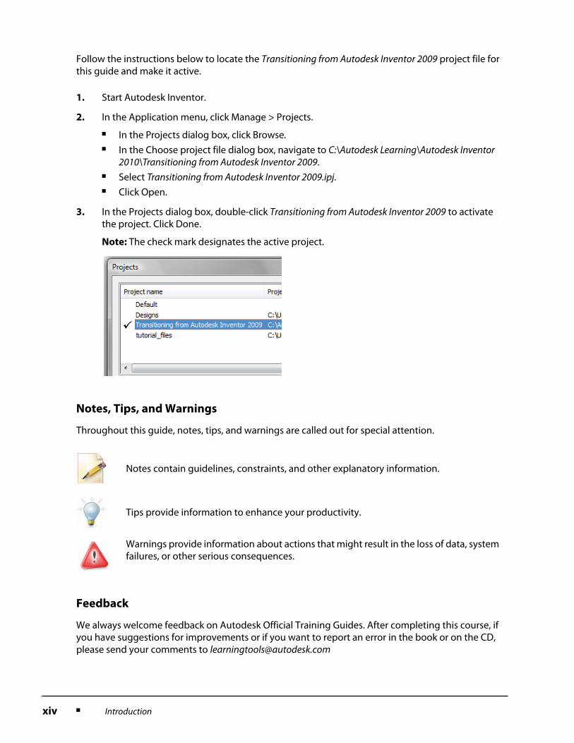
3. In the Projects dialog box, double-click Transitioning from Autodesk Inventor 2009 to activate the project. Click Done.
Note: The check mark designates the active project.
Notes contain guidelines, constraints, and other explanatory information.
Tips provide information to enhance your productivity.
Warnings provide information about actions that might result in the loss of data, system failures, or other serious consequences.
Introduction ■ xv
Digital Prototyping
Most of you probably recognize the enormity of the issues facing manufacturers and engineering companies today. Manufacturing and design are changing at the speed of sound. Manufacturing is being performed globally, and can change locations at any time. Design teams are becoming "virtual", located in many geographies and companies. And customers are located all over the world, each demanding greater communication, customization, shorter timelines, and customer service.
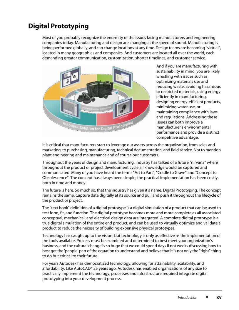
And if you are manufacturing with sustainability in mind, you are likely wrestling with issues such as optimizing materials use and reducing waste, avoiding hazardous or restricted materials, using energy efficiently in manufacturing, designing energy-efficient products, minimizing water use, or maintaining compliance with laws and regulations. Addressing these issues can both improve a manufacturer’s environmental performance and provide a distinct competitive advantage.
It is critical that manufacturers start to leverage our assets across the organization, from sales and marketing, to purchasing, manufacturing, technical documentation, and field service. Not to mention plant engineering and maintenance and of course our customers.
Throughout the years of design and manufacturing, industry has talked of a future "nirvana" where throughout the product or project development cycle all knowledge would be captured and communicated. Many of you have heard the terms "Art to Part", "Cradle to Grave" and "Concept to Obsolescence". The concept has always been simple; the practical implementation has been costly, both in time and money.
The future is here. So much so, that the industry has given it a name. Digital Prototyping. The concept remains the same. Capture data digitally at its source and pull and push it throughout the lifecycle of the product or project.
The "text book" definition of a digital prototype is a digital simulation of a product that can be used to test form, fit, and function. The digital prototype becomes more and more complete as all associated conceptual, mechanical, and electrical design data are integrated. A complete digital prototype is a true digital simulation of the entire end product, and can be used to virtually optimize and validate a product to reduce the necessity of building expensive physical prototypes.
Technology has caught up to the vision, but technology is only as effective as the implementation of the tools available. Process must be examined and determined to best meet your organization’s business, and the cultural change is so huge that we could spend days if not weeks discussing how to best get the 'people' part of the equation to understand and believe that it is not only the "right" thing to do but critical to their future.
For years Autodesk has democratized technology, allowing for attainability, scalability, and affordability. Like AutoCAD® 25 years ago, Autodesk has enabled organizations of any size to practically implement the technology; processes and infrastructure required integrate digital prototyping into your development process.
xvi ■ Introduction
Digital Prototyping is not a "one size fits all" solution. The sheer array of design projects is overwhelming. How can a consumer products company that must appeal to consumers with a cool look and feel and sell 1000s of units implement the same solution as a custom industrial equipment manufacturer that never designs or builds the same unit twice implement the same solution?
Digital Prototyping is a concept that can be adapted to any design process. The technology and process will differ, but the philosophy is the same.
In order to understand how digital prototyping can help manufacturers of all sizes and marketplaces, it is important to understand the general workflow of a design and fulfillment of a product. While each of you come from within this workflow it is easy to lose sight of the overarching process and the people involved. As we look at the workflow, you can see that many departments and steps are involved in this design project and each has its own set of challenges.
Products are typically conceptually created by studying market needs and wants. These concepts can come from many sources including sales and marketing, industrial design, or conceptual engineering. No matter where they come from, the end goal is to meet a customer’s need or want.'
Manufacturing is responsible to build what engineering has designed, purchasing is responsible to support those efforts and track costs. Each department has deadlines and if mistakes aren’t caught until the build phase, they can be costly in both time and money.
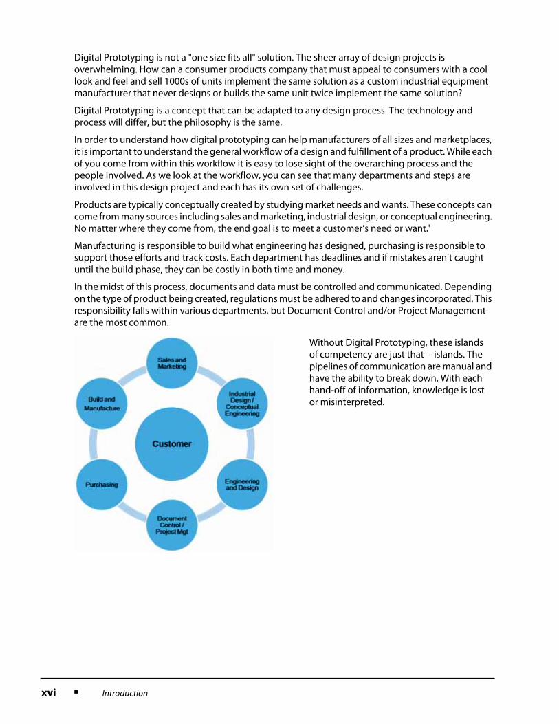
In the midst of this process, documents and data must be controlled and communicated. Depending on the type of product being created, regulations must be adhered to and changes incorporated. This responsibility falls within various departments, but Document Control and/or Project Management are the most common.
Without Digital Prototyping, these islands of competency are just that—islands. The pipelines of communication are manual and have the ability to break down. With each hand-off of information, knowledge is lost or misinterpreted.
Introduction ■ xvii
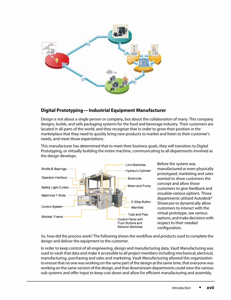
Digital Prototyping—Industrial Equipment Manufacturer
Design is not about a single person or company, but about the collaboration of many. This company designs, builds, and sells packaging systems for the food and beverage industry. Their customers are located in all parts of the world, and they recognize that in order to grow their position in the marketplace that they need to quickly bring new products to market and listen to their customer’s needs, and meet those expectations.
This manufacturer has determined that to meet their business goals, they will transition to Digital Prototyping, or virtually building the entire machine, communicating to all departments involved as the design develops.
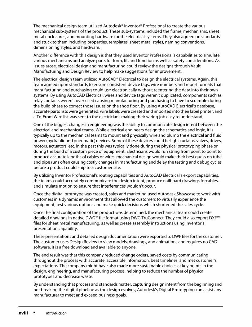
Before the system was manufactured or even physically prototyped, marketing and sales wanted to show customers the concept and allow those customers to give feedback and visualize various options. Those departments utilized Autodesk® Showcase to dynamically allow customers to interact with the virtual prototype, see various options, and make decisions with respect to their needed configuration.
So, how did the process work? The following shows the workflow and products used to complete the design and deliver the equipment to the customer.
In order to keep control of all engineering, design and manufacturing data, Vault Manufacturing was used to vault that data and make it accessible to all project members including mechanical, electrical, manufacturing, purchasing and sales and marketing. Vault Manufacturing allowed this organization to ensure that no one was working on the same part of the design at the same time, that everyone was working on the same version of the design, and that downstream departments could view the various sub-systems and offer input to keep cost down and allow for efficient manufacturing and assembly.
xviii ■ Introduction
The mechanical design team utilized Autodesk® Inventor® Professional to create the various mechanical sub-systems of the product. These sub-systems included the frame, mechanisms, sheet metal enclosures, and mounting hardware for the electrical systems. They also agreed on standards and stuck to them including properties, templates, sheet metal styles, naming conventions, dimensioning styles, and hardware.
Another difference with this design is that they used Inventor Professional’s capabilities to simulate various mechanisms and analyze parts for form, fit, and function as well as safety considerations. As issues arose, electrical design and manufacturing could review the designs through Vault Manufacturing and Design Review to help make suggestions for improvement.
The electrical design team utilized AutoCAD® Electrical to design the electrical systems. Again, this team agreed upon standards to ensure consistent device tags, wire numbers and report formats that manufacturing and purchasing could use electronically without reentering the data into their own systems. By using AutoCAD Electrical, wires and device tags weren’t duplicated; components such as relay contacts weren’t over used causing manufacturing and purchasing to have to scramble during the build phase to correct those issues on the shop floor. By using AutoCAD Electrical’s database, accurate parts lists were generated, wire labels were created and imported into their label printer, and a To-From Wire list was sent to the electricians making their wiring job easy to understand.
One of the biggest changes in engineering was the ability to communicate design intent between the electrical and mechanical teams. While electrical engineers design the schematics and logic, it is typically up to the mechanical teams to mount and physically wire and plumb the electrical and fluid power (hydraulic and pneumatic) devices. Some of these devices could be light curtains, valves, drives, motors, actuators, etc. In the past this was typically done during the physical prototyping phase or during the build of a custom piece of equipment. Electricians would run string from point to point to produce accurate lengths of cables or wires, mechanical design would make their best guess on tube and pipe runs often causing costly changes in manufacturing and delay the testing and debug cycles before a product could ship to a customer site.
By utilizing Inventor Professional’s routing capabilities and AutoCAD Electrical's export capabilities, the teams could accurately communicate the design intent, produce nailboard drawings forcables, and simulate motion to ensure that interferences wouldn’t occur.
Once the digital prototype was created, sales and marketing used Autodesk Showcase to work with customers in a dynamic environment that allowed the customers to virtually experience the equipment, test various options and make quick decisions which shortened the sales cycle.
Once the final configuration of the product was determined, the mechanical team could create detailed drawings in native DWG™ file format using DWG TruConnect. They could also export DXF™ files for sheet metal manufacturing, as well as create assembly instructions using Inventor’s presentation capability.
These presentations and detailed design documentation were exported to DWF files for the customer. The customer uses Design Review to view models, drawings, and animations and requires no CAD software. It is a free download and available to anyone.
The end result was that this company reduced change orders, saved costs by communicating throughout the process with accurate, accessible information, beat timelines, and met customer’s expectations. The company might have also made more sustainable choices at key points in the design, engineering, and manufacturing process, helping to reduce the number of physical prototypes and decrease waste.
By understanding that process and standards matter, capturing design intent from the beginning and not breaking the digital pipeline as the design evolves, Autodesk’s Digital Prototyping can assist any manufacturer to meet and exceed business goals.
Introduction ■ xix
Digital Prototyping—Consumer Products
The Consumer Products example may appear similar to the Industrial Equipment scenario, but it demonstrates the flexibility of Autodesk’s digital prototyping solution. It enables you to use the products that best suit the needs of your industry. Anyone involved in the design or manufacturing of consumer products understands the unique challenges involved. These challenges include differentiating your brand and product from other competitors, innovating new products that will excite customers to purchase, conveying your product through sales and marketing materials, quick product development cycles, not to mention designing a product that can be mass produced at a reasonable cost and with minimal environmental impact.
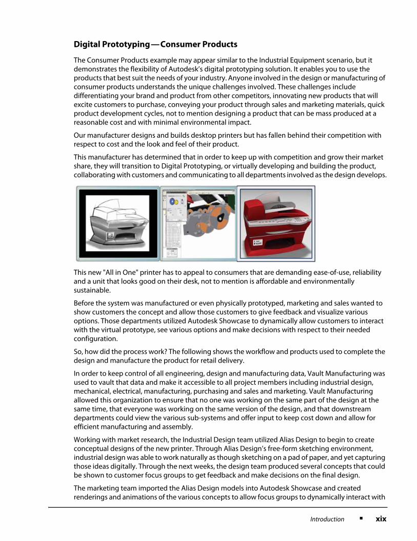
Our manufacturer designs and builds desktop printers but has fallen behind their competition with respect to cost and the look and feel of their product.
This manufacturer has determined that in order to keep up with competition and grow their market share, they will transition to Digital Prototyping, or virtually developing and building the product, collaborating with customers and communicating to all departments involved as the design develops.
This new "All in One" printer has to appeal to consumers that are demanding ease-of-use, reliability and a unit that looks good on their desk, not to mention is affordable and environmentally sustainable.
Before the system was manufactured or even physically prototyped, marketing and sales wanted to show customers the concept and allow those customers to give feedback and visualize various options. Those departments utilized Autodesk Showcase to dynamically allow customers to interact with the virtual prototype, see various options and make decisions with respect to their needed configuration.
So, how did the process work? The following shows the workflow and products used to complete the design and manufacture the product for retail delivery.
In order to keep control of all engineering, design and manufacturing data, Vault Manufacturing was used to vault that data and make it accessible to all project members including industrial design, mechanical, electrical, manufacturing, purchasing and sales and marketing. Vault Manufacturing allowed this organization to ensure that no one was working on the same part of the design at the same time, that everyone was working on the same version of the design, and that downstream departments could view the various sub-systems and offer input to keep cost down and allow for efficient manufacturing and assembly.
Working with market research, the Industrial Design team utilized Alias Design to begin to create conceptual designs of the new printer. Through Alias Design’s free-form sketching environment, industrial design was able to work naturally as though sketching on a pad of paper, and yet capturing those ideas digitally. Through the next weeks, the design team produced several concepts that could be shown to customer focus groups to get feedback and make decisions on the final design.
The marketing team imported the Alias Design models into Autodesk Showcase and created renderings and animations of the various concepts to allow focus groups to dynamically interact with
xx ■ Introduction
the printer in a typical home office setting. Because the customers could see different configurations and ideas digitally there was no need to take the time and money to produce physical prototypes, therefore shortening the development cycle.
The focus group results showed that the consumers like a combination of two concepts that they had been shown and also chose four colors for the printer that universally appealed to them. The marketing team was able to bring that information back to industrial design. Through the use of Alias Design, design was able to incorporate the two concepts into a single model and make the adjustments that the focus groups requested.
The mechanical design team utilized Autodesk Inventor Professional to import the Alias Design models to create a detailed design that was manufacturable. Through Inventor’s modeling environment various sub-systems were designed including the molds, mounting brackets for the electronic circuitry and mechanisms.
Another difference with this design is that they used Inventor Professional’s capabilities to simulate various mechanisms and analyze parts for form, fit, and function as well as safety considerations. As issues arose, electrical design and manufacturing could review the designs through Vault Manufacturing and Design Review to help make suggestions for improvement.
The electrical design team utilized a printed circuit board package and was able to export the physical model into Inventor using the IDF file format.
One of the biggest changes in engineering was the ability to communicate design intent between the electrical and mechanical teams. While electrical engineers design the schematics and logic, it is typically up to the mechanical teams to mount and physically wire the electrical systems. In the past this was typically done during the physical prototyping phase and added time and cost to the product development cycle.
Technicians and engineers would run string from point to point to produce accurate lengths of cables or wires and use that string to make physical nailboards to produce prototype harnesses.
By utilizing Inventor Professional’s routing capabilities the teams could accurately communicate the design intent, produce nailboard drawings for cables, and simulate motion to ensure that interferences wouldn’t occur.
Throughout the design process the engineering team used Autodesk Showcase to work with sales and marketing to make quick design decisions that allowed the detailed design to continue without having to render the models and hold formal design review meetings.
Once the final configuration of the product was determined, the mechanical team could create detailed drawings in native DWG file format using DWG TruConnect. They could also export files for manufacturing, as well as create assembly instructions using Inventor’s presentation capability.
Prior to the release of the product, sales and marketing used Autodesk Showcase and 3DS Max to produce renderings and animations for customer facing printed material and an interactive website.
The end result was that this company reduced change orders, saved costs by communicating throughout the process with accurate, accessible information, beat timelines and produced a product that consumers wanted to purchase at a price point that was profitable for the company and within the consumer’s price expectation. The company might have also made more sustainable choices at key points in the design, engineering and manufacturing process, helping to reduce the number of physical prototypes and decrease waste.
By understanding that process and standards matter, capturing design intent from the beginning and not breaking the digital pipeline as the design evolves, Autodesk’s Digital Prototyping can assist any manufacturer to meet and exceed business goals.