Embed Size (px)
DESCRIPTION
Autocad Materials
Citation preview

AutoCAD Workbook forArchitects and Engineers
Shannon R KylesProfessor ofArchitectureMohawk College, Ontario, Canada
• A Blackwell..II Publishing


AutoCAD Workbook forArchitects and Engineers
Shannon R KylesProfessor ofArchitectureMohawk College, Ontario, Canada
• A Blackwell..II Publishing

This edition first published 2008© 2008 by S.R. Kyles
Blackwell Publishing was acquired by John Wiley & Sons in February 2007. Blackwell's publishing programmehas been merged with Wiley's global Scientific, Technical, and Medical business to form Wiley-Blackwell.
Registered officeJohn Wiley & Sons Ltd, The Atrium, Southern Gate, Chichester, West Sussex, PO19 8SQ, United Kingdom
Editorial office9600 Garsington Road, Oxford, OX4 2DQ, United Kingdom
For details of our global editorial offices, for customer services and for information about how to apply forpermission to reuse the copyright material in this book please see our website at
www.wiley.comlwiley-blackwell.
The right of the author to be identified as the author of this work has been asserted in accordance with theCopyright, Designs and Patents Act 1988.
All rights reserved. No part of this publication may be reproduced, stored in a retrieval system, or transmitted,in any form or by any means, electronic, mechanical, photocopying, recording or otherwise, except aspermitted by the UK Copyright, Designs and Patents Act 1988, without the prior permission of the publisher.
Wiley also publishes its books in a variety of electronic formats. Some content that appears in print may not beavailable in electronic books.
Designations used by companies to distinguish their products are often claimed as trademarks. All brandnames and product names used in this book are trade names, service marks, trademarks or registeredtrademarks of their respective owners. The publisher is not associated with any product or vendor mentioned inthis book. This publication is designed to provide accurate and authoritative information in regard to thesubject matter covered. It is sold on the understanding that the publisher is not engaged in renderingprofessional services. If professional advice or other expert assistance is required, the services of a competentprofessional should be sought.
Certain images and materials contained in this publication were reproduced with the permission of Autodesk,Inc. © 1999-2007 All rights reserved. Autodesk, AutoCAD, and AutoCAD LT are registered trademarks ortrademarks of Autodesk, Inc., in the U.SA., Canada, and certain other countries.
Library ofCongress Cataloging-in-Publication Data
Kyles, Shannon.AutoCAD workbook for architects I S.R. Kyles.
p.em.Includes index.ISBN-13: 978-1-4051-8096-2 (pbk. : alk. paper)ISBN-I0: 1-4051-8096-X (pbk. : alk. paper) I. Architectural drawing-Computer-aided
design-Handbooks, manuals, etc. 2. AutoCAD-Handbooks, manuals, etc. 1. Title.NA2728.K952008720.28'40285536--dc22
2007033120
A catalogue record for this book is available from the British Library.
Set in Times New Roman 101l3pt by S.R. Kyles, CanadaPrinted in Singapore by C.O.S. Printers Pte Ltd12008

Contents
Acknowledgments
Introduction
Using this Book
Disks and File Storage
Starting AutoCAD
Keyboard and Mouse Functions
Function Buttons
Entering Commands and Coordinates
Windows Toolbars
Scroll Bars
Opening or Accessing Drawings
Exiting AutoCAD
Options Dialog Box
page viii
ix
ix
IX
X
x
Xl
Xl
Xl
XlI
xii
XlV
xiv
Introductory Geometry and Setting Up
Starting a Drawing in Metric or Imperial
The UNITS Command
Choosing the Origin
Using PAN to get Started
The LIMITS Command
Entry of Points
Coordinate Entry using Absolute, Relative, and Polar Values
Coordinate Entry using SNAP, ORTHO, POlAR and DYNAMICGeometry Commands
View Commands
Alternate Units
1
Tutorial1a
Tutoriallb
Exercise 1
Exercise 1
Exercise 1
Using Draw Commands and Limits
Using Draw Commands without Limits
Units Practice 1
Units Practice 2
Practice
1
I
2
3
4
4
6
6
8
11
13
17
18
21
23
24
25
Contents ii

iv Contents
Exercise 1 Architectural 26
Exercise 1 Mechanical 27
Exercise 1 Woodwork 28
2 Help Files, OSNAP, OTRACK, BREAK, TRIM, and ERASE 29
Understanding Command Strings 30
Object SNAPs 32
OTRACK 35
BREAK, TRIM, and ERASE 36
GRIPS 37
ERASE with Window and Crossing 37
UNDO and REDO 37
Tutoria12a Using SNAP, OSNAP, and TRIM 38
Tutoria12b Using OSNAP and OTRACK 42
Exercise 2 Practice 45
Exercise 2 Architectural 46
Exercise 2 Mechanical 47
Exercise 2 Challenger 48
3 Object Selection and Modify Commands 49
Selecting Objects Within the Modify Commands 49
Modify Commands 51
Editing with Grips 56
Setting LINETYPEs 58
Changing LTSCALE 58
Tutoria13a Using ROTATE, COPY, and MIRROR 59
Tutoria13b Using ROTATE, COPY, and MIRROR 61
Exercise 3 Practice 64
Exercise 3 Architectural 65
Exercise 3 Mechanical 66
Exercise 3 Challenger 67
4 STRETCH, TRIM, EXTEND, OFFSET, and ARRAY 69
Removing and Adding Objects 69
More Modify Commands 70
Tutoria14 Modify Commands 80
Exercise4a Practice 83
Exercise4b Practice 84
Exercise 4 Architectural 85
Exercise4a Mechanical 86
Exercise4b Mechanical 87
Exercise 4 Challenger 88
5 Entity Commands with Width 89
The PUNE Command 89
The PEDIT Command 92
The POLYGON Command 94
The SOLID Command 95

The DONUT Command
The TEXT Command
Multilines
Tutorial 5 Using PLiNE and SOLIDExercise 5 Practice
Exercise 5 Architectural
Exercise 5 Mechanical
Exercise 5 Wood
Exercise 5 Challenger
6 Entity Properties: Layers, Colors, and Linetypes
About LAYERs
Creating aNew Layer
Changing LTSCALE
Match Properties and CHPROPLayer Filtering
Tutorial 6 Layers, Colors, and Linetypes
Exercise 6 Practice
Exercise 6 Architectural
Exercise 6 Mechanical
Exercise 6 Challenger
7 Dimensioning
About Dimensioning
Entering Dimensions
Dimension Styles
The Text Tab
The Fit Tab
The Primary Units Tab
The Alternate Units Tab
The Symbols and Arrows Tab
Saving Dimension Styles
Editing Dimensions
Tutorial7a Dimensioning for Mechanical Applications
Tutorial7b Dimensioning for Architectural Applications
Exercise 7 Practice
Exercise 7 Architectural
Exercise 7 Mechanical
Exercise 7 Wood
Exercise 7 Challenger
8 Text and Pictorial Views
Linear Text
Paragraph Text
Text Styles and Fonts
Editing Text
Using LEADER to Create Notations
SNAP and GRIDTutoria18a Using Text and Text Styles
9596
9798
102
103104105106
107
107
108
110
110
111
112
116117118
119
121
121
122
126
126
127
128
128128
129129130
134
136
137
138
139
140
141141144
145
147
148
149
150
Contents V

vi Contents
Tutorial8b Using Rotated SNAP and GRID to make a 2D Isometric 155
Exercise 8 Practice 159
Exercise 8 Architectural 160
Exercise 8 Mechanical 161
Exercise 8 Wood Millwork 162
Exercise 8 Challenger 164
9 HATCH, SKETCH, and GRADIENTS 165
The BHATCH Command 165
Solid Hatches 169
Editing Hatches 169
The SKETCH Command 170
Gradient 171
Tutorial 9 HATCH 172
Exercise 9 Practice 175
Exercise 9 Architectural 176
Exercise 9 Wood Millwork 177
Exercise 9 Mechanical 178
Exercise 9 Challenger 180
10 Blocks and Wblocks 181
Using Blocks 181
The BLOCK Command 181
The INSERT Command 182
External Blocks 183
The WBLOCK Command 184
CopylPaste 185
The MINSERT Command 186
Editing Blocks 186
Blocks, Wblocks, Color, and Layers 187
Tutorial 10 BLOCK, WBLOCK, INSERT, and Copy/Paste 189
Exercise 10 Practice 192
Exercise 10 Mechanical ]93
Exercise 1Oa Architectural 194
Exercise lOb Architectural 195
Exercise 10 Challenger 196
11 Setting Up Drawings and Plotting 197
Set Up and Scale for Simple 2D Drawings 197
Using Blocks to Compile Drawings 199
View Titles and Drawing-Related Notations 202
Importing Notations 203
Using Lineweights 204
Plotting 204
Tutorial 11 a Imperial Example 207
Tutorial!!b Metric Example 210
Exercise 11 Practice 213
Exercise 11 Architectural 214

Exercise 11 Mechanical 215
Exercise 11 Challenger 216
12 Paper Space for 2 Dimensional Drawings 217
Paper Space 217
Accessing Paper Space 218
Scaling Views Within a Drawing 220
Layers Within Viewports 221
The VPLAYER Command 222
Dimensioning in Paper Space 222
AutoCAD~s Template Drawings 223
Tutoriall2a Imperial Example 224
Tutoria112b Metric Example 229
Exercise 12 Practice 236
Exercise 12 Architectural 237
Exercise 12 Mechanical 238
Exercise 12 Wood 239
Exercise 12 Challenger 240
13 POINTS, DIVIDE, MEASURE, and Inquiry Commands 241
Points, Point Display and Point Size Options 241
Using DIVIDE and MEASURE 242
The SPLINE Command 245
Inquiry Commands 246
Tutorial13a Inquiry Commands and SPLINE 252
Tutorial13b MEASURE and DIVIDE with Inquiry Commands 255
Exercise 13 Practice 257
Exercise 13 Architectural 258
Exercise 13 Mechanical 259
Exercise 13 Challenger 260
14 Attributes 261
Introduction 261
Attributes for Title Blocks and Notations 261
Defining the Attributes 262
Editing Attribute Definitions 263
Displaying Attributes 265
Creating Attributes for Data Extraction 265
Editing Attributes 266
Data Extraction 267
Tutorial14a Attributes for a Title Block 268
Tutorial14b Defining, Blocking, and Inserting Attributes 271
Tutorial14c Defining, Blocking, and Inserting Attributes 276
Exercise 14 Architectural 277
Exercise 14 Challenger 278
m~ 2~
Drawings 281
Contents vii

viii Acknowledgements
Acknowledgments
The exercises in this book went through many years ofstudent testing both at MohawkCollege and at McMaster University in Hamilton, Ontario, Canada. Since the studentedition appeared in January 1993,there have been many positive suggestions and muchconstructive criticism. I would like to thank all my students over the past 27 years ofteaching CAD for working with me on the development ofnew proj ects, and for proofing tutorials and exercises.
I would like to thank Brian McKibbin, Diego Gomez, and Trevor Garwood Jones fortheir generosity in letting me use their architectural designs to provide students withup-to-date architectural work. I would also like to thank Robert Deeks and HenryBrink for their help in updating the mechanical engineering examples, and Ken Mercer for checking the accuracy of the wood-related drawings.
Finally I would like to thank Catriona Dixon and Madeleine Metcalfe from BlackwellPublishing for their efforts in polishing this text.
Shanon R. KylesCanada
December 2007

Using this Book
[)isks and FileStorage
IntroductionAutoCAD is a very popular, flexible software system that allows the user to createboth 2-dimensional and 3-dimensional models and drawings. This book offers a seriesofexercises to help you learn the 2D drawing techniques ofAutoCAD. Most ofthe 2Dcommands in Releases 2006, 2007 and 2008 have not changed since Release 2000i.These exercises can be used on all releases from 2000i through 2008.
For those who are familiar with computers, learning AutoCAD will be easy, simplybecause you are aware ofthe typical response structure and the format ofyour system.
System Prompts and User Responses
All commands listed within the text of this book are in the command font. CIRCLE,LINE, ZOOM, MIRROR, etc. When shown as in this font are commands.
In this book, the system command information will be shown in this style:
Command:Specify first point:
Specify second point or [Undo]:
The user responses (what you should type in) will be shown in bold:
COffi."l1and: LINESpecify first point:O,OSpecify second point or [Undo] :5,3
The Enter or Return Key
At the end ofeach command or entry on the command line, use the Enter key (symbolized by .J) to signal the end of:
a command entry:Command:LlNE.J
• a coordinate entry:Specify first point:2,4.J
• a value:New fillet radius.OOOO:3.J
• text:Text:All Holes 2.00R Unless Note~
Please note that the .J will not be shown at the end ofevery entry after Chapter 1; it willonly be used when the user should press .J rather than entering any other response.
Most ofthe drawings in this book are small, so a floppy disk may be used for file storageif your computer still has a floppy drive. Zip drives, Jazz drives, mass storage unitsand CD writers are better suited to storing larger files. Always make three copies ofyour files. Save your file every halfhour on the permanent computer drive, either C: orD:. Ifyou have been working for more than three hours, also save onto an external filesystem like a flash drive. Before you sign offfrom the system, e-mail a copy ofthe fileto yourself as welL
INTRODUCTION ix

StartingAutoCAD
AutoC6.D Classic
Keyboard andMouse Functions
x INTRODUCTION
Your Windows environment should have been set up so that a double-click on theAutoCAD application icon will bring up AutoCAD.You will automatically be placedin the Drawing Editor.
When you first start up, there may be palettes overlaying your screen. Click on the "X"to remove them. On releases 2007 and 2008 a dashboard may come up instead ofto01bars. Pick AutoCAD Classic from the Workspaces toolbar.
Unfortunately, there is no way ofguaranteeing how the last user has left the screen, soyou may not have the necessary toolbars showing. If your screen is not the same asshown below, you can either open toolbars in the View pull-down menu (very cumbersome and difficult) or right~c1ickany toolbar on screen and pick from the list a toolbarthat you want.
The Windows Drawing Editor
The initial Windows screen contains the menu bar, the status bar, the drawing windowor graphics area, and several toolbars. Toolbars contain icons that represent commands.
The menu bar (along the top) contains the pull-down menus. The status bar (along thebottom) displays the cursor coordinates and the status modes such as GRID and SNAP.Mode names are always visible in the status bar as selectable buttons. Click the buttonsto toggle the modes. The command line in Windows is "floating," that is, it may bedragged to any location on the screen. The command line is where your commandswill be written out. Keep reading this to see where you are.
There are many different kinds ofpointing devices or mice on the market. Some havetwo or three buttons, others have as many as 20. Two buttons are adequate for mostoperations. A central roller on the top ofthe mouse will help with display cOlnmands.
In releases after 2004, the roller ball on the mouse will both ZOOM and PAN your file.
The Pick Button
On all mice there is a point or command indicator or pick button; on a two-buttonmouse, it is usually on the left side of the device.
The pick button is used to indicate the command you want to access either from theon-screen menu or from the digitizer tablet. It is also used to indicate point positions.
The Enter Button
The button on the right ofthe mouse will often have the function ofthe .J key (Enter orReturn) on the keyboard. This signals the end ofa command. There is also a right-clickfacility that accesses the functions associated with each command. This can be turnedoffunder the Tools pull-down menu by selecting Options and then UserPreferences.

Function Buttons Many people who have used AutoCAD for a few years still make use of the functionkeys on the top of the keyboard ( F6, F7, F8, etc). Move the mouse around the screennoting the movement of the crosshairs.
F6
F7
F8
F9
toggles the Co-ordinate readout fromabsolute, to incremental to off and back
toggles GRID on and off
toggles ORTHO on and off
toggles the SNAP on and off
EnteringCommands and
Coordinates
You can enter information either through the keyboard or through your mouse orpointing device. There are also toolbars and icons that help to access the information.You can enter a command by typing it in at the command prompt or you can use thepointing device to pick up commands from:
the pUll-down menus in the menu bar
the icons on the toolbars.
WindowsToolbors
Toolbars are groups of icons or tools compiled according to application. Toolbars can be on-screen or not, and can be on the topor side of your screen or floating.
Accessing Too/bars
In Releases 2000 to 2005, Toolbars can be accessed through theView pull-down menu. Pick View, then Toolbars, then the toolbar that you need. In Releases 2006, 2007 and 2008, simplyright-click the two parallel lines on the end of the toolbar, and alist of possible toolbars will appear. Pick the one you want.
To remove a toolbar from your screen, click on the X icon on thetop right of the toolbar.
Using Windows Too/hars
Toolbars contain tools that represent commands. When youmove the pointing device over a tool, Tooltips display the nameof the tool below the cursor. Pick that tool to invoke the command.
Placing Toolhars
The Standard toolbar is visible by default. It carries frequentlyused tools such as Zoom, Redraw, and Undo. A docked too/barattaches to any edge of the graphics window. Afloating too/barcan lie anywhere on the application screen, and it can be resizedand does not overlap with the drawing window.
3D Orbit
CAD Standards
Dimension
." Draw
Draw Order
Inquiry
Insert
..; Layers
Layouts
v ModifyModify II
Object Snap
." Properties
Refedit
Reference
Render
Shade
Solids
Solids Editing
." Standard
Styles
Surfaces
Text
UCS
ucsnView
Viewports
Web
Workspaces
Zoom
Lock Location ~
Customize.. ,
Ifnone ofyour toolbars appear on screen, exit AutoCAD and open the software again.Your start-up file may not have been properly loaded.
INTRODUCTION xi

Scroll Bars
Opening orAccessingDrawings
xii INTRODUCTION
To Dock a Toolbar
1. Position the cursor on the toolbar, and press the pick button on the pointing device.
2. Drag the toolbar to a dock location at the top, bottom, or either side of the drawingwindow.
3. When the outline ofthe toolbar appears in the docking area, release the pick button.
To place the toolbar in a docking region without docking it, hold down the Ctr1 key asyou drag.
Placing theFirst Toolbar
If your screen comes up with no toolbars, type in the word 'toolbar' preceeded by adash as shown below. Then type in 'Standard' and your Standard toolbar will appear.Dock it, as explained above, then right-click the two parallel lines on the end and placethe other toolbars as required. If this doesn't work, exit AutoCAD and reload it.
Command:-toolbar
Enter toolbar name or [All] :Standard
The Windows Command Window
Like the toolbars, the Windows command line or response area can be moved anddocked. By default the command window is docked at the bottom of your screen.
You can resize the command window vertically and horizontally, both with the pointing device and with the splitter bar located at the top edge ofthe window when dockedon the bottom and on the bottom edge when docked at the top. Resizing and dockingthe command window can help you to create more space for your drawings on-screen.Itcan also help you see your commands to find out where you may have gone wrong.
In most Windows applications there are scroll bars that advance the file you areviewing. Each scroll bar has arrows that indicate a move up or down. To access an areanot displayed, click on the up or down arrow until the information is displayed or pickthe box within the scroll bar and move it quickly up and down the screen.
Scroll bars can be either vertical or horizontal. In Windows, the scroll bars on the topand bottom move the file across the screen in the same way that PAN does.
Once you have accessed the Drawing Editor, you can start drawing and later save yourwork under a specified name in a specified directory. Ifyou have a drawing staTted in
AutoCAD Release 2000i, 2004 or some earlier version, you can use OPEN to find itand then work on it.
Opening Existing Drawing.5
The command line equivalent is OPEN.
In Windows, under File Name double-click the file name in the list of files. Use thescroll bars to access other files. To access other directories, pick the down arrow beside the words' Look in:'. You can also type in the drawing name by picking the longwhite box beside File Name:, then typing in the name ofthe file. Ifyou prefer to type inboth the directory and the name, type that into the File Name box.
Once your file is open, any changes can be saved to the same directory with the SAVEcommand.

Starting a New File
If you would like to start a new file, access the same File menu and choose New.
Before the new file is created, you can choose a default drawing file environmentand/or enter the name of the file that you wish to create.
Command: newEnter template file name or L. (For none)] <acad.dwt>:
Enter template file name or [. (For none)] <acadiso.dwt>:
The _dwt extension stands for drawing template. acad.dwt is imperial, acadiso.dwt ismetric.
The default file environment can be either the acad.dwt standard file or a prototype filethat contains all the settings for a specific application. Once you are familiar withAutoCAD, you can save drawing templates that contain plotter information, layer information, groups, blocks, linetypes, and other standard information so that you don'tneed to set up your file from scratch each time.
Recovering Files
Jfyou have a problem with retrieving a file using OPEN, you may need to RECOVERthe file. Usually these problems are caused by either bad diskettes or removing thefloppy disk from the drive before AutoCAD has completely exited from the file. Ifyouneed to restore a file, simply type in RECOVER at the command prompt. Theoretically,the OPEN cOlnmand should automatically repair any damaged files, but ifthis doesn'twork, try RECOVER.
Saving Files
Computers have a tendency to lose information at the worst possible times. It is suggested that when you are using AutoCAD you save your files at least every hour.
The first time you save a drawing, you will be prompted for the name ofthe file beforeit is saved. Ifyou have already entered the name ofthe current file under the New option under File, then AutoCAD simply saves the file under the given name and directory and you will not be prompted for a name.
To save a named file, use SAVE. Use the icon or
1. Type in the word SAVE at the command prompt
To save the file under a new name or on a differentdirectory, choose Save As frOln the File pull-downInenu.
Choose SAVE every subsequent time you wouldlike to save the drawing, and the drawing will automatically be saved under this specified file name.
If you specified a directory and file when yousigned on, use SAVE to save the file under thisname.
Save B.s ...
. IQ ;iave
.,~~i.~'.'N.~i:~.. ".:.~~::~.w ..~~!QI r:!ew ...
Ne~Sheet Set...
Qpen...
Op~n Sheet Set...
Load Marlsup Set .•.
~Iose
From the File menu, choose SAVE. In the Save
Drawing As dialog box, enter the new drawingname. Then choose OK.
2.
To save a file to be read on anearlier release of AutoCAD,choose Save As, then underthe Files of Type box, pickRel130se 2000.
To change the directory, double-click on the directory listing that you want. The linereading 'Look In:' must reflect the directory chosen.
You can save a file as a different release ofAutoCAD by specifying the file type. Specify the release you need under the Files of Type box in the Save As dialog box.
INTRODUCTION xiii

Exiting AutoCAD
Options DialogBox
Changing the Drawing Name or Directory
Ifyou want to change the drawing name or directory, use Save As. Ifyou have been addressing C: while creating your drawing, you can save the file onto a disk before exiting the file by using Save As, then pick A: or B: for the directory or drive.
Once you have saved the file, you can exit AutoCAD either by clicking onthe X at the top right or by picking Exit from the File menu.
The command line equivalent is QUIT.
The large red X will exit you from AutoCAD. The smaller black x will exit you fromthe current drawing.
Do not remove your floppy disk from the drive before you have completely exitedfronl AutoCAD.
In previous releases and in many other Windows programs theOptions dialog box is called Preferences. The Options setup yourscreen display, the drawing environment, and the systelTI. If youfmd the color ofthe screen difficult to work with, change it underTools, Options, Display, Color. You can also set right-clickpreferences here.
Window Elements
D Display sCioli bars in drawing window
o Display screen menu
(EJ U~e I<ltge buttom for loolbafS
oShow ToolTips
o Show shortcut kejls in ToolT ipsr----___
Colors... 1 I FonlL
Layout elements
oDisplay Layout and Model tabs
o Display Plintable aleC!
21 Display paper background
[!j Displey paper shadow
o Show Page SelupManagel tor new layouts
~ Creale viewport in new layouts
Closshair SIW
i5
DisplC!jI resolution
.:.! 11OO~.J Arc and circle smoothness
~~. ;8 I Segments in a polyline curve
~l ~! Rendered object smoolhness
:?! ;4 ! Contour lines per surtace
Display perlormance
o Pan and zoom with lasler &OLE
~ High~ght rasler image frMle only
:l 0 App~ solid liD
~ 0 Show lexl boundary flame only
~ 0 Draw tliue silhouettes 101 roIids and~fa=
Reference Edillading intensity
[50-------;L__i
xiv INTRODUCTION
Context: Interface e1eFlle!'¢;@t..Ugp--Tnx ,I!_ ••••I1I~~·I~out I 1Crosshairs .l=~------""';;;;';;.qi3D paralIel projection 1Autotrack vector II Redi3D perspective projection 1;Autosnap marker 0 YeBow
IBlock editor : 1Drafti[1Q tool tip EJ Green
I Command line IiDrafting tool tip background mCyan·ti Plot preview i ILight glyphs • Blue,~~._._~_~.~~~_"", ..} ILight hotspot
;Light falloff II Magenta1Light start limit 0 White!Ughtendlimlt •••••••••!~amera9lyp.hs c:~I?r CI Select Color, ..

Introductory Geometry andSetting Up
.
i chapter you should be able to:
UhAl SNAP, and GRID
methods and on-screen picking
ZOOM and PAN
This book is about how to use AutoCAD to make drawings. The information is relevant to all AutoCAD releases from 2000 to 2008. Commands not available before aparticular release are noted.
Figure 1.1
/UC5ICor.J
/ ...----C(llT1J'11i:jnd ~Ine. Co'ordlna+..e Readout
/
Move your cursor acrossthe screen to the right ofthedrawing area. If the nUll-hers in the coordinatereadout are under 100, youhave opened an ilnperialfile. If they are over 500,you have opened in metric.
Once you have entered the Drawing Editor,AutoCAD establishes a default working
environment. There may also be some 'floating
palettes' on the screen (Sheet Sets, Tool Palettes).Click on the X at the topright corner of each paletteto clear these off yourscreen so it looks likeFigure 1.1. Make sure yourworkspace is AutoCADClassic (Releases 2007 and2008).
Starting aDrawing in
Metric orImperial
Changing Imperial and Metric
It is best to start off immediately with the units thatyou want to use. If you have started in the wrongunits, open a new file with acad.dwt (imperial) oracadiso.dwt (metric).
The command STARTUP can also be used. This willprompt for either imperial or metric without the otheroptions.
'·~PTWT;;P'I;;·~'·····_·-'"·~~·.'~~'.~.~.~Sheet5et$
tijatad -Named Plot Styles..dwtg;acad.dwtliIacadISO ..NamedPlot Styles,dwtlliacadiso.dwttilANSI A (portraitl-Color Depe.,.
Command: STARTUPEnter new value for startup <0>:1
Com..rnand :NEW
Introductory Geometry and Setting Up 1

Pick either imperial or metric from the dialog box. Ifyou don't start in the right units,your dimensioning, area, and volume calculations will be difficult.
Figure 1.2
The UNITSCommand
If you pick a point on the graphicsscreen, you start to draw a rectangle,Pick another point and it will
disappear.
In AutoCAD it is suggested that you draw everything at full scale or 1: 1 scale, and plotthe drawing at the required scale factor later.
Once you have chosen your deired unitsfrom the startup menu, you then use the
UNITS command to set your readoutonly.The type of units chosen detennineshow AutoCAD interprets coordinate andangle command entries. The 'Insertionscale' area indicates again your base units.AutoCAD offers various types ofunits ofmeasure for use on your drawings. Beforesetting up the parameters of the drawing,first set up the units so that the readout displays the required units. Decimal modemay be used for Inetric units as well as forimperial units. Be sure you have set upyour file correctly for the units that you reqUIre.
+x
-y
+y
-x
Figure 1.40
Starting to Draw
AutoCAD uses Cartesian coordinates forpoint entry. The points are set around a determined origin atXO, YO, ZOo In this caseXis 21"10". Y is 5'0", and Z is 0.0000. Allpoints to the right of 0,0 have a positive Xvalue; all points to the left have a negativeX All points above 0,0 have a positive Yvalue; all points below have negative Y.
Moving the cursor around the screen youwill notice that the 0,0 position defaults tothe bottom left corner of your screen. SeeFigures 1.4a and Figure lAb.
The decimal unit type will display onemillimeter for one unit. Specify the number ofdecimal places for your readout using precision, as in Figure 1.2.
The engineering and architectural modes assume that one drawing unit equals one inch.Again set your precision, as shown in Figure1.3. Fractional and scientific settings willgive a readout in those specific units. Again,the UNITS cOlnmand only sets the readout. Ifyou are setting your UNITS in inches, but your'Insertion scale' is luillimeters, then you willhave problems later.
The UNITS command can be accessed either Figure 1.3
through the command line or through theUNITS dialog box from the Fonnat pull-downmenu at the top of your screen.
iIlf you press the space bar beforeentering any other command just asyou open the file, the system mightoffer you the 'HELP' files. To get the
'HELP' files off screen, click on the Xat
the top right.
Figure 1.4b
2 CHAPTER ONE

(:hoosing theOrigin
The origin or 0,0 should be the most easily accessible point on the design. If a largepercentage ofthe dimensions on a drawing stem from one point, it should be made theorigin. The coordinate readout on the bottom of the screen is there to help you fmdyour position. The placement of the origin is important to establish a base for yourreadouts. It will be more important later when merging files.
To move 0,0 from the bottom of the screen use the PAN command, as in Figure 1.5.
y
Figure 1.5
Often you can press down on the roller ball ofyour mouse to get PAN. The commandline equivalent is PAN or just P.
Command: PAN(drag the icon across the screen to where you want it)
In architectural drawings the origin is often at the bottom left comer, as in Figure 1.6.
upper right 35',30'
0,0*===::::::=a_-=!.I-2',-2' lower left
Figure 1.6
0,0
-5',-5' lower left
upper right 50',45'
142'
1In mechanical applications it is often in the center, as in Figure 1.7_
upper right 2,2 upper right 10,20
-2,-2 lower left
Figure 1.7
1.2
-10,-20 lower left
16
Introductory Geometry and Setting Up 3

Using PAN toget Started
IiIn the command examples, the boldtype is the user entry or response.
The easiest way to start a file is by using 0,0 as the starting point. Use PAN to move theorigin or 0,0 to the center of the screen. Then draw your first object using 0,0 as thefIrst point.
The PAN command is as follows:
The command line equivalent is PAN or P.
Once centered, draw a circle, then use ZOOM All to fit it to your screen, as in Figure1.8. The same can be done using LINE. The CIRCLE command is explained further onpage 11, but the commands below will show how it works.
PAN
Figure 1.8
y
~x
CIRCLE ZOOM ALL
The LIMITSCommand
4 CHAPTER ONE
Command:PAN (move your 0,0 to the center of the screen as in
Figure 1.5)
Command:CIRCLE
Specify center point for circle or [3P/2P/Ttr (tan tan
radius)] :0,0Specify radius of circle or [Diameter]<1'-O">:5
Command: ZOOM
Specify corner of window, enter a scale factor (nX or nXP),
or [All/Center/Dynamic/Extents/Previous/Scale
/Window/ObjectJ<real time>:ALL
LIMITS sets a flexible general size for your drawing. LIMITS sets the size ofyour screenand the area covered by the screen grid. Unlike drawing on paper, you can change theLIMITS size at any time. It simply gives you a place to start and helps provide a visualsize that you can identify with.
The command line equivalent is LIMITS.
Setting LIMITS does not limit your model; it merely lets you determine how big the finished product might be. You can reset the LIMITS at any time simply by picking newpoints on the screen. ZOOM All allows you to view the size you have chosen.

Open acad.dwt. Change your
UNITS to Architectural and drawin a line .. ZOOM All to see it on
the screE"n.
Use LIMiTS; GRID and SNAP to
set up a drawing environment.
Draw a line or circle the size of
your part, then use ZOOM All.
Set up your LIMITS, GRID andSNAP if they might be useful.
Draw a line or circle the size ofyour part, then ZOOM All.
A Sample Set Up
A house that is 40' x 36'.
The following commands will center the frrst line on your screen without LIMITS.
Command: LINE
LINE Specify first point:O,O
Specify next point or [Undo] :40' ,0Specify next point or [Undo]:~
Command: ZOOM
Specify corner of window, enter a scale factor (nX or nXP),
or [All/Center/Dynamic/Extents/Previous/Scale
/Window/Object]<real time>:ALL
You can also draw this using LIMITS.
Command: LIMITS
Reset Model space limits
Specify lower left corner or [ON / OFF]<0'-0",0'-0">:-5' ,-5'
Specify upper right corner <12.0000,9.0000>:45' ,40'Command: ZOOM
Specify corner of window, enter .... /ObjectJ<real time>:ALL
Cornmand:LINE
LINE Specify first point:O,O
Specify next point or [Undo] :40' ,0Specify next point or [Undo]:~
Setting LIMITS, SNAP and GRID
LIMITS sets an overall size for your design. SNAP sets an increment that the cursor willmove by. GRID sets a visual aid to help you place objects, and is often set to twice theSNAP value. The grid will extend over the area given by the LIMITS command.
To find GRID and SNAP:
The command line equivalent is SNAP or GRI D.
Command: LIMITSReset Model space limits
Specify lower left corner or [ON/OFF]<0.OOOO,O.OOOO>:-S,-40Specify upper right corner<12.0000,9.0000>:240,180
Command: ZOOM
Specify corner ..... Extents/Left/Previous/Scale/Window]<real
time>:ALL
Command: SNAP
Specify snap spacing (X) or
[ON/OFF/Aspect/Rotate/Style/Type]<1.0000>:5
Corn...'Tland: GRID
Specify grid spacing or [ON/OFF/Snap/Aspect]<O>:10
Introductory Geometry and Setting Up 5

Entry of Points
Coordinate Entryusing Absolute,
Relative, andPolar Values
The DYNamic function is very usefulbut confusing at first. Turn it off forcoordinate entry by clicking the icon.
DYNamic off
DYNamic on
6 CHAPTER ONE
All parts of geometry are entered by means of points. Lines have two points each.circles have a centerpoint and a point determining the radius. Arcs have a center point,
a radius point, a start point, and an end point.
There are three ways of entering points:
by coordinates: absolute values, relative values, or polar values
picking them on the screen, with or without SNAP or DYNamic
relative to existing geometry
In this chapter we will look only at the first two methods ofpoint entry. The LINE command will be used to illustrate coordinate entries.
The LINE Command
Find LINE as follows:
The command line equivalent is LINE or the command alias L.
Co~~and:LlNE or L
To create a LINE, you will need to know where it starts and where it ends. Pick two ormore points on the screen or enter the coordinates. Tenninate the command by pressing the Enter key (.J) .
The coordinates of an item, the X and Yvalues, can be entered either relative to theorigin (the absolute value of the line) or relative to the last point entered (the
incremental value).
Absolute Value Entries
In this method, the origin of the model or drawing does not change: the objects areplaced relative to the origin. To enter the absolute value ofan item, type in the X value,then the Y value, separated by a comma. You will need to enter two sets of values todraw a line. Press the enter key -I to signal the end of the coordinate entry and youshould get the line shown in Figure 1.9.
Command:LlNE
Specify first point:O,O
Specify next point or [Undo] :4,0
Figure 1.9
This will draw a line from the absolute position of 0,0 to the absolute position of4,0.

Relative Value Entries
To enter an incremental or relative value, type the @ symbol (Shift-2) before thenumber. @ means 'from the last point.'
Command:LINE
Specify first point:2,3
Specify next point or [Undo] :@4,0
This will draw a line from the absolute position of2,3 to a position 4 units in positiveXfrom this point.
Try these two examples:
AbsoluteComrnand:LINE
Specify first point:O,O
Specify next point or[Undo] :4,0
Specify next point or[Undo] :4,4
Specify next point or [Undo] :0,4
Specify next point or [Undo] :0,0
Specify next point or [Undo]:~
D
Figure 1.10
RelativeComrnand:LINE
Specify first point:5,5
Specify next [Undo] :@4,O
Specify next [Undo] :@O,4
Specify next [Undo] :@-4,O
Specify next [Undo] :@0,-4
Specify next [Undo] :~
The example on the left in Figure 1.10 is a four-unit square starting at 0,0. The exampleon the right is a four-unit square starting at 5,5. Both squares are created relative to theorigin, 0,0.
To draw a line from point 5,6 to point 8.3,6 use either of the following:
AbsoluteCommand: LINE
Specify first point:5,6
Specify next point or[Undo] :8.3,6
RelativeCommand: LINE
Specify first point:5,6
Specify next[Undo] :@3.3,0
In choosing between the absolute and the incremental method, the deciding factor iswhat you know. Ifyou know that the final point is going to be 8.3,6, use the absolutevalue. Ifyou know that the line is going to be 3.3 units inpositiveXfrom the last point,then enter the incremental coordinates. AutoCAD will do the calculations.
Introductory Geometry and Setting Up 7

Polar Value Entries
Polar coordinates allow you to enter an item, relative to the last item, at a specifiedlength and angle. Angles are normally calculated counterclockwise from the positiveX direction, as shown in Figure 1.11.
Command: LINESpecify first point:3,4Specify next point or [Undo] :@4<45
~@4<45
3,4 </,,---4-------J450
Figure 1.11
90
180 --+-+-----'-~-
270
o
Where: @4
<45
relative to the last pointthe length of the lineanglethe angle that the line will be drawn at; all angles are calculated
counterclockwise
@1<210
Try this example:
Command: LINESpecify first point:6,ONext point:@2<O
Next point:@3<90Next point:@2<O
Next point:@1<270
Next point:@2<O
Next point:@2<90
Next point:@6<150
Next point:@1<210
Next point:C (for close)
Close
6,0 @2<0
@6<150
@2<90@2<0 @1<270
@@2<O
3<90
Coordinate Entryusing SNAP,
ORTHO,POLAR,and DYNAMIC
8 CHAPTER ONE
As noted above, angles are calculated counter- Figure 1.12
clockwise from the furthest point in positive X
Functions that can help you enter your drawing information are found at the bottom ofyour screen. The lefthand button on the mouse will enter a point every time you press itwhile in a draw command. Yau can make your digitizing or picking of points much
easier and more accurate by using functions such as SNAP, POLAR and ORTHO. Thefunction bar is shown in Figure 1.13.
Figure 1.13

SNAP on
SNAP off
SNAPWith SNAP you can draw lines, arcs or circles at preset integers. SNAP can also be set at
an angle or on an isometric. GRID follows the SNAP settings. More advanced SNAPfunctions are found in Chapter 2. Ifyou set the SNAP to .25, all entries will be roundedto the nearest .25 interval as shown in Figure 1.14.
6.25,6.75
9.50,4.753.75,4
Figure 1.14
The toggle turns SNAP off and on, you need the command to change the size.
Command: SNAP
Specify snap spacing (X) or
[ON/OFF/Aspect/Rotate/Style!Type]<1.0000>:.25
Try repeating the examples on pages 7 and 8 using the mouse and setting the SNAPvalue to 1. If the coordinate readout does not move, press F6. Remember that it is athree-way toggle; off, absolute, and incremental. If you set SNAP to 1, all the pointsyou digitize or pick from the screen will be accurate to one-unit integers. You cannotbe accurate without using SNAP and/or POLAR.
ORTHO
With the ORTHO option (F8 or the ORTHO button ), lines can only be drawn verticallyor horizontally. Draw a LINE across your screen. Keep adding segments to the line andtum ORTHO on. You will notice that the cursor only goes vertically and horizontally.By turning ORTHO off, you will be able to draw diagonal lines again.
The GRID (F7 or the GRID button) gives you a visual display of distance.
POLAR is very useful for placinglines and determining distances.Use it with SNAP for accuracy.
POLAR
Now tum ORTHO offand POLAR on. AsshowninFigure 1.15, POLAR allows lines tobe drawn vertically or horizontally at a given distance and it gives the incremental distance from the last entered point. The button is on when it looks pushed in.
IPOLAR+_.-
Figure 1.15
Command: LINE
Specify first point: (pick a point) (with POLAR on move your
cursor to the right)
Specify next point or [Undo] :60
Specify next point or [Undo] :50 (move your cursor up)
The line will be drawn 60 units in positive X and 50 units in positive Y. POLAR will allow length entry for lines going 0,90, 180 or 270 degrees. Leave these lines on screen.
Introductory Geometry and Setting Up 9

DYNamicThe DYNamic function displays the command line beside the cursor. DYNamic alsogives you a dynamic angle readout. You can draw lines at anglesin a similar way todrawing using the POLAR option. Beware, however, because these angle readouts arenot given in decimal places; lines drawn in using DYNamic are not always accurate.Change your angle precision in UNITS for more accuracy. Place one line beside theotheras i n Figure 1.16. Zoom in to see how accurate they are.
••• 11I: •
...:..••.:~I/........k::x ;dynamic
Figure 1.16
\/I
coordinate entry
T
Command: LINESpecify first point:O,O
Specify next point:l00
Command: LINESpecify first point:O,O
Specify next point:@100<33
The second line in Figure 1.16 is accurate, the first is not. The line put in using the DYNamic angle is approximately 33 degrees, but is actually placed whereever your cursor is between 33 and 34 degrees.
The DYNamic readout is useful for those who like to read their cOlmnands on the display screen rather than on the command line. In Figure 1.17, the ERASE command isbeing used and the user is selecting the obj ects to be erased.
· .
Command: ERASESelect objects: (pick 1)
Select objects: ~
Turn DYNamic off for coordinate
entries.With geometry commands, you are promptedfor each point entry or value.
Figure 1.17
10 CHAPTER ON E
The value box will turn fromblue to white as you enter thevalue, as shown in the radiusoption of Figure 1.18.
Comrnand:Circle
Specify center point
for circle or
[3P/2P/Ttr (tan
tan radius) J :0,0
Figure 1.18

GeometryCommands
Without SNAP or coordinate entryusing POLAR or not your lines will
not be accurate.
All geometry commands are similar in the way they are entered. The user picks thecommand LINE, CIRCLE, ARC, etc., and then AutoCAD will prompt for the points ordistances needed to create that geometry.
The LINE Command
The LINE command is as simple as the above examples indicate. With either a pick onthe screen or a coordinate position you can tell AutoCAD where each point should be.Any combination ofpoints is accepted. Use the enter key.J to exit the command.
~~ ~ti~ /.~ ~
~~; ",,1
The command line equivalent is LINE or L.
Cornmand:LINE
Specify first point: (pick a point)Specify next point or (Undo) :@3<250
Specify next point or (Undo): (pick another point)
Specify next point or (Undo):~ (Enter)
When drawing lines, you are creating objects that are described by two points; a beginning and an end. Any number ofpoints can be entered in the LINE command with eachpoint joined to the last by a separate line. Ifyou have entered five or six points in a single command, any of the lines can be erased.
LINE Options
C will close the string of lines with a line from the last point to the first point.
U can be entered within the command line to undo the last entered point.
The CIRCLE Command
When drawing a CIRCLE you are also describing an obj ect that has two points; a centerand a radius. An ARC has four points: a center, a radius, a start, and an end.
The CIRCLE command will prompt you for the information needed to cOlnplete thecircle.
The command line equivalent is CIRCLE or C.
Figure 1.19 shows a circle with a radius of 4.
Command: CIRCLE
Specify center point for circle or
[3P/2P/Ttr (tan tan radius)]: (pick a
point or type 0,0)Specify radius of circle or
[Diameter}<l'-O!l>: (pick another point
or type in a radius value, for
example 4)
Figure 1.19
4,0
Introductory Geometry and Setting Up 11
Turn OSNAP off if your cursorkeeps going to another obiect on
..the screen.
Where: 3P = a circle fitted through three points2P a circle fitted through two pointsTtr = a circle that is tangent on its diameter to two selected objects
indicated with a specified radius
Options appear when you type in C or CIRCLE. The default is to have a circle definedby the radius. Type in D then space ifyou prefer to enter a diameter.When picking C IRCLE from either the screen menu or the pull-down menu, you will be prompted for oneof the options listed above.
The ARC Command
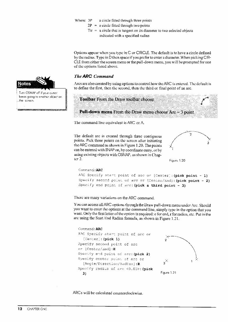
Arcs are also created by using options to control how the ARC is entered. The default isto define the first, then the second, then the third or final point of an arc.
The command line equivalent is ARC or A.
The default arc is created through three contiguouspoints. Pick three points on the screen after initiatingthe ARC command as shown in Figure 1.20. The pointscan be entered with SNAP on, by coordinate entry, or byusing existing objects with OSNAP, as shown in Chapter 2. Figure 1.20
Command:ARC
ARC Specify start point of arc or [Center]: (pick point - 1)
Specify second point of arc or [Center/End]: (pick point - 2)Specify end point of arc: (pick a third point - 3)
There are many variations on the ARC command.
You can access all ARC options through the Draw pull-down menu under Arc. Shouldyou want to enter the options at the command line, simply type in the option that youwant. Only the first letter ofthe option is required: e for end, r for radius, etc. Put in thearc using the Start End Radius fonnula, as shown in Figure 1.21.
12 CHAPTER ONE
Command:ARC
ARC Specify start point of arc or
[Center] : (pick 1)
Specify second point of arcor [Center/End]:ESpecify end point of arc: (pick 2)
Specify center point of arc or
[Angle/Direction/Radius] :R
Specify radius of arc <0.00>: (pick
3)
ARCs will be calculated counterclockwise.
Figure 1.21

View Commands
The FILLET Command
The FILLET command provides an easy way to place an arc between two existing objects, usually lines. FILLET can also be used with radius 0 to clean up comers and connect lines to an apex.
::,--
rn
~f,f::~~~ ...""" ...".."..
The command line equivalent is FILLET or F.
- -':*- - --
1
~2:
j
Figure 1.22
Command: FILLET
Current settings: Mode = Trim,Radius = <5.0000>
Select first object or
[Undo/Polyline/Radius/Trim/Multiple] : (pick 1)Select second object: (pick 2)
In Figure 1.22 the default radius of5 was used. To change the radius choose the optionR. Always press the enter key -l after letter options. In the example below the option Rto change the radius, has been used to create a FILLET with the new radius value of 12.Note that Rmust be followed by a space. R indicates that you would like to enter a newradius value, the actual number is entered on the next line.
Cornmand:FILLET
Current settings: Mode = Trim,Radius = <5.0000>
Select first object or
[Undo/Polyline/Radius/Trirn/MultipleJ :~
Specify fillet radius:12Select first object or
[Undo/Polyline/Radius/Trim/MultipleJ : (pick 1)Select second object: (pick 2)
The View menu and toolbar offer commands which will change the display of themodel or drawing relative to the screen. Commands from the View menu will notchange the coordinates or position of the model or the database. They only change theway you look at it. The following commands appear in the View menu:
ZOOMPAN
REDRAWREGEN
magnifies a section of the screenmoves the model across the screen without changing themagnification factor (zoom)updates the view and erase marksrecomputes the file
Ifyour scroll bars are not displayed, go to the Tools pull-down menu and choose Options, and then the Display tab.
Introductory Geometry and Setting Up 13

The ZOOM Command
ZOOM is accessed by typing it on the command line, using the slider bars on the topand bottom of the screen, or using the pull-down menus or the standard toolbar. Forthe ZOOM options on the toolbar, hold the Zoom Out button down and the options willbe shown.
ZOOM is a transparent command which means it can be used with the icons belowwithin a command string.
The command line equivalent is ZOOM or just Z.
Command:ZOOM (or Z)
Specify corner of window, enter a scale factor (nX or nXP) , or[All/Center/Dynamic/Extents/Previous/Scale/Window/Object]<re
al time>:
The options for the Zoom command are:
All (A)
Center (C)
Dynamic (D) =
Extents (E)
Previous (P)Realtime
Window(W)
Scale nXScale nXP
expands or shrinks the lllodel or drawing to fit onto thescreen relative to your limitscenters the model on the screen; you mustenter a
magnification factor or "height"creates a dynamic display of the item for zooming
expands or shrinks the model or drawing to fit all of theobjects on screenreturns you to the Previous zoom factorzooms interactively to a logical extent. Activate with eitherthe button or a right-clickdescribes by two diagonal points a rectangle around the
area you want to viewspecifies a percentage of the existing sizespecifies a size relative to paper space
Many mice have a roller ball that acts as a ZOOM function. Roll the roller ball tochange the Zoom factor, or press down on it and move it across the screen to PAN. InRelease 2008 the ZOOM function on the roller ball sometimes malfunctions. UseZOOM All or ZOOM Extents to center your drawing on the screen.
Zoomed in
Figure 1.23
Original Zoomed out
14 CHAPTER ONE
In Figure 1.23 the object is centered on the screen using ZOOM ALL. Ifyour object getslost use ZOOM ALL to get it back on screen.

ZOOM Window
\!IiI
II
I
Figure 1.24
Comrnand:ZOOM (or Z)Specify corner of window, enter a scale factor (nX or nXP),
or [All/Center/Dynamic/Extents/Previous/Scale
/Window]<real time>:W
Specify first corner: (pick 1)Specify opposite corner: (pick 2)
ZOOM Extents
Figure 1.25
Command:Z
Specify corner of window, enter a scale factor (nX or nXP),
or [All/Center/Dynamic/Extents/Previous/Scale
/WindowJ<real time>:E
ZOOM with scale
Figure 1.26
Scale works like this: .8x will display an image at 80% of its current size; .5x will display an image at half the current size; and 2x will display an image twice the size ofthecurrent size.
Comrnand:ZSpecify corner of window, enter a scale factor (nX or nXP),
or [All/Center/Dynamic/Extents/Previous/Scale/Window]<real time>: .5x
Introductory Geometry and Setting Up 15

ZOOM All is yourfriend. If you loseall your objects, just ZOOMAII andthey will magically reappear.
Zooming In and Out
Zooming in doubles the size of the image, zooming out reduces the image by half.
Zoom Limits shows the screen limits. Ifyou have a center rolling wheel on your mouseyou can zoom in and out quickly, but ZOOM Window is usually more efficient.
ZOOMAJI
To display the entire drawing, use ZOOM All or ZOOM Extents.
Cornmand:ZOOMSpecify corner of window, enter a scale factor (nX or nXP),
or [All/Center!Dynamic/Extents/Previous/Scale!Window]<real
time>:A
The PAN Command
To move the view across the screen without changing the display size, use PAN asshown in Figure 1.27.
X 1
Figure 1.27
X 2
16 CHAPTER ONE
Command:PAN (or P)
Press ESC or ENTER to exit, if you have a roller on your
mouse, just press down and move it to PAN.
PAN and ZOOM
The PAN command moves the model across the screen, while ZOOM magnifies themodel within the screen. The database, i.e. the 0,0,0 point and associated coordinatepoints, remain the same.
The roller ball can be very useful in placing the image on the screen, but be sure to experiment with ZOOM All and ZOOM with a window (pick two points around what youwant to look at) and you may find these useful as well.
Windows Scroll Bars
Windows scrollbars can be used instead of the PAN command. To move the drawingup, pick the down arrow on the vertical scroll bar. To move the drawing to the left, pickthe right arrow on the scroll bar. Ifyou have a smaller screen, you may want to have thescroll bars not displayed. To remove them from the screen, choose the Tools menu,then Options, then Display. Remove the check mark from the box beside DisplayScroll Bars.
REGEN
While your data are always available, to save memory, they are not always completely
generated. The REGEN command (RE) is used to update arc and circle displays to makethe objects look more rounded. If your arcs are choppy or squared, use REGEN toupdate the screen to the current magnification factor and display a superior image.

Figure 1.28
Alternate Units
Remember that UNITS onlychanges the readout. To be
-accurate, use SNAP or coordinates-to place points.
It is important to have the correct nomenclature when entering geometry.
ArchitecturalCommand: LINE
Specify first point:2,3 (X 2 inches, Y 3 inches)Specify next point or (Undo :@4',0 (4 feet in X, none in Y)
Specify next point or (Undo) :@O,2'3 (none in X, 2 feet 3
inches in Y)
Specify next point or (Undo) :@3'4-1/2",O (3 feet 4 1/2
inches in X, none in Y)
~"'ractional
With fractional units the information is entered as a fraction with a slash (I). For mixednumbers a hyphen (-) must be added with the slash (I).
Command:LINE
Specify first point:1-1/2,2-3/4
Specify next point or (Undo) :@3/4,O
Surveying
The surveyor's compass rose is much the same as a ship's compass. It is divided intofour parts with the top being north, the left being west, etc. Angles are expressed in 90degree quadrants.
The quadrant between north and east, for example, starts at 0 degrees due east and progresses 90 degrees to due north. To express 25 decimal degrees using AutoCAD's default origin for angles, enter N25dO/Q"E. You may omit null minutes and/or secondsand enter N25dE.
When entering this measurement, do not use spaces.
Command:L
Specify first point:O,O
Specify next point or (Undo) :@38<S44d14'9"W
Measuring Angles
AutoCAD's default setting for angles is zero degrees at due east. You may change this zerodegree reference point to due north, due west, ordue south. These are the only four positions offered by the UNITS command. To orient the zeroreference at an angle other than those specified,you can change the user coordinate system(UeS) as explained later.
Untranslated Angles: lfthe UNITS command isset to a nondecimal angular mode (e.g. radians),an angle can be preceded by a 'less than'symbol< to enter a measurement counterclockwisefrom 3 o'clock.
If an angle measurement direction or origin hasbeen changed, enter < before an angle measurement to have the angle measured counterclockwise from 3 o'clock.
Change the precision ofyour angle readouts to show up on the POLAR and DYNamicreadouts, as shown in Figure 1.28.
Introductory Geometry and Setting Up 17

Step]
Open AutoCAD. IfAutoCAD is already running, pick File fromthe pull-down Inenu (top left), then New to start a new file in metric by using acadiso.dwt.
Use the Tools pull-down menu and Drafting Settings or the
following typed commands to set your LIMITS and SNAP. Then
pick ZOOM All from the View pull-down menu, use the iconshown, or type it in.
The bold type in the following c01TIlnands is the user response or
what you type in. Use the Enter Key .J to enter each command orvalue.
Command:LIMITS.J
Tools Dra'H Dimen
layer...
LSl.yer tools
!:.olor ...
Liuetype...
Line~ejght..•
5cal!t,List ...
/;? Text ~tyle".
~ QimensKln style...
~. T~Style ...
eoint Style...
MuJtmne Style, ..
~njts ...
dl' Thickness
.4t".!IM~Rename. "
Step 2
/
Step 3
Reset model space limits
Specify lower left corner or [ON/OFFJ<O.OOOO,O.OOOO>:-S,-5.J
Specify upper right corner<12.0000,9.0000>:100,60.J
Command: (from the View pull-down menu, pick ZOOM All)
Command: SNAPSpecify snap spacing (X) or
[ON/OFF/Aspect/Rotate/Style/Type]<1.0000>:5
Start by drawing a series of lines using absolute coordinates. Turn DYNamic off.
Command:L.J
Specify start point:O,O~
Specify next point or [undo] :75,0....1
Specify next point or [undo] :75,50.J
Specify next point or [undo] :0,50....1
Specify next point or [undo] :c.J
Command: ZOOM
Specify corner of Scale/Window] <real time>:Extents
Command: ZOOMSpecify corner of Scale/Window]<real time>:.8x
Make sure that ORTHO, and OTRACK are off, but that POLAR and SNAP are on.
+
When entering coordinates, make
sure your DYN button is turnedoff! Its on the bottom line of your
screen
Then draw in the next lines using POLAR tocomplete an inside rectangle. Move yourcursor directly up, down, right or left from thelast entered point.
II
/
18 CHAPTER ONE
Command:L.J
Specify start point:5,5.J
Specify next point or
[undo]: (move your cursor to the right)65.J
Specify next point or [undo]: (move your cursor up)40.J
Specify next point or [undo]: {move your cursor left)65.J
Specify next point or [undo] :c.J

Step 4
Use the enter key .J at the end of
each typed entry to send theinformation to the computer or to
exit you from the LINE command.
Enter a line at an angle from 10,10.
COffi...rnand:LSpecify start point:10,10Specify next point or [undo] :@20<30Specify next point or [undo]:~
Then another from the opposite direction.
Command:L
Specify start point:50,10Specify next point or [undo] :@20<150Specify Dext point or [undo]:~
StepS Notice that the ends of the diagonal lines are not
near the snap points. ZOOM into the end ofthe lineon the left to start adding circles. Use either the
icon or type the letter Z.
Command:Z
Specify corner of window, enter a
scale factor (nX or nXP), or
[All/Center/Dynamic!Extents/Previo
us/Scale/Window]<real time>: (pick 1, pick 2)
Make sure SNAP is on too. Use the CIRCLE command with DYNamic.
Command:CIRCLE
Specify center point for circle
or [3P/2P/Ttr (tan tan
radius)]: (pick the snap point
to the right of the end of the
diagonal line)Specify radius of circle or
[Diameter]<1.OOOO>:2.7
The radius of the circle will snapto the closest snap point. Yourradius entry at the command linewill override this. When asked Bfor the radius, use .J to acceptthe default.
Command: CIRCLE
Specify center point for circle or [3P!2P!Ttr (tan tanradius)]: (pick the snap point shown)
Specify radius of circle or [Diameter]<2.7000>:~
Introductory Geometry and Setting Up 19

Step 6
Step 7
Now use ZOOM All to place your total image within your screen again.
Then use CIRCLE with the Ttr option to add a circle in the center.
Command:CIRCLE
Specify center point for circle or [3P/2P/Ttr (tan tan
radius)] :Ttr
Specify point on object for first tangent of circle: (pick
the first circle)
Specify point on object for first tangent of circle: (pickthe other circle)
Specify radius of circle <2.7000>:10
Finally add some FILLETs to the inside rectangle.
r----~--------------------: 2
tlIIIiIIIIII
20 CHAPTER ONE
~ Command: FILLET
Current settings: Mode = Trim,Radius = <5.0000>
Select first object or
[Undo/Polyline/Radius/Trim/MultipleJ :r
Specify fillet radius:l0
Select first object or [Undo/ Multiple]: (pick 1)
Select first object or [Undo/ Multiple]: (pick 2)
Continue to fillet the edge until your drawing looks like the one on the right above.

In this tutorial we will create a drawing in imperial measurements without using LIMITSor SNAP. Make sure your status bar looks like this: only MODEL and POLAR on:
Step] LIMITS, GRID and SNAP are very useful for placing items that are rectilinear with regular integers. For many applications, they are simply not needed. Here is how to getstarted without them.
First open a new file and make sure that the units are imperiaL Pick either File, thenNew, or pick the icon from the Standard toolbarwhich should be on the top left ofyourscreen.
Command:NEW
Then choose acad.dwt from the list of templateoptions.
Another way to get started is to use STARTUP.
"eipTW"e~e$ ... ---~.~~-~faI~etsetslIacad·~NamedPlotStYle$.dwt
lIaC~i£9'AtlIIacgolS0 ..NamedPiat 5t~S.dwtIIJqc&iiso·d~
IIIANSIA (oortrait:J·"€oIor DeOe...
Step 2
Step 3
Command: STARTUP
Enter new value for
startup <0>:1
Command:NEW
(Choose imperial)
Now set your UNITS to architectural.
Command:UNITS
Set your units to architectural.
Choose the 11'" under Precision.There is no need to change theAngle readout.
Choose OK.
Now draw a CIRCLE, then useZOOM to place it on the page.
Command:CIRCLE
Specify center point for circle or [3P/2P/Ttr (tan tan
radius)] :0,0
Specify Radius of circle or [Diameter] :4'
Don't forget the foot symool. AutoCAD defaults to inches, so if you only enter 4 asyour value it will be accepted as four inches not four feet.
Introductory Geometry and Setting Up 21

Step 4 You will not be able to see the object on screen, souse ZOOM to place it.
Use the roller on your mouse, the icons, or simply Zfrom your keyboard to start the ZOOM command.
Command:Z
Specify corner of window, enter a
scale factor (nX or nXP),or
[All/Center/Dynarnic/Extents/Previous
/Scale/Window] <realtirne>:A
Comrnand:ZSpecify corner a f window, enter a
scale factor (nX or nXP), or
[All ..... ow]<real time>: .5X
This centers your circle on the screen. Let's assumethis circle is a patio table, now let's make chairs.
-i;!
StepS
Step 6
Use the LI NE command to create a small rectangular chair. Use POLAR to make thechair 24" x 18". Just move the cursor directly right, then up, and type in the value.
Conunand:LlNE
Specify first point: (pick a point to start)
Specify next point or [Undo] :24 (move the cursor right)
Specify next point or [Undo] : 18 (move the cursor up)
Specify next point or [Undo] :24 (move the cursor left)
Specify next point or (Undo) : c
Now use CIRCLE and ARC to create another type of chair.
a
Comrnand:CIRCLE
Specify center point for circle or [3P/2P/Ttr (tan tan
radius) ] : (pick 1)Specify radius of circle or [Diameter] <1'-0">: (pick 2)
Command:ARC
ARC Specify start point of arc or
[Center] : (pick 3)Specify second point of arc or
[Center/End] : (pick 4)Specify end point of arc: (p~ck 5)
Command: (from the View pull-down
menu, pick ZOOM All)
22 CHAPTER ONE
Step 7 The only way to make progress is to practice. Use ZOOM to zoom in and out, creatingmore chairs.

Exercise 1 Units Practice 1Open a NEW file and set the UNITS accordingly.PAN the origin (0,0) onto your screen and draw in the first line starting at 0,0.Use ZOOM All or your roller boll to adjust the size of your image.
1--:---- ----~--~9~~~_11_i================-2-~-=1---J
-l4 3 11
4 4
I
34
34
--- - ----- - ------
Rl
FRACTIONAL
8'
2,50
~2'OI0---1~~O,80 ~~
r---I---f--+ 2,83
-~~1,20 ~
90"
~L 1,00 135' 2,12
I I~~L50
3,00---j
DECIMAL
"-In
I
(\J]
90"
~ ARCHITECTURAL
-- -~----- ,.------.
ENGINEERING
1250E+001
12,60l+00 f3.04E +00
--....--117"'(jI---l.20E+00~
SCIENTIFIC
1l' -6,0 11
~
01'-6.0 11
1'-3,0", I
f.---~- 5'-0.1' ------~
I
3 ,_ 3,0/' --.--f---f---11'-60'
Introductory Geometry and Setting Up 23

Exercise 1 Units Practice 2Open a file in imperial units - acad.dwt - and set your UNITS.Use PAN to move the object onto your screen and start drawing from 0,0.
'"(\JI~
20/-4 If
4'-6/1 -I
3 1
ARCHITECTURAL
24 CHAPTER ONE
SURVEYORS

Exercise 1 PracticeLIMITS may be used to get started, or put in the first line and ZOOM ALL.GRID and SNAP make these much easier. Don1t forget POLAR.These objects are drawn individually as practice. They are not scaled to the page.
L50
U~ ~,25
1---5,75----l
IblQ
3.50 I~5D 2'10
-'---'--._;:======-""'11--_---'~3,00-1 I
1----5.50---1
r-- 2.50T 2.00-1c-5.501~
t.5,
le
Introductory Geometry and Setting Up 25

Exercise 1 ArchitecturalOpen an imperial file - acad.dwt - and draw the objects as shown.Do not attempt to dimension the drawing.
I Command:ONITS, Architectural, Precision 0'-0"Command: LIMITSReset model space limitsSpecify lower left corner or [ON/OFF]<O,O>: -2' ,-2'Specify upper right corner<12,9>:25' ,20'Command: SNAPSpecify snap spacing (X) or [ON/OFF/Aspect/Rotate/Style/Type]<l>: 3Command: GRIDSpecify grid spacing or [ON/OFF!Snap/Aspect] <1>: 6
15'
~
I~tT
Rl~
~,I..q-
'"
I
2' fl ~
[I,QI
8
)Y (ryl ~I
80In
~ ~.t ] f[10' 8' 10'
083' 2'-6'" 2'-6"
,2'-6 6 ) 2' 2'-6'
I T I I r
eeo[
-=L11. 1'-6' "I g]II 2' ·1
~~1'-8"
I
1~ 4'"
I--..-:-
~
8
Kitchen Layout
26 CHAPTER ONE

Exercise 1 MechanicalOpen a NEW file in metric, acadiso.dwt, and draw the object below.The GRID and SNAP will help you get started.Some people find LIMITS handy.Draw the LINEs first, then add the CIRCLEs, ARCs, and FILLETs.
Command: UNITS, Decimal, Precision 0Command: LIMITSReset model space limitsSpecify lower left corner or [ON/OFFJ<O,O>:-lO,-40Specify upper right corner<12,9>:220,110Command: SNAPSpecify snap spacing (X) or [ON/OFF/Aspect/Rotate!Style!Type]<lO>:5Command: GRIDSpecify grid spacing or [ON/OFF!Snap!Aspect]<10>:lOCommand: (from the View Pull Down menu, pick ZOOM ~l)
R25¢30
R35
210
70 30 70R15 R15
10
I fl 75
100 20
R20
R6
Template
Introductory Geometry and Setting Up 27

Exercise 1 WoodworkStart a NEW file in metric - acadiso.dwt - and set it up as shown.Either use LIMITS as shown below, or put in a line from 0,0 to 580,0 and ZOOM ALL.
Command: UNITS, Decimal, Precision 0Command: LIMITSReset model space limitsSpecify lower left corner or [ON/OFF]<O,O>:-lO,-lOSpecify upper right corner<550,340>:1000,800Command: SNAPSpecify snap spacing (X) or [ON/OFF/Aspect/Rotate/Style/Type] <10>: 5Command: GRIDSpecify grid spacing or [ON/OFF/Snap/Aspect] <10>: 10Command: (from the View Pull Down menu, pick ZOOM All)
I
270_---1 r--
305
35
580
l J t 0f'...
l J0f'...
l J af"'--.
l J af'...
l0CD
l+-.;;t a0J 0J
R12 i.--i
96 f InLn.--i
T-- I-- 20 Ln
(Y)
Paper Cabinet
28 CHAPTER ONE

Help Files, OSNAP, OTRACK,BREAK, TRIM, and ERASE
Once you have learnedhow to sign on to the system and have located all the menus, youcan learn the system from on-screen documentation.The Help files have two mainfunctions.
The first function serves as an index ofcommands. When looking for a command thatwill change the magnification of the data on the screen, you may be able to spot it byusing the following (Note: There is no ~Ask Me' in Release 2007 or 2008).
displayingspacing
setting"Is. snap grid spacing
grid View window in dbConnectt elementsgrid [dr':~Wlrlg
Ifyou have just opened a new file in AutoCAD, you can get to the Help files simply bypressing the space bar before entering a command.
Use the X at the top right of the dialog box to remove the box from your screen.
The Help index gives you a listing ofthe various commands which are available on thesystem. Once you have found the correct command, you can retrieve informationabout how it works.
AutoCAD responds to any command with a series ofprompts. The Help files explainthose prompts.
On any version of AutoCAD, the Help files explain the syntax or command line sequence, and the prompts and options of each command.
Help Files, OSNAP, OTRACK, BREAK, TRIM, and ERASE 29

UnderstandingCommand
Strings
Creates a circle
~ [k<l;W menu: Circle
I!!Command line: circle
Command strings are generally very similar in construction. Once you understandhow they work, your AutoCAD skills should improve very quickly.
Option and Default Brackets
The AutoCAD commands are set up so that you can understand what the options areand accept the defaults within the commands. Once you understand how the commands are set up, it should be easier to figure out how to use theln. Remember you arein control.
Defaults
The information offered in angle brackets, < >, is the default. This is what the command will do if you do not specify something else.
Specify center point for circle or [3P Hhree PQlnts)i 2P (Two Points)1 rtr (tan tanradiusl]: Specify a point Of enter an option
In the case ofthe CIRCLE command, the previous radius is used by default ifno other isspecified. The square brackets offer you construction and diameter options.
Ifyou have asked AutoCAD to construct a circle for you, you will then be promptedfor the information needed to construct that circle.
Command:CIRCLESpecify center point for circle or [3P/2P/Ttr (tan Lan
radius) ]: (pick a point)
Specify radius of circle or [Diameter] <5.00>:
The first line says that by default you start the circle by indicating the center point.
2
Center/Radius
Figure 2.1
22 Point
1
o2
3 Point
Then you can specify the radius or, with the use of' D' to indicate diameter, you can indicate a diameter.
If you would like to specify another means by which you would like the circle constructed, choose one of the three options within the square brackets.
Figure 2.1 illustrates three different ways that AutoCAD can construct a circle withoutreference to any other objects. The first circle on the left is the default. 2 Point and 3Point are the other two circle types.
The AutoCAD prompts change according to the options you choose. Most options require a numeric value. For example, to change the diameter, type in d for diameter,then type in the diameter that you need, 1.5,2.75, etc. You can also choose the value onscreen by picking a point.
30 CHAPTER TWO

Option Brackets
The square brackets offer the various options available with each command. In theCIRCLE command, many ofthe options are shown in the first line; the Diameter optionis shown in the second line.
Command:CIRCLE
Specify center point for circle or [3P/2P/Ttr (tan tan
radius) ] : (pick a point)Specify radius of circle or [Diameter] <5.00>:
With the ARC command, some options are shown in the first prompt, but others showup with each option chosen. There are many ways of calculating arcs, and these arefound in the Draw pull-down menu and illustrated in the Help files, but you generallyonly use one or two.
In Figure 2.2, three different arcs are generated. The first is calculated through threepoints. The second is calculated through the start, end and radius. To enter this, type inC to place the center of the arc or E to place the end instead of the default.
2
3
X3
2
Xl
J2
Figure 2.2
Three Point Start End Radius Center Start Angle
( 3 e.oints
r: ;2.tart, Center! End
tN. Start, CenterJAngle
t? Stgrt, Center) Length
r;; Start) End) Angle
r Start, End) Q,irection
f1 Start) End! 8,.adius
r: ~.enter, Start, End
tN. C§.nter, Start, Angle
J7. Center, Start, b.ength
r; CQntinue
Command:ARC
ARC Specify start point of arc or [Center]: (pick 1)
Specify second point of arc or Center/End]: (pick 2)
Specify end point of arc: (pick 3)
The third is calculated through the center point, then the start point, which will give theradius, and then the angle through which it is drawn, in this case 135 degrees.
Command:ARC
arc Specify start point of arc or [Center]: c
Specify center point of arc: (pick 1)
Specify start point of arc: (pick 2)
Specify end point of arc or [Angle/chord Length] :_a
Specify included angle:135
Picking the arc from the Draw pull-down menu will bring up the list ofarcs shown onthe left. Ifyou pick an arc from this Inenu, you will be prompted for each component ofthe arc in tum.
In some cases you are prompted to pick a point through which the arc can be generated,such as the start, end or center of the arc.
In other cases you are prompted for a value. In the example above, 135, the angle ofthearc, is a value. When specifying an option such as a diameter or angle, you first choosethe option and use .J to have AutoCAD accept this option. You will then be promptedfor the required value. Values can be entered on screen with a 'pick' as well as by entering the numeric value at the command line.
Help Files, OSNAP, OTRACK, BREAK, TRIM, and ERASE 31

Obiect SNAPs There are three ways to enter points:
PICKING Pick on screen, using SNAP to be accurate. (Chapter 1)
COORDINATE ENTRY You can enter absolute, relative, or polar coordinates in anyorder.
ENTITY SELECTION, OBJECT SNAP, OR OSNAP This allows you to use existing obj ects to create your file. Accessing points on existing objects is called using OSNAPs.
,~
[~Dpoitlt
WIDpoint
I~T....S4PC tion
Figure 2.3
, ,, ,, ,.... ,.... ,, ,, ,
, off
SettifltJS...OSNAP: Object SNAP
Object Snaps allow you to specify precise points on objects in order to create or editobjects. AutoCAD has 16 Object Snap modes that allow you to specify precise pointson objects. The capitalized letters are those needed when typing in the option.
32 CHAPTER TWO
APPint
CENter
ENDpoint
EXTention
FROM
INSertion
INTersection
MIDpoint
NEARest
NODE
NONE
PARallel
PERpendicular
QUADrant
Quick
TANgent
snaps to a real or imaginary intersection of two ohj ects(apparent ntersection)
snaps to the center of an arc or circle
snaps to the closest end of any object
snaps to a point along the extension of a line or arc
establishes a temporary reference point from the parameters ofan existing objects
snaps to the insertion point of a block
snaps to the intersection of two items
snaps to the midpoint of a selected item
snaps to a point on an object nearest to the digitized point
snaps to a point created by POINT, DIVIDE, or MEASURE
turns the Object Snap mode off
draws a line parallel to an existing line
snaps to a 90 degree angle to an existing line
snaps to the 0, 90, 180, or 270 degree point on an arc, circh:, orellipse
snaps to the first snap point found
snaps to the tangent of an arc or circle

Accessing OSNAPs
OSNAPs can be accessed in one of four ways:
1. There may be a designated button on your mouse. Often ifyou hold the Shift button on
your keyboard down and use the right-click button on your mouse, an OSNAP menuwill appear where your cursor is.
2. Type in the first few letters of the OSNAP mode.
3. Choose Object Snap from the Drafting Settings under the Tools menu.
4. Use the OSNAP buttons.
The hyphen (-) in the architectural point entry is not the sameas in the architectural readouton the status line.
Using OSNAPs
Figure 2.4 illustrates the use of some OSNAPs withinthe command line. When entering the OSNAP, type inthe first three or four letters, or Shift right-click and access the asNAP list.
First, draw three circles as shown in Figure 2.5. Thesize doesn't matter.
Command: CIRCLE
Specify center point for circle or
[3P/2P/Ttr (tan tan radius)] :0,0
Specify radius of circle or
[Diameter] :3
Cornrnand:C
Specify center point for circle or
[3P/2P/Ttr (tan tan radius)) :9,4
Specify radius of circle or
[Diameter] :6
Cornmand:C
Specify center point for circle or
[3P/2P/Ttr (tan tan radius)) :18,0
Specify Radius of Circle or
[Diameter] :3
Figure 2.4
000Figure 2.5
Now create lines tangent to the arcs. The TANgent object snap creates a tangent to theidentified object from the last object to a circle or arc. For TANgent type in TAN,
Command:LINE
Specify first point:TANgent to (pick 1)
Specify next point or [Undo]:
TANgent to (pick 2)Specify next point or [Undo]:~
Comrnand:LlNE
Specify first point:TANgent to (pick 3)Specify next point or [Undo]:
TANgent to (pick 4)Specify next point or [Undo]:~
Figure 2.6
AutoCAD will calculate the tangent for you; just pick which side ofthe object the tangent should be on, as shown in Figure 2.6. You need to secure a tangent connection forboth sides ofthe line. To set the OSNAP to TANgent, right-click the OSNAP button, settangent, and make sure the OSNAP button is on.
Help Files, OSNAP, OTRACK, BREAK, TRIM, and ERASE 33

Now use the QUADrant option to attach the other two lines as shown in Figure 2.7.QUADrant takes the top, the bottom, or the far right or left ofa specified circle or arc.Type in QUAD for QUADrant.
Command:LINESpecify first point:TANgent to (pick 1)
Specify next point or [Undo]:QUADrant of (pick 2)
Specify next point or [Undo]:~
Command: LINESpecify first point:
QUADrant of (pick 3)Specify next point or [Undo):
TANgent to (pick 4)
Specify next point or [Undo]:~
Now use CENter to place a circle concentric with thefirst as shown in Figure 2.8, CENter takes the centerofan arc or circle. Only items with a defined radius canhave a center point.
Command:CIRCLE
Specify center point for circle or[3P/2P/Ttr (tan tan radius)] :CENter
of (pick 5)
Specify Radius of Circle or
[Diameter] :3
Now use the TRIM command (see page 72) to trim offthe extra portions ofthe circle, as shown in Figure 2.9.The TRIM command will erase a portion of an objectbetween two edges identified by intersections withother objects.
Command: TRIM
Current settings: Projection=UCS
Figure 2.7
Figure 2.8
Figure 2.9
Figure 2.10
34 CHAPTER TWO
Edge=None
Select cutting edges ...
Select objects: (pick 1)
Select objects: (pick 2)
Select objects: (pick 3)
Select objects: (pick 4)Select objects:~ (enter - no more cutting edges are needed)
<Select object to trim> orshift-select to extend [Fence/
Project/Edge/eRase/Undo] : (pick 5,6)
Your final image should look like Figure 2.10.
The TRIM command will not work unless the TANgentoption has been properly used. If the lines don't inter-sect the circles, they will not be trilnmed.
This example has shown how to use OSNAPs within acommand string. You can type in the first few lettersofthe OSNAP option, use Shift right-click to get a list on screen or get the OSNAP options from a pull-down menu or floating toolbar.You can also set up your OSNAP sothat the options automatically appear.

OTRACK
Running OSNAPs
You can set up OSNAP so that the options are automatically turned on.
ti) To llack hom an Omap point pau$/< O\Ief tho! POInI \'\/h,e in ~
"Vif cOl!lLl\l'lF'Jd A trocl<ing "actO! "PpedlS wher1 you move I"" CVIro<To:lop lr!lCkin;l, p!lll'$il <We[!he point_.
In this example, ENDpoint, MIDpoint and CENter are turned on. These are the usualchoices. We have seen how CENter works. ENDpoint takes the closest end point. Alllines are made up of two end points. MIDpoint takes the middle point of an object.These options are illustrated in the Tutorials at the end of this chapter.
The OTRACK cOlnmand is useful for lining objects up relative to other objects.
Figure 2.11
OTRACK is a toggle switch found on the function bar at the bottom ofyour screen, asshown in Figure 2.11.
Using OTRACK
With OSNAP on, OTRACK will track the ENDpoint, MIDpoint or CENter ofan objectand line up a new point exactly across from or beneath it. OTRACK works vertically orhorizontally. First draw in the lines as shown in Figure 2.12 (A).
_r· ..·TA
Figure 2,12
Command: LINE
Specify first point: (pick 1)
Specify next point or [Undo]: (pick 2)
Specify next point or [Undo]:~
Make a line from the top right comer, lining it up with point 1 as shown on Figure 2.12(A). Then draw your cursor across the endpoint ofpoint 1 without picking it. Move itup level to your beginning point. When you have found the position that lines up, pickthat point. AutoCAD will create a line using the X value ofpoint 1 and the Yvalue ofyour start point in Figure 2.12 B. It's a lot easier to do than to explain.
Help Files, OSNAP, OTRACK, BREAK, TRIM, and ERASE 35

BREAK, TRIM,and ERASE
The BREAK command removes a portion of a single object between two specifiedpoints. The TRIM command trims a series ofobjects according to a cutting line or cutting lines. The ERASE command removes an entire object from the file.
The BREAK Command
BREAK is found under the Modify menu in both the Toolbar and the pull-down menu.The obj ect will be broken from the point chosen on the object or by another pointspecified after entering F to indicate a different first break point. In Figure 2.13, theline indicated in the first pick is cut from the center of the circle to the intersection ofthe line and the circle.
ea2
Figure 2.13
Comrnand:BREAK
Select object: (pick 1)
Enter second point (or F for first point) :F
Enter first point:CENter of (pick 2)
Enter second point:INTersection of (pick 3)
The TRIM Command
TRIM is found under the Modify menu in both the Toolbar and the pull-down menu.Pick either one or a series of cutting lines, and then choose the objects to trim.
In Figure 2.14, the lines are all trimmed to the circle; the circle was indicated first.
Figure 2.14
Command:TRIM (or TR)
Current settings: Projection=UCS Edge=None
Select cutting edges ...
Select objects: (pick 1)
Select objects:~ (no more cutting edges are needed)
<Select object to trim> or shift-select to extend [Fence/
Project/Edge/eRase/Undo] : (pick 2,3,4,5,6)
The ERASE Command
Figure 2.15
@@@Command:ERASE (or E)
Select objects: (pick 1)
Select objects: ~
ERASE is found under the Modify menu in both the Toolbar and the pull-down menu.You can also simply type in E. In Fig-ure 2.15 the non-concentric circle iserased.
36 CHAPTER TWO

GRIPS GRIPS are used to identify a selection set or group of objects prior to a Modify command such as ERASE or MOVE (see Chapter 3). If you select a group of objects, bluegrips will appear. This means you have selected the objects for editing. Now you canuse ERASE to erase them.
Command: (pick 1) other corner
(pick 2)Command:ERASE Erase 5 found
In Figure 2.16, five objects were selected by a crossingwindow, going from right to left. The objects were thenerased. To undo an erase, use Undo or U.
Command:U Undo Erase
Figure 2.16
Use the Escape key on the top left ofyour keyboard to clear the grips ifyou have chosen them incorrectly.
ERASE can also be used with the Crossing and the Window options to erase a group ofobjects as seen in Figure 2.17.
ERASE withWindow and
Crossing
oFigure 2.17
WindowCol1l.t'Tland: ERASESelect objects: (pick 1, 2)
Select objects: ~
CrossingCommand:ERASESelect objects: (pick 3, 4)
Select objects: ~
UNDO andREDO
The Window selection set, as shown in picks 1 and 2, provides a blue-colored window.Any objects contained in this window will be erased. Since the diagonal line and thetop line do not lie completely within the window, they will not be erased.
The Crossing selection set, as shown in picks 3 and 4, provides a green-coloured rectangle. Any object that touches or is within this rectangle will be affected by the command. In this example, every object except the vertical line on the left will be erased.
The UNDO command will undo the previous command, regardless ofwhat it is. Ifyouerase something by mistake, trim something by mistake or enter some geometry that isnot correct, use UNDO to return to correct it. You can UNDO as many commands asyou have entered since the file was last opened.
Command:UNDO (or U)Command:REDO
REDO will bring back a command that you have taken out with UNDO.
Help Files, OSNAP, OTRACK, BREAK, TRIM, and ERASE 37

Step} Start a new file in imperial units. You aremaking a tricycle. No limits are needed, butyou need to make sure you are in imperial.Choose acad.dwt. (You make the entriesshown in BOLD).
Command: NEW
(Choose acad.dwt)
Or
Command:STARTUP
Enter new value for startup
<0>:1Command: NEW(Choose Imperial)
Command: UNITS
Set units to architectural.
[~~~:~~~=:~:~:~~~~~~~~;:~:::=:::::.:.~., .•-Id;~"'"'' ~iQPTWTemplates
\ OSheetSets!~acad -Named Plot Styles,dlNt 33 I<
!.~.dwt 331<i~ac~dISO ·Named Plot styles.dwt 25 K
: 5acadi5o,dwt 25K
!SANSI A(portrait)-Color Depe... 281<'
: [SjAN5I A (portrait) -Named Plot .. , 28 Ki BANSI A -Color Dependent Plot... 29 K
i SANSI A-Named Plot Styles.dwt 29 KI!5AN5I B -Color Dependent Plot.., 28 K
.1 [EiAN5I 6 -Named Plot Styles.dwt 29 K
; [!SANSI C -Color Dependent Plot... 29 K
I~AN51 C -Named Plot styles,dwt 291:
Li}:diliE1;c\' ~"'.~.,.~_ ...c •• ·._ •• : •. ~~~i
Step 2
38 CHAPTER TWO
Often with architectural designs the layout is set at regular intervals so LlMITS/ GRID and SNAP are an advantage. With this tricycle elevation these are not needed. Simply start with a couple ofcircles, then ZOOM Extents.
Command:CIRCLE
Specify center point for circle or [3P/2P/Ttr
(tan tan radius)] :0,0
Specify radius of circle or [Diameter] :10
Cornrnand:CIRCLESpecify center point for circle or [3P/2P/Ttr
(tan tan radius)] :0,0
Specify radius of circle or [Diameter] :12
Command: (from the View pull-down menu, pick ZOOM Extents)
Command:Z
Specify corner of window, enter a scale factor (nX or
nXP),or[All/Center/Dynamic!
Extents!Previous/Scale/WindowJ<realtime>:E
Command:Z
Specify corner of window, ..... Scale/Window] <real time>:.7X
You can also use your roller ball to ZOOM the objects into the middle ofyour screen.

Step 3 Make sure OSNAP is on, and draw an arc from the CENter ofthese two circles just upand to the right. When your cursor approaches the circle, a smaller circle should appearat the center indicating an OSNAP. If this doesn't show up, use Shift right-click for themenu, and pick kenter as shown on the left, or simply type in CEN.
Command:ARC
ARC Specify start point of arc or [Center] :CEN of (pick 1)Specify second point of arc or [Center/End]: (pick 2)
Specify end point of arc: (pick 3)
3
3
Command: ARC
ARC Specify start point of arc or
[Center] :CEN of (pick 1)
Specify second point of arc or
[Center/End] : (pick 2)
Specify end point of arc: (pick 3)
Next you want to place an arc starting from the sainecenter point, just alittle to the right ofthe first arc. OSNAP
After you have picked the first point, turn OSNAP offor you will have difficulty placing the next points. Ifthe cursor 'picks up' another line, an OSNAP is as-sumed, and the second arc will be generated along theendpoints of the existing arc.
no Qsnap Settings...
e ~ent8t
o Quadrant
() Tangent
......0 Temporary trac~point
£' EromMid Be~ween 2 Points
Poin~ Filter'S
/ t;.ndpoint
;:/ Midpoint
X Intersection
X ~parent Intersect
_ ... E)$.tension
...!.- !:erpendicular
; ParaUel
o Noqe
60 In~ert
.It Near.est
A;, tlone
You should now have two arcs and two circles.
Step 4 Place a circle with a radius of l' at the same center point.Use Zoom Window to zoom in and see it. You can eitheruse your roller ball on your mouse, the icon as shown, ortype in Z then pick two points.
Command:Z
Specify corner of window, enter a
scale ... ow]<realtime>: (pick 1)
Specify opposite
corner: (pick 2)
Now put the two circles in using the END of the two arcs.Turn your OSNAP on.
Command:CIRCLE
Specify center point for circle or
[3P/2P/Ttr (tan tan radius)] :END of(pick 1)
Specify Radius of Circle or
[Diameter] :3
Command: CIRCLE
Specify center point for circle or [3P/2P/Ttr (tan tan
radius) ] :END of (pick 1)
Specify Radius of Circle or [Diameter]:2
Help Files, OSNAP, OTRACK, BREAK, TRIM, and ERASE 39

StepS Use TRIM to remove the ends,ofthe arcs as shown.The circleis your cutting edge.
With OSNAP on, you will snap towhatever setti ngs are current.Squares and triangles will show upon your objects as you move yourcursor when OSNAP is on. Togglethem off on the status line.
Comrnand:TRIM
Current settings:
Select cutting edges ...
Select objects: (pick 1)
Select objects:.J<Select object to trim> or shift-select to extend [Fence/
Project/Edge/eRase/Undo] : (pick 2(3)
<Select object to trim> or shift-select to extend [Fence/
Project/Edge/eRase/Undo] :.J
Since you have now been using the file for at least a few minutes, you shouldsave at this point.
Step 6 Use the line command with OSNAP,OTRACK and POLAR to place therectangle at the topof the two arcs.
Comrnand:LINE
Specify first point:END of (pick 1)Specify next point or [Undo] :END of (pick 2)
Specify next point or [Undo] :4 (move your cursor up)
Specify next point or [Undo]: (move your cursor over pick 1,then back up to a horizontal, then pick the point shown)
Specify next point or [Undo]:c
/
Step 7
/
1
Now we need to draw the back wheels. Draw in aline from the bottom QUADrant of the first wheel,36 inches to the back. Make sure POLAR is on..
Command:LINE
Specify first point:QUAD of (pick
1)Specify next point or [Undo] :36
(move your cursor to the right)
Specify next point or [Undo]:.J
2
2
40 CHAPTER TWO
Command: CIRCLE
Specify center point for circle or [3P/2P/Ttr (tan tan
radius) ] :2P
Specify first end point on circle's diameter:END of (pick 1)
Enter second end point of circle's diameter:12{move your
cursor straight up)
Once the CIRCLE has been drawn in, ERASE the line.

NEAR
Command: CIRCLESpecify ... radius)] :CEN of {the
right circle}
Specify radius of circle or [Diameter]:D
Specify diameter:10
Command:ARC
ARC Specify start point of arc or [Center]:NEAR the line
Specify second point of arc or [Center/End]: (pick 2)
Specify end point of arc:NEAR the circle
Using a similar proceedure as for the front wheel, putin three more circles and two arcs. For the arcs, makethe first from the center ofthe small circle to the MIDpoint of the vertical line, and the second to a pointslightly higher using NEARest. TRIM all unwantedlines.
Step 8
Step 9 For the handle, use ARC and LINE. The ARC commandwill continue from the last entered point if you use .Jwhen prompted for the first point.
Comrnand:ARC
ARC Specify [Center]: (pick 1)
Specify second End] : (pick 2)
Specify end point of arc: (pick 3)
Command:~ (brings back ARC)
ARC Specify . of arc or [Center]:~
(continues from last point)
Specify second point of arc or [Center/End]: (pick 2)
Specify end point of arc: (pick 3)
Step 10 For the pedals, set up a GRID and SNAP, and draw themin without OSNAP. Use two points to pick the size ofyour limits.
Comrnand:LIMITS
Specify bottom left: (pick 1)
Specify upper right: (pick 2)
Command: SNAPSpecify snap spacing<>:.5
Command: GRID
Specify grid spacing<>:l
Finally use LINE and ARC to draw in a seat.
Help Files, OSNAP, OTRACK, BREAK, TRIM, and ERASE 41

In this Tutorial we will practice using OSNAP and OTRACK to draw the mechanicalpiece shown below. Make sure ORTHO, OTRACK and POLAR are all on.
o 0
Step]
,....... ....,••, ...., '""--.-..No..........'...... .. ..... ~ . .....,.""'"-.... ~
~10ij~Ji·r~PQ'LAB.]·ci·$.~~p'·.'liQiB~~~··.••••..·,~i
For many applications, particularly mechanical, LIMITS, GRID and SNAP are not needed. Another way toset up your screen is simply to choose your units, lnetric or imperial, then draw in the first object. UseZOOM to place it on the page.
Cornmand:CIRCLE
o
oo
Step 2
Specify center point for circle or [3P/2P/Ttr (tan tan
radius) J :0,0
Specify Radius of circle
or [Diameter] :100
Now ZOOM the object on screen.
Cornmand:Z
Specify corner of window, enter a scale factor (nX ornXP),or
[All!Center!Dynamic/Extents!Previous!Scale/Window]
<realtime>: A
Comrnand:Z
Specify corner of window, enter a scale factor (nX or nXP), or
[All!Center/Dynamic/Extents!Previous/Scale/Window]
<real time>:. 3X
You can also use your mouse roller ball to center the circle on the screen.
Use the POLAR option to place the lines around the outside of the circle. Move yourcursor along the direction indicated by the arrows, then type in the value.
Point entry by typing coordinates willnot work if DYNamic mode is on.Turn it off.
i
II
G Ii-~Q9~:~QQ J
i-- -------------1
i G !
i 300,->0°1
/ Command: LINE
Specify first point:-300,-300
Specify next point or [Undo] : 600 rightSpecify next point or [Undo] : 600 upSpecify next point or [Undo] : 600 leftSpecify next point or (Undo) :c
42 CHAPTER TWO

Step 3 Fillet the comers with a radius of 100.
Command: FILLET (or F)
Current settings: Mode = Trim,
Radius = <5.0000>
Select first object or[Undo/Polyline/
Radius/Trim/Multiple] :R
Specify fillet radius:l00
Select first object or
[Undo/Polyline/Radius/Trim/MultipleJ:
(pick 1)Select second object: (pick 2)
Corrunand:FILLET
Current settings: Mode = Trim,
Radius = <5.0000>
Select first object or[Undo/Polyline/
Radius/Trim/Multiple] : (pick 3)Select second object: (pick 4)
Continue until all four comers are done. By pressing thespacebar at the Command: prompt, the last entered command will be retreived. This could make your data entry alot quicker.
o
oo 0
• ----------- 2Step 4_n
If the CENter OSNAP does notcome on, right-click the OSNAPbutton, choose settings.
Place CIRCLEs in the four comers. As shown in the illustration, once the circle is identified, you can pick either the pe-rimeter or the center of the circle to place the smaller ones.
For pick 1place the cursor over the circle, then move the cursor to the center ofthe circle. The object snap picked up will be the CENter because the center mark is highlighted. The OSNAP button must be on.
Command:CIRCLE
Specify center point for circle or
[3P/2P/Ttr (tan tan radius)] : CENter of (pick 1)
Specify Radius of Circle or [Diameter] :25
Command: CIRCLE
Specify center point for circle or[3P/2P/Ttr (tan tan radius)] :CENter of (pick 2)
Specify Radius of Circle or [Diameter] :25
Step 5
If you type in CEN this will override the ENDpointOSNAP I which is the system default.
Now draw in the lines as shown in the illustration. Toplace these, use both OSNAP MIDpoint and the OTRACKofthe center ofthe circles for placelnent as described be~
low.
o 0
oo 0
Make sure that CENter, MIDpoint and ENDpoint OSNAP is set and that the OSNAPbutton is turned on.
Help Files, OSNAP, OTRACK, BREAK, TRIM, and ERASE 43

For the first point,pick the MID of theleft vertical line. (
Cornmand:LINESpecify first point:MID of (pick the vertical line)
For the next point, drag your cursor over the circle as shown. Donot pick the circle, simply drag thecursor across it. Then drag it downto line up with the horizontal. Thiswill give you a line with the Xvalue ofthe center ofthe circle andthe Yvalue of the MIDpoint of thevertical line, producing a straightline.
Draw in all four lines.In this example, the MIDpoint is taken fromthe top line and the end of the lineis lined up with the center of thecircle on the right.
Once you have done this for allfour lines, you should be familiarwith the way it works.
o 2~
oStep 6 Finally, access the ENDpoints of the small lines to
finish the drawing.
o
44 CHAPTER TWO
Command: LINE
Specify first point:END of (pick 1)
Specify next point or
[Undo] :END of (pick 2)Specify next point or [Undo] :END of (pick 3)Specify next point or [Undo] :END of (pick 4)Specify next point or [Undo] :c
o 0
When completed, your object should look like this. 0o 0

Exercises 2 PracticeDRAW all of these, just for practice.
i~O.90 ~
00.90~~
2 Holes
05.00(,14.00
4.275
1------ 8.55 --------
TeMple. te Po.ttern
,021.95
-o~qj1595
- + -I
Axle Side
-- 3/8" PL YBACK
DRECoRMED "oP - \I
I00'1f. ...... . . . . " .. ~ ... ' .. -.
cL .><: 1::><IA
~1'ill 1 x 3 PINE FRAME
\2 4 REQ'D- i--
'::><:':1 ::><
0 ~-- 1/2# PLY SID[S~
H\.1 ::><-1 1::><
~
~1 X 2 HARDwOCJD f-~RONT Pf"lNEL'JJ
C":>c:::: 1:><
1/2 Pl.._Y RllrmM\
,----;I~
~ ~'T
...-- 2 X 4 BASl --------...
4 I· 191
]2
24_.,~- .._---
CDcu
Cabinet
Help-Files, OSNAP, OTRACK, BREAK, TRIM, and ERASE 45

Exercise 2 ArchitecturalFor the Lot Plan you will need to change your UNITS to Surveyors.The Floor Plan is drawn with Architectural Units.To get the area of the lot, set your OSNAP to ENDpoint, then use the AREA command.You will be prompted for the corners of the lot. Press Enter for the area.
POOLUSE CIRCLE TTR
??o
~Z
ino
72 1 \0.75"
349 1 4.25"N84D54 11G'E
LOT PLANS SHOW THE PROPOSED STRUCTURE AND THE LOTUPON WHICH IT IS TO BE BUILT. THE LOT IS SHOWN IN
SURVEYORS I UNITS. AND OFTEN INCLUDES EXISTING WATER,
GASS AND ELECTRICAL SERVICES. THE NORTH ARROW SHOWS
THE ORIENTATION OF THE BUILDING. THE EASEMENTS AND
GRADING OF THE LOT WOULD BE NEEDED TO COMPLY WITHLOCAL BUILDING CODES IN ORDER TO GET A BUILDINGPERMIT.
IN THE NORTHERN HEMISPHERE, THE MAJORITY OF THE
WINDOWS SHOULD BE ON THE SOUTH SIDE OF THE BUILDINGTO TAKE ADVANTAGE OF PASSIVE SOLAR HEATING IN THEWINTER. DECIDUOUS TREES SHOULD BE PLACED OUTSIDETHESE WINDOWS TO SHADE THEM IN SUMMER.
LOT PLAN
46 CHAPTER TWO
r- 39 1 -4"
LOT (SURVEYORS' UNITS)

Exercise 2 MechanicalTANgent OSNAP will be important for both of these.Start with a circle at 0,0. ZOOM, then place your next circle relative to it.These objects are not drawn to scale within the page.
R1.l2
1~2,50
¢1.003 HOLES
Rl,SO
R 0
--+----1----+ .751.50
3,00 f-Escutcheon Detail
r---600-~
Escutcheon
Edges chamfered at 45°
Cir-cle Ttr
f---- 100 -----I
9'J28,QCircle 2P
Plate
R82.0
R64,O
ii
-~--t
,_--+-------+--.......-...1-I
i
R19,Q
f~ 12.0 --.T-----<-J
4 Fillets
R26,Q
R38.0
Help File, OSNAP, OTRACK, BREAK, TRIM, and ERASE 47

Exercise 2 ChallengerStart with the origin at the center of the left circle.Place the circles according to the coordinates.Fillets and lines at angles are demonstrated in Chapter 1.
U1C)
(J\
/0C)
w
\~
C)
t---"
\D
/0 /0t---"
[JJW
I------" t-'"[JJ
w~
t-'"
ru¢
~
Q\ ~
ru \D /0
IC)
/0 ruC) U1U1 /0C) C)
'-lW
C)
t::Jf'ICl
/0I------"
C) jC)
~-rC)
UlC)
'"T
t-'" C)
'" U1"- 0
ru'-J[JJ'-/
t:j/0~
rrU1.........t---"
(J\
InJ..p..
CZ'1
Iru
~
U1C)
Iru
ruC)
cZ'1
48 CHAPTER TWO

Selecting ObiectsWithin the
ModifyCommands
Object Selection andModify Commands
objects
Once objects are drawn on the screen, editing commands under the Modify menu ortoolbar are used to cut down on drawing time. When editing, OSNAP is particularlyimportant to get the exact position ofobjects when they are moved, copied, or rotated.
In virtually every editing command, you will be prompted to 'Select objects'. Thismakes sense because the editing command will change the position or the parametersof objects, and thus the system needs to know which objects you want to change. Asyou select items, they are highlighted (dotted lines).
Objects can be selected in a variety ofways. Ifyou are selecting the object after youhave invoked the command you can select the objects by:
• digitizing the desired item with the cursor pick box
• indicating a group of items with the Crossing option - type C or pick right toleft
• indicating a group of items with the Window option-type W or pick left toright
• indicating a series of items with Fence - type F
• indicating a group of items with CPolygon- type CP
• indicating a group of items with WPolygon - type WP
• indicating the last entered item using the Last option - type L
• indicating the previous selection set with Previous - type P
• indicating all objects by typing in ALL
Once you have identified your selection set or chosen the objects that are to be edited,AutoCAD will keep prompting you to select objects to be added or removed from theselection set. To continue with the Modify command after selecting objects, press.J tosignal the end of object selection.
Obiect Selection and Modify Commands 49

Figure 3.1
The object selection default is to select the items one by one, as shown in Figure 3.1.Only the two objects selected will be affected by the editing corrunand.
Select objects: (pick 1, 2)
Selection WindowsYou can also select objects by drawing a rectangular window or crossing area in response to the Select objects: prompts as shown in Figure 3.2.
aFigure 3.2
4
b
Window is BlueCommand: ERASE
Select objects: (pick 1)
Specify opposite corner: (pick 2)
Crossing is GreenCommand: ERASE
Select objects: (pick 3)
Other corner: (pick 4)
Picking from the left to the right,as in Figure 3.2 a will create a Window (blue after Release 2007) that will highlight for modification all objects contained within it. Pickingfrom right to left, as in Figure 3.2b will identify for modification all objects that touchthe crossing line (green after Release 2007).
Figure 3.3a b
SO CHAPTER THREE
Selection Polygons
To select objects in an irregularly shaped area, use Window Polygon or Crossing Polygon. The Wpolygon (Figure 3.3a) and Cpolygon (Figure 3.3b), work like Window andCrossing windows. Type in WP or CP after the Select objects: prompt.

ModifyCommands
Since COpy assumes multiplecopies, .J must be used to exitfrom the command.
Selection Lines or Fence
With the Fence option, the objects touching the fence line will be picked up, as in Figure 3.4. Fence is useful for non-adjacent objects.
((@~';•<V>
------ --_._~---
Figure 3.4
Select objects:F (Fence) (pick points)
You can use any of the above methods for object selection in any of the editingcommands. The following examples show how to choose first the command, and thenthe selection set. Choosing the selection set first with GRIPS is covered on page 56.
The COpy Command
The COPY command takes an item or group ofitems and places a copy at another location or at multiple locations. The COPY command assumes the creation of multiplecopies.
The command line equivalent is COPY.
~--9'3"·--'1 J'-------
Figure 3.5
Cornmand:COPY
Select objects: (pick 1, 2)
Select objects:.J
Specify base point or displacement [Multiple] :END of (pick 3)
Specify second point of displacement or <use first point as
displacernent>:END of (pick 4)
Specify second point of displacement or <>:.J
In Figure 3.5 the vector along which the objects will be copied is identified by pointpicks. You can also use an incremental value, as seen below.
Second point of displacernent:@9'3",O (uses the incrementalvalue rather than picking points)
Object Selection and Modify Commands Sl

Autodesk has unaccountably tripledthe words in the prompts. In COpyand MOVE, the first point is 'fromwhere' the next is 'to where'.
Figure 3.6 illustrates the use of COpy with multiple entries.
1------- ---0.0.---
1_1;1Figure 3.6
Command: COPYSelect objects: (pick 1, 2)
Select objects:.JSpecify base point or displacement [MultipleJ :END of (pick 3)Specify second point of displacement or <use first point as
displacement>:END of (pick 4, 5, 6)
Specify second point of displacement or <>:.J
The MOVE Command
The MOVE command moves an object or series of objects from one point to another,relative to a defined point on the obj ect or a base point.
The command line equivalent is MOVE or M.
.----_+-+-~......-¥2X,X4
I
)IE-.-~~~-~~f
Figure 3.7
IIii
.------ --- f----
52 CHAPTER THREE
Command:MOVE
Select objects: (pick 1)
Specify opposite corner: (pick 2)
Select objects:.J
Specify base point or displacement: (pick 3) (from where)
Specify second point of displacement or <use first point as
displacement>: (pick 4) (to where)
In Figure 3.7 the objects are moved according to point picks. As in the above examplefor copy, an increment or polar could also have been used:
Specify second point of displacement or <>:@-2,O

Moving Objects to 0,0
To move a selected group ofobjects from their current position to 0,0, fIrst identify theselection set. Identify which point you would like to be at 0,0. Use 0,0 as the destination or displacement. In Figure 3.8, the two circles were created in the middle of thescreen. They were then moved to 0,0 and then zoomed into the screen again.
In Figure 3.8, pick 3 is wherethe objects are coming from,and 0,0 is where they aregoing to. The destinationneed not be ON the objects
Figure 3.8
Comrnand:MOVE
Select objects: (pick 1)
Specify opposite corner: (pick 2)Select objects:.J
Specify base point or displacement:CENter of (pick 3)
Specify second point of displacement or <use first point as
displacement>:O,O (to 0,0)
The MIRROR Command
The MIRROR command creates a mirror image ofan item or group of items through aspecified mirroring plane selected by a real or imaginary line.
The command line equivalent is MIRROR.
r------¥2
'f3i
:~
Figure 3.9
Command:MIRROR
Select objects: (pick 1)
Specify opposite corner: (pick 2)
Select objects:~
Specify first point of mirroring plane:END of (pick 3)
Specify second point of mirroring plane:END of (pick 4)Delete source objects? [Yes/No]<N>:.J
In Figure 3.9 the objects are mirrored through a plane created by picks 3 and 4.
Object Selection and Modify Commands 53

The ROTATE Command
The ROTATE command rotates an object or series of objects around a specified basepoint. Using the command sequence below, the objects are rotated 45 degrees around apoint in the middle ofthe object itselfas shown in Figure 3.10. To view the rotation ofthe object dynamically, move the cursor in a circle around the base point.
The command line equivalent is ROTATE.
54 CHAPTER THREE
Figure 3 - 10
Command:ROTATECurrent positive angle in DCS: ANGDIR=clockwise ANGBASE=O
Select objects~ (pick 1)Specify opposite corner: (pick 2)
Select objects:.J
Specify base point: (pick 3) (use SNAP for accuracy)
Specify rotation angle or [Copy/Reference] :45
COpy and ROTATE
A very good new feature in ROTATE found in Releases 2007 and 2008 is the ability tocopy the objects within the command string.
Figure 3.11
Cornrnand:ROTATECurrent positive angle in DCS: ANGDIR=clockwise ANGBASE=O
Select objects:all (this will take all your objects)
Select objects:.J
Specify base point: (pick the middle point)
Specify rotation angle or [Copy/ReferenceJ:c
Rotating a copy of the selected objects
Specify rotation angle or [Copy/Reference] :45
In Figure 3.11 the'c' option for copy was used to copy the objects as they were rotated.

Rotating Using a Reference
Use the reference option to rotate something when you are not sure what the angle is,but you know the desired final angle.
.... 'Xs
Figure 3.12
Q.
. . .
' .. ". ~. ... '... .. .
, .. .. .. ~ .. .. .. .
Command: ROTATE
Current positive angle in DCS: ANGDIR=clockwise ANGBASE=O
Select objects: (pick 1)
Specify opposite corner: (pick 2)
Select objects:.J
Specify base point: (END of pick 3)
Specify rotation angle or [Copy/Reference]:r
Specify the reference angle <0>: (END of pick 4)
Specify second point: (END of pick 5)
Specify the new angle: (END of pick 6)
In Figure 3.12 the' r' option for reference was used to reference the current angle to thedesired angle in picks 5 and 6.
The SCALE Command
The SCALE command is very similar to those described above. Figure 3.13 shows objects scaled at a value of .5. A scale factor more than 1: 1 will make the image bigger. Ascale factor less than 1: 1 will make it smaller.
The command line equivalent is SCALE,
Figure 3.13
Command: SCALE
Select objects: (pick 1,2)
Specify base point: (pick 3)
Specify scale factor or [Reference]:.5
Obiect Selection and Modify Commands 55

Editing withGrips
Getting Good Results the First Time
Always use SNAP, OSNAP, or actual coordinates to pick base points. Ifa reference object is needed to complete an editing command (for example, a line in the MIRRORcommand), insert it, reference it with OSNAP, then erase it.
The commands demonstrated above were used before the objects were selected. Withthe aid of grips you can select objects, then use the editing commands to edit them.
LINE
Figure 3.14
CIRCLE POLYLINE SPLINED POLYLINE
Figure 3.14 shows where the grips would be placed on a variety of objects.
Grip Modes
Once you select objects using grips, the commands STRETCH, MOVE, ROTATE,SCALE, and MIRROR can be invoked. Once you have identified the selection set, youidentify a base point orhotgrip. This is solidinReleases 2005-2006, and red in Release2007 and 2008.
When the hot grip is chosen, it turns a solid color. The grip modes will then be loadedand you can edit using one of the five modes. Use the space bar or Enter key to togglethrough the modes, or type in the first two letters of the mode. For example, to reachScale mode from another mode, keep pressing.J until Scale appears, or enter se.If the grip mode does not work on your system, type GRIPS and then enter 1.
Grips Example
First draw in a series of lines as shown in Figure 3.15. At the Command: prompt pickup the two lines on the right. The grips will appear in blue on the set of objects.
,~i--I
11 B]3
56 CHAPTE RTH REE
Figure 3.15
Command: (pick 1, 2)Command: (pick 3)
Pick 3 loads the hot grip and the grip modes. Now you can modify the two objects chosen.

Figure 3.16 a
IhI ~li
b c
Clear grips by pressingESCape twice, or by accessinga new command througheither buttons or menus.
Once the base grip is chosen, the grip modes appear. Figure 3.16a shows STRETCH.
Command:**STRETCH**
Specify stretch point or [Base point!Copy/Undo/eXit] :
(pick a point to stretch the objects to as shown.)
Figure 3.16b shows MOVE. Just use the space bar or Enter to advance to MOVE.
Command:**STRETCH**~
Command: * *MOVE* *Specify move point or [Base point/Copy/Undo/ eXit]: (pick a
point to move the objects to as shown)
Figure 3.16c shows ROTATE. Just use the space bar or Enter to advance to ROTATE.
Command:**STRETCH**~
Command:**MOVE**~
Command: * *ROTATE* *
Specify rotation or [Basepoint/Copy/Undo!Reference!eXit] :-50
nI IL' D-E'l
Figure 3.17 a
Figure 3.17a shows SCALE.
b
Command:**STRETCH**SC
Command:**SCALE**Specify scale factor or [Base point/Copy/Undo!eXit] : .5
Figure 3.17b shows MIRROR.
Command:**STRETCH**MI
Command:**MIRROR**
Specify second point or [Base point/Copy/Undo/Exit] : (pick
above)
Exiting from Grips
Use the ESCape key on the top left ofyour keyboard to remove the grips. Ifyoll pickup grips by mistake use ESCape to remove them.
Obiect Selection and Modify Commands 57

SettingLINETYPEs
AutoCAD offers the standard different types oflines - center, hidden, and dashed - inaddition to many variations to make drawings more legible and more attractive. TheLlNETYPEs are not loaded with the default AutoCAD drawing, so for you to use them
they must be loaded into the file.
---ByLayer
---ByLayer---B.vBlock--- Continuous
If your Properties toolbar, or anyother tool bar, is not loaded,right-click any toolbar on thevertical lines and then choose the
ChangingLTSCALE
58 CHAPTER THREE
The command line equivalent is L1NETYPE.
To load new linetypes, choose Other. .. from the linetype menu. This will retrieve theLinetype Manager dialog box. From this, choose Load. This will retrieve the Load orReload dialog box. Choose the linetype you would like to use, then click OK. Close theLinetype Manager.
You will then return to the main menu. If you want to use the new linetype to drawwith, pick the down arrow, then the linetype you have just loaded. This will set the current linetype for subsequently drawn objects.
To change objects already drawn into a specific linetype, pick the object, pick thedown arrow on the Linetype button, and pick the linetype you want for those obj ects.
Depending on the size ofyour object, linetypes that are not continuous may show up assuch. This is because the scale of the drawing is too large or too small.
To see your changes properly you need to change the scale of the screen display.
Command:LTSCALEEnter new linetype scale factor <1.000>:13
The final drawing scale oflinetypes is discussed in Chapter 11. Don't waste too muchtime trying to work out what linetype scale you need, just keep entering numbers in increments of 10, .1,10,100,1000, -10, until it looks OK.

Step 1
In this tutorial we will make a roller arm. Open a new filein metric using acadiso.dwt. Keep the settings the same.
Start with two circles at 0,0. PAN them into view.
Command:C
Specify center point for circle or
[3P/2P/Ttr(tan tan rad)] :0,0
Specify Radius of circle or [Diameter] :50
Command:C
Specify center point for circle or
[3P/2P/Ttr(tan tan rad) ] :0,0
Specify Radius of circle or [Diameter] :75
o
1
©
Step 2
Step 3
IOlRACK
Command:Pan (the hand will show up and you can move the
image across the screen)
Now use COpy to place another set of circles at 300 units in X and 100 in Y.
Command:COPY
Select objects: (pick 1, 2)
Specify base point or
[Displacement] displacement:CEN
of (pick 2)
Specify second point of
displacement
or <use first point as displacement>:@300,100
Now use MIRROR to get the third set ofcircles in. Set POLAR and OTRACK on to makeyour line entry easier.
Command:MIRROR
Select objects: (pick 1)
Specify opposite corner: (pick 2)Select objects:.J
Specify first point of mirror line:CEN of (pick 3)
Specify second point: (pick 4)
Delete source objects?[Yes/No]<N>:.J
Obiect Selection and Modify Commands 59

Current settings: Mode =
TrimrRadius = <5.0000>
Select first object or[Undo/
Polyline/Radius/Trim/Multiple] :r
Specify fillet radius <1.000>:300Select first object or [Undo/Polyline/Radius/Trim/Multiple]:
(pick 1)Select second object or shift-select to apply corner:
Command: FILLET
Use FILLET to create the arcs between the parts.Step 4
(pick 2)
(pick 3 to 6) as shown
Your drawing should look like this. o
of (pick 3)
or [Copy/Reference]:c
selected objects
or [Copy/Reference] :240
StepS Now use ROTATE with the copy option to make tworocker anns at a 240 degree angle.
Command: ROTATECurrent positive angle in DeS:
ANGDIR=clockwise ANGBASE=O
Select objects: (pick 1, pick 2)
Select objects:.J
Specify base point:CEN
Specify rotation angle
Rotating a copy of theSpecify rotation angle
2)i(i ~
Your object should now look like this.
Step 6 Change the linetype of the new rocker ann.
Load a hidden linetype with the Linetype button.
Pick the objects using a crossing window andplace them on this linetype.
Use LTSCALE if needed to make the new linetypeappear as a hidden line.
60 CHAPTER THREE

In this example we will make a bay window using ROTATE, COPY, and MIRROR.Open anew file in imperial units and change your units to architectural- use UNITS.
Command:LlNE
Specify start point:O,O
/' Specify next point or (Undo) : 8,0
Specify next point or (Undo) : 8, 60
Specify next point or (Undo) :0,60
Specify next point or (Undo) : c
Step 1 Use LINE to draw in the window itself, not the dimensions,just the window.
Command: ZOOMCommand: ZOOM
All
.8X
Depending on how your
system is set UPt you may haveto use 5TARTUP to accessimperial units.
You can also use your mouse and roller ball to zoom the part onto the screen.
Command:LlNE
Specify start point:0,6
Specify next point or (Undo) :@8,0
Specify next point or (Undo):~
Comrnand:LINE
Specify start point:O,54
Specify next point or (Undo) :@8,0Specify next point or (Undo):~
Command:LlNE
Specify start point:MID of (pick 1)Specify next point or (Undo) : PER of (pick 2)Specify next point or (Undo):~
Step 2 Use COpy to create the glass section. Use POLAR ifyou like, if not type in the displacement value.
Command:COPY
Select objects: (pick line)Select objects:~
Specify base point or
[Displacement] displacement: (pick anywhere)Specify second point of displacementor <use first point as displacement>:@l,O
Step 3 Make sure that the POLAR and OTRACK options are on to add the next 8 x 8 section.
Command:LlNE
Specify start point: (pick the
corner)
Specify next point or (Undo):8
Specify next point or (Undo):8Specify next point or (Undo):8
Specify next point or (Undo):~
",--- --_.-I
S·
1 _
l~~8'-J
Object Selection and Modify Commands 61

Step 4
Step 5
Use ROTATE to rotate the comer section at 60 degrees while copying it.
Command:ROTATECurrent positive angle in Des:
ANGDIR=clockwise ANGBASE=O
Select objects: (pick 1, pick 2)
Select objects:~
Specify base point:END of (pick 3)
Specify rotation angle or
[Copy/Reference] :cRotating a copy of the selected objects
Specify rotation angle or [Copy/Reference] :300
Fillet the right side to make a good comer, and erase the other two lines.
Step 6
~.•......~..............•...........~
Command: FILLETCurrent settings: Mode Trim,Radius
Select first object
or [Undo/Polyline
/Radius/Trim/Multiple] :r
Specify fillet radius <1.000>:0
Select first object or
(Undo/Polyline/Radius/Trim/Multi
pie] : (pick 1)
Select second object or shift
select to apply corner: (pick 2)
Command: ERASE
Select objects: (pick 3,4)
Now COpy the window down to the comer, and rotate it using a reference point.
Command:COPY
Select obJects: (pick 1, pick 2)
Select objects: ~
Specify base point or
[Displacement) displacement:END
of (pick 3)
Specify second point of
displacement
or <use first point as
displacement:END of (pick 4)Command: ROTATE
Current positive ANGBASE=O
Select objects: (pick 5, pick 6)
Select objects:.J
<5.0000>
2
3 ),(---~I I
:"'-Tr- J,
: :: ~I II jI II j
: :::: :: l:
, I I ~
I II l• II II H II U II H II H II :if IJ Ii II H I, ~ l II l:I I
~jLi
4
6X
62 CHAPTE RTH REE
Use ZOOM Window to zoom into the object to see it. Within the command string pickZOOM from the Properties tool bar and zoom into the comer. See detail on next page.

Step 7
Specify base point:END of (pick 7 )
Specify rotation angle or [Copy/Reference]:R(Zoom into the area using the Zoom Window icon)
Specify the reference angle <O>:END of (pick 7)
Specify second point:END of (pick 8)Specify the new angle:END of (pick 9)
Now MIRROR the lower window through the upper window.
Command:MIRROR
Select objects: (pick 1)
Specify opposite corner: (pick 2)
Select objects:.J
Specify first point of mirror line:
MID of (pick 3)
Specify second point: (pick 4)
Delete source objects? [Yes/No]<N>:.J
Use ZOOM Extents to view the whole window. UsingZOOM Extents will show all parts of geometry on yourscreen.
I II I!---TI--j
I II II II II II II II I
4X
Command:ZOOM (or just Z)
Specify corner of window, enter a scale factor (nX or
nXP), or[All/Center/Dynamic/Extents/
Previous/Scale/Window/ObjectJ <real time>:E
Your bay window should look like this.
Object Selection and Modify Commands 63

Exercise 3 PracticeUse COPY, ROTATE, MIRROR, and MOVE to complete these drawings.Do not put in the dimensions.
I--- -- .-.....- I-~
- 1--
- 1--
- 1-- (u
- II 1-,... ~
1-1- -,...- -1-1- .....'-'- '-I--- 10-
81_--'3o:.....:....'O'_-J~
5'
CQSeMen-t window2'-11'
30.00
Lancet 'Window
60,00
I2'-8'
I
m~mIE!9IE]It---1'-10'_1~6'-4#_I
4'
1
Double Hung window
~20
Guide
~RIillLJ=d
Bushing
Rocker ArM
64 CHAPTER THREE

Exercise 3 ArchitecturalUse Architectural Units to draw this elevation.
~I
I
Jo;:----;:-~~~~~~~~~~
Finish d FloorSt eps 7'Jeach EJrade
~=t=----,-------+--------+----------,---,,-----,--
ELEVATION
THIS IS AN ELEVATION OF THE FRONT FACADE OF A HOUSE.
IT IS A SCALE DRAWING OF THE FRONT; ALL LINES ARE VIEWED AS IF FROM "STRAIGHT ON".
SOME NOTATIONS ARE PARTICULAR TO ELEVATIONS: NOTE THE ROOFLINE ON THE PORCH.
ROOFLINES IN IMPERIAL ARE NOTED WITH AN INCH VALUE RELATIVE TO 12" OR PER FOOT - 6/12 OR 45 DEGREES.
THE FOUNDATION IS NOT ALWAYS SHOWN. HERE IT IS 8' DEEP, SHOWN IN HIDDEN LINE, BROKEN.
THE HEIGHTS OF CEILINGS, DOORS, WINDOWS, ETC. ARE GENERALLY SHOWN IN THE SECTION DRAWINGS.
ANOTHER HIDDEN LINE SHOWS THE BOTTOM OF THE FINISHED CEILING.
THE OVERALL HEIGHT IS OFTEN NEEDED FOR A BUILDING PERMIT.
ELEVATIONS SHOULD BE LABELED WITH THE COMPASS DIRECTION, SOUTH, NORTH, EAST, ETC.
GOOD PLACEMENT OF WINDOWS AND SOLAR PANELS IS CRITICAL FOR SUSTAINABLE ARCHITECTURE.
Object Selection and Modify Commands 65

Exercise 3 MechanicalUse COPY, MIRROR, MOVE and TRIM to complete these drawings.See page 58 for hidden and center lines.These drawings are not drawn to scale within the page. Draw at 1 = 1.
06
04
021016
6
64
~--- 19 ~----.l
64
I-,-__~~ +--11--- __+ +-.--+ ---..+ .1..-
I
Base
R10
12
Foot Reel Side
66 CHAPTER THREE

Exercise 3 ChallengerSet Architectural Units, SNAP to 3, GRID to 6 and draw in these three desks.Note that you can copy the desk and modify it, then copy again to make the office.This is a plan of modular furniture.Once these desks are completed, assemble them as in the plan on the next page.
3"
IA)
2'-6"
~ r 111 -6'/
10------
wC\J
3/1
w(\J
Lo.rge Desk SMo.ll Desk
Filing Cabinet12/1 x 18 1
'
I
~.. '" I(Y) \.0
~ I I_L __
ru .... I M(lJ
i--- I-'--- I
-
- - - __/ 1'-6' M(IJ
-I--
I 3' I 3/'" '" I I(Y) MI~
Office
Object Selection and Modify Commands 67

Exercise 3 Challenger (continued>Doors are 31 long, aisle distances should not be less than 24".Don't forget OSNAP.
t~5'-9' 7'
'I5'-9'
11'
29'-7'
FLOOR PLANA FLOOR PLAN OR PLAN GIVES A LAYOUTOF WALLS OR, IN THIS CASE t FURNITURE.
68 CHAPTER THREE

STRETCH, TRIM, EXTEND,OFFSET, and ARRAY
should be able to:
Set options
Removing andAdding Obiects
Chapter 3 looked at identifying obj ects for a selection set using Window and Crossing,Window Polygon, Crossing Polygon, Fence, Previous and Last. Now we will discussremoving objects from the selection set.
REMOVE Option
To remove objects from your selection set you can hold the Shift button down whilepicking them or use the REMOVE option. Use REMOVE when a group of objects hasbeen identified and just a few need to be removed from this selection set.
Once this option is chosen, the Select objects: prompt changes to a Remove objects:prompt. Note that you can use Window and Crossing within the REMOVE option.
To copy just the lines and solids in the electrical symbol in Figure 4.1 you could pickeach object separately (four picks) or identify the whole set with Window, then remove the circle (three picks).
1
Figure 4.1
Command: COpy
Select objects: (pick 1)Select opposite corner: (pick 2)Select objects:R
Remove objects: (pick 3)Remove objects:~
Specify base point or displacement, or [Multiple]: (pick 4)
Specify second point of displacement
or <use first point as displacement>: (pick 5)
This option can be used with any Select objects: prompt.
STRETCH, TRIM, EXTEND, OFFSET, and ARRAY 69

Add Option
Ifobjects have been removed and should be added back into the selection set, use Add.Use Add to change the prompt from Remove objects: to Select objects:, then continueto add objects to the selection set. The command line equivalent is ADD or A.
4
3
More ModifyCommands
70 CHAPTER FOUR
2
Figure 4.2
Command:COPY
Select objects: (pick 1)Specify opposite corner: (pick 2)
Select objects:R
Remove objects: (pick 3)
Other corner: (pick 4)
Remove objects:A
Select objects: (pick 5)
Select objects:..JSpecify base point or displacement, or [Multiple]: (pick 6)
Specify second point of displacement
or <use first point as displacement>: (continue with
command)
You may alternate between Remove and Add as shown in Figure 4.2 until you aresatisfied with the objects in the selection set. Again the hot key is Shift while you arepicking.
These Modify commands are similar to those discussed in Chapter 3, but have a more
intricate structure. Keep reading the prompts for maximum efficiency.
Like the commands offered in Chapter 3, REMOVE and ADD can be found under theModify pull-down menu and under the Modify toolbar, and by typing them in withaliases.
The STRETCH Command
The STRETCH command is used to make lines, plines, and other linear objects eithershorter or longer. It repositions the selected side of an existing obj ect or group of objects relative to a new point or position.
Practice STRETCH to make sure you know how it works. It is very useful.
The command line equivalent is STRETCH.

You must use a CrossingWindow with STRETCH.
1,1 4 )
Figure 4.3
1,1
x4
1,1 7 )1
Command: STRETCH~.. Select objects to stretch by crossing-window or polygon ...
Select objects: (pick 1)Other corner: (pick 2) (crossing the right side)
Select objects:.JSpecify base point or displacement: (pick 3)Speci fy second point of displacement: (pick 4) (3 units)
Note that the Crossing option is automatic. You must pick your Crossing Windowfrom right to left as shown in Figure 4.3. All objects in the Crossing are highlightedwhen they are chosen.
Stretching Circles and Arcs
Circles are moved as full circles - stretching a circle does not create an ellipse. Oneend ofan arc can be picked up and stretched into a different radius. Ifthe arc is fully enclosed, there is no change in the radius.
X4
Figure 4.4
~-
Ii
r-l'-----1r=J----1 f--I----1
1.~_
If you pick all the objects withyour Crossing selection, you willMOVE the objects instead ofSTRETCHing them. Choose onlythe side of the object that youwould like to stretch.
Command: STRETCHSelect objects to stretch by crossing-window or polygon ...
Select objects: (pick 1)
Other corner: (pick 2)
Select objects:.J
Specify base point or displacement: (pick 3)Specify second point of displacement: (pick 4)
In Figure 4.4 the objects within the Crossing Window are the line for the door and thearc of the door, both of which will effectively be moved, and the two lines indicatingthe walls around the door, which will be stretched to accommodate the new position ofthe door.
STRETCH, TRIM, EXTEND, OFFSET, and ARRAY 71

The TRIM Command
The TRIM command is used to cut offan object or a series ofobjects at their intersectionwith a boundary or cutting edge. While you have already used TRIM on individual objects, you can also use it on multiple objects.
The command line equivalent is TRIM.
The cutting edge or boundary must already exist on the drawing before you can useTRIM. You can use TRIM on lines, as in Figure 4.5, or arcs as in Figure 4.6.
Figure 4.5
x
-----....",--------,..-..--. ·"'''''''''3
---~·---x-
, x" 2
Command: TRIM
Current settings Projection=UCS, Edge=None
Select cutting edges ...
Select objects or <select all>: (pick 1)
Select objects:~ (no more cutting edges are needed)
Select object to trim or shift select to extend or
[Fence/Crossing/Project/Edge/eRase/UndoJ : (pick 2, 3 )
Select object to trim or IUndo] : (pick 3)
Select object to trim or IUndo] :~
The Fence option, being sold as anew feature, has been around sinceRelease 12.
2
72 CHAPTER FOUR
Figure 4.6
Command: TRIMCurrent settings Projection=UCS, Edge=NoneSelect cutting edges ...Select objects or <select all>: (pick 1)Select objects:~ (no more cutting edges are needed)Select object to trim or shift select to extend or
[Fence/Crossing/Project/Edge/eRase/Undo]: (pick 2, 3, 4, 5)
Select object to trim or ge/UndoJ: ~
The arcs in Figure 4.6 are trimmed to the edges of the circle.

You can also choose multiple objects as the cutting edges. In Figure 4.7 all of the objects are considered to be cutting edges.
In both TRIM and EXTEND,<seled all> means type in theword All if you want everythingto be an edge.
Figure 4.7
Comrnand:TRIM
Current settings Projection=UCS, Edge=NoneSelect cutting edges ...
Select objects or <select all>: (pick 1)Other corner: (pick 2)
Select objects:.J
Select object to trim or shift select to extend or
[Fence/Crossing/Project/Edge/eRase/Undo] : (pick 3 to 10)
Select object to trim or IUndo]:~
The EXTEND Command
The EXTEND command also uses a boundary (or boundaries), but uses it as the item toextend objects to. In Figure 4.8, the boundary is clearly the diagonal line. Once picked,it will be highlighted.
The command line equivalent is EXTEND.
In Figure 4.8 small lines within the circle are extended to the perimeter ofthe circle.
1.' x. ~
::' x,---:x ....5
4
~. '.
, .
. .
.~.. .. .. .
The Fence option, as well as allthe others, are also part of theEXTEND command string. Stillvery useful, not new.
Figure 4.8
Command: EXTEND
Current settings Projection=DCS, Edge=None
Select boundary edges ...
Select objects or <select all>: (pick 1)Select objects:.J
Select object to trim or shift select to extend or
[Fence/Crossing/Project/Edge/eRase/Undo] : (pick 3 to 10)
Select object to trim or IUndo]:~
STRETCH, TRIM, EXTEND, OFfSET, and ARRAY 73

TRIM and EXTEND with Implied Intersections
Implied intersections are the points where two objects would intersect if they were either extended or trimmed. You can trim objects using their implied intersections ascutting edges for the trim as shown in Figure 4.9, and extend objects using their implied intersection as the boundary as shown in Figure 4.10.
Figure 4.9
Command: TRIM
Current settings Projection=UCS, Edge=None
Select cutting edges ...
Select objects or <select all>: (pick 1)
Select objects:~ (no more cutting edges are needed)
Select object to trim or shift select to extend or
[Fence/Crossing/Project/Edge/eRase/Undo:E
Enter an implied edge extension mode [Extend/No extend]:ESelect object to trim or [Project/Edge/Undo]: (pick 2, 3, 4)
Select object to trim or [Project/Edge/Undo]:~
If AutoCAD responds 'no cuttingedges selected' it means that theobjects would not intersect. Try Fillet
IRadius O.
Figure 4.10
3X
2
4X
1 c=--
."'7""( Command: EXTENDCurrent settings Projection=UCS, Edge=None
Select boundary edges ...
Select objects <select all>: (pick 1)
Select objects:~
Select object to extend shift select to extend or
[Fence/Crossing/Project/Edge/eRase/Undo] :E
Enter an implied edge extension mode [Extend/No extend] :E
Select object to extend or /Undo]: (pick 2, 3, 4)Select object to extend or Undo]:~
Figure 4.10 shows the last three objects extended to where the intersection with thevertical line might be.
Explore the other options of TRIM and EXTEND in the Help files.
74 CHAPTER FOUR

The OFFSET Command
OFFSET is arguably the most often used editing command on the system. OFFSET copies an object parallel to an existing object at a given distance. Note that the OFFSETcommand works only in theX-Yplane.
The command line equivalent is OFFSET,
Offset first requires the offset distance - the distance that all ofthe objects will be offset by. It doesn't matter how far away the direction pick point is from the offset object;only the side is important, as shown in Figure 4.11. Earlier releases ofAutoCAD haveless words in the command strings, and are generally easier to understand, but the actual command sequence has not changed.
4x
figure 4.11
~J
X
Command:OFFSET
Specify Current settings: Erase sQurce=NO Layer=SourceOFFSETGAPTYPE=O
Specify offset distance or [Through/Erase/Layer]<Through>:8Select object to offset or [exit/Ondo]<exit>: (pick 1)Specify point on side to offset: (pick 2)
Select object to offset or [exit/Undo] <exit>: (p~ck 3)Specify point on side to offset: (pick 4)
Select object to offset or [exit/Undo]<exit> : (continue topick points and sides)
The prompts for the objects to offset and the side to offset will continue in a paired sequence until you press .J.
As can be seen in Figure 4.12, ARCs, CIRCLEs and PUNEs will maintain the same cen-
7
3
Figure 4.12
ter point and have an offset radius.
The Through option in OFFSET, once used to specify a point through which you wouldlike subsequent offsets calculated, now functions as the COpy command. Each objectpicked up can be placed according to a separate distance, as shown in Figure 4.13.
STRETCH, TRIM, EXTEND, OFFSET, and ARRAY 75

4
35
6
Figure 4.13
The Undo option lets you undothe previous pick while still in thecommand.
Command:OFFSET
Specify Current settings: Erase =NO .... , OFFSETGAPTYPE=O
Specify offset distance or [Through/Erase/Layer]<Through>:t
Select object to offset or [exit/Undo] <exit>: (pick 1)
Specify through point: (pick 2)
Select object to offset or [exit/Undo] <exit>: (pick 3)Specify through point: (pick 4)Select object to offset or [exit/Undo] <exit>: (pick 3)
Specify through point: (pick 4)
Select object to offset or [exit/Undo]<exit>:~
Use OFFSET with FILLET radius 0 to create objects with parallel lines at many distances,as shown in Figure 4.14. Figure 4.14a is the final part. A vertical line is OFFSET at thevarious distances in 4.14b. Then the horizontal lines are OFFSET in Figure 4. 14c.FinallyFILLET with radius 0 is used to 'clean up' the comers (Figure 4.l4d). Diagonal lines canthen be added.
~--------.,----,
UU~~======
(D co(") l\I
co a>
"" (") l\IC\J
MJ 4
4870
]i1'\
..0lI"l
'--- 1/1-~~
-~~48
70
""a>
a b c dFigure 4.14
The ARRAY Command (Polar)
The ARRAY command rnakes circular (Polar) or rectangular patterns of selected objects by copying them along or around an identified point.
If you find the dialog boxes sloand cumbersome, type in - beforthe ARRAY command for thcommand without the dialog box. The command line equivalent is -ARRAY,
Command: -ARRAY
Select objects: (pick 1)
Other corner: (pick 2)
Select objects:~ (indicates that no more are needed)
Enter the type of array [Rectangular/Polar]<R>:P
Specify center point of array:CENter of (pick 3)Enter the number of items in the array:8Specify the angle to fill {+=CCW,-=CW)<360>:~ (accepts 360)
Rotate arrayed objects [Yes/No]<Y>:~ (accepts default)
76 CHAPTER FOUR

In Figure 4.15 the object (a chair) is arrayed around the center ofthe larger circle (a table) at equal distances through 360 degrees, rotating each object. To acheive this arrangement in the ARRAY dialog box you must pick the objects, then pick the centerpoint, then specify the number of items and the rotation angle.
Figure 4.15
Since you are not prompted, makesure that you have made a selectionfrom every area of the screen. If yourobjects end up in places that you didnot expect, it is probably your centerpoint that is incorrect.
Command:U
To Undo a bad ARRAY.
,.~
~ + ~"~/'
With a polar ARRAY, as seen in Figure 4.16, you can also specify the incremental anglebetween each object rather than the total distance ifyou prefer. Just choose that optionin the dialog box.
2
Figure 4.16
It is always a good idea to use thePreview button ifthere is one on adialog box. This will stop youfrom making a mistake and having to correct it later.
Again, ifyour objects are going inunexpected places, it is probablythe center point that is incorrect.
Generally speaking, the objectsare rotated as they are arrayedrelative to the rotation angle. Ifyou do not want them rotated,simply remove the check in the'Rotate items as copied' box.
STRETCH, TRIM, EXTEND, OFFSET, and ARRAY 77

The ARRAY Command (Rectangular)
The Rectangular option ofthe ARRAY command prompts for the number ofrows (copies in the Ydirection) and the number ofcolumns (copies in the X direction). Then youare prompted for the distance between the copies in rows and columns. This is thecenter-ta-center distance, useful for both building trades and mechanical engineering.
The command line equivalent is ARRAY.
In Figure 4.17, the objects are ARRAYed along X or in columns. Note that the distance
2
Figure 4.17
between the columns includes the halfwidth of the item itself.
ARRAY can be used to go in either one direction or two. In this case, the array iscreating a series ofobjects going in the Xdirection at a distance of .5625 units.
Again, ifyou don't like dialog boxes, theoptions can be typed in. Many peoplefind this faster.
78 CHAPTER FOUR
Command: -ARRAY
Select objects: (pick 1)
Other corner: (pick 2)Select objects:.J
Enter the type of array [Rectangular/Polar]<R>:.J
Enter the number of rows(--)<l>:~ (accepts the default of 1)Enter the number of columns ( )<1>:7
Enter the distance between the columns:.5625
When doing layouts that contain many objects in both the X and Ydirections, specifyboth rows and columns. In specifying the number of rows and colmnns, the totalnumber is indicated; if you have 1, and want 6 more, the total is 7.
Be sure to use asNAP where possible to make sure that your entries are as accurate aspossible.
Once the objects are ARRAYed, they are accessible as individual itelTIS and can bemodified individually.

ARRAY: Multiple Rows and Columns
Ifyou have a chair that is 24 inches wide and you want an aisle of 18 inches between itand the next chair, the spacing would be the width of the chair plus the width of theaisle (24 + 18 = 3'6").
T [Q] [Q] ~e [Q] [Q]
1[Q] [Q] [Q] [Q] [QJo.islE?
[Q][QJ[Q][Q][Q]--1Af-
Figure 4.18
In Figure 4.18 the chairs are placed in both rows and columns.
Command: -ARRAY
Select objects: (pick 1)
Other corner: (pick 2)Select objects:~
Enter the type of array [Rectangular/PolarJ<R>:~
Enter the number of rows{--)<1>:3
Enter the number of columns ( )<1>:5
Enter the distance between the rows:60 (distance B)
Enter the distance between the columns:42 (distance A)
A negative distance will placethe ARRAY in a negative direction: to the left if columns, anddown frOln the original if rows. d:ll::n::Il::l 0
c!:1l::ll:::ll:::1I::l"--'---'-~i!!!I-
What can go wrong with ModifY commands?
When entering commands from the Modify menus make sure that you follow theprompts and supply all the necessary infonnation. The typed-in commands are easierto get right than the dialog boxes because the dialog boxes assume defaults.
If your command goes terribly wrong, simply use Undo to correct the situation.
Command:U
STRETCH, TRIM, EXTEND, OFFSET, and ARRAY 79

Step]
This exatnple will illustrate how to use ARRAY, TRIM, EXTEND,and OFFSET to create a backyard hot tub.
Don't use LIMITS, GRID or SNAP. Tum DYNamic off.
IIIII
--f-
~O~f- I---- -- -- -- ~ / --I IIIII
Step 2 Create a line from 0,0 to 0,28, and ARRAY it to make 16. Use POLAR for your LINE, ortype in the coordinates as shown.
Command:LSpecify start point:O,O
Specify next point or [Undo] :0,28
Specify next point or [Undo]:~
Command:Zoom All
Corrunand:ARRAY
Select obj eets on the upper right corner to pickthe line. When completed, use.J to return tothe dialog box, then OKto accept the array.
Step 3
80 CHAPTER FOUR
Create a line from 0,0 to 30,0 and ARRAY it by 15 to nlake a rectangular grid (the patiostones). Use the command line version.
Corrunand:LSpecify start point:O,O
Specify next point or [Undo] :30,0
Specify next point or [Undo]:~
Command: -ARRAY
Select objects:L
Select objects:~
Enter the type of array [Rectangular/Polar]<R>:~
Enter the number of rows (---)<1>:15
Enter the number of columns ( )<1>:~
Enter the distance between rows ( ) :2

Step 4 Make a CIRCLE to create a hot tub shape and OFFSETit to make a ridge.
Command:C
Specify center point for circle or
[3P/2P/Ttr(tan tan rad)]: (pick 1)
Specify Radius of circle or
[Diameter] :6
.... .....I"
r-... I'\.1/ 1\
I ,1 1\~
\l~ }I"'\: 10- L..-
I){
I., I-
Command:OFFSET
Specify Current settings: Erase sQurce=NO Layer=Source
OFFSETGAPTYPE=O
Specify offset distance or [Through/Erase/Layer]<Through>:1
Select object to offset or [exit/Undo] <exit>: (pick 2)Specify point on side to offset: (pick 3)
Select object to offset or [exit/Undo]<exit>:~
Use TRIM with individual object picks if there are some objects nottrimmed.
'-""'10- to~,, r..... ."/ "1 \
3f\ I\ I
......Ik.
iJ.S~ A
Command: TRIM
Current settings Projection=UCS,
Edge=None
Select cutting edges ...
Select objects or <select all>: (pick 1)Select objects or <select all>:~
Select object to trim or _.... eRase/Undo:F
Specify first fence point or [Undo]: (pick 2)
Specify first fence point or [Undo]: (pick 3)
Specify first fence point or [Undo]: (pick 4)
Specify first fence point or [Undo]:~
Select object to trim or [Project/Edge/Undo]:~
Now trim out the lines inside the outer circle. Use Fence topick up the parts to be trimmed.
Step 5
Step 6 Use OFFSET to create a set oflarger patio stones on the outside ofthe original stones asa border.
Command: OFFSET
Specify Current ... E=O
Specify offset distance or
[Through/Erase/Layer] <Through>:4
Select object to offset or
[exit/Undo] <exit>: (pick 1)
Specify point on side to offset: (pick 2)
Select object to offset or
[exit/Undo] <exit>: (pick 3,4,5,6,7(8)
Use the roller ball on your mouse or ZOOM with a scale factor to keep the objects onthe screen.
STRETCH, TRIM, EXTEND, OFFSET, and ARRAY 81

Trim,Radius
Step 7 Use FILLET to make comers.
Cornmand:FILLETCurrent settings: Mode
= <5.0000>
Select first object or[Undo/polyline/Radius/Trirn/Multipl
e] :rSpecify fillet radius:O
Select first object or
[Undo/ ... Multiple]: (pick 1)
Specify second object: (pick 2)
FILLET all four comers.
Wi
rE)~------
~ L"L -T'
1IIIIII1
12
7
2
5
63
10
9
v
~
U> ! }~ ~
"
8
11
Command:EXTENDCurrent settings ... edges ...
Select objects: (pick 1 to 4)Select objects:.J
Select object to extend or [Project/
Edge/Undo] :F
Specify first fence point: (pick 5)
Specify next fence point or [Undo]:
(pick 6, 7, 8) .J
Specify next fence point or [Undo]: (9,
10, 11, 12).JSpecify next fence point or [Undo]:.J
Select object to extend or [Project/Edge/Undo]: .J
Use EXTEND to create a set of larger patio stones on theoutside of the original stones as a border.
StepS
2
I1III I
~
l~O--
1-- ----"""'- ./
-rT
IIIIII
~"I " I I I
~~
~,O}-!---..--
I"'... ./T'"T
II fill
Command: STRETCH
Select objects to stretch by
crossing-window or polygon ...
Select objects:CFirst corner: (pick 1)Other corner: (pick 2)
Select objects:.J
Specify base point or displacement: (pick3)
Specify second point of displacement:@l,O
Now you have a completed exterior hot tub area with 2x2stones, 2x3 stones and 2x5 stones.
Finally use STRETCH to· make the stones on the rightextend two units further.
Step 9
82 CHAPTER FOUR

Exercise 4a PracticeUse the Modify commands to complete these parts.oraw at a sca Ie of 1= 1.These parts are not drawn to scale within the page.
6.50x3.25 K\d
¢25,4
4A
1
1:-.
Oj
I ,50R
\
/l.OOR
---- 8,00 -------l
2,25
r,50
, I-+- I
I I
1.25
f----- 3.25 ------14B
4,50
1.50 - 1.50 250 !
,50
3.75
¢L6') holes
RO,753.500
4D
2,25
4C
2,50
4E
1.50
R1.25
STRETCH, TRIM, EXTEND, OFFSET, and ARRAY 83

Exercise 4b PracticeOFFSET and ARRAY will be useful for drawing these objects.
~
~j', ~='6",-
J"1 __
R5"ELEVATION
~~ 112 "l.n
I
In
I-- -
0 mm ; ~ D ~r--- I
~
~-
~ 0II~M ('lJ
/ f\ /V \ V
J 1\ J
/ \ / 0..-.I
1\ / 1\ ~
\ V \\. I \.
mJ\ V \.L-
6'-9# t
22j~6"
R
Cho..l"1fer (3)1/8 x 45"
Groove .375 'WIDE096 DEEP
DETAIL
~==:fC_===t=r:-l r r 10.625 0,875 1.125 1.375 1.625
Il====~-""""---·-~t-----Ll L L j
I bJ1.375--
L7502.375 -----1
i -3.375 -----1
I. I. 3.~~~O -~-_~1-------4,625---------1
1-------5.375-----~
Cho..l"1fer 1/8 x 45"
NOZZLE
84 CHAPTER FOUR

Exercise.4 ArchitecturalUse OFFSET to place the LINEs for the walls. Use FILLET radius 0 to clean them up.The indow measurements are on the first floor plan on page 137.Section A-A is on page 11 7.
ateh added later
Al' -5" IS ' -i7" 1'-4 '1
D 9 D r1= ===== Y \{-. I
\i'\?'-O"\ II'~BII Closet -
~I--~ ~- \
'------' '~.,-
~co
6'-4"0
\ ------' --11'-0 1 Q
- ~-~
~8'-0 ' ('W\ ~
,.J
--]~...-
Q[, 4'-0 '
\1
F==== ~ == ~\ ~ 9
(\
~14R ~ ~
0 DN r -L:II ~ ...-
I 1-1 .. '-- III
I
I II0 I II Ci? b• 0
\\
~II ~+--- ~ l'-. 0 N
I ve; ~II I"""CJ bI \...)11 -
III- IIi B'-B'I '?'-6 11 6 -1" 8'-0'1\ i II
i -,- ~_.~~
~
III \- ~
0i 19'-1 '1II
1-t 24'-0'1 6'-0"I
HI ?O'-Ol
A
Second floor
~~~~~~~ 4" to 10'1 veneer~ space for vapalr barrier
rr========#~-----+ 6 11e~terlor stud
drtjwall or C14proc
WORKING FLOOR PLANSPRESENTATION DRAWINGS ARE USED TO SELL THE IDEA TO THE CLIENT.WORKING DRAWINGS ARE MADE FOR THE CONSTRUCTION CREW.MEASUREMENTS ARE FROM THE OUTSIDE OF THE FRAME BECAUSETHE CARPENTER IS THE FIRST ONE TO USE THEM.EXTERIOR WALLS ARE 6" STUD WALLS, WITH A 4 TO 10" VENEER.
~K1:eriOr Wall
STRETCH, TRIM, EXTEND, OFFSET, and ARRAY 85

Exercise 40 MechanicalUse the commands on the facing page to create this gear.Save your file so you can add the dimensions to it later.
¢34,5
¢36,00
9 50 +0.02, -0,00
11,00
2 000+ 0,002, -0,000
033,00
¢30,OO
¢29,OO
014,00
---=----=--- ---- 09,00
R3,53
TOOTH
86 CHAPTER FOUR
WORM AND PINION

Exercise 4b Mechanical
3,125
a. b c d e
a. Draw the first lineb. OFFSET at the specified distancec. Add the bottom line and top lined. OFFSET to the tope. Use FILLET radius a to clean up the endsf. ARRAY
h9f
J k
n
STRETCH, TRIM, EXTEND, OFFSET,and ARRAY 87

O!::)
oLLO!LU........0..«Iu
RO,807
1.000
1.000
+
II. Rl.OOO
"- R1.803
1.500
R1.250 --
R1,250
0,500
~0,500 \
I
RO,300
RO,250
RO,500RO,875
RO,500
1.000
RO,125
RO,3751.000
0,750 -I- 1.250--1-100011" 2.000 -:" 10~~250
T"~-""" 1 Fi X '> 0.250 I R1250
RO,37S--I
2,500
RO,875
RO,750
Don/t forgetCircle 2PCircle Ttr
t.:2o(Y)
c:'- .-(I)~0)0c: ~(I) 8
- ::::>- 0c >-
-C]u~
oc.
~ ~
(I) ~en .&.- c:U .-'- §CI) .~>< .~w~
RO.l25 =

The PLINECommand
Entity Commands withWidth
A PLiNE or polyline is a single-drawing entity that includes line and curve sections thatmay vary in thickness, and may be edited using PEDIT (polyline edit) for the Spline andFit curve options to create contour lines or airfoils. The individual segments areconnected at vertices; the direction, tangency, and line width are stored at each vertex.
The PLiNE command can create rectangles as single entities as well as curved segmentsof varying thickness.
The command line equivalent is PLlNE.
Command:PLlNE
Specify start point: (pick a point)Current line width is 0.0000
Specify next point or
[Arc/Close/Halfwidth/Length!Ondo/Width] :
Where: ArcClose
HalfwidthLengthUndoWidth
a change from line entry to arc entrya closed pline, in which the first point will be joined tothe last entered point in the pline to make a closedobject; more than two points are needed to have aclosed plinea specified halfwidth on either side of the pline vectorthe length of the pimean undo of the last point entereda specified width of the line or arc segments on eitherside of the pline vector
The first PLiNE command prompt asks for a point at which the polyline will start.
Command:PLlNE
Specify start point: (pick a point)
Entity Commands with Width 89

You must enter the first point, after which you can choose one of the options (Width,Arc, etc.). Ifyou want to change the width, note that you must change the start and theend width to create a wide line as in Figure 5.1.
~ -=:r'SOI }(o ~
Figure 5.1
Command:PLlNE
Specify start point: (pick a point)
Specify next point or[Arc/Close/Halfwidth/Length/Undo/Width] :W
Specify starting width<O.OOOO>: .50
Specify ending width<O.500>:~
Specify next point or[Arc/Close/Halfwidth/Length/Undo/Width] :11,0
The command default is to enter the second point. Ifyou pick a second point, this assumes a straight segment or a line. If you continue picking points, the object createdwill look like a series of lines, but it will be a single object that can be edited using PEOIT or other editing commands.
PLiNE is often used to create borders around views or drawings, as in Figure 5.2.
Cornmand:PLlNE
Specify start point:O,OCurrent line width is 0.0000 units
Specify next point or[Arc/Close/Halfwidth/Length/Undo/
Width] :W
Specify starting width<O.OOOO>:.25
Specify ending width<O.2500>:~
Specify next point or
[Arc/Close/Halfwidth/Length/Undo/
Width] :11,0
0,8.5
-~
00
Figure 5.2
11,8.5
11,0
90 CHAPTER FIVE
You can continue drawing with this line at the current thickness or change it at anytime. POLAR, OTRACK, and ORTHO work the same on PLiNE as on LINE.
Specify next point or [Arc/Close/ /Undo/Width] :11,8.5
Specify next point or [Arc/Close/ /Undo/Widthj :0,8.5
Specify next point or [Arc/Close/ /Undo/Width]:C
To achieve a perfect comer on a box or rectangle, use the Close option. This will attachthe first point to the last entered point and create a clean, beveled comer.
When changing the width both start and end points must be entered.
Command:PLlNE
Specify start point: (pick 1)
Current line width is 4.00 units
Specify next point or
[Arc/Close/Halfwidth/Length/Undo/Width] :WSpecify starting width<4.00>:.25
Specify ending width<O.25>:~ (don't pick!)

Do notpickfIfyou pick, you will create an object similar to that in Figure 5.3. This is acornnlon mistake. AutoCAD will measure the distance from your first pick to yoursecond and use that as the end width of your PUNE.
Pick 2 is generally inside3 the triangle.
Figure 5.3
Pline with Varying Width
You can create objects such as arrows using one PUNE with a series ofdifferent segments with varying widths. You can change the width at every vertex, as in Figure 5.4.
Figure 5.4
Command;PLlNE
Specify start point: (pick 1)
Current line width is 4.00 units
Specify next point or[Arc/Close/Halfwidth/Length/Undo/Width] :W
Specify starting width<4.00>:0
Specify ending width<4.00>: .35
Specify next point or
[Arc/Close/Halfwidth/Length/Undo/width] : (pick 2)Specify next point or
[Arc/Close/Halfwidth/Length/Undo/Width] :W
Specify starting width<0.35>: .10
Specify ending width<O.lO>: .10
Specify next point or[Arc/Close/Halfwidth/Length/Undo/Width] : (pick 3)
PLINE Corners
The end ofeach pline is calculated relative 2 1 2to the points or vertices used to create it. If 1.-3 ..,the pline has a width, the ends are perpen-dicular to the pline itself. Pline comersmust be smooth, or a gap will result, as in 4 3Figure 5.5.
When making plines, use a continuous series of points as in Figure 5.5b, don't picktwice in the same spot as in Figure S.Sa.
a
Figure 5.5
b
Entity Commands with Width 91

figure 5.6
Editing the polyline curve options with PE DITwill override these line and arc segments.
Po/yares
The PLINE command can be used to create arcs within polyline seglnents or on theirown, as shown in Figure 5.6.
Simply type in the letterA to toggle to the arcmode, then type in the letter Lto get back tostraight line segments. The resulting polylinewill be one entity with arc and line segments.
Command:PLlNE
Specify start point: (pick a point)
Current line width is 0.1000
Specify next point or [Arc/Close/
Halfwidth/Length/Undo/Width] :A[Angle/CEnter/CLose/Direction/Halfwidth/
Line/Radius/Second point/Undo/Width] :
The command default is to create a two-point arc. Once the first arc segment is in, thesystem assumes that you want to continue with a series of arcs until the Loption is entered, which will return you to a line segment.
The PEDITCommand
One ofthe great advantages ofPLlNE is that, once the pline is entered, it can be modified
using PEDIT,
In the introductory stages, this command sequence is used most often to change thewidth of a pline. In Figure 5.7, the border is edited from .25 units to .10 units.
The PE DIT command changes the width of all the segments of the identified pline.
The command line equivalent is PEDIT.
Figure 5.7
Command:PEDIT
Select polyline: (pick the polyline)
Enter an option
[Close/Join/Width/Edit Vertex/Fitcurve/Spline/Decurve/Ltype
gen/Undo:W
Specify new width for all segrnents:.l0
Enter an option
[Close/Join/Width/Edit Vertex/Fitcurve/Spline/Decurve/Ltype
gen/Undo] :.J
92 CHAPTER FIVE

3
Figure 5.8
Command:PEDIT
Select polyline: (pick 1)
Enter an option
[Close!Join/Width/Edit
Vertex/Fit
curve/Spline/Decurve!Ltype
gen/UndoJ :J
Select objects: (pick 2)
Select objects: (pick 3)
Select objects: (pick 4)
Select object:.J
Enter an option [Close/Join/Width/Edit
Vertex/Fit curve/Spline/DecurveLtype gen/Undo]:~
More segments can be added to the pline by using the Join option. This will add lines orarcs to a pline which can then be edited for width.
In Figure 5.8, the arc and the two lines identified bypicks 2,3, and 4 are added to the pline selected withthe first pick before the command option Join. Only 4
segments with a common end point can be joined. 2
You can change polylines back to regular lines by using the command EXPLODE. Thiswill also remove the width given.
If you apply PEDIT to an object that is not a polyline, you will be given the option ofturning it into one. Then use Join.
PEDIT with Spline and Fit Curve
To create contour lines and other items used insurveying, among other fields, a polyline can bemodified to become a spline or fit a curvethrough a series of points or vertices.
The Spline curve option of PEDIT will edit thepline according to the series of points used tocreate it. Make sure you use the Close optionwhen entering the pline to get a continuousspline as seen in Figure 5.9.
FIT CURVE
Figure 5.9
PUNE with PEDIT can also be used to show wood grain as in reverse sections for woodworking or molding, as can be seen in Figure 5.10. First put in a PUNE. Then use PEDITwith either the Fit Curve or Spline options.
Figure 5.10
Entity Commands with Width 93
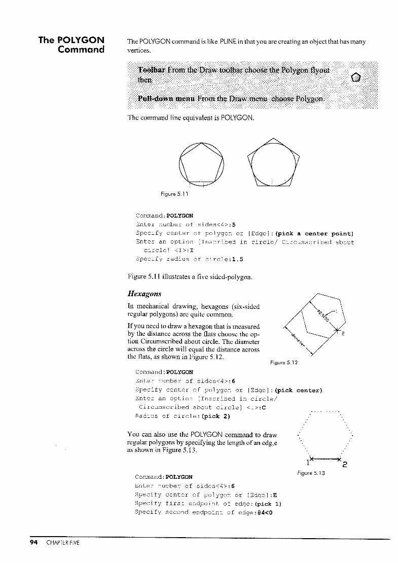
The POLYGONCommand
The POLYGON command is like PLINE in that you are creating an object that has many
vertices.
The command line equivalent is POLYGON.
Figure 5.11
Command: POLYGON
Enter number of sides<4>:5Specify center of polygon or [Edge]: (pick a center point)
Enter an option [Inscribed in circle/ Circumscribed about
circle] <I>:I
Specify radius of circle:l.5
Figure 5.11 illustrates a five sided-polygon.
Hexagons
In mechanical drawing, hexagons (six-sidedregular polygons) are quite common.
Ifyou need to draw a hexagon that is measuredby the distance across the flats choose the option Circumscribed about circle. The diameteracross the circle will equal the distance acrossthe flats, as shown in Figure 5.12.
Figure 5.12
94 CHAPTER FIVE
Cornmand:POLYGON
Enter number of sides<4>:6
Specify center of polygon or [Edge]: (pick
Enter an option [Inscribed in circle/
Circumscribed about circle] <I>:C
Radius of circle: (pick 2)
You can also use the POLYGON command to drawregular polygons by specifying the length ofan edg,eas shown in Figure 5.13.
Command: POLYGON
Enter number of sides<4>:6
Specify center of polygon or [Edge]:E
Specify first endpoint of edge: (pick 1)
Specify second endpoint of edge:@4<O
center)
1>< ><2Figure 5.13

The SOLIDCommand
SOLID and DONUT are commands that have a filled-in area or solid mass. This can also
be achieved with the BHATCH command with the solid fill hatch. These commands arealways available when you type them in, and can be found in some AutoCAD Releases(not Releases 2007 or 2008) on the pull-down menus and toolbars.
The command line equivalent is SOLID.
1 2''''3.42 4 10 12 6
Figure 5.14
Figure 5.15
Corrunand:SOLID
Specify first point: (pick 1)
Specify second point: (pick 2)
Specify third point: (pick 3)
Specify fourth point: (pick 4)
Third point:.J
Figure 5.14 illustratesthe order in which pointsare entered. If you continue to digitize after thefourth entry, the systemwill add in a paired sequence until you termi-nate with ~. To create atriangle, use .J after thethird point prompt.
The order in which points are entered is very important. Figure 5.15 provides some examples.
Do not confuse SOLID with theSOLIDS option given under theDraw menus.
The DONUTCommand
The DONUT command is used to create a thick orsolid circle. The inside diameter is used todetermine the hole of the doughnut. Use an insidediameter of zero to create a solid circle; use a
larger diameter to create a ring. Once DONUT isactive, a donut will be drawn every time you
digitize until you press .J.
1.00
Figure 5.16 illustrates the inside and outside diameters of a DONUT .
Figure 5.16
DONUT is useful for surveying and civil engineering applications for property and position markers. It is also useful within dimensioning ifthe options available aren't giving you what you think you want.
Corrunand: DONUT
Specify inside diameter of donut<.5>:O
Specify outside diameter<1.0>:2
Specify center of donut or <exit>: (pick 1)
Specify center of donut or <exit>: (pick 2)
Specify center of donut or <exit>:~
Like the SOLID command, DONUT has been replaced by CIRCLE and BHATCH. Formany applications, however, DONUT is a faster solution for a solid circle.
Entity Commands with Width 95

The TEXTCommand
Chapter 8 deals with many aspects oftext, including text style, editing, fonts, paragraphtext, and a wide variety of text alignments. Here we introduce simple, one-line textentry. The MTEXT command will make paragraphs and large text formats easier. The
TEXT command is useful for title blocks and view titles.When entering TEXT, AutoCAD will prompt you to choose a height for each character,a rotation angle for your string, and a point at which to place the text string on themodel or drawing.
The command line equivalent is TEXT.
Figure 5.17 illustrates the justification ofthe TEXT command. The default is left justification at the baseline ofthe text string. The other options will center, right justify, or fitto either top or bottom comers.
DEFAULT
Figure 5.17
CENT~RED
RIGH1<
96 CHAPTER FIVE
Comrnand:TEXTCurrent text style: "Standard" Text height 0.200
Specify start point [Justify/Style]:JAlign/Fit/Center/Middle/Right/TL/TC/TR/ML/MC/MR/BL/BC/BR:
Once you have chosen a point at which to place yourtext, the command will prompt you for the height ofthe SeALE:letters, the rotation angle, and the text or string ofchar- IX
acters itself. Figure 5.18 illustrates the placement of 2 xl / 4 II -_II aIIsingle line text.
Command: TEXT Figure 5.18
Current style: "Standard" Text height
0.200Specify start point [Justify/Style]: (pick 1)
Specify height <.2000>:.15Specify rotation angle of text <O>:~ (to accept the default)
Enter text:Scale:
Enter text:~
Command:~
Current text style: "Standard" Text height 0.150
Specify start point [Justify/Style]: (pick 2)
Specify height<.2000>: .25Specify rotation angle of text <O>:~
Enter text:1/4"=1'O"Enter text:~

Multilines The MLINE or multiline command is used to create multiple, parallel lines.
The command line equivalent is MLiNE.
MLiNE is particularly useful for drawing walls and other architectural features. From a specified point, AutoCAD draws a multiline segment using the current multiline style, and continues to prompt for other points. Like LINE, using Undo undoes the last vertex point on themultiline. If you create a multiline with two or more segments, the Close option will be included in the command string as seen in Figure 5.19.
3
2
1.00,
Figure 5.19
4
Command:MLlNE
Current settings; Justification = Top, Scale
Style = Standard
Specify start point or [Justification
/Scale/STyle] : (pick 1)Specify next point: (pick 2)Specify next point or
[Close/Undo] : (pick 3)
Specify next point or
[Close/Undo] : (pick 4)Specify next point or
[Close/Undo] :C
Justification
This option determines how the multiline is drawn between the points you specify.
Enter Justification type Top, Zero, or Bottom, as shown in Figure 5.20.
Top Zero Bottom
Figure 5.20
Scale
This option detcnnines the distance between the two lines of the multiline.
The scale is based on the width establishedin the multiline style, as shown in Figure5.21. All lines in the MLiNE will be scaledto the entered scale factor. Figure 5.21
Entity Commands with Width 97

+By using PLI NEand SOLI Deffectively, we can createa presentation view ofa small cabin with a staircaseand a fireplace. Like many architectural applications, this is more easily drawn with SNAP on because it is in regular intervals.
Step] First change the units to Architectural. At the command prOlupt type UNITS.
Command: UNITS
Architectural
Precision: O'-O~
Step 2 Make your LIMITS -1',-1' and 24',18'. Set SNAP to 4/t.
Command: LIMITS
Reset model space limitsSpecify lower left corner or [ON/OFF] <0'-0",0'-0">:-1' ,-1'
Specify upper right corner <12.0000,9.0000>:24' ,18'
1J'J'-I T
Note: PUNEs are gen-erated through the center bline. The Dimensionsinclude PLiNE width.
1-
iu
...J~~The polyline width is 81t
, the size of aregular exterior wall.
Add the PLiNEs as shown on theillustration.
This is a presentation drawing not aconstruction drawing, the dimensionsare from the middle ofthe plines on thecomers. Note how to start the PLlNE sothat your corner is correct in the command string below.
Set your SNAP and GRID to 4 to make iteaSIer.
When entering co-ordinates,DYNamic gets in the way. Usi ngGRI D and SNAP is the fastestway to do this.
Step 3
Command:PLlNE
Specify start point:4' ,0
Current line width is 0.00 units
Specify next point or
[Arc/Close/Halfwidth/Length/Undo/Width] :WSpecify starting width<O.OO>:8
Specify ending width<8.00>:~
Specify next point or
[Arc/Close/Halfwidth/Length/Undo!Width] :0,0
Specify next point or
[Arc/Close/Halfwidth/Length/Undo/Widthj :0,4'
Specify next point or
[Arc/Close/Halfwidth/Length/Undo/Width] :~
Repeat PLiNE for the exterior walls. Use the spacebar to bring back the PUNE command to make it faster.
98 CHAPTER FIVE

Step 4 Now use ZOOM Window to get a closer look at thenortheast corner of the building. Add the lines as shown,
with the pline width at 2".
Once sufficiently zoomed, enter the staircase with PLiNE.
Command:PLlNE
Specify start point:NEAR to (pick 1)
Current line width is 8.00 units
Specify next point or [Arc/Close/Halfwidth/Length/Undo/Width] :W
Specify starting width<8.00>:2
Specify ending width<2.00>:~
Specify next point or [Arc/Close/
Halfwidth/Length/Undo/Width] : (pick 2)
1/ r-..
--
Co -I
~
tB'/t/ 2 3,
Step 5 Now use PLiNE to place an arrow pointing up the stairs. The dimensions in thecommand string below are simply a guide. You can use your co-ordinate readout toplace these rather than typing them in. Just make the arrow look like the one shown.
Command:PLlNESpecify start point:18'2",4'6"Current line width is 2.00 units
Specify next point or [Arc/Close/Halfwidth
/Length/Undo/Width] :18'2",7'
Specify next point or [Arc/Close/Halfwidth
/Length/Undo/Width] :W
Specify starting width <2.00>:7
Specify ending width<7.00>:OSpecify next point or [Arc/Close/Halfwidth
/Length/Undo/Width] :18'2",8'
Specify next point or [Arc/Close/Halfwidth
/Length/Undo/Width] :~
Step 6 Now use PUNE to create a break line on the staircase. A break line is used on floor plansto indicate that the stairs extend up or down to another level.
I
Since PLiNEs are created alonga center line with width added to
'I· both sides, be sure to deducthalf the wall thickness to obtain
I the correct wall length.
Command:PLlNE
Specify start point: (pick 1)Current line width is 0.00 unitsSpecify next point or [Arc/Close/Halfwidth/Length/Undo/Width} : (pick 2,
3, 4, 5, 6, 7 in sequence)
A break line in a staircase is always necessary on a floorplan. The plan view shows only one floor or level in thebuilding. The stairs extend up to another level. The breakline is the visual image that tells the viewer that the stairscontinue.
6
4
Entity Commands with Width 99

Step 7 Now use PAN to move the drawing to the right, at the same scale factor, and then useSOLID to create a fIreplace. You should have SNAP on and OSNAP off for thiscommand.
1 3 5 7 9 11
2 4
6 8
10 12
PUNEs are entered from theirMIDDLE paint, so calculotionswill need to be adjusted.
Step 8
Step 9
100 CHAPTER FIVE
Command: SOLIDSpecify first point: (pick 1)Specify second point: (pick 2)
Specify third point: (pick 3)Specify fourth point or [Exit]: (pick 4)
Specify third point: (pick 5)Specify fourth point or [Exit]: (pick 6)
Specify third point: (pick 7)
Specify fourth point or [Exit]: (pick 8)
Specify third point: (pick 9)
Specify fourth point or [Exit]: (pick 10)
Specify third point: (pick 11)
Specify fourth point or [Exit]: (pick 12)
Specify third point:~
Use PAN again to move the drawing over to theleft so that you can create a North arrow outside
the building. Draw in a vertical line at 3 " and a
horizontal line at ] .5' across the lower section asshown. Then draw in two smaller lines to make
an x. Use the ends of these lines and OSNAPENDpoint to draw in a North arrow.
North arrows are used on floor plans to show thedirection that the house is facing. In the northernhemisphere, the north side ofthe building will becooler than the south, so the fireplace is oftenplaced on that wall.
Then, with your SNAP still set to 2, draw in twodiagonal lines through the intersection. Now use
SOUD to fill in the sides of the North arrow.
Command: SOLIDSpecify first point: (pick 1)
Specify second point: (pick 2)
Specify third point: (pick 3)Specify fourth point or [Exit]:~
Specify third point:~
2

Step 10
3
Continue adding solids until you have a North arrow.
1 2
Finally, add lines for windows and doors, and your simple floor plan is complete.
Once the first window is drawn in, use COPY, ROTATE, and STRETCH to make the others. Note that you can adjust the size of the window openings with STRETCH to makethe window on the south side longer, taking advantage of the sun and solar energy.
+ +
PRESENTATION DRAWINGS
PRESENTATION DRAWINGS, GENERALLY DRAWN IN PUNEs, ARE USED TO SHOW A CLI
ENT THE GENERAL LAYOUT OF A BUILDING. THE POSITIONS OF WINDOWS, DOORS,
STAIRCASES, AND FIREPLACES ARE SHOWN, BUT THERE ARE NO DEFINITE DIMENSIONS,
NO NOT ATIONS OF MATERIALS, AND NO STRUCTURAL INFORMATION. THESE WOULD BE
ON THE CONSTRUCTION DRAWINGS (SEE PAGE 85).
Entity Commands with Width 101

>u:~wli:«Iu
a...
oooI.rim:£
RAWN:
10m Van lUiden
BVILD
R1S,0
DATE: ICHECKED
Jan,2006 Suzanne Roblcheau
~;:/R20,O
18,7
1>(5II)
IQ..~
mJ
};I'
<1'JJ({\)
cIt4 of Hamilton
13.7
LOCATION
Aberdeen and ulen51de
CLIENT
.~R2a,o
45,0
...
BLVD
~~~-----
......-~-._--_._--- .~
Glenside Avenue
30.0
--- --==---==- , +",___~ - ====f-f-.------."""......-=-::::-- - - - - - - - - - - - -+1-----------------------1
c~0
...c::CI)
CI)Q)a.;:-""0C .o CI)
CI) ~.£ e+- lo.-
(I) ""0 0.~ C
U (1) .2.-.~ u
I0..... 0
U - (1) 0Q) .::: t.riC .£ ""0 t{)
-;(1) 0'- +a.. c-£ ..-'in 0=>'-+-
a.n C..s:::.
I I
trIo of-
:U:9 ..;
Q) Q) ~It'I
~-o MV) Q) C.- C cU .- w I '"~'- ·!:!?Z
.£ -Q) of- -J
>< ~o... I ~Iqo Q) In
W I... CI)
O::J
;;!
InM
Ifl<of

Exercise 5 ArchitecturalTo appreciate architecture you must have some knowledge of architectural styles.Here are two examples. Use PLiNE for the acanthus leaves.Set PDMODE to 34, then use DIVIDE to place the bricks along the arc.MIRROR, COPY, and SCALE will also be useful.
TRIGLYPHS
EGG AND DART
ECHINUS
\--1-__ ACANTHUS LEAVES
~----TORUS'r-----------r'
BYZANTINE AND ROMANESQUE
CENTER ALWAYSON SPRING LINE
jointeb 1linrseshne
ARCHITECTURAL DETAILS
THE ARCHITECTURAL DETAILS
AROUND DOORS AND WINDOWS AREUSED TO DETERMINE THE
BUILDING'S STYLE AND DATE. THISIS WHERE CRAFTSMANSHIP AND ASENSE OF PROPORTION AREIMPORTANT.WHERE STRUCTURAL DETAILSSHOW THE STRUCTURE OF ABUILDING, ARCHITECTURAL DETAILSDETERMINE THE STYLE.SEE
WWW.ONTARIOARCHITECTURE.COMFOR MORE INFORMATION ABOUT
THESE STYLES.
NOTE POINTED HORSESHOE ARCHES ARE FOUND PRIMARILY IN VENETIAN GOTHIC ARCHITECTURE.
STONE JOINTS MAY BE HANDLED IN A VARiETY OF WAYS
Entity Commands with Width 103

Exercise 5 MechanicalThe PUNE showing the break in the shaft will be the hardest partto draw in this example.
1--------------16'--------------f
-i 1/2¢ r
t----+- +--~Dllte' Dr"", cchl
1--+-----f---+--lcoI'\P().~b.rrlnton Inc
UNSPECIFIED TOLERANCE ProJ T tle
10"I
~r1/4 3/4
L...-_+-- -+-_-.I 11; L
~~:~SHAFT ENDDETAIL
NTS
2 3/4
1 1/2 =-_11
o
\VELD
-------7----·
PEDIT
PLINE AND
Rl/2
6,0
6,0I50,0
L'~~
MiG X 1.0
THREAD2 X 0 + 1/4 UP TO 6//
2 X 0 + 1/2 OVER 6/1
JC
104 CHAPTER FIVE

Exercise 5 WoodThese clock pieces have reverse sections to show how the clock is constructed.The break lines show that the body of the clock is longer than is shown.Draw the clock at a scale of 1= 1.
SIDE SECTION
r~ ,; ~~RONT SECTION
2~ -3~-J-.r~ [I, ===J-r 1 5§IIIIIIIII
9
~~-
L===:J I 5~
~JI 4
~,-6~- II
3~- --- --j III
"'--5~-III
9! II F
- f.-- 1-3
M 34 1/44
III
--_.-
I I III
III
1.-=:l ~~ 7~
'Ij2~ ::
t II 1 I 2L 1.. 1-..1.
CLOCK SIDE
R6r R5~1~3l /R4~
---~ II,.../''' 1
/ ~ 54
:J" + \7-~
lO~
11~
~
I 2~I II , I)
~- -!I II Ij II 10~ I! --1 1--- 1I 4
~3~I
I f--.j I-l~I ~I
13~
I II II I
I
I
II
~.
I~
I TI I4
I I ~f'~ _.I 19I ~
CLOCK FRONT
59
II11II
I ~~IIIII
~-
~-----"--21~---------l
III
:2§I1IIL- 2] _
u.l.. 1
BASE DETAIL
Entity Commands with Width 105

Exercise 5 ChallengerProfiles of wood and stone molding are often shown withsection lines as in this 13th century church doorway in Italy.
E
c
.~~...
B
.~,,; "
""'.: ..:..~ .~~.~~ '". 8 3i4:""
'-..:,,41 ."
.1Ii-.
'~'~:~~~"':/" .~/~~.~.
A
..... .'':, ... I. . ~~ ...E
Profiles: Church of Madonna Scorsa in Aquila
106 CHAPTER FIVE

Entity Properties: Layers,Colors, and Linetypes
chapter, you should be able to:
creote geometry on them........
and use the COLOR command
or obiects
of objects
on/off fhe LAYER
About LAYERs The LAYER command allows you to control the drawing bymeans of visible entities, much like transparencies, asshown in Figure 6.1. Different colors and linetypes can beassociated with different layers. To help complete thedrawing, these layers can be either displayed orundisplayed, active or inactive, accessible or inaccessible.The number of layers you can use is unlimited. Figure 6.1
The command line equivalent is LAYER.
Il' '-"-Gil_All
i ?;:,-.~ All Used Layers
I-I BLOCK V ~ t\t • whilB CON_GUS - O.-m Color_I~ BRiCKARCH V Q fb • white CON_OUS - O....m C;:4or_7... CENTER V (Wl ." • red CENTER -O.-m CclOf_1... DEFPOINTS '~ ~ ~ • white CON_OUS - O...m Coloc_... DIM (;) a 'i • white CON_OUS - O.Jn (oh,,3... DIMEN 9 (j flt • red CON_OUS - O.-m ColOf_1... HATCH Q Ci!! ~ • red CON-OUS - O....m Cclcr_).. HIDDEN .;) @I ~ • red HIDDEN -O...m CCkcf_1...-rilO lNORDING {~ GJ 0l'J • Mtite CON_OUS - O.-m 'C<:~k>f_7
Layers can only be set up and modified with the Layer Properties Manager, but thelayer can be can be set with the Layer toolbar.
Entity Properties: Layers, Colors, and Linetypes 107

The Layer Properties Manager dialog box will help you to view the layers, change thecolors, tum layers off, freeze and thaw them, and lock or unlock them.
Current
Name
Off or On
Freeze
Lock
Color
Linetype
Lineweight
New
Delete
OK
Show Details
Cancel
Help
sets the highlighted layer to current - the one you areworking on
the name of the layer; no spaces or dots allowed
sets the selected layers off or on, which makes the layerinvisible or visible
freezes selected layers, making them invisible and notregenerated, or thaws (unfreezes) them. Freeze is for modelspace layers
locks selected layers, making them visible but notaccessible, or unlocks them
the color set to that layer. All of the choices along the top sofar have been toggle switches, on or off; this allows you tochoose a color
the linetype of the layer
the lineweight of the layer
allows you to enter a new layer starting with the layer name
allows you to delete a layer if there are no objects in it
exits from the layer dialog box while saving changes
offers more information on the status of the highlightedlayer
cancels the layer changes or additions you have made
provides help files on the layer functions
.~ ~.......
<V 0 'li' &1J...I
Creating a NewLayer
108 CHAPTER SIX
Pick the button for New on the top left side ofthe layer dialog box, highlighted in Figure 6.2,and you will see a new layer appear in the listType in the name for the layer to overrideLayerl, the default name.
Once the name is entered the layer will beadded to the layer list. The next time you enterthe dialog box the layers will be listed alpha- Figure 6.2
betically.
When typing layer names, add no spaces, slashes or periods.
Activating Layers for Changes
In order to change the name, state, color, linetype, or lock value ofthe layer, it must beidentified or selected. Move the cursor to the layer name and pick it. The layer's lineshould be highlighted.
When selecting more than one layer for changes, use the regular Windows method foridentifying multiple objects: use the Shift key to highlight all layers between the topand bottom ones that you choose, and the CtrI key to highlight multiple layers individually. The selected layers will be highlighted and modified.

hidden
Color and Linetype options will affect all highlighted objects, as shown in Figure 6.3.
Figure 6.3
Changing a Layer 1Vame
Ifyou should type in the name incorrectly, double-click on the name. The area now activated will turn blue. Move your cursor away from the line, and the name itselfshouldbe highlighted. Type in a new name or revise the current name. The new name will replace the old.
Making a LAYER Current
In order to draw on a layer you must make it current. The easiest way to do this isthrough the Layer Properties Manager shown in Figure 6.4. Highlight the layer thatyou would like to have current, and pick the word Current.
Figure 6.4
The Layers toolbar shown on Figure 6.5 is possibly quicker, if that toolbar is displayed. Pick the down arrow and select the name ofthe layer that you would like to becurrent. To place objects on a different layer, highlight them, then using the down arrow, place them in the desired layer.
.0!Jl:il Ii.] center
BJ1~10 objects
Figure 6.5
The Layer toolbar will show which layer is current. If this toolbar is not displayed,right-click the end of another toolbar, then pick layers from the menu.
Changing Layer Color
In the Layer Properties Manager select the the colored box under the letter C that corresponds to the layer youwould like to change, as shown inFigure 6.6.
This will invoke the Select Color dialog box. Pick the color that you wouldlike, then click OK. Figure 6.6
Entity Properties: Layers, Colors, and Linetypes 109

• ByBlockII RedDYeUowo Green
o C.Yan
.6.!11j:~'ed Layers
• B,YLayer
•
~_AII
I····~l····~ Group Filter'L... Group Filter2
Figure 6.8
Figure 6.7Setting Color Independent ofLayer
You can set a color using the COLORcommand. This will override your layercolor setting. To do this, type in the wordCOLOR at the command prompt, or pickthe color button on the Object Propertiestoolbar shown in Figure 6.8, which isgenerally just to the right of the Layertoolbar.
Problem Shooting
If your layers suddenly disappear, youhave chosen the New Group Filter bymistake. In the Layer Properties Manager choose All Used Layers as shown inFigure 6.7 and your layers will reappear.
If your objects are being enteredin a color different than yourlayer setting, you have set acolor in the COLOR command.Set the COLOR setting back toBylayer.
Command:COLOR
All subsequent objects will be drawn in this color. This may cause some confusion ifyour colors have been set to a particular layer because the color setting overrides thelayer color. Keep the COLOR command set to Bylayer and you should have no problem.
Loading LINETYPEs
In addition to colors, you can also have linetypes associated with each layer. Load linetypes within the Layer Property Manager dialog box in the same way that you wouldload them in the Graphics area, see page 56.
Once you have set a color or a linetype outside the Layer dialog box, all future geometry added to this layer will use this color or linetype. Until you are sure ofwhat youare doing, both the Color setting and the Linetype setting should be ByLayer.
ChangingLTSCALE
Depending on the size ofthe object, the hidden lines may not show up as hidden. Ifthisis the case, either the objects that you thought were on that layer are not, or the scale ofthe drawing is too large or too small for the linetype to show. You will need to changethe linetype scale relative to the current drawing.
Command:LTSCALE
Enter new linetype scale factor<1.OO>:12
Match Propertiesand CHPROP
The Match Properties command will take the linetype, color, and linetype scale ofaselected object and apply these properties to any other objects that you choose.
Command: '_matchprop
Select source object: (Pick an object)Current active settings: Color Layer Ltype Ltscale
Lineweight Thickness
PlotStyle Dim Text Hatch Polyline Viewport Table Material
Shadow displaySelect destination object(s) or [Settings]: (Pick other
objects)
The last objects will have the properties i.e. color, linetype, dimension style, etc. ofthe first object chosen.
110 CHAPTER SIX

Layer Filtering
The CHPROP connnand cycles through the properties. With the dialog box you areprompted to pick the objects you would like modified; then you can choose Layer,Color, Linetype, Thickness, etc. and type in the new value. If you use the commandline, here is the sequence:
Command:CHPROP
Select objects: (pick an object)Select objects:~
Enter property to
change [Color/LAyer/LType!LtScale/Thickness] :cEnter new color <bylayer>:Red
Enter property to change
[Color/LAyer/LType/LtScale/ThicknessJ :LTEnter new linetype <hidden>:Center
Enter property to change
[Color/LAyer/LType/LtScale/ThicknessJ :~
Sometimes you Inay want only certain layers to be listed in the Layer Control dialogbox. The Filter option allows you to limit which layers are listed. You can filter on thebasis of:
• layer names, colors, and linetypes
• whether layers are on or off
• whether layers are frozen or thawed
• whether layers are locked or unlocked
• whether layers have plot or don't plot status
• whether layers contain objects or not
• whether or not layers are part of externally referenced (xref) drawings.
Layer filtering is used on verylarge files, or files that belong tosomeone else or where you don'tneed to use many of the layers.
To Filter a Layer
In the Layer Properties Manager,pick the New Property Filterbutton. Create a new filter bJTOUP
as shown. In Figure 6.9, all layersthat are red have been filtered.
Figure 6.9
Layer Management
The default layer is O. Ifyou enter any dimensions, you will also create a layer calledDefpoints. Neither of these layers is renamable. The Defpoints layer does not plot.
While creating a model in AutoCAD, layers should be named in a logical, straightforward manner. Also, keep your LlNETYPE and COLOR commands set to ByLayer.
Many industries have developed layering standards so that there is no question aboutwhere objects will be located. Ifyou are starting work with a company, make sure thatyou know what the layering standards for the company are, and find out whether thereare any standards outside of the company that you should be aware of.
Freezing layers when you are not using them will save a great deal oftime with largermodels. Until they are regenerated, layers that have been frozen will not display whenthey are thawed.
Entity Properties: Layers, Colors, and Linetypes 111

In this example we will make an adjustable bearingwith hidden lines and center lines.
Jt---- --
____ a.._ ....
.:_-=~--- -- --
Step 1 First set up your layers.
Pick the New Layer button to add new layers. Add Centre, Hidden, and Object.
Step 2 Once the names are loaded, change the color of each layer by picking the layer nameand then picking the Set color button. An overlay menu will offer you a selection ofcolors.
Choose a color for that layer. The nine base colorsare the best to choose.
• objects
• hidden
• center
White
Yellow
Red
Index cofor: 1 Red, Green,
Choose Load to load newlinetypes. Choose CENTER,hold the Ctrl key down on yourkeyboard and then pickHIDDEN from the list oflinetypes to load them both.
Pick OK. Then choose CENTER under the Select Linetypemenu shown to make your center lines 'center' lines.
Now load and set the linetypes. Pick the word Continuous under the linetype columnacross from the CENTER layerto load the Linetype manager.
Step 3
112 CHAPTER SIX

Step 4 Now that the linetypes have been loaded, return to the Layer Properties Manager andload the hidden line type to the Hidden layer.
Activate the Hidden layer, choose the word Continuous under the Linetype column,then choose the hidden linetype from the list. Press OK. Use OK to exit from the SetLinetype dialog box, then OK again to exit from the Layer Control dialog box.
Step 5 Now that the layers are ready, use the same menu to make the Objects layer current.
Your screen should look like this:
~ • white Continuous - Default Cok~ • red CENTER - I.Jefau1t Cok
o y...w HIDDEN - Default [Dk
•
R1.00
RO.SO
1-----6.00---....Mirror these through the center line, anduse LINE and TRIM to fmish the part.
Draw two more circles on at a centerof6,2.The radii will be .5 and 1.
Draw a circle with a center ofO,O. ZOOM to
the Extents of your geometry, and thenzoom down.
Now with the Objects layer current, draw in the front view ofthe adjustable bearing asshown. Do not draw in the dimensions.
Step 6
If you set 0 color or UN ETYPEunder the COLOR or LlNETYPEcommands, they will overrideyour layer setting.
Step 7 Now return to the pull-down menu and make the Centre layer current.
o1f!J. 0D12,.Jl;JO HiddenJl2J. Objects
Draw in the lines as shown. They shouldbe a different color as well as a differentlinetype.
Try changing the LTSCALE to see if thereis any noticeable difference in the centerlines.
Command:LTSCALENew scale factor<1.OO>:1.5
Entity Properties: Layers, Colors, and Unetypes 113
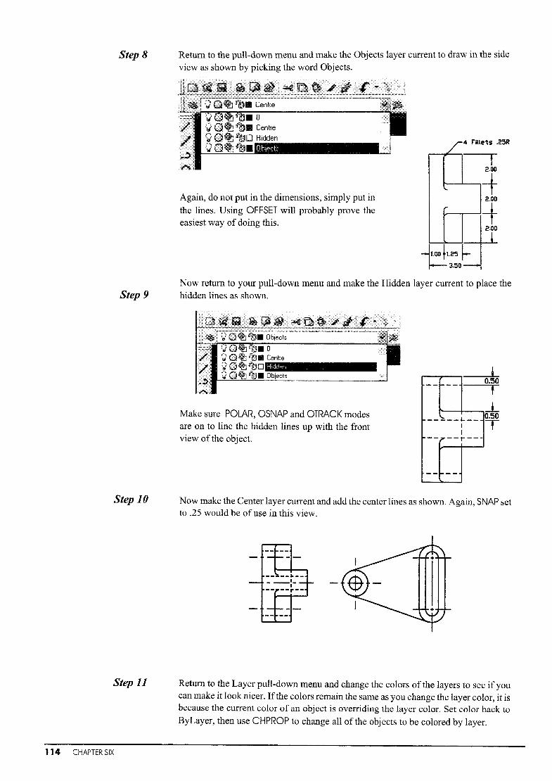
Step 8 Return to the pull-down menu and make the Objects layer current to draw in the sideview as shown by picking the word Objects.
Again, do not put in the dimensions, simply put inthe lines. Using OFFSET will probably prove theeasiest way of doing this.
/-'4 nuets .25R
~---r
2.00
~-+2.00
~-+
~l.ooh25 ~ 1+~3.50Y
Step 9Now return to your pull-down menu and make the Hidden layer current to place thehidden lines as shown.
En ~~ rr:lt. 0bjects
Hidden
Make sure POLAR, OSNAP and OTRACK modesare on to line the hidden lines up with the frontview of the object.
-- i---0.50,--L
- ____ 1- __ 0.50I TI
--7--r---
--1---
Step 10 Now make the Center layer current and add the center lines as shown. Again, SNAP setto .25 would be of use in this view.
-----1-----:---r--+
Step 11
114 CHAPTER SIX
Return to the Layer pull-down menu and change the colors of the layers to see ifyoucan make it look nicer. Ifthe colors remain the same as you change the layer color, it isbecause the current color of an object is overriding the layer color. Set color back toByLayer, then use CHPROP to change all of the objects to be colored by layer.

Step 12
If you lose your Layertoolbar, right-dick any
toolbar at the parol Ie! barsand bring it back.
Step 13
We are now going to play with the Lock/Unlock facility to see how it works. It may betime to save the file just in case.
Command: SAVE
(enter a name in the dialog box)
In the pull-down menu lock the Centre and Hidden layers. Once the layers are locked,you will be able to see them, but you will no longer be able to edit them. Make sure theObjects layer is current before you start.
Hidden
Now back in the drawing or model, use a Window pick to highlight all ofthe objects onscreen. Then from the Modify menu pick Properties and change the color to blue.
This can also be done on the command line as follows.
Command: CHPROPSelect objects:ALL
40 objects on locked layers
Select objects:...]
Enter property to change [Color/LAyer
/LType/ltScale/Thickness] :C
Enter new color <varies>:blue
Enter property to change [Color/LAyer/
LType/LtScale/Thickness] :.J
Step 14
Notice that only the objects on the Objects layer werechanged because the other layers were locked.
Try turning the Layers Off and On, and Freezing and Thawing them. The data for thelayers are still on file, but the information is not displayed.
* Freeze/Thaw
<it0i..·..•..>.'.·.·'~jf:
...................,On/Off
Entity Properties: Layers, Colors, and Linetypes 115

Exercise 6 PracticeUse different layers for the Hidden lines and Centre lines.These are practice parts, not drawn to any scale. Draw at 1= 1.
COUPLING
12.50
IR1.oo
r- 1•5O -j
1----3•00
07/8 2 holes
ROCKER ARM
34
58.0 82.0
~~J011.0 ---J4 HOLES
12.01-------112.0
1--------136.0--------j
SWIVEL HAMMER
01.00
t1~
L....I-..J--I-----=r-----""'-t---~Top Plate
LINK
116 CHAPTER SIX

-......CDn.....ca
m~.,niii-CD0'
».,n::r
w:'J
-i -i::::r2:"CD [II
::::r th'o _:::!, :rN CDo Vla. CDQ no..gVi' :::J-to-+,a 0:::J """In _CD ::::rC/) (TlQ """I"""I (TlCD [II
-0.:.o (TlC ::::l
~go ;;::::J C"'0::;.a a..(Q _.
CDc.6(X)-+,
UlOa §:::J a..0..
0...... :::JW-o:'Sa
co(\)III
ex>O'la:::Ja..
cARADr:.-
+--EAvt5fROUCiH ALUMINUM \M1lff50fflf ALUMINUM V'MllfACeeNf fRlM 10' ALUMINUM IM1llfPk£A BOARD 10' PLUMINJM \M1ilf
2" X6 " 50lf FtA1f5
~ tlUPJBONtJ fXitRlOR 511tCOIN5fALl fO MANUrK1UfRr'5 iN5fRX1l0N5
rt 2" '16" fXltRiQR SfVS@ 24" Of.
Cl-OSff
l-IVING ROOM
718" PlY 5UB-fWORiNCi
6" COMPACreO CiRAW~ fl~lUN~R 1-.N?
1/2' rpyw.
2" X10" WOOt? J5fS@' 12" O.c.
2" X12" WOOD JSf5 @ 12" o,e2" xBli SILl
:?IIJO 5flCOl
BEDROOM
1'1-WlootJ 5ll3F1.0Cl( ~" X10" IfADeR
~ I· IXlfxJ d<l ~ ,moolXIclarxllXJIXlI 2 - 2'1 X6 '1 DOU~t fOP PLAitJ 1I[X1 00 IX) IXlIX1 .
4'1 CONC~it 5!.-ABWI 616 10/10
Section
rOUBlE foP PlA1t5
~ A5PWif 5HINGiU;5121~' / §lJl"gl~'V:N1lw %A1HINU
2" X8" RNlfR5 @ 12 Oc.C0 "fJp "ra tv ftGIJRW ~Ji~rr~~~e fOR WNfilAfiO<l OII'R eAW5tV~RY RNlfR 2" X6" CCA1ARS
I'I K~l' 5fRA1?PINCi fOR atiNU J:):5f5211 '16" CflUNUJOl5f ~@24" Of
6 11
1/2 '1 DRY'I'VPLl
INitRIOR 5fJD54'1
L-
8" !?AnIN5Ul&J10NBtfv\fvNKNffW~lANt? OUl5lDfWlil
//~
-I:E-I W (/):r: » :r: C m (f)mrAJr O3: r go -I ml>l>G)ZO (')-IenIG)Z -Imen -~~~u;~ 0l>mmnl> Zf;;Cn~~cmmU>Z 0(J)- Z-IG)m -1:::oC/):UO~~Cl> l>
Z nAJ:ioorri m ~::oO"OC -o:E-I' C/) Z§»I-{m G)IZ mIOOowm-l (J)CO~(/)O~ormen
OonI:0 z::::! °J:G)O~
w Zm I(;)(1)-0II(/)~-10-1(/)~»-1- Z A Il>G)mmZ Z0
......'I
()o5""~a::Ja..r-5"
f
m::J
$-0a~:+ffi"
ran;?

Exercise 6 MechanicalDraw 6A using different layers for hidden and center lines.Draw the same iwo views - Front and Top - for 6B, 6C, and 6D.
R1.250.75
I -, r.....---l-_+___'_-----,
4.00 2.50 1.00
LU= ~---_~-----Lo.75~- 4-'25~-r----1-------6,75---------l
¢1.50
¢1.00
6A
0.75
~ --...&.::~::;t"~~~~- r075 1
n2,50 4.00 5,50
~----.----I--.----.l
itl1.00
¢1.50
¢2.00
R1.20
FILLETS AND ROUNDS R.25
PICTORIAL VIEWS
6C
PICTORIAL VIEWS, AS SHOWN BELOW, ARE 3 DIMENSIONAL
VIEWS USED TO ILLUSTRATE APART.
CREATE WORKING DRAWINGS, AS SHOWN ABOVE, FROM THE
PICTORIAL VIEWS BELOW.
118 CHAPTER SIX

Exercise 6 ChallengerHere are 40 different arches found in architecture.Set PDMODE to 34, then use DIVIDE to section plines and arcs.
DEPRESSEDQ) CINQUEFOILCORBELLEDCD BYZANTINE
® DROP @ ELLIPTICAL CD EQUILATERAL o FLAT
@ FLORENTINE ® HORSESHOE ® ITALIAN POINTED
MULTIFOIL@ MOORISH MULTIFOILLANCET@
@ OGEE @ ORIENTAL ® PARABOLIC @ POINTED HORSESHOE
Entity properties, Layers, Colours, and Linetypes 119

Exercise 6 Challenger (continued)You can never get too much practice.
\
\
\\
\\
\
VA
r \I \
I \
-------~
® POINTED SARACENIC @ POINTED SEGMENTAL @ POINTED TREFOIL @ POINTED TRIFOLIATED
PSEUDO@ FOUR CENTERED @ RAMPANT @ ROUND HORSESHOE
SEGMENTALSCALLOPED®ROUND
TRIFOLIATED
ROUND
TREFOIL
SEMI-CIRCULARSEMI-CIRCULAR
® STILTED @ SHOULDERED TANGENTAL
@ VENETIAN GOTHICVENETIANTRIANGULAR® THREE CENTERED
120 CHAPTER SIX

AboutDimensioning
Dimensioning
COrrlj:lletloCI.ot this chapter, you should be able to:
up 0 <:Hrrlensiontf1lg styler using the dialog box
and aligned dimensions
)................. ))( •••••..~•..<S'~q t>()~tlinl~ .••~lnd continuous dimensions
it ):. ·.(".·.~·.·~ .••••~leJj:ijqmE~telraind radius dimensions
••·•••·••••· •••<•••••••• ·••••~ ••••~Ii·~r't~~~i~irtu:m~;iOIlS once they are in.
While the objects are being created, the size of the object is being programmed witheach part's geometry. Lines, circles, arcs, etc. should be created perfectly every time. Ifyou get into the habit ofcreating data in a lazy or slapdash manner, it will catch up withyou later when dimensioning the drawing.
Dimensioning shows the measurements, the locations, and the angles ofobjects. Thedimensioning commands are designed to extract the sizes that are already programmed with the part, and display them in accepted formats. Every discipline has adifferent set of drawing protocols. The dimensioning variables and dimension stylesare used to set the dimensions to the required parameters.
AutoCAD offers a wide variety of ways to produce linear, baseline, radial, diameter,and angular dimensions. Figure 7.1 shows some of the basic dimension types.
FIWII!UNI!
rVERTICAL
Figure 7.1
+
lH:AR (VERTICAl..)
Dimensioning Components
Every dimension has several components. The dimension text states how big the object is. The dimension line holds the dimension text. The dimension text shouldbe offset from the dimension line by .625 mm or 1/16 inch. The extension line extends fromthe object to the dimension line. The extension line is offset by .625mm or 1/16 inchfrom the part itself and should extend 1.25mm or 1/8 inch past the dimension line.These measurements are universal drafting standards and must be maintained incomputer-aided drafting as well as in manual drafting.
Dimensioning 121

Figure 7.2 shows the components ofa dimension.
The point at which you start your dimension is the reference point or definitionpoint. AutoCAD automatically puts a gapbetween this point and the start of the extension line. AutoCAD also creates a layerfor this point called Defpoints that doesnot plot.
/;
EXTENSION LINE OVERSHOOT
~DIHENSION LINE
~ DII1ENSJON TEXT
~ !,..- ARRowHEAD
4.00 ~-:=EXTENSIONLINE
I rEXmGl~~
Figure 7.2
Accessing Dimensions
The Dimension toolbar, shown in Figure 7.3, can be accessed by right-clicking another toolbar at the parallel lines. Once in, move the toolbar until it is docked.
Dimension aSTANDARD
EnteringDimensions
Figure 7.3
The pull-down menu shown in Figure 7.4 is also useful.
Typing in the dimensioning commands is not recommended.
You may want to lock the objects layer before dimensioning.This way the objects cannot be altered when using STRETCH oranother Modify command.
Dimensions should be placed on the dimensioning layer andthis should be a different color. The lineweight of the dimensions when plotted should be significantly smaller than that ofthe object lines. Having the layers in different colors helps tomake sure that the dimensions will have the same lineweight.
Horizontal and Vertical Dimensions
Figure 7.5 illustrates linear dimensions. Use OSNAPs.
-~,~~~~~!!'!~ Quk:k Dimension .
H binear
'\. Aligned
If Arc Lengtb.
~~ Qrdinate·-----1
i.9 !3.adius
1; Jogged
~ Qiameter
~ [l.ngular
H Basoline
rH Continue------j
~ L~ader
~ lolerance" ,
e Center t1,ark
H ObJigue
Align Te~t
~ Dimension 2tyle,,,
~ O?{erride
~ l,!pdate
Reassociate Dime!lsions
Figure 7.4
2
122 CHAPTER SEVEN
Figure 7.5
Command: (D~ension pull-down menu, Linear)Specify first extension line origin or <select object>:.JSelect object to dimension: (pick 1)
Specify dimension line location[Mtext/Text/Angle/Horizontal/Vertical/RotatedJ : (pick 2)
Dimension text = 4.00

In the fITst example in Figure 7.5 the dimension is based on the line or object chosen.In the next two examples, the first extension line is picked, then the second, and finallythe dimension line is placed. Use SNAP and OSNAP for accuracy.
Before specifying the dimension line location, you are prompted to change the dimension text (Text), the text angle (Angle), the dimension direction (Horizontal or Vertical), or the dimension line angle (Rotated).
In the third illustration in Figure 7.6, either the horizontal or the verticallength couldbe taken. Move your cursor to the position the dimension should be in, then pick thespot.
Figure 7.6
Aligned Dimensions
Linear dimensions give vertical or horizontal lengths. Aligned dimensions, as shownin Figure 7.7, give the dimension aligned to an angled surface.
Command: (Dimension pull-down menu,
Aligned)
Specify first extension line orlgln
or <select object>: (pick 1)
Specify second extension line
origin: (pick 2)
Specify dimension line location
or [Mtext/Text/Angle]: (pick 3)
Dimension text = 2.8284
Figure 7.7
32.8284
2
Like the vertical and horizontal, you can also simply choose the line itselfto be dimensioned as in Figure 7.8.
Command: DlMALIGNED
Specify first extension line orlgln or RETURN to select:~
Select object to dimension: (pick 1)Specify dimension line location or [Mtext/Text/Angle]: (pick
2)Dimension text = 2.8284
The distance between circle centers can also bedimensioned with either a linear dimension, if avertical or horizontal is required, or with analigned dimension.
To change the unit readout, change the dimension style (see page 126).
Figure 7.8
Dimensioning 123

124 CHAPTER SEVEN
Continued Dimensions
Once you have a horizontal, a vertical, or an aligned dimension,you can create dimensions that continue at regular intervals along the same edge asshown in Figure 7.9.
SxI 13.5000~4.5000 I 3.000°1
i = ~ ~=f---..........c==:X:5<4==::J'---f
:3rZ.IOOOI1.900013.0000~Z.ZOOO~t~80001
*I !. 2 )(1 4 . I l: I7ll:. I-- -.;)~( 5 L x7
Figure 7.9
Command: DIMLINEARSpecify first extension line origin or <select object>: (pick
1)Specify second extension line origin: (pick 2)
Specify dimension line location [M/T /A/H/V/R]: (pick 3)
Cornrnand:_DIMCONTlNUE (pull-down menu)
Specify a second extension line origin or [Undo/Select]
<Select>: (pick 4)
Dimension text = 4.5000
Specify a second extension line origin or [Undo/Select]
<Select>: (pick 5)
Baseline Dimensions
Similarly, for baseline dimensions, create the first dimension and continue from there.
6-lt------------.L
Figure 7.10
Command: DIMLINEAR
Specify first extension lineorigin or <select object>: (pick 1)
Specify second extension line origin: (pick 2)
Specify dimension line location [Mtext/Text
IAngle/Horizontal/Vertical/Rotated] : (pick 3)Dimension text = 1
Command: DIMBASELlNE
Specify a second extension line origin or
[Undo/SelectJ<select>: (pick 4)
Specify a second extension line origin or
[Undo/Select] <select>: (pick 5)Specify a second extension line origin or
[Undo/Select]<select>:~

Radial Dimensions
A radial dimension measures the radius ofan arc or circle. The dimension appearanceis determined by the Fit tab options, as shown in Figure 7.11.
~/Figure 7.11
Command: (Dimension menu, Radius)
Select arc or circle: (pick 1 - the arc)Specify dimension line location or [Mtext!
Text/Angle] : (pick 2)
Diameter Dimensions
Diameter dimensions are affected by the same dimension variables as the radius dimensions as seen in Figure 7.12.
Figure 7.12
Command: DIMDIAMETER
Select arc or circle: (pick 1)Specify dimension line location
[Mtext!(Text!Angle]: (pick 2)
Aswith the linear commands, the text and the text angle can both be changed. Theseare under the Text tab of the Dimension Styles dialog box.
Angular Dimensions
The angular dimension commandmeasures the angle between two nonparallel lines or three points. It canalso measure the angle around a portion ofa circle or the angle subtendedby an arc, as shown in Figure 7.13.
The dimension line for the angularmeasurement is an arc that spans themeasured angle and passes throughthe measured point.
Figure 7.13
Command: DlMANGULARSelect are, circle, line, or <specify vertex>: (pick 1)Select second line: (pick 2)
Specify dimension arc line location or [Mtext/Text/
Angle] : (pick 3)
Dimensioning 125
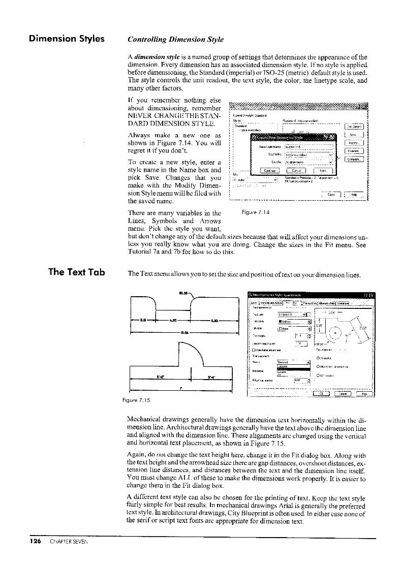
Dimension Styles Controlling Dimension Style
~
~I O"""id"_H jI Comp4le,.. I
Stando!lfd .. PteCi~on a 2, T01 pleci>ion ~ 2_Fit 1Ell(1 mO'iemenl ~ 2
Always make a new one asshown in Figure 7.14. You willregret it if you don't.
To create a new style, enter astyle name in the Name box andpick Save. Changes that youmake with the Modify Dimension Style menu will be filed withthe saved natTIe.
There are many variables in the Figure 7.14
Lines, Symbols and Arrowsmenu. Pick the style you want,but don't change any of the default sizes because that will affect your dimensions unless you really know what you are doing. Change the sizes in the Fit menu. SeeTutorial 7a and 7b for how to do this.
A dimension style is a named group of settings that determines the appearance of thedimension. Every dimension has an associated dimension style. Ifno style is appliedbefore dimensioning, the Standard (imperial) or 180-25 (metric) default style is used.The style controls the unit readout, the text style, the color, the linetype scale, andmany other factors.
If you remember nothing elseabout dimensioning, rememberNEVER CHANGE THE STAN- Ct-rrentDim$ly!e:Stand""d
DARD DIMENSION STYLE. I SetCurrenl )
The Text Tab The Text menu allows you to set the size and position oftext on your dimension lines.
~0It
1\15'..,r .1 5'-6"
:1Figure 7.15
Mechanical drawings generally have the dimension text horizontally within the dimension line. Architectural drawings generally have the text above the dimension lineand aligned with the dimension line. These alignments are changed using the verticaland horizontal text placement, as shown in Figure 7.15.
Again, do not change the text height here, change it in the Fit dialog box. Along withthe text height and the arrowhead size there are gap distances, overshoot distances, extension line distances, and distances between the text and the dimension line itself.You must change ALL ofthese to make the dimensions work properly. It is easier tochange them in the Fit dialog box.
A different text style can also be chosen for the printing of text. Keep the text stylefairly simple for best results. In mechanical drawings Arial is generally the preferredtext style. In architectural drawings, City Blueprint is often used. In either case none ofthe serif or script text fonts are appropriate for dimension text.
126 CHAPTER SEVEN

The Fit Tab The Fit menu allows you to set the size ofyour dimensions and have everything printedat the correct scale.
"'\:r=~.:..~~I_O.~I.sf~vwsI AIlRDW lAP
I I~ ...~I IFigure 7.16
The overall size of the dimensions isdetennined in the Fit tab ofthe Modify Dimension Style dialog box. Ifyou change the overall scale, you willchange the arrowhead size, the extension line gap, the extension line overshoot, and the gap between thedimension and the dimension line. Itis a much better idea to change theoverall scale than to change each sizeindividually. Figure 7.16 illustratesall the different preset elements.
190'333'-'"
1..3'-4'
1720 2280
2S;;.,'t---lf-=-+--=80='~ 25'20'-1 • 67'-6'
I
300 960 3002SO alO
Ifyou change the overall scale, all of these factors will change. Ifyou change just thetext size orjust the arrowhead size, all ofthe other parameters will remain the same.
Paper space dimensions are dealt with in Chapter 11.
"000
figure 7.17
When you dimension a drawing and plot it, the final drawing is a fraction ofthe original size of the object.
Metric Imperial
1:50 1/50 ofthe original size
1:100 = I/I00oftheoriginalsize
1:25 1/25 ofthe original size 112"= I'_ON = 1/240fthe original size
1/4"= 1/-0" = 1/48 ofthe original size
1/8" = l'_ON = 1/96 ofthe original size
Changing the overall scale under the Fit menu shown in Figure 7.17 will expand the dimensions to fit the drawing so that when printed the dimensions are the correct size.The dimensions are plotted at the same fraction as the drawing itself.
Metric Imperial
1:25
1:50
1:100
overall scale 25
overall scale 50
overall scale 100
1/2'1 = l'_On
1/4'1 = I'_On
1/8'1=]'_0'1
overall scale 24
overall scale 48
overall scale 96
Dimensioning 127

The PrimaryUnits Tab
The Primary Units menu allows you to choose the units print-out. This does not changethe size of the object, just the text units on the dimension line.
FRACTIONAL
DECIMAL
1:5·~~MSCIENTIFIC
U"ll"""-'l I ;jJP'ec"",n ~_----,it!J
F,~tion ~ormet ~uRzDnl~I__ ".~:~·", __ ~ ,~fil
Declrr4! sepaH~tof: ~Y~~L
Rwndo~ c=\;~
Prefix ~
Sulloc c===:=-~
SCilleioctor C=~OAjipJyio~<!mt;n,ioo",.,Jjr
-'·Zecoaup.pre;:ttClfl-·L."d"g fidoi<oel
T'oiliOli 00ircll'"
UnltsJOImal
ZlMr;~~on
o Loadirg
OT,.iIn~
Figure 7.18
The AlternateUnits Tab
The Symbols andArrows Tab
Choose the primary units that you would like the objects dimensioned in, then choosethe precision that you would like to have. Angle measurements can also be programmed. The Measurement scale (known as DIMLFAC in previous releases) allowsyou to provide detailed drawings. This is an alternative to the paper space layouts.
Note: In Figure 7.18 the text placement has also been changed to reflect disciplinestandards.
On rare occassions you may need to show both metric and imperial measurements on adrawing. These can both be displayed on the dimension line ifthey are set up under theAlternate Units tab.
The major criticism of the teaching of AutoCAD over the past 10 years is that theinstructors concentrate on teaching AutoCAD, and ignore drafting conventions. Yourfinal AutoCAD plots must be recognizable as drawings and employ the basic draftingprotocols of your discipline. Here are some of the protocols.
Center Marks
The centers ofcircles must have center marks showing that the circle has a constant radius. The three styles of center mark are shown in Figure 7.19.
OEBOMARK
Figure 7.19
LINE NONE
128 CHAPTER SEVEN
Also under the Symbols and Arrows tabyou can choose which type of arrowheadyou would like.
Mechanical operations use dots, architectural use ticks.
Make sure you have chosen an appropriate style.
III Closed filled

SavingDimension Styles
Once you have created a dimension style that has all the correct settings for your application, it is automatically saved with your file and can be transferred to other files.
Variations on that dimension style can also be saved. For example, you can create a dimension style in metric with two decimal places of accuracy. On some drawings youmay want to have the diameter lines forced inside, on others not. You can create different dimension styles to accomodate the different styles illustrated in Figure 7.20.
~ crSI
•
26
BEST FIT
a l1ll
•
61
~I'OO ~I'OO
Figure 7.20
oFORCE lINE INSIDE
II
Once you have opened the Dimension Style dialog box, pick the New button and create a new dimension style. Add the name for your new dimension style, use 'Copy ofStandard' to start, then pick Continue to set the parameters for your new style for yourdimensions. Use OK to save. Figure 7.21 illustrates some of the variables you maywant to set.
Texr AND ARRowS Texr ONLy
Figure 7.21
ARRows ONLy LEADER
EditingDimensions
You will notice that once you have started dimensioning, a new layer called'defpoints' will be part ofyour layer listing. This layer will not print, and is used to define the point to which your ditnension is pointing.
If you pick Properties from the Modify pull-down menu and select a dimension, youare given the Modify Dimension dialog box. Pick the box that offers what you wouldlike to change. If you would like to change just the text, select DDEDITJ just as inmodifying text.
Adding PrefIXes
Under the Primary Units dialog box is the heading Prefix. You can add the prefix0/0%c for the diameter sign to add diameter signs to all of the dimensions shown.
Stretch
You can also stretch the object and have the dimensions automatically updated. TheSTRETCH command can be used in the same way that DIMEDIT is used to move the textacross the dimension line.
EXTEND and TRIM can also be used to ensure dimensions show up exactly correctly.
Dimensioning 129

Step 1
Step 2
Quickly draw the part shown in metric units by
selecting acadiso.dwt, or use STARTUP to makesure that you are starting with a metric file. Thedimensioning defaults are set up differently inimperial and metric. It is VERY important tostart with the correct units or this tutorial willnot work.
The dimensions are shown for yourconvenience in this illustration. Do not try toadd them yet. Starting with the lower left arc at0,0 and a SNAP set to .25 is the easiest way to dothis.
Once the part is drawn in, let's see what adimension would look like using the standarddimensioning format.
Before starting dimensioning, create a layer calledDims, make it red, and make it current.
Now set your object snap to ENDpoint and CENter. The object snap dialog box is hidden in theDrafting Settings box under Tools.
RO.751.50
31'·ooo0r=x
2
Step 3
130 CHAPTER SEVEN
Comrnand:LlNEAR
Specify first extension line origin or <select object>:END
of (pick 1)Specify second extension line origin:END of (pick 2)Specify dimension line location or
[Mtext/Text/Angle/Horizontal/Vertical/RotatedJ : (pick 3)
Dimension text = 1.0000
The dimension line should be 1/2 inch away from the object line. With SNAP set at .25,this should be easy to place.
Four decimal points of accuracy are not needed, and the scale of the dimensions islarger than needed. The next step is to make a dimension styIe that will incorporate thechanges.
First, access the Dimension Styledialog box, create a style calledMechanical, and click Continue tochange the precision.
Note that the default style here is anIS0-25.
If you were using imperialmeasurements with your STARTUPcommand in imperial, the defaultwould be called Standard. Ifyou have started this drawing in the wrong measurements,close this file and start again in metric.

Having set up your mechanical style, now set the precision to two decimal places under the Primary Units tab.
'-<S New Dimemion Slyle. qllilllpf
···~~·fs;;;i;~~i;;;;;i'i~~~C:ij).;"·C:·FfJ~,;lfr.1fl~';~;"'tf~j Linear tfmen:slon::.
Umtfo,mat
PrecisiM
FractionlOlmlll"
DeClm<llsepi>lato,
J Round oft
Suffo<
NOW pick the Fit tab, and change the overall scale to .75 as shown on the right below.
Pick OK to return to the Dimension Styledialog box.
Make sure that your new dimension styIe iscurrent by choosing the Set Current buttonon the Dimension Style Manager menu, thenclose the dialog box.
rScale for dimension leatures
f!)Use averaH scale of:
eScaledimen$l9f'\Stokl,Ypul
1°,075 I
Now erase the first dimension and add the newone made with the right parameters as shownon the right. Make sure that your dimensionsare going on to the Dims layer.
Command: LINEAR
Specify first extension line
origin ... >:END of (pick 1)
Specify second extension line
origin:CEN of (pick 2)
Specify dimension line location
or J: (pick 3)
x......t--_--jko6
x---+--5
Specify first extension line
origin or ... >:CEN of (pick 1)
Specify second extension line
origin:CEN of (pick 2)
Specify dimension line location
or [Mtext ..... J: (pick 3)
Command:.J
Specify first extension line origin or <select object>:CENof (pick 4)
Specify second extension line origin:CEN of (pick 5)
Specify dimension line location or
[Mtext/Text/Angle/Horizontal/Vertical/Rotated] : (pick 6)
Now that the style has been set, add the lineardimensions. First create the horizontaldimension between the centers of the two arcson the top, then create the vertical dimension onthe right.
Command:LINEAR
Step 4
If you are not getting the twoI zeros, make sure that there areno zeros suppressed in Primary
Dimensioning 131

Step 5 Now add the other vertical and horizontal dimensions in the same manner. Don'tworry if the dimensioning defaults are different on your system.
5
1.506
4
Specify first extension line
origin .... >:END of (piok 1)
Specify second extension line
origin:CEN of (pick 2)
Specify dimension line location or
[ .... Rotated]: (pick 3)
Command:.J
Specify first extension line
origin or ... >:CEN of (piok 4)
Specify second extension line
origin:CEN of (pick 5)
Specify dimension line location or
[Mtext/Text/Angle/Horizontal/Verticall
Rotated]: (pick 6)
Command:LlNEAR
Step 6 Now add the radial dimensions. When you pick radial for the dimensions, you canmove the leader line either inside or outside the radius. Place the radii outside the objectas shown.
Command:RADIUS
Select arc or circle: (pick 1)
Specify dimension line location or
[Mtext/Text/Angle] : (pick 2)
Command:RADIUS
Select arc or circle: (pick 3)
Specify dimension line location or
[Mtext/(Text/Angle]: (pick 4)
lfthe radii do not respond in the way that you want,return to the Dimension Style Manager and makesure you are working in the correct dimension style,then use Modify to change the parameters. The linesof the radius dimension are under the Fit tab.
2RO.75
Step 7 Your dimensions are fine, so now add center marks. Fromeither the pull-down menu or the toolbar, choose CenterMark.
+ +
Command:CENTER
Select arc or circle: (pick the radii) +
+
+
The lines associated with the center mark are determinedunder the Lines tab.
Save your drawing now if you have not done so already.
Step 8 The dimensions added are associative dimensions. This means that the dimensions areentered relative to the points that you have identified. These are called defpoints, andthere is a special layer created for them under your Layer menu. This layer does notplot, so be careful not to make it current.
132 CHAPTER SEVEN

This means that you can STRETCH the part andthe dimensions will automatically update.
Command: STRETCH
Select objects to stretch by
window ...
Select objects:CFirst corner: (pick 1)
Other corner: (pick 2)
Select objects:.J
Base point: (pick 3)
New point:@1<90 (or pick 4)
1.50
1.50
The resulting object should look like this.
Your objects should stretch and the vertical dimension should change. If only the dimensionsstretch and not the part itself, it is because the Objects layer, or whatever layer you have placed theobjects on, is locked. Under the Layer toolbar,unlock the Objects layer.
RO.751.50
Step 9 Finally, if you have entered all the dimensions and then find that they are the wrongscale or the wrong units, that the arrowheads should be ticks, or some other problem,you can edit the dimensions singly or in groups by changing the options in theDimension Style dialog box. What if the dimensions should really be in fractionalrather than decimal? You can change the dimension style and apply it to the currentdrawing.
First, save the drawing under a different name by using the 'Save as' function underthe File pull-down menu. Now you have two copies, one with fractions and one withdecimals.
The next step is to make a new dimension style that incorporates the necessarychanges. Access the Dimension Style dialog box.
From the main dialog box, pick New and create a style called Fractional using Mechanical as the base.
Once this is entered, pick Continue and go to the Primary Units tab to change the unitsto fractions. Pick OK and you will return to the Dimension Style Manager.
Use the Set Current button to set the current style to Fractional and close the dialogbox.
21
i'--f---+-i-Command:DIMDim:UPDSelect objects: (pick all the
objects with crossing or window)Select objects:..J
Make a dimension anywhere on the screen. Pickthe Matchproperties icon. Pick the new dimension, then all the other dimensions. They will update.
To use update, change the mode to dimensioningmode, then use UPD.
To update all of your dimensions to fractional, use Matchproperties or the UPDatecommand.
Dimensioning 133

Step 1 Open a floor plan drawn in architectural units.
Ifyou don't have one, open a new file in itnperial unitsusing acad.dwt, change your units to architectural, anddraw in a few lines for a small house, 25.1 by 35' with asimple window and door.
I IL .l
Step 2 The Standard dimensioning is set up to beprinted at 1 - 1. For a floor plan, you will beprinting at 1/4"= 1.1_0" or 1/2" = l'_Of?
You will need to set up a dimension styIeright away_
DO NOT CHANGE THE STANDARDDEFAULTS!
Create a new dimension style and call itQuarter for 1/4"= I? _ON.
Step 3 You will need to change threethings right away.
New Dimension Style: quarter
i,-A_rCh_it_ec_IUI_at~__~ r1'[
Yii-!~IHorizontal 1"L---..---:-:-==~' ~l_ (~
\~)
Rl~~,-------------, Angular dimensions
5ufliK
Prefi:<:
Decimal separator:
Round off:
fu;;;-] Symbols and AIJows~ Te><l ~!l Fit . J~p;;;';~;lTnit;'fAit;f~t;~rr~: linear dimensions
! Unitlorma\:
'Ii Precision
Fraction formal:
The rounding-off factor is alsoimportant. In this case do notchange it. By changing this you cansometimes have drawings wherethe smaller dimensions add up tomore than the overall dimension.
First, set your primary units toarchitectural with a precision of 1".Having a 1/8'.1 or even a 1/2.'.'
precision on a floor plan isunrealistic. These are for details.
Now set your text position to be above the dimension line and aligned with it. This isunder the Text tab.
Vertical:
Horlzontat
Offset from dim line:
Above
ICentered
1°,0900
o Horizontat
@) Atigned w~h c!lmenslon line
o ISO standard
Architectural and construction applications generally have the text placed above thedimension line. This is a standard discipline protocol. In a set ofdrawings, it is not unusual to find that those prepared by the designers and architects have different protocols to the structural and mechanical drawings in the same set.
134 CHAPTER SEVEN

Now pick the Fit tab, and change the overall scale to 48 as shown on the right below.
If there isn't enough room to place both lext andarrol"ls inside e~temion ~n~, the first thing tomove outside the extension lines is:
@ Either teK! Of aHOWS (best fitl
o ArIOWS
OTe~t
o Both te~t and arrows
oAlways keep text between ext !ires
[] Suppte~sarlOWS if they don't fil insideextension lines
Often architectural drawings have ticksrather than arrowheads. Under the Symbolsand Arrows tab, change the arrows to architectural ticks.
First:
IIIArchitectural tick
Second:
IliMa".
I
IYour dimension style should be set and ready to use.Pick OK at the bottom ofthe dialog box, then choose SetCurrent from the Dimension Styles dialog box.
Setup a new layer called Dims, and start dimensioning.
Step 4 Yau will want to set your OSNAP to ENDpoint and MIDpoint.
The dimensions on a frame building are set up for the carpenter, so the outside of theframe is used as the definition point, not the outside of the veneer. Since the windowposition is known, but the exact size of the window is not always known until it isshipped to the site (due to changes in orders, etc.) the windows and doors are generallydimensioned to the center point.
The interior walls are dimensioned to the outer edge of the wall to give the interiordimension, or sometimes to the wall center.
11~1
tI~'~II
t11
......1
1~ D1- i\
T ~"-0'1I 1.-B"b q..
ib6·...f'
~Q
11'-0'
"~B'~II \to.
~
•
If the building is insulated with concrete or other masonry, these dimensions areusually measured from the outer edges.
Save your file when you are done. Don't forget to use STRETCH to place the text whereyou want it.
Dimensioning 135

Exercise 7 PracticeThis reinforced concrete footing is used in Tutorial 14c page 276.
»
Llj
oczo~oz
1'2302000
230'12300 920
fTlC . ..530 1770 1"-,.
VI~
UlVlO- -" fTl
fTl0a 0
1:;:0 3:: o~VJE; 3: (/) ~I'VfTl Cl
fTl AI0
-~-0
-lw~0
0 --t I 1 gruC Z--- -l fTIa
,-~ r-- --- -- ---,
t~ 1 ::::=J ~~- • -)...j::>.L __ » --- -- -- -l 0
....... --- I'V 0
IN<;)
~~;.0 :;:00 :>
\0:E 0fTl (J'.
fTl()1 a
rn L
R" ~ f::===:1 •~~
ruL ru~ OJ
0
~fTl""T'1II .~0 C0-l0I'VAi"-J-....J
~0
t---.........
<f. LINE 21 TO 28fTlI
(.,.j0OJ~0
~aaa
...p..
?OJ0
~ ~?' OJ
::: ()1
~
s::0j>
~
1350"-.l W
100 Ul (Xl
I 0
GIRT LINE
~
(j)fTlo-1
CDI
OJ
00r-AJa~
t t fTl
~
CD OJc...
(j)f1l()-1
rA» rI Z» fTl(J)
~
-10
Nco
;0fIl
(XlN
FOOTING AND FOUNDATION DRAWINGSFOOTING AND FOUNDATION DRAWINGS ILLUSTRATE THE SIZE OF THE FOUNDATION AND WHAT FASTENERS ARE USEDTO ATTACH IT TO THE STRUCTURAL MEMBERS. THESE DRAWINGS ARE GENERALLY PREPARED BY CIVIL
OR STRUCTURAL ENGINEERS AS OPPOSED TO ARCHITECTS.
136 CHAPTER SEVEN

Exercise 7 ArchitecturalThis is the first floor of the house shown on page 85.Open the second floor plan shown on page 85. Use Save as and call it First Floor.Erase what you don't need, and use STRETCH to adjust the windows.Add the interior walls and fireplace, then dimension. Add the section arrow last.
A
2 '-Oil
12 1-6 11
QI .~--- ~I
~ U 0 ~,~
BI"""-
f- ,...--~ ~
rr ~
~co ,,-\
~ I 0~ Q 00
\
~
co 0012 '-6 11
12'- ~)il t J 1I----
-~
/1'-0" 'iN~
rr~I:
- ~ !--
I "?'_I II
I T_L...-
"-----I
~ B'-B" ~~~ i<--
Q ~~
I " Q0 ~--"CD I l.-
I
t- I-4RI"- « II'-B'~'-6" up
~--- \-~
/ rL 0\
::IV b1 \0-
6 '-0"
9'-0" 9' b"
~O'-Qi'
A
THE DIMENSIONS ON A FRAME BUILDING ARE SET UP FOR THE CARPENTER, SO THE OUTSIDE OF
THE FRAME IS USED AS THE DEFINITION POINT, NOT THE OUTSIDE OF THE VENEER. SINCE THE
WINDOW POSITION IS KNOWN, BUT THE EXACT SIZE OF THE WINDOW IS NOT ALWAYS KNOWN UNTIL
IT IS SHIPPED TO THE SITE (DUE TO CHANGES IN ORDERS, ETC.) THE WINDOWS AND DOORS AREGENERALLY DIMENSIONED TO THE CENTER POINT.
~ Q\
\t\~ ~
0'-10"
~-ti
- C?-,N
~
:I-'~~O'-211 1f
~0
Dimensioning 137

Exercise 7 MechanicalWith multiple views you must make sure all the views line up.
16
10
_ 011.00 X THRU020.00 SFACE2 HOLESX2 DP
038
022.00 +_g.g~
TOP
'----- 58---~
~58
~~1I~....-82-.-----·1
R12.0
FRONT
Axle SupportORTHOGRAPHIC PROJECTIONTHE PURPOSE OF SIMPLE ORTHOGRAPHIC PROJECTION IS TO SHOW THREE OR MORE VIEWSOF AN OBJECT IN 2D IN ORDER TO COMPLETELY DESCRIBE IT. THE VIEWS ARE SHOWNAT RIGHT ANGLES TO ONE ANOTHER, THE VIEWER IS LOOKING FROM A POINTPERPENDICULAR TO THE MAIN FACE.COMMON DIMENSIONS ARE FOUND ON ONE VIEW ONLY.
THIS SYMBOL MEANS THE SURFACE IS CUT RATHER THAN CASTE .
____________________ ---'-'=-_~"-----.1-
.25 DIA x 45 0 CSK
--------Developed length 4.50 ---------;
.0625 x 45"
--\20"
.375 - 24 UNF - 2A HANDLE
138 CHAPTER SEVEN

Exercise 7 WoodThis is the top or bonnet for the dock base found on page 105.To create the numbers use ARRAY then DDEDIT or ED.The design for the top is created with PLINE.
RIl/4 RIR1/2
IA
R4
R6
IR12
I~16
Capital finial
Dimensioning 139

CRANE HOOKDETAIL ASSEMBLY
1,80~
1
.21+= L..----L...I
Tl-18 ---t-t:t:t+---'ttl==J:--=t-t-r-
~ -+-W"I--I
R056
.375 DIA6 holes
IT 0.56f-O.94
FILLETS AND ROUNDS .12RUNLESS OTHER'vIISE SPECIFIED
f--.-----5.26------I
CAST IRON 1 REQD
1.125 DIA2.062 CBOREFROM REAR
CONNECTOR
140 CHAPTER SEVEN

Text and Pictorial Views
G)fl~~brhpteti()n,ot this chapter, you should be able to:
},1'lrtr/:> Hn.::oru· tt:>vt in any size at any rotation angle
••.••••• ·'2:,t'IQ<:;e~)() oagf"oph text
}}i/ •• · T •..• ·•.···•• ··•· 3, C,'eQtel::Irl<:! CnOlnq(~oDlh~ctions of formats to make a text style
text
.••..•••·•.t>•• :>j~t ••.~)pi$2rnetrlc text and pictorial drawings.
AutoCAD provides two basic ways to create text. Linear text places simple entries ofone or two lines. For longer entries paragraph text is used. Text is entered in the current text style, which incorporates the current format and font settings. Use the Texttoolbar for Inany text entries.
Text E3
W~I,_,.,,,',_,,,::1:
Linear Text As stated in Chapter 5, the commands TEXT and DTEXT will place strings ofcharacterson your drawing. When entering text, AutoCAD will prompt you to choose a heightfor each character, a rotation angle for the string, and a point at which to place the textstring on the model or drawing. Many people prefer TEXT or Single Line Text from thepull-down menu for titles and filling in title blocks, as with it you can see the style andplacement of the text as it is entered.
The TEXT or DTEXT Command
In Releases 2008 and 2007, the TEXT command functions in the way that the DTEXTcommand functioned in releases prior to 2005. Release 2006 has only the TEXT command without the multiple line capabilities. This command is very useful for filling intitle blocks and adding data at a standard size and style in several spots on a drawing atonce. Multiline text is very useful for paragraphs and for importing ASCII data, but theTEXT command is still the best for annotating drawings.
The command line equivalent is TEXT.
The TEXT command is as follows:
Cornrnand:TEXT
Specify start point of text or [Justify/Style]:J
Enter an option
Align/Center/Fit/Middle/Right/TL/TC/TR/ML/MC/MR/BL/BC/BR:
Text and Pictorial Views 141

Where: JustifyStyle
Align
Center
Fit
Middle
Right
the placelnent of the textcontrols the style of the letters; the styles must be loadedin AutoCAD to be accessiblean alignment by the end points of the baseline; the aspectratio (X vs. Y) will correspond to the preset distancethe center point of the baseline; this option will fit the
text through the center point indicatedan adjustment of width only of the characters that are tobe fit or 'stretched' between the indicated pointsa placement of the text around the point, i.e. the top and
bottom of the text are centered as well as the sidesan alignment with the right side of the text
The examples in Figure 8.1 demonstratethe standard justifications. The defaultis left justification at the baseline of thetext string.
Height can be chosen by picking a pointto indicate the height, or by typing in anumber.
The double-initialed justification options illustrated in Figure 8.2 are as follows:
Default
)\\\9\\80:
III x F ~
Figure 8.1
Centeredx
Mid>dle
t Right
TL top left
Te top center
TR top right
ML middle left
Me middle center
MR middle right
BL bottom left
Be bottom center
-trop LEFTTOptENTERTop RIGH-F
Figure 8.2
-MIDDLE l.EFT ~OTTOM LEfTMIDDLE-tCENTER BOTTOM..rCENTEMIDDLE RIGHT+ BOTTOM R1GHlt
BR bottom right
Once you have chosen a point at which to place your text~ the command will promptyou for the height ofthe letters, the rotation angle, and the text or string ofcharacters itself.
A text string is one line of text. Front ffevQ tion
142 CHAPTER EIGHT
Command: TEXT (or DTEXT) Figure 8.3
Specify Start point or [Justify/
Style] :cSpecify center point: (pick 1)
Specify height<.2000>:.S
Specify rotation angle <O>:~ (to accept the default)
Enter text:Front Elevation~
In Figure 8.3, the justify option Center was chosen, so the other options for placementwere bypassed. If Justify had been chosen, the following line would have been offered:
Align/Center/Fit/Middle/Right/TL/TC/TR/ML/MC/MR/BL/BC/BR:

Degrees
PIus/Minus
Diameter
O/o%.d
°/oo/op%%c
If TEXT was the last command entered, pressing .J at the Specify start point [Justify/Style]: prompt skips the prompts for height and rotation angle, and immediatelydisplays the Enter text: prompt.
The text is placed directly beneath the previous line of text.
Special Character Fonts
You can underscore, overscore, or include a special character by including control information in the text string. In MTEXT, the special characters are found under the @symboL
Almost Equal
Angle
Bound(lry Line
Center Line
Delta
Electrical Phase
Flow Line
Identity
Initial Length
Monument Line
Not Equal
Ohm
Omega
Property Line
Subscript 2
Squared
Cubed
\U+2248
\'U+2220
\U+EI00\U+2104\U+0394
W+0278
W+EI01
\U+Z261\U+E200
\U+E102
\U+2260\U+2126
\U+03A9\U+214A\U+2082
\U+OOB2
\U+OOB3
%%u%%0%%d%%p%%c
%%nnn
underscoreoverscoredegree symbolplus/minus tolerance symboldiameter symbolASCII characters: %% 123 'ro%125 = { }
Non-breal<jng Space Ctrl+Shift+Space
Other."
When using special character fonts with the TEXT command, the special characters willhe displayed as you type, i.e., %%uFront Elevation%%u. The entry will be updated to the desired text once the command is finished, as shown in Figure 8.4.
Comrnand:TEXTSpecify start point or [Justify/Style]:R
Right side: (pick 1)Specify height<.2500>:~
Specify rotation angle<O>:~
Enter text:%%u%%c25 4 holesEnter text:.J
Multiline Text
~25
Figure 8.4
4
A new text string will line up with the previously entered text string, if there are nochanges in the base point or justification options in both the TEXT and DTEXT commands. If Center is chosen, all of the text will be centered (see Figure 8.5b); ifno option is chosen, all strings will be left-justified (see Figure 8.5a). Your last string oftextwill be highlighted to show where the next line will be lined up.
Ifyou do not want your text to line up with the last string entered, simply identify a newstart point. In TEXT use .J to reenter the command after the first text string, then press .Jagain to accept the default position, size, and rotation.
If you use ESCape to quit theDTEXT command, you willloose aII th e text you entered.Always use .J to exit from theDTEXT or TEXT commands.
ALL F~LL!ETS ARE RAlD~US .5BOTH SHOES
aFigure 8.5
MOHAWK COLLEGEFENNEL AND WeST F~FTH
HAMILTON! ON
b
Once your text has been entered, it is accepted as one item and can be edited using anyofthe edit commands, such as COPY I MOVE, ERASE, ROTATE, andARRAY. To edit thetext itself, use DDEDIT, ED, DDMODIFY, or CHANGE.
Text and Pictorial Views 143

Paragraph Text Paragraph text or MTEXT is for long, complex entries that have many lines oftext. Anynumber of text lines or paragraphs can be entered to fit within a specified width. Theparagraphs fonn a single obj ect that can be moved, rotated, copied, erased, mirrored,stretched, or scaled. This is the default text command under the Draw toolbar in Release 2000 and subsequent releases.
You can apply overscoring, underlining, fonts, color, and text height to any individualcharacter, word, or phrase of the paragraph.
Creating paragraph text is a lot more flexible, but slightly more difficult than enteringsingle line text. Text is entered in the Edit MText dialog box. This editor can bechanged using the MTEXTED system variable. Use Preferences to setup a different editor. Ifyou are using a system with limited RAM and limited speed, the ability to haveyour text spell-checked does not make up for the time necessary to access the MTEXTdialog box every time you want to add a string oftex!. For large paragraphs, however,this is a real advantage.
Paragraph Text
The Edit MText dialog box is a very efficient way to set properties that affect the entireparagraph or selected text. As in a word processor, you should set the width before youcreate the text. The paragraph will be displayed in a dialog box within the specifiedwidth. The text will wrap or spill in the direction defmed by the current attachment setting. The text boundary can be realigned. To create paragraph text, from the Text flyout on the Draw pull-down menu, choose Multiline text, or the button shown on thetoolbaLThis will invoke the MTEXT command.
A
144 CHAPTER EIGHT
The command line equivalent is MTEXT.
You will be prompted to specify the insertion base point for the text as follows:
Command:MTEXT
Current text style: STANDARD Text height: 0.2000Specify first corner or (Height/Justify/Line
Spacing/Rotation/Style/Width] : (pick a point where the textwill start)
Next you specify the width of the text by using one of the following methods:
• To define a diagonally opposite corner of a rectangular text boundary,specify a point.
• To define only the width of the text boundary, enter Wand specify a widthvalue. Entering 0 causes the text to extend horizontally until you press..J.
• The Properties and Find/Replace tabs offer more settings.
The Text Formatting box will appear and your text will be displayed within the box asyou type it, as shown in Figure 8.6.
The width ofthe text that you have chosen will be reflected on the dialog box. Type inthe text you would like placed at the specified location on your file, then choose OK towrite it to the file. Once there, you can highlight it to change the size or properties ofthe text.

Text Styles andFonts
hoose YOUrsettingsabove; -thentype in who ty_o~_u_.~. __w_o__u.l.d.....Lj_k_e",._,
inFigure 8.6
The text can be typed in as in a word processor; it will wrap according to the width chosen.
To edit the color of one word or phrase, or to have it underlined or overscored, selectthe text using the mouse, then choose Overscore, Underline, or Color.
Some fonts cannot be displayed in the Edit MText dialog box. If text isn't shown, select a substitute font to represent the original font, then choose OK. When you are finished editing, the original font selected appears in the graphics area.
The text will wrap according to the size of lettering that you have chosen. When youhave finished typing in the information you need, pick OK to have it placed in the areaon your screen that you specified earlier.
Text styles are what the user names the style ofthe lettering chosen. Fonts are the styleor design of the letters and numbers used to create the text string. The fonts can besupplied by AutoCAD or a third-party developer. A text style is stored with not only thelettering style but also a group of characteristic settings.
The simplest font files are shape files or .shx files. True Type Fonts can be loaded aswell. These are handy, but not always appropriate for drawing notation. They also usea lot of space on your file, so be careful when loading them.
Using Text Styles
Each text style takes a font file from the AutoCAD list.
The default styIe is Standard using the txt.shx font. To use any other type of letteringyou must load that style. To load a text font onto AutoCAD from another folder, findthe path where the fonts are used in AutoCAD. On most systems this is C:\ProgramFiles\AutoCAD 2007\Fonts. Copy the font file there and it will be available throughthe STYLE command.
The command line equivalent is STYLE.
Both the pull-down menu and typing will give you the dialog box shown in Figure 8.7.
Text and Pictorial Views 145

['jill Text Style 121~1
Figure 8.7
You can change the standard text font or add a new style. Next find a font that youwould like to assign to this name. City Blueprint is fairly standard.
Height can be specified in this style box or within the command itself. It is much betterto assign the height in the TEXT or MTEXT command than here.
To create anew text style, choose New, then pick a style from the font list. ChooseApply and it will be loaded. The word Cancel will be replaced by the word Close. ChooseClose and your style will be current.
ROMANS
AutoCAD
Aut.oCADAutoCAD~D\c:;~h.\J
Figure 8.8
width fQctor ,5width fQctor 1width fQctor 1.5
Oblique angle 0Oblique angle 30Oblique angle -30
Upside downBo.ckwo.rds
VAe u
AutoCAD r +
AutoCAD t 0iCC A~ 0
VntOC\iDOAJoJuA
Most ofthe options illustrated in Figure 8.8 you will never use; keep in mind it is computer people not designers who make the software. They make these option availablesimply because they can.
sMonotext
7 line segments
Figure 8.9
sRoman Simplex
19 line segmentsEnglish Gothic
70 line segments
146 CHAPTER EIGHT
Using Text Styles
In Figure 8.9 you can see that the Gothic letter has 10 times the number of lines as theMonotext letter; it may be appropriate for a title, but not for a notation or a dimension.The text fonts marked TT are bitmap fonts, not made with lines. These are MicrosoftTrue Type fonts. To make a style current, simply pick it from the list and then click Apply.

Editing Text A text string is considered an object and can therefore be moved, copied, changed intodifferent layers, and created in different colors. You can also alter the text string itselfas well as the height, the rotation angle, and the style of the characters.
Text objects also provide grips for moving, scaling, and rotating. A paragraph text hasgrips at the four comers of the text boundary and, in some cases, at the attachmentpoint. Line text provides a grip at the lower left comer and another at the alignmentpoint. (Review Chapter 4 for more information on grips.)
When using Object Snaps, INSERT will snap to the insertion point you selected to create the text.
Editing Line Text
You can change both the text characteristics and the text string with the CHANGEcommand, as shown in Figure 8.10. This is useful for changing many lines oftext, particularly when making charts.
DDEDIT and DDMODIFY make editingsingle strings oftext much easier. DDEDITcan be invoked with the alias ED or simply by double-clicking the text string.
AutoCLADAutoCLAD
2
Command: CHANGE Figure 8.10
Select objects: (pick 1)Select objects:.J
Specify change point or [Properties]:~
Specify new TEXT insertion point <no change>:.J
Enter new text style <STANDARD>:ROMANT (part 1, Figure8.13)
Specify new height <5.0000>:10 (part 2)
Specify new rotation angle <0>:30 (part 3)
Enter new text <AutoCLAD>:AutoCAD (part 4)
CHANGE gives you the options to change all of the variables in the TEXT command asshown in Figure 8.10.
Ifyou pick more than one string, the command will repeat the prompts for each string.
The DDEDIT Command
In long strings oftext, DDEDIT makes the editing process much easier. You can changeonly the text, not the formatting or properties of the text.
To edit the text string content:
The command line equivalent is DDEDIT or ED.
Select the line text object that you would like to edit. Within the text string offered forediting, select the text where you want it to be changed, or type over or reenter the text,then choose OK to have it updated. Pressing Backspace will delete the highlightedtext.
Select another line of text or press .J to exit the command.
Text and Pictorial Views 147

Modifying other Properties
Ifyou want to change more than the text line content, use Properties under the Modifymenu. This works on only one string oftext at a time, butoffers you a variety of things to change. ~~..•.••.~I
To edit the text string: ! i:t !:ropertles \
This works similarly to the CHANGE command in that you can change all ofthe properties associated with the line of text.
To change either the justification or the scale ofthe text using text paramaters choose:
Iii Justify text !ill Scale text
Using LEADER toCreate Notations
The LEADER command in the Dimension menu givesyou the facility of creating text with a leader line orseries of leader lines and an arrowhead as shown inFigure 8.11. The leader arrowhead emanates from thepoint picked. The command is as follows:
2 324.00¢ to.02
Figure 8.11Command: LEADERSpecify leader start point: (pick 1)
Specify next point: (pick 2)
Specify next point or [Annotation/Format/Undo] <Annotation>:
(pick 3)
Specify next point or [Annotation/Format/Undo]<Annotation>:~
Enter first line of annotation text:24.00%%c %%pO.02
MText:~
You can enter as many points on the leader line as are necessary.
All special text characters can be used in this dimension as well.
The arrowhead size is set in the dimension style or with DIMSCALE or DIMASZ.
To enter multiple lines oftext, either keep typing at the MText: prompt or enter at theAnnotation (or enter.J for options): prompt. Ifyou choose the latter, you will enter thetext editor and can continue entering text using it.
The options in LEADER include:
Tolerance
Copy
BlockFormat
offers a control frame containing geometric tolerances using theGeometric Tolerances dialog boxcopies text, a text paragraph, a block, or a feature control frame to theleader lineinserts a block at the end of the leader linecontrols the way the leader is drawn and whether or not it has anarrowhead. Options include Spline, Straight, and Arrow
148 CHAPTER EIGHT
To enter a leader line without related text, enter a single blank space when you areprompted for the dimension text. This can be done with all dimension entries.
As in the LINE command, you can use Uto undo the previous point entry without exiting the command. Enter multiple arrows by starting another leader, then use the spacebar for the annotation.

SNAP and GRID The SNAP and GRID Commands
¢1.50
RO.38
2,00
1..J8
SNAP allows you to indicatepoints or positions on thescreen at preset regular inte-gers. It also allows a rotated orisometric drawing to be entered. Set up your SNAP andGRID commands using theDrafting Settings dialog boxunder the Tools menu.
First set SNAP and GRID to.25 units. Then draw in Figure8.12.
Figure 8.12
Next rotate SNAP by 45 degrees and setthe base point in the center of the largecircle, as shown in Figure 8.13. TheGRID will follow the SNAP angle. Thecrosshairs will remain perpendicular,but are seen at an angle.
It is possible to enter all ofthis data usinglines at specified angles and offset, butusing GRID and SNAP can be easier. !UOOJi}' I ..
GIld""" ..
Gl1dx.pacing:
S"'lllypa&O\YlfI·"
0Gromap
E>R~snop
Ol>ornellicOMP
O~IIOP
Figure 8.13
COffiInand: SNAP
Specify snap spacing or
[ON/OFF/Aspect/Rotate/Style/Type] <O.500>:R
Specify base point<O'-O.OOu,O'-O.OO">:CEN of (pick the
circle)Specify rotation angle<O.OO>:45
Draw the other parts using the new rotated SNAPas shown in Figure 8.14.
To return to standardsnap and grid values,choose 0 degrees and 0,0for the angle and basepoints. You can turn theSNAP, GRID, andORTHOmodes on or offby selecting or deselecting therelevant box.
· . ,: .:), .: T-R!J..7:5 ..
-: .... " . -:/.'.,~~'.. -:' "":'R~.,3B. ..,,2:50.,. . ..
· , .: .-:/',: :-:->'.:~'''X.~:;.:-:,.: .: :'S~:'I"... /:;.'1,' >:. "· .. /",' ' .. '/ ....... .. ~"/.' .0,50.,.. ". \ " ....:: {.~5 G:+. J. :.<: ..
, .~
· .... , .. , ''--....:.. ... ' .. , .. :- ....
Options on the bottomleft will allow you tochange OSNAP I and Figure 8.14
many other settings.These options are onlyavailable if you have entered via the pull-down menu.
GRID and SNAP can also be useful for placing dimensions at regular or graduated intervals around the drawing. In traditional drafting there are set distances that the dimensions should be placed at. These are easier to arrange using SNAP.
Text and Pictorial Views 149

Step]
Step 2
In this tutorial we will create a title block.
Use PLiNE and LINE to create this title block. Ifyou setthe SNAP value to .25 to start, it will make drawingeasier. Change the SNAP value as needed.
The lower left area will be for Scale, Date, etc., thecentral area will be for the company title, which is '3DDesign Studio' and the top area will be for revisions.
Set up a text style.
The command line equivalent is STYLE.
=\1
-,- 0
0,20 :::l
--
Comrnand:STYLE
Create a new text style. Make Futura thetext font for it.
Scroll the bar up until you find Futura.Choose this font, or another if this is notavailable. Then choose Apply and thenClose to return to the command prompt.
Step 3 Use the TEXT command or, ifyou have an older version ofAutoCAD, the DTEXT command to allow multiple dynamic entries.
Make sure OSNAP is off and SNAP is set to .20. The pline distance is .40, so the textplaced with SNAP will be exactly halfway between the pEnes.
The command line equivalent is TEXT.
Command: TEXT
Current text style: "title U Text height
Specify start point or [Justify/Style]: (pick
Specify height <.5000>:.1
Specify rotation angle <O>:..J ~cale
Enter text:Scale ..J
0.00
1)
150 CHAPTER EIGHT
Command:TEXT (use ..J)
Current text ... 0.00Specify start point or
[Justify/Style] : (pick 2)~
Specify height <.1>:..J
Specify rotation angle <O>:~
Enter text:Drawn ByCommand: ..J
..... (pick 3)~
Enter text:Checked By..J
..... (pick 4).JEnter text:Date~
... (pick 5)
Enter text:Date of Print..J.J
2 ;Rrawn By
7 ~hecked By
-'\ ;k1ate
~ Rate of Prjnt

The lettering is a bit large, so use the CHANGE command to make the letters smaller.You can change them with DDMODIFY, but for this operation CHANGE and Matchprop is quicker.
Step 4
:Cont~ntslDrawn By[~~i~, '-TTiTLE~c
:Justify. -Left_r--o.o-s--II!R9~~JO!~~j~~~c.~,.:,:.,:.",~l:liJ[~'9~i~;O
StepS
Corrunand:CHANGE
Select objects: (pick 1)
Select objects:~
Specify change point or [Properties]:~
Specify new TEXT insertion point
<no change>:.J
Enter new text style <STANDARD>:~
Specify new height <5.0000>:.08
Specify new rotation angle <O>:~
Enter new text <Scale>:.J
Command:MATCHPROP
Select source object: (pick 2)
Select destination objects: (pick 3,4,S)
Now use the MOVE command to move the text up a bit.
~2
~~By
~By
Dat~?
Date of Print
Step 6
Command:MOVESelect objects:P
Select objects:.JSpecify base point or
displacement: (pick 1)
Specify second point as
displacement: (pick 2)
For the other text in this box, create a newtext style and add the text as shown. Thetext font illustrated is CityBlueprint.
The command line equivalent is STYLE.
Then add the text as single-line text.
For title blocks paragraph text is used onlyfor large notations.
Scale 2xIX
Drawn By
Checked By
SC&Jea5 noted
Drawn By
5, ~le5----_._--------""",,------ChedtedBy
tI, ~Iackman
Date
04/01/08Dale of PrInt
04/21/08
Text and Pictorial Views 151

Step 7
Step 8
Now make a cube with isometric lettering. Change theSNAP and GRID values to draw in the cube. From the Format menu, pick Drawing Aids. Change the rotation angle ofthe SNAP to 30 degrees.
Command: SNAP
Specify snap spacing or
[ON!OFF/Aspect/Rotate/Style/Type] :8
Enter Snap grid style Standard/Isometric <Standard>:I
Specify vertical spacing <0.01>:1 (will rotate at 30
degrees)
The grid size will follow the snap size unless it is changed by the GRID command.
Use the line command to draw in the cube.
Now use the STYLE command to load the ROMANT font and change the obliquing angle in order to load letters onto an isometric plane.
Note that the text font has changed.The oblique angle has also beenplaced at -30 degrees.
Now add the text.
Command: TEXT
Specify Start point or [Justify/Style]:F
Specify first endpoint of text baseline: (pick 1)
Specify second endpoint of text baseline: (pick 2)
Specify height<.2000>:.5
Specify rotation angle <O>:.J (to accept the default)
Enter text:3 .J
Enter text:.J
152 CHAPTER EIGHT
Now modify the text style to create the D. Youwill need to change the oblique angle.
For practice you can copy this cube and placeyour initials on it as part of your personal titleblock. The top face is either a 30 degree obliequeangle or a -30 degree oblique angle, dependingon the bottom orientation.

Step 9 Change the oblique angle ofthe romant font to 0 and add the title and address using theCenter option. Set SNAP back to nonnal before you start.
Command: SNAP
Specify snap spacing or
[ON/OFF/Aspect/Rotate/Style/Type] :S.J
Isornetric/Standard:S
Incrernent<l.OO>:~
Command: STYLE Change the oblique angle.
Command: TEXT
Specify start point or [Justify/Style]:C
Specify Center point of text: (pick 1)
Specify height <.5000>:.1
Specify rotation angle <O>:~
Enter text:Desiqn Studio @Enter text:Slip Gate Road ~ ~
Enter text:Frog Hollow ~ ~
Enter text:New Hampsh~re
Enter text:.J
Beach DesignSlip Gate Road
ReigateSurrey
Step 10 Use PAN to move the screen down so that you can change the STYLE to Italic and add thenotes regarding the revisions.
Revisions
Date DescriptionI II I
Cornrnand:TEXT
Specify start point or [Justify/Style]: (p~ck the firstpoint)
Specify height <1.5000>: .J
Specify rotation angle< O>:~
Enter text:Revisions
Text:~
Use the same command for
Text:Date
Text:Description
Step 11 Now create another box above the Revisions box, and add a paragraph oftext regarding the date oftender for the drawing. Use PUNE to quickly draw in a rectangle. Thenchange the style to romans. Finally add a paragraph of text using MTEXT.
The command line equivalent is MTEXT.
.•...••A··.••..•.i.·.....•....·.·.·•.·i...·..nCornrnand:MTEXT
I I I II I I II I I II I 111
pra;f~gs;filbe... ser:i I
k>ut for tender on}June 7 2008. Any~honqe orders will!follow. _
Text and Pictorial Views 153

SOlIeas noted
~~
o-nBy5,~le5
CtlecIGId By
l?,~
D8I&
04/01/08Dlll&ofPlfnl 04/21/ 08
drawings will besent out 10 tenderon June 2 08.
Once the area has been picked, type in the text that you want, then highlight it tochange the size of the text or the text font, as shown in this example.
tmg
Step 12
I ~ Futura U 8T
as noted
I...."BI S. Kyles
Ch""i«ldlll
D. Blackman
04/01/08
04121/08
Use ZOOM All to view your title block.
Id;;;;i~~~:;iill:>~ ....Isent OlJtto tender
n June 208.
Change some ofyour text using DDEDIT and file itfor future use under the name Titleblock.
Revisions
Date Description
~-
-
Beach DesignSlip Gate Road
ReigateSurrey
Once you have a title block, you can insert it intodrawings before printing, so don't lose it!
You can get title blocks that are made up by Autodesk on-line. Most companies, however, havetheir own title block.
Attributes are very useful in title blocks for settingup the parameters for the size of lettering, the textfont, the format, etc. So that the information on alldrawings fits a format.
- as noted
-Br S. Kyles_.~
a.r.oIBr D. Blackman- 04101108_01...04121108
cIrawlngrwdJ be_out101llnderonJunoo2OB.
154 CHAPTER EIGHT
Make sure that your title block fits your discipline,i.e. Tfyou are making a mechanical drawing, don't use an architectural title block.

Step 1 Start a new file in imperial units. You are making a rabbet corner for wood. No limitsare needed, but you need to make sure you are in imperial, then set an isometric SNAP
and GRID. Use acad.dwt or
Command: NEW
(Choose Imperial) or acad.dwt
Command:UNITS
Set units to architectural.
Under the Tools pull-down menu, chooseDrafting Settings and go to the Snap and Gridtab. Each release of AutoCAD has a differentlayout for the dialog boxes. The infonnationis generally the same, but it is in a differentplace.
GridspaClng
GridX spacing-
\1/4" ! GridY spacing:
Snap X ipaci1g:
Snap Y spacing-
Snap type
@Gridmap
o Re.ctangular snap
@lsomfllric~nllp
Major line evely:
Grid behavior
o Adapliytl grid
oAllow $lJbdi."mion below gridspacing
D Di;pk;y llli(j b~ond Limils
[JFollowDynilJllicUCS
Set the SNAP and GRID values asshown. Your spacing for the Yvalue will be ~". TheXvalue willbe relative to the Yonce isometricis chosen. Both GRID and SNAPshould be on. Choose OK to exitthis dialog box.
!1J PoW TlocI«>!i Un (Fl01
1'>101 A"!jl. ~ ,tOng,
Ir~~~
~-·--1~J
Set Polar Tracking to 30 degrees.
Make sure you have POLAR, OSNAP and OTRACK on.
Step 2 Start by drawing LINEs. Start at 0,0, then move your cursor along the direction ofthe grid points and enter a polarvalue. Follow the direction of the arrow as shown.
Command: LINESpecify first point:O,O
Specify next point or [Undo] : 6 upSpecify next point or [Undo] :3 acrossSpecify next point or [Undo]:6 down
Specify next point or [Undo] :c
Text and Pictorial Views 155

Step 3
Now create lines in the opposite direction and use the ENDpoint OSNAP to close theobject. If ENDpoint does not automatically come on with your OSNAP button depressed, right-click the word OSNAP, choose Settings,and indicate that you would like an ENDpoint setting. ~
2
Command: LINE
Specify first point: (pick 1)Specify next point or [Undo]:4 across
Specify next point or [Undo]:6 up
Specify next point or [Undo]: (pick 2)
Specify next point or [Undo]:~
Now create the top portion ofthe box. Follow the direction of the arrow as shown.
2
Cornmand:LINESpecify first point: (pick 1)Specify next point or [Undo]:3 across
Specify next point or [Undo] :END of
(pick 2)Specify next point or [Undo]:~
Step 4
156 CHAPTER EIGHT
Now use the MIDpoint object snap to create the wedge.Type in MID if a triangle doesn't show up.
Cornmand:LINE
Specify first point:MID of (pick 1)
Specify next point or [Undo]:2 downSpecify next point or [Undo]:4 across
Specify next point or [Undo]:~
Use TRIM to remove the end of the line as shown.
Cornmand:TRIM
Current settings: Projection=UCS
Edge=NoneSelect cutting edges ...
Select objects: (pick 1)
Select objects:..J
<Select object to trim> or
shift-select to extend [Fence/
Project/Edge/eRase/Undo] : (pick 2)
It .............
................
.... 2....x...........

Step 5
Step 6
Step 7
Use the LINE command to place the next two lines.
Command: LINESpecify first point:END of (pick 1)Specify next point or [Undo]:4 across
Specify next point or [Undo]:~
Command:LINESpecify first point:END of (pick 2)Specify next point or [Undo]:4 across
Specify next point or [Undo]:~
Use the LINE command to place the next three lines.
Command: LINESpecify first point:END of (pick 1)Specify next point or [Undo]:4 across
Specify next point or [Undo]:~
Command:LINE
Specify first point:END of (pick 2)
Specify next point or [Undo] :END of
(pi.ck 3)
Specify next point or [Undo] :END of
(pick 4)
Specify next point or [Undo]:~
Now trim the line ends as shown and erase the line onpick 5.
Command: TRIM
Current settings: Projection=UCS
Edge=None
Select cutting edges ...
Select objects: (pick 1, 2)Select objects:~
<Select object to trim> orshift-select to extend [Fence/
Project!Edge/eRase/Undo] : (pick 3,4)Command:ERASE
Select objects: (pick 5)
Select objects:.J
Use TRIM again to trim off the last two lines so that thefile looks like this. In woodworking, this is the first partofa rabbet.
Use PAN to get the objects fully on screen. Then movethem a bit to the right for the next step.
2
2
Text and Pictorial Views 157

Step 8 The GRID and SNAP should still be on. Use these to line up the next set oflines. Start atthe top.
Command:LINE
Specify first point: (pick 1)Specify next point or [Undo]:2 down
Specify next point or [Undo] :1.5across
Specify next point or [Undo] :1 down
Specify next point or [Undo] : 4 across
Specify next point or [Undo] :3 up
Specify next point or [Undo]:c
Step 9 Now draw lines in the opposite direction. Use the GRID as a guide or the lines will notbe straight.
158 CHAPTER EIGHT
Command:LlNESpecify first point: (pick 1)Specify next point or [Undo]:4
acrossSpecify next point or [Undo]: ~
Command:LlNE
Specify first point: (pick 2)
Specify next point or [Undo]:4
across
Specify next point or [Undo]: ~
Cornmand:LINESpecify first point: (pick 3)
Specify next point or [Undo]:4
acrossSpecify next point or [Undo]:~
Finally use ENDpoint in OSNAP to draw in thefinal two lines.
Command: LINE
Specify first point: (pick 1)
Specify next point or
[Undo] : (pick 2)Specify next point or
[Undo] : (pick 3)
Specify next point or
(Undo) :.J
Tutoria18b has illustrated how torotate the SNAP and GRID, how touse POLAR with Object Snaps ona rotated SNAP, and how to TRIM.
3
2
2

I ~ I i Compa.ny Dawn BlacKmanDeSiqlll1c' Project4 Holhs Street...BriX1:on ROBICHEAU YACHT CLUB
II I! R~ RfItJ. No. DGH Dra.wingI floor Plan5~
aaa(\j
Exercise 8 PracticeMake a sample drawing using Iineweights with a lineweight key as shown in 8A.Then make a sample title block that you can use later as shown in 88 and 8e.
-"'"'"""--1
IOUTLINE .30
WALLS DEFAULT
VENEER/DIMENSIONS .18
HATCH/DRYWALL .05
8A PRACTICE TEXT WITH DIFFERENT L1NEWEIGHTS.
ASSOCIATE THE LAYERS WITH THE L1NEWEIGHTS NOTED ABOVE
YOUR L1NEWEIGHT WILL DISTINGUISH A GOOD DRAWINGFROM A GREAT DRAWING.
10 1/2' I-----3 1/4·------ir2·-lI-----3 1/41
-----
r-..--t
88 Imperial
-----110-----0+1---80---
CLIENT MTL:TITLE FINISH:r 35-t-45--r-30-1 65 100MM CASTER ASS. SCALI:..: f:lTOl. UNLESS SPECIFIED DRN: I1J-y:. W'~DECIMAL O.O=tO.1 DATE: Ron. q 1008
0.00=+,0.05 CHK. BY: ,b.rAX.
Walker Inc. NUMBERR£V. lW'E ElY DESCRP110N J - 2288A
ae Metric
--.E 5
10
t
Text and Pictorial Views 159

Exercise 8 ArchitecturalNotations are extremely important in steel shop drawings.
80 80 80 95 ....C)
~
t~ I t-~H ~
I ~ (J\C) .......
I I I I0
,..-'-- X
IlJ
451I-"
r ...0Ul
I-" UiC) r-- U1C) Ul
X
0C)
X50\50, 159
I-"I I I0
X -o-e-o-wf\)C) to
P w.j:>, U1'-/ 0 \0 0
" Z CD 0
;r( r 0 C)
4::- -<(J\
=X
OJIlJ
X
J>.j:l.
\D(/.l (J\
0 8---lIfTl;;0
fTlZt:::I ~-,---
I I I I
++-+-+-+1 :::jru 0p
I I I -=-I
0"
tdfTlJ>3:(J\(/.)
IfTlJ>
td3:W(/.l
J>I(/.)
tdzruo---lfTlt:::I
"-l ~ ....~a
.j:l. (J\O't .......0 C)
X X
(J\ ~<Xl Ul
~ 14_5_
I I
~I
I
80 80 80 95.....a
~
131 -} t-t-1>-~H ;r(~ CJ'ICl .......
0
I I I I .... L- X
f\)
451I-"
r \DU1
I-"0 r--0
X
00
X
I-"0
X
Wf\)0
r-,
;r(.j:l. .j:>, U1(J\ \0 0
CO 00 W 0
X
CDru
Xf\)
~r \D
"'-J(J\(X)
Ul '-/
X
"'-JUl
X
0X
.......nJ0
I 1 11I T YI
! !~
SHOP DRAWINGS: STRUCTURAL STEELSTEEL BEAMS SUCH AS THESE ARE MANUFACTURED IN THE PLANT WITH THE FASTENERS IN PLACE AND READY TOINSTALL.
THE SHOP DRAWINGS TELL THE MANUFACTURERS WHAT FASTENERS - L BRACKETS - ARE NEEDED AND WHERE THEY GO.THE HORIZONTAL MEASUREMENTS ARE NOMINAL, BUT THE VERTICALS MUST BE DRAWN TO SCALE.ALL NOTATIONS MUST BE PUT IN EXACTLY AS SHOWN. BOTH THE MANUFACTURERS AND THE INSTALLERS WILL KNOW
WHAT THEY MEAN. THE BEAM MARK W460 X 82 X 4960 MEANS THE VERTICAL HEIGHT X THE MASS X THE LENGTH OF
THE BEAM WITHOUT THE FASTENERS. THESE PARAMETERS ARE MEASURED TO A CENTERLINE OF THE RECEIVING BEAM ORGIRDER.
160 CHAPTER EIGHT

Exercise 8 MechanicalDraw all of this example, including the title block.
TYPE-A
R1/4
3.0058
R15/16
¢ 3/8 6 HOLES
1 1/2
+
02
R3/16
..:;t
"--+--+----7f------+ (Y)---l...--+----+-===-~=-:-=~+_--_._
C\J
R1/2
1 5/8 -----+---1 1/8 -"--1 3/8
1----------5---------J
l----------6---------l
PART REVISIONS
The making of any portion of this drawing or any portion thereof by any means
is expressly prohibited unless authorized in writing.
Job GasketDrwn
Date
Scale
App
Company Cribbin LimitedOWG No.
Text and Pictorial Views 161

Exercise 8 Wood MillworkThis page shows a section and side view of a train station bench.The wood hatch is made with plines.The concrete hatch can be found in Chapter 9.
NOTE:ARMRESTS TO BE PROVIDEDAT BENCH TYPE 2 ONLY
25 CUBE ALUMGRI LLE (TYP)
19 HARDWOOD CAP
CONTINUOUS38 THK HARDWOODBENCH WISTAIN FIN ONWD FRAMINGPS REQUIRED
",--------
~2S THKHRDWDARMRESTSEE NOTEABOVE
40 TERRONMETAL LATH ON ----?>
90 CONC BLK
varies 125
LIGHT FIXTURE ANDMOUNTING BRACKETSEE ELEC. DRAWING.
varies 125 425
325
25
1"--~ 15...:.....:--.30~~!-_~~ 1680 (FOR TYPE 1 ONLY) ---J,Section
scale 1:50
BUILT-IN WOODBENCH TYPE 2
NOTETo show dimensions at twicethe scale factor on the samepage, create a new dimstyle.Under the Primary Units tabchange the Measurement Scale.
162 CHAPTER EIGHT
SKTINJOVf!.
3000
90 DIAHDWD/ ARMREST CAP (TVP)
o0.
Side Viewscale 1: 100

Exercise 8 Wood Millwork (continued)This pictorial view of the bench found on page 162 helps to describe it.A rotated SNAP makes this much easier.
CAVALIER AND CABINET PROJECTIONS
PICTORIAL VIEWS ARE USED TO HELP DESCRIBE AN
OBJECT. THE CAVALIER VIEW, SHOWN BELOW, IS A
STANDARD WOOD DETAILING PROTOCOL. THE
FRONT PLANE IS SHOWN AT A SLIGHT ANGLE TOTHE VIEWER WHILE THE BACK RECEEDS AT A 45DEGREE ANGLE.
ISOMETRIC VIEWS, AS SHOWN ON THE NEXT PAGE,
HAVE ALL ANGLES AT 30-35 DEGREES.
OBLIQUED VIEW
FRONT
CLR ANOD 25 CUBEALUM GRILLE(TYP)
S. ST COVER TOSUIT OPENING 250 X375e/W 19 WIDE EDGE TRIM& ENGRAVED SIGNAGEBY SECTION 10800
BULLET END(TYP)
WASTE
\\
\\
\\
>I
25 ;';50 25
I/
EQ EO
6 RADIUS (TYPALL OUTSIDEEDGES)
RECESSED TERRBASE --------Ir-----3>
HDWR ARMREST ---- ~
REMOVABLE SSTCONTAINER, 250 WX4000 X550 HSHOWN DASHED
5 5T PANEL C/WACCESS DOORLOCK & ENGRAVEDSIGNAGE (TYPOPPOSITE SIDE TONEWSPAPERRECEPTACLE)
Cavalier View
Text and Pictorial Views 163

Insulated Concrete Form
oNa::::
~::>t;21;;
L.. (l) •
,,, E ~'" E~0') ~ 0,.. O+-~ go(1) :E ~
_""'0_ 0'
C .;: E,.. (l) (;
...... -£ LL
U ~ Cl)
o 11>-'= l.-
V) UcI'Y"\ V) 0'\AJ § U
11\ :;:::"""'0'II' U Cl)*A (l) +-V# V) 0·u ~ ~L.. ~.E(1) 0 Cl)
>< ~-£W
(l)"""'O....c. CI- 0
,~ ~
~~~~
Frame
6 Double'2 x
ToP plate
~eill\\lttil\q\J(li~
'~!IIIlI at ~' ..--..I......
tal\~
f%\\1iq510b~
Of 2.5"65f111f1d pofYStYrene
£tPOnd8
Of 6"150(11((1 reteco(1C
lI(!)Wa!
~~u~"0-

The BHATCHCommand
HATCH, SKETCH, andGRADIENTS
On completion of this chapter, you should be able to:
f .. Use the BHATCH command
"",",,,,",, .~. hatches
command
fhe;(jRA..DIE:NJ command
This chapter will deal with graphic patterns that will make your drawings look moreprofessional. Hatches are used in mechanical and civil drawings to show cross-sections or the delineation ofdifferent materials. In architectural applications, hatches areused to show the types of material used e.g.brick/stonel wood/concrete/sand.
The BHATCH command fills an enclosed area with an associative hatch pattern that willupdate when the boundaries are modified. In addition, BHATCH allows you to previewthe hatch pattern and adjust the definition or options of the hatch such as scale andangle. BHATCH is accessed through a dialog box. To access BHATCH:
. ,
.
The command line equivalent is -HATCH for the command line, BHATCH for the dialog box.
Command:-HATCH
Current hatch pattern:ANSI31
Specify internal point or
[Properties/Select objects/draw
boundary/remove Boundaries/
Advanced/DRaw order/Origin] : (pick 1)
Figure 9.1The hatch will be drawn within the area specified. The areamust be a closed boundary, as in Figure 9.1.
When placing hatches, consider the boundary as containing something liquid: if theshape is not closed, the hatch will simply pour out until it meets with a boundary thatwill contain it. Close comers with Fillet radius 0 and try to avoid overlapping geometry.
In earlier releases there was a command called HATCH that created a hatch that was notassociated with the boundary. This was useful particularly in architectural applications for showing dappled light on textured surfaces. The boundary hatch could becopied to make several regular patterns.
In Releases 2007 and 2008, this is under Options in the BHATCH menu.
HATCH, SKETCH, and GRADIENTS 165

The BHATCH dialog Box
The BHATCH dialog box offers many good options.The GRADIENT command is underthe same menu but has a different tab. Ifyou don't get the full menu below when youopen the BHATCH command, use the small arrow on the bottom right.
I~l!optioo$
0u~<;l,ll'!I~,wongin
o Vie' ~O\lfCe fh>llq;hOliSin
opti=~A~ociaWe
oCreate Sepal',*,h$Che~
Scale:
Predefined Sf:!
ANSI31---'i~~Q
W'/%?7)/j'
Hatch Qflgin
G Use cunel"ll origin
o Specified origin
Swatch:
Type and pattern
Angle and scale
Pattern:
Type:
The BHATCH dialog box controls every aspect of the hatch pattern.
Type tells you if it is a user-defined or an AutoCAD-defined hatch
Pattern controls the ACAD standard hatch patterns. Hatch patterns arelisted by name in the dialog box. Click on the down arrow toview the available patterns. This area lists only the names ofthe patterns
Swatch illustrates the pattern
Preview allows you to preview the hatch before applying it
Angle controls the angle of the hatch patterns. Angles are generallycounterclockwise
Scale shows the scale of the pattern to be used. The default scalefactor is 1. This means that the hatch is calculated to bedisplayed at the default screen size or an 11" x 8 1/2" sheet
Hatch origin used for setting bricks or stone to start points
Boundaries refers to the objects that are to be hatched; either closedobjects, such as circles or ellipses, or sets of contiguousobjects
Options allows for the hatches to be non-associative
Inherit properties acts like the MATCHPROPERTIES command, matching thepattern scale and angle of a chosen hatch and applying it toanother hatch
166 CHAPTER NINE

Layers
In Figure 9.2 the hatches are contained by boundariesthat are placed on a different layer then frozen. Onlythe hatch is seen on the final drawing.
Figure 9.2
Scale
Each hatch pattern has a specific number of lines per inch. For example, the ANSI3]pattern generates three lines per inch at a scale of I: 1. Ifyou have changed the limitsand the model is larger than 11 units in X, you must change the scale factor.
When working in inch units, the scale factor of the hatch should be the lnaximum Xvalue ofthe screen divided by 12, the same as the scale factor for LTSCALE. For example, limits at 0,0 and 24,18 would have a scale factor of 2.
406,2:74 ?OII~(Y
----_._._----
Scale I Scale 2 Scale I Scale 20 Scale I Scale 48
a bFigure 9.3
Other scale sizes are shown in Figure 9.3. Remember, if you are using architecturalunits or feet and inches, each 11l1it is an inch, not a foot.
Always use the Preview option on the bottom left ofthe BHATCH dialog box before applying the hatch to see if it is correct.
In Chapter 11 there is a discussion on scale with regard to the size ofthe hatch and linetype scales and the size of the drawing. Before producing the final drawings, checkChapter 11 to see that the hatch is accurate.
Identifying the Boundary
For many students, this is where the difficulties begin because objects must form a perfect boundary.Lines, circles, and other objects are sometimes not entered accurately.SNAP and OSNAP are not always used effectively and consequently the lines arecrooked, do not have tidy intersections with adjacent items, or are otherwise defective.This means that these objects do not provide an adequate boundary for hatching.
Angle 90
baFigure 9.4
Angle
If you are picking a hatch from the pull-downmenu, the rotation angle will be exactly asshown. For example, Figure 9.4 a uses ANSI33,which is displayed at an angle of45 degrees. Topick this pattern as it appears on the screen, donot change the rotation angle; leave it at zero,because that is the angle of the pattern itself.
Figure 9Ab has ANSI33 at the default rotationand at a rotation angle of 90 degrees.
When using user-defined hatch patterns, the rotation angle is calculated at the horizontal, rotating counterclockwise.
If you do not adjust your scalefactor, AutoCAD will attempt tocreate the hatch at the defaultscale. There is a good chanceyou will run out of room on yourfloppy disk and be forced to exitfrom the file. Save your filebefore hatching, and previewthe hotch just in case.
HATCHj SKETCH, and GRADIENTS 167

Use FILLET with Radius 0 to clean up your comers, or make the objects into a continuous boundary with the PEDIT command and the Join option.
There are two basic ways of identifying the boundaries: by picking points and by selecting objects.
Add: Pick points identifies a boundary from existing objects that form anenclosed area. AutoCAD defines the boundary byanalyzing all the closed objects in the area. Once youhave chosen the Pick points option, the dialog boxdisappears and AutoCAD prompts for point
specification.
In Figure 9.5, pick 1 iswithin the outer closedboundary and outside thecircle, so the circle is Xl
shown not hatched.
Add: Objects
Figure 9.5
allows the user to identify the boundary by objectselection rather than as an internal point. Sometimesboth Select objects and Pick points can be used
successfully to identify one batch boundary.
2
Figure 9. 6
I@)(c?)ll~~l
l[Cl1'G I
i I Te~tI I i,.,', Test 1,1
"'~ : - !
,_~_ l ~_~
In Figure 9.6, the objects are picked up with a window selection using Add: Select ohj ects. In both cases the geometry must fonn a continuous boundary.
Preview displays the hatching before it is applied. This can save a lot oftime
Advanced Options Dialog Box
This dialog box controls the definition of the boundary set.
168 CHAPTER NINE
Object type AutoCAD's hatches are created either in regions or inpolylines.

2I ~
@1*- --l
a b cFigure 9.7
In Figure 9.7a, all of the objects were picked by Select objects. The resulting alternating hatch is the saine as in Figure 9.7b where the hatch boundary was chosen by a PickPoints option.
In Figure 9.7c, the second circle in from the center was removed from the selection using the Remove boundaries option of the Boundaries section. This allows you to controlwhich boundaries will be hatched.
The resulting hatch will he associative. You can modifY ordelete it as one object only; the individual areas cannot bemodified by themselves.
~. Add: .Pick point~
[iJ Add.SeJectobjecls
i'l Removeboundaries
,~~emz!;:::r~<?a%fdl}'
~ View Selections
Solid Hatches All Releases after 2006 allow for solids in undulatingboundaries, such as that shown in Figure 9.8. Pick theSolid hatch pattern from the BHATCH dialog box underpattern.
Solid hatches for circles are also a good idea when plot-ting; for SOlne reason a solid round hatch is easier for a Figure 9.8
plotter to calculate than a donut.
Editing Hatches There are two ways ofediting associative hatching. The first is to edit the boundaries;the second is to edit the actual hatch itself.
Editing Boundaries
With associative hatching, the hatch will update when the boundaries are changed.
x 4 r7"7""77";'777"-::>"77771
>f:c---------,
x3
Figure 9.9
Command: STRETCH
Select objects: (pick 1)
Other corner: (pick 2)
Select objects:~
Specify base point or
displacement: (pick 3)Specify second point of
displacement: (pick 4)
In Figure 9.9 the hatch has updated along with the boundaries. Hatches will alsoMOVE/ ROTATE/ MIRROR and SCALE along with the boundary. The hatch layer mustnot be locked for the hatch to be edited.
HATCH/ SKETCH/ and GRADIENTS 169

Editing the Hatch Properties
Figure 9.1 Oa shows the base hatch.
In Figure 9.10b, the pattern has been changedfrom ANSl35 to ANSI38.
In Figure 9.1 Oc, the scale of the hatch in Figure 9.1 Oa has been changed.
To edit a hatch, double-click the hatch and theBHATCH dialog box will appear. Change theproperties there. (In Releases prior to 2007, aright-click is needed.)
q
Figure 9.10b
The SKETCHCommand
SKETCH provides freehand sketching capabilitieson a drawing. Ifyou want to be taken seriously asa designer, lolly-pop trees will not do. The tree inFigure 9.11 is shown in context on page 180.
The motion of the mouse determines the positionofthe sketch segments; the accuracy ofthe sketchsegments is determined within the command.
The SKETCH command will prompt the user forthe increment or the distance between segments;for smoother curves, use smaller increments.Segments are not recorded on the disk until youuse the Record option.
The command line equivalent is SKETCH.Figure 9.11
Command: SKETCH
Record increment <0.01>:.1
Sketch, Pen eXit Quit Record Erase Connect:PSketch:
Where: Record
QUit
Pen
eXit
Erase
a save of all the lines drawn so far. Rwill make a permanentrecord of your lines without exiting from the command.
a cancellation of the segments to date. Q will leave SKETCHwithout saving the segments you have drawn.
the pen is lowered. The system prompts to put your pen down;whatever move you make with your cursor will be recorded. Pa second tinle will lift the pen up.
the end of the command. X will exit from the Sketchcommand, retaining all segments created up to that point.
an erasing of some of the line segments drawn. Ewill allowyou to erase lines from a certain point; it acts as a"backspace" over segments created.
170 CHAPTER NINE
Connect = a continuation of a previous sketch. C lets you pick up sketchagain at the last entered endpoint after it has been ended.
The SKETCH command is useful for making landscaping and rough-edged sketches.The number of lines created by the SKETCH command may be a problem. Be sure tosave your file before you start to sketch.

Gradient GRADIENT, like HATCH, is used near the end of a drawing session to add the finishingtouches to a drawing. Like the SKETCH command, this is more ofan art than the normalAutoCAD process. Because of this, it is suggested that you use GRADIENT sparingly.What may look really fantastic to the unpracticed eye may seemjust silly to people whohave some experience of reading and looking at drawings.
ie. ~..
The command line equivalent is GRADIENT.
Most of the options of the GRADIENT dialog box are similar to those of the BHATCHdialog box. First you lnust identify a closedboundary. Once this is done, you choose thepattern that you would like to have shown within that boundary.
The Pick points and Select objectsoptions are the same as those forthe HATCH command. The InheritProperties option is also the same.Like hatch, the gradients can beeither assocative or non-associative.
Bounrillrie~
!iii Adde Pick points
l!i] Add Select obiects
Angje:
Shiode Tlnl
1];' J '_••.~: ~ :- '
! J ••'1
~1111
0Cenlered
Col",
Gnne colol 0 Iwo ';;0101
Ori~ntallon
E [j
11 Hatch dnd GrudJelit IIJ~I
The major difference with gradients is in the choosing of colors.Once you open the color section,you will see that this is more computer graphics than computeraided design.
The GRADIENTS are loaded in apixel address format as opposed tothe usual vector format that AutoCAD uses. This takes up a lot ofspace, and care is required for
(i) plotting. Do a trial plot before sub-11...- --1 mitting your drawing.
The colors are also designer colors, and the palettes are RGB (red/greenlblue) andPantone colors. Most students need little encouragement to 'play' with the color palettes and tones. Keep in mind that there is a thin line between cutting edge design andoveruse of colors.
PrmtingyourGradkn~
When choosing your color palette, be aware that the colors you see on screen are rarelythe same as in a print-out. The final color depends on both resolution (dpi) and palettes.
RGB are on-screen colors. Printing machines are generally calibrated for CMYK(cyan, magenta, yellow and black). In addition, the Pantone colors are usually a bit different to those seen on screen.
Practice printing your gradients well before the time that your project is due. Each color printer will produce different results.
HATCH, SKETCH, and GRADIENTS 171

Veneer
Veneer
Pins
Concrete
Insulation
Walls
In order to make this cavity wall section, you need to have the outline of the sectionsdrawn. See page 174 Step 6 for the final version. Open a metric file acadiso.dwt.
Make up several layers :
Stepl
Draw the pin and the veneer on the respective layers. Make sure that the veneer layerhas all the lines for a continuous boundary' i.e. the area where the pin is inserted intothe veneer is part of the concrete layer, not the pin layer.
The insulation layer is between the veneer layer and the concrete layer.
~NSULAT~ON
CONCRETE
400
Step 2 Once these outlines have been drawn, the rest is relatively easy.
Freeze all layers except the veneer.
r----------------------¥2
fDDLLJDD
i[jDGq
___________________ J
172 CHAPTER NINE

11 Now access the BHATCH dialog box.
Once in the BHATCH dialog box:
• Choose the ANSI31 hatch pattern.
• Change the scale to 10.
• Choose the Add Select objectsicon, then use a window to select theobjects as shown above in picks Iand 2 to place the veneer hatch pattern in the boundaries as shown.
lfthe hatch does not look like the oneon the facing page, some ofyour corners are not closed. Window eachbrick individually and put hatches inone by one. You will soon find thefaulty comer.
Type and pattem
Type:
Step 3 Make the insulation layer current.
Pattern
Swatch:
Step 4
Freeze all the layers except for the insulation.
Using the Boundary hatch menu, add theinsulation using the insulation hatch.
Make sure that you have closed all the rectangles or the hatch will not work. Use FILLET Radius 0 to clean up comers.
Now thaw your concrete layer. Notice thatthe pin layer shows the pin from the outsideedge of the concrete. The concrete layer itself is a continuous boundary with the areafor the pin removed.
Once the boundary is continuous, add in thetext and PLiNEs as shown to indicate that thisis the concrete column.
~x
rII
. . ..... ]
:",."":~~N:~~E~E·.·.··.C?l~N: .
•• : ... J ~.. -# ...
• 011 ... ..t t .....
l_~' : .' :., ~~J
Your hatch will leave a space for the text sothat it can be properly read.
Now go to the BHATCH dialog box.
Change the hatch pattern to ar-conc (architectural concrete.)
You will also need to change the scale. Thearchitectural patterns are 12 times larger thanthe mechanical patterns, so a scale of 1is fine.
Choose the Pick points icon and pick a point within the concrete boundary as shown inpick 1 to identify the hatch boundary.
HATCH, SKETCH, and GRADIENTS 173

Preview the hatch.
If the concrete hatch doesn't look likethe one opposite, use ESCape to goback to the BHATCH menu and make the r ~I·I
necessary changes. ~
D 7I 2.J
Step 5 Finally put a hatch in your wall section.
...
I~~~-'" "'.d ill ~ ~ Jj
T~peand palteln
T~p<I ~~
P..lIi"An ~__!'JOS_ch 1111111111111111
Thaw all of your layers.
In construction drawings, unless youare seeing the entire expanse ofan area,there is a break line as shown at theedges of the walls, insulation andveneer. Put in the break line on your wall sections before hatching so that the ends of thewalls are shown to be broken as well.
As in the previous two hatches, you willneed to copy some data over to thewalls layer to make a complete boundary.
Step 6 The wall section is almost complete. All you need is to finish the drywall on the inside.
Create another layer calleddrywall. Put in the boundary asshown, and find an appropriatehatch for it.
I~-~--~~~. ~.
~.'(C~N'~~'E~Y-=[Elir. ":C~U'N ~ i
'G' J " ...1 ..
This is a construction detail ofa concrete column.
There is a thin layer of insulation on the outside of the exterior wall and the column.
The veneer, in this case eitherbrick or decorative concreteblock, is pinned to the column,as is the wall itself.
The inside finish is drywall.
To do this kind of detail without using layers is possible, butmuch more difficult.
A •
.:
174 CHAPTER NINE

Exercise 9 PracticeSections are used to show what an object is made ofas well as where the indentations and cuts are within it.In the case of the wheel, almost nothing can be gainedfrom looking at the front view alone. The section tells everything.
!II )
~I 3'
1v"1---9'--j!:II !:II -J11
~~ ,.. }.7'5'~ l 1
II165 175
Stair
Fft·511.5
I-L
Die Ring
t 420
1~3B'O-1
I
Section 'A-A'
Plate Section
9l100.0
¢38,O
l,ll22,O
HATCH, SKETCH, and GRADIENTS 175

Exercise 9 ArchitecturalIn architectural applications hatches and gradients are often usedin elevations. These are elevations of the house shown in plan on pages 85 and 137.The foundation, shown in hidden lines, has a break line. Note that theelevations are lined up on the page.
4'-0"
rc11
nJ+ ~~~~~
\~
~Ijl ~0~7~~ ~.~-0
[ ~1~ 1/E§. ~~a:
i I" ~I
El3n~ ~F=IIII
I
LJr+- i
LJ~l.I.~
IIIII
iI Ij Ij I
r8/ - O",I II II 1I 1
f---, l~ !~ e- nla '---:0 \.f>
!~ I"" ~
n~I"
~l~ :"" 3l~r :
I
iHEtr 1-I=hr i=
~~ 1"=~
~'i.. I- '=
I~~= =~ ~ i=
W '=
1=6:: = 6::
I- I
I EI:EEmILr
I I--.n;;:::;
u+ 11!j:f~1I1Q' !=11111=I l=t::
~I---J:::J-
~
w-I<----, 4'-0"
II
I111111
IIIII11
:=~ ~
I '-'~n I
r l) I~~--.= 1= I-
~IA~
I~
(J1§
1\I
IIIIIII
~~
EEEEE§j
LJ V, 0" f---:
1/<I I1l"""tII F1::j...lf1=
§II~::J-
U l' ..
I--- ~
4
ELEVATIONSELEVATIONS ARE A VIEW OF EITHER THE EXTERIOR OR THE INTERIOR OF A BUILDING AS SEEN FROM ·STRAIGHT-ON", THE FINISH MATERIALS ARE
INDICATED BOTH WITH HATCHES AND WITH NOTATIONS. THE HEIGHTS OF FINISHED FLOORS, CEILINGS AND/OR DOORS AND WINDOWS CAN BESHOWN AS WELL. THIS GIVES AN INDICATION OF WHAT THE PROJECT WILL LOOK LIKE WHEN COMPLETED.
176 CHAPTER NINE

m><(l).,n_e(I)(l)
'0
~ooc..~_e-~.,;\
Z-Im;0
o:::0
om--Il>rZG)
CONrlNUOJ55PNfR@BASEOf:;Hl.:l.f UNif
no~c~O-il>~-l3: I -l-in-umm(l)I~::tl::2l>~-i°ml>::tl(l)m-i[;;m(l)l>- oromj=z~~-i(l)(I)l>I
~~~~25omFo~~Zl>l>(I):E ~ ::! (I) -zm~z~C'l(l)::U °~l>m:im
::Uo- z-<c(l)-i,,:;omm~~~~m3:~
l>z-uz
~~~l> ZZ -io
IS~I
292.11
4
--l\".\
WOW\!lJt~R
5'6 11
5'6 11
9S112
front rlevatiGr1
I
~I~
29211
4
5Pl'AKfR
')
o~
Section @ HinC1ed Shelf
1~~~'6'h\].~

Exercise 9 MechanicalUsing the dimensions on this page, create theassembled section for the tool post shown on page 179.
7/8-9UNC
/
SQ, HD,5/8 AlP
J==~6,,-I---+-~c1-Y4~-l-~ f
6
37/8 - 9 UNC
BOLT
wEDGE EDAlI
R5%
¢2
\\\
J
//
/./
i
'-i--+--+-'--C~6 l
....---- .........,/ ..........
//
II\\
POST DETAIL
----e-Y2~-r---+-----+---::::O ~
1---4 rj) ------1./
BASE RING DETAIL
178 CHAPTER NINE

Exercise 9 Mechanical (continued)Using the dimensions on the previous page create a section of the toolpost as shown.Then try creating a section of the battery pulley.
4 5/8
PICTORIAL VIEW'SECTION
TDDLPDST
1/2 DIA
3/32 DRILL
/'........
-"-.....
17/64 DIA X 318
All FILLETS ANDROUNDS l/8R
BAT"TERY PULLEY
SCl'ew
/BI"D.Cket
,Jo.w
HATCH, SKETCH and GRADIENTS 179

Example 9 - ChallengerThis is a stunning use of gradients. Try designing a facade yourself.
180 CHAPTER NINE

Using Blocks
Blocks and Wblocks
Oncofflpletionof this chapter, you should be able to:
Create o· block
2.Creoteo·wblock
3. lNSERTboth blocks and wblocks
4,Use Copy/Paste
5.t)se COLOR, LAYERS, and other data with blocks
6. lJse blQcksform the AutoCAD Design Center.
Blocks are a way of compiling lnany different drawings and drawing details onto onefinal drawing. By using BLOCKs on large projects, you can cut down design time bycreating portions ofthe drawing separately and then assembling them on a final drawIng.
There are two types of blocks used in AutoCAD. An internal block created with theBLOCK command is part ofthe base drawing and cannot be accessed except within thedrawing. An external block or wblock is a drawing file.
Any drawing file can be inserted onto another drawing file at any time. Drawing filesare already external blocks.
Dimensions and hatches are also considered blocks by AutoCAD because they aregroups ofinfonnation, but these are not made with the BLOCK commands.
The six commands that are connected with blocks are:
BLOCK
WBLOCK
INSERT
MINSERT
BURST
EXPLODE
creates an internal block
creates a .DWG file or external block
inserts either a block or a wblock (external drawing file)
inserts blocks in rectangular arrays like the ARRAY command
reverts the blocked data back to individual objects
reverts the blocked data back to individual objects
The BLOCKCommand
The BLOCK command is used to create a group or set ofobjects that are identified by agiven name. Once blocked, an object can be inserted into your drawing many times.Blocks created with the BLOCK command are internal.
The command line equivalent is BLOCK or -BLOCK for no dialog box.
When creating a block, you must identify three things. The name ofthe block, the insertion base point, and the objects contained within that block. The dialog box can beaccessed either through the icon or by typing in BLOCK. If you find the dialog boxcumbersome, type in -BLOCK. It is much quicker.
Blocks and Wblocks 181

Adding the (-) before the command brings up the command without the dialog box.
If you don't like dialog boxes, mostcan be turned off by adding ahyphen, for example, -block,
Command:-BLOCK
Enter block name or [?) :STENO
Specify insertion base point:
MID of (pick 1)Select objects: (pick 2)
Other corner: (pick 3)
Select objects:..J
2r -----------¥I II II II II II II II II I
3 I I* J
Figure 10.1
If you use .BLOCK, your block willdisappear. With the dialog box, itwill only change color.
The INSERTCommand
182 CHAPTER TEN
Both the Block Definition dialog box and the command string above will create ablock of information, as shown in Figure lO.l.
The insertion base point on a block isparticularly important, because it is thepoint of reference for inserting, muchlike the base point in the COpy or MOVEcommands. If this point is placed logically on the object, the insertion of theblock should be perfect every time.
The Pick point button on the dialog boxDsC<lle urAfotmly is for you to pick the insertion base point.0Albwexpj~ If you don't pick this point, your block
will not show up where you want it.
Once you have given the block a name,chosen the insertion Base point, and cho-sen the objects to create that block it isready to insert into a drawing.
With the Block Definition dialog box, the objects identified for the block are formedinto a block and left on your screen. They can now be manipulated as one object. Withthe -BLOCK command, the block will disappear from the screen and you will then insert it where you would like it.
The INSERT command is used to place previously defined blocks into the currentdrawing.
The command line equivalent is INSERT or -INSERT for no dialog box.
The INSERT command places the block on the drawing in its original size. The X scalefactor defaults to 1. The Y scale factor defaults to X If you make the X value 2, the Yvalue will also be 2, unless you change it. Changing the Yvalue relative to the X valuewill distort the image of the original block.
The rotation angle is a counterclockwise rotation around the insertion base point. Theinsertion base point is the one you chose when blocking the items. If you have madethe insertion base point in a bad place on the object, use EXPLODE and reBLOCK it.

Inserting blocks is much like using COPY, except thatyou identify objects by a given name and not a pick. InFigure 10.2 the steno chair is inserted at a desk.
Figure 10.2
Command:-INSERT
Enter block name or [?] :Steno
Specify insertion point or[Scale/X/Y/Z/Rot .... ate]: (pick 1)
Enter X scale factor, specify
opposite corner, or [Corner/XYZ]
<1>:.J
Enter Y scale factor <use X scalefactor>:.J
Specify rotation angle <0>: (move your cursor around until
the chair is properly positioned, then pick)
In the Insert dialog box the Browse option allows you to insert externalblocks. Use the down arrow to accessall internal blocks or blocks alreadyused on the current drawing.
As an example take the title blockfrom Chapter 8. The Browse optionon the Insert dialog box will offer alist of all drawings on your C: or D:drive or on your floppy disks or storage cartridges.
External blocks are AutoCAD files thathave already been created. They areused to compile final drawings. Titleblocks, drawing arrows, sections, notations, or views of objects that areused on more than one final drawingcan all be used as external blocks.
External Blocks
Figure 10.3
In Figure 10.3 we have opened thedesk layout from page 68, created thesteno block, inserted it, and then inserted a title block from Chapter 8.
Use either the Insert dialog box or -INSERT to place the title block.
Command:-INSERT
EnLer block name (or ?)<STENO>:a:title
Specify insertion point or [Scale/X/Y!Z/Rotate/PScale/PX!
PY/PZ/PRotate] : (pick 1)Enter X scale factor, specify opposi te corner, or
[Corner /XYZ] :.J
Y scale factor <use X scale factor:.J
Specify rotation angle <O>::.J
Blocks and Wblocks 183

1
The WBLOCKCommand
You can insert a drawing fileonto your current drawing at anytime.
184 CHAPTER TEN
Once the block or drawing has been inserted into the file, it is referred to as the blockinstance. The original still exists in memory, but a copy ofit has been put in the currentdrawing. This is similar to a rubber stamp and the stamp impression.
Any file on disk can be inserted onto the current drawing. All layers, dimension stylesand text files associated with this block will also be copied to the receiving file.
Blocks created with the BLOCK command exist within the drawing and cannot beaccessed except within the base drawing. This is why they are referred to as internal
blocks.
The WBLOCK command creates a separate file with the extension .dwg from a portionofyour current drawing. For example, ifyou have drawn the steno chair from Figure10.2 on the desk layout and then want to copy it onto another layout use WBLOCK.
WBLOCK should not be blocked with BLOCK first.
WBLOCK is used when you want to take only a portion ofan existing file and use it onanother file. Because the wblocks exist outside of the current file, they are referred toas external blocks.
An example ofWBLOCK use is the extraction of a North arrow from onedrawing for use on another drawing, asseen in Figure 10.4.
To start, you must open the file that contains the information that you wouldlike to export as a block. Then access theWBLOCK command through the command line.
Figure 10.4
Command:-WBLOCK
Enter name of existing block or [=(Block=olltput
file)/*(whole
drawing)] <define new drawing>:~ (you will be taken to a
file menu)
Block name (or ?) :A:NORTH
Specify insertion base point: (pick 1)
Select objects: (pick 2)Specify opposite corner: (pick 3)Select obj ects : .,-.1
Once you have chosen the WBLOCK command, the Create Drawing File dialog boxwill be invoked. Enter the name of the file in the File Name box.
When you press.J, the dialog box will disappear and the command will continue.
When you are identifying the file name, be sure to type in the drive or directory as well.Ifnot, the WBLOCK will go onto the default directory, and no-one will know how to getback to it.
To place this file on another drawing, open the new drawing and use -INSERT or the Insert dialog box.
The North arrow will be inserted as a block. As in a regular insert, all layers, dimensionstyles and text files associated with this block will also be copied to the receiving file.

Figure 10.6
-1 1.4000 t-
o
Copy/Paste Another way to transfer graphics and data from one file to another is with copy andpaste. Copy is an editing function that is global throughout most computer applications. It is found under the Edit pull-down menu, as seen in Figure 10.5. The COpycommand in AutoCAD is found under the Modify menu. They are not the same command.
CTRL+V
CTRL+SHIFT+V
Del
CTRL+A
Figure 10.5
In Figure 10.5 the Copy with Base Point command from the Edit menu is being used.This is a standard computer command for copying text, graphics, or indeed anything atall from one screen to another. Copy with Base Point is used so that you can align thedata with the receiving file. Once the data have been copied, switch to the receivingfile and insert it with Paste.
The function Copy with Base Point does not work thesame way as the WBLOCI( command. In WBLOCK thedata are taken as a closed unit. None ofthe infonnationwithin the block is affected by the parameters ofthe receiving file.
InFigure 10.6 a dimension has been placed on the stenochair to be copied along with the file to show the difference between the WBLOCK command and the copypaste function.
Figure 10.7 shows two steno chairs. Both have been taken from the first file and placedinto a second fil e.
-1 1.4000 r ~ 1//o ' ),) 0WBLOCK
Figure 10.7 a
COPY/PASTEb
In Figure 10.7a the chair was first blocked using WBLOCK and thus there is a separatefile called Steno in the directory. The dimension, in the layerDIM and set up accordingto a dimension style called Furniture, was blocked along with the graphics. When inserted into the receiving file, the dimension shows up exactly as it was in the original.
Figure IO.7b shows a chair and dimension that have been placed with Copy/ Paste. Inthe receiving file there was a layer called DIM and a dimension styIe called Furniture.
Blocks and Wblocks 185
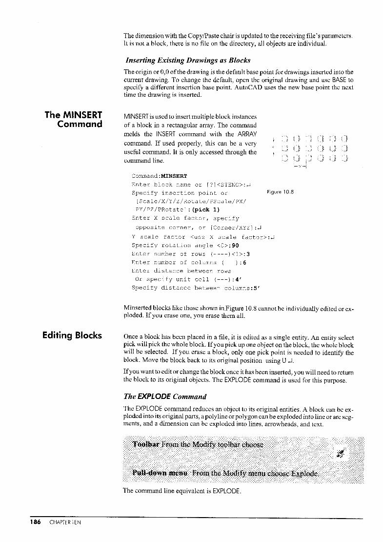
The MINSERTCommand
Editing Blocks
The dimension with the CopylPaste chair is updated to the receiving file's parameters.It is not a block, there is no file on the directory, all objects are individual.
Inserting Existing Drawings as Blocks
The origin or 0,0 ofthe drawing is the default base point for drawings inserted into thecurrent drawing. To change the default, open the original drawing and use BASE tospecify a different insertion base point. AutoCAD uses the new base point the nexttime the drawing is inserted.
MINSERT is used to insert multiple block instancesof a block in a rectangular array. The command
melds the INSERT command with the ARRAYcOlnmand. If used properly, this can be a veryuseful command. It is only accessed through thecommand line.
Command:MINSERT
Enter block name or [?]<STENO>:~
Specify insertion point or Figure 10.8
[Scale/X/Y/Z/Rotate/PScale/PX/PY/PZ/PRotate] : (pick 1)
Enter X scale factor, specify
opposite corner, or [Corner/XYZ]:~
Y scale factor <use X scale factor>:~
Specify rotation angle <0>:90
Enter number of rows (----)<1>:3
Enter number of columns ( ):6
Enter distance between rowsOr specify unit cell (---) :4'
Specify distance between columns:5'
Minserted blocks like those shown in Figure 10.8 cannot be individually edited or exploded. If you erase one, you erase them all.
Once a block has been placed in a file, it is edited as a single entity. An entity selectpick will pick the whole block. Ifyou pick up one object on the block, the whole blockwill be selected. If you erase a block, only one pick point is needed to identitY theblock. Move the block back to its original position using U.J.
Ifyou want to edit or change the block once it has been inserted, you will need to returnthe block to its original objects. The EXPLODE command is used for this purpose.
The EXPLODE Command
The EXPLODE command reduces an object to its original entities. A block can be exploded into its original parts, a polyline or polygon canbe exploded into line or arc segments, and a dimension can be exploded into lines, arrowheads, and text.
186 CHAPTER TEN
.... . r
The command line equivalent is EXPLODE.
..

Title blocks are usually saved with only the general information such as scale, date,etc., and not the information regarding the specific drawing. If you would like tochange any of the information already on the drawing, use EXPLODE then DDEDIT.
Updating Blocks
There can be only one definition of a block under each specific name within a file.Should you change or update the original block, the new block instances will be thenew block and the old block instances will update. This can be very useful, and verytroublesome.
Figure 10.9 shows four desk units and four stenochairs. These were inserted as internal blocks making them easier to Inanipulate. The client wants a chair with arm restson one desk, so the block is exploded.
Command:EXPLODE
Select objects: (pick the block instance 1 Figure 10.9)
The block of the chair will now revert back to the original lines and arcs.
Figure 10.9 Figure 10.10 Figure 10.11
Blocks, Wblocks,Color, and
Layers
Figure 10.10 shows arm rests being added.
In Figure 10.11 the chair is blocked again using the original name. Because this is thetyped-in version, the original chair disappears. The other chairs have been updatedwith arms.
Command:-BLOCKEnter block name or [?] :STENO
Block STENO already exists. Redefine it?<N>:Y
Insertion base point:MID of (pick 1)
Select objects: (pick the objects)
You may have noticed that the default layer is 0, and that this layer cannot be renamedor deleted. Layer 0, the universal layer, cannot be changed because it is usedextensively with regard to ByBlock and ByLayer settings for color and linetype. Thelayers blocks sit on and the color of the block can be set either by layer or by block.
Once you have created a number of blocks or wblocks, file management becomesmore difficult because you must remember the directory and the layers used.
If items are created on a layer other than 0 in a wblock, these new layers will be addedto the list of layers in tht~ current file when the wblock file is inserted.
All objects on layer 0 will be automatically placed on the current layer ofthe drawingon screen, and will assume the current layer color and linetype when the block is inserted. These are not necessarily added by layer. If color or linetype are not set by layer, the current setting overrides the layer setting. To check to see what the currentsettings are type in STATUS.
Blocks and Wblocks 187

'F !a~=;l!'--
-u--Analog AutoCAD Bas,c CMOS ElectrlC<ll
Integrated... Te>tS\l'~a Electronics... Integrated. POwef_dwg
f !';fiAtl .. ~ rlJiFa~tene[s . Fasteners - Home - Space House HVAC-Melric.dwg USdwg PJanner.dwg oesigneLdwg HeatingVe.
~-~ ~
'''-- ~!iii
188 CHAPTER TEN
Ifyou want a particular wblock to always have a specific layer, linetype, and color, assign it explicitly; do not leave it on layer O.
When in doubt, use 0,0 as the insertion point. Ifall ofthe files are created at a 1: 1 scale,the data will always fit.
The BURST Command
The BURST command works like the EXPLODE command, but it allows attributes to remain as "values" instead of "tags". BURST is not available in all versions of Release2006.
Removing Unwanted Blocks with the PURGE Command
Each time a block or drawing file (wblock) is inserted into a file, a copy of it is placed in the drawing memory or default area. If you want to cleanyour file, you must PURGE the blocks. ThePURGE command will erase all unused blocks,layers, text styles, linetypes, etc. from a file. Anyblocks, layers, etc. that have been brought into thefile but never used can be purged. It erases the information from the file defaults and settings.
When a drawing file or wblock is inserted, thenerased, the copy of the wblock remains in thememory in case it is needed again. The originalfile must be purged in order to accept a new file.PURGE removes unused named references, suchas unused blocks or layers from the database.
Command: PURGEEnter type of unused objects to purge
[Blocks/Dimstyles/LAyers/LTypes/PLotstyles/SHapes/textSTyl
es/Mlinestyles/All] :AEnter names to purge <*>:
The AutoCAD Design Center
AutoCAD has an extensive database ofsavedblocks for your use saved in the ADCENTER.Use ADCENTER or Ctrl2 to access the designcenter. Under the Folders tab you will find avariety of categories for saved blocks.
Pick the category that you would like tochoose from, then pick the block that youneed. Each block has a logical insertion basepoint. They are all drawn to a 1: 1 scale.
Some of these blocks are dynamic blocks.
Figure 10.12
Dynamic Blocks
Autodesk has provided seven new software upgrades for AutoCAD since 2000. In2006, the big feature was dynamic blocks. For those who need such things, dynamicblocks provide flexible blocks that can be placed within drawings. There are tutorialson how to make and use these blocks under the Block Edit icon. Essentially they allowyou to create a door, window, bolt, etc. that can be sized dynamically when placed on adrawing.

79
specify opposite corner, or
[Scale/X/Y/Z/Rotate/Pscale/PX/PY/
Command:-INSERT
Enter block name:chair
Specify insertion point or
PZ/PRotate] : (pick )
Enter X scale factor,
If you use the command line, thechair will disappear from thescreen. Re-insert it.Now draw a table 1800mm by1250mm and insert the chairsaround it.
The command line equivalent is -BLOCK.
Command:-BLOCK
Enter block name or [?] : chair
Specify insertion base
point:O,O
Select objects: (pick the chair and dimensions)Select objects:.J
Make layer 0current, then use BLOCK to createa block of this data.
Make sure the center of the bottom left circle isat 0,0 - the origin.
Create a dimension styIe called Furniture. Setit to an overall scale of 10 under the Fit tab andtwo decimal places of accuracy under the Primary Units tab.
Dimension the part on the Dims layer.
Draw in the chair as shown on the Objects layer.
In this tutorial we will draw a standard chair, block it, insert it, insert a title block ontoit, and then see the difference between this and Copy/Paste.
Use STARTUP or acadiso.dwt to start a metricdrawing. Create a layer called Dims and anothercalled Objects.
Step]
Step 2
Step 3
The insertion basepoint is REALLYimportant!
[Corner/XYZ] :-1
Y scale factor <use X scale factor>:-I
Specify rotation angle <O>:90.J
You can use MIRROR and ROTATE to place thechairs. Notice that the chair on the left has the dimensions in backwards - it was inserted with a 180- degree rotation. The bottom two chairs were mirrored.
Freeze the Dims layer.
Blocks and Wblocks 189

Step 4 Save the file as Dining room.
StepS Open a new file in metric units. Create the title block below and name the fileChaplOtitle. (Draw the lines and the text of the title block, but do not dimension it.)
m
The outside line represents theoutline of a 297 x 210 Inm paper. The title block fits insideit.
Save the file as Chap lOtitle.
-
I
- ~I I1- ...... --.-- ..~, ..- .-- F
DWhen scaling, make sure that the scale is reasonable; 1:10 or 1:20, not 1: 17. For this drawinguse 20.
Now go back to the chairs and INSERT the title block in. Make sure you have layer 0current. If not, the title block will be placed in the current layer and will take on thatlayer's properties. If layer Dims is current (now frozen), the title block will simply notappear.
You will notice that the title block is much toosmall.
The scale that you will print the file at on a 297 ~
by 210 sheet will be detennined by the scale thatyou must use to expand the title to fit the drawing.
Step 6
Step 7 The title block here is scaled by 20. This meansthat when the title block is printed at its originalsize, the table and chairs will be 1/20 of theirsize or a scale of 1:20.
Scales are discussed in Chapter 1] .
Freeze the Dims layer. Copy one chair over tothe side away from the table setting.
---
0II:~, "I"'" I......
ISCAIo r--
Step 8 Now explode the chair that is not at the table,and add arms as shown.Then block the chair under the original name.
Command:EXPLODE
Select objects: (pick the chair) r 366---,R2-4 I
2-4
Draw in the anns as shown.
Command:-BLOCK
Enter block name or [?] :Chair
Block Chair already exists. Redefine
it?<N>:Y
Insertion base point:CEN of (pick 1)
Select objects: (pick everything)
190 CHAPTER TEN

Your chairs will now have updated to include theanTIS.
This can be a very dangerous function. Alwaysbackup your files every few hours in case youreally make a mess. Three copies is always best.
0 0
.-1- ~ r-
R579Si!73
rL~+--
We are now going to take a look at the difference betweenWBLOCK and Copy /Paste.
Zoom into the chair placed away from the table orinsert one away from your drawing. Thaw the R24 r 366iDims layer. EXPLODE the block. 24 ~---...:...
Make Dims current and add all the dimensions asshown here. Make sure you use the Furniture dimension style.
Comma nd :WBLOCKEnter name of existing block or [=(Block=output
file)/* (whole drawing)] <define new drawing>:TESTCHAIR
Block name (or ?):~
Specify insertion base point: (pick the 0,0 area)
Select objects: (pick all the objects show in Step 9)
Select objects:.J
Command:U"J
Make a text style called Label and set the font toGothicE - (English Gothic). Add the text 0,0. ThenWBLOCK it. Use U.J to bring it back.
Step 9
If you WBlOCK an existi ngblock and use the samename, it will be unusable.AutoCAD will not be able tofind the file. Always explodeit or use another name.
U will bring back your data but maintain the wblocked file.
Step 10 Finally we are going to open a new file, INSERT one chair from the hard drive andCopy/Paste another from the existing file. You will have two chairs on screen.
Open a new file in metric units. Make a Dimension style called Furniture. Set the Fitsize to 10. Under the Primary Units tab, have no decimal places underprecision. Underthe Alternate Units tab, tum on the Alternate Units. Make it current.
r 366---.,R24 I24~----':'"
+ O,OR73
46
R579
Make a text style called Label and set it to Gothic E.
INSERT the file Testchair.
Now go back to your Dining room file and under the Edit menu pick Copy. Select theobjects shown in Step 9.
Go to the new file and pick Paste from the Edit menu. See the difference? The dimensions are updated to the current file with Copyl Paste, the text style is updated in both.
Remember: Afile is not a block until it is inserted into anotherfile. You do not need toblock a drawing to insert it into another file.
Blocks and Wblocks 191

Exercise 10 PracticeUse INSERT to compile a set of drawings as shown here.Don't change the size of the floor plan or elevation, change the title block.A third page could include details, Heating, Ventilating and Air Conditioning
(HVAC), a Section, or electrical plans.
•
t
II 0 Ff~
Pl'li5rl% l lIPidF"All flevatl:roI.fi¥.<:k3[;\"""JI">:B" d~ III2, fav8Wo,41, ALtn (I~)?,~rrtmPJ"",(ra.pe)
4, Sif't,AJ1Jlr1 (1aJPi')
'7. W~. a1d Oro-> InN.>bJralO<l<.
North
5cuth
(f)
1"'"Z
1!J";;'j' (,""" <:(12' /5._....p' .....J
0-cr:
1/:2"EJ""aI 0r"""....,f... 02"16"""".2~"OC
~-.J
R-:2(}(6"J """""'" ~ I?ln"'1Rron LL6 MlPd<VJJ,
D~"""=F.bh
(J) 0g~ ..:::
G.ta"D.... (J)-- cof~iJ.>Jl. "0"'-·-°8Cl)Q)
(J) ... cO::~.EOro=wI EJ!!(\j tlSQ..u>I
~".::JMI'J""'-~~
Cmtracta- .. o.t.If~.Ala"..,>~ !gn1"1'-'-Qu 6'-2"
'0'-0" B"'I" Drawlflgs Pc_red By
'0' _6:tariC5ecund rim- rlrst rica- !l(5) 25- 123
ll*
~r></w""DalItfllPIW:1910019,
192 CHAPTER TEN

Exercise 10 MechanicalCreate the template, bushing and jiglegs as shown.The BLOCK them and place them onto the part to make the assembly.
4.00
¢3.00
¢2,50
--3.00 -------I
0,50
f------- 6,00 ------------.
RO,25
¢O,50
¢0,60
¢O,60
¢O,90
~;O'25¢O.22
/':.. ¢0,45,,:/¢0,75
950.90
LOCK SCREW BUSHING
PRESS FIT BUSHING
¢O,30
¢0,45
Assembled Part
ASSEMBLY DRAWINGSMACHINES AND MECHANICAL UNITS ARE
GENERALLY COMPOSED OF NUMEROUS
PARTS. A DRAWING THAT SHOWS ALLOF THE PARTS ASSEMBLED IN THECOMPLETED SHAPE IS CALLED ANASSEMBLY DRAWING.AN ASSEMBLY DRAWING USUALLY
SHOWS EACH INDIVIDUAL COMPONENTAS WELL AS ITS RELATION TO THE
COMPILED PART AS SHOWN ON PAGE
196. SOME ASSEMBLIES ARE COMPILEDUNITS IN THEMSELVES t BUT WHEN
FORMING PART OF ANOTHER ASSEMBLY t
THESE ARE CALLED SUB-ASSEMBLIES,AS IN A DRIVE SHAFT IN A MOTOR.
ASSEMBLIES CAN ALSO BE FOUND IN
CABINETRY t FURNITURE, AND MODULAR
DESIGNS.
Blocks and Wblock 193

Exercise 100 ArchitecturalThis award winning building by Brian McKibbin illustrates the useof sections and details in creating an elevation and construction drawings.
ooV
-........ "'~
5CALE:: 1:25>
POOllNC1 t7~fAI~
100mm CONmfe - '.-.;';~.;~.~'. f.:";.:" :. :';~~::, .•-
200 mm Gl2AVEL -
3796
I I I I §
N. VJ
I1360
I1400
CD
~C\J
Clc=:(I)
ru
'"()'I
2ND FLDORCDCD
""J79l:ruct:ITa II IWI
V)
(MIO-OOI7A J...0
Bli ~eCO-BWCK r;lCNJ, I
D DD
If)vCDC\J
~GROUND fL
.;~ ~-. ..
1 .- .. "~." ",.
§~~
~:
t ~.~..
"~,
..~~~~:,.:).~.: ::.•...t ...··~~_ ..'i.;i
3990 .1
5~C1l0N @ N,f, CORNfRscale: I:?O
7\D\D 108
ECO·~OCK~AM 2EXrE:RlCl:SOFfif
MIO-OQm
DffAI~ 2ND f~OOR ROOf DffAI~5CALt: 1:2? 5CALE: 1:2?
194 CHAPTER TEN

Exercise 1Db ArchitecturalUse the section on page 194 to determine the height of this elevation.The building is 10 meters wide. You would get this from the plans.The windows would be on another drawing as well.
Nc;
wr,P5,tJINCiC/W
Meflt or
Ii~
!
J
" / S11JCCO fiNISHINSllAIlNCi CLP55 iN CLfAf(
CrJ(Nla MOULANOtJiZEV flUMiNUM fRAME5 \ ',,- PRe-PfJ N1tD
"fLA5HINc;
E:XI5f1NCi
LS11rWj - ------,ADJKfNf BUWINc;
77l/ v"- /'" V1\ GJi.VANllrtl /""- /'"/ RADIU:£tJ
a- U\,. CiLlARl? GL. uL.
/ i\ I
/ liT 11" '11' ~t~ 2NtJ fLOOR"I III II I
/ III I" I I I II
=st/A I I I I I I I I I I I A
/ r====LS l--.). ~~~ 5fAJNLf555reel.-
/ PANEL C/ WINC
/ L.iUHll1Nc;
//
/ - / ...---... ANODiZW flUM
/ CC\.-UMN CLI'VtJl
//
(cAL. uL. a. a. (il.. GiL. !:AL.
/ GK'OLNl? fLoa
/ , - "'1/I "---. aRAiV1IC...../ II
eA5f e~~VAfION? MffRE5
1490
ELEVATIONS ARE INTENDED TO GIVE AN IDEA OF WHAT THE
FINISHED BUILDING WILL LOOK LIKE. THERE ARE GENERALLYVERY FEW DIMENSIONS. THE HEIGHTS ARE GIVEN IN THESECTION VIEWS. THE SIZE OF INDIVIDUAL PARTS OF THEDESIGN, FOR EXAMPLE THE CORNICE, WOULD BE GIVEN INDETAIL DRAWINGS.ELEVATIONS SHOW THE FINAL FINISH MATERIALS OF THEBUILDING WHILE SECTIONS AND DETAILS SHOW THECONSTRUCTION.
2L o:l'-- (Xl
r-.
00
(\j
u[..
1020 I
30
Wlndow Upper fl(.l(j1'"
ELEVATIONSI?alcony tJetall
Blocks and Wblock 195

l-- 2.0
12.0
-j r-
2.0~
l2,OJ I-- i I1--38,0-1
Axle Support
____________L__~:--l----J~ms~~------------ I r ! I I I ! I ...-------------
1ll1LO X THRU1ll20,O SFACE2 HOLES
\ll38.0
58,0RI2,Q
Bolt
Bushing
-1190 1- ~34'O7.0-1 r-, 1622.0
~ + .IG,O
[l'TGO
~L: 6.0
THREAD
MlO X 1,0 2 X 0 + 1/4 UP TO 6'2 X 0 + 1/2 OVER 6'
16100,0
1tI38.0
022.0
LA
iA
.-JL
I 136,Q------J
~98.0-j
r,38,~---t I-.LI III' / I I ) f HIj-d:o
E12.0 I-J t44,0--1
92,0
Wheel
Section 'A-A'
1ll1l,04 HOLES
12,0-1 112,0 1
-.0o.~
C:2O.- Q)-:= CCO 0
<D en-C .-...... £.~ J2-0 ..:..=~O).!:!? c~ .~
Q) 0rnlo..0-0a. >Q)...o
-c E- Q)C eno enoC c~ 0o
-c Q)VlVl 0o ~Vl u't: ca Q)a.....c:<D-+:
-C Q)....... -;=~ '-+-o Q)cn crnO.;; c~ 00--00
Q) E-c Q)-....c:<D+-o 8~ 0ua::
r--
(1)en
e_
UL.
~W
L.(1)0)c:(1)--C
.J:Uo
Top Plate2
1Il135,O
20.0 l-- I60.0--1
80.0
Axle
~1tI22'O
1tI16,O
+
BILL OF MATERIALS
No ITEM QTY MATl DESCRIPTION PAGE1 TOP PLATE 1 CAST IRON 1162 WHEEL 1 CAST IRON 1753 AXLE SPT. 2 CAST IRON 1384 AXLE 1 SAE 1020 455 BUSHING 2 BRONZE 646 BOLT 4 PURCHASE M10X50MM HEX HD BOLT. 104
zUJI--ex.UJ
~U
-00-~

Set Up and Scalefor Simple 20
Drawings
Setting Up Drawings andPlotting
..•.•. >~~l'1 C(;)ffil:>le'tiOrlQ'tth.is chapter, you should be able to:
single view
and UNETYPE sizes for any drawing
•. ···••••• ·~i.l.,lse bJ,)cks1(>c<::>mplle multi-view drawings
4..l.)ses,ection c,rrrovvs·c)nd break lines
·•····•• •.•·ii:'}.Ait:id rlofaticlOSbvifTmortmQ textplotting drawings
fllc>tttle(jro'win~Q with plotters and PDFs.
So far we have been working on creating AutoCAD models and drawings as individualsets of data. The geometry is entered relative to the origin (0,0).
All AutoCAD drawings should be entered at a scale of 1: 1 and then the drawing information such as dimensions, notations, title blocks, etc., should be added according tothe scale for printing.
There are two ways of creating a scaled plot: with paper space and without paperspace. Paper space drawing is covered in Chapter 12.
To plot without paper space, draw the model at I: I, then insert the title block at an appropriate scale factor and plot the file at a specific scale.
For example, ifyou have a layout for a house that is 40' x 30' drawn in real units at a scaleof 1:1, you want to have this plotted at 114'" = 1'- 0"'. As you can see from Chart 1 (page198), 1/4'" = 1'- 0'" isl/48 of the original size.
In metric, a house that is 12 meters x 10 meters would be plotted at a scale of 1:50 or1/50 of the original size.
Title Blocks
Your title block should be drawn at 1: 1 as well. It must also be large enough to containthe floor plan. In this example it is set up for a 24 x3 6 sheet. In order to have this visibleat the correct scale on the layout, you can insert the title block at a scale of 48. Then,when plotting the model, use a plot scale of 1/48 or 114" = 1'-0".
This is by far the best method ofplotting and scaling, as it allows you to maintain themodel at a scale factor of 1:1. For all of the information that requires scaling such asoverall scale in the dimension style, hatch, linetype, text size, etc., 48 can be used.
Title Block, Dimension, Hatch, and Linetype Scale
The ANSI standard for the text in dimensions is 3/16'" or 5 mm. This is also the defaultfor the dimension text in AutoCAD. This will need to be changed, however, ifyou areplotting the part or view at a scale different to 1: 1. You want the part to be scaled, butyou still want your dimension text to show up at 3/16" on the paper.
To do this, you must determine the text size needed for each particular scale. Remember, by resetting the overall scale under the Fit tab of the Dimension Style dialog boxyou can automatically change the size ofthe dimensions if they are not the correct sizefor the plot ofyour drawing. The following is a chart ofsizes to be used in dimensions,linetypes and hatches.
Setting Up Drawings and Plotting 197

Chart 1: Determining Scale for Drawings
FractionDecimal ValueScale Factor
Architectural or Imperial_._-_._-_._---_.__._--_.__."._----~_. __..~----------_.--------
3" = 1'-0" 3:12 .25
1" = 1'-0" 1:12 .0833333
1/2"= 1'-0" .5:12 .0416666
114" = 1'-0" .25:12 .0208333
3116" = 1'-0" .1875: 12 .0156246
1/8" = 1'-0" .125: 12 .0104166
1116" = 1'-0" .0625: 12 .0052083
Mechanical
3/4" = 1" .75:1 .75
112" = 1" .50:1 .5
114" = 1" .25:1 .25
Metric
1: 10 .1
1:50 .02
1:100 .01
1:1000 .001
1/4
1/12
1/24
1/48
1/64
1/96
1/192
The first step is to determine the scale factor for the plot, and change the overall dimension scale factor under the Fit tabof the Dimension Style dialogbox. Remember that it is not onlythe dimension text but the arrowheads, overshoot, dimension textgap and other variables that needto be adjusted.
Always change the fit size not thedimension text size.
On a simple drawing with onlyone scale factor,. Chart 1 can beused to detennine the plottingscale factor and the block insertionfactor for title blocks and otherblocks.
For example, if you are creating aplot or drawing that will be 3116"=l'-0", draw the floor plan at a scaleof 1: 1. Add the dimensions at anoverall scale, under the Fit tab, of64. Add the hatch at a scale of64 (unless it is an architectural hatch), then insert the title block at a scale of64. Finally, plot the drawing ata scale of 1/64 or 3/16" = 1'-0". Chart 1 will help you to scale the model correctly. Thedimensions, text, hatch, and linetype must be scaled to fit the drawing.
198 CHAPTER ELEVEN

Scaling the Text and Annotations
6'-()"
!lO'-o'
9'-0'
Figure 11.1
When creating text and dimensions, you must change the scale factors in order to seethem on the screen. This is even more of a difficulty when working with very largedrawings.
If, for example, you want to make sure the texton a floor plan is at 118" on the final drawing,you would need to find 1he relationship between 1/8" on the paper and the size of the texton the floor plan. If 114" on the paper will beequivalent to 12 inches on the model, then 118"or half of that value will he 6"on the model. Ifyou create your notations and dimensions at 6",as shown in Figure 11.1, the final drawing plotted at 1/4" = 1'-0" will show text that is 1/8" inheight.
Text, dimensions, and related notations must be scaled to attain the appropriate size onthe paper. You can always tell a novice AutoCAD user by the size of their text.
Ifyou can read the text when you ZOOMAll, the text is too big.
!EL 31750
FLOOREL 32770
Figure 11.2
When creating metric drawings, use thesame formulas. For 3 mm text on the finaldrawing, you will need to create the text at300mm high in order for it to print at theproper size when plotted at a scale of1: 100. See Figure 11.2.
U/SIOE SASE PLEL 33100
Chart 2 (see page 200) shows you at what sizes to scale your text to obtain the propersize on the final drawing. Find the size that you want your text to be, then the scale youintend to use, and make the text the suggested size.
If you take your final plot scale and multiply it by the default sizes and scale factors,you will arrive at workable scales and heights.
LTSCALE and HATCH Scale
While working with views to be placed on a drawing, you must also consider hatch andlinetype. In creating these drawing aids for display on a screen, we determined that thescale for these functions should be the furthest value ofX on your screen divided by 12.This provided a working area that was visible on the screen and easy enough to workwith.
To place views onto a sheet ofpaperwith the linetype and hatch at the proper paper format, use the same setting that you would for dimension scale or final plot scale. Architectural hatches such as arcane and arroof are set to be viewed on floor plans, so ascaleof 4 can be used for a drawing to be plotted at 114" = 1'-0".
Using Blocks toCompile
Drawings
For plotting different drawings at different scale factors, you can insert drawings asblocks on a title block or another accepted drawing sheet. However, although this will
work, it is not recommended because any changes will have to be made in the originalfile.
In Figure 11.3 there are two separate files inserted onto a drawing sheet that is 36" x
24".
Setting Up Drawings and Plotting 199

200 CHAPTER ELEVEN
Chart 2: Dimension and Text Size
Plotted Text Size Scale Text on the Model SCALE
(Architectural or for Fit
Imperial) To plot drawing at. tab~-~--~~--~_._~~--
1/8" 1/16"= 1~-O" 24" 192
1/8"= 1~-0" 12" 96
3/1 6"= 1~-0" 8" 64
1/4"= 1~_0" 6" 48
1/2"= 1~-o" 3" 24
1"= 1'-a" 1.5" 12
1/411 1/1 6"= 1'-0" 48" 192
1/8"= 1~_011 2411 96
3/1 6"= 1~-0" 16" 64
1/4"= 1~-0" 12" 48
1/2"= 1~-0" 6" 24
1"= 1'-0" 311 12
3/16" 1/ 16 11 = 1'-0" 36" 192
1/8"= 1'-0" 18t! 96
3/16"= 1'-0" 12'~ 64
1/4"= 1'-0" 8" 48
1/2"= 1~-0" 4,5" 24
1"= 1~_011 2.25" 12
Mechanical
.25" 1:20 .5 2,0
1:10 25.0 10.0
2:10 ,125 0,5
.125" 1:20 .25 2,0
1: 10 12.50 10,0
2:10 ,0625 0,5
.1875" 1:20 .375 2.0
1: 10 18,75 10,0
2:10 .09375 0.5
Metric
3mm 1:10 30 10
1:25 75 25
1:100 300 100
1:250 750 250
1:500 1500 500
1:1000 3000 1000

F1reploee Detailt" - t' o·
Figure 11.3
The drawing shown in Figure 11.3 consists of three separate stored files:
1, a title block at 36" x 24"
2, a fireplace detail at 16' vertically
3, a floor plan 35' x 30'.
Since the floor plan is the most important view and the one most likely to have changesmade, it is the base file. The other two files are inserted onto it. The title block was inserted onto the floor plan at a scale of 48. The drawing will be plotted at 1/48, so the title will get back to its original size.The fireplace, being a detail, was inserted at a scalefactor of 4, four times its original size. It will be plotted at a scale of IN = 1'-0",
Command:-INSERT
Enter block name or [?] : FireplaceSpecify insertion point or [Scale/X/Y/Z/Rotate/PScale/PX/
PY/PZ/PRotate] : (pick a point)
Enter X scale factor, specify opposite corner, or
[Corner/XYZ] :4
Y scale factor <use X scale factor>:~
Specify rotation angle <O>:~
o
Ii 111-0.0-00-0----1
r Linear dimensions---------~
I Unit format:
'I' Precision
I
Fraction format:
DecimaJ separator:
I Round off:
I Prefix: II RO
I Suffix: I IrAn
Ir~::~=: >C~·-----I0-'2~5-00---1""""".1."1~!... U,
II mr1 . . I .• PrEl 6 Apply tolayouH:limensionsonfy !
!' "
Ifany dimensions need to be addedat this time, the fireplace is fourtimes its original size, so the Measurement Scale factor under the Primary Units tab of the DimensionStyle dialog box will need to bechanged to .25.
If a drawing is to be plotted atmany different scale factors, create different dimension styles foreach different size.
You can insert drawings at thefractions noted in Chart 2 onto thetitle block and plot at a scale of 1:1,but this allows for no changes intext or dimensions.
Setting Up Drawings and Plotting 201

View Titles andDrawing-Related
Notations
Once you have created your drawings and are ready to plot, you will want to add the[mal drawing-related information. Each view should have a title. If there are sectiondrawings, these sections must be noted on the plan, front or elevation view. Finally, ifyou are showing details, the place where the detail attaches to the main portion of theobject lnust be shown with a break line.
Figure 11.5
Figure 11.4
ggl'~'
R12.f/' .... ."JIOX1lRJ
• llIBlJIII8fW:I!.
~IlE _ 211l1l.E11 rt
12... \~( J. . j .~1l2~ a"
Section views are for all types of drawings, and theseshow a vertical or horizontal slice through the object toshow how it fits together and what is used in the construction or manufacture of the object in question.
In Figure 11.5, the view title indicates where the object iscut, in this case through the hinged shelf (page 177).
When the title for the section view is not sufficient to describe where the section is taken from, a section line isused.
The same orientations are used in civil and architectural applications, but the views are labeled differently.
The Top view becomes a Plan or Floor Plan, the Frontview becomes an Elevation, and the Side is also an Elevation. These are labeled North Elevation, West Elevation,etc. for those buildings where the designer has actuallytaken the trouble to orient the building on the lot. Otherwise they are called Front Elevation, etc.
In applications with orthographic projection, asshown in Figure 11.4 (from page 138), the views arelined up and the titles are directly beneath each view.
This is fairly straightforward in a simple part like this,but there are times when the parts are difficult to distinguish if they are not properly labeled.
View Titles
View titles are always shown below the view. Thesecan be slightly to the left or the right, but never above.
111100.0
022.0
11139.0
Wheel
Figure 11.6
Section 'A-A'
Section Lines
Section lines are used to show where a cutgoes through an object. Figure 11.6 showsa simple mechanical part cut through toshow where the section is. A more complicated mechanical part with several sectionlines is shown on page 238.
In civil and architectural applications, section lines are most often shown on floorplans. The section is often jagged so thatthe section of the building (page 1] 7) istaken through all the 'difficult' parts, or theparts where the builder may want moreclarification. Note the section lines on thefloor plans on page 192. The section in architectural drawings is often used to findthe height of objects on the elevation sincethese are not generally added to the elevation views. To see how this works, look atpages 194 and 195.
Section lines are made with PUNEs at varying widths (page 91).
202 CHAPTER ELEVEN

Break Lines
Break lines are used at the edge ofobjects to show that there is some material extending beyond what is being shown. In Figure 11.7a the stone at the top ofthe fireplace extends beyond the detail up to the roofline.
NTSo
.13/4
'-----d---ir----r-----',
PEDIT
PLINE AND
R1I2
I
II
----\t---v-IIi,_...J
IIL _
Q bFigure 11.7
Break lines are also used to show that the full length ofan object is not being shown, asin Figure 11.7b. Here the foundation ofthe building, under ground, is a full 8', but onlya portion is shown. Both of these applications are lised in every discipline.
In mechanical applications, the break shown in Figure 11.7c is typical because it illustrates that the object being broken is cylindrical.
ImportingNotations
Often you have notations on drawings that are standard or typical of many drawingssuch as manufacturing requirements, notations concerning adherence to building codeor national code requirements, or materials requirements. If this is the case, you can
type these up in a word processor and import them onto your file using MTEXT.
le~n about MTEXT
.. . i ~ show Toolbar
. ... . ! ~ Show Options~ Show Ruler
Figure 11.9
To test this out, type up a few sentences in Wordpad or Notepad.Open either ofthese programs underthe Programs area of the start menuon your computer.
Save the data as a .txt file or simpleASCII text file format, as shown inFigure 11.8. Make sure you areaware of what directory the text isbeing saved to. If you have a flashdrive or floppy disk, that is the bestplace to put it. The extension will be.txt. The .rtf (rich text format) fileswork as well. Figure 11.8
Invoke MTEXT or multiline text,pick the location for your notation, and then right-click to getthe Import Text function, asshown in Figure 11.9.
Find the directory that containsyour .txt file, and bring the fileonto the current drawing.Thetext will be imported onto yourfile where required. You canchange the size and font once itis in by highlighting it and adj listing the properties on theMTEXTmenu.
Seiting Up Drawings and Ploiting 203

UsingLineweights
To have a professional-looking plot, you must have different line weights for eachtype of information. The object lines will be the darkest. The dimension lines will belighter, and the hatch lines should be lighter still. The lineweights ofyour objects arebest set up within the Layer Properties Manager.
Lineweights and the Layer Properties Manager
You will want to spend some time finding out what lineweights work best with yourplotter. Do a few test runs to make sure the settings are correct, then make note ofthem.Each plotter will plot at a slightly different scale.
• white CON_OUS~- Default• white CON_OlJS ~- O.13mm• white CON.GUS~- 009mmIII m.ta CON.GLlS -- Defau.:ll
~~ Q ~. wMe CON_OLlS -- DefaIljI~ Q Jlh Cl 9-" CON ..GUS -- Defaull;; 0 tID. white CON.GUS --~._- 013mm
Plotting
I
IDo not leave the plotting of youridrawing to the day it is due. AnyIsystem will have difficulty printing'the first time. You need to know thefinal plotter destination and havethe necessary driver before you caneven start to plot. Practice someplots first.
204 CHAPTER ELEVEN
Before you plot, in the Layer Properties Manager, set all your layers that you want toprint to black. The Defpoints layer, which appears automatically with dimensioning,will not print. The other layers used for page set up you can toggle to unprintable asshown on the right above.
Leave the object lines and text as default or increase them to .3, as in the examples inthis book. Change the lineweight ofyour dimensions and hatches to be much smaller.Try 0.13 for dimensions and 0.09 for hatch. By making a .pdfof the page you can testthese lineweights out before sending them to paper (see page 206).
Plotting is only easy after you've done it a few times. Ifyour text sizes, notations, andlineweights are all good, you should get a good plot.
There are three main ways to plot: directly to a plotter or printer, plotting to a .plt file,then taking this .pltto a plotter, or printing to a .pdffile, which can then be sent over theInternet. The way you plot will depend on how your system is set up.
Plotting Directly to a Plotter
Ifyour printer or plotter is hooked up directly to your computer and working properly,you should have no trouble printing. Simply pick the PLOT command from the Filemenu or type in the word PLOT.
Comrnand : PLOT
Ifyou are working with an older version ofAutoCAD, the command listed under theFile menu may be Print. It changes every few versions. Both Print and Plot do the samething.
Once you have accessed the PLOT command, you will get the Plot menu. The title onthis dialog box will say Plot-Model unless you are in paper space (see Chapter 12).

( ..prev.iew.., 1
If your page is smaller thanthis, choose the expand arrowin the lower right corner.
]
Ifyou want to accept all of the defaults, press OK and your plot, ifthe plotter is set up,will be produced. The system defaults to printing the display from the screen. Ifyoursystem is set up to a laser or inkjet printer, then you should be able to simply pick upyour print. Should you wish to change any of the defaults or print to another plotter,another size, or another area ofthe screen, pick the related button. Always Preview before printing.
Printer/Plotter Selection
The PrinterlPlotter tab lets you direct your plot to a series ofplot devices. The one youare set up to should plot directly. It also allows you to have the plot written to a file asopposed to being sent straight to the plotter. The file types are .pIt, which will allowyou to take this to another printer and get a hardcopy, or .pdf, which is a portable document file for Internet use.
Use the down arrow beside the Printer/plotter name to choose a plotter. If the one youwant to use is not configured, you need to add it to the list.
Configuring a New Plotter
If the plotter you need is not on the list provided,use the CONFIG command to load a new one. Atthe command prompt, type in CONFIG, or go tothe Tools menu and choose Options at the bottom of the list.
Add-A-Plotter WizardShortcut1 KB
Command: PLOT
Then choose Add or Configure a Plotter, as inFigure 11.10.
You will get a choice ofplotting options. Choosethe Add-A-Plotter Wizard.
Choose the plotter you want from the many listed(Figure 11.11) and work your way through all thedialog boxes. If the plotter you need is not there,you can generally get the plot driver from theInternet.
Figure 11.10
:~~~-5i;pT;:l~s~rPl;;t'~~~rp~bii~hT
Defau~ plot settings for new drawings
e Use as default output deyice
!'* \\FE·WIGNALG·01 \HP LaserJel 6P
o Use last successful plot settings
Figure 11.11
Setting Up Drawings and Plotting 205

206 CHAPTE RELEVEN
Once the plotter driver is loaded, go back to the Plot menu and change thePrinter/plotter to the one you have just loaded.
Plot to File
Plot to File will create a .plt file for transfer either into a word processing file using aHP driver or to a plotter not connected to your machine. Always take a copy of yourdrawing file with you if you are plotting off-site in case there are errors.
Paper SizeThe paper size can only be changed once the plot device has been chosen. Ifyou have alaser printer as your plot device, you can only get a small paper size. Change to anotherplotter to get a larger size of paper.
Plot Area
The system is set to Display. Window gives you more control. Choose the window,then Preview.
Plot Preview
This will give you an idea ofhow big your plot is, and how it fits on paper. Use eitherthe Full Preview or the Partial Preview before you spend the time or money on a paperplot. Always preview your plot before clicking OK.
Plot Scale
The drawing will be set in terms ofplotted inches = drawing inches or plotted millimetres =: drawing units. Use Fit only when the actual scale of the drawing is notneeded.
Use Chart 1 to determine the plot scale. For a drawing at 1I4u= 1/-0", make the scale
1/48. To make a drawing that is 1:50, use a scale of .02. Always preview before youplot.
The plot origin is always assumed to be the bottom left comer ofthe paper. Ifyou wantto relocate the origin ofthe plot to another portion ofthe paper, reset this parameter bychanging the X and Yvalues in the edit box. This is usually done to place a title blockonto an existing drawing or to place a missing view onto an otherwise cOlnpleteddrawing. Some skill is needed here, so try placing the view or plot onto a test sheet before placing it on the final papere, especially if there are drawings on the paper thatcould be ruined.
PDFs
PDF files (Portable Document Files by Adobe) are a quick and easy way to both checkthe lineweights and quality ofyour plots prior to printing, and send plots over the internet.
In Releases 2007 and 2008 AutoCAD has added a built- in PDF driver. Configure thisdriver using AutoCAD e-PLOT under the Add-a-Plotter wizard Manufacturer's list,then from the Models list choose PDF.
In Release 2006 and earlier, try the PDF995 software available on the internet.

In this example we will take a tloorplan ofa house, copy a window, and plot so that thefloor plan is at a scale of 118" = 1'-0" and the window is at a scale of 114"=1'-0".
Step] Retrieve the file for Tutorial 3b.
Ifyou haven't got it, quickly draw it up. It isOnlY/, I I
about 20 commands, see page 61.~
~r---50__' ?Once in, draw a line from the MIDpoint ofthe centralwindow to the right 50'. ARRAY this window unitaround the central spot. This will make anice secondstory or well-lit tower.
Now just add some lines to place walls betweenthese windows, and a small opening for a staircase.
Make sure all of your lines are on Layer O.
SCALE it by 2.
The Inain obj ect that you are concentratingon is the floor plan. The window is a detailadded to it.
COpy the window unit on the right over tothe right.
Step 2
~ 15'-6' ~
Step 3 First dimension the floor plan. Make anew style called Eighth for 1/8"= 1'- 0".Set the Overall scale to 96. Just add a fewoverall dimensions (the dimensions in thisimage are larger than on your drawing).
44'-6'
Make sure you put the dimensions on a separate layer.
Now we are going to add some dimensions on the detail view. The view hasbeen scaled by 2, so you want the Measurement scale to be .5.
Measurement scale
Scale factor:
o Appl,y to layout dimensions only
Make a new dimension layer calledQuarter, and change the measurement scale to .5.
Setting Up Drawings and Plotting 207

l) 13mm
!0n IFree~e ILockl Color ~ tLinetype iUneweightt11J • white Corttinoous Default
• 'l.'lhite Continuous Defawt
•When you are setting up your layers,change the lineweight of the Dims layer to0.13.
Notice that your dimensions for the detailshow up at the same size as your other dimensions' but the readout reflects thechanged measurement size.
Step 4 Ifyou have an 8.5 x I] title block, use it. Ifnot,just make a simple title block 10.75x8.25 in size. INSERT it onto the drawing at a scale of 96.
~ Insert 11J[~
Name: ~felabtjtle
Path:
.~ .Ij [..Browse... DO
r OK I r Cancel l ( Help
Insertion poinl
l.EJ Specify On·screen
Scale
o Specil9 Olrscreen
X: l 96 I~--~
Y: lS6 r
2 ISS I~ Uniform Scale
Rotetion
.'·0.Specify OO'"screen
Angle:!'---0 _
Block Unit
Unit; ~~
Faclor: .L....11__~
StepS
208 CHAPTER ELEVEN
The views fit well within the title block. Ifthey don't, you have the imperial/metricproblem. Ifyou have started in metric, allthe numbers will be wrong, regardless ofthe fact that you may have changed yourunits.
Scale the title block by metric numbers 25.4, 2.54, etc. and it should eventuallyfit.
Look on Chart 2 for the size of text thatyou want for your titles. Since you will beplotting at a scale factor of 1/96, you willwant text that is 12" high to show up as118" on the final drawing.
The title should be underlined. Under thetitle should be the scale of the view:
Floor Plan
Scale 1/8" = 1'-0"

Step 6 Plotting the Views
Use the default printer that is set to your machine. This will be plotted at a scale of 1/8"= 1'-0". Set up the plot file as shown below. Using the option Window in the Plot areasection will allow you to pick which area you would like plotted.
Once everything is set up, be sure to use Preview to get a preliminary view ofthe plot.
Zoom Window
Zoom Original
At this point you may notice any errors in placement,line quality, or size that have been overlooked in themenu. Use the roller ball on your mouse to zoom intothe drawing and check out the lineweights.
If there are errors pick Exit to get back to the Plotmenu.
Ifthere are no errors pick Plot to continue with the plot.
IE~-~
I PlotI---~--~=~~
I Pan
I" Zoomi!I1
If your plot works the firsttime,consider yourself a genius.Allow a few hours to get yourfirst plot. Get someone to helpyou who has experience onTHAT plotter. If anyone elseuses it, you can assume thatthe plotterwiJl be messed up.
The menu choice Plot to file can be used to make a .pIt file that can be taken to a plotterfor printing. Not every plotter accepts .pIt files, so unless you are certain that the plotter will accept these files, making a .pdf is probably a better choice.
Setting Up Drawings and Plotting 209

In this example we will take a mechanical part and plot it at a scale of 1:40. The finaldrawing will be plotted on a letter-size sheet (8 1/2" xlI" or 297 X 210).
Stepl Open a new file in metric using acadiso.dwt. Set up your layers as shown below. Don'tforget about the lineweight. Different plotters print at different weights. These lineweights are good for some printers. Others print well at a larger lineweight.
The standard is minimum 0.30 mm, with thicker lines at 0.60 mm. The plots in thisbook are printed with objects and 0 layer at 0.30 mm. Try this, but if it' s too dark, setup as shown below.
, ayer roper les anager
~~. ~ ~)( +J Currenlla)'er: DIMENSION
• white Cootinoous -- 1109 mm• white HIDDEN -- 0.13 mm
HATCHFHIDDEN
: Name : On; Freeze j Lockl Color l Linetype 1Lineweight~ ··D-·······J~·-O . :l'tD -'·i~Wnjte· Cootinoous '-=:=-OefauJt ----.--
CENTRE "" a 1jt). white CENTER -- n.13 mID
DEFPOINTS ) 0 Jr:. 0 Y-.•w eootinoous -- Default
•
Status
Now draw up the obj ects below.
R20
101
Step 2 Make a new dimension style for these dimensions called Forty because it is beingplotted at a scale of 1:40. When you open the Dimension Style dialog box, if the basicdimension style is Standard, you have started the drawing in imperial units.
The base style should be ISO-25.~,~--....~.. ~ ~ ~ ~,-.
II] Create New Dimension Style W]~I
J
1 • .Use for: !All dimenSions
New Style Name:!\....F_or..::.;t~~ _
SlarlWith: ~,_SO_'2_5 ----,-,,;,=;m
Ifyou are in the wrong units, open afile in metric using acadiso.dwt.You might need to SCALE the drawing until the dimensions are correct.
Continue Cancel Help
210 CHAPTER ELEVEN

!Side
oth texl and:1 thing 10
(' Scale fOI dimension features~.•_~.~ .. w.<._.<_. ~~"\
! E> Use overalf scale of: ~Il:'~.:':':::.~.:~:~.::~:"=::: i 0 Scale dimensions to layout j
L .._~.__~ ._.~..__.~~.~~_.._.w.~-j
Many people set their text height, arrowhead size, gap, overshoot, etc. If youhave a template file - a base file that always has your settings - this is a goodidea. It is difficult, however, to remem-
3Sber to change all the settings each time,so an overall scale is a lot simpler. Thegraphic image will reflect what settingsyou have.
Now change your Primary Units so thereare no decimal places.
Change the overall scale under the Fit tabto 40.
Dimension the object as shown above.
210-3 UNC-2485 DEEP
R92S
105/165 DIA2 HOLES THRU
Note: Fillets QndRounds R20
RiOlO
R1170
101
Section A-A
Step 3 In mechanical applications, often the notations for threaded fasteners:screws, bolts,etc., are not shown with a diameter. Instead they are shown with class notations.
For example, the top left thread isshown in this diagram. The diameter and depth ofthe fastener are thusnot needed in the drawing. This notation says it all.
210 - 3 UNC - 2A
Update your drawing using the notations above. The height ofthe textshould be 120. Then add:
~NOHINAL DIAMETER
lNUMBER OF THREADS PER CENTIMETER
~THREAD FORM AND SERIES
CLASS OF FIT
.f;-A IS EXTERNAL. B IS INTERNAL10-3 UN -21¥
485 DEEP'--DEPTH AND NUMBER OF HOLES
View titles
Section A-A using PLlNE and TEXT
Notations for both sets of 'holes', as shown
The notation for all fillets and rounds.
Erase the dimensions that are better shown in notation
Setting Up Drawings and Plotting 211

Step 4 Zoom into a small portion of your screen. Make a PLiNE rectangle 265 X 185 units
which will fit onto a 297 x 210 paper.
TITLEMECHAN~CAL PART
DATE ~7/03/08SCALE
~:40
PROJECT SECT~ON DRAWNBoB EDMONDSNUMBER
M~
Zoom into the right COIner and create the title block shown at the side.The distance between the linesshould be 6 mm.
Now scale this block by 40. Youdrew it at the size it will be whenplotted. Then you scaled it to fit theimage. The objects will be plotted ata scale of 1:40.
Move the title block over so that itfits the image.
".~es 105/165 DlA194 2 HCIlES THRU
,a{J ",.' "'"" ~Rounds R20
1=
IJ,,'.",
Step 5 If your linetypes don't show up hidden and centered, use LTSCALE to change the display. Just change it until it looks good.
Double check your layer lineweights as in Step 1.
Step 6 Set to the default printer, use a scale of 1:40 and a paper size ofA4, and you should befine. You may need to Window and Preview a few times to get the image properly onthe page.
~Plot Model t~l~]
Learn <wout Plotting
Plot style table (pen assignments:)
---~.. --_." '1···IL-<_No_ne_> ~ ............;;~,M Add".
Plot .optioo$
Dplot in bad<.ground
~}Plot with plot ~Jf';S
o Plot st.emp 00
DSavechangesro.1aycut
Or~irIQ(ll'"lentation
OPortrJ!lito Landscape
OPlotUP~ide"down
Number of copies.
i 1 .•i&~.
~._JunitsoCenter the plotx. 1-13,65 Imm• ,=l ..,.J
Name:
Plot offset (qrigin set to printable area)
Printerjplotter
·'~i••••!I-g"'''I·I••••-••••I(j!.I .Properties".
PlQtarea
Wnattopfot:
fw~~il
( Preview:." .1 Apply to layout 11· OK J( Cancel JI Help J.<i
212 CHAPTER ELEVEN

UJ"=t;ic3c c.c.80=., ELn asNJ:
Izo m~a ><-+~ CD::r-(l) ~ ..,
o-cn n~ 0- -.~~' tn=:§ CD~ a..._.::;:. .....:: ~ .....::ro(l) a...a-a... .."_CD ..,~'O- 0
...en nQ ..p0... -.a... n~ CD=+CDco()
?'o:Ja....."
5;-i
• SCALE
U)
1:)S:2u...e:(
1:)
~Q)D.
....~
o+-JQ)
o
o+-J(j)
DATE:
21/03/01 various
NAME IDRAW
Z.P. 1
"IJ)
m
II
ri-----.Jl"ii1II
-.J
ll~ f>I
_-1
~
Metal Hat'1{;jer
Alternate to ledCier
Scale 111=11011
Wooden 5tair Detail
~--
PI4wood freadsand Risers
I. 10'9" .1
r~1 5u~:a?{ )~L
ill
floorit1C1
"(lJ"-....-1
Wood finish
I'--
fread DetailScale 21!=::::IIOII
0----~:---- "II
1/2"J III
,05R :~tl~~ -
~-..Ii(,,»
(/)CIl:4:5'
coC"0
oa::E5'
coII)
o:::::l0...-0
~:::::l
co

Exercise 11 ArchitecturalThis illustrates four types of drawings made for commercial applications.Use ARRAY for the curved text.Print it out with differing lineweights on a letter sized or A4 sheet.
@ @ ©6000 6000
2000SQX450
ooQCX)
o
3CX)
MANAGEMENT~
-------- I
4#6CONT, TOP
350X700 FTG
#S@200 HOR, EF#6@250 VERT EF
350
--:j- - - -- - - -I-
i(/) L-J/{' -1 I
/ /0 I
I / I~ { #8@150BVI : I~ --1 /
/2 / \~ :/ \r- BASIC SLAB =180:
A'0~ \-1\ I\V/ \' I
~~/ \~ I
S1\<.'JC:~ / \1J DROP PANEL:1- 2200SQX150 ! I
----/ Sl S2 \~ ~I~ \ r-
I" Y' I I-+----F-+--_+_ ~(: \=-= ---C..-l-+-I--I---+-
~ ---1 I
~'~ ~ Al 2 "'"L_~,I .6 \~ A OoR ,,-I.,: I \~ ~\.- -- - ~
/'J I \\?-~~ ~ oJ:I ~ I~ r- ,\v/I. "'-FDUNDATION '\ oJ I < '\~S- ...~, \ </) f0\./ OFFICE : ,
'; / BASEMENT \~ / ~I ~
I/ RECEPTION
~~:::z::lJ I I~ 0UP I
-- -
®
....
6000
'1000
/ 2000
2000 .. I
6000
-J ~475
214 CHAPTER ELEVEN

,63-11UNC-3B
----l m::::r ><in''U CDQ ..,4 nVI --:::r-
CA0c
CDa:::::0- ....([)
0.. ....a~
~::l
S-a CDVI nn ::raCD
QQ.. ::s--' --II n--'
Q
to'33
0,20
I
I0.94
~
PinScale 1=.5
-1 10.88 0.64
J_
hctA I~ I ~ .n,. .Various Full John Ripley
~ d11f I Cfa.4A. I SHEET 1 of 1Ben Drummond 2AR23
APPROVALS I DATE I COMpo.ny
iIlarria ilJarnpl1 ,]fnr.
~~~:Q~~SS~~~fED ITit l eFRACH[J.IS +/- 1/32 BOD Y AND PINDECIMALS +/- . 005
+~-
r
0,38
0,38
01,124
BodyScale 1=1
,. 4,00 .1
~
\- 5.40 "I
(/)
m::i"coc
"'0
oa:Es'coeno::l0-""0
~s·ec
to..)......t1I

'-\
co• 45
C)IRO,50
c:(1)--C
.J:U
I
r--r--
CO(I)--U'-CO><w
I
0,3[50
I
lieS (0,1495) DRILL - 15/32 DEEP
#10 <0,190) - 24 NC - 2 - 13/32 DEEP
718 - 8 ACMEI
2,6253
1/2 NPSH
1 7/16
1-118 UN-2/\
'[
7/8 - B ACME
0,9072
15/16 ACROSS FLATS
+
~~~~~J'%%?W~' '///>/Z I I 1/32 X 45" CHAM,
I" ~ 2.50 r
TDLERANCES UNLEESSOTHERErSE SPECIF"EDFRACTIDNS +/- 1/32DECIMALS +1- ,005ANGLES +/- 5 DEGREES
SHEET 1 OF 1
COMPANY
2)~ uU~ival
z~.....JU.J
~U.J
iu-0..."
~~~DRA'w'ING NO.SIZE
FAUCETTITLE
SCALEAIvrd 1/ 96
DATE
,~ 211 06
APPROVALS
Y.'!}:1.2J.X.
#29 (0.136) DRILL - 17132 DEEPis '0,164) 32 NC - 2 - 15/32 DEEP11/16 C BORE - 1/8 DEEP
I ! '~t~ .. 0.3748
-t:rO
J{%F{'/1;;1F~Y/4"41 0.2498
1/8

Paper Space for 2Dimensional Drawings
Paper Space
QI1Cjom,pJ~~tiQn¢lttrljslchc)pt~~r you should be able to:
••••...•,.</ .•.•••..••'••..••.•••••• < Y < •• ·.·,1·••• !..l:sepolPefcSf;:lcOCe to access Q paper environment
i< ••••••·•••••••·••.'•••/i<i:ii;;<:i2j, ~:~~iM~{'~'tt1'f.f~~~tup 0 drawing with four views on a standard title sheet
i:(( /.j•..•• j.jil .!•••~[.:~~!;~~~~~ ::;:dl~::lv~:i:.S:i~blle in selected viewports only•••.••...•••• to layout a drawing.
So far you have been working in model space, the part ofAutoCasd that creates designsor models. In Chapter 11 we discussed creating drawings in model space by adjustingthe title block size. In this chapter we will use paper space to create drawings. Paperspace is much easier to use when you are dealing with multiple views.
The most efficient way to compile a drawing that has details to be shown at differentscale factors is through paper space.
Essentially, paper space is a 2D document layout facility. Once the views are completed with all the dimensioning required, paper space takes these views and placesthem on a 'paper' much like a cut-and-paste routine, so that they can be compiled as adrawing.
Paper space makes use of the multiple viewport facility. Multiple viewports are usedto place the various views ofthe objects onto different portions ofpaper layout both in3D and2D.
Figure 12.1Model space Paper space
In Figure 12.1, the object on the left is in model space and the layout on the right is inpaper space. Both are filled with the same drawing. One has one view, the other hasthree views at different scale factors and different dimension styles.
The image on the left is in a tiled space, the TILEMODE system variable is on. The image on the right is in a non-tiled environment: the views can be anywhere.
Note that the view title and scale are always shown beneath the view in a drawing.
In paper space the crosshairs cover the screen. On the left in Figure 12.1 is a regularDeS icon; on the right is the paper space icon.
Paper Space 217

AccessingPaper Space
Getting from model space to paper space is quitesimple. Pick Layoutl from the Layout tab, shownin Figure 12.2, at the bottom of your graphicsscreen. If this tab is not at the bottom of yourscreen, type in the word TILEMODE and then entero(see bottom of page).
Figure 12.2
Once in paper space, right-click the Layout! tab for the Page Setup Manager. Thiswill allow you to set up the page that youare working with. Either make a new pageor accept the current layout.
Similar to the Dimension style and Textstyle menus, it is always a good idea to setup a new page so that you never lose thedefaults of the original page setup.
The next screen is the Page Setup dialogbox. It looks much like the Plot dialogbox. You must set your paper size beforeyou begin. If you do not, you will waste alot of time later adjusting the views.
First pick your plotting device from the Plot tab, then pick your paper size from theLayout tab. Ifyou are trying to set up a drawing, and all you have loaded are laser printers, you will need to get another plotter driver loaded before you can access any paperbigger than 297 x 420 mm (11 x 17 imperial). In AutoCAD, at the command prompt,type in CONFIG, then choose Load a Plotter to add a plotter.
OPorl:r,,1t
@L<W1ds<:ap<;
OPlotupsjde-dOfflt
0f'lotwithplot~
oPlot l'bPI.!I'IP/lCI.! l{,~t
OHItW PllPE,np~.eobjW$
prot <tyle t~bll' (pen "5s19nments)
~erJet 6P (missing) ~p
DDiSPlllY plot styles
I'Jo(';I;-Il!e
~Fittop~r
Window<
Plotter: DWF6 ePlot D\o\If ePfot • by Autodesk
Where; Flie
P1at.area
Whlll: to plot:
!WindoVl -inPlot offset (Cl'igin Si1t t<:>prlntab!e area)
x: I0.00 I rom D Center the plot
Y: c~~J rrrn
"Printer/plotter
~: !!ar DWF6 ePlotpc3_~~_~.~.__.~_~'j Propertles
Your page will now have the correct size. Return to the paper space layout to compilethe various views in your drawing.
Setting up a paper space environment toggles the TILEMODE system variable to off.
You can access the paper space mode through the command TILEMODE as well as theLayout tab. You will still need to set up your paper size in the Page Layout Manager.
Command:TILEMODE
Enter new value for TILEMODE <1>:0
Regenerating drawing.
218 CHAPTER TWELVE

Floating Viewports or MVIEW
The MVIEW or Floating Viewports command is used to identify views that will be usedin paper space. The Page Setup Manager dialog box forces you to pick a paper size,then fits whatever is currently on screen within a border on that paper. You can adjustthe size of the view using the comer grips, then add more views with MVIEW.
Figure 12.3
In Figure 12.3, the left screen has the model space object. The central screen has thepaper space views, two new ones have been added with MVIEW. The third screenshows the three views in model space with some layers frozen in two of the views. Toadd new views use MVIEW.
The command line equivalent is MVIEW.
The pull-down menu offers the same choices as the command line: 1 Viewport, 2Viewports, Restore, etc. The border for the viewport will be in the current layer. Makesure you have a new layer for the borders.
Once paper space has been accessed and the views have been made, you can togglebetween model space and paper space quite readily. The Layout tab means the systemvariable TILEMODE is off, you can place your views anywhere, they don't need to beplaced like ceramic tiles, side by side. When you return to TILEMODE on, AutoCADrestores the drawing as it was before paper space was entered.
When using the Floating Viewports or MVIEW command, you can create various configurations of viewports and have different layers active in specific viewports.
Using Model Space and Paper Space
When the Layoutl tab is on, you are creating a drawing in pa- "j'~ Layout1 rper space. The TILEMODE system variable is off. The model isstill accessible.
When the model tab is on you are working in model space. TI- ~.ij Model,(Layoutl/LEMODE is on.This means eithera paper or non-paper environ-· -- -ment.
When working in paper space (TILEMODE is off), each view can be accessed as if inmodel space by using the MODEL/PAPER toggle.
In the Layout mode you can toggle from paper space to model space in order to accessyour model for dimensioning. You can type in MSPACE or MS and PSPACE or PS, oruse the toggle switch.
Paper Space 219

,····'l\VI•••••·tpAPER,···
Command:MS (toggles back to model space)
Command:PS (toggles back to paper space)
Scaling ViewsWithin aDrawing
Paper space (PSPACE) only lets you access the paper view ofthe model. Model space(MSPACE) lets you access the modeL These can both be used in the Layoutl tab.
When you use the ZOOM command in paper space, it affects the entire page or paper.A ZOOM .5X will result in the paper with the views intact at half the size that it wasbefore.
When you use the ZOOM command in model space, the model or drawing within theview will be affected. Be careful not to ZOOM the views in model space after you havescaled them with ZOOM XP.
In model space you can PAN the objects within the viewports; in paper space the PANcommand will affect the view of your paper environment.
In model space the MOVE command will move the objects within the views. In paperspace the MOVE command will move the views relative to the other views.
Manipulating the Views
Any of the ModifY commands will work on the viewports in paper space in the sameway that they work on the objects in model space. You can use MOVE, COPY/STRETCH, etc. to place the viewports where you want with the necessary infonnation.
In model space, the command ZOOM All causes you to lose any relation to the actualscale of the part being designed; the image expands to fit the space provided. Use the
ZOOM "times paper space" XP option to set the drawing size relative to the paper.
Command:MSCommand: ZOOMSpecify corner of window, enter a scale factor (nX or nXP)
or [All/Center/Dynamic/ Object] <real time>:.5XP
220 CHAPTER TWELVE
If you are creating a standard page setup for usewith many objects of similar layout, this pagelayout zoom factors can be saved with the layout.
In paper space you want the views to be scaled to arelative size. Use the ZOOM XP option to scale theobject relative to the paper scale units.
While the ZOOM X option scales the object relative to its current size within the viewport, thescale factor of XP gives you a zoom factor timesthe paper scale or relative to the paper and alsorelative to the actual part. Zoom XP scales can beseen in Chart 12.1.
""b~!J ••••fPAfiR"'·'-
You can also scale with the Properties menu asshown on the right.
Pick the Viewport border, then Modify, Properties. You must be in paper space to do this.

Layers WithinViewports
Chart 12.1
For a Scale of Use Size Relative to Actual
1:1 ZOOM lXP
1/2 =1 ZOOM .5XP 1/2
1:50 ZOOM .02XP 1/50
1/4 = 1 -0 ZOOM lj48XP 1/48 or ( % x 12)
The easiest way to control your layers is within the active viewport. Viewportdependent layers are only possible in a non-tiled environment, with the Layout tab
showing that you have TILE MODE off.
Both in the layer pull-down menushown on the left and the LayerProperties Manager dialog box shownbelow, you can set the layers to beviewport dependent. Some layers arevisible in some viewports but not in all.
StalU$ _ i N<1lllle~ {)
• BORDERS~ CENTER"'*" DEFPOINTSJ DIM1
"$' DIM2
-%iI UNESOBJECTS
fOrti f)~~1 LockiColor J LineWPei lineweight: PIe<tStyle! PloI{CUllenl.VPI NewVPFre"~L2~oJ Q If[) • ....nne CON_OUS - DefauJt (;>:_7' t1 Q.l
o fO. 'hMe CON_OUS - Default {;fu Q]'#' Q "b. v-Me CENTER - Default 'i!J (2:1j Q ~. wtme CON_GUS - DefaLilt (2.),~
~) Q "W. 'Nhi1e CON_GUS - Defawt ~ ,~.~.•.Q • v.tlite CON_OUS - Default <,l·•
Q • wMe CON_nUS - Defaulto • white CON_GUS - Deflrult
This allows you to have dimensions in different scale factors as well as notations andgeometry that are not visible in all views.
I~IIA
,~IAPaper Space
Three viewports
Figure 12.4
Paper SpaceZoomed views
Model SpaceLayers frozen in viewports
In Figure 12.4, the first view shows three viewports in paper space. In the middle view,the two details have been zoomed with 2XP to be twice the size of the full part. Thethird view shows the non-relevant layers frozen in the two detail views.
Once the layers are frozen, a new layer for dimensioning is added and the dimensionsare added to the various views. This dimension layer will then be frozen in the other twoviews. Dimensions are added in model space because it is the actual size of the modelthat is to be recorded with the dimensions.
Paper Space 221

The VPLAYERCommand
VPLAYER is useful for manipulating many viewports. The Layer functions are easier forjust one or two viewports. You can set the visibility oflayers with the Layer dialog box
and the Layer pull-down menu or you can use the VPLAYER command for a large
number of views.
As with the Floating Viewports or MVIEW command, this command only shows up inpaper space.
The command line equivalent is VPLAYER.
Command:VPLAYER
Enter an option [?/Freeze/Thaw/Reset/Newfrz/VpvisdfltJ:
Where: ?
FreezeThaw
Newfrz
Reset
Vpvisdflt
lists the LAYERs that are frozen in any selectedviewportfreeze a LAYER or LAYERs in selected viewportsthe reverse of freeze; turns on selected LAYERs in
selected viewportscreates a new LAYER that is frozen in all viewports,and is primarily used for creating a LAYER to be viewed
only in one viewport ever.the default display for layers created in the LAYERcommand is thawed; with the Reset option, the layersare returned to their original default settingset a default visibility for any layer in any viewport.
Command:VPLAYEREnter an option [Freeze/Thaw/Reset/Newfrz/Vpvisdflt]:F
Enter Layer names to freeze or select objects:DIMl (name of
the LAYER)
Enter an option [All/Select/Current]<Current>:S
Select objects: (here you can pick any number of viewportsby their frames)
Dimensioning inPaper Space
Your final drawing, regardless ofthe scale factors oftheviews, should have all textand arrowheads the sameSIze.
In Figure 12.5 the dimensionarrow and text size are thesame in each of these views.The part is shown in four different viewports with fourdifferent scale factors. Thedimension text reads thesame dimension regardlessof the dimension scalefactor.
-1 6.00 r
~RI.22SCALE .75
RI.22
SCALE I
Figure 12.5
~ 6.00 r-IC:B~RI.ZZ
SCALE .5
--T-t-6.00
~RI.ZZSCALE .25
222 CHAPTERTWELVE
To use different scales in different viewports on the same drawing, set the DIMSCALEvalue to O.

In the Modify DimensionStyle dialog box, set the overall scale in the Fit tab to O.
This paper space scale willautomatically cause all dimensions to be shown in thedefault size regardless of thescale of the view. A dimension scale or fit size of 0 isuseful if you are happy withthe defaults of the system, ie,the size of text/arrows/gapsand offshoots.
There are some cases whereanother size of dimensioningwould give a better result. Inthis case, always create anew layer, then set the fit sizeto be a fraction of the zoomfactor.
If Ihe:r. 1Sn' enough roOOl to place both teKt ood"rrol"l~ inside eHleOSlon lin~, the fO.1 thing '0move out-ide the eHtension lines j.:
, @ E~her lexl or alrows Ibest fill
:o Anows
'0 Tel!!
o Bolh lexl and "rrow~
.: 0 Alwa~ keep teHt between ext rnes
.0 Suppress alrows II they don't iii insideexlemion lines
'-I~;.,;~~:-~""~=-~~ ... -When text i3. nol in t~ default position, p!acel
Scale for dimension tl'!~blJlp.:<: . .
o Use overall scale of:
o Scale dimensions to layout
Scale ofview
~ = 1-0
1:100
ZoomXP
1I48XP
1/100
Fit
48
100
Dimensions can be adjusted to
40 - 48
90 - 110
Ifyour dimensions just do not look right, you can adjust the size of a custom dimension. Changing the zoom factor on a drawing to adjust the automatic paper space sizewill not help. The scales for a drawing must be standard. A view scale of 1:46 or 1;4 =
1 -2 is just not going to work. Flexibility is only on the dimension scale factor.
You can use these, or you can set up your owntemplate file that also has layers and dimensionstyles. Simply set it up and save it as Mytemplate.Once the bugs are worked out, you can use it everytime you start a drawing.
AutoCAD'sTemplate
Drawings
AutoCAD has a series ofdrawing templates thatcanbe used. These title blocks are set up in paperspace and will not interfere with your drawing asyou develop it. For a list of AutoCAD's
templates, use NEW as in Figure 12.6.Command: NEW
The ANSI (American National Standards Institute) templates are imperial, the ISO (International Standards Organization) and JIS aremetric. All are professional layouts like the onein Figure 12.7.
IIANSlB ..NameciPlot Stoyles.dwtilANSI.t: ~Color. i)epengenl:PJot..•.IIal\NSIC~f\@J1leclPlotStyl~.gwt
AN$f.)~Color.Dep~nc1ent~Jot ••..ilA.[\JS10~Nami::d.PlotStyles·dy.t
lE"ColorD~pen.ntPtot, ...ANSIE -Narned Plot Styles.dwt
II·AN51~9Yout teropl.at~.dWtAfchitecturalJEngfisb .units ..C•••I?d'chite~turall.···EngJisb .·units ...N•..•
IIOIN Afl;'Color DeperlclentPfot. '.'iiiDIN AO."Namegp.lot Sty1es.dwtr::::I: ...... ~._,...:.' 4. .Jt- ~_ • _ '.' - ,f""\.; .. ....... ~J ....... ....., L r-.I _ L
Figure 12.6
Figure 12.7
Paper Space 223

In this example we will take a floor plan ofa house that has a circular fireplace and akitchen, and we will create one drawing sheet with a plan view and the two details described. Take your layout from Chapter 7, or use another floor plan. This drawing willhave three scales as follows:
Step]
Plan view ofhouse
Detail of fireplace
Detail of kitchen
Retrieving the File
1/4 = 1 -0
1 = 1 -0
1/2 = 1 -0
Final Drawing
[~
~~-.c;,...
~--'\r- §~~
Retrieve the floor plan file on which you want to create a drawing.
Ifyou would like to use an AutoCAD template, open a new file and choose Architectural English Units. Then you won't need to draw a title block. Insert the floor plan orCopylPaste into model space.
Now create the following layers:
Layer nameDIMI
DIM2
DIM3
BORDER
Pspace
Detail
Colorred
yellow
green
magenta
blue
cyan
!'\i&¥!}O Layout1 r
Step 2 Opening Paper Space
Make sure your BORDER layeris current.
'l!:J Pdge Setup Setup1
224 CHAPTER TWELVE
Pick the Layout tab at the bottomof your screen or use the T1LEMODE system variable.
Command:TILEMODE
Enter new value for
TILEMODE <1>:0Regenerating drawing.
This will get you into a non-tiledspace. There will be a view ofyour model on screen with a ma-genta border.
Right-click the Layout tab to set the size ofyour paper. Make a new layout called Floorplan.

Step 3
Now you want to pick the plotter size that you need for this drawing. We are going touse a 34 X 22 sheet.
Ifyour plotter options do not include a plotter this size, go back to AutoCAD and usethe CONFIG conunand plus Configure a Plotter Wizard to configure a Designjet orsimilar plotter. Just accept all the defaults. The driver should come with AutoCAD.
Then right-click again on Layoutl. Setup your page as above, and be sure to make thislayout current on your way out.
Creating the Views
Now you can add your views relative to this paper with the command MVIEW.
First, in model space zoom the current view to a scale of 1to 48.
Command:Z
Specify corner of window, enter a scale factor (nX or nXP)
or (All/Center/Dynamic/ Object] <real time>:1/48xp
or in paper space pick the border and choose 1/4 =: I -0 in the properties menu.
You must be in paper space to use the Properties toolbar.
4
3 .--- ~
2
Now adjust the size of this viewport using the grips on the corners.
Go back to paper space lllode for this.
Pick up the frame on the comer and drag it into place.
Now add two more views with MVIEW.
Command:MVIEW
Specify corner of viewport or
[ON/OFF/Fit/Hideplot/Lock/Object/
Polygonal/Restore/2/3/4] : (pick 1)
Specify opposite corner: (pick 2)Command: MVIEW
Specify corner of viewport or
[ON/OFF/Fit/Hideplot/Lock/Object/
Polygonal/Restore/2/3/4J : (pick 3)Specify opposite corner: (pick 4)
Each new view added will have the full floor plan on it.
Po per Space 225

Step 4 Zooming the Views
On the lower right view, toggle into modelspace, then zoom into the views so that you getapproximately the fireplace view.
Then use ZOOM with the xp scale to zoom it to1 =1 -0 This will be a zoom of 1/12XP.
Command: ZoomSpecify corner ... <real time>:1/12XP
Go back to paper space and move your screen sothat you can see the upper right view. Zoom intothe kitchen, then zoom it to a scale of lh = 1 -0 or1I24XP.
Command: ZoomSpecify corner ... <real
time>:1/24XP
The ZOOM command is viewport dependent. Youmust be in the view in model space to zoom the objects with ZOOM, and in paper space to use theProperties menu.
rni'\
~r
~[S~
StepS Dimensioning the Views
With your kitchen still on screen and zoomed at the correct view, go to the DimensionStyles dialog box and create a new dim layer called Pspace.
() Ute ovelllll scale cI
>1~;d,;~~;;:,;;;;t:::'WW' ::::.,. :.. :::.:.:..."..".~<::: :.' €> Sqll; dimentlOflt rolayoiA
Toggle to paper space to zoominto the view so that you can seeit properly.
Once you have the kitchen onyour screen return to modelspace so that you can access theinformation within the viewportin order to dimension it.
Since this is a drawing done in imperial, make surethat your primary units are set to imperial as well.
In model space, go to the Layer pull-down menuand make DIM1 frozen in the current viewport.Then make DIM3 current.
Use the linear dimension to dimension the room asshown.
Under the Fit tab, change theoverall scale to O. This will sizeall of the dimensions to the respective views.
Set this dimension style to current.
226 CHAPTER TWELVE

v~~~D dim2 You can use either the Layer dialog box or theLayer pull-down menu to freeze and thaw layers within individual viewports.
This must be done in model space.
Once it is completed, toggle to paperspace to pan the drawing over so that youcan access the fireplace.
Then toggle back to model space, makethe DIM 1 layer frozen in that viewport,make DIM2 current, and dimension theview as shown,
Now go back to paper space and zoomthe full paper. Notice that you must make
D.IM2 aynd DIM3 fro~ehn il1hthe
Lfloor pla11n ::I!
VIew. ou can use elt er t e ayer pu - ,down menu with model space on, or theVPLAYER command in paper space. .....0..- _
2/-6'"
Command:VPLAYEREnter an option Freeze/Thaw/Reset/Newfrz/Vpvisdflt:F
Layer(s) to Freeze:DIM3,DIM2
All/Selected/<current>:SSelect objects: (pick the plan view)Enter an option [Freeze/Thaw/Reset/Newfrz/Vpvisdflt:~
You may notice that the default dimensionsize sometimes just doesn't work. The numbers look too large and clumsy for the layout
It is always useful to know how to create acustom-scaled dimension layer for cases likethis.
Automatic dimension scaling is OK formany applications, but in this case a dimension scale of 10 may be better than one of 12,which is the default for this window zoomfactor.
Go to the Dimension Style dialog box. Create a new dimension called fireplace. Set theFit factor for the overall size to 10, then makeit current.
Put one dimension on with the new size. Ifyou like it, use Match properties to updatethe other dimensions.
You should never deflect more than a few units from the default size or the dimensionswi1llook wrong, but sOluetimes a little 'tweeking' is the difference between a goodplot and a great one.
If, when you go to paper space and zoom the whole paper, you can read the dimensions, they are too big.
Paper Space 227

Step 6
Step 7
Adding the Notations
Your three views are ready to be labeled. In paper space, make yourpspace layer current.
Add the title for each view at a scaleof 1;4 lettering. The TEXT command iseasier here than MTEXT. The togglefor underlining is %%U.
Remember that the view titles are always placed under the view.
In addition, when the borders are frozen you will need break lines to showthat the wall continues past the borders of the frames. AutoCAD drawings must maintain the sameprotocols as manual drawings.
Placing the Title Block
~
~~ ~ I'
il -Nf:§....... I-l": z--00
c=~ 1N tt'
fireplace Oetall5alIe 1",,1'0"
The dimensioning layers are frozen within certain views and not others. In paper spaceyou want to do a global freeze on the border layer.
With your border layer frozen, you oftensee that the layout could use a bit of minor adjustment to make it look better.
:~) CJ4®1i. 0'5 .;~ :~fII r.~::;!i·~,:~"i;.·.·.·":.·.·.·.·.·:::":""::".·:":::::::: :...·:.·.·:...·.~·:.·:::: .....·.·.·.·..•I.11':1 Freeze or thaw in ALL viewports
~iJ1jIl DIM'
Bring the borders back. Move them around ifnecessary, go into the views to tighten upsome ofthe dimensions, and move the view titles around so that there is room for a titleblock.
Finally, if you have not used the AutoCAD architectural template, add a title block.Your drawing is now ready to plot.
Use the PLOT command and plot to a scale factor of 1: 1.
x
~~---
l~lI-r~
I'!··.·~.3.~-.....>••.T.c."i __ .r..'.·<~..·.1--,~i /~
~
ooErJ
Drawing using custom title block
228 CHAPTE RTWE LVE
Drawing using AutoCAD architectural template

Step]
In this example we will draw two footingsand show how they are assembled on afooting layout. The footing layout will beat a scale of I:500. Footing A will be at ascale of 1:50. Footing B will be at a scaleof 1:25.
Be sure to start in a metric drawing. acadiso.dwt.
This will be plotted at 297 210 in landscape orientation. We will add our own title block.
First create the following layers
I
Draw the footings. Make the footprint (darkerlines) in the Footprint layer, and the other detailsof each view in the Detail layer. Do not
dimension the footings yet.
Laver nameDIM!
DIM2
DIM3Border
Footprint
Pspace
Detail
colorred
yellow
greenrnagE~nta
blue
blue
cyan
~0
'"' .~
lDru0
0
'"<"l
gt
I
230 1- -"'- I- 230920
2000
Footing A
coN
of-
Footing B is half the size offooting A. Clearly COpy and
SCALE will make the drawing alot simpler.
The footings will be assembledon a layout grid. On the detailviews you want to show theoutside dimension or footprintof each footing (the darkerline) as well as the pin and upper level details.
ooo
2000680
r 514 ~
I•~ fl.
'<t :Jf .t
I
.3u..~
wz::i
On drawings oflarge construc-tion projects, the footings are Footing B
often laid out in bays or grids.
Paper Space 229

Step 2 The Layout
On Layer DIMl draw in agrid of eight vertical linesspaced at 8000 units eachand five horizontal lines at6500 units each.
Draw bubbles along the topand side corresponding tothis grid. Put in the lettersand numbers shown.
[
II
Layout Grid
Use COpy to place the footings on the grid intersections.
Use the grid lines to placethe footings centered on thegrid lines. ARRAY will alsowork.
Note that the footings arecentered on the grid linesso the base point is quiteimportant
If you have not done so already, save the drawing atthis point.
Step 3
230 CHAPTER TWELVE
Layout grid with footings
Opening Paper Space
Make sure your Border layer is current.
Pick the Layoutl tab at the bottom of your screen or use the TILEMODE system variable.
T~ Layout' [
Command:TILEMODE
Enter new value for TILEMODE <1>:0
Regenerating drawing.
f,;;J ~ ;] f,;;l r.;\ ;\ f,;J ~ ~ [,;]
r~ ~ ~ r~ ~p l~ r~ ~ ~ r~
[,1;] r.~ [,1;) r.~ f,iJ r.J ~ ~ r.JC~ l'~ ~~ r~ r~ r ~ ~ ~ r~
L ~

~Clrwne:
P/ott/j(:
Plotsi:l&,
wtw."
This will get you into a non-tiled space. There will be a view ofyour model on screenwith a magenta border. If the border is not magenta, you are not in the correct layer.Make sure your frame or border is onthe Border layer.
Right-click the Layout1 tab to get tothe Page Setup Manager.
Make a New layout called Setup.
Now you want to pick the plotter sizethat you need for this drawing. Wearegoing to use an 8.5 x 11 sheet or 297x 210 mm.
Set the plotter to the one you generallyuse. Pick the paper size.
Make sure that the plotter will plotfrom 1: 1. Then click OK and return tothe drawing.
.... ......................... ....... ..:..... .... ......... ............
.........................
'N<lIller! .... ·r..lI:;;q~ r-., II .Pl'Qperti'?S.
c'
...••.•.... ...> : ... ...........
.1 210 MM j(-.' >
.~........... .........
.•..•..•...... .......... c.... . ..
> J...... ; .....
. ....... . '.... ...
... < .,..TC;li lJ.4 (?1 nnn ,,"0" nn MM' MI~I.·
<. ".......
;• ~~ ,~ 'f
..... . ..
.. ...... - ................ . ....•••• >
i .. ··.·.·...t·.:.•.....
. ......... . , ............
Layout ;1 . -.. : .....'...... .........
...... ..,I n
.. ~ iTIi!m"...
10.00 rfIl'I'l.•...••..> ............
Step 4 Setting up the First Viewport
Now you can add your views relative to this paper using either the Floating Viewportsor the command MVIEW. First set up the existing viewport. In model space, ZOOM thecurrent view to a scale of 1 to 500.
Command:MSCommand:Z
Specify corner of window,enter a scale factor (nX
or nXP)
or[All/Center/Dynamic/ ...
. ... . Object] <real
time>:1/500xp
This zooms the view to exactly 1I500thor 1:500.
Paper Space 231

L ----~
You must be in paper space for this.
Pick up the frame on the comer anddrag it into place.
There is no standard scale for this inthe Properties manager. Use the Properties toolbar to set up a custom size of1-500 or use ZOOM.
-_.' - ---. - - - ~- -~ - - - "1
.. -_ _---_ _ .
1:'·-----------····-·----------·-------------------1---:~'fIlI'rr~f~,.~
IV- - .
0- - : '!
: ,·~--·-~I, !
.................~
iI
Now adjust the size of this viewport I
using the grips on the comers. Pick the I
edge of the frame to highlight the :grips, then pick the comer to stretch I
the frame smaller. . IIII
r-Gil....-.,
(
1'"
i
I
-----J
'---------'-~~ J
Command: ZoomSpecify corner ... <real
time>:1/50XP
Command: Zoom
Specify corner ... <real time>:1/25XP
Toggle into model space, then zoom intothe footing views so that they are approximately centered in the view.
Then use ZOOM with the XP scale orProperties to zoom them. Footing Ashould be at a scale of 1:50. Footing Bshould be at a scale of 1:25.
Command:M for move
Then pick the view and move it.
Keep the view that is zoomed at 1:500 onthe bottom.
Zooming the Views
It is more practical to have the smaller views ontop, so move the views and stretch them untilthey look like this.
Making New Views
Now add two more views with MVIEW.
Command:MVIEWSpecify corner of viewport or
[ON/OFF/Fit/Hideplot/Lock/Ob
ject/ polygonal/Restore
/ 2 /3/ 4] : (pick 1)
Specify opposite corner: (pick 2)
Command:MVIEW
Specify corner of viewport or
[ON/OFF/Fit/Hideplot/Lock/Obje
ct/ Polygonal/Restore
/2/3/4] : (pick 3)
Specify opposite corner: (pick 4)
Step 6
StepS
232 CHAPTER TWELVE

Step 7
Step 8
The ZOOM command is viewport dependent. You must be in Inodel space to zoom theobjects using ZOOM, or in paper space to change the scale using the Properties menushown on the left.
Adding View TitlesSo you don't forget what scale you have zoomed the views to, add the notations.
Make the Pspace layer current, then use the TEXT command. The underline toggle is%%U. Make the title text height 2.5 mm for the title and 2 for the scale.
Command: text
Specify start point of text or [Justify/Style]: (pick a point
beneath the view)Specify height<10.000>:2.5
Specify rotation angle of text<O>:~
Enter text: %%UFo()ting A.J
Command: textSpecify start point of text or [Justify/Style]:~
Specify height<10.000>:2
Specify rotation angle of text<O>:~
Enter text:%%UScale 1:50~
Add the titles and scales for Footing B (scale I :25) and the layout (scale 1:500).
Dimensioning the Views
Toggle to paper space to zoom tothe outside of your border so youcan see your footing well enough :ition,prace it:
to dimension it.
Go to the Create Dimension Styledialog box and make a newdimension layer called Pspace.
Under the Fit tab, choose Scaledimensions to layout. This willmake all of the dimensions sizedto the respective views.
Choose OK to exit this dialogbox, and set current to have thePspace dimension style active.
9 both text andfirst thing tois:
lines
t inside o Use overall scale of:
@ Scale dimensions to layout
~ .0v~~ fl. borderV(I~~. DefpoinlsV~@I~. details\) ~ fJ fb. DIM1
V(i~fbD~••••••oG7J tJ ~ltJ dim3o(I ~lfbEJ footprint @§JV~~ 'lJ. pspace
Toggle back to model space to access the information within the viewport in order to dimension it.
In model space, go to the Layer pull-downmenu and make DIM! frozen in the currentviewport. Then make DIM2 current.
Use linear dimension to dimension the part asshown.
~g("l
•0 ro0
~0~
a'oj)
~
00("l
t
230 1- -.- r-- 230920
2000
«)('l
ot-
Nwz:J
Paper Space 233

Once it is completed, toggle back to paper space to pan the drawing over so thatyou can access Footing B.
Then toggle back to model space, makethe DIMl layer frozen in that viewport, gmake D1M3 current, and dimension theview as shown.
2000680
514
Ij
"o ~j I~ ~, I ., I
Do the same for the layout view. Notice that you must make DIM2 and DIM3 frozen aswell. You can also freeze the Detail layer in this view.
You may also find that you need to freeze the Footprint layer to place the dimensionsproperly. Once the dimensions are completed, thaw the Footprint layer.
You may notice that when the Footprint layer is turned back on, the default dimensionsize just doesn't work. The numbers look too large and clumsy for the layout.
It is always useful to know how to create a custOln-scaled dimension layer for caseslike this. The automatic dimension scaling is OK for many applications, but in thiscase a dimension scale of 450 is better than one of 500, which is the default for thiswindow zoom factor.
Go to the Dimension Style dialog box. Create a new dimension called Fullview.
Set the Fit factor for the overall size to 450, then make it current. Put one dimension onwith the new size. Ifyou like it, use Match properties to update the other dimensions.
;e both text and~ first thing to~ is:
t lines
fit inside
6349,38
@ Use overall scale of:
cD Scale dimensions to layout
234 CHAPTER TWELVE
It is a good idea atthis pointto go into each view andre-zoom at 1I500XP, lIS0XP, and1/25XP just in case you have zoomed the views while dimensioning.

Step 9
Thaw the Footprint layer if youhave frozen it.
The convention for a repetitivedimension like that ofthe footingbays is to put in one dimension F
and assume that the rest are thesame.
The footings must be labeled: A H
beside all A footings, and B beside all B footings.
Adding the Title Block
Your three views are n~ady, andthey are already labeled. Now allyou need to do is freeze the Borderlayer and add a title block.
With your Border layer frozen, youoften see that the layout could use abit of minor adjustment to make itlook better.
Bring the borders back. Movethem around if necessary, go intothe views to tighten up some ofthedimensions, and move the view titles around so that there is roomfor a title block.
Finally add a title block. Eitherdraw a new one or fill in the onethat you opened. Your drawing isnow ready to plot.
Use the PLOT command and plotto a scale factor of 1: 1.
i'DOG
.wr~~
I If L
I ~I~
"1~ .
A A
fltXX ~~al
~1:!700
l
l'--f- .
Ii: I!
"I~f--
il
23lI -.- -~aooo
Assemb Drowin - Footi B A &: SASSOIBLY BUILDING
MAY '06 R er Ali B noted 82
Paper Space 235

Exercise 12 PracticeCreate the fireplace drawing, then open new viewportsin paper space to create the details.
6'8 8
A 2' x 4'-16' a.c.
A I
~Ievatictl~cale 1/ 2" ~ 1'-0"
I 9' t
I l M <~"
7/ ,
( Jt 6'
Mt<::t"-_._-
3. 3'l f-13 -1~(~
~\11
Sl£ETl11F'l
Title I
Flreplo.ce
Column Detail5cale III :- I' -0 I
Section A - A5cale I/ 2" ~ I' -0' I
COl'lpa.ny
.A~ fJ/wJxvr.t HMTIiIb ~tytv
l'
Half Plan~cale 1/211
"" 1'-0 '
Mantle Detail
236 CHAPTER TWELVE

Exercise 12 ArchitecturalUse the drawings on pages 194 and 195 to compile this commercialbuilding in paper space. Use ISO A1 sheet size.
WORKING DRAWINGS
I:
~~i~
UII
~l
WORKING DRAWINGS ARE COMPILED IN
SETS. THE FLOOR PLANS ARE USUALLY
ON THE TOP, THEN THE ELEVATIONS,
SECTIONS, DETAILS, MECHANICAL, AND
HVAC.DRAWINGS ARE NUMBERED ON THE
BOTTOM RIGHT CORNER IN THE TITLE
BLOCK STARTING WITH AI, A2, ETC.
WHEN COMPLETED, THEY ARE SENT OUT
FOR ESTIMATING AND QUOTES.
l3d~~~d jO dOl 01 ~DOlj L218
~~t5
~z C)("l I:lL1..3 ....
I K ~ I ~ /I I
1-
K ~I- fI--- ~ aI I
~ .~~ ~~-'1.1.
UJo~ ~<C
I V~1S:1 ~~
-.I ~~ <:C)~r\
\3
g~I:L~
~ V ~ ~\
\3~ i'..
u~
!J ~~~
./
W~~~~
UJoSL
ffij~~~iS2
r-r-r-~ :u,.:.-'''--
~ I I~ W I Is::::, r-' I I~ -.I~ \:::'i
~ I-SL~
~-.I\:::'i
r---V I-. I I \I ~I t'\ ~ I I \
.i: ~ I K ~I I
. u u I- ~ ~
"- "-
s::::,~ ~~~~ ('::E~ ~~'t:3~~~~z>t-~ Z:3 <:C)
~~\2 I V I
I'UJo I:L~
~-'
I r\ I ..,::~ ~
I v ~
~~ I '-'"I r\ I \Al
\.)
r--r- .....
I I \
V I I I
f'-~ I I I
K~ ~
Iozn-1 "-
llV~ ~JOla-OJ3 JO dOL 01 lJ 0'1768
Paper Space 237

!~--1.6S0
0'900~0'
75°ri0.6000.450 I
-....
r
3 x 0.250-28 UNF-3BEQ SP AS SHOWNMINOR ¢ l 0500MIN FULL THD '" 0.450
~V\liO,260-0.265 x 45"
NOTEl THREAD ROTATED TOPLANE OF DRA'w'ING
¢2.750
; R 0,05A-ASCALE~4/1
l¢2,80
0,05 j2 xR 0.05
0,3000,15
5 x 0.050
NOTESI-DO NOT SCALE D~G
2-ALL DIMENSIONS ARE IN INCHES3-BREAK ALL SHARP EDGES AND CORNERS4-SURF'ACE FINISH .:2~U.C.S.
UJ
~
~~UJ
t~uco(I)c--.
.......PEDESTAL
MORA WX COLLEGE
-.ctA
-I11III
¢3.40
¢4.00
SHEET 1 DF" 1
~:::-
- ....__ IIlIIlIl_
2 X R l.00
It._-kjI I
1.70 I---J3.40
~PEDESTAL.
~1TDI QTY DESCRlPTDJt
SR 025 ALL AROUNDTYP
0,65
:J.c
.2
------~i-~~A
-101
OJ?
1------10,00----
10~~0'75
UF.ossoC::!:.
SCALE-2/1TYP-4 PLACES
08:lLi-- .. 905:5
-I I
3.40 rJ At
0,25 ALL AROUND
II
'4~;~ -J8.50
0,30
0.15
2 x R
.ll::.Il.SCALE-4fl
e9
~,45'
J~
~07C
IfO~
2 x
4 x ¢ 0,2604 HOLES EQ SP
AS SHO'w'NN~
CDCI).-UL-CD><w
cu.-c::c
-'=uCD~

--I
l\.)
~ooQ.
m><CD.,n(ji-CD
onnet r ronBonnet SideBase FrontBose SideMoulding Base 1Moulding Base 2Moulding Waist 1Moulding Waist 2Moulding BonnetWaist FrontWaist SideDoorCrown Post
Part List
280
~~f:J
250
'"
.ta.&. I.a,.Various Full I Belenoy
10
.1'" ~.s.$'
15
J\>J,s
COMp(\ny .
(JIonr;n; (///orlts
JJw- .,. I· JJob,: I SHEET 1 of 1Ryan MacIntosh 31/03/06
~,\6,S
~~\1'i:l
;."'.>".J~
R5
¢:'!-o
ll)o
.30
.1Jl- I J=W~ltS
~
~
Bonnet and Facescale 1:5
~":>~
R5
Detailsscale 1:2.5
~h~
A~
~][
~ ~n~lt)F~~~j I 75 I~~
:isL{)
FuU Qockscale 1:8
iII 1~g II
R52
TTr--:::Ji
~l :211,{)I llBnll :265
¢ ~
L{)L{)
~I ~~~I I~Il~ 20
.;l-
f L-t::H1ff I ~~ I I ~L{)<Dl"-
I ~I IiiWf~H1 1I*1L
I,{)N
~~if ? 'f G 1~ I I .a
R51~rffffil ~ ~ ~rrr
~I*I IlfP'trl ~I ~I I.,~
210
1 r-aI"')
h)~~
"'Uo"0~c..n
"8@

I
I
~
a,
BLOCK CONFI GURED FORUPPER COURSESSCALE I" = 1'-0"
6" CONNECTOR
Il"GffiI1"
2 2
I~"ni rnl~"
WEB 'T' LOCATIONS ~ 116"
1~~:~BLOCK CONFIGURED FOR
SCALE I" = 1'-0·
PLAN - FORMS AND TIESSCALE I" ;;: 1'-0"
I 'BARS' @ I" OC, 4'-O'DEEPER GROOVES IDENTIFY/\. WEB LOCATIONS
~
r16"
LIII!I!IIIIII!IIIII!!!IIII!!!!!!!!I'!!"!I!!!!'!!!
~'-t-8"~:.O~8'-T.8·14~l~"; :-;::::-:-ffi= ; -:: ffi;; ::;:::;F¥::rII" 6"J..ld:: :: :~:::::: ::~:::::=~ :::: ~::::: ::~
ti:'~
VI
E(;
u..~~uc0
U-0~0
"3VI
'- ..s(1)0C)~c: .~
(1) ~_ -0
- :-=C -t..c:-o
U 0Q)
-0N ~
u..... 0+-
(1) Q)u
U) 00..- VI
U I.....Q)
L- 0.(1) 0
0..
>< Q)
w:3
BLOCK CONFIGURED FORFIRST COURSESCALE I" ;;: 1'-0"
~6" CONNECTOR
SCALE 4" ;;: 1'_0'
emTIE ANCHOR
SCALE 4" = 1'-0"ICF DETAIL - RESIDENTIAL
ICompany BRIAN CRIBBIN LIMITED
Drwn SLR.Date Ap r i I U--woeScale as not edDWG No.
N
0:::ll.J
fi:~uo'l:I'c--.

POINT, DIVIDE, MEASURE, andInquiry Commands
Qocompletion of this chapter, you should be able to:
1. Change PDMODE and PDSIZE2,lJs~PtVI()EondMEASURE to place points and/or multiple obiects
where desired within a model
·3;Use··tneSBUNE· command
4.Ch¢ckfheporqrneters and properties of obiects within the model
O.Cnecktheo'leroll size ofthe model
6~Colculotethearea of a model with AREA or BOUNDARYI. Use the SPLINE command.
Points, PointDisplay and
Point SizeOptions
Points are used in spline generation, in many 3D applications, and as node or referencepoints which you can snap to or offset from, When you DIVIDE or MEASURE an obj ect,points are used to show the divisions. You can set the style of the point and its sizeeither relative to the screen or in absolute units.
The command line equivalent is POINT.
The default point display is as shown on the icon, simply a one pixel point. In order tomake use of points along other objects it is necessary to change the point display.
!::ielp I"--.....OK ~ I Cancel II
In PDSIZE, a positive nmnber will represent the actualsize in drawing units ofthe point. A negative number istaken as a relative percentage ofthe screen and a difference in the zoom factor will have no effect on the size of Point Size:
the point display.G} SetSizeJielative to 5Cl.Elen
First choose whether you want the point to be relative to ()SetSizein8bsoJuteUnii$
the screen or in absolute values. AutoCAD stores thepoint size in the PDSIZE systelll variable. All points willbe added relative to the new size, and all existing pointswill be updated according to this size on the next regeneration.
Points, either created by MEASURE and DIVIDE or entered using the POINT command,can be accessed with the OSNAP option NODE. This is particularly important whenentering blocks at specific points or, in 3D, when finding centers for fillets, etc.
Point Style
The Point Style dialog box is found under the formatmenu or by typing in DDPTYPE.
To set the point size or style without using the dialogbox, use PDMODE for the style and PDSIZE for the size.
POINT, DIVIDE, MEASURE, and Inquiry Commands 241

{JFigure 13.1
ZOOM ,~)(
{JZOOM ,~X
Using DIVIDEand MEASURE
242 CHAPTER THIRTEEN
The points will then be added in at the points determined by either the DIVIDE or theMEASURE command, as shown in Figure 13.1.
Ifyou have an object or space that needs to be cut into equal pieces or portions, you canuse DIVIDE or MEASURE.
DIVIDE will visually divide any linear element- an arc, a circle, a line, or a pline - intoa specified number of equal parts.
MEASURE will visually measure a linear element into segments ofa specified length.
The DNIDE Command
DIVIDE places equally spaced point objects or blocks along the length or perimeter ofan object.
The command line equivalent is DIVIDE.
DIVIDE with Points
Using the Point Style dialog box, set the current point to one that can be easily seen, notthe fIrst one.
Command:DIVIDE
Select object to divide: (pick the object)
Enter the number of segments or [Block]:6
Figure 13.2
The selected object is not altered in any way, but as can he seen in Figure 13.2, thereare points in the current style at regular intervals. The points become objects on thecurrent model. To access these points with OSNAP use NODE.
This command is particularly useful for placing lines and arcs along a polyline, as canbe seen in the arcs on pages 119 and 120.

o
DIVIDE Using a BLOCK
DIVIDE can also be used with blocks. In the follow-ing example, a mullion block is used to divide awindow into equally spaced sections. Both acurved window and a block called mullion areneeded.
In Figure 13.3 we have a curved window and ablock called mullion, which is the shape of a mullion. The insertion point on the block is the middleof the bottom line.
Figure 13.3The command will place this block at regular inter-vals along the window. The base point ofthe blockis very important. In Figure 13.3a the mullion is placed on the lower arc and rotated, in13.3b the mullion is placed on the upper arc without rotation.
Cornmand:DIVIDE
Select object to divide: (pick 1)
Enter the number of segments or [Block]:B
Enter name of block to insert:MULLION
Align block with object? [Yes/No] : (Y for a, N for b)Enter the number of segments:8
The MEASURE Command
The MEASURE command is very similar to the DIVIDE command in that it divides aspecified object into a series ofequal portions. The difference is that the equal portionsare given a specific length, and thus there may be a portion ofthe object left over whenthe command is finished. Again, the MEASURE command works on lines, arcs, circles,and plines, and again, the markers can be either points or blocks.
The command line equivalent is MEASURE.
MEASURE with Points
In the following example, use point display 4, orthe vertical line in the dialog box, and change thelength to 18m withPDSIZE 18. Then use MEASUREto divide a road illustrated by a pline, Figure13 Aa, into equally spaced lots, Figure 13 Ab.
First draw the pline representing the road. b
Type in the system variables PDMODE andPDSIZE. Figure 13.4
Command:PDMODE
Select new point mode <1>:4
Command:PDSIZE
Enter new point size< 1.000>:18
Command:MEASURE
Select object to measure: (pick (a)
Specify length of segment or [Block] :15
We now have a road that is divided into equal portions of 15 ill lengths with a depth of18 ill each. Notice that the road is created with pline and thus has line and arc segments.
POINT, DIVIDE, MEASURE, and Inquiry Commands 243

MEASURE Using BLOCKs
In the next exalnple, we will place a block ofa toilet along an existing wall. Both a LINErepresenting a 19' wall and a BLOCK that represents a toilet will be needed.
Create a toilet that has an interior space of 3'x 5,' as in Figure 13.5.
Now BLOCK the toilet, making sure that theinsertion base point leaves enough space for a2" wall on the back and on the sides.
Insl!1"'t;Oft Bast' po;,,1;~2" '-"01'1 bock _all
2'" Sl)act' 1'01" s;ck> _all
11
~3'4'~Figure 13.5
244 CHAPTER THIRTEEN
Now use MEASURE to place the toilet along the 19' long wall, as in Figure 13.6.
--------------19'0°---------------1
Figure 13.6
Command:BLOCK
Block name:TOILET
Insertion base point:corner
Select objects: (pick up all the objects)
Command:MEASURE
Select object to measure: (pick 1) (take the left side of thewall)
Specify length of segment or [Block]:B
Enter name of block to insert:TOILET
Align block with object? [Yes/No]:~
Specify length of segrnent:1000
When creating the block to be used in a MEASURE command, be sure that you have nooverlapping items.
If you use points in either the DIVIDE or the MEASURE commands, you will have tochange the PDMODE to be able to see the displayed points. Once placed, these pointsbecome objects in the file and will be affected by editing commands such as ERASE,MOVE, COPY, etc. Ifyou do not change the pOMaDE, these points may be difficult tosee.

The SPLINECommand
In Chapter 5 we looked at polylines and how to edit them into splines. There is also acommand to create splines or smooth curved lines without accessing the PLiNEcommand,
AutoCAD uses the Nonuniform Rational B-Spline (NURBS) formula to describe thesplines entered. A NURBS curve produces a smooth curve between control points;this spline can be either quadratic or cubic.
Ifyou are creating a large drawing with multiple splines for mapping or airfoil design,a drawing containing splines uses less disk space and memory than a drawing withpolylines. To access the SPLINE command:
The command line equivalent is SPLINE.
In Figure 13.7 a spline is drawn dynamically as thevertices are being entered. 2
10Cornmand:SPLlNE X 3Specify first point or [Object]:
(pick 1)Specify next point: (pick 2)
Specify next point or
[Close/Fi t tolerance] <start point>: Figure 13.7
(pick 3 through 9)
Specify start tangent: (pick 10)Specify end tangent: (pick 11)
7
9
8llX
Entering Points
Enter points to add additional spline curve segments until you press.J. Like the LINE and PUNEcommands, Ufor Undo will remove the last enteredpoint.
As the points are entered you can see the spline being created.
Start and End Tangency
The Enter start tangent: prompt specifies the tangencyof the spline at the fITst point; the Enter end tangent:prompt does the same for the end point. You can specify tangency at both ends ofthe spline, and you can usepoint, TANgent, or PERpendicular object snaps tomake the spline tangent or perpendicular to existingobjects.
Specify start tangent: (pick 12)Specify end tangent: (pick 13)
Points 12 and 13 in Figure 13.8 and 14 in Figure 13.9are points of continuity for the spline curve.
Figure 13.8
14XFigure 13.9
POINT, DIVIDE, MEASURE, and Inquiry Commands 245

Close
As in the PLiNE command, the Close option defines the last point as coincident withthe first and makes it tangent there.
Fit Tolerance
This changes the tolerance for fitting the spline through the points. The number ishigher or lower depending on how you want the spline to fit through the points.
Object
This option converts either 2D or 3D polylines into splines.
The SPLINEDIT Command
The SPLINEDIT command edits the spline object.
The command line equivalent is SPLINEDIT.
The options for this edit command are similar to those of PEDIT.
InquiryCommands
The Inquiry commands are used to see and listthe parameters of a model. Objects are put inrelative to the origin, 0,0. The size, shape andproperties of the objects can be listed with theInquiry commands.
;.~~PI~~~"~"W~~SWbQow .~~. Work$p""e<; •
i( P<llett(l$
·H~J Command Line CTRL+9
Clean Screen CTRL+O
:.;;,;: Qistance
: !lArea
:e. Region/tiass Properties
.i~. ~ist
,15 lDPolnt
Sp~l~g
Qulctseled ...
DrllWQ.rder .'
: €1 UpdilteFields----
: , illod Editor
Xref and Block In-place Editing
;~ Attribute E~tra(tion...1-IDDistance
Inquiry f3
~oad Apprtciltion•..
8,unScript...
~Clo
I!me
Set ~ariilble
•'r-'-.,"""'-----~
The Inquiry commands can be found on the Inquitytoolbar shown above or in the Tools pulldown menu under Inquiry, as shown in Figure13.10. These commands can also be typed in atthe Command: prompt.
Figure 13.10
AREA
0lS1
LIST
10
STATUS
computes the area of a closed polygon
computes the distance between two points
lists the position and properties of a specific object or group ofobjects
identifies the position of a point
displays a listing of all the statistics of a file along with otherinfonnation
246 CHAPTER THIRTEEN

The AREA Command
AutoCAD offers built-in area computationalabilities which also display the perimeter ofthe object calculated. This can be extremelyuseful for calculations of plines and irregularshapes.
AREA Using an Entity
In Figure 13.11 is a pline that has been fittedwith a spline curve, and the area and perimeterare to be calculated. In this case an entity ischosen for the area option.
Figure 13.1 1
Command:AREA
Specify first corner point or [Object/Add/Subtract]:O
Select objects; (pick 1)
Area = 16.1434 Perimeter = 19.6824
AREA Using Lines
When calculating a series ofstraight lines, the default is to have the shape entered by aseries of points as shown in Figure 13.12. OSNAPs are needed for accuracy.
Command:AREA
Specify first corner point or [Object/Add/Subtract] :
END of (pick 1)Specify next point or press ENTER for total:END of (pick 2)Specify next point or press ENTER for total:END of (pick 3)Specify next point or press ENTER for total:END of (pick 4)Specify next point or press ENTER for total:END of (pick 5)
Specify next point or press ENTER for total:..J
Area = 67.5000 Perimeter = 31.1131
4 3
52
Figure 13.12
Subtract and Add with AREA
To calculate the net floor area of a bathroom, adrawing ofa bathroom will be needed. Draw in abathroom 3 m x 2 m, as shown in Figure 13.13.
Set OSNAP to ENDpoint and calculate the totalfloor area.
Command:OSNAP
Object snap modes:ENDpoint
Figure 13.13
POINT, DIVIDE, MEASURE, and Inquiry Commands 247

2Command:AREA
Specify first corner point or
[Object/Add/Subtract] :A
First point: (pick 1)
Next point: (pick 2)Next point: (pick 3)
Next point: (pick 4)
Next point:.J
Area = 6000000
Perimeter = 10000
Without leaving the command, subtract the fixtures.
1L:J,x----------.-----7f.,.
Figure 13.14
Specify first corner point or [Object/Add/Subtract]:5
Specify next corner ENTER for total (SUBTRACT mode) : (pick 5)
Specify next corner ENTER for total (SUBTRACT mode) : (pick 6)
Specify next corner ENTER for total (SUBTRACT mode) : (pick 7)
Specify next corner ENTER for total (SUBTRACT mode) : (pick 8)
(SUBTRACT mode) Next point:.J
Area = 1859444, Perimeter = 5859
Total area = 41405566
Specify first corner point : (pick 10)
Specify (SUBTRACT mode) : (pick 11)
Specify (SUBTRACT mode) : (pick 12)
Specify (SUBTRACT mode):~
Area = 306148, Perimeter = 2226
Total area = 3834408
n10
)f----";{
9 8
Figure 13.15
5
u
The wording in these commands isIvoluminous, just Jook for SUBTRACTmode or Add.
Specify first corner point or [Object/Add]: (pickSpecify (SUBTRACT mode) : (pick 14)
Specify (SUBTRACT mode) : (pick 15)
Specify (SUBTRACT mode) : (pick 16)(SUBTRACT mode) Next point:.J
Area = 139611, Perimeter ::::: 1732
Total area = 3694797
13)
(SUBTRACT mode) <First
point>/Object/Add:O
Select objects: (pick 17)
Area = 199307, Perimeter 1615
Total area 3495490
248 CHAPTER THIRTEEN
Figure 13.16
As you can see from Figures 13.13, 13.14, 13.15,and 13.16, points and objects can be used together. With the Subtract mode, subse~quent area calculations are subtracted from the accumulated area. Use Add to enter thefirst area, then Subtract for the subsequent areas.
With the Add option, subsequent areas will be added to the accumulated area.
AREA and PERIMETER are also system variables and can be viewed but not changed bydisplaying them. Use the SENAR command to access the system variable. Ifyou calculated an area, but neglected to jot it down, type AREA as the variable name and thelast calculated area will be displayed. To find the length or circumference ofa circle,arc, or pline, use the LIST command. Be sure to change the units to the desired valuesbefore entering the AREA command, othelWise the readings may be inaccurate.

The BOUNDARY Command
The BOUNDARY command creates a region or a polyline ofa closed boundary. Specifying a boundary set can produce the boundary more quickly, because AutoCAD examines fewer objects when a boundary set is identified. For an example of howBOUNDARY works, see Tutoria113.
The DISTance Command
The DISTance command will give you the actual distance between two points.
The command line equivalent is OIST.
Remember that when dealing with points in AutoCAD or any other CAD package, youcan specify the points in three ways:
1, if they are associated with objects, by finding them with OSNAPs e.g. ENDpoint,
MIDpoint, etc.
2, by picking on them on the screen, with or without the use of SNAP
3, by specifying their coordinates.
When calculating DISTance, you can identify thepoints by any combination of the above. First enterthe DIST command, then respond with the two pointsthat identify the distance you want to know, as inFigure 13.17. It is better that you specify the exactpoints with either an OSNAP or a coordinate entry.As with the other commands, you will be offered theinformation relative to the current units specified.
You will note that the readout contains not only thedistance, but also the angle from the XY plane, andthe length and width of the object.
AFigure 13.17
_1
Command:DISTSpecify first point: (pick point A)Specify second point: (pick point B)Distance= 10.2956, Angle in X-Y Plane = 61, Angle from X-Y
Plane = 0 Delta X = 5.0000 Delta Y = 9.0000 Delta Z =
0.0000
The LIST Command
We looked at LIST briefly in the first section of this book to establish the layer, color,and linetype properties ofobjects that had already been entered. In addition to this, LISTis an extremely useful command for the following purposes:
1. cleaning up objects before hatching and editing
2. finding out the angle of an existing LINE3. finding out the radius of a specified circle
4. determining text fonts and sizes
5. finding out if existing items were put in incorrectly or without the use ofSNAP
6. checking for incorrect dimensions.
POINT, DIVIDE, MEASURE, and Inquiry Commands 249

LIST can also be used to show the number ofob·j ects within a specified window to check thatthe objects follow good CAD practice. In thefollowing exalnple, we will see how LIST canalso be used to tell us if the dimension for anobject is real or made up.
In Figure 13.18 there are two associative dimensions listed. To the eye, they look thesame. They are identified by being highlightedin the DOT linetype.
Note the difference in the readouts after theLIST command has been used.
Command:LISTSelect objects: (pick the dimension)
~"e:-;" 2.0000
Figure 13.18
5.0000
x= 2.0000 y= 4.5000 Z= 0.0000
x= 4.0000 ¥= 3.5000 Z= 0.0000
x= 4.0000 y= 2.5000 Z= 0.0000
y= 2.5000 Z= 0.0000
The Properties command has muchof the LIST information in a dialogformat.
250 CHAPTER THIRTEEN
DIMENSION Layer: dim
SPACE: Model Space
Handle = ID14
type: horizontal
1st extension defining point:
2nd extension defining point:
dimension line defining point:
default text position X= 3.875
default text
dimension style *UNNAMED
DIMENSION Layer: dim
SPACE: Model Space
Handle =:: ID14
type: vertical
1st extension defining point: X= 6.0000 Y= 8.5000 Z= 0.0000
2nd extension defining point: X= 6.0000 ¥= 3.0000 Z= 0.0000
dimension line defining point: X= 6.5000 ¥= 2.5000 Z= 0.0000
default text position X= 6.500 Y= 5.7500 Z= 0.0000
dimension text modifier: 5.0000
dimension style *UNNAMED
You can see that the first dimension has been entered properly, and the text for the dimension is the default text. In the second dimension, however, the dimension text hasbeenmodified to read 5.0000. Ifyou subtract the second extension defining point fromthe first in the Yvalue, you will notice that the actual distance should read 5.5000, butthe dimension text has been altered before it was entered.
In addition to checking your own work to be sure that it is all entered correctly and thatthere are no overlapping items, with the LIST command you can check to see that the dimensions associated with the drawing you have on file are correct and not altered inany way. Ifthe dimensions have been altered, check to see that all ofthe necessary dimensions have been altered.
Another great advantage of LIST is that it enables you to determine ifthere are overlapping lines when making hatches and dimensions. Use LIST, then Crossing, to see thenumber of objects overlapping.
The ID Command
The ID function is similar to the LIST function, in that it gives an exact position. The difference is that it gives an exact position ofa point rather than an object. This commandis used in 3D modeling more frequently than in 2D modeling, to determine the Z depthof items. In 2D this can be useful for finding out the exact position you are looking at

on a zoomed screen, or for simply getting your bearings. Keep in mind that ifyou arepicking a point in space, a snap can give a more usable readout.
The location ofthe point will be relative to the origin or 0,0,0 ofthe modeL Ifa point inspace is chosen, the Z depth will be the current elevation; ifan object is chosen with anOSNAP, the actual Z depth of the object will be used.
ID can be used as a reference point for the next point entered using @:
Command:LlNE
From point:@2,O (starts the line 2 units in X from the IDpoint)
There are basically two ways ofusing ID. The first is to find the parameters ofa pointon the screen.
Command:ID
Specify point: (pick a point)X = 34.6375 Y = 24.8758 Z 0.0000
This will give the coordinates ofa point in space in the defined units. The second is tolocate a point by typing in the coordinates.
Command:ID
Specify point:23,4,O
The STATUS Command
Another useful command for determining what is happening is STATUS. As you become proficient with AutoCAD, you will find the STATUS command more and moreuseful, because it displays a listing of all the statistics of a file.
The STATUS command also offers information on memory and the partition on the harddrive where your temporary file or .AC$ file is being stored. Ifyou run out of space inthis partition (in a classroomthis is often the A: drive), the program will terminate afterfirst saving your file.
STATUS is most often used by beginners to determine if the color setting is overridingthe layer color setting.
Enter STATUS at the command prompt and read the status of your file.
POINT, DIVIDE, MEASURE, and Inquiry Commands 251

Step 1
Step 2
Set up three layers, for Points, Object, and Dimensions. Make Points current. Then add
points.Make the top center or third point active, and change Size Relative to Screen to 50/0.
8.2'500
6.9375
Z.5000
0.7500 TYP. ALL SPACES
~a
.0 :2.0 <:> ~
~ ~ If) <:> C\J~ Q C> ,.; ,.;
ci (") ,..;ci ci
~If1
I .J-:: ru ruI I .... Cl' CO
~If) ....;
:! ~
Add the points. The lower left comer will be 0,0.
Command: POINT
Specify point:.75,.75
COffiInand: POINT
Specify point:l.5,.7725
Comrnand:POINT
Specify point:2.25, .7965Command: POINT
Specify point:3.0,.8665
Command: POINT
Specify point:3.75,l.0305 etc.
+ +++++
++
+++
Step 3
252 CHAPTER THIRTEEN
Change OSNAP to NODE and use SPLINE to create a spline through all ofthe points.
Command:OSNAP
Object snap rnodes:NODE
Now use SPLINE to create a spline throughthe identified points.
Comrnand:SPLlNE
Specify first point or
[Object] : (pick the first point)Specify next point: (pick the next point)
Specify next point or [Close, Fit Tolerance]: (pick the points
in sequence)Specify next point or [Close, Fit Tolerance] : (pick the last
point)
Specify next point or [Close, Fit Tolerance] :~~
Specify start tangent: (pick the first point)Specify end tangent: (pick the last point)

Step 4 Using the drawing given at the beginning, add the outside lines.
Step 5
Now use the Boundary option to help detennine thearea of the top of the part.
Step 6
From the Boundary Creation dialog box, choose Make New Boundary Set.
Now pick the lines and the spline.
3
2
4
65
Press .J when you are finished and you will return to the Boundary Creation dialogbox.
From the dialog box, select Pick Points. You will be prompted to pick the internalpoint; choose the inside of the part.
A region will be created and you will have the area for the part.
If your system doesn't allow this, enter theAREA command, use the Object option, andLfor last object.
Now list the properties ofthe spline and oneof thepoint nodes.
You will get a listing of the properties. 2
POINT, DIVIDE, MEASURE, and Inquiry Commands 253

Step 7 Now add some points along the top edge ofthe part that corresponds to the X measurement ofall ofthe points. This is to double-check that all ofyour points are entered correctly. Use DDPTYPE to change the point style to the vertical line as shown.
Command:MEASURESelect object to
measure: (pick 1)Specify length of
segment or [Block]: .75
Use Undo to remove the points oncethey have been used to double-checkthe lower points.
Step 8 Now add the remaining lines and dimensions to this view.
Step 9 Pan the screen over and, using the same method, draw in the front view of the gusset.
8.2500
6.9375
2.5000
0.7500 TYP, ALL SPACES .+_1-
In Inr-
~111
~a>
(\J
~>D
In..,
>D....'" '"
N M:; d d
~M M
I N
~t I In ""In
S '"
'"
I
, ~
, 0+'-+----+--+-4--+--f"--t"'i
*~
d ci
rr== T1-..~~ ~ ~ ~
I ~ ~ ~
1",>m ~i ~. ~ m TYP. ALL SPACES
'" ...d
I I
The points will be much easier to enter ifyou make 0,0 the upper left comer. Move thefIrst view up and out of the way.
When you are done, add a title block and notations to complete the drawing.
Type in the word TIME to see how long it took you to do the drawing.
254 CHAPTER THIRTEEN

Step 1
DIVIDE and MEASURE are used most effectively onPLlNEs. In this example we will draw a pseudo four-centered arch.
First we must detennine the span of the arch. Start bysetting up some construction lines with the span and therise of the arch.
We will make the span 5" or 60 N, and the rise
14 N.
Draw in two construction lines as shown.
Then put in two circles, each one centered 6"from the end ofthe span line, having a radius of
611•
" I-'".....------,.-------t
Step 2 Draw lines tangent to the circles terminating at the top of the rise. Trim the circles.
Step 3 Use PEDIT with the Join option to make two plines, one on either side of the rise.
2
Comrnand:PEDIT
Select object: (pick 1)
Object selected is not a polyline
Do you want to turn it into one? <y>:~
Enter an option [Close/Join/Width ... rve/Ltypegen/UndoJ: j
Select objects: (pick 2)
Select objects:.J
1 segments added to polyline
POINT, DIVIDE, MEASURE, and Inquiry Commands 255

Step 4 Use DIVIDE to divide the plines into six equal sections for the stone pieces. First setPDMODE. Under the Format menu, pick Point Style.
Cornmand:DIVIDE
Select object to divide: (pick 1)Enter the number of segments or
[Block] :6
StepS
Step 6
256 CHAPTER THIRTEEN
Your PLiNE should have six points on it. Do the Saine with the other side.
Now OFFSET the PUNEs first by 6", then by 7".
Use FILLET with a radius of0 to close the top off. Then use LINE with the OSNAP NODEand PERpendicular to make the lines for the stone.
The hidden lines and arrows show the method of calculation.
, I
~\ I
\ !.... /"
~~\ {
\ I\ {
\ I\ {
\ f\ I\ f\ I\ {
\ I\ {
\ f\ I\ f
\'

GLIDING DOOR UNIT
Exercise 13 PracticeCreate the simple floor plan shown below.Use DIVIDE to divide the glass wall and gliding doors into equal portions.Use MEASURE with BLOCK to create the decorative brick wall.
7:l~ BEDROOM 2
, WOODSEATo }E
-L()(Y)
I.
.~."'T"T-
17'
......-14R up
37/-6 11
FLOOR PLAN
CLOSET 2(V'IW
I
.1
I.. 8'-10° .1
~
CD
D~ion~nt
DECORAriVE WALL
POINT, DIVIDE, MEASURE, and Inquiry Commands 257

Exercise 13 ArchitecturalThis steel roof framing plan is very difficult without DIVIDE.To place the 'marks' make a dimension style without extension or dimension lines.
~'0<:::i
@800 i
\.1310 X 21 n fJ.:.
Bi
c- ._@0~
:(
2-!
I~g1 0
x
~
oD n~
Iw!
ttl!ru
'-I> Ir\JfI.)
l~,w'\£JjOi
telU1
x 6Clli5
tel .....M-<:1>""0:xVI."
0z::Ob::l :iF=: telU1 ..... r Ul
VI ......
~:;..... fT1Z;oGlz
1"r
\.1410 X
:I>II
0Drc3:
~ZVI::;\J:r:VI
~
Vi [J0 n
.:.~
(1\ SQ!
~
~[J \.I_41_0_X_5~"4_G_2 _
@ ~~Itj~~ <>,..,
n "s- ttl\D <9 m
yO~
@r
CSJ~----~m
B5
(/) (f)0-1]:>;0rcmn
-IC;0
Nl>(}1r(f)
-Immr11;0
»3:ZG)
-Url>Z
~D~I ,. I~
£)
cCl' J>ru rruU1 Vl
UJ>nrl(/l
258 CHAPTER THIRTEEN

Exercise 13 MechanicalUse DIVIDE and MEASURE to produce 13A.Use AREA to find the various surface area of 13B.Use PDSIZE to display the nodes at the corred distance.
RO,40
¢2,OO
¢O,5000
R3
¢1.00
13AR17
R2,25
¢5,50
(2)6,50
¢3,OO
(ll13
+
T r-38~R5
~345
I
L4
(ll13
R3
uu =t-r- ------- -+~u_ i 2r 113l 89J:J
138POINT, DIVIDE, MEASURE, and Inquiry Commands 259

'-Q)C)c:Q)--c
..cU
a5u..g:JCIl
o'CQ)
M~r-- Q)
.L+-,
Q)eV) 0.- OJU 0'- Q)
(1) -£>< -g
Wu::
!
I
r- 952
302 R32
J
A NO 7 DRILL 201 DEEP
SECTION A-A
FILLETS & ROUNDS 32 R

Introduction
Attributes forTitle Blocks and
Notations
Attributes
chapter, you should be able to:
••.•.••..•..•..•••.• >i3.••• ln~iedrth€:cltt(lbu·tesonto a drawing
boxes
In addition to creating geometry and drawings, AutoCAD allows for the generation ofnon-graphic information which can be accessed in the form of bills of materials,schedules, parts lists, and other data that is cross-referenced on the drawing. Thisnon-graphic intelligence is called an attribute. Attributes provide a label or tag that letsyou attach text or other data to a block. This attribute information can then bedownloaded onto your file in a text format.
Attributes can also be used to generate templates for fill-in-the-blanks situations suchas on drawing notations and title blocks. This information can then be used by yoursystem manager to track files and drawings.
Attributes are commonly used to fill in relevant infonnation on title blocks and otherdrawing notations. All of the sizes for the inserted text are determined at the time theattribute is defined and blocked, as are the placement ofthe text and the lettering font.All the user needs to do is add the missing information for the customer, name ofpart,date, name of designer, etc.
In the title block in Figure 14.1, all the information relative to the current drawing (in italics) hasbeen added using attributes.
Cornmand:-INSERT
r SCALE,
BEACH DESIGNSCOMPUTER AIDED DESIGN SERVICES
-s'kylab Industries_...
B.ChaUis
Ho";k Link>tAU: 1:500
...ro_..
MaTck 17 2008 DFC-1003
Figure 14.1Enter block name or [?] : TITLE
Specify insertion point or [Scale
/X/Y/Z/Rotate/PScale/PX/PY/PZ/P
Rotate] :0,0
Enter X scale factor,specify opposite corner,or
[Corner/XYZ] :.J
Enter Y scale factor <use X scale factor>:.J
Specify rotation angle <O>:.J (the same as block inserts)
Customer name <Skylab Industries>:~
Name of Part<>:Hook Link
Enter the current date (Month/Day/Year) :March 17 2006
Drawn by <B. Challis>:~
Scale <1:5>:~
Drawing no. DFC-####<>:DFC-1003
Remember that the angle brackets contain defaults, e.g. <Skylab Industries>.
Attributes 261

Defining theAttributes
Use -INSERT and -ATTDEF toavoid the dialog boxes.
262 CHAPTER FOURTEEN
To define attributes, use the ATTDEF command. In a title block the text font for the blocktitles (Name, Date, Drawn By) should be different from the text font for the currentinformation. Before creating the attribute defmitions, load the new text font.
To define the attribute use -ATIOEF or the Attribute dialog box.
The ATTDEF Command
The ATTDEF command allows you to define an attribute. We will create the attributedefinition for the date. Access the ATTDEF command through the command line.
The command line equivalent is ATIDEF for the dialog box and -ATIDEF for the command string.
Figure 14.2 illustrates a comer ofa title block. The word Scale is added in text to identify the information within that box. The tag Scale will then be added with the AITDEFcommand. See the Attribute Definition dialog box on the next page as well.
Command:-ATTDEFCurrent attribute modes -- Invisible-N, Constant-N,
Verify-N, Preset-NEnter an option to change [Invisible!Constant/Verify/Preset]
<done>:~
Change the modes ifyou want the attribute to be constant, invisible, preset, or verified.In this case no change is necessary.
The attribute tag is a one-word summary of the subject of the attribute. In this case,you want the user to enter the scale of the drawing.
Enter attribute tag name:Scale
The attribute prompt is what is actually going to appear on the command line. Thisprompt asks you for the required information, in this case the scale, and it should offerany further infonnation that may be required in order to enter that information.
Enter attribute prompt:Enter scale of drawing
The default attribute value is what the user will usually want to use. If most of yourdrawings are done with a scale of 1:50, that is the scale you should use as a default.
Enter default attribute value:l:50
Now that the you have identified what your attribute is going to say, you need to placeit on the title block. ATIDEF works like the TEXT command.
Specify start point of text or [Justify/Style]:J
Align/Center/Fit/Middle/Right/TL!TC/TR/ML/MC/MR/BL/BC/BR:R
Right: (pick the right to have your text right justified)
Specify height <0.1800>:.25
Specify rotation angle <O>:~

SCALE
Text in the Standard font was used to define the Itext for the title block. The tag for the scale at-tribute is in the Italic Complex Font. This is ~ ......where the current scale will appear. The tag 1-, _
shows up as shown in Figure 14.2 until the at-tributes are blocked.
Figure 14.2
Using the Define ATTribute DIAlog Box
In the Attribute Definition dialog box you can set the modes, tag information, prompt,location, and text style as described above. When Insertion Point is chosen, the dialogbox will disappear until the point is chosen, then reappear once the selection is made.
The Value box means defaultvalue.
Mode
o Invisible
Dkonstant
DY:elify
O,ererel
l~'ertion Point
Ea Spedy Q.n·screen
lag;
ProIDPt
Value:
TelllOptions
,lustkation:
Text~tyle:
H~ight<
flotation <
Editing AttributeDefinitions
o81ign helow previous attribute definition
r;a Loc!:, pos~ion in block
OK i I Cancel I I Help
When using the dialog boxes you need to be sure to enter a point for the referencepoint (Specify On-screen). Ifnot, your attribute could end up anywhere.
Once the attribute definitions are all entered, the attributes can be blocked and then inserted.
If you have made an error in defrning the attribute you can change the attributedefmition with the CHANGE command or with the Edit Attribute Definition dialogbox.
The command line equivalents are ED, DDEDIT or CHANGE.
DDEDIT and ED give you a dialog box where you can change the tag, prompt, and default values, etc. The CHANGE command does the same without the dialog box.
Command: CHANGESelect objects: (pick the definition you wish to change)Select objects:-lCommand:DDEDIT
<Select a TEXT or ATTDEF object>/Undo: (pick the ATTDEF)
Attributes 263
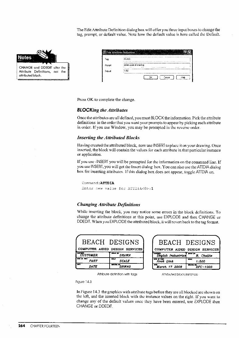
CHANGE and DDEDIT alter theAttribute Definitions, not theattributed block.
The Edit Attribute Definition dialog box will offer you three input boxes to change thetag, prompt, or default value. Note how the default value is here called the Default.
II Edit A;Hribute Definilion' " ' ' 11111Tag:
Prompt
Default:
OK l I Cancel I I Help
Press OK to complete the change.
SLOCKing the Attributes
Once the attributes are all defined, you must BLOCK the information. Pick the attributedefinitions in the order that you want your prompts to appear by picking each attributein order. If you use Window, you may be prompted in the reverse order.
Inserting the Attributed Blocks
Having created the attributed block, now use INSERT to place it on your drawing. Onceinserted, the block will contain the values for each attribute in that particular instanceor application.
If you use -INSERT you will be prompted for the information on the command line. Ifyou use INSERT, you will get the Insert dialog box. You can also use the ATTDIA dialogbox for inserting attributes. If this dialog box does not appear, toggle ATTDIA on.
Command:ATTDIA
Enter new value for ATTDIA<O>:l
Changing Attribute Definitions
While inserting the block, you may notice some errors in the block definitions. Tochange the attribute definitions at this point, use EXPLODE and then CHANGE orDDEDIT. When you EXPLODE the attributed block, it will revert back to the tag format.
r "BEACH DESIGNSCOMPUTER AIDED DESIGN SERVICES
M'IlIQ -'"CUSTOMER DRAWNIIIC .. ,..,. 'IOU
PART SCALE...~-DATE DRWNO
Attribute definition with tags
Figure 14.3
r'""BEACH DESIGNS
COMPUTER AIDED DESIGN SERVICES- .... '"Skylab lnd:u.stries B. Ch.aUisIIIC IF NIn'. mu:
Hook Link t:500..Ito ---March 17 2008 DFC-1003
Attributed block instance
264 CHAPTER FOURTEEN
In Figure 14.3 the graphics with attribute tags before they are all blocked are shown onthe left, and the inserted block with the instance values on the right. If you want tochange any of the default values once they have been entered, use EXPLODE thenCHANGE or DDEDIT.

DisplayingAttributes
When attributes are added to objects, they can be nlade universally invisible by setting
the Invisible mode in the ATIDEF command, or you can make them invisible later using
the ATIDISP command.
The ATTDISP Command
ATIDISP controls the display ofattributes. It is only available on the command line.
Command:ATTDISP
Enter attribute visibility setting
[Normal/ON/OFF] <Normal>:OFF
Where: ON
OFF
Normal
all attributes visible
all attributes invisible
normal visibility, set individually
Attribute Modes
Ifyou want to INSERT the attributed blocks without having to tum the display off, youcan set the attribute mode to invisible. You can set these as follows to make attributedblock insertion easier:
INVISIBLE
CONSTANT
VERIFY
PRESET
makes all attributes invisible
makes an attribute uneditable; for example, the president's desk isalways the president's desk even though the president may change
allows you to take a final look at what you have entered prior tohaving it added to the drawing
is used when creating attributes that will always have the samevalue
CreatingAttributes for
Data Extraction
Attributes can be used both for title blocks and drawing notations, and for occasionswhere the information can be downloaded to a price list or bill of materials. Theattributes are all defined in the same way, and the extractions take place once theattributed blocks are all inserted.
When attributes are used for drawing notations they are almost always visible on thedrawing. When they are used for bill ofmaterials, parts list or schedules, the attributesare usually invisible on the drawing but shown on the Attribute Extract Table, as explained on page 267.
Attributes are always associated with blocks. Ifyou want an attributed block, first create the geometry for the final block, if there is any, then add the attributes. You willneed to have lines and text as well as attributes in a title block, but you will not need geometry in an attributed block that is meant, for example, to extract room colors.
Tutorial14b gives an example ofattributes used for extraction toaBillofMaterials.
The concepts for attributes are relatively difficult for non-computer users. The onlyway to see how they are used is with practice. There are three tutorials at the end ofthischapter starting on page 268. Ifyou do all of them, you should understand better howattributes work.
Attributes 265

EditingAttributes
There are two ways ofediting attributes:one at a time or in groups. For one at a time useATIEDIT or the Enhanced Attribute Editor.
You will be prompted to choose the block to edit. Then you will get this screen.
You can change the value of the attribute on this tab, the size and quality ofthe text onthe next, and the properties (layer, color, linetype) on the last. Make changes then clickOK.
f------------- ------------------------------------x 2:, .
st...: .ell x.~I usI
IIII,,::,
1 :x-------------------------------------------------
Before ATTEDITFigure 14.4
After ATIEDIT
266 CHAPTER FOURTEEN
Cornmand:-ATTEDIT
Edit attributes one at a time? [Yes/No]<Y>:NPerforming global editing of attribute valuesEdit only attributes visible on screen? [Yes/No]<Y>:~
Enter block name specification <*>:JIGLEGEnter attribute tag specification <*>:Material
Enter attribute value specification <*>:~
Select Attributes: (pick 1 pick 2)Enter string to change:Steel
Enter new string value:Bronze
Figure 14.4 show a global change on a number of attributes. The value is case sensitive, i.e. Steel will work, STEEL won't. Make sure that you have typed the infomlationin correctly or you will have problems.
Ifyou need to change a lot of the information on an attributed block, another way ofdoing this is to EXPLODE the block, redefine it, then re-block it under the same name.All of the block instances will be updated.

Data Extraction Now that the data have been entered correctly, you can have the file printed out onto aspreadsheet or materials list by using the command ATIEXT. This operation does notchange the drawing in any way, but takes the attribute data to applications such asExcel, Lotus 1-2-3, or your favorite word processor. You can either export the data, or
have it written immediately on your drawing with EAnEXT.
ATTEXT and Template Files
To extract data with ATIEXT you must createa template file in .txt; Wordpad or Notepadare the easiest to use.The template file mightlook like this:
PARTNO C008000
DESCRIPT C0150DO
MATERIAL C0080Da
SIZE C00800a
PRICE C008000
The template file is set up with the tag plusthe code:
PARTNO C008000
TAGWhere: PARTNOC008000
character
8 characters maximum in the jig name (COOSOOO)
number of decimal places ( none are needed for acharacter field)
Once the template file is created, invoke the AnEXT command and you will get the Attribute Extraction dialog box. The template file is the one you have just created. Theextract file is the one you are trying to make. View the extract file in Wordpad or Notepad.
EATTEXT
Ifwhat you are after is a compiled listing ofyour attributes on screen, use the EATIEXTcommand. This will walk you through the process of extracting all of your attributedata and placing it on your screen. This is a new command with Release 2006. In Release 2008 it has become much more complicated. Simply remove all references to objects other than attributes when prommpted and it will work beautifully.
You will be prompted for such things as a table heading, in this case the heading JigAssembly was chosen. Figure 14.5 shows an extraction from quite a large drawing.The lists can be numbered according to any of the tags.
hardwareQuantity DESCRIPT MATERIAL NaMe PARTND PRICE PRODND SIZE
1 Jig Leg Bronze Jl JIG135 5.26 .60 X 1.251 brass jigleg none2 Jig Leg Steel Jl JIG135 5.26 .60 X 1.25-4 1-4 Jig Leg Bronze J1 JIG125 5.26 .60 X 1.25-4 Stnnc:t Bushing Steel B1 BU135 3.29 .125 X .5512 Stand. Bushing Steel B1 BUl25 3.29 .125 X .5519 Jig Leg SteEtl Jl JIG125 5.26 .60 X 1.2531 2
Figure 14.5
Attributes 267

Step] Use LINE and PLiNE to create the design for a standard title block. Use TEXT to enter theheadings for each area. Use imperial or metric sizes.
CUSTlINER DRAVN BY'
1
NAME OF p.r. ~~ --r0.lO (23
I)/IT£. !RA....INCi NO<
Your title block should be ina layer called title. If it is onLayer 0, it will pick up thelinetype, layer and color ofthe layer current in thereceiving file when it isinserted.
--------6-00 [1523--------:11-1---3.00 [76]------·
I1.50 CJ8l
~I~l
Step 2 Add the attribute definition for thedate.
l:USTDIlElt DRA\Il'II IIY,DRAWN
IWIE IT P.T, SCAI.£
DA,D~TFJ< 1 DRAVINIi to
'-- \.-.
First use the SlYLE command to set a
new text style for the attributes. Use the typed-in version of ATTDEF for this one.
Command:STYLE (set a new text style with the name attributes
using a different font)
Command:-ATTDEF
Current attribute modes:lnvisible-N Constant-N Verify-V
Preset-P
Enter an option to change [Invisible/Constant/Verify/PresetJ
<done>:.J
Enter attribute tag name:Date
Enter attribute prompt:Enter today's dateEnter default attribute value:
Justify/Style/<start point>:J
Align/Center/Fit/Middle/Right/TL/TC/TR/ML/MC/MR/BL/BC/BR:R
Right point: (pick 1)
Specify height <5.0000>: .15
Specify rotation angle <O>:.J
Step 3 Now enter the attribute for thedesigner using the AttributeDefinition dialog box.
DRAWN I
Mod"
D!nvisible
o Constant
D~81jfJl
oEresel
Insertion Pain!
[;2] SpeclJl .Qn·~feen
Mobute
lag
Vajue:
Use your own name as the default.
o 8ign below previous atbibute definition
E:l Lock.p~n in block
OKl j Cancel I [JieCJ
268 CHAPTER FOURTEEN
Ifyour attribute is not where you want it, the Insertion Point area cannot have been setup right. Use Undo to undo this command, and try again being sure to specify the insertion point on screen by first choosing Insertion point from the dialog box.

alSlIIO CUSTOMER...w .....
DRAWNtWC or PMr. ~
PART SCALED'Tto _vlNG ..
DRWNODATE
Step 4
Step 5
Use either the command line or the dialog box method ofdefming the other attributesso that each area has an attribute tag.
Once these are in, the title block can be inserted onto other drawings.
Title blocks are meant to be usedon many different drawings. Savethis file under the name of Titleljust to see if it works. Be sure youknow what directory it is going to.When in doubt use the A: drive oryour flash drive.
Command: SAVE
TITLE1
Step 6 Open a new file and test the block out. Use either the dialog box or the command lineform of the INSERT command. Keep the Title1 file open as well.
Command:New
Command:-INSERTEnter block name or [?] :TITLE
Specify insertion point or [Scale/X ... /PRotate] :0,0
Enter X scale factor, specify opposite corner,or[Corner/XYZ] :.J
Enter Y scale factor <use X scale factor>:~
Specify rotation angle <O>:~
Customer name <Skylab Industries>:~
Name of Part <>:Hook Link
Enter the current date (DD/MM/YY) :17/03/06
Drawn by <S.R.Kyles>:Bill Challis
Scale <1:50>:.J
Drawing no. DFC-####<>:DFC-1003
With the ATTDIA system variable on, you will get this dialog box to let you see all ofyour attributes. To change the defaults, simply type over them.
Turn on ATIDIA as shown.
Step 7
Command:ATTDIA
Enter new value for
ATTDIA<O>:1
Click OK to place them on screen.
A good way of checking your attributedblock is to have a fellow student insert theblock and fill in the details of the attributes without your help. If he/she has anyproblem understanding the prompts, goback and edit them. While you may understand your prompts now, the fact thatsomeone else doesn't understand themmay indicate that you won't either after afew days.
a;STOMfR
Attributes 269

Other areas you may want to adjust are the attribute text sizes or justifications.
Go to the file Title1. Use CHANGE, DDEDIT , or the Properties menu shown on the leftto make necessary changes.
Command:-justifytextSelect objects: (pick the text)Select objects:.J
n
~xternal Reference
Image
mf t!atch...
h f?olyJine
dt) ~line
Multiline, •.
8,ttribute
'6 liIock Description".
CUSTIKR DRAWN BY.
Skylab Industries Brian CrippinNAME IlF' PART,
SCALE 1:50Hook Link
DAn;· 17/03/06 IlRAVINCi to DFe - 1003
"T M0:teo Rotate
5] Scale
Dlk Stretcb.
~Ijp
.ti.. ~rase
'Q Cop~
t11~ Mlrror
~ Offiet
g~ ~rray ...
For the justification ofattributes such as in Skylab Industries andDFC - 1003, shownbelow, neither CHANGE nor DDEDil will help. Use the Properties bar under the Modify menu shown on the left or
i PositiOn X -'18.04
•Position Y28.45
Position 20.00
«<,~,B,y,Layer<o
,~in.,~~~P~c<,,===,~~~y~r ,Linetyp... 1.00
'pfotstYI8';E3YC~I~;i li~~~~i•.. <==Bye;y~;< Hyperllnk' ..... ,.'Thicl;;~sso:o6
: Contents DATE
[:~~til~<>C< ;IT~I~~
:.~s~i~¥.< ,~~ft
:~~~h.tH 0:3.5.R.:~,t~t~n 0Width f". 1.00
'6bliq~ing"0'T~~t~ii:.:'·o:O(i
rT~~t'~li.::'o:oo .r'~",_~, ·_···_, ·.. , __ ,,__ ,, ,
'Text ali ... 0.00
Once changed, save the file again and reinsert it.
Step 8 Ifyou have updated the file, resavedit, and reinserted it and the sameproblems still exist, erase the Title 1block, then use PURGE to erase itfrom memory. Sometimes, even ifyou have updated the file, it willbring back the old file instead of thenew one. Purge is a great way toclean up your files ofunwanted data.
0&l~~iiffi!~l~~~
o Vie!,! items you cannot PLllge
Items not u$ed in drawing:
I SJ • All items! iil@ Blocks, "~ Dimension styles
;:B~ Layers::;:::: Linetype$
j<R: Mline st,YlllS. III Plot styles
.If£. ShapesIml Table st)lles• Telll styles
Command: PURGE ; (
~~.~~~~~~~~_~_~ ~__'_A..-J
f2] Qlnfinn e<ICh item to be purged
o Pulga nested iterrn;
Close Help
270 CHAPTER FOURTEEN

In this tutorial, you will create a jig with a bushing andjigleg. In a manufacturing environment, it is usual to have items such as bushings purchased rather than made on-siteto save both time and money. Ifyou were to create a drawing of this part using theseitems, you could also have the ordering information stored as attributes with the blockbefore it is inserted into the drawing.
Step 1
Step 2
Draw up these very simple parts in imperial measures on different areas of yourscreen. Make separate layers for the bushing and the jigleg.
I: 6.00
"I3.00 al~~~{fflDO.3'O eo.15
02.00 t: .0.30RO.25 .0....0~2.50
.0.60 ...... ";1
.0.50
10.60
~3.50
If you wanted to create a bill of materials for these items, the information could include:
• Part Number
• Description
• Material
• Size
• Price
Then you would add the quantity and order the parts. The information listed above willbe added as attributes to the block before it is blocked and then extracted later.
The words in this illustration are attribute tags, nottext. No text is needed in this exercise.
PARTNODESCRIPTMATERIALSIZEPRICE
Attri butes 271

272 CHAPTER FOURTEEN
Add the attributes for the part using these default factors:
Tag Prompt Default Value
Partno Enter Part Number JIG125
Descript Enter Part Description Jigleg
Material Enter Material Steel
Size Enter Part Size .60 x 1.25
Price Enter Current Price 5.26
Enter the information for the jig with the -ATTDEF command. Use the Attribute Definition dialog box for the bushing.
Command:-ATTDEFCurrent attribute modes:Invisible-N Constant-N Verify-V
Preset-PEnter an option to change [Invisible/Constant/Verify/Preset]
<done>:.J
Enter attribute tag name:PARTNO
Enter attribute prompt:Enter Part Number
Enter default attribute value:JIG125
Justify/Style/<start point>: (pick a spot beside the part)
Specify height <5.0000>: .03
Specify rotation angle <O>:.J
When entering the next line for the attribute, the attribute definition will line up withthe last entered line ifyou press.J at the text justification line or simply choose OK onthe dialog box. The attribute definitions will line up perfectly.
Command: -ATTDEF
Current attribute modes:Invisible-N Preset-P
Enter an option to change [Invisible /PresetJ <done>:~
Enter attribute tag name:DESCRIPT
Enter attribute prompt:Enter Part Description
Enter default attribute value:JIGLEG
Justify/Style/<start point>:.J
Command: .J
ATTDEF
Current attribute modes:Invisible-N Preset-PEnter an option to change [Invisible Preset] <done>:.J
Enter attribute tag:MATERIAL
Enter attribute prompt:Enter Material
Enter default attribute value:Steel
Justify/Style/<start point>:.J
Continue with the final two definitions until all five are complete. It's simply a matterof typing.
Use ~ at the JustifY text prompt to line the attribute up with the previous definition.Also use -J to bring back the previous command to make the attribute definition morerapid.

Step 3 When all ofthe information has been added, create a block ofthe part with a new nameto help you identify it as an attributed block.
Command:-BLOCK
Block name (or ?) :ATTJIGLGInsertion base point:CENter of (pick 1)
Select objects: (pick 2, 3)
Remember that the block will disappear.
,--------Jf,." 2.... f'PARTNO
•~~~~SIZEPRICE
,l/ 1
Step 4 Do the same with the bushing using the dialog box. Use the values listed below.
Tag Prompt Default Value
Partno Enter Part Number BUl25
Descript Enter Part Description Stand. Bushing
Material Enter Material Steel
Size Enter Part Size .125 x .55
Price Enter Current Price 3.29
Use the dialog box by either typing in ATTDEF or on the Draw menu, choose Block thenDefine Attributes.
Mode
D!nvisible
DI;;onstant
DY:eril,Y
Dfreset
Attribute
lag:
PromPt
Vajue:
Insertion Point
G2J Specif,Y .on-screen
Text Optiom
Justification:
Text~t'yle:
H~ight <
flotation <
D align below previous attribute definition
~ Loc1, position in block
OK) I Cancel I { Help
After the first definition is entered you can pick the'Align under previous defmition'button to have the attribute definitions line up.
Your part should look like this. ~PARTNO
DESCRIPTMATERIAL
- SIZE(0\ PRICE'-/
Attributes 273
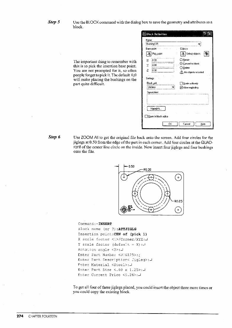
StepS Use the BLOCK command with the dialog box to save the geometry and attributes as ablock.
Name:
o ~cale uniformly
[t] Allow eXj;![oding
Objects
~ Selecl objects Ij]OfietainCD Convert to block
oQelete
ill No objects selected
Settings
Block y~~:..,__.__.~ .__jUnitless ~:i
jBushing125._-----_...._--_.._.-----------._-._-Base point
E!) Pic~ point
~:
X~
~:
The important thing to remember withthis is to pick the insertion base point.You are not prompted for it, so oftenpeople forget to pick it. The default 0,0will make placing the bushings on thepart quite difficult.
HyperJink...
O.Qpen in block eclitOl
OK·I [ Cancel 1\ Help
Step 6 Use ZOOM All to get the original file back onto the screen. Add four circles for thejiglegs at 0.50 from the edge ofthe part in each comer. Add four circles at the QUADrant of the center line circle on the inside. Now insert four jiglegs and four bushingsonto the file.
RO.30
Command:-INSERT
Block name (or ?) :ATTJIGLG
Insertion point:CEN of (pick 1)
X scale factor <l>/Corner/XYZ:~
Y scale factor (default = X) :~
Rotation angle <O>:~
Enter Part Number <JIG125>:GEnter Part Description< Jigleg>:~
Enter Material <Steel>:~
Enter Part Size <.60 x 1.25>;~
Enter Current Price <5.26>:~
To get all four ofthese jiglegs placed, you could insert the object three more times oryou could copy the existing block.
274 CHAPTER FOURTEEN

Step 7 Use the Attribute Dialog box to enter the final four parts.INSERT the four bushings, making sure to rotate each one by 90 degrees so they line upcorrectly.
Command: INSERT
Name:
Path:
Browse... I
I·. OKI [ Cancel I I Help
RotationoSpecify 0 n·screen
Angle:
G2J Uniform Scale
Scale
o Specify Orr-screen
X:
Insertion point
[!j Specify 0n-screen
oExp!ode
When all four bushing blockshave been entered, your file willlook like this:
Notice that when you insert the bushings, the attributes will be rotated along with thegeometry. This is ofno importance because the attributes will not be part ofan overalldrawing. In an electrical drawing, however, the attributes must be visible and legible;in this case, you should create attributed blocks for both directions. When attributesare added to parts in mechanical or architectural applications, they· are not usuallyprinted or plotted.
StepS If you were just making a drawing, it would never look like this. Use ATTDISP to turnall of the attributes off.
Command:ATTDISPNormal/On/Off <current value>:OFF
Step 9 Finally create an attribute table containing the Bill ofMaterials. Use EATTEXT and simply follow the menus.
Command: EATTEXT
Attributes 275

In this Tutorial we will create attributes for the footings in Tutorial12b page 229.
Step] Open Tutorial12b and save it as Tutorial 14c. Make one copy offooting A and one ofFooting B outside the grid.
~bd
Default ValuePrompt
Use theATTDEF command to define attributes with the same defaults as shown below.
Footing A
Tag
Name Enter Footing Designation Footing A
Size Enter Size 4000x2000x2300
Volume Enter Volume 7 cubic meters
Pins Enter Pin description 4 X 250 projection
Footing B
Tag Prompt Default Value
Name
Size
Enter Footing Designation
Enter Size
Footing B
2000xlOOOx1300
Volume Enter Volume 3.5 cubic Dleters
Pins Enter Pin description 4 x 125 projection
Step 2 Block the footings and insert them into the grid layout as they were before.
Step 3 Use ATIDISP to tum the Attribute Display off.
Step 4 Use EATTEXT to get a list ofthe footings on the part placed on the drawing. Simply openthe dialog box, use Next for every entry, add the title' Footings' where required. In Release 2008, you will nedd to remove any information not related to the attributes.
FootingsQuantity I No.l"'lE.> 1 NAME(D I PINS I SIZE I VOLUME
6 I f'ootinglo1 Footing A I <4 x 250 projection 1<4000 x 2000 x 2300 I 7 cubic t'leters16 I f'ootingo. I rooting A I <4 x 250 projection 14000 x 2000 x 2300 I 7 cubic Meters
276 CHAPTER FOURTEEN

Exercise 14 ArchitecturalFirst create this title block with attributes as shown. Save the file.Draw the two sample windows shown. Add the attributes. BLOCK them.Draw the simple layout shown. INSERT the attributed windows.Use EATTEXT to get a window schedule. Insert the attributed title block.
TlUIItI ~lIn ByI ~.. RrMIorlI
TITLE DRAWN By SCALE REVProJectJ ICMcked By1 Ik'tei illrw •
PROJECT CHECKED By DATE DRW.#
21 '~=-
I IlUI Itll
I
4'-9"
I PRODND pello.36o.
1 1: : ::[;.,(i[ FINISH wo.LnutTYPE doubLe gto.zed
lUI COST 450.00
I 4'-6" I-I Irui
ItII ~
CD
I9'-3" ·---1
I pello.60o. Itill 1: : ,:~
wo.lnut1111oIouble glo.zed
I875.00
. -_.!.-
==- ==-
Second Floor 'WIndow ScheduleQuo.ntity COST FINISH Na.Me PRDDND TYPE
3 875.00 wa.lnut wlndowl pello.GOa. double glo.zed10 450,00 wo.lnut wlndowl pelta.360 double glozed
TJtw. ~Q.n Iy' SCo.l.. Revlslonl
WINDOW PLAN JAMIE JONES NOTED 5ProJectJ lCMcked I)q Do."tea Dr••
WESTOVER HOUSE WENDY BENEDETTI 01/04/08 A2
Attributes 277

Exercise 14 ChallengerDraw these desks, the dimensions are on page 67.Attribute as shown. BLOCK them and then make the room layout.Create a Furniture Schedule using EATIEXT.
Cho.irA
DeskBSupplierPOortdesPo.rtnoF"o.brlc::BOoseF"lnlshCost
II
_L_IIIIIII
DeskASupplierPOortdesPOor'tnoF"o.brlcBo.seF"lnJshCost
II
_L_III
Cho.irB
SupplierPOortdesPo.r1:noFOobrlcBOoseFinishCos1:
SupplierPOortciesPo.rtnorOobrlcBOoseFinishCost
1-------16'-6"------~
-----11'-----1·
II
_L._III
II
_.J_III
WI I
~I II I-.-- -,-
32'-10'I II I
~Q~I
- _.J ___
I
aV I I 0-.-- -,-
I II I
27'-6"
278 CHAPTER FOURTEEN

IndexAabsolute coordinates, 6acad.dwt file, xiiialigned dimensions, 123angle brackets, 30angles
cjegrees/minutes/seconds, 17dimensioning, 125putting lines in at 8
ANGULAR dimensions, 125ARC command, 12, 24, 31
AREA commandl 247ATIDEF,262AITDISP, 265ATIEDlt 266ATIEXt 267attributesl 261
BBASELINE dimensionsl 124begin AutoCAD sessionl 1BHATCH command, 165BLOCK commandl 181blocks
attributed, 264(jefining, 181editing, 186external, 183
bordersin paper spacel 21 8
brackets, 30BREAK command, 36
Ccartesian coordinates, 6center lines, 58center marksl 132CHANGE commandl 1471 263
CHPr<Op command, 110CIRCLE commandl 11, 19, 23circles
creating/ 11tangent tal 23 1 33
COLOR command, 11 0color
blocks and, 187layers and I 1091 110
commandsentering from keyboard, Ixentry, 1
command lines, ix
configure plotterl 205coordinates
absolute/ 6
incrementaL 7polar/ 8relative, 7
COpy command, 51
crosshatchingl 165crossing polygon system variable, 50
DDDEDIT command, 147,263DEFPOINTS layer,129delete
objects, 36
unused blocks, 188DIAMETER dimensions,
125digitizingl 6dimensioningl
and paper space scalingl220/222
basic, 122center Iinesl 58editing, 129leaders, 148stretching, 129text, 126
dimension styles, 126dimension text 126
angle, 134
editing, 147displaying toolbars, xDISTANCE command, 249DIVIDE command, 242DONUT commandl 95drafting standards, 202drawing
compiling, 197inserting, 183Isometric, 149, 164opening existingl xscale, 206units, 1
dynamicblock/ 188zoom/ 4
DYNamic option, 10
EEATTEXT command I 267ED, 147,263editing
commands, 51dimensions, 129hatches, 170
ENDpoint object snap, 32
ERASE commandl 36exiting AutoCAD. viEXPLODE command, 186
EXTEND command, 73
Ffeet and inches, 1, 2Fence, 51, 81file names, xiifile
plotting to, 206recovery, xiiisaving, xiii
FILLET commandl 13,20
fractional units displaYI 17freezing layers
in paper space, 221in single views, 108
frozen layers, 108function keys, xi
Ggeometry commands, 11GRADIENT, 171grid
isometric, 149standard. 5
GRID command, 5grips, 37 1 56
HHATCH commandl 165HATCHEDIT commandl 170HELP command, 29hidden lines, 58
Iimperial/metric/ 1incremental point entry, 7inquiry commandsl 246INSERT command, 182isometric
grid and snap, 149text, 152
Jjoining PUNEs, 89justificaiion of text, 146
Kkeyboard entryl 1keys (funciion)1 xi
Llast entity selection method, 49LAYER commandl 107layers
changingl 108
colors/ 109defpoints, 129
Index 219

filtering, 111freeze and thaw in paper space,221linetypes, 110lock and unlock, 108, 115thaw and freeze, 115
LEADER command, 148LIMITS command, 4
LINE command J 11, 18lines
center, 58
extension, 122
filleting, 13freehand, 170mUltiple, 97using and entering, 11
Iinetypesand layers, 11 0assigning, 58changing, 110scaling, 58
LIST command,250Jineweights, 204
Iinewidth, 204LTSCALE command, 58
MMEASURE command, 243MIDpoint object snap, 32, 44MINSERT command, 186MIRROR command, 53MLiNE command, 97
model space,dimensioning in, 121
switching to, 21 9modify polyline, 92
modify toolbar, 51mouse, x
MOVE command, 52moving objects to 0,0, 53
moving viewports, 220, 228MSPACE command, 219MTEXT command, 144MVIEWcommand,219
NNEARest object snap, 32NEW command, xiiiNODE object snap, 32
NONE object snap, 32
oobject selection methods, 49, 69object snap, 32OFFSET command, 75orthographic projection, 138
ORTHO option, 9OSNAP command, 32, 39, 42OTRACK option, 35, 42
280 Index
PPAN command, 4, 16paper space
dimensioning, 220floating viewports, 21 9freezing layers, 221scaling views in, 220switching to, 21 7
paragraph text, 144PDMODE system variable, 214
PEDIT command, 92
PUNE command, 89
plotwith paper space, 204without paper space, 219
PLOT command, 204POINT command, 241POLAR, 9polar arrays, 77POLYGON command, 94polylines, 89
previewhatch, 166
plot 205, 212print dialog box, 204
properties, 115, 148PSPACE command, 219pull-down menus, xPURGE command, 188
QQUIT command, xiv
RRADIAL dimensions, 125
radiusare, 12
circle, 11
setting for fillets, 13
rectangUlar arrays, 76, 78REDO command, 37REGEN command, 16relative coordinates, 7remove entity selection method, 69rotate and copy, 54ROTATE command, 54running object snap dialog box, 35
SSAVE command, xiiiSAVE AS command, xiii
SCALE command, 55
scalingdimensions, 127draWIngs, 199
hatches, 167linetypes, 58plots, 206text, 142, 198title blocks, 201, 208
scroll bars, 16
sections, 202SKETCH command, 170
snapbasIc, 5Isometric or rotated, 149
SNAP command, 5SOLID command, 95
SPLINE command, 245STRETCH command, 70
STATUS command, 251
STYLE command, 145
TTANgent object snap, 32, 33
textediting, 147height, 142importing, 203justification, 142paragraph, 144
special characters, 143
styles, 146
underscored, 143TEXT command, 96, 141
TILEMODE command, 21 8
toolbarsmoving, xirestoring, xii
transparent commands, 14TRIM command, 34, 36, 72TrueType Fonts, 146
UUNDO command, 37
UNITS command, 2, 17units of measure,
alternate, 17
surveyors, 17
Vvalues
absolute, 6relative, 6
VPLAYER command, 222
WWBLOCK command, 184
width of lines, 204
width of polylines, 89window entity selection method, 38,
50
ZZOOM command, 14,15,
ZOOM in paper space, 220

DrawingsArchitecture, CiviLand Transportation
Detailsarches, 103, 119, 120bench, 162, 163bookshelf, 177
capital, 103doorway, 106Insulated Concrete Forms, 240stairs, 175, 213wall assembly, 85windows, 61, 84,137
Drawing setscommerciaL 237res1dential, 192
Elevationcommercial, 194, 195, 237interior, 162, 163, 177
residential, 65, 84, 176
Lot plans, 46
Pictorial viewscavaller, 163isometric, 164
Planfloor, 85, 98, 134, 137,207,257
kitchen, 26
Presentation, 101
Profile moulding, 106
Rendering, 180
Sectiondetails, 106, 177Insulated Concrete Form, 240rE!sidential, 11 7stair, 175structural, 194wood,177
StructuralaiL 214concrete, 136, 172footings, 136roof layout, 257steel beams, 160, 258
Transportation, 102
Mechanical
Applied geometryhook, 47,48
Assembiestemplate, bushing and jigleg, 193vise, 178wheel, 196
axle, 45axle support 138bolt 104bushing,64top plate 116wheel, 1i5
Completebody and pin, 215faucet, 216gasket, 161
pedestal, 238
Fastenersbolt, 102, 104
Geargear with threading, 86, 87
Orthographic projectionaxle support, 138
Pictorial viewscoupling, link, swivel hanger, 116rocker arm, 66rocker arm, top plate, 11 6various, 118
Sectiondie ring, 175fastener, 210vice, 178, 179
Single view geometrynozzle, 84template, 27, 66various, 25,45,47,83
Wood
Cabinetsfront 28side, 45
Clockbase and body, clock a, 105bonnet and face, clock a, 139full assembly, clock b, 239
Fireplacemantel,236
Orthographic projectionbookcase, 177
Reverse sectionbase, 105
Saw handle, 88
Shelvingbookcase, 177
Stairsdetail, 175full, 213
Wood grain detail, 93
Compiled Drawings
Commercialcomplete, 237front elevation, 195sections and details, 194side elevation, 237
Furniture, 67, 68
Residentialcomplete, 192elevations, 65, 84, 176first floor, 98, 134, 137full layout 192kitchen, 26second floor, 85section, 117
Index 281