Embed Size (px)
Citation preview

EnergySolutions LLC Issued - April 4,2003
Revised - August 7,2014
ATTACHMENT II-9
CONSTRUCTION QA/QC MANUAL
Table of Contents
INTRODUCTION 2
1.0 ORGANIZATION, RESPONSIBILITY AND AUTHORITY 2
2.0 EQUIPMENT CALIBRATION 5
3.0 CHANGE CONTROL PROCEDURES 6
4.0 DOCUMENTATION 7
TABLE 1 - CQA/QC ACTIVITIES
Work Elements: General Requirements Specifications 1-23 12 Foundation Preparation Specifications 24-29 19 Clay Liner Borrow Material Specifications 30-35 22 Clay Liner Test Pad Specifications 36-47 24 Clay Liner Placement Specifications 48-60 29 Geomembrane Liner Specifications 61-106 36 Granular Fill Specifications 107-111 53 Drainage Net Specifications 112-116 55 Geotextile Specifications 117-124 57 Soil Protective Cover Specifications 125-128 60 Temporary Cover Specifications 129-136 62 Radon Barrier Borrow Material Specifications 137-143 66 Radon Barrier Test Pad Specifications 144-155 68 Radon Barrier Placement Specifications 156-177 73 Cover System Rock Quality Specification 178 83 Filter Zone Specifications 179-183 84 Sacrificial Soil Placement Specifications 184-187 88 Rock Erosion Barrier Specifications 188-192 90 Drainage Ditch Imported Borrow Specifications 193-195 92 Drainage Ditch Specifications 196-202 94
Appendix 1: Test Methods 97
Appendix 2: Forms 101
Appendix 3: Material Specifications 123
Attachment II-9 - Construction QA/QC Manual - Page 1 of 134

EnergySolutions LLC Issued - April 4,2003
Revised - August 7,2014
INTRODUCTION
EnergySolutions LLC (the Permittee) has developed this Construction Quality Assurance/Quality Control (CQA/QC) Manual to ensure that construction activities comply with the applicable state and federal regulations, approved design criteria, engineering plans and specifications, and good engineering practice. The attached table of CQA/QC activities provides the Engineering Specifications, and the Quality Assurance (QA) and Quality Control (QC) inspections, sampling, testing, survey controls, and records required to demonstrate that the Permittee has met these requirements. This CQA/QC Manual is contained in the State-issued Part B Permit as Attachment II-9. Additional references to 'the Permit' in this CQA/QC Manual refer to the State-issued Part B Permit.
This CQA/QC Manual governs compliance in construction of each new phase of liner and final cover of the Mixed Waste Landfill Cell.
1.0 ORGANIZATION, RESPONSIBILITY AND AUTHORITY
1.1 The Permittee is both the owner and operator of its South Clive, Utah Mixed Waste Landfill Cell. Responsibility for the design, construction, operation, and closure of the facility rests with the Permittee alone.
1.2 References to the Director within this CQA/QC Manual refer to the Director of the Division of Solid and Hazardous Waste.
1.3 The CQA/QC organization is as follows: The Senior Vice President, Regulatory Affairs shall designate the Quality Assurance Manager (QAM). The QAM shall designate the Construction Quality Assurance Officer (CQAO) and External Quality Assurance Auditor.
The General Manager, Clive Facility shall designate the Manager, Engineering and Maintenance. The Manager, Engineering and Maintenance shall designate the Project Engineer, Project Manager, and the Lead, QC Embankment Construction.
Construction QA and QC activities are carried out by the QA group and the construction QC group. The construction QC group reports to the Manager, Engineering and Maintenance via the Lead, QC Embankment Construction. The Lead, QC Embankment Construction shall manage the construction QC group for Mixed Waste landfill construction. Both groups may be staffed by Permittee employees or contractors hired by the Permittee; hereinafter referred to as employees.
1.2.1 Quality Assurance Manager (QAM)
The QAM reports to the Director, Corporate Quality Assurance and supervises the CQAO and Quality Assurance personnel. The QAM is responsible for ensuring that the quality assurance requirements outlined in this manual are implemented. The reporting relationships allow the QAM sufficient authority and autonomy to: implement and direct
Attachment II-9 - Construction QA/QC Manual - Page 2 of 134
EmrgySolutions LLC Issued - April 4,2003
Revised - August 7, 2014
the Quality Assurance Program (QAP); identify quality problems and verify implementation of solutions independent of undue influences and responsibilities, such as costs and schedules. The QAM shall have direct contact (as needed) with the General Manager, Clive Facility for implementing the QAP.
The QAM coordinates implementation of this CQA/QC Manual with the Manager, Engineering and Maintenance. The QAM has the authority to stop any aspect of the work that is not in compliance with this CQA/QC Manual. After work has been stopped by the QAM, corrective action(s) shall be determined by the Manager, Engineering and Maintenance, and approved by the QAM. Corrective actions must be undertaken to correct any defective work. Specific responsibilities of the QAM include:
a. Ensure that this CQA/QC Manual is implemented and a satisfactory level of quality is maintained in construction QC activities;
b. Train QA staff on QA requirements and procedures;
c. Schedule, coordinate, and ensure timely completion of QA assessment activities with the construction QC Group;
d. Verify that construction QC personnel properly complete and document all on-site observations and tests required to ensure compliance with this CQA/QC Manual;
e. Verify that any non-conforming and/or suspected non-conforming work, and related resolutions of non-conforming work are documented and Notify the Manager, Compliance and Permitting, and the Director of nonconforming work within seven (7) calendar days of identification;
f. Assist in preparing the QA portion of the Construction Certification Report at the completion of the project; and
g. Ensure that any changes in approved drawings and specifications follow the change control procedures described herein and that, when appropriate, approval from the Director has been obtained prior to the implementation of the change.
1.2.2 Construction OA Officer (CQAO)
The role of the CQAO shall be filled by the QA Specialist on the Clive organization chart or by a contracted independent engineer. The CQAO reports to the QAM and has direct contact with the Senior Vice President, Regulatory Affairs. The CQAO is responsible for compliance with the construction quality assurance requirements outlined in this CQA/QC Manual. The CQAO works closely with the Project Manager and QAM to ensure that construction specifications are met and documented.
Attachment II-9 - Construction QA/QC Manual - Page 3 of 134
EneTgySolutions LLC Issued - April 4, 2003
Revised - August 7, 2014
The CQAO shall be a Utah Registered Professional Engineer. The CQAO shall have at least three years of experience in synthetic liner installation; or shall supervise quality assurance staff with at least three years of synthetic liner installation experience.
1.2.3 External Quality Assurance Auditor
An External Quality Assurance Auditor shall be contracted to audit the construction activities. The individual or group that is to perform this audit shall be independent of the Permittee. The auditor shall: a) audit at least 15% of the Mixed Waste landfill documentation; and b) perform observations of field actions that occur while the auditor is on-site. This audit shall occur during and after landfill construction.
1.2.4 General Manager, Clive Facility
The General Manager, Clive Facility is responsible for the oversight of site operations including waste acceptance, sampling, management and disposal; laboratory, engineering, and health physics activities; and carrying out activities efficiently and safely in accordance with design specifications, quality assurance program requirements, and all applicable regulations.
1.2.5 Manager, Engineering and Maintenance
The Manager, Engineering and Maintenance reports to the General Manager, Clive Facility and supervises the Project Engineer, Project Manager, and Lead, QC Embankment Construction. The Manager, Engineering and Maintenance is responsible for the management of facility design; including landfill construction, engineering support, site structural engineering, soil mechanics and materials. Reviews and approves, with QA oversight, those designs and specifications. Initiates and provides design solutions to non-conformance or quality problems encountered during construction. The Manager, Engineering and Maintenance has the authority to make minor changes in accordance with Section 3.0 below. The Manager, Engineering and Maintenance shall be a Utah Registered Professional Engineer.
The Manager, Engineering and Maintenance has been assigned the specific responsibility of overseeing the overall construction of the project. The Manager, Engineering and Maintenance shall oversee completion of the Construction Certification Report and the As-Built Drawings.
1.2.6 Project Engineer
The role of the Project Engineer may be filled by the Site Engineer or the Manager, Engineering and Maintenance. The Project Engineer either is or reports to the Manager, Engineering and Maintenance and is responsible for the following tasks:
a. Prepare the drawings, specifications and other documents for the construction of embankment liner and cover.
Attachment II-9 - Construction QA/QC Manual - Page 4 of 134
EnergySolutions LLC Issued - April 4,2003
Revised - August 7,2014
b. Inspect embankment construction activities to ensure the construction is in accordance with the project plans and specifications.
c. Assist the Manager, Engineering and Maintenance in designing solutions to nonconformance or quality problems encountered during construction.
d. Review proposed design, engineering, or construction changes and submit these changes to the Manager, Engineering and Maintenance for approval, as appropriate, in accordance with Section 3.0 below.
e. Prepare, with the assistance of the Project Manager, and certify the Construction Certification Report and As-Built Drawings.
1.2.7 Project Manager
The role of the Project Manager may be filled by the Site Engineer or the Manager, Engineering and Maintenance. The Project Manager is responsible for overseeing production, scheduling, and coordination activities associated with construction of the waste landfills. The Project Manager either is or reports directly to the Manager, Engineering and Maintenance. During construction, the Project Manager shall regularly inspect the construction site.
The Project Manager has the authority to stop any aspect of the work that is not in compliance with this CQA/QC Manual. After work has been stopped by the Project Manager, work can only be resumed with the documented approval of the corrective action by the Manager, Engineering and Maintenance and the QAM.
The Project Manager is responsible for day-to-day project coordination, as needed, with the Director. This coordination includes providing 48 hours notice prior to the preconstruction meetings with the construction crews for the overall project and for HDPE work. The Project Manager is also responsible to communicate other key meetings, such as for the implementation of major changes, to the Director.
1.2.8 Lead, QC Embankment Construction
The Lead, QC Embankment Construction shall implement and direct the QC portions of this CQA/QC Manual; identify quality control problems; initiate, recommend, or provide quality control solutions. The Lead, QC Embankment Construction, reports to the Manager, Engineering and Maintenance.
QC testing of synthetic layers shall be performed by the Synthetics Contractor's personnel.
2.0 EQUIPMENT CALIBRATION
Measuring and testing equipment shall be calibrated at the most frequent of the following:
• Annually, or
Attachment II-9 - Construction QA/QC Manual - Page 5 of 134
EnergySolutions LLC Issued-April 4, 2003
Revised - August 7, 2014
• As per the manufacturer's recommended calibration frequency, or • At the standard frequency practiced in the engineering profession.
Calibrations shall be performed per the manufacturer's specifications. Before using measuring and testing equipment on the project, the Lead, QC Embankment Construction shall provide the CQAO with the calibration documentation. This documentation shall be included in the QA project files.
3.0 CHANGE CONTROL PROCEDURES
3.1 The need may arise for a design, engineering, or construction change to the project. Therefore, change control procedures have been established to ensure the design analysis remains valid upon incorporation of the change. Where a significant design change is necessary because of an incorrect or faulty design, the design process and verification procedures themselves should be reviewed and modified, as necessary.
Phased construction activities, drawings and prints which are approved for a particular construction phase shall be stamped by a Utah Registered Professional Engineer and submitted to the Director prior to construction. Any subsequent changes are considered field changes.
3.2 The general change control procedure is as follows:
a. A change request may be initiated by, including but not limited to, the contractor, QAM, CQAO, Project Manager, Project Engineer, Manager, Engineering and Maintenance, or representatives of the Director.
b. All proposed design, engineering, or construction changes shall be reviewed for applicability by the Project Engineer. After consultation with the Manager, Engineering and Maintenance as well as other personnel (QAM, contractor, etc.), and i f determined to be justified by the Project Engineer, the scope of the change shall be subject to the same design control measures as those applied to the original design.
c. The Project Engineer shall submit the change for approval to the Manager, Engineering and Maintenance. The Manager, Engineering and Maintenance, with the concurrence of the QAM, determines i f the change is a: 1) minor change which does not require formal approval from the Director; or, 2) major change which requires formal approval from the Director. Minor and major changes are described as follows:
1) Minor changes are defined as all changes that are not major changes. Minor changes may be implemented immediately and shall be documented as outlined in items d, e, and f in this section. The Director shall be notified of the change within 24 hours of implementation. The Director will determine whether written notification is required.
Attachment II-9 - Construction QA/QC Manual - Page 6 of 134
EnergySolutions LLC Issued-April 4, 2003
Revised - August 7, 2014
2) Major changes are defined as changes which conflict with the Permit. Major changes shall be reviewed by the Manager, Engineering and Maintenance, the QAM, and the Manager, Compliance and Permitting. The Permittee shall submit a permit modification request and receive Director approval prior to implementation of major changes. The Director shall determine whether verbal or written approval is required.
If verbal approval is granted, the time, date, and agency contact for the approval shall be documented in the Daily Construction Report. A copy of the documented approval shall be provided to the Director and the QAM as part of the Construction Certification Report. Verbally approved changes can be implemented immediately.
If written approval is required, the Director may grant permission to incorporate the changes while the approval letter from the agency is prepared. If permission is granted to proceed, the time, date, and agency contact for granting the permission shall be recorded in the Daily Construction Report. A copy of the documented permission shall be provided to the Director as part of the Construction Certification Report.
d. Upon approval, the Project Manager shall communicate the change to all affected construction, QC, and QA personnel. The Project Manager may issue an amendment to the applicable documents and submit the amendment to the QAM (or designee) for distribution to critical personnel (as defined below). The Project Manager may also communicate the change via a Field Directive distributed to critical personnel.
e. Documentation of all changes shall be included in the Construction Certification Report.
f. As-built drawings of the project shall reflect all changes made to the Permit Drawings.
4.0 DOCUMENTATION
4.1 Critical personnel shall possess controlled copies of this CQA/QC Manual, the Permit Drawings, and the Construction Drawings. Controlled copies may be electronic. Critical personnel are:
Manager, Engineering and Maintenance Project Engineer Project Manager Lead, QC Embankment Construction QAM
Attachment II-9 - Construction QA/QC Manual - Page 7 of 134
EnergySolutions LLC Issued - April 4,2003
Revised - August 7, 2014
CQAO
Documentation of construction and inspection activities associated with this CQA/QC Manual shall consist of construction QA/QC forms, As-Built Drawings, and a Construction Certification Report. All records shall be indexed, identifiable, retrievable and controlled in an established document control system. All construction and testing documentation produced and received for the project shall become a part of the permanent construction record. This includes, but is not limited to, log books, field notes, transcription records, etc. The original documents shall be retained on-site until the Construction Certification Report has been submitted; then may be retained in a retrievable electronic archive.
4.2 Records may be corrected or updated when a change is accomplished or reviewed and approved by the originator or by the department manager or supervisor, as indicated on the organizational chart.
Records are corrected by:
a. lining out the original entry; b. entering the correction immediately adjacent to the original entry; c. having the individual making the correction initial and date the line-out; and
d. obtaining approval initials and dates from the original signatory for the changes.
NOTE: All dates are to be the actual dates of the review action being performed.
Records are updated by:
a. incorporating the additional data; b. having the individual incorporating the data initial and date the data adjacent to
entry; and c. obtaining approval initials and dates from the original signatory for the changes.
Any changes made to the original document subsequent to QC and/or QA review must be reviewed and approved by the QC and/or QA reviewer. The reviewer shall indicate approval of the changes by documenting the review on the corrected original document.
4.3 "White Out" shall not be used to make corrections. Record entries shall not be made by pencil, erasable ink, or any other means of non-permanent marking. When complete, records on pre-printed forms shall have blank spaces lined out so that no further entries may be made.
4.4 Access to original construction records is limited to those Permittee employees, excluding outside auditors and regulators, who have a specific need for information therein or as authorized by the QAM.
4.5 Construction QA/QC Forms
Attachment II-9 - Construction QA/QC Manual - Page 8 of 134
EnergySolutions LLC Issued-April 4,2003
Revised - August 7,2014
Documentation requirements associated with CQA/QC activities are described in Table 1. The level of detail provided on each individual form shall be sufficient to demonstrate all work elements were conducted in accordance with the requirements described in Table 1. Any nonconforming or suspected non-conforming work and corrective actions to be taken shall also be documented.
Each form shall be signed and dated by the individual completing the form. The signature date shall be the date on which the form was reviewed and approved. Example forms are included in Appendix 2 to this CQA/QC Manual. These forms identify the minimum documentation required. These forms may be revised i f the revision retains the minimum documentation.
4.5.1 Documentation Review
Construction documentation shall be reviewed for completeness, adequacy and correctness at the frequencies specified in this CQA/QC Manual. The results of testing and observations which are out of specification shall be reviewed for acceptance by the Project Engineer.
During construction, the Project Manager is responsible for maintaining and storing copies of all construction QC documentation. The QAM is responsible for maintaining and storing copies of all QA documentation.
4.5.2 Documentation Approval
Construction compliance is the responsibility of the Permittee. The Permittee shall observe, inspect, and test each lift or work element during active construction. The active construction process is not complete until the approval of each lift or work element is given by the appropriate Permittee field inspection. With the field approval of each lift or work element, the Permittee is documenting compliance with this CQA/QC Manual requirement. If at any time after initial field approval has been granted, the Permittee self-identifies any non-conforming work corrective action will be completed. Corrective action options include: repair, rework, reject, or use-as-is. If the work is repaired, reworked, or rejected then the non-conforming work will be considered to be in active construction once again. I f the Permittee exercises the use-as-is option, then a supporting technical justification will be documented. Use-as-is disposition requires Director approval.
Deficiencies found and corrected during active construction of a lift or work element, prior to field approval, are not a violation of the requirements of this CQA/QC Manual.
4.6 Drawings
Three distinct terms are applicable to the drawings that affect mixed waste construction.
4.6.1 Permit Drawings
Attachment II-9 - Construction QA/QC Manual - Page 9 of 134

EnergySolutions LLC Issued-April 4,2003
Revised - August 7,2014
Permit Drawings provide general design requirements for Mixed Waste Landfill Cell construction. The current approved Permit Drawings are found at Attachment 11-11, Facility Drawings.
4.6.2 Construction Drawings
Construction Drawings provide detailed design for each specific phase of cell construction (liner or final cover). Construction Drawings shall be provided to the Director no less than seven (7) calendar days prior to any final shaping of the rough excavation or significant compaction of the foundation.
The Project Engineer shall maintain a master red-lined set of Construction Drawings to track any major or minor changes implemented on the project.
4.6.3 As-Built Drawings
At the completion of construction, As-Built Drawings shall be prepared from the red-lined Construction Drawings. The As-Built Drawings shall incorporate all changes as outlined in the change control procedures in Section 3.0 of this manual. The As-Built Drawings shall include the key survey data of landfill construction.
As-Built Drawings shall be submitted to the Director with the Construction Certification Report.
4.6.4 Surveying
Either the local (Mixed Waste) coordinate system or the Clive coordinate system will be used during each phase of construction. The Mixed Waste coordinate system 0, 0 point, located at the southwest corner of the embankment, shall be clearly identified on the Construction Drawings and As-Built Drawings for each phase.
The local coordinate system shall be tied into the state plane coordinate system for section 32 of T1S Rl 1W, SLB&M. The southwest corner of section 32 is the point of beginning. East shall be the positive x direction and north shall be the positive y direction for local coordinate systems.
The Clive coordinate system control point, 10000 N, 10000 E, is located at the Section 32 southwest corner monument.
Surveying will be done on a 50 foot grid and at all key control points. Key control points are those points in addition to the 50 foot grid that are necessary to ensure compliance with the Permit Drawings.
4.7 Test Pad Reports
Test pad reports shall include a narrative description of construction activities performed, the equipment used, operating procedures, and results. Test pad reports shall clearly define construction procedures to be implemented in clay liner construction.
Attachment II-9 - Construction QA/QC Manual - Page 10 of 134
EnergySolutions LLC Issued - April 4,2003
Revised - August 7,2014
4.8 Construction Certification Report
At the completion of each construction project, a final joint inspection shall be conducted by the Manager, Engineering and Maintenance, CQAO, and Director.
Completion of construction is defined as the date of the final inspection.
At the completion of each construction project, a Construction Certification Report shall be prepared under the direction of the Manager, Engineering and Maintenance. The construction shall be certified by the Manager, Engineering and Maintenance as having been performed in accordance with the approved drawings, plans, and specifications. This report shall be submitted to the Director within 90 days of completion of each phase of construction. This report shall include, at a minimum, the following items:
a. A narrative of the work performed by work element; b. A summary of all changes, presented in matrix form, which includes the
following: - the number of the change; - a description of the change; - the type of change (e.g. to make things fit, to meet a code, substitution of
equivalent materials, or a major change approved by the Director); and - any comments to clarify or explain the change.
c. QC sampling and testing schedule; d. Copies of QC documentation; and e. As-Built Drawings.
4.9 Construction OA Review
At the completion of construction, a construction QA review shall be prepared under the direction of the CQAO. The CQAO shall approve this review. The required CQA/QC testing and inspections shall be certified as having been performed in accordance with this CQA/QC Manual. This review shall be included in the Construction Certification Report. This review shall include, as a minimum, the following items:
a. A narrative of the QA testing and inspections performed; b. A summary of all non-conforming work with the corrective actions taken; c. QA sampling and testing schedule; and d. Copies of QA documentation.
Attachment II-9 - Construction QA/QC Manual - Page 11 of 134

CQA/QC MANUAL FOR MIXED WASTE EMBANKMENT TABLE 1 - QA/QC ACTIVITIES
WORK ELEMENT - GENERAL REQUIREMENTS
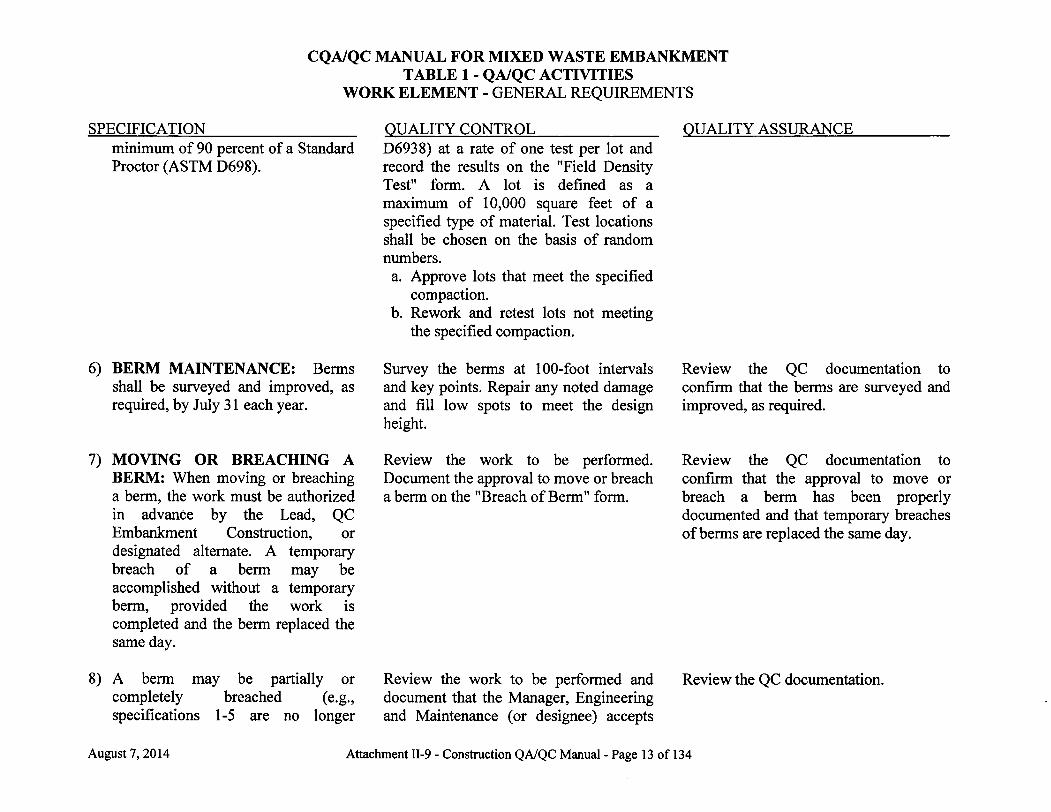
SPECIFICATION 1) RUNOFF BERMS: Runoff berms
around the perimeter of the embankment shall be constructed to a minimum height of three feet above the top of the tertiary synthetic liner materials. Runoff berms between construction phases (between sumps) shall be constructed to minimum height of five feet (including two feet of protective cover). The following specifications apply to both perimeter runoff berms (around the exterior of the embankment) and intermediate berms (berms completed between phases of construction).
2) Berms shall be constructed with clay. Satisfactory material shall be defined as CL, ML, or CL-ML soils based on the Unified Soil Classification.
3) Berms shall be a minimum of three feet wide across the top.
4) Berms shall be constructed in lifts with the first lift having an uncompacted thickness of no greater than 12 inches.
5) Berms shall be compacted to a
QUALITY CONTROL QUALITY ASSURANCE Survey the berms at 100-foot intervals and key points and compare them to top of liner as-built elevations.
Perform laboratory classification tests (ASTM D 2487) at a rate of one test per lot prior to approving the material for berms. A lot is defined as 3,000 cubic yards of specified material.
Conduct in-place density tests (ASTM
August 7,2014 Attachment II-9 - Construction QA/QC Manual - Page 12 of 134
CQA/QC MANUAL FOR MIXED WASTE EMBANKMENT TABLE 1 - QA/QC ACTIVITIES
WORK ELEMENT - GENERAL REQUIREMENTS
SPECIFICATION minimum of 90 percent of a Standard Proctor (ASTM D698).
QUALITY CONTROL D6938) at a rate of one test per lot and record the results on the "Field Density Test" form. A lot is defined as a maximum of 10,000 square feet of a specified type of material. Test locations shall be chosen on the basis of random numbers. a. Approve lots that meet the specified
compaction. b. Rework and retest lots not meeting
the specified compaction.
QUALITY ASSURANCE
6) BERM MAINTENANCE: Berms shall be surveyed and improved, as required, by July 31 each year.
7) MOVING OR BREACHING A BERM: When moving or breaching a berm, the work must be authorized in advance by the Lead, QC Embankment Construction, or designated alternate. A temporary breach of a berm may be accomplished without a temporary berm, provided the work is completed and the berm replaced the same day.
8) A berm may be partially or completely breached (e.g., specifications 1-5 are no longer
Survey the berms at 100-foot intervals and key points. Repair any noted damage and fi l l low spots to meet the design height.
Review the work to be performed. Document the approval to move or breach a berm on the "Breach of Berm" form.
Review the work to be performed and document that the Manager, Engineering and Maintenance (or designee) accepts
Review the QC documentation to confirm that the berms are surveyed and improved, as required.
Review the QC documentation to confirm that the approval to move or breach a berm has been properly documented and that temporary breaches of berms are replaced the same day.
Review the QC documentation.
August 7, 2014 Attachment 11-9 - Construction QA/QC Manual - Page 13 of 134
CQA/QC MANUAL FOR MIXED WASTE EMBANKMENT TABLE 1 - QA/QC ACTIVITIES
WORK ELEMENT - GENERAL REQUIREMENTS
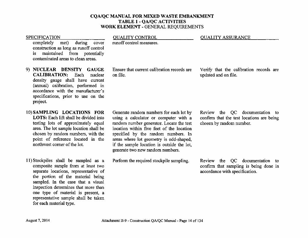
SPECIFICATION QUALITY CONTROL QUALITY ASSURANCE completely met) during cover runoff control measures, construction as long as runoff control is maintained from potentially contaminated areas to clean areas.
9) NUCLEAR DENSITY GAUGE CALIBRATION: Each nuclear density gauge shall have current (annual) calibration, performed in accordance with the manufacturer's specifications, prior to use on the project.
10) SAMPLING LOCATIONS FOR LOTS: Each lift shall be divided into testing lots of approximately equal area. The lot sample location shall be chosen by random numbers, with the point of reference located in the northwest corner of the lot.
11) Stockpiles shall be sampled as a composite sample from at least two separate locations, representative of the portion of the material being sampled. In the case that a visual inspection determines that more than one type of material is present, a representative sample shall be taken for each material type.
Ensure that current calibration records are on file.
Verify that the calibration records are updated and on file.
Generate random numbers for each lot by using a calculator or computer with a random number generator. Locate the test location within five feet of the location specified by the random numbers. In areas where lot geometry is odd-shaped, i f the sample location is outside the lot, generate two new random numbers.
Perform the required stockpile sampling.
Review the QC documentation to confirm that the test locations are being chosen by random number.
Review the QC documentation to confirm that sampling is being done in accordance with specification.
August 7,2014 Attachment II-9 - Construction QA/QC Manual - Page 14 of 134
CQA/QC MANUAL FOR MIXED WASTE EMBANKMENT TABLE 1 - QA/QC ACTIVITIES
WORK ELEMENT - GENERAL REQUIREMENTS
SPECIFICATION QUALITY CONTROL QUALITY ASSURANCE 12) Any failing QC test shall result in a
failing lot and initiate rework for the The CQAO shall document all evaluations of their visual and documentation inspections. lot.
13) UNSUITABLE MATERIAL: Unsuitable material is defined as non-soil material, contaminated soil (i.e., fuel spills) or soil which cannot be reworked to meet the compaction criteria.
14) GEOSYNTHETICS: Geosynthetics are defined herein as engineered polymeric products including geotextiles, drainage nets, and geomembranes. The geomembranes specified hereafter include High Density Polyethylene (HDPE) and Linear Low Density Polyethylene (LLDPE). HDPE will be used in the Leak Collection system covering the (bottom) clay liner system and HDPE and/or LLDPE may be used for the (top) capping system.
15) TEST METHODS: All tests shall be performed in accordance with the standards specified in Appendix 1 to this CQA/QC Manual.
16) FORMS: Appendix 2 to this CQA/QC Manual provides examples
August 7, 2014 Attachment II-9 - Construction QA/QC Manual - Page 15 of 134
CQA/QC MANUAL FOR MIXED WASTE EMBANKMENT TABLE 1 - QA/QC ACTIVITIES
WORK ELEMENT - GENERAL REQUIREMENTS
SPECIFICATION of forms to be used to document required testing and inspections. Actual documentation may be revised from the example forms, so long as the minimum information is provided.
QUALITY CONTROL QUALITY ASSURANCE
17) ANCHOR TRENCHES: An anchor trench is required for geosynthetics placed over the bottom liner system (i.e. clay liner). They are not required for (cover) geosynthetics placed over the top liner system (i.e. radon barrier). The inside face (the face closest to the centerline of the landfill) of the anchor trench shall be rounded.
Inspect the completed anchor trenches prior to placement of geosynthetic materials. Document the condition of the anchor trench on the Daily Construction Report.
18) Geosynthetic materials shall extend at a minimum to the intersection of the base of the anchor trench and the outside face of the anchor trench.
19) Seaming of geosynthetic layers shall extend at a minimum to the intersection of the inside face of the anchor trench and the base of the anchor trench.
Inspect geosynthetic material placement in the anchor trenches prior to backfilling. Document the condition of the anchor trench on the Daily Construction Report Inform the Project Manager and the CQAO of any deviations.
Inspect geosynthetic material placement in the anchor trenches prior to backfilling.
20) The anchor trench shall be backfilled Conduct in-place density tests (ASTM Verify that the density tests are
August 7,2014 Attachment II-9 - Construction QA/QC Manual - Page 16 of 134
CQA/QC MANUAL FOR MIXED WASTE EMBANKMENT TABLE 1 - QA/QC ACTIVITIES
WORK ELEMENT - GENERAL REQUIREMENTS
SPECIFICATION with 12-inch maximum lifts. All lifts shall be compacted to a minimum of 90.0% of a standard proctor.
QUALITY CONTROL D6938) at a rate of one test per lift per anchor trench and record the results on the Field Density Test form. Test locations shall be chosen on the basis of random numbers. a. Approve lots that meet the specified
compaction. b. Rework and retest lots not meeting
the specified compaction.
QUALITY ASSURANCE performed at the correct frequency and that the documentation has been completed correctly.
21) TEMPORARY ANCHOR TRENCHES: Temporary anchor trenches are those between the current phase of bottom liner (i.e. clay liner) construction and projected future cell phases. Temporary anchor trenches shall meet specifications 17, 18, 19, and 20. Temporary anchor trenches shall be backfilled in two-foot lifts. Backfill shall be compacted; however, there is no testing requirement for compaction. Backfill shall be placed at least five feet thick above geosynthetic materials in the base of the temporary anchor trench.
22) ARCHIVE SAMPLES: Archive samples from testing of synthetic materials shall be retained for no less than three years from the date of
Observe that backfill is compacted. Ensure that the minimum backfill thickness is attained. Document temporary anchor trench construction on the Daily Construction Report.
August 7, 2014 Attachment II-9 - Construction QA/QC Manual - Page 17 of 134

CQA/QC MANUAL FOR MIXED WASTE EMBANKMENT TABLE 1 - QA/QC ACTIVITIES
WORK ELEMENT - GENERAL REQUIREMENTS
SPECIFICATION QUALITY CONTROL QUALITY ASSURANCE project completion. After this time, archive samples may be discarded.
23) REQUIRED SUBMITTALS: Provide the Director with the following documentation prior to startup for each phase of liner construction: (1) current GRI or IAGI recommendations for cold and hot weather geomembrane liner welding (see specification 87); and (2) manufacturer's instructions for storage of Geomembrane liner, drainage net, and geotextile (see specifications 71,113 and 123).
August 7,2014 Attachment II-9 - Construction QA/QC Manual - Page 18 of 134
CQA/QC MANUAL FOR MIXED WASTE EMBANKMENT TABLE 1 - QA/QC ACTIVITIES
WORK ELEMENT - FOUNDATION PREPARATION
SPECIFICATION 24) EXCAVATION: Excavation shall be
made to the grades and dimensions prescribed in the Construction Drawings. Any over-excavation greater than one foot below design elevation shall be backfilled with native soils or clay liner material in maximum 12 inch loose lifts and compacted to a minimum of 95.0% of a standard proctor. Gross excavation may begin prior to Director approval to construct.
25) COMPACTION: Compact the foundation to a minimum of 95.0% of a standard proctor.
QUALITY CONTROL Observe cell excavation at least once per week. Record observations and corrective actions taken (where required) on the Daily Construction Report.
In areas of over excavation, conduct in-place density tests (ASTM D 6938) for backfill lifts at a rate of one test per lot per area of over-excavation and record the results on the Field Density Test form. A lot is defined as a maximum of 10,000 square feet of a specified type of material. Test locations shall be chosen on the basis of random numbers. a. Approve lots that meet the specified
compaction. b. Rework and retest lots not meeting
the specified compaction.
Conduct in-place density tests (ASTM D6938) at a rate of one test per lot and record the results on the Field Density Test form. A lot is defined as a maximum of 10,000 square feet of a specified type of material. Test locations shall be chosen on the basis of random numbers. a. Approve lots that meet the specified
compaction. b. Rework and retest lots not meeting
the specified compaction.
Standard proctors (ASTM D 698) shall
QUALITY ASSURANCE The Quality Assurance review for foundation preparation shall cover each specification in this work element. Review a minimum of 50% of QC documentation and verify that the tests were performed at the correct frequency.
August 7,2014 Attachment II-9 - Construction QA/QC Manual - Page 19 of 134
CQA/QC MANUAL FOR MIXED WASTE EMBANKMENT TABLE 1 - QA/QC ACTIVITIES
WORK ELEMENT - FOUNDATION PREPARATION
SPECIFICATION QUALITY CONTROL QUALITY ASSURANCE be performed at a rate of one test per 115,000 square feet (or less) for each material type. At least one proctor shall be performed for each material type. Record the location of the sample on the Sampling Log.
26) UNSUITABLE MATERIAL: Remove unsuitable material, i f any is encountered.
Define areas of unsuitable material and direct its removal. Observe the areas once the unsuitable material has been removed. Report corrective action on the Daily Construction Report. Notify the Project Manager and CQAO of any unsuitable material.
Visually inspect the area to confirm unsuitable material has been removed.
27) FINAL GRADING: The foundation surface shall be smooth-drum rolled and moist prior to clay liner placement. The foundation shall be free from surface debris, soft (wet) spots greater than three inches deep, and loose soil areas with a loose surface greater than three inches deep. Foundation shall be at or below grade.
28) FOUNDATION APPROVAL: The foundation shall be approved by the
Survey the foundation on a 50 ft grid and cell centerline and at key points in the sump and pipe trench. Key points are defined as: the north-south centerline of each sump, measured every 50 feet; six points per sump leachate removal point; and three points per leachate pipe trench. Final survey measurements shall be documented and provided to the Project Manager and CQAO. a. Approve foundation that meets the
design specifications. b. Rework and resurvey areas not
meeting the specified grade.
Obtain the "Notice of Acceptance" from the CQAO before construction of the clay
Review the final survey data. Verify the frequency of the survey points.
Provide a "Notice of Acceptance" to the Project Manager. Verify that a copy of
August 7, 2014 Attachment II-9 - Construction QA/QC Manual - Page 20 of 134

CQA/QC MANUAL FOR MIXED WASTE EMBANKMENT TABLE 1 - QA/QC ACTIVITIES
WORK ELEMENT - FOUNDATION PREPARATION
SPECIFICATION CQAO. Provide a copy of the "Notice of Acceptance" to the Director.
29) CLEARING AND GRUBBING: Remove vegetation, debris, organic, or unsuitable material from areas to be used for borrow. Grubbing depth shall depend on the type of vegetation, debris, organic, or unsuitable material on the site. I f the area is free of these materials then no clearing and grubbing is necessary.
QUALITY CONTROL liner begins.
Inspect the area once clearing and grubbing has been completed. Record observation and corrective actions on the Daily Construction Report.
QUALITY ASSURANCE the "Notice of Acceptance" has been provided to the Director.
The Quality Assurance review for clay liner material specifications shall cover each specification in this work element. Review a minimum of 50% of the QC documentation and verify that the tests were performed at the correct frequency.
August 7,2014 Attachment H-9 - Construction QA/QC Manual - Page 21 of 134

CQA/QC MANUAL FOR MIXED WASTE EMBANKMENT TABLE 1 - QA/QC ACTIVITIES
WORK ELEMENT - CLAY LINER BORROW MATERIAL
SPECIFICATION 30) MATERIAL: Satisfactory material
shall be defined as CL, ML, or CL-ML soils based on the Unified Soil Classification with a plasticity index (PI) between 10 and 25 and a liquid limit (LL) between 30 and 50. The clay shall also have a dry clod size less than one inch.
QUALITY CONTROL Perform laboratory classification tests (ASTM D 2487), plastic index/liquid limit/plastic limit tests (ASTM D 4318), and a standard proctor (ASTM D 698) at a rate of one test per lot prior to approving the material for the clay liner. If deflocculant is added in accordance with specifications 31-34, proctor testing shall be conducted after processing. A lot is defined as 3,000 cubic yards (minimum two per sump) of specified material. Record the location of the proctor and classification sample on the Sampling Log. a. Approve lots that meet the specified
classification. b. Lots not meeting the specified
classification shall be reworked and retested or removed.
QUALITY ASSURANCE
31) PROCESSING: The following procedure may be used to provide suitable material for construction of clay liner, as determined by a successful test pad.
32) Apply deflocculant at a minimum rate of 3.5 pounds per 50 cubic feet.
Measure the mixing areas and verify the deflocculant application rate. Record the size of the mixing areas and the amount of deflocculant applied on the Daily Construction Report.
August 7,2014 Attachment H-9 - Construction QA/QC Manual - Page 22 of 134

CQA/QC MANUAL FOR MIXED WASTE EMBANKMENT TABLE 1 - QA/QC ACTIVITIES
WORK ELEMENT - CLAY LINER BORROW MATERIAL
SPECIFICATION 33) Mix the deflocculant thoroughly into
the soils by tilling or similar action.
34) Remove dry clods in excess of 1" in diameter.
35) DEFLOCCULANT: If used, deflocculant shall be sodium tripolyphosphate or equivalent approved in writing by the Manager, Engineering and Maintenance.
QUALITY CONTROL QUALITY ASSURANCE Observe the mixed clay and advise the Project Manager of areas which are adequately mixed.
Obtain written approval of equivalent deflocculant from the Manager, Engineering and Maintenance, if used.
If equivalent deflocculant is used, verify that written approval from the Manager, Engineering and Maintenance was obtained.
August 7, 2014 Attachment II-9 - Construction QA/QC Manual - Page 23 of 134
CQA/QC MANUAL FOR MIXED WASTE EMBANKMENT TABLE 1 - QA/QC ACTIVITIES
WORK ELEMENT - CLAY LINER TEST PAD
SPECIFICATION 36) NOTICE OF TEST PAD
CONSTRUCTION: The test pad plan shall be provided to the Director at least 14 calendar days before test pad construction. The Director shall be notified 24-hours in advance of the start-up of test pad construction.
QUALITY CONTROL QUALITY ASSURANCE Verify that the Director has been notified of the start-up of test pad construction.
37) TEST PAD: An approximately 60 foot by 75 foot large test pad shall be constructed using the procedure, materials, and equipment proposed for construction of the clay liner. Prior to use of manually operated compaction equipment, an approximately five foot by five foot (or other size appropriate to the small equipment used) small test pad shall be constructed using the procedure, materials and equipment proposed for construction. I f manually operated compaction equipment is not used on the project, the small test pad is not required.
Daily, observe the construction of test pads. Measure test pads to ensure that they are constructed to the size indicated and in accordance with the Test Pad Plan. Record the test pad sizes and compliance observations on the Daily Construction Report.
Daily, observe the construction of the test pads. The Quality Assurance review for clay liner test pad specifications shall cover each specification in this work element. Review a minimum of 50% of the QC documentation and verify that the tests were performed according to the plan requirements.
38) A new test pad shall be constructed each time there is a major change (as defined in Section 3.0 of this CQA Plan) in specifications, construction procedures, types of equipment, or unified soil classification.
August 7,2014 Attachment II-9 - Construction QA/QC Manual - Page 24 of 134

CQA/QC MANUAL FOR MIXED WASTE EMBANKMENT TABLE 1 - QA/QC ACTIVITIES
WORK ELEMENT - CLAY LINER TEST PAD
SPECIFICATION 39) Test pads are to be constructed and
tested as follows:
QUALITY CONTROL QUALITY ASSURANCE
40) Place the clay in at least three lifts with a loose material thickness not exceeding twelve inches for the first lift and nine inches for each subsequent lift. A fourth lift shall be constructed i f deflocculant is tilled into the clay on the test pad. A fourth lift is not required i f deflocculant is tilled into the clay in separate stockpiles. Thickness for the lift shall be established by installing grade poles on the four corners and in the center of the test pad. The grade poles shall not be installed deeper than six inches into the underlying clay liner. After the lift thickness has been approved by QC, the grade poles shall be removed.
OR Survey to determine lift thickness.
41) The clay shall be compacted by equipment proposed for use during construction of the clay liner. There shall be a minimum of four passes by
Verify that the required lift thickness is achieved as follows: a. Ensure that the required frequency
for placement of grade poles has been met.
b. Compare soil level with the marked level on the grade poles.
c. Use a string line where necessary between poles to check for high spots.
d. Define out of specification areas and direct the contractor to rework those areas.
e. Review areas reworked and approve areas meeting criteria.
f. Continue "b" through "d" above until all areas meet criteria.
g. Indicate areas meeting criteria in the Daily Construction Reports.
OR a. Verify equipment calibration, b. Verify correct set-up and operation
of equipment. c. Document results of survey.
Record type of equipment used, and number of passes on the Daily Construction Report.
Perform a minimum of one visual inspection per test pad.
Perform a minimum of one visual inspection per test pad.
August 7, 2014 Attachment II-9 - Construction QA/QC Manual - Page 25 of 134

CQA/QC MANUAL FOR MIXED WASTE EMBANKMENT TABLE 1 - QA/QC ACTIVITIES
WORK ELEMENT - CLAY LINER TEST PAD
SPECIFICATION an appropriate compactor.
QUALITY CONTROL QUALITY ASSURANCE
42) A minimum of one pass shall be made with a sheepsfoot or other surface scarification equipment prior to placement of the subsequent lift.
Document equipment used and number of passes on the Daily Construction Report.
43) The clay shall be compacted to at least 95.0% of a Standard Proctor with a moisture content between 2 percentage points below optimum and 5 percentage points above optimum.
Conduct in-place density (ASTM D 6938) and dryback moisture content (ASTM D 4643 or D 2216) tests at a rate of three tests per lot. The test location shall be chosen on the basis of random numbers within each lot. Record test results on the Field Density Test form. a. Approve lots that meet the specified
moisture and compaction. b. Rework and retest lots not meeting
the specified moisture or compaction.
c. Any additional work under b. shall be included in the Test Pad construction method.
Perform a minimum inspection per test pad.
of one visual
44) Clay liner shall have in-place permeability of no more than 1.0 x 10"7 cm/sec. Permeability testing on the bottom lift will be performed at the lift surface. Permeability testing on the second lift will be performed > 2" below the lift surface. Permeability testing on the third lift
Conduct in-place permeability tests (Appendix 1) at a rate of one test per lot per lift. The permeability test shall be run in close proximity to the moisture-density test for each lot. Record the test result on the Field Permeability Test form. a. Approve each lift i f all lots meet the
required permeability.
Perform a minimum inspection per test pad.
of one visual
August 7,2014 Attachment II-9 - Construction QA/QC Manual - Page 26 of 134
CQA/QC MANUAL FOR MIXED WASTE EMBANKMENT TABLE 1 - QA/QC ACTIVITIES
WORK ELEMENT - CLAY LINER TEST PAD
QUALITY CONTROL QUALITY ASSURANCE b. Rework and retest lots not meeting
the specified moisture or compaction.
c. Any additional work under b. shall be included in the Test Pad construction method. I f different construction techniques or levels of compactive effort are required to meet this specification, the test pad report shall require the most rigorous construction method for clay liner placement.
The Project Engineer shall review laboratory permeability results against field test results. I f any laboratory permeability test results indicate clay liner may not have met specification 44, the Project Engineer shall evaluate potential causes and document this evaluation.
SPECIFICATION will be performed > 4" below the lift surface.
45) At the completion of each lift of the test pad, a thin-walled tube sample shall be taken in close proximity to one field permeability test per lift for laboratory permeability testing (ASTM D 5084). I f the test pad is otherwise approved by the Director of Engineering, clay liner placement may begin prior to receipt of laboratory permeability test results.
46) The procedures used to construct successful test pads shall be reviewed and approved by the Manager, Engineering and Maintenance, with concurrence by the CQAO.
August 7, 2014
Provide the Manager, Engineering and Maintenance with copies of the test pad documentation for review and approval.
Verify that approval has been obtained for the test pad from the Manager, Engineering and Maintenance. Review and approve the test pad report. Verify that the necessary construction procedure documents are on the job site for use during clay liner construction.
Attachment 11-9 - Construction QA/QC Manual - Page 27 of 134
CQA/QC MANUAL FOR MIXED WASTE EMBANKMENT TABLE 1 - QA/QC ACTIVITIES
WORK ELEMENT - CLAY LINER TEST PAD
SPECIFICATION QUALITY CONTROL QUALITY ASSURANCE 47) The approved test pad report shall be Verify that the test pad report has been
submitted to the Director prior to submitted to the Director. construction using the test pad method.
August 7, 2014 Attachment II-9 - Construction QA/QC Manual - Page 28 of 134

CQA/QC MANUAL FOR MIXED WASTE EMBANKMENT TABLE 1 - QA/QC ACTIVITIES
WORK ELEMENT - CLAY LINER PLACEMENT
SPECIFICATION 48) LIFT IDENTIFICATION: Each lot
and lift shall be given a discrete designation for testing purposes.
49) PLACEMENT: The clay liner shall be compacted using the same type of equipment, loading (if applicable), number of passes, and compacting procedures that were approved in the test pad(s). Equivalent equipment may be used i f documented by the Manager, Engineering and Maintenance; and approved by the CQAO.
50) LIFT BONDING: Clay lifts shall be constructed in accordance with the approved test pad report(s), to assure roughened surfaces for lift bonding.
51) LIFT THICKNESS: The first lift of uncompacted material shall be no greater than 12 inches. For the remaining lifts, the loose lift thickness shall not exceed the lesser of the minimum lift thickness used to construct the test pad or nine inches. Thickness for the lift shall be established by installing grade poles
QUALITY CONTROL QUALITY ASSURANCE Assign a lift identification number to each lift. Use the lift identification number to identify all paper work for that lift.
Daily, observe the clay liner placement. Record the equipment used to place the clay liner, along with any corrective actions taken (where required) on the Daily Construction Report.
Verify that the surface of the previously compacted clay liner lift has been roughened as required. Record observations on the Daily Construction Report.
Verify that the required lift thickness is achieved as follows: a. Ensure that the required frequency
for placement of grade poles has been met.
b. Compare soil level with the marked level on the grade poles.
c. Use a string line where necessary between poles to check for high
The Quality Assurance review for clay liner specifications shall be applied to each specification in this work element. Review a mimmum of 50% of the QC documentation and verify that the tests were performed at the correct frequency.
Perform a minimum of one visual inspection per lift per project area.
August 7, 2014 Attachment II-9 - Construction QA/QC Manual - Page 29 of 134


CQA/QC MANUAL FOR MIXED WASTE EMBANKMENT TABLE 1 - QA/QC ACTIVITIES
WORK ELEMENT - CLAY LINER PLACEMENT
SPECIFICATION on at least a 50-foot grid, center line of the sump, and at all key control points. The grade poles shall not be installed deeper than six inches into the underlying clay liner. After the lift thickness has been approved by QC, the grade poles shall be removed
OR Survey to determine lift thickness.
QUALITY CONTROL spots.
d. Define out of specification areas and advise the contractor to rework those areas.
e. Review areas reworked and approve areas meeting criteria.
f. Continue "b" through "d" above until all areas meet criteria.
g. Indicate areas meeting criteria in the Daily Construction Reports.
OR a. Verify equipment calibration, b. Verify correct set-up and operation
of equipment.
QUALITY ASSURANCE
52) COMPACTION: The clay liner shall be compacted to at least 95.0% of a Standard Proctor with a moisture content between 2 percentage points below optimum and 5 percentage points above optimum.
Conduct in-place density (ASTM D6938) and dryback moisture content (ASTM D 4643 or D 2216) tests at a rate of one test per lot and record the results on the Field Density Test form. A lot is defined as 1,000 cubic yards (compacted) of a single lift. The test location shall be chosen on the basis of random numbers within each lot. a. Approve lots that meet the specified moisture and compaction. b. Rework and retest lots not meeting the specified moisture or compaction until the lot is approved.
Perform a minimum of one visual inspection per project area.
53) PERMEABILITY: Clay liner shall have in-place permeability of no
Conduct in-place permeability tests (Appendix 1) at a rate of one test per lot
Visually observe one in-place permeability test per sump.
August 7, 2014 Attachment II-9 - Construction QA/QC Manual - Page 30 of 134

CQA/QC MANUAL FOR MIXED WASTE EMBANKMENT TABLE 1 - QA/QC ACTIVITIES
WORK ELEMENT - CLAY LINER PLACEMENT
SPECIFICATION more than 1.0 x 10"7 cm/sec.
54) LINER DRYING PREVENTION: To prevent the clay liner from drying, water shall be applied to the clay surface on an as needed basis or the liner shall be covered.
55) FROZEN MATERIAL: Clay liner shall not be placed above frozen material. In addition, no frozen material shall be processed or placed. If the air temperature has dropped below 32°F since clay liner was last worked, one of the following scenarios apply: (1) The last lift of clay liner shall be covered overnight
QUALITY CONTROL QUALITY ASSURANCE and record the results on the "Field Permeability Test" form. A lot is defined as 1,000 cubic yards of compacted clay liner. The permeability test shall be performed adjacent to one of the density tests in the permeability lot. a. Approve lots that meet the specified
permeability. b. Rework and retest lots not meeting
the specified permeability until the lot is approved. I f rework involves adding compactive effort only, density tests do not need to be repeated. If rework involves ripping and recompacting, new density tests shall be performed.
Regularly observe the liner surface for drying. Advise the Project Manager of deficiencies. Record corrective actions taken (where required) on the Daily Construction Report.
As needed, observe the area where clay liner is to be placed. I f frozen material is observed, cease placement of clay liner. Record the stopping of placement in the Daily Construction Report. Monitor liner/foundation temperature each day when ambient temperatures have fallen below 32°F. Temperature shall be taken between 6:00 am and 8:30 am.
August 7,2014 Attachment II-9 - Construction QA/QC Manual - Page 31 of 134
CQA/QC MANUAL FOR MIXED WASTE EMBANKMENT TABLE 1 - QA/QC ACTIVITIES
WORK ELEMENT - CLAY LINER PLACEMENT
SPECIFICATION (no longer than 24 hours) with at least nine inches of loose clay, and this loose clay shall have compactive effort applied the next day; or (2) Monitor the liner/foundation temperature approximately one inch beneath the surface. I f the temperature one inch beneath the surface is greater than 27°F, continue with liner construction. I f the temperature one inch beneath the surface is less than or equal to 27°F, re-work and re-test the affected area. I f neither scenario (1) nor (2) above is completed, perform spring start-up testing in accordance with specification 56.
56) SPRING START-UP: If clay liner is not covered with at least one layer of geomembrane liner and the clay temperature is not monitored in accordance with specification 55, spring start-up testing is required.
If clay liner is covered with at least one layer of geomembrane liner for more than 30 days, the ambient temperature has dropped below 13°F, and the clay temperature is not monitored in accordance with specification 55, spring start-up testing is required.
QUALITY CONTROL QUALITY ASSURANCE Temperature measurements shall include a location that is most likely to be coldest; i.e., i f there is a portion of the liner that is shaded or at a low point. Temperature monitoring frequency shall be at least one point per sump.
If the initial temperature measurement is less than or equal to 27°F, the affected sump may be resampled before 8:30 am the same day as follows: a. Measure the liner/foundation
temperature at a frequency of one measurement per lot. A lot is defined as 1,000 cubic yards of compacted clay liner.
b. Lots where the temperature is greater than 27°F do not require rework; except that the lot where the initial temperature less than or equal to 27°F was measured shall be reworked regardless of resampling
August 7, 2014 Attachment II-9 - Construction QA/QC Manual - Page 32 of 134
CQA/QC MANUAL FOR MIXED WASTE EMBANKMENT TABLE 1 - QA/QC ACTIVITIES
WORK ELEMENT - CLAY LINER PLACEMENT
SPECIFICATION
If clay liner is covered with at least one layer of geomembrane liner for more than 30 days and the clay temperature is monitored to remain greater than 27°F, neither re-rolling the lift surface nor spring start-up testing is required.
If clay liner is covered with at least one layer of geomembrane liner for more than 30 days and the clay temperature is monitored to be less than or equal to 27°F, spring start-up testing is required.
For spring start-up testing, re-test the top two inches of the approved lift for density. Areas that have been tested shall be repaired to meet liner specifications..
57) UNSUITABLE MATERIAL: Remove unsuitable material, i f any is encountered.
58) FINAL GRADING: Final grading shall be from grade to 0.2 feet above
QUALITY CONTROL QUALITY ASSURANCE results.
Conduct in-place density tests (ASTM D6938) at a rate of one test per lot. a. Approve lots that meet specification. b. For lots that do not meet
specification, test the surface of successively deeper increments until a passing depth is found; remove or re-work all failing areas as needed; and re-test.
Document that repairs are completed to the same level of effort as required by the approved test pad for clay liner construction.
Define areas of unsuitable material and direct its removal. Observe the areas once the unsuitable material has been removed. Report corrective action on the Daily Construction Report. Notify the Project Manager and CQAO of any unsuitable material.
Visually inspect the area to confirm unsuitable material has been removed.
Survey the clay liner surface on a 50 ft grid, at the sump centerline, and at key
Review the final survey data. Verify the elevations and frequency of the survey
August 7,2014 Attachment II-9 - Construction QA/QC Manual - Page 33 of 134
CQA/QC MANUAL FOR MIXED WASTE EMBANKMENT TABLE 1 - QA/QC ACTIVITIES
WORK ELEMENT - CLAY LINER PLACEMENT
SPECIFICATION grade.
59) DIRECTOR'S INSPECTION: Prior to the Director's inspection, all applicable records must be complete and available to the Director's Inspector. The Director shall inspect completed clay liner prior to covering. The Director shall be notified at least 24 hours prior to deployment of geomembrane liner. The Director may, at their discretion, waive the liner inspection.
60) CLAY LINER KEYING-IN: Segments of clay liner constructed at times more than 30 days apart from each other shall be keyed-in to each other by cutting a 5:1 horizontal to vertical slope into the existing clay liner and compacting, per the test pad methodology, over the interface of the clay liner segments. Water shall be applied as necessary in accordance with specification 54. The lifts of clay
QUALITY CONTROL QUALITY ASSURANCE control points. Final survey measurements points, shall be documented and provided to the Project Manager and CQAO. a. Indicate where the clay liner meets
design lines and grades. b. Rework and resurvey areas not
meeting the specified grade until the area is approved.
Notify the Project Manager and QA that the clay liner is prepared and ready for inspection. Obtain written authorization from the Director indicating that the clay liner has been inspected; or, i f applicable, that the inspection has been waived.
Inspect and approve the clay liner surface. Document approval on the Liner Inspection Form. Accompany the Director inspection.
Verify that the new liner has been properly keyed-in to the existing liner. Record deficiencies on the Daily Construction Report.
Verify that the keying-in of the liner has been documented. Visually observe at least one key-in.
August 7,2014 Attachment II-9 - Construction QA/QC Manual - Page 34 of 134
CQA/QC MANUAL FOR MIXED WASTE EMBANKMENT TABLE 1 - QA/QC ACTIVITIES
WORK ELEMENT - CLAY LINER PLACEMENT
SPECIFICATION QUALITY CONTROL QUALITY ASSURANCE shall be bonded by providing a roughened surface of the previously constructed clay liner lift to promote good bonding between the new and old lifts. The surface does not require scarification i f the surface is already rough at the end of compaction of a lift.
August 7, 2014 Attachment II-9 - Construction QA/QC Manual - Page 35 of 134
CQA/QC MANUAL FOR MIXED WASTE EMBANKMENT TABLE 1 - QA/QC ACTIVITIES
WORK ELEMENT - GEOMEMBRANE LINER
SPECIFICATION 61) GEOMEMBRANE PLACEMENT:
Director approval or waiver of inspection shall be obtained prior to geomembrane placement.
62) LINER SURFACE PREPARATION: Final grading and finishing efforts on the surface of the clay liner shall leave the surface free of sharp objects and unsuitable material. The surface of the completed clay liner shall be generally regular (i.e. < a one inch vertical drop). The surface shall be smooth drum rolled. Rocks or other hard objects on the surface that are greater than lA inch shall be removed. In addition, any angular rocks that can be seen protruding from the surface shall be removed. Voids greater than lA inch deep from the removal of rocks or unsuitable material shall be filled with clay liner material. The liner shall be free from soft (wet) spots greater than three inches deep, and loose soil areas with a loose surface greater than three inches deep. Desiccation cracks larger than one-fourth inch wide and one inch deep shall be filled with clay liner material or dry powdered bentonite. I f clay liner material is used to fi l l desiccation cracks, the crack
August 7,2014
QUALITY CONTROL Obtain Director approval or waiver, in writing of clay liner or radon barrier surfaces to be covered by geomembrane prior to geomembrane placement.
The QC personnel of the Synthetics Contractor shall observe and approve, in writing, the surfaces which form the subgrade for the geomembrane liners.
QUALITY ASSURANCE Verify that an approval or waiver, in writing, has been obtained from the Director.
Verify that an approval, in writing, has been obtained from the Synthetics Contractor.
Attachment II-9 - Construction QA/QC Manual - Page 36 of 134

CQA/QC MANUAL FOR MIXED WASTE EMBANKMENT TABLE 1 - QA/QC ACTIVITIES
WORK ELEMENT - GEOMEMBRANE LINER
SPECIFICATION shall be dug out to be at least as wide as it is deep, filled, and compacted with at least one pass of heavy equipment.
63) Photograph the clay liner surface immediately prior to deployment of the geomembrane liner material.
64) COVER CONSTRUCTION SPECIFIC TESTING: Prior to construction, conduct shear testing of the interfaces between the radon barrier and geomembrane liner and between the geomembrane liner and the nonwoven geotextile. Laboratory testing results shall be submitted to the Director for approval at least 30 days prior to construction using these geosynthetic materials. I f identical materials are purchased for use in later phases of construction, prior approved test results may be referenced and testing does not need to be repeated.
65) Shear testing shall be conducted in accordance with the most current version of ASTM D-5321. Other testing methods require prior approval by the Director.
QUALITY CONTROL QUALITY ASSURANCE
Photograph the clay liner surface.
Perform testing and submit results to the Project Engineer for submittal to the Director for approval at least 30 days prior to use of the tested materials.
Perform testing in accordance with ASTM D-5321 or other approved method. Provide results to Project Engineer for submittal.
Verify that a photographic record has been obtained prior to deployment of the geomembrane liner material.
Verify that testing results have been approved by the Director prior to. construction using ' these geosynthetic materials.
Verify that testing was performed in accordance with ASTM D-5321 or other Director approved method.
66) Each interface shear test shall consist Perform testing for each interface (2) at Verify that testing was performed for the
August 7,2014 Attachment 11-9 - Construction QA/QC Manual - Page 37 of 134
CQA/QC MANUAL FOR MIXED WASTE EMBANKMENT TABLE 1 - QA/QC ACTIVITIES
WORK ELEMENT - GEOMEMBRANE LINER
SPECIFICATION QUALITY CONTROL QUALITY ASSURANCE of four samples; one sample tested at the ranges and frequencies described. specified parameters. the low end of the normal stress range, two samples testing in the middle of the normal stress range, and one sample tested at the high end of the normal stress range. The extra sample in the middle of the normal stress range shall be a quality control sample to verify test performance.
67) Material approved shall require an interface friction angle greater than or equal to 16 degrees and an adhesion/cohesion greater than or equal to 50 pounds per square foot.
Verify that materials meet the mimmum specified requirements.
68) CERTIFICATION REQUIREMENTS: Prior to Geomembrane liner installation, QA and QC personnel shall review and approve:
69) Quality Control Certificates: Each roll of liner shall have a unique identification number. QC certificates shall be provided for the properties and frequencies specified in Appendix 3 to this CQA/QC Manual. Liner whose certificates indicate material which does not meet specification shall be marked conspicuously and removed from the construction area.
Review liner certificates. Forward acceptable liner certificates to QA for approval.
Review QC certificates prior to allowing liner to be deployed.
Document approval of each roll of geomembrane liner on the Geomembrane Liner Roll Approval Form. Document approval of polymer raw material on the Polymer Raw Material Approval Form. Provide copies of these forms to QC personnel.
August 7, 2014 Attachment II-9 - Construction QA/QC Manual - Page 38 of 134
CQA/QC MANUAL FOR MIXED WASTE EMBANKMENT TABLE 1 - QA/QC ACTIVITIES
WORK ELEMENT - GEOMEMBRANE LINER
SPECIFICATION
70) Welding Rod Certification: The welding rod manufacturer shall provide certification that the rod is of the same polymer as the sheet.
71) MANAGEMENT OF GEOMEMBRANE LINER AND WELDING ROD: Geomembrane liner and welding rod shall be stored in accordance with the manufacturer's instructions for protection from temperature extremes, weather, and other potential damaging conditions. Provide copies of the manufacturer's instructions to QC and QA personnel.
QUALITY CONTROL
Review welding rod certificates. Forward acceptable welding rod certificates to QA for approval.
Ensure that nonconforming liner materials or welding rod are not used on the project: a. Together with QA personnel,
observe the condition of each roll of geomembrane liner and welding rod.
b. Ensure the mil thickness is marked conspicuously on each roll of liner.
c. Mark conspicuously any rolls of liner or welding rod that based on observation or measurement do not conform to the specifications and/or appear to be damaged, and remove them from the construction area.
d. Ensure that each roll of liner has been accepted by QA prior to allowing it to be deployed by comparing the Geomembrane Liner Roll Approval Form with the rolls of liners.
e. Document deployment of the accepted rolls on the Panel Inspection Form.
f. Ensure that each roll or package of welding rod has been accepted by QA prior to allowing it to be used by
QUALITY ASSURANCE
Document approval of the welding rod on the Welding Rod Approval Form. Provide copies to QC personnel.
Ensure that nonconforming liner materials or welding rod are not used on the project: a. Together with QC personnel,
observe the condition of the geomembrane liner and welding rod.
b. Observe that the mil thickness is marked conspicuously on each roll of liner.
c. Compare the rolls of liners deployed with the rolls designated for acceptance.
August 7,2014 Attachment II-9 - Construction QA/QC Manual - Page 39 of 134

CQA/QC MANUAL FOR MIXED WASTE EMBANKMENT TABLE 1 - QA/QC ACTIVITIES
WORK ELEMENT - GEOMEMBRANE LINER
SPECIFICATION
72) LINER PLACEMENT: Prior to installation, the Geosynthetics Contractor shall provide a panel layout plan. The plan shall minimize the number of seams that run parallel to the toe of the side slopes within a distance of five feet from the toe and minimize the number and length of seams in high stress areas of the sump, the embankment's side slope, and the breakover to the top slope. The geomembrane panels shall be placed such that the up-slope panel overlaps the down-slope panel. The panel layout plan shall be reviewed and approved by the CQAO.
73) Immediately prior to geomembrane placement, all foreign material shall be removed from the surface to be covered.
74) All destructive and non-destructive testing for areas to be covered shall be complete prior to placement of subsequent layers.
QUALITY CONTROL QUALITY ASSURANCE comparing the Welding Rod Approval Form with the rolls or packages of welding rod as they are opened or prepared for use.
Provide a copy of the approved panel Review and approve the panel layout layout plan to the Director. plan.
Inspect to ensure that foreign material is Verify that inspections are performed, removed from the surface immediately prior to geomembrane placement.
Verify that all testing for affected areas is Review testing documentation, complete prior to continuing placement.
August 7,2014 Attachment II-9 - Construction QA/QC Manual - Page 40 of 134

CQA/QC MANUAL FOR MIXED WASTE EMBANKMENT TABLE 1 - QA/QC ACTIVITIES
WORK ELEMENT - GEOMEMBRANE LINER
SPECIFICATION 75) To minimize the risk of damage by
wind uplift during liner placement, geomembrane liner panels shall be secured using sand bags, or other means which will not damage the liner.
76) Liner material shall not be placed when wind speeds exceed 20 mph; or as provided in accordance with the manufacturer's recommendations, whichever is more restrictive.
77) The liner is to be placed as closely as practical to the panel layout plan. The Project Engineer shall approve all changes to the panel layout plan. The as-built drawing shall reflect modifications to the panel layout plan.
78) Rolls are to be inspected as they are unwound for holes, blisters, thin spots, undispersed raw materials, or any signs of contamination by foreign material. All defects shall be repaired in accordance with specifications 95-100.
QUALITY CONTROL Observe that the liner is adequately loaded to prevent wind uplift.
QUALITY ASSURANCE Verify that QC personnel have inspected the liner panels to ensure adequate loading to prevent wind uplift.
Ensure liner material is not placed during high winds.
Observe that the liner is placed in accordance with the approved panel layout plan.
Verify that the liner is placed as closely as practical in accordance with the approved panel layout plan. Verify that the Project Engineer has approved changes to the panel layout plan.
Observe the liner as the rolls are Observe the rolls as they are unwound. unwound. Mark the roll number conspicuously on the panel and then more closely inspect the panel for defects. Mark defective areas found for repair or removal. Record results of inspection on the Panel Inspection Form. Record that defective areas were repaired on the same form. Review results with the CQAO.
August 7, 2014 Attachment II-9 - Construction QA/QC Manual - Page 41 of 134
CQA/QC MANUAL FOR MIXED WASTE EMBANKMENT TABLE 1 - QA/QC ACTIVITIES
WORK ELEMENT - GEOMEMBRANE LINER
SPECIFICATION 79) WELDING: Field welding is to be
accomplished by either the fusion method or the extrusion welding method.
80) Prior to any welding (with either method) at the beginning of the shift and after lunch or dinner breaks, a pre-weld test shall be run for each technician/equipment combination.
81) In the case of extrusion welding, six coupons shall be taken after cooling, three coupons shall be tested for shear, and three for peel.
82) In the case of the fusion method, six coupons shall be taken after cooling, three coupons shall be tested for shear. The inner and outer seams of the remaining three coupons shall each be tested for peel. The inner seam is the seam which cannot be seen from the top surface of the liner.
QUALITY CONTROL QUALITY ASSURANCE Provide certification that the testing equipment has been calibrated within the past year.
Perform pre-weld testing and record results on the Welding Machine Operation Log form. Ensure problems are corrected and actions taken to correct problems are recorded on the above indicated form. Record the starting and stopping times associated with the operation of each welding machine on the above indicated form.
Observe pre-weld testing. Review results recorded on the Welding Machine Operation Log form for accuracy and completeness. Ensure problems are corrected and actions taken to correct problems are recorded. Report deficiencies (if any) to QC personnel and the CQAO.
Ensure that the welding machines remain energized (on) with power available throughout the period of welding. I f power becomes unavailable or the machine is turned off or otherwise is allowed to cool, another pre-weld test must be run.
August 7,2014 Attachment II-9 - Construction QA/QC Manual - Page 42 of 134

CQA/QC MANUAL FOR MIXED WASTE EMBANKMENT TABLE 1 - QA/QC ACTIVITIES
WORK ELEMENT - GEOMEMBRANE LINER
QUALITY CONTROL QUALITY ASSURANCE SPECIFICATION 83) In addition, at the discretion of the
Construction QA Officer, a pre-weld test may be required prior to welding key seams.
84) If any pre-weld test fails, then an additional pre-weld sample shall be made and tested. After any second pre-weld test failure, two consecutive pre-weld samples must be made, tested and have passing results before that particular technician/equipment is put into production welding.
85) If an extrudate welding unit has not been used for more than 15 minutes, the unit shall be run until overheated extrudate is removed prior to seaming.
86) Seams shall be clean, dry, and have adequate overlap (minimum three inches for extrusion welding; four inches for fusion welding) prior to welding.
87) Welding under temperature extremes: At liner temperatures below 32°F or above 170°F, current Geosynthetic Research Institute (GRI) or International Association of
August 7, 2014
Observe all seams immediately prior to welding to ensure compliance with the specifications. Verify that corrective action has been taken (where required) and record observations on the Seam Inspection Form.
Record liner temperature at the beginning and end of seaming activities for each shift. Advise welding personnel of applicable GRI or IAGI recommendations. Document
Randomly, observe seams prior to welding to ensure compliance with the specifications. Review QC documentation of welding. Report deficiencies (if any) to QC personnel and the CQAO.
Observe field implementation of applicable GRI or IAGI recommendations.
Attachment II-9 - Construction QA/QC Manual - Page 43 of 134
CQA/QC MANUAL FOR MIXED WASTE EMBANKMENT TABLE 1 - QA/QC ACTIVITIES
WORK ELEMENT - GEOMEMBRANE LINER
SPECIFICATION Geosynthetic Installers (IAGI) recommendations for cold weather or hot weather welding, respectively, shall be followed.
88) Grinding: Care shall be exercised such that excessive grinding of the liner does not occur as part of the extrusion welding technique. Excessive grinding is defined as one fourth inch or more of grind marks showing after the weld is in place, or in the opinion of QA personnel any exposed grind marks that are sufficiently deep to be 10% or greater of the liner nominal thickness. In the event that excessive grinding takes place, then the seam in that area shall be considered defective, and a cap bead shall be placed over the entire seam where the excessive grinding is observed. A cap bead is defined as one additional welding bead parallel to the seam weld, as long as the additional welding bead covers the area of excess grinding. I f the additional welding bead does not cover the area of excessive grinding, then a liner cap shall be placed over that portion of the seam where the welding bead does not cover the area of excessive grinding.
QUALITY CONTROL QUALITY ASSURANCE implementation of applicable recommendations on the Seam Inspection Form.
Observe the full length of each seam welded by the extrusion welding technique for excessive grinding. Ensure that corrective actions (where required) are accomplished and record observations on the Seam Inspection Form.
Observe the full length of each extrusion welded seam for excessive grinding. Report deficiencies (if any) to QC personnel and the CQAO. Verify that corrective action has been taken (where required).
August 7,2014 Attachment H-9 - Construction QA/QC Manual - Page 44 of 134
CQA/QC MANUAL FOR MIXED WASTE EMBANKMENT TABLE 1 - QA/QC ACTIVITIES
WORK ELEMENT - GEOMEMBRANE LINER
SPECIFICATION
89) Non-Destructive Seam Testing: Where practicable, production welding using the fusion method shall be tested using the Seam Air Pressure Test (ASTM D 5820). All fusion seams not tested by the Seam Air Pressure Test and all seams welded by the extrusion method shall be tested by the Vacuum Test (ASTM D 5641) or by the "Spark Test" (ASTM D6365) where Vacuum Testing is not possible. The seam also may be divided into sections and each section tested separately.
90) Destructive Seam Testing: The installed liner shall be destructively tested. One sample for destructive testing shall be cut from seams at a rate of one test for every 500 feet. QA personnel shall determine the location of the samples. As near as practical, samples shall be located near the start or end of seams. Samples shall be approximately 36 inches long by 12 inches wide, with the seam roughly centered in the 12 inch dimension, and numbered to allow traceability. Sample locations and numbers shall be included on the as-built drawings.
QUALITY CONTROL
Perform the non-destructive testing and document the results of the nondestructive seam testing on the Seam inspection Form.
Should a seam fail the seam air pressure test, the seam may be inspected for leaks, by soaping and pressurizing the seam and checking for bubbles. Any leaks found may be sealed by extrusion welding and the seam retested. The Spark Test may be used where the Vacuum Test is not possible.
QUALITY ASSURANCE
Observe the test. Verify that failing seams are repaired in accordance with specifications 97 or 98. Review daily the Seam Inspection Form.
Obtain samples for destructive testing (ASTM D 6392) at the intervals indicated. Number and then remove each destructive test sampled. Record sampling locations on the Seam Inspection Form. Document the test results on the Destructive Testing form. Divide the sample into three approximately 12 inch x 12 inch samples, one of which is to be tested by QC personnel on-site using a calibrated tensiometer. The remaining two samples shall be provided to QA. Provide sample locations and numbers to the Project Engineer for inclusion on the as-built drawings.
Notify QC of destructive sampling locations. Review daily the Seam Inspection and Destructive Testing forms prepared by QC personnel. Resolve any discrepancies with QC personnel. Send one sample to an approved laboratory for peel and shear testing. Archive one sample.
August 7,2014 Attachment II-9 - Construction QA/QC Manual - Page 45 of 134

CQA/QC MANUAL FOR MIXED WASTE EMBANKMENT TABLE 1 - QA/QC ACTIVITIES
WORK ELEMENT - GEOMEMBRANE LINER
SPECIFICATION QUALITY CONTROL QUALITY ASSURANCE
91) The pass/fail criteria for destructive testing shall follow the guidelines below:
92) Test Criterion for Production Seams and Geomembrane Liner Tie-Ins: Film Tear Bond (FTB) and shall meet the minimum specified values in the respective required HDPE or LLDPE Liner Seam Properties tables found in Appendix 3 to mis CQA/QC Manual. Yield in the sheet material or breaks at the seam edges are considered FTB.
Perform field peel and shear testing (ASTM D 6392) on coupons taken from the destructive samples described in specification 90. Record the results of the field testing on the Destructive Testing form. When the laboratory test results are received, attach the results of the laboratory testing to the same form. If either a field or laboratory sample fails the destructive testing then the entire length of the seam from which the destructive sample has been taken shall be repaired in accordance with specifications 95-100. Alternatively, the area of the defective seam may be isolated by the following procedure: a. Two destructive test samples shall
be taken from the same seam at least 10 feet from each side of the original sample. These coupons shall be field tested for peel and shear.
b. I f any one of those coupons fail to meet the passing criteria, then the entire seam must be capped in accordance with specifications 95-100.
Observe the field peel and shear testing conducted by QC personnel. Determine based on the pass/fail criteria whether or not the field peel and shear tests have passed or failed. Review the Destructive Testing form to ensure that the results are immediately and accurately recorded.
August 7,2014 Attachment II-9 - Construction QA/QC Manual - Page 46 of 134
CQA/QC MANUAL FOR MIXED WASTE EMBANKMENT TABLE 1 - QA/QC ACTIVITIES
WORK ELEMENT - GEOMEMBRANE LINER
SPECIFICATION 93) The criterion for field testing of peel
and shear is FTB. Partial peel failures of < 10% are acceptable if the primary mode of failure is FTB.
QUALITY CONTROL QUALITY ASSURANCE
94) Should tie-in testing between new geomembrane liner and geomembrane placed in previous phases of construction fail to meet the test criteria, three samples of the old sheet shall be sent to an off-site laboratory to determine the key sheet strength properties of the old geomembrane liner. The average values of the key sheet strength properties for the old geomembrane liner shall then be used to establish acceptance criteria for geomembrane liner seam properties. Shear strength shall be at least 90 percent of the tensile strength at yield. Peel strength shall be at least 60 percent of the tensile strength at yield.
Ensure that the destructive testing is completed in accordance with specification. Accompany QC personnel and designate required repairs or additional sampling locations. Review daily the Destructive Testing form prepared by QC personnel. Resolve any discrepancies with QC personnel.
Compare laboratory testing results with the acceptance criteria to ensure that the welds met the criteria. Review the above indicated forms to ensure that laboratory results have been recorded. Ensure that areas with failing test results are repaired in accordance with the specifications.
95) LINER REPAIRS: Definitions: A "cap" is a liner repair that crosses two or more panels. A "patch" is a liner repair within a single panel.
Perform vacuum tests (ASTM D 5641) on the seams of all patches, caps, and beads. Where defective results are obtained; require, verify, and record that
Inspect caps and patches prior to welding. Observe seams for excessive grinding. Observe the vacuum testing performed by QC personnel. Where defective results
August 7, 2014 Attachment II-9 - Construction QA/QC Manual - Page 47 of 134
CQA/QC MANUAL FOR MIXED WASTE EMBANKMENT TABLE 1 - QA/QC ACTIVITIES
WORK ELEMENT - GEOMEMBRANE LINER
SPECIFICATION
96) Holes: Any penetration of the geomembrane shall be repaired by capping or patching the area with a geomembrane liner cap or patch. The cap or patch shall be vacuum tested. Note: scrapes/scratches that do not penetrate liner may be repaired with an extrusion weld bead that completely covers the defect. Minor damage to the geomembrane liner in or adjacent to the anchor trench occurring or observed during the course of Cover construction may be left unrepaired with prior inspection or approval of the Director.
97) Failed Extrusion Welded Seams: Extrusion welded seams which fail non-destructive or destructive field or laboratory testing shall be repaired by capping the seam. Seam caps shall be circular or oval in shape, be of the same geomembrane material as the liner, and extend a minimum of six inches over the edge of the area to be capped. The corners of the patches
August 7,2014
QUALITY CONTROL seams are repaired and retested. Record results on the liner sheet adjacent to the cap or patch. Record and document observations on the Seam Inspection Form.
QUALITY ASSURANCE are obtained, require and verify that seams are repaired and retested. Review results with the CQAO.
Attachment II-9 - Construction QA/QC Manual - Page 48 of 134

CQA/QC MANUAL FOR MIXED WASTE EMBANKMENT TABLE 1 - QA/QC ACTIVITIES
WORK ELEMENT - GEOMEMBRANE LINER
SPECIFICATION QUALITY CONTROL QUALITY ASSURANCE shall have a radius of not less than three inches. Caps shall be extrusion welded and the welds shall be vacuum tested.
98) Failed Fusion Seams: Fusion seams which fail non-destructive or destructive field or laboratory testing must be repaired by a) welding the edge of the top liner to the bottom liner using the extrusion method provided the overlap is at least one inch, or b) the seam may be capped as specified under "Failed Extrusion Welded Seams" of this section.
99) Destructive Samples: For sample holes in fusion welded seams, the air space shall be sealed at both ends of the sample hole. A cap or patch shall be welded over any sample holes specified under "Failed Extrusion Welded Seam." A single cap or patch may be used to cover holes created by a destructive sample and a failed seam.
100) Procedure for Seaming Wrinkles: "Fish-mouths" or wrinkles at the seam overlaps shall be cut along the ridge of the wrinkle back into the panel to effect a flat overlap as
August 7,2014 Attachment II-9 - Construction QA/QC Manual - Page 49 of 134
CQA/QC MANUAL FOR MIXED WASTE EMBANKMENT TABLE 1 - QA/QC ACTIVITIES
WORK ELEMENT - GEOMEMBRANE LINER
QUALITY CONTROL QUALITY ASSURANCE SPECIFICATION directed by the Project Engineer. They shall then be capped with an oval or round geomembrane cap extending a minimum of six inches beyond the cut in all directions.
101) GEOMEMBRANE LINER TIE-IN (WELD DEMONSTRATION TESTING): A demonstration test is performed for new geomembrane liner tie-in to geomembrane liner placed in previous phases of construction by the following procedure:
102) Obtain liner samples from at least three locations, or at least one sample every 500 feet (whichever is greater) along the exposed edge of the previously placed liner adjacent to where liner tie-in shall occur, as determined by QA personnel. Multiple samples shall be taken at each location to evaluate both the fusion and extrusion welding techniques proposed for use during tie-in construction. Each sample shall be at least five feet long. Sample locations and numbers shall be included on the as-built drawings.
Daily, during performance of weld demonstration testing, perform a calibration check of the testing equipment and record the results on the Welding Machine Operating Log form. Correct any deviations prior to performing testing. Provide sample locations and numbers to the Project Engineer for inclusion on the as-built drawings.
Ensure that the welding machines remain energized (on) with power available throughout the period of welding. I f power becomes unavailable or the machine is turned off or otherwise is allowed to cool, another weld
Notify QC of sampling locations. Observe the performance of the calibration check of the testing equipment and that the results are properly recorded. Ensure any deviations are corrected prior to performing the weld demonstration testing.
August 7,2014 Attachment II-9 - Construction QA/QC Manual - Page 50 of 134

CQA/QC MANUAL FOR MIXED WASTE EMBANKMENT TABLE 1 - QA/QC ACTIVITIES
WORK ELEMENT - GEOMEMBRANE LINER
SPECIFICATION
103) Perform weld demonstration trial seams using both the fusion and extrusion methods by seaming the samples obtained from the previously placed liner with the new liner material. Seams shall be clean, dry, and have adequate overlap (minimum three inches for extrusion welding; minimum four inches for fusion welding) prior to weld demonstration trial seam welding.
104) After cooling, ten test coupons shall be obtained by QC personnel. Five each of the test coupons shall be tested for shear and peel strength. For the dual fusion method, both the inner and outer seam shall be tested for peel.
105) The pass/fail criteria for testing of the trial seams shall be the same as that noted above for destructive testing of the particular geomembrane liner production and repair seams.
August 7, 2014
QUALITY CONTROL demonstration trial seam must be run.
Observe all seams immediately prior to welding to ensure compliance with the specifications. Verify that corrective action has been taken (where required) and record observations on the Seam Inspection Form.
Record results of tie-in demonstration testing on the Field Destructive Test forms.
Obtain samples for peel and shear testing. Number each sample obtained. Record sampling locations on the Seam Inspection Form. Divide the sample into three approximately 12 inch by 12 inch samples, one sample to be tested by QC personnel on-site using a calibrated tensiometer. The remaining two samples shall be provided to QA. Provide sample locations and numbers to the Project Engineer for inclusion on the as-built drawings.
Perform trial seam testing (ASTM D 6392) and record results on the Welding Machine Operating Log form. Ensure problems are corrected and that any corrective actions taken are recorded.
QUALITY ASSURANCE
Observe all seams prior to welding to ensure compliance with the specifications. Report deficiencies (if any) to QC personnel and the CQAO. Verify that corrective action has been taken (where required) and properly recorded. Observe the weld demonstration testing. Review the results recorded on the Welding Machine Operation Log form for accuracy and completeness.
Accompany QC personnel and designate required repairs and sampling locations. Resolve any discrepancies with QC personnel.
Send one sample to an approved laboratory for peel and shear testing (ASTM D 638).
Archive one sample.
Determine whether or not the weld demonstration trial seam tests have passed or failed.
Attachment II-9 - Construction QA/QC Manual - Page 51 of 134
CQA/QC MANUAL FOR MIXED WASTE EMBANKMENT TABLE 1 - QA/QC ACTIVITIES
WORK ELEMENT - GEOMEMBRANE LINER
SPECIFICATION
106) Weld demonstration trial seams shall be performed until passing tests are achieved at each sample location for each type of welding technique (fusion and extrusion). Production welding for tie-in shall not begin until successful weld demonstration trial seams are completed.
QUALITY CONTROL
When the laboratory test results are received, record the results of the laboratory testing. I f either a field or laboratory sample fails any of the testing then additional weld demonstration trial seams shall be performed. Ensure the technique used during the weld demonstration testing (e.g. welding speed, wedge temperature, nip roller force, etc.) is replicated as much as possible during production or repair welding of the liner tie-in.
QUALITY ASSURANCE
Compare laboratory testing results with the acceptance-rejection criteria to ensure that the welds met the criteria. Ensure that laboratory results are recorded.
August 7, 2014 Attachment II-9 - Construction QA/QC Manual - Page 52 of 134
CQA/QC MANUAL FOR MIXED WASTE EMBANKMENT TABLE 1 - QA/QC ACTIVITIES
WORK ELEMENT - GRANULAR F I L L
SPECIFICATION 107) GRANULAR FILL: Granular
fi l l shall be clean, rounded to subrounded rock with 100% passing a 2.5 inch U.S. sieve. Clean rock shall be defined as material having no more than 10.0% passing the number 40 sieve, and free from all other material not of the same mineralogical nature.
QUALITY CONTROL Obtain one laboratory gradation test (ASTM C 136) on every sump or 200 cubic yards of material, whichever is more frequent. Record compliance, deficiencies and corrective action on the Daily Construction Report form. Ensure that corrective actions required by QA personnel are accomplished.
QUALITY ASSURANCE Review 10% of all QC documentation. Verify frequency of laboratory tests and compliance of test results. Report deficiencies (if any) to the Project Engineer and QC personnel. Verify that corrective action has been taken (where required) and recorded on the Daily Construction Report form. Record findings of observations, reviews, and corrective actions taken (where required) on the Daily Quality Assurance Report. Make an observation during the placement of one SLRP per sump.
108) RUB SHEET: The sump rub sheet shall be installed throughout the SLRP prior to granular fill placement.
Verify that the sump rub sheet has been installed.
109) DRAIN PIPE: The drainage pipe shall be in place and inspected prior to placement of granular fill into the SLRP
Verify that the drain pipe has been installed. Verify that all connections and inlet holes are completed as required. Document inspections on the Daily Construction Report.
Verify that the inspections are being performed as required.
110) PERMEABILITY: Granular fill shall have permeability of greater than or equal to 1 x 10"2 cm/sec.
Perform a permeability test on approved granular fill at a rate of one test per two sumps and record results on the Field Permeability Test form. Permeability testing may be performed on a representative sample of approved granular fill outside of the sump.
Verify that the measurements are being performed at the correct frequency.
August 7,2014 Attachment II-9 - Construction QA/QC Manual - Page 53 of 134
CQA/QC MANUAL FOR MIXED WASTE EMBANKMENT TABLE 1 - QA/QC ACTIVITIES
WORK ELEMENT - GRANULAR F I L L
SPECIFICATION 111) THICKNESS: The thickness of
granular f i l l shall be a minimum of one foot. Thickness shall be established by installing grade poles. The grade poles shall be marked at the appropriate depth to establish the thickness. After the thickness has been checked and approved by QC personnel, the grade poles shall be removed.
OR Survey to determine thickness.
QUALITY CONTROL QUALITY ASSURANCE Verify the required thickness is achieved
as follows: a. Ensure that the required frequency
for placement of grade poles has been met.
b. Compare granular f i l l levels with the marked level on the grade poles.
c. Use a string line where necessary between the poles to check for high or low spots.
d. Define out of specification areas and advise the contractor to rework those areas.
e. Review areas reworked and approved areas meeting criteria.
f. Continue "b" through "d" above until all areas meet criteria.
OR a. Verify equipment calibration, b. Verify correct set-up and operation
of equipment.
August 7,2014 Attachment II-9 - Construction QA/QC Manual - Page 54 of 134

CQA/QC MANUAL FOR MIXED WASTE EMBANKMENT TABLE 1 - QA/QC ACTIVITIES
WORK ELEMENT - DRAINAGE NET
SPECIFICATION 112) CERTIFICATION
REQUIREMENTS: Prior to installation, the manufacturer shall provide quality control certificates (roll and polymer raw materials) pertaining to the drainage net. The material properties and frequencies of testing are specified in Appendix 3 to this CQA/QC Manual. Each roll must have a unique manufacturing identification number that shall be recorded.
QUALITY CONTROL Review QC certificates. Forward acceptable QC certificates to QA for approval. Mark conspicuously rolls not meeting specification and require that they be removed from the construction area.
QUALITY ASSURANCE Review QC certificates prior to allowing liner to be deployed.
Document approval of each roll of drainage net on the Drainage Net Approval Form. Provide copies of this form to QC personnel.
113) MANAGEMENT OF DRAINAGE NET: Drainage net shall not be used on the project until it has been accepted by the CQAO. The drainage net shall be stored in accordance with the manufacturer's instructions for protection from temperature extremes, weather, and other potential damaging conditions. Provide copies of the manufacturer's instructions to QC and QA personnel.
Observe and document the condition of each roll of drainage net.
Ensure that each roll of drainage net has been accepted by QA personnel prior to allowing it to be deployed by comparing the Drainage Net Approval Form with the rolls of drainage net.
a. Together with QC personnel, observe the condition of each roll of drainage net.
b. Document acceptance of each roll of drainage net on the Drainage Net Approval Form.
c. Provide QC personnel with copies of the forms indicating acceptance of the drainage net rolls.
d. Ensure that any rolls of drainage net not meeting specifications are marked conspicuously and removed from the construction area.
114) DRAINAGE NET: Prior to covering the geomembrane liner with drainage net, the individual seams and panels must be approved by the CQAO. Prior to deployment of the
Verify that each panel and seam to be covered has been approved by QA. Observe and photograph the geomembrane liner prior to drainage net placement. Observe drainage net
Observe areas daily for compliance with the specifications. Report deficiencies (if any) to QC personnel and the CQAO. Verify that corrective action has been taken (where required) and recorded on
August 7,2014 Attachment II-9 - Construction QA/QC Manual - Page 55 of 134
CQA/QC MANUAL FOR MIXED WASTE EMBANKMENT TABLE 1 - QA/QC ACTIVITIES
WORK ELEMENT - DRAINAGE NET
SPECIFICATION drainage net, the underlying geomembrane liner is to be clear of soil or unsuitable material. Following deployment, the drainage net shall be covered in a timely manner.
QUALITY CONTROL QUALITY ASSURANCE placement. the Daily Quality Assurance Report.
115) The drainage net shall be installed by hand. Adjacent rolls shall be joined by overlapping the edges by a minimum of four inches. Adjacent rolls shall be connected by tying. The tying material shall be a polymer braid or polymer cable ties of a different colored material than the drainage net. Ties shall be secured so as to not damage the underlying or overlying geomembrane liner. Minor damage to the drainage net in or adjacent to the anchor trench occurring or observed during the course of Cover construction may be left unrepaired with prior inspection or approval of the Director.
116) A geocomposite (a geotextile laminated to a geonet) may be used in place of distinct geotextile and geonet layers. I f used, geocomposite shall meet or exceed the material properties contained in Appendix 3.
Observe placement and joining of adjacent panels of drainage net for compliance with the specifications. Require deficiencies to be corrected prior to covering the net. Document on the Daily Construction Report.
Observe areas daily for compliance with the specifications. Report deficiencies (if any) to QC personnel and the Project Engineer. Record findings of observations, review, and corrective actions taken (where required) in the Daily Quality Assurance Report. Document approval of each placed drainage net layer on the Daily Quality Assurance Report.
August 7,2014 Attachment II-9 - Construction QA/QC Manual - Page 56 of 134
CQA/QC MANUAL FOR MIXED WASTE EMBANKMENT TABLE 1 - QA/QC ACTIVITIES
WORK ELEMENT - GEOTEXTILE
SPECIFICATION 117) COVER CONSTRUCTION
SPECIFIC TESTING: In addition to the interface testing between the geomembrane and nonwoven geotextile required under Work Element -Geomembrane Liner, prior to construction conduct shear testing of the interface between the nonwoven geotextile and the Type B filter zone material. Laboratory testing results shall be submitted to the Director for approval at least 30 days prior to construction using these geosynthetic materials. If identical materials are purchased for use in later phases of construction, prior approved test results may be referenced and testing does not need to be repeated.
118) Shear testing shall be conducted in accordance with the most current version of ASTM D-5321. Other testing methods require prior approval by the Director.
119) Interface shear testing shall consist of four samples; one sample tested at the low end of the normal stress range, two samples testing in the middle of the normal stress range, and one sample tested at the high end
QUALITY CONTROL Perform testing and submit results to the Project Engineer for submittal to the Director for approval at least 30 days prior to use of the tested materials.
QUALITY ASSURANCE Verify that testing results have been approved by the Director prior to construction using these geosynthetic materials.
Perform testing in accordance with ASTM D-5321 or other approved method. Provide results to Project Engineer for submittal.
Verify that testing was performed in accordance with ASTM D-5321 or other Director approved method.
Perform testing at the ranges and Verify that testing was performed for the frequencies described. specified parameters.
August 7, 2014 Attachment II-9 - Construction QA/QC Manual - Page 57 of 134

CQA/QC MANUAL FOR MIXED WASTE EMBANKMENT TABLE 1 - QA/QC ACTIVITIES
WORK ELEMENT - GEOTEXTILE
QUALITY CONTROL QUALITY ASSURANCE SPECIFICATION of the normal stress range. The extra sample in the middle of the normal stress range shall be a quality control sample to verify test performance.
120) Material approved shall require an interface friction angle greater than or equal to 16 degrees and an adhesion/cohesion greater than or equal to 50 pounds per square foot.
121) CERTIFICATION REQUIREMENTS: Prior to installation, the manufacturer shall provide quality control certificates (roll number, unit mass, and strength) pertaining to the geotextile. The material properties and frequencies of testing are specified in Appendix 3 to this CQA/QC Manual. Each roll must have a unique manufacturing identification number that shall be recorded.
122) GEOTEXTILE PLACEMENT: Immediately prior to placement, all foreign material shall be removed from the surface to be covered.
August 7, 2014
Verify that materials meet the mimmum specified requirements.
Review QC certificates. Forward acceptable QC certificates to QA for approval. Mark conspicuously rolls not meeting specification and require that they be removed from the construction area. a. Together with QA personnel,
observe the condition of each roll of geotextile and observe that the tag or printing on each roll indicates that the roll is the type that has been specified.
b. Rolls of geotextile not meeting specifications shall be marked conspicuously and removed from the construction area.
Periodically inspect to ensure that foreign material is removed from the surface immediately prior to geotextile placement.
Receive, review and approve required QC certificates prior to allowing geotextile to be deployed. Review the results of the required submittals with the QC personnel. Document roll numbers and quality control certificates received on the Geotextile Approval Form. Mark conspicuously rolls of geotextile not meeting the specifications and require that they be removed from the construction area. In the comments column on the above-indicated form note any rolls not meeting specifications and document that those rolls have been removed from the construction area.
Verify that inspections are performed.
Attachment II-9 - Construction QA/QC Manual - Page 58 of 134

CQA/QC MANUAL FOR MIXED WASTE EMBANKMENT TABLE 1 - QA/QC ACTIVITIES
WORK ELEMENT - GEOTEXTILE
SPECIFICATION 123) GEOTEXTILE STORAGE: All
geotextile shall be stored in accordance with the manufacturer's instructions for protection from temperature extremes, weather, and other potential damaging conditions. Provide copies of the manufacturer's instructions to QC and QA personnel.
QUALITY CONTROL Periodically inspect to ensure that the stored geotextiles are covered in accordance with the manufacturer's instructions. Record observations and corrective actions taken (where required) on the Daily Construction Report.
124) GEOTEXTILE INSTALLATION: The geotextile shall be installed by hand. The geotextile shall be loaded to prevent wind uplift until the placement of the overlying layer. Adjacent rolls shall be joined by overlapping the edges by a minimum of three inches. Adjacent rolls shall be connected by sewing or fusion welding. Minor damage to the geotextile in or adjacent to the anchor trench occurring or observed during the course of Cover construction may be left unrepaired with prior inspection or approval of the Director.
Observe geotextile placement. Observe placement and joining of adjacent rolls of fabric for compliance with the specifications. Advise the Synthetics Contractor of any deficiencies. Require deficiencies to be corrected prior to covering the fabric with the soil cover. Perform a final inspection and photograph or video the geotextile prior to placement of the soil cover. Record observations and corrective actions taken (where required) on the Daily Construction Report.
QUALITY ASSURANCE a. Together with QC personnel,
observe the condition of each roll of geotextile and observe that the tag or printing on each roll indicates that the roll is the type that has been specified.
b. Ensure that any rolls of geotextile not meeting specifications are marked conspicuously. Designate a location for non-conforming rolls of geotextile to be placed sufficiently removed from the construction location so as to ensure the nonconforming roll of geotextile is not inadvertently used.
Observe geotextile placement. Record observations and corrective actions taken (where required) on the Daily Quality Assurance Report.
August 7,2014 Attachment II-9 - Construction QA/QC Manual - Page 59 of 134
CQA/QC MANUAL FOR MIXED WASTE EMBANKMENT TABLE 1 - QA/QC ACTIVITIES
WORK ELEMENT - SOIL PROTECTIVE COVER
SPECIFICATION 125) SOIL PROTECTIVE COVER
MATERIAL: Soil protective cover shall be native soil free of unsuitable material and rock greater than 3" diameter. Unsuitable material for soil protective cover shall be defined as metal, concrete, hard plastic, or any other material that may potentially damage the underlying or overlying synthetic layers. Soil protective cover material shall have a gradation of 100% passing the 3" screen and at least 85% passing the 1" screen. With notification to the Director, waste free of unsuitable material is approved for use in the upper soil protective cover layer.
126) Equipment used in placing the soil protective cover shall be restricted so as to ensure that the equipment ground pressure does not exceed 3000 psf at the clay liner surface. A minimum of one foot of soil protective cover shall be placed prior to any heavy equipment travel on the geosynthetics surface. Additional thickness of soil protective cover may be placed to reduce ground pressure at the geosynthetics surface.
QUALITY CONTROL QUALITY ASSURANCE Perform gradation tests (ASTM C 136) at a rate of one test per lot prior to approving the material for soil protective cover. A lot is defined as 10,000 cubic yards.
a. Approve lots that meet the specification.
b. Re-screen or reject lots that do not meet the specification.
Provide the Project Engineer with a list of equipment to be operated on top of soil protective cover. The Project Engineer shall calculate ground pressure exerted by the listed equipment and determine minimum soil protective cover thickness beneath each type of equipment. Observe that minimum thickness of soil protective cover required by the Project Engineer per equipment type is maintained. Advise the Project Manager of any deficiencies. Require all deficiencies to be corrected. Record observations and
Observe the sump construction areas at least once for compliance with the specifications. Review 10% of QC documentation. Report deficiencies (if any) to QC personnel and the Project Engineer. Record findings of observations, review, and corrective actions taken (where required) on the Daily Quality Assurance Report.
August 7,2014 Attachment II-9 - Construction QA/QC Manual - Page 60 of 134
CQA/QC MANUAL FOR MIXED WASTE EMBANKMENT TABLE 1 - QA/QC ACTIVITIES
WORK ELEMENT - SOIL PROTECTIVE COVER
SPECIFICATION
127) No compaction or moisture requirements are specified for the soil protective cover.
128) FINAL GRADING: Grade for the soil protective cover shall be established by installing plastic grade poles on at least a 50-foot grid and at all key control points. Grade poles shall be conspicuously marked at the appropriate compliance depth to establish the thickness.
OR Survey to determine thickness.
QUALITY CONTROL QUALITY ASSURANCE corrective actions taken (where required) on the Daily Construction Report.
Verify that the required soil cover thickness is achieved as follows: a. Ensure that the required frequency
for placement of grade poles has been met. Record the number of grade poles placed.
b. Compare soil level with the marked level on the grade poles.
c. Use a string line where necessary between poles to check for high or low spots.
d. Define out of specification areas and advise the Project Manager to rework those areas.
e. Review areas reworked and approve areas meeting criteria.
f. Continue "b" through "d" above until all areas meet criteria.
OR a. Verify equipment calibration, b. Verify correct set-up and operation
of equipment.
August 7, 2014 Attachment II-9 - Construction QA/QC Manual - Page 61 of 134

CQA/QC MANUAL FOR MIXED WASTE EMBANKMENT TABLE 1 - QA/QC ACTIVITIES
WORK ELEMENT - TEMPORARY COVER
SPECIFICATION 129) TEMPORARY COVER
MATERIAL: Temporary cover shall be native CL, ML or CL-ML soils that are free of debris material. This material provides an adequate thickness of material free of debris to protect the overlying radon barrier.
QUALITY CONTROL Perform laboratory classification tests at a rate of one test per lot prior to use of material. A lot is defined as a maximum of 10,000 cubic yards (compacted) of specified material type. Record the location of the classification sample on the Sampling Log. a. Approve lots which meet the
specified classification for use. b. Lots not meeting the specified
classification cannot be used.
QUALITY ASSURANCE
130) TEMPORARY COVER PLACEMENT: Temporary cover is placed after waste placement is complete and a final waste surface survey has been performed. The top of waste survey shall be reviewed and approved. Top of waste elevations and grades are defined as those found on the drawings In Attachment 11-11 of the Permit. Director approval of the top of waste surface or waiver of inspection shall be obtained prior to temporary cover placement.
Visually inspect temporary cover soil and verify that it is free of debris. Record results on the Lift Approval Form.
Perform, review, approve and document the top of waste surveys and provide results to Quality Assurance.
Review and approve the final waste surface survey. Verify that Director approval or waiver has been obtained.
131) Temporary cover shall be a Document lift area, location, thickness, Periodically observe lift approval
August 7,2014 Attachment II-9 - Construction QA/QC Manual - Page 62 of 134

CQA/QC MANUAL FOR MIXED WASTE EMBANKMENT TABLE 1 - QA/QC ACTIVITIES
WORK ELEMENT - TEMPORARY COVER
SPECIFICATION minimum of one foot thick. Temporary cover may be over-built to achieve this thickness. Temporary cover shall be placed in accordance with the lift thickness and compaction requirements specified under Work Element-Waste Placement in the current revision of the LLRW and lle.(2) CQA/QC Manual. Contaminated equipment may be used to place temporary cover.
132) The edge of the temporary cover shall be marked with fencing, rope, snow fence, or equivalent marking to prevent heavy equipment travel on the temporary cover surface. Haul routes may traverse temporary cover provided that the haul route is marked with fencing, rope, snow fence, or equivalent markings.
133) A commercial fixative product, magnesium chloride, or water may be applied to the surface of the temporary cover to aid in dust control and erosion prevention. Contaminated water or leachate shall not be used for dust suppression on temporary cover. Erosion control blankets, mats, or fiber mulch may be used, in
QUALITY CONTROL QUALITY ASSURANCE and compaction on the Lift Approval documentation. Form.
Document application and removal of erosion control materials on the Daily Construction Report.
August 7, 2014 Attachment II-9 - Construction QA/QC Manual - Page 63 of 134

CQA/QC MANUAL FOR MIXED WASTE EMBANKMENT TABLE 1 - QA/QC ACTIVITIES
WORK ELEMENT - TEMPORARY COVER
SPECIFICATION QUALITY CONTROL QUALITY ASSURANCE accordance with the manufacturer's instructions, for erosion control. I f used, such erosion control materials shall be removed prior to radon barrier construction.
134) INSPECTIONS: Monthly, inspect temporary cover for the presence of erosion gullies. I f the inspection indicates that waste material is exposed due to erosion, the temporary cover shall be repaired in that area within seven (7) calendar days.
Perform and document monthly inspections.
Periodically observe monthly inspection documentation.
135) Semi-annually, maintain the temporary cover surface. Maintenance shall consist of filling in any erosion gullies and, i f necessary, re-grading to prevent ponding on the temporary cover.
Document semi-annual maintenance activities. Document any areas requiring filling or re-grading.
Periodically observe semi-annual maintenance documentation.
136) TRANSTION TO RADON BARRIER CONSTRUCTION: Prior to placement of the first lift of radon barrier, survey the surface of the temporary cover. If necessary, place additional temporary cover material; or cut excess temporary cover material to establish design grades and elevations for radon
Perform, review, approve and document the top of temporary cover survey and provide results to Quality Assurance.
Review and approve the final temporary cover surface survey.
August 7,2014 Attachment II-9 - Construction QA/QC Manual - Page 64 of 134
CQA/QC MANUAL FOR MIXED WASTE EMBANKMENT TABLE 1 - QA/QC ACTIVITIES
WORK ELEMENT - TEMPORARY COVER
SPECIFICATION QUALITY CONTROL QUALITY ASSURANCE barrier construction. I f an area has settled more than 12", the temporary cover may be removed, additional bulk waste placed in accordance with applicable specifications, and new temporary cover constructed prior to radon barrier construction.
August 7,2014 Attachment II-9 - Construction QA/QC Manual - Page 65 of 134
CQA/QC MANUAL FOR MIXED WASTE EMBANKMENT TABLE 1 - QA/QC ACTIVITIES
WORK ELEMENT - RADON BARRIER BORROW MATERIAL
SPECIFICATION 137) CLEARING AND
GRUBBING: Remove vegetation, debris, organic, or unsuitable material from areas to be used for borrow. Grubbing depth will depend on the type of vegetation, debris, organic, or unsuitable material on the site. I f the area is free of these materials then no clearing and grubbing will be necessary.
138) MATERIAL-NATURAL CLAY MIXTURE: Satisfactory material shall be defined as CL, ML, or CL-ML soils based on the Unified Soil Classification with at least 85 percent passing the No. 200 sieve (silt and clay), a plasticity index (PI) between 10 and 25, and a liquid limit (LL) between 30 and 50. The clay shall also have a dry clod size less than or equal to one inch.
139) PROCESSING: These procedures may be used to provide suitable material for construction of the radon barrier.
140) Apply deflocculant at a rate of 3.5
QUALITY CONTROL Inspect the area once clearing and grubbing has been completed. Record observation and corrective actions on the Daily Construction Report.
QUALITY ASSURANCE The Quality Assurance review for Radon Barrier material specifications shall cover each specification in this work element. Review a minimum of 50% of the QC documentation and verify that the tests were performed at the correct frequency.
Perform laboratory classification tests at a rate of one test per lot prior to use of material in the radon barrier. A lot is defined as a maximum of 3,000 cubic yards (compacted) of specified material type. Record the location of the classification sample on the Sampling Log. a. Approve lots which meet the
specified classification for use in the radon barrier.
b. Lots not meeting the specified classification cannot be used.
Verify the frequency of laboratory tests and compliance of test results.
Measure the mixing areas and verify the
August 7,2014 Attachment II-9 - Construction QA/QC Manual - Page 66 of 134
CQA/QC MANUAL FOR MIXED WASTE EMBANKMENT TABLE 1 - QA/QC ACTIVITIES
WORK ELEMENT - RADON BARRIER BORROW MATERIAL
SPECIFICATION QUALITY CONTROL QUALITY ASSURANCE pounds per 50 cubic feet. application rate. Record the size of the
mixing areas and the amount of deflocculant applied on the Embankment Construction Lift Approval Form.
141) Mix the deflocculant thoroughly into the soils by tilling, or similar action.
142) Remove clumps or clods in excess of 1" in diameter.
143) DEFLOCCULANT: If used, deflocculant shall be sodium tripolyphosphate or equivalent approved in writing by the Manager, Engineering and Maintenance.
Observe the mixed clay and advise the Project Manager of areas which are adequately mixed.
Inspect the mixed clay following the mixing process.
Obtain written approval of equivalent deflocculant from the Manager, Engineering and Maintenance, if used.
If equivalent deflocculant is used, verify that written approval from the Manager, Engineering and Maintenance was obtained.
August 7, 2014 Attachment II-9 - Construction QA/QC Manual - Page 67 of 134
CQA/QC MANUAL FOR MIXED WASTE EMBANKMENT TABLE 1 - QA/QC ACTIVITIES
WORK ELEMENT - RADON BARRIER TEST PAD
QUALITY CONTROL SPECIFICATION 144) NOTICE OF TEST PAD
CONSTRUCTION: The test pad plan shall be provided to the Director at least 14 calendar days before test pad construction. The Director shall be notified 24-hours in advance of the start-up of test pad construction.
145) TEST PAD: An approximately 60 foot by 75 foot large test pad shall be constructed using the procedure, materials, and equipment proposed for construction of the radon barrier. Prior to use of manually operated compaction equipment, an approximately five foot by five foot (or other size appropriate to the small equipment used) small test pad shall be constructed using the procedure, materials and equipment proposed for construction. I f manually operated compaction equipment is not used on the project, the small test pad is not required.
146) A new test pad shall be constructed each time there is a major change (as defined in Section 3.0 of this CQA Plan) in specifications, construction procedures, types of equipment, or unified soil
Observe the construction of test pads. Measure test pads to ensure that they are constructed to the size indicated and in accordance with the Test Pad Plan. Record the test pad sizes and compliance observations on the Embankment Construction Lift Approval Form.
The large test pad shall be divided into three lots per lift (approximately 1,500 square feet per lift).
Each lift of the small test pad shall equal a lot.
QUALITY ASSURANCE Verify that the Director has been notified of the start-up of test pad construction.
Observe the construction of the test pads. The Quality Assurance review for radon barrier test pad specifications shall cover each specification in this work element. Review a minimum of 50% of the QC documentation and verify that the tests were performed according to the plan requirements.
August 7,2014 Attachment II-9 - Construction QA/QC Manual - Page 68 of 134

CQA/QC MANUAL FOR MIXED WASTE EMBANKMENT TABLE 1 - QA/QC ACTIVITIES
WORK ELEMENT - RADON BARRIER TEST PAD
QUALITY CONTROL QUALITY ASSURANCE SPECIFICATION classification.
147) Test pads are to be constructed and tested as follows:
148) Place the clay in at least three lifts with a loose material thickness not exceeding twelve inches for the first lift and nine inches for each subsequent lift. A fourth lift shall be constructed i f deflocculant is tilled into the clay on the test pad. A fourth lift is not required i f deflocculant is tilled into the clay in separate stockpiles. Thickness for the lift shall be established by installing grade poles on the four corners and in the center of the test pad. The grade poles shall not be installed deeper than six inches into the underlying clay liner. After the lift thickness has been approved by QC, the grade poles shall be removed.
OR Survey to determine lift thickness.
Verify that the required lift thickness is achieved as follows: a. Ensure that the required frequency
for placement of grade poles has been met.
b. Compare soil level with the marked level on the grade poles.
c. Use a string line where necessary between poles to check for high spots.
d. Define out of specification areas and direct the contractor to rework those areas.
e. Review areas reworked and approve areas meeting criteria.
f. Continue "b" through "d" above until all areas meet criteria.
g. Indicate areas meeting criteria in the "Daily Construction Reports."
OR a. Verify equipment calibration, b. Verify correct set-up and operation
of equipment.
Perform a minimum of one visual inspection per test pad.
August 7,2014 Attachment II-9 - Construction QA/QC Manual - Page 69 of 134
SPECIFICATION
CQA/QC MANUAL FOR MIXED WASTE EMBANKMENT TABLE 1 - QA/QC ACTIVITIES
WORK ELEMENT - RADON BARRIER TEST PAD
QUALITY CONTROL QUALITY ASSURANCE 149) The clay shall be compacted by
equipment proposed for use during construction of the radon barrier. There shall be a minimum of four passes by an appropriate compactor.
Record type of equipment used, and number of passes on the Daily Construction Report.
Perform a minimum inspection per test pad.
of one visual
150) A minimum of one pass shall be made with a sheepsfoot or other surface scarification equipment prior to placement of the subsequent lift.
Document equipment used and number of passes on the Daily Construction Report.
151) The clay shall be compacted to at least 95.0% of a Standard Proctor with a moisture content between 2 percentage points below optimum and 5 percentage points above optimum.
Conduct in-place density (ASTM D 6938) and dryback moisture content (ASTM D 4643 or D 2216) tests at a rate of three tests per lot. The test location shall be chosen on the basis of random numbers within each lot. Record test results on the Field Density Test form, a. Approve lots that meet the specified
moisture and compaction. Rework and retest lots not meeting the specified moisture or compaction. Any additional work under b. shall be included in the Test Pad construction method.
b.
c.
Perform a minimum inspection per test pad.
of one visual
152) The clay is to be constructed to provide a permeability of less than or equal to the specified permeability as
Conduct in-place permeability tests at a rate of one test per lot per lift. The permeability test shall be run in close
Perform a minimum inspection per test pad.
of one visual
August 7,2014 Attachment II-9 - Construction QA/QC Manual - Page 70 of 134
CQA/QC MANUAL FOR MIXED WASTE EMBANKMENT TABLE 1 - QA/QC ACTIVITIES
WORK ELEMENT - RADON BARRIER TEST PAD
SPECIFICATION QUALITY CONTROL QUALITY ASSURANCE shown on the approved engineering drawings. Permeability testing on the bottom lift will be performed at the surface. Permeability on the second lift will be performed > 2" below the surface. Permeability on the third lift will be performed > 4" below the surface.
proximity to the moisture-density test. Record the test result on the Field Permeability Test form. a. Approve lots that meet the specified
permeability. b. Rework and retest lots not meeting
the specified permeability c. Any additional work under b. shall
be included in the test pad construction method.
153) At the completion of each lift of the test pad, a thin-walled tube sample shall be taken in close proximity to one field permeability test per lift for laboratory permeability testing (ASTM D 5084). I f the test pad is otherwise approved by the Director of Engineering, radon barrier placement may begin prior to receipt of laboratory permeability test results.
The Project Engineer shall review laboratory permeability results against field test results. I f any laboratory permeability test results indicate radon barrier may not have met specification 152, the Project Engineer shall evaluate potential causes and document this evaluation.
154) The procedures used to construct successful test pads shall be reviewed and approved by the Manager, Engineering and Maintenance, with concurrence by the CQAO.
Provide the Manager, Engineering and Maintenance with copies of the test pad documentation for review and approval.
Verify that approval has been obtained for the test pad from the Manager, Engineering and Maintenance. Review and approve the test pad report. Verify that the necessary construction procedure documents are on the job site for use during clay liner construction.
August 7,2014 Attachment II-9 - Construction QA/QC Manual - Page 71 of 134
CQA/QC MANUAL FOR MIXED WASTE EMBANKMENT TABLE 1 - QA/QC ACTIVITIES
WORK ELEMENT - RADON BARRIER TEST PAD
SPECIFICATION QUALITY CONTROL QUALITY ASSURANCE 155) The approved test pad report shall
be submitted to the Director prior to construction using the test pad method.
Verify that the approved test pad report has been submitted to the Director prior to construction using the test pad method.
August 7, 2014 Attachment II-9 - Construction QA/QC Manual - Page 72 of 134

SPECIFICATION
CQA/QC MANUAL FOR MIXED WASTE EMBANKMENT TABLE 1 - QA/QC ACTIVITIES
WORK ELEMENT - RADON BARRIER PLACEMENT
QUALITY CONTROL QUALITY ASSURANCE 156) LIFT IDENTIFICATION: Each
lift shall be given a discrete designation for testing and surveying purposes.
157) PLACEMENT: The radon barrier shall be compacted using the same type of equipment, loading (if applicable), number of passes, and compacting procedures that were approved in the test pad(s). Equivalent equipment may be used if documented by the Manager, Engineering and Maintenance; and approved by the CQAO.
158) LIFT BONDING: Clay lifts shall be constructed in accordance with the approved test pad report(s), to assure roughened surfaces for lift bonding.
159) LIFT THICKNESS: The first lift of uncompacted material shall be no greater than 12 inches. For the remaining lifts, the loose lift thickness shall not exceed the lesser of the minimum lift thickness used to
Assign a lift identification number to each lift. Use the lift identification number to identify all paper work for that lift.
Daily, observe the radon barrier placement. Record the equipment used to place the radon barrier, along with any corrective actions taken (where required) on the Embankment Construction Lift Approval Form.
Verify that the surface of the previously compacted radon barrier lift has been roughened as required. Record observations on the Daily Construction Report.
Verify that the required lift thickness is achieved as follows: a. Ensure that the required frequency
for placement of grade poles has been met.
b. Compare soil level with the marked
The Quality Assurance review for Radon Barrier specifications shall cover each specification in this work element. Review a minimum of 50% of the QC documentation and verify that the tests were performed according to the plan requirements.
Perform a minimum of one visual inspection per lift per project area.
August 7,2014 Attachment II-9 - Construction QA/QC Manual - Page 73 of 134
CQA/QC MANUAL FOR MIXED WASTE EMBANKMENT TABLE 1 - QA/QC ACTIVITIES
WORK ELEMENT - RADON BARRIER PLACEMENT
SPECIFICATION QUALITY CONTROL QUALITY ASSURANCE construct the test pad or nine inches. Thickness for the lift shall be established by installing grade poles on at least a 75-foot grid and at all key control points. The grade poles shall not be installed deeper than six inches into the underlying radon barrier. After the lift thickness has been approved by QC, the grade poles shall be removed.
OR Survey to determine lift thickness.
c.
d.
f.
a. b.
level on the grade poles. Use a string line where necessary between poles to check for high spots. Define out of specification areas and advise the contractor to rework those areas. Review areas reworked and approve areas meeting criteria. Continue "b" through "d" above until all areas meet criteria. Indicate areas meeting criteria in the Daily Construction Reports.
OR Verify equipment calibration, Verify correct set-up and operation of equipment.
160) KEYING-IN: Segments of cell radon barrier constructed at times more than 30 days apart than each other shall be keyed-in to each other by cutting a 5:1 horizontal to vertical slope into the existing radon barrier and compacting, per the test pad methodology, over the interface of the radon barrier segments. For the north and east boundaries of the Phase I cover project only, the slope may be no steeper than 3:1 horizontal to vertical.
Verify that the new radon barrier has been properly keyed-in to the existing radon barrier. Record deficiencies on the Embankment Construction Lift Approval Form.
August 7, 2014 Attachment II-9 - Construction QA/QC Manual - Page 74 of 134
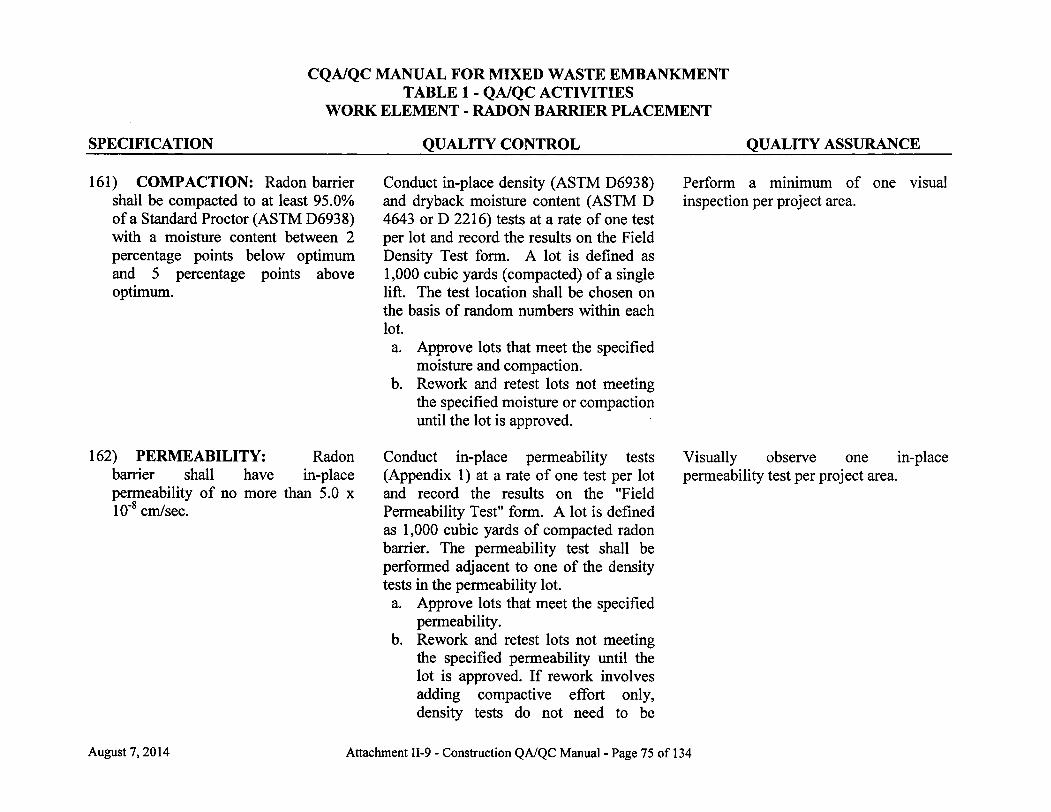
SPECIFICATION
CQA/QC MANUAL FOR MIXED WASTE EMBANKMENT TABLE 1 - QA/QC ACTIVITIES
WORK ELEMENT - RADON BARRIER PLACEMENT
QUALITY CONTROL QUALITY ASSURANCE
161) COMPACTION: Radon barrier shall be compacted to at least 95.0% of a Standard Proctor (ASTM D6938) with a moisture content between 2 percentage points below optimum and 5 percentage points above optimum.
162) PERMEABILITY: Radon barrier shall have in-place permeability of no more than 5.0 x 10"8 cm/sec.
Conduct in-place density (ASTM D6938) and dryback moisture content (ASTM D 4643 or D 2216) tests at a rate of one test per lot and record the results on the Field Density Test form. A lot is defined as 1,000 cubic yards (compacted) of a single lift. The test location shall be chosen on the basis of random numbers within each lot. a. Approve lots that meet the specified
moisture and compaction. b. Rework and retest lots not meeting
the specified moisture or compaction until the lot is approved.
Conduct in-place permeability tests (Appendix 1) at a rate of one test per lot and record the results on the "Field Permeability Test" form. A lot is defined as 1,000 cubic yards of compacted radon barrier. The permeability test shall be performed adjacent to one of the density tests in the permeability lot. a. Approve lots that meet the specified
permeability. b. Rework and retest lots not meeting
the specified permeability until the lot is approved. I f rework involves adding compactive effort only, density tests do not need to be
Perform a minimum of one visual inspection per project area.
Visually observe one in-place permeability test per project area.
August 7,2014 Attachment II-9 - Construction QA/QC Manual - Page 75 of 134

CQA/QC MANUAL FOR MIXED WASTE EMBANKMENT TABLE 1 - QA/QC ACTIVITIES
WORK ELEMENT - RADON BARRIER PLACEMENT
SPECIFICATION QUALITY CONTROL QUALITY ASSURANCE repeated. I f rework involves ripping and recompacting, new density tests shall be performed.
163) LAYER THICKNESS: For the Mixed Waste Landfill Cell, the radon barrier layer shall be at least 2.0 feet thick.
164) RADON BARRIER DRYING PREVENTION: To prevent the radon barrier from drying, water shall be applied to the clay surface on an as needed basis or the liner shall be covered.
165) SNOW REMOVAL: When radon barrier material is to be placed and the work area is covered with snow, the snow must be removed.
166) COLD WEATHER PLACEMENT OF RADON BARRIER: For purposes of this CQA/QC Manual, "frozen" is defined as a soil temperature of less than or equal to 27°F. Radon barrier shall not be placed above frozen material. In
Regularly observe the radon barrier surface for drying. Advise the Project Manager of deficiencies. Record corrective actions taken (where required) on the Daily Construction Report.
Observe that snow is removed. Advise the Project Manager of deficiencies. Construction cannot continue without taking corrective actions to remove the snow. Record corrective actions (where required) in the Daily Construction Report.
As needed, observe the area where radon barrier is to be placed. I f frozen material is observed, cease placement of radon barrier. I f frozen material is suspected, measure soil temperature. Record the stopping of placement in the Daily Construction Report.
Verify that radon barrier is tested during cold weather conditions.
August 7, 2014 Attachment II-9 - Construction QA/QC Manual - Page 76 of 134

SPECIFICATION
CQA/QC MANUAL FOR MIXED WASTE EMBANKMENT TABLE 1 - QA/QC ACTIVITIES
WORK ELEMENT - RADON BARRIER PLACEMENT
QUALITY CONTROL QUALITY ASSURANCE addition, no frozen material shall be processed or placed.
If the air temperature has dropped below 32°F since the last lift of radon barrier was approved, one of the following three scenarios apply:
If less than 30 days have passed since the date of lift approval and the last lift of radon barrier has been covered since the approval date with at least nine inches of loose clay or six inches of compacted clay, then the cover clay may be worked with no additional testing of the lower approved lift.
I f less than 30 days have passed since the date of lift approval and the last lift of radon barrier has not been covered with at least nine inches of loose clay or six inches of compacted clay, then:
Perform spring start-up testing as discussed below; or
Monitor the radon barrier temperature approximately one inch beneath the surface. I f the
Review ambient air temperature records as measured at the site meteorological station. Document status of radon barrier cover placement on the Daily Construction Report. Monitor radon barrier temperature when triggered. Clay temperature shall be measured between 6:00 am and 8:00 am on the day that radon barrier will be placed. Temperature measurements shall include a location that is most likely to be coldest; i.e., i f there is a portion of the radon barrier that is shaded or at a low point. Temperature monitoring frequency shall be at least one point per 100,000 square feet or one point per contiguous project area, whichever is smaller.
I f the initial radon barrier temperature measurement is less than or equal to 27°F, the affected area may be resampled before 8:30 am the same day as follows:
Measure the radon barrier temperature at a frequency of one measurement per lot (defined as no more than 10,000 square feet).
August 7,2014 Attachment II-9 - Construction QA/QC Manual - Page 77 of 134
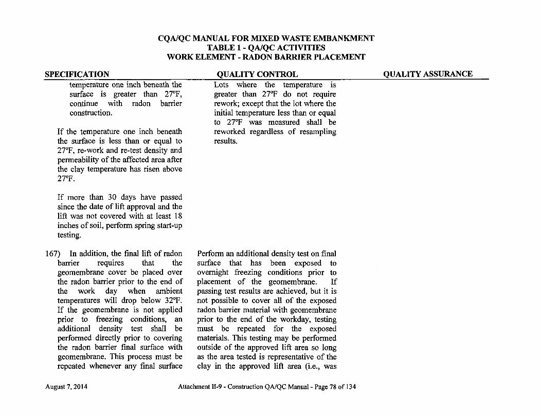
CQA/QC MANUAL FOR MIXED WASTE EMBANKMENT TABLE 1 - QA/QC ACTIVITIES
WORK ELEMENT - RADON BARRIER PLACEMENT
SPECIFICATION QUALITY CONTROL QUALITY ASSURANCE temperature one inch beneath the surface is greater than 27°F, continue with radon barrier construction.
If the temperature one inch beneath the surface is less than or equal to 27°F, re-work and re-test density and permeability of the affected area after the clay temperature has risen above 27°F.
Lots where the temperature is greater than 27°F do not require rework; except that the lot where the initial temperature less than or equal to 27°F was measured shall be reworked regardless of resampling results.
I f more than 30 days have passed since the date of lift approval and the lift was not covered with at least 18 inches of soil, perform spring start-up testing.
167) In addition, the final lift of radon barrier requires that the geomembrane cover be placed over the radon barrier prior to the end of the work day when ambient temperatures will drop below 32°F. I f the geomembrane is not applied prior to freezing conditions, an additional density test shall be performed directly prior to covering the radon barrier final surface with geomembrane. This process must be repeated whenever any final surface
Perform an additional density test on final surface that has been exposed to overnight freezing conditions prior to placement of the geomembrane. I f passing test results are achieved, but it is not possible to cover all of the exposed radon barrier material with geomembrane prior to the end of the workday, testing must be repeated for the exposed materials. This testing may be performed outside of the approved lift area so long as the area tested is representative of the clay in the approved lift area (i.e., was
August 7,2014 Attachment II-9 - Construction QA/QC Manual - Page 78 of 134

CQA/QC MANUAL FOR MIXED WASTE EMBANKMENT TABLE 1 - QA/QC ACTIVITIES
WORK ELEMENT - RADON BARRIER PLACEMENT
SPECIFICATION QUALITY CONTROL QUALITY ASSURANCE material is not covered with the constructed at the same time and with the geomembrane cover prior to same method), overnight freezing conditions.
168) SPRING START-UP: See "Cold Weather Placement of Radon Barrier" (specification 166) for situations that trigger this requirement.
169) For spring start-up testing, re-test the top two inches of the approved lift for density. Areas that have been tested shall be repaired to meet radon barrier specifications.
Perform density testing at a rate of one test per 1,000 cubic yard (compacted) lot. This testing may be performed outside of the approved lift area so long as the area tested is representative of the clay in the approved lift area (i.e., was constructed at the same time and with the same method). Moisture testing is not required for spring start-up.
a. Approve lots that meet specification. b. For lots that do not meet
specification, test the surface at successively deeper increments until a passing depth is found; remove or re-work all failing areas as needed; and re-test.
Document that repairs are completed to the same level of effort as required by the approved test pad for radon barrier
August 7,2014 Attachment II-9 - Construction QA/QC Manual - Page 79 of 134
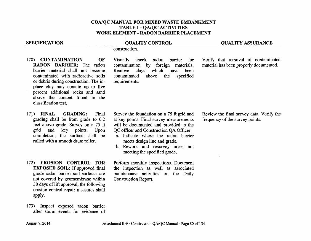
CQA/QC MANUAL FOR MIXED WASTE EMBANKMENT TABLE 1 - QA/QC ACTIVITIES
WORK ELEMENT - RADON BARRIER PLACEMENT
SPECIFICATION QUALITY CONTROL QUALITY ASSURANCE construction.
170) CONTAMINATION OF RADON BARRIER: The radon barrier material shall not become contaminated with radioactive soils or debris during construction. The in-place clay may contain up to five percent additional rocks and sand above the content found in the classification test.
Visually check radon barrier for contamination by foreign materials. Remove clays which have been contaminated above the specified requirements.
Verify that removal of contaminated material has been properly documented.
171) FINAL GRADING: Final grading shall be from grade to 0.2 feet above grade. Survey on a 75 ft grid and key points. Upon completion, the surface shall be rolled with a smooth drum roller.
172) EROSION CONTROL FOR EXPOSED SOIL: If approved final grade radon barrier soil surfaces are not covered by geomembrane within 30 days of lift approval, the following erosion control repair measures shall apply.
173) Inspect exposed radon barrier after storm events for evidence of
Survey the foundation on a 75 ft grid and at key points. Final survey measurements will be documented and provided to the QC officer and Construction QA Officer. a. Indicate where the radon barrier
meets design line and grade. b. Rework and resurvey areas not
meeting the specified grade.
Perform monthly inspections. Document the inspection as well as associated maintenance activities on the Daily Construction Report.
Review the final survey data. Verify the frequency of the survey points.
August 7,2014 Attachment II-9 - Construction QA/QC Manual - Page 80 of 134
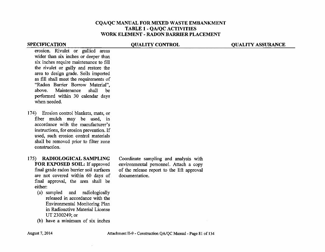
CQA/QC MANUAL FOR MIXED WASTE EMBANKMENT TABLE 1 - QA/QC ACTIVITIES
WORK ELEMENT - RADON BARRIER PLACEMENT
SPECIFICATION QUALITY CONTROL QUALITY ASSURANCE erosion. Rivulet or gullied areas wider than six inches or deeper than six inches require maintenance to fi l l the rivulet or gully and restore the area to design grade. Soils imported as f i l l shall meet the requirements of "Radon Barrier Borrow Material", above. Maintenance shall be performed within 30 calendar days when needed.
174) Erosion control blankets, mats, or fiber mulch may be used, in accordance with the manufacturer's instructions, for erosion prevention. If used, such erosion control materials shall be removed prior to filter zone construction.
175) RADIOLOGICAL SAMPLING FOR EXPOSED SOIL: If approved final grade radon barrier soil surfaces are not covered within 60 days of final approval, the area shall be either: (a) sampled and radiologically
released in accordance with the Environmental Monitoring Plan in Radioactive Material License UT 2300249; or
(b) have a mimmum of six inches
Coordinate sampling and analysis with environmental personnel. Attach a copy of the release report to the lift approval documentation.
August 7,2014 Attachment II-9 - Construction QA/QC Manual - Page 81 of 134
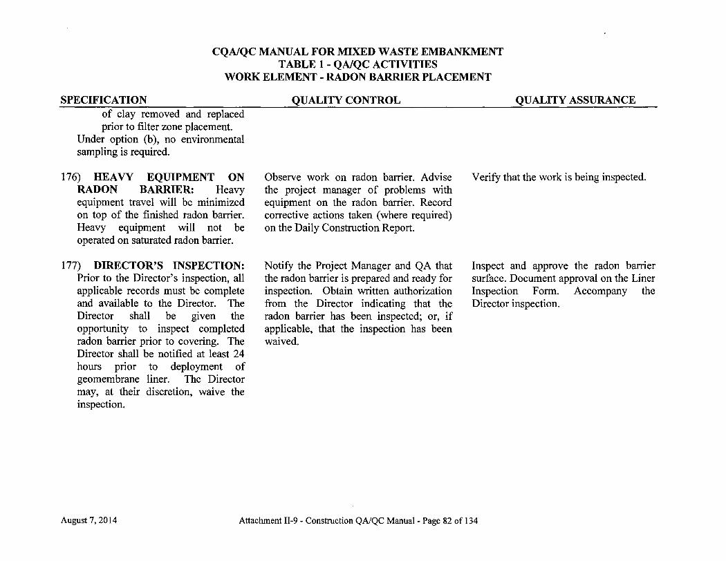
SPECIFICATION
CQA/QC MANUAL FOR MIXED WASTE EMBANKMENT TABLE 1 - QA/QC ACTIVITIES
WORK ELEMENT - RADON BARRIER PLACEMENT
QUALITY CONTROL QUALITY ASSURANCE of clay removed and replaced prior to filter zone placement.
Under option (b), no environmental sampling is required.
176) HEAVY EQUIPMENT ON RADON BARRIER: Heavy equipment travel will be minimized on top of the finished radon barrier. Heavy equipment will not be operated on saturated radon barrier.
177) DIRECTOR'S INSPECTION: Prior to the Director's inspection, all applicable records must be complete and available to the Director. The Director shall be given the opportunity to inspect completed radon barrier prior to covering. The Director shall be notified at least 24 hours prior to deployment of geomembrane liner. The Director may, at their discretion, waive the inspection.
Observe work on radon barrier. Advise the project manager of problems with equipment on the radon barrier. Record corrective actions taken (where required) on the Daily Construction Report.
Notify the Project Manager and QA that the radon barrier is prepared and ready for inspection. Obtain written authorization from the Director indicating that the radon barrier has been inspected; or, i f applicable, that the inspection has been waived.
Verify that the work is being inspected.
Inspect and approve the radon barrier surface. Document approval on the Liner Inspection Form. Accompany the Director inspection.
August 7,2014 Attachment II-9 - Construction QA/QC Manual - Page 82 of 134

CQA/QC MANUAL FOR MIXED WASTE EMBANKMENT TABLE 1 - QA/QC ACTIVITIES
WORK ELEMENT - COVER SYSTEM ROCK QUALITY
SPECIFICATION 178) QUALITY OF ROCK: All rock
used for Filter Zone and Rock Erosion Barrier shall have a "Rock Quality" score of at least 50 based on the following tests: Specific Gravity (ASTM C-128), Absorption (ASTM C-127), Sodium Soundness (ASTM C-88), and L.A. Abrasion (ASTM C-131 or ASTM C-535). The procedures for scoring "Rock Quality" are found in Appendix C.
QUALITY CONTROL As described in NUREG-1623, appendix F, perform at least one petrographic examination for each rock source in accordance with ASTM C-295. I f a combination of limestone, sandstone, and igneous rock is found for a source, percentages of each type of material shall be determined for scoring.
Perform Na soundness, LA abrasion, absorption, and specific gravity testing at a rate of one set of tests per 20,000 cubic yards of rock per source. Record the location of all collected samples in the Sampling Log. a. Approve rock for use in the filter
zone which meets the specifications for rock quality.
b. Rock not meeting the specifications for rock quality cannot be used.
QUALITY ASSURANCE Verify the frequency of laboratory quality control tests and compliance of test results. Verify the performance of the petrographic examination for each rock source and the Rock Quality scoring.
August 7, 2014 Attachment II-9 - Construction QA/QC Manual - Page 83 of 134
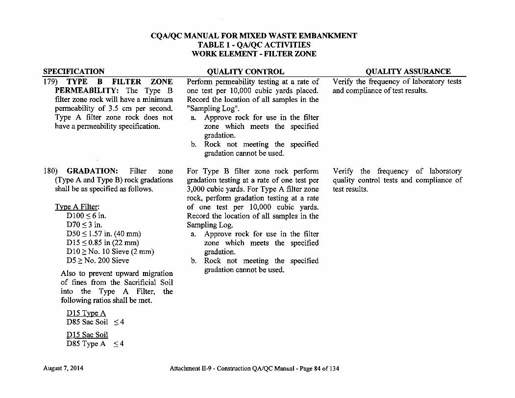
CQA/QC MANUAL FOR MIXED WASTE EMBANKMENT TABLE 1 - QA/QC ACTIVITIES
WORK ELEMENT - FILTER ZONE
SPECIFICATION QUALITY CONTROL QUALITY ASSURANCE 179) TYPE B FILTER ZONE
PERMEABILITY: The Type B filter zone rock will have a minimum permeability of 3.5 cm per second. Type A filter zone rock does not have a permeability specification.
180) GRADATION: Filter zone (Type A and Type B) rock gradations shall be as specified as follows.
Type A Filter: D100<6in. D70 < 3 in. D50< 1.57 in. (40 mm) D15<0.85 in (22 mm) D10 > No. 10 Sieve (2 mm) D5 > No. 200 Sieve
Also to prevent upward migration of fines from the Sacrificial Soil into the Type A Filter, the following ratios shall be met.
D15 Type A D85 Sac Soil <4
D15 Sac Soil D85 Type A < 4
Perform permeability testing at a rate of one test per 10,000 cubic yards placed. Record the location of all samples in the "Sampling Log". a. Approve rock for use in the filter
zone which meets the specified gradation.
b. Rock not meeting the specified gradation cannot be used.
For Type B filter zone rock perform gradation testing at a rate of one test per 3,000 cubic yards. For Type A filter zone rock, perform gradation testing at a rate of one test per 10,000 cubic yards. Record the location of all samples in the Sampling Log. a. Approve rock for use in the filter
zone which meets the specified gradation.
b. Rock not meeting the specified gradation cannot be used.
Verify the frequency of laboratory tests and compliance of test results.
Verify the frequency of laboratory quality control tests and compliance of test results.
August 7,2014 Attachment II-9 - Construction QA/QC Manual - Page 84 of 134
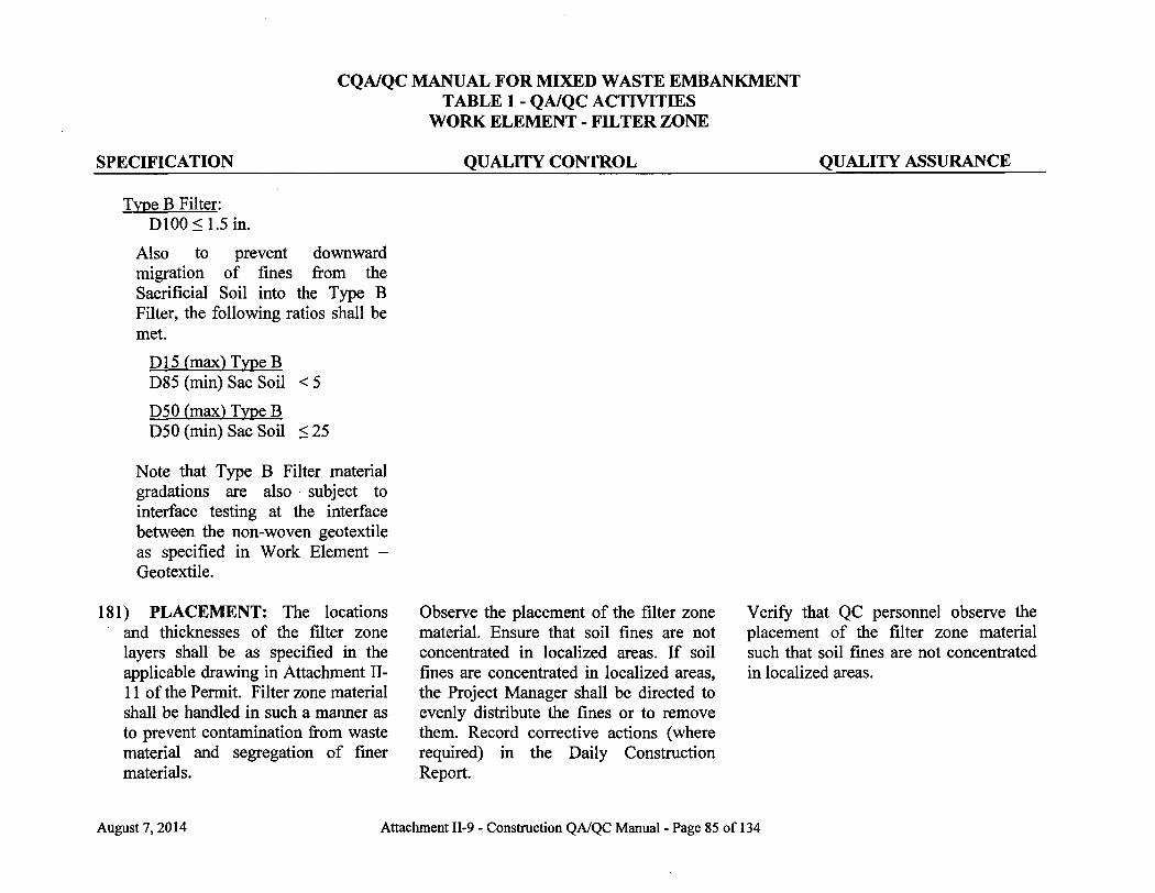
CQA/QC MANUAL FOR MIXED WASTE EMBANKMENT TABLE 1 - QA/QC ACTIVITIES
WORK ELEMENT - FILTER ZONE
QUALITY CONTROL QUALITY ASSURANCE SPECIFICATION
Type B Filter: D100<1.5 in.
Also to prevent downward migration of fines from the Sacrificial Soil into the Type B Filter, the following ratios shall be met.
D15 (max) Type B D85 (min) Sac Soil <5
D50 (max) Type B D50 (min) Sac Soil <25
Note that Type B Filter material gradations are also subject to interface testing at the interface between the non-woven geotextile as specified in Work Element -Geotextile.
181) PLACEMENT: The locations and thicknesses of the filter zone layers shall be as specified in the applicable drawing in Attachment I I -11 of the Permit. Filter zone material shall be handled in such a manner as to prevent contamination from waste material and segregation of finer materials.
Observe the placement of the filter zone material. Ensure that soil fines are not concentrated in localized areas. I f soil fines are concentrated in localized areas, the Project Manager shall be directed to evenly distribute the fines or to remove them. Record corrective actions (where required) in the Daily Construction Report.
Verify that QC personnel observe the placement of the filter zone material such that soil fines are not concentrated in localized areas.
August 7,2014 Attachment II-9 - Construction QA/QC Manual - Page 85 of 134

CQA/QC MANUAL FOR MIXED WASTE EMBANKMENT TABLE 1 - QA/QC ACTIVITIES
WORK ELEMENT - FILTER ZONE
SPECIFICATION QUALITY CONTROL QUALITY ASSURANCE
182) SNOW REMOVAL: When filter zone material is to be placed and the work area is covered with snow, the snow must be removed.
183) FINAL GRADING: Thickness for the layer (lift) will be established by installing grade poles on at least a 75 foot grid and at all control points. The grade poles shall consist of PVC pipe (approximately /4-inch diameter) with surveyor's ribbon (or other distinguishable markings) attached to the appropriate lift thickness. For the Type B filter zone, the poles shall be held in place by placing filter rock material adjacent to the base of the grade pole to secure it in a vertical position (long axis of the grade pole perpendicular to the radon barrier surface). The base of the grade poles shall rest on the surface of the geosynthetics and therefore not damage the geosynthetic surface. For the Type A filter zone, the grade poles can be driven, no more than 6",
Observe that snow is removed. Advise the Project Manager of any deficiencies. Construction may not continue without taking corrective actions to remove the snow. Record corrective actions (where required) in the Daily Construction Report.
Verify that the grade poles are marked at the appropriate depth to establish grade for the layer that will be placed. Observe the installation of some of the grade poles to ensure that the installation method has been followed and verify that the grade poles have not penetrated or damaged the surface of the geomembrane.
Verify the required grade is achieved at all control points throughout the placed filter rock in the project area. Rework and re-verify areas not meeting the specified grade. Ensure all grade poles have been removed following verification of grade. Document all inspections and corrective actions, where required, on the Daily Construction Report.
Verify that snow removal is being documented.
Review documentation for final grading.
August 7,2014 Attachment II-9 - Construction QA/QC Manual - Page 86 of 134

CQA/QC MANUAL FOR MIXED WASTE EMBANKMENT TABLE 1 - QA/QC ACTIVITIES
WORK ELEMENT - FILTER ZONE
SPECIFICATION QUALITY CONTROL QUALITY ASSURANCE into the underlying layer (Sacrificial soil). With the grade poles marked at the appropriate thickness and secured at the appropriate locations, the filter rock may be placed throughout the project area. After the grade has been checked and approved by QC personnel, the grade poles shall be removed.
August 7, 2014 Attachment II-9 - Construction QA/QC Manual - Page 87 of 134
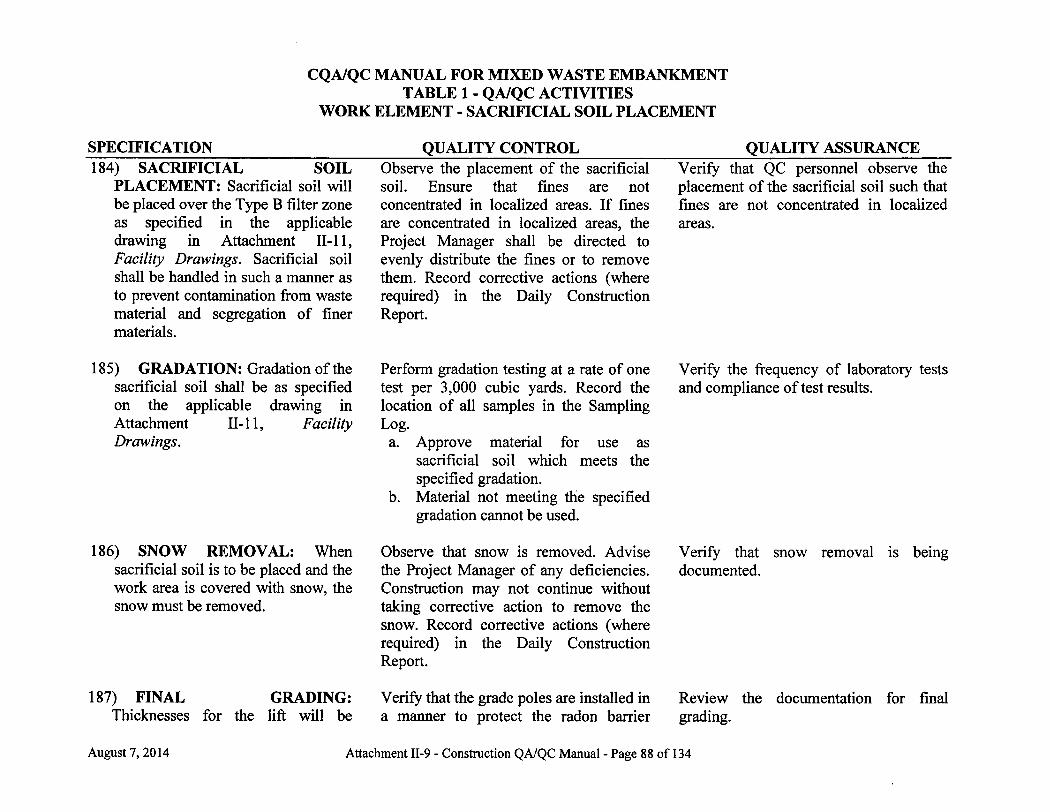
CQA/QC MANUAL FOR MIXED WASTE EMBANKMENT TABLE 1 - QA/QC ACTIVITIES
WORK ELEMENT - SACRIFICIAL SOIL PLACEMENT
SPECIFICATION 184) SACRIFICIAL SOIL
PLACEMENT: Sacrificial soil will be placed over the Type B filter zone as specified in the applicable drawing in Attachment 11-11, Facility Drawings. Sacrificial soil shall be handled in such a manner as to prevent contamination from waste material and segregation of finer materials.
QUALITY CONTROL Observe the placement of the sacrificial soil. Ensure that fines are not concentrated in localized areas. I f fines are concentrated in localized areas, the Project Manager shall be directed to evenly distribute the fines or to remove them. Record corrective actions (where required) in the Daily Construction Report.
QUALITY ASSURANCE Verify that QC personnel observe the placement of the sacrificial soil such that fines are not concentrated in localized areas.
185) GRADATION: Gradation of the sacrificial soil shall be as specified on the applicable drawing in Attachment 11-11, Facility Drawings.
186) SNOW REMOVAL: When sacrificial soil is to be placed and the work area is covered with snow, the snow must be removed.
187) FINAL GRADING: Thicknesses for the lift will be
Perform gradation testing at a rate of one test per 3,000 cubic yards. Record the location of all samples in the Sampling Log. a. Approve material for use as
sacrificial soil which meets the specified gradation.
b. Material not meeting the specified gradation cannot be used.
Observe that snow is removed. Advise the Project Manager of any deficiencies. Construction may not continue without taking corrective action to remove the snow. Record corrective actions (where required) in the Daily Construction Report.
Verify that the grade poles are installed in a manner to protect the radon barrier
Verify the frequency of laboratory tests and compliance of test results.
Verify that snow removal is being documented.
Review the documentation for final grading.
August 7,2014 Attachment II-9 - Construction QA/QC Manual - Page 88 of 134
CQA/QC MANUAL FOR MIXED WASTE EMBANKMENT TABLE 1 - QA/QC ACTIVITIES
WORK ELEMENT - SACRIFICIAL SOIL PLACEMENT
SPECIFICATION QUALITY CONTROL QUALITY ASSURANCE established by installing grade poles on at least a75' grid and at all control points. The grade poles shall not be installed in such a manner as to incur damage to the radon barrier surface or geosynthetics underlying the Type B filter zone. The grade poles must be marked at the appropriate depth to establish grade. After the grade has been checked and approved by QC personnel, the grade poles shall be removed.
surface. Verify the required grade is achieved at all control points. Rework and re-verify areas not meeting the specified grade.
August 7,2014 Attachment II-9 - Construction QA/QC Manual - Page 89 of 134
CQA/QC MANUAL FOR MIXED WASTE EMBANKMENT TABLE 1 - QA/QC ACTIVITIES
WORK ELEMENT - ROCK EROSION BARRIER
SPECIFICATION QUALITY CONTROL QUALITY ASSURANCE 188) ROCK EROSION BARRIER
GRADATION: Gradations for the rock erosion barriers (Type A and Type B riprap) shall be as specified on the applicable drawing in Attachment I I - l 1 of the Permit.
189) PLACEMENT: Rock erosion material will be placed over the Type A filter zone as specified in the applicable drawing in Attachment I I -11 of the Permit. Rock erosion material shall be handled in such a manner as to prevent contamination from waste material and segregation of finer materials.
190) SNOW REMOVAL: When rock erosion barrier material is to be placed and the work area is covered with snow, the snow must be removed.
191) FINAL GRADING: Thickness for the lift will be established by
Perform gradation testing, in accordance with ASTM D-5519 or C-136, at a rate of one test per 10,000 cubic yards. Record the location of all samples in the Sampling Log. a. Approve rock for use in the rock
erosion barrier which meets the specified gradation.
b. Rock not meeting the specified gradation cannot be used.
Observe the placement of the rock erosion material. Ensure that soil fines are not concentrated in localized areas. I f soil fines are concentrated in localized areas, the Project Manager shall be directed to evenly distribute the fines or to remove them. Record corrective actions (where required) in the Daily Construction Report.
Observe that snow is removed. Advise the Project Manager of any deficiencies. Construction may not continue without taking corrective action to remove the snow. Record corrective actions (where required) in the Daily Construction Report.
Verify the required grade is achieved at all control points. Rework and re-verify
Verify the frequency of laboratory quality control tests and compliance of test results.
Verify that QC personnel observe the placement of the rock erosion material such that soil fines are not concentrated in localized areas.
Verify that snow removal is being documented.
Review the documentation for final grading.
August 7, 2014 Attachment II-9 - Construction QA/QC Manual - Page 90 of 134
CQA/QC MANUAL FOR MIXED WASTE EMBANKMENT TABLE 1 - QA/QC ACTIVITIES
WORK ELEMENT - ROCK EROSION BARRIER
SPECIFICATION QUALITY CONTROL QUALITY ASSURANCE installing grade poles on at least a 75' grid and at all control points. The grade poles shall consist of PVC pipe (approximately '/2-inch diameter) with surveyor ribbon (or other distinguishable markings). The grade poles must be marked at the appropriate depth to establish grade. After the grade has been checked and approved by QC personnel, the grade poles shall be removed.
areas not meeting the specified grade. Document all inspections and corrective actions, where required, on the Daily Construction Report.
192) FINAL INSPECTION: At the completion of each cover construction project, a final joint inspection shall be conducted by the Manager, Engineering and Maintenance, CQAO, and Director.
Participate in the final joint inspection. Document results in the Construction QA Review.
August 7, 2014 Attachment II-9 - Construction QA/QC Manual - Page 91 of 134

CQA/QC MANUAL FOR MIXED WASTE EMBANKMENT TABLE 1 - QA/QC ACTIVITIES
WORK ELEMENT - DRAINAGE DITCH IMPORTED BORROW
SPECIFICATION QUALITY CONTROL QUALITY ASSURANCE 193) CLEARING AND
GRUBBING: Remove vegetation, debris, organic, or unsuitable material from areas to be used for borrow. Grubbing depth will depend on the type of vegetation, debris, organic, or unsuitable material on the site. If the area is free of these materials then no clearing and grubbing will be necessary.
Inspect the area once clearing and grubbing has been completed. Record observations and corrective actions (where required) on the Daily Construction Report.
Verify that the clearing and grubbing has been inspected by QC.
194) MATERIAL: The imported borrow shall be classified as CL, ML, or CL-ML soils by ASTM D-2487.
Perform laboratory classification tests at a rate of one test per lot prior to use of material. A lot is defined as a maximum of 3,000 cubic yards (compacted) of specified material type. Record the location of the classification sample on the Sampling Log. a. Approve lots which meet the
specified classification for use. b. Lots not meeting the specified
classification cannot be used.
Verify the frequency of laboratory tests and compliance of test results.
195) LIFT THICKNESS: Drainage ditch borrow material shall be placed in lifts with an uncompacted thickness of less than or equal to nine inches. Thickness for the lift will be established by installing grade poles on at least a 50-foot grid lengthwise and at all control .points. The grade poles must not be installed deeper
Verify that the required grading is achieved as follows: a. Ensure that the required frequency
for placement of grade poles has been met.
b. Compare soil level with the marked level on the grade poles.
c. Use a string line where necessary between poles to check for high or
Verify that the measurements are being performed at the correct frequency and that the documentation is being completed.
August 7,2014 Attachment II-9 - Construction QA/QC Manual - Page 92 of 134

CQA/QC MANUAL FOR MIXED WASTE EMBANKMENT TABLE 1 - QA/QC ACTIVITIES
WORK ELEMENT - DRAINAGE DITCH IMPORTED BORROW
SPECIFICATION QUALITY CONTROL QUALITY ASSURANCE than six inches into the underlying surface. The grade poles must be marked at the appropriate depth to establish the grade. After the grade has been checked and approved by QC personnel, the grade poles shall be removed.
low spots. d. Define those areas that are high out
of specification and advise the project manager to re-work those areas.
e. Review areas re-worked and approve areas meeting criteria.
f. Continue b through d above until all areas meet criteria.
g. Indicate areas meeting criteria in the Embankment Construction Lift Approval Form.
August 7, 2014 Attachment II-9 - Construction QA/QC Manual - Page 93 of 134

CQA/QC MANUAL FOR MIXED WASTE EMBANKMENT TABLE 1 - QA/QC ACTIVITIES
WORK ELEMENT - DRAINAGE DITCH
SPECIFICATION QUALITY CONTROL QUALITY ASSURANCE 196) EXCAVATION: Excavation
shall be made to the lines, grades, and dimensions prescribed in the approved plans. Prior Director approval, in writing, must be obtained before diverting ditches from the current approved design. The purpose and duration of diversion shall be specified in any request to do so.
197) Any over excavation shall be backfilled with select materials and compacted to 95 percent of standard Proctor (ASTM D698). The uncompacted lift thickness shall not exceed nine inches.
Provide daily observation of the cell excavation. Record observations and corrective actions (where required) on the Daily Construction Report.
In areas of over excavation, conduct in-place density tests at a rate of one test per lot and record the results on the Field Density Test form. A lot is defined as a maximum of 10,000 square feet of a lift of a specified type of material. Test locations shall be chosen on the basis of random numbers. a. Approve lots which meet the
specified compaction. b. Rework and retest lots not meeting
the specified compaction.
Proctors shall be performed at a rate of one test per 100,000 square feet for each material type. At least one proctor shall be performed for each material type. Record the location of the sample on the Sampling Log.
Verify that the tests are being performed at the correct frequency and that the documentation is being completed.
198) FINAL GRADING: Smooth roll Inspect the surface for smoothness. Review the final survey data. Verify the
August 7, 2014 Attachment II-9 - Construction QA/QC Manual - Page 94 of 134
CQA/QC MANUAL FOR MIXED WASTE EMBANKMENT TABLE 1 - QA/QC ACTIVITIES
WORK ELEMENT - DRAINAGE DITCH
SPECIFICATION QUALITY CONTROL QUALITY ASSURANCE the excavated surface to prepare for filter zone. Final grading of this surface shall be ±0.1 of a foot.
199) FILTER ZONE AND ROCK EROSION BARRIER: The filter zone and rock erosion barrier shall be constructed in accordance with the specifications outlined under work elements "Filter Zone" and "Rock Erosion Barrier".
Survey the surface on a 75 ft grid and at key points. Final survey measurements will be documented and provided to the Lead, QC Embankment Construction and CQAO. a. Indicate where the surface meets
design line and grade. b. Rework and resurvey areas not
meeting the specified grade.
See work elements "Filter Zone" and "Rock Erosion Barrier".
frequency of the survey points.
See work elements "Filter Zone" "Rock Erosion Barrier".
and
200) EROSION CONTROL FOR EXPOSED SOIL: I f reviewed and approved, drainage ditch soil surfaces will be covered by filter zone within 30days of lift approval.
201) Erosion control blankets, mats, or fiber mulch may be used, in accordance with the manufacturer's instructions, for erosion prevention.
202) RADIOLOGICAL SAMPLING FOR EXPOSED SOIL: If reviewed and approved drainage ditch soil
Perform inspections. Document the inspection as well as associated maintenance activities on the Daily Construction Report.
Coordinate sampling and analysis with environmental personnel. Attach a copy of the release report to the lift approval
August 7,2014 Attachment II-9 - Construction QA/QC Manual - Page 95 of 134
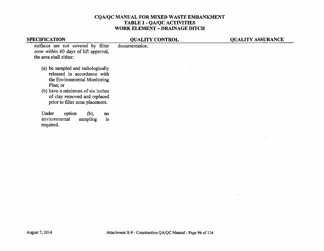
CQA/QC MANUAL FOR MIXED WASTE EMBANKMENT TABLE 1 - QA/QC ACTIVITIES
WORK ELEMENT - DRAINAGE DITCH
SPECIFICATION QUALITY CONTROL QUALITY ASSURANCE surfaces are not covered by filter documentation, zone within 60 days of lift approval, the area shall either:
(a) be sampled and radiologically released in accordance with the Environmental Monitoring Plan; or
(b) have a mimmum of six inches of clay removed and replaced prior to filter zone placement.
Under option (b), no environmental sampling is required.
August 7,2014 Attachment II-9 - Construction QA/QC Manual - Page 96 of 134
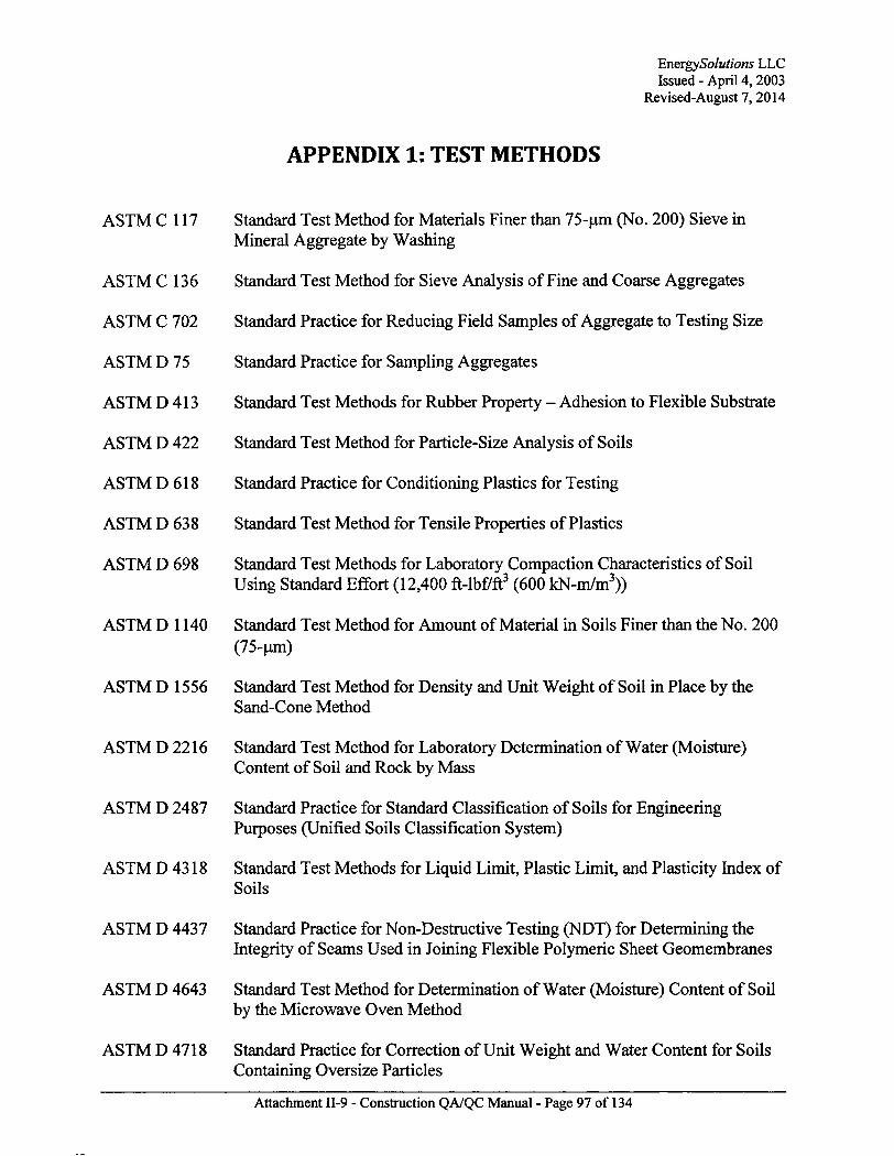
EnergySolutions LLC Issued - April 4,2003
Revised-August 7, 2014
ASTM C 117
ASTM C 136
ASTM C 702
ASTM D 75
ASTM D 413
ASTM D 422
ASTM D 618
ASTM D 638
ASTM D 698
ASTM D 1140
ASTM D 1556
ASTM D 2216
ASTM D 2487
ASTM D 4318
APPENDIX 1: TEST METHODS
Standard Test Method for Materials Finer than 75-um (No. 200) Sieve in Mineral Aggregate by Washing
Standard Test Method for Sieve Analysis of Fine and Coarse Aggregates
Standard Practice for Reducing Field Samples of Aggregate to Testing Size
Standard Practice for Sampling Aggregates
Standard Test Methods for Rubber Property - Adhesion to Flexible Substrate
Standard Test Method for Particle-Size Analysis of Soils
Standard Practice for Conditioning Plastics for Testing
Standard Test Method for Tensile Properties of Plastics
Standard Test Methods for Laboratory Compaction Characteristics of Soil Using Standard Effort (12,400 ft-lbf/ft 3 (600 kN-m/m3))
Standard Test Method for Amount of Material in Soils Finer than the No. 200 (75-um)
Standard Test Method for Density and Unit Weight of Soil in Place by the Sand-Cone Method
Standard Test Method for Laboratory Determination of Water (Moisture) Content of Soil and Rock by Mass
Standard Practice for Standard Classification of Soils for Engineering Purposes (Unified Soils Classification System)
Standard Test Methods for Liquid Limit, Plastic Limit, and Plasticity Index of Soils
ASTM D 4437 Standard Practice for Non-Destructive Testing (NDT) for Determining the Integrity of Seams Used in Joining Flexible Polymeric Sheet Geomembranes
ASTM D 4643 Standard Test Method for Determination of Water (Moisture) Content of Soil by the Microwave Oven Method
ASTM D 4718 Standard Practice for Correction of Unit Weight and Water Content for Soils Containing Oversize Particles
Attachment II-9 - Construction QA/QC Manual - Page 97 of 134

EnergySolutions LLC Issued - April 4, 2003
Revised-August 7,2014
ASTM D 5084
ASTM D 5321
Standard Test Method for Measurement of Hydraulic Conductivity of Saturated Porous Materials Using a Flexible Wall Permeameter
Standard Test Method for Determining the Coefficient of Soil and Geosynthetic or Geosynthetic and Geosynthetic Friction by the Direct Shear Method
ASTM D 5641 Standard Practice for Geomembrane Seam Evaluation by Vacuum Chamber
ASTM D 5820 Standard Practice for Pressurized Air Channel Evaluation of Dual Seamed Geomembranes
ASTM D 6365
ASTM D 6392
ASTM D 6938
Standard Practice for the Nondestructive Testing of Geomembrane Seams using the Spark Test
Standard Test Method for Determining the Integrity of Nonreinforced Geomembrane Seams Produced Using Thermo-Fusion Methods
Standard Test Methods for In-Place Density and Water Content of Soil and Soil-Aggregate by Nuclear Methods (Shallow Depth)
Attachment II-9 - Construction QA/QC Manual - Page 98 of 134
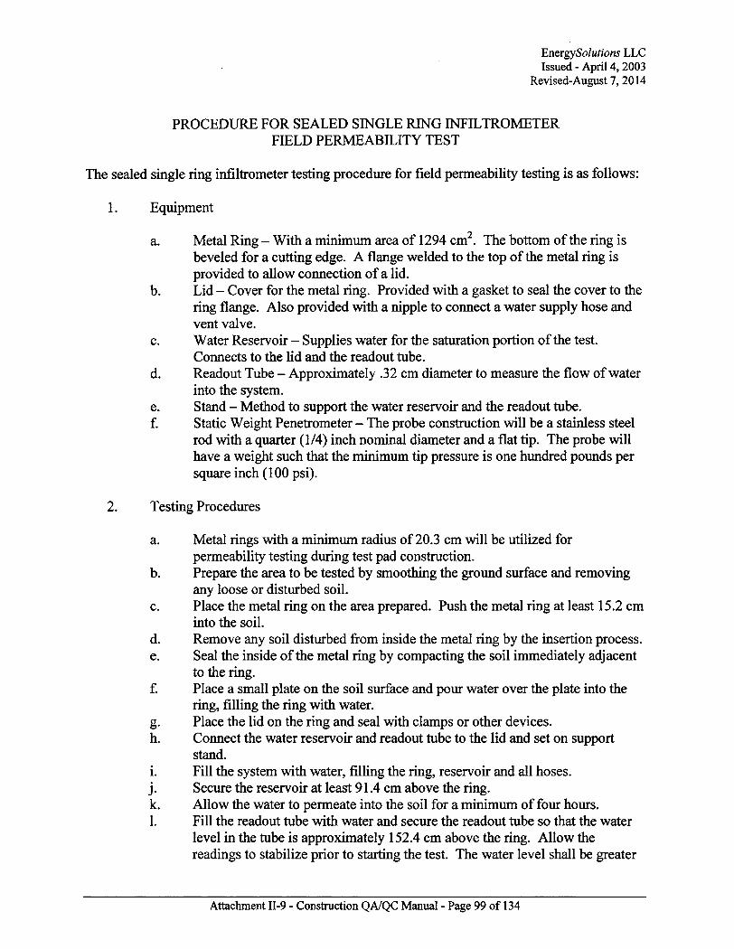
EnergySolutions LLC Issued - April 4,2003
Revised-August 7,2014
PROCEDURE FOR SEALED SINGLE RING INFILTROMETER FIELD PERMEABILITY TEST
The sealed single ring infiltrometer testing procedure for field permeability testing is as follows:
1. Equipment
a. Metal Ring - With a mimmum area of 1294 cm2. The bottom of the ring is beveled for a cutting edge. A flange welded to the top of the metal ring is provided to allow connection of a lid.
b. Lid - Cover for the metal ring. Provided with a gasket to seal the cover to the ring flange. Also provided with a nipple to connect a water supply hose and vent valve.
c. Water Reservoir - Supplies water for the saturation portion of the test. Connects to the lid and the readout tube.
d. Readout Tube - Approximately .32 cm diameter to measure the flow of water into the system.
e. Stand - Method to support the water reservoir and the readout tube. f. Static Weight Penetrometer - The probe construction will be a stainless steel
rod with a quarter (1/4) inch nominal diameter and a flat tip. The probe will have a weight such that the mimmum tip pressure is one hundred pounds per square inch (100 psi).
2. Testing Procedures
a. Metal rings with a mimmum radius of 20.3 cm will be utilized for permeability testing during test pad construction.
b. Prepare the area to be tested by smoothing the ground surface and removing any loose or disturbed soil.
c. Place the metal ring on the area prepared. Push the metal ring at least 15.2 cm into the soil.
d. Remove any soil disturbed from inside the metal ring by the insertion process. e. Seal the inside of the metal ring by compacting the soil immediately adjacent
to the ring. f. Place a small plate on the soil surface and pour water over the plate into the
ring, filling the ring with water. g. Place the lid on the ring and seal with clamps or other devices. h. Connect the water reservoir and readout tube to the lid and set on support
stand. i . Fill the system with water, filling the ring, reservoir and all hoses,
j . Secure the reservoir at least 91.4 cm above the ring. k. Allow the water to permeate into the soil for a minimum of four hours. 1. Fill the readout tube with water and secure the readout tube so that the water
level in the tube is approximately 152.4 cm above the ring. Allow the readings to stabilize prior to starting the test. The water level shall be greater
Attachment II-9 - Construction QA/QC Manual - Page 99 of 134
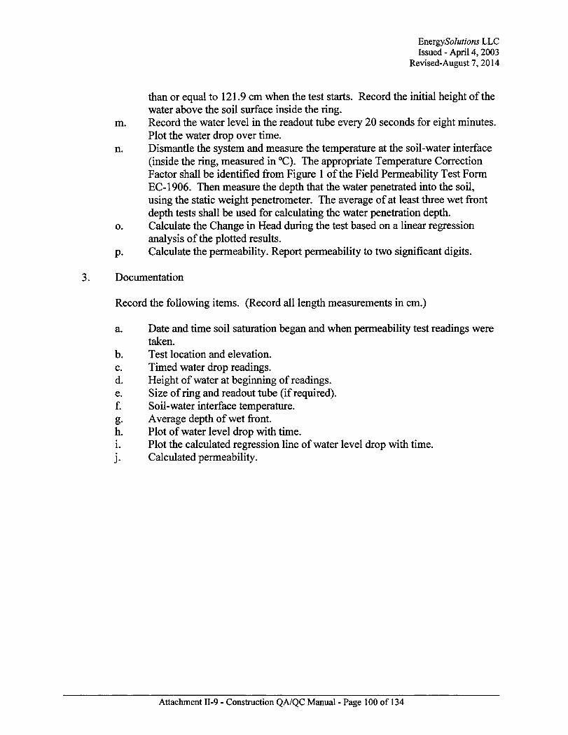
EnergySolutions LLC Issued - April 4,2003
Revised-August 7,2014
than or equal to 121.9 cm when the test starts. Record the initial height of the water above the soil surface inside the ring.
m. Record the water level in the readout tube every 20 seconds for eight minutes. Plot the water drop over time.
n. Dismantle the system and measure the temperature at the soil-water interface (inside the ring, measured in °C). The appropriate Temperature Correction Factor shall be identified from Figure 1 of the Field Permeability Test Form EC-1906. Then measure the depth that the water penetrated into the soil, using the static weight penetrometer. The average of at least three wet front depth tests shall be used for calculating the water penetration depth.
0. Calculate the Change in Head during the test based on a linear regression analysis of the plotted results.
p. Calculate the permeability. Report permeability to two significant digits.
3. Documentation
Record the following items. (Record all length measurements in cm.)
a. Date and time soil saturation began and when permeability test readings were taken.
b. Test location and elevation. c. Timed water drop readings. d. Height of water at beginning of readings. e. Size of ring and readout tube (if required). f. Soil-water interface temperature. g. Average depth of wet front. h. Plot of water level drop with time. 1. Plot the calculated regression line of water level drop with time,
j . Calculated permeability.
Attachment H-9 - Construction QA/QC Manual - Page 100 of 134

EnergySolutions LLC Issued - April 4, 2003
Revised-August 7, 2014
Appendix 2: Forms
ES-1901 Data Quality Assurance Report
ES-1902 Daily Construction Report
ES-1903 Sample Log
ES-98252 Embankment Construction Lift Approval Form
ES-1905 Field Density Test
ES-1906 Field Permeability Test
ES-1907 Aggregate Gradation Form
ES-1908 Soil Classification Form
ES-1909 Standard Proctor Form (2 pages)
ES-1911 Breach of Berm
ES-1912 Liner/Radon Barrier Inspection Form
Geomembrane Liner Roll Approval Form
Polymer Raw Material Approval Form
Welding Rod Approval Form
Drainage Net Approval Form
Panel Inspection Form
Destructive Testing
Seam Inspection Form
Welding Machine Operation Log
Geotextile Approval Form
Attachment II-9 - Construction QA/QC Manual - Page 101 of 134

EnergySolutions LLC Issued - April 4,2003
Revised-August 7,2014
FmRGYSOfXTiaVS DAILY QUALITY ASSURANCE REPORT
ES-1901 Bw.l
WOmcr: CAW MW 11«L{2)
DATS:
QUAIiryASSUEA>^AClTVmES;
HbmBB NOTED:
PSOBLEMffiSOLUnQNS;
OAAFTSDVAL MT£
EnergySolutions LLC Issued - April 4, 2003
Revised-August 7,2014
fXmzYSQLiTia\s Es-1302 Rev.l
DAILY CONSTRUCTION REPORT PROJECT: r j C A W Q l f l T • 11&<2) OTHER
DATE
WEATHER: • » r • Ooariy • W « H M dRata • S t a r • w » d OTHER
COMSTKUCnGWOFESATHHtS: OwBtoPtactsiat • CdlEmvatton • day Lisa • RsdM Barrier
Q Rock Placement OTHER
PERSONNEL ON SITE: • OpwiliiaH OTHER
BQXHFMEirrCSED:
RockTiscfa_ Track tots _
frjsyui Hilars Radars
CAT 115 _ Wafer Tracks _ CAT OS _ OTHER
DAILY FKOGRESS MEETING: • Yes • No
LIFTS TESTED:
LIFTS AFFBOVED:
EXFLANATKBiS:
HBD ESsGMEU/MSPFCTOR a i a i . m .
OfOFFKBlAPPfsOVftL DATE QA APPBTJVAL DATE
EfiefSjyrSnftADar Cnwtj.Utab Page •
Attachment II-9 - Construction QA/QC Manual - Page 103 of 134
EnergySolutions LLC Issued - April 4,2003
Revised-August 7, 2014
Attachment II-9 - Construction QA/QC Manual - Page 104 of 134

EnergySolutions LLC Issued - April 4,2003
Revised-August 7, 2014
SAMPLE LOG
ES-1KB
_CAW MW OTHER_
DATE:
IrQ2KJlTEIX>CATK]N AND tnJMBER OF SAMPLE CM MAP
Material Type: Sail or Xock Stapled By _
Texts to be y t i f i i i t J :
Proctor flwiirii afrra Specific Graaty LAAtnaoB._ KA Soaadbeu UbPananUirj
MaterMTyp-: Sail or lock ^aaulnlBy
Tagtatp bgyLifuiamiii. Proctar rjwirnranora Specific Gravity T A fttoaaa Atocrptioo_
HASa— (aim bfcBmaaaalitr
MatBalTrpe: S a l ar lock SaanMBf
Tests i» be| Proctar CJauificitisra Specific Gravity LA Atrmtra
HAS
QCAFFBTJVAL TMTE QA APPROVAL
Ca>e.{ftaa Pane of.
Attachment II-9 - Construction QA/QC Manual - Page 105 of 134
EnergySolutions LLC Issued - April 4, 2003
Revised-August 7,2014
Attachment II-9 - Construction QA/QC Manual - Page 106 of 134
EnergySolutions LLC Issued - April 4,2003
Revised-August 7,2014
KS482S2 Rev. 1
EMBANKMENT CONSTRUCTION LIFT APPROVAL FORM
CAW PROJECT;
WORK ELEMENT: FOUNDATION NW CORNER:
1K0 CLAY LINER RADON BARRIER
BW:" MS:
BW." NS:
_X_
"x~
? 3 . BW. NS:
_X_
~x~ 4 _
BW. KS:
X
~x~
BW: NS:
_X_
~x~ Paeel N
LIFT ID: nENnvrixns ABOVE
UNC. THICKNESS:
i per Eater feet): By:
PerTfestPad*
GiadePolebajieOiiaK(at leasts TOtaer^ By:
HoOBpWgDl Used B g C c P l M A # B f PlfHBC
gnfTJeflmiia'BilTtn.i S m c f Mbriag Ases:
KBYBJG IN NOTES: N B S W
PKgMRABHIl )t m»fSLQT#(S): COMMENTS:
Dale:
DENSITY TESTS ID 9 (S):
SANDCONB TEST LOT #(S):
LTFT APPROVED BY: DATE:
QC APPROVAL DATE QA APPROVAL DATE
arse , TJtak
Attachment II-9 - Construction QA/QC Manual - Page 107 of 134

EnergySolutions LLC Issued - April 4, 2003
Revised-August 7,2014
ES-1MS
MOtSTU&E U&IUOflNATIOM ASTMD21M$ll(rC«
S3
EN h^tlYSGLUTKrW
manner: car _ LIFT lUtNimCATTOrt
MW
FIELP DENSITY TEST QTHER_
DATE;
TESTIDNUMRERfS):
TESTLOCATSDN: A5iy BtTO (BKIKl'l'V IlfllkttalimH^
Serial #
Demaj
DepbSelae_
Dtasrjr Carat
WetDeanrrfaJ
W
ASTMD4«43
M*ss«f«H(afJ M . = M _ - J f . a
M«uofdrTspecmea<VJ
w=Qtw/VJxm
DryDesssy fr,, = { H » * # . . M M I + B >
= « j / f j a z i f f
TEST METHOD: D15S6 D » «
ASiUBiaUlUWIMY LWlaiCMlRAirar
Bs&De«ay«f srorlfr ,> Masai Saad ta Fffl Case ft Pate (VjJ
M**Bfbo«*;*ct
MiacfbottfeAi coBE.rda»ftaBa>
Mas of iaate.*asa>(»^
Man of ant soa ft cMaabai
I I fn i l aan
MEsafactssafafjJI
V=Qt,-MJf,t_
DryMraafaal M,=Ja»M J/f«r+ialO_
WetDeoBty
DrjDfsisrr
J
«ta0rJ
14=ptxOJ3
ProckK ID: .ASTM DOM of ASTM DI557
ai Dry DeasaTfrjaaEa) Oke/th
TO •Sal.
TESTKESULTS:
_RriW naajraJaai
Br.
QCOfMCF* aamtritfaj. DATE OA APPKOVAL DATE
CBVCTABB
Attachment II-9 - Construction QA/QC Manual - Page 108 of 134
EnergySolutions LLC Issued - April 4,2003
Re vised-August 7,2014
Attachment II-9 - Construction QA/QC Manual - Page 109 of 134
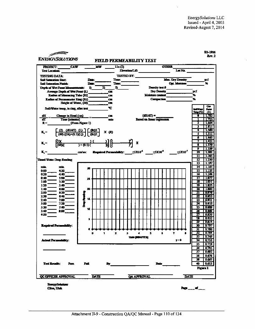
EnergySolutions LLC Issued - April 4,2003
Revised-August 7,2014
EfHWRGVSQLVTJKm
ES-1906 fiev.2
FIELD PERMEABILITY TEST PROJECT.
Te4 Location: CAW MW OTHER.
LotNa
TESTING DATA: S a l SaaaatKm Start Dsa>:_
Depfliaf WetPiiaa M a am im la i 1) Aveie^Depra of Wet Front (L) F^rastBTMtsuiajufi Tribe (Rr)
Htiq^rfWatE^CBfl
Sail/Wars temp, iarjag, afier, lest
TESTED BY:
_2)_
Max. Bay rJeosuj_ OpLMoesase~
Daosityk9t# Dry Denary
dH dT
; a Head (on) TmtyaiasseO
ptomPfearel)
(dH/oT) = linear regies
K.= I W(THt)*«)L5KL»J L<Rr)2j
>+<P-5>( c C1X10* <sxi«r* <rxur
Timed Water Drop Readaig
0.00 0 3 0 ' 0:40" 1:00 " uo" 1:40" 23»" 220* 2:40 " 3*0 ~ 330 " 3:40 " 4.00 "
420 4:40~ 530 -
520" 5:40" M O -
620"
W » " 720" 7:40" fc00~
30
1 f
15
1U
3 4 5 Tlai paKUTE»l
7 8
y-o
Test Br-
QCUI'VICER APPaOVAL DATE QA APPROVAL
11 12 13 14 15 16
Figarel
DATE
Ort * ,Uaa
Attachment II-9 - Construction QA/QC Manual - Page 110 of 134
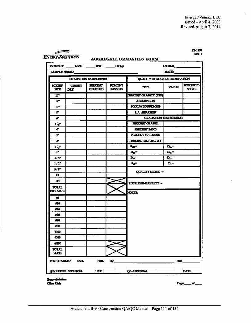
EnergySolutions LLC Issued - April 4, 2003
Re vised-August 7, 2014
65-1967 BBV.I
AGGREGATE GRADATION FORM
CAW MW
SAMPLE NAME:
OTHER
DATE:
CSADAIKVr AS RECEIVED QUALITY OF ROCK DtilUKMIKATJON
SCScSH DRY
PERCENT RETAINED
PEBCENT PASSING VALUE
14" SPBCDTC GRAVITY (SSD)
12" ABSORPTION
10" SOTRUMSOUNENESS
LAABRASEN
GFADATKW UCil RESULTS
4 % - PERCENT GRAVEL
PERCENT SAND
PEBCENT FINE SAND
PERCENT SILT* CLAY
i V Efe=
3/4"
1/2"
3 / P
#4 QUALTTY SCORE =
TOTAL DRY MASS
no #16
so »H)
«un *O0O
-4300
TOTAL MASS
50CEPERM6AHIL1TT' =
MOTES:
TEST RESULTS: PASS
QC OFFICER APPROVAL
FAB. By:
DATE OA APPROVAL DATE
Attachment II-9 - Construction QA/QC Manual - Page 111 of 134
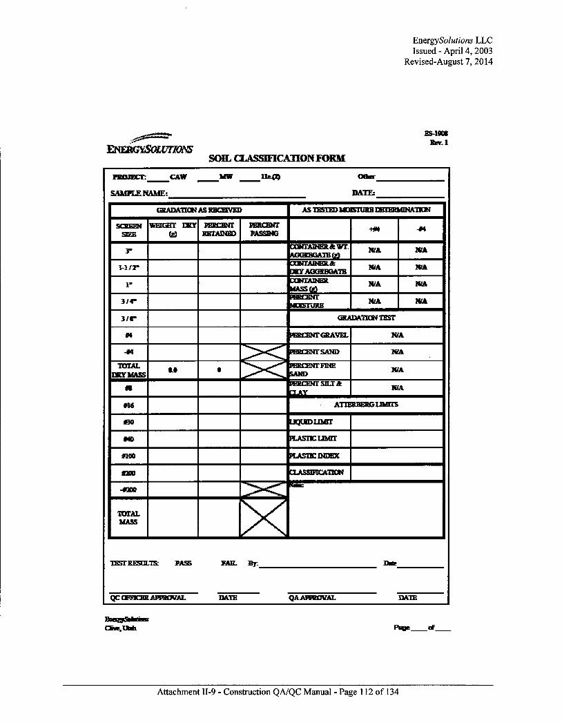
EnergySolutions LLC Issued - April 4,2003
Revised-August 7, 2014
ENERGYSOLUTIONS
ES-1908 Knr. l
SOIL CLASSIFICATION FORM
PROJECT: CAW
SAMPLE NtUiE: DATE:
GRADATION AS RBCETVED AS TESTED MQETURH UCTKKlaTNATJON
WEIGHT RBTATNBD
PERCENT PASSING
CONTAINER* WT AGGREGATE IjQ
N/A N/A
H / 2 " CONTAINER* •RYAGGRBGATE
N/A N/A
CONTAINER MASSfe)
N/A N/A
3 /4 - PERCENT MOISTURE
N/A WA
3/ f" GRADATION TEST
PERCENT CKAVEL N/A
PERCENT SAND N/A
TOTAL DRY MASS
Rt PEBCENT FINE SAND
N/A
•ERCENTSILTft AY
N/A
#1« ATTERBERCLIMrrS
LIQIRDLLMri
#40 PiAsncLiurr #100 PLASTKHNDEX
8200 [1ASSIMCAT1QN
-#300
TOTAL MASS
TEST RESULTS; PASS FAIL By.
QC OFFKSR APPROVAL DATE QA APPROVAL DATS
One , Utah Rage rf_
Attachment 11-9 - Construction QA/QC Manual - Page 112 of 134
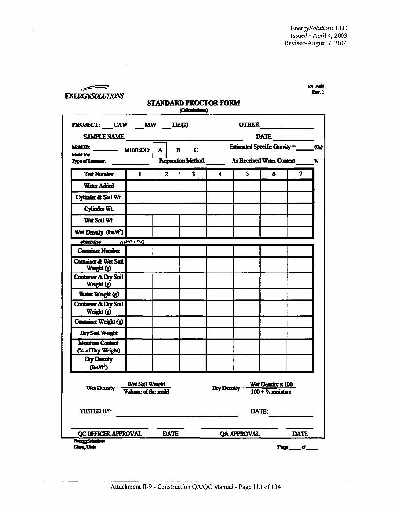
EnergySolutions LLC Issued - April 4,2003
Revised-August 7, 2014
EXTJXGYSOLUTimS ES-1M9
Rev. 1
STANDARD PROCTOR FORM
PROJECT: CAW
SAMPLE NAME:
MW OTHER
DATE;
Moid ID: l U S Vat:
METHOD; B
PiEpKxbofi Method: A^RecewedWitaCoiMerjt %
Terf Number
Wafer Added
Cyimrkr<ESoilWt
CjflmderWt
WctSoflwt
Wet Denary (tta/fl5)
Container .feWt* Sail Weight®
Crx BBBer&DrySal Wd#it(g)
Wafer Wei rt<g>
CSaBdraia£DrjSoii Weight (g)
Cartamar Weight (g)
Eky Soil Wags
MtirJiae Content (%flfEayWq#g)
DryDmnty (ttsffr3)
WUDuuil,- WetSoflWaghl WeiUensiry V o b m e a f t f a e Q K M
TESTED BY:
7 J 100+V. mnstare
DATE:
QC QrrTKER APPROVAL DATE QA APPROVAL DATE
One, Utah
Attachment II-9 - Construction QA/QC Manual - Page 113 of 134

EnergySolutions LLC Issued - April 4,2003
Revised-August 7, 2014
EN ERUIYSOLIITKXVS
SS-19D9
Rer.l
STANDARD PROCTOR FORM
PROJECT: CAW
SAMPLE NAME:
MW l i t ® OTHER
DATE:
ASTM 0-698 METHOD:
STANDARD MAX. DRY UNIX WEIGHT (so? ^ :
0 B C HffJTWlT * f HaTfTNIr
OVERSIZED CORRECTION*
STANDARD OPTIMUM WATER CONTEOT (ad*-^r
_IhfF&>
CQRR MAX. DRY UNIT WEIGBITcs*tT*-J:_
CCRR OPTIMUM WATER CONTENT ptd-w* ):
fcfft3
%
i
125J0
i2on
115J1
• « 1Q5J0
100Jl
OSuO
oao
100%Satnnticai (G*}=17
0 S 10 15 20 25 30 35
Water Contest-ar-%
TESTED BY: DATE:
QC OFFICER APPROVAL DATE QA APPROVAL BBeraSefcai CBVE,UBB
DATE
Rofle of_
Attachment II-9 - Construction QA/QC Manual - Page 114 of 134

EnergySolutions LLC Issued - April 4, 2003
Revised-August 7, 2014
E5-19I1
h2STLRGYSOLUTIO!Vi> to 1
BREACH OF BERM
FRQIECT: CAW MW Iteff) OTHER_
LOCATION OF BERM:
rf tTin iMi iMOriMki)
TYPE OF BREACH:
TfiijMiify irnMTWtl nfTitTnt
ACTXJN:
New nd./CH'tBaBSeniy IMSBB oeve ti 11 n wipwtril TBfl yrrniiiTinii is EBnteAiD ^ fte DEDDL
^—rfc 'T"'n^** 1M«IW wtM h» ifiM^iMhwl jtiiag IIMWI«U «I t M y y IM mm mm mtjtawmtl
Vi minim» paigedetteBcaDet peoafig one iksB on
DATE
QC OFFICER APPROVAL DATE:_
One,UBi i
Attachment II-9 - Construction QA/QC Manual - Page 115 of 134
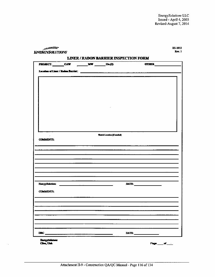
EnergySolutions LLC Issued - April 4,2003
Revised-August 7, 2014
ES-1PJ2
k^mtJYSOLUTiaYS tol
LINER / RADON BARRIER INSPECTION FORM FRDJECT: CAW MW 11«X*)
. { i f .
COMMENTS:
BaKSjSomittVHi DATE:_
COMMENTS:
DSC DATE:
One,Uaai
Attachment II-9 - Construction QA/QC Manual - Page 116 of 134

EnergySolutions LLC Issued - April 4, 2003
Revised-August 7, 2014
Attachment II-9 - Construction QA/QC Manual - Page 117 of 134
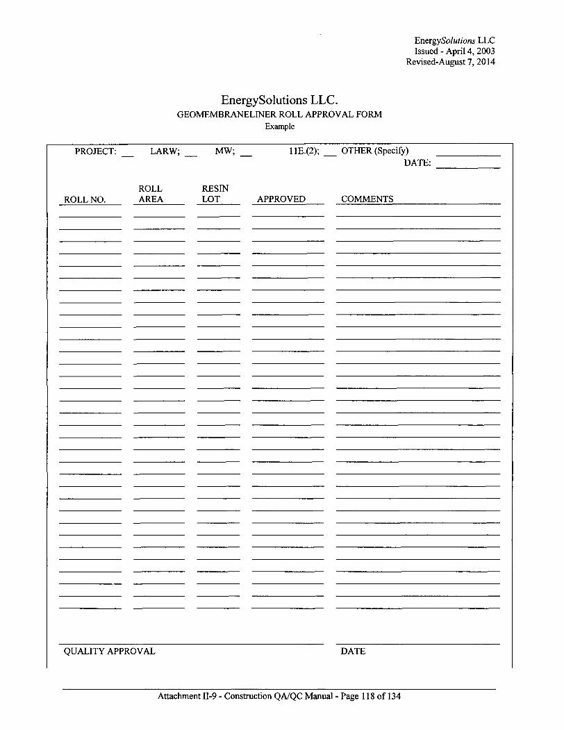
EnergySolutions LLC Issued - April 4, 2003
Revised-August 7, 2014
EnergySolutions LLC. GEOMEMBRANELINER ROLL APPROVAL FORM
Example
PROJECT: LARW; MW; HE.(2); OTHER (Specify) DATE:
ROLL RESIN ROLL NO. AREA LOT APPROVED COMMENTS
QUALITY APPROVAL DATE
Attachment II-9 - Construction QA/QC Manual - Page 118 of 134

EnergySolutions LLC Issued - April 4, 2003
Revised-August 7,2014
I
Attachment II-9 - Construction QA/QC Manual - Page 119 of 134

EnergySolutions LLC Issued - April 4,2003
Revised-August 7,2014
EnergySolutions LLC POLYMER RAW MATERIAL APPROVAL FORM
Example
PROJECT: LARW; Mixed Waste; He.(2); OTHER (Specify)
DATE:
LOT/ BATCH # APPROVED COMMENTS
QUALITY APPROVAL DATE
Attachment 11-9 - Construction QA/QC Manual - Page 120 of 134

EnergySolutions LLC Issued - April 4,2003
Revised-August 7,2014
EnergySolutions LLC WELDING ROD APPROVAL FORM
Example
PROJECT: LARW; Mixed Waste; lle.(2); OTHER (Specify)
DATE:
ROLL # APPROVED COMMENTS
QUALITY APPROVAL DATE
Attachment II-9 - Construction QA/QC Manual - Page 121 of 134
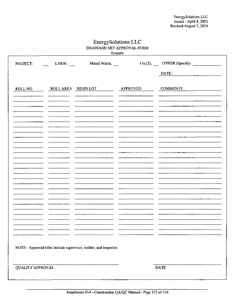
EnergySolutions LLC Issued - April 4, 2003
Revised-August 7,2014
EnergySolutions LLC DRAINAGE NET APPROVAL FORM
Example
PROJECT: LARW; Mixed Waste; lle.(2); OTHER (Specify)
DATE:
ROLL NO. ROLL AREA RESIN LOT APPROVED COMMENTS
NOTE: Approved titles include supervisor, welder, and inspector.
QUALITY APPROVAL DATE
Attachment II-9 - Construction QA/QC Manual - Page 122 of 134
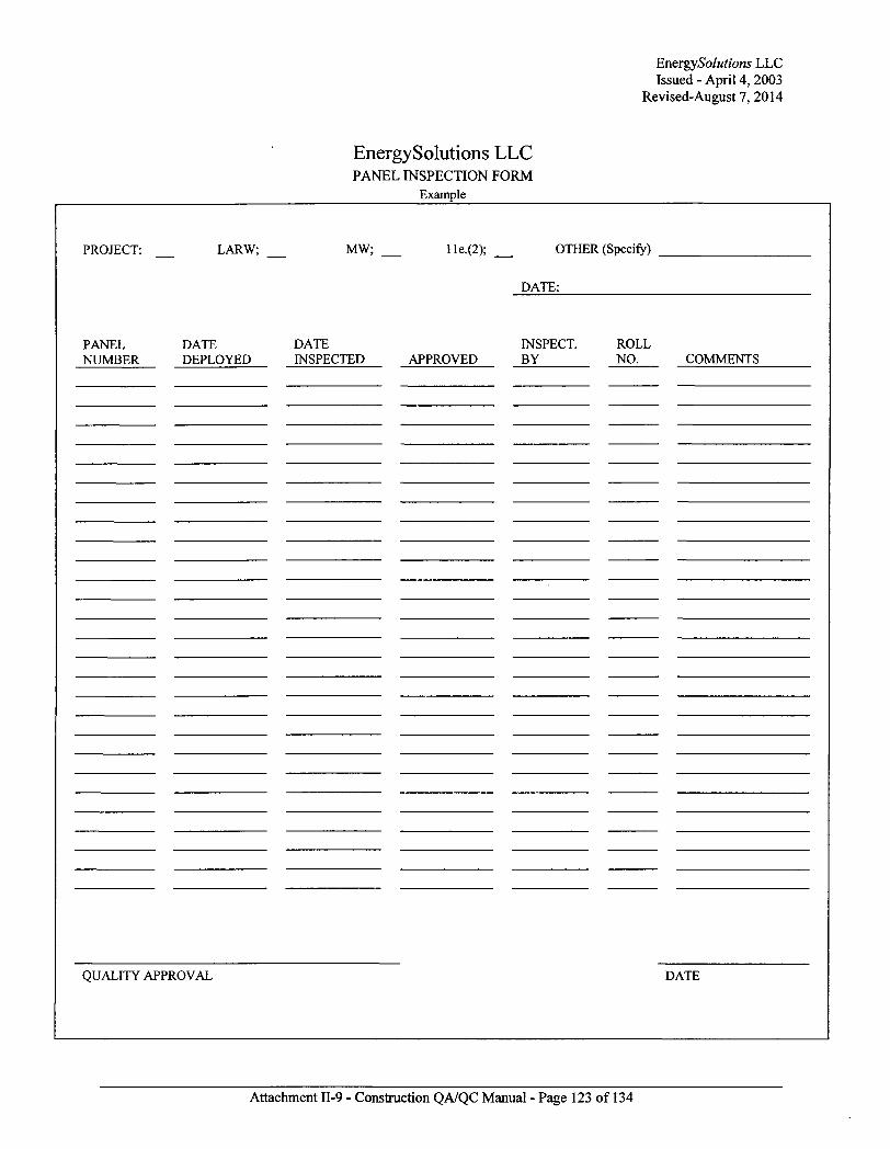
EmrgySolutions LLC Issued - April 4,2003
Revised-August 7, 2014
EnergySolutions LLC PANEL INSPECTION FORM
Example
PROJECT: LARW; MW; He.(2); OTHER (Specify)
DATE:
PANEL DATE DATE INSPECT. ROLL NUMBER DEPLOYED INSPECTED APPROVED BY NO. COMMENTS
QUALITY APPROVAL DATE
Attachment II-9 - Construction QA/QC Manual - Page 123 of 134

EnergySolutions LLC Issued - April 4, 2003
Revised-August 7,2014
EnergySolutions LLC DESTRUCTIVE TESTING
Example
PROJECT: LARW;
FIELD TESTING
TEST DATE NUMBER
OTHER MW; lle.(2); (Specify)
DESTRUCT NUMBER:
FTB/ NON- INSPECT. FTB TESTED BY BY COMMENTS
LABORATORY TESTS
TEST: ACCEPTABLE UNACCEPTABLE BY:
Attach a copy of the test results.
INSPECTOR APPROVAL DATE QUALITY APPROVAL DATE
Attachment 11-9 - Construction QA/QC Manual - Page 124 of 134

EnergySolutions LLC SEAM INSPECTION FORM
Example
EnergySolutions LLC Issued - April 4, 2003
Revised-August 7,2014
PROJECT: LARW; Mixed Waste; He.(2); OTHER
(Specify)
NES W
PRE-WELD INSPECTION WELDING POST WELD INSPECTION
SEAM/ PATCH # DATE
ADEQUATE OVERLAP
APPROVED TO WELD
INSPECT. BY DATE BY
MACHINE NUMBER
WELD ACCEPTABLE
INSPECT. BY
NON-DESTRUCTIVE TESTING DESTRUCTIVE TESTING SEAM/PATCH APPROVAL
SEAM/ PATCH # DATE TEST TYPE PASS / FAIL
INSPECT. BY
DESTRUCT NUMBER
FIELD P/F LABP/F ACCEPTABLE
IN SPEC. BY
QUALITY APPROVAL DATE
Attachment II-9 - Construction QA/QC Manual - Page 125 of 134

EnergySolutions LLC Issued - April 4, 2003
Revised-August 7, 2014
J
Attachment II-9 - Construction QA/QC Manual - Page 126 of 134
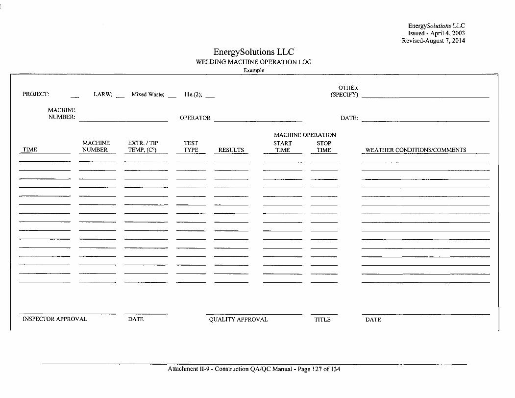
EnergySolutions LLC Issued - April 4, 2003
Revised-August 7, 2014
EnergySolutions LLC WELDING MACHINE OPERATION LOG
Example
OTHER PROJECT: LARW; Mixed Waste; He.(2); (SPECIFY)
MACHINE NUMBER: OPERATOR DATE:
MACHINE OPERATION MACHINE EXTR. / TIP TEST START STOP
TIME NUMBER TEMP, (C°) TYPE RESULTS TIME TIME WEATHER CONDITIONS/COMMENTS
INSPECTOR APPROVAL DATE QUALITY APPROVAL TITLE DATE
Attachment II-9 - Construction QA/QC Manual - Page 127 of 134
EnergySolutions LLC Issued - April 4, 2003
Revised-August 7, 2014
Attachment II-9 - Construction QA/QC Manual - Page 128 of 134
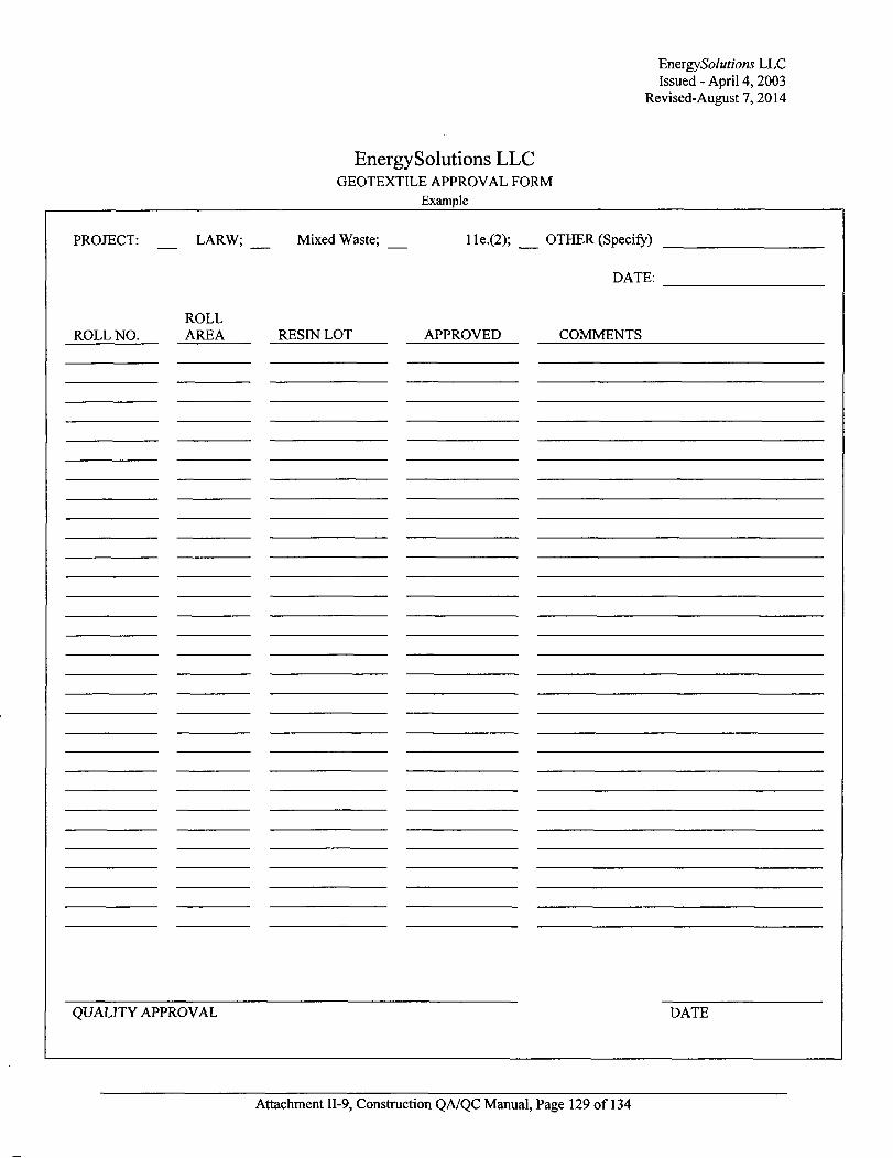
EnergySolutions LLC Issued - April 4,2003
Revised-August 7,2014
EnergySolutions LLC GEOTEXTILE APPROVAL FORM
Example
PROJECT: LARW; Mixed Waste; He.(2); OTHER (Specify)
DATE:
ROLL ROLL NO. AREA RESIN LOT APPROVED COMMENTS
QUALITY APPROVAL DATE
Attachment II-9, Construction QA/QC Manual, Page 129 of 134
EneigySolutions LLC Issued - April 4,2003
Revised-August 7, 2014
Appendix 3: Material Specifications
Attachment II-9, Construction QA/QC Manual, Page 130 of 134
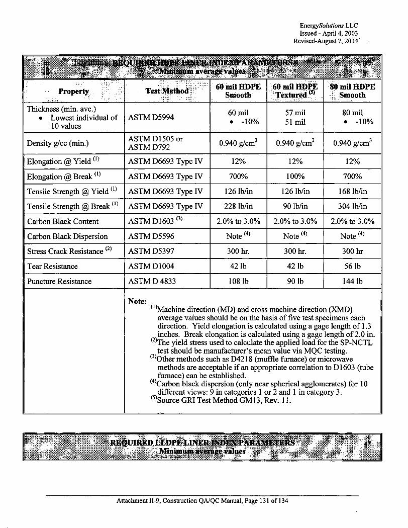
EnergySolutions LLC Issued - April 4, 2003
Revised-August 7,2014
!.:) BE U minim average ' I ! "
Property Test Method 60 mil HDPE Smooth
60 mil HDPE Textured(5)
80 rail HDPE Smooth
Thickness (min. ave.) • Lowest individual of
10 values ASTM D5994
60 mil • -10%
57 mil 51 mil
80 mil • -10%
Density g/cc (min.) ASTM D1505 or ASTM D792 0.940 g/cm3 0.940 g/cm3 0.940 g/cm3
Elongation @ Yield ( 1 ) ASTM D6693 Type IV 12% 12% 12%
Elongation @ Break ( i ) ASTM D6693 Type IV 700% 100% 700%
Tensile Strength @ Yield ( i ) ASTM D6693 Type IV 126 lb/in 126 lb/in 168 lb/in
Tensile Strength @ Break ( , ) ASTM D6693 Type IV 228 lb/in 90 lb/in 304 lb/in
Carbon Black Content ASTM D1603 ( 3 ) 2.0% to 3.0% 2.0% to 3.0% 2.0% to 3.0%
Carbon Black Dispersion ASTM D5596 Note (4) Note (4) Note (4)
Stress Crack Resistance (2) ASTM D5397 300 hr. 300 hr. 300 hr
Tear Resistance ASTM D1004 421b 42 lb 56 lb
Puncture Resistance ASTM D 4833 108 lb 90 lb 1441b
Note: ( 1 Machine direction (MD) and cross machine direction (XMD)
average values should be on the basis of five test specimens each direction. Yield elongation is calculated using a gage length of 1.3 inches. Break elongation is calculated using a gage length of 2.0 in.
( 2 ) The yield stress used to calculate the applied load for the SP-NCTL test should be manufacturer's mean value via MQC testing.
( 3 ) Other methods such as D4218 (muffle furnace) or microwave methods are acceptable i f an appropriate correlation to D1603 (tube furnace) can be established.
( 4 ) Carbon black dispersion (only near spherical agglomerates) for 10 different views: 9 in categories 1 or 2 and 1 in category 3.
( 5 ) Source GRI Test Method GM13, Rev. 11.
REQUIRED LLDPE LINER INDEX PARAMETER t .Minimum averag|values. ^ | |
Attachment II-9, Construction QA/QC Manual, Page 131 of 134

EnergySolutions LLC Issued - April 4,2003
Revised-August 7, 2014
Property Test Method 60 mil LLDPE
Textured ^ 80 mil LLDPE
Textured(6)
100 mil LLDPE
Textured ( 6 )
Thickness (min. ave.) • Lowest individual of
10 values ASTM D5994
57 mil 51 mil
76 mil 68 mil
95 mil 85 mil
Density g/ml (max.) ASTM Dl 505 or ASTM D792 0.939 g/cm3 0.939 g/cm3 0.939 g/cm3
Tensile Strength @ Break (min. ave.)(1) ASTM D6693 Type IV 90 lb/in 120 lb/in 150 lb/in
Elongation @ Break (min. ave.) ( ^
ASTM D6693 Type IV 250% 250% 250%
Oxidative Induction Time Standard OIT (min. ave.) or High Pressure OIT (min. ave.) (2 )
ASTM D3895
ASTM D5885
100
400
100
400
100
400
Asperity Height (min. ave.) (3 ) ASTM D 7466 10 mil 10 mil 10 mil
Carbon Black Content ASTMD4218 ( 4 ) 2.0% to 3.0% 2.0% to 3.0% 2.0% to 3.0%
Carbon Black Dispersion ASTM D5596 Note (5) Note (5) Note (5)
Tear Resistance (min. ave.) ASTM D1004 33 lb 44 lb 551b
Puncture Resistance (min. ave.)
ASTM D 4833 66 lb 88 lb 1101b
Note: ( 1 Machine direction (MD) and cross machine direction (XMD)
average values should be on the basis of 5 test specimens each direction. Break elongation is calculated using a gage length of 2.0 in. at 2.0 in/min.
( 2 ) The manufacturer has the option to select either one of the OIT methods listed to evaluate the antioxidant content in the geomembrane.
( 3 ) Of 10 readings; 8 out of 10 must be >^7mils, and lowest individual reading must be >_5 mils.
( 4 ) Other methods such as D1603 (tube furnace) or D6370 (TGA) are acceptable i f an appropriate correlation to D4218 (muffle furnace) can be established.
( 5 ) Carbon black dispersion (only near spherical agglomerates) for 10 different views: 9 in categories 1 or 2 and 1 in category 3.
( 6 ) Source GRI Test Method GM17, Rev 9.
Attachment II-9, Construction QA/QC Manual, Page 132 of 134
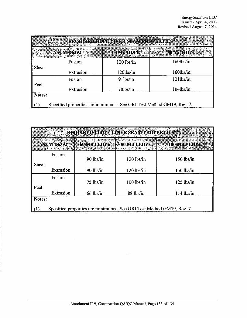
EnergySolutions LLC Issued - April 4,2003
Revised-August 7, 2014
..: I B REQUIRED HDpllrf&RiEAM PROPERT^E^
tiO Mil HDPE
Shear Fusion
Extrusion
120 lbs/in
1201bs/in
1601bs/in
1601bs/in
Peel Fusion
Extrusion
91 lbs/in
781bs/in
121 lbs/in
1041bs/in Notes:
(1) Specified properties are minimums. See GRI Test Method GM19, Rev. 7.
ASTMD6392 60tMiILli>PE ^OMilliLDPE^
Shear
Fusion
Extrusion
90 lbs/in
90 lbs/in
120 lbs/in
120 lbs/in
150 lbs/in
150 lbs/in
Peel
Fusion
Extrusion
75 lbs/in
66 lbs/in
100 lbs/in
88 lbs/in
125 lbs/in
114 lbs/in Notes:
(1) Specified properties are minimums. See GRI Test Method GM19, Rev. 7.
Attachment II-9, Construction QA/QC Manual, Page 133 of 134
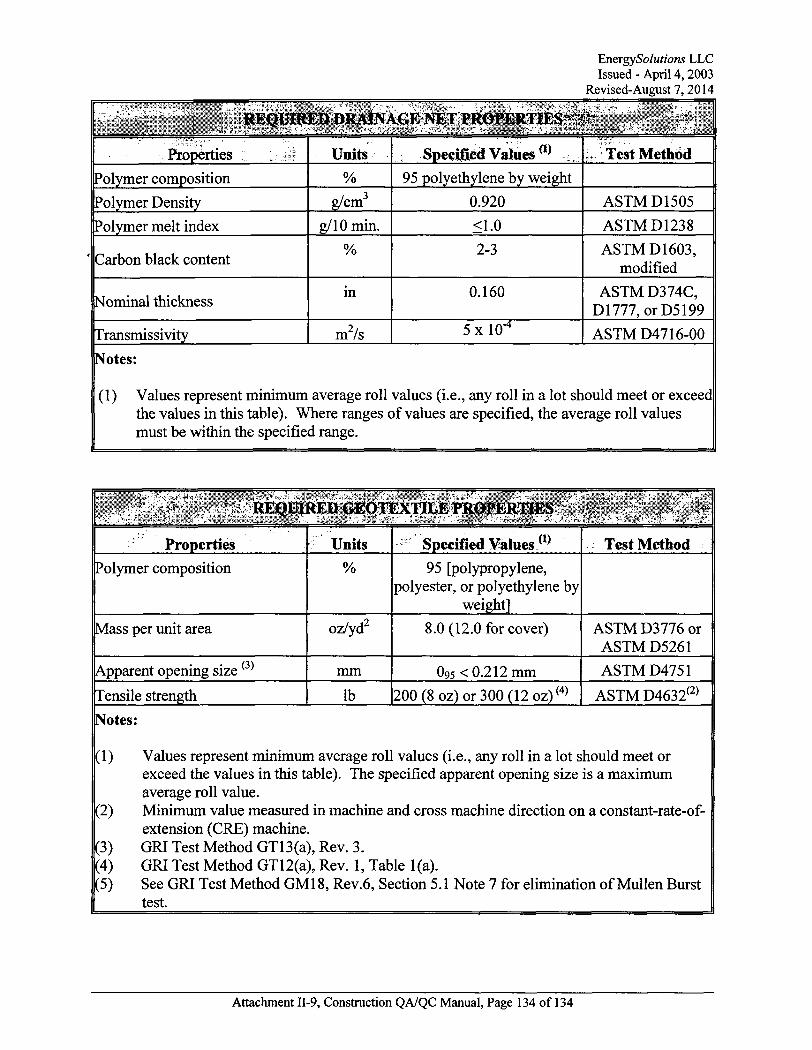
EnergySolutions LLC Issued - April 4,2003
Revised-August 7,2014
H I at-'.
Properties Units Specified Values w Test Method
Polymer composition % 95 polyethylene by weight
Polymer Density g/cm 0.920 ASTM D1505
Polymer melt index g/10 min. <1.0 ASTM D123 8
Carbon black content % 2-3 ASTM D1603,
modified
Nominal thickness in 0.160 ASTM D374C, D1777, orD5199
Transmissivity m7s 5x 10" ASTM D4716-00
Notes:
(1) Values represent minimum average roll values (i.e., any roll in a lot should meet or exceed the values in this table). Where ranges of values are specified, the average roll values must be within the specified range.
••~4 ^WmiMfft: ' alt
Properties Units Specified Values (1 ) Test Method Polymer composition % 95 [polypropylene,
polyester, or polyethylene by weight]
Mass per unit area oz/yd 8.0 (12.0 for cover) ASTM D3776 or ASTM D5261
Apparent opening size ( 3 )
mm 0 9 5 < 0.212 mm ASTM D4751
Tensile strength lb 200 (8 oz) or 300 (12oz) ( 4 ) ASTM D4632(2)
Notes:
(1)
(2)
(3) (4) (5)
Values represent minimum average roll values (i.e., any roll in a lot should meet or exceed the values in this table). The specified apparent opening size is a maximum average roll value. Minimum value measured in machine and cross machine direction on a constant-rate-of-extension (CRE) machine. GRI Test Method GT13(a), Rev. 3. GRI Test Method GT12(a), Rev. 1, Table 1(a). See GRI Test Method GM18, Rev.6, Section 5.1 Note 7 for elimination of Mullen Burst test.
Attachment II-9, Construction QA/QC Manual, Page 134 of 134