Embed Size (px)
Citation preview

Atlas Series Energy Meters
Mk10 / Mk7 Hardware Reference Manual
Revision M Release Date: 2nd September 2009
1910-E-02
EDMI Pty Ltd 162 South Pine Rd Brendale, Qld, 4500 Australia
EDMI Limited Level 3
No.47 Yishun Industrial Park A Singapore 768724

© Copyright 1999-2009, EDMI Pty Ltd.
All rights reserved.
Product names are trademarks or registered trademarks of their respective owners.

TABLE OF CONTENTS
Chapter 1 Introduction................................................................................ 1-1 Using this Manual ............................................................................................................................... 1-1 Conventions Used in this Manual ...................................................................................................... 1-1 For more information.......................................................................................................................... 1-2
Chapter 2 The Mk10 Meter........................................................................ 2-1 Dimensions and Mounting ................................................................................................................. 2-1 External Features................................................................................................................................. 2-4 Under the Terminal Cover.................................................................................................................. 2-5
Special I/O Variant ...................................................................................................................... 2-6 Mk10A Variant ............................................................................................................................ 2-7 UPS Variant ................................................................................................................................. 2-8 Terminal Spacing......................................................................................................................... 2-9 New Terminal Block ................................................................................................................. 2-10 Finger Guard .............................................................................................................................. 2-10 Terminal Cover Tamper Detect ................................................................................................ 2-10 Meter Lid Tamper Detect .......................................................................................................... 2-11
Under the Meter Lid.......................................................................................................................... 2-11 CT to VT Links.......................................................................................................................... 2-11 Config Jumper............................................................................................................................ 2-13
Connections in Detail........................................................................................................................ 2-14 Current and Voltage................................................................................................................... 2-14 Mk10 Serial Port Configurations .............................................................................................. 2-15 Mk10A Serial Port Configurations ........................................................................................... 2-17 FLAG Port.................................................................................................................................. 2-19 ANSI Port................................................................................................................................... 2-19 Inputs .......................................................................................................................................... 2-20 Outputs ....................................................................................................................................... 2-20 Battery ........................................................................................................................................ 2-20 UPS Battery................................................................................................................................ 2-21
LCD/Select Button............................................................................................................................ 2-22 Billing Reset Button.......................................................................................................................... 2-22 Servicing............................................................................................................................................ 2-22
Chapter 3 The Mk10D Meter..................................................................... 3-1 Dimensions and Mounting ................................................................................................................. 3-1 External Features................................................................................................................................. 3-3 Under the Terminal Cover.................................................................................................................. 3-4
Terminal Block Variations .......................................................................................................... 3-6 Terminal Cover Tamper Detect .................................................................................................. 3-6
Under the Meter Lid............................................................................................................................ 3-7 CT to VT Links............................................................................................................................ 3-7 Config Jumper.............................................................................................................................. 3-8
Connections in Detail.......................................................................................................................... 3-9 Current and Voltage..................................................................................................................... 3-9 Serial Port Configurations ......................................................................................................... 3-10 RS-232........................................................................................................................................ 3-11 RS-485........................................................................................................................................ 3-12 PLC............................................................................................................................................. 3-12 FLAG Port.................................................................................................................................. 3-12
Contents i
ii
ANSI Port ................................................................................................................................... 3-13 Inputs .......................................................................................................................................... 3-13 Outputs........................................................................................................................................ 3-13 Battery......................................................................................................................................... 3-13
LCD/Select Button............................................................................................................................ 3-14 Reconnect/Boost/Billing Reset Button............................................................................................. 3-15 Servicing ............................................................................................................................................ 3-15
Chapter 4 The Mk7A Meter ....................................................................... 4-1 Dimensions and Mounting.................................................................................................................. 4-1 External Features................................................................................................................................. 4-4 Under the Terminal Cover .................................................................................................................. 4-5
Finger Guard................................................................................................................................. 4-7 Terminal Cover Tamper Detect................................................................................................... 4-8
Under the Meter Lid............................................................................................................................ 4-8 CT to VT Links ............................................................................................................................ 4-8 Config Jumper.............................................................................................................................. 4-8
Connections in Detail.......................................................................................................................... 4-9 Current and Voltage..................................................................................................................... 4-9 RS-232........................................................................................................................................ 4-11 RS-485........................................................................................................................................ 4-11 FLAG Port.................................................................................................................................. 4-11 ANSI Port ................................................................................................................................... 4-12 Inputs .......................................................................................................................................... 4-12 Outputs........................................................................................................................................ 4-12 Battery......................................................................................................................................... 4-12
LCD/Select Button............................................................................................................................ 4-13 Reconnect/Boost or Billing Reset Button ........................................................................................ 4-14 Servicing ............................................................................................................................................ 4-15
Chapter 5 The Mk7C Meter ....................................................................... 5-1 Dimensions and Mounting.................................................................................................................. 5-1
Hanging Extension....................................................................................................................... 5-4 External Features................................................................................................................................. 5-5 Under the Terminal Cover .................................................................................................................. 5-6
Finger Guard................................................................................................................................. 5-9 Terminal Cover Tamper Detect................................................................................................. 5-10
Inside the Meter................................................................................................................................. 5-10 CT to VT Links .......................................................................................................................... 5-10 Config Jumper............................................................................................................................ 5-10
Connections in Detail........................................................................................................................ 5-11 Current and Voltage................................................................................................................... 5-11 RS-232 Passive........................................................................................................................... 5-12 RS-232 Active............................................................................................................................ 5-13 RS-485 Passive........................................................................................................................... 5-14 RS-485 Active............................................................................................................................ 5-14 FLAG Port.................................................................................................................................. 5-15 ANSI Port ................................................................................................................................... 5-15 Inputs .......................................................................................................................................... 5-15 Outputs........................................................................................................................................ 5-16 Battery......................................................................................................................................... 5-16
LCD/Select Button............................................................................................................................ 5-16 Connect / Boost Button..................................................................................................................... 5-17 Fitting a Modem................................................................................................................................ 5-18 Servicing ............................................................................................................................................ 5-20
ii EDMI Atlas Hardware Reference Manual

Chapter 6 The Mk10E Meter ..................................................................... 6-1 Dimensions and Mounting ................................................................................................................. 6-1 External Features................................................................................................................................. 6-3 Under the Terminal Cover.................................................................................................................. 6-4
Terminal Block Variations .......................................................................................................... 6-6 Terminal Cover Tamper Detect .................................................................................................. 6-6 Meter Lid Tamper Detect ............................................................................................................ 6-6
Under the Meter Lid............................................................................................................................ 6-7 CT to VT Links............................................................................................................................ 6-7 Config Jumper.............................................................................................................................. 6-8
Connections in Detail.......................................................................................................................... 6-9 Current and Voltage..................................................................................................................... 6-9 Serial Port Configurations ......................................................................................................... 6-11 RS-232........................................................................................................................................ 6-12 RS-485........................................................................................................................................ 6-13 FLAG Port.................................................................................................................................. 6-13 ANSI Port................................................................................................................................... 6-13 Inputs .......................................................................................................................................... 6-14 Outputs ....................................................................................................................................... 6-14 Battery ........................................................................................................................................ 6-14
Super Cap .......................................................................................................................................... 6-15 LCD/Select Button............................................................................................................................ 6-15 Reconnect/Boost/Billing Reset Button ............................................................................................ 6-16 Servicing............................................................................................................................................ 6-16
Chapter 7 LCD Display............................................................................... 7-1 LCD Variations................................................................................................................................... 7-1 LCD/Select Button Usage .................................................................................................................. 7-3
Display Sets.................................................................................................................................. 7-4 Default Display ............................................................................................................................ 7-4
Display Organisation .......................................................................................................................... 7-4 Appendix A System Specifications............................................................ A-1 Measured Quantities and Methods.....................................................................................................A-1 Operating Conditions..........................................................................................................................A-2 Energy Conventions............................................................................................................................A-3
Contents iii

iv
LIST OF TABLES
• TABLE 2-1 TERMINAL BLOCK CONNECTIONS.............................................................................................2-6 • TABLE 2-2 SPECIAL I/O TERMINAL BLOCK CONNECTIONS........................................................................2-7 • TABLE 2-3 MK10A TERMINAL BLOCK CONNECTIONS...............................................................................2-8 • TABLE 2-4 UPS TERMINAL BLOCK CONNECTIONS ....................................................................................2-9 • TABLE 2-5 TERMINAL SIZES..................................................................................................................... 2-10 • TABLE 2-6 MK10 SERIAL PORT OPTIONS................................................................................................. 2-15 • TABLE 2-7 MK10 RS-232 CONNECTIONS................................................................................................ 2-15 • TABLE 2-8 RS-485 CONNECTIONS........................................................................................................... 2-16 • TABLE 2-9 MK10A SERIAL PORT OPTIONS.............................................................................................. 2-17 • TABLE 2-10 MK10A TB1 CONNECTIONS................................................................................................ 2-18 • TABLE 2-11 MK10A TB1 TERMINAL BLOCK CONNECTIONS ................................................................. 2-18 • TABLE 2-12 MK10A TB9 CONNECTIONS................................................................................................ 2-19 • TABLE 2-13 SYMBOL DESCRIPTIONS....................................................................................................... 2-19 • TABLE 3-1 TERMINAL BLOCK CONNECTIONS.............................................................................................3-5 • TABLE 3-2 SERIAL PORT OPTIONS............................................................................................................ 3-10 • TABLE 3-3 RS-232 CONNECTIONS........................................................................................................... 3-11 • TABLE 3-4 RS-485 CONNECTIONS........................................................................................................... 3-12 • TABLE 4-1 TERMINAL BLOCK CONNECTIONS.............................................................................................4-6 • TABLE 4-2 TERMINAL SIZES........................................................................................................................4-7 • TABLE 4-3 CONFIGURATION OPTIONS ..................................................................................................... 4-10 • TABLE 4-4 RS-232 CONNECTIONS........................................................................................................... 4-11 • TABLE 5-1 METER OPTIONS ........................................................................................................................5-6 • TABLE 5-2 TERMINAL BLOCK CONNECTIONS - COMMON..........................................................................5-7 • TABLE 5-3 TERMINAL BLOCK CONNECTIONS - PASSIVE............................................................................5-8 • TABLE 5-4 TERMINAL BLOCK CONNECTIONS - ACTIVE WITHOUT RELAY.................................................5-8 • TABLE 5-5 TERMINAL BLOCK CONNECTIONS - ACTIVE WITH RELAY........................................................5-8 • TABLE 5-6 TERMINAL BLOCK CONNECTIONS - PLC NO RELAY.................................................................5-9 • TABLE 5-7 TERMINAL BLOCK CONNECTIONS - PLC WITH RELAY.............................................................5-9 • TABLE 5-8 RS-232 CONNECTIONS........................................................................................................... 5-12 • TABLE 5-9 RS-232 CONNECTIONS........................................................................................................... 5-13 • TABLE 5-10 RS-485 CONNECTIONS......................................................................................................... 5-14 • TABLE 5-11 RS-485 CONNECTIONS......................................................................................................... 5-14 • TABLE 6-1 TERMINAL BLOCK CONNECTIONS.............................................................................................6-5 • TABLE 6-2 SERIAL PORT OPTIONS............................................................................................................ 6-11 • TABLE 6-3 RS-232 CONNECTIONS........................................................................................................... 6-12 • TABLE 6-4 RS-485 CONNECTIONS........................................................................................................... 6-13 • TABLE 7-1 SECTIONS OF THE LCD.............................................................................................................7-5 • TABLE A-1 MEASUREMENTS.....................................................................................................................A-1 • TABLE A-2 OPERATING CONDITIONS........................................................................................................A-2 • TABLE A-3 OPERATING CONDITIONS........................................................................................................A-3 • TABLE A-4 NAMING CONVENTIONS ..........................................................................................................A-4
LIST OF FIGURES
• FIGURE 2-1 OVERALL DIMENSIONS OF THE METER....................................................................................2-1 • FIGURE 2-2 MOUNTING POINTS, STANDARD TERMINAL COVER ................................................................2-2
iv EDMI Atlas Hardware Reference Manual

• FIGURE 2-3 MOUNTING POINTS, EXTENDED TERMINAL COVER................................................................ 2-3 • FIGURE 2-4 FRONT VIEW OF THE METER WITH TERMINAL COVER FITTED................................................ 2-4 • FIGURE 2-5 UNDER THE TERMINAL COVER OF THE METER ....................................................................... 2-5 • FIGURE 2-6 TERMINAL BLOCK DIAGRAM .................................................................................................. 2-5 • FIGURE 2-7 SPECIAL I/O VARIANT TERMINAL BLOCK DIAGRAM .............................................................. 2-6 • FIGURE 2-8 MK10A VARIANT TERMINAL BLOCK DIAGRAM..................................................................... 2-7 • FIGURE 2-9 UPS VARIANT TERMINAL BLOCK DIAGRAM........................................................................... 2-8 • FIGURE 2-10 TB2 TERMINAL SPACINGS..................................................................................................... 2-9 • FIGURE 2-11 NEW STYLE TERMINAL BLOCK OF THE METER................................................................... 2-10 • FIGURE 2-12 THE FINGER GUARD IN PLACE............................................................................................. 2-10 • FIGURE 2-13 LOCATION OF THE CT TO VT LINKS................................................................................... 2-12 • FIGURE 2-14 THE SCREW USED TO FORM THE CT-VT LINK.................................................................... 2-12 • FIGURE 2-15 LOCATION OF THE CT TO VT LINKS................................................................................... 2-12 • FIGURE 2-16 THE REMOVED SCREW AND DISCONNECTED LINK ............................................................. 2-13 • FIGURE 2-17 LOCATION OF THE CONFIG JUMPER.................................................................................... 2-13 • FIGURE 2-18 TB2 CT AND VT CONNECTIONS FOR 3 ELEMENT .............................................................. 2-14 • FIGURE 2-19 CONNECTIONS FOR 3 ELEMENT WHOLE CURRENT ............................................................. 2-14 • FIGURE 2-20 MK10 LCD WITH ALL SEGMENTS TURNED ON .................................................................. 2-22 • FIGURE 3-1 OVERALL DIMENSIONS OF THE METER ................................................................................... 3-1 • FIGURE 3-2 MOUNTING POINTS.................................................................................................................. 3-2 • FIGURE 3-3 FRONT VIEW OF THE METER WITH TERMINAL COVER FITTED................................................ 3-3 • FIGURE 3-4 UNDER THE TERMINAL COVER OF THE METER ....................................................................... 3-4 • FIGURE 3-5 TERMINAL BLOCK DIAGRAM .................................................................................................. 3-5 • FIGURE 3-6 TB1 TERMINAL SPACING......................................................................................................... 3-6 • FIGURE 3-7 THE TERMINAL COVER TAMPER DETECT BUTTON.................................................................. 3-6 • FIGURE 3-8 LOCATION OF THE CT TO VT LINKS....................................................................................... 3-7 • FIGURE 3-9 METER WITH THE CT TO VT LINKS DISCONNECTED BY SLIDING SHIMS. .............................. 3-7 • FIGURE 3-10 METER WITH THE CT TO VT LINKS DISCONNECTED BY REMOVING SCREWS. .................... 3-7 • FIGURE 3-11 LOCATION OF THE CT TO VT LINKS..................................................................................... 3-8 • FIGURE 3-12 METER WITH THE CT TO VT LINKS DISCONNECTED BY REMOVING SCREWS. .................... 3-8 • FIGURE 3-13 LOCATION OF THE CONFIG JUMPER...................................................................................... 3-8 • FIGURE 3-14 CONNECTIONS FOR 3 ELEMENT WHOLE CURRENT ............................................................... 3-9 • FIGURE 3-15 TB1 CT AND VT CONNECTIONS FOR 3 ELEMENT TESTING ................................................. 3-9 • FIGURE 3-16 LCD WITH ALL SEGMENTS TURNED ON ............................................................................. 3-14 • FIGURE 4-1 OVERALL DIMENSIONS OF THE METER ................................................................................... 4-1 • FIGURE 4-2 DIMENSIONS............................................................................................................................ 4-2 • FIGURE 4-3 MOUNTING POINTS.................................................................................................................. 4-3 • FIGURE 4-4 FRONT VIEW OF THE METER WITH TERMINAL COVER FITTED................................................ 4-4 • FIGURE 4-5 UNDER THE TERMINAL COVER OF THE METER ....................................................................... 4-5 • FIGURE 4-6 TERMINAL BLOCK DIAGRAM .................................................................................................. 4-6 • FIGURE 4-7 TB5 TERMINAL SPACINGS....................................................................................................... 4-7 • FIGURE 4-8 THE FINGER GUARD IN PLACE................................................................................................. 4-7 • FIGURE 4-9 THE TERMINAL COVER TAMPER DETECT SWITCH .................................................................. 4-8 • FIGURE 4-10 LOCATION OF THE CONFIG JUMPER...................................................................................... 4-9 • FIGURE 4-11 TB5 CONNECTIONS INCLUDING A SWITCHED/METERED LOAD ........................................... 4-9 • FIGURE 4-12 LOCATION OF THE EXTERNAL BATTERY PLUGGED INTO PL3............................................ 4-13 • FIGURE 4-13 LCD WITH ALL SEGMENTS TURNED ON ............................................................................. 4-14 • FIGURE 4-14 LOCATION OF THE BILLING RESET / BOOST BUTTON........................................................... 4-14 • FIGURE 5-1 OVERALL DIMENSIONS OF THE METER ................................................................................... 5-1 • FIGURE 5-2 DIMENSIONS WITH STANDARD TERMINAL COVER ................................................................. 5-2 • FIGURE 5-3 DIMENSIONS WITH MODEM TERMINAL COVER....................................................................... 5-2 • FIGURE 5-4 MOUNTING POINTS.................................................................................................................. 5-3 • FIGURE 5-5 THE HANGER EXTENSION CLIP................................................................................................ 5-4 • FIGURE 5-6 HANGING KEYHOLE WITH THE CLIP FITTED ........................................................................... 5-4 • FIGURE 5-7 FRONT VIEW OF THE METER WITH TERMINAL COVER FITTED................................................ 5-5 • FIGURE 5-8 UNDER THE TERMINAL COVER OF THE METER ....................................................................... 5-6
Contents v

vi
• FIGURE 5-9 TERMINAL BLOCK DIAGRAM ...................................................................................................5-7 • FIGURE 5-10 TB1 TERMINAL DETAILS........................................................................................................5-7 • FIGURE 5-11 THE FINGER GUARD IN PLACE................................................................................................5-9 • FIGURE 5-12 THE TERMINAL COVER TAMPER DETECT BUTTON ............................................................. 5-10 • FIGURE 5-13 LOCATION OF THE CONFIG “JUMPER”................................................................................ 5-11 • FIGURE 5-14 TB1 CONNECTIONS ............................................................................................................ 5-11 • FIGURE 5-15 INTERNAL CONNECTION OPTIONS....................................................................................... 5-12 • FIGURE 5-16 LCD WITH ALL SEGMENTS TURNED ON ............................................................................. 5-16 • FIGURE 5-17 LOCATION OF THE BILLING RESET / BOOST BUTTON .......................................................... 5-17 • FIGURE 5-18 METER WITH AN EXTENDED TERMINAL COVER FITTED................................................... 5-18 • FIGURE 5-19 AN ETM9300 MODEM FITTED TO THE METER................................................................... 5-18 • FIGURE 5-20 A SAM2 MODEM FITTED UNDER THE TERMINAL COVER .................................................. 5-19 • FIGURE 5-21 ANTENNA FITTED UNDER THE TERMINAL COVER.............................................................. 5-19 • FIGURE 6-1 OVERALL DIMENSIONS OF THE METER....................................................................................6-1 • FIGURE 6-2 MOUNTING POINTS ..................................................................................................................6-2 • FIGURE 6-3 FRONT VIEW OF THE METER WITH TERMINAL COVER FITTED.................................................6-3 • FIGURE 6-4 UNDER THE TERMINAL COVER OF THE METER........................................................................6-4 • FIGURE 6-5 TERMINAL BLOCK DIAGRAM ...................................................................................................6-5 • FIGURE 6-6 TB1 TERMINAL SPACING .........................................................................................................6-6 • FIGURE 6-7 THE TERMINAL COVER TAMPER DETECT BUTTON ..................................................................6-6 • FIGURE 6-8 LOCATION OF THE CT TO VT LINKS........................................................................................6-7 • FIGURE 6-9 METER WITH THE CT TO VT LINKS DISCONNECTED BY SLIDING SHIMS................................6-7 • FIGURE 6-10 METER WITH THE CT TO VT LINKS DISCONNECTED BY REMOVING SCREWS......................6-7 • FIGURE 6-11 LOCATION OF THE CT TO VT LINKS......................................................................................6-8 • FIGURE 6-12 METER WITH THE CT TO VT LINKS DISCONNECTED BY REMOVING SCREWS......................6-8 • FIGURE 6-13 LOCATION OF THE CONFIG JUMPER.......................................................................................6-8 • FIGURE 6-14 TB1 CT AND VT CONNECTIONS FOR 3 ELEMENT (TOP) AND 2 ELEMENT (BOTTOM). .........6-9 • FIGURE 6-15 CONNECTIONS FOR 3 ELEMENT WHOLE CURRENT............................................................. 6-10 • FIGURE 6-16 TB1 CT AND VT CONNECTIONS FOR 3 ELEMENT TESTING ............................................... 6-10 • FIGURE 6-17 LCD WITH ALL SEGMENTS TURNED ON ............................................................................. 6-15 • FIGURE 7-1 LCD WITH ALL SEGMENTS TURNED ON ..................................................................................7-1 • FIGURE 7-2 CHINESE LCD WITH ALL SEGMENTS TURNED ON...................................................................7-2 • FIGURE 7-3 MK10D LCD WITH ALL SEGMENTS TURNED ON ....................................................................7-2 • FIGURE 7-4 MK10A LCD WITH ALL SEGMENTS TURNED ON ....................................................................7-2 • FIGURE 7-5 MK7 LCD WITH ALL SEGMENTS TURNED ON .........................................................................7-3 • FIGURE 7-6 EXAMPLE OF FIRST PAGE OF SET A LCD DISPLAY .................................................................7-4 • FIGURE A-1 ENERGY DIRECTIONS.............................................................................................................A-3 • FIGURE A-2 NAMING CONVENTION SETTINGS............................................................................................A-4
vi EDMI Atlas Hardware Reference Manual
Introduction 1-1
C h a p t e r
1
Chapter 1 Introduction This reference manual is for the EDMI Atlas series of Energy Meters.
• Mk10 Three Phase Energy Meter (includes Mk10A)
• Mk10D Three Phase Energy Meter with Disconnect
• Mk7A Single Phase Energy Meter
• Mk7C Compact Single phase Energy Meter
• Mk10E High Performance Three Phase Energy Meter
It covers the hardware of the meter, including installation and connections.
The meter is fundamentally an energy meter, measuring the basic quantities of Wh, varh and VAh. Consumption data may be recorded in a load survey, and as time of use data. The meter can also measure a wide variety of instantaneous quantities. The configuration is extremely flexible.
For information on configuring the meter and using it with the EziView software, see the Atlas Software Reference Manual, 1910-E-07.
Using this Manual Each chapter covers a specific meter type. While all Atlas meters share a common set of functionality, the different meter types cover a broad range of metering applications. Each hardware chapter stands on its own, and does not rely on the contents of other chapters. The information on the LCD interface of all the meters is covered in Chapter 7 “LCD Display”.
Conventions Used in this Manual All dates are in DD/MM/YY format.
References to settings or controls are printed in Italics.
1-2
The path to a specific menu option is written as:
Menu Level 1 → Menu Level 2 → Menu Level 3
Information with special note (such as safety information) is marked with a .
Additional noteworthy information is marked with a .
Mk10 Specific information will be marked with a . The name Mk10 refers to either the Mk10, Mk10D, MK10A, or the Mk10E
Mk7 Specific information will be marked with a . The name Mk7 refers to either the Mk7A or the Mk7C.
“Clicking” on a button or field means using the left mouse button.
Note that due to variations between computers and improvements in software, the screenshots shown in this manual may vary slightly from the appearance of the software on your system.
For more information The best source of information should generally be this manual. The table of contents has been organised to make finding information as easy as possible. If you are still having problems though, EDMI support may be contacted via email at [email protected] The EDMI web site is located at http://www.edmi-meters.com/.
The online help of EziView also has a wealth of information, and contains more information on advanced functions of EziView such as the scheduler, script files, and reading files.
When contacting EDMI for support you may be asked for the meter serial number, firmware version and EziView version. The serial number is printed on the label, and is the serial number used in EziView to identify the meter. The EziView version is available under Help → About in EziView.
All this information will help us help you.
1-2 EDMI Atlas Hardware Reference Manual

The Mk10 Meter 2-
C h a p t e r
2
Chapter 2 The Mk10 Meter This chapter covers the basic installation and physical features of the Mk10 meter, including the UPS (Uninterruptable Power Supply), Special I/O and MK10A variants.
Dimensions and Mounting Figure 2-1 shows the overall dimensions of the meter with a standard terminal cover. The height excludes the buttons and the ANSI fitting if present.
Height
Width Depth
• Figure 2-1 Overall dimensions of the meter
Height = 210 mm, Depth = 74 mm, Width = 166 mm Height is 240 mm with an extended terminal cover, such as used to house a modem.
1
2-2
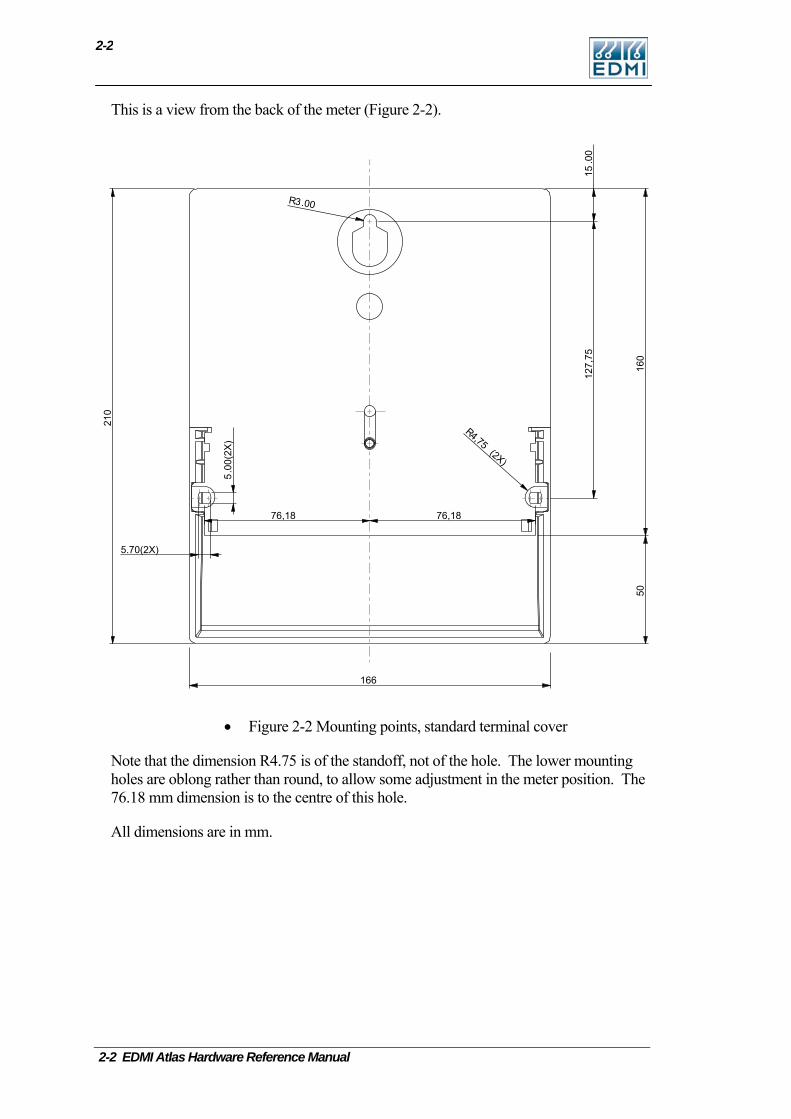
This is a view from the back of the meter (Figure 2-2).
.00
15
R .003
R
(2X)
4,75
.00(2X)
5
166
160
50
210
5.70(2X)
127,75
76,1876,18
• Figure 2-2 Mounting points, standard terminal cover
Note that the dimension R4.75 is of the standoff, not of the hole. The lower mounting holes are oblong rather than round, to allow some adjustment in the meter position. The 76.18 mm dimension is to the centre of this hole.
All dimensions are in mm.
2-2 EDMI Atlas Hardware Reference Manual
Dimensions and Mounting
2-3
.00
15
R .003
R
(2X)
4,75
.00(2X)
5
166
160
80
240
5.70(2X)
127,75
76,18 76,18
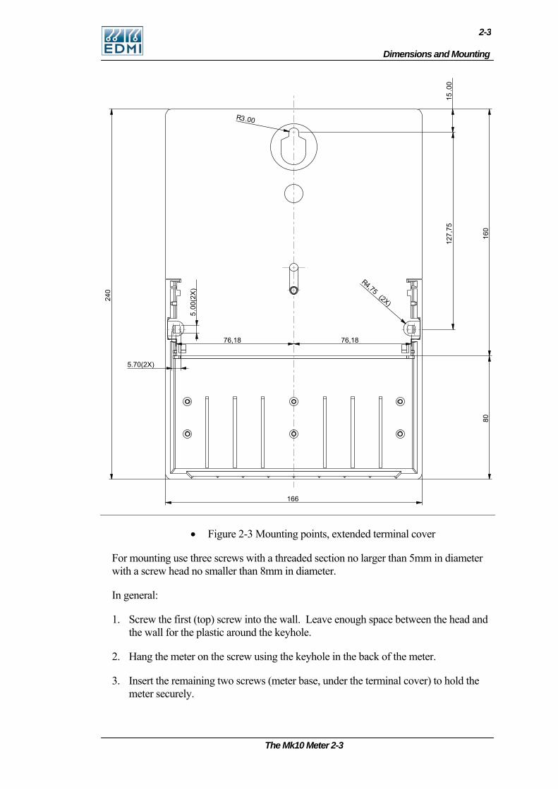
• Figure 2-3 Mounting points, extended terminal cover
For mounting use three screws with a threaded section no larger than 5mm in diameter with a screw head no smaller than 8mm in diameter.
In general:
1. Screw the first (top) screw into the wall. Leave enough space between the head and the wall for the plastic around the keyhole.
2. Hang the meter on the screw using the keyhole in the back of the meter.
3. Insert the remaining two screws (meter base, under the terminal cover) to hold the meter securely.
The Mk10 Meter 2-3
2-4
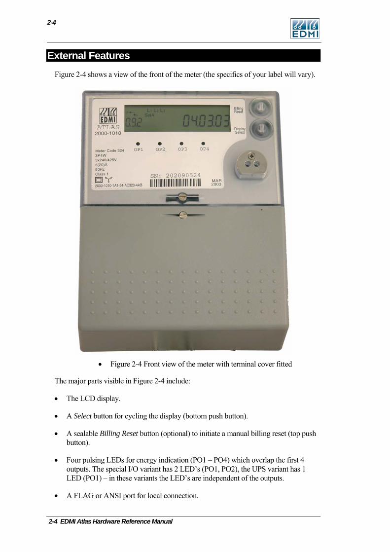
External Features Figure 2-4 shows a view of the front of the meter (the specifics of your label will vary).
• Figure 2-4 Front view of the meter with terminal cover fitted
The major parts visible in Figure 2-4 include:
• The LCD display.
• A Select button for cycling the display (bottom push button).
• A sealable Billing Reset button (optional) to initiate a manual billing reset (top push button).
• Four pulsing LEDs for energy indication (PO1 – PO4) which overlap the first 4 outputs. The special I/O variant has 2 LED’s (PO1, PO2), the UPS variant has 1 LED (PO1) – in these variants the LED’s are independent of the outputs.
• A FLAG or ANSI port for local connection.
2-4 EDMI Atlas Hardware Reference Manual
Under the Terminal Cover
2-5
The Mk10 Meter 2-5
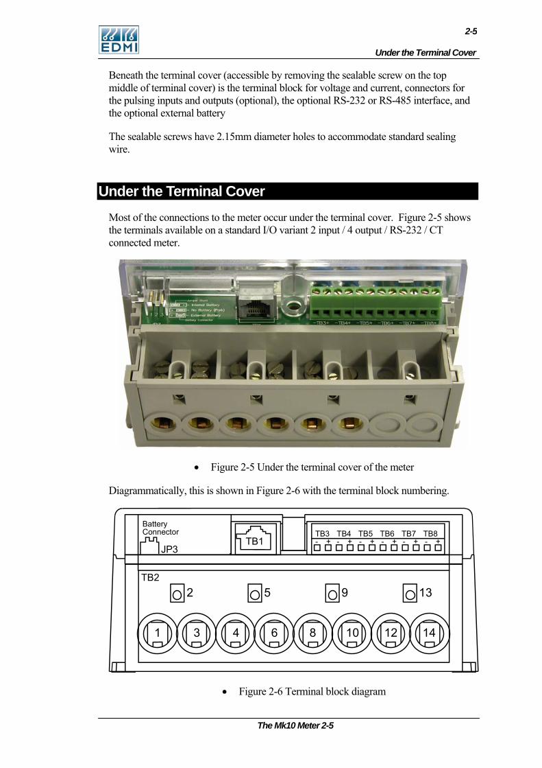
Beneath the terminal cover (accessible by removing the sealable screw on the top middle of terminal cover) is the terminal block for voltage and current, connectors for the pulsing inputs and outputs (optional), the optional RS-232 or RS-485 interface, and the optional external battery
The sealable screws have 2.15mm diameter holes to accommodate standard sealing wire.
Under the Terminal Cover Most of the connections to the meter occur under the terminal cover. Figure 2-5 shows the terminals available on a standard I/O variant 2 input / 4 output / RS-232 / CT connected meter.
• Figure 2-5 Under the terminal cover of the meter
Diagrammatically, this is shown in Figure 2-6 with the terminal block numbering.
BatteryConnector
JP3TB1 + + + + + +- - - - - -
TB3 TB4 TB5 TB6 TB7 TB8
TB2
1 3 4 6 8 10 12 14
2 5 9 13
• Figure 2-6 Terminal block diagram
2-6
2-6 EDMI Atlas Hardware Reference Manual
Table 2-1 lists the terminal block connections, standard I/O variant.
Terminal Description TB1 RJ45 connector which is hardware configured
to either RS485 or RS232, or a 5 way terminal block for RS485.
TB2 Voltage and current inputs.
TB3 I/O - PI5 or PO5.
TB4 I/O - PI6 or PO6.
TB5 I/O - PO1.
TB6 I/O - PO2.
TB7 I/O - PO3.
TB8 I/O - PO4.
• Table 2-1 Terminal block connections
Outputs are BOSFETs, up to 240V, 100mA, AC or DC. Inputs are AC or DC in a range of voltage options. An active input option is not offered on this variant. All I/O’s are isolated from each other to 2kV, except for active inputs which share a supply with the modem port. All I/O are isolated from the line (neutral) and TB1 by 4kV.
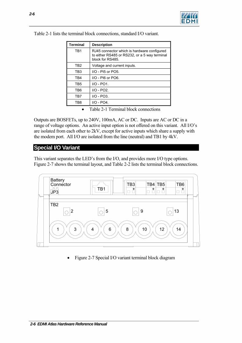
Special I/O Variant
This variant separates the LED’s from the I/O, and provides more I/O type options. Figure 2-7 shows the terminal layout, and Table 2-2 lists the terminal block connections.
+ + + +TB3 TB4 TB5 TB6
TB1
BatteryConnector
JP3
TB2
1 3 4 6 8 10 12 14
2 5 9 13
• Figure 2-7 Special I/O variant terminal block diagram
Under the Terminal Cover
2-7
The Mk10 Meter 2-7
Terminal Description TB1 RJ45 connector which is hardware configured
to either RS485 or RS232, or a 5 way terminal block for RS485.
TB2 Voltage and current inputs.
TB3 I/O - PI3 or PO3.
TB4 I/O - PI4 or PO4.
TB5 I/O - PI5 or PO5.
TB6 I/O - PI6 or PO6.
• Table 2-2 Special I/O Terminal block connections
All 4 I/O can be either SØ Outputs, BOSFET Outputs or 240V/110V/48V/12V/5V Inputs. PO3 and PO6 have the option of a 2A, 240V relay. TB4 and TB5 should not be considered as isolated from each other (1mm creepage between them). Isolation of TB1 to TB3, TB3 to TB4 and TB5 to TB6 is 4kV (unless active inputs are fitted, in which case there is no isolation between TB1 and the active inputs). All I/O are isolated from the line (neutral) by 4kV.
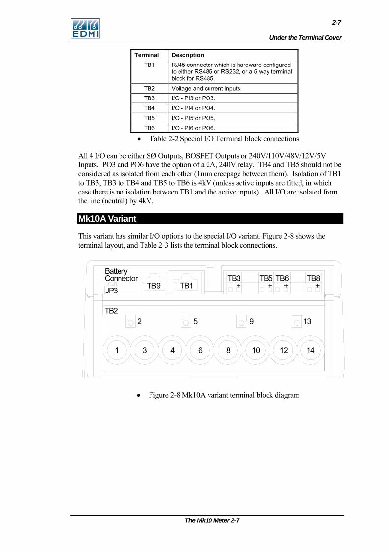
Mk10A Variant
This variant has similar I/O options to the special I/O variant. Figure 2-8 shows the terminal layout, and Table 2-3 lists the terminal block connections.
• Figure 2-8 Mk10A variant terminal block diagram
+ + + + TB3 TB5 T B 6 T B 8
TB1
B a tte r y C o nn e c t o r J P 3
T B 2
1 3 4 6 8 10 1 2 1 4
2 5 9 1 3
TB9
2-8
Terminal Description TB1 RJ45 connector which is hardware configured
to either RS485 or RS232, or a 3 way terminal block for RS485.
TB2 Voltage and current inputs.
TB3 I/O - PI3 or PO3.
TB5 I/O - PI4 or PO4.
TB6 I/O - PI5 or PO5.
TB8 I/O - PI6 or PO6.
TB9 RJ45 connector which is hardware configured to RS232 or RS485.
• Table 2-3 Mk10A Terminal block connections
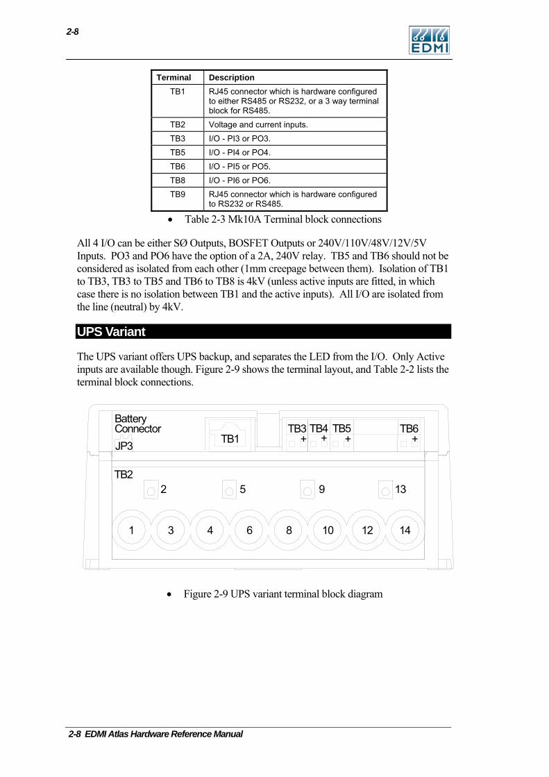
All 4 I/O can be either SØ Outputs, BOSFET Outputs or 240V/110V/48V/12V/5V Inputs. PO3 and PO6 have the option of a 2A, 240V relay. TB5 and TB6 should not be considered as isolated from each other (1mm creepage between them). Isolation of TB1 to TB3, TB3 to TB5 and TB6 to TB8 is 4kV (unless active inputs are fitted, in which case there is no isolation between TB1 and the active inputs). All I/O are isolated from the line (neutral) by 4kV.
UPS Variant
The UPS variant offers UPS backup, and separates the LED from the I/O. Only Active inputs are available though. Figure 2-9 shows the terminal layout, and Table 2-2 lists the terminal block connections.
+ ++ + TB3 TB4 TB5 T B 6
TB1
B a t t e r y C o n n e c t o r J P 3
T B 2
1 3 4 6 8 10 12 1 4
2 5 9 1 3
• Figure 2-9 UPS variant terminal block diagram
2-8 EDMI Atlas Hardware Reference Manual
Under the Terminal Cover
2-9
Terminal Description TB1 RJ45 connector which is hardware configured
to either RS485 or RS232, or a 5 way terminal block for RS485.
TB2 Voltage and current inputs.
TB3 Active Input - PI3.
TB4 Active Input - PI4.
TB5 Active Input - PI5.
TB8 UPS Battery connector.
• Table 2-4 UPS Terminal block connections
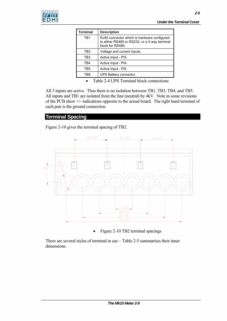
All 3 inputs are active. Thus there is no isolation between TB1, TB3, TB4, and TB5. All inputs and TB1 are isolated from the line (neutral) by 4kV. Note in some revisions of the PCB show +/- indications opposite to the actual board. The right hand terminal of each pair is the ground connection.
Terminal Spacing
Figure 2-10 gives the terminal spacing of TB2.
• Figure 2-10 TB2 terminal spacings
There are several styles of terminal in use – Table 2-5 summarises their inner dimensions.
The Mk10 Meter 2-9
2-10
Meter Type Terminal Type and Profile Dimensions CT Current Square 8.5 mm x 8.0 mm
CT Current Round 9.0 mm Ø
Whole Current Current Square 8.5 mm x 9.0 mm
Whole Current Current Round 9.0 mm Ø
All Voltage 3.0 mm Ø
• Table 2-5 Terminal sizes
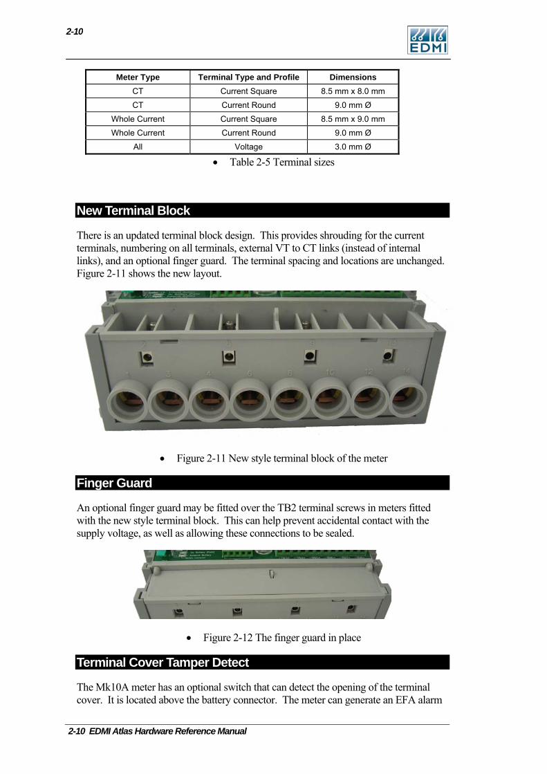
New Terminal Block
There is an updated terminal block design. This provides shrouding for the current terminals, numbering on all terminals, external VT to CT links (instead of internal links), and an optional finger guard. The terminal spacing and locations are unchanged. Figure 2-11 shows the new layout.
• Figure 2-11 New style terminal block of the meter
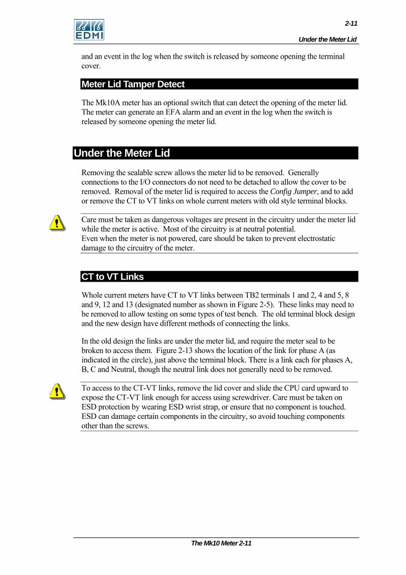
Finger Guard
An optional finger guard may be fitted over the TB2 terminal screws in meters fitted with the new style terminal block. This can help prevent accidental contact with the supply voltage, as well as allowing these connections to be sealed.
• Figure 2-12 The finger guard in place
Terminal Cover Tamper Detect
The Mk10A meter has an optional switch that can detect the opening of the terminal cover. It is located above the battery connector. The meter can generate an EFA alarm
2-10 EDMI Atlas Hardware Reference Manual
Under the Meter Lid
2-11
and an event in the log when the switch is released by someone opening the terminal cover.
Meter Lid Tamper Detect
The Mk10A meter has an optional switch that can detect the opening of the meter lid. The meter can generate an EFA alarm and an event in the log when the switch is released by someone opening the meter lid.
Under the Meter Lid Removing the sealable screw allows the meter lid to be removed. Generally connections to the I/O connectors do not need to be detached to allow the cover to be removed. Removal of the meter lid is required to access the Config Jumper, and to add or remove the CT to VT links on whole current meters with old style terminal blocks.
Care must be taken as dangerous voltages are present in the circuitry under the meter lid while the meter is active. Most of the circuitry is at neutral potential. Even when the meter is not powered, care should be taken to prevent electrostatic damage to the circuitry of the meter.
CT to VT Links
Whole current meters have CT to VT links between TB2 terminals 1 and 2, 4 and 5, 8 and 9, 12 and 13 (designated number as shown in Figure 2-5). These links may need to be removed to allow testing on some types of test bench. The old terminal block design and the new design have different methods of connecting the links.
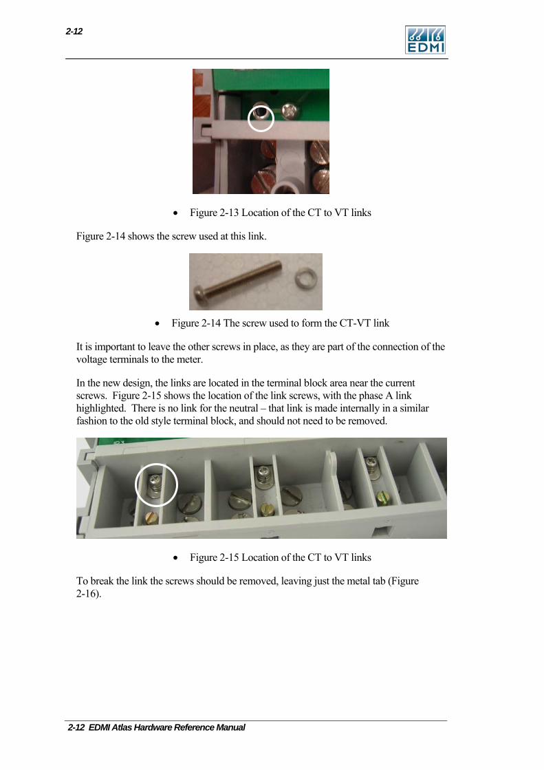
In the old design the links are under the meter lid, and require the meter seal to be broken to access them. Figure 2-13 shows the location of the link for phase A (as indicated in the circle), just above the terminal block. There is a link each for phases A, B, C and Neutral, though the neutral link does not generally need to be removed.
To access to the CT-VT links, remove the lid cover and slide the CPU card upward to expose the CT-VT link enough for access using screwdriver. Care must be taken on ESD protection by wearing ESD wrist strap, or ensure that no component is touched. ESD can damage certain components in the circuitry, so avoid touching components other than the screws.
The Mk10 Meter 2-11
2-12
• Figure 2-13 Location of the CT to VT links
Figure 2-14 shows the screw used at this link.
• Figure 2-14 The screw used to form the CT-VT link
It is important to leave the other screws in place, as they are part of the connection of the voltage terminals to the meter.
In the new design, the links are located in the terminal block area near the current screws. Figure 2-15 shows the location of the link screws, with the phase A link highlighted. There is no link for the neutral – that link is made internally in a similar fashion to the old style terminal block, and should not need to be removed.
• Figure 2-15 Location of the CT to VT links
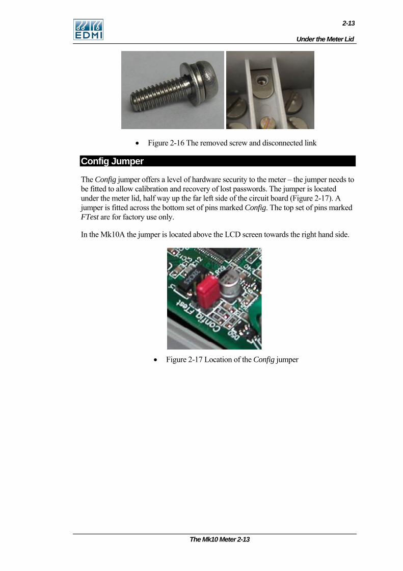
To break the link the screws should be removed, leaving just the metal tab (Figure 2-16).
2-12 EDMI Atlas Hardware Reference Manual
Under the Meter Lid
2-13
• Figure 2-16 The removed screw and disconnected link
Config Jumper
The Config jumper offers a level of hardware security to the meter – the jumper needs to be fitted to allow calibration and recovery of lost passwords. The jumper is located under the meter lid, half way up the far left side of the circuit board (Figure 2-17). A jumper is fitted across the bottom set of pins marked Config. The top set of pins marked FTest are for factory use only.
In the Mk10A the jumper is located above the LCD screen towards the right hand side.
• Figure 2-17 Location of the Config jumper
The Mk10 Meter 2-13
2-14
2-14 EDMI Atlas Hardware Reference Manual
Connections in Detail
Current and Voltage
Phase A Phase B Phase C Neutral
Ia Va Ia Ib Vb Ib Ic Vc Ic Vn
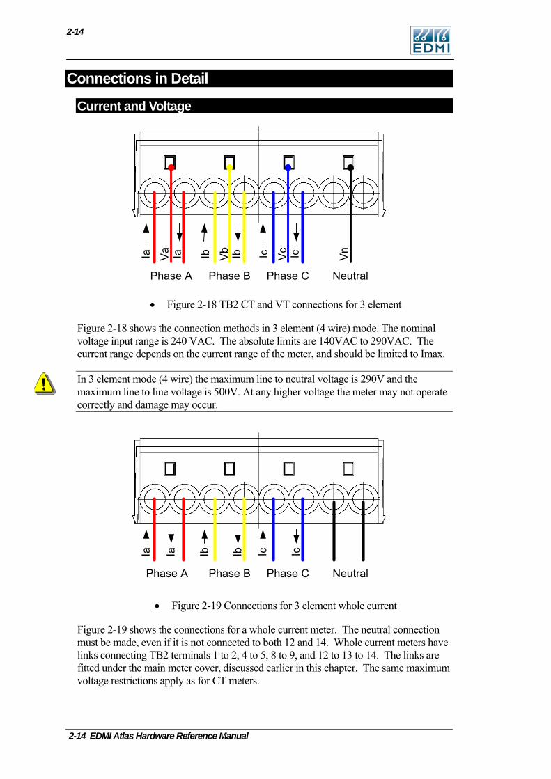
• Figure 2-18 TB2 CT and VT connections for 3 element
Figure 2-18 shows the connection methods in 3 element (4 wire) mode. The nominal voltage input range is 240 VAC. The absolute limits are 140VAC to 290VAC. The current range depends on the current range of the meter, and should be limited to Imax.
In 3 element mode (4 wire) the maximum line to neutral voltage is 290V and the maximum line to line voltage is 500V. At any higher voltage the meter may not operate correctly and damage may occur.
Ia Ia Ib Ib Ic Ic
Phase A Phase B Phase C Neutral
• Figure 2-19 Connections for 3 element whole current
Figure 2-19 shows the connections for a whole current meter. The neutral connection must be made, even if it is not connected to both 12 and 14. Whole current meters have links connecting TB2 terminals 1 to 2, 4 to 5, 8 to 9, and 12 to 13 to 14. The links are fitted under the main meter cover, discussed earlier in this chapter. The same maximum voltage restrictions apply as for CT meters.
Connections in Detail
2-15
Mk10 Serial Port Configurations
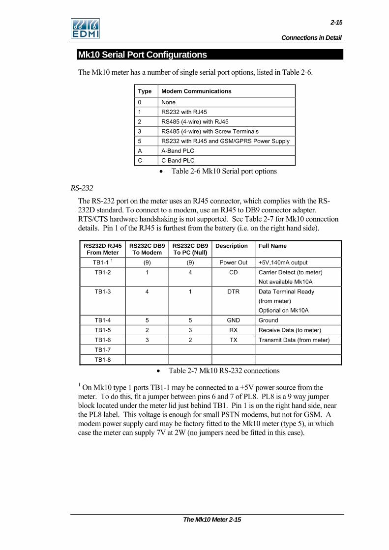
The Mk10 meter has a number of single serial port options, listed in Table 2-6.
Type Modem Communications
0 None 1 RS232 with RJ45 2 RS485 (4-wire) with RJ45 3 RS485 (4-wire) with Screw Terminals 5 RS232 with RJ45 and GSM/GPRS Power Supply A A-Band PLC C C-Band PLC
• Table 2-6 Mk10 Serial port options
RS-232
The RS-232 port on the meter uses an RJ45 connector, which complies with the RS-232D standard. To connect to a modem, use an RJ45 to DB9 connector adapter. RTS/CTS hardware handshaking is not supported. See Table 2-7 for Mk10 connection details. Pin 1 of the RJ45 is furthest from the battery (i.e. on the right hand side).
RS232D RJ45 From Meter
RS232C DB9 To Modem
RS232C DB9 To PC (Null)
Description Full Name
TB1-1 1 (9) (9) Power Out +5V,140mA output
TB1-2 1 4 CD Carrier Detect (to meter) Not available Mk10A
TB1-3 4 1 DTR Data Terminal Ready (from meter) Optional on Mk10A
TB1-4 5 5 GND Ground
TB1-5 2 3 RX Receive Data (to meter)
TB1-6 3 2 TX Transmit Data (from meter)
TB1-7
TB1-8
• Table 2-7 Mk10 RS-232 connections
1 On Mk10 type 1 ports TB1-1 may be connected to a +5V power source from the meter. To do this, fit a jumper between pins 6 and 7 of PL8. PL8 is a 9 way jumper block located under the meter lid just behind TB1. Pin 1 is on the right hand side, near the PL8 label. This voltage is enough for small PSTN modems, but not for GSM. A modem power supply card may be factory fitted to the Mk10 meter (type 5), in which case the meter can supply 7V at 2W (no jumpers need be fitted in this case).
The Mk10 Meter 2-15
2-16
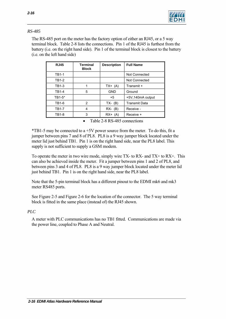
RS-485
The RS-485 port on the meter has the factory option of either an RJ45, or a 5 way terminal block. Table 2-8 lists the connections. Pin 1 of the RJ45 is furthest from the battery (i.e. on the right hand side). Pin 1 of the terminal block is closest to the battery (i.e. on the left hand side)
RJ45 Terminal Block
Description Full Name
TB1-1 Not Connected
TB1-2 Not Connected
TB1-3 1 TX+ (A) Transmit +
TB1-4 5 GND Ground
TB1-5* +5 +5V,140mA output
TB1-6 2 TX- (B) Transmit Data
TB1-7 4 RX- (B) Receive -
TB1-8 3 RX+ (A) Receive +
• Table 2-8 RS-485 connections
*TB1-5 may be connected to a +5V power source from the meter. To do this, fit a jumper between pins 7 and 8 of PL8. PL8 is a 9 way jumper block located under the meter lid just behind TB1. Pin 1 is on the right hand side, near the PL8 label. This supply is not sufficient to supply a GSM modem.
To operate the meter in two wire mode, simply wire TX- to RX- and TX+ to RX+. This can also be achieved inside the meter. Fit a jumper between pins 1 and 2 of PL8, and between pins 3 and 4 of PL8. PL8 is a 9 way jumper block located under the meter lid just behind TB1. Pin 1 is on the right hand side, near the PL8 label.
Note that the 5-pin terminal block has a different pinout to the EDMI mk6 and mk3 meter RS485 ports.
See Figure 2-5 and Figure 2-6 for the location of the connector. The 5 way terminal block is fitted in the same place (instead of) the RJ45 shown.
PLC
A meter with PLC communications has no TB1 fitted. Communications are made via the power line, coupled to Phase A and Neutral.
2-16 EDMI Atlas Hardware Reference Manual
Connections in Detail
2-17
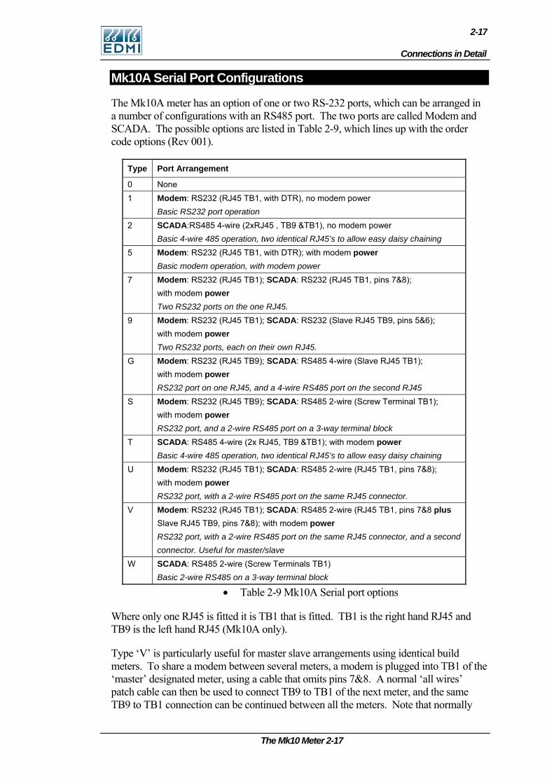
Mk10A Serial Port Configurations
The Mk10A meter has an option of one or two RS-232 ports, which can be arranged in a number of configurations with an RS485 port. The two ports are called Modem and SCADA. The possible options are listed in Table 2-9, which lines up with the order code options (Rev 001).
Type Port Arrangement
0 None 1 Modem: RS232 (RJ45 TB1, with DTR), no modem power
Basic RS232 port operation 2 SCADA:RS485 4-wire (2xRJ45 , TB9 &TB1), no modem power
Basic 4-wire 485 operation, two identical RJ45’s to allow easy daisy chaining 5 Modem: RS232 (RJ45 TB1, with DTR); with modem power
Basic modem operation, with modem power 7 Modem: RS232 (RJ45 TB1); SCADA: RS232 (RJ45 TB1, pins 7&8);
with modem power Two RS232 ports on the one RJ45.
9 Modem: RS232 (RJ45 TB1); SCADA: RS232 (Slave RJ45 TB9, pins 5&6); with modem power Two RS232 ports, each on their own RJ45.
G Modem: RS232 (RJ45 TB9); SCADA: RS485 4-wire (Slave RJ45 TB1); with modem power RS232 port on one RJ45, and a 4-wire RS485 port on the second RJ45
S Modem: RS232 (RJ45 TB9); SCADA: RS485 2-wire (Screw Terminal TB1); with modem power RS232 port, and a 2-wire RS485 port on a 3-way terminal block
T SCADA: RS485 4-wire (2x RJ45, TB9 &TB1); with modem power Basic 4-wire 485 operation, two identical RJ45’s to allow easy daisy chaining
U Modem: RS232 (RJ45 TB1); SCADA: RS485 2-wire (RJ45 TB1, pins 7&8); with modem power RS232 port, with a 2-wire RS485 port on the same RJ45 connector.
V Modem: RS232 (RJ45 TB1); SCADA: RS485 2-wire (RJ45 TB1, pins 7&8 plus Slave RJ45 TB9, pins 7&8); with modem power RS232 port, with a 2-wire RS485 port on the same RJ45 connector, and a second connector. Useful for master/slave
W SCADA: RS485 2-wire (Screw Terminals TB1) Basic 2-wire RS485 on a 3-way terminal block
• Table 2-9 Mk10A Serial port options
Where only one RJ45 is fitted it is TB1 that is fitted. TB1 is the right hand RJ45 and TB9 is the left hand RJ45 (Mk10A only).
Type ‘V’ is particularly useful for master slave arrangements using identical build meters. To share a modem between several meters, a modem is plugged into TB1 of the ‘master’ designated meter, using a cable that omits pins 7&8. A normal ‘all wires’ patch cable can then be used to connect TB9 to TB1 of the next meter, and the same TB9 to TB1 connection can be continued between all the meters. Note that normally
The Mk10 Meter 2-17
2-18
when the master meter cycles the power on the modem its RS485 port would stop working – in this configuration the RS485 port receives power from the following meter in the chain, useful in some situations (eg access to RS485 bus from the optical port of the master meter).
The options with modem power out are configured such that an externally applied voltage on the power pin (<24VDC) will not damage the meter. Note that the MK10A provides power on pin 1 rather than pin 5 for RS485 options, which is different to many of the other EDMI meters – this allows better integration of the multiple ports.
The connection on the label is indicated using a range of symbols that explain what the connections are. For instance:
TB1 22
33
22
SS
RR
LAUD
corresponds with a Mk10A Type 7 port. There is only one RJ45 (TB1), it is a dual connector (2 serial ports on the one connector), power is supplied ( ), and both ports are RS232 (the top port is the Modem port, the bottom is the SCADA port).
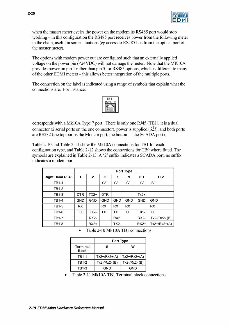
Table 2-10 and Table 2-11 show the Mk10A connections for TB1 for each configuration type, and Table 2-12 shows the connections for TB9 where fitted. The symbols are explained in Table 2-13. A ‘2’ suffix indicates a SCADA port, no suffix indicates a modem port.
Port Type Right Hand RJ45 1 2 5 7 9 G,T U,V
TB1-1 +V +V +V +V +V
TB1-2
TB1-3 DTR TX2+ DTR Tx2+
TB1-4 GND GND GND GND GND GND GND
TB1-5 RX RX RX RX RX
TB1-6 TX TX2- TX TX TX TX2- TX
TB1-7 RX2- RX2 RX2- Tx2-/Rx2- (B)
TB1-8 RX2+ TX2 RX2+ Tx2+/Rx2+(A)
• Table 2-10 Mk10A TB1 connections
Port Type Terminal
Bock S W
TB1-1 Tx2+/Rx2+(A) Tx2+/Rx2+(A)
TB1-2 Tx2-/Rx2- (B) Tx2-/Rx2- (B)
TB1-3 GND GND
• Table 2-11 Mk10A TB1 Terminal block connections
2-18 EDMI Atlas Hardware Reference Manual
Connections in Detail
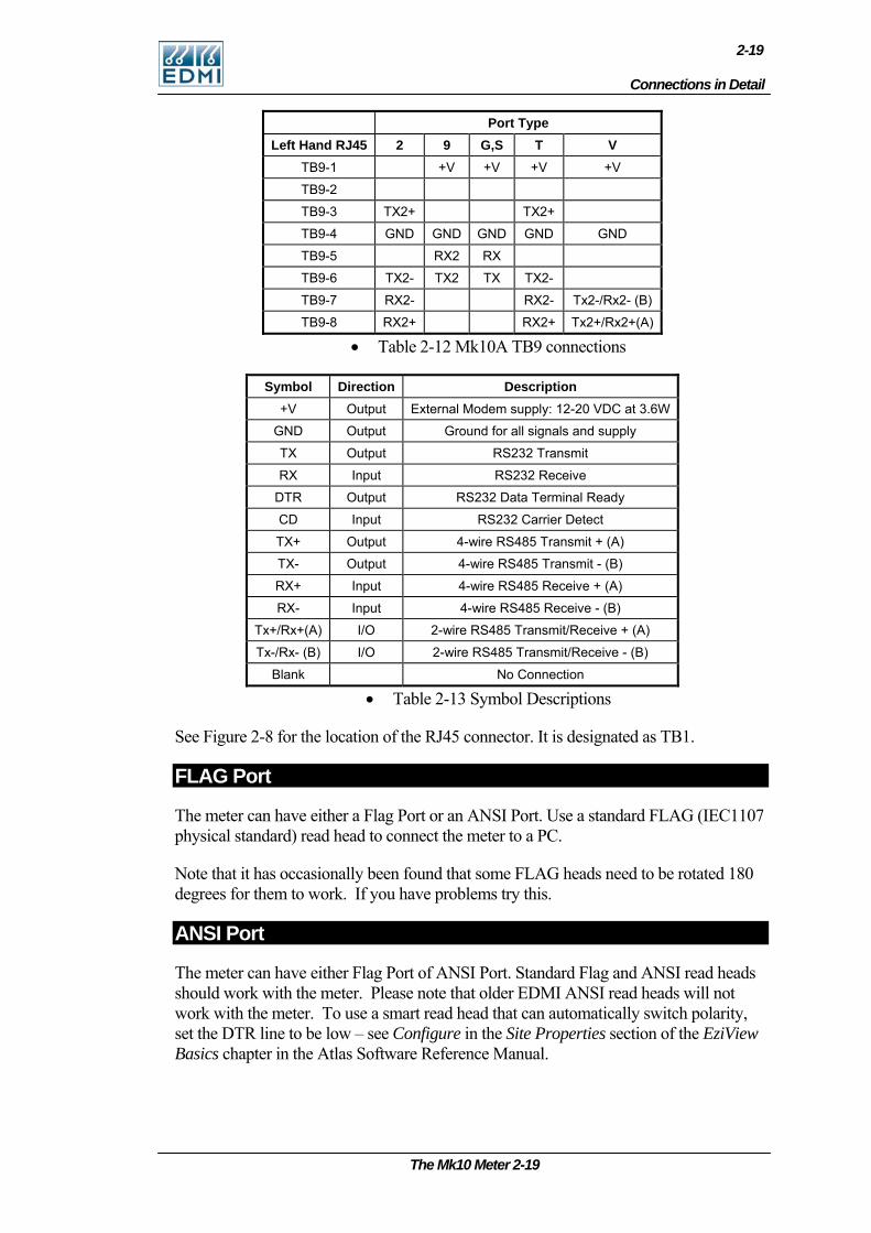
2-19
Port Type Left Hand RJ45 2 9 G,S T V
TB9-1 +V +V +V +V
TB9-2
TB9-3 TX2+ TX2+
TB9-4 GND GND GND GND GND
TB9-5 RX2 RX
TB9-6 TX2- TX2 TX TX2-
TB9-7 RX2- RX2- Tx2-/Rx2- (B)
TB9-8 RX2+ RX2+ Tx2+/Rx2+(A)
• Table 2-12 Mk10A TB9 connections
Symbol Direction Description +V Output External Modem supply: 12-20 VDC at 3.6W
GND Output Ground for all signals and supply
TX Output RS232 Transmit
RX Input RS232 Receive
DTR Output RS232 Data Terminal Ready
CD Input RS232 Carrier Detect
TX+ Output 4-wire RS485 Transmit + (A)
TX- Output 4-wire RS485 Transmit - (B)
RX+ Input 4-wire RS485 Receive + (A)
RX- Input 4-wire RS485 Receive - (B)
Tx+/Rx+(A) I/O 2-wire RS485 Transmit/Receive + (A)
Tx-/Rx- (B) I/O 2-wire RS485 Transmit/Receive - (B)
Blank No Connection
• Table 2-13 Symbol Descriptions
See Figure 2-8 for the location of the RJ45 connector. It is designated as TB1.
FLAG Port
The meter can have either a Flag Port or an ANSI Port. Use a standard FLAG (IEC1107 physical standard) read head to connect the meter to a PC.
Note that it has occasionally been found that some FLAG heads need to be rotated 180 degrees for them to work. If you have problems try this.
ANSI Port
The meter can have either Flag Port of ANSI Port. Standard Flag and ANSI read heads should work with the meter. Please note that older EDMI ANSI read heads will not work with the meter. To use a smart read head that can automatically switch polarity, set the DTR line to be low – see Configure in the Site Properties section of the EziView Basics chapter in the Atlas Software Reference Manual.
The Mk10 Meter 2-19
2-20
Inputs
The inputs are passive and are isolated from all other circuits, including the other inputs. There are a variety of input voltages that may be ordered with the meter, e.g. 110V and 240V, down to 5V. Under voltage will cause the input to trigger erratically or not at all, while over voltage will cause excessive heat dissipation and possible damage to the meter.
The rated voltage is the voltage that must be applied between the two terminals of the input. The inputs work with any polarity, and with AC or DC signals. There are a maximum of 2 inputs for the standard I/O variants (Table 2-1), 4 inputs for the special I/O variant (Table 2-2), and 3 for the UPS variant (Table 2-4).
Active inputs are also available as a factory option. They use power from the serial port, and are thus not isolated from the serial port. In this case simply shorting between the input terminals will cause the input to trigger. The maximum external impedance is 500 ohms. Note that power is drawn from the isolated serial port supply, and the inputs will not work while the serial port is powered down to cycle power to a modem. They will continue to operate on a UPS meter when running from the UPS battery.
Outputs
There are several types of outputs available. All outputs are isolated from all other circuits, including other I/O. See Table 2-1, Table 2-2, and Table 2-4 for details of isolation and connections.
The SØ outputs are designed to switch up to 24VDC and 24mA.
The relay outputs are rated to 2A, 240VAC with an inductive load, or 5A, 240VAC for the high current version. These outputs should not be used as pulsing outputs for transmitting energy pulses, as the output contacts are subject to contact bounce and are not rated for continuous switching.
The BOSFET outputs are rated up to 240V, 100mA. They may switch either AC or DC voltages, any polarity.
Battery
The battery is used to run the clock during loss of power. It also allows the meter LCD to be activated while main power is not available.
The meter comes with an optional internal or external battery.
The external battery is a 3.6V, 700mAh Lithium battery, or a 3.0V, 700mAh Lithium battery. The Mk10A only supports the 3.0V battery. The internal battery is a 3.0V, 700mAh Lithium battery. If both internal and external batteries are fitted, the meter will use both.
If an internal battery is used, a jumper will be connected to JP3 pin 1 and pin 2. To use an external battery, remove the jumper and plug the battery connector to pin 2 and 3 (polarized) of JP3. The external battery is clipped into the compartment to the right of
2-20 EDMI Atlas Hardware Reference Manual
Connections in Detail
2-21
JP3. In the Mk10A if TB9 is fitted the battery can be fitted end in. The battery cable should be routed away from the communication lines, since it is at neutral potential.
Replacement batteries may be ordered from EDMI separately. A low battery indicator is displayed on the LCD if the battery is not present or is depleted – the level this occurs at can be configured. The battery usage life is longer than 10 years on continuous backup with either of the 700mAh batteries at 25°C. In normal operation the battery should last for more than 10 years.
To eliminate the possibility of data loss it is best to change the battery while the meter is running. Care must be taken as the battery is at the potential of the neutral terminal.
The battery is at the potential of the neutral terminal. If conditions (such as wiring configuration) make this a dangerous operation then steps should be taken to ensure that it is safe to do so. While the risk of coming into contact with the conductors during a battery change is minimal, care must be exercised.
UPS Battery
This battery is fitted to the UPS variant to supply the meter and modem in case of power outage. It is separate to the normal battery used to run the clock during loss of power and which allows the LCD to be woken up.
The UPS battery is a rechargeable 500mAh Ni-MH battery. It is a custom battery, replacements are available from EDMI. It connects to PL11, a small connector towards the right of the meter.
In operation the meter switches over to the UPS battery when power is lost, to allow the meter to contact a server via GPRS and communicate the event. The meter turns off the UPS supply 2 minutes after the supply was lost.
The meter also measures the UPS battery voltage and will signal a battery alarm if the battery voltage is too low of too high, or no battery is fitted. It may take 24 hrs for the battery to reach the 5.4V needed for proper operation, and the meter will not switch to UPS if it is too low.
The battery is at the potential of the neutral terminal. If conditions (such as wiring configuration) make this a dangerous operation then steps should be taken to ensure that it is safe to do so.
The Mk10 Meter 2-21
2-22
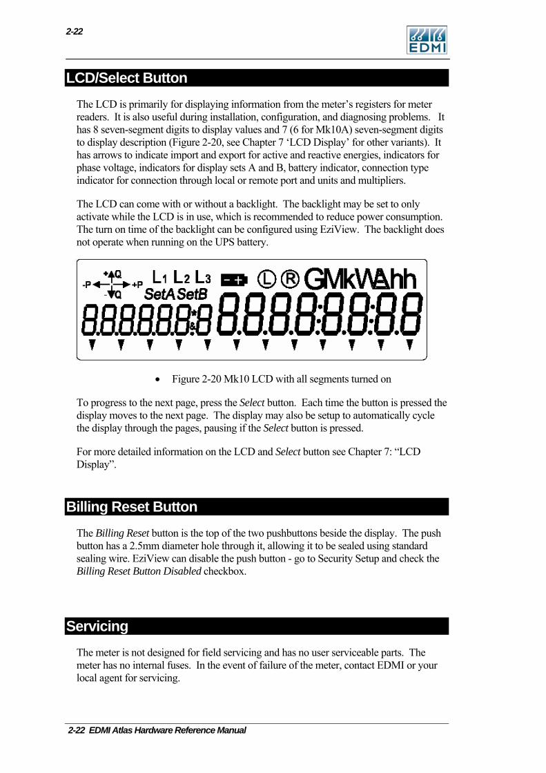
LCD/Select Button The LCD is primarily for displaying information from the meter’s registers for meter readers. It is also useful during installation, configuration, and diagnosing problems. It has 8 seven-segment digits to display values and 7 (6 for Mk10A) seven-segment digits to display description (Figure 2-20, see Chapter 7 ‘LCD Display’ for other variants). It has arrows to indicate import and export for active and reactive energies, indicators for phase voltage, indicators for display sets A and B, battery indicator, connection type indicator for connection through local or remote port and units and multipliers.
The LCD can come with or without a backlight. The backlight may be set to only activate while the LCD is in use, which is recommended to reduce power consumption. The turn on time of the backlight can be configured using EziView. The backlight does not operate when running on the UPS battery.
• Figure 2-20 Mk10 LCD with all segments turned on
To progress to the next page, press the Select button. Each time the button is pressed the display moves to the next page. The display may also be setup to automatically cycle the display through the pages, pausing if the Select button is pressed.
For more detailed information on the LCD and Select button see Chapter 7: “LCD Display”.
Billing Reset Button The Billing Reset button is the top of the two pushbuttons beside the display. The push button has a 2.5mm diameter hole through it, allowing it to be sealed using standard sealing wire. EziView can disable the push button - go to Security Setup and check the Billing Reset Button Disabled checkbox.
Servicing The meter is not designed for field servicing and has no user serviceable parts. The meter has no internal fuses. In the event of failure of the meter, contact EDMI or your local agent for servicing.
2-22 EDMI Atlas Hardware Reference Manual

The Mk10D Meter 3-1
C h a p t e r
3
Chapter 3 The Mk10D Meter This chapter covers the basic installation and physical features of the Mk10D meter.
Dimensions and Mounting Figure 3-1 shows the overall dimensions of the meter with a standard terminal cover. The height excludes the buttons and the ANSI fitting if present.
Width Depth
Height
• Figure 3-1 Overall dimensions of the meter
Height = 262 mm, Depth = 95 mm, Width = 175 mm
Height is 290 mm with an extended terminal cover.
Figure 3-2 is a view from the back of the meter.
3-2
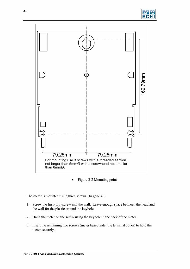
79.25mm79.25mmFor mounting use 3 screws with a threaded sectionnot larger than 5mmØ with a screwhead not smallerthan 8mmØ.
• Figure 3-2 Mounting points
The meter is mounted using three screws. In general:
1. Screw the first (top) screw into the wall. Leave enough space between the head and the wall for the plastic around the keyhole.
2. Hang the meter on the screw using the keyhole in the back of the meter.
3. Insert the remaining two screws (meter base, under the terminal cover) to hold the meter securely.
3-2 EDMI Atlas Hardware Reference Manual
External Features
3-3
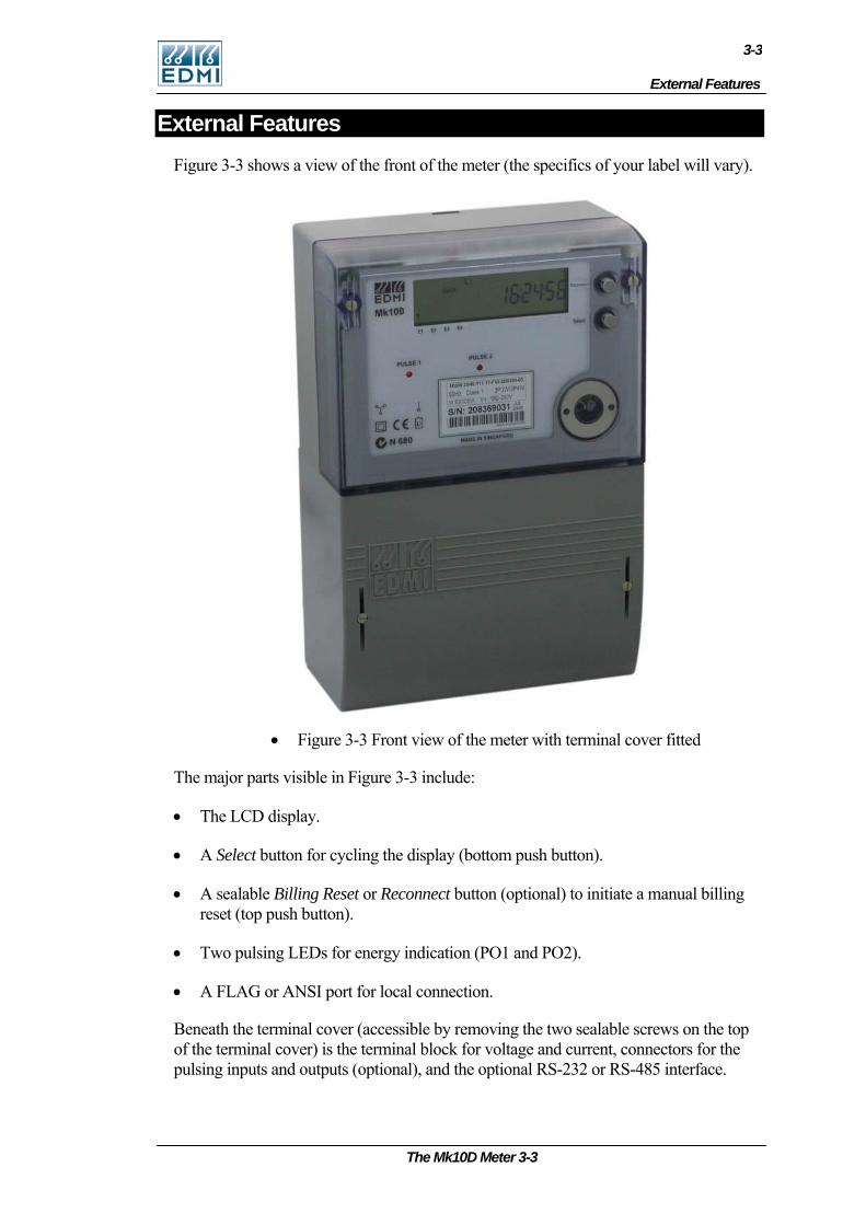
External Features Figure 3-3 shows a view of the front of the meter (the specifics of your label will vary).
• Figure 3-3 Front view of the meter with terminal cover fitted
The major parts visible in Figure 3-3 include:
• The LCD display.
• A Select button for cycling the display (bottom push button).
• A sealable Billing Reset or Reconnect button (optional) to initiate a manual billing reset (top push button).
• Two pulsing LEDs for energy indication (PO1 and PO2).
• A FLAG or ANSI port for local connection.
Beneath the terminal cover (accessible by removing the two sealable screws on the top of the terminal cover) is the terminal block for voltage and current, connectors for the pulsing inputs and outputs (optional), and the optional RS-232 or RS-485 interface.
The Mk10D Meter 3-3
3-4
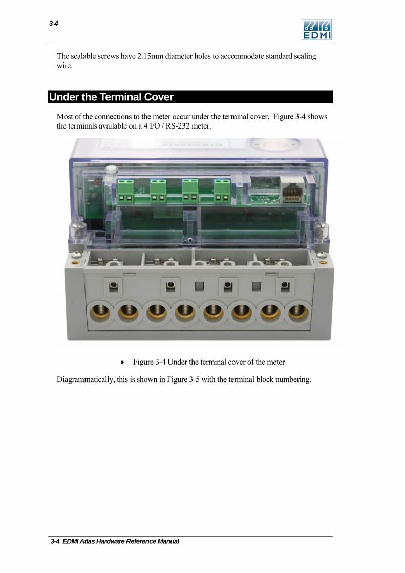
The sealable screws have 2.15mm diameter holes to accommodate standard sealing wire.
Under the Terminal Cover Most of the connections to the meter occur under the terminal cover. Figure 3-4 shows the terminals available on a 4 I/O / RS-232 meter.
• Figure 3-4 Under the terminal cover of the meter
Diagrammatically, this is shown in Figure 3-5 with the terminal block numbering.
3-4 EDMI Atlas Hardware Reference Manual

Under the Terminal Cover
3-5
TB1
TB2 TB3 TB4 TB5
TB9 TB10
1 3 4 6 10 12 14
2 5 9 11 13
• Figure 3-5 Terminal block diagram
Table 3-1 lists the terminal block connections.
Terminal Description TB1 Voltage and current inputs.
TB2 Input PI3 or Output PO3.
TB3 Input PI4 or Output PO4.
TB4 Input PI5 or Output PO5.
TB5 Input PI6 or Output PO6.
TB9 Second RJ45 connector for some communication options.
TB10 RJ45 connector which is hardware configured to either RS485 or RS232, or a 5 way terminal block for RS485.
• Table 3-1 Terminal block connections
The Mk10D Meter 3-5
3-6
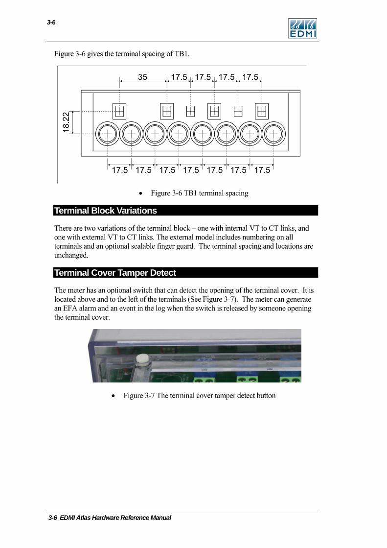
Figure 3-6 gives the terminal spacing of TB1.
• Figure 3-6 TB1 terminal spacing
Terminal Block Variations
There are two variations of the terminal block – one with internal VT to CT links, and one with external VT to CT links. The external model includes numbering on all terminals and an optional sealable finger guard. The terminal spacing and locations are unchanged.
Terminal Cover Tamper Detect
The meter has an optional switch that can detect the opening of the terminal cover. It is located above and to the left of the terminals (See Figure 3-7). The meter can generate an EFA alarm and an event in the log when the switch is released by someone opening the terminal cover.
• Figure 3-7 The terminal cover tamper detect button
3-6 EDMI Atlas Hardware Reference Manual
Under the Meter Lid
3-7
Under the Meter Lid Removing the sealable screw allows the meter lid to be removed. Generally connections to the I/O connectors do not need to be detached to allow the cover to be removed. Removal of the meter lid is required to access the Config Jumper, and to add or remove the CT to VT links on meters with old style terminal blocks.
Care must be taken as dangerous voltages are present in the circuitry under the meter lid while the meter is active. Most of the circuitry is at neutral potential. Even when the meter is not powered, care should be taken to prevent electrostatic damage to the circuitry of the meter.
CT to VT Links
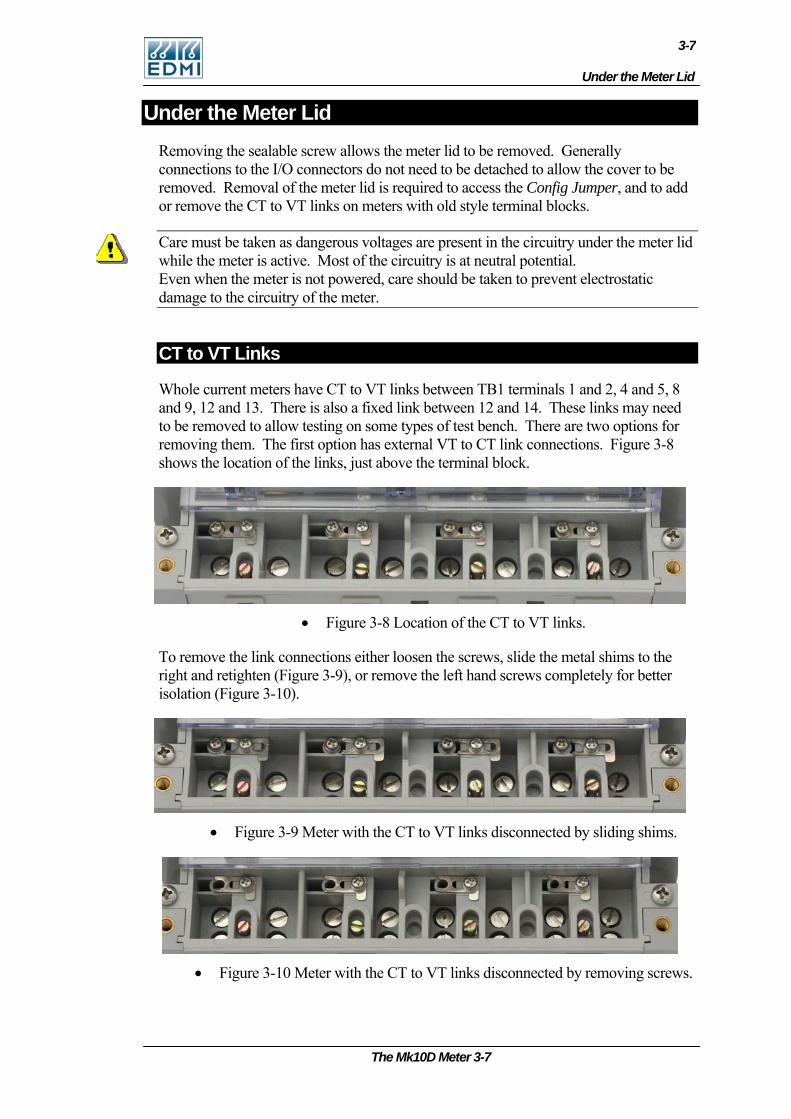
Whole current meters have CT to VT links between TB1 terminals 1 and 2, 4 and 5, 8 and 9, 12 and 13. There is also a fixed link between 12 and 14. These links may need to be removed to allow testing on some types of test bench. There are two options for removing them. The first option has external VT to CT link connections. Figure 3-8 shows the location of the links, just above the terminal block.
• Figure 3-8 Location of the CT to VT links.
To remove the link connections either loosen the screws, slide the metal shims to the right and retighten (Figure 3-9), or remove the left hand screws completely for better isolation (Figure 3-10).
• Figure 3-9 Meter with the CT to VT links disconnected by sliding shims.
• Figure 3-10 Meter with the CT to VT links disconnected by removing screws.
The Mk10D Meter 3-7
3-8
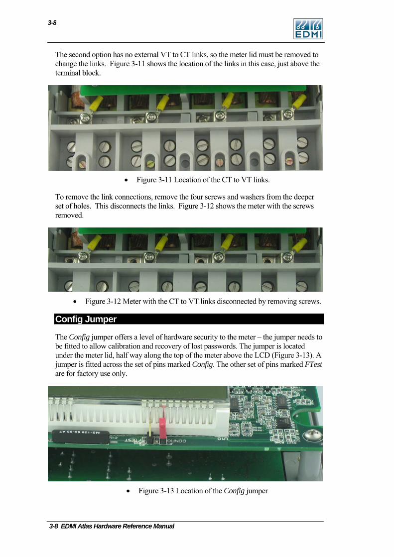
The second option has no external VT to CT links, so the meter lid must be removed to change the links. Figure 3-11 shows the location of the links in this case, just above the terminal block.
• Figure 3-11 Location of the CT to VT links.
To remove the link connections, remove the four screws and washers from the deeper set of holes. This disconnects the links. Figure 3-12 shows the meter with the screws removed.
• Figure 3-12 Meter with the CT to VT links disconnected by removing screws.
Config Jumper
The Config jumper offers a level of hardware security to the meter – the jumper needs to be fitted to allow calibration and recovery of lost passwords. The jumper is located under the meter lid, half way along the top of the meter above the LCD (Figure 3-13). A jumper is fitted across the set of pins marked Config. The other set of pins marked FTest are for factory use only.
• Figure 3-13 Location of the Config jumper
3-8 EDMI Atlas Hardware Reference Manual
Connections in Detail
3-9
Connections in Detail
Current and Voltage
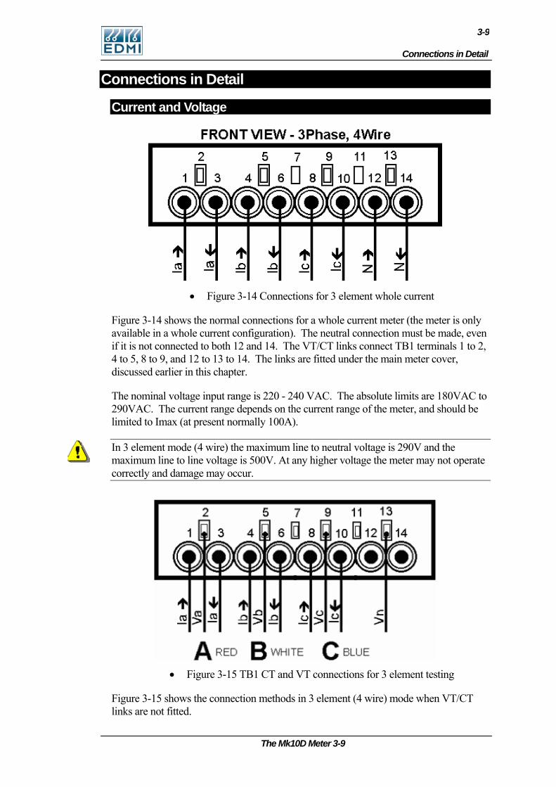
• Figure 3-14 Connections for 3 element whole current
Figure 3-14 shows the normal connections for a whole current meter (the meter is only available in a whole current configuration). The neutral connection must be made, even if it is not connected to both 12 and 14. The VT/CT links connect TB1 terminals 1 to 2, 4 to 5, 8 to 9, and 12 to 13 to 14. The links are fitted under the main meter cover, discussed earlier in this chapter.
The nominal voltage input range is 220 - 240 VAC. The absolute limits are 180VAC to 290VAC. The current range depends on the current range of the meter, and should be limited to Imax (at present normally 100A).
In 3 element mode (4 wire) the maximum line to neutral voltage is 290V and the maximum line to line voltage is 500V. At any higher voltage the meter may not operate correctly and damage may occur.
• Figure 3-15 TB1 CT and VT connections for 3 element testing
Figure 3-15 shows the connection methods in 3 element (4 wire) mode when VT/CT links are not fitted.
The Mk10D Meter 3-9
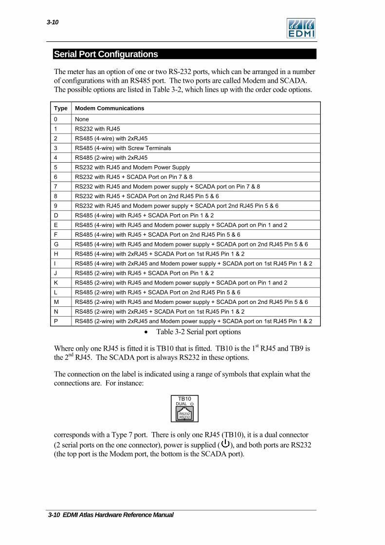
3-10
3-10 EDMI Atlas Hardware Reference Manual
Serial Port Configurations
The meter has an option of one or two RS-232 ports, which can be arranged in a number of configurations with an RS485 port. The two ports are called Modem and SCADA. The possible options are listed in Table 3-2, which lines up with the order code options.
Type Modem Communications
0 None 1 RS232 with RJ45 2 RS485 (4-wire) with 2xRJ45 3 RS485 (4-wire) with Screw Terminals 4 RS485 (2-wire) with 2xRJ45 5 RS232 with RJ45 and Modem Power Supply 6 RS232 with RJ45 + SCADA Port on Pin 7 & 8 7 RS232 with RJ45 and Modem power supply + SCADA port on Pin 7 & 8 8 RS232 with RJ45 + SCADA Port on 2nd RJ45 Pin 5 & 6 9 RS232 with RJ45 and Modem power supply + SCADA port 2nd RJ45 Pin 5 & 6 D RS485 (4-wire) with RJ45 + SCADA Port on Pin 1 & 2 E RS485 (4-wire) with RJ45 and Modem power supply + SCADA port on Pin 1 and 2 F RS485 (4-wire) with RJ45 + SCADA Port on 2nd RJ45 Pin 5 & 6 G RS485 (4-wire) with RJ45 and Modem power supply + SCADA port on 2nd RJ45 Pin 5 & 6 H RS485 (4-wire) with 2xRJ45 + SCADA Port on 1st RJ45 Pin 1 & 2 I RS485 (4-wire) with 2xRJ45 and Modem power supply + SCADA port on 1st RJ45 Pin 1 & 2 J RS485 (2-wire) with RJ45 + SCADA Port on Pin 1 & 2 K RS485 (2-wire) with RJ45 and Modem power supply + SCADA port on Pin 1 and 2 L RS485 (2-wire) with RJ45 + SCADA Port on 2nd RJ45 Pin 5 & 6 M RS485 (2-wire) with RJ45 and Modem power supply + SCADA port on 2nd RJ45 Pin 5 & 6 N RS485 (2-wire) with 2xRJ45 + SCADA Port on 1st RJ45 Pin 1 & 2 P RS485 (2-wire) with 2xRJ45 and Modem power supply + SCADA port on 1st RJ45 Pin 1 & 2
• Table 3-2 Serial port options
Where only one RJ45 is fitted it is TB10 that is fitted. TB10 is the 1st RJ45 and TB9 is the 2nd RJ45. The SCADA port is always RS232 in these options.
The connection on the label is indicated using a range of symbols that explain what the connections are. For instance:
TB10DUAL
RS232RS232
corresponds with a Type 7 port. There is only one RJ45 (TB10), it is a dual connector (2 serial ports on the one connector), power is supplied ( ), and both ports are RS232 (the top port is the Modem port, the bottom is the SCADA port).
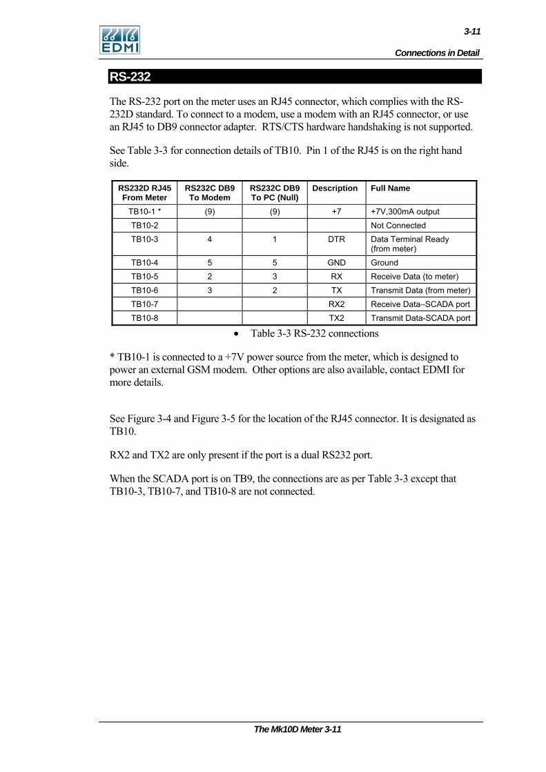
Connections in Detail
3-11
RS-232
The RS-232 port on the meter uses an RJ45 connector, which complies with the RS-232D standard. To connect to a modem, use a modem with an RJ45 connector, or use an RJ45 to DB9 connector adapter. RTS/CTS hardware handshaking is not supported.
See Table 3-3 for connection details of TB10. Pin 1 of the RJ45 is on the right hand side.
RS232D RJ45 From Meter
RS232C DB9 To Modem
RS232C DB9 To PC (Null)
Description Full Name
TB10-1 * (9) (9) +7 +7V,300mA output
TB10-2 Not Connected
TB10-3 4 1 DTR Data Terminal Ready (from meter)
TB10-4 5 5 GND Ground
TB10-5 2 3 RX Receive Data (to meter)
TB10-6 3 2 TX Transmit Data (from meter)
TB10-7 RX2 Receive Data–SCADA port
TB10-8 TX2 Transmit Data-SCADA port
• Table 3-3 RS-232 connections
* TB10-1 is connected to a +7V power source from the meter, which is designed to power an external GSM modem. Other options are also available, contact EDMI for more details.
See Figure 3-4 and Figure 3-5 for the location of the RJ45 connector. It is designated as TB10.
RX2 and TX2 are only present if the port is a dual RS232 port.
When the SCADA port is on TB9, the connections are as per Table 3-3 except that TB10-3, TB10-7, and TB10-8 are not connected.
The Mk10D Meter 3-11
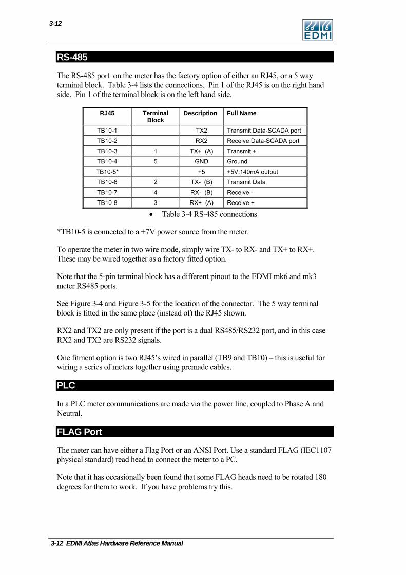
3-12
RS-485
The RS-485 port on the meter has the factory option of either an RJ45, or a 5 way terminal block. Table 3-4 lists the connections. Pin 1 of the RJ45 is on the right hand side. Pin 1 of the terminal block is on the left hand side.
RJ45 Terminal Block
Description Full Name
TB10-1 TX2 Transmit Data-SCADA port
TB10-2 RX2 Receive Data-SCADA port
TB10-3 1 TX+ (A) Transmit +
TB10-4 5 GND Ground
TB10-5* +5 +5V,140mA output
TB10-6 2 TX- (B) Transmit Data
TB10-7 4 RX- (B) Receive -
TB10-8 3 RX+ (A) Receive +
• Table 3-4 RS-485 connections
*TB10-5 is connected to a +7V power source from the meter.
To operate the meter in two wire mode, simply wire TX- to RX- and TX+ to RX+. These may be wired together as a factory fitted option.
Note that the 5-pin terminal block has a different pinout to the EDMI mk6 and mk3 meter RS485 ports.
See Figure 3-4 and Figure 3-5 for the location of the connector. The 5 way terminal block is fitted in the same place (instead of) the RJ45 shown.
RX2 and TX2 are only present if the port is a dual RS485/RS232 port, and in this case RX2 and TX2 are RS232 signals.
One fitment option is two RJ45’s wired in parallel (TB9 and TB10) – this is useful for wiring a series of meters together using premade cables.
PLC
In a PLC meter communications are made via the power line, coupled to Phase A and Neutral.
FLAG Port
The meter can have either a Flag Port or an ANSI Port. Use a standard FLAG (IEC1107 physical standard) read head to connect the meter to a PC.
Note that it has occasionally been found that some FLAG heads need to be rotated 180 degrees for them to work. If you have problems try this.
3-12 EDMI Atlas Hardware Reference Manual
Connections in Detail
3-13
ANSI Port
The meter can have either Flag Port of ANSI Port. Standard Flag and ANSI read heads should work with the meter. Please note that older EDMI ANSI read heads will not work with the meter. To use a smart read head that can automatically switch polarity, set the DTR line to be low – see Configure in the Site Properties section of the EziView Basics chapter in the Atlas Software Reference Manual.
Inputs
The inputs may either be active, or passive. Passive inputs are isolated from all other circuits, including the other inputs. There are a variety of input voltages that may be ordered with the meter, e.g. 12V and 240V. Under voltage will cause the input to trigger erratically or not at all, while over voltage will cause excessive heat dissipation and possible damage to the meter.
The rated voltage is the voltage that must be applied between the two terminals of the input. The inputs work with any polarity, and with AC or DC signals. There are a maximum of 4 inputs.
Active inputs are also available as a factory option. They use power from the serial port, and are thus not isolated from the serial port, or from each other. In this case simply shorting between the input terminals will cause the input to trigger. The maximum external impedance is 500 ohms. Note that power is drawn from the isolated serial port supply, and will the inputs will not work while the serial port is powered down to cycle power to a modem.
Outputs
There are several types of outputs available. All outputs are isolated from all other circuits, including other I/O.
The SØ outputs are designed to switch up to 24VDC and 24mA.
The relay outputs are rated to 2A, 240VAC with an inductive load, or 5A, 240VAC for the high current version. These outputs should not be used as pulsing outputs for transmitting energy pulses, as the output contacts are subject to contact bounce and are not rated for continuous switching.
The BOSFET outputs are rated up to 240V, 100mA. They may switch either AC or DC voltages, any polarity.
Battery
The battery is used to run the clock during loss of power. It also allows the meter LCD to be activated while main power is not available.
The meter comes with an optional internal battery. The internal battery is a 3.0V, 700mAh Lithium battery. There is no external battery option at this time.
The Mk10D Meter 3-13
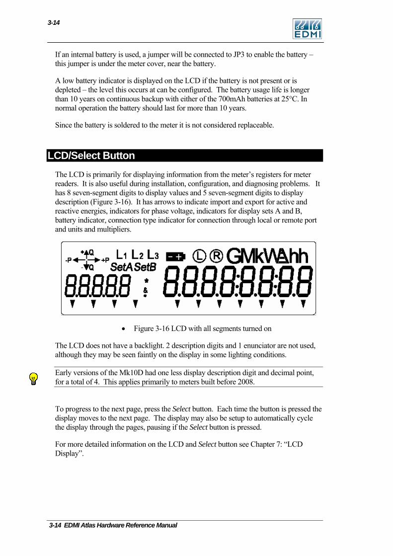
3-14
If an internal battery is used, a jumper will be connected to JP3 to enable the battery – this jumper is under the meter cover, near the battery.
A low battery indicator is displayed on the LCD if the battery is not present or is depleted – the level this occurs at can be configured. The battery usage life is longer than 10 years on continuous backup with either of the 700mAh batteries at 25°C. In normal operation the battery should last for more than 10 years.
Since the battery is soldered to the meter it is not considered replaceable.
LCD/Select Button The LCD is primarily for displaying information from the meter’s registers for meter readers. It is also useful during installation, configuration, and diagnosing problems. It has 8 seven-segment digits to display values and 5 seven-segment digits to display description (Figure 3-16). It has arrows to indicate import and export for active and reactive energies, indicators for phase voltage, indicators for display sets A and B, battery indicator, connection type indicator for connection through local or remote port and units and multipliers.
• Figure 3-16 LCD with all segments turned on
The LCD does not have a backlight. 2 description digits and 1 enunciator are not used, although they may be seen faintly on the display in some lighting conditions.
Early versions of the Mk10D had one less display description digit and decimal point, for a total of 4. This applies primarily to meters built before 2008.
To progress to the next page, press the Select button. Each time the button is pressed the display moves to the next page. The display may also be setup to automatically cycle the display through the pages, pausing if the Select button is pressed.
For more detailed information on the LCD and Select button see Chapter 7: “LCD Display”.
3-14 EDMI Atlas Hardware Reference Manual
Reconnect/Boost/Billing Reset Button
3-15
Reconnect/Boost/Billing Reset Button The Reconnect button is the top of the two push buttons beside the display. The push button has a 2.5mm diameter hole through it, allowing it to be sealed using standard sealing wire. This button is usually used to connect the main contactor.
Holding the button down for at least half a second will connect the customers supply, if it is enabled for connection. The display will show “Connect”. If it is not enabled, the display will show “not enabled” and the contactor state will not change.
Pushing both the Select button and the Reconnect button at the same time will cause the contactor to be disconnected. The message “Disconnect” will be displayed on the LCD.
The Reconnect button can also cause a boost operation for load control outputs, depending on configuration.
Note that the relay may not change state immediately. If another operation has just been performed, it may take 60 seconds to perform the requested operation.
EziView can configure what operations are permitted using the button. EziView can also be used to configure the button as a billing reset button - go to Security Setup and un-check the Billing Reset Button Disabled checkbox.
Servicing The meter is not designed for field servicing and has no user serviceable parts. The meter has no internal fuses. In the event of failure of the meter, contact EDMI or your local agent for servicing.
The Mk10D Meter 3-15

3-16
Intentionally Left Blank
3-16 EDMI Atlas Hardware Reference Manual
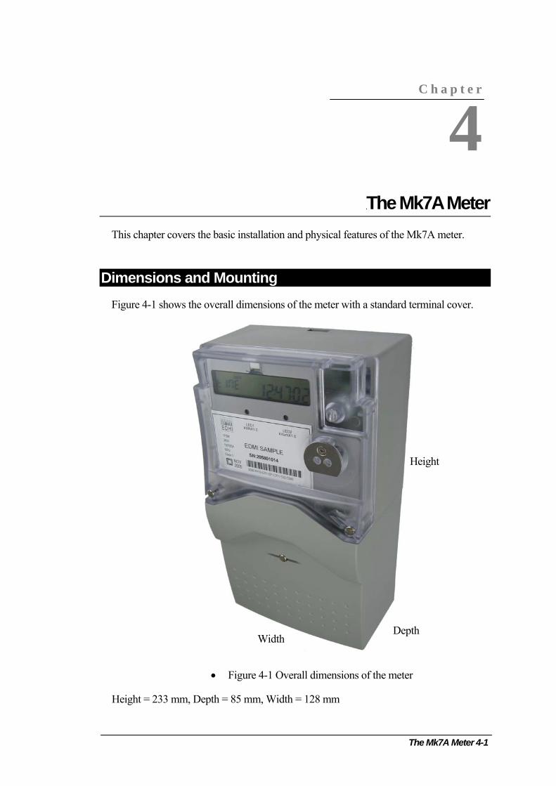
The Mk7A Meter 4-1
C h a p t e r
4
Chapter 4 The Mk7A Meter This chapter covers the basic installation and physical features of the Mk7A meter.
Dimensions and Mounting Figure 4-1 shows the overall dimensions of the meter with a standard terminal cover.
Height
Depth Width
• Figure 4-1 Overall dimensions of the meter
Height = 233 mm, Depth = 85 mm, Width = 128 mm
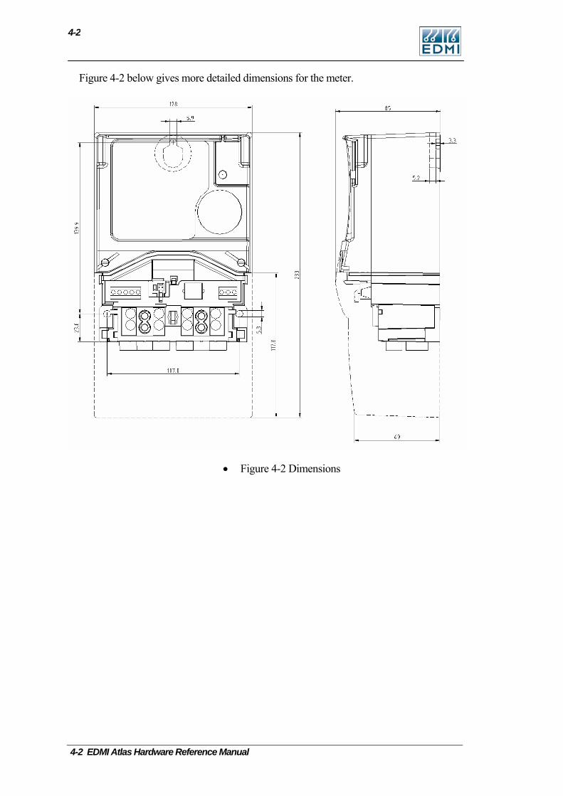
4-2
Figure 4-2 below gives more detailed dimensions for the meter.
• Figure 4-2 Dimensions
4-2 EDMI Atlas Hardware Reference Manual
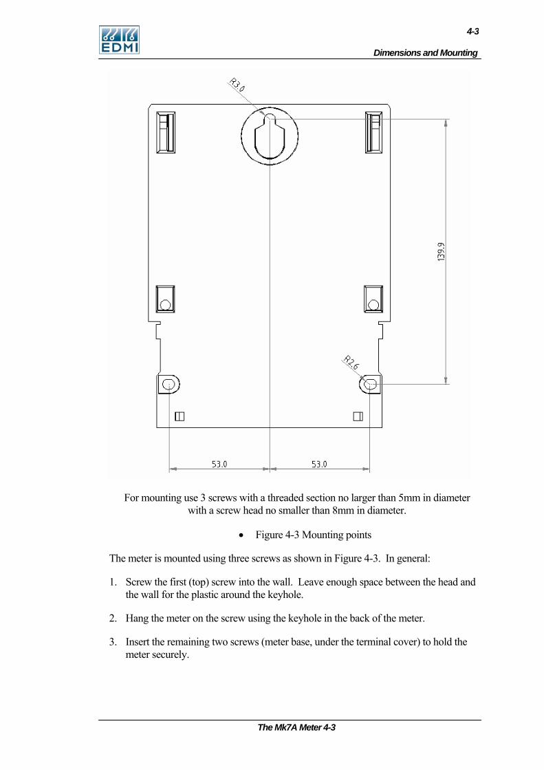
Dimensions and Mounting
4-3
For mounting use 3 screws with a threaded section no larger than 5mm in diameter with a screw head no smaller than 8mm in diameter.
• Figure 4-3 Mounting points
The meter is mounted using three screws as shown in Figure 4-3. In general:
1. Screw the first (top) screw into the wall. Leave enough space between the head and the wall for the plastic around the keyhole.
2. Hang the meter on the screw using the keyhole in the back of the meter.
3. Insert the remaining two screws (meter base, under the terminal cover) to hold the meter securely.
The Mk7A Meter 4-3
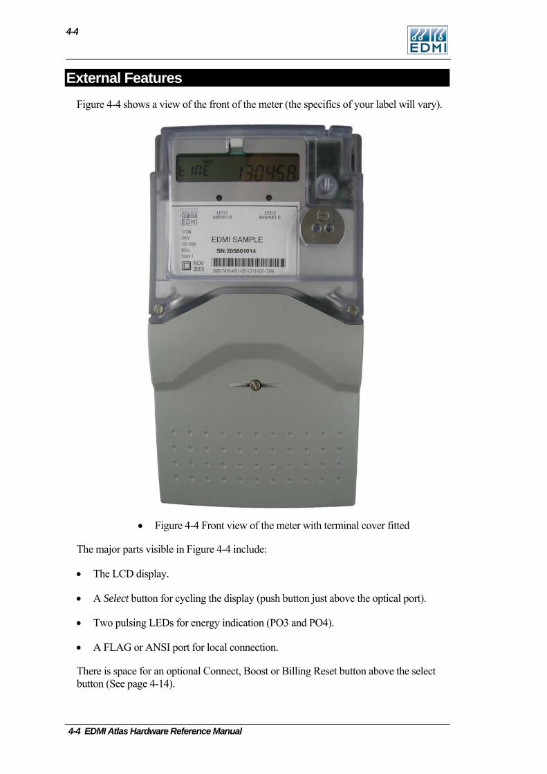
4-4
External Features Figure 4-4 shows a view of the front of the meter (the specifics of your label will vary).
• Figure 4-4 Front view of the meter with terminal cover fitted
The major parts visible in Figure 4-4 include:
• The LCD display.
• A Select button for cycling the display (push button just above the optical port).
• Two pulsing LEDs for energy indication (PO3 and PO4).
• A FLAG or ANSI port for local connection.
There is space for an optional Connect, Boost or Billing Reset button above the select button (See page 4-14).
4-4 EDMI Atlas Hardware Reference Manual
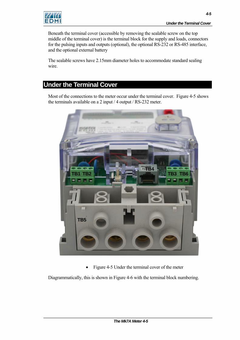
Under the Terminal Cover
4-5
Beneath the terminal cover (accessible by removing the sealable screw on the top middle of the terminal cover) is the terminal block for the supply and loads, connectors for the pulsing inputs and outputs (optional), the optional RS-232 or RS-485 interface, and the optional external battery
The sealable screws have 2.15mm diameter holes to accommodate standard sealing wire.
Under the Terminal Cover Most of the connections to the meter occur under the terminal cover. Figure 4-5 shows the terminals available on a 2 input / 4 output / RS-232 meter.
TB4 TB1 TB2 TB3 TB6
TB5
• Figure 4-5 Under the terminal cover of the meter
Diagrammatically, this is shown in Figure 4-6 with the terminal block numbering.
The Mk7A Meter 4-5
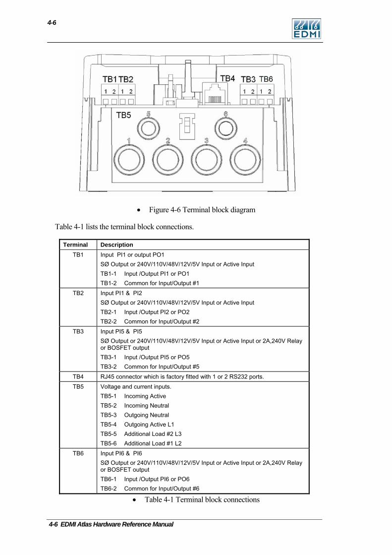
4-6
• Figure 4-6 Terminal block diagram
Table 4-1 lists the terminal block connections.
Terminal Description TB1 Input PI1 or output PO1
SØ Output or 240V/110V/48V/12V/5V Input or Active Input TB1-1 Input /Output PI1 or PO1 TB1-2 Common for Input/Output #1
TB2 Input PI1 & PI2 SØ Output or 240V/110V/48V/12V/5V Input or Active Input TB2-1 Input /Output PI2 or PO2 TB2-2 Common for Input/Output #2
TB3 Input PI5 & PI5 SØ Output or 240V/110V/48V/12V/5V Input or Active Input or 2A,240V Relay or BOSFET output TB3-1 Input /Output PI5 or PO5 TB3-2 Common for Input/Output #5
TB4 RJ45 connector which is factory fitted with 1 or 2 RS232 ports.
TB5 Voltage and current inputs. TB5-1 Incoming Active TB5-2 Incoming Neutral TB5-3 Outgoing Neutral TB5-4 Outgoing Active L1 TB5-5 Additional Load #2 L3 TB5-6 Additional Load #1 L2
TB6 Input PI6 & PI6 SØ Output or 240V/110V/48V/12V/5V Input or Active Input or 2A,240V Relay or BOSFET output TB6-1 Input /Output PI6 or PO6 TB6-2 Common for Input/Output #6
• Table 4-1 Terminal block connections
4-6 EDMI Atlas Hardware Reference Manual
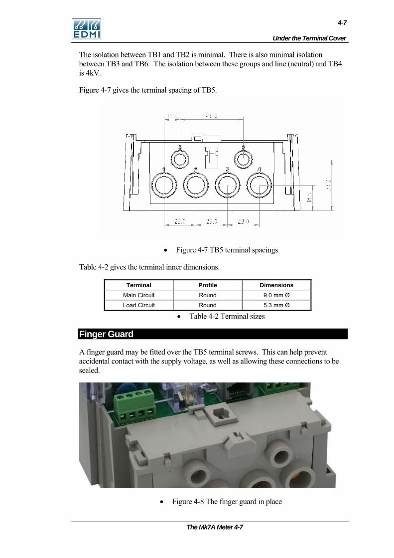
Under the Terminal Cover
4-7
The isolation between TB1 and TB2 is minimal. There is also minimal isolation between TB3 and TB6. The isolation between these groups and line (neutral) and TB4 is 4kV.
Figure 4-7 gives the terminal spacing of TB5.
• Figure 4-7 TB5 terminal spacings
Table 4-2 gives the terminal inner dimensions.
Terminal Profile Dimensions Main Circuit Round 9.0 mm Ø
Load Circuit Round 5.3 mm Ø
• Table 4-2 Terminal sizes
Finger Guard
A finger guard may be fitted over the TB5 terminal screws. This can help prevent accidental contact with the supply voltage, as well as allowing these connections to be sealed.
• Figure 4-8 The finger guard in place
The Mk7A Meter 4-7

4-8
Terminal Cover Tamper Detect
The meter has an optional switch that can detect the opening of the terminal cover. It is located above and to the left of the terminals (See Figure 4-9). The meter can generate an EFA alarm and an event in the log when the switch is released by someone opening the terminal cover. Alternatively it may be fitted to sense when the meter lid is opened, rather than the terminal cover.
• Figure 4-9 The terminal cover tamper detect switch
Under the Meter Lid Removing the two sealable screws allows the meter lid to be removed. Generally connections to the I/O connectors do not need to be detached to allow the cover to be removed. Removal of the meter lid is required to access the Config Jumper.
Care must be taken as dangerous voltages are present in the circuitry under the meter lid while the meter is active. Even when the meter is not powered, care should be taken to prevent electrostatic damage to the circuitry of the meter.
CT to VT Links
The meter does not have removable CT to VT links. If testing the meter on a test bench, the test bench must be able to properly handle the permanent VT to CT connection.
Config Jumper
The Config jumper offers a level of hardware security to the meter – the jumper needs to be fitted to allow calibration and recovery of lost passwords. The jumper is located under the meter lid, half way up the far right side of the circuit board (Figure 4-10). A jumper is fitted across the bottom set of pins marked JP1 Config. The top set of pins marked JP2 FTest are for factory use only.
4-8 EDMI Atlas Hardware Reference Manual

Connections in Detail
4-9
The Mk7A Meter 4-9
• Figure 4-10 Location of the Config jumper
Connections in Detail
Current and Voltage
Ia
1
TB5
In L1
432
L2
5 6
L3
• Figure 4-11 TB5 Connections including a switched/metered load
Figure 2-18 shows the connection method with an extra load circuit L2. The nominal voltage input range is 220 - 240 VAC. The limit range of operation is 176VAC to 288VAC. The current range depends on the current range of the meter, and should be limited to Imax. The Load terminals TB5-5 and TB5-6 are limited to 60A. Note that there is no IEC standard for a 60A load control relay, so for type test approval 40A is stated.
There are a number of variations for the internal configuration of the meter, including internal contactors. Table 4-3 illustrates the options. In all cases Ia is the incoming current, and should be limited to 100A. In is the neutral connection, and should be limited to 100A.
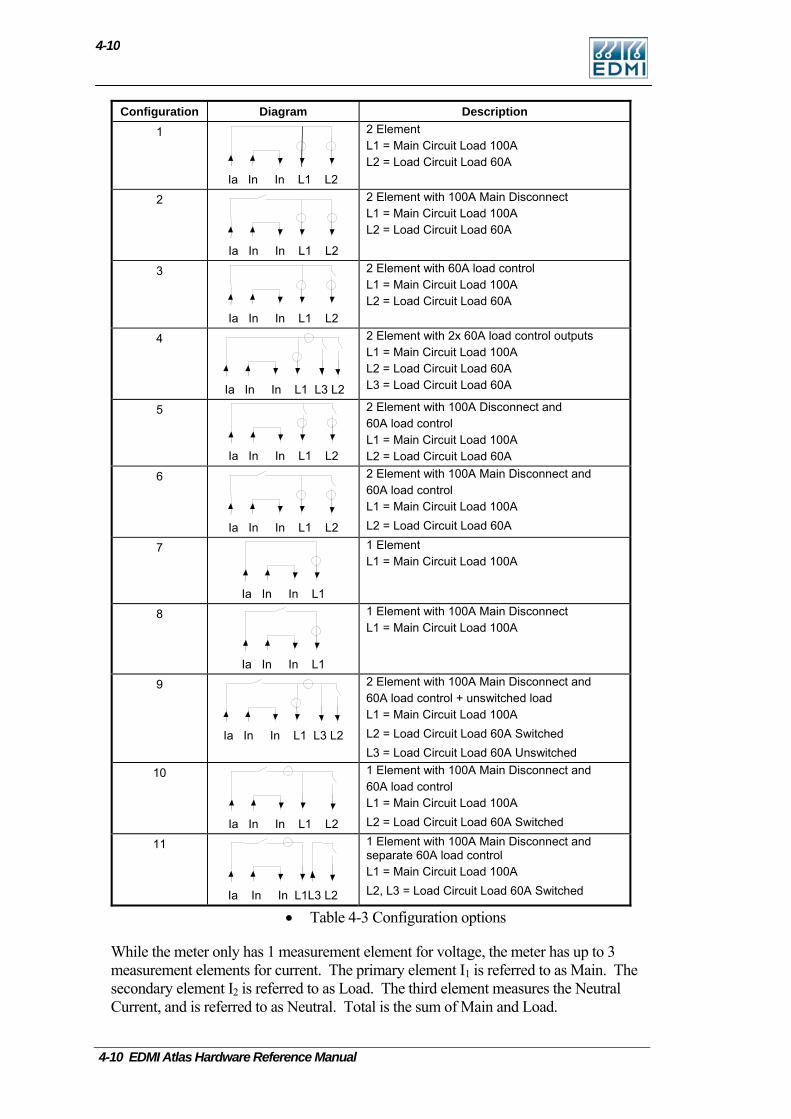
4-10
Configuration Diagram Description 1
Ia In In L1 L2
2 Element L1 = Main Circuit Load 100A L2 = Load Circuit Load 60A
2
Ia In In L1 L2
2 Element with 100A Main Disconnect L1 = Main Circuit Load 100A L2 = Load Circuit Load 60A
3
Ia In In L1 L2
2 Element with 60A load control L1 = Main Circuit Load 100A L2 = Load Circuit Load 60A
4
Ia In In L1 L3 L2
2 Element with 2x 60A load control outputs L1 = Main Circuit Load 100A L2 = Load Circuit Load 60A L3 = Load Circuit Load 60A
5
Ia In In L1 L2
2 Element with 100A Disconnect and 60A load control L1 = Main Circuit Load 100A L2 = Load Circuit Load 60A
6
Ia In In L1 L2
2 Element with 100A Main Disconnect and 60A load control L1 = Main Circuit Load 100A L2 = Load Circuit Load 60A
7
Ia In In L1
1 Element L1 = Main Circuit Load 100A
8
Ia In In L1
1 Element with 100A Main Disconnect L1 = Main Circuit Load 100A
9
Ia In In L1 L3 L2
2 Element with 100A Main Disconnect and 60A load control + unswitched load L1 = Main Circuit Load 100A L2 = Load Circuit Load 60A Switched L3 = Load Circuit Load 60A Unswitched
10
Ia In In L1 L2
1 Element with 100A Main Disconnect and 60A load control L1 = Main Circuit Load 100A L2 = Load Circuit Load 60A Switched
11
Ia In In L1L3 L2
1 Element with 100A Main Disconnect and separate 60A load control L1 = Main Circuit Load 100A L2, L3 = Load Circuit Load 60A Switched
• Table 4-3 Configuration options
While the meter only has 1 measurement element for voltage, the meter has up to 3 measurement elements for current. The primary element I1 is referred to as Main. The secondary element I2 is referred to as Load. The third element measures the Neutral Current, and is referred to as Neutral. Total is the sum of Main and Load.
4-10 EDMI Atlas Hardware Reference Manual
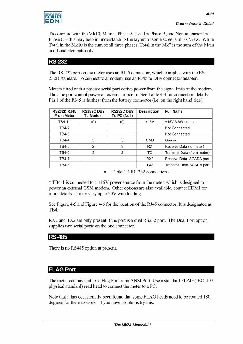
Connections in Detail
4-11
To compare with the Mk10, Main is Phase A, Load is Phase B, and Neutral current is Phase C – this may help in understanding the layout of some screens in EziView. While Total in the Mk10 is the sum of all three phases, Total in the Mk7 is the sum of the Main and Load elements only.
RS-232
The RS-232 port on the meter uses an RJ45 connector, which complies with the RS-232D standard. To connect to a modem, use an RJ45 to DB9 connector adapter.
Meters fitted with a passive serial port derive power from the signal lines of the modem. Thus the port cannot power an external modem. See Table 4-4 for connection details. Pin 1 of the RJ45 is furthest from the battery connector (i.e. on the right hand side).
RS232D RJ45 From Meter
RS232C DB9 To Modem
RS232C DB9 To PC (Null)
Description Full Name
TB4-1 * (9) (9) +15V +15V,3.6W output
TB4-2 Not Connected
TB4-3 Not Connected
TB4-4 5 5 GND Ground
TB4-5 2 3 RX Receive Data (to meter)
TB4-6 3 2 TX Transmit Data (from meter)
TB4-7 RX2 Receive Data–SCADA port
TB4-8 TX2 Transmit Data-SCADA port
• Table 4-4 RS-232 connections
* TB4-1 is connected to a +15V power source from the meter, which is designed to power an external GSM modem. Other options are also available, contact EDMI for more details. It may vary up to 20V with loading.
See Figure 4-5 and Figure 4-6 for the location of the RJ45 connector. It is designated as TB4.
RX2 and TX2 are only present if the port is a dual RS232 port. The Dual Port option supplies two serial ports on the one connector.
RS-485
There is no RS485 option at present.
FLAG Port
The meter can have either a Flag Port or an ANSI Port. Use a standard FLAG (IEC1107 physical standard) read head to connect the meter to a PC.
Note that it has occasionally been found that some FLAG heads need to be rotated 180 degrees for them to work. If you have problems try this.
The Mk7A Meter 4-11
4-12
ANSI Port
The meter can have either Flag Port of ANSI Port. Standard Flag and ANSI read heads should work with the meter. Please note that older EDMI ANSI read heads will not work with the meter. For smart read heads that can automatically switch polarity, set the DTR line to be low – see Configure in the Site Properties section of the EziView Basics chapter in the Atlas Software Reference Manual.
Inputs
The inputs may either be active, or passive. Passive inputs are isolated from all other circuits to 4kV, including the other inputs. The exception is the isolation to the adjacent I/O terminal which is minimal. There are a variety of input voltages that may be ordered with the meter, e.g. 12V and 240V. Under voltage will cause the input to trigger erratically or not at all, while over voltage will cause excessive heat dissipation and possible damage to the meter.
The rated voltage is the voltage that must be applied between the two terminals of the input. The inputs work with any polarity, and with AC or DC signals. There are a maximum of 4 inputs.
Active inputs are also available as a factory option. They use power from the serial port, and are thus not isolated from the serial port, or from each other. In this case simply shorting between the input terminals will cause the input to trigger. The maximum external impedance is 500 ohms. Note that power is drawn from the isolated serial port supply, but the inputs will still work while the serial port is powered down to cycle power to a modem.
Outputs
There are several types of outputs available. All outputs are isolated from all other circuits to 4kV, including other I/O. The exception is the isolation to the adjacent I/O terminal which is minimal.
The SØ outputs are designed to switch up to 24VDC and 24mA.
The relay outputs are rated to 2A, 240VAC with an inductive load. These outputs should not be used as pulsing outputs for transmitting energy pulses, as the output contacts are subject to contact bounce and are not rated for continuous switching.
The BOSFET outputs are rated up to 240V, 100mA. They may switch either AC or DC voltages, any polarity.
Battery
The battery is used to run the clock during loss of power. It also allows the meter LCD to be activated while main power is not available.
The meter comes with an optional internal or external battery. The external battery is a 3.0V, 700mAh Lithium battery. If a 3.6V external battery is used it will discharge
4-12 EDMI Atlas Hardware Reference Manual
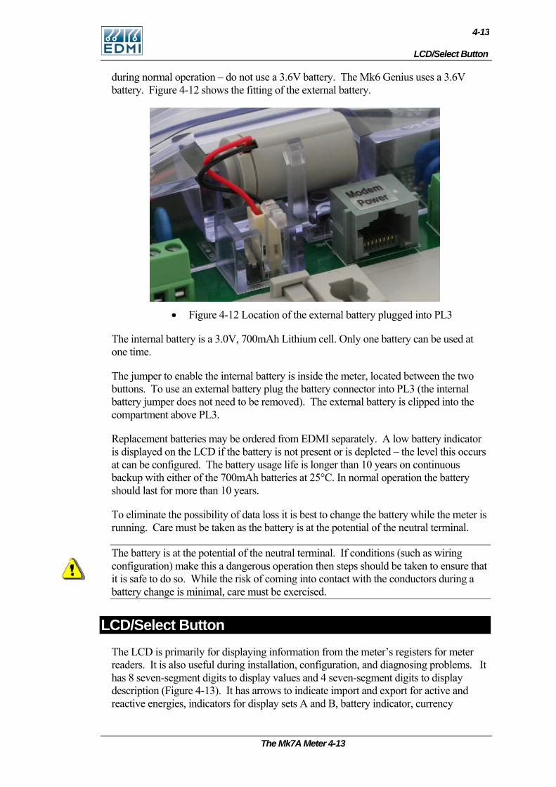
LCD/Select Button
4-13
during normal operation – do not use a 3.6V battery. The Mk6 Genius uses a 3.6V battery. Figure 4-12 shows the fitting of the external battery.
• Figure 4-12 Location of the external battery plugged into PL3
The internal battery is a 3.0V, 700mAh Lithium cell. Only one battery can be used at one time.
The jumper to enable the internal battery is inside the meter, located between the two buttons. To use an external battery plug the battery connector into PL3 (the internal battery jumper does not need to be removed). The external battery is clipped into the compartment above PL3.
Replacement batteries may be ordered from EDMI separately. A low battery indicator is displayed on the LCD if the battery is not present or is depleted – the level this occurs at can be configured. The battery usage life is longer than 10 years on continuous backup with either of the 700mAh batteries at 25°C. In normal operation the battery should last for more than 10 years.
To eliminate the possibility of data loss it is best to change the battery while the meter is running. Care must be taken as the battery is at the potential of the neutral terminal.
The battery is at the potential of the neutral terminal. If conditions (such as wiring configuration) make this a dangerous operation then steps should be taken to ensure that it is safe to do so. While the risk of coming into contact with the conductors during a battery change is minimal, care must be exercised.
LCD/Select Button The LCD is primarily for displaying information from the meter’s registers for meter readers. It is also useful during installation, configuration, and diagnosing problems. It has 8 seven-segment digits to display values and 4 seven-segment digits to display description (Figure 4-13). It has arrows to indicate import and export for active and reactive energies, indicators for display sets A and B, battery indicator, currency
The Mk7A Meter 4-13

4-14
indicator, connection type indicator for connection through local or remote port and units and multipliers. The LCD does not have a backlight
• Figure 4-13 LCD with all segments turned on
To progress to the next page, press the Select button. Each time the button is pressed the display moves to the next page. The display may also be setup to automatically cycle the display through the pages, pausing if the Select button is pressed.
For more detailed information on the LCD and Select button see Chapter 7: “LCD Display”.
Reconnect/Boost or Billing Reset Button An optional Reconnect, Boost, or Billing Reset button may be fitted above the select button (See Figure 4-14). The push button has a 2.5mm diameter hole through it, allowing it to be sealed using standard sealing wire.
• Figure 4-14 Location of the Billing Reset / Boost button
When used as a Reconnect button, holding the button down for at least half a second will connect the customers supply, if it is enabled for connection. The display will show “Connect”. If it is not enabled, the display will show “not enabled” and the contactor state will not change.
Pushing both the Select button and the Reconnect button at the same time will cause the contactor to be disconnected. The message “Disconnect” will be displayed on the LCD.
The Reconnect button can also cause a boost operation for load control outputs, depending on configuration.
4-14 EDMI Atlas Hardware Reference Manual

Servicing
4-15
Note that the relay may not change state immediately. If another operation has just been performed, it may take 60 seconds to perform the requested operation.
EziView can configure what operations are permitted using the button. EziView can also be used to configure the button as a billing reset button - go to Security Setup and un-check the Billing Reset Button Disabled checkbox.
Servicing The meter is not designed for field servicing and has no user serviceable parts. The meter has no internal fuses. In the event of failure of the meter, contact EDMI or your local agent for servicing.
The Mk7A Meter 4-15

4-16
Intentionally Left Blank
4-16 EDMI Atlas Hardware Reference Manual

The Mk7C Meter 5-1
C h a p t e r
5
Chapter 5 The Mk7C Meter This chapter covers the basic installation and physical features of the Mk7C meter.
Dimensions and Mounting Figure 5-1 shows the overall dimensions of the meter with a standard terminal cover.
Depth
Width
Height
• Figure 5-1 Overall dimensions of the meter
Height = 163.5 mm, Depth = 51 mm, Width = 134 mm
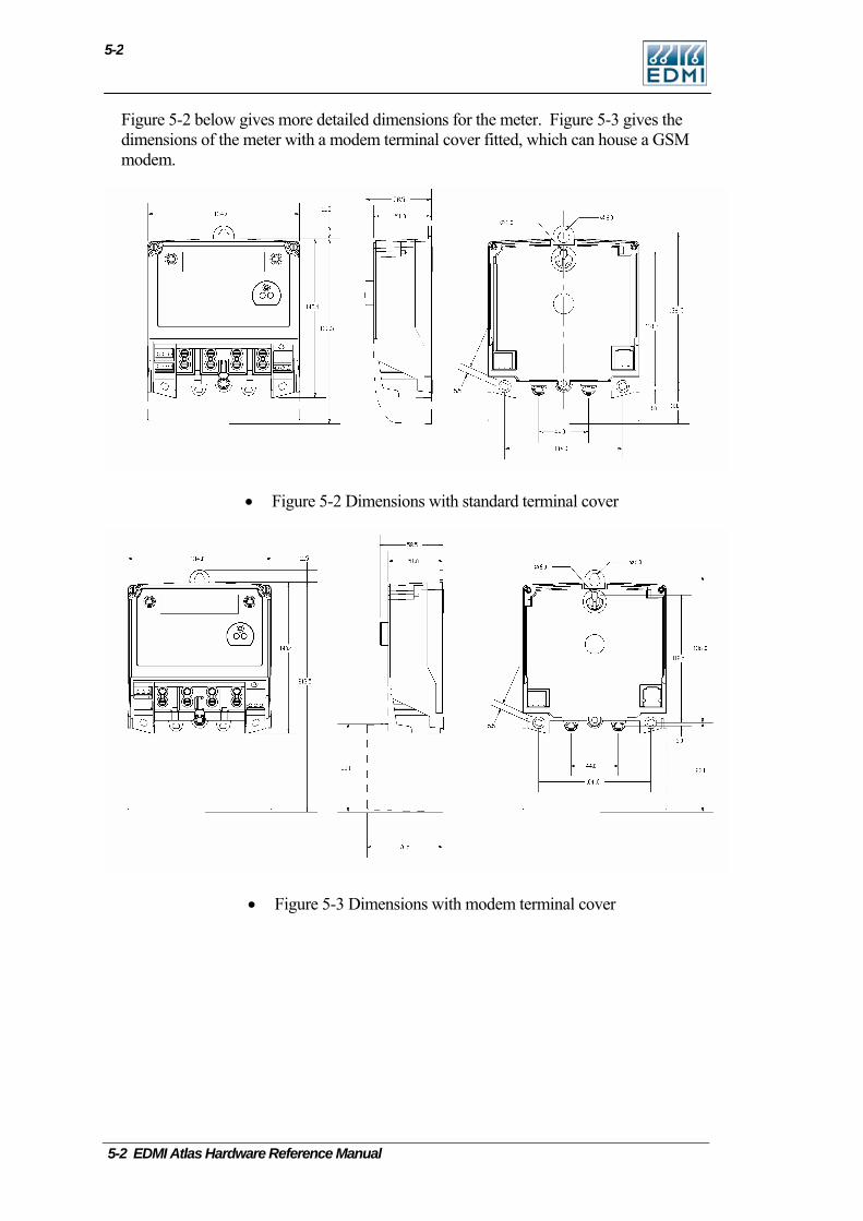
5-2 EDMI Atlas Hardware Reference Manual
5-2
Figure 5-2 below gives more detailed dimensions for the meter. Figure 5-3 gives the dimensions of the meter with a modem terminal cover fitted, which can house a GSM modem.
• Figure 5-2 Dimensions with standard terminal cover
• Figure 5-3 Dimensions with modem terminal cover
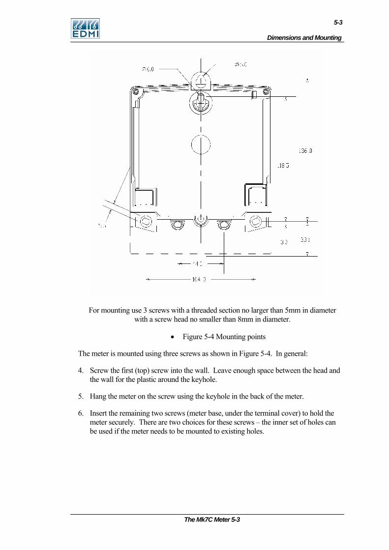
Dimensions and Mounting
5-3
For mounting use 3 screws with a threaded section no larger than 5mm in diameter with a screw head no smaller than 8mm in diameter.
• Figure 5-4 Mounting points
The meter is mounted using three screws as shown in Figure 5-4. In general:
4. Screw the first (top) screw into the wall. Leave enough space between the head and the wall for the plastic around the keyhole.
5. Hang the meter on the screw using the keyhole in the back of the meter.
6. Insert the remaining two screws (meter base, under the terminal cover) to hold the meter securely. There are two choices for these screws – the inner set of holes can be used if the meter needs to be mounted to existing holes.
The Mk7C Meter 5-3
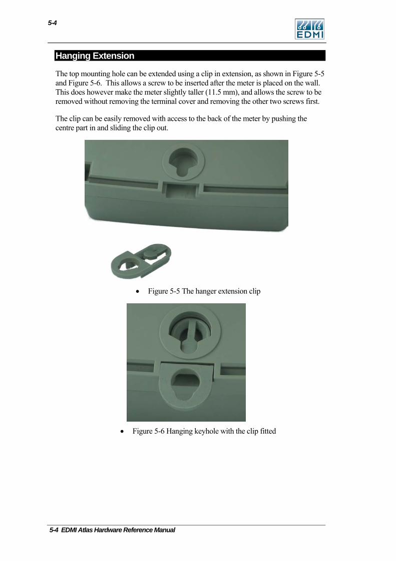
5-4
Hanging Extension
The top mounting hole can be extended using a clip in extension, as shown in Figure 5-5 and Figure 5-6. This allows a screw to be inserted after the meter is placed on the wall. This does however make the meter slightly taller (11.5 mm), and allows the screw to be removed without removing the terminal cover and removing the other two screws first.
The clip can be easily removed with access to the back of the meter by pushing the centre part in and sliding the clip out.
• Figure 5-5 The hanger extension clip
• Figure 5-6 Hanging keyhole with the clip fitted
5-4 EDMI Atlas Hardware Reference Manual
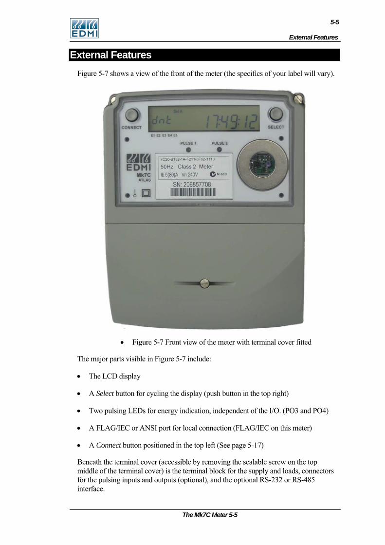
External Features
5-5
External Features Figure 5-7 shows a view of the front of the meter (the specifics of your label will vary).
• Figure 5-7 Front view of the meter with terminal cover fitted
The major parts visible in Figure 5-7 include:
• The LCD display
• A Select button for cycling the display (push button in the top right)
• Two pulsing LEDs for energy indication, independent of the I/O. (PO3 and PO4)
• A FLAG/IEC or ANSI port for local connection (FLAG/IEC on this meter)
• A Connect button positioned in the top left (See page 5-17)
Beneath the terminal cover (accessible by removing the sealable screw on the top middle of the terminal cover) is the terminal block for the supply and loads, connectors for the pulsing inputs and outputs (optional), and the optional RS-232 or RS-485 interface.
The Mk7C Meter 5-5
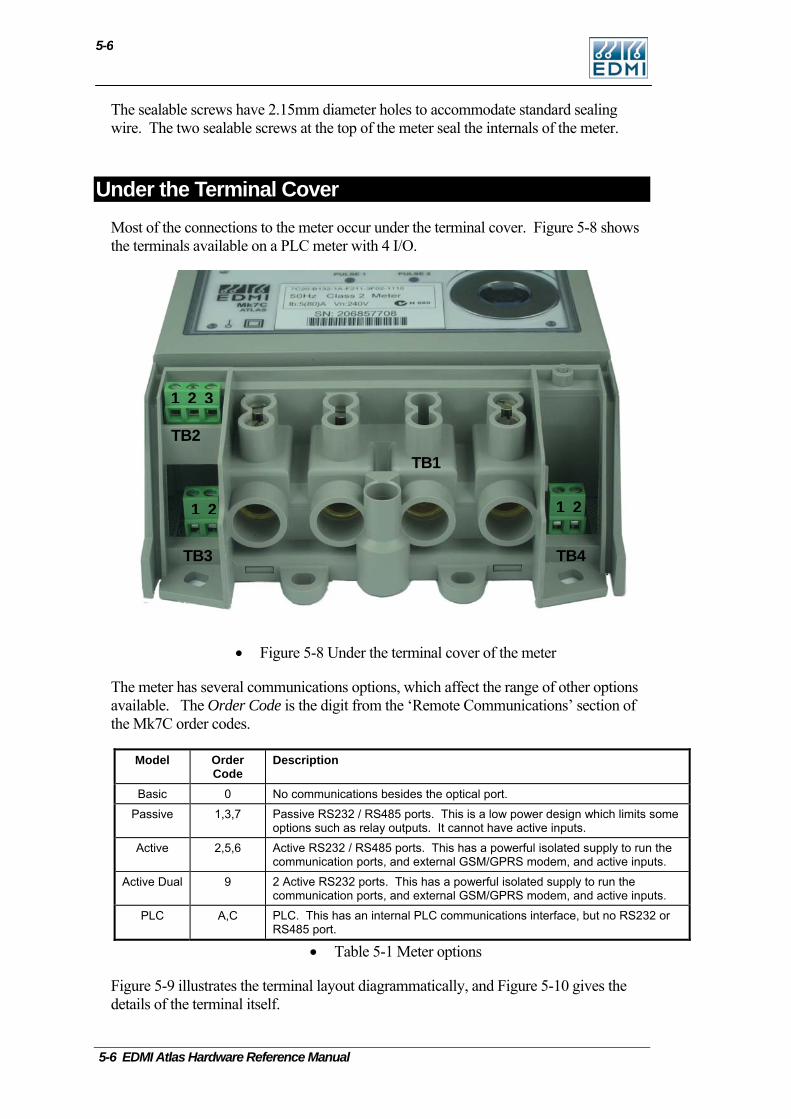
5-6
The sealable screws have 2.15mm diameter holes to accommodate standard sealing wire. The two sealable screws at the top of the meter seal the internals of the meter.
Under the Terminal Cover Most of the connections to the meter occur under the terminal cover. Figure 5-8 shows the terminals available on a PLC meter with 4 I/O.
1 21 2
1 2 3
TB3 TB4
TB2 TB1
• Figure 5-8 Under the terminal cover of the meter
The meter has several communications options, which affect the range of other options available. The Order Code is the digit from the ‘Remote Communications’ section of the Mk7C order codes.
Model Order Code
Description
Basic 0 No communications besides the optical port.
Passive 1,3,7 Passive RS232 / RS485 ports. This is a low power design which limits some options such as relay outputs. It cannot have active inputs.
Active 2,5,6 Active RS232 / RS485 ports. This has a powerful isolated supply to run the communication ports, and external GSM/GPRS modem, and active inputs.
Active Dual 9 2 Active RS232 ports. This has a powerful isolated supply to run the communication ports, and external GSM/GPRS modem, and active inputs.
PLC A,C PLC. This has an internal PLC communications interface, but no RS232 or RS485 port.
• Table 5-1 Meter options
Figure 5-9 illustrates the terminal layout diagrammatically, and Figure 5-10 gives the details of the terminal itself.
5-6 EDMI Atlas Hardware Reference Manual
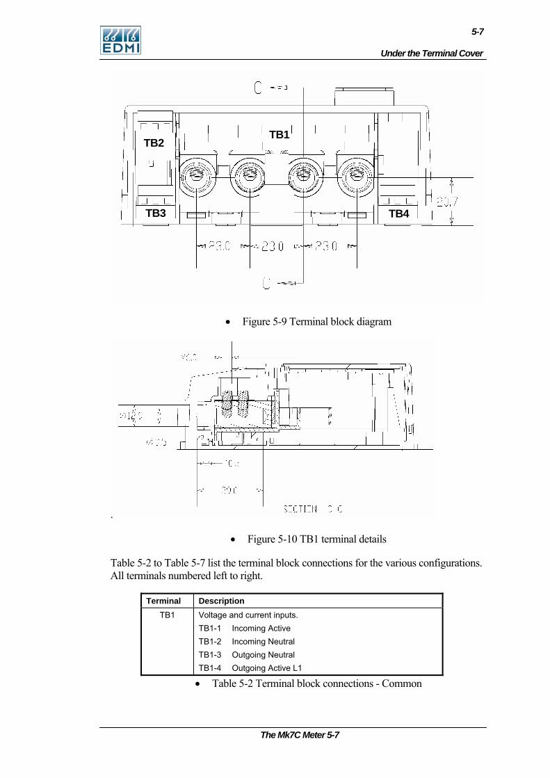
Under the Terminal Cover
5-7
• Figure 5-9 Terminal block diagram
.
TB4 TB3
TB2 TB1
• Figure 5-10 TB1 terminal details
Table 5-2 to Table 5-7 list the terminal block connections for the various configurations. All terminals numbered left to right.
Terminal Description TB1 Voltage and current inputs.
TB1-1 Incoming Active TB1-2 Incoming Neutral TB1-3 Outgoing Neutral TB1-4 Outgoing Active L1
• Table 5-2 Terminal block connections - Common
The Mk7C Meter 5-7
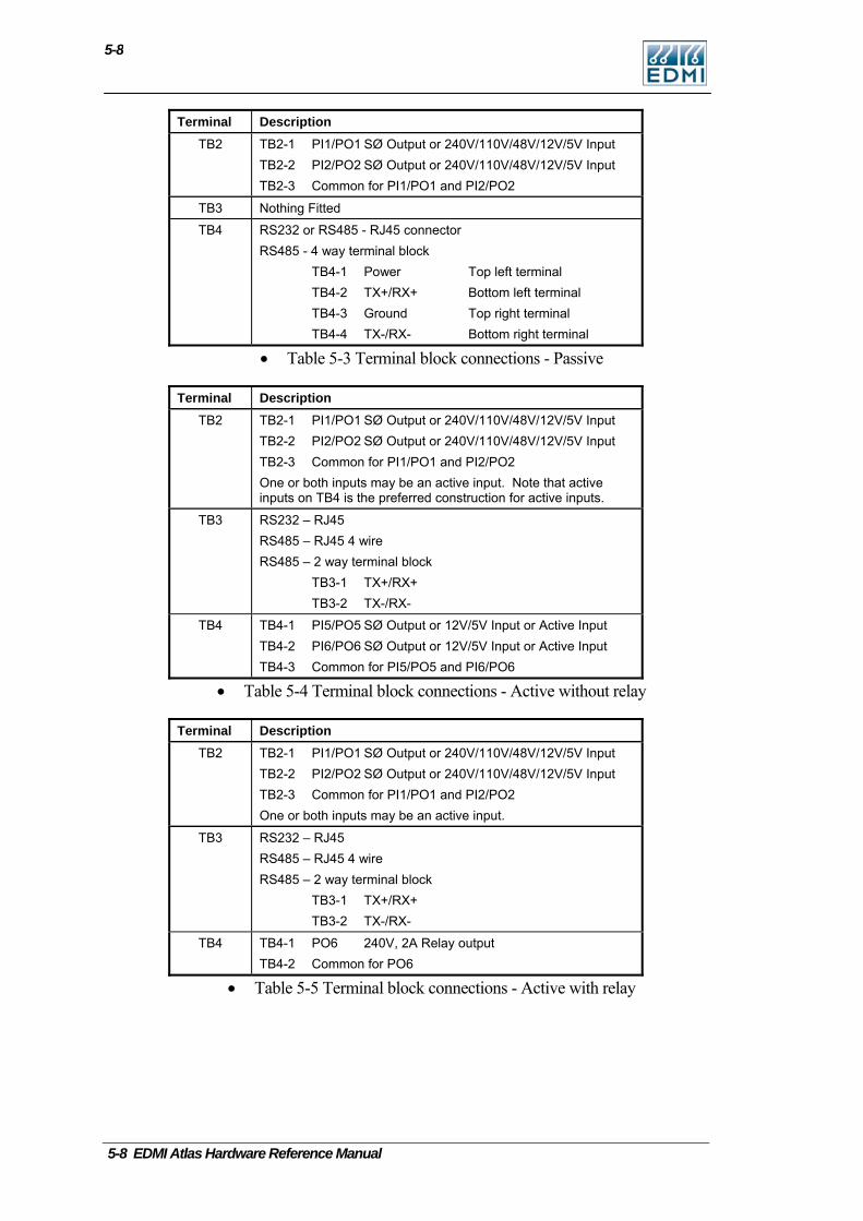
5-8
Terminal Description TB2 TB2-1 PI1/PO1 SØ Output or 240V/110V/48V/12V/5V Input
TB2-2 PI2/PO2 SØ Output or 240V/110V/48V/12V/5V Input TB2-3 Common for PI1/PO1 and PI2/PO2
TB3 Nothing Fitted
TB4 RS232 or RS485 - RJ45 connector RS485 - 4 way terminal block
TB4-1 Power Top left terminal TB4-2 TX+/RX+ Bottom left terminal TB4-3 Ground Top right terminal TB4-4 TX-/RX- Bottom right terminal
• Table 5-3 Terminal block connections - Passive
Terminal Description TB2 TB2-1 PI1/PO1 SØ Output or 240V/110V/48V/12V/5V Input
TB2-2 PI2/PO2 SØ Output or 240V/110V/48V/12V/5V Input TB2-3 Common for PI1/PO1 and PI2/PO2 One or both inputs may be an active input. Note that active inputs on TB4 is the preferred construction for active inputs.
TB3 RS232 – RJ45 RS485 – RJ45 4 wire RS485 – 2 way terminal block
TB3-1 TX+/RX+ TB3-2 TX-/RX-
TB4 TB4-1 PI5/PO5 SØ Output or 12V/5V Input or Active Input TB4-2 PI6/PO6 SØ Output or 12V/5V Input or Active Input TB4-3 Common for PI5/PO5 and PI6/PO6
• Table 5-4 Terminal block connections - Active without relay
Terminal Description TB2 TB2-1 PI1/PO1 SØ Output or 240V/110V/48V/12V/5V Input
TB2-2 PI2/PO2 SØ Output or 240V/110V/48V/12V/5V Input TB2-3 Common for PI1/PO1 and PI2/PO2 One or both inputs may be an active input.
TB3 RS232 – RJ45 RS485 – RJ45 4 wire RS485 – 2 way terminal block
TB3-1 TX+/RX+ TB3-2 TX-/RX-
TB4 TB4-1 PO6 240V, 2A Relay output TB4-2 Common for PO6
• Table 5-5 Terminal block connections - Active with relay
5-8 EDMI Atlas Hardware Reference Manual
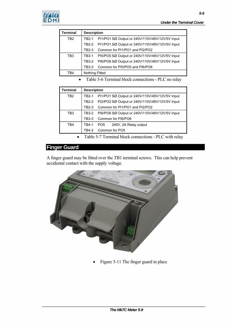
Under the Terminal Cover
5-9
Terminal Description TB2 TB2-1 PI1/PO1 SØ Output or 240V/110V/48V/12V/5V Input
TB2-2 PI1/PO1 SØ Output or 240V/110V/48V/12V/5V Input TB2-3 Common for PI1/PO1 and PI2/PO2
TB3 TB3-1 PI5/PO5 SØ Output or 240V/110V/48V/12V/5V Input TB3-2 PI6/PO6 SØ Output or 240V/110V/48V/12V/5V Input TB3-3 Common for PI5/PO5 and PI6/PO6
TB4 Nothing Fitted
• Table 5-6 Terminal block connections - PLC no relay
Terminal Description TB2 TB2-1 PI1/PO1 SØ Output or 240V/110V/48V/12V/5V Input
TB2-2 PI2/PO2 SØ Output or 240V/110V/48V/12V/5V Input TB2-3 Common for PI1/PO1 and PI2/PO2
TB3 TB3-2 PI6/PO6 SØ Output or 240V/110V/48V/12V/5V Input TB3-3 Common for PI6/PO6
TB4 TB4-1 PO5 240V, 2A Relay output TB4-2 Common for PO5
• Table 5-7 Terminal block connections - PLC with relay
Finger Guard
A finger guard may be fitted over the TB1 terminal screws. This can help prevent accidental contact with the supply voltage.
• Figure 5-11 The finger guard in place
The Mk7C Meter 5-9
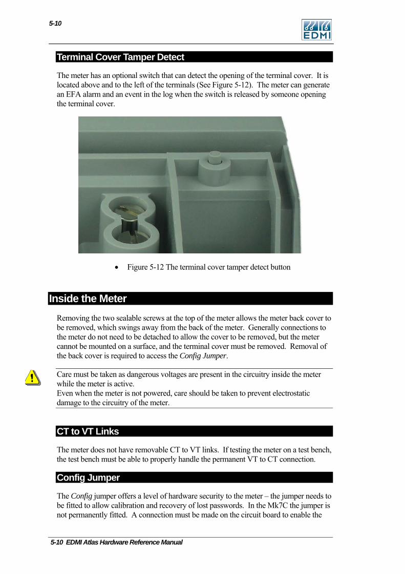
5-10
Terminal Cover Tamper Detect
The meter has an optional switch that can detect the opening of the terminal cover. It is located above and to the left of the terminals (See Figure 5-12). The meter can generate an EFA alarm and an event in the log when the switch is released by someone opening the terminal cover.
• Figure 5-12 The terminal cover tamper detect button
Inside the Meter Removing the two sealable screws at the top of the meter allows the meter back cover to be removed, which swings away from the back of the meter. Generally connections to the meter do not need to be detached to allow the cover to be removed, but the meter cannot be mounted on a surface, and the terminal cover must be removed. Removal of the back cover is required to access the Config Jumper.
Care must be taken as dangerous voltages are present in the circuitry inside the meter while the meter is active. Even when the meter is not powered, care should be taken to prevent electrostatic damage to the circuitry of the meter.
CT to VT Links
The meter does not have removable CT to VT links. If testing the meter on a test bench, the test bench must be able to properly handle the permanent VT to CT connection.
Config Jumper
The Config jumper offers a level of hardware security to the meter – the jumper needs to be fitted to allow calibration and recovery of lost passwords. In the Mk7C the jumper is not permanently fitted. A connection must be made on the circuit board to enable the
5-10 EDMI Atlas Hardware Reference Manual
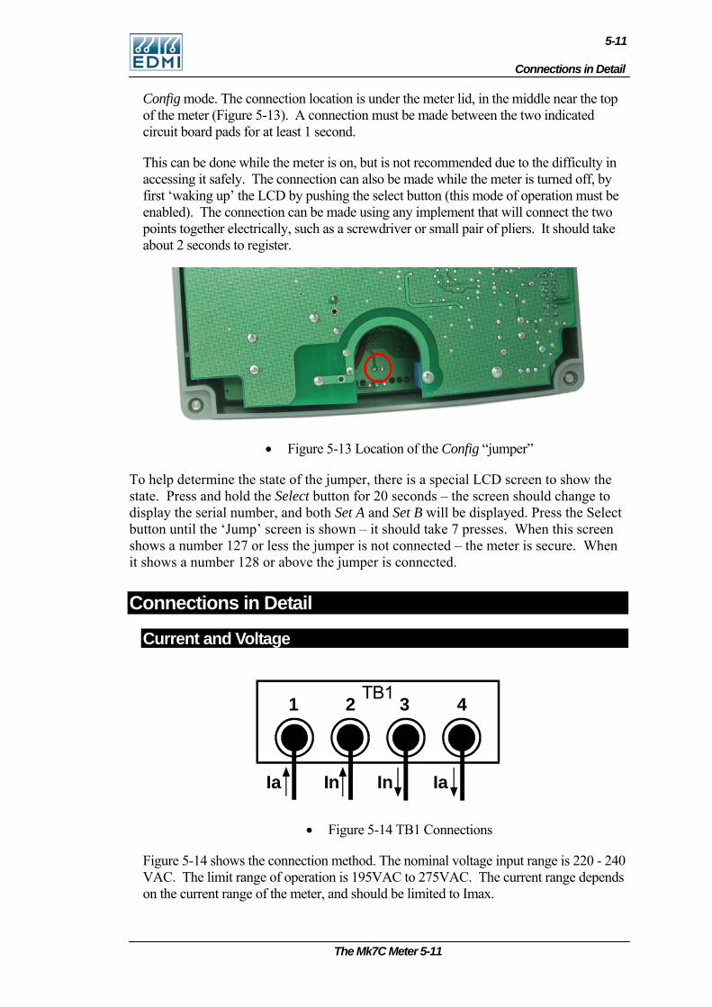
Connections in Detail
5-11
Config mode. The connection location is under the meter lid, in the middle near the top of the meter (Figure 5-13). A connection must be made between the two indicated circuit board pads for at least 1 second.
This can be done while the meter is on, but is not recommended due to the difficulty in accessing it safely. The connection can also be made while the meter is turned off, by first ‘waking up’ the LCD by pushing the select button (this mode of operation must be enabled). The connection can be made using any implement that will connect the two points together electrically, such as a screwdriver or small pair of pliers. It should take about 2 seconds to register.
• Figure 5-13 Location of the Config “jumper”
To help determine the state of the jumper, there is a special LCD screen to show the state. Press and hold the Select button for 20 seconds – the screen should change to display the serial number, and both Set A and Set B will be displayed. Press the Select button until the ‘Jump’ screen is shown – it should take 7 presses. When this screen shows a number 127 or less the jumper is not connected – the meter is secure. When it shows a number 128 or above the jumper is connected.
Connections in Detail
Current and Voltage
1 TB1
I a In
432
IaIn
• Figure 5-14 TB1 Connections
Figure 5-14 shows the connection method. The nominal voltage input range is 220 - 240 VAC. The limit range of operation is 195VAC to 275VAC. The current range depends on the current range of the meter, and should be limited to Imax.
The Mk7C Meter 5-11
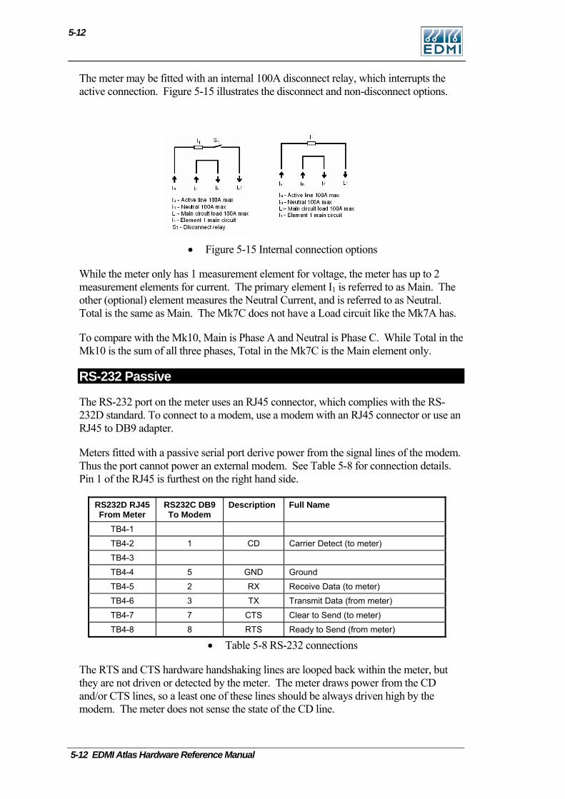
5-12
The meter may be fitted with an internal 100A disconnect relay, which interrupts the active connection. Figure 5-15 illustrates the disconnect and non-disconnect options.
• Figure 5-15 Internal connection options
While the meter only has 1 measurement element for voltage, the meter has up to 2 measurement elements for current. The primary element I1 is referred to as Main. The other (optional) element measures the Neutral Current, and is referred to as Neutral. Total is the same as Main. The Mk7C does not have a Load circuit like the Mk7A has.
To compare with the Mk10, Main is Phase A and Neutral is Phase C. While Total in the Mk10 is the sum of all three phases, Total in the Mk7C is the Main element only.
RS-232 Passive
The RS-232 port on the meter uses an RJ45 connector, which complies with the RS-232D standard. To connect to a modem, use a modem with an RJ45 connector or use an RJ45 to DB9 adapter.
Meters fitted with a passive serial port derive power from the signal lines of the modem. Thus the port cannot power an external modem. See Table 5-8 for connection details. Pin 1 of the RJ45 is furthest on the right hand side.
RS232D RJ45 From Meter
RS232C DB9 To Modem
Description Full Name
TB4-1
TB4-2 1 CD Carrier Detect (to meter)
TB4-3
TB4-4 5 GND Ground
TB4-5 2 RX Receive Data (to meter)
TB4-6 3 TX Transmit Data (from meter)
TB4-7 7 CTS Clear to Send (to meter)
TB4-8 8 RTS Ready to Send (from meter)
• Table 5-8 RS-232 connections
The RTS and CTS hardware handshaking lines are looped back within the meter, but they are not driven or detected by the meter. The meter draws power from the CD and/or CTS lines, so a least one of these lines should be always driven high by the modem. The meter does not sense the state of the CD line.
5-12 EDMI Atlas Hardware Reference Manual
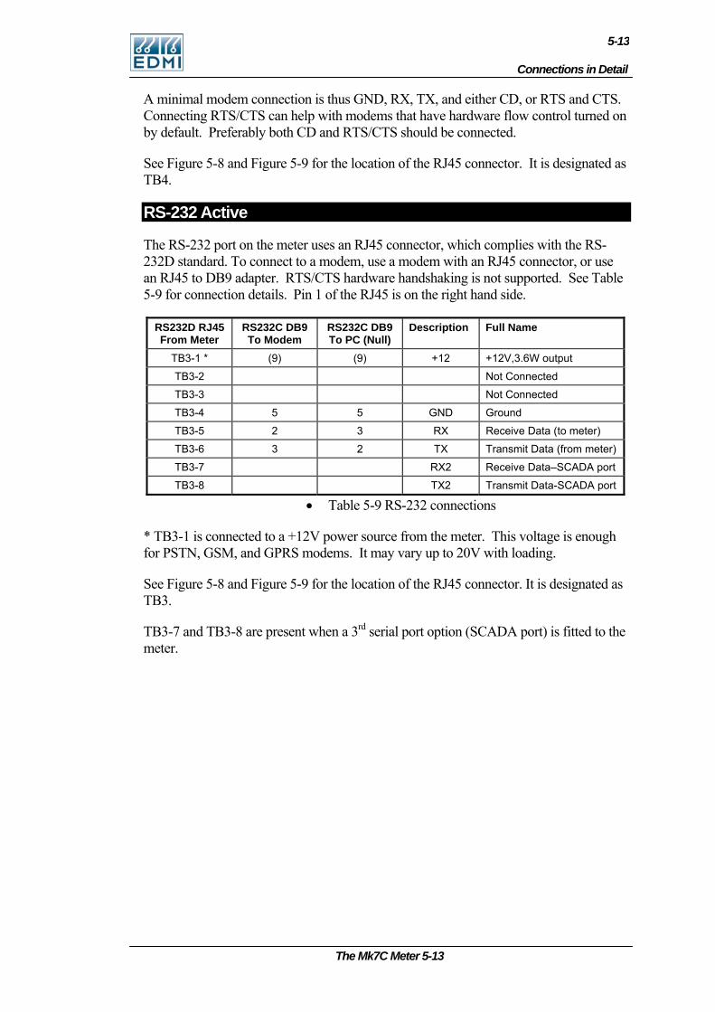
Connections in Detail
5-13
A minimal modem connection is thus GND, RX, TX, and either CD, or RTS and CTS. Connecting RTS/CTS can help with modems that have hardware flow control turned on by default. Preferably both CD and RTS/CTS should be connected.
See Figure 5-8 and Figure 5-9 for the location of the RJ45 connector. It is designated as TB4.
RS-232 Active
The RS-232 port on the meter uses an RJ45 connector, which complies with the RS-232D standard. To connect to a modem, use a modem with an RJ45 connector, or use an RJ45 to DB9 adapter. RTS/CTS hardware handshaking is not supported. See Table 5-9 for connection details. Pin 1 of the RJ45 is on the right hand side.
RS232D RJ45 From Meter
RS232C DB9 To Modem
RS232C DB9 To PC (Null)
Description Full Name
TB3-1 * (9) (9) +12 +12V,3.6W output
TB3-2 Not Connected
TB3-3 Not Connected
TB3-4 5 5 GND Ground
TB3-5 2 3 RX Receive Data (to meter)
TB3-6 3 2 TX Transmit Data (from meter)
TB3-7 RX2 Receive Data–SCADA port
TB3-8 TX2 Transmit Data-SCADA port
• Table 5-9 RS-232 connections
* TB3-1 is connected to a +12V power source from the meter. This voltage is enough for PSTN, GSM, and GPRS modems. It may vary up to 20V with loading.
See Figure 5-8 and Figure 5-9 for the location of the RJ45 connector. It is designated as TB3.
TB3-7 and TB3-8 are present when a 3rd serial port option (SCADA port) is fitted to the meter.
The Mk7C Meter 5-13
5-14
RS-485 Passive
The RS-485 port on the meter has the factory option of either an RJ45, or a 4 way terminal block. Table 5-10 lists the connections. Pin 1 of the RJ45 is on the right hand side. Pin 1 of the terminal block is on the left hand side.
RJ45 Terminal Block
Description Full Name
TB4-3 TB4-2 TX+ (A) Transmit +
TB4-6 TB4-4 TX- (B) Transmit -
TB4-8 TB4-2 RX+ (A) Receive +
TB4-7 TB4-4 RX- (B) Receive -
TB4-4 TB4-3 GND Ground
TB4-5* TB4-1* +8V to +15V Port supply
TB4-1 Not Connected
TB4-2 Not Connected
• Table 5-10 RS-485 connections
*This terminal must be connected to an external power supply in the range of +8V to +15V, with a capacity to supply 100mA (this is to deal with a shorted bus - normal operating current is far lower).
Transmit refers to transmitting data from the meter. When a terminal block is used the port operates in 2 wire mode. When an RJ45 is used the port operates in 4 wire mode. To operate the meter in two wire mode, simply wire TX- to RX- and TX+ to RX+.
See Figure 5-8 and Figure 5-9 for the location of the connector, designated as TB4.
RS-485 Active
The RS-485 port on the meter has the factory option of either an RJ45, or a 2 way terminal block. Table 5-11 lists the connections. Pin 1 of the RJ45 is on the right hand side). Pin 1 of the terminal block is on the left hand side.
RJ45 Terminal Block
Description Full Name
TB3-1 TX2 Transmit Data–SCADA port
TB3-2 RX2 Receive Data-SCADA port
TB3-3 TB3-1 TX+ (A) Transmit +
TB3-4 GND Ground
TB3-5* +12 +12V,200mA output
TB3-6 TB3-2 TX- (B) Transmit Data
TB3-7 TB3-2 RX- (B) Receive -
TB3-8 TB3-1 RX+ (A) Receive +
• Table 5-11 RS-485 connections
5-14 EDMI Atlas Hardware Reference Manual
Connections in Detail
5-15
* TB3-5 is connected to a +12V power source from the meter. This voltage is enough for PSTN, GSM, and GPRS modems.
Transmit refers to transmitting data from the meter. When a terminal block is used the port operates in 2 wire mode. When an RJ45 is used the port operates in 4 wire mode. To operate the meter in two wire mode, simply wire TX- to RX- and TX+ to RX+.
See Figure 5-8 and Figure 5-9 for the location of the connector, designated as TB3.
TB3-1 and TB3-2 are present when a 3rd serial port option (SCADA port) is fitted to the meter. They are RS232 signals.
FLAG Port
The meter can have either a Flag Port or an ANSI Port. Use a standard FLAG (IEC1107 physical standard) read head to connect the meter to a PC.
Note that it has occasionally been found that some FLAG heads need to be rotated 180 degrees for them to work. If you have problems try this.
ANSI Port
The meter can have either Flag Port of ANSI Port. Standard Flag and ANSI read heads should work with the meter. Please note that older EDMI ANSI read heads will not work with the meter. To use smart read heads that can automatically switch polarity, set the DTR line to be low – see Configure in the Site Properties section of the EziView Basics chapter in the Atlas Software Reference Manual.
Inputs
The meter may be fitted with up to 4 inputs, depending on configuration. There are two main types of inputs available, and a mix of these types may be fitted. Many of the configurations make use of a common terminal to allow for more I/O in the limited space available.
Passive inputs require an external voltage to activate them. They are isolated to 4kV from all other circuits except the other inputs and outputs on the same terminal block. There are a variety of input voltages that may be ordered with the meter, e.g. 24V, 240V, though higher voltages (>40V) are not available in some combinations and terminal locations. Under voltage will cause the input to trigger erratically or not at all, while over voltage will cause excessive heat dissipation and possible damage to the meter. The rated voltage is the voltage that must be applied between the two terminals of the input. The inputs work with any polarity, and with AC or DC signals.
Active inputs use a 12V supply from the active RS232 and RS485 versions of the meter to create active inputs. The power to the input is maintained even if the modem is power cycled by the meter. A load of 500 Ω or less across the input terminals will activate the input. Note that active inputs are not isolated from each other, and are not isolated from the RS232/RS485 port (they share a ground).
For the locations of the inputs see Figure 5-8 and Figure 5-9.
The Mk7C Meter 5-15
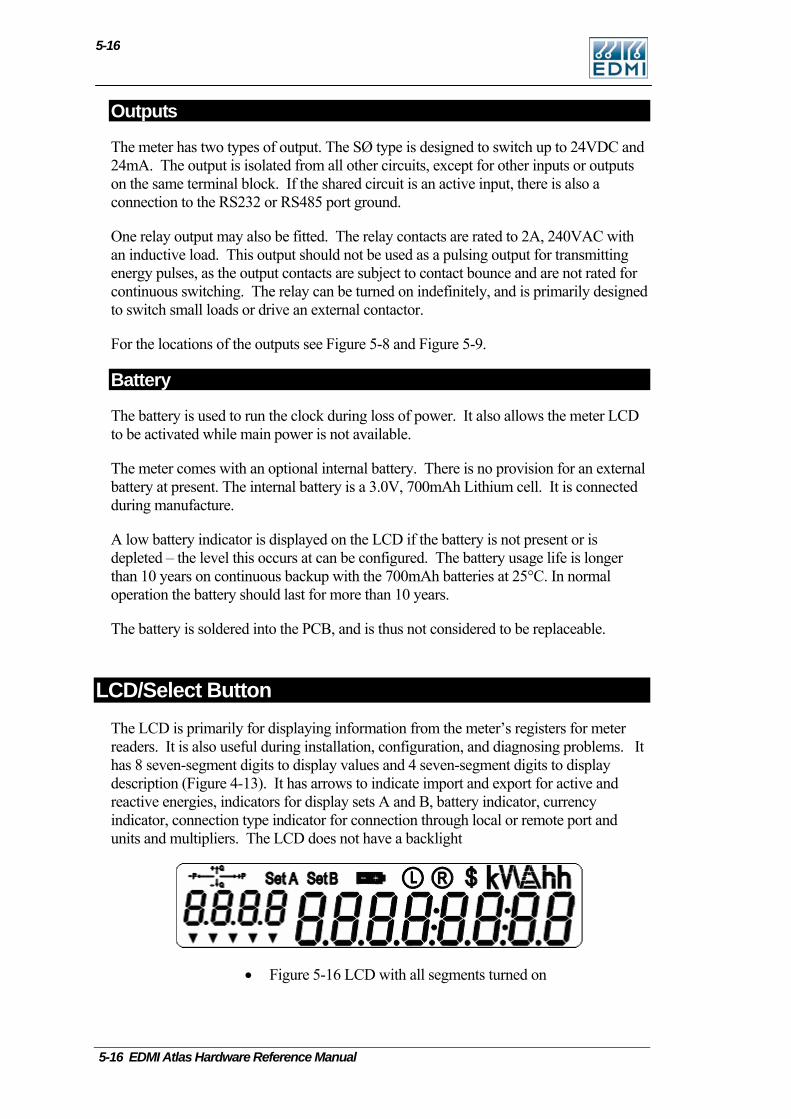
5-16
Outputs
The meter has two types of output. The SØ type is designed to switch up to 24VDC and 24mA. The output is isolated from all other circuits, except for other inputs or outputs on the same terminal block. If the shared circuit is an active input, there is also a connection to the RS232 or RS485 port ground.
One relay output may also be fitted. The relay contacts are rated to 2A, 240VAC with an inductive load. This output should not be used as a pulsing output for transmitting energy pulses, as the output contacts are subject to contact bounce and are not rated for continuous switching. The relay can be turned on indefinitely, and is primarily designed to switch small loads or drive an external contactor.
For the locations of the outputs see Figure 5-8 and Figure 5-9.
Battery
The battery is used to run the clock during loss of power. It also allows the meter LCD to be activated while main power is not available.
The meter comes with an optional internal battery. There is no provision for an external battery at present. The internal battery is a 3.0V, 700mAh Lithium cell. It is connected during manufacture.
A low battery indicator is displayed on the LCD if the battery is not present or is depleted – the level this occurs at can be configured. The battery usage life is longer than 10 years on continuous backup with the 700mAh batteries at 25°C. In normal operation the battery should last for more than 10 years.
The battery is soldered into the PCB, and is thus not considered to be replaceable.
LCD/Select Button The LCD is primarily for displaying information from the meter’s registers for meter readers. It is also useful during installation, configuration, and diagnosing problems. It has 8 seven-segment digits to display values and 4 seven-segment digits to display description (Figure 4-13). It has arrows to indicate import and export for active and reactive energies, indicators for display sets A and B, battery indicator, currency indicator, connection type indicator for connection through local or remote port and units and multipliers. The LCD does not have a backlight
• Figure 5-16 LCD with all segments turned on
5-16 EDMI Atlas Hardware Reference Manual
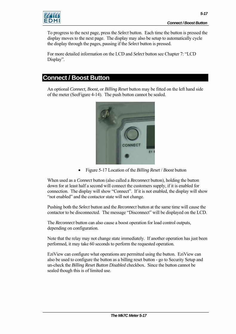
Connect / Boost Button
5-17
To progress to the next page, press the Select button. Each time the button is pressed the display moves to the next page. The display may also be setup to automatically cycle the display through the pages, pausing if the Select button is pressed.
For more detailed information on the LCD and Select button see Chapter 7: “LCD Display”.
Connect / Boost Button An optional Connect, Boost, or Billing Reset button may be fitted on the left hand side of the meter (SeeFigure 4-14). The push button cannot be sealed.
• Figure 5-17 Location of the Billing Reset / Boost button
When used as a Connect button (also called a Reconnect button), holding the button down for at least half a second will connect the customers supply, if it is enabled for connection. The display will show “Connect”. If it is not enabled, the display will show “not enabled” and the contactor state will not change.
Pushing both the Select button and the Reconnect button at the same time will cause the contactor to be disconnected. The message “Disconnect” will be displayed on the LCD.
The Reconnect button can also cause a boost operation for load control outputs, depending on configuration.
Note that the relay may not change state immediately. If another operation has just been performed, it may take 60 seconds to perform the requested operation.
EziView can configure what operations are permitted using the button. EziView can also be used to configure the button as a billing reset button - go to Security Setup and un-check the Billing Reset Button Disabled checkbox. Since the button cannot be sealed though this is of limited use.
The Mk7C Meter 5-17
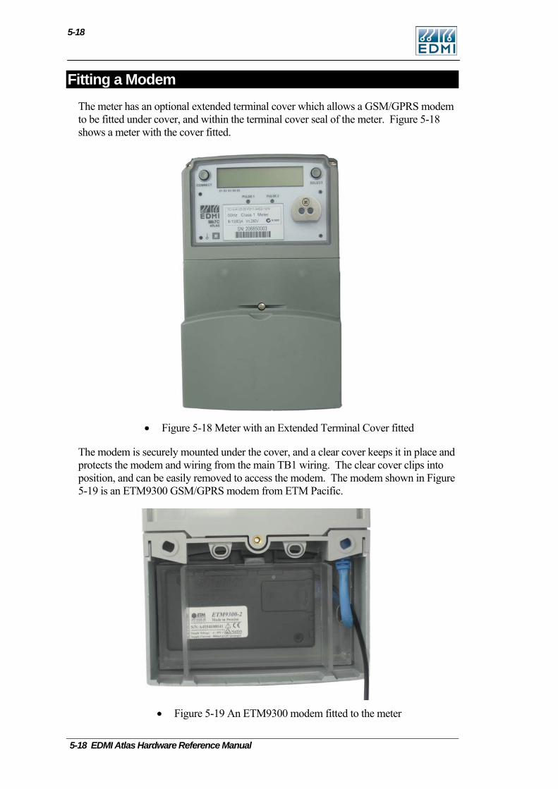
5-18
Fitting a Modem The meter has an optional extended terminal cover which allows a GSM/GPRS modem to be fitted under cover, and within the terminal cover seal of the meter. Figure 5-18 shows a meter with the cover fitted.
• Figure 5-18 Meter with an Extended Terminal Cover fitted
The modem is securely mounted under the cover, and a clear cover keeps it in place and protects the modem and wiring from the main TB1 wiring. The clear cover clips into position, and can be easily removed to access the modem. The modem shown in Figure 5-19 is an ETM9300 GSM/GPRS modem from ETM Pacific.
• Figure 5-19 An ETM9300 modem fitted to the meter
5-18 EDMI Atlas Hardware Reference Manual
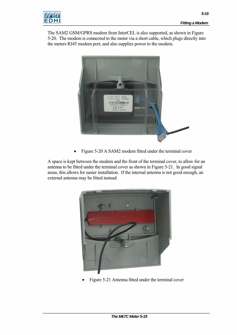
Fitting a Modem
5-19
The SAM2 GSM/GPRS modem from InterCEL is also supported, as shown in Figure 5-20. The modem is connected to the meter via a short cable, which plugs directly into the meters RJ45 modem port, and also supplies power to the modem.
• Figure 5-20 A SAM2 modem fitted under the terminal cover
A space is kept between the modem and the front of the terminal cover, to allow for an antenna to be fitted under the terminal cover as shown in Figure 5-21. In good signal areas, this allows for easier installation. If the internal antenna is not good enough, an external antenna may be fitted instead.
• Figure 5-21 Antenna fitted under the terminal cover
The Mk7C Meter 5-19

5-20
Servicing The meter is not designed for field servicing and has no user serviceable parts. The meter has no internal fuses. In the event of failure of the meter, contact EDMI or your local agent for servicing.
5-20 EDMI Atlas Hardware Reference Manual
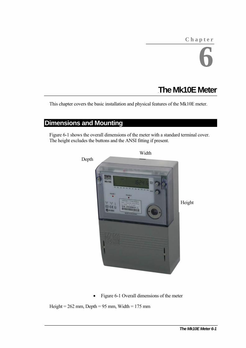
The Mk10E Meter 6-1
C h a p t e r
6
Chapter 6 The Mk10E Meter This chapter covers the basic installation and physical features of the Mk10E meter.
Dimensions and Mounting Figure 6-1 shows the overall dimensions of the meter with a standard terminal cover. The height excludes the buttons and the ANSI fitting if present.
Width Depth
Height
• Figure 6-1 Overall dimensions of the meter
Height = 262 mm, Depth = 95 mm, Width = 175 mm
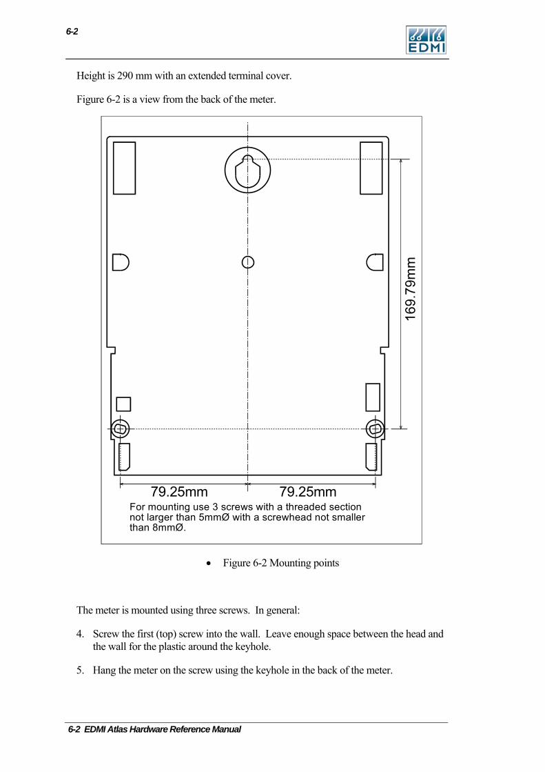
6-2
6-2 EDMI Atlas Hardware Reference Manual
Height is 290 mm with an extended terminal cover.
Figure 6-2 is a view from the back of the meter.
79.25mm79.25mmFor mounting use 3 screws with a threaded sectionnot larger than 5mmØ with a screwhead not smallerthan 8mmØ.
• Figure 6-2 Mounting points
The meter is mounted using three screws. In general:
4. Screw the first (top) screw into the wall. Leave enough space between the head and the wall for the plastic around the keyhole.
5. Hang the meter on the screw using the keyhole in the back of the meter.
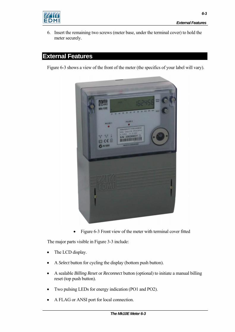
External Features
6-3
6. Insert the remaining two screws (meter base, under the terminal cover) to hold the meter securely.
External Features Figure 6-3 shows a view of the front of the meter (the specifics of your label will vary).
• Figure 6-3 Front view of the meter with terminal cover fitted
The major parts visible in Figure 3-3 include:
• The LCD display.
• A Select button for cycling the display (bottom push button).
• A sealable Billing Reset or Reconnect button (optional) to initiate a manual billing reset (top push button).
• Two pulsing LEDs for energy indication (PO1 and PO2).
• A FLAG or ANSI port for local connection.
The Mk10E Meter 6-3
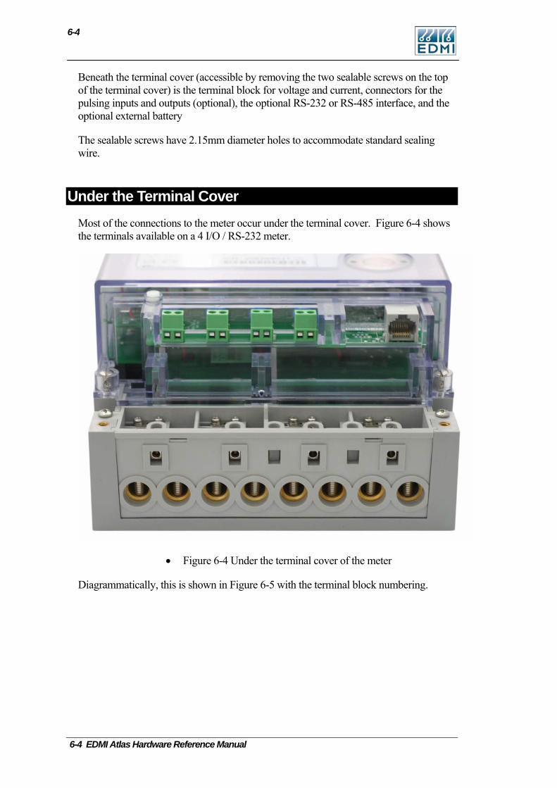
6-4
Beneath the terminal cover (accessible by removing the two sealable screws on the top of the terminal cover) is the terminal block for voltage and current, connectors for the pulsing inputs and outputs (optional), the optional RS-232 or RS-485 interface, and the optional external battery
The sealable screws have 2.15mm diameter holes to accommodate standard sealing wire.
Under the Terminal Cover Most of the connections to the meter occur under the terminal cover. Figure 6-4 shows the terminals available on a 4 I/O / RS-232 meter.
• Figure 6-4 Under the terminal cover of the meter
Diagrammatically, this is shown in Figure 6-5 with the terminal block numbering.
6-4 EDMI Atlas Hardware Reference Manual
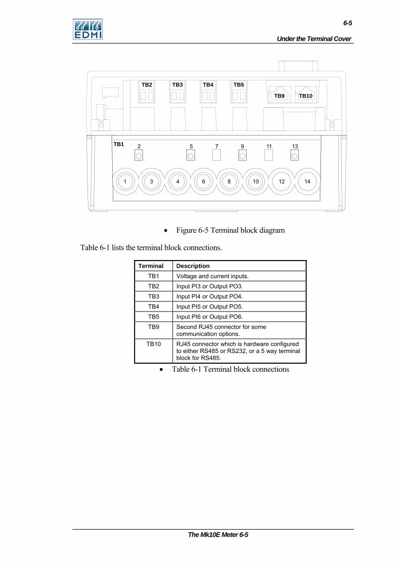
Under the Terminal Cover
6-5
TB1
TB2 TB3 TB4 TB5
TB9 TB10
1 3 4 6 10 12 14
2 5 9 11 13
• Figure 6-5 Terminal block diagram
Table 6-1 lists the terminal block connections.
Terminal Description TB1 Voltage and current inputs.
TB2 Input PI3 or Output PO3.
TB3 Input PI4 or Output PO4.
TB4 Input PI5 or Output PO5.
TB5 Input PI6 or Output PO6.
TB9 Second RJ45 connector for some communication options.
TB10 RJ45 connector which is hardware configured to either RS485 or RS232, or a 5 way terminal block for RS485.
• Table 6-1 Terminal block connections
The Mk10E Meter 6-5
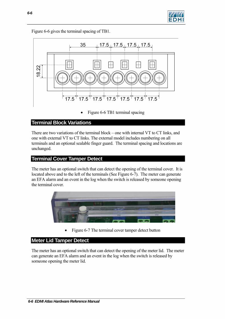
6-6
Figure 6-6 gives the terminal spacing of TB1.
• Figure 6-6 TB1 terminal spacing
Terminal Block Variations
There are two variations of the terminal block – one with internal VT to CT links, and one with external VT to CT links. The external model includes numbering on all terminals and an optional sealable finger guard. The terminal spacing and locations are unchanged.
Terminal Cover Tamper Detect
The meter has an optional switch that can detect the opening of the terminal cover. It is located above and to the left of the terminals (See Figure 6-7). The meter can generate an EFA alarm and an event in the log when the switch is released by someone opening the terminal cover.
• Figure 6-7 The terminal cover tamper detect button
Meter Lid Tamper Detect
The meter has an optional switch that can detect the opening of the meter lid. The meter can generate an EFA alarm and an event in the log when the switch is released by someone opening the meter lid.
6-6 EDMI Atlas Hardware Reference Manual

Under the Meter Lid
6-7
Under the Meter Lid Removing the sealable screw allows the meter lid to be removed. Generally connections to the I/O connectors do not need to be detached to allow the cover to be removed. Removal of the meter lid is required to access the Config Jumper, and to add or remove the CT to VT links on meters with old style terminal blocks.
Care must be taken as dangerous voltages are present in the circuitry under the meter lid while the meter is active. Most of the circuitry is at neutral potential. Even when the meter is not powered, care should be taken to prevent electrostatic damage to the circuitry of the meter.
CT to VT Links
Whole current meters have CT to VT links between TB1 terminals 1 and 2, 4 and 5, 8 and 9, 12 and 13. There is also a fixed link between 12 and 14. These links may need to be removed to allow testing on some types of test bench. There are two options for removing them. The first option has external VT to CT link connections. Figure 6-8 shows the location of the links, just above the terminal block.
• Figure 6-8 Location of the CT to VT links.
To remove the link connections either loosen the screws, slide the metal shims to the right and retighten (Figure 6-9), or remove the left hand screws completely for better isolation (Figure 6-10).
• Figure 6-9 Meter with the CT to VT links disconnected by sliding shims.
• Figure 6-10 Meter with the CT to VT links disconnected by removing screws.
The Mk10E Meter 6-7
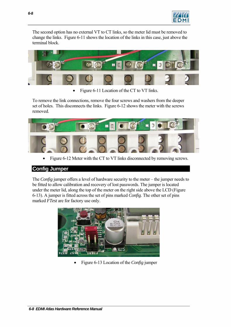
6-8
The second option has no external VT to CT links, so the meter lid must be removed to change the links. Figure 6-11 shows the location of the links in this case, just above the terminal block.
• Figure 6-11 Location of the CT to VT links.
To remove the link connections, remove the four screws and washers from the deeper set of holes. This disconnects the links. Figure 6-12 shows the meter with the screws removed.
• Figure 6-12 Meter with the CT to VT links disconnected by removing screws.
Config Jumper
The Config jumper offers a level of hardware security to the meter – the jumper needs to be fitted to allow calibration and recovery of lost passwords. The jumper is located under the meter lid, along the top of the meter on the right side above the LCD (Figure 6-13). A jumper is fitted across the set of pins marked Config. The other set of pins marked FTest are for factory use only.
• Figure 6-13 Location of the Config jumper
6-8 EDMI Atlas Hardware Reference Manual
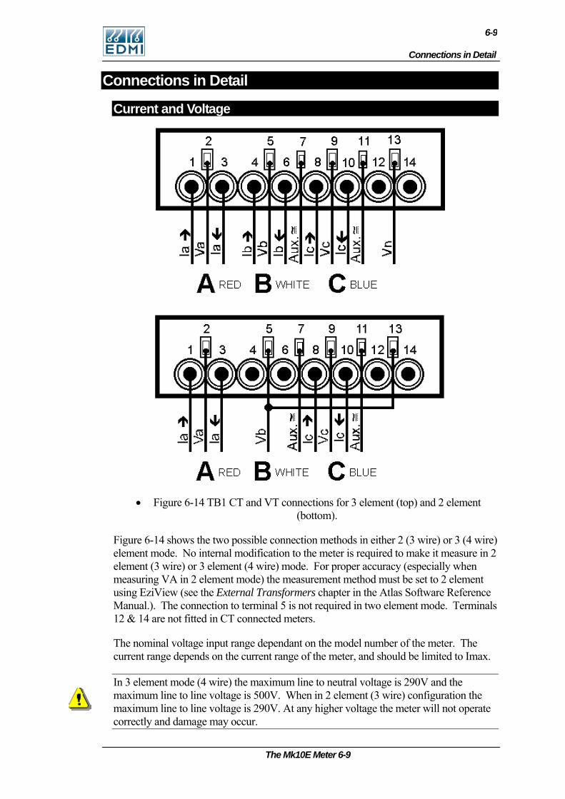
Connections in Detail
6-9
Connections in Detail
Current and Voltage
• Figure 6-14 TB1 CT and VT connections for 3 element (top) and 2 element
(bottom).
Figure 6-14 shows the two possible connection methods in either 2 (3 wire) or 3 (4 wire) element mode. No internal modification to the meter is required to make it measure in 2 element (3 wire) or 3 element (4 wire) mode. For proper accuracy (especially when measuring VA in 2 element mode) the measurement method must be set to 2 element using EziView (see the External Transformers chapter in the Atlas Software Reference Manual.). The connection to terminal 5 is not required in two element mode. Terminals 12 & 14 are not fitted in CT connected meters.
The nominal voltage input range dependant on the model number of the meter. The current range depends on the current range of the meter, and should be limited to Imax.
In 3 element mode (4 wire) the maximum line to neutral voltage is 290V and the maximum line to line voltage is 500V. When in 2 element (3 wire) configuration the maximum line to line voltage is 290V. At any higher voltage the meter will not operate correctly and damage may occur.
The Mk10E Meter 6-9
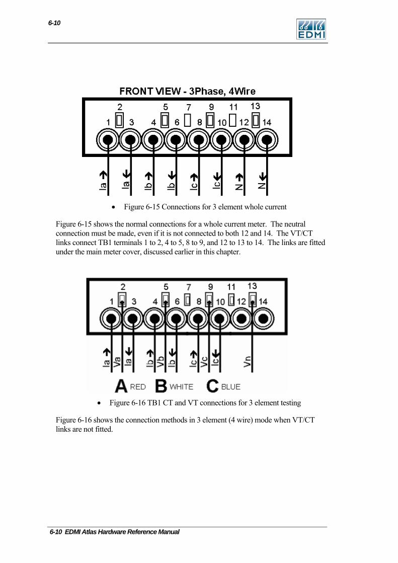
6-10 EDMI Atlas Hardware Reference Manual
6-10
• Figure 6-15 Connections for 3 element whole current
Figure 6-15 shows the normal connections for a whole current meter. The neutral connection must be made, even if it is not connected to both 12 and 14. The VT/CT links connect TB1 terminals 1 to 2, 4 to 5, 8 to 9, and 12 to 13 to 14. The links are fitted under the main meter cover, discussed earlier in this chapter.
• Figure 6-16 TB1 CT and VT connections for 3 element testing
Figure 6-16 shows the connection methods in 3 element (4 wire) mode when VT/CT links are not fitted.
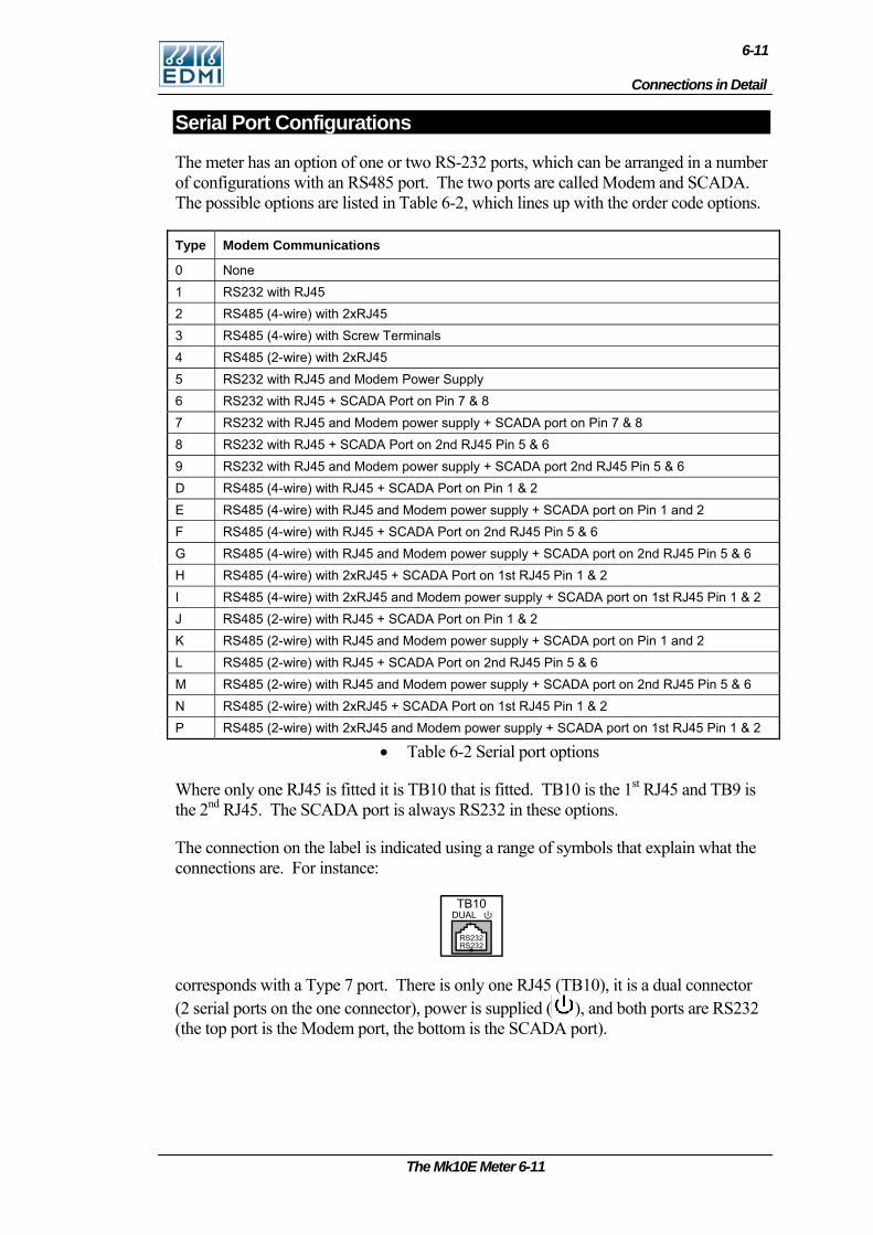
Connections in Detail
6-11
The Mk10E Meter 6-11
Serial Port Configurations
The meter has an option of one or two RS-232 ports, which can be arranged in a number of configurations with an RS485 port. The two ports are called Modem and SCADA. The possible options are listed in Table 6-2, which lines up with the order code options.
Type Modem Communications
0 None 1 RS232 with RJ45 2 RS485 (4-wire) with 2xRJ45 3 RS485 (4-wire) with Screw Terminals 4 RS485 (2-wire) with 2xRJ45 5 RS232 with RJ45 and Modem Power Supply 6 RS232 with RJ45 + SCADA Port on Pin 7 & 8 7 RS232 with RJ45 and Modem power supply + SCADA port on Pin 7 & 8 8 RS232 with RJ45 + SCADA Port on 2nd RJ45 Pin 5 & 6 9 RS232 with RJ45 and Modem power supply + SCADA port 2nd RJ45 Pin 5 & 6 D RS485 (4-wire) with RJ45 + SCADA Port on Pin 1 & 2 E RS485 (4-wire) with RJ45 and Modem power supply + SCADA port on Pin 1 and 2 F RS485 (4-wire) with RJ45 + SCADA Port on 2nd RJ45 Pin 5 & 6 G RS485 (4-wire) with RJ45 and Modem power supply + SCADA port on 2nd RJ45 Pin 5 & 6 H RS485 (4-wire) with 2xRJ45 + SCADA Port on 1st RJ45 Pin 1 & 2 I RS485 (4-wire) with 2xRJ45 and Modem power supply + SCADA port on 1st RJ45 Pin 1 & 2 J RS485 (2-wire) with RJ45 + SCADA Port on Pin 1 & 2 K RS485 (2-wire) with RJ45 and Modem power supply + SCADA port on Pin 1 and 2 L RS485 (2-wire) with RJ45 + SCADA Port on 2nd RJ45 Pin 5 & 6 M RS485 (2-wire) with RJ45 and Modem power supply + SCADA port on 2nd RJ45 Pin 5 & 6 N RS485 (2-wire) with 2xRJ45 + SCADA Port on 1st RJ45 Pin 1 & 2 P RS485 (2-wire) with 2xRJ45 and Modem power supply + SCADA port on 1st RJ45 Pin 1 & 2
• Table 6-2 Serial port options
Where only one RJ45 is fitted it is TB10 that is fitted. TB10 is the 1st RJ45 and TB9 is the 2nd RJ45. The SCADA port is always RS232 in these options.
The connection on the label is indicated using a range of symbols that explain what the connections are. For instance:
TB10DUAL
RS232RS232
corresponds with a Type 7 port. There is only one RJ45 (TB10), it is a dual connector (2 serial ports on the one connector), power is supplied ( ), and both ports are RS232 (the top port is the Modem port, the bottom is the SCADA port).
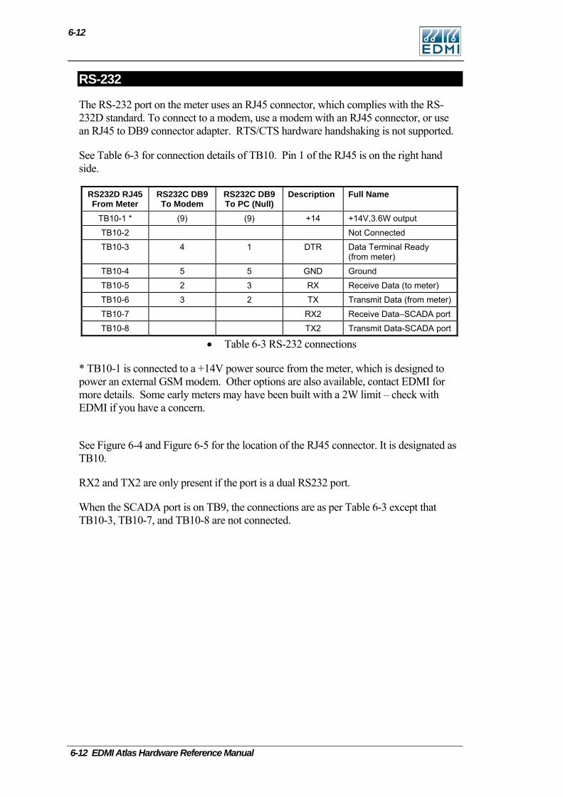
6-12
RS-232
The RS-232 port on the meter uses an RJ45 connector, which complies with the RS-232D standard. To connect to a modem, use a modem with an RJ45 connector, or use an RJ45 to DB9 connector adapter. RTS/CTS hardware handshaking is not supported.
See Table 6-3 for connection details of TB10. Pin 1 of the RJ45 is on the right hand side.
RS232D RJ45 From Meter
RS232C DB9 To Modem
RS232C DB9 To PC (Null)
Description Full Name
TB10-1 * (9) (9) +14 +14V,3.6W output
TB10-2 Not Connected
TB10-3 4 1 DTR Data Terminal Ready (from meter)
TB10-4 5 5 GND Ground
TB10-5 2 3 RX Receive Data (to meter)
TB10-6 3 2 TX Transmit Data (from meter)
TB10-7 RX2 Receive Data–SCADA port
TB10-8 TX2 Transmit Data-SCADA port
• Table 6-3 RS-232 connections
* TB10-1 is connected to a +14V power source from the meter, which is designed to power an external GSM modem. Other options are also available, contact EDMI for more details. Some early meters may have been built with a 2W limit – check with EDMI if you have a concern.
See Figure 6-4 and Figure 6-5 for the location of the RJ45 connector. It is designated as TB10.
RX2 and TX2 are only present if the port is a dual RS232 port.
When the SCADA port is on TB9, the connections are as per Table 6-3 except that TB10-3, TB10-7, and TB10-8 are not connected.
6-12 EDMI Atlas Hardware Reference Manual
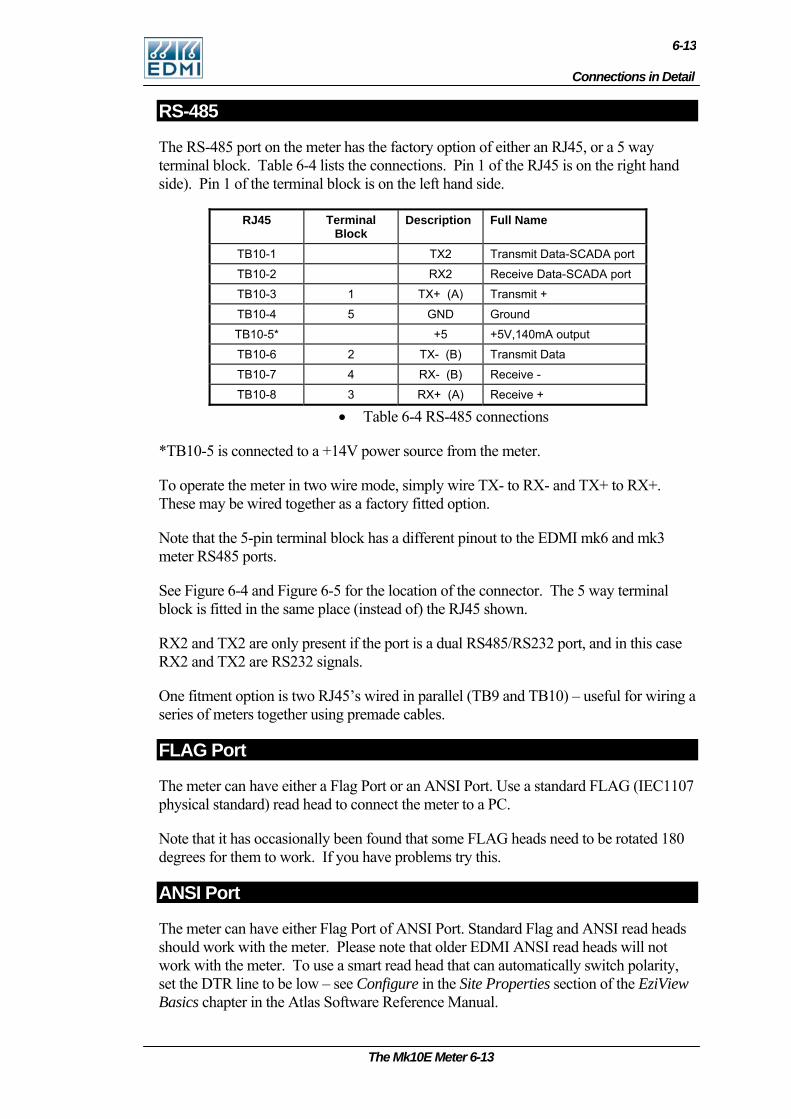
Connections in Detail
6-13
RS-485
The RS-485 port on the meter has the factory option of either an RJ45, or a 5 way terminal block. Table 6-4 lists the connections. Pin 1 of the RJ45 is on the right hand side). Pin 1 of the terminal block is on the left hand side.
RJ45 Terminal Block
Description Full Name
TB10-1 TX2 Transmit Data-SCADA port
TB10-2 RX2 Receive Data-SCADA port
TB10-3 1 TX+ (A) Transmit +
TB10-4 5 GND Ground
TB10-5* +5 +5V,140mA output
TB10-6 2 TX- (B) Transmit Data
TB10-7 4 RX- (B) Receive -
TB10-8 3 RX+ (A) Receive +
• Table 6-4 RS-485 connections
*TB10-5 is connected to a +14V power source from the meter.
To operate the meter in two wire mode, simply wire TX- to RX- and TX+ to RX+. These may be wired together as a factory fitted option.
Note that the 5-pin terminal block has a different pinout to the EDMI mk6 and mk3 meter RS485 ports.
See Figure 6-4 and Figure 6-5 for the location of the connector. The 5 way terminal block is fitted in the same place (instead of) the RJ45 shown.
RX2 and TX2 are only present if the port is a dual RS485/RS232 port, and in this case RX2 and TX2 are RS232 signals.
One fitment option is two RJ45’s wired in parallel (TB9 and TB10) – useful for wiring a series of meters together using premade cables.
FLAG Port
The meter can have either a Flag Port or an ANSI Port. Use a standard FLAG (IEC1107 physical standard) read head to connect the meter to a PC.
Note that it has occasionally been found that some FLAG heads need to be rotated 180 degrees for them to work. If you have problems try this.
ANSI Port
The meter can have either Flag Port of ANSI Port. Standard Flag and ANSI read heads should work with the meter. Please note that older EDMI ANSI read heads will not work with the meter. To use a smart read head that can automatically switch polarity, set the DTR line to be low – see Configure in the Site Properties section of the EziView Basics chapter in the Atlas Software Reference Manual.
The Mk10E Meter 6-13
6-14
Inputs
The inputs may either be active, or passive. Passive inputs are isolated from all other circuits, including the other inputs. There are a variety of input voltages that may be ordered with the meter, e.g. 12V and 240V. Under voltage will cause the input to trigger erratically or not at all, while over voltage will cause excessive heat dissipation and possible damage to the meter.
The rated voltage is the voltage that must be applied between the two terminals of the input. The inputs work with any polarity, and with AC or DC signals. There are a maximum of 4 inputs.
Active inputs are also available as a factory option. They use power from the serial port, and are thus not isolated from the serial port, or from each other. In this case simply shorting between the input terminals will cause the input to trigger. The maximum external impedance is 500 ohms. The inputs will continue to work when power is cycled to the modem.
Outputs
There are several types of outputs available. All outputs are isolated from all other circuits, including other I/O.
The SØ outputs are designed to switch up to 24VDC and 24mA.
The relay outputs are rated to 2A, 240VAC with an inductive load, or 5A, 240VAC for the high current version. These outputs should not be used as pulsing outputs for transmitting energy pulses, as the output contacts are subject to contact bounce and are not rated for continuous switching.
The BOSFET outputs are rated up to 240V, 100mA. They may switch either AC or DC voltages, any polarity.
Battery
The battery is used to run the clock during loss of power. It also allows the meter LCD to be activated while main power is not available.
The external battery is a 3.6V, 700mAh Lithium battery, or a 3.0V, 700mAh Lithium battery. The internal battery is a 3.0V, 700mAh Lithium batteries. Only one battery can be used at one time, the meter will use the one with the highest charge.
If an internal battery is used, a jumper will be connected to JP1 to enable the battery – this jumper is under the meter cover, near the battery.
A low battery indicator is displayed on the LCD if the battery is not present or is depleted – the level this occurs at can be configured. The battery usage life is longer than 10 years on continuous backup with either of the 700mAh batteries at 25°C. In normal operation the battery should last for more than 10 years.
6-14 EDMI Atlas Hardware Reference Manual
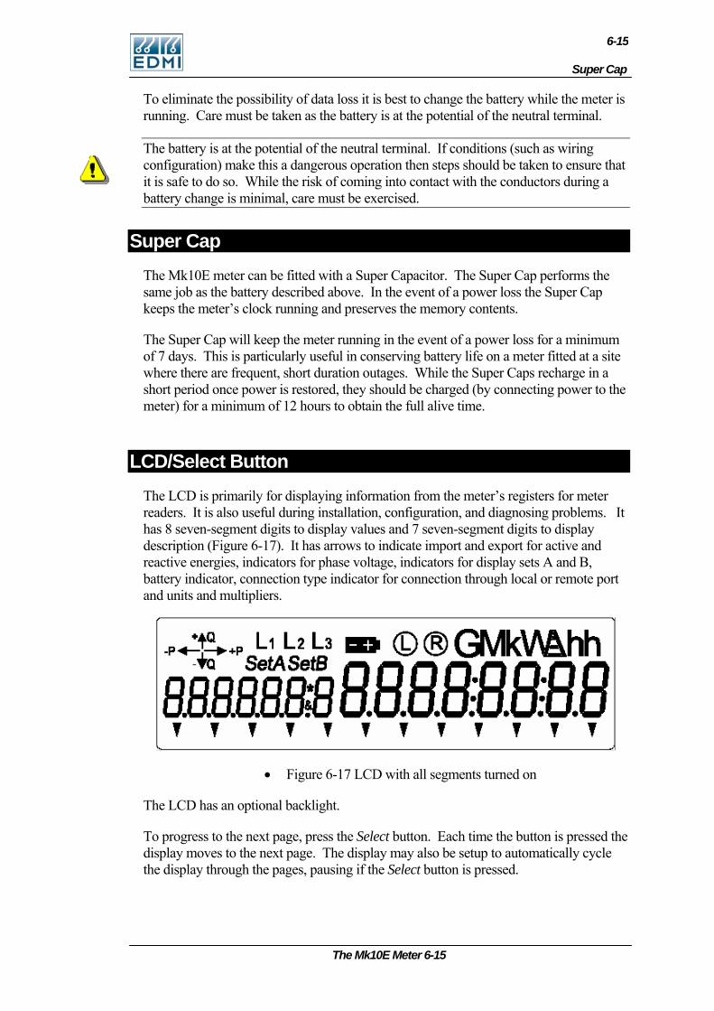
Super Cap
6-15
To eliminate the possibility of data loss it is best to change the battery while the meter is running. Care must be taken as the battery is at the potential of the neutral terminal.
The battery is at the potential of the neutral terminal. If conditions (such as wiring configuration) make this a dangerous operation then steps should be taken to ensure that it is safe to do so. While the risk of coming into contact with the conductors during a battery change is minimal, care must be exercised.
Super Cap The Mk10E meter can be fitted with a Super Capacitor. The Super Cap performs the same job as the battery described above. In the event of a power loss the Super Cap keeps the meter’s clock running and preserves the memory contents.
The Super Cap will keep the meter running in the event of a power loss for a minimum of 7 days. This is particularly useful in conserving battery life on a meter fitted at a site where there are frequent, short duration outages. While the Super Caps recharge in a short period once power is restored, they should be charged (by connecting power to the meter) for a minimum of 12 hours to obtain the full alive time.
LCD/Select Button The LCD is primarily for displaying information from the meter’s registers for meter readers. It is also useful during installation, configuration, and diagnosing problems. It has 8 seven-segment digits to display values and 7 seven-segment digits to display description (Figure 6-17). It has arrows to indicate import and export for active and reactive energies, indicators for phase voltage, indicators for display sets A and B, battery indicator, connection type indicator for connection through local or remote port and units and multipliers.
• Figure 6-17 LCD with all segments turned on
The LCD has an optional backlight.
To progress to the next page, press the Select button. Each time the button is pressed the display moves to the next page. The display may also be setup to automatically cycle the display through the pages, pausing if the Select button is pressed.
The Mk10E Meter 6-15
6-16
For more detailed information on the LCD and Select button see Chapter 7: “LCD Display”.
Reconnect/Boost/Billing Reset Button The Reconnect button is the top of the two push buttons beside the display. The push button has a 2.5mm diameter hole through it, allowing it to be sealed using standard sealing wire. This button may be used to trigger connection of an external contactor.
Holding the button down for at least half a second will connect the customers supply, if it is enabled for connection. The display will show “Connect”. If it is not enabled, the display will show “not enabled” and the contactor state will not change.
Pushing both the Select button and the Reconnect button at the same time will cause the contactor to be disconnected. The message “Disconnect” will be displayed on the LCD.
The Reconnect button can also cause a boost operation for load control outputs, depending on configuration.
Note that the relay may not change state immediately. If another operation has just been performed, it may take 60 seconds to perform the requested operation.
EziView can configure what operations are permitted using the button. EziView can also be used to configure the button as a billing reset button - go to Security Setup and un-check the Billing Reset Button Disabled checkbox.
Servicing The meter is not designed for field servicing and has no user serviceable parts. The meter has no internal fuses. In the event of failure of the meter, contact EDMI or your local agent for servicing.
6-16 EDMI Atlas Hardware Reference Manual
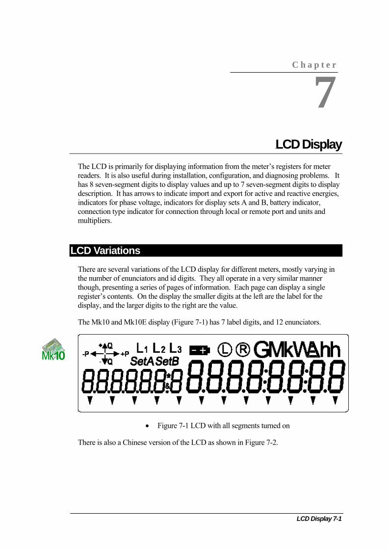
LCD Display 7-
Chapter 7 LCD Display The LCD is primarily for displaying information from the meter’s registers for meter readers. It is also useful during installation, configuration, and diagnosing problems. It has 8 seven-segment digits to display values and up to 7 seven-segment digits to display description. It has arrows to indicate import and export for active and reactive energies, indicators for phase voltage, indicators for display sets A and B, battery indicator, connection type indicator for connection through local or remote port and units and multipliers.
LCD Variations There are several variations of the LCD display for different meters, mostly varying in the number of enunciators and id digits. They all operate in a very similar manner though, presenting a series of pages of information. Each page can display a single register’s contents. On the display the smaller digits at the left are the label for the display, and the larger digits to the right are the value.
The Mk10 and Mk10E display (Figure 7-1) has 7 label digits, and 12 enunciators.
C h a p t e r
7
• Figure 7-1 LCD with all segments turned on
There is also a Chinese version of the LCD as shown in Figure 7-2.
1
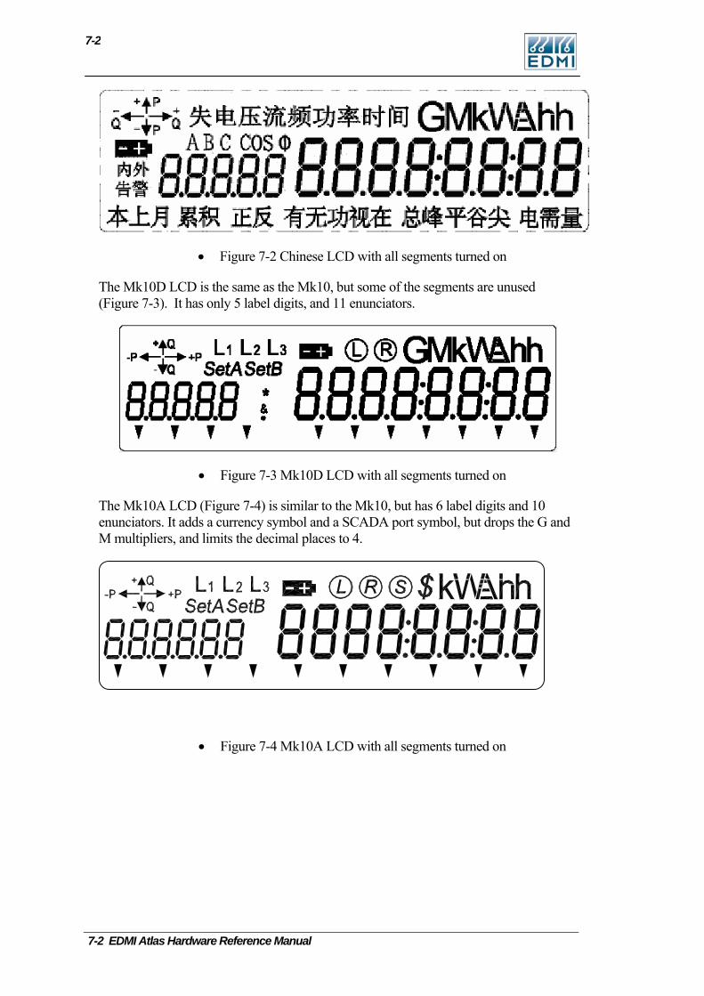
7-2
• Figure 7-2 Chinese LCD with all segments turned on
The Mk10D LCD is the same as the Mk10, but some of the segments are unused (Figure 7-3). It has only 5 label digits, and 11 enunciators.
• Figure 7-3 Mk10D LCD with all segments turned on
The Mk10A LCD (Figure 7-4) is similar to the Mk10, but has 6 label digits and 10 enunciators. It adds a currency symbol and a SCADA port symbol, but drops the G and M multipliers, and limits the decimal places to 4.
• Figure 7-4 Mk10A LCD with all segments turned on
7-2 EDMI Atlas Hardware Reference Manual
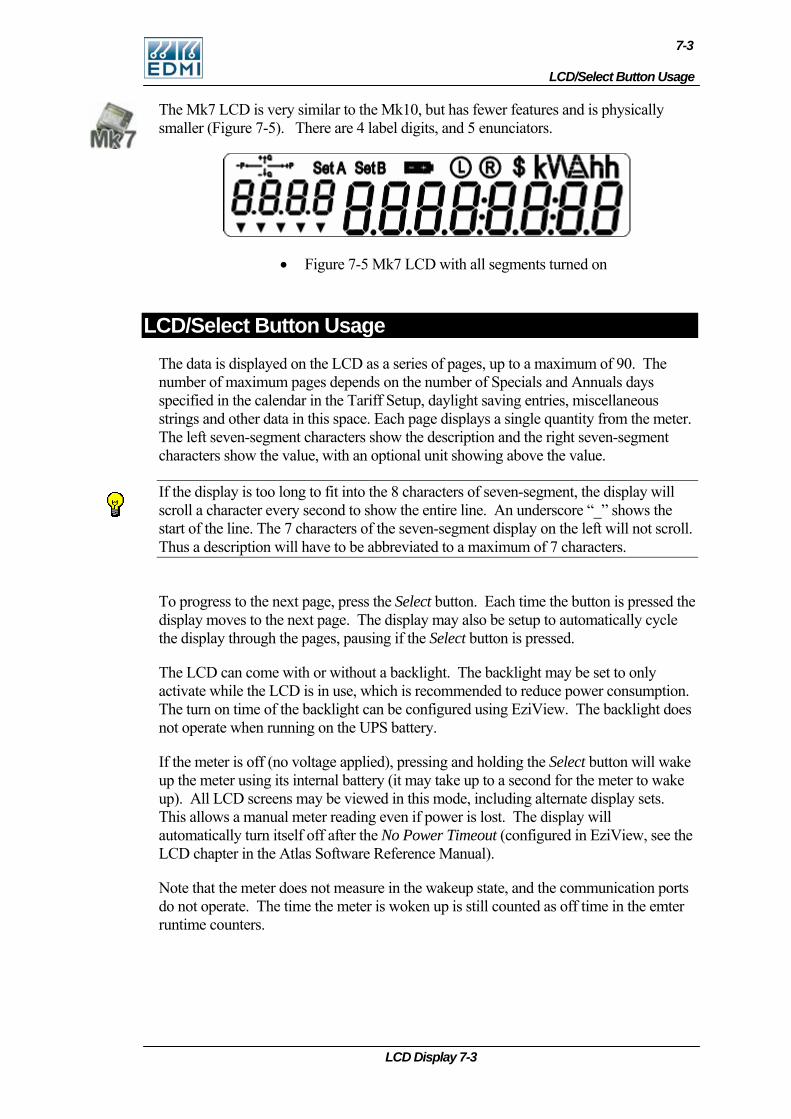
LCD/Select Button Usage
7-3
The Mk7 LCD is very similar to the Mk10, but has fewer features and is physically smaller (Figure 7-5). There are 4 label digits, and 5 enunciators.
• Figure 7-5 Mk7 LCD with all segments turned on
LCD/Select Button Usage The data is displayed on the LCD as a series of pages, up to a maximum of 90. The number of maximum pages depends on the number of Specials and Annuals days specified in the calendar in the Tariff Setup, daylight saving entries, miscellaneous strings and other data in this space. Each page displays a single quantity from the meter. The left seven-segment characters show the description and the right seven-segment characters show the value, with an optional unit showing above the value.
If the display is too long to fit into the 8 characters of seven-segment, the display will scroll a character every second to show the entire line. An underscore “_” shows the start of the line. The 7 characters of the seven-segment display on the left will not scroll. Thus a description will have to be abbreviated to a maximum of 7 characters.
To progress to the next page, press the Select button. Each time the button is pressed the display moves to the next page. The display may also be setup to automatically cycle the display through the pages, pausing if the Select button is pressed.
The LCD can come with or without a backlight. The backlight may be set to only activate while the LCD is in use, which is recommended to reduce power consumption. The turn on time of the backlight can be configured using EziView. The backlight does not operate when running on the UPS battery.
If the meter is off (no voltage applied), pressing and holding the Select button will wake up the meter using its internal battery (it may take up to a second for the meter to wake up). All LCD screens may be viewed in this mode, including alternate display sets. This allows a manual meter reading even if power is lost. The display will automatically turn itself off after the No Power Timeout (configured in EziView, see the LCD chapter in the Atlas Software Reference Manual).
Note that the meter does not measure in the wakeup state, and the communication ports do not operate. The time the meter is woken up is still counted as off time in the emter runtime counters.
LCD Display 7-3
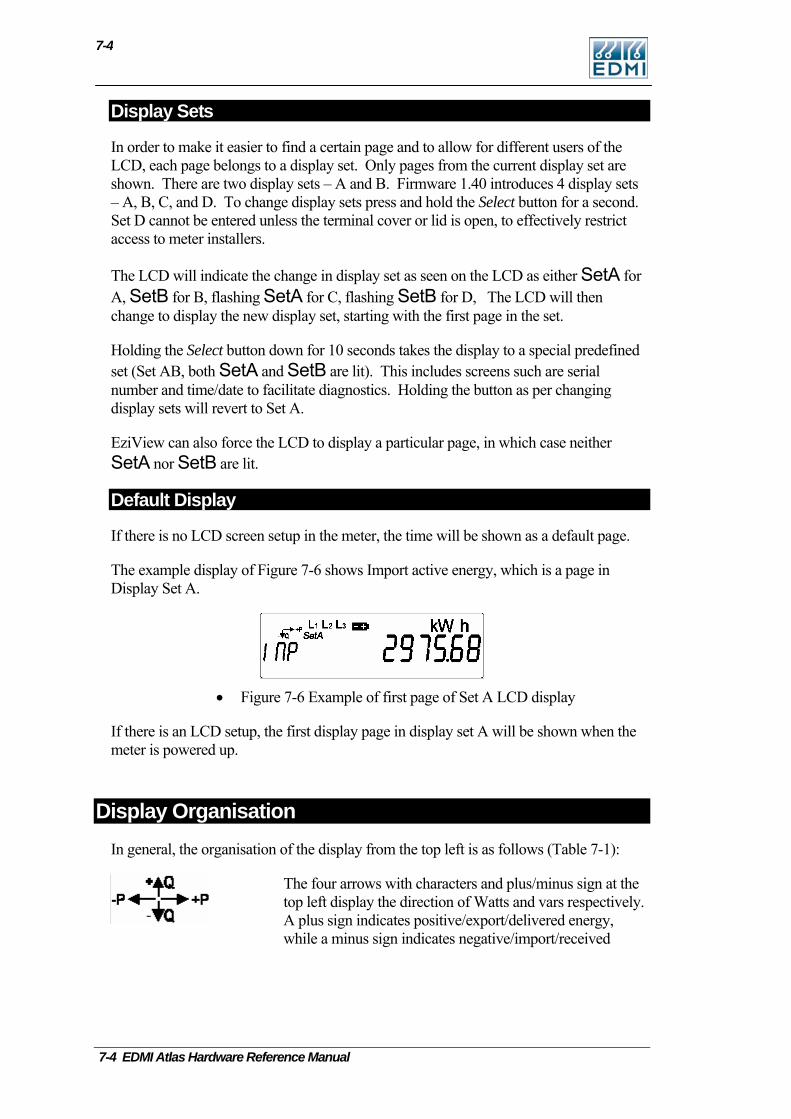
7-4
Display Sets
In order to make it easier to find a certain page and to allow for different users of the LCD, each page belongs to a display set. Only pages from the current display set are shown. There are two display sets – A and B. Firmware 1.40 introduces 4 display sets – A, B, C, and D. To change display sets press and hold the Select button for a second. Set D cannot be entered unless the terminal cover or lid is open, to effectively restrict access to meter installers.
The LCD will indicate the change in display set as seen on the LCD as either SetA for A, SetB for B, flashing SetA for C, flashing SetB for D, The LCD will then change to display the new display set, starting with the first page in the set.
Holding the Select button down for 10 seconds takes the display to a special predefined set (Set AB, both SetA and SetB are lit). This includes screens such are serial number and time/date to facilitate diagnostics. Holding the button as per changing display sets will revert to Set A.
EziView can also force the LCD to display a particular page, in which case neither SetA nor SetB are lit.
Default Display
If there is no LCD screen setup in the meter, the time will be shown as a default page.
The example display of Figure 7-6 shows Import active energy, which is a page in Display Set A.
• Figure 7-6 Example of first page of Set A LCD display
If there is an LCD setup, the first display page in display set A will be shown when the meter is powered up.
Display Organisation In general, the organisation of the display from the top left is as follows (Table 7-1):
The four arrows with characters and plus/minus sign at the top left display the direction of Watts and vars respectively. A plus sign indicates positive/export/delivered energy, while a minus sign indicates negative/import/received
7-4 EDMI Atlas Hardware Reference Manual
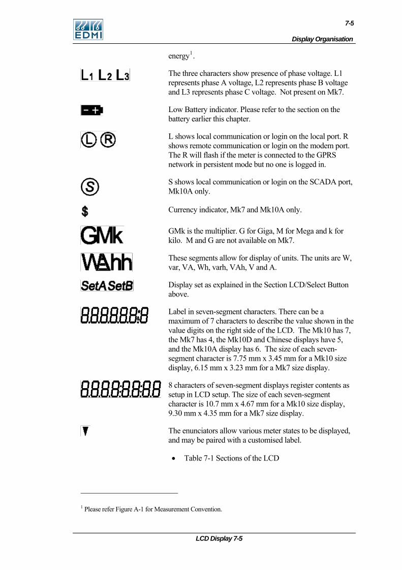
Display Organisation
7-5
LCD Display 7-5
energy1.
The three characters show presence of phase voltage. L1 represents phase A voltage, L2 represents phase B voltage and L3 represents phase C voltage. Not present on Mk7.
Low Battery indicator. Please refer to the section on the battery earlier this chapter.
L shows local communication or login on the local port. R shows remote communication or login on the modem port. The R will flash if the meter is connected to the GPRS network in persistent mode but no one is logged in.
S shows local communication or login on the SCADA port, Mk10A only.
Currency indicator, Mk7 and Mk10A only.
GMk is the multiplier. G for Giga, M for Mega and k for kilo. M and G are not available on Mk7.
These segments allow for display of units. The units are W, var, VA, Wh, varh, VAh, V and A.
Display set as explained in the Section LCD/Select Button above.
Label in seven-segment characters. There can be a maximum of 7 characters to describe the value shown in the value digits on the right side of the LCD. The Mk10 has 7, the Mk7 has 4, the Mk10D and Chinese displays have 5, and the Mk10A display has 6. The size of each seven-segment character is 7.75 mm x 3.45 mm for a Mk10 size display, 6.15 mm x 3.23 mm for a Mk7 size display.
8 characters of seven-segment displays register contents as setup in LCD setup. The size of each seven-segment character is 10.7 mm x 4.67 mm for a Mk10 size display, 9.30 mm x 4.35 mm for a Mk7 size display.
The enunciators allow various meter states to be displayed, and may be paired with a customised label.
• Table 7-1 Sections of the LCD
1 Please refer Figur for Measurement Convention. e A-1

7-6
The energy direction arrows, battery, communication status, and phase presence indicators are not related to the register being shown, they are a display of the meter’s state.
As the LCD is a numeric type, alphabetic characters are difficult to display. The meter will attempt to display them as best it can, but readability will vary depending on the letter.
7-6 EDMI Atlas Hardware Reference Manual
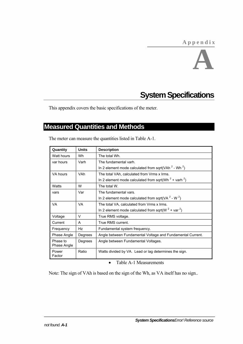
System SpecificationsError! Reference source not found. A-1
A p p e n d i x
A
Appendix ASystem Specifications This appendix covers the basic specifications of the meter.
Measured Quantities and Methods The meter can measure the quantities listed in Table A-1.
Quantity Units Description Watt hours Wh The total Wh.
var hours Varh The fundamental varh. In 2 element mode calculated from sqrt(VAh 2 - Wh 2)
VA hours VAh The total VAh, calculated from Vrms x Irms. In 2 element mode calculated from sqrt(Wh 2 + varh 2)
Watts W The total W.
vars Var The fundamental vars. In 2 element mode calculated from sqrt(VA 2 - W 2)
VA VA The total VA, calculated from Vrms x Irms. In 2 element mode calculated from sqrt(W 2 + var 2)
Voltage V True RMS voltage.
Current A True RMS current.
Frequency Hz Fundamental system frequency.
Phase Angle Degrees Angle between Fundamental Voltage and Fundamental Current.
Phase to Phase Angle
Degrees Angle between Fundamental Voltages.
Power Factor
Ratio Watts divided by VA. Lead or lag determines the sign.
• Table A-1 Measurements
Note: The sign of VAh is based on the sign of the Wh, as VA itself has no sign..
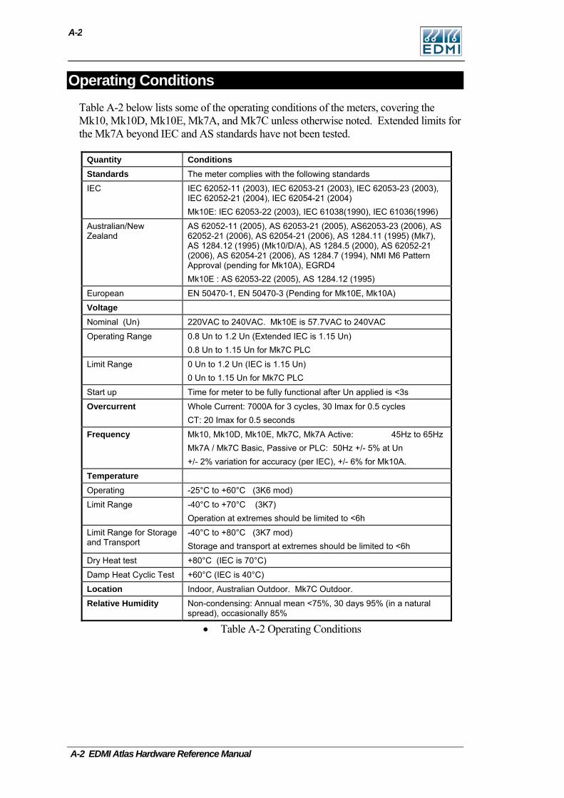
A-2
Operating Conditions Table A-2 below lists some of the operating conditions of the meters, covering the Mk10, Mk10D, Mk10E, Mk7A, and Mk7C unless otherwise noted. Extended limits for the Mk7A beyond IEC and AS standards have not been tested.
Quantity Conditions Standards The meter complies with the following standards
IEC IEC 62052-11 (2003), IEC 62053-21 (2003), IEC 62053-23 (2003), IEC 62052-21 (2004), IEC 62054-21 (2004) Mk10E: IEC 62053-22 (2003), IEC 61038(1990), IEC 61036(1996)
Australian/New Zealand
AS 62052-11 (2005), AS 62053-21 (2005), AS62053-23 (2006), AS 62052-21 (2006), AS 62054-21 (2006), AS 1284.11 (1995) (Mk7), AS 1284.12 (1995) (Mk10/D/A), AS 1284.5 (2000), AS 62052-21 (2006), AS 62054-21 (2006), AS 1284.7 (1994), NMI M6 Pattern Approval (pending for Mk10A), EGRD4 Mk10E : AS 62053-22 (2005), AS 1284.12 (1995)
European EN 50470-1, EN 50470-3 (Pending for Mk10E, Mk10A)
Voltage
Nominal (Un) 220VAC to 240VAC. Mk10E is 57.7VAC to 240VAC
Operating Range 0.8 Un to 1.2 Un (Extended IEC is 1.15 Un) 0.8 Un to 1.15 Un for Mk7C PLC
Limit Range 0 Un to 1.2 Un (IEC is 1.15 Un) 0 Un to 1.15 Un for Mk7C PLC
Start up Time for meter to be fully functional after Un applied is <3s
Overcurrent Whole Current: 7000A for 3 cycles, 30 Imax for 0.5 cycles CT: 20 Imax for 0.5 seconds
Frequency Mk10, Mk10D, Mk10E, Mk7C, Mk7A Active: 45Hz to 65Hz Mk7A / Mk7C Basic, Passive or PLC: 50Hz +/- 5% at Un +/- 2% variation for accuracy (per IEC), +/- 6% for Mk10A.
Temperature
Operating -25°C to +60°C (3K6 mod)
Limit Range -40°C to +70°C (3K7) Operation at extremes should be limited to <6h
Limit Range for Storage and Transport
-40°C to +80°C (3K7 mod) Storage and transport at extremes should be limited to <6h
Dry Heat test +80°C (IEC is 70°C)
Damp Heat Cyclic Test +60°C (IEC is 40°C)
Location Indoor, Australian Outdoor. Mk7C Outdoor.
Relative Humidity Non-condensing: Annual mean <75%, 30 days 95% (in a natural spread), occasionally 85%
• Table A-2 Operating Conditions
A-2 EDMI Atlas Hardware Reference Manual
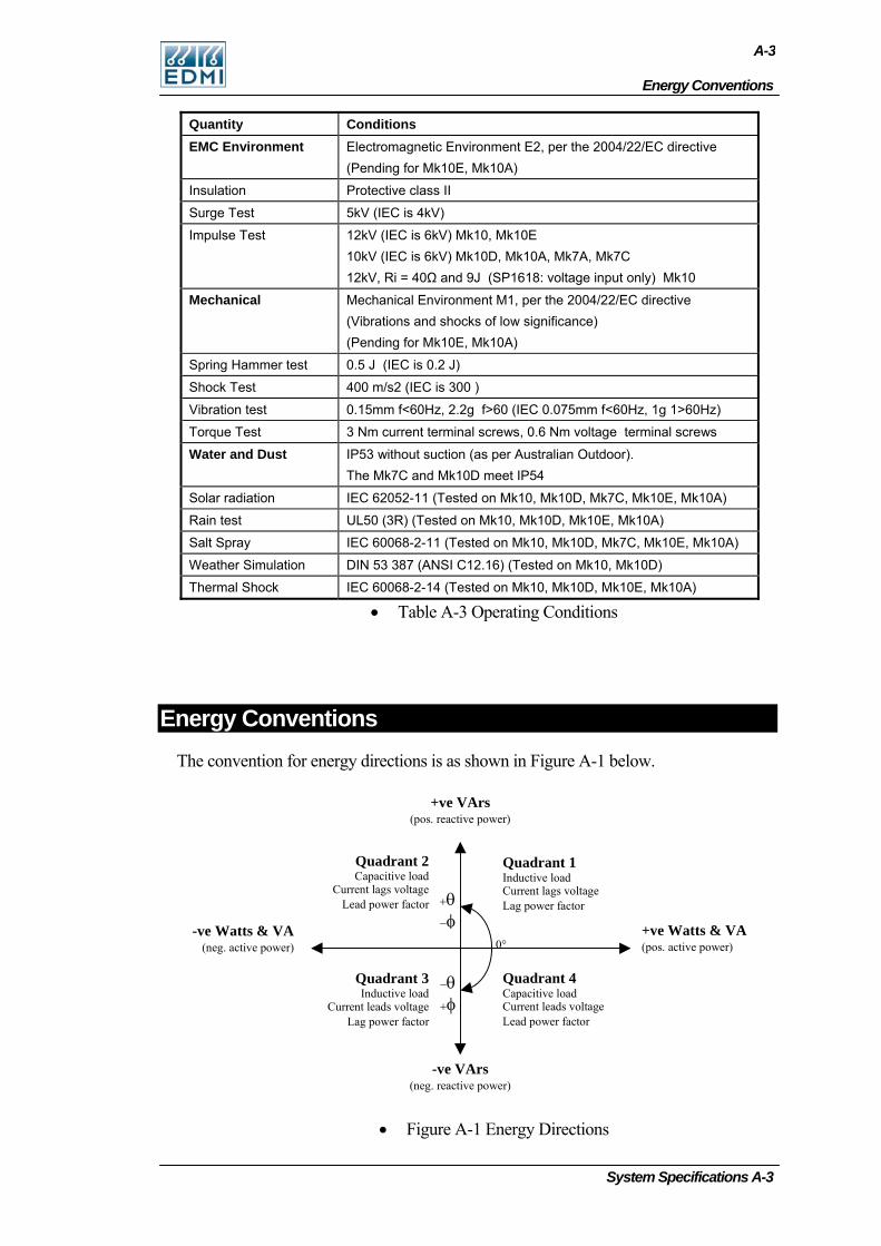
Energy Conventions
A-3
System Specifications A-3
Quantity Conditions EMC Environment Electromagnetic Environment E2, per the 2004/22/EC directive
(Pending for Mk10E, Mk10A)
Insulation Protective class II
Surge Test 5kV (IEC is 4kV)
Impulse Test 12kV (IEC is 6kV) Mk10, Mk10E 10kV (IEC is 6kV) Mk10D, Mk10A, Mk7A, Mk7C 12kV, Ri = 40Ω and 9J (SP1618: voltage input only) Mk10
Mechanical Mechanical Environment M1, per the 2004/22/EC directive (Vibrations and shocks of low significance) (Pending for Mk10E, Mk10A)
Spring Hammer test 0.5 J (IEC is 0.2 J)
Shock Test 400 m/s2 (IEC is 300 )
Vibration test 0.15mm f<60Hz, 2.2g f>60 (IEC 0.075mm f<60Hz, 1g 1>60Hz)
Torque Test 3 Nm current terminal screws, 0.6 Nm voltage terminal screws
Water and Dust IP53 without suction (as per Australian Outdoor). The Mk7C and Mk10D meet IP54
Solar radiation IEC 62052-11 (Tested on Mk10, Mk10D, Mk7C, Mk10E, Mk10A)
Rain test UL50 (3R) (Tested on Mk10, Mk10D, Mk10E, Mk10A)
Salt Spray IEC 60068-2-11 (Tested on Mk10, Mk10D, Mk7C, Mk10E, Mk10A)
Weather Simulation DIN 53 387 (ANSI C12.16) (Tested on Mk10, Mk10D)
Thermal Shock IEC 60068-2-14 (Tested on Mk10, Mk10D, Mk10E, Mk10A)
• Table A-3 Operating Conditions
Energy Conventions The convention for energy directions is as shown in Figure A-1 below.
0°
Quadrant 2Capacitive load
Current lags voltageLead power factor
Quadrant 3Inductive load
Current leads voltageLag power factor
Quadrant 4Capacitive loadCurrent leads voltageLead power factor
Quadrant 1Inductive loadCurrent lags voltageLag power factor+θ
−φ
−θ+φ
+ve Watts & VA(pos. active power)
-ve Watts & VA(neg. active power)
+ve VArs(pos. reactive power)
-ve VArs(neg. reactive power)
• Figure A-1 Energy Directions
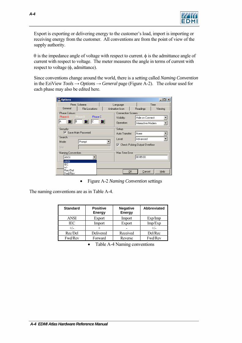
A-4
Export is exporting or delivering energy to the customer’s load, import is importing or receiving energy from the customer. All conventions are from the point of view of the supply authority.
θ is the impedance angle of voltage with respect to current. φ is the admittance angle of current with respect to voltage. The meter measures the angle in terms of current with respect to voltage (φ, admittance).
Since conventions change around the world, there is a setting called Naming Convention in the EziView Tools → Options → General page (Figure A-2). The colour used for each phase may also be edited here.
• Figure A-2 Naming Convention settings
The naming conventions are as in Table A-4.
Standard Positive Energy
Negative Energy
Abbreviated
ANSI Export Import Exp/Imp IEC Import Export Imp/Exp +/- + - +/-
Rec/Del Delivered Received Del/Rec Fwd/Rev Forward Reverse Fwd/Rev
• Table A-4 Naming conventions
A-4 EDMI Atlas Hardware Reference Manual