Embed Size (px)
Citation preview

Atlantic Sunrise Project – PA DEP Chapter 105 Joint Permit Application Transcontinental Gas Pipe Line Company, LLC Northumberland County
Revised April 2017
APPENDIX P -2
TRENCHLESS ANALYSIS

TRENCHLESS CROSSING ANALYSIS
Transcontinental Gas Pipe Line Company, LLC
ATLANTIC SUNRISE PROJECT
Central Penn Line Northumberland County, Pennsylvania
NOVEMBER 2016

ATLANTIC SUNRISE PROJECT ii Trenchless Crossing Analysis
TABLE OF CONTENTS
1.0 INTRODUCTION ......................................................................................................................................... 1
1.1 PROJECT BACKGROUND ............................................................................................................................... 2 1.2 PROJECT DESIGN AND CONSTRUCTION PRACTICES EMPLOYED ................................................................... 3
2.0 TYPICAL CONSTRUCTION METHODS ................................................................................................ 4
2.1 WATERWAY CROSSING PROCEDURES .......................................................................................................... 4 2.1.1 Dam-and-Pump Crossing ....................................................................................................................... 4 2.1.2 Flume Crossing ...................................................................................................................................... 5 2.1.3 Wet Open-Cut Crossing Method ............................................................................................................. 5 2.1.4 Duration of Construction ....................................................................................................................... 6
2.2 WETLAND CROSSING PROCEDURES ............................................................................................................. 6 2.2.1 Standard Pipeline Construction (Non-Saturated Wetlands) ................................................................... 7 2.2.2 Conventional Wetland Construction (Saturated) ................................................................................... 7 2.2.3 Push-Pull Technique .............................................................................................................................. 7
3.0 TRENCHLESS CONSTRUCTION – CONVENTIONAL BORE ........................................................... 8
3.1 CONVENTIONAL BORE TECHNIQUE .............................................................................................................. 8 3.2 CONVENTIONAL BORE RISK FACTORS ......................................................................................................... 8
3.2.1 Site Constraints and Topographic Considerations ................................................................................. 8 3.2.2 Mixed-Face Condition ............................................................................................................................ 9 3.2.3 Obstructions ........................................................................................................................................... 9 3.2.4 Soil Conditions ....................................................................................................................................... 9 3.2.5 Entry and Exit Pits ................................................................................................................................ 10 3.2.6 Drill Hole Failure ................................................................................................................................ 11
4.0 TRENCHLESS CONSTRUCTION – HORIZONTAL DIRECTIONAL DRILL (HDD) .................... 11
4.1 HDD TECHNIQUE ...................................................................................................................................... 11 4.2 HDD RISK FACTORS .................................................................................................................................. 12
4.2.1 Site Constraints and Topographic Considerations ............................................................................... 12 4.2.2 Elevation Differential and Dry Hole ..................................................................................................... 14 4.2.3 Hole Stability ........................................................................................................................................ 14 4.2.4 Obstructions ......................................................................................................................................... 15 4.2.5 Pilot Hole Steering ............................................................................................................................... 15 4.2.6 Drilling Fluid Loss, Hydraulic Fracture and Inadvertent Returns........................................................ 16 4.2.7 Poor Cuttings Removal ......................................................................................................................... 16 4.2.8 Hole Obstructions and Flushing ........................................................................................................... 17 4.2.9 Downhole Tooling Failure / Loss .......................................................................................................... 17 4.2.10 HDD Time of Installation 17
4.3 HDD ENVIRONMENTAL FACTORS ............................................................................................................. 17
5.0 SUMMARY OF CONSTRUCTION METHODS FOR ATLANTIC SUNRISE ................................... 19
6.0 RESOURCE CROSSING EVALUATION METHODOLOGY ............................................................. 20
6.1 OVERVIEW ................................................................................................................................................. 20 6.2 CONVENTIONAL BORE ASSESSMENT FOR WATERWAYS ............................................................................ 20 6.3 HDD ASSESSMENT FOR WETLANDS AND WATERWAYS ............................................................................ 24 6.4 EQUIPMENT AND SKILLED LABOR ASSESSMENT ........................................................................................ 27
7.0 RESULTS OF TRENCHLESS CROSSING ANALYSIS – NORTHUMBERLAND COUNTY ......... 28
7.1 CONVENTIONAL BORES ............................................................................................................................. 28
ATLANTIC SUNRISE PROJECT iii Trenchless Crossing Analysis
7.2 HDDS ........................................................................................................................................................ 28 7.3 GEOLOGICAL ASSESSMENTS ...................................................................................................................... 29
8.0 RESULTS OF EQUIPMENT / SKILLED LABOR ASSESSMENT ...................................................... 29
LIST OF FIGURES
Figure 1: Bore Pit Placement, Plan View ................................................................................................... 21
Figure 2: Bore Pit Depth - Determining Factors ......................................................................................... 22
LIST OF TABLES
Table 1: Summary of Construction Methods for the Atlantic Sunrise Project ........................................... 19
Table 2: Impact Comparison for WW-T47-11002 HDD. ........................................................................... 28
Table 3: Waterways Assessed for Conventional Bores – Northumberland County ................................... 30
Table 4: Waterways Assessed for HDD – Northumberland County .......................................................... 31
Table 5: Wetlands Assessed for HDD –Northumberland County .............................................................. 32
LIST OF APPENDICES
Appendix A Flow Chart of Trenchless Crossing Analysis
Appendix B Preliminary Site-Specific Crossing Detail

ATLANTIC SUNRISE PROJECT 1 Trenchless Crossing Analysis
1.0 INTRODUCTION
This Trenchless Crossing Analysis (Analysis) evaluates the potential use of trenchless construction methods to minimize impacts to wetlands and waterways associated with the proposed Atlantic Sunrise Project (Project). In August 2015, Transcontinental Gas Pipeline Company (Transco) submitted eight Joint Permit Applications for a Water Obstruction and Encroachment Permit to the Pennsylvania Department of Environmental Protection (PADEP) under Chapter 105 of Title 25 of the Pennsylvania Code. These applications covered each of the eight counties crossed by the Central Penn Line (CPL) pipeline alignment. Subsequent to issuance of Notices of Complete Application, PADEP issued technical deficiency letters on July 29, 2016 requesting additional information on the eight applications.
One of the technical deficiency requests that was common across all counties was to provide additional documentation of trenchless alternatives for crossing wetlands and waterways. Specifically, the deficiency stated ‘It appears that several waters of the Commonwealth could be crossed using trenchless installation methods. Provide a revised alternatives analysis that incorporates a discussion of alternative crossing techniques (conventional bore, HDD, micro-tunneling, etc.) addressing each resource crossing individually and explaining why trenchless installation methods are not appropriate’. Since the term ‘waters of the Commonwealth’ extends to both wetlands and waterways, Transco has incorporated both types of resources in its analysis.
In its technical deficiency regarding the use of trenchless crossing technology, PADEP provides two regulatory citations:
25 PA. Code §§ 105.13(e)(1)(viii) – Alternatives analysis. A detailed analysis of alternatives to the proposed action, including alternative locations, routings or designs to avoid or minimize adverse environmental impacts.
25 PA. Code §§ 105.18(a) – Exceptional value wetlands. Except as provided for in subsection (c), the Department will not grant a permit under this chapter for a dam, water obstruction or encroachment located in, along, across or projecting into an exceptional value wetland, or otherwise affecting an exceptional value wetland, unless the applicant affirmatively demonstrates in writing and the Department issues a written finding that the following requirements are met:
(1) The dam, water obstruction or encroachment will not have an adverse impact on the wetland, as determined in accordance with § § 105.14(b) and 105.15 (relating to review of applications; and environmental assessment).
(2) The project is water-dependent. A project is water-dependent when the project requires access or proximity to or siting within the wetland to fulfill the basic purposes of the project.
(3) There is no practicable alternative to the proposed project that would not involve a wetland or that would have less effect on the wetland, and not have other significant adverse effects on the environment. An alternative is practicable if it is available and capable of being carried out after taking into consideration construction cost, existing technology and logistics. An area not presently owned by the applicant which could reasonably be obtained, utilized, expanded or managed to fulfill the basic purpose of the project shall be considered as a practicable alternative.
ATLANTIC SUNRISE PROJECT 2 Trenchless Crossing Analysis
As previously presented within Attachment P of the Joint Permit Application, the objective of Transco’s alternatives analysis is to develop proposed pipeline routes that will be constructible, accomplish the Project’s purpose, and will avoid or minimize potential adverse environmental impacts and landowner concerns. This analysis was developed to be consistent with the Federal Energy Regulatory Commission’s regulatory requirements as set forth in 18 Code of Federal Regulations 380.15 and 25 PA. Code § 105.13(e)(viii).
An overview of routing considerations is provided in Section 1.2, and alternative routes considered have been presented in Resource Report 10, submitted as a part of Transco’s application to the Federal Energy Regulatory Commission (FERC) for a Certificate of Public Convenience and Necessity. Furthermore, Transco will provide field routing notes within the updated application in response to PADEP’s technical deficiency #13 issued for Northumberland County. Although this report focuses on construction techniques as a means of impact avoidance and minimization, Transco has a taken a holistic approach to minimize impacts using a combination of route selection, construction techniques, and best management practices.
To provide a complete response to this technical deficiency request, Transco has evaluated the potential use of trenchless installation techniques based on specific criteria for both wetlands and waterways. This analysis provides the following: a general description of the Project; an overview of and limitations associated with the various construction techniques used to install the pipeline across or under wetlands and waterways; a description of the systematic methodology used to determine feasibility of trenchless installation for both types of resources; the results of the analysis on an individual resource basis; an assessment of skilled labor and equipment availability to complete trenchless crossings and a discussion of the how this analysis has or has not modified the Project-related impacts to wetlands and waterways.
1.1 Project Background
The Project is a proposed expansion of the existing Transco natural gas transmission system. This proposed expansion will enable Transco to provide 1.7 million dekatherms per day of incremental firm transportation of natural gas from the Marcellus Shale production areas in northern Pennsylvania to its existing market areas, extending as far south as the Station 85 Pooling Point in Choctaw County, Alabama.
The Project includes modifications to the existing Transco Mainline system consisting of the following primary components:
58.6 miles of new 30-inch-diameter and 127.3 miles of 42-inch-diameter greenfield pipeline in Pennsylvania (Central Penn Line);
2.5 miles of new 36-inch-diameter and 8.5 miles of 42-inch-diameter pipeline loops in Pennsylvania;
Two new compressor stations in Pennsylvania;
Additional ancillary facilities, such as mainline valves (MLVs), cathodic protection, communication facilities, and internal inspection device (e.g., pig) launchers and receivers in Pennsylvania;
Two new meter stations and three new regulator stations with interconnecting piping in Pennsylvania;
Additional compression and related modifications to two existing compressor stations in Pennsylvania; and
ATLANTIC SUNRISE PROJECT 3 Trenchless Crossing Analysis
Modifications to the existing Transco Mainline system in other states to enable new north-to-south capabilities (bi-directional flow) to transport this new source of natural gas to existing markets.
1.2 Project Design and Construction Practices Employed
Transco has sought to avoid or minimize impacts to sensitive resources, to the extent practicable, by utilizing design and construction practices as detailed below.
When identifying routing options, Transco attempted to co-locate the pipeline with existing utility corridors and Right-of-Ways (ROWs) while considering impacts on other environmental factors. The use of co-location as a principal design element is consistent with the FERC guidelines, which stress the corridor concept, and complements the existing land use characteristics in the Project area. Siting pipeline facilities along existing corridors reduces the need to establish new corridors in previously undisturbed areas, which reduces the amount of fragmentation of interior forest and minimizes the number of affected landowners. Transco defines co-location as siting a pipeline ROW that:
Lies within an existing ROW or easement; or Abuts an existing ROW or easement.
The following routing considerations influenced the development of the proposed routes:
Identifying crossing locations of the Susquehanna River where, based on terrain, horizontal directional drilling (HDD) appeared to be technically feasible;
Crossing areas of significant topographic relief where technically feasible;
Avoiding state lands, including state parks, state forests, and state game lands to the extent practicable; and
Avoiding densely populated areas to the extent practicable.
After taking the above into consideration, Transco narrowed its analysis to 600-foot-wide study corridors for the CPL North and CPL South pipeline routes, which were determined based on desktop data and aerial reconnaissance (helicopter overflights). Once this initial routing process was complete, Transco then began field routing efforts within these study corridors. These field efforts began in May 2014 and have been completed to the extent that landowner approval has been granted.
Transco used various data sources to identify and evaluate pipeline route alternatives, including: observations made during routing surveys and field reconnaissance; Google Earth™; geographic information system databases from county, state, and federal sources; recently produced aerial photography; U.S. Geological Survey (USGS) topographic maps; National Wetland Inventory maps; and remote-sensing data. The factors used to select the proposed routes over the alternative routes focused on the FERC scoping information, landowner concerns, minimizing the number of affected landowners, minimizing adverse environmental impacts, ensuring constructability, and promoting safety.
Since field surveys began in the spring of 2014, Transco has refined the alignment of the Central Penn Line to avoid or minimize impacts to sensitive resources to the extent practicable. Since the initiation of the FERC pre-filing process, Transco has adopted approximately 190 reroutes and 91 minor deviations, resulting in a modification of approximately 150.25 miles (84.1 percent) of the pre-surveyed pipeline route.
ATLANTIC SUNRISE PROJECT 4 Trenchless Crossing Analysis
The construction and restoration procedures described in the Project Environmental Construction Plans (ECPs) are anticipated to fully restore and stabilize temporarily disturbed workspace locations, and promote natural revegetation of the ROW. During operation of the Project, Transco will be limiting the permanently maintained corridor to 50 feet in width centered over the pipeline in uplands. Areas where forested and scrub-shrub wetlands currently exist will reduce the permanently maintained portion of the ROW to 10 feet in width centered over the pipeline. Select removal of trees within 15 feet of the pipeline with roots that could compromise the integrity of the pipeline coating will also be conducted within forested wetlands. To minimize potential Project-related impacts on sensitive or high quality waterways supporting trout fisheries, Transco is planning construction activities to occur within the in-stream work windows recommended by the Pennsylvania Fish and Boat Commission (PFBC).
2.0 TYPICAL CONSTRUCTION METHODS
2.1 Waterway Crossing Procedures
Various methods will be used to install the pipeline across waterways, depending on waterway classifications and flow conditions at the time of crossing. Consistent with the FERC Procedures, waterways are classified as “minor,” “intermediate,” or “major,” as follows:
Minor waterway includes all waterways less than or equal to 10 feet wide at the water’s edge at the time of crossing;
Intermediate waterway includes all waterways greater than 10 feet wide but less than or equal to 100 feet wide at the water’s edge at the time of crossing; and
Major waterway includes all waterways greater than 100 feet wide at the water’s edge at the time of crossing.
Transco is considering the use of each waterway crossing method described below. Transco anticipates that most waterway crossings will be completed using one of the following methods and typically completed within 24 to 48 hours.
2.1.1 Dam-and-Pump Crossing
The dam-and-pump crossing method consists of diversion structures used to temporarily dam the waterway, which can consist of one or more of the following: concrete jersey barriers, water bladders, port-a-dams, steel plates, and/or sand bags. The selection of the dam type or material depends on the stream or waterway depth, flow velocity, channel width, and flow type.
This method for crossing streams and waterways temporarily diverts stream flow around construction area activities while maintaining downstream flow at all times. Damming structures will be installed upstream and downstream of the proposed trench. Pumps and hoses will be used to convey flow around the in-stream work area, discharging the water downstream of the construction site and creating a dry work area. Multiple discharge pumps may be required to keep the area dry and maintain adequate flow to avoid flooding of the waterway upstream. The trench then will be excavated, and the pipe will be installed in the dry ditch.
While the upstream and downstream dams are being installed, the pumps will be used to divert water around the pipeline crossing and associated workspaces. The water will be discharged to the downstream area through an energy dissipating (or similar) device to prevent erosion and scouring and minimize turbidity. Once the pipe is installed, the trench will be backfilled to preconstruction contours, and stream banks will be restored prior to restoring water flow.
ATLANTIC SUNRISE PROJECT 5 Trenchless Crossing Analysis
The following additional stipulations will apply to all dam-and-pump waterway crossings:
Sufficient pumps, including on-site backup pumps, will be used to maintain downstream flows;
Dams will be constructed with materials that prevent sediment and other pollutants from entering the waterway;
Pump intakes will be screened to minimize entrainment of fish; and
Dams and pumps will be continuously monitored to ensure proper operation throughout the waterway crossing.
2.1.2 Flume Crossing
Flume pipe(s) will be installed over the trench prior to trenching (or during trenching if a rain event creates flow in a dry stream channel). Flume pipes will remain in place and be maintained until restoration of the waterway is complete, and downstream flow will be maintained at all times. The size and number of flumes will be determined prior to installation based on engineering calculations and will be adequate to handle the maximum anticipated flow during the time of the crossing. Excavation equipment located on the stream banks will work around the flume pipe during excavation. The pipe will be threaded under the flume pipe, and the ditch will be backfilled while flows are maintained through the flume pipe(s) and downstream. Flume pipes will be permanently removed as part of restoration.
The following additional stipulations will apply to all flume waterway crossings:
Sand bags or sand bag with plastic sheeting diversion structures or equivalent will be used to develop an effective seal and to divert stream flow through the flume pipe;
Flume pipes will be properly aligned to prevent bank erosion and stream bed scour;
Flume pipes will not be removed during trenching, pipe laying, or initial stream bed restoration activities; and
All flume pipes and dams that are not part of the equipment bridge will be removed as soon as final cleanup of the stream bed and bank is complete.
2.1.3 Wet Open-Cut Crossing Method
The wet open-cut construction method involves the excavation of the pipeline trench across the waterway, installation of a prefabricated pipeline segment, and backfilling of the trench with excavated material. Depending on the width of the crossing and the reach of the excavating equipment, excavation and backfilling of the trench will generally be accomplished using backhoes or other excavation equipment operating from one or both banks of the waterway. Excavated material from the trench will be placed on the bank above the ordinary high water mark for use as backfill. The pipe segment can be weighted, as necessary, to provide negative buoyancy and placed below scour depth. Typical backfill cover requirements will be met, contours will be restored within the waterway, and the banks will be stabilized via seeding and/or the installation of erosion control matting or riprap, per applicable regulatory approvals.
The following additional stipulations will apply to wet open-cut stream crossings:
In-stream construction activities (including trenching, pipe installation, backfill, and streambed restoration) will be completed within 24 hours when crossing minor waterways and within 48 hours
ATLANTIC SUNRISE PROJECT 6 Trenchless Crossing Analysis
when crossing intermediate waterways, unless site-specific conditions make completion with these time frames infeasible;
Operation of equipment in the waterway will be limited to that needed to construct the crossing; and
Material excavated from the trench will be stockpiled in the construction ROW at least 10 feet from the water’s edge or in additional extra work areas.
2.1.4 Duration of Construction
Open-cut crossings of waterways less than 100 feet in width are typically completed within 24 to 48 hours. While restoration activities may occur over a longer period of time, the physical process of installing the pipeline across the stream is done in an expedited manner to minimize in-stream activity and associated impacts. With respect to timing of activities, the open-cut crossing method is the fastest of any of the crossing methods described herein.
2.2 Wetland Crossing Procedures
The width of the construction ROW will be limited to 75 feet in wetlands, except where ATWS is requested for site-specific conditions. Operation of construction equipment through wetlands will be limited to only that necessary for each stage of pipeline installation (e.g., clearing, trenching). Topsoil segregation techniques will be used in unsaturated wetlands to preserve the seed bank and allow for successful restoration. Wetland crossing methods will be determined based on site-specific conditions. Transco will use one of the following methods to install the pipeline within wetlands (please note that all methods will not necessarily be used in every county crossed):
Standard Pipeline Construction (non-saturated wetland), Conventional Wetland Construction (saturated wetland), and/or Push-Pull Technique (inundated wetland).
Transco will use the standard pipeline construction method in wetlands where soils are non-saturated and able to support construction equipment at the time of crossing. The conventional wetland construction method will be used for crossing wetlands with saturated soils or soils unable to support construction equipment without considerable soil disturbance. Inundated wetlands may require installation via the push-pull method, in which the pipe will be floated along the open trench. The welded pipe will be pushed along the water-filled trench until it is in place. Once in place within the trench, the floats attached to the pipe will be removed and the pipe will be allowed to sink into place.
Transco will construct the Project through wetlands in accordance with its Project-specific ECP as well as the FERC Wetland and Waterbody Construction and Mitigation Procedures and applicable federal and state environmental permit conditions. Transco will implement minimization measures within wetlands including workspace reduction and segregation of topsoil within the trenchline. Additionally, Transco will not remove stumps within wetlands with the exception of those directly within the trenchline and where stumps may present a safety concern for equipment and/or construction personnel. Wetlands will be restored subsequent to completion of construction, and there is no permanent wetland loss associated with the Project.

ATLANTIC SUNRISE PROJECT 7 Trenchless Crossing Analysis
2.2.1 Standard Pipeline Construction (Non-Saturated Wetlands)
The Standard Pipeline Construction method will be utilized in wetlands where soils are non-saturated and able to support construction equipment at the time of crossing. This method requires segregation of topsoil from subsoil along the trenchline. Where present, a maximum of 12 inches of topsoil will be segregated from the area disturbed by trenching, except where soils are frozen, standing water is present or soils are saturated, or where shallow depth to bedrock exists. These exceptions will be identified in the field with the Environmental or Agricultural Inspector. Topsoil segregation is followed by trench excavation, pipe laying, backfilling, and grade restoration. Immediately after backfilling is complete, the segregated topsoil is restored to its original location. Erosion control measures, including site-specific contouring, silt fence, hay-bale barriers, permanent slope breakers, mulching, and reseeding or sodding with soil-holding vegetation, will be implemented. Contouring will be accomplished using acceptable excess soils from construction. Where this method is to be implemented for construction, the environmental inspector will measure the pre- and post-construction soil density using a penetrometer to determine if the soil has been inadvertently compacted during construction or access. If the soils are found to be compacted, de-compaction of the soil will be conducted using a harrow, paraplow, paratill, or other equipment. Deep subsoil shattering, if necessary, will be performed with a subsoiler tool having angled legs.
2.2.2 Conventional Wetland Construction (Saturated)
The Conventional Wetland Construction method will be used for crossing wetlands with saturated soils or soils unable to support construction equipment without considerable soil disturbance. Prior to crossing and movement of construction equipment through these wetlands, the ROW will be stabilized using equipment mats to allow for a stable, safe working condition. Unless soils are inundated or saturated, a maximum of 12 inches of topsoil will be segregated from the area disturbed by trenching. Trench spoil will be stockpiled temporarily in a ridge along the pipeline trench. Gaps in the spoil pile will be left at appropriate intervals to provide for natural circulation or drainage of water.
While the trench is being dug, the pipeline will be assembled in a staging area located in an upland area. The pipe will then be moved from the assembly area to the ROW. After the pipeline is lowered into the trench, wide track bulldozers or backhoes supported on equipment mats will be used for backfill, final cleanup, and grading. This method will minimize the amount of equipment and travel in wetland areas.
2.2.3 Push-Pull Technique
Construction in saturated/inundated wetland areas may involve the Push-Pull Technique. The Push-Pull Technique is used in large wetland areas (>300 feet crossing length) where sufficient water is present for floating the pipeline in the trench, and grade elevation over the length of the push-pull area will not require damming to maintain adequate water levels for flotation of the pipe. If dry conditions prevail, the push-pull method will not be viable. This method involves pushing the prefabricated pipe from the edge of the wetland or pulling the pipe with a winch from the opposite bank of the wetland into the trench. For implementation of this technique, initial clearing within the wetland will be minimized. The width of the ROW cleared will be limited to only that necessary to install the pipeline. Grading in inundated wetlands will be held to a minimum and generally will not be necessary, due to the typically level topography and the absence of rock outcrops in such areas.
Equipment mats may be placed over existing vegetation where grading is not required. Trees and brush will be cut at ground level by hand, with low ground pressure equipment, or with equipment supported by equipment mats. Transco will not use dirt, rock, pulled tree stumps, or brush rip-rap to stabilize the travel lane, and sediment barriers will be installed prior to grading, as needed, to protect adjacent wetland areas.

ATLANTIC SUNRISE PROJECT 8 Trenchless Crossing Analysis
The trench will be excavated using amphibious excavators (pontoon mounted backhoes) or tracked backhoes (supported by fabricated equipment mats or floats). The excavated material will be stored adjacent to the trench, if possible. If storage of excavated material next to the trench is not possible, the material will be stored temporarily in one of the following locations: (1) in upland areas of the ROW as near to the trench as possible, (2) in construction vehicles, or (3) at an approved off-site staging location until needed for backfilling. The pipe will be stored and joined at staging areas (push and pull sites) located outside of the wetland. Floats may be attached temporarily to give the pipe positive buoyancy. After floating the pipe into place, these floats will be cut and the negatively buoyant pipe will settle to the bottom of the ditch. This operation will be repeated, with pipe sections fabricated, welded together, and pushed into place until the wetland crossing is complete. The excavated material then will be placed over the pipe to backfill the trench.
3.0 TRENCHLESS CONSTRUCTION – CONVENTIONAL BORE
3.1 Conventional Bore Technique
Conventional boring consists of creating a shaft/tunnel for a pipe to be installed to minimize surface disturbance. This is accomplished by first excavating a bore pit and a receiving pit. The bore pit is excavated to a depth that allows the pipeline to maintain a safe clearance underneath the resource being avoided, and is graded such that the bore will follow the proposed angle of the pipe. A boring machine is then lowered to the bottom of the bore pit to tunnel using a cutting head mounted on an auger. The auger rotates through a bore tube, both of which are pushed forward as the hole is cut. The pipeline is then installed through the bored hole and welded to the adjacent pipeline. The typical workspace configurations required for boring operations consists of approximately two, 50 foot by 100 foot staging areas for boring machine setup, cuttings/return settlement and storage pits, pipe storage, entrance and exit pit spoil storage and construction equipment necessary to support the operation, in addition to nominal workspace required for conventional lay. Topography and subsurface conditions can greatly influence the workspace associated with a conventional bore. Additionally, a travel lane and temporary bridge will be necessary during construction to facilitate movement of equipment for construction activities. The duration of construction for conventional bore crossings of wetlands and waterbodies typically ranges from 3 to more than 4 weeks, depending on the pipe diameter, crossing length, topography, soil conditions, and the need for blasting in areas of shallow bedrock.
ROW corridors will be maintained as described in Attachment J of the application submitted in March 2015.
3.2 Conventional Bore Risk Factors
It is important to predicate any discussion of trenchless construction risk with the understanding that although risk factors may be identified and presented individually, in the context of overall construction risk, the factors should be considered interrelated and in varying degrees, reactive with and upon one another. Thus, the risks should be evaluated as a whole.
3.2.1 Site Constraints and Topographic Considerations
The existing ground topography and site features may require significant entry and exit pit excavation depths to obtain the desired depth of cover for the conceptual conventional bore beneath the deepest part of the waterbodies. Soil borings would be required to fully evaluate subsurface conditions, necessitating tree clearing and grading of steep slopes for the drilling equipment to access the boring locations, which would

ATLANTIC SUNRISE PROJECT 9 Trenchless Crossing Analysis
need to be as near to the waterbody as possible. Other site and topographic constraints are discussed in the paragraphs below.
3.2.2 Mixed-Face Condition
A mixed-face condition occurs when the cutting tool encounters both soil and rock formations in the tunnel face. This can result in difficulties in boring including, but not limited to, deflection of the conventional bore tooling and pipe, seizing of the auger as it encounters boulders along the soil-rock interface, and over-mining of soil which can lead to soil raveling into the bore pipe.
Soil borings would be needed to fully evaluate the subsurface soil conditions, potentially necessitating tree clearing and grading of steep slopes for drilling rig access. The depth of cover may need to be increased to contain the conventional bore within a homogeneous soil strata, resulting in deeper entry and exit pits and increased workspace sizes.
3.2.3 Obstructions
Conventional auger boring techniques will be at a risk of encountering obstacles (cobble and boulders) that would potentially stop the forward movement of the bore pipe casing. Generally, an auger bore can ingest a cobble or boulder up to one-third the diameter of the casing. For a 30-inch-diameter sacrificial bore pipe this would be about a 10-inch cobble, while a 42-inch-diameter bore pipe could ingest a 14-inch diameter boulder. Cobble and boulder size clasts in excess of 10 or 14 inches in diameter could be encountered and may not be of ingestible size if fully within the tunnel zone, and/or potentially too hard to be broken down to an ingestible size if partially within the tunnel zone, resulting in stopping the forward movement of the sacrificial bore pipe. These features may not be present in soil boring data and therefore present a high risk during construction.
If an obstruction is present that stops the forward movement of the sacrificial bore pipe and/or the augers, there are limited remedies to remove the obstruction. Since man-entry is not an option, the only recourse would be to either use a pipe ram to try to advance the sacrificial bore pipe, to use a down-the-hole hammer to break up the obstruction, or to access the face of the auger bore from the ground surface to remove the obstruction. Both pipe ram and down-the-hole hammer options are risky with no guarantee of success. The last resort would be to use a pipe ram in reverse to pull the sacrificial bore pipe out, and try crossing at a different location or elevation where the geology may be more favorable. If forward movement of the sacrificial bore pipe is halted, and attempting a crossing at a different adjacent location is the most feasible option remaining, new or expanded entry and exit pit excavations may be required as well as additional dewatering as needed, and potentially the expansion of additional temporary workspace.
3.2.4 Soil Conditions
If soils with lower clay contents are encountered during construction, these soils may present the challenge of flowing soils with all of the above-referenced potential risks. If flowing soils are encountered the entire tunnel zone would likely need to be dewatered and the waterbody diverted to accomplish the auger bore. Dewatering may generate large volumes of water that will require handling and disposal. Such dewatering measures would likely lower the groundwater table as well. The disturbance associated with constructing dewatering wells across the waterbody channel may negate the desired benefits of a trenchless method of construction.
ATLANTIC SUNRISE PROJECT 10 Trenchless Crossing Analysis
3.2.5 Entry and Exit Pits
The soils near the boring and the depths of the bore pits will present challenges with respect to shoring for entry and exit pit construction. Ground water is anticipated to be present during construction. These excavations may require continuous (entry pit) and temporary (exit pit) dewatering, which could generate large volumes of water that will require handling and disposal and could lower the groundwater table within the waterbody. Shoring will be necessary for protection of workers and equipment. Sheetpile shoring is frequently used for conventional bore construction. However, the density of the soils at depth, the presence of cobbles and boulders, the unknown depth of bedrock, and the required depths for installation may limit the ability to drive the sheet piles into place. Blasting may be needed to install the pits if consolidated rock is encountered.
Worker safety is a top priority. Per company Job Safety Analysis (JSA) policy and in accordance with Occupational Safety and Health Administration (OSHA) regulations, Transco has identified multiple safety hazards associated with the conventional bore crossing method. Specifically, the work required to be conducted within the entry and exit pits (i.e., confined space) poses significant risks due to the pit depth (20-feet and greater) and the potential for unanticipated and sudden flooding (below water table for majority of pit depth).
Conventional bores are typically used to cross features that have a higher elevation than the adjacent landscape, where entry and exit bore pits would be located. Bore pit depths associated with such crossings (often roadways) do not pose a significant hazard. However the crossing of streams and wetlands, where the feature is below the elevation of the start and end of a bore, adds many additional challenges and hazards. The largest hazard is the extra excavation/depth required to develop the necessary depth of cover between the pipe and feature. While a 10-foot to 15-foot bore pit depth may be typical for a road crossing, steep terrain may put the necessary depth of a wetland or waterbody pit over 20-foot in depth. This requires additional safeguards (such as trench boxes, dedicated safety teams,) etc. As the pits become deeper, more workspace is required to store the excavated pit material and to bench/slope the work area around the pit for safety and construction equipment access. As many waterbodies are in forested areas, these extra workspaces will have direct impacts on forested areas adjacent to the pits. Wetlands have a tendency to be located adjacent to streams as well. It may be necessary to store spoils on top of matting or excavate within the wetlands to install the bore pits successfully.
There is also a risk of the bore pipe becoming a conduit for the groundwater and then subsequently flooding the entry pit suddenly, thereby creating a hazard for the operators. Transco is committed to protecting the safety of both Company and Contractor personnel by minimizing exposure to hazards. Through execution of the Company hazard assessment policy, the basic hazards associated with work conducted in a confined space (e.g., ease of ingress/egress from the pits, air quality, and excavation wall stability) can be mitigated, though excessive depth will require an extensive cave-in protection system to be designed by a professional engineer. While the cave-in hazard may be mitigated, the extended depths cannot be avoided. This depth substantially increases the risks of all associated hazards (e.g., worker injury resulting from suspended loads) and could significantly hamper evacuation in the event of an emergency. In addition, the hazards associated with unforeseen/unknown circumstances, specifically the volume of water that could enter the pits via the bore pipe and the speed with which it could enter, cannot be avoided or mitigated with absolute certainty.
Transco has evaluated the hazards associated with both the conventional bore and open-cut crossing methods. While open-cut crossing methods also present challenges, including work within excavations, the associated hazards can be better mitigated. For example, the depth of bell holes used to tie-in the waterbody pipe segment would be approximately 8-feet, which can be mitigated through excavation
ATLANTIC SUNRISE PROJECT 11 Trenchless Crossing Analysis
(benching/sloping) and shoring techniques. Open-cut crossing methods eliminate both worker exposure to the deep pits and the potential for flooding via the bore pipe.
3.2.6 Drill Hole Failure
Drill hole failure (collapse of the drill hole) during drilling operations is one of the greatest risks to the successful completion of a conventional bore. If flowing soils are encountered, the bore pipe can become a conduit and suddenly flood the entry pit without warning. The streambed could collapse through the bore pipe requiring extensive restoration as well as draining the stream.
4.0 TRENCHLESS CONSTRUCTION – HORIZONTAL DIRECTIONAL DRILL (HDD)
4.1 HDD Technique
HDD is a trenchless method of installing pipelines in areas where neither traditional open cut excavations nor conventional bores are feasible due to sensitive resource areas or logistical reasons. With an HDD, open cut trenching and equipment disturbance may not be necessary near the sensitive resource, and as a result, environmental impacts on sensitive resource areas are minimized. However, a greater amount of equipment staging workspace is required for HDD than for the open cut crossing method, and typical installation of an HDD segment will take several months.
In ideal conditions, a minimum workspace footprint of 200 feet wide by 250 feet long is typically required at both the entry and exit points to support the drilling operation. The amount of workspace required can increase significantly based on site specific conditions. The entry-side equipment and operations typically will include the drilling rig and entry hole, control cab, drill string pipe storage, site office and tool storage trailers, power generators, bentonite storage, bentonite slurry mixing equipment, slurry pump, cuttings separation equipment, cuttings return/settlement pit, water trucks and water storage, and the heavy construction equipment necessary to support the operation.
Exit-side equipment and operations typically will include the exit point and slurry containment pit, cuttings return/settlement pit, cuttings separation and slurry reclamation equipment, drill string pipe storage, and the heavy construction equipment necessary to support the operation. In addition to the footprint associate with drilling operations, Additional Temporary Workspace (ATWS) will be required along the working side ROW. ATWS in the form of false ROW may be required at HDD locations where the ROW changes direction from the orientation of the drill. This false ROW provides a straight corridor for handling pipe and prefabricating the pipeline into one continuous section in preparation for the pull-back. Because this false ROW must be relatively straight to accommodate a long section of pipe before it is pulled through the annulus, a significant area of ATWS would be required outside of the standard pipeline construction workspace. Once assembled, the pipeline will be placed on pipe rollers so that it may be conveyed into the drill hole during the pull-back operation.
Risks associated with a HDD crossing technique include:
Potential inadvertent returns of fluids and tailings during HDD drilling operations;
Potential drill hole collapse during construction or subsequent settlement of HDD locations following installation;
Pipeline inaccessibility for visual inspection and repairs;
ATLANTIC SUNRISE PROJECT 12 Trenchless Crossing Analysis
Pipeline denting and/or coating damage during pullback ;and
Uneven cathodic protection on the pipeline.
Transco has developed a HDD Contingency Plan (Appendix 3 of the Environmental Construction Plan) to establish procedures for addressing potential impacts associated with an inadvertent release of drilling fluid through hydraulically-induced cracks. The plan identifies operational procedures and responsibilities for the prevention, containment, and clean-up of drilling fluids in the event a release occurs to the ground surface or within a waterway during HDD operations. Uneven cathodic protection across a pipeline segment can occur due to the effects of geologic strata changes and difficulty in identifying interference with cathodic protection due to external forces. Although Transco uses in-line inspection tools to identify anomalies as part of its integrity management program, the depth of the HDD pipe does not allow potential anomalies to be visually inspected and verified, and anomalies cannot be accessed for repair. Such anomalies may include external coating defects, corrosion, stress corrosion cracking, and dents. Therefore, the pipe utilized for HDD operations is generally a thicker-walled diameter pipe that is subject to x-ray inspection following assembly, and is treated with fusion-boned epoxy coating and coated with abrasion-resistant overlay prior to installation. These measures minimize the potential for damage or corrosion occurring to the pipeline.
The length of land-based 30-inch HDDs are limited to approximately 7,000 feet in length for the highest probability of success, while 42-inch HDDs are limited to approximately 6,000 feet in length. The longer the length, the more forces are applied to the pipe and the larger potential for failures and additional pullback area restraints.
4.2 HDD Risk Factors
It is important to predicate any discussion of trenchless construction risk with the understanding that although risk factors may be identified and presented individually, in the context of overall construction risk, the factors should be considered interrelated and in varying degrees, reactive with and upon one another.
4.2.1 Site Constraints and Topographic Considerations
In an effort to reduce the risk of hole collapse, hole flushing and dry hole conditions, HDD’s are designed with an entry and exit point at or near the same elevation. When a significant elevation difference between the entry and exit point is unavoidable, a portion of the drilled hole will not be filled with drilling fluid. In rock formations, this increases the risk of drill tool failure because the tools may not be adequately cooled and lubricated through the dry section of the hole, despite drilling fluid being pumped during operations. In soil formations, the risk of hole collapse is also elevated, which may lead to ground surface settlement along the HDD alignment, damage to structures, inadvertent drilling fluid release to the surface, or a stuck pipe during pullback operations.
Locating suitable areas for entry and exit sites can be challenging, especially in steep, hilly terrain. The site needs to be as flat as possible, and any relief on the site in question will need additional space to grade and stockpile soil, which would further increase impacts to the surrounding resources (i.e., trees, wetlands, agricultural fields). In ideal conditions, a normal entry site can be as small as an acre, however this can grow substantially dependent upon the terrain and other site conditions. The length separating the entry and exit point is also a function of the pipe’s allowable bending radius, as well as the terrain and soil conditions. This bending radius dictates the minimum horizontal length that an HDD can accommodate; it will take a substantial horizontal distance to allow the pipe to travel underneath the sensitive resource and

ATLANTIC SUNRISE PROJECT 13 Trenchless Crossing Analysis
curve back up to its typical depth of cover. Even if a feature is only a few feet wide, if an HDD is required, it could take several thousand feet for the HDD to cross features in a steep valley. HDDs may also be lengthened to avoid certain soil strata that are more susceptible to inadvertent returns.
Due to the radius of curvature required to install a large diameter pipeline using the HDD technique, the pipe is usually installed at depths greater than 50-feet below the ground surface, which poses considerable operational implications. If in-line inspection activities indicate that maintenance or repairs are needed for a section of pipe that has been installed using the HDD technique, the pipeline’s installation depth would render it inaccessible for repairs. In these cases, the section of pipe would have to be abandoned in-place. There would be additional environmental impacts resulting from the need to install a second HDD parallel and adjacent to the original HDD section, assuming adequate space is available for a replacement HDD section to be installed. As an industry practice, for long-term operations and maintenance purposes, an HDD is only utilized where no other construction method is deemed feasible and where adequate space exists for a replacement pipeline in the event the HDD section must be replaced (e.g., at very large river crossings).
To support an HDD, a minimum workspace of 200-feet wide by 250-feet long is typically required at the entry and exit points. Additionally, a pullback stringing workspace of 50-feet in width by the length of the crossing (1,300-feet to 6,000-feet or more in length) to place and weld pipe before it is pulled through the hole. The acreage of workspace required can increase significantly if grading is required to reduce the slope across the site. Installation of storm water management controls will also increase the footprint for sites with steep slopes. Furthermore, the entry-side equipment typically includes the drilling rig, control cab, drill string pipe storage, site office and tool storage trailers, power generators, bentonite storage, bentonite slurry mixing equipment, slurry pump, cuttings separation equipment, cuttings return/settlement pit, water trucks and water storage, and the heavy construction equipment necessary to support the operation.
Topography is also a risk as the pipe is prepared for pullback operations. Steep slopes limit the amount of stringing areas and therefore increase the number of strings to be pulled through the drill hole. A single-string pull-back is preferred for HDDs because it avoids the need to stop the pullback activity to weld up separate pipe strings. A single tie-in weld can take up to eight hours to complete and apply protective coating. The longer the hole is left open without the pipeline in it, the greater the chance of a collapse of the drill hole. A single string pullback allows for a continuous force to be applied to the pipe during the pullback, and reduces the risk of the pipeline becoming stuck in the borehole (due to the potential for a localized collapse of the borehole around the pipeline, and soil set up around the pipe).
Transco views safety as a top priority. Per company Job Safety Analysis (JSA) policy and in accordance with Occupational Safety and Health Administration (OSHA) regulations, Transco has identified general safety hazards associated with HDD crossings. These include high pressure hydraulic fluid hoses, rotating equipment, pinch points, and elevated noise levels. Transco is committed to protecting the safety of both Company and contractor personnel by minimizing exposure to hazards. All stream crossing methods, including open-cut crossings, pose unique safety hazards. These hazards may be eliminated or mitigated through proper use of safety controls and personal protective equipment. However, the projected duration of the HDD process is significantly higher than the duration of an open-cut crossing.
HDDs require several teams working in tight spaces, near operating equipment, with their own separate tasks, and incidents can occur when there is not adequate communication due to all of these different teams working individually. This also increases the number of construction vehicles on-site, congesting the necessary workspace while creating concerns of foot traffic. The stringing and lifting of the pipe high into

ATLANTIC SUNRISE PROJECT 14 Trenchless Crossing Analysis
the air to adequately align the pipe into the hole causes danger from overhead and the rollers (both on the ground and on the cranes) cause many of the several other locations of pinch points.
4.2.2 Elevation Differential and Dry Hole
Elevation differential between the entry and exit points is a high risk factor to the success of an HDD, as terrain and landowner constraints will drive entry and exit locations. During HDD construction, a high elevation differential can result in the drilling fluid within the hole coming to equilibrium at the lower of the two points, causing a portion of the hole to be situated above the drilling fluid equilibrium elevation. This condition creates a “dry” section within the hole, which can increase the risk of hole collapse, groundwater intrusion and poor cuttings removal from the hole which, in turn may lead to additional risks (ground settlement, loss of drilling fluid returns, inadvertent returns, hole flushing, stuck tool/pipe).
If geotechnical investigations find high groundwater, this suggests a “dry” hole may experience groundwater intrusion that will flow towards the low (entry) side of the crossing. This will present a high risk of dilution of drilling fluids, inability to transfer cuttings out of the hole, sinkhole formation, and hole instability and collapse. Gravelly and large-grained soils can also lead to hole instability and collapse. This risk is mitigated, to a degree, by the presence of drilling fluid. However, where drilling fluids are lacking in areas of “dry” hole, this risk is more acute. The “dry” hole condition will likely result in a risk of cuttings buildup within the hole. The stability of the “dry” hole section may be improved by installing dewatering wells near the HDD alignment and/or through the installation of large diameter casing. However, casing may be difficult to drive to the extent needed to fully mitigate the risk, and dewatering may only be partially effective to control groundwater intrusion. Consideration to dewatering locations adds complexity to maintaining compliance.
4.2.3 Hole Stability
The stability of the hole during HDD operations is dependent on the type and composition of the formation, drilling fluid properties, groundwater conditions and the HDD profile geometry. Holes drilled or reamed through loose soil formations, soil formations with significant gravel content, or fractured rock formations with poor rock mass quality are prone to instabilities.
Soil Portions of the HDD Profile
Where granular soils are encountered within the hole, particularly if they lack a significant fine-grained matrix to support hole integrity, they may tend to ravel and collapse the hole. Installing large diameter casing through sections with non-cohesive soils can partially mitigate these risks. However, casing may be difficult to install to the extents required to mitigate the risks.
Rock Portions of the HDD Profile
The possible loss of hole stability through zones of highly fractured bedrock cannot be mitigated with a high level of confidence. An extensive grouting program to improve the rock mass characteristics could be attempted, however, the grouting is unlikely to be effective at stabilizing the formation. The aim of the grouting program would be to seal the fractures in the bedrock in an effort to stabilize the formation prior to the commencement of HDD operations. For the grouting program to be effective, numerous closely spaced holes would need to be drilled down vertically from the surface to the depths of the HDD profile and the grout would need to be injected at several depth intervals within each hole to attempt to create a zone of improvement.

ATLANTIC SUNRISE PROJECT 15 Trenchless Crossing Analysis
4.2.4 Obstructions
As discussed above, the HDD profile could potentially pass through soil zones that contain significant volumes of gravel, cobble, and boulder-sized materials. These granular soils can present risk to HDD operations in addition to of the risk of hole stability described above. Even if the soil contains sufficient fine-grained matrix (silt and clay) to maintain hole stability in gravelly soils, gravel and larger-sized rock particles within the cross section of the hole are too large to be carried out of the hole by the drilling fluid during pilot hole, reaming and swabbing operations. This can lead to an accumulation of this coarse material within the hole. In some instances, this material can be pushed aside into the wall of the hole or be broken down into smaller particles during subsequent reaming and swabbing operations. The denser the formation, the less likely the larger particles will be pushed into the walls of the hole. The portion of this material that is not pushed aside or broken down can create difficulties during pullback operations and may cause the product pipe to become lodged in the hole or damage the product pipe during pullback. This effect may range from sudden to gradual depending on the location and volume of accumulated material.
In addition to the accumulation of large particles downhole, the bottom hole assembly (BHA) and/or reaming tools may be deflected around cobble and boulder-sized material partially protruding into the cross section of the hole. During pilot hole operations, this can result in radii of curvature below the acceptable minimum and increase the amount of time necessary to complete the pilot hole within acceptable tolerances. As a reaming tool moves past these obstacles and returns to its original path, a localized deviation in the geometry of the hole may be formed. These localized deviations can create difficulties during pullback operations depending on their location, magnitude and frequency. More specifically, these locations become “hard” points that are more likely to: (1) damage the coating and/or product pipe during pullback operations; (2) increase the pull load required to install the product pipe; and (3) cause the product pipe to become stuck in the hole because it is unable to conform to the shape of the resulting hole geometry.
4.2.5 Pilot Hole Steering
Steering difficulties can arise during pilot hole operations if the drill bit penetrates through layers of gravelly soil consisting cobble or boulder-sized material and/or rock units of varying strength and quality along the HDD profile. Developing a suitable steering pattern during pilot hole operations can be challenging. It may take drilling 60 to 100 feet of the pilot hole before the pilot hole surveyor can determine how the BHA will react to the operator’s prescribed steering inputs. By the time a steering pattern is developed, the formation may have changed and the steering pattern becomes either ineffective or too aggressive.
Once the geometry of the pilot hole begins deviating from the specified vertical or horizontal tolerance and/or the minimum horizontal and vertical curve radius tolerances, it can be difficult and time consuming to correct the deviation when drilling through gravelly soils or rock. If the pilot hole deviates outside the horizontal or vertical tolerances it may be preferable to accept the out of tolerance condition and continue drilling the pilot hole if the condition will not adversely impact the installation of the product pipe or its performance, once installed. If the out-of-tolerance condition is not acceptable, the HDD contractor will have to extract the tooling back to a location in the hole where it would be possible to “kick out” of the existing hole and begin drilling new pilot hole. If the pilot hole radius of curvature deviates from the minimum allowable radius, the HDD contractor would need to retract and attempt to correct the section of the hole that is out of specification or “kick out” and begin drilling new pilot hole, which in bedrock, can take a significant period of time.

ATLANTIC SUNRISE PROJECT 16 Trenchless Crossing Analysis
To aid in steering the BHA during pilot hole operations, the contractor can vary the components of the BHA to provide either more aggressive or less aggressive steering bias. The HDD contractor may also utilize a specialized tool as part of the BHA that can measure the inclination at the drill bit as well as at the steering probe. This can help the pilot hole surveyor more quickly judge how well the BHA is reacting to his prescribed steering inputs. If the HDD contractor is willing to make changes to the components of the BHA to better suit the conditions, we estimate that the risk of excessive steering problems may be reduced from high to moderate.
4.2.6 Drilling Fluid Loss, Hydraulic Fracture and Inadvertent Returns
Drilling fluid loss can occur as a result of either formational fluid loss or hydraulic fracture. The loss of drilling fluid downhole is accompanied by either partial or full loss of drilling fluid returns to the entry and/or exit pits. Hydraulic fracture is a term typically used to describe the condition in which the downhole drilling fluid pressure exceeds the overburden pressure and shear strength of the formation surrounding a drill path. The risk of hydraulically fracturing subsurface formations during the HDD process generally depends on the type and shear strength of the formation and the downhole drilling fluid pressures. Downhole drilling fluid pressures can easily exceed the shear strength of soil formations; however, rock formations normally have shear strengths far exceeding typical drilling fluid pressures, and therefore, the risk of hydraulically fracturing rock formations is low.
Inadvertent drilling fluid returns occur when drilling fluid emerges at the ground surface or in any other undesired location such as wetlands, utility trenches, roads, railroads and water bodies. Inadvertent drilling fluid returns may occur either as a result of hydraulically fracturing the subsurface formations or as a result of formational fluid loss. In rock formations the risk of formational fluid loss is greater than that of hydraulic fracture. Whether by formational drilling fluid loss or hydraulic fracture, relatively large volumes of drilling fluid may be released over a short period of time, particularly if the high pressure drilling fluid pumps are not immediately disengaged. Once inadvertent drilling fluid returns occur, it can be difficult to prevent fluid from continuing to surface. Transco anticipates moderate to high risk of inadvertent returns near the entry and exit points of any HDD where the depth of soil cover above the HDD is relatively low. The management of the drilling fluid properties and construction methods to promote proper drilling fluid returns help to reduce the risk of inadvertent drilling fluid returns near the entry/exit points.
4.2.7 Poor Cuttings Removal
An important aspect of the HDD process is the removal of cuttings from the annulus of the hole. If drilling fluid returns are lost to the formation, the likelihood of cuttings accumulating in the hole is significant. If soil and rock cuttings are not adequately removed from the hole, several additional risk factors can negatively impact the likelihood of a successful pipeline installation. When cuttings build up within the hole, rotary torque on the drill pipe string can increase, tool wear is increased, the risk of drilling fluid loss and subsequent inadvertent drilling fluid returns is increased as is the risk of hole flushing. At worst, the accumulation of cuttings downhole can cause the downhole tooling to become stuck, cause a twist-off downhole or cause the pipeline to become lodged in the hole during pullback operations. To decrease the risk of cuttings buildup downhole and the associated risk factors, the HDD contractor could complete reaming operations in a staged approach from both sides of the crossing (bi-directional reaming) to help promote drilling fluid returns and cuttings removal from the hole and reduce the risk of lost drilling fluid returns, inadvertent returns and hole flushing.

ATLANTIC SUNRISE PROJECT 17 Trenchless Crossing Analysis
4.2.8 Hole Obstructions and Flushing
If the hole becomes obstructed with gravel or cuttings generated during pilot hole or reaming operations, the drilling fluid level in the hole can begin to rise above the low end of the crossing into the normally dry portion of the hole. The drilling fluid will often continue to rise in the dry section of the hole until the hydrostatic pressure within the hole causes a breach in the obstruction and the drilling fluid level in the hole begins to equalize. This condition is referred to as a “hole flush”. Depending on the diameter of the hole and the height of the drilling fluid above the low side of the crossing when the hole flushes, the volume of drilling fluid that is expelled from the hole can be significant. The volume of drilling fluid expelled during the hole flush may impact sensitive areas outside of the designated workspace areas or the sensitive feature that was being avoided by use of the HDD.
4.2.9 Downhole Tooling Failure / Loss
Tooling failure can be caused by many factors including metal fatigue, general wear, improper make-up of tool joints, and abnormally high operating loads or misuse. When tooling is lost downhole, recovery efforts may or may not be successful. Downhole tooling used to complete the project will be subjected to high stresses and be more prone to metal fatigue and ultimately failure downhole with the presence of boulders and gravelly soil conditions, fractured zones of bedrock and hole instabilities.
4.2.10 HDD Time of Installation
Duration from site preparation to pipe tie-in and dependent on subsurface conditions, the HDD can take more than 6 months. Upon initiation of the HDD pullback, operation will continue twenty-four hours a day until the pipeline is pulled though the drill hole.
If encountered, hard bedrock can significantly lengthen the pilot hole and reaming process. Similarly, if cobbles/boulders or highly fractured rock is encountered along the drill path, then these soils could become dislodged and obstruct the drill, necessitating multiple drill attempts. Similarly, boulders can deflect the pilot drill bit and push the drill off of the desired alignment, also resulting in multiple drill attempts to get past the obstruction.
Surface terrain constraints also pose significant challenges to HDD installations. If multiple pullback strings are needed due to road crossings, changes in pipeline alignment, topographic constraints, etc., then the duration of the crossing is also increased. Additional risk can also be realized if multiple pullback strings are needed in that the pullback process must be stopped so that tie-in welds can be completed and protective coatings applied and allowed proper time to cure. The longer that the pullback string remains stationary downhole, the greater the pull force will be needed to break the stiction of the soil set up around the pipe. The stiction forces can become high enough that the pipe could become stuck part-way in the hole or break the drill pipe, requiring abandonment and restarting the HDD in another location.
4.3 HDD Environmental Factors
Drill hole failure (collapse of the drill hole) during drilling or pipeline pullback operations is one of the greatest risks to the successful completion of a HDD. A drill hole failure can cause an accidental release of drilling mud to the surface. If an inadvertent return of drilling mud takes place within the stream it could increase turbidity and sedimentation within the stream and migrate downstream, thus potentially altering the habitat at, and downstream of, the site of disturbance. HDDs require a greater amount of equipment than is required for trenched installation of the pipe. Large-diameter pipeline (e.g., 30- to 42-inch) HDDs typically require 90,000 to 100,000 gallons of water per day for use in the creation of drilling mud. If

ATLANTIC SUNRISE PROJECT 18 Trenchless Crossing Analysis
surface water is not available at the site, it must be identified and trucked in daily from a municipal water source. This increase in equipment onsite could increase the amount of the impacts due to traffic. The drilling mud is used to lubricate the drill stem as well as return cuttings to the surface for collection and disposal.

ATLANTIC SUNRISE PROJECT 19 Trenchless Crossing Analysis
5.0 SUMMARY OF CONSTRUCTION METHODS FOR ATLANTIC SUNRISE
Table 1: Summary of Construction Methods for the Atlantic Sunrise Project
Type Maximum Distance
(feet)
Minimum Distance
(feet)
Typical Workspace Requirements (square feet)
Typical Duration Compared to Dry
Open Cut Construction a/
Cost to Construct 1,600 Linear feet with One 30-feet Stream Crossing b/
Advantages Limitations Risks
Dry Open Cut N/A N/A
90 feet wide x length of crossing – 42-inch pipe 80 feet wide x length of crossing – 30-inch pipe
Typically 24 to 48 hours from start of excavation
through restoration $902,000
High probability of success and minimal impacts using best
management practices.
Seasonal restrictions; flow rates may necessitate a wet-open cut or trenchless (as terrain allows)
Unanticipated weather events
Conventional Bore
300 N/A 10,000 (entry and exit pit
workspace)
Five times slower than typical durations for
open cut excavations $1,302,000
Avoidance of resource; best suited for short crossing
distances.
Limited by crossing distance, subsurface soil and geologic conditions, existing topography, and groundwater.
Safety constraints related to excavation and shoring of bore pit locations. Potential drill failure resulting in abandonment and
re-drill, or implementation of an open cut design.
Horizontal Directional Drill
7,000 for 30-inch
6,000 for 42-inch
1,280 d/ for 30-inch pipe
1,700 d/ for 42-inch pipe
100,000 (entry and exit pit workspace) as well as
additional false ROW for pull-back locations. False ROW is generally 100-150 feet wide with a length dictated by the
crossing segment.
20 times slower than typical durations for
open cut excavations $5,600,000
Avoidance of resource; best suited for significant crossing
lengths.
Geotechnical investigations requiring access road development, and potential tree clearing, wetland and
waterway crossings prior to pipeline construction. Large workspace requirements for entry and exit locations.
Continuous day and night noise disturbances associated with drilling equipment, generators, water and drill fluid pumps, construction vehicles and ancillary equipment. Water consumption for drilling operations, and disposal requirements for drilling fluids. Pipeline inaccessible for visual inspection and repairs. Potential uneven cathodic
protection on the pipeline.
Potential inadvertent returns of drilling fluids; Additional workspace for access and mitigation; Potential hole collapse or subsequent settlement following installation; Potential drill failure resulting in abandonment and implementation of an
open cut design; Future repair work may necessitate the HDD segment to be abandoned in place, and another HDD
installed.
a/ Estimated durations for construction include the time necessary for workspace setup, construction and restoration when compared to typical open cut surface trenching operations. b/ Costs provided for construction were based on actual construction contractor bids received for the Atlantic Sunrise Project. All costs provided are for 42-inch pipeline work. For Dry Open Cut and Conventional Bore, costs include 1,570 feet of upland construction to achieve an apples-to-apples comparison with the 1600’ HDD length. c/ Estimates of typical workspace requirements are based on past Transco natural gas transmission projects and current proposed workspace configurations for Transco. d/ Minimum distance is a function of the maximum allowable radius of curvature as well as site-specific topography. If the elevation of the resource being avoided is higher than the HDD entry and exit locations, the shorter length presented herein can be achieved. Lower resource elevations, relative to the entry and exit elevations, will yield longer minimum lengths.

ATLANTIC SUNRISE PROJECT 20 Trenchless Crossing Analysis
6.0 RESOURCE CROSSING EVALUATION METHODOLOGY
6.1 Overview
As the lead federal agency with ultimate jurisdiction over the siting of the CPL pipeline, FERC reviews Transco’s preferred alignment as well as multiple alternatives to determine the least impactful alternative with respect to environmental resources including wetlands and waterways as well as other factors such as landowner impacts and constructability.
The use of trenchless construction methods is not feasible or practical for every wetland or waterway crossing. Trenchless construction methods can be limited by topography, unfavorable underlying geology, available workspace, available time (i.e., limited construction windows), and the inherent risks associated with use of trenchless construction methods, including extended crossing times and potential remediation of inadvertent drilling mud releases or drill failures. All of these factors must be considered to determine if trenchless construction methods are a suitable option for crossing a specific resource.
When examined in aggregate, the quantity of trenchless crossings that may be adopted are further constrained by the availability of qualified contractors that have the required equipment available. Although skilled labor and equipment availability are considerations that must be evaluated, Transco has attempted to focus this analysis on the technical feasibility of trenchless installations, environmental effects, and other risks. A flow chart depicting the phases of the analysis used is provided in Appendix B. A description of each phase is further defined within this Section below.
6.2 Conventional Bore Assessment for Waterways
Phase I: Resource Characteristics
Transco will make reasonable efforts to cross streams classified as “ephemeral” or “intermittent” during periods of no flow, resulting in minimal disturbances to dry channels which would presumably be restored prior to the return of flow. Additionally, as noted in Table 1, the associated workspace requirements to implement a trenchless crossing would present a greater overall impact to the surrounding area when factors such as equipment mobilization, site clearing, water allocations, durations and site restoration are compared to the workspace requirements and procedures to complete a dry crossing. The majority of intermittent streams to be crossed are less than five feet in width which allows for an expedited crossing without the need for significant areas of additional temporary workspace. Intermittent stream crossings will be completed and restored within 24 hours. Water quality within these resources will be protected by constructing during periods of no or low flow. Should an intermittent stream contain flowing water at the time of construction, a dry-crossing technique will be used. For these reasons, it was determined that impacts are sufficiently minimized using a typical construction method for ephemeral and intermittent features, and only streams designated as perennial continued to Phase II of the assessment.
Similarly, Transco did not consider the conventional bore crossing technique for wetland crossings because there are minimal impacts using a dry open cut construction technique. Clearing within the permanent ROW would be required during operation of the pipeline to ensure that root systems of trees do not compromise the pipe coating, and to allow for aerial inspection of the alignment. Because a swath would be cleared during construction and maintained during operation (even if a conventional bore were completed), there would be minimal impact reductions to the resource by utilizing the conventional bore installation method versus an open cut. However, there would be significant increases in impacts to resources outside of the wetlands to accommodate the workspace required for a bore. Therefore conventional bores are not practical for avoiding wetland resources.

ATLANTIC SUNRISE PROJECT 21 Trenchless Crossing Analysis
Phase II: Topography Assessment
Transco evaluated site-specific topography to determine if bore pits could be constructed in a safe manner, as previously discussed in Section 3.2.5. The following Figure 1 is a simplified plan view of a bored crossing.
Figure 1: Bore Pit Placement, Plan View
Note that the bore pits, both entry and receiving, are approximately 70 feet long for a typical 30-inch boring in ideal conditions. Bore pits are offset from floodway boundaries by a minimum 20 feet on each side to prevent any potential impacts to the floodways while the pits are being excavated or while the bore is being conducted. Bore pits may have to be further offset from the stream to avoid placement in wetlands, as depicted by the receiving pit in Figure 1.
Maximum Bore Length
The maximum distance that a bore can be completed is 300 feet. This distance is lower if soil conditions lend themselves to a higher skin friction that the pipe must overcome as it is pushed through the bore annulus. The potential bores with a bore length less than 300 feet continued to the bore pit depth assessment.

ATLANTIC SUNRISE PROJECT 22 Trenchless Crossing Analysis
Figure 2, below, demonstrates elevation considerations via a profile view of a bore pit.
Figure 2: Bore Pit Depth - Determining Factors
Where:
‐ HEP = depth of the entry pit ‐ HRP = depth of the receiving pit ‐ EPfront = grade elevation at the entry pit’s front face ‐ EPback = grade elevation at the entry pit’s back face ‐ RPfront = grade elevation at the receiving pit’s front face ‐ RPback = grade elevation at the receiving pit’s back face ‐ S = location of stream bed where the pipeline crosses ‐ YEP = difference in elevations between the top of the entry pit and the stream bed. For the entry
pit elevation, use the higher elevation of EPfront or EPback ‐ YRP = difference in elevations between the top of the receiving pit and the stream bed. For the
receiving pit elevation, use the higher elevation of RPfront or RPback ‐ D = pipeline diameter ‐ C = clearance between stream bed and top of pipe ‐ F = clearance between bottom of pipe and the bore pit floor ‐ L = horizontal length of the bore
Maximum Bore Pit Depth
Both Williams Onshore Construction Safety Handbook and the OSHA Pocket Guide for Excavations require engineering design and approval for bore pits that are deeper than 20 feet. At this depth, standard trench boxes are not tall enough to protect the integrity of the pit walls, and significant benching and spoil storage will be required, thereby necessitating a larger footprint for workspace.
Transco used the following methodology to determine bore pit depth:
Identify the elevations associated with both faces of both bore pits
Identify the elevation for the stream bed, S
Calculate YEP and YRP by finding the difference between bore pit grade elevations and stream bed elevations.

ATLANTIC SUNRISE PROJECT 23 Trenchless Crossing Analysis
Assume 5 feet minimum clearance between the top of pipe and the stream bed, C. Actual clearance requirements may be greater if less-than-ideal subsurface conditions are identified by geotechnical investigations.
Identify the clearance between bottom of pipe and the bore pit floor, F. This clearance is needed to complete tie-in welds, and the minimum clearance is approximately 2 feet.
Calculate the bore pits depths using the formulas below:
C D F 20
20
Based on this methodology, bores with entry and exit pits less than 20 feet in depth continued to Phase III of the assessment.
Phase III: Desktop Risk and Impacts Assessments
This phase involves an assessment of the risks and environmental effects of the potential bores. The determination regarding the feasibility of the potential bores evaluated in Phase III is based on the assessment of the factors listed below.
Phase 3A: Impacts Assessment
After verifying that the site topography could accommodate a conventional bore at a particular crossing, Transco developed the site-specific workspace associated with implementation of the crossing technique. The associated footprint is heavily influenced by spoil storage requirements, grading requirements, and soil conditions.
Phase III includes activities that allow Transco to assess the crossing from a multi-disciplinary perspective. Once developed, the workspace associated with a bore was then compared to the workspace associated with the current crossing technique to compare impacts. Impacts were compared based on the following criteria:
Wetland Acreage o PFO o PEM o PSS
Upland Acreage
Land Use
Anticipated construction durations
Transco also reviewed affected landowners including those that would be impacted by incremental workspace requirements. Transco noted each landowner’s willingness to accommodate the changes needed to complete a trenchless crossing.
Other
A given location may have other considerations, outside of the PADEP regulatory purview, that Transco must take into consideration when determining practicality. One such example is landowner willingness

ATLANTIC SUNRISE PROJECT 24 Trenchless Crossing Analysis
to provide additional workspace that a bore may require. In recent projects, FERC has denied variance requests where landowner concurrence could not be obtained.
Phase 3B: Risk Assessment
In addition to the construction risks inherent to conventional bores, as discussed in Section 3.2, Transco also assessed other risk criteria that are dependent upon site-specific conditions, including:
Blasting that may be required through shallow rock to achieve bore pit depths Geological hazards, including but not limited to karst formations Nearby public or private water intakes, such as wells springs.
Using the impacts and risk assessments, qualitative assessments completed under Phase III are compiled into site-specific narratives for each potential conventional bore crossing. A determination about the feasibility of a conventional bore for each crossing is made based on these assessments.
Phase IV: Geotechnical Investigation
Geotechnical investigations will be conducted where access is granted to verify whether or not subsurface conditions can accommodate all conventional bores deemed feasible in the Phase III analysis. Geotechnical investigations are usually completed using a track-mounted drill rig. Access to the bore locations may also require crossing of regulated resources that may result in temporary impacts, and therefore Transco may have to apply for permits and clearances for the activity. These general permits/clearances can take several months to procure and also require landowner approval prior to conducting the subsurface investigations. Where geotechnical results indicate subsurface soil conditions are conducive to a conventional bore crossing, those waterways were then moved as a group for a programmatic assessment of skilled labor and equipment availability.
6.3 HDD Assessment for Wetlands and Waterways
Phase I: Resource Classification
An HDD was not evaluated for waterways where a conventional bore was deemed feasible, as Project-related impacts to the waterway would be avoided.
Analysis of High Quality / Exceptional Value Waterways and Wetlands
Transco has investigated the use of HDD construction for wetlands and waterways designated as High Quality (HQ) or Exceptional Value (EV) by PADEP under Chapter 93. Features without these designations were not considered for crossing via HDD based on the less sensitive nature of the resource with respect to water quality and fisheries resources. The use of standard dry-crossing construction techniques and adherence to Transco’s ECP will fully protect these resources and maintain their water quality designations.
Phase II: Feature Characteristics
Forested Wetlands with Impacts that Exceed One Acre
A preliminary desktop analysis of the forested wetlands designated as HQ or EV with Project-related impacts resulting in greater than 1.0 acres of disturbance was conducted to evaluate the logistics and
ATLANTIC SUNRISE PROJECT 25 Trenchless Crossing Analysis
feasibility for use of a trenchless crossing method. Individual wetland crossings resulting in greater than 1.0 acre of disturbance in Pennsylvania which would exceed United States Army Corp of Engineers (USACE) and state permitting agency thresholds for a State Programmatic General Permits.
Transco found that HDDs are not practical for non-HQ/EV wetlands, or for wetlands that have PFO impacts less than 1 acre. For such wetlands, a dry open cut construction technique has minimal impacts, and the additional workspace, construction duration, and cost associated with an HDD are not warranted.
HQ or EV wetlands with PFO impacts greater than 1 acre, advanced to Phase III.
Minimum Crossing Distance for Waterways
Because of the substantial risks and environmental factors, previously reviewed in Sections 4.2 and 4.3, respectively, HDDs are typically reserved for major waterways or highway crossings, where other means of construction are not feasible based on site-specific conditions. For waterways, this typically relates to a crossing width of 100 feet or greater.
Implementation of a trenchless crossing for waterways less than 30 feet in width that are independent of adjacent wetland and waterway resources have the potential to require workspace requirements significantly greater than the typical impacts that would generally occur for a conventional dry crossing method. Typical workspace requirements to conduct a dry crossing for a 30-inch pipeline for a minor waterway (30 feet or less in width) generally do not involve a temporary disturbance greater than 24,000 square feet (approximately 76% less workspace than the typical requirements for an HDD). Use of an HDD would require a minimum crossing distance of approximately 1,280 linear feet and would result in approximately 100,000 square feet of clearing and surface disturbances plus additional disturbances for false ROW pullback locations (generally a 100-150 feet wide and a length similar to the distance of the crossing).
Due to the minimum crossing requirements for HDD construction methods, Transco did not evaluate waterway crossings less than 30 feet in width unless the feature was determined to be immediately associated with a larger waterway complex crossed by the Project; or the feature was determined to be located in the immediate vicinity of a proposed rail or roadway crossing. Additionally, waterways not directly crossed by the pipeline (located in workspace only) were not evaluated for trenchless construction methods. And similar to the Phase I assessment for conventional bores, only perennial waterways were considered for HDD.
HQ/EV perennial waterways that are greater than 30 feet in width advanced to Phase III.
Phase III: Assess Impacts, Risks, and Landowners
Next, Transco developed the HDD profile and site-specific workspace. The associated workspace footprint is heavily influenced by spoil storage requirements, grading requirements, and soil conditions.
Phase 3A: Impacts Assessment
The workspace associated with the HDD was then compared to the workspace associated with the current crossing technique to compare impacts. Impacts were compared on the following criteria:
Wetland Acreage
ATLANTIC SUNRISE PROJECT 26 Trenchless Crossing Analysis
o PFO o PEM o PSS
Upland Acreage
Land Use
Water Consumption
Noise generated by construction equipment
Air emissions generated by construction equipment
Anticipated construction durations
Other
Transco also reviewed affected landowners, and those that would be impacted by incremental workspace requirements were consulted. Transco noted each landowner’s willingness to accommodate the changes needed to complete a trenchless crossing.
A given location may have other considerations, outside of the PADEP regulatory purview, that Transco must take into consideration when determining practicality. One such example is landowner willingness to provide additional workspace that an HDD may require or the necessary permissions to access the property for the necessary geotechnical investigations. FERC will deny variance requests where landowner concurrence could not be obtained.
Phase 3B: Risk Assessment
There are numerous site-specific construction risks associated with an HDD, as outlined in Section 4.2. Transco also assessed other risk criteria that are dependent upon site-specific conditions including proximity to public or private water intakes such as a well or spring. Perhaps the most notable risk facing the HDD construction method is the availability of the HDD equipment and skilled labor to operate the equipment. There are a limited number of HDD contractors capable of completing large diameter crossings, and those contractors are typically in high demand. Contractors are limited to the amount of equipment, and the expertise that they may have available at any given time. If awarded several individual HDD crossings on a single project such as Atlantic Sunrise, an HDD contractor will likely have to complete the HDDs sequentially, rather than concurrently, which can significantly influence the schedule and potentially compromise the FERC-certificated in-service date. Numerous other large-diameter pipeline projects are scheduled to be in construction in 2017-2018 which will limit the number of qualified contractors available to complete all of the associated HDD work. In fact, all contractors that have bid to perform work for Atlantic Sunrise have identified skilled labor and equipment constraints in their responses with respect to HDD’s.
The qualitative assessments completed under Phase II are compiled into site-specific narratives for each potential HDD crossing. A determination about the feasibility of an HDD for each crossing is made based on these assessments.
Using the impacts and risk assessments, Transco was able to draw a conclusion regarding the overall feasibility of completing an HDD crossing. All HDDs deemed feasible were then scheduled for geotechnical analysis of the subsurface conditions.
ATLANTIC SUNRISE PROJECT 27 Trenchless Crossing Analysis
Phase IV: Geotechnical Investigation
Geotechnical investigations will be conducted to verify whether or not subsurface conditions can accommodate a HDD. Where geotechnical results indicate subsurface soil conditions conducive to a HDD crossing, those waterways were then moved as a group to the programmatic review.
6.4 Equipment and Skilled Labor Assessment
All trenchless crossings that were deemed practical will then be evaluated as a program, to determine if sufficient skilled labor and equipment resources were available to complete the quantity of trenchless crossings deemed practical / feasible. Because trenchless crossings are highly technical, experienced contractors are critical to realizing successful installations. Where a qualified contractor may note symptoms of a potential issue and take corrective action, an inexperienced contractor may allow a risk to manifest, instead of being mitigated.

ATLANTIC SUNRISE PROJECT 28 Trenchless Crossing Analysis
7.0 RESULTS OF TRENCHLESS CROSSING ANALYSIS – NORTHUMBERLAND COUNTY
7.1 Conventional Bores
All streams crossed in Northumberland County are presented in Table 3. Conventional boring was not found to be a practical construction technique for any of these streams, primarily due to stream characterizations of ‘ephemeral or intermittent’, as well as topography challenges that yielded deep bore pits. Of the 11 streams impacted in Northumberland County, 6 did not pass Phase 1 assessments (were not perennial or were not being crossed), and the remaining 5 did not pass Phase 2 (topography could not accommodate bore length and/or bore pit depth limitations).
7.2 HDDs
HDD’s are being evaluated for one waterbody crossing in Northumberland County that meets the Phase 1 criteria of being an EV/HQ resource that is perennial in nature and greater than 30 feet in width. Transco then proceeded with the Phase 2 assessment, and evaluated the crossing locations for a feasible alignment, of which the waterbody was found to have a potentially feasible alignment from a desktop perspective. Transco is currently conducting geological assessments to further evaluate the feasibility of an HDD crossing at the WW-T47-11002 location.
CPLS impacts WW-T47-11002 near MP 91.8 in Northumberland County, PA. The workspace developed for the boring is presented in drawing number 24-1600-70-09-A/NO-M.P. 91.8. A comparison of impacts is presented in Table 2. This HDD would impact 2.37 more acres overall, but would eliminate surface impacts between the HDD entry and exit pits.
Table 2: Impact Comparison for WW-T47-11002 HDD.
Cover Type HDD LOD (Acres) Current PADEP LOD
(Acres) Difference (Acres)
Open Land 3.85 4.06 -0.21
Upland Forest 6.50 7.13 -0.63
Agricultural 5.07 1.83 3.24
Wetland/Waterbody 0.15 0.18 -0.03
Total 15.57 13.20 2.37
LOD = Limit of Disturbance
WW-T47-11002, South Branch Roaring Creek (MP 91.76) Conceptual length – 3800 feet Pullback length – 2076 feet, half within ROW (2 pullback strings) Elevation differential – 75 feet Dry hole length – 309 ft

ATLANTIC SUNRISE PROJECT 29 Trenchless Crossing Analysis
The primary risks associated with the conceptual alignment are the lengths of dry hole, pullback string lengths and workspace requirements, and the mapped glacial till geology within the conceptual alignments.
7.3 Geological Assessments
As noted above, geological assessments are currently being pursued for the zero conventional bores and one HDD that were determined to have feasible conceptual alignments.
8.0 RESULTS OF EQUIPMENT / SKILLED LABOR ASSESSMENT
Northumberland County has no additional conventional bores and one HDD still being considered. After the geological assessment has been completed, and if it indicates that a given resource has acceptable construction risk and is practical, then that resource will be considered in the equipment and skilled labor availability assessment, which will be completed as a program across all Central Penn Line counties.
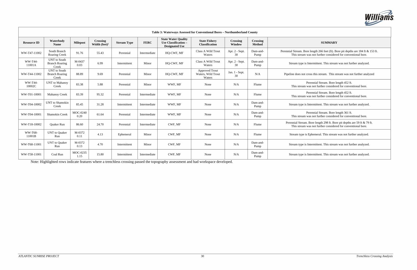
ATLANTIC SUNRISE PROJECT 30 Trenchless Crossing Analysis
Table 3: Waterways Assessed for Conventional Bores – Northumberland County
Resource ID Waterbody
Name Milepost
Crossing Width (feet))
Stream Type FERC State Water Quality Use Classification –
Designated Use
State Fishery Classification
Crossing Window
Crossing Method
SUMMARY
WW-T47-11002 South Branch Roaring Creek
91.76 55.43 Perennial Intermediate HQ-CWF, MF Class A Wild Trout
Waters Apr. 2 - Sept.
30 Dam-and-
Pump Perennial Stream. Bore length 266 feet (ft). Bore pit depths are 184 ft & 153 ft.
This stream was not further considered for conventional bore.
WW-T44-11001A
UNT to South Branch Roaring
Creek
M-0437 0.03
6.99 Intermittent Minor HQ-CWF, MF Class A Wild Trout
Waters Apr. 2 - Sept.
30 Dam-and-
Pump Stream type is Intermittent. This stream was not further analyzed.
WW-T44-11002 UNT to South
Branch Roaring Creek
88.89 9.69 Perennial Minor HQ-CWF, MF Approved Trout
Waters, Wild Trout Waters
Jan. 1 - Sept. 30
N/A Pipeline does not cross this stream. This stream was not further analyzed
WW-T44-10002C
UNT to Mahanoy Creek
83.38 5.88 Perennial Minor WWF, MF None N/A Flume Perennial Stream. Bore length 452 ft.
This stream was not further considered for conventional bore.
WW-T01-10001 Mahanoy Creek 83.39 95.32 Perennial Intermediate WWF, MF None N/A Flume Perennial Stream. Bore length 452 ft.
This stream was not further considered for conventional bore.
WW-T04-10002 UNT to Shamokin
Creek 85.45 31.28 Intermittent Intermediate WWF, MF None N/A
Dam-and-Pump
Stream type is Intermittent. This stream was not further analyzed.
WW-T04-10001 Shamokin Creek MOC-0240
0.20 61.64 Perennial Intermediate WWF, MF None N/A
Dam-and-Pump
Perennial Stream. Bore length 361 ft. This stream was not further considered for conventional bore.
WW-T18-10002 Quaker Run 86.60 24.70 Perennial Intermediate CWF, MF None N/A Flume Perennial Stream. Bore length 298 ft. Bore pit depths are 59 ft & 79 ft.
This stream was not further considered for conventional bore.
WW-T68-11001B
UNT to Quaker Run
M-0372 0.11
4.13 Ephemeral Minor CWF, MF None N/A Flume Stream type is Ephemeral. This stream was not further analyzed.
WW-T68-11001 UNT to Quaker
Run M-0372
0.13 4.70 Intermittent Minor CWF, MF None N/A
Dam-and-Pump
Stream type is Intermittent. This stream was not further analyzed.
WW-T58-11001 Coal Run MOC-0235
1.15 15.80 Intermittent Intermediate CWF, MF None N/A
Dam-and-Pump
Stream type is Intermittent. This stream was not further analyzed.
Note: Highlighted rows indicate features where a trenchless crossing passed the topography assessment and had workspace developed.

ATLANTIC SUNRISE PROJECT 31 Trenchless Crossing Analysis
Table 4: Waterways Assessed for HDD – Northumberland County
Resource ID Waterbody Name Milepost Crossing
Width (feet)
Stream Type FERC
Classification HQ?
(Yes/No)
State Water Quality Use
Classification – Designated
Use
State Fishery Classification
Crossing Window
Crossing Method
HDD Summary
WW-T47-11002
South Branch Roaring Creek
91.76 55.43 Perennial Intermediate Yes HQ-CWF,
MF Class A Wild Trout Waters
Apr. 2 - Sept. 30
Dam-and-Pump
This stream is HQ, Perennial, and has a crossing wider than 30 ft. Geotechnical investigations will be pursued.
WW-T44-11001A
UNT to South Branch Roaring
Creek
M-0437 0.03
6.99 Intermittent Minor Yes HQ-CWF,
MF Class A Wild Trout Waters
Apr. 2 - Sept. 30
Dam-and-Pump
Stream is not HQ. Not further considered for HDD.
WW-T44-11002
UNT to South Branch Roaring
Creek 88.89 9.69 Perennial Minor Yes
HQ-CWF, MF
Approved Trout Waters, Wild Trout Waters
Jan. 1 - Sept. 30
Dam-and-Pump
Stream is HQ and Perennial, but crossing length is less than 30 ft.
WW-T44-10002C
UNT to Mahanoy Creek
83.38 5.88 Perennial Minor No WWF, MF None N/A Flume Stream not HQ. Not further considered for HDD.
WW-T01-10001
Mahanoy Creek 83.39 95.32 Perennial Intermediate No WWF, MF None N/A Flume Stream not HQ. Not further considered for HDD.
WW-T04-10002
UNT to Shamokin Creek
85.45 31.28 Intermittent Intermediate No WWF, MF None N/A Dam-and-
Pump Stream not HQ. Not further considered for HDD.
WW-T04-10001
Shamokin Creek MOC-0240 0.20
61.64 Perennial Intermediate No WWF, MF None N/A Dam-and-
Pump Stream not HQ. Not further considered for HDD.
WW-T18-10002
Quaker Run 86.60 24.70 Perennial Intermediate No CWF, MF None N/A Flume Stream not HQ. Not further considered for HDD.
WW-T68-11001B
UNT to Quaker Run M-0372
0.11 4.13 Ephemeral Minor No CWF, MF None N/A Flume Stream not HQ. Not further considered for HDD.
WW-T68-11001
UNT to Quaker Run M-0372
0.13 4.70 Intermittent Minor No CWF, MF None N/A
Dam-and-Pump
Stream not HQ. Not further considered for HDD.
WW-T58-11001
Coal Run MOC-0235 1.15
15.80 Intermittent Intermediate No CWF, MF None N/A Dam-and-
Pump Stream not HQ. Not further considered for HDD.
Note: Highlighted rows indicate features where a trenchless crossing passed the topography assessment and had workspace developed.

ATLANTIC SUNRISE PROJECT 32 Trenchless Crossing Analysis
Table 5: Wetlands Assessed for HDD –Northumberland County
Wetland ID Milepost Crossing Length (ft) Cowardin Class EV?
(Yes/No) PFO Impacts
(acres) HDD Summary
W‐T18‐10001 83.43 28.1 PEM No 0.00 Wetland is not EV.
Wetland was not further assessed for HDD
W‐T44‐11001 88.83 69.6 PEM/PFO Yes 0.08 Wetland is EV, but does not have PFO impacts greater than 1 acre.
Wetland was not further assessed for HDD.
W‐T49‐11001 91.77 4.5 PEM Yes 0.00 Wetland is EV, but does not have PFO impacts greater than 1 acre.
Wetland was not further assessed for HDD.
W‐T49‐11003 M‐0437 0.05
0 PEM Yes 0.00 Wetland is EV, but does not have PFO impacts greater than 1 acre.
Wetland was not further assessed for HDD.

ATLANTIC SUNRISE PROJECT Trenchless Crossing Analysis
Appendix A
Flow Chart of Trenchless Crossing Analysis
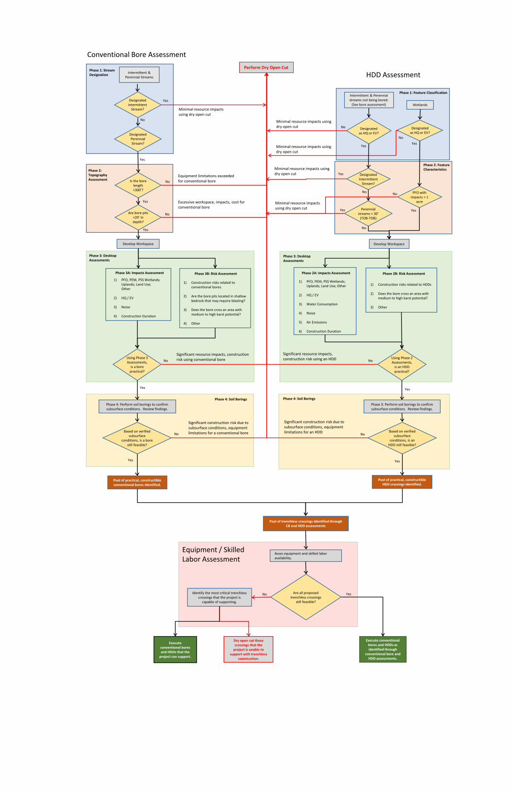
1) PFO, PEM, PSS Wetlands; Uplands; Land Use; Other
2) HQ / EV
3) Noise
4) Construction Duration
Significant construction risk due to subsurface conditions, equipment limitations for an HDD
Designated Intermittent
Stream?
Are bore pits <20’ in depth?
Is the bore length <300’?
Phase 2: Topography Assessment
Yes
No
Phase 4: Perform soil borings to confirm subsurface conditions. Review findings.
Yes
Phase 1: Stream Designation
Phase 3A: Impacts Assessment
Develop Workspace
Phase 3B: Risk Assessment
1) Construction risks related to conventional bores.
2) Are the bore pits located in shallow bedrock that may require blasting?
3) Does the bore cross an area with medium to high karst potential?
4) Other
Using Phase 3 Assessments,
is a bore practical?
Phase 3: Desktop Assessments
Perform Dry Open Cut
Conventional Bore Assessment
Yes
Phase 1: Feature Classification
HDD Assessment
Pool of trenchless crossings identified through CB and HDD assessments
Equipment / Skilled Labor Assessment
Based on verified subsurface
conditions, is a bore still feasible?
Pool of practical, constructible conventional bores identified.
Yes
Yes
Minimal resource impacts using dry open cut
Equipment limitations exceeded for conventional bore
Excessive workspace, impacts, cost for conventional bore
Significant resource impacts, construction risk using conventional bore
Significant construction risk due to subsurface conditions, equipment limitations for a conventional bore
Identify the most critical trenchless crossings that the project is
capable of supporting.
Execute conventional bores and HDDs as identified through
conventional bore and HDD assessments.
Execute conventional bores and HDDs that the
project can support.
Yes
Dry open cut those crossings that the
project is unable to support with trenchless
construction.
Minimal resource impacts using dry open cut
Minimal resource impacts using dry open cut
No
No
No
Yes
No
No
Asses equipment and skilled labor availability.
Are all proposed trenchless crossings
still feasible?
Phase 3: Perform soil borings to confirm subsurface conditions. Review findings.
No
Phase 2A: Impacts Assessment
Develop Workspace
1) PFO, PEM, PSS Wetlands; Uplands; Land Use; Other
2) HQ / EV
3) Water Consumption
4) Noise
5) Air Emissions
6) Construction Duration
Phase 2B: Risk Assessment
1) Construction risks related to HDDs
2) Does the bore cross an area with medium to high karst potential?
3) Other
Using Phase 2 Assessments,
is an HDD practical?
Phase 3: Desktop Assessments
Based on verified subsurface
conditions, is an HDD still feasible?
Pool of practical, constructible HDD crossings identified.
Yes
Yes
Significant resource impacts, construction risk using an HDD No
No
Phase 4: Soil Borings Phase 4: Soil Borings
No
Intermittent & Perennial streams not being bored.
(See bore assessment) Wetlands
PFO with impacts > 1
acre
Yes
No
Minimal resource impacts using dry open cut
Designated as HQ or EV?
Designated as HQ or EV?
Yes
Perennial streams < 30’
(TOB-TOB)
No
Intermittent & Perennial Streams
Phase 2: Feature Characteristics
No
Yes
Designated Perennial Stream?
Yes
Designated Intermittent
Stream?
YesMinimal resource impacts using dry open cut
ATLANTIC SUNRISE PROJECT Trenchless Crossing Analysis
Appendix B
Preliminary Site-Specific Crossing Detail

MP
93.8
MP
93.9
MP
94.0
MP
94.1 M
P94
.2
MP
94.3
MP 94.4
MP 94.5
PA-NO-000.300
PA-NO-000.400
PA
-CO
-014.5RD
PA-CO-019.000
PA-CO-017.000
PA-CO-018.000
150'
75'
250'
75'150'
75'PROPOSED SBR44-B-1N. 253458.72545E. 2312965.25129LAT. N40° 51' 19.8588"LONG. W76° 30' 17.1614"
PROPOSED SBR44-B-2N. 253445.37912E. 2313647.39069LAT. N40° 51' 19.6300"LONG. W76° 30' 08.2878"
PROPOSED SBR44-B-3N. 253548.79970E. 2314638.26364LAT. N40° 51' 20.5105"LONG. W76° 29' 55.3751"
PROPOSED SBR44-B-4N. 253595.30356E. 2315502.01267LAT. N40° 51' 20.8465"LONG. W76° 29' 44.1271"
PROPOSED SBR44-B-5N. 253501.70147E. 2316553.56564LAT. N40° 51' 19.7710"LONG. W76° 29' 30.4618"
PROPOSED SBR44-B-6N. 253712.23525E. 2317673.86717LAT. N40° 51' 21.6900"LONG. W76° 29' 15.8444"
250'
75'
CONCEPTUALHDD EXIT POINTN. 253701.22604
E. 2317934.40046LAT. N40° 51' 21.5437"
LONG. W76° 29' 12.4564"
CONCEPTUALHDD ENTRY POINTN. 253424.35331E. 2312791.84842LAT. N40° 51' 19.5439"LONG. W76° 30' 19.4242"
148'
SOUTH BRANCH ROARING CREEK HDD (WW-T44-11001)NORTHUMBERLAND & COLUMBIA COUNTIES, PENNSYLVANIA
TRANSCONTINENTAL GAS PIPE LINE CO. LLCATLANTIC SUNRISE PROJECT
CONCEPTUAL SITE PLAN AND PROFILE
FIGURE 2A
NOT FOR CONSTRUCTIONFOR DISCUSSION ONLY
ISSUED DATE: SEPTEMBER 23, 2016
:P
:\8\
8169
114\
02\C
AD
\Cro
ssin
gs\C
PL
S\S
out
hB
ran
chR
oari
ngC
reek
(WW
-T44
-110
01)\
Dra
win
gs\S
outh
Bra
nch
Ro
arin
gC
ree
kH
DD
.dw
g\T
AB
:Fig
ure
2A
mo
difie
do
nS
ep
23,
2016
-11
:56a
mB
TL
JLR
NOTES:1. THE LOCATIONS OF ALL FEATURES SHOWN ARE APPROXIMATE.2. THIS DRAWING IS FOR INFORMATION PURPOSES. IT IS INTENDED TO ASSIST IN SHOWING FEATURES DISCUSSED IN AN
ATTACHED DOCUMENT. GEOENGINEERS, INC. CANNOT GUARANTEE THE ACCURACY AND CONTENT OF ELECTRONICFILES. THE MASTER FILE IS STORED BY GEOENGINEERS, INC. AND WILL SERVE AS THE OFFICIAL RECORD OF THISCOMMUNICATION.
3. THE UTILITIES SHOWN ON THE DRAWING ARE BASED ON SURVEY DATA PROVIDED BY TRANSCONTINENTAL GAS PIPELINE COMPANY LLC. GEOENGINEERS, INC. HAS NOT VERIFIED THE FIELD LOCATION OF THE EXISTING UTILITIES.
REFERENCE: BASE FILES, GROUND SURFACE SURVEY AND SURVEY DATA PROVIDED BY TRANSCONTINENTAL GAS PIPELINE COMPANY LLC. GROUND SURFACE LiDAR DOWNLOADED FROMHTTP://MAPS.PSIEE.PSU.EDU/IMAGERYNAVIGATOR/. AERIAL IMAGE TAKEN FROM GOOGLE EARTH PRO ©2016, LICENSED TO GEOENGINEERS, INC., IMAGE DATED 03/29/16.
DATUM:
HORIZONTAL:
VERTICAL:
NAD83, PENNSYLVANIA STATE PLANE, NORTH ZONE, US FOOT
NAVD 88
GROUND SURFACE (SURVEY)
PROPOSEDLIMITS OFDISTURBANCE
PROPOSED CPLS_PANALIGNMENT 07-07-2016
WATER BODY (TYP.)
WETLAND (TYP.)
PROPERTYLINE (TYP.)
NEW EASEMENT (TYP.)
HA
PP
YV
ALLE
Y
RO
AD
HAPPY VALLEY ROAD
NO
RT
HU
MB
ER
LAN
DC
OU
NT
YC
OLU
MB
I AC
OU
NT
YSOUTH BRANCHROARING CREEK
LEGEND:LEGEND:
MAJOR CONTOUR - 20' INTERVAL
MINOR CONTOUR - 5' INTERVAL
ADDITIONAL TEMPORARYHDD WORKSPACE
CORRIDOR EXTRA WORKSPACE
HDD TEMPORARYWORKSPACE BOUNDARY
PROPOSED BORING LOCATION
CONCEPTUAL 42" HORIZONTALDIRECTIONAL DRILL - 5,150'
GROUND SURFACE (LiDAR)
CONCEPTUAL TEMPORARY CARRIERPIPE STRINGING AND
FABRICATION WORKSPACE(SEE FIGURE 2B FOR LAYOUT)
CONCEPTUAL 42" HDD PROFILE
CONCEPTUAL HDDEXIT POINT
CONCEPTUAL HDD ENTRY POINT
"DRY HOLE"APPROX.294 LINEAR FEET
FLUID EQUILIBRIUMELEVATION (935')
PROPOSED SBR44-B-6(DEPTH 450')
CONCEPTUAL SOUTH BRANCHROARING CREEK (T47) HDD
MA
TC
HLI
NE
(SE
EF
IGU
RE
2B)
PROPOSED SBR44-B-5(DEPTH 580')
PROPOSED SBR44-B-4(DEPTH 300')
PROPOSED SBR44-B-3(DEPTH 255')
PROPOSED SBR44-B-2(DEPTH 480')
PROPOSED SBR44-B-1(DEPTH 375')

MP
94.3
MP 94.4
MP 94.5
PA-CO-017.000
PA-CO-018.000
PA-CO-021.000
150'
75'
PROPOSED SBR44-B-5N. 253501.70147E. 2316553.56564LAT. N40° 51' 19.7710"LONG. W76° 29' 30.4618"
PROPOSED SBR44-B-6N. 253712.23525E. 2317673.86717LAT. N40° 51' 21.6900"LONG. W76° 29' 15.8444"
250'75'
CONCEPTUALHDD EXIT POINTN. 253701.22604
E. 2317934.40046LAT. N40° 51' 21.5437"
LONG. W76° 29' 12.4564"
51'
41'
FIGURE 2B
NOT FOR CONSTRUCTIONFOR DISCUSSION ONLY
ISSUED DATE: SEPTEMBER 23, 2016
NOTES:1. THE LOCATIONS OF ALL FEATURES SHOWN ARE APPROXIMATE.2. THIS DRAWING IS FOR INFORMATION PURPOSES. IT IS INTENDED TO ASSIST IN SHOWING FEATURES DISCUSSED IN AN
ATTACHED DOCUMENT. GEOENGINEERS, INC. CANNOT GUARANTEE THE ACCURACY AND CONTENT OF ELECTRONICFILES. THE MASTER FILE IS STORED BY GEOENGINEERS, INC. AND WILL SERVE AS THE OFFICIAL RECORD OF THISCOMMUNICATION.
3. THE UTILITIES SHOWN ON THE DRAWING ARE BASED ON SURVEY DATA PROVIDED BY TRANSCONTINENTAL GAS PIPELINE COMPANY LLC. GEOENGINEERS, INC. HAS NOT VERIFIED THE FIELD LOCATION OF THE EXISTING UTILITIES.
REFERENCE: BASE FILES, GROUND SURFACE SURVEY AND SURVEY DATA PROVIDED BY TRANSCONTINENTAL GAS PIPELINE COMPANY LLC. GROUND SURFACE LiDAR DOWNLOADED FROMHTTP://MAPS.PSIEE.PSU.EDU/IMAGERYNAVIGATOR/. AERIAL IMAGE TAKEN FROM GOOGLE EARTH PRO ©2016, LICENSED TO GEOENGINEERS, INC., IMAGE DATED 05/10/14.
:P
:\8\
8169
114\
02\C
AD
\Cro
ssin
gs\C
PL
S\S
out
hB
ran
chR
oari
ngC
reek
(WW
-T44
-110
01)\
Dra
win
gs\S
outh
Bra
nch
Ro
arin
gC
ree
kH
DD
.dw
g\T
AB
:Fig
ure
2B
mo
difie
do
nS
ep
23,
2016
-12
:02p
mB
TL
JLR
TRANSCONTINENTAL GAS PIPE LINE CO. LLCATLANTIC SUNRISE PROJECT
CONCEPTUAL STRINGING ALIGNMENT AND PROFILE
CONCEPTUAL 42" HDD PROFILE
CONCEPTUAL HDD STRINGING PROFILE1,800 FT R.
1,800 FT R.
DATUM:
HORIZONTAL:
VERTICAL:
NAD83, PENNSYLVANIA STATE PLANE, NORTH ZONE, US FOOT
NAVD 88
GROUND SURFACE (LiDAR)
CONCEPTUAL HDD EXIT POINT
CONCEPTUAL TEMPORARY CARRIERPIPE STRINGING ANDFABRICATION WORKSPACE(3,200' X 50)
SOUTH BRANCH ROARING CREEK HDD (WW-T44-11001)NORTHUMBERLAND & COLUMBIA COUNTIES, PENNSYLVANIA
PROPOSEDLIMITS OF DISTURBANCE
PROPOSED CPLS_PANALIGNMENT 07-07-2016
PROPERTYLINE (TYP.)NEW EASEMENT
(TYP.)
CO
OLID
GE
RO
AD
CONCEPTUAL 42" HORIZONTALDIRECTIONAL DRILL - 5,150'
MA
TC
HLI
NE
(SE
EF
IGU
RE
2A)
WILS
ON
RO
AD
1,800 FT R.
"DRY HOLE" APPROX.294 LINEAR FEET
FLUID EQUILIBRIUMELEVATION (935')
PROPOSED SBR44-B-6(DEPTH 450')
PROPOSED SBR44-B-5(DEPTH 580')
COOLIDGE ROAD
WILSON ROAD
LEGEND:LEGEND:
MAJOR CONTOUR - 20' INTERVAL
MINOR CONTOUR - 5' INTERVAL
ADDITIONAL TEMPORARYHDD WORKSPACE
CORRIDOR EXTRA WORKSPACE
HDD TEMPORARYWORKSPACE BOUNDARY
PROPOSED BORING LOCATION

PA-CO-004.000
PA-CO-004.200 PA-NO-000.300MP
93. 0
MP
93. 1
MP
93. 2
MP
93. 3 M
P93
.4 MP
93.5
MP 93.6
MP93.7
PA
-CO
-004.6.R
D
PA
-CO
-004.5.R
D
150'75'
250'75'
150'
75'
PROPOSED SBR47-B-5N. 253016.56378
E. 2313346.47397LAT. N40° 51' 15.4362"
LONG. W76° 30' 12.2837"
PROPOSED SBR47-B-4N. 252031.57514
E. 2313341.74354LAT. N40° 51' 05.7054"
LONG. W76° 30' 12.5297"
PROPOSED SBR47-B-3N. 250980.74682
E. 2313511.69894LAT. N40° 50' 55.2992"
LONG. W76° 30' 10.5153"
PROPOSED SBR47-B-2N. 250231.04362
E. 2313448.09778LAT. N40° 50' 47.9013"
LONG. W76° 30' 11.4832"
PROPOSED SBR47-B-1N. 249571.36339E. 2313379.92891LAT. N40° 50' 41.3935"LONG. W76° 30' 12.4936"
250'
75'
CONCEPTUALHDD EXIT POINTN. 249366.48581E. 2313353.94469LAT. N40° 50' 39.3731"LONG. W76° 30' 12.8700"
CONCEPTUALHDD ENTRY POINT
N. 253166.44199E. 2313372.19405
LAT. N40° 51' 16.9133"LONG. W76° 30' 11.9210"
118'
UNT TO SOUTH BRANCH ROARING CREEK (WW-T47-11001)AND SOUTH BRANCH ROARING CREEK HDD (WW-T47-11002)COLUMBIA & NORTHUMBERLAND COUNTIES, PENNSYLVANIA
TRANSCONTINENTAL GAS PIPE LINE CO. LLCATLANTIC SUNRISE PROJECT
CONCEPTUAL SITE PLAN AND PROFILE
FIGURE 2A
NOT FOR CONSTRUCTIONFOR DISCUSSION ONLY
ISSUED DATE: SEPTEMBER 23, 2016
:P
:\8\
8169
114\
02\C
AD
\Cro
ssin
gs\C
PL
S\U
NT
toS
outh
Bra
nch
Ro
arin
gC
ree
k(W
W-T
47-
1100
1)\D
raw
ing
s\U
NT
toS
outh
Bra
nch
Ro
arin
gC
ree
kH
DD
.dw
g\T
AB
:Fig
ure
2A
mo
difie
do
nS
ep
23,
2016
-12
:35p
mB
TL
JLR
NOTES:1. THE LOCATIONS OF ALL FEATURES SHOWN ARE APPROXIMATE.2. THIS DRAWING IS FOR INFORMATION PURPOSES. IT IS INTENDED TO ASSIST IN SHOWING FEATURES DISCUSSED IN AN
ATTACHED DOCUMENT. GEOENGINEERS, INC. CANNOT GUARANTEE THE ACCURACY AND CONTENT OF ELECTRONICFILES. THE MASTER FILE IS STORED BY GEOENGINEERS, INC. AND WILL SERVE AS THE OFFICIAL RECORD OF THISCOMMUNICATION.
3. THE UTILITIES SHOWN ON THE DRAWING ARE BASED ON SURVEY DATA PROVIDED BY TRANSCONTINENTAL GAS PIPELINE COMPANY LLC. GEOENGINEERS, INC. HAS NOT VERIFIED THE FIELD LOCATION OF THE EXISTING UTILITIES.
REFERENCE: BASE FILES, GROUND SURFACE SURVEY AND SURVEY DATA PROVIDED BY TRANSCONTINENTAL GAS PIPELINE COMPANY LLC. GROUND SURFACE LiDAR DOWNLOADED FROMHTTP://MAPS.PSIEE.PSU.EDU/IMAGERYNAVIGATOR/. AERIAL IMAGE TAKEN FROM GOOGLE EARTH PRO ©2016, LICENSED TO GEOENGINEERS, INC., IMAGE DATED 03/29/16.
DATUM:
HORIZONTAL:
VERTICAL:
NAD83, PENNSYLVANIA STATE PLANE, NORTH ZONE, US FOOT
NAVD 88
GROUND SURFACE (SURVEY)
PROPOSEDLIMITS OFDISTURBANCE
PROPOSED CPLS_PANALIGNMENT 07-07-2016
WATER BODY(TYP.)
WETLAND(TYP.)
PROPERTYLINE (TYP.)
PROPOSEDR.O.W. (TYP.)
EXISTINGOVERHEADPOWER LINE
HA
PP
YV
ALLE
Y
RO
AD
HAPPY VALLEY ROAD
NO
RTH
UM
BE
RLA
ND
CO
UN
TY
CO
LUM
BIA
CO
UN
TY
COUNTY LINE
UNT TO SOUTH BRANCH ROARING CREEK
SOUTH BRANCH ROARING CREEK
SO
UT
HB
RA
NC
H
RO
AR
ING
CR
EE
KCONCEPTUAL 42" HDD PROFILE
CONCEPTUAL HDDEXIT POINT
CONCEPTUALHDD ENTRY POINT"DRY HOLE" APPROX.
309 LINEAR FEET
FLUID EQUILIBRIUMELEVATION (865')
LEGEND:LEGEND:
MAJOR CONTOUR - 10' INTERVAL
MINOR CONTOUR - 2' INTERVAL
ADDITIONAL TEMPORARYHDD WORKSPACE
CORRIDOR EXTRA WORKSPACE
HDD TEMPORARYWORKSPACE BOUNDARY
PROPOSED BORING LOCATION
CONCEPTUAL 42" HORIZONTALDIRECTIONAL DRILL - 3,800'
WY
NN
SC
HO
OL
RO
AD
MA
TC
HLI
NE
(SE
EF
IGU
RE
2B)
PROPOSED SBR47-B-1(DEPTH 240')
PROPOSED SBR47-B-2(DEPTH 280')
PROPOSED SBR47-B-3(DEPTH 145')
PROPOSED SBR47-B-4(DEPTH 325')
PROPOSED SBR47-B-5(DEPTH 175')
CONCEPTUAL TEMPORARYCARRIER PIPE STRINGING ANDFABRICATION WORKSPACE(SEE FIGURE 2B FOR LAYOUT)

PA-CO-002.000
PA-CO-004.000
MP 92.7
MP
92. 8
MP
92. 9
MP
93. 0
MP
93. 1
MP
93. 2
PA
-CO
-004.5.R
D
250'75'
150'
75'
PROPOSED SBR47-B-2N. 250231.04362
E. 2313448.09778LAT. N40° 50' 47.9013"
LONG. W76° 30' 11.4832"
PROPOSED SBR47-B-1N. 249571.36339E. 2313379.92891LAT. N40° 50' 41.3935"LONG. W76° 30' 12.4936"
CONCEPTUALHDD EXIT POINTN. 249366.48581E. 2313353.94469LAT. N40° 50' 39.3731"LONG. W76° 30' 12.8700"
52'
14'
FIGURE 2B
NOT FOR CONSTRUCTIONFOR DISCUSSION ONLY
ISSUED DATE: SEPTEMBER 23, 2016
NOTES:1. THE LOCATIONS OF ALL FEATURES SHOWN ARE APPROXIMATE.2. THIS DRAWING IS FOR INFORMATION PURPOSES. IT IS INTENDED TO ASSIST IN SHOWING FEATURES DISCUSSED IN AN
ATTACHED DOCUMENT. GEOENGINEERS, INC. CANNOT GUARANTEE THE ACCURACY AND CONTENT OF ELECTRONICFILES. THE MASTER FILE IS STORED BY GEOENGINEERS, INC. AND WILL SERVE AS THE OFFICIAL RECORD OF THISCOMMUNICATION.
3. THE UTILITIES SHOWN ON THE DRAWING ARE BASED ON SURVEY DATA PROVIDED BY TRANSCONTINENTAL GAS PIPELINE COMPANY LLC. GEOENGINEERS, INC. HAS NOT VERIFIED THE FIELD LOCATION OF THE EXISTING UTILITIES.
REFERENCE: BASE FILES, GROUND SURFACE SURVEY AND SURVEY DATA PROVIDED BY TRANSCONTINENTAL GAS PIPELINE COMPANY LLC. GROUND SURFACE LiDAR DOWNLOADED FROMHTTP://MAPS.PSIEE.PSU.EDU/IMAGERYNAVIGATOR/. AERIAL IMAGE TAKEN FROM GOOGLE EARTH PRO ©2016, LICENSED TO GEOENGINEERS, INC., IMAGE DATED 03/29/16.
:P
:\8\
8169
114\
02\C
AD
\Cro
ssin
gs\C
PL
S\U
NT
toS
outh
Bra
nch
Ro
arin
gC
ree
k(W
W-T
47-
1100
1)\D
raw
ing
s\U
NT
toS
outh
Bra
nch
Ro
arin
gC
ree
kH
DD
.dw
g\T
AB
:Fig
ure
2B
mo
difie
do
nS
ep
23,
2016
-12
:33p
mB
TL
JLR
TRANSCONTINENTAL GAS PIPE LINE CO. LLCATLANTIC SUNRISE PROJECT
CONCEPTUAL STRINGING ALIGNMENT AND PROFILE
CONCEPTUAL 42" HDD PROFILE
CONCEPTUAL HDD STRINGING PROFILE
1,800 FT R.
1,800 FT R.
DATUM:
HORIZONTAL:
VERTICAL:
NAD83, PENNSYLVANIA STATE PLANE, NORTH ZONE, US FOOT
NAVD 88
GROUND SURFACE (SURVEY)
CONCEPTUAL 42" HORIZONTALDIRECTIONAL DRILL - 3,800'
CONCEPTUAL HDD EXIT POINT
MA
TC
HLI
NE
(SE
EF
IGU
RE
2A)
CONCEPTUAL TEMPORARY CARRIERPIPE STRINGING AND
FABRICATION WORKSPACE(LENGTH 2,075', WIDTH VARIES)
PROPOSEDLIMITS OFDISTURBANCE
PROPOSED CPLS_PANALIGNMENT 07-07-2016
PROPERTYLINE (TYP.)
PROPOSEDR.O.W. (TYP.)
EXISTING OVERHEADPOWER LINE
UNT TO SOUTH BRANCH ROARING CREEK (WW-T47-11001)AND SOUTH BRANCH ROARING CREEK HDD (WW-T47-11002)COLUMBIA & NORTHUMBERLAND COUNTIES, PENNSYLVANIA
WY
NN
SC
HO
OL
RO
AD
MO
NR
OE
DR
IVE
CONCEPTUAL TEMPORARY CARRIER PIPESTRINGING ALIGNMENT (2,075' LONG)
BEAR GAP ROAD
HAPPY VALLEY ROAD
GROUND SURFACE (LiDAR)
PROPOSED SBR47-B-1(DEPTH 240')
LEGEND:LEGEND:
MAJOR CONTOUR - 10' INTERVAL
MINOR CONTOUR - 2' INTERVAL
ADDITIONAL TEMPORARYHDD WORKSPACE
CORRIDOR EXTRA WORKSPACE
HDD TEMPORARYWORKSPACE BOUNDARY
PROPOSED BORING LOCATION
6,000 FT. R
PA-CO-004.200
PROPOSED SBR47-B-2(DEPTH 280')
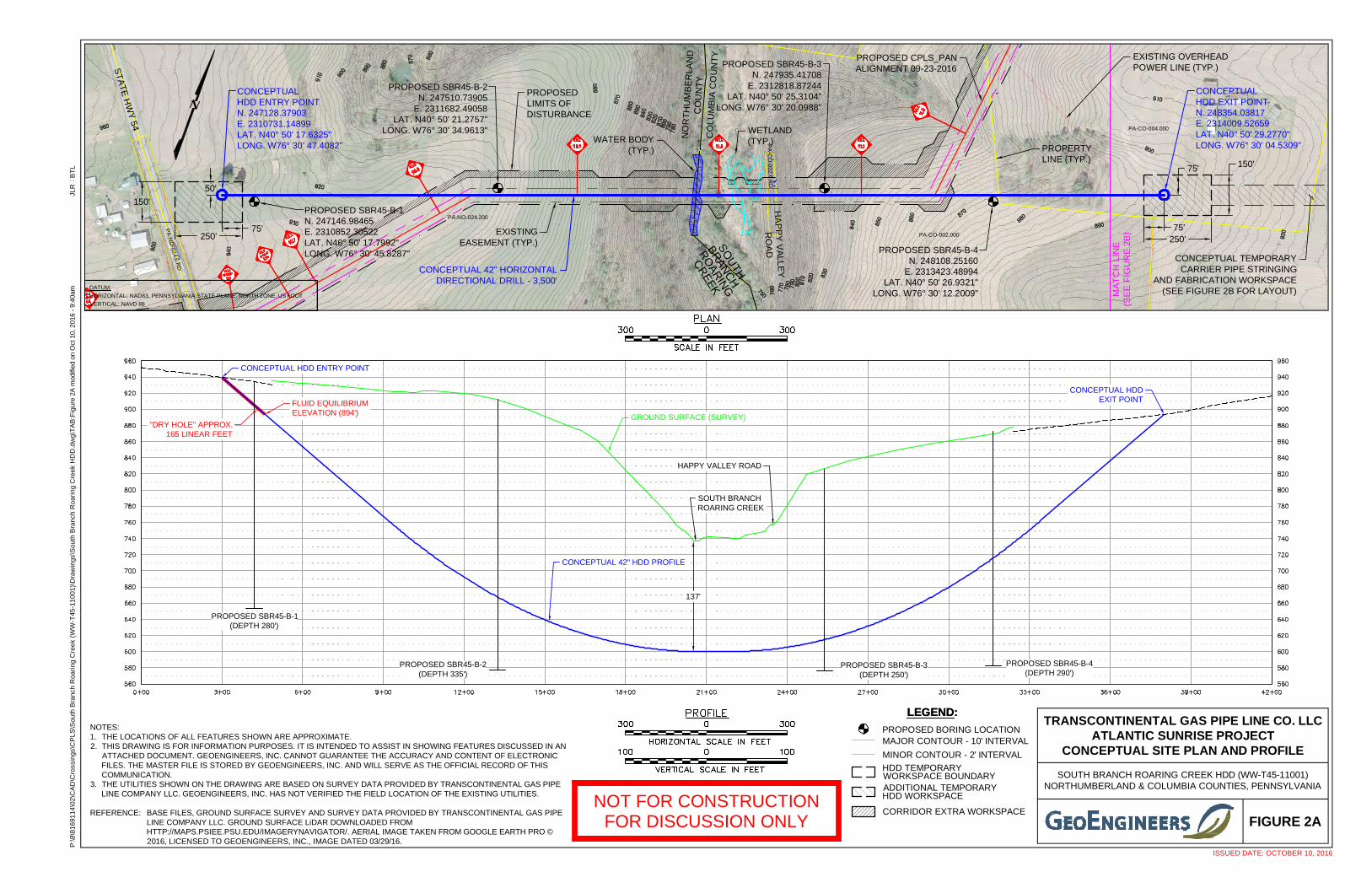
PA-NO-024.200
PA-CO-002.000
PA-CO-004.000
PA
-CO
-00
2 .6 .RD
250'75'
150'75'
250'75'
50'
150'
PA
-NO
-024.6.RD
PROPOSED SBR45-B-1N. 247146.98465E. 2310852.30522LAT. N40° 50' 17.7992"LONG. W76° 30' 45.8287"
PROPOSED SBR45-B-2N. 247510.73905
E. 2311682.49058LAT. N40° 50' 21.2757"
LONG. W76° 30' 34.9613"
CONCEPTUALHDD ENTRY POINTN. 247128.37903E. 2310731.14899LAT. N40° 50' 17.6325"LONG. W76° 30' 47.4082"
PROPOSED SBR45-B-4N. 248108.25160
E. 2313423.48994LAT. N40° 50' 26.9321"
LONG. W76° 30' 12.2009"
CONCEPTUALHDD EXIT POINTN. 248354.03817E. 2314009.52659LAT. N40° 50' 29.2770"LONG. W76° 30' 04.5309"
PROPOSED SBR45-B-3N. 247935.41708
E. 2312818.87244LAT. N40° 50' 25.3104"
LONG. W76° 30' 20.0988"
137'
SOUTH BRANCH ROARING CREEK HDD (WW-T45-11001)NORTHUMBERLAND & COLUMBIA COUNTIES, PENNSYLVANIA
TRANSCONTINENTAL GAS PIPE LINE CO. LLCATLANTIC SUNRISE PROJECT
CONCEPTUAL SITE PLAN AND PROFILE
FIGURE 2A
CONCEPTUAL 42" HDD PROFILE
NOT FOR CONSTRUCTIONFOR DISCUSSION ONLY
ISSUED DATE: OCTOBER 10, 2016
:P
:\8
\81
69
11
4\0
2\C
AD
\Cro
ssin
gs\
CP
LS
\So
uth
Bra
nch
Ro
ari
ng
Cre
ek
(WW
-T4
5-1
10
01
)\D
raw
ing
s\S
ou
thB
ran
chR
oa
rin
gC
ree
kH
DD
.dw
g\T
AB
:Fig
ure
2Am
odifi
edon
Oct
10,2
016
-9:
40am
BT
LJL
R
NOTES:1. THE LOCATIONS OF ALL FEATURES SHOWN ARE APPROXIMATE.2. THIS DRAWING IS FOR INFORMATION PURPOSES. IT IS INTENDED TO ASSIST IN SHOWING FEATURES DISCUSSED IN AN
ATTACHED DOCUMENT. GEOENGINEERS, INC. CANNOT GUARANTEE THE ACCURACY AND CONTENT OF ELECTRONICFILES. THE MASTER FILE IS STORED BY GEOENGINEERS, INC. AND WILL SERVE AS THE OFFICIAL RECORD OF THISCOMMUNICATION.
3. THE UTILITIES SHOWN ON THE DRAWING ARE BASED ON SURVEY DATA PROVIDED BY TRANSCONTINENTAL GAS PIPELINE COMPANY LLC. GEOENGINEERS, INC. HAS NOT VERIFIED THE FIELD LOCATION OF THE EXISTING UTILITIES.
REFERENCE: BASE FILES, GROUND SURFACE SURVEY AND SURVEY DATA PROVIDED BY TRANSCONTINENTAL GAS PIPELINE COMPANY LLC. GROUND SURFACE LiDAR DOWNLOADED FROMHTTP://MAPS.PSIEE.PSU.EDU/IMAGERYNAVIGATOR/. AERIAL IMAGE TAKEN FROM GOOGLE EARTH PRO ©2016, LICENSED TO GEOENGINEERS, INC., IMAGE DATED 03/29/16.
DATUM:
HORIZONTAL:
VERTICAL:
NAD83, PENNSYLVANIA STATE PLANE, NORTH ZONE, US FOOT
NAVD 88
GROUND SURFACE (SURVEY)
CONCEPTUAL HDDEXIT POINT
CONCEPTUAL HDD ENTRY POINT
HAPPY VALLEY ROAD
SOUTH BRANCHROARING CREEK
ST
AT
EH
WY
54
LEGEND:LEGEND:
MAJOR CONTOUR - 10' INTERVAL
MINOR CONTOUR - 2' INTERVAL
ADDITIONAL TEMPORARYHDD WORKSPACE
CORRIDOR EXTRA WORKSPACE
HDD TEMPORARYWORKSPACE BOUNDARY
PROPOSED BORING LOCATION
PROPOSEDLIMITS OFDISTURBANCE
PROPOSED CPLS_PANALIGNMENT 09-23-2016
CONCEPTUAL 42" HORIZONTALDIRECTIONAL DRILL - 3,500'
WATER BODY(TYP.) PROPERTY
LINE (TYP.)
CONCEPTUAL TEMPORARYCARRIER PIPE STRINGING
AND FABRICATION WORKSPACE(SEE FIGURE 2B FOR LAYOUT)
EXISTING OVERHEADPOWER LINE (TYP.)
EXISTINGEASEMENT (TYP.)
HA
PP
YV
ALLE
Y
RO
AD
NO
RT
HU
MB
ER
LAN
DC
OU
NT
YC
OL
UM
BIA
CO
UN
TY
SO
UTH
BR
AN
CH
RO
ARIN
G
CR
EEK
MA
TC
HLI
NE
(SE
EF
IGU
RE
2B)
WETLAND(TYP.)
"DRY HOLE" APPROX.165 LINEAR FEET
FLUID EQUILIBRIUMELEVATION (894')
PROPOSED SBR45-B-1(DEPTH 280')
PROPOSED SBR45-B-2(DEPTH 335')
PROPOSED SBR45-B-3(DEPTH 250')
PROPOSED SBR45-B-4(DEPTH 290')

45'
PA-CO-002.000
PA-CO-004.000
PA
-CO
-00 2. 6 .R
D
250'75'
150'75'
PROPOSED SBR45-B-4N. 248108.25160
E. 2313423.48994LAT. N40° 50' 26.9321"
LONG. W76° 30' 12.2009"
CONCEPTUALHDD EXIT POINTN. 248354.03817E. 2314009.52659LAT. N40° 50' 29.2770"LONG. W76° 30' 04.5309"
PROPOSED SBR45-B-3N. 247935.41708
E. 2312818.87244LAT. N40° 50' 25.3104"
LONG. W76° 30' 20.0988"
FIGURE 2B
NOT FOR CONSTRUCTIONFOR DISCUSSION ONLY
ISSUED DATE: OCTOBER 10, 2016
NOTES:1. THE LOCATIONS OF ALL FEATURES SHOWN ARE APPROXIMATE.2. THIS DRAWING IS FOR INFORMATION PURPOSES. IT IS INTENDED TO ASSIST IN SHOWING FEATURES DISCUSSED IN AN
ATTACHED DOCUMENT. GEOENGINEERS, INC. CANNOT GUARANTEE THE ACCURACY AND CONTENT OF ELECTRONICFILES. THE MASTER FILE IS STORED BY GEOENGINEERS, INC. AND WILL SERVE AS THE OFFICIAL RECORD OF THISCOMMUNICATION.
3. THE UTILITIES SHOWN ON THE DRAWING ARE BASED ON SURVEY DATA PROVIDED BY TRANSCONTINENTAL GAS PIPELINE COMPANY LLC. GEOENGINEERS, INC. HAS NOT VERIFIED THE FIELD LOCATION OF THE EXISTING UTILITIES.
REFERENCE: BASE FILES, GROUND SURFACE SURVEY AND SURVEY DATA PROVIDED BY TRANSCONTINENTAL GAS PIPELINE COMPANY LLC. GROUND SURFACE LiDAR DOWNLOADED FROMHTTP://MAPS.PSIEE.PSU.EDU/IMAGERYNAVIGATOR/. AERIAL IMAGE TAKEN FROM GOOGLE EARTH PRO ©2016, LICENSED TO GEOENGINEERS, INC., IMAGE DATED 03/29/16.
:P
:\8
\81
69
11
4\0
2\C
AD
\Cro
ssin
gs\
CP
LS
\So
uth
Bra
nch
Ro
ari
ng
Cre
ek
(WW
-T4
5-1
10
01
)\D
raw
ing
s\S
ou
thB
ran
chR
oa
rin
gC
ree
kH
DD
.dw
g\T
AB
:Fig
ure
2Bm
odifi
edon
Oct
10,2
016
-9:
42am
BT
LJL
R
TRANSCONTINENTAL GAS PIPE LINE CO. LLCATLANTIC SUNRISE PROJECT
CONCEPTUAL STRINGING ALIGNMENT AND PROFILE
CONCEPTUAL 42" HDD PROFILE
CONCEPTUAL HDD STRINGING PROFILE
1,800 FT R. 1,800 FT R.
DATUM:
HORIZONTAL:
VERTICAL:
NAD83, PENNSYLVANIA STATE PLANE, NORTH ZONE, US FOOT
NAVD 88
GROUND SURFACE (SURVEY)
CONCEPTUAL HDD EXIT POINT
MA
TC
HL
INE
(SE
EF
IGU
RE
2A)
PROPERTYLINE (TYP.)
SO
UTH
BRAN
CH
RO
AR
ING
CR
EEK
GROUND SURFACE (LiDAR)
LEGEND:LEGEND:
MAJOR CONTOUR - 10' INTERVAL
MINOR CONTOUR - 2' INTERVAL
ADDITIONAL TEMPORARYHDD WORKSPACE
CORRIDOR EXTRA WORKSPACE
HDD TEMPORARYWORKSPACE BOUNDARY
PROPOSED BORING LOCATION
PROPOSEDLIMITS OFDISTURBANCE
PROPOSED CPLS_PANALIGNMENT 09-23-2016
CONCEPTUAL 42" HORIZONTALDIRECTIONAL DRILL - 3,500'
WATERBODY(TYP.)
CONCEPTUAL TEMPORARYCARRIER PIPE STRINGING
AND FABRICATION WORKSPACE(1,555' X 75')
EXISTING OVERHEADPOWER LINE (TYP.)
EXISTING EASEMENT (TYP.)
HA
PP
YV
ALLE
Y
RO
AD
NO
RT
HU
MB
ER
LAN
DC
OU
NT
YC
OL
UM
BIA
CO
UN
TY
WETLAND(TYP.)
HAPPY VALLEY ROAD
SOUTH BRANCHROARING CREEK
SOUTH BRANCH ROARING CREEK HDD (WW-T45-11001)NORTHUMBERLAND & COLUMBIA COUNTIES, PENNSYLVANIA
PROPOSED SBR45-B-3(DEPTH 250')
PROPOSED SBR45-B-4(DEPTH 290')


![Atlantic Sunrise Project - Sierra Club · impacts (“PA Pipeline Explosion: Evidence of Corrosion Found,” Phillips [Susan], 2016). Atlantic Sunrise Project Economics iv At a Glance:](https://img.dokumen.tips/doc/110x75/5f271fb3e89d5921914f1ce8/atlantic-sunrise-project-sierra-club-impacts-aoepa-pipeline-explosion-evidence.jpg)