Embed Size (px)
Citation preview
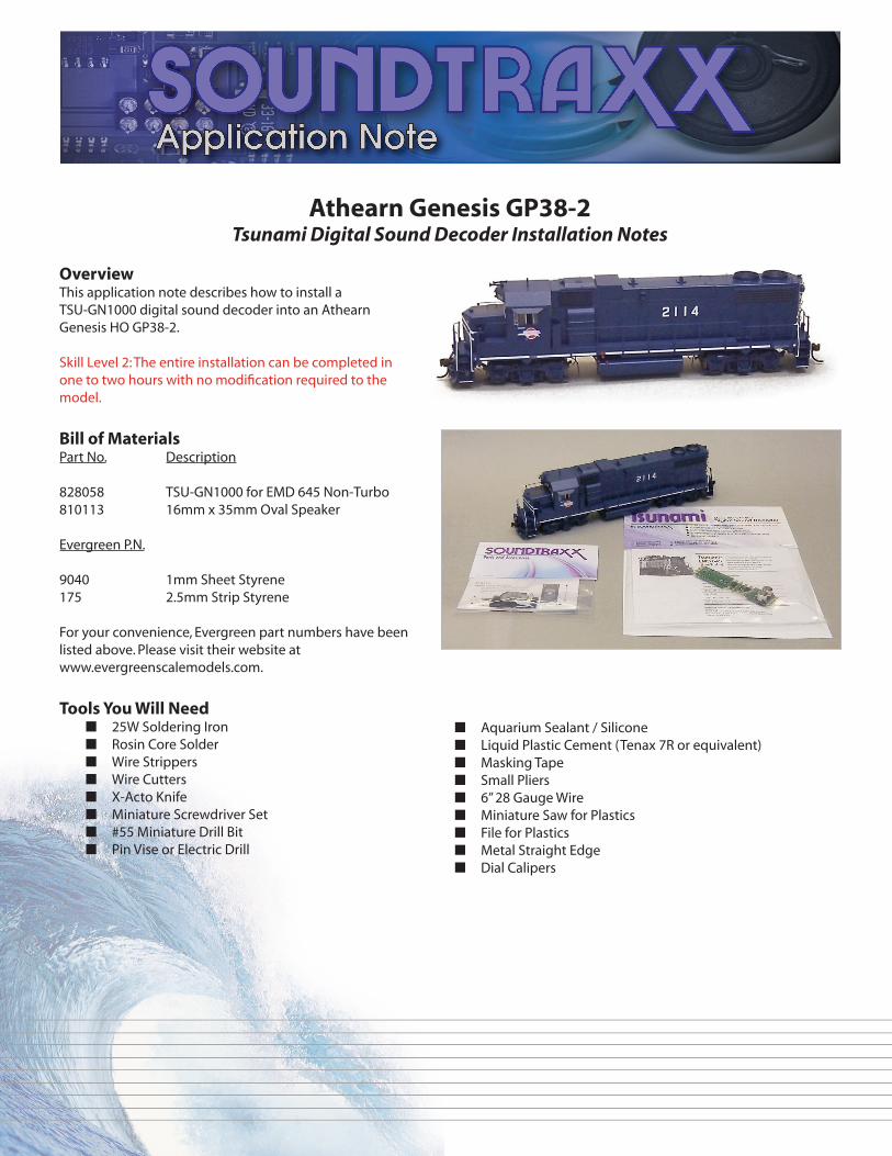
Athearn Genesis GP38-2Tsunami Digital Sound Decoder Installation Notes
OverviewThis application note describes how to install a TSU-GN1000 digital sound decoder into an Athearn Genesis HO GP38-2.
Skill Level 2: The entire installation can be completed in one to two hours with no modification required to the model.
Bill of MaterialsPart No. Description
828058 TSU-GN1000 for EMD 645 Non-Turbo810113 16mm x 35mm Oval Speaker
Evergreen P.N.
9040 1mm Sheet Styrene175 2.5mm Strip Styrene
For your convenience, Evergreen part numbers have been listed above. Please visit their website at www.evergreenscalemodels.com.
Tools You Will Need■ 25W Soldering Iron■ Rosin Core Solder■ Wire Strippers■ Wire Cutters■ X-Acto Knife■ Miniature Screwdriver Set■ #55 Miniature Drill Bit■ Pin Vise or Electric Drill
■ Aquarium Sealant / Silicone■ Liquid Plastic Cement (Tenax 7R or equivalent)■ Masking Tape■ Small Pliers■ 6” 28 Gauge Wire■ Miniature Saw for Plastics■ File for Plastics■ Metal Straight Edge■ Dial Calipers
Installation
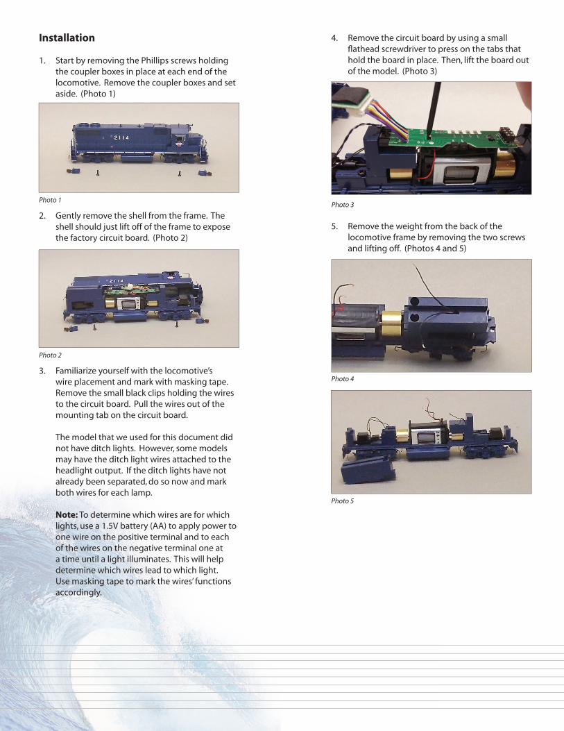
1. Start by removing the Phillips screws holding the coupler boxes in place at each end of the locomotive. Remove the coupler boxes and set aside. (Photo 1)
2. Gently remove the shell from the frame. The shell should just lift off of the frame to expose the factory circuit board. (Photo 2)
3. Familiarize yourself with the locomotive’s wire placement and mark with masking tape. Remove the small black clips holding the wires to the circuit board. Pull the wires out of the mounting tab on the circuit board.
The model that we used for this document did not have ditch lights. However, some models may have the ditch light wires attached to the headlight output. If the ditch lights have not already been separated, do so now and mark both wires for each lamp.
Note: To determine which wires are for which lights, use a 1.5V battery (AA) to apply power to one wire on the positive terminal and to each of the wires on the negative terminal one at a time until a light illuminates. This will help determine which wires lead to which light. Use masking tape to mark the wires’ functions accordingly.
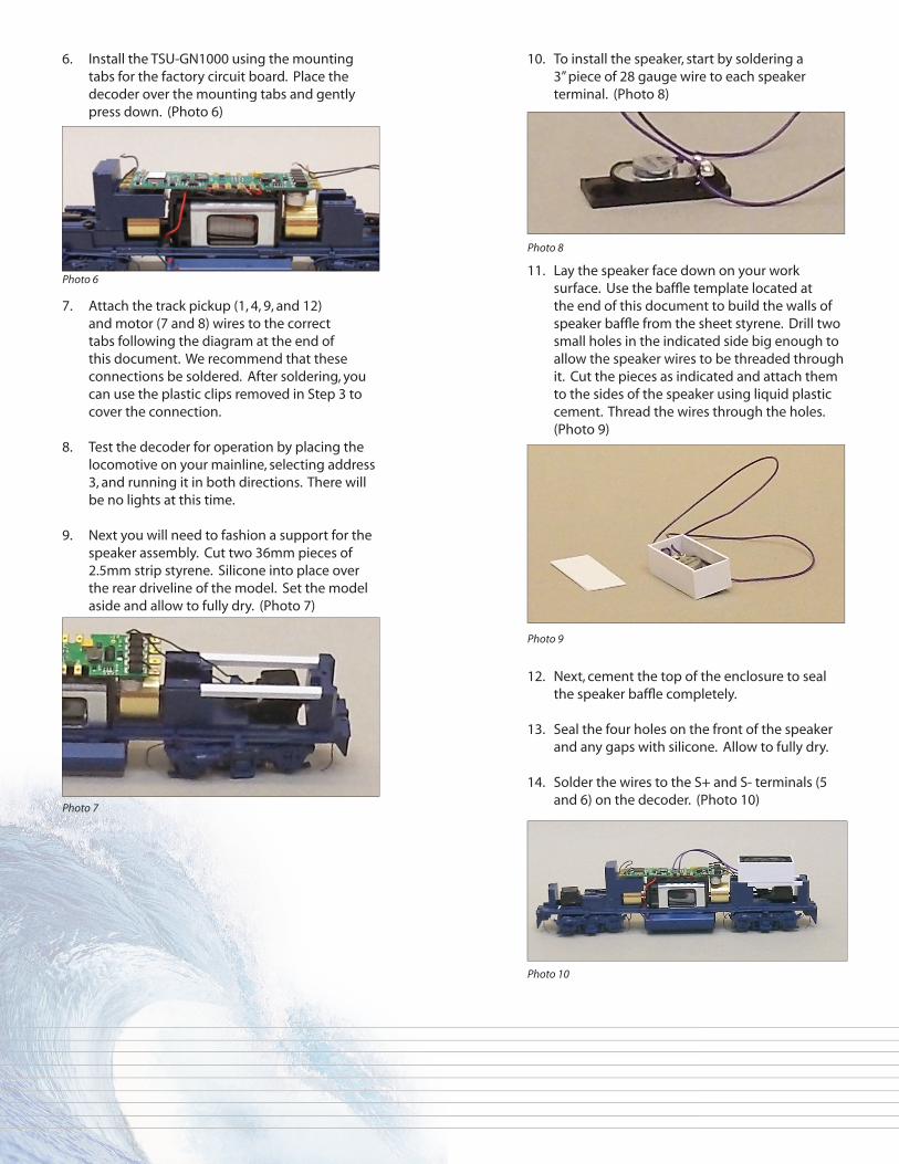
4. Remove the circuit board by using a small fl athead screwdriver to press on the tabs that hold the board in place. Then, lift the board out of the model. (Photo 3)
5. Remove the weight from the back of the locomotive frame by removing the two screws and lifting off. (Photos 4 and 5)
Photo 1
Photo 2
Photo 3
Photo 4
Photo 5
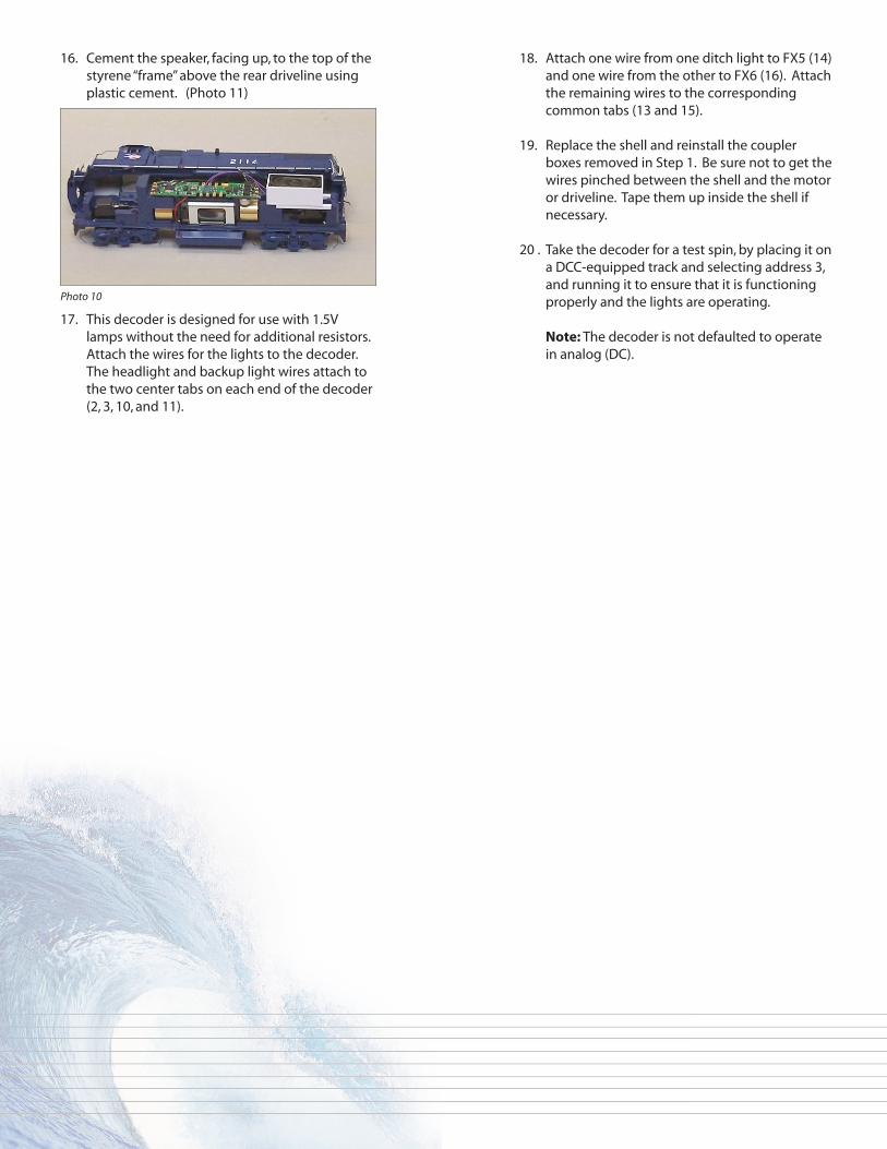
10. To install the speaker, start by soldering a 3” piece of 28 gauge wire to each speaker terminal. (Photo 8)
11. Lay the speaker face down on your work surface. Use the baffl e template located at the end of this document to build the walls of speaker baffl e from the sheet styrene. Drill two small holes in the indicated side big enough to allow the speaker wires to be threaded through it. Cut the pieces as indicated and attach them to the sides of the speaker using liquid plastic cement. Thread the wires through the holes. (Photo 9)
12. Next, cement the top of the enclosure to seal the speaker baffl e completely.
13. Seal the four holes on the front of the speaker and any gaps with silicone. Allow to fully dry.
14. Solder the wires to the S+ and S- terminals (5 and 6) on the decoder. (Photo 10)
6. Install the TSU-GN1000 using the mounting tabs for the factory circuit board. Place the decoder over the mounting tabs and gently press down. (Photo 6)
7. Attach the track pickup (1, 4, 9, and 12) and motor (7 and 8) wires to the correct tabs following the diagram at the end of this document. We recommend that these connections be soldered. After soldering, you can use the plastic clips removed in Step 3 to cover the connection.
8. Test the decoder for operation by placing the locomotive on your mainline, selecting address 3, and running it in both directions. There will be no lights at this time.
9. Next you will need to fashion a support for the speaker assembly. Cut two 36mm pieces of 2.5mm strip styrene. Silicone into place over the rear driveline of the model. Set the model aside and allow to fully dry. (Photo 7)
Photo 7
Photo 8
Photo 9
Photo 10
Photo 6
16. Cement the speaker, facing up, to the top of the styrene “frame” above the rear driveline using plastic cement. (Photo 11)
17. This decoder is designed for use with 1.5V lamps without the need for additional resistors. Attach the wires for the lights to the decoder. The headlight and backup light wires attach to the two center tabs on each end of the decoder (2, 3, 10, and 11).
18. Attach one wire from one ditch light to FX5 (14) and one wire from the other to FX6 (16). Attach the remaining wires to the corresponding common tabs (13 and 15).
19. Replace the shell and reinstall the coupler boxes removed in Step 1. Be sure not to get the wires pinched between the shell and the motor or driveline. Tape them up inside the shell if necessary.
20 . Take the decoder for a test spin, by placing it on a DCC-equipped track and selecting address 3, and running it to ensure that it is functioning properly and the lights are operating.
Note: The decoder is not defaulted to operate in analog (DC).
Photo 10
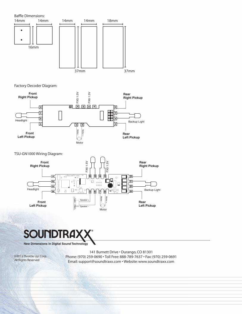
Baffl e Dimensions:14mm 14mm 14mm 14mm 18mm
®
New Dimensions in Digital Sound Technology
©2013 Throttle Up! Corp.All Rights Reserved
141 Burnett Drive • Durango, CO 81301Phone: (970) 259-0690 • Toll Free: 888-789-7637 • Fax: (970) 259-0691
Email: [email protected] • Website: www.soundtraxx.com
Front Right Pickup
Front Left Pickup
RearRight Pickup
RearLeft Pickup
Headlight Backup Light
FX
6 1.
5V
FX
5 1.
5V
5 6 7 8
Speaker +
Speaker -
Motor
Motor -
Motor +
TSU_GN1000_INSTALL_1.EPS
1 2 3 4 9
10
11
12
F5
F6
S+
S-
M-
M+
16 15 14 13
TSU-GN1000 Wiring Diagram:
16mm
37mm 37mm
Factory Decoder Diagram:
Front Right Pickup
Front Left Pickup
Headlight
RearRight Pickup
RearLeft Pickup
Backup Light
Motor
Motor -
Motor +
FX
6 1.
5V
FX
5 1.
5V